KR20150141902A - Hybrid vehicle - Google Patents
Hybrid vehicle Download PDFInfo
- Publication number
- KR20150141902A KR20150141902A KR1020150081252A KR20150081252A KR20150141902A KR 20150141902 A KR20150141902 A KR 20150141902A KR 1020150081252 A KR1020150081252 A KR 1020150081252A KR 20150081252 A KR20150081252 A KR 20150081252A KR 20150141902 A KR20150141902 A KR 20150141902A
- Authority
- KR
- South Korea
- Prior art keywords
- mode
- power
- control
- engine
- hybrid vehicle
- Prior art date
Links
Images


Classifications
-
- B—PERFORMING OPERATIONS; TRANSPORTING
- B60—VEHICLES IN GENERAL
- B60L—PROPULSION OF ELECTRICALLY-PROPELLED VEHICLES; SUPPLYING ELECTRIC POWER FOR AUXILIARY EQUIPMENT OF ELECTRICALLY-PROPELLED VEHICLES; ELECTRODYNAMIC BRAKE SYSTEMS FOR VEHICLES IN GENERAL; MAGNETIC SUSPENSION OR LEVITATION FOR VEHICLES; MONITORING OPERATING VARIABLES OF ELECTRICALLY-PROPELLED VEHICLES; ELECTRIC SAFETY DEVICES FOR ELECTRICALLY-PROPELLED VEHICLES
- B60L53/00—Methods of charging batteries, specially adapted for electric vehicles; Charging stations or on-board charging equipment therefor; Exchange of energy storage elements in electric vehicles
-
- B—PERFORMING OPERATIONS; TRANSPORTING
- B60—VEHICLES IN GENERAL
- B60W—CONJOINT CONTROL OF VEHICLE SUB-UNITS OF DIFFERENT TYPE OR DIFFERENT FUNCTION; CONTROL SYSTEMS SPECIALLY ADAPTED FOR HYBRID VEHICLES; ROAD VEHICLE DRIVE CONTROL SYSTEMS FOR PURPOSES NOT RELATED TO THE CONTROL OF A PARTICULAR SUB-UNIT
- B60W10/00—Conjoint control of vehicle sub-units of different type or different function
- B60W10/04—Conjoint control of vehicle sub-units of different type or different function including control of propulsion units
- B60W10/06—Conjoint control of vehicle sub-units of different type or different function including control of propulsion units including control of combustion engines
-
- B—PERFORMING OPERATIONS; TRANSPORTING
- B60—VEHICLES IN GENERAL
- B60W—CONJOINT CONTROL OF VEHICLE SUB-UNITS OF DIFFERENT TYPE OR DIFFERENT FUNCTION; CONTROL SYSTEMS SPECIALLY ADAPTED FOR HYBRID VEHICLES; ROAD VEHICLE DRIVE CONTROL SYSTEMS FOR PURPOSES NOT RELATED TO THE CONTROL OF A PARTICULAR SUB-UNIT
- B60W20/00—Control systems specially adapted for hybrid vehicles
- B60W20/10—Controlling the power contribution of each of the prime movers to meet required power demand
-
- B—PERFORMING OPERATIONS; TRANSPORTING
- B60—VEHICLES IN GENERAL
- B60K—ARRANGEMENT OR MOUNTING OF PROPULSION UNITS OR OF TRANSMISSIONS IN VEHICLES; ARRANGEMENT OR MOUNTING OF PLURAL DIVERSE PRIME-MOVERS IN VEHICLES; AUXILIARY DRIVES FOR VEHICLES; INSTRUMENTATION OR DASHBOARDS FOR VEHICLES; ARRANGEMENTS IN CONNECTION WITH COOLING, AIR INTAKE, GAS EXHAUST OR FUEL SUPPLY OF PROPULSION UNITS IN VEHICLES
- B60K6/00—Arrangement or mounting of plural diverse prime-movers for mutual or common propulsion, e.g. hybrid propulsion systems comprising electric motors and internal combustion engines ; Control systems therefor, i.e. systems controlling two or more prime movers, or controlling one of these prime movers and any of the transmission, drive or drive units Informative references: mechanical gearings with secondary electric drive F16H3/72; arrangements for handling mechanical energy structurally associated with the dynamo-electric machine H02K7/00; machines comprising structurally interrelated motor and generator parts H02K51/00; dynamo-electric machines not otherwise provided for in H02K see H02K99/00
- B60K6/20—Arrangement or mounting of plural diverse prime-movers for mutual or common propulsion, e.g. hybrid propulsion systems comprising electric motors and internal combustion engines ; Control systems therefor, i.e. systems controlling two or more prime movers, or controlling one of these prime movers and any of the transmission, drive or drive units Informative references: mechanical gearings with secondary electric drive F16H3/72; arrangements for handling mechanical energy structurally associated with the dynamo-electric machine H02K7/00; machines comprising structurally interrelated motor and generator parts H02K51/00; dynamo-electric machines not otherwise provided for in H02K see H02K99/00 the prime-movers consisting of electric motors and internal combustion engines, e.g. HEVs
- B60K6/22—Arrangement or mounting of plural diverse prime-movers for mutual or common propulsion, e.g. hybrid propulsion systems comprising electric motors and internal combustion engines ; Control systems therefor, i.e. systems controlling two or more prime movers, or controlling one of these prime movers and any of the transmission, drive or drive units Informative references: mechanical gearings with secondary electric drive F16H3/72; arrangements for handling mechanical energy structurally associated with the dynamo-electric machine H02K7/00; machines comprising structurally interrelated motor and generator parts H02K51/00; dynamo-electric machines not otherwise provided for in H02K see H02K99/00 the prime-movers consisting of electric motors and internal combustion engines, e.g. HEVs characterised by apparatus, components or means specially adapted for HEVs
- B60K6/24—Arrangement or mounting of plural diverse prime-movers for mutual or common propulsion, e.g. hybrid propulsion systems comprising electric motors and internal combustion engines ; Control systems therefor, i.e. systems controlling two or more prime movers, or controlling one of these prime movers and any of the transmission, drive or drive units Informative references: mechanical gearings with secondary electric drive F16H3/72; arrangements for handling mechanical energy structurally associated with the dynamo-electric machine H02K7/00; machines comprising structurally interrelated motor and generator parts H02K51/00; dynamo-electric machines not otherwise provided for in H02K see H02K99/00 the prime-movers consisting of electric motors and internal combustion engines, e.g. HEVs characterised by apparatus, components or means specially adapted for HEVs characterised by the combustion engines
-
- B—PERFORMING OPERATIONS; TRANSPORTING
- B60—VEHICLES IN GENERAL
- B60K—ARRANGEMENT OR MOUNTING OF PROPULSION UNITS OR OF TRANSMISSIONS IN VEHICLES; ARRANGEMENT OR MOUNTING OF PLURAL DIVERSE PRIME-MOVERS IN VEHICLES; AUXILIARY DRIVES FOR VEHICLES; INSTRUMENTATION OR DASHBOARDS FOR VEHICLES; ARRANGEMENTS IN CONNECTION WITH COOLING, AIR INTAKE, GAS EXHAUST OR FUEL SUPPLY OF PROPULSION UNITS IN VEHICLES
- B60K6/00—Arrangement or mounting of plural diverse prime-movers for mutual or common propulsion, e.g. hybrid propulsion systems comprising electric motors and internal combustion engines ; Control systems therefor, i.e. systems controlling two or more prime movers, or controlling one of these prime movers and any of the transmission, drive or drive units Informative references: mechanical gearings with secondary electric drive F16H3/72; arrangements for handling mechanical energy structurally associated with the dynamo-electric machine H02K7/00; machines comprising structurally interrelated motor and generator parts H02K51/00; dynamo-electric machines not otherwise provided for in H02K see H02K99/00
- B60K6/20—Arrangement or mounting of plural diverse prime-movers for mutual or common propulsion, e.g. hybrid propulsion systems comprising electric motors and internal combustion engines ; Control systems therefor, i.e. systems controlling two or more prime movers, or controlling one of these prime movers and any of the transmission, drive or drive units Informative references: mechanical gearings with secondary electric drive F16H3/72; arrangements for handling mechanical energy structurally associated with the dynamo-electric machine H02K7/00; machines comprising structurally interrelated motor and generator parts H02K51/00; dynamo-electric machines not otherwise provided for in H02K see H02K99/00 the prime-movers consisting of electric motors and internal combustion engines, e.g. HEVs
- B60K6/22—Arrangement or mounting of plural diverse prime-movers for mutual or common propulsion, e.g. hybrid propulsion systems comprising electric motors and internal combustion engines ; Control systems therefor, i.e. systems controlling two or more prime movers, or controlling one of these prime movers and any of the transmission, drive or drive units Informative references: mechanical gearings with secondary electric drive F16H3/72; arrangements for handling mechanical energy structurally associated with the dynamo-electric machine H02K7/00; machines comprising structurally interrelated motor and generator parts H02K51/00; dynamo-electric machines not otherwise provided for in H02K see H02K99/00 the prime-movers consisting of electric motors and internal combustion engines, e.g. HEVs characterised by apparatus, components or means specially adapted for HEVs
- B60K6/26—Arrangement or mounting of plural diverse prime-movers for mutual or common propulsion, e.g. hybrid propulsion systems comprising electric motors and internal combustion engines ; Control systems therefor, i.e. systems controlling two or more prime movers, or controlling one of these prime movers and any of the transmission, drive or drive units Informative references: mechanical gearings with secondary electric drive F16H3/72; arrangements for handling mechanical energy structurally associated with the dynamo-electric machine H02K7/00; machines comprising structurally interrelated motor and generator parts H02K51/00; dynamo-electric machines not otherwise provided for in H02K see H02K99/00 the prime-movers consisting of electric motors and internal combustion engines, e.g. HEVs characterised by apparatus, components or means specially adapted for HEVs characterised by the motors or the generators
-
- B—PERFORMING OPERATIONS; TRANSPORTING
- B60—VEHICLES IN GENERAL
- B60K—ARRANGEMENT OR MOUNTING OF PROPULSION UNITS OR OF TRANSMISSIONS IN VEHICLES; ARRANGEMENT OR MOUNTING OF PLURAL DIVERSE PRIME-MOVERS IN VEHICLES; AUXILIARY DRIVES FOR VEHICLES; INSTRUMENTATION OR DASHBOARDS FOR VEHICLES; ARRANGEMENTS IN CONNECTION WITH COOLING, AIR INTAKE, GAS EXHAUST OR FUEL SUPPLY OF PROPULSION UNITS IN VEHICLES
- B60K6/00—Arrangement or mounting of plural diverse prime-movers for mutual or common propulsion, e.g. hybrid propulsion systems comprising electric motors and internal combustion engines ; Control systems therefor, i.e. systems controlling two or more prime movers, or controlling one of these prime movers and any of the transmission, drive or drive units Informative references: mechanical gearings with secondary electric drive F16H3/72; arrangements for handling mechanical energy structurally associated with the dynamo-electric machine H02K7/00; machines comprising structurally interrelated motor and generator parts H02K51/00; dynamo-electric machines not otherwise provided for in H02K see H02K99/00
- B60K6/20—Arrangement or mounting of plural diverse prime-movers for mutual or common propulsion, e.g. hybrid propulsion systems comprising electric motors and internal combustion engines ; Control systems therefor, i.e. systems controlling two or more prime movers, or controlling one of these prime movers and any of the transmission, drive or drive units Informative references: mechanical gearings with secondary electric drive F16H3/72; arrangements for handling mechanical energy structurally associated with the dynamo-electric machine H02K7/00; machines comprising structurally interrelated motor and generator parts H02K51/00; dynamo-electric machines not otherwise provided for in H02K see H02K99/00 the prime-movers consisting of electric motors and internal combustion engines, e.g. HEVs
- B60K6/22—Arrangement or mounting of plural diverse prime-movers for mutual or common propulsion, e.g. hybrid propulsion systems comprising electric motors and internal combustion engines ; Control systems therefor, i.e. systems controlling two or more prime movers, or controlling one of these prime movers and any of the transmission, drive or drive units Informative references: mechanical gearings with secondary electric drive F16H3/72; arrangements for handling mechanical energy structurally associated with the dynamo-electric machine H02K7/00; machines comprising structurally interrelated motor and generator parts H02K51/00; dynamo-electric machines not otherwise provided for in H02K see H02K99/00 the prime-movers consisting of electric motors and internal combustion engines, e.g. HEVs characterised by apparatus, components or means specially adapted for HEVs
- B60K6/28—Arrangement or mounting of plural diverse prime-movers for mutual or common propulsion, e.g. hybrid propulsion systems comprising electric motors and internal combustion engines ; Control systems therefor, i.e. systems controlling two or more prime movers, or controlling one of these prime movers and any of the transmission, drive or drive units Informative references: mechanical gearings with secondary electric drive F16H3/72; arrangements for handling mechanical energy structurally associated with the dynamo-electric machine H02K7/00; machines comprising structurally interrelated motor and generator parts H02K51/00; dynamo-electric machines not otherwise provided for in H02K see H02K99/00 the prime-movers consisting of electric motors and internal combustion engines, e.g. HEVs characterised by apparatus, components or means specially adapted for HEVs characterised by the electric energy storing means, e.g. batteries or capacitors
-
- B—PERFORMING OPERATIONS; TRANSPORTING
- B60—VEHICLES IN GENERAL
- B60K—ARRANGEMENT OR MOUNTING OF PROPULSION UNITS OR OF TRANSMISSIONS IN VEHICLES; ARRANGEMENT OR MOUNTING OF PLURAL DIVERSE PRIME-MOVERS IN VEHICLES; AUXILIARY DRIVES FOR VEHICLES; INSTRUMENTATION OR DASHBOARDS FOR VEHICLES; ARRANGEMENTS IN CONNECTION WITH COOLING, AIR INTAKE, GAS EXHAUST OR FUEL SUPPLY OF PROPULSION UNITS IN VEHICLES
- B60K6/00—Arrangement or mounting of plural diverse prime-movers for mutual or common propulsion, e.g. hybrid propulsion systems comprising electric motors and internal combustion engines ; Control systems therefor, i.e. systems controlling two or more prime movers, or controlling one of these prime movers and any of the transmission, drive or drive units Informative references: mechanical gearings with secondary electric drive F16H3/72; arrangements for handling mechanical energy structurally associated with the dynamo-electric machine H02K7/00; machines comprising structurally interrelated motor and generator parts H02K51/00; dynamo-electric machines not otherwise provided for in H02K see H02K99/00
- B60K6/20—Arrangement or mounting of plural diverse prime-movers for mutual or common propulsion, e.g. hybrid propulsion systems comprising electric motors and internal combustion engines ; Control systems therefor, i.e. systems controlling two or more prime movers, or controlling one of these prime movers and any of the transmission, drive or drive units Informative references: mechanical gearings with secondary electric drive F16H3/72; arrangements for handling mechanical energy structurally associated with the dynamo-electric machine H02K7/00; machines comprising structurally interrelated motor and generator parts H02K51/00; dynamo-electric machines not otherwise provided for in H02K see H02K99/00 the prime-movers consisting of electric motors and internal combustion engines, e.g. HEVs
- B60K6/42—Arrangement or mounting of plural diverse prime-movers for mutual or common propulsion, e.g. hybrid propulsion systems comprising electric motors and internal combustion engines ; Control systems therefor, i.e. systems controlling two or more prime movers, or controlling one of these prime movers and any of the transmission, drive or drive units Informative references: mechanical gearings with secondary electric drive F16H3/72; arrangements for handling mechanical energy structurally associated with the dynamo-electric machine H02K7/00; machines comprising structurally interrelated motor and generator parts H02K51/00; dynamo-electric machines not otherwise provided for in H02K see H02K99/00 the prime-movers consisting of electric motors and internal combustion engines, e.g. HEVs characterised by the architecture of the hybrid electric vehicle
- B60K6/44—Series-parallel type
- B60K6/445—Differential gearing distribution type
-
- B—PERFORMING OPERATIONS; TRANSPORTING
- B60—VEHICLES IN GENERAL
- B60K—ARRANGEMENT OR MOUNTING OF PROPULSION UNITS OR OF TRANSMISSIONS IN VEHICLES; ARRANGEMENT OR MOUNTING OF PLURAL DIVERSE PRIME-MOVERS IN VEHICLES; AUXILIARY DRIVES FOR VEHICLES; INSTRUMENTATION OR DASHBOARDS FOR VEHICLES; ARRANGEMENTS IN CONNECTION WITH COOLING, AIR INTAKE, GAS EXHAUST OR FUEL SUPPLY OF PROPULSION UNITS IN VEHICLES
- B60K6/00—Arrangement or mounting of plural diverse prime-movers for mutual or common propulsion, e.g. hybrid propulsion systems comprising electric motors and internal combustion engines ; Control systems therefor, i.e. systems controlling two or more prime movers, or controlling one of these prime movers and any of the transmission, drive or drive units Informative references: mechanical gearings with secondary electric drive F16H3/72; arrangements for handling mechanical energy structurally associated with the dynamo-electric machine H02K7/00; machines comprising structurally interrelated motor and generator parts H02K51/00; dynamo-electric machines not otherwise provided for in H02K see H02K99/00
- B60K6/20—Arrangement or mounting of plural diverse prime-movers for mutual or common propulsion, e.g. hybrid propulsion systems comprising electric motors and internal combustion engines ; Control systems therefor, i.e. systems controlling two or more prime movers, or controlling one of these prime movers and any of the transmission, drive or drive units Informative references: mechanical gearings with secondary electric drive F16H3/72; arrangements for handling mechanical energy structurally associated with the dynamo-electric machine H02K7/00; machines comprising structurally interrelated motor and generator parts H02K51/00; dynamo-electric machines not otherwise provided for in H02K see H02K99/00 the prime-movers consisting of electric motors and internal combustion engines, e.g. HEVs
- B60K6/42—Arrangement or mounting of plural diverse prime-movers for mutual or common propulsion, e.g. hybrid propulsion systems comprising electric motors and internal combustion engines ; Control systems therefor, i.e. systems controlling two or more prime movers, or controlling one of these prime movers and any of the transmission, drive or drive units Informative references: mechanical gearings with secondary electric drive F16H3/72; arrangements for handling mechanical energy structurally associated with the dynamo-electric machine H02K7/00; machines comprising structurally interrelated motor and generator parts H02K51/00; dynamo-electric machines not otherwise provided for in H02K see H02K99/00 the prime-movers consisting of electric motors and internal combustion engines, e.g. HEVs characterised by the architecture of the hybrid electric vehicle
- B60K6/48—Parallel type
-
- B—PERFORMING OPERATIONS; TRANSPORTING
- B60—VEHICLES IN GENERAL
- B60L—PROPULSION OF ELECTRICALLY-PROPELLED VEHICLES; SUPPLYING ELECTRIC POWER FOR AUXILIARY EQUIPMENT OF ELECTRICALLY-PROPELLED VEHICLES; ELECTRODYNAMIC BRAKE SYSTEMS FOR VEHICLES IN GENERAL; MAGNETIC SUSPENSION OR LEVITATION FOR VEHICLES; MONITORING OPERATING VARIABLES OF ELECTRICALLY-PROPELLED VEHICLES; ELECTRIC SAFETY DEVICES FOR ELECTRICALLY-PROPELLED VEHICLES
- B60L50/00—Electric propulsion with power supplied within the vehicle
- B60L50/50—Electric propulsion with power supplied within the vehicle using propulsion power supplied by batteries or fuel cells
- B60L50/60—Electric propulsion with power supplied within the vehicle using propulsion power supplied by batteries or fuel cells using power supplied by batteries
- B60L50/61—Electric propulsion with power supplied within the vehicle using propulsion power supplied by batteries or fuel cells using power supplied by batteries by batteries charged by engine-driven generators, e.g. series hybrid electric vehicles
-
- B—PERFORMING OPERATIONS; TRANSPORTING
- B60—VEHICLES IN GENERAL
- B60L—PROPULSION OF ELECTRICALLY-PROPELLED VEHICLES; SUPPLYING ELECTRIC POWER FOR AUXILIARY EQUIPMENT OF ELECTRICALLY-PROPELLED VEHICLES; ELECTRODYNAMIC BRAKE SYSTEMS FOR VEHICLES IN GENERAL; MAGNETIC SUSPENSION OR LEVITATION FOR VEHICLES; MONITORING OPERATING VARIABLES OF ELECTRICALLY-PROPELLED VEHICLES; ELECTRIC SAFETY DEVICES FOR ELECTRICALLY-PROPELLED VEHICLES
- B60L53/00—Methods of charging batteries, specially adapted for electric vehicles; Charging stations or on-board charging equipment therefor; Exchange of energy storage elements in electric vehicles
- B60L53/50—Charging stations characterised by energy-storage or power-generation means
- B60L53/53—Batteries
-
- B—PERFORMING OPERATIONS; TRANSPORTING
- B60—VEHICLES IN GENERAL
- B60L—PROPULSION OF ELECTRICALLY-PROPELLED VEHICLES; SUPPLYING ELECTRIC POWER FOR AUXILIARY EQUIPMENT OF ELECTRICALLY-PROPELLED VEHICLES; ELECTRODYNAMIC BRAKE SYSTEMS FOR VEHICLES IN GENERAL; MAGNETIC SUSPENSION OR LEVITATION FOR VEHICLES; MONITORING OPERATING VARIABLES OF ELECTRICALLY-PROPELLED VEHICLES; ELECTRIC SAFETY DEVICES FOR ELECTRICALLY-PROPELLED VEHICLES
- B60L58/00—Methods or circuit arrangements for monitoring or controlling batteries or fuel cells, specially adapted for electric vehicles
- B60L58/10—Methods or circuit arrangements for monitoring or controlling batteries or fuel cells, specially adapted for electric vehicles for monitoring or controlling batteries
- B60L58/12—Methods or circuit arrangements for monitoring or controlling batteries or fuel cells, specially adapted for electric vehicles for monitoring or controlling batteries responding to state of charge [SoC]
-
- B—PERFORMING OPERATIONS; TRANSPORTING
- B60—VEHICLES IN GENERAL
- B60W—CONJOINT CONTROL OF VEHICLE SUB-UNITS OF DIFFERENT TYPE OR DIFFERENT FUNCTION; CONTROL SYSTEMS SPECIALLY ADAPTED FOR HYBRID VEHICLES; ROAD VEHICLE DRIVE CONTROL SYSTEMS FOR PURPOSES NOT RELATED TO THE CONTROL OF A PARTICULAR SUB-UNIT
- B60W10/00—Conjoint control of vehicle sub-units of different type or different function
- B60W10/04—Conjoint control of vehicle sub-units of different type or different function including control of propulsion units
- B60W10/08—Conjoint control of vehicle sub-units of different type or different function including control of propulsion units including control of electric propulsion units, e.g. motors or generators
-
- B—PERFORMING OPERATIONS; TRANSPORTING
- B60—VEHICLES IN GENERAL
- B60W—CONJOINT CONTROL OF VEHICLE SUB-UNITS OF DIFFERENT TYPE OR DIFFERENT FUNCTION; CONTROL SYSTEMS SPECIALLY ADAPTED FOR HYBRID VEHICLES; ROAD VEHICLE DRIVE CONTROL SYSTEMS FOR PURPOSES NOT RELATED TO THE CONTROL OF A PARTICULAR SUB-UNIT
- B60W10/00—Conjoint control of vehicle sub-units of different type or different function
- B60W10/24—Conjoint control of vehicle sub-units of different type or different function including control of energy storage means
- B60W10/26—Conjoint control of vehicle sub-units of different type or different function including control of energy storage means for electrical energy, e.g. batteries or capacitors
-
- B—PERFORMING OPERATIONS; TRANSPORTING
- B60—VEHICLES IN GENERAL
- B60W—CONJOINT CONTROL OF VEHICLE SUB-UNITS OF DIFFERENT TYPE OR DIFFERENT FUNCTION; CONTROL SYSTEMS SPECIALLY ADAPTED FOR HYBRID VEHICLES; ROAD VEHICLE DRIVE CONTROL SYSTEMS FOR PURPOSES NOT RELATED TO THE CONTROL OF A PARTICULAR SUB-UNIT
- B60W20/00—Control systems specially adapted for hybrid vehicles
- B60W20/10—Controlling the power contribution of each of the prime movers to meet required power demand
- B60W20/13—Controlling the power contribution of each of the prime movers to meet required power demand in order to stay within battery power input or output limits; in order to prevent overcharging or battery depletion
-
- B—PERFORMING OPERATIONS; TRANSPORTING
- B60—VEHICLES IN GENERAL
- B60W—CONJOINT CONTROL OF VEHICLE SUB-UNITS OF DIFFERENT TYPE OR DIFFERENT FUNCTION; CONTROL SYSTEMS SPECIALLY ADAPTED FOR HYBRID VEHICLES; ROAD VEHICLE DRIVE CONTROL SYSTEMS FOR PURPOSES NOT RELATED TO THE CONTROL OF A PARTICULAR SUB-UNIT
- B60W20/00—Control systems specially adapted for hybrid vehicles
- B60W20/50—Control strategies for responding to system failures, e.g. for fault diagnosis, failsafe operation or limp mode
-
- B—PERFORMING OPERATIONS; TRANSPORTING
- B60—VEHICLES IN GENERAL
- B60W—CONJOINT CONTROL OF VEHICLE SUB-UNITS OF DIFFERENT TYPE OR DIFFERENT FUNCTION; CONTROL SYSTEMS SPECIALLY ADAPTED FOR HYBRID VEHICLES; ROAD VEHICLE DRIVE CONTROL SYSTEMS FOR PURPOSES NOT RELATED TO THE CONTROL OF A PARTICULAR SUB-UNIT
- B60W50/00—Details of control systems for road vehicle drive control not related to the control of a particular sub-unit, e.g. process diagnostic or vehicle driver interfaces
- B60W50/02—Ensuring safety in case of control system failures, e.g. by diagnosing, circumventing or fixing failures
- B60W50/029—Adapting to failures or work around with other constraints, e.g. circumvention by avoiding use of failed parts
-
- B—PERFORMING OPERATIONS; TRANSPORTING
- B60—VEHICLES IN GENERAL
- B60W—CONJOINT CONTROL OF VEHICLE SUB-UNITS OF DIFFERENT TYPE OR DIFFERENT FUNCTION; CONTROL SYSTEMS SPECIALLY ADAPTED FOR HYBRID VEHICLES; ROAD VEHICLE DRIVE CONTROL SYSTEMS FOR PURPOSES NOT RELATED TO THE CONTROL OF A PARTICULAR SUB-UNIT
- B60W50/00—Details of control systems for road vehicle drive control not related to the control of a particular sub-unit, e.g. process diagnostic or vehicle driver interfaces
- B60W50/08—Interaction between the driver and the control system
- B60W50/085—Changing the parameters of the control units, e.g. changing limit values, working points by control input
-
- B60K2006/26—
-
- B—PERFORMING OPERATIONS; TRANSPORTING
- B60—VEHICLES IN GENERAL
- B60W—CONJOINT CONTROL OF VEHICLE SUB-UNITS OF DIFFERENT TYPE OR DIFFERENT FUNCTION; CONTROL SYSTEMS SPECIALLY ADAPTED FOR HYBRID VEHICLES; ROAD VEHICLE DRIVE CONTROL SYSTEMS FOR PURPOSES NOT RELATED TO THE CONTROL OF A PARTICULAR SUB-UNIT
- B60W2510/00—Input parameters relating to a particular sub-units
- B60W2510/06—Combustion engines, Gas turbines
- B60W2510/0604—Throttle position
-
- B—PERFORMING OPERATIONS; TRANSPORTING
- B60—VEHICLES IN GENERAL
- B60W—CONJOINT CONTROL OF VEHICLE SUB-UNITS OF DIFFERENT TYPE OR DIFFERENT FUNCTION; CONTROL SYSTEMS SPECIALLY ADAPTED FOR HYBRID VEHICLES; ROAD VEHICLE DRIVE CONTROL SYSTEMS FOR PURPOSES NOT RELATED TO THE CONTROL OF A PARTICULAR SUB-UNIT
- B60W2510/00—Input parameters relating to a particular sub-units
- B60W2510/24—Energy storage means
- B60W2510/242—Energy storage means for electrical energy
- B60W2510/244—Charge state
-
- B—PERFORMING OPERATIONS; TRANSPORTING
- B60—VEHICLES IN GENERAL
- B60W—CONJOINT CONTROL OF VEHICLE SUB-UNITS OF DIFFERENT TYPE OR DIFFERENT FUNCTION; CONTROL SYSTEMS SPECIALLY ADAPTED FOR HYBRID VEHICLES; ROAD VEHICLE DRIVE CONTROL SYSTEMS FOR PURPOSES NOT RELATED TO THE CONTROL OF A PARTICULAR SUB-UNIT
- B60W2520/00—Input parameters relating to overall vehicle dynamics
- B60W2520/28—Wheel speed
-
- B—PERFORMING OPERATIONS; TRANSPORTING
- B60—VEHICLES IN GENERAL
- B60W—CONJOINT CONTROL OF VEHICLE SUB-UNITS OF DIFFERENT TYPE OR DIFFERENT FUNCTION; CONTROL SYSTEMS SPECIALLY ADAPTED FOR HYBRID VEHICLES; ROAD VEHICLE DRIVE CONTROL SYSTEMS FOR PURPOSES NOT RELATED TO THE CONTROL OF A PARTICULAR SUB-UNIT
- B60W2710/00—Output or target parameters relating to a particular sub-units
- B60W2710/24—Energy storage means
- B60W2710/242—Energy storage means for electrical energy
- B60W2710/244—Charge state
-
- Y—GENERAL TAGGING OF NEW TECHNOLOGICAL DEVELOPMENTS; GENERAL TAGGING OF CROSS-SECTIONAL TECHNOLOGIES SPANNING OVER SEVERAL SECTIONS OF THE IPC; TECHNICAL SUBJECTS COVERED BY FORMER USPC CROSS-REFERENCE ART COLLECTIONS [XRACs] AND DIGESTS
- Y02—TECHNOLOGIES OR APPLICATIONS FOR MITIGATION OR ADAPTATION AGAINST CLIMATE CHANGE
- Y02T—CLIMATE CHANGE MITIGATION TECHNOLOGIES RELATED TO TRANSPORTATION
- Y02T10/00—Road transport of goods or passengers
- Y02T10/60—Other road transportation technologies with climate change mitigation effect
- Y02T10/62—Hybrid vehicles
-
- Y—GENERAL TAGGING OF NEW TECHNOLOGICAL DEVELOPMENTS; GENERAL TAGGING OF CROSS-SECTIONAL TECHNOLOGIES SPANNING OVER SEVERAL SECTIONS OF THE IPC; TECHNICAL SUBJECTS COVERED BY FORMER USPC CROSS-REFERENCE ART COLLECTIONS [XRACs] AND DIGESTS
- Y02—TECHNOLOGIES OR APPLICATIONS FOR MITIGATION OR ADAPTATION AGAINST CLIMATE CHANGE
- Y02T—CLIMATE CHANGE MITIGATION TECHNOLOGIES RELATED TO TRANSPORTATION
- Y02T10/00—Road transport of goods or passengers
- Y02T10/60—Other road transportation technologies with climate change mitigation effect
- Y02T10/70—Energy storage systems for electromobility, e.g. batteries
-
- Y—GENERAL TAGGING OF NEW TECHNOLOGICAL DEVELOPMENTS; GENERAL TAGGING OF CROSS-SECTIONAL TECHNOLOGIES SPANNING OVER SEVERAL SECTIONS OF THE IPC; TECHNICAL SUBJECTS COVERED BY FORMER USPC CROSS-REFERENCE ART COLLECTIONS [XRACs] AND DIGESTS
- Y02—TECHNOLOGIES OR APPLICATIONS FOR MITIGATION OR ADAPTATION AGAINST CLIMATE CHANGE
- Y02T—CLIMATE CHANGE MITIGATION TECHNOLOGIES RELATED TO TRANSPORTATION
- Y02T10/00—Road transport of goods or passengers
- Y02T10/60—Other road transportation technologies with climate change mitigation effect
- Y02T10/7072—Electromobility specific charging systems or methods for batteries, ultracapacitors, supercapacitors or double-layer capacitors
-
- Y—GENERAL TAGGING OF NEW TECHNOLOGICAL DEVELOPMENTS; GENERAL TAGGING OF CROSS-SECTIONAL TECHNOLOGIES SPANNING OVER SEVERAL SECTIONS OF THE IPC; TECHNICAL SUBJECTS COVERED BY FORMER USPC CROSS-REFERENCE ART COLLECTIONS [XRACs] AND DIGESTS
- Y02—TECHNOLOGIES OR APPLICATIONS FOR MITIGATION OR ADAPTATION AGAINST CLIMATE CHANGE
- Y02T—CLIMATE CHANGE MITIGATION TECHNOLOGIES RELATED TO TRANSPORTATION
- Y02T90/00—Enabling technologies or technologies with a potential or indirect contribution to GHG emissions mitigation
- Y02T90/10—Technologies relating to charging of electric vehicles
- Y02T90/12—Electric charging stations
-
- Y—GENERAL TAGGING OF NEW TECHNOLOGICAL DEVELOPMENTS; GENERAL TAGGING OF CROSS-SECTIONAL TECHNOLOGIES SPANNING OVER SEVERAL SECTIONS OF THE IPC; TECHNICAL SUBJECTS COVERED BY FORMER USPC CROSS-REFERENCE ART COLLECTIONS [XRACs] AND DIGESTS
- Y02—TECHNOLOGIES OR APPLICATIONS FOR MITIGATION OR ADAPTATION AGAINST CLIMATE CHANGE
- Y02T—CLIMATE CHANGE MITIGATION TECHNOLOGIES RELATED TO TRANSPORTATION
- Y02T90/00—Enabling technologies or technologies with a potential or indirect contribution to GHG emissions mitigation
- Y02T90/10—Technologies relating to charging of electric vehicles
- Y02T90/14—Plug-in electric vehicles
Landscapes
- Engineering & Computer Science (AREA)
- Transportation (AREA)
- Mechanical Engineering (AREA)
- Chemical & Material Sciences (AREA)
- Combustion & Propulsion (AREA)
- Automation & Control Theory (AREA)
- Power Engineering (AREA)
- Sustainable Development (AREA)
- Human Computer Interaction (AREA)
- Life Sciences & Earth Sciences (AREA)
- Sustainable Energy (AREA)
- General Health & Medical Sciences (AREA)
- Biomedical Technology (AREA)
- Health & Medical Sciences (AREA)
- Electric Propulsion And Braking For Vehicles (AREA)
- Hybrid Electric Vehicles (AREA)
Abstract
Description
본 발명은 구동용 전동기와, 구동용 전동기에 전력을 공급하는 축전 장치와, 축전 장치를 충전하기 위해서 동작하는 엔진을 탑재하는 하이브리드 차량의 제어에 관한 것이다.BACKGROUND OF THE
일본 특허 공개 제2011-093335호에는, 축전 장치의 축전량을 증가시키기 위한 유저로부터의 충전 요구가 검지된 때에, 축전 장치의 충전이 촉진되도록, 충전 요구의 비검지 시와 비교해서 엔진의 출력을 증가시키는 하이브리드 차량이 개시된다.Japanese Patent Laid-Open Publication No. 2011-093335 discloses a technique in which when the charging request from the user for increasing the electric storage capacity of the power storage device is detected, charging of the power storage device is accelerated, A hybrid vehicle is disclosed.
유저로부터의 충전 요구에 따라서 엔진을 동작시켜서 축전 장치를 충전할 때, 유저가 작동 중인 엔진의 동작을 제한하는 것을 의도하여, 유저가 축전 장치의 충전을 정지하는 것을 요구하는 경우가 있다. 유저가 소정의 조작 장치, 예를 들어 스위치 등을 조작함으로써 축전 장치의 충전 정지가 요구된다.There is a case where the user intends to limit the operation of the engine in operation when charging the power storage device by operating the engine in response to a charge request from the user, thereby requiring the user to stop charging the power storage device. A charge stop of the power storage device is required by the user operating a predetermined operating device, for example, a switch or the like.
그러나 축전 장치의 충전을 정지해도, 차량의 상태에 따라서 엔진의 동작이 계속될 때에는, 유저가 의도하는 엔진의 동작 제한을 실시할 수 없는 경우가 있다.However, even when the charging of the power storage device is stopped, when the operation of the engine is continued according to the state of the vehicle, the operation restriction of the engine intended by the user may not be performed.
본 발명은 엔진을 사용한 축전 장치의 충전 정지가 요구될 때에 유저의 의도에 따라 작동 중인 엔진의 동작을 제한하는 하이브리드 차량을 제공하는 것이다.The present invention is to provide a hybrid vehicle that limits the operation of an engine in operation according to a user's intention when charging stop of a power storage device using an engine is required.
본 발명의 제1 형태에 의하면, 하이브리드 차량은 엔진(10), 회전 전기(30), 축전 장치(70), 발전 장치(20), 스위치(150), ECU(200)를 포함한다. 회전 전기(30)는 하이브리드 차량의 구동원이 되도록 구성된다. 축전 장치(70)는 회전 전기(30)에 전력을 공급하도록 구성된다. 발전 장치(20)는 엔진(10)의 동력을 사용해서 축전 장치(70)를 충전하기 위한 전력을 발전하도록 구성된다. 스위치(150)는 유저가 회복 제어의 실행 또는 정지를 요구할 때에 유저가 조작하기 위한 스위치이다. 회복 제어는, 발전 장치(20)를 사용해서 축전 장치(70)의 축전량을 상한치까지 증가시키는 제어이다. ECU(200)는 복수의 제어 모드 중 어느 하나를 선택하도 록 구성된다. 복수의 제어 모드는 CS(charge sustaining) 모드와 CD(charge depleting) 모드를 포함한다. CS 모드는, 축전량의 저하를 억제하는 모드이다. CD 모드는, 축전 장치(70)의 전력을 소비하는 모드이다. ECU(200)는 선택된 제어 모드에 따라서 하이브리드 차량을 제어하도록 구성된다. 또한 ECU(200)는 회복 제어의 실행 중에 스위치(150)를 사용해서 회복 제어의 정지가 요구될 때, CD 모드를 선택하도록 구성된다.The hybrid vehicle includes an engine 10, a rotary
상기 형태에 있어서, ECU(200)는 회복 제어의 실행에 의해 축전량이 상한치에 도달할 때에, CS 모드를 선택해도 좋다.In this aspect, the
상기 형태에 있어서, ECU(200)는 회복 제어의 실행에 의해 축전량이 상한치에 도달한 후에, 스위치(150)를 사용해서 회복 제어의 정지가 요구될 때, CS 모드를 선택해도 좋다.In this aspect, the
상기 형태에 있어서, ECU(200)는 회복 제어의 실행 중에 축전량이 상한치에 도달할 때, 또한 하이브리드 차량에 이상 개소가 있을 때, 이상 개소에 따라서 CS 모드와 CD 모드 중 어느 하나를 선택한다.In the above-described aspect, the
본 발명의 제2 형태에 의하면, 하이브리드 차량은, 엔진(10), 회전 전기(30), 축전 장치(70), 발전 장치(20), 스위치(150), ECU(200)를 포함한다. 회전 전기(30)는 하이브리드 차량의 구동원이 되도록 구성된다. 축전 장치(70)는 회전 전기(30)에 전력을 공급하도록 구성된다. 발전 장치(20)는 엔진(10)의 동력을 사용해서 축전 장치를 충전하기 위한 전력을 발전하도록 구성된다. 스위치(150)는 스위치(150)가 조작되었을 때, 신호를 송신하도록 구성된다. 스위치(150)는 유저가 조작하기 위한 스위치이다. 회복 제어는, 축전 장치(70)의 축전량을 상한치까지 증가시키는 제어이다. ECU(200)는 복수의 제어 모드 중 어느 하나를 선택하고, 선택된 제어 모드에 따라서 하이브리드 차량을 제어하도록 구성된다. 복수의 제어 모드는 CS 모드와 CD 모드를 포함한다. CS 모드는, 축전량의 저하를 억제하는 모드이다. CD 모드는, 축전 장치의 전력을 소비하는 모드이다. ECU(200)는 신호를 수신하도록 구성된다. ECU(200)는 제1 신호를 수신했을 때, 회복 제어를 실행하도록 구성된다. 제1 신호는, 회복 제어를 실행하는 것을 요구하는 신호이다. ECU(200)는 제2 신호를 수신했을 때, 회복 제어를 정지한다. 제2 신호는, 회복 제어를 정지하는 것을 요구하는 신호이다. ECU(200)는 회복 제어의 실행 중에 제2 신호를 수신한 때, CD 모드를 선택하도록 구성된다.The hybrid vehicle includes an engine 10, a rotary
본 발명의 예시적인 실시예들의 특징과, 이점과, 기술적 및 산업적 의의는 동일 부호가 동일 요소를 나타내는 첨부된 도면을 참조하여 아래에 설명된다.
도 1은 차량의 전체 블록도이다.
도 2는 SOC 회복 제어 실행 시의 SOC의 변화의 일례를 설명하기 위한 도면이다.
도 3은 ECU의 기능 블록도이다.
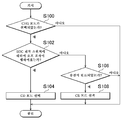
도 4는 ECU에서 실행되는 제어 처리를 나타내는 흐름도이다.
도 5는 ECU의 동작을 나타내는 타이밍차트이다.The features, advantages, and technical and industrial significance of the exemplary embodiments of the present invention are described below with reference to the accompanying drawings in which like numerals represent like elements.
1 is an overall block diagram of a vehicle.
2 is a diagram for explaining an example of a change in the SOC at the time of execution of the SOC recovery control.
3 is a functional block diagram of the ECU.
4 is a flowchart showing the control process executed by the ECU.
5 is a timing chart showing the operation of the ECU.
이하, 도면을 참조하면서, 본 발명의 실시 형태에 대해서 설명한다. 이하의 설명에서는, 동일한 부품에는 동일한 부호가 부여되어 있다. 그들의 명칭 및 기능도 동일하다. 따라서 그들에 대한 상세한 설명은 반복되지 않는다.Hereinafter, an embodiment of the present invention will be described with reference to the drawings. In the following description, the same components are denoted by the same reference numerals. Their names and functions are the same. Therefore, a detailed description of them is not repeated.
도 1을 참조하여, 본 실시 형태에 관한 하이브리드 차량(1)[이하, 간단히 차량(1)이라고 기재함]의 전체 블록도를 설명한다. 차량(1)은, 트랜스미션(8)과, 엔진(10)과, 구동축(17)과, PCU(Power Control Unit)(60)와, 배터리(70)와, 구동륜(72)과, 충전 장치(78)와, SOC 회복 스위치(150)와, 액셀러레이터 페달(160)과, ECU(Electronic Control Unit)(200)를 포함한다.1, an overall block diagram of the hybrid vehicle 1 (hereinafter simply referred to as "
트랜스미션(8)은, 출력축(16)과, 제1 모터 제너레이터(이하, 제1 MG라 기재함)(20)와, 제2 모터 제너레이터(이하, 제2 MG라 기재함)(30)와, 동력 분할 장치(40)와, 감속기(58)를 포함한다.The
ECU(200)는, 차륜속 센서(14)와, 전류 센서(152)와, 전압 센서(154)와, 전지 온도 센서(156)와, 페달 스트로크 센서(162) 등의 각종 센서로부터 각종 신호를 수신한다.The ECU 200 receives various signals from various sensors such as the wheel speed sensor 14, the
이와 같은 구성을 갖는 차량(1)은, 엔진(10) 및 제2 MG(30) 중 적어도 한쪽으로부터 출력되는 구동력에 의해 주행한다. 엔진(10)이 발생하는 동력은, 동력 분할 장치(40)에 의해 2 경로로 분할된다. 2 경로 중 한쪽 경로는 감속기(58)를 통해서 구동륜(72)으로 동력이 전달되는 경로이며, 다른 쪽 경로는 제1 MG(20)로 동력이 전달되는 경로이다.The
제1 MG(20) 및 제2 MG(30)는, 예를 들어 삼상 교류 회전 전기이다. 제1 MG(20) 및 제2 MG(30)는, PCU(60)에 의해 구동된다.The first MG 20 and the second MG 30 are, for example, three-phase AC rotary electric machines. The first MG 20 and the second MG 30 are driven by the PCU 60.
제1 MG(20)는, 동력 분할 장치(40)에 의해 분할된 엔진(10)의 동력을 사용하여 발전해서 PCU(60)를 경유해서 배터리(70)를 충전하는 제네레이터(발전 장치)로서의 기능을 갖는다. 또한, 제1 MG(20)는, 배터리(70)로부터의 전력을 받아서 엔진(10)의 출력축인 크랭크축을 회전시킨다. 이에 의해, 제1 MG(20)는, 엔진(10)을 시동하는 스타터로서의 기능을 갖는다.The first MG 20 has a function as a generator (power generation device) for generating electricity using the power of the engine 10 divided by the power dividing
제2 MG(30)는, 배터리(70)에 축적된 전력 및 제1 MG(20)에 의해 발전된 전력 중 적어도 한쪽을 사용해서 구동륜(72)에 구동력을 부여하는 구동용 모터로서의 기능을 갖는다. 또한, 제2 MG(30)는 회생 제동에 의해 발전된 전력을 사용하여 PCU(60)를 경유해서 배터리(70)를 충전하기 위한 제네레이터로서의 기능을 갖는다.The second MG 30 has a function as a drive motor that applies driving force to the
엔진(10)은, 복수 개(본 실시 형태에 있어서는 4개)의 기통(112)을 포함하는 가솔린 엔진이며, ECU(200)로부터의 제어 신호 S1에 기초하여 제어된다. 엔진(10)으로서는, 도 1에 도시된 형식에 특별히 한정되는 것은 아니다.The engine 10 is a gasoline engine including a plurality of (four in this embodiment) cylinders 112, and is controlled based on the control signal S1 from the
이와 같은 구성을 갖는 엔진(10)에 있어서, ECU(200)는 복수의 기통(112)의 각각에 대하여 적절한 시기에 적절한 양의 연료를 분사하거나, 복수의 기통(112)에의 연료의 분사를 정지하거나 함으로써, 복수의 기통(112)의 각각의 연료 분사량을 제어한다.In the engine 10 having such a configuration, the
동력 분할 장치(40)는, 엔진(10)이 발생하는 동력을, 출력축(16)을 경유한 구동축(17)에의 경로와, 제1 MG(20)에의 경로로 분할 가능하게 구성된다. 동력 분할 장치(40)로서는, 선 기어, 플래니터리 캐리어 및 링 기어의 3개의 회전축을 갖는 유성 기어 기구를 사용할 수 있다. 예를 들어, 제1 MG(20)의 로터를 선 기어에 접속하고, 엔진(10)의 출력축을 플래니터리 캐리어에 접속하고, 또한 출력축(16)을 링 기어에 접속함으로써, 동력 분할 장치(40)에, 엔진(10)과 제1 MG(20)와 제2 MG(30)를 기계적으로 접속할 수 있다.The
제2 MG(30)의 로터와도 접속된 출력축(16)은, 감속기(58)를 경유하여, 구동륜(72)을 회전 구동하기 위한 구동축(17)과 기계적으로 연결된다. 또한, 제2 MG(30)의 회전축과 출력축(16) 사이에 변속기를 더 내장해도 좋다.The
PCU(60)는, 배터리(70)로부터 공급되는 직류 전력을 교류 전력으로 변환하고, 제1 MG(20) 및 제2 MG(30)를 구동한다. 또한, PCU(60)는 제1 MG(20) 및 제2 MG(30)가 발전한 교류 전력을 직류 전력으로 변환하고, 배터리(70)를 충전한다. 예를 들어, PCU(60)는 직류/교류 전력 변환을 위한 인버터(도시하지 않음)와, 인버터의 직류 링크측과 배터리(70) 사이에서 직류 전압 변환을 실행하기 위한 컨버터(도시하지 않음)를 포함하도록 구성된다.The
배터리(70)는 축전 장치이며, 재충전 가능한 직류 전원이다. 배터리(70)로서는, 예를 들어 니켈 수소 전지나 리튬 이온 전지 등의 이차 전지가 사용된다. 배터리(70)의 전압은, 예를 들어 200V 정도이다. 배터리(70)는, 상술한 바와 같이 제1 MG(20) 및/또는 제2 MG(30)에 의해 발전된 전력을 사용해서 충전되는 외에, 후술하는 외부 전원(302)으로부터 공급되는 전력을 사용해서 충전되어도 좋다. 또한, 배터리(70)는 이차 전지에 한정되지 않고, 직류 전압을 생성할 수 있는 것, 예를 들어 캐패시터, 태양 전지, 연료 전지 등이라도 좋다.The
배터리(70)에는, 전류 센서(152)와, 전압 센서(154)와, 전지 온도 센서(156)가 설치된다. 전류 센서(152)는 배터리(70)의 전류 IB를 검출하고, 검출 결과를 나타내는 신호를 ECU(200)로 송신한다. 전압 센서(154)는, 배터리(70)의 전압 VB를 검출하고, 검출 결과를 나타내는 신호를 ECU(200)로 송신한다. 전지 온도 센서(156)는, 배터리(70)의 전지 온도 TB를 검출하고, 검출 결과를 나타내는 신호를 ECU(200)로 송신한다.The
ECU(200)는, 배터리(70)의 전류 IB와, 전압 VB와, 전지 온도 TB에 기초하여 배터리(70)의 축전량[이하, SOC(State Of Charge)라고 기재함]을 추정한다. ECU(200)는, 예를 들어 전류와, 전압과, 전지 온도에 기초하여 OCV(Open Circuit Voltage)를 추정하고, 추정된 OCV와 소정의 맵에 기초하여 배터리(70)의 SOC를 추정해도 좋다. 또는, ECU(200)는, 예를 들어 배터리(70)의 충전 전류와 방전 전류를 적산함으로써 배터리(70)의 SOC를 추정해도 좋다.The
충전 장치(78)는, 차량(1)의 정지 중에 있어서, 충전 플러그(300)가 차량(1)에 설치됨으로써 외부 전원(302)으로부터 공급되는 전력을 사용해서 배터리(70)를 충전한다. 충전 플러그(300)는, 충전 케이블(304)의 한쪽 단부에 접속된다. 충전 케이블(304)의 다른 쪽 단부는, 외부 전원(302)에 접속된다. 충전 장치(78)의 정극 단자는, PCU(60)의 정극 단자와 배터리(70)의 정극 단자를 접속하는 전원 라인 PL에 접속된다. 충전 장치(78)의 부극 단자는, PCU(60)의 부극 단자와 배터리(70)의 부극 단자를 접속하는 접지 라인 NL에 접속된다. 또한, 충전 플러그(300) 등을 사용한 접촉 급전에 의해 외부 전원(302)으로부터 차량(1)의 배터리(70)에 전력이 공급되는 충전 방법에 추가하여 또는 대신에, 공명법이나 전자기 유도 등의 비접촉 급전에 의해 외부 전원(302)으로부터 차량(1)의 배터리(70)에 전력이 공급되는 충전 방법이 사용되어도 좋다.The charging
차륜속 센서(14)는, 구동륜(72)의 회전 속도 Nw를 검출한다. 차륜속 센서(14)는, 검출된 회전 속도 Nw를 나타내는 신호를 ECU(200)로 송신한다. ECU(200)는, 수신된 회전 속도 Nw에 기초하여 차속 V를 산출한다. 또한, ECU(200)는, 회전 속도 Nw 대신에 제2 MG(30)의 회전 속도에 기초하여 차속 V를 산출하도록 해도 좋다.The wheel speed sensor 14 detects the rotational speed Nw of the
액셀러레이터 페달(160)은, 운전석에 설치된다. 액셀러레이터 페달(160)에는, 페달 스트로크 센서(162)가 설치된다. 페달 스트로크 센서(162)는, 액셀러레이터 페달(160)의 스트로크량(답입량) AP를 검출한다. 페달 스트로크 센서(162)는, 스트로크량 AP를 나타내는 신호를 ECU(200)로 송신한다. 또한, 페달 스트로크 센서(162) 대신에 액셀러레이터 페달(160)에 대한 차량(1)의 탑승원의 답력을 검출하기 위한 액셀러레이터 페달 답력 센서를 사용해도 좋다.The
ECU(200)는, 엔진(10)을 제어하기 위한 제어 신호 S1을 생성하고, 그 생성된 제어 신호 S1을 엔진(10)으로 출력한다. 또한, ECU(200)는, PCU(60)를 제어하기 위한 제어 신호 S2를 생성하고, 그 생성된 제어 신호 S2를 PCU(60)로 출력한다.The
ECU(200)는, 엔진(10) 및 PCU(60) 등을 제어함으로써 차량(1)이 가장 효율적으로 운행할 수 있도록 하이브리드 시스템 전체, 즉 배터리(70)의 충방전 상태, 엔진(10), 제1 MG(20) 및 제2 MG(30)의 동작 상태를 제어하는 제어 장치이다.The
ECU(200)는, 운전석에 설치된 액셀러레이터 페달(160)의 스트로크량 AP 및 차속 V에 대응하는 차량 요구 파워를 산출한다. ECU(200)는, 산출된 차량 요구 파워에 따라, 제1 MG(20)의 토크, 제2 MG(30)의 토크, 또는 엔진(10)의 출력을 제어한다.
본 실시 형태에 있어서, ECU(200)는 배터리(70)의 SOC의 저하를 허용해서(SOC를 유지하지 않고) 배터리(70)의 전력을 소비해서 주행하는 모드[이하, CD(Charge Depleting) 모드라고 기재함]와, 엔진(10)이 동작 또는 정지되는 제어 모드이며, 배터리(70)의 SOC의 저하를 억제해서(SOC를 유지하는 경우를 포함함) 주행하는 모드[이하, CS(Charge Sustaining) 모드라고 기재함]를 포함하는 제어 모드 중 어느 하나의 제어 모드를 따라, PCU(60) 및 엔진(10)을 제어한다.In the present embodiment, the
또한, CD 모드로서는, SOC를 유지하지 않는 것에 특별히 한정되는 것은 아니며, 예를 들어 배터리(70)의 SOC를 유지해서 주행하는 것보다 EV 주행에 의해 배터리(70)의 전력을 소비해서 주행하는 것을 우선하는 모드라도 좋다. 또한, 제어 모드로서는, CD 모드 및 CS 모드 이외의 제어 모드가 포함되어도 좋다. 또한, 제어 모드는, 주행 시에 있어서의 차량(1)의 제어에 한정해서 사용되는 것은 아니며, 주행 시 및 정지 시에 있어서의 차량(1)의 제어에 사용된다.The CD mode is not particularly limited to the case where the SOC is not maintained. For example, it is possible to drive the
ECU(200)는, 예를 들어 CD 모드와 CS 모드를 자동으로 전환한다. ECU(200)는, 예를 들어 배터리(70)의 SOC가 전환 임계치 A보다도 큰 경우에는, CD 모드에 따라서 PCU(60) 및 엔진(10)을 제어하고, 배터리(70)의 SOC가 전환 임계치 A보다도 작은 경우에는, CS 모드에 따라서 PCU(60) 및 엔진(10)을 제어한다. 또한, 제어 모드를 전환하기 위해 설치되는 스위치나 레버 등의 조작 부재가 유저에 의해 조작된 것을 받아, ECU(200)가 CD 모드와 CS 모드를 전환해도 좋다.
CD 모드에 따른 차량(1)의 주행 시에 있어서는, 발전을 위한 엔진(10)의 동작이 억제되므로[즉, 배터리(70)의 SOC의 저하가 허용되므로], 배터리(70)의 SOC는 유지되지 않고, 주행 거리의 증가에 따라서 배터리(70)의 전력이 소비되고, 배터리(70)의 SOC는 감소되어 간다.Since the operation of the engine 10 for power generation is suppressed (i.e., the SOC of the
ECU(200)는, CD 모드 시에 있어서는, 차량 요구 파워가 엔진(10)의 시동 임계치 Pr(1)을 초과하지 않는 한에 있어서, 제2 MG(30)의 출력만으로 차량(1)이 주행하도록 PCU(60)를 제어한다.The
ECU(200)는, CD 모드 시에 제2 MG(30)의 출력만으로 차량(1)이 주행하고 있는 경우에, 차량 요구 파워가 엔진(10)의 시동 임계치 Pr(1)을 초과한 후에[즉, 차량 요구 파워를 제2 MG(30)의 출력만으로 충족시킬 수 없다고 판정된 후에], 엔진(10)을 시동시켜서, 제2 MG(30)의 출력과 엔진(10)의 출력으로 차량 요구 파워를 충족시키도록 PCU(60)와 엔진(10)을 제어한다. 즉, CD 모드는, 발전을 위한 엔진(10)의 동작을 억제하면서, 차량 요구 파워를 충족시키기 위한 엔진(10)의 동작이 가능한 제어 모드이다. 또한, 차량 요구 파워 대신에 차량(1)의 실제 파워가 엔진(10)의 시동 임계치를 초과하는 경우에 엔진(10)을 시동시켜도 좋다. 또한, ECU(200)는 CD 모드 시에 차량 요구 파워가 엔진(10)의 정지 임계치를 하회할 경우에는, 엔진(10)을 정지시킨다. CD 모드 시의 정지 임계치는, 시동 임계치 Pr(1) 이하의 값의 미리 정해진 값이다.When the
CS 모드에 따른 차량(1)의 주행 시에 있어서는, 발전을 위한 엔진(10)의 동작이 가능하게 되어, 배터리(70)의 SOC를 유지하거나, 또는 배터리(70)의 SOC를 회복시키거나 함으로써, 배터리(70)의 SOC의 저하가 억제된다.It is possible to operate the engine 10 for power generation at the time of traveling of the
ECU(200)는, 예를 들어 CS 모드 시에 배터리(70)의 SOC가 소정의 제어 범위 내(예를 들어, 상술한 전환 임계치 A를 포함하는 제어 범위 내)가 되도록 배터리(70)의 충방전 제어를 실행해도 좋고, 배터리(70)의 SOC가 소정의 목표 SOC(예를 들어, 상술한 전환 임계치 A)를 유지하도록 배터리(70)의 충방전 제어를 실행해도 좋다.The
배터리(70)의 충전 제어로서는, 예를 들어 제2 MG(30)의 회생 제동에 의해 발생하는 회생 전력을 사용한 충전 제어와, 엔진(10)의 동력을 사용한 제1 MG(20)의 발전 전력을 사용한 충전 제어를 포함한다.As the charge control of the
ECU(200)는, CS 모드 시에 있어서는, 배터리(70)의 SOC가 소정의 제어 범위나 소정의 목표 SOC를 크게 초과하고 있는 경우에는, 차량 요구 파워가 엔진(10)의 시동 임계치 Pr(2)을 초과하지 않는 한에 있어서, 제2 MG(30)의 출력만으로 차량이 주행하도록 PCU(60)를 제어한다.When the SOC of the
ECU(200)는, 상술한 바와 같이 CS 모드 시에 제2 MG(30)의 출력만으로 차량(1)이 주행하고 있을 경우에, 차량 요구 파워가 엔진(10)의 시동 임계치 Pr(2)을 초과한 후에[즉, 차량 요구 파워를 제2 MG(30)의 출력만으로 충족시킬 수 없다고 판정된 후에], 엔진(10)을 시동시켜서, 제2 MG(30)의 출력과 엔진(10)의 출력으로 차량 요구 파워를 충족시키도록 PCU(60)와 엔진(10)을 제어한다. 즉, CS 모드는, 발전을 위한 엔진(10)의 동작도, 차량 요구 파워를 충족시키기 위한 엔진(10)의 동작도 가능한 제어 모드이다. 또한, ECU(200)는 CS 모드 시에 차량 요구 파워가 엔진(10)의 정지 임계치를 하회할 경우에는, 엔진(10)을 정지시킨다. CS 모드 시의 정지 임계치는, 시동 임계치 Pr(2) 이하의 값의 미리 정해진 값이다.The
또한, 본 실시 형태에 있어서는, CD 모드 시의 시동 임계치 Pr(1)은 CS 모드 시의 시동 임계치 Pr(2)보다도 높은 것으로 하고, CD 모드 시의 정지 임계치는, CS 모드 시의 정지 임계치보다도 높은 것으로 하여 설명한다. 시동 임계치 Pr(1) 및 Pr(2)은, 모두 제2 MG(30)의 출력 상한치 이하이며, 또한 배터리(70)의 출력 상한치(Wout) 이하의 값이다. 이렇게 하면, CD 모드 시와 CS 모드 시에서 엔진(10)이 가동하는 기회에 차이가 발생하게 된다.In the present embodiment, it is assumed that the starting threshold Pr (1) in the CD mode is higher than the starting threshold Pr (2) in the CS mode, and the stop threshold in the CD mode is higher than the stop threshold in the CS mode . The starting threshold values Pr (1) and Pr (2) are both equal to or lower than the upper limit value of the output of the
또한, ECU(200)는 SOC 회복 스위치(150)로부터 SOC 회복 스위치 조작 신호를 받으면, 엔진(10)을 동작시켜서 배터리(70)의 SOC값을 소정의 목표까지 증가시키는 SOC 회복 제어를 실행한다. 이 SOC 회복 제어는, CD 모드 및 CS 모드와 다른 CHG 모드 선택 시에 실행되는 제어이다. CHG 모드는, CS 모드와 비교하여, SOC값의 제어 목표치를 만충전 임계치 C로 함으로써 SOC값을 만충전 임계치 C까지 증가시키는 점에서 상이하다.When the
SOC 회복 스위치(150)는, SOC 회복 제어의 실행 또는 정지를 유저가 요구하기 위한 스위치이다. CHG 모드 이외의 제어 모드의 선택 중에, 유저가 SOC 회복 스위치(150)를 조작함으로써(이하, 이러한 조작을 온 조작이라고 함), CHG 모드가 선택되고, SOC 회복 제어의 실행이 요구된다. 그로 인해, CD 모드가 선택되는 것에 대비해서 SOC값을 미리 높여 둘 수 있다. 이에 의해, CD 모드의 선택을 어느 정도의 기간 계속할 수 있게 된다. 한편, CHG 모드의 선택 중에, 유저가 SOC 회복 스위치(150)를 조작함으로써(이하, 이러한 조작을 오프 조작이라고 함), SOC 회복 제어의 정지가 요구된다.The
이하에, 도 2를 사용해서 SOC 회복 제어 실행 시(즉, CHG 모드의 선택 시)의 SOC의 변화의 일례를 설명한다. 예를 들어, 도 2에 도시한 바와 같이, 배터리(70)가 만충전 상태[배터리(70)의 SOC가 만충전 임계치 C에 도달하고 있는 상태]일 경우에, 차량(1)이 CD 모드에서 주행을 개시하는 경우를 상정한다. 또한, 만충전 임계치 C는, 예를 들어 외부 전원(302)을 사용해서 배터리(70)를 충전하는 경우에 설정되는 배터리(70)의 SOC의 상한치이다.Hereinafter, an example of the change of the SOC when the SOC recovery control is executed (i.e., when the CHG mode is selected) will be described using Fig. For example, as shown in FIG. 2, when the
CD 모드에서 주행할 경우에는, EV 주행이 행하여지는 빈도가, HV 주행이 행하여지는 빈도보다도 높아지는 등으로 해서 배터리(70)의 전력이 소비되므로, 시간이 경과됨과 함께, 배터리(70)의 SOC가 저하되어 간다.In the case of running in the CD mode, the power of the
그리고, 시간 T(0)에서, 배터리(70)의 SOC가 전환 임계치 A에 도달할 때까지, SOC 회복 스위치(150)가 조작되지 않은 경우에는, 도 2의 중간단 그래프의 파선으로 나타낸 바와 같이, 전환 임계치 A에 도달한 시점에서 CD 모드로부터 CS 모드로 전환할 수 있다. 그리고, 전환 임계치 A를 목표치로 해서 배터리(70)의 SOC가 제어되기 때문에, 도 2의 상단 그래프의 파선으로 나타낸 바와 같이, 임계치 A를 제어 중심으로 해서 배터리(70)의 SOC가 변동된다.When the
한편, 예를 들어 시간 T(0)에서, SOC 회복 스위치(150)에 대하여 온 조작이 행하여져서 온 상태가 될 경우에는, 제어 모드가 CD 모드로부터 CHG 모드로 전환된다. CHG 모드가 선택됨으로써, 배터리(70)의 SOC의 상한치인 만충전 임계치 C를 목표치로 해서 배터리(70)의 SOC가 제어된다. 그로 인해, 도 2의 상단 그래프의 실선으로 나타낸 바와 같이, 엔진(10)의 동력을 사용한 발전 등에 의해, 시간이 경과됨과 함께 배터리(70)의 SOC가 증가되어 간다. SOC 회복 제어는, 적어도 시간 T(1)에서, 배터리(70)의 SOC가 만충전 임계치 C에 도달할 때까지 계속된다.On the other hand, for example, when the
이상과 같은 구성을 갖는 하이브리드 차량에 있어서, SOC 회복 제어의 실행 중에, 유저가 작동 중인 엔진(10)의 동작을 제한하는 것을 의도하여, SOC 회복 스위치(150)에 대하여 오프 조작을 행하여 SOC 회복 제어의 정지를 요구하는 경우가 있다.In the hybrid vehicle having the above-described configuration, during the execution of the SOC recovery control, the user intends to limit the operation of the engine 10 while the user is in operation, performs an OFF operation on the
그러나 SOC 회복 제어를 정지해도, 예를 들어 그 후에 CS 모드가 선택되면, 차량(1)의 상태에 따라서 엔진(10)의 동작이 계속되는 경우가 있다. 그로 인해, 유저가 의도하는 엔진(10)의 동작 제한을 실시할 수 없는 경우가 있다.However, even if the SOC recovery control is stopped, for example, if the CS mode is subsequently selected, the operation of the engine 10 may continue depending on the state of the
따라서, 본 실시 형태에 있어서는, ECU(200)가, SOC 회복 제어의 실행 중에 SOC 회복 스위치(150)를 사용해서 SOC 회복 제어의 정지가 요구될 경우에는, CD 모드를 선택하는 점을 특징으로 한다.Therefore, in the present embodiment, the
이렇게 하면, SOC 회복 제어의 실행 중에, SOC 회복 스위치(150)를 사용해서 회복 제어의 정지가 요구될 경우에, CS 모드보다도 차량 요구 파워에 대한 엔진(10)의 시동 임계치가 높고 또한 배터리(70)의 전력이 소비되는 CD 모드가 선택되므로, 엔진(10)의 동력을 사용한 배터리(70)의 충전이 억제된다. 그로 인해, CS 모드가 선택되는 경우보다도 엔진(10)의 동작을 제한할 수 있다.When the
또한, 본 실시 형태에 있어서는, ECU(200)는 SOC 회복 제어의 실행에 의해 배터리(70)의 SOC가 만충전 임계치 C에 도달하는 경우에, CS 모드를 선택한다.Further, in the present embodiment, the
도 3에, 본 실시 형태에 관한 차량(1)에 탑재된 ECU(200)의 기능 블록도를 나타낸다. ECU(200)는, CHG 모드 판정부(202)와, 오프 조작 판정부(204)와, 완료 판정부(206)와, CD/CS 모드 선택부(208)를 포함한다. 또한, 이들 구성은, 프로그램 등의 소프트웨어에 의해 실현되어도 좋고, 하드웨어에 의해 실현되어도 좋다.3 is a functional block diagram of the
CHG 모드 판정부(202)는, CHG 모드의 선택 중인지 여부를 판정한다. CHG 모드 판정부(202)는, 예를 들어 CHG 모드가 선택되었을 때에 온 상태가 되는 모드 플래그의 상태에 기초하여 CHG 모드의 선택 중인지 여부를 판정한다. CHG 모드 판정부(202)는, 예를 들어 모드 플래그가 온 상태인 경우에, CHG 모드가 선택 중이라고 판정한다. 또한, 모드 플래그는, 예를 들어 SOC 회복 스위치(150)에 대하여 온 조작이 행해짐으로써 온 상태가 되고, 오프 조작이 행해짐으로써 오프 상태가 되는 것으로 한다.The CHG
오프 조작 판정부(204)는, SOC 회복 스위치(150)로부터 수신하는 SOC 회복 스위치 조작 신호에 기초하여 오프 조작이 행해졌는지 여부를 판정한다. 오프 조작 판정부(204)는, CHG 모드의 선택 중에 SOC 회복 스위치(150)로부터 SOC 회복 스위치 조작 신호를 수신하는 경우에, 오프 조작이 행하여졌다고 판정한다.The OFF
완료 판정부(206)는, SOC 회복 제어에 의한 배터리(70)의 충전이 완료되었는지 여부를 판정한다. 구체적으로는, 완료 판정부(206)는 SOC 회복 제어의 실행 중에 배터리(70)의 SOC가 만충전 임계치 C에 도달하는 경우에, SOC 회복 제어에 의한 배터리(70)의 충전이 완료되었다고 판정한다.The
CD/CS 모드 선택부(208)는, CHG 모드 판정부(202)의 판정 결과와, 오프 조작 판정부(204)의 판정 결과와, 완료 판정부(206)의 판정 결과에 기초하여 제어 모드를 선택한다. 구체적으로는, CD/CS 모드 선택부(208)는 CHG 모드 판정부(202)에 의해 CHG 모드의 선택 중이라고 판정된 경우에 있어서, 오프 조작 판정부(204)에 의해 SOC 회복 스위치(150)에 대하여 오프 조작이 행하여졌다고 판정된 경우에는, CD 모드를 제어 모드로서 선택한다. 한편, CD/CS 모드 선택부(208)는, CHG 모드의 선택 중이라고 판정된 경우에 있어서, 완료 판정부(206)에 의해 SOC 회복 제어가 완료되었다고 판정될 때까지, 오프 조작 판정부(204)에 의해 SOC 회복 스위치에 대하여 오프 조작이 행하여졌다고 판정되지 않은 경우에, CS 모드를 제어 모드로서 선택한다.The CD / CS
도 4를 참조하여, 본 실시 형태에 관한 차량(1)에 탑재된 ECU(200)에서 실행되는 제어 처리에 대해서 설명한다.Referring to Fig. 4, control processing executed by the
스텝(이하, 스텝을 S로 기재함) 100에서, ECU(200)는 CHG 모드의 선택 중인지 여부를 판정한다. CHG 모드의 선택 중이라고 판정되는 경우(S100에서 "예"), 처리는 S102로 이행된다. 만약 그렇지 않은 경우(S100에서 "아니오"), 이 처리는 종료된다.In step (hereinafter referred to as step S) 100, the
S102에서, ECU(200)는 SOC 회복 스위치(150)에 대하여 오프 조작이 행하여졌는지 여부를 판정한다. SOC 회복 스위치(150)에 대하여 오프 조작이 행하여졌다고 판정되는 경우(S102에서 "예"), 처리는 S104로 이행된다. 만약 그렇지 않은 경우(S102에서 "아니오"), 처리는 S106으로 이행된다.In S102, the
S104에서, ECU(200)는 CD 모드를 제어 모드로서 선택한다. S106에서, ECU(200)는 SOC 회복 제어에 의한 배터리(70)의 충전이 완료되었는지 여부를 판정한다. SOC 회복 제어에 의한 배터리(70)의 충전이 완료되었다고 판정될 경우(S106에서 "예"), 처리는 S108로 이행된다. 만약 그렇지 않은 경우(S106에서 "아니오"), 이 처리는 종료된다. S108에서, ECU(200)는 CS 모드를 제어 모드로서 선택한다.In S104, the
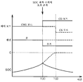
이상과 같은 구조 및 흐름도에 의거하는 본 실시 형태에 관한 차량(1)에 탑재된 ECU(200)의 동작에 대해서 도 5를 사용해서 설명한다.The operation of the
예를 들어, 도 5에 도시한 바와 같이, CHG 모드가 선택된 상태에서 차량(1)이 운전되고 있는 경우를 상정한다. SOC 회복 제어가 실행되고 있으므로, 엔진(10)이 작동 상태(온 상태)인 것으로 한다.For example, as shown in Fig. 5, it is assumed that the
시간 T(2)가 될 때까지는, CHG 모드가 선택된 채(S100에서 "예"), SOC 회복 스위치(150)에 대하여 오프 조작은 행하여지지 않으므로(S102에서 "아니오"), CHG 모드가 유지된다.Until the time T (2) is reached, the CHG mode is selected (Yes in S100) and the
시간 T(2)에서, CHG 모드의 선택 중에(S100에서 "예"), SOC 회복 스위치(150)에 대하여 오프 조작이 행하여진 경우(S102에서 "예"), 도 5의 상단 그래프의 실선으로 나타낸 바와 같이, 제어 모드로서 CD 모드가 선택된다(S104). CD 모드가 선택됨으로써, CD 모드에 대응한, 차량 요구 파워에 대한 엔진(10)의 시동 임계치에 의해 엔진(10)의 동작이 결정된다. 그 결과, 도 5의 중단 그래프의 실선으로 나타낸 바와 같이, 시간 T(2)에서, 엔진(10)은 정지 상태가 된다.When the
SOC 회복 제어가 정지됨으로써, 배터리(70)의 충전이 정지된다. 또한, CD 모드가 선택됨으로써 배터리(70)의 전력이 소비되므로, 도 5의 하단 그래프의 실선으로 나타낸 바와 같이, 시간 T(2) 이후에 있어서, SOC는 시간의 경과와 함께 저하되어 가게 된다.By stopping the SOC recovery control, the charging of the
한편, 시간 T(2)에서, CHG 모드의 선택 중에(S100에서 "예"), SOC 회복 스위치(150)에 대하여 오프 조작이 행하여지지 않은 경우(S102에서 "아니오"), 시간 T(2) 이후도 CHG 모드의 선택이 유지된다. 그로 인해, 도 5의 하단 그래프의 파선으로 나타낸 바와 같이, 배터리(70)의 SOC는, SOC 회복 제어에 의해 시간의 경과와 함께 증가되어 간다.On the other hand, if the OFF operation is not performed on the SOC recovery switch 150 ("NO" in S102) during the time T (2) Thereafter, the selection of the CHG mode is maintained. 5, the SOC of the
시간 T(3)에서, SOC 회복 제어에 의한 배터리(70)의 충전이 완료될 경우(S106에서 "예"), 도 5의 상단 그래프의 파선으로 나타낸 바와 같이, 제어 모드로서 CS 모드가 선택된다(S108). CS 모드가 선택됨으로써, 배터리(70)의 SOC는, 시간 T(3) 이후 유지되어, CS 모드에 대응한, 차량 요구 파워에 대한 엔진(10)의 시동 임계치에 의해 엔진(10)의 동작이 결정된다. 그 결과, 도 5의 중단 그래프의 파선으로 나타낸 바와 같이, 시간 T(2) 이후, 엔진(10)의 동작 상태는 계속된다.When the charging of the
이상과 같이 하여, 본 실시 형태에 관한 차량(1)에 의하면, SOC 회복 제어의 실행 중에, SOC 회복 스위치(150)를 사용해서 SOC 회복 제어의 정지가 요구될 경우에, 배터리(70)의 전력이 소비되는 CD 모드가 선택되므로, 엔진(10)의 동력을 사용한 배터리(70)의 충전이 억제된다. 그로 인해, CS 모드가 선택되는 경우보다도 엔진(10)의 동작을 제한[예를 들어, 엔진(10)의 동작을 정지시켜, 정지 상태를 유지]할 수 있다. 즉, 유저의 의도에 따라 엔진(10)의 동작을 제한할 수 있다. 따라서, 엔진을 사용한 축전 장치의 충전 정지가 요구되는 경우에 유저의 의도에 따라 작동 중인 엔진의 동작을 제한하는 하이브리드 차량을 제공할 수 있다.As described above, according to the
또한, SOC 회복 제어의 실행 중에 배터리(70)의 SOC가 만충전 임계치 C에 도달하는 경우에, CS 모드가 선택되므로, 배터리(70)의 SOC를 상한치 부근에서 유지할 수 있다. 그로 인해, 유저가 희망하는 타이밍에서 배터리(70)의 전력을, 차량(1)의 주행이나 배터리(70)에 접속된 차실 내 또는 차 밖의 전기 기기의 작동 등에 이용할 수 있게 된다.In addition, when the SOC of the
이하에 변형예에 대해서 설명한다. 본 실시 형태에 있어서는, SOC 회복 제어의 실행에 의해, 배터리(70)의 SOC가 만충전 임계치 C에 도달한 경우에는, CS 모드가 선택되는 것으로서 설명했지만, 특별히 이에 한정되는 것은 아니다. 예를 들어, ECU(200)는 SOC 회복 제어의 실행에 의해, 배터리(70)의 SOC가 만충전 임계치 C에 도달한 후에, SOC 회복 스위치(150)에 대하여 오프 조작이 행하여진 경우에, CS 모드를 선택해도 좋다.Modifications will be described below. In the present embodiment, the case where the SOC of the
본 실시 형태에 있어서는, SOC 회복 제어의 실행에 의해, 배터리(70)의 SOC가 만충전 임계치 C에 도달한 경우에는, CS 모드가 선택되는 것으로서 설명했지만, 특별히 이에 한정되는 것은 아니다. 예를 들어, ECU(200)는 SOC 회복 제어의 실행에 의해, 배터리(70)의 SOC가 만충전 임계치 C에 도달한 경우이며, 또한 차량에 이상이 있는 경우에는, 이상 개소에 따라서 CS 모드와 CD 모드 중 어느 하나를 선택해도 좋다.In the present embodiment, the case where the SOC of the
예를 들어, ECU(200)는, 예를 들어 SOC 회복 제어의 실행에 의해, 배터리(70)의 SOC가 만충전 임계치 C에 도달한 경우이며, 또한 배터리(70)의 방전을 할 수 없는 이상이 발생한 경우[예를 들어, 제2 MG(30)나 배터리(70)의 고장], CS 모드를 선택해도 좋다. 또는, ECU(200)는, 예를 들어 SOC 회복 제어의 실행에 의해, 배터리(70)의 SOC가 만충전 임계치 C에 도달한 경우이며, 또한 배터리(70)의 충전을 할 수 없는 이상이 발생한 경우[예를 들어, 제1 MG(20)나 엔진(10)의 고장], 전력의 소비를 우선해서 CD 모드를 선택해도 좋다. 이렇게 하면, 차량(1)에 이상이 발생한 경우에 수리 공장 등까지의 자주가 가능하게 되므로, 이상 개소에 따라서 적절한 제어 모드를 선택할 수 있다.For example, when the SOC of the
본 실시 형태에 있어서는, SOC 회복 스위치(150)는, 하드웨어인 것으로서 설명했지만, 예를 들어 디스플레이의 전방면에 터치 패널이 배치되어 있고, 디스플레이에 표시된 SOC 회복 스위치(150)에 대응하는 화상과 중복되는 터치 패널 상의 소정 영역에 대하여 터치 조작이 행해짐으로써 SOC 회복 제어의 실행이 요구되도록 해도 좋고, 또는 음성 입력 수단 등을 사용해서 SOC 회복 제어의 실행이 요구되도록 해도 좋다.In the present embodiment, the
본 실시 형태에 있어서, SOC 회복 제어는, CHG 모드의 선택 시에 실행되는 것으로서 설명했지만, 예를 들어 CS 모드 중에 있어서의, 통상 시와 SOC의 목표치가 다른 제어 형태 중 하나로서 실행되는 것으로 해도 좋다.In the present embodiment, the SOC recovery control is described as being executed at the time of selecting the CHG mode. However, for example, the SOC recovery control may be executed as one of the control modes in which the target value of the SOC is different from that of the normal mode during the CS mode .
본 실시 형태에 있어서, SOC 회복 제어의 실행 중에, SOC 회복 스위치(150)를 사용해서 SOC 회복 제어의 정지가 요구될 경우에, CD 모드가 선택되는 것으로서 설명했지만, 예를 들어 CD 모드가 선택됨과 함께, 소정 시간이 경과될 때까지는, 엔진(10)의 시동을 금지하도록 해도 좋다. 이렇게 하면, SOC 회복 제어의 실행 중에 SOC 회복 스위치(150)에 대하여 오프 조작이 행하여진 경우에, 엔진(10)의 동작을 확실하게 제한할 수 있다. 또한, 상기한 변형예는, 그 전부 또는 일부를 조합해서 실시해도 좋다.In the present embodiment, the CD mode is selected when the SOC recovery control is requested using the
금회 개시된 실시 형태는 모든 점에서 예시이며 제한적인 것은 아니라고 생각되어야 한다. 본 발명의 범위는 상기한 설명에서는 없고 특허 청구 범위에 의해 나타내고, 특허 청구 범위와 균등한 의미 및 범위 내에서의 모든 변경이 포함되는 것이 의도된다.It should be understood that the embodiments disclosed herein are illustrative and non-restrictive in all respects. It is intended that the scope of the invention be defined not by the foregoing description but by the appended claims, and all changes that come within the meaning and range of equivalency of the claims are intended to be embraced therein.
본 발명의 형태에 의하면, 회복 제어의 실행 중에, 스위치를 사용해서 회복 제어의 정지가 요구될 때, 축전 장치의 전력이 소비되는 CD 모드가 선택된다. 그로 인해, 엔진을 정지한 상태에서 주행하는 EV(Electric Vehicle) 주행이 우선되어, 엔진의 동력을 사용한 축전 장치의 충전이 억제된다. 그로 인해, CS 모드가 선택될 때보다도 엔진의 동작을 제한(예를 들어, 엔진의 동작을 정지시켜, 정지 상태를 유지)할 수 있다. 이에 의해, 유저의 의도에 따라 엔진의 동작을 제한할 수 있다.According to the embodiment of the present invention, when the restoration control is to be stopped by using the switch during execution of the recovery control, the CD mode in which the power of the power storage device is consumed is selected. As a result, EV (Electric Vehicle) traveling traveling in a state in which the engine is stopped is given priority, so that charging of the power storage device using the engine power is suppressed. Thereby, it is possible to limit the operation of the engine (for example, stop the operation of the engine and maintain the stopped state) rather than when the CS mode is selected. Thus, the operation of the engine can be restricted in accordance with the intention of the user.
본 발명의 형태에 의하면, 회복 제어의 실행 중에 축전량이 상한치에 도달할 때, CS 모드가 선택된다. 그로 인해, 축전량을 상한치 부근에서 유지할 수 있다. 이에 의해 유저가 희망하는 타이밍에서 축전 장치의 전력을 이용할 수 있게 된다.According to the aspect of the present invention, when the power storage amount reaches the upper limit value during the execution of the recovery control, the CS mode is selected. Therefore, it is possible to maintain the charge amount at about the upper limit value. Thus, the power of the power storage device can be used at a desired timing by the user.
이렇게 하면, 회복 제어의 실행 중에 축전량이 상한치에 도달한 후에, 스위치를 사용해서 회복 제어의 정지가 요구될 때, CS 모드가 선택된다. 그로 인해, 축전량을 상한치 부근에서 유지할 수 있다. 그로 인해, 유저가 희망하는 타이밍에서 축전 장치의 전력을 이용할 수 있게 된다.In this way, the CS mode is selected when a stop of the recovery control is requested using the switch after the amount of electric power reaches the upper limit value during execution of the recovery control. Therefore, it is possible to maintain the charge amount at about the upper limit value. Thereby, the power of the power storage device can be used at a timing desired by the user.
이렇게 하면, 예를 들어 축전 장치의 방전을 할 수 없는 이상(예를 들어, 회전 전기나 축전 장치의 고장)이 발생했을 때에는, 엔진의 동작 빈도가 높은 CS 모드를 선택할 수 있다. 또한, 축전 장치의 충전을 할 수 없는 이상(예를 들어, 발전 장치나 엔진의 고장)이 발생했을 때에는, 축전 장치의 전력 소비(회전 전기의 동작)를 우선해서 CD 모드를 선택할 수 있다. 이와 같이 하여, 차량에 이상이 발생했을 때에 수리 공장 등까지의 자주가 가능하게 된다. 그로 인해, 이상 개소에 따라서 적절한 제어 모드를 선택할 수 있다.In this way, for example, when an abnormality (for example, a failure of the rotating electric machine or the power storage device) that can not discharge the power storage device occurs, the CS mode in which the operation frequency of the engine is high can be selected. Further, when an abnormality in which the power storage device can not be charged (for example, a malfunction of the power generation device or an engine) occurs, the CD mode can be selected by giving priority to the power consumption of the power storage device (operation of the rotating electrical machine). In this manner, frequent repairs to repair shops can be made when an abnormality occurs in the vehicle. Therefore, an appropriate control mode can be selected in accordance with the abnormal position.
Claims (5)
엔진(10)과 ;
상기 하이브리드 차량의 구동원이 되도록 구성된 회전 전기(30)와 ;
상기 회전 전기(30)에 전력을 공급하도록 구성된 축전 장치(70)와 ;
상기 엔진(10)의 동력을 사용해서 상기 축전 장치(70)를 충전하기 위한 전력을 발전하도록 구성된 발전 장치(20)와,
유저가, 상기 발전 장치(20)를 사용해서 상기 축전 장치(70)의 축전량을 상한치까지 증가시키는 제어인 회복 제어의 실행 또는 정지를 요구할 때에 유저가 조작하는 스위치(150)와 ; 그리고
(a) 복수의 제어 모드 중 어느 하나를 선택하고, 상기한 복수의 제어 모드는 CS(charge sustaining) 모드와 CD(charge depleting) 모드를 포함하고, 상기 CS 모드는 상기 축전량의 저하를 억제하는 모드이며, 상기 CD 모드는 상기 축전 장치(70)의 전력을 소비하는 모드이고.
(b) 상기 선택된 제어 모드에 따라서 상기 하이브리드 차량을 제어하고,
(c) 상기 회복 제어의 실행 중에 상기 스위치(150)를 사용해서 상기 회복 제어의 정지가 요구될 때, 상기 CD 모드를 선택하도록 구성된 ECU(200)를
포함하는 것을 특징으로 하는, 하이브리드 차량.Hybrid vehicle,
An engine (10);
A rotary electric machine (30) configured to be a drive source of the hybrid vehicle;
A power storage device (70) configured to supply power to the rotating electric machine (30);
A power generation device (20) configured to generate electric power for charging the power storage device (70) using the power of the engine (10)
A switch 150 operated by the user when the user requests execution or stop of the recovery control, which is a control for increasing the electric storage capacity of the power storage device 70 to the upper limit value by using the power generation device 20; And
(a) selecting one of a plurality of control modes, wherein the plurality of control modes include a charge sustaining mode (CS) and a charge depleting mode (CD), and the CS mode suppresses a decrease in the storage amount Mode, and the CD mode is a mode for consuming power of the power storage device (70).
(b) controlling the hybrid vehicle in accordance with the selected control mode,
(c) when the stop of the recovery control is requested using the switch (150) during execution of the recovery control, the ECU (200) configured to select the CD mode
The hybrid vehicle.
엔진(10)과 ;
상기 하이브리드 차량의 구동원이 되도록 구성된 회전 전기(30)와 ;
상기 회전 전기(30)에 전력을 공급하도록 구성된 축전 장치(70)와 ;
상기 엔진(10)의 동력을 사용해서 상기 축전 장치를 충전하기 위한 전력을 발전하도록 구성된 발전 장치(20)와 ;
스위치(150)가 조작되었을 때, 신호를 송신하고, 유저가 조작하기 위한 스위치이도록 구성된 스위치(150)와 ; 그리고
(a) 복수의 제어 모드 중 어느 하나를 선택하고,
(b) 선택된 상기 제어 모드에 따라서 상기 하이브리드 차량을 제어하고, 상기 복수의 제어 모드는 CS(charge sustaining) 모드와 CD(charge depleting) 모드를 포함하고, 상기 CS 모드는 상기 축전량의 저하를 억제하는 모드이고, 상기 CD 모드는 상기 축전 장치의 전력을 소비하는 모드이며,
(c) 상기 신호를 수신하고,
(d) 상기 신호가 제1 신호일 때, 회복 제어를 실행하고, 상기 제1 신호는, 상기 회복 제어를 실행하는 것을 요구하는 신호이며, 상기 회복 제어는 상기 축전 장치(70)의 축전량을 상한치까지 증가시키는 제어이고,
(e) 상기 신호가 제2 신호일 때, 상기 회복 제어를 정지하고, 상기 제2 신호는, 상기 회복 제어를 정지하는 것을 요구하는 신호이고, 그리고,
(f) 상기 회복 제어의 실행 중에 상기 제2 신호를 수신한 때, 상기 CD 모드를 선택하도록 구성된 ECU(200)를
포함하는 것을 특징으로 하는, 하이브리드 차량.Hybrid vehicle,
An engine (10);
A rotary electric machine (30) configured to be a drive source of the hybrid vehicle;
A power storage device (70) configured to supply power to the rotating electric machine (30);
A power generator (20) configured to generate electric power for charging the power storage device using the power of the engine (10);
A switch 150 configured to transmit a signal when the switch 150 is operated and to be a switch for a user to operate; And
(a) selecting any one of a plurality of control modes,
(b) controls the hybrid vehicle according to the selected control mode, wherein the plurality of control modes include a charge sustaining mode (CS) and a charge depletion mode (CD), and the CS mode suppresses The CD mode is a mode in which the power of the power storage device is consumed,
(c) receiving said signal,
(d) a recovery control is performed when the signal is a first signal, and the first signal is a signal for requesting execution of the recovery control, and the recovery control is performed when the power storage capacity of the power storage device (70) Up control,
(e) when the signal is a second signal, stopping the recovery control, and the second signal is a signal requesting to stop the recovery control,
(f) an ECU (200) configured to select the CD mode when the second signal is received during execution of the recovery control
The hybrid vehicle.
Applications Claiming Priority (2)
| Application Number | Priority Date | Filing Date | Title |
|---|---|---|---|
| JPJP-P-2014-119593 | 2014-06-10 | ||
| JP2014119593A JP6149806B2 (en) | 2014-06-10 | 2014-06-10 | Hybrid vehicle |
Related Child Applications (1)
| Application Number | Title | Priority Date | Filing Date |
|---|---|---|---|
| KR1020170043777A Division KR101761539B1 (en) | 2014-06-10 | 2017-04-04 | Hybrid vehicle |
Publications (2)
| Publication Number | Publication Date |
|---|---|
| KR20150141902A true KR20150141902A (en) | 2015-12-21 |
| KR101730712B1 KR101730712B1 (en) | 2017-04-26 |
Family
ID=54549035
Family Applications (2)
| Application Number | Title | Priority Date | Filing Date |
|---|---|---|---|
| KR1020150081252A KR101730712B1 (en) | 2014-06-10 | 2015-06-09 | Hybrid vehicle |
| KR1020170043777A KR101761539B1 (en) | 2014-06-10 | 2017-04-04 | Hybrid vehicle |
Family Applications After (1)
| Application Number | Title | Priority Date | Filing Date |
|---|---|---|---|
| KR1020170043777A KR101761539B1 (en) | 2014-06-10 | 2017-04-04 | Hybrid vehicle |
Country Status (5)
| Country | Link |
|---|---|
| US (1) | US9873336B2 (en) |
| JP (1) | JP6149806B2 (en) |
| KR (2) | KR101730712B1 (en) |
| CN (1) | CN105172784B (en) |
| DE (2) | DE202015009795U1 (en) |
Cited By (1)
| Publication number | Priority date | Publication date | Assignee | Title |
|---|---|---|---|---|
| KR20180064972A (en) * | 2016-12-06 | 2018-06-15 | 도요타 지도샤(주) | Hybrid vehicle and control method for hybrid vehicle |
Families Citing this family (9)
| Publication number | Priority date | Publication date | Assignee | Title |
|---|---|---|---|---|
| US10131442B2 (en) * | 2015-10-30 | 2018-11-20 | Sikorsky Aircraft Corporation | Power leveling controller |
| JP7013827B2 (en) * | 2017-12-05 | 2022-02-01 | トヨタ自動車株式会社 | Hybrid vehicle and control device mounted on it |
| JP6958329B2 (en) | 2017-12-20 | 2021-11-02 | トヨタ自動車株式会社 | Hybrid vehicle |
| KR102394843B1 (en) * | 2017-12-27 | 2022-05-06 | 현대자동차주식회사 | Method for Controlling Engine Power during CD Mode Heating of PHEV |
| JP6935751B2 (en) | 2018-01-15 | 2021-09-15 | トヨタ自動車株式会社 | Hybrid vehicle |
| JP7020144B2 (en) * | 2018-01-30 | 2022-02-16 | トヨタ自動車株式会社 | Electric vehicle and control method of electric vehicle |
| JP7010069B2 (en) * | 2018-03-07 | 2022-02-10 | トヨタ自動車株式会社 | Fuel cell system, vehicle equipped with fuel cell system, and control method of fuel cell system |
| US20220032696A1 (en) * | 2018-12-13 | 2022-02-03 | Pacific Industrial Co., Ltd. | Transmitter |
| CN109823188A (en) * | 2019-01-10 | 2019-05-31 | 乾碳国际公司 | The mixed gentle speed system of dynamic commercial vehicle regenerative braking |
Family Cites Families (33)
| Publication number | Priority date | Publication date | Assignee | Title |
|---|---|---|---|---|
| KR20040045744A (en) | 2002-11-25 | 2004-06-02 | 현대자동차주식회사 | Power control method of fuel cell hybrid electrical vehicle |
| JP4396615B2 (en) * | 2005-10-19 | 2010-01-13 | トヨタ自動車株式会社 | Control device for hybrid vehicle |
| DE102007056723A1 (en) | 2006-11-28 | 2008-12-18 | GM Global Technology Operations, Inc., Detroit | Vehicle hybrid powertrain system, has transmission provided with transmission input member and electric machines, planetary gear set provided with gear members, and control system configured for establishing powertrain operating states |
| US8566013B2 (en) * | 2008-05-15 | 2013-10-22 | Eaton Corporation | Electric vehicle (EV) driving mode optimization for a parallel hybrid electric vehicle |
| JP4650532B2 (en) * | 2008-07-11 | 2011-03-16 | トヨタ自動車株式会社 | Storage device deterioration determination device and storage device deterioration determination method |
| CN102458946B (en) * | 2009-06-10 | 2014-05-14 | 丰田自动车株式会社 | Power supply system for electric vehicle and method for controlling same |
| JP2011093335A (en) * | 2009-10-27 | 2011-05-12 | Toyota Motor Corp | Controller for hybrid vehicle |
| US9764632B2 (en) * | 2010-01-07 | 2017-09-19 | Ford Global Technologies, Llc | Plug-in hybrid electric vehicle battery state of charge hold function and energy management |
| JP5344086B2 (en) * | 2010-04-07 | 2013-11-20 | トヨタ自動車株式会社 | Control device for hybrid vehicle and hybrid vehicle including the same |
| JP2011219039A (en) * | 2010-04-13 | 2011-11-04 | Toyota Motor Corp | Hybrid drive device for vehicle |
| CN102858576B (en) | 2010-04-14 | 2015-08-19 | 丰田自动车株式会社 | Motor vehicle driven by mixed power |
| US20130293195A1 (en) * | 2011-01-21 | 2013-11-07 | Nec Corporation | Charging control device, charging control method, and program |
| DE102011051439A1 (en) * | 2011-06-29 | 2013-01-03 | Dr. Ing. H.C. F. Porsche Aktiengesellschaft | Drive system for a plug-in hybrid motor vehicle |
| JP2013049381A (en) * | 2011-08-31 | 2013-03-14 | Toyota Motor Corp | Control device of hybrid vehicle |
| GB2498376A (en) * | 2012-01-13 | 2013-07-17 | Sandeep Kumar Chintala | Battery Management Apparatus and Method |
| JP5825115B2 (en) | 2012-01-23 | 2015-12-02 | トヨタ自動車株式会社 | Plug-in hybrid vehicle |
| CN104583037B (en) * | 2012-08-31 | 2018-05-25 | 丰田自动车株式会社 | The control method of vehicle and vehicle |
| US8903579B2 (en) * | 2012-10-19 | 2014-12-02 | Ford Global Technologies, Llc | User override for electric-only operation of a hybrid vehicle |
| US8958936B2 (en) * | 2012-10-19 | 2015-02-17 | Ford Global Technologies, Llc | System override for user selected electric-only operation of a hybrid vehicle |
| US20140114514A1 (en) * | 2012-10-19 | 2014-04-24 | Ford Global Technologies, Llc | Delayed electric-only operation of a hybrid vehicle |
| CN104903132A (en) * | 2013-01-11 | 2015-09-09 | 本田技研工业株式会社 | Hybrid-vehicle control device and control method |
| JP5803965B2 (en) * | 2013-03-25 | 2015-11-04 | トヨタ自動車株式会社 | vehicle |
| JP5825289B2 (en) * | 2013-04-08 | 2015-12-02 | トヨタ自動車株式会社 | Hybrid vehicle |
| JP5825287B2 (en) * | 2013-04-08 | 2015-12-02 | トヨタ自動車株式会社 | Hybrid vehicle |
| EP3006291B1 (en) * | 2013-05-29 | 2018-05-16 | Nissan Motor Co., Ltd | Control device for a plug-in hybrid vehicle |
| JP5999261B2 (en) * | 2013-05-29 | 2016-09-28 | 日産自動車株式会社 | Control device for plug-in hybrid vehicle |
| JP6235251B2 (en) * | 2013-06-28 | 2017-11-22 | 日立オートモティブシステムズ株式会社 | Secondary battery system |
| US9533596B2 (en) * | 2014-01-16 | 2017-01-03 | Ford Global Technologies, Llc | Electric vehicle rule-maker |
| US20150217755A1 (en) * | 2014-02-05 | 2015-08-06 | Ford Global Technologies, Llc | Vehicle energy management system and method |
| US9278684B2 (en) * | 2014-02-24 | 2016-03-08 | GM Global Technology Operations LLC | Method and system for controlling a hybrid vehicle |
| US10109176B2 (en) * | 2014-02-25 | 2018-10-23 | Ford Global Technologies, Llc | Power generation shutdown alert |
| JP6269539B2 (en) * | 2015-03-09 | 2018-01-31 | トヨタ自動車株式会社 | Hybrid vehicle |
| JP6156419B2 (en) * | 2015-03-19 | 2017-07-05 | トヨタ自動車株式会社 | vehicle |
-
2014
- 2014-06-10 JP JP2014119593A patent/JP6149806B2/en active Active
-
2015
- 2015-06-08 DE DE202015009795.2U patent/DE202015009795U1/en not_active Withdrawn - After Issue
- 2015-06-08 DE DE102015108980.7A patent/DE102015108980B4/en active Active
- 2015-06-09 US US14/734,224 patent/US9873336B2/en active Active
- 2015-06-09 KR KR1020150081252A patent/KR101730712B1/en active IP Right Grant
- 2015-06-10 CN CN201510317030.XA patent/CN105172784B/en active Active
-
2017
- 2017-04-04 KR KR1020170043777A patent/KR101761539B1/en active IP Right Grant
Cited By (1)
| Publication number | Priority date | Publication date | Assignee | Title |
|---|---|---|---|---|
| KR20180064972A (en) * | 2016-12-06 | 2018-06-15 | 도요타 지도샤(주) | Hybrid vehicle and control method for hybrid vehicle |
Also Published As
| Publication number | Publication date |
|---|---|
| DE102015108980A1 (en) | 2015-12-10 |
| CN105172784B (en) | 2019-01-01 |
| DE102015108980B4 (en) | 2018-10-18 |
| US20150352962A1 (en) | 2015-12-10 |
| KR101730712B1 (en) | 2017-04-26 |
| US9873336B2 (en) | 2018-01-23 |
| KR101761539B1 (en) | 2017-07-25 |
| JP6149806B2 (en) | 2017-06-21 |
| KR20170040173A (en) | 2017-04-12 |
| JP2015231796A (en) | 2015-12-24 |
| DE202015009795U1 (en) | 2020-03-09 |
| CN105172784A (en) | 2015-12-23 |
Similar Documents
| Publication | Publication Date | Title |
|---|---|---|
| KR101761539B1 (en) | Hybrid vehicle | |
| EP2808197B1 (en) | Vehicle and vehicle control method | |
| US9114726B2 (en) | Vehicle and method for controlling vehicle | |
| US9233613B2 (en) | Electrically powered vehicle and method for controlling electrically powered vehicle | |
| JP6011541B2 (en) | Charge control device and charge control method | |
| US9168915B2 (en) | Vehicle and method for controlling vehicle | |
| US8583308B2 (en) | Control device for vehicle | |
| WO2009008546A1 (en) | Hybrid vehicle and hybrid vehicle control method | |
| JP2009143563A (en) | Hybrid vehicle | |
| KR101972958B1 (en) | Hybrid vehicle and control method for hybrid vehicle | |
| US10179516B2 (en) | Vehicle power control system and power control method | |
| US9219433B2 (en) | Vehicle and method of controlling vehicle | |
| US9868434B2 (en) | Vehicle and control method for vehicle | |
| US9199542B2 (en) | Vehicle and method of controlling vehicle | |
| US9376032B2 (en) | Vehicle and control method for vehicle | |
| US9193278B2 (en) | Vehicle and method of controlling vehicle | |
| EP2815945B1 (en) | Vehicle and vehicle control method | |
| JP2013049381A (en) | Control device of hybrid vehicle | |
| US20140214254A1 (en) | Vehicle and method of controlling vehicle | |
| US9162670B2 (en) | Vehicle and method of controlling vehicle | |
| JP6361299B2 (en) | Hybrid vehicle | |
| US20140244092A1 (en) | Vehicle and method of controlling vehicle |
Legal Events
| Date | Code | Title | Description |
|---|---|---|---|
| A201 | Request for examination | ||
| E902 | Notification of reason for refusal | ||
| E701 | Decision to grant or registration of patent right | ||
| A107 | Divisional application of patent | ||
| GRNT | Written decision to grant |