KR20140143827A - Flow stop insert apparatus and methods - Google Patents
Flow stop insert apparatus and methods Download PDFInfo
- Publication number
- KR20140143827A KR20140143827A KR1020147031088A KR20147031088A KR20140143827A KR 20140143827 A KR20140143827 A KR 20140143827A KR 1020147031088 A KR1020147031088 A KR 1020147031088A KR 20147031088 A KR20147031088 A KR 20147031088A KR 20140143827 A KR20140143827 A KR 20140143827A
- Authority
- KR
- South Korea
- Prior art keywords
- attachable
- flow stop
- pressure plate
- arch
- cassette
- Prior art date
Links
Images


Classifications
-
- A—HUMAN NECESSITIES
- A61—MEDICAL OR VETERINARY SCIENCE; HYGIENE
- A61M—DEVICES FOR INTRODUCING MEDIA INTO, OR ONTO, THE BODY; DEVICES FOR TRANSDUCING BODY MEDIA OR FOR TAKING MEDIA FROM THE BODY; DEVICES FOR PRODUCING OR ENDING SLEEP OR STUPOR
- A61M5/00—Devices for bringing media into the body in a subcutaneous, intra-vascular or intramuscular way; Accessories therefor, e.g. filling or cleaning devices, arm-rests
- A61M5/14—Infusion devices, e.g. infusing by gravity; Blood infusion; Accessories therefor
- A61M5/168—Means for controlling media flow to the body or for metering media to the body, e.g. drip meters, counters ; Monitoring media flow to the body
- A61M5/16804—Flow controllers
-
- A—HUMAN NECESSITIES
- A61—MEDICAL OR VETERINARY SCIENCE; HYGIENE
- A61M—DEVICES FOR INTRODUCING MEDIA INTO, OR ONTO, THE BODY; DEVICES FOR TRANSDUCING BODY MEDIA OR FOR TAKING MEDIA FROM THE BODY; DEVICES FOR PRODUCING OR ENDING SLEEP OR STUPOR
- A61M5/00—Devices for bringing media into the body in a subcutaneous, intra-vascular or intramuscular way; Accessories therefor, e.g. filling or cleaning devices, arm-rests
- A61M5/14—Infusion devices, e.g. infusing by gravity; Blood infusion; Accessories therefor
- A61M5/142—Pressure infusion, e.g. using pumps
- A61M5/14212—Pumping with an aspiration and an expulsion action
- A61M5/14228—Pumping with an aspiration and an expulsion action with linear peristaltic action, i.e. comprising at least three pressurising members or a helical member
-
- A—HUMAN NECESSITIES
- A61—MEDICAL OR VETERINARY SCIENCE; HYGIENE
- A61M—DEVICES FOR INTRODUCING MEDIA INTO, OR ONTO, THE BODY; DEVICES FOR TRANSDUCING BODY MEDIA OR FOR TAKING MEDIA FROM THE BODY; DEVICES FOR PRODUCING OR ENDING SLEEP OR STUPOR
- A61M5/00—Devices for bringing media into the body in a subcutaneous, intra-vascular or intramuscular way; Accessories therefor, e.g. filling or cleaning devices, arm-rests
- A61M5/14—Infusion devices, e.g. infusing by gravity; Blood infusion; Accessories therefor
- A61M5/142—Pressure infusion, e.g. using pumps
- A61M5/14244—Pressure infusion, e.g. using pumps adapted to be carried by the patient, e.g. portable on the body
-
- A—HUMAN NECESSITIES
- A61—MEDICAL OR VETERINARY SCIENCE; HYGIENE
- A61M—DEVICES FOR INTRODUCING MEDIA INTO, OR ONTO, THE BODY; DEVICES FOR TRANSDUCING BODY MEDIA OR FOR TAKING MEDIA FROM THE BODY; DEVICES FOR PRODUCING OR ENDING SLEEP OR STUPOR
- A61M2205/00—General characteristics of the apparatus
- A61M2205/12—General characteristics of the apparatus with interchangeable cassettes forming partially or totally the fluid circuit
- A61M2205/123—General characteristics of the apparatus with interchangeable cassettes forming partially or totally the fluid circuit with incorporated reservoirs
-
- A—HUMAN NECESSITIES
- A61—MEDICAL OR VETERINARY SCIENCE; HYGIENE
- A61M—DEVICES FOR INTRODUCING MEDIA INTO, OR ONTO, THE BODY; DEVICES FOR TRANSDUCING BODY MEDIA OR FOR TAKING MEDIA FROM THE BODY; DEVICES FOR PRODUCING OR ENDING SLEEP OR STUPOR
- A61M2207/00—Methods of manufacture, assembly or production
-
- A—HUMAN NECESSITIES
- A61—MEDICAL OR VETERINARY SCIENCE; HYGIENE
- A61M—DEVICES FOR INTRODUCING MEDIA INTO, OR ONTO, THE BODY; DEVICES FOR TRANSDUCING BODY MEDIA OR FOR TAKING MEDIA FROM THE BODY; DEVICES FOR PRODUCING OR ENDING SLEEP OR STUPOR
- A61M39/00—Tubes, tube connectors, tube couplings, valves, access sites or the like, specially adapted for medical use
- A61M39/22—Valves or arrangement of valves
- A61M39/28—Clamping means for squeezing flexible tubes, e.g. roller clamps
- A61M39/281—Automatic tube cut-off devices, e.g. squeezing tube on detection of air
-
- A—HUMAN NECESSITIES
- A61—MEDICAL OR VETERINARY SCIENCE; HYGIENE
- A61M—DEVICES FOR INTRODUCING MEDIA INTO, OR ONTO, THE BODY; DEVICES FOR TRANSDUCING BODY MEDIA OR FOR TAKING MEDIA FROM THE BODY; DEVICES FOR PRODUCING OR ENDING SLEEP OR STUPOR
- A61M5/00—Devices for bringing media into the body in a subcutaneous, intra-vascular or intramuscular way; Accessories therefor, e.g. filling or cleaning devices, arm-rests
- A61M5/14—Infusion devices, e.g. infusing by gravity; Blood infusion; Accessories therefor
- A61M5/142—Pressure infusion, e.g. using pumps
- A61M5/14212—Pumping with an aspiration and an expulsion action
- A61M5/14232—Roller pumps
-
- Y—GENERAL TAGGING OF NEW TECHNOLOGICAL DEVELOPMENTS; GENERAL TAGGING OF CROSS-SECTIONAL TECHNOLOGIES SPANNING OVER SEVERAL SECTIONS OF THE IPC; TECHNICAL SUBJECTS COVERED BY FORMER USPC CROSS-REFERENCE ART COLLECTIONS [XRACs] AND DIGESTS
- Y10—TECHNICAL SUBJECTS COVERED BY FORMER USPC
- Y10T—TECHNICAL SUBJECTS COVERED BY FORMER US CLASSIFICATION
- Y10T29/00—Metal working
- Y10T29/49—Method of mechanical manufacture
- Y10T29/49405—Valve or choke making
- Y10T29/49412—Valve or choke making with assembly, disassembly or composite article making
Landscapes
- Health & Medical Sciences (AREA)
- Heart & Thoracic Surgery (AREA)
- Hematology (AREA)
- Anesthesiology (AREA)
- Biomedical Technology (AREA)
- Engineering & Computer Science (AREA)
- Life Sciences & Earth Sciences (AREA)
- Animal Behavior & Ethology (AREA)
- General Health & Medical Sciences (AREA)
- Public Health (AREA)
- Veterinary Medicine (AREA)
- Vascular Medicine (AREA)
- Pulmonology (AREA)
- Infusion, Injection, And Reservoir Apparatuses (AREA)
Abstract
본 발명의 실시예는 주입 펌프에 부착하기 위한 압력판에 관한 것으로, 압력판은 융기된 주변부 지지체에 의해 적어도 부분적으로 둘러싸인 튜빙 지지 표면을 포함한다. 압력판은 융기된 주변부 지지체로부터 연장되고 주입 펌프 튜브를 위한 통로를 한정하는 복수의 안내 구조체들을 포함한다. 부가적으로, 부착가능한 폐색 아치 및 부착가능한 유동 정지 아암을 포함하는 부착가능한 유동 정지 조립체가 포함된다. 부착가능한 폐색 아치는 융기된 주변부 지지체에 결합되는 복수의 탭 구조체들을 포함한다. 폐색 아치는 관통하여 꿰어진 주입 펌프 튜브를 둘러싸도록 구성된 구멍을 더 포함한다. 부착가능한 유동 정지 아암은 스프링-편의 방식으로 부착가능한 폐색 아치에 인접하여 융기된 주변부 지지체들에 작동가능하게 결합되어, 폐색 아치 내의 구멍이 유동 정지 아암에 의해 선택적으로 폐색될 수 있게 한다.An embodiment of the present invention relates to a pressure plate for attachment to an infusion pump, the pressure plate comprising a tubing support surface at least partially surrounded by a raised peripheral support. The pressure plate includes a plurality of guide structures extending from the raised peripheral support and defining a passageway for the injection pump tube. In addition, an attachable flow stop assembly including an attachable closure arch and an attachable flow stop arm is included. The attachable closure arch includes a plurality of tab structures coupled to the raised peripheral support. The occluded arch further comprises a hole configured to surround the injection pump tube threaded therethrough. The attachable flow stop arm is operatively associated with the raised peripheral supports adjacent the occlusive arch in a spring-biased manner, such that a hole in the occlusal arch can be selectively occluded by the flow stop arm.
Description
본 발명은 의료용 주입 펌프에서의 유체 유동을 조정하기 위한 특징부(feature)에 관한 것이다. 보다 구체적으로는, 본 발명은 작동 및 제조에 대해 개량된 설계를 갖는 주입 펌프용 유동 정지 삽입체(flow stop insert)에 관한 것이다.The present invention relates to a feature for regulating fluid flow in a medical infusion pump. More particularly, the present invention relates to a flow stop insert for an injection pump having an improved design for operation and manufacturing.
주입 펌프, 약제(drug) 펌프, 및 약물 전달기(medication delivery device)들은 오늘날 전세계에 걸쳐 잘 알려져 있고 널리 사용되고 있다. 의학적 질병의 치료와 관련하여 환자에게 설치된 튜브를 통해 유체 약(medicant) 또는 영양제를 펌핑하기 위한 정맥 주입 펌프들이 수 십년 전에 개발되었다. 예를 들어, 주입 펌프들은 연동 펌프, 롤러 펌프, 또는 배출기(expulsor) 펌프를 포함한다. 다양한 펌프들은 일회용 또는 재사용가능 유체 저장조 카세트의 상부에 있는 압력판(pressure plate)에 분리가능하게 결합되는 재사용가능 제어 모듈을 포함한다. 유체는 카세트가 제어 모듈에 결합될 때 재사용가능 제어 모듈에 의해 카세트로부터 펌핑된다. 대안적으로, 주입 펌프의 다른 변형예들은 펌프 제어부와는 별개인 원격 IV 백(bag) 또는 유체 저장조와 함께 사용되는 투여 세트(administration set)의 일부로서 재사용가능 펌프 제어 모듈 및 압력판 카세트를 포함한다.Infusion pumps, drug pumps, and medication delivery devices are well known and widely used today throughout the world. Intravenous infusion pumps have been developed several decades ago for pumping medicants or nutrients through tubes installed in patients with regard to the treatment of medical illnesses. For example, the infusion pumps include peristaltic pumps, roller pumps, or expulsor pumps. The various pumps include a reusable control module that is releasably coupled to a pressure plate at the top of the disposable or reusable fluid reservoir cassette. The fluid is pumped from the cassette by the reusable control module when the cassette is coupled to the control module. Alternatively, other variations of the infusion pump include a reusable pump control module and a pressure plate cassette as part of an administration set used with a remote IV bag or fluid reservoir that is separate from the pump control .
주입 펌프들은 튜브에 대항하여 밸브 또는 기구(mechanism)를 누름으로써 튜브의 일부분들을 선택적으로 폐색하는 것에 의해 전달 튜브를 통한 유체의 이동을 조정하도록 작동된다. 예를 들어, 일부 펌프들에서, 펌프의 기구는 튜브를 압력판에 대항하여 연동 방식(peristaltic fashion)으로 선택적으로 맞닿게 하여 튜브를 통해 유체를 가압하게 한다.Infusion pumps are actuated to adjust fluid movement through the delivery tube by selectively occluding portions of the tube by pressing a valve or mechanism against the tube. For example, in some pumps, the mechanism of the pump selectively urges the tube in a peristaltic fashion against the pressure plate to pressurize the fluid through the tube.
과거에, "자유 유동(free-flow)"이라 불리는 한가지 잠재적인 문제 상황이 확인되었다. 자유 유동은 유체가 유체 공급원으로부터 튜브를 통해 환자 내로 자유롭게 흐를 때 주입 펌프 내에서 발생한다. 의료인 및 펌프 조작자들은 유체를 환자에게 투여할 때 자유 유동의 발생을 피하려고 노력한다.In the past, one potential problem situation called "free-flow" was identified. Free flow occurs in the infusion pump when fluid flows freely from the fluid source through the tube into the patient. Medical personnel and pump operators try to avoid the occurrence of free flow when administering fluids to patients.
자유 유동은 과잉 투약으로 인해 환자에게 심각한 피해를 야기할 수 있다. 따라서, 주입 펌프에서 자유 유동을 방지하기 위한 설계 및 기기(device)들이 개발되어 왔다. 자유 유동 방지 설계들 중 많은 것이 다소 효과적일지라도, 많은 설계들은 제조 또는 조립하기가 어려운 배열체(arrangement)로 인해 고통을 겪는다. 예를 들어, 전달 튜브 배치를 위한 현재의 많은 압력판 배열체들은 조립이 곤란한 설계들을 제기하는 특징부를 포함한다. 게다가, 과거의 압력판 설계들의 구성요소 및 작동은 최적화에 덜 미치고 상당한 개선의 여지를 남기는 것으로 여겨진다.Free flow can cause serious injury to the patient due to overdosing. Thus, designs and devices have been developed to prevent free flow in the infusion pump. Although many of the free flow prevention designs are somewhat effective, many designs suffer from arrangements that are difficult to manufacture or assemble. For example, many current pressure plate arrangements for delivery tube arrangements include features that raise designs that are difficult to assemble. In addition, the components and operation of past pressure plate designs are believed to be less than optimal and leave significant room for improvement.
그러므로, 압력판에 대한 개량을 포함하여, 주입 펌프의 유체 유동을 선택적으로 제한하기 위한 개량된 방법 및 장치(apparatus)가 요구된다.Therefore, there is a need for an improved method and apparatus for selectively limiting fluid flow in an infusion pump, including improvements to pressure plates.
본 발명은 주입 펌프에서의 유체 유동을 조정하기 위한 개량된 기기를 제공함으로써 종래 기술의 문제점들을 극복한다. 일반적으로, 유체 유동은 주입 펌프 튜브를 통해 흐르는 유체를 폐색하는 부착가능한 유동 정지 조립체 또는 자유 유동 보호기(free flow protection device)의 사용, 및 관련 방법들을 통해 조정된다. 다양한 실시예들에서, 유체 유동은 주입 펌프의 저장조 카세트의 압력판에서 제한될 수 있다.The present invention overcomes the problems of the prior art by providing an improved apparatus for regulating fluid flow in an infusion pump. In general, fluid flow is regulated through the use of an attachable flow stop assembly or free flow protection device that occludes fluid flowing through the injection pump tube, and related methods. In various embodiments, fluid flow may be limited at the pressure plate of the reservoir cassette of the infusion pump.
본 발명의 하나의 실시예는 주입 펌프에 부착하기 위한 압력판에 관한 것이다. 구체적으로, 압력판은 융기된 레일 및 복수의 융기된 지지 구조체들을 포함하는 융기된 주변부 지지체에 의해 적어도 부분적으로 둘러싸이는 튜빙(tubing) 지지 표면을 포함한다. 압력판은 또한 융기된 주변부 지지체로부터 연장되어 주입 펌프 튜브를 위한 통로를 한정하는 복수의 안내 구조체들을 포함한다. 부가적으로, 본 실시예에서, 부착가능한 유동 정지 조립체가 압력판 상에 포함된다. 부착가능한 유동 정지 조립체는 부착가능한 폐색 아치(occlusion arch) 및 부착가능한 유동 정지 아암을 포함한다. 부착가능한 폐색 아치는 융기된 주변부 지지체에 부착가능하게 결합되는 복수의 탭 구조체들을 포함한다. 폐색 아치는 관통하여 꿰어진(threaded) 주입 펌프 튜브를 둘러싸도록 구성된 구멍을 더 포함한다. 부착가능한 유동 정지 아암은 부착가능한 폐색 아치에 인접하여 융기된 주변부 지지체들에 스프링 편의 방식(spring-biased fashion)으로 작동가능하게 결합되어, 폐색 아치 내의 구멍이 유동 정지 아암에 의해 선택적으로 폐색될 수 있게 한다.One embodiment of the invention relates to a pressure plate for attachment to an infusion pump. Specifically, the pressure plate includes a tubing support surface that is at least partially surrounded by a raised peripheral support comprising raised rails and a plurality of raised support structures. The pressure plate also includes a plurality of guide structures extending from the raised peripheral support to define a passage for the injection pump tube. Additionally, in this embodiment, an attachable flow stop assembly is included on the pressure plate. The attachable flow stop assembly includes an attachable occlusion arch and an attachable flow stop arm. The attachable closure arch includes a plurality of tab structures that are adhesively coupled to the raised peripheral support. The occlusion arch further includes a hole configured to surround an injection pump tube threaded therethrough. The attachable flow stop arm is operably coupled in a spring-biased fashion to raised peripheral supports adjacent the attachable occlusion arch such that the aperture in the occlusion arch can be selectively occluded by a flow stop arm Let's do it.
본 발명의 다른 실시예는 주입 펌프의 카세트 저장조 부착체에 관한 것이다. 카세트 저장조 부착체는 일정량의 유체를 봉입하기 위한 저장조 하우징, 저장조 하우징으로부터 유체를 공급하기 위한 주입 튜브, 및 압력판을 포함한다. 압력판은 저장조 하우징으로부터 연장되는 주입 튜브의 일부분을 지지하기 위한 튜빙 지지 표면, 및 튜빙 지지 표면에 형성된 복수의 보유 및 안내 특징부들을 포함한다. 카세트 저장조 부착체는 또한 튜브 내에서의 유체의 자유 유동을 방지하는 자유 유동 보호기를 포함한다. 자유 유동 보호기는 보유 및 안내 특징부들에 부착되는 스냅(snap)들을 갖는 부착가능한 폐색 아치, 및 폐색 아치를 통과하는 주입 튜브를 선택적으로 폐색하기 위해 부착가능한 폐색 아치에 인접하여 이동하도록 보유 및 안내 특징부들에 작동가능하게 결합된 부착가능한 유동 정지 아암을 포함한다.Another embodiment of the invention relates to a cassette storage attachment of an infusion pump. The cassette reservoir attachment body includes a reservoir housing for enclosing a certain amount of fluid, an injection tube for supplying fluid from the reservoir housing, and a pressure plate. The pressure plate includes a tubing support surface for supporting a portion of the injection tube extending from the reservoir housing, and a plurality of retention and guiding features formed on the tubing support surface. The cassette reservoir attachment also includes a free flow protector that prevents free flow of fluid within the tube. The free flow protector includes a retaining and guiding feature for moving adjacent the occlusive arch to selectively occlude the infusion tube through the occlusion arch and an attachable occlusion arch having snaps attached to the retaining and guiding features And an attachable flow stop arm operably coupled to the portions.
본 발명의 또 다른 실시예는 주입 펌프의 튜브를 폐색하는 데 사용하기 위한 부착가능한 유동 정지 조립체에 관한 것이다. 부착가능한 유동 정지 조립체는 부착가능한 폐색 아치 및 부착가능한 유동 정지 아암을 포함한다. 보다 구체적으로, 부착가능한 폐색 아치는 주입 펌프의 압력판에 부착가능하게 결합하기 위한 탭 구조체들을 포함하며, 폐색 아치는 일정 길이의 주입 펌프 튜브를 적어도 부분적으로 둘러싸기 위한 통로를 한정한다. 게다가, 부착가능한 유동 정지 아암은 폐색 아치에 의해 한정된 통로를 선택적으로 폐색하기 위해 부착가능한 폐색 아치에 인접하여 이동하도록 압력판에 스프링 편의 방식으로 작동가능하게 결합된다. Another embodiment of the present invention relates to an attachable flow stop assembly for use in occluding a tube of an infusion pump. The attachable flow stop assembly includes an attachable closure arch and an attachable flow stop arm. More specifically, the attachable occlusion arch includes tab structures for attachably attaching to the pressure plate of the infusion pump, wherein the occlusion arch defines a passageway for at least partially surrounding the infusion pump tube of a length. In addition, the attachable flow stop arm is operably coupled to the pressure plate in a spring biased manner to move adjacent the occlusive arch to selectively occlude the passage defined by the occlusal arch.
본 발명의 일 실시예에 따르면, 주입 펌프용 카세트의 조립 방법이 제공된다. 이 방법은 압력판을 포함하는 상부 표면 및 내부 저장조 백을 포함하는 주입 펌프 저장조 카세트를 제공하는 단계를 포함한다. 이 방법은 또한 압력판 내의 개구에 근접한 위치에서 저장조 백에 결합된 주입 튜빙을, 부착가능한 유동 정지 조립체 내의 구멍을 통해 그리고 압력판의 표면을 가로질러 연장시키는 단계를 포함한다. 본 실시예에서, 부착가능한 유동 정지부는, 결합된 맞물림을 제공하기 위한 하나 이상의 탭 부재들을 갖는 다리부(leg)들을 구비하고 구멍을 한정하는 부착가능한 폐색 아치, 및 부착가능한 유동 정지 아암을 포함한다. 이 방법은 또한, 탭 부재들을 압력판 내의 특징부들에 고정시키는 단계를 포함한다.According to one embodiment of the present invention, a method of assembling a cassette for an infusion pump is provided. The method includes providing an infusion pump reservoir cassette comprising an upper surface comprising a pressure plate and an internal reservoir bag. The method also includes extending the injection tubing coupled to the reservoir bag at a location proximate the opening in the pressure plate, through the aperture in the attachable flow stop assembly and across the surface of the pressure plate. In this embodiment, the attachable flow stop includes an attachable closure arch that has legs with one or more tab members for providing engaged engagement and defines an aperture, and an attachable flow stop arm . The method also includes securing the tab members to the features in the pressure plate.
본 발명은 첨부 도면과 관련한 본 발명의 다양한 실시예들의 하기의 상세한 설명을 고려하여 보다 완전히 이해될 수 있다.
도 1은 본 발명의 일 실시예에 따른 조립된 주입 펌프 배열체의 사시도이다.
도 2는 본 발명의 일 실시예에 따른 펌프 조립체의 분해 부분도이다.
도 3은 본 발명의 일 실시예에 따른 유동 정지 조립체 구성요소들의 분해도이다.
도 4는 본 발명의 일 실시예에 따른, 조립 방식으로 함께 결합된 도 3의 유동 정지 조립체 구성요소들을 도시한다.
도 5a는 본 발명의 일 실시예에 따른, 조립 방식으로 함께 결합된 유동 정지 조립체 구성요소들의 일 실시예의 사시도이다.
도 5b는 본 발명의 일 실시예에 따른, 도 5a의 유동 정지 조립체 구성요소들을 포함하는 압력판의 사시도이다.
도 6은 본 발명의 일 실시예에 따른 유동 정지 삽입체의 배치를 위한 압력판 리세스(recess)의 단면도이다.
도 7a는 종래 기술의 주입 펌프 조립체의 예시적인 압력판의 사시도이다.
도 7b는 종래 기술의 예시적인 압력판의 자유 유동 제어부의 평면도이다.
도 8은 본 발명의 일 실시예에 따른 유동 정지 조립체의 대안적인 실시예의 분해도이다.
도 9는 본 발명의 일 실시예에 따른 유동 정지 아치의 대안적인 실시예의 분해도이다.
도 10은 본 발명의 일 실시예에 따른 유동 정지 아치의 대안적인 실시예의 분해도이다.The invention may be more fully understood in consideration of the following detailed description of various embodiments of the invention in connection with the accompanying drawings.
1 is a perspective view of an assembled infusion pump arrangement in accordance with one embodiment of the present invention.
2 is an exploded partial view of a pump assembly in accordance with an embodiment of the present invention.
3 is an exploded view of flow stop assembly components in accordance with an embodiment of the present invention.
Figure 4 illustrates flow stop assembly components of Figure 3, joined together in an assembled fashion, in accordance with an embodiment of the present invention.
5A is a perspective view of one embodiment of flow stop assembly components joined together in an assembled fashion, in accordance with an embodiment of the present invention.
Figure 5B is a perspective view of a pressure plate including flow stop assembly components of Figure 5A, in accordance with an embodiment of the present invention.
6 is a cross-sectional view of a pressure plate recess for placement of a flow stop insert in accordance with one embodiment of the present invention.
7A is a perspective view of an exemplary pressure plate of a prior art infusion pump assembly.
7B is a plan view of a free flow control section of an exemplary pressure plate of the prior art.
8 is an exploded view of an alternate embodiment of a flow stop assembly in accordance with one embodiment of the present invention.
9 is an exploded view of an alternate embodiment of a flow stop arch according to an embodiment of the present invention.
10 is an exploded view of an alternate embodiment of a flow stop arch according to an embodiment of the present invention.
본 발명은 그의 본질적인 속성으로부터 벗어남이 없이 다른 특정한 형태로 실시될 수 있으며, 따라서 예시된 실시예들은 모든 관점에서 제한적이 아닌 예시적인 것으로서 고려되어야 한다.The present invention may be embodied in other specific forms without departing from the essential characteristics thereof, and therefore the illustrated embodiments should be considered as illustrative and not restrictive in all respects.
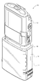
본 발명의 다양한 실시예들에서, 주입 펌프용의 개량된 유동 정지기(flow stop device)를 위한 장치 및 방법이 개시된다. 도 1은 일반적으로 제어 모듈(12) 및 카세트(14)를 결합된 배열로 포함하는 주입 펌프(10)의 일례를 도시한다. 구체적으로, 카세트(14)는 약물용 백 또는 저장조를 내장하고 이를 대체로 둘러싸는 공간을 한정하는 용기부(container portion)(16), 및 카세트의 상부 표면을 가로질러 연장되는 압력판(18)을 포함한다. 제어 모듈(12)과 카세트(14)는 도면들에 도시된 바와 같은 펌프 또는 카세트들의 크기 또는 유형들로 한정되지 않는 다양한 설계, 크기 및 형상의 것일 수 있다. 주입 펌프들은 연동 펌프, 롤러 펌프, 배출기 펌프, 또는 다른 펌프들을 포함할 수 있다. 카세트들은 도 1a에 도시된 대형 카세트들로 한정되지 않으며, 임의의 크기 및 형상의 것일 수 있다. 카세트들은 일회용이거나 재사용가능할 수 있으며, 밀봉될 수 있거나 쉽게 개방될 수 있다.In various embodiments of the present invention, an apparatus and method for an improved flow stop device for an injection pump is disclosed. 1 shows an example of an
본 명세서 및 도면에서는 유동 정지기가 주입 펌프용 카세트(14)의 부분으로서 대체로 기술되어 있지만, 이 유동 정지기는 그러한 카세트 배열체에서의 구현으로 한정되는 것으로 보아서는 안된다. 예를 들어, 다른 실시예들에서, 유동 정지기는 IV 백 또는 다른 유체 공급원과 함께 사용하도록 구성된 투여 세트의 부분으로서 사용되는 주입 펌프용 압력판 설계에서 용이하게 구현될 수 있다.Although the flow stop in this specification and the drawings is generally described as part of the cassette for an
도 2는 제어 모듈(12)과 카세트(14)가 분리된 배열로 있는, 주입 펌프의 분해도를 도시한다. 보다 상세하게는, 제어 모듈(12)과 카세트는, 제어 모듈(12)의 하부 표면 상의 구성요소들 및 압력판(18)의 상부 표면 상의 구성요소들이 보여지도록, 독립적으로 기울어진 것으로 도시되어 있다. 또한, 본 도면에는 유동 정지 조립체(20), 튜빙(tubing)(22), 및 약물 백(24)이 나타나 있다. 도시된 실시예에서, 유동 정지 조립체(20)는 폐색 아치(28) 및 유동 정지 아암(arm)(30)을 포함한다.Figure 2 shows an exploded view of the infusion pump in which the
제어 모듈(12)의 하부 표면은 구성요소들이 함께 결합될 때 제어 모듈(12)과 카세트(14)를 연결하는 힌지 핀(hinge pin)(32) 및 리세스(35) 내의 래칭 기구(latching mechanism)(34)를 포함한다. 제어 모듈(12)은 입구 밸브(36), 출구 밸브(38), 및 중앙에 위치된 배출기(40)를 더 포함한다. 또한, 도 2에는 상류측 폐색 센서(42), 하류측 폐색 센서(44), 공기 검출기 센서(46), 및 복수의 카세트 검출 핀(48)들이 보여지고 있다.The lower surface of the
도 2에 도시된 압력판(18)은 상부 및 하부 표면, 2개의 측벽(52)들뿐만 아니라 상류측 벽(54)과 하류측 벽(56)을 포함한다. 카세트(14)는 백(24) 또는 주사기(도시되지 않음) 내에 수용된 유체 공급원을 포함한다. 백(24) 또는 다른 유체 저장조는 또한 제어 모듈(12)과 압력판(14)으로부터 멀리 위치될 수 있다. 압력판(18)은 압력판(18)의 상부에 위치되어 튜브(22)를 압력판(18) 상의 제 위치에 유지하는 복수의 안내체(62)들을 포함한다. 적어도 한 쌍의 안내체(62)들의 중간에는, 통과하는 튜브(22)에 정확한 높이를 제공하기 위한 램프 플랫폼(ramp platform)(63)이 위치된다. 압력판(18)은 또한 레일(64), 및 압력판(18)을 둘러싸는 다양한 지지 구조체(65)들을 포함한다.The
도면에 도시된 바와 같이, 압력판(18)은 후크(66) 및 루프(68)에 의해 제어 모듈(12)에 부착된다. 특히, 후크(66)는 제어 모듈(12)의 핀(32)과 맞물리고, 루프(68)는 리세스(35) 내에 수용된다. 리세스(35)는 루프(68)와 선택적으로 맞물려서 제어 모듈(12)에 압력판(18)을 고정하는 래치(34)를 포함한다. 압력판(18)이 제어 모듈(12)에 고정될 경우, 튜브(22)는 밸브 및 배출기 특징부(36, 38, 40)들 중 적어도 하나와 계속적으로 맞물려서 튜브(22)가 끊임없이 폐색되게 한다. 작동 시에, 밸브 및 배출기는 압력판(18)에 대항하여 튜브(22)를 선택적으로 압착하여 튜브(22)를 통한 유체의 이동을 달성하게 한다.As shown in the figure, the
도 2에는 또한 유동 정지 폐색 아치(28) 및 유동 정지 아암(30)으로 구성된 유동 정지 조립체(20)가 도시되어 있다. 도 2에는 압력판(18) 내에 조립된 상태로 도시되어 있지 않지만, 유동 정지 조립체(20)는 루프(68)와 중앙 튜빙 지지 표면(70) 사이에서 압력판(18) 내로 조립되도록 구성되는 것으로서 이해될 수 있다. 폐색 아치(28)는 압력판에 부착가능하게 되는데, 그 이유는 폐색 아치는 기부판(18)의 중앙을 둘러싸는 레일(64) 및/또는 지지 구조체(65)들의 특징부 내에 고정되는 스냅들을 가지고 구성되기 때문이다. 2 also shows a
유동 정지 조립체(20)의 통합을 허용하는 리세스형 영역(74) 및 특징부들이 폐색 아치(28)에 인접하여 위치된다. 유동 정지 아암(30)은 스프링(78)을 거쳐 스프링 편의되고(spring biased), 일반적으로 폐색 아치(28)에 의해 제공된 개구를 가로질러 부분적으로 연장된다. 통합된 유동 정지 조립체(20)의 목적은 약물 자유 유동의 위험성을 감소시키기 위한 것이다. 일반적으로, 유동 정지 조립체(20)는 폐색 아치(28)를 통과하는 튜빙(22)에 대항한 유동 정지 아암(30)의 스프링-편의식 가압 접촉에 의해 이를 달성할 수 있다. 바꿔 말하면, 유동 정지 아암(30)은 편의되어, 폐색 아치(28)의 개구가 감소되게 하여서, 이를 통과하는 튜빙이 방해를 받고 폐색되도록 한다. 이는 본 출원의 후속의 도면들과 관련하여 보다 상세하게 도시되고 기술될 것이다. A recessed
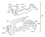
도 3은 유동 정지 조립체(20)의 일 실시예의 분해도이다. 이 조립체는 주입 펌프의 튜빙을 선택적으로 폐색하는 것을 허용하며, 유동 정지 폐색 아치(28) 및 유동 정지 아암(30)을 포함한다.3 is an exploded view of one embodiment of a
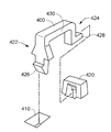
유동 정지 폐색 아치(28)는 제1 단부(102)와 제2 단부(104)를 갖는 다방향의 긴 구조체이다. 도 3 및 도 4에 도시된 제1 단부(102)는 압력판(18)의 융기된 레일(64) 또는 대응하는 지지 구조체에 결합하기 위한 탭 보유 특징부(tab retention feature)(106)를 갖는다. 제2 단부(104)는 융기된 레일(64) 또는 인접한 지지 구조체 상에서 보여지는 보유 특징부의 아래 또는 내부에 폐색 아치가 클립핑되게 해주는 탭 구조체(108)를 갖는다. 폐색 아치(28)의 제1 및 제2 단부(102, 104)들 사이에 구멍(110)이 형성된다. 이 구멍(110)은 사용 시에 이를 통하여 꿰어질 수 있는 주입 펌프용의 삽입된 주입 튜브(22)를 둘러싸도록 형상화된다. 아치(28)는 구멍(110)의 일부분을 형성하는 상향 돌출부(112)뿐만 아니라 또한 구멍(110)의 둘러싸는 부분을 형성하는 외향 돌출부(114) 양자 모두를 갖는다. 유동 정지 폐색 아치(28)는, 독립적으로 부착가능하고, 튜빙(22)을 위치설정할 때를 포함하여 카세트를 조립할 때 초기 시간 부분 동안에 펌프로부터 분리된 채로 둘 수 있으므로, 특히 유리하다.The flow
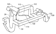
유동 정지 아암(30)은 일 단부에서 푸시 탭(120)을 갖고 다른 단부에서 피벗 핀(122)을 갖는 다방향 몸체이다. 아암(30)의 중간 몸체부(124)는 그 폭이 좁고 다단 방식(multi-tiered fashion)으로 연장된다. 푸시 탭(120)은 일반적으로 수렴하는 형상(converging shape)의 작고 편평한 상부 표면(126)을 갖는다. 푸시 탭(120)의 저부는 스프링 부재(78) 내에 축방향으로 수용가능한 원추형 돌기(128)를 포함한다. 따라서, 사용자는 작동 시에 유동 정지 아암을 변위시키기 위해 스프링(78)의 편의에 대항하여 푸시 탭(120)의 상부 표면(126)에 대해 수직 하방으로 가압할 수 있다. 도 3에 도시된 바와 같이, 피벗 핀(122)은 푸시 탭(120)으로부터 아암의 반대 단부에서 유동 정지 아암(30)의 측부들로부터 수평으로 연장된다. 핀(122)들은 폐색 아치(28)의 제2 단부(104) 부근에서 오목한 아치형 표면(130)들 내에 배치되고 피벗 결합하도록 형상화된다. 게다가, 조립된 때, 아암(30)의 몸체부(124)는 아치(28)에 의해 형성된 구멍(110)을 통하여 배치된다. 이러한 배열체는 아암의 몸체의 상부 표면(130)이 폐색 아치(28)의 구멍(110)을 통한 통로의 하부 개구를 한정하게 한다. 따라서, 유동 정지 아암(30)의 누름은 주입 튜브(22)가 통과할 수 있는 보다 큰 개구를 제공할 것이다. 아암(30)의 해제는 아암(30)과 상부 표면(130)의 상향 이동을 초래하여, 삽입된 주입 튜브에 대해 보다 작은 통로를 제공할 것이고, 이에 따라 아암(30)이 눌러지지 않을 때에 튜브의 폐색을 초래할 것이다. 이러한 배열이 도 4의 유동 정지 조립체의 조립도에서 보다 완전하게 도시되어 있다.The
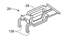
도 5a는 조립 방식으로 함께 결합된 유동 정지 조립체(20)의 일 실시예의 대안적인 조립도를 도시한다. 이 실시예에서, 폐색 아치(28)의 제1 단부는 압력판 레일(64)과 지지 구조체에 스냅 체결되기 위한 교번적인 탭(136)들을 갖는다.5A shows an alternative assembly view of one embodiment of a
도 5b는 압력판(18) 내에 삽입된, 도 5a의 유동 정지 조립체를 도시한다. 일반적으로, 유동 정지 조립체는 일 단부가 일 측부(150) 상의 레일(64)에 근접하여 위치되고 조립체의 다른 단부가 다른 측부(152) 상의 레일(64) 및 지지 구조체에 근접하여 위치된 상태로 펌프의 전방으로부터 펌프의 후방까지 펌프의 압력판(18)을 수평으로 가로질러 연장된다. 또한, 유동 정지 조립체(20)는 일반적으로 압력판(18) 내의 수직 리세스형 슬롯(74) 내에 안착된다. 리세스(74)는 전방 측부(150)로부터 후방 측부(152)까지 펌프를 가로지르며, 루프(68)와 중앙 튜빙 지지 표면(70) 사이에 위치된다.Fig. 5b shows the flow stop assembly of Fig. 5a inserted into the
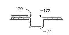
도 6은 유동 정지 조립체(20)가 카세트(14) 또는 압력판(18)의 제조 및 조립 동안에 위치되는 압력판(18)의 리세스(74)의 단면도이다. 몇몇 종래 기술의 설계들과 달리, 리세스(74)는 예를 들어 위치(170, 172)들에서의 압력판 표면의 에지들에서 램프형 특징부를 포함하지 않는다. 이들 위치에서 램프형 특징부를 제거함으로써, 신규의 유동 정지 조립체(20)는 주입 펌프(10)의 정확도 및 원하는 작동에 영향을 줄 수 있는 잠재적인 원치 않는 배압(back pressure) 효과를 겪지 않는다. 6 is a cross-sectional view of the
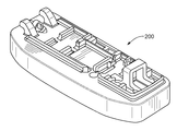
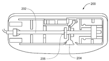
도 7a는 일반적으로 종래 기술의 압력판(200)을 도시하고 있다. 도 7b는 일반적으로 종래 기술의 조립된 압력판(200), 주입 튜빙(202) 및 유동 정지 아암(204)의 평면도를 도시하고 있다. 이들 도면은 폐색 아치(206)가 압력판(200)과 일체로 형성된 종래 기술의 배열체를 도시한다. 제조 동안에 이러한 설계의 조립은 다소 난제인 것이다. 예를 들어, 튜빙을 도 7b에 도시된 형태로 조립하기 위해서, 스프링 편의된 유동 정지 아암(204)에 의해 생성된 아치의 매우 좁은 개구를 통해 튜빙을 꿰는 것이 필요하다. 대안적으로, 사람이 이 구조체를 부착가능한 배열체를 통해 꿰게 하는 것은, 본 발명의 실시예들의 것과 마찬가지로, 제조상의 곤란성을 크게 줄이고, 조립 비용을 실질적으로 감소시킨다.FIG. 7A generally shows a
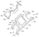
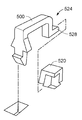
도 8은 유동 정지 폐색 아치(328)와 유동 정지 아암(330)을 갖는 유동 정지 조립체의 대안적인 실시예의 분해도이다.8 is an exploded view of an alternate embodiment of a flow stop assembly having flow stop
폐색 아치(328)는 제1 단부(332)와 제2 단부(334)를 갖는 구조용 클립이다. 이들 단부들 각각은 압력판(18)의 융기된 레일 또는 대응하는 지지 구조체에 결합하기 위해 탭 보유 특징부(336)를 갖는 한 쌍의 다리부(leg)(335)들을 갖는다. 탭 보유 특징부(336)는 압력판(18)의 융기된 레일 또는 인접한 지지 구조체 상에서 보여지는 보유 특징부의 아래 또는 내부에 클립핑될 수 있다. 폐색 아치(328)의 제1 및 제2 단부(332, 334)들 사이에는 구멍(340)이 위치된다. 이 구멍(340)은 사용 시에 이를 통하여 꿰어질 수 있는 주입 펌프용의 삽입된 주입 튜브(22)를 둘러싸도록 형상화된다. 아치(328)는 구멍(340)의 일부분을 형성하는 상향 돌출부(342)뿐만 아니라 또한 구멍(340)의 둘러싸는 부분을 형성하는 외향 돌출부(344)를 갖는다. 유동 정지 폐색 아치(328)는, 부착가능하고, 튜빙(22)을 위치설정할 때를 포함하여 카세트를 조립할 때 초기에 펌프로부터 분리된 채로 둘 수 있으므로, 특히 유리하다.The
유동 정지 아암(330)은 일 단부에서 푸시 탭(350)을 그리고 다른 단부에서 피벗 핀(352)을 갖는 다방향 몸체이다. 아암(330)의 중간 몸체부(354)는 그 폭이 좁고 다단 방식으로 연장된다. 푸시 탭(350)은 일반적으로 수렴하는 형상의 작고 편평한 상부 표면(356)을 갖는다. 푸시 탭(350)의 저부는 스프링 부재(78) 내에 축방향으로 수용가능한 원추형 돌기(358)를 포함한다. 따라서, 사용자는 동작 시에 유동 정지 아암을 변위시키기 위해 스프링(78)의 편의에 대항하여 푸시 탭(350)의 상부 표면(356)에 대항하여 수직 하방으로 가압할 수 있다. 피벗 핀(352)은 푸시 탭(350)으로부터 아암의 반대 단부에서 유동 정지 아암(330)의 측부들로부터 수평으로 연장된다. 핀(352)들은 폐색 아치(328)의 제2 단부(334) 부근에서의 배치 및 피벗 결합하는 형상으로 되어 있다. 게다가, 조립될 때, 아암(30)의 몸체부(354)는 아치(342)에 의해 형성된 구멍(340)을 통하여 배치된다. 이러한 배열은 아암(330)의 몸체의 상부 표면(360)으로 하여금 폐색 아치(328)의 구멍(340)을 통한 통로의 하부 개구를 한정하게 한다. 따라서, 유동 정지 아암(330)의 누름은 주입 튜브(22)가 통과할 수 있는 보다 큰 개구를 제공할 것이다. 아암(330)의 해제는 아암(330)과 상부 표면(360)의 상향 이동을 초래하여, 삽입된 주입 튜브를 위한 보다 작은 통로를 제공하고, 그에 따라 아암(330)이 눌리고 있지 않을 때에 튜브의 폐색을 초래할 것이다.The
도 9는 유동 정지 아치 설계의 대안적인 실시예를 도시한다. 이 실시예는 대안적인 부착가능한 유동 정지 아치 구성요소, 폐색 아치(400)뿐만 아니라, 보유 특징부(410, 420)를 도시하며, 이들은 그러한 설계의 압력판(18)에 통합될 것이다.Figure 9 shows an alternative embodiment of a flow stop arch design. This embodiment shows retaining
폐색 아치(400)는 제1 단부(422)와 제2 단부(424)를 갖는 구조용 클립이다. 제1 단부(422)에는 압력판(18)의 리세스형 구조체(410)에 결합하기 위한 탭 보유 특징부(426)가 구비되어 있다. 탭 보유 특징부(426)는 이러한 리세스형 구조체(410)의 아래 또는 내부에 클립핑될 수 있다. 제2 단부(424)는 수평 배치 방향으로 약간 연장되는 돌기(428)를 포함한다. 이러한 돌기(428)는 보유 특징부(420) 내에 끼워지도록 정렬될 수 있다. 융기된 아치 부분(430)이 제1 및 제2 단부(422, 424)들 사이에서 폐색 아치(400)의 중앙 몸체를 구성한다. 이러한 융기된 아치 부분(430)은 그 내부에서 구멍을 부분적으로 한정한다. 폐색 아치(400)가 각자의 보유 특징부(410, 420) 내에 삽입되면, 아치 주변부는 압력판과 조합하여, 주입 튜브(22)가 관통 삽입되어 꿰어질 수 있는 구멍을 형성하게 한다. 폐색 아치는 몇몇 실시예들에서 유동 정지 아암과 함께 사용될 수 있다. 다른 실시예들에서, 폐색 아치는 폐색을 위해 주입 튜브를 충분히 압축하도록 단독으로 작동된다.
도 10은 유동 정지 아치 설계의 대안적인 실시예를 도시한다. 이러한 실시예는 도 9에 도시된 것과 대체로 동일하지만, 도 9에 도시된 보유 특징부(420)와는 약간 상이한 보유 특징부(520)를 갖는다. 구체적으로, 보유 특징부는 2개의 측부들로부터의 접근을 허용한다. 따라서, 유동 정지 아치 구성요소(500)의 단부(524)에 있는 돌기(528)를 다수의 방향들로부터 삽입할 수 있는 능력이 가능하게 된다.Figure 10 shows an alternative embodiment of a flow stop arch design. This embodiment is substantially the same as that shown in FIG. 9, but has
소정의 실시예들은 유동 정지 특징부의 존재를 탐지할 수 있는 센서를 주입 펌프의 일부로서 더 포함할 수 있다. 이는 카세트 탐지 핀(48)들 이외의 다른 센서이거나 핀(48)들 중의 하나를 이용할 수 있다. 따라서, 펌프(12)는 유동 정지 특징부를 탐지하지 못하면 경보를 울릴 수 있다. 이는 또한 펌프가 경보음을 울릴 수 있기 때문에 압력판 또는 하우징이 펌프(12)로부터 분리되어 있는 상황에서 유리할 수 있다.Certain embodiments may further include a sensor capable of detecting the presence of flow stop features as part of the infusion pump. It may be a sensor other than the cassette detection pins 48 or may use one of the
주입 펌프용 카세트는 먼저, 내부 저장조 백을 수용한 주입 펌프 저장조 카세트 및 압력판을 포함하는 상부 표면을 제공함으로써 조립될 수 있다. 이러한 방법은 압력판 내의 개구에 근접한 위치에서 저장조 백에 결합된 주입 튜빙을, 부착가능한 유동 정지 조립체의 구멍을 통해 그리고 압력판의 표면을 가로질러 연장시키는 단계를 더 포함한다. 부착가능한 유동 정지부는 부착가능한 폐색 아치 및 부착가능한 유동 정지 아암을 포함한다. 부착가능한 유동 정지부는 구멍을 한정하며, 부착가능한 유동 정지 아암 및 결합 맞물림을 제공하기 위한 하나 이상의 탭 부재들을 갖는 다리부들을 구비한다. 이 방법은 탭 부재들을 압력판의 특징부에 고정시키는 단계를 포함한다.The cassette for an infusion pump can first be assembled by providing an upper surface comprising an infusion pump reservoir cassette and a pressure plate that houses an internal reservoir bag. The method further includes extending the injection tubing coupled to the reservoir bag at a location proximate to the opening in the pressure plate through a hole in the attachable flow stop assembly and across the surface of the pressure plate. The attachable flow stop includes an attachable closure arch and an attachable flow stop arm. The attachable flow stop defines the hole and includes legs with one or more tab members for providing an attachable flow stop arm and engagement engagement. The method includes securing the tab members to the features of the pressure plate.
또한, 예시적인 실시예 또는 예시적인 실시예들이 단지 예들이며, 본 발명의 범주, 적용가능성 또는 구성을 어떤 식으로든 제한하려고 의도되지 않음을 알아야 한다. 오히려, 전술된 상세한 설명은 당업자에게 예시적인 실시예 또는 예시적인 실시예들을 구현하기 위한 가능한 개시 내용을 제공할 것이다. 첨부된 특허청구범위에 기술된 바와 같은 본 발명의 범주 및 그의 법적 균등물로부터 벗어남이 없이 요소들의 기능 및 배열에 다양한 변경들이 이루어질 수 있음을 이해해야 한다.It is also to be understood that the exemplary embodiments or illustrative embodiments are merely examples, and are not intended to limit the scope, applicability, or configuration of the invention in any way. Rather, the foregoing detailed description will provide those of ordinary skill in the art with a possible disclosure of an exemplary embodiment or example embodiment. It should be understood that various changes may be made in the function and arrangement of elements without departing from the scope of the invention and its legal equivalents as set forth in the appended claims.
상기 실시예들은 제한하려는 것이 아니라 예시적인 것으로 의도된 것이다. 추가의 실시예들이 특허청구범위 내에 있다. 본 발명이 특정 실시예들을 참조하여 기술되었지만, 당업자들은 본 발명의 사상 및 범주로부터 벗어남이 없이 형태 및 세부에서 변경이 이루어질 수 있음을 인식할 것이다.The above embodiments are intended to be illustrative, not limiting. Additional embodiments are within the claims. While the invention has been described with reference to specific embodiments, those skilled in the art will recognize that changes may be made in form and detail without departing from the spirit and scope of the invention.
본 개시 내용을 읽을 때 본 발명에 대한 다양한 수정예들이 당업자에게 명백해질 수 있다. 예를 들어, 당업자는 본 발명의 상이한 실시예들에 대해 기술된 다양한 특징부들이 본 발명의 사상 내에서 다른 특징부들과 함께, 단독으로 또는 상이한 조합으로 적합하게 조합되고, 조합해제되고, 재조합될 수 있다는 것을 인식할 것이다. 마찬가지로, 전술된 다양한 특징부들 모두는 본 발명의 범주 또는 사상에 대한 제한이라기보다는 오히려 예시적인 실시예들로서 간주되어야 한다. 그러므로, 전술된 것은 본 발명의 범주를 제한하는 것으로는 고려되지 않는다.Various modifications to the present invention may become apparent to those skilled in the art upon reading this disclosure. For example, those skilled in the art will appreciate that various features described with respect to different embodiments of the invention may be suitably combined, disassociated, recombined, or otherwise combined with other features, alone or in different combinations, It will be appreciated. Likewise, all of the various features described above should be regarded as illustrative embodiments rather than as limitations on the scope or spirit of the invention. Therefore, the foregoing is not considered to limit the scope of the present invention.
본 발명에 대한 특허청구범위의 해석의 경우, "~하기 위한 수단" 또는 "~하기 위한 단계"와 같은 특정 용어들이 특허청구범위에 인용되지 않는다면 35 U.S.C.의 제112절, 제6항의 규정들이 적용되어서는 안된다는 것이 명백히 의도된다.In the case of interpretation of the claims to the present invention, unless a specific term such as "means for" or "step for" is cited in the claims, the provisions of
Claims (19)
융기된 레일 및 복수의 융기된 지지 구조체들을 포함하는 융기된 주변부 지지체에 의해 적어도 부분적으로 둘러싸인 튜빙 지지 표면;
융기된 주변부 지지체로부터 연장되고, 주입 펌프 튜브를 위한 통로를 한정하는 복수의 안내 구조체들; 및
부착가능한 유동 정지 조립체를 포함하고,
상기 부착가능한 유동 정지 조립체는,
융기된 주변부 지지체에 부착가능하게 결합되는 복수의 탭 구조체들을 포함하고, 관통하여 꿰어진 주입 펌프 튜브를 둘러싸도록 구성된 구멍을 더 포함하는 부착가능한 폐색 아치, 및
부착가능한 유동 정지 아암으로서, 부착가능한 유동 정지 아암은 스프링-편의 방식으로 부착가능한 폐색 아치에 인접하여 융기된 주변부 지지체에 작동가능하게 결합되어, 폐색 아치 내의 구멍이 유동 정지 아암에 의해 선택적으로 폐색될 수 있는, 부착가능한 유동 정지 아암
을 포함하는, 압력판.A pressure plate for attachment to an infusion pump,
A tubing support surface at least partially surrounded by a raised peripheral support comprising raised rails and a plurality of raised support structures;
A plurality of guide structures extending from the raised peripheral support and defining a passageway for the injection pump tube; And
An attachable flow stop assembly,
The attachable flow stop assembly comprises:
An attachable occlusion arch further comprising a plurality of tab structures attachably attached to the raised peripheral support and configured to surround an infusion pump tube threaded therethrough,
An attachable flow stop arm, wherein the attachable flow stop arm is operably associated with a raised peripheral support adjacent a spring-biased attachable closure arch such that the aperture in the closure arch is selectively occluded by a flow stop arm A removable flow stop arm
And the pressure plate.
일정량의 유체를 봉입하기 위한 저장조 하우징;
저장조 하우징으로부터 유체를 공급하기 위한 주입 튜브; 및
압력판을 포함하고,
상기 압력판은,
저장조 하우징으로부터 연장되는 주입 튜브의 일 섹션을 지지하기 위한 튜빙 지지 표면,
튜빙 지지 표면에 형성된 복수의 보유 및 안내 특징부들,
보유 및 안내 특징부들에 부착되는 스냅들을 갖는 부착가능한 폐색 아치를 포함하고, 튜브 내에서의 유체의 자유 이동을 방지하는 자유 유동 보호기, 및
폐색 아치를 통과하는 주입 튜브를 선택적으로 폐색하기 위해, 부착가능한 폐색 아치에 인접하여 이동하도록 보유 및 안내 특징부들에 작동가능하게 결합되는 부착가능한 유동 정지 아암
을 포함하는, 카세트 저장조 부착체.A cassette storage attachment body of an infusion pump,
A reservoir housing for enclosing a quantity of fluid;
An injection tube for supplying fluid from the reservoir housing; And
Comprising a pressure plate,
Wherein the pressure plate comprises:
A tubing support surface for supporting a section of the infusion tube extending from the reservoir housing,
A plurality of retention and guiding features formed on the tubing support surface,
A free flow protector including an attachable closure arch with snaps attached to the retaining and guiding features and preventing free movement of fluid within the tube,
An attachable flow stop arm operatively associated with the retention and guiding features to move adjacent the attachable occlusal arch to selectively occlude the injection tube through the occlusion arch,
And the cassette reservoir attachment body.
주입 펌프의 압력판에 부착가능하게 결합하기 위한 탭 구조체들을 포함하고, 일정 길이의 주입 펌프 튜브의 길이를 적어도 부분적으로 둘러싸도록 통로를 한정하는 부착가능한 폐색 아치; 및
폐색 아치에 의해 한정된 통로를 선택적으로 폐색하기 위해, 스프링 편의 방식으로 부착가능한 폐색 아치에 인접하여 이동하도록 압력판에 작동가능하게 결합되는 부착가능한 유동 정지 아암
을 포함하는, 부착가능한 유동 정지 조립체.An attachable flow stop assembly for use in occluding a tube of an infusion pump,
An attachable closure arch including tap structures for attachably attaching to the pressure plate of the infusion pump and defining a passage to at least partially surround the length of the infusion pump tube of a length; And
An attachable flow stop arm operatively coupled to the pressure plate to move adjacent the occlusive arch to a spring bi-directionally selectively closing the passageway defined by the occlusion arch,
Wherein the flow stop assembly comprises:
압력판을 포함하는 상부 표면 및 내부 저장조 백을 포함하는 주입 펌프 저장조 카세트를 제공하는 단계와,
압력판 내의 개구에 근접한 위치에서 저장조 백에 결합된 주입 튜빙을, 부착가능한 유동 정지 조립체 내의 구멍을 통해 그리고 압력판의 표면을 가로질러 연장시키는 단계로서, 상기 부착가능한 유동 정지부는, 결합된 맞물림을 제공하기 위한 하나 이상의 탭 부재들을 갖는 다리부들을 구비하고 구멍을 한정하는 부착가능한 폐색 아치, 및 부착가능한 유동 정지 아암을 포함하는, 주입 튜빙을 연장시키는 단계와,
탭 부재들을 압력판 내의 특징부들에 고정시키는 단계
를 포함하는, 주입 펌프용 카세트를 조립하는 방법.A method of assembling a cassette for an infusion pump,
Providing an infusion pump reservoir cassette comprising an upper surface comprising a pressure plate and an inner reservoir bag,
Extending the injection tubing coupled to the reservoir bag at a location proximate the opening in the pressure plate, through the aperture in the attachable flow stop assembly and across the surface of the pressure plate, the attachable flow stop providing a combined engagement Comprising an attachable closure arch having legs with one or more tab members for defining an aperture and defining an aperture, and an attachable flow stop arm;
Fixing the tab members to the features in the pressure plate
Wherein the cassette is adapted to receive the cassette.
Applications Claiming Priority (3)
| Application Number | Priority Date | Filing Date | Title |
|---|---|---|---|
| US13/443,390 | 2012-04-10 | ||
| US13/443,390 US8974415B2 (en) | 2012-04-10 | 2012-04-10 | Flow stop insert apparatus and methods |
| PCT/US2013/035393 WO2013154929A1 (en) | 2012-04-10 | 2013-04-05 | Flow stop insert apparatus and methods |
Publications (1)
| Publication Number | Publication Date |
|---|---|
| KR20140143827A true KR20140143827A (en) | 2014-12-17 |
Family
ID=49292883
Family Applications (1)
| Application Number | Title | Priority Date | Filing Date |
|---|---|---|---|
| KR1020147031088A KR20140143827A (en) | 2012-04-10 | 2013-04-05 | Flow stop insert apparatus and methods |
Country Status (11)
| Country | Link |
|---|---|
| US (2) | US8974415B2 (en) |
| EP (1) | EP2836250A4 (en) |
| JP (1) | JP6222750B2 (en) |
| KR (1) | KR20140143827A (en) |
| CN (1) | CN104334209A (en) |
| AU (1) | AU2013246241A1 (en) |
| CA (1) | CA2869865A1 (en) |
| IL (1) | IL235061A0 (en) |
| IN (1) | IN2014DN08461A (en) |
| SG (1) | SG11201406476YA (en) |
| WO (1) | WO2013154929A1 (en) |
Families Citing this family (28)
| Publication number | Priority date | Publication date | Assignee | Title |
|---|---|---|---|---|
| US8974415B2 (en) | 2012-04-10 | 2015-03-10 | Smiths Medical Asd, Inc. | Flow stop insert apparatus and methods |
| USD762850S1 (en) | 2013-04-23 | 2016-08-02 | Covidien Lp | Cassette |
| US20150182688A1 (en) * | 2013-12-31 | 2015-07-02 | Abbvie Inc. | Devices and methods for delivering a beneficial agent to a user |
| WO2015167927A1 (en) * | 2014-04-28 | 2015-11-05 | Smiths Medical Asd, Inc. | Infusion pump pressure plate |
| US20160058940A1 (en) | 2014-08-28 | 2016-03-03 | Zyno Medical, LLC. | Low-cost ambulatory medical pump |
| US10363360B2 (en) | 2014-12-01 | 2019-07-30 | Carefusion 2200, Inc. | Pump cassettes with slider and infusion pump systems |
| US10293102B2 (en) | 2014-12-01 | 2019-05-21 | Carefusion 2200, Inc. | Pump cassettes with piston and infusion pump systems |
| US10245373B2 (en) | 2014-12-01 | 2019-04-02 | Carefusion 2200, Inc. | Pump cassettes with positioning feature and infusion pump systems |
| US10376639B2 (en) | 2014-12-01 | 2019-08-13 | Carefusion 2200, Inc. | Valving system for infusion cassette |
| USD777247S1 (en) | 2014-12-30 | 2017-01-24 | Abbvie Inc. | Interface portion of a cassette |
| USD746871S1 (en) | 2014-12-30 | 2016-01-05 | Abbvie Inc. | Interface portion of a pump |
| USD777831S1 (en) | 2014-12-30 | 2017-01-31 | Abbvie Inc. | Cassette |
| USD766424S1 (en) * | 2014-12-30 | 2016-09-13 | Abbvie Inc. | Delivery device including pump and cassette |
| USD744005S1 (en) | 2014-12-30 | 2015-11-24 | Abbvie Inc. | Pump |
| CN104906657A (en) * | 2015-06-23 | 2015-09-16 | 苏州麦德迅医疗科技有限公司 | Leakage-proof infusion pump medicine box assembly |
| CN104941031B (en) * | 2015-07-07 | 2018-06-01 | 苏州麦德迅医疗科技有限公司 | Infusion pump and method with rotation lock |
| WO2017023489A1 (en) * | 2015-07-31 | 2017-02-09 | Smiths Medical Asd, Inc. | Infusion line clamp systems for infusion pumps |
| IL296753B2 (en) * | 2016-06-16 | 2024-05-01 | Smiths Medical Asd Inc | Assemblies and methods for infusion pump system administration sets |
| JP6912580B2 (en) * | 2016-12-30 | 2021-08-04 | バクスター・インターナショナル・インコーポレイテッドBaxter International Incorp0Rated | Obstruction prevention venous port |
| JP7295840B2 (en) | 2017-07-19 | 2023-06-21 | スミスズ メディカル エーエスディー,インコーポレイティド | Housing structure for infusion pump |
| USD870263S1 (en) | 2017-07-26 | 2019-12-17 | Smiths Medical Asd, Inc. | Infusion set |
| EP3705148A1 (en) | 2019-03-04 | 2020-09-09 | Avoset Health Ltd. | In cycle pressure measurement |
| WO2020178827A1 (en) | 2019-03-05 | 2020-09-10 | Avoset Health Ltd. | Anti-free-flow valve |
| US11426515B2 (en) | 2019-07-25 | 2022-08-30 | Zevex, Inc. | Infusion pump cassette having integrated pinch clip occluder |
| US11524108B2 (en) * | 2019-11-12 | 2022-12-13 | Infusaid Medical Mfg, Llc | Cassette assembly for ambulatory drug pump |
| USD948037S1 (en) * | 2019-11-15 | 2022-04-05 | Kpr U.S., Llc | Cassette |
| CN111731812B (en) * | 2020-05-09 | 2021-12-28 | 昕迪精密机械(东莞)有限公司 | Waste liquid bag production line |
| JPWO2022091775A1 (en) * | 2020-10-28 | 2022-05-05 |
Family Cites Families (86)
| Publication number | Priority date | Publication date | Assignee | Title |
|---|---|---|---|---|
| US5935099A (en) | 1992-09-09 | 1999-08-10 | Sims Deltec, Inc. | Drug pump systems and methods |
| US5669877A (en) | 1994-03-07 | 1997-09-23 | Sims Deltec, Inc. | Systems and methods for automated testing of medical equipment |
| US6241704B1 (en) | 1901-11-22 | 2001-06-05 | Sims Deltec, Inc. | Drug pump systems and methods |
| US5338157B1 (en) | 1992-09-09 | 1999-11-02 | Sims Deltec Inc | Systems and methods for communicating with ambulat |
| US2954485A (en) * | 1956-12-24 | 1960-09-27 | Bell Telephone Labor Inc | Transistor binary counters with fast carry |
| US3494458A (en) | 1968-04-23 | 1970-02-10 | American Home Prod | Tamperproof closure means for pilferproof package |
| US4193174A (en) * | 1978-04-11 | 1980-03-18 | Portex, Inc. | Lever and fulcrum clamping assembly |
| US4381836A (en) | 1981-06-15 | 1983-05-03 | Liberty Diversified Industries (Shamrock) | Anti-theft point-of-sale container |
| US4451693A (en) | 1982-03-22 | 1984-05-29 | Vest Gary W | Combined ballast container and wall plug for portable electrical equipment |
| US4567983A (en) | 1984-04-09 | 1986-02-04 | Handleman Company | Theft resistant cassette holder |
| US4565542A (en) | 1984-10-19 | 1986-01-21 | Deltec Systems, Inc. | Locking mechanism for a drug delivery system |
| US4559038A (en) | 1984-10-19 | 1985-12-17 | Deltec Systems, Inc. | Drug delivery system |
| US4650469A (en) | 1984-10-19 | 1987-03-17 | Deltec Systems, Inc. | Drug delivery system |
| US4634004A (en) | 1984-12-11 | 1987-01-06 | Empak Inc. | Magnetic tape security housing |
| USD294733S (en) | 1985-01-23 | 1988-03-15 | Pharmacia Deltec, Inc. | Casing for a drug delivery system |
| GB8602043D0 (en) | 1986-01-28 | 1986-03-05 | Amaray Int Ltd | Housing |
| US4867738A (en) | 1987-09-14 | 1989-09-19 | International Technidyne Corporation | Apparatus and methods for utilizing autotransfusion systems and related equipment |
| USD309662S (en) | 1987-12-01 | 1990-07-31 | Pacesetter Infustion, Ltd. | Medication infusion pump |
| US5246347A (en) | 1988-05-17 | 1993-09-21 | Patients Solutions, Inc. | Infusion device with disposable elements |
| US4944485A (en) * | 1989-08-28 | 1990-07-31 | Ivac Corporation | Clamp for flexible tubing |
| US5017192A (en) | 1989-10-20 | 1991-05-21 | Minnesota Mining And Manufacturing Company | Free flow prevention system for infusion pump |
| US5106366A (en) | 1990-03-08 | 1992-04-21 | Nestle, S.A. | Medical fluid cassette and control system |
| US5165874A (en) | 1990-05-04 | 1992-11-24 | Block Medical, Inc. | Disposable infusion apparatus and peristaltic pump for use therewith |
| US5181910A (en) | 1991-02-28 | 1993-01-26 | Pharmacia Deltec, Inc. | Method and apparatus for a fluid infusion system with linearized flow rate change |
| CA2064134A1 (en) * | 1991-04-23 | 1992-10-24 | Gary A. Thill | Free flow prevention system for infusion pump |
| US5213483A (en) | 1991-06-19 | 1993-05-25 | Strato Medical Corporation | Peristaltic infusion pump with removable cassette and mechanically keyed tube set |
| JP3133461B2 (en) | 1992-03-18 | 2001-02-05 | 株式会社クボタ | Rice transplanter |
| US5336174A (en) | 1992-05-07 | 1994-08-09 | Ivac Corporation | Flow control valve |
| US5257978A (en) * | 1992-07-14 | 1993-11-02 | Habley Medical Technology Corporation | IV safety module |
| US5364242A (en) | 1992-11-25 | 1994-11-15 | Pharmacia Deltec, Inc. | Pump apparatus and method including double activation pump apparatus |
| GB2273533B (en) | 1992-12-18 | 1996-09-25 | Minnesota Mining & Mfg | Pumping cassette with integral manifold |
| USD353667S (en) | 1993-06-03 | 1994-12-20 | Terumo Kabushiki Kaisha | Infusion pump |
| US5336190A (en) | 1993-08-12 | 1994-08-09 | Fred Erlich | Medical cassette for ambulatory medical infusion pumps with access port for reservoir bags and method of resupplying bags in said cassette |
| US5425173A (en) | 1993-10-12 | 1995-06-20 | Fredrick Kamienny | Method of resupplying new replacement tubing in a medical cassette for ambulatory medical infusion pumps |
| US5567119A (en) | 1993-10-28 | 1996-10-22 | Sims Deltec, Inc. | Bag/syringe enclosure arrangements and methods |
| US5540561A (en) | 1993-10-28 | 1996-07-30 | Sims Deltec, Inc. | Reservoir enclosure arrangements |
| US5397222A (en) | 1993-11-01 | 1995-03-14 | Moss; Richard | Reusable medical cassette for ambulatory medical infusion pumps |
| US5531697A (en) | 1994-04-15 | 1996-07-02 | Sims Deltec, Inc. | Systems and methods for cassette identification for drug pumps |
| US5772409A (en) | 1993-11-22 | 1998-06-30 | Sims Deltec, Inc. | Drug infusion device with pressure plate |
| US5658252A (en) | 1993-11-22 | 1997-08-19 | Sims Deltec, Inc. | Drug pump including pressure plate and tube |
| DE69411951T2 (en) | 1993-12-30 | 1999-01-07 | Sims Graseby Ltd | MEDICAL INFUSION PUMP |
| US5630710A (en) | 1994-03-09 | 1997-05-20 | Baxter International Inc. | Ambulatory infusion pump |
| US5482446A (en) | 1994-03-09 | 1996-01-09 | Baxter International Inc. | Ambulatory infusion pump |
| US5370622A (en) | 1994-04-28 | 1994-12-06 | Minimed Inc. | Proctective case for a medication infusion pump |
| US5453098A (en) | 1994-05-09 | 1995-09-26 | Imed Corporation | Two step IV fluid flow stop |
| WO1995031233A1 (en) * | 1994-05-13 | 1995-11-23 | Abbott Laboratories | Disposable fluid infusion pumping chamber cassette having a push button flow stop thereon |
| US5695473A (en) | 1994-07-27 | 1997-12-09 | Sims Deltec, Inc. | Occlusion detection system for an infusion pump |
| US6203528B1 (en) | 1995-03-06 | 2001-03-20 | Baxter International Inc. | Unitary molded elastomer conduit for use with a medical infusion pump |
| US5620312A (en) | 1995-03-06 | 1997-04-15 | Sabratek Corporation | Infusion pump with dual-latching mechanism |
| USD376848S (en) | 1995-03-06 | 1996-12-24 | Sabratek Corporation | Infusion pump cassette |
| US5904668A (en) | 1995-03-06 | 1999-05-18 | Sabratek Corporation | Cassette for an infusion pump |
| US5788674A (en) | 1996-03-05 | 1998-08-04 | Medication Delivery Devices, Inc. | Apparatus and method for limiting free-flow in an infusion system |
| US5782805A (en) | 1996-04-10 | 1998-07-21 | Meinzer; Randolph | Medical infusion pump |
| US5879143A (en) | 1996-04-26 | 1999-03-09 | Sims Deltec, Inc. | Reservoir enclosure adaptors and methods |
| US5928196A (en) | 1996-08-14 | 1999-07-27 | Sims Deltec, Inc. | Control module cassette locks and methods |
| US5823746A (en) | 1996-08-14 | 1998-10-20 | Sims Deltec, Inc. | Reusable pressure plates and methods |
| US5954485A (en) * | 1996-08-14 | 1999-09-21 | Sims Deltec, Inc. | Free-flow protection devices and methods |
| US5788671A (en) | 1996-08-14 | 1998-08-04 | Sims Deltec, Inc. | Reusable cassette housings and methods |
| US5879144A (en) | 1996-08-14 | 1999-03-09 | Sims Deltec, Inc. | Pressure plate adaptors and methods |
| US5954696A (en) | 1997-12-15 | 1999-09-21 | B. Braun Medical, Inc. | Pressure infusion pump |
| US6056522A (en) | 1998-05-13 | 2000-05-02 | Sims Deltec, Inc. | Reusable cassette with a moveable door |
| US6422057B1 (en) | 1998-09-29 | 2002-07-23 | Deltec, Inc. | Drug pump testing system and methods |
| US6202708B1 (en) | 1998-11-09 | 2001-03-20 | Sims Deltec, Inc. | Fillable cassette apparatus and method |
| US6077055A (en) | 1998-12-03 | 2000-06-20 | Sims Deltec, Inc. | Pump system including cassette sensor and occlusion sensor |
| US6131773A (en) | 1998-12-30 | 2000-10-17 | Steris Inc | Mounting and locking mechanism for a soap dispenser |
| AU2893899A (en) | 1999-03-03 | 2000-09-21 | Sims Deltec, Inc. | A pump pressure plate and method for mounting thereof |
| US6267564B1 (en) | 1999-05-12 | 2001-07-31 | Sims Deltec, Inc. | Medical reservoir bag and system |
| USD447558S1 (en) | 2000-04-14 | 2001-09-04 | Smisson-Cartledge Biomedical, Llc | Infusion pump cartridge |
| WO2002068018A2 (en) | 2001-02-23 | 2002-09-06 | Stryker Instruments | Integrated medication delivery system |
| US20030014011A1 (en) | 2001-07-12 | 2003-01-16 | Robert Renee Joy | Bypass anti-siphon valve and method |
| US7150735B2 (en) | 2002-05-16 | 2006-12-19 | Scott Laboratories, Inc. | Drug container entry mechanisms and method |
| JP3885018B2 (en) | 2002-10-24 | 2007-02-21 | 株式会社トップ | Infusion pump cassette |
| US7258534B2 (en) | 2003-09-22 | 2007-08-21 | Hospira, Inc. | Fluid delivery device identification and loading system |
| JP4949700B2 (en) * | 2006-03-08 | 2012-06-13 | テルモ株式会社 | Infusion tube loading aid and infusion device |
| CN201108641Y (en) * | 2007-10-26 | 2008-09-03 | 凌孝民 | Portable intelligent transfusion utensil |
| AU2009231734B2 (en) | 2008-04-01 | 2014-08-28 | Zevex, Inc. | Anti-free flow mechanism for enteral feeding pumps |
| USD586463S1 (en) | 2008-04-01 | 2009-02-10 | Smiths Medical Md, Inc. | Ambulatory pump |
| EP2193815B1 (en) | 2008-12-03 | 2013-02-13 | F. Hoffmann-La Roche AG | Flexible container with a preformed fluid channel and infusion pump device using such a container |
| MX2011008084A (en) | 2009-01-30 | 2011-10-03 | Nestec Sa | Infusion pump cassette with anti-free-flow valve mechanism. |
| US20100211002A1 (en) | 2009-02-18 | 2010-08-19 | Davis David L | Electromagnetic infusion pump with integral flow monitor |
| JP5111536B2 (en) | 2009-04-27 | 2013-01-09 | 株式会社エヌ・ティ・ティ・ドコモ | User apparatus, base station apparatus, and communication control method |
| EP2453950B1 (en) * | 2009-07-13 | 2016-10-26 | Nestec S.A. | Infusion pump with infusion cassettes |
| US7967773B2 (en) * | 2009-10-13 | 2011-06-28 | Smiths Medical Asd, Inc. | Two piece medication cassette closure apparatus and method |
| USD626647S1 (en) | 2009-10-13 | 2010-11-02 | Smiths Medical Asd, Inc. | Infusion pump cassette |
| US9220833B2 (en) | 2011-06-27 | 2015-12-29 | Smiths Medical Asd, Inc. | Medicament infusion systems |
| US8974415B2 (en) | 2012-04-10 | 2015-03-10 | Smiths Medical Asd, Inc. | Flow stop insert apparatus and methods |
-
2012
- 2012-04-10 US US13/443,390 patent/US8974415B2/en not_active Expired - Fee Related
-
2013
- 2013-04-05 IN IN8461DEN2014 patent/IN2014DN08461A/en unknown
- 2013-04-05 JP JP2015505813A patent/JP6222750B2/en not_active Expired - Fee Related
- 2013-04-05 CN CN201380029347.2A patent/CN104334209A/en active Pending
- 2013-04-05 WO PCT/US2013/035393 patent/WO2013154929A1/en active Application Filing
- 2013-04-05 AU AU2013246241A patent/AU2013246241A1/en not_active Abandoned
- 2013-04-05 KR KR1020147031088A patent/KR20140143827A/en not_active Application Discontinuation
- 2013-04-05 CA CA2869865A patent/CA2869865A1/en not_active Abandoned
- 2013-04-05 SG SG11201406476YA patent/SG11201406476YA/en unknown
- 2013-04-05 EP EP13775816.5A patent/EP2836250A4/en not_active Withdrawn
-
2014
- 2014-07-08 US US14/325,989 patent/US9789251B2/en not_active Expired - Fee Related
- 2014-10-07 IL IL235061A patent/IL235061A0/en unknown
Also Published As
| Publication number | Publication date |
|---|---|
| EP2836250A1 (en) | 2015-02-18 |
| AU2013246241A1 (en) | 2014-10-30 |
| JP6222750B2 (en) | 2017-11-01 |
| JP2015516207A (en) | 2015-06-11 |
| US9789251B2 (en) | 2017-10-17 |
| US20140317929A1 (en) | 2014-10-30 |
| EP2836250A4 (en) | 2016-04-27 |
| CA2869865A1 (en) | 2013-10-17 |
| CN104334209A (en) | 2015-02-04 |
| SG11201406476YA (en) | 2014-11-27 |
| US20130267899A1 (en) | 2013-10-10 |
| WO2013154929A1 (en) | 2013-10-17 |
| IN2014DN08461A (en) | 2015-05-08 |
| IL235061A0 (en) | 2014-12-31 |
| US8974415B2 (en) | 2015-03-10 |
Similar Documents
| Publication | Publication Date | Title |
|---|---|---|
| KR20140143827A (en) | Flow stop insert apparatus and methods | |
| JP5632363B2 (en) | Safety occluder and method of using the same | |
| JP5526228B2 (en) | Pinch clamp assembly for injection cassette | |
| US6142979A (en) | Pinch clip occluder system for infusion sets | |
| US7998121B2 (en) | Automatic safety occluder | |
| US7815612B2 (en) | Apparatus and method for preventing free flow in an infusion line | |
| JP5319761B2 (en) | Cassette for differential-pressure-based drug administration flow sensor assembly for monitoring drug administration and method for making the same | |
| US6749591B1 (en) | Pinch clip occluder system for infusion sets | |
| US9302091B2 (en) | Check valve system | |
| US20170120035A1 (en) | Fluid infusion systems and methods | |
| WO2014039222A1 (en) | Infusion pump pressure plate adapter system | |
| CN111601629B (en) | Liquid flow regulating device | |
| KR101794925B1 (en) | Drug injection controller |
Legal Events
| Date | Code | Title | Description |
|---|---|---|---|
| WITN | Application deemed withdrawn, e.g. because no request for examination was filed or no examination fee was paid |