JP6222750B2 - Pressure plate for attachment to an infusion pump, cassette reservoir attachment for an infusion pump, attachable flow stop assembly for use in occlusion of an infusion pump tube, and method for assembling an infusion pump cassette - Google Patents
Pressure plate for attachment to an infusion pump, cassette reservoir attachment for an infusion pump, attachable flow stop assembly for use in occlusion of an infusion pump tube, and method for assembling an infusion pump cassette Download PDFInfo
- Publication number
- JP6222750B2 JP6222750B2 JP2015505813A JP2015505813A JP6222750B2 JP 6222750 B2 JP6222750 B2 JP 6222750B2 JP 2015505813 A JP2015505813 A JP 2015505813A JP 2015505813 A JP2015505813 A JP 2015505813A JP 6222750 B2 JP6222750 B2 JP 6222750B2
- Authority
- JP
- Japan
- Prior art keywords
- attachable
- infusion pump
- pressure plate
- tube
- flow stop
- Prior art date
- Legal status (The legal status is an assumption and is not a legal conclusion. Google has not performed a legal analysis and makes no representation as to the accuracy of the status listed.)
- Expired - Fee Related
Links
- DVDJLXBXRDCNEL-ZAZKALAHSA-N C[C@H]([C@@H](C1)CCC2)C12[IH]C Chemical compound C[C@H]([C@@H](C1)CCC2)C12[IH]C DVDJLXBXRDCNEL-ZAZKALAHSA-N 0.000 description 1
Images


Classifications
-
- A—HUMAN NECESSITIES
- A61—MEDICAL OR VETERINARY SCIENCE; HYGIENE
- A61M—DEVICES FOR INTRODUCING MEDIA INTO, OR ONTO, THE BODY; DEVICES FOR TRANSDUCING BODY MEDIA OR FOR TAKING MEDIA FROM THE BODY; DEVICES FOR PRODUCING OR ENDING SLEEP OR STUPOR
- A61M5/00—Devices for bringing media into the body in a subcutaneous, intra-vascular or intramuscular way; Accessories therefor, e.g. filling or cleaning devices, arm-rests
- A61M5/14—Infusion devices, e.g. infusing by gravity; Blood infusion; Accessories therefor
- A61M5/168—Means for controlling media flow to the body or for metering media to the body, e.g. drip meters, counters ; Monitoring media flow to the body
- A61M5/16804—Flow controllers
-
- A—HUMAN NECESSITIES
- A61—MEDICAL OR VETERINARY SCIENCE; HYGIENE
- A61M—DEVICES FOR INTRODUCING MEDIA INTO, OR ONTO, THE BODY; DEVICES FOR TRANSDUCING BODY MEDIA OR FOR TAKING MEDIA FROM THE BODY; DEVICES FOR PRODUCING OR ENDING SLEEP OR STUPOR
- A61M5/00—Devices for bringing media into the body in a subcutaneous, intra-vascular or intramuscular way; Accessories therefor, e.g. filling or cleaning devices, arm-rests
- A61M5/14—Infusion devices, e.g. infusing by gravity; Blood infusion; Accessories therefor
- A61M5/142—Pressure infusion, e.g. using pumps
- A61M5/14212—Pumping with an aspiration and an expulsion action
- A61M5/14228—Pumping with an aspiration and an expulsion action with linear peristaltic action, i.e. comprising at least three pressurising members or a helical member
-
- A—HUMAN NECESSITIES
- A61—MEDICAL OR VETERINARY SCIENCE; HYGIENE
- A61M—DEVICES FOR INTRODUCING MEDIA INTO, OR ONTO, THE BODY; DEVICES FOR TRANSDUCING BODY MEDIA OR FOR TAKING MEDIA FROM THE BODY; DEVICES FOR PRODUCING OR ENDING SLEEP OR STUPOR
- A61M5/00—Devices for bringing media into the body in a subcutaneous, intra-vascular or intramuscular way; Accessories therefor, e.g. filling or cleaning devices, arm-rests
- A61M5/14—Infusion devices, e.g. infusing by gravity; Blood infusion; Accessories therefor
- A61M5/142—Pressure infusion, e.g. using pumps
- A61M5/14244—Pressure infusion, e.g. using pumps adapted to be carried by the patient, e.g. portable on the body
-
- A—HUMAN NECESSITIES
- A61—MEDICAL OR VETERINARY SCIENCE; HYGIENE
- A61M—DEVICES FOR INTRODUCING MEDIA INTO, OR ONTO, THE BODY; DEVICES FOR TRANSDUCING BODY MEDIA OR FOR TAKING MEDIA FROM THE BODY; DEVICES FOR PRODUCING OR ENDING SLEEP OR STUPOR
- A61M2205/00—General characteristics of the apparatus
- A61M2205/12—General characteristics of the apparatus with interchangeable cassettes forming partially or totally the fluid circuit
- A61M2205/123—General characteristics of the apparatus with interchangeable cassettes forming partially or totally the fluid circuit with incorporated reservoirs
-
- A—HUMAN NECESSITIES
- A61—MEDICAL OR VETERINARY SCIENCE; HYGIENE
- A61M—DEVICES FOR INTRODUCING MEDIA INTO, OR ONTO, THE BODY; DEVICES FOR TRANSDUCING BODY MEDIA OR FOR TAKING MEDIA FROM THE BODY; DEVICES FOR PRODUCING OR ENDING SLEEP OR STUPOR
- A61M2207/00—Methods of manufacture, assembly or production
-
- A—HUMAN NECESSITIES
- A61—MEDICAL OR VETERINARY SCIENCE; HYGIENE
- A61M—DEVICES FOR INTRODUCING MEDIA INTO, OR ONTO, THE BODY; DEVICES FOR TRANSDUCING BODY MEDIA OR FOR TAKING MEDIA FROM THE BODY; DEVICES FOR PRODUCING OR ENDING SLEEP OR STUPOR
- A61M39/00—Tubes, tube connectors, tube couplings, valves, access sites or the like, specially adapted for medical use
- A61M39/22—Valves or arrangement of valves
- A61M39/28—Clamping means for squeezing flexible tubes, e.g. roller clamps
- A61M39/281—Automatic tube cut-off devices, e.g. squeezing tube on detection of air
-
- A—HUMAN NECESSITIES
- A61—MEDICAL OR VETERINARY SCIENCE; HYGIENE
- A61M—DEVICES FOR INTRODUCING MEDIA INTO, OR ONTO, THE BODY; DEVICES FOR TRANSDUCING BODY MEDIA OR FOR TAKING MEDIA FROM THE BODY; DEVICES FOR PRODUCING OR ENDING SLEEP OR STUPOR
- A61M5/00—Devices for bringing media into the body in a subcutaneous, intra-vascular or intramuscular way; Accessories therefor, e.g. filling or cleaning devices, arm-rests
- A61M5/14—Infusion devices, e.g. infusing by gravity; Blood infusion; Accessories therefor
- A61M5/142—Pressure infusion, e.g. using pumps
- A61M5/14212—Pumping with an aspiration and an expulsion action
- A61M5/14232—Roller pumps
-
- Y—GENERAL TAGGING OF NEW TECHNOLOGICAL DEVELOPMENTS; GENERAL TAGGING OF CROSS-SECTIONAL TECHNOLOGIES SPANNING OVER SEVERAL SECTIONS OF THE IPC; TECHNICAL SUBJECTS COVERED BY FORMER USPC CROSS-REFERENCE ART COLLECTIONS [XRACs] AND DIGESTS
- Y10—TECHNICAL SUBJECTS COVERED BY FORMER USPC
- Y10T—TECHNICAL SUBJECTS COVERED BY FORMER US CLASSIFICATION
- Y10T29/00—Metal working
- Y10T29/49—Method of mechanical manufacture
- Y10T29/49405—Valve or choke making
- Y10T29/49412—Valve or choke making with assembly, disassembly or composite article making
Landscapes
- Health & Medical Sciences (AREA)
- Heart & Thoracic Surgery (AREA)
- Hematology (AREA)
- Anesthesiology (AREA)
- Biomedical Technology (AREA)
- Engineering & Computer Science (AREA)
- Life Sciences & Earth Sciences (AREA)
- Animal Behavior & Ethology (AREA)
- General Health & Medical Sciences (AREA)
- Public Health (AREA)
- Veterinary Medicine (AREA)
- Vascular Medicine (AREA)
- Pulmonology (AREA)
- Infusion, Injection, And Reservoir Apparatuses (AREA)
Description
本発明は、医療用輸液ポンプ内の流体の流れを制御するための特徴に関する。特に、本発明は、動作及び製造用の改良された設計を有する輸液ポンプのための流れ停止挿入物に関する。 The present invention relates to features for controlling fluid flow in a medical infusion pump. In particular, the present invention relates to a flow stop insert for an infusion pump having an improved design for operation and manufacture.
今日では、輸液ポンプ、薬剤ポンプ及び薬物送達デバイスは、世界中で周知であるとともに広く使用されている。静脈内輸液ポンプは、病態の治療に関連して、流体薬物又は栄養素を、チューブセットを通じて患者に圧送するために数十年前に開発された。輸液ポンプには、例えば、蠕動ポンプ、ローラポンプ又はエクスパルサ式ポンプ(expulsor pump)を含む。種々のポンプは、使い捨ての又は再利用可能な流体リザーバカセットの上部にある圧力板に着脱可能に結合された再利用可能な制御モジュールを含む。このカセットが制御モジュールに結合されている場合、流体は、カセットから、再利用可能な制御モジュールによって圧送される。別法として、輸液ポンプの他の変形形態は、再利用可能なポンプ制御モジュールと、ポンプ制御部から独立している、離れたIVバッグ又は流体リザーバとともに使用される投与セットの一部としての圧力板カセットと、を含む。 Today, infusion pumps, drug pumps and drug delivery devices are well known and widely used throughout the world. Intravenous infusion pumps were developed decades ago to pump fluid drugs or nutrients through a tube set to a patient in connection with the treatment of a disease state. Infusion pumps include, for example, peristaltic pumps, roller pumps, or expulsor pumps. Various pumps include a reusable control module removably coupled to a pressure plate on top of a disposable or reusable fluid reservoir cassette. When the cassette is coupled to the control module, fluid is pumped from the cassette by the reusable control module. Alternatively, other variations of the infusion pump include a reusable pump control module and pressure as part of a dosing set for use with a separate IV bag or fluid reservoir independent of the pump controller. A plate cassette.
輸液ポンプは、バルブ又は機構を送達チューブに対して押下して送達チューブの一部を選択的に閉塞することにより、送達チューブ内の流体の動きを制御することで動作する。例えば、いくつかのポンプにおいては、送達チューブ内において流体を押し出すために、ポンプの機構が送達チューブを圧力板に蠕動状態で選択的に係合させる。 Infusion pumps operate by controlling fluid movement within the delivery tube by depressing a valve or mechanism against the delivery tube to selectively occlude a portion of the delivery tube. For example, in some pumps, the pump mechanism selectively engages the delivery tube in a peristaltic manner with the pressure plate to force fluid into the delivery tube.
これまで、「自由流」と呼ばれる、場合によっては問題のある状況が認められている。自由流は、流体が流体の供給源から送達チューブを通過して患者に自由に流れる場合に輸液ポンプ内において発生する。医療従事者及びポンプオペレータは、患者に流体を投与する際、自由流の発生を回避しようとする。 So far, sometimes problematic situations called “free flow” have been recognized. Free flow occurs in an infusion pump when fluid flows freely from a source of fluid through a delivery tube to a patient. Medical personnel and pump operators attempt to avoid the generation of free flow when administering fluid to a patient.
自由流は過剰投薬により患者に重篤な危害を及ぼす可能性がある。従って、輸液ポンプ内の自由流を防止するための設計及びデバイスが開発されてきた。自由流予防設計の多くは幾分有効ではあるが、多くの設計には製造又は組み立てが困難な配置構成を伴う。例えば、送達チューブ配置のための多くの現在の圧力板配置構成は、組み立てが困難な設計の原因となる特徴を含む。更に、従来の圧力板設計の構成要素及び動作は最善ではなく、かなりの改良の余地が残されていると考えられる。 Free flow can cause serious harm to patients through overdose. Accordingly, designs and devices have been developed to prevent free flow in infusion pumps. Many free flow prevention designs are somewhat effective, but many designs involve arrangements that are difficult to manufacture or assemble. For example, many current pressure plate arrangements for delivery tube arrangements include features that cause difficult to assemble designs. In addition, the components and operation of conventional pressure plate designs are not optimal, and there remains considerable room for improvement.
従って、圧力板の改良を含む、輸液ポンプの流体の流れを選択的に制限するための改良された方法及び装置が所望されている。 Accordingly, an improved method and apparatus for selectively restricting fluid flow in an infusion pump, including improvements in pressure plates, is desired.
本発明は、輸液ポンプ内における流体の流れを制御するための改良型のデバイスを提供することにより先行技術の課題を克服する。概して、流体の流れは、輸液ポンプチューブ内を流れる流体を閉塞する取り付け可能な流れ停止アセンブリ又は自由流保護デバイスの使用、及び関連の方法を通じて制御される。種々の実施形態においては、流体の流れは輸液ポンプのリザーバカセットの圧力板において制限されてもよい。 The present invention overcomes the problems of the prior art by providing an improved device for controlling fluid flow within an infusion pump. In general, fluid flow is controlled through the use of attachable flow stop assemblies or free flow protection devices that block fluid flowing in the infusion pump tube and related methods. In various embodiments, fluid flow may be restricted at the pressure plate of the infusion pump reservoir cassette.
本発明の一実施形態は、輸液ポンプに取り付けるための圧力板に関する。具体的には、圧力板は、上昇レール及び複数の上昇支持構造を含む上昇周囲支持部によって少なくとも部分的に取り囲まれた管支持面を含む。圧力板はまた、上昇周囲支持部から延びる、輸液ポンプチューブ用の通路を画定する複数の案内構造を含む。更に、この実施形態においては、取り付け可能な流れ停止アセンブリが圧力板上に含まれる。取り付け可能な流れ停止アセンブリは、取り付け可能な閉塞アーチ及び取り付け可能な流れ停止アームを含む。取り付け可能な閉塞アーチは、上昇周囲支持部に取り付け可能に結合する複数のタブ構造を含む。閉塞アーチは、更に穴を含み、この穴は、そこに通された輸液ポンプチューブを取り囲むように構成されている。閉塞アーチ内の穴が流れ停止アームによって選択的に閉塞され得るように、取り付け可能な流れ停止アームは取り付け可能な閉塞アーチの近傍の上昇周囲支持部にばねに付勢された状態で作動的に結合されている。 One embodiment of the invention relates to a pressure plate for attachment to an infusion pump. Specifically, the pressure plate includes a tube support surface that is at least partially surrounded by a rising perimeter support that includes a rising rail and a plurality of rising support structures. The pressure plate also includes a plurality of guide structures that define a passage for the infusion pump tube that extends from the elevated perimeter support. Further, in this embodiment, an attachable flow stop assembly is included on the pressure plate. The attachable flow stop assembly includes an attachable occlusion arch and an attachable flow stop arm. The attachable occlusion arch includes a plurality of tab structures that are attachably coupled to the raised perimeter support. The occlusion arch further includes a hole that is configured to surround the infusion pump tube passed therethrough. The attachable flow stop arm is operatively spring-biased on an elevated perimeter support in the vicinity of the attachable occlusion arch so that the hole in the obstruction arch can be selectively closed by the flow stop arm. Are combined.
本発明の別の実施形態は輸液ポンプのカセットリザーバアタッチメントに関する。カセットリザーバアタッチメントは、一定量の流体を収容するためのリザーバハウジングと、リザーバハウジングから流体を供給するための輸液チューブと、圧力板と、を含む。圧力板は、輸液チューブの、リザーバハウジングから延びる部分を支持するための管支持面と、管支持面に形成された複数の保持及び案内特徴部と、を含む。カセットリザーバアタッチメントはまた、チューブ内における流体の自由流を防止する自由流保護デバイスを含む。自由流保護デバイスは、保持及び案内特徴部に取り付けるスナップを備えた取り付け可能な閉塞アーチと、保持及び案内特徴部に作動的に結合された、取り付け可能な閉塞アーチの近傍において動き、閉塞アーチを挿通する輸液チューブを選択的に閉塞するための取り付け可能な流れ停止アームと、を含む。 Another embodiment of the invention relates to an infusion pump cassette reservoir attachment. The cassette reservoir attachment includes a reservoir housing for containing a certain amount of fluid, an infusion tube for supplying fluid from the reservoir housing, and a pressure plate. The pressure plate includes a tube support surface for supporting a portion of the infusion tube extending from the reservoir housing, and a plurality of holding and guiding features formed on the tube support surface. The cassette reservoir attachment also includes a free flow protection device that prevents free flow of fluid within the tube. The free-flow protection device moves in the vicinity of the attachable occlusion arch with a snap attached to the retention and guidance feature and the attachable occlusion arch operatively coupled to the retention and guidance feature. And an attachable flow stop arm for selectively occluding the infusion tube to be inserted.
本発明の別の実施形態は、輸液ポンプのチューブの閉塞において使用するための取り付け可能な流れ停止アセンブリに関する。取り付け可能な流れ停止アセンブリは、取り付け可能な閉塞アーチ及び取り付け可能な流れ停止アームを含む。より具体的には、取り付け可能な閉塞アーチは輸液ポンプの圧力板に取り付け可能に結合するためのタブ構造を含み、閉塞アーチは一定の長さの輸液ポンプチューブを少なくとも部分的に取り囲むための通路を画定する。更に、取り付け可能な流れ停止アームは、圧力板に作動的に結合されており、ばねに付勢された状態で取り付け可能な閉塞アーチの近傍において動き、閉塞アーチによって画定された通路を選択的に閉塞する。 Another embodiment of the invention relates to an attachable flow stop assembly for use in occlusion of an infusion pump tube. The attachable flow stop assembly includes an attachable occlusion arch and an attachable flow stop arm. More specifically, the attachable occlusion arch includes a tab structure for attachably coupling to an infusion pump pressure plate, the occlusion arch being a passage for at least partially surrounding a length of infusion pump tube. Is defined. In addition, the attachable flow stop arm is operatively coupled to the pressure plate and moves in the vicinity of the attachable occlusion arch while being biased by a spring, selectively passing the passage defined by the occlusion arch. Block.
本発明の一実施形態によれば、輸液ポンプのカセットを組み立てる方法が提供される。この方法は、内部リザーババッグと、圧力板を含む頂面とを収容する輸液ポンプリザーバカセットを用意するステップを含む。方法はまた、輸液チューブを延ばし、取り付け可能な流れ停止アセンブリ内の穴を通し、圧力板の表面を横断させ、圧力板内の開口部の近傍の位置においてリザーババッグに結合するステップを含む。この実施形態においては、取り付け可能な流れ停止アセンブリは、穴を画定し、結合された係合を提供するための1つ又は複数のタブ部材を備えた脚を有する、取り付け可能な閉塞アーチと、取り付け可能な流れ停止アームと、を含む。方法はまた、タブ部材を圧力板内の特徴部に固定するステップを含む。 According to one embodiment of the present invention, a method for assembling an infusion pump cassette is provided. The method includes providing an infusion pump reservoir cassette that houses an internal reservoir bag and a top surface that includes a pressure plate. The method also includes extending the infusion tube, passing through a hole in the attachable flow stop assembly, traversing the surface of the pressure plate, and coupling to the reservoir bag at a location near the opening in the pressure plate. In this embodiment, the attachable flow stop assembly includes an attachable occlusion arch having legs with one or more tab members for defining a hole and providing coupled engagement; And an attachable flow stop arm. The method also includes securing the tab member to a feature in the pressure plate.
本発明は、本発明の種々の実施形態の以下の詳細な説明を添付の図面とともに考察するとより完全に理解されうる。 The invention may be more fully understood when the following detailed description of various embodiments of the invention is considered in conjunction with the accompanying drawings.
本発明はその必須の特性から逸脱することなく他の特定の形態において具現化されてもよく、従って、示される実施形態はあらゆる点において例示としてとみなされるべきであり、限定ではない。 The present invention may be embodied in other specific forms without departing from its essential characteristics, and thus the illustrated embodiments are to be considered in all respects as illustrative and not restrictive.
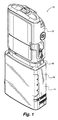
本発明の種々の実施形態においては、輸液ポンプの改良した流れ停止デバイスのための装置及び方法が開示される。図1は、全般的に、結合した配置構成の制御モジュール12及びカセット14を含む輸液ポンプ10の例を示す。具体的には、カセット14は、薬物のバッグ又はリザーバを収容し且つ全般的に密封するための空間を画定する容器部16と、カセットの上面全体に延在する圧力板18と、を含む。制御モジュール12及びカセット14は種々の設計、サイズ及び形状のものであってもよく、図に示されるポンプ又はカセットのサイズ又は種類に限定されない。輸液ポンプには、蠕動ポンプ、ローラポンプ、エクスパルサ式ポンプ又は他のポンプを含んでもよい。カセットは図1に示される大型カセットに限定されず、あらゆるサイズ及び形状のものであってもよい。カセットは使い捨てであっても再利用可能であってもよく、且つ、密閉されても容易に開くことができてもよい。
In various embodiments of the present invention, an apparatus and method for an improved flow stop device of an infusion pump is disclosed. FIG. 1 generally illustrates an example of an
この開示及び図では、流れ停止デバイスは主として輸液ポンプのカセット14の一部として説明するが、流れ停止デバイスはそのようなカセット配置での実施に限定されるものと解釈すべきではない。他の実施形態においては、例えば、流れ停止アセンブリは、IVバッグ又は他の流体源との使用のために構成された投与セットの一部として使用される輸液ポンプの圧力板設計内において容易に実施されてもよい。
In this disclosure and the figures, the flow stop device is described primarily as part of the
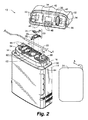
図2は、分離された配置構成にある制御モジュール12及びカセット14を備えた輸液ポンプの分解図を示す。特に、制御モジュール12及びカセットは制御モジュール12の下面の構成要素及び圧力板18の上面の構成要素が示されるように個々に傾斜して示される。この図には、流れ停止アセンブリ20、チューブ22及び薬物バッグ24も示される。図示される実施形態においては、流れ停止アセンブリ20は、閉塞アーチ28及び流れ停止アーム30を含む。
FIG. 2 shows an exploded view of the infusion pump with
制御モジュール12の下面は、構成要素がともに結合されている場合に制御モジュール12とカセット14とを結合する、ヒンジピン32と、凹部35内のラッチ機構34と、を含む。制御モジュール12は、入口バルブ36と、出口バルブ38と、中央に位置するエクスパルサ40と、を更に含む。また、図2に示されるのは、上流側閉塞センサ42、下流側閉塞センサ44、空気検知センサ46及び複数のカセット検知ピン48である。
The lower surface of the
図2に示される圧力板18は、頂面及び底面と、2つの側壁52と、上流側壁54と、下流側壁56と、を含む。カセット14は、バッグ24又はシリンジ(不図示)内に収容された流体の供給源を含む。バッグ24又は他の流体リザーバはまた、制御モジュール12及び圧力板14から離して配置されてもよい。圧力板18は、圧力板18の上部に配置されており、チューブ22を圧力板18上の所定の位置に保持する複数の案内部62を含む。中間に位置する、少なくとも1対の案内部62は通過するチューブ22に適正な高さを提供するための傾斜台63である。圧力板18はまた、圧力板18を取り囲む、レール64及び種々の支持構造65を含む。
The
図に示すように、圧力板18はフック66及びループ68によって制御モジュール12に取り付けられている。特に、フック66は制御モジュール12のピン32に係合し、ループ68は凹部35内に受容される。凹部35は、ループ68に選択的に係合して圧力板18を制御モジュール12に係止するラッチ34を含む。圧力板18が制御モジュール12にロックされると、チューブ22が常時閉塞されるように、チューブ22はバルブ及びエクスパルサ特徴部36,38,40のうちの少なくとも1つによって連続的に係合される。動作時、バルブ及びエクスパルサはチューブ22を圧力板18に対して選択的に押しつぶし、チューブ22を通過する流体の動きに作用する。
As shown, the
また、図2に示されるのは、流れ停止閉塞アーチ28と流れ停止アーム30とで構成された流れ停止アセンブリ20である。図2では圧力板18に組み付けられた状態で示されないが、流れ停止アセンブリ20は圧力板18の、ループ68と中央管支持面70との間への組み付けのために適応させるものと理解される。スナップを、底板18の中央を取り囲むレール64及び/又は支持構造65の特徴部に固定するように適合させているため、閉塞アーチ28は圧力板に取り付け可能である。
Also shown in FIG. 2 is a
閉塞アーチ28の近傍にあるのは、流れ停止アセンブリ20の組み込みを可能にする凹部領域74及び特徴部である。流れ停止アーム30はばね78によりばね付勢され、全般的に、閉塞アーチ28によって設けられた開口部に部分的に延在する。組み込まれた流れ停止アセンブリ20の目的は薬物の自由流のリスクを低減するためである。概して、流れ停止アセンブリ20は、流れ停止アーム30の、閉塞アーチ28を挿通するチューブ22に対するばね付勢による圧力接触(pressure contact)によってこれを実現することができる。換言すると、流れ停止アーム30は、挿通したチューブが妨害され(interfered with)且つ閉塞されるよう閉塞アーチ28の開口部が低減されるように付勢される。これについては本出願の後の図とともにより詳細に示し、且つ記載する。
In the vicinity of the
図3は、流れ停止アセンブリ20の一実施形態の分解図である。アセンブリは、輸液ポンプのチューブを選択的に閉塞することを可能にし、流れ停止閉塞アーチ28及び流れ停止アーム30を含む。
FIG. 3 is an exploded view of one embodiment of the
流れ停止閉塞アーチ28は、第1端部102と第2端部104とを有する多方向性の、長尺状の構造である。図3及び図4に示される第1端部102は、上昇レール64又は圧力板18の対応する支持構造に結合するためのタブ保持特徴部106を有する。第2端部104は、閉塞アーチが上昇レール64又は隣接する支持構造上にある保持特徴部の下又は内部をクリップすることを可能にするタブ構造108を有する。閉塞アーチ28の第1端部102と第2端部104との間に画定されるのは穴110である。この穴110は、使用時、そこに通されてもよい、輸液ポンプの挿入された輸液チューブ22を取り囲むような形状である。アーチ28は、穴110の一部を形成する上方突出部112と、穴110の取り囲む部分を形成する外側突出部114と、の両方を有する。流れ停止閉塞アーチ28は、単独で取り付け可能であり、且つ、チューブ22を配置しているときを含む、カセットを組み立てる際の初期の時間はポンプから取り外されたままであってもよいため、特に有利である。
The flow
流れ停止アーム30は、一端にプッシュタブ120、他端に枢動ピン122を有する多方向性本体(multi−directional body)である。アーム30の中間本体部124はその幅が狭く、多段状に延在する。プッシュタブ120は、全般的に、収束形状(converging shape)の狭い平坦な頂面126を有する。プッシュタブ120の底部は、ばね部材78内に軸方向に受容可能な円錐形の突起物128を含む。従って、動作時、流れ停止アームを変位するため、使用者はプッシュタブ120の頂面126をばね78の付勢に抗して垂直方向に下方に押すことができる。図3に示されるように、枢動ピン122は、アームの、プッシュタブ120の反対端において流れ停止アーム30の側部から水平に延びる。ピン122は、凹形円弧状表面130内の、閉塞アーチ28の第2端部104近辺における配置及び枢動結合のための形状である。更に、組み立てられると、アーム30の本体部124はアーチ28によって形成された穴110内に配置される。この配置構成により、アームの本体の頂面130が閉塞アーチ28の穴110を通る通路の下部開口部を画定する。従って、流れ停止アーム30の凹みは輸液チューブ22が通過することができるより大きな開口部を提供する。アーム30の解放によりアーム30の上方の動きが発生し、上面130が、挿入された輸液チューブのためのより狭い通路を提供するため、アーム30が押下されていない場合はチューブの閉塞が生じる。この配置構成については図4の流れ停止アセンブリの組立図により詳細に示す。
The
図5Aは、全般的に、組み立てられた状態でともに結合された流れ停止アセンブリ20の一実施形態の別の組立図を示す。この実施形態においては、閉塞アーチ28の第1端部は圧力板レール64及び支持構造にスナップ留めするための別のタブ136を有する。
FIG. 5A generally illustrates another assembly view of one embodiment of the
図5Bは、圧力板18に挿入された図5Aの流れ停止アセンブリを示す。概して、流れ停止アセンブリは、ポンプの圧力板18の、ポンプの前部からポンプの後部まで水平に延在し、その一端は側部150にあるレール64の近傍にあり、アセンブリの他端は他の側部152にあるレール64及び支持構造の近傍にある。更に、流れ停止アセンブリ20は、全般的に、圧力板18内の垂直方向に凹んだスロット74内に載置される。凹部74は、前側側部150から後側側部152までポンプを横断し、且つ、ループ68と中央管支持面70との間にある。
FIG. 5B shows the flow stop assembly of FIG. 5A inserted into the
図6は、流れ停止アセンブリ20がカセット14又は圧力板18の製造及び組み立て時に配置される、圧力板18の凹部74の断面図である。一部の先行技術による設計とは異なり、凹部74は圧力板表面の縁端、例えば、位置170,172に傾斜状の特徴部を含まない。これらの位置における傾斜状の特徴部を排除することによって、新規の流れ停止アセンブリ20は輸液ポンプ10の精度及び所望の動作に影響を及ぼす可能性のある不要な潜在的背圧作用を被らない。
FIG. 6 is a cross-sectional view of the
図7Aは、全般的に、先行技術の圧力板200を示す。図7Bは、全般的に、先行技術の組み立てられた圧力板200、輸液チューブ202及び流れ停止アーム204の頂面図を示す。これらの図は、閉塞アーチ206が圧力板200と一体的に形成された先行技術の配置構成を示す。製造時にこの設計を組み立てるのは幾分困難である。例えば、図7Bに示される構成にチューブを組み付けるためには、ばね付勢式流れ停止アーム204によって形成されたアーチ内の非常に狭い開口部にチューブを通す必要がある。別法として、本発明の実施形態のもののような取り付け可能な装置によりこの構造に通すことを可能にすると、製造の難解さを大幅に低減し、組み立てコストがかなり低減する。
FIG. 7A generally shows a prior
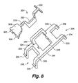
図8は、流れ停止閉塞アーチ328及び流れ停止アーム330を備えた流れ停止アセンブリの別実施形態の分解図である。
閉塞アーチ328は第1端部332及び第2端部334を有する構造的クリップ(structural clip)である。これら端部のそれぞれは、上昇レール又は圧力板18の対応する支持構造に結合するためのタブ保持特徴部336を備えた一対の脚335を有する。タブ保持特徴部336は上昇レール又は隣接する圧力板18の支持構造上にある保持特徴部の下又は内部をクリップしてもよい。閉塞アーチ328の第1端部332と第2端部334との間にあるのは穴340である。この穴340は、使用時、そこに通されてもよい、輸液ポンプの挿入された輸液チューブ22を取り囲むような形状である。アーチ328は、穴340の一部を形成する上方突出部342と、穴340の取り囲む部分を形成する外側突出部344と、の両方を有する。流れ停止閉塞アーチ328は、取り付け可能であるとともに、チューブ22の配置を含むカセットの組み立ての際、初めはポンプから取り外されたままであってもよいため、特に有利である。
FIG. 8 is an exploded view of another embodiment of a flow stop assembly comprising a flow
The
流れ停止アーム330は、一端にプッシュタブ350、他端に枢動ピン352を有する多方向性本体である。アーム330の中間本体部354はその幅が狭く、多段状に延在する。プッシュタブ350は、全般的に、収束形状の狭い平坦な頂面356を有する。プッシュタブ350の底部はばね部材78内に軸方向に受容可能な円錐形の突起物358を含む。従って、動作時、流れ停止アームを変位するため、使用者はプッシュタブ350の頂面356をばね78の付勢に抗して垂直方向に下方に押すことができる。枢動ピン352は、アームの、プッシュタブ350の反対端において流れ停止アーム330の側部から水平に延びる。ピン352は、閉塞アーチ328の第2端部334近辺における配置及び枢動結合のための形状である。更に、組み立てられると、アーム30の本体部354はアーチ342によって形成された穴340内に配置される。この配置構成により、アームの本体330の頂面360が閉塞アーチ328の穴340を通る通路の下部開口部を画定する。従って、流れ停止アーム330の凹みは輸液チューブ22が通過することができるより大きな開口部を提供する。アーム330の解放によりアーム330の上方の動きが発生し、上面360が、挿入された輸液チューブのためのより狭い通路を提供するため、アーム330が押下されていない場合はチューブの閉塞が生じる。
The
図9は、流れ停止アーチ設計の別実施形態を示す。この実施形態は、別の取り付け可能な流れ停止アーチ構成要素である閉塞アーチ400と、そのような設計の圧力板18に組み込まれうる保持特徴部410,420と、を示す。
FIG. 9 illustrates another embodiment of a flow stop arch design. This embodiment shows an
閉塞アーチ400は第1端部422及び第2端部424を有する構造的クリップである。第1端部422は、圧力板18の凹んだ構造410に結合するためのタブ保持特徴部426を備える。タブ保持特徴部426はこの凹んだ構造410の下方又は内部をクリップしてもよい。第2端部424は、水平に配置された方向にわずかに突出する突起物428を含む。この突起物428は保持特徴部420内に嵌合するように調整してもよい。上昇アーチ部430は、第1端部422と第2端部424との間に閉塞アーチ400の中心本体を含む。この上昇アーチ部430はその内部に穴を部分的に画定する。閉塞アーチ400が保持特徴部410,420の各々に挿入されると、アーチの周囲が圧力板と組み合わされ、輸液チューブ22が挿入されるとともに通されてもよい穴を形成する。いくつかの実施形態においては、閉塞アーチは流れ停止アームとともに使用される。他の実施形態においては、閉塞アーチは輸液チューブを十分に圧縮して閉塞させるため単独で動作する。
The
図10は、流れ停止アーチ設計の別実施形態を示す。この実施形態は主として図9に示されるものと同じであるが、図9に示される保持特徴部420とはわずかに異なる保持特徴部520を有する。具体的には、保持特徴部は2つの側からのアクセスを可能にする。従って、流れ停止アーチ構成要素500の端部524にある突起物528を複数の方向から挿入する機能を可能にする。
FIG. 10 shows another embodiment of a flow stop arch design. This embodiment is primarily the same as that shown in FIG. 9, but has a holding
特定の実施形態では、更に、輸液ポンプの一部として、流れ停止特徴部の存在を検知しうるセンサを含んでもよい。これはカセット検知ピン48以外の別のセンサとすることも、ピン48の1つを使用することもできる。従って、ポンプ12は、それが流れ停止特徴部を検知しなかった場合は警報を発する。ポンプが警報を鳴らすため、これは板又はハウジングがポンプ12から外れた状況においても有利である。
Certain embodiments may further include a sensor capable of detecting the presence of a flow stop feature as part of the infusion pump. This can be a separate sensor other than the
輸液ポンプのためのカセットは、まず、内部リザーババッグと、圧力板を含む頂面とを収容する輸液ポンプリザーバカセットを用意することによって組み立てられてもよい。この方法は、更に、輸液チューブを延ばし、取り付け可能な流れ停止アセンブリ内の穴を通し、圧力板の表面を横断させ、圧力板内の開口部の近傍の位置においてリザーババッグに結合するステップを含む。取り付け可能な流れ停止アセンブリは、取り付け可能な閉塞アーチ及び取り付け可能な流れ停止アームを含む。取り付け可能な流れ停止アセンブリは穴を画定し、且つ、結合された係合を提供するための1つ又は複数のタブ部材を備えた脚と、取り付け可能な流れ停止アームと、を有する。方法は、更に、タブ部材を圧力板内の特徴部に固定するステップを含む。 A cassette for an infusion pump may be assembled by first providing an infusion pump reservoir cassette that houses an internal reservoir bag and a top surface that includes a pressure plate. The method further includes extending the infusion tube, passing through a hole in the attachable flow stop assembly, traversing the surface of the pressure plate, and coupling to the reservoir bag at a location near the opening in the pressure plate. . The attachable flow stop assembly includes an attachable occlusion arch and an attachable flow stop arm. The attachable flow stop assembly defines a hole and has a leg with one or more tab members for providing coupled engagement and an attachable flow stop arm. The method further includes securing the tab member to a feature in the pressure plate.
また、例示的実施形態は単に例であり、本発明の範囲、適用性又は構成をいかようにも限定するものではないことは理解すべきである。むしろ、前述の詳細な説明は例示的実施形態を実施するための可能な開示を当業者に提供するものである。要素の機能及び配置構成に、添付の特許請求の範囲及びその法的均等物において説明する本発明の範囲から逸脱することなく種々の変更を施すことができることを理解すべきである。 It should also be understood that the exemplary embodiments are merely examples and do not limit the scope, applicability, or configuration of the invention in any way. Rather, the foregoing detailed description provides those skilled in the art with a possible disclosure for practicing the exemplary embodiments. It should be understood that various changes can be made in the function and arrangement of elements without departing from the scope of the invention as set forth in the appended claims and the legal equivalents thereof.
上記実施形態は例証であり、限定を意図するものではない。更なる実施形態が特許請求の範囲内にある。本発明は特定の実施形態に関して記載されたが、当業者であれば、本発明の範囲及び精神から逸脱することなく形態及び細部に変更を施してもよいことを理解するであろう。 The above embodiments are illustrative and are not intended to be limiting. Further embodiments are within the scope of the claims. Although the invention has been described with reference to particular embodiments, those skilled in the art will recognize that changes may be made in form and detail without departing from the scope and spirit of the invention.
本発明に対する種々の修正については当業者がこの開示を読めば明らかとなりうる。例えば、当業者は、本発明の精神内において、本発明の異なる実施形態に記載された種々の特徴を他の特徴と、単独で又は異なる組み合わせで、適切に組み合わせることも、組み合わせないことも、再度組み合わせることもできることを理解するであろう。同様に、上に記載した種々の特徴は全て本発明の範囲又は精神の限定ではなくむしろ実施形態例とみなすべきである。従って、上記は本発明の範囲を限定することを意図しない。 Various modifications to the present invention will become apparent to those skilled in the art after reading this disclosure. For example, those skilled in the art may, within the spirit of the present invention, properly combine or not combine various features described in different embodiments of the present invention with other features, alone or in different combinations, It will be understood that they can be combined again. Similarly, all of the various features described above are not to be construed as limiting the scope or spirit of the invention, but rather as example embodiments. Accordingly, the above is not intended to limit the scope of the invention.
Claims (10)
上昇レール及び複数の上昇支持構造を含む上昇周囲支持部によって少なくとも部分的に取り囲まれた管支持面と、
前記上昇周囲支持部から延びる、輸液ポンプチューブ用の通路を画定する複数の案内構造と、
取り付け可能な流れ停止アセンブリであって、
前記上昇周囲支持部に取り付け可能に結合する複数のタブ構造を含む取り付け可能な閉塞アーチであって、前記閉塞アーチが、更に穴を含み、前記穴が、そこに通された輸液ポンプチューブを取り囲むように構成されている、取り付け可能な閉塞アーチと、
取り付け可能な流れ停止アームであって、前記閉塞アーチ内の前記穴が前記流れ停止アームによって選択的に閉塞されるように、前記閉塞アーチの近傍の前記上昇周囲支持部にばねに付勢された状態で作動的に結合されている取り付け可能な流れ停止アームと、
を含む、取り付け可能な流れ停止アセンブリと、
を備える、圧力板。 A pressure plate for mounting on an infusion pump,
A tube support surface at least partially surrounded by a rising perimeter support including a rising rail and a plurality of rising support structures;
A plurality of guide structures defining a passage for the infusion pump tube extending from the raised perimeter support;
An attachable flow stop assembly comprising:
An attachable occlusion arch comprising a plurality of tab structures that are attachably coupled to the raised perimeter support, the occlusion arch further including a hole, the hole surrounding an infusion pump tube passed therethrough. An attachable occlusion arch configured to
An attachable flow stop arm biased by a spring to the raised peripheral support near the occlusion arch so that the hole in the occlusion arch is selectively occluded by the flow stop arm An attachable flow stop arm operatively coupled in a state;
An attachable flow stop assembly comprising:
A pressure plate.
一定量の流体を収容するためのリザーバハウジングと、
前記リザーバハウジングから前記流体を供給するための輸液チューブと、
圧力板であって、
前記輸液チューブの、前記リザーバハウジングから延びる部分を支持するための管支持面と、
前記管支持面に形成された複数の保持及び案内特徴部と、
前記輸液チューブ内における流体の自由流を防止する自由流保護デバイスであって、
前記保持及び案内特徴部に取り付けるスナップを備えた取り付け可能な閉塞アーチと、
前記保持及び案内特徴部に作動的に結合された、前記取り付け可能な閉塞アーチの近傍において動き、前記閉塞アーチを挿通する輸液チューブを選択的に閉塞するための取り付け可能な流れ停止アームと、
を含む、自由流保護デバイスと、
を含む、圧力板と、
を備える、カセットリザーバアタッチメント。 A cassette reservoir attachment for an infusion pump,
A reservoir housing for containing a quantity of fluid;
An infusion tube for supplying the fluid from the reservoir housing;
A pressure plate,
A tube support surface for supporting a portion of the infusion tube extending from the reservoir housing;
A plurality of holding and guiding features formed on the tube support surface;
A free flow protection device for preventing free flow of fluid in the infusion tube,
An attachable occlusion arch with a snap attached to the holding and guiding feature;
An attachable flow stop arm operatively coupled to the holding and guiding feature and moving in the vicinity of the attachable occlusion arch to selectively occlude an infusion tube passing through the occlusion arch;
Including a free flow protection device, and
Including a pressure plate,
A cassette reservoir attachment comprising:
輸液ポンプの圧力板に取り付け可能に結合するためのタブ構造を含む取り付け可能な閉塞アーチであって、前記閉塞アーチが、一定の長さの輸液ポンプチューブを少なくとも部分的に取り囲むための通路を画定する、取り付け可能な閉塞アーチと、
前記圧力板に作動的に結合されており、ばねに付勢された状態で前記取り付け可能な閉塞アーチの近傍において動き、前記閉塞アーチによって画定された通路を選択的に閉塞する、取り付け可能な流れ停止アームと、
を備える、取り付け可能な流れ停止アセンブリ。 An attachable flow stop assembly for use in occlusion of an infusion pump tube comprising:
An attachable occlusion arch comprising a tab structure for attachably coupling to an infusion pump pressure plate, wherein the occlusion arch defines a passage for at least partially surrounding a length of infusion pump tube. An attachable occlusion arch,
An attachable flow that is operatively coupled to the pressure plate and moves in the vicinity of the attachable occlusion arch in a spring-biased condition to selectively occlude a passage defined by the occlusion arch. A stop arm,
An attachable flow stop assembly comprising:
内部リザーババッグと、圧力板を含む頂面とを収容する輸液ポンプリザーバカセットを用意するステップと、
輸液チューブを延ばし、取り付け可能な流れ停止アセンブリ内の穴を通し、前記圧力板の表面を横断させ、前記圧力板内の開口部の近傍の位置において前記リザーババッグに結合するステップであって、前記取り付け可能な流れ停止アセンブリが、
前記穴を画定し、結合された係合を提供するための1つ又は複数のタブ部材を備えた脚を有する、取り付け可能な閉塞アーチと、
取り付け可能な流れ停止アームと、
を備える、ステップと、
前記タブ部材を前記圧力板内の特徴部に固定するステップと、
を含む、方法。 A method of assembling an infusion pump cassette,
Providing an infusion pump reservoir cassette containing an internal reservoir bag and a top surface including a pressure plate;
Extending the infusion tube, passing through a hole in the attachable flow stop assembly, traversing the surface of the pressure plate, and coupling to the reservoir bag at a location near the opening in the pressure plate, comprising: An attachable flow stop assembly
An attachable occlusion arch having a leg with one or more tab members to define the hole and provide coupled engagement;
An attachable flow stop arm;
A step comprising:
Securing the tab member to a feature in the pressure plate;
Including a method.
Applications Claiming Priority (3)
| Application Number | Priority Date | Filing Date | Title |
|---|---|---|---|
| US13/443,390 | 2012-04-10 | ||
| US13/443,390 US8974415B2 (en) | 2012-04-10 | 2012-04-10 | Flow stop insert apparatus and methods |
| PCT/US2013/035393 WO2013154929A1 (en) | 2012-04-10 | 2013-04-05 | Flow stop insert apparatus and methods |
Publications (2)
| Publication Number | Publication Date |
|---|---|
| JP2015516207A JP2015516207A (en) | 2015-06-11 |
| JP6222750B2 true JP6222750B2 (en) | 2017-11-01 |
Family
ID=49292883
Family Applications (1)
| Application Number | Title | Priority Date | Filing Date |
|---|---|---|---|
| JP2015505813A Expired - Fee Related JP6222750B2 (en) | 2012-04-10 | 2013-04-05 | Pressure plate for attachment to an infusion pump, cassette reservoir attachment for an infusion pump, attachable flow stop assembly for use in occlusion of an infusion pump tube, and method for assembling an infusion pump cassette |
Country Status (11)
| Country | Link |
|---|---|
| US (2) | US8974415B2 (en) |
| EP (1) | EP2836250A4 (en) |
| JP (1) | JP6222750B2 (en) |
| KR (1) | KR20140143827A (en) |
| CN (1) | CN104334209A (en) |
| AU (1) | AU2013246241A1 (en) |
| CA (1) | CA2869865A1 (en) |
| IL (1) | IL235061A0 (en) |
| IN (1) | IN2014DN08461A (en) |
| SG (1) | SG11201406476YA (en) |
| WO (1) | WO2013154929A1 (en) |
Families Citing this family (28)
| Publication number | Priority date | Publication date | Assignee | Title |
|---|---|---|---|---|
| US8974415B2 (en) | 2012-04-10 | 2015-03-10 | Smiths Medical Asd, Inc. | Flow stop insert apparatus and methods |
| USD762850S1 (en) | 2013-04-23 | 2016-08-02 | Covidien Lp | Cassette |
| US20150182688A1 (en) * | 2013-12-31 | 2015-07-02 | Abbvie Inc. | Devices and methods for delivering a beneficial agent to a user |
| WO2015167927A1 (en) * | 2014-04-28 | 2015-11-05 | Smiths Medical Asd, Inc. | Infusion pump pressure plate |
| US20160058940A1 (en) | 2014-08-28 | 2016-03-03 | Zyno Medical, LLC. | Low-cost ambulatory medical pump |
| US10363360B2 (en) | 2014-12-01 | 2019-07-30 | Carefusion 2200, Inc. | Pump cassettes with slider and infusion pump systems |
| US10293102B2 (en) | 2014-12-01 | 2019-05-21 | Carefusion 2200, Inc. | Pump cassettes with piston and infusion pump systems |
| US10245373B2 (en) | 2014-12-01 | 2019-04-02 | Carefusion 2200, Inc. | Pump cassettes with positioning feature and infusion pump systems |
| US10376639B2 (en) | 2014-12-01 | 2019-08-13 | Carefusion 2200, Inc. | Valving system for infusion cassette |
| USD777247S1 (en) | 2014-12-30 | 2017-01-24 | Abbvie Inc. | Interface portion of a cassette |
| USD746871S1 (en) | 2014-12-30 | 2016-01-05 | Abbvie Inc. | Interface portion of a pump |
| USD777831S1 (en) | 2014-12-30 | 2017-01-31 | Abbvie Inc. | Cassette |
| USD766424S1 (en) * | 2014-12-30 | 2016-09-13 | Abbvie Inc. | Delivery device including pump and cassette |
| USD744005S1 (en) | 2014-12-30 | 2015-11-24 | Abbvie Inc. | Pump |
| CN104906657A (en) * | 2015-06-23 | 2015-09-16 | 苏州麦德迅医疗科技有限公司 | Leakage-proof infusion pump medicine box assembly |
| CN104941031B (en) * | 2015-07-07 | 2018-06-01 | 苏州麦德迅医疗科技有限公司 | Infusion pump and method with rotation lock |
| WO2017023489A1 (en) * | 2015-07-31 | 2017-02-09 | Smiths Medical Asd, Inc. | Infusion line clamp systems for infusion pumps |
| IL296753B2 (en) * | 2016-06-16 | 2024-05-01 | Smiths Medical Asd Inc | Assemblies and methods for infusion pump system administration sets |
| JP6912580B2 (en) * | 2016-12-30 | 2021-08-04 | バクスター・インターナショナル・インコーポレイテッドBaxter International Incorp0Rated | Obstruction prevention venous port |
| JP7295840B2 (en) | 2017-07-19 | 2023-06-21 | スミスズ メディカル エーエスディー,インコーポレイティド | Housing structure for infusion pump |
| USD870263S1 (en) | 2017-07-26 | 2019-12-17 | Smiths Medical Asd, Inc. | Infusion set |
| EP3705148A1 (en) | 2019-03-04 | 2020-09-09 | Avoset Health Ltd. | In cycle pressure measurement |
| WO2020178827A1 (en) | 2019-03-05 | 2020-09-10 | Avoset Health Ltd. | Anti-free-flow valve |
| US11426515B2 (en) | 2019-07-25 | 2022-08-30 | Zevex, Inc. | Infusion pump cassette having integrated pinch clip occluder |
| US11524108B2 (en) * | 2019-11-12 | 2022-12-13 | Infusaid Medical Mfg, Llc | Cassette assembly for ambulatory drug pump |
| USD948037S1 (en) * | 2019-11-15 | 2022-04-05 | Kpr U.S., Llc | Cassette |
| CN111731812B (en) * | 2020-05-09 | 2021-12-28 | 昕迪精密机械(东莞)有限公司 | Waste liquid bag production line |
| JPWO2022091775A1 (en) * | 2020-10-28 | 2022-05-05 |
Family Cites Families (86)
| Publication number | Priority date | Publication date | Assignee | Title |
|---|---|---|---|---|
| US5935099A (en) | 1992-09-09 | 1999-08-10 | Sims Deltec, Inc. | Drug pump systems and methods |
| US5669877A (en) | 1994-03-07 | 1997-09-23 | Sims Deltec, Inc. | Systems and methods for automated testing of medical equipment |
| US6241704B1 (en) | 1901-11-22 | 2001-06-05 | Sims Deltec, Inc. | Drug pump systems and methods |
| US5338157B1 (en) | 1992-09-09 | 1999-11-02 | Sims Deltec Inc | Systems and methods for communicating with ambulat |
| US2954485A (en) * | 1956-12-24 | 1960-09-27 | Bell Telephone Labor Inc | Transistor binary counters with fast carry |
| US3494458A (en) | 1968-04-23 | 1970-02-10 | American Home Prod | Tamperproof closure means for pilferproof package |
| US4193174A (en) * | 1978-04-11 | 1980-03-18 | Portex, Inc. | Lever and fulcrum clamping assembly |
| US4381836A (en) | 1981-06-15 | 1983-05-03 | Liberty Diversified Industries (Shamrock) | Anti-theft point-of-sale container |
| US4451693A (en) | 1982-03-22 | 1984-05-29 | Vest Gary W | Combined ballast container and wall plug for portable electrical equipment |
| US4567983A (en) | 1984-04-09 | 1986-02-04 | Handleman Company | Theft resistant cassette holder |
| US4565542A (en) | 1984-10-19 | 1986-01-21 | Deltec Systems, Inc. | Locking mechanism for a drug delivery system |
| US4559038A (en) | 1984-10-19 | 1985-12-17 | Deltec Systems, Inc. | Drug delivery system |
| US4650469A (en) | 1984-10-19 | 1987-03-17 | Deltec Systems, Inc. | Drug delivery system |
| US4634004A (en) | 1984-12-11 | 1987-01-06 | Empak Inc. | Magnetic tape security housing |
| USD294733S (en) | 1985-01-23 | 1988-03-15 | Pharmacia Deltec, Inc. | Casing for a drug delivery system |
| GB8602043D0 (en) | 1986-01-28 | 1986-03-05 | Amaray Int Ltd | Housing |
| US4867738A (en) | 1987-09-14 | 1989-09-19 | International Technidyne Corporation | Apparatus and methods for utilizing autotransfusion systems and related equipment |
| USD309662S (en) | 1987-12-01 | 1990-07-31 | Pacesetter Infustion, Ltd. | Medication infusion pump |
| US5246347A (en) | 1988-05-17 | 1993-09-21 | Patients Solutions, Inc. | Infusion device with disposable elements |
| US4944485A (en) * | 1989-08-28 | 1990-07-31 | Ivac Corporation | Clamp for flexible tubing |
| US5017192A (en) | 1989-10-20 | 1991-05-21 | Minnesota Mining And Manufacturing Company | Free flow prevention system for infusion pump |
| US5106366A (en) | 1990-03-08 | 1992-04-21 | Nestle, S.A. | Medical fluid cassette and control system |
| US5165874A (en) | 1990-05-04 | 1992-11-24 | Block Medical, Inc. | Disposable infusion apparatus and peristaltic pump for use therewith |
| US5181910A (en) | 1991-02-28 | 1993-01-26 | Pharmacia Deltec, Inc. | Method and apparatus for a fluid infusion system with linearized flow rate change |
| CA2064134A1 (en) * | 1991-04-23 | 1992-10-24 | Gary A. Thill | Free flow prevention system for infusion pump |
| US5213483A (en) | 1991-06-19 | 1993-05-25 | Strato Medical Corporation | Peristaltic infusion pump with removable cassette and mechanically keyed tube set |
| JP3133461B2 (en) | 1992-03-18 | 2001-02-05 | 株式会社クボタ | Rice transplanter |
| US5336174A (en) | 1992-05-07 | 1994-08-09 | Ivac Corporation | Flow control valve |
| US5257978A (en) * | 1992-07-14 | 1993-11-02 | Habley Medical Technology Corporation | IV safety module |
| US5364242A (en) | 1992-11-25 | 1994-11-15 | Pharmacia Deltec, Inc. | Pump apparatus and method including double activation pump apparatus |
| GB2273533B (en) | 1992-12-18 | 1996-09-25 | Minnesota Mining & Mfg | Pumping cassette with integral manifold |
| USD353667S (en) | 1993-06-03 | 1994-12-20 | Terumo Kabushiki Kaisha | Infusion pump |
| US5336190A (en) | 1993-08-12 | 1994-08-09 | Fred Erlich | Medical cassette for ambulatory medical infusion pumps with access port for reservoir bags and method of resupplying bags in said cassette |
| US5425173A (en) | 1993-10-12 | 1995-06-20 | Fredrick Kamienny | Method of resupplying new replacement tubing in a medical cassette for ambulatory medical infusion pumps |
| US5567119A (en) | 1993-10-28 | 1996-10-22 | Sims Deltec, Inc. | Bag/syringe enclosure arrangements and methods |
| US5540561A (en) | 1993-10-28 | 1996-07-30 | Sims Deltec, Inc. | Reservoir enclosure arrangements |
| US5397222A (en) | 1993-11-01 | 1995-03-14 | Moss; Richard | Reusable medical cassette for ambulatory medical infusion pumps |
| US5531697A (en) | 1994-04-15 | 1996-07-02 | Sims Deltec, Inc. | Systems and methods for cassette identification for drug pumps |
| US5772409A (en) | 1993-11-22 | 1998-06-30 | Sims Deltec, Inc. | Drug infusion device with pressure plate |
| US5658252A (en) | 1993-11-22 | 1997-08-19 | Sims Deltec, Inc. | Drug pump including pressure plate and tube |
| DE69411951T2 (en) | 1993-12-30 | 1999-01-07 | Sims Graseby Ltd | MEDICAL INFUSION PUMP |
| US5630710A (en) | 1994-03-09 | 1997-05-20 | Baxter International Inc. | Ambulatory infusion pump |
| US5482446A (en) | 1994-03-09 | 1996-01-09 | Baxter International Inc. | Ambulatory infusion pump |
| US5370622A (en) | 1994-04-28 | 1994-12-06 | Minimed Inc. | Proctective case for a medication infusion pump |
| US5453098A (en) | 1994-05-09 | 1995-09-26 | Imed Corporation | Two step IV fluid flow stop |
| WO1995031233A1 (en) * | 1994-05-13 | 1995-11-23 | Abbott Laboratories | Disposable fluid infusion pumping chamber cassette having a push button flow stop thereon |
| US5695473A (en) | 1994-07-27 | 1997-12-09 | Sims Deltec, Inc. | Occlusion detection system for an infusion pump |
| US6203528B1 (en) | 1995-03-06 | 2001-03-20 | Baxter International Inc. | Unitary molded elastomer conduit for use with a medical infusion pump |
| US5620312A (en) | 1995-03-06 | 1997-04-15 | Sabratek Corporation | Infusion pump with dual-latching mechanism |
| USD376848S (en) | 1995-03-06 | 1996-12-24 | Sabratek Corporation | Infusion pump cassette |
| US5904668A (en) | 1995-03-06 | 1999-05-18 | Sabratek Corporation | Cassette for an infusion pump |
| US5788674A (en) | 1996-03-05 | 1998-08-04 | Medication Delivery Devices, Inc. | Apparatus and method for limiting free-flow in an infusion system |
| US5782805A (en) | 1996-04-10 | 1998-07-21 | Meinzer; Randolph | Medical infusion pump |
| US5879143A (en) | 1996-04-26 | 1999-03-09 | Sims Deltec, Inc. | Reservoir enclosure adaptors and methods |
| US5928196A (en) | 1996-08-14 | 1999-07-27 | Sims Deltec, Inc. | Control module cassette locks and methods |
| US5823746A (en) | 1996-08-14 | 1998-10-20 | Sims Deltec, Inc. | Reusable pressure plates and methods |
| US5954485A (en) * | 1996-08-14 | 1999-09-21 | Sims Deltec, Inc. | Free-flow protection devices and methods |
| US5788671A (en) | 1996-08-14 | 1998-08-04 | Sims Deltec, Inc. | Reusable cassette housings and methods |
| US5879144A (en) | 1996-08-14 | 1999-03-09 | Sims Deltec, Inc. | Pressure plate adaptors and methods |
| US5954696A (en) | 1997-12-15 | 1999-09-21 | B. Braun Medical, Inc. | Pressure infusion pump |
| US6056522A (en) | 1998-05-13 | 2000-05-02 | Sims Deltec, Inc. | Reusable cassette with a moveable door |
| US6422057B1 (en) | 1998-09-29 | 2002-07-23 | Deltec, Inc. | Drug pump testing system and methods |
| US6202708B1 (en) | 1998-11-09 | 2001-03-20 | Sims Deltec, Inc. | Fillable cassette apparatus and method |
| US6077055A (en) | 1998-12-03 | 2000-06-20 | Sims Deltec, Inc. | Pump system including cassette sensor and occlusion sensor |
| US6131773A (en) | 1998-12-30 | 2000-10-17 | Steris Inc | Mounting and locking mechanism for a soap dispenser |
| AU2893899A (en) | 1999-03-03 | 2000-09-21 | Sims Deltec, Inc. | A pump pressure plate and method for mounting thereof |
| US6267564B1 (en) | 1999-05-12 | 2001-07-31 | Sims Deltec, Inc. | Medical reservoir bag and system |
| USD447558S1 (en) | 2000-04-14 | 2001-09-04 | Smisson-Cartledge Biomedical, Llc | Infusion pump cartridge |
| WO2002068018A2 (en) | 2001-02-23 | 2002-09-06 | Stryker Instruments | Integrated medication delivery system |
| US20030014011A1 (en) | 2001-07-12 | 2003-01-16 | Robert Renee Joy | Bypass anti-siphon valve and method |
| US7150735B2 (en) | 2002-05-16 | 2006-12-19 | Scott Laboratories, Inc. | Drug container entry mechanisms and method |
| JP3885018B2 (en) | 2002-10-24 | 2007-02-21 | 株式会社トップ | Infusion pump cassette |
| US7258534B2 (en) | 2003-09-22 | 2007-08-21 | Hospira, Inc. | Fluid delivery device identification and loading system |
| JP4949700B2 (en) * | 2006-03-08 | 2012-06-13 | テルモ株式会社 | Infusion tube loading aid and infusion device |
| CN201108641Y (en) * | 2007-10-26 | 2008-09-03 | 凌孝民 | Portable intelligent transfusion utensil |
| AU2009231734B2 (en) | 2008-04-01 | 2014-08-28 | Zevex, Inc. | Anti-free flow mechanism for enteral feeding pumps |
| USD586463S1 (en) | 2008-04-01 | 2009-02-10 | Smiths Medical Md, Inc. | Ambulatory pump |
| EP2193815B1 (en) | 2008-12-03 | 2013-02-13 | F. Hoffmann-La Roche AG | Flexible container with a preformed fluid channel and infusion pump device using such a container |
| MX2011008084A (en) | 2009-01-30 | 2011-10-03 | Nestec Sa | Infusion pump cassette with anti-free-flow valve mechanism. |
| US20100211002A1 (en) | 2009-02-18 | 2010-08-19 | Davis David L | Electromagnetic infusion pump with integral flow monitor |
| JP5111536B2 (en) | 2009-04-27 | 2013-01-09 | 株式会社エヌ・ティ・ティ・ドコモ | User apparatus, base station apparatus, and communication control method |
| EP2453950B1 (en) * | 2009-07-13 | 2016-10-26 | Nestec S.A. | Infusion pump with infusion cassettes |
| US7967773B2 (en) * | 2009-10-13 | 2011-06-28 | Smiths Medical Asd, Inc. | Two piece medication cassette closure apparatus and method |
| USD626647S1 (en) | 2009-10-13 | 2010-11-02 | Smiths Medical Asd, Inc. | Infusion pump cassette |
| US9220833B2 (en) | 2011-06-27 | 2015-12-29 | Smiths Medical Asd, Inc. | Medicament infusion systems |
| US8974415B2 (en) | 2012-04-10 | 2015-03-10 | Smiths Medical Asd, Inc. | Flow stop insert apparatus and methods |
-
2012
- 2012-04-10 US US13/443,390 patent/US8974415B2/en not_active Expired - Fee Related
-
2013
- 2013-04-05 IN IN8461DEN2014 patent/IN2014DN08461A/en unknown
- 2013-04-05 JP JP2015505813A patent/JP6222750B2/en not_active Expired - Fee Related
- 2013-04-05 CN CN201380029347.2A patent/CN104334209A/en active Pending
- 2013-04-05 WO PCT/US2013/035393 patent/WO2013154929A1/en active Application Filing
- 2013-04-05 AU AU2013246241A patent/AU2013246241A1/en not_active Abandoned
- 2013-04-05 KR KR1020147031088A patent/KR20140143827A/en not_active Application Discontinuation
- 2013-04-05 CA CA2869865A patent/CA2869865A1/en not_active Abandoned
- 2013-04-05 SG SG11201406476YA patent/SG11201406476YA/en unknown
- 2013-04-05 EP EP13775816.5A patent/EP2836250A4/en not_active Withdrawn
-
2014
- 2014-07-08 US US14/325,989 patent/US9789251B2/en not_active Expired - Fee Related
- 2014-10-07 IL IL235061A patent/IL235061A0/en unknown
Also Published As
| Publication number | Publication date |
|---|---|
| EP2836250A1 (en) | 2015-02-18 |
| AU2013246241A1 (en) | 2014-10-30 |
| JP2015516207A (en) | 2015-06-11 |
| US9789251B2 (en) | 2017-10-17 |
| KR20140143827A (en) | 2014-12-17 |
| US20140317929A1 (en) | 2014-10-30 |
| EP2836250A4 (en) | 2016-04-27 |
| CA2869865A1 (en) | 2013-10-17 |
| CN104334209A (en) | 2015-02-04 |
| SG11201406476YA (en) | 2014-11-27 |
| US20130267899A1 (en) | 2013-10-10 |
| WO2013154929A1 (en) | 2013-10-17 |
| IN2014DN08461A (en) | 2015-05-08 |
| IL235061A0 (en) | 2014-12-31 |
| US8974415B2 (en) | 2015-03-10 |
Similar Documents
| Publication | Publication Date | Title |
|---|---|---|
| JP6222750B2 (en) | Pressure plate for attachment to an infusion pump, cassette reservoir attachment for an infusion pump, attachable flow stop assembly for use in occlusion of an infusion pump tube, and method for assembling an infusion pump cassette | |
| US9017296B2 (en) | Safety occluder and method of use | |
| JP4934145B2 (en) | Automatic clamping device | |
| JP5526228B2 (en) | Pinch clamp assembly for injection cassette | |
| ES2288559T3 (en) | PERISTALTIC INFUSION PUMP WITH FLOW INTERRUPTION AND A PLATE FOR THE INFUSION TUBE. | |
| US7815612B2 (en) | Apparatus and method for preventing free flow in an infusion line | |
| US5954485A (en) | Free-flow protection devices and methods | |
| US20070269324A1 (en) | Finger-Type Peristaltic Pump | |
| JP2008521477A5 (en) | ||
| NZ552794A (en) | A clamp apparatus to prevent fluid flow in tubes with a detent holding the clamp in either an open or a closed position | |
| AU2014287212B2 (en) | Check valve system | |
| JP7438112B2 (en) | Infusion pump system and method for administration set | |
| WO2014062403A1 (en) | Infusion system disposable alignment system | |
| US20140066850A1 (en) | Infusion pump pressure plate adapter system | |
| KR101794925B1 (en) | Drug injection controller |
Legal Events
| Date | Code | Title | Description |
|---|---|---|---|
| A621 | Written request for application examination |
Free format text: JAPANESE INTERMEDIATE CODE: A621 Effective date: 20160328 |
|
| A131 | Notification of reasons for refusal |
Free format text: JAPANESE INTERMEDIATE CODE: A131 Effective date: 20161220 |
|
| A977 | Report on retrieval |
Free format text: JAPANESE INTERMEDIATE CODE: A971007 Effective date: 20161222 |
|
| A521 | Request for written amendment filed |
Free format text: JAPANESE INTERMEDIATE CODE: A523 Effective date: 20170317 |
|
| TRDD | Decision of grant or rejection written | ||
| A01 | Written decision to grant a patent or to grant a registration (utility model) |
Free format text: JAPANESE INTERMEDIATE CODE: A01 Effective date: 20170829 |
|
| A61 | First payment of annual fees (during grant procedure) |
Free format text: JAPANESE INTERMEDIATE CODE: A61 Effective date: 20170928 |
|
| R150 | Certificate of patent or registration of utility model |
Ref document number: 6222750 Country of ref document: JP Free format text: JAPANESE INTERMEDIATE CODE: R150 |
|
| LAPS | Cancellation because of no payment of annual fees |