KR20140133672A - Ultrasound Probe - Google Patents
Ultrasound Probe Download PDFInfo
- Publication number
- KR20140133672A KR20140133672A KR20130052604A KR20130052604A KR20140133672A KR 20140133672 A KR20140133672 A KR 20140133672A KR 20130052604 A KR20130052604 A KR 20130052604A KR 20130052604 A KR20130052604 A KR 20130052604A KR 20140133672 A KR20140133672 A KR 20140133672A
- Authority
- KR
- South Korea
- Prior art keywords
- ultrasonic probe
- adapter
- ultrasonic
- vacuum
- vacuum state
- Prior art date
Links
Images


Classifications
-
- G—PHYSICS
- G01—MEASURING; TESTING
- G01N—INVESTIGATING OR ANALYSING MATERIALS BY DETERMINING THEIR CHEMICAL OR PHYSICAL PROPERTIES
- G01N29/00—Investigating or analysing materials by the use of ultrasonic, sonic or infrasonic waves; Visualisation of the interior of objects by transmitting ultrasonic or sonic waves through the object
- G01N29/22—Details, e.g. general constructional or apparatus details
- G01N29/24—Probes
-
- A—HUMAN NECESSITIES
- A61—MEDICAL OR VETERINARY SCIENCE; HYGIENE
- A61B—DIAGNOSIS; SURGERY; IDENTIFICATION
- A61B8/00—Diagnosis using ultrasonic, sonic or infrasonic waves
- A61B8/42—Details of probe positioning or probe attachment to the patient
- A61B8/4245—Details of probe positioning or probe attachment to the patient involving determining the position of the probe, e.g. with respect to an external reference frame or to the patient
- A61B8/4254—Details of probe positioning or probe attachment to the patient involving determining the position of the probe, e.g. with respect to an external reference frame or to the patient using sensors mounted on the probe
-
- A—HUMAN NECESSITIES
- A61—MEDICAL OR VETERINARY SCIENCE; HYGIENE
- A61B—DIAGNOSIS; SURGERY; IDENTIFICATION
- A61B8/00—Diagnosis using ultrasonic, sonic or infrasonic waves
-
- A—HUMAN NECESSITIES
- A61—MEDICAL OR VETERINARY SCIENCE; HYGIENE
- A61B—DIAGNOSIS; SURGERY; IDENTIFICATION
- A61B8/00—Diagnosis using ultrasonic, sonic or infrasonic waves
- A61B8/42—Details of probe positioning or probe attachment to the patient
- A61B8/4272—Details of probe positioning or probe attachment to the patient involving the acoustic interface between the transducer and the tissue
- A61B8/4281—Details of probe positioning or probe attachment to the patient involving the acoustic interface between the transducer and the tissue characterised by sound-transmitting media or devices for coupling the transducer to the tissue
-
- B—PERFORMING OPERATIONS; TRANSPORTING
- B06—GENERATING OR TRANSMITTING MECHANICAL VIBRATIONS IN GENERAL
- B06B—METHODS OR APPARATUS FOR GENERATING OR TRANSMITTING MECHANICAL VIBRATIONS OF INFRASONIC, SONIC, OR ULTRASONIC FREQUENCY, e.g. FOR PERFORMING MECHANICAL WORK IN GENERAL
- B06B3/00—Methods or apparatus specially adapted for transmitting mechanical vibrations of infrasonic, sonic, or ultrasonic frequency
-
- A—HUMAN NECESSITIES
- A61—MEDICAL OR VETERINARY SCIENCE; HYGIENE
- A61B—DIAGNOSIS; SURGERY; IDENTIFICATION
- A61B8/00—Diagnosis using ultrasonic, sonic or infrasonic waves
- A61B8/44—Constructional features of the ultrasonic, sonic or infrasonic diagnostic device
- A61B8/4483—Constructional features of the ultrasonic, sonic or infrasonic diagnostic device characterised by features of the ultrasound transducer
-
- A—HUMAN NECESSITIES
- A61—MEDICAL OR VETERINARY SCIENCE; HYGIENE
- A61B—DIAGNOSIS; SURGERY; IDENTIFICATION
- A61B8/00—Diagnosis using ultrasonic, sonic or infrasonic waves
- A61B8/54—Control of the diagnostic device
-
- B—PERFORMING OPERATIONS; TRANSPORTING
- B06—GENERATING OR TRANSMITTING MECHANICAL VIBRATIONS IN GENERAL
- B06B—METHODS OR APPARATUS FOR GENERATING OR TRANSMITTING MECHANICAL VIBRATIONS OF INFRASONIC, SONIC, OR ULTRASONIC FREQUENCY, e.g. FOR PERFORMING MECHANICAL WORK IN GENERAL
- B06B2201/00—Indexing scheme associated with B06B1/0207 for details covered by B06B1/0207 but not provided for in any of its subgroups
- B06B2201/70—Specific application
- B06B2201/76—Medical, dental
Abstract
Description
질병을 진단하기 위한 초음파 진단장치의 초음파 프로브에 관한 것이다.To an ultrasonic probe of an ultrasonic diagnostic apparatus for diagnosing a disease.
초음파 진단장치는 대상체의 표면에서 대상체 내부의 타겟 부위를 향해 초음파를 조사하고, 반사된 초음파 에코신호를 수신하여 연부조직의 단층이나 혈류에 관한 이미지를 비침습으로 얻는 장치이다.The ultrasonic diagnostic apparatus irradiates ultrasonic waves from a surface of a target object toward a target portion inside the object and receives the reflected ultrasonic echo signals to obtain a non-invasive image of a tomographic layer or blood flow of a soft tissue.
초음파 진단장치는 X선 장치, CT스캐너(Computerized Tomography Scanner), MRI(Magnetic Resonance Imaging), 핵의학 진단장치 등의 다른 영상진단장치와 비교할 때, 소형이고 저렴하며, 실시간으로 진단 영상을 표시할 수 있다는 장점이 있다. 또한, 방사선 피폭 위험이 없기 때문에 안전성이 높은 장점이 있다. 따라서 산부인과 진단을 비롯하여, 심장, 복부, 비뇨기과 진단을 위해 널리 이용되고 있다.The ultrasound diagnostic device is small, inexpensive, and can display diagnostic images in real time when compared with other image diagnostic devices such as X-ray device, CT scanner (Computerized Tomography Scanner), MRI (Magnetic Resonance Imaging) . In addition, there is no danger of radiation exposure, so there is a high safety advantage. Therefore, it is widely used for diagnosis of obstetrics and gynecology, heart, abdomen and urology.
초음파 진단장치는 대상체 내부의 영상을 얻기 위해 초음파를 대상체로 방출하고, 대상체로부터 반사된 초음파 에코신호를 수신하는 초음파 프로브를 포함한다.The ultrasonic diagnostic apparatus includes an ultrasonic probe for emitting an ultrasonic wave to a target object to receive an image of the inside of the object and receiving the reflected ultrasonic echo signal from the object.
한편, 초음파는 물리적 특성 상 공기 중에서 전파가 되지 않으며, 액체나 금속 같은 매질을 통해서 전파된다. 일반적으로 정확한 검진을 위해서 초음파 프로브를 인체에 밀착시키고, 초음파의 전파를 위해 검사부위에 젤을 바른 후 검사를 진행한다. On the other hand, ultrasonic waves do not propagate in the air due to their physical properties, and propagate through media such as liquid or metal. Generally, for accurate examination, the ultrasonic probe is attached to the human body, and the gel is applied to the examination site for propagation of the ultrasonic wave, and the examination is carried out.
이러한 젤의 사용은 환자에게 불쾌감을 줄 수 있고, 검사가 종료된 후 젤을 제거하기 위해 페이터 타월과 같은 소모성 재료를 사용해야 하는 낭비 및 번거로움이 있다.Use of these gels can be uncomfortable to the patient and waste and hassle to use consumable materials such as a peter's towel to remove the gel after the test is over.
초음파 프로브의 동작 시 초음파 프로브와 대상체 사이에 존재하는 공기를 제거하여 진공상태를 형성함으로써 젤을 사용하지 않고 초음파 검사를 실시할 수 있는 초음파 프로브를 제공한다.The present invention provides an ultrasonic probe capable of performing an ultrasonic inspection without using a gel by forming a vacuum state by removing air existing between an ultrasonic probe and an object during operation of the ultrasonic probe.
본 발명의 일 측면에 따른 초음파 프로브는 초음파 프로브의 움직임을 감지하는 모션센서; 상기 초음파 프로브의 전단에 설치되고, 상기 초음파 프로브의 동작 시 상기 초음파 프로브로부터 조사되는 초음파가 진행할 수 있도록 그 내부 공간을 진공상태로 형성하는 어댑터; 및 상기 모션센서에서 상기 초음파 프로브의 움직임을 감지하면 상기 어댑터 내부의 진공상태를 해제시키기 위한 신호를 출력하는 제어부를 포함한다.
According to an aspect of the present invention, there is provided an ultrasonic probe comprising: a motion sensor for detecting movement of an ultrasonic probe; An adapter installed at a front end of the ultrasonic probe and forming an internal space of the ultrasonic probe in a vacuum state so that ultrasonic waves irradiated from the ultrasonic probe can proceed during operation of the ultrasonic probe; And a controller for outputting a signal for releasing a vacuum state of the adapter when the motion sensor senses movement of the ultrasonic probe.
본 발명의 다른 측면에 따른 초음파 프로브는 초음파 프로브의 움직임을 감지하는 모션센서; 상기 초음파 프로브의 전면에 마련되어 상기 초음파 프로브와 대상체가 접촉하는 공간이 진공상태가 되도록 공기를 흡수하는 홀; 및 상기 모션센서에서 상기 초음파 프로브의 움직임을 감지하면 상기 진공상태를 해제시키기 위한 신호를 출력하는 제어부;를 포함한다.According to another aspect of the present invention, there is provided an ultrasonic probe including: a motion sensor for detecting movement of an ultrasonic probe; A hole provided on a front surface of the ultrasonic probe for absorbing air so that a space in which the ultrasonic probe and the object are in contact with each other is in a vacuum state; And a controller for outputting a signal for releasing the vacuum state when the motion sensor senses movement of the ultrasonic probe.
초음파 검사 시 젤을 사용하지 않아도 되므로 환자가 젤의 사용으로 불쾌감을 느끼는 것을 방지할 수 있다Because it does not require the use of a gel during the ultrasound examination, it is possible to prevent the patient from feeling uncomfortable by using the gel
초음파 프로브를 휴대하여 검사를 진행할 경우, 젤을 휴대하지 않아도 된다.If carrying the ultrasonic probe and carrying out the inspection, it is not necessary to carry the gel.
도 1은 초음파 프로브의 외관을 나타낸 사시도이다.
도 2는 도 1의 초음파 프로브와 어댑터가 분리된 모습을 나타낸 도면이다.
도 3은 도 2의 초음파 프로브와 어댑터가 결합된 모습을 나타낸 도면이다.
도 4는 다른 실시예에 따른 초음파 프로브의 외관을 나타낸 사시도이다.
도 5는 도 4의 초음파 프로브의 구성을 개념적으로 나타낸 도면이다.
도 6은 도 5의 초음파 프로브가 대상체에 접촉한 상태를 나타낸 도면이다.
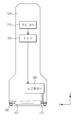
도 7은 또 다른 실시예에 따른 초음파 프로브의 외관을 나타낸 사시도이다.
도 8은 도 7의 초음파 프로브의 구성을 개념적으로 나타낸 도면이다.
도 9는 도 8의 초음파 프로브가 대상체에 접촉한 상태를 나타낸 도면이다.1 is a perspective view showing an appearance of an ultrasonic probe.
FIG. 2 is a view showing the ultrasonic probe of FIG. 1 and the adapter separated from each other.
FIG. 3 is a view showing a state where the ultrasonic probe of FIG. 2 and the adapter are combined.
4 is a perspective view showing an external appearance of an ultrasonic probe according to another embodiment.
FIG. 5 is a conceptual view showing the configuration of the ultrasonic probe of FIG. 4. FIG.
FIG. 6 is a view showing a state in which the ultrasonic probe of FIG. 5 is in contact with a target object.
7 is a perspective view showing an appearance of an ultrasonic probe according to another embodiment.
FIG. 8 is a conceptual view showing the configuration of the ultrasonic probe of FIG. 7. FIG.
FIG. 9 is a view showing a state in which the ultrasonic probe of FIG. 8 is in contact with a target object.
이하 구체적인 실시예들을 도면을 참조하여 상세하게 설명한다.Hereinafter, specific embodiments will be described in detail with reference to the drawings.
도 1은 초음파 프로브의 외관을 나타낸 사시도이고, 도 2는 도 1의 초음파 프로브와 어댑터가 분리된 모습을 나타낸 도면이고, 도 3은 도 2의 초음파 프로브와 어댑터가 결합된 모습을 나타낸 도면이다.
FIG. 1 is a perspective view showing an appearance of an ultrasonic probe, FIG. 2 is a view showing a state in which an ultrasonic probe and an adapter are separated from each other in FIG. 1, and FIG. 3 is a view showing an ultrasonic probe and an adapter in FIG.
도 1 내지 도 3을 참조하면, 초음파 프로브(100)는 초음파를 송수신하는 트랜스듀서(101), 초음파 프로브(100)의 움직임을 감지하는 모션센서(110), 초음파 프로브(100)의 전단에 결합되는 어댑터(200), 모션센서(110)로부터 출력되는 신호에 따라 상기 어댑터(200)와 대상체 사이 공간의 진공상태을 조절하는 제어부(120)를 포함한다.1 to 3, the
초음파 프로브(100)는 초음파를 송수신하는 트랜스듀서(101)를 포함한다.The
트랜스듀서(101)의 일 실시예로는, 초음파 프로브(100)에 주로 사용되던 자성체의 자왜효과를 이용하는 자왜 초음파 트랜스듀서(Magnetostrictive Ultrasonic Transducer)나, 압전 물질의 압전 효과를 이용한 압전 초음파 트랜스듀서(Piezoelectric Ultrasonic Transducer) 등이 이용될 수 있으며, 미세 가공된 수백 또는 수천 개의 박막의 진동을 이용하여 초음파를 송수신하는 정전용량형 미세가공 초음파 트랜스듀서(Capacitive Micromachined Ultrasonic Transducer, 이하 cMUT으로 약칭한다)도 사용될 수도 있다.As an embodiment of the
본 실시예에 따른 초음파 프로브(100)에서 트랜스듀서(101)에 의해 발생된 초음파가 조사되는 면(이하, 전면이라함)에는 어댑터(200)가 설치된다.The
어댑터(200)는 도 1에 도시된 것처럼, 그 중앙에 초음파 프로브(100)가 삽입될 수 있는 개구(210)를 가진 각진 튜브 형태를 갖는다.The
개구(210)는 초음파 프로브(100)의 전단의 xy평면과 평행한 단면과 동일한 크기를 갖도록 형성될 수 있다. 도 1 내지 도 3에서는 초음파 프로브(100) 전단의 단면이 사각형 모양이므로 개구(210) 또한 동일한 사각형 모양으로 형성된다. 즉, 개구(210)의 크기나 모양은 초음파 프로브(100) 전단의 단면의 크기나 모양을 반영한다.The opening 210 may be formed to have the same size as a cross section parallel to the xy plane of the front end of the
개구(210)의 내측면, 즉 초음파 프로브(100)가 개구(210)에 삽입될 때 초음파 프로브(100)와 접촉하는 개구(210)의 면에는 초음파 프로브(100)의 외면과 밀착할 수 있도록 실리콘 고무와 같은 재질의 재료로 형성된 제2배리어(240)가 부착될 수 있다.The surface of the
제2배리어(240)는 초음파 프로브(100)가 삽입된 후 초음파 프로브(100)의 동작 시 어댑터(200) 내부의 공간이 진공상태로 될 때 기밀성을 보장하는 역할을 한다. 즉, 제2배리어(240)는 초음파 프로브(100)와 어댑터(200) 개구(210) 사이의 틈을 통해 공기가 유입되어 진공상태가 해제되는 것을 방지한다.The
또한, 어댑터(200)가 대상체와 접촉하는 면에는 상기 제2배리어(240)와 같은 재질로 형성된 제1배리어(230)가 접촉면을 따라 형성될 수 있다.In addition, a
제1배리어(230)는 제2배리어(240)와 마찬가지로 초음파 프로브(100)가 삽입된 후 초음파 프로브(100)의 동작 시 어댑터(200) 내부의 공간이 진공상태로 될 때 기밀성을 보장하는 역할을 한다.Like the
어댑터(200) 내부가 진공상태가 되어 어댑터(200)가 대상체에 흡착될 때, 제1배리어(230)가 대상체에 밀착하여 어댑터(200)와 대상체 사이의 틈을 통해 공기가 유입되어 진공상태가 해제되는 것을 방지한다.When the
어댑터(200)에는 어댑터(200)가 대상체에 부착될 때 어댑터(200)와 대상체 사이의 공간을 진공상태로 만들기 위해 어댑터(200)와 대상체 사이의 공간에 존재하는 공기가 빠져나가는 홀(220)이 마련된다.The
홀(220)은 진공펌프와 같은 외부에 마련된 진공형성장치(300)와 호스 같은 관(310)을 통해 연결된다. The
도 3을 참조하면, 초음파 프로브(100)가 삽입된 상태에서 어댑터(200)가 대상체에 접촉하고, 진공형성장치(300)가 동작하면, 어댑터(200)와 대상체 사이의 공간에 존재하는 공기가 홀(220)을 통해 진공형성장치(300)로 유출되게 된다. 공기가 유출되면서 어댑터(200)는 대상체이 흡착되게 되고, 제1배리어(230)와 제2배리어(240)에 의해 어댑터(200)와 대상체 사이 공간의 기밀성이 유지되면서 어댑터(200)와 대상체 사이 공간은 진공상태가 된다. 도 3에 실선으로 도시한 화살표는 공기가 홀(220)을 통해 진공형성부(190)로 흡입되는 것을 표현한 것이다.3, when the
어댑터(200)와 대상체 사이 공간이 진공상태가 되어 공기가 없어지면, 초음파 프로브(100)에서 조사되는 초음파는 대상체를 향해 진행하고 대상체를 투과하게 된다. 도 3에 점선으로 도시한 화살표는 인체로 투과되는 초음파를 표현한 것이다.
When the space between the
물리적 특성 상 초음파는 공기 중에서 전파가 되지 않기 때문에 일반적으로 대상체에 젤을 바르고 초음파 검사를 진행하게 되는데, 본 실시예에 따른 어댑터(200)를 사용하여 초음파가 진행하는 어댑터(200)와 대상체 사이의 공간을 진공상태로 조성하게 되면 젤을 사용하지 않고도 초음파 검사를 진행할 수 있다Since the ultrasonic waves are not propagated in the air due to their physical characteristics, generally, the gel is applied to the object and the ultrasonic inspection is performed. By using the
초음파 프로브(100)는 초음파 프로브(100)의 움직임을 감지할 수 있는 모션센서(110)를 포함한다.The
모션센서(110)로는 자이로 센서나 가속도 센서가 사용될 수 있으나, 이에 한정되지 않고, 초음파 프로브(100)의 움직임을 감지할 수 있는 센서라면 본 실시예의 모션센서(110)에 포함된다.As the
초음파 프로브(100)의 전단에 전술한 어댑터(200)가 설치된 상태에서 어댑터(200)와 대상체 사이 공간이 진공상태가 되어 초음파 검사가 이루어지면, 어댑터(200)가 대상체에 흡착된 상태가 되므로, 초음파 프로브(100)를 이동시키면서 검사를 진행하려면 진공상태를 해제시켜야 한다.When the space between the
따라서 본 실시예에 따른 초음파 프로브(100)는 모션센서(110)에서 초음파 프로브(100)의 움직임이 감지되면, 어댑터(200)와 대상체 사이 공간의 진공상태를 해제시켜 초음파 프로브(100)의 이동을 가능하게 한다.Therefore, when the movement of the
모션센서(110)는 초음파 프로브(100)의 움직임을 감지하고 초음파 프로브(100)의 움직임과 관련된 신호를 생성하여 제어부(120)로 출력한다. 제어부(120)는 모션센서(110)로부터 출력된 신호를 수신하면, 수신된 신호를 미리 정해진 소정의 기준값과 비교하여 기준값을 초과하는지 판단한다. 기준값을 초과하면, 제어부(120)는 어댑터(200)와 대상체 사이 공간의 진공상태를 해제시키기 위한 신호를 출력한다.The
예를 들면, 제어부(120)는 어댑터(200)의 홀(220)에 연결된 진공형성장치(300)의 동작을 오프시키는 신호를 진공형성장치(300)로 출력함으로써 진공형성장치(300)의 구동을 정지시킬 수 있다. 또는, 진공형성장치(300)에 밸브가 마련된 경우, 밸브의 개폐를 조절하는 신호를 출력하여 어댑터(200)와 대상체 사이 공간의 진공상태가 해제되도록 할 수 있다. 즉, 제어부(120)는 진공상태를 유지하는 중에는 개방되어 있던 진공형성장치(300)의 밸브를 진공상태의 해제가 필요한 시점에 폐쇄시켜 홀(220)을 통한 공기의 흡입을 중단시킴으로써 진공상태를 해제시킬 수 있다. For example, the
또는, 어댑터(200)에 진공형성장치(300)와 연결되는 홀(220) 외에 별도의 홀(미도시)을 더 마련하고, 진공상태의 해제가 필요한 시점에서 상기 별도로 마련된 홀을 개방하여 공기가 어댑터(200)와 대상체의 사이 공간으로 유입되도록 함으로써 진공상태를 해제시킬 수 있다. 즉, 밸브로 개폐되는 별도의 홀을 어댑터(200)에 더 마련하고, 제어부(120)에서 밸브의 개폐를 조절함으로써, 진공상태를 해제시킬 수 있다.Alternatively, the
진공상태를 해제할 필요가 없는 초음파 프로브(100)의 작은 움직임에도 진공상태를 해제시키게 되면 오히려 초음파 검사를 방해하게 된다. Even if the
따라서, 모션센서(110)에서 감지한 움직임의 정도가 일정 수준을 초과하는 경우에만 제어부(120)에서 진공상태를 해제하는 신호가 출력되도록, 모션센서(110)에서 감지한 움직임과 관련된 신호를 미리 정해진 기준값과 비교하는 과정을 거칠 수 있다. 즉, 제어부(120)는 모션센서(110)에서 감지한 움직임과 관련된 신호가 미리 정해진 기준값을 초과하는 경우에만 진공상태를 해제시키기 위한 신호를 출력한다. Accordingly, only when the degree of motion sensed by the
상기 기준값은 초음파 프로브(100)의 움직임이 다른 영역을 검사하기 위한 움직임일 때 모션센서(110)에서 출력되는 신호값으로 미리 결정되어 저장될 수 있고, 반복되는 실험을 통해 최적화된 값으로 결정될 수 있다.The reference value may be previously determined and stored as a signal value output from the
초음파 프로브(100)에는 어댑터(200)와 대상체 사이 공간이 진공상태가 되도록 진공형성장치(300)의 동작을 유도하는 입력부(미도시)가 마련될 수 있다. 입력부는 버튼이나 스위치와 같은 공지된 다양한 형태로 마련될 수 있다.The
사용자는 초음파 프로브(100)를 대상체에 접촉시키고 상기 입력부를 조작하여 진공형성장치(300)를 동작시킨 후 초음파 검사를 진행할 수 있다. 제어부(120)가 진공형성장치(300)의 동작을 제어할 수도 있지만, 사용자가 수동으로 상기 입력부를 조작하여 진공형성장치(300)의 동작을 제어할 수도 있다. 그러나, 사용자가 초음파 검사에 집중할 수 있도록 모션센서(110)와 제어부(120)에 의해 진공형성장치(300)의 동작이 제어되는 것이 바람직하다.
The user can operate the
제어부(120)에서 출력되는 진공상태 해제신호에 의해 진공형성장치(300)의 동작이 오프되고, 사용자가 다른 위치에서 초음파 검사를 진행하고자 하면, 사용자가 초음파 프로브(100)에 마련된 입력부를 조작하여 진공형성장치(300)를 동작시킬 수 있다.The operation of the
또는, 모션센서(110)에서 감지하여 출력한 초음파 프로브(100)의 움직임과 관련된 신호가 전술한 기준값 이하로 감소하고 감소된 시간이 미리 정해진 소정의 시간을 초과하면 제어부(120)는 진공형성장치(300)를 동작을 시작시키기 위한 제어신호를 진공형성장치(300)로 출력할 수 있다. 제어부(120)와 진공형성장치(300) 간의 통신은 공지된 다양한 유무선 통신방식이 사용될 수 있으나, 검사의 편의를 위해 무선통신방식으로 제어부(120)와 진공형성장치(300) 간의 통신이 이루어지는 것이 바람직하다.
If the signal related to the movement of the
도 4는 다른 실시예에 따른 초음파 프로브(100)의 외관을 나타낸 사시도이고, 도 5는 도 4의 초음파 프로브(100)의 구성을 개념적으로 나타낸 도면이고, 도 6은 도 5의 초음파 프로브(100)가 대상체에 접촉한 상태를 나타낸 도면이다.
FIG. 4 is a perspective view showing an external appearance of the
도 4 내지 도 6을 참조하면, 초음파 프로브(100)는 초음파를 송수신하는 트랜스듀서(101), 초음파 프로브(100)의 움직임을 감지하는 모션센서(110), 모션센서(110)로부터 출력되는 신호에 따라 상기 초음파 프로브(100)와 대상체 사이 공간의 진공상태을 조절하는 제어부(120)를 포함한다.4 to 6, the
초음파 프로브(100)는 초음파를 송수신하는 트랜스듀서(101)를 포함한다.The
트랜스듀서(101)의 일 실시예로는, 초음파 프로브(100)에 주로 사용되던 자성체의 자왜효과를 이용하는 자왜 초음파 트랜스듀서(Magnetostrictive Ultrasonic Transducer)나, 압전 물질의 압전 효과를 이용한 압전 초음파 트랜스듀서(Piezoelectric Ultrasonic Transducer) 등이 이용될 수 있으며, 미세 가공된 수백 또는 수천 개의 박막의 진동을 이용하여 초음파를 송수신하는 정전용량형 미세가공 초음파 트랜스듀서(Capacitive Micromachined Ultrasonic Transducer, 이하 cMUT으로 약칭한다)도 사용될 수도 있다.As an embodiment of the
본 실시예에 따른 초음파 프로브(100)는 도 4에 도시된 것처럼 전면의 외곽을 따라 제3배리어(150)가 형성되고, 제3배리어(150)는 전술한 어댑터(200)의 제2배리어(240)와 같은 역할을 한다.4, a
즉, 제3배리어(150)는 전술한 어댑터(200)의 제2배리어(240)와 마찬가지로 초음파 프로브(100)가 대상체에 접촉된 후 초음파 프로브(100)의 전면과 대상체 사이 공간이 진공상태로 될 때 대상체의 표면에 밀착하여 기밀성을 보장하는 역할을 한다.That is, the
초음파 프로브(100)의 전면과 대상체 사이의 공간이 진공상태가 되어 초음파 프로브(100)가 대상체에 흡착될 때, 제3배리어(150)가 대상체에 밀착하여 초음파 프로브(100)의 전면과 대상체 사이의 틈을 통해 공기가 유입되는 것을 방지하고 이를 통해 진공상태가 해제되는 것을 방지한다.When the space between the front surface of the
또한, 초음파 프로브(100)의 전면에는 초음파 프로브(100)가 대상체에 접촉될 때 초음파 프로브(100)와 대상체 사이의 공간을 진공상태로 만들기 위해 초음파 프로브(100)와 대상체 사이의 공간에 존재하는 공기가 흡수되는 홀(170)이 마련된다.The front surface of the
본 실시예에 따른 초음파 프로브(100)의 내부에는 상기 홀(170)과 연결되어 공기를 흡수하는 진공펌프와 같은 진공형성부(190)가 마련될 수 있다.A
도 6을 참조하면, 초음파 프로브(100)가 대상체에 접촉하고, 진공형성부(190)가 동작하면, 초음파 프로브(100)의 전면과 대상체 사이의 공간에 존재하는 공기가 진공형성부(190)에 의해 홀(170)을 거쳐 초음파 프로브(100) 내부로 유입되게 된다. 진공형성부(190)에 의해 공기가 초음파 프로브(100)의 내부로 유입되면 초음파 프로브(100)의 전면은 대상체에 흡착하게 되고, 제3배리어(150)에 의해 초음파 프로브(100)의 전면과 대상체 사이 공간의 기밀성이 유지되면서 초음파 프로브(100)의 전면과 대상체 사이 공간은 진공상태가 된다. 본 실시예에 따른 초음파 프로브(100)에는 진공형성부(190)에서 흡입한 공기가 배출될 수 있는 벤트홀(미도시)이 형성될 수 있다. 도 6에 실선으로 도시한 화살표는 공기가 홀(170)을 통해 진공형성부(190)로 흡입되는 것을 표현한 것이다.6, when the
초음파 프로브(100)의 전면과 대상체 사이 공간이 진공상태가 되어 공기가 없어지면, 초음파 프로브(100)에서 조사되는 초음파는 대상체를 향해 진행하고 대상체를 투과하게 된다. 도 6에 점선으로 도시한 화살표는 인체로 투과되는 초음파를 표현한 것이다.When the space between the front surface of the
물리적 특성 상 초음파는 공기 중에서 전파가 되지 않기 때문에 일반적으로 대상체에 젤을 바르고 초음파 검사를 진행하게 되는데, 본 실시예에 따른 초음파 프로브(100)를 사용하여 초음파가 진행하는 어댑터(200)와 대상체 사이의 공간을 진공상태로 조성하게 되면 젤을 사용하지 않고도 초음파 검사를 진행할 수 있다.Since ultrasonic waves are not propagated in air due to their physical characteristics, generally, a gel is applied to a target object and an ultrasonic inspection is performed. The
초음파 프로브(100)는 초음파 프로브(100)의 움직임을 감지할 수 있는 모션센서(110)를 포함한다.The
모션센서(110)로는 자이로 센서나 가속도 센서가 사용될 수 있으나, 이에 한정되지 않고, 초음파 프로브(100)의 움직임을 감지할 수 있는 센서라면 본 실시예의 모션센서(110)에 포함된다.As the
초음파 프로브(100)의 전면과 대상체 사이 공간이 진공상태가 되어 초음파 검사가 이루어지면, 초음파 프로브(100)가 대상체에 흡착된 상태가 되므로, 초음파 프로브(100)를 이동시키면서 검사를 진행하려면 진공상태를 해제시켜야 한다.When the space between the front surface of the
따라서 본 실시예에 따른 초음파 프로브(100)는 모션센서(110)에서 초음파 프로브(100)의 움직임이 감지되면, 초음파 프로브(100)와 대상체 사이 공간의 진공상태를 해제시켜 초음파 프로브(100)의 이동을 가능하게 한다.Therefore, when the movement of the
모션센서(110)는 초음파 프로브(100)의 움직임을 감지하고 초음파 프로브(100)의 움직임과 관련된 신호를 생성하여 제어부(120)로 출력한다. 제어부(120)는 모션센서(110)로부터 출력된 신호를 수신하면, 수신된 신호를 미리 정해진 소정의 기준값과 비교하여 기준값을 초과하는지 판단한다. 기준값을 초과하면, 제어부(120)는 어댑터(200)와 대상체 사이 공간의 진공상태를 해제시키기 위한 신호를 출력한다.The
예를 들면, 제어부(120)는 홀(170)에 연결된 진공형성부(190)의 동작을 오프시키는 신호를 진공형성부(190)로 출력함으로써 진공형성부(190)의 구동을 정지시킬 수 있다. 또는, 진공형성부(190)에 밸브가 마련된 경우, 밸브의 개폐를 조절하는 신호를 출력하여 초음파 프로브(100)의 전면과 대상체 사이 공간의 진공상태가 해제되도록 할 수 있다. 즉, 제어부(120)는 진공상태를 유지하는 중에는 개방되어 있던 진공형성부(190)의 밸브를 진공상태의 해제가 필요한 시점에 폐쇄시켜 홀(170)을 통한 공기의 흡입을 중단시킴으로써 진공상태를 해제시킬 수 있다. For example, the
또는, 초음파 프로브(100)의 전면에 진공형성부(190)와 연결되는 홀(170) 외에 별도의 홀(미도시)을 더 마련하고, 진공상태의 해제가 필요한 시점에서 상기 별도로 마련된 홀을 개방하여 공기가 초음파 프로브(100)와 대상체의 사이 공간으로 유입되도록 함으로써 진공상태를 해제시킬 수 있다. 즉, 밸브로 개폐되는 별도의 홀을 초음파 프로브(100)의 전면에 더 마련하고, 제어부(120)에서 밸브의 개폐를 조절함으로써, 진공상태를 해제시킬 수도 있다.Alternatively, a separate hole (not shown) may be provided in addition to the
진공상태를 해제할 필요가 없는 초음파 프로브(100)의 작은 움직임에도 진공상태를 해제시키게 되면 오히려 초음파 검사를 방해하게 된다. Even if the
따라서, 모션센서(110)에서 감지한 움직임의 정도가 일정 수준을 초과하는 경우에만 제어부(120)에서 진공상태를 해제하는 신호가 출력되도록, 모션센서(110)에서 감지한 움직임과 관련된 신호를 미리 정해진 기준값과 비교하는 과정을 거칠 수 있다. 즉, 제어부(120)는 모션센서(110)에서 감지한 움직임과 관련된 신호가 미리 정해진 기준값을 초과하는 경우에만 진공상태를 해제시키기 위한 신호를 출력한다. Accordingly, only when the degree of motion sensed by the
상기 기준값은 초음파 프로브(100)의 움직임이 다른 영역을 검사하기 위한 움직임일 때 모션센서(110)에서 출력되는 신호값으로 미리 결정되어 저장될 수 있고, 반복되는 실험을 통해 최적화된 값으로 결정될 수 있다.The reference value may be previously determined and stored as a signal value output from the
초음파 프로브(100)에는 초음파 프로브(100)와 대상체 사이 공간이 진공상태가 되도록 진공형성부(190)의 동작을 유도하는 입력부(미도시)가 마련될 수 있다. 입력부는 버튼이나 스위치와 같은 공지된 다양한 형태로 마련될 수 있다.The
사용자는 초음파 프로브(100)를 대상체에 접촉시키고 상기 입력부를 조작하여 진공형성부(190)를 동작시킨 후 초음파 검사를 진행할 수 있다. 제어부(120)가 진공형성부(190)의 동작을 제어할 수도 있지만, 사용자가 수동으로 상기 입력부를 조작하여 진공형성부(190)의 동작을 제어할 수도 있다. 그러나, 사용자가 초음파 검사에 집중할 수 있도록 모션센서(110)와 제어부(120)에 의해 진공형성부(190)의 동작이 제어되는 것이 바람직하다.
The user can operate the
제어부(120)에서 출력되는 진공상태 해제신호에 의해 진공형성부(190)의 동작이 오프되고, 사용자가 다른 위치에서 초음파 검사를 진행하고자 하면, 사용자가 초음파 프로브(100)에 마련된 입력부를 조작하여 진공형성부(190)를 동작시킬 수 있다.The operation of the
또는, 모션센서(110)에서 감지하여 출력한 초음파 프로브(100)의 움직임과 관련된 신호가 전술한 기준값 이하로 감소하고 감소된 시간이 미리 정해진 소정의 시간을 초과하면 제어부(120)는 진공형성부(190)의 동작을 온시키기 위한 제어신호를 진공형성부(190)로 출력할 수도 있다.
If the signal related to the movement of the
도 7은 또 다른 실시예에 따른 초음파 프로브(100)의 외관을 나타낸 사시도이고, 도 8은 도 7의 초음파 프로브(100)의 구성을 개념적으로 나타낸 도면이고, 도 9는 도 8의 초음파 프로브(100)가 대상체에 접촉한 상태를 나타낸 도면이다.
FIG. 7 is a perspective view showing the appearance of an
도 7 내지 도 9를 참조하면, 초음파 프로브(100)는 초음파를 송수신하는 트랜스듀서(101), 초음파 프로브(100)의 움직임을 감지하는 모션센서(110), 모션센서(110)로부터 출력되는 신호에 따라 상기 초음파 프로브(100)와 대상체 사이 공간의 진공상태을 조절하는 제어부(120)를 포함한다.7 to 9, the
초음파 프로브(100)는 초음파를 송수신하는 트랜스듀서(101)를 포함한다.The
트랜스듀서(101)의 일 실시예로는, 초음파 프로브(100)에 주로 사용되던 자성체의 자왜효과를 이용하는 자왜 초음파 트랜스듀서(Magnetostrictive Ultrasonic Transducer)나, 압전 물질의 압전 효과를 이용한 압전 초음파 트랜스듀서(Piezoelectric Ultrasonic Transducer) 등이 이용될 수 있으며, 미세 가공된 수백 또는 수천 개의 박막의 진동을 이용하여 초음파를 송수신하는 정전용량형 미세가공 초음파 트랜스듀서(Capacitive Micromachined Ultrasonic Transducer, 이하 cMUT으로 약칭한다)도 사용될 수도 있다.As an embodiment of the
본 실시예에 따른 초음파 프로브(100)는 도 7에 도시된 것처럼 전면의 외곽을 따라 제3배리어(150)가 형성되고, 제3배리어(150)는 전술한 어댑터(200)의 제2배리어(240)와 같은 역할을 한다.7, a
즉, 제3배리어(150)는 전술한 어댑터(200)의 제2배리어(240)와 마찬가지로 초음파 프로브(100)가 대상체에 접촉된 후 초음파 프로브(100)의 전면과 대상체 사이 공간이 진공상태로 될 때 대상체의 표면에 밀착하여 기밀성을 보장하는 역할을 한다.That is, the
초음파 프로브(100)의 전면과 대상체 사이의 공간이 진공상태가 되어 초음파 프로브(100)가 대상체에 흡착될 때, 제3배리어(150)가 대상체에 밀착하여 초음파 프로브(100)의 전면과 대상체 사이의 틈을 통해 공기가 유입되는 것을 방지하고 이를 통해 진공상태가 해제되는 것을 방지한다.When the space between the front surface of the
또한, 초음파 프로브(100)의 전면에는 초음파 프로브(100)가 대상체에 접촉될 때 초음파 프로브(100)와 대상체 사이의 공간을 진공상태로 만들기 위해 초음파 프로브(100)와 대상체 사이의 공간에 존재하는 공기가 흡수되는 홀(170)이 마련된다.The front surface of the
본 실시예에 따른 초음파 프로브(100)는 도 4 내지 도 6에 도시된 실시예와 달리 홀(170)을 통해 공기를 흡수하는 진공펌프와 같은 진공형성장치(300)가 초음파 프로브(100)의 외부에 마련된다. 도 8을 참조하면, 초음파 프로브(100)의 전면에 형성된 홀(170)은 초음파 프로브(100)의 측면에 형성되는 타측홀(180)과 연결되고, 진공형성장치(300)는 상기 타측홀(180)에 호스와 같은 관(310)을 통해 연결된다.4 to 6, a
도 9를 참조하면, 초음파 프로브(100)가 대상체에 접촉하고, 진공형성장치(300)가 동작하면, 초음파 프로브(100)의 전면과 대상체 사이의 공간에 존재하는 공기가 초음파 프로브(100)의 전면에 형성된 홀(170)을 거쳐 타측홀(180)을 통해 진공형성장치(300)로 흡수된다.9, when the
진공형성장치(300)로 공기가 유입되면 초음파 프로브(100)의 전면은 대상체에 흡착하게 되고, 제3배리어(150)에 의해 초음파 프로브(100)의 전면과 대상체 사이 공간의 기밀성이 유지되면서 초음파 프로브(100)의 전면과 대상체 사이 공간은 진공상태가 된다. 도 9에 실선으로 도시한 화살표는 진공형성장치(300)에 의해 공기가 홀(170)로 유입되는 것을 표현한 것이다.When the air is introduced into the
초음파 프로브(100)의 전면과 대상체 사이 공간이 진공상태가 되어 공기가 없어지면, 초음파 프로브(100)에서 조사되는 초음파는 대상체를 향해 진행하고 대상체를 투과하게 된다. 도 9에 점선으로 도시한 화살표는 인체로 투과되는 초음파를 표현한 것이다.When the space between the front surface of the
물리적 특성 상 초음파는 공기 중에서 전파가 되지 않기 때문에 일반적으로 대상체에 젤을 바르고 초음파 검사를 진행하게 되는데, 본 실시예에 따른 초음파 프로브(100)를 사용하여 초음파가 진행하는 어댑터(200)와 대상체 사이의 공간을 진공상태로 조성하게 되면 젤을 사용하지 않고도 초음파 검사를 진행할 수 있다.Since ultrasonic waves are not propagated in air due to their physical characteristics, generally, a gel is applied to a target object and an ultrasonic inspection is performed. The
초음파 프로브(100)는 초음파 프로브(100)의 움직임을 감지할 수 있는 모션센서(110)를 포함한다.The
모션센서(110)로는 자이로 센서나 가속도 센서가 사용될 수 있으나, 이에 한정되지 않고, 초음파 프로브(100)의 움직임을 감지할 수 있는 센서라면 본 실시예의 모션센서(110)에 포함된다.As the
초음파 프로브(100)의 전면과 대상체 사이 공간이 진공상태가 되어 초음파 검사가 이루어지면, 초음파 프로브(100)가 대상체에 흡착된 상태가 되므로, 초음파 프로브(100)를 이동시키면서 검사를 진행하려면 진공상태를 해제시켜야 한다.When the space between the front surface of the
따라서 본 실시예에 따른 초음파 프로브(100)는 모션센서(110)에서 초음파 프로브(100)의 움직임이 감지되면, 초음파 프로브(100)와 대상체 사이 공간의 진공상태를 해제시켜 초음파 프로브(100)의 이동을 가능하게 한다.Therefore, when the movement of the
모션센서(110)는 초음파 프로브(100)의 움직임을 감지하고 초음파 프로브(100)의 움직임과 관련된 신호를 생성하여 제어부(120)로 출력한다. 제어부(120)는 모션센서(110)로부터 출력된 신호를 수신하면, 수신된 신호를 미리 정해진 소정의 기준값과 비교하여 기준값을 초과하는지 판단한다. 기준값을 초과하면, 제어부(120)는 어댑터(200)와 대상체 사이 공간의 진공상태를 해제시키기 위한 신호를 출력한다.The
예를 들면, 제어부(120)는 홀(170)에 연결된 진공형성장치(300)의 동작을 오프시키는 신호를 진공형성장치(300)로 출력함으로써 진공형성장치(300)의 구동을 정지시킬 수 있다. 또는, 진공형성장치(300)에 밸브가 마련된 경우, 밸브의 개폐를 조절하는 신호를 출력하여 초음파 프로브(100)의 전면과 대상체 사이 공간의 진공상태가 해제되도록 할 수 있다. 즉, 제어부(120)는 진공상태를 유지하는 중에는 개방되어 있던 진공형성장치(300)의 밸브를 진공상태의 해제가 필요한 시점에 폐쇄시켜 홀(170)을 통한 공기의 흡입을 중단시킴으로써 진공상태를 해제시킬 수 있다. For example, the
또는, 초음파 프로브(100)의 전면에 공기가 흡입되는 홀(170) 외에 별도의 홀(미도시)을 더 마련하고, 진공상태의 해제가 필요한 시점에서 상기 별도로 마련된 홀을 개방하여 공기가 초음파 프로브(100)와 대상체의 사이 공간으로 유입되도록 함으로써 진공상태를 해제시킬 수 있다. 즉, 밸브로 개폐되는 별도의 홀을 초음파 프로브(100)의 전면에 더 마련하고, 제어부(120)에서 밸브의 개폐를 조절함으로써, 진공상태를 해제시킬 수도 있다.Alternatively, a separate hole (not shown) may be provided in addition to a
진공상태를 해제할 필요가 없는 초음파 프로브(100)의 작은 움직임에도 진공상태를 해제시키게 되면 오히려 초음파 검사를 방해하게 된다. Even if the
따라서, 모션센서(110)에서 감지한 움직임의 정도가 일정 수준을 초과하는 경우에만 제어부(120)에서 진공상태를 해제하는 신호가 출력되도록, 모션센서(110)에서 감지한 움직임과 관련된 신호를 미리 정해진 기준값과 비교하는 과정을 거칠 수 있다. 즉, 제어부(120)는 모션센서(110)에서 감지한 움직임과 관련된 신호가 미리 정해진 기준값을 초과하는 경우에만 진공상태를 해제시키기 위한 신호를 출력한다. Accordingly, only when the degree of motion sensed by the
상기 기준값은 초음파 프로브(100)의 움직임이 다른 영역을 검사하기 위한 움직임일 때 모션센서(110)에서 출력되는 신호값으로 미리 결정되어 저장될 수 있고, 반복되는 실험을 통해 최적화된 값으로 결정될 수 있다.The reference value may be previously determined and stored as a signal value output from the
초음파 프로브(100)에는 초음파 프로브(100)와 대상체 사이 공간이 진공상태가 되도록 진공형성장치(300)의 동작을 유도하는 입력부(미도시)가 마련될 수 있다. 입력부는 버튼이나 스위치와 같은 공지된 다양한 형태로 마련될 수 있다.The
사용자는 초음파 프로브(100)를 대상체에 접촉시키고 상기 입력부를 조작하여 진공형성장치(300)를 동작시킨 후 초음파 검사를 진행할 수 있다. 제어부(120)가 진공형성장치(300)의 동작을 제어할 수도 있지만, 사용자가 수동으로 상기 입력부를 조작하여 진공형성장치(300)의 동작을 제어할 수도 있다. 그러나, 사용자가 초음파 검사에 집중할 수 있도록 모션센서(110)와 제어부(120)에 의해 진공형성장치(300)의 동작이 제어되는 것이 바람직하다.
The user can operate the
제어부(120)에서 출력되는 진공상태 해제신호에 의해 진공형성장치(300)의 동작이 오프되고, 사용자가 다른 위치에서 초음파 검사를 진행하고자 하면, 사용자가 초음파 프로브(100)에 마련된 입력부를 조작하여 진공형성장치(300)를 동작시킬 수 있다.The operation of the
또는, 모션센서(110)에서 감지하여 출력한 초음파 프로브(100)의 움직임과 관련된 신호가 전술한 기준값 이하로 감소하고 감소된 시간이 미리 정해진 소정의 시간을 초과하면 제어부(120)는 진공형성장치(300)의 동작을 온시키기 위한 제어신호를 진공형성장치(300)로 출력할 수도 있다.If the signal related to the movement of the
100: 초음파 프로브
101: 트랜스듀서
110: 모션센서
120: 제어부
150: 제3배리어
170: 홀
180: 타측홀
190: 진공형성부
200: 어댑터
210: 개구
220: 홀
230: 제1배리어
240: 제2배리어
300: 진공형성장치
310: 관100: Ultrasonic probe
101: Transducer
110: Motion sensor
120:
150: Third barrier
170: hole
180:
190: Vacuum forming part
200: Adapter
210: opening
220: hole
230: first barrier
240: second barrier
300: vacuum forming device
310: tube
Claims (12)
상기 초음파 프로브의 전단에 설치되고, 상기 초음파 프로브의 동작 시 상기 초음파 프로브로부터 조사되는 초음파가 진행할 수 있도록 그 내부 공간을 진공상태로 형성하는 어댑터; 및
상기 모션센서에서 상기 초음파 프로브의 움직임을 감지하면 상기 어댑터 내부의 진공상태를 해제시키기 위한 신호를 출력하는 제어부;를 포함하는 초음파 프로브.A motion sensor for detecting movement of the ultrasonic probe;
An adapter installed at a front end of the ultrasonic probe and forming an internal space of the ultrasonic probe in a vacuum state so that ultrasonic waves irradiated from the ultrasonic probe can proceed during operation of the ultrasonic probe; And
And a controller for outputting a signal for releasing a vacuum state inside the adapter when the motion sensor senses movement of the ultrasonic probe.
상기 어댑터는,
상기 초음파 프로브의 전단이 삽입되는 개구;
상기 어댑터 내부의 공기가 유출되는 홀; 및
대상체에 접촉 시 상기 대상체에 밀착하도록 상기 대상체와 접촉하는 면에 마련되어 진공상태로 형성된 상기 어댑터 내부공간을 기밀상태로 유지하는 제1배리어;를 포함하는 초음파 프로브.The method according to claim 1,
The adapter includes:
An opening into which the front end of the ultrasonic probe is inserted;
A hole through which the air inside the adapter flows out; And
And a first barrier provided on a surface of the adapter, which is in contact with the target object so as to be brought into contact with the target object, to keep the adapter internal space formed in a vacuum state in a hermetic state.
상기 홀은 상기 어댑터 내부의 공기를 흡입할 수 있는 외부의 진공형성장치와 연결되는 초음파 프로브.3. The method of claim 2,
Wherein the hole is connected to an external vacuum forming device capable of sucking air inside the adapter.
상기 개구의 내측면에는 진공상태로 형성된 상기 어댑터 내부공간을 기밀상태로 유지하도록 상기 초음파 프로브의 삽입 시 상기 초음파 프로브와 밀착되는 제2배리어가 마련되는 초음파 프로브.3. The method of claim 2,
And an inner surface of the opening is provided with a second barrier which is in close contact with the ultrasonic probe when the ultrasonic probe is inserted to keep the inner space of the adapter formed in a vacuum state in an airtight state.
상기 제어부는 상기 모션센서로부터 출력되는 상기 초음파 프로브의 움직임과 관련된 신호를 수신하고, 상기 수신한 신호가 미리 정해진 기준값을 초과하면 상기 어댑터의 홀과 연결된 진공형성장치의 구동을 오프시키는 신호를 출력하는 초음파 프로브.3. The method of claim 2,
The control unit receives a signal related to the motion of the ultrasonic probe output from the motion sensor and outputs a signal to turn off the driving of the vacuum forming apparatus connected to the hole of the adapter when the received signal exceeds a predetermined reference value Ultrasonic probe.
상기 초음파 프로브의 전면에 마련되어 상기 초음파 프로브와 대상체가 접촉하는 공간이 진공상태가 되도록 공기를 흡수하는 홀; 및
상기 모션센서에서 상기 초음파 프로브의 움직임을 감지하면 상기 진공상태를 해제시키기 위한 신호를 출력하는 제어부;를 포함하는 초음파 프로브.A motion sensor for detecting movement of the ultrasonic probe;
A hole provided on a front surface of the ultrasonic probe for absorbing air so that a space in which the ultrasonic probe and the object are in contact with each other is in a vacuum state; And
And a controller for outputting a signal for releasing the vacuum state when the movement of the ultrasonic probe is sensed by the motion sensor.
대상체에 접촉 시 상기 대상체에 밀착하도록 상기 대상체와 접촉하는 상기 초음파 프로브의 전면에 마련되어 진공상태로 형성된 상기 초음파 프로브와 대상체가 접촉하는 공간을 기밀상태로 유지하는 제3배리어;를 더 포함하는 초음파 프로브.The method according to claim 6,
And a third barrier disposed on a front surface of the ultrasonic probe that contacts the object so as to be in close contact with the object when the ultrasonic probe is in contact with the object and keeps a space in which the object is in contact with the ultrasonic probe formed in a vacuum state in a hermetic state. .
상기 제3배리어는 상기 초음파 프로브 전면의 외곽을 따라 형성되는 초음파 프로브.8. The method of claim 7,
And the third barrier is formed along an outer surface of the front surface of the ultrasonic probe.
상기 홀을 통해 외부의 공기를 흡수하는 진공형성부;를 더 포함하는 초음파 프로브. The method according to claim 6,
And a vacuum forming part for absorbing external air through the hole.
상기 진공형성부는 진공펌프를 포함하고, 상기 진공형성부는 상기 초음파 프로브 내부에 마련되는 초음파 프로브.10. The method of claim 9,
Wherein the vacuum forming part includes a vacuum pump, and the vacuum forming part is provided inside the ultrasonic probe.
상기 홀은 상기 초음파 프로브의 일측면에 마련된 타측홀과 연결되고,
상기 타측홀은 공기를 흡입할 수 있는 외부의 진공형성장치와 연결되는 초음파 프로브. The method according to claim 6,
The hole is connected to the other hole provided on one side of the ultrasonic probe,
And the other hole is connected to an external vacuum forming device capable of sucking air.
상기 제어부는 상기 모션센서로부터 출력되는 상기 초음파 프로브의 움직임과 관련된 신호를 수신하고, 상기 수신한 신호가 미리 정해진 기준값을 초과하면 상기 진공형성부 또는 진공형성장치의 구동을 오프시키는 신호를 출력하는 초음파 프로브.The method according to claim 9 or 11,
Wherein the control unit receives a signal related to the movement of the ultrasonic probe output from the motion sensor and outputs a signal for turning off the driving of the vacuum forming unit or the vacuum forming apparatus when the received signal exceeds a predetermined reference value Probes.
Priority Applications (2)
| Application Number | Priority Date | Filing Date | Title |
|---|---|---|---|
| KR20130052604A KR20140133672A (en) | 2013-05-09 | 2013-05-09 | Ultrasound Probe |
| PCT/KR2014/004068 WO2014182075A1 (en) | 2013-05-09 | 2014-05-08 | Ultrasonic probe |
Applications Claiming Priority (1)
| Application Number | Priority Date | Filing Date | Title |
|---|---|---|---|
| KR20130052604A KR20140133672A (en) | 2013-05-09 | 2013-05-09 | Ultrasound Probe |
Publications (1)
| Publication Number | Publication Date |
|---|---|
| KR20140133672A true KR20140133672A (en) | 2014-11-20 |
Family
ID=51867484
Family Applications (1)
| Application Number | Title | Priority Date | Filing Date |
|---|---|---|---|
| KR20130052604A KR20140133672A (en) | 2013-05-09 | 2013-05-09 | Ultrasound Probe |
Country Status (2)
| Country | Link |
|---|---|
| KR (1) | KR20140133672A (en) |
| WO (1) | WO2014182075A1 (en) |
Cited By (1)
| Publication number | Priority date | Publication date | Assignee | Title |
|---|---|---|---|---|
| KR20200000754A (en) * | 2018-06-25 | 2020-01-03 | 주식회사 미듬 | High intensity focused ultrasound generating device |
Families Citing this family (3)
| Publication number | Priority date | Publication date | Assignee | Title |
|---|---|---|---|---|
| GB2544559A (en) * | 2015-11-23 | 2017-05-24 | Owen Mumford Ltd | Apparatus for medicament delivery |
| EP3643242A1 (en) | 2018-10-25 | 2020-04-29 | Koninklijke Philips N.V. | Support unit for a medical imaging element |
| CN113303826B (en) * | 2021-06-02 | 2023-07-07 | 无锡医百加科技有限公司 | Intelligent ultrasonic system |
Family Cites Families (5)
| Publication number | Priority date | Publication date | Assignee | Title |
|---|---|---|---|---|
| US8116845B2 (en) * | 2005-08-04 | 2012-02-14 | Dune Medical Devices Ltd. | Tissue-characterization probe with effective sensor-to-tissue contact |
| JP2008073391A (en) * | 2006-09-25 | 2008-04-03 | Citizen Holdings Co Ltd | Ultrasonic diagnostic apparatus |
| KR101478618B1 (en) * | 2008-01-15 | 2015-01-02 | 삼성메디슨 주식회사 | Ultrasound probe for switching of power supplying |
| KR20110057740A (en) * | 2009-11-25 | 2011-06-01 | 삼성메디슨 주식회사 | Ultrasound system and method for providing motion guide information |
| US9149658B2 (en) * | 2010-08-02 | 2015-10-06 | Guided Therapy Systems, Llc | Systems and methods for ultrasound treatment |
-
2013
- 2013-05-09 KR KR20130052604A patent/KR20140133672A/en not_active Application Discontinuation
-
2014
- 2014-05-08 WO PCT/KR2014/004068 patent/WO2014182075A1/en active Application Filing
Cited By (1)
| Publication number | Priority date | Publication date | Assignee | Title |
|---|---|---|---|---|
| KR20200000754A (en) * | 2018-06-25 | 2020-01-03 | 주식회사 미듬 | High intensity focused ultrasound generating device |
Also Published As
| Publication number | Publication date |
|---|---|
| WO2014182075A1 (en) | 2014-11-13 |
Similar Documents
| Publication | Publication Date | Title |
|---|---|---|
| US8372009B2 (en) | System and method for treating a therapeutic site | |
| EP2298175B1 (en) | Three-dimensional probe apparatus | |
| JP5608008B2 (en) | Probe for ultrasonic diagnostic apparatus and control method thereof | |
| US11583252B2 (en) | Miniature transducer device and related methods | |
| KR20140133672A (en) | Ultrasound Probe | |
| EP2862519A1 (en) | Dental ultrasonic diagnostic apparatus | |
| JP6452110B2 (en) | Hand-held probe | |
| JP2019093140A (en) | Optical ultrasonic diagnostic apparatus, medical image processing apparatus, medical image processing program, and ultrasonic diagnostic apparatus | |
| JP7410955B2 (en) | How to scan materials using an ultrasound imaging probe | |
| JP2021035442A (en) | Ultrasonic diagnostic system and operation method for ultrasonic diagnostic system | |
| JP4526298B2 (en) | Ultrasound endoscope device | |
| JP2013220185A (en) | Apparatus for acquiring information on subject | |
| EP2870917B1 (en) | Support apparatus of ultrasound probe, handsfree ultrasound probe including the support apparatus, and method of operating the support apparatus | |
| Gumprecht et al. | A new ultrasound imaging concept for laparoscopy in urology | |
| JP2007044074A (en) | Ultrasonic diagnostic device | |
| US11259775B2 (en) | Ultrasonic wave transmission and reception device | |
| JPH02295553A (en) | Impulse wave treating device | |
| KR101196209B1 (en) | Adhere type ultrasonic diagnosis apparatus | |
| KR20120115771A (en) | Probe of ultrasonic diagnostic apparatus | |
| KR101313560B1 (en) | Ultrasonic diagnosis apparatus | |
| KR101277770B1 (en) | Contrl method for 3d probe apparatus | |
| JPS6359698B2 (en) | ||
| KR101133464B1 (en) | Ultrasonic diagnosis apparatus | |
| JPH0345249A (en) | Ultrasonic diagnosing device | |
| JP2697331B2 (en) | Guide device for ultrasonic probe |
Legal Events
| Date | Code | Title | Description |
|---|---|---|---|
| WITN | Application deemed withdrawn, e.g. because no request for examination was filed or no examination fee was paid |