KR20140066258A - Video display modification based on sensor input for a see-through near-to-eye display - Google Patents
Video display modification based on sensor input for a see-through near-to-eye display Download PDFInfo
- Publication number
- KR20140066258A KR20140066258A KR1020147011240A KR20147011240A KR20140066258A KR 20140066258 A KR20140066258 A KR 20140066258A KR 1020147011240 A KR1020147011240 A KR 1020147011240A KR 20147011240 A KR20147011240 A KR 20147011240A KR 20140066258 A KR20140066258 A KR 20140066258A
- Authority
- KR
- South Korea
- Prior art keywords
- light
- display
- image
- light source
- sensor
- Prior art date
Links
Images


Classifications
-
- G—PHYSICS
- G02—OPTICS
- G02B—OPTICAL ELEMENTS, SYSTEMS OR APPARATUS
- G02B27/00—Optical systems or apparatus not provided for by any of the groups G02B1/00 - G02B26/00, G02B30/00
- G02B27/01—Head-up displays
- G02B27/017—Head mounted
- G02B27/0172—Head mounted characterised by optical features
-
- G—PHYSICS
- G02—OPTICS
- G02B—OPTICAL ELEMENTS, SYSTEMS OR APPARATUS
- G02B27/00—Optical systems or apparatus not provided for by any of the groups G02B1/00 - G02B26/00, G02B30/00
- G02B27/0093—Optical systems or apparatus not provided for by any of the groups G02B1/00 - G02B26/00, G02B30/00 with means for monitoring data relating to the user, e.g. head-tracking, eye-tracking
-
- G—PHYSICS
- G02—OPTICS
- G02B—OPTICAL ELEMENTS, SYSTEMS OR APPARATUS
- G02B27/00—Optical systems or apparatus not provided for by any of the groups G02B1/00 - G02B26/00, G02B30/00
- G02B27/01—Head-up displays
- G02B27/017—Head mounted
-
- G—PHYSICS
- G02—OPTICS
- G02B—OPTICAL ELEMENTS, SYSTEMS OR APPARATUS
- G02B27/00—Optical systems or apparatus not provided for by any of the groups G02B1/00 - G02B26/00, G02B30/00
- G02B27/01—Head-up displays
- G02B27/017—Head mounted
- G02B27/0176—Head mounted characterised by mechanical features
-
- G—PHYSICS
- G06—COMPUTING; CALCULATING OR COUNTING
- G06F—ELECTRIC DIGITAL DATA PROCESSING
- G06F1/00—Details not covered by groups G06F3/00 - G06F13/00 and G06F21/00
- G06F1/16—Constructional details or arrangements
- G06F1/1613—Constructional details or arrangements for portable computers
- G06F1/163—Wearable computers, e.g. on a belt
-
- G—PHYSICS
- G06—COMPUTING; CALCULATING OR COUNTING
- G06F—ELECTRIC DIGITAL DATA PROCESSING
- G06F3/00—Input arrangements for transferring data to be processed into a form capable of being handled by the computer; Output arrangements for transferring data from processing unit to output unit, e.g. interface arrangements
- G06F3/01—Input arrangements or combined input and output arrangements for interaction between user and computer
- G06F3/011—Arrangements for interaction with the human body, e.g. for user immersion in virtual reality
-
- G—PHYSICS
- G06—COMPUTING; CALCULATING OR COUNTING
- G06F—ELECTRIC DIGITAL DATA PROCESSING
- G06F3/00—Input arrangements for transferring data to be processed into a form capable of being handled by the computer; Output arrangements for transferring data from processing unit to output unit, e.g. interface arrangements
- G06F3/16—Sound input; Sound output
- G06F3/167—Audio in a user interface, e.g. using voice commands for navigating, audio feedback
-
- G—PHYSICS
- G02—OPTICS
- G02B—OPTICAL ELEMENTS, SYSTEMS OR APPARATUS
- G02B27/00—Optical systems or apparatus not provided for by any of the groups G02B1/00 - G02B26/00, G02B30/00
- G02B27/01—Head-up displays
- G02B27/0101—Head-up displays characterised by optical features
- G02B2027/0112—Head-up displays characterised by optical features comprising device for genereting colour display
-
- G—PHYSICS
- G02—OPTICS
- G02B—OPTICAL ELEMENTS, SYSTEMS OR APPARATUS
- G02B27/00—Optical systems or apparatus not provided for by any of the groups G02B1/00 - G02B26/00, G02B30/00
- G02B27/01—Head-up displays
- G02B27/0101—Head-up displays characterised by optical features
- G02B2027/0118—Head-up displays characterised by optical features comprising devices for improving the contrast of the display / brillance control visibility
Landscapes
- Engineering & Computer Science (AREA)
- Physics & Mathematics (AREA)
- General Physics & Mathematics (AREA)
- Theoretical Computer Science (AREA)
- General Engineering & Computer Science (AREA)
- Optics & Photonics (AREA)
- Human Computer Interaction (AREA)
- Computer Hardware Design (AREA)
- General Health & Medical Sciences (AREA)
- Audiology, Speech & Language Pathology (AREA)
- Health & Medical Sciences (AREA)
- Multimedia (AREA)
- User Interface Of Digital Computer (AREA)
Abstract
본 개시 내용은 손목 착용 NFC(near field communication) 지원 전자 장치를 포함하는 NFC 장치에 관한 것이며, 손목 착용 NFC 지원 전자 장치는 NFC 프로토콜을 통해 제2 NFC 지원 전자 장치와 통신하는 제1 통신 링크, 및 중간 거리(medium-range) 통신 프로토콜을 통해 접안경과 통신하고 제어 명령을 수신하는 제2 통신 링크를 포함한다. 손목 착용 NFC 지원 전자 장치는 접안경과 제2 NFC 지원 전자 장치 사이의 데이터의 전송을 용이하게 해준다. 접안경은 데이터가 디스플레이되는 투시 디스플레이를 가능하게 해주는 광학계를 포함한다.The present disclosure relates to an NFC device including a near field communication (NFC) enabled electronic device, wherein the wrist wearing NFC enabled electronic device includes a first communication link for communicating with a second NFC enabled electronic device via an NFC protocol, And a second communication link that communicates with the eyepiece via a medium-range communication protocol and receives a control command. The wrist-worn NFC-enabled electronic device facilitates the transfer of data between the eyepiece and the second NFC-enabled electronic device. The eyepiece includes an optical system that enables a perspective display in which data is displayed.
Description
관련 출원의 상호 참조Cross reference of related application
본 출원은 이하의 미국 가특허 출원들(이들 각각은 참조 문헌으로서 그 전체 내용이 본 명세서에 포함됨)에 기초하여 우선권을 주장한다:This application claims priority based on the following US patent applications, each of which is incorporated herein by reference in its entirety:
2011년 9월 26일자로 출원된 미국 가특허 출원 제61/539,269호.U. S. Patent Application No. 61 / 539,269, filed September 26,
본 출원은 이하의 미국 정규 특허 출원들(이들 각각은 참조 문헌으로서 그 전체 내용이 본 명세서에 포함됨)의 일부 계속 출원(continuation-in-part)이다:This application is a continuation-in-part of the following US patent applications, each of which is incorporated herein by reference in its entirety:
이하의 가출원들(이들 각각은 참조 문헌으로서 그 전체 내용이 본 명세서에 포함됨)의 이익을 주장하는 2012년 8월 21일자로 출원된 미국 정규 출원 제13/591,187호: 2012년 8월 3일자로 출원된 미국 가특허 출원 제61/679,522호; 2012년 8월 3일자로 출원된 미국 가특허 출원 제61/679,558호; 2012년 8월 3일자로 출원된 미국 가특허 출원 제61/679,542호; 2012년 8월 3일자로 출원된 미국 가특허 출원 제61/679,578호; 2012년 8월 3일자로 출원된 미국 가특허 출원 제61/679,601호; 2012년 8월 3일자로 출원된 미국 가특허 출원 제61/679,541호; 2012년 8월 3일자로 출원된 미국 가특허 출원 제61/679,548호; 2012년 8월 3일자로 출원된 미국 가특허 출원 제61/679,550호; 2012년 8월 3일자로 출원된 미국 가특허 출원 제61/679,557호; 및 2012년 8월 3일자로 출원된 미국 가특허 출원 제61/679,566호; 2012년 5월 8일자로 출원된 미국 가특허 출원 제61/644,078호; 2012년 7월 11일자로 출원된 미국 가특허 출원 제61/670,457호; 및 2012년 7월 23일자로 출원된 미국 가특허 출원 제61/674,689호.U.S. Provisional Application No. 13 / 591,187, filed on August 21, 2012, which claims the benefit of the following provisional applications (each of which is incorporated herein by reference in its entirety): As of August 3, 2012 Filed U.S. Provisional Patent Application No. 61 / 679,522; U.S. Provisional Patent Application No. 61 / 679,558, filed August 3, 2012; U.S. Provisional Patent Application No. 61 / 679,542, filed August 3, 2012; U.S. Provisional Patent Application No. 61 / 679,578, filed August 3, 2012; U.S. Provisional Patent Application No. 61 / 679,601, filed August 3, 2012; U.S. Provisional Patent Application No. 61 / 679,541, filed August 3, 2012; U.S. Provisional Patent Application No. 61 / 679,548, filed August 3, 2012; U. S. Patent Application No. 61 / 679,550, filed August 3, 2012; U.S. Provisional Patent Application No. 61 / 679,557, filed August 3, 2012; And U.S. Provisional Patent Application No. 61 / 679,566, filed August 3, 2012; U.S. Provisional Patent Application No. 61 / 644,078, filed May 8, 2012; U.S. Provisional Patent Application No. 61 / 670,457, filed July 11, 2012; And U.S. Provisional Patent Application No. 61 / 674,689, filed July 23,
이하의 가출원들(이들 각각은 참조 문헌으로서 그 전체 내용이 본 명세서에 포함됨)의 이익을 주장하는 2012년 4월 6일자로 출원된 미국 정규 출원 제13/441,145호: 2012년 2월 14일자로 출원된 미국 가특허 출원 제61/598,885호; 2012년 2월 14일자로 출원된 미국 가특허 출원 제61/598,889호; 2012년 2월 14일자로 출원된 미국 가특허 출원 제61/598,896호; 및 2012년 2월 29일자로 출원된 미국 가특허 출원 제61/604,917호.U.S. Application Serial No. 13 / 441,145, filed April 6, 2012, which claims the benefit of the following provisional application (each of which is incorporated herein by reference in its entirety): As of February 14, 2012 Filed U.S. Provisional Patent Application No. 61 / 598,885; U.S. Provisional Patent Application No. 61 / 598,889, filed February 14, 2012; U.S. Provisional Patent Application No. 61 / 598,896, filed February 14, 2012; And U. S. Patent Application No. 61 / 604,917, filed February 29,
이하의 가출원들(이들 각각은 참조 문헌으로서 그 전체 내용이 본 명세서에 포함됨)의 이익을 주장하는 2012년 3월 25일자로 출원된 미국 정규 출원 제13/429,413호: 2012년 1월 6일자로 출원된 미국 가특허 출원 제61/584,029호.U.S. Application Serial No. 13 / 429,413, filed March 25, 2012, which claims the benefit of the following provisional application (each of which is incorporated herein by reference in its entirety): As of January 6, 2012 Filed U.S. Provisional Patent Application No. 61 / 584,029.
이하의 가출원들(이들 각각은 참조 문헌으로서 그 전체 내용이 본 명세서에 포함됨)의 이익을 주장하는 2011년 12월 30일자로 출원된 미국 정규 출원 제13/341,758호: 2011년 11월 8일자로 출원된 미국 가특허 출원 제61/557,289호.U.S. Application Serial No. 13 / 341,758, filed December 30, 2011, which claims the benefit of the following provisional application (each of which is incorporated herein by reference): As of November 8, 2011 Filed U.S. Provisional Patent Application No. 61 / 557,289.
이하의 가출원들(이들 각각은 참조 문헌으로서 그 전체 내용이 본 명세서에 포함됨)의 이익을 주장하는 2011년 9월 14일자로 출원된 미국 정규 출원 제13/232,930호: 2010년 9월 14일자로 출원된 미국 가특허 출원 제61/382,578호; 2011년 4월 6일자로 출원된 미국 가특허 출원 제61/472,491호; 2011년 5월 6일자로 출원된 미국 가특허 출원 제61/483,400호; 2011년 5월 18일자로 출원된 미국 가특허 출원 제61/487,371호; 및 2011년 7월 5일자로 출원된 미국 가특허 출원 제61/504,513호.U.S. Application Serial No. 13 / 232,930, filed September 14, 2011, which claims the benefit of the following provisional application (each of which is incorporated herein by reference): as of September 14, 2010 Filed U.S. Provisional Patent Application No. 61 / 382,578; U. S. Patent Application No. 61 / 472,491, filed April 6, 2011; U. S. Patent Application No. 61 / 483,400, filed May 6, 2011; U. S. Patent Application No. 61 / 487,371, filed May 18, 2011; And U. S. Patent Application No. 61 / 504,513, filed July 5,
각각이, 이하의 가출원들(이들 각각은 참조 문헌으로서 그 전체 내용이 본 명세서에 포함됨)의 이익을 주장하는 2011년 2월 28일자로 출원된 미국 정규 특허 출원 제13/037,324호 및 2011년 2월 28일자로 출원된 미국 정규 특허 출원 제13/037,335호: 2010년 2월 28일자로 출원된 미국 가특허 출원 제61/308,973호; 2010년 8월 13일자로 출원된 미국 가특허 출원 제61/373,791호; 2010년 9월 14일자로 출원된 미국 가특허 출원 제61/382,578호; 2010년 11월 8일자로 출원된 미국 가특허 출원 제61/410,983호; 2011년 1월 3일자로 출원된 미국 가특허 출원 제61/429,445호; 및 2011년 1월 3일자로 출원된 미국 가특허 출원 제61/429,447호.Each of which is incorporated herein by reference in its entirety for all purposes to the benefit of U.S. Provisional Patent Application No. 13 / 037,324, filed February 28, 2011, the benefit of which is hereby incorporated by reference in its entirety, U.S. Provisional Patent Application No. 13 / 037,335, filed on February 28, U.S. Provisional Patent Application No. 61 / 308,973, filed February 28, 2010; U. S. Patent Application No. 61 / 373,791, filed August 13, 2010; U. S. Patent Application No. 61 / 382,578, filed September 14, 2010; U. S. Patent Application No. 61 / 410,983, filed November 8, 2010; U.S. Provisional Patent Application No. 61 / 429,445, filed January 3, 2011; And U. S. Patent Application No. 61 / 429,447, filed January 3,
분야:Field:
본 개시 내용은 증강 현실 접안경(augmented reality eyepiece), 관련 제어 기술, 및 사용을 위한 적용에 관한 것으로서, 보다 구체적으로는 접안경(eyepiece) 상에서 실행되는 소프트웨어 응용 프로그램에 관한 것이다.The present disclosure relates to an augmented reality eyepiece, associated control techniques, and applications for use, and more particularly to a software application program running on an eyepiece.
본 개시 내용은 도파관으로부터 영상을 제공하기 위해 시퀀스 패턴(sequenced pattern)으로 전환가능 거울(switchable mirror)을 사용하는 박형 디스플레이(thin display) 기술에 관한 것이다.The present disclosure relates to thin display technology that uses a switchable mirror in a sequenced pattern to provide images from a waveguide.
반사 표면(reflecting surface)을 갖는 두부 탑재형 디스플레이(head mounted display)가 업계에 공지되어 있다. 각진 단일의 부분 반사 빔 분할기 플레이트(angled single partial reflecting beam splitter plate)를 갖는 두부 탑재형 디스플레이가 미국 특허 제4969714호에 기술되어 있다. 이 방식이 디스플레이 시야(display field of view)에 걸쳐 우수한 밝기 및 색상 균일성을 제공하지만, 각진 빔 분할기 플레이트로 인해 광학 시스템이 비교적 두껍다.BACKGROUND OF THE INVENTION [0002] Head mounted displays having reflecting surfaces are known in the art. A head mounted display having an angled single partial reflecting beam splitter plate is described in U.S. Patent No. 4969714. [ While this approach provides excellent brightness and color uniformity over the display field of view, the optical system is relatively thick due to the angled beam splitter plate.
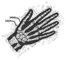
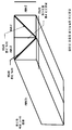
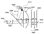
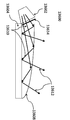
보다 얇은 광학 시스템을 제공하기 위해 부분 반사 표면들의 어레이를 갖는 두부 탑재형 디스플레이가 미국 특허 제6829095호 및 제7724441호에 기술되어 있고, 도 124에 도시되어 있으며, 부분 반사 표면들(12408)의 어레이는 디스플레이 시야에 걸쳐 영상 광(image light)(12404)을 제공하여, 사용자가 사용자의 전방에 있는 환경의 뷰(view)와 결합되는 디스플레이된 영상을 볼 수 있게 해주기 위해 사용된다. 사용자가 보는 영상 광(12404)은 다수의 부분 반사 표면들(12408) 각각으로부터 반사된 광의 결합으로 이루어져 있다. 영상 광원(image source)으로부터의 광(12402)은 다수의 부분 반사 표면들(12408) - 여기에서 광(12402)의 일부분이 영상 광(12404)을 제공하기 위해 사용자의 눈 쪽으로 반사됨 - 을 통과해야만 한다. 디스플레이 시야에 걸쳐 균일한 영상을 제공하기 위해, 부분 반사 표면들(12408)의 반사 특성이 정밀하게 제어되어야만 한다. 부분 반사 표면들(12408)의 반사율(reflectivity)은 영상 광원에 가장 가까이 있는 표면들에 대해 가장 낮아야만 하고 영상 광원으로부터 가장 멀리 있는 표면들에 대해 가장 높아야 한다. 일반적으로 부분 반사 표면들(12408)의 반사율은 영상 광원으로부터의 거리에 대해 선형적으로 증가해야만 한다. 이것은 제조 및 비용 문제를 야기하는데, 그 이유는 각각의 부분 반사 표면(12408)의 반사율이 이웃하는 표면들과 상이하고 각각의 표면의 반사율이 엄격하게 제어되어야만 하기 때문이다. 그에 따라, 부분 반사 표면들의 어레이를 사용하여 디스플레이 시야 전체에 걸쳐 균일한 밝기 및 색상을 가지는 영상을 제공하는 것이 어렵다.A head mounted display having an array of partial reflective surfaces to provide a thinner optical system is described in US Patent Nos. 6829095 and 7724441, shown in Fig. 124, and an array of partial reflective surfaces 12408 Is used to provide an
다른 대안으로서, 미국 특허 제4711512호에 기술되어 있는 바와 같이, 도파관으로 들어가는 및 도파관으로부터 나오는 영상 광(image light into and out of a waveguide)을 디스플레이 시야 쪽으로 방향 전환시키기 위해 회절 격자(diffractive grating)가 사용된다. 그렇지만, 회절 격자는 고가이고 색 수차(color aberration)를 겪는다.As another alternative, a diffractive grating may be used to direct the image light into and out of a waveguide toward the display field, as described in U.S. Patent No. 4,711,512. Is used. However, the diffraction grating is expensive and undergoes color aberration.
따라서, 디스플레이 시야에 걸쳐 양호한 영상 밝기 및 색상 균일성을 또한 제공하는 두부 탑재형 디스플레이에 대한 비교적 얇은 광학 시스템이 필요하다.Thus, there is a need for a relatively thin optical system for a head mounted display that also provides good image brightness and color uniformity across the display field of view.
본 개시 내용은 또한 조명 광(illumination light)을 아래로 반사 영상 광원(reflective image source) 쪽으로 편향시키기 위해 와이어 그리드 편광 필름(wire grid polarizer film)을 부분 반사 표면으로서 포함하는 소형 경량의 전방 조명(frontlight)에 관한 것이다.The present disclosure also relates to a lightweight frontlight that includes a wire grid polarizer film as a partial reflective surface to deflect illumination light down toward a reflective image source. ).
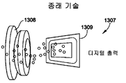
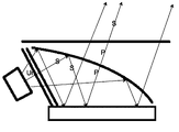
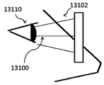
도 133에 도시된 바와 같은 반사 영상 광원 및 전방 조명을 갖는 디스플레이에서, 조명 광(13308)은 에지 광원(edge light source)(13300)으로부터 나가서, 전방 조명(13304)에 의해 편향되어 반사 영상 광원(13302)을 조명한다. 조명 광(13308)은 이어서 반사 영상 광원(13302)으로부터 반사되어 영상 광(13310)으로 되고, 이 영상 광(13310)은 이어서 다시 전방 조명(13304)을 통과하여 디스플레이 광학계(display optics)로 들어간다. 그에 따라, 전방 조명(13304)은 이와 동시에 에지 광원(13300)으로부터 들어오는 조명 광(13308)을 편향시키고, 반사된 영상 광(13310)이 디스플레이 광학계로 들어갈 수 있도록 편향됨이 없이 통과할 수 있게 해주며, 여기서 디스플레이 광학계는 디스플레이가 평판 스크린 디스플레이(flat screen display)일 때 분산성(dispersive)일 수 있거나 디스플레이가 근안 디스플레이(near eye display)일 때 굴절성(refractive) 또는 회절성(diffractive)일 수 있다. 이 실시예에서, 디스플레이 광학계는 확산기(diffuser)를 포함할 수 있다.133, the
LCOS(liquid crystal on silicon) 영상 광원 등의 반사 영상 광원의 경우, 조명 광이 편광되고, 반사 영상 광원은 반사 영상 광원으로부터의 반사 동안 편광 상태를 변경하는 1/4파 지연 필름(quarter wave retardation film)을 포함한다. 영상 광이 디스플레이 광학계를 통과할 때 액정에 의해 주어지는 편광 효과가 영상을 형성하게 하는 편광기가 이어서 디스플레이 광학계에 포함되어 있다.For a reflected image light source such as a liquid crystal on silicon (LCOS) image light source, the illumination light is polarized and the reflected image light source is a quarter wave retardation film that changes the polarization state during reflection from the reflected image light source. ). A polarizer is then included in the display optics to allow the polarization effect imparted by the liquid crystal to form an image as the image light passes through the display optics.
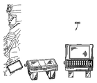
미국 특허 제7163330호는 에지 광원으로부터의 광을 아래로 반사 영상 광원 쪽으로 편향시키기 위한 전방 조명의 상부 표면에 있는 그루브(groove)를, 반사된 영상 광이 디스플레이 광학계 내로 들어갈 수 있게 해주기 위한 그루브들 사이의 평탄한 섹션과 함께, 포함하는 일련의 전방 조명을 기술하고 있다. 도 134는 그루브(13410) 및 평탄한 섹션(13408)을 갖는 전방 조명(13400)의 예시를 나타낸 것이다. 에지 광원(13300)으로부터의 조명 광(13402)은 그루브(13410)로부터 반사되고, 아래쪽으로 편향되어 반사 영상 광원(13302)을 조명한다. 영상 광(13404)은 반사 영상 광원(13302)으로부터 반사되어, 전방 조명(13400)의 평탄한 섹션(13408)을 통과한다. 선형 및 곡면 그루브(13410)가 기술되어 있다. 그렇지만, 그루브(13410)가 조명 광(13402)을 효과적으로 편향시키기 위해, 그루브(13410)가 전방 조명의 상당한 영역을 차지해야만 하고, 그로써 평탄한 섹션(13408)의 영역을 제한하고 광이 다시 전방 조명을 통과할 때 그루브로부터의 광 산란으로 인해 디스플레이 광학계에 제공되는 영상 품질을 열화시킨다. 전방 조명(13400)은 전형적으로 중실 물질 플레이트(solid plate of material)로 형성되고, 그에 따라, 비교적 무거울 수 있다.U.S. Patent No. 7,163,330 discloses a method of forming a groove in an upper surface of a front illuminator for deflecting light from an edge light source toward a reflective image light source downwardly between grooves for allowing reflected image light to enter the display optical system Along with a flat section of the front lighting. Fig. 134 shows an example of a
미국 특허 제7545571호에서, 도 135에 도시되어 있는 바와 같이, 에지 광원(13500)에 의해 공급되는 조명 광(13504)을 반사 영상 광원(13502) 상으로 편향 및 편광시키기 위해 편광 빔 분할기(polarizing beam splitter)(13512)를 갖는 반사 영상 광원(13502)을 전방 조명으로서 포함하는 웨어러블 디스플레이 시스템(wearable display system)이 제시되어 있다. 편광 빔 분할기(13512)는 에지 광원(13500)과 연관되어 있는 별도의 곡면 반사체(curved reflector)(13514)를 갖는 중실 블록(solid block) 내의 각진 평면(angled plane)이다. 곡면 반사체(13514)는 편광 빔 분할기(13512)에 연결되어 있는 내부 전반사 블록(total internal reflection block)(13510)일 수 있다. 그에 따라, 편광 빔 분할기의 중실 블록 및 내부 전반사 블록을 갖는 이 특허에 개시되어 있는 전방 조명은 크고 비교적 무거운 전방 조명을 제공한다. 게다가, 도 135는 영상 광선(image light ray)(13508)도 나타내고 있다.In US 7545571 a
산란된 광이 거의 없는 양호한 영상 품질을 제공하고 또한 소형 경량인, 반사 영상 광원을 갖는 디스플레이에 대한 전방 조명을 제공할 필요가 있다.There is a need to provide front lighting for a display that provides good image quality with little scattered light and is also small and lightweight and has a reflective image light source.
본 개시 내용은 또한 광학 필름으로 제조되는 광학적으로 평탄한 표면(optically flat surface)에 관한 것이다. 보다 상세하게는, 본 개시 내용은 광학 필름을 사용하는 광학적으로 평탄한 빔 분할기를 제조하는 방법을 제공한다.The disclosure also relates to an optically flat surface made of an optical film. More specifically, the present disclosure provides a method of manufacturing an optically planar beam splitter using an optical film.
빔 분할기, 편광 빔 분할기, 홀로그래픽 반사체(holographic reflector) 및 거울을 비롯한 다양한 목적을 위해 광학 필름이 획득될 수 있다. 영상(imaging) 응용에서 그리고 특히 반사 영상(reflective imaging) 응용에서, 영상의 파면(wavefront)을 유지하기 위해 광학 필름이 아주 평탄한 것으로 규정하는 것이 중요하다. 광학 필름이 구조적 지지를 위해 기판에 부착될 수 있게 해주기 위해 그리고 광학 필름을 평탄하게 유지하는 데 도움을 줄 수 있기 위해 한쪽 측면 상에 감압 접착제를 갖는 어떤 광학 필름이 이용가능하다. 그렇지만, 이러한 방식으로 기판에 부착되어 있는 광학 필름은 작은 기복(undulation) 및 곰보 자국(pock mark)[오렌지 껍질(orange peel)이라고 함]을 갖는 표면을 가지는 경향이 있고, 이는 표면이 광학적 평탄성(optical flatness)에 도달하지 못하게 하고, 그 결과, 반사된 영상이 열화된다.Optical films can be obtained for various purposes, including beam splitters, polarizing beam splitters, holographic reflectors, and mirrors. In imaging applications, and particularly in reflective imaging applications, it is important to define the optical film as very flat to maintain the wavefront of the image. Any optical film with a pressure sensitive adhesive on one side is available to allow the optical film to adhere to the substrate for structural support and to help keep the optical film flat. However, the optical film attached to the substrate in this manner tends to have a surface with small undulations and pockmarks (called orange peels), which may result in optical surface flatness optical flatness, and as a result, the reflected image is deteriorated.
미국 특허 출원 제20090052030호에서, 광학 필름이 와이어 그리드 편광기(wire grid polarizer)인 광학 필름을 제조하는 방법이 제공된다. 그렇지만, 광학적 평탄성을 갖는 필름을 제공하는 기술이 제공되어 있지 않다.In U.S. Patent Application No. 20090052030, a method of manufacturing an optical film in which the optical film is a wire grid polarizer is provided. However, a technique for providing a film having optical flatness is not provided.
미국 특허 제4537739호 및 제4643789호에서, 몰드에 아트워크를 지니게 하기 위해 스트립을 사용하여 성형된 구조물에 아트워크를 부착하는 방법이 제공되어 있다. 그렇지만, 이들 방법은 광학 필름에 대한 특수한 요구사항을 예상하지 않고 있다.U.S. Patent Nos. 4537739 and 4643789 provide a method of attaching artwork to a molded structure using a strip to carry the artwork in a mold. However, these methods do not anticipate specific requirements for optical films.
미국 특허 출원 제20090261490호에서, 광학 필름 및 성형을 포함하는 간단한 광학 물품을 제조하는 방법이 제공된다. 이 방법은 발생된 곡면 표면에 관한 것인데, 그 이유는 이 방법이 성형 동안의 필름의 변형으로 인한 필름에서의 주름(wrinkle)을 피하기 위해 곡률 반경 대 직경의 비에 대한 한계를 포함하기 때문이다. 광학 필름을 갖는 광학적으로 평탄한 표면을 제조하기 위한 특수한 요구사항이 해결되지 않는다.In U.S. Patent Application No. 20090261490 there is provided a method of making a simple optical article comprising an optical film and a molding. This method relates to the curved surface generated since the method involves a limitation on the ratio of radius of curvature to diameter to avoid wrinkles in the film due to deformation of the film during molding. The specific requirements for producing optically flat surfaces with optical films are not addressed.
미국 특허 제7820081호에서, 기능성 필름을 렌즈에 라미네이트하는 방법이 제공된다. 이 방법은 기능성 필름을 렌즈에 접착시키기 위해 열 경화 접착제(thermally cured adhesive)를 사용한다. 그렇지만, 이 공정은, 광학 필름, 접착제 및 렌즈가 본딩 공정 동안 함께 변형되도록, 렌즈가 고온인 동안 광학 필름을 열성형(thermoforming)하는 것을 포함한다. 그에 따라, 이 방법은 광학적으로 평탄한 표면을 제조하는 데 적합하지 않다.In U.S. Patent No. 7820081, a method of laminating a functional film to a lens is provided. This method uses a thermally cured adhesive to bond the functional film to the lens. However, this process involves thermoforming the optical film while the lens is at a high temperature so that the optical film, the adhesive, and the lens are deformed together during the bonding process. Accordingly, this method is not suitable for producing an optically smooth surface.
따라서, 광학 필름을 포함하는 표면이 광학적 평탄성을 구비할 수 있도록 광학 필름을 사용하는 방법이 필요하다.Therefore, there is a need for a method of using an optical film so that the surface including the optical film has optical flatness.
실시예들에서, 접안경은 3D 증강 현실(augmented reality, AR) 콘텐츠 디스플레이 및 접안경과의 상호작용을 하도록 구성되어 있는 일체형 멀티미디어 컴퓨팅 설비 상에서 실행 중인 내부 소프트웨어 응용 프로그램을 포함할 수 있다. 3D AR 소프트웨어 응용 프로그램은 모바일 응용 프로그램과 함께 개발될 수 있고 응용 프로그램 스토어(들)를 통해 또는 구체적으로는 최종 사용 플랫폼으로서의 접안경을 목표로 하는 독립형 응용 프로그램으로서 그리고 전용 3D AR 접안경 스토어를 통해 제공될 수 있다. 내부 소프트웨어 응용 프로그램은 접안경의 내부 및 외부에 있는 설비를 통해(감지 장치, 사용자 동작 포착 장치, 내부 처리 설비, 내부 멀티미디어 처리 설비, 다른 내부 응용 프로그램, 카메라, 센서, 마이크로부터 개시되는 것 등), 송수신기를 통해, 촉각 인터페이스를 통해, 외부 컴퓨팅 설비, 외부 응용 프로그램, 이벤트 및/또는 데이터 피드, 외부 장치, 써드 파티 등으로부터, 접안경에 의해 제공되는 입력 및 출력 설비와 인터페이스할 수 있다. 입력 장치를 통한 입력, 사용자 동작, 외부 장치 상호작용, 이벤트 및/또는 데이터 피드의 수신, 내부 응용 프로그램 실행, 외부 응용 프로그램 실행 등을 감지함으로써 접안경과 관련하여 동작하는 명령 및 제어 모드가 개시될 수 있다. 실시예들에서, 적어도 이벤트 및/또는 데이터 피드, 감지 입력 및/또는 감지 장치, 사용자 동작 포착 입력 및/또는 출력, 명령을 제어 및/또는 개시하는 사용자 움직임 및/또는 동작, 입력이 반영될 수 있는 명령 및/또는 제어 모드 및 인터페이스, 입력에 응답하기 위해 명령을 사용할 수 있는 플랫폼 상의 응용 프로그램, 온플랫폼 인터페이스로부터 외부 시스템 및/또는 장치로의 통신 및/또는 연결, 외부 장치, 외부 응용 프로그램, 사용자에 대한 피드백(외부 장치, 외부 응용 프로그램에 관련된 것 등), 기타 중 2개의 조합을 비롯한, 내부 소프트웨어 응용 프로그램을 통해 제공되는 실행 제어에 포함되어 있는 일련의 단계들이 있을 수 있다.In embodiments, the eyepiece may include an internal software application running on an integrated multimedia computing facility configured to interact with the 3D augmented reality (AR) content display and the eyepiece. 3D AR software applications may be developed with mobile applications and may be provided as stand-alone applications targeting the eyepiece either through the application store (s) or specifically as an end-use platform, and through a dedicated 3D AR eyepiece store . The internal software application may be accessed via equipment inside and outside the eyepiece (such as those initiated from sensing devices, user motion capture devices, internal processing equipment, internal multimedia processing equipment, other internal applications, cameras, sensors, Through the transceiver, through the tactile interface, with the input and output facilities provided by the eyepiece, from external computing facilities, external applications, events and / or data feeds, external devices, third parties, Commands and control modes that operate in relation to the eyepiece can be initiated by sensing input through the input device, user actions, external device interaction, receiving events and / or data feeds, executing internal applications, executing external applications, have. In embodiments, at least an event and / or data feed, a sense input and / or sense device, a user action capture input and / or output, a user movement and / or action to control and / An application on a platform on which the command can be used to respond to input, a communication and / or connection from an on-platform interface to an external system and / or device, an external device, an external application, There may be a series of steps included in the execution control provided through the internal software application, including the combination of two of the feedback (the external device, the external application, etc.) to the user or the like.
본 개시 내용은 또한 디스플레이 시야에 걸쳐 개선된 밝기 및 색상 균일성을 갖는 영상을 제공하는 비교적 얇은 광학 시스템을 제공하는 방법을 제공한다. 본 개시 내용은 디스플레이 시야를 제공하기 위해 디스플레이 영역에 걸쳐 좁은 전환가능 거울들의 일체형 어레이(integral array)를 포함하고, 영상 광원으로부터의 광의 부분들을 반사시켜 영상의 순차적인 부분들을 사용자에게 제시하기 위해, 전환가능 거울들이 순차적으로 사용된다. 반복 시퀀스에서 좁은 전환가능 거울들을 투명에서 반사로 신속히 전환함으로써, 사용자는 영상 광원에 의해 제시된 것과 같은 전체 영상으로 결합될 영상의 부분들을 인지한다. 좁은 전환가능 거울들 각각이 60 Hz 이상으로 전환되면, 사용자는 영상의 부분들에서 플리커를 인지하지 않는다.The present disclosure also provides a method of providing a relatively thin optical system that provides images with improved brightness and color uniformity over the display field of view. The present disclosure includes an integral array of narrow switchable mirrors across a display area to provide a display field of view and to reflect portions of light from an image light source to present sequential portions of the image to a user, Switchable mirrors are used sequentially. By quickly switching narrow transparent mirrors from transparent to reflective in a repeating sequence, the user recognizes portions of the image that will be combined into the overall image as presented by the image light source. If each of the narrow switchable mirrors is switched to more than 60 Hz, the user does not recognize flicker in portions of the image.
좁은 전환가능 거울들의 어레이의 다양한 실시예들이 제시되어 있다. 일 실시예에서, 전환가능 거울은 액정 전환가능 거울이다. 다른 실시예에서, 전환가능 거울은 전환가능 내부 전반사 거울을 제공하기 위해 공극(air gap)을 사용하는 가동 프리즘 요소(moveable prism element)이다.Various embodiments of arrays of narrowly switchable mirrors are shown. In one embodiment, the switchable mirror is a liquid crystal switchable mirror. In another embodiment, the switchable mirror is a moveable prism element that uses an air gap to provide a convertible internal total reflection mirror.
대안의 실시예에서, 전환가능 거울들 모두가 시퀀스에서 사용되는 것이 아니라, 그 대신에 전환가능 거울들이 사용자의 눈 간격에 기초하여 변하는 선택된 그룹으로 사용된다.In an alternative embodiment, not all of the switchable mirrors are used in the sequence, but instead the switchable mirrors are used as the selected group, which changes based on the eye distance of the user.
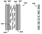
본 개시 내용은 또한 조명 광을 아래로 반사 영상 광원 쪽으로 편향시키기 위해 와이어 그리드 편광 필름을 부분 반사 표면으로서 포함하는 소형 경량의 전방 조명을 제공한다. 에지 광원이 편광되고, 와이어 그리드 편광기는 조명 광이 반사되고 영상 광이 디스플레이 광학계로 들어갈 수 있도록 배향되어 있다. 가요성인 와이어 그리드 편광 필름을 사용함으로써, 본 개시 내용은 조명 광을 반사 영상 광원에 집속시키기 위해 곡면으로 될 수 있는 부분 반사 표면을 제공하고, 그로써 효율을 향상시키고 영상 밝기의 균일성을 향상시킨다. 와이어 그리드 편광기는 또한, 영상 광이 전방 조명을 통과하여 디스플레이 광학계까지 계속 가기 때문에, 아주 낮은 광 산란을 가지며, 따라서 영상 품질이 유지된다. 그에 부가하여, 부분 반사 표면이 와이어 그리드 편광 필름이기 때문에, 대부분의 전방 조명이 공기로 이루어져 있고, 그에 따라, 전방 조명이 중량이 훨씬 더 가볍다.The present disclosure also provides a small, lightweight frontal illumination that includes the wire grid polarizing film as a partial reflective surface to deflect the illumination light down toward the reflective image light source. The edge light source is polarized, and the wire grid polarizer is oriented so that the illumination light is reflected and the image light enters the display optics. By using a flexible wire grid polarizing film, the present disclosure provides a partially reflective surface that can be curved to focus illumination light onto a reflected image light source, thereby improving efficiency and improving uniformity of image brightness. The wire grid polarizer also has very low light scattering because the image light passes through the front illumination and continues to the display optics, thus maintaining the image quality. In addition, since the partially reflective surface is a wire grid polarizing film, most of the front lighting is made up of air, so that the front lighting is much lighter in weight.
본 개시 내용은 또한 광학 필름을 사용할 때 광학적 평탄성을 갖는 표면을 제조하는 방법을 제공한다. 본 개시 내용의 실시예들에서, 광학 필름은 빔 분할기, 편광 빔 분할기, 와이어 그리드 편광기, 거울, 부분 거울(partial mirror) 또는 홀로그래픽 필름(holographic film)을 포함할 수 있다. 본 개시 내용에 의해 제공되는 장점은, 향상된 영상 품질을 제공하기 위해 광의 파면이 유지되도록, 광학 필름의 표면이 광학적으로 평탄하다는 것이다.The present disclosure also provides a method of making a surface having optical flatness when using an optical film. In embodiments of the present disclosure, the optical film may comprise a beam splitter, a polarizing beam splitter, a wire grid polarizer, a mirror, a partial mirror, or a holographic film. An advantage provided by the present disclosure is that the surface of the optical film is optically flat so that the wavefront of the light is maintained to provide improved image quality.
어떤 실시예들에서, 본 개시 내용은 광학적으로 평탄한 광학 필름을 포함하는 영상 디스플레이 시스템을 제공한다. 광학적으로 평탄한 광학 필름은 영상 광원 및 보기 위치(viewing location)를 갖는 디스플레이 모듈 하우징에서 광학 필름을 광학적으로 평탄하게 유지하는 기판을 포함한다. 영상 광원에 의해 제공되는 영상은 광학 필름으로부터 보기 위치로 반사되고, 광학 필름을 갖는 기판은 디스플레이 모듈 하우징 내에서 교체가능하다.In certain embodiments, the present disclosure provides an image display system that includes an optically flat optical film. The optically planar optical film includes a substrate that maintains the optical film optically flat in a display module housing having an image light source and a viewing location. The image provided by the image light source is reflected from the optical film to the viewing position and the substrate with the optical film is replaceable within the display module housing.
본 개시 내용의 다른 실시예들에서, 광학 필름이 성형된 구조물에 부착되고, 따라서 광학 필름은 디스플레이 모듈 하우징의 일부이다.In other embodiments of the present disclosure, the optical film is attached to the molded structure, and thus the optical film is part of the display module housing.
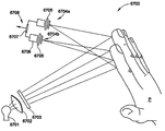
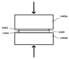
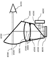
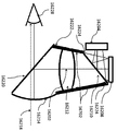
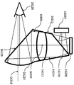
도 187에 도시되어 있는 바와 같은 반사 영상 광원(18720) 및 중실 빔 분할기 큐브 전방 조명(solid beam splitter cube frontlight)(18718)을 갖는 종래 기술의 디스플레이(18700)에서, 광(18712)은 광원(18702)으로부터 확산기(18704) 내로 들어가고, 조명 광(18714)을 제공하기 위해 확산기(18704)에서 광이 보다 균일하게 된다. 조명 광(18714)은 부분 반사층(18708)에 의해 방향 전환되고, 그로써 반사 영상 광원(18720)을 조명한다. 조명 광(18714)은 이어서 반사 영상 광원(18720)으로부터 반사되어 영상 광(18710)으로 되고, 이 영상 광(18710)은 이어서 다시 부분 반사층(18708)을 통과하여 영상을 관찰자에게 제시하는 관련 영상 광학계(도시 생략)로 들어간다. 그에 따라, 중실 빔 분할기 큐브(18718)는 이와 동시에 조명 광(18714)을 방향 전환시키고, 반사된 영상 광(18710)이 영상 광학계로 들어갈 수 있도록 방향 전환됨이 없이 통과할 수 있게 해주며, 여기서 영상 광학계는 디스플레이가 평판 스크린 디스플레이일 때 분산성일 수 있거나 디스플레이가 프로젝터 또는 근안 디스플레이일 때 굴절성 또는 회절성일 수 있다.In a
LCOS(liquid crystal on silicon) 영상 광원 등의 반사 영상 광원의 경우, 조명 광이 편광되고, 반사 영상 광원은 조명 광이 반사 영상 광원으로부터 반사될 때 영상 광원에 의해 제공되는 영상 콘텐츠에 기초하여 편광 상태를 변경하며, 그로써 영상 광을 형성한다. 영상 광이 영상 광학계를 통과하여 영상이 관찰자에게 제시될 때 LCOS에 의해 제공되는 편광 효과가 영상을 형성하게 하는 분석기 편광기(analyzer polarizer)가 이어서 포함되어 있다.In the case of a reflective image light source such as a liquid crystal on silicon (LCOS) image light source, the illumination light is polarized, and the reflected image light source is polarized based on the image content provided by the image light source when the illumination light is reflected from the reflected image light source. Thereby forming an image light. An analyzer polarizer is then included which allows the imaging light to pass through the imaging optics and cause the polarization effect provided by the LCOS to form an image when the image is presented to an observer.
미국 특허 제7545571호에서, 에지 광원에 의해 공급되는 조명 광을 반사 영상 광원 상으로 편향 및 편광시키기 위해 편광 빔 분할기를 갖는 반사 영상 광원을 전방 조명으로서 포함하는 웨어러블 디스플레이 시스템이 제시되어 있다. 편광 빔 분할기는 에지 광원과 연관되어 있는 별도의 곡면 반사체를 갖는 중실 블록 내의 각진 평면이다. 곡면 반사체는 편광 빔 분할기에 연결되어 있는 내부 전반사 블록일 수 있다. 그에 따라, 편광 빔 분할기의 중실 블록 및 내부 전반사 블록을 갖는 이 특허에 개시되어 있는 전방 조명은 크고 비교적 무거운 전방 조명을 제공한다.U.S. Patent No. 7545571 discloses a wearable display system that includes as a front illumination a reflected image light source having a polarizing beam splitter for deflecting and polarizing illumination light supplied by an edge light source onto a reflected image light source. The polarizing beam splitter is an angular plane in the solid block with a separate curved reflector associated with the edge light source. The curved reflector may be an internal total reflection block connected to the polarization beam splitter. Accordingly, the front lighting disclosed in this patent with the solid block and the total internal reflection block of the polarizing beam splitter provides large and relatively heavy front lighting.
미국 특허 제6195136호는 반사 영상 광원에 대해 사용하는 일련의 전방 조명 조명 방법(frontlight illumination method)을 개시하고 있다. 전방 조명을 보다 소형으로 만들기 위해 곡면 빔 분할기(curved beam splitter)를 사용하는 방법이 개시되어 있다. 그렇지만, 광원으로부터의 광(이 광이 나중에 빔 분할기에 의해 영상 광원 쪽으로 반사됨)의 각도를 감소시키기 위해 곡면 빔 분할기가 영상 광원으로부터 상당히 멀리 떨어져 위치해 있다. 또한, 광이 전방 조명의 한쪽 측면에만 제공되고, 따라서 빔 분할기의 크기가 적어도 영상 광원만큼 커야만 한다. 그 결과로서, 전방 조명의 전체 크기가, 광학축을 따라 측정될 때, 영상 광원 상의 조명된 영역에 비해 여전히 비교적 크다.U.S. Patent No. 6,195,136 discloses a series of frontlight illumination methods for use with reflective image light sources. A method of using a curved beam splitter to make the front lighting smaller is disclosed. However, the curved beam splitter is located quite far away from the image light source to reduce the angle of light from the light source (which is later reflected by the beam splitter towards the image light source). Further, the light is provided only on one side of the front light, and therefore the size of the beam splitter must be at least as large as the image light source. As a result, when the overall size of the front illumination is measured along the optical axis, it is still relatively large compared to the illuminated area on the image light source.
산란된 광이 거의 없는 양호한 영상 품질을 제공하고 또한 소형이고 효율적이며 경량인, 반사 영상 광원을 갖는 디스플레이에 대한 전방 조명을 제공할 필요가 있다.There is a need to provide front lighting for a display having a reflective image light source that provides good image quality with little scattered light and is also small, efficient, and lightweight.
본 개시 내용은 측면에 있는 광원으로부터의 조명 광을 반사 영상 광원 쪽으로 방향 전환시키기 위해 부분 반사 표면을 포함하는 소형이고 효율적이며 경량인 전방 조명을 디스플레이 어셈블리에 제공하고, 확산기 영역의 높이로 측정되는 디스플레이 어셈블리의 크기는 조명되는 반사 영상 광원의 폭보다 실질적으로 더 작다. 어떤 실시예들에서, 광원으로부터의 광을 반사 영상 광원 상에 집속 또는 집중시키기 위해 부분 반사 표면이 곡면일 수 있다. 광원이 편광될 수 있고, 조명 광이 방향 전환되고 반사된 영상 광이 영상 광학계로 들어갈 수 있도록 편광 빔 분할기 필름이 곡면 부분 반사 표면으로서 사용될 수 있다. 편광 빔 분할기 필름은 경량이고, 영상 광이 전방 조명을 통과하여 디스플레이 광학계까지 계속 가기 때문에, 아주 낮은 광 산란을 가지며, 따라서 영상 품질이 유지된다.The present disclosure provides a small, efficient, and lightweight front light to the display assembly that includes a partial reflective surface for redirecting illumination light from a side light source toward a reflective image light source, The size of the assembly is substantially smaller than the width of the reflected reflection image light source. In certain embodiments, the partial reflective surface may be curved to focus or focus light from the light source onto the reflective image light source. The polarizing beam splitter film can be used as a curved partial reflecting surface so that the light source can be polarized and the illumination light can be redirected and the reflected video light can enter the imaging optics. The polarizing beam splitter film is lightweight and has a very low light scattering because the image light passes through the front illumination and continues to the display optical system, thus the image quality is maintained.
본 개시 내용의 다른 실시예들에서, 광이 반사 영상 광원의 대향하는 가장자리에 제공되도록 전방 조명의 대향하는 측면 상에 광원이 제공된다. 이 경우에, 부분 반사 표면은 2개의 표면으로 이루어져 있고, 한쪽 표면은 하나의 광원으로부터의 조명 광을 영상 광원의 한쪽 절반 쪽으로 편향시키고, 다른쪽 표면은 광을 영상 광원의 다른쪽 절반 쪽으로 편향시킨다. 이 실시예에서, 부분 반사 표면은 곡면이거나 평탄할 수 있다.In other embodiments of the present disclosure, a light source is provided on opposite sides of the forward illumination such that light is provided at the opposite edges of the reflective image light source. In this case, the partially reflecting surface consists of two surfaces, one surface deflecting the illumination light from one light source towards one half of the image light source, and the other surface deflecting the light towards the other half of the image light source . In this embodiment, the partially reflective surface may be curved or flat.
본 개시 내용의 추가의 실시예에서, 부분 반사 표면은 편광 빔 분할기이고, 광원이 편광되며 따라서 광원으로부터의 광이 먼저 편광 빔 분할기에 의해 방향 전환되고, 이어서 반사 영상 광원에 의해 반사되고 편광이 변경된 후에 투과된다.In a further embodiment of the present disclosure, the partial reflective surface is a polarizing beam splitter, in which the light source is polarized and thus the light from the light source is first redirected by the polarizing beam splitter, then reflected by the reflected image light source, Lt; / RTI >
다른 실시예에서, 광원으로부터의 광이 비편광(unpolarized)이고, 따라서 편광 빔 분할기는 반사 영상 광원의 절반을 조명하기 위해 광의 하나의 편광 상태는 반사시키는 반면 광의 다른 편광 상태는 투과시킨다. 광의 투과된 편광 상태는 전방 조명의 반대쪽 측면으로 들어가고 이곳에서 광이 재순환된다. 투과된 편광 상태의 재순환은 광이 1/4파 필름을 다시 통과하고 그로써 편광 상태를 변경하도록 1/4파 필름을 통과하고 거울에 의해 반사됨으로써 행해질 수 있다. 투과되고 반사된 광의 편광 상태가 변화된 후에, 그 광은 반사 영상 광원의 다른쪽 절반을 조명하기 위해 편광 빔 분할기에 의해 방향 전환된다. 대안의 실시예에서, 전방 조명의 2개의 측면 조명(sidelight)으로부터의 광은 상보적 방식으로 기능하고, 여기서 반대쪽 측면으로부터의 광의 투과된 편광 상태는 반대쪽 측면에 있는 확산기와 상호작용할 때 비편광으로 되고, 그로써 재순환된다.In another embodiment, the light from the light source is unpolarized, so that the polarization beam splitter reflects one polarization state of light to illuminate half of the reflected image light source while the other polarization state of light is transmitted. The transmitted polarization state of light enters the opposite side of the front illumination, where light is recirculated. Recirculation of the transmitted polarization state can be done by passing through the quarter wave film and reflecting off the mirror so that light passes again through the quarter wave film and thereby changes the polarization state. After the polarization state of the transmitted and reflected light changes, the light is redirected by the polarization beam splitter to illuminate the other half of the reflected image light source. In an alternative embodiment, the light from the two sidelights of the front illumination functions in a complementary manner, wherein the transmitted polarization state of light from the opposite side is unpolarized when interacting with the diffuser on the opposite side And is thereby recirculated.
본 개시 내용의 또 다른 실시예에서, 가요성 부분 반사 필름으로 전방 조명을 제조하는 방법이 제공된다. 가요성 필름이 가장자리에서 지지되고 반사 영상 광원 상에 프리스탠딩(freestanding)되어 있거나, 가요성 필름이 투명한 2개 이상의 중실 편부(solid piece) 사이에 클램핑(clamp)되어 있을 수 있다. 중실 편부는 가요성 필름과 접촉하게 배치되기 전에 형성될 수 있다. 중실 편부는 가요성 필름을 평탄한 형태로 또는 곡면 형태로 보유할 수 있다. 또 다른 실시예에서, 가요성 필름이 가장자리에서 지지될 수 있고, 이어서 가요성 필름이 투명한 중실 물질(solid material) 내에 매립되도록 중실 편부가 제 위치에 캐스팅(cast)될 수 있다.In yet another embodiment of the present disclosure, a method is provided for manufacturing a front lighting with a flexible partial reflective film. The flexible film may be either supported at the edges and freestanding on the reflective image light source or the flexible film may be clamped between two or more solid solid pieces that are transparent. The solid side piece may be formed before being placed in contact with the flexible film. The solid single piece can hold the flexible film in a flat shape or a curved shape. In yet another embodiment, the flexible film may be supported at the edge, and then the solid side piece may be cast in place such that the flexible film is embedded in a transparent solid material.
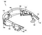
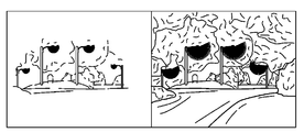
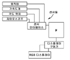
일 실시예에서, 시스템은, 사용자가 착용하는 대화형 두부 탑재형 접안경(interactive head-mounted eyepiece) - 접안경은 사용자가 그를 통해 주변 환경 및 디스플레이된 콘텐츠를 보는 광학 어셈블리(optical assembly)를 포함함 -, 사용자에게 디스플레이하기 위한 콘텐츠를 처리하는 일체형 프로세서, 콘텐츠를 광학 어셈블리로 들여보내는 일체형 영상 광원을 포함할 수 있고, 상기 프로세서는 콘텐츠를 수정하도록 구성되고, 이 수정은 센서 입력에 응답하여 행해진다. 콘텐츠는 비디오 영상일 수 있다. 이 수정은 밝기를 조절하는 것, 색상 채도(color saturation)를 조절하는 것, 색상 균형(color balance)을 조절하는 것, 색상 색조(color hue)를 조절하는 것, 비디오 해상도를 조절하는 것, 투명도를 조절하는 것, 압축비를 조절하는 것, 초당 프레임 레이트를 조절하는 것, 비디오의 일부를 고립시키는 것, 비디오의 재생을 중단하는 것, 비디오를 일시 정지시키는 것, 또는 비디오를 재시작하는 것 중 적어도 하나일 수 있다. 센서 입력은 전하 결합 소자(charge-coupled device), 블랙 실리콘 센서(black silicon sensor), IR 센서, 음향 센서, 유도 센서(induction sensor), 움직임 센서, 광 센서, 불투명도 센서, 근접 센서, 유도형 센서(inductive sensor), 와전류 센서, 수동 적외선 근접 센서(passive infrared proximity sensor), 레이더, 커패시턴스 센서, 용량형 변위 센서, 홀효과 센서, 자기 센서, GPS 센서, 열영상 센서, 열전쌍, 서미스터(thermistor), 광전 센서, 초음파 센서, 적외선 레이저 센서, 관성 움직임 센서, MEMS 내부 움직임 센서, 초음파 3D 움직임 센서, 가속도계, 경사계, 힘 센서, 압전 센서, 로터리 인코더, 선형 인코더, 화학 물질 센서, 오존 센서, 연기 센서, 열 센서, 자력계, 이산화탄소 검출기, 일산화탄소 검출기, 산소 센서, 포도당 센서, 연기 검출기, 금속 검출기, 빗물 센서, 고도계, GPS, 외부에 있는 것의 검출, 상황의 검출, 활동의 검출, 물체 검출기(예컨대, 광고판), 표식 검출기(예컨대, 광고를 위한 지리적 위치 표식), 레이저 거리 측정기, 소나(sonar), 커패시턴스, 광학 응답, 심박동수 센서, 또는 RF/MIR(micropower impulse radio) 센서 중 적어도 하나로부터 도출될 수 있다. 사용자의 머리가 움직이고 있다는 가속도계 입력으로부터의 표시에 응답하여 콘텐츠의 재생이 중단될 수 있다. 화상 회의의 적어도 하나의 참가자가 말을 하는 것에 의해 오디오 센서 입력이 발생될 수 있다. 시각 센서 입력은 화상 회의의 적어도 하나의 참가자의 비디오 영상 또는 시각적 프리젠테이션의 비디오 영상일 수 있다. 이 수정은 사용자가 움직이고 있다는 센서로부터의 표시에 응답하여 비디오 영상을 더 투명하게 또는 덜 투명하게 만드는 것 중 적어도 하나일 수 있다.In one embodiment, the system includes an interactive head-mounted eyepiece worn by the user, the eyepiece includes an optical assembly through which a user views the surrounding environment and the displayed content, An integrated processor that processes content for display to a user, an integrated image light source that directs the content into an optical assembly, and the processor is configured to modify the content, the modification being made in response to the sensor input. The content may be a video image. These modifications include adjusting the brightness, adjusting the color saturation, adjusting the color balance, adjusting the color hue, adjusting the video resolution, transparency Adjusting the compression ratio, adjusting the frame rate per second, isolating a portion of the video, stopping playback of the video, pausing the video, or restarting the video It can be one. The sensor input may be a charge-coupled device, a black silicon sensor, an IR sensor, an acoustic sensor, an induction sensor, a motion sensor, an optical sensor, an opacity sensor, a capacitive sensor, a capacitive displacement sensor, a Hall effect sensor, a magnetic sensor, a GPS sensor, a thermal image sensor, a thermocouple, a thermistor, a thermoelectric sensor, an inductive sensor, an eddy current sensor, a passive infrared proximity sensor, Ultrasonic 3D motion sensor, accelerometer, inclinometer, force sensor, piezoelectric sensor, rotary encoder, linear encoder, chemical sensor, ozone sensor, smoke sensor, ultrasonic sensor, ultrasonic sensor, infrared laser sensor, inertial motion sensor, MEMS internal motion sensor, A sensor, a magnetometer, a carbon dioxide detector, a carbon monoxide detector, an oxygen sensor, a glucose sensor, a smoke detector, a metal detector, a rain sensor, an altimeter, (E.g., a billboard), a landmark detector (e.g., a geographical location marker for advertising), a laser range finder, a sonar, a capacitance, an optical response, a heart rate sensor, Or an RF / MIR (micropower impulse radio) sensor. The playback of the content may be interrupted in response to an indication from the accelerometer input that the user's head is moving. Audio sensor input can be generated by at least one participant in the videoconference talking. The visual sensor input may be a video image of at least one participant of the videoconference or a video image of a visual presentation. This modification may be at least one of making the video image more transparent or less transparent in response to an indication from the sensor that the user is moving.
일 실시예에서, 시스템은 사용자가 착용하는 대화형 두부 탑재형 접안경을 포함할 수 있고, 접안경은 사용자가 그를 통해 주변 환경 및 디스플레이된 콘텐츠를 보는 광학 어셈블리, 사용자에게 디스플레이하기 위한 콘텐츠를 처리하는 일체형 프로세서, 콘텐츠를 광학 어셈블리로 들여보내는 일체형 영상 광원 - 프로세서는 콘텐츠를 수정하도록 구성되어 있음 - 을 포함하며, - 이 수정은 센서 입력에 응답하여 행해짐 -; 주변 환경의 모습을 기록하고 디스플레이하기 위한 콘텐츠를 제공하는 일체형 비디오 영상 포착 설비를 추가로 포함한다.In one embodiment, the system may include an interactive head mounted eyepiece worn by a user, the eyepiece may include an optical assembly through which a user views the surrounding environment and the displayed content, an integrated assembly A processor, an integrated image light source processor for importing content into the optical assembly, the processor configured to modify the content, the modification being made in response to the sensor input; And an integrated video image capturing facility that provides content for recording and displaying the appearance of the surrounding environment.
실시예들에 대한 이하의 상세한 설명 및 도면으로부터, 본 개시 내용의 이들 및 기타 시스템, 방법, 목적, 특징 및 장점이 기술 분야의 당업자에게 명백하게 될 것이다.These and other systems, methods, objects, features, and advantages of the present disclosure will become apparent to those skilled in the art from the following detailed description and drawings of the embodiments.
본 명세서에 언급되는 모든 문서는 그 전체 내용이 참조 문헌으로서 본 명세서에 포함된다. 달리 명백히 언급하지 않는 한 또는 본문으로부터 명백하지 않는 한, 항목을 단수로 언급하는 것은 항목을 복수개 포함하는 것으로 이해되어야 하고, 그 반대도 마찬가지이다. 달리 언급하지 않는 한 또는 문맥으로부터 명백하지 않는 한, 문법 접속사는 결합된 절, 문장, 단어 등의 모든 논리합 및 논리곱 조합을 표현하는 것으로 보아야 한다.All documents referred to herein are incorporated herein by reference in their entirety. Unless expressly stated otherwise or clear from the text, reference to an item in singular is to be understood as including a plurality of items, and vice versa. Unless otherwise stated or clear from the context, a grammatical conjunction is to be understood as representing all logical AND combinations of combined clauses, sentences, words, and so on.
이하의 도면들을 참조하면 본 개시 내용 및 본 개시 내용의 특정의 실시예들에 대한 이하의 상세한 설명이 이해될 수 있다.
도 1은 광학 구성의 예시적인 실시예를 나타낸 도면.
도 2는 RGB LED 프로젝터를 나타낸 도면.
도 3은 사용 중인 프로젝터를 나타낸 도면.
도 4는 프레임에 배치되어 있는 도파관 및 교정 렌즈(correction lens)의 일 실시예를 나타낸 도면.
도 5는 도파관 접안경(waveguide eyepiece)에 대한 설계를 나타낸 도면.
도 6은 투시 렌즈(see-through lens)를 갖는 접안경의 일 실시예를 나타낸 도면.
도 7은 투시 렌즈를 갖는 접안경의 일 실시예를 나타낸 도면.
도 8a 내지 도 8c는 플립-업/플립-다운(flip-up/flip-down) 구성으로 배열된 접안경의 실시예들을 나타낸 도면.
도 8d 및 도 8e는 2차 광학계(secondary optic)의 스냅 피트 요소(snap-fit element)의 실시예들을 나타낸 도면.
도 8f는 플립-업/플립-다운 전기 광학 모듈들(flip-up/flip-down electro-optics modules)의 실시예들을 나타낸 도면.
도 9는 접안경의 전기 변색 층(electrochromic layer)을 나타낸 도면.
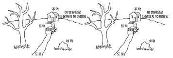
도 10은 실시간 영상 강조(image enhancement), 키스톤 보정(keystone correction), 및 가상 원근 보정(virtual perspective correction)에서의 접안경의 장점들을 나타낸 도면.
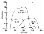
도 11은 3개의 기판에 대한 응답성(responsivity) 대 파장의 플롯을 나타낸 도면.
도 12는 블랙 실리콘 센서의 성능을 나타낸 도면.
도 13a는 종래의 나이트 비전(night vision) 시스템을 나타낸 도면이고, 도 13b는 본 개시 내용의 나이트 비전 시스템을 나타낸 도면이며, 도 13c는 이 둘 사이의 응답성의 차를 나타낸 도면.
도 14는 접안경의 촉각 인터페이스를 나타낸 도면.
도 14a는 끄덕임 제어(nod control)를 특징으로 하는 접안경의 일 실시예에서의 움직임을 나타낸 도면.
도 15는 접안경을 제어하는 반지를 나타낸 도면.
도 15aa는, 일 실시예에서, 사용자가 화상 회의의 일부로서 자신의 비디오 영상을 제공할 수 있게 해줄 수 있는 일체형 카메라를 갖는 접안경을 제어하는 반지를 나타낸 도면.
도 15a는 가상 마우스의 일 실시예에서의 손 탑재형 센서(hand mounted sensor)를 나타낸 도면.
도 15b는 접안경 상에 탑재되어 있는 안면 작동 센서(facial actuation sensor)를 나타낸 도면.
도 15c는 접안경의 핸드 포인팅 제어(hand pointing control)를 나타낸 도면.
도 15d는 접안경의 핸드 포인팅 제어를 나타낸 도면.
도 15e는 눈 추적 제어의 한 예를 나타낸 도면.
도 15f는 접안경의 손 위치 결정 제어를 나타낸 도면.
도 16은 접안경의 위치-기반 응용 프로그램 모드를 나타낸 도면.
도 17은 A) VIS/NIR/SWIR 영상 촬영을 할 수 있는 비냉각형(uncooled) CMOS 영상 센서의 가요성 플랫폼과 B) 영상 강화(image intensified) 나이트 비전 시스템 사이의 영상 품질의 차를 나타낸 도면.
도 18은 증강 현실-지원 맞춤형 광고판을 나타낸 도면.
도 19는 증강 현실-지원 맞춤형 광고를 나타낸 도면.
도 20은 증강 현실-지원 맞춤형 아트워크를 나타낸 도면.
도 20a는 관찰자가 특정의 장소에 도달할 때 전송될 메시지를 게시하는 방법을 나타낸 도면.
도 21은 접안경 광학계 및 전자 장치의 대안의 구성을 나타낸 도면.
도 22는 접안경 광학계 및 전자 장치의 대안의 구성을 나타낸 도면.
도 22a는 눈부심(eyeglow)의 한 예를 갖는 접안경을 나타낸 도면.
도 22b는 눈부심을 감소시키는 광 제어 요소를 갖는 접안경의 단면을 나타낸 도면.
도 23은 접안경 광학계 및 전자 장치의 대안의 구성을 나타낸 도면.
도 24는 가상 키보드의 잠금 위치(lock position)를 나타낸 도면.
도 24a는 인체의 일부 상에 가상적으로 투영된 영상의 일 실시예를 나타낸 도면.
도 25는 프로젝터의 상세도를 나타낸 도면.
도 26은 RGB LED 모듈의 상세도를 나타낸 도면.
도 27은 게임 네트워크를 나타낸 도면.
도 28은 증강 현실 안경을 사용하여 게임을 하는 방법을 나타낸 도면.
도 29는 증강 현실 접안경에 대한 예시적인 전자 회로도를 나타낸 도면.
도 29a는 외부 장치의 눈 추적 제어용 제어 회로를 나타낸 도면.
도 29b는 증강 현실 접안경의 사용자들 간의 통신 네트워크를 나타낸 도면.
도 30은 접안경에 의한 부분 영상 제거를 나타낸 도면.
도 31은 증강 현실 장치의 마이크에 의해 포착되는 사람의 음성에 기초하여 사람을 식별하는 방법에 대한 플로우차트를 나타낸 도면.
도 32는 화상 전화 또는 화상 회의에서 사용하기 위한 전형적인 카메라를 나타낸 도면.
도 33은 화상 전화 카메라의 블록도의 일 실시예를 나타낸 도면.
도 34a 내지 도 34e는 광학 또는 디지털 안정화를 위한 접안경의 실시예들을 나타낸 도면.
도 35는 고전적인 카센그레인(cassegrain) 구성의 일 실시예를 나타낸 도면.
도 36은 마이크로-카센그레인 망원 굴곡 광학 카메라(micro-cassegrain telescoping folded optic camera)의 구성을 나타낸 도면.
도 37은 가상 키보드에 의한 스와이프 프로세스(swipe process)를 나타낸 도면.
도 38은 가상 키보드에 대한 목표 표식 프로세스(target marker process)를 나타낸 도면.
도 38a는 시각적 단어 번역기의 일 실시예를 나타낸 도면.
도 39는 일 실시예에 따른 생체 데이터 포착을 위한 안경을 나타낸 도면.
도 40은 일 실시예에 따른 생체 데이터 포착 안경을 사용한 홍채 인식을 나타낸 도면.
도 41은 일 실시예에 따른 얼굴 및 홍채 인식을 나타낸 도면.
도 42는 일 실시예에 따른 듀얼 옴니 마이크(dual omni-microphone)의 사용을 나타낸 도면.
도 43은 다수의 마이크에 의한 방향성 개선을 나타낸 도면.
도 44는 일 실시예에 따른 오디오 포착 설비를 조정하기 위해 적응적 어레이를 사용하는 것을 나타낸 도면.
도 45는 일 실시예에 따른 모자이크 손가락 및 손바닥 등록 시스템을 나타낸 도면.
도 46은 다른 손가락 및 손바닥 인쇄 시스템에 의해 사용되는 전통적인 광학 방식을 나타낸 도면.
도 47은 일 실시예에 따른 모자이크 센서에 의해 사용되는 방식을 나타낸 도면.
도 48은 일 실시예에 따른 모자이크 센서의 장치 레이아웃을 나타낸 도면.
도 49는 다른 실시예에 따른 모자이크 센서에서 사용되는 카메라 시야 및 카메라의 수를 나타낸 도면.
도 50은 일 실시예에 따른 바이오폰(bio-phone) 및 전술용 컴퓨터(tactical computer)를 나타낸 도면.
도 51은 일 실시예에 따른 잠재 지문(latent fingerprint) 및 장문(palm print)을 포착하는 데 바이오폰 및 전술용 컴퓨터를 사용하는 것을 나타낸 도면.
도 52는 전형적인 DOMEX 컬렉션을 나타낸 도면.
도 53은 일 실시예에 따른, 바이오폰 및 전술용 컴퓨터를 사용하여 포착된 생체 영상들과 생체 감시 목록(biometric watch list) 간의 관계를 나타낸 도면.
도 54는 일 실시예에 따른 포켓 바이오 키트(pocket bio-kit)를 나타낸 도면.
도 55는 일 실시예에 따른 포켓 바이오 키트의 구성요소들을 나타낸 도면.
도 56은 일 실시예에 따른, 지문, 장문, 지리적 위치 및 POI 등록 장치를 나타낸 도면.
도 57a 내지 도 57e는 일 실시예에 따른, 다중 모드 생체 수집(biometric collection), 식별, 지리적 위치 및 POI 등록 시스템을 나타낸 도면.
도 58은 일 실시예에 따른, 지문, 장문, 지리적 위치 및 POI 등록 팔뚝 웨어러블 장치를 나타낸 도면.
도 59는 일 실시예에 따른 모바일 접이식 생체 등록 키트를 나타낸 도면.
도 60은 일 실시예에 따른 생체 등록 키트의 상위 레벨 시스템도.
도 61은 일 실시예에 따른 접이식 생체 등록 장치의 시스템도.
도 62는 일 실시예에 따른 박막 지문 및 장문 센서를 나타낸 도면.
도 63은 일 실시예에 따른, 손가락, 손바닥, 및 등록 데이터 수집을 위한 생체 수집 장치를 나타낸 도면.
도 64는 일 실시예에 따른 2 단계 장문(two stage palm print)의 포착을 나타낸 도면.
도 65는 일 실시예에 따른 손가락 끝 탭(fingertip tap)의 포착을 나타낸 도면.
도 66은 일 실시예에 따른 누름 및 굴림 지문(slap and roll print)의 포착을 나타낸 도면.
도 67은 비접촉식 지문, 장문 또는 기타 생체 자국(biometric print)을 채취하는 시스템을 나타낸 도면.
도 68은 비접촉식 지문, 장문 또는 기타 생체 자국(biometric print)을 채취하는 프로세스를 나타낸 도면.
도 69는 시계 제어기의 일 실시예를 나타낸 도면.
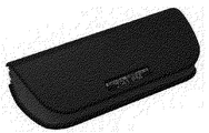
도 70a 내지 도 70d는 충전 기능 및 일체형 디스플레이를 포함하는 접안경에 대한 실시예 케이스들을 나타낸 도면.
도 71은 지상 말뚝 데이터 시스템(ground stake data system)의 일 실시예를 나타낸 도면.
도 72는 접안경을 포함하는 제어 매핑 시스템의 블록도.
도 73은 생체 플래시라이트(biometric flashlight)를 나타낸 도면.
도 74는 접안경의 헬멧 탑재형 버전을 나타낸 도면.
도 75는 상황 인식 안경의 일 실시예를 나타낸 도면.
도 76의 A는 조립된 360° 영상기(imager)를 나타낸 도면이고, 도 76의 B는 360° 영상기의 파단도.
도 77은 다중 동시 뷰 카메라(multi-coincident view camera)의 분해도.
도 78a 및 도 78b는 플라이트 아이(flight eye)를 나타낸 도면.
도 79는 접안경의 분해 평면도.
도 80은 분해된 전기 광학 어셈블리를 나타낸 도면.
도 81은 전기 광학 어셈블리의 샤프트(shaft)의 분해도.
도 82는 반사형 디스플레이와 함께 평면 조명 설비를 이용하는 광학 디스플레이 시스템의 일 실시예를 나타낸 도면.
도 83은 평면 조명 광학 시스템의 구조 실시예를 나타낸 도면.
도 84는 레이저 반점 억제 구성요소를 갖는 평면 조명 설비 및 반사형 디스플레이의 실시예 어셈블리를 나타낸 도면.
도 85는 광을 방향 전환시키는 그루브형 특징부(grooved feature)를 갖는 평면 조명 설비의 일 실시예를 나타낸 도면.
도 86은 영상 수차를 감소시키기 위해 쌍을 이루고 있는 그루브형 특징부 및 '반그루브형(anti-grooved)' 특징부를 갖는 평면 조명 설비의 일 실시예를 나타낸 도면.
도 87은 라미네이트 구조물(laminate structure)로 제조되는 평면 조명 설비의 일 실시예를 나타낸 도면.
도 88은 광을 방향 전환시키는 쐐기형 광학 어셈블리(wedged optic assembly)를 갖는 평면 조명 설비의 일 실시예를 나타낸 도면.
도 89는 본 개시 내용의 일 실시예에 따른 조명 모듈의 블록도.
도 90은 본 개시 내용의 일 실시예에 따른 광 주파수 변환기(optical frequency converter)의 블록도.
도 91은 본 개시 내용의 일 실시예에 따른 레이저 조명 모듈의 블록도.
도 92는 본 개시 내용의 다른 실시예에 따른 레이저 조명 시스템의 블록도.
도 93은 본 개시 내용의 일 실시예에 따른 영상 시스템의 블록도.
도 94a 및 도 94b는, 각각, 광 변색 요소(photochromic element) 및 히터 요소를 갖는 렌즈를 평면도 및 측면도로 나타낸 도면.
도 95는 LCoS 전방 조명 설계의 일 실시예를 나타낸 도면.
도 96은 편광기와 광학적으로 접합된 프리즘(optically bonded prism)을 나타낸 도면.
도 97은 편광기와 광학적으로 접합된 프리즘을 나타낸 도면.
도 98a 내지 도 98c는 LCoS 전방 조명 설계의 다수의 실시예들을 나타낸 도면.
도 99는 LCoS 상에 오버레이된 쐐기 + OBS를 나타낸 도면.
도 100a 및 도 100b는 쐐기의 2가지 버전을 나타낸 도면.
도 101은 LCoS 칩 상의 곡면 PBS 필름을 나타낸 도면.
도 102a는 광학 어셈블리의 일 실시예를 나타낸 도면.
도 102b는 인라인 카메라(in-line camera)를 갖는 광학 어셈블리의 일 실시예를 나타낸 도면.
도 103은 영상 광원의 일 실시예를 나타낸 도면.
도 104는 영상 광원의 일 실시예를 나타낸 도면.
도 105는 영상 광원의 실시예들을 나타낸 도면.
도 106은 본 개시 내용의 일 실시예에서의 접안경의 기능 및 제어 측면과 관련하여 소프트웨어 응용 프로그램 설비 및 시장을 나타낸 상위 레벨 블록도.
도 107은 본 개시 내용의 일 실시예에서의 접안경 응용 프로그램 개발 환경의 기능 블록도.
도 108은 본 개시 내용의 일 실시예에서의 접안경의 소프트웨어 응용 프로그램에 대한 플랫폼 요소 개발 스택(platform elements development stack)을 나타낸 도면.
도 109는 본 개시 내용의 일 실시예에 따른, 투시 기능(see-through capability)을 갖는 두부 탑재형 디스플레이를 나타낸 도면.
도 110은 도 109에 도시되어 있는 두부 탑재형 디스플레이를 통해 보는 라벨링되지 않은 장면의 뷰를 나타낸 도면.
도 111은 2D 라벨이 오버레이되어 있는 도 110의 장면의 뷰를 나타낸 도면.
도 112는 관찰자의 좌안에 디스플레이되는 도 111의 3D 라벨을 나타낸 도면.
도 113은 관찰자의 우안에 디스플레이되는 도 111의 3D 라벨을 나타낸 도면.
도 114는 불일치를 보여주기 위해 서로 오버레이되어 있는 도 111의 좌측 및 우측 3D 라벨을 나타낸 도면.
도 115는 3D 라벨을 갖는 도 110의 장면의 뷰를 나타낸 도면.
도 116은 도 110의 장면의 포착된 입체 영상을 나타낸 도면.
도 117은 영상들 간의 불일치를 보여주는 도 116의 오버레이된 좌측 및 우측 입체 영상을 나타낸 도면.
도 118은 오버레이된 3D 라벨을 보여주는 도 110의 장면을 나타낸 도면.
도 119는 3D 라벨을 제공하는 본 개시 내용의 깊이 단서(depth cue) 방법 실시예에 대한 플로우차트.
도 120은 3D 라벨을 제공하는 본 개시 내용의 다른 깊이 단서 방법 실시예에 대한 플로우차트.
도 121은 3D 라벨을 제공하는 본 개시 내용의 또 다른 깊이 단서 방법 실시예에 대한 플로우차트.
도 122는 3D 라벨을 제공하는 본 개시 내용의 또 다른 깊이 단서 방법 실시예에 대한 플로우차트.
도 123a는 디스플레이 구성요소를 통한 영상 디스플레이를 위해 디스플레이 순차 프레임들(display sequential frames)을 제공하는 프로세서를 나타낸 도면.
도 123b는 디스플레이 구동기를 생략하도록 구성되어 있는 디스플레이 인터페이스를 나타낸 도면.
도 124는 다수의 부분 반사체를 갖는 종래 기술의 도파관의 개략도.
도 125는 제1 위치에 다수의 전기적 전환가능 거울을 갖는 도파관의 개략도.
도 125a는 전기적 연결을 갖는 도파관 어셈블리를 나타낸 도면.
도 126은 제2 위치에 다수의 전기적 전환가능 거울을 갖는 도파관의 개략도.
도 127은 제3 위치에 다수의 전기적 전환가능 거울을 갖는 도파관의 개략도.
도 128은 제1 위치에 다수의 기계적 전환가능 거울을 갖는 도파관의 개략도.
도 128a는 마이크로작동기(microactuator) 및 관련 하드웨어를 갖는 도파관 어셈블리의 개략도.
도 129는 제2 위치에 다수의 기계적 전환가능 거울을 갖는 도파관의 개략도.
도 130은 제3 위치에 다수의 기계적 전환가능 거울을 갖는 도파관의 개략도.
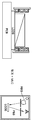
도 131a 및 도 131b는 사용자의 얼굴 상에 있는 전환가능 거울을 갖는 도파관 디스플레이를 나타낸 도면.
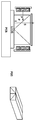
도 132a 내지 도 132c는 상이한 눈 간격을 갖는 사용자들에 대해 제공되는 디스플레이 영역을 나타낸 도면.
도 133은 광의 광선이 통과하는 것을 보여주고 있는, 에지 광원 및 전방 조명을 갖는 반사 영상 광원의 개략도.
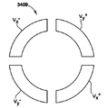
도 134는 그루브를 포함하는 종래 기술의 전방 조명의 개략도.
도 135는 중실 블록 내에 평면 편광 빔 분할기 및 곡면 반사체를 포함하는 종래 기술의 전방 조명의 개략도.
도 136은 단일의 에지 광원 및 곡면 와이어 그리드 편광 필름을 갖는 본 개시 내용의 일 실시예의 개략도.
도 137은 2개의 에지 광원 및 곡면 와이어 그리드 편광 필름을 갖는 본 개시 내용의 일 실시예의 개략도.
도 138은 원하는 곡면 형상으로 가요성 와이어 그리드 편광 필름을 보유하는 측면 프레임(side frame)의 개략도.
도 139는 본 개시 내용의 방법의 플로우차트.
도 140은 빔 분할기를 갖는 근안 영상 시스템(near eye imaging system)의 개략도.
도 141은 근안 영상 시스템에 대한 광학계 모듈의 개략도.
도 142는 펠리클 스타일(pellicle style) 광학 플레이트를 나타낸 도면.
도 143은 매립된 광학 플레이트를 갖는 삽입 성형된 모듈 하우징(insert molded module housing)을 나타낸 도면.
도 144는 라미네이트 스타일(laminate style) 광학 플레이트의 압축 성형(compression molding)을 나타낸 도면.
도 145a 내지 도 145c는 성형된 모듈 하우징 내에 광학 필름을 부착한 것을 나타낸 도면.
도 146은 본 개시 내용의 일 실시예에 따른 AR 접안경(안경 다리 편부를 갖지 않음)의 개략 전방 사시도.
도 147은 도 146의 AR 접안경의 개략 후방 사시도.
도 148은 도 146의 AR 접안경의 착용자의 우측의 개략 후방 사시 부분도.
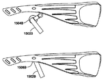
도 149는 도 146의 AR 접안경의 착용자의 우측의 개략 후방 사시 부분도.
도 150은 프로젝션 스크린들 중 하나를 지원하는 도 146에 도시되어 있는 AR 접안경의 구성요소들의 개략 사시도.
도 151은 도 146에 도시되어 있는 AR 접안경의 조절 플랫폼의 개략 사시도.
도 152는 도 146에 도시되어 있는 AR 접안경의 횡방향 조절 메커니즘의 구성요소의 개략 사시도.
도 153은 도 146에 도시되어 있는 AR 접안경의 틸트 조절 메커니즘(tilt adjustment mechanism)의 구성요소의 개략 사시도.
도 154는 사람의 눈에 대한 암순응 곡선(dark adaptation curve)을 나타낸 차트.
도 155는 사람의 눈에 대한 암순응 곡선 상에서 휘도(illuminance)를 점진적으로 감소시키는 것의 효과를 나타낸 차트.
도 156은 투시 기능을 갖는 두부 탑재형 디스플레이를 나타낸 도면.
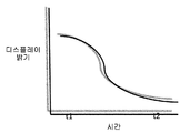
도 157은 어두운 환경에 들어갈 때 디스플레이 밝기와 시간 사이의 관계를 보여주는 그래프.
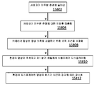
도 158은 암순응 방법에 대한 플로우차트.
도 159는 사용자의 시야에 제시되는 가상 키보드를 나타낸 도면.
도 160은 광학적으로 평탄한 반사 표면을 갖는 디스플레이 시스템의 한 예를 나타낸 도면.
도 161은 근안 디스플레이 모듈의 예시를 나타낸 도면.
도 162는 한 유형의 두부 탑재형 디스플레이와 연관되어 있는 광학계의 예시를 나타낸 도면.
도 163은 배플(baffle)이 하우징의 내부에서 조명 빔 분할기와 렌즈 사이에 부가되어 있는 예시를 나타낸 도면.
도 164는 배플이 렌즈의 입구 표면에 부가되어 있는 본 개시 내용의 다른 실시예의 예시를 나타낸 도면.
도 165는 배플이 렌즈의 출구에 부가되어 있는 본 개시 내용의 다른 실시예의 예시를 나타낸 도면.
도 166은 배플이 렌즈와 영상 빔 분할기 사이에서 하우징에 부착되어 있는 본 개시 내용의 다른 실시예의 예시를 나타낸 도면.
도 167은 흡수 코팅이 하우징의 측벽에 도포되어 있는 본 개시 내용의 추가의 실시예의 예시를 나타낸 도면.
도 168은 두부 탑재형 디스플레이의 미광(stray light)의 다른 소스의 예시를 나타낸 도면으로서, 여기서 미광은 광원의 가장자리로부터 직접 나옴.
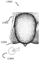
도 169는 미광이 하우징 내의 임의의 반사 표면 또는 렌즈의 가장자리로부터 반사되는 것을 나타낸 도면.
도 170은 배플이 광원에 인접하여 제공되어 있는 본 개시 내용의 다른 추가의 실시예의 예시를 나타낸 도면.
도 171은 릿지들(ridges)을 갖는 흡수 코팅이 사용될 수 있는 것을 나타낸 도면으로서, 여기서 일련의 작은 릿지들 또는 계단들이 하우징의 전체 측벽 영역에 걸쳐 에지 광선(edge ray)을 차단 또는 클립핑하는 일련의 배플로서 기능함.
도 172는 캐리어 시트(carrier sheet) 및 반사된 광을 차단하는 데 사용될 수 있는 릿지들을 포함하는 테이프 또는 시트의 추가의 실시예를 나타낸 도면.
도 173은 안경의 일 실시예의 분해도.
도 174는 안경의 와이어링(wiring) 설계 및 와이어 가이드(wire guide)를 나타낸 도면.
도 175는 안경의 와이어링 설계 및 와이어 가이드를 확대하여 나타낸 도면.
도 176a는 안경의 와이어링 설계 및 와이어 가이드의 파단도.
도 176b는 안경의 와이어링 설계 및 와이어 가이드의 파단도.
도 176c는 안경의 와이어링 설계 및 와이어 가이드의 온전한 모습을 나타낸 도면.
도 177은 안경을 고정시키는 U자 형상의 액세서리를 나타낸 도면.
도 178은 안경을 사용자의 두부에 고정시키는 케이블-장력 시스템(cable-tensioned system)의 일 실시예를 나타낸 도면.
도 179a 및 도 179b는 구부러진 구성으로 안경을 사용자의 두부에 고정시키는 케이블-장력 시스템의 일 실시예를 나타낸 도면.
도 180은 안경을 사용자의 두부에 고정시키는 케이블-장력 시스템의 일 실시예를 나타낸 도면.
도 181은 안경을 사용자의 두부에 고정시키는 시스템의 일 실시예를 나타낸 도면.
도 182는 안경을 사용자의 두부에 고정시키는 시스템의 일 실시예를 나타낸 도면.
도 183은 안경을 사용자의 두부에 고정시키는 시스템의 일 실시예를 나타낸 도면.
도 184는 안경을 사용자의 두부에 고정시키는 시스템의 일 실시예를 나타낸 도면.
도 185a는 광 트레인(optical train)의 일 실시예를 나타낸 도면.
도 185b는 광 트레인의 일 실시예에서 광에 대한 샘플 광선 궤적(ray trace)을 나타낸 도면.
도 186은 LCoS + ASIC 패키지의 일 실시예를 나타낸 도면.
도 187은 단일의 광원 및 빔 분할기 큐브를 사용하는 종래 기술의 전방 조명을 개략적으로 나타낸 도면.
도 188은 단일의 광원 및 반사 빔 분할기 층을 사용하는 종래 기술의 전방 조명을 개략적으로 나타낸 도면.
도 189는 단일의 광원을 사용하는 전방 조명을 개략적으로 나타낸 도면으로서, 평탄한 반사 빔 분할기 층이 감소된 각도로 배치되어 있음.
도 190은 단일의 광원을 사용하는 전방 조명을 개략적으로 나타낸 도면으로서, 반사 빔 분할기 층이 곡면임.
도 191은 듀얼 광원을 사용하는 전방 조명을 개략적으로 나타낸 도면으로서, 평탄한 표면을 갖는 굴곡된 반사 빔 분할기 필름이 투명한 중실체(solid) 내에 배치되어 있음.
도 192는 듀얼 광원을 사용하는 전방 조명을 개략적으로 나타낸 도면으로서, 평탄한 표면을 갖는 굴곡된 프리스탠딩 반사 빔 분할기 필름이 사용됨.
도 193은 듀얼 광원을 사용하는 전방 조명을 개략적으로 나타낸 도면으로서, 곡면 표면을 갖는 굴곡된 프리스탠딩 반사 빔 분할기 필름이 사용됨.
도 194는 듀얼 광원을 사용하는 전방 조명을 개략적으로 나타낸 도면으로서, 곡면 표면을 갖는 굴곡된 반사 빔 분할기 필름이 투명한 중실체 내에 배치되어 있음.
도 195는 편광된 광의 일부분을 재순환시키기 위해 대향하는 거울 및 1/4파 필름을 갖는 단일의 광원을 사용하는 전방 조명을 개략적으로 나타낸 도면으로서, 평탄한 표면을 갖는 굴곡된 반사 빔 분할기 필름이 투명한 중실체 내에 제공되어 있음.
도 196은 편광된 광의 일부분을 재순환시키기 위해 대향하는 거울 및 1/4파 필름을 갖는 단일의 광원을 사용하는 전방 조명을 개략적으로 나타낸 도면으로서, 평탄한 표면을 갖는 프리스탠딩 굴곡된 반사 편광기 빔 분할기 필름이 제공되어 있음.
도 197은 편광된 광의 일부분을 재순환시키기 위해 대향하는 거울 및 1/4파 필름을 갖는 단일의 광원을 사용하는 전방 조명을 개략적으로 나타낸 도면으로서, 곡면 표면을 갖는 프리스탠딩 굴곡된 반사 편광기 빔 분할기 필름이 제공되어 있음.
도 198은 도 197에 도시되어 있는 것과 같지만 평탄한 표면을 갖는 굴곡된 반사 빔 분할기 필름이 투명한 중실체 내에 배치되어 있는 전방 조명을 제조하는 방법을 개략적으로 나타낸 도면으로서, 반사 빔 분할기 필름을 형성 및 배치하기 위해 상부 및 하부 필름 홀더가 사용되고 편광된 광의 일부분이 재순환됨.
도 199는 도 198에 예시되어 있는 방법을 사용하여 제조된, 듀얼 광원과 함께 사용하기 위한 그리고 편광된 광의 일부분이 재순환되는 전방 조명을 개략적으로 나타낸 도면.
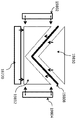
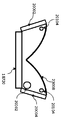
도 200은 중실 전방 조명(solid frontlight)을 캐스팅하는 방법의 제1 단계에서 가장자리에서 지지되는 굴곡된 프리스탠딩 반사 빔 분할기 필름을 개략적으로 나타낸 도면.
도 201은 중실 전방 조명을 캐스팅하는 방법에서 투명한 캐스팅 물질을 주입하고 공기를 배기시키는 구멍을 개략적으로 나타낸 도면.
도 202는 캐스팅된 중실 전방 조명의 상부 부분의 캐스팅을 개략적으로 나타낸 도면.
도 203은 캐스팅된 중실 전방 조명의 상부를 평탄화하기 위해 평탄한 투명 시트를 사용하는 것을 나타낸 개략도.
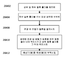
도 204는 조립에 의해 중실 전방 조명을 제조하는 방법에 대한 플로우차트.
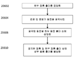
도 205는 캐스팅에 의해 중실 전방 조명을 제조하는 방법에 대한 플로우차트.
도 206은 다단계 성형 공정을 사용하여 중실 필름 홀더를 제조하는 방법에 대한 플로우차트.
도 207은 근거리 통신 시계의 일 실시예를 나타낸 도면.
도 208은 근거리 통신 지원 POS(point of service) 장치와 인터페이스하는 근거리 통신 시계의 일 실시예를 나타낸 도면.
도 209는 근거리 통신 지원 POS(point of service) 장치와 그리고 사용자의 스마트폰과 인터페이스하는 근거리 통신 시계의 일 실시예를 나타낸 도면.The following detailed description of certain embodiments of the present disclosure and the present disclosure can be understood with reference to the following drawings.
1 illustrates an exemplary embodiment of an optical configuration;
Figure 2 shows an RGB LED projector.
3 shows a projector in use;
Figure 4 shows one embodiment of a waveguide and a correction lens disposed in a frame.
5 shows a design for a waveguide eyepiece.
6 illustrates one embodiment of an eyepiece having a see-through lens;
7 shows an embodiment of an eyepiece having a perspective lens;
Figures 8a-8c illustrate embodiments of eyepieces arranged in a flip-up / flip-down configuration.
8D and 8E illustrate embodiments of a snap-fit element of a secondary optic.
Figure 8f illustrates embodiments of flip-up / flip-down electro-optic modules.
9 is a view showing an electrochromic layer of an eyepiece;
Figure 10 illustrates advantages of an eyepiece in real-time image enhancement, keystone correction, and virtual perspective correction.
11 is a plot of the responsivity versus wavelength for three substrates;
12 shows performance of a black silicon sensor.
FIG. 13A is a diagram showing a conventional night vision system, FIG. 13B is a diagram showing a night vision system of the present disclosure, and FIG. 13C is a diagram showing a difference in responsiveness between the two.
14 shows a tactile interface of an eyepiece;
Figure 14a illustrates movement in an embodiment of an eyepiece featuring nod control;
15 shows a ring for controlling an eyepiece;
15aa illustrates, in one embodiment, a ring that controls an eyepiece having an integral camera that allows a user to provide his or her video image as part of a video conference.
15A is a view of a hand mounted sensor in an embodiment of a virtual mouse.
Figure 15B shows a facial actuation sensor mounted on an eyepiece;
15C is a diagram illustrating hand pointing control of an eyepiece;
15D is a view showing hand pointing control of the eyepiece;
15E is a diagram showing an example of eye tracking control;
15F is a view showing hand position determination control of the eyepiece.
Figure 16 illustrates a position-based application mode of an eyepiece.
17 is a diagram showing the difference in image quality between the flexible platform of an uncooled CMOS image sensor capable of VIS / NIR / SWIR imaging and B) an image intensified night vision system.
18 shows an augmented reality-supported custom billboard;
19 illustrates an augmented reality-supported customized advertisement;
20 illustrates augmented reality-supported custom artwork.
20A is a diagram illustrating a method for posting a message to be transmitted when an observer reaches a specific place;
21 is a view showing an alternative configuration of an eyepiece optical system and an electronic device;
22 is a view showing an alternative configuration of an eyepiece optical system and an electronic device;
22A is a view showing an eyepiece having an example of an eyeglow;
22B is a cross-sectional view of an eyepiece having a light control element for reducing glare;
23 is a view showing an alternative configuration of an eyepiece optical system and an electronic device.
24 is a view showing the lock position of the virtual keyboard;
Figure 24A illustrates one embodiment of an image that is virtually projected on a portion of a human body;
25 is a view showing a detailed view of the projector.
26 is a view showing a detailed view of an RGB LED module;
27 shows a game network;
28 is a view showing a method of playing a game using an augmented reality glasses.
29 illustrates an exemplary electronic circuit diagram for an augmented reality eyepiece;
29A is a diagram showing a control circuit for eye tracking control of an external apparatus.
29B illustrates a communication network between users of an augmented reality eyepiece;
30 shows partial image removal by an eyepiece;
31 is a flowchart of a method for identifying a person based on a person's voice captured by a microphone of an augmented reality device;
32 illustrates a typical camera for use in a video telephone or video conference;
33 shows an embodiment of a block diagram of a video telephone camera;
Figures 34A-34E illustrate embodiments of eyepieces for optical or digital stabilization.
35 illustrates one embodiment of a classic cassegrain configuration;
36 is a view showing a configuration of a micro-cassegrain telescoping folded optical camera;
37 is a view showing a swipe process by a virtual keyboard;
38 shows a target marker process for a virtual keyboard;
Figure 38A illustrates one embodiment of a visual word translator.
39 is a view of glasses for capturing biometric data according to an embodiment;
40 is a view showing iris recognition using biometric data capturing glasses according to one embodiment;
41 illustrates face and iris recognition according to one embodiment;
Figure 42 illustrates the use of a dual omni-microphone in accordance with one embodiment.
Figure 43 is a diagram illustrating directionality improvement by a plurality of microphones;
Figure 44 illustrates the use of an adaptive array to tune an audio capture facility in accordance with one embodiment;
45 illustrates a mosaic finger and palm registration system in accordance with one embodiment;
46 shows a conventional optical scheme used by other finger and palm printing systems;
Figure 47 illustrates a method used by a mosaic sensor in accordance with one embodiment;
48 illustrates a device layout of a mosaic sensor according to one embodiment;
49 is a view showing the number of camera view fields and cameras used in the mosaic sensor according to another embodiment;
50 illustrates a bio-phone and a tactical computer in accordance with an embodiment;
Figure 51 illustrates the use of a biophone and tactical computer for capturing latent fingerprints and palm prints according to one embodiment;
52 illustrates a typical DOMEX collection;
53 is a diagram illustrating a relationship between biometric images captured using a biophone and a tactical computer and a biometric watch list according to an embodiment;
54 illustrates a pocket bio-kit according to one embodiment.
55 illustrates components of a pocket biotic kit according to one embodiment.
56 illustrates a fingerprint, a long portal, a geographic location, and a POI registration device, according to one embodiment.
57A-57E illustrate a multi-mode biometric collection, identification, geolocation, and POI registration system, according to one embodiment.
58 illustrates a fingerprint, a long pass, a geographic location, and a POI registered forearm wearable device, according to one embodiment.
59 shows a mobile folding biometric registration kit according to one embodiment;
60 is a high-level system diagram of a biometric registration kit according to an embodiment;
61 is a system diagram of a folding biometric registration device according to one embodiment;
62 illustrates a thin film fingerprint and long-range sensor according to one embodiment;
63 illustrates a biometric collection device for finger, palm, and registration data collection, according to one embodiment.
64 illustrates acquisition of a two stage palm print according to one embodiment;
65 illustrates capture of a fingertip tap in accordance with one embodiment;
Figure 66 illustrates acquisition of a slap and roll print according to one embodiment;
67 shows a system for collecting non-contact fingerprints, long or other biometric prints;
68 shows a process for collecting non-contact fingerprints, long or other biometric prints;
69 shows an embodiment of a clock controller;
Figures 70A-70D illustrate exemplary cases for an eyepiece including a charging function and an integral display.
71 illustrates one embodiment of a ground stake data system;
72 is a block diagram of a control mapping system including an eyepiece;
73 shows a biometric flashlight;
74 shows a helmet-mounted version of an eyepiece;
75 illustrates an embodiment of a situation-aware eyeglass.
FIG. 76A is a view showing an assembled 360 ° imager, and FIG. 76B is a broken view of a 360 ° imager.
77 is an exploded view of a multi-coincident view camera;
78A and 78B are diagrams showing a flight eye;
79 is an exploded top view of an eyepiece;
80 shows a disassembled electro-optical assembly;
81 is an exploded view of a shaft of an electro-optical assembly;
82 illustrates one embodiment of an optical display system that utilizes a planar lighting fixture with a reflective display;
83 shows a structural embodiment of a planar illumination optical system;
84 shows an embodiment assembly of a planar lighting fixture and a reflective display with laser spot suppression components;
85 shows an embodiment of a planar lighting fixture having a grooved feature for redirecting light;
86 illustrates one embodiment of a planar lighting fixture having a pair of grooved features and a " anti-grooved " feature to reduce image aberration.
87 shows one embodiment of a planar lighting fixture made of a laminate structure;
88 illustrates one embodiment of a planar lighting fixture having a wedged optic assembly for redirecting light;
89 is a block diagram of a lighting module according to one embodiment of the present disclosure;
90 is a block diagram of an optical frequency converter according to one embodiment of the present disclosure;
91 is a block diagram of a laser illumination module in accordance with one embodiment of the present disclosure;
92 is a block diagram of a laser illumination system in accordance with another embodiment of the present disclosure;
93 is a block diagram of an imaging system in accordance with one embodiment of the present disclosure;
94A and 94B are top and side views, respectively, of a lens having a photochromic element and a heater element;
95 illustrates one embodiment of a LCoS forward lighting design;
96 is a view of an optically bonded prism optically bonded to a polarizer;
97 is a view showing a prism optically bonded to a polarizer;
98a-c illustrate multiple embodiments of a LCoS frontal lighting design.
99 shows a wedge + OBS overlaid on a LCoS;
Figures 100a and 100b show two versions of the wedge.
101 shows a curved PBS film on an LCoS chip;
102A illustrates one embodiment of an optical assembly;
102B illustrates one embodiment of an optical assembly having an in-line camera.
103 shows an embodiment of an image light source;
104 shows an embodiment of an image light source;
105 shows embodiments of an image light source;
106 is a high-level block diagram depicting a software application program facility and market in connection with the function and control aspects of the eyepiece in one embodiment of the present disclosure;
107 is a functional block diagram of an eyepiece application development environment in an embodiment of the present disclosure;
108 is a view of a platform elements development stack for a software application of an eyepiece in an embodiment of the present disclosure;
109 illustrates a head-mounted display with see-through capability, in accordance with an embodiment of the present disclosure;
110 is a view showing a view of an unlabeled scene viewed through the head mounted display shown in FIG. 109; FIG.
Figure 111 shows a view of the scene of Figure 110 with 2D labels overlaid.
112 is a view showing the 3D label of FIG. 111 displayed on the left eye of the observer; FIG.
113 is a view showing the 3D label of FIG. 111 displayed on the observer's right side; FIG.
114 shows left and right 3D labels of FIG. 111 overlapped with each other to show discrepancies; FIG.
115 shows a view of the scene of FIG. 110 with a 3D label; FIG.
116 is a view showing a captured stereoscopic image of the scene of FIG. 110; FIG.
117 shows the overlaid left and right stereoscopic images of FIG. 116 showing discrepancies between images; FIG.
118 shows a scene of FIG. 110 showing an overlaid 3D label; FIG.
119 is a flow chart for a depth cue method embodiment of the present disclosure that provides a 3D label;
120 is a flowchart for another depth cue method embodiment of the present disclosure that provides a 3D label;
121 is a flow chart for another depth cue method embodiment of the present disclosure that provides a 3D label;
122 is a flow chart for another depth cue method embodiment of the present disclosure that provides a 3D label;
123a illustrates a processor that provides display sequential frames for image display through a display component;
123B shows a display interface configured to omit the display driver;
124 is a schematic view of a prior art waveguide having a plurality of partial reflectors;
125 is a schematic view of a waveguide having a plurality of electrically switchable mirrors in a first position;
125A is a view of a waveguide assembly having an electrical connection;
126 is a schematic view of a waveguide having a plurality of electrically switchable mirrors in a second position;
127 is a schematic view of a waveguide having a plurality of electrically switchable mirrors in a third position;
128 is a schematic view of a waveguide having a plurality of mechanically switchable mirrors in a first position;
128a is a schematic diagram of a waveguide assembly having a microactuator and associated hardware;
129 is a schematic view of a waveguide having a plurality of mechanically switchable mirrors in a second position;
130 is a schematic view of a waveguide having a plurality of mechanically switchable mirrors in a third position;
131A and 131B show a waveguide display with a switchable mirror on the face of the user;
Figures 132a-132c show display areas provided for users with different eye gaps.
133 is a schematic view of a reflected image light source having an edge light source and a forward illumination, showing the passage of light rays of light;
134 is a schematic view of a prior art front lighting comprising a groove;
135 is a schematic diagram of a prior art front illumination including a planar polarizing beam splitter and a curved reflector in a solid block;
136 is a schematic diagram of one embodiment of the present disclosure having a single edge light source and a curved wire grid polarizing film.
137 is a schematic diagram of one embodiment of the present disclosure having two edge light sources and a curved wire grid polarizing film.
138 is a schematic view of a side frame holding a flexible wire grid polarizing film in a desired curved shape;
139 is a flow chart of a method of the present disclosure.
140 is a schematic diagram of a near-eye imaging system having a beam splitter;
141 is a schematic diagram of an optical system module for a near vision system;
Figure 142 shows a pellicle style optical plate.
143 is a view of an insert molded module housing having an embedded optical plate;
144 shows compression molding of a laminate style optical plate;
Figures 145a-c illustrate attachment of an optical film within a molded module housing.
146 is a schematic front perspective view of an AR eyepiece (without eyepiece leg portion) according to one embodiment of the present disclosure;
147 is a schematic rear perspective view of the AR eyepiece of FIG. 146;
Figure 148 is a schematic rear perspective view of the right side of the wearer of the AR eyepiece of Figure 146;
149 is a schematic rear perspective view of the right side of the wearer of the AR eyepiece of FIG. 146;
150 is a schematic perspective view of the components of the AR eyepiece shown in FIG. 146 to support one of the projection screens;
151 is a schematic perspective view of the adjustment platform of the AR eyepiece shown in FIG. 146;
152 is a schematic perspective view of the components of the lateral adjustment mechanism of the AR eyepiece shown in FIG. 146;
Figure 153 is a schematic perspective view of the components of a tilt adjustment mechanism of the AR eyepiece shown in Figure 146;
154 is a chart showing dark adaptation curves for human eyes;
FIG. 155 is a chart showing the effect of progressively reducing the illuminance on the dark adaptation curve to the human eye. FIG.
156 shows a head-mounted display having a perspective function;
157 is a graph showing the relationship between display brightness and time when entering a dark environment;
158 is a flowchart of a dark adaptation method;
Figure 159 shows a virtual keyboard presented in the field of view of the user.
160 shows an example of a display system having an optically flat reflective surface;
161 is a diagram showing an example of a near vision display module;
Figure 162 illustrates an example of an optical system associated with one type of head mounted display.
Figure 163 shows an example in which a baffle is added between the illumination beam splitter and the lens in the interior of the housing;
164 illustrates an example of another embodiment of the present disclosure in which a baffle is added to the entrance surface of the lens;
165 illustrates an example of another embodiment of the present disclosure in which a baffle is added to the exit of the lens;
Figure 166 illustrates an example of another embodiment of the present disclosure in which the baffle is attached to the housing between the lens and the image beam splitter.
Figure 167 illustrates an example of a further embodiment of the present disclosure in which an absorbent coating is applied to a side wall of the housing.
168 shows an illustration of another source of stray light in a head mounted display wherein the stray light comes directly from the edge of the light source.
169 is a view showing that a stray light is reflected from an arbitrary reflective surface or an edge of a lens in a housing;
170 shows an illustration of another further embodiment of the present disclosure in which a baffle is provided adjacent to a light source;
Figure 171 illustrates that an absorbent coating with ridges may be used wherein a series of small ridges or stairs form a series of < RTI ID = 0.0 > It functions as a baffle.
172 shows a further embodiment of a tape or sheet comprising a carrier sheet and ridges that can be used to block reflected light;
Figure 173 is an exploded view of an embodiment of a pair of glasses.
Figure 174 shows a wiring design of a spectacle and a wire guide;
175 is an enlarged view of a wiring design of a spectacle and a wire guide;
176 (a) shows a wiring design of glasses and a broken view of a wire guide.
Fig. 176b shows a wiring design of glasses and a broken view of a wire guide; Fig.
Fig. 176c is a diagram showing the wiring design of glasses and a complete view of the wire guide; Fig.
177 is a view showing a U-shaped accessory for fixing glasses.
Figure 178 shows an embodiment of a cable-tensioned system for securing glasses to a user's head.
Figures 179a and 179b illustrate an embodiment of a cable-tensioning system for securing glasses to a user's head with a curved configuration.
180 illustrates one embodiment of a cable-tensioning system for securing glasses to a wearer's head;
Figure 181 shows an embodiment of a system for securing glasses to a user's head;
Figure 182 illustrates an embodiment of a system for securing glasses to a user's head.
Figure 183 shows an embodiment of a system for fixing glasses to a user's head.
Figure 184 illustrates an embodiment of a system for securing glasses to a user's head.
185a shows an embodiment of an optical train;
185B shows a sample ray trace for light in one embodiment of a light train;
Figure 186 illustrates one embodiment of an LCoS + ASIC package.
Figure 187 schematically illustrates a prior art front illumination using a single light source and a beam splitter cube;
Figure 188 schematically depicts a prior art frontlight using a single light source and a reflective beam splitter layer;
189 schematically shows a front light using a single light source, in which a flat reflective beam splitter layer is arranged at a reduced angle.
FIG. 190 schematically shows a front light using a single light source, wherein the reflective beam splitter layer is curved. FIG.
191 schematically shows a front light using a dual light source, wherein a curved reflective beam splitter film with a flat surface is disposed in a transparent solid body.
FIG. 192 schematically shows a front light using a dual light source, wherein a bent free-standing reflective beam splitter film having a flat surface is used.
Figure 193 schematically shows front illumination using a dual light source, wherein a curved free standing reflective beam splitter film with a curved surface is used.
Figure 194 is a schematic representation of front illumination using a dual light source, in which a curved reflective beam splitter film with a curved surface is disposed in a transparent medium.
195 is a schematic view of a front light using a single light source having opposing mirrors and a quarter wave film to recycle a portion of the polarized light, wherein the curved reflective beam splitter film having a flat surface is transparent Provided within the entity.
196 schematically depicts a frontal illumination using a single light source having opposite mirrors and quarter wave films to recycle a portion of the polarized light, wherein the free standing reflective polarizer beam splitter film with a flat surface Is provided.
197 is a schematic representation of a front light using a single light source having opposite mirrors and quarter wave films to recycle a portion of the polarized light, wherein the free standing reflective polarizer beam splitter film having a curved surface Is provided.
198 is a schematic view of a method of manufacturing a front illumination in which a curved reflective beam splitter film having a flat surface as shown in FIG. 197 is disposed in a transparent intermediate body, wherein a reflective beam splitter film is formed and arranged The upper and lower film holders are used and a portion of the polarized light is recycled.
199 is a schematic illustration of a front light, for use with a dual light source, produced using the method illustrated in FIG. 198 and in which a portion of the polarized light is recirculated;
200 schematically depicts a curved free standing reflective beam splitter film supported at the edge in a first step of a method of casting a solid frontlight;
201 is a schematic view of a hole for injecting transparent casting material and venting air in a method for casting solid front lighting.
202 schematically illustrates the casting of the upper portion of the cast solid front light.
Figure 203 is a schematic diagram showing the use of a flat transparent sheet to planarize the top of cast solid front lighting.
204 is a flowchart of a method of fabricating solid front lighting by assembly.
205 is a flowchart for a method of manufacturing solid front lighting by casting;
Figure 206 is a flow chart of a method for manufacturing a solid film holder using a multistage molding process.
207 shows an embodiment of a local communication clock;
Figure 208 illustrates one embodiment of a telecommunications clock that interfaces with a point-of-service (POS) device that supports point-to-point communication.
Figure 209 illustrates an embodiment of a point-of-service (POS) device that supports near-field communication and a short-range communication clock that interfaces with a user's smartphone.
본 개시 내용은 접안경 전기 광학계(eyepiece electro-optics)에 관한 것이다. 접안경은 투시(see-through) 또는 반투명 렌즈 상에 영상을 투사하여, 접안경의 착용자가 디스플레이된 영상 뿐만 아니라 주변 환경도 볼 수 있게 해주는 데 적합한 프로젝션 광학계를 포함할 수 있다. 프로젝터라고도 하는 프로젝션 광학계는 필드 순차 색상(field sequential color)을 사용하는 RGB LED 모듈을 포함할 수 있다. 필드 순차 색상에서는, 단일의 완전 컬러 영상(full color image)이, LCoS(liquid crystal on silicon) 광학 디스플레이(210)에 의해 개별적으로 영상화되는, 적색, 녹색 및 청색의 원색(primary color)에 기초한 색상 필드들(color fields)로 분해될 수 있다. 각각의 색상 필드가 광학 디스플레이(210)에 의해 영상화되기 때문에, 대응하는 LED 색상이 턴온된다. 이들 색상 필드가 빠르게 순차적으로 디스플레이될 때, 완전 컬러 영상을 볼 수 있다. 필드 순차 색상 조명에서, 청색 및/또는 녹색 영상에 대해 적색 영상을 시프트시킴으로써 접안경에 생기는 투사된 영상이 임의의 색수차에 대해 조절될 수 있다. 영상은 그 후에 2 표면 자유 형태 도파관(two surface freeform waveguide) 내로 반사될 수 있고, 여기서 영상 광은 사용자가 영상을 보는 렌즈의 활성 보기 영역(active viewing area)에 도달할 때까지 내부 전반사(TIR)를 겪는다. 메모리 및 운영 체제를 포함할 수 있는 프로세서는 LED 광원 및 광학 디스플레이를 제어할 수 있다. 프로젝터는 또한 디스플레이 결합 렌즈(display coupling lens), 집광 렌즈(condenser lens), 편광 빔 분할기, 및 시야 렌즈(field lens)를 포함할 수 있거나 그에 광학적으로 결합될 수 있다.The present disclosure relates to eyepiece electro-optics. The eyepiece may include a projection optics suitable for projecting an image on a see-through or translucent lens to allow the wearer of the eyepiece to view the displayed image as well as the surrounding environment. A projection optics, also referred to as a projector, may include an RGB LED module using a field sequential color. In a field sequential color, a single full color image is displayed on a color basis based on the primary colors of red, green, and blue, which are individually imaged by a liquid crystal on silicon (LCoS) Can be decomposed into color fields. Since each color field is imaged by the
도 123a 및 도 123b를 참조하면, 프로세서(12302)(예컨대, 디지털 신호 처리기)는 접안경(100)의 디스플레이 구성요소(12328)(예컨대, LCOS 디스플레이 구성요소)를 통한 영상 디스플레이를 위한 디스플레이 순차 프레임들(12324)을 제공할 수 있다. 실시예들에서, 순차 프레임들(12324)은 프로세서(12302)와 디스플레이 구성요소(12328) 사이의 중간 구성요소로서의 디스플레이 구동기(12312)를 사용하여 또는 이를 사용함이 없이 생성될 수 있다. 예를 들어, 도 123a를 참조하면, 프로세서(12302)는 프레임 버퍼(12304) 및 디스플레이 인터페이스(12308)[예컨대, MIPI(mobile industry processor interface)]를 DSI(display serial interface)와 함께 포함할 수 있다. 디스플레이 인터페이스(12308)는 픽셀당 RGB 데이터(12310)를 프로세서(12302)와 디스플레이 구성요소(12328) 사이의 중간 구성요소로서의 디스플레이 구동기(12312)에 제공할 수 있고, 여기서 디스플레이 구동기(12312)는 픽셀당 RGB 데이터(12310)를 받아서, 적색(12318), 녹색(12320) 및 청색(12322)에 대한 개별적인 전체 프레임 디스플레이 데이터(full frame display data)를 발생하고, 이와 같이 디스플레이 순차 프레임들(12324)을 디스플레이 구성요소(12328)에 제공한다. 그에 부가하여, 디스플레이 구동기(12312)는 전체 프레임들(12318, 12320, 12322)을 디스플레이 순차 프레임들(12324)로서 디스플레이 구성요소(12328)에 전달하는 것을 동기화하는 등을 위해 타이밍 신호를 제공할 수 있다. 다른 예에서, 도 123b를 참조하면, 디스플레이 인터페이스(12330)는 적색(12334), 녹색(12338), 및 청색(12340)에 대한 전체 프레임 디스플레이 데이터를 디스플레이 순차 프레임들(12324)로서 디스플레이 구성요소(12328)에 곧바로 제공함으로써 디스플레이 구동기(12312)를 생략하도록 구성되어 있을 수 있다. 그에 부가하여, 타이밍 신호(12332)가 디스플레이 인터페이스(12330)로부터 디스플레이 구성요소에 직접 제공될 수 있다. 이 구성은 디스플레이 구동기를 필요 없게 함으로써 상당히 더 낮은 전력 소모를 제공할 수 있다. 이러한 직접적인 패널 정보(panel information)가 구동기를 필요없게 할 수 있을 뿐만 아니라, 구성의 전체적인 논리를 단순화시키고 픽셀들로부터 패널 정보를 재형성하는 데, 프레임으로부터 픽셀 정보를 발생하는 데, 기타를 위해 필요한 중복 메모리(redundant memory)를 제거시킬 수 있다.Referring to Figures 123A and 123B, a processor 12302 (e.g., a digital signal processor) is operatively coupled to display sequential frames for display of images through the
도 186을 참조하면, 실시예들에서, LCoS + ASIC 패키지(18600)의 수율을 향상시키기 위해, ASIC이 상부측에 보강판(stiffener)을 갖는 FPC(flexible printed circuit)(18604) 상에 탑재될 수 있다. 상부측 보강판은, 길이가 ASIC과 같은 경우, 전체 패키지의 두께를 증가시키지 않는다. FPC는 보다 많은 핀 수에 대한 ZIF(zero insertion force) 연결부 또는 보드간 커넥터(Board to Board connector) 등의 커넥터(18602)를 통해 유리 섬유 강화 에폭시 라미네이트(FR4)(18608) 상의 LCoS 등의 표준 LCoS 패키지에 연결될 수 있다. ASIC 보강판(들) 및 LCoS를 FPC에 접합시키기 위해 감압 접착제가 사용될 수 있다.Referring to Figure 186, in embodiments, to improve the yield of the LCoS +
도 1을 참조하면, 증강 현실 접안경(100)의 예시적인 실시예가 도시되어 있을 수 있다. 접안경(100)의 실시예들이 도 1에 도시되어 있는 요소들 전부를 포함하지는 않을 수 있는 반면, 다른 실시예들이 부가의 또는 상이한 요소들을 포함할 수 있다는 것을 잘 알 것이다. 실시예들에서, 광학 요소들이 접안경의 프레임(102)의 아암 부분들(122)에 매립되어 있을 수 있다. 영상들이 프로젝터(108)를 사용하여 프레임(102)의 개구부에 배치되어 있는 적어도 하나의 렌즈(104) 상에 투사될 수 있다. 나노프로젝터, 피코프로젝터, 마이크로프로젝터, 펨토프로젝터, 레이저-기반 프로젝터, 홀로그래픽 프로젝터 등과 같은 하나 이상의 프로젝터(108)가 접안경 프레임(102)의 아암 부분에 배치될 수 있다. 실시예들에서, 양쪽 렌즈(104)가 투명 또는 반투명일 수 있는 반면, 다른 실시예들에서는, 단지 하나의 렌즈(104)만이 반투명이고 다른 하나는 불투명이거나 없다. 실시예들에서, 2개 이상의 프로젝터(108)가 접안경(100)에 포함되어 있을 수 있다.Referring to FIG. 1, an exemplary embodiment of an
도 1에 도시되어 있는 것과 같은 실시예들에서, 접안경(100)은 또한 적어도 하나의 관절형 이어폰(articulating ear bud)(120), 무선 송수신기(118), 및 LED 광 엔진(LED light engine)으로부터의 열을 흡수하여 이를 냉각시키고 전체 밝기에서 동작할 수 있게 해주는 히트 싱크(heat sink)(114)를 포함할 수 있다. 또한, 하나 이상의 TI OMAP4(open multimedia applications processors)(112) 및 RF 안테나를 갖는 플렉스 케이블(flex cable)(110)이 있으며, 이들 모두가 본 명세서에서 추가로 기술될 것이다.1,
일 실시예에서, 도 2를 참조하면, 프로젝터(200)는 RGB 프로젝터일 수 있다. 프로젝터(200)는 하우징(202), 히트 싱크(204), 및 RGB LED 엔진 또는 모듈(206)을 포함할 수 있다. RGB LED 엔진(206)은 LED, 다이크로익(dichroic), 집광기(concentrator) 등을 포함할 수 있다. DSP(digital signal processor)(도시 생략)는, LED 조명의 세기, 지속기간 및 혼합을 제어하기 위해, 영상 또는 비디오 스트림을 전압 강하/전류 수정, PWM(pulse width modulation) 신호 등과 같은 제어 신호로 변환할 수 있다. 예를 들어, DSP는 복수의 색을 발생하는 각각의 LED를 통해 흐르는 평균 전류를 제어하기 위해 각각의 PWM 신호의 듀티비를 제어할 수 있다. 접안경의 정지 영상 코프로세서(still image co-processor)는 잡음 필터링, 영상/비디오 안정화, 및 얼굴 검출을 이용할 수 있고, 영상 강조를 행할 수 있다. 접안경의 오디오 백엔드 프로세서(audio back-end processor)는 버퍼링, SRC, 등화(equalization) 등을 이용할 수 있다.In one embodiment, referring to FIG. 2, the
프로젝터(200)는 LCoS 디스플레이 등의 광학 디스플레이(210), 및 도시되어 있는 것과 같은 다수의 구성요소들을 포함할 수 있다. 실시예들에서, 프로젝터(200)는 단일 패널 LCoS 디스플레이(210)로 설계될 수 있지만, 3 패널 디스플레이도 가능할 수 있다. 단일 패널 실시예에서, 디스플레이(210)는 적색, 청색 및 녹색으로 순차적으로 조명된다(필드 순차 색상이라고도 함). 다른 실시예들에서, 프로젝터(200)는 백라이트 방식(back-lit) LCD(liquid crystal display), 프런트라이트 방식(front-lit) LCD, 반투과형(transflective) LCD, OLED(organic light emitting diode), FED(field emission display), FLCOS(ferroelectric LCoS), 사파이어 상에 탑재된 액정 기술, 투명 액정 마이크로디스플레이, 양자점 디스플레이 등과 같은 대안의 광학 디스플레이 기술들을 사용할 수 있다.The
다양한 실시예들에서, 디스플레이는 3D 디스플레이, LCD, 박막 트랜지스터 LCD, LED, LCOS, FLCOS(ferroelectric liquid crystal on silicon) 디스플레이, CMOS 디스플레이, OLED, QLED, OED 픽셀들 사이의 접합부에 CMOS 스타일 픽셀 센서를 가지는 OLED 어레이, 투과형 LCoS 디스플레이, CRT 디스플레이, VGA 디스플레이, SXGA 디스플레이, QVGA 디스플레이, 비디오 기반 시선 추적기(video based gaze tracker)를 갖는 디스플레이, 사출 동공 확장(exit pupil expanding) 기술을 갖는 디스플레이, 아사히 필름(Asahi film) 디스플레이, 자유 형태 광학계(free form optics) 디스플레이, XY 다항식 결합기(XY polynomial combiner) 디스플레이, 도광체 전달(light guide transfer) 디스플레이, 아몰레드(Amoled) 디스플레이 등일 수 있다. 실시예들에서, 디스플레이는 접안경이 영상 광원으로부터의 영상을 홀로그램으로서 디스플레이할 수 있게 해주는 홀로그래픽 디스플레이일 수 있다. 실시예들에서, 디스플레이는 액정 반사 마이크로디스플레이일 수 있다. 이러한 디스플레이는 편광 광학계를 포함할 수 있고, 특정의 OLED 마이크로디스플레이에 비해 밝기를 향상시킬 수 있다. 실시예들에서, 디스플레이는 자유 형태 프리즘 디스플레이(free form prism display)일 수 있다. 자유 형태 프리즘 디스플레이는 3D 입체 영상 기능을 달성할 수 있다. 실시예들에서, 디스플레이는 Cannon의 특허 제6,384,983호 및/또는 Olympus의 특허 제6,181,475호에 기술되어 있는 그 디스플레이와 유사하거나 동일할 수 있다. 또 다른 실시예들에서, 디스플레이는 비디오 기반 시선 추적기를 포함할 수 있다. 실시예들에서, 적외선 광원의 광 빔이 분할되고 EPE(exit pupil expander) 내부로 확장되어 EPE로부터 눈 쪽으로 평행화된 빔(collimated beam)을 생성할 수 있다. 소형 비디오 카메라(miniature video camera)가 각막을 촬영할 수 있고, 동공 및 적외선 빔의 글린트(glint)의 위치를 알아냄으로써 눈 시선 방향이 계산될 수 있다. 사용자 교정 후에, 시선 추적기로부터의 데이터는 입력 장치로서 사용될 수 있는 디스플레이된 영상에서의 사용자 초점(focus point)을 반영할 수 있다. 이러한 장치는 핀란드 탐페레 소재의 Nokia Research Center에 의해 제공되는 것과 유사할 수 있다. 게다가, 실시예들에서, 디스플레이는 사출 동공을 확대시켜 영상을 새로운 위치로 전달하는 사출 동공 확장기(exit pupil expander)를 포함할 수 있다. 따라서, 사용자의 양눈의 전방에 단지 얇은 투명 플레이트만 위치되면 될 수 있고, 영상 광원이 다른 곳에 위치될 수 있다. 또 다른 실시예들에서, 디스플레이는 비축 광학계 디스플레이(off axis optics display)일 수 있다. 실시예들에서, 이러한 디스플레이는 개구(aperture)의 기계적 중심과 일치하지 않을 수 있다. 이것은 보조 광학 요소, 계기 패키지(instrument package) 및/또는 센서가 주 개구(primary aperture)를 방해하는 것을 방지할 수 있고, 초점에서 계기 패키지 및/또는 센서에의 액세스를 제공할 수 있다. 예를 들어, 아몰레드(Amoled, active-maxtrix organic light-emitting diode) 디스플레이는 2가지 방식으로 보다 많은 광을 통과시키는 Nouvoyance의 PenTile이라고 하는 픽셀 설계를 사용할 수 있다. 첫째, 적색, 청색 및 녹색 서브픽셀이 종래의 디스플레이에서의 것보다 더 크다. 둘째, 4개마다 하나의 서브픽셀이 투명하다. 이것은 백라이트가 보다 적은 전력을 사용하고 보다 밝게 발광할 수 있다는 것을 의미한다. 보다 적은 수의 서브픽셀은 보통 보다 낮은 해상도를 의미할 것이지만, PenTile 디스플레이는 RGB 스트라이프 패널(RGB stripe panel)의 약 1/3의 서브픽셀을 사용하면서 눈이 동일한 해상도를 인지하도록 하기 위해 개개의 서브픽셀을 사용한다. PenTile 디스플레이는 또한 영상 처리 알고리즘을 사용하여 장면의 밝기를 판정하고, 보다 어두운 영상에 대해 백라이트를 자동으로 디밍(dimming)시킨다.In various embodiments, the display includes a CMOS-style pixel sensor at the junction between the 3D display, LCD, thin film transistor LCD, LED, LCOS, ferroelectric liquid crystal on silicon (FLCOS) display, CMOS display, OLED, QLED, (OLED) array, transmissive LCoS display, CRT display, VGA display, SXGA display, QVGA display, display with video based gaze tracker, display with exit pupil expanding technology, An asahi film display, a free form optics display, an XY polynomial combiner display, a light guide transfer display, an amoled display, and the like. In embodiments, the display may be a holographic display that allows the eyepiece to display an image from the image light source as a hologram. In embodiments, the display may be a liquid crystal reflective microdisplay. Such a display can include a polarization optic and can improve brightness compared to a particular OLED microdisplay. In embodiments, the display may be a free form prism display. The free-form prism display can achieve the 3D stereoscopic function. In embodiments, the display may be similar or identical to the display described in Cannon Patent No. 6,384,983 and / or Olympus Patent No. 6,181,475. In still other embodiments, the display may include a video based gaze tracker. In embodiments, the light beam of the infrared light source may be split and expanded into the exit pupil expander (EPE) to produce a collimated beam from the EPE towards the eye. A miniature video camera can capture the cornea and the eye line direction can be calculated by locating the glint of the pupil and infrared beam. After user calibration, the data from the gaze tracker can reflect the user's focus point in the displayed image that can be used as an input device. Such a device may be similar to that provided by the Nokia Research Center in Tampere, Finland. In addition, in embodiments, the display may include an exit pupil expander that enlarges the exit pupil to deliver the image to a new location. Thus, only a thin transparent plate may be positioned in front of the user's two eyes, and the image light source may be located elsewhere. In still other embodiments, the display may be an off axis optics display. In embodiments, such a display may not coincide with the mechanical center of the aperture. This can prevent the secondary optical element, the instrument package and / or the sensor from interfering with the primary aperture, and provide access to the instrument package and / or sensors at the focus. For example, an amoled (active-maxtrix organic light-emitting diode) display can use a pixel design called Nouvoyance's PenTile, which transmits more light in two ways. First, red, blue, and green subpixels are larger than in conventional displays. Second, one subpixel is transparent for every four pixels. This means that the backlight uses less power and can emit brighter. A smaller number of subpixels will usually mean a lower resolution, but the PenTile display uses a sub-pixel of about 1/3 of the RGB stripe panel, Pixels. The PenTile display also uses image processing algorithms to determine the brightness of the scene and automatically dims the backlight for darker images.
앞서 기술한 종래 기술의 한계를 극복하기 위해, 본 개시 내용은 디스플레이 시야에 걸쳐 영상의 부분들의 순차 주사(progressive scan)를 제공하기 위해 순차적으로 사용될 수 있는 전환가능 거울들의 일체형 어레이를 도파관에 제공한다. 거울들을 순차적으로 반사에서 투과로 신속히 전환함으로써, 인지가능한 플리커 없이 영상이 사용자에게 제공될 수 있다. 각각의 전환가능 거울이 반사 상태보다 더 많이 투과 상태에 있기 때문에, 전환가능 거울들의 어레이는 사용자에게 투명한 것처럼 보이면서 또한 디스플레이된 영상을 사용자에게 제시한다.In order to overcome the limitations of the prior art described above, the present disclosure provides an integrated array of switchable mirrors to the waveguide that can be used sequentially to provide a progressive scan of the portions of the image over the display field of view . By rapidly switching mirrors sequentially from reflection to transmission, images can be provided to the user without perceptible flicker. Since each switchable mirror is in a more transmissive state than the reflective state, the array of switchable mirrors appears to the user as transparent and also presents the displayed image to the user.
영상 광원으로부터의 광을 도파관에 의해 제시하는 것은 기술 분야의 당업자에 공지되어 있으며, 그에 따라 본 명세서에서 논의되지 않을 것이다. 도파관 및 영상 광원으로부터의 광을 디스플레이 영역으로 전달하는 것에 대한 예시적인 논의는 미국 특허 제5076664호 및 제6829095호에 제공되어 있다. 본 개시 내용은 영상을 사용자에게 제공하기 위해 도파관에서의 영상 광을 방향 전환시키는 방법 및 장치를 포함하고 있으며, 여기서 도파관에서의 영상 광은 영상 광원으로부터 제공된 것이다.Presenting light from an image light source by a wave guide is well known to those skilled in the art and will not be discussed herein as such. An exemplary discussion of delivering light from waveguides and image light sources to the display area is provided in U.S. Patent Nos. 5076664 and 6829095. The present disclosure includes a method and apparatus for redirecting image light in a waveguide to provide an image to a user, wherein the image light in the waveguide is provided from an image light source.
도 125는 영상 광(12504)을 사용자에게 제공하기 위해 도파관(12510)을 통해 전달되는 영상 광원(12502)으로부터의 광을 방향 전환시키는 전환가능 거울들(12508a 내지 12508c)의 일체형 어레이를 갖는 도파관 디스플레이 장치(12500)를 나타낸 것이다. 본 개시 내용에서, 3개의 전환가능 거울들(12508a 내지 12508c)이 도시되어 있지만, 어레이는 상이한 수의 전환가능 거울들을 포함할 수 있다. 도 125에 도시되어 있는 전환가능 거울들은 액정 전환가능 거울을 비롯한 전기적 전환가능 거울이다. 전환가능 거울들(12508a 내지 12508c)로서 도시되어 있는 얇은 층들에 액정 물질을 포함시키기 위해 커버 유리(12512)가 제공된다. 도 125는 또한 전원선(power wire)(12514 및 12518)을 나타내고 있다.Figure 125 illustrates a waveguide display 12508 having an integral array of
도파관(12510) 및 전환가능 거울들(12508a 내지 12508c)의 일체형 어레이는, 적당히 평탄한 한, 플라스틱 또는 유리 물질로 이루어져 있을 수 있다. 대부분의 액정 장치에서만큼 두께 균일성이 중요하지는 않은데, 그 이유는 전환가능 거울이 높은 반사율을 가지기 때문이다. 전환가능 액정 거울의 구조는 미국 특허 제6999649호에 기술되어 있다.The integral array of
도 126 및 도 127은, 한번에 어레이에서의 전환가능 거울들 중 하나만이 반사 상태에 있고 어레이에서의 다른 전환가능 거울들이 이어서 투과 상태에 있다는 점에서, 본 개시 내용의 순차적 측면을 나타내고 있다. 도 124는 제1 전환가능 거울(12508a)이 반사 상태에 있고, 따라서 영상 광원(12502)으로부터의 광을, 영상의 일부분을 사용자에게 제시하는 영상 광(12504)으로 되도록 방향 전환시키는 것을 나타내고 있다. 다른 전환가능 거울들(12508b 및 12508c)은 투과 상태에 있다. 도 124는 도파관(12410)을 추가로 나타내고 있다.Figures 126 and 127 show sequential aspects of the present disclosure in that only one of the switchable mirrors in the array at a time is in a reflective state and the other switchable mirrors in the array are then in a transmissive state. Figure 124 illustrates that the first
도 126에서, 전환가능 거울들(12508a 및 12508c)은 투과 상태에 있는 반면, 전환가능 거울(12508b)은 반사 상태에 있다. 이 조건은 영상의 그와 관련된 부분을 갖는 영상 광(12600)을 사용자에게 제공한다. 마지막으로, 도 127에서, 전환가능 거울들(12508a 및 12508b)은 투과 상태에 있는 반면, 전환가능 거울(12508c)은 반사 상태에 있다. 이 마지막 조건은 영상의 그와 관련된 부분을 갖는 영상 광(12700)을 사용자에게 제공한다. 이 마지막 조건 이후에, 이 시퀀스가 도 124에 도시되어 있는 바와 같이 반복되고, 이어서 도 125에 도시되어 있는 것이 오고, 그 다음에 도 126에 도시되어 있는 바와 같이 되어, 영상의 순차 주사를 제공한다. 사용자가 디스플레이된 영상을 보고 있는 동안 이 시퀀스가 계속하여 반복된다. 이와 같이, 영상 광원(12502)으로부터의 광의 전부가 시퀀스에서의 임의의 주어진 때에 단일의 전환가능 거울에 의해 방향 전환된다. 영상 광원은 전환가능 거울들이 시야에 걸쳐 영상 광(12504)의 순차 주사를 제공하는 동안 연속하여 동작할 수 있다. 영상 광이 보다 밝게 인지되거나 상이한 전환가능 거울들에 대해 상이한 색상 균형이 있는 경우, 영상 광원이 보상을 위해 조절될 수 있거나, 영상 광원의 밝기 또는 색상 균형이 전환가능 거울들의 어레이의 전환 시퀀스와 동기하도록 변조될 수 있다. 본 개시 내용의 다른 실시예에서, 4개의 전환가능 거울들의 어레이에 대해 반복하여 1, 3, 2, 4와 같이 인터레이스된 영상(interlaced image)을 사용자에게 제공하기 위해 전환가능 거울들의 전환 순서가 변경될 수 있다.In Figure 126, switchable mirrors 12508a and 12508c are in the transmissive state, while
도 128은 기계적으로 구동되는 전환가능 거울들의 일체형 어레이가 제공되어 있는 본 개시 내용의 다른 실시예를 나타낸 것이다. 이 경우에, 도파관 디스플레이 장치(12800)에서의 전환가능 거울들은 공극 또는 표면들(12810a 내지 12810c)과의 광학적 접촉을 교대로 제공하기 위해, 각각, 이동되는 프리즘들(12804a 내지 12804c)을 포함한다. 도 128에 도시된 바와 같이, 표면(12810a)이 내부 전반사에 의해 동작하는 반사 표면이도록 공극을 제공하기 위해 프리즘(12804a)이 아래쪽으로 이동되었다. 이와 동시에, 표면들(12810b 및 12810c)이 투과형이도록 표면들(12810b 및 12810c)과의 광학적 접촉을, 각각, 제공하기 위해 프리즘들(12804b 및 12804c)이 위쪽으로 밀어졌다. 이 조건은 영상 광원(12502)으로부터의 광을, 영상의 일부분을 사용자에게 제시하는 영상 광(12802)으로 되도록 방향 전환시킨다. 이 실시예에서, 전환가능 거울은 투과율이 거의 100%인 광학적 접촉으로부터 반사율이 거의 100%인 내부 전반사로 움직인다. 도 128은 또한 전원선(12812), 마운트(mount) 및 공통 접지 연결부(12814), 그리고 마이크로작동기들(12818a 내지 12818c)을 나타내고 있다.Figure 128 shows another embodiment of the present disclosure in which an integral array of mechanically driven switchable mirrors is provided. In this case, the switchable mirrors in
도 129 및 도 130은 전환가능 거울 어레이에서의 기계적으로 구동되는 전환가능 거울들에 대한 시퀀스에서의 다른 조건들을 나타내고 있다. 도 129에서, 표면들(12810a 및 12810c)과의 광학적 접촉을, 각각, 제공하기 위해 프리즘들(12804a 및 12804c)이 위쪽으로 밀어졌고, 그에 의해 영상 광원(12502)으로부터의 광에 대해 투과 상태를 제공한다. 이와 동시에, 영상 광원(12502)으로부터의 광이 방향 전환되어 영상의 관련 부분을 사용자에게 제시하는 영상 광(12900)으로 되도록 표면(12810b)에 공극을 생성하기 위해 프리즘(12804b)이 아래쪽으로 이동된다. 도 130에 도시되어 있는 시퀀스의 마지막 단계에서, 영상 광원으로부터의 광이 통과하여 표면(12810c)으로 가도록 표면들(12810a 및 12810b)과의 광학적 접촉을, 각각, 제공하기 위해 프리즘들(12804a 및 12804b)이 위쪽으로 밀어진다. 표면(12810c)이 내부 전반사를 갖는 반사 표면으로 되고 영상 광원(12502)으로부터의 광이 방향 전환되어 영상의 그와 관련된 부분을 갖는 영상 광(13000)으로 되도록 표면(12810c)에 공극을 제공하기 위해 프리즘(12804c)이 아래쪽으로 이동된다.129 and 130 show other conditions in the sequence for the mechanically driven switchable mirrors in the switchable mirror array. In Figure 129,
이전의 논의에서, 내부 전반사에 대한 조건들은, 기술 분야의 당업자에게 공지되어 있는 바와 같이, 도파관(12808)의 물질 및 공기의 광학적 특성에 기초하고 있다. 도 128 내지 도 130에 도시되어 있는 바와 같이 90도 반사를 획득하기 위해, 도파관(12808)의 굴절률이 1.42 초과이어야만 한다. 프리즘들(12804a 내지 12804c)과 표면들(12810a 내지 12810c) 사이에, 각각, 광학적 접촉을 제공하기 위해, 프리즘들(12804a 내지 12804c)의 표면들이 표면들(12810a 내지 12810c)의 표면과 1.0 마이크로미터 내에서 정합되어야만 한다. 마지막으로, 영상 광원(12502)으로부터의 광이, 계면들에서 편향하는 일 없이, 도파관(12808) 및 프리즘들(12804a 내지 12804c)을 통해 진행하기 위해, 프리즘들(12804a 내지 12804c)의 굴절률이 도파관(12808)의 굴절률과 약 0.1 내에서 동일해야만 한다.In the previous discussion, the conditions for total internal reflection are based on the optical properties of the material and air of the
도 131a 및 도 131b는 본 개시 내용에 포함되어 있는 것과 같은 전환가능 거울들의 어레이를 갖는 도파관 어셈블리(13102)의 예시들을 나타낸 것이다. 도 131a는 도파관 어셈블리(13102)가 사용자의 두부에 있는 것의 측면도를 나타낸 것이고, 여기서 영상 광(13100)이 사용자의 눈으로 지향되도록 전환가능 거울들의 어레이의 장축이 수직으로 배향되어 있다. 도 131b는 도파관 어셈블리(13102)가 사용자의 두부에 있는 것을 위쪽에서 본 도면(overhead view)을 나타낸 것이고, 여기서 전환가능 거울들(13104)의 어레이의 단축이 보일 수 있고, 영상 광(13100)이 사용자의 눈(13110)에 제공된다. 도 131a 및 도 131b에서, 영상 광(13100)에서 제공되는 시야가 명확하게 보일 수 있다. 도 131b에서, 어레이에서의 상이한 전환가능 거울들에 의해 제공되는 것과 같은 영상의 각자의 부분들이 또한 보일 수 있다. 도 131b는 또한 영상 광원(13108)을 포함하는 도파관 어셈블리(13102)의 일 실시예를 나타낸 것이고, 여기서 영상 광원(13108)은 LCOS 디스플레이 또는 LCD 디스플레이 등의 소형 디스플레이(miniature display)로부터의 광 - 이 광은 나중에 도파관에 의해 전환가능 거울들로 전달되고, 여기서 이 광은 전환가능 거울들에 의해 방향 전환되어 사용자의 눈(13110)에 제시되는 영상 광(13100)으로 됨 - 을 제공하는 내부 광원을 가진다.131A and 131B illustrate examples of
전환가능 거울들이 영상의 순차적 부분들을 사용자에게 제공하도록 동작되기 때문에 사용자에 의한 영상 플리커의 인지를 감소시키기 위해, 전환가능 거울 시퀀스는 바람직하게는 60 Hz보다 더 빠르게 동작된다. 이 경우에, 어레이 내의 n개의 전환가능 거울들 각각은, 시퀀스의 각각의 사이클에서, (1/60) X 1/n초 동안 반사 상태에 있고 이어서 (1/60) X (n-1)/n초 동안 투과 상태에 있다. 그에 따라, 각각의 전환가능 거울은 반사 상태에 있는 것보다 시퀀스에서 각각의 사이클의 더 큰 부분 동안 투과 상태에 있고, 그 결과 사용자는 전환가능 거울들의 어레이를 비교적 투명한 것으로 인지한다.In order to reduce the perception of the image flicker by the user since the switchable mirrors are operated to provide sequential portions of the image to the user, the switchable mirror sequence is preferably operated faster than 60 Hz. In this case, each of the n switchable mirrors in the array is in the (1/60) X (n-1) / n-second reflective state for each cycle of the sequence, and is in the transmission state for n seconds. As such, each switchable mirror is in a transmission state for a greater portion of each cycle in the sequence than it is in the reflective state, so that the user perceives the array of switchable mirrors as relatively transparent.
본 개시 내용의 다른 실시예에서, 전환가능 거울들의 일체형 어레이는 디스플레이 영역을 커버하는 데 필요한 것보다 더 많은 전환가능 거울들을 가진다. 상이한 눈 간격[동공간 거리(interpupillary distance)라고도 함]을 가지는 상이한 사용자들에 대한 조절을 제공하기 위해 추가의 전환가능 거울들이 사용된다. 이 경우에, 영상을 사용자에게 제시하는 데 사용되는 전환가능 거울들은 연속적인 영상 영역을 제공하기 위해 서로 인접해 있다. 어레이의 가장자리에 있는 전환가능 거울들은 사용자의 눈 간격에 의존하여 사용된다. 도 132a 내지 도 132c에 예시되어 있는 예로서, 어레이(13200)는 각각 3 mm 폭의 7개의 전환가능 거울들을 구비하고 있다. 사용 동안, 눈 간격에 대해 +/- 3 mm의 조절을 갖는 15 mm 폭의 디스플레이 영역(13202a 내지 13202c)을 제공하기 위해 5개의 인접한 전환가능 거울들이 사용된다. 도 132a에 도시되어 있는 좁은 눈 간격의 경우에, 디스플레이하기 위해 내측 가장자리 쪽으로 있는 5개의 전환가능 거울들이 사용되는 반면, 2개의 외측 전환가능 거울들은 사용되지 않는다. 도 132c에 도시되어 있는 넓은 눈 간격의 경우에, 디스플레이하기 위해 외측 가장자리 쪽으로 있는 5개의 전환가능 거울들이 사용되는 반면, 2개의 내측 전환가능 거울들은 사용되지 않는다. 중앙에 있는 경우는 도 132b에 도시되어 있고, 이 경우 중앙의 5개의 전환가능 거울들이 사용되고 외측 및 내측 전환가능 거울들은 사용되지 않는다. 이 설명에서, 용어 "사용되지 않는"은 전환가능 거울이 투과 상태에 유지되어 있는 것을 말하는 반면, 다른 전환가능 거울들은 반복 시퀀스에서 투과 상태와 반사 상태 사이에서 사용된다.In another embodiment of the present disclosure, the integral array of switchable mirrors has more switchable mirrors than are needed to cover the display area. Additional switchable mirrors are used to provide control for different users with different eye gaps (also called interpupillary distances). In this case, the switchable mirrors used to present the image to the user are adjacent to each other to provide a continuous image area. Switchable mirrors at the edge of the array are used depending on the user's eye spacing. As an example illustrated in Figures 132A-132C, the
예Yes
제1 예에서, 미국 뉴욕주 호프웰 정션 소재의 Kent Optronics Inc.에 의해 제공되는 것과 같은 빠른 응답을 갖는 액정 전환가능 거울이 사용된다(http://www.kentoptronics.com/). 도파관은 유리 또는 플라스틱으로 이루어져 있고, 액정이 5 마이크로미터 두께이도록 액정이 층들 사이의 공간에 들어 있다. 커버 유리는 외측 표면 상에 액정을 포함한다. 응답 시간은 10 밀리초이고, 반사 상태에서 반사율이 87%이고 투과 상태에서 투과율이 87%이다. 30 Hz로 동작하는 시퀀스에서 3개의 전환가능 거울들이 구동될 수 있다. 전환가능 거울들이 5 mm 폭인 경우, 8 mm 폭의 아이박스(eyebox)를 갖는 도파관으로부터 10 mm에 있는 눈으로 볼 때 38도의 시야에 해당하는 15 mm 폭의 디스플레이 영역이 제공된다.In the first example, a liquid crystal switchable mirror with a fast response as provided by Kent Optronics Inc. of Hopewell Junction, NY is used (http://www.kentoptronics.com/). The waveguide is made of glass or plastic, and the liquid crystal is contained in the space between the layers so that the liquid crystal is 5 micrometers thick. The cover glass comprises liquid crystal on the outer surface. The response time is 10 milliseconds, and the reflectance is 87% in the reflected state and the transmittance in the transmitted state is 87%. Three switchable mirrors can be driven in a sequence operating at 30 Hz. If the switchable mirrors are 5 mm wide, then a 15 mm wide display area corresponding to a field of view of 38 degrees with an eye at 10 mm from a waveguide with an 8 mm wide eyebox is provided.
제2 예에서, 1.53의 굴절률을 갖는 유리 또는 플라스틱으로 이루어져 있는 기계적으로 구동되는 프리즘들의 어레이가 제공되고, 도파관은 1.53의 굴절률을 갖는 동일한 물질로 이루어져 있다. 1 마이크로미터 미만의 평탄도(flatness)를 제공하기 위해 프리즘들의 표면들이 폴리싱되고, 프리즘들을 투과 상태로부터 반사 상태로 약 10 마이크로미터 이동시키기 위해 압전 마이크로작동기가 사용된다. 프리즘들과 짝을 이루는 표면들 상에 1 마이크로미터 미만의 평탄도를 제공하도록 도파관이 성형된다. 시퀀스에서 100 Hz로 동작하도록 압전 작동기에 의해 5개의 전환가능 거울들이 구동될 수 있다. 압전 마이크로작동기는 미국 플로리다주 마이애미 소재의 Steiner & Martins Inc.로부터 입수되고(http://www.steminc.com/piezo/PZ_STAKPNViewPN.asp?PZ_SM_MODEL=SMPAK155510D10), 마이크로작동기는 150V로 구동되는 5X5X10mm 패키지에서 200 파운드 초과의 힘으로 10 마이크로미터 이동을 제공한다. 각각 5 mm 폭인 5개의 프리즘들의 어레이는 8 mm 폭의 아이박스를 갖는 도파관으로부터 10 mm에 있는 눈으로 볼 때 72도의 시야에 해당하는 25 mm 폭의 디스플레이 영역을 제공하는 데 사용된다. 다른 대안으로서, 상이한 사용자에 대한 상이한 양눈 사이의 간격에 대해 조절을 하기 위해 횡방향으로 +/- 5 mm만큼 디스플레이 영역을 이동시킬 수 있는 것에 의해, 15 mm 폭의 디스플레이 영역(38도의 시야)을 제공하기 위해 한번에 단지 3개의 프리즘들이 사용된다.In a second example, an array of mechanically driven prisms made of glass or plastic with a refractive index of 1.53 is provided, and the waveguide is made of the same material with a refractive index of 1.53. The surfaces of the prisms are polished to provide a flatness of less than one micrometer and a piezoelectric micro-actuator is used to move the prisms from the transmissive state to the reflective state by about 10 micrometers. The waveguide is shaped to provide a flatness of less than one micrometer on the surfaces mated with the prisms. Five switchable mirrors can be driven by the piezoelectric actuator to operate at 100 Hz in the sequence. Piezoelectric micro-actuators are available from Steiner & Martins Inc. of Miami, Florida, USA (http://www.steminc.com/piezo/PZ_STAKPNViewPN.asp?PZ_SM_MODEL=SMPAK155510D10), micro actuators in a 5X5X10mm package driven at 150V Providing a 10 micrometer shift with a force of over 200 pounds. An array of five prisms each 5 mm wide is used to provide a display area of 25 mm wide corresponding to a field of view of 72 degrees with an eye at 10 mm from a waveguide having an 8 mm wide eye box. As another alternative, a display area of 15 mm width (view of 38 degrees) can be moved by +/- 5 mm in the lateral direction to adjust the spacing between different binaries for different users Only three prisms are used at a time to provide.
실시예들에서, 도파관 디스플레이 시스템은 디스플레이된 영상으로부터의 영상 광을 제공하는 영상 광원, 영상 광을 디스플레이 영역에 전달하는 도파관, 및 도파관으로부터의 영상 광을, 사용자가 디스플레이된 영상을 볼 수 있는 디스플레이 영역으로 방향 전환시키는 전환가능 거울들의 일체형 어레이를 포함할 수 있다. 실시예들에서, 전환가능 거울들은 전기적으로 구동될 수 있다. 실시예들에서, 전환가능 거울들은 기계적으로 구동될 수 있다. 추가의 실시예들에서, 전환가능 거울들을 기계적으로 구동하기 위해 마이크로작동기가 사용될 수 있다. 게다가, 마이크로작동기는 압전형일 수 있다. 영상 광의 일부분을 순차 주사로 디스플레이 영역에 걸쳐 제공하기 위해 전환가능 거울들이 투과 상태와 반사 상태 사이에서 전환될 수 있다.In embodiments, the waveguide display system may include an image light source that provides image light from the displayed image, a waveguide that transmits the image light to the display area, and a display that allows the user to view the displayed image Lt; RTI ID = 0.0 > mirrors. ≪ / RTI > In embodiments, the switchable mirrors may be electrically driven. In embodiments, the switchable mirrors may be mechanically driven. In further embodiments, a micro-actuator may be used to mechanically drive the switchable mirrors. In addition, the micro-actuator may be piezoelectric. The switchable mirrors can be switched between the transmissive state and the reflective state to provide a portion of the image light through the display area in a progressive scan.
실시예들에서, 도파관으로부터 디스플레이된 영상을 제공하는 방법은 영상 광원으로부터의 영상 광을 도파관에 제공하는 단계, 디스플레이 영역에 걸쳐 도파관에 전환가능 거울들의 일체형 어레이를 제공하는 단계, 및 영상 광의 일부분을 순차 주사로 디스플레이 영역에 걸쳐 제공하기 위해 전환가능 거울들을 투과 상태와 반사 상태 사이에서 순차적으로 동작시키는 단계를 포함할 수 있다.In embodiments, a method of providing an image displayed from a waveguide includes providing image light from an image light source to the waveguide, providing an integrated array of convertible mirrors in the waveguide over the display area, and providing a portion of the image light And sequentially moving the switchable mirrors between the transmissive state and the reflective state for providing across the display area with progressive scanning.
또 다른 실시예들에서, 동공간 거리 조절(interpupillary adjustment)을 갖는 도파관 디스플레이 시스템은 디스플레이된 영상으로부터의 영상 광을 제공하는 영상 광원, 영상 광을 디스플레이 영역에 전달하는 도파관, 및 도파관으로부터의 영상 광을 디스플레이로 방향 전환시키는 전환가능 거울들의 내부 어레이를 포함할 수 있다. 게다가, 전환가능 거울들의 어레이는 디스플레이 영역을 커버하는 데 필요한 것보다 더 많은 전환가능 거울들을 가질 수 있고, 어레이의 가장자리에 있는 전환가능 거울들은 사용자의 눈 간격과 일치하는 디스플레이 영역을 제공하기 위해 사용될 수 있다.In yet another embodiment, a waveguide display system with interpupillary adjustment comprises an image light source providing image light from the displayed image, a waveguide delivering the image light to the display area, and an image light from the waveguide Lt; RTI ID = 0.0 > a < / RTI > display to a display. In addition, the array of switchable mirrors may have more switchable mirrors than needed to cover the display area, and the switchable mirrors at the edges of the array may be used to provide a display area that matches the user & .
접안경은 배터리 전원, 태양광 전원, 선로 전원(line power) 등과 같은 임의의 전원 공급 장치에 의해 전력을 공급받을 수 있다. 전원은 프레임(102)에 일체화되어 있거나 접안경(100)의 외부에 배치되어 있을 수 있고, 접안경(100)의 전동 요소들(powered elements)과 전기 통신을 하고 있을 수 있다. 예를 들어, 태양 에너지 집열기(solar energy collector)가 프레임(102) 상에, 벨트 클립 상에, 기타에 배치될 수 있다. 배터리 충전은 콘센트 충전기(wall charger), 차량 충전기를 사용하여, 벨트 클립에서, 접안경 케이스에서, 기타에서 행해질 수 있다.The eyepiece can be powered by any power supply, such as battery power, solar power, line power, and the like. The power source may be integral to the
프로젝터(200)는 LED 광 엔진, 중공 테이퍼형 광 터널(hollow tapered light tunnel)(220), 확산기(212), 및 집광 렌즈(214)에 대한 무진동 탑재를 보장하기 위해, 히트 싱크(204) 및 홀더(208) 상에 탑재될 수 있는 LED 광 엔진(206)을 포함할 수 있다. 중공 터널(220)은 RGB LED 광 엔진으로부터의 빠르게 변하는 광을 균질화하는 데 도움을 준다. 일 실시예에서, 중공 광 터널(220)은 은 코팅을 포함한다. 확산기 렌즈(212)는, 광이 집광 렌즈(214)에 이르기 전에, 광을 추가적으로 균질화하고 혼합한다. 광은 집광 렌즈(214)를 빠져나가고, 이어서 PBS(polarizing beam splitter)(218)에 들어간다. PBS에서, LED 광이 전파되고 시야 렌즈(216) 및 LCoS 디스플레이(210)로 굴절되기 전에 편광 성분들로 분할된다. LCoS 디스플레이는 마이크로프로젝터에 영상을 제공한다. 영상은 이어서 LCoS 디스플레이로부터 반사되고 다시 편광 빔 분할기를 통과한 다음에 90도 반사된다. 이와 같이, 영상은 마이크로프로젝터의 중간쯤에서 마이크로프로젝터(200)를 빠져나간다. 광은 이어서 결합 렌즈(coupling lens)(504)에 이르며, 이에 대해서는 이하에서 기술한다.The
도 2는 본 명세서에 기술되어 있는 것과 같은 다른 지원하는 도면들과 함께 프로젝터 어셈블리의 일 실시예를 나타낸 것이지만, 기술 분야의 당업자라면 다른 구성들 및 광학 기술들이 이용될 수 있다는 것을 잘 알 것이다. 예를 들어, 반사 광학계를 사용하기보다는, 사파이어 기판을 갖는 것과 같은 투명 구조물이 프로젝터 시스템의 광 경로를 구현하는 데 이용될 수 있고, 따라서 아마도 빔 분할기, 방향 전환 거울 등과 같은 광학 구성요소를 변경하고 및/또는 생략한다. 이 시스템은 백라이트 시스템을 가질 수 있고, 여기서 LED RGB 트리플렛(triplet)은 디스플레이를 통해 광을 통과시키도록 지향되어 있는 광원일 수 있다. 그 결과, 백라이트 및 디스플레이가 도파관에 인접하여 탑재되어 있을 수 있거나, 광이 광학계에 적절히 들어가게 하기 위해 디스플레이 후에 지주/지향 광학계(columnizing/directing optics)가 있을 수 있다. 지향 광학계가 없는 경우, 디스플레이는 도파관의 상부, 측면 등에 탑재될 수 있다. 한 예에서, 소형 투명 디스플레이가 투명 기판(예컨대, 사파이어) 상에 실리콘 활성 백플레인(silicon active backplane), 실리콘 활성 백플레인에 의해 제어되는 투명 전극들, 액정 물질, 편광기 등으로 구현될 수 있다. 편광기의 기능은 디스플레이의 콘트라스트를 향상시키기 위해 시스템을 통과하는 광의 탈편광(polarization)을 보정하는 것일 수 있다. 다른 예에서, 이 시스템은 멤브레인-거울 광 셔터(membrane-mirror light shutter)가 MEMS(micro-electromechanical system)에 기초하는 마이크로채널 공간 광 변조기(micro-channel spatial light modulator) 등의 광 경로에 어떤 형태의 공간적으로 변하는 변조를 부과하는 공간 광 변조기를 이용할 수 있다. 이 시스템은 또한 파장 가변 광학 필터(tunable optical filter)[예컨대, 변형가능 멤브레인 작동기(deformable membrane actuator)를 가짐], 높은 각도 편향의 마이크로거울 시스템(high angular deflection micro-mirror system), 개별 위상 광학 요소(discrete phase optical element) 등과 같은 다른 광학 구성요소들을 이용할 수 있다.2 illustrates one embodiment of a projector assembly with other supporting figures such as those described herein, it will be appreciated by those skilled in the art that other configurations and optical techniques may be utilized. For example, rather than using a reflective optical system, a transparent structure, such as having a sapphire substrate, can be used to implement the optical path of the projector system, thus changing optical components such as a beam splitter, And / or omitted. The system may have a backlight system, where the LED RGB triplet may be a light source that is directed to pass light through the display. As a result, the backlight and display may be mounted adjacent to the waveguide, or there may be columnizing / directing optics after display to allow light to enter the optical system properly. If there is no direct optical system, the display may be mounted on the top, side or the like of the waveguide. In one example, a small transparent display may be implemented on a transparent substrate (e.g., sapphire) with a silicon active backplane, transparent electrodes controlled by a silicon active backplane, a liquid crystal material, a polarizer, and the like. The function of the polarizer may be to correct the polarization of the light passing through the system to improve the contrast of the display. In another example, the system may be configured to provide a membrane-mirror light shutter in any form of optical path, such as a micro-channel spatial light modulator based on a micro-electromechanical system (MEMS) A spatial light modulator that imposes a spatially varying modulation of the spatial light modulator. The system also includes a tunable optical filter (e.g., having a deformable membrane actuator), a high angular deflection micro-mirror system, an individual phase optical element discrete phase optical elements, and the like.
다른 실시예들에서, 접안경은 보다 높은 전력 효율, 보다 밝은 디스플레이, 보다 저렴한 구성요소 등을 제공하는 OLED 디스플레이, 양자점 디스플레이 등을 이용할 수 있다. 그에 부가하여, OLED 및 양자점 디스플레이 등의 디스플레이 기술은 유연한 디스플레이를 가능하게 해줄 수 있고, 따라서 접안경의 전체 크기를 감소시킬 수 있는 보다 큰 패키징 효율을 가능하게 해줄 수 있다. 예를 들어, OLED 및 양자점 디스플레이 물질이 스탬핑 기술을 통해 플라스틱 기판 상에 인쇄되고, 따라서 가요성 디스플레이 구성요소를 생성할 수 있다. 예를 들어, OLED(organic LED) 디스플레이는 백라이팅(backlighting)을 필요로 하지 않는 가요성 저전력 디스플레이일 수 있다. 이는 보통의 안경 렌즈에서와 같이 곡면일 수 있다. 일 실시예에서, OLED 디스플레이는 투명 디스플레이일 수 있거나 이를 제공할 수 있다. 실시예들에서, 고변조 전달 함수는 이전에는 달성가능하지 않았던 해상도 레벨들 및 장치 크기(예컨대, 안경 프레임 두께)의 조합을 가능하게 해준다.In other embodiments, the eyepiece may utilize an OLED display, a quantum dot display, or the like that provides higher power efficiency, brighter display, less expensive components, and the like. In addition, display technologies such as OLEDs and quantum dot displays can enable flexible display and thus enable greater packaging efficiency that can reduce the overall size of the eyepiece. For example, OLED and quantum dot display materials may be printed on a plastic substrate through stamping techniques, thus creating a flexible display component. For example, an OLED (organic LED) display can be a flexible low power display that does not require backlighting. This can be a curved surface as in an ordinary spectacle lens. In one embodiment, the OLED display may be a transparent display or may provide it. In embodiments, the high modulation transfer function enables a combination of resolution levels and device size (e.g., eyeglass frame thickness) that were previously not achievable.
도 82를 참조하면, 접안경은 반사형 디스플레이(8210)와 관련하여 평면 조명 설비(8208)를 이용할 수 있고, 여기서 광원(들)(8202)은 평면 조명 설비(8208)의 가장자리와 결합(8204)되어 있고, 여기서 평면 조명 설비(8208)의 평면 측면은 전달 광학계(transfer optics)(8212)를 통해 착용자의 눈(8222)에 제시될 콘텐츠의 영상을 제공하는 반사형 디스플레이(8210)를 조명한다. 실시예들에서, 반사형 디스플레이(8210)는 LCD, LCoS(LCD on silicon), 콜레스테릭 액정, 게스트-호스트 액정, 중합체 분산된 액정, 위상 지연 액정 등, 또는 기술 분야에 공지되어 있는 기타 액정 기술일 수 있다. 다른 실시예들에서, 반사형 디스플레이(8210)는 전기 영동(electrophoretic), 전기 유체(electrofluidic), 전기 습윤(electrowetting), 동전기(electrokinetic), 콜레스테릭 액정 등, 또는 기술 분야에 공지되어 있는 임의의 다른 쌍안정 디스플레이와 같은 쌍안정 디스플레이일 수 있다. 반사형 디스플레이(8210)는 또한 LCD 기술과 쌍안정 디스플레이 기술의 조합일 수 있다. 실시예들에서, 광원(8202)과 평면 조명 설비(8208)의 '가장자리' 사이의 결합(8204)이 평면 조명 설비(8208)의 다른 표면들을 통해 행해지고, 이어서 처음에 상부 표면, 하부 표면, 각진 표면 등을 통해 평면 조명 설비(8208)의 평면 내로 지향될 수 있다. 예를 들어, 광은 상부 표면으로부터 평면 조명 설비에 들어갈 수 있지만, 광이 평면의 방향 내로 굴곡되도록 45° 절단면(facet) 내로 들어간다. 대안의 실시예에서, 광의 방향의 이러한 굴곡은 광학 코팅으로 구현될 수 있다.82, the eyepiece may utilize a
한 예에서, 광원(8202)은 평면 조명 설비의 가장자리에 직접 결합(8204)되어 있는 RGB LED 광원(예컨대, LED 어레이)일 수 있다. 평면 조명 설비의 가장자리에 들어가는 광은 이어서, 본 명세서에 기술되어 있는 것과 같이, 영상 형성(imaging)을 위해 반사형 디스플레이 쪽으로 지향될 수 있다. 광은 영상 형성되도록 반사형 디스플레이에 들어가고, 이어서, 반사형 디스플레이의 배면에 있는 반사 표면 등에 의해, 다시 평면 조명 설비를 통해 방향 전환될 수 있다. 광은 이어서 영상을 착용자의 눈(8222)으로 - 예컨대, 렌즈(8214)를 통과하고, 빔 분할기(8219)에 의해 반사 표면(8220)으로 반사되며, 다시 빔 분할기(8218) 등을 통해 눈(8222)으로 - 지향시키기 위해 전달 광학계(8212)에 들어간다. 전달 광학계(8212)가 8214, 8218, 및 8220과 관련하여 기술되어 있지만, 기술 분야의 당업자라면 전달 광학계(8212)가, 본 명세서에 기술되어 있는 것보다 더 복잡하거나 더 간단한 구성을 비롯하여, 공지된 임의의 전달 광학계 구성을 포함할 수 있다는 것을 잘 알 것이다. 예를 들어, 시야 렌즈(8214)에서의 상이한 초점 길이로 인해, 빔 분할기(8218)는 영상을 곧바로 눈 쪽으로 굴곡시킬 수 있을 것이고, 따라서 곡면 거울(8220)을 생략하고 보다 간단한 설계 구현을 달성할 수 있다. 실시예들에서, 광원(8202)은 LED 광원, 레이저 광원, 백색 광원 등, 또는 기술 분야에 공지되어 있는 임의의 다른 광원일 수 있다. 광 결합 메커니즘(8204)은 광원(8202)과 평면 조명 설비(8208) 간의 직접 결합(direct coupling)일 수 있거나, 도파관, 광섬유, 광 파이프, 렌즈 등과 같은 결합 매질(coupling medium) 또는 메커니즘을 통하는 것일 수 있다. 평면 조명 설비(8208)는 광을 수광하고 간섭 격자(interference grating), 광학적 결함, 산란 특징부, 반사 표면, 굴절 요소 등을 통해 그의 구조의 평면 측면으로 방향 전환시킬 수 있다. 평면 조명 설비(8208)는 반사형 디스플레이(8210) 및 평면 조명 설비(8208)의 결합 두께를 감소시키는 등을 위해 반사형 디스플레이(8210) 상의 커버 유리일 수 있다. 평면 조명 설비(8208)는, 영상 광이 평면 조명 설비(8208)를 통해 전달 광학계(8212)로 갈 때, 영상 광의 원추각(cone angle)을 확장시키기 위해, 전달 광학계(8212)에 가장 가까운 측면 상에 위치해 있는 확산기를 추가로 포함할 수 있다. 전달 광학계(8212)는 렌즈, 거울, 빔 분할기 등 또는 기술 분야에 공지되어 있는 임의의 다른 광 전달 요소(optical transfer element)와 같은 복수의 광학 요소를 포함할 수 있다.In one example, the
도 83은 접안경(8300)에 대한 광학 시스템(8302)의 일 실시예를 제공하고, 착용자의 눈이 영상을 수광하는 아이박스(8320)에 영상을 제시하는 초기 발산 렌즈(8312), 빔 분할기(8314), 및 구면 거울(8318)을 포함하는 전달 광학계(8212)를 통해 인터페이스하는, 기판(8304) 상에 탑재되어 있는 평면 조명 설비(8310) 및 반사형 디스플레이(8304)가 도시되어 있다. 한 예에서, 평탄한 빔 분할기(8314)는 와이어 그리드 편광기, 금속 부분 투과 거울 코팅(metal partially transmitting mirror coating) 등일 수 있고, 구면 반사체(8318)는 표면 상에 부분 거울을 제공하기 위해 일련의 유전체 코팅일 수 있다. 다른 실시예에서, 구면 거울(8318) 상의 코팅은 부분 투과 거울을 제공하는 얇은 금속 코팅일 수 있다.83 provides one embodiment of an
광학 시스템의 일 실시예에서, 도 84는 도파관 파장 변환기(8420, 8422)를 통한 평면 조명 설비(8408)에의 레이저 광원(8402) 결합을 이용하는 구성을 비롯하여, FLC(ferroelectric light-wave circuit)(8404)의 일부로서 평면 조명 설비(8408)를 나타낸 것이며, 여기서 평면 조명 설비(8408)는 평면 조명 설비의 가장자리로부터 들어오는 광을 반사형 디스플레이(8410)와 마주하는 평면 표면에 제공하기 위해 격자 기술을 이용한다. 반사형 디스플레이(8410)로부터의 영상 광은 이어서 다시 평면 조명 설비(8408)를 통해 지지 구조물(8414)에서의 구멍(8412)을 거쳐 전달 광학계로 방향 전환된다. 이 실시예가 레이저 광을 이용하기 때문에, FLC는 또한 미국 특허 제7265896호에 기술되어 있는 바와 같이 레이저 스펙트럼을 확장함으로써 레이저로부터의 반점을 감소시키기 위해 광학 피드백을 이용한다. 이 실시예에서, 레이저 광원(8402)은 IR 레이저 광원이고, 여기서 FLC는 빔들을 RGB로 결합하고, 레이저 광을 호핑시켜 확장된 대역폭을 생성하는 후방 반사는 반점 억제를 제공한다. 이 실시예에서, 도파관(8420)에서 반점 억제가 일어난다. 레이저 광원(8402)로부터의 레이저 광이 다중 모드 간섭 결합기(multi-mode interference combiner, MMI)(8422)를 통해 평면 조명 설비(8408)에 결합된다. MMI 결합기를 횡단하는 광이 평면 조명 설비(8408)로의 하나의 출력 포트 상에 중첩되도록 각각의 레이저 광원 포트가 배치된다. 평면 조명 설비(8408)의 격자는 반사형 디스플레이에 대한 균일한 조명을 생성한다. 실시예들에서, 격자 요소들은, 광이 평면 조명 설비를 통해 전달 광학계로 갈 때 격자로부터 아주 낮은 산란으로 다시 반사되는, 반사형 디스플레이에 대한 조명을 생성하기 위해 아주 미세한 피치[예컨대, 간섭 측정(interferometric)]를 사용할 수 있다. 즉, 격자가 거의 완전 투명하도록 광이 정렬되어 나온다. 유의할 점은, 이 실시예에서 이용되는 광학 피드백이 레이저 광원의 사용으로 인한 것이고, LED가 이용될 때, LED가 이미 충분히 광대역이기 때문에, 반점 억제가 필요하지 않을 수 있다는 것이다.84 includes a configuration utilizing a ferroelectric light-wave circuit (FLC) 8404, including a configuration that utilizes coupling of a
광학 시스템의 일 실시예에서, 광학적 결함을 갖는 구성 - 이 경우에, '그루브형' 구성 - 을 포함하는 평면 조명 설비(8502)를 이용하는 것이 도 85에 도시되어 있다. 이 실시예에서, 광원(들)(8202)은 평면 조명 설비(8502)의 가장자리에 직접 결합(8204)되어 있다. 광은 이어서 평면 조명 설비(8502)를 통해 진행하고 평면 조명 설비 물질 내의 작은 그루브들(8504A 내지 8504D) - 예컨대, PMMA(Poly-methyl methacrylate)의 단편 내의 그루브들 - 을 만난다. 실시예들에서, 그루브들(8504A 내지 8504D)은 입력 포트로부터 멀어지는 쪽으로 진행함에 따라 간격이 변할 수 있고[예컨대, 8504A로부터 8504D로 진행함에 따라 덜 '공격적(aggressive)'임], 높이가 변할 수 있으며, 피치가 변할 수 있고, 기타 등등이다. 광은 이어서 그루브들(8504A 내지 8504D)에 의해 비간섭성 광원들의 어레이로서의 반사형 디스플레이(8210) 쪽으로 방향 전환되어, 반사형 디스플레이(8210) 쪽으로 진행하는 부채꼴의 광선들을 생성하며, 여기서 반사형 디스플레이(8210)는 반사형 디스플레이(8210)의 영역의 균일한 조명을 제공하기 위해 중복되는 각각의 그루브로부터의 조명 패턴을 생성하기 위해 그루브들(8504A 내지 8504D)로부터 충분히 멀리 떨어져 있다. 다른 실시예들에서, 그루브들에 대한 최적의 간격이 있을 수 있고, 여기서 광을 보다 비간섭성으로 만들기 위해(보다 많이 채우기 위해) 반사형 디스플레이(8210) 상의 픽셀당 그루브의 수가 증가될 수 있지만, 차례로 이는 착용자에게 제공되는 영상에 보다 낮은 콘트라스트를 생성하여, 제공된 영상 내에서 보다 많은 그루브들이 간섭한다. 이 실시예가 그루브들과 관련하여 논의되어 있지만, 점(dot)과 같은 다른 광학적 결함도 있을 수 있다.In one embodiment of the optical system, the use of a
실시예들에서, 도 86을 참조하면, '스냅온' 릿지 어셈블리('snap-on' ridge assembly)(8602)에서와 같이, 대향 릿지들(counter ridges)(8604)[또는 '반그루브(anti-groove)']이 평면 조명 설비의 그루브들 내에 부착될 수 있다. 그루브 측벽과 대향 릿지 측벽 사이에 공극이 있도록 대향 릿지들(8604)이 그루브들(8504A 내지 8504D)에 배치되어 있다. 이 공극은 광이 평면 조명 설비를 통해 진행할 때 광에 의해 인지되는 정의된 굴절률 변화를 제공하고, 이 평면 조명 설비는 그루브 측벽에서의 광의 반사를 증진시킨다. 대향 릿지(8604)의 부착은 그루브들에 의해 야기되는 영상 광의 수차 및 편향을 감소시킨다. 즉, 반사형 디스플레이(8210)으로부터 반사되는 영상 광이 그루브 측벽에 의해 굴절되고, 그에 따라 스넬(Snell)의 법칙으로 인해 방향을 변경한다. 그루브들에 대향 릿지들을 제공함으로써, 그루브의 측벽 각도가 대향 릿지의 측벽 각도와 일치하는 경우, 영상 광의 굴절이 보상되고, 영상 광이 전달 광학계(8212) 쪽으로 방향 전환된다. In embodiments, referring to FIG. 86, counter-ridges 8604 (or 'anti-ridge') 8604, such as in a 'snap-on'
실시예들에서, 도 87을 참조하면, 평면 조명 설비(8702)는 복수의 라미네이트 층들(8704)로 생성되는 라미네이트 구조물일 수 있고, 여기서 라미네이트 층들(8704)은 교대로 상이한 굴절률을 가진다. 예를 들어, 평면 조명 설비(8702)는 라미네이트된 시트의 2개의 대각 평면(8708)을 따라 절단될 수 있다. 이러한 방식으로, 도 85 및 도 86에 도시되어 있는 그루브형 구조물은 라미네이트 구조물(8702)로 대체된다. 예를 들어, 라미네이트 시트는 유사한 물질(PMMA 1 대 PMMA 2: 여기서 차이점은 PMMA의 분자량임)로 이루어져 있을 수 있다. 층들이 꽤 두꺼운 한, 간섭 효과가 없을 수 있고, 투명한 플라스틱 시트로서 기능할 수 있다. 도시되어 있는 구성에서, 대각 라미네이션(diagonal lamination)은 광원(8202)의 작은 비율을 반사형 디스플레이 쪽으로 방향 전환시킬 것이고, 여기서 라미네이션의 피치는 수차를 최소화하도록 선택된다.87, the
광학 시스템의 일 실시예에서, 도 88은 "쐐기" 구성을 이용하는 평면 조명 설비(8802)를 나타낸 것이다. 이 실시예에서, 광원(들)은 평면 조명 설비(8802)의 가장자리에 직접 결합(8204)되어 있다. 광은 이어서 평면 조명 설비(8802)를 통해 진행하고, 제1 쐐기(8804)의 경사진 표면을 만나고, 여기서 광은 반사형 디스플레이(8210) 쪽으로, 이어서 다시 조명 설비(8802) 쪽으로, 그리고 제1 쐐기(8804) 및 제2 쐐기(8812)를 통해 전달 광학계 상으로 방향 전환된다. 그에 부가하여, 전달 특성을 향상시키기 위해 다중층 코팅(8808, 8810)이 쐐기에 도포될 수 있다. 한 예에서, 쐐기는 PMMA로 이루어져 있을 수 있고, 치수는 높이 1/2mm 및 폭 10mm이며, 반사형 디스플레이 전체에 걸쳐 있고, 1 내지 1.5의 각도를 가지며, 기타 등등이다. 실시예들에서, 광은, 반사형 디스플레이(8210)를 조명하기 위해 쐐기(8804)를 통과하기 전에, 쐐기(8804) 내에서 여러번 반사를 거칠 수 있다. 쐐기(8804)가 높은 반사성의 코팅(8808 및 8810)으로 코팅되는 경우, 광선은 되돌아서 광원(8202) 쪽으로 다시 나오기 전에 쐐기(8804) 내에서 여러번 반사될 수 있다. 그렇지만, 쐐기(8804) 상에 다중층 코팅(8808 및 8810)(SiO2, 니오븀 펜톡사이드 등으로 이루어짐)을 이용함으로써, 광이 반사형 디스플레이(8210)를 조명하도록 지향될 수 있다. 코팅(8808 및 8810)은 지정된 파장의 광을 넓은 각도 범위에 걸쳐 반사시키도록 그렇지만 특정의 각도 범위(예컨대, 세타 아웃 각도) 내에서 광을 투과시키도록 설계될 수 있다. 실시예들에서, 이 설계는 광이 반사형 디스플레이(8210)에 제시되기 위해 투과 창(transmission window)에 도달할 때까지 쐐기 내에서 반사될 수 있게 해줄 수 있고, 이 경우 코팅은 이어서 투과를 가능하게 해주도록 구성되어 있다. 쐐기의 각도는 LED 조명 시스템으로부터의 광을, 반사형 영상 디스플레이를 균일하게 조사(irradiate)하여 조명 시스템을 통해 반사되는 영상을 생성하도록 지향시킨다. 넓은 원추각의 광이 쐐기(8804)에 들어가도록 광원(8202)으로부터 광을 제공함으로써, 광의 상이한 광선들이 쐐기(8804)의 길이를 따라 상이한 위치들에서 투과 창에 도달할 것이고, 따라서 반사형 디스플레이(8210)의 표면의 균일한 조명이 제공되고, 그 결과 착용자의 눈에 제공되는 영상이 영상 내의 영상 콘텐츠에 의해 결정되는 것과 같은 균일한 밝기를 가진다.In one embodiment of the optical system, FIG. 88 shows a
실시예들에서, 본 명세서에 기술되어 있는 것과 같은 평면 조명 설비(8802) 및 반사형 디스플레이(8210)를 포함하는 투시 광학 시스템(see-through optics system)이 본 명세서에 기술되어 있는 것과 같은 접안경 등을 비롯하여 기술 분야에 공지되어 있는 임의의 두부-착용 장치(head-worn device)에 뿐만 아니라, 헬멧(예컨대, 군용 헬멧, 파일럿 헬멧, 자전거 헬멧, 모터사이클 헬멧, 심해 헬멧, 우주 헬멧 등), 스키 고글, 안경류, 수중 다이빙 마스크, 먼지 마스크, 인공 호흡기, 위험 물질 헤드 기어(Hazmat head gear), 가상 현실 헤드 기어, 시뮬레이션 장치 등에도 적용될 수 있다. 그에 부가하여, 두부-착용 장치와 연관되어 있는 광학 시스템 및 보호 커버는, 종래에 두부-착용 장치와 연관되어 있는 광학계 및 커버에 부가하여 광학 시스템을 두부-착용 장치 내에 삽입하는 것을 비롯하여, 복수의 방식으로 광학 시스템을 포함할 수 있다. 예를 들어, 광학 시스템은 스키 고글에 별도의 유닛으로서 포함되어, 사용자에게 투사된 콘텐츠를 제공할 수 있지만, 여기서 광학 시스템은 스키 고글의 투시 커버(see-through covering)(예컨대, 외부 환경에 노출되어, 바람 및 눈이 사용자의 양눈에 들어가지 않게 해주는 투명 또는 착색 플라스틱 커버) 등의 스키 고글의 어떤 구성요소도 대체하지 않는다. 다른 대안으로서, 광학 시스템은 종래에 두부-착용 기어(head-worn gear)와 연관되어 있는 특정의 광학계를, 적어도 부분적으로, 대체할 수 있다. 예를 들어, 전달 광학계(8212)의 특정의 광학 요소들은 안경류 응용의 외측 렌즈를 대체할 수 있다. 한 예에서, 전달 광학계(8212)의 빔 분할기, 렌즈 또는 거울은 안경류 응용(예컨대, 선글라스)에 대한 전방 렌즈를 대체할 수 있을 것이고, 따라서 곡면 반사 거울(8220)이 안경을 커버하도록 연장되어 커버 렌즈(cover lens)를 필요없게 하는 경우 등에 안경의 전방 렌즈를 필요없게 한다. 실시예들에서, 평면 조명 설비(8208) 및 반사형 디스플레이(8210)를 포함하는 투시 광학 시스템이 두부-착용 기어의 기능 및 외관에 방해가 되지 않도록 두부-착용 기어에 위치될 수 있다. 예를 들어, 안경류 또는 보다 구체적으로는 접안경의 경우에, 광학 시스템은 렌즈의 상부 부분에(프레임의 상부 부분 등에) 근접하여 위치될 수 있다.In embodiments, a see-through optics system including a
실시예들에서, 광학 어셈블리가 두부 또는 헬멧 탑재 디스플레이 등의 구성들에서 사용될 수 있고, 및/또는 단일 렌즈, 쌍안경(binocular), 홀로그래픽 쌍안경(holographic binocular), 헬멧 바이저(helmet visor), 마진 미러(mangin mirror)를 갖는 두부 장착 디스플레이, 일체형 헬멧 및 디스플레이 조준 시스템, 헬멧 일체형 디스플레이 조준 시스템, 링크(link) AHMD(advanced head mounted display), 및 다중 마이크로디스플레이 광학계를 더 포함할 수 있다. 실시예들에서, 광학 어셈블리는 망원 렌즈를 포함할 수 있다. 이러한 렌즈는 안경에 탑재(spectacle mounted)되거나 다른 방식으로 탑재될 수 있다. 이러한 실시예는 시각 장애를 갖는 사람들에 유익할 수 있다. 실시예들에서, 엘리 펠리(Eli Peli)의 광시야(wide-field) 케플러식 망원경(Keplerian telescope)이 안경 렌즈 내에 구축될 수 있다. 이러한 설계가 보다 높은 확대를 위해 광 경로 및 배율 요소들(power elements)을 굴곡시키기 위해 캐리어 렌즈(carrier lens) 내부의 매립된 거울을 사용할 수 있다. 이것은 착용자가 안경 포맷(eyeglass format) 내에서 확대된 시야 및 비확대된 시야를 동시에 볼 수 있게 해줄 수 있다. 실시예들에서, 광학 어셈블리가 영국 런던 소재의 BAE Systems에 의해 개발된 Q-Sight 헬멧 장착 디스플레이를 갖는 구성들에서 사용될 수 있다. 이러한 구성은 상황 인식을 전달하는 빈틈없고 깜짝 놀랄만한(heads-up and eyes-out) 기능을 제공할 수 있다. 게다가, 다양한 실시예들은 앞서 살펴본 바와 같은 구성들에서의 광학 어셈블리들 중 임의의 것을 사용할 수 있다.In embodiments, the optical assembly may be used in configurations such as a head or helmet mounted display, and / or may be a single lens, a binocular, a holographic binocular, a helmet visor, an integrated helmet and display aiming system, a helmet monolithic display aiming system, a link advanced head mounted display (AHMD), and multiple microdisplay optics. In embodiments, the optical assembly may include a telephoto lens. These lenses may be spectacle mounted or otherwise mounted. Such an embodiment may be beneficial for people with visual impairment. In embodiments, a wide-field Keplerian telescope of Eli Peli may be built into the spectacle lens. This design can use an embedded mirror inside the carrier lens to bend the optical path and power elements for higher magnification. This allows the wearer to simultaneously view the magnified view and the non-magnified view within the eyeglass format. In embodiments, the optical assembly may be used in configurations having a Q-Sight helmet mount display developed by BAE Systems, London, UK. This configuration can provide heads-up and eyes-out functions that convey situational awareness. In addition, various embodiments may use any of the optical assemblies in the configurations discussed above.
평면 조명 설비(조명 모듈이라고도 함)는 RGB(Red-Green-Blue) 광 및/또는 백색광을 비롯한 복수의 색상으로 광을 제공할 수 있다. 조명 모듈로부터의 광은 3LCD 시스템, DLP®(Digital Light Processing) 시스템, LCoS(Liquid Crystal on Silicon) 시스템, 또는 다른 마이크로디스플레이 또는 마이크로프로젝션 시스템으로 지향될 수 있다. 조명 모듈은 높은 밝기, 긴 수명, 반점이 감소된 또는 반점이 없는 광의 광원을 제공하기 위해, 광원으로의 비선형 피드백과 함께, 파장 결합(wavelength combining) 및 비선형 주파수 변환(nonlinear frequency conversion)을 사용할 수 있다. 본 개시 내용의 다양한 실시예들은 RGB(Red-Green-Blue) 광 및/또는 백색광을 비롯한 복수의 색상으로 광을 제공할 수 있다. 조명 모듈로부터의 광은 3LCD 시스템, DLP(Digital Light Processing) 시스템, LCoS(Liquid Crystal on Silicon) 시스템, 또는 다른 마이크로디스플레이 또는 마이크로프로젝션 시스템으로 지향될 수 있다. 본 명세서에 기술되어 있는 조명 모듈이 접안경(100)에 대한 광학 어셈블리에서 사용될 수 있다.Planar lighting fixtures (also referred to as lighting modules) can provide light in a plurality of colors, including Red-Green-Blue (RGB) light and / or white light. The light from the lighting module may be directed to a 3LCD system, a Digital Light Processing (DLP®) system, a liquid crystal on silicon (LCoS) system, or other microdisplay or micro projection system. The lighting module can use wavelength combining and nonlinear frequency conversion with nonlinear feedback to the light source to provide a high brightness, long life, reduced spot or spot free light source. have. Various embodiments of the present disclosure may provide light in a plurality of colors, including Red-Green-Blue (RGB) light and / or white light. The light from the lighting module may be directed to a 3LCD system, a Digital Light Processing (DLP) system, a liquid crystal on silicon (LCoS) system, or other microdisplay or micro projection system. The illumination module described herein may be used in an optical assembly for the
본 개시 내용의 일 실시예는 시스템을 포함하는데, 이 시스템은 제1 파장의 광 빔(optical beam)을 생성하도록 구성되어 있는 레이저, LED 또는 기타 광원, 레이저에 결합되어 있고, 광 빔을 안내하도록 구성되어 있는 평면 광파 회로(planar lightwave circuit), 및 평면 광파 회로에 결합되어 있고 제1 파장의 광 빔을 수광하고, 제1 파장의 광 빔을 제2 파장의 출력 광 빔으로 변환하도록 구성되어 있는 도파관 광 주파수 변환기(waveguide optical frequency converter)를 구비한다. 이 시스템은 제1 파장의 광 빔의 전력(power)에 비선형적으로 의존하는 광학적으로 결합된 피드백을 레이저에 제공할 수 있다.One embodiment of the present disclosure includes a system comprising a laser, an LED or other light source configured to produce an optical beam of a first wavelength, a laser coupled to the laser, A planar lightwave circuit configured and configured to receive the light beam of the first wavelength and to convert the light beam of the first wavelength into the output light beam of the second wavelength, coupled to the planar lightwave circuit, And a waveguide optical frequency converter. The system can provide the laser with optically coupled feedback that is non-linearly dependent on the power of the light beam of the first wavelength.
본 개시 내용의 다른 실시예는 시스템을 포함하는데, 이 시스템은 기판, 기판 상에 배치되어 있고 제1 파장의 복수의 광 빔을 방출하도록 구성되어 있는 레이저 다이오드 어레이 또는 하나 이상의 LED 등의 광원, 기판 상에 배치되어 있고 광원에 결합되어 있으며 복수의 광 빔을 결합하여 제1 파장의 결합된 광 빔을 생성하도록 구성되어 있는 평면 광파 회로, 및 기판 상에 배치되어 있고 평면 광파 회로에 결합되어 있으며 비선형 주파수 변환을 사용하여 제1 파장의 결합된 광 빔을 제2 파장의 광 빔으로 변환하도록 구성되어 있는 비선형 광학 요소를 구비한다. 이 시스템은 제1 파장의 결합된 광 빔의 전력에 비선형적으로 의존하는 광학적으로 결합된 피드백을 레이저 다이오드 어레이에 제공할 수 있다.Another embodiment of the present disclosure includes a system comprising a substrate, a light source such as a laser diode array or one or more LEDs arranged to emit a plurality of light beams of a first wavelength, A planar lightwave circuit disposed on the substrate and coupled to the light source and configured to couple the plurality of lightwaves to produce a combined light beam of the first wavelength and a planar lightwave circuit disposed on the substrate and coupled to the planar lightwave circuit, And a nonlinear optical element configured to convert the combined light beam of the first wavelength into the light beam of the second wavelength using frequency conversion. The system can provide optically coupled feedback to the laser diode array that is non-linearly dependent on the power of the combined light beam of the first wavelength.
본 개시 내용의 다른 실시예는 시스템을 포함하는데, 이 시스템은 제1 파장의 복수의 광 빔을 생성하도록 구성되어 있는 반도체 레이저 어레이 또는 하나 이상의 LED 등의 광원, 광원에 결합되어 있으며 복수의 광 빔을 결합하여 제1 파장의 결합된 광 빔을 출력하도록 구성되어 있는 어레이형 도파관 격자(arrayed waveguide grating), 어레이형 도파관 격자에 결합되어 있고 제2 고조파 발생을 이용하여 제1 파장의 결합된 광 빔에 기초하여 제2 파장의 출력 광 빔을 생성하도록 구성되어 있는 의사 위상 정합 파장 변환 도파관(quasi-phase matching wavelength-converting waveguide)을 구비한다.Another embodiment of the present disclosure includes a system comprising a light source, such as a semiconductor laser array or one or more LEDs, configured to generate a plurality of light beams of a first wavelength, a light source coupled to the light source, An arrayed waveguide grating coupled to the arrayed waveguide grating and configured to output a combined light beam of a first wavelength, an arrayed waveguide grating coupled to the arrayed waveguide grating and configured to generate a combined light beam of a first wavelength using a second harmonic generation, Phase matching wavelength-converting waveguide configured to generate an output light beam of the second wavelength based on the quasi-phase matching wavelength-converting waveguide.
전력이 파장 변환 장치 내로부터 획득되어 광원에 피드백될 수 있다. 피드백 전력은 광원에 의해 파장 변환 장치에 제공되는 입력 전력에 비선형 의존성을 가진다. 비선형 피드백은 파장 변환 장치로부터 출력 전력의 감도를 장치의 비선형 계수의 변동으로 환산시킬 수 있는데, 그 이유는 비선형 계수가 감소하면 피드백 전력이 증가하기 때문이다. 증가된 피드백은 파장 변환 장치에 공급되는 전력을 증가시키는 경향이 있고, 따라서 감소된 비선형 계수의 효과를 완화시킨다.Power can be obtained from within the wavelength converter and fed back to the light source. The feedback power has a nonlinear dependence on the input power provided to the wavelength converter by the light source. The nonlinear feedback can convert the sensitivity of the output power from the wavelength converter to the variation of the nonlinear coefficient of the device because the feedback power increases as the nonlinear coefficient decreases. The increased feedback tends to increase the power supplied to the wavelength converter and thus alleviates the effect of the reduced nonlinear coefficient.
도 109a 및 도 109b를 참조하면, 프로세서(10902)(예컨대, 디지털 신호 처리기)는 접안경(100)의 디스플레이 구성요소(10928)(예컨대, LCOS 디스플레이 구성요소)를 통한 영상 디스플레이를 위한 디스플레이 순차 프레임들(10924)을 제공할 수 있다. 실시예들에서, 순차 프레임들(10924)은 프로세서(10902)와 디스플레이 구성요소(10928) 사이의 중간 구성요소로서의 디스플레이 구동기(10912)를 사용하여 또는 이를 사용함이 없이 생성될 수 있다. 예를 들어, 도 109a를 참조하면, 프로세서(10902)는 프레임 버퍼(10904) 및 디스플레이 인터페이스(10908)[예컨대, MIPI(mobile industry processor interface)]를 DSI(display serial interface)와 함께 포함할 수 있다. 디스플레이 인터페이스(10908)는 픽셀당 RGB 데이터(10910)를 프로세서(10902)와 디스플레이 구성요소(10928) 사이의 중간 구성요소로서의 디스플레이 구동기(10912)에 제공할 수 있고, 여기서 디스플레이 구동기(10912)는 픽셀당 RGB 데이터(10910)를 받아서, 적색(10918), 녹색(10920) 및 청색(10922)에 대한 개별적인 전체 프레임 디스플레이 데이터(full frame display data)를 발생하고, 이에 따라 디스플레이 순차 프레임들(10924)을 디스플레이 구성요소(10928)에 제공한다. 그에 부가하여, 디스플레이 구동기(10912)는 전체 프레임들(10918, 10920, 10922)을 디스플레이 순차 프레임들(10924)로서 디스플레이 구성요소(10928)에 전달하는 것을 동기화하는 등을 위해 타이밍 신호를 제공할 수 있다. 다른 예에서, 도 109b를 참조하면, 디스플레이 인터페이스(10930)는 적색(10934), 녹색(10938), 및 청색(10940)에 대한 전체 프레임 디스플레이 데이터를 디스플레이 순차 프레임들(10924)로서 디스플레이 구성요소(10928)에 직접 제공함으로써 디스플레이 구동기(10912)를 생략하도록 구성되어 있을 수 있다. 그에 부가하여, 타이밍 신호(10932)가 디스플레이 인터페이스(10930)로부터 디스플레이 구성요소에 직접 제공될 수 있다. 이 구성은 디스플레이 구동기를 필요 없게 함으로써 상당히 더 낮은 전력 소모를 제공할 수 있다. 이러한 직접적인 패널 정보(panel information)가 구동기를 필요없게 할 수 있을 뿐만 아니라, 구성의 전체적인 논리를 단순화시키고 픽셀들로부터 패널 정보를 재형성하는 데, 프레임으로부터 픽셀 정보를 발생하는 데, 그리고 기타를 위해 필요한 중복 메모리(redundant memory)를 제거할 수 있다.109A and 109B, a processor 10902 (e.g., a digital signal processor) is coupled to display
도 89는 본 개시 내용의 일 실시예에 따른 조명 모듈의 블록도이다. 조명 모듈(8900)은 본 개시 내용의 일 실시예에 따른, 광원(optical source), 결합기(combiner), 및 광 주파수 변환기를 포함한다. 광원(8902, 8904)은 광 방사(optical radiation)(8910, 8914)를 결합기(8906)의 입력 포트(8922, 8924) 쪽으로 방출한다. 결합기(8906)는 결합된 방사(8918)를 방출하는 결합기 출력 포트(8926)를 가진다. 결합된 방사(8918)는 광 주파수 변환기(8908)에 의해 수광되고, 광 주파수 변환기(8908)는 출력 광 방사(8928)를 제공한다. 광 주파수 변환기(8908)는 또한 피드백 방사(feedback radiation)(8920)를 결합기 출력 포트(8926)에 제공할 수 있다. 결합기(8906)는 입력 포트(8922)로부터 방출되는 광원 피드백 방사(source feedback radiation)(8912) 및 입력 포트(8924)로부터 방출되는 광원 피드백 방사(8916)를 제공하기 위해 피드백 방사(8920)를 분할한다. 광원 피드백 방사(8912)는 광원(8902)에 의해 수광되고, 광원 피드백 방사(8916)는 광원(8904)에 의해 수광된다. 광원(8902)과 결합기(8906) 사이의 광 방사(8910) 및 광원 피드백 방사(8912)는 자유 공간 및/또는 안내 구조물(guiding structure)(예컨대, 광 섬유 또는 임의의 다른 광 도파관)의 임의의 조합으로 전파할 수 있다. 광 방사(8914), 광원 피드백 방사(8916), 결합된 방사(8918) 및 피드백 방사(8920)도 또한 자유 공간 및/또는 안내 구조물의 임의의 조합으로 전파될 수 있다.89 is a block diagram of a lighting module according to an embodiment of the present disclosure;
적합한 광원(8902 및 8904)은 광학 피드백에 의해 영향을 받는 방출 파장을 가지는 하나 이상의 LED 또는 임의의 광 방사 광원을 포함한다. 광원의 예는 레이저를 포함하고, 반도체 다이오드 레이저일 수 있다. 예를 들어, 광원(8902 및 8904)은 반도체 레이저들의 어레이의 요소들일 수 있다. 레이저 이외의 광원들이 또한 이용될 수 있다(예컨대, 광 주파수 변환기가 광원으로서 사용될 수 있다). 2개의 광원이 도 89에 도시되어 있지만, 본 개시 내용은 또한 3개 이상의 광원으로도 실시될 수 있다. 결합기(8906)가 일반적으로 포트들(8922, 8924, 및 8926)을 가지는 3 포트 장치로서 도시되어 있다. 포트들(8922 및 8924)이 입력 포트라고 지칭되고, 포트(8926)가 결합기 출력 포트라고 지칭되고 있지만, 이들 포트는 양방향일 수 있고, 앞서 살펴본 바와 같이, 광 방사를 수광하기도 방출하기도 할 수 있다.Suitable
결합기(8906)는 파장 분산 요소(wavelength dispersive element) 및 포트들을 정의하는 광학 요소들을 포함할 수 있다. 적합한 파장 분산 요소는 어레이형 도파관 격자, 반사형 회절 격자(reflective diffraction grating), 투과형 회절 격자(transmissive diffraction grating), 홀로그래픽 광학 요소, 파장 선택적 필터들의 어셈블리, 및 광자 대역 갭 구조물을 포함한다. 이와 같이, 결합기(8906)는 파장 결합기(wavelength combiner)일 수 있고, 여기서 입력 포트들 각각은 결합기 출력 포트에의 효율적인 결합을 위한 대응하는 비중복 입력 포트 파장 범위를 가진다.
고조파 발생, SFG(sum frequency generation, 합 주파수 발생), SHG(second harmonic generation, 2차 고조파 발생), 차 주파수 발생(difference frequency generation), 파라메트릭 발생(parametric generation), 파라메트릭 증폭(parametric amplification), 파라메트릭 발진(parametric oscillation), 3파 혼합(three-wave mixing), 4파 혼합, 유도 라만 산란(stimulated Raman scattering), 유도 브릴루앙 산란(stimulated Brillouin scattering), 유도 방출(stimulated emission), 음향 광학 주파수 천이(acousto-optic frequency shifting) 및/또는 전기 광학 주파수 천이(electro-optic frequency shifting)[이들로 제한되지 않음]를 비롯한 다양한 광학 프로세스가 광 주파수 변환기(8908) 내에서 행해질 수 있다.Harmonic generation, sum frequency generation (SHG), second harmonic generation (SHG), difference frequency generation, parametric generation, parametric amplification, , Parametric oscillation, three-wave mixing, four-wave mixing, stimulated Raman scattering, stimulated Brillouin scattering, stimulated emission, acoustic Various optical processes can be performed in the
일반적으로, 광 주파수 변환기(8908)는 입력 세트의 광 파장들의 광 입력을 받고 출력 세트의 광 파장들의 광 출력을 제공하고, 여기서 출력 세트는 입력 세트와 상이하다.In general,
광 주파수 변환기(8908)는 리튬 니오브산염(lithium niobate), 리튬 탄탈산염(lithium tantalate), 칼륨 티타닐 인산염(potassium titanyl phosphate), 칼륨 니오브산염(potassium niobate), 석영, 실리카, 실리콘 산질화물, 갈륨 비소, 리튬 붕산염(lithium borate), 및/또는 베타-바륨 붕산염(beta-barium borate) 등의 비선형 광학 물질을 포함할 수 있다. 광 주파수 변환기(8908)에서의 광학적 상호작용은 벌크 구조, 도파관, 양자 우물 구조, 양자선 구조, 양자점 구조, 광자 대역 갭 구조, 및/또는 다중 구성요소 도파관 구조를 비롯한 다양한 구조에서 일어날 수 있다.The
광 주파수 변환기(8908)가 파라메트릭 비선형 광학 프로세스를 제공하는 경우, 이 비선형 광학 프로세스는 바람직하게는 위상-정합(phase-matched)된다. 이러한 위상 정합은 복굴절 위상 정합(birefringent phase-matching) 또는 의사 위상 정합(quasi-phase-matching)일 수 있다. 의사 위상 정합은 Miller의 미국 특허 제7,116,468호(그의 개시 내용이 참조 문헌으로서 본 명세서에 포함됨)에 개시되어 있는 방법을 포함할 수 있다.If the
광 주파수 변환기(8908)는 또한 그의 동작을 향상시키기 위해, 파장 선택적 출력 결합을 위한 파장 선택적 반사체, 파장 선택적 공명(wavelength selective resonance)을 위한 파장 선택적 반사체, 및/또는 변환기의 스펙트럼 응답을 제어하는 파장 선택적 손실 요소 등의 다양한 요소들을 포함할 수 있다.The
실시예들에서, 복합 조명 모듈(compound illumination module)을 형성하기 위해 도 89에 기술되어 있는 것과 같은 다수의 조명 모듈들이 연관될 수 있다.In embodiments, a plurality of illumination modules, such as those described in Figure 89, may be associated to form a compound illumination module.
조명 모듈의 하나의 구성요소는 회절 격자 또는 격자일 수 있고, 이에 대해서는 본 명세서에 추가적으로 기술되어 있다. 회절 격자 플레이트는 1 mm 미만의 두께일 수 있지만, 영구적으로 제 위치에 접합되도록 또는 LCOS의 커버 유리를 대체하도록 여전히 충분히 경성일 수 있다. 조명 모듈에서 격자를 사용하는 것의 하나의 장점은 효율을 증가시키고 전력을 감소시키기 위해 레이저 조명 광원을 사용하는 것이다. 격자는 본질적으로 보다 적은 미광을 가질 수 있고, 협대역으로 인해, 투시 밝기(see through brightness)의 보다 적은 감소와 함께 눈부심(eye glow)을 필터링 제거하는 추가의 옵션들을 가능하게 해줄 것이다.One component of the illumination module may be a diffraction grating or a grating, which is further described herein. The diffraction grating plate may be less than 1 mm thick, but may still be sufficiently rigid to be permanently bonded in place or to replace the cover glass of the LCOS. One advantage of using a grating in an illumination module is the use of a laser illumination light source to increase efficiency and reduce power. The grating may have essentially less stray light and will allow additional options to filter out eye glow with less reduction of see through brightness due to narrow band.
도 90은 본 개시 내용의 일 실시예에 따른 광 주파수 변환기의 블록도이다. 도 90은 파라메트릭 주파수 변환을 제공하는 예시적인 광 주파수 변환기(8908)에 의해 어떻게 피드백 방사(8920)가 제공되는지를 나타낸 것이다. 결합된 방사(8918)는 도 90에서 우측으로 전파하는 광 주파수 변환기(8908) 내에서의 전방향 방사(forward radiation)(9002)를 제공하고, 도 90에서 역시 우측으로 전파하는 파라메트릭 방사(parametric radiation)(9004)는 광 주파수 변환기(8908) 내에서 발생되고 광 주파수 변환기(8908)로부터 출력 광 방사(8928)로서 방출된다. 전형적으로, 상호작용이 진행함에 따라(즉, 이 예에서, 방사가 우측으로 전파함에 따라) 전방향 방사(9002)로부터 파라메트릭 방사(9004)로의 순 전력 전달(net power transfer)이 있다. 전방향 방사(9002)를 반사(또는 부분적으로 반사)시켜 역방향 방사(backward radiation)(9006)를 제공하기 위해 파장 의존적 투과율을 가질 수 있는 반사체(9008)가 광 주파수 변환기(8908)에 배치되어 있거나, 단부면(endface)(9010) 이후의 광 주파수 변환기(8908)의 외부에 배치되어 있을 수 있다. 반사체(9008)는 격자, 내부 계면(internal interface), 코팅된 또는 코팅되지 않은 단부면, 또는 이들의 임의의 조합일 수 있다. 반사체(9008)의 바람직한 반사율 레벨은 90% 초과이다. 입력 계면(input interface)(9012)에 위치해 있는 반사체는 순수 선형 피드백(purely linear feedback)(즉, 프로세스 효율에 의존하지 않는 피드백)을 제공한다. 단부면(9010)에 위치해 있는 반사체는 최대의 비선형 피드백을 제공하는데, 그 이유는 프로세스 효율에 대한 전방향 전력의 의존성이 출력 계면(output interface)에서 최대로 되기 때문이다[위상 정합 파라메트릭 상호작용(phase-matched parametric interaction)을 가정함].90 is a block diagram of an optical frequency converter according to one embodiment of the present disclosure; 90 shows how
도 91은 본 개시 내용의 일 실시예에 따른 레이저 조명 모듈의 블록도이다. 이 실시예에서, 레이저가 사용되고 있지만, LED 등의 다른 광원들도 역시 사용될 수 있다는 것을 잘 알 것이다. 레이저 조명 모듈(9100)은 다이오드 레이저들의 어레이(9102), 도파관들(9104 및 9106), 스타 결합기들(star couplers)(9108 및 9110), 및 광 주파수 변환기(9114)를 포함한다. 다이오드 레이저들의 어레이(9102)는 평면 도파관 스타 결합기(planar waveguide star coupler)(9108)에의 입력 포트[도 89에서의 포트들(8922 및 8924)]로서 기능하는 도파관들(9104)에 결합되어 있는 레이저 발생 요소들(lasing elements)을 가진다. 스타 결합기(9108)는 상이한 길이들을 가지는 도파관들(9106)에 의해 다른 평면 도파관 스타 결합기(9110)에 결합되어 있다. 스타 결합기들(9108 및 9110)과 도파관들(9106)의 결합은 어레이형 도파관 격자일 수 있고, 결합된 방사(8918)를 도파관(9112)에 제공하는 파장 결합기[예컨대, 도 89의 결합기(8906)]로서 기능한다. 도파관(9112)은 결합된 방사(8918)를 광 주파수 변환기(9114)에 제공한다. 광 주파수 변환기(9114) 내에서, 선택적인 반사체(9116)는 결합된 방사(8918)의 후방 반사(back reflection)를 제공한다. 도 90과 관련하여 앞서 살펴본 바와 같이, 이 후방 반사는 본 개시 내용의 실시예들에 따른 비선형 피드백을 제공한다. 도 91을 참조하여 기술된 요소들 중 하나 이상의 요소는, 비용, 구성요소 수(parts count) 및 정렬 요구사항을 감소시키기 위해, 평면 코팅법 및/또는 리소그래피법을 사용하여 공통 기판 상에 제조될 수 있다.91 is a block diagram of a laser illumination module in accordance with one embodiment of the present disclosure; In this embodiment, it is to be appreciated that while lasers are used, other light sources such as LEDs may also be used. The
제2 도파관이 그의 코어가 광 주파수 변환기(8908) 내의 도파관의 코어와 아주 근접해 있도록 배치될 수 있다. 기술 분야에 공지되어 있는 바와 같이, 도파관들의 이러한 구성은 방향성 결합기(directional coupler)로서 기능하며, 따라서 도파관에서의 방사가 광 주파수 변환기(8908)에서의 부가의 방사를 제공할 수 있다. 전방향 방사(9002)의 파장들 이외의 파장들의 방사를 제공함으로써 상당한 결합이 방지될 수 있거나, 전방향 방사(9002)가 공핍되는 위치에서 부가의 방사가 광 주파수 변환기(8908)에 결합될 수 있다.The second waveguide can be arranged so that its core is very close to the core of the waveguide in the
피드백 전력이 입력 전력이 따라가는 동일한 경로를 따라 역방향으로 전파하는 정재파(standing wave) 피드백 구성이 유용하지만, 진행파(traveling wave) 피드백 구성도 역시 사용될 수 있다. 진행파 피드백 구성에서, 피드백은 입력 전력이 방출되는 위치와 상이한 위치에서 이득 매질(gain medium)에 다시 들어간다.While a standing wave feedback configuration is useful where the feedback power propagates in the opposite direction along the same path along which the input power follows, a traveling wave feedback configuration may also be used. In the progressive feedback configuration, the feedback re-enters the gain medium at a different location from where the input power is emitted.
도 92는 본 개시 내용의 다른 실시예에 따른 복합 레이저 조명 모듈(compound laser illumination module)의 블록도이다. 복합 레이저 조명 모듈(9200)은 도 91을 참조하여 기술되는 하나 이상의 레이저 조명 모듈(9100)을 포함한다. 도 92가 간단함을 위해 3개의 레이저 조명 모듈(9100)을 포함하는 복합 레이저 조명 모듈(9200)을 예시하고 있지만, 복합 레이저 조명 모듈(9200)은 보다 많은 또는 보다 적은 레이저 조명 모듈(9100)을 포함할 수 있다. 다이오드 레이저들의 어레이(9120)는 적외선 스펙트럼 내의(즉, 무선파보다 짧고 가시광보다 긴 파장을 갖는) 광 방사를 방출하도록 구성되어 있는 레이저 다이오드들의 어레이, 다이오드 레이저 어레이, 및/또는 반도체 레이저 어레이일 수 있는 다이오드 레이저들의 하나 이상의 어레이(9102)를 포함할 수 있다.92 is a block diagram of a compound laser illumination module according to another embodiment of the present disclosure; Composite
레이저 어레이 출력 도파관들(9220)은 다이오드 레이저들의 어레이(9210) 내의 다이오드 레이저들에 결합되어 있고, 다이오드 레이저들의 어레이(9210)의 출력들을 스타 결합기들(9108A 내지 9108C)로 지향시킨다. 레이저 어레이 출력 도파관들(9220), 어레이형 도파관 격자들(9230), 및 광 주파수 변환기들(9114A 내지 9114C)은 평면 광파 회로를 사용하여 단일의 기판 상에 제조될 수 있고, 실리콘 산질화물 도파관 및/또는 리튬 탄탈산염 도파관을 포함할 수 있다.The laser
어레이형 도파관 격자들(9230)은 스타 결합기들(9108A 내지 9108C), 도파관들(9206A 내지 9206C), 및 스타 결합기들(9110A 내지 9110C)를 포함한다. 도파관들(9112A 내지 9112C)은 결합된 방사를 광 주파수 변환기들(9114A 내지 9114C)에 그리고 피드백 방사를 스타 결합기들(9110A 내지 9110C)에, 각각, 제공한다.
광 주파수 변환기들(9114A 내지 9114C)은 비선형 광학(nonlinear optical, NLO) 요소(예를 들어, 광 파라메트릭 발진기 요소 및/또는 의사 위상 정합 광학 요소)를 포함할 수 있다.
복합 레이저 조명 모듈(9200)은 복수의 파장들의 출력 광 방사를 생성할 수 있다. 복수의 파장들은 가시 스펙트럼(즉, 적외선보다 짧고 자외선 보다 긴 파장을 가짐) 내에 있을 수 있다. 예를 들어, 도파관(9240A)도 이와 유사하게 약 450 nm와 약 470 nm 사이의 출력 광 방사를 제공할 수 있고, 도파관(9240B)은 약 525 nm와 약 545 nm 사이의 출력 광 방사를 제공할 수 있으며, 도파관(9240C)은 약 615 nm와 약 660 nm 사이의 출력 광 방사를 제공할 수 있다. 출력 광 방사의 이들 범위가 사람 관찰자에게 만족스러운 가시 파장들(예를 들어, 각각, 청색, 녹색 및 적색 파장)을 제공하기 위해 다시 선택될 수 있고, 백색광 출력을 생성하기 위해 다시 결합될 수 있다.The composite
도파관들(9240A 내지 9240C)이 레이저 어레이 출력 도파관들(9220), 어레이형 도파관 격자들(9230), 및 광 주파수 변환기들(9114A 내지 9114C)과 동일한 평면 광파 회로 상에 제조될 수 있다. 어떤 실시예들에서, 도파관들(9240A 내지 9240C) 각각에 의해 제공되는 출력 광 방사는 약 1 와트 내지 약 20 와트의 범위에서 광 전력을 제공할 수 있다.
광 주파수 변환기(9114)는 제1 파장의 결합된 방사에 대해 SHG(second harmonic generation, 2차 고조파 발생)를 수행하여 제2 파장의 방사를 발생하도록 구성되어 있는 의사 위상 정합 파장 변환 도파관을 포함할 수 있다. 의사 위상 정합 파장 변환 도파관은 의사 위상 정합 파장 변환 도파관과 일체로 되어 있는 광 파라메트릭 발진기를 펌핑하여 제3 파장의 방사(제3 파장은 선택적으로 제2 파장과 상이함)를 생성하기 위해 제2 파장의 방사를 사용하도록 구성되어 있을 수 있다. 의사 위상 정합 파장 변환 도파관은 또한 도파관(9112)을 거쳐 어레이형 도파관 격자(9230)를 통해 다이오드 레이저들의 어레이(9210)로 전파되는 피드백 방사를 생성할 수 있고, 그로써 다이오드 레이저들의 어레이(9210) 내에 배치되어 있는 각각의 레이저가 어레이형 도파관 격자 상의 대응하는 포트에 의해 결정되는 개별적인 파장에서 동작할 수 있게 해준다.The
예를 들어, 복합 레이저 조명 모듈(9200)은 적색, 녹색 또는 청색 중 임의의 색상에 대응하는 가시 스펙트럼에서의 출력 광 방사를 발생하기 위해 공칭상으로 약 830 nm의 파장에서 동작하는 다이오드 레이저들의 어레이(9210)를 사용하여 구성되어 있을 수 있다.For example, the composite
복합 레이저 조명 모듈(9200)은 선택적으로 중간 광학계 없이 공간 광 변조기들을 직접 조명하도록 구성되어 있을 수 있다. 어떤 실시예들에서, 복합 레이저 조명 모듈(9200)은 적색, 녹색 및 청색에 대응하는 파장 등의 다수의 제2 파장들의 출력 광 방사를 동시에 생성하기 위해 공칭상으로 단일의 제1 파장에서 동작하는 다이오드 레이저들의 어레이(9210)를 사용하여 구성되어 있을 수 있다. 각각의 상이한 제2 파장은 레이저 조명 모듈(9100)의 한 인스턴스에 의해 생성될 수 있다.Composite
복합 레이저 조명 모듈(9200)은, 예를 들어, 도파관 선택적 탭들(waveguide-selective taps)(도시 생략)을 사용하여 다수의 제2 파장들의 출력 광 방사를 단일의 파장으로 결합시킴으로써 회절 한계 백색광(diffraction-limited white light)을 생성하도록 구성되어 있을 수 있다.Composite
다이오드 레이저들의 어레이(9210), 레이저 어레이 출력 도파관들(9220), 어레이형 도파관 격자들(9230), 도파관들(9112), 광 주파수 변환기들(9114), 및 주파수 변환기 출력 도파관들(9240)이 코팅 및 리소그래피 등의 제조 공정을 사용하여 공통의 기판 상에 제조될 수 있다. 빔 정형 요소(beam shaping element)(9250)는 도파관들(9240A 내지 9240C)에 의해 복합 레이저 조명 모듈(9200)에 결합되어 있으며, 이에 대해서는 도 92를 참조하여 기술되어 있다.An array of
빔 정형 요소(9250)는 복합 레이저 조명 모듈(9200)과 동일한 기판 상에 배치될 수 있다. 기판은, 예를 들어, 열 전도성 물질, 반도체 물질, 또는 세라믹 물질을 포함할 수 있다. 기판은 구리-텅스텐, 실리콘, 갈륨 비소, 리튬 탄탈산염, 실리콘 산질화물, 및/또는 갈륨 질화물을 포함할 수 있고, 코팅, 리소그래피, 에칭, 증착, 및 주입을 비롯한 반도체 제조 공정을 이용하여 처리될 수 있다.
다이오드 레이저들의 어레이(9210), 레이저 어레이 출력 도파관들(9220), 어레이형 도파관 격자들(9230), 도파관들(9112), 광 주파수 변환기들(9114), 도파관들(9240), 빔 정형 요소(9250), 및 다양한 관련된 평면 광파 회로들과 같은 기술된 요소들 중 일부는 수동적으로 결합 및/또는 정렬될 수 있고, 어떤 실시예들에서는, 공통의 기판 상에 높이별로 수동적으로 정렬될 수 있다. 도파관들(9240A 내지 9240C) 각각은, 도시되어 있는 바와 같이 단일의 요소에 결합되기보다는, 빔 정형 요소(9250)의 상이한 인스턴스에 결합될 수 있다.An array of
빔 정형 요소(9250)는 도파관들(9240A 내지 9240C)로부터의 출력 광 방사를 거의 직사각형인 회절 한계 광 빔으로 정형하도록 구성되어 있을 수 있고, 또한 도파관들(9240A 내지 9240C)로부터의 출력 광 방사를 거의 직사각형인 빔 형상에 걸쳐 약 95% 초과의 밝기 균일성을 갖도록 구성할 수 있다.
빔 정형 요소(9250)는 "톱 햇(top-hat)" 마이크로렌즈(microlens), 홀로그래픽 요소, 또는 광 격자 등의 비구면 렌즈(aspheric lens)를 포함할 수 있다. 어떤 실시예들에서, 빔 정형 요소(9250)에 의해 출력되는 회절 한계 광 빔은 실질적으로 감소된 반점을 생성하거나 반점을 생성하지 않을 수 있다. 빔 정형 요소(9250)에 의해 출력되는 광 빔은 약 1 와트 내지 약 20 와트의 범위에 있는 광 전력, 및 실질적으로 평탄한 위상면(phase front)을 제공할 수 있다.
도 93은 본 개시 내용의 일 실시예에 따른 영상 시스템의 블록도이다. 영상 시스템(9300)은 광 엔진(light engine)(9310), 광 빔(9230), 공간 광 변조기(9330), 변조된 광 빔(9340), 및 프로젝션 렌즈(9350)를 포함한다. 광 엔진(9310)은 도 89에 기술되어 있는 다수의 조명 모듈들과 같은 복합 광학 조명 모듈(compound optical illumination module), 도 92를 참조하여 기술되어 있는 복합 레이저 조명 모듈(9200), 또는 도 93을 참조하여 기술되어 있는 레이저 조명 시스템(9300)일 수 있다. 공간 광 변조기(9330)는 3LCD 시스템, DLP 시스템, LCoS 시스템, 투과형 액정 디스플레이(예컨대, 투과형 LCoS), LCoS(liquid-crystal-on-silicon) 어레이, 격자 기반 광 밸브(grating-based light valve), 또는 기타 마이크로디스플레이 또는 마이크로프로젝션 시스템 또는 반사형 디스플레이일 수 있다.93 is a block diagram of an imaging system in accordance with one embodiment of the present disclosure; The imaging system 9300 includes a
공간 광 변조기(9330)는 광 빔(9320)을 공간적으로 변조하도록 구성되어 있을 수 있다. 공간 광 변조기(9330)는, 변조된 광 빔(9340)을 생성하기 위해, 공간 광 변조기(9330)으로 하여금 텔레비전 또는 컴퓨터 모니터에 의해 디스플레이될 수 있는 것과 같은 비디오 영상을 광 빔(9320) 상에 변조하도록 구성되어 있는 전자 회로에 결합되어 있을 수 있다. 어떤 실시예들에서, 변조된 광 빔(9340)이 공간 광 변조기가 광학 반사 원리를 이용하여 광 빔(9320)을 수광하는 것과 동일한 측면에서 공간 광 변조기로부터 출력될 수 있다. 다른 실시예들에서, 변조된 광 빔(9340)이 공간 광 변조기가 광학 투과 원리를 사용하여 광 빔(9320)을 수광하는 것과 반대쪽 측면에서 공간 광 변조기로부터 출력될 수 있다. 변조된 광 빔(9340)은 선택적으로 프로젝션 렌즈(9350)에 결합될 수 있다. 프로젝션 렌즈(9350)는 통상적으로 변조된 광 빔(9340)을 비디오 디스플레이 화면 등의 디스플레이 상에 투사하도록 구성되어 있다.The
비디오 디스플레이를 조명하는 방법은 다수의 조명 모듈들(8900), 복합 레이저 조명 모듈(9100), 레이저 조명 시스템(9200), 또는 영상 시스템(9300)을 포함하는 것과 같은 복합 조명 모듈을 사용하여 수행될 수 있다. 복합 조명 모듈, 복합 레이저 조명 모듈(9100), 레이저 조명 시스템(9200), 또는 광 엔진(9310)을 사용하여 회절 한계 출력 광 빔이 발생된다. 공간 광 변조기(9330) 등의 공간 광 변조기 및 선택적으로 프로젝션 렌즈(9350)를 사용하여 출력 광 빔이 지향된다. 공간 광 변조기는 영상을 비디오 디스플레이 화면 등의 디스플레이 상으로 투사할 수 있다.The method of illuminating a video display may be performed using a composite illumination module such as a plurality of
조명 모듈은 1개, 2개, 3개, 4개, 5개, 6개 또는 그 이상을 비롯하여 임의의 수의 파장들을 방출하도록 구성되어 있을 수 있고, 파장들은 가변적인 양만큼 서로 떨어져 있고 동일하거나 상이한 전력 레벨을 가진다. 조명 모듈은 광 빔마다 단일의 파장을 방출하도록 또는 광 빔마다 다수의 파장들을 방출하도록 구성되어 있을 수 있다. 조명 모듈은 또한 편광 제어기, 편광 회전자(polarization rotator), 전원 공급 장치, 전력 FET 등의 전력 회로, 전자 제어 회로, 열 관리 시스템, 히트 파이프(heat pipe), 및 안전 인터록(safety interlock)을 비롯한 부가의 구성요소들 및 기능을 포함할 수 있다. 어떤 실시예들에서, 조명 모듈은 광 섬유 또는 도광체 - 유리(예컨대, BK7) 등 - 에 결합되어 있을 수 있다.The illumination module may be configured to emit any number of wavelengths, including one, two, three, four, five, six, or more, the wavelengths being spaced apart from one another by a variable amount, And have different power levels. The illumination module may be configured to emit a single wavelength for each light beam or to emit multiple wavelengths for each light beam. The lighting module may also include a power circuit, such as a polarization controller, a polarization rotator, a power supply, a power FET, an electronic control circuit, a thermal management system, a heat pipe, and a safety interlock And may include additional components and functionality. In some embodiments, the lighting module may be coupled to an optical fiber or a light guide-glass (e.g., BK7).
LCoS 전방 조명 설계에 대한 어떤 옵션들은 다음과 같은 것들을 포함한다: 1) MLC(MultiLayer Coating, 다층 코팅)를 갖는 쐐기. 이 개념은 특정의 반사 각도 및 투과 각도를 정의하기 위해 MLC를 사용한다; 2) 편광 빔 분할기 코팅을 갖는 쐐기. 이 개념은 정규의 PBS 큐브처럼 동작하지만, 훨씬 더 낮은 각도(shallow angle)로 동작한다. 이것은 PBS 코팅 또는 와이어 그리드 필름일 수 있다; 3) PBS 프리즘 바[(PBS Prism bar); 이들은 옵션 #2와 유사함]이지만, 패널의 중앙 아래에 시임(seam)을 가진다; 4) 와이어 그리드 편광기 플레이트 빔 분할기[PBS 쐐기와 유사하지만, 단지 플레이트이고, 따라서 중실 유리(solid glass) 대신에 대체로 공기임]; 및 5) 하나의 면내 방향(in-plane direction)에서 정합하지만 다른 면내 방향에서는 그렇지 않도록 조정되는 굴절률을 갖는 교대로 있는 상이한 플라스틱 층으로 이루어져 있는 3M 편광 빔 분할기와 같은 가요성 필름을 포함하는 PBS(polarizing beamsplitter). 정합되지 않은 방향에서는, 고반사성 1/4파 적층물(highly reflective quarter-wave stack)이 형성되는 반면, 정합된 방향에서는, 필름이 투명한 플라스틱 슬라브(slab)처럼 기능한다. 이 필름은 유리 프리즘들 사이에 라미네이트되어, 가시 범위 전체에 걸쳐 고속 빔에 대해 높은 성능을 제공하는 광각(wide angle) PBS를 형성한다. MLC 쐐기는 경성일 수 있고, 응축(condensation) 또는 열 변형(thermal deflection)을 위한 공극 없이 제 위치에 견고하게 접착될 수 있다. 이는 광대역 LED 광원에 대해 동작할 수 있다. 실시예들에서, MLC 쐐기는 완성된 모듈에 대해 LCOS의 커버 유리를 대체할 수 있다. MLC 쐐기는 두께가 약 4 mm 미만일 수 있다. 일 실시예에서, MLC 쐐기는 두께가 2 mm 이하일 수 있다.Some options for LCoS frontal lighting design include the following: 1) Wedge with MLC (Multi Layer Coating). This concept uses MLC to define specific reflection and transmission angles; 2) a wedge with a polarizing beam splitter coating. This concept works like a regular PBS cube, but works at a much lower angle (shallow angle). This can be PBS coating or wire grid film; 3) PBS Prism bar [(PBS Prism bar); These are similar to option # 2], but have a seam under the center of the panel; 4) wire grid polarizer plate beam splitter [similar to PBS wedge, but only plate and therefore generally air instead of solid glass]; And 5) a flexible film such as a 3M polarizing beam splitter consisting of alternating different plastic layers with an index of refraction that is matched in one plane direction but not otherwise in an in-plane direction polarizing beamsplitter). In the unmatched direction, a highly reflective quarter-wave stack is formed, while in the matched direction, the film functions like a transparent plastic slab. The film is laminated between glass prisms to form a wide angle PBS that provides high performance over high-speed beams throughout the visible range. The MLC wedge can be rigid and can be firmly bonded in place without voids for condensation or thermal deflection. Which can operate on a broadband LED light source. In embodiments, the MLC wedge may replace the cover glass of the LCOS for the finished module. The MLC wedge may be less than about 4 mm thick. In one embodiment, the MLC wedge may be less than 2 mm thick.
본 개시 내용이 증강 현실 접안경을 포함할 수 있는(그렇지만, 꼭 포함할 필요는 없음) 모든 유형의 광학 구성들에서 본 명세서에 기술되어 있는 것과 같은 전방 조명 시스템(frontlighting systems)을 이용하는 것을 제공한다는 것을 잘 알 것이다. 전방 조명 시스템이 직접 또는 간접 조명의 광원으로서 임의의 유형의 광학 시스템에서의 구성요소로서 사용될 수 있고, 임의의 유형 또는 유형들의 광학 요소, 광학 표면(optical surface), 또는 광 센서의 조명에 특히 바람직하고, 예컨대, LCoS 또는 액정 디스플레이 등의 선택적으로 구성가능한 광 경로를 갖고 및/또는 광을 반사시키는 것에 가장 바람직하다. 어떤 실시예들에서, 전방 조명 시스템에 의해 생성된 광의 적어도 일부는 그의 최종 목적지(예컨대, 눈, 광 센서 등)에 이르기까지 계속하여 전방 조명 시스템의 일부분을 다시 통과하기 위해 반사될 것이지만, 다른 실시예들에서는, 생성된 광의 어느 것도 그의 최종 목적지까지 계속하여 전방 조명 시스템을 다시 통과하지 않는다. 예를 들어, 전방 조명 시스템은 전방 조명 시스템의 구성요소를 통해 다시 지향될 수 있고 그 후에 사용자의 눈이 궁극적으로 수신하는 영상 광을 조절(condition)하는 하나 이상의 부가의 광학 시스템을 통과할 수 있는 영상을 생성하기 위해 LCoS 등의 광학 장치를 조명할 수 있다. 어떤 다른 광학 시스템은 도파관(자유 형태 도파관일 수 있음), 빔 분할기, 콜리메이터(collimator), 편광기, 거울, 렌즈, 및 회절 격자 중 하나 이상일 수 있거나, 그의 구성요소들 중에, 이를 포함할 수 있다.It is to be understood that the present disclosure provides for the use of frontlighting systems such as those described herein in all types of optical configurations that may (but need not necessarily) include an augmented reality eyepiece You will know. The front lighting system can be used as a component in any type of optical system as a light source of direct or indirect illumination and is particularly suitable for illumination of any type or type of optical element, optical surface, or optical sensor And is most preferred for having, for example, selectively configurable light paths, such as LCoS or liquid crystal displays, and / or for reflecting light. In some embodiments, at least a portion of the light generated by the front lighting system will be reflected to continue to pass through a portion of the front lighting system back to its final destination (e.g., eye, light sensor, etc.) In the example, none of the generated light continues to pass through the front lighting system again to its final destination. For example, the front lighting system can be redirected through the components of the front lighting system and then passed through one or more additional optical systems that condition the image light that the user's eye ultimately receives An optical device such as LCoS can be illuminated to generate an image. Any other optical system may be, or may include, one or more of a waveguide (which may be a free-form waveguide), a beam splitter, a collimator, a polarizer, a mirror, a lens, and a diffraction grating.
도 95는 LCoS 전방 조명 설계의 일 실시예를 나타낸 것이다. 이 실시예에서, RGB LED(9508)로부터의 광은 쐐기, PBS 등일 수 있는 전방 조명(9504)을 조명한다. 광은 편광기(9510)에 충돌하고, 그의 S 상태로 투과되어 LCoS(9502)로 가며, 여기서 그의 P 상태의 영상 광으로서 반사되어 비구면(asphere)(9512)을 다시 통과한다. 인라인 편광기(inline polarizer)(9512)는 영상 광을 다시 편광시킬 수 있고 및/또는 S 상태로 1/2파 회전시킬 수 있다. 영상 광은 이어서 와이어 그리드 편광기(9520)에 충돌하고, 곡면(구면) 부분 거울(9524) 쪽으로 반사되어 1/2파 지연기(9522)를 통과하여 계속 간다. 영상 광은 거울로부터 사용자의 눈(9518) 쪽으로 반사되고, 1/2파 지연기(9522) 및 와이어 그리드 편광기(9520)를 한번 더 지나간다. 전방 조명(9504)의 다양한 예들에 대해 이제부터 기술할 것이다.95 illustrates one embodiment of a LCoS frontal illumination design. In this embodiment, the light from the RGB LED 9508 illuminates the front illumination 9504, which may be a wedge, a PBS, or the like. The light impinges on polarizer 9510, is transmitted through its S state and goes to LCoS 9502, where it is reflected as image light in its P state and passes through aspheres 9512 again. An inline polarizer 9512 can again polarize the image light and / or rotate it in half-wave to the S state. The image light then hits the wire grid polarizer 9520 and is reflected toward the curved (spherical) partial mirror 9524 and passes through the 1/2
실시예들에서, 광학 어셈블리는 영상 광원으로부터의 영상 광의 각자의 부분들을 반사시키고 주변 환경의 투시 뷰(see-through view)로부터의 장면 광(scene light)을 투과시키는 부분 반사성, 부분 투과성 광학 요소를 포함하고 있으며, 따라서 반사된 영상 광과 투과된 장면 광의 부분들로 이루어져 있는 결합된 영상이 사용자의 눈에 제공된다.In embodiments, the optical assembly includes a partially reflective, partially transmissive optical element that reflects portions of the image light from the image light source and transmits scene light from a see-through view of the environment So that a combined image composed of the reflected image light and the transmitted portions of the scene light is provided to the user's eyes.
휴대용 디스플레이 시스템에서, 밝고 소형 경량인 디스플레이를 제공하는 것이 중요하다. 휴대용 디스플레이 시스템은 셀폰(cellphone), 랩톱 컴퓨터, 태블릿 컴퓨터, 및 두부 탑재형 디스플레이를 포함한다.In portable display systems, it is important to provide a display that is bright, small and lightweight. Portable display systems include cellphones, laptop computers, tablet computers, and head-mounted displays.
본 개시 내용은 에지 광원으로부터의 광을 효율적으로 편향시켜 반사 영상 광원을 조명하기 위해 부분 반사체로서의 곡면 또는 기타 비평면 와이어 그리드 편광 필름으로 이루어져 있는 휴대용 디스플레이 시스템에 대한 소형 경량의 전방 광원을 제공한다. 와이어 그리드 편광기는 하나의 편광 상태에 대한 효율적인 반사를 제공하면서 이와 동시에 다른 편광 상태가 통과할 수 있게 해주는 것으로 알려져 있다. 유리 플레이트 와이어 그리드 편광기가 업계에 공지되어 있고 본 개시 내용에서 경성 와이어 그리드 편광기가 사용될 수 있지만, 본 개시 내용의 바람직한 실시예에서, 곡면 와이어 그리드 편광기에 대해 가요성 와이어 그리드 편광 필름이 사용된다. 적당한 와이어 그리드 편광 필름이 일본 도쿄 소재의 Asahi-Kasei E-materials Corp로부터 입수가능하다.The present disclosure provides a compact lightweight front light source for a portable display system comprising a curved or other nonplanar wire grid polarizing film as a partial reflector to efficiently deflect light from the edge light source and illuminate the reflected image light source. Wire grid polarizers are known to provide efficient reflection for one polarization state while allowing other polarization states to pass through at the same time. Although glass plate wire grid polarizers are well known in the industry and hard wire grid polarizers can be used in this disclosure, in a preferred embodiment of the present disclosure, flexible wire grid polarizers are used for curved wire grid polarizers. A suitable wire grid polarizing film is available from Asahi-Kasei E-materials Corp of Tokyo, Japan.
에지 광원은 디스플레이에 소형 형태의 조명을 제공하지만, 영상 광원의 가장자리에 위치해 있기 때문에, 영상 광원을 조명하기 위해 광이 90도만큼 편향되어야만 한다. 본 개시 내용의 일 실시예에서, 곡면 와이어 그리드 편광 필름은 반사 영상 광원을 조명하기 위해 에지 광원에 의해 제공되는 광을 아래쪽으로 편향시키기 위해 부분 반사 표면으로서 사용된다. 곡면 와이어 그리드 편광기에 제공되는 조명 광을 편광시키기 위해 편광기가 에지 광원에 인접하여 제공되어 있다. 편광기 및 와이어 그리드 편광기는 편광기를 통과하는 광이 와이어 그리드 편광기에 의해 반사되도록 배향되어 있다. 반사 영상 광원에 포함되어 있는 1/4파 지연 필름(quarter wave retarder film)으로 인해, 반사된 영상 광의 편광은 조명 광과 비교하여 반대의 편광 상태이다. 그에 따라, 반사된 영상 광은 와이어 그리드 편광 필름을 통과하여 계속하여 디스플레이 광학계로 간다. 가요성 와이어 그리드 편광 필름을 부분 반사체로서 사용함으로써, 부분 반사 표면이 경량 구조에서 곡면일 수 있고, 여기서 와이어 그리드 편광기는 조명 광에 대해서는 반사체이고 영상 광에 대해서는 투명 부재인 이중 역할을 수행한다. 와이어 그리드 편광 필름에 의해 제공되는 장점은 넓은 범위의 입사각에 걸쳐 영상 광을 수광할 수 있고 따라서 곡면이 디스플레이 광학계로 가는 영상 광을 방해하지 않는다는 것이다. 그에 부가하여, 와이어 그리드 편광 필름이 얇기 때문에(예컨대, 200 마이크로미터 미만), 영상 광이 디스플레이 광학계를 통과할 때 곡면 형상이 영상 광을 그다지 왜곡시키지 않는다. 마지막으로, 와이어 그리드 편광기는 광을 산란시키는 경향이 아주 낮고, 따라서 높은 영상 콘트라스트가 유지될 수 있다.The edge light source provides a small form of illumination on the display, but because it is located at the edge of the image light source, the light must be deflected by 90 degrees to illuminate the image light source. In one embodiment of the present disclosure, a curved wire grid polarizing film is used as the partial reflective surface to deflect the light provided by the edge light source downward to illuminate the reflected image light source. A polarizer is provided adjacent to the edge light source to polarize the illumination light provided to the curved wire grid polarizer. Polarizers and wire grid polarizers are oriented such that light passing through the polarizers is reflected by the wire grid polarizers. Due to the quarter wave retarder film contained in the reflected image light source, the polarization of the reflected image light is in the opposite polarization state compared to the illumination light. Thereby, the reflected image light passes through the wire grid polarizing film and continues to the display optical system. By using a flexible wire grid polarizing film as a partial reflector, the partially reflective surface can be a curved surface in a lightweight structure, where the wire grid polarizer performs a dual role: a reflector for illumination light and a transparent member for imaging light. The advantage provided by the wire grid polarizing film is that it can receive the image light over a wide range of incident angles and thus the curved surface does not interfere with the image light going to the display optics. In addition, since the wire grid polarizing film is thin (for example, less than 200 micrometers), the curved shape does not distort the image light much when the image light passes through the display optical system. Finally, the wire grid polarizer has a very low tendency to scatter light, thus a high image contrast can be maintained.
도 136은 본 개시 내용의 전방 조명형 영상 광원(frontlighted image source)(13600)의 개략도를 나타낸 것이다. 에지 광원(13602)은 편광기(13614)를 통과하는 조명 광을 제공하고, 따라서 조명 광(13610)이 편광되며, 여기서 편광기(13614)는 흡수 편광기(absorptive polarizer) 또는 반사 편광기(reflective polarizer)일 수 있다. 조명 광(13610)의 편광 상태가 광이 곡면 와이어 그리드 편광기(13608)에 의해 반사되고 그로써 조명 광(13610)을 아래로 반사 영상 광원(13604) 쪽으로 편향시키게 되어 있도록 편광기가 배향되어 있다. 이와 같이, 편광기(13614)의 통과축(passing axis)은 와이어 그리드 편광기(13608)의 통과축에 수직이다. 기술 분야의 당업자가 유의할 점은, 도 136이 수평으로 배향되어 있는 전방 조명형 영상 광원(13600)을 나타내고 있지만, 다른 배향들도 똑같이 가능하다는 것이다. 앞서 언급한 바와 같이, 통상적으로 LCOS 영상 광원 등의 반사 영상 광원은 1/4파 지연 필름을 포함하고 있으며, 따라서 조명 광의 편광 상태가 반사 동안 반사 영상 광원에 의해 변경되고, 그 결과, 영상 광이 일반적으로 조명 광과 비교하여 반대의 편광 상태를 가진다. 이러한 편광 상태의 변화는, 기술 분야의 당업자에게 공지되어 있는 바와 같이 그리고 미국 특허 제4398805호에 기술되어 있는 바와 같이, 모든 액정 기반 디스플레이의 동작에 기본적인 것이다. 영상의 개별적인 부분들에 대해, 반사 영상 광원(13604)의 액정 요소는 보다 많은 또는 보다 적은 편광 상태의 변화를 야기할 것이고, 따라서 반사된 영상 광(13612)은, 곡면 와이어 그리드 편광기를 통과하기 전에, 혼합된 타원 편광 상태를 가진다. 곡면 와이어 그리드 편광기(13608) 및 디스플레이 광학계에 포함될 수 있는 임의의 부가의 편광기를 통과한 후에, 영상 광(13612)의 편광 상태는 곡면 와이어 그리드 편광기(13608)에 의해 결정되고, 영상 광(13612)에 포함되어 있는 영상 콘텐츠는 휴대용 디스플레이 시스템에 의해 디스플레이되는 영상에서의 영상 광(13612)의 국소 세기를 결정한다.136 shows a schematic diagram of a
곡면 와이어 그리드 편광기(13608)에서 사용되는 와이어 그리드 편광 필름의 가요성 성질은 그를 조명 광(13610)을 반사 영상 광원(13604)에 집속시키는 형상으로 형성될 수 있게 해준다. 곡면 와이어 그리드 편광기의 곡면의 형상은 반사 영상 광원의 균일한 조명을 제공하도록 선택된다. 도 136은 포물선 형상을 갖는 곡면 와이어 그리드 편광기(13608)를 나타내고 있지만, 에지 광원(13602)의 성질에 따라 조명 광(13610)을 반사 영상 광원(13604) 상으로 균일하게 편향시키기 위해 일정 반경의 곡면(radiused curve), 복잡한 스플라인의 곡면 또는 평면도 역시 가능하다. 실험에 의해, 포물선 곡면, 일정 반경의 곡면, 및 복잡한 스플라인의 곡면 모두가 평탄한 표면보다 더 균일한 조명을 제공한다는 것을 알았다. 그렇지만, 어떤 아주 얇은 전방 조명형 영상 광원에서, 평탄한 와이어 그리드 편광 필름이 경량 휴대용 디스플레이 시스템을 제공하기 위해 효과적으로 사용될 수 있다. 전방 조명형 영상 광원 어셈블리(13800)의 개략도를 도시하고 있는 도 138에 도시되어 있는 바와 같이 와이어 그리드 편광 필름을 제 위치에 보유하기 위해 적절한 곡면의 슬롯들을 형성하고 있는 측면 프레임들에 의해 가요성 와이어 그리드 편광 필름의 형상이 유지될 수 있다. 가요성 와이어 그리드 편광 필름이 원하는 곡면 형상으로 보유되도록 하기 위해 곡면 슬롯(13804)을 갖는 측면 프레임(13802)이 도시되어 있다. 단지 하나의 측면 프레임(13802)만이 도 138에 도시되어 있지만, 전방 조명형 영상 광원의 다른 구성요소들을 따라 양측에서 곡면 형상을 지지하기 위해 2개의 측면 프레임(13802)이 사용될 것이다. 어느 경우든지, 본 개시 내용인 전방 조명형 영상 광원의 대부분이 공기로 이루어져 있고 와이어 그리드 편광 필름이 아주 얇기 때문에, 중량이 종래 기술의 전방 조명 시스템에 비해 실질적으로 더 낮다.The flexible nature of the wire grid polarizing film used in curved
본 개시 내용의 추가의 실시예에서, 도 137에 도시되어 있는 바와 같이, 2개 이상의 에지 광원(13702)이 반사 영상 광원(13604)의 2개 이상의 가장자리를 따라 배치되어 있는 전방 조명형 영상 광원(13700)이 제공된다. 조명 광(13708)을 편광시키기 위해 편광기들(13712)이 각각의 에지 광원(13702)에 인접하여 제공되어 있다. 조명 광(13708)은 곡면 와이어 그리드 편광기(13704)에 의해 편향되어 반사 영상 광원(13604)을 조명한다. 반사된 영상 광(13710)은 이어서 곡면 와이어 그리드 편광기(13704)를 통과하여 디스플레이 광학계로 계속 간다. 2개 이상의 에지 광원(13702)을 사용하는 것의 장점은 보다 많은 광이 반사 영상 광원(13604)에 인가될 수 있고 그로써 보다 밝은 영상을 제공할 수 있다는 것이다.137, two or more edge
에지 광원은 형광 조명 장치(fluorescent light), 백열 조명 장치(incandescent light), 유기 발광 다이오드, 레이저 또는 전계 발광 조명 장치(electroluminescent light)일 수 있다. 본 개시 내용의 바람직한 실시예에서, 에지 광원은 3개 이상의 발광 다이오드들의 어레이이다. 반사 영상 광원을 균일하게 조명하기 위해, 에지 광원은 실질적으로 원추각을 가져야만 한다[예를 들어, 에지 광원이 램버트 광원(Lambertian light source)일 수 있다]. 레이저 광원의 경우에, 광의 원추각이 확장될 필요가 있을 것이다. 광원들의 어레이 또는 다수의 에지 광원들을 사용함으로써, 보다 균일한 조명을 제공하기 위해 반사 영상 광원 상으로의 광의 분포가 조절될 수 있고, 그 결과, 디스플레이된 영상의 밝기가 보다 균일하게 될 수 있다.The edge light source may be a fluorescent light, an incandescent light, an organic light emitting diode, a laser, or an electroluminescent light. In a preferred embodiment of the present disclosure, the edge light source is an array of three or more light emitting diodes. In order to uniformly illuminate the reflected image light source, the edge light source must have a substantially conical angle (e.g., the edge light source may be a Lambertian light source). In the case of a laser light source, the cone angle of the light will need to be expanded. By using an array of light sources or a plurality of edge light sources, the distribution of light onto the reflected image light source can be adjusted to provide more uniform illumination, resulting in a more uniform brightness of the displayed image.
본 개시 내용의 전방 조명형 영상 광원에 의해 제공되는 영상 광은 휴대용 디스플레이 시스템의 디스플레이 광학계 내로 들어간다. 디스플레이된 영상이 어떻게 사용되느냐에 따라 다양한 디스플레이 광학계가 가능하다. 예를 들어, 디스플레이 광학계는 디스플레이가 평판 스크린 디스플레이일 때 분산성일 수 있거나, 다른 대안으로서, 디스플레이가 근안 디스플레이 또는 두부 탑재형 디스플레이일 때 굴절성 또는 회절성일 수 있다.The image light provided by the front illuminated image light source of the present disclosure enters into the display optics of the portable display system. Various display optical systems are possible depending on how the displayed image is used. For example, the display optics may be decentralized when the display is a flat screen display or, alternatively, may be refractive or diffractive when the display is a near-vision display or a head-mounted display.
도 139는 반사 영상 광원을 갖는 휴대용 디스플레이 시스템에 대한 본 개시 내용의 방법의 플로우차트이다. 단계(13900)에서, 반사 영상 광원의 하나 이상의 가장자리에 편광된 조명 광이 제공된다. 단계(13902)에서, 곡면 와이어 그리드 편광기는 조명 광을 수광하고, 이를 편향시켜 반사 영상 광원을 조명하고, 여기서 와이어 그리드 편광기의 곡면은 반사 영상 광원의 영역의 조명의 균일성을 향상시키도록 선택된다. 단계(13904)에서, 반사 영상 광원은 조명 광을 수광하고, 조명 광을 반사시킴과 동시에 디스플레이되는 영상에 대응하여 조명 광의 편광 상태를 변경한다. 영상 광은 이어서 단계(13908)에서 곡면 와이어 그리드 편광기를 통과하여 디스플레이 광학계 내로 들어간다. 단계(13910)에서, 휴대용 디스플레이 시스템에 의해 영상이 디스플레이된다.Figure 139 is a flow chart of the method of the present disclosure for a portable display system having a reflected image light source. At
실시예들에서, 영상을 디스플레이하기 위한 반사 액정 영상 광원을 갖는 경량 휴대용 디스플레이 시스템은 반사 액정 영상 광원의 하나 이상의 가장자리들에 인접하여 편광된 조명 광을 제공하는 하나 이상의 에지 광원, 편광된 조명 광을 수광할 수 있고 이를 편향시켜 반사 액정 영상 광원을 조명할 수 있는 곡면 와이어 그리드 편광기 부분 반사체(curved wire grid polarizer partial reflector), 및 반사 액정 영상 광원으로부터 반사된 영상 광을 수광하여 영상을 디스플레이하는 디스플레이 광학계를 포함할 수 있다. 게다가, 하나 이상의 에지 광원은 발광 다이오드를 포함할 수 있다. 실시예들에서, 와이어 그리드 편광기는 가요성 필름일 수 있고, 가요성 필름은 측면 프레임에 의해 곡면 형상으로 보유될 수 있다. 실시예들에서, 디스플레이 시스템의 곡면 와이어 그리드 편광기는 포물선, 일정 반경의 또는 복잡한 스플라인의 곡면일 수 있다. 게다가, 디스플레이 시스템의 반사 액정 영상 광원은 LCOS일 수 있다. 실시예들에서, 디스플레이 시스템의 디스플레이 광학계는 확산기를 포함할 수 있고, 디스플레이 시스템은 평판 스크린 디스플레이일 수 있다. 실시예들에서, 디스플레이 시스템의 디스플레이 광학계는 굴절 또는 회절 요소를 포함할 수 있고, 디스플레이 시스템은 근안 디스플레이 또는 두부 탑재형 디스플레이일 수 있다.In embodiments, a lightweight portable display system having a reflective liquid crystal image light source for displaying an image includes one or more edge light sources providing polarized illumination light adjacent one or more edges of the reflective liquid crystal image light source, A curved wire grid polarizer partial reflector capable of receiving and deflecting light to illuminate a reflective liquid crystal image light source and a display optical system for receiving the image light reflected from the reflective liquid crystal image light source and displaying the image, . ≪ / RTI > In addition, the one or more edge light sources may include light emitting diodes. In embodiments, the wire grid polarizer may be a flexible film, and the flexible film may be retained in a curved shape by a side frame. In embodiments, the curved wire grid polarizer of the display system may be a curved surface of a parabolic, constant radius, or complex spline. In addition, the reflective liquid crystal image light source of the display system may be an LCOS. In embodiments, the display optics of the display system may include a diffuser, and the display system may be a flat screen display. In embodiments, the display optics of the display system may include refractive or diffractive elements, and the display system may be a near vision display or a head mounted display.
실시예들에서, 반사 액정 영상 광원을 갖는 경량 휴대용 디스플레이 시스템에서 영상을 제공하는 방법은 반사 액정 영상 광원의 하나 이상의 가장자리들에 편광된 조명 광을 제공하는 단계, 곡면 와이어 그리드 편광기로 조명 광을 수광하고 그 광을 편광시켜 반사 액정 영상 광원을 조명하는 단계, 조명 광을 반사시켜 그의 편광 상태를 반사 액정 영상 광원으로 디스플레이될 영상에 대해 변경하여 영상 광을 제공하는 단계, 영상 광을 곡면 와이어 그리드 편광기를 통과시키는 단계, 디스플레이 광학계로 영상 광을 수광하는 단계, 및 영상을 디스플레이하는 단계를 포함할 수 있다. 이 방법의 실시예들에서, 곡면 와이어 그리드 편광기의 곡면 형상은 반사 액정 영상 광원의 조명의 균일성을 향상시키도록 선택될 수 있다. 게다가, 하나 이상의 에지 광원은 발광 다이오드를 포함할 수 있다. 실시예들에서, 와이어 그리드 편광기는 가요성 필름일 수 있다. 게다가, 가요성 필름은 측면 프레임에 의해 곡면 형상으로 보유될 수 있다. 이 방법의 실시예들에서, 곡면 와이어 그리드 편광기는 포물선, 일정 반경의 또는 복잡한 스플라인의 곡면일 수 있다. 게다가, 상기 방법의 실시예들에서, 반사 액정 영상 광원은 LCOS일 수 있다. 실시예들에서, 디스플레이 광학계는 확산기를 포함할 수 있고, 디스플레이 시스템은 평판 스크린 디스플레이일 수 있다. 상기한 방법의 실시예들에서, 디스플레이 광학계는 굴절 또는 회절 요소를 포함할 수 있고, 디스플레이 시스템은 근안 디스플레이 또는 두부 탑재형 디스플레이일 수 있다.In embodiments, a method of providing images in a lightweight portable display system having a reflective liquid crystal imaging light source includes providing polarized illumination light to one or more edges of the reflective liquid crystal imaging light source, receiving the illumination light with a curved wire grid polarizer, Illuminating a reflective liquid crystal image light source by polarizing the light; reflecting the illumination light to change its polarization state with respect to an image to be displayed as a reflective liquid crystal image light source to provide image light; converting the image light into a curved wire grid polarizer Receiving the image light by the display optical system, and displaying the image. In embodiments of the method, the curved surface shape of the curved wire grid polarizer may be selected to enhance the uniformity of illumination of the reflected liquid crystal image light source. In addition, the one or more edge light sources may include light emitting diodes. In embodiments, the wire grid polarizer may be a flexible film. In addition, the flexible film can be held in a curved shape by the side frame. In embodiments of the method, the curved wire grid polarizer may be a curved surface of a parabola, a constant radius, or a complex spline. In addition, in embodiments of the method, the reflected liquid crystal image light source may be an LCOS. In embodiments, the display optics may include a diffuser, and the display system may be a flat screen display. In embodiments of the above method, the display optical system may comprise a refracting or diffractive element, and the display system may be a near vision display or a head mounted display.
도 96은 편광기와 광학적으로 접합된 프리즘들을 포함하는 전방 조명(9504)의 일 실시예를 나타낸 것이다. 프리즘들은 둘 사이에 실질적으로 투명한 계면(9602)을 갖는 2개의 직사각형 중실체(rectangular solid)처럼 보인다. 각각의 직사각형 중실체는 대각으로 양분되어 있고, 편광 코팅(9604)이 양분 부위(bisection)의 계면을 따라 배치되어 있다. 직사각형 중실체의 양분된 부분에 의해 형성된 하부 삼각형은 선택적으로 단일의 편부(9608)로서 이루어져 있을 수 있다. 프리즘들은 B-7 또는 등가물로 이루어져 있을 수 있다. 이 실시예에서, 직사각형 중실체는 2 mm x 2 mm 크기의 정사각형 단부를 가진다. 이 실시예에서, 중실체의 길이는 10 mm이다. 대안의 실시예에서, 양분 부위는 50% 거울(9705) 표면을 포함하고, 2개의 직사각형 중실체 사이의 계면은 P 상태의 광을 통과시킬 수 있는 편광기(9702)를 포함한다.96 shows an embodiment of a front illumination 9504 that includes prisms optically conjugated with a polarizer. The prisms look like a rectangular solid of two having a substantially transparent interface 9602 between them. The entities of each rectangle are diagonally bisected and a
도 98은 LCoS 전방 조명 설계의 3개의 버전을 나타낸 것이다. 도 98a는 MLC(MultiLayer Coating)를 갖는 쐐기를 나타낸 것이다. 이 개념은 특정의 반사 각도 및 투과 각도를 정의하기 위해 MLC를 사용한다. 이 실시예에서, P 또는 S 편광 상태의 영상 광이 사용자의 눈에 의해 관찰된다. 도 98b는 편광기 코팅을 갖는 PBS를 나타낸 것이다. 여기서, S-편광된 영상 광만이 사용자의 눈 쪽으로 투과된다. 도 98c는 프리즘의 물질의 대부분을 제거하여 영상 광이 S-편광된 광으로서 공기를 통해 투과될 수 있게 해주는 직각 프리즘을 나타낸 것이다.98 shows three versions of the LCoS forward lighting design. 98 (a) shows a wedge having an MLC (multi-layer coating). This concept uses MLC to define specific reflection and transmission angles. In this embodiment, video light in the P or S polarization state is observed by the user's eyes. 98b shows a PBS with a polarizer coating. Here, only the S-polarized image light is transmitted toward the user's eye. 98c shows a rectangular prism that removes most of the material of the prism so that the image light can be transmitted through the air as S-polarized light.
도 99는 편광 코팅(9902)이 LCoS(9904) 상에 층을 이루고 있는 쐐기 + PBS를 나타낸 것이다.99 shows a wedge + PBS in which the polarizing coating 9902 is layered on the
도 100은 광이 짧은 단부에 들어가는 프리즘(A)과 광이 긴 단부를 따라 들어가는 프리즘(B)의 2개의 실시예를 나타낸 것이다. 도 100a에서, 양분 부위 계면에서 적어도 하나의 8.6도 각도를 형성하기 위해 직사각형 중실체를 오프셋 양분(offset bisecting)함으로써 쐐기가 형성된다. 이 실시예에서, 오프셋 양분에 의해, 측면 상에 높이가 0.5 mm인 세그먼트와 1.5 mm인 다른 세그먼트가 얻어지고, 이들을 통해 RGB LED(10002)가 광을 투과시키고 있다. 양분 부위를 따라, 편광 코팅(10004)이 배치되어 있다. 도 100b에서, 양분 부위 계면에서 적어도 하나의 14.3도 각도를 형성하기 위해 직사각형 중실체를 오프셋 양분함으로써 쐐기가 형성된다. 이 실시예에서, 오프셋 양분에 의해, 측면 상에 높이가 0.5 mm인 세그먼트와 1.5 mm인 다른 세그먼트가 얻어지고, 이들을 통해 RGB LED(10008)가 광을 투과시키고 있다. 양분 부위를 따라, 편광 코팅(10010)이 배치되어 있다.100 shows two embodiments of a prism A in which light enters a short end and a prism B in which light enters along a long end. In Fig. 100a, a wedge is formed by offset bisecting an entity in a rectangle to form at least one 8.6 degree angle at the nutrient site interface. In this embodiment, by offset natures, a segment with a height of 0.5 mm on the side and another segment with 1.5 mm are obtained, through which the
도 101은 LCoS 칩(10108) 상에 배치되어 있는 RGB LED(10102)에 의해 조명되는 곡면 PBS 필름(10104)을 나타낸 것이다. PBS 필름(10104)은 LED 어레이(10102)로부터의 RGB 광을 LCOS 칩의 표면(10108) 상으로 반사시키지만, 영상 칩으로부터 반사된 광을 방해 없이 광학 어셈블리 쪽으로 그리고 궁극적으로 사용자의 눈 쪽으로 가게 한다. 이 시스템에서 사용되는 필름은 트라이-아세테이트 셀룰로오스 또는 셀룰로오스 아세테이트 기판(TAC)인 아사히 필름을 포함한다. 실시예들에서, 이 필름은 100 nm의 UV 엠보싱된 물결 모양(corrugation) 및 광의 입사각을 위해 각도를 이루고 있을 수 있는 릿지들 상에 구축된 캘린더링된 코팅(calendared coating)을 가질 수 있다. 아사히 필름은 20 cm 폭 x 30 cm 길이의 롤 형태로 나올 수 있고, LCD 조명에서 사용될 때 BEF 특성을 가진다. 아사히 필름은 가시부터 IR까지의 파장을 지원할 수 있고, 100℃까지 안정적일 수 있다.101 shows a
다른 실시예에서, 도 21 및 도 22는 도파관 및 프로젝터의 대안의 구성을 분해도로 나타낸 것이다. 이 구성에서, 프로젝터는 접안경의 아암(arm)의 힌지(hinge) 바로 뒤에 위치해 있고, 도파관 렌즈에 들어가기 위해 RGB LED 신호의 초기 진행이 반사 프리즘에 의해 방향이 변경될 때까지 수직이도록 수직으로 배향되어 있다. 수직으로 배열된 프로젝션 엔진은 중앙에 있는 PBS(218), 하부에 있는 RGB LED 어레이, 광학계에서 집광을 위한 색상들을 혼합시키기 위해 박막 확산기를 갖는 중공 테이퍼형 터널, 및 집광 렌즈를 가질 수 있다. PBS는 입구면(entrance face) 상에 전편광기(pre-polarizer)를 가질 수 있다. 전편광기는 p-편광된 광 등의 특정의 편광의 광을 투과시키고 s-편광된 광 등의 반대 편광의 광 반사(또는 흡수)시키도록 정렬되어 있을 수 있다. 편광된 광은 이어서 PBS를 통과하여 시야 렌즈(216)로 갈 수 있다. 시야 렌즈(216)의 목적은 LCoS 패널의 거의 텔레센트릭인 조명(near telecentric illumination)을 생성하는 것일 수 있다. LCoS 디스플레이는 엄밀히 반사성일 수 있고, 정확한 타이밍으로 색상들을 순차적으로 반사시키며, 따라서 영상이 적절히 디스플레이된다. 광이 LCoS 패널로부터 반사될 수 있고, 영상의 밝은 영역에 대해, s-편광으로 회전될 수 있다. 광은 이어서 시야 렌즈(216)를 통해 굴절될 수 있고, PBS의 내부 계면에서 반사되어 프로젝터를 빠져나가 결합 렌즈 쪽으로 나아갈 수 있다. 중공 테이퍼형 터널(220)은 다른 실시예들로부터의 균질화 렌즈릿(homogenizing lenslet)을 대체할 수 있다. 프로젝터를 수직으로 배향하고 PBS를 중앙에 위치시킴으로써, 공간이 절감되고, 모멘트 아암(moment arm)이 도파관에 걸리는 일이 거의 없이 프로젝터가 힌지 공간에 위치될 수 있다.In another embodiment, Figures 21 and 22 show an exploded view of an alternative configuration of a waveguide and a projector. In this configuration, the projector is positioned immediately behind the hinge of the arm of the eyepiece and is vertically oriented to be vertical until the initial progress of the RGB LED signal is redirected by the reflective prism to enter the waveguide lens have. The vertically arranged projection engine may have a
접안경의 영상 광원 또는 관련 광학계로부터 반사 또는 산란되는 광이 바깥쪽으로 환경 내로 갈 수 있다. 이들 광 손실은 외부 관찰자에 의해 '눈부심' 또는 '야광(night glow)'으로서 인지되고, 이 경우 어두운 조명의 환경에서 볼 때 렌즈의 일부분 또는 접안경을 둘러싸고 있는 영역이 빛나는 것처럼 보인다. 도 22a에 도시되어 있는 바와 같은 눈부심의 특정의 경우에, 외부 관찰자가 외부에서 볼 때 디스플레이된 영상이 디스플레이 영역 내의 관찰가능 영상(2202A)으로서 보일 수 있다. 보고 있는 영상의 프라이버시를 유지하는 측면에서는 물론 어두운 조명의 환경에서 접안경을 사용할 때 사용자가 잘 보이지 않게 하는 측면에서도, 사용자에 대한 보기 경험의 프라이버시를 유지하기 위해, 눈부심을 감소시키는 것이 바람직하다. 방법 및 장치는 광 제어 요소를 통해(예컨대, 영상 광원과 연관되어 있는 광학계에서의 부분 반사 거울에 의해, 편광 광학계에 의해, 기타에 의해) 눈부심을 감소시킬 수 있다. 예를 들어, 도파관에 들어가는 광이 편광(예컨대, s-편광)될 수 있다. 광 제어 요소는 선형 편광기를 포함할 수 있다. 부분 반사 거울을 통과하는 선형 편광된 영상 광의 제2 부분이 차단되어 눈부심이 감소되도록, 광 제어 요소에서의 선형 편광기가 선형 편광된 영상 광에 대해 배향되어 있다. 실시예들에서, 사용자의 눈으로부터 반사되는 광과 반대로 편광되어 있는(예컨대, 이 경우에, p-편광되어 있는) 본 명세서에 기술되어 있는 스냅 피트 광학계(snap-fit optics) 등의 렌즈를 도파관 또는 프레임에 부착함으로써 눈부심이 최소화 또는 제거될 수 있다.Light reflected or scattered from the image source of the eyepiece or from the associated optical system can go out into the environment. These light losses are perceived as 'glare' or 'night glow' by an external observer, in which case a portion of the lens or the area surrounding the eyepiece appears to glow in a darkened light environment. In the specific case of the glare as shown in Fig. 22A, the image displayed when the external observer looks from the outside can be viewed as the
실시예들에서, 광 제어 요소는 제2 1/4파 필름 및 선형 편광기를 포함할 수 있다. 제2 1/4파 필름은 원형 편광된 영상 광의 제2 부분을 광 제어 요소 내의 선형 편광기에 의해 차단되는 편광 상태를 갖는 선형 편광된 영상 광으로 변환하며, 그에 따라 눈부심이 감소된다. 예를 들어, 광 제어 요소가 선형 편광기 및 1/4파 필름을 포함할 때, 사용자의 전방에 있는 외부 환경으로부터 들어오는 비편광된 장면 광이 선형 편광된 광으로 변환되면서 그 광의 50%가 차단된다. 선형 편광기를 통과하는 장면 광의 제1 부분은 선형 편광된 광이고, 이는 1/4파 필름에 의해 원형 편광된 광으로 변환된다. 부분 반사 거울로부터 반사되는 장면 광의 제3 부분은 원형 편광을 반전시키고, 이는 이어서 제2 1/4파 필름에 의해 선형 편광된 광으로 변환된다. 선형 편광기는 이어서 장면 광의 반사된 제3 부분을 차단하고, 그로써 탈출 광(escaping light)을 감소시키고 눈부심을 감소시킨다. 도 22b는 안경 프레임에 광 제어 요소를 갖는 투시 디스플레이 어셈블리의 한 예를 나타낸 것이다. 안경 단면(2200B)은 안경 프레임(2202B)에서의 투시 디스플레이 어셈블리의 구성요소들을 보여주고 있다. 광 제어 요소는 사용자가 보고 있는 투시 뷰 전체를 맡고 있다. 지지 부재들(2204B 및 2208B)은 사용자의 눈(2214B)의 시야에 있는 부분 반사 거울(2210B) 및 빔 분할기 층(2212B)을, 각각, 지지하는 것으로 도시되어 있다. 지지 부재들(2204B 및 2208B)은, 광 제어 요소(2218B)와 함께, 안경 프레임(2202B)에 연결되어 있다. 굴곡 거울(folding mirror)(2220B) 및 제1 1/4파 필름(2222B) 등의 다른 구성요소들도 역시 지지 부재들(2204B 및 2208B)에 연결되어 있고, 따라서 결합된 어셈블리는 구조적으로 안정적이다.In embodiments, the light control element may comprise a second quarter wave film and a linear polarizer. The second quarter wave film converts the second portion of the circularly polarized image light into linearly polarized image light having a polarization state that is blocked by a linear polarizer in the light control element, thereby reducing glare. For example, when the light control element includes a linear polarizer and a quarter wave film, 50% of the light is blocked as unpolarized scene light coming from the external environment in front of the user is converted into linearly polarized light . The first portion of the scene light passing through the linear polarizer is linearly polarized light, which is converted into circularly polarized light by a quarter wave film. A third portion of the scene light reflected from the partially reflecting mirror inverts the circularly polarized light, which is then converted into linearly polarized light by the second quarter wave film. The linear polarizer then blocks the reflected third portion of the scene light, thereby reducing escaping light and reducing glare. 22B shows an example of a perspective display assembly having a light control element in a spectacle frame. The
두부 탑재형 디스플레이 등의 소형 광학 시스템에서의 미광은 통상적으로 하우징 또는 기타 구조물들의 측면으로부터의 산란에 의해 생기며, 여기서 광은 표면과 가파른 각도로 만난다. 이러한 유형의 미광은 디스플레이된 영상을 둘러싸고 있는 산란된 광의 밝은 영역을 생성한다.Stray light in small optical systems, such as head mounted displays, is typically caused by scattering from the side of the housing or other structures where the light meets the surface at a steep angle. This type of stray light creates a bright region of scattered light surrounding the displayed image.
이러한 유형의 미광을 감소시키는 2가지 방식이 있다. 한가지 방식은 광의 반사율을 감소시키기 위해 측벽 또는 기타 구조물을 어둡게 하거나 거칠게 하는 것이다. 그렇지만, 이것이 표면에서의 흡광도(absorbance)를 증가시키는 반면, 표면으로부터 산란되는 반사된 광이 여전히 눈에 띌 정도일 수 있다. 다른 방식은 미광을 차단 또는 클립핑하기 위해 배플을 제공하는 것이다. 표면으로부터 산란되는 반사된 광을 차단하거나 클립핑하는 것은 이 미광의 효과를 크게 감소시킨다. 두부 탑재형 디스플레이에서, 미광을 감소시키는 이들 방식 둘 다를 사용하는 것이 유익한데, 그 이유는 디스플레이된 영상 주변의 밝은 영역이 제거되고 디스플레이된 영상의 콘트라스트가 증가되기 때문이다.There are two ways to reduce this type of stray light. One approach is to darken or roughen the sidewalls or other structures to reduce the reflectivity of the light. However, while this increases the absorbance at the surface, the reflected light scattering from the surface may still be noticeable. Another approach is to provide a baffle for blocking or clipping stray light. Blocking or clipping the reflected light scattered from the surface greatly reduces the effect of this stray light. In a head mounted display, it is advantageous to use both of these ways to reduce stray light, since the bright areas around the displayed image are removed and the contrast of the displayed image is increased.
미국 특허 제5949583호는 미광이 위쪽으로부터 들어오지 못하도록 차단하기 위해 두부 탑재형 디스플레이의 상부에 바이저(visor)를 제공한다. 그렇지만, 이것은 두부 탑재형 디스플레이 시스템의 내부로부터 나오는 미광을 감소시키기 위한 제어의 필요성을 해결하지 못하고 있다.U.S. Patent No. 5949583 provides a visor on top of a head mounted display to block stray light from coming from above. However, this does not address the need for control to reduce stray light from the inside of a head mounted display system.
미국 특허 제6369952호는 두부 탑재형 디스플레이에서의 액정 디스플레이 영상 광원의 가장자리 주변으로부터 나오는 광을 차단하는 2개의 마스크를 제공하고 있다. 제1 마스크는 백라이트에 인접하여 액정 영상 광원의 입력 측면에 위치해 있는 반면, 제2 마스크는 액정 디스플레이의 출력 측면에 위치해 있다. 2개의 마스크가 액정 디스플레이에 가까이 위치해 있기 때문에, "제1 마스크(222) 및 제2 마스크(224) 둘 다는, 각각, LCD의 활성 영역과 실질적으로 같고 합동인 개구부 또는 창(232, 234)을 가진다"(컬럼 15, 라인 15-19). 마스크를 영상 광원에 가까이 위치시킴으로써, 마스크가 영상 광원의 활성 영역의 중앙에 더 가까운 영상 광원의 영역으로부터 넓은 원추각으로 영상 광원에 의해 방출되는 광에는 거의 영향을 주지 않을 수 있다. 이 넓은 원추각 광은 다양한 방식으로 하우징의 측벽으로부터 반사될 수 있고, 그로써 밝은 영역 및 감소된 콘트라스트의 형태로 미광을 제공한다.U.S. Patent No. 6369952 provides two masks that block light from around the edges of a liquid crystal display image source in a head mounted display. The first mask is located on the input side of the liquid crystal image light source adjacent the backlight while the second mask is located on the output side of the liquid crystal display. Because both masks are located close to the liquid crystal display, "both the first mask 222 and the second mask 224 can be made to have openings or windows 232 and 234, which are substantially identical and co- Quot; (
따라서, 두부 탑재형 디스플레이 내부의 광원으로부터의 미광을 감소시키는 방법이 필요하다.Therefore, a method for reducing the stray light from the light source inside the head mounted display is needed.
도 160은 기판 상에 광학 필름으로 이루어져 있는 빔 분할기인 광학적으로 평탄한 반사 표면을 갖는 디스플레이 시스템의 한 예를 나타낸 것이고, 여기서 디스플레이 시스템은 근안 디스플레이(16002)이다. 이 예에서, 영상 광원(16012)은 근안 디스플레이(16002)에 위치해 있는 굴곡된 광학축(16018)을 포함하는 광학 레이아웃(optical layout)을 영상 광에 제공하는 프로젝션 시스템(도시 생략)을 포함한다. 광학축(16018)을 따라 있는 광학계는 영상 광원(16012)으로부터 사용자의 눈(16004)으로 집속된 영상을 제공하기 위해 영상 광을 집속시키는 렌즈를 포함할 수 있다. 빔 분할기(16008)는 영상 광원(16012)로부터의 광학축(16018)을 구면 또는 비구면 반사체(16010) 쪽으로 굴곡시킨다. 빔 분할기(16008)는 부분 반사 거울 또는 편광 빔 분할기일 수 있다. 근안 디스플레이(16002)에서의 빔 분할기(16008)는 영상 광원(16012)으로부터의 영상 광의 적어도 일부분을 반사체(16010) 쪽으로 방향 전환시키는 각도로 배향되어 있다. 반사체(16010)로부터, 영상 광의 적어도 추가 부분이 다시 사용자의 눈(16004) 쪽으로 반사된다. 영상 광의 반사된 추가 부분은 다시 빔 분할기(16008)를 통과하고, 사용자의 눈(16004)에 집속된다. 반사체(16010)는 거울 또는 부분 거울일 수 있다. 반사체(16010)가 부분 거울인 경우에, 근안 디스플레이(16002)의 전방에 있는 장면으로부터의 장면 광이 영상 광과 결합될 수 있고, 그로써 축(16018)을 따라 있는 영상 광 및 장면 광(16014)으로 이루어져 있는 결합된 영상 광(16020)을 사용자의 눈(16004) 쪽으로 제공한다. 결합된 영상 광(16020)은 장면과 영상 광원으로부터의 오버레이된 영상의 결합된 영상을 사용자의 눈(16004)에 제공한다.Figure 160 shows an example of a display system having an optically flat reflective surface that is a beam splitter made of an optical film on a substrate, wherein the display system is a near vision display 16002. [ In this example, the image
도 161은 근안 디스플레이 모듈(200)의 예시를 나타낸 것이다. 모듈(200)은 반사체(16104), 영상 광원 모듈(16108), 및 빔 분할기(16102)로 이루어져 있다. 모듈은 반사체(16104), 영상 광원 모듈(16108) 및 빔 분할기(16102) 사이의 결합 에지들(joining edges) 중 적어도 일부 에지들 사이의 부착부(attachment)에 의해 측면들에서 개방되어 있을 수 있다. 다른 대안으로서, 모듈(200)은 밀폐형 모듈(enclosed module)을 제공하여 먼지, 오염 물질 및 수분이 모듈(200)의 내부 표면에 도달하지 못하게 하기 위해 측벽에 의해 측면들에서 폐쇄되어 있을 수 있다. 반사체(16104), 영상 광원 모듈(16108) 및 빔 분할기(16102)가 개별적으로 제조되고 이어서 서로 결합될 수 있거나, 단편들 중 적어도 일부가 결합된 서브어셈블리로 함께 제조될 수 있다. 모듈(200)에서, 광학 필름이 빔 분할기(16102) 또는 반사체(16104) 상에 사용될 수 있다. 도 161에서, 빔 분할기(16102)는 평탄한 표면으로서 도시되어 있는 반면, 반사체(16104)는 구면 표면으로서 도시되어 있다. 근안 디스플레이 모듈(200)에서, 반사체(16104) 및 빔 분할기(16102) 둘 다는, 도 160에 도시되어 있는 바와 같이, 사용자의 눈에 영상을 제공하는 데 사용되고, 그에 따라, 표면들이 광학적으로 평탄하거나 광학적으로 균일한 것이 중요하다.Fig. 161 shows an example of the near
영상 광원(16108)이 넓은 원추각의 광을 갖는 광원을 갖는 프로젝션 시스템을 포함하는 경우, 영상 광도 역시 넓은 원추각을 가진다. 그 결과로서, 영상 광은 모듈(200)의 측벽들과 상호작용하고, 이 상호작용은 밝은 영역의 형태로 반사되고 산란된 광을 제공할 수 있으며, 이는 사용자에 의해 디스플레이된 영상을 둘러싸고 있는 밝은 영역으로서 관찰된다. 이 밝은 영역은, 디스플레이된 영상을 둘러싸고 있는 후광(halo)처럼 보일 수 있기 때문에, 사용자에게 아주 거슬릴 수 있다. 그에 부가하여, 산란된 광은 영상에 걸쳐 랜덤하게 낮은 레벨의 광을 제공함으로써 디스플레이된 영상에서의 콘트라스트를 열화시킬 수 있다.When the image
도 162는 한 유형의 두부 탑재형 디스플레이(16200)와 연관되어 있는 광학계의 예시를 나타낸 것이다. 광학계에서, 광원(16204)은 중앙 광선(16202) 및 에지 광선(16224)을 포함하는 넓은 원추각의 광선을 제공한다. 광원(16204)은 편광된 광을 제공할 수 있다. 광선은 광원(16204)으로부터 조명 빔 분할기(16210)로 가며, 조명 빔 분할기(16210)는 그 광의 일부분을 LCOS 디스플레이일 수 있는 반사 영상 광원(16208) 쪽으로 반사시킨다. 광의 제1 부분은 디스플레이되고 있는 영상 콘텐츠에 대응하여 영상 광원(16208)에 의해 반사됨과 동시에 편광 상태가 변경된다. 광의 제2 부분은 이어서 조명 빔 분할기(16210)를 통과하고 이어서 광선의 원추각을 확장시키는 하나 이상의 렌즈(16212)를 통과한다. 광의 제3 부분은 영상 빔 분할기(16220)에 의해 구면(또는 반구면) 부분 거울(16214) 쪽으로 일정 각도로 반사된다. 부분 거울(16214)은 광의 제4 부분을 반사시키면서 광이 수렴하게 하여 영상을 사용자의 눈(16228)에 집속시킨다. 광의 제4 부분이 부분 거울(16214)에 의해 반사된 후에, 광의 제5 부분이 영상 빔 분할기(16220)를 통과하고 사용자의 눈(16228) 쪽으로 계속 가고, 이 경우 영상 광원(16208)에 의해 디스플레이되는 영상의 확대된 버전이 사용자의 눈(16228)에 제공된다. 투시 두부 탑재형 디스플레이(see-through head mounted display)에서, 환경으로부터의 광(16218)(또는 장면 광)은 부분 거울(16214) 및 영상 빔 분할기(16220)를 통과하여 환경의 투시 영상(see-through image)을 제공한다. 사용자는 이어서 영상 광원으로부터의 디스플레이된 영상 및 환경의 투시 영상으로 이루어져 있는 결합된 영상을 제공받는다.Figure 162 shows an example of an optical system associated with one type of head mounted
중앙 광선(16202)은 광학계의 광학축을 따라 두부 탑재형 디스플레이의 광학계의 중앙을 통과한다. 광학계는 조명 빔 분할기(16210), 영상 광원(16208), 영상 빔 분할기(16220) 및 부분 거울(16214)을 포함한다. 도 162에 도시되어 있는 바와 같이, 에지 광선(16224)은 하우징(16222)의 측면들을 따라 가고, 이 때 하우징(16222)의 측벽들과 상호작용할 수 있으며, 이 경우 에지 광선(16224)은 측벽들에 의해 반사되거나 산란될 수 있다. 에지 광선(16224)으로부터의 이 반사된 또는 산란된 광은 디스플레이된 영상을 둘러싸고 있는 밝은 영역으로서 또는 영상에서의 콘트라스트의 감소로서 사용자에게 보인다. 본 개시 내용은 반사된 또는 산란된 광을 차단하거나 클립핑하는 것에 의해 측벽으로부터 반사 및 산란된 광을 감소시킴으로써 밝은 영역을 감소시키는 방법을 제공한다.The
도 163은 배플(16302)이 하우징(16222)의 내부에서 조명 빔 분할기(16210)와 렌즈(16212) 사이에 부가되어 있는 본 개시 내용의 제1 실시예의 예시를 나타낸 것이다. 배플(16302)은 에지 광선(16224)이 렌즈(16212) 내로 들어가기 전에 이를 차단하거나 클립핑한다. 에지 광선(16224)이 차단되거나 클립핑되도록 배플(16302)이 불투명한 임의의 물질로 이루어져 있을 수 있다. 바람직한 실시예에서, 입사광이 배플에 의해 흡수되도록 배플(16302)은 무광택 마감(matte finish)을 갖는 흑색 물질로 이루어져 있을 수 있다. 배플(16302)은 하우징(16222)에 배치되어 있는 개구를 갖는 평탄한 물질 시트로 이루어져 있을 수 있거나, 배플(16302)은 하우징(16222)의 일부로서 이루어져 있을 수 있다. 배플(16302)이 영상 광원(16208)으로부터 멀리 떨어져 배치되어 있고 영상 광이 발산하기 때문에, 영상 광원(16208)에 의해 제공되는 영상이 배플의 가장자리에 의해 클립핑되지 않도록 주변의 배플(16302)에 의해 생성되는 개구가 영상 광원(16208)의 활성 영역보다 더 크고, 그 결과로서, 도 163에 도시되어 있는 바와 같이, 영상 광원(16208)에 의해 제공되는 영상 전체가 사용자의 눈에 보인다. 그에 부가하여, 광이 배플의 가장자리로부터 산란되지 않도록 배플은 바람직하게는 가는 단면(도 163에 도시됨) 또는 예리한 가장자리를 구비하고 있다.Figure 163 shows an example of a first embodiment of the present disclosure in which a
도 164는 배플(16402)이 렌즈(16212)의 입구 표면에 부가되어 있는 본 개시 내용의 다른 실시예의 예시를 나타낸 것이다. 배플(16402)이 하우징(16222)의 일부로서 제조될 수 있거나, 배플(16402)이 렌즈(16212) 상에 마스크로서 부착될 수 있다. 어느 경우든지, 배플(16402)은 입사광을 차단 및 흡수하기 위해 불투명이어야만 하고 바람직하게는 무광택 마감을 갖는 흑색이어야 한다.Figure 164 shows an example of another embodiment of the present disclosure in which a
도 165는 도 164에 도시되어 있는 실시예와 유사하지만 렌즈(16212)의 출력 측면에 위치해 있는 본 개시 내용의 일 실시예의 예시를 나타낸 것이다. 이 실시예에서, 배플(16502)은 에지 광선(16224)이 렌즈(16212)를 통과한 후에 에지 광선(16224)을 차단하거나 클립핑하기 위해 제공되어 있다.165 shows an example of an embodiment of the present disclosure, similar to the embodiment shown in FIG. 164, but located on the output side of the
도 166은 배플(16602)이 렌즈(16212)와 영상 빔 분할기(16220) 사이에서 하우징(16222)에 부착되어 있는 본 개시 내용의 다른 실시예의 예시를 나타낸 것이다. 배플(16602)이 하우징(16222)의 일부일 수 있거나, 배플(16602)이 하우징(16222)에 배치되어 있는 별도의 구조물일 수 있다. 밝은 영역이 디스플레이된 영상 주변에서 사용자의 눈(16228)에 제공되지 않도록 배플(16602)이 에지 광선(16224)을 차단하거나 클립핑한다.Figure 166 shows an example of another embodiment of the present disclosure in which a
도 167은 입사광 및 에지광(edge light)(16224)의 반사 및 산란을 감소시키기 위해 하우징(16222)의 측벽에 흡수 코팅(16702)이 도포되어 있는 본 개시 내용의 추가의 실시예의 예시를 나타낸 것이다. 흡수 코팅(16702)은 배플(16302, 16402, 16502 또는 16602)과 결합될 수 있다.Figure 167 illustrates an example of a further embodiment of the present disclosure in which an absorbing
도 168은 두부 탑재형 디스플레이에서 미광의 다른 소스의 예시를 나타낸 것이며, 여기서 미광(16802)은 광원(16204)의 가장자리로부터 직접 나온다. 이 미광(16802)은, 먼저 조명 빔 분할기(16210)으로부터 반사되는 일 및 이어서 영상 광원(16208)으로부터 반사되는 일 없이 광원(16204)으로부터 직접 나오기 때문에, 특히 밝을 수 있다. 도 169는 광원(16204)으로부터 나오는 미광(16902)의 다른 소스의 예시를 나타낸 것이며, 여기서 미광(16902)은 편광 상태가 변경되는 영상 광원(16208)의 표면으로부터 반사되고, 미광(16902)은 이어서 비교적 가파른 각도로 조명 빔 분할기를 통과할 수 있다. 도 169에 도시되어 있는 바와 같이, 이 미광(16902)은 이어서 하우징 내의 임의의 반사 표면 또는 렌즈(16212)의 가장자리로부터 반사될 수 있다. 도 170은 배플(17002)이 광원(16204)에 인접하여 제공되어 있는 본 개시 내용의 다른 추가의 실시예의 예시를 나타낸 것이다. 미광(16802 및 16902)이 광원(16204) 직후에 차단되거나 클립핑됨으로써 사용자의 눈(16228)에 도달되지 못하도록 배플(17002)이 불투명하고 광원(16204)로부터 연장되어 있다.Figure 168 shows an example of another source of stray light in a head mounted display wherein the
추가의 실시예에서, 두부 탑재형 디스플레이에서 미광을 추가적으로 감소시키고 그로써 디스플레이된 영상을 둘러싸고 있는 밝은 영역을 감소시키거나 디스플레이된 영상에서의 콘트라스트를 증가시키기 위해 도 163 내지 도 167, 도 169 및 도 170에 도시되어 있는 배플 또는 코팅이 결합된다. 광원(16204)과 영상 빔 분할기(16220) 사이에 다수의 배플이 사용될 수 있다. 그에 부가하여, 도 171에 도시된 바와 같이, 릿지들(17102)을 갖는 흡수 코팅이 사용될 수 있고, 여기서 일련의 작은 릿지들 또는 계단들이 하우징의 전체 측벽 영역에 걸쳐 에지 광선을 차단 또는 클립핑하는 일련의 배플로서 기능한다. 릿지들(17102)은 하우징(16222)의 일부로서 이루어져 있을 수 있거나 하우징(16222)의 내부 벽에 별도의 층으로서 부착되어 있을 수 있다.163 to 167, 169 and 170 to further reduce stray light in the head mounted display and thereby reduce the bright area surrounding the displayed image or to increase the contrast in the displayed image, in a further embodiment, The baffle or coating shown in FIG. A plurality of baffles may be used between the
도 172는 캐리어 시트(17212) 및 도 171에 도시되어 있는 바와 같이 반사된 광을 차단하는 데 사용될 수 있는 릿지들(17214)을 포함하는 테이프 또는 시트(17210)의 추가의 실시예를 나타낸 것이다. 릿지들(17214)이 한쪽 측면에서는 비스듬히 경사져 있고 다른쪽 측면에서는 급격히 경사져 있으며, 따라서 급격히 경사진 측면으로부터 접근하는 입사광이 치단된다. 릿지들(17214)은 도 172에 도시되어 있는 바와 같이 예리한 가장자리를 갖는 삼각형 단면을 갖는 중실 릿지(solid ridge)일 수 있거나, 한쪽 가장자리에 부착된 얇은 경사진 스케일(thin inclined scale)일 수 있거나, 한쪽 단부에 부착된 경사진 섬유일 수 있고 따라서 표면이 측벽에 대해 각을 이루고 입사광이 차단된다. 테이프 또는 시트(17210)의 장점은 릿지들(17214)이 비교적 얇을 수 있고 릿지들이 하우징(16222)의 상당 영역을 덮고 있을 수 있다. 테이프 또는 시트(17210)의 추가의 장점은 릿지들(17214)이 하우징의 일부로서 성형되기가 어려울 수 있는 도 171에 도시되어 있는 릿지들보다 더 용이하게 제조될 수 있다는 것이다.172 shows a further embodiment of a tape or sheet 17210 that includes a
모든 실시예들에서, 주변의 배플들은 영상 광원으로부터 광학축을 따라 그들이 위치해 있는 거리에 대응하는 크기를 갖는 개구를 생성할 수 있고, 따라서 영상 광이 광학축을 따라 발산할 수 있고 그로써 영상 광원(16208)의 매끄러운 뷰(undipped view)를 사용자의 눈(16228)에 제공할 수 있다.In all embodiments, the surrounding baffles can create an aperture having a magnitude corresponding to the distance they are located along the optical axis from the image light source, so that the image light can diverge along the optical axis, The user may provide an undipped view of the user's
일 실시예에서, 광학 어셈블리 내의 흡수 편광기는 미광을 감소시키는 데 사용된다. 흡수 편광기는 반사 방지 코팅(anti-reflective coating)을 포함할 수 있다. 광학 어셈블리의 광학적으로 평탄한 필름을 통과하는 광을 감소시키기 위해 흡수 편광기가 광학 어셈블리의 집속 렌즈(focusing lens) 후에 배치될 수 있다. 콘트라스트를 증가시키기 위해 영상 광원으로부터의 광이 편광될 수 있다.In one embodiment, an absorption polarizer in the optical assembly is used to reduce stray light. The absorption polarizer may comprise an anti-reflective coating. An absorption polarizer can be placed after the focusing lens of the optical assembly to reduce the light passing through the optically flat film of the optical assembly. The light from the image light source can be polarized to increase the contrast.
일 실시예에서, 광학 어셈블리 내의 반사 방지 코팅은 미광을 감소시키는 데 사용될 수 있다. 반사 방지 코팅은 광학 어셈블리의 편광기 또는 광학 어셈블리의 지연 필름(retarding film) 상에 배치될 수 있다. 지연 필름은 1/4파 필름 또는 1/2파 필름일 수 있다. 반사 방지 코팅은 부분 반사 거울의 외측 표면 상에 배치될 수 있다. 콘트라스트를 증가시키기 위해 영상 광원으로부터의 광이 편광될 수 있다.In one embodiment, an anti-reflective coating in the optical assembly can be used to reduce stray light. The antireflective coating may be disposed on the retarder film of the polarizer or optical assembly of the optical assembly. The retardation film may be a quarter wave film or a half wave film. The anti-reflection coating may be disposed on the outer surface of the partial reflective mirror. The light from the image light source can be polarized to increase the contrast.
도 102a를 참조하면, 영상 광원(10228)은 영상 광을 광학 어셈블리의 빔 분할기 층으로 지향시킨다. 도 103은 영상 광원(10228)의 확대도(blow-up)를 나타낸 것이다. 이 특정의 실시예에서, 영상 광원(10228)은 광을 확산기(10304) 및 전편광기(prepolarizer)(10308)를 통해 곡면 와이어 그리드 편광기(10310) - 여기에서 광이 LCoS 디스플레이(10312) 쪽으로 반사됨 - 쪽으로 지향시키는 광원[LED 바(10302)]을 포함하는 것으로 도시되어 있다. LCoS로부터의 영상 광은 이어서 다시 곡면 와이어 그리드 편광기(10310) 및 1/2파 필름(10312)을 통해 광학 어셈블리(10200)의 빔 분할기 층으로 반사된다. 실시예들에서, 광학 구성요소들(10204, 10210, 10212, 10212, 10230)을 포함하는 광학 어셈블리가 밀봉형 광학 어셈블리 - 분리가능(예컨대, 스냅온 및 스냅오프), 교환가능, 기타 등등 - 로서 제공될 수 있고, 영상 광원(10228)이 접안경의 프레임 내의 일체형 구성요소로서 제공될 수 있다. 이것은 밀봉형 광학 어셈블리를 방수(water proof), 방진(dust proof), 교환가능, 맞춤가능 등으로 할 수 있게 해줄 수 있다. 예를 들어, 주어진 밀봉형 광학 어셈블리는 한 사람에 대한 교정 광학계(corrective optics)를 구비할 수 있고, 상이한 교정 광학계 요구사항(예컨대, 상이한 처방)을 가지는 다른 사람에 대한 제2 밀봉형 광학 어셈블리로 교체될 수 있다. 실시예들에서, 양쪽 눈이 접안경으로부터의 입력을 수신할 필요가 없는 응용이 있을 수 있다. 이 예에서, 사람은 단순히 한쪽 측면을 분리(detach)시킬 수 있고, 콘텐츠의 투사를 위해 단일 측면만을 사용할 수 있다. 이러한 방식으로, 사용자는 이제 어셈블리가 제거된 눈에 대해 방해받지 않는 광 경로를 가질 것이고, 시스템의 1/2만이 동작하는 등에 의해 접안경은 배터리 수명을 절감할 것이다.Referring to FIG. 102A, an image
광학계 어셈블리는 어느 부분이 밀봉되어 있는지에 따라 개별적인 부분들로 분할된 것으로 - 예컨대, 도 102a에 도시되어 있는 바와 같이 영상 발생 설비(image generation facility)(10228) 및 지향 광학계 설비(directive optics facility)(10204, 10210, 10212, 및 10230)로 이루어져 있는 것으로 - 간주될 수 있다. 추가의 예시에서, 도 147은 지향 광학계를 '프로젝션 스크린'(14608a 및 14608b)으로서 나타내고 있는 접안경의 일 실시예 구성을 나타낸 것이다. 도 102a는 또한 접안경 전자 장치 및 프로젝션 시스템(14602)의 일부분을 나타내고 있으며, 여기서 프로젝션 시스템의 이 부분은 영상 발생 설비라고 할 수 있다. 영상 발생 설비 및 지향 광학계 설비는, 주변 환경의 오염 물질로부터 그 안에 있는 광학계를 보호하는 등을 위해, 밀봉형 서브어셈블리일 수 있다. 그에 부가하여, 지향 광학계는, 예컨대, 교체를 위해, 사용자가 방해받지 않고 볼 수 있도록 제거하기 위해, 비파괴적 강제 제거를 수용하기 위해(예컨대, 지향 광학계가 부딪혀 손상 없이 접안경의 본체로부터 떨어져 나감), 기타를 위해 분리가능일 수 있다. 실시예들에서, 본 개시 내용은 사용자가 착용하는 대화형 두부 탑재형 접안경을 포함할 수 있고, 여기서 접안경은 사용자가 그를 통해 주변 환경 및 디스플레이된 콘텐츠를 보는 광학 어셈블리, 및 콘텐츠를 광학 어셈블리에 유입시키도록 구성되어 있는 일체형 영상 광원을 포함하고, 광학 어셈블리는 접안경의 프레임 내에 탑재되어 있는 영상 발생 설비 및 사용자의 눈의 전방에 배치되어 있고 접안경의 프레임으로부터 분리가능한 지향 광학계 설비를 포함하며, 영상 발생 설비는 주변 환경으로부터의 오염을 감소시키기 위해 프레임 내에 밀봉되어 있다. 실시예들에서, 밀봉부(seal)는 밀봉된 광학 창(sealed optical window)일 수 있다. 본 명세서에 기술된 바와 같이, 접안경은 처리 설비, 전력 관리 설비, 분리 센서(detachment sensor), 배터리 등을 추가로 포함할 수 있고, 여기서 전력 관리 설비는 분리 센서로부터의 분리 표시(detachment indication)를 통해 지향 광학계 설비의 분리를 검출할 수 있고, 배터리로부터 소모되는 전력을 감소시키기 위해 접안경의 구성요소들로의 전력을 선택적으로 감소시킬 수 있다. 예를 들어, 전력이 감소되는 구성요소는 영상 광원일 수 있고(예컨대, 영상 광원의 밝기를 감소시키고, 영상 광원으로의 전력을 턴오프시키는 것 등), 전력 관리 설비는 지향 광학계 설비가 재부착되는지 모니터링하고 영상 광원의 전력 사용을 분리전 동작 레벨로 복귀시킬 수 있다. 지향 광학계 설비가 부주의로 강제로 분리되는 경우, 접안경의 손상 없이 그렇게 되도록 지향 광학계 설비가 떨어져 나가는 방식으로 분리될 수 있다. 지향 광학계 설비가 자석, 핀, 레일, 스냅온 커넥터 등과 같은 연결 메커니즘을 통해 분리될 수 있다. 지향 광학계 설비는 교정 안경을 필요로 하는 사용자의 시력 교정을 제공할 수 있고, 이 경우 접안경의 시력 교정 처방을 변경하기 위해 지향 광학계 설비가 교체가능하다. 접안경은 각각의 눈에 대해 2개의 개별적인 분리가능 광학 어셈블리들을 가질 수 있고, 이 때 개별적인 광학 어셈블리들 중 하나는 개별적인 광학 어셈블리들 중 나머지에 의한 단안 사용(monocular usage)을 가능하게 해주기 위해 제거된다. 예를 들어, 단안 사용은 화기 조준 사용(firearms sighting usage)일 수 있고, 이 때 분리형 지향 광학계 설비를 갖는 접안경의 측면은 화기를 조준하는 데 사용되어, 방해받지 않는 시각 경로를 갖는 사용자가 화기 조준을 할 수 있게 해주면서 접안경에 의해 다른쪽 눈에 제공되는 설비를 유지한다. 지향 광학계 설비는 실내 사용에 적합하게 되어 있는 지향 광학계 설비와 실외 사용에 적합하게 되어 있는 지향 광학계 설비 간의 교환을 가능하게 해주기 위해 분리될 수 있다. 예를 들어, 실내 사용 대 실외 사용을 위한 상이한 필터, 시야, 콘트라스트, 차폐 등이 있을 수 있다. 지향 광학계 설비는 광학 요소, 기계 요소, 조절 요소 등과 같은 부가의 요소를 받아들이도록 구성되어 있을 수 있다. 예를 들어, 사용자의 광학 처방을 조절하기 위해 광학 요소가 삽입될 수 있다. 제1 시야를 갖는 지향 광학계 설비를 제2 시야를 갖는 지향 광학계 설비로 교체하는 등에 의해, 제공되는 시야를 변경하기 위해 지향 광학계 설비가 또한 교체될 수 있다.The optical system assembly is divided into discrete portions depending on which portion is sealed-for example, an
도 104를 참조하면, LED는 비편광된 광을 제공한다. 확산기는 LED로부터의 광을 확산시켜 균질화한다. 흡수 전편광기는 광을 S 편광으로 변환한다. S 편광된 광은 이어서 곡면 와이어 그리드 편광기에 의해 LCOS 쪽으로 반사된다. LCOS는 S 편광된 광을 반사시키고 국소 영상 콘텐츠에 따라 이를 P 편광된 광으로 변환한다. P 편광된 광은 곡면 와이어 그리드 편광기를 통과하여 P 편광된 영상 광으로 된다. 1/2파 필름은 P 편광된 영상 광을 S 편광된 영상 광으로 변환한다.Referring to Figure 104, the LED provides unpolarized light. The diffuser spreads the light from the LED and homogenizes it. The absorption full-beam photon converts the light into S polarized light. The S polarized light is then reflected towards the LCOS by a curved wire grid polarizer. The LCOS reflects the S polarized light and converts it into P polarized light according to the local image content. The P polarized light passes through the curved wire grid polarizer and becomes P polarized image light. The 1/2 wave film converts the P-polarized image light into S-polarized image light.
도 102a를 다시 참조하면, 빔 분할기 층(10204)은 편광 빔 분할기이거나, 영상 광원은 편광된 영상 광(10208)을 제공하고, 빔 분할기 층(10204)은 편광 빔 분할기이며, 따라서 반사된 영상 광(10208)은 선형 편광된 광이고, 이 실시예 및 연관된 편광 제어가 도 102a에 도시되어 있다. 영상 광원이 선형 편광된 영상 광을 제공하고 빔 분할기 층(10204)이 편광 빔 분할기인 경우에, 영상 광의 편광 상태가 편광 빔 분할기에 따라 정렬되고 따라서 영상 광(10208)이 편광 빔 분할기에 의해 반사된다. 도 102a는 반사된 영상 광을 S 상태 편광을 가지는 것으로 나타내고 있다. 빔 분할기 층(10204)이 편광 빔 분할기인 경우에, 빔 분할기 층(10204)과 부분 반사 거울(10212) 사이에 제1 1/4파 필름(10210)이 제공된다. 제1 1/4파 필름(10210)은 선형 편광된 영상 광을 원형 편광된 영상 광으로 변환한다(도 102a에서 S가 CR로 변환되는 것으로 도시되어 있음). 영상 광(10208)의 반사된 제1 부분이 또한 원형 편광되고, 이 때 원형 편광 상태가 반전되고(도 102a에서 CL로 도시되어 있음), 따라서 1/4파 필름을 통과한 후에, 영상 광(10208)의 반사된 제1 부분의 편광 상태가 영상 광원에 의해 제공되는 영상 광(10208)의 편광 상태(S로 도시되어 있음)와 비교하여 (P 편광으로) 반전된다. 그 결과로서, 영상 광(10208)의 반사된 제1 부분은 반사 손실 없이 편광 빔 분할기를 통과한다. 빔 분할기 층(10204)이 편광 빔 분할기이고, 투시 디스플레이 어셈블리(10200)가 제1 1/4파 필름(10210)을 포함할 때, 광 제어 요소(10230)는 제2 1/4파 필름 및 선형 편광기(10220)를 포함할 수 있다. 실시예들에서, 광 제어 요소(10230)는 제어가능 감광 층(controllable darkening layer)(10214)을 포함한다. 제2 1/4파 필름(10218)은 원형 편광된 영상 광(10208)의 제2 부분을 광 제어 요소(10230) 내의 선형 편광기(10220)에 의해 차단되는 편광 상태를 갖는 선형 편광된 영상 광(10208)으로 변환시키며(CR이 S로 변환되는 것으로 도시되어 있음), 그에 따라 눈부심이 감소된다.Referring again to Figure 102a, the
광 제어 요소(10230)가 선형 편광기(10220) 및 1/4파 필름(10218)을 포함할 때, 사용자의 전방에 있는 외부 환경으로부터 들어오는 비편광된 장면 광(10222)이 선형 편광된 광으로 변환되면서(도 102a에 P 편광 상태로 도시되어 있음) 그 광의 50%가 차단된다. 선형 편광기(10220)를 통과하는 장면 광(10222)의 제1 부분은 선형 편광된 광이고, 이는 1/4파 필름에 의해 원형 편광된 광으로 변환된다(도 102a에서 P가 CL로 변환되는 것으로 도시되어 있음). 부분 반사 거울(10212)로부터 반사되는 장면 광의 제3 부분은 원형 편광을 반전시키고(도 102a에서 CL을 CR로 변환시키는 것으로 도시되어 있음), 이는 이어서 제2 1/4파 필름(10218)에 의해 선형 편광된 광으로 변환된다(도 102a에서 CR이 S 편광으로 변환되는 것으로 도시되어 있음). 선형 편광기(10220)는 이어서 장면 광의 반사된 제3 부분을 차단하고, 그로써 탈출 광(escaping light)을 감소시키고 눈부심을 감소시킨다.When the
도 102a에 도시된 바와 같이, 영상 광(10208)의 반사된 제1 부분 및 장면 광의 투과된 제2 부분은 동일한 원형 편광 상태를 가지며(CL로서 도시되어 있음) 따라서 이들이 결합되고 제1 1/4파 필름(10210)에 의해 선형 편광된 광으로 변환되며(P로서 도시되어 있음) 이는 빔 분할기 층(10204)이 편광 빔 분할기일 때 빔 분할기를 통과한다. 선형 편광된 결합된 광(10224)은 이어서 결합된 영상을 투시 디스플레이 어셈블리(10200)의 후방에 위치해 있는 사용자의 눈(10202)에 제공되고, 여기서 결합된 영상은 영상 광원으로부터의 디스플레이된 영상과 사용자의 전방에 있는 외부 환경의 투시 뷰의 오버레이된 부분으로 이루어져 있다.As shown in Figure 102A, the reflected first portion of the
빔 분할기 층(10204)은 본 명세서에서 논의된 아사히 TAC 필름 등의 광학적으로 평탄한 필름을 포함한다. 빔 분할기 층(10204)은, 영상 광의 각자의 부분들을 반사 및 투과시키고 주변 환경의 투시 뷰으로부터의 장면 광을 투과시키도록, 사용자의 눈의 전방에 일정 각도로 배치될 수 있고, 따라서 영상 광과 투과된 장면 광의 부분들로 이루어져 있는 결합된 영상이 사용자의 눈에 제공된다. 광학적으로 평탄한 필름은 와이어 그리드 편광기 등의 편광기일 수 있다. 광학적으로 평탄한 필름은 투명 기판에 라미네이트되어 있을 수 있다. 광학적으로 평탄한 필름은 빔 분할기(10202) 등의 접안경의 광학 표면들 중 하나의 광학 표면의 표면 내에 또는 그 표면 상에 성형되거나, 오버몰딩(over-molded)되거나, 접착(glued)되거나, 기타일 수 있다. 광학적으로 평탄한 필름은 수직으로부터 40도 미만으로 배치될 수 있다. 곡면 편광 필름은 광원의 높이 대 조명된 영역의 폭의 비가 1:1 미만일 수 있다. 곡면 필름의 가장 높은 지점이 디스플레이의 가장 좁은 축의 길이보다 낮다. 실시예들에서, 광학적으로 얇은 필름(들)이 빔 분할기 상에 있는 경우, 필름을 그들 사이의 샌드위치 층에서 평탄하게 유지하는 등을 위해, 교정 광학계, 처방 등과 같은 부가의 광학계가 표면에 부가될 수 있다.The
본 개시 내용은 또한 광학적으로 평탄한 표면에 광학 필름을 제공하는 방법을 제공한다. 광학 필름은 영상 장치의 나머지 구조물과 아주 상이한 광학적 특성을 갖는 광학 구조물을 형성하는 편리한 방식이다. 영상 장치에 기능을 제공하기 위해, 광학 필름이 광학 장치에 부착될 필요가 있다. 광학 필름이 반사적 방식으로 사용될 때, 반사 표면이 광학적으로 평탄한 것이 중요하며 그렇지 않으면 반사 표면으로부터 반사하는 광의 파면이 보존되지 않을 것이고 영상 품질이 열화될 것이다. 광학적으로 평탄한 표면은, 영상 장치가 사용되는 광의 파장에 대해 측정될 때 그리고 평탄한 표면 또는 원하는 광학 곡면과 비교하여, 표면의 인치당 광의 5개의 파장 내에서 균일한 표면으로서 정의될 수 있다.The present disclosure also provides a method of providing an optical film on an optically smooth surface. Optical films are a convenient way of forming optical structures with optical properties that are very different from the rest of the imaging device. In order to provide a function to the imaging device, an optical film needs to be attached to the optical device. When the optical film is used in a reflective manner, it is important that the reflective surface is optically flat, otherwise the wavefront of the light reflected from the reflective surface will not be preserved and the image quality will deteriorate. The optically planar surface can be defined as a uniform surface within five wavelengths of light per inch of the surface when the imaging device is measured for the wavelength of light used and compared to a flat surface or a desired optical surface.
본 개시 내용에 기술되어 있는 것과 같은 광학 필름을 비롯한 광학적으로 평탄한 표면이 프로젝터, 프로젝션 텔레비전, 근안 디스플레이, 두부 탑재형 디스플레이, 투시 디스플레이 등을 비롯한 디스플레이 시스템에 포함될 수 있다.Optically planar surfaces, including optical films such as those described in this disclosure, may be included in display systems, including projectors, projection televisions, near vision displays, head mounted displays, perspective displays, and the like.
도 140은 기판 상에 광학 필름으로 이루어져 있는 빔 분할기인 광학적으로 평탄한 반사 표면을 갖는 디스플레이 시스템의 한 예를 나타낸 것이고, 여기서 디스플레이 시스템은 근안 디스플레이(14000)이다. 이 예에서, 영상 광원(14010)은 근안 디스플레이(14000)에 위치해 있는 굴곡된 광학축(14014)을 포함하는 광학 레이아웃(optical layout)을 영상 광에 제공하는 프로젝션 시스템(도시 생략)을 포함한다. 광학축(14014)을 따라 있는 광학계는 영상 광원(14010)으로부터 사용자의 눈(14002)으로 집속된 영상을 제공하기 위해 영상 광을 집속시키는 렌즈를 포함할 수 있다. 빔 분할기(14004)는 영상 광원(14010)로부터의 광학축(14014)을 구면 또는 비구면 반사체(14008) 쪽으로 굴곡시킨다. 빔 분할기(14004)는 부분 반사 거울 또는 편광 빔 분할기 층일 수 있다. 근안 디스플레이(14000)에서의 빔 분할기(14004)는 영상 광원(14010)으로부터의 영상 광의 적어도 일부분을 반사체(14008) 쪽으로 방향 전환시키는 각도로 배향되어 있다. 반사체(14008)로부터, 영상 광의 적어도 추가 부분이 다시 사용자의 눈(14002) 쪽으로 반사된다. 영상 광의 반사된 추가 부분은 다시 빔 분할기(14004)를 통과하고, 사용자의 눈(14002)에 집속된다. 반사체(14008)는 거울 또는 부분 거울일 수 있다. 반사체(14008)가 부분 거울인 경우에, 근안 디스플레이(14000)의 전방에 있는 장면으로부터의 장면 광이 영상 광과 결합될 수 있고, 그로써 축(14014)을 따라 있는 영상 광 및 축(14012)을 따라 있는 장면 광으로 이루어져 있는 결합된 영상 광(14018)을 사용자의 눈(14002) 쪽으로 제공한다. 결합된 영상 광(14018)은 장면과 영상 광원으로부터의 오버레이된 영상의 결합된 영상을 사용자의 눈에 제공한다.Figure 140 shows an example of a display system having an optically flat reflective surface that is a beam splitter made of an optical film on a substrate, wherein the display system is a
도 141은 근안 디스플레이 모듈(14100)의 예시를 나타낸 것이다. 모듈(14100)은 반사체(14104), 영상 광원 모듈(14108), 및 빔 분할기(14102)로 이루어져 있다. 모듈은 반사체(14104), 영상 광원 모듈(14108) 및 빔 분할기(14102) 사이의 결합 에지들(joining edges) 중 적어도 일부 에지들 사이의 부착부(attachment)에 의해 측면들에서 개방되어 있을 수 있다. 다른 대안으로서, 모듈(14100)은 밀폐형 모듈을 제공하여 먼지, 오염 물질 및 수분이 모듈(14100)의 내부 표면에 도달하지 못하게 하기 위해 측벽에 의해 측면들에서 폐쇄되어 있을 수 있다. 반사체(14104), 영상 광원 모듈(14108) 및 빔 분할기(14102)가 개별적으로 제조되고 이어서 서로 결합될 수 있거나, 단편들 중 적어도 일부가 결합된 서브어셈블리로 함께 제조될 수 있다. 모듈(14100)에서, 광학 필름이 빔 분할기(14102) 또는 반사체 상에 사용될 수 있다. 도 141에서, 빔 분할기(14102)는 평탄한 표면으로서 도시되어 있는 반면, 반사체(14104)는 구면 표면으로서 도시되어 있다. 근안 디스플레이 모듈(14100)에서, 반사체(14104) 및 빔 분할기(14102) 둘 다는, 도 140에 도시되어 있는 바와 같이, 사용자의 눈에 영상을 제공하는 데 사용되고, 그에 따라, 표면들이 광학적으로 평탄하거나 광학적으로 균일한 것이 중요하다.Fig. 141 shows an example of the near
도 142는 본 개시 내용의 일 실시예인 펠리클 스타일 필름 어셈블리(14200)의 개략도를 나타낸 것이다. 펠리클 스타일 필름 어셈블리(14200)는 상부 및 하부 프레임 부재(14202a 및 14202b)로 이루어지는 프레임(14202)을 포함한다. 광학 필름(14204)은 접착제 또는 결합제(fastener)에 의해 프레임 부재(14202a)와 프레임 부재(14202b) 사이에 보유되어 있다. 광학 필름(14204)의 평탄도를 향상시키기 위해, 접착제가 도포되고 프레임 부재(14202a 및 14202b)가 광학 필름(14204)에 접합되는 동안 광학 필름(14204)이 하나 이상의 방향으로 신장될 수 있다. 광학 필름(14204)이 프레임(14202)에 접합된 후에, 프레임(14204)의 외측 가장자리에 매끄러운 표면을 제공하기 위해 광학 필름의 가장자리들이 트리밍될 수 있다.Figure 142 shows a schematic view of a pellicle
본 개시 내용의 어떤 실시예들에서, 광학 필름(14204)은 일련의 광학적으로 평탄한 표면들로 이루어져 있는 굴곡된 필름(folded film)이고, 프레임 부재들(14202a 및 14202b)의 계면은 정합하는 굴곡된 형상(matching folded shape)을 가진다. 굴곡된 필름은 이어서 굴곡부의 방향을 따라 신장되고, 프레임 부재들(14202a 및 14202b)이 광학 필름(14204)을 굴곡된 형상으로 보유하고 일련의 광학적으로 평탄한 표면들 각각이 제 위치에 보유되도록 하는 위치에 접합된다.In some embodiments of the present disclosure, the
모든 경우에, 프레임 부재들(14202a 및 14202b)이 광학 필름(14204)에 접합된 후에, 얻어진 펠리클 스타일 필름 어셈블리(14200)는 빔 분할기(14102)를 형성하기 위해 근안 디스플레이 모듈(14100) 등의 광학 장치 내에 위치될 수 있는 경성 어셈블리(rigid assembly)이다. 이 실시예에서, 펠리클 스타일 필름 어셈블리(14200)는 근안 디스플레이 모듈(14100)에서의 교체가능 빔 분할기(14102) 어셈블리이다. 근안 디스플레이 모듈(14100)에서의 측벽들은 프레임(14202)이 끼워지는 그루브들을 가질 수 있거나, 다른 대안으로서, 측벽들을 연결시키는 평탄한 표면이 제공될 수 있고, 프레임(14202)이 평탄한 표면의 상부에 있을 수 있다.In all cases, after the
도 143은 광학 필름(14302)을 포함하는 삽입 성형된 어셈블리(14300)의 예시를 나타낸 것이다. 이 실시예에서, 광학 필름(14302)이 몰드 내에 위치되고, 플라스틱이 몰드 캐비티(mold cavity)를 채우고 광학 필름(14302)에 인접하여 그리고 광학 필름(14302) 후방에 성형된 구조물(14304)을 형성하도록, 점성 플라스틱 물질이 성형 게이트(molding gate)(14308)를 통해 몰드 내에 주입된다. 플라스틱 물질이 몰드에서 경화될 때, 몰드는 분할선(parting line)(14310)을 따라 개방되고, 삽입 성형된 어셈블리(14300)가 몰드로부터 제거된다. 광학 필름(14302)이 이어서 삽입 성형된 어셈블리(14300) 내에 매립되어 그에 부착된다. 삽입 성형된 어셈블리(14300) 내의 광학 필름(14302)의 광학적 평탄성을 향상시키기 위해, 광학 필름(14302)가 맞닿게 위치되어 있는 몰드의 내측 표면은 광학적으로 평탄한 표면이다. 이러한 방식으로, 점성 플라스틱 물질은 성형 공정 동안 광학 필름(14302)을 몰드의 광학적으로 평탄한 표면과 강제로 맞닿게 한다. 이 공정은 앞서 기술된 바와 같이 평탄하거나 원하는 광학 곡면을 가지는 광학적으로 평탄한 표면을 제공하기 위해 사용될 수 있다. 추가의 실시예에서, 광학 필름(14302)은 광학 필름(14302)과 성형된 구조물(14304) 사이의 접착력을 증가시키기 위해 접착제층 또는 결합층(tie layer)을 구비할 수 있다.Figure 143 shows an example of an insert molded
또 다른 실시예에서, 광학 필름(14302)이 몰드 내에 위치되고, 몰드 표면과 광학 필름(14302) 사이에 보호 필름이 있다. 보호 필름은 광학 필름(14302) 또는 몰드에 부착될 수 있다. 맞닿게 성형될 광학 필름(14302)에 보다 매끄럽거나 보다 평탄한 표면을 제공하기 위해 보호 필름이 몰드 표면보다 더 매끄럽거나 더 평탄할 수 있다. 그에 따라, 보호 필름은, 예를 들어, 플라스틱 또는 금속 등의 임의의 물질일 수 있다.In another embodiment, the
도 144는 광학 필름(14400)을 갖는 라미네이트된 플레이트를 제조하는 라미네이트 공정의 예시를 나타낸 것이다. 이 실시예에서, 광학 필름(14400)을 기판(14404)에 라미네이트하기 위해 상부 및 하부 압착 플레이트(press plate)(14408a 및 14408b)가 사용된다. 기판(14404)을 광학 필름(14400)에 접합시키기 위해 접착제(14402)가 선택적으로 사용될 수 있다. 그에 부가하여, 기판(14404)과 광학 필름(14400) 사이에 보다 높은 레벨의 접착력을 제공하기 위해 압착 플레이트들(14408a 및 14408b) 중 하나 이상이 가열될 수 있거나 기판(14404)이 가열될 수 있다. 압착 플레이트들(14408a 및 14408b) 중 하나 이상 및 기판을 가열하는 것은 또한 기판(14404)을 연화시키기 위해 사용될 수 있고, 그에 의해 광학 필름(14400)의 후방에 보다 균일한 압력을 제공하여 라미네이트된 플레이트에서 광학 필름(14400)의 매끄러움 또는 평탄성을 향상시킬 수 있다. 펠리클 스타일 필름 어셈블리(14200)에 대해 앞서 기술된 바와 같이, 이 실시예의 광학 필름(14400)을 갖는 라미네이트된 플레이트는 근안 광학 모듈(14100)에서 교체가능 빔 분할기로서 사용될 수 있다.144 shows an example of a lamination process for producing a laminated plate having an
도 145a 내지 도 145c는 광학 필름(14500)을 포함하는 광학 표면을 갖는 성형된 구조물(14502)을 제조하는 부착 공정(application process)의 예시를 나타낸 것이다. 이 실시예에서, 광학 필름(14500)이 고무 애플리케이터(rubber applicator)(14508)에 의해 성형된 구조물(14502) 내의 광학적으로 평탄한 표면(14504)에 부착된다. 광학 필름(14500)을 성형된 구조물(14502)에 접착시키기 위해 접착제층이 성형된 구조물(14502)의 광학적으로 평탄한 표면(14504) 또는 광학 필름(14500)의 하부 표면에 도포될 수 있다. 광학 필름(14500)의 중앙 부분이 성형된 구조물(14502)의 광학적으로 평탄한 표면(14504)에 먼저 접촉되도록 고무 애플리케이터(14508)는 곡면 표면을 갖는 비교적 연성인 고무 물질일 수 있다. 고무 애플리케이터(14508)가 아래로 더 밀어짐에 따라, 도 145a, 도 145b 및 도 145c에 도시되어 있는 바와 같이, 광학 필름(14500)과 성형된 구조물(14502)의 광학적으로 평탄한 표면(14504) 사이의 접촉 영역이 크기가 증가한다. 이 점진적 부착 공정은 부착 공정 동안 계면에 있는 공기가 배출될 수 있게 해주는 아주 균일한 압력의 인가를 제공한다. 도 145c에 도시되어 있는 바와 같이, 점진적 부착 공정은, 성형된 구조물(14502)의 광학적으로 평탄한 표면(14504)과 함께, 성형된 구조물(14502)의 내측 표면에 부착된 광학적으로 평탄한 광학 필름(14500)을 제공한다. 광학 필름(14500)을 성형된 구조물(14502)에 접합시키는 데 사용되는 접착제층은 광학 필름(14500) 또는 성형된 구조물(14502)의 내측 상의 광학적으로 평탄한 표면(14504)에 부착될 수 있다. 기술 분야의 당업자라면 이 부착 공정이 이와 유사하게 광학 필름을 성형된 구조물의 외측 표면에 부착하는 데도 사용될 수 있다는 것을 잘 알 것이다. 그에 부가하여, 광학적으로 평탄한 표면은 평탄한 표면 또는 원하는 광학 곡면을 갖는 표면 또는 일련의 광학적으로 평탄한 표면일 수 있고, 고무 애플리케이터는 광학 필름이 부착될 때 점진적 압력 인가를 제공하도록 하는 형상으로 되어 있다.145A to 145C show examples of an application process for producing a molded
실시예들에서, 영상 디스플레이 시스템은 디스플레이 모듈 하우징을 포함하는 광학적으로 평탄한 광학 필름을 포함할 수 있고, 여기서 하우징은 광학적으로 평탄한 광학 필름, 영상 광원 및 보기 위치를 보유하는 기판을 포함하며, 영상 광원에 의해 제공되는 영상은 광학 필름으로부터 보기 위치 쪽으로 반사된다. 실시예들에서, 영상 디스플레이 시스템의 광학 필름이 디스플레이 모듈 내에 성형될 수 있다. 실시예들에서, 광학 필름이 디스플레이 모듈에 부착될 수 있다. 게다가, 실시예들에서, 디스플레이 시스템의 광학 필름이 와이어 그리드 편광기, 거울, 부분 거울, 홀로그래픽 필름 등일 수 있다. 실시예들에서, 영상 디스플레이 시스템이 근안 디스플레이일 수 있다. 실시예들에서, 광학 필름이 디스플레이 모듈 내에 성형되어 있거나, 그렇지 않고 광학 필름이 디스플레이 모듈 내에 성형될 때 광학 필름이 광학적으로 평탄한 표면과 맞닿게 보유될 수 있다. 실시예들에서, 영상 디스플레이 시스템의 광학 필름은 인치당 광의 5개의 파장의 광학적 평탄성을 포함할 수 있다.In embodiments, the image display system may include an optically planar optical film comprising a display module housing, wherein the housing comprises an optically flat optical film, an image light source, and a substrate having a viewing position, Is reflected from the optical film toward the viewing position. In embodiments, the optical film of the image display system may be molded into the display module. In embodiments, an optical film may be attached to the display module. In addition, in embodiments, the optical film of the display system may be a wire grid polarizer, a mirror, a partial mirror, a holographic film, or the like. In embodiments, the image display system may be a near vision display. In embodiments, the optical film may be retained against the optically smooth surface when the optical film is molded in the display module, or alternatively when the optical film is molded into the display module. In embodiments, the optical film of the image display system may include optical flatness of five wavelengths of light per inch.
일 실시예에서, 광학적으로 평탄한 광학 필름을 포함하는 영상 디스플레이 시스템은 광학적으로 평탄한 광학 필름, 디스플레이 모듈 하우징, 영상 광원 및 보기 위치를 보유하는 기판을 포함할 수 있고, 여기서 영상 광원에 의해 제공되는 영상은 광학 필름으로부터 보기 위치로 반사될 수 있고, 광학 필름을 갖는 기판은 디스플레이 모듈 하우징 내에서 교체될 수 있다. 이러한 실시예들에서, 영상 디스플레이 시스템의 기판은 프레임일 수 있고, 광학 필름은 프레임에 의해 장력을 받는 채로 있을 수 있고, 기판은 필름 후방에 성형되어 있는 플레이트일 수 있고 및/또는 기판이 라미네이트된 플레이트일 수 있다. 게다가, 영상 디스플레이 시스템의 광학 필름은 빔 분할기, 편광 빔 분할기, 와이어 그리드 편광기, 거울, 부분 거울, 홀로그래픽 필름 등일 수 있다. 게다가, 영상 디스플레이 시스템이 근안 디스플레이일 수 있다. 실시예들에서, 플레이트가 광학 필름 후방에 성형될 때 영상 디스플레이 시스템의 광학 필름이 광학적으로 평탄한 표면에 맞닿게 보유될 수 있다. 게다가, 실시예들에서, 플레이트가 광학 필름에 라미네이트될 때 영상 디스플레이 시스템의 광학 필름이 광학적으로 평탄한 표면에 맞닿게 보유될 수 있다. 다양한 실시예들에서, 영상 디스플레이 시스템의 광학 필름은 인치당 광의 5개의 파장의 광학적 평탄성을 포함할 수 있다.In one embodiment, an image display system that includes an optically flat optical film can include an optically flat optical film, a display module housing, an image light source, and a substrate having viewing locations, wherein the image provided by the image light source Can be reflected from the optical film to the viewing position, and the substrate with the optical film can be replaced in the display module housing. In such embodiments, the substrate of the image display system may be a frame, the optical film may remain tensioned by the frame, the substrate may be a plate molded behind the film, and / or the substrate may be laminated Plate. In addition, the optical film of the image display system can be a beam splitter, a polarizing beam splitter, a wire grid polarizer, a mirror, a partial mirror, a holographic film, and the like. In addition, the image display system may be a near vision display. In embodiments, the optical film of the image display system can be retained against an optically smooth surface when the plate is molded behind the optical film. In addition, in embodiments, the optical film of the image display system can be held against an optically flat surface when the plate is laminated to the optical film. In various embodiments, the optical film of the image display system may include optical flatness of five wavelengths of light per inch.
일 실시예에서, 도 102a에서의 구성요소들이 모두 모여서 전기 광학 모듈을 형성한다. 디스플레이와 연관되어 있는 광학축의 각도는 수직으로부터 전방으로 10도 이상일 수 있다. 이 틸트 각도는 광학계 모듈의 상부 부분이 전방으로 어떻게 기울어져 있는지를 말한다. 이것은 빔 분할기 각도가 감소될 수 있게 해주고 이는 광학계 모듈를 보다 얇게 만든다.In one embodiment, all of the components in FIG. 102A are gathered to form an electro-optic module. The angle of the optical axis associated with the display may be more than 10 degrees forward from the vertical. This tilt angle refers to how the upper portion of the optical module is inclined forward. This allows the beam splitter angle to be reduced, which makes the optical module thinner.
곡면 편광 필름의 높이 대 반사형 영상 디스플레이의 폭의 비는 1 : 1 미만이다. 편광 필름 상의 곡면은 반사형 디스플레이 상의 조명된 영역의 폭을 결정하고, 곡면 영역의 틸트는 반사형 디스플레이 상의 조명된 영역의 배치를 결정한다. 곡면 편광 필름은 제1 편광 상태의 조명 광을 반사형 디스플레이 상으로 반사시키고, 이는 조명 광의 편광을 변경하여 영상 광을 발생하고, 곡면 편광 필름은 반사된 영상 광을 통과시킨다. 곡면 편광 필름은 광원 상에 반사형 디스플레이에 평행한 부분을 포함한다. 영상 광원의 높이는 디스플레이 활성 영역 폭의 적어도 80%, 3.5 mm 이상, 또는 4 mm 미만일 수 있다.The ratio of the height of the curved polarizing film to the width of the reflective image display is less than 1: 1. The curved surface on the polarizing film determines the width of the illuminated area on the reflective display and the tilt of the curved area determines the placement of the illuminated area on the reflective display. The curved polarizing film reflects the illumination light in the first polarization state onto the reflective display, which changes the polarization of the illumination light to generate image light, and the curved polarizing film passes the reflected image light. The curved polarizing film includes a portion parallel to the reflective display on the light source. The height of the image light source may be at least 80%, 3.5 mm or more, or less than 4 mm of the display active area width.
휴대용 디스플레이 시스템에서, 밝고 소형 경량인 디스플레이를 제공하는 것이 중요하다. 휴대용 디스플레이 시스템은 셀폰, 랩톱 컴퓨터, 태블릿 컴퓨터, 근안 디스플레이 및 두부 탑재형 디스플레이를 포함한다.In portable display systems, it is important to provide a display that is bright, small and lightweight. Portable display systems include cell phones, laptop computers, tablet computers, near vision displays and head-mounted displays.
본 개시 내용은 에지 광원으로부터의 광을 방향 전환시켜 반사 영상 광원을 조명하기 위해 부분 반사 필름으로 이루어져 있는 휴대용 디스플레이 시스템에 대한 소형 경량의 전방 광원을 제공한다. 부분 반사 필름은 부분 거울 빔 분할기 필름 또는 편광 빔 분할기 필름일 수 있다. 편광 빔 분할기 필름은 다층 유전체 필름 또는 와이어 그리드 편광 필름일 수 있다. 편광 빔 분할기 필름은 하나의 편광 상태에 대한 효율적인 반사를 제공하면서 이와 동시에 다른 편광 상태가 통과할 수 있게 해주는 것으로 알려져 있다. 다층 유전체 필름은 미국 미네소타주 미니애폴리스 소재의 3M으로부터 DBEF라는 이름으로 입수가능하다. 와이어 그리드 편광 필름은 일본 도쿄 소재의 Asahi-Kasei E-Materials로부터 WGF라는 이름으로 입수가능하다.The present disclosure provides a compact lightweight front light source for a portable display system that is redirected from an edge light source to a partially reflective film for illuminating a reflected image light source. The partially reflecting film may be a partial mirror beam splitter film or a polarizing beam splitter film. The polarizing beam splitter film may be a multilayer dielectric film or a wire grid polarizing film. Polarizing beam splitter films are known to provide efficient reflection for one polarization state while allowing other polarization states to pass through at the same time. Multilayer dielectric films are available from 3M under the name DBEF, Minneapolis, Minn. The wire grid polarizing film is available from Asahi-Kasei E-Materials, Tokyo, Japan under the name WGF.
에지광은 디스플레이에 대한 소형 광원을 제공하지만, 영상 광원의 가장자리에 위치해 있기 때문에, 영상 광원을 조명하기 위해서는 광이 90도 방향 전환되어야만 한다. 영상 광원이 LCOS(liquid crystal on silicon) 영상 광원 등의 반사 영상 광원일 때, 조명 광이 편광되어야만 한다. 편광된 광은 영상 광원의 표면에 의해 반사되고, 디스플레이되고 있는 영상 콘텐츠에 대응하여 광의 편광 상태가 변경된다. 반사된 광은 이어서 다시 전방 조명을 통과한다.The edge light provides a small light source for the display, but because it is located at the edge of the image light source, the light must be turned 90 degrees to illuminate the image light source. When the image light source is a reflection image light source such as a liquid crystal on silicon (LCOS) image light source, the illumination light must be polarized. The polarized light is reflected by the surface of the image light source, and the polarization state of the light is changed corresponding to the image content being displayed. The reflected light then passes through the backlight again.
도 187은 전방 조명으로서 중실 빔 분할기 큐브(18718)를 갖는 종래 기술의 디스플레이 어셈블리(18700)의 개략적 예시를 나타낸 것이다. 디스플레이 어셈블리는 전방 조명, 하나 이상의 광원 및 영상 광원을 포함한다. 디스플레이 어셈블리(18700)에서, 광선(18712)으로서 도시되어 있는 광을 제공하기 위해 하나 이상의 광원(18702)이 포함되어 있다. 광원은 LED, 형광 조명 장치, OLED, 백열 조명 장치, 또는 고상 조명 장치(solid state light)일 수 있다. 보다 균일한 조명을 위해 광을 횡방향으로 확산시키기 위해 광선(18712)이 확산기(18704)를 통과한다. 확산된 광이 편광되는 경우, 확산기는 선형 편광기를 포함한다. 확산된 광선(18714)은 중실 빔 분할기 큐브(18718)를 통해 부분 반사층(18708) 쪽으로 방출되고, 여기서 반사 영상 광원(18720) 쪽으로 부분 반사된다. 확산된 광선(18714)은 이어서 반사 영상 광원(18720)에 의해 반사되고, 그로써 부분 반사층(18708)에 의해 투과되는 영상 광(18710)을 형성한다. 영상 광(18710)은 이어서 관찰자에게 영상을 제시하기 위해 관련 영상 광학계(도시 생략) 내로 들어갈 수 있다. 그렇지만, 도 187에서 알 수 있는 바와 같이, 본 명세서에서 확산기(18704)로서 도시되어 있는 광원의 조명된 영역의 높이는 조명되는 반사 영상 광원(18720)의 폭과 동일하다. 똑바로 또는 수직으로 관련 영상 광학계 내로 진행하는 영상 광선(18710)을 제공하기 위해 부분 반사층(18708)이 45도 끼인각(included angle)으로 배치된다. 그 결과로서, 도 187에 도시되어 있는 전방 조명은 크기가 비교적 크다.Figure 187 shows a schematic illustration of a prior
일반적인 영상 시스템에서, 양호한 해상도 및 콘트라스트를 갖는 고품질 영상을 제공하기 위해 영상 광원으로부터의 파면을 유지하는 것이 중요하다. 그에 따라, 기술 분야의 당업자에게 공지되어 있는 바와 같이, 고품질 영상이 관찰자에게 제공되로록 관련 영상 광학계에 균일한 파면을 제공하기 위해 영상 광(18710)이 반사 영상 광원(18720)으로부터 수직으로 진행해야만 한다. 그에 따라, 확산된 광선(18714)이 부분 반사 필름(18708)에 의해 반사 영상 광원(18720)에 수직으로 방향 전환되어야만 하며, 따라서 이 광선은 반사되고 (도 187 내지 도 198에 도시되어 있는 바와 같이) 관련 영상 광학계 내로 수직으로 들어갈 수 있다.In a typical imaging system, it is important to maintain the wavefront from the image light source to provide a high quality image with good resolution and contrast. Accordingly, as is known to those skilled in the art, a high quality image is provided to the observer so that the
도 188은 가장자리에서 지지되고 반사 영상 광원(18720) 상에 프리스탠딩하고 있는 부분 반사 필름(18804)을 포함하는 다른 종래 기술의 디스플레이 어셈블리(18802)를 나타낸 것이다. 이 디스플레이 어셈블리는 도 187에 도시되어 있는 디스플레이 어셈블리와 유사한 방식으로 동작하며, 차이점은, 중실 빔 분할기 큐브(18718)가 없는 것으로 인해, 디스플레이 어셈블리(18802)가 디스플레이 어셈블리(18700)보다 중량이 가볍다는 것이다. 도 188에서 알 수 있는 바와 같이, 반사 영상 광원(18720)에 의해 반사될 때, 수직으로 관련 영상 광학계 내로 진행하는 영상 광(18808)을 제공하기 위해 확산기(18704)의 높이가, 다시 말하지만, 반사 영상 광원(18720)의 폭과 동일하다.Figure 188 shows another prior
도 189는 부분 반사 필름(18804)이 45도 미만의 끼인각으로 배치되는 경우 디스플레이 어셈블리(18902)에서 광에 무슨 일이 일어나는지의 개략적 예시를 나타낸 것이다. 이 경우에, 반사 영상 광원(18720)의 부분들이 균일하게 조명되지 않는다. 확산기로부터 가장 멀리 떨어져 있는 반사 영상 광원의 일부분을 조명하는 광선은 [광선(18904)의 경우에서와 같이] 똑바로 관련 영상 광학계로 진행하지 않거나 [광선(18908)의 경우에서와 같이] 편광 상태를 변경하는 반사 영상 광원의 표면으로부터 이전에 반사되지 않았고, 이 광선은 이어서 부분 반사 필름이 편광 빔 분할기 필름(반사 편광기 필름이라고도 함)인 경우 이 필름을 통과한다. 그에 따라, 관련 영상 광학계가 반사 영상 광원(18720)으로부터 똑바로 진행하는 영상 광만을 사용할 수 있을 때, 부분 반사 필름(18804)이 45도 미만의 각도로 배치되는 경우, 조명되는 반사 영상 광원(18720)의 영역이 감소되고, 그에 대응하여, 영상의 어두운 부분이 생성된다.Figure 189 shows a schematic illustration of what happens to light in the
도 190에 도시되어 있는 본 개시 내용의 일 실시예에서, 광원(18702)에 의해 제공되는 확산된 광(19010)을 아래로 방향 전환시켜 반사 영상 광원(18720)을 조명하기 위해 곡면 부분 반사 표면(19004)이 제공된다. 곡면 부분 반사 표면(19004)은 얇고 가요성인 편광 빔 분할기 필름일 수 있다. 이 경우에, 확산기(18704)는 광(18712)이 확산된 다음에 선형 편광되도록 선형 편광기를 포함하고 있으며, 따라서 확산된 광(19010)이 편광된다. 확산기(18704) 내의 선형 편광기 및 편광 빔 분할기 필름(19004)은 선형 편광기를 통과하는 광이 편광 빔 분할기 필름에 의해 반사되도록 배향되어 있다. 이러한 방식으로, 반사 영상 광원(18720)이 확산된 광(19010)의 편광을 변경할 때, 반사된 영상 광(19008)의 편광은 확산된 광(19010)과 비교하여 반대의 편광 상태이다. 반사된 영상 광(19008)은 이어서 부분 반사 필름(19004)을 통과하여 디스플레이 광학계로 계속 간다. 부분 반사 표면(19004)으로서 가요성 편광 빔 분할기 필름을 사용함으로써, 부분 반사 표면(19004)은 곡면이고 경량일 수 있다. 편광 빔 분할기 필름은 반사 영상 광원(18720)을 조명하는 확산된 광(19010)에 대한 반사체인 것과 반사된 영상 광(19008)에 대한 투명 부재인 것의 이중 역할을 수행한다. 기술 분야의 당업자에게 공지되어 있는 바와 같이, 편광 빔 분할기 필름에 의해 제공되는 장점은 곡면이 필름으로 들어가는 광을 방해하지 않도록 넓은 범위의 입사각에 걸쳐 광을 수광할 수 있다는 것이다. 그에 부가하여, 편광 빔 분할기 필름이 얇기(예컨대, 200 마이크로미터 미만) 때문에, 영상 광(19008)이 필름을 통해 디스플레이 광학계에 들어갈 때 곡면 형상이 영상 광(19008)을 그다지 왜곡시키지 않는다. 마지막으로, 편광 빔 분할기 필름은 광을 산란시키는 경향이 낮고, 따라서 높은 영상 콘트라스트가 유지될 수 있다.In one embodiment of the present disclosure shown in FIG. 190, the diffused
편광 빔 분할기 필름의 가요성 특성은 그 필름이 확산기로부터의 광을 방향 전환시켜 반사 영상 광원 상으로 집속시키는 곡면 형상으로 형성될 수 있게 해준다. 반사 영상 광원의 균일한 조명을 제공하기 위해 확산기에 의해 제공되는 광 분포에 기초하여 편광 빔 분할기 필름의 곡면의 형상이 선택될 수 있다. 도 190은 포물선 형상을 갖는 곡면 부분 반사 필름(19004)을 나타내고 있지만, 광원(18702)의 성질 및 확산기(18704)의 유효성에 따라 확산된 광(19010)을 반사 영상 광원(18720) 상으로 균일하게 방향 전환시켜 집속시키기 위해 일정 반경의 곡면, 복잡한 스플라인의 곡면, 비교적 평탄한 곡면, 평탄부(flat) 또는 세그먼트화된 평면도 역시 가능하다. 실험으로부터, 부분 반사 표면(19004) 상의 곡면 표면이 확산된 광(19010)을 반사 영상 광원(18720)의 중앙으로 집중시키는 경향이 있고 따라서 확산기(18704)가 가장자리에서 보다 밝은 광의 분포를 제공할 때 곡면 표면이 최상으로 사용된다는 것을 알았다. 이와 달리, 실험으로부터, 확산기(18704)가 중앙에서 보다 밝은 광의 분포를 제공할 때 부분 반사 표면(19004) 상의 비교적 평탄한 표면이 최상으로 사용된다는 것을 알았다. 부분 반사 표면(19004)이 가요성 필름으로 이루어져 있을 때 그의 형상은 가요성 필름을 도 190에 도시되어 있는 바와 같이 제 위치에 프리스탠딩 필름(free standing film)으로서 보유하기에 적절한 곡면의 슬롯들을 가지는 측면 프레임에 의해 유지될 수 있다. 다른 구성요소들과 함께 디스플레이 어셈블리(190002)의 어느 한 측면 상에 곡면 형상을 지지하기 위해 2개의 측면 프레임이 사용된다. 디스플레이 어셈블리(19002)의 대부분이 공기로 이루어져 있고 부분 반사 표면(19004)이 박막이기 때문에, 도 187에 도시되어 있는 종래 기술의 디스플레이 어셈블리(18700)에 비해 중량이 실질적으로 더 낮다. 그에 부가하여, 도 190에서 알 수 있는 바와 같이, 디스플레이 어셈블리(19002)가 도 188에 도시되어 있는 종래 기술의 디스플레이 어셈블리보다 더 소형이도록 조명되는 반사 영상 광원(18720)의 폭이 확산기(18704)의 높이보다 더 크다.The flexible nature of the polarizing beam splitter film allows the film to be formed into a curved shape that redirects the light from the diffuser and focuses it onto the reflected image light source. The shape of the curved surface of the polarizing beam splitter film can be selected based on the light distribution provided by the diffuser to provide uniform illumination of the reflected image light source. 190 shows a curved
도 191은 2개의 비교적 평탄한 부분 반사 표면이 맞대어(back to back) 배치되어 있는 디스플레이 어셈블리(19102)에서 듀얼 광원(19104)이 사용되는 본 개시 내용의 다른 실시예를 나타낸 것이다. 도 191에 도시되어 있는 구성은 2개의 측면을 갖는 전방 조명 내의 중실 필름 홀더(19120)를 제공하고, 따라서 디스플레이 어셈블리(19102)는 맞대어 배치되어 있는 도 187에 도시되어 있는 바와 같은 2개의 디스플레이 어셈블리를 사용하는 것과 유사하다. 도 191에서, 광선이 한쪽 측면에 대해서만 도시되어 있지만, 다른 측면에서의 요소들 및 광선들은 도시된 측면과 대칭적이다. 중실 필름 홀더(19120)에는 2개의 측면 사이에 연속하여 뻗어 있는 부분 반사 필름(19110)이 있다. 영상 광(19112)이 디스플레이 어셈블리(19102)의 2개의 측면 사이의 시임 라인(seam line)에 의해 방해되거나 편향되지 않도록 중실 필름 홀더(19120)는 또한 2개의 측면 사이에서 연속적이다. 중실 필름 홀더(19120) 및 부분 반사 필름(19110)은 함께 일정한 광학 두께(optical thickness)를 제공하고, 따라서 영상 광이 편향되거나 왜곡되지 않는다. 그에 따라, 2개의 광원(19104)로부터의 광에 의해 조명되면서 연속적인 영상 품질을 갖는 영상 광(19112)이 제공될 수 있다. 각각의 광원(19104)은 광(19114)을 확산기(19108)에 제공하고, 확산기(19108)는 반사 영상 광원(18720)의 절반을 조명하기 위한 확산된 광(19118)을 제공하기 위해 광(19114)을 횡방향으로 확산시킨다. 중실 필름 홀더(19120)는 원하는 형상으로 부분 반사 필름(19110)을 보유한다. 가장 중요한 것은, 반사 영상 광원(18720)의 조명된 폭과 비교할 때, 확산기(19108)의 높이가 디스플레이 어셈블리(18700)에 대한 도 187에 도시되어 있는 종래 기술의 확산기(18704)의 절반으로 감소된다는 것이다.Figure 191 illustrates another embodiment of the present disclosure in which a dual
도 192는 듀얼 광원(19104) 및 가장자리에서만 지지되는 프리스탠딩 부분 반사 필름(19204)을 갖는 디스플레이 어셈블리(19202)의 개략적 예시를 나타낸 것이다. 도 192에서, 광선이 한쪽 측면에 대해서만 도시되어 있지만, 다른 측면에 대한 요소들 및 광선들은 도시된 측면과 대칭적이다. 디스플레이 어셈블리(19202)의 다양한 구성요소들의 기능이 도 191에 도시되어 있는 것과 동일하지만, 부가의 이점은, 디스플레이 어셈블리(19202)의 대부분이 공기로 이루어져 있기 때문에, 디스플레이 어셈블리(19202)가 디스플레이 어셈블리(19102)보다 중량이 더 가볍다는 것이다.Figure 192 shows a schematic illustration of a
도 193은 듀얼 광원(19104) 및 프리스탠딩 부분 반사 필름(19308)을 갖는 디스플레이 어셈블리(19302)를 나타낸 것이며, 여기서 이 필름은 2개의 곡면 표면이 제공되도록 가장자리에서 지지되어 있다. 도 193에서, 광선이 한쪽 측면에 대해서만 도시되어 있지만, 다른 측면에 대한 요소들 및 광선들은 도시된 측면과 대칭적이다. 부분 반사 필름(19308)은 양쪽 측면에 걸쳐 연속적이고, 양쪽 측면 상에 유사한 곡면을 갖는다. 확산기에 의해 제공된 확산된 광(19312)을 반사 영상 광원(18720) 상으로 반사시켜 집속시키도록 곡면이 선택된다. 반사 영상 광원(18720)은 확산된 광(19312)을 반사시키고 그로써 영상 광(19310)을 형성한다. 확산기(19304)의 높이는 도 187에 도시되어 있는 종래 기술의 확산기(18704)의 1/2 미만이고, 따라서 전방 조명 및 디스플레이 어셈블리(19302)가 아주 소형이다.Figure 193 shows a
도 194는 그렇지 않았으면 도 193에 도시되어 있는 디스플레이 어셈블리(19302)와 유사한, 중실 필름 홀더(19404) 내부에 연속적인 부분 반사 필름(19308)을 갖는 디스플레이 어셈블리(19402)의 개략적 예시를 나타낸 것이다. 도 194에서, 광선이 한쪽 측면에 대해서만 도시되어 있지만, 다른 측면에 대한 요소들 및 광선들은 도시된 측면과 대칭적이다. 필름을 정해진 2 측면 곡면 내에 보유하기 위해 그리고 또한 부분 반사 필름(19308)을 보호하기 위해 부분 반사 필름(19308)의 어느 한쪽 측면에 중실 필름 홀더(19404)가 사용된다. 영상의 중앙에서의 영상 광(19310)을 방해하게 될 시임 라인을 제공하는 것을 추가적으로 피하기 위해 중실 필름 홀더(19404)의 2개의 측면이 중실 필름 홀더(19404)의 하부 부분의 중간에 있는 비교적 얇은 섹션에 의해 연결되어 있다.Figure 194 shows a schematic illustration of a
본 개시 내용의 바람직한 실시예들에서, 도 191 내지 도 194에 도시되어 있는 디스플레이 어셈블리에서의 부분 반사 필름은 편광 빔 분할 필름이다. 이들 실시예에서, 확산된 광이 편광되도록 확산기는 선형 편광기를 포함한다. 확산된 광이 편광 빔 분할기 필름에 의해 반사되는 편광 상태를 가지도록 선형 편광기가 편광 빔 분할기 필름에 맞춰 정렬되어 있다. 편광 빔 분할기 필름은 또한 영상 광에 대해 분석기로서 기능한다. 전방 조명에서 편광 빔 분할기 필름에 의해 편광된 확산된 광을 사용하는 것의 장점은, 편광된 확산된 광의 전부가 편광 빔 분할기 필름에 의해 반사 영상 광원 쪽으로 반사되고 여기서 영상 광으로 변환되기 때문에, 디스플레이 어셈블리에서 미광이 감소된다는 것이다. 확산된 광이 편광되지 않는 경우, 반사되지 않은 확산된 광의 편광 상태는 편광 빔 분할기 필름을 통해 투과될 것이고, 이 광이 제어되지 않는 경우, 이는 영상 광에 산란된 광을 제공할 것이고, 이는 관찰자에게 제시되는 영상에서의 콘트라스트를 감소시킬 것이다.In preferred embodiments of the present disclosure, the partially reflecting film in the display assembly shown in Figures 191 to 194 is a polarizing beam splitting film. In these embodiments, the diffuser includes a linear polarizer such that the diffused light is polarized. The linear polarizer is aligned with the polarizing beam splitter film so that the diffused light has a polarization state that is reflected by the polarizing beam splitter film. The polarizing beam splitter film also functions as an analyzer for image light. The advantage of using diffused light polarized by a polarizing beam splitter film in forward illumination is that because all of the polarized diffused light is reflected by the polarizing beam splitter film towards the reflected image light source and is converted to image light there, The stray light is reduced. If the diffused light is not polarized, the polarization state of the unreflected diffused light will be transmitted through the polarizing beam splitter film, and if this light is not controlled, it will provide scattered light to the image light, Lt; RTI ID = 0.0 > a < / RTI >
도 195는 한쪽 측면에 있는 단일의 광원(19104) 및 양쪽 측면으로부터 반사 영상 광원(18720)을 효과적으로 조명하기 위한 편광 제어를 갖는 디스플레이 어셈블리(19502)의 개략적 예시를 나타낸 것이다. 이 경우에, 광원(19104)은 비편광된 광(19114) 및 비편광된 확산된 광(19508)을 제공한다. 부분 반사 필름은 중실 필름 홀더(19514) 내의 편광 빔 분할기 필름(19504)이다. 편광 빔 분할기 필름(19504)은 확산된 광의 하나의 편광 상태[광선(19510)으로 도시되어 있음]를 반사시키면서 다른 편광 상태[광선(19518)으로 도시되어 있음]를 투과시킨다. 다른 편광 상태(19518)를 갖는 광이 굴곡된 편광 빔 분할기 필름(19504)의 양쪽 측면을 통과하도록 편광 빔 분할기 필름(19504)이 굴곡되어 있고 연속적이다. 이 광(19518)은 이어서 편광 상태를 선형으로부터 원형으로 변경하는 1/4파 지연 필름(19524)을 통과한다. 원형 편광된 광은 이어서 거울(19528)에 의해 반사되고 편광 상태를 하나의 편광 상태의 원형 편광으로부터 선형 편광으로[광선(19520)으로서 도시되어 있음] 변경하는 1/4파 지연 필름(19524)를 다시 통과하고, 따라서 광(19520)은 이어서 편광 빔 분할기 필름(19504)에 의해 반사 영상 광원(18720) 쪽으로 반사된다. 이와 같이, 디스플레이 어셈블리(19502) 내의 광원(19104)에 의해 제공되는 광은 동일한 편광 상태의 광을 사용하여 양쪽 측면에서 반사 영상 광원(18720)을 조명한다. 확산된 광(19508)이 편광되어 있지 않고, 양쪽 편광 상태(19510, 19518)가 반사 영상 광원(18720)을 조명하는 데 사용되기 때문에, 본질적으로 광원에 의해 제공되는 광의 전부가 영상 광(19512, 19522)으로 변환된다. 영상 광(19512, 19522)은 관련 영상 광학계로 똑바로 제공된다. 다시 말하지만, 확산기(19108)의 높이는 도 187에 도시되어 있는 확산기(18704)의 절반이고, 따라서 소형이고 효율적인 전방 조명 및 디스플레이 어셈블리를 제공한다.195 shows a schematic illustration of a
도 196은 도 195에 도시되어 있는 것과 유사한 기하 형태를 갖는 디스플레이 어셈블리(19602)를 나타낸 것이지만, 편광 빔 분할기 필름(19604)은 프리스탠딩이고 전방 조명의 중량을 감소시키기 위해 가장자리에서만 지지되어 있으면서 여전히 조명되는 반사 영상 광원의 폭에 대해 확산기의 낮은 높이를 제공한다.Figure 196 shows a
도 197은 듀얼 광원(19704 및 19708) 및 굴곡된 편광 빔 분할기 필름(19714)을 갖는 디스플레이 어셈블리(19702)를 포함하는 본 개시 내용의 또 다른 실시예를 나타낸 것이며, 여기서 굴곡된 편광 빔 분할기 필름(19714)의 2개의 측면은 곡면이다. 광원들(189704, 19708)로부터의 광(19718, 19720)은 편광되어 있지 않고, 확산기들(19710, 19712)은 편광기를 포함하고 있지 않으며, 따라서 확산 광(19722, 19724)도 역시 편광되어 있지 않다. 편광 빔 분할기 필름(19714)의 곡면의 각진 측면들은 확산 광(19728, 19730으로서 도시되어 있음)의 하나의 편광 상태를 반사 영상 광원(18720) 쪽으로 방향 전환시키면서 또한 광(19728, 19730)을 반사 영상 광원(18720)의 영상 영역 상으로 집중시킨다. 이 디스플레이 어셈블리에서, 듀얼 광원(19704, 19708) 및 굴곡된 편광 빔 분할기(19714)는 상보적 방식으로 동작하는데, 그 이유는 편광 빔 분할기 필름(19714)이 연속적이기 때문이다. 그에 따라, 비편광된 확산된 광(19722, 19724)이 각각 디스플레이 어셈블리(19702)의 각각의 측면에 제공되고, 제1 편광 상태(통상적으로 S)는 편광 빔 분할기 필름(19714)에 의해 반사 영상 광원(18720) 쪽으로 방향 전환되는 반면, 다른 편광 상태(통상적으로 P)를 갖는 광(19740, 19738)은 편광 빔 분할기 필름(19714)에 의해 투과된다. 다른 편광 상태를 갖는 투과된 광(19740, 19638)은 굴곡된 편광 빔 분할기 필름(19714)의 양쪽 측면을 통과하고, 따라서 각각 반대쪽 측면에 있는 확산기(19712, 19710)에 도달한다. 광(19740, 19738)이, 각각, 반대쪽 측면에 있는 확산기(19712, 19710)에 영향을 줄 때, 광은 확산기에 의해 확산 반사(diffusely reflected)되고, 이 프로세스에서, 편광되지 않는다. 광(19740, 19738)의 반사를 증가시키기 위해 반사체가 광원(19704, 19708) 및 주변 영역에 부가될 수 있다. 이 확산 반사된 비편광된 광은 이어서 각자의 측면에서 광원(19704, 19708)에 의해 제공된 확산 광(19722, 19724)과 혼합되고, 이어서 다시 편광 빔 분할기 필름(19714) 쪽으로 가고, 여기서 제1 편광 상태를 갖는 광(19730, 19728)은 반사 영상 광원 쪽으로 반사되고, 다른 편광 상태를 갖는 광(19738, 19740)은 투과되며 이 프로세스가 계속하여 반복된다. 그에 따라, 본 개시 내용의 이 실시예에서, 다른 편광 상태의 광은 연속적으로 재순환되고, 그에 의해 디스플레이 어셈블리(19702)의 효율을 증가시키는데, 그 이유는 듀얼 광원(19704, 19708)에 의해 공급되는 광(19718, 19720)의 양쪽 편광 상태가 반사 영상 광원(18720)을 조명하는 데 이용되기 때문이다. 재순환된 광의 증가된 확산 반사는 또한 반사 영상 광원(18720)에 제공되는 조명 광의 균일성을 향상시킨다. 영상 광(19732, 19734)은 관련 영상 광학계로 똑바로 제공될 수 있다.Figure 197 illustrates another embodiment of the present disclosure including a
도 197에 제시되고 이상에서 기술된 것과 유사한 방식이 굴곡된 편광 빔 분할기 필름의 측면들에 평탄한 표면을 가지는 디스플레이 어셈블리를 갖는 다른 실시예에서 사용될 수 있다. 이 실시예에서, 반사 편광기 필름의 측면들이 평탄하기 때문에, 측면 조명으로부터의 광은 확산기에 의해 제공되는 조명 균일성을 유지한다.197 and similar to that described above may be used in other embodiments having a display assembly having a flat surface on the sides of the curved polarizing beam splitter film. In this embodiment, since the sides of the reflective polarizer film are flat, the light from the side illumination maintains the illumination uniformity provided by the diffuser.
도 197에 도시되어 있는 디스플레이 어셈블리에 대한 추가의 실시예에서, 중실 필름 홀더가 사용될 수 있고, 여기서 효율을 향상시키기 위해 다른 편광 상태의 광이 재순환된다. 이 실시예에서, 굴곡된 편광 빔 분할기 필름의 측면들은 평탄하거나 곡면일 수 있다.In a further embodiment of the display assembly shown in Figure 197, a solid film holder may be used, wherein light of another polarization state is recycled to improve efficiency. In this embodiment, the sides of the curved polarizing beam splitter film may be flat or curved.
도 198은 굴곡된 반사 빔 분할기 필름(19808) 및 측면들에 있는 듀얼 광원을 갖는 도 199에 도시되어 있는 것과 같은 전방 조명(19902)을 제조하는 방법을 개략적 예시를 나타낸 것이다. 도 198에서, 듀얼 광원이 도시되어 있지 않은데, 그 이유는 이들이 다른 조립 단계의 일부이거나 주변 모듈에 있을 수 있기 때문이다. 조립 방법의 플로우차트가 도 204에 제공되어 있다. 이 방법에서, 단계(20402)에서, 상부 필름 홀더(19810) 및 하부 필름 홀더(19812)가 제공된다. 상부 및 하부 필름 홀더(19810, 19812)는 다이어몬드 선삭(diamond turning), 사출 성형(injection molding), 압축 성형(compression molding) 또는 그라인딩(grinding)에 의해 임의의 투명 물질로 제조될 수 있다. 낮은 복굴절을 갖는 상부 필름 홀더(19810) 및 하부 필름 홀더(19812)를 제공하기 위해 물질 및 제조 기법들의 조합이 선택된다. 필름 홀더들(19810, 19812)에 적당한 저복굴절 물질은 Zeon Chemicals로부터의 Zeonex F52, Mitsui로부터의 APL5514, 또는 Osaka Gas로부터의 OKP4 등의 유리 물질 또는 플라스틱을 포함한다. 굴곡된 편광 빔 분할기 필름(19808)과 접촉하게 될 상부 및 하부 필름 홀더에서의 표면들은, 그다지 공극을 유입시키지 않으면서, 필름(19808)을 원하는 형상 및 각도로 제 위치에 보유하기 위해 정합되고, 따라서 영상 광이 그다지 편향되는 일 없이 전방 조명(19902)을 통과할 수 있다. 단계(20404)에서, 하부 필름 홀더(19812)는 접착제 바인딩(adhesive binding)에 의해 또는 반사 영상 광원(18720)과 일정 관계로(접촉하게 또는 지정된 거리를 두고) 하부 필름 홀더(19812)를 보유하는 주변 구조물을 제공하는 것에 의해 반사 영상 광원(18720)에 부착된다. 단계(20408)에서, 편광 빔 분할기 필름이 굴곡된다. 이어서, 단계(20410)에서, 굴곡된 편광 빔 분할기 필름(19808)은 하부 필름 홀더(19812) 내에 위치되고, 상부 필름 홀더(19810)는 상부에 위치되며, 그로써 편광 빔 분할기 필름(19808)을 상부 필름 홀더(19810) 및 하부 필름 홀더(19812)의 정합된 표면들과 합치(conform)시킨다. 이 방법의 대안의 실시예에서, 편광 빔 분할기 필름(19808)이 상부 필름 홀더(19810) 또는 하부 필름 홀더(19812)에 접합되도록 접착제가 상부 필름 홀더(19810) 또는 하부 필름 홀더(19812)의 표면에 도포된다. 단계(20412)에서, 확산기들(19802, 19804)이 하부 필름 홀더(19812)의 측면들에 부착된다. 조립된 전방 조명(19902)의 개략적 예시가 도 199에 도시되어 있다. 도 191, 도 194 및 도 195에 도시되어 있는 전방 조명을 제조하기 위해 유사한 방법들이 사용될 수 있다. 본 개시 내용의 범위 내에서 조립의 순서가 변경될 수 있다.FIG. 198 shows a schematic illustration of a method for manufacturing a front reflector (19902) as shown in FIG. 199 with a curved reflective beam splitter film (19808) and a dual light source on the sides. In Figure 198, dual light sources are not shown because they may be part of other assembly steps or may be in a peripheral module. A flow chart of the assembly method is provided in FIG. In this method, at
앞서 기술한 방법에 대한 대안의 실시예에서, 필름 홀더들(19810, 19812)이, 확산기들(19802, 19804) 또는 반사 영상 광원(18720) 또는 임의의 다른 편부들에 부착되기 전에, 굴곡된 편광 빔 분할기 필름(19808)과 조립된다. 도 191, 도 194 및 도 195에 유사하게 도시되어 있는 바와 같이, 굴곡된 편광 빔 분할기 필름(19808)을 내부에 갖는 중실 필름 홀더를 제조하기 위해 단계들(20402, 20408 및 20410)이 이어서 순차적으로 행해진다. 반사 영상 광원(18720) 및 확산기들(19802, 19804)은 나중에 부착된다[단계들(20404, 20412)].In an alternative embodiment to the previously described method, before the
반사 빔 분할기 필름을 상부 필름 홀더와 하부 필름 홀더 사이의 제 위치에 보유하기 위해 다양한 방법들이 사용될 수 있다. 이 필름은 제 위치에서 상부 또는 하부 필름 홀더에 접합될 수 있다. 상부 또는 하부 필름 홀더는 주변 구조 편부(도시 생략)에 또는 관련 영상 광학계(도시 생략)에 접합될 수 있다. 반사 빔 분할기 필름이 와이어 그리드 편광기를 갖는 편광 빔 분할기 필름일 때, 와이어 그리드 구조물의 측면에 접착제가 사용되는 경우, 와이어 그리드 편광기의 성능이 열화될 수 있다. 이 경우에, 편광 빔 분할기 필름이 와이어 그리드 구조물의 반대쪽 측면 상에서, 어느 것이 와이어 그리드 구조물에 인접해 있는지에 따라, 상부 또는 하부 필름 홀더에 접합될 수 있다. 편광 빔 분할기 필름를 필름 홀더에 접합시키는 데 사용되는 접착제는 투명하고 저복굴절이어야만 한다. 적당한 접착제의 예로는 UV 경화 접착제 또는 감압 접착제가 있다.Various methods can be used to retain the reflective beam splitter film in place between the upper film holder and the lower film holder. The film may be bonded in place to the upper or lower film holder. The upper or lower film holder may be attached to the peripheral structural piece (not shown) or to an associated imaging optical system (not shown). When the reflective beam splitter film is a polarizing beam splitter film with a wire grid polarizer, the performance of the wire grid polarizer may deteriorate if an adhesive is used on the side of the wire grid structure. In this case, the polarizing beam splitter film may be bonded to the upper or lower film holder, depending on which side is adjacent to the wire grid structure, on the opposite side of the wire grid structure. The adhesive used to bond the polarizing beam splitter film to the film holder must be transparent and low birefringence. Examples of suitable adhesives include UV curing adhesives or pressure sensitive adhesives.
도 200 내지 도 203은 듀얼 측면 조명을 갖는 전방 조명을 제조하는 다른 방법의 일련의 개략적 예시를 나타낸 것이다. 도 205는 이 방법의 단계들을 열거하는 플로우차트이다. 이 방법에서, 상부 및 하부 필름 홀더가 굴곡된 반사 빔 분할기 필름 주위의 제 위치에 캐스팅된다. 단계(20502)에서, 편광 빔 분할기 필름(20008)이 굴곡된다. 단계(20504)에서, 굴곡된 편광 빔 분할기 필름(20008)이 전방 조명에 대해 원하는 형상으로 편광 빔 분할기 필름(20008)을 보유하기 위한 슬롯들 또는 정합 편부들을 가지는 측면 프레임들 내로 삽입된다(도 200에 도시되어 있는 듀얼 곡면 형상을 참조). 단계(20508)에서, 측면 프레임들이 이어서 반사 영상 광원(18720)에 부착된다. 단계(20510)에서, 확산기들(20002, 20004)이 측면 프레임들의 측면들에 부착된다. 이 시점에서, 굴곡된 편광 빔 분할기 필름(20008)이 측면들은 측면 프레임들 및 확산기들(20002, 20004)에 의해 둘러싸여 있고 하부는 반사 영상 광원(18720)에 의해 둘러싸여 있다. 도 200은 부착된 확산기들(20002, 20004) 및 반사 빔 분할기 필름(20008)에 원하는 형상이 부여되도록 가장자리에서 지지되는 프리스탠딩 반사 빔 분할기 필름(20008)을 갖는 반사 영상 광원(18720)의 개략적 예시를 나타낸 것이다.Figures 200 to 203 show a series of schematic illustrations of alternative methods of manufacturing frontal illumination with dual side illumination. 205 is a flowchart listing the steps of the method. In this method, the upper and lower film holders are cast into place around the curved reflective beam splitter film. In
도 201은 굴곡된 반사 빔 분할기 필름 아래에 투명 캐스팅 물질을 유입시키는 데 사용되는 측면 프레임들 또는 주변 구조물에 있는 구멍들을 나타내고 있다. 도시된 바와 같이, 반사 영상 광원(18720) 근방의 보다 큰 구멍(20102)은 투명 캐스팅 물질을 유입시키는 데 사용되는 반면, 보다 작은 구멍들(20104)은 공기가 굴곡된 반사 빔 분할기 필름(20008) 아래로부터 배출될 수 있게 해주는 데 사용된다. 이 방법에서, 굴곡된 반사 빔 분할기 필름(20008)은 반사 영상 광원(18720) 상에 확산기들(20002, 20004) 및 측면 프레임들 또는 주변 구조물에 의해 둘러싸여 있는 밀폐된 캐비티를 형성한다. 투명한 캐스팅 수지가 구멍(20102) 내로 서서히 주입될 때, 밀폐된 캐비티로부터의 공기가 보다 작은 구멍들(20104)로부터 빠져나간다. 캐비티가 채워질 때, 투명한 캐스팅 물질의 일부분이 구멍들(20104)로부터 흘러나가고, 그로써 반사 빔 분할기 필름(20008) 아래에 필름의 형상을 왜곡시키게 될 압력이 형성되는 것을 방지한다. 투명한 캐스팅 물질이 누설되는 것을 막기 위해 이어서 구멍들(20102 및 20104)을 막는다.FIG. 201 shows holes in the side frames or surrounding structures used to introduce a transparent casting material under the curved reflective beam splitter film. As shown, a
단계(20512)에서, 도 202에 도시되어 있는 바와 같이, 투명한 액체 캐스팅 물질(20202)이 편광 빔 분할기 필름(20008) 상에 쏟아진다. 단계(20514)에서, 도 203에 도시되어 있는 바와 같이 물질(20202)에 평탄한 상부 표면을 제공하기 위해 투명한 상부 시트 또는 플레이트(20302)가 이어서 부착된다. 평탄한 투명 물질 시트가 투명한 캐스팅 물질에 부착될 때 그 시트 아래에 공기가 포획되지 않도록 주의를 기울어야만 한다. 평탄한 투명 물질 시트를 반사 영상 광원에 평행하게 보유하기 위해 주변 구조물에 스톱(stop)이 제공될 수 있다.At
투명한 액체 캐스팅 물질은 에폭시, 아크릴 또는 우레탄 등의 임의의 투명한 액체 캐스팅 물질일 수 있다. 상부 필름 홀더에 대해 하부 필름 홀더와 동일한 투명한 액체 캐스팅 물질이 사용되어야만 하고, 따라서 영상 광이 균일한 광학 두께의 중실 블록에 노출되고 영상 광이 굴곡된 편광 빔 분할기 필름의 표면들에 의해 편향되지 않는다. 투명한 액체 캐스팅 물질이 경화 시간을 허용하는 것, UV에 노출시키는 것, 또는 열에 노출시키는 것에 의해 경화될 수 있다. 투명한 캐스팅 물질의 경화는 단일의 단계에서 또는 다수의 단계에서 행해질 수 있다. 도 201에 도시되어 있는 바와 같은 하부 부분의 경화는 도 202에 도시되어 있는 상부 부분의 캐스팅 이전에 행해질 수 있다. 다른 대안으로서, 캐스팅된 전방 조명 전체의 경화는 도 203에 도시되어 있는 단계 후에 행해질 수 있다.The transparent liquid casting material may be any transparent liquid casting material such as epoxy, acrylic or urethane. The same transparent liquid casting material as the lower film holder should be used for the upper film holder so that the image light is exposed to the solid block of uniform optical thickness and the image light is not deflected by the surfaces of the bent polarizing beam splitter film . Transparent liquid casting materials can be cured by allowing curing time, by exposure to UV, or by exposure to heat. Curing of the transparent casting material can be done in a single step or in multiple steps. The curing of the lower portion as shown in Fig. 201 can be performed before casting of the upper portion shown in Fig. As another alternative, the curing of the entire casted front lighting can be done after the step shown in Fig.
도 200 내지 도 203에 도시되어 있는 방법의 장점은 광이 방해 없이 전방 조명의 부분들을 통과할 수 있도록 투명한 캐스팅 물질과 반사 빔 분할기 필름 사이에 밀접한 접촉이 획득된다는 것이다. 상부 또는 하부 필름 홀더만이 캐스팅되도록 중실 상부 또는 하부 필름 홀더에 대해 캐스팅 방법이 또한 사용될 수 있다. 도 200 내지 도 203이 곡면 표면을 갖는 전방 조명이 제조되는 것을 나타내고 있지만, 평탄한 표면을 갖는 전방 조명을 제조하는 데도 이 방법이 사용될 수 있다.The advantage of the method shown in Figures 200 to 203 is that close contact is obtained between the transparent casting material and the reflective beam splitter film so that light can pass through parts of the frontlight without interference. A casting method may also be used for the solid top or bottom film holder so that only the top or bottom film holder is cast. Figures 200 to 203 show that front lighting with curved surfaces is produced, but this method can also be used to produce front lighting with a flat surface.
추가의 실시예에서, 필름 홀더들 중 하나는 중실 편부로서 제조되고, 다른 필름 홀더는 굴곡된 편광 빔 분할기 필름을 제 위치에 둔 상태로 캐스팅된다. 다른 필름 홀더를 제 위치에 캐스팅하기 전에, 굴곡된 편광 빔 분할기 필름이 중실 편부에 접합될 수 있다. 이러한 방식으로, 캐스팅된 필름 홀더는 편광 빔 분할기 필름의 표면과 밀접한 접촉을 가질 것이다. 영상 광이 반사 영상 광원으로부터 관련 영상 광학계로 갈 때 영상 광을 편향시키는 것을 피하기 위해, 중실 필름 홀더에 사용되는 물질이 캐스팅된 필름 홀더와 동일한 굴절률을 가져야만 한다. 적당히 정합된 물질들의 예는 1.56의 굴절률을 가지고 사출 성형가능한 Bayer로부터의 APEC 2000과 1.565의 굴절률을 가지고 캐스팅가능한 Smooth-On으로부터의 EpoxAcast 690이다.In a further embodiment, one of the film holders is fabricated as a solid single piece and the other film holder is cast with the curved polarizing beam splitter film in place. Prior to casting the other film holder in place, the curved polarizing beam splitter film can be bonded to the solid piece. In this way, the cast film holder will have intimate contact with the surface of the polarizing beam splitter film. The material used in the solid film holder must have the same refractive index as the cast film holder in order to avoid deflecting the image light when the image light travels from the reflected image light source to the associated image optical system. An example of moderately matched materials is
이 방법의 다른 추가의 실시예에서, 도 206의 플로우차트에 도시되어 있는 바와 같은 다단계 성형 공정을 사용하여 중실 필름 홀더가 제조된다. 단계(20602)에서, 하부 필름 홀더가 성형된다. 적당한 성형 기법들은 사출 성형, 압축 성형 또는 캐스팅을 포함한다. 단계(20604)에서, 편광 빔 분할기 필름이 굴곡된다. 단계(20608)에서, 굴곡된 편광 빔 분할기 필름이 성형된 하부 필름 홀더 상에 위치되고 이어서 삽입물(insert)로서 상부 필름 홀더에 대한 몰드 내에 위치된다. 단계(20610)에서, 상부 필름 홀더는 이어서 굴곡된 편광 빔 분할기 필름 및 하부 필름 홀더 상에 성형된다. 최종 결과는 도 191, 도 194 및 도 195에 도시되어 있는 것과 같은 내부에 굴곡된 편광 빔 분할기 필름을 갖는 중실 필름 홀더이다. 이러한 다단계 성형 기법의 장점은 굴곡된 편광 빔 분할기 필름이 하부 필름 홀더의 표면에 합치되고 하부 필름 홀더가 굴곡된 편광 빔 분할기 필름과 밀접한 접촉을 하고 있다는 것이다. 바람직한 실시예에서, 상부 및 하부 필름 홀더의 굴절률은 0.03 내에서 동일하다. 추가의 바람직한 실시예에서, 하부 필름 홀더에 대한 물질의 유리 전이점(glass transition point)이 상부 필름 홀더의 물질에 대한 유리 전이점보다 높거나, 상부 필름 홀더가 굴곡된 편광 빔 분할기 필름 및 하부 필름 홀더 상에 성형될 때 하부 필름 홀더가 변형되지 않도록 하부 필름 홀더에 대한 물질이 가교 결합된다. 사출 성형가능 물질의 적당한 조합의 예는 139C의 Tg와 1.53의 굴절률을 갖는 Zeon Chemicals로부터의 Zeonex E48R 및 177C의 Tg와 1.53의 굴절률을 갖는 Topas Advanced Polymers로부터의 Topas 6017 등의 환형 올레핀(cyclic olefin) 물질이다.In another further embodiment of this method, a solid film holder is fabricated using a multistage molding process as shown in the flowchart of Figure 206. In
본 개시 내용의 AR 접안경의 어떤 실시예들이 지금까지 달성가능하지 않았던 해상도 레벨과 장치 크기(예컨대, 안경 프레임 두께)의 조합을 가능하게 해주는 높은 변조 전달 함수를 가진다는 것을 잘 알 것이다. 예를 들어, 어떤 실시예들에서, 사용자에게 제시되는 가상 영상 픽셀 해상도 레벨은 약 28 내지 약 46 픽셀/도(pixels per degree)의 범위에 있을 수 있다.It will be appreciated that certain embodiments of the AR eyepiece of this disclosure have a high modulation transfer function that allows for a combination of resolution levels and device size (e.g., eyeglass frame thickness) that were not previously achievable. For example, in some embodiments, the virtual image pixel resolution level presented to the user may be in the range of about 28 to about 46 pixels per degree.
도 105a 내지 도 105c를 참조하면, 곡면 와이어 그리드 편광기의 각도는 영상 광의 방향을 제어한다. 곡면 와이어 그리드 편광기의 곡면은 영상 광의 폭을 제어한다. 곡면은 좁은 광원의 사용을 가능하게 해주는데, 왜냐하면 곡면은 광이 곡면에 충돌할 때 광을 확산시키고 이어서 광을 굴곡/반사시켜 영상 디스플레이를 균일하게 조명하기 때문이다. 다시 와이어 그리드 편광기를 통과하는 영상 광은 교란되어 있지 않다. 이와 같이, 곡면은 또한 광학 어셈블리의 소형화를 가능하게 해준다.105A to 105C, the angle of the curved wire grid polarizer controls the direction of the image light. The curved surface of the curved wire grid polarizer controls the width of the image light. The curved surface allows the use of a narrow light source because curved surfaces diffuse light when the light impinges on the curved surface and then bends / reflects the light to uniformly illuminate the image display. Again, the video light passing through the wire grid polarizer is not disturbed. As such, curved surfaces also enable miniaturization of the optical assembly.
도 21 및 도 22에서, 증강 현실 접안경(2100)은 프레임(2102)과 좌 및 우 이어피스(earpiece) 또는 안경 다리 편부(2104)를 포함한다. 사용자의 양눈을 보호하기 위해 또는 처방 렌즈(prescription lens)인 경우 사용자의 주변 환경 시야를 교정하기 위해, 발리스틱 렌즈(ballistic lens) 등의 보호 렌즈(2106)가 프레임(2102)의 전방에 탑재되어 있다. 프레임의 전방 부분은 또한 카메라 또는 영상 센서(2130) 및 하나 이상의 마이크(2132)를 탑재하는 데 사용될 수 있다. 도 21에는 보이지 않지만, 중앙 또는 조절가능 코걸이(nose bridge)(2138)의 각각의 측면에 하나씩, 도파관이 프레임(2102)에서 보호 렌즈(2106) 후방에 탑재되어 있다. 전방 커버(front cover)(2106)는 교환될 수 있고, 따라서 증강 현실 장치의 특정의 사용자에 대해 색조(tint) 또는 처방이 즉각 변경될 수 있다. 일 실시예에서, 각각의 렌즈가 신속하게 교환가능하고, 이는 각각의 눈에 대한 상이한 처방을 가능하게 해준다. 일 실시예에서, 본 명세서의 다른 곳에서 논의되는 바와 같이, 렌즈가 스냅 피트(snap-fit)에 의해 신속히 교환가능하다. 특정의 실시예들은 접안경의 한쪽 측면 상에 프로젝터 및 도파관 조합만을 가질 수 있는 반면, 다른쪽 측면은 정규의 렌즈, 독서 렌즈, 처방 렌즈 등으로 채워져 있을 수 있다. 좌 및 우 이어폰(2104) 각각은 보다 용이한 조립 및 진동/충격 보호를 위해 스프링-장착 힌지(spring-loaded hinge)(2128) 상부에 프로젝터 또는 마이크로프로젝터(2114) 또는 다른 영상 광원를 수직으로 탑재할 수 있다. 각각의 안경 다리 편부는 또한 접안경에 대한 관련 전자 장치를 탑재하기 위한 안경 다리 하우징(2116) 포함하고 있고, 각각은 또한 사용자 상에 보다 낫게 보유하기 위한 탄성중합체 헤드 그립 패드(elastomeric head grip pad)(2120)를 포함한다. 각각의 안경 다리 편부는 또한 뻗어 있는 랩어라운드 이어폰(2112) 및 헤드스트랩(headstrap)(2142)을 탑재하기 위한 오리피스(orifice)(2126)를 포함한다.21 and 22, the
살펴본 바와 같이, 안경 다리 하우징(2116)은 증강 현실 접안경과 연관되어 있는 전자 장치를 포함한다. 전자 장치는 마이크로프로세서 및 무선부(2122), 통신 SOC(system on a chip)(2124) 및 OMAP(open multimedia applications processor) 프로세서 보드(2140) 등에 대한 도시되어 있는 바와 같은 몇개의 회로 보드를 포함할 수 있다. 통신 SOC(system on a chip)는 WLAN(wide local area network), BlueTooth™ 통신, FM(frequency modulation) 무선부, GPS(global positioning system), 3축 가속도계, 하나 이상의 자이로스코프 등을 비롯한 하나 이상의 통신 기능을 위한 전자 장치를 포함할 수 있다. 그에 부가하여, 우측 안경 다리 편부는 접안경 및 하나 이상의 응용의 사용자 제어를 위한 안경 다리 편부의 외측 상에 광학 트랙패드(optical trackpad)(도시 생략)를 포함할 수 있다.As will be seen, the
일 실시예에서, DSP(digital signal processor)는, 광학 디스플레이에서 사용되고 있는 영상 광원의 유형이 무엇이든 이를 구동하기 위해, 비디오 피드(video feed) 정보를 수신하여 비디오 피드를 구성하도록 프로그램 및/또는 구성되어 있을 수 있다. DSP는 정보를 전달하기 위한 버스 또는 기타 통신 메커니즘, 및 정보를 처리하기 위해 버스와 결합되어 있는 내부 프로세서를 포함할 수 있다. DSP는 정보 및 실행될 명령어를 저장하기 위해 버스에 결합되어 있는 메모리 - RAM(random access memory) 또는 기타 동적 저장 장치[예컨대, DRAM(dynamic RAM), SRAM(static RAM), 및 SDRAM(synchronous DRAM)] 등 - 를 포함할 수 있다. DSP는 내부 프로세서에 대한 정적 정보 및 명령어를 저장하기 위해 버스에 결합되어 있는 비휘발성 메모리 - 예를 들어, ROM(read only memory) 또는 기타 정적 저장 장치[예컨대, PROM(programmable ROM), EPROM(erasable PROM), 및 EEPROM(electrically erasable PROM)] 등 - 를 포함할 수 있다. DSP는 특수 목적 논리 장치[예컨대, ASIC(application specific integrated circuit)] 또는 구성가능 논리 장치[예컨대, SPLD(simple programmable logic device), CPLD(complex programmable logic device), 및 FPGA(field programmable gate array)]를 포함할 수 있다.In one embodiment, a digital signal processor (DSP) is programmed and / or configured to receive video feed information to configure the video feed to drive whatever type of image light source is being used in the optical display . A DSP may include a bus or other communication mechanism for communicating information, and an internal processor coupled to the bus to process the information. A DSP is a random access memory (RAM) or other dynamic storage device (e.g., dynamic RAM, static RAM, and synchronous DRAM) coupled to a bus for storing information and instructions to be executed, Etc. < / RTI > The DSP may be a non-volatile memory (e.g., read only memory (ROM) or other static storage device (e.g., PROM (programmable ROM), erasable PROM), and EEPROM (electrically erasable PROM)], and the like. The DSP may be a special purpose logic device (e.g., an application specific integrated circuit) or a configurable logic device (e.g., a simple programmable logic device (SPLD), a complex programmable logic device (CPLD), and a field programmable gate array . ≪ / RTI >
DSP는 광학 디스플레이를 구동하도록 프로그램된 명령어를 보유하기 위한 및 광학 디스플레이를 구동하는 데 필요한 데이터 구조, 테이블, 레코드, 또는 기타 데이터를 포함하기 위한 적어도 하나의 컴퓨터 판독가능 매체 또는 메모리를 포함할 수 있다. 본 개시 내용의 응용에 적당한 컴퓨터 판독가능 매체의 예는 컴팩트 디스크, 하드 디스크, 플로피 디스크, 테이프, 광자기 디스크, PROM(EPROM, EEPROM, 플래시 EPROM), DRAM, SRAM, SDRAM, 또는 임의의 다른 자기 매체, 컴팩트 디스크(예컨대, CD-ROM), 또는 임의의 다른 광학 매체, 펀치 카드, 종이 테이프, 또는 구멍들의 패턴을 갖는 기타 물리 매체, 반송파(이하에서 기술됨), 또는 컴퓨터가 판독할 수 있는 임의의 다른 매체일 수 있다. 실행을 위해 광학 디스플레이에 대해 하나 이상의 명령어들의 하나 이상의 시퀀스들을 수행하는 데 다양한 형태의 컴퓨터 판독가능 매체가 관여될 수 있다. DSP는 또한, 예를 들어, LAN(local area network)에 또는 인터넷 등의 다른 통신 네트워크에 연결될 수 있는 네트워크 링크에 대한 데이터 통신 결합(data communication coupling)을 제공하는 통신 인터페이스를 포함할 수 있다. 무선 링크도 역시 구현될 수 있다. 임의의 이러한 구현예에서, 적절한 통신 인터페이스는 다양한 유형의 정보(비디오 정보 등)를 나타내는 디지털 데이터 스트림을 광학 디스플레이에 전달하는 전기, 전자기 또는 광학 신호를 송신 및 수신할 수 있다.The DSP may include at least one computer readable medium or memory for holding instructions programmed to drive the optical display and for containing data structures, tables, records, or other data necessary to drive the optical display . Examples of computer readable media suitable for the application of this disclosure include, but are not limited to, a compact disk, a hard disk, a floppy disk, a tape, a magneto optical disk, a PROM (EPROM, EEPROM, Flash EPROM), a DRAM, a SRAM, Other physical media having a pattern of punch cards, paper tapes, or holes, a carrier wave (described below), or a computer readable medium, such as a computer readable medium, But may be any other medium. Various forms of computer readable media may be involved in carrying out one or more sequences of one or more instructions with respect to an optical display for execution. The DSP may also include a communication interface that provides data communication coupling to a network link that may, for example, be connected to a local area network (LAN) or other communication network such as the Internet. A wireless link may also be implemented. In any such implementation, a suitable communication interface may transmit and receive electrical, electromagnetic, or optical signals that convey a digital data stream representing various types of information (such as video information) to the optical display.
접안경은 관찰자의 움직임에 기초하여 비디오 포착 파라미터를 조절하는 상황 인식(context-aware) 비디오 포착을 수행할 수 있고, 여기서 파라미터는 영상 해상도, 비디오 압축, 초당 프레임 레이트(frames per second rate) 등일 수 있다. 일체형 카메라를 통해 촬영된 또는 외부 비디오 장치로부터 전송된 비디오를 기록하는 것, (본 명세서에 기술되어 있는 것과 같은 방법 및 시스템에 의해) 접안경을 통해 비디오를 착용자에게 재생하는 것, 외부 소스(예컨대, 화상 회의, 생방송 뉴스 피드, 다른 접안경으로부터의 비디오 스트림)로부터 또는 일체형 카메라로부터의[예컨대, 일체형 비시선 카메라(non-line-of-sight camera)로부터의] 라이브 비디오를 스트리밍하는 것 등의 복수의 비디오 응용을 위해 접안경이 사용될 수 있다. 실시예들에서, 접안경은 다수의 비디오 응용이 한번에 착용자에게 제시되는 것 - 예를 들어, 접안경 상에 저장되어 있는 비디오 파일을 재생하는 것과 동시에 스트리밍되는 외부 비디오 링크를 보는 것 등 - 을 수용할 수 있다. 접안경은 어느 한쪽 눈에 영상을 제공하는 것 등을 통해 3D 보기 경험을 제공하거나, 다른 대안으로서, 양쪽 눈 중 한쪽 눈에 감소된 양의 콘텐츠를 제공하는 것 등의 축소된 3D 경험을 제공할 수 있다. 접안경은, 오디오 상황이 너무 시끄러워 포함된 오디오를 들을 수 없을 때, 오디오가 사용자에 대해 외국어로 되어 있을 때, 사용자가 오디오의 텍스트 전사(transcription)를 기록하고자 할 때 등에, 텍스트 향상된 비디오(text-enhanced video)를 제공할 수 있다.The eyepiece may perform context-aware video acquisition that adjusts the video capture parameters based on the observer's movements, where the parameters may be video resolution, video compression, frames per second rate, etc. . Recording video through an eyepiece to a wearer, by recording an image taken via an integrated camera or transmitted from an external video device, by playing back the video through an eyepiece (by means of a method and system as described herein) Streaming live video from a video camera (e.g., video conferencing, live broadcast news feeds, video streams from other eyepieces) or from an integrated camera (e.g., from a non-line-of-sight camera) An eyepiece can be used for video applications. In embodiments, the eyepiece can accommodate multiple video applications being presented to the wearer at one time-for example, viewing an external video link being streamed while playing a video file stored on the eyepiece have. The eyepiece can provide a 3D viewing experience, such as by providing an image to either eye, or, alternatively, provide a reduced 3D experience, such as providing a reduced amount of content to either eye of either eye. have. The eyepiece can be a text-enhanced video, such as when the audio situation is too loud to hear the included audio, when the audio is in a foreign language to the user, when the user wants to record a text transcription of the audio, enhanced video.
실시예들에서, 접안경은 비디오 포착의 적어도 하나의 파라미터를 조절하는 것 및/또는 착용자의 환경의 함수로서 보는 것 등의 상황 인식 비디오 응용을 제공할 수 있다. 예를 들어, 접안경의 착용자는 착용자가 비디오보다는 외부 환경에 더 집중할 것을 필요로 하는 외부 환경의 상황에서 접안경을 통해 비디오를 제시받을 수 있고, 이 경우 그 제시가 주의를 덜 산만하게 하도록 만드는 방식으로(예컨대, 공간 해상도의 조절; 초당 프레임의 조절; 비디오 제시를 비디오의 콘텐츠를 나타내는 정적 영상 - 저장된 사람의 사진, 비디오로부터의 단일 프레임 - 으로 대체하는 것 등) 적어도 하나의 파라미터가 제시된 비디오를 조절한다. 다른 경우에, 착용자가 움직이고 있는 상황(예컨대, 걷고 있는 것, 뛰고 있는 것, 자전거를 타는 것, 운전을 하는 것)에서 비디오가 접안경 상의 일체형 카메라에 의해 포착될 수 있고, 이 경우 움직임에 대처하는 것에 도움을 주기 위해 적어도 하나의 파라미터가 포착되고 있는 비디오를 조절한다(예컨대, 비디오가 블러링되어질 빠른 움직임을 접안경이 감지하는 기간 동안 조절을 하는 것, 착용자가 걷고 있거나 천천히 이동하고 있는 기간 동안 조절을 하는 것).In embodiments, the eyepiece may provide context aware video applications such as adjusting at least one parameter of video capture and / or viewing as a function of the wearer's environment. For example, a wearer of an eyepiece may be presented with an eyepiece in an external environment where the wearer needs to focus more on the outside environment than on video, in which case the presentation is less distracting (E.g., adjustment of spatial resolution; adjustment of frames per second; replacement of a video presentation with a static image representing the content of the video, a photograph of the person being stored, a single frame from video, etc.) do. In other cases, the video can be captured by the integrated camera on the eyepiece in situations where the wearer is moving (e.g., walking, jumping, riding, driving), and in this case, At least one parameter is adjusted to aid in the adjustment (e.g., adjusting during the time the eyepiece detects a fast movement of the video to be blurred, adjusting during the wearer is walking or slowly moving, .
실시예들에서, 적어도 하나의 파라미터는 공간 해상도 파라미터(예컨대, 단위 면적당 픽셀 수, 단위 면적당 특정 색상 픽셀 수, 단위 면적당 단지 하나의('흑백') 픽셀로만 제한), 시야, 단위 시간당 기록되는 프레임 수, 단위 시간당 제시되는 프레임 수, 데이터 압축, 기록/제시되지 않은 기간 등일 수 있다.In embodiments, the at least one parameter may include at least one of a spatial resolution parameter (e.g., a number of pixels per unit area, a number of specific color pixels per unit area, only one (& Number of frames presented per unit time, data compression, periods not recorded / presented, and so on.
실시예들에서, 적어도 하나의 파라미터가 접안경에 의해 감지된 입력에 기초하여, 예컨대, 머리 움직임을 판정하기 위한(예컨대, 빠른 머리 움직임, 느린 머리 움직임을 판정하기 위한) 움직임 검출 입력(본 명세서에 기술되어 있음), 착용자와 환경 간의 상대 운동을 판정하기 위한 비디오 포착되는 주변 환경의 또는 일체형 카메라를 통해 수신되는 영상들의 처리에 걸친 환경 내에서의 움직임, 착용자가 착용자에게 제시되고 있는 비디오에 의해 주의가 산만해지고 있는지를 판정하기 위한 착용자의 눈 움직임(본 명세서에 기술되어 있음), 주변 광 및/또는 음향 상태 등으로부터 조절될 수 있다.In embodiments, at least one parameter may be determined based on an input sensed by the eyepiece, such as a motion detection input (e.g., to determine a head motion, e.g., a fast head motion, to determine slow head motion) Movement in the environment over the processing of images received through the integrated camera or of the ambient environment in which the video is captured to determine relative motion between the wearer and the environment, (Described herein), ambient light, and / or acoustic conditions to determine if the wearer is distracted.
실시예들에서, 접안경은 가벼운 움직임, 바운싱(bouncing), 빠른 움직임을 보상하는 등을 위해 비디오를 포착할 때 저장되는 것과 같은 착용자의 비디오 경험의 품질에 대한 움직임 또는 환경의 효과를 감소시키는 것과 관련한 영상 처리; 색 혼합, 밝기를 조절하는 것 등에 의한 배경 조명 및/또는 음향 환경의 조절 등을 제공할 수 있다. 처리의 선택은 감지된 입력, 환경 조건, 비디오 콘텐츠 등의 함수일 수 있다. 예를 들어, 어떤 경우에, 고품질 영상이 선호될 수 있고, 따라서 특정의 상황 하에서 품질의 감소가 용납되지 않으며, 그에 따라 그 상황 하에서 비디오가 일시 정지될 수 있다. 다른 경우에, 상황이 타당한 레벨의 품질의 포착을 불가능하게 하는 것으로 판정되는 경우에 그렇지만 포착의 어떤 연속성이 여전히 요망되는 경우에 비디오 및/또는 오디오 압축이 적용될 수 있다. 처리가 또한 접안경의 각각의 눈에 대해, 예컨대, 착용자의 우세안(dominant eye)에 대해, 한쪽 눈에서 경험하는 환경 조건과 다른쪽 눈에서 경험하는 환경 조건이 다른 것에 대해, 기타에 대해 상이하게 적용될 수 있다. 콘텐츠의 디스플레이에 대한 가능한 조절이 있는지 주변 광 레벨을 검사하기 위해 - 예컨대, 환경에 기초하여 어느 색상 채널 압축 및/또는 조작이 수행되어야 하는지를 결정하는 것, 주변 환경에 대해 잘 보이게 또는 잘 안보이게 하기 위해 색상 곡선/팔레트를 수정하는 것, 색상 심도(color depth), 색상 곡선(color curve)을 변화시키는 것, 색상이 어떻게 압축되는지를 변화시키는 것 등을 위해 - 내장된 센서가 사용되는 경우에, 처리가 밝은 환경을 보상할 수 있다.In embodiments, the eyepiece may be associated with reducing movement or environmental effects on the quality of the wearer ' s video experience, such as being stored upon capturing video for light motion, bouncing, Image processing; Adjustment of background illumination and / or acoustic environment by adjusting color mixing, brightness, and the like. The choice of process may be a function of the sensed input, environmental conditions, video content, and the like. For example, in some cases, a high quality image may be preferred, and therefore a reduction in quality under certain circumstances is not tolerated, thereby causing the video to pause under that circumstance. In other cases, video and / or audio compression may be applied if a situation is determined to render capture of a reasonable level of quality impossible, but where certain continuity of capture is still desired. The treatment is also different for each eye of the eyepiece, for example for the dominant eye of the wearer, with respect to different environmental conditions experienced in one eye and in the other eye, Can be applied. In order to check the ambient light level for possible adjustments to the display of the content - for example, to determine which color channel compression and / or manipulation should be performed based on the environment, to make the surroundings look or not well visible To modify the color curve / palette, to change the color depth, to change the color curve, to change how the colors are compressed, etc. - If an embedded sensor is used, Can compensate for a bright environment.
실시예들에서, 접안경은 감지된 조건의 결과로서 동작 - 접안경의 움직임이 미리 정해진 양을 초과하는 것과 같이 조건이 초과될 때 비디오의 오디오 부분을 계속하면서 스크린 샷 모드로 가는 것, 움직임이 미리 정해진 품질 레벨을 열화시킬 정도인 경우 비디오를 촬영하는 것을 중단하는 것, 수신된 비디오에서의 움직임 레벨이 초과될 때 비디오 제시의 변화를 트리거하는 것 등 - 을 개시할 수 있다. In embodiments, the eyepiece may be configured to go into the screen shot mode while continuing the audio portion of the video when the condition is exceeded, such that motion of the eyepiece exceeds a predetermined amount as a result of the sensed condition, Stopping video shooting if it is enough to degrade the quality level, triggering changes in the video presentation when the level of motion in the received video is exceeded, and so on.
실시예들에서, 접안경은 제어 신호의 수신의 결과로서 동작을 개시할 수 있다. 제어 신호는 접안경의 위치에, 접안경이 현재 무엇을 보고 있는지에, 또는 사용자 제스처에 기초할 수 있을 것이다. 이 동작은 접안경에 의해 포착되는 비디오를 저장 장소로부터 업로드 또는 다운로드하는 것일 수 있다. 이 동작은 제어 신호 자체의 수신 시에만 또는 제어 신호 및 사용자에 의해 개시되는 확인 제어 신호의 수신에 의해 개시될 수 있다. 이 동작은 안경에 의해 디스플레이되고 있는 비디오 내에서 특정의 위치로 이동하는 프로세스의 개시, 안경에 의해 디스플레이되고 있는 비디오 내의 특정의 위치를 북마크하는 것 등일 수 있다.In embodiments, the eyepiece may initiate operation as a result of receipt of a control signal. The control signal may be based on the position of the eyepiece, what the eyepiece is currently viewing, or on a user gesture. This action may be to upload or download video captured by the eyepiece from a storage location. This operation may be initiated only upon receipt of the control signal itself or by receipt of a control signal and a confirmation control signal initiated by the user. This action may be the initiation of a process to move to a specific location within the video being displayed by the glasses, bookmarking a specific location in the video being displayed by the glasses, and the like.
실시예들에서, 감지된 조건의 결과로서 행해진 조절이 사용자 기본설정, 조직 정책, 주 또는 연방 규칙 등을 통해 제어될 수 있다. 예를 들어, 감지된 입력이 무엇을 나타내든 간에, 특정의 품질, 해상도, 압축 등을 항상 제공하는 것이 바람직할 수 있다.In embodiments, adjustments made as a result of the sensed condition may be controlled through user preferences, organizational policies, state or federal rules, and the like. For example, whatever the sensed input represents, it may be desirable to always provide a specific quality, resolution, compression, and the like.
한 예에서, 접안경의 착용자는 접안경이 비디오를 녹화하고 있는 동안 그의 머리, 따라서 접안경의 일체형 카메라가 빠르게 흔들리는 환경에 있을 수 있다. 이 경우에, 접안경은 흔들리는 비디오가 포착되는 정도를 감소시키기 위해 적어도 하나의 파라미터를 조절할 수 있다 - 예컨대, 비디오에 적용되는 압축을 증가시키는 것, 단위 기간당 포착되는 프레임의 수를 감소시키는 것(예컨대, 수초마다 프레임을 포착하는 것), 프레임마다 영상에 큰 변화를 가지는 프레임을 폐기하는 것, 공간 해상도를 감소시키는 것 등 -.In one example, the wearer of the eyepiece may be in an environment where his head, and therefore the integrated camera of the eyepiece, is rapidly shaking while the eyepiece is recording the video. In this case, the eyepiece can adjust at least one parameter to reduce the degree to which shaken video is captured-for example, increasing the compression applied to the video, reducing the number of frames captured per unit period For example, capturing frames every few seconds), discarding frames with large changes in image per frame, reducing spatial resolution, and the like.
한 예에서, 접안경의 착용자는 접안경을 통해 화상 회의를 하고 있을 수 있고, 여기서 접안경은 움직임 센서를 통해 착용자가 움직이고 있다는 것을 감지한다. 그 결과로서, 다른 참가자들 중 하나의 영상 또는 다른 멤버들에게 전송되는 사용자의 영상 등에 대해, 정적 영상이 이 움직임 동안의 참가자의 비디오 피드를 대체할 수 있다. 이러한 방식으로, 착용자 및/또는 화상 회의에 참석한 다른 참가자들에 대해 착용자의 움직임의 주의를 산만케하는 효과가 감소될 수 있다.In one example, the wearer of the eyepiece may be videoconferencing through the eyepiece, wherein the eyepiece senses that the wearer is moving through the motion sensor. As a result, for a video of one of the other participants or the video of the user being sent to other members, the static video can replace the participant's video feed during this move. In this way, the effect of distracting the attention of the wearer ' s movement to the wearer and / or other participants in the videoconference can be reduced.
한 예에서, 착용자는 비디오를 보고 있다가 자동차를 운전하기 시작할 수 있으며, 이 때 착용자가 현재 디스플레이되고 있는 비디오를 계속 보는 경우, 이는 안전 문제가 될 수 있다. 이 예에서, 접안경은 자동차 안에 있는 것을 나타내는 것과 같은 환경의 움직임을 검출하고, 착용자의 눈 움직임이 사용자가 시선(운전 방향) 또는 자동차의 정후방의 시야와 디스플레이된 비디오 사이를 빠르게 왔다갔다하고 있는 것을 나타내는 것과 같은 경우에, 보는 경험을 주의를 덜 산만케하도록 변경할 수 있다. 접안경은, 예를 들어, 비디오를 정지시키고, 계속하기 위한 옵션들을 관찰자에게 제시할 수 있다. 접안경은 또한 자동차 안에 있는 것, 자전거를 타고 있는 것, 걷고 있는 것, 기타 간에 구별되는 것과 같은 환경의 움직임을 감지하고 그에 따라 조절할 수 있다.In one example, the wearer can start driving the car while watching the video, which can be a safety issue if the wearer continues to watch the video currently being displayed. In this example, the eyepiece detects the movement of the environment, such as indicating that it is in the car, and the wearer's eye movements cause the wearer's eye movements to move quickly between the visual line of sight (driving direction) In the case of representing something, the viewing experience can be changed to make distractions less noticeable. The eyepiece may, for example, present the observer with options to stop and continue the video. The eyepiece can also detect and adjust the movement of the environment, such as being in an automobile, riding a bicycle, walking, or distinguishing between others.
한 예에서, 착용자는 자동차에 있든, 자전거를 타고 있든, 걷고 있든 간에 어떤 장소로 이동하는 데 도움을 필요로 할 수 있다. 이 예에서, 접안경은 비디오 내비게이션 응용 프로그램을 사용자에게 디스플레이할 것이다. 접안경에 의해 사용자에게 디스플레이되는 내비게이션 명령어는 제어 신호에 의해 선택될 수 있을 것이다. 제어 신호는 착용자에 의해 지정된 장소에 의해, 안경에 현재 디스플레이되고 있는 것에 의해, 또는 착용자가 말하는 목적지에 기초하여 발생될 수 있을 것이다. 장소는 식사/음주, 교육, 행사, 운동, 집, 옥외, 소매점, 교통 시설 위치, 기타 중 하나일 수 있다.In one example, a wearer may need assistance in moving to a place, whether in a car, on a bicycle, or walking. In this example, the eyepiece will display a video navigation application to the user. The navigation commands displayed to the user by the eyepiece may be selected by the control signal. The control signal may be generated by the location designated by the wearer, by the one currently being displayed on the glasses, or based on the destination the wearer is talking about. The place may be one of meal / drinking, education, ceremony, exercise, house, outdoors, retail store, traffic facility location,
한 예에서, 주변 환경이 주의를 산만케하거나 어떤 점에서(예컨대, 색상 콘트라스트, 혼합, 심도, 해상도, 밝기 등으로 인해) 비디오의 품질을 떨어뜨리는 상황에서 착용자가 비디오를 포착하고 있을 수 있다. 접안경은 착용자가 실외와 실내에 있는 경우에, 상이한 조명 조건 하에서, 좋지 않은 음향 상태 하에서, 기타에서 조건을 조절할 수 있다. 이 경우에, 접안경은 포착되고 있는 콘텐츠의 보다 효과적인 표현인 비디오 제품을 제작하기 위해 기록되는 영상 및 음향을 조절할 수 있다.In one example, the wearer may be capturing video in a situation where the environment distracts or degrades the quality of the video at some point (e.g., due to color contrast, blending, depth, resolution, brightness, etc.). The eyepiece can adjust conditions in the guitar under different lighting conditions, under poor acoustic conditions, when the wearer is outdoors and indoors. In this case, the eyepiece can adjust the image and sound recorded to produce a video product that is a more effective representation of the content being captured.
실시예들에서, 접안경은 모니터, 디스플레이, TV, 키보드, 마우스, 메모리 저장 장치(예컨대, 외장형 하드 디스크, 광 드라이브, 고상(solid state) 메모리), (예컨대, 인터넷에 대한) 네트워크 인터페이스 등과 같은 컴퓨터 주변 장치에 대한 외부 인터페이스를 제공할 수 있다. 예를 들어, 외부 인터페이스는, 유선 연결, 무선 연결 등을 통해, 외부 컴퓨터 주변 장치에 대한 직접 연결(예컨대, 모니터에 직접 연결됨), (예컨대, 중앙의 외부 주변 장치 인터페이스를 통한) 외부 컴퓨터 주변 장치에 대한 간접 연결을 제공할 수 있다. 한 예에서, 접안경은 외부 주변 장치에의 연결을 제공하는 중앙의 외부 주변 장치 인터페이스에 연결될 수 있고, 이 경우 외부 주변 장치 인터페이스는 컴퓨터 프로세서, 메모리, 운영 체제, 주변 장치 드라이버 및 인터페이스, USB 포트, 외부 디스플레이 인터페이스, 네트워크 포트, 스피커 인터페이스, 마이크 인터페이스 등과 같은 컴퓨터 인터페이스 설비를 포함할 수 있다. 실시예들에서, 접안경은 유선 연결, 무선 연결, 크레이들(cradle)에서 직접, 기타에 의해 중앙의 외부 주변 장치 인터페이스에 연결될 수 있고, 연결될 때 접안경은 개인용 컴퓨터와 유사하거나 동일한 컴퓨팅 설비를 제공받을 수 있다. 실시예들에서, 접안경에 의해 제어되도록 선택되는 장치는 사용자가 접안경을 쳐다보는 것, 접안경을 가리키는 것, 접안경 상에 디스플레이되는 사용자 인터페이스로부터 선택하는 것 등에 의해 선택될 수 있다. 다른 실시예들에서, 접안경은, 사용자가 장치를 쳐다보거나 가리킬 때, 장치의 사용자 인터페이스를 디스플레이할 수 있다.In embodiments, the eyepiece may be a computer, such as a monitor, display, TV, keyboard, mouse, memory storage device (e.g., external hard disk, optical drive, solid state memory), network interface And may provide an external interface to the peripheral device. For example, the external interface can be a direct connection to an external computer peripheral device (e.g., directly connected to the monitor), an external computer peripheral device (e.g., via a central external peripheral interface), a wired connection, Lt; / RTI > In one example, the eyepiece may be coupled to a central, external peripheral interface that provides connection to an external peripheral device, wherein the external peripheral interface includes a computer processor, memory, operating system, peripheral driver and interface, USB port, An external display interface, a network port, a speaker interface, a microphone interface, and the like. In embodiments, the eyepiece may be connected to a central external peripheral interface by a wired connection, a wireless connection, a cradle directly, or the like, and when the eyepiece is connected, the eyepiece may be provided with computing equipment similar or identical to a personal computer . In embodiments, the device selected to be controlled by the eyepiece may be selected by the user viewing the eyepiece, pointing to the eyepiece, selecting from the user interface displayed on the eyepiece, and the like. In other embodiments, the eyepiece may display the user interface of the device when the user is looking at or pointing to the device.
프레임(2102)은 랩어라운드 선글라스의 일반 형상으로 되어 있다. 안경의 측면들은 니티놀(nitinol) 스트랩(strap) 등의 형상 기억 합금 스트랩(2134)을 포함한다. 니티놀 또는 기타 형상 기억 합금 스트랩이 증강 현실 접안경의 사용자에 맞게 조정된다. 스트랩은 사용자에 의해 착용되어 체온에 가깝게 될 때 그의 훈련된 또는 선호된 형상을 유지하도록 조정된다. 실시예들에서, 접안경의 피트(fit)는 사용자 눈 폭 정렬 기법 및 측정을 제공할 수 있다. 예를 들어, 접안경의 착용자에게 투사되는 디스플레이의 배치 및/또는 정렬은 상이한 착용자의 다양한 눈 폭을 수용하기 위해 위치가 조절될 수 있다. 배치 및/또는 정렬은 자동적 - 광학 시스템을 통해 착용자의 양눈의 위치를 검출하는 것(예컨대, 홍채 또는 동공 검출) 등에 의함 - 이거나, 수동적 - 착용자 등에 의함 - 이거나 기타일 수 있다.The
이 실시예의 다른 특징들은 분리가능한 잡음 제거 이어폰을 포함한다. 이 도면에서 보는 바와 같이, 이어폰은 음향을 사용자의 귀에 전달하기 위해 증강 현실 접안경의 컨트롤에 연결되도록 되어 있다. 음향은 증강 현실 접안경의 무선 인터넷 또는 통신 기능부로부터의 입력을 포함할 수 있다. 이어폰은 또한 연성의 변형가능 플라스틱 또는 발포체 부분을 포함할 수 있고, 따라서 귀마개(earplug)와 유사한 방식으로 사용자의 내이(inner ear)가 보호된다. 일 실시예에서, 이어폰은 사용자의 귀에 대한 입력을 약 85 dB로 제한한다. 이것은 총성 잡음 또는 기타 폭발물 잡음으로부터의 보호 및 높은 배경 잡음 환경에서 듣는 것을 제공하면서 착용자가 정상적으로 듣는 것을 가능하게 해준다. 일 실시예에서, 잡음 제거 이어폰의 컨트롤은 착용자의 귀를 보호함에 있어서 제거 특징의 아주 빠른 조절을 위해 자동 이득 제어를 가진다.Other features of this embodiment include a detachable noise canceling earphone. As shown in this figure, the earphone is adapted to be connected to the control of the augmented reality eyepiece for delivering sound to the ear of the user. The sound may include input from a wireless Internet or communication function of the augmented reality eyepiece. The earphone may also include a flexible, deformable plastic or foam portion, thus protecting the inner ear of the user in a manner similar to an earplug. In one embodiment, the earphone limits the input to the user's ear to about 85 dB. This allows the wearer to hear normally while providing protection from gun noise or other explosive noise and listening in a high background noise environment. In one embodiment, the control of the noise canceling earphone has automatic gain control for very quick adjustment of the elimination feature in protecting the wearer's ear.
도 23은 접안경(2300)에서 수직으로 배열되어 있는 프로젝터(2114)의 레이아웃을 나타낸 것이며, 여기서 조명 광은 하부에서 상부로 PBS의 한쪽 측면을 통과하여 디스플레이 및 영상기(imager) 보드[실리콘 배킹되어(silicon backed) 있을 수 있음]까지 계속가서 영상 광으로서 굴절되고, 이 경우 편광 빔 분할기를 구성하고 있는 삼각 프리즘의 내부 계면과 충돌하고, 프로젝터로부터 반사되어 도파관 렌즈 내로 들어간다. 이 예에서, 프로젝터의 치수는 영상기 보드의 폭이 11 mm이고, 영상기 보드의 끝으로부터 영상의 중심선까지의 거리는 10.6 mm이며, 영상 중심선으로부터 LED 보드의 끝까지의 거리는 약 11.8 mm인 것으로 도시되어 있다.23 shows the layout of the
앞서 논의된 프로젝터의 구성요소들의 상세한 조립된 도면은 도 25에서 볼 수 있다. 이 도면은 마이크로프로젝터(2500)가, 예를 들어, 증강 현실 접안경의 힌지 부근에 조립되었을 때 얼마나 소형인지를 나타내고 있다. 마이크로프로젝터(2500)는 하우징 및 광학 부품들 중 일부를 탑재하기 위한 홀더(2508)를 포함한다. 각각의 색상 필드(color field)가 광학 디스플레이(2510)에 의해 영상화될 때, 대응하는 LED 색상이 턴온된다. 히트 싱크(2504) 상에 탑재되어 있는 RGB LED 광 엔진(2502)이 하부 근방에 도시되어 있다. 홀더(2508)는 LED 광 엔진(2502)의 상부에 탑재되어 있고, 홀더는 광 터널(2520), (핫스폿을 제거하기 위한) 확산기 렌즈(2512), 및 집광 렌즈(2514)를 탑재하고 있다. 광은 집광 렌즈로부터 편광 빔 분할기(2518) 내로 그리고 이어서 시야 렌즈(2516) 쪽으로 간다. 광은 이어서 LCoS(liquid crystal on silicon) 칩(2510) 상으로 굴절하고, 여기서 영상이 형성된다. 영상에 대한 광은 이어서 시야 렌즈(2516)를 통해 다시 반사되고, 편광되고 90° 반사되어 편광 빔 분할기(2518)를 통과한다. 광은 이어서 마이크로프로젝터를 빠져나가 안경의 광학 디스플레이로 전송된다.A detailed assembled view of the components of the projector discussed above can be seen in Fig. This figure shows how compact the
도 26은 예시적인 RGB LED 모듈(2600)을 나타낸 것이다. 이 예에서, LED는 1개의 적색 다이, 1개의 청색 다이 및 2개의 녹색 다이를 갖는 2x2 어레이이고, LED 어레이는 4개의 음극(cathode) 및 공통 양극(anode)를 가진다. 최대 전류는 다이당 0.5 A일 수 있고, 녹색 및 청색 다이에 대해서는 최대 전압(![]()
![]()
실시예들에서, 본 시스템은 착용자에게 단색 디스플레이(monochrome display)를 발생할 수 있는 광학 시스템을 이용할 수 있고, 이는 영상 선명성, 영상 해상도, 프레임 레이트 등에 장점을 제공할 수 있다. 예를 들어, 프레임 레이트는 (RGB 시스템보다) 3배일 수 있고, 이것은 나이트 비전 및 카메라가 주변을 촬영하고 있는 유사한 상황에서 유용할 수 있으며, 이 경우 그 영상들은 처리되어 콘텐츠로서 디스플레이될 수 있다. 영상이 보다 밝을 수 있거나(예컨대, 3개의 LED가 사용되는 경우 3배 더 밝음), 단지 하나의 LED로 공간 절감을 제공할 수 있다. 다수의 LED가 사용되는 경우, 그 LED들이 동일한 색상일 수 있거나, 상이할 수 있다(RGB). 본 시스템은 전환가능 단색/컬러 시스템(RGB가 사용됨)일 수 있지만, 착용자가 단색을 원할 때, 개별 LED 또는 다수의 LED를 선택할 수 있을 것이다. 백색광을 생성하기 위해, 3개의 LED 모두가 순차적(sequencing)이 아니라 동시에 사용될 수 있다. 순차적(sequencing)이 아닌 방식으로 3개의 LED를 사용하는 것은 프레임 레이트가 3배 상승하는 임의의 다른 백색광과 비슷할 수 있다. 실행 중인 응용에 따라, 단색과 컬러 사이의 "전환"이 "수동으로"(예컨대, 물리 버튼, GUI 인터페이스 선택에 의해) 행해질 수 있거나 자동으로 행해질 수 있다. 예를 들어, 착용자가 나이트 비전 모드(night vision mode) 또는 안개 제거 모드(fog clearing mode)로 갈 수 있고, 시스템의 처리 부분은 접안경이 단색 고응답 속도 모드(monochrome high refresh rate mode)로 될 필요가 있는 것으로 자동으로 판정한다.In embodiments, the system may utilize an optical system capable of producing a monochrome display to the wearer, which may provide advantages such as image sharpness, image resolution, frame rate, and the like. For example, the frame rate can be three times (than the RGB system), which can be useful in night vision and similar situations where the camera is shooting the surroundings, in which case the images can be processed and displayed as content. The image may be brighter (e.g., three times brighter when three LEDs are used), or may provide space savings with only one LED. When multiple LEDs are used, the LEDs may be the same color or may be different (RGB). The system may be a switchable monochromatic / color system (RGB is used), but when the wearer wishes to have a single color, an individual LED or multiple LEDs may be selected. To generate white light, all three LEDs may be used simultaneously, not sequencing. Using three LEDs in a manner other than sequencing can be similar to any other white light with a three times higher frame rate. Depending on the application being executed, a "switch" between monochrome and color may be done manually or manually (e.g., by physical buttons, GUI interface selection). For example, the wearer may go to night vision mode or fog clearing mode, and the processing portion of the system may require the eyepiece to be in a monochrome high refresh rate mode It is automatically determined that there is.
도 3은 수평으로 배치된 프로젝터가 사용 중인 일 실시예를 나타낸 것이다. 프로젝터(300)는 접안경 프레임의 아암 부분에 배치될 수 있다. 프로세서 제어(processor control)(304) 하에 있는 LED 모듈(302)은 빠르게 순차적으로 한번에 하나의 색상을 방출할 수 있다. 방출된 광은 광 터널(308)을 따라 아래로 그리고 적어도 하나의 균질화 렌즈릿(310)을 통해 진행하고, 이어서 편광 빔 분할기(312)를 만나고 그리고 완전 컬러 영상이 디스플레이되는 LCoS 디스플레이(314) 쪽으로 편향될 수 있다. LCoS 디스플레이는 1280 x 720p의 해상도를 가질 수 있다. 영상은 이어서 다시 위쪽으로 반사되어 편광 빔 분할기를 통과하고, 굴곡 거울(fold mirror)(318)로부터 반사되며 콜리메이터를 통해 계속 진행하여 프로젝터로부터 나와 도파관 내로 들어갈 수 있다. 프로젝터는 수차를 제거하기 위해 회절 요소(diffractive element)를 포함할 수 있다.Fig. 3 shows an embodiment in which horizontally arranged projectors are in use. The
일 실시예에서, 대화형 두부 탑재형 접안경은 사용자가 주변 환경 및 디스플레이된 콘텐츠를 보는 광학 어셈블리를 포함하고 있으며, 여기서 광학 어셈블리는 주변 환경의 사용자 뷰를 보정하는 보정 요소(corrective element), 내부 반사(internal reflection)를 가능하게 해주는 자유 형태 광 도파관(freeform optical waveguide), 및 LCoS 디스플레이 등의 광학 디스플레이로부터 광 도파관 쪽으로 영상을 지향시키도록 배치되어 있는 결합 렌즈(coupling lens)를 포함한다. 접안경은 사용자에게 디스플레이하기 위한 콘텐츠를 처리하는 하나 이상의 일체형 프로세서(integrated processor) 및 콘텐츠를 광학 어셈블리에 유입시키기 위한 프로젝터 설비 등의 일체형 영상 광원(integrated image source)을 추가로 포함한다. 영상 광원이 프로젝터인 실시예들에서, 프로젝터 설비는 광원 및 광학 디스플레이를 포함한다. RGB 모듈 등의 광원으로부터의 광은 프로세서의 제어 하에서 방출되고, 편광 빔 분할기(여기서 광이 편광됨)를 통과하고 이어서 LCoS 디스플레이 또는 LCD 디스플레이(특정의 다른 실시예들에서) 등의 광학 디스플레이로부터 반사되어 광 도파관 내로 들어간다. 편광 빔 분할기의 표면은 광학 디스플레이로부터의 컬러 영상을 광 도파관 내로 반사시킬 수 있다. RGB LED 모듈은 광학 디스플레이로부터 반사되는 컬러 영상을 형성하기 위해 광을 순차적으로 방출할 수 있다. 보정 요소는 영상 광원이 온이든 오프이든 관계없이 주변 환경을 적절히 볼 수 있게 해주기 위해 광 도파관에 부착되어 있는 투시 보정 렌즈(see-through correction lens)일 수 있다. 이 보정 요소는 쐐기 형상의 교정 렌즈일 수 있고, 처방이거나, 착색되어 있거나, 코팅되어 있거나, 기타일 수 있다. 고차 다항식에 의해 기술될 수 있는 자유 형태 광 도파관은 도파관의 곡률 및 크기 조정을 가능하게 해주는 듀얼 자유 형태 표면(dual freeform surface)을 포함할 수 있다. 도파관의 곡률 및 크기 조정은 대화형 두부 탑재형 접안경의 프레임에 그를 배치하는 것을 가능하게 해준다. 이 프레임은 선글라스 또는 안경과 유사한 방식으로 사용자의 머리에 맞는 크기로 되어 있을 수 있다. 접안경의 광학 어셈블리의 다른 요소들은 균질화기(homogenizer) - 광의 빔이 균일하도록 하기 위해 광원으로부터의 광이 균질화기를 통해 전파됨 - 및 광 도파관에 들어가는 광의 해상도를 향상시키는 콜리메이터를 포함한다.In one embodiment, the interactive head-mounted eyepiece includes an optical assembly in which a user views the surrounding environment and the displayed content, wherein the optical assembly includes a corrective element for correcting a user view of the ambient environment, a freeform optical waveguide that enables internal reflection, and a coupling lens that is arranged to direct the image from the optical display, such as an LCoS display, towards the optical waveguide. The eyepiece further includes an integrated image source, such as one or more integrated processors for processing content for display to a user and projector equipment for introducing the content into the optical assembly. In embodiments where the image light source is a projector, the projector facility includes a light source and an optical display. Light from a light source such as an RGB module is emitted under the control of the processor and passes through a polarization beam splitter where light is polarized and then reflected from an optical display, such as an LCoS display or an LCD display (in certain other embodiments) And enters the optical waveguide. The surface of the polarizing beam splitter can reflect the color image from the optical display into the light pipe. The RGB LED module may sequentially emit light to form a color image that is reflected from the optical display. The correction factor may be a see-through correction lens attached to the optical waveguide to allow the ambient light to be properly viewed regardless of whether the image light source is on or off. The correction element may be a wedge-shaped correcting lens, prescription, colored, coated or otherwise. A free-form optical waveguide that can be described by a higher-order polynomial may include a dual freeform surface that allows curvature and magnification of the waveguide. The curvature and size adjustment of the waveguide makes it possible to place it in the frame of the interactive head-mounted eyepiece. This frame may be sized to fit the user's head in a manner similar to sunglasses or glasses. Other components of the optical assembly of the eyepiece include a homogenizer-a light from the light source is propagated through the homogenizer so that the beam of light is uniform, and a collimator that improves the resolution of the light entering the light pipe.
실시예들에서, 처방 렌즈는 접안경 렌즈의 내측에 또는 외측에 탑재될 수 있다. 어떤 실시예들에서, 처방 배율(prescription power)이 접안경 렌즈의 외측 및 내측에 탑재되어 있는 처방 렌즈들에 분배되어 있을 수 있다. 실시예들에서, 표면 장력 등에 의해 접안경 렌즈 또는 광학 어셈블리의 구성요소(빔 분할기 등)에 달라붙어 있는 교정 광학계에 의해 처방 교정(prescription correction)이 제공된다. 실시예들에서, 교정 광학계가 일부는 광 경로에 있는 한 위치에 그리고 일부는 광 경로에 있는 다른 위치에 제공될 수 있다. 예를 들어, 교정 광학계의 절반이 빔 분할기의 수렴 표면(converging surface)의 외측에 제공되어 있을 수 있고, 다른 절반은 수렴 표면의 내측에 제공되어 있을 수 있다. 이러한 방식으로, 내부 광원으로부터의 영상 광에 대해 그리고 장면 광에 대해 상이하게 교정이 제공될 수 있다. 즉, 광원으로부터의 광은, 영상이 사용자의 눈 쪽으로 반사되기 때문에, 수렴 렌즈(converging lens)의 내측에 있는 교정 광학계의 부분에 의해서만 교정될 수 있고, 장면 광은, 광이 빔 분할기를 통해 투과되고 이에 따라 상이한 광학 교정(optical correction)에 노출되기 때문에, 양쪽 부분을 통해 교정될 수 있다. 다른 실시예에서, 빔 분할기와 연관되어 있는 광학 어셈블리는, 예컨대, 어셈블리를 방수, 방진 등이 되도록 만들기 위해, 밀봉형 어셈블리(sealed assembly)일 수 있고, 여기서 밀봉형 광학 어셈블리의 내측 표면은 교정 광학계의 한 부분을 갖고 밀봉형 광학 어셈블리의 외측 표면은 교정 광학계의 다른 부분을 가진다. 적어도 프리즘(Prisms)[프레넬 프리즘(Fresnel Prisms)이라고도 함], 비구면 마이너스 렌즈(Aspheric Minus Lenses), 비구면 플러스 렌즈(Aspheric Plus Lenses), 및 이중 초점 렌즈(Bifocal Lenses)로서 입수가능한 적당한 광학계가 3M의 Press-On Optics에 의해 제공될 수 있다. 교정 광학계는, 디옵터 교정 설비가 디스플레이된 콘텐츠 및 주변 환경에 대해 사용자의 시력을 교정하도록, 사용자의 눈과 디스플레이된 콘텐츠 사이의 위치에 분리가능하게 부착되도록 구성되어 있는 사용자 분리가능 및 교체가능 디옵터(diopter) 교정 설비일 수 있다. 디옵터 교정 설비는 광학 어셈블리에 탑재되도록 구성되어 있을 수 있다. 디옵터 교정 설비는 두부 탑재형 접안경(head-mounted eyepiece)에 탑재되도록 구성되어 있을 수 있다. 디옵터 교정 설비는 마찰 피트(friction fit)를 사용하여 탑재될 수 있다. 디옵터 교정 설비는 자기 부착 설비(magnetic attachment facility)를 사용하여 탑재될 수 있다. 사용자는 사용자의 시력에 따라 복수의 상이한 디옵터 교정 설비 중에서 선택할 수 있다.In embodiments, the prescription lens may be mounted inside or outside the eyepiece lens. In some embodiments, prescription power may be distributed to prescription lenses mounted on the outside and inside of the eyepiece lens. In embodiments, prescription correction is provided by a calibration optics attached to an eyepiece lens or component of the optical assembly (such as a beam splitter) by surface tension or the like. In embodiments, the calibration optical system may be provided at one location in the optical path and at some other location in the optical path. For example, one half of the correcting optics may be provided on the outside of the converging surface of the beam splitter, and the other half may be provided on the inside of the converging surface. In this way, calibration can be provided for the image light from the internal light source and for the scene light differently. That is, the light from the light source can be corrected only by the part of the correcting optical system inside the converging lens, since the image is reflected toward the user's eye, and the scene light is transmitted through the beam splitter And thus can be calibrated through both parts, since they are exposed to different optical corrections. In other embodiments, the optical assembly associated with the beam splitter may be a sealed assembly, for example, to make the assembly waterproof, dustproof, etc., wherein the inner surface of the encapsulated optical assembly has a correcting optical system And the outer surface of the encapsulated optical assembly has another portion of the correcting optics. At least a suitable optical system available as Prisms (also referred to as Fresnel Prisms), Aspheric Minus Lenses, Aspheric Plus Lenses, and Bifocal Lenses is available from 3M Lt; / RTI > Press-On Optics. The calibration optical system includes a user detachable and interchangeable diopter configured to detachably attach to a position between the user's eye and the displayed content to correct the visual acuity of the user with respect to the displayed content and the surrounding environment diopter calibration facility. The diopter correction facility may be configured to be mounted on the optical assembly. The diopter correction device may be configured to be mounted on a head-mounted eyepiece. A diopter correction device can be mounted using a friction fit. A diopter correction device can be mounted using a magnetic attachment facility. The user can select from a plurality of different diopter correction equipments depending on the user's visual acuity.
실시예들에서, 본 개시 내용은, 디옵터 교정 설비가 디스플레이된 콘텐츠 및 주변 환경에 대해 사용자의 시력을 교정하도록, 사용자 분리가능 및 교체가능 디옵터 교정 설비가 사용자의 눈과 디스플레이된 콘텐츠 사이의 위치에 분리가능하게 부착되도록 구성되어 있는 경우와 같이 접안경에 '스냅온(snap on)'하는 교정 광학계를 제공할 수 있다. 디옵터 교정 설비는 광학 어셈블리에, 두부 탑재형 접안경에, 기타에 탑재되도록 구성되어 있을 수 있다. 디옵터 교정 설비는 마찰 피트, 자기 부착 설비 등을 사용하여 탑재될 수 있다. 사용자는 사용자의 시력에 따라 복수의 상이한 디옵터 교정 설비 중에서 선택할 수 있다.In embodiments, the present disclosure is directed to an apparatus and method for correcting a user ' s visual acuity with respect to displayed content and the surrounding environment, It is possible to provide a correcting optical system that " snap-on " the eyepiece as if it was configured to be detachably attached. The diopter correction device may be configured to be mounted on an optical assembly, on a head mounted eyepiece, or on a guitar. The diopter correction apparatus can be mounted using friction pits, magnetic attachment facilities, and the like. The user can select from a plurality of different diopter correction equipments depending on the user's visual acuity.
도 4를 참조하면, 편광되고 평행화(collimate)될 수 있는 영상 광이 선택적으로 디스플레이 결합 렌즈(412) - 콜리메이터 자체 또는 콜리메이터에 부가적인 것일 수 있거나 그렇지 않을 수 있음 - 를 통과하여 도파관(414)에 들어갈 수 있다. 실시예들에서, 도파관(414)은 자유 형태 도파관일 수 있고, 여기서 도파관의 표면은 다항 방정식(polynomial equation)에 의해 기술된다. 도파관은 직선(rectilinear)일 수 있다. 도파관(414)은 2개의 반사 표면을 포함할 수 있다. 영상 광은, 도파관(414)에 들어갈 때, 임계각 - 이를 초과하면 내부 전반사(TIR)가 일어남 - 보다 큰 입사각으로 제1 표면에 충돌할 수 있다. 영상 광은 제1 표면과 제2 대향 표면 사이에서 TIR 바운스(TIR bounce)를 할 수 있고, 궁극적으로 복합 렌즈(composite lens)의 활성 보기 영역(active viewing area)(418)에 도달할 수 있다. 일 실시예에서, 광은 적어도 3회 TIR 바운스를 할 수 있다. TIR 바운스가 궁극적으로 도파관을 빠져나갈 수 있게 해주기 위해 도파관(414)이 테이퍼화 되어 있기 때문에, 복합 렌즈(420)의 두께가 균일하지 않을 수 있다. 복합 렌즈(420)의 보기 영역을 통한 왜곡이, 쐐기 형상의 교정 렌즈(410)를 자유 형태 도파관(414)의 길이를 따라 배치하여 적어도 렌즈(420)의 보기 영역에 걸쳐 균일한 두께를 제공함으로써, 최소화될 수 있다. 교정 렌즈(410)는 접안경 렌즈의 내측 또는 외측 상에 탑재되어 있는, 또는 어떤 실시예들에서, 접안경 렌즈의 내측 및 외측 둘 다에 탑재되어 있는 처방 렌즈(prescription lens), 착색 렌즈(tinted lens), 편광 렌즈(polarized lens), 발리스틱 렌즈(ballistic lens) 등일 수 있다.Referring to FIG. 4, the image light that can be polarized and collimated selectively passes through the
어떤 실시예들에서, 광 도파관이 도파관에 들어가는 광의 내부 전반사를 가능하게 해주는 제1 표면 및 제2 표면을 가질 수 있는 반면, 광이 실제로는 내부 전반사를 일으킬 내부 입사각(internal angle of incidence)으로 도파관에 들어가지 않을 수 있다. 접안경은 디스플레이된 콘텐츠를 광 도파관의 제2 표면 쪽으로 반사시키기 위해 광 도파관의 제1 표면 상에 경면(mirrored surface)을 포함할 수 있다. 이와 같이, 경면은 광 도파관에 들어가는 광의 전반사(total reflection) 또는 광 도파관에 들어가는 광의 적어도 일부분의 반사를 가능하게 해준다. 실시예들에서, 표면은 100% 경면이거나 보다 낮은 비율의 경면일 수 있다. 어떤 실시예들에서, 경면 대신에, 도파관과 보정 요소 사이의 공극이 TIR을 일으키지 않을 입사각으로 도파관에 들어가는 광의 반사를 야기할 수 있다.In some embodiments, the optical waveguide may have a first surface and a second surface that allow for total internal reflection of light entering the waveguide, while the waveguide may have an internal angle of incidence, . ≪ / RTI > The eyepiece may include a mirrored surface on the first surface of the light pipe to reflect the displayed content toward the second surface of the light pipe. Thus, the mirror surface enables total reflection of light entering the light pipe or reflection of at least a portion of the light entering the light pipe. In embodiments, the surface may be 100% mirrored or a lower proportion of the mirrored surface. In some embodiments, instead of a mirror surface, the gap between the waveguide and the correction element can cause reflection of light entering the waveguide at an angle of incidence that will not cause TIR.
일 실시예에서, 접안경은 접안경의 아암에 인접한 광 도파관의 측면으로부터 광학 어셈블리로 디스플레이하기 위한 콘텐츠를 유입시키는 프로젝터 등의 일체형 영상 광원을 포함한다. 영상 주입(image injection)이 광 도파관의 상부 측면으로부터 일어나는 종래 기술의 광학 어셈블리와 달리, 본 개시 내용은 도파관의 측면으로부터 도파관에의 영상 주입을 제공한다. 디스플레이된 콘텐츠의 종횡비는 대략 정사각형 내지 대략 직사각형이고, 장축은 대략 수평이다. 실시예들에서, 디스플레이된 콘텐츠의 종횡비는 16:9이다. 실시예들에서, 장축이 대략 수평인 경우에 디스플레이된 콘텐츠에 대해 직사각형 종횡비를 달성하는 것은 주입된 영상의 회전을 통해 행해질 수 있다. 다른 실시예들에서, 이는 영상이 원하는 종횡비에 도달할 때까지 영상을 신장시키는 것에 의해 행해질 수 있다.In one embodiment, the eyepiece comprises an integrated image light source, such as a projector, for introducing content for display from the side of the light pipe adjacent to the arm of the eyepiece to the optical assembly. Unlike prior art optical assemblies in which image injection occurs from the upper side of the light pipe, this disclosure provides an image injection from the side of the wave guide to the wave guide. The aspect ratio of the displayed content is approximately square to approximately rectangular, and the major axis is approximately horizontal. In embodiments, the aspect ratio of the displayed content is 16: 9. In embodiments, achieving a rectangular aspect ratio for displayed content when the long axis is approximately horizontal can be done through rotation of the injected image. In other embodiments, this may be done by stretching the image until the image reaches the desired aspect ratio.
도 5는 샘플 치수를 보여주는 도파관 접안경에 대한 설계를 나타낸 것이다. 예를 들어, 이 설계에서, 결합 렌즈(504)의 폭은 13 내지 15 mm일 수 있고, 광학 디스플레이(502)는 직렬로 광학적으로 결합되어 있다. 이들 요소는 아암에 또는 접안경의 양쪽 아암에 중복하여 배치될 수 있다. 광학 디스플레이(502)로부터의 영상 광은 결합 렌즈(504)를 통해 자유 형태 도파관(508) 내로 투사된다. 도파관(508) 및 교정 렌즈(510)를 포함하여 복합 렌즈(520)의 두께는 9 mm일 수 있다. 이 설계에서, 도파관(502)은 눈 이격 거리(eye clearance)가 20 mm인 경우 8 mm의 사출 동공 직경을 가능하게 해준다. 얻어진 투시 뷰(see-through view)(512)는 약 60 내지 70 mm일 수 있다. 동공으로부터 영상 광이 도파관(502)에 들어갈 때의 영상 광 경로까지의 거리(치수 a)는 약 50 내지 60 mm일 수 있고, 이는 사람의 머리 폭의 대부분을 수용할 수 있다. 일 실시예에서, 시야가 동공보다 더 클 수 있다. 실시예들에서, 시야가 렌즈를 채우지 않을 수 있다. 이들 치수가 특정의 예시적인 실시예에 대한 것이고 제한하는 것으로 해석되어서는 안된다는 것을 잘 알 것이다. 일 실시예에서, 도파관, 스냅온 광학계(snap-on optics), 및/또는 교정 렌즈가 광학 플라스틱(optical plastic)을 포함할 수 있다. 다른 실시예들에서, 도파관, 스냅온 광학계, 및/또는 교정 렌즈가 유리, 마지널 유리(marginal glass), 벌크 유리(bulk glass), 금속 유리, 팔라듐 강화 유리(palladium-enriched glass), 또는 기타 적당한 유리를 포함할 수 있다. 실시예들에서, 도파관(508) 및 교정 렌즈(510)는 색수차를 거의 내지 전혀 일으키지 않도록 선택된 상이한 물질로 제조될 수 있다. 이들 물질은 회절 격자, 홀로그래픽 격자 등을 포함할 수 있다.Figure 5 shows a design for a waveguide eyepiece showing sample dimensions. For example, in this design, the width of the
도 1에 도시되어 있는 것과 같은 실시예들에서, 2개의 프로젝터(108)가 좌 영상 및 우 영상에 대해 사용될 때, 투사된 영상은 입체 영상일 수 있다. 입체 관찰(stereo viewing)을 가능하게 해주기 위해, 프로젝터들(108)이 서로로부터 개개의 접안경 착용자들에 대한 동공간 거리에 기초한 조절을 가능하게 해주는 조절가능 거리에 배치될 수 있다. 예를 들어, 단일의 광학 어셈블리가 수평, 수직 및 틸트 배치에 대한 개별적인 조절을 갖는 2개의 독립적인 전기 광학 모듈(electro- optic module)을 포함할 수 있다. 다른 대안으로서, 광학 어셈블리는 단일의 전기 광학 모듈만을 포함할 수 있다.In the embodiments as shown in FIG. 1, when two
도 146 내지 도 149는 영상들의 배치가 조절될 수 있는 증강 현실(AR) 접안경(14600)(안경 다리 편부를 갖지 않음)의 일 실시예를 개략적으로 나타낸 것이다. 도 146 및 도 147은, 각각, AR 접안경(14600)의 전방 및 후방 사시도를 나타낸 것이다. 이 실시예에서, 프로젝션 시스템들의 전자 장치 및 부분들(모두 합하여 14602)은 렌즈들(14604a, 14604b) 위쪽에 위치되어 있다. AR 접안경(14600)은 렌즈들(14604a, 14604b)의 착용자 측면 상에 있는 조절 플랫폼(14610)에 조절가능하게 매달려 있는 2개의 프로젝션 스크린(14608a, 14608b)을 가진다. 조절 플랫폼(14610)은 AR 접안경(14600)의 코걸이(14612)에 대한 횡방향 위치 및 프로젝션 스크린들(14608a, 14608b) 각각의 틸트를 독립적으로 조절하는 메커니즘을 그 위에 탑재하고 있다.146 to 149 schematically illustrate an embodiment of an augmented reality (AR) eyepiece 14600 (without eyewear leg part) in which placement of images can be adjusted. 146 and 147 are front and rear perspective views of the
디스플레이 화면들 중 하나 또는 둘 다의 위치를 조절하는 메커니즘은 수동 작동(manually-activated)(예컨대, 버튼에 의함) 또는 소프트웨어 작동(software-activated) 모터에 의해, 수동 제어 장치[썸휠(thumbwheel), 레버 아암(lever arm), 기타 등등]에 의해, 또는 모터 구동형 장치(motorized device) 및 수동 장치(manual device) 둘 다의 조합에 의해 제어될 수 있다. AR 접안경(14600)은 이제부터 기술하게 될 수동 장치를 이용한다. 기술 분야의 당업자라면 조절 메커니즘이 횡방향 조절과 틸트 조절을 분리시키도록 설계된다는 것을 잘 알 것이다.The mechanism for adjusting the position of one or both of the display screens may be manually controlled by a manual-activated (e.g., button) or software-activated motor, a manual control device (thumbwheel, A lever arm, etc.), or by a combination of both a motorized device and a manual device. The
도 148은 프로젝션 스크린(14608a)에 대한 조절 플랫폼(14610) 상의 조절 메커니즘(14614)이 보다 명확하게 도시되어 있는 AR 접안경(14600)의 착용자의 좌측의 일부분의 후방 사시도를 나타낸 것이다. 프로젝션 스크린(14608a)은 가동 캐리지(movable carriage)(14620)에 고정하여 부착되어 있는(또는 그의 일부인) 프레임(14618) 상에 탑재되어 있다. 그의 코걸이(14612) 측면에서, 캐리지(14620)는 조절 플랫폼(14610)에 부착되어 있는 제1 블록(14624)의 아치형 그루브에서 회전가능하게 그리고 슬라이딩가능하게 캐리지 샤프트(carriage shaft)(14622)에 의해 지지되어 있다. 그의 안경 다리 측면에서, 캐리지(14620)는 회전가능하게 그리고 슬라이딩가능하게 요크(yoke)(14628)에 의해 지지되어 있다. 도 150을 참조하면, 요크(14628)는 캐리지(14620)에 회전축을 제공하기 위해 캐리지(14620)에 고정하여 부착되어 있고 캐리지 샤프트(14622)와 동축인 샤프트 부분(14630)을 가진다. 요크(14628)는 조절 플랫폼(14610)(도 151 참조)에 부착되어 있는 제2 지지 블록(14632)의 아치형 그루브에 슬라이딩가능하게 그리고 회전가능하게 지지되어 있다.Figure 148 shows a rear perspective view of a portion of the left side of the wearer of the
요크(14628)는 또한 샤프트 부분(146320)으로부터 바깥쪽으로 반경 방향으로 뻗어 있는 2개의 평행한 아암들(14634a, 14634b)을 가진다. 각각의 아암(14634a, 14634b)의 자유단(free end)은 그들 사이에 샤프트(14678)을 고정하여 포획하기 위한 구멍[예컨대, 아암(14634b)의 구멍(14638)]을 가지며, 이에 대해서는 이하에서 논의된다(도 149 참조). 아암(14634a)은 아암(14634a)이 요크(14628)의 샤프트 부분(14630)에 부착되는 다른 부분(14640)을 가진다. 앵커 부분(anchor portion)(14640)은 핀(14660)을 슬라이딩가능하게 포획하기 위한 관통 구멍(through-hole)(14642)을 가지며, 이에 대해서는 이하에서 논의된다(도 152 참조).The
다시 도 148을 참조하면, 조절 메커니즘은 프로젝션 스크린(14608a)의 횡방향 위치를 제어하는 제1 썸휠(14644) 및 프로젝션 스크린(14608a)의 틸트를 제어하는 제2 썸휠(14648)을 가진다. 제1 썸휠(14644)은 부분적으로 조절 플랫폼(14610)에서의 슬롯(14650)을 통해 뻗어 있고 제1 나사식 샤프트(threaded shaft)(14652)에 의해 나사식으로(threadably) 계합 및 지지되어 있다. 제1 나사식 샤프트(14652)는 제3 및 제4 지지 블록들(14654, 14658)(도 151 참조) 내의 관통 구멍들에서 슬라이딩가능하게 지지되어 있다. 제3 및 제4 블록들(14654, 14658) 및/또는 슬롯(14650)의 측면들은 제1 썸휠(14644)이 횡방향으로 움직이지 못하도록 하는 기능을 한다. 이와 같이, 썸휠(14644)을 그의 축을 중심으로 회전시키는 것(화살표 A로 나타냄)은 제1 나사식 샤프트(14652)를 횡방향으로 움직이게 한다(화살표 B로 나타냄). 도 152에서 가장 잘 알 수 있는 바와 같이, 제1 나사식 샤프트(14652)는 그의 코걸이측 단부(bridge-side end)로부터 바깥쪽으로 반경 방향으로 뻗어 있는 핀(14660)을 가진다. [유의할 점은, 제1 나사식 샤프트(14652)의 나사가 도면에 도시되어 있지 않지만, 단일 또는 다중 피치 나사일 수 있다는 것이다.] 핀(14660)은 요크(14628)의 아암(14634a)의 앵커 부분(14640)의 수직으로 배향된 관통 구멍(14642)에 의해 슬라이딩가능하게 포획되어 있다. 제1 썸휠(14644)이 제1 나사식 샤프트(14652)를 코걸이(14612) 쪽으로 횡방향으로 전진시키는 방향으로 회전될 때, 핀(14660)은 관통 구멍(14642)의 코걸이(14612) 측면을 밀고, 이는 차례로 요크(14628), 캐리지(14620), 프레임(14618), 및 제1 프로젝션 스크린(14608a) 모두를 코걸이(14612) 쪽으로 횡방향으로 움직이게 한다(화살표 C 참조). 이와 유사하게, 제1 썸휠(14644)을 반대 방향으로 회전시키면 제1 프로젝션 스크린(14608a)이 코걸이(14612)로부터 멀어지는 쪽으로 횡방향으로 움직인다.Referring again to Figure 148, the adjustment mechanism has a
제2 썸휠(14648)은 캐리지 샤프트(14622) 및 요크 샤프트 부분(14630)에 의해 정의되는 축을 중심으로 제1 프로젝션 스크린(14608a)의 틸트를 제어하는 데 사용된다. 이제 도 153을 참조하면, 제2 썸휠(14648)은 중공 플랜지형 샤프트(hollow flanged shaft)(14664)의 좁은 부분(14662)에 고정하여 부착되어 있다. 플랜지형 샤프트(14664)의 플랜지 부분(14668)은 아이훅(eyehook)(14672)의 나사식 샤프트 부분(14670)을 나사식으로 받아들인다. [유의할 점은, 나사식 샤프트 부분(14670)의 나사가 도면에 도시되어 있지 않지만, 단일 또는 다중 피치 나사일 수 있다는 것이다.] 사용 중에, 플랜지형 샤프트(14664)의 좁은 부분(14662)은 조절 플랫폼(14610)(도 151 참조)에서의 접시형 구멍(countersunk hole)(14674)을 회전가능하게 통과하고, 썸휠(14648)은 조절 플랫폼(14610)의 하부 측면 상에 있고 아이훅(14672)은 상부 부분 상에 있으며 플랜지형 샤프트(14664)의 플랜지 부분(14668)은 접시형 구멍(14674)의 접시형 부분(countersunk portion) 내에 포획된다. 다시 도 149를 참조하면, 아이훅(14672)의 아이(eye)는 요크 아암들(14634a, 14634b)의 자유단에 있는 구멍들에 포획되어 있는 샤프트(14678)를 중심으로 슬라이딩가능하게 계합된다. 이와 같이, 제2 썸휠(14644)을 그의 축을 중심으로 회전시키는 것(화살표 D로 나타냄)은 플랜지형 샤프트(14664)를 그와 함께 회전시키며, 이는 아이훅(14672)의 나사식 샤프트 부분(14670)을 플랜지 부분(14668) 내로 또는 그 밖으로 수직으로 이동시키고(화살표 E로 나타냄), 이는 아이훅(14672)의 아이로 하여금 샤프트(14678)를 밀게 하며, 이는 차례로 요크(14628)를 그의 축을 중심으로 움직이게 하고, 이로써 제1 프로젝션 스크린(14608a)이 착용자로부터 멀어지게 또는 착용자 쪽으로 틸트시킨다(화살표 F로 나타냄).The
다시 도 148을 참조하면, 주목할 점은, 프로젝션 시스템(14602a)의 전자 장치 및 부분들이 캐리지(14620)의 상부에 고정되어 있는 플랫폼(14680) 상에 위치해 있다는 것이다. 이와 같이, 프로젝션 스크린(14608a)과 그의 프로젝션 시스템(14602a)의 그의 관련 전자 장치 및 부분 사이의 공간적 관계가 프로젝션 스크린(14608a)에 대해 행해지는 임의의 횡방향 또는 틸트 조절에 의해 실질적으로 변하지 않은 채로 있다.Referring again to Figure 148, it is noted that the electronics and parts of the projection system 14602a are located on a
AR 안경(14600)은 또한 AR 접안경(14600)의 착용자의 우측에 위치해 있는 제2 프로젝션 스크린(14608b)을 횡방향으로 배치 및 틸트시키기 위한 방금 기술한 조절 메커니즘(14614)과 유사한 조절 메커니즘을 포함한다.The
일 실시예에서, 접안경은 광학계 모듈을 곡면 프레임에 더 많이 유지시키는 IPD 조절을 위한 경사진(slanted) 또는 곡면 가이드 레일(guide rail)을 포함할 수 있다. 어떤 실시예들에서, 디스플레이는 이러한 경사진 또는 곡면 가이드 레일에 연결되어 동작한다.In one embodiment, the eyepiece may include a slanted or curved guide rail for IPD adjustment to further maintain the optical module in the curved frame. In some embodiments, the display operates in conjunction with such tilted or curved guide rails.
실시예들에서, AR 접안경의 디스플레이 화면 또는 화면들은 사용자의 양눈을 연결하는 라인에 평행하도록 배열되어 있다. 어떤 실시예에서, 디스플레이 화면 또는 화면들은 그의 수직축을 중심으로 회전되고, 따라서 코 근방에 있는 그의 단부가 사용자의 양눈을 연결하는 라인에 평행한 것으로부터 약 0.1 내지 약 5도의 범위에 있는 각도로 눈 쪽으로 안쪽으로 회전된다[즉, "토우인(toe-in)"됨]. 이들 후자의 실시예 중 일부에서, 토우인 각도(toe-in angle)가 영구적으로 고정되어 있는 반면, 다른 실시예들에서, 토우인 각도가 사용자 조절가능하다(user-adjustable). 사용자 조절가능 실시예들 중 일부에서, 조절성(adjustability)이 2개 이상의 사전 설정된 위치[예컨대, 근접 수렴(near convergence), 중간 거리 수렴(medium distance convergence), 및 원거리 수렴(distant convergence)을 나타내는 위치]로 제한된다. 다른 실시예들에서, 조절성은 연속적이다. 바람직하게는, 본 명세서에 개시되어 있는 것과 같은 자동 버전스 교정(automatic vergence correction)도 포함하는 AR 안경의 실시예들에서, 버전스 교정에서 토우인(toe-in)의 양이 고려된다. 토우인이 영구적으로 고정되어 있는 실시예들에서, 위치 센서를 필요로 하지 않고 토우인 양이 자동 버전스 교정에 직접 포함될 수 있지만, 사용자 조절가능 실시예들에서, 바람직하게는, 버전스 교정 계산에서 사용하기 위해 존재하는 토우인의 양을 프로세서에 전달하기 위해 위치 센서가 사용된다. 토우인 각도가 사용자 조절가능한 실시예들에서, 조절이 수동으로 - 예컨대, 디스플레이 화면들 중 하나 또는 둘 다를 그의 수직축을 중심으로 직접 또는 간접으로[예컨대, 동력 전달계(drive train)를 통해] 선택가능하게 회전시키는 턴휠(turnwheel)을 사용하여 - 행해질 수 있거나, 사용자 인터페이스 또는 제어 스위치를 통해 사용자에 의해 작동될 때 선택가능 회전을 달성하기 위해 모터로 구동(motorize)될 수 있다.In embodiments, the display screen or screens of the AR eyepiece are arranged parallel to the line connecting the two eyes of the user. In some embodiments, the display screen or screens are rotated about their vertical axis, and thus their edges near the nose are angled at an angle in the range of about 0.1 to about 5 degrees from parallel to the line connecting the user & (I.e., "toe-in"). In some of these latter embodiments, the toe-in angle is permanently fixed, while in other embodiments the toe angle is user-adjustable. In some of the user adjustable embodiments, the adjustability is indicative of two or more predetermined positions (e.g., near convergence, medium distance convergence, and distant convergence) Location]. In other embodiments, the controllability is continuous. Preferably, in embodiments of the AR glasses that also include automatic vergence correction as disclosed herein, the amount of toe-in is taken into account in the version calibration. In the embodiments in which the toein is permanently fixed, the amount of toe in can be directly incorporated into the automatic version calibration without the need for a position sensor, but in user adjustable embodiments, preferably, A position sensor is used to communicate the amount of toyne present to the processor. In embodiments in which the toe angle is user adjustable, the adjustment can be made manually - for example, either directly or indirectly (e.g. via a drive train) about one or both of the display screens about its vertical axis Or may be motorized to achieve selectable rotation when operated by a user via a user interface or control switch.
어떤 경우에, 사용자의 양눈이 특정의 초점 거리(focus distance)에 유지되어 있는(예컨대, 독서를 하거나, 모니터, 구기 종목, 또는 수평선을 보는 동안) 오랜 활동 기간 동안 사용자의 양눈을 쉬게 하기 위해 토우인 특징이 사용될 수 있다. 앞서 기술한 토우인 특징은 사용자의 양눈과 더 잘 정렬되도록 디스플레이 화면을 효과적으로 회전시키는 것에 의해 사용자의 동공간 거리를 조절하는 데 사용될 수 있다.In some cases, in order for the user's two eyes to rest on the user's eyes for long periods of time during which the user's two eyes are kept at a particular focus distance (e.g., reading, watching, playing ball, Feature can be used. The toein feature described above can be used to adjust the user's dynamic distance by effectively rotating the display screen to better align with the user ' s eyes.
실시예들에서, 본 개시 내용은, 예컨대, 사용자가 사용자의 눈에 대해 광학 어셈블리의 위치를 변경할 수 있도록 접안경의 광학 어셈블리가 안경 프레임 내에서 사용자 위치 조절가능하도록 구성되어 있는 경우, 기계적 동공 거리 조절을 제공할 수 있다. 위치 조절은 안경 프레임 내에서의 광학 어셈블리의 수평 위치, 수직 위치, 틸트 등을 제어할 수 있다.In embodiments, the present disclosure provides a method and system for adjusting the mechanical pupil distance when the optical assembly of the eyepiece is configured to be adjustable in user position within the eyeglass frame, such as, for example, allowing the user to change the position of the optical assembly relative to the user & Can be provided. The position adjustment can control the horizontal position, vertical position, tilt, etc. of the optical assembly within the spectacle frame.
실시예들에서, 본 개시 내용은, 예컨대, 일체형 프로세서가, 다른 디스플레이 콘텐츠의 배치에서 사용될 동공 정렬 교정 인자(pupil alignment calibration factor)를 설정하기 위해, 사용자가 접안경 광학 어셈블리 상에 제시되는 시야 내에서 디스플레이된 콘텐츠의 배치 위치를 조절할 수 있게 해주는 동공 정렬 절차(pupil alignment procedure)를 실행하는 경우, 디지털 동공 거리 조절을 제공할 수 있다. 교정 인자는 시야 내에서의 디스플레이된 콘텐츠의 수평 및/또는 수직 조절을 포함할 수 있다. 교정 인자는, 각각이 실세계 물체까지의 거리의 계산에 기초하여 시야 내에서 콘텐츠를 배치할 때 사용될 실세계 물체까지의 거리 교정 인자를 나타내는, 복수의 교정 인자들을 포함할 수 있다. 교정 인자는, 각각이 실세계 물체까지의 거리의 계산에 기초하여 시야 내에서 콘텐츠를 배치할 때 사용될 실세계 물체까지의 거리 교정 인자를 나타내는, 복수의 교정 인자들에 기초한 교정 프로세스를 포함할 수 있다. 영상을 배치하는 것이 영상을 시야 내에서 이동시키기 위해 디스플레이 상에서 조절될 수 있다. 2개의 영상을 보다 멀리 떨어지게 이동시키는 것은 영상화된 물체가 보다 멀어지게 되는 것처럼 보이게 할 것인 반면, 영상들을 서로 보다 가까이 이동시키는 것은 물체가 보다 가까이 있는 것처럼 보이게 할 것이다. 각각의 눈에 대한 시야 내에서 물체의 위치의 차이는 시차(disparity)라고 한다. 시차는 물체가 사용자로부터 떨어져 있는 인지된 거리에 관련되어 있다.In embodiments, the present disclosure provides a method and system for determining the pupil alignment calibration factor to be used in an arrangement of other display content, for example, When performing a pupil alignment procedure that allows adjustment of the placement of the displayed content, digital pupil distance adjustment can be provided. The correction factor may include horizontal and / or vertical adjustment of the displayed content within the field of view. The correction factors may include a plurality of correction factors, each representing a distance correction factor from the real world object to be used when placing the content within the field of view based on the calculation of the distance to the real world object. The calibration factor may include a calibration process based on a plurality of calibration factors, each representing a distance calibration factor from the real world object to be used when placing the content within the field of view based on the calculation of the distance to the real world object. Placing the image may be adjusted on the display to move the image within the field of view. Moving the two images farther apart will make the imaged object look more distant, while moving the images closer together will make the object appear closer. The disparity of the object's position within the field of view for each eye is called the disparity. The parallax is related to the perceived distance the object is away from the user.
이제 도 173을 참조하면, 안경의 분해도가 도시되어 있다. CPU, 디스플레이 구동기, 카메라, 무선부, 프로세서, 사용자 인터페이스 등을 비롯한 전자 장치(17302)는 안경의 전방 프레임에서 양눈의 위쪽에 있다. 광학계 모듈(17308)은 그를 덮고 있는 렌즈(17304) - 선택적일 수 있음 - 와 함께 프레임에 부착되어 있다. 렌즈(17304)는 착색되어(tinted) 있거나 착색될(tintable) 수 있다. 입체 실시예가 여기에 도시되어 있지만, 단일의 광학계 모듈(17308)이 또한 사용될 수 있다는 것을 잘 알 것이다. 전자 장치(17302)는 버튼, 터치 인터페이스, 롤러볼(rollerball), 스위치, 또는 임의의 다른 물리 사용자 인터페이스일 수 있는 물리 사용자 인터페이스(17310)를 포함하는 커버(17314)로 밀봉되어 있다. 물리 사용자 인터페이스(17310)는 안경의 기능, 안경 상에서 실행 중인 응용 프로그램, 또는 외부 장치를 제어하는 응용 프로그램 등의 안경의 다양한 측면들을 제어할 수 있다. 사용자는 프레임의 상부에 있는 제어 특징부/UI를 터치하는 동안 프레임을 안정시키기 위해 프레임의 하부 부분을 잡음으로써 이 제어 특징부를 용이하게 이용할 수 있다. 아암들(17312)은 귀 위에 놓이고, 안경을 고정시키는 스트랩, 오디오/이어폰 기능부 또는 외부 오디오 장치에 대한 잭, 배터리(17318) 또는 전원 기능부 등을 포함할 수 있다. 본 명세서에 개시되어 있지만 임의의 이용가능한 배터리 유형을 포함할 수 있는 옵션인 배터리(17318)는 어느 한쪽 아암에 위치될 수 있다. 스트랩은 니티놀 또는 다른 형상 기억 합금으로 이루어져 있는 이어 밴드(ear band)일 수 있다. 이어 밴드는 밴드(band) 형식으로 되어 있을 수 있거나, 도 177에서와 같이, 이어 밴드(17702)는 박형화되고, 경량화되며, 단가를 낮추기 위해 구부러진 와이어(bent wire) 형식으로 되어 있을 수 있다. 외관을 위해, 프레임이 임의의 색상으로 되어 있을 수 있고, 렌즈가 임의의 색상으로 되어 있을 수 있으며, 접안경 아암 또는 적어도 아암의 선단부가 착색되어 있을 수 있다. 예를 들어, 아암의 선단부를 형성하는 니티놀이 착색되어 있을 수 있다.Referring now to Figure 173, an exploded view of the glasses is shown. An
이제 도 174를 참조하면, 배터리는 최소 수의 와이어를 사용하고 와이어 가이드(17404)에서 힌지를 통과하는 배선 설계를 사용하여 전방 프레임에 있는 전자 장치에, 심지어 동작가능 힌지(17408)를 통해, 전원을 공급할 수 있다. 배선 설계는 전방 프레임 전자 장치로부터 아암에 위치해 있는 이어폰으로 뻗어 있는 와이어(17402)를 포함할 수 있다. 도 175는 와이어 가이드(17404)를 통과하는 와이어(17402)에 중점을 두고 있는 도 174의 확대된 버전을 나타낸 것이다. 도 176a 내지 도 176c는 동작하는 프레임 및 내부 안경의 다양한 부분들을 갖는 와이어 가이드를 절취하여 나타낸 것이다. 이 도면은 프레임의 사용자 측면으로부터 힌지를 본 것이다. 도 176a는 가장 많은 부분을 절취하여 나타낸 것이고, 도 176b는 그 다음으로 가장 많은 부분을 절취하여 나타낸 것인 반면, 도 176c는 안경의 원래 모습을 나타낸 것이다.Referring now to Figure 174, a battery is connected to an electronic device in the front frame, even through an
도 6은 투시 또는 반투명 렌즈(602)를 갖는 접안경(600)의 일 실시예를 나타낸 것이다. 투사된 영상(618)이 렌즈(602) 상에 보일 수 있다. 이 실시예에서, 렌즈(602) 상으로 투사되고 있는 영상(618)이 착용자가 보고 있는 장면의 증강 현실 버전인 경우가 있고, 시야에서의 태깅된 관심 지점(point of interest, POI)이 착용자에게 디스플레이된다. 증강 현실 버전은 착용자가 보고 있는 것을 영상화하고 위치/POI를 식별하는 접안경에 내장되어 있는 전방 카메라(forward facing camera)(도 6에 도시되어 있지 않음)에 의해 가능하게 될 수 있다. 일 실시예에서, 카메라 또는 광 송신기(optical transmitter)의 출력은, 저장을 위해, 원격 위치로의 전송을 위해, 또는 접안경 또는 안경을 착용하고 있는 사람이 보기 위해, 접안경 제어기 또는 메모리로 송신될 수 있다. 예를 들어, 비디오 출력이 사용자가 보고 있는 가상 스크린(virtual screen)으로 스트리밍될 수 있다. 비디오 출력은 이와 같이 사용자의 위치를 결정하는 데 도움을 주기 위해 사용될 수 있거나, 착용자의 위치를 알아내는 데 도움을 주기 위해 또는 임의의 다른 목적을 위해 다른 사람들에게 원격으로 송신될 수 있다. 기타 검출 기술들(GPS, RFID, 수동 입력, 기타 등등)이 착용자의 위치를 결정하는 데 사용될 수 있다. 위치 또는 식별 데이터를 사용하여, 보고 있는 것과 함께 오버레이, 투사 또는 다른 방식으로 디스플레이될 수 있는 정보가 있는지 접안경에 의해 데이터베이스가 액세스될 수 있다. 증강 현실 응용 및 기술에 대해서는 본 명세서에 추가로 기술될 것이다.6 illustrates an embodiment of an
도 7에서, 스트리밍 미디어(이메일 응용 프로그램) 및 착신 호 통지(incoming call notification)(704)가 디스플레이되고 있는 반투명 렌즈(702)를 갖는 접안경(700)의 일 실시예가 도시되어 있다. 이 실시예에서, 미디어가 보기 영역의 일부분을 가리지만, 디스플레이된 영상이 시야의 아무곳에나 배치될 수 있다는 것을 잘 알 것이다. 실시예들에서, 미디어가 더 투명하거나 덜 투명하게 될 수 있다.7, an embodiment of an
일 실시예에서, 접안경은 외부 변환기 박스(external converter box) 등의 임의의 외부 소스로부터 입력을 수신할 수 있다. 소스는 접안경의 렌즈에 나타내어질 수 있다. 일 실시예에서, 외부 소스가 전화일 때, 접안경은 마커 기반 AR 응용(marker-based AR application)으로부터의 마커 오버레이(marker overlay)를 포함하는 위치 기반 증강 현실을 디스플레이하기 위해 전화의 위치 확인 기능을 사용할 수 있다. 실시예들에서, 접안경의 프로세서 또는 관련 장치 상에서 실행 중인 VNC 클라이언트가 컴퓨터에 연결되어 컴퓨터를 제어하는 데 사용될 수 있고, 여기서 착용자는 접안경에서 컴퓨터의 디스플레이를 본다. 일 실시예에서, 차량 상에 실려 있는 파노라마 카메라로부터의 디스플레이, 장치에 대한 사용자 인터페이스, 무인 항공기(drone) 또는 헬리콥터로부터의 영상 등과 같은 임의의 소스로부터의 콘텐츠가 접안경으로 스트리밍될 수 있다. 예를 들어, 총기에 탑재된 카메라는 카메라 피드(camera feed)가 접안경으로 보내질 때 직접 시선(direct line of sight)에 있지 않은 표적에 사격하는 것을 가능하게 해줄 수 있다.In one embodiment, the eyepiece may receive input from any external source, such as an external converter box. The source can be represented by a lens in the eyepiece. In one embodiment, when the external source is a telephone, the eyepiece can be used to position the phone to display a location-based augmented reality that includes a marker overlay from a marker-based AR application Can be used. In embodiments, a VNC client running on a processor of an eyepiece or associated device may be coupled to the computer and used to control the computer, wherein the wearer sees the display of the computer in the eyepiece. In one embodiment, content from any source, such as a display from a panoramic camera carried on a vehicle, a user interface to the device, an image from an unmanned airplane or helicopter, etc., may be streamed to the eyepiece. For example, a gun mounted camera can make it possible to shoot a target that is not in direct line of sight when the camera feed is sent to the eyepiece.
렌즈는 광 변색(photochromic) 렌즈 또는 전기 변색(electrochromic) 렌즈 등의 변색(chromic) 렌즈일 수 있다. 전기 변색 렌즈는 변색 물질에 걸쳐 프로세서에 의해 인가되는 전하 버스트(burst of charge)에 응답하여 렌즈의 적어도 일부분의 불투명도(opacity)를 변화시키는 일체형 변색 물질 또는 변색 코팅을 포함할 수 있다. 예를 들어, 도 9를 참조하면, 렌즈(904)의 변색 부분(902)은 그 부분이 착용자에게 디스플레이된 콘텐츠를 보여주고 있을 때 접안경의 착용자에 의한 보다 큰 시인성(viewability)을 제공하는 등을 위해 어둡게 도시되어 있다. 실시예들에서, 독립적으로 제어될 수 있는 복수의 변색 영역들 - 렌즈의 대부분, 투사된 영역의 서브부분, 렌즈 및/또는 투사된 영역의 프로그램가능 영역(픽셀 레벨로 제어됨), 기타 등등 - 이 렌즈 상에 있을 수 있다. 변색 물질의 활성화는 본 명세서에 추가적으로 기술되어 있는 제어 기법들을 통해 제어되거나, 특정의 응용(예컨대, 스트리밍 비디오 응용, 태양 추적 응용, 주변 밝기 센서, 시야에서의 밝기를 추적하는 카메라)에 의해 또는 프레임에 내장된 UV 센서에 응답하여 자동으로 인에이블될 수 있다. 실시예들에서, 전기 변색 층이 광학 요소들 사이에 및/또는 접안경 상의 광학 요소의 표면 상에(교정 렌즈 상에, 발리스틱 렌즈 상에, 기타 등등에) 위치될 수 있다. 한 예에서, 전기 변색 층은 ITO(Indium Tin Oxide) 코팅된 PET/PC 필름과 이들 사이에 있는 2개의 전기 변색(electrochromic, EC) 층 등의 적층물(stack)로 이루어져 있을 수 있으며, 이는 다른 PET/PC 층을 생략할 수 있고, 그로써 반사를 감소시킨다(예컨대, 층 적층물은 PET/PC - EC - PET/PC - EC - PET/PC를 포함할 수 있음). 실시예들에서, 전기적 제어가능 광학 층(electrically controllable optical layer)이 이진 색조 상태(binary state of tint)를 갖는 액정 기반 해결책으로서 제공될 수 있다. 다른 실시예들에서, 광학층의 특정의 층들 또는 세그먼트들이 단계적으로 턴온 또는 턴오프될 수 있도록 다수의 액정층들 또는 광학층을 형성하는 대안의 이틴트(e-tint)가 가변 색조를 제공하는 데 사용될 수 있다. SPD, LCD, 전기 습윤 등을 비롯한 접안경에서 전기적으로 제어되는 투명도들 중 임의의 것에 대해 전기 변색 층이 일반적으로 사용될 수 있다.The lens may be a chromatic lens, such as a photochromic lens or an electrochromic lens. The electrochromic lens may include an integral discoloring material or discoloring coating that changes the opacity of at least a portion of the lens in response to a burst of charge applied by the processor over the discoloring material. For example, referring to FIG. 9, the
실시예들에서, 렌즈는 낮은 입사각을 갖는 광파를 투과시킬 수 있고 높은 입사각을 갖는 광(s-편광된 광 등)을 반사시킬 수 있는 각도 감응 코팅(angular sensitive coating)을 가질 수 있다. 본 명세서에 기술되어 있는 제어 기술들 등에 의해 변색 코팅이 부분적으로 또는 전체적으로 제어될 수 있다. 렌즈는 가변 콘트라스트일 수 있고, 콘트라스트는 푸시 버튼의 제어 또는 본 명세서에 기술되어 있는 임의의 다른 제어 기법 하에 있을 수 있다. 실시예들에서, 사용자는 대화형 두부 탑재형 접안경을 착용할 수 있고, 여기서 접안경은 사용자가 그를 통해 주변 환경 및 디스플레이된 콘텐츠를 보는 광학 어셈블리를 포함한다. 광학 어셈블리는 주변 환경의 사용자 뷰를 보정하는 보정 요소, 사용자에게 디스플레이하기 위한 콘텐츠를 처리하는 일체형 프로세서, 및 콘텐츠를 광학 어셈블리에 유입시키는 일체형 영상 광원을 포함할 수 있다. 광학 어셈블리는 디스플레이된 콘텐츠 요구사항 및 주변 환경 조건에 의존하는 디스플레이 특성 조절을 제공하는 전기 변색 층을 포함할 수 있다. 실시예들에서, 디스플레이 특성은 밝기, 콘트라스트 등일 수 있다. 주변 환경 조건은, 디스플레이 특성 조절이 없는 경우, 디스플레이된 콘텐츠를 접안경의 착용자가 알아보기 어렵게 만들게 될 밝기의 레벨일 수 있고, 여기서 디스플레이 특성 조절은 콘텐츠가 디스플레이되고 있는 광학 어셈블리의 영역에 적용될 수 있다.In embodiments, the lens may have an angular sensitive coating that is capable of transmitting light waves having a low angle of incidence and reflecting light having a high angle of incidence (such as s-polarized light). The discoloration coating can be controlled, in part or in whole, by control techniques, etc., as described herein. The lens may be a variable contrast, and the contrast may be under the control of a push button or any other control technique described herein. In embodiments, the user may wear an interactive head-mounted eyepiece wherein the eyepiece includes an optical assembly through which the user views the surrounding environment and the displayed content. The optical assembly may include a correction element for correcting a user view of the environment, an integrated processor for processing content for display to a user, and an integrated image light source for introducing the content into the optical assembly. The optical assembly may include an electrochromic layer that provides display property adjustment that is dependent on displayed content requirements and environmental conditions. In embodiments, the display characteristics may be brightness, contrast, and the like. The ambient condition may be a level of brightness that would make the displayed content less noticeable to the wearer of the eyepiece if there is no display characteristic adjustment, wherein the display characteristic adjustment may be applied to the area of the optical assembly in which the content is being displayed .
실시예들에서, 접안경은 접안경 투사 영역에 대해 밝기, 콘트라스트, 공간 해상도 등을 제어할 수 있다(예컨대, 밝은 또는 어두운 주변 환경에 대해 투사된 콘텐츠의 사용자 뷰를 변경하고 개선함). 예를 들어, 사용자는 밝은 주간(daylight) 조건 하에서 접안경을 사용하고 있을 수 있고, 사용자가 디스플레이된 콘텐츠를 명확하게 보기 위해, 디스플레이 영역이 밝기 및/또는 콘트라스트가 변경될 필요가 있을 수 있다. 다른 대안으로서, 디스플레이 영역을 둘러싸고 있는 보기 영역이 변경될 수 있다. 그에 부가하여, 변경된 영역은, 디스플레이 영역 내에 있든 그렇지 않든 간에, 구현되고 있는 응용에 따라 공간적으로 배향되거나 제어될 수 있다. 예를 들어, 디스플레이 영역의 작은 부분이 디스플레이 영역의 디스플레이 부분과 주변 환경 사이의 어떤 결정된 또는 사전 결정된 콘트라스트 비로부터 벗어날 때와 같이, 디스플레이 영역의 그 작은 부분만이 변경될 필요가 있다. 실시예들에서, 전체 디스플레이 영역을 포함하도록 고정되어 있는, 렌즈의 일부분만으로 조절되는, 주변 환경의 조명 조건 및/또는 디스플레이된 콘텐츠의 밝기-콘트라스트의 변화에 적응가능하고 동적인 것과 같은, 렌즈의 일부분이 밝기, 콘트라스트, 공간 범위, 해상도 등이 변경될 수 있다. 공간 범위(예컨대, 변경에 의해 영향을 받는 영역) 및 해상도(예컨대, 디스플레이 광학 해상도)가 고해상도 세그먼트, 저해상도 세그먼트, 단일 픽셀 세그먼트 등을 비롯한 렌즈의 상이한 부분들에 걸쳐 변할 수 있고, 여기서 실행 중인 응용 프로그램(들)의 보기 목적을 달성하기 위해 상이한 세그먼트들이 결합될 수 있다. 실시예들에서, 밝기, 콘트라스트, 공간 범위, 해상도 등의 변경을 구현하는 기술들은 전기 변색 물질, LCD 기술, 광학계에 매립된 비드(bead), 플렉서블 디스플레이(flexible display), SPD(suspension particle device) 기술, 콜로이드 기술 등을 포함할 수 있다.In embodiments, the eyepiece may control brightness, contrast, spatial resolution, etc. for the eyepiece projection area (e.g., alter and improve the user view of the projected content for a bright or dark environment). For example, the user may be using the eyepiece under bright daylight conditions, and the display area may need to be changed in brightness and / or contrast so that the user can clearly see the displayed content. As another alternative, the viewing area surrounding the display area may be changed. In addition, the modified areas, whether or not they are within the display area, can be spatially oriented or controlled depending on the application being implemented. For example, only a small portion of the display area needs to be changed, such as when a small portion of the display area deviates from a predetermined or predetermined contrast ratio between the display area of the display area and the surrounding environment. In embodiments, it is possible to adjust the brightness of the displayed content such that the illumination condition of the surrounding environment and / or the brightness of the displayed content, which is adjusted only with a portion of the lens, fixed to include the entire display area, Some of the brightness, contrast, space range, resolution, etc. may change. The spatial extent (e.g., the area affected by the change) and resolution (e.g., display optical resolution) may vary across different portions of the lens, including high resolution segments, low resolution segments, single pixel segments, Different segments may be combined to achieve the viewing purpose of the program (s). In embodiments, techniques that implement variations in brightness, contrast, spatial range, resolution, etc. may be used in electrochromic materials, LCD technology, beads embedded in optical systems, flexible displays, suspension particle devices (SPDs) Techniques, colloidal techniques, and the like.
실시예들에서, 다양한 전기 변색 층 활성화 모드가 있을 수 있다. 예를 들어, 사용자는 복합 렌즈가 단지 약간 어두워진(darkened) 것처럼 보이는 선글라스 모드에 들어갈 수 있거나, 사용자가 복합 렌즈가 완전히 흑화된(blackened) 것처럼 보이는 "블랙아웃(Blackout)" 모드에 들어갈 수 있다.In embodiments, there may be various electrochromic layer activation modes. For example, a user may enter a sunglass mode in which the compound lens appears to be only slightly darkened, or the user may enter a "Blackout" mode in which the compound lens appears to be completely blackened .
밝기, 콘트라스트, 공간 범위, 해상도 등의 변경을 구현하는 데 이용될 수 있는 기술의 한 예는 전기 변색 물질, 필름, 잉크 등일 수 있다. 전기 변색은 전기 전하가 가해질 때 모습을 정반대로 변경하는 어떤 물질들이 나타내는 현상이다. 특정의 응용에 따라, 전기 변색 장치를 구성하기 위해 다양한 유형의 물질 및 구조가 사용될 수 있다. 예를 들어, 전기 변색 물질은 전기 변색 창(electrochromic window) 또는 스마트 유리(smart glass)의 제조에 사용되는 주된 화학 물질인 텅스텐 산화물(WO3)을 포함한다. 실시예들에서, 전기 변색 코팅은 변경을 구현함에 있어서 접안경의 렌즈 상에서 사용될 수 있다. 다른 예에서, 전기 변색 디스플레이는 보통의 종이의 모습을 모방하도록 설계되어 있는 '전자 종이(electronic paper)'를 구현하는 데 사용될 수 있고, 여기서 전자 종이는 보통의 종이처럼 반사된 광을 디스플레이한다. 실시예들에서, 지리콘(gyricon)(투명한 실리콘 시트에 매립된 폴리에틸렌 구로 이루어져 있고, 각각의 구는 오일 거품(bubble of oil)의 형태로 떠 있으며 따라서 자유롭게 회전할 수 있음), 전기 영동 디스플레이(인가된 전계를 사용하여 대전된 안료 입자를 재배열함으로써 영상을 형성함), 전자 잉크 기술, 전기 습윤(electro-wetting), 전기 유체(electro-fluidic), 간섭계형 변조기(interferometric modulator), 가요성 기판에 매립된 유기 트랜지스터, NCD(nano-chromics display) 등을 비롯한 아주 다양한 응용 및 물질에서 전기 변색이 구현될 수 있다.One example of a technique that can be used to implement changes in brightness, contrast, spatial range, resolution, etc. may be electrochromic materials, films, inks, and the like. Electrochromism is a phenomenon represented by some materials that alter their appearance when electrical charge is applied. Depending on the particular application, various types of materials and structures may be used to construct the electrochromic device. For example, electrochromic materials include tungsten oxide (WO 3 ), which is a major chemical used in the manufacture of electrochromic windows or smart glass. In embodiments, the electrochromic coating may be used on a lens of an eyepiece in implementing the modification. In another example, an electrochromic display can be used to implement an 'electronic paper' designed to mimic the appearance of a normal paper, where the electronic paper displays reflected light like normal paper. In embodiments, a gyricon (consisting of a polyethylene sphere embedded in a transparent silicone sheet, each sphere floating in the form of a bubble of oil and thus free to rotate), an electrophoretic display Electro-wetting, electro-fluidic, an interferometric modulator, a flexible substrate (e.g., an image is formed by rearranging charged pigment particles using an applied electric field), electronic ink technology, electro- Electrochromic devices can be implemented in a wide variety of applications and materials, including organic transistors embedded in the nano-chromics display (NCD), and the like.
밝기, 콘트라스트, 공간 범위, 해상도 등의 변경을 구현하는 데 이용될 수 있는 기술의 다른 예는 SPD(suspended particle device)일 수 있다. SPD 필름에 작은 전압이 인가될 때, 안정 상태에서 랜덤하게 분산되어 있는 그의 미시적 입자들(microscopic particles)이 정렬되고 광이 통과할 수 있게 해준다. 응답은 즉각적이고 균일할 수 있고, 필름 전체에 걸쳐 안정된 색상을 가진다. 전압의 조절은 사용자가 통과하는 광, 눈부심(glare) 및 열의 양을 제어할 수 있게 해줄 수 있다. 시스템의 응답은 진한 청색 모습으로부터 그의 오프 상태에서의 광의 완전 차단, 그리고 그의 온 상태에서의 투명함까지의 범위에 있을 수 있다. 실시예들에서, SPD 기술은 에멀션(emulsion)이 플라스틱 기판 상에 도포되어 활성 필름(active film)을 생성하는 것일 수 있다. 이 플라스틱 필름은 (단일의 창 유리로서) 라미네이트되어 있거나, 2개의 유리, 플라스틱 또는 기타 투명 물질 시트 사이에 떠 있거나, 기타일 수 있다.Another example of a technique that may be used to implement changes in brightness, contrast, spatial range, resolution, etc. may be a suspended particle device (SPD). When a small voltage is applied to the SPD film, its microscopic particles, which are randomly dispersed in a steady state, are aligned and allow light to pass through. The response can be immediate and uniform, and has a stable color throughout the film. Adjustment of the voltage can allow the user to control the amount of light, glare and heat that passes through. The response of the system can range from a deep blue appearance to the complete block of light in its off state and to its transparency in its on state. In embodiments, the SPD technique may be that an emulsion is applied on a plastic substrate to produce an active film. This plastic film may be laminated (as a single pane of glass), floating between two sheets of glass, plastic or other transparent material, or the like.
도 8a 내지 도 8c를 참조하면, 특정의 실시예들에서, 전기 광학계가 다음과 같은 2개의 부분으로 된 단안(monocular) 또는 양안(binocular) 플립-업/플립-다운 구성으로 탑재되어 있을 수 있다: 1) 전기 광학계; 및 2) 교정 렌즈. 도 8a는 전기 광학계가 전기 커넥터(810)(플러그, 핀, 소켓, 배선 기타 등등)를 통해 접안경(804)에 전기적으로 연결되어 있을 수 있는 모듈(802) 내에 포함되어 있는 2 부분 접안경(two part eyepiece)을 나타낸 것이다. 이 구성에서, 프레임(814) 내의 렌즈(818)는 전적으로 교정 렌즈일 수 있다. 전기 광학 모듈(802)의 2개의 절반 사이의 동공간 거리(interpupillary distance, IPD)가 다양한 IPD를 수용하기 위해 코걸이(808)에서 조절될 수 있다. 이와 유사하게, 디스플레이(812)의 배치가 코걸이(808)를 통해 조절될 수 있다. 도 8b는 한쪽 절반은 플립 업되어 있고 다른쪽 절반은 플립 다운되어 있는 양안 전기 광학 모듈(802)을 나타낸 것이다. 코걸이는 완전히 조절가능하고 탄성중합체로 되어 있을 수 있다. 이것은, 두피(scalp) 상에서 움직이는 헬멧 탑재형 광학계의 불안정성과 달리, 사용자의 양눈에서의 영상의 안정성을 보장하기 위해 머리 스트랩과 함께 코걸이 및 귀에서의 3-점 탑재를 가능하게 해준다. 도 8c를 참조하면, 렌즈(818)는 ANSI 호환의 하드코트 긁힘 방지 처리된 폴리카보네이트 발리스틱 렌즈일 수 있거나, 변색 렌즈일 수 있거나, 각도 감응 코팅을 가질 수 있거나, UV 감응 물질을 포함할 수 있거나, 기타일 수 있다. 이 구성에서, 전기 광학 모듈은 나이트 비전 기능을 위한 CMOS-기반 VIS/NIR/SWIR 블랙 실리콘 센서를 포함할 수 있다. 전기 광학 모듈(802)은 사용자 유연성(user flexibility), 현장 교체(field replacement), 및 업그레이드를 위해 신속한 연결 해제 기능을 특징으로 할 수 있다. 전기 광학 모듈(802)은 일체형 전원 도크(integrated power dock)를 특징으로 할 수 있다.8A-8C, in certain embodiments, the electro-optic system may be mounted in a monocular or binocular flip-up / flip-down configuration with two parts as follows : 1) Electro-optic system; And 2) a corrective lens. Figure 8a illustrates a two part eyepiece included within a
도 79에서와 같이, 플립-업/플립-다운 렌즈(7910)는 광 블록(light block)(7908)을 포함할 수 있다. 야간 동작 등을 위해 플립-업/플립-다운 렌즈(7910)를 차폐시키기 위해, 분리가능한 탄성중합체 나이트 어댑터(night adapter)/광 댐(light dam)/광 블록(7908)이 사용될 수 있다. 접안경의 분해 상면도는 또한 헤드스트랩(7900), 프레임(7904), 및 조절가능 코걸이(7902)도 나타내고 있다. 도 80은 전기 광학 어셈블리의 분해도를 정면도(front view)(A) 및 측각도(side angle view)(B)로 나타낸 것이다. 홀더(8012)는 교정 렌즈(7910)를 갖는 투시 광학계(see-through optic)를 보유한다. O-링(O-ring)(8020) 및 나사(screw)(8022)는 홀더를 샤프트(8024)에 고정시킨다. 스프링(8028)은 홀더(8012)와 샤프트(8024) 사이의 스프링-장착 연결을 제공한다. 샤프트(8024)는 썸스크류(thumbscrew)(8018)를 사용하여 접안경에 고정되는 부착 브라켓(attachment bracket)(8014)에 연결된다. 샤프트(8024)는 피봇(pivot) 및 IPD 조절 노브(8030)를 사용하는 IPD 조절 도구로서 기능한다. 도 81에서 보는 바와 같이, 노브(8030)는 조절 스레드(adjustment thread)(8134)를 따라 회전한다. 샤프트(8024)는 또한 2개의 멈춤 나사 그루브(set screw groove)(8132)를 특징으로 한다.As shown in FIG. 79, the flip-up / flip-
실시예들에서, 접안경의 광학계의 일부로서 광 변색 층이 포함될 수 있다. 광 변색은 전자기 방사의 흡수에 의한 2가지 형태 사이에서의 화학종의 가역 변환(reversible transformation)이고, 여기서 2가지 형태는 주어진 주파수의 광에의 노출 시에 색상, 어두움 정도 등의 가역 변화와 같은 상이한 흡수 스펙트럼을 가진다. 한 예에서, 교정 광학계 등의 외측 상에, 접안경의 도파관과 교정 광학계 사이에 광 변색 층이 포함될 수 있다. 실시예들에서, 광 변색 층[다크닝층(darkening layer)으로서 사용되는 것 등]이 UV 다이오드 또는 기술 분야에 공지되어 있는 기타 광 변색 응답 파장(photochromic responsive wavelength)으로 활성화될 수 있다. 광 변색 층이 UV 광으로 활성화되는 경우에, 접안경 광학계는 또한 태양으로부터의 UV 광이 뜻하지 않게 그를 활성화시키는 것을 방지하기 위해 광 변색 층의 외측에 UV 코팅을 포함할 수 있다.In embodiments, a photochromic layer may be included as part of the optical system of the eyepiece. Photochromism is a reversible transformation of chemical species between two forms by the absorption of electromagnetic radiation, where the two forms are the same as the reversible changes such as color, degree of darkness upon exposure to light of a given frequency And have different absorption spectra. In one example, a photochromic layer may be included between the waveguide of the eyepiece and the correcting optical system on the outside of the correcting optical system or the like. In embodiments, a photochromic layer (such as that used as a darkening layer) may be activated with a UV diode or other photochromic responsive wavelength known in the art. When the photochromic layer is activated with UV light, the eyepiece optics may also include a UV coating outside the photochromic layer to prevent UV light from the sun unintentionally activating it.
광 변색이 현재는 밝음으로부터 어두움으로는 빠르게 변하지만 어두움으로부터 밝음으로는 느리게 변한다. 이것은 광 변색 물질이 투명함으로부터 어두움으로 변하는 것에 관여되어 있는 분자 변화로 인한 것이다. 광 변색 분자는 UV 광(태양으로부터의 UV 광 등)이 제거된 후에 다시 진동하여 투명하게 된다. 열에 노출시키는 것 등에 의해 분자의 진동을 증가시키면, 광학계가 보다 빠르게 투명하게 될 것이다. 광 변색 층이 어두움으로부터 밝음으로 가는 속도는 온도 의존적일 수 있다. 선글라스의 사용자가 밝은 외부 환경으로부터 어두운 내부 환경으로 가는 경우가 많은 군사 응용에 대해서는 어두움으로부터 밝음으로 빠르게 변하는 것이 특히 중요하고, 내부 환경에서 신속하게 볼 수 있는 것이 중요하다.Photochromism now changes rapidly from light to dark, but slowly from dark to light. This is due to the molecular changes involved in changing the photochromic material from transparent to dark. The photochromic molecules are again vibrated after UV light (such as UV light from the sun) is removed and becomes transparent. If the vibration of the molecule is increased by exposure to heat, the optical system will become more transparent. The rate at which the photochromic layer travels from dark to bright may be temperature dependent. For military applications where sunglasses users often go from a bright external environment to a darker interior environment, it is particularly important that they change rapidly from dark to bright, and it is important that they can be seen quickly in an internal environment.
본 개시 내용은 광 변색 물질에서 어두움으로부터 투명함으로의 천이를 가속화시키는 데 사용되는 부착된 히터를 갖는 광 변색 필름 장치를 제공한다. 이 방법은 어두움으로부터 투명함으로의 광 변색 물질의 천이 속도 간의 관계에 의존하고, 여기서 보다 높은 온도에서 천이가 더 빠르다. 히터가 광 변색 물질의 온도를 빠르게 증가시킬 수 있게 해주기 위해, 광 변색 물질이 얇은 히터를 갖는 얇은 층으로서 제공된다. 광 변색 필름 장치의 열 질량(thermal mass)을 단위 면적당 낮게 유지함으로써, 광 변색 물질의 큰 온도 변화를 생성하기 위해 히터는 소량의 열만 제공하면 된다. 광 변색 물질이 어두움으로부터 투명함으로의 천이 동안 보다 높은 온도에 있기만 하면 되기 때문에, 히터는 짧은 기간 동안 사용되기만 하면 되고, 따라서 전력 요구사항이 낮다.The present disclosure provides a photochromic film device having an attached heater that is used to accelerate the transition from dark to clear in a photochromic material. This method relies on the relationship between the transition speed of the photochromic material from dark to clear, where the transition is faster at higher temperatures. To allow the heater to rapidly increase the temperature of the photochromic material, the photochromic material is provided as a thin layer with a thin heater. By keeping the thermal mass of the photochromic film device low per unit area, the heater only needs to provide a small amount of heat in order to generate a large temperature change of the photochromic material. Since the photochromic material only has to be at a higher temperature during the transition from dark to clear, the heater needs only to be used for a short period of time, and therefore the power requirements are low.
히터는 ITO 히터 또는 임의의 다른 투명하고 전기 전도성인 필름 물질 등의 얇고 투명한 히터 요소일 수 있다. 사용자가 접안경이 빠르게 투명하게 되는 것을 필요로 할 때, 사용자는 본 명세서에 논의되어 있는 제어 기법들 중 임의의 것에 의해 히터 요소를 활성화시킬 수 있다.The heater may be a thin and transparent heater element, such as an ITO heater or any other transparent and electrically conductive film material. When the user needs to make the eyepiece fast transparent, the user can activate the heater element by any of the control techniques discussed herein.
일 실시예에서, 렌즈가 자체적으로 어둡게 될지도 모를 때 추운 주변 상태를 보상하도록 광 변색 요소를 교정하기 위해 히터 요소가 사용될 수 있다.In one embodiment, a heater element may be used to calibrate the photochromic element to compensate for cold ambient conditions when the lens may be self-dimming.
다른 실시예에서, 광 변색 물질의 얇은 코트가 두꺼운 기판 상에 증착될 수 있고, 그 위에 히터 요소가 층을 이루고 있을 수 있다. 예를 들어, 선글라스 커버 렌즈는 가속화된 전기 변색 해결책을 포함할 수 있고, UV 광을 사용하여 또는 이를 사용함이 없이 선택적으로 제어될 수 있는 별도의 전기 변색 패치(electrochromic patch)를 디스플레이 영역 상에 여전히 가질 수 있다.In another embodiment, a thin coat of photochromic material may be deposited on a thick substrate, over which a heater element may be layered. For example, a sunglass cover lens may include an accelerated electrochromic solution and a separate electrochromic patch that can be selectively controlled with or without UV light is still on the display area Lt; / RTI >
도 94a는 구불구불한 히터 패턴을 갖는 광 변색 필름 장치를 나타낸 것이고, 도 94b는 광 변색 필름 장치의 측면도를 나타낸 것이며, 여기서 광 변색 필름 장치는 선글라스용 렌즈이다. 광 변색 필름 장치가, 장치의 열 질량을 감소시키기 위해, 위쪽에 보호 커버 렌즈(protective cover lens)와 접촉하지 않는 것으로 도시되어 있다.94A shows a photochromic film device having a serpentine heater pattern, and FIG. 94B shows a side view of the photochromic film device, wherein the photochromic film device is a lens for sunglasses. The photochromic film device is shown as not contacting the protective cover lens at the top in order to reduce the thermal mass of the device.
미국 특허 제3,152,215호는 어두움으로부터 투명함으로 천이하는 시간을 감소시키기 위해 광 변색 물질을 가열하기 위한 광 변색 층과 결합되어 있는 히터 층(heater layer)을 기술하고 있다. 그렇지만, 광 변색 층이 쐐기 형태로 배치되어 있으며, 이는 장치의 열 질량을 크게 증가시키고 그로써 히터가 광 변색 물질의 온도를 변화시킬 수 있는 속도를 감소시키거나, 다른 대안으로서, 광 변색 물질의 온도를 변화시키는 데 필요한 전력을 크게 증가시킬 것이다.U.S. Patent No. 3,152,215 describes a heater layer coupled with a photochromic layer for heating a photochromic material to reduce the transit time from dark to clear. However, the photochromic layer is arranged in a wedge shape, which greatly increases the thermal mass of the device thereby reducing the rate at which the heater can change the temperature of the photochromic material, or, alternatively, the temperature of the photochromic material Will greatly increase the power required to change the current.
본 개시 내용은 광 변색 물질이 도포되는 얇은 캐리어 층(carrier layer)의 사용을 포함한다. 캐리어 층은 유리 또는 플라스틱일 수 있다. 기술 분야에 공지되어 있는 바와 같이, 광 변색 물질이 진공 코팅(vacuum coating)에 의해, 침적(dipping)에 의해, 또는 캐리어 층 내로의 열 확산(thermal diffusion)에 의해 도포될 수 있다. 캐리어 층의 두께는 150 마이크로미터 이하일 수 있다. 캐리어 층의 두께의 선택은 어두운 상태에서의 광 변색 필름 장치의 원하는 어두움 정도(darkness) 및 어두운 상태와 투명한 상태 간의 원하는 천이 속도에 기초하여 선택된다. 보다 두꺼운 캐리어 층은 어두운 상태에서 보다 어두울 수 있는 반면, 보다 많은 열 질량을 가지는 것으로 인해 높은 온도로 가열하는 데 보다 느릴 수 있다. 이와 달리, 보다 얇은 캐리어 층은 어두운 상태에서 덜 어두울 수 있는 반면, 보다 적은 열 질량을 가지는 것으로 인해 높은 온도로 가열하는 데 보다 빠를 수 있다.The present disclosure includes the use of a thin carrier layer onto which a photochromic material is applied. The carrier layer may be glass or plastic. As is known in the art, the photochromic material can be applied by vacuum coating, by dipping, or by thermal diffusion into the carrier layer. The thickness of the carrier layer may be 150 micrometers or less. The choice of the thickness of the carrier layer is selected based on the desired darkness of the photochromic film device in the dark state and the desired transition speed between the dark state and the transparent state. Thicker carrier layers may be darker in a dark state, but may be slower to heat to higher temperatures due to having more thermal mass. Alternatively, a thinner carrier layer may be less dark in a dark state, while it may be faster to heat to higher temperatures due to having a lower thermal mass.
도 94에 도시되어 있는 보호층은, 광 변색 필름 장치의 열 질량을 낮게 유지하기 위해, 광 변색 필름 장치로부터 분리되어 있다. 이러한 방식으로, 보다 높은 충격 강도(impact strength)를 제공하기 위해 보호층이 보다 두껍게 제조될 수 있다. 보호층은 유리 또는 플라스틱일 수 있다(예를 들어, 보호층이 폴리카보네이트일 수 있음).The protective layer shown in Fig. 94 is separated from the photochromic film device in order to keep the thermal mass of the photochromic film device low. In this way, the protective layer can be made thicker to provide higher impact strength. The protective layer may be glass or plastic (e.g., the protective layer may be polycarbonate).
패턴화된 히터의 길이에 걸쳐 발생된 열이 비교적 균일하도록, 히터는 비교적 균일한 전도성 경로로 패턴화되어 있는 투명한 도체일 수 있다. 패턴화될 수 있는 투명한 도체의 한 예는 티타늄 이산화물이다. 도 94에 도시되어 있는 것과 같이 전기 접점을 위해 히터 패턴의 끝부분에 보다 큰 영역이 제공된다.The heater may be a transparent conductor patterned with a relatively uniform conductive path so that the heat generated over the length of the patterned heater is relatively uniform. One example of a transparent conductor that can be patterned is titanium dioxide. A larger area is provided at the end of the heater pattern for the electrical contact as shown in Fig.
도 8a 내지 도 8c에 대한 논의에서 살펴본 바와 같이, 증강 현실 안경은 착용자의 각각의 눈에 대한 렌즈(818)를 포함할 수 있다. 렌즈(818)는 프레임(814)에 쉽게 끼워지도록 제조될 수 있고, 따라서 각각의 렌즈가 안경을 쓰게 될 사람에 맞게 조정될 수 있다. 이와 같이, 렌즈는 교정 렌즈일 수 있고, 또한 선글라스로 사용하기 위해 착색되어 있을 수 있거나, 의도된 환경에 적합한 다른 특성을 가질 수 있다. 따라서, 렌즈가 황색, 어두운 색 또는 기타 적합한 색으로 착색되어 있을 수 있거나, 광 변색일 수 있으며, 따라서 보다 밝은 광에 노출될 때 렌즈의 투명도가 감소된다. 일 실시예에서, 렌즈는 또한 프레임 내에 또는 프레임 상에 스냅 피트(snap fit)하도록 설계될 수 있다[즉, 스냅온 렌즈(snap on lens)가 일 실시예이다]. 예를 들어, 렌즈가 고품질 Schott 광학 유리로 제조될 수 있고, 편광 필터(polarizing filter)를 포함할 수 있다.As discussed in the discussion of Figures 8A-8C, the augmented reality glasses may include a
물론, 렌즈가 교정 렌즈일 필요는 없으며, 단순히 선글라스로서 또는 프레임 내의 광학 시스템에 대한 보호물로서의 역할을 할 수 있다. 비플립-업/플립-다운(non-flip up/flip down) 구성에서, 증강 현실 안경 내의 상당히 고가인 도파관, 관찰 시스템 및 전자 장치를 보호하는 데 도움을 주기 위해 외측 렌즈가 중요하다는 것은 말할 필요도 없다. 최소한, 외측 렌즈는 사용자의 환경(한 환경에서, 모래, 가시나무, 가시 등 및, 다른 환경에서, 날아가는 파편, 총알 및 산탄)에 의한 긁힘으로부터의 보호를 제공한다. 그에 부가하여, 외측 렌즈는 어쩌면 사용자의 개성 또는 패션 감각에 따라 관심을 끌기 위해 복합 렌즈의 모습을 변화시키는 기능을 하는 장식용일 수 있다. 외측 렌즈는 또한, 예를 들어, 많은 사용자들이 함께 모여 있을 때, 한명의 개인 사용자가 그의 안경을 다른 것들과 구분하는 데 도움을 줄 수 있다.Of course, the lens need not be a corrective lens, but can simply serve as a sunglass or as a shield to the optical system in the frame. It is important to note that in non-flip-up / flip-down configurations, the outer lens is important to help protect the much more expensive waveguides, observation systems and electronics in augmented reality glasses There is no. At the very least, the outer lens provides protection from scratches by the user's environment (sand, spiny, visible, and other environments, flying debris, bullets and shotguns) in one environment. In addition, the outer lens may be decorative for functioning to change the appearance of the compound lens to attract attention, perhaps in accordance with the user's personality or fashion sense. The outer lens can also help one individual user to distinguish his glasses from others, for example, when many users are gathered together.
렌즈가 탄도 충격(ballistic impact) 등의 충격에 적합한 것이 바람직하다. 그에 따라, 일 실시예에서, 렌즈 및 프레임은 방탄 성능(ballistic resistance)에 대한 ANSI 표준 Z87.1-2010을 충족시킨다. 일 실시예에서, 렌즈는 또한 방탄 표준(ballistic standard) CE EN166B를 충족시킨다. 다른 실시예에서, 군사적 용도를 위해, 렌즈 및 프레임이 MIL-PRF-31013의 표준들인 표준 3.5.1.1 또는 표준 4.4.1.1을 충족시킬 수 있다. 이들 표준 각각은 방탄 성능을 위해 약간 다른 요구사항을 가지며, 각각은 사용자의 눈을 고속 탄환 또는 파편에 의한 충격으로부터 보호하도록 되어 있다. 특정의 물질이 지정되어 있지 않지만, 해당 표준에 지정되어 있는 검사를 통과하는 데 특정의 Lexan® 등급 등의 폴리카보네이트로 보통 충분하다.It is preferable that the lens is suitable for impact such as ballistic impact. Accordingly, in one embodiment, the lens and frame meet the ANSI standard Z87.1-2010 for ballistic resistance. In one embodiment, the lens also meets the ballistic standard CE EN166B. In another embodiment, for military applications, the lens and frame may meet standard 3.5.1.1 or standard 4.4.1.1, which are standards of MIL-PRF-31013. Each of these standards has slightly different requirements for ballistic performance, and each is designed to protect the user's eyes from impacts due to high-speed bullets or debris. Certain substances are not specified, but polycarbonates such as certain Lexan® grades are usually sufficient to pass the tests specified in the standard.
일 실시예에서, 도 8d에 도시된 바와 같이, 렌즈는, 보다 나은 내충격성을 위해, 프레임의 내측이 아니라 프레임의 외측으로부터 스냅인(snap in)되는데, 그 이유는 증강 현실 안경의 외측으로부터 임의의 충격이 예상되기 때문이다. 이 실시예에서, 교체가능 렌즈(819)는 프레임(820)의 함몰부(820a)에 끼워지는 복수의 스냅 피트 아암(819a)을 가진다. 아암의 계합 각도(engagement angle)(819b)는 90° 초과인 반면, 함몰부의 계합 각도(820b)도 역시 90° 초과이다. 각도를 직각보다 크게 하는 것은 렌즈(819)를 프레임(820)으로부터 분리시키는 것을 가능하게 해주는 실제 효과를 가진다. 사람의 시력이 변한 경우 또는 어떤 이유로 다른 렌즈가 요망되는 경우, 렌즈(819)가 분리될 필요가 있다. 스냅 피트의 설계는 렌즈와 프레임 사이에 약간의 압축 또는 지지 하중(bearing load)이 있도록 되어 있다. 즉, 프레임 내에 렌즈를 약간 억지 끼워맞춤(interference fit)하는 것 등에 의해 렌즈가 프레임 내에 견고하게 보유될 수 있다.In one embodiment, as shown in Fig. 8D, the lens is snap in from the outside of the frame, not from the inside of the frame, for better impact resistance, This is because a shock is expected. In this embodiment, the
도 8d의 캔틸레버 스냅 피트(cantilever snap fit)가 렌즈 및 프레임을 분리가능하게 스냅 피트하는 유일하게 가능한 방법은 아니다. 예를 들어, 환형 스냅 피트가 사용될 수 있고, 이 경우 프레임의 연속적인 실링 립(sealing lip)이 렌즈의 확대된 가장자리와 계합하고, 이는 이어서 립 내에 또는 어쩌면 립 상에 스냅 피트한다. 이러한 스냅 피트는 통상적으로 캡(cap)을 잉크 펜(ink pen)에 결합시키는 데 사용된다. 이 구성은 아주 작은 먼지 및 오염 물질 입자의 유입 가능성이 거의 없는 보다 견고한 결합 부위(joint)의 장점을 가질 수 있다. 있을 수 있는 단점은 렌즈 및 프레임 둘 다의 주변부 전체에 걸쳐 상당히 엄격한 공차가 요구되는 것, 및 시간에 따른 3개의 차원 모두에서의 치수 안정성(dimensional integrity)을 요구하는 것을 포함한다.The cantilever snap fit of Figure 8d is not the only possible way to detachably snap fit the lens and frame. For example, an annular snap fit can be used, in which case a continuous sealing lip of the frame engages the enlarged edge of the lens, which then snaps into the lip or possibly onto the lip. These snap pits are typically used to bond a cap to an ink pen. This configuration can have the advantage of a more robust joint where little dust and contaminant particles are likely to enter. A possible disadvantage is that a fairly stringent tolerance is required throughout the perimeter of both the lens and the frame, and requires dimensional integrity in all three dimensions over time.
또한, 여전히 스냅 피트인 것으로 간주될 수 있는 훨씬 더 간단한 계면을 사용하는 것도 가능하다. 그루브가 프레임의 외측 표면 내에 성형될 수 있고, 렌즈는 그루브 내에 끼워맞춰지는 텅(tongue)인 것으로 간주될 수 있는 돌출 표면(protruding surface)을 가진다. 그루브가 약 270°부터 약 300°까지와 같이 반원통형(semi-cylindrical)인 경우, 텅은 그루브로 스냅인되어 견고하게 보유될 것이며, 그루브에 남아 있는 갭을 통해 여전히 분리가능하다. 도 8e에 도시된 이 실시예에서, 텅(828)을 갖는 렌즈 또는 교체 렌즈 또는 커버(826)가 프레임(825)에서의 그루브(827) 내에 삽입될 수 있지만, 렌즈 또는 커버가 프레임에 스냅 피트되지 않는다. 피트가 비슷한 것이기 때문에, 피트는 스냅 피트로서 기능할 것이고 프레임에 렌즈를 견고하게 유지할 것이다.It is also possible to use a much simpler interface that can still be considered a snap fit. The grooves can be molded in the outer surface of the frame, and the lens has a protruding surface that can be regarded as a tongue that fits into the groove. If the groove is semi-cylindrical, such as from about 270 ° to about 300 °, the tongue will snap into the groove and be firmly retained and still be removable through the gap remaining in the groove. 8E, a lens or a replacement lens or cover 826 with a
다른 실시예에서, 프레임은 종래의 텅 앤 그루브 피트(tongue-and-groove fit)를 갖는 2개의 편부(하부 부분 및 상부 부분 등)로 제조될 수 있다. 다른 실시예에서, 이 설계는 또한 프레임이 렌즈를 강하게 잡고 있도록 보장하기 위해 표준의 고정 장치(fastener)를 사용할 수 있다. 이 설계는 프레임의 내측에 있는 어느 것도 분해하는 것을 필요로 해서는 안된다. 이와 같이, 스냅온 또는 기타 렌즈 또는 커버는, 프레임의 내부로 들어갈 필요 없이, 프레임 상에 조립되거나 프레임으로부터 분리되어야만 한다. 본 개시 내용의 다른 부분들에서 살펴본 바와 같이, 증강 현실 안경은 많은 구성 부품들을 가진다. 어셈블리들 및 서브어셈블리들 중 일부는 주의 깊은 정렬을 필요로 할 수 있다. 이들 어셈블리를 움직이고 그에 충격을 주는 것은, 프레임 및 외측 또는 스냅온 렌즈 또는 커버를 움직이고 그에 충격을 주는 것과 같이, 그의 기능에 해가 될 수 있다.In another embodiment, the frame may be made of two piece portions (lower portion and upper portion, etc.) having a conventional tongue-and-groove fit. In another embodiment, the design may also use a standard fastener to ensure that the frame holds the lens firmly. This design should not require dismantling anything on the inside of the frame. As such, the snap-on or other lens or cover must be assembled on or separated from the frame without the need to enter the interior of the frame. As seen in other parts of the present disclosure, augmented reality glasses have many components. Some of the assemblies and subassemblies may require careful alignment. Moving and impacting these assemblies can be detrimental to its function, such as moving and impacting frames and outer or snap-on lenses or covers.
실시예들에서, 플립-업/플립-다운 배열은 접안경에 대한 모듈식 설계를 가능하게 해준다. 예를 들어, 접안경이 단안 또는 양안 모듈(802)를 장착하고 있을 수 있을 뿐만 아니라, 렌즈(818)가 교체될 수 있다. 실시예들에서, 한쪽 또는 양쪽 디스플레이(812)와 연관되어 있는 부가의 특징들이 모듈(802)과 함께 포함될 수 있다. 도 8f를 참조하면, 모듈(802)의 단안 버전 또는 양안 버전은 디스플레이 전용[852(단안), 854(양안)]일 수 있거나, 전방 카메라(forward-looking camera)[858(단안) 및 860 및 862(양안)]를 장착하고 있을 수 있다. 어떤 실시예들에서, 모듈은 GPS, 레이저 거리 측정기(laser range finder) 등과 같은 부가의 일체형 전자 장치를 가질 수 있다. '울트라 비스(Ultra- Vis)'(urban leader tactical response, awareness & visualization)를 가능하게 해주는 실시예(862)에서, 양안 전기 광학 모듈(862)은 입체 전방 카메라(870), GPS 및 레이저 거리 측정기(868)를 장착하고 있다. 이들 특징은 울트라 비스 실시예가 파노라마 나이트 비전, 및 레이저 거리 측정기 및 지리적 위치를 갖는 파노라마 나이트 비전을 가질 수 있게 해줄 수 있다.In embodiments, the flip-up / flip-down arrangement enables a modular design for the eyepiece. For example, not only can the eyepiece be equipped with a monocular or
일 실시예에서, 전기 광학계 특성들은 다음과 같은 것들이 있을 수 있지만, 이들로 제한되지 않는다:In one embodiment, the electro-optic properties may be, but are not limited to, the following:

일 실시예에서, 프로젝터 특성들은 다음과 같은 것들이 있을 수 있다:In one embodiment, the projector characteristics may be as follows:

다른 실시예에서, 증강 현실 접안경은 마이크로프로젝터의 일부로서 또는 마이크로프로젝터와 도파관 사이의 광학계의 일부로서 전기적으로 제어되는 렌즈를 포함할 수 있다. 도 21은 이러한 액체 렌즈(liquid lens)(2152)를 갖는 일 실시예를 나타낸 것이다.In another embodiment, the augmented reality eyepiece may comprise a lens that is electrically controlled as part of a microprojector or as part of an optical system between a microprojector and a waveguide. Fig. 21 shows an embodiment having such a liquid lens (liquid lens) 2152. Fig.
안경은 또한 사용자가 보기 위한 영상 또는 영상들을 제공할 수 있는 적어도 하나의 카메라 또는 광 센서(2130)도 포함할 수 있다. 안경의 각각의 측면 상의 마이크로프로젝터(2114)에 의해 그 측면 상의 도파관(2108)으로 전달하기 위해 영상들이 형성될 수 있다. 일 실시예에서, 부가의 광학 요소인 가변 초점 렌즈(variable focus lens)(2152)도 역시 제공될 수 있다. 도파관(2108)에서 보여지는 영상이 사용자에 대해 집속되도록 이 렌즈가 사용자에 의해 전기적으로 조절될 수 있다. 실시예들에서, 카메라는 '어레이 카메라(array camera)' 등의 멀티 렌즈 카메라일 수 있고, 여기서 접안경 프로세서는 다수의 렌즈로부터의 데이터와 렌즈들의 다수의 뷰포인트(viewpoint)를 결합하여 단일의 고품질 영상을 작성할 수 있다. 이 기술은 컴퓨터 영상 처리(computational imaging)라고 할 수 있는데, 그 이유는 영상을 처리하는 데 소프트웨어가 사용되기 때문이다. 컴퓨터 영상 처리는 복합 영상(composite image)을 개별 렌즈 영상들의 함수로서 처리하는 것을 가능하게 해주는 것 등의 영상 처리 장점을 제공할 수 있다. 예를 들어, 각각의 렌즈가 그 자신의 영상을 제공할 수 있기 때문에, 프로세서는 중심와 영상 처리(foveal imaging) 등의 특수한 초점 조절(focusing)을 갖는 영상을 생성하기 위한 영상 처리를 제공할 수 있고, 여기서 렌즈 영상들 중 하나로부터의 초점은 선명(clear), 고해상도 등이고, 나머지 영상은 초점 이탈(defocused), 저해상도 등이다. 프로세서는 또한, 메모리 저장 장치가 제한되어 있고 복합 영상의 일부분만이 저장할 정도로 아주 중요할 때, 메모리에 저장할 복합 영상의 부분들을 선택할 수 있는 반면, 나머지는 삭제할 수 있다. 실시예들에서, 어레이 카메라의 사용은, 영상이 촬영된 후에, 영상의 초점을 변경하는 기능을 제공할 수 있다. 어레이 카메라의 영상 처리 이점에 부가하여, 어레이 카메라는 종래의 단일 렌즈 어레이 카메라보다 얇은 기계적 프로파일을 제공할 수 있고, 따라서 접안경 내에 통합시키는 것이 더 쉬워진다.The glasses may also include at least one camera or
가변 렌즈는 프랑스 리옹 소재의 Varioptic, S.A.에 의해 또는 미국 캘리포니아주 마운틴뷰 소재의 LensVector, Inc.에 의해 제공되는 소위 액체 렌즈를 포함할 수 있다. 이러한 렌즈는 2개의 불혼합 액체(immiscible liquid)를 갖는 중앙 부분을 포함할 수 있다. 통상적으로 이들 렌즈에서, 렌즈를 통과하는 광의 경로(즉, 렌즈의 초점 길이)가 액체에 침적되어 있는 전극들 사이에 전위를 인가함으로써 변경되거나 집속된다. 그 결과 생기는 전위(electric potential) 또는 자위(magnetic field potential)에 의해 액체들 중 적어도 하나가 영향을 받는다. 이와 같이, LensVector, Inc.에 양도된 미국 특허 출원 제2010/0007807호에 기술된 바와 같이, 전기 습윤이 일어날 수 있다. 다른 기법들은 LensVector의 특허 출원 공개 제2009/021331호 및 제2009/0316097호에 기술되어 있다. 이들 3개의 개시 내용 모두는 각각의 페이지 및 도면이 본 명세서에 그대로 기재되어 있는 것처럼 참조 문헌으로서 본 명세서에 포함된다.The variable lens may comprise a so-called liquid lens provided by Varioptic, SA of Lyon, France, or by LensVector, Inc. of Mountain View, California, USA. Such a lens may include a central portion having two immiscible liquids. Typically in these lenses, the path of light passing through the lens (i.e., the focal length of the lens) is changed or focused by applying a potential between the electrodes immersed in the liquid. At least one of the liquids is affected by the resulting electric potential or magnetic field potential. As such, electrowetting can occur, as described in U.S. Patent Application No. 2010/0007807, assigned to LensVector, Inc. Other techniques are described in LensVector's patent application publications 2009/021331 and 2009/0316097. All three of these disclosures are incorporated herein by reference, such that each page and drawing is incorporated herein by reference.
Varioptic, S.A.로부터의 다른 특허 문서는 역시 전기 습윤 현상을 통해 동작할 수 있는 가변 초점 렌즈에 대한 다른 장치들 및 기법들을 기술하고 있다. 이들 문서는 미국 특허 제7,245,440호 및 제7,894,440호 그리고 미국 특허 출원 공개 제2010/0177386호 및 제2010/0295987호를 포함하고, 이들 각각도 역시, 각각의 페이지 및 도면이 본 명세서에 그대로 기재되어 있는 것처럼, 참조 문헌으로서 본 명세서에 포함된다. 이들 문서에서, 2개의 액체는 통상적으로 상이한 굴절률 및 상이한 전기 전도도(electrical conductivity)를 가진다[예컨대, 하나의 액체는 전도성(수성 액체(aqueous liquid) 등)이고 다른 액체는 절연성(유성 액체(oily liquid) 등)이다]. 전위를 인가하는 것은 렌즈의 두께를 변경할 수 있고, 렌즈를 통과하는 광의 경로도 변경하며, 따라서 렌즈의 초점 길이를 변경한다.Another patent document from Varioptic, S.A., describes other devices and techniques for variable focus lenses that can also operate through electro-wetting phenomena. These documents include U.S. Patent Nos. 7,245,440 and 7,894,440 and U.S. Patent Application Publication Nos. 2010/0177386 and 2010/0295987, each of which is also incorporated herein by reference in its entirety, , Incorporated herein by reference. In these documents, the two liquids usually have different refractive indices and different electrical conductivity (e.g., one liquid is conductive (such as an aqueous liquid) and the other liquid is an insulating (oily liquid ), Etc.). Applying a potential changes the thickness of the lens, changes the path of light passing through the lens, and thus changes the focal length of the lens.
전기적 조절가능 렌즈가 안경의 컨트롤들에 의해 제어될 수 있다. 일 실시예에서, 컨트롤들로부터 메뉴를 호출하고 렌즈의 초점을 조절함으로써 초점 조절이 행해진다. 렌즈들이 개별적으로 제어될 수 있거나 한번에 제어될 수 있다. 이 조절이 컨트롤 노브(control knob)를 물리적으로 돌리는 것에 의해 또는 제스처로 표시하는 것에 의해 또는 음성 명령에 의해 행해질 수 있다. 다른 실시예에서, 증강 현실 안경은 또한 거리 측정기를 포함할 수 있고, 전기적 조절가능 렌즈의 초점이 레이저 거리 측정기 등의 거리 측정기를 사용자로부터 원하는 거리만큼 떨어져 있는 표적 또는 물체 쪽으로 향하게 함으로써 자동으로 제어될 수 있다.An electrically adjustable lens can be controlled by the controls of the glasses. In one embodiment, focus adjustment is done by calling a menu from the controls and adjusting the focus of the lens. The lenses can be individually controlled or can be controlled at one time. This adjustment can be made by physically turning the control knob or by displaying it as a gesture or by voice command. In other embodiments, the augmented reality glasses may also include a range finder, and the focus of the electrically adjustable lens may be automatically controlled by directing a range finder, such as a laser range finder, to a target or object a desired distance away from the user .
앞서 논의된 미국 특허 제7,894,440호에 나타낸 바와 같이, 가변 렌즈가 또한 증강 현실 안경 또는 접안경의 외측 렌즈에 적용될 수 있다. 일 실시예에서, 렌즈가 단순히 교정 렌즈를 대체할 수 있다. 전기적 조절가능 제어를 갖는 가변 렌즈가 영상 광원에 탑재된 또는 프로젝터에 탑재된 렌즈 대신에 또는 그에 부가하여 사용될 수 있다. 교정 렌즈 삽입물은, 도파관 디스플레이가 활성인지 여부에 관계없이, 사용자의 환경인 외부 세계에 대한 교정 광학계를 제공한다.As shown in the above-mentioned U.S. Patent No. 7,894,440, a variable lens can also be applied to the augmented reality glasses or the outer lens of the eyepiece. In one embodiment, the lens can simply replace the correcting lens. A variable lens with electrically adjustable control may be used instead of or in addition to a lens mounted on the image light source or mounted on the projector. The corrective lens insert provides a correcting optics for the outside world, which is the user's environment, regardless of whether the waveguide display is active or not.
증강 현실 안경 또는 접안경(들)의 착용자에게 제시되는 영상(즉, 도파관에서 보이는 영상)을 안정화시키는 것이 중요하다. 제시되는 뷰 또는 영상은 접안경 상에 탑재되어 있는 1개 또는 2개의 디지털 카메라로부터 디지털 회로로 진행하고, 디지털 회로에서 영상이 처리되며, 원하는 경우, 안경의 디스플레이에 나타나기 전에 디지털 데이터로서 저장된다. 어쨋든, 앞서 논의된 바와 같이, 디지털 데이터가 이어서, LCOS 디스플레이 및 일련의 RGB 발광 다이오드를 사용하는 등에 의해, 영상을 형성하는 데 사용된다. 광 영상(light image)이 일련의 렌즈, 편광 빔 분할기, 전기-작동 액체 교정 렌즈, 및 프로젝터로부터 도파관까지의 적어도 하나의 전환 렌즈(transition lens)를 사용하여 처리된다.It is important to stabilize the image presented to the wearer of the augmented reality eyewear or eyepiece (s) (i.e., the image seen in the waveguide). The presented view or image goes from one or two digital cameras mounted on an eyepiece to a digital circuit, the image is processed in a digital circuit and, if desired, is stored as digital data before appearing on the display of the glasses. Anyway, as discussed above, digital data is then used to form an image, such as by using an LCOS display and a series of RGB light emitting diodes. A light image is processed using a series of lenses, a polarizing beam splitter, an electro-actuated liquid calibration lens, and at least one transition lens from the projector to the waveguide.
영상을 수집하고 제시하는 프로세스는 증강 현실 안경의 구성요소들 간의 몇개의 기계적 및 광학적 연결을 포함한다. 따라서, 어떤 형태의 안정화가 필요하다는 것은 명백한 것 같다. 이것은 가장 직접적인 원인인 카메라 자체의 광학적 안정화(optical stabilization)를 포함할 수 있는데, 그 이유는 카메라가 모바일 플랫폼인 안경 - 그 자체가 모바일 사용자 상에 움직일 수 있게 탑재되어 있음 - 상에 탑재되어 있기 때문이다. 그에 따라, 카메라 안정화 또는 교정이 필요할 수 있다. 그에 부가하여, 액체 가변 렌즈에 대해 적어도 어떤 안정화 또는 교정이 사용되어야만 한다. 이상적으로는, 그 시점에서의 안정화 회로가 액체 렌즈 뿐만 아니라 영상 광원을 비롯한 액체 렌즈로부터 업스트림에 있는 회로의 많은 부분들로부터의 임의의 수차 및 진동도 교정할 수 있을 것이다. 본 시스템의 한 장점은 많은 상용 출시 카메라들이 아주 진보되어 있고 통상적으로 적어도 하나의 영상 안정화 특징 또는 옵션을 가지고 있다는 것이다. 이와 같이, 각각이 영상 또는 아주 빠른 영상 스트림을 안정화시키는 동일하거나 상이한 방법을 갖는 본 개시 내용의 많은 실시예들이 있을 수 있으며, 이에 대해서는 이하에서 논의한다. 광학적 안정화라는 용어는 통상적으로 본 명세서에서 카메라, 카메라 플랫폼, 또는 다른 물리적 물체를 물리적으로 안정화시키는 것을 의미하는 것으로 사용되는 반면, 영상 안정화(image stabilization)는 데이터 조작 및 처리를 말한다.The process of gathering and presenting images involves several mechanical and optical connections between the components of the augmented reality glasses. Therefore, it seems clear that some form of stabilization is needed. This may include the optical stabilization of the camera itself, which is the most direct cause, since the camera is mounted on a mobile platform, in which the glasses - themselves are movably mounted on the mobile user - to be. Accordingly, camera stabilization or correction may be required. In addition, at least some stabilization or correction must be used for the liquid variable lens. Ideally, the stabilization circuit at that point would be able to correct any aberrations and vibrations from the liquid lens as well as from many parts of the circuit upstream from the liquid lens, including the image light source. One advantage of this system is that many commercially available cameras are highly advanced and typically have at least one image stabilization feature or option. As such, there may be many embodiments of the present disclosure having the same or different methods of stabilizing each image or very fast video stream, as will be discussed below. The term optical stabilization is commonly used herein to mean physically stabilizing a camera, camera platform, or other physical object, while image stabilization refers to data manipulation and processing.
한가지 영상 안정화 기법은 디지털 영상이 형성될 때 디지털 영상에 대해 수행된다. 이 기법은 가시 프레임(visible frame)의 경계 밖에 있는 픽셀들을 원하지 않는 움직임에 대한 버퍼로서 사용할 수 있다. 다른 대안으로서, 이 기법은 연속적인 프레임들에서 다른 비교적 안정된 영역 또는 기초를 사용할 수 있다. 이 기법은 움직임에 대응하기에 충분한 방식으로 비디오의 프레임마다 전자 영상을 천이시키는 비디오 카메라에 적용가능하다. 이 기법은 센서에 의존하지 않고, 움직이는 카메라로부터의 진동 및 기타 주의를 산만케하는 움직임을 감소시킴으로써, 영상을 직접 안정화시킨다. 어떤 기법들에서, 디지털 프로세스의 나머지에 안정화 프로세스를 부가하기 위해 영상의 속도가 느려질 수 있고, 영상마다 더 많은 시간을 필요로 할 수 있다. 이들 기법은 프레임마다의 움직임 차이로부터 계산된 전역 움직임 벡터(global motion vector)를 사용하여 안정화의 방향을 결정할 수 있다.One image stabilization technique is performed on a digital image when a digital image is formed. This technique can use pixels outside the boundaries of a visible frame as a buffer for unwanted motion. As an alternative, this technique may use other relatively stable regions or bases in successive frames. This technique is applicable to video cameras that transition electronic images every frame of video in a manner sufficient to accommodate the movements. This technique does not rely on a sensor, but directly stabilizes the image by reducing motion distracting vibrations and other distractions from moving cameras. In some techniques, the speed of the image may be slowed to add a stabilization process to the rest of the digital process, and may require more time per image. These techniques can determine the direction of stabilization using a global motion vector calculated from the motion difference per frame.
영상에 대한 광학적 안정화는 광학 요소 또는 영상 센서를 주변 진동에 대응하도록 움직이거나 조절하기 위해 중력 또는 전기적 구동 메커니즘을 사용한다. 디스플레이된 콘텐츠를 광학적으로 안정화시키는 다른 방식은 증강 현실 안경을 가지고 있는 플랫폼(예컨대, 사용자)의 자이로스코프 교정 또는 감지(gyroscopic correction or sensing)를 제공하는 것이다. 앞서 살펴본 바와 같이, 이용가능하고 증강 현실 안경 또는 접안경에서 사용되는 센서는 MEMS 자이로스코프 센서(gyroscopic sensor)를 포함한다. 이들 센서는 3개의 차원에서의 이동 및 움직임을 아주 작은 증분으로 포착하고 카메라로부터 송신되는 영상을 실시간으로 보정하기 위한 피드백으로서 사용될 수 있다. 원하지 않고 바람직하지 않은 이동의 적어도 대부분이 어쩌면 사용자 및 카메라 자체의 이동에 의해 야기된다는 것은 명백하다. 이들 보다 큰 이동은 사용자의 전체적 이동(예컨대, 걷는 것 또는 뛰는 것, 차량에 타고 있는 것)을 포함할 수 있다. 보다 작은 진동 - 즉, 카메라(입력)로부터 도파관에서의 영상(출력)까지의 경로를 형성하는 전기적 및 기계적 연결부에 있는 구성요소들에서의 진동 - 이 또한 증강 현실 안경 내에서 일어날 수 있다. 예를 들어, 프로젝터로부터 다운스트림에 있는 구성요소들의 연결부에서의 독립적이고 작은 이동보다는, 이들 전체적 이동을 교정 또는 고려하는 것이 보다 중요할 수 있다. 실시예들에서, 자이로스코프 안정화(gyroscopic stabilization)는, 영상이 주기적인 움직임을 겪을 때, 영상을 안정화시킬 수 있다. 이러한 주기적인 움직임에 대해, 자이로스코프는, 사용자의 뷰에서의 콘텐츠의 배치를 보정하기 위해, 사용자의 움직임의 주기성을 결정하고 정보를 프로세서로 전송할 수 있다. 자이로스코프는 주기성을 결정하는 데 2개 또는 3개 또는 그 이상의 사이클의 이동 평균(rolling average)을 이용할 수 있다. 가속도계, 위치 센서, 거리 센서, 거리 측정기, 생물학적 센서(biological sensor), 측지 센서(geodetic sensor), 광학 센서, 비디오 센서, 카메라, 적외선 센서, 광 센서, 광전지 센서(photocell sensor), 또는 RF 센서 등의 다른 센서들도 역시 영상을 안정화시키거나 사용자의 시야에서 영상을 올바르게 위치시키기 위해 사용될 수 있다. 센서가 사용자 머리 또는 눈 움직임을 검출할 때, 센서는 출력을 프로세서에 제공하고, 프로세서는 사용자의 머리 또는 눈 움직임의 방향, 속도, 양, 및 레이트(rate)를 결정할 수 있다. 프로세서는 광학 어셈블리를 제어하는 프로세서(동일한 프로세서일 수 있음)에 의한 추가의 처리를 위해 이 정보를 적당한 데이터 구조로 변환할 수 있다. 데이터 구조는 하나 이상의 벡터량일 수 있다. 예를 들어, 벡터의 방향은 움직임의 배향을 정의할 수 있고, 벡터의 길이는 움직임의 레이트를 정의할 수 있다. 처리된 센서 출력을 사용하여, 콘텐츠의 디스플레이가 그에 따라 조절된다.Optical stabilization of an image uses gravity or an electrical drive mechanism to move or adjust the optical element or image sensor to correspond to ambient vibration. Another way to optically stabilize the displayed content is to provide gyroscopic correction or sensing of a platform (e.g., a user) having augmented reality glasses. As previously noted, the sensors that are available and used in augmented reality glasses or eyepieces include MEMS gyroscopic sensors. These sensors can be used as feedback to capture movements and movements in three dimensions in very small increments and to correct the image transmitted from the camera in real time. It is clear that at least a majority of unwanted and undesirable movements are caused by movement of the user and the camera itself. These larger movements may include a user ' s overall shift (e.g., walking or running, riding in the vehicle). Vibration in the components at the electrical and mechanical connections that form a path from the camera (input) to the image (output) at the waveguide - can also occur within the augmented reality glasses. For example, it may be more important to calibrate or consider these global movements, rather than independent and small movements at the connections of components downstream from the projector. In embodiments, gyroscopic stabilization may stabilize the image when the image experiences periodic motion. For this periodic motion, the gyroscope can determine the periodicity of the user's movement and send the information to the processor to correct for the placement of the content in the user's view. The gyroscope may use a rolling average of two or three or more cycles to determine the periodicity. Such as an accelerometer, a position sensor, a distance sensor, a distance sensor, a biological sensor, a geodetic sensor, an optical sensor, a video sensor, a camera, an infrared sensor, an optical sensor, a photocell sensor, Other sensors of the system can also be used to stabilize the image or to position the image correctly in the user's field of view. When the sensor detects a user's head or eye movement, the sensor provides an output to the processor, which can determine the direction, speed, amount, and rate of the user's head or eye movement. The processor may convert this information to an appropriate data structure for further processing by a processor (which may be the same processor) that controls the optical assembly. The data structure may be one or more vector quantities. For example, the direction of the vector may define the orientation of the motion, and the length of the vector may define the rate of motion. Using the processed sensor output, the display of the content is adjusted accordingly.
움직임 감지가 이와 같이, 광학적 안정화에서와 같이, 움직임을 감지하고 그를 보정하기 위해 또는, 영상 안정화에서와 같이, 움직임을 감지한 다음에 촬영되고 처리되고 있는 영상을 보정하기 위해 사용될 수 있다. 움직임을 감지하고 영상 또는 데이터를 보정하는 장치가 도 34a에 도시되어 있다. 이 장치에서, 가속도계, 각도 위치 센서 또는 자이로스코프(MEMS 자이로스코프 등)를 비롯한 하나 이상의 종류의 움직임 센서가 사용될 수 있다. 센서들로부터의 데이터가 아날로그-디지털 변환기(ADC) 등의 적절한 센서 인터페이스 또는 디지털 신호 처리기(DSP) 등의 다른 적당한 인터페이스로 피드백된다. 마이크로프로세서는 이어서, 앞서 논의된 바와 같이, 이 정보를 처리하고, 영상 안정화된 프레임을 디스플레이 구동기로 이어서 앞서 논의된 투시 디스플레이 또는 도파관으로 송신한다. 일 실시예에서, 디스플레이는 증강 현실 접안경의 마이크로프로젝터에서의 RGB 디스플레이부터 시작한다.Motion detection can thus be used to correct the image being captured and processed after sensing motion, such as in optical stabilization, to detect motion and correct it, or in image stabilization. An apparatus for detecting movement and correcting an image or data is shown in FIG. 34A. In this device, one or more kinds of motion sensors may be used, including an accelerometer, an angular position sensor or a gyroscope (MEMS gyroscope, etc.). The data from the sensors is fed back to a suitable sensor interface such as an analog-to-digital converter (ADC) or other suitable interface such as a digital signal processor (DSP). The microprocessor then processes this information, as discussed above, and sends the image stabilized frame to the display driver and then to the perspective display or waveguide discussed above. In one embodiment, the display begins with an RGB display in a microprojector of an augmented reality eyepiece.
다른 실시예에서, 비디오 센서 또는 증강 현실 안경, 또는 비디오 센서를 갖는 기타 장치가 차량 상에 탑재되어 있을 수 있다. 이 실시예에서, 비디오 스트림이 통신 기능 또는 인터넷 기능을 통해 차량에 있는 사람에게 전달될 수 있다. 한 응용은 지역의 관광 또는 투어링일 수 있을 것이다. 다른 실시예는 지역의 탐험 또는 정찰 또는 심지어 순찰일 수 있을 것이다. 이들 실시예에서, 영상 또는 영상을 나타내는 디지털 데이터에 자이로스코프 보정(gyroscopic correction)을 적용하는 것보다는, 영상 센서의 자이로스코프 안정화가 도움이 될 것이다. 이 기법의 일 실시예가 도 34b에 도시되어 있다. 이 기법에서, 카메라 또는 영상 센서(3407)는 차량(3401) 상에 탑재되어 있다. 자이로스코프 등의 하나 이상의 움직임 센서(3406)가 카메라 어셈블리(3405) 내에 탑재되어 있다. 안정화 플랫폼(stabilizing platform)(3403)은 움직임 센서로부터 정보를 수신하고 카메라 어셈블리(3405)를 안정화시키며, 따라서 카메라가 동작하는 동안 지터(jitter) 및 워블(wobble)이 최소화된다. 이것이 진정한 광학적 안정화이다. 다른 대안으로서, 움직임 센서 또는 자이로스코프가 안정화 플랫폼 자체 상에 또는 그 내부에 탑재될 수 있다. 이 기법은, 카메라에 의해 촬영된 데이터의 컴퓨터 처리에 의해 나중에 영상을 보정하는 디지털 안정화와 달리, 카메라 또는 영상 센서를 안정화시키는 광학적 안정화를 실제로 제공할 것이다.In another embodiment, a video sensor or augmented reality glasses, or other device having a video sensor, may be mounted on the vehicle. In this embodiment, the video stream may be communicated to a person in the vehicle via a communication function or an Internet function. One application could be local tourism or touring. Other embodiments may be exploration or scouting or even patrolling of the area. In these embodiments, rather than applying gyroscopic correction to the digital data representing the image or image, the gyroscope stabilization of the image sensor will be helpful. One embodiment of this technique is shown in Figure 34B. In this technique, a camera or an
하나의 기법에서, 광학적 안정화의 핵심은, 영상 센서가 영상을 디지털 정보로 변환하기 전에, 안정화 또는 보정을 적용하는 것이다. 하나의 기법에서, 자동 초점 메커니즘이 렌즈의 초점을 조절하는 것처럼, 자이로스코프 또는 각속도 센서(angular velocity sensor) 등의 센서로부터의 피드백이 인코딩되고 영상 센서를 이동시키는 작동기(actuator)로 송신된다. 영상을 영상면(image plane)에 투사하는 것 - 사용되는 렌즈의 초점 길이의 함수임 - 을 유지하는 방식으로 영상 센서가 이동된다. 어쩌면 대화형 두부 탑재형 접안경의 거리 측정기로부터의 자동 범위 설정(autoranging) 및 초점 길이 정보가 렌즈 자체를 통해 획득될 수 있다. 다른 기법에서, 수평 및 수직 움직임을, 각각, 검출하기 위해 각속도 센서(때때로 자이로스코프 센서라고도 함)가 사용될 수 있다. 검출된 움직임은 이어서, 카메라의 부동 렌즈(floating lens)를 이동시키기 위해, 전자석에 피드백될 수 있다. 그렇지만, 이 광학적 안정화 기법은 생각되는 각각의 렌즈에 적용될 필요가 있을 것이고, 그 결과 상당히 비용이 많이 들 것이다.In one technique, the key to optical stabilization is to apply stabilization or correction before the image sensor converts the image to digital information. In one technique, feedback from a sensor, such as a gyroscope or an angular velocity sensor, is encoded and transmitted to an actuator that moves the image sensor as the autofocus mechanism adjusts the focus of the lens. The image sensor is moved in such a way as to maintain the projection of the image onto the image plane - a function of the focal length of the lens used. Perhaps autoranging and focal length information from an interactive head-mounted eyepiece's range finder can be obtained through the lens itself. In another technique, an angular velocity sensor (sometimes referred to as a gyroscope sensor) may be used to detect horizontal and vertical motion, respectively. The detected motion can then be fed back to the electromagnet to move a floating lens of the camera. However, this optical stabilization technique will need to be applied to each lens considered and as a result it will be quite costly.
액체 렌즈의 안정화는 프랑스 리옹 소재의 Varioptic, S.A.에 양도된 미국 특허 출원 공개 제2010/0295987호에 논의되어 있다. 이론적으로, 액체 렌즈의 제어는 비교적 간단한데, 그 이유는 제어할 변수가 하나 밖에 없기 때문이다 - 예를 들어, 렌즈 하우징 및 캡을 전극으로서 사용하여, 렌즈의 전도성 및 비전도성 액체에 있는 전극들에 인가될 전압의 레벨 -. 전압을 인가하는 것에 의해, 전기 습윤 효과를 통해 액체-액체 계면에 변화 또는 틸트가 야기된다. 이 변화 또는 틸트는 렌즈의 초점 또는 출력을 조절한다. 가장 기본적으로 말하자면, 피드백을 갖는 제어 방식은 이어서 전압을 인가하고 결과[즉, 영상의 초점 또는 비점수차(astigmatism)]에 대한 인가된 전압의 효과를 확인할 것이다. 전압이 여러 패턴으로(예를 들어, 크기는 같지만 반대인 플러스 및 마이너스 전압, 둘 다 상이한 크기의 플러스 전압, 둘 다 상이한 크기의 마이너스 전압 등) 인가될 수 있다. 이러한 렌즈는 전기적 가변 광학 렌즈(electrically variable optic lens) 또는 전기 광학 렌즈(electro-optic lens)라고 한다.Stabilization of the liquid lens is discussed in U.S. Patent Application Publication No. 2010/0295987, assigned to Varioptic, S. A., Lyon, France. Theoretically, the control of the liquid lens is relatively simple, since there is only one variable to control - for example, by using the lens housing and cap as electrodes, the electrodes in the conductive and non- Level of voltage to be applied -. Applying a voltage causes a change or tilt to the liquid-liquid interface through the electrowetting effect. This change or tilt adjusts the focus or output of the lens. Most fundamentally, the control scheme with feedback will then apply the voltage and verify the effect of the applied voltage on the result (i.e., focus or astigmatism of the image). The voltage may be applied in various patterns (e.g., positive and negative voltages of the same magnitude but opposite, positive voltages of different magnitudes, negative voltages of different magnitudes, etc.). Such a lens is called an electrically variable optical lens or an electro-optic lens.
전압이 짧은 기간 동안 전극들에 여러 패턴으로 인가될 수 있고, 초점 또는 비점수차에 대한 검사가 행해질 수 있다. 이 검사는, 예를 들어, 영상 센서에 의해 행해질 수 있다. 그에 부가하여, 카메라 또는 이 경우에 렌즈 상의 센서가 카메라 또는 렌즈의 움직임을 검출할 수 있다. 움직임 센서는 액체 렌즈 또는 액체 렌즈 바로 근방에 있는 광 트레인(optic train)의 일부분 상에 탑재되어 있는 가속도계, 자이로스코프, 각속도 센서 또는 압전 센서를 포함할 것이다. 일 실시예에서, 그러면, 교정 테이블 등의 테이블은 인가된 전압 및 주어진 레벨의 움직임에 대해 필요한 교정 또는 전압의 정도로 구성되어 있다. 예를 들어, 2개보다는 4개의 전압이 인가될 수 있도록 액체의 상이한 부분들에서 세그먼트화된 전극들을 사용함으로써 보다 많은 정교함이 또한 부가될 수 있다. 물론, 4개의 전극이 사용되는 경우, 단지 2개의 전극에서보다 더욱 많은 패턴으로 4개의 전압이 인가될 수 있다. 이들 패턴은 대향하는 세그먼트들에 대한 크기는 같지만 반대인 플러스 및 마이너스 전압 등을 포함할 수 있다. 한 예가 도 34c에 도시되어 있다. 액체 렌즈 하우징(도시 생략) 내에 4개의 전극(3409)이 탑재되어 있다. 2개의 전극은 비전도성 액체 내에 또는 그 근방에 탑재되어 있고, 2개는 전도성 액체 내에 또는 그 근방에 탑재되어 있다. 인가될 수 있는 가능한 전압의 면에서 각각의 전극이 독립적이다.The voltage can be applied to the electrodes in a variety of patterns for a short period of time and a focus or astigmatism check can be made. This inspection can be done, for example, by an image sensor. In addition, a camera or a sensor on the lens in this case can detect the movement of the camera or the lens. The motion sensor may include an accelerometer, a gyroscope, an angular velocity sensor, or a piezoelectric sensor mounted on a portion of a liquid lens or a lens optic train in the immediate vicinity of the liquid lens. In one embodiment, a table, such as a calibration table, then consists of the applied voltage and the degree of calibration or voltage required for a given level of motion. More sophistication can also be added, for example, by using segmented electrodes at different parts of the liquid so that four rather than two voltages can be applied. Of course, when four electrodes are used, four voltages can be applied in more patterns than in only two electrodes. These patterns may include positive and negative voltages that are the same for opposite segments but opposite. One example is shown in Figure 34c. Four
탐색 테이블 또는 교정 테이블이 구성되고 증강 현실 안경의 메모리에 위치될 수 있다. 사용 중에, 가속도계 또는 다른 움직임 센서가 안경(즉, 안경 또는 렌즈 자체 상의 카메라)의 움직임을 감지할 것이다. 가속도계 등의 움직임 센서가, 상세하게는, 도파관으로의 영상의 매끄러운 전달을 방해하는 작은 진동 유형의 움직임을 감지할 것이다. 일 실시예에서, 프로젝터로부터의 영상이 즉각 보장되도록, 본 명세서에 기술되어 있는 영상 안정화 기법이 전기적 제어가능 액체 렌즈에 적용될 수 있다. 이것은 프로젝터의 출력을 안정화시켜, 증강 현실 접안경의 진동 및 움직임은 물론 적어도 사용자의 어떤 움직임을 적어도 부분적으로 보정할 것이다. 또한 보정의 이득 또는 기타 파라미터를 조절하는 수동 제어도 있을 수 있다. 유의할 점은, 이 기법이 또한, 영상 센서 제어에 의해 이미 제공되고 조절가능 초점 프로젝터(adjustable-focus projector)의 일부로서 논의된 초점 조절에 부가하여, 개별 사용자의 근시 또는 원시를 교정하는 데 사용될 수 있다는 것이다.A search table or calibration table may be constructed and placed in the memory of the augmented reality glasses. During use, an accelerometer or other motion sensor will sense movement of the glasses (i.e., the glasses or the camera on the lens itself). A motion sensor, such as an accelerometer, will, in particular, sense a movement of a small vibration type that interferes with the smooth transmission of the image to the waveguide. In one embodiment, the image stabilization techniques described herein can be applied to electrically controllable liquid lenses so that images from the projector are immediately assured. This will stabilize the output of the projector, at least partially correcting at least some movement of the user, as well as the vibration and movement of the augmented reality eyepiece. There may also be manual control to adjust the gain or other parameters of the correction. It should be noted that this technique can also be used to calibrate myopia or hyperopia of individual users in addition to the focus adjustment already discussed by image sensor control and discussed as part of an adjustable-focus projector It is.
다른 가변 초점 요소는 영상의 초점을 맞추기 위해 조정가능 액정 셀(tunable liquid crystal cell)을 사용한다. 이들은, 예를 들어, 미국 특허 출원 공개 제2009/0213321호, 제2009/0316097호 및 제2010/0007807호(참조 문헌으로서 그 전체 내용이 본 명세서에 포함됨)에 개시되어 있다. 이 방법에서, 액정 물질이 투명 셀(바람직하게는, 일치하는 굴절률을 가짐) 내에 포함되어 있다. 셀은 ITO(indium tin oxide)로 이루어진 것과 같은 투명 전극을 포함한다. 하나의 나선형 전극 및 제2 나선형 전극 또는 평면 전극을 사용하여, 공간적으로 불균일한 자계가 인가된다. 다른 형상의 전극들이 사용될 수 있다. 자계의 형상은 굴절률 그리고 따라서 렌즈의 초점의 변화를 달성하기 위해 액정 셀 내의 분자들의 회전을 결정한다. 액정의 굴절률을 변화시켜 조정가능 액정 셀을 렌즈로서 기능하게 하기 위해 액정이 이와 같이 전자기적으로 조작된다.Another variable focus element uses a tunable liquid crystal cell to focus the image. These are disclosed, for example, in U.S. Patent Application Publication Nos. 2009/0213321, 2009/0316097 and 2010/0007807, the entire contents of which are incorporated herein by reference. In this method, the liquid crystal material is contained in a transparent cell (preferably having a matching refractive index). The cell includes a transparent electrode made of ITO (indium tin oxide). Using one spiral electrode and a second spiral electrode or a planar electrode, a spatially non-uniform magnetic field is applied. Other shapes of electrodes may be used. The shape of the magnetic field determines the rotation of the molecules in the liquid crystal cell to achieve a refractive index and thus a change in focus of the lens. Adjustable by changing the refractive index of the liquid crystal The liquid crystal is thus electromagnetically operated to make the liquid crystal cell function as a lens.
제1 실시예에서, 조정가능 액정 셀(3420)이 도 34d에 도시되어 있다. 이 셀은 내부 액정 층(3421) 및 폴리이미드 등의 얇은 배향 물질 층(3423)을 포함한다. 이 물질은 액정을 바람직한 방향으로 배향시키는 데 도움을 준다. 투명 전극(3425)은 배향 물질(orienting material)의 각각의 측면 상에 있다. 전극은 평면일 수 있거나, 도 34d의 우측에 도시되어 있는 바와 같이 나선형일 수 있다. 투명 유리 기판(3427)은 셀 내의 물질을 포함한다. 전극들은 자계에 형상을 부여하도록 형성되어 있다. 살펴본 바와 같이, 일 실시예에서, 둘이 대칭이 아니도록, 한쪽 측면 또는 양쪽 측면 상에 있는 나선형 전극이 사용된다. 제2 실시예가 도 34e에 도시되어 있다. 조정가능 액정 셀(3430)은 중앙의 액정 물질(3431), 투명 유리 기판 벽(3433), 및 투명 전극을 포함한다. 하부 전극(3435)은 평면인 반면, 상부 전극(3437)은 나선 형상으로 되어 있다. 투명 전극은 ITO(indium tin oxide)로 이루어져 있을 수 있다.In the first embodiment, adjustable
액정의 비정형(non-shaped) 또는 자연 상태로의 신속한 복귀를 위해 부가의 전극들이 사용될 수 있다. 이와 같이, 광이 통과하는 물질의 굴절률을 동적으로 변화시키기 위해 작은 제어 전압이 사용된다. 전압은 원하는 형상의 공간적으로 불균일한 자계를 발생하여, 액정이 렌즈로서 기능할 수 있게 해준다.Additional electrodes may be used for rapid return of the liquid crystal to a non-shaped or natural state. Thus, a small control voltage is used to dynamically change the refractive index of the material through which the light passes. The voltage generates a spatially nonuniform magnetic field of the desired shape, allowing the liquid crystal to function as a lens.
일 실시예에서, 카메라는 이 특허의 다른 곳에 기술되어 있는 블랙 실리콘 SWIR(short wave infrared) CMOS 센서를 포함한다. 다른 실시예에서, 카메라는 5 메가픽셀(MP)의 광학적으로 안정화된(optically-stabilized) 비디오 센서이다. 일 실시예에서, 제어는 3 GHz 마이크로프로세서 또는 마이크로컨트롤러를 포함하고, 또한 카메라 또는 비디오 센서로부터의 영상에 대한 실시간 영상 처리를 위한 30 M 폴리곤/제2 그래픽 가속기를 갖는 633 MHz 디지털 신호 처리기를 포함할 수 있다. 일 실시예에서, 증강 현실 안경은 무선 인터넷, 광대역을 위한 무선 또는 통신 기능, PAN(personal area network), LAN(local area network), IEEE 802.11에 부합하는 WLAN(wide local area network), 또는 리치백 통신(reach-back communications)을 포함할 수 있다. 일 실시예에서 제공되는 장비는 IEEE 802.15에 부합하는 블루투스 기능을 포함한다. 일 실시예에서, 증강 현실 안경은 보안 통신을 위해 256 비트 AES(Advanced Encryption System) 암호화 시스템 또는 다른 적당한 암호화 프로그램 등의 암호화 시스템을 포함한다.In one embodiment, the camera includes a black silicon short wave infrared (SWIR) CMOS sensor as described elsewhere in this patent. In another embodiment, the camera is a 5 megapixel (MP) optically-stabilized video sensor. In one embodiment, the control includes a 3 GHz microprocessor or microcontroller and also includes a 633 MHz digital signal processor with a 30 M polygon / second graphics accelerator for real time image processing of the image from the camera or video sensor can do. In one embodiment, the augmented reality glasses may include wireless Internet, wireless or communication capabilities for broadband, a personal area network (PAN), a local area network (LAN), a wide local area network (WLAN) And may include reach-back communications. The equipment provided in one embodiment includes a Bluetooth function compliant with IEEE 802.15. In one embodiment, the augmented reality glasses include an encryption system such as a 256 bit AES (Advanced Encryption System) encryption system or other suitable encryption program for secure communication.
일 실시예에서, 무선 통신은 3G 또는 4G 네트워크에 대한 기능을 포함할 수 있고, 또한 무선 인터넷 기능도 포함할 수 있다. 수명 연장을 위해, 증강 현실 접안경 또는 안경은 또한 적어도 하나의 리튬 이온 배터리 및, 앞서 논의된 바와 같이, 충전 기능을 포함할 수 있다. 충전 플러그는 AC/DC 전력 컨버터를 포함할 수 있고, 120 또는 240 VAC 등의 다수의 입력 전압을 사용할 수 있다. 일 실시예에서 조절가능 초점 렌즈의 초점을 조절하기 위한 제어는 사용자의 제스처 또는 움직임에 응답하는 2D 또는 3D 무선 에어 마우스(wireless air mouse) 또는 다른 비접촉식 컨트롤(non-contact control)을 포함한다. 2D 마우스는 미국 캘리포니아주 프리몬트 소재의 Logitech으로부터 입수가능하다. 3D 마우스는 본 명세서에 기술되어 있거나, 대만의 Cideko로부터 입수가능한 Cideko AVK05 등의 다른 것들이 사용될 수 있다.In one embodiment, the wireless communication may include functionality for a 3G or 4G network, and may also include wireless Internet functionality. For extended life, the augmented reality eyepiece or glasses may also include at least one lithium ion battery and a charging function, as discussed above. The charging plug may include an AC / DC power converter and may use multiple input voltages, such as 120 or 240 VAC. In one embodiment, the control for adjusting the focus of the adjustable focus lens includes a 2D or 3D wireless air mouse or other non-contact control responsive to the user's gesture or movement. 2D mice are available from Logitech, Fremont, CA, USA. 3D mice are described herein, or others such as Cideko AVK05 available from Cideko of Taiwan may be used.
일 실시예에서, 접안경은 광학계를 제어하는 데 적당한 전자 장치, 및 중앙 처리 장치, 비휘발성 메모리, 디지털 신호 처리기, 3D 그래픽 가속기 등을 비롯한 관련 시스템들을 포함할 수 있다. 접안경은 관성 내비게이션 시스템, 카메라, 마이크, 오디오 출력, 전원, 통신 시스템, 센서, 스톱워치 또는 크로노미터(chronometer) 기능, 온도계, 진동 안경 다리 모터(vibratory temple motor), 움직임 센서, 시스템의 오디오 제어를 가능하게 해주는 마이크, 광 변색 물질을 사용하여 콘트라스트 및 디밍(dimming)을 가능하게 해주는 UV 센서 등을 비롯한 부가의 전자 요소 또는 특징부를 제공할 수 있다.In one embodiment, the eyepiece may comprise an electronic device suitable for controlling the optical system and related systems, including a central processing unit, a non-volatile memory, a digital signal processor, a 3D graphics accelerator, and the like. The eyepiece is equipped with an inertial navigation system, camera, microphone, audio output, power supply, communication system, sensor, stopwatch or chronometer function, thermometer, vibratory temple motor, , A UV sensor that allows contrast and dimming using a photochromic material, and the like, as well as other electronic components or features.
일 실시예에서, 접안경의 중앙 처리 장치(CPU)는 듀얼 1 GHz 프로세서 코어를 갖는 OMAP 4일 수 있다. CPU는 30 M 폴리곤/초(million polygons/second)의 CPU에 대한 능력을 제공하는 633 MHz DSP를 포함할 수 있다.In one embodiment, the central processing unit (CPU) of the eyepiece may be OMAP 4 with a dual 1 GHz processor core. The CPU may include a 633 MHz DSP that provides the capability for a CPU of 30 M polygons / second.
이 시스템은 또한 부가의 분리가능 비휘발성 메모리를 제공하기 위한 듀얼 마이크로-SD(secure digital) 슬롯을 제공할 수 있다.The system can also provide a dual micro-SD (secure digital) slot to provide additional removable non-volatile memory.
온보드 카메라는 1.3 MP 색상을 제공하고 최대 60분 분량의 비디오 푸티지(video footage)를 녹화할 수 있다. 푸티지를 비우기 위해 녹화된 비디오가 무선으로 또는 미니-USB 전송 장치를 사용하여 전송될 수 있다.The onboard camera offers 1.3 MP color and can record up to 60 minutes of video footage. Video recorded to empty the footage can be transmitted wirelessly or using a mini-USB transmission device.
통신 SOC(system-on-a-chip)는 WLAN(wide local area network), 블루투스 버전 3.0, GPS 수신기, FM 무선기 등으로 동작할 수 있다.The communication system-on-a-chip (SOC) can operate as a wide local area network (WLAN), Bluetooth version 3.0, GPS receiver, FM radio, and the like.
접안경은 긴 배터리 수명 및 사용 편의를 위해 3.6 VDC 리튬 이온 충전 배터리로 동작할 수 있다. 부가의 전원이 시스템의 프레임의 외부에 있는 태양 전지를 통해 제공될 수 있다. 이들 태양 전지는 전력을 공급할 수 있고, 또한 리튬 이온 배터리를 충전시킬 수 있다.The eyepiece can be operated with a 3.6 VDC Li-ion rechargeable battery for long battery life and ease of use. Additional power may be provided through the solar cell outside the frame of the system. These solar cells can supply power and can also charge lithium ion batteries.
접안경의 총 전력 소모는 대략 400 mW일 수 있지만, 사용되는 특징 및 응용 프로그램 따라 가변적이다. 예를 들어, 상당한 비디오 그래픽을 갖는 프로세서 이용이 많은(processor-intensive) 응용 프로그램은 보다 많은 전력을 요구하고 400 mW에 더 가까울 것이다. 보다 간단하고 비디오 이용이 보다 적은(less video-intensive) 응용 프로그램은 보다 적은 전력을 사용할 것이다. 한번 충전에 의한 동작 시간이 또한 응용 프로그램 및 특징 사용에 따라 달라질 수 있다.The total power consumption of the eyepiece can be approximately 400 mW, but it is variable depending on the features and applications used. For example, processor-intensive applications with significant video graphics will require more power and will be closer to 400 mW. Less simpler, less video-intensive applications will use less power. The operating time by a single charge may also vary depending on the application and feature usage.
마이크로프로젝터 조명 엔진(본 명세서에서 프로젝터라고도 함)은 다수의 발광 다이오드(LED)를 포함할 수 있다. 실사와 같은 색상(life-like color)을 제공하기 위해, Osram 적색 LED, Cree 녹색 LED, 및 Cree 청색 LED가 사용된다. 이들은 다이 기반 LED이다. RGB 엔진은 조절가능한 색상 출력을 제공하여, 사용자가 다양한 프로그램 및 응용 프로그램에 대한 보기를 최적화할 수 있게 해줄 수 있다.A micro-projector lighting engine (also referred to herein as a projector) may include a plurality of light emitting diodes (LEDs). To provide a life-like color, Osram red LED, Cree green LED, and Cree blue LED are used. These are die-based LEDs. The RGB engine provides an adjustable color output that allows the user to optimize the viewing of various programs and applications.
실시예들에서, 조명이 안경에 부가될 수 있거나 다양한 수단을 통해 제어될 수 있다. 예를 들어, LED 조명 또는 기타 조명이 접안경의 프레임에, 예컨대, 코걸이에, 복합 렌즈 주위에, 또는 안경 다리에 매립되어 있을 수 있다.In embodiments, light may be added to the glasses or may be controlled through various means. For example, an LED illumination or other illumination may be embedded in the frame of the eyepiece, for example, around the nose ring, around the composite lens, or in the eyeglass leg.
조명의 세기 및 조명의 색상이 변조될 수 있다. 본 명세서에 기술되어 있는 다양한 제어 기술들을 통해, 다양한 응용 프로그램, 필터링 및 확대를 통해 변조가 달성될 수 있다.The intensity of the illumination and the color of the illumination can be modulated. Through various control techniques described herein, modulation can be achieved through various application programs, filtering and magnification.
예로서, 컨트롤 노브의 조절, 제스처, 눈 움직임, 또는 음성 명령을 통하는 것과 같이 본 명세서에 기술되어 있는 다양한 제어 기술들을 통해 조명이 변조될 수 있다. 사용자가 조명의 세기를 증가시키고자 하는 경우, 사용자는 컨트롤 노브 또는 안경을 조절할 수 있거나, 렌즈 상에 디스플레이되는 사용자 인터페이스에서 또는 다른 수단에 의해 컨트롤 노브를 조절할 수 있다. 사용자는 렌즈 상에 디스플레이되는 노브를 제어하기 위해 눈 움직임을 사용할 수 있거나, 다른 수단에 의해 노브를 제어할 수 있다. 조명의 세기 또는 색상이 사용자에 의해 행해지는 움직임에 기초하여 변하도록, 사용자는 손 또는 다른 신체 움직임을 통해 조명을 조절할 수 있다. 또한, 사용자는, 조명의 증가 또는 감소를 요청하는 구문을 말하거나 다른 색상이 디스플레이스되도록 요청하는 것 등에 의해, 음성 명령을 통해 조명을 조절할 수 있다. 그에 부가하여, 조명 변조가 본 명세서에 기술되어 있는 임의의 제어 기술을 통해 또는 다른 수단에 의해 달성될 수 있다.By way of example, the illumination can be modulated through various control techniques described herein, such as through control of the control knob, gestures, eye movements, or voice commands. When the user intends to increase the intensity of the illumination, the user can adjust the control knob or glasses, or adjust the control knob in the user interface displayed on the lens or by other means. The user can use the eye movement to control the knob displayed on the lens, or control the knob by other means. The user may adjust the illumination through the hand or other body movement so that the intensity or color of the illumination changes based on the movement being performed by the user. The user can also adjust the illumination through voice commands, such as by saying a syntax requesting an increase or decrease in illumination, or by requesting another color to be displayed. In addition, illumination modulation may be achieved through any control technique described herein or by other means.
게다가, 실행 중인 특정의 응용 프로그램에 따라 조명이 변조될 수 있다. 한 예로서, 응용 프로그램이 그 응용 프로그램에 대한 최적의 설정에 기초하여 조명의 세기 또는 조명의 색상을 자동으로 조절할 수 있다. 현재의 조명 레벨이 실행 중인 응용 프로그램에 대해 최적의 레벨에 있지 않은 경우, 조명 조절을 제공하기 위한 메시지 또는 명령이 송신될 수 있다.In addition, the illumination can be modulated depending on the particular application being executed. As an example, an application may automatically adjust the intensity of illumination or the color of the illumination based on an optimal setting for the application. If the current illumination level is not at an optimal level for a running application, a message or command may be sent to provide illumination adjustment.
실시예들에서, 필터링을 통해 또는 확대를 통해 조명 변조가 달성될 수 있다. 예를 들어, 최적의 또는 원하는 조명이 달성되도록 광의 세기 및/또는 색상이 변경될 수 있게 해주는 필터링 기법들이 이용될 수 있다. 또한, 실시예들에서, 원하는 조명 세기에 도달하기 위해 보다 큰 또는 보다 적은 확대를 적용함으로써 조명의 세기가 변조될 수 있다.In embodiments, illumination modulation can be accomplished through filtering or through magnification. For example, filtering techniques may be used that allow the intensity and / or color of the light to be varied such that optimal or desired illumination is achieved. Also, in embodiments, the intensity of the illumination can be modulated by applying greater or less magnification to reach the desired illumination intensity.
비디오 및 기타 디스플레이 요소들을 사용자에게 출력하기 위해 프로젝터가 디스플레이에 연결될 수 있다. 사용되는 디스플레이는 SVGA 800 x 600 도트/인치 SYNDIANT LCoS(liquid crystal on silicon) 디스플레이일 수 있다.The projector can be connected to the display to output video and other display elements to the user. The display used may be a SVGA 800 x 600 dot / inch SYNDIANT liquid crystal on silicon (LCoS) display.
시스템에 대한 목표 MPE 치수는 24 mm x 12 mm x 6 mm일 수 있다.The target MPE dimension for the system may be 24 mm x 12 mm x 6 mm.
초점이 조절될 수 있어, 사용자가 프로젝터 출력을 그의 요구에 적합하도록 미세 조정할 수 있게 해준다.The focus can be adjusted, allowing the user to fine-tune the projector output to suit its needs.
광학 시스템이 6061-T6 알루미늄 및 유리 충전(glass-filled) ABS/PC로 제조된 하우징 내에 포함되어 있을 수 있다.The optical system may be contained within a housing made of 6061-T6 aluminum and glass-filled ABS / PC.
일 실시예에서, 시스템의 중량이 3.75 온스 또는 95 그램인 것으로 추정된다.In one embodiment, the weight of the system is estimated to be 3.75 ounces or 95 grams.
일 실시예에서, 접안경 및 관련 전자 장치는 나이트 비전 기능을 제공한다. 이 나이트 비전 기능은 블랙 실리콘 SWIR 센서에 의해 가능하게 될 수 있다. 블랙 실리콘은 실리콘의 광 응답(photo response)을 100배 이상 향상시키는 CMOS(complementary metal-oxide silicon) 처리 기법이다. 스펙트럼 범위가 SWIR(short wave infra-red, 단파 적외선) 파장 범위 내로 깊숙이 확장된다. 이 기법에서, 300 nm 깊이의 흡수 및 반사 방지 층이 안경에 부가된다. 이 층은 도 11에 도시되어 있는 바와 같이 개선된 응답성을 제공하고, 여기서 블랙 실리콘의 응답성은 가시 및 NIR 범위에 걸쳐 실리콘의 응답성보다 훨씬 더 크고, SWIR 범위 내로 깊숙이 확장된다. 이 기술은 극히 높은 비용, 성능 문제는 물론 대량 제조성(high volume manufacturability) 문제를 겪고 있는 현재의 기술보다 개선된 것이다. 이 기술을 나이트 비전 광학계에 포함시키는 것은 설계에 CMOS 기술의 경제점 이점을 가져다준다.In one embodiment, the eyepiece and associated electronics provide a night vision function. This night vision function can be enabled by a black silicon SWIR sensor. Black silicon is a CMOS (complementary metal-oxide silicon) processing technique that improves the photo response of silicon more than 100 times. The spectral range extends deeper into the SWIR (short wave infra-red) wavelength range. In this technique, an absorption and anti-reflection layer with a depth of 300 nm is added to the glasses. This layer provides improved responsiveness, as shown in FIG. 11, where the responsiveness of black silicon is much greater than the responsiveness of silicon over the visible and NIR ranges and extends deeper into the SWIR range. This technology is an improvement over current technology, which suffers from very high cost, performance and high volume manufacturability problems. Incorporating this technology into night vision optics brings the economic advantages of CMOS technology to the design.
가시광 스펙트럼으로부터의 별빛 또는 기타 주변 광을 증폭시키는 현재의 나이트 비전 고글(night-vision goggle, NVG)과 달리, SWIR 센서는 개개의 광자를 포착하고, 디지털 사진과 유사하게, SWIR 스펙트럼에서의 광을 전기 신호로 변환한다. 광자는 야간에 대기 중에 있는 산소 원자와 수소 원자의 자연적 재결합(natural recombination)으로부터 생성될 수 있다["야광(Night Glow)"이라고도 함]. 단파 적외선(shortwave infrared) 장치는 반사된 별빛, 도시 조명 또는 달 내의 비가시 단파 적외선 방사를 검출함으로써 야간에 물체를 본다. 이는 주간에도 또는 안개, 연무 또는 연기 속에서도 동작하는 반면, 현재의 NVG 영상 강화기(Image Intensifier) 적외선 센서는 열 또는 밝기에 의해 압도될 것이다. 단파 적외선 장치가 가시 스펙트럼의 가장자리에 있는 비가시 방사(invisible radiation)를 포착하기 때문에, SWIR 영상은 동일한 음영 및 콘트라스트 및 얼굴 디테일(facial detail)을 갖는 가시광에 의해 생성된 영상(단지 흑백으로 되어 있음)처럼 보이고, 인식을 극적으로 향상시키고, 따라서 사람들이 사람들처럼 보이고 열 영상기(thermal Imager)에서 종종 보이는 블로브(blob)처럼 보이지 않는다. 중요한 SWIR 기능들 중 하나는 전쟁터에서 조준 레이저(targeting laser)를 보는 것을 제공하는 것이다. 조준 레이저(1.064um)가 현재의 나이트 비전 고글로는 보이지 않는다. SWIR 전기 광학계에 의해, 군인들은 적군에 의해 사용되는 것을 비롯한 사용 중인 모든 조준 레이저를 볼 수 있게 될 것이다. 차량 또는 건물의 창문을 투과하지 못하는 열 영상기와 달리, 가시/근적외선/단파 적외선 센서는 주간 또는 야간에 이를 투시할 수 있고, 사용자에게 중요한 전략적 장점을 제공한다.Unlike current night vision goggles (NVGs) that amplify starlight or other ambient light from the visible spectrum, the SWIR sensor captures individual photons and, similarly to digital photography, And converts it into an electric signal. Photons can be generated from natural recombination of oxygen atoms and hydrogen atoms in the atmosphere at night (also called "night glow"). Shortwave infrared devices look at objects at night by detecting reflected starlight, city lights, or invisible short-wave infrared radiation within the moon. This will work in daylight or in fog, mist or smoke, while current NVG Image Intensifier infrared sensors will be overwhelmed by heat or brightness. Since a shortwave infrared device captures invisible radiation at the edge of the visible spectrum, the SWIR image is an image generated by visible light with the same shading and contrast and facial detail (only black and white ), Dramatically improves cognition, and therefore does not look like a blob that people often look like in people and are often seen in thermal imagers. One of the important SWIR functions is to provide a sighting laser on the battlefield. The aiming laser (1.064um) is not visible as a current night vision goggle. With SWIR electro-optics, soldiers will be able to see all the aiming lasers in use, including those used by enemy forces. Unlike thermal imagers that can not penetrate the windows of a vehicle or a building, visible / near-infrared / short-wave infrared sensors can view them day or night and provide important strategic advantages to the user.
특정의 장점들로는 필요할 때에만 능동 조명(active illumination)을 사용하는 것이 있다. 어떤 경우에, 보름달이 뜰 때와 같이 야간에 충분한 자연 조명이 있을 수 있다. 이러한 경우에, 능동 조명을 사용하는 인공 나이트 비전이 필요하지 않을 수 있다. 블랙 실리콘 CMOS 기반 SWIR 센서에 의해, 능동 조명이 이들 조건 동안 필요하지 않을 수 있고, 제공되지 않으며, 따라서 배터리 수명을 향상시킨다.Certain advantages include the use of active illumination only when needed. In some cases, there may be enough natural lighting at night, such as when a full moon appears. In this case, an artificial night vision using active illumination may not be necessary. With a black silicon CMOS based SWIR sensor, active illumination may or may not be needed during these conditions, thus improving battery life.
그에 부가하여, 블랙 실리콘 영상 센서는 밤하늘 조건 하에서 고가의 인듐-갈륨 비소 영상 센서에서 보이는 8배 이상의 신호대 잡음비를 가질 수 있다. 이 기술에 의해 보다 나은 해상도가 또한 제공되고, 나이트 비전에 대한 현재의 기술을 사용하여 이용가능한 것보다 훨씬 더 높은 해상도를 제공한다. 통상적으로 CMOS 기반 SWIR에 의해 생성되는 장파장 영상은 해석하기 어려웠고, 양호한 열 검출을 갖지만 좋지 않은 해상도를 가진다. 이 문제는 훨씬 더 짧은 파장에 의존하는 블랙 실리콘 SWIR 영상 센서에 의해 해결된다. 이러한 이유로 SWIR은 전쟁터의 나이트 비전 안경에 아주 바람직하다. 도 12는 a) 먼지; b) 안개 및 c) 연기를 통해 본 전후 영상 둘 다를 제공하는, 블랙 실리콘 나이트 비전 기술의 유효성을 나타낸 것이다. 도 12에서의 영상들은 새로운 VIS/NIR/SWIR 블랙 실리콘 센서의 성능을 보여주고 있다. 실시예들에서, 영상 센서는 훼손된 초목, 훼손된 지면 등과 같은 자연 환경에서의 변화들을 구분할 수 있다. 예를 들어, 적군의 병사가 최근에 폭파 장치를 지상에 설치했을 수 있고, 따라서 폭발물 상의 지면이 "훼손된 지면"일 것이고, 영상 센서(접안경의 내부 또는 외부에 있는 처리 설비와 함께)는 최근에 훼손된 지면을 주변 지면과 구분할 수 있다. 이러한 방식으로, 군인이 먼 곳으로부터 지하의 폭파 장치[예컨대, IED(improvised explosive device)]의 설치 가능성을 탐지할 수 있다.In addition, the black silicon image sensor can have a signal-to-noise ratio greater than eight times that seen in expensive indium-gallium arsenide image sensors under the night sky conditions. Better resolution is also provided by this technique and provides much higher resolution than is available using current technology for night vision. Generally, long wavelength images generated by CMOS-based SWIRs are difficult to interpret and have good thermal detection but poor resolution. This problem is solved by a black silicon SWIR image sensor that relies on much shorter wavelengths. For this reason, SWIR is highly desirable for night vision glasses on the battlefield. 12 shows a) dust; b) fog, and c) smoke, both before and after the image. The images in FIG. 12 show the performance of a new VIS / NIR / SWIR black silicon sensor. In embodiments, the image sensor can distinguish changes in the natural environment, such as degraded vegetation, damaged ground, and the like. For example, an enemy soldier may have recently installed a demolition device on the ground, so the ground on the explosive will be the "damaged ground" and the image sensor (along with the treatment facilities inside or outside the eyepiece) The damaged ground can be distinguished from the surrounding ground. In this way, a soldier can detect the possibility of installing an underground explosive device (e.g., an improvised explosive device) from a distance.
이전의 나이트 비전 시스템에서는 가로등 등의 밝은 광원으로 인한 "블룸(bloom)"이 있었다. 이 "블룸"은 영상 강화 기술에서 특히 강하였고, 또한 해상도의 손실과도 연관되어 있다. 어떤 경우에, 영상 강화 기술 시스템에 냉각 시스템이 필요하고, 중량을 증가시키고 배터리 전력 수명을 단축시킨다. 도 17은 A) VIS/NIR/SWIR 영상 촬영을 할 수 있는 비냉각형(uncooled) CMOS 영상 센서의 가요성 플랫폼과 B) 영상 강화(image intensified) 나이트 비전 시스템 사이의 영상 품질의 차를 나타낸 것이다.In previous night vision systems, there was a "bloom" caused by a bright light source such as a streetlight. This "bloom" is particularly strong in image enhancement technology and is also associated with loss of resolution. In some cases, a video enhancement technology system requires a cooling system, which increases weight and shortens battery power life. 17 shows the difference in image quality between the flexible platform of an uncooled CMOS image sensor capable of A) VIS / NIR / SWIR imaging and B) image intensified night vision system.
도 13은 현재의 또는 종래의 시력 향상(vision enhancement) 기술(1300)과 비냉각형 CMOS 영상 센서(1307) 간의 구조의 차이를 나타낸 것이다. 종래의 플랫폼(도 13a)은 비용, 중량, 전력 소모, 스펙트럼 범위, 및 신뢰성 문제로 인해 설치가 제한된다. 종래의 시스템은 통상적으로 전방 렌즈(1301), 광 음극(photocathode)(1302), 마이크로 채널 플레이트(micro channel plate)(1303), 고전압 전원 공급 장치(1304), 형광 스크린(phosphorous screen)(1305), 및 접안경(1306)으로 이루어져 있다. 이것은 적은 비용, 전력 소모 및 중량으로 VIS/NIR/SWIR 영상화를 할 수 있는 비냉각형 CMOS 영상 센서(1307)의 가요성 플랫폼(도 13b)과 대조적이다. 이들 훨씬 더 간단한 센서는 전방 렌즈(1308) 및 디지털 영상 출력을 갖는 영상 센서(1309)를 포함한다.13 shows the difference in structure between the current or conventional
이들 장점은 실리콘의 광 응답을 10배 이상 향상시키고 스펙트럼 범위를 단파 적외선 범위 내로 깊숙이 확장시키는 CMOS 호환 처리 기법으로부터 도출된다. 응답성의 차이가 도 13c에 예시되어 있다. 통상적인 나이트 비전 고글이 UV, 가시 및 근적외선(NIR) 범위로, 약 1100 nm(1.1 마이크로미터)로 제한되어 있지만, 보다 최신의 CMOS 영상 센서 범위는 또한 2000 nm(2 마이크로미터) 정도까지 바깥쪽으로 단파 적외선(SWIR) 스펙트럼도 포함한다.These advantages are derived from CMOS-compatible processing techniques that improve the light response of silicon by a factor of 10 or more and extend the spectrum range deep into the short-wave infrared range. The difference in responsiveness is illustrated in FIG. 13C. Although conventional night vision goggles are limited to about 1100 nm (1.1 micrometers) in the UV, visible and near infrared (NIR) range, newer CMOS image sensor ranges are also limited to 2000 nm (2 micrometers) It also includes a short-wave infrared (SWIR) spectrum.
블랙 실리콘 코어 기술은 현재의 나이트 비전 안경보다 상당한 개선을 제공할 수 있다. 펨토초 레이저 도핑(femtosecond laser doping)은 넓은 스펙트럼에 걸쳐 실리콘의 광 검출 특성을 향상시킬 수 있다. 그에 부가하여, 광학 응답(optical response)이 100 내지 10,000배만큼 개선될 수 있다. 블랙 실리콘 기술은 현재의 나이트 비전 시스템에 비해 아주 저렴한, 빠르고 확장가능한(scalable) CMOS 호환 기술이다. 블랙 실리콘 기술은 또한 낮은 동작 바이어스(통상적으로 3.3 V임)를 제공할 수 있다. 그에 부가하여, 최대 50℃까지 비냉각식 동작(uncooled performance)이 가능할 수 있다. 현재의 기술에 대한 냉각 요구사항은 중량 및 전력 소모 둘 다를 증가시키고, 또한 사용자에게 불편을 야기한다. 앞서 살펴본 바와 같이, 블랙 실리콘 코어 기술은 현재의 영상 강화기 기술에 대한 고해상도 대체물을 제공한다. 블랙 실리콘 코어 기술은 최소한의 크로스토크로 최대 1000 프레임/초의 속도로 고속 전자 셔터링을 제공할 수 있다. 나이트 비전 접안경의 특정의 실시예들에서, OLED 디스플레이가 LCoS 디스플레이 등의 다른 광학 디스플레이보다 바람직할 수 있다.Black silicon core technology can provide a significant improvement over current night vision glasses. Femtosecond laser doping can enhance the photodetecting properties of silicon over a broad spectrum. In addition, the optical response can be improved by 100 to 10,000 times. Black silicon technology is a very inexpensive, fast and scalable CMOS compatible technology compared to current night vision systems. Black silicon technology can also provide a low operating bias (typically 3.3 V). In addition, uncooled performance up to 50 ° C may be possible. Cooling requirements for current technology increase both weight and power consumption, and also cause inconvenience to the user. As we have seen, black silicon core technology provides a high-resolution alternative to current image enhancer technology. Black silicon core technology can provide high-speed electronic shuttering at speeds of up to 1000 frames / second with minimal crosstalk. In certain embodiments of night vision eyepieces, OLED displays may be preferable to other optical displays such as LCoS displays.
VIS/NIR/SWIR 블랙 실리콘 센서를 포함하는 접안경은 보다 나은 SAAS(situational awareness) 감시 및 실시간 영상 향상(image enhancement)을 제공할 수 있다.Eyepieces with VIS / NIR / SWIR black silicon sensors can provide better SAAS (situational awareness) monitoring and real-time image enhancement.
어떤 실시예들에서, VIS/NIR/SWIR 블랙 실리콘 센서가 나이트 비전 고글 또는 나이트 비전 헬멧 등의 나이트 비전에만 적당한 폼 팩터(form factor)에 포함될 수 있다. 나이트 비전 고글은 러기다이제이션(ruggedization) 및 대안의 전원 공급 장치 등의 군수품 시장(military market)에 적당하게 만들어주는 특징부를 포함할 수 있는 반면, 다른 폼 팩터는 소비자 또는 장난감 시장에 적당할 수 있다. 한 예에서, 나이트 비전 고글은 500 내지 1200 nm 등의 확장된 범위를 가질 수 있고, 또한 카메라로서 사용될 수 있다.In some embodiments, the VIS / NIR / SWIR black silicon sensor may be included in a form factor suitable only for night vision, such as night vision goggles or night vision helmets. Night vision goggles may include features that make them suitable for military markets such as ruggedization and alternative power supplies, while other form factors may be suitable for consumer or toy markets . In one example, night vision goggles may have an extended range, such as 500 to 1200 nm, and may also be used as a camera.
어떤 실시예들에서, VIS/NIR/SWIR 블랙 실리콘 센서는 물론 기타 아웃보드 센서(outboard sensor)가 수송 또는 전투 차량에 탑재되어 있을 수 있는 탑재된 카메라에 포함될 수 있고, 따라서 전방향 뷰(forward view)를 방해함이 없이 비디오를 전방향 뷰 상에 중첩시킴으로써 실시간 피드가 차량의 운전자 또는 다른 탑승자로 송신될 수 있다. 운전자는 자신이 가고 있는 곳을 더 잘 볼 수 있고, 사수(gunner)는 임기 위협 또는 표적을 더 잘 볼 수 있으며, 항법사(navigator)가 위협도 찾아내면서 SAAS(situational awareness)를 더 잘 감지할 수 있다. 피드는 또한 원하는 바에 따라, 표적 선정, 내비게이션, 감시, 데이터 마이닝 등에서 나중에 사용하기 위해 상위 본부의 메모리/저장 장소 등의 원격 장소(off-site location)로도 송신될 수 있을 것이다.In some embodiments, VIS / NIR / SWIR black silicon sensors as well as other outboard sensors may be included in the mounted camera, which may be mounted on a transport or combat vehicle, The real time feed can be transmitted to the driver of the vehicle or other passenger by superimposing the video on the forward view. The driver can better see where he or she is going, the gunner can better see the threat of the tenure or the target, and the navigator can detect threats and better detect situational awareness (SAAS). have. The feed may also be sent to an off-site location, such as memory / storage at the parent headquarters for later use in target selection, navigation, monitoring, data mining, etc., as desired.
접안경의 추가적인 장점은 안정된 연결을 포함할 수 있다. 이 연결은 엄청난 양의 데이터를 신속하게 송신/수신하기 위해 블루투스, Wi-Fi/인터넷, 셀룰러, 위성, 3G, FM/AM, TV, 및 UVB 송수신기를 사용한 다운로드 및 전송을 가능하게 해준다. 예를 들어, 무기 조준경(weapon sight), 무기 탑재 마우스/컨트롤러, E/O 센서, 의료 센서, 오디오/비디오 디스플레이 등을 연결시키기 위해 초고속 데이터 전송률(very high data rate) LPI/LPD(low-probability-of-intercept/low-probability-of-detection) WPAN(Wireless Personal Area Network)을 생성하기 위해 UWB 송수신기가 사용될 수 있다. 다른 실시예들에서, 다른 통신 프로토콜을 사용하여 WPAN이 생성될 수 있다. 예를 들어, WPAN 송수신기는 전투 무전기(combat radio)의 전력 관리의 응답성을 높이기 위해 그리고 무전기의 안정성을 저해하는 것을 방지하기 위해 COTS 호환 모듈 프런트 엔드(COTS-compliant module front end)일 수 있다. UWB 송수신기, 기저대역/MAC 및 암호화 칩을 모듈 상에 통합시킴으로써, 다수의 동작 요구사항들을 해결하는 물리적으로 작은, 동적이고 구성가능한 송수신기가 획득된다. WPAN 송수신기는 군인 착용 장치들 간의 저전력의 암호화된 WPAN(wireless personal area network)을 생성한다. WPAN 송수신기는 네트워크 인터페이스[핸드헬드 컴퓨터, 전투 디스플레이(combat display) 등]를 갖는 거의 모든 야전 군사 장치(fielded military device)에 부착되거나 내장될 수 있다. 이 시스템은 많은 사용자들, AES 암호화, 재밍(jamming) 및 RF 간섭에 대해 안정적인 것은 물론 LPI/LPD(low probabilities of interception and detection)를 제공하는 전투에 이상적인 것을 지원할 수 있다. WPAN 송수신기는 병사가 지니는 데이터 케이블의 부피, 중량 및 "손상가능성(snagability)"을 없애준다. 인터페이스는 USB 1.1 , USB 2.0 OTG, 이더넷 10-, 100 Base-T 및 RS232 9핀 D-Sub를 포함한다. 전력 출력은 최대 2 미터의 가변 범위에 대해 -10, -20 dBm 출력일 수 있다. 데이터 용량은 768 Mbps 이상일 수 있다. 대역폭은 1.7 GHz일 수 있다. 암호화는 128 비트, 192 비트 또는 256 비트 AES일 수 있다. WPAN 송수신기는 최적화된 MAC(Message Authentication Code) 발생을 포함할 수 있다. WPAN 송수신기는 MIL-STD-461F를 준수할 수 있다. WPAN 송수신기는 커넥터 먼지 캡(connector dust cap)의 형태로 되어 있을 수 있고, 임의의 야전 군사 장치에 부착될 수 있다. WPAN 송수신기는 동시적인 비디오, 음성, 스틸 사진(still), 텍스트 및 채팅을 가능하게 해주고, 전자 장치들 간의 데이터 케이블을 필요없게 해주며, 주의를 산만하게 하는 일 없이 다수의 장치들의 핸즈프리 제어(hands-free control)를 가능하게 해주고, 조절가능한 연결 범위(connectivity range)를 특징으로 하며, 이더넷 및 USB 2.0과 인터페이스하고, 조절가능 주파수 3.1 내지 10.6 GHz 및 200 mw 피크 소모(peak draw) 및 공칭 대기(nominal standby)를 특징으로 한다.An additional advantage of the eyepiece can include a stable connection. This connection enables downloading and transmission using Bluetooth, Wi-Fi / Internet, cellular, satellite, 3G, FM / AM, TV, and UVB transceivers to transmit / receive huge amounts of data quickly. For example, a very high data rate LPI / LPD (low-probability) data link to connect weapon sight, weapon-mounted mouse / controller, E / O sensor, medical sensor, -of-intercept / low-probability-of-detection A UWB transceiver may be used to create a Wireless Personal Area Network (WPAN). In other embodiments, WPANs may be generated using other communication protocols. For example, a WPAN transceiver may be a COTS-compliant module front end to increase responsiveness of the combat radio's power management and to prevent degradation of the stability of the transceiver. By integrating the UWB transceiver, baseband / MAC and encryption chip onto the module, a physically small, dynamic and configurable transceiver is achieved that addresses a number of operational requirements. A WPAN transceiver generates a low-power encrypted wireless personal area network (WPAN) between military wear devices. WPAN transceivers can be attached or embedded in almost any fielded military device with a network interface (handheld computer, combat display, etc.). The system can support many users, ideal for combat that provides low probabilities of interception and detection (LPI / LPD) as well as stable to AES encryption, jamming and RF interference. The WPAN transceiver eliminates the volume, weight and "snagability" of the solder's data cables. The interface includes USB 1.1, USB 2.0 OTG, Ethernet 10-, 100 Base-T and RS232 9-pin D-Sub. The power output can be -10, -20 dBm output for a variable range of up to 2 meters. The data capacity may be greater than 768 Mbps. The bandwidth can be 1.7 GHz. The encryption may be 128 bit, 192 bit or 256 bit AES. The WPAN transceiver may include optimized MAC (Message Authentication Code) generation. The WPAN transceiver can comply with MIL-STD-461F. The WPAN transceiver may be in the form of a connector dust cap and may be attached to any field military device. The WPAN transceiver enables simultaneous video, voice, still, text and chat, eliminates the need for data cables between electronic devices, and enables hands-free control of multiple devices without distracting attention. -free control, featuring an adjustable connectivity range, interfacing with Ethernet and USB 2.0, adjustable frequency 3.1 to 10.6 GHz and 200 mw peak draw and nominal standby nominal standby.
예를 들어, WPAN 송수신기는 GSE 입체 헤드업(heads-up) 전투 디스플레이 안경 형태의 접안경(100), 컴퓨터, 원격 컴퓨터 제어기, 및 도 58에서 보는 것과 같은 생체 등록 장치 사이의 WPAN을 생성하는 것을 가능하게 해줄 수 있다. 다른 예에서, WPAN 송수신기는 플립-업/플립-다운 헤드업 디스플레이 전투 안경 형태의 접안경, HUD CPU(외부에 있는 경우), 무기 전방 손잡이 제어기(weapon fore-grip controller), 및 도 58에서 보는 것과 유사한 팔뚝 컴퓨터(forearm computer) 사이에 WPAN을 생성하는 것을 가능하게 해줄 수 있다.For example, a WPAN transceiver is capable of generating a WPAN between an
접안경은 셀룰러 시스템과의 개인 무선 연결(personal wireless connection)을 통하는 등에 의해 그 자신의 셀룰러 연결을 제공할 수 있다. 개인 무선 연결은 접안경의 착용자에게만 이용될 수 있거나, Wi-Fi 핫스폿(예컨대, WiFi)에서와 같이 복수의 근접 사용자들에게 이용될 수 있으며, 여기서 접안경은 다른 사람들이 이용하기 위한 로컬 핫스폿을 제공한다. 이들 근접 사용자는 다른 접안경 착용자들 또는 어떤 다른 무선 컴퓨팅 장치 - 이동 통신 설비(예컨대, 휴대폰) 등 - 의 사용자들일 수 있다. 이 개인 무선 연결을 통해, 착용자는 무선 서비스에 연결하기 위해 다른 셀룰러 또는 인터넷 무선 연결을 필요로 하지 않을 수 있다. 예를 들어, 접안경에 통합되어 있는 개인 무선 연결이 없는 경우, 착용자는 무선 연결을 설정하기 위해 그의 이동 통신 설비에 대한 WiFi 연결점 또는 테더(tether)를 찾아야만 할지도 모른다. 실시예들에서, 접안경은 이들 기능 및 사용자 인터페이스를 접안경에 통합시키는 것에 의해 휴대폰, 모바일 컴퓨터 등과 같은 별도의 이동 통신 장치를 가질 필요성을 대신할 수 있다. 예를 들어, 접안경은 일체형 WiFi 연결 또는 핫스폿, 실제 또는 가상 키보드 인터페이스, USB 허브, (예컨대, 음악을 스트리밍할) 스피커 또는 스피커 입력 연결, 일체형 카메라, 외부 카메라 등을 가질 수 있다. 실시예들에서, 외부 장치는, 접안경과 관련하여, 개인 네트워크 연결(예컨대, WiFi, 셀룰러 연결), 키보드, 제어 패드(예컨대, 터치 패드) 등을 갖는 단일의 유닛을 제공할 수 있다.The eyepiece can provide its own cellular connection by, for example, via a personal wireless connection with the cellular system. The personal wireless connection may be used only by the wearer of the eyepiece, or may be available to a plurality of nearby users, such as in a Wi-Fi hotspot (e.g., WiFi) where the eyepiece may be a local hotspot to provide. These proximity users may be users of other eyecare wearers or any other wireless computing device-such as a mobile communication facility (e.g., a cellular phone). Through this personal wireless connection, the wearer may not need another cellular or internet wireless connection to connect to the wireless service. For example, if there is no personal wireless connection integrated into the eyepiece, the wearer may have to find a WiFi connection point or tether for his mobile communication setup to establish a wireless connection. In embodiments, the eyepiece may replace the need to have a separate mobile communication device, such as a mobile phone, mobile computer, etc., by integrating these functions and a user interface into the eyepiece. For example, the eyepiece may have an integral WiFi connection or hotspot, a physical or virtual keyboard interface, a USB hub, a speaker or speaker input connection (e.g., to stream music), an integral camera, an external camera, In embodiments, the external device may provide a single unit with a personal network connection (e.g., WiFi, cellular connection), a keyboard, a control pad (e.g., a touchpad), etc., with respect to the eyepiece.
접안경으로부터의 통신은 특수 목적을 위한 통신 링크를 포함할 수 있다. 예를 들어, 대량의 데이터를 짧은 시간 내에 송신 및/또는 수신할 때 초광대역(ultra-wide bandwidth) 통신 링크가 이용될 수 있다. 다른 경우에, 전략적 이유로, 지역 방향(local direction)을 위해, 경고를 위해, 기타와 같이, 사람이 아주 가까이 있을 때 그 사람에게 전송할 정보를 포스팅하기 위해 아주 제한된 전송 범위(transmission range)를 갖는 NFC(near-field communications) 링크가 사용될 수 있다. 예를 들어, 군인이 정보를 안전하게 포스팅/보유하고 알 필요가 있거나 사용할 필요가 있는 아주 가까이 있는 사람들에게만 정보를 전송할 수 있다. 다른 경우에, 예컨대, 무기 조준경, 무기 탑재 마우스/컨트롤러, 전기 광학 센서, 의료 센서, 시청각 디스플레이(audio-visual display) 등에 연결하기 위해, 무선 PAN(personal area network)이 이용될 수 있다.Communication from the eyepiece may include a communication link for a special purpose. For example, an ultra-wide bandwidth communication link may be used when transmitting and / or receiving large amounts of data in a short period of time. In other cases, an NFC having a very limited transmission range can be used for posting information to be transmitted to the person when the person is very close, such as for strategic reasons, for local direction, for warning, a near-field communications link may be used. For example, a soldier can safely post / possess information and send information only to those who are in close proximity to those who need to know or need to use it. In other cases, a wireless personal area network (PAN) may be used to connect to, for example, an inorganic sight, an on-board mouse / controller, an electro-optical sensor, a medical sensor, an audio-
접안경은 GPS 프로세서, 가속도계(예컨대, 시스템 및 기타 기능의 헤드 제어를 가능하게 해줌), 자이로스코프, 고도계, 경사계, 속도계/주행 거리계, 레이저 거리 측정기, 및 자력계 등의 MEMS 기반 관성 내비게이션 시스템을 포함할 수 있으며, 이는 또한 영상 안정화를 가능하게 해준다.The eyepiece may include a MEMS based inertial navigation system such as a GPS processor, an accelerometer (e.g., which enables head control of the system and other functions), a gyroscope, an altimeter, an inclinometer, a speedometer / odometer, a laser range finder, and a magnetometer , Which also enables image stabilization.
접안경은 사용자 또는 착용자에게 오디오 출력을 제공하는 관절형 이어폰(120) 등의 일체형 헤드폰을 포함할 수 있다.The eyepiece may include integral headphones such as an articulating
일 실시예에서, 접안경과 일체로 되어 있는 전방 카메라(도 21 참조)는 기본적인 증강 현실을 가능하게 해줄 수 있다. 증강 현실에서, 관찰자는 보고 있는 것을 영상화하고, 이어서 증강된, 편집된, 태깅된, 또는 분석된 버전을 기본 뷰(basic view)의 상부에 계층화할 수 있다. 대안에서, 관련 데이터가 기본 영상(basic image)과 함께 또는 기본 영상 상에 디스플레이될 수 있다. 2대의 카메라가 제공되고 사용자에 대해 올바른 동공간 거리에 탑재되어 있는 경우, 입체 비디오 영상이 생성될 수 있다. 이 기능은 시력 보조(vision assistance)를 필요로 하는 사람들에게 유용할 수 있다. 많은 사람들이 근시, 원시 등과 같이 그의 시력에 장애가 있다. 카메라 및 본 명세서에 기술되어 있는 것과 같은 아주 가까이 있는 가상 스크린은 이러한 사람들에게 "비디오"를 제공하고, 이 비디오는 초점과 관련하여 보다 가깝게 또는 보다 멀게 조절가능하고, 음성 또는 기타 명령을 통해 사람에 의해 완전히 제어되고 있다. 이 기능은 또한 백내장, 색소성 망막염 등과 같은 안질환을 앓고 있는 사람들에게 유용할 수 있다. 어떤 유기적 시력 기능이 유지되고 있는 한, 증강 현실 접안경은 사람이 보다 명확하게 보는 데 도움을 줄 수 있다. 접안경의 실시예는 확대, 증가된 밝기, 및 콘텐츠를 여전히 건강한 눈의 영역에 매핑하는 기능 중 하나 이상을 특징으로 할 수 있다. 접안경의 실시예는 이중 초점 안경(bifocal) 또는 돋보기로서 사용될 수 있다. 착용자는 시야에서 줌잉을 증가시키거나 부분 시야 내에서 줌잉을 증가시킬 수 있다. 일 실시예에서, 연관된 카메라는 물체의 영상을 만들고 이어서 줌잉된 사진을 사용자에게 제시할 수 있다. 사용자 인터페이스는, 예컨대, 본 명세서에 기술되어 있는 제어 기법들에 의해, 착용자가 줌잉하고자 하는 영역을 가리킬 수 있게 해줄 수 있고, 따라서 영상 처리는 카메라의 시야에 있는 모든 것에 대해 단순히 줌인하는 것과는 달리 작업을 계속할 수 있다.In one embodiment, a forward camera (see FIG. 21) integrated with the eyepiece can enable a basic augmented reality. In augmented reality, an observer can visualize what is being viewed and then layer on top of the enhanced view, enhanced, edited, tagged, or analyzed version. In the alternative, the related data may be displayed on a basic image or with a basic image. If two cameras are provided and are mounted at the correct co-spatial distance for the user, a stereoscopic video image can be generated. This function can be useful for people who need vision assistance. Many people have barriers to his vision, such as nearsightedness, primacy, A camera and a very close virtual screen such as that described herein provide these people with "video ", which video is adjustable closer or further in relation to focus, Is fully controlled by the. This function may also be useful for people suffering from eye diseases such as cataracts, pigmented retinitis, and the like. As long as any organic vision function is maintained, the augmented reality eyepiece can help people see more clearly. Embodiments of the eyepiece may feature one or more of magnification, increased brightness, and the ability to still map the content to the area of the healthy eye. Embodiments of eyepieces may be used as bifocal or magnifying glasses. The wearer may increase the zooming in the field of view or increase the zooming in the partial field of view. In one embodiment, the associated camera can create an image of the object and then present the zoomed-in photo to the user. The user interface can allow the wearer to point to the area to which the wearer wishes to zoom, for example, by the control techniques described herein, and thus, unlike simply zooming in on everything in the camera's field of view Can continue.
추가의 실시예에서, 후방 카메라(rear-facing camera)(도시 생략)가 또한 접안경에 포함되어 있을 수 있다. 이 실시예에서, 후방 카메라는 접안경의 눈 제어를 가능하게 해줄 수 있고, 사용자는 그의 눈을 접안경 상에 디스플레이된 특정의 항목 쪽으로 향하게 함으로써 응용 프로그램 또는 특징 선택을 행한다.In a further embodiment, a rear-facing camera (not shown) may also be included in the eyepiece. In this embodiment, the rear camera can enable eye control of the eyepiece, and the user makes an application or feature selection by directing his or her eye to the particular item displayed on the eyepiece.
개인에 관한 생체 데이터를 포착하는 장치의 추가의 실시예는 마이크로-카센그레인 망원 굴곡 광학 카메라를 장치에 포함할 수 있다. 마이크로-카센그레인 망원 굴곡 광학 카메라는 바이오 프린트(bio-print) 장치, 바이오폰과 같은 핸드헬드 장치 상에 탑재될 수 있고, 또한 생체 데이터를 수집하기 위해 바이오 키트(bio-kit)의 일부로서 사용되는 안경 상에 탑재될 수 있을 것이다.A further embodiment of an apparatus for capturing biometric data relating to an individual may include a micro-catenary telephoto bending optical camera in the apparatus. The Micro-Cassegrain telephoto bending optical camera can be mounted on handheld devices such as bio-print devices, biophones, and also used as part of a bio-kit to acquire biometric data. Lt; RTI ID = 0.0 > glasses. ≪ / RTI >
카센그레인 반사체는 주 오목 거울(primary concave mirror)과 부 볼록 거울(secondary convex mirror)의 결합이다. 이들 반사체는, 보다 짧고 보다 작은 패키지에서 양호한 집광(light collecting)[또는 수음(sound collecting)] 기능을 제공하기 때문에, 종종 광학 망원경 및 무선 안테나에서 사용된다.The Cassegrain reflector is the combination of a primary concave mirror and a secondary convex mirror. These reflectors are often used in optical telescopes and wireless antennas because they provide good light collecting (or sound collecting) functionality in shorter and smaller packages.
대칭적 카센그레인에서, 양쪽 거울이 광학축을 중심으로 정렬되어 있고, 주 거울(primary mirror)은 보통 중앙에 구멍을 가져, 광이 접안경 또는 카메라 칩 또는 광 검출 장치(CCD 칩 등)에 도달할 수 있게 해준다. 종종 전파 망원경에서 사용되는 대안의 설계는 최종 초점을 주 반사체(primary reflector)의 전방에 위치시킨다. 추가적인 대안의 설계는 주 거울 또는 부 거울(secondary mirror)을 방해하지 않기 위해 거울을 틸트시킬 수 있고, 주 거울 또는 부 거울에 구멍을 필요로 하지 않을 수 있다. 마이크로-카센그레인 망원 굴곡 광학 카메라는 이상의 변형들 중 임의의 것을 사용할 수 있고, 최종적인 선택은 광학 장치의 원하는 크기에 의해 결정된다.In a symmetric case grain, both mirrors are aligned about the optical axis, and the primary mirror usually has a hole in the center so that the light can reach the eyepiece or camera chip or a light detecting device (such as a CCD chip) I will. An alternative design, often used in radio telescopes, places the final focus in front of the primary reflector. An additional alternative design may be to tilt the mirror so as not to disturb the primary mirror or secondary mirror, and may not require a hole in the primary mirror or secondary mirror. The micro-Cassegrain telephoto bending optical camera can use any of the above variations, and the final choice is determined by the desired size of the optical device.
고전적인 카센그레인 구성(3500)은 포물선 반사체(parabolic reflector)를 주 거울로서 사용하고 쌍곡선 거울(hyperbolic mirror)을 부 거울로서 사용한다. 마이크로-카센그레인 망원 굴곡 광학 카메라의 추가적인 실시예들은 쌍곡선 주 거울 및/또는 구면 또는 타원 부 거울을 사용할 수 있다. 동작을 설명하면, 도 35에 도시되어 있는 바와 같이, 포물선 주 거울 및 쌍곡선 부 거울을 갖는 고전적인 카센그레인은 광을 다시 아래로 주 거울에 있는 구멍을 통해 반사시킨다. 광 경로를 굴곡시키는 것은 설계를 보다 콤팩트하게 만들고, "마이크로" 크기에서, 본 명세서에 기술되어 있는 바이오 프린트 센서 및 바이오 프린트 키트에서 사용하기에 적합하게 만든다. 굴곡 광학 시스템에서, 광 경로를 시스템의 물리적 길이보다 훨씬 더 길게 만들기 위해 빔이 굴곡된다. 굴곡 광학계의 한가지 통상의 예는 프리즘 쌍안경(prismatic binocular)이다. 카메라 렌즈에서, 부 거울은 렌즈 튜브(lens tube)를 폐쇄시키는 광학적으로 평탄하고 광학적으로 투명한 유리 플레이트 상에 탑재될 수 있다. 이 지지체는 직선 베인의 지지 스파이더(straight-vaned support spider)에 의해 야기되는 "별모양의" 회절 효과를 없애준다. 이것은 밀봉 폐쇄된 튜브를 가능하게 해주고 주 거울을 보호하지만, 얼마간의 집광력(light collecting power)의 손실이 있다.The classic Caspian grain configuration (3500) uses a parabolic reflector as the main mirror and a hyperbolic mirror as the submirror. Additional embodiments of the micro-Cassegrain telephoto bending optical camera may use hyperbolic main mirrors and / or spherical or ellipsoidal mirrors. To explain the operation, as shown in Fig. 35, a classical cassense grain with a parabolic main mirror and a hyperbolic mirror reflects light back down through a hole in the main mirror. Bending the optical path makes the design more compact and, at "micro" size, makes it suitable for use in the bioprint sensors and bio print kits described herein. In a bending optical system, the beam is bent to make the optical path much longer than the physical length of the system. One common example of a bending optical system is a prismatic binocular. In a camera lens, the sub-mirror can be mounted on an optically flat, optically transparent glass plate that closes the lens tube. This support eliminates the "star-shaped" diffraction effect caused by the straight-vaned support spider of the straight vane. This enables a sealed closed tube and protects the main mirror, but there is some loss of light collecting power.
카센그레인 설계는 또한 포물선 반사체 및 쌍곡선 반사체의 특수한 특성들을 사용한다. 오목 포물선 반사체는 그의 대칭축에 평행한 모든 들어오는 광선을 단일 초점 쪽으로 반사시킬 것이다. 볼록 쌍곡선 반사체는 2개의 초점을 가지며, 한쪽 초점으로 지향되는 모든 광선을 다른쪽 초점 쪽으로 반사시킨다. 이러한 유형의 렌즈에서의 거울들은 하나의 초점을 공유하도록 설계되고 배치되며, 쌍곡선 거울의 제2 초점을 영상이 관찰되는 곳(보통 접안경의 바로 외부에 있음)과 동일한 지점에 위치시킨다. 포물선 거울은 렌즈에 들어오는 평행 광선을, 쌍곡선 거울의 초점과 일치하는 그의 초점 쪽으로 반사시킨다. 쌍곡선 거울은 이어서 그 광선들을, 카메라가 영상을 녹화하는 곳인 다른쪽 초점 쪽으로 반사시킨다.The Cassegrain design also uses special properties of parabolic reflectors and hyperbolic reflectors. A concave parabolic reflector will reflect all incoming rays parallel to its symmetry axis to a single focal point. The convex hyperbolic reflector has two focal points and reflects all rays directed at one focal point to the other focal point. The mirrors in this type of lens are designed and arranged to share a single focus, and the second focus of the hyperbolic mirror is located at the same point as the image is observed (usually just outside the eyepiece). The parabolic mirror reflects the parallel rays coming into the lens to its focal point coinciding with the focus of the hyperbolic mirror. The hyperbolic mirror then reflects the rays to the other focal point, where the camera records the image.
도 36은 마이크로-카센그레인 망원 굴곡 광학 카메라(microcassegrain telescoping folded optic camera)의 구성을 나타낸 것이다. 이 카메라는 증강 현실 안경, 바이오폰 또는 다른 생체 수집 장치 상에 탑재될 수 있다. 어셈블리(3600)는 카메라가 보다 긴 광 경로를 제공하는 카센그레인 광학계로 확장할 수 있게 해주는 다수의 망원 세그먼트들(telescoping segments)을 가진다. 나사(thread)(3602)는 카메라가 장치(증강 현실 안경 또는 기타 생체 수집 장치 등) 상에 탑재될 수 있게 해준다. 도 36에 도시되어 있는 실시예가 나사를 사용하고 있지만, 베이어닛 마운트(bayonet mount), 노브(knob), 또는 압입(press-fit) 등의 다른 탑재 방식들이 또한 사용될 수 있다. 제1 망원 섹션(telescoping section)(3604)은 또한 렌즈가 완전히 후퇴된 위치(fully retracted position)에 있을 때 외부 하우징으로서 기능한다. 카메라는 또한 카메라의 전진(extension) 및 후퇴(retraction)를 구동하는 모터를 포함할 수 있다. 제2 망원 섹션(3606)이 또한 포함될 수 있다. 다른 실시예들은 선택된 작업 또는 수집될 데이터에 대해 필요한 광 경로의 길이에 따라 가변 수의 망원 섹션들을 포함할 수 있다. 제3 망원 섹션(3608)은 렌즈 및 반사 거울(reflecting mirror)을 포함한다. 카메라가 고전적인 카메라 설계에 따라 설계되는 경우, 반사 거울은 주 반사체일 수 있다. 부 거울은 제1 망원 섹션(3604)에 포함되어 있을 수 있다.36 shows a configuration of a microcassegrain telescoping folded optical camera. The camera may be mounted on augmented reality glasses, bio-phones or other bio-collection devices.
추가의 실시예들은 카메라를 형성하기 위해 마이크로스코픽 미러(microscopic mirror)를 이용할 수 있으면서 굴곡 광학계(folded optics)의 사용을 통해 보다 긴 광 경로를 여전히 제공한다. 카센그레인 설계의 동일한 원리들이 사용된다.Additional embodiments can still use a microscopic mirror to form a camera while still providing a longer optical path through the use of folded optics. The same principles of Cassegrain design are used.
렌즈(3610)는 카센그레인 설계의 굴곡 광학계와 협력하여 사용하기 위한 광학계를 제공한다. 렌즈(3610)는 각종의 유형으로부터 선택될 수 있고, 응용에 따라 달라질 수 있다. 나사(2602)는 사용자의 요구사항에 따라 각종의 카메라가 교환될 수 있게 해준다.
특징 및 옵션 선택의 눈 제어는 시스템 프로세서 상에 로드되는 물체 인식 소프트웨어에 의해 제어 및 활성화될 수 있다. 물체 인식 소프트웨어는 증강 현실을 가능하게 해주고, 인식 출력을 데이터베이스를 쿼리하는 것과 결합시키며, 인식 출력을 계산 도구와 결합하여 의존성/확률을 구하고, 기타 등을 한다.Eye control of feature and option selections can be controlled and activated by object recognition software loaded on the system processor. Object recognition software enables augmented reality, combines recognition output with querying the database, combines recognition output with a calculation tool to determine dependencies / probabilities, and so on.
3D 프로젝터를 포함하는 부가의 실시예에서 3차원 보기가 또한 가능하다. 3차원 영상 출력을 생성하기 위해 2개의 적층된 피코프로젝터(도시 생략)가 사용될 수 있다.In a further embodiment including a 3D projector, a three dimensional view is also possible. Two stacked pico projectors (not shown) may be used to produce a three-dimensional image output.
도 10을 참조하면, 각각의 센서 어레이 및 프로젝터에 대한 중복 마이크로(micro) 및 DSP를 갖는 복수의 디지털 CMOS 센서는 실시간 영상 향상(1002), 실시간 키스톤 보정(1004) 및 실시간 가상 원근 보정(1008) 등의 수동 주간 및 야간 동작을 가능하게 해주기 위해 가시, 근적외선 및 단파 적외선 광을 검출한다. 접안경은 [예컨대, 생체 인식, 제스처 제어, 2D/3D 투사된 지도를 갖는 좌표 영상(coordinated imaging)을 위해] 가시 장면을 모니터링하기 위한 가시 영상 처리(visible imaging), 장면 향상을 위한 IR/UV 영상 처리(예컨대, 연무, 연기를 통해, 어둠 속에서 보는 것), 음향 방향 감지(예컨대, 사격 또는 폭발의 방향, 음성 검출) 기타 등등을 위해 본 명세서에 기술되어 있는 것과 같은 디지털 CMOS 영상 센서 및 지향성 마이크(directional microphone)(예컨대, 마이크 어레이)를 이용할 수 있다. 실시예들에서, 이들 센서 입력 각각이 처리를 위해, 예컨대, 접안경의 내부에 있거나 외부 처리 설비와 인터페이스하는, 디지털 신호 처리기(DSP)에 피드될 수 있다. 각각의 센서 입력 스트림의 DSP 처리의 출력들은 이어서 유용한 정보 데이터(intelligence data)를 발생하는 방식으로 알고리즘적으로 결합될 수 있다. 예를 들어, 이 시스템은 실시간 얼굴 인식, 실시간 음성 검출, 및 데이터베이스에의 링크를 통한 분석의 결합에 유용할 수 있으며, 관심의 원격 영역(예컨대, 알고 있는 경로 또는 산길, 또는 엄중 경비 영역)을 모니터링하는 등에 있어서 병사, 서비스 요원 등에 대한 왜곡 보정 및 동시적 GPS 위치 확인에 대해 특히 그렇다. 일 실시예에서, 음향의 방향을 알려주기 위해 접안경의 사용자에게 시각, 청각 또는 진동 큐(queue) 중 하나 이상을 생성하기 위해 DSP에의 음향 방향 센서 입력이 처리될 수 있다. 예를 들어, 병사의 청각을 보호하기 위해 큰 폭발 또는 사격의 음향을 차단하기 위해 청각 보호물(hearing protection)이 사용되는 경우 또는 폭발이 너무 커서 그것이 어디로부터 온 것인지를 병사가 알 수 없고 이제 그의 귀가 너무 시끄럽게 웅웅거려서 병사가 아무것도 들을 수 없는 경우, 조작자에 대한 시각, 청각 또는 진동 큐가 원래의 위협의 방향을 알려주기 위해 사용될 수 있다.Referring to FIG. 10, a plurality of digital CMOS sensors having redundant micro and DSP for each sensor array and projector may be used for real-
증강 현실 접안경 또는 안경은 배터리 전원, 태양광 전원, 선로 전원 등과 같은 임의의 저장된 에너지 시스템에 의해 전력을 공급받을 수 있다. 태양 에너지 집열기가 프레임(102) 상에, 벨트 클립 상에, 기타에 배치될 수 있다. 배터리 충전은 콘센트 충전기, 차량 충전기를 사용하여, 벨트 클립에서, 안경 케이스에서, 기타에서 행해질 수 있다. 일 실시예에서, 접안경이 충전될 수 있고 충전을 위한 미니 USB 커넥터를 장착하고 있을 수 있다. 다른 실시예에서, 접안경은 미국 펜실베니아주 리고니어 소재의 Powercast; 및 미국 미시간주 에이다 소재의 Fulton Int'l. Inc.(다른 공급업체인 영국 캠브리지 소재의 Splashpower, Inc.도 소유하고 있음)에 의해 제공되는 것과 같은 하나 이상의 원격 유도 전력 변환 기술들에 의한 원격 유도 충전(remote inductive recharging)을 위한 장비를 갖추고 있을 수 있다.The augmented reality eyepiece or glasses can be powered by any stored energy system, such as battery power, solar power, line power, and the like. A solar energy collector may be disposed on the
증강 현실 접안경은 또한 카메라 및 카메라를 회로에 연결시키는 데 필요한 임의의 인터페이스를 포함한다. 카메라의 출력은 메모리에 저장될 수 있고, 또한 안경의 착용자에게 이용가능한 디스플레이 상에 디스플레이될 수 있다. 디스플레이를 제어하기 위해 디스플레이 구동기가 또한 사용될 수 있다. 증강 현실 장치는 또한 도시된 바와 같은 배터리 등의 전원 공급 장치, 전력 관리 회로, 및 전원 공급 장치를 충전시키는 회로를 포함한다. 다른 곳에서 살펴본 바와 같이, 충전은 하드 연결(hard connection)(예컨대, 미니 USB 커넥터)을 통해, 또는 인덕터, 태양광 패널 입력 등에 의해 행해질 수 있다.The augmented reality eyepiece also includes any interface needed to connect the camera and camera to the circuit. The output of the camera can be stored in memory and can also be displayed on a display available to the wearer of the glasses. A display driver may also be used to control the display. The augmented reality device also includes a power supply such as a battery as shown, a power management circuit, and a circuit for charging the power supply. As we have seen elsewhere, charging can be done via a hard connection (e. G., A mini USB connector) or by an inductor, a solar panel input, or the like.
접안경 또는 안경에 대한 제어 시스템은 배터리 등의 전원이 저전력을 나타낼 때 전력을 절감하기 위한 제어 알고리즘을 포함할 수 있다. 이 절감 알고리즘은 조명, 카메라, 또는, 예를 들어, 히터를 필요로 하는 임의의 센서 등의 고레벨의 에너지를 필요로 하는 센서 등의 에너지를 많이 소비하는 응용에 대한 전원을 차단하는 것을 포함할 수 있다. 다른 절감 단계들은 센서 또는 카메라에 대해 사용되는 전력을 서서히 저하시키는 것(예컨대, 샘플링 또는 프레임 레이트를 낮추는 것, 전력이 낮을 때 보다 느린 샘플링 또는 프레임 레이트로 가는 것); 또는 훨씬 더 낮은 레벨에서 센서 또는 카메라를 종료시키는 것을 포함할 수 있다. 이와 같이, 가용 전력에 따라 적어도 3개의 동작 모드 - 정상 모드(normal mode); 절전 모드(conserve power mode); 및 비상 또는 종료 모드(emergency or shutdown mode) - 가 있을 수 있다.A control system for an eyepiece or glasses may include a control algorithm to save power when the power source of the battery or the like exhibits low power. This reduction algorithm may involve powering off applications such as lighting, cameras, or energy consuming applications, such as sensors requiring high levels of energy, such as, for example, any sensor requiring a heater have. Other saving steps include slowing down the power used for the sensor or camera (e.g., lowering the sampling or frame rate, going to a slower sampling or frame rate when power is low); Or lowering the sensor or camera at a much lower level. Thus, there are at least three operating modes-normal mode, depending on the available power; Conserve power mode; And an emergency or shutdown mode.
본 개시 내용의 응용은 착용자의 움직임 및 직접적인 동작을 통해(사용자의 손, 손가락, 발, 머리, 눈 등의 움직임 등) 제어될 수 있고, 접안경의 설비(예컨대, 가속도계, 자이로, 카메라, 광학 센서, GPS 센서 등)를 통해 및/또는 착용자가 착용하고 있거나 그에 탑재되어 있는 설비(예컨대, 신체에 탑재된 센서 제어 설비)를 통해 인에이블될 수 있다. 이러한 방식으로, 착용자는 전통적인 핸드헬드 원격 제어기를 사용하지 않고 그의 신체의 움직임 및/또는 동작을 통해 접안경을 직접 제어할 수 있다. 예를 들어, 착용자는 한쪽 손 또는 양쪽 손에(예컨대, 적어도 하나의 손가락에, 손바닥에, 손등에, 기타에) 탑재되어 있는 감지 장치(위치 감지 장치 등)를 가질 수 있고, 여기서 위치 감지 장치는 손의 위치 데이터를 제공하고, 위치 데이터의 무선 통신을 명령 정보로서 접안경에 제공한다. 실시예들에서, 본 개시 내용의 감지 장치는 위치 정보의 제공에 있어서 자이로스코프 장치(예컨대, 전자식 자이로스코프, MEMS 자이로스코프, 기계식 자이로스코프, 양자 자이로스코프, 링 레이저 자이로스코프, 광섬유 자이로스코프), 가속도계, MEMS 가속도계, 속도 센서, 힘 센서, 압력 센서, 광 센서, 근접 센서, FID 등을 포함할 수 있다. 예를 들어, 착용자는 위치 감지 장치를 그의 오른손 검지 손가락에 탑재할 수 있고, 이 장치는 손가락의 움직임을 감지할 수 있다. 이 예에서, 사용자는 접안경 상의 어떤 스위칭 메커니즘을 통해 또는 손가락의 어떤 정해진 움직임 시퀀스(예컨대, 손가락을 빠르게 움직이는 것, 손가락으로 하드 표면(hard surface)을 탭핑하는 것 등)를 통해 접안경을 활성화시킬 수 있다. 주목할 점은, 가속도계, 힘 센서, 압력 센서 등에 의한 감지를 통해 하드 표면을 탭핑하는 것이 해석될 수 있다는 것이다. 위치 감지 장치는 이어서 손가락의 움직임(예컨대, 디스플레이된 또는 투사된 영상을 가로질러 커서를 이동시키기 위해 공중에서 손가락을 움직이는 것, 선택을 나타내기 위해 빠른 움직임으로 움직이는 것 등)을 명령 정보로서 전송할 수 있다. 실시예들에서, 위치 감지 장치는 감지된 명령 정보를 명령 처리를 위해 곧바로 접안경으로 송신할 수 있거나, 명령 처리 회로가 위치 감지 장치와 동일 위치에 있을 수 있다(이 예에서, 위치 감지 장치의 센서들을 포함하는 어셈블리의 일부로서 손가락 상에 탑재되어 있음). 명령 정보는 시각적 표시자를 수반할 수 있다. 예를 들어, 커서는 상이한 콘텐츠와 상호작용할 때 색상을 변경할 수 있다. 예를 들어, 안경을 제어하기 위해 외부 장치를 사용하고 있을 때 손가락이 어디에 있는지를 알기 위해, 명령 정보의 시각적 표시가 안경에 디스플레이될 수 있다.The application of the present disclosure can be controlled through the wearer's movement and direct action (such as movement of the user's hand, finger, foot, head, eyes, etc.) , A GPS sensor, etc.) and / or through equipment worn by or worn by a wearer (e.g., a sensor control facility mounted on the body). In this way, the wearer can directly control the eyepiece through his / her body movement and / or motion without using a traditional handheld remote controller. For example, a wearer may have a sensing device (such as a position sensing device) mounted on one or both hands (e.g., on at least one finger, palm, on the back, etc.) Provides position data of the hand, and provides wireless communication of the position data to the eyepiece as command information. In embodiments, the sensing device of the present disclosure may include a gyroscope device (e.g., an electronic gyroscope, a MEMS gyroscope, a mechanical gyroscope, a quantum gyroscope, a ring laser gyroscope, a fiber optic gyroscope) An accelerometer, a MEMS accelerometer, a velocity sensor, a force sensor, a pressure sensor, an optical sensor, a proximity sensor, an FID, and the like. For example, the wearer can mount the position sensing device on his right index finger, and this device can sense the movement of the finger. In this example, the user can activate the eyepiece through some switching mechanism on the eyepiece or through a certain sequence of movements of the finger (e.g., fast-moving fingers, tapping a hard surface with fingers, etc.) have. Notably, tapping the hard surface through sensing by an accelerometer, force sensor, pressure sensor, or the like can be interpreted. The position sensing device can then transmit the motion of the finger (e.g., moving the finger in the air to move the cursor across the displayed or projected image, moving in quick motion to indicate selection, etc.) as command information have. In embodiments, the position sensing device may send sensed command information directly to the eyepiece for command processing, or the command processing circuit may be co-located with the position sensing device (in this example, the sensor of the position sensing device Which is mounted on the finger as part of an assembly comprising the < RTI ID = 0.0 > The command information may be accompanied by a visual indicator. For example, the cursor may change colors when interacting with different content. For example, a visual indication of command information may be displayed in the glasses to know where the finger is when the external device is being used to control the glasses.
실시예들에서, 착용자는 복수의 위치 감지 장치를 그의 신체 상에 탑재하고 있을 수 있다. 예를 들어, 이전의 예를 계속하여, 착용자는 위치 감지 장치들을 손의 복수의 지점들에 탑재하고 있을 수 있다(예컨대, 개개의 센서들이 상이한 손가락에 있거나 장갑에서와 같이 장치들의 집합체로서 있음). 이러한 방식으로, 손의 상이한 위치들에 있는 센서들의 집합체로부터의 감지 명령 정보 전체가 보다 복잡한 명령 정보를 제공하는 데 사용될 수 있다. 예를 들어, 착용자는 게임을 플레이하기 위해 센서 장치 장갑(sensor device glove)을 사용할 수 있고, 여기서 이 장갑은 시뮬레이트된 게임의 시뮬레이션 및 플레이에서 본 개시 내용을 사용함에 있어서 공, 배트, 라켓 등에 있는 사용자의 손의 움켜잡기(grasp) 및 움직임을 감지한다. 실시예들에서, 복수의 위치 감지 장치들이 신체의 상이한 부위들에 탑재되어 있을 수 있어, 응용이 사용하도록 착용자가 신체의 복잡한 움직임을 접안경으로 전송할 수 있게 해준다.In embodiments, the wearer may be mounting a plurality of position sensing devices on his body. For example, continuing with the previous example, the wearer may be mounting the position sensing devices at a plurality of points in the hand (e.g., the individual sensors are on different fingers or as a collection of devices, such as in a glove) . In this way, the entire sense command information from the collection of sensors at different locations of the hand can be used to provide more complex command information. For example, a wearer may use a sensor device glove to play the game, where the glove may be used in a ball, bat, racket, or the like to use the present disclosure in simulating and playing a simulated game It detects the grasp and movement of the user's hand. In embodiments, a plurality of position sensing devices may be mounted on different parts of the body, allowing the wearer to transmit complex movements of the body to the eyepiece for use by the application.
실시예들에서, 감지 장치는 감지 장치가 물체와 접촉하게 될 때를 검출하는 등을 위해 힘 센서, 압력 센서 등을 가질 수 있다. 예를 들어, 감지 장치는 착용자의 손가락의 끝부분에 힘 센서를 포함할 수 있다. 이 경우에, 착용자는 접안경에 대한 명령을 발생하기 위해 탭핑, 다중 탭핑(multiple tap), 순차 탭핑(sequence tap), 스와이프, 터치 등을 할 수 있다. 힘 센서는 또한 터치, 잡기(grip), 밀기(push) 등의 정도를 나타내는 데 사용될 수 있고, 사전 결정된 또는 학습된 문턱값은 상이한 명령 정보를 판정한다. 이러한 방식으로, 명령들이 접안경을 통해 응용에서 사용되고 있는 명령 정보를 계속하여 업데이트하는 일련의 연속적인 명령으로서 전달될 수 있다. 한 예에서, 착용자는 게임 응용 프로그램, 군사 응용 프로그램, 상용 응용 프로그램 등과 같은 시뮬레이션을 실행하고 있을 수 있고, 이 경우 복수의 감지 장치들 중 적어도 하나를 통하는 등에 의한 움직임 및 물체와의 접촉이 접안경을 통해 디스플레이되는 시뮬레이션에 영향을 미치는 명령으로서 접안경에 피드된다. 예를 들어, 감지 장치가 펜 제어기(pen controller)에 포함되어 있을 수 있고, 여기서 펜 제어기는 힘 센서, 압력 센서, 관성 측정 유닛 등을 가질 수 있고, 펜 제어기는 가상 필기를 생성하는 데, 접안경의 디스플레이와 연관되어 있는 커서를 제어하는 데, 컴퓨터 마우스로서 기능하는 데, 물리적 움직임 및/또는 접촉을 통해 제어 명령을 제공하는 데, 기타에 사용될 수 있다.In embodiments, the sensing device may have a force sensor, a pressure sensor, etc. for detecting when the sensing device comes into contact with an object, and so on. For example, the sensing device may include a force sensor at the end of the wearer's finger. In this case, the wearer may tap, multiple tap, sequence tap, swipe, touch, etc. to generate a command for the eyepiece. The force sensor may also be used to indicate the degree of touch, grip, push, etc., and the predetermined or learned threshold value determines the different command information. In this manner, the instructions can be delivered as a series of sequential instructions that continually update the instruction information being used in the application via the eyepiece. In one example, the wearer may be performing a simulation such as a game application, a military application, a commercial application, etc. In this case, movement due to, for example, at least one of the plurality of sensing devices, Lt; / RTI > is fed to the eyepiece as a command that affects the simulation being displayed. For example, a sensing device may be included in a pen controller, where the pen controller may have a force sensor, a pressure sensor, an inertial measurement unit, and the like, May be used to control the cursor associated with the display of the computer mouse, to serve as a computer mouse, to provide control commands through physical movement and / or contact, and the like.
실시예들에서, 감지 장치는 움직임이 명령으로서 해석되는 방식으로서 광 센서 또는 광 송신기를 포함할 수 있다. 예를 들어, 감지 장치는 착용자의 손에 탑재되어 있는 광 센서를 포함할 수 있고, 접안경 하우징은 광 송신기를 포함할 수 있으며, 따라서 사용자가 그의 손을 접안경 상의 광 송신기를 지나가게 움직일 때, 그 움직임이 명령으로서 해석될 수 있다. 광 센서를 통해 검출된 움직임은 상이한 속도로, 반복된 움직임으로, 멈춤(dwelling) 및 움직임(movement)의 조합으로, 기타로 스와이프하는 것을 포함할 수 있다. 실시예들에서, 광 센서 및/또는 송신기는 접안경 상에 위치해 있거나, 착용자에(예컨대, 손에, 발에, 장갑에, 옷에) 탑재되어 있거나, 착용자 및 접안경 상의 상이한 영역들 간의 조합에서 사용될 수 있거나, 기타일 수 있다.In embodiments, the sensing device may include an optical sensor or optical transmitter as a manner in which motion is interpreted as a command. For example, the sensing device may include a light sensor mounted in the wearer's hand, and the eyepiece housing may include an optical transmitter, so that when the user moves his or her hands past the optical transmitter on the eyepiece, Motion can be interpreted as a command. Motion detected through the optical sensor may include swiping to a guitar at a different rate, in repeated motion, in combination with dwelling and movement. In embodiments, the optical sensor and / or transmitter may be located on the eyepiece, or may be mounted on the wearer (e.g., in the hands, feet, gloves, clothing), or may be used in combination between the wearer and different areas of the eyepiece Or other.
일 실시예에서, 착용자 또는 착용자에 근접해 있는 사람의 상태를 모니터링하는 데 유용한 다수의 센서들이 증강 현실 안경 내에 탑재되어 있다. 전자 기술의 진보로 인해, 센서는 훨씬 더 작아지게 되었다. 신호 변환(signal transducing) 및 신호 처리 기술들이 또한 크기 감소 및 디지털화의 방향에서 상당한 진보를 하였다. 그에 따라, AR 안경에 온도 센서 뿐만 아니라 센서 어레이 전체를 가지는 것이 가능하다. 이들 센서는, 살펴본 바와 같이, 온도 센서, 그리고 또한 맥박수; 박동간 심박 변이도(beat-to-beat heart variability); EKG 또는 ECG; 호흡수(respiration rate); 심부 체온(core body temperature); 신체로부터의 열 흐름(heat flow); GSR(galvanic skin response); EMG; EEG; EOG; 혈압; 체지방; 수화 레벨(hydration level); 활동 레벨(activity level); 산소 섭취량(oxygen consumption); 포도당 또는 혈당 레벨; 신체 위치(body position); 및 UV 방사선 피폭 또는 흡수를 검출하는 센서를 포함할 수 있다. 그에 부가하여, 또한, 그 중에서도 특히, 망막 센서(retinal sensor) 및 혈액 산소화 센서(blood oxygenation sensor)(SpO2 센서 등)가 있을 수 있다. 이러한 센서들은 미국 버몬트주의 벨로즈 폴스 소재의 Vermed; 핀란드 벤타 소재의 VTI; 및 미국 메사츄세츠주 렉싱턴 소재의 ServoFlow를 비롯한 다양한 제조업체로부터 입수가능하다.In one embodiment, a number of sensors useful for monitoring a wearer or a person's condition in proximity to the wearer are mounted within the augmented reality glasses. With advances in electronics, the sensors have become much smaller. Signal transducing and signal processing techniques have also made significant advances in the direction of size reduction and digitization. Accordingly, it is possible to have not only the temperature sensor but also the entire sensor array in the AR glasses. These sensors, as we have seen, include temperature sensors and also pulse oximeters; Beat-to-beat heart variability; EKG or ECG; Respiration rate; Core body temperature; Heat flow from the body; Galvanic skin response (GSR); EMG; EEG; EOG; Blood pressure; Body fat; Hydration level; Activity level; Oxygen consumption; Glucose or blood glucose level; Body position; And a sensor for detecting UV radiation exposure or absorption. In addition, there may also be a retinal sensor and a blood oxygenation sensor (SpO 2 sensor, etc.) among others. These sensors are commercially available from Vermed of Bellows Falls, Vermont, USA; VTI from Vantaa, Finland; And ServoFlow, Lexington, Mass., USA.
어떤 실시예들에서, 센서들이 안경 자체에보다는 사람에 또는 사람의 장비에 탑재되어 있는 것이 보다 유용할 수 있다. 예를 들어, 가속도계, 움직임 센서 및 진동 센서가 사람에, 사람의 옷에, 또는 사람이 착용하고 있는 장비에 탑재되어 있는 것이 유용할 수 있다. 이들 센서는 IEEE 802.11 규격을 준수하는 블루투스® 무선 송신기 또는 기타 무선 장치를 통해 AR 안경의 제어기와의 연속적인 또는 주기적인 접촉을 유지할 수 있다. 예를 들어, 의사가 환자가 달리기(foot race) 동안 경험하는 움직임 또는 충격을 모니터링하고자 하는 경우, 센서들이, 안경 상에 탑재되어 있는 것보다는, 환자의 피부 바로 위에 탑재되어 있거나 심지어 사람이 착용하고 있는 T 셔츠에 탑재되어 있는 경우 센서들이 보다 유용할 수 있다. 이들 경우에, 안경에보다는 사람에 또는 옷에 위치되어 있는 센서에 의해 보다 정확한 판독치(reading)가 획득될 수 있다. 이러한 센서들은 안경 자체에 탑재하는 데 적당할 센서들처럼 작을 필요가 없고, 아는 있는 바와 같이, 보다 유용할 수 있다.In some embodiments, it may be more useful for the sensors to be mounted on a person or equipment of a person rather than on the glasses themselves. For example, it may be useful to have an accelerometer, a motion sensor, and a vibration sensor mounted on a person, on a person's clothing, or on equipment the person wears. These sensors can maintain continuous or periodic contact with the controller of the AR glasses via a Bluetooth® wireless transmitter or other wireless device compliant with the IEEE 802.11 standard. For example, if a physician wishes to monitor a movement or an impact experienced by a patient during a foot race, the sensors may be mounted directly above the patient's skin rather than mounted on the glasses, Sensors can be more useful when mounted on a T-shirt. In these cases, a more accurate reading can be obtained by a sensor located on the person or on the clothing rather than on the glasses. These sensors do not need to be as small as sensors suitable for mounting in the glasses themselves, and, as you know, can be more useful.
AR 안경 또는 고글은 또한 환경 센서 또는 센서 어레이를 포함한다. 이들 센서는 안경에 탑재되고 착용자의 부근에 있는 대기 또는 공기를 샘플링한다. 이들 센서 또는 센서 어레이는 특정의 물질 또는 물질의 농도에 민감할 수 있다. 예를 들어, 센서 및 어레이는 일산화탄소, 질소 산화물("NOx")의 농도, 온도, 상대 습도, 소음 레벨, VOC(volatile organic chemical), 오존, 미립자, 황화수소, 대기압, 그리고 자외선 광 및 그의 세기를 측정하는 데 이용가능하다. 판매자 및 제조업체는 프랑스 크롤 소재의 Sensares; 프랑스 알레 소재의 Cairpol; 캐나다 BC주 델타 소재의 Critical Environmental Technologies of Canada; 중국 셴? 소재의 Apollo Electronics Co.; 및 영국 체셔 스톡포트 소재의 AV Technology Ltd.를 포함한다. 많은 다른 센서들이 공지되어 있다. 이러한 센서들이 사람에 또는 사람의 옷 또는 장비에 탑재되어 있는 경우, 이들이 또한 유용할 수 있다. 이들 환경 센서는 방사선 센서, 화학 물질 센서, 유독 가스 센서 등을 포함할 수 있다.The AR glasses or goggles also include environmental sensors or sensor arrays. These sensors are mounted on glasses and sample air or air in the vicinity of the wearer. These sensors or sensor arrays may be sensitive to the concentration of a particular substance or substance. For example, sensors and arrays can measure the concentration of carbon monoxide, nitrogen oxides ("NOx"), temperature, relative humidity, noise level, volatile organic chemical (VOC), ozone, particulate, hydrogen sulfide, It is available for measurement. Sellers and Manufacturers of Sensares in Kroll, France; Cairpol in Ales, France; Critical Environmental Technologies of Canada, Delta, BC; Chinese Shen? Apollo Electronics Co .; And AV Technology Ltd., Cheshire Stockport, UK. Many other sensors are known. If these sensors are mounted on a person or on a person's clothing or equipment, they can also be useful. These environmental sensors may include radiation sensors, chemical sensors, toxic gas sensors, and the like.
일 실시예에서, 환경 센서, 건강 모니터링 센서, 또는 둘 다는 증강 현실 안경의 프레임에 탑재되어 있다. 다른 실시예에서, 센서들이 사람에 또는 사람의 옷 또는 장비에 탑재되어 있을 수 있다. 예를 들어, 착용자의 심장의 전기적 활동(electrical activity)을 측정하는 센서가 사람의 심장 활동을 나타내는 신호를 변환 및 전송하는 데 적당한 액세서리와 함께 이식될 수 있다.In one embodiment, the environmental sensor, the health monitoring sensor, or both are mounted on the frame of the augmented reality glasses. In another embodiment, the sensors may be mounted on a person or on a person's clothing or equipment. For example, a sensor that measures the electrical activity of a wearer's heart may be implanted with an accessory suitable for converting and transmitting a signal indicative of a person's cardiac activity.
이 신호는 IEEE 802.15.1 규격을 준수하는 블루투스® 무선 송신기 또는 기타 무선 장치를 통해 아주 짧은 거리에 걸쳐 전송될 수 있다. 다른 주파수 또는 프로토콜이 그 대신에 사용될 수 있다. 이 신호는 이어서 증강 현실 안경의 신호 모니터링 및 처리 장비에 의해 처리되고, 기록되어 착용자에게 이용가능한 가상 스크린 상에 디스플레이될 수 있다. 다른 실시예에서, 이 신호는 또한 AR 안경을 통해 착용자의 친구 또는 분대장(squad leader)에게 송신될 수 있다. 이와 같이, 사람의 건강 및 복지가 사람에 의해 그리고 다른 사람들에 의해 모니터링될 수 있고, 또한 시간의 경과에 따라 추적될 수 있다.This signal can be transmitted over a very short distance via an IEEE 802.15.1 compliant Bluetooth® wireless transmitter or other wireless device. Other frequencies or protocols may be used instead. This signal can then be processed by the signal monitoring and processing equipment of augmented reality glasses, recorded and displayed on a virtual screen available to the wearer. In another embodiment, the signal may also be transmitted to the wearer's friend or squad leader via the AR glasses. As such, human health and well-being can be monitored by humans and by others, and can be tracked over time.
다른 실시예에서, 환경 센서들이 사람에 또는 사람의 장비에 탑재되어 있을 수 있다. 예를 들어, 방사선 또는 화학 물질 센서는, 안경에 직접 탑재되기보다는 사람의 겉옷 또는 웹 벨트(web-belt)에 착용되는 경우, 보다 유용할 수 있다. 앞서 살펴본 바와 같이, 센서들로부터의 신호들이 AR 안경을 통해 사람에 의해 로컬적으로 모니터링될 수 있다. 센서 판독치가 또한 요청 시에 또는 자동적으로, 어쩌면 설정된 간격으로(예컨대, 매 25분마다 또는 30분마다) 다른 곳으로 전송될 수 있다. 이와 같이, 추적 또는 경향 분석(trending)을 위해, 사람의 신체 판독치에 대한 것이든 환경에 대한 것이든, 센서 판독치의 이력이 만들어질 수 있다.In another embodiment, the environmental sensors may be mounted on a person or on a person's equipment. For example, a radiation or chemical sensor may be more useful when worn on a person's coat or web-belt rather than mounted directly on the glasses. As previously noted, the signals from the sensors can be monitored locally by the person through the AR glasses. The sensor readings may also be transmitted on request or automatically, perhaps at set intervals (e.g., every 25 minutes or every 30 minutes). Thus, for tracking or trending, a history of sensor readings can be made, whether for human body readings or environmental readings.
일 실시예에서, RF/MIR(micropower impulse radio) 센서가 접안경과 연관되어 있을 수 있고 단거리 의료 레이더(short-range medical radar)로서 역할을 할 수 있다. 센서는 초광대역(ultra-wide band)에서 동작할 수 있다. 센서는 RF/임펄스 발생기, 수신기, 및 신호 처리기를 포함할 수 있고, 피부로부터 3 mm 내에 있는 심장 세포에서의 이온 흐름을 측정함으로써 심장 신호를 검출 및 측정하는 데 유용할 수 있다. 수신기는 어떤 공간 영역에서 신호의 위치를 결정하는 것을 가능하게 해주는 위상 배열 안테나(phased array antenna)일 수 있다. 벽, 물, 콘크리트, 오염물, 금속, 나무 등과 같은 장애물을 통해 심장 신호를 검출하고 식별하기 위해 센서가 사용될 수 있다. 예를 들어, 사용자는 몇개의 심박동수가 검출되는지에 의해 콘크리트 구조물에 몇명의 사람들이 있는지를 판정하기 위해 센서를 사용할 수 있다. 다른 실시예에서, 검출된 심박동수는 사람이 장래에 인식될 수 있도록 사람에 대한 고유 식별자로서 역할을 할 수 있다. 일 실시예에서, RF/임펄스 발생기는 접안경 또는 어떤 다른 장치 등의 하나의 장치 내에 내장되어 있을 수 있는 반면, 다른 접안경 또는 장치 등의 상이한 장치에는 수신기가 내장되어 있다. 이러한 방식으로, 송신기와 수신기 사이에서 심박동수가 검출될 때 가상 "트립와이어(tripwire)"가 생성될 수 있다. 일 실시예에서, 센서가 현장 진단(in-field diagnostic) 또는 자기 진단(self-diagnosis) 도구로서 사용될 수 있다. EKG가 분석되고 생체 식별자(biometric identifier)로서 장래에 사용하기 위해 저장될 수 있다. 사용자는 감지된 심박동수 신호의 경보 및 접안경에서의 디스플레이된 콘텐츠로서 몇개의 심박동수가 존재하는지를 수신할 수 있다.In one embodiment, a RF / MIR (micropower impulse radio) sensor may be associated with the eyepiece and may serve as a short-range medical radar. The sensor can operate in an ultra-wide band. The sensor may include an RF / impulse generator, a receiver, and a signal processor and may be useful for detecting and measuring heart signals by measuring ion flow in cardiac cells within 3 mm from the skin. The receiver may be a phased array antenna which allows to determine the position of the signal in a certain spatial region. Sensors can be used to detect and identify cardiac signals through obstructions such as walls, water, concrete, contaminants, metals, trees, and the like. For example, a user can use sensors to determine how many people are in a concrete structure by how many heartbeats are detected. In another embodiment, the detected heart rate can serve as a unique identifier for a person so that the person can be recognized in the future. In one embodiment, the RF / impulse generator may be embedded in one device, such as an eyepiece or some other device, whereas a different device, such as another eyepiece or device, has a built-in receiver. In this way, a virtual "tripwire" can be generated when the heart rate is detected between the transmitter and the receiver. In one embodiment, the sensor may be used as an in-field diagnostic or self-diagnosis tool. The EKG can be analyzed and stored as a biometric identifier for future use. The user may be alerted of the sensed heart rate signal and how many heart beats are present as the displayed content in the eyepiece.
도 29는 각종의 센서들 및 통신 장비를 갖는 증강 현실 접안경 또는 안경의 일 실시예(2900)를 나타낸 것이다. 1개 또는 2개 이상의 환경 또는 건강 센서들이, 도시되어 있는 바와 같이, 단거리 무선 회로 및 안테나를 통해 로컬적으로 또는 원격적으로 센서 인터페이스에 연결되어 있다. 센서 인터페이스 회로는 센서(들)에 의해 검출된 신호들을 검출, 증폭, 처리 및 송신 또는 전송하는 장치들 모두를 포함한다. 원격 센서는, 예를 들어, 이식된 심박동수 모니터 또는 기타 신체 센서(도시 생략)를 포함할 수 있다. 기타 센서들은 가속도계, 경사계, 온도 센서, 하나 이상의 화학 물질 또는 가스를 검출하는 데 적당한 센서, 또는 본 개시 내용에서 논의되는 기타 건강 또는 환경 센서들 중 임의의 것을 포함할 수 있다. 센서 인터페이스는 증강 현실 장치의 마이크로프로세서 또는 마이크로컨트롤러에 연결되어 있고, 이 지점으로부터 수집된 정보가, 도시되어 있는 바와 같이, RAM(random access memory) 또는 영구 메모리, ROM(read only memory) 등의 메모리에 기록될 수 있다.29 shows an
일 실시예에서, 감지 장치는 접안경을 통한 동시적인 전계 감지를 가능하게 해준다. 전계(electric field, EF) 감지는 컴퓨터가 그 근방에 있는 물체들을 검출, 평가하고 그에 대해 작업을 할 수 있게 해주는 근접성 감지 방법이다. 다른 사람과의 악수와 같은 피부와의 물리적 접촉 또는 전도성 또는 비전도성 장치 또는 물체와의 어떤 다른 물리적 접촉이 전계의 변화로서 감지되고 접안경으로의 데이터 전송 또는 그로부터의 데이터 전송을 가능하게 해주거나 데이터 전송을 종료시킬 수 있다. 예를 들어, 접안경에 의해 포착된 비디오는, 내장된 전계 감지 송수신기를 갖는 접안경의 착용자가 물체를 터치하고 접안경으로부터 수신기로의 데이터 전송을 개시할 때까지, 접안경에 저장될 수 있다. 송수신기는 신체 쪽으로의 전계를 유발시키는 송신기 회로, 및 전송 데이터 및 수신 데이터 둘 다를 검출함으로써 전송 모드 및 수신 모드를 구분하고 이 2개의 모드에 응답하여 제어 신호를 출력하여 양방향 전송을 인에이블시키는 데이터 감지 회로를 포함하는 송신기를 포함할 수 있다. 악수 등의 접촉으로 2명의 사람 간의 순간적인 사설 네트워크(private network)가 발생될 수 있다. 사용자의 접안경과 제2 사용자의 데이터 수신기 또는 접안경 사이에서 데이터가 전송될 수 있다. 사설 네트워크를 향상시키기 위해, 얼굴 또는 오디오 인식, 시선 마주침의 검출, 지문 검출, 생체 입력, 홍채 또는 망막 추적 등과 같은 부가의 보안 대책들이 사용될 수 있다.In one embodiment, the sensing device enables simultaneous field sensing through an eyepiece. Electric field (EF) detection is a proximity detection method that allows a computer to detect, evaluate, and work on objects in its vicinity. Physical contact with the skin, such as a handshake with another person, or any other physical contact with a conductive or non-conductive device or object, is sensed as a change in the electric field and allows data transfer to or from the eyepiece, . ≪ / RTI > For example, the video captured by the eyepiece may be stored in the eyepiece until the wearer of the eyepiece having the embedded field-sensitive transceiver touches the object and initiates data transmission from the eyepiece to the receiver. The transceiver distinguishes the transmission mode and the reception mode by detecting both the transmission data and the reception data, and transmits the control signal in response to the two modes to detect the data which enables the bidirectional transmission And a transmitter including a circuit. A handshake or other contact can cause a momentary private network between two people. Data may be transmitted between the eyepiece of the user and the data receiver or eyepiece of the second user. To improve the private network, additional security measures such as face or audio recognition, detection of eye contact, fingerprint detection, biometric input, iris or retina tracking, etc. may be used.
실시예들에서, 디스플레이된 또는 투사된 콘텐츠에의 액세스, 제한된 투사된 콘텐츠에의 액세스 등의 접안경의 기능에 액세스하는 것, (예컨대, 접안경의 기능에 액세스하기 위해 로그인을 통해) 접안경 자체의 기능을 전체적으로 또는 부분적으로 인에이블시키는 것 등과 연관되어 있는 인증 설비가 있을 수 있다. 착용자의 음성, 홍채, 망막, 지문 등의 인식 또는 기타 생체 식별자를 통해 인증이 제공될 수 있다. 예를 들어, 접안경 또는 관련 제어기는 인증 또는 기타 접안경 기능에 관련되어 있는 제어 입력을 수신하는 IR, 초음파 또는 용량성 촉각 센서를 가질 수 있다. 커패시턴스 센서는 지문을 검출하고 응용 프로그램을 기동시키거나 다른 방식으로 접안경 기능을 제어할 수 있다. 각각의 손가락은 상이한 지문을 가지며, 따라서 각각의 손가락이 상이한 접안경 기능들을 제어하는 데 또는 상이한 응용 프로그램을 신속하게 기동시키는 데 또는 다양한 레벨의 인증을 제공하는 데 사용될 수 있다. 커패시턴스는 장갑에 대해서는 동작하지 않지만, 초음파 센서는 동작하며, 생체 인증 또는 제어를 제공하기 위해 동일한 방식으로 사용될 수 있다. 접안경 또는 관련 제어기에서 유용한 초음파 센서는 지문을 256개의 그레이 음영으로 영상화하여 가장 가는 지문 디테일을 구분하기 위해 지문의 융선(ridge) 및 골(valley)을 음향적으로 측정하는 것에 의해 동작하는 Sonavation의 SonicSlide™ 센서에서 사용되는 Sonavation의 SonicTouch™ 기술을 포함한다. SonicSlide™의 주된 영상화 구성요소는 세라믹 복합 물질로 이루어져 있는 세라믹 MEMS(Micro-Electro Mechanical System) 압전 트랜스듀서 어레이이다.In embodiments, access to the function of the eyepiece, such as access to the displayed or projected content, access to the restricted projected content, the ability of the eyepiece itself (e.g., via a login to access the function of the eyepiece) , ≪ / RTI > enabling, in whole or in part, < RTI ID = 0.0 > and / or < / RTI > Authentication may be provided via recognition of the wearer's voice, iris, retina, fingerprint, or other biometric identifier. For example, the eyepiece or associated controller may have an IR, ultrasonic or capacitive tactile sensor that receives control input related to authentication or other eyepiece function. Capacitance sensors can detect fingerprints, activate applications, or otherwise control eyepiece functions. Each finger has a different fingerprint, and thus each finger can be used to control different eyepiece functions or to quickly activate different applications or to provide different levels of authentication. The capacitance does not work for gloves, but the ultrasonic sensor operates and can be used in the same way to provide biometric or control. An ultrasonic sensor useful in an eyepiece or related controller is Sonavation's SonicSlide, which operates by imaging the fingerprint in 256 gray shades and measuring the ridges and valleys of the fingerprint acoustically to distinguish the finest fingerprint detail Includes Sonavation's SonicTouch ™ technology, which is used in the sensor. The main imaging component of the SonicSlide ™ is a ceramic micro-electro mechanical system (MEMS) piezoelectric transducer array consisting of a ceramic composite material.
인증 시스템은, 데이터베이스에 입력된 사용자들 각각에 대한 정책 및 관련 액세스 권한(access privilege)에 기초하여 접안경의 사용을 위해 액세스 제어가 제공될 수 있도록, 복수의 사용자들에 대한 생체 입력의 데이터베이스를 제공할 수 있다. 접안경은 인증 프로세스를 제공할 수 있다. 예를 들어, 인증 설비는 사용자가 접안경을 벗을 때를 감지할 수 있고, 사용자가 접안경을 다시 착용할 때 재인증을 필요로 할 수 있다. 이것은 접안경이 허가되어 있는 사용자들에만 그리고 착용자가 허가받은 권한들에 대해서만 액세스를 제공하는 것을 더 잘 보장해준다. 한 예에서, 접안경을 착용할 때, 인증 설비는 사용자의 눈 또는 머리의 존재를 검출할 수 있다. 제1 레벨의 액세스에서, 인증이 완료될 때까지 사용자는 민감도가 낮은 항목들(low-sensitivity item)에만 액세스할 수 있다. 인증 동안, 인증 설비는 사용자를 식별하고 그의 액세스 권한을 탐색할 수 있다. 이들 권한이 확인되면, 인증 설비는 적절한 액세스를 사용자에게 제공할 수 있다. 허가되지 않은 사용자가 검출되는 경우에, 접안경은 민감도가 낮은 항목에의 액세스를 유지하거나, 액세스를 추가적으로 제한하거나, 액세스를 완전히 거부하거나, 기타를 할 수 있다.The authentication system provides a database of biometric inputs for a plurality of users so that access control may be provided for use of the eyepiece based on policies and associated access privileges for each of the users entered into the database can do. The eyepiece can provide an authentication process. For example, the authentication facility can detect when the user takes off the eyepiece and may require re-authentication when the user wears the eyepiece again. This further ensures that the eyecare is available only to authorized users and that the wearer only provides access to authorized rights. In one example, when wearing an eyepiece, the authentication facility can detect the presence of the user's eyes or head. In the first level of access, the user can only access low-sensitivity items until authentication is completed. During authentication, the authentication facility can identify the user and navigate his access privileges. Once these rights are verified, the authentication facility can provide the appropriate access to the user. In the case where an unauthorized user is detected, the eyepiece may maintain access to less sensitive items, further restrict access, completely deny access, or otherwise.
일 실시예에서, 접안경의 착용자에 의한 터치를 통해 물체의 제어를 인에이블시키기 위해 수신기는 그 물체와 연관되어 있을 수 있고, 여기서 터치는 물체에서의 명령 신호의 전송 또는 실행을 인에이블시킨다. 예를 들어, 수신기는 자동차 도어 록(car door lock)과 연관되어 있을 수 있다. 접안경의 착용자가 자동차를 터치할 때, 자동차 도어가 잠금 해제될 수 있다. 다른 예에서, 수신기가 약병(medicine bottle)에 내장되어 있을 수 있다. 접안경의 착용자가 약병을 터치할 때, 경보 신호가 개시될 수 있다. 다른 예에서, 수신기는 인도(sidewalk)를 따라 있는 벽과 연관되어 있을 수 있다. 접안경의 착용자가 벽을 지나가거나 벽을 터치할 때, 접안경에 또는 벽의 비디오 패널 상에 광고가 개시될 수 있다.In one embodiment, a receiver may be associated with the object to enable control of the object through a touch by the wearer of the eyepiece, wherein the touch enables transmission or execution of a command signal on the object. For example, the receiver may be associated with a car door lock. When the wearer of the eyepiece touches the car, the car door can be unlocked. In another example, the receiver may be embedded in a medicine bottle. When the wearer of the eyepiece touches the vial, an alarm signal may be initiated. In another example, the receiver may be associated with a wall along a sidewalk. When the wearer of the eyepiece passes the wall or touches the wall, the advertisement can be launched on the eyepiece or on the video panel of the wall.
일 실시예에서, 접안경의 착용자가 물리적 접촉을 개시할 때, 수신기와의 WiFi 정보 교환은 착용자가 게임 등의 온라인 활동에 연결되어 있다는 표시를 제공할 수 있거나, 온라인 환경에서의 ID(identity)의 검증을 제공할 수 있다. 이 실시예에서, 접촉에 응답하여 사람의 표현이 색상을 변경하거나 어떤 다른 시각적 표시를 나타낼 수 있다.In one embodiment, when the wearer of the eyepiece initiates a physical contact, the exchange of WiFi information with the receiver may provide an indication that the wearer is connected to an online activity, such as a game, Verification can be provided. In this embodiment, the expression of a person in response to a touch can change color or indicate some other visual indication.
실시예들에서, 접안경은, 예컨대, 스와이프, 탭핑, 터치, 누르기, 클릭, 롤러볼 굴리기 등에 의해, 접안경의 햅틱 제어를 인에이블시키는 등을 위해 도 14에서와 같은 촉각 인터페이스를 포함할 수 있다. 예를 들어, 촉각 인터페이스(1402)는 접안경(1400)의 프레임 상에, 예컨대, 한쪽 아암, 양쪽 아암, 코걸이(nosepiece), 프레임의 상부, 프레임의 하부 등에 탑재되어 있을 수 있다. 실시예들에서, 촉각 인터페이스(1402)는 좌 및 우 버튼을 갖는 컴퓨터 마우스, 본 명세서에 기술되어 있는 것과 같은 2D 위치 제어 패드 등과 유사한 컨트롤 및 기능을 포함할 수 있다. 예를 들어, 촉각 인터페이스가 사용자의 안경 다리 부근에서 접안경 상에 탑재되어 있을 수 있고 사용자에 대해 접안경 투사된 콘텐츠에 대한 '안경 다리 마우스' 제어기로서 기능할 수 있으며, 안경 다리 탑재된 회전 선택기(rotary selector) 및 엔터 버튼(enter button)을 포함할 수 있다. 다른 예에서, 촉각 인터페이스는, 좌측 위험(danger left), 우측 위험(danger right), 건강 상태(medical condition) 등과 같이, 사용자에게 경고하거나 통지하기 위해 진동할 수 있는 하나 이상의 진동 안경다리 모터일 수 있다. 촉각 인터페이스는 착용형 제어기(worn controller), 휴대형 제어기(hand-carried controller) 등과 같은 접안경으로부터 떨어져 있는 제어기 상에 탑재되어 있을 수 있다. 제어기에 가속도계가 있는 경우, 가속도계는 키보드 상에서, 사용자의 손에서(제어기를 갖는 손에서 또는 제어기를 가진 손으로 탭핑하는 것), 기타 등에서의 사용자 탭핑을 감지할 수 있다. 착용자는 이어서 접안경에 의해 명령으로서 해석될 복수의 방식으로(예컨대, 인터페이스를 한번 또는 여러번 탭핑하는 것, 손가락으로 인터페이스를 스쳐 지나가는 것, 누른 채로 있는 것, 한번에 2개 이상의 인터페이스를 누르는 것 등) 촉각 인터페이스를 터치할 수 있다. 실시예들에서, 촉각 인터페이스가 착용자의 신체(예컨대, 손, 팔, 다리, 몸통, 목), 착용자의 옷에, 옷에 대한 부착물로서, 반지(1400)로서, 팔찌로서, 목걸이로서, 기타로서 부착될 수 있다. 예를 들어, 인터페이스가 신체 상에(예컨대, 손목 뒤에) 부착될 수 있고, 여기서 인터페이스의 상이한 부분을 터치하는 것은 상이한 명령 정보(예컨대, 전방 부분, 후방 부분, 중앙을 터치하는 것, 일정 기간 그대로 있는 것, 탭핑하는 것, 스와이프하는 것 등)를 제공한다. 실시예들에서, 촉각 인터페이스에 대한 사용자 접촉은 힘, 압력, 움직임 등을 통해 해석될 수 있다. 예를 들어, 촉각 인터페이스는 저항성(resistive) 터치 기술, 용량성(capacitive) 터치 기술, 비례 압력(proportional pressure) 터치 기술 등을 포함할 수 있다. 한 예에서, 촉각 인터페이스는 개별적인 저항성 터치 기술을 이용할 수 있고, 여기서 응용은 인터페이스를 간단하게, 견고하게, 저전력으로, 기타로 할 필요가 있다. 다른 예에서, 촉각 인터페이스는 용량성 터치 기술을 이용할 수 있고, 이 경우 인터페이스를 통해 보다 많은 기능(예컨대, 이동, 스와이프, 다중점 접촉 등)이 요구된다. 다른 예에서, 촉각 인터페이스는, 예컨대, 가변 압력 명령이 필요할 때, 압력 터치 기술을 이용할 수 있다. 실시예들에서, 본 명세서에 기술되어 있는 것과 같은 임의의 촉각 인터페이스에서 이들 또는 유사한 터치 기술들 중 임의의 것이 사용될 수 있다.In embodiments, the eyepiece may include a tactile interface as in Fig. 14 for enabling haptic control of the eyepiece, e.g., by swiping, tapping, touching, clicking, clicking, . For example, the
일 실시예에서, 안경에의 입력을 위해 가상 키보드를 제어하는 데 핸드헬드 액세서리가 사용될 수 있다. 예를 들어, 핸드헬드 장치가 터치 스크린을 가지는 경우, 사용자는 온스크린 키보드를 제시하거나 사용자가 가상 키보드와 협력하여 안경에 입력을 제공하는 장치와 상호작용할 수 있게 해주도록 구성되어 있는 터치 스크린과 상호작용할 수 있다. 예를 들어, 가상 키보드가 안경에 제시될 수 있지만, 공중에서 항목을 선택하는 대신에, 사용자는 가상 키보드에 대응하는 입력을 받도록 터치 스크린 장치를 구성할 수 있다. 이 장치는 손가락이 용량성 모듈을 가로질러 슬라이딩할 때 손가락을 추적할 수 있고, 장치의 클릭은 키 두드림 느낌(key strike sensation)을 제공할 것이다. 이 장치는 전방에 터치 표면을 갖고 후방 또는 상부에 사용자가 그의 손가락을 터치 표면으로부터 들어올리는 일 없이 선택하기 위해 클릭할 수 있게 해주는 하나 이상의 동작 버튼을 가질 수 있다. 사용자가 선택한 문자들이 하이라이트될 수 있다. 사용자는 여전히 텍스트를 스와이프하고, 단어를 끝내기 위해 손가락을 들어올리며, 공백을 삽입하고, 마침표를 삽입하기 위해 두번 탭핑하며, 기타 등등을 할 수 있을 것이다. 도 159는 사용자의 시야에 제시되는 가상 키보드(15902)를 나타낸 것이다. 키보드 상에서, 2개의 키 'D' 및 'Enter'가 하이라이트되어 있다. 도면에서 이 입력을 키보드에 제공하기 위해 터치스크린 액세서리 장치(15904)가 사용되고 있고, 이 입력은 이어서 입력으로서 안경으로 전송된다. 이와 같이, 가상 인터페이스 또는 외부 장치 상의 실제의 터치 스크린을 사용하여 입력 또는 제어 명령을 실행했다는 것을 나타내는 시각적 표시자가 제공된다.In one embodiment, a handheld accessory can be used to control the virtual keyboard for input to the glasses. For example, if the handheld device has a touch screen, the user may interact with a touch screen configured to present an on-screen keyboard or allow the user to interact with a device that provides input to the glasses in cooperation with the virtual keyboard. Lt; / RTI > For example, a virtual keyboard may be presented to the glasses, but instead of selecting an item in the air, the user may configure the touch screen device to receive input corresponding to the virtual keyboard. The device may track the finger as the finger slides across the capacitive module, and the click of the device will provide a key strike sensation. The device may have one or more motion buttons that have a front touch surface and allow the user to click back or up to select the user without lifting his finger from the touch surface. Characters selected by the user can be highlighted. The user will still be able to swipe the text, lift the finger to end the word, insert a blank, tap twice to insert a period, and so on. Figure 159 shows a
실시예들에서, 접안경은 접안경과 외부 장치 사이에서 또는 직접 사용자로/로부터 명령, 원격 측정, 정보 등을 전송 및/또는 수신하기 위해 자계를 이용하는 햅틱 통신 인터페이스를 포함할 수 있다. 예를 들어, 사용자는 패턴화된 자기 물질을 그의 신체의 어떤 부분(예컨대, 피부, 손톱, 신체의 내부 등)에 직접 도포하고 있을 수 있고, 여기서 패턴화된 자기 물질은 햅틱 통신 인터페이스에 의해 발생되는 진동 자계(oscillating magnetic field)에 물리적으로 응답한다(예컨대, 진동, 힘, 움직임 등). 진동 자계는 자계의 변조를 통해[예컨대, 신호의 진폭, 신호의 시간별 변동(time-wise variance), 신호의 주파수 등을 통해] 정보를 전달할 수 있다. 전달되는 정보는 경보, 착신 호의 표시, 엔터테인먼트에 대한, 통신에 대한 표시, 사용자의 접근성을 접안경에 알려주기 위해, 접안경으로부터 사용자에게 햅틱 피드백을 제공하기 위해, 기타를 위해 접안경 응용과 연관되어 있는 표시일 수 있다. 상이한 명령은 상이한 명령 또는 표시자에 대한 패턴화된 자기 물질에 대해 상이한 자극 효과를 유발할 수 있다. 예를 들어, 상이한 자극 효과가 사용자의 연락처 목록에 있는 상이한 사람들로부터의 착신 호에 대해 상이한 주파수 및/또는 시퀀스 패턴으로, 상이한 경보 레벨에 대해 상이한 세기로, 엔터테인먼트를 위해 관심을 끄는 패턴으로, 기타로 구현될 수 있다.In embodiments, the eyepiece may include a haptic communication interface that uses a magnetic field to transmit and / or receive commands, telemetry, information, etc., between the eyepiece and the external device or directly to / from the user. For example, a user may be applying a patterned magnetic material directly to any part of his body (e.g., skin, nails, body interior, etc.) where the patterned magnetic material is generated by a haptic communication interface (E.g., vibration, force, motion, etc.) to an oscillating magnetic field. The vibrating magnetic field can transmit information through modulation of the magnetic field (e.g., through the amplitude of the signal, the time-wise variance of the signal, the frequency of the signal, etc.). The information conveyed may include an indication associated with the eyepiece application for the purpose of providing haptic feedback from the eyepiece to the user, an indication of the incoming call, an indication of entertainment, an indication of communication, Lt; / RTI > Different commands can cause different stimulus effects on the patterned magnetic material for different commands or indicators. For example, different stimulus effects can be detected in different frequency and / or sequence patterns for incoming calls from different people in the user's contact list, different intensities for different alert levels, patterns of interest for entertainment, . ≪ / RTI >
햅틱 통신 인터페이스는 진동 자기 신호(oscillating magnetic signal)를 전송 및/또는 수신하는 코일을 포함할 수 있다. 자기 물질은 강자성 물질, 상자성 물질 등일 수 있고, 파워(power), 잉크, 문신, 전사지(decal), 테이프, 판박이(rub-on), 분사된 것(sprayed-on) 등으로서 도포될 수 있다. 실시예들에서, 자기 물질은 사용자가 접안경을 사용하지 않을 때 소자(demagnetize)될 수 있고, 자기 물질이 접안경으로부터의 자계가 없는 곳에 있을 때 비자화(un-magnetize)될 수 있으며, 기타일 수 있다. 도포된 자기 물질은, 예컨대, 특정의 통신 신호 변조에 응답하는, 특정의 임피던스를 가지는, 특정의 주파수에 응답하는 등과 같은 기능을 하는 공간적 패턴으로 도포될 수 있다. 도포된 자기 물질은 가시 영상, 비가시 영상, 문신, 마킹, 라벨, 심볼 등일 수 있다. 도포된 자기 물질은, 접안경과 자기 물질 사이의 근접성 등을 나타내는 신호로서, 사용자에 대한 식별자 등과 함께, 접안경 햅틱 통신 인터페이스로 다시 전송되는 신호를 발생하기 위해 들어오는 자기 신호를 이용하는 패턴을 포함할 수 있다. 예를 들어, 식별자는 사용자가 접안경의 허가된 사용자인지를 확인하기 위해 접안경 상에 저장된 ID와 비교되는 사용자 ID일 수 있다. 다른 예에서, 자기 물질은 단지, 자기 물질이 접안경에 가까이 있는 경우에, 접안경으로 다시 전송되는 신호를 발생할 수 있다. 예를 들어, 사용자는 자기 물질을 손톱에 도포할 수 있고, 사용자는 그의 손가락을 사용자 촉각 인터페이스에 가까이 가져감으로써 명령 표시자를 접안경에 제공할 수 있다.The haptic communication interface may include a coil for transmitting and / or receiving an oscillating magnetic signal. The magnetic material may be a ferromagnetic material, a paramagnetic material, or the like and may be applied as power, ink, tattoo, decal, tape, rub-on, sprayed-on, In embodiments, the magnetic material may be demagnetized when the user is not using the eyepiece, and may be unmagnetized when the magnetic material is in a location free of magnetic fields from the eyepiece, have. The applied magnetic material may be applied in a spatial pattern that functions, for example, in response to a particular communication signal modulation, has a specific impedance, responds to a particular frequency, and so on. The applied magnetic material may be a visible image, an invisible image, a tattoo, a marking, a label, a symbol, and the like. The applied magnetic material may include a pattern that uses an incoming magnetic signal to generate a signal that is transmitted back to the eyepiece haptic communication interface along with an identifier for the user as a signal indicating proximity between the eyepiece and the magnetic material . For example, the identifier may be a user ID that is compared to an ID stored on the eyepiece to verify that the user is an authorized user of the eyepiece. In another example, the magnetic material may only generate a signal that is transmitted back to the eyepiece, if the magnetic material is near the eyepiece. For example, a user may apply magnetic material to the nail and the user may provide the command indicator to the eyepiece by bringing his finger close to the user's tactile interface.
다른 예에서, 착용자는 도 15에 도시되어 있는 것과 같이 반지에, 핸드피스(hand piece)에, 기타에 탑재되어 있는 인터페이스를 가질 수 있고, 이 경우 인터페이스는 접안경에의 무선 명령 연결을 갖는 촉각 인터페이스, 위치 센서 장치 등과 같은 복수의 명령 인터페이스 유형들 중 적어도 하나를 가질 수 있다. 일 실시예에서, 반지(1500)는 버튼(1504)(예컨대, 1 버튼, 다중 버튼, 및 유사한 마우스 기능으로서 기능함), 2D 위치 컨트롤(1502), 스크롤 휠(scroll wheel) 등과 같은 컴퓨터 마우스를 반영하는 컨트롤을 가질 수 있다. 버튼(1504) 및 2D 위치 컨트롤(1502)은 도 15에 도시되어 있는 것과 같을 수 있고, 여기서 버튼은 엄지손가락과 마주하는 측면 상에 있고, 2D 위치 컨트롤은 상부에 있다. 다른 대안으로서, 버튼 및 2D 위치 컨트롤은 다른 구성으로(예컨대, 모두가 엄지손가락 쪽에 있음, 모두가 상부 표면에 있음, 또는 임의의 다른 조합) 되어 있을 수 있다. 2D 위치 컨트롤(1502)은 2D 버튼 위치 제어기(예컨대, 마우스의 위치를 제어하기 위해 어떤 랩톱 키보드에 내장되어 있는 TrackPoint 포인팅 장치 등), 포인팅 스틱(pointing stick), 조이스틱, 광학 트랙 패드(optical track pad), 광학 터치 휠(opto touch wheel), 터치 스크린, 터치 패드, 트랙 패드, 스크롤 트랙 패드, 트랙볼, 임의의 다른 위치 또는 포인팅 제어기 등일 수 있다. 실시예들에서, 촉각 인터페이스[반지 촉각 인터페이스(1500) 등]로부터의 제어 신호는 유선 또는 무선 인터페이스에 의해 접안경에 제공될 수 있고, 여기서 사용자는 그의 손, 엄지손가락, 손가락 등으로 제어 입력을 편리하게 제공할 수 있다. 실시예들에서, 반지는 어떤 손가락이라도 들어가도록 확장되거나 더 잘 맞도록 수축될 수 있다. 예를 들어, 반지는 맞춤가능한 스트랩(customizable strap) 또는 스프링-장착 힌지(spring-mounted hinge)를 가질 수 있다. 예를 들어, 사용자는 그의 엄지손가락으로 제어를 명확하게 표현할 수 있고, 여기서 반지는 사용자의 검지 손가락에 착용되어 있다. 실시예들에서, 방법 또는 시스템은 사용자가 착용하는 대화형 두부 탑재형 접안경을 제공할 수 있고, 여기서 접안경은 사용자가 그를 통해 주변 환경 및 디스플레이된 콘텐츠를 보는 광학 어셈블리, 사용자에게 디스플레이하기 위한 콘텐츠를 처리하는 프로세서, 및 콘텐츠를 광학 어셈블리에 투사하는 일체형 프로젝터 설비, 그리고 사용자에 의해 작동되는 적어도 하나의 제어 구성요소(control component)를 포함하고 적어도 하나의 제어 구성요소의 작동으로부터의 제어 명령을 프로세서에 명령 지시(command instruction)로서 제공하는, 사용자의 손 등의 사용자의 신체에 착용되어 있는 제어 장치를 포함한다. 명령 지시는 사용자에게 디스플레이하기 위한 콘텐츠의 조작에 관한 것일 수 있다. 제어 장치가 사용자의 손의 제1 손가락에 착용될 수 있고, 적어도 하나의 제어 구성요소가 사용자의 손의 제2 손가락에 의해 작동될 수 있다. 제1 손가락은 검지 손가락일 수 있고, 제2 손가락은 엄지손가락일 수 있으며, 제1 및 제2 손가락이 사용자의 동일한 손에 있을 수 있다. 제어 장치가 엄지손가락과 마주하는 검지 손가락 측면에 탑재되어 있는 적어도 하나의 제어 구성요소를 가질 수 있다. 적어도 하나의 제어 구성요소가 버튼일 수 있다. 적어도 하나의 제어 구성요소가 2D 위치 제어기일 수 있다. 제어 장치가 엄지손가락과 마주하는 검지 손가락 측면에 탑재되어 있는 적어도 하나의 버튼 작동 제어 구성요소, 및 검지 손가락의 측면과 마주하는 상부에 탑재되어 있는 2D 위치 제어기 작동 제어 구성요소를 가질 수 있다. 제어 구성요소가 사용자의 손의 적어도 2개의 손가락에 탑재되어 있을 수 있다. 제어 장치가 사용자의 손에 장갑으로서 착용될 수 있다. 제어 장치가 사용자의 손목에 착용될 수 있다. 적어도 하나의 제어 구성요소가 손의 적어도 하나의 손가락에 착용될 수 있고, 전송 설비가 손에 별도로 착용될 수 있다. 전송 설비가 손목에 착용될 수 있다. 전송 설비가 손등에 착용될 수 있다. 제어 구성요소가 복수의 버튼들 중 적어도 하나일 수 있다. 적어도 하나의 버튼은 종래의 컴퓨터 마우스 버튼과 실질적으로 유사한 기능을 제공할 수 있다. 복수의 버튼들 중 2개는 종래의 2-버튼 컴퓨터 마우스의 주 버튼과 실질적으로 유사하게 기능할 수 있다. 제어 구성요소가 스크롤 휠일 수 있다. 제어 구성요소가 2D 위치 제어 구성요소일 수 있다. 2D 위치 제어 구성요소가 버튼 위치 제어기, 포인팅 스틱, 조이스틱, 광학 트랙 패드, 광학 터치 휠, 터치 스크린, 터치 패드, 트랙 패드, 스크롤 트랙 패드, 트랙볼, 용량성 터치 스크린 등일 수 있다. 2D 위치 제어 구성요소가 사용자의 엄지손가락으로 제어될 수 있다. 제어 구성요소가 버튼과 유사한 기능 및 2D 조작 기능을 포함하는 터치 제어를 구현할 수 있는 터치 스크린일 수 있다. 사용자가 투사된 프로세서 콘텐츠 상에 포인팅 및 제어 장치를 놓을 때 제어 구성요소가 작동될 수 있다. 반지 제어기는 일회용, 충전용, 태양 전지 등일 수 있는 온보드 배터리에 의해 전원을 공급받을 수 있다.In another example, the wearer may have an interface on the ring, on a hand piece, on a guitar as shown in FIG. 15, where the interface is a tactile interface with wireless command connection to the eyepiece , A position sensor device, and the like. In one embodiment,
실시예들에서, 착용자는, 도 15aa에 도시되어 있는 바와 같이, 카메라(1502AA)를 포함하는 반지(1500AA)에 탑재되어 있는 인터페이스를 가질 수 있다. 실시예들에서, 반지 제어기(1502AA)는 본 명세서에 기술되어 있는 것과 같은 제어 인터페이스 유형[예컨대, 버튼(1504), 2D 위치 컨트롤(1502), 3D 위치 컨트롤(예컨대, 가속도계, 자이로를 이용함) 등을 통함]을 가질 수 있다. 반지 제어기(1500AA)는 그러면 착용자에게 투사된 디스플레이 콘텐츠의 조작을 제어하는 것 등의 접안경 내의 기능들을 제어하는 데 사용될 수 있다. 실시예들에서, 제어 인터페이스(1502, 1504)는 내장된 카메라(1502AA)에 제어 측면(예컨대, 온/오프, 줌잉, 패닝, 초점, 정지 영상 사진을 녹화하는 것, 비디오를 녹화하는 것 등)을 제공할 수 있다. 다른 대안으로서, 기능들이 접안경의 다른 제어 측면들을 통해(예컨대, 음성 제어, 기타 촉각 제어 인터페이스, 본 명세서에 기술되어 있는 것과 같은 눈동자 시선 검출 등을 통해) 제어될 수 있다. 카메라는 또한 자동 초점, 타이머 기능, 얼굴 검출 및/또는 추적, 자동 줌잉 등과 같은 자동 제어 기능을 인에이블시킬 수 있다. 예를 들어, 일체형 카메라(1502AA)를 갖는 반지 제어기(1500AA)는 접안경을 통해 가능하게 되는 화상 회의 동안 착용자(1508AA)를 보는 데 사용될 수 있고, 이 경우 착용자(1508AA)는 카메라(1502AA)에 그의 얼굴의 뷰를 제공하여 화상 회의에 참석 중인 적어도 하나의 다른 참가자에게 전송하기 위해 (예컨대, 손가락에 착용되어 있는) 반지 제어기를 내밀 수 있다. 다른 대안으로서, 착용자는, 카메라(1502AA)가 착용자를 보도록, 반지 제어기(1500AA)를 벗고 이를 표면(1510AA) 상에(예컨대, 테이블 윗면에) 내려놓을 수 있다. 착용자(1512AA)의 영상이 이어서, 화상 회의 전화에 참석 중인 다른 참가자들의 영상들(1514AA) 등과 함께, 접안경의 디스플레이 영역(1518AA) 상에 디스플레이되고, 화상 회의에 참석 중인 다른 사람들에게 전송될 수 있다. 실시예들에서, 카메라(1502AA)는 수동 또는 자동 FOV(1504AA) 조절을 제공할 수 있다. 예를 들어, 착용자는 화상 회의 전화에서 사용하기 위해 반지 제어기(1500AA)를 표면(1510AA) 상에 내려놓을 수 있고, 카메라의 FOV(1504AA)를 착용자의 얼굴 쪽으로 지향시키기 위해 FOV(1504AA)가 수동으로[예컨대, 버튼 컨트롤(1502, 1504), 음성 제어, 기타 촉각 인터페이스를 통해] 또는 자동으로[예컨대, 얼굴 인식을 통해] 제어될 수 있다. 착용자가 움직임에 따라(예컨대, 얼굴 인식에 의한 추적에 의해) FOV(1504AA)가 변경될 수 있다. 착용자의 얼굴의 위치 변화에 따라 조절하기 위해 FOV(1504AA)가 또한 줌인/줌아웃될 수 있다. 실시예들에서, 복수의 스틸 사진 및/또는 비디오 응용에 대해 카메라(1502AA)가 사용될 수 있고, 여기서 카메라의 뷰가 접안경의 디스플레이 영역(1518AA) 상에서 착용자에게 제공되고, 여기서 접안경으로부터 어떤 외부 저장 설비, 사용자, 웹-응용 프로그램 등으로 전송, 전달 등이 행해질 수 있는 영상/비디오를 저장하기 위해 접안경에서 저장 장치가 이용될 수 있다. 실시예들에서, 도 32 및 도 33에 도시되어 있는 바와 같이, 내장된 카메라(3200)를 갖는 손목 시계(3202)와 같이, 카메라가 팔, 손, 손목, 손가락 등에 착용되어 있는 것과 같은 복수의 상이한 모바일 장치들에 포함될 수 있다. 반지 제어기(1502AA)에서와 같이, 이들 모바일 장치 중 임의의 것이 반지 제어기(1502AA)에 대해 기술되어 있는 것과 같은 수동 및/또는 자동 기능들을 포함할 수 있다. 실시예들에서, 반지 제어기(1502AA)는 지문 스캐너, 촉각적 피드백(tactile feedback), 및 LCD 스크린, 가속도계, 블루투스 등과 같은 부가의 센서들, 내장된 기능들, 제어 특징부들, 기타를 가질 수 있다. 예를 들어, 반지 제어기는 접안경과 본 명세서에 기술되어 있는 것과 같은 다른 제어 구성요소들 사이의 동기화된 모니터링을 제공할 수 있다.In embodiments, the wearer may have an interface mounted on a ring 1500AA that includes a camera 1502AA, as shown in Fig. 15aa. In embodiments, the ring controller 1502AA may include a control interface type (e.g.,
실시예들에서, 접안경은 착용자의 영상을 외부 거울의 사용을 통해 화상 회의 참가자들에게 제공하는 시스템 및 방법을 제공할 수 있고, 여기서 착용자는 거울에 있는 자신을 보고 자신의 영상이 접안경의 일체형 카메라를 통해 포착된다. 포착된 영상은 직접 사용될 수 있거나, 거울의 영상 반전(image reversal)을 보정하기 위해 영상이 뒤집어질 수 있다. 한 예에서, 착용자는 복수의 다른 사람들과 화상 회의에 들어갈 수 있고, 여기서 착용자는 접안경을 통해 다른 사람들의 라이브 비디오 영상을 볼 수 있다. 보통의 거울 및 접안경 내의 일체형 카메라를 이용함으로써, 사용자는 거울 속의 자신을 볼 수 있고, 일체형 카메라에 의해 영상을 포착할 수 있으며, 화상 회의를 위해 다른 사람들에게 자신의 영상을 제공할 수 있다. 이 영상은 또한, 예컨대, 화상 회의에 참여한 다른 사람들의 영상들에 부가하여, 접안경에 투사된 영상으로서 착용자에게도 이용될 수 있다.In embodiments, the eyepiece may provide a system and method for presenting a wearer ' s image to a video conference participant through the use of an external mirror, wherein the wearer sees himself in the mirror, Lt; / RTI > The captured image can be used directly or the image can be inverted to compensate for the image reversal of the mirror. In one example, the wearer can enter a videoconference with a plurality of other people, where the wearer can view live video images of others via the eyepiece. By using an ordinary camera in an ordinary mirror and an eyepiece, a user can see himself in a mirror, capture an image by an integrated camera, and provide his or her own image to a videoconference. This image can also be used by the wearer as an image projected on the eyepiece, in addition to the images of other people participating in the video conference, for example.
실시예들에서, 표면에 걸쳐 움직임을 검출하는 제어 장치 내의 표면 감지 구성요소가 또한 제공될 수 있다. 표면 감지 구성요소는 사용자의 손의 손바닥 측면 상에 배치될 수 있다. 이 표면은 하드 표면, 소프트 표면(soft surface), 사용자의 피부의 표면, 사용자의 옷의 표면, 기타 중 적어도 하나일 수 있다. 제어 명령을 제공하는 것은 무선으로, 유선 연결을 통해, 기타에 의해 전송될 수 있다. 제어 장치는 디스플레이된 프로세서 콘텐츠와 연관되어 있는 포인팅 기능을 제어할 수 있다. 포인팅 기능은 커서 위치의 제어; 디스플레이된 콘텐츠의 선택, 디스플레이된 콘텐츠를 선택하고 이동시키는 것; 디스플레이된 콘텐츠의 줌잉, 패닝, 시야, 크기, 위치의 제어; 기타일 수 있다. 제어 장치는 관찰된 주변 환경과 연관되어 있는 포인팅 기능을 제어할 수 있다. 포인팅 기능은 주변 환경에서의 관찰된 물체 상에 커서를 위치시키는 것일 수 있다. 관찰된 물체의 위치는 접안경과 일체로 되어 있는 카메라와 함께 프로세서에 의해 결정될 수 있다. 관찰된 물체의 식별은 접안경과 일체로 되어 있는 카메라와 함께 프로세서에 의해 결정될 수 있다. 제어 장치는 접안경의 기능을 제어할 수 있다. 이 기능은 디스플레이된 콘텐츠와 연관되어 있을 수 있다. 이 기능은 접안경의 모드 제어일 수 있다. 제어 장치는 사용자가 착용하지 않을 때 보관의 편의를 위해 접어질 수 있다. 실시예들에서, 접안경과 함께 외부 장치를 제어하는 등을 위해, 제어 장치가 외부 장치에 대해 사용될 수 있다. 오디오는 엔터테인먼트 장비, 오디오 장비, 휴대용 전자 장치, 내비게이션 장치, 무기, 자동차 컨트롤 등일 수 있다.In embodiments, a surface sensing component in a control device that detects motion across a surface may also be provided. The surface sensing component can be placed on the palm side of the user's hand. The surface may be a hard surface, a soft surface, a surface of the user's skin, a surface of the user's clothing, or the like. Providing control commands may be sent by wireless, via a wired connection, or by others. The control device may control the pointing function associated with the displayed processor content. The pointing function controls the cursor position; Selecting displayed content, selecting and moving displayed content; Control of zooming, panning, viewing, size, and position of the displayed content; Others. The control device can control the pointing function associated with the observed environment. The pointing function may be to position the cursor on the observed object in the environment. The position of the observed object can be determined by the processor along with the camera integrated with the eyepiece. The identification of the observed object can be determined by the processor with the camera integrated with the eyepiece. The control device can control the function of the eyepiece. This function may be associated with the displayed content. This function can be the mode control of the eyepiece. The control device can be folded for storage convenience when the user is not wearing it. In embodiments, a control device may be used for an external device, such as for controlling an external device with an eyepiece. Audio can be an entertainment device, an audio device, a portable electronic device, a navigation device, a weapon, a car control, and the like.
실시예들에서, 신체 착용 제어 장치(예컨대, 손가락에 착용되거나, 손바닥에서 손에 부착되거나, 팔, 다리, 몸통 등에 있음)는 3D 위치 센서 정보를 접안경에 제공할 수 있다. 예를 들어, 제어 장치는 '에어 마우스(air mouse)'로서 기능할 수 있고, 여기서 3D 위치 센서(예컨대, 가속도계, 자이로 등)는, 예컨대, 버튼의 클릭, 음성 명령, 시각적으로 검출된 제스처 등에 의해 사용자가 그렇게 명령할 때, 위치 정보를 제공한다. 사용자는 접안경 프로젝션 시스템을 통해 사용자에게 투사되고 있는 2D 또는 3D 영상을 탐색하기 위해 이 특징을 사용할 수 있다. 게다가, 접안경은, 프레젠테이션의 경우에서와 같이, 다른 사람들에게 디스플레이 또는 투사하기 위한 영상의 외부 중계(external relay)를 제공할 수 있다. 사용자는, 상이한 기능, 응용 프로그램, 사용자 인터페이스 등을 수용하기 위해, 2D와 3D 사이에서 제어 장치의 모드를 변경할 수 있다. 실시예들에서, 시뮬레이션 응용 프로그램 등의 특정의 응용 프로그램에 대해 다수의 3D 제어 장치가 이용될 수 있다.In embodiments, a body wear control device (e. G., Worn on a finger, hand held on a palm, or on an arm, leg, torso, etc.) may provide 3D position sensor information to the eyepiece. For example, the control device may function as an 'air mouse', wherein a 3D position sensor (eg, an accelerometer, gyro, etc.) may, for example, be a button click, a voice command, a visually detected gesture, When the user orders it, it provides the location information. The user can use this feature to search 2D or 3D images being projected to the user through an eyepiece projection system. In addition, the eyepiece can provide an external relay of the image for display or projection to others, as in the case of a presentation. The user can change the mode of the control device between 2D and 3D to accommodate different functions, application programs, user interfaces, and the like. In embodiments, multiple 3D control devices may be used for a particular application, such as a simulation application.
실시예들에서, 시스템은 사용자가 착용하는 대화형 두부 탑재형 접안경 - 접안경은 사용자가 그를 통해 주변 환경 및 디스플레이된 콘텐츠를 보는 광학 어셈블리를 포함하고, 광학 어셈블리는 주변 환경의 사용자 뷰를 보정하는 보정 요소, 사용자에게 디스플레이하기 위한 콘텐츠를 처리하는 일체형 프로세서, 및 콘텐츠를 광학 어셈블리에 유입시키는 일체형 영상 광원을 포함함 -; 및 사용자가 인터페이스를 터치하는 것 및 사용자가 인터페이스에 근접해 있는 것 중 적어도 하나를 통해 사용자로부터 제어 입력을 받는 접안경 상에 탑재되어 있는 촉각 제어 인터페이스(tactile control interface)를 포함한다.In embodiments, the system includes an interactive head-mounted eyepiece eyepiece worn by a user that includes an optical assembly through which a user views the surrounding environment and the displayed content, and the optical assembly includes a correction An integrated processor for processing content for display to a user, and an integrated image light source for introducing the content into an optical assembly; And a tactile control interface mounted on the eyepiece that receives control input from the user through at least one of the user touching the interface and the user proximate to the interface.
실시예들에서, 접안경의 제어, 그리고 특히 사용자에게 디스플레이된 콘텐츠와 연관되어 있는 커서의 제어가, 도 15에서와 같이 착용된 장치(1500)에 의해, 도 15a에서와 같이 가상 컴퓨터 마우스(1500A)로서, 기타 등등에 의해, 손 제어(hand control)를 통해 인에이블될 수 있다. 예를 들어, 착용된 장치(1500)는 물리 인터페이스[예컨대, 버튼(1502), 스크롤 휠(1504)]를 통해 명령을 전송할 수 있고, 가상 컴퓨터 마우스(1500A)는 사용자의 엄지손가락, 주먹, 손 등의 움직임 및 동작을 검출하는 것을 통해 명령을 해석할 수 있다. 컴퓨팅에서, 물리 마우스는 그의 지지 표면에 대한 2차원 움직임을 검출하는 기능을 하는 포인팅 장치이다. 물리 마우스는 전통적으로 하나 이상의 버튼을 갖는, 사용자의 손들 중 하나의 손 아래에 보유되는 물체로 이루어져 있다. 이는 때때로 사용자가 다양한 시스템 의존적 동작들을 수행할 수 있게 해주는 "휠", 또는 보다 많은 제어 또는 차원 입력을 부가할 수 있는 추가의 버튼 또는 특징부 등의 다른 요소들을 특징으로 한다. 마우스의 움직임은 디스플레이 상에서의 커서의 움직임으로 변환되고, 이는 그래픽 사용자 인터페이스의 세밀한 제어를 가능하게 해준다. 접안경의 경우에, 사용자는 물리 마우스, 가상 마우스, 또는 이 둘의 조합을 이용할 수 있다. 실시예들에서, 가상 마우스는, 예컨대, 엄지손가락(1504A), 손가락(1504A), 손바닥(1508A), 손목(1510A) 등의 사용자의 손에 부착되어 있는 하나 이상의 센서를 포함할 수 있고, 여기서 접안경은 센서들로부터 신호를 수신하고 수신된 신호를 사용자에 대한 접안경 디스플레이 상에서의 커서의 움직임으로 변환한다. 실시예들에서, 촉각 인터페이스(1402) 등의 외부 인터페이스를 통해, 접안경의 내부에 있는 수신기를 통해, 보조 통신 인터페이스에서, 관련 물리 마우스 또는 착용된 인터페이스를 통해, 기타에 의해 신호가 수신될 수 있다. 가상 마우스는 또한, 예컨대, 진동, 힘, 압력, 전기 충격(electrical impulse), 온도 등을 통해 사용자에의 햅틱 피드백을 위한, 사용자의 손에 부착되어 있는 작동기 또는 기타 출력 유형 요소를 포함할 수 있다. 센서 및 작동기는 랩(wrap), 반지, 패드, 장갑 등을 통해 사용자의 손에 부착되어 있을 수 있다. 그에 따라, 접안경 가상 마우스는 사용자가 손의 움직임을 접안경 디스플레이 상에서의 커서의 움직임으로 변환할 수 있게 해줄 수 있고, 여기서 '움직임'은 느린 이동, 빠른 움직임, 갑작스런 움직임, 위치, 위치 변화 등을 포함할 수 있고, 사용자가 물리적 표면을 필요로 함이 없이 6개의 자유도(degree of freedom) 중 일부 또는 전부를 포함하여 3차원에서 작업하는 것을 가능하게 해줄 수 있다. 유의할 점은, '가상 마우스'가 손의 다수의 부분들과 연관되어 있을 수 있기 때문에, 가상 마우스가 다수의 '가상 마우스' 제어기로서 또는 손의 다수의 제어 부재들에 걸쳐 분산된 제어기로서 구현될 수 있다는 것이다. 실시예들에서, 접안경은, 예컨대, 사용자의 양손 각각에, 사용자의 양발 중 하나 이상의 발에, 기타에 하나씩, 복수의 가상 마우스를 사용자에게 제공할 수 있다.In embodiments, control of the eyepiece, and in particular control of the cursor associated with the displayed content to the user, is enabled by the
실시예들에서, 접안경 가상 마우스는 조작할 물리적 표면을 필요로 하지 않고, 복수의 가속도계 유형들[예컨대, 소리 굽쇠(tuning fork), 압전기, 전단 모드(shear mode), 변형 모드(strain mode), 용량성, 열, 저항성, 전기 기계, 공진, 자기, 광학, 음향, 레이저, 3차원 등] 중 하나와 같은 센서 등을 통해 움직임을 검출하며, 센서(들)의 출력 신호를 통해, 손 또는 손의 어떤 부분의 병진 및 각 변위를 결정할 수 있다. 예를 들어, 가속도계는 3개의 방향에서의 손의 병진 가속도(translational acceleration)에 비례하는 크기의 출력 신호를 생성할 수 있다. 가속도계 쌍은 손 또는 손의 일부분의 회전 가속도(rotational acceleration)를 검출하도록 구성되어 있을 수 있다. 손 또는 손의 일부분의 병진 속도 및 변위는 가속도계 출력 신호를 적분함으로써 결정될 수 있고, 손의 회전 속도 및 변위는 가속도계 쌍의 출력 신호 사이의 차를 적분함으로써 결정될 수 있다. 다른 대안으로서, 초음파 센서, 영상기, IR/RF, 자력계, 자이로 자력계 등과 같은 기타 센서들이 이용될 수 있다. 가속도계 또는 기타 센서가 손의 다양한 부분들에 탑재되어 있을 수 있기 때문에, 접안경은 보통 컴퓨터 마우스 움직임과 연관되어 있는 간단한 움직임부터 아주 복합한 움직임(시뮬레이션 응용 프로그램에서의 복잡한 손 움직임의 해석 등)에 이르는 손의 복수의 움직임을 검출할 수 있다. 실시예들에서, 사용자는 이들 동작이 사용자에 대한 접안경 프로젝션 상에서의 사용자 의도 동작과 연관되어 있는 움직임으로 변환되게 하기 위해 단지 작은 병진 또는 회전 동작만을 필요로 할 수 있다.In embodiments, the eyepiece virtual mouse does not require a physical surface to manipulate, but rather includes a plurality of accelerometer types (e.g., a tuning fork, a piezoelectric, a shear mode, a strain mode, Such as one of a magnetic field, a magnetic field, a magnetic field, a magnetic field, a magnetic field, a capacitance, a heat, a resistance, an electromechanical, a resonance, To determine the translational and angular displacement of any portion of < RTI ID = 0.0 > For example, an accelerometer can produce an output signal that is proportional to the translational acceleration of the hand in three directions. The accelerometer pair may be configured to detect rotational acceleration of a hand or a portion of a hand. The translational velocity and displacement of the hand or portion of the hand may be determined by integrating the accelerometer output signal and the rotational speed and displacement of the hand may be determined by integrating the difference between the output signals of the pair of accelerometers. Alternatively, other sensors such as ultrasonic sensors, imagers, IR / RF, magnetometers, gyro magnetometers, etc., may be used. Because an accelerometer or other sensor may be mounted on various parts of the hand, the eyepiece can be used to move from simple movements usually associated with computer mouse movements to highly complex movements (such as the interpretation of complex hand movements in a simulation application) The motion of the plurality of hands can be detected. In embodiments, the user may only require a small translation or rotation operation to cause these actions to be translated into a motion associated with the user's intentional motion on the eyepiece projection for the user.
실시예들에서, 가상 마우스는 장치를 제어하기 위해 그와 연관되어 있는 물리 스위치들(손, 접안경, 또는 신체의 다른 부분 상에 탑재되어 있는 온/오프 스위치 등)을 가질 수 있다. 가상 마우스는 또한 손의 사전 정의된 움직임 또는 동작을 통한 온/오프 제어 등을 가질 수 있다. 예를 들어, 손의 빠른 좌우 움직임(back and forth motion)을 통해 가상 마우스의 동작이 인에이블될 수 있다. 다른 예에서, 예컨대, 접안경의 전방에서, 접안경을 지나가는 손의 움직임을 통해 가상 마우스가 디스에이블될 수 있다. 실시예들에서, 접안경에 대한 가상 마우스는 복수의 움직임들을 물리 마우스 제어와 통상적으로 연관되어 있고 그에 따라 훈련을 받지 않은 사용자에게 익숙한 동작들(예컨대, 손가락으로 한번 클릭, 두번 클릭, 세번 클릭, 우측 클릭, 좌측 클릭, 클릭 앤 드래그, 조합 클릭, 롤러 휠 움직임 등)로 해석하는 것을 제공할 수 있다. 실시예들에서, 접안경은, 수학적 알고리즘을 통해 손 제스처를 해석하는 등에 있어서, 제스처 인식을 제공할 수 있다.In embodiments, the virtual mouse may have physical switches associated therewith (hand, eyepiece, or on / off switch mounted on another part of the body, etc.) to control the device. The virtual mouse may also have on / off control through predefined movements or actions of the hand, and so on. For example, the motion of the virtual mouse may be enabled through fast and forth motion of the hand. In another example, the virtual mouse may be disabled through movement of a hand passing through the eyepiece, e.g., in front of the eyepiece. In embodiments, a virtual mouse for an eyepiece may include a plurality of motions that are typically associated with physical mouse control and thus are used to perform operations familiar to an untrained user (e.g., one-click, two-click, Click, left click, click and drag, combination click, roller wheel movement, etc.). In embodiments, the eyepiece may provide gesture recognition, such as in interpreting the hand gesture through a mathematical algorithm.
실시예들에서, 사용자의 손과 접안경의 제어 시스템의 일부인 도체 요소 사이의 거리의 변화로 생기는 커패시턴스 변화(capacitive change)를 이용하는 기술들을 통해 제스처 제어 인식이 제공될 수 있고, 따라서 사용자의 손에 탑재되어 있는 어떤 장치도 필요로 하지 않을 것이다. 실시예들에서, 도체는 접안경의 일부로서, 예컨대, 팔에 또는 프레임의 다른 부분 상에, 또는 사용자의 신체 또는 옷에 탑재되어 있는 어떤 외부 인터페이스로서 탑재되어 있을 수 있다. 예를 들어, 도체는 안테나일 수 있고, 여기서 제어 시스템은 테레민(theremin)이라고 하는 터치리스(touch-less) 악기와 유사한 방식으로 거동한다. 테레민은 오디오 신호를 발생하기 위해 헤테로다인 원리를 사용하지만, 접안경의 경우에, 제어 입력 신호를 발생하기 위해 그 신호가 사용될 수 있다. 제어 회로는, 하나의 발진기는 고정 주파수에서 동작하고 다른 발진기는 사용자의 손에 의해 제어되는 경우와 같이, 다수의 무선 주파수 발진기를 포함할 수 있고, 이 경우 손으로부터의 거리는 제어 안테나에서의 입력을 변화시킨다. 이 기술에서, 사용자의 손은 L-C(inductance-capacitance) 회로(발진기의 일부로서 발진기의 주파수를 결정함)에서의 가변 커패시터의 접지된 플레이트(사용자의 신체가 접지에의 연결부임)로서 기능한다. 다른 예에서, 이 회로는 단일의 발진기, 2 쌍의 헤테로다인 발진기 등을 사용할 수 있다. 실시예들에서, 제어 입력으로서 사용되는 복수의 상이한 도체들이 있을 수 있다. 실시예들에서, 이 유형의 제어 인터페이스는 볼륨 제어, 줌잉 제어 등과 같이 일정 범위에 걸쳐 변하는 제어 입력에 이상적일 수 있다. 그렇지만, 이 유형의 제어 인터페이스는 또한 정해진 문턱값이 제어 입력의 상태 변화를 결정하는 보다 이산적인 제어 신호들(예컨대, 온/오프 제어)에 대해 사용될 수 있다.In embodiments, gesture control awareness can be provided through techniques that use a capacitive change resulting from a change in distance between a user's hand and a conductor element that is part of a control system of the eyepiece, You will not need any devices. In embodiments, the conductor may be mounted as part of an eyepiece, for example as an external interface mounted on an arm or other part of the frame, or on the user's body or clothing. For example, the conductor may be an antenna, where the control system behaves in a manner similar to a touch-less instrument, called a theremin. Although telemin uses the heterodyne principle to generate an audio signal, in the case of an eyepiece, the signal can be used to generate a control input signal. The control circuit may include a plurality of radio frequency oscillators, such as where one oscillator operates at a fixed frequency and the other oscillator is controlled by the user's hand, Change. In this technique, the user's hand functions as a grounded plate (a connection of the user's body to the ground) of the variable capacitor at an inductance-capacitance (L-C) circuit (which determines the frequency of the oscillator as part of the oscillator). In another example, the circuit may use a single oscillator, two pairs of heterodyne oscillators, and the like. In embodiments, there may be a plurality of different conductors used as control inputs. In embodiments, this type of control interface may be ideal for control inputs that vary over a range of ranges, such as volume control, zooming control, and the like. However, this type of control interface can also be used for more discrete control signals (e.g., on / off control) where a predetermined threshold determines the state change of the control input.
실시예들에서, 접안경은 무선 트랙 패드 마우스, 핸드헬드 리모콘, 신체 탑재 리모콘, 접안경에 탑재되어 있는 리모콘 등과 같은 물리 리모콘 장치와 인터페이스할 수 있다. 리모콘 장치는 개인적 사용, 게임, 직업적 사용, 군사적 사용 등을 위해 외부 장비 상에 탑재되어 있을 수 있다. 예를 들어, 리모콘이 군인을 위해 무기 상에 탑재되어[예컨대, 권총 그립에, 소염기(muzzle shroud)에, 전방 손잡이에 등에 탑재되어 있음], 군인의 손을 무기로부터 분리시킬 필요 없이 군인에게 리모콘을 제공할 수 있다 리모콘은 접안경에 분리가능하게 탑재되어 있을 수 있다.In embodiments, the eyepiece may interface with a physical remote control device such as a wireless trackpad mouse, a handheld remote control, a body mounted remote control, a remote control mounted on an eyepiece, or the like. The remote control device may be mounted on external equipment for personal use, games, professional use, military use, and the like. For example, a remote control may be mounted on a weapon for a soldier [e.g., a hand grip, a muzzle shroud, a front handle, etc.) The remote control may be removably mounted on the eyepiece.
실시예들에서, 접안경에 대한 리모콘은 근접 센서를 통해 활성화 및/또는 제어될 수 있다. 근접 센서는 어떤 물리적 접촉 없이 근방의 물체의 존재를 검출할 수 있는 센서일 수 있다. 예를 들어, 근접 센서는 전자기장(electromagnetic field) 또는 정전기장(electrostatic field) 또는 전자기 방사 빔(예를 들어, 적외선)을 방출하고, 장(field) 또는 복귀 신호(return signal)의 변화를 탐색할 수 있다. 감지되는 물체는 종종 근접 센서의 목표물이라고 한다. 상이한 근접 센서 목표물은 상이한 센서를 요구할 수 있다. 예를 들어, 플라스틱 목표물에 대해서는 용량성 또는 광전 센서가 적당할 수 있고; 유도성 근접 센서는 금속 목표물을 필요로 한다. 근접 센서 기술들의 다른 예는 용량성 변위 센서, 와전류, 자기, 광전지(반사성), 레이저, 수동 열 적외선(passive thermal infrared), 수동 광학, CCD, 전리 방사선(ionizing radiation)의 반사 등을 포함한다. 실시예들에서, 근접 센서는 물리 리모콘, 가상 마우스, 접안경에 탑재되어 있는 인터페이스, 외부 장비에 탑재되어 있는 컨트롤(예컨대, 게임 컨트롤러, 무기) 등을 비롯한 본 명세서에 기술된 제어 실시예들 중 임의의 것에 일체로 되어 있을 수 있다.In embodiments, the remote control for the eyepiece may be activated and / or controlled via a proximity sensor. The proximity sensor may be a sensor capable of detecting the presence of a nearby object without any physical contact. For example, a proximity sensor may emit an electromagnetic field or an electrostatic field or an electromagnetic radiation beam (e.g., infrared), and search for changes in the field or return signal . Objects that are sensed are often referred to as proximity sensor targets. Different proximity sensor targets may require different sensors. For example, a capacitive or photoelectric sensor may be suitable for plastic targets; Inductive proximity sensors require metal targets. Other examples of proximity sensor technologies include capacitive displacement sensors, eddy currents, magnetic, photovoltaic (reflective), laser, passive thermal infrared, passive optics, CCD, and reflection of ionizing radiation. In embodiments, the proximity sensor may be any of the control embodiments described herein, including a physical remote control, a virtual mouse, an interface mounted on an eyepiece, controls (e.g., game controllers, weapons) It can be integrated into one.
실시예들에서, 접안경을 제어하기 위해 또는 외부 입력으로서 사용자의 신체 움직임을 측정하는 센서들이 사용될 수 있다[예컨대, IMU(inertial measurement unit), 3축 자력계, 3축 자이로, 3축 가속도계 등을 사용하는 것]. 예를 들어, 센서가 사용자의 손(들)에 탑재되어 있을 수 있고, 그로써 본 명세서에 기술되어 있는 바와 같이 접안경의 제어를 위해 센서로부터의 신호를 사용하는 것을 가능하게 해준다. 다른 경우에, 제어 이외의 목적을 위해 사용자의 신체 움직임을 평가 및/또는 이용하기 위해 센서 신호가 접안경에 의해 수신되고 해석될 수 있다. 한 예에서, 사용자의 각각의 다리 및 각각의 팔에 탑재되어 있는 센서들은 접안경이 사용자의 자세를 측정할 수 있게 해주는 신호를 접안경에 제공할 수 있다. 사용자의 자세는 이어서 차례로 시간의 경과에 따라 사용자의 자세를 모니터링하는 데(예컨대, 신체 거동의 변화, 물리 치료 동안의 개선, 머리 외상으로 인한 변화 등을 모니터링하는 데) 사용될 수 있다. 머리 외상을 모니터링하는 경우에, 접안경은 먼저 사용자의 기준 자세 프로파일(baseline gait profile)을 결정하고, 이어서 시간의 경과에 따라[예컨대, 신체적 사건(예컨대, 스포츠 관련 충돌, 폭발, 차량 사고 등) 전후 등에] 사용자를 모니터링할 수 있다. 물리 치료 중인 운동 선수 또는 사람의 경우에, 사용자의 자세를 측정하기 위해 그리고 그 측정을 분석을 위해 데이터베이스에 유지하기 위해 접안경이 주기적으로 사용될 수 있다. 신체적 외상, 신체적 개선 등의 표시를 위해 사용자의 자세를 모니터링하기 위해, 달리는 자세 시간 프로파일이 생성될 수 있다.In embodiments, sensors may be used to control the eyepiece or to measure the user's body movement as an external input (e.g., an inertial measurement unit (IMU), a three-axis magnetometer, a three-axis gyro, a three-axis accelerometer, etc.) . For example, the sensor may be mounted on the user's hand (s), thereby making it possible to use the signal from the sensor for control of the eyepiece as described herein. In other cases, the sensor signal may be received and interpreted by the eyepiece to assess and / or utilize the user ' s body movement for purposes other than control. In one example, the user's respective legs and sensors mounted on each arm can provide a signal to the eyepiece that allows the eyepiece to measure the user's posture. The user's posture can then be used in turn to monitor the user's posture over time (e.g., to monitor changes in body behavior, improvement during physical therapy, changes due to head trauma, etc.). In the case of monitoring head trauma, the eyepiece first determines the baseline gait profile of the user, and then, after a lapse of time (e.g., after a physical event (e.g., a sports related crash, an explosion, The user can be monitored. In the case of an athlete or person in physical therapy, the eyepiece may be used periodically to measure the user's attitude and to keep the measurements in the database for analysis. To monitor the user's posture for indication of physical trauma, physical improvement, etc., a running posture time profile may be generated.
실시예들에서, 접안경의 제어, 그리고 특히 사용자에게 디스플레이된 콘텐츠와 연관되어 있는 커서의 제어가 안면 작동 센서(1502B)를 통해 접안경을 착용하고 있는 사용자의 얼굴 특징부의 움직임, 안면 근육의 긴장, 이를 딱딱거리는 것(clicking of the teeth), 턱의 움직임 등의 감지를 통해 인에이블될 수 있다. 예를 들어, 도 15b에 도시된 바와 같이, 접안경은 접안경 이어폰 어셈블리(1504B)로부터의, 접안경의 아암(1508B)으로부터의, 기타로부터의 연장부로서 안면 작동 센서를 가질 수 있고, 안면 작동 센서는 얼굴 특징부의 움직임과 연관되어 있는 힘, 진동 등을 감지할 수 있다. 안면 작동 센서는 또한 접안경 어셈블리와 분리되어(예컨대, 독립형 이어피스의 일부로서) 탑재되어 있을 수 있고, 이어피스 및 안면 작동 센서의 센서 출력은 유선 또는 무선 통신(예컨대, 기술 분야에 공지되어 있는 블루투스 또는 기타 통신 프로토콜)에 의해 접안경으로 전송될 수 있다. 안면 작동 센서는 또한 귀 주위에, 입에, 얼굴에, 목에, 기타에 부착되어 있을 수 있다. 안면 작동 센서는 또한, 예컨대, 상이한 얼굴 또는 내부 움직임 또는 동작의 감지된 움직임을 최적화하기 위해, 복수의 센서들로 이루어져 있을 수 있다. 실시예들에서, 안면 작동 센서는 움직임을 검출하고 이를 명령으로서 해석할 수 있거나, 원시 신호(raw signal)가 해석을 위해 접안경으로 송신될 수 있다. 명령은 접안경 기능들의 제어, 사용자에 대한 콘텐츠의 디스플레이의 일부로서 제공되는 커서 또는 포인터와 연관되어 있는 제어 등을 위한 명령일 수 있다. 예를 들어, 사용자는, 컴퓨터 마우스의 클릭과 통상적으로 연관되어 있는 것과 같이, 한번 클릭 또는 두번 클릭을 나타내기 위해 이를 한번 또는 두번 딱딱거릴 수 있다. 다른 예에서, 사용자는 투사된 영상과 연관되어 있는 선택 등의 명령을 나타내기 위해 안면 근육을 긴장시킬 수 있다. 실시예들에서, 안면 작동 센서는, 예컨대, 적응적 신호 처리 기술들을 통해, 얼굴, 머리 등의 배경 움직임(background motion)을 최소화하기 위해 잡음 감소 처리를 이용할 수 있다. 예컨대, 사용자로부터의, 근방에 있는 다른 사람으로부터의, 주변 환경으로부터의, 기타로부터의 간섭을 감소시키기 위해 음성 활동 센서가 또한 이용될 수 있다. 한 예에서, 안면 작동 센서는 또한, 예컨대, 배경 잡음을 식별하고 잡음 소거, 볼륨 증대 등을 통해 이를 제거하기 위해 다수의 마이크를 사용하여, 말하는 동안 사용자의 뺨에서 진동을 검출함으로써 통신을 향상시킬 수 있고 잡음을 제거할 수 있다.In embodiments, the control of the eyepiece, and in particular the control of the cursor associated with the displayed content to the user, is facilitated by the movement of the facial features of the user wearing the eyepiece, facial muscle strain, Clicking through the teeth, movement of the jaw, and the like. For example, as shown in Fig. 15B, the eyepiece may have a facial activity sensor as an extension from the guitar, from the eyepiece ear 1508B, from the eyepiece earphone assembly 1504B, and the facial activity sensor The force, vibration, etc. associated with the movement of the facial feature can be detected. The facial activity sensor may also be mounted separately (e.g., as part of a stand-alone earpiece) from the eyepiece assembly and the sensor output of the earpiece and facial activity sensor may be wireless or wired (e.g., Or other communication protocol) to the eyepiece. Facial activity sensors can also be attached to the ears, mouth, face, neck, guitar. The facial activity sensor may also be comprised of a plurality of sensors, for example to optimize the sensed movement of different faces or internal movements or movements. In embodiments, the facial activity sensor may detect motion and interpret it as a command, or a raw signal may be transmitted to the eyepiece for analysis. The command may be a command for control of the eyepiece functions, a cursor provided as part of the display of the content to the user, or a control associated with the pointer, and so on. For example, a user may crack one or two times to indicate a one-click or two-click, such as typically associated with a click of a computer mouse. In another example, the user may relax the facial muscles to indicate a command, such as a selection, associated with the projected image. In embodiments, the facial activity sensor may use noise reduction processing to minimize background motions of the face, head, etc., e.g., through adaptive signal processing techniques. For example, a voice activity sensor may also be used to reduce interference from the user, from other people in the vicinity, from the surrounding environment, and the like. In one example, the facial activity sensor may also improve communications by detecting vibrations in the user's cheek during speech, e.g., using multiple microphones to identify background noise and remove it through noise cancellation, volume increase, etc. And can eliminate noise.
실시예들에서, 접안경의 사용자는 자신의 손을 접안경의 시야 내로 들어올려 물체 또는 위치를 가리킴으로써 접안경을 통해 보는 어떤 환경 특징부, 위치, 물체 등에 관한 정보를 획득할 수 있다. 예를 들어, 사용자의 가리키는 손가락(pointing finger)은 환경 특징부를 가리킬 수 있고, 여기서 손가락은 접안경의 뷰에 있을 뿐만 아니라 내장된 카메라의 뷰에도 있다. 본 시스템은 이제 가리키는 손가락의 위치를 카메라가 보는 환경 특징부의 위치와 상관시킬 수 있다. 그에 부가하여, 접안경은, 시스템이 사용자의 위치 및 시선을 알 수 있게 해주기 위해, GPS 및 자력계 등의 위치 및 배향 센서를 가질 수 있다. 이것으로부터, 본 시스템은, 예컨대, 위치 정보를 사용자에게 제공하기 위해, 환경 정보의 위치를 2D 또는 3D 지도 상에 오버레이하기 위해, 확정된 위치 정보를, 그 위치 정보를 그 위치에 관한 보조 정보(예컨대, 주소, 그 주소에 있는 사람의 이름, 그 주소에 있는 기업체의 이름, 위치의 좌표)와 상관시키기 위해, 추가적으로 연관시키기 위해, 기타를 위해, 환경 특징부의 위치 정보를 외삽할 수 있다. 도 15c를 참조하면, 한 예에서, 사용자는 접안경(1502C)을 통해 보고 있으며 손(1504C)으로 그의 시야 내의 주택(1508C)을 가리키고 있으며, 여기서 내장된 카메라(1510C)는 가리키는 손(1504C) 및 그의 시야 내의 주택(1508C) 둘 다를 가지고 있다. 이 예에서, 본 시스템은 주택(1508C)의 위치를 결정하고 위치 정보(1514C) 및 환경의 사용자 뷰 상에 중첩된 3D 지도를 제공할 수 있다. 실시예들에서, 환경 특징부와 연관되어 있는 정보가 외부 설비에 의해 제공될 수 있다[예컨대, 무선 통신 연결을 통해 전달됨, 접안경의 내부에 저장됨(예컨대, 현재 위치에 대해 접안경으로 다운로드됨), 기타]. 실시예들에서, 접안경의 착용자에게 제공되는 정보는, 지리적 정보, 관심 지점 정보, 소셜 네트워킹 정보(예컨대, 사람의 주위에 증강되어 있는(예컨대, 사람의 주위에 '부유'해 있는) 착용자의 전방에 서있는 사람에 관련되어 있는 트위터, 페이스북 및 기타 정보), 프로파일 정보(예컨대, 착용자의 연락처 목록에 저장되어 있는 것 등), 이력 정보, 소비자 정보, 제품 정보, 소매 정보, 안전 정보, 광고, 상업 정보, 보안 정보, 게임 관련 정보, 익살스런 주석, 뉴스 관련 정보 등과 같은, 착용자가 보는 장면에 관련된 복수의 정보 중 임의의 것을 포함할 수 있다.In embodiments, the user of the eyepiece may obtain information about any environmental features, locations, objects, etc. that are viewed through the eyepiece by lifting his or her hands into the field of view of the eyepiece and pointing to the object or location. For example, a pointing finger of a user may point to an environmental feature, where the finger is not only in the view of the eyepiece, but also in the view of the built-in camera. The system can now correlate the position of the pointed finger with the position of the environmental feature that the camera sees. In addition, the eyepiece may have a position and orientation sensor, such as a GPS and a magnetometer, to allow the system to know the user's position and line of sight. From this, the present system can provide the position information to the user, for example, in order to overlay the position of the environment information on the 2D or 3D map in order to provide the position information to the user, For example, the location information of the environmental feature may be extrapolated to further correlate, correlate with, for example, the address, the name of the person at the address, the name of the company at that address, the coordinates of the location. Referring to Figure 15C, in one example, the user is viewing through an
실시예들에서, 사용자는 외부 환경과 연관되어 있는 3D 투사된 영상, 저장되고 검색된 3D 투사된 영상, 3D 디스플레이된 영화(예컨대, 보기 위해 다운로드된 것) 등과 같은 3D 투사된 영상에 대한 그의 뷰 원근(view perspective)을 제어할 수 있다. 예를 들어, 도 15c를 다시 참조하면, 사용자는, 예컨대, 그의 머리를 돌리는 것에 의해, 3D 디스플레이된 영상(1512C)의 뷰 원근을 변화시킬 수 있고, 여기서 사용자가 그의 머리를 돌리거나, 그의 위치를 움직이거나, 기타를 할 때에도 라이브 외부 환경 및 3D 디스플레이된 영상이 여전히 함께 있다. 이러한 방식으로, 접안경은 사용자가 보는 외부 환경 상에 정보[예컨대, 오버레이된 3D 디스플레이된 지도(1512C), 위치 정보(1514C) 등]를 오버레이함으로써 증강 현실을 제공할 수 있고, 여기서 사용자 뷰가 변할 때 디스플레이된 지도, 정보 등이 변할 수 있다. 다른 경우에, 3D 영화 또는 3D 변환된 영화의 경우, 시점(viewing perspective)의 어떤 제어에 의해 관찰자를 영화 환경 '내에' 두기 위해 관찰자의 원근이 변화될 수 있고, 여기서 사용자는 그의 머리를 여기저기로 이동시킬 수 있고, 변화된 머리 위치에 대응하여 뷰가 변화되며, 여기서 사용자가 물리적으로 전방으로 걸을 때 사용자가 영상 "내로" 걸어 들어갈 수 있고, 사용자가 그의 눈의 응시 뷰(gazing view)를 이동시킬 때 원근이 변화될 수 있으며, 기타 등등이다. 그에 부가하여, 머리를 돌림으로써 액세스될 수 있는 사용자 뷰의 측면 등에서의 부가의 영상 정보가 제공될 수 있다.In embodiments, a user may view his or her view of a 3D projected image associated with an external environment, a 3D projected image retrieved and retrieved, a 3D projected image (e.g., downloaded for viewing) (view perspective). For example, referring back to Fig. 15C, the user can change the view perspective of the 3D displayed
실시예들에서, 하나의 접안경의 사용자는 투사된 영상 또는 비디오의 사용자 뷰를 적어도 접안경 또는 다른 비디오 디스플레이 장치의 제2 사용자의 뷰와 동기화시킬 수 있다. 예를 들어, 2개의 개별적인 접안경 사용자가 동일한 3D 지도, 게임 프로젝션, 관심 지점 프로젝션, 비디오 등을 보고자 할 수 있고, 여기서 2명의 관찰자가 동일한 투사된 콘텐츠를 볼 뿐만 아니라 투사된 콘텐츠의 뷰가 그들 사이에 동기화된다. 한 예에서, 2명의 사용자가 한 지역의 3D 지도를 함께 보고자 할 수 있고, 한 사용자가 다른 사용자가 보고 상호작용할 수 있는 3D 지도 상의 위치를 가리킬 수 있도록 그 영상이 동기화된다. 2명의 사용자가 3D 지도 여기저기로 이동할 수 있고 2명의 사용자와 3D 지도 간의 가상적-물리적 상호작용을 공유할 수 있으며, 기타를 할 수 있다. 게다가, 일군의 접안경 착용자들이 함께 그룹으로서 프로젝션과 상호작용할 수 있다. 이러한 방식으로, 2명 이상의 사용자들이 그들의 접안경의 조정-동기화(coordination-synchronization)를 통해 통합된 증강 현실 경험을 가질 수 있다. 접안경들 사이에서의 위치 정보(예컨대, 본 명세서에 기술되어 있는 것과 같은 위치 센서들[예컨대, 자이로스코프, IMU, GPS 등)로부터의, 예컨대, 절대 위치 정보, 상대 위치 정보, 병진 및 회전 위치 정보 등]의 전달에 의해 2개 이상의 접안경의 동기화가 제공될 수 있다. 접안경들 사이의 통신은 직접적이거나, 인터넷 네트워크를 통하거나, 셀 네트워크를 통하거나, 위성 네트워크를 통하거나, 기타일 수 있다. 동기화에 기여하는 위치 정보의 처리는 모두 합하여 일군의 접안경들 중에서 단일의 접안경 내의 마스터 프로세서에서, 원격 서버 시스템에서, 기타에서, 또는 이들의 임의의 조합으로 실행될 수 있다. 실시예들에서, 다수의 접안경들 사이의 투사된 콘텐츠의 조정되고 동기화된 뷰는 개인으로부터 복수의 개인들까지 확장된 증강 현실 경험을 제공할 수 있고, 여기서 복수의 개인들은 그룹 증강 현실 경험으로부터 이득을 본다. 예를 들어, 시각적 효과 또는 오디오가 콘서트 제작자, 연주자, 기타 청중 구성원 등에 의해 접안경을 갖는 사람들에게 푸시될 수 있도록, 콘서트에 가는 일군의 사람들은 그들의 접안경을 콘서트 제작자로부터의 피드와 동기화시킬 수 있다. 한 예에서, 연주자는 마스터 접안경을 가질 수 있고, 콘텐츠를 청중 구성원에게 송신하는 것을 제어할 수 있다. 일 실시예에서, 콘텐츠는 주변 환경의 연주자 뷰일 수 있다. 연주자가 또한 응용들(예컨대, 외부 조명 시스템을 제어하는 것, 증강 현실 드럼 키트 또는 샘플링 보드와 상호작용하는 것, 노래 가사를 호출하는 것 등)에 대해 마스터 접안경을 사용하고 있을 수 있다.In embodiments, a user of one eyepiece may synchronize the user view of the projected image or video with at least the view of the second user of the eyepiece or other video display device. For example, two separate eyepiece users may want to view the same 3D map, game projection, point of interest projection, video, etc., where the two observers not only see the same projected content, / RTI > In one example, two users may want to view a 3D map of an area together, and the image is synchronized so that one user can point to a location on a 3D map that other users can view and interact with. Two users can move to and from the 3D map, share the virtual-physical interaction between the two users and the 3D map, and so on. In addition, a group of eyewear wearers can interact with the projection as a group together. In this way, two or more users can have an integrated augmented reality experience through coordination-synchronization of their eyepieces. Position information (e.g., absolute position information, relative position information, translational and rotational position information from the position sensors (e.g., gyroscope, IMU, GPS, etc.) Etc.) can be provided for synchronization of two or more eyepieces. Communication between the eyepieces may be direct, through the Internet network, through the cell network, through the satellite network, or others. The processing of position information that contributes to synchronization may all be performed in a master processor within a single eyepiece of a group of eyepieces, at a remote server system, at other, or any combination thereof. In embodiments, a coordinated and synchronized view of the projected content between a plurality of eyepieces may provide an augmented reality experience from an individual to a plurality of individuals, wherein a plurality of individuals may benefit from group augmented reality experience . For example, a group of people going to a concert can synchronize their eyepieces with a feed from a concert maker so that visual effects or audio can be pushed to people with eyepieces by concert producers, performers, or other audience members. In one example, a player may have a master eyepiece and control the transmission of content to audience members. In one embodiment, the content may be a player view of the surrounding environment. The player may also be using a master eyepiece for applications (e.g., controlling an external lighting system, interacting with an augmented reality drum kit or sampling board, calling song lyrics, etc.).
실시예들에서, 접안경 상에 디스플레이되는 영상 또는 비디오는 접안경에의 통신 링크를 가지는 연결된 장치 상에 디스플레이되거나 그에 의해 포착된 또는 원격 카메라의 피드로부터 곧바로 오는 영상 또는 비디오와 동기화될 수 있다. 이 피드가 선택될 수 있거나, 다른 동작이 센서 입력 또는 연결된 장치들 중 하나로부터 수신된 제어 신호, 다른 연결된 장치들 중 하나에 의해 송신된 메타데이터 등에 의해 개시될 수 있다. 다른 비디오 디스플레이 장치는 다른 접안경, 데스크톱 컴퓨터, 랩톱 컴퓨터, 스마트폰, 태블릿 컴퓨터, 텔레비전 등일 수 있다. 접안경, 장치, 및 원격 카메라는 WAN(wide area network), LAN(local area network), MAN(metropolitan area network), PAN(personal area network), 및 클라우드 네트워크 통신 링크에 의해 연결되어 있을 수 있다. 센서 입력은 오디오 센서 입력, 비디오 센서 입력 등일 수 있을 것이다. 센서 입력 또는 제어 신호의 수신에 의해 개시될 수 있는 다른 동작들은 본 개시 내용의 다른 곳에 기술되어 있는 바와 같이 목표물을 추적하는 것, 메시지를 송신하는 것, 또는 비디오 동기화를 개시하는 것과 같은 동작을 개시하는 것을 포함할 수 있을 것이다. 예를 들어, 얼굴 인식 응용 프로그램이 경비 요원의 접안경으로부터의 비디오 피드에서 관심의 사람을 인식할 때, 원격 검문소 또는 검문 장소(screening location)에 있는 경비 요원의 접안경에 의해 포착된 비디오가 상관(supervisor)의 접안경 상에 디스플레이되도록 자동으로 선택될 수 있다.In embodiments, the image or video displayed on the eyepiece may be displayed on a connected device having a communication link to the eyepiece or may be synchronized with an image or video captured by it or coming directly from a feed of the remote camera. This feed may be selected, or other operations may be initiated by a control signal received from a sensor input or one of the connected devices, metadata transmitted by one of the other connected devices, and so on. Other video display devices may be other eyepieces, desktop computers, laptop computers, smart phones, tablet computers, televisions, and the like. The eyepiece, device, and remote camera may be connected by a wide area network (WAN), a local area network (LAN), a metropolitan area network (MAN), a personal area network (PAN), and a cloud network communication link. The sensor input may be an audio sensor input, a video sensor input, or the like. Other operations that may be initiated by sensor input or receipt of a control signal include initiating operations such as tracking a target, sending a message, or initiating video synchronization, as described elsewhere in this disclosure. Or < / RTI > For example, when a face recognition application recognizes a person of interest in a video feed from a guard's eyepiece, the video captured by the guard's eyepiece at a remote checkpoint or screening location is supervisor ) On the eyepiece of the camera.
실시예들에서, 접안경은 서라운드 사운드(surround sound) 기술 등에 의해 접안경의 착용자에 대한 음향의 방향을 인식하기 위해 음향 투사(sound projection) 기법을 이용할 수 있다. 착용자에 대한 음향의 방향의 인식은 실시간으로 또는 재생으로서 음원(origin)의 방향으로부터의 음향의 재현을 포함할 수 있다. 이는 음원(source of sound)에 대한 방향을 제공하기 위해 시각적 또는 청각적 표시자를 포함할 수 있다. 사용자가, 예컨대, 청각 손실을 경험하는 것, 사용자가 헤드폰을 착용하는 것, 사용자가 청각 보호물을 착용하는 것, 기타로 인해, 청각 장애가 있거나 청각 폐색된 사람에 음향 투사 기법이 유용할 수 있다. 이 예에서, 접안경은 향상된 3D 오디오 재현(audible reproduction)을 제공할 수 있다. 한 예에서, 착용자는 헤드폰을 끼고 있을 수 있고, 사격이 행해졌다. 이 예에서, 접안경은 사격의 소리에 대한 3D 음향 프로파일을 재현할 수 있고, 이로써 착용자가 소리가 난 곳을 알고서 사격에 반응할 수 있게 해준다. 다른 예에서, 헤드폰, 청각 손실을 갖는, 시끄러운 환경에 있는, 기타의 착용자는 그렇지 않았으면 무엇을 말하고 있는지 및/또는 말하고 있는 사람의 방향을 알 수 없을지도 모르며, 접안경으로부터의 3D 음향 향상을 제공받는다(예컨대, 착용자는 헤드폰을 통해 다른 근접한 개인에 귀를 기울이고 있으며, 따라서 방향성 정보를 갖지 않는다). 다른 예에서, 착용자는 시끄러운 주변 환경에 또는 주기적인 시끄러운 소음이 발생할 수 있는 환경에 있을 수 있다. 이 예에서, 접안경은 착용자의 청각을 보호하기 위해 시끄러운 소리를 차단시킬 수 있거나, 소리가 너무 커서 착용자가 그 소리가 어디서 왔는지를 알 수 없고, 게다가, 이제 착용자의 귀가 너무 시끄럽게 웅웅거려서 착용자가 아무것도 듣지 못할 수 있을 것이다. 이 상황을 돕기 위해, 접안경은 음원의 방향을 나타내기 위해 시각, 청각, 진동 큐 등을 착용자에게 제공할 수 있다. 실시예들에서, 접안경은 사용자의 귀를 시끄러운 소음으로부터 보호하기 위해 착용자의 귀가 막혀 있지만 자연계에 없는 것을 대체하는 음향의 재현을 발생하기 위해 이어폰을 사용하는 "증강" 청각(augmented hearing)을 제공할 수 있다. 조작자가 자연에서 들을 수 없는 이 인공 음향은 이어서 무선 전송된 통신에 방향성을 제공하기 위해 사용될 수 있다.In embodiments, the eyepiece may utilize a sound projection technique to recognize the direction of the sound to the wearer of the eyepiece by a surround sound technique or the like. Recognition of the direction of the sound to the wearer may include reproduction of the sound from the direction of the origin in real time or as reproduction. This may include visual or auditory indicators to provide direction to the source of sound. An acoustical projection technique may be useful to a person with a hearing impairment or a hearing impairment, for example, due to a user experiencing hearing loss, a user wearing a headphone, a user wearing a hearing protection, etc. . In this example, the eyepiece can provide improved 3D audio reproduction. In one example, the wearer could be wearing headphones and shooting was done. In this example, the eyepiece can reproduce a 3D acoustic profile of the sound of the shot, thereby allowing the wearer to know where the sound is and respond to the shot. In another example, the wearer of the guitar in a noisy environment with headphones, hearing loss, etc. may not know what they are talking about and / or the direction of the person speaking, and provides a 3D sound enhancement from the eyepiece (E. G., The wearer is listening to another close individual via headphones and therefore has no directional information). In another example, the wearer may be in a noisy environment or in an environment where periodic loud noises may occur. In this example, the eyepiece can block the noisy sound to protect the hearing of the wearer, or the sound can be too loud to tell the wearer where the sound is coming from, and besides, the ears of the wearer are now too loudly clenched, You will not hear it. To help with this situation, the eyepiece can provide the wearer with visual, auditory, vibration cues, etc. to indicate the direction of the sound source. In embodiments, the eyepiece provides an "augmented " hearing using an earphone to generate a reproduction of the sound that replaces the wearer ' s ears but is not in the natural world to protect the user's ear from loud noises . This artificial sound, which the operator can not hear in nature, can then be used to provide directionality to wirelessly transmitted communications.
실시예들에서, 음원의 방향성을 설정하는 구성의 한 예는 상이한 방향에 있는 상이한 포인트 마이크(point microphone)일 수 있다. 예를 들어, 적어도 하나의 마이크가 착용자의 음성에 대해 사용될 수 있고, 적어도 하나의 마이크가 주변 환경에 대해 사용될 수 있으며, 적어도 하나는 아래로 지면 쪽을 그리고 아마도 복수의 상이한 개별 방향을 가리키고 있다. 이 예에서, 아래를 가리키고 있는 마이크는 3D 사운드 서라운드(sound surround) 및 본 명세서에 기술되어 있는 것과 같은 증강 청각 기법들과 결합될 수 있는 다른 음향들을 분리시키기 위해 차감될 수 있다.In embodiments, an example of a configuration for setting the directionality of a sound source may be a different point microphone in a different direction. For example, at least one microphone may be used for the wearer's voice, and at least one microphone may be used for the surroundings, at least one pointing down to the ground and possibly a plurality of different individual directions. In this example, the microphone pointing below can be deducted to separate 3D sound surround and other sounds that can be combined with enhancement hearing techniques such as those described herein.
접안경의 일부인 음향 증강 시스템(sound augmented system)의 한 예에서 접안경 이어폰을 통한 인위적 소음 차단을 통해 구현되는 바와 같이, 모든 사용자들이 '귀를 막고' 있는 시끄러운 환경에서와 같이 접안경을 갖는 다수의 사용자들이 있다. 착용자들 중 한명은 어떤 장비가 필요하다고 소리를 지를 수 있다. 모든 주변 소음 및 접안경이 생성하는 청각 보호로 인해, 아무도 장비에 대한 요청을 듣지 못할 수 있다. 여기서, 구두 요청을 하는 착용자는 그의 입에 가까운 곳에 필터형 마이크(filtered microphone)를 가지며, 그 요청을 다른 사람들에게 무선으로 전송할 수 있을 것이며, 여기서 그의 접안경은 음향 신호를 다른 사용자의 접안경으로 그리고 올바른 측면에 있는 귀로 중계할 수 있고, 다른 사람들은 누가 그 요청을 했는지를 알기 위해 좌 또는 우를 보게 될 것이다. 이 시스템은 모든 착용자들의 지리적 위치, 및 3D 공간의 인지를 제공하기 위해 2개의 이어폰을 사용하는 "가상" 서라운드 사운드 시스템[SRS 트루 서라운드 기술(True Surround Technology) 등]으로 추가적으로 향상될 수 있을 것이다.In an example of a sound augmented system that is part of an eyepiece, a number of users with eyepieces, such as in a noisy environment where all users are 'in the ear', as implemented by artificial noise cancellation through the eyepiece earphone, have. One of the wearers can say what equipment is needed. Because of all the ambient noise and the hearing protection that the eyepiece produces, no one may hear requests for equipment. Here, the wearer who has made a verbal request will have a filtered microphone near his mouth and will be able to wirelessly transmit the request to others, where his eyepiece will be able to send the acoustic signal to the other user's eyepiece and to the correct You can relay to your ears on the side, and others will see left or right to know who made the request. The system could be further enhanced with a "virtual" surround sound system (SRS True Surround Technology, etc.) that uses two earphones to provide geographical location for all wearers and awareness of 3D space.
실시예들에서, 청각 큐(auditory queue)가 또한 컴퓨터 발생될 수 있을 것이고, 따라서 통신하는 사용자는 그의 통신을 말로 표현할 필요가 없고 통상의 명령들의 목록으로부터 그를 선택할 수 있으며, 컴퓨터는 사전 구성된 조건들에 기초하여 통신을 발생하고, 기타 등등이다. 한 예에서, 착용자가 그의 눈의 전방에 디스플레이를 원하지 않고 그의 귀에 이어폰을 가지고자 하는 상황에 있을 수 있다. 이 경우에, 그룹 내의 어떤 사람에게 일어나 따라오라고 통지하고자 하는 경우, 단지 컨트롤러를 특정의 횟수만큼 클릭하거나, 카메라, IMU 등을 갖는 시각적 핸드 제스처러(visual hand gesturer)를 제공할 수 있다. 본 시스템은, 3D 시스템이 실제로는 보이지 않는 곳으로부터 들리는 것처럼 다른 사용자들을 속이기 위해, '따라오세요' 명령을 선택하고 이를 통신하는 사용자의 위치와 함께 다른 사용자들로 전송할 수 있다. 실시예들에서, 접안경의 사용자로부터의 위치 정보를 통해 방향 정보가 결정 및/또는 제공될 수 있다.In embodiments, an auditory queue may also be computer generated so that the communicating user does not need to express his communication in words and can select him from the list of conventional commands, And the like, and so on. In one example, the wearer may be in a situation where he does not want a display in front of his eyes and wants to have an earphone in his ear. In this case, if you want to notify someone in the group to come up, you can just click the controller a certain number of times, or provide a visual hand gesturer with a camera, IMU, and so on. The system can select the 'Follow Me' command and send it to other users along with the location of the communicating user, in order to deceive other users as if the 3D system is actually heard from invisible. In embodiments, direction information may be determined and / or provided via location information from a user of the eyepiece.
접안경은, 기계적 진동 모터, 압전 진동 작동기, 초음파 진동 작동기 등의 접안경 구조의 프레임 또는 아암에 있는 진동 작동기를 통해, 진동 느낌을 사용자에게 제공하는 설비를 포함할 수 있다. (예컨대, 어두움, 연기, 구름, 실명으로 인해) 시각 장애가 있는 사용자에 대한 표시자로서, 게임의 일부로서, 시뮬레이션의 일부로서, 기타로서 메시지 표시를 사용자에게 알려주기 위해 진동이 제공될 수 있다. 예컨대, 게임, 시뮬레이션 등에 대해 3D 시각-음향-진동 가상 현실 환경을 생성하는 데 도움을 주기 위해, 진동 작동기가 별도로 또는 접안경의 측면 아암에 있는 스피커와 함께 사용될 수 있다. 예를 들어, 응용 프로그램이 사용자의 머리 좌측을 지나 날아가는 탄환을 제시할 때, 좌측 진동 작동기가 탄환이 실제로 사용자를 지나 날아가는 느낌을 시뮬레이트하는 방식으로 진동하게 설정되도록, 진동 작동기가 접안경의 각각의 측면 아암에 탑재되어 있을 수 있다. 그에 부가하여, 그 측면 아암 상의 스피커는 그에 동기하여 탄환이 사용자의 머리를 지나 날아갈 때 내는 소리와 흡사한 음향을 적용할 수 있다. 진동 및/또는 스피커는 3D의 시각적으로 디스플레이된 콘텐츠에서와 같이 시각적으로 디스플레이된 콘텐츠를 통해 제공되는 시각적 경험을 보강하기 위해 3D 진동-오디오 경험을 사용자에게 제공하는 방식으로 접안경 상에 탑재되어 있을 수 있다. 이러한 방식으로, 사용자는 다중 감각(multi-sensory) 가상 3D 환경으로 둘러싸여 있을 수 있다. 실시예들에서, 본 개시 내용은 사용자가 착용하는 대화형 두부 탑재형 접안경을 포함할 수 있고, 여기서 접안경은 사용자가 그를 통해 주변 환경 및 디스플레이된 콘텐츠를 보는 광학 어셈블리, 콘텐츠를 광학 어셈블리에 유입시키도록 구성되어 있는 일체형 영상 광원, 및 접안경의 기능을 관리하도록 구성되어 있는 처리 설비를 포함하며, 두부 탑재형 접안경은 사용자가 그를 통해 주변 환경을 보는 프레임 및 사용자의 머리 상에 프레임을 지지하기 위한 좌 및 우 측면 아암을 포함하는 구조물, 및 좌 및 우 측면 아암 각각에 있는 진동 작동기 - 각각의 진동 작동기는 처리 설비로부터의 진동 명령에 독립적으로 응답함 - 를 가진다. 진동 명령은 디스플레이된 콘텐츠의 일부인 가상 탄환, 가상 폭발, 메시지 표시, 시각적 단서, 경고 등에 응답하여 진동 작동기들 중 하나에서 진동을 개시할 수 있다. 사용자가 시뮬레이션, 게임 응용 프로그램, 유틸리티 응용 프로그램 등을 수행하는 것의 일부로서, 디스플레이된 콘텐츠가 제공될 수 있다. 진동 명령을 호출하는 응용 프로그램은 접안경 상에서 로컬적으로, 부분적으로 또는 전체적으로 외부 플랫폼을 통해 - 이 경우 접안경이 외부 플랫폼과 통신 상호연결을 가짐 -, 기타에 의해 실행 중일 수 있다. 게다가, 접안경은, 예컨대, 좌 및 우 측면 아암 각각에 있는, 본 명세서에 기술되어 있는 것과 같은 일체형 스피커를 포함할 수 있고, 여기서 진동 명령은, 진동 명령을 수신하는 것과 동일한 측면 아암 상의 스피커에서 음향을 개시하기 위해, 청각적 명령과 시간 동기하여 진동 작동기들 중 하나에서 진동을 개시한다.The eyepiece may include a facility that provides a user with a sense of vibration through a vibrating actuator in a frame or arm of an eyepiece structure, such as a mechanical vibration motor, a piezoelectric vibration actuator, an ultrasonic vibration actuator, and the like. Vibration may be provided as an indicator for a user with a visual impairment (e.g., due to darkness, smoke, clouds, blindness), as part of a game, as part of a simulation, or as a guitar to inform the user of a message display. For example, to help create a 3D visual-acoustic-vibration virtual reality environment for games, simulations, etc., a vibrating actuator can be used separately or with a speaker in the side arm of the eyepiece. For example, when the application presents a bullet flying over the left side of the user's head, the vibrating actuator is moved to each side of the eyepiece so that the left vibrating actuator is set to vibrate in a manner simulating the feeling that the bullet actually flew over the user May be mounted on the arm. In addition, the speaker on the side arm can apply sound similar to the sound emitted when the bullet flies over the user's head in synchronism therewith. The vibration and / or the speaker may be mounted on the eyepiece in a manner that provides the user with a 3D vibration-audio experience to augment the visual experience provided through visually displayed content, such as in visually displayed content in 3D have. In this way, the user may be surrounded by a multi-sensory virtual 3D environment. In embodiments, the present disclosure may include an interactive head-mounted eyepiece worn by a user, wherein the eyepiece includes an optical assembly through which a user views the surrounding environment and the displayed content, And a processing facility configured to manage the function of the eyepiece, wherein the head-mounted eyepiece comprises a frame for viewing a surrounding environment through which the user views the surroundings, and a left- And a right side arm, and a vibrating actuator in each of the left and right side arms, wherein each vibrating actuator is responsive to vibration commands from the treatment facility independently. The vibration command may initiate a vibration in one of the vibration actuators in response to a virtual bullet, a virtual explosion, a message indication, a visual cue, an alert, etc., that are part of the displayed content. As part of the user performing a simulation, a gaming application, a utility application, etc., the displayed content can be provided. An application that invokes a vibration command may be running on an eyepiece locally, partly or wholly, through an external platform - in this case, the eyepiece has communication interconnections with the external platform, and so on. In addition, the eyepiece may comprise, for example, an integral speaker, such as that described herein, on each of the left and right side arms, wherein the vibration command is a sound command from a speaker on the same side arm To initiate vibration in one of the vibration actuators in time synchronization with the audible command.
실시예들에서, 접안경은 접안경의 착용자에 근접해 있는 장치들 및 사용자들에 대한 신호 정보(signals intelligence)를 수집하기 위해, 기존의 WiFi, 3G, 블루투스 및 기타 통신 신호의 사용에서와 같이, 신호 정보(SIGINT)의 측면들을 제공할 수 있다. 이들 신호는 다른 알고 있는 친한 사용자들에 관한 정보를 수집하는 등을 위해 다른 접안경들; 허가되지 않은 사람이 습득한 다른 접안경들(예컨대, 허가되지 않은 사용자가 접안경을 사용하려고 시도할 때 발생되는 신호를 통함); 다른 통신 장치들(예컨대, 무선기, 셀폰, 페이저, 워키토키 등); 통신을 위해 직접 사용되지 않을 수 있는 장치들로부터 방출되는 전자 신호 등으로부터 온 것일 수 있다. 접안경에 의해 수집된 정보는 방향 정보, 위치 정보, 움직임 정보, 통신의 횟수 및/또는 속도 등일 수 있다. 게다가, 신호의 위치를 결정하기 위한 신호의 삼각측량에서와 같이 다수의 접안경들의 협력 동작을 통해 정보가 수집될 수 있다.In embodiments, the eyepiece may be used to acquire signal intelligence for devices and users that are close to the wearer of the eyepiece, such as in the use of existing WiFi, 3G, Bluetooth and other communication signals, RTI ID = 0.0 > (SIGINT). ≪ / RTI > These signals include other eyepieces for collecting information about other known friendly users; Other eyepieces acquired by an unauthorized person (e.g., through a signal generated when an unauthorized user attempts to use the eyepiece); Other communication devices (e.g., a radio, a cell phone, a pager, a walkie-talkie, etc.); Electronic signals emitted from devices that may not be used directly for communication, and the like. The information collected by the eyepiece may be orientation information, position information, motion information, number of communications and / or speed, and the like. In addition, information can be gathered through the cooperative operation of multiple eyepieces, such as in triangulation of signals to determine the position of the signal.
도 15d를 참조하면, 실시예들에서, 접안경(1502D)의 사용자는, 증강 현실 응용 프로그램에 대해서와 같이, 투시 뷰(see-thru view)에 대한 카메라(1510D)의 시야(FOV)(1508D)를 정의하기 위해 그의 손(1504D)로부터의 다수의 손/손가락 지점들을 사용할 수 있다. 예를 들어, 도시된 예에서, 사용자는 접안경(1502D)의 카메라(1510D)의 FOV(1508D)를 조절하기 위해 제1 손가락 및 엄지손가락을 이용하고 있다. 사용자는, 예컨대, 손가락들의 조합, 손가락들과 엄지손가락, 양쪽 손으로부터의 손가락들과 엄지손가락들의 조합, 손바닥(들)의 사용, 오므린 손(들), 기타에 의해, FOV(1508D)를 조절하기 위해 다른 조합들을 이용할 수 있다. 다수의 손/손가락 지점들의 사용은 터치 스크린의 사용자와 거의 동일한 방식으로 사용자가 카메라(1510D)의 FOV(1508)를 변경할 수 있게 해줄 수 있고, 여기서 손/손가락의 상이한 지점들은 원하는 뷰를 설정하기 위한 FOV의 지점들을 설정한다. 그렇지만, 이 경우에, 사용자의 손(들)과 접안경 사이에 물리적 접촉이 행해지지 않는다. 여기서, 카메라는 사용자의 손(들)의 부분들을 카메라의 FOV의 설정 또는 변경과 연관시키도록 명령받을 수 있다. 명령은 카메라의 FOV에서의 손 움직임, 접안경 상의 물리 인터페이스와 연관되어 있는 명령, 접안경 근방에서 감지된 움직임과 연관되어 있는 명령, 사용자의 어떤 부분 상의 명령 인터페이스로부터 수신된 명령 등(이들로 제한되지 않음)을 비롯한, 본 명세서에 기술되어 있는 임의의 명령 유형일 수 있다. 접안경은, 어떤 반복적 움직임에서와 같이, 손가락/손 움직임을 명령으로서 인식할 수 있다. 실시예들에서, 사용자는 또한 투사된 영상의 어떤 부분을 조절하기 위해 이 기법을 이용할 수 있고, 여기서 접안경은 카메라가 보는 영상을 투사된 영상의 어떤 측면에 관련시킨다(예컨대, 뷰에서의 손/손가락 지점들을 사용자의 투사된 영상에 관련시킴). 예를 들어, 사용자는 외부 환경 및 투사된 영상을 동시에 보고 있을 수 있고, 사용자는 투사된 보기 영역, 지역, 확대 등을 변경하기 위해 이 기법을 이용한다. 실시예들에서, 사용자는 라이브 환경에서 관찰된 장면으로부터의 줌인 또는 줌아웃, 투사된 영상의 관찰된 부분으로부터의 줌인 또는 줌아웃, 투사된 영상에 할당된 보기 영역을 변경하는 것, 환경 또는 투사된 영상의 투시도를 변경하는 것 등을 비롯한 복수의 이유로 FOV의 변경을 수행할 수 있다.15D, in embodiments, the user of eyepiece 1502D may determine a field of view (FOV) 1508D of
실시예들에서, 접안경은 동시적인 FOV를 가능하게 해줄 수 있다. 예를 들어, 동시적인 광폭, 중간 및 협폭 카메라 FOV가 사용될 수 있고, 여기서 사용자는 뷰에 상이한 FOV를 동시에 가질 수 있다[즉, 시야 전체를 보여주기 위해 광폭(어쩌면 정적임)이고, 특정의 목표물에 초점을 맞추기 위해 협폭임(어쩌면 눈과 함께 또는 커서와 함께 움직임)].In embodiments, the eyepiece may enable simultaneous FOV. For example, simultaneous wide, medium and narrow camera FOVs can be used, where the user can have different FOVs at the same time (i. E., Wide to show the entire field of view (maybe static) (Perhaps moving with the eye or with the cursor) to focus on.
실시예들에서, 접안경은, 사용자의 눈으로부터 반사된 광을 통해 눈을 추적함으로써, 사용자가 응시하는 곳 또는 사용자의 눈의 움직임을 결정할 수 있다. 이 정보는 이어서 사용자의 시선을 투사된 영상, 카메라 뷰, 외부 환경 등에 대해 상관시키는 데 도움을 주기 위해 사용될 수 있고, 본 명세서에 기술되어 있는 것과 같은 제어 기법들에서 사용될 수 있다. 예를 들어, 사용자는 투사된 영상 상의 장소를 응시하고 [예컨대, 외부 리모콘에 의해 또는 어떤 검출된 눈 움직임(예컨대, 깜박거림)에 의해] 선택을 할 수 있다. 이 기법의 한 예에서, 도 15e를 참조하면, 적외선 광 등의 투과된 광(1508E)이 눈(1504E)으로부터 반사(1510E)되고, (예컨대, 카메라 또는 기타 광 센서를 가짐) 광학 디스플레이(502)에서 감지될 수 있다. 이 정보는 이어서 반사의 변화로부터 눈 회전을 추출하기 위해 분석될 수 있다. 실시예들에서, 눈 추적 설비는 시간의 경과에 따라 추적할 특징으로서 각막 반사 및 동공의 중심을 사용하고; 추적할 특징으로서 각막의 전방 및 렌즈의 후방으로부터의 반사를 사용하며; 망막 혈관 등의 눈의 내부로부터의 특징부를 영상화하고 눈이 회전할 때 이들 특징부를 따라가며; 기타를 수행한다. 다른 대안으로서, 접안경은, 예컨대, 눈 상의 콘택트 렌즈에 탑재되어 있는 눈을 둘러싸고 있는 구성요소들에 의해, 눈의 움직임을 추적하기 위해 다른 기법들을 사용할 수 있다. 예를 들어, 눈의 움직임을 측정하기 위한 거울, 자계 센서 등과 같은 내장된 광학 구성요소를 갖는 특수 콘택트 렌즈가 사용자에게 제공될 수 있다. 다른 경우에, 눈으로부터의 정상 전위장(steady electric potential field)을 쌍극자[예컨대, 양극(positive pole)은 각막에 있고 음극(negative pole)은 망막에 있음]로서 이용하여 눈 주위에 배치되어 있는 전극들에 의해 전위가 측정되고 모니터링될 수 있다. 이 경우에, 눈 주위의 피부 상에, 접촉 전극의 프레임 상에, 기타에 배치되어 있는 접촉 전극을 사용하여 전기 신호가 도출될 수 있다. 눈이 중앙 위치로부터 주변부 쪽으로 움직이는 경우, 망막은 하나의 전극에 접근하는 반면, 각막은 대향하는 전극에 접근한다. 쌍극자 그리고 따라서 전위장(electric potential field)의 이러한 배향 변화로 인해, 측정된 신호가 변한다. 이들 변화를 분석함으로써, 눈 움직임이 추적될 수 있다.In embodiments, the eyepiece may track the eye through the light reflected from the user's eye, thereby determining the movement of the user's eye or of the user's eye. This information can then be used to help correlate the user's line of sight to the projected image, the camera view, the external environment, etc., and can be used in control techniques such as those described herein. For example, the user can take a look at the location on the projected image (e.g., by an external remote control or by some detected eye movement (e.g., blinking)). 15E, the transmitted light 1508E, such as infrared light, is reflected 1510E from the
사용자의 눈동자 시선 방향 및 관련 제어가 어떻게 적용될 수 있는지의 다른 예는, 예컨대, 눈의 가장 높은 시각적 입력이 존재하는 응시 방향 주위의 사용자의 시야의 좁은 부분에서의 복잡함(clutter)을 감소시키기 위해, 사용자의 주변 시야에 시각 표시기의 (접안경에 의한) 배치 및 (사용자에 의한) 선택적인 선택을 포함한다. 두뇌가 한번에 얼마의 정보를 처리할 수 있는지에 관해 한계가 있고 두뇌가 응시의 방향에 가까운 시각적 콘텐츠에 가장 주목하기 때문에, 접안경은 단서(cue)로서 시야의 주변부에 투사된 시각적 표시자를 사용자에게 제공할 수 있다. 이와 같이, 두뇌는 표시자와 연관되어 있는 정보가 아니라 표시자의 검출을 처리하기만 하면 될 수 있고, 따라서 사용자에게 정보를 과다하게 제공할 가능성을 감소시킨다. 표시자는 아이콘, 사진, 색상, 심볼, 깜박거리는 물체 등일 수 있고, 경보, 이메일 도착, 착신 전화 호, 달력 일정, 사용자의 관심을 필요로 하는 내부 또는 외부 처리 설비 등을 나타낼 수 있다. 시각적 표시자가 주변부에 있는 경우, 사용자는 그에 의해 주의가 산만하게 되는 일 없이 그를 인식하게 될 수 있다. 사용자는 이어서, 추가 정보를 보기 위해(예컨대, 시각적 표시자를 쳐다보고, 그렇게 함으로써, 그의 콘텐츠를 열기 위해), 선택적으로 시각적 단서와 연관되어 있는 콘텐츠를 상승시키기로 결정할 수 있다. 예를 들어, 착신 이메일을 나타내는 아이콘은 이메일이 수신되고 있다는 것을 나타낼 수 있다. 사용자는 아이콘을 알아채고 그를 무시하기로 할 수 있다(예컨대, 응시 또는 어떤 다른 제어 설비 등에 의해 활성화되지 않는 경우 일정 기간 후에 아이콘이 사라짐). 다른 대안으로서, 사용자는 시각적 표시자를 알아채고, 시각적 표시자의 방향을 응시함으로써, 그를 '활성화'시키기로 할 수 있다. 이메일의 경우에, 접안경이 사용자의 눈동자 시선이 아이콘의 위치와 일치하는 것을 검출할 때, 접안경은 이메일을 열고 그의 콘텐츠를 보여줄 수 있다. 이러한 방식으로, 사용자는 어떤 정보가 주목을 받고 있는지에 대한 제어를 유지하고, 그 결과, 주의 산만을 최소화하고 콘텐츠 사용 효율을 최대화한다.Another example of how the user ' s eye direction and associated control can be applied is to reduce the clutter in a narrow portion of the user ' s field of view around the gaze direction in which the highest visual input of the eye is present, (By the eyepiece) of the visual indicator in the user ' s peripheral view and an optional selection (by the user). Since the brain is limited in how much information it can process at a time and the brain is most concerned with the visual content close to the direction of gaze, the eyecam is a cue that provides the user with a visual indicator projected on the periphery of the field of view can do. As such, the brain may only have to deal with the detection of the indicator, not the information associated with the indicator, thus reducing the likelihood of over-provisioning the information to the user. The indicator may be an icon, a picture, a color, a symbol, a blinking object, etc. and may indicate an alarm, an e-mail arrival, an incoming call, a calendar schedule, an internal or external processing facility requiring user attention, If the visual indicator is in the periphery, the user can be aware of it without being distracted by it. The user may then decide to raise the content associated with the visual cue, optionally to view additional information (e.g., to look at the visual indicator and thereby open its content). For example, an icon representing an incoming email may indicate that an email is being received. The user may decide to ignore the icon and ignore it (e.g., the icon will disappear after a period of time if not activated by the stare or some other control facility). As an alternative, the user may be aware of the visual indicator and may "activate" it by striking the direction of the visual indicator. In the case of e-mail, when the eyepiece detects that the user's eye line matches the position of the icon, the eyepiece can open the e-mail and display its contents. In this manner, the user maintains control over what information is being watched, and as a result, minimizes distractions and maximizes content usage efficiency.
실시예들에서, 전방 조명 LCoS 등의 본 명세서에 기술되어 있는 특정의 광학 구성과 관련하여, 2개 이상의 디스플레이 사이의 피드백은 디스플레이가 동일한 밝기 및 콘트라스트를 갖도록 보장해줄 수 있다. 실시예들에서, 각각의 디스플레이에서의 카메라가 이용될 수 있다. 예컨대, 유사한 품질, 출력 및 색상의 LED를 (예컨대, 유사한 빈으로부터) 선택함으로써 LED에의 전류가 제어될 수 있고 색상 균형이 달성될 수 있으며, 좌 및 우 PWM(pulse width modulation) 값이 제공될 수 있고, 주기적인 교정이 수행될 수 있다. 실시예들에서, 전력 스펙트럼의 교정이 달성될 수 있다. 디스플레이가 높은 외부 밝기로 인해 약하게 되는 경우, 사용자는 각각의 디스플레이에 대한 교정을 알 수 있다. 실시예들에서, 2개의 디스플레이 간에 똑같은 밝기, 색상 채도, 색상 균형, 색조 등이 생성될 수 있다. 이것은 사용자의 두뇌가 하나의 디스플레이를 무시하는 것을 방지할 수 있다. 실시예들에서, 각각의 디스플레이가 일정한 및/또는 일관성있는 밝기, 색상 채도, 균형, 색조 등을 갖도록 사용자 또는 다른 사람이 밝기 등을 조절할 수 있게 해주는 디스플레이로부터의 피드백 시스템이 생성될 수 있다. 실시예들에서, 색상, RGB, 백색 센서, 전체 광에 대한 센서 등일 수 있는 밝기 센서가 각각의 디스플레이 상에 있을 수 있다. 실시예들에서, 센서가 LED로 전달되거나 LED에 의해 소비되는 전력을 모니터링하거나 검사하는 전력 센서일 수 있다. 사용자 또는 다른 사람은 LED로의 전력을 상승 또는 하강시킴으로써 하나 이상의 디스플레이를 조절할 수 있다. 이것은 제조 동안 행해질 수 있고 및/또는 접안경의 수명 동안 및/또는 주기적으로 행해질 수 있다. 실시예들에서, 동적 범위 측면이 있을 수 있다. LED 및/또는 전력이 약하게 될 때, 양쪽 디스플레이가 일관성있는 밝기를 유지하도록 하나의 디스플레이 상에서 미세 조정될 수 있는 전력 알고리즘이 있을 수 있다. 실시예들에서, 사용자 및/또는 제조업체 또는 접안경은 전력이 변화될 때 동일한 밝기 곡선을 따르도록 LED를 조절할 수 있다. RGB LED가 있을 수 있고, 2개의 디스플레이 간에 LED 곡선이 정합될 수 있다. 그에 따라, 밝기, 색상 채도, 색상 균형, 색조 등이 동적 범위에 걸쳐 제어될 수 있다. 실시예들에서, 이러한 항목들이 제조 동안, 동적 범위 동안, 안경의 수명 동안, 기타 동안 측정되고 제어될 수 있다. 실시예들에서, 2개의 디스플레이 간에 똑같은 밝기, 색상 채도, 색상 균형, 색조 등이 실제로 생성되거나 사용자의 양눈 사이의 차이에 기초하여 사용자에 의해 인지되도록 생성될 수 있다. 다양한 실시예들에서, 밝기, 색상 채도, 색상 균형, 색조 등의 조절이 사용자, 제조업체에 의해 수행될 수 있고 및/또는 피드백, 다양한 프로그램 알고리즘 등에 기초하여 접안경에 의해 자동으로 수행될 수 있다. 실시예들에서, 센서 피드백은 밝기, 색상 채도, 색상 균형, 색조 등 중 적어도 하나에서의 자동 및/또는 수동 조절을 야기할 수 있다.In embodiments, in connection with the particular optical configuration described herein, such as front illuminated LCoS, feedback between two or more displays may ensure that the display has the same brightness and contrast. In embodiments, a camera in each display may be used. For example, by selecting LEDs of similar quality, output and color (e.g., from similar bins), the current to the LEDs can be controlled and color balance can be achieved, and left and right PWM (pulse width modulation) And periodic calibration can be performed. In embodiments, calibration of the power spectrum can be achieved. When the display is weakened due to high external brightness, the user can know the calibration for each display. In embodiments, the same brightness, color saturation, color balance, hue, etc. may be generated between the two displays. This can prevent the user's brain from ignoring one display. In embodiments, a feedback system may be created from a display that allows the user or other person to adjust the brightness, etc., so that each display has a constant and / or consistent brightness, color saturation, balance, hue, In embodiments, a brightness sensor, which may be a color, RGB, white sensor, sensor for total light, etc., may be on each display. In embodiments, the sensor may be a power sensor that is passed to the LED or monitors or inspects the power consumed by the LED. The user or other person can adjust one or more displays by raising or lowering the power to the LEDs. This can be done during manufacture and / or can be done during the life of the eyepiece and / or periodically. In embodiments, there may be a dynamic range aspect. There may be power algorithms that can be fine-tuned on one display so that both displays have consistent brightness when the LED and / or power is weak. In embodiments, the user and / or manufacturer or eyepiece may adjust the LED to follow the same brightness curve when power is changed. There can be an RGB LED, and the LED curves can be matched between the two displays. Accordingly, brightness, color saturation, color balance, hue, etc. can be controlled over the dynamic range. In embodiments, these items can be measured and controlled during manufacture, during the dynamic range, during the lifetime of the glasses, and others. In embodiments, the same brightness, color saturation, color balance, hue, etc. may be generated between two displays or may be generated to be perceived by the user based on the difference between the eyes of the user. In various embodiments, adjustment of brightness, color saturation, color balance, hue, etc. may be performed by the user, manufacturer, and / or performed automatically by the eyepiece based on feedback, various program algorithms, In embodiments, the sensor feedback may cause automatic and / or manual adjustment in at least one of brightness, color saturation, color balance, hue, and the like.
실시예들에서, 시스템은 사용자가 착용하는 대화형 두부 탑재형 접안경을 포함할 수 있고, 여기서 접안경은 사용자가 그를 통해 주변 환경 및 디스플레이된 콘텐츠를 보는 광학 어셈블리, 및 콘텐츠를 광학 어셈블리에 유입시키는 일체형 영상 광원을 포함하며, 여기서 광학 어셈블리는 2개 이상의 디스플레이를 포함하고, 2개 이상의 디스플레이의 밝기, 색상 채도, 색상 균형, 및 색조 중 적어도 하나가 정해진 범위 내에서 서로에 대해 균형을 이루도록, 디스플레이들 중 적어도 하나에 대해 밝기, 색상 채도, 색상 균형 및 색조 중 적어도 하나가 조절된다. 실시예들에서, 이 조절은 2개 이상의 디스플레이의 밝기, 색상 채도, 색상 균형, 색조, 기타 중 적어도 하나를 서로에 대해 정해진 범위 내에 있도록 만드는 것을 포함할 수 있다. 실시예들에서, 밝기, 색상 채도, 색상 균형, 색조, 기타 중 적어도 하나의 조절은 일체형 영상 광원으로 전달되는 전력의 검출에 기초하여 행해질 수 있다. 실시예들에서, 밝기, 색상 채도, 색상 균형, 색조, 기타 중 적어도 하나가 2개 이상의 디스플레이 간에 일관성이 있도록 조절이 전력 알고리즘에 기초할 수 있다. 추가의 실시예들에서, 조절이 총 광 센서 피드백의 센서에 기초할 수 있다. 실시예들에서, 제조 동안, 일체형 영상 광원에 의해 생성된 출력의 동적 범위 동안, 기타 중 적어도 하나에서 밝기, 색상 채도, 색상 균형, 색조, 기타 중 적어도 하나가 조절될 수 있다. 실시예들에서, 본 시스템은 접안경의 수명에 걸쳐 주기적으로 2개 이상의 디스플레이의 밝기, 색상 채도, 색상 균형, 색조, 기타 중 적어도 하나를 서로에 대해 자동으로 검사하도록 구성되어 있을 수 있다. 실시예들에서, 본 시스템은 2개 이상의 디스플레이의 밝기, 색상 채도, 색상 균형, 색조 기타 중 적어도 하나를 서로에 대해 자동으로 검사하고 2개 이상의 디스플레이의 밝기, 색상 채도, 색상 균형, 색조, 기타 중 적어도 하나를 정해진 값으로 선택적으로 설정하도록 구성되어 있을 수 있다. 게다가, 본 시스템의 일 실시예는 2개 이상의 디스플레이의 밝기, 색상 채도, 색상 균형, 색조 기타 중 적어도 하나를 서로에 대해 자동으로 검사하고 센서 피드백 측정에 기초하여 2개 이상의 디스플레이의 밝기, 색상 채도, 색상 균형, 색조, 기타 중 적어도 하나를 정해진 값으로 선택적으로 설정하도록 구성되어 있을 수 있다.In embodiments, the system may include an interactive head mounted eyepiece worn by a user, wherein the eyepiece includes an optical assembly through which a user views the surrounding environment and the displayed content, and an integrated assembly Wherein the optical assembly comprises two or more displays and wherein at least one of the brightness, color saturation, color balance, and hue of the two or more displays is balanced against each other within a predetermined range, At least one of brightness, color saturation, color balance and color tone is adjusted for at least one of the colors. In embodiments, the adjustment may include making at least one of the brightness, color saturation, color balance, hue, etc. of two or more displays within a predetermined range for each other. In embodiments, adjustment of at least one of brightness, color saturation, color balance, hue, etc. may be performed based on detection of power delivered to the integrated image light source. In embodiments, the adjustment may be based on a power algorithm such that at least one of brightness, color saturation, color balance, hue, etc. is consistent between two or more displays. In further embodiments, the adjustment may be based on a sensor of total optical sensor feedback. In embodiments, during manufacture, at least one of brightness, color saturation, color balance, hue, etc. may be adjusted in at least one of the others during the dynamic range of the output produced by the integrated image light source. In embodiments, the system may be configured to automatically check for at least one of the brightness, color saturation, color balance, hue, etc. of two or more displays periodically over the life of the eyepiece. In embodiments, the system may automatically check at least one of the brightness, color saturation, color balance, tint, etc. of two or more displays against each other and determine the brightness, color saturation, color balance, May be configured to selectively set at least one of the first and second threshold values to a predetermined value. In addition, one embodiment of the present system can automatically check at least one of the brightness, color saturation, color balance, hue, etc. of two or more displays against each other and determine the brightness, color saturation , Color balance, color tone, and the like to a predetermined value.
실시예들에서, 전방 조명 LCoS 등의 본 명세서에 기술되어 있는 특정의 광학 구성과 관련하여, 2개 이상의 디스플레이 간의 콘트라스트가 똑같도록 또는 사용자에 의해 똑같이 인지되도록 조절될 수 있다. 실시예들에서, 콘트라스트가 각각의 디스플레이 상에서 검사되고 그에 따라 조절될 수 있으며, 디스플레이를 교정 및 조절하기 위해 제조 공정 동안 조정될 수 있고, 콘트라스트가 제조 공정에서, 동적 범위에 걸쳐, 안경의 수명 동안, 기타 동안 측정될 수 있다. 실시예들에서, 2개의 디스플레이 사이에서는 물론 외부 세계와 비교하여 시스템의 콘트라스트가 자동으로 교정될 수 있다. 실시예들에서, 사용자는 그의 양눈 사이의 차이를 보상할 수 있다. 사용자의 시력 및/또는 지각 장애를 보상하기 위해 필요에 따라 콘트라스트가 조절될 수 있다. 실시예들에서, 콘트라스트 비는 광학계 모듈이 어떻게 조립되는지의 함수일 수 있다. 본 명세서에 기술되어 있는 바와 같이, 미광을 감소시키는 것은 높은 콘트라스트 비를 제공하기 위해 조립하는 기법을 해결할 수 있다. 실시예들에서, 디스플레이의 아이 박스(eye box)까지 계속 가지 않는 광의 일부 또는 전부를 샘플링하기 위해 다양한 유형의 단일 픽셀 밝기 검출기 및/또는 다중 픽셀 색상 검출기가 광 트레인 내에 삽입될 수 있다. 실시예들에서, 검출기가 광 경로에서 어디에 배치되는지에 따라, 본 시스템은 조립 공차(assembly tolerance), LED 및 LCoS 패널 수율(panel yield), 비닝 공차(binning tolerance), 고온 및 저온 패널 보상(Hot and Cold panel compensation)을 보상하기 위해 및/또는 개별적인 사용자 교정을 유지하기 위해 실시간 피드백을 제공받을 수 있다. 실시예들에서, 양호한 제조 관행을 통해 디스플레이의 밝기 및 콘트라스트가 관리될 수 있다. 게다가, 제조 동안, 디스플레이를 검사하고, 필요에 따라, 교정하며 그리고 필요에 따라 보상하기 위해 품질 분석이 행해질 수 있다. 그에 부가하여, 시스템의 수명에 걸쳐, 구성요소들이 마모됨에 따라, 또는 사용 동안 시스템이 가열되고 냉각됨에 따라, 보상값에 대한 탐색 테이블로 교정을 수정할 수 있다. 다양한 실시예들에서, 밝기, 색상 채도, 색상 균형, 색조, 콘트라스트 등의 조절이 사용자, 제조업체에 의해 수행될 수 있고 및/또는 피드백, 다양한 프로그램 알고리즘 등에 기초하여 접안경에 의해 자동으로 수행될 수 있다. 실시예들에서, 센서 피드백은 밝기, 색상 채도, 색상 균형, 색조, 콘트라스트 등 중 적어도 하나에서의 자동 및/또는 수동 조절을 야기할 수 있다.In embodiments, with respect to the specific optical configuration described herein, such as front illuminated LCoS, the contrast between two or more displays may be adjusted to be the same or equally recognized by the user. In embodiments, the contrast can be checked on each display and adjusted accordingly, adjusted during the manufacturing process to calibrate and adjust the display, and the contrast can be adjusted in the manufacturing process, over the dynamic range, It can be measured during guitar. In embodiments, the contrast of the system can be automatically corrected as compared to the outside world, as well as between the two displays. In embodiments, the user can compensate for differences between his or her eyes. The contrast can be adjusted as needed to compensate for the user ' s visual and / or sensory disturbances. In embodiments, the contrast ratio may be a function of how the optical system module is assembled. As described herein, reducing stray light can solve the technique of assembling to provide a high contrast ratio. In embodiments, various types of single pixel brightness detectors and / or multiple pixel color detectors may be inserted within the light train to sample some or all of the light that does not continue to the eye box of the display. In embodiments, depending on where the detectors are located in the optical path, the system can be used for assembly tolerance, LED and LCoS panel yield, binning tolerance, hot and cold panel compensation and cold panel compensation and / or to maintain individual user calibration. In embodiments, the brightness and contrast of the display can be managed through good manufacturing practice. In addition, during manufacture, quality analysis can be done to inspect the display, if necessary, calibrate, and compensate as needed. In addition, corrections can be made to the search table for compensation values as the components are worn, or as the system is heated and cooled during use, over the lifetime of the system. In various embodiments, adjustment of brightness, color saturation, color balance, hue, contrast, etc. may be performed by the user, manufacturer, and / or performed automatically by the eyepiece based on feedback, various program algorithms, . In embodiments, the sensor feedback may cause automatic and / or manual adjustment in at least one of brightness, color saturation, color balance, hue, contrast, and the like.
실시예들에서, 시스템은 사용자가 착용하는 대화형 두부 탑재형 접안경을 포함할 수 있고, 여기서 접안경은 사용자가 그를 통해 주변 환경 및 디스플레이된 콘텐츠를 보는 광학 어셈블리, 및 콘텐츠를 광학 어셈블리에 유입시키는 일체형 영상 광원을 포함하고 있으며, 여기서 광학 어셈블리는 2개 이상의 디스플레이를 포함하고, 여기서 2개 이상의 디스플레이의 콘트라스트가 정해진 범위 내에서 서로에 대해 균형을 이루도록 디스플레이들 중 적어도 하나에 대해 콘트라스트가 조절된다. 추가의 실시예들에서, 2개 이상의 디스플레이들 사이에서 콘트라스트가 같도록 콘트라스트가 조절될 수 있다. 실시예들에서, 콘트라스트가 제조 공정 동안, 일체형 영상 광원에 의해 생성되는 출력의 동적 범위 동안, 기타 동안 조절될 수 있다. 실시예들에서, 본 시스템은 접안경의 수명에 걸쳐 주기적으로 2개 이상의 디스플레이의 콘트라스트를 서로에 대해 자동으로 검사하도록 구성되어 있을 수 있다. 실시예들에서, 본 시스템은 2개 이상의 디스플레이의 콘트라스트를 서로에 대해 자동으로 검사하고 선택적으로 2개 이상의 디스플레이의 콘트라스트를 정해진 값으로 설정하도록 구성되어 있을 수 있다. 실시예들에서, 본 시스템은 2개 이상의 디스플레이의 콘트라스트를 서로에 대해 자동으로 검사하고, 센서 피드백 측정에 기초하여, 선택적으로 2개 이상의 디스플레이의 콘트라스트를 정해진 값으로 설정하도록 구성되어 있을 수 있다. 실시예들에서, 사용자의 장애(deficit)를 보상하기 위해 콘트라스트가 조절될 수 있다. 실시예들에서, 콘트라스트가 미광 및 일체형 영상 광원에 의해 생성되는 광 중 적어도 하나의 것의 함수로서 조절될 수 있다. 실시예들에서, 콘트라스트가 시스템의 광 경로에 있는 검출기들로부터의 피드백에 기초하여 조절될 수 있다. 게다가, 검출기들은 단일 픽셀 밝기 검출기 및 다중 픽셀 색상 검출기 중 적어도 하나를 포함할 수 있다. 실시예들에서, 본 시스템은 조립 공차, LED 및 LCoS 패널 수율, 비닝 공차, 고온 및 저온 패널 보상 중 적어도 하나를 보상하기 위해 그리고 개별적인 사용자 교정을 유지하기 위해 실시간 피드백을 제공받을 수 있다. 실시예들에서, 콘트라스트의 교정이 하나 이상의 보상값에 대한 탐색 테이블에 기초하여 조절될 수 있다.In embodiments, the system may include an interactive head mounted eyepiece worn by a user, wherein the eyepiece includes an optical assembly through which a user views the surrounding environment and the displayed content, and an integrated assembly Wherein the optical assembly includes two or more displays wherein contrast is adjusted for at least one of the displays such that the contrast of the two or more displays is balanced against each other within a predetermined range. In further embodiments, the contrast can be adjusted so that the contrast is equal between two or more displays. In embodiments, the contrast can be adjusted during the manufacturing process, during the dynamic range of the output produced by the integrated image light source, and others. In embodiments, the system may be configured to automatically check the contrast of two or more displays periodically against each other over the life of the eyepiece. In embodiments, the system may be configured to automatically check the contrast of two or more displays against each other and optionally to set the contrast of two or more displays to a predetermined value. In embodiments, the system may be configured to automatically check the contrast of two or more displays against each other, and optionally to set the contrast of two or more displays to a predetermined value based on the sensor feedback measurements. In embodiments, the contrast may be adjusted to compensate for the user's deficit. In embodiments, the contrast can be adjusted as a function of at least one of the stray light and the light generated by the integrated image light source. In embodiments, the contrast may be adjusted based on feedback from the detectors in the optical path of the system. In addition, the detectors may include at least one of a single pixel brightness detector and a multi-pixel color detector. In embodiments, the system may be provided with real-time feedback to compensate for at least one of assembly tolerance, LED and LCoS panel yield, binning tolerance, high temperature and low temperature panel compensation, and to maintain individual user calibration. In embodiments, the calibration of the contrast may be adjusted based on the search table for one or more compensation values.
일 실시예에서, 전방 조명 LCoS 등의 본 명세서에 기술되어 있는 특정의 광학 구성은, 카메라를 눈과의 축 바로 위에 두기 위해, 광 트레인을 따라 있는 많은 장소들에 카메라를 삽입하는 것을 가능하게 해준다. 예를 들어, 도 102b의 카메라(10232) 등의 카메라 센서가 LCoS에 인접하여 배치될 수 있다. 이것은 차례로 동공의 위치, 직경, 속도 및 방향을 측정하는 것 그리고 홍채를 직접 영상화하는 것을 가능하게 해준다. 이러한 측정 및 영상화는 안전한 로그인 또는 사용자 설정을 로드하는 것, 모세 혈관의 크기 및/또는 두께를 측정하는 것에 의해 건강 상태를 검출하는 것, 책에서 마지막으로 응시한 영역에 기초하여 플레이스홀더(placeholder)/북마크(bookmark)를 설정하는 것 등을 위해 사용될 수 있다. 눈의 다양한 구성요소들에 관한 카메라에 의해 수집된 데이터는 사용자 인터페이스를 제어하는 데, 응력 레벨을 결정하는 데, 경계 태세(alertness)를 모니터링하는 데, 외부 또는 투사된 자극에 대한 반응을 검출하는 데, 기타를 위해 사용될 수 있다. 전방 조명 광학계가 뾰족하고 콤팩트하기 때문에, 극히 작은 픽셀을 갖는 카메라가 광 트레인에 배치되어, 광학계의 전체 크기를 작게 유지하고 고해상도 영상을 보장해줄 수 있다. 실시예들에서, 도 185에서와 같이 빔 분할기를 삽입함으로써 카메라가 광 경로의 많은 부분들에 배치될 수 있지만, 이는 또한 LCoS PCB 상에 카메라를 배치하는 것, LCoS 실리콘 기판 내에 직접 매립하는 것, 또는 기타 광 트레인 배치를 가능하게 해줄 수 있다.In one embodiment, the particular optical configuration described herein, such as a front illuminated LCoS, allows the camera to be inserted into many locations along the optical train, to place the camera directly above the axis with the eye . For example, a camera sensor, such as
카메라가 눈과의 축 바로 위에 놓여 있는 실시예들에서, 카메라는 눈을 또는 눈 바로 안쪽을 보거나 검출할 수 있다. 실시예들에서, 본 시스템은 눈 움직임을 추적할 수 있고, 동공 확장을 검출할 수 있으며, 동공의 위치, 직경, 속도 및 방향을 측정할 수 있고, 홍채를 직접 영상화할 수 있다. 실시예들에서, 카메라는 사용자가 환경을 둘러보고 있는지 또는 사용자가 접안경을 제어하고 있는지를 판정할 수 있다. 단지 예를 들면, 카메라는 눈 움직임의 패턴을 감지할 수 있고, 이로 인해 사용자가 그의 눈으로 수행할지도 모르는 정해진 제어 명령을 감지하도록 눈 움직임을 추적하라는 신호를 송신한다. 예로서, 카메라는, 사용자의 눈 움직임의 패턴에 기초하여, 사용자의 눈이 사용자 인터페이스 상에서 무언가를 읽고 있다는 것을 인식할 수 있다. 이러한 경우에, 카메라는 이메일을 여는 것 등과 같은 특정의 기능을 수행하기 위해 접안경으로 전송할 특정의 일련의 눈 명령의 검출을 개시한다. 실시예들에서, 카메라는, 오랜 기간 동안 아이템에 초점을 맞추는 것, 아이템에 초점을 맞추는 것, 눈을 빠르게 움직였다가 아이템에 다시 초점을 맞추는 것 등에 의해, 사용자가 접안경을 제어하기 위해 정해진 방식으로 물체에 초점을 맞출지도 모른다는 것을 검출할 수 있다. 카메라가 이것들과 같은 움직임의 패턴을 검출할 때, 카메라는 접안경에 특정의 기능을 수행하라고 신호할 수 있다. 단지 예를 들면, 초점을 맞추고 눈길을 돌렸다가 다시 초점을 맞추는 것은 카메라로 하여금 사용자가 디스플레이 내의 아이템을 "두번 클릭"하려고 한다는 것을 접안경에 신호하게 할 수 있다. 물론, 임의의 이러한 패턴 및/또는 알고리즘이 사용자의 눈 움직임을 통해 장치를 제어하는 데 사용될 수 있다. 실시예들에서, 카메라는 특정의 움직임 패턴을 검출할 수 있고, 특정의 응용 프로그램이 사용 중일 때 이러한 움직임이 검출되는 경우, 카메라는 이러한 조합에 기초하여 접안경으로 특정의 신호를 송신할 수 있다. 예로서, 이메일 프로그램이 열려 있고 사용자의 눈이 독서와 부합되는 패턴을 나타내는 경우, 카메라는 사용자의 눈이 초점을 맞추고 있는 특정의 이메일을 열어보라고 접안경에 신호할 수 있다. 다양한 실시예들에서, 카메라의 검출에 기초하여 접안경을 제어하는 명령이 개시될 수 있다.In embodiments in which the camera lies directly above the axis with the eye, the camera can see or detect the eye or just inside the eye. In embodiments, the system can track eye movements, detect pupil dilation, measure pupil location, diameter, velocity, and direction, and can image iris directly. In embodiments, the camera may determine whether the user is browsing the environment or the user is controlling the eyepiece. By way of example only, the camera can sense a pattern of eye movements, thereby transmitting a signal to track the eye movements so that the user can sense certain control commands that his eyes may perform. By way of example, the camera can recognize that the user's eyes are reading something on the user interface, based on the pattern of the user's eye movements. In this case, the camera initiates detection of a specific series of eye commands to be transmitted to the eyepiece to perform a specific function, such as opening an email. In embodiments, the camera may be configured to allow the user to control the eyepiece in a predetermined manner to control the eyepiece, such as by focusing on the item for an extended period of time, focusing on the item, quickly moving the eye, It may be detected that the object may be focused on the object. When the camera detects such motion patterns, the camera can signal the eyepiece to perform a specific function. For example, focus, focus, and focus again can cause the camera to signal to the eyepiece that the user is about to "double-click" an item in the display. Of course, any such pattern and / or algorithm may be used to control the device through the user's eye movements. In embodiments, the camera can detect a specific motion pattern, and if such a motion is detected when a particular application is in use, the camera can send a specific signal to the eyepiece based on this combination. For example, if an email program is open and the user's eyes indicate a pattern that matches the reading, the camera may signal the eyepiece to open a particular email that the user's eyes are focusing on. In various embodiments, an instruction to control the eyepiece based on detection of the camera may be initiated.
실시예들에서, 카메라가 동공의 위치, 직경, 속도 및 방향을 검출하는 것, 망막 및/또는 홍채를 직접 영상화하는 것 등은 보안 대책을 가능하게 해줄 수 있다. 예로서, 사용자가 접안경을 착용할 때, 카메라는 접안경 상에 있거나 그로부터 원격지에 저장되어 있는 데이터베이스와 대조하여 사용자를 식별해주는 망막 스캔을 수행할 수 있다. 실시예들에서, 사용자가 안경의 소유자로서 또는 안경의 사용자로서 인식되는 경우, 안경은 응용 프로그램을 열고 사용자에게 액세스를 제공할 수 있다. 안경이 사용자를 인식하지 못하는 경우, 안경은 모든 또는 일부 기능을 잠그거나 사용하지 못하게 할 수 있다. 실시예들에서, 사용자는 이러한 패스워드를 필요로 하지 않을 수 있고, 접안경은 이 기능을 자동으로 수행할 수 있다. 실시예들에서, 사용자가 인식되지 않을 때, 카메라는 착용자가 접안경을 훔친 경우에 착용자에 관한 식별 정보를 취득할 수 있다.In embodiments, the camera may enable security measures such as detecting pupil location, diameter, velocity and direction, imaging the retina and / or iris directly, and the like. For example, when a user wears an eyepiece, the camera may perform a retinal scan that identifies the user in contrast to a database stored on or remote from the eyepiece. In embodiments, if the user is identified as the owner of the glasses or as a user of the glasses, the glasses may open the application and provide access to the user. If the glasses do not recognize the user, the glasses may lock or disable all or some of the functions. In embodiments, the user may not need such a password, and the eyepiece may perform this function automatically. In embodiments, when the user is not recognized, the camera may obtain identification information about the wearer in case the wearer stole the eyepiece.
실시예들에서, 접안경은 눈 움직임의 검출, 동공의 위치, 직경, 속도 및 방향의 검출, 망막 및/또는 홍채를 직접 영상화한 것 등에 기초하여 사용자 진단을 수행할 수 있다. 예를 들어, 진단은 동공 확장에 기초할 수 있다. 예를 들어, 사용자의 동공이 아픈 사람과 부합되는 방식으로 확장되는 경우, 카메라 및/또는 접안경은 사용자가 아프다는 것을 검출할 수 있다. 게다가, 사용자가 뇌진탕을 당한 경우, 주어진 양의 광이 눈에 들어감에도 불구하고 동공이 크기가 변할 수 있다. 접안경은 사용자가 뇌진탕을 당한 경우 사용자에게 경고할 수 있다. 실시예들에서, 군인, 운동 선수 등이 신체 활동을 그만둘 때 접안경이 이들에 제공될 수 있고, 접안경은, 예를 들어, 뇌진탕을 당한 것으로 사용자를 진단하는 데 사용될 수 있다. 접안경은 다양한 사용자들에 관련되어 있는 정보를 저장하고 있을 수 있는 사용자들의 데이터베이스를 보드 상에 또는 접안경과 분리된 곳에 가질 수 있다. 일 실시예에서, 경기자가 운동장으로부터 사이드라인으로 나올 때, 경기자는 망막 스캔을 수행하여 데이터베이스를 통해 사용자를 식별하고 이어서 사용자의 동공 크기를 검출하고 주어진 광 상태에 대해 예상되는 동공의 크기와 비교함으로써 사용자를 진단하거나 검사하기 위해 안경을 착용할 수 있다. 사용자의 데이터가 예상된 범위를 벗어나는 경우, 안경은 사용자에게 그의 동공이 뇌진탕을 당한 것과 부합한다는 것을 알려줄 수 있다. 가능한 약물 중독을 검출하는 것, 망막 손상을 검출하는 것, 눈 상태를 검출하는 것 등과 같은 유사한 사용법이 이용될 수 있다.In embodiments, the eyepiece may perform user diagnostics based on detection of eye movement, detection of pupil location, diameter, velocity and direction, direct imaging of the retina and / or iris, and the like. For example, the diagnosis may be based on pupil dilation. For example, if the pupil of the user is expanded in a manner compatible with the sick person, the camera and / or eyepiece can detect that the user is sick. In addition, if the user is suffering from a concussion, the pupil may change in size despite the amount of light entering the eye. The eyepiece can alert the user if the user has a concussion. In embodiments, an eyepiece may be provided to them when a soldier, athlete, or the like quits physical activity, and the eyepiece may be used, for example, to diagnose the user as having a concussion. The eyepiece may have a database of users on the board or separate from the eyepiece, which may store information related to various users. In one embodiment, when a competitor exits the playground to the sideline, the player performs a retina scan to identify the user through the database and then detects the pupil size of the user and compares it with the expected pupil size for a given light state You can wear glasses to diagnose or inspect users. If the user ' s data is outside the expected range, the glasses may inform the user that his pupil is consistent with the concussion. Similar uses can be used, such as detecting possible drug intoxication, detecting retinal damage, detecting eye conditions, and the like.
실시예들에서, OLED(organic light emitting diode)가 본 명세서에서의 마이크로디스플레이 및/또는 센서에 대한 응용에서 사용될 수 있고, OLEDCam 등의 Fraunhofer 시스템에서 또는 눈 움직임의 검출에서 다른 방식으로 사용되거나, 사용자의 눈을 조명하는 접안경에서 다른 방식으로, 기타로 사용될 수 있다. 실시예들에서, 눈 움직임을 검출하는 장치가 사용자의 눈과의 축 상에 광 트레인을 따라 배치될 수 있다. 실시예들에서, 미소 광 방출기 및 수광기가 동일한 칩 내에 통합되어 있을 수 있다. 이들이 양방향 또는 단방향 마이크로디스플레이로서 어레이형 구조로 구현될 수 있다. 실시예들에서, 장치가 영상의 제시 및/또는 포착을 동시에 행할 수 있다. 마이크로디스플레이는 개인화된 정보에 대한 시스템의 기초일 수 있고 사용자에게 정보를 제시하며 사용자에 의한 상호작용을 인식할 수 있다. 사용자가 평상시처럼 환경을 인지할 수 있고, 부가의 정보가 양방향 디스플레이에 장착되어 있는 접안경을 통해 제시될 수 있다. 시각적 정보는 시스템의 동작의 상황에 적합하게 되어 있을 수 있고, 사용자는 눈의 움직임 또는 동작으로 상호작용할 수 있다. 실시예들에서, CMOS 칩은 마이크로디스플레이 및 카메라를 하나의 기판 상에 포함할 수 있고, 중앙 요소는 OLED 픽셀 및 포토 다이오드로 이루어져 있는 내포된 능동 매트릭스(nested active matrix)이다. 실시예들에서, 픽셀 셀은 적색-녹색-청색 및 적색-녹색-청색-포토다이오드 픽셀 셀 등으로 이루어져 있을 수 있다.In embodiments, organic light emitting diodes (OLEDs) may be used in applications to the microdisplay and / or sensors herein and may be used in Fraunhofer systems such as OLEDCam or in other ways in the detection of eye movements, Can be used in other ways, such as in an eyepiece illuminating the eyes of a person. In embodiments, an apparatus for detecting eye movement may be disposed along a light train on an axis with the user's eye. In embodiments, the micro-light emitter and receiver may be integrated within the same chip. They can be implemented as an array-like structure as bidirectional or unidirectional microdisplays. In embodiments, the device may simultaneously present and / or capture the image. The microdisplay can be the basis of the system for personalized information, presenting information to the user and recognizing the interaction by the user. The user can perceive the environment as usual, and additional information can be presented through an eyepiece equipped with a bi-directional display. The visual information may be adapted to the context of the operation of the system, and the user may interact with the movement or motion of the eye. In embodiments, a CMOS chip is a nested active matrix that can include a microdisplay and a camera on one substrate, the central element consisting of an OLED pixel and a photodiode. In embodiments, the pixel cell may comprise a red-green-blue and a red-green-blue-photodiode pixel cell or the like.
실시예들에서, 시스템은 사용자가 착용하는 대화형 두부 탑재형 접안경을 포함할 수 있고, 여기서 접안경은 사용자가 그를 통해 주변 환경 및 디스플레이된 콘텐츠를 보는 광학 어셈블리, 디스플레이된 콘텐츠를 광학 어셈블리에 유입시키도록 구성되어 있는 일체형 영상 광원, 및 카메라가 사용자의 눈의 적어도 일부분을 볼 수 있도록 광학축을 따라 광학 어셈블리에 배치되어 있는 카메라를 포함한다. 실시예들에서, 카메라는 눈, 동공, 망막, 눈꺼풀 및/또는 속눈썹의 영상을 포착하도록 구성되어 있을 수 있다. 실시예들에서, 카메라에 의해 포착된 적어도 하나의 영상에 기초하여 접안경을 제어하는 명령이 개시될 수 있다. 실시예들에서, 사용자의 진단이 카메라에 의해 포착된 적어도 하나의 영상에 기초할 수 있다. 사용자의 식별이 또한 카메라에 의해 포착된 적어도 하나의 영상에 기초할 수 있다. 예로서, 진단은 뇌진탕의 진단을 포함할 수 있다. 이 시스템의 실시예들에서, 사용자의 식별은 접안경의 보안 측면으로서 설치되어 있을 수 있다. 실시예들에서, 일체형 영상 광원은 카메라에 의해 영상 포착 동안 눈을 조명할 수 있다. 게다가, 영상 광원으로부터의 광이 카메라에 의한 영상 포착 동안 변조될 수 있다. 실시예들에서, 카메라는 하나 이상의 OLED(organic light emitting diode)를 포함할 수 있다. 실시예들에서, 사용자의 눈 및 본 명세서에서 열거된 다른 부위(홍채, 동공, 눈꺼풀, 속눈썹 등을 포함함)가 다양한 조명 장치, LED, OLED 등에 의해 조명될 수 있다. 실시예들에서, 사용자의 눈의 조명은 영상화 기법들에 대해, 눈의 데이터를 포착하는 데, 식별 등을 위해 사용될 수 있다.In embodiments, the system may include an interactive head-mounted eyepiece worn by a user, wherein the eyepiece includes an optical assembly through which the user views the ambient environment and the displayed content, And a camera disposed in the optical assembly along the optical axis to allow the camera to view at least a portion of the user's eye. In embodiments, the camera may be configured to capture images of an eye, a pupil, a retina, an eyelid, and / or an eyelash. In embodiments, an instruction to control the eyepiece based on at least one image captured by the camera may be initiated. In embodiments, the user's diagnosis may be based on at least one image captured by the camera. The identification of the user may also be based on at least one image captured by the camera. By way of example, the diagnosis may include a diagnosis of a concussion. In embodiments of the system, the identification of the user may be installed as a security aspect of the eyepiece. In embodiments, the integrated image light source may illuminate the eye during image capture by the camera. In addition, light from the image light source can be modulated during image capture by the camera. In embodiments, the camera may include one or more OLEDs (organic light emitting diodes). In embodiments, the user ' s eye and other areas listed herein (including iris, pupil, eyelid, eyelash, etc.) may be illuminated by various lighting devices, LEDs, OLEDs, In embodiments, illumination of the user's eye may be used for imaging techniques, for capturing eye data, for identification, and so on.
일 실시예에서, 시스템은 사용자가 착용하는 대화형 두부 탑재형 접안경을 포함할 수 있고, 여기서 접안경은 사용자가 그를 통해 주변 환경 및 디스플레이된 콘텐츠를 보는 광학 어셈블리, 디스플레이된 콘텐츠를 광학 어셈블리에 유입시키도록 구성되어 있는 일체형 영상 광원, 및 눈 움직임을 검출하는 장치를 포함한다. 실시예들에서, 눈 움직임을 검출하는 장치는 동일한 칩 내에 통합되어 있는 미소 광 방출기 및 수광기를 포함할 수 있다. 실시예들에서, 이 장치는 마이크로디스플레이 및 카메라를 하나의 기판 상에 포함하는 CMOS 칩을 포함할 수 있다. 실시예들에서, 눈 움직임을 검출하는 장치가 사용자의 눈과의 축 상에 광 트레인을 따라 배치될 수 있다.In one embodiment, the system may include an interactive head-mounted eyepiece worn by a user, wherein the eyepiece includes an optical assembly through which the user views the surrounding environment and the displayed content, An integrated image light source configured to detect an eye movement, and an apparatus for detecting an eye movement. In embodiments, the device for detecting eye movement may include a micro-light emitter and receiver that are integrated within the same chip. In embodiments, the apparatus may comprise a CMOS chip comprising a microdisplay and a camera on one substrate. In embodiments, an apparatus for detecting eye movement may be disposed along a light train on an axis with the user's eye.
실시예들에서, 카메라가 사용자의 눈의 적어도 일부분을 보고 눈, 동공, 망막, 눈꺼풀 및 속눈썹 중 하나 이상을 영상화할 수 있도록 카메라가 광학축을 따라 광학 어셈블리에 배치되어 있다. 일체형 프로세서 및 카메라는 사용자의 눈 움직임을 추적하고; 동공 확장, 동공 위치, 동공 직경, 동공 속도, 및 동공 방향 중 적어도 하나를 측정하며; 제어 또는 명령으로서 의도되어 있는 사용자 눈 움직임을 독서 또는 응시를 위한 사용자 눈 움직임과 구별하고; 사용자의 눈 움직임을 프로세서가 일체형 프로세서 또는 대화형 두부 탑재형 접안경의 기능을 제어하는 명령으로서 사용하며; 사용자의 눈 움직임을 사용자의 외부에 있고 대화형 두부 탑재형 접안경의 외부에 있는 장치를 제어하는 명령으로서 사용하도록 구성되어 있다. 뇌진탕 등의 사용자의 진단 또는 식별이 카메라에 의해 포착된 적어도 하나의 영상에 기초할 수 있다. 사용자의 식별은 접안경의 보안 측면으로서 설치되어 있을 수 있다. 본 시스템은 사용자로부터의 눈 움직임에 기초하여 외부 장치를 제어하거나 그에 신호하기 위해 사용자 입력 인터페이스를 포함할 수 있다. 카메라는 양쪽 눈의 영상을 포착하도록 구성되어 있을 수 있고, 여기서 진단을 나타내기 위해 이 영상이 양쪽 눈의 다른 영상들을 포함하는 데이터베이스와 비교된다. 일체형 영상 광원의 광학축 및 카메라의 광학축이 상이할 수 있다. 일체형 영상 광원의 광학축 및 카메라의 광학축의 적어도 일부분이 동일할 수 있다.In embodiments, the camera is disposed in the optical assembly along the optical axis so that the camera can view at least a portion of the user ' s eye and image one or more of the eye, pupil, retina, eyelid, and eyelashes. The integrated processor and camera track the eye movement of the user; Measuring at least one of pupil dilation, pupil position, pupil diameter, pupil velocity, and pupil direction; Distinguishing user eye movements intended as controls or commands from user eye movements for reading or gazing; The user's eye movement is used by the processor as an instruction to control the function of the integrated processor or interactive head-mounted eyepiece; And is configured to use the user's eye movement as an instruction to control an apparatus external to the user and external to the interactive head-mounted eyepiece. The diagnosis or identification of the user, such as a concussion, may be based on at least one image captured by the camera. The identification of the user may be provided as a security aspect of the eyepiece. The system may include a user input interface for controlling or signaling an external device based on eye movement from a user. The camera may be configured to capture images of both eyes, where the image is compared to a database containing different images of both eyes to indicate diagnosis. The optical axis of the integrated image light source and the optical axis of the camera may be different. The optical axis of the integrated image light source and at least a portion of the optical axis of the camera may be the same.
증강 현실 접안경에서의 카메라, 동일한 칩 내에 통합되어 있는 미소 광 방출기 및 수광기, 또는 마이크로디스플레이 및 카메라를 하나의 기판 상에 포함하는 CMOS 칩 등의 장치가 사용자의 눈 움직임을 검출할 수 있다. 일체형 영상 광원은, 카메라에 의한 영상 포착 동안, 영상 광원으로부터의 광을 변조하는 것 및 눈을 조명하는 것 중 적어도 하나를 행하도록 구성되어 있다. 카메라는 하나 이상의 OLED(organic light emitting diode)를 포함할 수 있다. 눈 움직임을 검출하는 장치는 사용자의 눈과의 축 상에 또는 사용자의 눈과 상이한 축 상에 광 트레인을 따라 있을 수 있다. 일체형 프로세서는 사용자의 눈 움직임을 대화형 두부 탑재형 접안경 또는 외부 장치 내의 장치를 동작시키는 명령으로서 해석하도록 구성되어 있을 수 있다.Devices such as a camera in an augmented reality eyepiece, a micro-light emitter and receiver incorporated in the same chip, or a CMOS chip including a microdisplay and a camera on a single substrate can detect a user's eye movement. The integrated image light source is configured to perform at least one of modulating light from the image light source and illuminating the eye during image capture by the camera. The camera may include one or more organic light emitting diodes (OLEDs). The device for detecting eye movement may be along the optical train on the axis with the user's eye or on an axis different from the user's eye. The integrated processor may be configured to interpret the user's eye movement as an instruction to operate the device in an interactive head-mounted eyepiece or external device.
사용자의 눈 움직임을 검출하는 방법은 두부 탑재형 접안경을 착용하는 단계 - 두부 탑재형 접안경은 사용자가 그를 통해 주변 환경 및 디스플레이된 콘텐츠를 보는 광학 어셈블리, 일체형 프로세서 및 디스플레이된 콘텐츠를 광학 어셈블리에 유입시키도록 구성되어 있는 일체형 영상 광원 및 카메라를 포함함 -, 카메라 및 일체형 프로세서로 사용자의 눈 움직임을 검출하는 단계, 및 눈 움직임 및 일체형 프로세서를 통해 장치를 제어하는 단계를 포함할 수 있고, 여기서 카메라는 사용자의 적어도 하나의 눈의 움직임을 검출하고 움직임을 명령으로서 해석한다. 일체형 프로세서는 명령으로서의 눈 움직임과 응시를 위한 눈 움직임을 구별할 수 있다. 이 방법은 정해진 눈 움직임을 특정의 기능을 수행하라는 명령으로서 해석하는 단계를 포함할 수 있다. 이 방법은 사용자의 ID(identification)를 판정하기 위해 사용자의 적어도 하나의 눈을 스캔하는 단계를 포함할 수 있다. 이 방법은 사용자의 건강 상태를 진단하기 위해 사용자의 적어도 하나의 눈을 스캔하는 단계를 포함할 수 있다. 카메라는 적어도 하나의 OLED(organic light emitting diode)를 포함할 수 있다. 특정의 눈 움직임이 특정의 명령으로서 해석될 수 있다. 눈 움직임이 깜박거림, 반복적 깜박거림, 깜박거림 횟수, 깜박거림 속도, 눈 뜨기-감기(느린 깜박거림), 시선 추적, 측면으로, 상하로, 좌우로, 일련의 위치들을 통한, 특정의 위치로의 눈 움직임, 한 위치에서의 정지 시간, 고정된 물체 쪽으로의 응시, 및 두부 탑재형 접안경의 렌즈의 특정 부분을 통한 응시로 이루어져 있는 그룹 중에서 선택될 수 있다. 이 방법은 눈 움직임 및 사용자 입력 인터페이스를 통해 장치를 제어하는 단계를 포함할 수 있다. 이 방법은 카메라 또는 사용자에게 디스플레이하기 위한 제2 카메라로 주변 환경의 뷰를 포착하는 단계를 포함할 수 있다.A method of detecting a user's eye movement includes wearing a head mounted eyepiece wherein the head mounted eyepiece includes an optical assembly through which a user views the surrounding environment and the displayed content through the user, an integrated processor, The method comprising the steps of: detecting an eye movement of a user with a camera and an integrated processor, and controlling the device through an eye movement and an integrated processor, wherein the camera comprises: Detects motion of at least one eye of the user and interprets the motion as a command. The integrated processor can distinguish between eye movement as an instruction and eye movement as a stare. The method may include interpreting the determined eye movement as an instruction to perform a particular function. The method may include scanning at least one eye of the user to determine an identification of the user. The method may include scanning at least one eye of the user to diagnose a user ' s health condition. The camera may include at least one organic light emitting diode (OLED). A particular eye movement can be interpreted as a specific command. Eye movement, blinking, repetitive flicker, flicker rate, flicker rate, eye-cold (slow flicker), eye tracking, side to side, up and down, left to right, Eye movement of one eye, stopping time at one position, gazing at a fixed object, and gazing through a particular portion of the lens of the head-mounted eyepiece. The method may include controlling the device through eye movement and a user input interface. The method may include capturing a view of the environment with a camera or a second camera for display to a user.
실시예들에서, 접안경은 착용자의 주변에서의 영상, 관찰자가 보는 장면에 대한 의식적 지각(conscious perception), 잠재의식적 지각(sub-conscious perception) 미만의 속도로 사용자에게 제시되는 영상 등과 같은 잠재의식적 제어 측면을 이용할 수 있다. 예를 들어, 착용자는 착용자가 인식하지 못하지만 잠재의식적으로 제시된 콘텐츠[미리 알림(reminder), 경보(예컨대, 어떤 것에 대한 주의 레벨을 증가시키지만 사용자가 완전히 의식적인 미리 알림을 필요로 할 정도로 그렇게 증가시키지는 말라고 착용자에게 요구하는 경보), 착용자의 당면한 환경(예컨대, 접안경이 착용자가 얼마간 관심을 가질 수 있는 무언가를 착용자의 시야에서 검출하고 그 표시가 착용자의 관심을 끄는 것)에 관련되어 있는 표시 등]로서 인식하게 되는 속도로 접안경을 통해 영상을 제시받을 수 있다. 다른 경우에, 접안경은 두뇌 활동 모니터링 인터페이스를 통해 표시자를 착용자에게 제공할 수 있고, 여기서 두뇌가 영상을 인식했다는 것을 사람이 알아채기 전에 두뇌 내에서의 전기 신호가 발생된다. 예를 들어, 두뇌 활동 모니터링 인터페이스는, 착용자가 현재의 환경을 보고 있을 때, 두뇌 활동을 모니터링하기 위해 EEG(electroencephalogram, 뇌파도) 센서(또는 기타)를 포함할 수 있다. 접안경이, 두뇌 활동 모니터링 인터페이스를 통해, 착용자가 주변 환경의 요소를 '인식'하게 되었다는 것을 감지할 때, 접안경은 착용자가 요소를 더 잘 인식하게 만들기 위해 의식적 레벨 피드백을 착용자에게 제공할 수 있다. 예를 들어, 착용자는 군중 속에서 친숙한 얼굴(예컨대, 친구, 용의자, 유명 인사)을 보는 것을 무의식적으로 인식하게 될 수 있고, 접안경은 착용자가 그 사람에게 더 의식적으로 관심을 갖게 하기 위해 시각적 또는 오디오 표시를 착용자에게 제공한다. 다른 예에서, 착용자는 잠재의식 레벨에서 그의 관심을 불러일으키는 제품을 볼 수 있고, 접안경은 의식적 표시, 제품에 관한 추가 정보, 제품의 향상된 뷰, 제품에 관한 추가 정보에 대한 링크 등을 착용자에게 제공할 수 있다. 실시예들에서, 접안경이 착용자의 현실을 무의식 레벨까지 확장시킬 수 있는 것은 접안경이 착용자 주변의 세계에 대한 착용자의 통상적인 의식적 경험을 넘는 증강 현실을 착용자에게 제공할 수 있게 해줄 수 있다.In embodiments, the eyepiece may be a subconscious perception of the image of the wearer's surroundings, a scene viewed by an observer, a subconscious perception, or a subconscious perception, Side can be used. For example, a wearer may be aware that a wearer may not be aware of the wearer, but may be able to increase the level of attention to the subconsciously presented content (e.g., reminders, alerts (E.g., a warning that the eyepiece detects something in the wearer's sight that the eyewearer may be interested in for some time and the indication is of interest to the wearer) It is possible to present the image through the eyepiece at a speed at which it is recognized. In other cases, the eyepiece can provide an indicator to the wearer through a brain activity monitoring interface, where an electrical signal is generated within the brain before the human notices that the brain has recognized the image. For example, the brain activity monitoring interface may include an EEG (electroencephalogram) sensor (or other) to monitor brain activity when the wearer is viewing the current environment. When the eyecamper detects, through the brain activity monitoring interface, that the wearer has "recognized" the elements of the surrounding environment, the eyepiece can provide the wearer with conscious level feedback to make the wearer more aware of the element. For example, the wearer may be unconsciously perceived to see familiar faces (e.g., friends, suspects, celebrities) in the crowd, and the eyepiece may be visually or audiophile to make the wearer more consciously interested in the person Provide a mark to the wearer. In another example, the wearer may see a product that raises his interest in the subconscious level, and the eyecamer may provide the wearer with a conscious indication, additional information about the product, an improved view of the product, and links to additional information about the product can do. In embodiments, the ability of the eyepiece to extend the wearer ' s reality to unconscious levels may allow the eyepiece to provide the wearer with an augmented reality that exceeds the wearer ' s normal conscious experience with the world around the wearer.
실시예들에서, 접안경은 복수의 동작 모드를 가질 수 있고, 이 경우 접안경의 제어는 적어도 부분적으로 손의 위치, 형상, 움직임 등에 의해 제어된다. 이 제어를 제공하기 위해, 접안경은 손/손가락의 형상을 검출하기 위해 그리고 이어서 그 손 구성들을, 어쩌면 손의 움직임과 결합하여 명령으로서 연관시키기 위해 손 인식 알고리즘을 이용할 수 있다. 현실적으로, 접안경에 명령하기 위해 이용가능한 제한된 수의 손 구성 및 움직임만이 있을 수 있기 때문에, 접안경의 동작 모드에 따라 이들 손 구성이 재사용될 필요가 있을 수 있다. 실시예들에서, 접안경을 하나의 모드로부터 그 다음 모드로 전환시키기 위해 특정의 손 구성 또는 움직임이 할당될 수 있고, 그로써 손 움직임의 재사용을 가능하게 해준다. 예를 들어, 도 15f를 참조하면, 사용자의 손(1504F)이 접안경 상의 카메라가 보이는 곳으로 이동될 수 있고, 이 이동은 이어서 모드에 따라 상이한 명령[예컨대, 회전 움직임(1508F), 시야(1510F)에 걸친 움직임, 좌우 움직임(1512F) 등]으로서 해석될 수 있다. 간단한 예에서, 2개의 동작 모드 - 투사된 영상으로부터 뷰를 패닝하는 모드 1 및 투사된 영상을 줌잉하는 모드 2 -가 있는 것으로 가정하자. 이 예에서, 사용자는 우측으로의 패닝 움직임을 명령하기 위해 좌에서 우로의 손가락 가리킴 손 움직임(left-to-right finger-pointed hand motion)을 사용하고자 할 수 있다. 그렇지만, 사용자는 또한 영상을 줌잉하여 보다 크게 확대하는 것을 명령하기 위해 좌에서 우로의 손가락 가리킴 손 움직임을 사용하고자 할 수 있다. 양쪽 명령 유형에 대한 이 손 움직임의 이중 사용을 가능하게 해주기 위해, 접안경은 접안경이 현재 있는 모드에 따라 손 움직임을 상이하게 해석하도록 구성되어 있을 수 있고, 여기서 특정의 손 움직임이 모드 전환을 위해 할당되어 있다. 예를 들어, 시계 방향 회전 움직임은 패닝 모드에서 줌잉 모드로의 전환을 나타낼 수 있고, 반시계 방향 회전 움직임은 줌잉 모드에서 패닝 모드로의 전환을 나타낼 수 있다. 이 예는 예시를 위한 것이고 결코 제한하는 것이 아니며, 기술 분야의 당업자라면 이 일반적인 기법이 손-손가락 구성 움직임, 양손 구성 움직임 등과 같은 손(들) 및 손가락(들)을 사용하여 각종의 명령/모드 구조를 구현하는 데 어떻게 사용될 수 있을지를 잘 알 것이다.In embodiments, the eyepiece may have a plurality of modes of operation, in which the control of the eyepiece is at least partially controlled by the position, shape, motion, etc. of the hand. To provide this control, the eyepiece may use a hand recognition algorithm to detect the shape of the hand / finger and then associate the hand configurations, perhaps in combination with the motion of the hand, as an instruction. In reality, these hand configurations may need to be re-used depending on the mode of operation of the eyepiece, since there may only be a limited number of hand structures and movements available for commanding the eyepiece. In embodiments, certain hand structures or movements may be assigned to switch the eyepiece from one mode to the next, thereby enabling reuse of hand movements. For example, referring to FIG. 15F, a user's
실시예들에서, 시스템은 사용자가 착용하는 대화형 두부 탑재형 접안경 - 접안경은 사용자가 그를 통해 주변 환경 및 디스플레이된 콘텐츠를 보는 광학 어셈블리를 포함하고, 광학 어셈블리는 주변 환경의 사용자 뷰를 보정하는 보정 요소, 사용자에게 디스플레이하기 위한 콘텐츠를 처리하는 일체형 프로세서, 및 콘텐츠를 광학 어셈블리에 유입시키는 일체형 영상 광원을 포함함 -; 및 제스처를 영상화하는 일체형 카메라 설비를 포함할 수 있고, 여기서 일체형 프로세서는 제스처를 식별하고 이를 명령 지시로서 해석한다. 제어 지시(control instruction)는 디스플레이하기 위한 콘텐츠의 조작, 외부 장치로 전달되는 명령 등을 제공할 수 있다.In embodiments, the system includes an interactive head-mounted eyepiece eyepiece worn by a user that includes an optical assembly through which a user views the surrounding environment and the displayed content, and the optical assembly includes a correction An integrated processor for processing content for display to a user, and an integrated image light source for introducing the content into an optical assembly; And an integrated camera facility for imaging the gesture, where the integrated processor identifies the gesture and interprets it as a commanded instruction. A control instruction may provide manipulation of content for display, instructions to be delivered to an external device, and so on.
실시예들에서, 접안경의 제어는 눈 움직임, 눈의 동작 등을 통해 가능하게 될 수 있다. 예를 들어, 후방쪽으로 착용자의 눈(양눈)을 보는 접안경 상의 카메라가 있을 수 있고, 여기서 눈 움직임 또는 동작은 깜박거림, 반복적 깜박거림, 깜박거림 횟수, 깜박거림 속도, 눈 뜨기- 감기, 시선 추적, 측면으로, 상하로, 좌우로, 일련의 위치들을 통한, 특정의 위치로의 눈 움직임, 한 위치에서의 정지 시간, 고정된 물체(예컨대, 접안경의 렌즈의 코너) 쪽으로, 렌즈의 특정 부분을 통해, 실세계 물체에 응시하는 것, 기타를 통해 명령 정보로서 해석될 수 있다. 그에 부가하여, 눈 제어는 관찰자가 접안경으로부터 디스플레이된 영상 상의 특정의 지점에 초점을 맞출 수 있게 해줄 수 있고, 카메라가 눈의 관찰 방향을 디스플레이 상의 지점에 상관시킬 수 있기 때문에, 접안경은 착용자가 어디를 보고 있는지 및 착용자에 의한 동작(예컨대, 깜박거림, 인터페이스 장치를 터치하는 것, 위치 감지 장치의 움직임 등)의 조합을 통해 명령을 해석할 수 있다. 예를 들어, 관찰자는 디스플레이 상의 물체를 보고, 위치 감지 장치를 통해 가능하게 되는 손가락의 움직임을 통해 그 물체를 선택할 수 있다.In embodiments, control of the eyepiece may be enabled through eye movement, eye movement, and the like. For example, there may be a camera on the eyepiece for viewing the wearer ' s eyes (the two eyes) toward the rear, where the eye movement or motion is blinking, repetitive flickering, flickering rate, flickering rate, eye- To a fixed position (e.g., the corner of the lens of the eyepiece), to a specific position through a series of positions, side to side, up and down, left to right, eye movement to a specific position, , Or by looking at a real-world object, or the like. In addition, the eye control can allow the observer to focus on a particular point on the displayed image from the eyepiece, and because the camera can correlate the observing direction of the eye with the point on the display, (E.g., flicker, touching the interface device, motion of the position sensing device, etc.) by the wearer. For example, an observer can view an object on the display and select the object through motion of the finger enabled through the position sensing device.
어떤 실시예들에서, 안경이 사용자의 눈 또는 바람직하게는 양쪽 눈의 움직임을 추적하는 눈 추적 장치를 장착하고 있을 수 있고; 다른 대안으로서, 안경은 6 자유도의 움직임 추적(즉, 머리 움직임 추적)을 위한 센서를 장착하고 있을 수 있다. 이들 장치 또는 센서는, 예를 들어, 독일 베를린 소재의 Chronos Vision GmbH 및 미국 메사추세츠주 워번 소재의 ISCAN으로부터 입수가능하다. 눈 움직임을 추적하기 위해 망막 스캐너가 또한 이용가능하다. 망막 스캐너가 또한 증강 현실 안경에 탑재되어 있을 수 있고, 스웨덴 스톡홀롬 소재의 Tobii, 독일 텔토브 소재의 SMI, 및 ISCAN 등의 다양한 회사들로부터 입수가능하다.In some embodiments, the glasses may be equipped with an eye tracking device that tracks the movement of the user's or preferably both eyes; As an alternative, the glasses may be equipped with sensors for motion tracking of six degrees of freedom (i.e., tracking head movement). These devices or sensors are available, for example, from Chronos Vision GmbH, Berlin, Germany, and ISCAN, Woburn, Mass., USA. Retina scanners are also available to track eye movements. Retinal scanners can also be installed in augmented reality glasses, and are available from a variety of companies including Tobii, Stockholm, Sweden, SMI, Teltov, Germany, and ISCAN.
증강 현실 접안경은 또한 사용자가 장치를 제어할 수 있게 해주기 위해, 도시된 바와 같이, 사용자 입력 인터페이스를 포함한다. 장치를 제어하는 데 사용되는 입력은 앞서 논의된 센서들 중 임의의 것을 포함할 수 있고, 또한 트랙 패드, 하나 이상의 기능 키, 및 임의의 다른 적당한 로컬 또는 원격 장치를 포함할 수 있다. 예를 들어, 비디오 게임 또는 외부 추적 장치 등의 다른 장치를 제어하기 위해 눈 추적 장치가 사용될 수 있다. 한 예로서, 도 29a는 본 문서의 다른 곳에서 논의된 눈 추적 장치(2900A)를 장착하고 있는 증강 현실 접안경을 갖는 사용자를 나타낸 것이다. 눈 추적 장치는 접안경이 사용자의 눈 또는 바람직하게는 양눈의 방향을 추적하고 움직임을 접안경의 제어기로 송신할 수 있게 해준다. 제어 시스템은 증강 현실 접안경 및 무기에 대한 제어 장치를 포함한다. 움직임은 이어서 사용자의 시야 내에 있을 수 있는, 제어 장치에 의해 제어되는 무기에 대한 제어 장치로 전송될 수 있다. 사용자의 양눈의 움직임이 이어서 적당한 소프트웨어에 의해 사분면(범위) 및 방위각(방향) 등의 무기의 움직임을 제어하는 신호로 변환된다. 사용자의 트랙 패드 또는 기능 키 등과 같은 부가의 컨트롤이 눈 추적과 함께 사용될 수 있다. 무기는 유탄포(howitzer) 또는 박격포(mortar) 등의 대구경일 수 있거나 기관총 등의 소구경일 수 있다.The augmented reality eyepiece also includes a user input interface, as shown, to allow the user to control the device. The input used to control the device may include any of the sensors discussed above, and may also include a trackpad, one or more function keys, and any other suitable local or remote device. For example, an eye tracking device may be used to control other devices such as video games or external tracking devices. As an example, FIG. 29A shows a user with an augmented reality eyepiece equipped with an
사용자의 양눈의 움직임이 이어서 적당한 소프트웨어에 의해 무기의 사분면(범위) 및 방위각(방향) 등의 무기의 움직임을 제어하는 신호로 변환된다. 사용자의 트랙 패드 또는 기능 키 등과 같은 부가의 컨트롤이 무기의 한번 또는 연속적인 발사를 위해 사용될 수 있다. 다른 대안으로서, 무기가 정지해 있고 비방향성(non-directional)일 수 있으며[매설된 지뢰 또는 성형 작약(shape-charge) 등], 안전 장치에 의해(예컨대, 특정의 인코딩된 명령을 필요로 하는 것에 의해) 보호될 수 있다. 증강 현실 장치의 사용자는, 눈 추적 특징을 사용함이 없이, 적절한 코드 및 명령을 전송함으로써 무기를 활성화시킬 수 있다.The movement of the user's two eyes is then converted into a signal by the appropriate software to control the movement of the weapon, such as the quadrant (range) and azimuth (direction) of the weapon. Additional controls, such as the user's trackpad or function keys, may be used for single or sequential firing of the weapon. Alternatively, the weapon may be stationary, non-directional (such as buried mines or shape-charge), secured by a safety device (e.g., ). ≪ / RTI > The user of the augmented reality device can activate the weapon by transmitting appropriate codes and commands without using the eye tracking feature.
실시예들에서, 접안경의 제어가 착용자의 제스처를 통해 인에이블될 수 있다. 예를 들어, 접안경은 바깥쪽(예컨대, 전방, 측방, 아래쪽)을 보고 있는 카메라를 가질 수 있고, 착용자의 손의 제스처 또는 움직임을 제어 신호로서 해석한다. 손 신호는 카메라 옆으로 손을 지나가게 하는 것, 카메라의 전방에서의 손 위치 또는 수화(sign language), (예컨대, 물체의 증강을 활성화시키기 위해) 실세계 물체를 가리키는 것 등을 포함할 수 있다. 손 움직임이 또한, 물체를 이동시키는 것, 물체를 회전시키는 것, 물체를 삭제하는 것, 영상에서의 스크린 또는 창을 열고 닫는 것 등과 같이, 반투명 렌즈의 내측에 디스플레이되는 물체를 조작하는 데 사용될 수 있다. 이전의 예들에서 손 움직임이 사용되고 있지만, 접안경에 의한 제스처 인식을 위해 신체 또는 착용자가 보유하거나 착용하고 있는 물체의 임의의 부분이 또한 이용될 수 있다.In embodiments, control of the eyepiece may be enabled through the wearer's gesture. For example, the eyepiece may have a camera looking outside (e.g., front, side, bottom) and interprets the gesture or movement of the wearer's hand as a control signal. Hand signals may include passing a hand across a camera, hand position or sign language in front of the camera, pointing to a real world object (e.g., to activate an enhancement of an object), and the like. Hand motion can also be used to manipulate objects displayed inside a translucent lens, such as moving an object, rotating an object, deleting an object, opening or closing a screen or window in an image have. While hand movements have been used in the previous examples, any part of the body that the body or wearer holds or wears for gesture recognition by the eyepiece can also be used.
실시예들에서, 명령을 접안경으로 송신하기 위해 손 움직임 제어가 사용될 수 있고, 여기서 가속도계, 자이로, 또는 본 명세서에 기술되어 있는 임의의 다른 센서와 같은 움직임 센서가 착용자의 머리에, 접안경에, 모자에, 헬멧에, 기타에 탑재되어 있을 수 있다. 도 14a를 참조하면, 머리 움직임은 전방 및/또는 후방으로의 움직임(1412)에서, 위쪽 및/또는 아래쪽으로의 움직임(1410)에서, 끄덕거림과 같은 좌우로의 움직임에서 머리를 갑자기 움직이는 것, 측면 등의 한 위치에 멈춰 있는 것, 이동하여 제 위치에 있는 것 등과 같은 머리의 빠른 움직임을 포함할 수 있다. 움직임 센서가 접안경에 통합되어 있거나, 접안경에의 유선 또는 무선 연결에 의해 사용자의 머리에 또는 머리 커버(예컨대, 모자, 헬멧)에 탑재되어 있거나, 기타일 수 있다. 실시예들에서, 사용자는 대화형 두부 탑재형 접안경을 착용할 수 있고, 여기서 접안경은 사용자가 그를 통해 주변 환경 및 디스플레이된 콘텐츠를 보는 광학 어셈블리를 포함한다. 광학 어셈블리는 주변 환경의 사용자 뷰를 보정하는 보정 요소, 사용자에게 디스플레이하기 위한 콘텐츠를 처리하는 일체형 프로세서, 및 콘텐츠를 광학 어셈블리에 유입시키는 일체형 영상 광원을 포함할 수 있다. 사전 정의된 머리 움직임 특성을 감지한 것에 기초하여 명령 지시로서 프로세서에 제어 명령을 제공하는 복수의 머리 움직임 감지 제어 장치들 중 적어도 하나가 접안경에 통합되어 있거나 그와 연관되어 있을 수 있다. 머리 움직임 특성은 사용자의 머리의 끄덕임일 수 있고, 따라서 그 끄덕임은 보통의 머리 움직임과 다른 명시적인 움직임이다. 명시적인 움직임은 머리를 갑자기 움직이는 것일 수 있다. 제어 지시는 디스플레이하기 위한 콘텐츠의 조작을 제공할 수 있고, 외부 장치를 제어하기 위해 전달될 수 있으며, 기타일 수 있다. 머리 움직임 제어가, 명령을 활성화시키고 머리 움직임이 그를 실행시키기 위해 본 명세서에 논의되어 있는 것과 같은 다른 제어 메커니즘을 사용하는 것과 같이, 다른 제어 메커니즘과 함께 사용될 수 있다. 예를 들어, 착용자는 물체를 오른쪽으로 이동시키고자 할 수 있고, 본 명세서에 논의되어 있는 것과 같은 눈 제어를 통해, 물체를 선택하고 머리 움직임 제어를 활성화시킬 수 있다. 이어서, 그의 머리를 오른쪽으로 기울이는 것에 의해, 물체는 오른쪽으로 이동하라고 명령받을 수 있고, 명령은 눈 제어를 통해 종료될 수 있다.In embodiments, hand motion control may be used to transmit an instruction to the eyepiece, wherein a motion sensor, such as an accelerometer, gyro, or any other sensor described herein, is attached to the head of the wearer, , On a helmet, on a guitar. Referring to FIG. 14A, head movements may include sudden movement of the head in a forward and / or backward
실시예들에서, 접안경이 오디오를 통해(예컨대, 마이크를 통해) 제어될 수 있다. 오디오 신호는 발화 인식(speech recognition), 음성 인식(voice recognition), 음향 인식(sound recognition), 음향 검출(sound detection) 등을 포함할 수 있다. 오디오가 접안경 상의 마이크, 인후 마이크(throat microphone), 턱뼈 마이크(jaw bone microphone), 붐 마이크(boom microphone), 마이크를 갖는 헤드폰, 이어폰 등을 통해 검출될 수 있다.In embodiments, the eyepiece may be controlled via audio (e.g., via a microphone). The audio signal may include speech recognition, voice recognition, sound recognition, sound detection, and the like. Audio can be detected through an eyepiece microphone, a throat microphone, a jaw bone microphone, a boom microphone, a headphone with a microphone, an earphone, and the like.
실시예들에서, 명령 입력은 접안경 프로젝터를 온/오프시키는 것, 오디오를 온/오프시키는 것, 카메라를 온/오프시키는 것, 증강 현실 프로젝션을 온/오프시키는 것, GPS를 온/오프시키는 것, 디스플레이와의 상호작용(예컨대, 디스플레이된 기능을 선택/수락하는 것, 포착된 영상 또는 비디오의 재생 등), 실세계와의 상호작용(예컨대, 영상 또는 비디오를 포착하는 것, 디스플레이된 책의 페이지를 넘기는 것), 내장된 또는 외부 모바일 장치(예컨대, 휴대폰, 내비게이션 장치, 음악 장치, VoIP 등)로 동작을 수행하는 것, 인터넷을 위한 브라우저 제어(예컨대, 전송, 그 다음 결과 등), 이메일 제어(예컨대, 이메일 읽기, 텍스트 디스플레이, 텍스트-음성 변환, 작성, 선택 등), GPS 및 내비게이션 제어(예컨대, 위치 저장, 저장된 위치 호출, 방향 보여주기, 지도 상에 위치 보여주기) 등과 같은 복수의 제어 기능을 제공할 수 있다. 실시예들에서, 접안경 또는 그의 구성요소 부분이, 예컨대, IR 센서, 가속도계, 힘 센서, 마이크로 스위치, 용량성 센서로부터의 센서 표시를 통해, 눈 추적 검출 설비를 통해, 기타를 통해 자동으로 온/오프될 수 있다. 예를 들어, 사용자가 그의 머리에서 접안경을 벗을 때 접안경이 더 이상 사용자의 피부와 물리적 접촉을 하고 있지 않다는 것을 감지하는 용량성 센서(예컨대, 사용자의 코의 코걸이에 있음)에 의해 접안경이 자동으로 오프될 수 있다. 기술 분야의 당업자라면 접안경을 벗었을 때를 감지하는 다른 유사한 구성을 잘 알 것이다. 실시예들에서, 접안경은 분기가능 구성요소가 접안경에 부착/그로부터 분리될 때를 감지할 수 있고, 접안경의 측면들을 온/오프시키기 위해 이 감지를 이용할 수 있다. 예를 들어, 광학계의 일부분이 분리될 수 있고, 광학계 일부분이 분리될 때, 배터리의 전력을 절감하기 위해 접안경 시스템의 그 부분으로의 전원이 차단된다. 본 개시 내용은 전력 관리 설비를 포함할 수 있고, 여기서 전력 관리 설비는 센서에 대응하여 접안경의 구성요소를 선택하기 위헤 제공되는 전력을 제어한다. 접안경은 코걸이 및 접이식 아암(foldable arm)을 갖는 프레임에 탑재되어 있을 수 있고, 여기서 프레임에 대한 힌지는 접이식 아암을 부착시키고, 여기서 센서는 프레임의 코걸이에, 아암에, 힌지에, 기타에 탑재되어 있을 수 있다. 선택된 구성요소는 영상 광원, 프로세서, 기타일 수 있다. 전력 관리 설비는 사용자가 접안경을 착용하고 있지 않을 때 절전 모드(sleep mode)에 있을 수 있고, 여기서 절전 모드는 센서의 주기적인 판독을 포함할 수 있고, 여기서 전력 관리 설비는, 사용자가 접안경을 착용하고 있다는 것을 검출할 때, 절전 해제 모드(wake mode)로 전환하고 접안경의 전원을 켠다. 전력 관리 설비는 접안경 기능의 사용, 일체형 배터리에 남아 있는 전력, 네트워크 이용가능성, 전력 소모율 등에 기초하여 구성요소로의 전력을 감소시킬 수 있다. 전력의 감소는 사용자 기본 설정 프로필에 기초할 수 있다. 사용자는 명령을 통해 전력의 감소를 무시할 수 있다. 사용자는 전력이 감소되고 있을 때 접안경의 사용자 인터페이스를 통해 표시를 제공받을 수 있다. 영상 광원으로의 전력을 감소시킨 결과로서 영상 광원의 밝기 레벨이 감소되는 경우 광학 어셈블리에서의 전기 변색 밀도가 증가될 수 있다.In embodiments, the command inputs include turning on / off the eyepiece projector, turning the audio on / off, turning the camera on / off, turning the augmented reality projection on and off, turning the GPS on and off , Interacting with the display (e.g., selecting / accepting displayed functions, playing a captured image or video, etc.), interacting with the real world (e.g., capturing video or video, (E.g., forwarding, subsequent results, etc.), e-mail control (e. G., Sending < / RTI > (E.g., e-mail reading, text display, text-to-speech conversion, creation, selection, etc.), GPS and navigation control It may provide a plurality of control features such as location list). In embodiments, the eyepiece or a component part thereof may be automatically turned on / off via an eye tracing detection facility, for example via a sensor indication from an IR sensor, an accelerometer, a force sensor, a microswitch, a capacitive sensor, Off. For example, a capacitive sensor (e.g., in the nose of the user's nose) that senses that the eyepiece is no longer in physical contact with the user's skin when the user removes the eyepiece from his head, Off. Those skilled in the art will recognize other similar configurations for detecting when the eyepiece is removed. In embodiments, the eyepiece may sense when the divergent component is attached to / detached from the eyepiece and may use this detection to turn on / off the sides of the eyepiece. For example, a portion of the optical system can be split, and when a portion of the optical system is split, power to that portion of the eyepiece system is cut off to save battery power. The present disclosure may include a power management facility where the power management facility controls the power provided to select the components of the eyepiece in response to the sensor. The eyepiece may be mounted on a frame having a nose paddle and a foldable arm, wherein the hinge for the frame attaches the foldable arm, wherein the sensor is mounted on the nose ring of the frame, on the arm, on the hinge, Can be. The selected component may be an image light source, a processor, or the like. The power management facility may be in a sleep mode when the user is not wearing an eyepiece wherein the power saving mode may include periodic reading of the sensor wherein the power management facility is configured to allow the user to wear the eyepiece , It switches to the wake mode and turns on the power of the eyepiece. The power management facility can reduce power to the components based on the use of the eyepiece function, power remaining in the integral battery, network availability, power consumption rate, and the like. The reduction in power may be based on a user preference profile. The user can ignore the power reduction through the command. The user can be provided with an indication through the user interface of the eyepiece when power is being reduced. The electrochromic density in the optical assembly can be increased if the brightness level of the image light source is reduced as a result of reducing power to the image light source.
실시예들에서, 접안경은, 입체(stereoscopic), 무안경 입체(auto-stereoscopic), 컴퓨터 발생 홀로그래피, 공간 디스플레이 영상(volumetric display image), 입체화(stereogram)/입체경(stereoscope), 연속보기 디스플레이(view-sequential display), 전기-홀로그래픽 디스플레이(electro-holographic display), 시차 "2 뷰" 디스플레이(parallax "two view" display) 및 시차 파노라마그램(parallax panoramagram), 리이미징 시스템(re-imaging system) 등을 전달하여, 관찰자에게 3D 깊이의 지각을 생성하는 것 등을 통해, 3D 디스플레이 영상을 사용자에게 제공할 수 있다. 3D 영상을 사용자에게 디스플레이하는 것은, 좌측 및 우측 광 경로가 영상을 구별하는 어떤 광학 구성요소를 가지는 경우와 같이, 사용자의 좌안 및 우안에 제시되는 상이한 영상들을 이용할 수 있고, 여기서 프로젝터 설비는 사용자의 좌안 및 우안에 상이한 영상을 투사하고, 기타를 한다. 프로젝터 설비로부터 광 경로를 통해 사용자의 눈까지를 포함하는 광 경로는 3개의 물리적 차원으로 물체의 시각적 표현을 형성하는 그래픽 디스플레이 장치를 포함할 수 있다. 접안경에 있는 일체형 프로세서 또는 외부 설비에 있는 프로세서 등의 프로세서는 사용자에 대한 3D 영상의 발생에서의 적어도 하나의 단계로서 3D 영상 처리를 제공할 수 있다.In embodiments, the eyepiece may be a stereoscopic, auto-stereoscopic, computer generated holography, volumetric display image, stereogram / stereoscope, an electro-holographic display, a parallax " two view " display, a parallax panoramagram, a re-imaging system, etc. To provide a 3D display image to the user, for example, by generating a perception of 3D depth to the observer. Displaying the 3D image to the user may utilize different images presented in the left and right eyes of the user, such as when the left and right optical paths have certain optical components that differentiate the image, Project different images on left eye and right eye, and do guitar. The optical path from the projector facility to the user's eye through the optical path may include a graphic display device that forms a visual representation of the object in three physical dimensions. A processor, such as an integrated processor in an eyepiece or a processor in an external facility, may provide 3D image processing as at least one step in the generation of a 3D image for a user.
실시예들에서, 홀로그래픽 간섭 패턴(holographic interference pattern)을 디지털적으로 발생하는 방법인 CGH(computer-generated holography) 등의 홀로그래픽 프로젝션 기술이 3D 영상 효과를 사용자에게 제시하는 데 이용될 수 있다. 예를 들어, 간섭성 광(coherent light)의 간섭에 기초하여 동작하는 디스플레이 등의 홀로그래픽 3D 디스플레이에 의해 홀로그래픽 영상이 투사될 수 있다. 컴퓨터 발생 홀로그램은 보여주고자 하는 물체가 어떤 물리적 실체(physical reality)를 전혀 가질 필요가 없다(즉, 완전히 '합성 홀로그램'으로서 발생될 수 있다)는 이점이 있다. 홀로그래픽 정보 및 컴퓨팅 감소의 분야는 물론 컴퓨팅 및 양자화 기법을 비롯한 CGH에 대한 간섭 패턴을 계산하는 복수의 상이한 방법이 있다. 예를 들어, 푸리에 변환 방법 및 점광원 홀로그램(point source hologram)은 컴퓨팅 기법의 2가지 예이다. 푸리에 변환 방법은 물체의 각각의 심도 평면(plane of depth)이 홀로그램 평면(hologram plane)으로 전파하는 것을 시뮬레이트하는 데 사용될 수 있고, 여기서 영상의 재구성이 원거리장(far field)에서 일어날 수 있다. 예시적인 프로세스에서, 2개의 단계가 있을 수 있고, 여기서 먼저 멀리 있는 관찰자 평면(far observer plane)에서의 명시야(light field)가 계산되고, 그 시야가 다시 렌즈 평면(lens plane)으로 푸리에 변환되며, 여기서 홀로그램에 의해 재구성될 파면(wavefront)은 각각의 물체 심도 평면(object plane in depth)의 푸리에 변환의 중첩이다. 다른 예에서, 목표 영상이 역푸리에 변환이 적용되는 위상 패턴(phase pattern)과 곱해질 수 있다. 이어서 이 영상 곱(image product)을 시프트함으로써 중간 홀로그램들이 발생될 수 있고, 결합되어 최종 세트를 생성할 수 있다. 홀로그램들의 최종 세트는 이어서 사용자에게 순차적으로 디스플레이하기 위한 키노폼(kinoform)을 형성하기 위해 근사화될 수 있고, 여기서 키노폼은 물체 파면(object wavefront)의 위상 변조가 표면 부조 프로파일(surface-relief profile)로서 기록되는 위상 홀로그램이다. 점광원 홀로그램 방법에서, 물체가 자체 발광점(self-luminous point)으로 분해되고, 여기서 모든 점광원에 대해 요소 홀로그램(elementary hologram)이 계산되고, 모든 요소 홀로그램들을 중첩하는 것에 의해 최종 홀로그램이 합성된다.In embodiments, a holographic projection technique, such as computer-generated holography (CGH), which is a method of digitally generating a holographic interference pattern, can be used to present 3D video effects to a user. For example, a holographic image may be projected by a holographic 3D display, such as a display, that operates based on interference of coherent light. Computer generated holograms have the advantage that the object they are trying to show need not have any physical reality at all (ie they can be generated entirely as 'synthetic holograms'). There are a number of different ways to calculate interference patterns for CGH, including computing and quantization techniques, as well as the field of holographic information and computing reduction. For example, Fourier transform methods and point source holograms are two examples of computing techniques. The Fourier transform method can be used to simulate the propagation of each plane of depth of an object to the hologram plane, where reconstruction of the image can take place in the far field. In an exemplary process, there may be two steps, where a light field in the far observer plane is first calculated and the field of view is again Fourier transformed into the lens plane , Where the wavefront to be reconstructed by the hologram is a superposition of the Fourier transform of each object plane in depth. In another example, the target image may be multiplied by a phase pattern to which an inverse Fourier transform is applied. The intermediate holograms can then be generated by shifting this image product and combined to create the final set. The final set of holograms can then be approximated to form a kinoform for sequential display to a user, where the kinoform is a surface-relief profile in which the phase modulation of the object wavefront is < RTI ID = 0.0 >Lt; / RTI > In the point light source hologram method, an object is decomposed into a self-luminous point, wherein an elementary hologram is calculated for all point light sources, and the final hologram is synthesized by superimposing all the element holograms .
일 실시예에서, 3D 또는 홀로그래픽 영상이 듀얼 프로젝터 시스템(dual projector system)에 의해 가능하게 될 수 있고, 여기서 2개의 프로젝터는 3D 영상 출력을 위해 서로 겹치게 적층되어 있다. 본 명세서에 기술되어 있는 제어 메커니즘에 의해 또는 손바닥을 위로 하여 펼친 손, SKU, RFID 판독 등과 같은 영상 또는 신호의 포착에 의해 홀로그래픽 투사 모드에 들어갈 수 있다. 예를 들어, 접안경의 착용자는 접안경으로 하여금 홀로그래픽 모드에 들어가게 하여 제2 적층된 프로젝터를 온시키는 판지 상의 글자 'X'를 볼 수 있다. 어떤 홀로그램을 디스플레이할지를 선택하는 것은 제어 기법에 의해 행해질 수 있다. 프로젝터는 홀로그램을 판지 상의 글자 'X' 위쪽에 투사할 수 있다. 관련 소프트웨어는 글자 'X'의 위치를 추적하고 글자 'X'의 이동과 함께 투사된 영상을 이동시킬 수 있다. 다른 예에서, 접안경은 장난감 조립 키트 상의 SKU 등의 SKU를 스캔할 수 있고, 완성된 장난감 조립의 3D 영상이 온라인 소스 또는 비휘발성 메모리로부터 액세스될 수 있다. 홀로그램을 회전시키는 것, 줌인/줌아웃 등과 같은 홀로그램과의 상호작용이 본 명세서에 기술되어 있는 제어 메커니즘을 사용하여 행해질 수 있다. 관련 바코드/SKU 스캔 소프트웨어에 의해 스캔이 인에이블될 수 있다. 다른 예에서, 키보드가 공간에 또는 표면 상에 투사될 수 있다. 관련 응용 프로그램들/기능들 중 임의의 것에서 또는 그를 제어하는 데 홀로그래픽 키보드가 사용될 수 있다.In one embodiment, a 3D or holographic image may be made possible by a dual projector system, where the two projectors are stacked one over the other for 3D image output. And may enter the holographic projection mode by capturing an image or signal, such as a hand, SKU, RFID readout, etc., spread out by a control mechanism as described herein or with the palm of the hand. For example, the wearer of the eyepiece may see the letter "X" on the cardboard that causes the eyepiece to enter the holographic mode to turn on the second stacked projector. Choosing which hologram to display may be done by control techniques. The projector can project the hologram onto the letter 'X' on the cardboard. Related software can track the location of the letter 'X' and move the projected image with movement of the letter 'X'. In another example, the eyepiece may scan a SKU, such as an SKU on a toy assembly kit, and a 3D image of the completed toy assembly may be accessed from an online source or non-volatile memory. Interaction with the hologram, such as rotating the hologram, zooming in / out, etc., can be done using the control mechanism described herein. Scanning can be enabled by the associated barcode / SKU scan software. In another example, a keyboard may be projected into space or onto a surface. A holographic keyboard may be used to control or control any of the related applications / functions.
실시예들에서, 접안경 설비는 실제 환경 물체(예컨대, 테이블, 벽, 차량 대시보드 등)에 대해 아래쪽에 가상 키보드의 위치를 잠금하는 것을 제공할 수 있고, 그러면 착용자가 그의 머리를 움직일 때 가상 키보드가 움직이지 않는다. 한 예에서, 도 24를 참조하면, 사용자가 테이블에 앉아서 접안경(2402)을 착용하고 있을 수 있으며, 워드 프로세싱 응용 프로그램, 웹 브라우저, 통신 응용 프로그램 등과 같은 응용 프로그램에 텍스트를 입력하고자 할 수 있다. 사용자는 입력하는 데 사용하기 위해 가상 키보드(2408) 또는 다른 상호작용적 제어 요소(예컨대, 가상 마우스, 계산기, 터치 스크린 등)를 나타나게 할 수 있다. 사용자 명령은 가상 키보드(2408)를 나타나게 하는 명령을 제공할 수 있고, 가상 키보드(2408)의 고정된 위치를 나타내기 위해 손 제스처(2404)를 사용할 수 있다. 그러면, 가상 키보드(2408)는 외부 환경에 대해 공간에 고정된 채로 있을 수 있고[예컨대, 테이블(2410) 상의 위치에 고정됨], 여기서 접안경 설비는, 사용자가 머리를 돌릴 때에도, 테이블(2410) 상의 가상 키보드(2408)의 위치를 유지한다. 즉, 접안경(2402)은, 테이블(2410) 상에 위치해 있는 가상 키보드(2408)의 사용자 뷰를 유지하기 위해, 사용자의 머리 움직임을 보상할 수 있다. 실시예들에서, 사용자는 대화형 두부 탑재형 접안경을 착용할 수 있고, 여기서 접안경은 사용자가 그를 통해 주변 환경 및 디스플레이된 콘텐츠를 보는 광학 어셈블리를 포함한다. 광학 어셈블리는 주변 환경의 사용자 뷰를 보정하는 보정 요소, 사용자에게 디스플레이하기 위한 콘텐츠를 처리하는 일체형 프로세서, 및 콘텐츠를 광학 어셈블리에 유입시키는 일체형 영상 광원을 포함할 수 있다. 주변 환경을 영상화하고 특정의 방식으로 이동되는, 특정의 방식으로 배치되는 등의 손-손가락 구성과 같은 사용자 손 제스처를 대화형 제어 요소 위치 명령으로서 식별하는 일체형 카메라 설비가 제공될 수 있다. 그러면, 대화형 제어 요소의 위치가, 대화형 제어 요소 위치 명령에 응답하여, 사용자의 관찰 방향의 변화에 관계없이 주변 환경에서의 물체에 대해 제 위치에 고정된 채로 있을 수 있다. 이러한 방식으로, 사용자는 물리 키보드를 이용하는 것과 거의 유사한 방식으로 가상 키보드를 이용할 수 있고, 여기서 가상 키보드는 동일한 위치에 머물러 있다. 그렇지만, 가상 키보드의 경우에, 사용자가 키보드를 위치시킬 수 있는 곳을 제한하는 중력 등의 '물리적 제한'이 없다. 예를 들어, 사용자가 벽 옆에 서 있고 벽 위에 키보드 위치를 배치할 수 있고, 기타 등등일 수 있다. 기술 분야의 당업자라면 '가상 키보드' 기술이 가상 마우스, 가상 터치 패드, 가상 게임 인터페이스, 가상 전화, 가상 계산기, 가상 페인트브러시(virtual paintbrush), 가상 드로잉 패드(virtual drawing pad) 등과 같은 임의의 컨트롤러에 적용될 수 있다는 것을 잘 알 것이다. 예를 들어, 가상 터치패드가 접안경을 통해 사용자에게 시각화될 수 있고, 손 제스처의 사용 등에 의해 사용자에 의해 배치될 수 있으며, 물리 터치패드 대신에 사용될 수 있다.In embodiments, the eyepiece assembly may provide for locking the position of the virtual keyboard below the actual environmental object (e.g., table, wall, vehicle dashboard, etc.), so that when the wearer moves his head, Does not move. In one example, referring to FIG. 24, a user may be sitting at a table and wearing an
실시예들에서, 접안경 설비는, 예컨대, 시차(parallax), 키스톤(keystone) 등과 같은 왜곡을 적용하는 것에 의해, 표면 상으로의 물체[예컨대, 가상 키보드, 키패드, 계산기, 노트패드(notepad), 조이스틱, 제어 패널(control panel), 책]의 투사를 렌더링하기 위해 시각적 기술을 사용할 수 있다. 예를 들어, 적당한 원근을 갖는 사용자의 전방에 있는 테이블 윗면 상에 투사되는 키보드의 모습은 키스톤 효과를 적용함으로써 도움을 받을 수 있고, 여기서 접안경을 통해 사용자에게 제공되는 투사는 테이블의 표면 상에 놓여 있는 것처럼 보이도록 왜곡된다. 그에 부가하여, 사용자가 표면에 대해 이리저리 움직이더라도 적당한 원근을 제공하기 위해 이들 기법이 동적으로 적용될 수 있다.In embodiments, the eyepiece facility may include an object (e.g., a virtual keyboard, a keypad, a calculator, a notepad, a keyboard, etc.) on the surface by applying distortions such as parallax, keystone, You can use visual techniques to render the projection of the joystick, control panel, book. For example, the appearance of a keyboard projected on the table top in front of a user with a suitable perspective can be assisted by applying a keystone effect, where the projection provided to the user through the eyepiece lies on the surface of the table It is distorted to appear to exist. In addition, these techniques can be applied dynamically to provide a suitable perspective even if the user moves around with respect to the surface.
실시예들에서, 접안경 설비는 접안경으로 키보드 및 마우스 경험을 제공하기 위해 사용될 수 있는 제스처 인식을 제공할 수 있다. 예를 들어, 키보드, 마우스 및 손가락의 영상이 디스플레이의 하부 부분 상에 오버레이된 상태에서, 시스템은 가상 데스크톱(virtual desktop)을 가능하게 해주기 위해 실시간으로 손가락 위치를 추적할 수 있다. 제스처 인식을 통해, 와이어 및 외부 전원을 받는 장치(external powered device) 없이 추적이 행해질 수 있다. 다른 경우에, 각각의 손가락 끝에 수동 RFID 칩을 갖는 장갑 등에 의해 와이어 및 외부 전원 없이 접안경을 통한 제스처 인식을 통해 손가락 끝 위치가 추적될 수 있다. 이 경우에, 각각의 RFID 칩은 손가락들 중 복수의 손가락이 동시에 판독될 수 있게 해주는 그 자신의 응답 특성을 가질 수 있다. RFID 칩이 안경과 페어링되어 있을 수 있고, 따라서 근방에서 동작하고 있을 수 있는 다른 RFID 칩과 구별될 수 있다. 안경은 RFID 칩을 활성화시키는 신호를 제공할 수 있고 2개 이상의 수신 안테나를 가질 수 있다. 각각의 수신 안테나는 위상 측정 회로 요소에 연결되어 있을 수 있고, 위상 측정 회로 요소는 차례로 위치 결정 알고리즘에 입력을 제공한다. 위치 결정 알고리즘은 또한 속도 및 가속도 정보, 그리고 궁극적으로 접안경 운영 체제에 키보드 및 마우스 정보를 제공할 수 있는 알고리즘을 제공할 수 있다. 실시예들에서, 2개의 수신 안테나에 의해, 각각의 손가락 끝의 방위각 위치(azimuthal position)가 수신 안테나들 간의 위상차(phase difference)로 결정될 수 있다. RFID 칩들 간의 상대 위상차가 이어서 손가락 끝의 반경 방향 위치(radial position)를 결정하는 데 사용될 수 있다.In embodiments, the eyepiece facility may provide gesture recognition that may be used to provide a keyboard and mouse experience with the eyepiece. For example, with images of a keyboard, a mouse, and a finger overlaid on a lower portion of the display, the system can track the finger position in real time to enable a virtual desktop. With gesture recognition, tracing can be done without wires and external powered devices. In other cases, the fingertip position may be tracked through gesture recognition through the eyepiece without wires and external power by gloves or the like having a passive RFID chip at each fingertip. In this case, each RFID chip may have its own response characteristic which allows a plurality of fingers of the fingers to be read simultaneously. The RFID chip may be paired with the glasses and thus be distinguishable from other RFID chips that may be operating in the vicinity. The glasses may provide a signal to activate the RFID chip and may have two or more receive antennas. Each receive antenna may be coupled to a phase measurement circuit element, which in turn provides an input to a position determination algorithm. The location algorithm can also provide speed and acceleration information and, ultimately, algorithms that can provide keyboard and mouse information to the eyepiece operating system. In embodiments, with two receive antennas, the azimuthal position of each fingertip can be determined as the phase difference between the receive antennas. The relative phase difference between the RFID chips can then be used to determine the radial position of the fingertip.
실시예들에서, 접안경 설비는 이전에 촬영된 의료 스캔(medical scan)(예컨대, x-선, 초음파, MRI, PET 스캔 등)을 착용자의 신체 상으로 투사하는 것을 렌더링하기 위해 시각적 기법들을 사용할 수 있다. 예를 들어, 도 24a를 참조하면, 접안경은 착용자의 손을 촬영한 x-선 영상에 액세스할 수 있다. 접안경은 이어서 착용자의 손(2402A)을 보기 위해 그의 일체형 카메라를 이용하고 x-선의 투사된 영상(2404A)을 손에 오버레이할 수 있다. 게다가, 착용자가 다른 것에 대해 그의 손 및 시선을 움직일 때 접안경은 영상 오버레이를 유지할 수 있다. 실시예들에서, 착용자가 거울을 들여다보고 있는 동안 이 기법이 또한 구현될 수 있고, 여기서 접안경은 영상을 반사된 영상 위에 오도록 뒤바꾼다. 이 기법은 진단 절차의 일부로서, 물리 치료 동안 재활을 위해, 운동 및 다이어트를 권장하기 위해, 진단 또는 상태를 환자에게 설명하기 위해, 기타를 위해 사용될 수 있다. 영상은 착용자의 영상, 건강 상태에 대한 영상들의 데이터베이스로부터의 일반 영상, 기타일 수 있다. 일반적인 오버레이는 건강 상태(physical condition)를 나타내는 어떤 유형의 내부 문제, 일정 기간 동안 특정의 일상을 따르는 경우 신체가 어떻게 보일 것인지의 투사, 기타를 보여줄 수 있다. 실시예들에서, 포인터 컨트롤러 등의 외부 제어 장치는 영상의 조작을 가능하게 해줄 수 있다. 게다가, 영상의 오버레이가, 본 명세서에 기술되어 있는 바와 같이, 각각이 접안경을 착용하고 있는 다수의 사람들 간에 동기화될 수 있다. 예를 들어, 환자와 의사 둘 다가 영상을 환자의 손에 투사할 수 있고, 여기서 의사는 이제 육체적 질병(physical ailment)을 설명할 수 있고 그 동안 환자는 투사된 스캔의 동기화된 영상 및 의사의 설명을 본다.In embodiments, the eyepiece facility may use visual techniques to render previously projected medical scans (e.g., x-rays, ultrasound, MRI, PET scans, etc.) have. For example, referring to Fig. 24A, an eyepiece can access an x-ray image of a wearer's hand. The eyepiece can then use its integral camera to view the wearer ' s
실시예들에서, 접안경 설비는 중간에 끼어있는 장애물이 나타나는 경우 가상 키보드 투사의 일부분을 제거하는 것을 제공할 수 있다(예컨대, 사용자의 손이 방해가 되고 있고, 이 경우 키보드를 사용자의 손에 투사하는 것은 바람직하지 않다). 한 예에서, 도 30을 참조하면, 접안경(3002)은 투사된 가상 키보드(3008)를 착용자에게(예컨대, 테이블 윗면 상에) 제공할 수 있다. 착용자는 이어서 타이핑하기 위해 가상 키보드(3008) '상에' 도달할 수 있다. 키보드가, 물리 키보드보다는, 단지 투사된 가상 키보드이기 때문에, 투사된 영상에 대한 어떤 종류의 보상이 없는 경우, 투사된 가상 컴퓨터가 사용자의 손등 '상에' 투사될 것이다. 그렇지만, 이 예에서와 같이, 접안경은 투사된 영상에 보상을 제공할 수 있고, 따라서 가상 키보드의 테이블 상으로의 의도된 투사를 방해하는 착용자의 손(3004)의 일부분이 프로젝션으로부터 제거될 수 있다. 즉, 키보드 투사(3008)의 일부분이 사용자의 손에 시각화되는 것이 바람직하지 않을 수 있고, 따라서 접안경은 착용자의 손(3004)과 동일 위치에 있는 가상 키보드 프로젝션의 일부분을 제외시킨다. 실시예들에서, 사용자는 대화형 두부 탑재형 접안경을 착용할 수 있고, 여기서 접안경은 사용자가 그를 통해 주변 환경 및 디스플레이된 콘텐츠를 보는 광학 어셈블리를 포함한다. 광학 어셈블리는 주변 환경의 사용자 뷰를 보정하는 보정 요소, 사용자에게 디스플레이하기 위한 콘텐츠를 처리하는 일체형 프로세서, 및 콘텐츠를 광학 어셈블리에 유입시키는 일체형 영상 광원을 포함할 수 있다. 디스플레이된 콘텐츠는 대화형 제어 요소(예컨대, 가상 키보드, 가상 마우스, 계산기, 터치 스크린 등)를 포함할 수 있다. 일체형 카메라 설비는, 사용자의 신체 부위가 대화형 제어 요소와 상호작용할 때, 그 신체 부위를 영상화할 수 있고, 여기서 프로세서는 사용자 뷰에 기초하여 영상화된 사용자 신체 부위와 동일 위치에 있는 것으로 판정되는 대화형 제어 요소의 일부분을 제외시킴으로써 대화형 제어 요소의 일부분을 제거한다. 실시예들에서, 부분적인 투사된 영상 제거의 이 기법은 다른 투사된 영상 및 방해물에 적용될 수 있고, 가상 키보드 상의 손의 이 예로 제한되는 것으로 보아서는 안된다.In embodiments, the eyepiece assembly may provide for removing a portion of the virtual keyboard projection when an intervening obstacle is present (e.g., the user's hand is interfering, in which case the keyboard is projected into the user's hand Is not desirable). In one example, referring to FIG. 30,
실시예들에서, 접안경 설비는 "실제" 세계 콘텐츠 상에 디스플레이되는 임의의 가상 콘텐츠에 대한 중간에 끼어 있는 방해물을 제공할 수 있다. 콘텐츠를 얼마간 떨어져 위치시키는 어떤 참조 프레임이 결정되는 경우, 가상 영상과 관찰자 사이를 지나가는 임의의 물체가 디스플레이된 정보가 특정의 거리만큼 떨어져 존재할 것으로 기대하고 있는 사용자에 대해 불연속성을 야기하지 않기 위해 디스플레이된 콘텐츠로부터 제외될 수 있다. 실시예들에서, 관찰된 콘텐츠에서의 거리 계층(distance hierarchy)의 지각을 증가시키기 위해 가변 초점 기법이 또한 사용될 수 있다.In embodiments, the eyepiece facility may provide an intervening blockage for any virtual content displayed on "real" world content. In the event that any reference frame that positions the content somewhat away is determined, any object passing between the virtual image and the observer will be able to display the displayed content < RTI ID = 0.0 > . ≪ / RTI > In embodiments, a variable focus technique may also be used to increase the perception of the distance hierarchy in the observed content.
실시예들에서, 접안경 설비는, 예컨대, 손가락, 스타일러스, 손 전체, 기타를 사용하여 가상 키패드에 걸쳐 스와이프되는 일련의 문자 접촉들로부터의 의도된 텍스트 입력을 결정하는 기능을 제공할 수 있다. 예를 들어, 도 37을 참조하면, 접안경은 가상 키보드(3700)를 투사하고 있을 수 있고, 여기서 사용자는 단어 'wind'를 입력하고자 한다. 보통, 사용자는 'w', 이어서 'i', 이어서 'n' 그리고 마지막으로 'd'에 대한 키 위치를 개별적으로 누를 것이고, 접안경과 연관되어 있는 설비(본 명세서에 기술되어 있는 것과 같은 카메라, 가속도계 등)는 각각의 위치를 그 위치에 대한 문자로서 해석할 것이다. 그렇지만, 본 시스템은 또한 가상 키보드에 걸친 사용자의 손가락 또는 기타 포인팅 장치의 움직임 또는 스와이프를 모니터링하고 포인터 움직임에 대해 가장 적합한 일치를 판정할 수 있다. 이 도면에서, 포인터는 문자 'w'에서 시작하고 문자들 e, r, t, y, u, i, k, n, b, v, f, 및 d를 거치는 경로(3704)를 지나갔고, d에서 멈췄다. 접안경은 이 시퀀스를 관찰하고, 예컨대, 입력 경로 분석기(input path analyzer)를 통해, 시퀀스를 결정하고, 감지된 시퀀스를 단어 일치 검색 설비로 피드하며, 가장 적합한 단어(이 경우에, 'wind')를 텍스트(3708)로서 출력할 수 있다. 실시예들에서, 접안경은 키패드에 걸친 포인팅 장치의 움직임을 모니터링하고 단어를 보다 직접적으로(예컨대, 자동 완성 단어 일치, 패턴 인식, 물체 인식 등을 통해) 결정할 수 있고, 여기서 어떤 '분리자(separator)'는 포인팅 장치의 움직임에서의 일시 정지(pause), 포인팅 장치의 탭핑(tap), 포인팅 장치의 나선 움직임(swirling motion) 등과 같은 단어들 사이의 공백을 나타낸다. 예를 들어, 패턴 또는 물체 인식 알고리즘에서 전체 스와이프 경로가 전체 단어를, 사용자의 손가락이 단어를 형성하기 위해 각각의 문자를 지나갈 때 그 손가락에 의해 형성된 개별 패턴과 연관시키는 데 사용될 수 있고, 움직임들 사이의 멈춤은 단어들 사이의 구분이다. 접안경은 가장 적합한 단어, 가장 적합한 단어들의 목록 등을 제공할 수 있다. 실시예들에서, 사용자는 대화형 두부 탑재형 접안경을 착용할 수 있고, 여기서 접안경은 사용자가 그를 통해 주변 환경 및 디스플레이된 콘텐츠를 보는 광학 어셈블리를 포함한다. 광학 어셈블리는 주변 환경의 사용자 뷰를 보정하는 보정 요소, 사용자에게 디스플레이하기 위한 콘텐츠를 처리하는 일체형 프로세서, 및 콘텐츠를 광학 어셈블리에 유입시키는 일체형 영상 광원을 포함할 수 있다. 디스플레이된 콘텐츠는 대화형 키보드 제어 요소(예컨대, 가상 키보드, 계산기, 터치 스크린 등)를 포함할 수 있고, 여기서 키보드 제어 요소는 입력 경로 분석기, 단어 일치 검색 설비, 및 키보드 입력 인터페이스와 연관되어 있다. 사용자는 사용자가 텍스트로서 입력하고자 하는 단어의 대략적인 시퀀스를 지나는 슬라이딩 움직임으로 키보드 입력 인터페이스의 문자 키들을 가로질러 포인팅 장치(예컨대, 손가락, 스타일러스 등)를 슬라이딩시킴으로써 텍스트를 입력할 수 있고, 여기서 입력 경로 분석기는 입력 경로에서 접촉되는 문자들을 결정하고, 단어 일치 설비는 접촉된 문자들의 시퀀스에 대한 최상의 단어 일치를 찾아내고, 최상의 단어 일치를 입력 텍스트로서 입력한다. 실시예들에서, 디스플레이된 참조 콘텐츠가 프리핸드 텍스트(freehand text)를 위한 스케치 패드(sketch pad), 또는 게임 또는 실제 로봇 및 비행기를 제어하는 4-웨이 조이스틱 패드(4-way joystick pad)와 같은 다른 인터페이스 참조(interface reference) 등과 같은 키보드 이외의 무언가일 수 있다. 다른 예는 사용자가 소리를 내기 위해 "탭핑"하는 컬러 패드 등을 갖는 가상 트럼 키트일 수 있다. 접안경이 표면에 걸친 움직임의 패턴을 해석할 수 있는 것은, 사용자에게 가리킬 무언가를 제공하고 사용자에게 시각적 및/또는 오디오 피드백을 제공하기 위해, 참조 콘텐츠를 투사하는 것을 가능하게 해줄 수 있다. 실시예들에서, 접안경에 의해 검출되는 '움직임'은 사용자가 표면을 바라볼 때 사용자의 눈의 움직임일 수 있다. 예를 들어, 접안경은 사용자의 눈 움직임을 추적하는 설비를 가질 수 있고, 투사된 가상 키보드의 콘텐츠 디스플레이 위치 및 사용자의 눈의 응시 방향 둘 다를 가짐으로써, 접안경은 키보드에 걸친 사용자의 눈의 시선 움직임을 검출하고, 이어서 본 명세서에 기술되어 있는 바와 같이 움직임을 단어로서 해석할 수 있다.In embodiments, the eyepiece facility may provide the functionality to determine the intended text input from a series of character contacts that are swiped across the virtual keypad, for example, using a finger, stylus, hand gesture, or the like. For example, referring to FIG. 37, the eyepiece may be projecting a
실시예들에서, 접안경은, 착용자가 그의 손가락을 사용하여 내장된 접안경 카메라로부터 보이는 곳에 있는 문자, 단어 등을 에어 스와이프(air swipe)하는 것과 같은, 손 제스처 '에어 레터링(air lettering)'을 통해 접안경에 명령하는 기능을 제공할 수 있고, 여기서 접안경은 손가락 움직임을 명령, 서명, 작문, 이메일 보내기, 문자 메시지 교환(texting) 등을 위한 문자, 단어, 심볼로서 해석한다. 예를 들어, 착용자는 '에어 서명(air signature)'을 사용하여 문서에 서명하기 위해 이 기법을 사용할 수 있다. 착용자는 이메일, 텍스트, 문서 등에서와 같이 텍스트를 작성하기 위해 이 기법을 사용할 수 있다. 착용자 접안경은 손 움직임을 통해 만들어진 심볼을 제어 명령으로서 인식할 수 있다. 실시예들에서, 본 명세서에 기술되어 있는 바와 같이, 접안경 카메라를 통해 포착된 영상에 의해 해석되는 손 제스처 인식을 통해 또는 사용자의 손가락, 손, 기타 상의 장치에 탑재되어 있는 IMU(inertial measurement unit)를 통하는 등에 의한 다른 입력 제어 장치를 통해 에어 레터링이 구현될 수 있다.In embodiments, the eyepiece may include a hand gesture 'air lettering', such as air swiping letters, words, etc., visible from the built-in eyepiece camera using the wearer's fingers And the eyepiece interprets finger movements as letters, words, and symbols for commands, signatures, writing, emailing, texting, and the like. For example, a wearer may use this technique to sign documents using an 'air signature'. The wearer can use this technique to create text, such as in e-mail, text, documents, and so on. The wearer's eyepiece can recognize a symbol made by hand motion as a control command. In embodiments, as described herein, an inertial measurement unit (IMU) mounted on a device on a user's finger, hands, or the like, through hand gesture recognition interpreted by an image captured through an eyepiece camera, Air lettering can be implemented through other input control devices,
실시예들에서, 접안경 설비는 콘텐츠를 디스플레이하고자 하는 의도를 나타내는 식별된 마커에 대응하는 디스플레이된 콘텐츠를 제시하는 것을 제공할 수 있다. 즉, 접안경은 정해진 외부 시각적 단서를 감지한 것에 응답하여 특정의 콘텐츠를 디스플레이하라고 명령받을 수 있다. 시각적 단서는 영상, 아이콘, 사진, 얼굴 인식, 손 구성, 신체 구성 등일 수 있다. 디스플레이된 콘텐츠는 사용하기 위해 나타난 인터페이스 장치, 사용자가 어떤 여행 장소에 가는 경우 사용자가 위치를 찾는 데 도움을 주기 위한 내비게이션 보조 장치, 접안경이 목표 영상을 볼 때의 광고, 정보 프로파일 등일 수 있다. 실시예들에서, 디스플레이하기 위한 시각적 마커 단서 및 그와 연관된 콘텐츠가 접안경 상의 메모리에, 외부 컴퓨터 저장 설비에 저장되고 필요에 따라(예컨대, 지리적 위치, 트리거 목표에의 근접성, 사용자에 의한 명령 등에 의해) 가져오기(import)되거나, 써드파티에 의해 발생되거나 기타일 수 있다. 실시예들에서, 사용자는 대화형 두부 탑재형 접안경을 착용할 수 있고, 여기서 접안경은 사용자가 그를 통해 주변 환경 및 디스플레이된 콘텐츠를 보는 광학 어셈블리를 포함한다. 광학 어셈블리는 주변 환경의 사용자 뷰를 보정하는 보정 요소, 사용자에게 디스플레이하기 위한 콘텐츠를 처리하는 일체형 프로세서, 및 콘텐츠를 광학 어셈블리에 유입시키는 일체형 영상 광원을 포함할 수 있다. 외부 시각적 단서를 영상화하는 일체형 카메라 설비가 제공될 수 있고, 여기서 일체형 프로세서는 외부 시각적 단서를 식별하고 시각적 단서와 연관되어 있는 콘텐츠를 디스플레이하라는 명령으로서 해석한다. 도 38을 참조하면, 실시예들에서, 시각적 단서(3812)는 주변 환경에서의 간판(3814)에 포함되어 있을 수 있고, 여기서 투사된 콘텐츠는 광고와 연관되어 있다. 간판은 게시판일 수 있고, 개인화된 광고를 위한 광고는 사용자의 선호사항 프로파일에 기초할 수 있다. 시각적 단서(3802, 3808)는 손 제스처일 수 있고, 투사된 콘텐츠는 투사된 가상 키보드(3804, 3810)일 수 있다. 예를 들어, 손 제스처는 제1 사용자 손의 엄지손가락 및 검지 손가락 제스처(3802)일 수 있고, 가상 키보드(3804)는 제1 사용자 손의 손바닥 상에 투사될 수 있으며, 여기서 사용자는 제2 사용자 손으로 가상 키보드 상에 타이핑할 수 있다. 손 제스처(3808)는 양쪽 사용자 손의 엄지손가락 및 검지 손가락 제스처 조합일 수 있고, 가상 키보드(3810)는 손 제스처에 구성되어 있는 것과 같이 사용자 양손 사이에 투사될 수 있고, 여기서 사용자는 사용자의 양손의 엄지손가락을 사용하여 가상 키보드 상에 타이핑할 수 있다. 시각적 단서는 정해진 외부 시각적 단서를 투사된 콘텐츠를 방해하고 있는 원하는 결과와 연관시키는 자동화된 자원을 접안경의 착용자에게 제공할 수 있고, 따라서 착용자가 자체적으로 단서를 탐색하는 일을 덜어준다.In embodiments, the eyepiece facility may provide for presenting displayed content corresponding to an identified marker indicative of an intent to display the content. That is, the eyepiece may be instructed to display a specific content in response to detecting a predetermined external visual cue. Visual clues can be images, icons, photographs, face recognition, hand composition, body composition, and so on. The displayed content may be an interface device displayed for use, a navigation aid to help a user find a location when the user goes to a travel destination, an advertisement when the eyepiece is viewing the target image, an information profile, and the like. In embodiments, the visual marker clue for display and its associated content may be stored in memory on the eyepiece, stored in an external computer storage facility and used as needed (e.g., by geographic location, proximity to a trigger target, ) Imported, generated by a third party, or the like. In embodiments, the user may wear an interactive head-mounted eyepiece wherein the eyepiece includes an optical assembly through which the user views the surrounding environment and the displayed content. The optical assembly may include a correction element for correcting a user view of the environment, an integrated processor for processing content for display to a user, and an integrated image light source for introducing the content into the optical assembly. An integrated camera facility for imaging external visual cues may be provided wherein the integrated processor interprets the external visual cue as an instruction to identify the visual cue and display the content associated with the visual cue. 38, in embodiments, the
실시예들에서, 접안경은 시각적으로 제시된 콘텐츠에 대한, 예컨대, 도로 표지판, 메뉴, 게시판, 상점 간판, 책, 잡지 등에 대한 번역을 제공하는 시각적 인식 언어 번역 설비를 포함할 수 있다. 시각적 인식 언어 번역 설비는 콘텐츠로부터의 문자를 식별하고 번역 데이터베이스를 통해 문자들의 문자열을 단어 및 구문과 정합시키기 위해 광학 문자 인식을 이용할 수 있다. 이 기능은 접안경 내에 완전히 포함되어 있거나(예컨대, 오프라인 모드로), 또는 적어도 부분적으로 외부 컴퓨팅 설비 내에(예컨대, 외부 서버 상에) 포함되어 있을 수 있다. 예를 들어, 사용자가 외국에 있을 수 있고, 여기서 접안경의 착용자가 간판, 메뉴 등을 이해하지 못하지만, 그에 대한 번역을 접안경이 제공할 수 있다. 이 번역은 사용자에게 주석으로서 나타날 수 있고, (예컨대, 간판 상의) 외국어 단어를 오디오 번역을 통해 사용자에게 제공되는 번역 등으로 대체할 수 있다. 이러한 방식으로, 착용자는 단어 번역을 탐색하려고 노력할 필요가 없을 것이고, 오히려 이들이 자동으로 제공될 것이다. 한 예에서, 접안경의 사용자가 이탈리아인일 수 있고, 미국에 갈 때, 안전하게 운전하기 위해 대부분의 도로 표지판을 해석할 필요가 있다. 도 38a를 참조하면, 접안경의 이탈리아인 사용자는 미국 정지 표지판(3802A)을 보고 있다. 이 예에서, 접안경은 표지판 상의 문자들을 식별하고, 단어 'stop'을 'stop'에 대한 이탈리아어인 'arresto'로 번역하며, 정지 표지판(3804A)을 'stop'보다는 단어 'arresto'로 보이게 한다. 실시예들에서, 접안경은 또한 간단한 번역 메시지를 착용자에게 제공하고, 오디오 번역을 제공하며, 번역 사전을 착용자에게 제공하고, 기타를 할 수 있다. 본 개시 내용은 사용자가 착용하는 대화형 두부 탑재형 접안경 - 접안경은 사용자가 그를 통해 주변 환경 및 디스플레이된 콘텐츠를 보는 광학 어셈블리, 및 콘텐츠를 광학 어셈블리에 유입시키도록 구성되어 있는 일체형 영상 광원을 포함함 -; 주변 환경 내에서 보이는 텍스트를 영상화하는 일체형 카메라; 및 보이는 텍스트로부터의 하나 이상의 문자를 제1 언어의 하나 이상의 문자와 상관시키고 제1 언어의 하나 이상의 문자를 제2 언어의 하나 이상의 문자와 상관시키는 광학 문자 인식 설비를 포함하며, 일체형 영상 광원은 제2 언어의 하나 이상의 문자를 디스플레이된 콘텐츠로서 제시하고, 디스플레이된 콘텐츠는 보이는 텍스트로부터의 하나 이상의 문자에 대해 위치가 잠금된다. 제2 언어의 하나 이상의 문자의 제시가 주석으로서 사용자에게 나타날 수 있고, 원래 보이던 텍스트에 대해 디스플레이된 콘텐츠로서 배치될 수 있다. 제2 언어의 하나 이상의 문자의 제시가 원래 보이던 텍스트의 보이는 위치 상에 중첩될 수 있다(예컨대, 원래 보이던 텍스트 상에 중첩되는 제2 언어의 하나 이상의 문자의 제시가 원래 보이던 텍스트의 폰트 특성과 일치한다). 보이는 텍스트는 간판, 인쇄된 문서, 책, 도로 표지판, 게시판, 메뉴 등에 있을 수 있다. 광학 문자 인식 설비가 접안경에 포함되어 있거나, 접안경의 외부에 제공되어 있거나, 내부 및 외부의 조합으로 제공되어 있을 수 있다. 하나 이상의 문자는 단어, 구문, 영숫자 문자들의 문자열 등일 수 있다. 제2 언어의 하나 이상의 문자가 외부 설비에 저장되고 동일한 텍스트를 보고 있는 제2 접안경에 이용가능하게 되도록 태깅될 수 있다(예컨대, 태깅은 지리적 위치 표시, 물체 식별자 등을 포함한다). 그에 부가하여, 텍스트의 뷰가 접안경의 뷰 밖으로 이동할 때, 텍스트가 접안경의 뷰 내로 다시 이동하는 경우 제시를 위해 텍스트의 뷰가 재호출되도록, 제2 언어의 하나 이상의 문자의 제시가 저장될 수 있다.In embodiments, the eyepiece may include a visual recognition language translation facility for providing translations of visually presented content, e.g., road signs, menus, bulletin boards, store signage, books, magazines, Visual Recognition Language translation facilities can use optical character recognition to identify characters from content and match strings of characters with words and phrases through a translation database. This functionality may be entirely contained within the eyepiece (e.g., in off-line mode), or at least partially within an external computing device (e.g., on an external server). For example, the user may be in a foreign country, where the wearer of the eyecare does not understand signs, menus, etc., but the eyecamer can provide a translation thereof. This translation may appear to the user as a comment, and may replace a foreign language word (e.g., on a billboard) with a translation or the like provided to the user via audio translation. In this way, the wearer will not have to try to search for a translation of the words, but rather they will be provided automatically. In one example, the user of the eyepiece may be Italian, and when going to the US, it is necessary to interpret most road signs to drive safely. Referring to FIG. 38A, an Italian user of an eyepiece is viewing a
한 예에서, 접안경이 적응적 환경에서, 예컨대, 맹인 사용자에 대해 사용될 수 있다. 실시예들에서, 얼굴 인식 또는 물체 식별의 결과가 가청 결과를 획득하기 위해 처리될 수 있고, 관련 이어폰/헤드폰을 통해 안경의 착용자에게 오디오로서 제시될 수 있다. 다른 실시예들에서, 얼굴 인식 또는 물체 식별의 결과가 안경 또는 관련 컨트롤러에서 햅틱 진동으로 변환될 수 있다. 한 예에서, 적응적 안경의 사용자의 전방에 누군가 서 있는 경우, 카메라는 그 사람을 영상화하고, 얼굴 인식 소프트웨어에 의한 처리를 위해 영상을 일체형 프로세서로 또는 서버에서 또는 클라우드에서 동작하는 얼굴 인식 소프트웨어로 전송할 수 있다. 얼굴 인식의 결과가 특정의 개인에 대한 안경의 디스플레이에 문자 텍스트(written text)로서 제시될 수 있지만, 맹인 또는 약시 사용자에 대해서는, 결과가 오디오를 획득하기 위해 처리될 수 있다. 다른 예들에서, 물체 인식은 사용자가 도로 경계석(curb), 출입구, 또는 다른 물체에 접근하고 있는 것으로 판정할 수 있고, 안경 또는 컨트롤러는 사용자에게 청각적으로 또는 햅틱적으로 경고할 것이다. 약시 사용자에 대해, 디스플레이 상의 텍스트가 확대될 수 있거나, 콘트라스트가 증가될 수 있을 것이다.In one example, an eyepiece can be used in an adaptive environment, e.g., for a blind user. In embodiments, the result of face recognition or object identification may be processed to obtain an audible result and presented as audio to the wearer of the glasses via the associated earphone / headphone. In other embodiments, the results of face recognition or object identification may be converted to haptic vibrations in the glasses or the associated controller. In one example, if someone is standing in front of the user of the adaptive eyeglasses, the camera images the person, and the images are processed into an integrated processor for processing by the face recognition software, or facial recognition software running on the server or in the cloud Lt; / RTI > The results of facial recognition may be presented as written text on a display of glasses for a particular individual, but for a blind or amblyopic user, the results may be processed to obtain audio. In other examples, object recognition may determine that the user is approaching a road curb, exit, or other object, and the glasses or controller will warn the user audibly or haptically. For an amblyopic user, the text on the display may be enlarged, or the contrast may be increased.
실시예들에서, 적응적 디스플레이를 착용하는 사용자의 위치를 결정하기 위해 GPS 센서가 사용될 수 있다. 다양한 관심 지점에 접근하거나 도달함에 따라 그 관심 지점을 사용자에게 청각적으로 알려주기 위해 GPS 센서가 내비게이션 응용 프로그램에 의해 액세스될 수 있다. 실시예들에서, 사용자가 내비게이션 응용 프로그램에 의해 종착점까지 청각적으로 안내될 수 있다.In embodiments, a GPS sensor may be used to determine the position of the user wearing the adaptive display. A GPS sensor can be accessed by the navigation application program to audibly inform the user of the point of interest as it approaches or reaches various points of interest. In embodiments, a user may be audibly guided to a destination by a navigation application.
접안경이 다양한 응용 및 시장에 유용할 수 있다. 본 명세서에 기술되어 있는 제어 메커니즘이 본 명세서에 기술되어 있는 응용의 기능을 제어하는 데 사용될 수 있다는 것을 잘 알 것이다. 접안경은 한번에 하나의 응용 프로그램을 실행할 수 있거나, 한번에 다수의 응용 프로그램이 실행될 수 있다. 응용 프로그램들 간의 전환이 본 명세서에 기술되어 있는 제어 메커니즘에 의해 행해질 수 있다. 접안경이 군사 응용, 게임, 영상 인식 응용, 전자책을 보는 것/주문하는 것, GPS 내비게이션(위치, 방향, 속도 및 ETA), 모바일 TV, 운동 경기[페이스(pacing), 순위, 경기 시간 보기; 지도 받기(receive coaching)], 원격 의료, 산업 검사, 항공, 쇼핑, 재고 관리 추적, 소방(안개, 연무, 어둠을 투시하는 VIS/NIRSWIR 센서에 의해 가능함), 옥외 활동/모험, 맞춤 광고 등에 사용될 수 있다. 일 실시예에서, 접안경이 도 7에서의 GMAIL 등의 이메일, 인터넷, 웹 브라우징, 스포츠 점수 보기, 화상 채팅 등에 사용될 수 있다. 일 실시예에서, 접안경이, 핸즈프리, 무선 유지 관리 및 보수 설명서 등의 단계별 안내서를 디스플레이하는 것 등에 의해, 교육/훈련 목적으로 사용될 수 있다. 예를 들어, 비디오 매뉴얼 및/또는 설명서가 시야에 디스플레이될 수 있다. 일 실시예에서, 접안경이 패션, 건강, 및 미용에서 사용될 수 있다. 예를 들어, 잠재적인 복장, 헤어스타일 또는 메이크업이 사용자의 거울 영상에 투사될 수 있다. 일 실시예에서, 접안경이 비지니스 인텔리전스(Business Intelligence), 회의, 및 학회에서 사용될 수 있다. 예를 들어, 신상 정보를 획득하기 위해, 사용자의 이름표가 스캔되거나, 사용자의 얼굴이 얼굴 인식 시스템을 통해 지나가거나, 사용자 음성으로 말하는 이름이 데이터베이스에서 검색될 수 있다. 나중에 보기 위해 또는 파일링을 위해 스캔된 이름표, 얼굴, 및 대화가 기록될 수 있다.The eyepiece can be useful for a variety of applications and markets. It will be appreciated that the control mechanisms described herein may be used to control the functionality of the applications described herein. The eyepiece can run one application program at a time, or multiple applications can be executed at a time. The switching between the application programs can be done by the control mechanism described herein. GPS navigation (location, direction, speed and ETA), mobile TV, athletics (pacing, ranking, view of the time of the game); Receive coaching], telemedicine, industrial inspection, airline, shopping, inventory control tracking, firefighting (possible with fog, haze, VIS / NIRSWIR sensor visibility), outdoor activities / . In one embodiment, the eyepiece may be used for e-mail, Internet, web browsing, sports score viewing, video chatting, etc., such as GMAIL in FIG. In one embodiment, an eyepiece can be used for educational / training purposes, such as by displaying a step-by-step guide, such as hands-free, wireless maintenance and repair instructions. For example, video manuals and / or instructions may be displayed in the field of view. In one embodiment, an eyepiece can be used in fashion, health, and beauty. For example, a potential costume, hairstyle or makeup may be projected onto the user's mirror image. In one embodiment, eyepieces may be used in business intelligence, conferences, and conferences. For example, in order to acquire personal information, the user's name tag may be scanned, the user's face may pass through the face recognition system, or the name spoken by the user's voice may be retrieved from the database. Name tags, faces, and dialogues scanned for later viewing or for filing can be recorded.
일 실시예에서, 접안경에 의해 "모드"에 들어갈 수 있다. 이 모드에서, 특정의 응용 프로그램이 이용될 수 있다. 예를 들어, 접안경의 소비자 버전은 여행 모드, 교육 모드, 인터넷 모드, TV 모드, 게임 모드, 운동 모드, 스타일리스트 모드, 개인 비서 모드 등을 가질 수 있다.In one embodiment, "mode" may be entered by the eyepiece. In this mode, a specific application program can be used. For example, the consumer version of the eyepiece may have a travel mode, an education mode, an internet mode, a TV mode, a game mode, a motion mode, a stylist mode, a personal assistant mode,
증강 현실 안경의 사용자는 안경을 착용하고 있는 동안 화상 전화 또는 화상 회의에 참가하고자 할 수 있다. 많은 컴퓨터(데스크톱 및 랩톱 둘 다)가 화상 전화 및 화상 회의를 사용하는 것을 용이하게 해주기 위해 일체형 카메라를 가지고 있다. 통상적으로, 전화 또는 회의 기능을 갖는 카메라의 사용을 통합하기 위해 소프트웨어 응용 프로그램이 사용된다. 증강 현실 안경이 랩톱 및 기타 컴퓨팅 장치의 기능 대부분을 제공하는 것에 의해, 많은 사용자들은 증강 현실 안경을 착용하고 이동 중에 화상 전화 및 화상 회의를 이용하고자 할 수 있다.A user of the augmented reality glasses may wish to participate in a video call or video conference while wearing glasses. Many computers (both desktops and laptops) have integrated cameras to facilitate the use of videophones and videoconferencing. Typically, a software application is used to integrate the use of a camera having a telephone or conference function. By providing augmented reality glasses with most of the functionality of laptops and other computing devices, many users may want to wear augmented reality glasses and use videophones and video conferencing while on the move.
일 실시예에서, 화상 전화 또는 화상 회의 응용 프로그램이 WiFi 연결로 동작할 수 있거나, 사용자의 휴대폰과 연관되어 있는 3G 또는 4G 통화 네트워크의 일부일 수 있다. 화상 전화 또는 화상 회의를 위한 카메라는 손목 시계 또는 다른 개별적인 전자 컴퓨팅 장치 등의 장치 컨트롤러 상에 배치되어 있다. 화상 전화 또는 화상 회의 카메라를 증강 현실 안경 상에 배치하는 것은 실시가능하지 않은데, 그 이유는 이러한 배치가 사용자에게 그 자신의 뷰만을 제공할 것이고 회의 또는 통화의 다른 참가자들을 디스플레이하지 않을 것이기 때문이다. 그렇지만, 사용자는 화상 회의 중에 그의 주변 또는 다른 사람을 디스플레이하기 위해 전방 카메라를 사용하기로 선택할 수 있다.In one embodiment, a video telephony or video conferencing application program may operate as a WiFi connection, or may be part of a 3G or 4G call network associated with the user's mobile phone. Cameras for video telephony or video conferencing are located on a device controller, such as a wrist watch or other discrete electronic computing device. It is not feasible to place a videophone or videoconference camera on the augmented reality goggles because this arrangement will provide the user only with his or her own view and will not display other participants in the conference or call. However, the user may choose to use the front camera to display his or her surroundings or others during a videoconference.
도 32는 화상 전화 또는 화상 회의에서 사용하기 위한 전형적인 카메라(3200)를 나타낸 것이다. 이러한 카메라는 통상적으로 작고, 도 32에 도시된 바와 같이, 손목시계(3202)에, 휴대폰 또는 기타 휴대용 컴퓨팅 장치(랩톱 컴퓨터를 포함함)에 탑재될 수 있을 것이다. 화상 전화는 장치 제어기를 휴대폰 또는 다른 통신 장치와 연결함으로써 동작한다. 이 장치는 안경 및 통신 장치 또는 컴퓨팅 장치의 운영 체제와 호환되는 소프트웨어를 이용한다. 일 실시예에서, 증강 현실 안경의 스크린은 전화를 걸기 위한 옵션들의 목록을 디스플레이할 수 있고, 사용자는 증강 현실 안경의 스크린 상의 화상 전화 옵션을 선택하기 위해 포인팅 제어 장치를 사용하여 제스처를 하거나 본 명세서에 기술되어 있는 임의의 다른 제어 기법을 사용할 수 있다.32 shows a
도 33은 화상 전화 카메라의 블록도의 일 실시예(3300)를 나타낸 것이다. 카메라는 렌즈(3302), CCD/CMOS 센서(3304), 비디오 신호에 대한 아날로그-디지털 변환기(3306), 및 오디오 신호에 대한 아날로그-디지털 변환기(3314)를 포함하고 있다. 마이크(3312)는 오디오 입력을 수집한다. 이들 아날로그-디지털 변환기(3306 및 3314) 둘 다는 그의 출력 신호를 신호 향상 모듈(3308)로 송신한다. 신호 향상 모듈(3308)은 비디오 신호 및 오디오 신호 둘 다의 합성인 향상된 신호를 인터페이스(3310)로 전달한다. 인터페이스(3310)는, 제어 모듈(3316)과 함께, IEEE 1394 표준 버스 인터페이스에 연결되어 있다.33 shows an
동작을 설명하면, 화상 전화 카메라는 입사광(incident light)은 물론 입사음(incident sound)을 전자로 변환하는 신호 포착에 의존한다. 광의 경우, 이 프로세스는 CCD 또는 CMOS 칩(3304)에 의해 수행된다. 마이크는 소리를 전기 임펄스(electrical impulse)로 변환한다.In operation, a video telephone camera relies on signal acquisition to convert incident light as well as incident light into electrons. In the case of light, this process is performed by a CCD or
화상 전화에 대한 영상을 발생하는 프로세스에서의 첫번째 단계는 영상을 디지털화하는 것이다. CCD 또는 CMOS 칩(3304)은 영상을 분리하고 이를 픽셀로 변환한다. 픽셀이 많은 광자를 수집하면, 전압이 하이일 것이다. 픽셀이 적은 광자를 수집하면, 전압이 로우일 것이다. 이 전압은 아날로그 값이다. 디지털화의 두번째 단계 동안, 전압이 영상 처리를 다루고 있는 아날로그-디지털 변환기(3306)에 의해 디지털 값으로 변환된다. 이 시점에서, 원시 디지털 영상(raw digital image)이 이용가능하다.The first step in the process of generating an image for a videophone is to digitize the image. A CCD or
마이크(3312)에 의해 포착된 오디오도 역시 전압으로 변환된다. 이 전압은 아날로그-디지털 변환기(3314)로 송신되고, 여기서 아날로그 값이 디지털 값으로 변환된다.The audio captured by the
그 다음 단계는 신호가 화상 전화 또는 화상 회의의 관찰자로 송신될 수 있도록 신호를 향상시키는 것이다. 신호 향상은 CCD 또는 CMOS 칩(3304)의 전방에 위치해 있는 컬러 필터를 사용하여 영상에 색상을 생성하는 것을 포함한다. 이 필터는 적색, 녹색 또는 청색이고, 픽셀마다 그의 색상을 변경하며, 일 실시예에서, 컬러 필터 어레이(color filter array) 또는 베이어 필터(Bayer filter)일 수 있다. 이들 원시 디지털 영상은 이어서 심미적 요구사항을 충족시키기 위해 필터에 의해 향상된다. 보다 나은 통화 경험을 위해 오디오 데이터도 역시 향상될 수 있다.The next step is to improve the signal so that the signal can be transmitted to the observer of the video telephony or videoconference. The signal enhancement includes generating color on the image using a color filter located in front of the CCD or
전송 이전의 최종 단계에서, 일 실시예에서, 디지털 비디오 카메라를 사용하여, 영상 및 오디오 데이터가 압축되고 디지털 비디오 스트림으로서 출력된다. 포토 카메라(photo camera)가 사용되는 경우, 단일 영상이 출력될 수 있고, 추가의 실시예에서, 음성 설명(voice comment)이 파일에 첨부될 수 있다. 원시 디지털 데이터의 향상은 카메라로부터 떨어진 곳에서 행해지고, 일 실시예에서, 화상 전화 또는 화상 회의 동안 증강 현실 안경과 통신하는 장치 제어기 또는 컴퓨팅 장치에서 행해질 수 있다.In the final stage before transmission, in one embodiment, the video and audio data is compressed and output as a digital video stream using a digital video camera. When a photo camera is used, a single image may be output, and in a further embodiment, a voice comment may be attached to the file. Enhancement of the raw digital data is done away from the camera and, in one embodiment, can be done in a device controller or computing device that communicates with augmented reality glasses during a video call or videoconference.
추가의 실시예는 특수 카메라 사용을 필요로 하는 산업, 의료, 천문학, 현미경, 및 기타 분야에서 사용하기 위한 휴대용 카메라를 제공할 수 있다. 이들 카메라는 종종 신호 향상을 하지 않고 원시 디지털 영상을 출력한다. 이들 카메라는 사용의 편의를 위해 다른 전자 장치 또는 사용자의 손에 탑재되어 있을 수 있다Additional embodiments may provide portable cameras for use in industry, medical, astronomy, microscopy, and other fields requiring special camera use. These cameras often output raw digital images without signal enhancement. These cameras may be mounted in other electronic devices or in the user's hands for ease of use
카메라는 IEEE 1394 인터페이스 버스를 사용하여 증강 현실 안경 및 장치 제어기 또는 컴퓨팅 장치와 인터페이스한다. 이 인터페이스 버스는 데이터를 조작하거나 영상을 전달하기 위한 파라미터 또는 파일을 비롯한, 무결성이 아주 중요한 비디오 및 데이터 등의 시간이 중요한(time critical) 데이터를 전송한다.The camera interfaces with augmented reality glasses and device controllers or computing devices using an
인터페이스 버스에 부가하여, 프로토콜은 화상 전화 또는 화상 회의와 연관되어 있는 장치들의 거동을 정의한다. 증강 현실 안경과 함께 사용하기 위한 카메라는, 실시예들에서, 이하의 프로토콜들 중 하나를 이용할 수 있다: AV/C, DCAM, 또는 SBP-2.In addition to the interface bus, the protocol defines the behavior of devices associated with video telephony or video conferencing. Cameras for use with augmented reality glasses may, in embodiments, use one of the following protocols: AV / C, DCAM, or SBP-2.
AV/C는 오디오 비디오 제어(Audio Video Control)를 위한 프로토콜이고, 비디오 카메라 및 비디오 레코더를 비롯한 디지털 비디오 장치의 거동을 정의한다.AV / C is a protocol for audio video control and defines the behavior of digital video devices, including video cameras and video recorders.
DCAM은 1394 기반 디지털 카메라 규격(Digital Camera Specification)이고, 오디오를 갖지 않는 미압축 영상 데이터를 출력하는 카메라의 거동을 정의한다.DCAM is a 1394-based digital camera specification, which defines the behavior of a camera that outputs uncompressed image data without audio.
SBP-2는 직렬 버스 프로토콜(Serial Bus Protocol)을 말하고, 하드 드라이브 또는 디스크 등의 대용량 저장 장치의 거동을 정의한다.SBP-2 refers to the Serial Bus Protocol and defines the behavior of mass storage devices such as hard drives or disks.
동일한 프로토콜을 사용하는 장치들은 서로 통신을 할 수 있다. 이와 같이, 증강 현실 안경을 사용하는 화상 전화의 경우, 장치 제어기 및 증강 현실 안경 상의 비디오 카메라에 의해 동일한 프로토콜이 사용될 수 있다. 증강 현실 안경, 장치 제어기 및 카메라가 동일한 프로토콜을 사용하기 때문에, 이들 장치 간에 데이터가 교환될 수 있다. 장치들 간에 전송될 수 있는 파일은 영상 및 오디오 파일, 영상 및 오디오 데이터 흐름, 카메라를 제어하는 파라미터 등을 포함한다.Devices using the same protocol can communicate with each other. Thus, in the case of a videophone using augmented reality glasses, the same protocol can be used by the device controller and the video camera on the augmented reality glasses. Since augmented reality glasses, device controllers and cameras use the same protocol, data can be exchanged between these devices. Files that may be transferred between devices include video and audio files, video and audio data flows, parameters controlling the camera, and the like.
일 실시예에서, 화상 전화를 개시하고자 하는 사용자는 호 프로세스(call process)가 개시될 때 제시되는 스크린으로부터 화상 전화 옵션을 선택할 수 있다. 사용자는 포인팅 장치를 사용하여 제스처를 행하거나, 화상 전화 옵션의 선택을 신호하는 제스처를 행함으로써 선택을 한다. 사용자는 이어서 장치 제어기, 손목시계 또는 다른 분리가능 전자 장치 상에 위치해 있는 카메라를, 사용자의 영상이 카메라에 의해 포착되도록, 배치한다. 영상이 앞서 기술한 프로세스를 통해 처리되고, 이어서 사용자들에게 디스플레이하기 위해 증강 현실 안경 및 다른 참가자들로 스트리밍된다.In one embodiment, a user attempting to initiate a video call can select a video call option from the screen presented when the call process is initiated. The user makes a selection by performing a gesture using the pointing device or by performing a gesture signaling the selection of the video call option. The user then places the camera located on the device controller, wrist watch or other removable electronic device so that the user's image is captured by the camera. The images are processed through the process described above and then streamed to the augmented reality glasses and other participants for display to the users.
실시예들에서, 카메라가 휴대, 착용 또는 탑재될 수 있는 휴대폰, PDA(personal digital assistant), 손목시계, 펜던트(pendant), 또는 다른 소형 휴대용 장치 상에 탑재될 수 있다. 카메라에 의해 포착되는 영상 또는 비디오가 접안경으로 스트리밍될 수 있다. 예를 들어, 카메라가 소총에 탑재될 때, 착용자는 시선에 있지 않은 표적을 영상화하고 접안경으로의 디스플레이된 콘텐츠의 스트림으로서 영상을 무선으로 수신할 수 있다.In embodiments, the camera may be mounted on a cell phone, a personal digital assistant (PDA), a wrist watch, a pendant, or other small portable device that can be carried, worn or mounted. An image or video captured by the camera can be streamed to the eyepiece. For example, when a camera is mounted on a rifle, the wearer can image a target that is not in the line of sight and wirelessly receive the image as a stream of displayed content to the eyepiece.
실시예들에서, 본 개시 내용은 도 6에서와 같이 GPS 기반 콘텐츠 수신을 착용자에게 제공할 수 있다. 살펴본 바와 같이, 본 개시 내용의 증강 현실 안경은 메모리, GPS(global positioning system), 나침반 또는 다른 배향 장치, 및 카메라를 포함할 수 있다. 착용자에게 이용가능한 GPS 기반 컴퓨터 프로그램은 통상적으로 아이폰 사용을 위해 Apple Inc.의 앱 스토어(App Store)로부터 입수가능한 다수의 응용 프로그램을 포함할 수 있다. 이들 프로그램의 유사한 버전들이 다른 브랜드의 스마트폰에 대해 이용가능하고, 본 개시 내용의 실시예들에 적용될 수 있다. 이들 프로그램은, 예를 들어, SREngine(장면 인식 엔진, scene recognition engine), Nearest Tube, TAT Augmented ID, Yelp, Layar, 및 TwittARound는 물론, 다른 보다 전문화된 응용 프로그램(RealSki 등)을 포함한다.In embodiments, the present disclosure may provide the wearer with GPS-based content reception as in FIG. As discussed, the augmented reality glasses of the present disclosure may include a memory, a global positioning system (GPS), a compass or other orientation device, and a camera. A GPS-based computer program available to the wearer may include a number of applications typically available from Apple Inc.'s App Store for use with the iPhone. Similar versions of these programs are available for other brands of smartphones and can be applied to embodiments of the present disclosure. These programs include, for example, SREngine (scene recognition engine), Nearest Tube, TAT Augmented ID, Yelp, Layar, and Twittound as well as other more specialized applications such as RealSki.
SREngine은 사용자의 카메라가 보는 물체를 식별할 수 있는 장면 인식 엔진이다. 이는 건축물, 구조물, 그림, 물체, 방 등의 장면과 같은 정적 장면을 인식할 수 있는 소프트웨어 엔진이다. 이는 이어서 그가 인식하는 것에 따라 구조물 또는 물체에 가상 "라벨"을 자동으로 부착할 수 있다. 예를 들어, 도 6과 같은 거리 장면을 보고 있을 때, 이 프로그램이 본 개시 내용의 사용자에 의해 호출될 수 있다. 증강 현실 안경의 카메라를 사용하여, 이 엔진은 파리에 있는 콩코드 광장의 분수를 인식할 것이다. 이 프로그램은 이어서 렌즈(602) 상에 투사되는 가상 영상(618)의 일부로서 도 6에 도시되어 있는 가상 라벨을 호출할 것이다. 이 라벨은, 영상(618)의 하부에서 보는 바와 같이, 텍스트로만 되어 있을 수 있다. 이 장면에 부착가능한 다른 라벨들은 "분수", "호텔", 또는 후방에 있는 기둥있는 건축물의 이름을 포함할 수 있다. 이 유형의 다른 프로그램들은 Wikitude AR Travel Guide, Yelp 및 많은 다른 것들을 포함할 수 있다.SREngine is a scene recognition engine that can identify the objects that the user's camera sees. It is a software engine that can recognize static scenes such as scenes of buildings, structures, pictures, objects, rooms, and so on. This can then automatically attach a virtual "label" to the structure or object as he perceives it. For example, when viewing a distance scene as in FIG. 6, the program may be called by the user of the present disclosure. Using augmented reality glasses camera, this engine will recognize the fountain of Concorde Square in Paris. This program will then invoke the virtual label shown in Figure 6 as part of the
NearestTube은, 예를 들어, 런던에 있는 가장 가까운 지하철 역으로 사용자를 안내하기 위해 동일한 기술을 사용하고, 다른 프로그램들은 다른 도시들에서 동일하거나 유사한 기능을 수행할 수 있다. Layar는 사용자의 위치 및 시야를 식별하기 위해 카메라, 나침반 또는 방향, 및 GPS 데이터를 사용하는 다른 응용 프로그램이다. 이 정보에 의해, 사용자에게 위치를 알려주고 사용자를 안내하는 것을 돕기 위해 오버레이 또는 라벨이 가상적으로 나타날 수 있다. Yelp 및 Monocle은 유사한 기능을 수행하지만, 그들의 데이터베이스는 얼마간 더 전문화되어 있어, 사용자를 유사한 방식으로 레스토랑으로 또는 다른 서비스 제공업체로 안내하는 것을 돕는다.NearestTube uses the same technology to guide users, for example, to the nearest subway station in London, and other programs can perform the same or similar functions in different cities. Layar is a camera, compass or direction, and other applications that use GPS data to identify the user's location and view. With this information, an overlay or label may appear virtually to help inform the user of the location and guide the user. Yelp and Monocle perform similar functions, but their databases are somewhat more specialized, helping to guide users to restaurants or other service providers in a similar way.
사용자는, 이 특허에 기술되어 있는 컨트롤들 중 임의의 것을 사용하여, 안경을 제어하고 이들 기능을 호출할 수 있다. 예를 들어, 안경은 사용자로부터의 음성 명령을 수음(pick up)하고 안경의 메모리에 포함되어 있는 소프트웨어를 사용하여 그를 처리하기 위해 마이크를 장착하고 있을 수 있다. 사용자는 이어서 역시 안경 프레임 내에 포함되어 있는 소형 스피커 또는 이어폰으로부터의 프롬프트에 응답할 수 있다. 안경은 또한 스마트폰에 있는 것과 유사한 작은 트랙 패드를 장착하고 있을 수 있다. 트랙 패드는 사용자가 터치 스크린과 유사한 AR 안경 내의 가상 스크린 상의 포인터 또는 표시자를 이동시킬 수 있게 해줄 수 있다. 사용자가 스크린 상에서 원하는 지점에 도달할 때, 사용자는 그의 선택을 알려주기 위해 트랙 패드를 누른다. 이와 같이, 사용자는 프로그램(예컨대, 여행 안내)을 호출하고, 몇가지 메뉴(아마도 국가, 도시 그리고 이어서 카테고리를 선택하는 것)를 통해 자신의 길을 찾을 수 있다. 카테고리 선택은, 예를 들어, 호텔, 쇼핑, 박물관, 레스토랑 등을 포함할 수 있다. 사용자는 선택을 하고, 이어서 AR 프로그램에 의해 안내된다. 일 실시예에서, 안경은 또한 GPS 위치 추적기(GPS locator)를 포함하고, 현재의 국가 및 도시는 치환될 수 있는 기본 위치를 제공한다.The user can control the glasses and invoke these functions using any of the controls described in this patent. For example, the glasses may be equipped with a microphone to pick up a voice command from the user and use it to process it using software contained in the memory of the glasses. The user can then also respond to a prompt from a small speaker or earphone included in the eyeglass frame. The glasses may also be equipped with a small trackpad similar to that on a smartphone. The trackpad may allow a user to move a pointer or indicator on a virtual screen within the AR glasses similar to a touch screen. When the user reaches a desired point on the screen, the user presses the trackpad to announce his selection. As such, the user can call a program (e.g., a tour guide) and find his way through several menus (perhaps by selecting a country, city and then a category). The category selection can include, for example, hotels, shopping, museums, restaurants, and the like. The user makes a selection and is then guided by the AR program. In one embodiment, the glasses also include a GPS locator, and the current country and city provide a base location that can be replaced.
일 실시예에서, 접안경의 물체 인식 소프트웨어는 시야에 있는 것을 확인하기 위해 접안경의 전방 카메라에 의해 수신되는 영상을 처리할 수 있다. 다른 실시예들에서, 시야에 있는 것을 확인하는 데 접안경의 GPS에 의해 결정되는 위치의 GPS 좌표로 충분할 수 있다. 다른 실시예들에서, 환경에 있는 RFID 또는 다른 비이컨(beacon)이 위치를 브로드캐스트하고 있을 수 있다. 위치 및 시야에 있는 것의 ID를 식별하기 위해 상기한 것들 중 임의의 하나 또는 조합이 접안경에 의해 사용될 수 있다.In one embodiment, the object recognition software of the eyepiece may process the image received by the forward camera of the eyepiece to confirm that it is in the field of view. In other embodiments, the GPS coordinates of the position determined by the GPS of the eyepiece may be sufficient to confirm that it is in view. In other embodiments, an RFID or other beacon in the environment may be broadcasting the location. Any one or combination of the above may be used by the eyepiece to identify the position and the ID of what is in sight.
물체가 인식될 때, 그 물체를 영상화하는 해상도가 증가될 수 있거나 영상 또는 비디오가 낮은 압축으로 포착될 수 있다. 그에 부가하여, 필요한 대역폭을 감소시키기 위해, 사용자의 뷰에 있는 다른 물체들에 대한 해상도가 감소될 수 있거나 보다 높은 압축비로 포착될 수 있다.When an object is recognized, the resolution of imaging the object can be increased or the image or video can be captured with low compression. In addition, in order to reduce the required bandwidth, the resolution for other objects in the user's view can be reduced or captured with a higher compression ratio.
결정되면, 시야에 있는 관심 지점에 관련된 콘텐츠가 소셜 네트워킹 콘텐츠, 대화형 여행, 지역 정보 등과 같은 실세계 영상 위에 오버레이될 수 있다. 영화, 지역 정보, 날씨, 레스토랑, 레스토랑 이용가능성, 지역 사건, 지역 택시, 음악 등에 관련된 정보 및 콘텐츠가 접안경에 의해 액세스되고, 사용자가 보고 상호작용하도록, 접안경의 렌즈 상에 투사될 수 있다. 예를 들어, 사용자가 에펠탑을 볼 때, 전방 카메라는 영상을 촬영하고, 처리를 위해 접안경의 관련 프로세서로 송신할 수 있다. 물체 인식 소프트웨어는 착용자의 시야에 있는 구조물이 에펠탑인 것으로 판정할 수 있다. 다른 대안으로서, 좌표가 에펠탑의 좌표와 일치하는지를 판정하기 위해, 접안경의 GPS에 의해 결정된 GPS 좌표가 데이터베이스에서 검색될 수 있다. 어느 경우든지, 에펠탑 방문자 정보, 근방에 그리고 에펠탑 자체 내에 있는 레스토랑, 지역 날씨, 지역 메트로 정보, 지역 호텔 정보, 다른 근방의 여행지 등에 관한 콘텐츠가 이어서 검색될 수 있다. 콘텐츠와 상호작용하는 것이 본 명세서에 기술되어 있는 제어 메커니즘들에 의해 가능하게 될 수 있다. 일 실시예에서, 접안경의 여행자 모드에 들어갈 때 GPS 기반 콘텐츠 수신이 가능하게 될 수 있다.Once determined, content related to points of interest in the field of view can be overlaid on real-world images such as social networking content, interactive travel, local information, and the like. Information and content related to movies, local information, weather, restaurants, restaurant availability, local events, local taxis, music, etc., can be accessed by the eyepiece and projected onto the eyepiece lens for viewing and interacting by the user. For example, when the user views the Eiffel Tower, the front camera can take an image and transmit it to the associated processor of the eyepiece for processing. The object recognition software can determine that the structure in the wearer's field of view is the Eiffel Tower. Alternatively, GPS coordinates determined by the GPS of the eyepiece can be retrieved from the database to determine whether the coordinates coincide with the coordinates of the Eiffel Tower. In either case, content regarding Eiffel tower visitor information, restaurants in the vicinity of the Eiffel Tower itself, local weather, local metro information, local hotel information, other nearby attractions, and the like can then be retrieved. Interacting with the content may be enabled by the control mechanisms described herein. In one embodiment, GPS-based content reception may be enabled when entering the traveler mode of the eyepiece.
일 실시예에서, 스트리밍 비디오를 보기 위해 접안경이 사용될 수 있다. 예를 들어, GPS 위치에 의한 검색, 시야에 있는 물체의 물체 인식에 의한 검색, 음성 검색, 홀로그래픽 키보드 검색 등을 통해 비디오가 식별될 수 있다. 에펠탑의 예를 계속하여, 시야에 있는 구조물인 것으로 판정되면, 에펠탑의 GPS 좌표를 통해 또는 용어 '에펠탑'에 의해 비디오 데이터베이스가 검색될 수 있다. 검색 결과는 지오태깅된(geo-tagged) 비디오 또는 에펠탑과 연관되어 있는 비디오를 포함할 수 있다. 본 명세서에 기술되어 있는 제어 기법들을 사용하여 비디오가 스크롤 또는 회전(flip)될 수 있다. 본 명세서에 기술되어 있는 제어 기법들을 사용하여 관심의 비디오가 재생될 수 있다. 비디오가 실세계 장면 상에 오버레이될 수 있거나 시야를 벗어나 렌즈 상에 디스플레이될 수 있다. 일 실시예에서, 보다 높은 콘트라스트 보기를 가능하게 해주기 위해 접안경이 본 명세서에 기술되어 있는 메커니즘들을 통해 어두워질 수 있다. 다른 예에서, 착용자에게 화상 회의 스트리밍 기능을 제공하기 위해, 접안경은, 본 명세서에 기술되어 있는 바와 같이, 카메라 및 네트워크 연결을 이용할 수 있다. 스트리밍된 비디오는 적어도 하나의 다른 화상 회의 참가자의 비디오, 시각적 프레젠테이션 등일 수 있다. 스트리밍된 비디오는, 접안경의 사용자의 상호작용 없이, 포착 시에 비디오 저장 장소로 자동으로 업로드될 수 있을 것이다. 스트리밍된 비디오는 물리 또는 가상 저장 장소로 업로드될 수 있을 것이다. 가상 저장 장소가 단일의 물리 장소 또는 클라우드 저장 장소에 위치해 있을 수 있을 것이다. 화상 회의의 스트리밍된 비디오는 또한 접안경에 의해 수정될 수 있을 것이고, 여기서 수정은 센서 입력에 기초할 수 있을 것이다. 센서 입력은 시각적 센서 입력 또는 오디오 센서 입력일 수 있다. 시각적 센서 입력은 화상 회의의 다른 참가자의 영상, 시각적 프레젠테이션 등일 수 있다. 오디오 센서 입력은 화상 회의의 특정의 참가자의 음성일 수 있을 것이다.In one embodiment, an eyepiece may be used to view the streaming video. For example, the video can be identified by searching by GPS position, by object recognition of objects in view, by voice search, by holographic keyboard search, and the like. Continuing with the example of the Eiffel Tower, if it is determined to be a structure in view, the video database can be searched through the GPS coordinates of the Eiffel Tower or by the term " Eiffel Tower ". The search results may include geo-tagged video or video associated with the Eiffel Tower. Video may be scrolled or flipped using the control techniques described herein. Video of interest may be played using control techniques described herein. The video can be overlaid on the real-world scene or displayed on the lens out of view. In one embodiment, the eyepiece may be dimmed through the mechanisms described herein to enable a higher contrast view. In another example, to provide a videoconference streaming function to the wearer, the eyepiece may utilize a camera and network connection, as described herein. The streamed video may be video, visual presentation, etc. of at least one other video conference participant. The streamed video may be automatically uploaded to the video storage location upon capture, without the user interaction of the eyepiece. The streamed video may be uploaded to a physical or virtual storage location. The virtual storage location may be located in a single physical location or cloud storage location. The streamed video of the videoconference may also be modified by the eyepiece, where modification may be based on the sensor input. The sensor input may be a visual sensor input or an audio sensor input. The visual sensor input may be video, visual presentation, etc. of other participants of the videoconference. The audio sensor input may be the voice of a particular participant of the videoconference.
실시예들에서, 접안경은 스마트폰, 태블릿, 개인용 컴퓨터, 엔터테인먼트 장치, 휴대용 음악 및 비디오 장치, 홈 씨어터 시스템, 홈 엔터테인먼트 시스템, 다른 접안경 등과 같은 외부 설비로부터 무선 스트리밍 미디어[예컨대, 비디오, 오디오, 문자 메시지, 전화 호출 및 일정 알림(calendar alert)]를 수신하는 인터페이스를 제공할 수 있다. 무선 스트리밍 미디어는 블루투스, WiFi, 무선 홈 네트워크 연결, 무선 근거리 통신망(wireless local area network, WLAN), 무선 홈 디지털 인터페이스(wireless home digital interface, WHDI), 셀룰러 이동 통신 등과 같은 기술 분야에 공지되어 있는 무선 통신 시스템 및 프로토콜 중 임의의 것을 통할 수 있다. 접안경은 또한 고속 데이터 레이트 미디어(예컨대, 비디오)를 스트리밍하기 위한 것, 저속 데이터 레이트 미디어(예컨대, 문자 메시지)를 위한 것, 외부 설비와 접안경 사이의 명령 데이터를 위한 것 등과 같은 다수의 무선 통신 시스템을 사용할 수 있다. 예를 들어, 고속 데이터 레이트 비디오가 WiFi DLNA(Digital Living Network Alliance) 인터페이스, 및 문자 메시지 등의 저속 데이터 레이트 응용을 위한 블루투스를 통해 스트리밍될 수 있을 것이다. 실시예들에서, 외부 설비는 접안경과의 인터페이스를 지원하는 응용 프로그램을 구비하고 있을 수 있다. 예를 들어, 사용자의 스마트폰을 접안경과 인터페이스시키기 위해 모바일 응용 프로그램이 사용자에게 이용가능하게 될 수 있다. 실시예들에서, 외부 설비는 접안경과 인터페이스하기 위해 전송 설비를 구비하고 있을 수 있다. 예를 들어, 사용자의 스마트폰을 접안경과 인터페이스시키기 위해 송신기 동글(transmitter dongle)이 제공될 수 있다. 외부 장치로부터 미디어를 스트리밍하는 것이 처리 요구사항의 대부분을 외부 장치에 둘 수 있기 때문에, 접안경은 스트리밍 미디어에 대응하기 위해 보다 적은 온보드 처리 능력을 필요로 할 수 있다. 예를 들어, 스트리밍 미디어에 대응하기 위한 접안경의 일 실시예는 스트리밍 미디어를 수신하고, 데이터를 버퍼링하며, 스트리밍 미디어를 사용자가 그를 통해 주변 환경 및 디스플레이된 콘텐츠를 보는 광학 어셈블리에 제공하고, 기타 등등을 하는 인터페이스를 포함할 수 있다. 즉, 스트리밍 미디어를 수신하는 접안경의 일 실시예는 본 명세서에 기술되어 있는 접안경의 다른 실시예들의 간단화된 버전(예컨대, 외부 설비에 대한 디스플레이로서 기능함)일 수 있다. 한 예에서, 사용자는 그의 스마트폰으로부터 접안경의 '간단화된 버전'으로 비디오를 스트리밍할 수 있다. 그렇지만, 기술 분야의 당업자라면, 접안경의 가장 간단한 버전(예컨대, 외부 설비에 대한 디스플레이 인터페이스로서만 역할함)으로부터 본 명세서에 기술되어 있는 전 범위의 능력들을 포함하는 버전(예컨대, 무선 스트리밍 인터페이스가 접안경에 의해 제공되는 복수의 기능들 및 능력들 중 하나에 불과함)에 이르는 접안경의 실시예 버전들을 생성하기 위해, 본 명세서에 기술되어 있는 임의의 부가적인 기능들이 또한 포함될 수 있다는 것을 잘 알 것이다. 예를 들어, 본 명세서에 기술되어 있는 것과 같은 제어 기법, 전력 절감 기법, 응용 프로그램, 스트리밍 미디어로 하나의 또는 양쪽 디스플레이를 구동하는 것, 3D 모드로 디스플레이하는 것 등이, 스트리밍 미디어의 명령 모드, 수명 증가를 위한 배터리 관리, 선택적인 미디어 보기 모드 등에 도움을 주기 위해, 접안경의 보다 간단한 버전에서도 유용할 수 있다. 다른 대안으로서, 접안경의 초간단 버전은 접안경의 비용 및 복잡도를 최소화하는 일 실시예(예컨대, 외부 설비와 접안경 사이의 인터페이스가 유선 인터페이스임)를 제공할 수 있다. 예를 들어, 접안경의 일 실시예는 사용자의 스마트폰 또는 태블릿과 접안경 사이에 유선 인터페이스를 제공할 수 있고, 여기서 접안경의 처리 능력은 이제 접안경의 렌즈(들) 상에서 콘텐츠를 보기 위해 스트리밍 미디어를 광학계 어셈블리에 제시하는 데 필요한 그 처리만으로 제한될 수 있다.In embodiments, the eyepiece may be a wireless streaming media (e.g., video, audio, text, etc.) from an external facility such as a smartphone, tablet, personal computer, entertainment device, portable music and video device, home theater system, home entertainment system, Messages, phone calls, and calendar alerts). Wireless streaming media may be wireless, such as Bluetooth, WiFi, wireless home network connectivity, wireless local area network (WLAN), wireless home digital interface (WHDI), cellular mobile communication, A communication system and a protocol. The eyepiece can also be used in a number of wireless communication systems, such as for streaming high data rate media (e.g., video), for low data rate media (e.g., text messages), for command data between external equipment and eyepieces, Can be used. For example, high data rate video may be streamed over Bluetooth for low data rate applications such as WiFi Digital Living Network Alliance (DLNA) interfaces and text messaging. In embodiments, the external facility may include an application program that supports an interface with an eyepiece. For example, a mobile application program may be made available to the user to interface the user's smartphone with the eyepiece. In embodiments, the external facility may have transmission facilities to interface with the eyepiece. For example, a transmitter dongle may be provided to interface the user's smartphone with the eyepiece. Because streaming media from an external device can place most of the processing requirements on external devices, the eyepiece may require less onboard processing power to accommodate streaming media. For example, one embodiment of an eyepiece for responding to streaming media includes receiving streaming media, buffering data, providing streaming media to an optical assembly through which a user sees the surrounding environment and displayed content, and so on Lt; / RTI > That is, one embodiment of an eyepiece that receives streaming media may be a simplified version (e.g., serving as a display for external equipment) of other embodiments of the eyepiece described herein. In one example, a user may stream video from his smartphone to a 'simplified version' of the eyepiece. However, those skilled in the art will appreciate that versions that include the full range of capabilities described herein from the simplest version of the eyepiece (e.g., serving only as a display interface to an external facility) (e.g., a wireless streaming interface, It will be appreciated that any of the additional functions described herein may also be included to produce embodiments versions of the eyepiece that are only one of a plurality of functions and capabilities provided by the eyepiece. For example, control techniques such as those described herein, power saving techniques, application programs, driving one or both displays with streaming media, displaying in 3D mode, etc., It may also be useful in a simpler version of the eyepiece to help with battery management for increased life, optional media viewing mode, and so on. As an alternative, a quick version of the eyepiece may provide an embodiment that minimizes the cost and complexity of the eyepiece (e.g., the interface between the external facility and the eyepiece is a wired interface). For example, one embodiment of an eyepiece may provide a wired interface between a user's smartphone or tablet and an eyepiece, where the processing capabilities of the eyepiece can now include a streaming media to view the content on the eyepiece lens (s) But can be limited to the processing required to present it to the assembly.
다른 실시예들에서, 스마트폰에서 실행 중인 앱(app)은 안경에 대한 원격 입력 장치로서 기능할 수 있다. 예를 들어, 키보드 등의 사용자 인터페이스는 사용자가 스마트폰을 통해 문자를 타이핑할 수 있게 해줄 수 있다. 앱이 전화를 블루투스 키보드처럼 보이게 만들 것이다. 앱이 단순히 터치를 안경 상에서 실행 중인 의사 터치 스크린 구동기로 전송하는 전체 화면 비우기(full screen blank) 앱일 수 있고, 따라서 사용자는 이들 움직임을 행하고 사용자의 손에 대한 촉각적 피드백 및 안경에서의 시각적 피드백을 얻기 위해 스마트폰을 실제의 물리 장소처럼 사용하여 핀치 앤 드래그(pinch and drag)를 행할 수 있을 것이다. 이와 같이, 이들 유형의 입력 제스처를 이용하는 안경 상에서 실행 중인 보다 일반적인 앱은 스마트폰 터치 스크린을 사용하는 사용자에 대해 잘 동작할 것이다. 명령 정보는 시각적 표시자를 수반할 수 있다. 예를 들어, 안경 또는 안경 앱을 제어하기 위해 외부 장치를 사용하고 있을 때 손가락이 어디에 있는지를 알기 위해, 명령 정보의 시각적 표시가 안경에 디스플레이될 수 있다(예컨대, 손가락의 움직임의 하이라이트된 자취). 본 개시 내용은 사용자가 착용하는 대화형 두부 탑재형 접안경 - 접안경은 사용자가 그를 통해 주변 환경 및 디스플레이된 콘텐츠를 보는 광학 어셈블리, 및 콘텐츠를 광학 어셈블리에 유입시키도록 구성되어 있는 일체형 영상 광원을 포함함 -; 일체형 프로세서; 물리 사용자 인터페이스 및 외부 장치를 일체형 프로세서를 통해 동작가능한 접안경에 대한 사용자 인터페이스로 변환시키는 응용 프로그램을 가지는 외부 장치를 포함할 수 있고, 외부 장치와의 물리적 상호작용은 디스플레이된 콘텐츠에 표시된다. 실시예들에서, 외부 장치는 스마트폰, 태블릿, 모바일 내비게이션 장치 등일 수 있다. 물리 사용자 인터페이스는 키패드, 터치패드, 제어 인터페이스 등일 수 있다. 예를 들어, 물리 인터페이스는 아이폰일 수 있고, 디스플레이된 콘텐츠는 아이폰 키패드 상에서의 사용자의 동작을 접안경 상의 디스플레이된 콘텐츠인 가상 키보드 상에서의 동작으로서 디스플레이하는 가상 키보드일 수 있다(예컨대, 사용자의 손가락 동작이 아이폰의 물리 키패드와 물리적으로 상호작용할 때 하이라이트된 키, 키 누름의 표시 등을 가상 키패드 상에 보여줌). 손가락 동작은 콘텐츠의 선택 및 디스플레이된 콘텐츠의 이동 중 하나일 수 있다. 조작은 터치 패드 상에서의 다중 손가락 동작(예컨대, 접안경 상의 디스플레이된 콘텐츠를 크기 조정하기 위한 핀치 조작)일 수 있다.In other embodiments, an app running on a smartphone may function as a remote input device for glasses. For example, a user interface, such as a keyboard, may allow a user to type characters through a smartphone. The app will make the phone look like a Bluetooth keyboard. The app may simply be a full screen blank app that sends the touch to the pseudo touch-screen driver running on the glasses, so that the user can perform these moves and provide tactile feedback on the user's hands and visual feedback on the glasses To get it, you could pinch and drag using your smartphone as a real physical place. As such, the more common apps running on glasses using these types of input gestures will work well for users using the smartphone touchscreen. The command information may be accompanied by a visual indicator. For example, to know where a finger is when using an external device to control the glasses or glasses app, a visual indication of the command information may be displayed in the glasses (e.g., a highlighted trace of finger movement) . The present disclosure provides an interactive head mounted eyepiece eyepiece worn by a user includes an optical assembly in which a user views the surrounding environment and the displayed content therethrough and an integrated image light source configured to introduce the content into the optical assembly -; Integrated processor; A physical user interface, and an external device having an application program for converting an external device into a user interface for an eyepiece operable through an integrated processor, wherein the physical interaction with the external device is displayed on the displayed content. In embodiments, the external device may be a smart phone, tablet, mobile navigation device, or the like. The physical user interface may be a keypad, a touchpad, a control interface, or the like. For example, the physical interface may be an iPhone, and the displayed content may be a virtual keyboard that displays the user's actions on the iPhone keypad as an action on the virtual keyboard that is displayed content on the eyepiece (e.g., Showing the highlighted keys, keystroke indicators on the virtual keypad when physically interacting with the iPhone's physical keypad). The finger action may be one of selection of the content and movement of the displayed content. The manipulation may be multiple finger operations on the touchpad (e.g., pinch manipulation to resize the displayed content on the eyepiece).
살펴본 바와 같이, 증강 현실의 사용자는 풍부한 소스들로부터 콘텐츠를 수신할 수 있다. 방문자 또는 여행자는 선택을 지역 기업체 또는 기관으로 제한하고자 할 수 있고; 한편, 방문자 또는 여행자를 찾고 있는 기업체는 그의 제안 또는 모집(solicitation)을 그의 영역 또는 장소에 있지만 지역 거주자보다는 방문 중인 사람들로 제한하고자 할 수 있다. 이와 같이, 일 실시예에서, 방문자 또는 여행자는 그의 검색을 지역 기업체(말하자면, 특정의 지리적 경계 내의 기업체)로만 제한할 수 있다. 이들 경계는 GPS 기준을 통해 또는 지리적 제한을 수동으로 표시함으로써 설정될 수 있다. 예를 들어, 사람은 스트리밍 콘텐츠 또는 광고의 소스가 그 사람으로부터 특정의 반경(설정된 숫자 또는 km 또는 마일) 내의 것들로 제한될 것을 필요로 할 수 있다. 다른 대안으로서, 이 기준은 소스가 특정의 도시 또는 지방 내에 있는 것으로 제한되는 것을 필요로 할 수 있다. 이들 경계는 집 또는 사무실에 있는 컴퓨터의 사용자가 키보드 또는 마우스를 사용하여 그의 검색을 제한하는 것처럼 증강 현실 사용자에 의해 설정될 수 있고; 증강 현실 사용자의 입력이 단순히 음성에 의해, 손 움직임에 의해, 또는 다른 곳에서 제어를 논의하는 본 개시 내용의 부분들에 기술되어 있는 기타 방식으로 행해진다.As we have seen, augmented reality users can receive content from rich sources. Visitors or travelers may wish to restrict their choice to a local business or organization; On the other hand, an entrepreneur looking for a visitor or traveler may want to limit his suggestion or solicitation to those in his area or place, but who are visiting rather than a local resident. As such, in one embodiment, a visitor or traveler may limit his search to a local business entity (i.e., a business within a particular geographic boundary). These boundaries can be set by way of a GPS reference or by manually indicating a geographical limitation. For example, a person may need to limit the streaming content or the source of the advertisement to those within a certain radius (set number or km or miles) from that person. Alternatively, this criterion may require that the source be limited to being within a particular city or province. These boundaries can be set by the augmented reality user as if the user of the computer at home or office were to restrict his search using a keyboard or a mouse; The input of the augmented reality user is done by simply voice, by hand movements, or in any other manner as described in portions of the present disclosure discussing control elsewhere.
그에 부가하여, 사용자에 의해 선택되는 이용가능한 콘텐츠가 제공업체의 유형에 의해 한정되거나 제한될 수 있다. 예를 들어, 사용자는 선택을 정부 기관에 의해 운영되는 웹사이트(.gov)로 또는 비영리 기관 또는 단체에 의해 운영되는 웹사이트(.org)로 제한할 수 있다. 이러한 방식으로, 관공서, 박물관, 유적지 등을 방문하는 데 보다 많은 관심이 있을 수 있는 여행자 또는 방문자는 자신의 선택 사항들이 보다 깔끔하다는 것을 알 수 있다. 이용가능한 선택 사항들이 보다 타당한 수로 축소되었을 때 결정을 보다 쉽게 할 수 있다. 많은 선택 사항들이 있는 파리 또는 워싱턴 등의 도시 지역에서 이용가능한 선택 사항들을 신속하게 줄일 수 있는 것이 바람직하다.In addition, the available content selected by the user may be limited or limited by the type of provider. For example, a user may restrict the selection to a web site (.gov) run by a government agency or to a website (.org) run by a nonprofit or organization. In this way, travelers or visitors who may be more interested in visiting government offices, museums, heritage sites, etc., will find that their choices are cleaner. It is easier to make a decision when the available options have been reduced to a more reasonable number. It is desirable to be able to rapidly reduce the options available in urban areas such as Paris or Washington with many options.
이 특허의 다른 곳에 기술되어 있는 방식들 또는 모드들 중 임의의 것으로 사용자는 안경을 제어한다. 예를 들어, 사용자는 음성에 의해 또는 선택 사항을 증강 현실 안경의 가상 스크린 상에 표시함으로써 원하는 프로그램 또는 응용 프로그램을 호출할 수 있다. 앞서 기술한 바와 같이, 증강 현실 안경은 안경의 프레임 상에 탑재되어 있는 트랙 패드에 응답할 수 있다. 다른 대안으로서, 안경은 프레임 상에 탑재되어 있는 하나 이상의 움직임 또는 위치 센서에 응답할 수 있다. 센서로부터의 신호는 이어서 안경 내의 마이크로프로세서 또는 마이크로컨트롤러로 송신되고, 안경은 또한 임의의 필요한 신호 변환 또는 처리를 제공한다. 선택된 프로그램이 시작되면, 사용자는, 머리 움직임, 손 제스처, 트랙 패드 누름, 또는 음성 명령으로 "예" 또는 "아니오"를 신호하는 것과 같이, 본 명세서에 논의되어 있는 방법들 중 임의의 것에 의해 선택을 하고 응답을 입력한다.The user controls the glasses in any of the modes or modes described elsewhere in this patent. For example, the user may call the desired program or application by voice or by displaying the selection on a virtual screen of the augmented reality glasses. As described above, the augmented reality glasses can respond to track pads mounted on frames of glasses. As another alternative, the glasses may be responsive to one or more movements or position sensors mounted on the frame. The signal from the sensor is then transmitted to a microprocessor or microcontroller in the glasses and the glasses also provide any necessary signal conversion or processing. Once the selected program is started, the user may select by any of the methods discussed herein, such as signaling "yes" or "no" with head movement, hand gesture, trackpad press, And enters a response.
이와 동시에, 콘텐츠 제공업자(즉, 광고주)는 또한 그의 제안을 특정의 지리적 영역(예컨대, 그의 도시 경계) 내에 있는 사람들로 제한하고자 할 수 있다. 이와 동시에, 광고주(어쩌면 박물관)는 지역 사람들에게 콘텐츠를 제공하고자 하지 않을 수 있고 방문자 또는 외지 사람들에 제공하고자 할 수 있다. 다른 예에서, 광고가 사용자가 집에 있을 때는 제시되지 않을 수 있지만, 사용자가 여행을 하거나 집을 떠나 있을 때는 제시될 수 있다. 본 명세서에 논의되어 있는 증강 현실 장치는 바람직하게는 GPS 기능 및 통신 기능 둘 다와 광고 제시를 위한 지리 기반 규칙을 구현하는 일체형 프로세서를 장착하고 있다. 박물관이 그의 방송 전력을 제한함으로써 제한된 지역 내에서 스트리밍 콘텐츠를 제공하는 것은 간단한 문제일 것이다. 그렇지만, 박물관은 인터넷을 통해 콘텐츠를 제공할 수 있고, 그의 콘텐츠가 전세계적으로 이용될 수 있다. 이 경우에, 사용자는 박물관이 오늘 개관하고 관람할 수 있다는 것을 알려주는 콘텐츠를 증강 현실 장치를 통해 수신할 수 있다.At the same time, the content provider (i. E., Advertiser) may also wish to limit his offer to people within a particular geographic area (e.g., its city boundary). At the same time, an advertiser (perhaps a museum) may not want to provide content to local people and may want to offer it to visitors or outsiders. In another example, an advertisement may not be presented when the user is at home, but may be presented when the user is traveling or is away from home. The augmented reality device discussed herein is preferably equipped with an integrated processor that implements both geographically based rules for advertising and presentation of both GPS and communication functions. It would be a simple matter for a museum to provide streaming content within a restricted area by limiting its broadcast power. However, museums can provide content over the Internet, and their content can be used globally. In this case, the user can receive content through the augmented reality device that informs the museum that it can be opened and viewed today.
사용자는 박물관에 대한 링크를 클릭하는 것의 증강 현실 등가물에 의해 콘텐츠에 응답할 수 있다. 증강 현실 등가물은 사용자의 선택 사항의 음성 표시, 손 또는 눈 움직임, 또는 다른 감각 표시이거나, 관련 신체 탑재 컨트롤러를 사용하는 것일 수 있다. 박물관은 이어서 사용자의 ID(identity) 또는 적어도 사용자의 ISP(internet service provider, 인터넷 서비스 제공자)를 나타내는 쿠키를 수신한다. 쿠키가 지역 제공자 이외의 인터넷 서비스 제공자를 나타내거나 암시하는 경우, 박물관 서버는 방문자에 맞춰져 있는 광고 또는 제안으로 응답할 수 있다. 쿠키는 또한 통신 링크(예컨대, 전화 번호)의 표시를 포함할 수 있다. 전화 번호가 지역 번호가 아닌 경우, 이것은 응답하는 사람이 방문자라는 부가의 단서이다. 박물관 또는 다른 기관은 이어서 그의 마케팅 부서에 의해 요망되거나 제안되는 콘텐츠로 계속할 수 있다.The user can respond to the content by the augmented reality equivalent of clicking on the link to the museum. Augmented reality equivalents may be voice representations of the user's choice, hand or eye movements, or other sensory indicia, or using the associated body-mounted controller. The museum then receives the user's identity or at least a cookie indicating the user's ISP (internet service provider). If the cookie indicates or implies an Internet service provider other than the local provider, the museum server may respond with an ad or suggestion tailored to the visitor. The cookie may also include an indication of a communication link (e.g., a telephone number). If the telephone number is not a local number, this is an additional clue that the responding person is a visitor. The museum or other institution may then continue with the content requested or suggested by his marketing department.
증강 현실 접안경의 다른 응용은 사용자가, 사용자의 손을 최소한으로 사용하고 그 대신에 음성 명령, 제스처 또는 움직임을 사용하여, 접안경 및 그의 도구들을 제어할 수 있는 것을 이용한다. 앞서 살펴본 바와 같이, 사용자는 증강 현실 접안경에 정보를 검색하도록 요구할 수 있다. 이 정보는 이미 접안경의 메모리에 저장되어 있을 수 있지만, 그 대신에 인터넷을 통해 또는 어쩌면 특정의 회사 또는 단체의 직원에 의해서만 액세스가능한 인트라넷을 통해 액세스가능한 데이터베이스 등의 원격지에 위치해 있을지도 모른다. 이와 같이, 접안경은 아주 가까운 거리에서 보고 들을 수 있고 일반적으로 사람의 손을 최소한으로 사용하고 제어될 수 있는 컴퓨터 또는 디스플레이 화면에 비유될 수 있다.Other applications of the augmented reality eyepiece utilize the user to be able to control the eyepiece and its tools using a minimal amount of user's hand and instead using voice commands, gestures or movements. As previously noted, the user may request that the augmented reality eyepiece be searched for information. This information may already be stored in the eyepiece's memory, but may instead be located remotely, such as in a database accessible via the Internet or possibly via an intranet accessible only by employees of a particular company or organization. As such, the eyepiece can be likened to a computer or display screen that can be seen and heard at very short distances and can generally be controlled and used with a minimum of human hands.
이와 같이, 응용은 기계 또는 전자 기술자에게 즉석에서 정보를 제공하는 것을 포함할 수 있다. 기술자는, 예를 들어, 엔진 또는 전원 공급 장치를 수리할 때, 만나게 되는 특정의 구조 또는 문제에 관한 정보를 탐색하는 경우, 안경을 착용할 수 있다. 음성 명령을 사용하여, 기술자는 데이터베이스에 액세스하고 데이터베이스 내에서 특정의 정보(예컨대, 매뉴얼 또는 기타 수리 및 유지 관리 문서)를 검색할 수 있다. 이와 같이, 원하는 정보가 최소한의 노력으로 즉각 액세스되고 적용될 수 있어, 기술자가 필요한 수리 또는 유지 관리를 보다 신속하게 수행하고 장비를 다시 이용할 수 있게 해줄 수 있다. 임무 수행에 필수적인 장비의 경우, 수리 또는 유지 관리 비용을 절감하는 것에 부가하여, 이러한 시간 절감은 또한 생명을 구할 수 있다.As such, an application may include providing information to a mechanical or electronic technician on the fly. The technician can wear the glasses, for example, when searching for information regarding the particular structure or problem encountered when repairing the engine or power supply. Using voice commands, the technician can access the database and retrieve specific information (e.g., manual or other repair and maintenance documents) within the database. In this way, desired information can be immediately accessed and applied with minimal effort, allowing the technician to perform the necessary repairs or maintenance more quickly and re-use the equipment. In addition to reducing repair or maintenance costs, these time savings can also save lives for mission critical equipment.
제공된 정보는 수리 매뉴얼 등을 포함할 수 있지만, 또한 전범위의 오디오-비주얼 정보를 포함할 수 있다(즉, 접안경 스크린은 작업을 수행하려고 시도하는 것과 동시에 특정의 작업을 어떻게 수행하는지의 비디오를 기술자 또는 정비사에게 디스플레이할 수 있다). 증강 현실 장치는 또한 통신 기능도 포함하고 있으며, 따라서 기술자가 또한 작업에 어떤 문제 또는 예상치 못한 어려움이 있는 경우 다른 사람들에게 도움을 요구할 수 있다. 본 개시 내용의 이러한 교육적 측면은 유지 관리 및 보수로 제한되지 않고, 중등학교 또는 중등학교 이후 수업, 계속적인 교육 과정 또는 주제, 세미나 등과 같은 임의의 교육적 노력에 적용될 수 있다.The information provided may include repair manuals, etc., but may also include a full range of audio-visual information (i.e., the eyepiece screen may include a video descriptor of how to perform a particular task at the same time as attempting to perform the task) Or to a mechanic). The augmented reality device also includes communication capabilities, so the technician can also ask others for help if there are any problems or unexpected difficulties in the work. This educational aspect of the present disclosure is not limited to maintenance and repair, but may apply to any educational endeavor, such as secondary school or post secondary school, continuing education courses or subjects, seminars, and the like.
일 실시예에서, Wi-Fi 지원 접안경은 참여한 사용자들의 지리적 위치에 대해 위치 기반 응용 프로그램을 실행할 수 있다. 사용자들은 자신의 전화에서 응용 프로그램에 로그인하고 자신의 위치의 브로드캐스트를 인에이블함으로써 또는 그 자신의 접안경에서 지리적 위치를 인에이블함으로써 참여할 수 있다. 접안경의 착용자가 사람들, 따라서 그의 참여한 장치를 스캔할 때, 응용 프로그램은 참여한 사용자들을 식별하고 사용자의 시야에 있는 참여한 사용자에 증강 현실 표시자를 투사하라는 지시를 프로젝터로 송신할 수 있다. 예를 들어, 자신의 위치를 보이게 하는 데 참여한 사람들 주위에 녹색 링이 배치될 수 있다. 다른 예에서, 황색 링은 참여하긴 했지만 어떤 기준을 충족시키지 않는 사람들[예컨대, 페이스북(FACEBOOK) 계정을 갖지 않은 사람들, 페이스북 계정을 가지고 있지만 서로 친구가 아는 사람들]을 나타낼 수 있다.In one embodiment, the Wi-Fi enabled eyepiece may execute a location based application for the geographic location of the participating users. Users can join by logging into the application on their phone and enabling the broadcast of their location or by enabling their geographical location in their own eyepiece. When the wearer of the eyepiece scans people, and therefore his participating device, the application can identify the participating users and send an indication to the projector to project the augmented reality indicator to the participating users in the user's field of view. For example, a green ring can be placed around people who have participated in making their location visible. In another example, the yellow ring may represent people who have joined but do not meet certain criteria (e.g., people who do not have a Facebook account, people who have a Facebook account, but friends of each other).
어떤 소셜 네트워킹, 커리어 네트워킹(career networking), 및 친구 사귀기 응용 프로그램(dating application)은 위치 기반 응용 프로그램과 함께 동작할 수 있다. 접안경에 존재하는 소프트웨어는 네트워킹 및 친구 사귀기 사이트 그리고 위치 기반 응용 프로그램로부터의 데이터를 정리할 수 있다. 예를 들어, TwittARound는 근방에 있는 다른 트위터(tweeter)로부터의 위치-스탬핑된(location-stamped) 트윗(tweet)을 검출하고 라벨링하기 위해 탑재된 카메라를 사용하는 하나의 이러한 프로그램이다. 이것은 본 개시 내용을 사용하는 사람이 다른 근방의 트위터 사용자들을 찾아낼 수 있게 해준다. 다른 대안으로서, 사용자들은 다양한 네트워킹 및 친구 사귀기 사이트들로부터의 정보를 정리하도록 그의 장치를 설정해야만 할지도 모른다. 예를 들어, 접안경의 착용자는 자신의 위치를 브로드캐스트하고 있는 모든 이하모니(E-HARMONY) 사용자들을 보고자 할지도 모른다. 참여한 사용자가 접안경에 의해 식별되는 경우, 증강 현실 표시자가 참여한 사용자에 오버레이될 수 있다. 사용자가 착용자와 공통으로 무언가를 가지고 있거나, 사용자와 공통으로 많은 것을 가지고 있거나 기타인 경우 이 표시자는 다른 모습을 취할 수 있다. 예를 들어, 도 16을 참조하면, 착용자가 2명의 사람을 보고 있다. 이들 둘 다는 그들 주위에 링이 배치되어 있는 것에 의해 이하모니 사용자로서 식별된다. 그렇지만, 실선 링으로 나타내어져 있는 여성은 착용자와 공통으로 2개 이상의 항목을 가지고 있는 반면, 점선 링으로 나타내어져 있는 여성은 착용자와 공통으로 어떤 항목도 갖지 않는다. 임의의 이용가능한 프로파일 정보가 액세스되고 사용자에게 디스플레이될 수 있다.Some social networking, career networking, and dating applications can work with location-based applications. The software in the eyepiece can organize data from networking and friend site and location-based applications. For example, Twittound is one such program that uses a camera mounted to detect and label location-stamped tweets from other nearby tweeters. This allows a person using this disclosure to find other nearby Twitter users. As an alternative, users may have to configure their device to organize information from various networking and dating sites. For example, a wearer of an eyepiece may wish to view all E-HARMONY users broadcasting their location. If the participating user is identified by the eyepiece, the augmented reality indicator can be overlaid on the participating user. If the user has something in common with the wearer, has a lot in common with the user, or the like, the indicator can take on a different appearance. For example, referring to FIG. 16, the wearer sees two persons. Both of these are identified as the following monitor users by the ring being arranged around them. However, a woman represented by a solid line ring has more than one item in common with a wearer, while a woman represented by a dashed ring does not have any items in common with the wearer. Any available profile information can be accessed and displayed to the user.
일 실시예에서, 착용자가 페이스북(FACEBOOK), 트위터(TWITTER), 블리피(BLIPPY), 링크드인(LINKEDIN), 구글(GOOGLE), 위키피디아(WIKIPEDIA) 등과 같은 네트워킹 계정을 가지고 있는 사용자의 방향으로 접안경을 지향시킬 때, 사용자의 최근 포스트 또는 프로파일 정보가 착용자에게 디스플레이될 수 있다. 예를 들어, TwittARound에 대해 앞서 언급한 바와 같이, 최근의 상태 업데이트, "트윗", "블립(blip)" 등이 디스플레이될 수 있다. 일 실시예에서, 착용자가 접안경을 목표 사용자의 방향으로 향하게 할 때, 접안경이 일정 지간 동안 향해 있고 및/또는 제스처, 머리, 눈 또는 오디오 제어가 활성화되는 경우, 착용자가 사용자에 대한 관심을 나타내는지도 모른다. 목표 사용자는 그의 전화로 또는 그의 안경에서 관심의 표시를 수신할 수 있다. 목표 사용자가 착용자를 관심있는 것으로 표시했지만 착용자가 먼저 관심을 표명하기를 기다리고 있는 경우, 목표 사용자의 관심의 표시가 접안경에 즉각 팝업될 수 있다. 영상을 포착하고 목표 사용자의 정보를 관련 비휘발성 메모리에 또는 온라인 계정에 저장하기 위해 제어 메커니즘이 사용될 수 있다.In one embodiment, the wearer is directed to a user having a networking account such as FACEBOOK, TWITTER, BLIPPY, LINKEDIN, GOOGLE, WIKIPEDIA, When directing the eyepiece, the user's recent post or profile information may be displayed to the wearer. For example, as noted above for TwittARound, recent status updates, "tweets", "blips", and the like can be displayed. In one embodiment, when the wearer is aiming the eyepiece towards the direction of the target user, if the eyepiece is aimed for a period of time and / or when a gesture, head, eye or audio control is activated, I do not know. The target user can receive an indication of interest in his phone or in his glasses. If the target user marks the wearer as interested but waits for the wearer to first express interest, an indication of the target user's interest may pop up immediately on the eyepiece. A control mechanism may be used to capture the image and store the target user's information in the associated non-volatile memory or in an online account.
소셜 네트워킹에 대한 다른 응용에서, 스웨덴 말모 소재의 TAT(The Astonishing Tribe)로부터의 TAT Augmented ID 등의 얼굴 인식 프로그램이 사용될 수 있다. 이러한 프로그램은 사람을 그의 얼굴 특징에 의해 식별하는 데 사용될 수 있다. 이 소프트웨어는 사람을 식별하기 위해 얼굴 인식 소프트웨어를 사용한다. Flickr로부터의 사진 식별 소프트웨어 등의 다른 응용 프로그램을 사용하면, 특정의 근방의 사람을 식별할 수 있고, 그 사람에 관한 정보를 갖는 소셜 네트워킹 사이트로부터 정보를 다운로드할 수 있다. 이 정보는 그 사람의 이름 및 그 사람이 페이스북, 트위터 등과 같은 사이트에서 이용할 수 있는 프로파일을 포함할 수 있다. 이 응용 프로그램은 그 사람에 대한 사용자의 메모리를 새로고침하는 데 또는 근방의 사람을 식별하는 데는 물론 그 사람에 관한 정보를 수집하는 데 사용될 수 있다.In other applications for social networking, face recognition programs such as TAT Augmented ID from TAT (The Astonishing Tribe) of Malmo, Sweden can be used. Such a program can be used to identify a person by his facial features. The software uses face recognition software to identify people. Other application programs, such as photo identification software from Flickr, can be used to identify people in a particular neighborhood and download information from social networking sites that have information about that person. This information may include the name of the person and the profile that the person can use on sites such as Facebook, Twitter, and the like. The application can be used to refresh the user's memory for that person or to collect information about the person as well as to identify the person in the vicinity.
소셜 네트워킹에 대한 다른 응용에서, 착용자는 사람, 장소, 제품 등과 관련하여 여러 곳에 메모, 설명, 후기 등을 남기기 위해 접안경의 위치 기반 설비를 이용할 수 있다. 예를 들어, 자신이 방문한 곳에 관한 설명을 포스팅할 수 있고, 여기서 포스팅은 이어서 소셜 네트워크를 통해 다른 사람들에게 이용가능하게 될 수 있다. 다른 예에서, 다른 사람이 그 장소에 올 때 그 설명이 이용가능하도록 그 설명을 그 방문한 곳의 장소에 포스팅할 수 있다. 이러한 방식으로, 착용자는 그 장소에 올 때 다른 사람들이 남긴 설명에 액세스할 수 있다. 예를 들어, 착용자는 레스토랑의 입구에 올 수 있고, 예컨대, 어떤 기준(예컨대, 가장 최근의 후기, 후기 작성자의 나이 등)에 따라 분류된 레스토랑에 대한 후기에 액세스할 수 있다.In other applications for social networking, the wearer may use the location-based equipment of the eyepiece to leave notes, explanations, reviews, etc. in various places relating to people, places, products, and the like. For example, you can post a description of where you came from, where postings can then be made available to others via social networks. In another example, the description may be posted at the place of the visit so that the description is available when the other person comes to the place. In this way, the wearer can access comments left by others when they come to the place. For example, a wearer may come to the entrance of a restaurant and have access to a later review of restaurants categorized, for example, by some criteria (e.g., latest, late, author's age, etc.).
사용자는 음성에 의해, 앞서 기술한 바와 같이 가상 터치스크린으로부터 선택 사항을 선택하는 것에 의해, 원하는 프로그램을 선택하기 위해 트랙 패드를 사용하는 것에 의해, 또는 본 명세서에 기술되어 있는 제어 기법들 중 임의의 것에 의해 원하는 프로그램을 개시할 수 있다. 메뉴 선택이 이어서 유사하거나 상보적인 방식으로 행해질 수 있다. 사용자의 신체 상의 편리한 위치에 탑재된 센서 또는 입력 장치[예컨대, 손목 패드에, 장갑에 탑재되어 있는 센서 및 트랙 패드, 또는 심지어 어쩌면 스마트폰 또는 PDA(personal digital assistant)의 크기인 개별 장치]가 또한 사용될 수 있다.The user can select the desired program by selecting from the virtual touch screen, by voice, as described above, by using the trackpad to select the desired program, or by using any of the control techniques described herein The desired program can be started. The menu selection can then be done in a similar or complementary manner. Sensors or input devices (e.g., wrist pads, sensors and track pads mounted on gloves, or even individual devices that are the size of a smart phone or a personal digital assistant) mounted at a convenient location on the user's body Can be used.
본 개시 내용의 응용은, 예컨대, 접안경에의 무선 통신 인터페이스를 통해, 예컨대, 브라우징, 검색, 쇼핑, 엔터테인먼트 등을 위한 인터넷 액세스를 착용자에게 제공할 수 있다. 예를 들어, 착용자는, 예컨대, 착용자의 신체의 어떤 부분에(예컨대, 손, 머리, 발에) 착용되어 있는 제어 설비를 통해, 착용자에 의해 사용되고 있는 어떤 구성요소(예컨대, 개인용 컴퓨터, 스마트폰, 음악 플레이어)에서, 착용자 근방에 있는 가구(예컨대, 의자, 책상, 테이블, 램프)에서, 기타에서 제어 제스처로 웹 검색을 개시할 수 있고, 여기서 접안경을 통해 착용자가 보도록 웹 검색의 영상이 투사된다. 착용자는 이어서 접안경을 통해 검색을 보고 제어 설비를 통해 웹 상호작용을 제어할 수 있다.The application of the present disclosure may provide the wearer with Internet access, for example, for browsing, searching, shopping, entertainment, etc., via a wireless communication interface to an eyepiece, for example. For example, a wearer may use any component (e.g., a personal computer, a smartphone, a personal digital assistant, a personal digital assistant , A music player) can initiate a web search from a guitar to a control gesture in a furniture (e.g., a chair, a desk, a table, a lamp) near the wearer where the video of the web search is viewed do. The wearer can then view the search through the eyepiece and control the web interaction through the control facility.
한 예에서, 사용자가 안경으로서 구성되어 있는 일 실시예를 착용하고 있을 수 있고, 실제 주변 환경의 적어도 일부분을 동시에 볼 수 있으면서 인터넷 웹 브라우저의 투사된 영상이 안경을 통해 제공된다. 이 경우에, 사용자는 그의 손에 움직임 감응 제어 설비를 착용하고 있을 수 있고, 여기서 제어 설비는, 예컨대, 종래의 개인용 컴퓨터 구성에서의 마우스와 유사하게, 접안경에 대한 사용자 손의 상대 운동을 웹 제어를 위한 제어 움직임으로서 전송할 수 있다. 사용자가 종래의 개인용 컴퓨터 구성과 유사한 방식으로 웹 동작을 수행할 수 있게 된다는 것을 잘 알 것이다. 이 경우에, 웹 검색의 영상이 접안경을 통해 제공되는 반면, 검색을 수행하는 동작의 선택을 위한 제어는 손의 움직임을 통해 제공된다. 예를 들어, 손의 전체적인 움직임이 웹 검색의 투사된 영상 내에서 커서를 이동시킬 수 있고, 손가락(들)의 플릭(flick)은 선택 동작을 제공할 수 있으며, 기타 등등이 있다. 이러한 방식으로, 착용자는, 인터넷에 연결되어 있는 일 실시예를 통해, 원하는 웹 검색 또는 임의의 다른 인터넷 브라우저 지원 기능을 수행할 수 있다. 한 예에서, 사용자는 앱 스토어로부터 입수가능한 컴퓨터 프로그램 Yelp 또는 Monocle, 또는 근방에 있는 레스토랑 또는 기타 상점을 찾는 Zagat로부터의 응용 프로그램인 NRU("near you"), 구글 어스(Google Earth), 위키피디아 등과 같은 유사한 제품을 다운로드했을 수 있다. 그 사람은, 예를 들어, 레스토랑, 또는 기타 제품 또는 서비스 공급자(예컨대, 호텔, 수리공 등), 또는 정보의 검색을 개시할 수 있다. 원하는 정보가 발견될 때, 장소가 디스플레이되거나, 원하는 장소까지의 거리 및 방향이 디스플레이된다. 이 디스플레이는 사용자 뷰에서의 실세계 물체와 동일 위치에 있는 가상 라벨의 형태를 취할 수 있다.In one example, a user may be wearing an embodiment configured as a pair of glasses, and at least a portion of the actual surroundings may be viewed at the same time, and a projected image of an internet web browser is provided through the glasses. In this case, the user may be wearing a motion-sensitive control facility in his hand, where the control facility may control the relative movement of the user's hand with respect to the eyepiece, for example in a similar manner to a mouse in a conventional personal computer configuration, Lt; / RTI > It will be appreciated that the user will be able to perform web operations in a manner similar to conventional personal computer configurations. In this case, while the image of the web search is provided through the eyepiece, the control for the selection of the operation to perform the search is provided through the movement of the hand. For example, the overall motion of the hand may move the cursor within the projected image of the web search, the flick of the finger (s) may provide a selection action, and so on. In this manner, the wearer may perform desired web browsing or any other Internet browser supporting function through one embodiment connected to the Internet. In one example, a user may access a computer program Yelp or Monocle, which is available from the App Store, or NRU ("near you") applications from Zagat to find restaurants or other stores nearby, Google Earth, You may have downloaded a similar product. The person may initiate a search for, for example, a restaurant or other product or service provider (e.g., hotel, repairman, etc.), or information. When desired information is found, the place is displayed or the distance and direction to the desired place are displayed. This display can take the form of a virtual label that is co-located with the real world object in the user view.
Layar(네덜란드 암스텔담 소재)로부터의 다른 응용 프로그램들은 사용자가 원하는 특정의 정보에 맞춰져 있는 다양한 "계층"을 포함하고 있다. 계층은 레스토랑 정보, 특정의 회사에 관한 정보, 부동산 목록, 주유소 등을 포함할 수 있다. 모바일 응용 프로그램 및 사용자의 GPS(global positioning system) 등의 소프트웨어 응용 프로그램에서 제공되는 정보를 사용하여, 원하는 정보를 가지는 태그와 함께 안경의 스크린 상에 정보가 제공될 수 있다. 본 개시 내용의 다른 곳에서 논의되는 햅틱 제어 또는 기타 제어를 사용하여, 사용자는 그의 신체를 피보팅(pivot)하거나 다른 방식으로 회전하고 정보를 포함하는 가상 태그로 태깅되어 있는 건물을 볼 수 있다. 사용자가 레스토랑을 찾는 경우, 스크린은 레스토랑 정보(이름 및 위치 등)를 디스플레이할 것이다. 사용자가 특정의 주소를 찾는 경우, 착용자의 시야에 있는 건물 상에 가상 태그가 나타날 것이다. 사용자는 이어서 음성에 의해, 트랙 패드에 의해, 가상 터치 스크린에 의해, 기타에 의해 선택을 할 수 있다.Other applications from Layar (Amsterdam, The Netherlands) include various "layers" that are tailored to the specific information the user wants. The hierarchy may include restaurant information, information about a particular company, listing of real estate, gas stations, and the like. Using information provided in a software application such as a mobile application and a user's global positioning system (GPS), information can be provided on the screen of the eyeglasses with the tag having the desired information. Using haptic control or other controls discussed elsewhere in this disclosure, a user can view buildings tagged with virtual tags that pivot his body or otherwise rotate and contain information. If the user is looking for a restaurant, the screen will display restaurant information (name and location, etc.). If the user is looking for a particular address, a virtual tag will appear on the building in the wearer's view. The user can then select by voice, by the trackpad, by the virtual touch screen, or by guitar.
본 개시 내용의 응용은 광고가 착용자에게 전달되는 방식을 제공할 수 있다. 예를 들어, 관찰자가 하루를 시작할 때, 인터넷을 브라우징하거나, 웹 검색을 수행하거나, 상점을 걸어다니거나, 기타를 하는 동안, 광고가 접안경을 통해 관찰자에게 디스플레이될 수 있다. 예를 들어, 사용자가 웹 검색을 수행하고 있을 수 있으며, 웹 검색을 통해, 광고가 사용자에게 타겟팅된다. 이 예에서, 광고가 투사된 웹 검색과 동일한 공간에 투사되어, 착용자의 시야각(view angle) 측면쪽에, 위쪽에, 또는 아래쪽에 떠 있을 수 있다. 다른 예에서, 어떤 광고 제공 설비(어쩌면 착용자에 근접해 있는 것)가 (예컨대, 무선 연결, RFID 등을 통해) 접안경의 존재를 감지고 광고를 접안경으로 보낼 때, 광고가 접안경으로 전달되도록 트리거될 수 있다. 실시예들에서, 접안경은 광고 상호작용을 추적하는 데(예컨대, 사용자가 광고판, 판촉, 광고 등을 보거나 그와 상호작용하는 데) 사용될 수 있다. 예를 들어, 사용자에게 혜택, 보상 등을 제공하는 등을 위해, 광고에 대한 사용자 거동이 추적될 수 있다. 한 예에서, 사용자가 광고판을 볼 때마다 사용자에게 가상 현금으로 5달러가 지불될 수 있다. 접안경은, 브랜드 영상을 보는 것 등에 기초하여(예컨대, 시간, 지리적 위치에 기초하여), 인상 추적을 제공할 수 있다. 그 결과로서, 접안경에 관련된 위치 및 이벤트(예컨대, 사용자가 보거나, 듣거나, 상호작용한 것 등)에 기초하여 제안이 타겟팅될 수 있다. 실시예들에서, 광고 타겟팅은 과거의 거동(예컨대, 사용자가 과거에 상호작용했던 것, 상호작용의 패턴 등)에 기초할 수 있다.The application of the present disclosure may provide a manner in which the advertisement is delivered to the wearer. For example, an advertisement may be displayed to an observer through an eyepiece while the observer begins a day, browses the Internet, performs a web search, walks the store, or the like. For example, a user may be performing a web search, and through a web search, the advertisement is targeted to the user. In this example, the ad may be projected in the same space as the projected web search and floated to the side, upper, or lower side of the wearer's view angle. In another example, when an ad provisioning facility (perhaps proximate to the wearer) detects the presence of an eyepiece (e.g., via wireless connection, RFID, etc.) and sends the ad to the eyepiece, the ad may be triggered to be delivered to the eyepiece have. In embodiments, the eyepiece may be used to track ad interaction (e.g., to allow a user to view or interact with billboards, promotions, advertisements, etc.). For example, the user behavior for an advertisement can be tracked, such as to provide benefits, rewards, etc. to the user. In one example, each time a user views the billboard, the user may be paid $ 5 in virtual cash. The eyepiece can provide impression tracking based on viewing brand images (e.g., based on time, geographic location). As a result, the proposal may be targeted based on the location and events associated with the eyepiece (e.g., viewed, listened to, or interacted with by the user). In embodiments, ad targeting may be based on past behavior (e.g., the user has interacted in the past, patterns of interaction, etc.).
예를 들어, 착용자는 맨해턴에서 윈도우 쇼핑을 하고 있을 수 있고, 여기서 점포는 이러한 광고 제공 설비를 장착하고 있다. 착용자가 점포 옆을 걸어갈 때, 광고 제공 설비는 접안경의 일체형 위치 센서(GPS 등)에 의해 결정된 사용자의 기지의 위치에 기초하여 착용자로의 광고의 전달을 트리거할 수 있다. 일 실시예에서, 사용자의 위치가 지역 특화된(hyperlocal) 증강 현실 광고를 가능하게 해주기 위해 자력계 등 다른 일체형 센서들에 의해 추가로 세분화될 수 있다. 예를 들어, 자력계 및 GPS 판독치가 특정의 점포의 전방에 있는 사용자를 나타내는 경우, 쇼핑몰의 1층에 있는 사용자는 특정의 광고를 수신할 수 있다. 사용자가 쇼핑몰에서 한층 위로 올라갈 때, GPS 위치는 동일한 채로 있을 수 있지만, 자력계 판독치는 사용자의 고도의 변화 및 상이한 점포의 전방에 있는 사용자의 새로운 배치를 나타낼 수 있다. 실시예들에서, 광고 제공 설비가 착용자의 요구에 광고를 더 잘 일치시킬 수 있도록, 착용자가 광고에 대한 선호사항을 제공할 수 있도록, 착용자가 광고의 적어도 일부를 차단할 수 있도록, 기타를 위해, 개인 프로파일 정보를 저장할 수 있다. 착용자는 또한 광고 및 관련 할인을 친구들에게 전달할 수 있다. 착용자는 이들을 근접해 있고 그 자신의 접안경을 사용할 수 있는 친구들에게 직접 전달할 수 있고; 착용자는 또한 이들을 무선 인터넷 연결을 통해, 예컨대, 이메일, SMS를 통해 소셜 네트워크의 친구들에게로 전달할 수 있으며, 기타를 할 수 있다. 착용자는 스폰서로부터 착용자로의 광고의 전달을 가능하게 해주는 설비 및/또는 인프라에; 착용자로부터 광고 설비, 광고의 스폰서 등으로의 피드백에; 친구 및 가족 등의 다른 사용자들, 또는 착용자에 근접해 있는 누군가에; 점포 등에 접안경에서 로컬적으로 또는, 예컨대, 인터넷 상의 또는 사용자의 홈 컴퓨터 상의 원격 사이트에서 연결될 수 있다. 이들 상호연결 설비는 착용자의 방향, 속도, 자세(예컨대, 응시 방향)를 결정하기 위해, 예컨대, GPS, 3축 센서, 자력계, 자이로, 가속도계 등의 사용을 통해, 사용자의 위치 및 응시 방향을 제공하기 위해 접안경에 일체로 되어 있는 설비를 포함할 수 있다. 상호연결 설비는 셀룰러 링크, WiFi/MiFi 브리지 등과 같은 통신 설비를 제공할 수 있다. 예를 들어, 착용자는 이용가능한 WiFi 링크를 통해, 셀룰러 시스템에 일체로 되어 있는 MiFi(또는 임의의 다른 개인 또는 그룹 셀룰러 링크)를 통해, 기타를 통해 통신할 수 있다. 착용자가 나중에 사용하기 위해 광고를 저장하는 설비가 있을 수 있다. 예컨대, 로컬 영역 내에, 광고를 캐싱하는 것을 가능하게 해주는 착용자의 접안경과 일체로 되어 있는 또는 로컬 컴퓨터 설비에 위치해 있는 설비가 있을 수 있고, 여기서 캐싱된 광고는, 착용자가 광고와 연관되어 있는 장소 근방에 있을 때, 광고를 전달하는 것을 가능하게 해줄 수 있다. 예를 들어, 지역 광고가 지리적 위치에 따른 지역 광고 및 특집(special)을 포함하는 서버 상에 저장될 수 있고, 사용자가 특정의 장소 근방에 접근할 때 광고가 이용가능하도록, 이들 광고는, 착용자가 특정의 장소에 접근할 때, 착용자에게 개별적으로 전달될 수 있거나, 착용자가 광고와 연관되어 있는 지리적 영역에 들어갈 때 한 세트의 광고가 착용자에게 대량으로 전달될 수 있다. 지리적 위치는 지방, 지역, 특화된 지역(hyper-local)의 영역을 나타내는, 도시, 도시의 일부, 다수의 블록, 단일 블록, 거리, 거리의 일부분, 인도 등일 수 있다. 유의할 점은, 이상의 논의가 광고라는 용어를 사용하고 있지만, 기술 분야의 당업자라면 이것이 또한 공고, 방송, 회람(circular), 상업 광고(commercial), 유료 커뮤니케이션(sponsored communication), 홍보(endorsement), 통지, 판촉, 회보(bulletin), 메시지 등을 의미할 수 있음을 잘 알 것이라는 것이다.For example, a wearer may be doing window shopping in Manhattan, where the store is equipped with such an ad provisioning facility. When the wearer walks by the store, the ad serving facility may trigger delivery of the ad to the wearer based on the user's known location determined by an integrated position sensor (GPS, etc.) of the eyepiece. In one embodiment, the user's location may be further subdivided by other integrated sensors, such as a magnetometer, to enable hyperlocal augmented reality advertising. For example, if the magnetometers and GPS readings represent a user in front of a particular store, a user on the first floor of the shopping mall can receive a particular ad. When the user climbs up the mall, the GPS position may remain the same, but the magnetometer reading may indicate a user's altitude change and a new placement of the user in front of a different store. In embodiments, for the purpose of enabling the wearer to block at least part of the advertisement so that the wearer ' s can provide preferences for the advertisement, so that the advertisement provisioning facility can better match the advertisement to the wearer & Personal profile information can be stored. The wearer can also communicate advertising and related discounts to friends. The wearer may be in proximity to them and may direct their own eyepieces to friends who can use them; The wearer can also forward them to a friend of the social network via a wireless Internet connection, for example via e-mail, SMS, or the like. The wearer is in a facility and / or infrastructure that enables delivery of advertisements from the sponsor to the wearer; Feedback from the wearer to advertising facilities, advertising sponsors, etc.; Other users, such as friends and family, or someone close to the wearer; Locally in an eyepiece, for example, at a store, or at a remote site, for example, on the Internet or on a user's home computer. These interconnecting facilities provide the user's position and gazing direction through the use of, for example, a GPS, a three-axis sensor, a magnetometer, a gyro, an accelerometer, etc. to determine the wearer's direction, speed and attitude It is possible to include a facility integrally provided in the eyepiece. The interconnect facility can provide communications facilities such as cellular links, WiFi / MiFi bridges, and the like. For example, the wearer may communicate via guitar via an available WiFi link, via MiFi (or any other individual or group cellular link) that is integral to the cellular system. There may be a facility for the wearer to store advertisements for later use. For example, there may be a facility in the local area that is integrated with the eyepiece of the wearer or that is located at the local computer facility, which enables the caching of the advertisement, wherein the cached advertisement is located near the location where the wearer is associated with the advertisement , It can make it possible to deliver the advertisement. For example, local ads may be stored on a server that includes local advertisements and specials according to geographic location, and such advertisements may be stored on a server, such as a wearer Can be delivered individually to the wearer when approaching a particular place, or a set of ads can be delivered to the wearer in bulk when the wearer enters a geographic area associated with the advertisement. A geographic location may be a city, a portion of a city, a plurality of blocks, a single block, a street, a portion of a street, an Indian, etc., representing a region of a province, a region, a hyper-local. It should be noted that although the discussion above uses the term advertising, those of skill in the art will also appreciate that this may also be used in announcements, broadcasts, circles, commercials, sponsored communications, , Promotions, bulletins, messages, and so on.
도 18 내지 도 20a는 소매 점포 등의 메시지를 송신하고자 하는 시설로부터 단거리 내에 있는 사람들에게 맞춤 메시지를 전달하는 방식을 나타낸 것이다. 이제 도 18을 참조하면, 실시예들은 상품 및 서비스의 제공업체를 검색하는 앞서 언급한 응용 프로그램들에 의해, 예컨대, 접안경의 착용자가 걷고 있거나 운전하고 있을 때, 맞춤 광고판을 보는 방식을 제공할 수 있다. 도 18에 도시된 바와 같이, 광고판(1800)은 판매자 또는 서비스 제공자에 의해 디스플레이되는 예시적인 증강 현실 기반 광고를 보여준다. 예시적인 광고는, 도시되어 있는 바와 같이, 술집에 의한 술에 관한 제안에 관한 것일 수 있다. 예를 들어, 2개의 주류가 단지 하나의 주류의 값으로 제공될 수 있다. 이러한 증강 현실 기반 광고 및 제안에 의해, 착용자의 관심이 광고판 쪽으로 쉽게 갈 수 있다. 광고판은 또한 거리 주소, 층 번호, 전화 번호 등과 같은 술집의 위치에 관한 상세를 제공할 수 있다. 다른 실시예들에 따르면, 광고판을 보기 위해 접안경 이외의 몇개의 장치가 이용될 수 있다. 이들 장치는 스마트폰, 아이폰, 아이패드, 자동차 앞유리, 사용자 안경, 헬멧, 손목시계, 헤드폰, 차량 마운트(vehicle mount)(이들로 제한되지 않음) 등을 포함할 수 있다. 일 실시예에 따르면, 사용자(증강 현실 기술이 접안경에 내장되어 있는 경우의 착용자)는, 사용자가 도로 옆을 지나가거나 운전할 때, 자동으로 제안을 수신하거나 광고판의 장면을 볼 수 있다. 다른 실시예에 따르면, 사용자는 그의 요청에 기초하여 제안을 수신하거나 광고판의 장면을 볼 수 있다.18 to 20A illustrate a method of delivering a personalized message to people within a short distance from a facility to which a message such as a retail store is to be transmitted. Referring now to FIG. 18, embodiments may provide a way of viewing a custom billboard, for example, when the wearer of the eyepiece is walking or driving, by the aforementioned application programs searching for a provider of goods and services have. As shown in FIG. 18,
도 19는 증강 현실 방식으로 볼 수 있는 판매자 또는 서비스 제공자로부터의 제안 및 광고를 포함하는 2개의 예시적인 도로변 광고판(1900)을 나타내고 있다. 증강 광고는 라이브 및 현실에 가까운 지각을 사용자 또는 착용자에게 제공할 수 있다.19 shows two
도 20에 예시된 바와 같이, 접안경에 제공되어 있는 카메라 렌즈 등의 증강 현실 지원 장치가 도로변에 또는 건물 및 상점의 상부, 측면, 전방에 디스플레이될 수 있는 그래피티(graffiti)(2000), 슬로건, 그림 등을 수신하기 위해 및/또는 보기 위해 이용될 수 있다. 도로변 광고판 및 그래피티는 광고 또는 광고 데이터베이스를 광고판에 링크시킬 수 있는 시각적(예컨대, 코드, 형상) 또는 무선 표시자를 가질 수 있다. 착용자가 광고판에 접근하여 광고판을 볼 때, 광고판 광고의 투사가 이어서 착용자에게 제공될 수 있다. 실시예들에서, 광고가 착용자의 요구에 더 잘 일치할 수 있도록, 착용자가 광고에 대한 선호사항을 제공할 수 있도록, 착용자가 광고의 적어도 일부를 차단할 수 있도록, 기타를 위해, 개인 프로파일 정보를 또한 저장할 수 있다. 실시예들에서, 접안경은, 예컨대, 밝은 외부 환경에서, 광고의 가독성을 향상시키기 위해 광고판의 접안경 투사된 영역에 대한 밝기 및 콘트라스트 제어를 가질 수 있다.As illustrated in FIG. 20, an augmented reality supporting device such as a camera lens provided in an eyepiece can be displayed on a road side or in a graffiti (2000), a slogan, a picture Etc. < / RTI > The roadside billboard and graffiti may have a visual (e.g., code, shape) or wireless indicator that can link the ad or the ad database to the billboard. When the wearer approaches the billboard and views the billboard, projection of the billboard advertisement can then be provided to the wearer. In embodiments, to enable the wearer to block at least some of the advertisements so that the advertiser may better match the needs of the wearer, the wearer may be provided with personal profile information It can also be stored. In embodiments, the eyepiece may have brightness and contrast controls for the eyepiece-projected area of the billboard to improve the readability of the advertisement, e.g., in a bright external environment.
다른 실시예들에서, 사용자는 그의 GPS 위치 또는 다른 위치 표시(예컨대, 자력계 판독치)에 기초하여 특정의 장소에 정보 또는 메시지를 포스팅할 수 있다. 도 20a에 설명된 바와 같이, 의도된 관찰자는, 관찰자가 그 위치로부터 특정의 거리 내에 있을 때, 메시지를 볼 수 있다. 도 20a의 방법의 제1 단계(2001)에서, 사용자는 메시지를 송신받게 되는 사람들에 의해 메시지가 수신될 위치를 결정한다. 이어서, 메시지가 포스팅되고(2003), 수신자가 의도된 "보기 영역"에 가까울 때 해당 사람 또는 사람들로 송신된다. 증강 현실 접안경의 착용자의 위치가 접안경의 일부를 형성하는 GPS 시스템에 의해 계속하여 업데이트된다(2005). GPS 시스템이 착용자가 원하는 보기 영역으로부터 특정의 거리(예컨대, 10 미터) 내에 있는 것으로 판정할 때, 메시지가 이어서 관찰자로 송신된다(2007). 일 실시예에서, 메시지가 이어서 이메일 또는 문자 메시지로서 수신자에게 나타나거나, 수신자가 접안경을 착용하고 있는 경우, 메시지가 접안경에 나타날 수 있다. 메시지가 사람의 위치에 기초하여 사람으로 송신되기 때문에, 한 의미에서, 메시지가 "그래피티"로서 지정된 위치에 또는 그 근방에 있는 건물 또는 특징부 상에 디스플레이될 수 있다. "보기 영역"을 지나가는 모든 행인이 메시지를 볼 수 있는지 또는 특정의 사람 또는 특정의 그룹의 사람들 또는 특정의 식별자를 갖는 장치들만이 메시지를 볼 수 있는지를 판정하기 위해 특정의 설정이 사용될 수 있다. 예를 들어, 마을을 수색하고 있는 군인은, 메시지 또는 식별자를 주택과 연관시키는 것(예컨대, 주택의 위치에 큰 X자로 표시를 하는 것)에 의해 수색 완료된 주택에 가상적으로 표시를 할 수 있다. 군인은 다른 미국 군인들만이 위치 기반 콘텐츠를 수신할 수 있다는 것을 표시할 수 있다. 다른 미국 군인들이 주택을 지나갈 때, 이들 미국 군인은, 예컨대, 접안경 또는 어떤 다른 증강 현실-지원 장치를 가지고 있는 경우 주택의 측면에 있는 가상 'X'를 보는 것에 의해, 또는 주택이 수색되었다는 것을 나타내는 메시지를 수신하는 것에 의해, 자동으로 표시를 수신할 수 있다. 다른 예에서, 경보, 목표물 식별, 통신 등과 같은 안전 응용에 관련된 콘텐츠가 접안경으로 스트리밍될 수 있다.In other embodiments, a user may post information or a message at a specific location based on his or her GPS location or other location indication (e.g., a magnetometer reading). 20A, an intended observer can view a message when the observer is within a certain distance from its position. In the
실시예들은, 예컨대, 점포에서, 제품과 연관되어 있는 정보를 보는 방식을 제공할 수 있다. 정보는 식료품에 대한 영양물 정보, 의류 제품에 대한 취급 설명서, 가전 제품에 대한 기술적 규격, E-쿠폰(e-coupon) 판촉, 다른 유사 제품과의 비교, 다른 점포와의 가격 비교 등을 포함할 수 있다. 이 정보는 제품과의 상대 위치에, 착용자에 대한 시야의 주변에, 점포 레이아웃과 관련하여, 기타에 투사될 수 있다. 제품이 SKU, 브랜드 태그(brand tag) 등을 통해, 시각적으로 식별될 수 있고; 예컨대, 제품 상의 RFID 태그를 통해, 제품 포장에 의해 전달될 수 있으며; 예컨대, 제품에 대해 상대 위치에 있는 점포에 있는 착용자의 위치에 기초하여, 점포에 의해 전달될 수 있고, 기타 등등일 수 있다.Embodiments may provide a way of viewing information associated with a product, e.g., at a store. The information may include nutritional information on foodstuffs, instruction manuals for apparel products, technical specifications for home appliances, e-coupon promotions, comparison with other similar products, price comparison with other stores, etc. have. This information can be projected onto the guitar, in relation to the product, around the perimeter of the wearer, in relation to the shop layout. The product can be visually identified through SKU, brand tag, etc.; For example, via an RFID tag on the product, by a product package; For example, based on the location of the wearer in the store in relative position relative to the product, may be carried by the store, and so on.
예를 들어, 관찰자는 의류 점포 내에서 걸어다니고 있을 수 있고, 걸어다닐 때, 진열대에 걸려 있는 의류에 관한 정보를 제공받으며, 여기서 정보는 제품의 RFID 태그를 통해 제공된다. 실시예들에서, 이 정보는 정보의 목록으로서, 그래픽 표현으로서, 오디오 및/또는 비디오 제시로서, 기타로서 전달될 수 있다. 다른 예에서, 착용자는 식료품 쇼핑 중일 수 있으며, 광고 제공 설비는 착용자에 근접해 있는 제품과 관련하여 정보를 착용자에게 제공하고 있을 수 있고, 착용자는 제품을 집어서 브랜드, 제품 이름, SKU 등을 볼 때 정보를 제공받을 수 있다. 이러한 방식으로, 착용자는 효과적으로 쇼핑할 추가 정보 환경을 제공받을 수 있다.For example, the observer may be walking around in the clothing store, and when walking, information about the garment hanging on the shelf is provided, where the information is provided through the RFID tag of the product. In embodiments, this information may be conveyed as a list of information, as a graphical representation, as an audio and / or video presentation, or otherwise. In another example, the wearer may be in grocery shopping, the ad serving facility may be providing information to the wearer in relation to the product in proximity to the wearer, and the wearer may pick up the product to view the brand, product name, SKU, Information can be provided. In this way, the wearer can be provided with an additional information environment to effectively shop.
일 실시예는 사용자가 예시적인 선글라스의 접안경에 설치되어 있는 카메라 렌즈 등의 증강 현실 지원 장치의 사용을 통해 쇼핑 또는 도시 지역에 관한 정보를 수신 또는 공유할 수 있게 해줄 수 있다. 이들 실시예는 상품 및 서비스의 제공업자를 검색하는 것과 관련하여 앞서 언급한 것과 같은 증강 현실(AR) 소프트웨어 응용 프로그램을 사용할 것이다. 한 시나리오에서, 접안경의 착용자는 쇼핑을 위해 거리 또는 시장을 걷고 있을 수 있다. 게다가, 사용자는 특정의 시나리오 또는 환경에 대한 사용자 선호사항을 정의하는 데 도움을 줄 수 있는 다양한 모드를 활성화시킬 수 있다. 예를 들어, 사용자는 착용자가 선호하는 액세서리 및 제품의 쇼핑을 위해 거리 및 시장에서 안내를 받을 수 있는 내비게이션 모드에 들어갈 수 있다. 모드가 선택될 수 있고, 다양한 방법들을 통해(예컨대, 텍스트 명령, 음성 명령 등을 통해) 착용자에 의해 다양한 지시가 주어질 수 있다. 일 실시예에서, 착용자는 내비게이션 모드를 선택하는 음성 명령을 제공할 수 있고, 그 결과 착용자의 전방에 증강 디스플레이(augmented display)가 나타날 수 있다. 증강 정보(augmented information)는 시장에서의 다양한 상점 및 판매자의 위치, 다양한 상점에서의 및 다양한 판매자에 의한 제안, 현재의 할인 시간대, 현재 날짜 및 시각 등에 관한 정보를 나타낼 수 있다. 다양한 종류의 옵션들이 또한 착용자에게 디스플레이될 수 있다. 착용자는 옵션들을 스크롤하고 내비게이션 모드를 통해 안내되는 거리를 걸어갈 수 있다. 제공되는 옵션들에 기초하여, 착용자는 제안 및 할인 등에 기초하여 쇼핑을 위해 그에게 가장 적합한 곳을 선택할 수 있다. 실시예들에서, 접안경은 접안경을 통해 보는 것과 같은 구매 물품에 대한 광고 등을 검색, 브라우징, 선택, 저장, 공유, 수신하는 기능을 제공할 수 있다. 예를 들어, 착용자는 인터넷을 통해 물품을 검색하고, 예컨대, 애플리케이션 스토어(application store), 상거래 응용 프로그램(commerce application) 등을 통해, 전화 통화 없이 구매를 할 수 있다.One embodiment may allow a user to receive or share information about a shopping or urban area through the use of an augmented reality supporting device, such as a camera lens, installed in an eyepiece of an exemplary sunglass. These embodiments will use augmented reality (AR) software applications such as those mentioned above in connection with searching for providers of goods and services. In one scenario, the wearer of the eyepiece may be walking the street or the market for shopping. In addition, the user can activate various modes that can help define user preferences for a particular scenario or environment. For example, a user may enter a navigation mode where the wearer may be guided in the street and market to shop for their favorite accessories and products. Mode may be selected and various indications may be given by the wearer via various means (e.g., via text, voice, etc.). In one embodiment, the wearer may provide a voice command to select the navigation mode, so that an augmented display may appear in front of the wearer. The augmented information may indicate information about the location of various shops and sellers in the market, suggestions at various stores and by various sellers, current discount time zones, current date and time, and the like. Various types of options can also be displayed to the wearer. The wearer can scroll through the options and walk the guided streets through the navigation mode. Based on the options offered, the wearer can select the best fit for the shopping based on suggestions, discounts and the like. In embodiments, the eyepiece may provide the ability to search, browse, select, store, share, and receive advertisements for purchased items, such as those viewed through an eyepiece. For example, a wearer may search for goods through the Internet and make purchases without telephone calls, for example, through an application store, a commerce application, or the like.
착용자는 그 장소로 이동하기 위해 음성 명령을 제공할 수 있고, 착용자는 이어서 그쪽으로 안내를 받을 수 있다. 착용자는 또한 자동으로 또는 현재의 거래에 관한 요청, 근방의 쇼핑 스토어 등의 관심의 장소에서의 판촉 및 행사에 기초하여 광고 및 제안을 수신할 수 있다. 광고, 거래 및 제안은 착용자에 근접하여 나타날 수 있고, 광고, 거래 및 제안에 기초하여 원하는 제품을 구매하기 위한 옵션들이 디스플레이될 수 있다. 착용자는, 예를 들어, 제품을 선택하고 구글 체크아웃(Google checkout)을 통해 그를 구입할 수 있다. 도 7에 나타낸 것과 유사하게, 제품의 구매에 대한 거래가 완료되었다는 정보를 갖는 메시지 또는 이메일이 접안경에 나타날 수 있다. 제품 배달 상태/정보가 또한 디스플레이될 수 있다. 착용자는 또한 소셜 네트워킹 플랫폼을 통해 제안 및 행사에 관하여 친구 및 친척에 전달하거나 알려줄 수 있고 또한 그들에게 동참하라고 요구할 수 있다.The wearer can provide a voice command to move to that location, and the wearer can then be guided over there. The wearer can also receive advertisements and offers automatically or based on promotions and events at a place of interest, such as a request for a current transaction, a nearby shopping store, or the like. The advertisements, transactions and offers may appear in close proximity to the wearer, and options for purchasing desired products based on advertisements, transactions and offers may be displayed. The wearer can, for example, select the product and purchase him through Google checkout. Similar to that shown in Fig. 7, a message or email with information that the transaction for purchase of the product has been completed may appear in the eyepiece. Product delivery status / information can also be displayed. The wearer can also communicate with friends and relatives about the proposal and the event via the social networking platform, and can also tell them to join and join them.
실시예들에서, 사용자는 두부 탑재형 접안경을 착용할 수 있고, 여기서 접안경은 사용자가 그를 통해 주변 환경 및 디스플레이된 콘텐츠를 볼 수 있는 광학 어셈블리를 포함하고 있다. 디스플레이된 콘텐츠는 하나 이상의 지역 광고를 포함할 수 있다. 접안경의 위치는 일체형 위치 센서에 의해 결정될 수 있고, 지역 광고는 접안경의 위치와 관련성을 가질 수 있다. 예로서, GPS, RFID, 수동 입력 등을 통해 사용자의 위치가 결정될 수 있다. 게다가, 사용자는 커피숍 옆을 걸어가고 있을 수 있으며, 커피숍에 대한 사용자의 근접성에 기초하여, 패스트푸드 레스토랑 또는 커피에 대한 브랜드 등의 점포의 브랜드(1900)를 보여주는, 도 19에 도시되어 있는 것과 유사한 광고가 사용자의 시야에 나타날 수 있다. 사용자는, 주변 환경 여기저기로 이동할 때, 유사한 유형의 지역 광고를 경험할 수 있다.In embodiments, the user may wear a head-mounted eyepiece, where the eyepiece includes an optical assembly through which the user can view the surrounding environment and the displayed content. The displayed content may include one or more local ads. The position of the eyepiece can be determined by the integrated position sensor, and the local advertisement can be related to the position of the eyepiece. By way of example, the location of the user can be determined via GPS, RFID, manual input, and the like. In addition, the user may be walking next to the coffee shop, and based on the proximity of the user to the coffee shop, it is possible to display a
다른 실시예들에서, 접안경은 접안경이 사람의 피부와 접촉해 있는지를 감지할 수 있는 용량성 센서를 포함할 수 있다. 센서는 용량성 센서, 저항성 센서, 유도성 센서, 전자계 센서 등일 수 있다. 이러한 센서 또는 일군의 센서들이 사용자가 안경을 착용하고 있을 때를 검출할 수 있는 방식으로 접안경 및/또는 접안경 아암에 배치될 수 있다. 다른 실시예들에서, 예를 들어, 이어피스가 굴곡되지 않은 상태로 있을 때, 접안경이 사용자에 의해 착용될 수 있도록 되어 있는 상태로 있는지를 판정하기 위해 센서들이 사용될 수 있다. 게다가, 접안경이 사람의 피부와 접촉하고 있을 때, 착용가능 위치에 있을 때, 이 둘의 조합일 때, 사용자가 접안경을 실제로 착용하고 있을 때 등에만 지역 광고가 송신될 수 있다. 다른 실시예들에서, 접안경의 전원이 켜진 것에 응답하여 또는 접안경의 전원이 켜지고 사용자가 접안경을 착용한 것 등에 응답하여 지역 광고가 송신될 수 있다. 예로서, 광고주는 사용자가 특정의 시설에 근접해 있을 때 및 사용자가 안경을 실제로 착용하고 있고 안경의 전원이 켜져 있어 광고주가 적절한 때에 사용자에게로 광고를 타겟팅할 수 있을 때에만 지역 광고를 송신하기로 선택할 수 있다.In other embodiments, the eyepiece may include a capacitive sensor that can sense whether the eyepiece is in contact with the human skin. The sensor may be a capacitive sensor, a resistive sensor, an inductive sensor, an electromagnetic sensor, or the like. These sensors or a group of sensors can be placed in the eyepiece and / or eyepiece arm in such a way that they can detect when the user is wearing glasses. In other embodiments, sensors may be used to determine if the eyepiece is in a state ready to be worn by a user, for example, when the earpiece is unbent. In addition, local advertisements can be transmitted only when the eyepiece is in contact with the human skin, when in the wearable position, when they are in combination, when the user is actually wearing the eyepiece. In other embodiments, local advertisements may be transmitted in response to powering on the eyepiece or in response to powering on the eyepiece and wearing the eyepiece. By way of example, an advertiser may send a local ad only when the user is close to a particular facility and only when the user is actually wearing the glasses and the glasses are powered on and the advertiser is able to target the ad to the user at an appropriate time You can choose.
다른 실시예들에 따르면, 지역 광고가 배너 광고, 2차원 그래픽, 텍스트 등으로서 사용자에게 디스플레이될 수 있다. 게다가, 지역 광고가 주변 환경의 사용자 뷰의 물리적 측면과 연관되어 있을 수 있다. 지역 광고가 또한 증강 현실 광고로서 디스플레이될 수 있고, 여기서 광고는 주변 환경의 물리적 측면과 연관되어 있다. 이러한 광고는 2차원 또는 3차원일 수 있다. 예로서, 도 18에 추가로 기술되어 있는 바와 같이, 지역 광고가 물리 광고판과 연관되어 있을 수 있고, 여기서 주변 환경에 있는 실제 건물 상의 광고판(1800)으로부터 음료를 따르는 것을 보여주는 디스플레이된 콘텐츠가 사용자의 관심을 끌 수 있다. 지역 광고는 또한 이어피스, 오디오 장치 또는 기타 수단을 통해 사용자에게 제공되는 사운드를 포함할 수 있다. 게다가, 실시예들에서, 지역 광고가 애니메이션화되어 있을 수 있다. 예를 들어, 사용자는 음료가 광고판으로부터 인접 건물 상으로 그리고 선택적으로 주변 환경 내로 흐르는 것을 볼 수 있다. 이와 유사하게, 광고에서 원하는 바에 따라, 광고가 임의의 다른 유형의 움직임을 디스플레이할 수 있다. 그에 부가하여, 지역 광고가 주변 환경과 연관되어 있거나 상호작용할 수 있는 3차원 물체로서 디스플레이될 수 있다. 광고가 주변 환경의 사용자 뷰 내의 물체와 연관되어 있는 실시예들에서, 사용자가 머리를 돌릴 때에도, 광고가 물체와 연관되어 있거나 물체에 근접한 채로 있을 수 있다. 예를 들어, 도 19에 기술되어 있는 바와 같이 커피잔 등의 광고가 특정의 건물과 연관되어 있는 경우, 사용자가 그의 환경 내의 다른 물체를 보기 위해 머리를 돌릴 때에도, 커피잔 광고가 그 건물과 연관되어 있고 그 건물 상의 제 위치에 그대로 있을 수 있다.According to other embodiments, the local advertisement may be displayed to the user as a banner advertisement, a two-dimensional graphic, text, or the like. In addition, local advertisements may be associated with the physical aspects of the user view of the surrounding environment. The local advertisement may also be displayed as an augmented reality advertisement, where the advertisement is associated with the physical aspects of the surrounding environment. Such advertisements may be two-dimensional or three-dimensional. By way of example, and as further described in FIG. 18, a local advertisement may be associated with a physical billboard, wherein the displayed content, which is indicative of following a drink from an
다른 실시예들에서, 지역 광고가 사용자에 의해 수행된 웹 검색에 기초하여 사용자에게 디스플레이될 수 있고, 여기서 광고는 웹 검색 결과의 콘텐츠에 디스플레이될 수 있다. 예를 들어, 사용자는 거리를 따라 걷고 있을 때 "할인 시간대"를 검색할 수 있고, 검색 결과의 콘텐츠에, 지역 술집의 맥주 가격을 광고하는 지역 광고가 디스플레이될 수 있다.In other embodiments, a local advertisement may be displayed to a user based on a web search performed by the user, where the advertisement may be displayed in the content of the web search results. For example, a user may search for "discounted time zones" while walking along a street, and local ads that advertise beer prices in a local bar may be displayed in the content of search results.
게다가, 사용자의 개인 정보에 기초하여 지역 광고의 콘텐츠가 결정될 수 있다. 사용자의 정보가 웹 응용 프로그램, 광고 설비 등에 이용가능하게 될 수 있다. 게다가, 웹 응용 프로그램, 광고 설비 또는 사용자의 접안경은 사용자의 개인 정보에 기초하여 광고를 필터링할 수 있다. 일반적으로, 예를 들어, 사용자는 그가 좋아하는 것 및 싫어하는 것에 관한 개인 정보를 저장할 수 있고, 이러한 정보는 광고를 사용자의 접안경으로 보내는 데 사용될 수 있다. 특정의 예로서, 사용자는 지역 스포츠 팀에 대한 그의 친근감에 관한 데이터를 저장할 수 있고, 광고가 이용가능하게 될 때, 그의 좋아하는 스포츠 팀에 대한 그 광고가 우선권을 부여받고 사용자에게 푸시될 수 있다. 이와 유사하게, 특정의 광고를 시야로부터 제외시키기 위해 사용자가 싫어하는 것이 사용될 수 있다. 다양한 실시예들에서, 광고가 서버 상에 캐싱될 수 있고, 여기서 광고는 광고 설비, 웹 응용 프로그램 및 접안경 중 적어도 하나에 의해 액세스되고 사용자에게 디스플레이될 수 있다.In addition, the content of the local advertisement can be determined based on the user's personal information. The user's information can be made available to a web application, an advertisement facility, and the like. In addition, the eyepiece of the web application, advertising facility or user may filter the advertisement based on the user ' s personal information. In general, for example, a user may store personal information about what he likes and dislikes, and this information may be used to send the advertisement to the user's eyepiece. As a specific example, a user may store data regarding his or her affinity for a local sports team, and when the ad becomes available, the ad for his favorite sports team may be given priority and pushed to the user . Similarly, what a user dislikes to exclude a particular ad from view can be used. In various embodiments, advertisements may be cached on the server, where the advertisements may be accessed by at least one of an advertising facility, a web application, and an eyepiece and displayed to a user.
다양한 실시예들에서, 사용자는 수많은 방식으로 임의의 유형의 지역 광고와 상호작용할 수 있다. 사용자 요청는 눈 움직임, 신체 움직임 및 기타 제스처 중 적어도 하나의 동작을 행함으로써 지역 광고에 관련된 부가의 정보를 요청할 수 있다. 예를 들어, 광고가 사용자에게 디스플레이되는 경우, 사용자는, 특정의 광고를 선택하여 이러한 광고에 관한 추가 정보를 수신하기 위해, 그의 시야에 있는 광고 상에서 그의 손을 흔들 수 있거나 광고 상에서 그의 눈을 움직일 수 있다. 더욱이, 사용자는 본 명세서에 기술되어 있는 임의의 움직임 또는 제어 기술에 의해(예컨대, 눈 움직임, 신체 움직임, 기타 제스처 등을 통해) 광고를 무시하기로 할 수 있다. 게다가, 사용자는 주어진 기간 내에 추가의 상호작용을 위해 광고를 선택하지 않음으로써 광고가 기본적으로 무시될 수 있게 하는 것에 의해 광고를 무시하기로 할 수 있다. 예를 들어, 사용자가 광고가 디스플레이되고 나서 5초 이내에 광고로부터 추가 정보를 얻기 위해 제스처를 하지 않기로 하는 경우, 광고가 기본적으로 무시될 수 있고 사용자 뷰로부터 사라질 수 있다. 게다가, 사용자는, 상기 사용자가 그래픽 사용자 인터페이스 상에서 이러한 옵션을 선택함으로써, 또는 상기 접안경 상의 컨트롤을 통해 이러한 특징을 오프시킴으로써, 지역 광고가 디스플레이될 수 없도록 선택할 수 있다.In various embodiments, a user may interact with any type of local advertisement in a number of ways. The user request may request additional information related to the local advertisement by performing at least one of eye movement, body movement and other gestures. For example, when an advertisement is displayed to a user, the user may shake his or her hands on the advertisement in his view, or may move his eyes on the advertisement to receive additional information about the advertisement by selecting a particular advertisement . Moreover, a user may choose to ignore the advertisement by any motion or control technique described herein (e.g., through eye movements, body movements, other gestures, etc.). In addition, the user may decide to ignore the advertisement by allowing the advertisement to be essentially ignored by not selecting the advertisement for further interaction within a given period of time. For example, if a user decides not to make a gesture to get additional information from an advertisement within five seconds of the ad being displayed, the ad may be ignored by default and may disappear from the user view. In addition, the user can select such that the local advertisement can not be displayed by the user turning off this feature by selecting this option on the graphical user interface, or through control on the eyepiece.
다른 실시예들에서, 접안경은 오디오 장치를 포함할 수 있다. 그에 따라, 디스플레이된 콘텐츠가 지역 광고 및 오디오를 포함할 수 있고, 따라서 사용자가 또한 지역 광고와 관련되어 있는 메시지 또는 기타 사운드 효과를 들을 수 있다. 예로서, 도 18을 다시 참조하면, 맥주를 따르고 있는 것을 사용자가 보는 동안, 사용자는 광고에서의 동작에 대응하는 오디오 전송(audio transmission)을 실제로 들을 수 있을 것이다. 이 경우에, 사용자는 병이 열리는 것을 들을 수 있고, 이어서 액체가 병으로부터 지붕 위에 쏟아지는 소리를 들을 수 있다. 또 다른 실시예들에서, 설명 메시지가 플레이될 수 있거나, 일반 정보가 광고의 일부로서 제공될 수 있거나, 둘 다가 행해질 수 있다. 실시예들에서, 광고에 대해 원하는 바에 따라 임의의 오디오가 재생될 수 있다.In other embodiments, the eyepiece may comprise an audio device. Accordingly, the displayed content may include local advertisements and audio, so that the user may also hear messages or other sound effects associated with the local advertisement. By way of example, referring back to Figure 18, while the user is watching that it is following a beer, the user will in fact be able to hear an audio transmission corresponding to the action in the advertisement. In this case, the user can hear the bottle open and then hear the liquid pouring from the bottle onto the roof. In still other embodiments, a description message may be played, general information may be provided as part of the advertisement, or both. In embodiments, any audio may be played as desired for the advertisement.
다른 실시예에 따르면, 접안경에 설치되어 있는 카메라 렌즈 등의 증강 현실 지원 장치의 사용으로 소셜 네트워킹이 용이하게 될 수 있다. 이것은 서로 생각과 사상을 공유할지도 모르는 증강 현실 지원 장치를 가지고 있지 않을 수 있는 몇명의 사용자들 또는 다른 사람들을 서로 연결시키는 데 이용될 수 있다. 예를 들어, 접안경의 착용자가 다른 학생들과 함께 학교 캠퍼스에 앉아 있을 수 있다. 착용자가 커피숍에 있을 수 있는 제1 학생과 연결되어 그에게 메시지를 송신할 수 있다. 착용자는, 예를 들어, 환경 경제학 등의 특정의 주제에 관심이 있는 사람들에 관해 제1 학생에게 질문을 할 수 있다. 다른 학생들이 착용자의 시야를 통해 지나갈 때, 접안경 내부에 설치된 카메라 렌즈는 학생들을 추적하고 공개 프로파일을 포함할 수 있는 'Google me' 등의 네트워킹 데이터베이스와 대조해볼 수 있다. 공개 데이터베이스 중의 관심이 있고 관련성있는 사람들의 프로파일이 접안경 상에서 착용자의 전방에 나타나 팝업될 수 있다. 관련성이 없을지도 모르는 프로파일들 중 일부가 차단되어 있거나 사용자에게 차단되어 있는 것으로 보일 수 있다. 착용자의 신속한 참조를 위해 관련성있는 프로파일이 하이라이트될 수 있다. 착용자에 의해 선택된 관련성있는 프로파일은 환경 경계학이라는 주제에 관심이 있을 수 있고, 착용자가 또한 그 주제와 연결되어 있을 수 있다. 게다가, 그 주제가 또한 제1 학생과 연결되어 있을 수 있다. 이러한 방식으로, 증강 현실의 특징을 갖춘 접안경을 사용하여 착용자에 의해 소셜 네트워크가 설정될 수 있다. 착용자에 의해 관리되는 소셜 네트워크 및 그 안에서의 대화가 장래의 참조를 위해 저장될 수 있다.According to another embodiment, social networking can be facilitated by using an augmented reality supporting device such as a camera lens installed in an eyepiece. This can be used to connect a number of users or others who may not have an augmented reality support device that may share ideas and ideas with one another. For example, a wearer of an eyepiece may be sitting on a school campus with other students. The wearer may be connected to the first student who may be in the coffee shop and send a message to him. The wearer may ask the first student about people who are interested in a particular subject, such as, for example, environmental economics. As other students pass through the wearer's vision, the camera lens installed inside the eyepiece can be compared to a networking database such as 'Google me' that can track students and include a public profile. A profile of interested and relevant persons in the public database may appear in front of the wearer on the eyepiece and pop up. Some of the profiles that may not be relevant may seem to be blocked or blocked by the user. Relevant profiles can be highlighted for quick reference by the wearer. A relevant profile selected by the wearer may be of interest to the subject of environmental boundaries, and the wearer may also be associated with the subject. In addition, the subject may also be associated with the first student. In this way, the social network can be set by the wearer using an eyepiece having the features of an augmented reality. A social network managed by the wearer and a conversation therein can be stored for future reference.
본 개시 내용은 접안경에 설치되어 있는 카메라 렌즈 등의 증강 현실 지원 장치를 사용하여 부동산 시나리오에서 적용될 수 있다. 이 실시예에 따르면, 착용자는 사용자가 특정의 때에(예컨대, 운전, 걷기, 조깅, 기타 동안) 있을 수 있는 장소에 관한 정보를 얻고자 할 수 있다. 착용자는, 예를 들어, 그 장소에서의 거주 이점 및 손해를 알고자 할 수 있다. 착용자는 또한 그 장소에 있는 설비들에 관한 상세 정보를 얻고자 할 수 있다. 따라서, 착용자는 구글 온라인 지도 등의 지도를 이용하고 그곳에 임대 또는 구매를 위해 나와 있을 수 있는 부동산을 알아볼 수 있다. 앞서 살펴본 바와 같이, 사용자는 Layar와 같은 모바일 인터넷 응용 프로그램을 사용하여 매매 또는 임대를 위한 부동산에 관한 정보를 수신할 수 있다. 한가지 이러한 응용 프로그램에서, 사용자의 시야 내의 건물에 관한 정보가, 사용자가 살펴보도록, 안경의 내부 상에 투사된다. 안경의 프레임에 탑재되어 있는 트랙 패드에서와 같이, 스크롤을 위해 옵션들이 접안경 렌즈 상에서 착용자에게 디스플레이될 수 있다. 착용자는 선택된 옵션에 관한 정보를 선택하고 수신할 수 있다. 선택된 옵션들의 증강 현실 지원 장면이 착용자에게 디스플레이될 수 있고, 착용자는 사진을 볼 수 있고 가상 환경에서 시설 관람을 할 수 있다. 착용자는 또한 부동산 중개인들에 관한 정보를 수신하고 그들 중 한명과 약속을 할 수 있다. 약속의 확인을 위한 이메일 통지 또는 전화 통지가 또한 접안경을 통해 수신될 수 있다. 착용자가 선택된 부동산이 가치가 있는 것을 알게 되는 경우, 거래가 이루어질 수 있고, 착용자가 그를 구입할 수 있다.The present disclosure can be applied to real estate scenarios using an augmented reality supporting device such as a camera lens installed in an eyepiece. According to this embodiment, the wearer may wish to obtain information about a place where the user may be at a particular time (e.g., during driving, walking, jogging, etc.). The wearer may want to know, for example, the residential advantages and losses at the place. The wearer may also wish to obtain detailed information about the facilities in the place. Therefore, the wearer can use a map such as a Google online map and find out the real estate that can be listed there for rental or purchase. As previously noted, a user may receive information about a property for sale or lease using a mobile internet application such as Layar. In one such application, information about the building in the user's field of view is projected onto the interior of the glasses for the user to look at. Options for scrolling can be displayed to the wearer on an eyepiece lens, such as in a trackpad mounted on a frame of glasses. The wearer may select and receive information regarding the selected option. The augmented reality support scene of the selected options can be displayed to the wearer and the wearer can view the pictures and view the facility in a virtual environment. The wearer may also receive information about real estate agents and make an appointment with one of them. E-mail notifications or telephone notifications for confirmation of appointments may also be received via the eyepiece. If the wearer realizes that the selected property is worthwhile, the transaction can be made and the wearer can purchase him.
다른 실시예에 따르면, 접안경에 설치되어 있는 카메라 렌즈 등의 증강 현실 지원 장치의 사용으로 맞춤화되고 스폰서있는 관람 및 여행이 향상될 수 있다. 예를 들어, (여행자로서의) 착용자가 파리 등의 도시에 도착할 수 있고, 장소에 관한 여행 및 관광 관련 정보를 수신하고 그에 따라 그의 체류 동안 연속적인 며칠 동안의 그의 방문을 계획하고자 한다. 착용자는 그의 접안경을 착용하거나 임의의 다른 증강 현실 지원 장치를 동작시키고 그의 요청에 관한 음성 또는 텍스트 명령을 제공할 수 있다. 증강 현실 지원 접안경은 지오센싱(geo-sensing) 기술을 통해 착용자 위치를 찾아내고 착용자의 여행 선호사항을 결정할 수 있다. 접안경은 착용자의 요청에 기초한 맞춤 정보를 수신하고 스크린 상에 디스플레이할 수 있다. 맞춤 여행 정보는 아트 갤러리 및 박물관, 기념물 및 유적지, 쇼핑 단지, 오락 및 유흥 장소, 레스토랑 및 술집, 가장 인기있는 여행 목적지 및 여행 센터/명소, 가장 인기있는 지역/문화/지방 목적지 및 명소 등에 관한 정보를 포함할 수 있다. 이들 카테고리 중 하나 이상의 카테고리의 사용자 선택에 기초하여, 접안경은 사용자에게 체류 시간, 여행에 대한 투자 등과 같은 다른 질문들을 할 수 있다. 착용자은 음성 명령을 통해 응답할 수 있고, 그에 대해, 착용자가 선택한 순서대로 맞춤 여행 정보를 수신할 수 있다. 예를 들어, 착용자는 기념물보다 아트 갤러리에 우선순위를 부여할 수 있다. 그에 따라, 그 정보가 착용자에게 이용가능하게 될 수 있다. 게다가, 상이한 세트의 여행 옵션들과 함께 그리고 다음과 같이 상이한 우선 순위로 착용자의 전방에 지도가 또한 나타날 수 있다.According to another embodiment, the use of an augmented reality supporting device such as a camera lens installed in an eyepiece can improve personalized and sponsored viewing and traveling. For example, a wearer (as a traveler) may arrive in a city such as Paris and receive travel and tourism related information about the place and thereby plan his visit for several consecutive days during his stay. The wearer may wear his eyepiece or operate any other augmented reality assisted device and provide voice or text instructions on his request. Augmented Reality Support The eyepiece can detect the wearer's position and determine the wearer's travel preferences through geo-sensing technology. The eyepiece can receive custom information based on the wearer ' s request and display it on the screen. Customized travel information includes information on art galleries and museums, monuments and sites, shopping complexes, entertainment and nightlife, restaurants and pubs, most popular travel destinations and travel centers / attractions, and most popular local / cultural / local destinations and attractions . ≪ / RTI > Based on user selection of one or more of these categories, the eyepiece may ask the user other questions such as stay time, investment in travel, and the like. The wearer can respond through voice commands and receive customized travel information in the order selected by the wearer. For example, a wearer may prioritize an art gallery rather than a monument. Accordingly, the information can be made available to the wearer. In addition, a map may also appear in front of the wearer with different sets of travel options and with different priorities as follows.
우선 순위 1: 제1 여행 옵션(샹젤리제, 루브르, 로뎅, 박물관, 유명한 카페)Priority 1: First trip option (Champs-Elysees, Louvre, Rodin, museum, famous café)
우선 순위 2: 제2 옵션Priority 2: Second option
우선 순위 3: 제3 옵션Priority 3: Third option
착용자는, 예를 들어, 제1 옵션을 선택할 수 있는데, 그 이유는 착용자 표시 선호사항에 기초하여 제1 옵션이 우선 순위가 가장 높기 때문이다. 스폰서에 관련된 광고는 선택 직후에 팝업될 수 있다. 이어서, 실제 환경에 아주 가까울 수 있는 증강 현실 방식으로 가상 여행이 시작될 수 있다. 착용자는, 예를 들어, 바하마에 있는 아틀란티스 리조트로의 특별 휴가를 위해 30초 여행을 떠날 수 있다. 가상 3D 여행은 객실, 해변, 공공 장소, 공원, 시설 등을 한눈에 보는 것을 포함할 수 있다. 착용자는 또한 그 지역에 있는 쇼핑 시설을 경험할 수 있고 그 장소 및 상점에서 제안 및 할인을 받을 수 있다. 결국 가장 중요한 것은, 착용자가 그의 객실 또는 호텔에 앉아서 전일 여행(whole day tour)을 경험할 수 있을지도 모른다는 것이다. 마지막으로, 착용자는 결정을 하고 그에 따라 그의 계획을 스케줄링할 수 있다.The wearer can, for example, select the first option because the first option has the highest priority based on the wearer's display preferences. Advertisements related to sponsors can be popped up immediately after selection. Then, a virtual trip can be started in an augmented reality mode that is very close to the actual environment. The wearer may, for example, take a 30-second trip for a special vacation to the Atlantis resort in the Bahamas. Virtual 3D travel can include viewing rooms, beaches, public places, parks, and facilities at a glance. The wearer can also experience shopping facilities in the area and receive suggestions and discounts at the places and shops. After all, the most important thing is that the wearer may be able to sit in his room or hotel and experience a whole day tour. Finally, the wearer can make a decision and schedule his schedule accordingly.
다른 실시예는 접안경에 설치되어 있는 카메라 렌즈 등의 증강 현실 지원 장치의 사용으로 자동차 수리및 유지 관리 서비스에 관한 정보를 제공할 수 있다. 착용자는 요청을 위한 음성 명령을 송신함으로써 자동차 수리점 및 딜러에 관한 광고를 수신할 수 있다. 요청은, 예를 들어, 차량/자동차에서의 오일 교환의 요구를 포함할 수 있다. 접안경은 수리점으로부터 정보를 수신하여 착용자에게 디스플레이할 수 있다. 접안경은 착용자의 차량의 3D 모델을 호출하고 증강 현실 지원 스크린/뷰를 통해 자동차에 남아 있는 오일량을 보여줄 수 있다. 접안경은 역시 착용자의 차량에 관한 다른 관련 정보(예컨대, 브레이크 패드와 같은 다른 부품에서의 유지 관리 요구사항)를 보여줄 수 있다. 착용자는 마모중인 브레이크 패드의 3D 뷰를 볼 수 있고, 그를 수리 또는 교환하는 데 관심을 가질 수 있다. 그에 따라, 착용자는 접안경의 일체형 무선 통신 기능을 사용하여 문제를 해결하기 위해 판매자와 약속을 잡을 수 있다. 이메일 또는 접안경 카메라 렌즈 상의 착신호 경보를 통해 확인이 수신될 수 있다.Other embodiments can provide information on automotive repair and maintenance services through the use of an augmented reality support device, such as a camera lens, installed on an eyepiece. The wearer may receive advertisements for auto repair shops and dealers by sending a voice command for the request. The request may include, for example, a request for oil change in the vehicle / motor vehicle. The eyepiece can receive information from the repair shop and display it to the wearer. The eyepiece can invoke the 3D model of the wearer's vehicle and show the amount of oil remaining in the car through the augmented reality support screen / view. The eyepiece may again show other relevant information about the wearer's vehicle (e.g., maintenance requirements on other parts such as a brake pad). The wearer can see a 3D view of the wear brake pad and may be interested in repairing or replacing it. Accordingly, the wearer can make an appointment with the seller to solve the problem using the integrated wireless communication function of the eyepiece. Confirmation may be received via e-mail or an incoming call alert on the eyepiece camera lens.
다른 실시예에 따르면, 접안경에 설치되어 있는 카메라 렌즈 등의 증강 현실 지원 장치의 사용으로 선물 쇼핑이 이득을 볼 수 있다. 착용자는 텍스트 또는 음성 명령을 통해 어떤 축하를 위한 선물에 대한 요청을 포스팅할 수 있다. 접안경은 착용자에게 선물의 유형, 선물을 받을 사람의 연령대, 선물의 가격 범위 등과 같은 그의 선호사항을 대답하도록 요청할 수 있다. 수신된 선호사항에 기초하여 다양한 옵션들이 사용자에게 제시될 수 있다. 예를 들어, 착용자에게 제시되는 옵션들은 쿠키 바구니, 와인 및 치즈 바구니, 초콜릿 모음, 골퍼의 선물 바구니 등일 수 있다.According to another embodiment, the use of an augmented reality supporting device such as a camera lens installed in an eyepiece can benefit a gift shopping. The wearer can post a request for a gift for any celebration via a text or voice command. The eyepiece may ask the wearer to answer his preferences, such as the type of gift, the age range of the person to receive the gift, the price range of the gift, and the like. Various options may be presented to the user based on the received preferences. For example, options presented to a wearer may be a cookie basket, a wine and cheese basket, a chocolate bar, a golfer's gift basket, and the like.
이용가능한 옵션들이 착용자에 의해 스크롤될 수 있고, 가장 적합한 옵션이 음성 명령 또는 텍스트 명령을 통해 선택될 수 있다. 예를 들어, 착용자는 골퍼의 선물 바구니를 선택할 수 있다. 골퍼의 선물 바구니의 3D 뷰가 골프 코스와 함께 착용자의 전방에 나타날 수 있다. 증강 현실을 통해 가능하게 되는 골퍼의 선물 바구니와 골프 코스의 가상 3D 뷰가 실세계 환경에 아주 비슷한 것으로 지각될 수 있다. 착용자는 마지막으로 접안경을 통해 프롬프트되는 주소, 위치 및 다른 유사한 질의에 응답할 수 있다. 이어서, 이메일 또는 접안경 카메라 렌즈 상의 착신호 경보를 통해 확인이 수신될 수 있다.Available options can be scrolled by the wearer, and the most suitable option can be selected via a voice command or a text command. For example, the wearer may select a golfer's gift basket. A 3D view of a golfer's gift basket can appear along the golf course in front of the wearer. A virtual 3D view of golfers' gift baskets and golf courses made possible by Augmented Reality can be perceived as being very similar to the real world environment. The wearer may finally respond to the address, location and other similar queries prompted by the eyepiece. The confirmation may then be received via an e-mail or an incoming call alert on the eyepiece camera lens.
다양한 실시예들에서, 안경 플랫폼이 다양한 제어 메커니즘에 의해 사용될 수 있고, 물리적 및 유용한 입력을 받고, 처리 기능을 수행하며, 온보드 및 외부 특징부 및 시스템을 제어하여(피드백 루프에 기초하는 것을 포함함) 콘텐츠와 상호작용하고 전자 상거래를 실행할 수 있다. 이러한 전자 상거래 및 콘텐츠 시나리오가 엄청나지만, 어떤 이러한 시나리오는 소매 쇼핑 환경, 교육 환경, 교통 환경, 가정 환경, 이벤트 환경, 식사/음주 환경, 및 옥외 환경을 포함하지만, 이들로 제한되지 않는다. 이들 영역이 본 명세서에 기술되어 있지만, 다양한 다른 시나리오들이 기술 분야의 당업자에게는 명백할 것이다.In various embodiments, the eyeglass platform can be used by various control mechanisms, receive physical and useful inputs, perform processing functions, control on-board and external features and systems (including those based on feedback loops ) Content and execute electronic commerce. While such e-commerce and content scenarios are enormous, some of these scenarios include, but are not limited to, retail shopping environments, educational environments, traffic environments, home environments, event environments, dining / drinking environments, and outdoor environments. While these areas are described herein, various other scenarios will be apparent to those skilled in the art.
실시예들에서, 안경 플랫폼이 소매 쇼핑 환경에서 사용될 수 있다. 예를 들어, 사용자는 관심의 물품 및/또는 환경에 관련된 콘텐츠를 수신하기 위해 안경을 사용할 수 있다. 사용자는 소매 쇼핑 환경에서 가격 정보 또는 대안의 제안, SKU/바코드 등의 제품 정보, 평가, 광고, GroupOn 제안 등을 수신 및/또는 탐색할 수 있다. 실시예들에서, 사용자는 특정의 물품에 대한 위치 정보를 탐색하거나 획득할 수 있다. 사용자는 또한 특정의 브랜드, 물품 및/또는 쇼핑 환경에 관련된 충성도 프로그램 정보(loyalty program information)에 관한 정보를 획득할 수 있다. 게다가, 사용자는 물품들을 스캔하여 쇼핑 바구니에 넣기 위해 카메라, 스캐너, QR 판독기 등을 장착한 안경을 사용할 수 있다. 게다가, 사용자는 일군의 물품들 중의 최상의 물품을 검출하기 위해 접안경을 사용할 수 있다. 예로서, 사용자는 많은 것들 중에 최상의 것을 찾기 위해 물품을 특정의 방식으로(물품의 밀도 또는 두께를 결정 또는 감지하는 프로그램에 의해) 시각화하기 위해 안경의 특징부를 활성화시킬 수 있다. 실시예들에서, 사용자는 물품의 가격을 협상하기 위해 또는 그의 선호된 가격을 말하기 위해 안경을 사용할 수 있다. 예를 들어, 안경과 연관되어 있는 스캐너 등으로 물품을 가상적으로 스캔한 후에, 사용자는, 물품에 대해 지불할 가격을 말하기 위해, 제스처를 하거나, 그의 눈을 움직이거나, 음성 명령 등을 사용할 수 있다. 사용자는 또한 물품을 스캔하고 이어서 사용자 인터페이스를 통해 디스플레이되거나 제안되는 지불 방법을 통해 지불하라고 명령하기 위해 안경을 사용할 수 있다. 이러한 지불은 본 명세서에 기술되어 있는 바와 같이 손 제스처, 눈 움직임 등을 통해 지시될 수 있다. 이와 유사하게, 사용자는 쇼핑 여행 동안 "포인트" 또는 적립금(reward)으로 결재할 수 있고, 예를 들어, GroupOn을 통해 특정의 물품 및/또는 시설에 관련된 판촉을 수신할 수 있고, 기타를 할 수 있다. 게다가, 사용자는 하나의 인터페이스에서 물품이 인식되고 물품에 대한 주문을 하도록 안경에 의한 영상 인식을 이용할 수 있다. 예를 들어, 안경에서 사용되는 프로그램은 사용자가 안경을 사용하여 점포앞에서 손목시계를 인식할 수 있게 해줄 수 있고 그에 의해 물품이 인식될 때 그 인터페이스에서 물품에 대한 주문 신청 메뉴를 트리거할 수 있다. 부가의 실시예들에서, 바코드, QR 코드, 제품 라벨 등을 스캔함으로써 정보가 안경 플랫폼에 입력될 수 있다. 사용자가 소매 환경을 지나갈 때 또는 안경으로 소매 인터페이스(retail interface)에 관여하고 있을 때, 프로세스(process), 간판, 광고, 쿠폰 등과 같은 판촉 정보가 안경에 의해 스캔 또는 다른 방식으로 수신 또는 인식될 수 있다. 사용자는 거래에서 사용하기 위해 안경으로 충성도 카드를 스캔하거나 소매 거래 동안 사용하기 위해 이러한 정보를 다른 방식으로 입력할 수 있다. 실시예들에서, 안경은 내비게이션 및 안내에 도움을 줄 수 있다. 예를 들어, 사용자는 점포의 특정의 지도를 제시받을 수 있고, 사용자가 물품들을 더 잘 탐색하고 소매 환경 여기저기를 더 잘 탐색할 수 있게 해주는 통로 목록 표시(aisle content sign)를 제공받을 수 있다. 사용자는 실제 환경으로부터 제품 영상을 포착하거나 제품 영상을 다운로드할 수 있으며, 따라서 물품을 구매하기 위해, 물품에 대한 메모를 작성하기 위해, 물품에 대한 평가, 후기 및 제품 정보를 발생하거나 수신하는 등을 위해, 그 영상이 사용될 수 있다. 게다가, 물체 영상 및 안경의 지리적 위치 응용 프로그램은 사용자가 물품의 가장 가까운 위치, 물품에 대한 지역 사람들의 후기 등을 수신할 수 있게 해줄 수 있다. 실시예들에서, 사용자의 지리적 위치는 특정의 물체 영상이 발생되거나 보다 적절하게 인식될 수 있게 해줄 수 있다.In embodiments, a glasses platform may be used in a retail shopping environment. For example, the user may use the glasses to receive content related to the item of interest and / or the environment. The user can receive and / or search for pricing information or alternative proposals, product information such as SKU / barcode, evaluation, advertisement, GroupOn proposal, etc. in a retail shopping environment. In embodiments, a user may search for or obtain location information for a particular article. The user may also obtain information about loyalty program information related to a particular brand, article, and / or shopping environment. In addition, the user can use glasses with cameras, scanners, QR readers, etc. to scan the items and place them in a shopping basket. In addition, the user can use the eyepiece to detect the best item among a group of items. By way of example, a user can activate a feature of a spectacle to visualize the article in a particular way (by a program that determines or senses the density or thickness of the article) to find the best of many. In embodiments, the user may use the glasses to negotiate the price of the article or to speak of his preferred price. For example, after virtually scanning an item with a scanner or the like associated with the glasses, the user may use a gesture, move his eyes, or use a voice command, etc., to say the price to pay for the item . The user can also use the glasses to scan the item and then command the user to pay through the displayed or suggested payment method through the user interface. Such payments may be indicated through hand gestures, eye movements, etc., as described herein. Similarly, a user may pay for a "point" or reward during a shopping trip, for example, receive promotions related to a particular item and / or facility via a GroupOn, have. In addition, the user can use the image recognition by the glasses to recognize the article on one interface and make an order for the article. For example, a program used in glasses may allow a user to use the glasses to recognize the wristwatch in front of the store, thereby triggering an order entry menu for the item in the interface when the article is recognized. In additional embodiments, information can be entered into the glasses platform by scanning bar codes, QR codes, product labels, and the like. Promotional information such as processes, signage, advertisements, coupons, etc., may be scanned or otherwise received or recognized by the glasses when the user is passing through a retail environment or engaged in a retail interface with the glasses have. The user may scan the loyalty card with glasses for use in a transaction or otherwise input such information for use during retail transactions. In embodiments, the glasses can aid navigation and guidance. For example, a user may be presented with a specific map of the store, and may be provided with an aisle content sign that allows the user to better navigate the items and navigate around the retail environment . The user can capture the product image from the real environment or download the product image, and thus, to make a memo on the article, to make an article, to make an evaluation of the article, For that, the image can be used. In addition, the geographic location application of the object image and the glasses can allow the user to receive the nearest location of the item, the local people's review of the item, and so on. In embodiments, the geographic location of the user may allow a particular object image to be generated or more appropriately recognized.
보다 구체적인 예로서, 시스템은 사용자가 착용하는 대화형 두부 탑재형 접안경을 포함할 수 있고, 여기서 접안경은 접안경이 소매 환경에 근접해 있는지를 판정하는 모듈을 포함하며 이 시스템은 사용자가 그를 통해 주변 소매 환경을 보는 광학 어셈블리, 환경의 특징부를 인식하고 두부 탑재형 접안경 상의 접안경의 소매 장소로 타겟팅되는 광고 콘텐츠의 3D 디스플레이를 렌더링하는 3D 처리 모듈, 두부 탑재형 접안경의 착용자의 환경의 영상을 포착하고 처리하는 영상 처리 모듈, 및 콘텐츠를 광학 어셈블리에 유입시키는 일체형 영상 광원을 포함할 수 있고, 여기서 일체형 영상 광원은 3D 디스플레이를 환경 상에 오버레이로서 렌더링하며, 여기서 일체형 영상 광원은 소매 환경에 관련된 광고 콘텐츠의 3D 디스플레이를 제시한다. 실시예들에서, 3D 처리 모듈은 환경의 인식된 특징부 상에 디스플레이 요소를 잠금시킬 수 있고, 디스플레이에서의 인식된 특징부와 관련하여 콘텐츠가 제시될 수 있다. 실시예들에서, 광고의 3D 디스플레이의 렌더링은 바코드, QR 코드, 제품 라벨, 기타 중 적어도 하나를 스캔한 것의 결과일 수 있다. 이는 또한 제품을 구매하는 것, 접안경에서 제품의 영상을 입력하는 것, 소매 환경의 장소에 들어가는 것(또는 소매 환경의 장소 내로 이동하는 것), 사용자의 양눈을 제품에 고정시키는 것, 및 접안경에서 충성도 프로그램 정보를 입력하는 것의 결과물일 수 있다. 실시예들에서, 제품을 스캔하는 것, 제품을 구매하는 것, 소매 환경의 장소에 들어가는 것, 기타 중 적어도 하나의 것의 결과로서 제2 3D 디스플레이가 렌더링될 수 있다. 실시예들에서, 사용자는 접안경을 통해 전자 상거래를 실행할 수 있고, 이 거래는 구매를 위한 물품을 스캔하는 것, 다른 물품들과의 비교에 기초하여 물품을 선택하는 것, 가격을 협상하는 것, 충성도 포인트로 결재하는 것, 판촉 할인을 이용하는 것(redeeming promotions), 물품을 주문하는 것 등을 포함할 수 있다. 실시예들에서, 광고는 사용자에 근접해 있는 물품의 위치를 포함할 수 있다. 물품의 위치가 사용자의 위치와 관련하여 보여질 수 있고, 사용자는 물품 쪽으로의 방향을 제공받을 수 있다. 실시예들에서, 접안경이 소셜 네트워킹을 위해 사용될 수 있고, 접안경이 소셜 네트워킹에 있는 다른 사람의 얼굴 인식을 이용할 수 있다. 게다가, 접안경이 사람이 그 환경에 존재하는 것을 인식하고 착용자와 인식된 사람 간의 관계에 관련된 소셜 네트워킹 콘텐츠를 제시하는 데 사용될 수 있다. 게다가, 사용자는 그의 신체의 일부로 제스처를 함으로써 친구 요청을 송신 및/또는 수신할 수 있다. 실시예들에서, 사용자는 광고를 통해 물품들의 가격을 비교할 수 있다. 실시예들에서, 광고는 오디오 콘텐츠를 포함할 수 있다. 실시예들에서, 특징부를 인식하는 것은 특징부를 포함하는 영상의 자동화된 처리, 특징부를 신호로 핑잉(pinging)하는 것, 특징부와 통신하는 것, 특징부의 위치를 처리함으로써 특징부를 인식하는 것, 데이터베이스로부터 특징부에 관한 정보를 검색하는 것, 특징부의 사용자 지정, 기타 중 적어도 하나를 포함할 수 있다. 게다가, 사용자는 접안경의 사용자 인터페이스와 상호작용함으로써 오버레이 콘텐츠를 보유할 특징부를 지정할 수 있다. 실시예들에서, 오버레이는 인식된 특징부 상에 또는 그에 근접하여 콘텐츠를 제시할 수 있고, 추가의 실시예들에서, 인식된 특징부는 구매를 위한 물품, 판매할 물품, 간판, 광고, 통로, 점포에서의 장소, 키오스크, 서비스 카운터, 금전 등록기, 텔레비전, 스크린, 적재 카트(shipping cart), 기타 중 적어도 하나일 수 있다.As a more specific example, the system may include an interactive head-mounted eyepiece worn by a user, wherein the eyepiece includes a module for determining whether the eyepiece is in close proximity to the retail environment, , A 3D processing module that recognizes the features of the environment and renders a 3D display of advertising content targeted to the retail location of an eyepiece on an eyepiece eyepiece, and an optical assembly for capturing and processing images of the wearer's environment of the head mounted eyepiece An image processing module, and an integrated image light source for introducing the content into the optical assembly, wherein the integrated image light source renders the 3D display as an overlay on the environment, wherein the integrated image light source is a 3D Present the display. In embodiments, the 3D processing module may lock the display element on the recognized feature of the environment and the content may be presented in relation to the recognized feature in the display. In embodiments, rendering of the 3D display of an advertisement may be a result of scanning at least one of a bar code, QR code, product label, or the like. This may also include purchasing the product, entering images of the product in the eyepiece, entering the retail environment (or moving into a retail environment), fixing the user's two eyes to the product, May be the result of entering the loyalty program information. In embodiments, a second 3D display may be rendered as a result of scanning at least one of the product, purchasing the product, entering the retail environment, or the like. In embodiments, a user may execute an electronic commerce via an eyepiece, which involves scanning an item for purchase, selecting an item based on a comparison with other items, negotiating a price, Paying with loyalty points, redeeming promotions, ordering items, and the like. In embodiments, the advertisement may include the location of the article in proximity to the user. The position of the article can be viewed in relation to the location of the user, and the user can be provided with a direction toward the article. In embodiments, an eyepiece may be used for social networking, and the eyepiece may use another person's face recognition in social networking. In addition, an eyepiece can be used to recognize that a person is present in the environment and to present social networking content related to the relationship between the wearer and the perceived person. In addition, the user may send and / or receive a friend request by gesturing as part of his body. In embodiments, the user may compare the prices of the items through the advertisement. In embodiments, the advertisement may include audio content. In embodiments, recognizing a feature may include automated processing of the image including the feature, pinging the feature to a signal, communicating with the feature, recognizing the feature by processing the position of the feature, Retrieving information about the feature from the database, customizing the feature, and / or the like. In addition, the user can specify a feature to retain the overlay content by interacting with the user interface of the eyepiece. In embodiments, the overlay may present the content on or near the recognized feature, and in further embodiments, the recognized feature may include an item for purchase, an item to sell, a sign, an advertisement, A place at a store, a kiosk, a service counter, a cash register, a television, a screen, a shipping cart, and the like.
실시예들에서, 안경이 교육 환경에서 사용될 수 있다. 예로서, 안경이 교과서 또는 다른 곳에 있는 것과 같은 이러닝 콘텐츠(e-learning content)를 디스플레이할 수 있다. 안경은 사용자가 시험볼 항목을 보고, 선택하며, 검토할 수 있게 해줄 수 있다. 실시예들에서, 시험을 보는 동안 사용자가 모니터링될 수 있다. 안경은 사용자가 자료를 훑고 이동하는 사용자의 시간을 측정할 수 있고, 사용자의 대답에 기초하여 필요에 따라 시험을 조절하고 및/또는 시험을 계속하기 위해 사용자의 응답을 추적할 수 있다. 추가의 실시예들에서, 사용자는 안경을 통해 증강 현실(AR) 오버레이를 볼 수 있다. 실시예들에서, AR 오버레이는 실습 과정에서, 강의에서, 기타에서 단계별 안내를 포함할 수 있다. 실시예들에서, 가상 교수(virtual professor)가 디스플레이되어, 비디오, 오디오 및 채팅을 통한 상호작용을 가능하게 해줄 수 있다. 사용자는 안경을 통해 블랙보드/화이트보드 메모를 볼 수 있고, 사용자가 특정의 블랙보드/화이트보드를 볼 때 AR 메모가 추가 및/또는 오버레이될 수 있도록 사용자가 사용자 인터페이스에서 블랙보드/화이트보드를 보거나 실제의 보드를 볼 때 사용자는 다른 사용자들과 공유될 수 있는 부가의 항목을 보드 상에 입력할 수 있다. 실시예들에서, 안경은 수업 또는 교육 섹션의 구성원들에게 소셜 네트워킹 플랫폼을 제공하고 수업 구성원들에 소셜 네트워킹 콘텐츠를 제공하고 수업 구성원들에 관한 소셜 네트워킹 콘텐츠를 제공할 수 있다.In embodiments, glasses may be used in an educational environment. By way of example, the glasses may display e-learning content such as textbooks or elsewhere. The glasses can allow the user to view, select, and review items for examination. In embodiments, the user may be monitored while viewing the test. The glasses can measure the time of the user navigating through the data and can track the user's response to adjust the test as needed based on the user's answer and / or continue the test. In further embodiments, the user may view an augmented reality (AR) overlay via glasses. In embodiments, the AR overlay may include step-by-step guidance in an exercise, in a lecture, and the like. In embodiments, a virtual professor may be displayed to enable interaction via video, audio, and chat. The user can view the black board / whiteboard memo through the glasses, and the user can use the blackboard / whiteboard in the user interface so that the AR memo can be added and / or overlaid when the user views a particular blackboard / When viewing or viewing the actual board, the user can enter additional items on the board that can be shared with other users. In embodiments, the eyeglasses can provide a social networking platform to members of the class or education section, provide social networking content to the class members, and provide social networking content about the class members.
실시예들에서, 안경이 교육 환경에서의 상거래에 대해 사용될 수 있다. 예로서, 사용자는 프로그램을 구입하기 위해 또는 콘텐츠 진행 및 과정 학점(course credit)을 다른 방식으로 추적하기 위해 안경을 사용할 수 있다. 게다가, 사용자는 시험 및 퀴즈 성적 그리고 다가올 시험 및 퀴즈 실시 날짜를 모니터링할 수 있고, 사용자는 과정 학점/학위 정보를 다운로드할 수 있으며, 사용자는 수업에서 논의된, 교수요목(syllabus)에 열거되어 있는, 또는 기타에 의한 숙제를 포착할 수 있고, 이를 일정표에 추가할 수 있으며, 사용자는 안경을 통해 다른 사람과 통신하거나 다른 사람에 관해 통신하는 것에 의해 친구 또는 수업 구성원을 만날 수 있다. 실시예들에서, 사용자는 검토 및 그의 추적을 위해 자신의 청구서 및 수업료 고지서를 볼 수 있다. 실시예들에서, 사용자는 그를 하기 위해 프로그램을 구입할 수 있거나, 프로그램이 그와 관련하여 광고를 제공하는 경우 프로그램을 사용할 수 있다.In embodiments, the glasses may be used for commerce in an educational environment. As an example, a user may use the glasses to purchase a program or to track content progress and course credits in other ways. In addition, the user can monitor test and quiz scores, and the dates of upcoming tests and quizzes, and the user can download the course credits / degrees information, and the user will be able to download the course credits / degree information listed in the syllabus , Or others, which can be added to a timetable, and the user can meet a friend or class member by communicating with another person through glasses or by communicating with another person. In embodiments, the user may view his bill and tuition bill for review and tracking. In embodiments, the user may purchase the program to do so, or the program may use the program if it provides advertising in connection therewith.
추가의 실시예들에서, 사용자는 교육 환경에서 안경을 이용할 수 있다. 사용자는 보기, 조작 또는 기타를 위해 시험/퀴즈 종이를 안경을 통해 스캔할 수 있다. 사용자는 메모 작성 및 숙제 추적을 위해 교과서 콘텐츠, 매뉴얼 및/또는 워크시트, 블랙보드/화이트보드 콘텐츠와 연관되어 있는 데이터를 스캔하거나 다른 방식으로 포착할 수 있다. 사용자는 포스터/사이니지(signage)에 관련된 데이터를 스캔하거나 포착할 수 있다. 그에 따라, 사용자는 다가오는 학생 회의, 인벤토리 작성 설명(inventory building description), 회의 장소 등을 추적할 수 있다. 실시예들에서, 사용자는 급우, 친구, 이해관계인(interest) 등의 얼굴을 포착할 수 있다. 실시예들에서, 안경은 콘텐츠와의 상호작용을 검증하기 위해 사용자의 눈 움직임을 추적할 수 있다. 실시예들에서, 안경은 콘텐츠를 입력(intake)하는 등을 위해 "Lifestride" 또는 기타 펜 기능을 가능하게 해줄 수 있다. 사용자는 메모를 제스처로 나타낼 수 있고, 안경과 통신하고 있는 펜을 움직이는 것에 의해, 안경은 사용자의 메모를 저장할 수 있다. 다른 실시예들에서, 사용자는 제스처를 할 수 있고, 안경은 이러한 제스처에 기초하여 메모를 기록할 수 있으며, 또 다른 실시예들에서, 사용자의 손과 관련한 다른 센서가 사용자가 메모를 작성할 때 메모가 안경에 의해 기록될 수 있게 해줄 수 있다.In further embodiments, the user may use the glasses in an educational environment. The user can scan the test / quiz paper through the glasses for viewing, manipulation or otherwise. Users can scan or otherwise capture data associated with textbook content, manuals and / or worksheets, and blackboard / whiteboard content for notes and homework tracking. The user can scan or capture data related to the poster / signage. As a result, the user can track upcoming student meetings, inventory building descriptions, meeting locations, and the like. In embodiments, the user may capture faces such as classmates, friends, interests, and the like. In embodiments, the glasses may track a user's eye movement to verify interaction with the content. In embodiments, the glasses may enable "Lifestride" or other pen functionality, for example, to take in content. The user can display the note as a gesture, and by moving the pen in communication with the glasses, the glasses can store the user's memo. In other embodiments, the user can make a gesture and the glasses can record a note based on this gesture; in other embodiments, another sensor associated with the user's hand may be able to record a note Can be recorded by the glasses.
실시예들에서, 시스템은 사용자가 착용하는 대화형 두부 탑재형 접안경을 포함할 수 있고, 여기서 접안경은 접안경이 교육 환경에 근접해 있는지를 판정하는 모듈을 포함한다. 게다가, 이 시스템은 사용자가 그를 통해 주변 환경을 보는 광학 어셈블리, 환경의 특징부를 인식하고 환경에 관련되어 있는 교육 관련 콘텐츠를 렌더링하는 처리 모듈, 두부 탑재형 접안경의 착용자의 환경의 영상을 포착하고 처리하는 영상 처리 모듈 - 영상 처리 모듈은 디스플레이 요소를 환경의 인식된 특징부 상에 잠금시킬 수 있음 -, 및 콘텐츠를 광학 어셈블리에 유입시키는 일체형 영상 광원을 포함할 수 있고, 여기서 일체형 영상 광원은 교육 관련 콘텐츠를 환경 상에 오버레이로서 렌더링하며, 여기서 이 콘텐츠는 디스플레이에서 인식된 특징부와 관련하여 제시될 수 있다. 실시예들에서, 일체형 영상 광원은 교통 환경에 관련되어 있는 교통 콘텐츠의 디스플레이를 제시할 수 있고, 인식된 특징부와의 이러한 관계가 존재하지 않을지도 모른다. 실시예들에서, 교육 콘텐츠의 렌더링은 바코드, QR 코드 등을 스캔한 결과일 수 있다. 이는 접안경에서 교과서의 영상을 입력하는 것, 접안경에서 배포자료의 영상을 입력하는 것, 환경에 있는 마커를 인식하는 것 및 교육 환경의 장소에 들어가는 것의 결과일 수 있다. 실시예들에서, 교육 환경은 교실, 연습 스튜디오, 자동차 차고, 옥외 환경, 강당, 실험실, 공장, 사업장, 주방, 병원 등일 수 있다. 게다가, 교육 콘텐츠는 텍스트, 교과서 발췌 부분, 사용설명서, 비디오, 오디오, 실습 계획서, 화학 구조, 3D 영상, 3D 오버레이, 수업 시간표(classroom worksheet), 시험, 레시피, 강의 노트, 의료 차트, 고객 파일, 안전 지침, 및 운동 일정(exercise routine)일 수 있다. 실시예들에서, 교육 콘텐츠는 환경에 있는 물체와 연관되어 있거나 그 위에 오버레이될 수 있다. 실시예들에서, 물체는 화이트보드, 블랙보드, 기계, 자동차, 비행기, 환자, 교과서, 프로젝터 등일 수 있다. 실시예들에서, 이 시스템은 소셜 네트워킹을 위해 사용될 수 있고, 또한 환경에 있는 급우, 선생님, 기타 중 적어도 하나의 얼굴 인식을 이용할 수 있다. 실시예들에서, 사용자는 사용자의 신체의 일부로 제스처를 함으로써 친구 요청을 송신 및/또는 수신할 수 있다. 실시예들에서, 사용자는 시험을 보기 위해, 숙제를 완료하기 위해, 교수요목을 보기 위해, 강의 계획을 보기 위해, 기법을 실시하기 위해, 과정 진행을 추적하기 위해, 학생 학점을 추적하기 위해, 메모를 하기 위해, 메모를 기록하기 위해, 질문을 제출하기 위해, 기타를 위해 콘텐츠와 상호작용할 수 있다. 실시예들에서, 오버레이는 인식된 특징부 상에 또는 그에 근접하여 콘텐츠를 제시할 수 있다. 게다가, 인식된 특징부는 포스터, 블랙보드, 화이트보드, 스크린, 기계, 자동차, 비행기, 환자, 교과서, 프로젝터, 모니터, 책상, 스마트 보드(smart board), 기타 중 적어도 하나일 수 있다. 예로서, 프레임이 블랙보드로 되어 있는 메모가 디스플레이 상에 나타날 수 있고; 영화가 디스플레이 상에서 스크린이 있는 지점에 나타날 수 있고, 블랙보드 상에 분자 디스플레이(molecular display)가 나타날 수 있으며, 기타 등등일 수 있다. 실시예들에서, 특징부를 인식하는 것은 특징부를 포함하는 영상의 자동화된 처리, 특징부를 신호로 핑잉하는 것, 특징부와 통신하는 것, 특징부의 위치를 처리함으로써 특징부를 인식하는 것, 특징부의 위치를 처리함으로써 특징부에 관한 정보를 검색하는 것, 데이터베이스로부터 특징부에 관한 정보를 검색하는 것, 특징부의 사용자 지정 중 적어도 하나를 포함할 수 있다. 게다가, 사용자는 접안경의 사용자 인터페이스와 상호작용함으로써 오버레이 콘텐츠를 보유할 특징부를 지정할 수 있다.In embodiments, the system may include an interactive head mounted eyepiece worn by a user, wherein the eyepiece includes a module for determining whether the eyepiece is close to the educational environment. In addition, the system includes an optical assembly that allows a user to view the surroundings through the user, a processing module that recognizes the characteristics of the environment and renders educational contents related to the environment, and an image capture and processing device of the wearer's environment of the head- An image processing module capable of locking the display element on a recognized feature of the environment, and an integrated image light source for introducing the content into the optical assembly, Rendering the content as an overlay on the environment, where the content may be presented in relation to a feature recognized in the display. In embodiments, the integrated image light source may present a display of traffic content that is related to the traffic environment, and this relationship with the recognized feature may not exist. In embodiments, the rendering of the training content may be a result of scanning bar codes, QR codes, and the like. This may be the result of entering a textbook image in the eyepiece, entering the image of the distribution in the eyepiece, recognizing the marker in the environment, and entering the educational environment. In embodiments, the educational environment may be a classroom, a practice studio, a car garage, an outdoor environment, an auditorium, a laboratory, a factory, a business location, a kitchen, a hospital, In addition, educational content includes text, textbook excerpts, user manuals, video, audio, lab plans, chemical structures, 3D visuals, 3D overlays, classroom worksheets, exams, recipes, lecture notes, Safety instructions, and exercise routines. In embodiments, the training content may be associated with or overlaid on an object in the environment. In embodiments, the object may be a whiteboard, a blackboard, a machine, a car, an airplane, a patient, a textbook, a projector, and the like. In embodiments, the system can be used for social networking, and can also use face recognition of at least one of the classmates, teachers, etc. in the environment. In embodiments, the user may send and / or receive a friend request by gesturing as part of the user's body. In embodiments, the user can use a variety of methods to view the test, to complete the homework, to view the lecture notes, to view the lecture plan, to perform the technique, to track the progress of the course, You can interact with the content for notes, for writing notes, for submitting questions, for other purposes. In embodiments, the overlay may present the content on or near the recognized feature. In addition, the recognized features may be at least one of a poster, a blackboard, a whiteboard, a screen, a machine, a car, an airplane, a patient, a textbook, a projector, a monitor, a desk, a smart board, As an example, a memo with a frame blackboard may appear on the display; A movie may appear at the point where the screen is on the display, a molecular display may appear on the blackboard, and so on. In embodiments, recognizing a feature may include automated processing of the image including the feature, pinging the feature with a signal, communicating with the feature, recognizing the feature by processing the position of the feature, Retrieving information about the feature section by processing the feature information, retrieving information about the feature section from the database, and specifying the feature section. In addition, the user can specify a feature to retain the overlay content by interacting with the user interface of the eyepiece.
실시예들에서, 안경이 교통 환경에서 사용될 수 있다. 예로서, 사용자가 교통과 관련하여 스케줄, 이용가능성, 지연 및 취소 등의 콘텐츠를 검색하거나 포착할 수 있다. 예를 들어, 사용자가 공항에 도착할 때, 사용자는 안경을 통해 그의 항공편 정보를 볼 수 있고, 그의 항공편이 예정대로인지 지연되는지를 알 수 있다. 실시예들에서, 사용자는 그의 좌석/등급 선택을 볼 수 있고, 스낵 및 식사 선호사항을 선택할 수 있다. 사용자는 안경을 통해 검사할 수 있고, 실시예들에서, 안경을 통해 그의 좌석 선택을 전환 또는 갱신할 수 있다. 실시예들에서, 사용자 조종사럿은 FAA 요구사항에 대한 비행전 체크리스트에 대한 단계별 절차를 제공받을 수 있다. 실시예들에서, 기차 승무원, 조종사 등은 기차, 비행기 등을 조작함에 있어서의 안내 및 내비게이션 사용설명서를 제공받을 수 있다. 다른 실시예들에서, 사용자 승객은 안경을 통해 안전 정보를 검토할 수 있다(예를 들어, 사용자는 구명 장비 등을 어떻게 조작하는지를 보여주는 비행전 안전 사용설명서를 볼 수 있다). 실시예들에서, 사용자는 렌트카, 호텔 등과 같은 부수 항목들을 예약하기 위해 안경을 사용할 수 있다. 실시예들에서, 사용자는 체험 여행(in person tour)을 예약할 수 있고 및/또는 안경을 통해 관심 지역의 가상 여행을 할 수 있다. 사용자는 도착 전에 그 지역에 익숙하도록 여행하게 될 목적지의 주변 환경을 볼 수 있다. 다른 실시예들에서, 사용자는 또한 다양한 항목들을 검사하고 그 프로세스를 비교할 수 있다. 사용자는 특정의 계정에서 이용가능한 적립금, 사용할 수 있는 포인트 및 어느 항목에 대해 사용할 수 있는지 등과 같은 충성도 콘텐츠를 보고 및/또는 수신할 수 있다. 사용자는 안경을 통해 항공편, 렌트카, 호텔 등을 예약하는 데 충성도 포인트로 결재를 할 수 있다. 실시예들에서, 사용자는 여행 또는 교통 환경에서 네트워킹을 위해 안경을 이용할 수 있다. 예를 들어, 사용자는 그의 특정의 항공편 또는 기차에 타고 있는 사람들이 누구인지를 알아낼 수 있다. 사용자는 또한 탑승 동안 엔터테인먼트 콘텐츠를 보기 위해 안경을 사용할 수 있다. 예로서, 기내용 영화(inflight movie)가 사용자의 안경으로 전송될 수 있다. 실시예들에서, 사용자는 다양한 장소에 관련되어 있는 콘텐츠를 볼 수 있고, AR 랜드마크 등을 볼 수 있다. 예로서, 기차 또는 차창이 풍경을 지나칠 때, 사용자는 특정의 지역과 연관되어 있는 랜드마크 등의 관심 항목의 AR 오버레이를 볼 수 있다. 실시예들에서, 사용자는 탑승 동안 광고판/사이니지를 지나갈 때 광고 콘텐츠를 수신할 수 있다. 게다가, 사용자는 그의 탑승에 관여되어 있는 교통 종사자에 관련되어 있는 직원 정보를 수신할 수 있다. 예로서, 사용자는 그의 운전사의 기록을 보기 위해 택시의 운전사에 관련되어 있는 정보를 수신할 수 있거나, 사용자는 조종사의 안전 등급(safety rating)을 반영할 수 있는 조종사의 사고 및/또는 위법 기록을 볼 수 있다.In embodiments, glasses may be used in a traffic environment. As an example, a user may search for or capture content such as schedules, availability, delays and cancellations related to traffic. For example, when a user arrives at an airport, the user can view his flight information through the glasses and see if his flight is delayed as scheduled. In embodiments, the user can view his / her seat / grade selection and select snacks and meal preferences. The user can check through the glasses and, in embodiments, switch or update his seat selection through the glasses. In embodiments, the user pilot may be provided with a step-by-step procedure for the pre-flight checklist for the FAA requirements. In embodiments, train crews, pilots, and the like may be provided with guidance and navigational instructions for operating trains, airplanes, and the like. In other embodiments, the user passenger can review the safety information through the eyeglasses (e.g., the user can view the pre-flight safety instruction manual showing how to operate the life-saving equipment, etc.). In embodiments, the user may use the glasses to reserve additional items such as rental cars, hotels, and the like. In embodiments, a user may schedule an in person tour and / or make a virtual tour of the area of interest through the glasses. The user can see the surrounding environment of the destination to be familiar with the area before arrival. In other embodiments, the user can also examine various items and compare the processes. A user may view and / or receive loyalty content such as available reserves, available points and which items are available for a particular account. Users can pay for loyalty points to book flights, rent-a-car, hotels, etc. through glasses. In embodiments, the user may use the glasses for networking in a travel or traffic environment. For example, a user can find out who is on his particular flight or train. The user can also use the glasses to view entertainment content during boarding. As an example, an inflight movie may be transmitted to the user's glasses. In embodiments, the user can view content associated with various locations, view AR landmarks, and the like. By way of example, when a train or windscreen crosses the landscape, the user may see AR overlays of items of interest, such as landmarks, associated with a particular area. In embodiments, the user may receive ad content as it passes through the billboard / signage during boarding. In addition, the user can receive employee information related to the traffic attendant involved in his boarding. As an example, the user may receive information related to the driver of the taxi to view his driver ' s records, or the user may have a pilot's accident < RTI ID = 0.0 > and / can see.
게다가, 사용자는 상거래에 관련되어 있는 교통 환경에서 안경을 사용할 수 있다. 예를 들어, 사용자는 좌석을 예약하기 위해, 그에 대해 적립금 포인트로 결재하기 위해, 탑승 동안 식사 계획을 세우고 그에 대해 지불을 하기 위해, 기타를 위해 안경을 사용할 수 있다. 사용자는 항공편을 찾고 예약/지불하며, 자동차를 렌트하고, 호텔, 택시, 버스를 예약하며, 기타를 할 수 있다. 사용자는 다른 승객 등의 그의 여행에 관련되어 있는 사람들과 네트워크를 형성할 수 있다. 실시예들에서, 사용자는 안경을 사용하여 길을 찾아갈 수 있다. 예를 들어, 사용자는 시내를 둘러보는 최상의 경로 및 방법을 보여주는 버스 및 택시 지도를 제공받을 수 있다. 사용자는 그에 대한 응용 프로그램에 대해 지불을 하고 및/또는 그에 대한 응용 프로그램과 연관되어 있는 광고를 볼 수 있다. 사용자는 여행 동안 랜드마크 내에서 그리고 그 주위에서 AR 콘텐츠와 상호작용할 수 있고, AR 기반 광고판, 간판 등으로부터의 광고 및 판촉과 상호작용할 수 있다.In addition, the user can use the glasses in a traffic environment related to commerce. For example, a user can use glasses for guitars to set up a meal plan during boarding and make a payment for it, to make a reservation for a seat, to pay as a reserve point for him. Users can find, book / pay for flights, rent cars, book hotels, taxis, buses, and so on. The user can form a network with people related to his trip, such as other passengers. In embodiments, the user may navigate the path using glasses. For example, a user may be provided with a bus and taxi map showing the best route and method of exploring the city. The user can pay for the application for it and / or view the advertisement associated with the application thereon. The user can interact with the AR content in and around the landmark during the trip, and interact with advertisements and promotions from AR-based billboards, signs and the like.
실시예들에서, 사용자는 교통 환경에서 항목들을 안경 플랫폼에 입력할 수 있다. 예를 들어, 사용자는 안경을 사용하여 체크인 프로세스를 시작하기 위해 그의 티켓을 스캔할 수 있다. 사용자는 그의 탑승 동안 속도, 연료 및 GPS 위치를 디스플레이하는 계기판을 제공받을 수 있다. 안경은 계기판을 디스플레이하기 위해 그리고 차량 및/또는 교통 모드에 관한 정보를 제공하기 위해 블루투스를 통해 차량의 IT 시스템과 통신할 수 있다. 실시예들에서, 사용자는 영상을 안경에 입력함으로써 다른 승객의 얼굴을 인식하기 위해 및/또는 그의 영상을 저장하기 위해 안경을 사용할 수 있다. 사용자는, 상호작용을 위해 또는 나중에 호출하기 위한 그의 데이터베이스를 생성하기 위해, 랜드마크 관련 콘텐츠를 안경에 입력할 수 있다. 실시예들에서, 사용자는 AR 기반일 수 있거나 그렇지 않을 수 있는 광고판/간판을, 그의 저장을 위해 및 그와의 상호작용을 위해, 입력할 수 있다.In embodiments, the user may enter items into the spectacle platform in a traffic environment. For example, the user may scan his ticket to start the check-in process using the glasses. The user may be provided with a dashboard displaying the speed, fuel and GPS position during his boarding. The glasses can communicate with the vehicle's IT system via Bluetooth to display the instrument panel and to provide information about the vehicle and / or traffic mode. In embodiments, the user may use the glasses to recognize the face of another passenger by entering the image into the glasses and / or to store the image thereof. The user may enter the landmark related content into the glasses to create his database for interaction or for later calling. In embodiments, a user may enter a billboard / signboard, which may or may not be AR based, for its storage and interaction therewith.
게다가, 시스템은 사용자가 착용하는 대화형 두부 탑재형 접안경을 포함할 수 있고, 여기서 접안경은 접안경이 교통 환경에 근접해 있는지를 판정하는 모듈, 사용자가 그를 통해 주변 환경을 보는 광학 어셈블리, 환경의 특징부를 인식하고 교통 환경에 관련되어 있는 교통 관련 콘텐츠를 렌더링하는 처리 모듈, 두부 탑재형 접안경의 착용자의 환경의 영상을 포착하고 처리하는 영상 처리 모듈 - 영상 처리 모듈은 디스플레이 요소를 환경의 인식된 특징부 상에 잠금시킬 수 있음 -, 및 콘텐츠를 광학 어셈블리에 유입시키는 일체형 영상 광원을 포함하고, 여기서 일체형 영상 광원은 교통 콘텐츠를 환경 상에 오버레이로서 렌더링하며, 여기서 이 콘텐츠는 디스플레이에서 인식된 특징부와 관련하여 제시될 수 있다. 실시예들에서, 일체형 영상 광원은 교통 환경에 관련되어 있는 교통 콘텐츠의 디스플레이를 제시할 수 있고, 인식된 특징부와의 이러한 관계가 존재하지 않을지도 모른다. 실시예들에서, 교통 콘텐츠의 렌더링은 바코드, QR 코드, 티켓 등을 스캔하는 것, 교통 티켓의 영상을 입력하는 것, 기차, 기차역, 택시 승차장, 택시, 공항, 배, 역, 지하철, 지하철 역 등에 들어가는 것의 결과일 수 있다. 실시예들에서, 교통 콘텐츠는 텍스트, 비디오, 오디오, 3D 영상, 3D 오버레이, 텍스트 오버레이, 방향, 일정표, 지도, 내비게이션, 광고, 관심 지점의 위치, 부속 자원, 안전 사용설명서, 비행 사용설명서, 조작자 체크리스트, FAA 정보, 항공편 정보, 도착 및 출발 시각 정보, 여행 일정 등일 수 있다. 실시예들에서, 보조 자원은 호텔 예약을 하기 위한, 자동차 렌트 예약을 하기 위한, 식사 예약을 하기 위한, 개인 선호사항을 메모하기 위한, 좌석 선택을 변경하기 위한, 지역 엔터테인먼트를 찾기 위한, 지역 여행을 계획하기 위한, 기타를 위한 자원을 포함할 수 있다. 실시예들에서, 사용자는 항공편, 배 탑승, 기차 탑승을 위한 탑승권을 구입하기 위해 접안경을 이용할 수 있고, 사용자는 지하철 탑승권에 대한 액면 금액을 구매하거나, 택시를 예약하거나, 교통 일정표를 보거나, 여행 가격을 비교하거나, 방향을 검색하거나, 교통 경로를 검색하거나, 지도에서의 현재 위치를 보거나, 교통 방식에 대한 효율적인 경로를 보거나, 기타를 할 수 있다. 실시예들에서, 콘텐츠는 차량에 관한 정보를 디스플레이하기 위해 상기 차량과 연관되어 있을 수 있고, 여기서 이러한 정보는 비상 출구 정보, 유지 관리 정보, 동작 정보, 계기판 정보, 모델 정보 등을 포함하고 있다. 이 시스템은 소셜 네트워킹을 위해 사용될 수 있고, 이 시스템은 환경에 있는 여행자, 조작자 등의 얼굴 인식을 이용할 수 있다. 사용자는 그의 신체의 일부로 제스처를 함으로써 친구 요청을 송신 및/또는 수신할 수 있다. 실시예들에서, 접안경이 어떤 사람이 그 환경에 존재하는 것을 인식하고 착용자와 인식된 사람 간의 관계에 관련된 소셜 네트워킹 콘텐츠를 제시하는 데 사용될 수 있다. 실시예들에서, 사용자는 부가의 정보를 획득하기 위해 디스플레이된 광고와 상호작용할 수 있다. 실시예들에서, 콘텐츠는 시각적 사용설명서, 오디오 사용설명서, 시각적 마커, 다양한 이유(긴급 시에 환경을 빠져나가는 것을 포함함)로 인한 오버레이된 경로 계획, 기타 중 임의의 것을 포함하는 증강 환경(augmented environment)일 수 있다(콘텐츠가 환경을 증강시킬 수 있다). 실시예들에서, 오버레이는 인식된 특징부 상에 또는 그에 근접하여 콘텐츠를 제시할 수 있다. 게다가, 인식된 특징부는 포스터, 기차, 비행기, 택시, 배, 지하철 기차, 스크린, 키오스크, 지도, 창 및 벽 중 적어도 하나일 수 있다. 실시예들에서, 특징부를 인식하는 것은 특징부를 포함하는 영상의 자동화된 처리, 특징부를 신호로 핑잉하는 것, 특징부와 통신하는 것, 특징부의 위치를 처리함으로써 특징부를 인식하는 것, 데이터베이스로부터 특징부에 관한 정보를 검색하는 것, 특징부의 사용자 지정, 기타 중 적어도 하나를 포함할 수 있다. 게다가, 사용자는 접안경의 사용자 인터페이스와 상호작용함으로써 오버레이 콘텐츠를 보유할 특징부를 지정할 수 있다.In addition, the system may include an interactive head-mounted eyepiece worn by the user, wherein the eyepiece comprises a module for determining whether the eyepiece is close to the traffic environment, an optical assembly for viewing the surroundings through which the user views the feature, A video processing module for capturing and processing the image of the environment of the wearer of the head mounted eyepiece, an image processing module for recognizing the display element as a recognized feature of the environment And an integrated image light source for introducing the content into the optical assembly, wherein the integrated image light source renders the traffic content as an overlay on the environment, wherein the content is associated with a recognized feature in the display . In embodiments, the integrated image light source may present a display of traffic content that is related to the traffic environment, and this relationship with the recognized feature may not exist. In embodiments, the rendering of traffic content may include scanning a bar code, QR code, tickets, etc., inputting images of traffic tickets, trains, train stations, taxi stands, taxis, airports, boats, stations, ≪ / RTI > In embodiments, the traffic content may be text, video, audio, 3D images, 3D overlays, text overlays, directions, schedules, maps, navigation, Checklist, FAA information, flight information, arrival and departure time information, travel itinerary, and the like. In embodiments, the auxiliary resources may be used to make hotel reservations, to make car rental reservations, to make meal reservations, to note personal preferences, to change seating selections, to find local entertainment, , And resources for others. In embodiments, a user may use an eyepiece to purchase a boarding pass for flights, boarding, or boarding a train, and a user may purchase a face value for a subway boarding pass, reserve a taxi, view a traffic timetable, You can compare prices, search for directions, search for traffic routes, view your current location on a map, see an efficient route to traffic patterns, and more. In embodiments, the content may be associated with the vehicle to display information about the vehicle, wherein the information includes emergency exit information, maintenance information, operational information, instrument panel information, model information, and the like. The system can be used for social networking, which can take advantage of face recognition by travelers, operators, etc. in the environment. A user may send and / or receive a friend request by gesturing as part of his body. In embodiments, the eyepiece can be used to recognize that a person is present in the environment and to present social networking content related to the relationship between the wearer and the perceived person. In embodiments, the user may interact with the displayed advertisement to obtain additional information. In embodiments, the content may be augmented (including any of a visual user guide, audio usage guide, visual marker, overlay path planning due to various reasons (including escape of the environment in an emergency) environment (content can enhance the environment). In embodiments, the overlay may present the content on or near the recognized feature. In addition, the recognized feature can be at least one of a poster, a train, an airplane, a taxi, a ship, a subway train, a screen, a kiosk, a map, a window and a wall. In embodiments, recognizing a feature may include automated processing of the image including the feature, pinging the feature with a signal, communicating with the feature, recognizing the feature by processing the position of the feature, Retrieving information about the part, customizing the feature, and / or the like. In addition, the user can specify a feature to retain the overlay content by interacting with the user interface of the eyepiece.
실시예들에서, 안경 플랫폼이 가정 환경에서 사용될 수 있다. 실시예들에서, 안경이 콘텐츠에 대해 사용될 수 있다. 예를 들어, 안경이 엔터테인먼트를 위해 사용될 수 있고, 여기서 사용자는 집에서 미디어를 보고 있다. 안경이 또한 출하를 위해, 예를 들어, 식료잡화류 목록을 발생하는 것 등을 위해 그리고 필요한 보관된 재고 물품들 및 그의 검사를 위해 사용될 수 있다. 사용자는, 안경을 통해 청구서를 지불하는 것, 가족을 위해 해야 하는 작업들의 체크리스트를 작성하는 것 등과 같은 가족 협동을 위해 안경을 이용할 수 있다. 예를 들어, 안경이 의사의 예약을 하고 지키는 것, 다가오는 축구 경기 등을 위해 사용될 수 있다. 안경이 절차 안내를 위해 사용될 수 있다. 예로서, 안경이 DVD 플레이어, VCR, 리모콘 등과 같은 가전제품을 조작함에 있어서 사용자를 안내하기 위해 사용될 수 있다. 게다가, 안경이 보안 및/또는 안전을 위해 사용될 수 있다. 사용자는 집에 있거나 집에서 나와 있는 동안 경보 시스템이 켜져 있도록 하기 위해 경보 시스템을 활성화시킬 수 있다. 사용자는 외출 중인 동안 홈 카메라를 볼 수 있고, 집에 있는 조명을 켜고 끌 수 있으며, 기타를 할 수 있다. 사용자는 응급 상황에 대한 사용설명서를 제공받을 수 있다(예를 들어, 사용자는 화재, 허리케인 동안 등에 무엇을 해야 하는지에 관한 사용설명서를 제공받을 수 있다). 사용자는 연기 등을 투시하기 위해 본 명세서에 기술되어 있는 바와 같이 안경의 특징부를 켤 수 있다. 사용자는 이러한 응급 상황 동안 가족 구성원을 추적하고 그와 통신하기 위해 안경을 이용할 수 있다. 안경은 인명 구조 CPR 안내, 911 호출 등을 제공할 수 있다.In embodiments, a glasses platform may be used in a home environment. In embodiments, glasses may be used for the content. For example, glasses can be used for entertainment, where the user is viewing the media at home. Glasses can also be used for shipment, for example, to generate a grocery list, etc., and for necessary stored stock items and their inspection. The user may use the glasses for family collaboration, such as paying bills through glasses, creating a checklist of tasks to do for the family, and the like. For example, glasses can be used for doctor's appointments and keeping, upcoming soccer games, and so on. Glasses can be used for procedural guidance. By way of example, the glasses may be used to guide the user in operating appliances such as DVD players, VCRs, remote controllers, and the like. In addition, glasses can be used for security and / or safety. The user can activate the alarm system to keep the alarm system on while he is at home or out of the house. The user can view the home camera while on the go, turn on and off the lights in the house, and play guitar. The user can be provided with an instruction manual for the emergency (for example, the user can be provided with instructions on what to do during a fire, a hurricane, etc.). The user may turn on the features of the glasses as described herein to view smoke or the like. The user can use the glasses to track family members and communicate with them during such an emergency. The glasses can provide lifesaving CPR guidance, 911 calls, and so on.
실시예들에서, 안경이 가정 환경에서의 상거래를 위해 사용될 수 있다. 예를 들어, 사용자는 음식 배달을 주문하기 위해, 드라이 크리닝을 확인하기 위해, 드라이 크리닝 픽업을 주문하기 위해, 기타를 위해 안경을 이용할 수 있다. 사용자는 영화, 비디오 게임 등과 같은 엔터테인먼트 콘텐츠를 주문할 수 있다. 실시예들에서, 사용자는 가정 용품에 대한 안내 자료를 찾아 사용하고, 청구서를 지불하고, 기타를 할 수 있다. 사용자는 집에 있는 동안 광고 및/또는 판촉을 보고 그에 따라 행동할 수 있다. 예를 들어, 사용자가 주방에서 블렌더(blender)를 사용할 때 광고가 안경에 디스플레이되는 경우, 광고는 사용자에게 새로운 블렌더에 관한 더 많은 것들을 찾아보도록 유도하고 사용자는 그 장치에 관한 더 많은 것들을 알기 위해 광고를 선택할 수 있다.In embodiments, the glasses may be used for commerce in a home environment. For example, a user can use glasses for guitars to order food delivery, to order dry cleaning, or to order a dry cleaning pickup. Users can order entertainment content such as movies, video games, and the like. In embodiments, the user can find and use information about housewares, pay bills, and so on. A user can view advertisements and / or promotions while at home and act accordingly. For example, if a user is using a blender in a kitchen and the ad is displayed in glasses, the ad will prompt the user to look for more about the new blender and the user will be prompted to find out more about the device Can be selected.
실시예들에서, 사용자가 안경에 정보를 입력하도록 사용자는 가정 환경에서 안경을 사용할 수 있다. 예로서, 사용자는 저장, 호출, 상호작용 등을 위해 문서 업무를 입력할 수 있다. 사용자는 쇼핑 목록, 청구서, 체크리스트, 매뉴얼, 메일 등을 입력할 수 있다. 사용자는 AR, TV, 라디오 등에 대해 지원되는 종이 메일 광고로부터의 광고를 입력할 수 있다. 사용자는 광고와 연관되어 있는 부가의 AR 정보를 보거나 수신하기 위해 종이 광고를 스캔할 수 있다. 사용자는, 예를 들어, 가전제품 또는 기타 하드웨어를 식별하기 위해 내장된 심볼 및/또는 ID를 입력할 수 있다. 사용자는 Wi-Fi 네트워크 콘텐츠를 안경에 입력할 수 있다. 게다가, 사용자는 스크린 및 스마트 TV 콘텐츠 등의 텔레비전 콘텐츠를 입력할 수 있다. 그에 따라, 사용자는 안경 플랫폼을 통해 이러한 콘텐츠와 상호작용할 수 있다. 사용자는 사용자가 TV, VCR, DVD 플레이어, 가전 제품 등과 같은 다양한 장치들을 조작할 수 있도록 리모콘 명령을 안경 플랫폼에 입력할 수 있다. 게다가, 사용자가 보안 시스템, 그와 연관되어 있는 카메라 등과 상호작용하고 그를 제어할 수 있도록, 사용자는 보안 시스템 콘텐츠를 입력할 수 있다. 사용자가 안경 플랫폼을 통해 가정 환경 주위의 다양한 영역을 볼 수 있도록 사용자는 보안 시스템과 연관되어 있는 다양한 카메라 피드를 볼 수 있다. 안경은 블루투스를 통해, 인터넷, Wi-Fi 연결 등을 통해 이러한 카메라와 연결될 수 있다. 사용자는 또한 보안 시스템과 연관되어 있는 경보를 설정하고, 경보를 끄며, 경보를 보고, 경보와 상호작용할 수 있다.In embodiments, the user may use the glasses in a home environment so that the user enters information into the glasses. As an example, a user may enter document tasks for storage, calling, interaction, and the like. The user can enter shopping lists, invoices, checklists, manuals, mail, and the like. The user can enter advertisements from supported paper mail advertisements for AR, TV, radio, and the like. The user may scan the paper advertisement to view or receive additional AR information associated with the advertisement. The user may enter embedded symbols and / or IDs, for example, to identify household appliances or other hardware. Users can enter Wi-Fi network content into their glasses. In addition, the user can input television content such as screen and smart TV content. Thereby, the user can interact with this content through the eyeglass platform. The user can input a remote control command to the glasses platform so that the user can operate various devices such as a TV, a VCR, a DVD player, a household appliance, and the like. In addition, the user can enter the security system content so that the user can interact with and control the security system, its associated camera, and the like. The user can view various camera feeds associated with the security system so that the user can view various areas around the home environment through the glasses platform. Glasses can be connected to these cameras via Bluetooth, Internet, Wi-Fi connection, and so on. The user can also set alerts associated with the security system, turn off alerts, view alerts, and interact with alerts.
게다가, 시스템은 사용자가 착용하는 대화형 두부 탑재형 접안경을 포함할 수 있고, 여기서 접안경은 접안경이 가정 환경에 근접해 있는지를 판정하는 모듈, 사용자가 그를 통해 주변 가정 환경을 보는 광학 어셈블리, 환경의 특징부를 인식하고 환경에 관련되어 있는 가정 관련 콘텐츠를 렌더링하는 처리 모듈, 두부 탑재형 접안경의 착용자의 환경의 영상을 포착하고 처리하는 영상 처리 모듈 - 영상 처리 모듈은 디스플레이 요소를 환경의 인식된 특징부 상에 잠금시킬 수 있음 -, 및 콘텐츠를 광학 어셈블리에 유입시키는 일체형 영상 광원을 포함하고, 여기서 일체형 영상 광원은 가정 관련 콘텐츠를 환경 상에 오버레이로서 렌더링할 수 있으며, 여기서 이 콘텐츠는 디스플레이에서 인식된 특징부와 관련하여 제시될 수 있다. 실시예들에서, 일체형 영상 광원은 환경에 관련되어 있는 콘텐츠의 디스플레이를 제시할 수 있고, 인식된 특징부 및 콘텐츠와의 이러한 관계가 존재하지 않을지도 모른다. 실시예들에서, 콘텐츠의 렌더링은 집에 들어가는 것, 사용자의 눈을 집에 있는 물품에 고정시키는 것, 접안경으로 환경에 있는 마커를 인식하는 것, 집에 있는 다른 장치를 조작하는 것, 기타의 결과일 수 있다. 실시예에서, 콘텐츠는 VCR, DVD, 위성 수신기, 셋톱 박스, 주문형 비디오 장치, 오디오 장비, 비디오 게임 콘솔, 경보 시스템, 홈 컴퓨터, 난방 및 냉방 시스템 등과 같은 장치를 조작하는 사용자 인터페이스를 포함할 수 있다. 실시예들에서, 사용자는 눈 움직임, 손 제스처, 머리 끄덕임 등을 통해 사용자 인터페이스와 상호작용할 수 있다. 실시예들에서, 콘텐츠는 사용자가 쇼핑 목록을 발생하는 것, 식료잡화류 재고를 검토하는 것, 청구서를 지불하는 것, 청구서를 보는 것, 장치를 활성화시키는 것, 조명을 조작하는 것, 가족 구성원들 및/또는 다른 사람들에 대한 가상 통신을 발생하는 것, 드라이 크리닝, 음식 등과 같은 배달을 주문하는 것, 환경에서의 광고에 따라 행동하는 것 등과 같은 작업을 완료할 수 있게 해줄 수 있다. 실시예들에서, 사용자는 접안경을 통해 가정 환경에 접근하는 또는 집에 있는 다른 사람의 얼굴을 인식할 수 있다. 실시예들에서, 콘텐츠는 응급 상황에서의 사용설명서를 포함할 수 있고, 이 사용설명서는 오디오, 비디오, 비디오 사용설명서, 기타 중 적어도 하나일 수 있다. 실시예들에서, 콘텐츠는 증강 환경일 수 있거나, 환경을 증강시킬 수 있고 시각적 사용설명서, 오디오 사용설명서, 시각적 마커, 긴급 시에 환경을 빠져나가기 위한 오버레이된 경로 계획, 기타 중 임의의 것을 포함할 수 있다. 실시예들에서, 내장된 심볼, 텔레비전 오디오 및/또는 비디오 콘텐츠, 광고 등에 응답하여 콘텐츠가 발생될 수 있다. 실시예들에서, 콘텐츠가 접안경에 저장되어 있는 사용자 매뉴얼로부터 검색되거나 인터넷으로부터 다운로드될 수 있거나, 기타일 수 있다. 콘텐츠는 3D 광고, 오디오, 비디오, 텍스트 등을 포함할 수 있다. 실시예들에서, 특징부를 인식하는 것은 특징부를 포함하는 영상의 자동화된 처리, 특징부를 신호로 핑잉하는 것, 특징부와 통신하는 것, 특징부의 위치를 처리함으로써 특징부를 인식하는 것, 데이터베이스로부터 특징부에 관한 정보를 검색하는 것, 특징부의 사용자 지정, 기타 중 적어도 하나를 포함할 수 있다. 실시예들에서, 사용자는 접안경의 사용자 인터페이스와 상호작용함으로써 오버레이 콘텐츠를 보유할 특징부를 지정할 수 있다. 실시예들에서, 오버레이는 인식된 특징부 상에 또는 그에 근접하여 콘텐츠를 제시할 수 있다. 게다가, 인식된 특징부는 가전 제품, 메모 스테이션, 노트 패드, 일정표, 벽, 전자 장치, 보안 시스템, 방, 문, 출입구, 키 홀더, 및 붙박이 중 적어도 하나일 수 있다.In addition, the system may include an interactive head mounted eyepiece worn by a user, wherein the eyepiece comprises a module for determining whether the eyepiece is close to the home environment, an optical assembly for viewing the surrounding home environment therethrough, Image processing module for capturing and processing the image of the wearer's environment of the head-mounted eyepiece. The image processing module is a module for recognizing the environment of the environment, , And an integrated image light source for introducing the content into the optical assembly, wherein the integrated image light source can render the home related content as an overlay in an environment, wherein the content is characterized by features Can be presented in relation to wealth. In embodiments, the integrated image light source may present a display of content that is related to the environment, and this relationship with recognized features and content may not exist. In embodiments, the rendering of the content may include entering the house, fixing the user ' s eyes to an item at home, recognizing markers in the environment with an eyepiece, manipulating other devices in the home, Can be the result. In an embodiment, the content may include a user interface for manipulating devices such as VCRs, DVDs, satellite receivers, set-top boxes, video-on-demand devices, audio equipment, video game consoles, alarm systems, home computers, heating and cooling systems, . In embodiments, a user may interact with the user interface through eye movement, hand gestures, head nudity, and the like. In embodiments, the content may be provided by a user, such as a user generating a shopping list, reviewing a grocery inventory, paying an invoice, viewing an invoice, activating a device, manipulating lighting, And / or completing tasks such as generating virtual communication to other people, ordering delivery such as dry cleaning, food, etc., acting in accordance with advertising in the environment, and the like. In embodiments, a user may access a home environment through an eyepiece or recognize the face of another person at home. In embodiments, the content may include an instruction manual in an emergency, and the instruction manual may be at least one of audio, video, video instruction manual, and the like. In embodiments, the content may be an augmented environment, or may enhance the environment and include any of the following: a visual user guide, an audio usage guide, a visual marker, an overlay path plan for escaping the environment in an emergency, . In embodiments, content may be generated in response to embedded symbols, television audio and / or video content, advertisements, and the like. In embodiments, the content may be retrieved from a user manual stored in the eyepiece, downloaded from the Internet, or the like. The content may include 3D advertisements, audio, video, text, and the like. In embodiments, recognizing a feature may include automated processing of the image including the feature, pinging the feature with a signal, communicating with the feature, recognizing the feature by processing the position of the feature, Retrieving information about the part, customizing the feature, and / or the like. In embodiments, a user may designate a feature to retain the overlay content by interacting with a user interface of the eyepiece. In embodiments, the overlay may present the content on or near the recognized feature. In addition, the recognized features may be at least one of a home appliance, a memo station, a notepad, a calendar, a wall, an electronic device, a security system, a room, a door, an entrance, a key holder, and a built-in.
실시예들에서, 사용자는 행사 환경에서 안경을 이용할 수 있다. 다양한 행사 환경에서, 사용자는 안경 플랫폼을 사용하여 콘텐츠와 상호작용할 수 있다. 예로서, 사용자는 콘서트, 구기 경기, 다양한 엔터테인먼트, 기업 행사 등과 같은 행사에 대한 스케줄, 티켓 발행 정보 및/또는 티켓/좌석의 이용가능성을 볼 수 있다. 사용자는 행사에 대한 홍보 정보를 보거나 다른 방식으로 그와 상호작용할 수 있다. 사용자는 행사와 연관되어 있는 포인트 또는 적립금 값 등과 같은 충성도 프로그램 콘텐츠를 볼 수 있다. 사용자는 충성도 프로그램 등으로 인해 또는 그와 관련하여 행사에의 접근을 제공받을 수 있다. 사용자는 충성도 프로그램 등으로 인해 행사에서 "보너스" 자료를 볼 기회를 부여받을 수 있다. 실시예들에서, 사용자는 행사와 연관되어 있는 보조 서비스 및 상품을 볼 수 있고, 그를 구입하는 등을 할 수 있다. 실시예들에서, 사용자는 퍼스트 다운 라인(first down line), 골 마커(goal marker), 선수/연주자와의 인터뷰 등과 같은 행사에서의 AR 콘텐츠를 볼 수 있다. 실시예들에서, 사용자는 사용자가 경기장에서 다른 좌석에 있을 때의 사이드라인(sideline) 뷰, 백 스테이지(back stage) 뷰/비디오 피드 등과 같은 대안의 비디오 피드를 볼 수 있다.In embodiments, the user may use the glasses in an event environment. In various event environments, a user can interact with content using a glasses platform. By way of example, a user may view the availability of a schedule, ticketing information, and / or tickets / seats for events such as concerts, ball games, various entertainment, corporate events, and the like. Users can view promotional information about the event or interact with it in other ways. The user can view loyalty program content such as points or reserve values associated with the event. The user may be provided access to the event due to, or in connection with, a loyalty program. Users may be given the opportunity to view "bonus" material at the event due to their loyalty program. In embodiments, the user can view auxiliary services and merchandise associated with the event, purchase him or the like. In embodiments, a user may view AR content at an event such as a first down line, a goal marker, an interview with a player / player, and the like. In embodiments, the user may view alternate video feeds such as sideline views, back stage views / video feeds, etc. when the user is in another seat in the arena.
실시예들에서, 안경이 행사 환경에서의 상거래에 대해 사용될 수 있다. 예로서, 사용자는 티켓을 구입/예약할 수 있고, 선택된/이용가능한 좌석을 볼 수 있으며, 기타를 할 수 있다. 사용자는 백 스테이지 입장권(back stage pass)을 구입하는 것, 그의 좌석을 업그레이드하는 것 등과 같은 보조 항목을 예약할 수 있다. 실시예들에서, 사용자는 저지(jersey), 콘서트 셔츠, 포스터 등과 같은 행사 관련 상품을 구입할 수 있다. 사용자는 또한 적립금 또는 단골 참석자 프로그램(frequent attendee program)과 연관되어 있는 것과 같은 포인트로 결재할 수 있다. 실시예들에서, 사용자는 행사, 특정의 부분 또는 전체 경기 또는 행사로부터의 디지털 "서명된" 비디오 등과 같은 영상을 구입할 수 있고 및/또는 기념품, 수집품을 볼 수 있다. 사용자는 부가의 비용으로 또는 무료로 이러한 행사 동안의 선수 및/또는 연주자 또는 해설의 부가의 비디오를 볼 수 있다.In embodiments, the glasses may be used for commerce in an event environment. By way of example, a user can purchase / reserve tickets, view selected / available seats, and so on. The user can reserve ancillary items such as purchasing a back stage pass, upgrading his / her seat, and the like. In embodiments, the user may purchase event related merchandise such as a jersey, a concert shirt, a poster, and the like. The user can also pay at points such as those associated with a reserve or frequent attendee program. In embodiments, a user may purchase images such as digital "signed" video from an event, a particular portion or an entire event or event, and / or view a souvenir, collection. The user can view additional videos of the player and / or performer or commentary during these events at an additional cost or for free.
실시예들에서, 사용자는 행사 환경에서의 물품들 및/또는 데이터를 안경 플랫폼에 입력할 수 있다. 다양한 실시예들에서, 사용자는 그의 좌석을 찾기 위해 티켓/입장권을 입력하거나, 서명하여 행사에 들어가거나, 기타를 할 수 있다. 사용자는 포스터 및 간판 등의 판촉 자료를 입력할 수 있고, 그를 보고 및/또는 그와 상호작용하기 위해 AR 향상을 사용한다. 사용자는 충성도 프로그램 정보를 입력할 수 있고, 특정의 행사에 대해 카드 등을 스캔할 수 있다. 그에 따라, 사용자는 행사와 관련하여 이러한 계정과 상호작용하거나, 이러한 계정에 데이터를 제공하거나, 이러한 계정을 활성화시키거나 등을 할 수 있다. 실시예들에서, 사용자는 Wi-Fi, 블루투스 등을 통해 네트워크 콘텐츠를 안경에 입력할 수 있다.In embodiments, the user may enter items and / or data in an event environment into the glasses platform. In various embodiments, a user may enter tickets, enter tickets, enter events, or otherwise, to find his seat. The user can enter promotional materials such as posters and signboards, and use AR enhancements to report and / or interact with him. The user can enter loyalty program information and scan the card for a specific event. Accordingly, you may interact with, associate with, provide data to, activate such accounts, and so forth with respect to the Event. In embodiments, a user may enter network content into glasses via Wi-Fi, Bluetooth, and the like.
게다가, 시스템은 사용자가 착용하는 대화형 두부 탑재형 접안경을 포함할 수 있고, 여기서 접안경은 접안경이 행사 환경에 근접해 있는지를 판정하는 모듈, 사용자가 그를 통해 주변 행사 환경을 보는 광학 어셈블리, 접안경의 행사 환경을 대상으로 하고 있는 행사 콘텐츠의 디스플레이를 두부 탑재형 접안경 상에 렌더링하는 처리 모듈, 두부 탑재형 접안경의 착용자의 환경의 영상을 포착하고 처리하는 영상 처리 모듈 - 처리는 행사에 관련되어 있는 특징부를 인식하고 특징부의 위치를 저장하는 것을 포함함 -, 및 콘텐츠를 광학 어셈블리에 유입시키는 일체형 영상 광원을 포함하고, 여기서 일체형 영상 광원은 행사 콘텐츠를 접안경 착용자가 보는 환경 상에 오버레이로서 렌더링하고 콘텐츠를 특징부와 연관시키며; 여기서 일체형 영상 광원은 환경과 관련되어 있는 콘텐츠를 제시한다. 실시예들에서, 영상 처리 모듈은 환경의 인식된 특징부 상에 디스플레이 요소를 잠금시킬 수 있고, 디스플레이에서의 인식된 특징부와 관련하여 콘텐츠가 제시될 수 있다. 다양한 실시예들에서, 콘텐츠의 렌더링은 행사 환경에 들어가는 것, 행사에서의 어떤 물품에 사용자의 눈을 고정시키는 것, 환경에 있는 특징부를 인식하는 것, 사용자의 티켓을 스캔하는 것, 어떤 사람이 행사에 있는 것을 인식하는 것, 행사로부터의 영상을 입력하는 것, 기타 중 적어도 하나의 것의 결과일 수 있다. 실시예들에서, 콘텐츠는 퍼스트 다운 라인, 운동장 마커 라인, 연주자의 디스플레이, 연주자의 장비의 디스플레이, 순간 재생, 향상된 뷰, 라이브 비디오, 대안의 뷰, 행사에 관련된 광고, 3D 콘텐츠, 좌석 업그레이드 이용가능성, 기타 중 임의의 것을 포함하는 증강 시각적 피드(augmented visual feed)를 포함할 수 있다. 다양한 실시예들에서, 콘텐츠는 선수 해설, 해설 오디오, 경기 소리, 향상된 연주 소리, 연주자 설명, 라이브 오디오, 기타 중 임의의 것을 포함하는 증강 오디오 피드(augmented audio feed)를 포함할 수 있다. 사용자는 눈 움직임, 손 제스처, 머리 끄덕임, 기타 중 적어도 하나를 통해 콘텐츠와 상호작용할 수 있다. 실시예들에서, 접안경이 어떤 사람이 그 행사에 존재하는 것을 인식하고 착용자와 인식된 사람 간의 관계에 관련된 소셜 네트워킹 콘텐츠를 제시하는 데 사용될 수 있다. 게다가, 사용자는 머리 끄덕임 등과 같이 사용자의 신체의 일부로 제스처를 함으로써 친구 요청을 송신하는 것 및/또는 수신하는 것 중 적어도 하나를 할 수 있다. 이 시스템은 행사 물품, 영상, 및 행사 뷰, 그리고 행사로부터의 디지털 서명된 수집품 중 적어도 하나를 구매하는 사용자 인터페이스를 포함할 수 있다. 게다가, 내장된 심볼, 텔레비전 콘텐츠, 광고, 기타 중 적어도 하나에 응답하여 콘텐츠가 발생될 수 있다. 실시예들에서, 콘텐츠는 백스테이지, 라커 룸(locker room), 덕아웃(dugout), 불펜(bullpen), 선수의 벤치, 기타의 증강 비디오 및 오디오 중 적어도 하나를 포함할 수 있다. 실시예들에서, 특징부를 인식하는 것은 특징부를 포함하는 영상의 자동화된 처리, 특징부를 신호로 핑잉하는 것, 특징부와 통신하는 것, 특징부의 위치를 처리함으로써 특징부를 인식하는 것, 데이터베이스로부터 특징부에 관한 정보를 검색하는 것, 특징부의 사용자 지정, 기타 중 적어도 하나를 포함할 수 있다. 게다가, 사용자는 접안경의 사용자 인터페이스와 상호작용함으로써 오버레이 콘텐츠를 보유할 특징부를 지정할 수 있다. 실시예들에서, 오버레이는 인식된 특징부 상에 또는 그에 근접하여 콘텐츠를 제시할 수 있고, 실시예들에서, 인식된 특징부는 운동장, 공, 득점, 점수판, 점보트론, 스크린, 공이 지나간 거리, 공의 경로, 경기장 좌석, 기타 중 적어도 하나를 포함하는 경기 플레이의 물체 중 적어도 하나일 수 있다. 실시예들에서, 인식된 특징부는 음악가, 악기, 무대, 악보대, 배우, 세트, 세트 소품, 커튼, 기타 중 적어도 하나를 포함하는 예술적 연주의 물체일 수 있다. 실시예들에서, 인식된 특징부는 인형, 박제된 동물, 콘서트 셔츠, 음식물, 음료, 모자, 의류, 비치 타월, 장난감, 스포츠 수집품, 콘서트 수집품, 기타 중 적어도 하나를 포함하는 매점에 대한 물체이다.In addition, the system may include an interactive head-mounted eyepiece worn by the user, wherein the eyepiece comprises a module for determining whether the eyepiece is close to the event environment, an optical assembly for viewing the event environment through which the user views the event, A processing module for rendering the display of the event contents targeted for the environment on the head mounted eyepiece, and an image processing module for capturing and processing the image of the wearer's environment of the head mounted eyepiece. And an integrated image light source for introducing the content into the optical assembly, wherein the integrated image light source renders the event content as an overlay in an environment viewed by the eyewear wearer, Associate with wealth; Here, the integrated image light source presents contents related to the environment. In embodiments, the image processing module may lock the display element on the recognized feature of the environment, and the content may be presented in relation to the recognized feature in the display. In various embodiments, the rendering of the content may include entering an event environment, pinning the user's eyes to an item at an event, recognizing features in the environment, scanning a user's ticket, Recognizing what is happening at the event, entering a video from the event, or the like. In embodiments, the content may include at least one of a first down line, a playground marker line, a player's display, a player's display of equipment, instant playback, enhanced view, live video, alternative views, , And the like, as well as augmented visual feeds. In various embodiments, the content may include an augmented audio feed that includes any of a player commentary, commentary audio, game sound, enhanced playing sound, player description, live audio, and the like. The user can interact with the content through at least one of eye movement, hand gestures, nudging, and the like. In embodiments, the eyepiece can be used to recognize that a person is present at the event and present social networking content related to the relationship between the wearer and the perceived person. In addition, a user can do at least one of sending and / or receiving a friend request by gesturing as part of the user's body, such as nudging. The system may include a user interface for purchasing at least one of an event item, a picture, and an event view, and a digitally signed collection from the event. In addition, content may be generated in response to at least one of embedded symbols, television content, advertisements, and the like. In embodiments, the content may include at least one of a backstage, a locker room, a dugout, a bullpen, a player's bench, or other enhancement video and audio. In embodiments, recognizing a feature may include automated processing of the image including the feature, pinging the feature with a signal, communicating with the feature, recognizing the feature by processing the position of the feature, Retrieving information about the part, customizing the feature, and / or the like. In addition, the user can specify a feature to retain the overlay content by interacting with the user interface of the eyepiece. In embodiments, the overlay may present the content on or near the recognized feature, and in embodiments, the recognized feature may include a playground, a ball, a score, a scoreboard, a jumbo tron, a screen, An object of the game including at least one of a ball path, a stadium seat, and the like. In embodiments, the recognized feature may be an object of artistic performance comprising at least one of a musician, a musical instrument, a stage, a music rack, an actor, a set, a set props, a curtain, In embodiments, the recognized feature is an object for a kiosk comprising at least one of a doll, a stuffed animal, a concert shirt, a food, a beverage, a hat, clothing, a beach towel, a toy, a sports collection, a concert collection,
실시예들에서, 안경 플랫폼이 음주/식사 환경에서 사용될 수 있다. 예를 들어, 안경이 음주/식사 환경에서의 콘텐츠에 대해 사용될 수 있다. 실시예들에서, 사용자는 좌석 등을 예약하기 위해, 가능한 좌석 이용가능성을 검토하기 위해, 평가, 후기, 개최지 위치 및 콘텐츠를 보기 위해, 기타를 위해 안경을 사용할 수 있다. 사용자는 또한 메뉴 내용 및 가격, 개최지와 다른 개최지들 사이의 비교, 검토, 영양 함량, 제조 방법 등과 같은 음식 및 음료에 관한 상세, 와인 평가, 자동화된 와인 페어링 등을 볼 수 있다. 사용자는 소셜 콘텐츠를 볼 수 있다(예를 들어, 사람을 인식하거나 식별하고 및/또는 동일한 개최지의 후원자와 상호작용할 수 있다). 실시예들에서, 사용자는 사용자의 계정 및/또는 특정의 개최지와 관련되어 있는 식사 포인트(dining point) 등의 충성도 프로그램 콘텐츠를 볼 수 있다. 사용자는 메뉴 상의 항목들을 번역하기 위해, 검색에 의해 콘텐츠의 이름 및 정의를 탐색하기 위해, 기타를 위해 안경을 사용할 수 있다. 사용자는 메뉴 항목의 비디오 또는 영상을 볼 수 있다. 실시예들에서, 사용자는 메뉴의 AR 버전을 볼 수 있다. 실시예들에서, 사용자는 메뉴 영상을 포착하고 무한 초점(infinite focus)으로 그를 볼 수 있으며, 확대를 증가시키고, 메뉴의 콘트라스트, 조명을 조절하며, 기타를 할 수 있다. 실시예들에서, 사용자는 메뉴 항목을 볼 수 있고, 평가 및 가격에 의해 와인 및 음료의 섹션들을 자동으로 짝지을 수 있으며, 기타를 할 수 있다. 사용자는 먹었던 것 및 좋아했던 것의 데이터베이스에 액세스할 수 있고, 과거의 식사의 추억들을 볼 수 있다. 실시예들에서, 사용자는 자신이 먹고 있는 것과 상이한 항목을 볼 수 있다. 예를 들어, 사용자가 잘게 썬 샐러드를 주문한 경우, 사용자는 이것을 필레 살(filet mignon) 등으로 볼 수 있다.In embodiments, a glasses platform may be used in a drinking / eating environment. For example, glasses may be used for content in a drinking / eating environment. In embodiments, the user may use the glasses for guitars to view ratings, reviews, venue locations, and content to review available seat availability to reserve seats and the like. The user can also view menu details and prices, food and beverage details such as comparisons between venues and venues, reviews, nutritional content, manufacturing methods, wine evaluation, automated wine pairing, and more. The user can view the social content (e.g., recognize and identify a person and / or interact with sponsors of the same venue). In embodiments, a user may view loyalty program content, such as a dining point, associated with a user's account and / or a particular venue. The user can use the glasses for the guitar to search for the name and definition of the content by searching, to translate items on the menu. The user can view the video or image of the menu item. In embodiments, the user can view the AR version of the menu. In embodiments, the user can capture the menu image and view it in infinite focus, increase the magnification, adjust the contrast of the menu, adjust the lighting, and so on. In embodiments, a user can view menu items, automatically pair the sections of wine and beverage by rating and price, and so on. Users can access the database of what they ate and liked, and they can see memories of past meals. In embodiments, the user may see items different from what he or she is eating. For example, if a user ordered a chopped salad, the user could see it as a filet mignon.
실시예들에서, 안경이 음주/식사 환경에서의 상거래에서 사용될 수 있다. 예를 들어, 개최지를 찾기 위해, 예약을 하거나 업데이트하기 위해, 메뉴를 보기 위해, 관심의 물품 또는 메뉴로부터 구매할 물품을 선택하기 위해, 그리고 개최지에서 주문할 물품을 선택하기 위해 안경이 이용될 수 있다. 물품에 대해 지불하기 위해, 지불을 공유하기 위해, 팁을 계산하기 위해, 포인트로 결재하기 위해, 기타를 위해 안경이 사용될 수 있다.In embodiments, glasses may be used in commerce in a drinking / dining environment. For example, glasses may be used to search for venues, to make reservations or updates, to view menus, to select items to purchase from items of interest or menus, and to select items to be ordered at venues. Glasses can be used to pay for goods, to share payments, to calculate tips, to pay points, for guitars.
실시예들에서, 데이터/항목을 입력하기 위해 음주/식사 환경에서 안경이 사용될 수 있다. 실시예들에서, 사용자는 Wi-Fi, 블루투스 등을 통해 콘텐츠를 입력할 수 있다. 실시예들에서, 사용자는 메뉴, 사이니지 등을 입력할 수 있고, 그를 보고 및/또는 그와 상호작용하기 위해 AR 향상을 사용한다. 실시예들에서, 사용자는 광고 콘텐츠를 입력할 수 있고, 그를 보고 및/또는 그와 상호작용하기 위해 AR 향상을 사용한다. 사용자는 신용 카드/직불 카드, 충성도 지불/결재 등과 같은 지불을 위한 항목을 입력할 수 있다. 이러한 입력은 근거리 통신 등을 통해 행해질 수 있다. 실시예들에서, 사용자는 얼굴 인식을 통해 지불을 할 수 있다. 실시예들에서, 직원의 얼굴을 인식하기 위해 안경이 사용될 수 있고, 이러한 지불이 이러한 얼굴 인식에 기초하여 사용될 수 있다. 다른 실시예들에서, 사용자의 얼굴 또는 다른 사람의 얼굴이 인식될 수 있고, 그에 기초하여 지불을 하기 위해 계좌에서 인출될 수 있다.In embodiments, glasses may be used in a drinking / eating environment to enter data / items. In embodiments, the user may enter content via Wi-Fi, Bluetooth, and the like. In embodiments, the user may enter a menu, signage, etc., and use AR enhancement to report and / or interact with him. In embodiments, a user may enter ad content and use AR enhancement to view and / or interact with it. The user can enter items for payment such as credit card / debit card, loyalty payment / settlement, and the like. Such input can be done through local communication or the like. In embodiments, the user may make a payment through face recognition. In embodiments, glasses may be used to recognize a face of an employee, and such payment may be used based on such face recognition. In other embodiments, the face of the user or another person's face can be recognized and can be withdrawn from the account to make a payment based thereon.
실시예들에서, 시스템은 사용자가 착용하는 대화형 두부 탑재형 접안경을 포함할 수 있고, 여기서 접안경은 접안경이 식사 환경 및 음주 환경 중 적어도 하나에 근접하여 있는지를 판정하는 모듈, 사용자가 그를 통해 주변 환경을 보는 광학 어셈블리, 환경의 특징부를 인식하고 환경에 관련되어 있는 식사 및 음주 관련 콘텐츠 중 적어도 하나를 렌더링하는 처리 모듈, 두부 탑재형 접안경의 착용자의 환경의 영상을 포착하고 처리하는 영상 처리 모듈 - 영상 처리 모듈은 디스플레이 요소를 환경의 인식된 특징부 상에 잠금시킬 수 있음 -, 및 콘텐츠를 광학 어셈블리에 유입시키는 일체형 영상 광원을 포함하고, 여기서 일체형 영상 광원은 식사 및 음주 관련 콘텐츠 중 적어도 하나를 환경 상에 오버레이로서 렌더링하고, 콘텐츠는 디스플레이에서 인식된 특징부와 관련하여 제시된다. 실시예들에서, 일체형 영상 광원은 환경에 관련되어 있는 콘텐츠의 디스플레이를 제시할 수 있고, 인식된 특징부 및 콘텐츠와의 이러한 관계가 존재하지 않을지도 모른다. 실시예들에서, 콘텐츠의 렌더링은 식사 환경 및 음주 환경 중 적어도 하나에 들어가는 것, 환경에서의 메뉴에 사용자의 눈을 고정시키는 것, 메뉴를 여는 것, 환경에서의 마커를 인식하는 것, 환경에서의 사이니지에 초점을 맞추는 것, 기타 중 적어도 하나의 것의 결과일 수 있다. 실시예들에서, 콘텐츠는 메뉴의 평가, 메뉴 항목들의 비교, 메뉴 항목의 영양가(nutritional value), 와인과 메뉴 항목의 짝지우기, 메뉴 항목의 영상, 메뉴 항목의 오디오 설명, 메뉴 항목의 비디오, 메뉴 항목의 증가된 확대, 콘트라스트 및 조명, 그리고 지리적 영역, 성분, 항목의 평가, 사용자가 항목을 이전에 먹어보았는지 등에 기초한 메뉴 항목의 카테고리화 중 적어도 하나를 포함하는 증강 메뉴 콘텐츠를 포함할 수 있다. 실시예들에서, 사용자가 자리로 안내되기를 기다릴 때 콘텐츠가 메뉴로서 수신될 수 있다. 실시예들에서, 사용자는 눈 움직임, 손 제스처, 머리 끄덕임, 기타 중 적어도 하나를 통해 콘텐츠와 상호작용할 수 있다. 실시예들에서, 사용자는 접안경을 통해 주문을 할 수 있다. 실시예들에서, 사용자는 접안경을 통해 수표, 청구서 또는 전표(tab)를 지불할 수 있다. 실시예들에서, 접안경이 소셜 네트워킹을 위해 사용될 수 있고, 환경의 후기 및 환경에 있는 다른 사람의 얼굴 인식 중 적어도 하나를 제공할 수 있다. 실시예들에서, 사용자는 사용자의 신체의 일부로 제스처를 함으로써 친구 요청을 송신하는 것 및/또는 수신하는 것 중 적어도 하나를 할 수 있다. 콘텐츠는 인터넷으로부터 검색된 메뉴 항목에 관한 부가의 정보를 포함할 수 있다. 실시예들에서, 오버레이는 인식된 특징부 상에 또는 그에 근접하여 콘텐츠를 제시할 수 있다. 실시예들에서, 인식된 특징부는 포스터, 프레임, 메뉴판, 메뉴, 음료 용기, 음식 프레젠테이션 카트(food presentation cart), 술집, 테이블, 창, 벽, 기타 중 적어도 하나일 수 있다. 실시예들에서, 특징부를 인식하는 것은 특징부를 포함하는 영상의 자동화된 처리, 특징부를 신호로 핑잉하는 것, 특징부와 통신하는 것, 특징부의 위치를 처리함으로써 특징부를 인식하는 것, 데이터베이스로부터 특징부에 관한 정보를 검색하는 것, 특징부의 사용자 지정, 기타 중 적어도 하나를 포함할 수 있다. 실시예들에서, 사용자는 접안경의 사용자 인터페이스와 상호작용함으로써 오버레이 콘텐츠를 보유할 특징부를 지정할 수 있다.In embodiments, the system may include an interactive head-mounted eyepiece worn by a user, wherein the eyepiece comprises a module for determining whether the eyepiece is close to at least one of a dietary environment and a drinking environment, An optical assembly for viewing the environment, a processing module for recognizing the feature of the environment and rendering at least one of the environment related drinking and drinking related contents, an image processing module for capturing and processing the image of the wearer's environment of the head mounted eyepiece, The image processing module may lock the display element on a recognized feature of the environment and an integrated image light source for introducing the content into the optical assembly, wherein the integrated image light source includes at least one of the meal- and alcohol- Rendered as an overlay in the environment, and the content is recognized It is presented in relation to the feature portion. In embodiments, the integrated image light source may present a display of content that is related to the environment, and this relationship with recognized features and content may not exist. In embodiments, the rendering of the content may include entering at least one of a meal environment and a drinking environment, pinning the user's eyes to a menu in the environment, opening a menu, recognizing markers in the environment, Focusing on the signage of the subject, or at least one of the others. In embodiments, the content may include a menu, a menu item comparison, a nutritional value of the menu item, a paired wine and menu item, an image of the menu item, an audio description of the menu item, Enhancement menu content including at least one of increased enlargement of the item, contrast and illumination, and categorization of the menu item based on geographic area, component, evaluation of the item, user's previous eating of the item, and the like. In embodiments, the content may be received as a menu when waiting for the user to be directed to the seat. In embodiments, the user may interact with the content through at least one of eye movement, hand gestures, head nudity, and the like. In embodiments, the user may place an order through the eyepiece. In embodiments, the user may pay a check, bill, or tab through an eyepiece. In embodiments, an eyepiece may be used for social networking and provide at least one of face recognition of others in the environment and the environment. In embodiments, the user may do at least one of sending and / or receiving a friend request by gesturing as part of the user ' s body. The content may include additional information about menu items retrieved from the Internet. In embodiments, the overlay may present the content on or near the recognized feature. In embodiments, the recognized features may be at least one of a poster, a frame, a menu plate, a menu, a beverage container, a food presentation cart, a bar, a table, a window, a wall, In embodiments, recognizing a feature may include automated processing of the image including the feature, pinging the feature with a signal, communicating with the feature, recognizing the feature by processing the position of the feature, Retrieving information about the part, customizing the feature, and / or the like. In embodiments, a user may designate a feature to retain the overlay content by interacting with a user interface of the eyepiece.
실시예들에서, 안경 플랫폼이 옥외 환경에서 사용될 수 있다. 실시예들에서, 콘텐츠와 상호작용하거나 콘텐츠를 보기 위해 안경이 사용될 수 있다. 사용자는 트레일 위치, 목적지까지의 시간, 트레일까지의 과정 또는 트레일을 내려오는 과정, 트레일 지도, 사용자가 그렇지 않았으면 보지 않을지도 모르는 AR 오버레이 등과 같은 내비게이션 정보를 볼 수 있다. 사용자는 온도, 날씨, 파종 상태(sow condition), 어황(fishing condition), 수위(water level), 조류 상태(tide condition) 등과 같은 옥외 환경의 조건을 제공받을 수 있다. 사용자는 옥외 환경과 관련되어 있는 위치별 그룹의 조정, 날씨 경보 등과 같은 통신을 위해 안경을 사용할 수 있다. 사용자는 식물, 나무, 동물, 새, 소리, 새소리 등을 식별하는 등을 위해 정보를 수집할 수 있다. 실시예들에서, 사용자는 물체를 볼 수 있고, "이것이 무엇인가"라고 안경에 질문함으로써, 사용자는 물체에 관한 콘텐츠 및/또는 정보를 제시받을 수 있다. 실시예들에서, 사용자는 무언가가 식용인지, 독성이 있는지, 위험한지 등과 같은 안전 정보를 획득할 수 있다. 예를 들어, 사용자는 안경으로 볼 때 "이것이 위험한 뱀인가"와 같은 문제를 제기할 수 있고, 안경은 그러면 뱀이 위험한 독을 가지고 있는지와 같은 뱀에 관한 정보를 사용자에게 제공하는 데 사용될 수 있다. 실시예들에서, 사용자는 옥외 환경과 연관되어 있는 랜드마크에 관련되어 있는 콘텐츠를 식별하고 및/또는 수신하기 위해 안경을 사용할 수 있다. 이러한 랜드마크는 사용자가 환경을 탐색하는 데 또는 환경에 관해 학습하는 데 도움을 줄 수 있다. 실시예들에서, 사용자는 어떻게 텐트를 치는지, 특정의 매듭을 묶는지, 어려운 지형을 횡단하는지, 기타와 같은 절차 안내를 보기 위해 안경을 사용할 수 있다. 사용자는 "어떻게 이 텐트를 세우는가"라고 질문할 수 있고, 사용자는 그에 대한 단계별 사용설명서를 수신할 수 있다. 실시예들에서, 사용자는 자아 행동 또는 상태, 또는 그에 대한 분석에 관한 콘텐츠를 볼 수 있다. 사용자는 "내가 탈수 증세를 보이는가", "내가 저체온증인가", "내가 저산소증인가" 등과 같이 안경에 업데이트를 요청할 수 있다. 결과에 기초하여, 사용자는 특정의 결과를 방지하기 위해 또는 특정의 결과를 촉진시키기 위해 그의 거동을 변경할 수 있다. 실시예들에서, 사용자는 트레일에서의 다른 사람들의 경험에 관한 소셜 콘텐츠 및 환경, 경험 블로그 등을 볼 수 있다. 실시예들에서, 사용자는 특정의 스키 트레일이 전문자 전용이라고 경고를 받을 수 있거나, 사용자는 또한 트레일의 다양한 부분들에 심각한 얼음 조작들이 있다는 것과 같은 현재의 상태에 관해 통보를 받을 수 있다.In embodiments, a spectacle platform may be used in an outdoor environment. In embodiments, the glasses may be used to interact with or view the content. The user can view navigation information such as the location of the trail, the time to the destination, the process of trailing or trailing the trail, the trail map, and the AR overlay that the user might not otherwise see. The user may be provided with outdoor conditions such as temperature, weather, sow condition, fishing condition, water level, tide condition, and the like. The user may use the glasses for communication such as coordination of position-specific groups, weather alerts, etc., which are related to the outdoor environment. The user can collect information for identifying plants, trees, animals, birds, sounds, birds, and the like. In embodiments, a user can view an object and ask the glasses what is "what it is" so that the user can be presented with content and / or information about the object. In embodiments, the user can obtain safety information, such as whether something is edible, toxic, dangerous, and so on. For example, a user may raise a problem such as "is this a dangerous snake" when viewed with glasses, and the glasses may then be used to provide the user with information about the snake, such as whether the snake has a dangerous poison . In embodiments, a user may use the glasses to identify and / or receive content associated with landmarks that are associated with the outdoor environment. These landmarks can help users explore the environment or learn about the environment. In embodiments, a user may use the glasses to view procedural guidance, such as how to hit a tent, tie a particular knot, traverse a difficult terrain, or otherwise. The user can ask "How do I build this tent? &Quot;, and the user can receive a step-by-step instructions for that. In embodiments, the user may view content related to an ego behavior or state, or an analysis thereof. The user may request an update to the glasses, such as "Do I show signs of dehydration," "I am hypothermia," "I am hypoxic," and so on. Based on the results, the user can change his behavior to prevent a particular outcome or to promote a particular outcome. In embodiments, a user may view social content and environments, experience blogs, etc., about other people's experiences on the trail. In embodiments, a user may be alerted that a particular ski trail is dedicated to a professional, or the user may also be informed of the current status, such as that there are severe ice operations on various parts of the trail.
실시예들에서, 사용자는 옥외 환경에서의 상거래와 관련하여 안경을 사용할 수 있다. 사용자는 환경에 관계되어 있는 관련 콘텐츠를 다운로드할 수 있다. 예로서, 사용자는 트레일 지도, 낚시 지도, 고기 잡는 것, 스키 타는 것, 스노보드 타는 것 등에 관한 데이터를 다운로드할 수 있다. 사용자는 숙소를 정하고, 소모품을 주문하며, 장비를 렌트하고, 가이드를 정하며, 여행을 하고, 행사에 참여하며, 예를 들어, 사냥 허가 등과 같이 낚시를 위한 허가를 획득하고, 기타를 할 수 있다. 사용자는 이러한 상황에서 안경을 통해 소셜 네트워크와 상호작용할 수 있다(예를 들어, 사용자는 트레이닝 클럽에 가입하고, 트레일에 참여한 또는 특정의 환경에 있는 다른 사람들과 대화하는 등을 할 수 있다). 사용자는 목표 지향 성취에 주목하고 및/또는 그를 추적할 수 있다. 예를 들어, 사용자는 휘트니산을 등산하는 목표를 추적하거나 그에 주목할 수 있고, 자선 "달리기 대회"에 대한 목표에 주목할 수 있으며, 기타를 할 수 있다. 사용자는 블로그 기반 상거래 모델 등을 이용할 수 있다. 실시예들에서, 사용자는 안경 플랫폼을 통해 특정의 옥외 행사를 위한 기금을 조성하기 위해 소셜 네트워킹을 사용할 수 있다.In embodiments, the user may use the glasses in connection with commerce in an outdoor environment. The user can download related contents related to the environment. By way of example, the user can download data relating to trail maps, fishing maps, fishing, skiing, snowboarding, and the like. The user can set up accommodations, order supplies, rent equipment, set guides, travel, participate in events, obtain permission for fishing, such as hunting permits, and so on . In this situation, the user can interact with the social network through the glasses (e.g., the user can join a training club, participate in a trail or chat with other people in a particular environment, etc.). The user can focus on and / or track the goal-directed achievement. For example, a user can track or highlight the goal of climbing Whitney Mountain, pay attention to goals for the charity "running contest " and do other things. The user can use a blog-based commerce model or the like. In embodiments, a user may use social networking to fund a particular outdoor event through a glasses platform.
실시예들에서, 사용자는 옥외 환경에서의 또는 그와 관련되어 있는 콘텐츠, 데이터 등을 안경에 입력할 수 있다. 실시예들에서, 사용자는 장면 인식을 위해 안경 내의 카메라를 사용할 수 있고, 사용자는 특정의 환경에 관련되어 있는 정보를 제공하기 위해 또는 특정의 환경을 탐색하기 위해 안경 내의 GPS를 이용할 수 있다. 사용자는 통신을 환경 내의 다른 사용자들로 송신 및 그로부터 수신하거나, 환경에 관련되어 있는 통신을 송신 및 수신할 수 있다. 사용자는 랜드마크 데이터를 입력할 수 있고, 환경의 랜드마크를 AR 향상을 이용하여 볼 수 있으며, 기타를 할 수 있다. 사용자는 잎 및 꽃 등의 특징부를 입력할 수 있고, 그와 관련되어 있는 메모를 할 수 있으며, 그의 사진을 포착할 수 있고 및/또는 환경에서의 그것들에 관해 학습할 수 있다. 사용자는 환경으로부터의 물품, 동물 등에 관해 더 많은 것을 학습하기 위해 그들의 영상을 포착할 수 있고, 그에 관련되어 있는 데이터를 저장할 수 있으며, 그와 관련되어 있는 AR 콘텐츠와 상호작용할 수 있고, 기타를 할 수 있다.In embodiments, the user may enter content, data, etc., in or out of the environment, into the glasses. In embodiments, the user can use the camera in the glasses for scene recognition, and the user can use the GPS in the glasses to provide information related to the specific environment or to search for the specific environment. A user may transmit and receive communications to and from other users in the environment, or may transmit and receive communications related to the environment. The user can input the landmark data, view the landmark of the environment using AR enhancement, and do other things. The user can enter features such as leaves and flowers, take notes associated with them, capture their photographs and / or learn about them in the environment. Users can capture their images to learn more about articles, animals, etc. from the environment, store data related to them, interact with the AR content associated with them, .
실시예들에서, 시스템은 사용자가 착용하는 대화형 두부 탑재형 접안경을 포함할 수 있고, 여기서 접안경은 접안경이 옥외 환경에 근접해 있는지를 판정하는 모듈, 사용자가 그를 통해 주변 옥외 환경을 보는 광학 어셈블리, 접안경의 옥외 환경을 대상으로 하고 있는 옥외 콘텐츠를 두부 탑재형 접안경 상에 렌더링하는 처리 모듈, 두부 탑재형 접안경의 착용자의 환경의 영상을 포착하고 처리하는 영상 처리 모듈 - 처리는 행사에 관련되어 있는 특징부를 인식하고 특징부의 위치를 저장하는 것을 포함함 -, 및 콘텐츠를 광학 어셈블리에 유입시키는 일체형 영상 광원을 포함하고, 여기서 일체형 영상 광원은 옥외 콘텐츠를 접안경 착용자가 보는 환경 상에 오버레이로서 렌더링할 수 있고 콘텐츠를 특징부와 연관시킬 수 있고, 여기서 일체형 영상 광원은 옥외 환경과 관련되어 있는 콘텐츠를 제시한다. 추가의 실시예들에서, 영상 처리 모듈은 환경의 인식된 특징부 상에 디스플레이 요소를 잠금시킬 수 있고, 디스플레이에서의 인식된 특징부와 관련하여 콘텐츠가 제시될 수 있다. 실시예들에서, 옥외 환경에 들어가는 것, 환경에서의 물품에 사용자의 눈을 고정시키는 것, 환경에서의 특징부를 인식하는 것, 환경에서 어떤 사람의 존재를 인식하는 것, 환경의 영상을 입력하는 것, 환경에서의 사이니지에 초점을 맞추는 것, 기타 중 적어도 하나의 것의 결과로서 콘텐츠가 렌더링될 수 있다. 실시예들에서, 콘텐츠는 오버레이된 트레일 정보, 목적지까지의 시간 정보, 사용자 진행 정보, 랜드마크 정보, 환경에 관한 안전 정보, 다른 소스들에 대한 환경에서의 위치, 및 환경에서의 유기체에 관한 정보 중 적어도 하나를 포함하는 증강 환경 콘텐츠를 포함할 수 있다. 실시예들에서, 콘텐츠는 사용자에 대한 사용설명서를 포함할 수 있고, 이 사용설명서는 물체 상에 오버레이되어 있는 오디오, 비디오, 영상, 3D 영상, 단계별 사용설명서, 기타 중 적어도 하나일 수 있다. 사용자는 눈 움직임, 손 제스처, 머리 끄덕임, 기타 중 적어도 하나를 통해 콘텐츠와 상호작용할 수 있다. 사용자는 숙소를 정하는 것, 소모품을 주문하는 것, 장비를 렌트하는 것, 여행 일정표를 짜는 것, 활동을 위한 허가 또는 인가를 획득하는 것, 환경에 관한 댓글을 입력하는 것, 기타 중 적어도 하나를 수행할 수 있다. 게다가, 콘텐츠는 카메라 입력, GPS 정보, 환경에서의 랜드마크, 및 옥외 환경에서의 특징부 중 적어도 하나를 증강시킬 수 있다. 실시예들에서, 접안경이 사람이 그 환경에 존재하는 것을 인식하고 착용자와 인식된 사람 간의 관계에 관련된 소셜 네트워킹 콘텐츠를 제시하는 데 사용된다. 게다가, 사용자는 사용자의 신체의 일부로 제스처를 함으로써 친구 요청을 송신하는 것 및/또는 수신하는 것 중 적어도 하나를 할 수 있다. 실시예들에서, 사용자의 상태의 분석에 기초하여 콘텐츠가 렌더링될 수 있다. 실시예들에서, 특징부를 인식하는 것은 특징부를 포함하는 영상의 자동화된 처리, 특징부를 신호로 핑잉하는 것, 특징부와 통신하는 것, 특징부의 위치를 처리함으로써 특징부를 인식하는 것, 데이터베이스로부터 특징부에 관한 정보를 검색하는 것, 특징부의 사용자 지정, 기타 중 적어도 하나를 포함할 수 있다. 게다가, 사용자는 접안경의 사용자 인터페이스와 상호작용함으로써 오버레이 콘텐츠를 보유할 특징부를 지정할 수 있다. 실시예들에서, 오버레이는 인식된 특징부 상에 또는 그에 근접하여 콘텐츠를 제시할 수 있다. 게다가, 인식된 특징부는 식물, 나무, 덤불, 트레일, 바위, 담, 경로, 빈터, 캠핑장, 오두막, 텐트, 수상 교통 방식, 수상 차량, 및 동물 중 적어도 하나일 수 있다.In embodiments, the system may include an interactive head mounted eyepiece worn by a user, wherein the eyepiece comprises a module for determining whether the eyepiece is close to the outdoor environment, an optical assembly through which the user views the surrounding outdoor environment, A processing module for rendering the outdoor contents for the outdoor environment of the eyepiece on the head mounted eyepiece, an image processing module for capturing and processing the image of the wearer's environment of the head mounted eyepiece, And an integrated image light source for introducing the content into the optical assembly, wherein the integrated image light source can render the outdoor content as an overlay in an environment viewed by the eyewear wearer The content may be associated with a feature, It presents content that is related to the outdoor environment. In further embodiments, the image processing module may lock the display element on the recognized feature of the environment and the content may be presented in relation to the recognized feature in the display. In embodiments, it may be desirable to enter the outdoor environment, to fix the user's eyes to the article in the environment, to recognize features in the environment, to recognize the presence of a person in the environment, The content may be rendered as a result of at least one of focusing on the environment, focusing on signing in the environment, and the like. In embodiments, the content may include information on overlayed trail information, time to destination, user progress information, landmark information, safety information about the environment, location in the environment for other sources, ≪ RTI ID = 0.0 > and / or < / RTI > In embodiments, the content may include user instructions for the user, which may be at least one of audio, video, images, 3D images, step-by-step instructions, and so on over the object. The user can interact with the content through at least one of eye movement, hand gestures, nudging, and the like. The user can select at least one of the following options: accommodation, ordering supplies, renting equipment, making travel itineraries, obtaining permissions or accreditation for activities, entering comments about the environment, Can be performed. In addition, the content may enhance at least one of camera input, GPS information, landmarks in the environment, and features in an outdoor environment. In embodiments, the eyepiece is used to recognize that a person is present in the environment and to present social networking content related to the relationship between the wearer and the perceived person. In addition, the user may do at least one of sending and / or receiving a friend request by gesturing as part of the user ' s body. In embodiments, the content may be rendered based on an analysis of the user's status. In embodiments, recognizing a feature may include automated processing of the image including the feature, pinging the feature with a signal, communicating with the feature, recognizing the feature by processing the position of the feature, Retrieving information about the part, customizing the feature, and / or the like. In addition, the user can specify a feature to retain the overlay content by interacting with the user interface of the eyepiece. In embodiments, the overlay may present the content on or near the recognized feature. In addition, the recognized feature may be at least one of a plant, a tree, a bush, a trail, a rock, a fence, a pathway, a camping ground, a cabin, a tent, a water transportation mode, a water vehicle, and an animal.
실시예들에서, 사용자는 운동 환경에서 안경을 이용할 수 있다. 실시예들에서, 사용자는 안경을 사용하여 콘텐츠를 보거나, 다운로드하거나, 다른 방식으로 그와 상호작용할 수 있다. 예를 들어, 사용자는 "내가 탈수 증상을 보이는가?"; "내가 저체온증인가?"; "내가 저산소증인가?" 등을 안경에 질문하는 것 등에 의해 자아 행동 또는 상태 분석을 이용할 수 있다. 실시예들에서, 사용자는 클럽 요금 및 제안, 다가오는 트레이닝 세션 등과 같은 헬스 클럽 위주 콘텐츠를 볼 수 있다. 사용자는 안내 및 교육 콘텐츠 등의 트레이닝 위주 콘텐츠를 볼 수 있다. 예를 들어, 사용자는 어떻게 쪼그리는지, 스트레칭하는지, 장비를 어떻게 사용하는지 등에 관한 사용설명서, 비디오, AR 또는 기타를 볼 수 있다. 사용자는 운동 환경에 관련되어 있는 개인 경험 블로그 등의 블로그를 보고, 검토하고 업데이트할 수 있다.In embodiments, the user may use the glasses in an athletic environment. In embodiments, the user may use the glasses to view, download, or otherwise interact with the content. For example, the user may say, "Do I show signs of dehydration?"; "Is I hypothermia?"; "I am hypoxia?" Or self-behaviors or status analysis can be used by asking glasses for example. In embodiments, the user may view health-oriented content such as club fees and offers, upcoming training sessions, and the like. The user can view training-oriented contents such as guidance and educational contents. For example, you can see how to squat, stretch, use instructions, video, AR, and more. Users can view, review, and update blogs such as personal experience blogs that are related to the athletic environment.
실시예들에서, 사용자는 운동 환경에서의 상거래에서 안경을 사용할 수 있다. 예로서, 사용자는 사용설명서, 트레이너, 또는 다른 안내에 관련되어 있는 것과 같은 안내 프로그램을 유료로 또는 무료로 다운로드할 수 있다. 실시예들에서, 사용자는 프로그램을 통해 끝까지 성공 및/또는 진행을 추적할 수 있다. 다양한 실시예들에서, 응용 프로그램은 사용자에게 디스플레이될 그와 연관되어 있는 광고를 가질 수 있다. 실시예들에서, 사용자는 보조 장비 구매 및 판매를 위해 안경을 사용할 수 있다. 예를 들어, 사용자는 달리기용의 증가된 장심(arch) 지지를 위한 새로운 스니커즈를 구입할 수 있다. 실시예들에서, 사용자는 "달리기 행사" 또는 "자선 X를 위한 에베레스트 등반"(이들로 제한되지 않음) 등의 자선 행사를 위해 안경을 사용할 수 있고, 여기서 사용자는 기부금을 모금하고 및/또는 안경 플랫폼을 통해 그에 대한 블로그 항목을 보거나 업데이트한다.In embodiments, the user may use the glasses in commerce in an athletic environment. By way of example, a user may download a guidance program, such as that associated with a user's guide, a trainer, or other guide, for a fee, or for free. In embodiments, the user may track success and / or progress through the program to completion. In various embodiments, the application program may have an advertisement associated with it to be displayed to the user. In embodiments, the user may use the glasses to purchase and sell auxiliary equipment. For example, a user may purchase a new sneaker for increased arch support for running. In embodiments, the user may use the glasses for a charitable event such as "Running Event" or "Everest Climbing for Charity X ", where the user collects donations and / View or update blog entries about him through the platform.
실시예들에서, 사용자는 운동 환경에서 정보 및/또는 데이터를 입력하기 위해 안경을 사용할 수 있다. 실시예들에서, 사용자는 성능 추적을 위해 데이터를 입력하고, 센서를 통해 데이터를 입력하며, 영상 및 비디오를 입력할 수 있다. 단지 예로서, 사용자는 특정의 활동에서의 다른 것을 기록할 수 있고, 이어서 모습, 기술 등을 완벽하게 하기 위해 그 자신의 훈련 동안 비디오를 사용할 수 있다.In embodiments, the user may use the glasses to input information and / or data in a motion environment. In embodiments, a user may enter data for performance tracking, input data via a sensor, and input video and video. By way of example only, a user may record another in a particular activity, and then use the video during his training to perfect his appearance, skills, and the like.
실시예들에서, 시스템은 사용자가 착용하는 대화형 두부 탑재형 접안경을 포함할 수 있고, 여기서 접안경은 접안경 착용자가 운동하는 것 또는 운동 환경에 근접하여 있는 것 중 적어도 하나를 행하는지를 판정하는 모듈, 사용자가 그를 통해 주변 운동 환경을 보는 광학 어셈블리, 두부 탑재형 접안경 상에 운동 관련 콘텐츠를 렌더링하는 처리 모듈, 두부 탑재형 접안경의 착용자의 환경의 영상을 포착 및 처리하고 환경의 특징부를 인식하는 영상 처리 모듈, 콘텐츠를 광학 어셈블리에 유입시키는 일체형 영상 광원을 포함하고, 여기서 일체형 영상 광원은 운동 콘텐츠를 사용자가 보는 환경 상에 오버레이로서 렌더링할 수 있으며, 여기서 사용자가 접안경을 움직일 때 오버레이가 인식된 특징부에 근접하여 고정되어 있고, 여기서 일체형 영상 광원은 운동 환경과 관련되어 있는 콘텐츠를 제시한다. 실시예들에서, 콘텐츠의 렌더링은 운동 환경에 들어가는 것, 환경에서의 물품에 사용자의 눈을 고정시키는 것, 접안경의 시야에 있는 특징부를 자동으로 인식하는 것, 운동 환경에서의 장비를 이용하는 것, 환경에서의 마커를 인식하는 것, 환경에서의 사이니지에 초점을 맞추는 것, 기타 중 적어도 하나의 것의 결과일 수 있다. 실시예들에서, 콘텐츠는 트레이닝 위주 콘텐츠, 클럽 정보 콘텐츠, 운동에 대한 사용설명서, 다가오는 수업에 관한 정보, 기타 중 적어도 하나를 포함하는 증강 운동 콘텐츠를 포함할 수 있다. 실시예들에서, 콘텐츠는 3D 콘텐츠, 오디오, 시각적, 비디오, 및 텍스트 콘텐츠 중 적어도 하나를 포함할 수 있다. 사용자는 눈 움직임, 손 제스처, 머리 끄덕임, 기타 중 적어도 하나를 통해 콘텐츠와 상호작용할 수 있다. 실시예들에서, 콘텐츠는 생명 징후 심박동수, 운동 시간, 랩 타임(lap time), 최상의 설정 시간, 과거의 사용자 데이터, 기타 중 적어도 하나를 포함하는 사용자 정보를 포함할 수 있다. 콘텐츠는 사용자가 트레이닝 세션(training session), 기계 이용 시간, 클럽에서의 추가 시간, 음료, 헬스바(health bar) 등을 구입할 수 있게 해줄 수 있다. 실시예들에서, 콘텐츠는 다가오는 수업, 헬스 클럽, 주스 바에서의 물품들에 관한 할인, 장비 세일, 기타 중 적어도 하나에 대한 광고일 수 있다. 게다가, 실시예들에서, 접안경이 소셜 네트워킹을 위해 사용될 수 있고, 여기서 접안경은 환경의 사용자 후기 및 환경에 있는 다른 사람의 얼굴 인식 중 적어도 하나를 제공한다. 게다가, 사용자는 사용자의 신체의 일부로 제스처를 함으로써 친구 요청을 송신하는 것 및/또는 수신하는 것 중 적어도 하나를 할 수 있다. 실시예들에서, 사용자는 다른 구성원, 트레이너, 강사 등으로/그로부터 친구 요청을 송신 및 수신할 수 있다. 실시예들에서, 오버레이는 인식된 특징부 상에 또는 그에 근접하여 콘텐츠를 제시할 수 있다. 게다가, 인식된 특징부는 달력, 벽, 창, 보드, 거울, 런닝머신, 종합 헬스 기계, 자전거, 자전거 운동기구, 타원형 운동기구, 체조 장비, 샌드백(heavy bag), 트랙, 스코어보드, 골문, 운동장 영역, 코트 영역, 기타 중 적어도 하나일 수 있다. 실시예들에서, 특징부를 인식하는 것은 특징부를 포함하는 영상의 자동화된 처리, 특징부를 신호로 핑잉하는 것, 특징부와 통신하는 것, 특징부의 위치를 처리함으로써 특징부를 인식하는 것, 데이터베이스로부터 특징부에 관한 정보를 검색하는 것, 특징부의 사용자 지정, 기타 중 적어도 하나를 포함할 수 있다. 실시예들에서, 사용자는 접안경의 사용자 인터페이스와 상호작용하는 등에 의해 오버레이 콘텐츠를 보유할 특징부를 지정할 수 있다.In embodiments, the system may include an interactive head mounted eyepiece worn by a user, wherein the eyepiece comprises a module for determining whether the eyepiece wearer is performing at least one of being in motion or in close proximity to the motion environment, An optical assembly for viewing the peripheral motion environment through the user, a processing module for rendering motion-related contents on the head-mounted eyepiece, an image processing unit for capturing and processing the image of the wearer's environment of the head mounted eyepiece, Module, content into an optical assembly, wherein the integrated image light source can render the motion content as an overlay in an environment that the user views, wherein when the user moves the eyepiece, , Wherein the integrated image light source Present content related to exercise environment. In embodiments, the rendering of the content may include entering the athletic environment, pinning the user's eyes to the article in the environment, automatically recognizing the features in the eyepiece's vision, using the equipment in the athletic environment, Recognizing markers in the environment, focusing on signage in the environment, and the like. In embodiments, the content may include augmented movement content that includes at least one of training-oriented content, club information content, a user's manual for the exercise, information about the upcoming classes, and the like. In embodiments, the content may include at least one of 3D content, audio, visual, video, and textual content. The user can interact with the content through at least one of eye movement, hand gestures, nudging, and the like. In embodiments, the content may include user information including at least one of vital signs heart rate, exercise time, lap time, best set time, past user data, and the like. The content may allow a user to purchase a training session, machine time, additional time at the club, beverage, health bar, and the like. In embodiments, the content may be an advertisement for at least one of upcoming classes, health clubs, discounts on items in a juice bar, equipment sales, and the like. In addition, in embodiments, an eyepiece may be used for social networking, wherein the eyepiece provides at least one of a user's posture of the environment and other people's face recognition in the environment. In addition, the user may do at least one of sending and / or receiving a friend request by gesturing as part of the user ' s body. In embodiments, a user may send and receive friend requests to / from other members, trainers, instructors, and the like. In embodiments, the overlay may present the content on or near the recognized feature. In addition, the recognized features may include a calendar, a wall, a window, a board, a mirror, a treadmill, a comprehensive fitness machine, a bicycle, a bicycle exercise equipment, an oval fitness equipment, a gym equipment, a heavy bag, a track, An area, a coat area, and the like. In embodiments, recognizing a feature may include automated processing of the image including the feature, pinging the feature with a signal, communicating with the feature, recognizing the feature by processing the position of the feature, Retrieving information about the part, customizing the feature, and / or the like. In embodiments, a user may specify a feature to retain the overlay content, such as by interacting with a user interface of the eyepiece.
사용자의 관심을 끌 수 있는 다른 응용은 증강 현실 안경을 사용하는 모바일 온라인 게임이다. 이들 게임은 Electronic Arts Mobile, UbiSoft and Activision Blizzard에 의해 제공되는 것과 같은 컴퓨터 비디오 게임[예컨대, World of Warcraft®(WoW)]일 수 있다. 게임 및 오락 응용 프로그램이 (직장에 있는 컴퓨터보다는) 집에 있는 컴퓨터에서 플레이되는 것처럼, 증강 현실 안경도 역시 게임 응용 프로그램을 사용할 수 있다. 스크린은 안경의 내측에 나타날 수 있고, 따라서 사용자는 게임을 보고 게임에 참여할 수 있다. 그에 부가하여, 게임을 플레이하는 컨트롤이 본 명세서의 다른 곳에서 기술되는 조이스틱, 제어 모듈 또는 마우스와 같은 가상 게임 컨트롤러를 통해 제공될 수 있다. 게임 컨트롤러는, 예컨대, 가속도, 진동, 힘, 압력, 전기 충격, 온도, 전계 감지 등을 통해 사용자로부터의 피드백을 위한, 사용자의 손에 부착되어 있는 센서 또는 기타 출력 유형 요소를 포함할 수 있다. 센서 및 작동기는 랩, 반지, 패드, 장갑, 팔찌 등을 통해 사용자의 손에 부착되어 있을 수 있다. 그에 따라, 접안경 가상 마우스는 사용자가 손, 손목 및/또는 손가락의 움직임을 접안경 디스플레이 상에서의 커서의 움직임으로 변환할 수 있게 해줄 수 있고, 여기서 "움직임"은 느린 이동, 빠른 움직임, 갑작스런 움직임, 위치, 위치 변화 등을 포함할 수 있고, 사용자가 물리적 표면을 필요로 함이 없이 6개의 자유도 중 일부 또는 전부를 포함하여 3차원에서 작업하는 것을 가능하게 해줄 수 있다.Another application that may be of interest to users is mobile online games using augmented reality glasses. These games may be computer video games such as those provided by Electronic Arts Mobile, UbiSoft and Activision Blizzard [e.g., World of Warcraft® (WoW)]. Just as a game and entertainment application is played on a home computer (rather than a computer at work), augmented reality glasses can also use game applications. The screen can appear inside the glasses, thus allowing the user to view the game and participate in the game. In addition, controls for playing the game may be provided via a virtual game controller, such as a joystick, control module, or mouse, described elsewhere herein. The game controller may include sensors or other output type elements attached to the user's hand for feedback from the user, e.g., through acceleration, vibration, force, pressure, electric shock, temperature, field sensing, The sensors and actuators may be attached to the user's hands through wraps, rings, pads, gloves, bracelets, and the like. Accordingly, the eyepiece virtual mouse may allow the user to convert the movement of the hand, wrist and / or finger into the movement of the cursor on the eyepiece display, where the "motion" includes slow motion, rapid motion, , Position changes, etc., and may allow the user to work in three dimensions including some or all of the six degrees of freedom without requiring a physical surface.
도 27에서 보는 바와 같이, 게임 응용 프로그램 구현(2700)은 인터넷 및 GPS 둘 다를 사용할 수 있다. 일 실시예에서, 게임 제공업체를 통해 고객 데이터베이스로부터, 어쩌면 도시된 바와 같이 그의 웹 서비스 및 인터넷을 사용하여 게임이 사용자 컴퓨터 또는 증강 현실 안경으로 다운로드된다. 이와 동시에, 역시 통신 기능을 가지는 안경은 통신 및 원격 측정 신호를 셀 타워(cellular tower) 및 위성을 통해 수신 및 송신한다. 이와 같이, 온라인 게임 시스템은 사용자의 위치는 물론 사용자의 원하는 게임 활동에 관한 정보에 액세스한다.27, the
게임은 각각의 플레이어의 위치에 대한 이 정보를 이용할 수 있다. 예를 들어, 게임은 위치에 도달하는 것에 대해 포인트를 부여하기 위해 GPS 위치 추적기 또는 자력계 위치 추적기를 통해 플레이어의 위치를 사용하는 특징부를 내장할 수 있다. 플레이어가 특정의 위치에 도달할 때, 게임은 또한 메시지를 송신할 수 있다(예컨대, 단서, 또는 장면 또는 영상을 디스플레이함). 메시지는, 예를 들어, 그 다음 목적지로 가라는 것일 수 있고, 이 메시지가 이어서 플레이어에게 제공된다. 장면 또는 영상이 극복해야만 하는 투쟁 또는 장애물의 일부로서 또는 게임 포인트를 얻을 기회로서 제공될 수 있다. 이와 같이, 일 실시예에서, 증강 현실 접안경 또는 안경은 컴퓨터 기반 비디오 게임을 활기있게 하고 생동감있게 하기 위해 착용자의 위치를 사용할 수 있다.The game can use this information for each player's location. For example, the game may incorporate a feature that uses the location of the player via a GPS location tracker or magnetometer location tracker to give points for reaching the location. When the player reaches a certain position, the game may also send a message (e.g., a clue, or display a scene or an image). The message may, for example, be to go to the next destination, and this message is then provided to the player. May be provided as part of a struggle or obstacle that a scene or image must overcome or as an opportunity to gain game points. As such, in one embodiment, the augmented reality eyepiece or glasses can use the wearer's position to make the computer-based video game vigorous and vibrant.
증강 현실 게임을 플레이하는 한 방법이 도 28에 도시되어 있다. 이 방법(2800)에서, 사용자는 웹 사이트에 로그인하고, 그에 의해 게임에의 액세스가 허용된다. 게임이 선택된다. 한 예에서, 다중 플레이어 게임이 이용가능하고 요망되는 경우, 사용자가 게임에 참여할 수 있고; 다른 대안으로서, 사용자가, 어쩌면 사용자가 원하는 특수 역할을 사용하여, 맞춤 게임을 생성할 수 있다. 게임이 스케줄링될 수 있고, 어떤 경우에, 플레이어들이 게임을 위한 특정의 시각 및 장소를 선택할 수 있고, 게임이 플레이될 장소로의 방향을 배포할 수 있고, 기타를 할 수 있다. 나중에, 플레이어들이 만나서 게임에 들어가고, 이 때 하나 이상의 플레이어들은 증강 현실 안경을 사용한다. 참여자들은 이어서 게임을 플레이하고, 적용가능한 경우, 게임 결과 및 임의의 통계(플레이어들의 점수, 게임 시간 등)가 저장될 수 있다. 게임이 시작되면, 게임 내의 상이한 플레이어들에 대해 장소가 달라질 수 있고, 한 플레이어는 한 장소로 보내고 다른 플레이어 또는 플레이어들은 다른 장소로 보낸다. 그러면, 게임은 각각의 플레이어 또는 일군의 플레이어들에 대해, 그의 GPS 또는 자력계 제공 위치에 기초하여, 상이한 시나리오를 가질 수 있다. 각각의 플레이어는 또한, 그의 역할, 그의 위치, 또는 둘 다에 기초하여, 상이한 메시지 또는 영상을 송신받을 수 있다. 물론, 각각의 시나리오는 이어서 다른 상황, 다른 상호작용, 다른 장소로의 방향, 기타로 이어질 수 있다. 한 의미에서, 이러한 게임은 플레이어의 위치의 현실과 플레이어가 참여하고 있는 게임을 혼합하고 있다.One method of playing an augmented reality game is shown in Fig. In this
게임은 작은 단일 플레이어 게임 등의 플레이어의 손의 손바닥에서 플레이되는 유형의 간단한 게임일 수 있다. 다른 대안으로서, 보다 복잡한 다중 플레이어 게임도 플레이될 수 있다. SkySiege, AR Drone 및 Fire Fighter 360 등의 게임은 전자의 카테고리에 속한다. 그에 부가하여, 다중 플레이어 게임도 역시 용이하게 생각되고 있다. 모든 플레이어가 게임에 로그인해야만 하기 때문에, 특정의 게임에 로그인하고 다른 사람 또는 사람들을 지정하는 친구들에 의해 플레이될 수 있다. 플레이어의 위치도 역시 GPS 또는 다른 방법을 통해 이용가능하다. 앞서 기술한 바와 같이, 증강 현실 안경에 또는 게임 컨트롤러에 있는 센서(가속도계, 자이로스코프 또는 심지어 자기 나침반 등)가 또한 배향 및 게임 플레이를 위해 사용될 수 있다. 한 예는 앱스토어로부터 아이폰 응용 프로그램으로 이용가능한 AR Invaders이다. 다른 게임들은 다른 벤더로부터 그리고 비아이폰 유형 시스템(암스텔담 소재의 Layar 및 AR Drone, AR Flying Ace 및 AR Pursuit의 공급업체인 프랑스 파리 소재의 Parrot SA 등)에 대해 획득될 수 있다.The game can be a simple game of the type that is played in the palm of a player's hand, such as a small single player game. As a further alternative, more complex multiplayer games may be played. Games like SkySiege, AR Drone, and Fire Fighter 360 belong to the former category. In addition, a multiplayer game is also easily considered. Because all players have to log in to the game, they can be played by friends who log in to a particular game and designate others or people. The location of the player is also available via GPS or other methods. As previously described, sensors in augmented reality glasses or in game controllers (such as accelerometers, gyroscopes, or even magnetic compasses) can also be used for orientation and game play. One example is the AR Invaders available as an iPhone application from the App Store. Other games can be obtained from other vendors and for non-iPhone type systems (such as Layar and AR Drone from Amsterdam, AR Flying Ace and AR Pursuit, Parrot SA, Paris, France).
실시예들에서, 사용자가 3D 게임을 경험할 수 있도록 게임이 또한 3D로 되어 있을 수 있다. 예를 들어, 3D 게임을 플레이할 때, 사용자는 사용자가 그의 시점(view perspective)을 제어할 수 있는 가상 증강 현실 또는 다른 환경을 볼 수 있다. 사용자는 가상 환경 또는 다른 환경의 다양한 측면들을 보기 위해 그의 머리를 돌릴 수 있다. 그에 따라, 사용자가 그의 머리를 돌리거나 다른 움직임을 할 때, 사용자는 실제로 게임 환경에 있는 것처럼 게임 환경을 볼 수 있다. 예를 들어, 사용자의 시점은 사용자가 시점에 대한 적어도 어떤 제어를 갖는 3D 게임 환경 '내에' 놓여 있도록 되어 있을 수 있고, 여기서 사용자가 그의 머리를 움직일 수 있고 변화된 머리 위치에 대응하여 게임 환경 변화의 뷰를 가질 수 있다. 게다가, 사용자는, 실제로 전방으로 걸어갈 때, 게임으로 '걸어 들어갈' 수 있고, 사용자가 움직임에 따라 시점 변화를 가질 수 있다. 게다가, 사용자가 그의 눈의 응시 뷰를 움직이는 등을 할 때 시점이 또한 변할 수 있다. 머리를 돌림으로써 액세스될 수 있는 사용자 뷰의 측면 등에서의 부가의 영상 정보가 제공될 수 있다.In embodiments, the game may also be 3D so that the user may experience a 3D game. For example, when playing a 3D game, the user may see a virtual augmented reality or other environment where the user can control his or her view perspective. The user can turn his head to see various aspects of a virtual environment or other environment. Thereby, when the user turns his head or makes another motion, the user can see the game environment as if it is actually in the game environment. For example, the user's viewpoint may be such that the user is positioned " within the 3D game environment " having at least some control over the viewpoint, wherein the user is able to move his head, You can have a view. In addition, the user can 'walk in' to the game when actually walking forward, and the user can have a viewpoint change as the user moves. In addition, the point of view can also change when the user moves the staring view of his eye or the like. Additional image information can be provided on the side of the user view or the like that can be accessed by turning the head.
실시예들에서, 3D 게임 환경을 안경의 렌즈 상에 투사하거나 기타 수단에 의해 볼 수 있다. 게다가, 렌즈가 불투명 또는 투명일 수 있다. 실시예들에서, 사용자가 그의 머리를 돌릴 수 있고 3D 영상 및 외부 환경이 함께 있도록, 3D 게임 영상이 사용자의 외부 환경과 연관되어 있을 수 있고 그를 포함할 수 있다. 게다가, 3D 영상이 실제 환경의 다양한 측면들 또는 물체들과 상호작용하고 있는 것처럼 사용자에게 보이도록, 3D 영상이 다양한 경우에 외부 환경에 있는 2개 이상의 물체 또는 물체의 2개 이상의 부분과 연관되도록 이러한 3D 게임 영상 및 외부 환경 연관이 변할 수 있다. 예로서, 사용자는 3D 게임 괴물이 건물을 기어 올라가거나 자동차 위로 올라가는 것을 볼 수 있고, 여기서 이러한 건물 또는 자동차는 사용자의 환경에 있는 실제 물체이다. 이러한 게임에서, 사용자는 3D 게임 경험의 일부로서 괴물과 상호작용할 수 있다. 사용자 주위의 실제 환경은 3D 게임 경험의 일부일 수 있다. 렌즈가 투명한 실시예들에서, 사용자는 그의 실제 환경 여기저기로 이동하는 동안 3D 게임 환경에서 상호작용할 수 있다. 3D 게임은 사용자의 환경의 요소들을 게임에 포함시킬 수 있거나, 전적으로 게임에 의해 만들어질 수 있거나, 이 둘의 혼합일 수 있다.In embodiments, the 3D game environment may be projected onto a lens of the glasses or viewed by other means. In addition, the lens may be opaque or transparent. In embodiments, a 3D game image may be associated with and include the user ' s external environment so that the user can turn his head and the 3D image and the external environment coexist. In addition, it is also possible that the 3D image is associated with two or more parts of two or more objects or objects in the external environment, such that the 3D image is visible to the user as if the 3D image is interacting with various aspects or objects of the real environment. 3D game video and external environment can be changed. By way of example, a user can see a 3D game monster crawling up or over a car, where such a building or car is an actual object in the user's environment. In this game, the user can interact with the monster as part of the 3D game experience. The actual environment around the user can be part of the 3D gaming experience. In embodiments where the lens is transparent, the user may interact in a 3D gaming environment while moving around in its real environment. The 3D game may include elements of the user's environment in the game, may be entirely created by the game, or may be a mixture of the two.
실시예들에서, 3D 영상이 증강 현실 프로그램, 3D 게임 소프트웨어 등 또는 기타 수단과 연관되어 있거나 그에 의해 발생될 수 있다. 3D 게임을 위해 증강 현실이 이용되는 실시예들에서, 사용자의 위치 또는 기타 데이터에 기초하여, 3D 영상이 나타나거나 사용자에 의해 지각될 수 있다. 이러한 증강 현실 응용 프로그램은 안경을 사용할 때 3D 게임 환경을 제공하기 위해 사용자가 이러한 3D 영상 또는 영상들과 상호작용하는 것을 제공할 수 있다. 예를 들어, 사용자가 그의 위치를 변경할 때, 게임에서의 플레이가 전진할 수 있고 게임의 다양한 3D 요소들이 관찰자에게 액세스가능하거나 액세스가능하지 않게 될 수 있다. 예로서, 사용자의 게임 캐릭터의 다양한 3D 적군들이 사용자의 실제 위치에 기초하여 게임에 나타날 수 있다. 사용자는 게임을 플레이하고 있는 다른 사용자들 및/또는 게임을 플레이하고 있는 다른 사용자들과 연관되어 있는 3D 요소들과 상호작용하거나 그들로부터의 반응을 야기할 수 있다. 사용자들과 연관되어 있는 이러한 요소들은 무기, 메시지, 화폐, 사용자의 3D 영상 등을 포함할 수 있다. 사용자의 위치 또는 기타 데이터에 기초하여, 사용자는 다른 사용자들 및 다른 사용자들과 연관되어 있는 3D 요소들을 만나거나, 보거나, 임의의 수단에 의해, 가담시킬 수 있다. 실시예들에서, 3D 게임이 또한 안경에 설치되어 있거나 안경에 다운로드되는 소프트웨어에 의해 제공될 수 있고, 여기서 사용자의 위치는 사용되거나 사용되지 않는다.In embodiments, the 3D image may be associated with or generated by an augmented reality program, 3D game software, or other means. In embodiments where an augmented reality is used for a 3D game, a 3D image may be displayed or perceived by the user based on the user's location or other data. Such augmented reality applications can provide a user with interacting with such 3D images or images to provide a 3D game environment when using glasses. For example, when the user changes his position, the play in the game may advance and various 3D elements of the game may become inaccessible or inaccessible to the observer. By way of example, various 3D enemies of the user's game character may appear in the game based on the user's actual location. The user may interact with or react to the 3D elements associated with other users playing the game and / or other users playing the game. These elements associated with users may include weapons, messages, money, 3D images of users, and the like. Based on the user's location or other data, the user can meet, view, or by any means join the 3D elements associated with other users and other users. In embodiments, a 3D game may also be provided by software installed in glasses or downloaded to glasses, where the user's location is not used or used.
실시예들에서, 사용자에게 가상 현실 또는 다른 가상 3D 게임 경험을 제공하기 위해 렌즈가 불투명할 수 있고, 여기서 사용자는 사용자의 움직임이 사용자에 대한 3D 게임 환경의 시점을 변경시킬 수 있는 게임에 들어가 있다. 사용자는 사용자가 3D 환경을 탐색하고, 조작하며 그와 상호작용할 수 있게 해주고 그로써 3D 게임을 플레이할 수 있게 해줄 수 있는 다양한 신체, 머리 및/또는 눈 움직임, 게임 컨트롤러, 하나 이상의 터치 스크린, 또는 본 명세서에 기술되어 있는 제어 기법들 중 임의의 것을 사용하여 가상 환경에서 이동하거나 그를 탐험할 수 있다.In embodiments, the lens may be opaque to provide a virtual reality or other virtual 3D gaming experience to the user, where the user enters a game in which the user's move may change the viewpoint of the 3D gaming environment for the user . The user may be provided with various body, head and / or eye movements, a game controller, one or more touch screens, or any other type of display that allows the user to navigate, manipulate, and interact with the 3D environment, Any of the control techniques described in the specification can be used to navigate or explore in a virtual environment.
다양한 실시예들에서, 사용자는 신체, 손, 손가락, 눈, 또는 기타 움직임을 통해, 하나 이상의 유선 또는 무선 컨트롤러, 하나 이상의 터치 스크린, 본 명세서에 기술되어 있는 제어 기법들 중 임의의 것의 사용을 통해, 기타에 의해, 3D 게임 환경을 탐색하고 그와 상호작용하며 그를 조작할 수 있고 3D 게임을 경험할 수 있다.In various embodiments, a user may interact with one or more wired or wireless controllers, one or more touch screens, through the use of any of the control techniques described herein, via the body, hands, fingers, eyes, or other movement , Etc., can navigate the 3D game environment, interact with it, manipulate it, and
실시예들에서, 접안경에 의해 이용가능한 내부 및 외부 설비는, 위치 인식 제어, 활동 인식 제어, 예측 제어 등을 가능하게 해주기 위해, 접안경의 사용자의 행동을 학습하는 것 및 그 학습된 행동을 행동 데이터베이스에 저장하는 것을 제공할 수 있다. 예를 들어, 사용자는 사용자로부터의 명령, 카메라를 통해 감지되는 영상, 사용자의 GPS 위치, 시간의 경과에 따른 센서 입력, 사용자에 의해 트리거된 행동, 사용자로/로부터의 통신, 사용자 요청, 웹 활동, 듣고 있는 음악, 요청된 방향, 사용되거나 제공되는 추천 등과 같은 행사 및/또는 행동의 추적이 접안경에 의해 기록되게 할 수 있다. 이 행동 데이터는, 예컨대, 사용자 식별자로 태깅되어 또는 자율적으로, 행동 데이터베이스에 저장될 수 있다. 접안경은 학습 모드, 수집 모드, 기타에서 이 데이터를 수집할 수 있다. 접안경은 사용자가 이전에 했던 것을 사용자에게 통보하거나 알려주기 위해 사용자에 의해 취득된 과거의 데이터를 이용할 수 있거나, 다른 대안으로서, 접안경은 과거의 수집된 경험에 기초하여 사용자가 어떤 접안경 기능 및 응용 프로그램을 필요로 할 수 있는지를 예측하기 위해 그 데이터를 이용할 수 있다. 이러한 방식으로, 접안경은 사용자에 대한 자동화된 보조 수단으로서 기능할 수 있다(예를 들어, 사용자가 통상적으로 응용 프로그램을 기동시키는 때에 응용 프로그램을 기동시키고, 장소에 접근하거나 건물에 들어갈 때 증강 현실 및 GPS를 끄며, 사용자가 체육관에 들어갈 때 음악을 스트리밍하며, 기타를 함). 다른 대안으로서, 복수의 접안경 사용자들의 학습된 행동 및/또는 행위가 공동의 행동 데이터베이스에 자율적으로 저장될 수 있고, 여기서 복수의 사용자들에서 학습된 행동은 유사한 조건에 기초하여 개별 사용자들에 대해 이용가능하다. 예를 들어, 사용자는 도시를 방문하여 플랫폼에서 기차를 기다리고 있을 수 있고, 사용자의 접안경은 다른 사람들이 기차를 기다리면서 무엇을 했는지(예컨대, 길을 묻는 것, 관심 지점을 검색하는 것, 특정의 음악을 듣는 것, 기차 일정표를 보는 것, 여행 정보를 위해 도시 웹 사이트에 접촉하는 것, 그 지역에서의 엔터테인먼트를 위해 소셜 네트워킹 사이트에 연결하는 것 등)를 확인하기 위해 공동의 행동 데이터베이스에 액세스한다. 이러한 방식으로, 접안경은 많은 상이한 사용자 경험의 이점을 갖는 자동화된 보조 수단을 사용자에게 제공할 수 있다. 실시예들에서, 학습된 행동은 사용자를 위한/사용자에 대한 선호사항 프로파일, 추천, 광고 타겟팅, 소셜 네트워크 연락처, 사용자 또는 일군의 사용자들에 대한 행동 프로파일 등을 개발하는 데 사용될 수 있다.In embodiments, the internal and external facilities that can be used by the eyepiece include learning a user's behavior of the eyepiece and enabling the learned behavior to be stored in a behavior database Lt; / RTI > For example, the user may be provided with commands from the user, images sensed by the camera, GPS position of the user, sensor input over time, triggered by the user, communication to / from the user, , The music being heard, the direction requested, the recommendations used or provided, etc., may be recorded by the eyepiece. This behavior data may be stored in the behavior database, for example, tagged with a user identifier or autonomously. The eyepiece can collect this data in learning mode, acquisition mode, and others. The eyepiece may utilize past data acquired by the user to inform or inform the user of what the user has done previously, or as an alternative, the eyepiece may allow the user to view some of the eyepiece functions and applications The data may be used to predict if the data may be needed. In this way, the eyepiece can serve as an automated assistant to the user (e.g., when a user typically launches an application and launches an application, accesses a place or enters a building, Turn off GPS, stream music when the user enters the gym, and play guitar). Alternatively, the learned behaviors and / or behaviors of a plurality of eyepiece users may be autonomously stored in a common behavior database, wherein the learned behaviors of a plurality of users are used for individual users based on similar conditions It is possible. For example, a user may be visiting a city and waiting for a train on a platform, and the user's eyepiece may be used to determine what other people did while waiting for the train (e.g., asking for directions, searching for points of interest, Accessing a common behavior database to check for music, listening to music, viewing train schedules, contacting city websites for travel information, connecting to social networking sites for entertainment in the area, etc.) . In this way, the eyepiece can provide the user with automated assistant means having many different user experience advantages. In embodiments, the learned behavior may be used to develop preference profiles for users / users, recommendations, ad targeting, social network contacts, behavior profiles for users or a group of users, and the like.
일 실시예에서, 증강 현실 접안경 또는 안경은 소리를 검출하는 하나 이상의 음향 센서(2900)를 포함할 수 있다. 한 예가 앞서 도 29에 도시되어 있다. 한 의미에서, 음향 센서는 소리를 검출한다는 점에서 마이크와 유사하다. 음향 센서는 통상적으로 보다 민감한 하나 이상의 주파수 대역폭을 가지며, 이와 같이 센서가 의도된 응용에 맞게 선택될 수 있다. 음향 센서는 다양한 제조업체들로부터 입수가능하고, 적절한 트랜스듀서 및 기타 필요한 회로와 함께 이용가능하다. 제조업체들은 미국 유타주 솔트레이크 시티 소재의 ITT Electronic Systems; 미국 캘리포니아주 산후안 카피스트라노 소재의 Meggitt Sensing Systems; 및 미국 텍사스주 오스틴 소재의 National Instruments를 포함한다. 적당한 마이크는 단일 마이크를 포함하는 것은 물론 마이크들의 어레이 또는 마이크 어레이를 포함하는 것을 포함한다.In one embodiment, the augmented reality eyepiece or glasses may include one or more
음향 센서는 MEMS(micro electromechanical systems) 기술을 사용하는 것을 포함할 수 있다. MEMS 센서에서의 아주 미세한 구조물로 인해, 센서는 극히 민감하고 통상적으로 넓은 범위의 감도를 가진다. MEMS 센서는 통상적으로 반도체 제조 기술을 사용하여 제조된다. 통상적인 MEMS 가속도계의 요소는 2 세트의 핑거(finger)로 이루어져 있는 가동 빔 구조물(moving beam structure)이다. 한 세트는 기판 상의 고체 접지 평면에 고정되어 있고; 다른 세트는 인가된 가속도에 응답하여 움직일 수 있는 스프링 상에 탑재되어 있는 기지의 질량체에 부착되어 있다. 이 인가된 가속도는 고정 빔 핑거(fixed beam finger)와 가동 빔 핑거(moving beam finger) 사이의 커패시턴스를 변화시킨다. 그 결과물은 아주 민감한 센서이다. 이러한 센서는, 예를 들어, 텍사스 오스틴 소재의 STMicroelectronics 및 미국 뉴저지주 모리스타운 소재의 Honeywell International에 의해 제조된다.Acoustic sensors may include using micro electromechanical systems (MEMS) technology. Due to the very fine structure of the MEMS sensor, the sensor is extremely sensitive and typically has a wide range of sensitivity. MEMS sensors are typically fabricated using semiconductor manufacturing techniques. A typical MEMS accelerometer element is a moving beam structure consisting of two sets of fingers. One set being fixed to a solid ground plane on the substrate; The other set is attached to a known mass mounted on a spring movable in response to an applied acceleration. This applied acceleration changes the capacitance between the fixed beam finger and the moving beam finger. The result is a very sensitive sensor. Such sensors are, for example, manufactured by STMicroelectronics of Austin, Texas and Honeywell International of Morristown, New Jersey, USA.
식별에 부가하여, 증강 현실 장치의 사운드 기능은 또한 소리의 발생지의 위치를 찾아내는 데 적용될 수 있다. 공지된 바와 같이, 소리의 위치를 찾아내기 위해 적어도 2개의 사운드 또는 음향 센서가 필요하다. 음향 센서는 신호를 해석하고 원하는 목표를 달성하기 위해 적절한 트랜스듀서 및 신호 처리 회로(디지털 신호 처리기 등)를 장착하게 될 것이다. 사운드 위치 센서에 대한 한 응용은 응급 장소(예컨대, 화재가 난 건물, 자동차 사고 등) 내로부터의 소리의 발생지를 결정하는 것일 수 있다. 본 명세서에 기술된 실시예들을 장착하고 있는 응급 작업원들 각각은 프레임 내에 내장되어 있는 하나 또는 2개 이상의 음향 센서 또는 마이크를 가질 수 있다. 물론, 센서가 또한 사람의 옷에 착용되어 있거나, 심지어 사람에 부착되어 있을 수 있을 것이다. 어느 경우든지, 신호가 증강 현실 접안경의 제어기로 전송된다. 접안경 또는 안경은 GPS 기술을 장착하고 있고, 또한 방향 탐지(direction-finding) 기능을 장착하고 있을 수 있으며; 다른 대안으로서, 사람당 2개의 센서가 있는 경우, 마이크로컨트롤러는 소음이 발생된 방향을 판정할 수 있다.In addition to identification, the sound function of the augmented reality device can also be applied to locate the location of the source of sound. As is known, at least two sounds or acoustic sensors are needed to locate the sound. Acoustic sensors will be equipped with appropriate transducers and signal processing circuitry (such as digital signal processors) to interpret the signal and achieve the desired target. One application for a sound position sensor may be to determine the source of sound from within a emergency location (e.g., a fire building, a car accident, etc.). Each of the emergency workers mounting the embodiments described herein may have one or more acoustic sensors or microphones embedded within the frame. Of course, the sensor may also be worn on a person's clothing, or even attached to a person. In either case, a signal is transmitted to the controller of the augmented reality eyepiece. The eyepiece or glasses may be equipped with GPS technology and may also be equipped with a direction-finding function; Alternatively, if there are two sensors per person, the microcontroller can determine the direction in which the noise is generated.
2명 이상의 소방관 또는 다른 응급 조치자가 있는 경우, 그들의 위치는 그들의 GPS 기능으로부터 알게 된다. 2명 중 어느 한명, 또는 소방 대장 또는 통제 본부는 이어서 2명의 조치자의 위치 및 각각의 조치자로부터 검출된 소음으로의 방향을 알게 된다. 소음의 발생지의 정확한 지점이 이어서 공지된 기법 및 알고리즘을 사용하여 결정될 수 있다. 예컨대, Acoustic Vector-Sensor Beamforming and Capon Direction Estimation, M. Hawkes and A. Nehorai, IEEE Transactions on Signal Processing, vol. 46, no. 9, Sept. 1998(2291 내지 2304 페이지)을 참조하고; 또한 Cramer-Rao Bounds for Direction Finding by an Acoustic Vector Sensor Under Nonideal Gain-Phase Responses, Noncollocation or Nonorthogonal Orientation, P.K. Tam and K. T. Wong, IEEE Sensors Journal, vol. 9. No. 8, August 2009(969 내지 982 페이지)를 참조하십시오. 사용되는 기법은 타이밍 차이(감지된 파라미터의 도착 시간의 차이), 음향 속도(acoustic velocity) 차이, 및 음압(sound pressure) 차이를 포함할 수 있다. 물론, 음향 센서는 통상적으로 음압의 레벨(예컨대, 단위: 데시벨)을 측정하고, 이들 다른 파라미터는 음향 방출 센서 및 초음파 센서 또는 트랜스듀서를 비롯한 적절한 유형의 음향 센서에서 사용될 수 있다.If there are two or more firefighters or other emergency responders, their location is known from their GPS function. Either of the two, or the fire brigade or headquarters, will then know the location of the two arrestors and the direction to the noise detected by each of the arrestors. The exact point of the source of the noise can then be determined using known techniques and algorithms. For example, Acoustic Vector-Sensor Beamforming and Capone Direction Estimation, M. Hawkes and A. Nehorai, IEEE Transactions on Signal Processing, vol. 46, no. 9, Sept. 1998 (pages 2291 to 2304); Also, Cramer-Rao Bounds for Direction Finding an Acoustic Vector Sensor Under Nonideal Gain-Phase Responses, Noncollocation or Nonorthogonal Orientation, P.K. Tam and K. T. Wong, IEEE Sensors Journal, vol. 9. No. 8, August 2009 (pp. 969-982). The techniques used may include timing differences (differences in arrival times of sensed parameters), acoustic velocity differences, and sound pressure differences. Of course, acoustic sensors typically measure the level of sound pressure (e.g., decibels), and these other parameters can be used in acoustical sensors of the appropriate type, including acoustic emission sensors and ultrasonic sensors or transducers.
적절한 알고리즘 및 모든 다른 필요한 프로그래밍이 접안경의 마이크로컨트롤러에 또는 접안경에 의해 액세스가능한 메모리에 저장될 수 있다. 2명 이상의 조치자 또는 몇명의 조치자를 이용하여, 유력한 장소가 이어서 결정될 수 있고, 조치자들은 구조할 사람을 찾아내려고 시도할 수 있다. 다른 응용들에서, 조치자들은 법 집행을 위해 관심의 사람의 위치를 결정하기 위해 이들 음향 기능을 사용할 수 있다. 또 다른 응용들에서, 작전 중인 다수의 사람들이 직접 사격(direct fire)(조준선) 또는 간접 사격(indirect fire)[조준선을 벗어남, 고사계 사격(high angle fire)을 포함함]을 포함하는 적의 사격을 만날 수 있다. 본 명세서에 기술되어 있는 동일한 기법들이 적의 사격의 위치를 추정하는 데 사용될 수 있다. 그 지역에 몇명의 사람이 있는 경우, 이 추정이 보다 정확할 수 있으며, 사람들이 보다 넓은 지역에 걸쳐 적어도 얼마간 떨어져 있는 경우 특히 그렇다. 이것은 적군에 대한 대포대 사격(counter-battery fire) 또는 대박격포 사격(counter-mortar fire)을 지시하는 데 효과적인 도구일 수 있다. 목표물이 충분히 가까운 경우 직접 사격이 또한 사용될 수 있다.Suitable algorithms and all other necessary programming can be stored in a microcontroller of the eyepiece or in a memory accessible by the eyepiece. With more than two arrestors or a number of arrestors, a potent location can be determined subsequently, and the arrestees can try to find the person to rescue. In other applications, facilitators may use these acoustic functions to determine the location of a person of interest for law enforcement purposes. In other applications, a large number of people in operation may be exposed to enemy fire including direct fire (line of sight) or indirect fire (including high angle fire) You can meet. The same techniques described herein can be used to estimate the location of enemy fire. This can be more accurate if there are a few people in the area, especially if people are at least some distance from a larger area. This can be an effective tool for directing counter-battery fire or counter-mortar fire on enemy forces. Direct shooting can also be used if the target is close enough.
증강 현실 접안경의 실시예들을 사용하는 한 예가 도 29b에 도시되어 있다. 이 예(2900B)에서, 각각이 증강 현실 접안경을 장착하고 있는 수많은 군인들이 정찰 중에 있고, 적의 사격에 대해 경계하고 있다. 그들의 음향 센서 또는 마이크에 의해 검출된 사운드가, 도시된 바와 같이, 지휘 차량(squad vehicle)으로, 그들의 소대장으로, 또는 원격 TOC(tactical operations center) 또는 CP(command post)로 중계될 수 있다. 다른 대안으로서 또는 그에 부가하여, 신호가 또한, 도시된 바와 같이, 공중 플랫폼(airborne platform) 등의 모바일 장치로 송신될 수 있다. 군인들과 부가의 장소들 간의 통신이 근거리 통신망 또는 다른 네트워크를 사용하여 용이하게 될 수 있다. 그에 부가하여, 모든 전송 신호는 암호화 또는 기타 보호 대책에 의해 보호될 수 있다. 지휘 차량, 소대장, 모바일 플랫폼, TOC, 또는 CPS 중 하나 이상은 몇명의 군인들로부터의 입력을 결합시키고 적의 사격의 가능한 위치를 결정하는 통합 기능을 가질 것이다. 각각의 군인으로부터의 신호는 증강 현실 안경 또는 접안경에 내장되어 있는 GPS 기능으로부터의 군인의 위치를 포함할 것이다. 각각의 군인에 있는 음향 센서는 소음의 가능한 방향을 나타낼 수 있다. 몇명의 군인들로부터의 신호들을 사용하여, 적의 사격의 방향 및 어쩌면 위치가 결정될 수 있다. 군인들은 이어서 그 위치를 무력화시킬 수 있다.One example of using embodiments of an augmented reality eyepiece is shown in Figure 29B. In this example (2900B), a number of soldiers, each equipped with Augmented Reality eyepieces, are on probing and are alert to enemy fire. Sounds detected by their acoustic sensors or microphones can be relayed to a squad vehicle, their sub-summit, or to a remote tactical operations center (CP) or command post (CP), as shown. Alternatively or additionally, the signal may also be transmitted to a mobile device, such as an airborne platform, as shown. Communication between soldiers and additional locations may be facilitated using a local area network or other network. In addition, all transmission signals can be protected by encryption or other protection measures. One or more of the command vehicles, the platoon leader, the mobile platform, the TOC, or the CPS will have an integrated function to combine inputs from a number of soldiers and determine the possible locations of enemy fire. The signal from each soldier will include the position of the soldier from the augmented reality glasses or the GPS function built into the eyepiece. Acoustic sensors in each soldier can indicate possible directions of noise. Using signals from a number of soldiers, the direction and possibly the location of the enemy fire can be determined. Soldiers can then neutralize their position.
마이크에 부가하여, 증강 현실 접안경은, 본 명세서의 다른 곳에서 언급한 바와 같이, 관절형 이어폰일 수 있고, 분리가능하게 부착되어 있을 수 있거나(1403) 오디오 출력 잭(1401)을 장착하고 있을 수 있는, 이어폰을 장착하고 있을 수 있다. 접안경 및 이어폰은 잡음 제거 간섭(noise-cancelling interference)을 전달하도록 장착되어 있을 수 있고, 따라서 사용자가 증강 현실 접안경 또는 안경의 오디오-비디오 통신 기능으로부터 전달되는 소리를 더 잘 들을 수 있게 해주며, 자동 이득 제어를 특징으로 할 수 있다. 증강 현실 접안경의 스피커 또는 이어폰은 또한 장치의 오디오 및 비디오 전기능과 연결되어 있을 수 있고, 따라서 포함된 통신 장치로부터 고품질의 깨끗한 사운드를 전달할 수 있다. 본 명세서의 다른 곳에서 살펴본 바와 같이, 이것은 무선기 또는 셀룰러폰(스마트폰) 오디오 기능을 포함하고, 또한 블루투스™ 기능 또는 WPAN(wireless personal area network)에 대한 관련 기술(IEEE 802.11 등)과 같은 보완 기술을 포함할 수 있다.In addition to the microphone, the augmented reality eyepiece may be an articulating earphone, detachably attached (1403), or equipped with an audio output jack (1401), as discussed elsewhere herein , Which may be equipped with an earphone. The eyepiece and earphone may be equipped to deliver noise-canceling interference, thus allowing the user to better hear the sound transmitted from the augmented reality eyepiece or glasses' audio-video communication function, The gain control can be characterized. The augmented reality eyepiece loudspeaker or earphone may also be connected to the entire audio and video functions of the device and thus deliver high quality, clean sound from the included communication device. As discussed elsewhere herein, this includes a radio or cellular (smartphone) audio function and also includes supplemental technologies such as Bluetooth ™ functionality or related technology for a wireless personal area network (WPAN), such as IEEE 802.11 . ≪ / RTI >
증강 오디오 기능의 다른 측면은 음성 인식 및 식별 기능을 포함한다. 음성 인식은 무엇이 말해지는지를 이해하는 것에 관한 것인 반면, 식별은 화자가 누구인지를 이해하는 것에 관한 것이다. 음성 식별은 관심의 사람을 보다 명확하게 식별하기 위해 이들 장치의 얼굴 인식 기능과 함께 동작할 수 있다. 이 문서의 다른 곳에서 기술되는 바와 같이, 증강 현실 접안경의 일부로서 연결되어 있는 카메라는 군중 속의 한명의 사람 또는 군중 속의 다수의 얼굴 등의 원하는 사람에 은밀히 초점을 맞출 수 있다. 카메라 및 적절한 얼굴 인식 소프트웨어를 사용하여, 사람 또는 사람들의 영상이 촬영될 수 있다. 영상의 특징부가 임의의 수의 측정 및 통계로 나누어지고, 결과가 기지의 사람들의 데이터베이스와 비교된다. 이어서, 신원이 확인될 수 있다. 동일한 방식으로, 관심의 사람으로부터의 음성 또는 음성 샘플링이 취해질 수 있다. 샘플이, 예컨대, 특정의 시간 간격으로, 표시되거나 태깅될 수 있고, 라벨링될 수 있다(예컨대, 사람의 신체적 특징의 설명 또는 수). 음성 샘플이 기지의 사람들의 데이터베이스와 비교될 수 있고, 사람의 음성이 일치하는 경우, 신원이 확인될 수 있다. 실시예들에서, 생체 식별 등을 위해 다수의 관심의 사람들이 선택될 수 있다. 다중 선택은 커서, 손 제스처, 눈 움직임 등의 사용을 통할 수 있다. 다중 선택의 결과로서, 선택된 사람에 관한 정보가, 예컨대, 디스플레이를 통해, 오디오를 통해, 기타를 통해 사용자에게 제공될 수 있다.Other aspects of the enhanced audio functionality include speech recognition and identification capabilities. Speech recognition is about understanding what is being said, whereas identification is about understanding who the speaker is. Voice identification can work with the face recognition capabilities of these devices to more clearly identify the person of interest. As described elsewhere in this document, a camera connected as part of an augmented reality eyepiece can stealthily focus on a desired person, such as a person in a crowd or multiple faces in a crowd. Using a camera and appropriate face recognition software, images of people or people can be taken. The feature portion of the image is divided into any number of measurements and statistics, and the results are compared to a database of known people. Then, the identity can be confirmed. In the same way, voice or voice sampling from a person of interest can be taken. The sample may be displayed or tagged, e.g., at a specified time interval (e.g., a description or number of physical characteristics of a person). The voice samples can be compared to a database of known people, and if the voice of a person is matched, the identity can be verified. In embodiments, a number of people of interest may be selected for biometric identification and the like. Multiple selection can be through the use of cursors, hand gestures, eye movements, and so on. As a result of the multiple selection, information about the selected person can be provided to the user via, for example, display, audio, and the like.
군중 속의 다수의 사람들의 생체 식별을 위해 카메라가 사용되는 실시예들에서, 영상화를 위한 얼굴 또는 홍채를 선택하기 위해 본 명세서에 기술되어 있는 제어 기술들이 사용될 수 있다. 예를 들어, 사용자의 주변 환경의 뷰에서 다수의 얼굴을 선택하기 위해 손 착용 제어 장치를 사용한 커서 선택이 사용될 수 있다. 다른 예에서, 생체 식별을 위해 어느 얼굴을 선택할지를 선택하기 위해 시선 추적기가 사용될 수 있다. 다른 예에서, 손 착용 제어 장치는 사람을 선택하는 데 사용되는 제스처(예컨대, 각각의 사람을 가리키는 것)를 감지할 수 있다.In embodiments where a camera is used for biometric identification of a large number of people in the crowd, the control techniques described herein may be used to select the face or iris for imaging. For example, cursor selection using a hand wearing control device may be used to select multiple faces in a view of the user's surroundings. In another example, a gaze tracker may be used to select which face to select for biometric identification. In another example, the hand held control device may sense a gesture (e.g., indicating a person) that is used to select a person.
일 실시예에서, 특정의 사람의 음성의 중요한 특징이 사람의 음성의 하나의 샘플로부터 또는 다수의 샘플들로부터 이해될 수 있다. 샘플들은 통상적으로 세그먼트, 프레임 및 서브프레임으로 분해된다. 통상적으로, 중요한 특징은 사람의 음성의 기본 주파수, 에너지, 포먼트, 발성 속도(speaking rate) 등을 포함한다. 이들 특징은 특정의 식 또는 알고리즘에 따라 음성을 분석하는 소프트웨어에 의해 분석된다. 이 분야는 계속 변하고 향상되고 있다. 그렇지만, 현재 이러한 분류기는, 그 중에서도 특히, 신경망 분류기(neural network classifier), k-분류기(k-classifier), 은닉 마르코프 모델(hidden Markov model), 가우시안 혼합 모델(Gaussian mixture model), 및 패턴 정합 알고리즘 등의 알고리즘을 포함할 수 있다.In one embodiment, an important characteristic of a particular person's voice can be understood from one sample of the human voice or from multiple samples. Samples are typically decomposed into segments, frames, and subframes. Typically, the important features include the fundamental frequency, energy, formant, speaking rate, etc. of the human voice. These features are analyzed by software that analyzes speech according to a particular equation or algorithm. This field is constantly changing and improving. However, at present, these classifiers are, among others, neural network classifiers, k-classifiers, hidden Markov models, Gaussian mixture models, and pattern matching algorithms And the like.
음성 인식 및 화자 식별에 대한 일반적인 템플릿(3100)이 도 31에 도시되어 있다. 제1 단계(3101)는 음성 신호를 제공하는 것이다. 이상적으로는, 신호와 비교할 이전의 만남으로부터의 기지의 샘플을 가진다. 신호가 이어서 단계(3102)에서 디지털화되고, 단계(3103)에서 세그먼트, 프레임 및 서브프레임 등의 단편들(fragments)로 분할된다. 이어서, 단계(3104)에서 음성 샘플의 특징 및 통계가 발생되고 추출된다. 이어서, 단계(3105)에서 샘플의 일반 분류를 결정하기 위해 분류기 또는 2개 이상의 분류기가 적용된다. 이어서, 단계(3106)에서, 예컨대, 가능한 정합 및 식별을 위해 샘플을 기지의 샘플들과 비교하기 위해 샘플의 후처리가 적용될 수 있다. 이어서, 단계(3107)에서 결과가 출력될 수 있다. 출력이 정합을 요청하는 사람에게 보내질 수 있고, 또한 기록되고 다른 사람들로 및/또는 하나 이상의 데이터베이스로 송신될 수 있다.A
일 실시예에서, 접안경의 오디오 기능은 관련 이어폰에 의한 청각 보호를 포함한다. 접안경의 오디오 프로세서는, 예컨대, 착용자의 머리 근방에서 큰 잡음이 검출되는 경우, 자동 잡음 억제(automatic noise suppression)를 인에이블시킬 수 있다. 본 명세서에 기술되어 있는 제어 기술들 중 임의의 것이 자동 잡음 억제와 함께 사용될 수 있다.In one embodiment, the audio function of the eyepiece includes hearing protection by the associated earphone. The audio processor of the eyepiece can enable automatic noise suppression if, for example, a large noise is detected near the wearer's head. Any of the control techniques described herein may be used with automatic noise suppression.
일 실시예에서, 접안경은 니티놀 헤드 스트랩을 포함할 수 있다. 헤드 스트랩은 접안경을 머리에 고정시키기 위해 접안경의 아암으로부터 외측으로 당기거나 외측으로 회전하여 머리 뒤쪽으로 외측으로 연장될 수 있는 곡면 금속의 얇은 밴드일 수 있다. 일 실시예에서, 니티놀 스트랩의 선단부는 실리콘 커버를 가질 수 있고, 따라서 실리콘 커버를 붙잡고 아암의 단부로부터 외측으로 당긴다. 실시예들에서, 하나의 아암만이 니티놀 밴드를 가지며, 스트랩을 형성하기 위해 다른 아암에 고정된다. 다른 실시예들에서, 양쪽 아암이 니티놀 밴드를 가지며, 결합되어 스트랩을 형성하도록 또는 머리의 일부분을 독립적으로 붙잡아 접안경을 착용자의 머리에 고정시키기 위해 양쪽 측면이 외측으로 당겨진다. 실시예들에서, 접안경은 접안경을 사람의 머리에 부착시키는 교체가능한 장비[예컨대, 조인트(joint)]를 가질 수 있고, 여기서 헤드 스트랩, 안경 아암, 헬멧 스트랩, 헬멧 스냅 연결부(helmet snap connection) 등이 부착되어 있을 수 있다. 예를 들어, 접안경에서 사용자의 안경 다리 근방에 조인트가 있을 수 있고, 여기서 접안경은 스트랩에 부착될 수 있고, 여기서 스트랩은 분리될 수 있고 따라서 사용자는 접안경이 안경의 형태를 취하게 만들기 위해 아암을 부착하거나, 헬멧에 부착하거나, 기타를 할 수 있다. 실시예들에서, 접안경을 사용자의 머리에 또는 헬멧에 부착시키는 교체가능한 장비는 내장형 안테나를 포함할 수 있다. 예를 들어, 니티놀 헤드 스트랩은, 예컨대, 특정의 주파수에 대한, 복수의 주파수에 대한, 기타에 대한 내장된 안테나를 내부에 가질 수 있다. 그에 부가하여, 아암, 스트랩 등은 안테나가 전송에 사용되는 동안 RF 에너지를 흡수하는 데 도움을 주기 위해 RF 흡수 발포체를 포함할 수 있다.In one embodiment, the eyepiece may comprise a Nitinol head strap. The head strap can be a thin band of curved metal that can be pulled outwardly from the arm of the eyepiece for securing the eyepiece to the head, or rotated outward and extend outwardly behind the head. In one embodiment, the tip of the Nitinol strap may have a silicon cover, thus capturing the silicon cover and pulling outwardly from the end of the arm. In embodiments, only one arm has a nitinol band and is fixed to the other arm to form a strap. In other embodiments, both arms have a Nitinol band, and both sides are pulled outward to combine to form a strap or to independently hold a portion of the head and secure the eyepiece to the head of the wearer. In embodiments, the eyepiece may have replaceable equipment (e. G., A joint) that attaches the eyepiece to a person's head, wherein the head strap, eye arm, helmet strap, helmet snap connection, May be attached. For example, there may be a joint in the eyepiece near the user's eyewear, where the eyepiece can be attached to the strap, where the strap can be detached and thus the user can move the eyepiece Attached to a helmet, or otherwise. In embodiments, the replaceable equipment for attaching the eyepiece to the user ' s head or to the helmet may comprise a built-in antenna. For example, a Nitinol head strap may have a built-in antenna for the guitar, for example, for a plurality of frequencies, for a particular frequency. In addition, arms, straps, etc. may include RF absorbing foams to help absorb RF energy while the antenna is being used for transmission.
도 21을 참조하면, 접안경은 하나 이상의 조절가능한 랩어라운드 연장가능 아암들(adjustable wrap around extendable arms)(2134)을 포함할 수 있다. 조절가능한 랩어라운드 연장가능 아암들(2134)은 접안경의 위치를 사용자의 머리에 고정시킬 수 있다. 연장가능 아암들(2134) 중 하나 이상은 형상 기억 물질로 이루어져 있을 수 있다. 실시예들에서, 아암들 중 하나 또는 둘 다는 니티놀 및/또는 임의의 형상 기억 물질로 이루어져 있을 수 있다. 다른 경우에, 랩어라운드 연장가능 아암들(2134) 중 적어도 하나의 아암의 단부가 실리콘으로 덮여 있을 수 있다. 게다가, 조절가능한 랩어라운드 연장가능 아암들(2134)은 접안경 아암(2115)의 단부로부터 뻗어 있을 수 있다. 이들은 망원경 방식으로 연장될 수 있고 및/또는 접안경 아암의 단부로부터 외측으로 슬라이딩할 수 있다. 이들은 접안경 아암(2116)의 내부로부터 외측으로 슬라이딩할 수 있거나 접안경 아암(2116)의 외부 표면을 따라 슬라이딩할 수 있다. 게다가, 연장가능 아암들(2134)은 만나서 서로에 고정될 수 있다. 연장가능 아암들은 또한 접안경을 사용자의 머리에 고정시키는 수단을 생성하기 위해 두부 탑재형 접안경의 다른 부분에 부착될 수 있다. 랩어라운드 연장가능 아암들(2134)은, 사용자의 머리에 대한 안전한 부착을 제공하기 위해, 만나서 서로에 고정될 수 있거나, 인터로킹(interlock)되거나, 연결되거나, 자기 결합되거나, 다른 수단에 의해 고정될 수 있다. 실시예들에서, 조절가능한 랩어라운드 연장가능 아암들(2134)은 또한 사용자의 머리의 일부분에 부착되거나 그를 붙잡기 위해 독립적으로 조절될 수 있다. 그에 따라, 독립적으로 조절가능한 아암들은 개인화된 피트(personalized fit)가 접안경을 사용자의 머리에 고정시키는 맞춤성(customizability)의 증가를 사용자에게 제공할 수 있다. 게다가, 실시예들에서, 랩어라운드 연장가능 아암들(2134) 중 적어도 하나가 두부 탑재형 접안경으로부터 분리될 수 있다. 또 다른 실시예들에서, 랩어라운드 연장가능 아암들(2134)이 두부 탑재형 접안경의 부가 특징부일 수 있다. 이러한 경우에, 사용자는 연장가능, 비연장가능 또는 기타 아암을 두부 탑재형 접안경에 설치하기로 할 수 있다. 예를 들어, 아암들은 사용자가 접안경을 그의 특정의 선호사항에 따라 맞춤화할 수 있게 해주는 키트로서 또는 키트의 일부로서 판매될 수 있다. 그에 따라, 사용자는, 그의 선호사항에 적합한 특정의 연장가능 아암들을 갖는 상이한 키트를 선택함으로써, 조절가능한 랩어라운드 연장가능 아암들(2134)을 이루고 있는 그 유형의 물질을 맞춤화할 수 있다. 그에 따라, 사용자는 그의 특정의 필요 및 선호사항을 위해 그의 접안경을 맞춤화할 수 있다.Referring to FIG. 21, the eyepiece may include one or more adjustable wrap around
또 다른 실시예들에서, 접안경을 제 위치에 고정시키기 위해, 조절가능한 스트랩(2142)이 사용자의 머리의 후방 주위에 뻗어 있도록 접안경 아암에 부착될 수 있다. 스트랩이 적절한 피트에 맞게 조절될 수 있다. 스트랩은 고무, 실리콘, 플라스틱, 면직물(이들로 제한되지 않음) 등을 비롯한 임의의 적당한 물질로 이루어져 있을 수 있다.In yet other embodiments, an
일 실시예에서, 접안경이 경성 아암, 가요성 아암, 거위목 굴곡 아암(gooseneck flex arm), 케이블-장력 시스템 등과 같은 복수의 다른 구조물들에 의해 사용자의 머리에 고정될 수 있다. 예를 들어, 가요성 아암은 거위목 구성에서와 같이 가요성 튜브(flexible tubing)로 구성되어 있을 수 있고, 여기서 가요성 아암은 주어진 사용자의 피트에 맞게 조절하기 위한 위치로 굴곡될 수 있으며, 여기서 가요성 아암은 필요에 따라 재성형(reshape)될 수 있다. 다른 경우에, 가요성 아암은 조인트 및 부재를 통해 지나가는 케이블에 인가되는 인장력(pulling force)에 의해 곡면 형상으로 구부러지는 부재들을 연결시키는 다수의 조인트를 가지는 로봇 손가락 구성에서와 같이 케이블-장력 시스템으로서 구성되어 있을 수 있다. 이 경우에, 케이블 구동 시스템은 크기 조절 및 접안경 헤드웨어(headwear) 보유를 위해 관절형 이어혼(ear horn)을 구현할 수 있다. 케이블-장력 시스템은 2개 이상의 링크 장치(linkage)를 가질 수 있고, 케이블은 스테인레스 강, 니티놀 기반, 전기 작동형(electro-actuated), 래칫형(ratcheted), 휠 조절형(wheel adjusted), 기타일 수 있다.In one embodiment, the eyepiece may be secured to the user's head by a plurality of other structures, such as a rigid arm, a flexible arm, a gooseneck flex arm, a cable-tension system, and the like. For example, the flexible arm may be comprised of a flexible tubing, such as in a gooseneck configuration, wherein the flexible arm may be bent into a position for adjustment to a given user's pit, where The flexible arm may be reshaped as needed. In other cases, the flexible arm may be used as a cable-tensioning system, such as in a robot finger configuration having a plurality of joints connecting members curved in a curved shape by a pulling force applied to the cable passing through the joint and member . In this case, the cable drive system may implement an articulated ear horn for size adjustment and eyepiece headwear retention. The cable-tension system may have two or more linkages and the cables may be stainless steel, Nitinol-based, electro-actuated, ratcheted, wheel-adjusted, etc. Lt; / RTI >
케이블-장력 시스템(17800)의 실시예들이 도 178, 도 179a 및 도 179b에 도시되어 있다. 실시예들에서, 케이블-장력 시스템은 조인트 및/또는 부재를 통해 지나가는 케이블(17804)에 인가되는 인장력에 의해 곡면 형상으로 구부러질 수 있는 부재들을 연결시키는 2개 이상의 조인트로 이루어져 있는 이어혼(17802)을 포함할 수 있다. 도 178에 도시되어 있는 바와 같이 똑바로 선 자세에서, 이어혼은 사용자의 머리를 따라 직선으로 배치될 수 있다. 케이블(17804)이 조절기(17808)에 부착되어 그를 통해 팽팽하게 되고, 그에 의해 케이블(17804)의 장력을 증가시키기 위해 조절기를 배치하는 것은 이어혼이 사용자의 머리에 맞는 형태가 되도록 굴곡되거나 구부러지게 한다. 이러한 장력을 증가시킴으로써, 이어혼이 뻣뻣하게 되고 및/또는 보다 단단하게 될 수 있다. 사용자의 머리에 맞는 형태가 됨으로써, 이어혼(17802)이 특정의 사용자의 머리에 맞게 및/또는 안경을 사용자의 머리에 견고하게 보유함으로써 안경 보유에 도움을 주도록 조절될 수 있다. 실시예들에서, 케이블(17804)의 장력이 증가함에 따라, 이어혼이 사용자의 머리에 맞게 배치되도록 보다 단단하게 되거나 덜 느슨하게 되고, 케이블(17804)에서 장력이 완화됨에 따라, 이어혼은 보다 유연하게 되어 이어혼들 중 하나 또는 둘 다가 쭉 펴지고 및/또는 납작하게 접어질 수 있게 해준다. 실시예들에서, 조절기(17808)는 래칫형, 전기 작동형, 휠 조절형일 수 있고, ?지 슬라이더(wedge slider)를 포함할 수 있으며, 기타일 수 있다. 실시예들에서, ?지 슬라이더는 조절을 제공하기 위해 안쪽으로 또는 바깥쪽으로 탭 등을 밀거나 당김으로써 이어혼 및/또는 접안경의 하나 이상의 부분들의 위치가 상승 또는 하강될 수 있게 해주는 테이퍼화 되어 있는 조절부(tapered adjustment)일 수 있다. 실시예들에서, 이어혼(17804)은 로봇 손가락 구성으로 구성되어 있을 수 있고 도 179b에 도시되어 있는 바와 같은 형상으로 되어 있을 수 있다. 조절가능한 이어혼은, 본 명세서에 기술되어 있는 바와 같이, 사용의 편의를 위해 접는 편리함을 제공하면서 접안경을 사용자의 머리에 고정시키는 이점을 제공할 수 있다. 실시예들에서, 이어혼은 랩어라운드 헤드 설계를 제공할 수 있고, 여기서 좌 및 우 이어피스의 이어혼들은 사용자의 머리 주위를 감싸고 있고 사용자의 머리의 후방에서 터치하거나 거의 터치한다. 실시예들에서, 이어혼들은 추가의 안전을 위해 서로 체결될 수 있다. 이러한 체결(fastening)은 각각의 이어혼에 있는 자석, 이어혼에 있는 후킹 메커니즘(hooking mechanism) 등을 통할 수 있다. 실시예들에서, 이어혼은 사용자의 머리 주위를 부분적으로 또는 전체적으로 감싸고 있거나 윤곽을 따라 있을 수 있고 및/또는, 사용자의 머리의 측면을 따라가는 것 및/또는 사용자의 귀 후방에 고정되는 것에 의해, 사용자의 머리에 고정되어 있을 수 있다. 실시예들에서, 이어혼은 도 22에 도시되어 있는 이어피스(2104) 등의 접안경의 이어피스에 부착될 수 있다. 이어혼은 이어피스에 영구적으로 또는 분리가능하게 부착되어 있을 수 있다. 실시예들에서, 이어혼은 도 180에 도시되어 있는 바와 같은 접안경의 이어피스의 일부분을 포함할 수 있거나, 이어피스 전체(도시 생략)를 포함할 수 있다. 실시예들에서, 조절기(17808)는 접안경에 근접하여 이어혼의 일부분 상에, 사용자의 귀 근방에 또는 사용자의 귀를 넘어서 이어혼의 단부에, 또는 이어혼 및/또는 접안경의 임의의 다른 부분 상에 배치될 수 있다. 실시예들에서, 이어혼들 중 하나 또는 둘 다가 본 명세서에 기술되어 있는 바와 같이 조절될 수 있다. 실시예들에서, 본 명세서에 기술된 바와 같이, 이어혼(접안경 없이 그 자체만 도시되어 있음)은 도 184에 도시되어 있는 바와 같이 사용자의 머리를 감싸고 있고 및/또는 사용자의 머리의 윤곽을 따라 있을 수 있다.Embodiments of the cable-
실시예들에서, 라미네이트(laminate) 내의 다수의 층들 사이의 전환가능 인력(switchable attraction)이 이어혼에서 사용될 수 있다. 예를 들어, 하나 이상의 이어혼은 라미네이트 내에 층들을 포함할 수 있고, 층들 사이의 인력은 자기, 정전기, 및/또는 진공 수단으로부터 나올 수 있다. 실시예들에서, 극이 라미네이트 내의 층들이 이어혼이 뻣뻣해지도록 서로를 끌어당기고 이어혼이 느슨해지도록 서로를 밀어낼 수 있는 인력 또는 척력 위치에 있도록 회전시키는 것에 의해 자석이 사용될 수 있다. 라미네이트 층들이 서로 가까이 있는 실시예들에서, 전기적으로 전환될 수 있는 정전기 인력을 생성하기 위해 전압이 인가될 수 있다. 인력이 생성될 때, 이어혼은 뻣뻣해질 수 있다. 전압이 제거될 때 또는 정전기 인력이 전환될 때, 이어혼이 느슨해질 수 있다. 실시예들에서, 서로 결합되어 있고 층들 사이에 캐비티 또는 보이드를 생성하는, 층들의 하나 이상의 부분에 있는 스프링백(spring back)을 가지는 2개의 층에 함께 힘을 가하여 진공을 생성하는 것에 의해 진공이 생성될 수 있다. 층들이 함께 힘을 받을 때, 층들은 이어혼을 뻣뻣하게 만들 수 있다. 이어혼이 느슨하게 될 수 있게 해주기 위해 진공 밀봉부(vacuum seal)가 파손될 수 있다. 다양한 실시예들에서, 이어혼이 뻣뻣하게 될 때, 이어혼은 접안경을 사용자의 머리에 보다 단단하고 및/또는 견고하게 보유하는 것을 제공할 수 있다. 실시예들에서, 이어혼은 사용자의 머리 주위를 부분적으로 또는 전체적으로 감싸고 있거나 윤곽을 따라 있을 수 있고 및/또는, 사용자의 머리의 측면을 따라가는 것 및/또는 사용자의 귀 후방에 및/또는 사용자의 머리의 후방에 고정되는 것에 의해, 사용자의 머리에 고정되어 있을 수 있다. 정전기 전압(electrostatic voltage), 자기 인력(magnetic attraction) 및/또는 진공이 조절될 때, 이어혼이 사용자의 머리에 고정될 수 있게 해주기 위해 이어혼이 뻣뻣하게 될 수 있고, 이어혼이 느슨하게 되거나 풀어져 쭉 펴지고 및/또는 닫힌 위치(closed position)로 납작하게 접어질 수 있다.In embodiments, switchable attraction between multiple layers in a laminate may be used in the ear horn. For example, the one or more ear horns can include layers within the laminate, and attraction between the layers can come from magnetic, electrostatic, and / or vacuum means. In embodiments, the magnets can be used by rotating the poles so that the layers in the laminate are attracted to each other so that the horns become stiff and the horns are in an attractive or repulsive position that can push each other to loosen. In embodiments where the laminate layers are close to each other, a voltage may be applied to create an electrostatic attraction that can be electrically switched. When manpower is created, then the horn can become stiff. When the voltage is removed or when the electrostatic attraction is switched, the horn can be loosened. In embodiments, by creating a vacuum by applying forces together to the two layers having a spring back at one or more portions of the layers that are coupled to each other and create cavities or voids between the layers, Lt; / RTI > When layers are energized together, the layers can then stiffen the horn. The vacuum seal can then be broken to allow the horn to loosen. In various embodiments, the ear horn can provide for holding the eyepiece more rigidly and / or firmly to the user's head when the earhorn becomes stiff. In embodiments, the ear horn may be partially or entirely surrounding or contoured around the user ' s head and / or following the side of the user ' s head and / or behind the user ' s ear and / And may be fixed to the user's head by being fixed to the back of the head. When the electrostatic voltage, the magnetic attraction and / or the vacuum are adjusted, the horn may become stiff so that the horn can be fixed to the user's head, and then the horn is loosened or loosened And may be flattened in a straight and / or closed position.
실시예들에서, 하나 이상의 이어혼이 내부 로드 및/또는 스트링 구조물을 포함할 수 있고, 여기서 각각의 이어혼은 자석을 추가로 포함하고 있다. 각각의 이어혼의 자석이 다른쪽 이어혼의 자석에 연결될 수 있고, 그로써 2개의 이어혼이 사용자의 머리 둘레를 감쌀 수 있게 해준다. 자석들이 서로에 연결되는 동작은 스트링 및/또는 내부 로드 구조물이 팽팽할 수 있게 해주어 사용자의 머리에의 보다 견고한 피트를 제공할 수 있게 해줄 수 있다. 자석들을 연결시키는 것에 의해, 실시예들에서, 이어혼의 내부 로드(inner rod)가 똑바로 서거나 보다 견고하게 되어 이어혼이 사용자의 머리 둘레를 감쌀 수 있게 해줄 수 있고 및/또는 이어혼의 내부 스트링(inner string)이 팽팽하고 이어혼이 사용자의 머리 둘레를 감쌀 수 있게 해줄 수 있다. 실시예들에서, 이어혼은 사용자의 머리 주위를 부분적으로 또는 전체적으로 감싸고 있거나 윤곽을 따라 있을 수 있고 및/또는, 사용자의 머리의 측면을 따라가는 것 및/또는 사용자의 귀 후방에 고정되는 것에 의해, 사용자의 머리에 고정되어 있을 수 있다. 자석들이 연결되지 않을 때, 이어혼이 쭉 펴질 수 있고 및/또는 납작하게 접어질 수 있다.In embodiments, the at least one ear horn can include an inner rod and / or string structure, wherein each ear horn further comprises a magnet. The magnet of each ear horn can be connected to the magnet of the horn on the other side, thereby allowing two ear horns to wrap around the user's head. The actuation of the magnets to each other may allow the string and / or inner rod structure to be taut, thereby providing a more rigid fit to the user's head. By connecting the magnets, in embodiments, the inner rods of the horn can then stand upright or become more rigid so that the horn can wrap around the user ' s head and / or the inner string of the ear horn inner string) is tight and the horn can wrap around the user ' s head. In embodiments, the ear horn may partially or wholly surround or follow the contour of the user ' s head and / or may be secured to the rear of the user ' s ear and / And may be fixed to the user's head. When the magnets are not connected, the horn can then be straightened and / or folded flat.
실시예들에서, 하나 이상의 이어혼은 이어혼을 뻣뻣하게 할 수 있는 이어혼의 내부의 챔버에서의 공기압을 이용할 수 있다. 이어혼을 뻣뻣하게 하기 위해 공기압이 증가될 수 있다. 이와 같이 뻣뻣하게 하는 것은, 접안경이 사용 중일 때, 이어혼이 사용자의 머리에 맞게 조절되거나 및/또는 사용자의 머리 둘레를 감쌀 수 있게 해줄 수 있다. 실시예들에서, 이어혼은 사용자의 머리 주위를 부분적으로 또는 전체적으로 감싸고 있거나 윤곽을 따라 있을 수 있고 및/또는, 사용자의 머리의 측면을 따라가는 것 및/또는 사용자의 귀 후방에 고정되는 것에 의해, 사용자의 머리에 고정되어 있을 수 있다. 이어혼을 느슨하게 하기 위해 공기압이 감소될 수 있다. 이어혼이 느슨하게 될 때, 이어혼이 쭉 펴질 수 있고 및/또는 납작하게 접어질 수 있다. 사용자의 머리에 쓰거나 벗기 전에 또는 그 이후에 공기압이 조절될 수 있다. 실시예들에서, 손가락 압력 또는 기타 수단에 의해 조작되는 측면 프레임에 있는 펌프에 의해 공기압이 조절될 수 있다. 실시예들에서, 안경에 디스플레이되는 사용자 인터페이스를 통해 또는 기타 수단에 의해 펌프가 조절될 수 있다.In embodiments, the at least one ear horn can utilize the air pressure in the chamber inside the ear horn, which can stiffen the ear horn. The air pressure can then be increased to stiffen the horn. This stiffening can allow the horn to be adjusted to fit the user ' s head and / or wrap around the user ' s head when the eyepiece is in use. In embodiments, the ear horn may partially or wholly surround or follow the contour of the user ' s head and / or may be secured to the rear of the user ' s ear and / And may be fixed to the user's head. Air pressure can then be reduced to loosen the horn. When the horn is loosened, the horn can then be straightened and / or folded flat. The air pressure can be adjusted before or after writing on or off the user's head. In embodiments, the air pressure can be regulated by a pump in the side frame operated by finger pressure or other means. In embodiments, the pump may be adjusted through a user interface displayed on the glasses or by other means.
다양한 실시예들에서, 본 명세서에 기술된 바와 같이, 이어혼의 뻣뻣함은 세제곱 관계(cubic relationship)로 두께에 관련되어 있을 수 있다. 예로서, 2개의 연결되지 않은 층들은 단일 층보다 2배 뻣뻣할 수 있지만, 층들이 단일 층으로 연결되어 있는 경우, 두께가 2배인 결합된 층은 8배만큼 증가된 뻣뻣함을 가질 것이다. 추가의 예로서, 3개의 단일 층은 단일 층보다 3배 뻣뻣하지만, 서로 연결된 3개의 층은 단일 층보다 27배 뻣뻣할 것이다.In various embodiments, as described herein, the stiffness of the ear horn may be related to thickness in a cubic relationship. By way of example, two unconnected layers may be twice as stiff as a single layer, but if the layers are connected in a single layer, the combined layer that is twice as thick will have an increased stiffness by eight times. As a further example, three single layers are three times stiffer than a single layer, but three interconnected layers will be 27 times stiffer than a single layer.
실시예들에서, 하나 이상의 이어혼은 내측 부분 및 외측 부분을 포함할 수 있고, 그로써 도 181에 도시되어 있는 바와 같이, 내측 부분은 이어혼의 한 부분으로부터 형성되어 있고 외측 부분은 이어혼의 다른 부분으로부터 형성되어 있다. 내측 부분 및 외측 부분은 2개의 개별적인 부분을 형성하도록 이어혼으로부터 형성되거나 이어혼으로부터 다른 방식으로 형성될 수 있고, 여기서 한 부분은 외측 부분이고 다른 부분은 내측 부분이다. 실시예들에서, 내측 부분은 사용자의 머리와 접촉하고 있을 수 있는 반면, 외측 부분은 내측 부분과 접촉하고 있을 수 있다. 실시예들에서, 도 182에 기술되어 있는 실시예에 도시된 바와 같이, 내측 부분 및 외측 부분이 인터로킹되어 있을 수 있다. 내측 부분 및 외측 부분은 이들을 서로 인터로킹 또는 고정시키는 인터로킹 그루브, 치부(teeth) 또는 기타 수단을 포함할 수 있다. 상부 및/또는 외측 부분은 탭 또는 다른 돌출부를 포함할 수 있고, 그에 의해 사용자가 내측 및 외측 부분이 더 이상 서로 잠금되지 않게 할 수 있다. 실시예들에서, 이 부분들은 사용자의 머리에 맞게 곡면으로 되어 있을 수 있다. 게다가, 내측 표면은 외측 표면에 맞닿게 바깥쪽으로 밀어질 수 있다. 내측 부분과 외측 부분을 인터로킹함으로써, 이 부분들의 두께가 2배로 될 수 있다. 그에 따라, 이어혼 부분의 두께를 증가시킴으로써, 뻣뻣함이 증가될 수 있다. 실시예들에서, 이어혼의 두께를 2배로 함으로써, 뻣뻣함이 단일 층과 비교하여 8배 증가될 수 있다. 외측 층을 벗겨내면 이어혼 부분이 가요성 상태로 복귀할 수 있고, 그에 의해 이어혼이 납작하게 접어질 수 있다. 실시예들에서, 사용자의 머리에 고정시키기 위해 이어혼이 자석, 클립, 후크에 의해 또는 기타 수단에 의해 부착될 수 있다.In embodiments, the at least one ear horn can include an inner portion and an outer portion such that, as shown in Figure 181, the inner portion is formed from one portion of the horn and the outer portion is formed from another portion of the horn Respectively. The inner portion and the outer portion may be formed from the ear horn to form two separate portions or may be formed in different ways from the ear horn, wherein one portion is the outer portion and the other portion is the inner portion. In embodiments, the inner portion may be in contact with the user ' s head, while the outer portion may be in contact with the inner portion. In embodiments, as shown in the embodiment described in Figure 182, the inner and outer portions may be interlocked. The inner and outer portions may include interlocking grooves, teeth or other means for interlocking or securing them together. The top and / or outer portion may include a tab or other protrusion, thereby allowing the user to prevent the inner and outer portions from further locking together. In embodiments, these portions may be curved to fit the user ' s head. In addition, the inner surface can be pushed outward against the outer surface. By interlocking the inner and outer portions, the thickness of these portions can be doubled. Accordingly, by increasing the thickness of the horn portion, the stiffness can be increased. In embodiments, by doubling the thickness of the ear hone, the stiffness can be increased by a factor of eight compared to the single layer. When the outer layer is peeled off, the horn portion can return to the flexible state, whereby the ear horn can be folded flat. In embodiments, the ear horn may be attached by a magnet, clip, hook, or by other means to secure it to the user's head.
게다가, 실시예들에서, 도 183에 도시되어 있는 바와 같이, 하나 이상의 이어혼이 3개의 부분을 포함할 수 있다. 이러한 실시예에서, 도 181 및 도 182를 참조하여 기술된 바와 같이, 이어혼이 내측 부분 및 외측 부분을 포함할 수 있지만, 이 실시예는 또한, 도 183에 도시되어 있는 바와 같이, 이어혼이 3개의 부분으로 이루어져 있도록 중간 부분(18302)을 포함할 수 있다. 이어혼은 이어혼 부분들을 서로 잠금시키기 위해 하나 이상의 버튼, 스트랩, 인터로킹 그루브, 치부, 핀 또는 기타 수단을 추가로 포함할 수 있다. 부분들 중 하나 이상은 탭 또는 다른 돌출부를 포함할 수 있고, 그로써 사용자는 부분들을 서로 잠금시키는 치부 또는 기타 수단이 해제되게 하는 것에 의해 내측 및 외측 부분이 서로 더 이상 잠금되지 않게 할 수 있다. 실시예들에서, 3개의 연결되지 않은 층은 단일 층보다 3배 뻣뻣할 수 있지만, 3개의 층이 서로 잠금/연결될 때, 이어혼은 단일 층보다 27배 뻣뻣할 수 있다. 3개의 부분이 서로 연결되지 않거나 잠금되지 않을 때, 이어혼은 가요성일 수 있고, 따라서 쭉 펴지고 및/또는 납작하게 접어질 수 있다. 게다가, 부분들이 서로 잠금되어 있지 않은 동안, 부분들은 서로의 위에서 슬라이딩할 수 있고, 그로써 가요성으로 될 수 있고 사용 중이 아닐 때 보다 쉽게 보관될 수 있으며, 층들이 서로 잠금되거나 피닝될 때, 층들이 서로의 위에서 슬라이딩할 수 없을지도 모른다. 이어혼 부분들은, 개별적인 부분들이 노출되지 않도록, 이어혼을 구성하는 덮개(sheath), 튜브 또는 기타 구조물에 존재할 수 있다. 2개 및 3개의 부분들의 이어혼이 기술되어 있지만, 기술 분야의 당업자라면, 다양한 실시예들에서, 이어혼이 4개 이상의 부분들로 및/또는 다양한 두께로 이루어져 있을 수 있다는 것을 잘 알 것이다.In addition, in embodiments, as shown in Figure 183, one or more ear horns can include three portions. In this embodiment, although the ear horn can include an inner portion and an outer portion, as described with reference to Figures 181 and 182, this embodiment also includes an ear horn, as shown in Figure 183, And may include an
본 명세서에 기술된 다양한 실시예들에서, 래핑 이어혼이 납작하게 접어질 수 있다. 사용자가 접안경을 사용하지 않을 때와 같이, 이어혼이 닫힌 위치로 접어질 때, 이어혼이 쭉 펴질 수 있고 따라서 보다 납작하게 접어지고, 이어혼이 사용자의 머리 및/또는 귀를 감싸거나 윤곽을 따라 있을 수 있는 것이 납작하게 접어지는 것을 방해하지 않을 수 있다. 본 명세서에 기술된 다양한 실시예들에서, 이어혼이 접어짐으로써 쭉 펴질 수 있고, 그로써 접이식이 보다 납작한 구성으로 보관될 수 있게 해주기 위해 이어혼이 납작하게 될 수 있다. 다양한 실시예들에서, 이어혼이 힌지에서 또는 다른 수단에 의해 해제될 때 쭉 펴질 수 있고, 그로써 접안경이 납작하게 접어질 수 있다. 본 명세서에 기술된 바와 같이, 다양한 실시예들에서, 이어혼이 덜 경성으로 될 수 있고, 그로써 납작하게 접어질 수 있다.In various embodiments described herein, the lapping horn can be folded flat. When the ear hone is folded into the closed position, such as when the user is not using the eyepiece, the horn can be straightened and thus folded more flatly, and then the horn wraps around the user's head and / What you can follow may not hinder you from folding flat. In various embodiments described herein, the horn can be flattened by being folded, so that the horn can be flattened so that the folding can be stored in a more flattened configuration. In various embodiments, the ear horn can be straightened when released at the hinge or by other means, thereby allowing the eyepiece to be folded flat. As described herein, in various embodiments, the ear horn can be made less rigid and thereby fold flat.
실시예들에서, 하나 이상의 이어혼에 대해 레벨러 패드(leveler pad)가 사용될 수 있고, 따라서 레벨러 패드는 상이한 수직 위치에 있는 귀에 대한 조절을 제공할 수 있거나, 사용자의 귀 또는 눈의 상이한 높이를 고려할 수 있다. 실시예들에서, 사용자의 귀 및/또는 눈의 상이한 위치에 맞도록 접안경을 조절하기 위해, 패드가 사용자의 귀의 접촉 지점에서 이어혼에 배치될 수 있다. 실시예들에서, ?지 슬라이더에 의해 또는 다양한 수단에 의해 레벨러 패드가 조절될 수 있다. 레벨러 패드는 이어혼의 일부분일 수 있거나, 레벨러 패드는 클립, 접착제, 마찰 또는 기타 수단을 통해 이어혼에 부착될 수 있다.In embodiments, a leveler pad may be used for one or more ear horns, so that the leveler pad may provide for adjustment to the ear in a different vertical position, or may take into account the different heights of the user's ear or eyes . In embodiments, the pads may be disposed on the horns at the contact points of the user's ear to adjust the eyepiece to fit different positions of the user's ears and / or eyes. In embodiments, the leveler pads may be adjusted by a pawl slider or by various means. The leveler pad may be part of the ear horn or the leveler pad may be attached to the ear horn through a clip, adhesive, friction or other means.
본 명세서에 기술된 다양한 실시예들에서, 접안경 및 이어혼이 사용자와 접촉하게 되는 하나 이상의 영역에서 밀폐 셀 발포체(closed cell foam)로 피팅될 수 있다. 발포체는 사용자에게 편안함을 제공할 수 있으면서 또한 습기 및 땀이 발포체에 침투하는것을 방지할 수 있다. 게다가, 밀폐 셀 발포체는 접안경이 박테리아, 미생물 및 기타 유기체를 전달하는 것을 방지하기 위해 그리고 그의 성장을 방지하기 위해 비다공성 표면을 제공할 수 있다. 본 명세서에 기술된 다양한 실시예들에서, 발포체는 항균성 및/또는 항세균성일 수 있고 및/또는 이러한 목적을 위한 물질로 처리될 수 있다.In various embodiments described herein, the eyepiece and ear horn can be fitted with a closed cell foam in one or more areas that will come into contact with the user. The foam can provide comfort to the user while also preventing moisture and sweat from penetrating the foam. In addition, the closed cell foam can provide a non-porous surface to prevent the eyepiece from transferring bacteria, microorganisms and other organisms and to prevent its growth. In the various embodiments described herein, the foam may be antibacterial and / or anti-bacterial and / or may be treated with a material for this purpose.
일 실시예에서, 접안경은 M-Shield 보안(M-Shield Security), 보안 콘텐츠(Secure content), DSM, 보안 런타임(Secure Runtime), IPsec 등과 같은 보안 특징을 포함할 수 있다. 다른 소프트웨어 특징은 사용자 인터페이스, 앱(App), 프레임워크(Framework), BSP, 코덱, 통합, 테스팅, 시스템 검증(System Validation) 등을 포함할 수 있다.In one embodiment, the eyepiece may include security features such as M-Shield Security, Secure Content, DSM, Secure Runtime, IPsec, and the like. Other software features may include a user interface, an app, a framework, a BSP, a codec, integration, testing, system validation, and the like.
일 실시예에서, 접안경 물질은 러기다이제이션을 가능하게 해주도록 선택될 수 있다.In one embodiment, the eyepiece material may be selected to enable retouching.
일 실시예에서, 접안경은 장치로부터 접안경의 3G 지원 실시예로 데이터를 호핑하는 것을 가능하게 해주기 위해 3G 무선, 802.11b 연결 및 블루투스 연결을 포함하는 3G 액세스 포인트에 액세스할 수 있다.In one embodiment, the eyepiece can access a 3G access point that includes a 3G wireless, 802.11b connection and a Bluetooth connection to enable it to hop data from the device to a 3G supported embodiment of the eyepiece.
본 개시 내용은 또한 개인에 관한 생체 데이터를 포착하는 방법 및 장치에 관한 것이다. 이 방법 및 장치는 개인의 지문, 홍채 패턴, 안면 구조 및 기타 독특한 생체 특징의 무선 포착을 제공하고 이어서 데이터를 네트워크로 또는 직접 접안경으로 송신한다. 개인으로부터 수집된 데이터는 또한 이전에 수집된 데이터와 비교되고 특정의 개인을 식별하는 데 사용될 수 있다.The present disclosure also relates to a method and apparatus for capturing biometric data about an individual. The method and apparatus provide wireless capture of an individual's fingerprints, iris patterns, facial structures, and other unique biometric features and then transmit data to the network or directly to the eyepiece. The data collected from an individual can also be compared to previously collected data and used to identify a particular individual.
실시예들에서, 접안경(100)은 생체 인식 플래시라이트(7300), 생체 인식 전화(5000), 생체 인식 카메라, 포켓 생체 인식 장치(5400), 아암 스트랩 생체 인식 장치(5600) 등과 같은 모바일 생체 인식 장치(mobile biometric device)와 연관되어 있을 수 있고, 여기서 모바일 생체 인식 장치는, 예컨대, 장치를 제어하기 위해, 장치로부터의 데이터를 디스플레이하기 위해, 데이터를 저장하기 위해, 외부 시스템에 연결하기 위해, 다른 접안경들 및/또는 다른 모바일 생체 인식 장치들에 연결하기 위해, 기타를 위해, 독립형 장치로서 기능할 수 있거나 접안경과 통신하고 있을 수 있다. 모바일 생체 인식 장치는 군인 또는 다른 비군사 요원이 개인의 프로파일을 작성하기 위해 기존의 생체를 수집 또는 이용할 수 있게 해줄 수 있다. 이 장치는 비디오, 음성, 자세, 얼굴, 홍채 생체 인식 등을 비롯하여 생체 기록을 추적, 모니터링 및 수집하는 것을 제공할 수 있다. 이 장치는 시각, 날짜, 위치, 데이터 취득 요원, 환경 등과 같은 수집된 데이터에 대한 지리적 위치 태그를 제공할 수 있다. 이 장치는, 예컨대, 박막 센서를 이용하여, 얼굴, 지문, 홍채, 잠재 지문, 잠재 장문, 주머니에 들어 있는 물건, 및 기타 식별용 가시 마크 및 환경 데이터를 기록, 수집, 식별 및 확인하여, 음성, 지문, 장문, 흉터, 마크, 문신, 오디오, 비디오, 주석 등을 포착 및 기록할 수 있다. 이 장치는 젖은 또는 마른 상태에서 지문을 판독할 수 있다. 이 장치는 먼지, 연기, 연무 등을 투시할 수 있는, 예컨대, IR 조명, UV 조명 등을 갖는 카메라를 포함할 수 있다. 카메라는 동적 범위 확장, 적응적 결함 픽셀 보정, 진보된 선명도 향상, 기하학적 왜곡 보정, 진보된 색상 관리, 하드웨어 기반 얼굴 검출, 비디오 안정화 등을 지원할 수 있다. 실시예들에서, 카메라 출력은 군인에게 제시하기 위해 접안경으로 전송될 수 있다. 이 장치는, 요구사항에 따라, 가속도계, 나침반, 주변 광, 근접성, 기압 및 온도 센서 등을 비롯한 본 명세서에 기술되어 있는 것과 같은 복수의 다른 센서들을 수용할 수 있다. 이 장치는 또한 사람의 지문, 동시적인 다수의 지문, 장문 등의 와상문(whorl) 및 모공의 고해상도 영상을 생성하는, 본 명세서에 기술되어 있는 바와 같이 모자이크 지문 센서(mosaic print sensor)를 가질 수 있다. 군인은 DOMEX(document and media exploitation) 등을 위해 개인 정보를 보다 용이하게 수집하기 위해 모바일 생체 인식 장치를 이용할 수 있다. 예를 들어, 인터뷰, 등록, 심문, 기타 동안, 경영자는 식별 데이터 또는 '주머니에 들어 있는 물건'(예컨대, 여권, ID, 카드, 개인 문서, 휴대폰 번호부, 사진)을 촬영하고 판독하며, 생체 데이터를 취득하고, 기타를 하여 관심의 사람의 프로파일을 작성할 수 있고, 이 프로파일은 검색가능한 보안 데이터베이스에 입력될 수 있다. 실시예들에서, 가장 중요한 영상 및 수동 입력을 사용하여 생체 데이터가 파일링될 수 있고, 이는 부분 데이터 포착(partial data capture)을 가능하게 해준다. 로컬적으로 할당된 또는 네트워크에 할당된 GUID(global unique identifier) 등으로, 데이터가 자동으로 지리적 위치 확인되고, 시간/날짜 스탬핑되며, 디지털 서류(digital dossier)로 파일링되고, 기타가 행해질 수 있다. 예를 들어, 얼굴 영상이 IED 폭파의 장면에서 포착될 수 있고, 좌측 홍채 영상이 자폭(suicide bombing)의 장면에서 포착될 수 있으며, 잠재 지문이 저격수 소총으로부터 채취될 수 있으며, 각각은 상이한 위치에서 상이한 때에 상이한 모바일 생체 인식 장치로부터 취득되고, 모두가 랜덤한 차량 검사 지점 등에서의 다수의 입력으로부터 관심의 사람을 식별한다.In embodiments, the
접안경의 추가의 실시예는 생체 데이터 수집 및 결과 보고를 제공하는 데 사용될 수 있다. 생체 데이터는 얼굴 생체 데이터 또는 홍채 생체 데이터 등의 시각적 생체 데이터일 수 있거나, 오디오 생체 데이터일 수 있다. 도 39는 생체 데이터 포착을 제공하는 일 실시예를 나타낸 것이다. 어셈블리(3900)는 도 1과 관련하여 앞서 논의된 접안경(100)을 포함하고 있다. 접안경(100)은 광학 어셈블리를 포함하는 대화형 두부 탑재형 접안경을 제공한다. 유사한 기능을 제공하는 다른 접안경들이 또한 사용될 수 있다. 접안경은 또한 위치 정보 표시 및 보고를 가능하게 해주기 위해 GPS(global positioning system) 기능을 포함할 수 있다.Additional embodiments of the eyepiece may be used to provide biometric data collection and result reporting. The biometric data may be visual biometric data such as face biometric data or iris biometric data, or may be audio biometric data. 39 shows an embodiment for providing biometric data acquisition. The
광학 어셈블리는 사용자가 착용자의 부근에 있는 사람들을 비롯한 주변 환경을 볼 수 있게 해준다. 접안경의 일 실시예는 사용자가 얼굴 영상 및 홍채 영상 또는 얼굴 영상과 홍채 영상 둘 다 또는 오디오 샘플을 사용하여 근방의 사람을 생체적으로 식별할 수 있게 해준다. 접안경은 주변 환경의 사용자 뷰를 보정하는 보정 요소를 포함하고 있고, 또한 일체형 프로세서 및 영상 광원을 통해 사용자에게 제공되는 콘텐츠를 디스플레이한다. 일체형 영상 광원은 사용자에게 디스플레이될 콘텐츠를 광학 어셈블리로 유입시킨다.The optical assembly allows the user to view the surroundings, including those in the vicinity of the wearer. One embodiment of an eyepiece allows a user to physically identify nearby people using both facial and iris images or facial and iris images or audio samples. The eyepiece includes a correction element for correcting the user view of the surrounding environment, and also displays the contents provided to the user through the integrated processor and the image light source. The integrated image light source introduces the user to the content to be displayed to the optical assembly.
접안경은 또한 생체 데이터를 포착하는 광 센서를 포함하고 있다. 일 실시예에서, 일체형 광 센서는 접안경 상에 탑재되어 있는 카메라를 포함할 수 있다. 이 카메라는 접안경의 사용자의 근방에 있는 사람의 생체 영상을 포착하는 데 사용된다. 사용자는 접안경을 적절한 방향으로 배치함으로써(이는 단지 사람을 바라보는 것만으로 행해질 수 있음) 광 센서 또는 카메라를 근방의 사람 쪽으로 지향시킨다. 사용자는 얼굴 영상, 홍채 영상, 또는 오디오 샘플 중 하나 이상을 포착할지를 선택할 수 있다.The eyepiece also includes an optical sensor that captures biometric data. In one embodiment, the integrated light sensor may include a camera mounted on an eyepiece. This camera is used to capture a person's biomedical image in the vicinity of the user of the eyepiece. The user directs the optical sensor or camera to a nearby person by placing the eyepiece in the proper direction (which can only be done by looking at a person). The user can select whether to capture one or more of a face image, an iris image, or an audio sample.
도 39에 예시되어 있는 접안경에 의해 포착될 수 있는 생체 데이터는 얼굴 인식을 위한 얼굴 영상, 홍채 인식을 위한 홍채 영상, 및 음성 식별을 위한 오디오 샘플을 포함한다. 접안경(3900)은 접안경의 좌우 안경 다리 둘 다를 따라 배치되어 있는 엔드 파이어 어레이(end fire array)로 다수의 마이크(3902)를 포함하고 있다. 높은 수준의 주변 잡음을 갖는 환경에서 사람의 음성의 포착을 가능하게 해주기 위해 마이크 어레이(3902)가 특정하여 조정된다. 마이크는 지향성이고, 조정가능하며, 은폐되어 있을 수 있다. 마이크(3902)는 무지향성 동작 또는 지향성 빔 동작을 비롯한 개선된 오디오 포착을 위한 선택가능 옵션들을 제공한다. 지향성 빔 동작은 사용자가 마이크 어레이를 목표 사람의 방향으로 조정함으로써 특정의 사람으로부터의 오디오 샘플을 기록할 수 있게 해준다. 조작자가 3개의 차원에서 마이크 어레이의 지향성을 조정할 수 있게 해줄 적응적 마이크 어레이가 생성될 수 있고, 여기서 정지해 있지 않은 목표물에 대해 신호를 최대화하거나 간섭 잡음을 최소화하기 위해 지향성 빔이 실시간으로 조절될 수 있다. 어레이 처리는 아날로그 또는 디지털 수단에 의해 카디오이드 요소(cardioid element)의 합산을 가능하게 해줄 수 있고, 여기서 무지향성 어레이 동작과 지향성 어레이 동작 간의 전환이 있을 수 있다. 실시예들에서, 빔 형성, 어레이 조정, 적응적 어레이 처리(음성 소스 위치) 등이 온보드 프로세서에 의해 수행될 수 있다. 일 실시예에서, 마이크는 10 dB 지향성 녹음(directional recording)을 할 수 있다.The biometric data that can be captured by the eyepiece illustrated in Fig. 39 includes a face image for face recognition, an iris image for iris recognition, and an audio sample for voice recognition. The
오디오 및 비디오 포착을 위한 위상 어레이(phased array) 오디오 및 비디오 추적을 포함함으로써 오디오 생체 포착이 향상된다. 다른 잡음 소스를 갖는 환경에서 목표 사람이 움직이고 있을 때 오디오 추적은 오디오 샘플을 계속하여 포착하는 것을 가능하게 해준다. 실시예들에서, 예컨대, 무엇을 말하고 있는지를 구별하기 위해, 보다 나은 위치 추적을 제공하기 위해, 보다 나은 오디오 추적을 제공하기 위해, 기타를 위해, 목표 사람의 보다 명확한 렌더링을 가능하게 해주기 위해 사용자의 음성이 오디오 트랙(audio track)으로부터 차감될 수 있다.The inclusion of phased array audio and video tracking for audio and video capture improves audio capture. In an environment with different noise sources, audio tracking allows the continuous capture of audio samples when the target person is moving. In embodiments, it may be possible to provide a better location tracking, for example, to distinguish what it is talking about, to provide better location tracking, to provide better audio tracking, Can be subtracted from the audio track.
디스플레이 광학계 및 생체 데이터 수집을 위한 전력을 제공하기 위해, 접안경(3900)은 또한 한번 충전으로 12시간 이상 동안 동작할 수 있는 리튬 이온 배터리(3904)를 포함하고 있다. 그에 부가하여, 접안경(100)은 또한 포착된 생체 데이터를 처리하는 프로세서 및 고상 메모리(3906)를 포함하고 있다. 프로세서 및 메모리는 생체 포착 프로토콜 또는 형식(예컨대, .wav 형식)의 일부로서 사용되는 임의의 소프트웨어 또는 알고리즘으로 기능하도록 구성가능하다.To provide power for the display optics and biometric data collection, the
접안경 어셈블리(3900)의 추가의 실시예는 포착된 생체 데이터를 생체 데이터를 생체 데이터 데이터베이스에 저장하는 원격 설비로 전송하는 일체형 통신 설비를 제공한다. 생체 데이터 데이터베이스는 포착된 생체 데이터를 해석하고, 데이터를 해석하며, 접안경 상에 디스플레이하기 위한 콘텐츠를 준비한다.A further embodiment of
동작을 설명하면, 근방에 있는 관찰된 사람으로부터 생체 데이터를 포착하고자 하는 접안경의 착용자는 그 사람이 접안경의 시야에 나타나도록 자신을 위치시킨다. 제 위치에 있는 경우, 사용자는 생체 정보의 포착을 개시한다. 포착될 수 있는 생체 정보는 홍채 영상, 얼굴 영상, 및 오디오 데이터를 포함한다.In operation, a wearer of an eyepiece for capturing biometric data from an observed person in the vicinity positions itself so that the person appears in the field of view of the eyepiece. When in the home position, the user starts capturing biometric information. Biometric information that can be captured includes iris images, face images, and audio data.
동작을 설명하면, 근방에 있는 관찰된 사람으로부터 오디오 생체 데이터를 포착하고자 하는 접안경의 착용자는 그 사람이 접안경의 근방에, 구체적으로는 접안경 안경 다리에 위치해 있는 마이크 어레이의 근방에 나타나도록 자신을 위치시킨다. 제 위치에 있는 경우, 사용자는 오디오 생체 정보의 포착을 개시한다. 이 오디오 생체 정보는 목표 사람이 말하는 것의 녹음된 샘플로 이루어져 있다. 홍채 영상 및 얼굴 영상 등의 시각적 생체 데이터와 함께 오디오 샘플이 포착될 수 있다.To describe the operation, a wearer of an eyepiece for capturing audio biometric data from an observer in the vicinity of the eyepiece is set so that the person is positioned near the eyepiece, specifically, in the vicinity of the microphone array located on the eyepiece eyepiece bridge . When in the home position, the user starts capturing audio biometric information. This audio biometric information consists of recorded samples of what the target person is talking about. Audio samples may be captured along with visual biometric data such as iris images and face images.
홍채 영상을 포착하기 위해, 광 센서 어셈블리 또는 카메라가 원하는 사람의 생체 파라미터들의 영상을 수집할 수 있도록, 착용자/사용자는 원하는 사람을 관찰하고 접안경을 위치시킨다. 포착되었으면, 접안경 프로세서 및 고상 메모리는 포착된 영상을 추가의 처리를 위해 원격 컴퓨팅 설비로 전송할 준비를 한다.To capture the iris image, the wearer / user observes the desired person and positions the eyepiece so that the photosensor assembly or camera can capture images of the desired person's biological parameters. Once captured, the eyepiece processor and the solid state memory are ready to transfer the captured image to the remote computing facility for further processing.
원격 컴퓨팅 설비는 전송된 생체 영상을 수신하고 전송된 영상을 동일한 유형의 이전에 포착된 생체 데이터와 비교한다. 그 사람이 이전에 만났었고 식별되었는지를 판정하기 위해 홍채 또는 얼굴 영상이 이전에 수집된 홍채 또는 얼굴 영상과 비교된다.The remote computing facility receives the transmitted biometric image and compares the transmitted image with previously captured biometric data of the same type. The iris or facial image is compared to the previously collected iris or facial image to determine if the person has previously met and identified.
비교가 행해졌으면, 원격 컴퓨팅 설비는 비교의 보고를 디스플레이하기 위해 착용자/사용자의 접안경으로 전송한다. 보고는 포착된 생체 영상이 이전에 포착된 영상과 일치한다는 것을 나타낼 수 있다. 이러한 경우에, 사용자는, 다른 식별 정보 또는 통계와 함께, 그 사람의 ID를 포함하는 보고를 수신한다. 포착된 생체 데이터 모두가 신원의 명확한 확인을 가능하게 해주는 것은 아니다. 이러한 경우에, 원격 컴퓨팅 설비는 조사 결과의 보고를 제공하고, 식별 및 비교 프로세스에 도움을 주기 위해 어쩌면 다른 유형의 부가의 생체 데이터를 수집하라고 요청할 수 있다. 식별에 대한 추가의 도움으로서 시각적 생체 데이터가 오디오 생체 데이터로 보완될 수 있다.If a comparison has been made, the remote computing facility transmits to the wearer / user's eyepiece to display a report of the comparison. The report may indicate that the captured biomedical image matches the previously captured image. In this case, the user receives a report containing the identity of the person, along with other identifying information or statistics. Not all of the captured biometric data allow a clear identification of the identity. In such a case, the remote computing facility may provide a report of the findings of the investigation and may ask to possibly collect other types of additional biomaterials to aid in the identification and comparison process. As a further aid to identification, visual biometric data can be supplemented with audio biometric data.
홍채 영상과 유사한 방식으로 얼굴 영상이 포착된다. 수집되는 영상의 크기로 인해 시야가 보다 클 필요가 있다. 이것은 또한 사용자가 얼굴 생체 데이터가 포착되고 있는 대상으로부터 더 멀리 떨어져 서 있을 수 있게 해준다.Facial images are captured in a similar way to iris images. Due to the size of the image collected, the field of view needs to be larger. This also allows the user to stand further away from the subject on which face biometric data is being captured.
동작을 설명하면, 사용자는 사람의 얼굴 영상을 처음으로 포착했을 수 있다. 그렇지만, 얼굴 영상이 불완전하거나 확정적이지 않을 수 있는데, 그 이유는 사람이 옷 또는 얼굴 특징을 모호하게 하는 다른 치장물(예컨대, 모자)을 착용하고 있을 수 있기 때문이다. 이러한 경우에, 원격 컴퓨팅 설비는 상이한 유형의 생체 포착이 사용되고 부가의 영상 또는 데이터가 전송되도록 요청할 수 있다. 앞서 기술한 경우에, 사용자는 포착된 얼굴 영상을 보완하기 위해 홍채 영상을 획득하도록 지시받을 수 있다. 다른 경우에, 부가의 요청된 데이터는 사람의 음성의 오디오 샘플일 수 있다.In operation, the user may have captured a face image for the first time. However, the facial image may be incomplete or inconclusive, because a person may be wearing other embellishments (e.g., hats) that obscure the clothes or facial features. In this case, the remote computing facility may request that different types of biometric capture be used and additional images or data be transmitted. In the case described above, the user may be instructed to acquire an iris image to supplement the captured face image. In other cases, the additional requested data may be an audio sample of a human voice.
도 40은 홍채 인식을 위해 홍채 영상을 포착하는 것을 나타낸 것이다. 이 도면은 영상을 분석하는 데 사용되는 초점 파라미터를 나타내고 있으며, 생체 데이터 포착 시의 사람의 지리적 위치를 포함하고 있다. 도 40은 또한 접안경 상에 디스플레이되는 샘플 보고를 나타내고 있다.FIG. 40 shows that an iris image is captured for iris recognition. This figure shows the focus parameter used for analyzing the image and includes the geographical position of the person in capturing biometric data. Figure 40 also shows a sample report displayed on the eyepiece.
도 41은 다수의 유형의 생체 데이터(이 경우에, 얼굴 영상 및 홍채 영상)의 포착을 나타낸 것이다. 이 포착은 동시에 또는 제1 유형의 생체 데이터가 확정적이지 않은 결과를 가져오는 경우 원격 컴퓨팅 설비의 요청에 의해 행해질 수 있다.Figure 41 shows capture of multiple types of biometric data (in this case, facial and iris images). This acquisition can be done at the same time or at the request of a remote computing facility if the first type of biometric data results in non-deterministic results.
도 42는 도 39의 접안경의 안경 다리에 포함되어 있는 다수의 마이크 어레이의 전기적 구성을 나타낸 것이다. 엔드 파이어 마이크 어레이는 보다 먼 거리에서 신호의 보다 나은 구별 및 보다 나은 지향성을 가능하게 해준다. 후방 마이크의 전송선에 지연을 포함시킴으로써 신호 처리가 개선된다. 듀얼 무지향성 마이크의 사용은 무지향성 마이크와 지향성 마이크 간의 전환을 가능하게 해준다. 이것은 원하는 사람의 오디오 포착을 위한 보다 나은 방향 탐지를 가능하게 해준다. 도 43은 상이한 마이크에 의해 이용가능한 지향성 개선을 나타낸 것이다.Fig. 42 shows the electrical configuration of a plurality of microphone arrays included in the eyepiece of the eyepiece of Fig. 39; The endfire microphone array allows for better distinction and better directivity of the signal at greater distances. Signal processing is improved by including a delay in the transmission line of the rear microphone. The use of a dual omnidirectional microphone allows the transition between an omnidirectional microphone and a directional microphone. This enables better direction detection for the desired person's audio capture. Figure 43 shows the directional improvement available by different microphones.
도 43의 상부 부분에 도시되어 있는 바와 같이, 단일의 무지향성 마이크가 사용될 수 있다. 마이크는 음원으로부터 주어진 거리에 배치될 수 있고, 마이크에서의 음압 또는 디지털 오디오(DI)가 주어진 dB 레벨에 있을 것이다. 단일의 마이크 대신에, 다수의 마이크 또는 마이크들의 어레이가 사용될 수 있다. 예를 들어, 2의 거리 인자에 대해, 2개의 마이크가 음원으로부터 2배 더 멀리 떨어져 배치될 수 있고, 음압이 6 dB 증가한다. 다른 대안으로서, 2.7의 거리 인자에 있는 4개의 마이크가 사용될 수 있고, 음압이 8.8 dB 증가한다. 어레이가 또한 사용될 수 있다. 예를 들어, 4의 거리 인자에 있는 8-마이크 어레이는 12 dB의 DI 증가를 가질 수 있는 반면, 5의 거리 인자에 있는 12-마이크 어레이는 13.2 dB의 DI 증가를 가질 수 있다. 도 43의 그래프는 그 지점에서 주어진 음압 레벨로부터 마이크에 동일한 신호 레벨을 생성하는 점들을 나타낸 것이다. 도 43에 도시된 바와 같이, 1차 수퍼카디오이드 마이크(supercardioid microphone)가 동일한 거리에서 사용될 수 있고, 이 예에서, 6.2 dB 증가를 가지는 반면, 2차 다수의 마이크가 복합 마이크 어레이로 배열될 수 있다. 오디오 샘플을 포착하기 위해 하나의 표준의 고품질 마이크를 사용하는 대신에, 접안경 안경 다리 편부는 상이한 특성의 다수의 마이크를 하우징하고 있다. 예를 들어, 사용자가 장래의 포착 및 비교를 위해 어떤 사람의 음성의 생체 지문을 발생하고 있을 때 이것이 제공될 수 있다. 다수의 마이크 사용의 한 예는 사람의 음성의 정확한 전기적 및 음향적 특성을 재현하기 위해 절단된 휴대폰(cut off cell phone)으로부터의 마이크들을 사용한다. 이 샘플은 장래의 비교를 위해 데이터베이스에 저장된다. 사람의 음성이 나중에 포착되는 경우, 이전의 샘플이 비교될 수 있고, 2개의 샘플의 음향적 특성이 일치할 때, 접안경 사용자에게 보고될 것이다.As shown in the upper portion of FIG. 43, a single non-directional microphone may be used. The microphone can be placed at a given distance from the source, and the sound pressure at the microphone or digital audio (DI) will be at the given dB level. Instead of a single microphone, an array of multiple microphones or microphones may be used. For example, for a distance factor of 2, two microphones can be placed two times farther away from the source, and the sound pressure increases by 6 dB. As an alternative, four microphones at a distance factor of 2.7 can be used, and the sound pressure is increased by 8.8 dB. An array may also be used. For example, an 8-microphone array at a distance factor of 4 can have a DI increase of 12 dB, whereas a 12-microphone array at a distance factor of 5 can have a DI increase of 13.2 dB. The graph of Figure 43 shows points that produce the same signal level at the microphone from a given sound pressure level at that point. As shown in FIG. 43, a primary supercardioid microphone may be used at the same distance, and in this example, a 6.2 dB increase, while a secondary multiple microphone may be arranged in a multiple microphone array . Instead of using one standard high quality microphone to capture the audio sample, the eyepiece eyepiece leg cuff portion houses a plurality of microphones of different characteristics. This can be provided, for example, when a user is generating a biometric fingerprint of a person's voice for future capture and comparison. One example of the use of multiple microphones is to use microphones from a cut off cell phone to reproduce the exact electrical and acoustic characteristics of the human voice. This sample is stored in the database for future comparisons. If a human voice is later captured, the previous sample may be compared and reported to the eyepiece user when the acoustic characteristics of the two samples match.
도 44는 오디오 데이터 포착을 향상시키기 위해 적응적 어레이를 사용하는 것을 나타낸 것이다. 오디오 처리를 위한 기존의 알고리즘을 수정함으로써, 사용자가 3개의 차원에서 안테나의 지향성을 조정할 수 있게 해주는 적응적 어레이가 생성될 수 있다. 적응적 어레이 처리는 음성의 소스를 찾아낼 수 있게 해주고, 따라서 포착된 오디오 데이터를 특정의 사람과 연계시킬 수 있게 해준다. 어레이 처리는 신호의 카디오이드 요소들의 간단한 합산이 디지털적으로 또는 아날로그 기법을 사용하여 행해질 수 있게 해준다. 보통의 사용에서, 사용자는 무지향성 패턴과 지향성 어레이 사이에서 마이크를 전환시켜야만 한다. 프로세서는 접안경에 대해 빔형성, 어레이 조정 및 적응적 어레이 처리가 수행될 수 있게 해준다. 실시예들에서, 특정의 사람의 오디오 추적을 위해 오디오 위상 어레이가 사용될 수 있다. 예를 들어, 사용자는 [예컨대, 실시간으로 획득되는 또는 사운드 서명(sound signature)의 데이터베이스로부터의] 주변 환경에 있는 사람의 오디오 서명(audio signature)을 추적(lock onto)할 수 있고, 시선 마주침을 유지할 필요 없이 또는 사용자가 그의 머리를 움직일 필요 없이 사람의 위치를 추적할 수 있다. 사람의 위치가 접안경 디스플레이를 통해 사용자에게 투사될 수 있다. 실시예들에서, 사람의 추적이 또한 접안경에 내장된 카메라를 통해 제공될 수 있고, 여기서 사용자는 사람과의 시선 마주침을 유지하거나 그의 머리를 움직여 따라갈 필요가 없을 것이다. 즉, 오디오 추적 또는 시각적 추적의 경우에, 추적이 행해지고 있다는 것을 알려주기 위해 사용자가 신체적 움직임을 보여줄 필요 없이 그리고 심지어 사용자가 그의 시야 방향을 움직일 때에도, 접안경이 로컬 환경 내의 사람을 추적할 수 있다.Figure 44 shows the use of an adaptive array to improve audio data acquisition. By modifying existing algorithms for audio processing, an adaptive array can be created that allows the user to adjust the directivity of the antenna in three dimensions. The adaptive array processing allows to find the source of the voice, and thus to associate the captured audio data with a specific person. The array processing allows simple summation of the cardioid elements of the signal to be done digitally or using analog techniques. In normal use, the user must switch the microphone between the omnidirectional pattern and the directional array. The processor allows beamforming, array adjustment and adaptive array processing to be performed on the eyepiece. In embodiments, an audio phased array may be used for audio tracking of a particular person. For example, a user can lock onto an audio signature of a person in the environment (e.g., obtained in real time or from a database of sound signatures) It is possible to track the position of a person without having to keep it or the user needing to move his head. The position of a person can be projected to the user through an eyepiece display. In embodiments, tracking of a person may also be provided via a camera embedded in the eyepiece, where the user will not need to keep an eye contact with a person or move his head and follow it. That is, in the case of audio tracking or visual tracking, the eyepiece can track a person in the local environment without the user having to show physical movements to indicate that tracking is being done, and even when the user moves his or her viewing direction.
일 실시예에서, 일체형 카메라는 비디오 파일을 계속하여 기록할 수 있고, 일체형 마이크는 오디오 파일을 계속하여 기록할 수 있다. 접안경의 일체형 프로세서는 연속적인 오디오 또는 비디오 기록의 긴 섹션에서 이벤트 태깅(event tagging)을 가능하게 해줄 수 있다. 예를 들어, 이벤트, 대화, 만남, 또는 기타 관심 항목이 일어날 때마다 하루의 수동적 기록(passive recording)이 태깅될 수 있다. 버튼의 명시적 누름, 소리 또는 물리적 탭핑, 손 제스처, 또는 본 명세서에 기술되어 있는 임의의 다른 제어 기법을 통해 태깅이 달성될 수 있다. 마커(marker)가 오디오 또는 비디오 파일에 위치될 수 있거나, 메타데이터 헤더에 저장될 수 있다. 실시예들에서, 마커는 이벤트, 대화, 만남, 또는 기타 관심 항목의 GPS 좌표를 포함할 수 있다. 다른 실시예들에서, 마커는 하루의 GPS 로그(GPS log)와 시간 동기되어 있을 수 있다. 다른 사용자, 장치, 위치 등에 대한 근접성 관계 등의 다른 논리 기반 트리거가 또한 오디오 또는 비디오 파일을 태깅할 수 있다. 이벤트 태그는 사용자가 수동으로 트리거하는 능동 이벤트 태그(active event tag), 자동으로(예컨대, 사전 프로그래밍을 통해, 이벤트 프로파일 관리 설비를 통해, 기타를 통해) 행해지는 수동 이벤트 태그(passive event tag), 사용자의 위치에 의해 트리거되는 위치 감응 태그(location-sensitive tag) 등일 수 있다. 이벤트 태그를 트리거하는 이벤트는 사운드, 광경, 시각적 마커(네트워크 연결로부터 수신됨), 광학 트리거, 음향 트리거, 근접성 트리거, 시간 트리거, 지리적 공간 트리거(geo-spatial trigger) 등에 의해 트리거될 수 있다. 이벤트 트리거는 사용자에게 피드백(오디오 톤, 시각적 표시자, 메시지, 기타 등등)을 발생하는 것, 정보를 저장하는 것(예컨대, 파일, 문서, 목록 내의 엔트리, 오디오 파일, 비디오 파일 등을 저장함), 정보 전송을 발생하는 것 등을 할 수 있다.In one embodiment, the integrated camera may continue to record the video file, and the integral microphone may continue to record the audio file. The integrated processor of the eyepiece can enable event tagging in long sections of continuous audio or video recording. For example, a passive recording of a day can be tagged whenever an event, conversation, encounter, or other item of interest occurs. Tagging can be accomplished through explicit pushing of the button, sound or physical tapping, hand gesture, or any other control technique described herein. A marker may be located in an audio or video file, or it may be stored in a metadata header. In embodiments, the marker may include GPS coordinates of an event, conversation, encounter, or other item of interest. In other embodiments, the marker may be time synchronized with the GPS log of the day. Other logic-based triggers, such as proximity relationships to other users, devices, locations, etc., can also tag audio or video files. The event tag includes an active event tag that is manually triggered by the user, a passive event tag that is automatically (e.g., via preprogramming, through event profile management facilities, etc.) A location-sensitive tag triggered by the user's location, and so on. Events that trigger event tags can be triggered by sounds, scenes, visual markers (received from a network connection), optical triggers, sound triggers, proximity triggers, time triggers, geo-spatial triggers, Event triggers can be triggered by generating feedback (audio tones, visual indicators, messages, etc.) to the user, storing information (e.g., storing files, documents, entries in lists, audio files, video files, Information transmission can be generated, and so on.
일 실시예에서, 접안경이 SigInt Glasses로서 사용될 수 있다. 일체형 WiFi, 3G 또는 블루투스 무선부 중 하나 이상을 사용하여, 사용자의 근방에 있는 장치 및 사람에 대한 신호 정보(signals intelligence)를 명확하게 그리고 수동적으로 수집하기 위해 접안경이 사용될 수 있다. 신호 정보가 자동으로 수집될 수 있거나, 특정의 장치 ID가 근방에 있을 때, 특정의 오디오 샘플이 검출될 때, 특정의 지리적 위치에 도달될 때, 기타에 트리거될 수 있다.In one embodiment, an eyepiece can be used as SigInt Glasses. Using one or more of the integrated WiFi, 3G, or Bluetooth wireless units, the eyepiece can be used to clearly and passively collect signal intelligence for devices and people in the vicinity of the user. Signal information can be automatically collected, triggered on others when a particular device ID is in proximity, when a particular audio sample is detected, when a specific geographic location is reached.
전술적 안경의 다양한 실시예들은 안전한 거리에서 시각적 생체(얼굴, 홍채, 걸음걸이)로 POI의 지리적 위치를 확인하고 얼굴 및 홍채에 대해 강건한 희소 인식(sparse recognition) 알고리즘으로 POI를 확실하게 식별하기 위해 생체의 독립형 식별 또는 수집을 포함할 수 있다. 안경은 생체 컴퓨터 인터페이스가 지문 및 시각적 생체를 증강 목표물 하이라이트(augmented target highlighting)를 갖는 하나의 포괄적 디스플레이 상에 병합하고 POI를 알려주는 일 없이 일치 및 경고를 보는 핸즈프리 디스플레이(hands free display)를 포함할 수 있다. 안경은 현재 및 평균 속도 및 목적지까지의 경로 및 ETA를 디스플레이하는 것 및 분쟁 지점(trouble spot) 및 탈출 경로(ex-filtration route)를 사전 로드하거나 기록하는 것과 같은 위치 인식(location awareness)을 포함할 수 있다. 안경은 아군이 어디에 있는지를 항상 알기 위해, 아군과 적군 사이의 시각적 분리 거리(visual separation range)를 달성하기 위해, 그리고 적의 지리적 위치를 확인하고 그의 위치를 실시간으로 공유하기 위해 아군 및 적군의 실시간 네트워크화된 추적을 포함할 수 있다. 안경과 연관되어 있는 프로세서는 OCR 번역 및 음성 번역 기능을 포함할 수 있다.Various embodiments of tactical glasses may be used to identify the POI's geographical location with visual anatomy (face, iris, gait) at a safe distance and to identify the POI with a robust sparse recognition algorithm for faces and irises Lt; RTI ID = 0.0 > or < / RTI > The glasses include a hands free display in which the bio-computer interface merges the fingerprint and visual biometrics onto one comprehensive display with augmented target highlighting and sees matches and alerts without informing the POI . The glasses may include location awareness such as displaying the current and average speed and path to the destination and the ETA and preloading or recording the trouble spot and ex-filtration route . The glasses are used to achieve a visual separation range between the friendly and the enemy, to know where the ally is, and to monitor the enemy's geographical location and to share his location in real time. ≪ / RTI > The processor associated with the glasses may include OCR translation and voice translation capabilities.
사용자에게 방향 및 팀 구성원 위치 데이터, 지역의 지도 정보, SWIR/CMOS 나이트 비전, 군인에 대한 차량 S/A와 같은 것에 관한 증강 현실 데이터를 렌즈 상에 투사되는 그래픽 사용자 인터페이스, 통상적으로 2 미터 미만의 위치 정확도로 500m 초과까지 POI 또는 목표물의 지리적 위치를 확인하기 위한 지리적 위치 확인 레이저 거리 측정기, S/A 아군 거리환(range ring), Domex 등록, AR 현장 수리 오버레이, 및 실시간 UAV 비디오를 제공하기 위해 전술적 안경이 전투에서 사용될 수 있다. 일 실시예에서, 레이저 거리 측정기는 눈에 안전한 1.55 마이크로미터 레이저 거리 측정기일 수 있다.Augmented reality data relating to such things as direction and team member location data, map information of the area, SWIR / CMOS night vision, vehicle S / A for a soldier, etc. is provided to the user via a graphical user interface projected onto the lens, Geo-location to identify geolocations of POIs or targets to more than 500m with location accuracy To provide laser rangefinder, S / A friendly range ring, Domex registration, AR field overlay, and real-time UAV video Tactical glasses can be used in combat. In one embodiment, the laser range finder may be an eye-safe 1.55 micrometer laser range finder.
본 명세서에 기술되어 있는 것과 같이, 위치 및 방향 정확도를 제공하기 위해, 접안경은 본 명세서에 기술되어 있는 바와 같이 GPS 및 관성 내비게이션(예컨대, 관성 측정 유닛을 이용함)을 이용할 수 있다. 그렇지만, 접안경은, 예컨대, 3축 디지털 나침반, 경사계, 가속도계, 자이로스코프 등에 의해, 위치 및 방향 정확도를 향상시키기 위해 부가의 센서 및 관련 알고리즘을 이용할 수 있다. 예를 들어, 군사 작전은 GPS로부터 이용가능한 것보다 더 높은 위치 정확도를 필요로 할 수 있고, 따라서 GPS의 위치 정확도를 향상시키기 위해 다른 내비게이션 센서가 함께 이용될 수 있다.As described herein, to provide position and orientation accuracy, the eyepiece may utilize GPS and inertial navigation (e.g., using an inertial measurement unit) as described herein. However, the eyepiece may employ additional sensors and associated algorithms to improve position and orientation accuracy, e.g., with a three-axis digital compass, inclinometer, accelerometer, gyroscope, and the like. For example, military operations may require higher positional accuracy than is available from GPS, and therefore other navigation sensors may be used together to improve the positional accuracy of the GPS.
전술적 안경은 1280 x 1024 픽셀 등의 향상된 해상도를 특징으로 할 수 있고, 또한 자동 초점을 특징으로 할 수 있다.Tactical glasses can feature improved resolution, such as 1280 x 1024 pixels, and can also feature autofocus.
비탑승의(dismounted) 점령지 적 교전 임무에서, 저강도, 저밀도, 비대칭 형태의 전투를 이기는 것은 효율적인 정보 관리에 의존한다. 전술적 안경 시스템은 상황 인식의 포괄적인 실상에 대한 비협력적 데이터 기록 및 직관적 전술 디스플레이를 통한 ES2(모든 군인이 센서임) 기능을 포함하고 있다.In dismounted occupation engagements, winning low-intensity, low-density, asymmetric combat depends on efficient information management. The tactical eyewear system includes ES2 (all soldiers are sensors) functionality through non-collaborative data recording and intuitive tactical display of a comprehensive picture of situational awareness.
실시예들에서, 전술적 안경은 프레임에 일체화되어 있는 하나 이상의 도파관을 포함할 수 있다. 어떤 실시예들에서, 내부 전반사 렌즈가 탄도 안경(ballistic glasses)에 단안 또는 양안 플립-업/플립-다운 구성으로 부착되어 있다. 전술적 안경은 향상된 듣기 및 보호를 위한 무지향성 이어폰 및 음성적으로 구분되는 명령을 전달하기 위한 잡음 제거 붐 마이크(noise-cancelling boom microphone)를 포함할 수 있다.In embodiments, the tactical glasses may include one or more waveguides integrated into the frame. In some embodiments, the total internal reflection lens is attached to ballistic glasses in a monocular or binocular flip-up / flip-down configuration. The tactical glasses may include an omnidirectional earphone for improved listening and protection and a noise-canceling boom microphone for delivering spoken commands.
어떤 실시예들에서, 도파관은 콘트라스트 제어를 가질 수 있다. 제스처 제어, 자동 센서 제어, 안경 다리 탑재 컨트롤러를 사용하는 수동 제어 등과 같은 본 명세서에 기술되어 있는 제어 기법들 중 임의의 것을 사용하여 콘트라스트가 제어될 수 있다.In some embodiments, the waveguide may have a contrast control. Contrast may be controlled using any of the control techniques described herein, such as gesture control, automatic sensor control, manual control using a spectacle foot mounted controller, and the like.
전술적 안경은 논슬립(non-slip) 조절가능 탄성 헤드 스트랩을 포함할 수 있다. 전술적 안경은 클립 인(clip-in) 보정 렌즈를 포함할 수 있다.The tactical glasses may include a non-slip adjustable resilient head strap. The tactical glasses may include a clip-in correction lens.
어떤 실시예들에서, 내부 전반사 렌즈가, 도 74에서와 같이, 헬멧 탑재형 장치에 부착되어 있고, 주간/야간, VIS/NIR/SWIR CMOS 컬러 카메라를 포함할 수 있다. 이 장치는 "투시형" 플립-업 전기 광학 프로젝터 영상 디스플레이에 의해 위협은 물론 군인 자신의 무기의 방해받지 않는 "시야"를 가능하게 해준다. 도 74a에 도시되어 있는 헬멧 탑재형 장치는 IR/SWIR 조명기(7402), UV/SWIR 조명기(7404), 가시 내지 SWIR 파노라마 렌즈(panoramic lens)(7408), 가시 내지 SWIR 대물 렌즈(도시 생략), 투명 감시창(7410), 홍채 인식 대물 렌즈(7412), 레이저 방출기(7414), 레이저 수신기(7418), 또는 본 명세서에 기술되어 있는 접안경과 관련하여 기술되어 있는 임의의 다른 센서, 프로세서 또는 기술(예컨대, 일체형 IMU, 눈에 안전한 레이저 거리 측정기, 일체형 GPS 수신기, 위치 정확도를 위한 나침반 및 경사계, 눈 위치와 정합시키기 위해 영상의 시야각을 변경하는 시점 제어, 전자 영상 안정화 및 실시간 향상, 온보드에 또는 전술적 네트워크를 통해 액세스하기 위해 원격적으로 저장되어 있는 위협들의 라이브러리 등)을 포함할 수 있다. 신체 착용 무선 컴퓨터가 도 74의 장치와 인터페이스할 수 있다. 헬멧 탑재형 장치는 RGB 마이크로프로젝터 광학계 등의 가시 내지 SWIR 프로젝터 광학계를 포함하고 있다. 다중 스펙트럼 IR 및 UV 영상화는 위조된 또는 변경된 문서를 찾아내는 데 도움을 준다. 헬멧 탑재형 장치는 암호화된 무선 UWB 손목 또는 무기 전방 손잡이(fore grip) 제어기로 제어될 수 있다.In some embodiments, the total internal reflection lens is attached to the helmet-mounted device, as in FIG. 74, and may include a day / night VIS / NIR / SWIR CMOS color camera. This device enables the unobtrusive "sight" of the soldier's own weapons, as well as threats, by means of a "perspective" flip-up electro-optical projector image display. The helmet-mounted device shown in FIG. 74A includes a IR /
일 실시예에서, 투명 감시창(7410)은 다른 사람들과 공유하기 위해 표면 상에 영상을 투사하기 위해 180° 회전할 수 있다.In one embodiment, the transparent monitoring window 7410 may be rotated 180 degrees to project an image on the surface for sharing with others.
도 74b는 헬멧에 탑재되어 있는 분해된 장치의 측면도를 나타낸 것이다. 이 장치는 헬멧의 좌측 또는 우측에 탑재하기 위한 완전 양손잡이용 마운트(fully ambidextrous mount)를 포함할 수 있다. 어떤 실시예들에서, 양안시(binocular vision)를 가능하게 해주기 위해 헬멧의 좌측 및 우측 각각에 2개의 장치가 탑재되어 있을 수 있다. 장치 또는 장치들은 표준의 MICH 또는 PRO-TECH 헬멧 마운트에 스냅인될 수 있다.74B shows a side view of the disassembled device mounted on the helmet. The device may include a fully ambidextrous mount for mounting on the left or right side of the helmet. In some embodiments, two devices may be mounted on each of the left and right sides of the helmet to enable binocular vision. The device or devices can be snap-on to a standard MICH or PRO-TECH helmet mount.
현재, 전투원은 현장 데이터 장치(fielded data device)를 효과적으로 이용할 수 없다. 전술적 안경 시스템은 현장에서 빠르고 정확한 결정을 하기 위해 로우 프로파일 형태(low profile form)의 경량 물질 및 고속 프로세서를 겸비하고 있다. 시스템의 모듈식 설계는 장치가 임의의 현장 컴퓨터(fielded computer)와 연동할 수 있으면서 개인, 분대 또는 중대에 대해 효과적으로 설치될 수 있게 해준다. 전술적 안경 시스템은 데이터의 실시간 배포를 포함하고 있다. 온보드 컴퓨터 인터페이스에 의해, 조작자는 데이터를 실시간으로 보거나, 업로드하거나, 비교할 수 있다. 이것은 귀중한 상황 및 환경 데이터가 모든 네트워크로 연결된 사람들은 물론 CP(command post) 및 TOC(tactical operations center)에도 신속하게 배포될 수 있는 것을 제공한다.Currently, combatants can not effectively use fielded data devices. Tactical eyewear systems combine lightweight materials and high-speed processors in a low profile form for quick and accurate determination in the field. The modular design of the system allows the device to be interfaced with any fielded computer, allowing it to be effectively installed on an individual, part, or company. The tactical glasses system includes real-time distribution of data. The onboard computer interface allows the operator to view, upload, or compare data in real time. This provides valuable situations and environmental data that can be quickly distributed to the CP (command post) and TOC (tactical operations center) as well as to all networked people.
도 75a 및 도 75b는, 각각, 생체 및 상황 인식 안경의 예시적인 실시예를 전면도 및 측면도로 나타낸 것이다. 이 실시예는 생체 수집, 상황 인식 및 증강 뷰 사용자 인터페이스를 위한 다수의 시야 센서(7502), 위치 및 방향 정확도를 위한 3축 디지털 나침반, 자이로스코프, 가속도계 및 경사계를 포함하는 고속 동기(fast locking) GPS 수신기 및 IMU, 생체 포착 및 2개의 플래시 SD 카드, 실시간 전자 영상 안정화 및 실시간 영상 향상, 온보드 미니 SD 카드에 저장되거나 전술적 네트워크를 통해 원격적으로 로드되는 위협들의 라이브러리를 저장하는 일체형 디지털 비디오 레코더를 조준하는 것을 돕기 위한 눈에 안전한 1.55 마이크로미터 레이저 거리 측정기(7504), 플립-업 광 변색 렌즈(7508), 잡음 제거 가요성 붐 마이크(7510), 및 3축 분리가능 스테레오 이어폰 및 증강된 듣기 및 보호 시스템(7512)을 포함할 수 있다. 예를 들어, 다수의 시야 센서(7502)는 파노라마 SXGA일 수 있는 100° x 40° FOV를 가능하게 해줄 수 있다. 예를 들어, 센서는 VGA 센서, SXGA 센서, 및 안경의 디스플레이 상에 이어붙인(stitched) 100° x 40° FOV를 갖는 파노라마 SXGA 뷰를 발생하는 VGA 센서일 수 있다. 디스플레이는 반투명일 수 있고, 눈 위치와 정합시키기 위해 영상의 시야각을 변경하는 시점 제어(perspective control)를 가진다. 이 실시예는 또한 착용자가 적에게 보이지 않는 1064nm 및 1550nm 레이저 표적 지시기(laser designator)를 보게 하기 위해 SWI 검출을 포함할 수 있고, 안경, 전술 무전기 및 컴퓨터 사이의 초저전력 256 비트 AES 암호화된 연결, 순간 2배 줌, 자동 얼굴 추적, 얼굴 및 홍채 기록, 그리고 1m 자동 인식 범위를 갖는 인식 및 GPS 지리적 위치 확인을 특징으로 할 수 있다. 이 실시예는 24시간 지속 4-AA 알칼리, 리튬 및 충전 배터리 박스 등의 전원 공급 장치를 포함할 수 있고, 그의 컴퓨터 및 메모리 확장 슬롯은 방수 및 방진 코드를 갖는다. 일 실시예에서, 안경은 곡면 홀로그래픽 도파관을 포함하고 있다.75A and 75B are front and side views, respectively, of an exemplary embodiment of a living body and situational awareness glasses. This embodiment includes a plurality of field of view sensors 7502 for biometric acquisition, situational awareness and augmented view user interface, a fast locking system including a 3-axis digital compass for location and directional accuracy, gyroscopes, accelerometers and inclinometers, An integrated digital video recorder that stores a library of threats stored on an onboard Mini SD card or remotely loaded via a tactical network, a GPS receiver and IMU, biometric capture and two flash SD cards, real-time electronic image stabilization and real- Eye-safe 1.55 micrometer laser rangefinder (7504), flip-up photochromic lens 7508, noise-canceling boom microphone 7510, and three-axis detachable stereo earphone and augmented listening and And a protection system 7512. For example, a plurality of field of view sensors 7502 may enable a 100 ° x 40 ° FOV, which may be a panoramic SXGA. For example, the sensor may be a VGA sensor that generates a panoramic SXGA view with a VGA sensor, an SXGA sensor, and a stitched 100 DEG x 40 DEG FOV on the display of the glasses. The display may be translucent and has perspective control to change the viewing angle of the image to match the eye position. This embodiment may also include SWI detection to allow the wearer to see a 1064 nm and 1550 nm laser laser designator that is invisible to the enemy and may include an ultra low power 256 bit AES encrypted connection between the glasses, It can feature instantaneous 2x zoom, automatic face tracking, face and iris recording, and recognition with 1m automatic recognition range and GPS geolocation. This embodiment may include a power supply such as a 24-hour continuous 4-AA alkaline, lithium and rechargeable battery box, and its computer and memory expansion slots have a waterproof and dustproof cord. In one embodiment, the glasses include a curved holographic waveguide.
실시예들에서, 접안경은 전장 표적 조준(battlefield targeting)에서 사용되는 것과 같은 레이저를 감지할 수 있다. 예를 들어, 접안경에 있는 센서들은 1064nm, 1550nm 등과 같은 통상의 군사용 레이저 전송 대역에서의 레이저 광을 검출할 수 있다. 이러한 방식으로, 접안경은 그의 위치가 조준되고 있는지, 다른 위치가 조준되고 있는지, 조준 보조 수단으로서 레이저를 사용하는 정찰병의 위치 등을 검출할 수 있다. 게다가, 접안경이 직접적으로 또는 반사되는 레이저 광을 감지할 수 있기 때문에, 군인은 그의 위치로 지향되거나 반사되는 적의 레이저 광원을 검출할 수 있을 뿐만 아니라 전장에서 광학 표면(예컨대, 쌍안경)을 찾아내기 위해 레이저 광원 자체를 공급할 수 있다. 예를 들어, 군인은 레이저로 전장을 스캔하고 쌍안경을 통해 보고 있는 적의 가능한 위치로서 레이저의 반사된 복귀가 있는지 접안경으로 감시한다. 실시예들에서, 접안경은 레이저 광이 있는지 주변 환경을 계속하여 스캔하고, 검출의 결과로서 피드백 및/또는 동작(예컨대, 군인에게로의 가청 경보, 접안경 디스플레이 상에 시각적 표시자를 통해 나타낸 위치 등)을 제공할 수 있다.In embodiments, the eyepiece may sense a laser such as that used in battlefield targeting. For example, sensors in an eyepiece can detect laser light in a conventional military laser transmission band such as 1064 nm, 1550 nm, and the like. In this way, the eyepiece can detect whether its position is being aimed, whether another position is being aimed at, the position of a scout using a laser as a collimating assistant, and the like. Furthermore, since the eyepiece can sense laser light directly or reflected, the soldier can not only detect an enemy laser light source that is directed or reflected at his position, but also finds an optical surface (e.g., binoculars) The laser light source itself can be supplied. For example, a soldier scans a battlefield with a laser and monitors it with an eyepiece to see if there is a reflected return of the laser as an enemy's possible position seen through the binoculars. In embodiments, the eyepiece may continually scan the surrounding environment to see if there is laser light and provide feedback and / or motion (e. G., An audible alert to a soldier, a position indicated by a visual indicator on the eyepiece display, etc.) as feedback .
어떤 실시예들에서, 포켓 카메라가 비디오 녹화를 하고 스틸 사진을 포착할 수 있으며, 그로써 조작자가 포켓에 들어가는 크기로 되어 있는 경량의 튼튼한 모바일 생체 인식 장치로 분석하기 위한 환경 데이터를 기록할 수 있게 해준다. 일 실시예는 2.25" x 3.5" x .375"일 수 있고, 10 피트에서 얼굴을 포착할 수 있고 3 피트에서 홍채를 포착할 수 있으며, 음성 녹음, 주머니에 들어 있는 물건, 걸음걸이 및 기타 식별 가시 마크 및 환경 데이터를 임의의 홍채/얼굴 알고리즘과 호환되는 EFTS 및 EBTS 호환 형식 설정으로 기록할 수 있다. 이 장치는 임의의 생체 정합(biometric matching) 소프트웨어 또는 사용자 인터페이스에 의해 정합되고 파일링될 EFTS/EBTS/ NIST/ISO/ITL 1 -2007 호환 중요 영상을 사전 검수(pre-qualify)하고 포착하도록 설계되어 있다. 이 장치는 고선명 비디오 칩, 533Mhz DSP를 갖는 1GHz 프로세서, GPS 칩, 능동 조명 및 사전 검수 알고리즘(pre-qualification algorithm)을 포함할 수 있다. 어떤 실시예들에서, 포켓 바이오 캠(Pocket Bio Cam)은 생체 감시 목록을 포함하지 않을 수 있고, 따라서 모든 제형(echelon)에서 및/또는 경찰대 철수 작전(constabulary leave-behind operation)을 위해 사용될 수 있다. 데이터가 자동으로 지리적 위치 확인되고 날짜/시간 스탬핑될 수 있다. 어떤 실시예들에서, 이 장치는 Linux SE OS를 동작시키고, MIL-STD-810 환경 표준을 충족시키며, 3 피트 깊이(약 1 m)에서 방수될 수 있다.In some embodiments, a pocket camera allows video recording and capture of still pictures, thereby recording environmental data for analysis with a lightweight robust mobile biometric device sized for the operator to enter the pocket . An embodiment may be 2.25 " x 3.5 "x .375 ", capture a face at 10 feet, capture an iris at 3 feet, record voice, pockets, gaits, Visual mark and environmental data can be recorded in EFTS and EBTS compatible format settings compatible with any iris / face algorithm. The device can be any biometric matching software or EFTS / EBTS / NIST / ISO / ITL 1 -2007 Compatibility This device is designed to pre-qualify and capture critical images, including high-definition video chips, 1GHz processor with 533Mhz DSP, GPS chip, active illumination and pre- In some embodiments, the Pocket Bio Cam may not include a biopsy list, and thus may contain all of the echelon (s) Data can be automatically geo-located and date / time stamped. In some embodiments, the device may be configured to operate a Linux SE OS , Meets the MIL-STD-810 environmental standard, and can be waterproofed to a depth of 3 feet (about 1 m).
일 실시예에서, 지문 수집 장치는 바이오 프린트 장치(bio-print device)라고 알려져 있을 수 있다. 바이오 프린트 장치는 2개의 비스듬한 에지를 갖는 투명한 플래튼(clear platen)을 포함한다. 플래튼은 LED들의 뱅크 및 하나 이상의 카메라에 의해 조명된다. 다수의 카메라가 사용되고 조밀하게 배치되어 있으며 플래튼의 비스듬한 에지로 지향되어 있다. 손가락 또는 손바닥이 플래튼 위에 배치되고 플래튼의 상부 표면에 대고 눌러지며, 여기서 카메라는 융선 패턴(ridge pattern)을 포착한다. 이 영상이 FTIR(frustrated total internal reflection)를 사용하여 기록된다. FTIR에서, 광은 플래튼에 대고 눌러지는 손가락 또는 손바닥의 융선과 골에 의해 생성되는 공극을 통해 플래튼을 빠져나간다.In one embodiment, the fingerprint collection device may be known as a bio-print device. The bioprint device includes a clear platen with two beveled edges. The platen is illuminated by a bank of LEDs and one or more cameras. A number of cameras are used and densely arranged and oriented at the oblique edge of the platen. A finger or palm is placed on the platen and pressed against the top surface of the platen, where the camera captures a ridge pattern. This image is recorded using FTIR (frustrated total internal reflection). In FTIR, the light exits the platen through a finger or palm ridge pressed against the platen and a gap created by the valley.
다른 실시예들도 가능하다. 일 실시예에서, 다수의 카메라가 톱니 패턴의 반전된 'V자'로 배치되어 있다. 다른 실시예에서, 직사각형이 형성되고 한 변을 통과하는 광을 사용하며, 카메라들의 어레이가 생성된 영상을 포착한다. 광은 직사각형의 변을 통해 직사각형에 들어가는 반면, 카메라는 직사각형의 바로 아래에 있고, 따라서 카메라가 직사각형을 통과하는 광에 의해 조명되는 융선 및 골을 포착할 수 있게 된다.Other embodiments are possible. In one embodiment, a plurality of cameras are arranged in inverted " V " In another embodiment, a rectangle is formed and light passing through one side is used, and an array of cameras captures the generated image. The light enters the rectangle through the sides of the rectangle while the camera is directly below the rectangle so that the camera can capture the ridges and valleys illuminated by the light passing through the rectangle.
영상이 포착된 후에, 다수의 카메라들로부터의 영상들을 함께 이어붙이기(stitch) 위해 소프트웨어가 사용된다. 디지털 영상 처리를 위해 커스텀 FPGA(custom FPGA)가 사용될 수 있다.After the image is captured, software is used to stitch the images from multiple cameras together. A custom FPGA can be used for digital image processing.
포착되고 처리되면, 영상들은 스마트폰, 컴퓨터, 핸드헬드 장치, 또는 접안경, 또는 기타 장치 등의 원격 디스플레이로 스트리밍될 수 있다.Once captured and processed, the images may be streamed to a remote display such as a smart phone, computer, handheld device, or eyepiece, or other device.
이상의 설명은 본 개시 내용의 방법 및 장치의 동작의 개요를 제공한다. 이들 및 기타 실시예에 대한 부가의 설명 및 논의가 이하에서 제공된다.The above description provides an overview of the operation of the method and apparatus of the present disclosure. Additional descriptions and discussion of these and other embodiments are provided below.
도 45는 일 실시예에 따른 광학계 기반(optics based) 지문 및 장문 시스템의 구성 및 레이아웃을 나타낸 것이다. 광학 어레이(optical array)는 약 60개의 웨이퍼 스케일(wafer scale) 카메라(4502)로 이루어져 있다. 광학계 기반 시스템은 지문 또는 장문을 구성하는 와상문 및 모공의 고해상도 영상화를 위해 순차적 주변부 조명(perimeter illumination)(4503, 4504)을 사용한다. 이 구성은 로우 프로파일의 경량이고 극히 튼튼한 구성을 제공한다. 긁힘 방지 투명 플래튼(scratch proof, transparent platen)으로 내구성이 향상된다.45 illustrates the configuration and layout of an optics-based fingerprint and long-range system according to an embodiment. The optical array consists of about 60 wafer scale cameras 4502. The optical system based system uses
모자이크 지문 센서는 PCB와 같은 기판(4505) 상에 탑재되어 있는 웨이퍼 스케일 카메라들의 어레이에 영상을 제공하는 FTIR(frustrated total internal reflection) 광학 면판(optical faceplate)을 사용한다. 이 센서는 약 1/2"의 깊이를 갖는 임의의 평탄한 폭 및 길이로 스케일링될 수 있다. 단지 하나의 손가락 굴림 지문을 포착할 정도로 충분히 작은 플레이트로부터 양손의 지문들을 동시에 포착할 정도로 충분히 큰 플레이트까지 크기가 변할 수 있다.The mosaic fingerprint sensor uses a frustrated total internal reflection (FTIR) optical faceplate that provides an image to an array of wafer scale cameras mounted on a
모자이크 지문 센서는 조작자가 지문을 포착하고 수집된 데이터를 온보드 데이터베이스와 대조하여 비교할 수 있게 해준다. 데이터가 또한 무선으로 업로드 및 다운로드될 수 있다. 유닛은 독립형 유닛으로서 동작할 수 있거나 임의의 생체 인식 시스템과 일체로 되어 있을 수 있다.The Mosaic fingerprint sensor allows the operator to capture fingerprints and compare the collected data against the onboard database. Data can also be uploaded and downloaded wirelessly. The unit may operate as a stand-alone unit or may be integral with any biometric system.
동작을 설명하면, 모자이크 지문 센서는 과도한 태양광을 갖는 거친 환경에서 높은 신뢰성을 제공한다. 이 능력을 제공하기 위해, 다수의 웨이퍼 스케일 광 센서들이 픽셀 차감(pixel subtraction)을 사용하여 디지털적으로 서로 이어붙이기될 수 있다. 얻어지는 영상은 500 dpi(dots per inch) 초과이도록 제작된다. 배터리에 의해 또는 USB 프로토콜을 사용하여 다른 전원으로부터 전력을 기생적으로 인출함으로써 전력이 공급된다. 형식 설정은 EFTS, EBTS NIST, ISO, 및 ITL 1 -2007 호환이다.In operation, the mosaic fingerprint sensor provides high reliability in harsh environments with excessive sunlight. To provide this capability, multiple wafer scale optical sensors can be digitally connected together using pixel subtraction. The resulting image is made to be over 500 dpi (dots per inch). Power is supplied by a battery or by using a USB protocol to parasitically draw power from another power source. The format settings are compatible with EFTS, EBTS NIST, ISO, and ITL 1 -2007.
도 46은 다른 센서들에 의해 사용되는 전통적인 광학 방식을 나타낸 것이다. 이 방식도 역시 FTIR(frustrated total internal reflection)에 기초하고 있다. 이 도면에서, 프린지(fringe)가 프리즘과 접촉하고 광을 산란시킨다. 카메라는 산란된 광을 포착한다. 손가락 상의 프린지는 어두운 선으로 나타내어져 있고, 지문의 골은 밝은 선으로 나타내어져 있다.Figure 46 shows a conventional optical scheme used by other sensors. This method is also based on frustrated total internal reflection (FTIR). In this figure, a fringe contacts the prism and scatters light. The camera captures scattered light. The fringes on the fingers are represented by dark lines, and the fingerprints are represented by bright lines.
도 47은 모자이크 센서(4700)에 의해 사용되는 방식을 나타낸 것이다. 모자이크 센서도 역시 FTIR을 사용한다. 그렇지만, 플레이트가 측면으로부터 조명되고, 내부 반사가 센서의 플레이트 내로 제한된다. 도면의 상부에 도시되어 있는, 영상이 촬영되고 있는 지문의 프린지는 프리즘과 접촉하고 광을 산란시켜, 카메라가 산란된 광을 포착할 수 있게 해준다. 손가락 상의 프린지는 밝은 선으로 나타내어져 있는 반면, 골은 어두운 선으로 나타내어져 있다.Fig. 47 shows a method used by the
도 48은 모자이크 센서(4800)의 레이아웃을 나타낸 것이다. 플레이트의 주변부 주위에 LED 어레이가 배열되어 있다. 지문 영상을 포착하는 데 사용되는 카메라는 플레이트의 아래에 있다. 포착 평면(capture plane)이라고 하는 이 하부 플레이트 상에서 영상이 포착된다. 포착 평면은 손가락이 위치되는 센서 평면(sensor plane)에 평행하다. 플레이트의 활성 포착 영역(active capturing area)의 크기에 따라, 플레이트의 두께, 카메라의 수, 및 LED의 수가 변할 수 있다. 카메라의 광 경로를 굴곡시키는 거울을 부가하여 필요한 두께를 감소시킴으로써 플레이트의 두께가 감소될 수 있다. 각각의 카메라가 1 인치의 공간을 담당해야만 하고, 카메라들 사이에서 몇몇 픽셀들이 중복된다. 이것은 모자이크 센서가 500 ppi를 달성할 수 있게 해준다. 카메라는 60도의 시야를 가질 수 있지만, 영상에 상당한 왜곡이 있을 수 있다.Fig. 48 shows the layout of the
도 49는 카메라 시야 및 모자이크 센서에서 사용되는 다수의 카메라의 상호작용의 일 실시예(4900)를 나타낸 것이다. 각각의 카메라는 작은 포착 영역을 담당하고 있다. 이 영역은 카메라 시야 및 카메라와 플레이트의 상부 표면 사이의 거리에 의존하고, α는 카메라의 수평 시야의 1/2이고 β는 카메라의 수직 시야의 1/2이다.Figure 49 shows an
도 50에 예시되어 있는 바와 같이, 모자이크 센서는 바이오폰 및 전술용 컴퓨터에 포함될 수 있다. 바이오폰 및 전술용 컴퓨터는 듀얼 코어 프로세서, DSP, 3D 그래픽 가속기, (802.11 a/b/g/n에 따른) 3G-4G Wi-Lan, 블루투스 3.0, 및 GPS 수신기를 포함하는 완성된 모바일 컴퓨터 아키텍처를 사용한다. 바이오폰 및 전술용 컴퓨터는 전화 크기 패키지에서의 표준 랩톱과 동등한 전력을 전달한다.As illustrated in FIG. 50, the mosaic sensor may be included in a bio-phone and a tactical computer. The biphone and tactical computer is a complete mobile computer architecture including a dual core processor, a DSP, a 3D graphics accelerator, a 3G-4G Wi-Lan (according to 802.11 a / b / g / n), Bluetooth 3.0, Lt; / RTI > Biophones and tactical computers deliver power equivalent to standard laptops in phone-sized packages.
도 50은 바이오폰 및 전술용 컴퓨터의 구성요소들을 나타내고 있다. 바이오폰 및 전술용 컴퓨터 어셈블리(5000)는 케이스(5004) 내에 포함되어 있는 디스플레이 화면(5001), 스피커(5002), 및 키보드(5003)를 제공한다. 이들 요소는 바이오폰 및 전술용 컴퓨터 어셈블리(5000)의 전방에 보인다. 홍채 영상화를 위한 카메라(5005), 얼굴 영상화 및 비디오 녹화를 위한 카메라(5006) 및 바이오 프린트 지문 센서(5009)는 어셈블리(5000)의 후방에 위치해 있다.Figure 50 shows the components of a bio-phone and a tactical computer. The biophone and
안전한 통신 및 데이터 전송을 제공하기 위해, 이 장치는 POI 획득을 위해 생체 사전 검수(biometric pre-qualification)를 위한 COTS 센서 및 소프트웨어에 의한 선택가능한 256 비트 AES 암호화를 포함한다. 이 소프트웨어는 안전한 "소멸성(perishable)" 음성, 비디오 및 데이터 통신을 송신 및 수신하기 위해 임의의 승인된 생체 정합 소프트웨어에 의해 정합되고 파일링된다. 그에 부가하여, 바이오폰은 Windows Mobile, Linux, 및 Android 운영 체제를 지원한다.To provide secure communication and data transmission, the device includes 256 bit AES encryption, selectable by COTS sensors and software for biometric pre-qualification for POI acquisition. The software is matched and filed by any approved biometric matching software to transmit and receive secure "perishable" voice, video and data communications. In addition, BioPhone supports Windows Mobile, Linux, and Android operating systems.
바이오폰은 웹 포털 및 생체 지원 감시 목록(biometric enabled watch list, BEWL) 데이터베이스로의 리치백(reach back)을 위한 3G-4G 지원 핸드헬드 장치이다. 이들 데이터베이스는 포착된 생체 영상 및 데이터의 현장 비교(in-field comparison)를 가능하게 해준다. 이 장치는 표준의 LBV 또는 포켓에 들어가도록 설계되어 있다. 실시예들에서, 생체 인식 폰(biometrics phone) 및 전술용 컴퓨터는 경량 설계로 랩톱 능력을 제공하는, 듀얼 코어 프로세서, DSP, 3D 그래픽 가속기, 3G-4G, Wi-LAN(802.11 a/b/g/n), 블루투스 3.0(보안 및 민간 네트워크에 대해 지원됨), GPS 수신기, 입체 3D 비디오를 출력할 수 있는 WVGA 태양광 판독가능 커패시턴스 터치 스크린 디스플레이, 촉각 백라이트 QWERTY 키보드, 온보드 저장 장치, 다수의 운영 체제를 지원하는 것 등을 특징으로 하는 모바일 컴퓨터 아키텍처를 사용할 수 있다.BioPhone is a 3G-4G capable handheld device for reach back to a web portal and a biometric enabled watch list (BEWL) database. These databases enable in-field comparisons of captured biomedical images and data. The device is designed to fit into a standard LBV or pocket. In embodiments, the biometrics phone and tactical computer are dual core processors, DSPs, 3D graphics accelerators, 3G-4G, Wi-LAN (802.11 a / b / g / n), Bluetooth 3.0 (supported for security and private networks), GPS receiver, WVGA solar readable capacitive touch screen display capable of outputting stereoscopic 3D video, tactile backlit QWERTY keyboard, onboard storage, And the like. ≪ / RTI >
바이오폰은 얼굴, 홍채, 2 손가락 지문은 물론 인적 사항(biographic data)을 비롯한 다수의 유형의 생체 데이터를 검색, 수집, 등록 및 검증할 수 있다. 이 장치는 또한 비디오, 음성, 자세, 식별 마크, 및 주머니에 들어 있는 물건을 기록한다. 주머니에 들어 있는 물건은 주머니, 서류 가방 또는 지갑에 넣어 다니는 각종의 소형 물품을 포함하고, 예비 잔돈(spare change), ID, 여권, 충전 카드 등의 물품을 포함할 수 있다. 도 52는 전형적인 일단의 이러한 유형의 정보를 나타낸 것이다. 일단의 주머니에 들어 있는 물건(5200)의 예들이 도 52에 도시되어 있다. 포함될 수 있는 유형의 물품들은 개인 문서 및 사진(5201), 책(5202), 노트 및 종이(5203), 및 여권(5204) 등의 문서이다.Biophones can search, collect, register, and verify many types of biometric data, including face, iris, 2-finger prints, as well as biographical data. The device also records video, audio, posture, identification marks, and items contained in the pocket. The items in the pocket may include items such as spare change, ID, passport, recharging card, etc., including various small items carried in a pocket, briefcase or purse. Figure 52 shows a typical set of this type of information. Examples of the object 5200 contained in a bag in a group are shown in Fig. Items of a type that may be included are documents such as personal documents and photos 5201, books 5202, notes and paper 5203, and passports 5204.
생체 인식 폰 및 전술용 컴퓨터는 생체 데이터 취득 및 화상 회의를 할 수 있는 고선명 스틸 및 비디오 카메라 등의 카메라를 포함할 수 있다. 실시예들에서, 접안경 카메라 및 화상 회의 기능이, 본 명세서에 기술되어 있는 바와 같이, 생체 인식 폰 및 전술용 컴퓨터와 관련하여 사용될 수 있다. 예를 들어, 접안경에 일체화되어 있는 카메라가 영상을 포착하고 그 영상을 생체 인식 폰 및 전술용 컴퓨터로 전달할 수 있고, 그 반대도 마찬가지이다. 접안경과 생체 인식 폰 사이에서 데이터가 교환될 수 있고, 네트워크 연결이 어느 하나에 의해 설정되어 공유될 수 있고, 기타가 행해질 수 있다. 그에 부가하여, 생체 인식 폰 및 전술용 컴퓨터가 튼튼한 완전히 무장된 구조물 내에 하우징되어 있고, 무장된 온도 범위(militarized temperature range)에 견디며, (예컨대, 5m의 깊이까지) 방수이고, 기타일 수 있다.Biometric phones and tactical computers may include cameras such as high-definition still and video cameras capable of biometric data acquisition and video conferencing. In embodiments, an eyepiece camera and video conferencing functionality may be used in connection with a biometric phone and a tactical computer, as described herein. For example, a camera integrated in an eyepiece can capture an image and deliver the image to a biometric phone and a tactical computer, and vice versa. Data can be exchanged between the eyepiece and the biometric phone, the network connection can be set and shared by either one, and the like can be done. In addition, biometric phones and tactical computers can be housed in a robust, fully armed structure, resistant to a militarized temperature range, waterproof to a depth of, for example, 5 meters, and others.
도 51은 잠재 지문 및 장문을 포착하기 위해 바이오폰을 사용하는 것의 일 실시예(5100)을 나타낸 것이다. 지문 및 장문이 스케일 오버레이(scale overlay)를 갖는 자외선 다이오드로부터의 능동 조명(active illumination)에 의해 1000 dpi로 포착된다. 지문 및 장문(5100) 둘 다가 바이오폰을 사용하여 포착될 수 있다.51 shows an
바이오폰에 의해 수집된 데이터는 GPS 기능을 사용하여 자동으로 지리적 위치 확인되고 날짜 및 시간 스탬핑된다. 데이터가 업로드 또는 다운로드되고 온보드 또는 네트워크로 연결된 데이터베이스와 대조하여 비교될 수 있다. 이 데이터 전송은 장치의 3G-4G, Wi-Lan 및 블루투스 기능에 의해 용이하게 된다. QWERTY 키보드 또는 제공될 수 있는 다른 방법들(스타일러스 또는 터치 스크린, 기타 등등)에 의해 데이터 입력이 행해질 수 있다. 생체 데이터가 수집 후에 가장 중요한 영상을 사용하여 파일링된다. 수동 입력은 부분적인 데이터 포착을 가능하게 해준다. 도 53은 디지털 서류 영상과 데이터베이스에 유지되는 생체 감시 목록 간의 상호작용(interplay)(5300)을 나타낸 것이다. 현장에서 포착된 데이터를 이전에 포착된 데이터와 비교하기 위해 생체 감시 목록이 사용된다.The data collected by the biophone is automatically geo-located and date and time stamped using the GPS function. Data can be uploaded or downloaded and compared against onboard or networked databases. This data transfer is facilitated by the 3G-4G, Wi-Lan and Bluetooth functions of the device. Data entry may be done by a QWERTY keyboard or other methods that may be provided (stylus or touch screen, etc.). Biometric data is filed using the most important images after collection. Manual input enables partial data capture. 53 shows an
형식 설정은 생체 데이터에 대한 일정 범위의 다양한 데이터베이스와의 호환성을 제공하기 위해 EFTS, EBTS NIST, ISO, 및 ITL 1 -2007 형식을 사용할 수 있다.Formatting can use EFTS, EBTS NIST, ISO, and ITL 1 -2007 formats to provide compatibility with a range of diverse databases for biometric data.
바이오폰 및 전술용 컴퓨터에 대한 규격은 이하에 주어져 있다:Specifications for biophones and tactical computers are given below:
동작 온도: -22℃ 내지 +70℃Operating temperature: -22 ° C to + 70 ° C
연결 I/O: 3G, 4G, WLAN a/b/g/n, 블루투스 3.0, GPS, FMConnectivity I / O: 3G, 4G, WLAN a / b / g / n, Bluetooth 3.0, GPS, FM
연결 출력: USB 2.0, HDMI, 이더넷Connection output: USB 2.0, HDMI, Ethernet
물리적 치수: 6.875" (H) x 4.875" (W) x 1.2" (T)Physical Dimensions: 6.875 "(H) x 4.875" (W) x 1.2 "(T)
중량: 1.75 파운드Weight: 1.75 lbs
프로세서: 듀얼 코어 - 1 GHz 프로세서, 600MHz DSP, 및 30M 폴리곤/초Processor: Dual-core - 1 GHz processor, 600 MHz DSP, and 30M polygons / second
3D 그래픽 가속기 3D graphics accelerator
디스플레이: 3,8" WVGA (800 x 480) 태양광 판독가능(sunlight Readable),Display: 3,8 "WVGA (800 x 480) sunlight readable,
반투과형 용량성 터치 스크린, 3x 1080p 고선명 스크린에의 Transflective capacitive touchscreen with 3x 1080p high definition screen
동시적인 연결을 위한 확장가능 디스플레이 출력 Scalable display output for simultaneous connections
운영 체제: Windows Mobile, Linux, SE, AndroidOperating Systems: Windows Mobile, Linux, SE, Android
저장 장치: 128 GB 고상 드라이브Storage: 128 GB solid state drive
부가의 저장 장치: 부가의 128 GB 저장을 위한 듀얼 SD 카드 슬롯Additional storage: Dual SD card slots for additional 128 GB storage
메모리: 4 GB RAMMemory: 4 GB RAM
카메라: 3개의 고선명 스틸 및 비디오 카메라: 얼굴, 홍채 및 회의(사용자의 얼굴)Camera: Three high-definition still and video cameras: face, iris and conference (face of the user)
3D 지원: 입체 3D 비디오를 출력할 수 있음3D support: can output stereoscopic 3D video
카메라 센서 지원: 센서 동적 범위 확장, 적응적 결함 픽셀 보정, Camera sensor support: sensor dynamic range expansion, adaptive defect pixel correction,
진보된 선명도 향상, 기하학적 왜곡 보정, 진보된 관리, Advanced clarity enhancement, geometric distortion correction, advanced management,
하드웨어 기반 얼굴 검출, 비디오 안정화 Hardware based face detection, video stabilization
생체 인식: 온보드 광학, 2 지문 센서, 얼굴, DOMEX 및 홍채 카메라Biometrics: onboard optics, 2 fingerprint sensors, face, DOMEX and iris cameras
센서: 요구사항에 따라, 가속도계, 나침반, 주변 광, 근접, 기압 및 온도 센서의 부가를 수용할 수 있음Sensors: can accommodate the addition of accelerometers, compasses, ambient light, proximity, air pressure and temperature sensors, depending on requirements
배터리: <8시간, 1400 Mah, 충전 Li-이온, 핫 스왑 배터리 팩(hot swap battery pack)Battery: <8 hours, 1400 mAh, charged Li-ion, hot swap battery pack
전력: 연속 동작을 위한 다양한 전력 옵션Power: Various power options for continuous operation
소프트웨어 특징: 얼굴/제스처 검출, 잡음 필터링, 픽셀 보정 멀티 오버레이(multi-overlay), 회전 및 크기 조정 기능을 갖는 강력한 디스플레이 프로세서Software features: powerful display processor with face / gesture detection, noise filtering, pixel-correction multi-overlay, rotation and scaling
오디오: 온보드 마이크, 스피커, 및 오디오/비디오 입력Audio: Onboard microphone, speakers, and audio / video inputs
키보드: 조절가능 백라이트를 갖는 완전 촉각 QWERTY 키보드Keyboard: Full-haptic QWERTY keyboard with adjustable backlight
부가의 장치 및 키트가 또한 모자이크 센서를 포함할 수 있고, 수집 생체 데이터에 대한 완전한 현장 해결책을 제공하기 위해 바이오폰 및 전술용 컴퓨터와 관련하여 동작할 수 있다.Additional devices and kits may also include mosaic sensors and may operate in conjunction with biophones and tactical computers to provide a complete on-site solution to the collected biometric data.
한가지 이러한 장치는 도 54에 예시되어 있는 포켓 바이오 키트이다. 포켓 바이오 키트(5400)의 구성요소들은 GPS 안테나(5401), 바이오 프린트 센서(5402), 키보드(5404) - 이들 모두는 케이스(5403)에 들어 있음 - 를 포함하고 있다. 바이오 키트의 규격은 이하에 주어져 있다:One such device is the pocket biocide illustrated in FIG. The components of the pocket
크기: 6" x 3" x 1.5"Size: 6 "x 3" x 1.5 "
중량: 총 2 파운드Weight: 2 pounds total
프로세서 및 메모리: 1GHz OMAP 프로세서Processor and memory: 1 GHz OMAP processor
650 MHz 코어 650 MHz core
최대 18 M 폴리곤/초를 처리하는 3D 가속기 3D accelerator for up to 18 M polygons / second
64 KB L2 캐시 64 KB L2 cache
32 비트 FSB에서 166 MHz 166 MHz at 32-bit FSB
최대 4 GB NAND까지 확장가능한, 1 GB 내장 PoP 메모리 1 GB internal PoP memory, expandable up to 4 GB NAND
64 GB 고상 하드 드라이브 64 GB solid state hard drive
디스플레이: 75 mm x 50 mm, 640 x 480 (VGA) 일광 판독가능(daylight readable) LCD, 눈부심 방지, 반사 방지, 긁힘 방지 스크린 처리Display: 75 mm x 50 mm, 640 x 480 (VGA) daylight readable LCD, anti-glare, anti-reflective, anti-scratch screen
인터페이스: USB 2.0Interface: USB 2.0
10/100/1000 이더넷 10/100/1000 Ethernet
전력: 배터리 동작: 등록당 대략 5분으로 약 8 시간의 연속 등록Power: Battery operation: Approximately 5 minutes per registration, 8 hours continuous registration
내장된 기능: 모자이크 센서 광학 지문 판독기Built-in function: Mosaic sensor Optical fingerprint reader
능동 IR 조명을 갖는 디지털 홍채 카메라 Digital iris camera with active IR illumination
플래시를 갖는 디지털 얼굴 및 DOMEX 카메라(가시) Digital face and DOMEX camera with flash (visible)
고속 동기 GPS High-speed synchronous GPS
바이오폰 및 전술용 컴퓨터의 특징들이 또한 튼튼하고 콤팩트한 케이스 내에 접어져 들어가는 생체 데이터 수집 시스템을 제공하는 바이오 키트로 제공될 수 있다. 데이터가 국방부 생체 기본 데이터베이스(Department of Defense Biometric Authoritative Databases)와의 실시간에 가까운 데이터 통신을 위해 상호 참조될 수 있는 생체 표준 영상 및 데이터 형식으로 수집된다.The features of the bio-phone and the tactical computer can also be provided in a bio-kit that provides a biometric data collection system that is folded into a robust and compact case. Data is collected in biometric standard images and data formats that can be cross-referenced for near-real-time data communication with the Department of Defense Biometric Authoritative Databases.
도 55에 도시되어 있는 포켓 바이오 키트는 스케일 오버레이를 갖는 자외선 다이오드로부터의 능동 조명에 의해 잠재 지문 및 장문을 1,000 dpi로 포착할 수 있다. 바이오 키트는 실시간 현장 상태에서 데이터의 업로드 및 다운로드를 위해 전투 무전기 또는 컴퓨터와 연동될 수 있는 32 GB 메모리 저장 카드를 보유하고 있다. 전력은 리튬 이온 배터리에 의해 제공된다. 바이오 키트 어셈블리(5500)의 구성요소들은 GPS 안테나(5501), 바이오 프린트 센서(5502), 및 베이스 하부(base bottom)(5505)를 갖는 케이스(5503)를 포함한다.The pocket biotic kit shown in Fig. 55 can capture potential fingerprints and long passages at 1,000 dpi by active illumination from ultraviolet diodes having a scale overlay. The BioKit has a 32 GB memory storage card that can be interfaced with a combat radio or computer for uploading and downloading data in real-time field conditions. The power is provided by a lithium ion battery. The components of the
개개의 움직임을 모니터링 및 추적하기 위해 생체 데이터 수집이 지리적 위치 확인된다. 지문 및 장문, 홍채 영상, 얼굴 영상, 잠재 지문 및 비디오가 바이오 키트를 사용하여 수집되고 데이터베이스에 등록될 수 있다. 지문 및 장문, 홍채 영상, 및 얼굴 영상에 대한 알고리즘은 이들 유형의 데이터 수집을 용이하게 해준다. 홍채 영상 및 잠재 지문 영상을 동시에 포착하는 것을 돕기 위해, 바이오 키트는 홍채 또는 잠재 지문을 능동적으로 조명하는 IR 및 UV 다이오드를 가지고 있다. 그에 부가하여, 포켓 바이오 키트는 또한 ITL 1 -2007 및 WSQ를 비롯하여 완전히 EFTS/EBTS 호환이다. 바이오 키트는 극한 환경에서 동작하기 위해 MIL-STD-810을 충족시키고 Linux 운영 체제를 사용한다.Biometric data collection is geo-located to monitor and track individual movements. Fingerprints and long passages, iris images, facial images, potential fingerprints and video can be collected using a bio-kit and registered in the database. Algorithms for fingerprints and long passages, iris images, and facial images facilitate this type of data collection. To help capture iris images and potential fingerprint images at the same time, the biokit has IR and UV diodes that actively illuminate the iris or potential fingerprint. In addition, the PocketBioKit is also fully EFTS / EBTS compatible, including ITL 1 -2007 and WSQ. The bio kit meets MIL-STD-810 to operate in extreme environments and uses the Linux operating system.
영상을 포착하기 위해, 바이오 키트는 최대 피사계 심도(depth of field)를 위해 파면 코딩(wave front coding)을 갖는 고 다이나믹 레인지 카메라(high dynamic range camera)를 사용하여, 잠재 지문 및 홍채 영상에서의 디테일이 포착되도록 보장해준다. 일단 포착되면, 실시간 영상 향상 소프트웨어 및 영상 안정화는 판독성을 향상시키고 우수한 시각적 판별을 제공하는 기능을 한다.To capture the image, the bio-kit uses a high dynamic range camera with wave front coding for maximum depth of field to capture the details of the potential fingerprint and iris image Is captured. Once captured, real-time image enhancement software and image stabilization function to improve readability and provide superior visual discrimination.
바이오 키트는 또한 비디오를 녹화할 수 있고 완전 동영상(30 fps) 컬러 비디오를 온보드 "캠코더 온 칩(camcorder on chip)"에 저장한다.The BioKit can also record video and store full motion (30 fps) color video on-board "camcorder on chip".
접안경(100)은 콤팩트하고 튼튼한 케이스에 접어져 들어가고 따라서 본 명세서에 기술되어 있는 바와 같이 지문, 홍채 및 얼굴 인식, 잠재 지문, 및 기타 생체 데이터를 위해 미니 워크스테이션으로 펼쳐지는 생체 데이터 수집 시스템인 모바일 접이식 생체 등록 키트(바이오 키트라고도 함)(5500)와 인터페이스할 수 있다. 다른 모바일 생체 인식 장치에 대한 경우와 같이, 모바일 접이식 생체 등록 키트(5500)는, 본 명세서에 기술되어 있는 바와 같이, 독립형 장치로서 또는 접안경(100)과 관련하여 사용될 수 있다. 일 실시예에서, 모바일 접이식 생체 등록 키트는 6" x 3" x 1.5" 등의 작은 크기로 접어질 수 있고, 2 파운드 등의 중량을 가진다. 이는 프로세서, 디지털 신호 처리기, 3D 가속기, 고속 신드롬 기반 해쉬(fast syndrome-based hash, FSB) 기능, 고상 메모리[예컨대, PoP(package-on-package)], 하드 드라이브, 디스플레이[예컨대, 75mm x 50mm, 640x480(VGA) 일광 판독가능 LCD 눈부심 방지, 반사 방지, 긁힘 방지 스크린], USB, 이더넷, 내장 배터리, 모자이크 광학 지문 판독기, 디지털 홍채 카메라(예컨대, 능동 IR 조명을 가짐), 플래시를 갖는 디지털 얼굴 및 DOMEX 카메라, 고속 동기 GPS 등을 포함할 수 있다. 데이터가 국방부 생체 기본 데이터베이스와의 실시간에 가까운 데이터 통신을 위해 상호 참조될 수 있는 생체 표준 영상 및 데이터 형식으로 수집될 수 있다. 이 장치는 표준의 네트워킹 인터페이스를 갖는 전투 무전기 또는 컴퓨터 등을 사용한 무선 데이터 업로드/다운로드를 모니터링 및 추적하기 위해 관심의 사람의 생체 데이터 및 지리적 위치를 수집할 수 있다.The
바이오 키트에 부가하여, 모자이크 센서가 도 56에 도시되어 있는 손목 탑재형 지문, 장문, 지리적 위치 및 POI 등록 장치에 포함될 수 있다. 접안경(100)은, 본 명세서에 기술되어 있는 바와 같이, 군인의 손목 또는 팔에 착용되고 지문, 홍채 인식, 컴퓨터 및 기타 생체 데이터를 위해 접이식으로 열리는 생체 데이터 수집 시스템인 생체 인식 장치(5600)와 인터페이스할 수 있다. 이 장치는 일체형 컴퓨터, 키보드, 태양광 판독가능 디스플레이, 생체 감응 플래튼 등을 가질 수 있고, 따라서 조작자가 수집 및 식별을 위해 데이터를 신속하게 그리고 원격적으로 저장 또는 비교할 수 있다. 예를 들어, 장문, 지문 등을 스캔하기 위해 아암 스트랩 생체 감응 플래튼(arm strap biometric sensitive platen)이 사용될 수 있다. 이 장치는 시간, 날짜, 위치 등에 의한 관심의 사람 및 수집된 데이터에 대한 지리적 위치 태그를 제공할 수 있다. 다른 모바일 생체 인식 장치에 대한 경우와 같이, 생체 인식 장치(5600)는, 본 명세서에 기술되어 있는 바와 같이, 독립형 장치로서 또는 접안경(100)과 관련하여 사용될 수 있다. 일 실시예에서, 생체 인식 장치는 군인의 팔에 편안하게 착용될 수 있도록 소형 경량일 수 있다(예컨대, 치수가 능동 지문 및 장문 센서의 경우 5" x 2.5"이고 중량이 16 온스임). 지문 및 장문 포착 알고리즘이 있을 수 있다. 이 장치는 프로세서, 디지털 신호 처리기, 송수신기, Qwerty 키보드, 대형 내후성 압력 구동 지문 센서, 태양광 판독가능 반투과형 QVGA 컬러 백라이트 LCD 디스플레이, 내부 전원 등을 포함할 수 있다.In addition to the biocide, a mosaic sensor may be included in the wrist-mounted fingerprint, long-range, geographical location and POI registration device shown in FIG. The
일 실시예에서, 손목 탑재형 어셈블리(5600)는 이하의 요소들을 케이스(5601)에 포함하고 있다: 스트랩(5602), 설정 및 온/오프 버튼(5603), 센서(5604)에 대한 보호 커버, 압력 구동 센서(5605), 및 키보드 및 LCD 스크린(5606).In one embodiment, the wrist-
지문, 장문, 지리적 위치 및 POI 등록 장치는 일체형 컴퓨터, QWERTY 키보드, 및 디스플레이를 포함하고 있다. 디스플레이는 강한 태양광에서 용이한 조작을 가능하게 해주도록 설계되어 있고, 성공적인 지문 및 장문 포착을 조작자에게 알려주기 위해 LCD 스크린 또는 LED 표시자를 사용한다. 디스플레이는 반투과형 QVGA 컬러를 사용하고, 가독성을 향상시키기 위해 백라이트 LCD 스크린을 가진다. 이 장치는 소형 경량이고, 중량이 16 온스이고 크기가 모자이크 센서에서 5" x 2.5"이다. 이 작은 크기 및 중량은, 도 56에 도시되어 있는 바와 같이, 장치가 LBV 포켓에 미끄러져 들어가거나 사용자의 팔뚝에 착용될 수 있게 해준다. 모자이크 센서를 포함하는 다른 장치에서와 같이, 모든 POI는 포착 시에 지리적 위치 정보로 태깅된다.The fingerprint, the long pass, the geographical location, and the POI registration device include an integrated computer, a QWERTY keyboard, and a display. The display is designed to allow easy manipulation in strong sunlight and uses an LCD screen or LED indicator to notify the operator of successful fingerprint and long-distance capture. The display uses a transflective QVGA color and has a backlit LCD screen to improve readability. The device is compact and lightweight, weighs 16 ounces and is 5 "x 2.5" in size with a mosaic sensor. This small size and weight allows the device to be slid into the LBV pocket or worn on the forearm of the user, as shown in FIG. As with other devices, including mosaic sensors, all POIs are tagged with geo-location information at acquisition.
센서 스크린의 크기는 열 손가락, 손바닥, 네 손가락 누름, 및 손가락 끝 포착을 가능하게 해준다. 센서는 MIL-STD-810에 규정되어 있는 바와 같이 임의의 날씨 상황에서 500 dpi의 레이트로 빠른 등록을 위한 대형 압력 구동 지문 센서(pressure driven print sensor)를 포함하고 있다. 소프트웨어 알고리즘은 지문 및 장문 포착 모드 둘 다를 지원하고 장치 관리를 위해 Linux 운영 체제를 사용한다. 533 MHZ DSP를 갖는 720 MHz 프로세서로 인해 포착이 빠르다. 이 처리 능력은 올바른 형식의 중요 영상들을 임의의 기존의 승인된 시스템 소프트웨어로 전달한다. 그에 부가하여, 이 장치는 또한 ITL 1 -2007 및 WSQ를 비롯하여 완전히 EFTS/EBTS 호환이다.The size of the sensor screen enables ten fingers, palms, four fingers, and fingertip capture. The sensor includes a large pressure-driven print sensor for fast registration at a rate of 500 dpi in any weather conditions as specified in MIL-STD-810. Software algorithms support both fingerprint and long capture modes and use the Linux operating system for device management. The acquisition is fast because of the 720 MHz processor with 533 MHZ DSP. This processing capability delivers critical images of the correct format to any existing approved system software. In addition, the device is also fully EFTS / EBTS compatible, including ITL 1 -2007 and WSQ.
다른 모자이크 센서 장치에서와 같이, 이동식 UWB 무선 256 비트 AES 송수신기를 사용하여 무선 모드에서의 통신이 가능하다. 이것은 또한 장치로부터 떨어져 있는 곳에 저장되어 있는 생체 데이터베이스로/로부터의 안전한 업로드 및 다운로드를 제공한다.As with other mosaic sensor devices, communication in wireless mode is possible using a mobile UWB wireless 256 bit AES transceiver. It also provides secure uploading and downloading to / from a biometric database stored off-site.
전력이 리튬 중합체 또는 AA 알칼리 배터리를 사용하여 공급된다.The power is supplied using a lithium polymer or AA alkaline battery.
앞서 기술한 손목 탑재형 장치는 또한 도 57에 도시되어 있는 데이터 및 비디오 디스플레이를 갖는 증강 현실 접안경을 비롯한 다른 장치와 관련하여 사용될 수 있다. 어셈블리(5700)는 이하의 구성요소들을 포함하고 있다: 접안경(5702) 및 바이오 프린트 센서 장치(5700). 증강 현실 접안경은 중복적인 양안 입체 센서 및 디스플레이를 제공하고, 한낮의 눈부신 태양으로부터 야간에 있는 극히 낮은 광 레벨까지 다양한 조명 상태에서 볼 수 있는 기능을 제공한다. 접안경의 조작이 사용자가 팔뚝 컴퓨터 또는 센서, 또는 랩톱 장치로부터 데이터에 액세스할 수 있는 접안경의 안경 다리에 위치해 있는 회전 스위치(rotary switch)에 의해 간단하다. 접안경은 또한 청각 보호 및 향상된 듣기를 위해 무지향성 이어폰을 제공한다. 음성적으로 구분되는 명령의 보다 나은 전달을 제공하기 위해 잡음 제거 붐 마이크가 또한 접안경에 일체화되어 있을 수 있다.The wrist-mounted device described above may also be used in conjunction with other devices, including an augmented reality eyepiece having the data and video display shown in Fig.
접안경은 256 비트 AES 암호화된 UWB를 사용하여 바이오폰 센서 및 팔뚝 탑재형 장치와 무선으로 통신할 수 있다. 이것은 또한 장치가 랩톱 또는 전투 무전기와 통신할 수 있게 해주는 것은 물론, CP, TOC 및 생체 데이터베이스에 네트워크로 연결될 수 있게 해준다. 접안경은 ABIS, EBTS, EFTS, 및 JPEG 2000 호환이다.The eyepiece can communicate wirelessly with biophone sensors and forearm-mounted devices using 256-bit AES-encrypted UWB. It also allows devices to communicate with laptops or combat radios, as well as networked CP, TOC and biometric databases. The eyepiece is ABIS, EBTS, EFTS, and
앞서 기술한 다른 모자이크 센서 장치와 유사하게, 접안경은 POI의 아주 정확한 지리적 위치를 제공하기 위한 네트워크로 연결된 GPS는 물론 RF 필터 어레이를 사용한다.Similar to the other mosaic sensor devices described above, the eyepiece uses an RF filter array as well as networked GPS to provide a very precise geographic location of the POI.
동작을 설명하면, 로우 프로파일 팔뚝 탑재형 컴퓨터 및 전술적 디스플레이는 얼굴, 홍채, 지문, 장문 및 손가락 끝 수집 및 식별을 통합하고 있다. 이 장치는 또한 비디오, 음성, 자세, 및 기타 특징적인 특성을 기록한다. 얼굴 및 홍채 추적은 자동적이고, 그로써 장치가 비협력적 POI를 인식하는 데 도움을 줄 수 있게 해준다. 접안경에 의해 제공되는 투명 디스플레이에 의해, 조작자는 또한 센서 영상, 움직이는 지도, 센서, UAV 등으로부터의 내비게이션, 표적 선정, 위치 또는 기타 정보와 중첩된 응용 프로그램, 및 데이터는 물론, 생체 데이터가 포착되고 있는 사람 또는 기타 목표물/POI를 볼 수 있다.In operation, the low profile forearm-mounted computer and tactical display incorporate face, iris, fingerprint, long finger, and fingertip acquisition and identification. The device also records video, voice, pose, and other characteristic features. Face and iris tracking is automatic, thereby allowing the device to help recognize non-cooperative POIs. With the transparent display provided by the eyepiece, the operator can also capture biometric data, as well as navigational, target selection, positional or other information superimposed applications and data from sensor images, moving maps, sensors, UAVs You can see the person or other target / POI.
도 58은 지문, 장문, 지리적 위치 및 POI 등록 장치의 추가의 실시예를 나타낸 것이다. 이 장치는 16 온스(약 450 g)이고, 5" x 2.5" 능동 지문 및 장문 커패시턴스 센서를 사용한다. 이 센서는 열 손가락 지문, 하나의 장문, 네 손가락 누름 지문, 및 손가락 끝 지문을 500 dpi로 등록할 수 있다. 430 MHz DSP를 갖는 0.6 내지 1 GHz 프로세서는 빠른 등록 및 데이터 포착을 제공한다. 이 장치는 ABIS, EBTS, EFTS, 및 JPEG 2000 호환이고, 관심의 사람의 고도로 정확한 위치 확인을 위한 네트워크로 연결된 GPS를 특징으로 한다. 그에 부가하여, 이 장치는 256 비트 AES 암호화된 UWB 랩톱 또는 전투 무전기를 통해 무선으로 통신한다. 데이터베이스 정보가 또한 장치 상에 저장될 수 있고, 그로써 정보를 업로드하는 일 없이 현장 비교를 가능하게 해준다. 이 온보드 데이터가 다른 장치들(랩톱 또는 전투 무전기 등)과 무선으로 공유될 수 있다.58 shows a further embodiment of a fingerprint, a long text, a geographic location and a POI registration device. It is 16 ounces (about 450 g) and uses a 5 "x 2.5" active fingerprint and long-range capacitance sensor. The sensor can register a thermal fingerprint, a long finger, a four finger press fingerprint, and a finger tip fingerprint at 500 dpi. A 0.6 to 1 GHz processor with a 430 MHz DSP provides fast registration and data capture. This device is compatible with ABIS, EBTS, EFTS, and
손목 탑재형 바이오 프린트 센서 어셈블리(5800)의 추가의 실시예는 이하의 요소들을 포함하고 있다: 바이오 프린트 센서(5801), 손목 스트랩(5802), 키보드(5803), 및 전투 무전기 커넥터 인터페이스(5804).A further embodiment of a wrist-mounted
데이터가 팔뚝 장치에 저장될 수 있는데, 그 이유는 이 장치가 증가된 저장 용량을 위해 Mil-con 데이터 저장 캡(data storage cap)을 이용할 수 있기 때문이다. 데이터 입력이 QWERTY 키보드 상에서 수행되고, 장갑을 낀 채로 행해질 수 있다.The data can be stored in the upper device because the device can use the Mil-con data storage cap for increased storage capacity. Data entry is done on a QWERTY keyboard and can be done with gloves on.
디스플레이는 태양광 하에서 판독가능하도록 설계되어 있는 반투과형 QVGA 컬러 백라이트 LCD 디스플레이이다. 강한 태양광에서의 동작에 부가하여, 이 장치는, 극한의 환경에서 MIL-STD-810 동작의 요구사항을 충족시키기 때문에, 매우 다양한 환경에서 동작될 수 있다.The display is a transflective QVGA color backlit LCD display designed to be readable under sunlight. In addition to operation in strong sunlight, the device can be operated in a wide variety of environments, since it meets the requirements of MIL-STD-810 operation in extreme environments.
앞서 기술한 모자이크 센서가 또한, 도 59에 도시되어 있는 바와 같이, 모바일 접이식 생체 등록 키트에 포함될 수 있다. 모바일 접이식 생체 등록 키트(5900)는 접어지고, 전술적 조끼 주머니에 들어가는 크기로 되어 있으며, 펼쳐질 때 8" x 12" x 4"의 치수를 가진다.The above-described mosaic sensor can also be included in the mobile folding biometric registration kit, as shown in Fig. The mobile folding
도 60은 생체 데이터 수집을 위한 완전한 시스템을 제공하기 위해 접안경 및 팔뚝 탑재형 장치가 어떻게 인터페이스할 수 있는지의 일 실시예(6000)를 나타낸 것이다.Figure 60 illustrates one embodiment (6000) of how an eyepiece and forearm-mounted device can interface to provide a complete system for biometric data collection.
도 61은 모바일 접이식 생체 등록 키트에 대한 시스템도(6100)를 제공한다.61 provides a system diagram 6100 for a mobile folded biometric registration kit.
동작을 설명하면, 모바일 접이식 생체 등록 키트는 사용자가 피험자에 대한 얼굴, 홍채, 장문, 손가락 끝, 및 인적 사항을 검색, 수집, 식별, 확인 및 등록할 수 있게 해주고, 또한 음성 샘플, 주머니에 들어 있는 물건, 및 기타 눈에 보이는 식별 마크를 기록할 수 있다. 일단 수집되면, 데이터는 자동으로 지리적 위치 확인되고, 날짜 및 시간 스탬핑된다. 수집된 데이터가 검색되고 온보드 데이터베이스 및 네트워크로 연결된 데이터베이스와 대조하여 비교될 수 있다. 장치 상에 있지 않은 데이터베이스와 통신하기 위해, 표준의 네트워킹 인터페이스를 갖는 전투 무전기 또는 랩톱 컴퓨터를 사용하는 무선 데이터 업로드/다운로드가 제공된다. 형식 설정은 EFTS, EBTS, NIST, ISO, 및 ITL 1 - 2007과 호환된다. 장치가 임의의 정합 및 등록 소프트웨어를 사용할 수 있기 때문에, 사전 검수된 영상이 직접 정합 소프트웨어로 송신될 수 있다.Describing the operation, the mobile foldable biometric registration kit allows the user to search, collect, identify, verify and register face, iris, long finger, fingertip, and personal information for a subject, Goods, and other visible identification marks may be recorded. Once collected, the data is automatically geo-located and stamped with date and time. The collected data can be retrieved and compared against an on-board database and a networked database. Wireless data upload / download using a combat radio or laptop computer with a standard networking interface is provided to communicate with a database that is not on the device. Format settings are compatible with EFTS, EBTS, NIST, ISO, and ITL 1 - 2007. Because the device can use any matching and registration software, the pre-verified images can be sent directly to matching software.
앞서 기술한 것들을 포함하는 장치 및 시스템은 모바일 생체 데이터 수집, 식별, 및 상황 인식을 위한 포괄적인 해결책을 제공한다. 이 장치는 비협력적인 POI(person of interest)의 인식을 위해 지문, 장문, 손가락 끝, 얼굴, 홍채, 음성 및 비디오 데이터를 수집할 수 있다. 불안정한 상황에서의(예컨대, 움직이는 비디오로부터의) 포착을 가능하게 해주기 위해 비디오가 고속 비디오를 사용하여 포착된다. 포착된 정보가 용이하게 공유될 수 있고, 부가의 데이터가 키보드를 통해 입력될 수 있다. 그에 부가하여, 모든 데이터가 날짜, 시간 및 지리적 위치로 태깅된다. 이것은 어쩌면 적대적일 수 있는 환경에서 상황 인식에 필요한 정보의 신속한 배포를 용이하게 해준다. 보다 많은 사람들이 장치를 장착하고 있는 것(따라서 "모든 군인이 센서"라는 개념을 보여줌)에 의해 부가의 데이터 수집이 가능하다. 생체 인식 장치와 전투 무전기 및 전장 컴퓨터(battlefield computer)의 일체화에 의해 공유가 용이하게 된다.Devices and systems, including those described above, provide a comprehensive solution for mobile biometric data collection, identification, and situational awareness. The device can collect fingerprints, long, fingertip, face, iris, voice, and video data for the recognition of non-cooperative person of interest (POI). The video is captured using high speed video to enable capture in unstable situations (e.g., from moving video). The captured information can be easily shared, and additional data can be input through the keyboard. In addition, all data is tagged with date, time, and geographic location. This facilitates the rapid dissemination of information needed for context awareness in potentially hostile environments. Additional data collection is possible by the fact that more people are equipped with the device (hence the concept "all soldiers are sensors"). The sharing is facilitated by the integration of the biometric device with the combat radio and battlefield computer.
실시예들에서, 접안경은 접안경 자체에, 접안경과 인터페이스하는 외부 장치에 일체화되어 있는 것 등과 같은 가요성 박막 센서를 이용할 수 있다. 박막 센서는 갑작스런 접촉력 또는 연속적으로 변하는 힘을 받을 때 전기 신호를 생성하는 얇은 다층 전기 기계 구성을 포함할 수 있다. 전기 기계 박막 센서의 전형적인 응용은 온-오프 전기 절환 감지 및 힘의 시간 분해 감지(time-resolved sensing) 둘 다를 이용한다. 박막 센서는 스위치, 힘 측정기(force gauge) 등을 포함할 수 있고, 여기서 박막 센서는 갑작스런 전기 접촉(절환), 힘의 작용 하에서의 전기 저항의 점진적인 변화, 응력(stress force)의 작용 하에서의 전기 부하의 점진적인 방출, 자기장에서 움직일 때 도체에 걸쳐 점진적인 기전력의 발생 등의 효과에 의존할 수 있다. 예를 들어, 2차원 힘 어레이 센서에 대한 미소 힘 감응 픽셀을 갖는 힘-압력 센서에서 가요성 박막 센서가 이용될 수 있다. 이것은 컴퓨터, 스마트폰, 노트북, MP3 유사 장치, 특히 군사 응용을 갖는 것의 터치 스크린; UAV(unmanned aerial vehicle), 드론, 모바일 로봇, 외골격 기반 장치(exoskeleton-based device)를 비롯한 컴퓨터 제어 하에서 임의의 것을 제어하는 스크린 등에 유용할 수 있다. 박막 센서가 보안 응용에서, 예컨대, 침입, 장치, 문, 창문, 장비 등의 열림 또는 닫힘을 검출하는 원격 또는 로컬 센서에서 유용할 수 있다. 박막 센서는 무음 원격 트립 와이어(trip wire) 검출기에서 사용되는 전자 장치 및 무전기에서와 같이, 트립 와이어 검출에 유용할 수 있다. 박막 센서가 차량 객실, 선박 선체, 비행기 패널 등에서의 변형-응력(strain-stress)을 검출하는 힘 센서와 같이 개폐 검출에서 사용될 수 있다. 박막 센서가 지문 채취, 장문 채취(palm-printing), 손가락 끝 지문 채취(fingertip printing) 등에서 생체 인식 센서로서 유용할 수 있다. 박막 센서가 누출 탱크, 저장 설비 등을 탐지하는 등 누출 탐지에 유용할 수 있다. 박막 센서가 신체 외부에 있는 액체 또는 혈액 등을 검출하는 등 의료 센서에서 유용할 수 있다. 이들 센서 응용은 접안경을 통한 외부 장치의 제어 및 모니터링과 관련하여 박막 센서가 이용될 수 있는 많은 응용들을 예시하기 위한 것이고, 결코 제한하기 위한 것이 아니다.In embodiments, the eyepiece may utilize a flexible thin film sensor, such as one integrated into the eyepiece itself, with an external device that interfaces with the eyepiece. The thin film sensor may include a thin multilayered electromechanical arrangement that generates an electrical signal when subjected to sudden contact forces or continuously varying forces. A typical application of electromechanical thin film sensors utilizes both on-off electrical switching sensing and time-resolved sensing of force. The thin film sensor may comprise a switch, a force gauge, etc., wherein the thin film sensor is designed to operate in response to a sudden electrical contact (switching), a gradual change in electrical resistance under the action of a force, Gradual release, and the generation of gradual electromotive force across the conductor when moving in a magnetic field. For example, a flexible thin film sensor can be used in a force-pressure sensor having a micro-force sensitive pixel for a two-dimensional force array sensor. This includes touch screens for computers, smart phones, laptops, MP3-like devices, especially those with military applications; Such as an unmanned aerial vehicle (UAV), a drones, a mobile robot, an exoskeleton-based device, or the like, which controls anything under computer control. Thin film sensors may be useful in security applications, for example, in remote or local sensors that detect the opening or closing of intrusions, devices, doors, windows, equipment, and the like. Thin film sensors may be useful for trip wire detection, such as in electronic devices and radios used in silent remote trip wire detectors. Thin-film sensors can be used in opening and closing detection, such as force sensors that detect strain-stress in vehicle cabins, ship hulls, airplane panels, and the like. Thin-film sensors can be useful as biometric sensors in fingerprinting, palm-printing, fingertip printing, and the like. Thin film sensors can be useful for leak detection, such as detecting leak tanks and storage facilities. Thin film sensors may be useful in medical sensors, such as detecting liquid or blood outside the body. These sensor applications are intended to illustrate, but in no way limit, many applications in which thin film sensors may be used in connection with the control and monitoring of external devices through an eyepiece.
도 62는 박막 지문 및 장문 수집 장치의 일 실시예(6200)를 나타낸 것이다. 이 장치는 NIST 표준에 따라 네 손가락 누름 및 굴림 지문, 장문, 및 지문을 기록할 수 있다. 젖은 또는 마른 손으로 우수한 품질의 지문 영상이 포착될 수 있다. 이 장치가 다른 대형 센서와 비교하여 중량 및 전력 소모가 감소된다. 그에 부가하여, 센서는 자체 완비되고 핫 스왑가능하다. 센서의 구성이 다양한 요구에 적합하도록 변화될 수 있으며, 센서가 다양한 형상 및 치수로 제조될 수 있다.62 shows an
도 63은 손가락, 손바닥, 및 등록 데이터 수집 장치의 일 실시예(6300)를 나타낸 것이다. 이 장치는 손가락 끝, 굴림, 누름, 및 장문을 기록한다. 내장된 QWERTY 키보드는 필기 등록 데이터의 입력을 가능하게 해준다. 앞서 기술한 바와 같은 장치에서와 같이, 모든 데이터가 수집의 날짜, 시간, 및 지리적 위치로 태깅된다. 내장된 데이터베이스는 내장된 데이터베이스와 대조하여 잠재적인 POI의 온보드 정합을 제공한다. 전장 네트워크를 통해 다른 데이터베이스들에 대해 정합이 또한 수행될 수 있다. 이 장치는 얼굴 및 홍채 인식을 지원하기 위해 앞서 기술한 광학 생체 수집 접안경과 일체로 되어 있을 수 있다.63 shows one
손가락, 손바닥, 및 등록 장치에 대한 규격은 이하에 주어져 있다:Specifications for fingers, palms, and registration devices are given below:
중량 및 크기: 16 온스 팔뚝 스트랩 또는 LBV 포켓에의 삽입물Weight and size: insert in 16-ounce biceps strap or LBV pocket
5" x 2.5" 지문/장문 센서 5 "x 2.5" fingerprint / long range sensor
5.75" x 2.75" QWERTY 키보드 5.75 "x 2.75" QWERTY keyboard
3.5" x 2.25" LCD 디스플레이 3.5 "x 2.25" LCD display
한손 동작 One-handed motion
환경: 센서는 모든 날씨 조건(-20℃ 내지 +70℃)에서 동작한다.Environment: The sensor operates at all weather conditions (-20 ° C to + 70 ° C).
방수: 1m에서 4시간 동안 열화 없이 동작함Waterproof: operates without deterioration for 4 hours at 1m
생체 수집: 지문 및 장문 수집, 식별Biometric collection: fingerprint and long collection, identification
POI의 등록을 위한 키보드 및 LCD 디스플레이 Keyboard and LCD display for registration of POI
POI의 온보드 정합을 위한 30,000 초과의 전체 템플릿 포트폴리오(2개의 홍채, 10개의 지문, 얼굴 영상, 신상 정보의 35개 필드)를 유지함 Maintains over 30,000 full template portfolios (2 irises, 10 fingerprints, face images, 35 fields of personal information) for onboard matching of POIs
모든 수집된 생체 데이터를 시간, 날짜 및 위치로 태깅함 Tag all collected biometric data by time, date, and location
압력 커패시턴스 지문/장문 센서 Pressure Capacitance Fingerprint / Long Range Sensor
30 fps 고 콘트라스트 비트맵 영상 30 fps high contrast bitmap image
1000 dpi 1000 dpi
무선: 전투 무전기, 핸드헬드 또는 랩톱 컴퓨터 및 256 비트 AES 암호화와 완전히 연동가능함Wireless: Fully interoperable with combat radios, handheld or laptop computers and 256 bit AES encryption
배터리: 듀얼 2000 mAh 리튬 중합체 배터리 Battery: Dual 2000 mAh lithium polymer battery
12시간 초과, 15초 미만의 고속 충전 배터리 Fast rechargeable battery with over 12 hours, less than 15 seconds
처리 및 메모리: 256 MB 플래시 및 128 MB SDRA는 각각 최대 32 GB인 3개의 SD 카드를 지원한다.Processing and Memory: 256 MB Flash and 128 MB SDRA support three SD cards, each with up to 32 GB.
600-1 GHZ ARM Cortex A8 프로세서 600-1 GHZ ARM Cortex A8 processor
1 GB RAM 1 GB RAM
도 64 내지 도 66은 생체 데이터를 수집하는 센서를 포함하는 장치의 사용을 나타낸 것이다. 도 64는 2 단계 장문의 포착의 일 실시예(6400)를 나타낸 것이다. 도 65는 손가락 끝 탭핑을 사용하는 수집(6500)을 나타낸 것이다. 도 66은 누름 지문 및 굴림 지문이 수집되는 것의 일 실시예(6600)를 나타낸 것이다.Figures 64 to 66 illustrate the use of an apparatus including a sensor for collecting biometric data. Figure 64 shows an
이상에서의 논의는, 도 66 및 도 62 내지 도 66에 도시되어 있는 바와 같이, 플래튼 또는 터치 스크린을 사용하여 지문 또는 장문 등의 생체 데이터를 수집하는 방법에 관한 것이다. 본 개시 내용은 또한 편광된 광을 사용하는 터치리스 또는 비접촉식 지문 채취 방법 및 시스템을 포함하고 있다. 일 실시예에서, 사람이 편광된 광원을 사용하고 2개의 평면에서 반사된 편광된 광을 사용하는 지문의 영상을 검색하는 것에 의해 지문이 취득될 수 있다. 다른 실시예에서, 사람이 광원을 사용하고 다중 스펙트럼 처리(multispectral processing)를 사용하는(예컨대, 상이한 입력을 갖는 2개의 상이한 위치에 있는 2개의 영상기를 사용하는) 지문의 영상을 검색하는 것에 의해 지문이 취득될 수 있다. 상이한 입력은 상이한 필터 또는 상이한 센서/영상기를 사용하는 것에 의해 야기될 수 있다. 이 기술의 응용은 검사를 행하는 사람의 안전이 문제가 될 수 있는 미지의 사람 또는 피험자의 생체 검사를 포함할 수 있다.The discussion above relates to a method for collecting biometric data such as fingerprints or long passages using a platen or a touch screen, as shown in Figs. 66 and 62-66. The present disclosure also includes a touchless or non-contact fingerprinting method and system using polarized light. In one embodiment, a fingerprint can be obtained by the person using a polarized light source and retrieving the image of the fingerprint using the polarized light reflected from the two planes. In another embodiment, a fingerprint may be generated by a person using a light source and using multispectral processing (e.g., using two imagers at two different positions with different inputs) Can be acquired. Different inputs may be caused by using different filters or different sensor / imagers. The application of this technique may include biopsies of unknown persons or subjects whose safety of the person performing the examination may be a problem.
이 방법에서, 미지의 사람 또는 피험자는, 예를 들어, 그의 목적지로의 추가적인 여행을 허가받기 위해, 검문소에 접근할 수 있다. 도 67에 도시되어 있는 시스템(6700)에 나타낸 바와 같이, 사람 P 및 적절한 신체 부위(예컨대, 손, 손바닥 P, 또는 다른 부위)가 편광된 광의 광원(6701)에 의해 조명된다. 광학 기술 분야의 당업자라면 잘 알 것인 바와 같이, 편광된 광의 광원은 단순히 하나의 평면에서 편광되는 광을 방출하기 위해 편광 필터를 갖는 램프 또는 기타 조명 광원일 수 있다. 광은 비접촉식 지문 채취에 대해 규정되어 있는 영역에 있는 사람으로 진행하고, 따라서 편광된 광이 사람 P의 손가락들 또는 다른 신체 부위에 충돌한다. 입사되는 편광된 광은 이어서 손가락들 또는 다른 신체 부위로부터 반사되고, 사람으로부터 모든 방향으로 진행한다. 2개의 영상기 또는 카메라(6704)는 광이 렌즈(6702) 및 편광 필터(6703) 등의 광학 요소들을 통과한 후에 반사된 광을 수광한다. 도 8f와 관련하여 앞서 논의된 바와 같이, 카메라 또는 영상기는 증강 현실 안경에 탑재되어 있을 수 있다In this way, an unknown person or subject may have access to the checkpoint, for example, to be authorized for further travel to his destination. As shown in the
광은 이어서 관심의 사람의 손바닥 또는 손가락 또는 손가락들로부터 2개의 상이한 편광 필터(6704a, 6704b)로 가고 이어서 영상기 또는 카메라(6705)로 간다. 편광 필터를 통과한 광은 90° 배향차(orientation difference)(수평 및 수직) 또는 다른 배향차(30°, 45°, 60° 또는 120° 등)를 가질 수 있다. 카메라는 입사광을 적절한 신호로 변환하는 적절한 디지털 영상화 센서를 갖는 디지털 카메라일 수 있다. 신호는 이어서 디지털 신호 처리기 등의 적절한 처리 회로(6706)에 의해 처리된다. 신호는 이어서, 메모리를 갖는 디지털 마이크로프로세서(6707) 등에 의해 종래의 방식으로 결합될 수 있다. 적절한 메모리를 갖는 디지털 프로세서는 원하는 바에 따라 손바닥, 지문의 영상 또는 기타 영상에 적당한 데이터를 생성하도록 프로그램되어 있다. 영상기로부터의 디지털 데이터는 이어서, 예를 들어, 미국 특허 제6,249,616호 및 다른 특허들의 기법들을 사용하여, 이 프로세스에서 결합될 수 있다. 본 개시 내용에서 앞서 살펴본 바와 같이, 결합된 "영상"은 이어서 사람의 신원을 확인하기 위해 데이터베이스와 대조하여 검사될 수 있다. 증강 현실 안경은 메모리에 이러한 데이터베이스를 포함할 수 있거나 비교 및 검사를 위해 다른 곳(6708)에 있는 신호 데이터를 참조할 수 있다.The light then travels from the palm or finger or fingers of a person of interest to two different
비접촉식 지문, 장문 또는 기타 생체 지문을 취득하는 프로세스가 도 68의 플로우차트에 개시되어 있다. 일 실시예에서, 편광된 광의 광원(polarized light source)이 제공된다(6801). 제2 단계(6802)에서, 광에 의한 조명을 위해 관심의 사람 및 선택된 신체 부위가 배치된다. 다른 실시예에서, 편광된 광의 광원을 사용하기보다는 입사 백색광을 사용하는 것이 가능할 수 있다. 영상이 촬영될 준비가 되어 있을 때, 사람으로부터 2대의 카메라 또는 영상기로 광이 반사된다(6803). 편광 필터가 2대의 카메라 각각의 전방에 위치되고, 따라서 카메라에 의해 수광된 광이 2개의 상이한 평면에서(예컨대, 수평 및 수직 평면에서) 편광된다(6804). 각각의 카메라는 이어서 편광된 광을 검출한다(6805). 카메라 또는 기타 센서는 이어서 광의 입사를 영상의 준비에 적당한 신호 또는 데이터로 변환한다(6806). 마지막으로, 아주 뚜렷한 신뢰할 수 있는 지문을 형성하기 위해 영상들이 이어서 결합된다(6807). 그 결과는 사람을 식별하고 관심의 사람을 검출하기 위해 디지털 데이터베이스와 비교될 수 있는 아주 높은 품질의 영상이다.A process for acquiring a non-contact type fingerprint, a long fingerprint or other biometric fingerprint is shown in the flowchart of FIG. In one embodiment, a polarized light source of polarized light is provided (6801). In a
이 비접촉식 시스템에서 디지털 카메라가 사용되지만, 능동 픽셀 영상기, CMOS 영상기, 다수의 파장에서 영상화하는 영상기, CCD 카메라, 광 검출기 어레이, TFT 영상기 등과 같은 다른 영상기가 사용될 수 있다는 것을 잘 알 것이다. 또한, 2개의 상이한 영상을 생성하기 위해 편광된 광이 사용되고 있지만, 반사된 광의 다른 변형이 또한 사용될 수 있다는 것을 잘 알 것이다. 예를 들어, 편광된 광을 사용하기보다는, 백색광이 사용될 수 있고, 그러면 Bayer 필터, CYGM 필터, 또는 GBE 필터 등의 상이한 필터가 영상기에 적용될 수 있다. 다른 실시예들에서, 편광된 광의 광원을 제거하고 그 대신에 편광된 광의 광원보다는 자연광 또는 백색광을 사용하는 것이 가능할 수 있다.Although digital cameras are used in this non-contact system, it is well known that other imagers such as active pixel imagers, CMOS imagers, imagers imaging at multiple wavelengths, CCD cameras, photodetector arrays, TFT imagers, . It will also be appreciated that although polarized light is used to produce two different images, other variations of the reflected light may also be used. For example, rather than using polarized light, white light can be used, and different filters such as a Bayer filter, a CYGM filter, or a GBE filter can then be applied to the imager. In other embodiments, it may be possible to remove the light source of polarized light and instead use natural or white light rather than a light source of polarized light.
이전의 시스템들에 의해 입증된 바와 같이, 터치리스 또는 비접촉식 지문 채취의 사용이 얼마전부터 개발되어 왔다. 예를 들어, 미국 특허 출원 제2002/0106115호는 비접촉식 시스템에서 편광된 광을 사용하였지만, 지문 채취되는 사람의 손가락 상에 금속 코팅을 필요로 하였다. 미국 특허 제7,651,594호 및 미국 특허 출원 공개 제2008/0219522호에 기술되어 있는 것들과 같은 나중의 시스템들은 플래튼 또는 다른 표면과의 접촉을 필요로 하였다. 본 명세서에 기술되어 있는 비접촉식 시스템은 영상화 시에 접촉을 필요로 하지 않으며, 사전 접촉(예컨대, 관심의 신체 부위 상에 코팅 또는 반사 코팅을 위치시키는 것)도 필요로 하지 않는다. 물론, 보다 용이한 처리를 위해 영상기 또는 카메라의 서로에 대한 위치를 알고 있어야만 한다.As evidenced by previous systems, the use of touchless or non-contact fingerprinting has been developed some time ago. For example, U.S. Patent Application No. 2002/0106115 used polarized light in a non-contact system, but required a metal coating on the finger of the person being fingerprinted. Later systems such as those described in U.S. Patent No. 7,651,594 and U.S. Patent Application Publication No. 2008/0219522 required contact with a platen or other surface. The non-contact system described herein does not require contact during imaging and does not require prior contact (e.g., placing a coating or reflective coating on a body part of interest). Of course, the position of the imager or camera relative to each other must be known for easier handling.
사용을 설명하면, 비접촉식 지문 시스템은 단지 입구, 건물 입구, 도로변 검문소 또는 기타 편리한 장소 등의 검문소에서 이용될 수 있다. 이러한 장소는 어떤 사람들의 입장을 허용하는 것 및 입장을 거부하거나 다른 관심의 사람을 심지어 억류하는 것이 바람직한 곳일 수 있다. 실제로, 이 시스템은, 편광된 광이 사용되는 경우, 램프 등의 외부 광원을 사용할 수 있다. 비접촉식 영상화를 위해 사용되는 카메라 또는 기타 영상기는 (한 사람에 대한) 한 세트의 증강 현실 안경의 대향하는 측면 상에 탑재되어 있을 수 있다. 예를 들어, 2대 카메라 버전이 도 8f에 도시되어 있고, 2대의 카메라(870)가 프레임(864) 상에 탑재되어 있다. 이 실시예에서, 적어도 영상을 처리하기 위한 소프트웨어가 증강 현실 안경의 메모리 내에 포함되어 있을 수 있다. 다른 대안으로서, 카메라/영상기로부터의 디지털 데이터가 적절한 처리를 위해 근방의 데이터센터로 보내질 수 있다. 이 처리는 지문의 영상을 형성하기 위해 디지털 데이터를 결합하는 것을 포함할 수 있다. 이 처리는 또한 피험자가 관심의 사람인지를 판정하기 위해 기지의 사람들의 데이터베이스를 검사하는 것을 포함할 수 있다.To illustrate its use, non-contact fingerprint systems can only be used at checkpoints such as entrances, building entrances, roadside checkpoints or other convenient locations. Such a place may be where it is desirable to allow someone's position and refuse entry or even detain a person of other interest. Indeed, the system can use an external light source such as a lamp, if polarized light is used. A camera or other imager used for non-contact imaging may be mounted on the opposite side of a set of augmented reality glasses (for one person). For example, two versions of the camera are shown in FIG. 8F, and two
다른 비접촉식 지문 채취 방법은 손가락들 및 손을 비접촉식으로 스캔하여 극히 낮은[ppb(parts per billion) 또는 심지어 ppt(parts per trillion)] 농도의 폭발성 화합물은 물론 마약 화합물을 검출하기 위해 양자점 레이저를 이용한다. 예를 들어, 한 피험자로부터 다른 피험자로의 오염을 방지하기 위해, 터치가 아니라 아주 가까이 근접함에 의해 검출하기 위해 양자점 또는 기타 종류의 레이저, 레이저 어레이가 바이오폰의 후방에 또는 안경의 프레임에 탑재되어 있을 수 있다. 이와 같이, 안경 또는 기타 액세서리 장치가 홍채, 지문, 얼굴 및 음성에 관련된 생체 데이터를 수집할 수 있는 것에 부가하여, 폭발물 또는 마약 오염물 ID가 또한 수집될 수 있을 것이다.Other non-contact fingerprinting methods use non-contact scanning of fingers and hands to use quantum dot lasers to detect extremely low explosive compounds in parts per billion (ppb) or even parts per trillion (ppt) concentrations as well as drug compounds. For example, in order to prevent contamination from one subject to another, quantum dots or other types of lasers, laser arrays are mounted behind the bio-phone or in the frame of the glasses to detect by very close proximity, rather than by touching Can be. Thus, in addition to being able to collect biometric data relating to irises, fingerprints, faces, and voices, glasses or other accessory devices may also be able to collect explosive or drug contaminant IDs.
다른 대안으로서, 도 8f의 카메라(858)에서 보는 바와 같이, 2명의 사람 각각에 하나씩의 카메라가 사용될 수 있다. 이 구성에서, 2명의 사람이 비교적 가까이 있을 수 있고, 따라서 그 각자의 영상이 적절한 소프트웨어에 의해 결합시키기에 적당히 유사할 것이다. 예를 들어, 도 67에서의 2대의 카메라(6705)가 2개의 상이한 증강 현실 안경 상에(예컨대, 검문소에 배치되어 있는 2명의 군인 등에) 탑재되어 있을 수 있다. 다른 대안으로서, 카메라가 벽에 또는 검문소 자체의 정지된 부분에 탑재되어 있을 수 있다. 2개의 영상이 이어서 메모리를 갖는 원격 프로세서(6707)(건물 검문소에 있는 컴퓨터 시스템 등)에 의해 결합될 수 있다.Alternatively, as shown in
앞서 논의한 바와 같이, 증강 현실 안경을 사용하는 사람들은 많은 무선 기술들 중 적어도 하나를 통해 서로 항상 연락하고 있을 수 있으며, 이들 모두가 검문소에서 근무 중인 경우에 특히 그렇다. 그에 따라, 1대의 카메라로부터 또는 2대 카메라 버전으로부터의 데이터가 적절한 처리를 위해 데이터 센터 또는 다른 본부(command post)로 송신될 수 있고, 이어서 장문, 지문, 홍채 지문(iris print) 등의 정합을 위해 데이터베이스를 검사한다. 데이터 센터가 편리하게도 검문소 근방에 위치될 수 있다. 최신의 컴퓨터 및 저장 장치의 이용가능성에 의해, 다수의 데이터센터를 제공하고 소프트웨어를 무선으로 업데이트하는 비용이 이러한 시스템에서 주된 비용 고려사항이 아닐 것이다.As discussed above, people using augmented reality glasses can always be in contact with each other through at least one of many wireless technologies, especially when all of them are working at checkpoints. Accordingly, data from one camera or from two camera versions can be sent to the data center or another command post for proper processing, followed by matching of longs, fingerprints, iris prints, etc. Check the database. The data center can conveniently be located near the checkpoint. Due to the availability of modern computers and storage devices, the cost of providing multiple data centers and updating software wirelessly will not be a major cost consideration in such systems.
앞서 논의한 터치리스 또는 비접촉식 생체 데이터 수집은 본 개시 내용의 다른 곳에서 논의된 제어 기법들과 같은 몇가지 방식으로 제어될 수 있다. 예를 들어, 일 실시예에서, 사용자는 안경 상의 터치 패드를 누름으로써 또는 음성 명령을 제공함으로써 데이터 수집 세션을 개시할 수 있다. 다른 실시예에서, 사용자는 손 움직임 또는 제스처에 의해 또는 본 명세서에 기술되어 있는 제어 기법들 중 임의의 것을 사용하여 세션을 개시할 수 있다. 이들 기법 중 임의의 것은 메뉴를 나타나게 할 수 있고, 그로부터 사용자는 "데이터 수집 세션 시작", "데이터 수집 세션 종료", 또는 "세션 계속"과 같은 옵션을 선택할 수 있다. 데이터 수집 세션이 선택되는 경우, 컴퓨터 제어 메뉴는, 사용자가 프린터를 선택할 때와 같이, 카메라의 개수, 어느 카메라 등에 대한 메뉴 선택항목을 제공할 수 있다. 또한, 편광된 광 모드, 컬러 필터 모드 등과 같은 모드가 있을 수 있다. 각각의 선택 후에, 시스템은 작업을 완료하거나, 적절한 경우, 다른 선택항목을 제공할 수 있다. 편광된 광의 광원 또는 다른 광원을 켜는 것, 필터 또는 편광기를 적용하는 것 등과 같은 사용자 개입이 또한 필요할 수 있다.The touchless or non-contact biometric data collection discussed above may be controlled in several ways, such as the control techniques discussed elsewhere in this disclosure. For example, in one embodiment, a user may initiate a data collection session by pressing a touchpad on a pair of glasses or by providing a voice command. In another embodiment, a user may initiate a session using hand movements or gestures, or any of the control techniques described herein. Any of these techniques may cause a menu to be displayed from which the user can select options such as "start data collection session", "end data collection session", or "continue session". When a data collection session is selected, the computer control menu may provide menu selections for the number of cameras, any camera, etc., such as when the user selects a printer. In addition, there may be a mode such as a polarized light mode, a color filter mode, and the like. After each selection, the system can complete the task or, if appropriate, provide other choices. User intervention may also be required, such as turning on a light source or other light source of polarized light, applying a filter or polarizer, and the like.
지문, 장문, 홍채 영상 또는 다른 원하는 데이터가 획득된 후에, 메뉴는 이어서 비교를 위해 어느 데이터베이스를 사용할지, 저장을 위해 어느 장치(들)를 사용할지 등에 관한 선택을 제공할 수 있다. 터치리스 또는 비접촉식 생체 데이터 수집 시스템은 본 명세서에 기술되어 있는 방법들 중 임의의 것에 의해 제어될 수 있다.After a fingerprint, a long text, an iris image, or other desired data is obtained, the menu may then provide a selection as to which database to use for comparison, which device (s) to use for storage, and so on. The touchless or non-contact biometric data acquisition system may be controlled by any of the methods described herein.
시스템 및 센서가 잠재적인 관심의 사람을 식별하는 데 명백한 용도를 가지지만, 전장에서도 명확한 용도가 있다. 군인의 의료 이력을 호출하고, 알레르기, 혈액형 또는 기타 시간에 민감하고 빠르고 용이하게 치료를 결정하는 데이터에 관한 정보를 즉각 제공함으로써 전장 상황 하에서 적절한 치료가 제공될 수 있게 해주는 데, 지문 센서가 사용될 수 있다. 이것은 초기 치료시에 무의식 상태에 있을 수 있고 인식표가 없을 수 있는 환자에 특히 도움이 된다.Systems and sensors have obvious uses to identify people of potential interest, but there are also clear uses in the battlefield. A fingerprint sensor can be used to invoke a soldier's medical history and provide appropriate treatment under battlefield conditions by providing immediate information on data that is sensitive to allergy, blood type or other time, have. This is especially helpful for patients who may be unconscious at the time of initial treatment and who may not have an identifier.
개인으로부터 생체 데이터를 포착하는 장치의 추가의 실시예는 수집된 생체 데이터를 저장 및 처리하는 서버를 포함할 수 있다. 포착된 생체 데이터는 다수의 손가락을 갖는 손 영상, 장문, 얼굴 카메라 영상, 홍채 영상, 개인의 음성의 오디오 샘플, 및 개인의 자세 또는 움직임의 비디오를 포함할 수 있다. 수집된 데이터가 유용하기 위해서는 액세스가능해야만 한다.Additional embodiments of an apparatus for capturing biometric data from an individual may include a server for storing and processing the collected biometric data. The captured biometric data may include a hand image with a plurality of fingers, a long face, a face camera image, an iris image, an audio sample of a person's voice, and a video of a person's attitude or motion. The collected data must be accessible to be useful.
생체 데이터의 처리는 로컬적으로 또는 별도의 서버에서 원격적으로 행해질 수 있다. 로컬 처리는 원시 영상 및 오디오를 포착하고 WiFi 또는 USB 링크를 통한 컴퓨터 호스트로부터의 요청 시에 정보를 이용가능하게 해주는 옵션을 제공할 수 있다. 대안으로서, 다른 로컬 처리 방법은 영상을 처리하고 이어서 처리된 데이터를 인터넷을 통해 전송한다. 이 로컬 처리는 지문을 찾아내는 단계, 지문을 평가하는 단계, 얼굴을 찾아낸 다음에 크로핑(cropping)하는 단계, 홍채를 찾아낸 다음에 평가하는 단계, 및 오디오 및 비디오 데이터에 대한 다른 유사한 단계들을 포함하고 있다. 데이터를 로컬적으로 처리하는 것이 보다 복잡한 코드를 필요로 하지만, 이는 인터넷을 통한 데이터 전송의 감소라는 이점을 제공한다.The processing of biometric data can be done locally or remotely from a separate server. Local processing can capture raw video and audio and provide the option of making information available upon request from a computer host via a WiFi or USB link. Alternatively, another local processing method processes the image and then transmits the processed data over the Internet. This local processing includes the steps of finding the fingerprint, evaluating the fingerprint, cropping the face after finding it, evaluating it after finding it, and other similar steps for audio and video data have. Processing data locally requires more complex code, but it offers the advantage of reducing data transmission over the Internet.
생체 데이터 수집 장치와 연관되어 있는 스캐너는 흔히 사용되는 스캐너 표준인 USB 영상 장치(USB Image Device) 프로토콜과 호환되는 코드를 사용할 수 있다. 다른 실시예는, 필요에 따라, 상이한 스캐너 표준을 사용할 수 있다.A scanner associated with a biometric data acquisition device can use a code compatible with the USB Image Device protocol, which is a commonly used scanner standard. Other embodiments may use different scanner standards, if desired.
데이터를 전송하는 데 WiFi 네트워크가 사용될 때, 본 명세서에 추가적으로 기술되어 있는 바이오 프린트(Bio-Print) 장치 가 네트워크에 대해 웹 서버처럼 기능하거나 보일 수 있다. 브라우저 클라이언트로부터 웹 페이지 링크 또는 버튼을 선택하거나 클릭함으로써 다양한 유형의 영상들 각각이 이용될 수 있다. 이 웹 서버 기능은 바이오 프린트 장치의 일부일 수 있고, 구체적으로는, 마이크로컴퓨터 기능에 포함되어 있을 수 있다.When a WiFi network is used to transmit data, the Bio-Print device described further herein may function or look like a web server to the network. Each of various types of images can be used by selecting or clicking a web page link or button from a browser client. This web server function may be part of a bioprint device, and in particular may be included in a microcomputer function.
웹 서버는 바이오 프린트 마이크로컴퓨터 호스트의 일부일 수 있고, 바이오 프린트 장치가 포착된 데이터를 노출시키고 또한 어떤 제어를 제공하는 웹 페이지를 작성할 수 있게 해준다. 브라우저 응용 프로그램의 부가의 실시예는 고해상도 손자국(hand print), 얼굴 영상, 홍채 영상을 포착하고, 카메라 해상도를 설정하며, 오디오 샘플에 대한 포착 시간을 설정하고, 또한 웹 캠, Skype, 또는 유사한 메커니즘을 사용하여 스트리밍 연결을 가능하게 해주는 제어를 제공할 수 있다. 이 연결은 오디오 및 얼굴 카메라에 접속될 수 있다.The web server can be part of a biometric print microcomputer host, allowing the biometric device to create web pages that expose captured data and also provide some control. Additional embodiments of the browser application include capturing high resolution hand prints, face images, iris images, setting camera resolutions, setting acquisition times for audio samples, and also providing web cam, Skype, or similar mechanisms Can be used to provide control to enable streaming connections. This connection can be connected to audio and face cameras.
추가의 실시예는 파일 전송 프로토콜(file transfer protocol, FTP) 또는 기타 프로토콜을 통해 포착된 영상 및 오디오에의 액세스를 제공하는 브라우저 응용 프로그램을 제공한다. 브라우저 응용 프로그램의 또 다른 실시예는 미리보기 영상을 반복하여 잡아두기 위해 선택가능한 레이트로 자동 새로고침을 제공할 수 있다.Additional embodiments provide a browser application program that provides access to captured images and audio through a file transfer protocol (FTP) or other protocol. Another embodiment of the browser application may provide an automatic refresh at a selectable rate to iteratively capture the preview image.
부가의 실시예는 마이크로컴퓨터를 사용하여 포착된 생체 데이터의 로컬 처리를 제공하고, 포착된 영상의 평가를 디스플레이하기 위해 부가의 제어를 제공하여, 사용자가 발견된 지문들 각각을 평가하고, 포착된 얼굴을 검색하며, 또한 크로핑된 홍채 영상을 검색할 수 있게 해주고 사용자가 홍채 지문들 각각을 평가할 수 있게 해준다.Additional embodiments provide for local processing of biometric data captured using a microcomputer and provide additional control for displaying an evaluation of the captured image to allow the user to evaluate each of the fingerprints found and to capture It also allows you to search for faces and also to search for cropped iris images and allows the user to evaluate each of the iris fingerprints.
또 다른 실시예는 OMAP3(Open Multimedia Application Platform) 시스템과 호환되는 USB 포트를 제공한다. OMAP3는 휴대용 멀티미디어 응용을 위한 독점 시스템 온 칩(proprietary system on a chip)이다. OMAP3 장치 포트는 USB의 상부에서 사용될 수 있는 독점 프로토콜인 RNDIS(Remote Network Driver Interface Specification)을 갖추고 있다. 이들 시스템은 바이오 프린트 장치가 Windows PC USB 호스트 포트에 꽂아질 때, 장치가 IP 인터페이스로서 나타나는 기능을 제공한다. 이 IP 인터페이스는 WiFi(TCP/IP 웹 서버)를 통하는 것과 동일할 것이다. 이것은 데이터를 마이크로컴퓨터 호스트로부터 떨어진 곳으로 이동시키는 것을 가능하게 해주고 포착된 지문의 디스플레이를 제공한다.Another embodiment provides a USB port that is compatible with the Open Multimedia Application Platform (OMAP3) system. OMAP3 is a proprietary system on a chip for portable multimedia applications. The OMAP3 device port has a Remote Network Driver Interface Specification (RNDIS), a proprietary protocol that can be used at the top of USB. These systems provide the ability for the device to appear as an IP interface when the bioprint device is plugged into the Windows PC USB host port. This IP interface will be the same as via a WiFi (TCP / IP Web server). This makes it possible to move the data away from the microcomputer host and provides a display of the captured fingerprint.
마이크로컴퓨터 상의 응용 프로그램은 USB 버스를 통해 FPGA로부터 데이터를 수신함으로써 상기한 것을 구현할 수 있다. 일단 수신되면, JPEG 콘텐츠가 생성된다. 이 콘텐츠는 소켓을 통해 랩톱 상에서 실행 중인 서버에 기록되거나 파일에 기록될 수 있다. 다른 대안으로서, 서버는 소켓 스트림을 수신하고, 영상을 띄우며(pop), 그 영상을 창에 열려 있는 채로 두고, 따라서 각각의 생체 포착에 대해 새로운 창을 생성할 수 있다. 마이크로컴퓨터가 Sun 기반 시스템에서 사용하는 프로토콜인 NFS(Network File System) 또는 Windows 클라이언트에 파일 및 인쇄 서비스를 제공하는 무료 소프트웨어 재구현(reimplementation)인 SAMBA를 실행하는 경우, 포착된 파일이 NFS 또는 SMB(System Management Bus), PC 통신 버스 구현을 실행하는 임의의 클라이언트에 의해 공유되고 액세스될 수 있다. 이 실시예에서, JPEG 뷰어가 파일을 디스플레이할 것이다. 디스플레이 클라이언트는 랩톱, 증강 현실 안경, 또는 Android 플랫폼을 실행하는 전화를 포함할 수 있다.An application on the microcomputer can implement the above by receiving data from the FPGA via the USB bus. Once received, the JPEG content is generated. This content can be written to or written to a server running on a laptop via a socket. Alternatively, the server may receive a socket stream, pop an image, leave the image open in the window, and thus create a new window for each bio-capture. If the microcomputer is running Network File System (NFS), a protocol used by Sun-based systems, or SAMBA, a free software reimplementation that provides file and print services to Windows clients, the captured files can be NFS or SMB System Management Bus), and may be shared and accessed by any client executing a PC communication bus implementation. In this embodiment, the JPEG viewer will display the file. The display client may include a laptop, augmented reality glasses, or a phone running an Android platform.
부가의 실시예는 앞서 기술한 것과 동일한 서비스를 제공하는 서버측 응용 프로그램을 제공한다.Additional embodiments provide server-side applications that provide the same services as described above.
서버측 응용 프로그램에 대한 대안의 실시예는 증강 현실 안경 상에 결과를 디스플레이한다.An alternative embodiment to the server-side application displays results on the augmented reality glasses.
추가의 실시예는 대용량 저장 장치 또는 스트리밍 카메라와 유사한 이동식 플랫폼(removable platform) 상의 마이크로컴퓨터를 제공한다. 이동식 플랫폼은 또한 능동 USB 직렬 포트(active USB serial port)를 포함한다.A further embodiment provides a microcomputer on a removable platform similar to a mass storage or streaming camera. The mobile platform also includes an active USB serial port.
실시예들에서, 접안경은 접안경의 착용자의 주변 360도로부터 사운드 및/또는 시각 자료(visual)를 포착하는 오디오 및/또는 시각적 센서를 포함할 수 있다. 이것은 접안경 자체 상에 탑재되어 있는 또는 착용자가 있는 차량에 탑재되어 있는 센서들에 결합되어 있는 센서들로부터 온 것일 수 있다. 예를 들어, 사운드 센서 및/또는 카메라가 차량의 외부에 탑재되어 있을 수 있고, 여기서 센서들은 주변 환경의 서라운드 사운드 및/또는 시야 '뷰'를 제공하기 위해 접안경에 통신 연결되어 있다. 그에 부가하여, 접안경의 사운드 시스템은 착용자가 외부 또는 시끄러운 소음으로 둘러싸여 있는 동안 착용자의 듣기 품질을 향상시키는 데 도움을 주기 위해 사운드 보호, 제거, 증강 등을 제공할 수 있다. 한 예에서, 착용자가 자신이 운전하고 있는 차량에 탑재되어 있는 카메라들에 연결되어 있을 수 있다. 이들 카메라는 그러면 접안경과 통신하고 있을 수 있고, 접안경 디스플레이를 통해 착용자에게 투사되는 그래픽 영상에서 제공되는 것과 같은, 차량 주위의 360도 뷰를 제공할 수 있다.In embodiments, the eyepiece may include an audio and / or visual sensor that captures sound and / or visuals from 360 degrees around the wearer of the eyepiece. This may be from sensors that are mounted on the eyepiece itself or attached to sensors mounted on a vehicle with a wearer. For example, a sound sensor and / or a camera may be mounted external to the vehicle, wherein the sensors are communicatively coupled to the eyepiece to provide a surround sound and / or visual 'view' of the surrounding environment. In addition, the sound system of the eyepiece may provide sound protection, removal, enhancement, etc. to help improve the wearer's listening quality while the wearer is surrounded by external or loud noises. In one example, the wearer may be connected to cameras mounted on the vehicle in which he or she is driving. These cameras can then be in communication with the eyepiece and provide a 360 degree view around the vehicle, such as is provided in a graphical image projected onto a wearer through an eyepiece display.
한 예에서, 도 69를 참조하면, 접안경의 제어 측면은 사용자가 접안경을 착용하고 있지 않을 때 메시징을 위해 및/또는 접안경을 제어하기 위해 접안경과 인터페이스하기 위한 수신기 및/또는 송신기 등을 포함하는 손목시계 제어기(6902) 형태의 원격 장치를 포함할 수 있다. 손목시계 제어기는 카메라, 지문 스캐너, 개별 제어 버튼, 2D 제어 패드, LCD 스크린, 다중 터치 제어를 위한 용량성 터치 스크린, 촉각적 피드백을 제공하는 흔들기 모터(shake motor)/피에조 범퍼(piezo bumper), 촉각 느낌을 갖는 버튼, 블루투스, 카메라, 지문 스캐너, 가속도계 등[예컨대, 제어 기능 영역(6904)에 또는 손목시계 제어기(6902)의 다른 기능 부분(6910) 상에 제공됨]을 포함할 수 있다. 예를 들어, 손목시계 제어기는 표준의 손목시계 디스플레이(6908)를 가질 수 있지만, 그에 부가하여, 예컨대, 제어 기능 영역(6904)에 있는 제어 기능들(6914)을 통해, 접안경을 제어하는 기능을 가질 수 있다. 손목시계 제어기는 접안경으로부터의 메시지(예컨대, 이메일, 광고, 일정 알림 등)를 사용자에게 디스플레이하고 및/또는 다른 방식으로(예컨대, 진동, 가청 사운드) 통지할 수 있고, 사용자가 현재 착용하고 있지 않은 접안경으로부터 오는 메시지의 콘텐츠를 보여줄 수 있다. 흔들기 모터, 피에조 범퍼 등은 촉각적 피드백을 터치 스크린 제어 인터페이스에 제공할 수 있다. 손목시계 수신기는 제어 기능 영역(6904) 사용자 인터페이스에 가상 버튼 및 클릭을 제공할 수 있고, 메시지가 수신될 때, 사용자의 손목을 웅웅거리며 떨게(buzz and bump) 하고, 기타를 할 수 있다. 접안경과 손목시계 수신기 사이의 통신 연결이 블루투스, WiFi, 셀 네트워크, 또는 기술 분야에 공지되어 있는 임의의 다른 통신 인터페이스를 통해 제공될 수 있다. 손목시계 제어기는 (본 명세서에 기술되어 있는 바와 같은) 화상 회의, (예컨대, 홍채의 영상을 데이터베이스에 저장하기 위해 기록하기 위한, 저장되어 있는 기존의 홍채 영상과 관련하여 인증에서 사용하기 위한, 기타를 위한) 홍채 스캔, 사진 촬영, 비디오 등을 위해 내장된 카메라를 이용할 수 있다. 손목시계 제어기는 본 명세서에 기술되어 있는 것과 같은 지문 스캐너를 가질 수 있다. 손목시계 제어기 또는 본 명세서에 기술되어 있는 임의의 다른 촉각 인터페이스는 맥박 센서(6912)(밴드에서 손목시계의 본체 아래쪽에 위치해 있을 수 있음) 등을 통해 사용자의 맥박을 측정할 수 있다. 실시예들에서, 접안경 및 기타 제어/촉각 인터페이스 구성요소들은 건강, 활동 모니터링, 허가 등을 위해, 상이한 제어 인터페이스 구성요소들로부터의 펄스가 동기화된 방식으로 모니터링되도록, 펄스 검출을 가질 수 있다. 예를 들어, 손목시계 제어기 및 접안경 둘 다는 펄스 모니터링을 가질 수 있고, 여기서 접안경은, (예컨대, 인증을 위해) 이들 둘 다가 이전에 측정된 프로파일과 정합하는 경우 등에, 이 둘이 동기되어 있는지를 감지할 수 있다. 이와 유사하게, 지문, 홍채 스캔, 맥박, 건강 프로파일 등에서와 같이, 다수의 제어 인터페이스와 접안경 사이의 인증을 위해 다른 생체 인식이 사용될 수 있고, 여기서 접안경은 동일한 사람이 인터페이스 구성요소(예컨대, 손목시계 제어기) 및 접안경을 착용하고 있는지를 알고 있다. 피하 맥박(subsurface pulse) 등을 보기 위해 피부의 IR LED 뷰를 봄으로써 사람의 생체/건강이 판정될 수 있다. 실시예들에서, 예컨대, 양쪽 장치 상의 센서들(예컨대, 양쪽 장치 상의 지문을 블루투스 토큰에 대한 해쉬로서) 등을 사용하여, 다중 장치 인증[예컨대, 블루투스 핸드쉐이크(Bluetooth handshake)를 위한 토큰]이 사용될 수 있다.In one example, referring to Fig. 69, the control aspect of the eyepiece may include a wrist including a receiver and / or a transmitter for interfacing with the eyepiece for messaging and / or for controlling the eyepiece when the user is not wearing the eyepiece And may include a remote device in the form of a
일 실시예에서, 손목시계 제어기는, 사용자의 얼굴에 탑재되어 있지 않은 경우에도(예컨대, 배낭에 있는 경우), 안경을 제어하는 데 유용할 수 있는 터치 스크린을 가질 수 있다. 손목시계의 투명 렌즈는 렌즈의 아래쪽에 부착되어 있는 전환가능 거울을 갖는 OLED 디스플레이를 가질 수 있다. 다른 실시예들에서, 손목시계 제어기 렌즈는 전기 거울(electric mirror) 또는 전자 잉크 디스플레이(E-Ink display)를 포함할 수 있다. 어느 경우든지, 렌즈는 표준의 아날로그 손목시계 메커니즘을 덮고 있을 수 있고, 콘텐츠를 디스플레이하기 위해 전환가능 거울 또는 전기 거울 또는 전자 잉크 디스플레이를 포함하는 투명 렌즈가 활성화될 수 있다. 제스처를 검출하는 일체형 센서에 대한 제스처 제어를 위해 손목시계가 사용될 수 있다. 손목시계가 AR 마커로서 사용될 수 있고, 따라서 안경의 카메라가 손목시계를 인식할 때, 앱이 기동될 수 있다. 하나의 이러한 앱은 손목시계를, 사실상 손목시계를 터치 스크린 인터페이스로 만드는 오버레이된 가상 영상을 갖는 물리적 표면으로서 사용하는 것일 수 있다.In one embodiment, the wristwatch controller may have a touch screen that may be useful to control the glasses even when not on the user's face (e.g., in a backpack). The transparent lens of the wristwatch may have an OLED display with a switchable mirror attached to the underside of the lens. In other embodiments, the wristwatch controller lens may include an electric mirror or an electronic ink display (E-Ink display). In either case, the lens may cover a standard analog wristwatch mechanism and a transparent lens, including a switchable mirror or an electric mirror or an electronic ink display, may be activated to display the content. A wristwatch can be used for gesture control for an integrated sensor that detects gestures. The wristwatch can be used as an AR marker, so when the camera in the eyeglasses recognizes the wristwatch, the app can be activated. One such app could be using a wristwatch as a physical surface with an overlaid virtual image that makes the wristwatch virtually a touch screen interface.
도 70a 내지 도 70d를 참조하면, 접안경이, 예컨대, 충전 기능, 일체형 디스플레이 등을 포함하는 접안경 휴대 케이스에 보관될 수 있다. 도 70a는 일체형 충전 AC 플러그 및 디지털 디스플레이를 갖는 닫혀 있는 것으로 도시되어 있는 케이스의 일 실시예를 나타낸 것이고, 도 70b는 동일한 실시예의 케이스가 열려 있는 것을 나타낸 것이며, 도 70c는 다른 실시예의 케이스가 닫혀 있는 것을 나타낸 것이고, 도 70d는 동일한 실시예가 열려 있는 것을 나타낸 것이며, 여기서 디지털 디스플레이는 커버를 통해 보여지고 있다. 실시예들에서, 케이스는 케이스에 있는 동안, 예컨대, AC 연결 또는 배터리(예컨대, AC 전원으로부터 멀리 떨어져 있는 동안 접안경을 충전하기 위해 휴대 케이스에 내장되어 있는 충전가능 리튬-이온 배터리)를 통해, 접안경을 충전시키는 기능을 가질 수 있다. 전기 전력이 유선 또는 무선 연결을 통해[예컨대, 케이스와 접안경 사이의 무선 유도 패드 구성(wireless induction pad configuration)을 통해] 접안경으로 전송될 수 있다. 실시예들에서, 케이스는, 예컨대, 블루투스 무선 등을 통해, 접안경과 통신하고 있는 디지털 디스플레이를 포함할 수 있다. 디스플레이는 수신된 메시지, 배터리 레벨 표시, 통지 등과 같은 접안경의 상태에 관한 정보를 제공할 수 있다.70A to 70D, an eyepiece can be stored in an eyepiece carrying case including, for example, a charging function, an integral display, and the like. Figure 70a shows one embodiment of a case shown as closed with an integral charging AC plug and a digital display, Figure 70b shows that the case of the same embodiment is open, Figure 70c shows that the case of another embodiment is closed And Fig. 70d shows that the same embodiment is open, wherein the digital display is shown through the cover. In embodiments, the case may be in the case, for example, through an AC connection or via a battery (e.g., a rechargeable lithium-ion battery that is embedded in the carrying case to charge the eyepiece while away from the AC power source) As shown in Fig. Electrical power may be transmitted to the eyepiece via a wired or wireless connection (e.g., via a wireless induction pad configuration between the case and the eyepiece). In embodiments, the case may include a digital display in communication with the eyepiece, e.g., via a Bluetooth radio or the like. The display may provide information about the status of the eyepiece, such as a received message, a battery level indication, a notification, and the like.
도 71을 참조하면, 접안경(7120)은, 예컨대, 사람에 의해 지면(7118)에 삽입될 수 있는, 원격 제어 헬리콥터로부터 발사될 수 있는, 비행기에 의해 떨어뜨릴 수 있는, 기타에 의한 말뚝(7104)으로서 형성되어 있는 무인 지상 센서 유닛(unattended ground sensor unit)(7102)과 관련하여 사용될 수 있다. 지상 센서 유닛(7102)은 카메라(7108), 제어기(7110), 센서(7112) 등을 포함할 수 있다. 센서(7112)는 자기 센서, 사운드 센서, 진동 센서, 열 센서, 수동 IR 센서, 움직임 검출기, GPS, 실시간 시계 등을 포함할 수 있고, 지상 센서 유닛(7102)의 위치에서의 감시를 제공할 수 있다. 카메라(7108)는 방위각 및 고도 둘 다에서의 시야(7114) - 예컨대, 방위각에서 전체 또는 부분 360도 카메라 어레이 및 고도에서 +/-90도 - 를 가질 수 있다. 지상 센서 유닛(7102)은 이벤트(들)의 센서 및 영상 데이터를 포착하고, 이를 무선 네트워크 연결을 통해 접안경(7120)으로 전송할 수 있다. 게다가, 접안경은 이어서 데이터를 외부 통신 설비(7122)(셀 네트워크, 위성 네트워크, WiFi 네트워크 등)로, 다른 접안경으로, 기타로 전송할 수 있다. 실시예들에서, 지상 센서 유닛(7102)은 유닛에서 유닛으로(예컨대, 7102A에서 7102B를 거쳐 7102C로) 데이터를 중계할 수 있다. 게다가, 데이터가 이어서, 백홀 데이터 네트워크에서와 같이, 접안경(7120A)으로부터 접안경(7120B)으로 그리고 계속하여 통신 설비(7122)로 중계될 수 있다. 지상 센서 유닛(7102) 또는 지상 센서 유닛들의 어레이로부터 수집된 데이터가 복수의 접안경들과(예컨대, 접안경 간에, 통신 설비와 접안경 간에, 기타) 공유될 수 있고, 따라서 접안경의 사용자들은 데이터를, 그의 원시 형태로 또는 후처리된 형태로(즉, 접안경을 통한 데이터의 그래픽 디스플레이) 이용 및 공유할 수 있다. 실시예들에서, 지상 센서 유닛은 저렴하고, 일회용이며, 장난감 수준(toy-grade)이고, 기타일 수 있다. 실시예들에서, 지상 센서 유닛(7102)은 접안경(7120)으로부터의 컴퓨터 파일에 대한 백업을 제공할 수 있다.71, the
도 72를 참조하면, 접안경은 외부 컴퓨팅 설비(7232), 외부 응용 프로그램(7234), 이벤트 및/또는 데이터 피드(7238), 외부 장치(7240), 써드 파티(7242) 등으로부터 송수신기(7228)를 통해, 촉각 인터페이스(7230)를 통해, 주변 환경(7202), 입력 장치(7204), 감지 장치(7208), 사용자 동작 포착 장치(7210), 내부 처리 설비(7212), 내부 멀티미디어 처리 설비, 내부 응용 프로그램(7214), 카메라(7218), 센서(7220), 이어피스(7222), 프로젝터(7224)로부터 개시되는 것과 같이, 접안경의 내부 및 외부에 있는 설비를 통해 제어를 제공할 수 있다. 입력 장치(7244)를 통한 입력, 사용자 동작(7248), 외부 장치 상호작용(7250), 이벤트 및/또는 데이터 피드의 수신(7252), 내부 응용 프로그램 실행(7254), 외부 응용 프로그램 실행(7258) 등을 감지함으로써 접안경의 명령 및 제어 모드(7260)가 개시될 수 있다. 실시예들에서, 적어도 이벤트 및/또는 데이터 피드, 감지 입력 및/또는 감지 장치, 사용자 동작 포착 입력 및/또는 출력, 명령을 제어 및/또는 개시하는 사용자 움직임 및/또는 동작, 입력이 반영될 수 있는 명령 및/또는 제어 모드 및 인터페이스, 입력에 응답하기 위해 명령을 사용할 수 있는 플랫폼 상의 응용 프로그램, 온플랫폼 인터페이스로부터 외부 시스템 및/또는 장치로의 통신 및/또는 연결, 외부 장치, 외부 응용 프로그램, 사용자에 대한 피드백(외부 장치, 외부 응용 프로그램에 관련된 것 등), 기타 중 2개의 조합을 비롯한, 실행 제어에 포함되어 있는 일련의 단계들이 있을 수 있다.72, the eyepiece includes a transceiver 7228 from an
실시예들에서, 이벤트 및/또는 데이터 피드는 이메일, 군사 관련 통신, 일정표 알림, 보안 이벤트, 안전 이벤트, 금융 이벤트, 개인 이벤트, 입력 요청, 지시, 활동 상태에 들어감, 군사 교전 활동 상태에 들어감, 한 유형의 환경에 들어감, 적대적 환경에 들어감, 위치에 들어감, 기타 및 이들의 조합을 포함할 수 있다.In embodiments, the event and / or data feed may be in the form of an email, military communications, timetable notification, security event, safety event, financial event, personal event, input request, One type of environment, a hostile environment, a location, etc., and combinations thereof.
실시예들에서, 감지 입력 입력 및/또는 감지 장치는 전하 결합 소자(charge-coupled device), 블랙 실리콘 센서(black silicon sensor), IR 센서, 음향 센서, 유도 센서(induction sensor), 움직임 센서, 광학 센서, 불투명도 센서, 근접 센서, 유도형 센서(inductive sensor), 와전류 센서, 수동 적외선 근접 센서(passive infrared proximity sensor), 커패시턴스 센서, 용량형 변위 센서, 홀효과 센서, 자기 센서, GPS 센서, 열영상 센서, 열전쌍, 서미스터(thermistor), 광전 센서, 초음파 센서, 적외선 레이저 센서, 관성 움직임 센서, MEMS 내부 움직임 센서, 초음파 3D 움직임 센서, 가속도계, 경사계, 힘 센서, 압전 센서, 로터리 인코더, 선형 인코더, 화학물 센서, 오존 센서, 연기 센서, 열 센서, 자력계, 이산화탄소 검출기, 일산화탄소 검출기, 산소 센서, 포도당 센서, 연기 검출기, 금속 검출기, 빗물 센서, 고도계, GPS, 외부에 있는 것의 검출, 상황의 검출, 활동의 검출, 물체 검출기(예컨대, 광고판), 표식 검출기(예컨대, 광고를 위한 지리적 위치 표식), 레이저 거리 측정기, 소나(sonar), 커패시턴스, 광학 응답, 심박동수 센서, RF/MIR(micropower impulse radio) 센서, 기타 및 이들의 조합을 포함할 수 있다.In embodiments, the sensing input and / or sensing device may be a charge-coupled device, a black silicon sensor, an IR sensor, an acoustic sensor, an induction sensor, a motion sensor, A sensor, an opacity sensor, a proximity sensor, an inductive sensor, an eddy current sensor, a passive infrared proximity sensor, a capacitance sensor, a capacitive displacement sensor, a Hall effect sensor, a magnetic sensor, Sensor, thermocouple, thermistor, photoelectric sensor, ultrasonic sensor, infrared laser sensor, inertial motion sensor, MEMS internal motion sensor, ultrasonic 3D motion sensor, accelerometer, inclinometer, force sensor, piezoelectric sensor, rotary encoder, linear encoder, chemical Water sensor, ozone sensor, smoke sensor, heat sensor, magnetometer, carbon dioxide detector, carbon monoxide detector, oxygen sensor, glucose sensor, smoke detector, metal detector, rainwater (Eg, billboards), a landmark detector (eg, a geographic location marker for advertising), a laser rangefinder, a sonar, an altimeter, a GPS, Capacitance, optical response, heart rate sensor, RF / MIR (micropower impulse radio) sensor, and the like, and combinations thereof.
실시예들에서, 사용자 동작 포착 입력 및/또는 장치는 머리 추적 시스템, 카메라, 음성 인식 시스템, 신체 움직임 센서[예컨대, 운동 센서(kinetic sensor)], 눈동자 시선 검출 시스템, 혀 터치 패드, 호흡 조절(sip-and-puff) 시스템, 조이스틱, 커서, 마우스, 터치 스크린, 터치 센서, 손가락 추적 장치, 3D/2D 마우스, 관성 움직임 추적, 마이크, 웨어러블 센서 세트, 로봇 움직임 검출 시스템, 광학 움직임 추적 시스템, 레이저 움직임 추적 시스템, 키보드, 가상 키보드, 물리 플랫폼 상의 가상 키보드, 컨텍스트 판정 시스템, 활동 판정 시스템(예컨대, 기차에 있음, 비행기에 있음, 걷는 중, 운동하는 중, 기타), 손가락 추종 카메라, 가상화된 인핸드 디스플레이(in-hand display), 수화 시스템, 트랙볼, 손 탑재형 카메라, 안경 다리에 위치된 센서, 안경에 위치된 센서, 블루투스 통신, 무선 통신, 위성 통신, 기타, 및 이들의 조합을 포함할 수 있다.In embodiments, the user motion capture input and / or device may include a head tracking system, a camera, a speech recognition system, a body motion sensor (e.g., kinetic sensor), a pupil gaze detection system, a tongue touch pad, sip-and-puff system, joystick, cursor, mouse, touch screen, touch sensor, finger tracker, 3D / 2D mouse, inertial movement tracking, microphone, wearable sensor set, robot motion detection system, optical movement tracking system, laser A motion detection system, a keyboard, a virtual keyboard, a virtual keyboard on a physical platform, a context determination system, an activity determination system (e.g., on a train, in an airplane, walking, Hand-held display, a hydration system, a trackball, a hand-held camera, a sensor located on the legs of a spectacle, a sensor located on the glasses, Communication may include wireless communication, satellite communication, etc, and combinations thereof.
실시예들에서, 명령을 제어하거나 개시하는 사용자 움직임 또는 동작은 머리 움직임, 머리 흔듦, 머리 끄덕임, 머리 돌리기, 이마 찡그림, 귀 움직임, 눈 움직임, 눈 뜨기, 눈 감기, 눈 깜빡이기, 눈 굴림, 손 움직임, 주먹 쥐기, 주먹 펴기, 주먹 휘두르기, 주먹 내밀기, 주먹 빼기, 음성 명령, 빨대로 불거나 빨기, 혀 움직임, 손가락 움직임, 하나 이상의 손가락 움직임, 손가락 펴기, 손가락 구부리기, 손가락 빼기, 엄지손가락 펴기, 손가락(들)으로 심볼 만들기, 손가락 및 엄지손가락으로 심볼 만들기, 엄지손가락의 손가락 누르기, 손가락으로 드래그 앤 드래그, 터치 앤 드래그, 두 손가락으로 터치 앤 드래그, 손목 움직임, 손목 돌리기, 손목 까딱거림, 팔 움직임, 팔 뻗기, 팔 움추리기, 팔 좌회전 신호, 팔 우회전 신호, 양손을 허리에 댐(arms akimbo), 양팔 뻗기, 다리 움직임, 다리 차기, 다리 뻗기, 다리 꼬기(leg curl), 거수 도약 운동(jumping jack), 신체 움직임 걷기(body movement walk), 좌회전 달리기(run turn left), 우회전, 뒤로 돌기, 빙빙 돌기, 양팔을 위로 하고 빙빙 돌기, 양팔을 아래로 하고 빙빙 돌기, 한팔을 왼쪽으로 펴고 빙빙 돌기(one left out and twirl), 다양한 손 및 팔 자세로 빙빙 돌기, 손가락 오무리기 펴기 움직임, 손가락 움직임(예컨대, 가상 타이핑), 스냅핑(snapping), 엉덩이 탭핑 움직임, 어깨 움직임, 발 움직임, 스와이프 움직임, 수화(예컨대, ASL), 기타, 및 이들의 조합을 포함할 수 있다.In embodiments, the user's movements or actions that control or initiate an instruction may be selected from the group consisting of head movement, head waving, head nodding, hair turning, forehead distortion, ear movements, eye movements, eye movements, eye winding, eye blinking, Swinging or sucking with a straw, tongue movement, finger movement, one or more finger movements, finger-pushing, finger bending, finger subtraction, thumb-pushing , Creating a symbol with your finger (s), creating a symbol with your fingers and your thumb, pressing your thumb's finger, dragging and dragging with your fingers, touch and drag, touch and drag with two fingers, wrist movement, wrist- Arm movements, arm stretches, arm movements, arm left turn signals, arm right turn signals, arms on both arms (arms akimbo), arms stretched Leg movement, leg kick, leg stretch, leg curl, jumping jack, body movement walk, run turn left, turn right, turn back, turn around, (Eg, one left out and twirl), a rounding motion in various hand and arm positions, a fingering movement in the hands and arms, a finger movement (eg, (E.g., virtual typing), snapping, hip tapping, shoulder, foot, swipe, hydration (e.g., ASL), etc., and combinations thereof.
실시예들에서, 입력이 반영될 수 있는 명령 및/또는 제어 모드 및 인터페이스는 그래픽 사용자 인터페이스(GUI), 청각 명령 인터페이스, 클릭가능 아이콘, 탐색가능 목록, 가상 현실 인터페이스, 증강 현실 인터페이스, 헤드업 디스플레이, 반불투명 디스플레이, 3D 내비게이션 인터페이스, 명령줄, 가상 터치 스크린, 로봇 제어 인터페이스, 타이핑(예컨대, 제 위치에 잠금되어 있는 영속적인 가상 키보드에 의함), 예측 및/또는 학습 기반 사용자 인터페이스(예컨대, 착용자가 '훈련 모드'에서 무엇을 하는지, 그리고 언제 어디서 그를 하는지를 학습함), 단순화된 명령 모드(예컨대, 응용 프로그램을 시작하는 손 제스처 등), 블루투스 제어기, 커서 보유(cursor hold), 가상 디스플레이 잠금, 위치된 커서 주변에서의 머리 움직임, 기타, 및 이들의 조합을 포함할 수 있다.In embodiments, the commands and / or control modes and interfaces through which inputs may be reflected may include a graphical user interface (GUI), a hearing command interface, a clickable icon, a searchable list, a virtual reality interface, (E.g., by a persistent virtual keyboard that is locked in place), a predictive and / or learning-based user interface (e.g., a wearer), a semi-opaque display, a 3D navigation interface, a command line, a virtual touch screen, (Such as a hand gesture that starts an application program), a Bluetooth controller, a cursor hold, a virtual display lock, and so on) Head movement around a positioned cursor, etc., and combinations thereof. have.
실시예들에서, 명령을 사용하고 및/또는 입력에 응답할 수 있는 접안경 상의 응용 프로그램은 군사 응용 프로그램, 무기 제어 응용 프로그램, 군사 표적 선정 응용 프로그램, 워 게임 시뮬레이션, 백병전 전투 시뮬레이터, 수리 매뉴얼 응용 프로그램, 전술 작전 응용 프로그램, 휴대폰 응용 프로그램(예컨대, 아이폰 앱), 정보 처리, 지문 포착, 얼굴 인식, 정보 디스플레이, 정보 전달, 정보 수집, 홍채 포착, 엔터테인먼트, 조종사에 대한 정보에의 용이한 액세스, 실세계에서 3D로 물체 위치 확인, 시민에 대한 표적 선정, 경찰에 대한 표적 선정, 손을 사용하는 일이 없는 설명 지침 안내(예컨대, 유지 관리, 조립, 응급 처치 등), 계기 비행 보조(blind navigation assistance), 통신, 음악, 검색, 광고, 비디오, 컴퓨터 게임, 비디오, 컴퓨터 게임, 전자책, 광고, 쇼핑, 전자 상거래, 화상 회의, 기타, 및 이들의 조합을 포함할 수 있다.In embodiments, the applications on the eyepiece that can use and / or respond to commands may be selected from the group consisting of a military application, a weapon control application, a military target selection application, a wargame simulation, a battlefield combat simulator, , Tactical operations applications, mobile phone applications (eg, iPhone apps), information processing, fingerprint capture, face recognition, information display, information delivery, information gathering, iris capture, entertainment, easy access to information on pilots, (Eg, maintenance, assembly, first aid, etc.), blind navigation assistance, and the like, in order to identify the location of the object in 3D, to select the target for the citizen, to select the target for the police, , Communication, music, search, advertisement, video, computer game, video, computer game, e-book, advertisement, shopping, It may include commerce, video conferencing, etc., and combinations thereof.
실시예들에서, 접안경 인터페이스로부터 외부 시스템 및 장치로의 통신 및/또는 연결은 마이크로컨트롤러, 마이크로프로세서, 디지털 신호 처리기, 운전대 제어 인터페이스, 조이스틱 제어기, 움직임 및 센서 리졸버(resolver), 스텝퍼 제어기, 오디오 시스템 제어기, 사운드 및 영상 신호를 통합시키는 프로그램, API(application programming interface), GUI(graphical user interface), 내비게이션 시스템 제어기, 네트워크 라우터, 네트워크 제어기, 자동 분류 시스템(reconciliation system), 지불 시스템, 게임 장치, 압력 센서 등을 포함할 수 있다.In embodiments, the communication and / or connection from the eyepiece interface to the external system and / or device may be performed by a microcontroller, a microprocessor, a digital signal processor, a steering wheel control interface, a joystick controller, a motion and sensor resolver, An application programming interface (API), a graphical user interface (GUI), a navigation system controller, a network router, a network controller, an automatic classification system, a payment system, Sensors, and the like.
실시예들에서, 제어될 외부 장치는 무기, 무기 제어 시스템, 통신 시스템, 폭탄 탐지 시스템, 폭탄 해체 시스템, 원격 제어 차량, 컴퓨터(따라서 컴퓨터에 의해 제어될 수 있는 많은 장치들), 카메라, 프로젝터, 셀폰, 추적 장치, 디스플레이(예컨대, 컴퓨터, 비디오, TV 화면), 비디오 게임, 워 게임 시뮬레이터, 모바일 게임, 포인팅 또는 추적 장치, 무선 또는 사운드 시스템, 거리 측정기, 오디오 시스템, 아이팟, 스마트폰, TV, 엔터테인먼트 시스템, 컴퓨터 제어 무기 시스템, 드론, 로봇, 자동차 대시보드 인터페이스, 조명 장치(예컨대, 무드 조명), 운동 장비, 게임 플랫폼(사용자를 인식하고 플레이하고 싶은 것을 사전 로드하는 게임 플랫폼 등), 차량, 저장 지원 장치, 지불 시스템, ATM, POS 시스템 등을 포함할 수 있다.In embodiments, the external device to be controlled may be any of a variety of devices, including but not limited to, weapons, weapon control systems, communication systems, bomb detection systems, bomb disassembly systems, remote control vehicles, computers (and thus many devices that can be controlled by a computer) (Eg, computer, video, TV screen), video game, war game simulator, mobile game, pointing or tracking device, wireless or sound system, distance meter, audio system, A game platform (such as a game platform that pre-loads the user to recognize and play the user), a vehicle, a game machine, a game machine, a game machine, a game machine, an entertainment system, a computer controlled weapon system, a drones, a robot, an automobile dashboard interface, A storage support device, a payment system, an ATM, a POS system, and the like.
실시예들에서, 외부 장치와 관련한 응용 프로그램은 군사 응용 프로그램, 무기 제어 응용 프로그램, 군사 표적 선정 응용 프로그램, 워 게임 시뮬레이션, 백병전 전투 시뮬레이터, 수리 매뉴얼 응용 프로그램, 전술 작전 응용 프로그램, 통신, 정보 처리, 지문 포착, 얼굴 인식, 홍채 포착, 엔터테인먼트, 조종사에 대한 정보에의 용이한 액세스, 실세계에서 3D로 물체 위치 확인, 시민에 대한 표적 선정, 경찰에 대한 표적 선정, 손을 사용하는 일이 없는 교육 지침 안내(예컨대, 유지 관리, 조립, 응급 처치), 계기 비행 보조(blind navigation assistance), 음악, 검색, 광고, 비디오, 컴퓨터 게임, 전자책, 자동차 대시보드 응용 프로그램, 광고, 군사 적군 조준, 쇼핑, 전자 상거래, 기타, 및 이들의 조합일 수 있다.In embodiments, the applications associated with the external device may be selected from the group consisting of a military application, a weapon control application, a military target selection application, a wargame simulation, a battlefield combat simulator, a repair manual application, a tactical operational application, Fingerprint capture, face recognition, iris capture, entertainment, easy access to information on pilots, object location in 3D in the real world, target selection for citizens, target selection for police, (Eg, maintenance, assembly, first aid), blind navigation assistance, music, search, advertising, video, computer games, electronic books, automotive dashboard applications, Electronic commerce, and the like, and combinations thereof.
실시예들에서, 외부 장치 및 응용 프로그램에 관련된 착용자로의 피드백은 시각적 디스플레이, 헤드업 디스플레이, 표적(bulls-eye) 또는 목표물 추적 디스플레이, 톤 출력 또는 사운드 경고, 성능 또는 평가 표시자, 임무 완수 표시, 동작 완료 표시, 콘텐츠의 재생, 정보의 디스플레이, 보고, 데이터 마이닝, 추천, 타겟팅 광고 등을 포함할 수 있다.In embodiments, the feedback to the wearer associated with the external device and the application may include a visual display, a head-up display, a bulls-eye or target tracking display, a tone output or sound alert, a performance or evaluation indicator, , An action completion indication, playback of content, display of information, reporting, data mining, referrals, targeted advertisements, and the like.
한 예에서, 접안경의 제어 측면들은 (에컨대, 전투 교전 동안) 무음 명령(silent command)을 개시하는 움직임으로서의 군인으로부터의 머리 끄덕임, 반영 모드에 대한 그래픽 사용자 인터페이스 및/또는 제어 입력이 반영되는 인터페이스를 통하는 것, 명령을 사용하고 및/또는 제어 입력에 응답하는 접안경에서의 군사 응용 프로그램, 접안경 인터페이스로부터 외부 시스템으로 통신 및/또는 연결하는 오디오 시스템 제어기 등의 조합을 포함할 수 있다. 예를 들어, 군인은 전투 교전 동안 접안경을 통해 보안 통신 장치를 제어하고 있을 수 있고, 들리거나 보일 가능성을 최소화하기 위해 소리를 내지 않고 최소한의 움직임으로 채널, 주파수, 인코딩 레벨 등과 같은 통신의 어떤 측면을 변경하고자 할 수 있다. 이 예에서, 군인의 머리의 끄덕임은 변경을 나타내도록 프로그램되어 있을 수 있다(예컨대, 전방으로의 빠른 끄덕임은 전송의 시작을 나타내고, 후방으로의 빠른 끄덕임은 전송의 종료를 나타내며, 기타 등등). 그에 부가하여, 접안경은, 예컨대, 어느 채널이 활성인지, 어느 대안의 채널이 이용가능한지, 현재 전송하고 있는 그의 팀 내의 다른 사람들 등을 보여주는, 보안 통신 장치에 대한 그래픽 사용자 인터페이스를 군인에게 투사하고 있을 수 있다. 군인의 끄덕임은 이어서 접안경의 처리 설비에 의해 변경 명령으로서 해석될 수 있고, 그 명령은 오디오 시스템 제어기로 전송되며, 통신 장치의 그래픽 사용자 인터페이스는 변경을 보여준다. 게다가, 특정의 끄덕임/신체 움직임은, 군인이 들릴 수 있을 필요 없이 접안경이 사전 설정된 통신을 송신하도록, 전송될 특정의 명령으로서 해석될 수 있다. 즉, 군인은 (예를 들어, 교전 이전에 팀과 함께 결정한 것과 같은) 신체 움직임을 통해 사전 녹음된(pre-canned) 통신을 그의 팀으로 송신할 수 있다. 이러한 방식으로, 접안경의 설비들을 착용하고 이용하는 군인은 완전히 은밀한 방식으로 외부 보안 통신 장치와 연결되어 그와 상호작용할 수 있고, 교전 동안, 심지어 팀으로부터 보이지 않는 곳에 있을 때에도 그의 팀과 무음 통신(silent communications)을 유지할 수 있다. 실시예들에서, 본 명세서에 기술되어 있는 바와 같이, 입력이 반영될 수 있는 명령, 명령 및/또는 제어 모드 및 인터페이스를 제어 또는 개시하는 다른 움직임 또는 동작, 명령을 사용하고 및/또는 입력에 응답할 수 있는 플랫폼 상의 응용 프로그램, 온플랫폼 인터페이스(on-platform interface)로부터 외부 시스템 및 장치로의 통신 또는 연결 등이 또한 적용될 수 있다.In one example, the control aspects of the eyepiece may include head nodding from the soldier as a motion to initiate a silent command (e.g. during battle engagement), a graphical user interface for the reflective mode, and / , Military applications in the eyepiece using commands and / or responding to control inputs, audio system controllers communicating and / or connecting to the external system from the eyepiece interface, and the like. For example, a soldier may be controlling a secure communication device through an eyepiece during combat engagement and may be able to control certain aspects of communication such as channel, frequency, encoding level, etc. with minimal movement without sound to minimize the possibility of being audible or visible May be desired. In this example, a soldier's head nod may be programmed to indicate a change (e.g., a fast nod to the front indicates the beginning of the transmission, a quick nod to the rear indicates the end of the transmission, etc.). In addition, the eyepiece may be projecting to the soldier a graphical user interface for the secure communication device, e.g., showing which channel is active, which alternative channel is available, others in his team currently transmitting, . The nudity of the soldier can then be interpreted as a change command by the processing equipment of the eyepiece, the command being sent to the audio system controller, and the graphical user interface of the communications device showing the change. In addition, a particular nod / body movement can be interpreted as a specific command to be transmitted, so that the eyepiece transmits the preset communication without the need for the soldier to be heard. That is, a soldier can transmit pre-canned communications to his team through body movements (such as, for example, decisions made with the team prior to engagement). In this way, the soldier wearing and using the eyepiece equipment can be connected with and interacting with the externally secured communication device in a completely confidential manner, and is able to interact with his team during silence, even when not invisible to the team, ). In embodiments, the instructions, commands and / or control modes in which inputs may be reflected, and / or other motions or actions that control or initiate an interface, and / or commands and / An application on the platform, an on-platform interface to an external system and a device, or the like can also be applied.
한 예에서, 접안경의 제어 측면은 감지 입력으로서의 움직임 및 위치 센서, 입력이 군인에게 반영될 수 있는 명령 및 제어 인터페이스로서의 증강 현실 인터페이스, 제어될 외부 장치로서의 무기 시스템의 움직임 센서 및 거리 측정기, 그리고 외부 장치로부터 수집된 정보, 외부 장치에 관련된 군인으로의 피드백 등의 조합을 포함할 수 있다. 예를 들어, 접안경을 착용하고 있는 군인은 움직임 센서로 환경 내에서의 군사적 움직임을 감시하고 있을 수 있고, 움직임 센서가 트리거될 때, 추가의 감시 및/또는 조준을 위해 사람, 차량 등과 같은 목표물을 식별하는 데 도움을 주는 증강 현실 인터페이스가 착용자에게 투사될 수 있다. 그에 부가하여, 거리 측정기는 물체까지의 거리를 측정하고 그 정보를 조준에서 사용하도록(예컨대, 군인이 발사 동작을 실행하는 경우 수동으로; 또는 무기 시스템이 조준을 위한 정보를 수신하고 군인이 발사하라는 명령을 제공하는 경우 자동으로) 군인에게 피드백할 수 있다. 실시예들에서, 증강 현실 인터페이스는 2D 또는 3D 투사된 지도 상에서의 물체의 위치, 이전에 수집된 정보로부터의 목표물의 ID(예컨대, 얼굴 인식, 물체 인식을 비롯하여 물체 데이터베이스에 저장되어 있음), 목표물의 좌표, 목표물의 나이트 비전 영상 등과 같은 목표물에 관한 정보를 군인에게 제공할 수 있다. 실시예들에서, 움직임 검출기의 트리거링은 접안경의 처리 설비에 의해 경고 이벤트로서 해석될 수 있고, 명령이 물체의 위치를 확인하기 위해 거리 측정기로 전송될 수 있음은 물론, 감시되고 있는 영역에서 움직이는 물체가 감지되었다는 오디오 경고를 군인에게 제공하기 위해 접안경의 이어폰의 스피커로 전송될 수 있다. 군인에 대한 오디오 경고 및 시각적 표시자는, 예컨대, 기지의 전투원, 기지의 차량 유형 등에 대한 액세스된 데이터베이스를 통해, 물체가 군인에게 관심의 물체로서 식별된 경우와 같이, 움직이는 물체에 대해 주의를 기울여야만 한다는 군인에 대한 입력으로서 역할할 수 있다. 예를 들어, 군인은 야간에 경계 초소 주위의 주변부를 감시하면서 초소에 있을 수 있다. 이 경우에, 환경은 어두울 수 있고, 군인은 모든 환경 조건이 조용한 늦은 밤일 수 있기 때문에 주의력이 떨어진 상태로 되어 있을 수 있다. 그러면, 접안경은 (경계 초소에 대한 어떤 외부 감시 설비와 달리) 군인의 개인 시점으로부터 '감시하는' 보초 증강 장치(sentry augmentation device)로서 기능할 수 있다. 접안경이 움직임을 감지할 때, 군인은 즉각 경보를 받음은 물론 움직임의 위치 확인, 거리 측정, 식별 등을 하도록 안내될 수 있다. 이러한 방식으로, 군인은 개인적 위험을 피하기 위해, 위치 확인된 움직임 쪽으로 사격을 조준하기 위해, 기타를 위해서는 물론 잠재적인 위험을 초소에 알려주기 위해 반응할 수 있다. 게다가, 총격전이 뒤따라야 하는 경우, 군인은 접안경으로부터의 경고의 결과로서 향상된 반응 시간을 가질 수 있고, 목표물에 관한 정보를 통해 보다 나은 결정을 할 수 있으며, 부상을 입을 위험을 최소화하고 경계 초소가 침투당하지 않게 한다. 실시예들에서, 입력이 반영될 수 있는 다른 감지 입력 및/또는 감지 장치, 명령 및/또는 제어 모드 및 인터페이스, 제어될 유용한 외부 장치, 외부 장치 및/또는 외부 응용 프로그램에 관련된 피드백 등이 또한 적용될 수 있다.In one example, the control aspects of the eyepiece include movement and position sensors as a sensing input, an augmented reality interface as a command and control interface that the input can be reflected to the soldier, a motion sensor and distance meter of the weapon system as an external device to be controlled, Information collected from the device, feedback to the soldier associated with the external device, and the like. For example, a soldier wearing an eyepiece may be monitoring a military movement in the environment with a motion sensor, and when the motion sensor is triggered, the target, such as a person, vehicle, or the like for additional monitoring and / An augmented reality interface that helps to identify can be projected to the wearer. In addition, the range finder can be used to measure the distance to an object and use the information at the aim (e.g., manually if the soldier is performing a fire operation; or if the weapon system receives information for aiming and the soldier If you provide an order, you can automatically provide feedback to the soldier. In embodiments, the augmented reality interface may include a location of an object on a 2D or 3D projected map, an ID of the target from previously collected information (e.g., stored in the object database, including face recognition, object recognition) Such as coordinates of a target, night vision images of a target, and the like, to a soldier. In embodiments, the triggering of the motion detector may be interpreted as a warning event by the processing equipment of the eyepiece, and the command may be sent to the range finder to identify the position of the object, May be transmitted to the speaker of the eyepiece of the eyepiece to provide an audio alert to the soldier that it has been detected. Audio warnings and visual indicators for soldiers should be paid attention to moving objects, such as when an object is identified as an object of interest to a soldier, e.g. through an accessible database of known combatants, base vehicle types, Can serve as an input to the soldier. For example, a soldier can be in the prairie at night watching the perimeter around the perimeter. In this case, the environment can be dark, and the soldier can be in a state of reduced attentiveness because all environmental conditions can be quiet late at night. The eyepiece can then function as a sentry augmentation device to 'watch' from the soldier's personal point of view (as opposed to any external surveillance equipment at the border crossing). When the eyepiece detects movement, the soldier can be guided to promptly alert, as well as to position, distance measure, identify, etc. the movement. In this way, the soldier can react to avoid personal hazards, to aim the shot towards a locat- ed movement, and to inform potential hazards of course for others. In addition, if a shootout is to be followed, the soldier can have an improved response time as a result of warning from the eyepiece, make better decisions with information about the target, minimize the risk of injury, Do not let them get hurt. In embodiments, other sensing inputs and / or sensing devices, commands and / or control modes and interfaces to which inputs may be reflected, useful external devices to be controlled, external devices, and / or feedback related to external applications are also applied .
실예들에서, 접안경은 트럭, 로봇, 드론, 헬리콥터, 배 등과 같은 차량의 원격 제어를 가능하게 해줄 수 있다. 예를 들어, 접안경을 착용하고 있는 군인은 차량의 제어를 위해 내부 통신 인터페이스를 통해 명령을 할 수 있다. 차량 제어는 음성 명령, 신체 움직임(예컨대, 군인이 접안경과 대화형 통신을 하고 있는 움직임 센서를 갖추고 차량을 제어하기 위해 접안경을 통해 인터페이스함), 키보드 인터페이스 등을 통해 제공될 수 있다. 한 예에서, 접안경을 착용하고 있는 군인은 폭탄 처리 로봇 또는 차량에 원격 제어를 제공할 수 있고, 여기서 명령은 본 명세서에 기술되어 있는 것과 같은 접안경의 명령 인터페이스를 통해 군인에 의해 발생된다. 다른 예에서, 군인은 원격 제어 드론, 원격 제어 전술적 역회전 헬리콥터(tactical counter-rotating helicopter) 등과 같은 비행기에 명령할 수 있다. 다시 말하자면, 군인은 본 명세서에 기술되어 있는 것과 같은 제어 인터페이스를 통해 원격 제어 비행기를 제어할 수 있다.In the examples, the eyepiece can enable remote control of the vehicle such as trucks, robots, drones, helicopters, boats, and the like. For example, a soldier wearing an eyepiece may command through an internal communication interface to control the vehicle. Vehicle control may be provided via voice commands, body movements (e.g., a soldier having a motion sensor in interactive communication with the eyepiece, which interfaces with the eyepiece to control the vehicle), a keyboard interface, and the like. In one example, a soldier wearing an eyepiece may provide remote control to a bomb processing robot or vehicle, wherein the command is generated by a soldier through an instruction interface of the eyepiece as described herein. In another example, a soldier may command a plane, such as a remote control drones, a tactical counter-rotating helicopter, or the like. In other words, a soldier can control a remote control plane through a control interface as described herein.
한 예에서, 접안경의 제어 측면은 입력이 반영될 수 있는 명령 및 제어 인터페이스로서 로봇 제어 인터페이스를 이용하는, 군인에 대한 동작 포착 입력으로서의 웨어러블 센서 세트, 제어될 외부 장치로서의 드론 또는 기타 로봇 장치 등의 조합을 포함할 수 있다. 예를 들어, 접안경을 착용하고 있는 군인은 드론의 움직임을 제어하는 움직임 센서 입력 등을 갖는 군사용 드론의 제어, (예컨대, 접안경을 통해 디스플레이되는 그래픽 사용자 인터페이스를 통해) 드론의 제어 특징부의 조작을 위한 손 인식 제어, 드론의 제어를 위한 음성 명령 입력 등을 위한 센서 세트를 갖추고 있을 수 있다. 실시예들에서, 접안경을 통한 드론의 제어는 비행의 제어, 온보드 조사 센서(예컨대, 가시 카메라, IR 카메라, 레이더)의 제어, 위협 회피 등을 포함할 수 있다. 군인은 신체 탑재형 센서를 사용하여 그리고 가상 2D/3D 투사된 영상을 통해 실제의 전장을 상상하면서 드론을 그의 의도된 목표물로 안내할 수 있고, 여기서 비행, 카메라, 감시 제어는 군인의 신체 움직임을 통해 명령된다. 이러한 방식으로, 군인은 보다 직관적인 제어를 위해 드론의 비행 및 환경의 개별적인 완전한 시각적 몰입을 유지할 수 있다. 접안경은 군인 착용 센서 세트로부터의 다양한 제어 입력을 관리 및 조정하기 위한 그리고 드론의 제어를 위한 인터페이스를 제공하기 위한 로봇 제어 인터페이스를 가질 수 있다. 그러면, 드론은 군인의 신체적 행동을 통해(예컨대, 드론 제어 및 관리를 위한 군사 통제 센터에의 무선 연결을 통해) 원격적으로 제어될 수 있다. 다른 유사한 예에서, 군인은 군인 착용 센서 세트 및 관련 접안경 로봇 제어 인터페이스를 통해 제어될 수 있는 폭탄 해체 로봇을 제어할 수 있다. 예를 들어, 군인은 폭탄 해체 로봇 주위의 환경의 2D 또는 3D 뷰를 제공하는 그래픽 사용자 인터페이스를 제공받을 수 있고, 여기서 센서 팩은 군인(예컨대, 팔, 손 등)의 움직임을 로봇의 움직임으로 변환하는 것을 제공한다. 이러한 방식으로, 군인은 까다로운 폭탄 해체 프로세스 동안 민감한 제어를 더 잘 할 수 있게 해주기 위해 로봇에 원격 제어 인터페이스를 제공할 수 있다. 실시예들에서, 본 명세서에 기술되어 있는 바와 같이, 입력이 반영될 수 있는 다른 사용자 동작 포착 입력 및/또는 장치, 명령 및/또는 제어 모드 및 인터페이스, 제어될 유용한 외부 장치 등이 또한 적용될 수 있다.In one example, the control aspect of the eyepiece is a combination of a wearable sensor set as an actuation acquisition input to a soldier, a drone or other robotic device as an external device to be controlled, etc., using a robot control interface as a command and control interface through which inputs may be reflected . ≪ / RTI > For example, a soldier wearing an eyepiece may control a military drones having a motion sensor input or the like to control the movement of the drones (e.g., via a graphical user interface displayed through an eyepiece) Hand recognition control, voice command input for control of the drones, and the like. In embodiments, control of the drones through the eyepiece may include control of flight, control of onboard illumination sensors (e.g., visible cameras, IR cameras, radar), threat avoidance, and the like. The soldier can direct the drones to his intended targets, imagining the actual battlefield, using a body-mounted sensor and a virtual 2D / 3D projected image, where the flight, camera, Lt; / RTI > In this way, the soldier can maintain a complete visual commitment of the individual on the drones' flight and environment for more intuitive control. The eyepiece may have a robot control interface for managing and adjusting various control inputs from the military wear sensor set and for providing an interface for control of the drone. The drones can then be controlled remotely through physical behavior of the soldier (e.g., via a wireless connection to a military control center for dron control and management). In another similar example, a soldier can control a bomb disassembly robot that can be controlled through a soldier wear sensor set and associated eyepiece robot control interface. For example, a soldier may be provided with a graphical user interface that provides a 2D or 3D view of the environment around the bomb decay robot, where the sensor pack translates the movement of a soldier (e.g., arm, hand, etc.) . In this way, the soldier can provide a remote control interface to the robot to allow for more sensitive control during difficult bomb disassembly processes. In embodiments, other user action acquisition inputs and / or devices, commands and / or control modes and interfaces, input devices to be controlled, etc. may also be applied, as described herein, .
한 예에서, 접안경의 제어 측면은 군인이 장소에 들어갈 때 군인에 대한 이벤트 표시, 이벤트의 입력 발생이 반영되는 명령 및 제어 모드 및/또는 인터페이스로서의 예측 학습 기반 사용자 인터페이스, 제어될 외부 장치로서의 무기 제어 시스템 등의 조합을 포함할 수 있다. 예를 들어, 접안경이 군인의 행동(예컨대, 군인이 특정의 무기 제어 시스템을 갖고 특정의 환경에 들어갈 때 통상적으로 무엇을 하는지, 예컨대, 착용자는 시스템을 켜고, 시스템을 무장시키며, 시스템에 대한 시각적 디스플레이를 나타나게 하고, 기타를 함)을 학습하도록 프로그램될 수 있다. 이 학습된 행동으로부터, 접안경은 군인이 접안경 제어 기능 대신에 무엇을 원하는지를 예측할 수 있다. 예를 들어, 군인은 전투 상황으로 밀려 들어갈 수 있고, 무기 제어 시스템의 즉각적인 사용을 필요로 한다. 이 경우에, 접안경은 군인이 접근할 때 무기 시스템의 위치 및/또는 ID를 감지할 수 있고, 접안경이 학습 모드에 있는 경우 무기 시스템의 이전의 사용에서와 같이, 군인이 무기 제어 시스템의 근방에 있을 때 무기 시스템을 통상적으로 어떻게 구성하는지에 따라 무기 시스템을 구성/인에이블시킬 수 있고, 무기 시스템을 마지막으로 구성된 대로 켜도록 무기 제어 시스템에 명령할 수 있다. 실시예들에서, 접안경은 복수의 방법 및 시스템을 통해[예컨대, 위치를 인식하는 시각 시스템(vision system), RFID 시스템, GPS 시스템 등을 통해] 무기 시스템의 위치 및/또는 ID를 감지할 수 있다. 실시예들에서, 무기 제어 시스템에 명령하는 것은 무기 시스템의 발사 제어(fire-control)를 위한 시각 자료를 군인에게 제공하는 그래픽 사용자 인터페이스, 군인에게 선택항목을 제공하고 명령에 대한 음성 인식을 제공하는 오디오-음성 명령 시스템 인터페이스, 기능의 정해진 자동 활성화 등을 통할 수 있다. 실시예들에서, 이러한 학습된 명령과 연관되어 있는 프로파일이 있을 수 있고, 여기서 군인은 학습된 프로파일을 수정할 수 있고 및/또는 자동화된 동작 등을 최적화하는 데 도움을 주기 위해 학습된 프로파일 내에서의 선호사항을 설정할 수 있다. 예를 들어, 군인은 무기 준비 태세를 위한(즉, 초소에서 동작을 기다리고 있는 동안) 그리고 적군과의 능동적인 무기 교전을 위한 개별적인 무기 제어 프로파일을 가질 수 있다. 군인은 무기 시스템의 사용과 연관되어 있는 변하는 상황(예컨대, 무기 명령 프로토콜의 변화, 탄약 유형, 무기 시스템의 추가된 기능 등)에 따라 조절하기 위해 프로파일을 수정할 필요가 있을 수 있다. 실시예들에서, 본 명세서에 기술되어 있는 바와 같이, 입력이 반영될 수 있는 다른 이벤트 및/또는 데이터 피드, 명령 및/또는 제어 모드 및 인터페이스, 제어될 유용한 외부 장치 등이 또한 적용될 수 있다.In one example, the control aspects of the eyepiece include an event display for the soldier when the soldier enters the place, a command reflecting the occurrence of an event input and a control mode and / or a predictive learning based user interface as an interface, System, and the like. For example, when an eyepiece is used to indicate a soldier's behavior (e.g., what a soldier typically does when he or she enters a particular environment with a particular weapon control system, such as a wearer turning on the system, arming the system, Displaying a display, and so on). From this learned behavior, the eyepiece can predict what the soldier wants instead of the eyepiece control function. For example, a soldier can be pushed into combat situations and requires immediate use of a weapon control system. In this case, the eyepiece can sense the position and / or the ID of the weapon system when the soldier approaches and, as in the previous use of the weapon system when the eyepiece is in the learning mode, You can configure / enable the weapon system depending on how you normally configure the weapon system when you are there, and command the weapon control system to turn on the weapon system as configured last. In embodiments, the eyepiece may sense the position and / or the identity of the weapon system via a plurality of methods and systems (e.g., via a vision system, a RFID system, a GPS system, etc.) . In embodiments, commanding the weapon control system may include providing a graphical user interface for providing visual information to the soldier for fire-control of the weapon system, providing a selection to the soldier and providing speech recognition for the command An audio-voice command system interface, and automatic activation of functions. In embodiments, there may be a profile associated with such a learned instruction, where the soldier may modify the learned profile and / or modify the profile in the learned profile to help in optimizing automated actions, Preferences can be set. For example, a soldier may have an individual weapon control profile for weapon readiness (ie, while waiting for action at the headquarters) and for active weapon engagement with enemy forces. A soldier may need to modify the profile to adjust according to changing circumstances associated with the use of the weapon system (e.g., changes in the weapon command protocol, ammo type, added functionality of the weapon system, etc.). In embodiments, other events and / or data feeds, commands and / or control modes and interfaces to which input may be reflected, as well as useful external devices to be controlled, etc., as described herein, may also be applied.
한 예에서, 접안경의 제어 측면은 이벤트 및/또는 데이터 피드로서의 군인에 대한 개별적인 책임 이벤트(작전 지역에 배치되는 것 및 그의 시간을 관리하는 것 등), 사용자 동작 포착 입력 장치로서의 음성 인식 시스템, 입력이 반영될 수 있는 명령 및 제어 인터페이스로서의 청각 명령 인터페이스, 군인으로부터의 입력에 응답하기 위해 사용되는 접안경 상의 응용 프로그램으로서의 비디오 기반 통신 등의 조합을 포함할 수 있다. 예를 들어, 접안경을 착용하고 있는 군인은 지휘관들 사이의 그룹 비디오 지원 통신(group video supported communication)에 대한 예정된 이벤트의 시각적 표시를 투사받을 수 있다. 군인은 이어서 호출을 위한 연락처 정보를 나타나게 하기 위해 접안경 상의 청각 명령 인터페이스에 대해 음성 명령 및 개시될 그룹 비디오 통신에 대한 음성 명령을 사용할 수 있다. 이러한 방식으로, 접안경은 예정된 이벤트를 나타나게 하고 예정된 이벤트를 실행하기 위해 핸즈 프리 명령 인터페이스를 군인에게 제공하는 군인에 대한 개인 비서로서 역할할 수 있다. 그에 부가하여, 접안경은 그룹 비디오 통신을 위한 시각적 인터페이스를 제공할 수 있고, 여기서 다른 지휘관들의 영상들이 접안경을 통해 군인에게 투사되며, 여기서 외부 카메라는 접안경에의 통신 연결을 통해(예컨대, 본 명세서에 기술되어 있는 바와 같이, 카메라를 갖는 외부 장치에 의해, 내부적으로 일체화된 카메라를 갖는 거울을 사용하여, 기타에 의해) 군인의 비디오 영상을 제공하고 있다. 이러한 방식으로, 접안경은 완전히 일체화된 개인 비서 및 전화/비디오 기반 통신 플랫폼을 제공할 수 있고, 다른 전통적으로 분리된 전자 장치(예컨대, 무선부, 휴대폰, 비디오폰, 개인용 컴퓨터, 일정표, 핸즈프리 명령 및 제어 인터페이스 등)의 기능을 포함한다. 실시예들에서, 본 명세서에 기술되어 있는 바와 같이, 입력이 반영될 수 있는 다른 이벤트 및/또는 데이터 피드, 사용자 동작 포착 입력 및/또는 장치, 명령 및/또는 제어 모드 및 인터페이스, 명령을 사용하고 및/또는 입력에 응답할 수 있는 플랫폼 상의 응용 프로그램 등이 또한 적용될 수 있다.In one example, the control aspects of the eyepiece may include an individual responsibility event (such as being placed in an operational area and managing its time) for a soldier as an event and / or data feed, a speech recognition system as a user action capture input device, And a video-based communication as an application program on the eyepiece used for responding to input from the soldier, and the like. For example, a soldier wearing an eyepiece may be projected with a visual indication of a scheduled event for a group video supported communication between commanders. The soldier can then use a voice command for the audible command interface on the eyepiece and a voice command for the group video communication to be initiated to display the contact information for the call. In this manner, the eyepiece can act as a personal assistant to the soldier to present the hands-free command interface to the soldier to cause the scheduled event to occur and to execute the scheduled event. In addition, the eyepiece may provide a visual interface for group video communication, wherein images of the other commanders are projected to the soldier through the eyepiece, where the external camera is connected to the eyepiece via a communication link (e.g., (By means of an external device having a camera, a mirror with an internally integrated camera, or the like), as described. In this way, the eyepiece can provide a fully integrated personal assistant and a telephone / video-based communication platform, and can be used with other traditionally separate electronic devices (e.g., wireless, cellular, videophone, personal computer, calendar, hands- Control interface, etc.). In embodiments, other events and / or data feeds, user action capture inputs and / or devices, commands and / or control modes and interfaces, commands that may be reflected in inputs, as described herein ≪ / RTI > and / or an application on the platform that is capable of responding to input may also be applied.
한 예에서, 접안경의 제어 측면은 이벤트 및/또는 데이터 피드로서의 군인에 대한 보안 이벤트; 사용자 동작 포착 입력 장치로서의 카메라 및 터치 스크린; 입력에 응답하는 접안경 상의 정보 처리, 지문 포착, 얼굴 인식 응용 프로그램; 접안경과 외부 시스템 및 장치 간의 통신 및/또는 연결을 위한 그래픽 사용자 인터페이스; 그리고 외부 보안 설비 및 연결에 액세스하기 위한 외부 정보 처리, 지문 포착, 얼굴 인식 응용 프로그램 및 데이터베이스 등의 조합을 포함할 수 있다. 예를 들어, 군인은 복수의 사람들이 보안 검문되고 및/또는 식별되는 군사 검문소에 있는 초소에 있는 동안 '보안 이벤트'를 수신할 수 있다. 이 경우에, 예컨대, 보안 데이터베이스에 나타나지 않기 때문에, 의심스런 행동으로 인해, 전투 부대의 구성원의 프로파일에 들어맞기 때문에, 기타로 인해, 개인의 생체를 기록할 필요가 있을 수 있다. 군인은 이어서 얼굴을 촬영하는 카메라 및 지문을 기록하는 터치 스크린 등의 생체 입력 장치를 사용할 수 있고, 여기서 생체 입력은 접안경 상의 내부 정보, 처리, 지문 포착, 및 얼굴 인식 응용 프로그램을 통해 관리된다. 그에 부가하여, 접안경은 외부 정보, 처리, 지문 포착, 및 얼굴 인식 응용 프로그램에의 통신 연결로서 그래픽 사용자 인터페이스를 제공할 수 있고, 여기서 그래픽 사용자 인터페이스는 데이터 포착 인터페이스, 외부 데이터베이스 액세스, 관심의 사람 데이터베이스 등을 제공한다. 접안경은 관심의 사람에 대한 모니터링을 비롯한 종단간(end-to-end) 보안 관리 설비, 생체 데이터를 취득하는 입력 장치, 입력 및 데이터베이스 정보를 디스플레이하는 것, 외부 보안 및 데이터베이스 응용 프로그램에의 연결 등을 제공할 수 있다. 예를 들어, 군인은 군사 검문소를 통과하는 사람들을 검문할 수 있고, 군인은 프로파일을 충족시키고 보안 데이터베이스에 현재 없는 임의의 사람에 대한, 예컨대, 홍채 생체를 갖는, 얼굴 영상을 수집하라고 명령받는다. 사람들이 검문소를 통과하기 위해 줄을 서 있는 것과 같이 군인에 접근할 때, 네트워크 통신 링크를 통해 액세스가능한 데이터베이스를 통해 검문되는 것과 같이, 군인의 접안경은 얼굴 및/또는 홍채 인식을 위해 각각의 개인의 고해상도 영상을 취득한다. 사람은, 프로파일을 충족시키지 않는 경우(예컨대, 어린 아이인 경우) 또는 위협이 아닌 것으로 생각된다는 표시와 함께 데이터베이스에 있는 경우, 검문소를 통과하도록 허용될 수 있다. 사람은 검문소를 통과하도록 허용되지 않을 수 있고, 개인이 위협인 것으로 표시되어 있는 경우 또는 프로파일을 충족시키고 데이터베이스에 없는 경우, 한쪽으로 불려간다. 이들이 보안 데이터베이스에 입력될 필요가 있는 경우, 군인은 접안경의 설비를 통해 직접 또는, 예컨대, 본 명세서에 기술되어 있는 것과 같이, 사람에 대한 개인 정보를 수집하는, 사람의 얼굴 및/또는 홍채의 클로즈업 영상을 촬영하는, 지문을 기록하는, 기타를 하는 외부 장치를 제어하는 접안경에 의해 사람을 처리할 수 있다. 실시예들에서, 본 명세서에 기술되어 있는 바와 같이, 명령을 사용할 수 있고 및/또는 입력에 응답할 수 있는 다른 이벤트 및/또는 데이터 피드, 사용자 동작 포착 입력 및/또는 장치, 플랫폼 상의 응용 프로그램, 온플랫폼 인터페이스로부터 외부 시스템 및 장치로의 통신 또는 연결, 외부 장치에 대한 응용 프로그램 등이 또한 적용될 수 있다.In one example, the control aspect of the eyepiece is a security event for a soldier as an event and / or data feed; A camera and a touch screen as a user action capturing input device; Information processing on eyepiece responding to input, fingerprint capture, face recognition application program; A graphical user interface for communication and / or connection between the eyepiece and the external system and device; And a combination of external information processing, fingerprint capture, facial recognition applications and databases for accessing external security facilities and connections, and the like. For example, a soldier may receive a " security event " while a plurality of people are at a security checkpoint and / or at a checkpoint at an identified military checkpoint. In this case, for example, because it does not appear in the security database, it may be necessary to record the biometrics of the individual because of other reasons, because of the suspicious behavior and the profile of the members of the combat unit. The soldier may then use a biometric input device such as a camera for photographing a face and a touch screen for recording a fingerprint, where the biometric input is managed through internal information, processing, fingerprint capture, and face recognition application programs on the eyepiece. In addition, the eyepiece may provide a graphical user interface as a communication link to external information, processing, fingerprint capture, and face recognition application programs, where the graphical user interface may include a data capture interface, external database access, . An eyepiece is an end-to-end security management facility, including monitoring of the person of interest, an input device for acquiring biometric data, displaying input and database information, connection to external security and database applications, etc. Can be provided. For example, a soldier can check people passing through a military checkpoint, and a soldier is commanded to collect face images, such as an iris biofilm, for any person who does not currently exist in the security database and meets the profile. When approaching a soldier, such as people standing in line to pass a checkpoint, a soldier's eyepiece is scanned through a database accessible via a network communication link, And acquires a high-resolution image. A person can be allowed to pass through a checkpoint if they are in the database with an indication that they do not meet the profile (for example, a child) or that they are not considered a threat. A person may not be allowed to pass through the checkpoint, and if the individual is marked as a threat or if the profile is met and is not in the database, it is called on one side. If they need to be entered into the security database, the soldier may use the equipment of the eyepiece directly or in close-up of the face and / or iris of the person, collecting personal information about the person, for example as described herein A person can be handled by an eyepiece that controls an external device that captures an image, records a fingerprint, or performs a guitar. In embodiments, as described herein, other events and / or data feeds that can use commands and / or respond to input, user action capture inputs and / or devices, applications on a platform, Communication or connection from the on-platform interface to external systems and devices, applications to external devices, etc. may also be applied.
한 예에서, 접안경의 제어 측면은 군인이 접안경 명령을 개시하기 위한 사용자 동작으로서의 손가락 움직임, 사용자 동작이 반영될 수 있는 명령 및 제어 모드 및/또는 인터페이스로서의 클릭가능한 아이콘, 접안경 상의 응용 프로그램(예컨대, 무기 제어, 군대 이동, 정보 데이터 피드 등), 접안경 응용 프로그램으로부터 외부 시스템으로의 통신 및/또는 연결로서의 군사 응용 프로그램 추적 API, 외부 개인 추적 응용 프로그램, 군사 인력으로의 피드백 등의 조합을 포함할 수 있다. 예를 들어, 군인이 접안경 상의 응용 프로그램을 선택하는 것을 모니터링하는 시스템이, 모니터링이 응용 프로그램 사용을 모니터링 및 추적하는 서비스를 군인에게 제공하고, 모니터링된 행동에 기초하여 군인에게 이용가능한 다른 응용 프로그램에 관한 피드백을 군인에게 제공하며, 기타를 하도록, API를 통해 구현될 수 있다. 하루 동안에, 군인은, 예컨대, 클릭가능한 아이콘들이 제시되는 그리고 군인이 손가락 움직임 제어 구현 설비(예컨대, 이 경우에, 클릭가능한 아이콘을 선택하기 위해, 군인의 손가락 동작이 제어 입력으로서 사용되는 카메라 또는 관성 시스템)에 기초하여 아이콘을 선택할 수 있는 그래픽 사용자 인터페이스를 통해, 사용 및/또는 다운로드하기 위한 응용 프로그램을 선택할 수 있다. 이 선택은 이어서 선택 또는 저장된 선택 횟수를 외부 인력 추적 응용 프로그램으로 송신하는(예컨대, 저장된 선택들을 일정 기간에 걸쳐 전송함) 군사 응용 프로그램 추적 API를 통해 모니터링될 수 있다. 군인의 응용 프로그램 선택(이 경우에, '가상 클릭')은 이어서, 예컨대, 대역폭의 증가, 이용가능한 응용 프로그램의 변경, 기존의 응용 프로그램에 대한 개선 등을 통해, 사용의 최적화를 위해 분석될 수 있다. 게다가, 외부 인력 추적 응용 프로그램은 응용 프로그램 사용의 면에서 착용자의 선호사항이 무엇인지를 판정하기 위해 분석을 이용할 수 있고, 착용자가 관심을 가질 수 있는 응용 프로그램의 추천, 선호사항 프로파일, 다른 유사한 군인 사용자가 이용하고 있는 것의 목록 등의 형태로 피드백을 착용자로 송신할 수 있다. 실시예들에서, 접안경은 접안경에 대한 군인의 경험을 향상시키는 서비스를, 예컨대, 접안경 및 그의 응용 프로그램의 군사적 사용을 안내하는 데 도움을 주면서, 군인이 이득을 볼 수 있는 사용법에 대한 추천 등으로, 제공할 수 있다. 예를 들어, 접안경을 처음으로 사용하는 군인은, 증강 현실 인터페이스, 유기적 응용 프로그램, 임무 지원 등의 사용에서와 같이, 그의 기능을 충분히 이용하지 못할 수 있다. 접안경은 군인의 활용도를 모니터링하고, 활용도를 (예컨대, 외부 접안경 활용도 설비에 저장되어 있는) 활용도 척도와 비교하며, 접안경의 사용 및 관련 효율을 향상시키기 위해 피드백을 군인에 제공하는 등의 기능을 가질 수 있다. 실시예들에서, 본 명세서에 기술되어 있는 바와 같이, 입력이 반영될 수 있는 명령, 명령 및/또는 제어 모드 및 인터페이스를 제어 또는 개시하는 다른 사용자 움직임 또는 동작, 명령을 사용하고 및/또는 입력에 응답할 수 있는 플랫폼 상의 응용 프로그램, 온플랫폼 인터페이스로부터 외부 시스템 및 장치로의 통신 또는 연결, 외부 장치에 대한 응용 프로그램, 외부 장치 및/또는 외부 응용 프로그램에 관련된 피드백 등이 또한 적용될 수 있다.In one example, the control aspect of the eyepiece may include a finger movement as a user action to initiate an eyepiece command, a command and control mode in which a user action may be reflected, and / or a clickable icon as an interface, Military control, military movement, informational data feeds, etc.), military application tracking APIs as communication and / or connection from an eyepiece application to an external system, external personal tracking application, feedback to military personnel, have. For example, a system in which a soldier monitors the selection of an application on an eyepiece may be provided to a soldier where monitoring provides monitoring and tracking of the use of the application, and to other applications available to the soldier based on the monitored behavior Providing feedback to the soldier, and so on. During the course of a day, the soldier may, for example, have the ability of a soldier to be presented with clickable icons and to allow the soldier to use a finger motion control implementation (e.g., in this case, Or downloading, via a graphical user interface that can select an icon based on the system (e.g., the system). This selection can then be monitored via the military application tracking API to send the selected or stored selection count to an external personnel tracking application (e.g., sending stored selections over a period of time). The soldier's application selection (in this case, "virtual click") can then be analyzed for optimization of usage, for example, by increasing bandwidth, changing available applications, improving existing applications, have. In addition, the external workforce tracking application can use the analysis to determine what the wearer's preferences are in terms of application usage, and can include recommendations of applications that the wearer may be interested in, preference profiles, The user can transmit the feedback to the wearer in the form of a list of things the user is using. In embodiments, the eyepiece can be used to provide services that enhance the soldier's experience with the eyepiece, such as recommendations for how the soldier can benefit, such as helping guide the use of the eyepiece and its application for military use . For example, a soldier using an eyepiece for the first time may not be able to take full advantage of his functions, such as in use of an augmented reality interface, organic application, mission support, and the like. The eyepiece monitors the utilization of the soldier, compares the utilization to a measure of utilization (eg, stored in an external eyepiece utilization facility), and provides feedback to the soldier to improve the use and associated efficiency of the eyepiece . In embodiments, as described herein, commands, commands and / or control modes in which inputs may be reflected, and / or other user actions or actions that control or initiate an interface and / Communications on or connection to an external system and device from an on-platform interface, applications on external devices, feedback on external devices, and / or external applications may also be applied.
한 예에서, 접안경의 제어 측면은 입력으로서의 IR, 열, 힘, 일산화탄소, 및 기타 센서; 부가의 입력 장치로서의 마이크; 군인이 명령을 개시하는 동작으로서의 음성 명령; 입력이 반영될 수 있는 명령 및 제어 인터페이스로서의 헤드업 디스플레이; 현장에서의 응급 수리, 유지 관리, 조립, 기타에서와 같이, 군인이 그의 손을 사용할 필요를 감소시키면서 안내를 제공하는 교육 안내 응용 프로그램; 군인의 동작 및 센서 입력에 기초하여 피드백을 군인에게 제공하는 시각적 디스플레이 등의 조합을 포함할 수 있다. 예를 들어, 군인의 차량이 총격전에서 손상을 입었고, 군인(들)이 즉각적으로 수송될 수 없고 꼼짝못하게 되었을 수 있다. 군인은 차량의 문제를 진단하는 것에 대한 핸즈프리 사용설명서 및 컴퓨터 기반 전문가 지식 액세스를 제공하기 위해, 접안경을 통해 실행시키는 것과 같이, 교육 안내 응용 프로그램을 나타나게 할 수 있다. 그에 부가하여, 응용 프로그램은 군인에게 익숙하지 않은 절차들(예컨대, 차량의 기본적인 및 임시적인 기능을 복원시키는 것)에 대한 설명을 제공할 수 있다. 접안경은 또한 진단에 관련된 다양한 센서 입력(예컨대, IR, 열, 힘, 오존, 일산화탄소, 및 기타 센서)을 모니터링할 수 있고, 따라서 센서 입력이 교육 응용 프로그램에 의해 액세스가능하고 및/또는 군인에 의해 직접 액세스될 수 있다. 응용은 또한 음성 명령이 수신될 수 있는 마이크; 사용설명서 정보, 수리 중인 차량의 부분의 2D 또는 3D 표현을 디스플레이하기 위한 헤드업 디스플레이 등을 제공할 수 있다. 실시예들에서, 접안경은 군인이 적군과 재교전하거나 안전한 곳으로 이동할 수 있게 해주는 수송 수단을 재확보하기 위해 차량의 진단 및 수리에서 군인을 돕는 핸즈프리 가상 비서를 군인에게 제공할 수 있다. 실시예들에서, 본 명세서에 기술되어 있는 바와 같이, 명령을 제어 또는 개시하는 다른 감지 입력 및/또는 감지 장치, 사용자 동작 포착 입력 및/또는 장치, 사용자 움직임 또는 동작, 입력이 반영될 수 있는 명령 및/또는 제어 모드, 명령을 사용하고 및/또는 입력에 응답할 수 있는 플랫폼 상의 응용 프로그램, 외부 장치 및/또는 외부 응용 프로그램에 관련된 피드백 등이 또한 적용될 수 있다.In one example, the control aspects of the eyepiece include IR, heat, power, carbon monoxide, and other sensors as inputs; A microphone as an additional input device; A voice command as an operation for the soldier to initiate the command; A head up display as a command and control interface through which input can be reflected; Instructional applications that provide guidance while reducing the need for a soldier to use his hands, such as in the field of emergency repairs, maintenance, assembly, etc; A visual display that provides feedback to the soldier based on the actions of the soldier and sensor inputs, and the like. For example, a soldier's vehicle may have been damaged in a gunfight, and the soldier (s) could not be immediately transported and stuck. A soldier can display a training guide application, such as running through an eyepiece, to provide a hands-free instruction manual and computer-based expert knowledge access to diagnosing a problem in a vehicle. In addition, the application program may provide a description of unfamiliar procedures (e.g., restoring the basic and temporary functions of the vehicle) to the soldier. The eyepiece can also monitor various sensor inputs (e.g., IR, heat, power, ozone, carbon monoxide, and other sensors) related to the diagnosis and thus the sensor input can be accessed by the training application and / Can be directly accessed. The application also includes a microphone on which a voice command can be received; User guidance information, a head-up display for displaying a 2D or 3D representation of the portion of the vehicle under repair, and the like. In embodiments, the eyepiece may provide the soldier with a hands-free virtual assistant to assist the soldier in diagnosing and repairing the vehicle to recreate a means of transport that allows the soldier to re-engage with the enemy or move to a safe location. In embodiments, as described herein, other sensing inputs and / or sensing devices that control or initiate an instruction, user motion capture inputs and / or devices, user movements or actions, And / or control modes, feedback on applications, external devices and / or external applications on the platform using commands and / or responding to input may also be applied.
한 예에서, 접안경의 제어 측면은 접안경이 '군사 교전' 활동 모드(예컨대, 군인이 접안경에 군사 교전 모드에 들어가라고 명령하는 것) 등의 '활동 상태'에 들어가는 것, 또는 접안경이 수신된 임무 지시를 통해 군사 활동(어쩌면 심지어 사전 결정된 또는 목표로 한 교전 지역)에 근접해 있음을 감지하는 것(이는 부분적으로 자체 모니터링 및 착용자의 일반 교전 임무를 학습하는 것을 통해 추가로 발전될 수 있음)의 조합을 포함할 수 있다. 이 예를 계속하여, 적과 대전하게 또는 적지(hostile territory) 내로 차량을 운전하는 동안과 같이, 활동 상태(예컨대, 군사 교전 활동 상태)에 들어가는 것은 감지 입력 또는 감지 장치로서의 물체 검출기, 사용자 동작 포착 입력으로서의 두부 탑재형 카메라 및/또는 눈동자 시선 검출 시스템, 명령을 제어 또는 개시하기 위한 사용자 움직임 또는 행동으로서의 눈 움직임, 입력이 반영될 수 있는 명령 및 제어 모드 및/또는 인터페이스로서의 3D 내비게이션 인터페이스, 명령 입력 및 사용자 인터페이스를 조정하는 응용 프로그램으로서의 접안경에 내장되어 있는 교전 관리 응용 프로그램, 외부 시스템 또는 장치와 통신 또는 연결하는 내비게이션 시스템 제어기, 제어 및/또는 인터페이스될 외부 장치로서의 차량 내비게이션 시스템, 군사 지시에 관한 사용자 동작을 처리하는 외부 응용 프로그램으로서의 군사 기획 및 실행 설비, 운전 동안 시야 내에서의 적군 조준 기회에 관한 착용자로의 피드백으로서의 표적 또는 목표물 추적 시스템 등과 결합될 수 있다. 예를 들어, 군인은 그의 차량을 운전하는 동안 적대적 환경에 들어갈 수 있고, (예컨대, GPS, 일체형 카메라를 통해 목표물을 직접 보는 것 등을 통해) 적군 교전 지역의 존재를 검출하는 접안경은 '군사 교전 활동 상태'(예컨대, 군인에 의해 인에이블되고 및/또는 승인됨)에 들어갈 수 있다. 접안경은 이어서, 예컨대, 두부 탑재 카메라를 통해, 적군 조준 기회를 찾아내는 물체 검출기에 의해 적군 차량, 적의 숙소 등을 검출할 수 있다. 게다가, 접안경 상의 눈동자 시선 검출 시스템은 군인이 어디를 보고 있는지를 모니터링하고, 어쩌면 착용자의 시선의 위치에 있는 목표물(적군 요원, 적군 차량, 적군 무기는 물론 아군 등)에 관한 정보를 하이라이트할 수 있으며, 이 경우 아군 및 적군이 식별되고 구별된다. 예컨대, 관심의 목표물을 변경하기 위해, 또는 명령 입력(예컨대, 선택 명령을 나타내는 빠른 끄덕임, 부가 정보에 대한 명령을 나타내는 아래쪽으로의 눈 움직임 등)을 위해, 군인의 눈 움직임이 또한 추적될 수 있다. 접안경은 군인에게 그의 주변과 연관되어 있는 정보를 제공하는 데 도움을 주기 위해 3D 내비게이션 인터페이스 프로젝션, 및 군사 교전 활동 상태(예컨대, 군인으로부터 입력을 받는 것, 3D 내비게이션 인터페이스로 출력을 제공하는 것, 외부 장치 및 응용 프로그램과 인터페이스하는 것 등)를 조정하기 위한 군사 교전 응용 프로그램을 호출할 수 있다. 접안경은, 예를 들어, 차량 내비게이션 시스템과 인터페이스하기 위해 내비게이션 시스템 제어기를 이용할 수 있고, 따라서 차량 내비게이션 시스템을 군사 교전 경험에 포함시킬 수 있다. 다른 대안으로서, 예컨대, 차량 시스템 대신에 또는 그를 보강하기 위해, 군인이 차량에서 내려서 지상에서의 방향(over-the-ground direction)을 제공받고자 할 때, 접안경은 그 자신의 내비게이션 시스템을 사용할 수 있다. 군사 교전 활동 상태의 일부로서, 접안경은, 예컨대, 현재 상태, 부대 이용, 날씨 조건, 아군 위치 및 병력 등을 제공하기 위해, 외부 군사 기획 및 실행 설비와 인터페이스할 수 있다. 실시예들에서, 군인은, 활동 상태에 들어가는 것을 통해, 활동 상태와 연관되어 있는 피드백을 제공받을 수 있고, 예컨대, 군사 교전 활동 상태에 대해 식별된 목표물과 연관되어 있는 정보의 형태로 피드백을 공급받는다. 실시예들에서, 본 명세서에 기술되어 있는 바와 같이, 다른 이벤트 및/또는 데이터 피드, 감지 입력 및/또는 감지 장치, 사용자 동작 포착 입력 및/또는 장치, 입력이 반영될 수 있는 명령, 명령 및/또는 제어 모드 및 인터페이스를 제어 또는 개시하는 다른 사용자 움직임 또는 동작, 명령을 사용하고 및/또는 입력에 응답할 수 있는 플랫폼 상의 응용 프로그램, 온플랫폼 인터페이스로부터 외부 시스템 및 장치로의 통신 또는 연결, 외부 장치에 대한 응용 프로그램, 외부 장치 및/또는 외부 응용 프로그램에 관련된 피드백 등이 또한 적용될 수 있다.In one example, the control aspect of the eyepiece is that the eyepiece enters an 'activity state' such as a 'military engagement' activity mode (eg, a soldier orders the eyepiece to enter a military engagement mode) A combination of detection of proximity to military activities (possibly even predetermined or targeted engagement areas) through instructions (which may be further developed through self-monitoring and learning of the wearer's general engagement missions) . ≪ / RTI > Continuing with this example, entering an activity state (e.g., a military engagement activity state), such as while driving a vehicle into an enemy or hostile territory, may include an object detector as a sensing input or sensing device, On-camera and / or a pupil gaze detection system as a user, an eye movement as a user movement or action for commanding, a command and control mode in which the input can be reflected, and / or a 3D navigation interface as an interface, An engagement management application embedded in an eyepiece as an application for adjusting a user interface, a navigation system controller for communicating or connecting with an external system or device, a vehicle navigation system as an external device to be controlled and / or interfaced, A military planning and execution facility as an external application processing an action, a target or target tracking system as feedback to the wearer regarding an enemy aiming opportunity in the field during operation, and the like. For example, a soldier can enter hostile environments while driving his vehicle, and an eyepiece that detects the presence of an enemy engagement zone (for example, by looking at a target through GPS, an integrated camera, etc.) Active state " (e.g., enabled and / or authorized by the soldier). The eyepiece can then detect enemy vehicles, enemy accommodation, etc., by means of an object detector that finds an enemy targeting opportunity, for example, through a head-mounted camera. In addition, the eye-gaze detection system on the eyepiece can monitor where a soldier is watching and possibly highlight information about targets (enemy agents, enemy vehicles, enemy vehicles, as well as friendly forces) in the eye of the wearer , In which case friendly and enemy forces are identified and distinguished. For example, for the purpose of changing a target of interest, or for command input (e.g., quick nudging indicating a selection command, downward eye movement indicating a command for additional information, etc.), a soldier's eye movement may also be tracked . The eyepiece may include a 3D navigation interface projection to assist the soldier in providing information related to his surroundings, and a state of military engagement activity (e.g., receiving input from a soldier, providing output to a 3D navigation interface, Interfacing with devices and applications, etc.) can be invoked. The eyepiece may, for example, use a navigation system controller to interface with the vehicle navigation system, and thus incorporate the vehicle navigation system into the military engagement experience. As an alternative, the eyepiece may use its own navigation system, for example, in place of or in order to reinforce the vehicle system, when a soldier is to get off the vehicle and want to be provided with an over-the-ground direction . As part of a military engagement activity, the eyepiece may interface with an external military planning and execution facility to provide, for example, current status, unit usage, weather conditions, friendly locations and forces. In embodiments, a soldier may be provided with feedback associated with an activity state through entering an activity state, and may provide feedback in the form of information associated with the identified target for, for example, a military engagement activity state Receive. In embodiments, other instructions and / or data feeds, sensing inputs and / or sensing devices, user motion capture inputs and / or devices, inputs, Or other user actions or actions that control or initiate the control mode and interface, applications on the platform that are capable of using commands and / or responding to inputs, communication or connection from the on-platform interface to external systems and devices, Feedback relating to an application program, an external device and / or an external application program, etc., may also be applied.
한 예에서, 접안경의 제어 측면은 군인에 대한 트리거링 이벤트로서의 보안 통신 수신, 사용자 동작 포착 입력 장치로서의 관성 움직임 추적, 명령을 제어 또는 개시하기 위한 사용자 움직임 또는 행동으로서의 군인에 의한 손가락 드래그-앤-드롭 및 스와이프 움직임, 입력이 반영될 수 있는 명령 및 제어 인터페이스로서의 탐색가능 목록, 명령을 사용하고 입력에 응답할 수 있는 접안경 상의 일종의 응용 프로그램으로서의 정보 전달, 외부 시스템 및 장치에 대한 접안경 상의 인터페이스로부터의 통신 또는 연결로서의 조정 시스템, 외부 시스템 및 장치에 대한 외부 응용 프로그램으로서의 홍채 포착 및 인식 시스템 등의 조합을 포함할 수 있다. 접안경을 착용하고 있는 군인은 보안 통신을 수신할 수 있고, 이 통신은, 예컨대, 접안경의 동작 모드를 트리거하기 위해, 시각적 및/또는 가청 경보와 함께, 접안경에서 응용 프로그램 또는 동작을 개시하기 위해, 기타를 위해, 군인에 대한 '이벤트'로서 접안경에 들어올 수 있다. 군인은 복수의 제어 메커니즘들 - 예컨대, 손 제스처 인터페이스를 통한(예컨대, 접안경에 내장되어 있는 카메라 및 손 제스처 응용 프로그램을 통한, 여기서 착용자는 통신 내의 이메일 또는 정보를 파일, 응용 프로그램, 다른 통신 등으로 드래그함) 착용자의 손가락 및 손에 의한 착용자 '드래그 앤 드롭', 스와이프, 기타 - 을 통해 이벤트에 반응할 수 있다. 착용자는 통신에 따라 행동하는 것의 일부로서 탐색가능 목록을 호출할 수 있다. 사용자는 보안 통신으로부터의 정보를 접안경 응용 프로그램을 통해 외부 시스템 및 장치(예컨대, 통신 및 관련 행동을 추적하기 위한 조정 시스템)로 전달할 수 있다. 실시예들에서, 접안경 및/또는 보안 액세스 시스템은 생체 ID 검증(예컨대, 지문 포착, 홍채 포착 인식 등), 기타를 통한 ID 검증(identification verification)을 필요로 할 수 있다. 예를 들어, 군인은 보안 경보인 보안 통신을 수신할 수 있고, 여기서 보안 통신은 추가의 정보에 대한 보안 링크와 함께 오고, 여기서 군인은 액세스를 제공받기 전에 생체 인증을 제공할 필요가 있다. 인증되면, 군인은 그의 응답 및 접안경을 통해 이용가능한 콘텐츠의 조작(예컨대, 통신으로부터 직접 및/또는 포함된 링크를 통해 이용가능한 목록, 링크, 데이터, 영상 등을 조작하는 것)에서 손 제스처를 사용할 수 있다. 군인이 보안 통신과 관련하여 응답하고 콘텐츠를 조작하는 기능을 제공하는 것은 군인이 그가 현재 있을 수 있는 임의의 비보안 환경을 오염시키지 않는 방식으로 메시지 및 콘텐츠와 더 잘 상호작용할 수 있게 해줄 수 있다. 실시예들에서, 본 명세서에 기술되어 있는 바와 같이, 다른 이벤트 및/또는 데이터 피드, 사용자 동작 포착 입력 및/또는 장치, 입력이 반영될 수 있는 명령, 명령 및/또는 제어 모드 및 인터페이스를 제어 또는 개시하는 다른 사용자 움직임 또는 동작, 명령을 사용하고 및/또는 입력에 응답할 수 있는 플랫폼 상의 응용 프로그램, 온플랫폼 인터페이스로부터 외부 시스템 및 장치로의 통신 또는 연결, 외부 장치에 대한 응용 프로그램 등이 또한 적용될 수 있다.In one example, the control aspects of the eyepiece include receiving secure communications as a triggering event for a soldier, tracking inertial movement as a user motion capture input device, dragging and dropping a finger by a soldier as a user movement or action to control or initiate an instruction And swipe movements, a command that can reflect the input and a searchable list as a control interface, information delivery as a kind of application program on the eyepiece that can use commands and respond to the input, from the interface on the eyepiece for external systems and devices An adjustment system as a communication or connection, an iris acquisition and recognition system as an external application for external systems and devices, and the like. The soldier wearing the eyepiece can receive secure communications, which can be used to initiate an application or operation in the eyepiece, for example, with visual and / or audible alarms to trigger an operating mode of the eyepiece, For others, you can enter the eyepiece as an 'event' for the soldier. A soldier may be able to use a plurality of control mechanisms - e.g., via a hand gesture interface (e.g., via a camera and hand gesture application program embedded in the eyepiece, where the wearer places the email or information in the communication in a file, application program, Drag & drop ', swipe, etc) of the wearer's fingers and hands. The wearer may call the searchable list as part of acting on the communication. The user may communicate information from the secure communication to an external system and device (e.g., an adjustment system for tracking communications and related actions) through an eyepiece application. In embodiments, the eyepiece and / or security access system may require identification verification via biometric ID verification (e.g., fingerprint capture, iris capture recognition, etc.) or others. For example, a soldier may receive a secure communication that is a security alert, where the secure communication comes with a secure link to additional information, where the soldier needs to provide biometrics before being provided access. Once authenticated, the soldier may use the hand gesture in his response and manipulation of the content available through the eyepiece (e.g., manipulating available lists, links, data, images, etc., from the communication and / or via included links) . Providing a soldier with the ability to respond and manipulate content in relation to secure communications can enable a soldier to better interact with messages and content in a way that does not contaminate any non-security environment that he may be present. In embodiments, control and / or control of other events and / or data feeds, user motion capture inputs and / or devices, commands, commands and / or control modes in which inputs may be reflected, Other user actions or actions that initiate, application programs on the platform that can use and / or respond to input, communication or connection from the on-platform interface to external systems and devices, applications to external devices, etc., are also applied .
한 예에서, 접안경의 제어 측면은 접안경을 통해 외부 디스플레이 장치로 군인에 대한 군사 지시를 제공하기 위해 사용자 동작 포착 입력 장치로서 관성 사용자 인터페이스를 사용하는 것의 조합을 포함할 수 있다. 예를 들어, 접안경을 착용하고 있는 군인은 접안경의 설비들을 통해 이용가능하게 된 브리핑으로부터 전장에 있는 일군의 다른 군인들에게 지시를 제공하고자 할 수 있다. 군인은 브리핑에서의 콘텐츠를 조작하기 위한 인터페이스를 제공하기 위해 물리 3D 또는 2D 마우스(예컨대, 관성 움직임 센서, MEMS 관성 센서, 초음파 3D 움직임 센서, IR, 초음파, 또는 용량성 촉각 센서, 가속도계 등을 가짐), 가상 마우스, 가상 터치 스크린, 가상 키보드 등의 사용을 통해 도움을 받을 수 있다. 브리핑은 접안경을 통해 볼 수 있고 조작될 수 있지만, 또한, 예컨대, 외부 디스플레이 장치(예컨대, 컴퓨터 모니터, 프로젝터, 비디오 화면, TV 화면 등)에 연결되어 있는 외부 라우터로 실시간으로 내보내질 수 있다. 그에 따라, 접안경은 군인이 그가 접안경을 통해 그리고 제어에 따라 접안경의 제어 설비를 통해 보는 것을 다른 사람들이 보게 하는 방법을 제공할 수 있고, 그로써 군인은 접안경을 통해 가능하게 되는 것과 같은 브리핑과 연관되어 있는 멀티미디어 콘텐츠를 다른 비접안경 착용자로 내보내기할 수 있다. 한 예에서, 임무 브리핑이 전장에 있는 지휘관에게 제공될 수 있고, 지휘관은 멀티미디어 및 증강 현실 자원을 사용하여, 본 명세서에 기술되어 있는 바와 같이, 접안경을 통해 그의 팀에게 브리핑할 수 있으며, 따라서 이러한 시각적 자원이 제공하는 이점을 얻는다. 실시예들에서, 본 명세서에 기술되어 있는 바와 같이, 다른 감지 입력 및/또는 감지 장치, 사용자 동작 포착 입력 및/또는 장치, 입력이 반영될 수 있는 명령 및/또는 제어 모드 및 인터페이스, 온플랫폼 인터페이스로부터 외부 시스템 및 장치로의 통신 또는 연결, 제어될 유용한 외부 장치, 외부 장치 및/또는 외부 응용 프로그램에 관련된 피드백 등이 또한 적용될 수 있다.In one example, the control aspect of the eyepiece may comprise a combination of using an inertial user interface as a user motion capture input device to provide military indication to a soldier through an eyepiece to an external display device. For example, a soldier wearing an eyepiece may wish to provide instructions to a group of other soldiers on the battlefield from a briefing made available through the eyepiece facilities. The soldier has a physical 3D or 2D mouse (e.g., an inertial motion sensor, a MEMS inertial sensor, an ultrasonic 3D motion sensor, an IR, an ultrasonic or capacitive tactile sensor, an accelerometer, etc.) to provide an interface for manipulating the content in the briefing. ), Virtual mice, virtual touch screens, virtual keyboards, and more. The briefing can be viewed and manipulated through an eyepiece, but can also be exported in real time to an external router connected to, for example, an external display device (e.g., a computer monitor, projector, video screen, TV screen, etc.). Accordingly, the eyepiece can provide a way for the soldier to see what he sees through the eyepiece and under the control of the eyepiece through the control facility, thereby allowing the soldier to be associated with the same briefing as is possible through the eyepiece The multimedia contents can be exported to other non-contact eyeglass wearers. In one example, a mission briefing may be provided to a commander in the battlefield, and the commander may use the multimedia and augmented reality resources to brief his team through the eyepiece, as described herein, Obtain the advantages provided by visual resources. In embodiments, other sensing inputs and / or sensing devices, user motion capture inputs and / or devices, commands and / or control modes and interfaces through which inputs may be reflected, on-platform interfaces Communications or connections to external systems and devices, useful external devices to be controlled, external devices, and / or feedback related to external applications may also be applied.
한 예에서, 접안경의 제어 측면들은 명령을 개시하는 사용자 움직임으로서의 머리 끄덕임, 반영 모드에 대한 그래픽 사용자 인터페이스 및/또는 제어 입력이 반영되는 인터페이스, 명령을 사용하고 및/또는 제어 입력에 응답하는 접안경에서의 엔터테인먼트 응용 프로그램, 접안경 인터페이스로부터 외부 시스템 또는 장치로 통신 및/또는 연결하는 오디오 시스템 제어기 등의 조합을 포함할 수 있다. 예를 들어, 접안경의 착용자는 접안경을 통해 오디오 플레이어를 제어하고 있을 수 있고, 그 다음 트랙으로 변경하고자 할 수 있다. 착용자의 머리의 끄덕임이, 이 경우에, 트랙의 변경을 나타내도록 프로그램되어 있을 수 있다. 그에 부가하여, 접안경이 오디오 플레이어에 대한 그래픽 사용자 인터페이스(예컨대, 어느 트랙이 재생 중인지를 보여줌)를 착용자에게 투사하고 있을 수 있다. 착용자의 끄덕임은 이어서 접안경의 처리 설비에 의해 트랙 변경 명령으로서 해석될 수 있고, 그 명령은 이어서 트랙을 변경하기 위해 오디오 시스템 제어기로 전송될 수 있으며, 오디오 플레이어에 대한 그래픽 사용자 인터페이스는 트랙의 변경을 착용자에게 보여줄 수 있다.In one example, the control aspects of the eyepiece may include head nodding as a user movement initiating a command, an interface reflecting a graphical user interface and / or a control input to the reflective mode, using an instruction, and / An audio system controller for communicating and / or connecting to an external system or device from an eyepiece interface, and the like. For example, the wearer of the eyepiece may be controlling the audio player through the eyepiece and may wish to change to the next track. The nod of the wearer's head may be programmed to indicate a change in track in this case. In addition, the eyepiece may be projecting a graphical user interface to the audio player (e.g., showing which track is being played) to the wearer. The wearer's nod can then be interpreted as a track change command by the processing equipment of the eyepiece and the command can then be sent to the audio system controller to change the track and the graphical user interface to the audio player will change the track You can show it to the wearer.
한 예에서, 접안경의 제어 측면은 감지 입력으로서의 움직임 센서, 입력이 착용자에게 반영될 수 있는 명령 및 제어 인터페이스로서의 증강 현실 인터페이스, 제어될 외부 장치로서의 거리 측정기 및 그로부터 수집된 정보 등의 조합을 포함할 수 있다. 예를 들어, 접안경의 착용자는 움직임 센서로 환경 내에서의 움직임을 모니터링하고 있을 수 있고, 움직임 센서가 트리거링될 때, 물체를 식별하는 데 도움을 주는 증강 현실 인터페이스가 착용자에게 투사될 수 있다. 그에 부가하여, 물체까지의 거리를 결정하는 거리 측정기 등의 다른 센서들이 식별하는 데 도움을 줄 수 있다. 증강 현실 인터페이스는 2D 또는 3D 투사된 지도 상에서의 물체의 위치, 이전에 수집된 정보로부터의 물체의 ID(예컨대, 얼굴 인식, 물체 인식을 비롯하여 물체 데이터베이스에 저장되어 있음), 물체의 좌표, 물체의 나이트 비전 영상 등과 같은 물체에 관한 정보를 착용자에게 제공할 수 있다. 움직임 검출기의 트리거링은 접안경의 처리 설비에 의해 경고 이벤트로서 해석될 수 있고, 명령이 이어서 물체의 위치를 확인하기 위해 거리 측정기로 전송될 수 있음은 물론, 움직이는 물체가 감지되었다는 오디오 경고를 착용자에게 제공하기 위해 접안경의 이어폰의 스피커로 전송될 수 있다. 착용자에 대한 오디오 경고 및 시각적 표시자는 물체가 착용자에게 관심의 물체로서 식별된 경우와 같이, 움직이는 물체에 대해 주의를 기울여야만 한다는 착용자에 대한 입력으로서 역할할 수 있다.In one example, the control aspect of the eyepiece includes a combination of a motion sensor as a sensing input, an instruction that the input can be reflected to the wearer, an augmented reality interface as a control interface, a distance meter as an external device to be controlled and information gathered therefrom . For example, a wearer of an eyepiece may be monitoring movement in the environment with a motion sensor, and an augmented reality interface may be projected to the wearer to help identify the object when the motion sensor is triggered. In addition, it can help identify other sensors, such as a range finder that determines the distance to an object. The augmented reality interface is used to determine the position of an object on a 2D or 3D projected map, the ID of an object from previously collected information (e.g., stored in an object database including face recognition, object recognition), the coordinates of an object, Information about an object such as a night vision image can be provided to the wearer. The triggering of the motion detector can be interpreted as a warning event by the processing equipment of the eyepiece and the command can then be sent to the distance meter to confirm the position of the object and also provide an audio alert to the wearer that a moving object has been detected To the earphone of the eyepiece. The audio alert and visual indicator for the wearer may serve as an input to the wearer who must pay attention to the moving object, such as when the object is identified as an object of interest to the wearer.
한 예에서, 접안경의 제어 측면은 사용자 동작 포착 입력으로서의 웨어러블 센서 세트, 입력이 반영될 수 있는 명령 및 제어 인터페이스로서 로봇 제어 인터페이스, 제어될 외부 장치로서의 드론 또는 기타 로봇 장치 등의 조합을 포함할 수 있다. 예를 들어, 접안경의 착용자는 드론의 움직임을 제어하는 움직임 센서 입력 등의 드론의 제어, (예컨대, 접안경을 통해 디스플레이되는 그래픽 사용자 인터페이스를 통해) 드론의 제어 특징부의 조작을 위한 손 인식 제어, 드론의 제어를 위한 음성 명령 입력 등을 위한 센서 세트를 갖추고 있을 수 있다. 접안경은 센서 세트로부터의 다양한 제어 입력을 관리 및 조정하기 위한 그리고 드론의 제어를 위한 인터페이스를 제공하기 위한 로봇 제어 인터페이스를 가질 수 있다. 그러면, 드론은 착용자의 행동을 통해(예컨대, 드론 제어 및 관리를 위한 통제 센터에의, 보다 직접적으로 드론에의, 기타에의 무선 연결을 통해) 원격적으로 제어될 수 있다. 다른 유사한 예에서, 로봇(예컨대, 폭탄 해체 로봇)은 센서 세트 및 접안경 로봇 제어 인터페이스를 통해 제어될 수 있다. 예를 들어, 착용자는 로봇 주위의 환경의 2D 또는 3D 뷰를 제공하는 그래픽 사용자 인터페이스를 제공받을 수 있고, 여기서 센서 팩은 착용자(예컨대, 팔, 손 등)의 움직임을 로봇의 움직임으로 변환하는 것을 제공한다. 이러한 방식으로, 착용자는 원격 제어 인터페이스를 로봇에 제공할 수 있다.In one example, the control aspect of the eyepiece may comprise a combination of a wearable sensor set as a user motion capture input, a command that can receive input and a robot control interface as a control interface, a drone or other robotic device as an external device to be controlled, have. For example, the wearer of the eyepiece may be controlled by a drones, such as a motion sensor input to control the movement of the drones, a hand recognition control for manipulation of the control features of the drones (e.g., via a graphical user interface displayed through the eyepiece) A voice command input for the control of the speaker, and the like. The eyepiece may have a robot control interface for managing and adjusting various control inputs from the sensor set and for providing an interface for control of the drone. The drones can then be remotely controlled via the wearer's actions (e.g., via a wireless connection to the control center for dron control and management, more directly to the drones, to the guitar). In another similar example, a robot (e.g., a bomb disassembly robot) may be controlled via a sensor set and an eyepiece robot control interface. For example, a wearer may be provided with a graphical user interface that provides a 2D or 3D view of the environment around the robot, where the sensor pack is used to transform the movement of a wearer (e.g., an arm, a hand, etc.) to provide. In this manner, the wearer can provide the remote control interface to the robot.
한 예에서, 접안경의 제어 측면은 접안경에 대한 이벤트로서의 장소에 들어가는 것, 이벤트의 입력 발생이 반영되는 명령 및 제어 모드 및/또는 인터페이스로서의 예측 학습 기반 사용자 인터페이스, 제어될 외부 장치로서의 엔터테인먼트 시스템 등의 조합을 포함할 수 있다. 예를 들어, 접안경이 착용자의 행동(예컨대, 착용자가 엔터테인먼트 시스템을 갖고 방에 들어갈 때 통상적으로 무엇을 하는지, 예컨대, 착용자는 텔레비전, 사운드 시스템, 게임 시스템 등을 켬)을 학습하도록 프로그램될 수 있다. 이 학습된 행동으로부터, 접안경은 착용자가 접안경 제어 기능 대신에 무엇을 원하는지를 예측할 수 있다. 예를 들어, 거실로 걸어 들어갈 때, 접안경은 위치를 감지하고, 착용자가 방에 들어갈 때 엔터테인먼트 시스템을 통해 통상적으로 음악을 틀며, 마지막으로 재생된 음악을 틀도록 엔터테인먼트 시스템에 명령한다. 실시예들에서, 접안경은 복수의 방법 및 시스템을 통해[예컨대, 위치를 인식하는 시각 시스템, RFID 시스템, GPS 시스템 등을 통해] 위치를 감지할 수 있다. 엔터테인먼트 시스템에 명령하는 것은 선택 항목을 착용자에게 제공하는 그래픽 사용자 인터페이스, 착용자에게 선택 항목을 제공하고 명령에 대한 음성 인식을 제공하는 오디오-음성 명령 시스템 인터페이스, 명령의 자동 활성화 등을 통할 수 있다. 이러한 학습된 명령과 연관되어 있는 프로파일이 있을 수 있고, 여기서 착용자는 학습된 프로파일을 수정할 수 있고 및/또는 자동화된 동작 등을 최적화하는 데 도움을 주기 위해 학습된 프로파일 내에서의 선호사항을 설정할 수 있다.In one example, the control aspect of the eyepiece may include an entry into the event as an event for the eyepiece, a command reflecting the input generation of the event and a control mode and / or a predictive learning based user interface as an interface, an entertainment system as an external device to be controlled, Combinations thereof. For example, the eyepiece can be programmed to learn the behavior of the wearer (e.g., what the wearer typically does when the wearer enters the room with the entertainment system, e.g., the wearer turns on the television, sound system, gaming system, etc.) . From this learned behavior, the eyepiece can predict what the wearer would want instead of the eyepiece control function. For example, when walking into the living room, the eyepiece senses the position, commands the entertainment system to play music through the entertainment system typically when the wearer enters the room, and finally plays the reproduced music. In embodiments, the eyepiece may sense the location through a plurality of methods and systems (e.g., through a visual system, a RFID system, a GPS system, etc.) that recognize the location. Instructing the entertainment system may be through a graphical user interface that provides a selection item to the wearer, an audio-voice command system interface that provides a choice to the wearer and provides speech recognition for the command, and automatic activation of the command. There may be a profile associated with such a learned command where the wearer may modify the learned profile and / or set preferences within the learned profile to help optimize automated actions, have.
한 예에서, 접안경의 제어 측면은 이벤트 및/또는 데이터 피드, 사용자 동작 포착 입력 장치로서의 음성 인식 시스템, 입력이 반영될 수 있는 명령 및 제어 인터페이스로서의 청각 명령 인터페이스, 착용자로부터의 입력에 응답하기 위해 사용되는 접안경 상의 응용 프로그램으로서의 화상 회의 등의 조합을 포함할 수 있다. 예를 들어, 착용자에게 회의 통화를 위한 일정표 이벤트의 시각적 표시가 투사될 수 있다. 사용자는 이어서 통화를 위한 다이얼인(dial-in) 정보를 나타나게 하기 위해 접안경 상의 청각 명령 인터페이스에 대한 음성 명령 및 개시될 화상 회의에 대한 음성 명령을 사용할 수 있다. 이러한 방식으로, 접안경은 일정 이벤트를 나타나게 하고 일정 이벤트를 실행하기 위해 핸즈 프리 명령 인터페이스를 착용자에게 제공하는 개인 비서로서 역할할 수 있다. 그에 부가하여, 접안경은 화상 회의를 위한 시각적 인터페이스를 제공할 수 있고, 여기서 다른 사람들의 영상들이 접안경을 통해 착용자에게 투사되며, 여기서 외부 카메라는 통신 연결을 통해 착용자의 비디오 영상을 접안경에 제공하고 있다. 접안경은 완전히 일체화된 개인 비서 및 전화/화상 회의 플랫폼을 제공할 수 있고, 다른 전통적으로 분리된 전자 장치(예컨대, 휴대폰, PDA, 일정표, 핸즈프리 명령 및 제어 인터페이스 등)의 기능을 포함한다.In one example, the control aspects of the eyepiece include an event and / or data feed, a voice recognition system as a user motion capture input device, an audible command interface as an instruction to which the input can be reflected, and a control interface, A video conference as an application program on an eyepiece, and the like. For example, a visual indication of a calendar event for a conference call may be projected to the wearer. The user can then use a voice command for the audible command interface on the eyepiece and a voice command for the video conference to be launched to display dial-in information for the call. In this way, the eyepiece can act as a personal assistant to present a hands-free command interface to the wearer to cause certain events to occur and to execute certain events. In addition, the eyepiece can provide a visual interface for video conferencing, where images of others are projected onto the wearer through the eyepiece, where the external camera provides the wearer's video image to the eyepiece via a communication connection . The eyepiece can provide a fully integrated personal assistant and telephone / videoconferencing platform and includes the functionality of other traditionally separate electronic devices (e.g., cell phones, PDAs, calendars, hands-free commands and control interfaces, etc.).
한 예에서, 접안경의 제어 측면은 이벤트 및/또는 데이터 피드로서의 보안 이벤트; 사용자 동작 포착 입력 장치로서의 카메라 및 터치 스크린; 입력에 응답하는 접안경 상의 정보 처리, 지문 포착, 얼굴 인식 응용 프로그램; 접안경과 외부 시스템 및 장치 간의 통신 및/또는 연결을 위한 그래픽 사용자 인터페이스; 그리고 외부 보안 설비 및 연결에 액세스하기 위한 외부 정보 처리, 지문 포착, 얼굴 인식 응용 프로그램 및 데이터베이스 등의 조합을 포함할 수 있다. 예를 들어, 보안 관계자는 많은 사람들이 보안 검문 및/또는 신원 확인되어야 하는, 사람이 검문 및/또는 신원 확인되어야 하는, 기타가 행해지는 어떤 검문소일 수 있는 '보안 이벤트'를 처리하고 있을 수 있고, 여기서 (예컨대, 보안 데이터베이스에 나오지 않기 때문에, 의심스런 행동으로 인해, 기타로 인해) 사람의 생체 특징을 기록할 필요가 있다. 보안 관계자는 이어서 얼굴을 촬영하는 카메라 및 지문을 기록하는 터치 스크린 등의 생체 입력 장치를 사용할 수 있고, 여기서 생체 입력은 접안경 상의 내부 정보, 처리, 지문 포착, 및 얼굴 인식 응용 프로그램을 통해 관리된다. 그에 부가하여, 접안경은 외부 정보, 처리, 지문 포착, 및 얼굴 인식 응용 프로그램에의 통신 연결로서 그래픽 사용자 인터페이스를 제공할 수 있고, 여기서 그래픽 사용자 인터페이스는 데이터 포착 인터페이스, 외부 데이터베이스 액세스, 관심의 사람 데이터베이스 등을 제공한다. 접안경은 관심의 사람에 대한 모니터링을 비롯한 종단간(end-to-end) 보안 관리 설비, 생체 데이터를 취득하는 입력 장치, 입력 및 데이터베이스 정보를 디스플레이하는 것, 외부 보안 및 데이터베이스 응용 프로그램에의 연결 등을 제공할 수 있다.In one example, the control aspect of the eyepiece is a security event as an event and / or data feed; A camera and a touch screen as a user action capturing input device; Information processing on eyepiece responding to input, fingerprint capture, face recognition application program; A graphical user interface for communication and / or connection between the eyepiece and the external system and device; And a combination of external information processing, fingerprint capture, facial recognition applications and databases for accessing external security facilities and connections, and the like. For example, a security official may be handling a " security event " that may be a checkpoint where many people are to be checked and / or authenticated, others should be checked and / or identified, , Where it is necessary to record a person's biometric characteristics (e.g., due to a suspicious behavior, etc.) because they do not appear in the security database. The security person may then use a biometric input device such as a camera for photographing a face and a touch screen for recording a fingerprint, where the biometric input is managed through internal information on the eyepiece, processing, fingerprint capture, and a face recognition application program. In addition, the eyepiece may provide a graphical user interface as a communication link to external information, processing, fingerprint capture, and face recognition application programs, where the graphical user interface may include a data capture interface, external database access, . An eyepiece is an end-to-end security management facility, including monitoring of the person of interest, an input device for acquiring biometric data, displaying input and database information, connection to external security and database applications, etc. Can be provided.
한 예에서, 접안경의 제어 측면은 명령을 개시하기 위한 사용자 동작으로서의 손가락 움직임, 사용자 동작이 반영될 수 있는 명령 및 제어 모드 및/또는 인터페이스로서의 클릭가능한 아이콘, 접안경 상의 응용 프로그램(예컨대, 전화 응용 프로그램, 음악 검색, 광고 선택 등), 접안경 응용 프로그램으로부터 외부 시스템으로의 통신 및/또는 연결로서의 광고 추적 API, 외부 광고 응용 프로그램, 사용자에 대한 피드백 등의 조합을 포함할 수 있다. 예를 들어, 접안경 상의 응용 프로그램의 사용자 선택을 모니터링하는 시스템은 API를 통해 구현될 수 있고, 따라서 모니터링은 광고 배치 설비에 대한 서비스, 모니터링된 거동에 기초하여 착용자가 관심을 가질 수 있는 다른 응용 프로그램들에 관한 착용자로의 피드백 등을 제공한다. 하루 동안에, 착용자는, 예컨대, 클릭가능한 아이콘들이 제시되는 그리고 착용자가 손가락 움직임 제어 구현 설비(예컨대, 이 경우에, 클릭가능한 아이콘을 선택하기 위해, 착용자의 손가락 동작이 제어 입력으로서 사용되는 카메라 또는 관성 시스템)에 기초하여 아이콘을 선택할 수 있는 그래픽 사용자 인터페이스를 통해, 사용 및/또는 다운로드하기 위한 응용 프로그램을 선택할 수 있다. 이 선택은 이어서 선택 또는 저장된 선택 횟수를 외부 광고 응용 프로그램으로 송신하는(예컨대, 저장된 선택들을 일정 기간에 걸쳐 전송함) 광고 추적 API를 통해 모니터링될 수 있다. 착용자의 응용 프로그램 선택(이 경우에, '가상 클릭')은 이어서, 예컨대, 광고를 착용자에게 다시 배치하는 것, 데이터를 써드파티 광고 설비에 판매하는 것, 기타를 통해, 광고 수익을 창출하기 위해 분석될 수 있다. 게다가, 외부 광고 응용 프로그램은 응용 프로그램 사용의 면에서 착용자의 선호사항이 무엇인지를 판정하기 위해 분석을 이용할 수 있고, 착용자가 관심을 가질 수 있는 응용 프로그램의 추천, 선호사항 프로파일, 다른 유사한 사용자가 다운로드에 관심을 가지고 있는 것의 목록 등의 형태로 되어 있는 피드백을 착용자로 송신할 수 있다. 실시예들에서, 접안경은, 예컨대, 착용자가 관심을 가질 수 있는 다운로드에 대한 추천에 의해, 착용자가 관심을 가질 수 있는 보다 나은 타겟팅 광고에 의해, 기타에 의해 착용자의 접안경에 대한 경험을 향상시키는 서비스를 제공할 수 있으면서, 외부 광고 응용 프로그램을 통해 써드파티에 대한 광고 수익을 창출하는 데 도움을 줄 수 있다.In one example, the control aspects of the eyepiece may include finger movements as user actions to initiate an instruction, commands and control modes in which user actions may be reflected, and / or a clickable icon as an interface, an application program on the eyepiece , Music search, advertising selection, etc.), communication from an eyepiece application to an external system and / or a combination of an advertising tracking API as a connection, an external advertising application, feedback to the user, and the like. For example, a system for monitoring user selection of an application program on an eyepiece may be implemented via an API, and thus monitoring may include services to the placement facility, other applications that may be of interest to the wearer based on the monitored behavior As well as feedback to the wearer about the wearer. During the day, the wearer may be instructed, for example, to select a clickable icon and a wearer's finger movement control implementation (e.g., in this case, to select a clickable icon, Or downloading, via a graphical user interface that can select an icon based on the system (e.g., the system). This selection may then be monitored via the ad tracking API to send the selected or saved number of selections to an external ad application (e.g., sending saved selections over a period of time). The wearer ' s application selection (in this case, " virtual click ") is then used to create ad revenue, e.g., by repositioning the ad to the wearer, selling data to a third party ad equipment, Can be analyzed. In addition, the external advertising application may use the analysis to determine what the wearer's preferences are in terms of application usage, and may include recommendations of applications that the wearer may be interested in, preference profiles, A list of those interested in downloading, and the like can be transmitted to the wearer. In embodiments, the eyepiece can be configured to provide a better viewing experience, e.g., by a recommendation for a download that the wearer may be interested in, by better targeted advertising that the wearer may be interested in, Services, while helping to generate advertising revenue for third parties through external advertising applications.
한 예에서, 접안경의 제어 측면은 신체 움직임(예컨대, 운동 센서가 머리 움직임을 감지하는 것, 카메라가 머리 움직임을 감지하는 것, 운동 센서가 신체 움직임을 감지하는 것) 및 사용자 동작 포착 감지 장치로서의 터치 센서 또는 오디오(예컨대, 운전대, 검, 기타와 같은 게임 장치를 감지하는 것; 게임에서 다른 플레이어를 감지하는 것 등), (예컨대, 제스처 제어를 통해) 명령을 제어 및/또는 개시하기 위한 사용자 동작으로서의 머리 및 손 움직임, 입력이 반영될 수 있는 명령 및 제어 인터페이스로서의 가상 현실 인터페이스, 입력에 응답할 수 있는 접안경 상의 응용 프로그램으로서의 정보 디스플레이, 게임 응용 프로그램을 통해 제어될 외부 장치로서의 컴퓨터 게임 장치, 및 착용자에 대한 게임 콘텐츠의 재생 및 외부 장치 및 응용 프로그램에 관련된 사용자에 대한 피드백으로서의 성능, 평가, 점수 등의 조합을 포함할 수 있다. 예를 들어, 착용자는 접안경과 관련하여 (예컨대, 컴퓨터, 컴퓨터 기반 게임 플랫폼, 모바일 게임 플랫폼에서) 대화형 컴퓨터 게임을 플레이할 수 있고, 여기서 착용자의 신체 움직임이, 예컨대, 신체 움직임 센서, 터치 센서, 적외선 센서, IR 카메라, 가시 카메라 등을 통해, 제어 입력으로서 해석된다. 이러한 방식으로, 핸드헬드 게임 컨트롤러 등의 보다 종래의 제어 입력을 사용하기보다는, 착용자의 신체의 움직임이 컴퓨터 게임에 피드될 수 있다. 예를 들어, 접안경은 접안경 상의 IR 및/또는 가시 카메라를 통해 사용자의 손 등의 움직임을 감지하고, 온보드 또는 외부 제스처 인식 알고리즘을 통해 처리할 수 있다. 접안경은 (예컨대, 게임에 응답하여 사용자가 점프하는 것, 앞뒤로 움직이는 것, 좌우로 움직이는 것을 감지하기 위한) 접안경 상의 움직임 센서 등을 통해 사용자의 머리의 움직임을 감지할 수 있다. 일 실시예에서, 아래쪽으로 향해 있는 카메라 또는 굴곡 광학계의 사용 등을 통해 아래쪽을 촬영하고 있는 카메라에 의해 제스처가 포착될 수 있다. 다른 실시예들에서, 카메라는 인식을 위해 비시선 제스처(non-line of sight gesture)를 포착할 수 있다. 예를 들어, 포비에이션된(foviated) 또는 세그먼트화된(segmented) 카메라가 앞쪽을 보고 있을 때 움직임 추적 및 방 매핑을 행할 수 있지만, 디스플레이의 중심 축에 평행하지 않은 사용자의 측면에서 또는 사용자의 무릎에서 사용자의 손에 의한 제스처 및 사용자 인터페이스 제어 명령을 포착하기 위해 아래쪽을 보고 있는 사분면 또는 반구체를 가진다. 물론, 본 명세서에 기술되어 있는 바와 같이, 예컨대, 장치(반지 제어기, 손목시계, 권총 그립, 기타 등등)에 있는 IMU 센서, 자기 마커, RF 태그 등을 사용하는 것에 의해 손 제스처가 추적될 수 있다. 이들 신체 움직임 제어 입력은 이어서, 게임 환경의 시각적 표현을 사용자에게 제공하기 위해, 접안경 상의 가상 현실 인터페이스 및 정보 디스플레이 응용 프로그램에 피드될 수 있고, 사용자의 움직임으로부터 게임 플랫폼을 제어하기 위해 컴퓨터 게임 플랫폼에 피드될 수 있으며, 접안경을 통해 증강 현실 게임 플랫폼을 생성하기 위해 접안경 및 게임 플랫폼의 가상 현실 인터페이스 및 정보 디스플레이 둘 다에 제공될 수 있고, 기타일 수 있다. 실시예들에서, 신체 움직임을 감지하거나 사용자 상호작용을 다른 방식으로 보여주기 위해 사용되는 제어 장치 또는 대화형 제어 요소가 접안경과 연관되어 있는 프로세서에 의해 컴퓨터 영상으로부터 제거될 수 있다. 센서가 게임의 일부로 되는 것을 원하지 않는 경우에, 제어 장치의 영상의 전부 또는 일부가 게임 플레이를 위해 생성된 영상으로부터 제거될 수 있다. 예를 들어, 센서가 단순히 손/팔다리 움직임을 검출하기 위해 사용되는 경우에, 센서가 영상 발생으로부터 제거될 수 있지만, 센서 또는 제어 장치가 게임 플레이에 관련된 물체(예컨대, 검)인 경우, 물체가 게임 플레이 또는 AR 환경에서 그 자체로서 표시될 수 있다. 실시예들에서, 제어 장치가 실제로 있는 곳 이외의 위치에서 보이도록 요망될 수 있다. 예를 들어, 사용자가 다트(dart)를 던지는 표적이, 사용자가 던지고 있는 다트와 연관되어 디스플레이되는 대신에, 사용자의 전방에 있는 홀의 끝에 디스플레이될 수 있다. 추가의 예로서, 사용자가 실제의 게임 플레이에서 다트를 결코 발사하지 않는 경우, 사용자의 던짐의 특성에 기초하여 제어 장치로서의 다트가 표적 쪽으로 진행하는 것으로 보여질 수 있다. 실시예들에서, 컴퓨터 게임이 전적으로 접안경 상에서 로컬 게임 응용 프로그램으로서 실행될 수 있거나, 착용자에게 로컬인 외부 게임 설비에 인터페이스될 수 있거나, 네트워크로 연결된 게임 설비[예컨대, 대규모 멀티플레이어 온라인 게임(massively multiplayer online game, MMOG)]에 인터페이스될 수 있거나, 접안경 상에서 및 게임 플랫폼을 통하는 것의 조합일 수 있거나, 기타일 수 있다. 접안경이 로컬 외부 게임 설비(예컨대, 착용자의 집에 있는 게임 플랫폼)와 인터페이스하여 그를 제어하고 있는 경우에, 게임 실행의 접안경 응용 프로그램 부분은 시각적 환경 및 정보 디스플레이를 착용자에게 제공할 수 있고, 외부 게임 설비는 게임 응용 프로그램 실행을 제공할 수 있다. 다른 대안으로서, 접안경은 사용자 움직임 감지 인터페이스를 제공하고 그 정보를 게임 플랫폼에 제공할 수 있으며, 여기서 게임 플랫폼은 이어서 게임의 시각적 인터페이스를 사용자에게 제공한다. 다른 대안으로서, 접안경은 사용자 움직임 감지 인터페이스를 제공할 수 있고, 여기서 이 정보는 사용자에 대한 게임 제시에서 시각적 인터페이스 및 게임 플랫폼을 겸비하고 있는 증강 현실 게임 인터페이스를 생성하기 위해 접안경 및 게임 플랫폼 둘 다에 의해 사용된다. 실시예들에서, 응용 프로그램은 건물 또는 기타 구조물의 측면에 광고 등을 전경에서 지나가는 물체로 보강할 수 있다. 사용자가 차를 몰고 지나갈 때, 카메라는 물체(예컨대, 길가에 있는 가로등)가 배경에 있는 증강된 표면보다 더 빠르게 시야를 통해 움직이고 있다는 것을 알아챌 수 있다. 디스플레이 시스템은 영상의 후방에 있는 콘텐츠의 가상 계층화(virtual layering)를 보존하기 위해 증강된 영상의 일부를 차감할 수 있다. 이것은 사용자의 눈, 디스플레이 및 카메라 간의 시차의 엄격한 교정을 필요로 할 수 있다. 실시예들에서, 이 기법은 깊이 맵(depth map)을 생성하는 데 사용될 수 있다. 접안경에 의해 제공되는 처리와 외부 설비에 의해 제공되는 처리 간의 많은 상이한 분할 구성(partitioning configuration)이 구현될 수 있다는 것이 기술 분야의 당업자에게 명백할 것이다. 게다가, MMOG에서와 같이, 게임 구현이 인터넷을 거쳐 외부 게임 설비로 확장될 수 있다. 이어서, 외부 설비는, 로컬이든 인터넷을 통하든 간에, 예컨대, 적어도 재생된 콘텐츠(예컨대, 외부 설비 및 다른 플레이어로부터의 콘텐츠와 결합되는 로컬적으로 제공된 게임 프로젝션)의 일부분, 성능 표시, 점수, 순위 등을 제공할 시에, 착용자에게 피드백을 제공할 수 있다. 실시예들에서, 접안경은 컴퓨터 게임을 위한 사용자 환경을 제공할 수 있고, 여기서 접안경은, 차세대 게임 플랫폼을 생성하기 위해, 외부 제어 입력 및 외부 처리 설비와 인터페이스한다.In one example, the control aspects of the eyepiece include a body movement (e.g., a motion sensor sensing head movement, a camera sensing head movement, a motion sensor sensing body movement) and a user motion capture sensor A user for controlling and / or initiating an instruction (e.g., via gesture control), a touch sensor or audio (e.g., sensing a game device such as a steering wheel, a sword, A virtual reality interface as a control interface, an information display as an application program on an eyepiece capable of responding to an input, a computer game device as an external device to be controlled through a game application program, And reproduction of game contents for wearer and external device and application program And may include a combination of performance, evaluation, score, etc., as feedback to the user. For example, a wearer may play an interactive computer game in connection with an eyepiece (e.g., in a computer, a computer-based game platform, a mobile gaming platform), where the physical movement of the wearer may include, , An infrared sensor, an IR camera, a visible camera, and the like. In this way, rather than using a more conventional control input, such as a handheld game controller, the wearer's body movement can be fed into a computer game. For example, the eyepiece can detect movement of the user's hand or the like through IR and / or visible cameras on the eyepiece and can be processed through onboard or external gesture recognition algorithms. The eyepiece can detect movement of the user's head through a motion sensor on the eyepiece (e.g., to sense the user's jumping, back and forth movement, left and right movement in response to the game). In one embodiment, a gesture can be captured by a camera that is capturing down through the use of a downward facing camera or a bending optics. In other embodiments, the camera may capture a non-line of sight gesture for recognition. For example, motion tracking and room mapping may be performed when a foviated or segmented camera is looking forward, but it may be desirable to have a motion tracking and room mapping function on the side of a user that is not parallel to the central axis of the display, Has a quadrant or hemisphere looking down to capture gestures and user interface control commands by the user's hand. Of course, hand gestures can be tracked, for example, by using IMU sensors, magnetic markers, RF tags, etc. in devices (ring controller, wrist watch, hand grip, etc.), as described herein . These body motion control inputs can then be fed to a virtual reality interface and information display application program on the eyepiece to provide the user with a visual representation of the game environment and can be fed to a computer game platform And can be provided to both the virtual reality interface and the information display of the eyepiece and gaming platform to create an augmented reality game platform via the eyepiece, or the like. In embodiments, a control device or interactive control element used to detect body movement or otherwise display user interaction may be removed from the computer image by a processor associated with the eyepiece. In the event that the sensor does not want to be part of the game, all or a portion of the image of the control device may be removed from the image generated for game play. For example, if the sensor is simply used to detect hand / arm movement, the sensor can be removed from the image generation, but if the sensor or control device is an object (e.g., gum) May be displayed as such in a game play or AR environment. In embodiments, it may be desired to be visible at a location other than where the control device is actually located. For example, a target that a user throws a dart may be displayed at the end of the hole in front of the user, instead of being displayed in association with the dart the user is throwing. As a further example, if the user never fires a dart in an actual gameplay, the dart as a control device can be seen to advance towards the target based on the characteristics of the user's throw. In embodiments, the computer game may be implemented entirely as a local game application on the eyepiece, interfaced to an external game facility local to the wearer, or connected to a networked game facility (e.g., massively multiplayer online game game, MMOG), or a combination of things on the eyepiece and through the game platform, or the like. In the event that the eyepiece is interfacing with and controlling a local external game facility (e.g., a game platform at the wearer's home), the eyepiece application portion of the game execution may provide the wearer with a visual environment and information display, The facility may provide a game application execution. As an alternative, the eyepiece may provide a user motion detection interface and provide that information to the gaming platform, which in turn provides the user with a visual interface of the game. Alternatively, the eyepiece may provide a user motion detection interface, where the information may be provided to both the eyepiece and the gaming platform to create an augmented reality game interface that combines a visual interface and a gaming platform in presenting the game to the user. Lt; / RTI > In embodiments, the application program may reinforce an advertisement or the like on the side of a building or other structure with an object passing through the foreground. When the user drives the car, the camera may notice that the object (e.g. street lamps on the roadside) is moving through the field of view faster than the augmented surface in the background. The display system may subtract a portion of the augmented image to preserve the virtual layering of the content behind the image. This may require rigorous correction of the parallax between the user's eyes, display and camera. In embodiments, this technique may be used to generate a depth map. It will be apparent to those skilled in the art that many different partitioning configurations between the processing provided by the eyepiece and the processing provided by the external facility may be implemented. In addition, as in MMOG, game implementations can be extended to external game facilities over the Internet. Subsequently, the external facility may be part of at least the reproduced content (e.g., locally provided game projection combined with content from external equipment and other players), whether it is local or over the Internet, Etc., it is possible to provide feedback to the wearer. In embodiments, the eyepiece may provide a user environment for a computer game, where the eyepiece interfaces with an external control input and an external processing facility to create a next-generation game platform.
착용자에 직접 물리적으로 연결되어 있는 센서(예컨대, 운동 센서, 신체 움직임 센서, 터치 센서)를 통해 신체 움직임을 검출하는 접안경에 대한 대안으로서, 접안경은 착용자의 손, 발 등의 위치를 감지하기 위해, 예컨대, 투사된 IR, 소나, RF, 에너지 등을 이용하는 3D 능동 깊이 센서의 사용을 통해, 착용자의 신체 움직임의 간접 감지 및 해석을 위한 능동 원격 감지 시스템을 포함할 수 있다. 능동 3D 깊이 센서가 또한 접안경 상의 가시 또는 IR 카메라와 함께 사용될 수 있다. 카메라 및 3D 깊이 센서의 조합은 진보된 제스처 인식을 제공하기 위해 접안경에서 처리되는 3D 움직임 포착을 제공할 수 있다. 3D 능동 깊이 센서는 소스(예컨대, IR 레이저 프로젝터) 및 수신 센서(예컨대, IR 센서)를 포함할 수 있다. 실시예들에서, 카메라 및 3D 능동 깊이 센서는, 사용자의 손, 발 등에 대한 시스템의 가시성을 향상시키기 위해, 접안경 시선에 대해 아래쪽으로, 옆으로, 바깥쪽으로 향해 있을 수 있다. 실시예들에서, 본 명세서에 기술되어 있는 바와 같이 영상화를 위한 하나 이상의 카메라(예컨대, 하나는 앞쪽으로 향해 있고, 하나는 눈 움직임을 검출하며, 하나는 뒤쪽으로 향해 있음), 명령 및 접안경 기능, 응용 프로그램, 외부 장치 등의 제어를 위해 착용자의 움직임을 감지하는 하나 이상의 카메라 등의 복수의 카메라가 접안경 상에 있을 수 있다. 한 예에서, 깊이 센서 및 카메라의 조합은 착용자의 손의 영상 및 움직임을 포착하기 위해 아래쪽으로 향해 있을 수 있고, 여기서 접안경 프로세서는 손 움직임(예컨대, 손의 병진 및 회전, 손의 개별 손가락의 움직임)을 추적하기 위해 깊이 센서 및 카메라로부터의 입력을 사용하고, 움직임 알고리즘을 사용하여 손의 움직임을 계산하며, 검출된 움직임의 함수로서 검출된 움직임 및 기능 명령들의 온보드 데이터베이스에 기초하여 접안경 기능을 제어한다. 실시예들에서, 접안경 기능, 접안경 응용 프로그램의 제어, 접안경을 통한 외부 설비의 제어, 외부 게임 플랫폼에의 입력, 외부 가상 현실 게임에의 입력 등을 위해 해석된 손 움직임이 사용될 수 있다. 실시예들에서, 주변 환경의 소리 및 움직임 둘 다를 검출하기 위해, 카메라, 3D 능동 깊이 센서, 및 관련 알고리즘이 온보드 마이크 또는 마이크들의 어레이와 결합될 수 있다.As an alternative to an eyepiece for detecting body movement through a sensor (e.g., a motion sensor, a body motion sensor, a touch sensor) physically connected directly to a wearer, the eyepiece is used to detect the position of the wearer's hands, feet, For example, an active remote sensing system for indirect sensing and interpretation of a wearer's body movement through the use of a 3D active depth sensor utilizing projected IR, sonar, RF, energy, and the like. An active 3D depth sensor can also be used with a visible or IR camera on an eyepiece. The combination of camera and 3D depth sensor can provide 3D motion capture that is processed in the eyepiece to provide advanced gesture recognition. The 3D active depth sensor may include a source (e.g., an IR laser projector) and a receive sensor (e.g., an IR sensor). In embodiments, the camera and the 3D active depth sensor may be oriented downward, sideways, and outward relative to the eyepiece line of sight to enhance system visibility to the user's hands, feet, and the like. In embodiments, one or more cameras (e.g., one facing the front, one detecting the eye movement and one facing back), imaging and eyepiece functions for imaging, as described herein, A plurality of cameras such as one or more cameras for detecting movement of a wearer for controlling an application program, an external device, and the like may be on the eyepiece. In one example, the combination of the depth sensor and the camera may be directed downward to capture the image and movement of the wearer ' s hand, where the ophthalmologic processor is capable of moving the hand (e.g., translation and rotation of the hand, ), Calculates the motion of the hand using a motion algorithm, and controls the eyepiece function based on the onboard database of detected motion and function commands as a function of the detected motion do. In embodiments, interpreted hand movements may be used for eyepiece function, control of an eyepiece application, control of an external facility via an eyepiece, input to an external game platform, input to an external virtual reality game, and the like. In embodiments, a camera, a 3D active depth sensor, and associated algorithms may be combined with an array of onboard microphones or microphones to detect both the sound and movement of the surroundings.
본 개시 내용은 사용자가 착용하는 대화형 두부 탑재형 접안경을 포함할 수 있고, 여기서 접안경은 전방을 보고 있는 시선을 따른 주변 환경의 뷰 및 일체형 영상 광원으로부터 광학 어셈블리에 유입되는 디스플레이된 콘텐츠의 뷰를 사용자에게 동시에 제공하는 광학 어셈블리를 포함하고, 일체형 제스처 인식 설비를 통한 사용자 제스처 인식을 위해 아래쪽을 보고 있는 시선을 따른 주변 환경의 뷰를 일체형 카메라에 제공한다. 실시예들에서, 제스처 인식 설비는 접안경이 접안경에 대한 명령으로서 해석하는 움직임을 식별할 수 있다. 움직임은 손 움직임, 팔 움직임, 손가락 움직임, 발 움직임, 다리 움직임 등일 수 있다. 일체형 카메라는 제스처 인식을 위해 전방을 보는 시선 주변 환경은 물론 아래쪽을 보는 시선을 볼 수 있다. 일체형 카메라는 전방을 보는 시선 뷰 및 아래쪽을 보는 시선 뷰를 동시에 영상화하기 위해 세그먼트화된 광학 요소를 가질 수 있다. 게다가, 접안경은 간접적 감지 및 사용자의 신체 움직임의 해석을 위한 능동 감지 시스템을 가질 수 있고, 여기서 능동 감지 시스템은 아래쪽을 보는 시선 뷰를 따라 광학 어셈블리를 통해 능동 신호(active signal)를 제공한다. 능동 신호는 IR, 소나, RF 및 기타 능동 신호일 수 있다. 능동 감지 시스템은 사용자의 손, 발, 신체, 기타 중 적어도 하나의 위치를 감지하기 위해 3D 능동 깊이 센서를 포함할 수 있다. 사용자 제스처 인식을 추가로 제공하기 위해, 능동 감지 시스템이 일체형 카메라와 관련하여 사용될 수 있다.The present disclosure may include an interactive head mounted eyepiece worn by a user, wherein the eyepiece has a view of the ambient environment along the line of sight looking forward and a view of the displayed content entering the optical assembly from the integrated image light source And provides an integrated camera with a view of the surroundings along the line of sight looking downward for user gesture recognition through the integrated gesture recognition facility. In embodiments, the gesture recognition facility may identify the movement that the eyepiece interprets as an instruction to the eyepiece. Movement can be hand movements, arm movements, finger movements, foot movements, leg movements, and the like. The integrated camera can see not only the surroundings of the eyes looking forward but also the eyes looking downward for gesture recognition. The integrated camera may have segmented optical elements to simultaneously image a forward-looking view of the eye and a downward-facing view of the eye. In addition, the eyepiece may have an active sensing system for indirect sensing and interpretation of the user ' s body movement, wherein the active sensing system provides an active signal through the optical assembly along the eye view looking downward. Active signals can be IR, sonar, RF, and other active signals. The active sensing system may include a 3D active depth sensor for sensing the position of at least one of the user's hands, feet, body, or the like. To further provide user gesture recognition, an active sensing system may be used in conjunction with an integrated camera.
실시예들에서, 접안경은 마커 위치 확인 및 추적을 위한 듀얼 모드를 포함할 수 있다. POI 근방의 일반 마커 위치에 대한 GPS가 생성될 수 있고, 이어서 다른 제2 마커가 생성될 수 있다. 제2 마커는 센서 판독, 영상 처리, 영상 인식, 사용자 피드백 등을 통해 발생될 수 있다. 이 제2 마커는 GPS 판독치를 취득하는 사이 추적을 위해 사용될 수 있다. 실시예들에서, 관심 지점까지 또는 그로부터의 거리를 제공하기 위해 제2 마커가 사용될 수 있다. 듀얼 마커 시스템은 2개의 지점 사이의 거리, 시간 및 방향을 사용자에게 제공할 수 있다. 이 지점은 여행, 운송, 사업, 상업 등을 위한 관심 지점일 수 있다. 마커 위치 확인 및 추적을 위한 듀얼 모드는 사용자가 구입할 항목, 방문할 항목, 여행 목적지, 교통 방식 등을 찾아낼 수 있게 해줄 수 있다. 운송 항목은 사용자의 자동차, 기차, 공항, 택시 승강장, 택시, 지하철 등을 포함할 수 있다. 상업의 항목은 음식, 엔터테인먼트, 쇼핑, 의류, 책, 서비스(이들로 제한되지 않음) 등과 같은 다양한 항목을 포함할 수 있다. 실시예들에서, 찾아낼 항목은 관광 명소, 레스토랑, 공원, 거리 등일 수 있다. QR 코드부터 광범위한 통신 장치(라우터 및 스위치) 또는 수동 센서[핑잉(ping)될 수 있는 RFID 태그]에 이르는 마커의 생태계가 있을 수 있고, 이들 모두는, 백엔드 네트워크가 어느 콘텐츠를 전달해야 하는지를 알 수 있게 해주는 정확한 위치 또는 마커의 위치에 특유한 어떤 콘텐츠 자체 등의, 어떤 관련 정보를 안경으로 중계하고자 할 수 있다. 단일의 당사자가 안경을 배향하거나 삼각측량하여, 어떤 단일 마커(특히 자체적으로 보이지 않는 것)로는 획득하기가 더 어려울 수 있는 정확한 배향 및 거리 정보를 제공하는 데 도움을 주기 위해 2개의 마커를 사용할 수 있다. 실시예들에서, 마커가 처리될 수 있다. 접안경은 근접해 있는/시야에 있는 2개의 마커를 인식할 수 있고, 그들에 동시에(예컨대, 삼각측량을 위해) 작용하거나 그들 중 하나에 우선순위를 할당할 수 있다(예컨대, 광고 시나리오에서 유료 마커가 무료 마커보다 우선순위를 가질 수 있고; 안전 지향 마커가 광고 마커보다 우선순위를 가질 수 있으며, 기타일 수 있음). 마커가 안경으로부터 올 수 있지만, 또한, 예를 들어, 다른 안경 또는 다른 시스템(예컨대, 광고주, 정부 당사자 등의 시스템)에 의해 배치될 수 있다.In embodiments, the eyepiece may include dual modes for marker location and tracking. A GPS for the general marker position in the vicinity of the POI can be generated and then another second marker can be generated. The second marker can be generated through sensor reading, image processing, image recognition, user feedback, and the like. This second marker can be used for tracking between acquisitions of GPS readings. In embodiments, a second marker may be used to provide a distance to or from the point of interest. The dual marker system can provide the distance, time and direction between the two points to the user. This point can be a point of interest for travel, transportation, business, commerce, and so on. Dual mode for marker location and tracking can allow users to find items to buy, items to visit, travel destinations, traffic patterns, and more. Transportation items can include your car, train, airport, taxi stand, taxi, subway, etc. Items of commerce may include various items such as, but not limited to, food, entertainment, shopping, clothing, books, services, and the like. In embodiments, the items to be found may be tourist spots, restaurants, parks, streets, and the like. There can be ecosystems of markers ranging from QR codes to a wide range of communication devices (routers and switches) or passive sensors (RFID tags that can be pinged), all of which know what content the backend network should deliver Such as the exact location at which the marker is placed, or any content itself specific to the location of the marker. Two markers can be used to help a single party orientate or triangulate the glasses to provide precise orientation and distance information, which can be more difficult to obtain with any single marker (especially the invisible ones). have. In embodiments, the markers may be processed. The eyepiece can recognize two markers in close proximity / field of view and can act on them at the same time (e.g., for triangulation) or assign a priority to one of them (e.g., in an ad scenario, May have priority over free markers; safety-oriented markers may have priority over ad markers, and others). The marker may come from the glasses, but may also be placed by other glasses or other systems (e.g., a system of advertisers, government parties, etc.), for example.
실시예들에서, 시스템은 사용자가 착용하는 대화형 두부 탑재형 접안경을 포함할 수 있고, 여기서 접안경은 사용자가 그를 통해 주변 환경 및 디스플레이된 콘텐츠를 보는 광학 어셈블리, 콘텐츠를 광학 어셈블리에 유입시키는 일체형 영상 광원, 및 GPS 판독치에 기초하여 관심 지점에 대한 마커를 발생하고 마커를 접안경의 메모리에 저장하는 일체형 프로세서를 포함하고, 여기서 일체형 프로세서는 GPS 지점과 관련하여 제2 마커를 생성하고 제2 마커를 메모리에 저장한다. 실시예들에서, 제2 마커는 센서 판독, 영상 처리, 영상 인식, 현재 위치에 관한 사용자 피드백, 기타 중 적어도 하나를 통해 발생될 수 있다. 제2 마커는 관심 지점까지의 거리, 방향, 및 시간 중 적어도 하나를 계산하는 데 사용될 수 있다. 실시예들에서, 관심 지점은 관광 명소, 레스토랑, 공원, 거리, 기타 중 적어도 하나일 수 있다. 실시예들에서, GPS 지점은 제2 마커와 함께 상업 항목까지의 거리, 방향, 시간, 기타 중 적어도 하나를 제공하는 데 사용될 수 있다. 실시예들에서, GPS 지점은 제2 마커와 함께 교통 방식까지의 거리, 방향, 시간, 교통 방식의 추적, 기타 중 적어도 하나를 제공하는 데 사용될 수 있다. 이러한 실시예들에서, 교통 방식은 기차, 지하철, 자동차, 기타 중 적어도 하나를 포함할 수 있다. 이 시스템의 실시예들에서, GPS 지점은 제2 마커와 함께 관심 지점의 추적을 제공하는 데 사용될 수 있다. 실시예들에서, GPS 지점은 제2 마커와 함께 상업 항목의 추적을 제공하는 데 사용될 수 있다. 실시예들에서, 사용자 피드백은 접안경에 대한 구두 입력일 수 있다. 제2 마커는 다양한 수단들을 통해 발생될 수 있다. 예로서, 제2 마커는 영상의 피사체에 대한 위치 정보를 획득하기 위해 접안경에 의해 포착된 정지 및/또는 비디오 영상의 처리에 기초할 수 있다. 실시예들에서, 제2 마커는 인터넷 검색, QR 코드, 바코드, 물체의 스캔, 기타로부터 획득된 데이터에 기초할 수 있다.In embodiments, the system may include an interactive head-mounted eyepiece worn by a user, wherein the eyepiece comprises an optical assembly through which the user views the ambient environment and the displayed content, an integrated image An integrated processor for generating a marker for a point of interest based on the light source and GPS readings and storing the marker in a memory of the eyepiece, wherein the integrated processor generates a second marker in association with the GPS point and a second marker And stores it in the memory. In embodiments, the second marker may be generated through at least one of sensor reading, image processing, image recognition, user feedback on the current position, and the like. The second marker may be used to calculate at least one of the distance, direction, and time to the point of interest. In embodiments, the point of interest may be at least one of a tourist attraction, a restaurant, a park, a street, and the like. In embodiments, the GPS point may be used with the second marker to provide at least one of distance, direction, time, etc. to a commercial item. In embodiments, the GPS point may be used with the second marker to provide at least one of distance, direction, time of way to traffic mode, tracking of traffic mode, and the like. In such embodiments, the mode of transportation may include at least one of a train, a subway, an automobile, and the like. In embodiments of this system, a GPS point may be used to provide tracking of points of interest with the second marker. In embodiments, a GPS point may be used to provide tracking of a commercial item with a second marker. In embodiments, the user feedback may be a verbal input to the eyepiece. The second marker may be generated through various means. By way of example, the second marker may be based on the processing of the still and / or video image captured by the eyepiece to obtain positional information for the subject of the image. In embodiments, the second marker may be based on data obtained from an Internet search, a QR code, a bar code, an object scan, or the like.
다양한 실시예들에서, 접안경은 사용자가 그의 주변 환경은 물론 부가의 오디오도 들을 수 있는 증강 청각을 제공하기 위해 이어피스를 포함할 수 있다. 이러한 오디오는 게임 콘텐츠, 스포츠 해설 등을 포함할 수 있다. 실시예들에서, 마이크 및/또는 이어폰은 오디오를 바이노럴 방식으로(binaurally) 또는 다른 방식으로 재생할 수 있다. 실시예들에서, 골 전도 이어피스(bone conduction earpiece)가 접안경과 함께 사용될 수 있다. 이러한 이어피스는 사용자가 오디오 파(audio wave)를 두개골을 통해 내이로 전송할 수 있게 해주고, 그로써 사용자의 고막을 우회한다. 실시예들에서, 이어피스는 사용자의 귀의 바로 앞에 있는 광대뼈 및/또는 오디오를 전송할 수 있는 다른 뼈와 함께 사용될 수 있다. 그에 따라, 사용자는 그의 주변을 인식하면서 오디오를 모니터링하거나 들을 수 있다. 실시예들에서, 이어피스는 또한 사운드 레이저(sounds laser)를 이용할 수 있고, 그에 의해 레이저의 사용을 통해, 이어피스가 음파를 방출한다. 실시예들에서, 이어피스는 또한 사용자가 외부 사운드 또는 이어피스에 의해 발생된 사운드의 강화된 볼륨 및/또는 명확성을 경험할 수 있게 해주는 장치를 이용할 수 있다. 다양한 실시예들에서, 접안경의 이어피스는 라디오로부터의 오디오, 무선으로 획득된 오디오, 인터넷을 통한 오디오, 기타를 재생 및/또는 전송할 수 있다. 실시예들에서, 접안경은 또한 위성 라디오 오디오를 사용자로 전송할 수 있다.In various embodiments, the eyepiece may include an earpiece to provide augmented hearing that allows the user to hear additional audio as well as its surroundings. Such audio may include game content, sports commentary, and the like. In embodiments, the microphone and / or earphone may play audio in a binaurally or otherwise manner. In embodiments, a bone conduction earpiece may be used with the eyepiece. These earpieces allow the user to transmit an audio wave through the skull to the inside, thereby bypassing the user's eardrum. In embodiments, the earpiece may be used with cheekbones immediately preceding the user ' s ear and / or with other bones capable of transmitting audio. Accordingly, the user can monitor or hear the audio while recognizing its surroundings. In embodiments, the earpiece may also use a sound laser, whereby the earpiece emits sound waves through the use of a laser. In embodiments, the earpiece may also employ a device that allows the user to experience enhanced volume and / or clarity of the sound generated by the external sound or earpiece. In various embodiments, the eyepiece earpiece may reproduce and / or transmit audio from the radio, wirelessly acquired audio, audio over the Internet, or the like. In embodiments, the eyepiece may also transmit satellite radio audio to the user.
다양한 실시예들에서, 접안경은 두뇌 및/또는 사용자의 기타 신체 부위를 위한 RF 차폐를 포함할 수 있다. 실시예들에서, 전자기장을 전송하는 접안경의 임의의 부분이 전도성 또는 자성 물질로 이루어진 장벽에 의해 또는 다른 방식으로 차폐될 수 있다. 실시예들에서, 이 차폐물은 시트 금속, 금속 스크린, 발포 금속, 발포체 등을 포함할 수 있다. 차폐물 또는 메쉬에 있는 구멍은 차단되는 방사 또는 기타 방사의 파장보다 상당히 더 작을 수 있다. 실시예들에서, 접안경 및/또는 접안경 인클로저의 내부 또는 다른 부분은 차폐를 제공하기 위해 금속 잉크 또는 다른 물질로 코팅되어 있을 수 있다. 이러한 금속은 아주 작은 미립자의 형태로 되어 있는 구리, 니켈 등일 수 있다. 이러한 금속은 인클로저 상에 분사될 수 있다. 추가의 실시예들에서, 다양한 주파수가 사용자의 두뇌, 눈, 또는 기타 신체 부위에 도달하는 것을 방지하기 위해 이러한 RF 차폐물을 사용자가 착용하고 있을 수 있다.In various embodiments, the eyepiece may include RF shielding for the brain and / or other body parts of the user. In embodiments, any portion of the eyepiece transmitting the electromagnetic field may be shielded by a barrier made of a conductive or magnetic material, or otherwise. In embodiments, the shield may include a sheet metal, a metal screen, a foamed metal, a foam, or the like. The hole in the shield or mesh may be considerably smaller than the wavelength of the radiation or other radiation being blocked. In embodiments, the interior or other portion of the eyepiece and / or eyepiece enclosure may be coated with metallic ink or other material to provide shielding. Such metals may be copper, nickel, etc., which are in the form of very small particulates. These metals can be sprayed onto the enclosure. In further embodiments, such RF shields may be worn by the user to prevent the various frequencies from reaching the user's brain, eyes, or other body parts.
실시예들에서, 사용자가 착용하는 대화형 두부 탑재형 접안경은 사용자가 그를 통해 주변 환경 및 디스플레이된 콘텐츠를 보는 광학 어셈블리, 및 콘텐츠를 광학 어셈블리에 유입시키는 일체형 영상 광원, 무선 요소 및 차폐물을 포함할 수 있고, 여기서 무선 요소는 전자기 방사를 방사할 수 있고, 차폐물은 방사가 접안경의 일부분으로부터 방사되지 않도록 차단한다. 추가의 실시예들에서, 차폐물은 사용자를 방사로부터 보호하기 위해 배치될 수 있다. 게다가, 차폐물은 사용자 및 다른 사람을 방사로부터 보호하기 위해 배치될 수 있다. 실시예들에서, 차폐물은 적어도 사용자의 두뇌, 사용자의 두뇌의 일부, 사용자의 신체의 다른 부위, 기타를 차폐할 수 있다. 실시예들에서, 차폐물은 전도성 물질, 자성 물질, 시트 금속, 금속 스크린, 메쉬, 및 발포 금속 중 적어도 하나로 이루어져 있을 수 있다. 본 명세서에 기술된 실시예들에서, 차폐물은 특정의 방사의 파장보다 작은 구멍을 포함할 수 있고, 구멍은 접안경으로부터 방사하는 방사의 파장보다 작을 수 있다. 실시예들에서, 차폐물은 금속 잉크, 구리 잉크, 니켈 잉크, 기타 중 적어도 하나를 포함할 수 있다. 실시예들에서, 차폐물은 접안경의 내부를 코팅할 수 있다. 실시예들에서, 차폐물은 접안경의 아암, 접안경의 이마 섹션, 기타 중 적어도 하나에 배치될 수 있다. 실시예들에서, 차폐물은 적어도 접안경의 이마 섹션 및 접안경의 아암에 배치될 수 있다. 실시예들에서, 차폐물을 사용자가 착용하고 있을 수 있다.In embodiments, the interactive head-mounted eyepiece worn by the user includes an optical assembly through which a user views the ambient environment and the displayed content therethrough, and an integrated image light source, a wireless element, and a shield for introducing the content into the optical assembly Wherein the radio element is capable of emitting electromagnetic radiation, and the shield shields radiation from being emitted from a portion of the eyepiece. In further embodiments, the shield may be disposed to protect the user from radiation. In addition, the shield may be arranged to protect the user and others from radiation. In embodiments, the shield may shield at least the user's brain, part of the user's brain, other parts of the user's body, and the like. In embodiments, the shield may comprise at least one of a conductive material, a magnetic material, a sheet metal, a metal screen, a mesh, and a foamed metal. In the embodiments described herein, the shield may include apertures that are smaller than the wavelength of the particular radiation, and the apertures may be less than the wavelength of the radiation emitting from the eyepiece. In embodiments, the shield may comprise at least one of metal ink, copper ink, nickel ink, and the like. In embodiments, the shield may coat the interior of the eyepiece. In embodiments, the shield may be disposed on at least one of the arm of the eyepiece, the forehead section of the eyepiece, or the like. In embodiments, the shield may be disposed on at least the forehead section of the eyepiece and the arm of the eyepiece. In embodiments, the shield may be worn by the user.
한 예에서, 접안경의 제어 측면은 입력으로서의 IR, 열, 힘, 오존, 일산화탄소, 기타; 부가의 입력 장치로서의 마이크; 착용자가 명령을 개시하는 동작으로서의 음성 명령; 입력이 반영될 수 있는 명령 및 제어 인터페이스로서의 헤드업 디스플레이; 유지 관리 및 조립 등에서 사용자의 손을 사용할 필요를 감소시키면서 안내를 제공하는 사용 설명 안내 응용 프로그램; 착용자의 동작 및 센서 입력에 기초하여 피드백을 착용자에게 제공하는 시각적 디스플레이 등의 조합을 포함할 수 있다. 예를 들어, 자동차 정비사가 접안경의 착용자일 수 있고, 여기서 정비사는 차량의 유지 관리에 도움을 주기 위해 접안경을 사용하고 있다. 접안경을 통해 실행 중인 사용 설명 안내 응용 프로그램은 차량의 문제점을 진단하는 동안 핸즈프리 사용 설명 및 컴퓨터 기반 전문가 지식 액세스를 정비사에게 제공할 수 있다. 그에 부가하여, 이 응용 프로그램은 정비사에게 익숙하지 않은 절차들에 대한 사용 지침을 제공할 수 있다. 접안경은 또한 진단 및 안전에 관련된 다양한 센서 입력(예컨대, IR, 열, 힘, 오존, 일산화탄소, 및 기타 센서)을 모니터링할 수 있고, 따라서 센서 입력이 사용 설명 응용 프로그램에 의해 액세스가능하고 및/또는 정비사에 의해 직접 액세스가능할 수 있다. 이 응용은 또한 음성 명령이 수신될 수 있는 마이크; 사용설명서 정보, 수리 중인 차량의 부분의 2D 또는 3D 표현을 디스플레이하기 위한 헤드업 디스플레이; 수리의 시간 및 비용에 관한 피드백 등을 제공할 수 있다. 실시예들에서, 접안경은 차량을 진단 및 수리하는 데 정비사를 돕기 위해 핸즈프리 가상 비서를 정비사에게 제공할 수 있다.In one example, the control aspects of the eyepiece include IR, heat, power, ozone, carbon monoxide, etc as inputs; A microphone as an additional input device; A voice command as an operation for the wearer to start the command; A head up display as a command and control interface through which input can be reflected; A usage guide application that provides guidance while reducing the need to use a user's hand in maintenance and assembly; A visual display that provides feedback to the wearer based on wearer ' s motion and sensor input, and the like. For example, a mechanic may be the wearer of an eyepiece, where the mechanic uses an eyepiece to help maintain the vehicle. A usage guide application running through the eyepiece can provide a mechanic with hands-free usage instructions and access to computer-based expert knowledge while diagnosing problems in the vehicle. In addition, this application program can provide instructions on how to use procedures that are not familiar to mechanics. The eyepiece can also monitor a variety of sensor inputs (e.g., IR, heat, power, ozone, carbon monoxide, and other sensors) related to diagnostics and safety so that the sensor input is accessible by the use descriptive application and / It can be accessed directly by a mechanic. The application also includes a microphone on which a voice command can be received; A user guidance information, a head-up display for displaying a 2D or 3D representation of the portion of the vehicle being serviced; Feedback on time and cost of repair, and the like. In embodiments, the eyepiece may provide a hands-free virtual assistant to the mechanic to assist the mechanic in diagnosing and repairing the vehicle.
한 예에서, 접안경의 제어 측면은 접안경이 '쇼핑' 활동 모드(예컨대, 사용자가 접안경에 점포 쇼핑 모드에 들어가라고 명령하는 것) 등의 '활동 상태'에 들어가는 것, 또는 접안경이 선호사항 프로파일을 통해 쇼핑 영역(어쩌면 심지어 착용자가 관심을 갖고 있는 쇼핑 영역)에 근접해 있음을 감지하는 것(이는 부분적으로 자체 모니터링 및 착용자의 쇼핑 선호사항을 학습하는 것을 통해 추가로 발전될 수 있음)의 조합을 포함할 수 있다. 이 예를 계속하여, 자동차를 운전하고 있는 동안 활동 상태(예컨대, 쇼핑 활동 상태)에 들어가는 것은 감지 입력 또는 감지 장치로서의 물체 검출기, 사용자 동작 포착 입력으로서의 두부 탑재형 카메라 및/또는 눈동자 시선 검출 시스템, 명령을 제어 또는 개시하기 위한 사용자 움직임 또는 행동으로서의 눈 움직임, 입력이 반영될 수 있는 명령 및 제어 모드 및/또는 인터페이스로서의 3D 내비게이션 인터페이스, 명령 입력 및 사용자 인터페이스를 조정하는 응용 프로그램으로서의 접안경에 내장되어 있는 전자 상거래 응용 프로그램, 외부 시스템 또는 장치와 통신 또는 연결하는 내비게이션 시스템 제어기, 제어 및/또는 인터페이스될 외부 장치로서의 차량 내비게이션 시스템, 광고 데이터베이스에 관한 사용자 동작을 처리하는 외부 응용 프로그램으로서의 광고 설비, 운전 동안 시야 내에서의 쇼핑 기회에 관한 착용자로의 피드백으로서의 표적 또는 목표물 추적 시스템 등과 결합될 수 있다. 예를 들어, 착용자는 그의 차량을 운전하는 동안 쇼핑 지역에 들어갈 수 있고, (예컨대, GPS, 일체형 카메라를 통해 목표물을 직접 보는 것 등을 통해) 쇼핑 지역의 존재를 검출하는 접안경은 '쇼핑 활동 상태'(예컨대, 착용자에 의해 인에이블되고 및/또는 승인됨)에 들어갈 수 있다. 접안경은 이어서, 예컨대, 두부 탑재 카메라를 통해, 쇼핑 기회를 찾아내는 물체 검출기에 의해 광고판, 점포앞 등을 검출할 수 있다. 게다가, 접안경 상의 눈동자 시선 검출 시스템은 착용자가 보고 있는 곳을 모니터링할 수 있고, 어쩌면 착용자의 시선의 위치에 있는 목표물에 관한 정보(점포에서 현재 이용가능한 세일 물품 또는 특별 할인가 등)를 하이라이트할 수 있다. 예컨대, 관심의 목표물을 변경하기 위해, 또는 명령 입력(예컨대, 선택 명령을 나타내는 빠른 끄덕임, 부가 정보에 대한 명령을 나타내는 아래쪽으로의 눈 움직임 등)을 위해, 착용자의 눈 움직임이 또한 추적될 수 있다. 예를 들어, 제어 입력을 제공하기 위해 사용자의 홍채 또는 망막이 추적될 수 있다. 접안경은 착용자에게 그의 주변과 연관되어 있는 정보를 제공하는 데 도움을 주기 위해 3D 내비게이션 인터페이스 프로젝션, 및 쇼핑 활동 상태(예컨대, 착용자로부터 입력을 받는 것, 3D 내비게이션 인터페이스로 출력을 제공하는 것, 외부 장치 및 응용 프로그램과 인터페이스하는 것 등)를 조정하기 위한 전자 상거래 응용 프로그램을 호출할 수 있다. 접안경은, 예를 들어, 차량 내비게이션 시스템과 인터페이스하기 위해 내비게이션 시스템 제어기를 이용할 수 있고, 따라서 차량 내비게이션 시스템을 쇼핑 경험에 포함시킬 수 있다. 다른 대안으로서, 예컨대, 차량 시스템 대신에 또는 그를 보강하기 위해, 착용자가 차량에서 내려서 걷는 방향을 제공받고자 할 때, 접안경은 그 자신의 내비게이션 시스템을 사용할 수 있다. 쇼핑 활동 상태의 일부로서, 접안경은, 예컨대, 주변 상인들에 대한 현재의 거래, 특별 할인가, 팝업 광고 등을 제공하기 위해, 외부 광고 설비와 인터페이스할 수 있다. 외부 광고 설비는 또한 써드파티 광고주, 게시자, 상인 지원 설비 등과 관련되어 있을 수 있고, 착용자에게 제공되는 정보에 기여할 수 있다. 실시예들에서, 착용자는, 활동 상태에 들어가는 것을 통해, 활동 상태와 연관되어 있는 피드백을 제공받을 수 있고, 예컨대, 쇼핑 활동 상태에 대해 식별된 목표물과 연관되어 있는 정보의 형태로 피드백을 공급받는다.In one example, the control aspect of the eyepiece is that the eyepiece enters an 'activity' mode, such as a 'shopping' activity mode (eg, the user commands the eyepiece to enter store shopping mode) Sensing a proximity to a shopping area (perhaps even a shopping area of interest to the wearer), which may be further developed through self-monitoring in part and by learning the wearer's shopping preferences can do. Continuing with this example, entering an activity state (e.g., a shopping activity state) while driving a vehicle may include an object detector as a sensing input or sensing device, a head-mounted camera as a user motion acquisition input and / An eye movement as a user movement or action for controlling or initiating an instruction, an instruction and control mode in which the input can be reflected, and / or a 3D navigation interface as an interface, an instruction input and an application program for controlling the user interface An electronic commerce application, a navigation system controller communicating or connecting with an external system or device, a vehicle navigation system as an external device to be controlled and / or interfaced, an external application program While standing advertising equipment, operation can be combined with the wearer feedback as a target or a target tracking system with about shopping opportunities within the field. For example, a wearer may enter a shopping area while driving his vehicle, and an eyepiece that detects the presence of a shopping area (e.g., via GPS, looking directly at a target through an integrated camera, etc.) (E. G., Enabled and / or approved by the wearer). The eyepiece can then be detected, for example, by a head-mounted camera, by an object detector that finds shopping opportunities, in front of the billboard, in front of the store, and so on. In addition, the eyepiece eye detection system on the eyepiece can monitor where the wearer is looking, and possibly highlight information about the target (e.g., the sale item or special discount currently available in the store) at the location of the wearer's gaze . For example, the wearer ' s eye movement can also be tracked to change a target of interest, or for command input (e.g., quick nudge indicating a selection command, downward eye movement indicative of a command for additional information, etc.) . For example, a user ' s iris or retina may be tracked to provide a control input. The eyepiece includes a 3D navigation interface projection to assist the wearer in providing information associated with his or her surroundings, and a shopping activity state (e.g., receiving input from a wearer, providing output to a 3D navigation interface, And interfacing with an application program, etc.). The eyepiece can, for example, utilize a navigation system controller to interface with the vehicle navigation system and thus include the vehicle navigation system in the shopping experience. As an alternative, the eyepiece can use its own navigation system, for example, in lieu of or in order to reinforce the vehicle system, when the wearer wishes to be provided with a direction to walk down from the vehicle. As part of the shopping activity state, the eyepiece may interface with the external advertising facility to provide, for example, current transactions for nearby merchants, special discounts, pop-up advertisements, and the like. External advertising facilities may also be associated with third party advertisers, publishers, merchant support facilities, and may contribute to information provided to the wearer. In embodiments, the wearer can be provided with feedback associated with the activity state through entering the activity state, for example, in the form of information associated with the identified target for the shopping activity state .
한 예에서, 접안경의 제어 측면은 트리거링 이벤트로서의 이메일 수신, 사용자 동작 포착 입력 장치로서의 관성 움직임 추적, 명령을 제어 또는 개시하기 위한 사용자 움직임 또는 행동으로서의 손가락 드래그-앤-드롭 및 스와이프 움직임, 입력이 반영될 수 있는 명령 및 제어 인터페이스로서의 탐색가능 목록, 명령을 사용하고 입력에 응답할 수 있는 접안경 상의 일종의 응용 프로그램으로서의 정보 전달, 외부 시스템 및 장치에 대한 접안경 상의 인터페이스로부터의 통신 또는 연결로서의 지불 시스템, 외부 시스템 및 장치에 대한 외부 응용 프로그램으로서의 홍채 포착 및 인식 시스템 등의 조합을 포함할 수 있다. 예를 들어, 착용자는 이메일을 통해 청구서를 수신할 수 있고, 이메일은, 예컨대, 접안경의 동작 모드를 트리거하기 위해, 시각적 및/또는 가청 경보와 함께, 접안경에서 응용 프로그램을 개시하기 위해, 기타를 위해, 착용자에 대한 '이벤트'로서 접안경에 들어올 수 있다. 착용자 복수의 제어 메커니즘들 - 예컨대, 손 제스처 인터페이스를 통한(예컨대, 접안경에 내장되어 있는 카메라 및 손 제스처 응용 프로그램을 통한, 여기서 착용자는 이메일 또는 이메일 내의 정보를 파일, 응용 프로그램, 다른 이메일 등으로 드래그함) 착용자의 손가락 및 손에 의한 착용자 '드래그 앤 드롭', 스와이프, 기타 - 을 통해 이메일 이벤트에 반응할 수 있다. 착용자는 지불하기 위해 청구서의 탐색가능 목록을 호출하고 기타를 할 수 있다. 사용자는 이메일로부터의 정보(예컨대, 과금 정보, 계정 번호, 청구된 금액 등)를 접안경 응용 프로그램을 통해 외부 시스템 및 장치(청구서를 지불하기 위한 지불 시스템 등)로 전달할 수 있다. 실시예들에서, 접안경 및/또는 지불 시스템은 생체 ID 검증(예컨대, 지문 포착, 홍채 포착 인식 등), 기타를 통한 ID 검증(identification verification)을 필요로 할 수 있다.In one example, the control aspects of the eyepiece include receiving e-mail as a triggering event, tracking inertial movement as a user motion capture input device, finger drag-and-drop and swipe movement as user movement or action to control or initiate an instruction, A searchable list as a command and control interface that can be reflected, an information delivery as a kind of application program on an eyepiece that can use commands and respond to an input, a communication system from an interface on an eyepiece for an external system and apparatus, An iris acquisition and recognition system as an external application for external systems and devices, and the like. For example, the wearer may receive an invoice via e-mail, and the e-mail may be sent to the user to initiate an application in the eyepiece, for example, with a visual and / or audible alert to trigger an operating mode of the eyepiece, , It can enter the eyepiece as an 'event' for the wearer. The wearer may have a plurality of control mechanisms - e.g., via a hand gesture interface (e.g., via a camera and hand gesture application embedded in the eyepiece, where the wearer drags the information in the email or email to a file, application, And respond to email events via 'drag and drop', swipes, etc. via wearer's fingers and hands. The wearer can call the searchable list of invoices and make other payments. The user can deliver information from the email (e.g., billing information, account number, bill amount, etc.) to an external system and device (such as a payment system for paying bills) via an eyepiece application. In embodiments, the eyepiece and / or payment system may require biometric ID verification (e.g., fingerprint capture, iris capture recognition, etc.), or identification verification via others.
한 예에서, 접안경의 제어 측면은 접안경을 통해 외부 디스플레이 장치로 지시를 제공하기 위해 사용자 동작 포착 입력 장치로서 관성 사용자 인터페이스를 사용하는 것의 조합을 포함할 수 있다. 예를 들어, 착용자는 접안경의 설비를 통해 이용가능한 프레젠테이션으로부터 일군의 사람들에게 지시를 제공하고자 할 수 있다. 착용자는 프레젠테이션에서의 콘텐츠를 조작하기 위한 인터페이스를 제공하기 위해 물리 3D 또는 2D 마우스(예컨대, 관성 움직임 센서, MEMS 관성 센서, 초음파 3D 움직임 센서, 가속도계 등을 가짐), 가상 마우스, 가상 터치 스크린, 가상 키보드 등의 사용을 통해 도움을 받을 수 있다. 프레젠테이션은 접안경을 통해 볼 수 있고 조작될 수 있지만, 또한, 예컨대, 외부 디스플레이 장치(예컨대, 컴퓨터 모니터, 프로젝터, 비디오 화면, TV 화면 등)에 연결되어 있는 외부 라우터로 실시간으로 내보내질 수 있다. 그에 따라, 접안경은 착용자가 접안경을 통해 그리고 제어에 따라 접안경의 제어 설비를 통해 보는 것을 다른 사람들이 보게 하는 방법을 제공할 수 있고, 그로써 착용자는 접안경을 통해 가능하게 되는 멀티미디어 콘텐츠를 다른 비접안경 착용자로 내보내기할 수 있다.In one example, the control aspect of the eyepiece may include a combination of using an inertial user interface as a user motion capture input device to provide an indication to an external display device through the eyepiece. For example, a wearer may wish to provide instructions to a group of people from available presentations through the equipment of the eyepiece. The wearer may use a physical 3D or 2D mouse (e.g., an inertial motion sensor, a MEMS inertial sensor, an
한 예에서, 접안경의 제어 측면은, 예컨대, 보안 이벤트 및 음향 센서가 구현될 수 있는 경우, 이벤트/데이터 피드 및 감지 입력/감지 장치를 사용하는 것의 조합을 포함할 수 있다. 보안 경보가 군인에게 송신될 수 있고, 주변 환경에서의 음성 콘텐츠, 사격의 방향 등을 모니터링하기 위해 음향 센서가 입력 장치로서 이용된다. 예를 들어, 보안 경보가 특정의 지역에 있는 모든 군사 요원으로 브로드캐스트되고, 경고에 의해, 접안경은 음원의 유형 및 소리가 난 방향을 식별하기 위해 큰 소리를 분석하는 내장된 음향 센서 어레이를 모니터링하는 응용 프로그램을 활성화시킨다. 실시예들에서, 본 명세서에 기술되어 있는 것과 같은, 다른 이벤트 및/또는 데이터 피드, 감지 입력 및/또는 감지 장치 등이 또한 적용될 수 있다.In one example, the control aspects of the eyepiece may include a combination of using an event / data feed and a sensing input / sensing device, for example, where security events and acoustic sensors can be implemented. A security alert can be sent to the soldier, and an acoustic sensor is used as an input device to monitor the audio content in the surrounding environment, the direction of shooting, and the like. For example, a security alert is broadcast to all military personnel in a particular area and, by warning, the eyepiece monitors the built-in acoustic sensor array, which analyzes the loud sound to identify the type of sound source and the direction To activate the application. In embodiments, other events and / or data feeds, sensing inputs and / or sensing devices, etc., as described herein, may also be applied.
한 예에서, 접안경의 제어 측면은, 예컨대, 입력 및 카메라의 사용에 대한 요청을 위해, 이벤트/데이터 피드 및 사용자 동작 포착 입력/장치를 사용하는 것의 조합을 포함할 수 있다. 요청이 무엇을 촬영할 것인지에 대한 지시를 수반하고 있는 경우와 같이, 군인이 관심의 위치에 있을 수 있고, 그의 위치로부터의 사진 또는 비디오에 대한 요청을 송신받는다. 예를 들어, 군인이 검문소에 있고, 어떤 중앙 본부에서, 관심의 사람이 검문소를 통과하려고 시도할 수 있는 것으로 판정된다. 중앙 명령이 이어서 검문소에 근접해 있는 사용자에게 영상 및 비디오를 녹화하고 업로드하라고 지시를 제공할 수 있고, 실시예들에서, 이는, 군인이 수동으로 카메라를 켤 필요 없이, 자동으로 수행될 수 있다. 실시예들에서, 본 명세서에 기술되어 있는 것과 같은, 다른 이벤트 및/또는 데이터 피드, 사용자 동작 포착 입력 및/또는 장치 등이 또한 적용될 수 있다.In one example, the control aspect of the eyepiece may include a combination of using an event / data feed and a user motion capture input / device, e.g., for a request for input and use of a camera. A soldier may be in a position of interest, such as when the request is accompanied by an indication of what to shoot, and receives a request for a photo or video from his location. For example, a soldier is at a checkpoint, and at some central headquarters, a person of interest is determined to be able to attempt to cross the checkpoint. The central command may then provide an instruction to the user proximate to the checkpoint to record and upload video and video, and in embodiments, this may be performed automatically, without the need for the soldier to manually turn on the camera. In embodiments, other events and / or data feeds, user action capture inputs, and / or devices, etc., as described herein may also be applied.
한 예에서, 접안경의 제어 측면은, 군인이 '활동 상태'에 들어가고 있고 제어를 위해 손 제스처를 사용할 때와 같이, 명령을 제어 또는 개시하기 위해 이벤트/데이터 피드 및 사용자 움직임 또는 동작을 사용하는 것의 조합을 포함할 수 있다. 군인이 적과의 교전 준비가 되어 있는 활동 상태에 있을 수 있고, 군인은 교전 명령 및 제어 환경 내에서 접안경에 무음으로 명령하기 위해 손 제스처를 사용한다. 예를 들어, 군인이 접안경을 강화된 경보 상태에 두는 수신된 새로운 정보에 의해 갑자기 적지에 들어갈지도 모른다. 이 상태에서, 요구 사항은 무음이 필요할 수 있다는 것이고, 따라서 접안경은 손 제스처 명령 모드로 천이한다. 실시예들에서, 본 명세서에 기술되어 있는 것과 같은, 다른 이벤트 및/또는 데이터 피드, 명령을 제어하거나 개시하기 위한 사용자 움직임 또는 동작 등이 또한 적용될 수 있다.In one example, the control aspect of the eyepiece is that of using an event / data feed and user movement or motion to control or initiate commands, such as when a soldier is entering an 'active state' and using a hand gesture for control Combinations thereof. The soldier may be in an active state ready to engage the enemy, and the soldier uses the hand gesture to silently command the eyepiece within the engagement command and control environment. For example, a soldier may suddenly get into a spot by new information received that puts the eyepiece in an enhanced alarm state. In this state, the requirement is that silence may be required, so the eyepiece transitions to hand gesture command mode. In embodiments, other events and / or data feeds, such as those described herein, user actions or actions for controlling or initiating commands, etc., may also be applied.
한 예에서, 접안경의 제어 측면은, 한 유형의 환경에 들어가는 것 및 가상 터치 스크린의 사용과 같이, 입력이 반영될 수 있는 이벤트/데이터 피드 및 명령/제어 모드 및 인터페이스를 사용하는 것의 조합을 포함할 수 있다. 군인은 무기 시스템 영역에 들어갈 수 있고, 가상 터치 스크린이 무기 시스템의 제어의 적어도 일부분에 대해 착용자에게 이용가능하게 된다. 예를 들어, 군인이 무기 차량에 들어가고, 접안경은 무기 시스템의 존재, 및 군인이 무기를 사용하도록 허가되어 있다는 것을 검출하며, 가상 터치 스크린을 갖는 가상 사격 제어 인터페이스를 나타나게 한다. 실시예들에서, 본 명세서에 기술되어 있는 바와 같이, 다른 이벤트 및/또는 데이터 피드, 입력이 반영될 수 있는 명령 및/또는 제어 모드 및 인터페이스 등이 또한 적용될 수 있다.In one example, the control aspect of the eyepiece includes a combination of an event / data feed and an instruction / control mode and interface that can be reflected in the input, such as entering a type of environment and using a virtual touch screen can do. The soldier can enter the weapon system area and the virtual touch screen becomes available to the wearer for at least a portion of the control of the weapon system. For example, a soldier enters a weapon vehicle, the eyepiece detects that the weapon system is present, and that the soldier is authorized to use the weapon, and presents a virtual fire control interface with a virtual touch screen. In embodiments, other events and / or data feeds, commands and / or control modes and interfaces through which inputs may be reflected, etc., may also be applied, as described herein.
한 예에서, 접안경의 제어 측면은, 예컨대, 조종사에 대한 정보에 대한 용이한 액세스와 함께 안전 이벤트에 대해, 이벤트/데이터 피드 및 명령을 사용하고/입력에 응답할 수 있는 플랫폼 상의 응용 프로그램을 사용하는 것의 조합을 포함할 수 있다. 군인 조종사(또는 무인 항공기의 비행 점검을 맡고 있는 사람)은 항공기 이륙 전에 항공기에 접근할 때 안전 이벤트 통지를 수신할 수 있고, 조종사를 비행전 점검으로 안내하기 위해 응용 프로그램이 나타난다. 예를 들어, 드론 전문가가 발사 준비를 하기 위해 드론에 접근하고, 대화형 점검 절차가 접안경에 의해 군인에게 디스플레이된다. 그에 부가하여, 드론의 조종사에게 통신 채널이 열릴 수 있고, 따라서 조종사가 비행전 점검에 포함된다. 실시예들에서, 본 명세서에 기술되어 있는 것과 같은, 다른 이벤트 및/또는 데이터 피드, 명령을 사용하고 및/또는 입력에 응답할 수 있는 플랫폼 상의 응용 프로그램 등이 또한 적용될 수 있다.In one example, the control aspect of the eyepiece uses an application on the platform that can use / respond to / input events / data feeds and commands for safety events, for example, with easy access to information about the pilot And the like. A military pilot (or a person in charge of a flight check of an unmanned aircraft) can receive a safety event notification when approaching an aircraft before takeoff, and an application appears to guide the pilot to a preflight check. For example, a drone expert approaches the drones to prepare for launch, and an interactive check procedure is displayed to the soldier by the eyepiece. In addition, the communication channel can be opened to the pilot of the drone, so the pilot is included in the pre-flight check. In embodiments, other events and / or data feeds, such as those described herein, an application on a platform that is capable of using commands and / or responding to input, etc., may also be applied.
한 예에서, 접안경의 제어 측면은 이벤트/데이터 피드 및 온플랫폼 인터페이스로부터 외부 시스템 및 장치로의 통신 또는 연결을 사용하는 것[예컨대, 군인이 위치에 들어가는 것 및 그래픽 사용자 인터페이스(GUI)]의 조합을 포함할 수 있다. 군인이 외부 장치와 상호작용할 필요가 있는 위치에 들어갈 수 있고, 여기서 외부 장치는 GUI를 통해 인터페이스한다. 예를 들어, 군인은 군사 이동 중이고, 군인은 이동의 상이한 단계들 동안에 무엇을 해야 하는지를 군인에게 지시하는 대화형 인터페이스를 여는 GUI를 제시받는다. 실시예들에서, 본 명세서에 기술되어 있는 것과 같은, 다른 이벤트 및/또는 데이터 피드, 온플랫폼 인터페이스로부터 외부 시스템 및 장치로의 통신 또는 연결 등이 또한 적용될 수 있다.In one example, the control aspect of the eyepiece is a combination of event / data feed and use of communication or connection from an on-platform interface to an external system and device (e.g., a soldier entering a location and a graphical user interface (GUI) . ≪ / RTI > A soldier can enter a location where it needs to interact with an external device, where the external device interfaces through a GUI. For example, a soldier is on a military move, and a soldier is presented with a GUI that opens an interactive interface that instructs the soldier what to do during the different phases of movement. In embodiments, other events and / or data feeds, such as those described herein, communications or connections from an on-platform interface to external systems and devices, etc., may also be applied.
한 예에서, 접안경의 제어 측면은, 제공되는 지시 및 무기 시스템에 대해서와 같이, 이벤트/데이터 피드 및 제어될 유용한 외부 장치를 사용하는 것의 조합을 포함할 수 있다. 군인은 지시 또는 지시들의 피드를 제공받을 수 있고, 여기서 적어도 하나의 지시는 외부 무기 시스템의 제어에 관한 것이다. 예를 들어, 군인은 대포를 조작하고 있을 수 있고, 접안경은 무기와 관련한 성능 및 절차 정보를 제공할 뿐만 아니라, 조준과 연관되어 있는 지시, 보정 등의 피드도 제공한다. 실시예들에서, 본 명세서에 기술되어 있는 것과 같은, 다른 이벤트 및/또는 데이터 피드, 제어될 유용한 외부 장치 등이 또한 적용될 수 있다.In one example, the control aspects of the eyepiece may include a combination of an event / data feed and using a useful external device to be controlled, such as for the instructions and weapon systems provided. The soldier may be provided with a feed of instructions or instructions, where at least one instruction is about the control of the external weapon system. For example, a soldier may be manipulating a cannon, and the eyepiece not only provides performance and procedural information related to the weapon, but also provides a feed, such as instructions, corrections, etc., associated with the aim. In embodiments, other events and / or data feeds, such as those described herein, useful external devices to be controlled, etc., may also be applied.
한 예에서, 접안경의 제어 측면은, 보안 이벤트/피드 및 생체 특징 포착/인식에서와 같이, 이벤트/데이터 피드 및 유용한 외부 장치에 대한 응용 프로그램을 사용하는 것의 조합을 포함할 수 있다. 군인은 특정의 사람의 생체 특징(지문, 홍채 스캔, 걸음걸이 프로파일)을 포착하기 위해 (예컨대, 보안 피드를 통해) 보안 이벤트 통지를 송신받을 수 있고, 생체 특징이 (예컨대, 보안 군사 네트워크 기반 서버/클라우드로부터 서비스되는) 외부 생체 인식 응용 프로그램을 통해 저장, 평가, 분석 등이 행해진다. 실시예들에서, 본 명세서에 기술되어 있는 것과 같은, 다른 이벤트 및/또는 데이터 피드, 외부 장치에 대한 응용 프로그램 등이 또한 적용될 수 있다.In one example, the control aspects of the eyepiece may include a combination of using an event / data feed and an application to a useful external device, such as in a security event / feed and biometric feature capture / recognition. A soldier can be sent a security event notification to capture a particular person's biometric characteristics (fingerprint, iris scan, gait profile) (e.g., via a secure feed) / RTI > and / or < / RTI > through an external biometric application (served from the cloud). In embodiments, other events and / or data feeds, such as those described herein, applications for external devices, etc., may also be applied.
한 예에서, 접안경의 제어 측면은 이벤트/데이터 피드 및 외부 장치 및 응용 프로그램에 관련된 군인에 대한 피드백을 사용하는 것(예컨대, 활동 상태에 들어가는 것 및 군인이 정보의 디스플레이를 제공받는 것)의 조합을 포함할 수 있다. 군인은 접안경을 군사 집결(military staging), 준비 태세, 동작, 귀환 보고 등을 위한 활동 상태에 둘 수 있고, 활동 상태에 두는 것에 대한 피드백으로서, 군인은 들어간 상태에 관한 정보의 디스플레이를 수신한다. 예를 들어, 군인은 임무를 위한 집결 상태에 들어가고, 여기서 접안경은 집결 동안 군인이 완수해야만 하는 임무들의 일부로서 원격 서버로부터 정보(보안 장비, 부가의 훈련 등을 포함함)를 가져온다. 실시예들에서, 본 명세서에 기술되어 있는 것과 같은, 다른 이벤트 및/또는 데이터 피드, 외부 장치 및/또는 외부 응용 프로그램에 관련된 피드백 등이 또한 적용될 수 있다.In one example, the control aspects of the eyepiece include a combination of using feedback on an event / data feed and a soldier associated with an external device and an application (e.g., entering an active state and a soldier being provided with a display of information) . ≪ / RTI > The soldier can place the eyepiece in an active state for military staging, readiness, action, return reporting, etc., and as a feedback on putting the active state in the active state, the soldier receives a display of information about the entered state. For example, a soldier enters a state of gathering for a mission, where the eyepiece brings information (including security equipment, additional training, etc.) from a remote server as part of a mission that a soldier must accomplish during the gathering. In embodiments, other events and / or data feeds, such as those described herein, feedback related to external devices and / or external applications may also be applied.
한 예에서, 접안경의 제어 측면은, 관성 움직임 센서 및 머리 추적 시스템에서와 같이, 감지 입력/감지 장치 및 사용자 동작 포착 입력/장치를 사용하는 것의 조합을 포함할 수 있다. 군인의 머리 움직임이, 접안경의 끄덕임 제어, 접안경에 대한 시야 방향 감지, 기타 등을 위해, 접안경에서의 관성 움직임 센서(들)를 통해 추적될 수 있다. 예를 들어, 군인은 무기 시스템을 조준하고 있을 수 있고, 접안경은 무기의 연속적인 조준을 제공하기 위해 관성 움직임 센서(들)를 통해 군인의 머리의 응시 방향을 감지한다. 게다가, 무기 시스템은 군인의 응시 방향에 응답하여 연속적으로 움직일 수 있고, 따라서 계속하여 목표물을 사격할 준비가 되어 있을 수 있다. 실시예들에서, 본 명세서에 기술되어 있는 것과 같은, 다른 감지 입력 및/또는 감지 장치, 사용자 동작 포착 입력 및/또는 장치 등이 또한 적용될 수 있다.In one example, the control aspect of the eyepiece may include a combination of a sensing input / sensing device and a user motion acquisition input / device, such as in an inertial motion sensor and a head tracking system. The head movement of the soldier can be traced through the inertial movement sensor (s) in the eyepiece for nudge control of the eyepiece, detection of the direction of view of the eyepiece, and so on. For example, the soldier may be aiming at the weapon system, and the eyepiece senses the heading direction of the soldier's head through the inertial motion sensor (s) to provide a continuous aiming of the weapon. In addition, the weapon system can move continuously in response to the direction of the soldier's gaze, and thus may be ready to continue shooting targets. In embodiments, other sensing inputs and / or sensing devices, user motion acquisition inputs and / or devices, etc., as described herein, may also be applied.
한 예에서, 접안경의 제어 측면은, 광 센서 및 눈 감기, 깜박거림, 및 기타 움직임에서와 같이, 명령을 제어 또는 개시하기 위해 감지 입력/감지 장치 및 사용자 움직임 또는 동작을 사용하는 것의 조합을 포함할 수 있다. 군인의 눈의 상태가, 접안경의 제어를 위해 눈 움직임을 사용하는 것 등을 위해, 접안경의 광학 체인(optical chain)에 포함되어 있는 광 센서에 의해 감지될 수 있다. 예를 들어, 군인은 그의 소총을 조준하고 있을 수 있고, 여기서 소총은 접안경으로부터의 제어 명령을 통해 사격될 수 있다(저격수의 경우에, 접안경을 통한 명령은 수동으로 방아쇠를 당기는 것으로 인한 조준에서의 오류를 감소시킬 수 있다). 군인은 이어서, 접안경에 유지되는 명령 프로파일에서와 같이, 정해진 눈 움직임을 검출하는 광 센서에 의해 개시되는 명령을 통해 무기를 발사할 수 있다. 실시예들에서, 본 명세서에 기술되어 있는 것과 같은, 다른 감지 입력 및/또는 감지 장치, 명령을 제어하거나 개시하기 위한 사용자 움직임 또는 동작 등이 또한 적용될 수 있다.In one example, the control side of the eyepiece includes a combination of a light sensor and a sensing input / sensing device and user motion or motion to control or initiate an instruction, such as in blink, blink, and other motion can do. The state of the soldier's eye can be detected by an optical sensor included in the optical chain of the eyepiece for example using eye movements for control of the eyepiece. For example, a soldier may be aiming at his rifle, where the rifle can be shot through a control command from the eyepiece (in the case of a sniper, the command through the eyepiece is triggered manually by the trigger Errors can be reduced). The soldier can then fire the weapon through a command initiated by a light sensor that detects a predetermined eye movement, such as in a command profile maintained on the eyepiece. In embodiments, other sensing inputs and / or sensing devices, such as those described herein, user motions or actions for controlling or initiating commands, etc., may also be applied.
한 예에서, 접안경의 제어 측면은, 근접 센서 및 로봇 제어 인터페이스에서와 같이, 입력이 반영될 수 있는 감지 입력/감지 장치 및 명령/제어 모드 및 인터페이스를 사용하는 것의 조합을 포함할 수 있다. 접안경에 일체화되어 있는 근접 센서는 로봇의 사용을 활성화 및 인에이블시키기 위해 로봇 제어 인터페이스에 대한 군인의 근접성을 감지하는 데 사용될 수 있다. 예를 들어, 군인은 폭발물 탐지 로봇에까지 걸어가고, 로봇은 이 특정의 군인에 대한 구성(예컨대, 군인의 선호사항에 대한 구성)을 자동으로 활성화 및 초기화한다. 실시예들에서, 본 명세서에 기술되어 있는 바와 같이, 다른 감지 입력 및/또는 감지 장치, 입력이 반영될 수 있는 명령 및/또는 제어 모드 및 인터페이스 등이 또한 적용될 수 있다.In one example, the control aspect of the eyepiece may include a combination of a sensing input / sensing device and an instruction / control mode and interface that may be reflective of the input, such as in a proximity sensor and a robot control interface. Proximity sensors integrated into the eyepiece can be used to detect soldier proximity to the robot control interface to enable and enable use of the robot. For example, a soldier walks up to an explosive detection robot, and the robot automatically activates and initializes a configuration for this particular soldier (e.g., configuration for a soldier's preferences). In embodiments, other sensing inputs and / or sensing devices, commands and / or control modes and interfaces, etc., to which inputs may be reflected may also be applied, as described herein.
한 예에서, 접안경의 제어 측면은, 오디오 센서 및 음악/사운드 응용 프로그램에서와 같이, 명령을 사용하고/입력에 응답할 수 있는 플랫폼 상의 감지 입력/감지 장치 및 응용 프로그램을 사용하는 것의 조합을 포함할 수 있다. 오디오 센서는 주변음을 모니터링하고 바람직하지 않은 주변음에 대응하는 데 도움을 주기 위해 음악에 대한 볼륨, 주변음, 음 소거 등을 개시 및/또는 조절할 수 있다. 예를 들어, 군인은 수송 수단에 태워지고, 수송 수단의 엔진이 처음에는 꺼져 있다. 이 때, 군인은 휴식을 취하는 것을 제외하고는 어떤 다른 임무도 갖지 않을 수 있고, 따라서 수송 수단은 휴식을 취하는 것을 돕기 위해 음악을 개시한다. 수송 수단의 엔진이 켜질 때, 음악/사운드 응용 프로그램은, 엔진이 기동하기 전과 동일하게 음악 입력을 유지하는 것을 돕기 위해, 볼륨을 조절하고 및/또는 부가의 음 소거 오디오를 개시한다. 실시예들에서, 본 명세서에 기술되어 있는 것과 같은, 다른 감지 입력 및/또는 감지 장치, 명령을 사용하고 및/또는 입력에 응답할 수 있는 플랫폼 상의 응용 프로그램 등이 또한 적용될 수 있다.In one example, the control aspect of the eyepiece includes a combination of using a sensing input / sensing device and an application on a platform that is capable of using and responding to commands, such as in an audio sensor and a music / sound application can do. The audio sensor may be able to initiate and / or adjust the volume, ambient tone, mute, etc., for the music to monitor ambient sounds and to assist in responding to undesirable ambient sounds. For example, a soldier is picked up on a vehicle, and the engine of the vehicle is initially turned off. At this time, the soldier may not have any other mission except to take a break, so the vehicle commences the music to help take a break. When the engine of the vehicle is turned on, the music / sound application program adjusts the volume and / or initiates additional unmute audio to help keep the music input the same as before the engine started. In embodiments, other sensing inputs and / or sensing devices, such as those described herein, an application on a platform that is capable of using commands and / or responding to inputs, etc., may also be applied.
한 예에서, 접안경의 제어 측면은, 수동 IR 근접 센서 및 외부 디지털 신호 처리기에서와 같이, 감지 입력/감지 장치 및 온플랫폼 인터페이스로부터 외부 시스템 및 장치로의 통신 또는 연결을 사용하는 것의 조합을 포함할 수 있다. 군인은 수동 IR 근접 센서로 야간 장면을 모니터링하고 있을 수 있고, 이 센서는 움직임을 나타내고, 접안경은 근접 센서 데이터로부터 목표물을 식별하는 데 도움을 주기 위해 외부 디지털 신호 처리기에의 연결을 개시한다. 게다가, 부가의 데이터를 디지털 신호 처리기에 제공하기 위해 IR 영상화 카메라가 개시될 수 있다. 실시예들에서, 본 명세서에 기술되어 있는 것과 같은, 다른 감지 입력 및/또는 감지 장치, 온플랫폼 인터페이스로부터 외부 시스템 및 장치로의 통신 또는 연결 등이 또한 적용될 수 있다.In one example, the control aspect of the eyepiece includes a combination of sensing input / sensing device and using communication or connection from an on-platform interface to an external system and device, such as in a manual IR proximity sensor and an external digital signal processor . The soldier may be monitoring the night scene with a manual IR proximity sensor, which indicates motion, and the eyepiece initiates a connection to an external digital signal processor to help identify the target from the proximity sensor data. In addition, an IR imaging camera can be disclosed to provide additional data to the digital signal processor. In embodiments, other sensing inputs and / or sensing devices, such as those described herein, communication or connection from an on-platform interface to an external system and device, etc. may also be applied.
한 예에서, 접안경의 제어 측면은, 음향 센서 및 무기 시스템에 대해서와 같이, 감지 입력/감지 장치 및 제어될 유용한 외부 장치를 사용하는 것의 조합을 포함할 수 있고, 여기서 군인이 착용하고 있는 접안경은, 예컨대, 폭발 또는 사격일 수 있는 큰 소리를 감지하며, 여기서 접안경은 이어서 큰 소리의 생성과 연관되어 있는 목표물에 대한 가능한 동작을 위해 무기 시스템의 제어를 개시한다. 예를 들어, 군인이 경비 임무 중이고, 사격이 들린다. 접안경은 사격의 방향을 검출할 수 있고, 군인을 사격이 행해진 위치로 안내할 수 있다. 실시예들에서, 본 명세서에 기술되어 있는 것과 같은, 다른 감지 입력 및/또는 감지 장치, 제어될 유용한 외부 장치 등이 또한 적용될 수 있다.In one example, the control aspect of the eyepiece may include a combination of a sensing input / sensing device and using a useful external device to be controlled, such as for an acoustic sensor and an inorganic system, wherein the eyepiece worn by the soldier For example, an explosion or a fire, wherein the eyepiece then initiates control of the weapon system for possible action on a target associated with the production of loud sounds. For example, a soldier is on a guard duty, and a shot is heard. The eyepiece can detect the direction of the shooting and guide the soldier to the position where the shooting was done. In embodiments, other sensing inputs and / or sensing devices, such as those described herein, useful external devices to be controlled, etc., may also be applied.
한 예에서, 접안경의 제어 측면은, 카메라 및 지시를 위한 외부 응용 프로그램에 대해서와 같이, 감지 입력/감지 장치 및 그 유용한 외부 장치에 대한 응용 프로그램을 사용하는 것의 조합을 포함할 수 있다. 군인의 접안경에 내장되어 있는 카메라는 지시가 있다는 것을 나타내는 목표물 아이콘을 볼 수 있고, 접안경은 지시를 위해 외부 응용 프로그램에 액세스한다. 예를 들어, 군인이 집결 지역으로 이동되고, 진입 시에, 접안경 카메라는 아이콘을 보고, 외부에서의 지시에 액세스하며, 무엇을 해야 하는지에 대한 지시를 군인에게 제공하고, 여기서 군인이 아이콘을 인식하는 일 없이 지시를 제공받도록 모든 단계들이 자동적일 수 있다. 실시예들에서, 본 명세서에 기술되어 있는 것과 같은, 다른 감지 입력 및/또는 감지 장치, 외부 장치에 대한 응용 프로그램 등이 또한 적용될 수 있다.In one example, the control aspect of the eyepiece may include a combination of using a sensing input / sensing device and an application for its useful external device, such as for an external application program for a camera and an instruction. The camera built into the soldier's eyepiece can see a target icon indicating that there is an indication, and the eyepiece has access to an external application for indication. For example, a soldier is moved to a gathering area, and upon entry, the eyepiece camera views the icon, accesses instructions from outside, provides instructions to the soldier about what to do, All steps can be automatic so that instructions are provided without having to. In embodiments, other sensing inputs and / or sensing devices, such as those described herein, applications for external devices, etc., may also be applied.
한 예에서, 접안경의 제어 측면은, GPS 센서 및 원격 응용 프로그램으로부터의 시각적 디스플레이에서와 같이, 감지 입력/감지 장치 및 외부 장치 및 응용 프로그램에 관련된 사용자에 대한 피드백을 사용하는 것의 조합을 포함할 수 있다. 군인은 주변 물리 환경의 시각적 디스플레이를 디스플레이를 위해 접안경으로 송신/스트리밍하는 원격 위치 설비/응용 프로그램으로 위치 좌표를 송신/스트리밍하는 내장된 GPS 센서를 가질 수 있다. 예를 들어, 군인은 접안경을 통해 주변 환경을 항상 보고 있을 수 있고, 내장된 GPS 센서에 의해, 군인이, 심지어 변경 위치로서, 주변 환경의 증강 현실 뷰를 가질 수 있게 해주는 시각적 디스플레이 오버레이가 연속적으로 스트리밍된다. 실시예들에서, 본 명세서에 기술되어 있는 것과 같은, 다른 감지 입력 및/또는 감지 장치, 외부 장치 및/또는 외부 응용 프로그램에 관련된 피드백 등이 또한 적용될 수 있다.In one example, the control aspect of the eyepiece may include a combination of sensing input / sensing devices and using feedback to the user related to the external device and application, such as in a visual display from a GPS sensor and a remote application have. The soldier may have a built-in GPS sensor that transmits / streams position coordinates to a remote location facility / application that sends / streams a visual display of the surrounding physical environment to the eyepiece for display. For example, a soldier could always see the surrounding environment through an eyepiece, and a visual display overlay, which allows the soldier to have an augmented reality view of the surrounding environment, even as a change location, Streaming. In embodiments, other sensing inputs and / or sensing devices, such as those described herein, external devices and / or feedback related to external applications may also be applied.
한 예에서, 접안경의 제어 측면은, 신체 움직임 센서(예컨대, 운동 센서) 및 팔 움직임에서와 같이, 명령을 제어 또는 개시하기 위해 사용자 동작 포착 입력/장치 및 사용자 움직임 또는 동작을 사용하는 것의 조합을 포함할 수 있다. 군인은 그의 팔에 부착되어 있는 신체 움직임 센서를 가질 수 있고, 여기서 그의 팔의 움직임은 명령을 전달한다. 예를 들어, 군인은 그의 팔에 운동 센서를 가질 수 있고, 그의 팔의 움직임이 항공기 착륙 조명 시스템에서 똑같이 행해지고, 따라서 착륙에 도움을 주는 요원이 보통 붙잡고 있는 조명 장치가 더 크고 더 잘 보이게 될 수 있다. 실시예들에서, 본 명세서에 기술되어 있는 것과 같은, 다른 사용자 동작 포착 입력 및/또는 장치, 명령을 제어하거나 개시하기 위한 사용자 움직임 또는 동작 등이 또한 적용될 수 있다.In one example, the control aspects of the eyepiece include a combination of user motion capture input / device and user motion or motion to control or initiate an instruction, such as in a body motion sensor (e.g., motion sensor) and arm motion . A soldier can have a body motion sensor attached to his arm, where the movement of his arm delivers commands. For example, a soldier can have a motion sensor on his arm, his arms move the same in an aircraft landing light system, and thus the lighting device that the assistant usually helps to land on can be bigger and better visible have. In embodiments, other user action acquisition inputs and / or devices, such as those described herein, user actions or actions for controlling or initiating commands, etc., may also be applied.
한 예에서, 접안경의 제어 측면은, 웨어러블 센서 세트 및 예측 학습 기반 사용자 인터페이스와 같이, 입력이 반영될 수 있는 사용자 동작 포착 입력/장치 및 명령/제어 모드 및 인터페이스를 사용하는 것의 조합을 포함할 수 있다. 군인은 센서 세트를 착용할 수 있고, 여기서 센서 세트로부터 데이터는 계속하여 수집되고 학습 기반 사용자 인터페이스를 통해 기계 학습 설비에 피드되며, 여기서 군인은 그의 움직임 및 행동으로부터의 학습을 수락, 거부, 수정 등을 할 수 있다. 예를 들어, 군인은 월요일 아침마다 일반적으로 동일한 물리 방식으로 동일한 임무를 수행할 수 있고, 기계 학습 설비는, 특정의 장비를 정비하고, 특정의 양식을 채우며, 특정의 음악을 재생하고, 특정의 사람을 만나며, 기타를 하라는 미리 알림 등의, 다음 월요일 아침에 군인에게 제공하는 학습된 일과를 설정할 수 있다. 게다가, 군인은, 학습된 거동 프로파일에서와 같이, 일과에 대한 직접적인 편집을 통해 학습의 결과를 수정할 수 있다. 실시예들에서, 본 명세서에 기술되어 있는 바와 같이, 다른 사용자 동작 포착 입력 및/또는 장치, 입력이 반영될 수 있는 명령 및/또는 제어 모드 및 인터페이스 등이 또한 적용될 수 있다.In one example, the control aspects of the eyepiece may include a combination of a user motion capture input / device and an instruction / control mode and interface that may be reflective of the input, such as a wearable sensor set and predictive learning based user interface have. The soldier may wear a sensor set wherein data from the sensor set is continuously collected and fed to the machine learning facility via a learning based user interface where the soldier accepts, rejects, corrects can do. For example, a soldier can perform the same task on Monday morning, usually in the same physical way, and a machine learning facility can be used to repair certain equipment, fill in certain forms, play specific music, You can set up a learned routine that will be provided to a soldier next Monday morning, such as a meeting with a person, a reminder to do guitar, and so on. In addition, the soldier can modify the outcome of the learning through direct editing of the work, as in the learned behavior profile. In embodiments, other user action acquisition inputs and / or devices, commands and / or control modes and interfaces through which inputs may be reflected, etc., may also be applied, as described herein.
한 예에서, 접안경의 제어 측면은, 손가락 추종 카메라 및 비디오 응용 프로그램에서와 같이, 명령을 사용하고/입력에 응답할 수 있는 플랫폼 상의 사용자 동작 포착 입력/장치 및 응용 프로그램을 사용하는 것의 조합을 포함할 수 있다. 군인은 접안경 내장 카메라가 상주 비디오 응용 프로그램을 통해 비디오를 촬영하고 있는 방향을 제어할 수 있다. 예를 들어, 군인은 전투 장면을 보고 있을 수 있고, 여기서 군인은, 교전에서의 새로운 사태 전개에 대해 경계하는 것과 같이, 한 방향을 응시하면서 상이한 방향(예컨대, 현재의 교전 지점)을 촬영할 필요가 있다. 실시예들에서, 본 명세서에 기술되어 있는 것과 같은, 다른 사용자 동작 포착 입력 및/또는 장치, 명령을 사용하고 및/또는 입력에 응답할 수 있는 플랫폼 상의 응용 프로그램 등이 또한 적용될 수 있다.In one example, the control aspect of the eyepiece includes a combination of using a user motion capture input / device and an application on a platform that can use and respond to commands, such as in a finger track camera and video application can do. The soldier can control the direction in which the built-in eyepiece camera captures video through the resident video application. For example, a soldier may be watching a battle scene where a soldier needs to shoot in a different direction (eg, the current engagement point) while gazing in one direction, such as guarding against new developments in an engagement have. In embodiments, other user action acquisition inputs and / or devices, such as those described herein, an application on a platform that is capable of using commands and / or responding to input may also be applied.
한 예에서, 접안경의 제어 측면은, 마이크 및 음성 인식 입력 그리고 운전대 제어 인터페이스와 같이, 사용자 동작 포착 입력/장치 및 온플랫폼 인터페이스로부터 외부 시스템 및 장치로의 통신 또는 연결을 사용하는 것의 조합을 포함할 수 있다. 군인은 (예컨대, 접안경과 운전대 제어 인터페이스 사이의 무선 통신을 통해) 접안경을 통해 수신되고 차량의 운전대 제어 인터페이스로 전달되는 음성 명령을 통해 차량을 조작하는 것의 측면을 변경할 수 있다. 예를 들어, 군인이 차량을 운전하고 있으며, 따라서 차량은 도로에 이상적인 특정의 조작 기능을 가지고 있다. 그렇지만, 차량은 또한 상이한 조건(예컨대, 오프로드, 눈이 내리는, 진흙탕에 빠진, 폭우속에서, 다른 차량을 추적하는 중, 기타) 하에서 다른 모드를 가진다. 이 예에서, 군인은 차량이 운전 상황을 변경할 때 음성 명령을 통해 모드를 변경할 수 있다. 실시예들에서, 본 명세서에 기술되어 있는 것과 같은, 다른 사용자 동작 포착 입력 및/또는 장치, 온플랫폼 인터페이스로부터 외부 시스템 및 장치로의 통신 또는 연결 등이 또한 적용될 수 있다.In one example, the control aspect of the eyepiece includes a combination of user motion capture input / device and using communication or connection from an on-platform interface to an external system and device, such as a microphone and voice recognition input and a steering wheel control interface . The soldier may change aspects of operating the vehicle through voice commands received via the eyepiece and transmitted to the vehicle's steering wheel control interface (e.g., via wireless communication between the eyepiece and the steering wheel control interface). For example, a soldier is driving a vehicle, and therefore the vehicle has certain operational functions that are ideal for the road. However, vehicles also have different modes under different conditions (e.g., off-road, snowing, muddy, in heavy rain, tracking other vehicles, etc.). In this example, the soldier can change modes through voice commands when the vehicle changes driving conditions. In embodiments, other user action acquisition inputs and / or devices, such as those described herein, communication or connection from an on-platform interface to an external system and device, etc., may also be applied.
한 예에서, 접안경의 제어 측면은, 마이크 및 음성 인식 입력 그리고 자동차 대시보드 인터페이스 장치와 같이, 사용자 동작 포착 입력/장치 및 제어될 유용한 외부 장치를 사용하는 것의 조합을 포함할 수 있다. 군인은, 난방 및 통풍, 라디오, 음악, 조명, 트립 컴퓨터(trip computer) 등과 같은, 차량의 대시보드와 연관되어 있는 다양한 장치를 제어하기 위해 음성 명령을 사용할 수 있다. 예를 들어, 군인은 임무 중에, 거친 지형을 통해 차량을 운전하고 있을 수 있고, 따라서 군인은 차량 대시보드 장치를 수동으로 제어하기 위해 어느 한 손으로 운전대를 놓을 수 없다. 이 예에서, 군인은 접안경에 대한 음성 제어를 통해 차량 대시보드 장치를 제어할 수 있다. 접안경을 통한 음성 명령은, 예컨대, 대시보드 마이크 시스템을 통한 음성 명령와 달리, 특히 유리할 수 있는데, 그 이유는 군용 차량이 아주 큰 음향 환경에 빠질 수 있고, 따라서 접안경에서의 마이크를 사용하여, 이러한 상황 하에서 실질적으로 향상된 성능을 제공할 수 있다. 실시예들에서, 본 명세서에 기술되어 있는 것과 같은, 다른 사용자 동작 포착 입력 및/또는 장치, 제어될 유용한 외부 장치 등이 또한 적용될 수 있다.In one example, the control aspect of the eyepiece may include a combination of a user motion capture input / device and a useable external device to be controlled, such as a microphone and voice recognition input and an automotive dashboard interface device. The soldier can use voice commands to control various devices associated with the vehicle's dashboard, such as heating and ventilation, radio, music, lighting, trip computers, and the like. For example, a soldier may be driving a vehicle through a rough terrain during a mission, so a soldier can not place the steering wheel in either hand to manually control the vehicle dashboard device. In this example, the soldier can control the vehicle dashboard device through voice control over the eyepiece. Voice commands via the eyepiece may be particularly advantageous, for example, in contrast to voice commands via the dashboard microphone system, because the military vehicle may fall into a very loud acoustic environment and, therefore, using a microphone in the eyepiece, Lt; RTI ID = 0.0 > substantially < / RTI > In embodiments, other user action acquisition inputs and / or devices, such as those described herein, useful external devices to be controlled, etc., may also be applied.
한 예에서, 접안경의 제어 측면은, 조이스틱 장치 및 외부 엔터테인먼트 응용 프로그램에 대해서와 같이, 사용자 동작 포착 입력/장치 및 유용한 외부 장치에 대한 응용 프로그램을 사용하는 것의 조합을 포함할 수 있다. 군인은 게임 조이스틱 컨트롤러에 액세스할 수 있고 네트워크 서버 상에서 호스팅되는 멀티플레이어 게임 등의 외부 엔터테인먼트 응용프로그램을 통해 게임을 플레이할 수 있다. 예를 들어, 군인은 설치 동안 정지 시간을 경험할 수 있고, 그에 기초하여, 접안경과 인터페이스하는 조이스틱 장치에 액세스하며, 접안경은 차례로 외부 엔터테인먼트 응용 프로그램에 액세스한다. 실시예들에서, 군인은 네트워크를 통해 다른 군사 요원과 서로 네트워크 연결되어 있을 수 있다. 군인은 게임 플레이와 연관되어 있는 선호사항, 프로파일 등을 저장하고 있을 수 있다. 외부 엔터테인먼트 응용 프로그램은, 예컨대, 그의 배치, 준비 태세의 현재 상태, 준비 태세의 요구된 상태, 과거 이력, 능력 레벨, 지휘 위치, 등급, 지리적 위치, 장래의 배치 등의 면에서, 군인의 게임 플레이를 관리할 수 있다. 실시예들에서, 본 명세서에 기술되어 있는 것과 같은, 다른 사용자 동작 포착 입력 및/또는 장치, 외부 장치에 대한 응용 프로그램 등이 또한 적용될 수 있다.In one example, the control aspect of the eyepiece may include a combination of user motion capture input / device and application to a useful external device, such as for a joystick device and an external entertainment application. The soldier can access the game joystick controller and play the game through an external entertainment application, such as a multiplayer game hosted on a network server. For example, a soldier may experience a downtime during installation and, based thereon, access a joystick device that interfaces with the eyepiece, which in turn accesses an external entertainment application. In embodiments, the soldier may be networked with other military personnel through the network. The soldier may be storing preferences, profiles, etc. associated with gameplay. The external entertainment application program may be adapted to play a game of a soldier in terms of, for example, its placement, the current state of readiness, the required state of readiness, past history, capability level, command location, rating, geographic location, . In embodiments, other user action acquisition inputs and / or devices, applications for external devices, etc., as described herein may also be applied.
한 예에서, 접안경의 제어 측면은, 활동 결정 시스템 및 톤 출력(tonal output) 또는 사운드 경고에서와 같이, 사용자 동작 포착 입력/장치 및 외부 장치 및 응용 프로그램에 관련된 사용자로의 피드백을 사용하는 것의 조합을 포함할 수 있다. 군인은 군인의 활동 상태(극한 활동, 휴식 중, 지루함, 걱정함, 운동중, 기타 등)를 모니터링 및 결정하기 위해 접안경을 통해 활동 결정 시스템에 액세스할 수 있고, 여기서 접안경은, 조건이 어떤 식으로든지(예컨대, 사전 설정됨, 학습됨, 전형적인 것, 기타) 한계를 벗어날 때, 여러 형태의 톤 출력 또는 사운드 경고를 제공할 수 있다. 예를 들어, 군인이 전투 동안 현재의 건강 상태에 대해 모니터링될 수 있고, 여기서 군인 및/또는 다른 사람(예컨대, 위생병, 병원 직원, 군인의 팀의 다른 구성원, 지휘 센터 등)은, 건강 상태가 위험한 레벨에 들어갈 때(예컨대, 군인이 전투 중 부상을 입었음을 나타냄), 가청 신호를 제공받는다. 그에 따라, 다른 사람들은 군인의 부상을 통보받을 수 있고, 보다 시간 효과적인 방식으로 부상을 돌볼 수 있을 것이다. 실시예들에서, 본 명세서에 기술되어 있는 것과 같은, 다른 사용자 동작 포착 입력 및/또는 장치, 외부 장치 및/또는 외부 응용 프로그램에 관련된 피드백 등이 또한 적용될 수 있다.In one example, the control aspects of the eyepiece include a combination of user motion capture inputs / devices and feedback to the user associated with external devices and applications, such as in an activity determination system and a tonal output or sound alert . ≪ / RTI > The soldier can access the activity determination system through the eyepiece to monitor and determine the status of the soldier's activities (extremes, resting, boredom, anxiety, during exercise, etc.) (E.g., pre-set, learned, typical, etc.) limitations, it is possible to provide various types of tone output or sound warnings. For example, a soldier may be monitored for a current health condition during a battle, where the soldier and / or others (e.g., medics, hospital staff, other members of the military's team, command center, etc.) When entering a dangerous level (indicating, for example, that a soldier was injured during battle), an audible signal is provided. As a result, others will be notified of the soldier's injuries and will be able to take care of injuries in a more time-effective manner. In embodiments, other user action acquisition inputs and / or devices, external devices, and / or feedback related to external application programs, such as those described herein, may also be applied.
한 예에서, 접안경의 제어 측면은, 꽉쥔 주먹 및 탐색가능 목록과 같이, 명령을 제어 또는 개시하기 위한 사용자 움직임 또는 동작 그리고 입력이 반영될 수 있는 명령/제어 모드 및 인터페이스를 사용하는 것의 조합을 포함할 수 있다. 군인은 꽉쥔 주먹 등과 같은 제스처로 탐색가능 목록을 접안경 디스플레이 상에 나타나게 할 수 있다. 예를 들어, 접안경 카메라는 군인의 손 제스처(들)를 볼 수 있고 손 제스처(들)를 인식 및 식별할 수 있으며, 정해진 제스터-명령 데이터베이스에 따라 명령을 실행할 수 있다. 실시예들에서, 손 제스처는 손, 손가락, 팔, 다리 등의 제스처를 포함할 수 있다. 실시예들에서, 본 명세서에 기술되어 있는 바와 같이, 명령을 제어하거나 개시하는 다른 사용자 움직임 또는 동작, 입력이 반영될 수 있는 명령 및/또는 제어 모드 및 인터페이스 등이 또한 적용될 수 있다.In one example, the control aspect of the eyepiece includes a combination of user movement or motion for controlling or initiating an instruction, such as a tight fist and searchable list, and using an instruction / control mode and interface in which the input can be reflected can do. The soldier can make the navigable list appear on the ocular display with a gesture such as a tight fist. For example, an eyepiece camera can view a soldier's hand gesture (s), recognize and identify the hand gesture (s), and execute commands in accordance with a predetermined gesture-command database. In embodiments, the hand gesture may include a gesture of a hand, a finger, an arm, a leg, and the like. In embodiments, as described herein, other user actions or actions that control or initiate an instruction, commands and / or control modes and interfaces through which input may be reflected, etc. may also be applied.
한 예에서, 접안경의 제어 측면은, 머리 끄덕임 및 정보 디스플레이와 같이, 명령을 제어하거나 개시하는 사용자 움직임 또는 동작 그리고 명령을 사용하고/입력에 응답할 수 있는 플랫폼 상의 응용 프로그램을 사용하는 것의 조합을 포함할 수 있다. 군인은 머리 가로젓기, 팔 움직임, 다리 움직임, 눈 움직임 등과 같은 제스처로 정보 디스플레이 응용 프로그램을 나타나게 할 수 있다. 예를 들어, 군인은 접안경을 통해 응용 프로그램, 데이터베이스, 네트워크 연결 등에 액세스하고자 할 수 있고, (예컨대, 접안경에, 군인의 머리에, 군인의 헬멧에, 기타에 있는 움직임 검출기를 통해 감지되는) 그의 머리의 끄덕임으로 그래픽 사용자 인터페이스의 일부로서 디스플레이 응용 프로그램을 나타나게 할 수 있다. 실시예들에서, 본 명세서에 기술되어 있는 것과 같은, 명령을 제어하거나 개시하는 다른 사용자 움직임 또는 동작, 명령을 사용하고 및/또는 입력에 응답할 수 있는 플랫폼 상의 응용 프로그램 등이 또한 적용될 수 있다.In one example, the control aspects of the eyepiece include a combination of user movement or motion to control or initiate an instruction, such as head nodding and information display, and using an application on the platform to use / respond to the input . A soldier can display an information display application program with gestures such as head-to-head, arm movements, leg movements, eye movements, and the like. For example, a soldier may wish to access an application, a database, a network connection, etc. through an eyepiece, and may have access to his or her computer (e.g., a headset, soldier's head, soldier's helmet, The head nod can cause the display application to appear as part of the graphical user interface. In embodiments, other user movements or actions that control or initiate an instruction, such as those described herein, an application on a platform that is capable of using commands and / or responding to input, etc., may also be applied.
한 예에서, 접안경의 제어 측면은, 눈의 깜박거림 및 외부 응용 프로그램에 대한 API를 통하는 것과 같이, 명령을 제어하거나 개시하는 사용자 움직임 또는 동작 그리고 온플랫폼 인터페이스로부터 외부 시스템 및 장치로의 통신 또는 연결을 사용하는 것의 조합을 포함할 수 있다. 군인은, 눈의 깜박거림, 머리의 끄덕임, 팔 또는 다리의 움직임 등에서와 같이, 애플리케이션 프로그램 인터페이스를 나타나게 하여 외부 응용 프로그램에 액세스할 수 있다. 예를 들어, 군인은 접안경 설비에 내장되어 있는 API를 통해 외부 응용 프로그램에 액세스할 수 있고, 접안경의 광학계 시스템을 통한 광학 모니터링 기능을 통해 검출되는 것과 같은 눈의 깜박거림으로 그렇게 할 수 있다. 실시예들에서, 본 명세서에 기술되어 있는 것과 같은, 명령을 제어하거나 개시하는 다른 사용자 움직임 또는 동작, 온플랫폼 인터페이스로부터 외부 시스템 및 장치로의 통신 또는 연결 등이 또한 적용될 수 있다.In one example, the control aspects of the eyepiece include user motions or actions that control or initiate commands, such as through an eye blinking and an API for external applications, and communications or connections to external systems and devices from the on- Lt; RTI ID = 0.0 > a < / RTI > A soldier can access an external application program by displaying an application program interface, such as blinking of an eye, nodding of a head, motion of an arm or leg, and the like. For example, a soldier can access an external application via an API built into the eyepiece facility and do so with an eye blinking as detected by optical monitoring through an eyepiece optical system. In embodiments, other user motions or actions that control or initiate an instruction, such as those described herein, communication or connection to an external system and device from an on-platform interface, etc., may also be applied.
한 예에서, 접안경의 제어 측면은, 발의 탭핑이 외부 거리 측정기 장치에 액세스하는 것 등을 통해, 명령을 제어하거나 개시하는 사용자 움직임 또는 동작과 제어될 외부 장치를 사용하는 것의 조합을 포함할 수 있다. 군인은 군인의 발의 움직임을 검출하게 될 그의 신발에 있는 운동 센서 등의 센서를 가질 수 있고, 군인은 적군 목표물 등의 물체까지의 거리를 결정하기 위해 외부 거리 측정기 장치를 사용하기 위해 그의 발의 탭핑 등의 발 움직임을 사용한다. 예를 들어, 군인은 무기 시스템을 조준하고 있을 수 있고, 이 프로세스에서 양손을 사용하고 있을 수 있다. 이 경우에, 접안경을 통해 발 동작에 의해 명령하는 것은 "핸즈프리" 명령을 가능하게 해준다. 실시예들에서, 본 명세서에 기술되어 있는 것과 같은, 명령을 제어하거나 개시하는 다른 사용자 움직임 또는 동작, 제어될 유용한 외부 장치 등이 또한 적용될 수 있다.In one example, the control aspect of the eyepiece may include a combination of user movement or motion to control or initiate an instruction, or to use an external device to be controlled, such as foot tapping accessing an external range finder device . A soldier may have a sensor such as a motion sensor in his shoe that will detect movement of the soldier's foot and the soldier may use a tapping or the like of his foot to use an external range finder device to determine the distance to an object, Of the foot. For example, a soldier may be aiming at a weapon system and may be using both hands in this process. In this case, commanding by the foot operation through the eyepiece allows a "hands free" command. In embodiments, other user movements or actions that control or initiate commands, such as those described herein, useful external devices to be controlled, etc., may also be applied.
한 예에서, 접안경의 제어 측면은, 손으로 심볼을 만드는 것 및 정보 전달 응용 프로그램과 같이, 명령을 제어하거나 개시하는 사용자 움직임 또는 동작 그리고 그 유용한 외부 장치에 대한 응용 프로그램을 사용하는 것의 조합을 포함할 수 있다. 군인은, 외부 정보 피드, 사진/비디오 공유 응용 프로그램, 텍스트 응용 프로그램 등과 같이, 외부 정보 전달 응용 프로그램을 통해 공유되는 정보를 트리거하기 위해 손으로 형성된 심볼을 이용할 수 있다. 예를 들어, 군인은 내장된 카메라를 켜기 위해 손 신호를 사용하고, 비디오 스트림을 다른 사람과 공유하고, 저장하며, 기타를 한다. 실시예들에서, 본 명세서에 기술되어 있는 것과 같은, 명령을 제어하거나 개시하는 다른 사용자 움직임 또는 동작, 외부 장치에 대한 응용 프로그램 등이 또한 적용될 수 있다.In one example, the control aspect of the eyepiece includes a combination of user motion or motion to control or initiate an instruction, and application of the useful external device, such as creating a symbol by hand and communicating an application program can do. A soldier can use hand-formed symbols to trigger information shared through external information delivery applications, such as external information feeds, photo / video sharing applications, text applications, and the like. For example, a soldier uses a hand signal to turn on the built-in camera, shares the video stream with others, stores it, and plays guitar. In embodiments, other user movements or actions that control or initiate an instruction, such as those described herein, an application to an external device, etc., may also be applied.
한 예에서, 접안경의 제어 측면은, 머리 가로젓기 및 가청 경보와 같이, 명령을 제어하거나 개시하는 사용자 움직임 또는 동작 그리고 외부 장치 및 응용 프로그램에 관련된 군인으로의 피드백을 사용하는 것의 조합을 포함할 수 있다. 군인은 가속도계[또는 지포스(g-force) 머리 가로젓기를 검출할 수 있는 유사한 센서]를 장착하고 있는 접안경을 착용하고 있을 수 있고, 여기서 군인이 위험할 정도로 높은 레벨에 있는 지포스 머리 가로젓기를 경험할 때, 온-접안경 또는 오프-접안경 응용 프로그램의 일부로서 결정되는 바와 같이, 사용자에 대한 피드백으로서 가청 경보가 들린다. 게다가, 가속도계의 출력이 기록되고 분석을 위해 저장될 수 있다. 예를 들어, 군인은 근접한 폭발로부터 지포스 머리 가로젓기를 경험할 수 있고, 접안경은 머리 가로젓기와 연관되어 있는 센서 데이터를 감지하고 기록할 수 있다. 게다가, 위험한 레벨의 머리 가로젓기는 경보를 다른 군인들로 및/또는 지휘 센터로 전송하는 것과 같은 접안경에 의한 자동 동작을 트리거할 수 있고, 다른 신체 탑재 센서로부터 군인의 건강을 모니터링하고 및/또는 전송하는 것을 시작할 수 있으며, 그의 잠재적 부상에 관련된 가청 지시를 군인에게 제공할 수 있고, 기타를 할 수 있다. 실시예들에서, 본 명세서에 기술되어 있는 것과 같은, 명령을 제어하거나 개시하는 다른 사용자 움직임 또는 동작, 외부 장치 및/또는 외부 응용 프로그램에 관련된 피드백 등이 또한 적용될 수 있다.In one example, the control aspect of the eyepiece may include a combination of user movement or motion to control or initiate the command, such as head-to-head traversal and audible alarm, and feedback to the soldier associated with the external device and application have. The soldier may be wearing an eyepiece equipped with an accelerometer [or a similar sensor that can detect a g-force head sideways], where a soldier may experience a GeForce head sideways at a dangerously high level An audible alarm is heard as feedback to the user, as determined as part of the on-eyepiece or off-eyepiece application. In addition, the output of the accelerometer can be recorded and stored for analysis. For example, a soldier can experience Geforce head traversing from an adjacent explosion, and an eyepiece can sense and record sensor data associated with head traversing. In addition, dangerous level headstroke can trigger automatic operation by an eyepiece, such as sending an alert to another soldier and / or a command center, monitor the health of the soldier from other body-mounted sensors, and / or And may provide the soldier with an audible indication of his potential injury, and so forth. In embodiments, other user movements or actions that control or initiate commands, such as those described herein, feedback related to external devices and / or external application programs, etc., may also be applied.
한 예에서, 접안경의 제어 측면은, 그래픽 사용자 인터페이스 및 접안경에 상주하는 다양한 응용 프로그램과 같이, 입력이 반영될 수 있는 명령/제어 모드 및 인터페이스 그리고 명령을 사용하고/입력에 응답할 수 있는 플랫폼 상의 응용 프로그램을 사용하는 것의 조합을 포함할 수 있다. 접안경은 군인에게 그래픽 사용자 인터페이스를 제공하고 선택을 위해 제시되는 응용 프로그램을 제공할 수 있다. 예를 들어, 상이한 응용 프로그램의 영역들(군사용, 개인용, 민간용, 기타)을 제공하는 그래픽 사용자 인터페이스가 접안경에 의해 군인에게 투사될 수 있다. 실시예들에서, 본 명세서에 기술되어 있는 바와 같이, 입력이 반영될 수 있는 다른 명령 및/또는 제어 모드 및 인터페이스, 명령을 사용하고 및/또는 입력에 응답할 수 있는 플랫폼 상의 응용 프로그램 등이 또한 적용될 수 있다.In one example, the control aspect of the eyepiece may include a command / control mode and interface that can reflect the input, such as a graphical user interface and various application programs resident on the eyepiece, and an interface / Application programs, and the like. The eyepiece can provide the soldier with a graphical user interface and an application program presented for selection. For example, a graphical user interface that provides areas of different application programs (military, personal, civilian, etc.) can be projected to the soldier by the eyepiece. In embodiments, as described herein, other commands and / or control modes and interfaces through which inputs may be reflected, application programs on a platform that are capable of using commands and / or responding to inputs, etc., Can be applied.
한 예에서, 접안경의 제어 측면은, 3D 내비게이션 접안경 인터페이스 및 외부 시스템으로의 내비게이션 시스템 제어기 인터페이스와 같이, 입력이 반영될 수 있는 명령/제어 모드 및 인터페이스 그리고 온플랫폼 인터페이스로부터 외부 시스템 및 장치로의 통신 또는 연결을 사용하는 것의 조합을 포함할 수 있다. 접안경은 내비게이션 모드에 들어갈 수 있고 내비게이션 시스템 제어기 인터페이스를 통해 외부 시스템에 연결될 수 있다. 예를 들어, 군인은 군사 작전 중에 있고, 접안경 내비게이션 모드를 통해 주변 지형의 사전 로드된 3D 영상을 나타나게 하고, 접안경은 업데이트, 위성 영상으로 오버레이된 것과 같은 현재의 관심 객체 등을 위해 자동으로 외부 시스템에 연결한다. 실시예들에서, 본 명세서에 기술되어 있는 바와 같이, 입력이 반영될 수 있는 다른 명령 및/또는 제어 모드 및 인터페이스, 온플랫폼 인터페이스로부터 외부 시스템으로의 통신 또는 연결 등이 또한 적용될 수 있다.In one example, the control aspects of the eyepiece include command / control modes and interfaces that may be reflective of input, such as a 3D navigation eyepiece interface and a navigation system controller interface to an external system, and communication from an on- Or using a connection. The eyepiece can enter the navigation mode and can be connected to an external system via the navigation system controller interface. For example, a soldier may be in a military operation, display a preloaded 3D image of the surrounding terrain through the eyepiece navigation mode, and automatically update the eyepiece for an existing interest object, such as an update, Lt; / RTI > In embodiments, other commands and / or control modes and interfaces from which inputs may be reflected, as well as communications or connections from an on-platform interface to an external system, as described herein, may also be applied.
한 예에서, 접안경의 제어 측면은, 증강 현실 인터페이스 및 외부 추적 장치와 같이, 입력이 반영될 수 있는 명령/제어 모드 및 인터페이스 그리고 제어될 외부 장치를 사용하는 것의 조합을 포함할 수 있다. 군인의 접안경은 증강 현실 모드에 들어갈 수 있고 추적된 물체 또는 사람의 위치에 관한 정보를 증강 현실 디스플레이로 오버레이하기 위해 외부 추적 장치와 인터페이스할 수 있다. 예를 들어, 증강 현실 모드는 3D 지도를 포함할 수 있고, 외부 추적 장치에 의해 결정되는 사람의 위치가 지도 상에 오버레이될 수 있으며, 추적된 사람이 이동함에 따라 자취를 보여준다. 실시예들에서, 본 명세서에 기술되어 있는 바와 같이, 입력이 반영될 수 있는 다른 명령 및/또는 제어 모드 및 인터페이스, 제어될 유용한 외부 장치 등이 또한 적용될 수 있다.In one example, the control aspect of the eyepiece may include a combination of an instruction / control mode and interface that may be reflective of the input, such as an augmented reality interface and an external tracking device, and using an external device to be controlled. The soldier's eyepiece may enter an augmented reality mode and interface with an external tracking device to overlay information about the tracked object or person's position with the augmented reality display. For example, the augmented reality mode can include a 3D map, the location of a person determined by an external tracking device can be overlaid on the map, and the traced person shows traces as they move. In embodiments, other commands and / or control modes and interfaces, external devices that are useful to be controlled, etc., may also be applied, as described herein, as well.
한 예에서, 접안경의 제어 측면은, 반투명 디스플레이 모드 및 시뮬레이션 응용 프로그램과 같이, 입력이 반영될 수 있는 명령/제어 모드 및 인터페이스 그리고 그 외부 장치에 대한 응용 프로그램을 사용하는 것의 조합을 포함할 수 있다. 접안경은 시뮬레이션 디스플레이 응용 프로그램을 군인에게 디스플레이하는 것을 향상시키기 위해 반투명 디스플레이 모드에 놓일 수 있다. 예를 들어, 군인이 임무 준비를 하고 있고, 전장에 들어가기 전에, 군인은 임무 환경의 시뮬레이션을 제공받으며, 사용자가 시뮬레이션 동안 그 주위의 실제 환경을 볼 필요가 없기 때문에, 접안경은 접안경을 반투명 디스플레이 모드에 둔다. 실시예들에서, 본 명세서에 기술되어 있는 바와 같이, 입력이 반영될 수 있는 다른 명령 및/또는 제어 모드 및 인터페이스, 외부 장치에 대한 응용 프로그램 등이 또한 적용될 수 있다.In one example, the control aspect of the eyepiece may include a combination of an instruction / control mode and interface that may reflect input, such as a translucent display mode and a simulation application, and an application using an interface and an external device . The eyepiece can be placed in translucent display mode to enhance display of the simulation display application to the soldier. For example, before a soldier is preparing for a mission and before entering the battlefield, the soldier is provided with a simulation of the mission environment and the user does not need to see the actual environment around him during the simulation, . In the embodiments, other commands and / or control modes and interfaces to which inputs may be reflected, as well as applications for external devices, etc., as described herein, may also be applied.
한 예에서, 접안경의 제어 측면은, 청각적 명령 인터페이스 및 톤 출력 피드백과 같이, 입력이 반영될 수 있는 명령/제어 모드 및 인터페이스 그리고 외부 장치 및 응용 프로그램에 관련된 사용자에 대한 피드백을 사용하는 것의 조합을 포함할 수 있다. 군인은 접안경을 청각적 명령 인터페이스 모드에 둘 수 있고, 접안경은 접안경이 청각적 명령을 수신할 준비가 되어 있다는 시스템으로부터의 피드백으로서의 톤 출력에 다시 응답한다. 예를 들어, 청각적 명령 인터페이스는 외부 위치에(예컨대, 네트워크 상에) 있는 청각적 명령 인터페이스의 적어도 일부분을 포함할 수 있고, 전체 시스템이 청각적 명령을 수신할 준비가 되면 톤이 제공된다. 실시예들에서, 본 명세서에 기술되어 있는 바와 같이, 입력이 반영될 수 있는 다른 명령 및/또는 제어 모드 및 인터페이스, 외부 장치 및/또는 외부 응용 프로그램에 관련된 피드백 등이 또한 적용될 수 있다.In one example, the control aspects of the eyepiece include a combination of command / control modes and interfaces, where input can be reflected, such as an auditory command interface and tone output feedback, and feedback using the user associated with external devices and applications . ≪ / RTI > The soldier can place the eyepiece in an audible command interface mode and the eyepiece responds back to the tone output as feedback from the system that the eyepiece is ready to receive audible commands. For example, the auditory command interface may include at least a portion of an audible command interface at an external location (e.g., on a network), and a tone is provided when the entire system is ready to receive audible commands. In embodiments, other commands and / or control modes and interfaces to which inputs may be reflected, as well as feedback related to external devices and / or external application programs may also be applied, as described herein.
한 예에서, 접안경의 제어 측면은, 통신 응용 프로그램 및 네트워크 라우터와 같이, 명령을 사용하고/입력에 응답할 수 있는 플랫폼 상의 응용 프로그램 그리고 온플랫폼 인터페이스로부터 외부 시스템 및 장치로의 통신 또는 연결을 사용하는 것의 조합을 포함할 수 있고, 여기서 군인은 통신 응용 프로그램을 열 수 있고, 접안경은 네트워크 기반 시설에의 연결을 위해 네트워크 라우터를 자동으로 검색한다. 예를 들어, 군인은 그의 부대와 함께 전장에 있고, 새로운 베이스 캠프가 구축된다. 군인의 접안경은, 통신 설비가 구축되면, 보안 무선 연결에 연결할 수 있다. 게다가, 통신 설비가 구축되면, 군인이 아직 통신을 시도하지 않았더라도, 접안경은 군인에게 경보할 수 있다. 실시예들에서, 본 명세서에 기술되어 있는 것과 같은, 명령을 사용하고 및/또는 입력에 응답할 수 있는 플랫폼 상의 다른 응용 프로그램, 온플랫폼 인터페이스로부터 외부 시스템 및 장치로의 통신 또는 연결 등이 또한 적용될 수 있다.In one example, the control aspects of the eyepiece include communications applications and network routers, applications on the platform that can use and respond to commands / commands, and communications or connections from the on-platform interface to external systems and devices , Where the soldier can open a communication application and the eyepiece automatically retrieves the network router for connection to the network infrastructure. For example, a soldier is on the battlefield with his unit, and a new base camp is built. The soldier's eyepiece can be connected to a secure wireless connection once the communication facility is established. In addition, when telecommunications equipment is built, the eyepiece can alert the soldier, even if the soldier has not yet attempted to communicate. In embodiments, other applications on the platform using commands and / or responding to inputs, such as those described herein, communications or connections from the on-platform interface to external systems and devices, etc., are also applied .
한 예에서, 접안경의 제어 측면은, 비디오 응용 프로그램 및 외부 카메라와 같이, 명령을 사용하고/입력에 응답할 수 있는 플랫폼 상의 응용 프로그램 그리고 제어될 유용한 외부 장치를 사용하는 것의 조합을 포함할 수 있다. 군인은, 예컨대, 전장에서의 감시를 위해, 설치된 카메라와 인터페이스할 수 있다. 예를 들어, 모바일 설치가능 카메라가 항공기로부터 투하될 수 있고, 군인은 이어서 접안경 비디오 응용 프로그램을 통해 카메라에 연결한다. 실시예들에서, 본 명세서에 기술되어 있는 것과 같은, 명령을 사용하고 및/또는 입력에 응답할 수 있는 플랫폼 상의 다른 응용 프로그램, 제어될 유용한 외부 장치 등이 또한 적용될 수 있다.In one example, the control aspect of the eyepiece may include a combination of an application on the platform that can use and / or respond to commands, such as a video application and an external camera, and using a useful external device to be controlled . The soldier can interface with the installed camera, for example, for monitoring at the battlefield. For example, a mobile installable camera can be dropped from an aircraft, and the soldier then connects to the camera via an eyepiece video application. In embodiments, other applications on the platform, such as those described herein using commands and / or responding to inputs, useful external devices to be controlled, etc., may also be applied.
한 예에서, 접안경의 제어 측면은, 접안경 상의 검색 응용 프로그램 및 외부 검색 응용 프로그램과 같이, 명령을 사용하고/입력에 응답할 수 있는 플랫폼 상의 응용 프로그램 그리고 외부 장치에 대한 응용 프로그램을 사용하는 것의 조합을 포함할 수 있다. 접안경 상의 검색 응용 프로그램은 외부 검색 응용 프로그램으로 보강될 수 있다. 예를 들어, 군인은 의심을 받고 있는 개인의 신원을 검색할 수 있고, 접안경 상에서의 검색이 아무것도 찾아내지 못할 때, 접안경은 외부 검색 설비와 연결한다. 실시예들에서, 본 명세서에 기술되어 있는 것과 같은, 명령을 사용하고 및/또는 입력에 응답할 수 있는 플랫폼 상의 다른 응용 프로그램, 외부 장치에 대한 응용 프로그램 등이 또한 적용될 수 있다.In one example, the control aspect of the eyepiece is a combination of using an application on a platform and / or an application on an external device, such as a search application on an eyepiece and an external search application, . ≪ / RTI > Search applications on the eyepiece can be augmented with external search applications. For example, a soldier can search for the identity of a suspected individual, and when the search on the eyepiece does not find anything, the eyepiece connects to the external search facility. In embodiments, other applications on the platform, such as those described herein, using commands and / or responding to inputs, applications to external devices, etc., may also be applied.
한 예에서, 접안경의 제어 측면은, 엔터테인먼트 응용 프로그램 및 성능 표시자 피드백과 같이, 명령을 사용하고/입력에 응답할 수 있는 플랫폼 상의 응용 프로그램 그리고 외부 장치 및 응용 프로그램에 관련된 군인으로의 피드백을 사용하는 것의 조합을 포함할 수 있다. 엔터테인먼트 응용 프로그램은, 휴식을 필요로 하지만 여전히 엄중한 경계 상태에 있는 배치에서, 주의력이 떨어지고 있어 다시 환기시킬 필요가 있는 침체된 시간 동안 등과 같이, 휴식을 필요로 하지만 다른 방식으로 걱정을 하고 있을 수 있는 군인에 대한 휴식 메커니즘으로서 사용될 수 있고, 성능 피드백은 주어진 환경에 있는 군인을 위해 설계되어 있다. 예를 들어, 군인은 수송 중에 있고 곧 교전에 들어갈 수 있다. 이 예에서, 엔터테인먼트 응용 프로그램은 주의력과 공격성을 높이기 위한 액션-사고 게임일 수 있고, 여기서 성능 표시자 피드백은 빠르고 효율적인 방식으로 수행하고 문제를 충분히 생각하고자 하는 군인의 욕망을 극대화하도록 설계되어 있다. 실시예들에서, 본 명세서에 기술되어 있는 것과 같은, 명령을 사용하고 및/또는 입력에 응답할 수 있는 플랫폼 상의 다른 응용 프로그램, 외부 장치 및/또는 외부 응용 프로그램에 관련된 피드백 등이 또한 적용될 수 있다.In one example, the control aspect of the eyepiece uses feedback to the soldier involved in applications on the platform and external devices and applications, such as entertainment applications and performance indicator feedback, using commands and responding to input And the like. An entertainment application may require rest, but may be worried in other ways, such as during a recession that requires a break, but is still in a critical state of distress, Can be used as a resting mechanism for a soldier, and performance feedback is designed for a soldier in a given environment. For example, a soldier is in transit and can enter into battle soon. In this example, the entertainment application may be an action-thinking game to increase attention and aggressiveness, where the performance indicator feedback is designed to maximize the desire of the soldier to perform in a fast and efficient manner and to fully consider the problem. In embodiments, other applications, external devices, and / or feedback related to external applications on the platform that are capable of using commands and / or responding to inputs, such as those described herein, may also be applied .
한 예에서, 접안경의 제어 측면은, 외부 설비로의 접안경 상의 프로세서 인터페이스 및 외부 프로젝터와 같이, 온플랫폼 인터페이스로부터 외부 시스템 및 장치로의 통신 또는 연결 그리고 제어될 외부 장치를 사용하는 것의 조합을 포함할 수 있다. 접안경 프로세서는, 다른 사람들이 접안경에 이용가능한 콘텐츠를 볼 수 있도록, 외부 프로젝터에 연결될 수 있다. 예를 들어, 군인은 전장에 있을 수 있고, 접안경을 착용하고 있지 않은 다른 사람들(예컨대, 군대에 있지 않은 사람들)과 공유할 필요가 있는 콘텐츠에 액세스할 수 있다. 이 예에서, 군인의 접안경은 외부 프로젝터와 인터페이스할 수 있고, 접안경으로부터의 콘텐츠를 프로젝터에 피드할 수 있다. 실시예들에서, 프로젝터는 포켓 프로젝터, 차량 내의, 회의실 내의, 원격지에 위치한 프로젝터 등일 수 있다. 실시예들에서, 프로젝터는 또한, 콘텐츠가 외부에서 일체형 프로젝터로부터 투사될 수 있도록, 접안경에 일체로 되어 있을 수 있다. 실시예들에서, 본 명세서에 기술되어 있는 것과 같은, 온플랫폼 인터페이스로부터 외부 시스템 및 장치로의 다른 통신 또는 연결, 제어될 유용한 외부 장치 등이 또한 적용될 수 있다.In one example, the control aspect of the eyepiece includes a combination of communicating or connecting from an on-platform interface to an external system and device and using an external device to be controlled, such as a processor interface on an eyepiece to an external facility and an external projector . The eyepiece processor may be connected to an external projector so that others can view content available on the eyepiece. For example, a soldier can be on the battlefield and access content that needs to be shared with other people who are not wearing eyepieces (e.g., those who are not in the army). In this example, a soldier's eyepiece can interface with an external projector and can feed content from the eyepiece to the projector. In embodiments, the projector may be a pocket projector, in a vehicle, in a conference room, at a remote location, or the like. In embodiments, the projector may also be integral to the eyepiece, such that the content can be projected from an integral projector from the outside. In embodiments, other communications or connections from an on-platform interface to an external system and device, such as those described herein, as well as useful external devices to be controlled, etc., may also be applied.
한 예에서, 접안경의 제어 측면은, 오디오 시스템 제어기 인터페이스 및 외부 사운드 시스템과 같이, 온플랫폼 인터페이스로부터 외부 시스템 및 장치로의 통신 또는 연결 그리고 외부 장치에 대한 응용 프로그램을 사용하는 것의 조합을 포함할 수 있다. 군인은 접안경 설비의 오디오 부분(예컨대, 음악, 오디오 재생, 오디오 네트워크 파일 등)을 외부 사운드 시스템에 연결시킬 수 있다. 예를 들어, 군인은 다른 사람들이 들을 수 있도록 접안경에 의해 수신되는 통신을 차량 사운드 시스템에 패치할 수 있다. 실시예들에서, 본 명세서에 기술되어 있는 것과 같은, 온플랫폼 인터페이스로부터 외부 시스템 및 장치로의 다른 통신 또는 연결, 외부 장치에 대한 응용 프로그램 등이 또한 적용될 수 있다.In one example, the control aspects of the eyepiece may include a combination of communicating or connecting from an on-platform interface to an external system and device, such as an audio system controller interface and an external sound system, and using an application to an external device have. The soldier may connect the audio portion of the eyepiece facility (e.g., music, audio playback, audio network file, etc.) to an external sound system. For example, a soldier may patch communications received by an eyepiece to a vehicle sound system so that others can hear it. In embodiments, other communications or connections from an on-platform interface to an external system and device, such as those described herein, an application to an external device, etc., may also be applied.
한 예에서, 접안경의 제어 측면은, 스텝퍼 제어기 인터페이스 및 상태 피드백과 같이, 온플랫폼 인터페이스로부터 외부 시스템 및 장치로의 통신 또는 연결 그리고 외부 장치 및 응용 프로그램에 관련된 군인으로의 피드백을 사용하는 것의 조합을 포함할 수 있다. 군인은 스텝퍼 제어기 인터페이스를 통해 디지털 스텝퍼 제어를 갖는 메커니즘에 액세스하여 제어할 수 있고, 여기서 이 메커니즘은 메커니즘의 상태에 관한 피드백을 군인에게 제공한다. 예를 들어, 노상 바리케이드를 제거하는 작업을 하는 군인은 그의 차량 상에 기중기 메커니즘을 가질 수 있고, 군인은 접안경을 통해 기중기 메커니즘과 직접 인터페이스할 수 있다. 실시예들에서, 본 명세서에 기술되어 있는 것과 같은, 온플랫폼 인터페이스로부터 외부 시스템 및 장치로의 다른 통신 또는 연결, 외부 장치 및/또는 외부 응용 프로그램에 관련된 피드백 등이 또한 적용될 수 있다.In one example, the control aspects of the eyepiece include a combination of communication or connection from an on-platform interface to an external system and device, such as a stepper controller interface and status feedback, and feedback to a soldier associated with external devices and applications . The soldier can access and control the mechanism with digital stepper control via the stepper controller interface, where the mechanism provides feedback to the soldier about the status of the mechanism. For example, a soldier who works to remove a street barricade may have a crane mechanism on his vehicle, and a soldier may interface directly with the crane mechanism through an eyepiece. In embodiments, other communications or connections from an on-platform interface to an external system and device, such as those described herein, feedback related to external devices and / or external applications may also be applied.
한 예에서, 접안경의 제어 측면은, 저장 지원 장치 및 자동 백업 응용 프로그램과 같이, 제어될 외부 장치 및 그 외부 장치에 대한 응용 프로그램을 사용하는 것의 조합을 포함할 수 있다. 전장에 있는 군인은 데이터 저장 설비 및 관련 자동 백업 응용 프로그램을 제공받을 수 있다. 예를 들어, 저장 설비가 군용 차량에 위치해 있을 수 있고, 따라서 데이터가 복수의 군인의 접안경들로부터 차량으로 백업될 수 있고, 원격 백업 사이트로 다운로드하기 위해 네트워크 링크가 이용가능하지 않을 때 특히 그렇다. 저장 설비는 야영과 연관되어 있을 수 있고, 전장에 있는(예컨대, 한 집단 내의) 군인들 중 일부와 연관되어 있을 수 있으며, 군인 자체에 위치해 있을 수 있고, 기타일 수 있다. 실시예들에서, 네트워크 서비스 연결이 이용가능하게 될 때 로컬 저장 설비가 백업을 업로드할 수 있다. 실시예들에서, 본 명세서에 기술되어 있는 것과 같은, 제어될 다른 유용한 외부 장치, 외부 장치에 대한 응용 프로그램 등이 또한 적용될 수 있다.In one example, the control aspect of the eyepiece may include a combination of an external device to be controlled and an application for that external device, such as a storage assist device and an automatic backup application program. Soldiers on the battlefield can be provided with data storage facilities and associated automatic backup applications. This is particularly true, for example, when the storage facility may be located in a military vehicle, so that data can be backed up from the eyepieces of multiple soldiers to the vehicle and the network link is not available for download to the remote backup site. The storage facility may be associated with a camp, may be associated with some of the soldiers in the battlefield (e.g. within a group), may be located in the soldier itself, or may be other. In embodiments, a local storage facility may upload a backup when a network service connection is made available. In embodiments, other useful external devices to be controlled, such as those described herein, applications to external devices, etc., may also be applied.
한 예에서, 접안경의 제어 측면은, 외부 지불 시스템 및 시스템으로부터의 피드백과 같이, 제어될 외부 장치 및 외부 장치 및 응용 프로그램에 관련된 군인으로의 피드백을 사용하는 것의 조합을 포함할 수 있다. 군인은 군사 관리 지불 시스템(military managed payment system)에 액세스할 수 있고, 여기서 그 시스템은 피드백(예컨대, 영수증, 계좌 잔고, 계좌 활동 등)을 군인에 제공한다. 예를 들어, 군인은 접안경을 통해 벤더에게 지불을 할 수 있고, 여기서 접안경 및 외부 지불 시스템은 데이터, 허가, 자금 등을 교환하고, 지불 시스템은 군인에게 피드백 데이터를 제공한다. 실시예들에서, 본 명세서에 기술되어 있는 것과 같은, 제어될 다른 유용한 외부 장치, 외부 장치 및/또는 외부 응용 프로그램에 관련된 피드백 등이 또한 적용될 수 있다.In one example, the control aspect of the eyepiece may include a combination of external devices to be controlled and feedback to the soldier associated with the external device and the application program, such as feedback from an external payment system and system. A soldier may have access to a military managed payment system where the system provides feedback to the soldier (e.g., receipts, account balances, account activity, etc.). For example, a soldier can make a payment to a vendor through an eyepiece where the eyepiece and an external payment system exchange data, permissions, funds, and the payment system provides feedback data to the soldier. In embodiments, other useful external devices, external devices, and / or feedback related to external applications to be controlled, such as those described herein, may also be applied.
한 예에서, 접안경의 제어 측면은, 외부 3D 매핑-렌더링 설비로부터의 정보 디스플레이 및 정보 디스플레이와 함께 피드백과 같이, 외부 장치에 대한 응용 프로그램 및 응용 프로그램에 관련된 군인으로의 피드백을 사용하는 것의 조합을 포함할 수 있다. 군인은 접안경을 통해 3D 매핑 정보 데이터를 디스플레이시킬 수 있고, 여기서 매핑 설비는, 예컨대, 전달된 과거의 정보, 요청된 과거의 정보, 그 지역에 있는 다른 사람들로부터의 요청에 기초하여, 지리적 영역과 연관되어 있는 변경들에 기초하여, 기타에 의해, 군인에게 피드백을 제공한다. 예를 들어, 군인은 외부 응용 프로그램으로부터 3D 지도 렌더링을 수신하고 있을 수 있고, 여기서 외부 응용 프로그램은 또한 3D 지도 렌더링을 동일한 지리적 영역에 있는 적어도 제2 군인에게 제공하고 있다. 군인은 이어서 제2 군인에 관련된 외부 설비로부터 피드백(예컨대, 3D 지도 렌더링에 표시되어 있는 그의 위치, ID 정보, 움직임의 이력 등)을 수신할 수 있다. 실시예들에서, 본 명세서에 기술되어 있는 것과 같은, 외부 장치에 대한 다른 응용 프로그램, 외부 장치 및/또는 외부 응용 프로그램에 관련된 피드백 등이 또한 적용될 수 있다.In one example, the control aspects of the eyepiece include a combination of application to the external device and feedback to the military associated with the application, such as feedback with information display and information display from an external 3D mapping-rendering facility . The soldier can display the 3D mapping information data via the eyepiece, where the mapping facility is able to display the 3D mapping information data on the basis of the geographical area and the geographical area based on the request from the other people in the area, And provides feedback to the soldier, by others, based on the associated changes. For example, a soldier may be receiving 3D map rendering from an external application, where the external application also provides 3D map rendering to at least a second soldier in the same geographic area. The soldier can then receive feedback (e.g., its location, ID information, history of movement, etc.) displayed on the 3D map rendering from external equipment associated with the second soldier. In embodiments, other applications to the external device, such as those described herein, external devices, and / or feedback related to external applications may also be applied.
실시예들에서, 접안경은 의료 상황에 응답하여 다양한 형태의 안내를 사용자에게 제공할 수 있다. 제1 예로서, 사용자는 전투, 훈련에서, 근무 중에/근무 중이 아닐 때, 기타에 발생할지도 모르는 의료 상황을 시뮬레이션하기 위해 훈련 목적으로 접안경을 사용할 수 있다. 시뮬레이션은 전문 의료진 또는 비의료 요원에 맞게 조정될 수 있다.In embodiments, the eyepiece may provide various types of guidance to the user in response to a medical condition. As a first example, a user may use an eyepiece for training purposes to simulate medical situations that may occur in others, such as in combat, in training, during work / on duty. The simulation can be tailored to professional medical or non-medical personnel.
예로서, 저수준의 전투 군인은 전장에서의 의료 상황에 대응하기 위한 훈련을 제공하기 위해 훈련 모듈의 일부로서 의료 시뮬레이션을 보기 위해 접안경을 사용할 수 있다. 접안경은 증강 환경을 제공할 수 있고, 여기서 사용자는 전장에서 통상적인 또는 일어날 수 있는 것들을 시뮬레이션하기 위해 다른 군인에 오버레이된 부상을 본다. 군인은 이어서 사용자 인터페이스를 통해 제시된 상황에 대처하도록 요청받을 수 있다. 사용자는 전장에서 응급 의료 처치를 제공함에 있어서의 행동 방침의 단계별 지시를 받을 수 있거나, 사용자는 상황에 응답하여 적절한 대응이 제공될 때까지 나중에 보정되는 행동을 수행할 수 있다.As an example, a low-level combat soldier can use an eyepiece to view a medical simulation as part of a training module to provide training to respond to medical conditions on the battlefield. The eyepiece can provide an augmented environment where the user sees overlaid injury to other soldiers to simulate what is common or happening on the battlefield. The soldier may then be asked to respond to the presented situation through the user interface. The user may receive step-by-step instructions of the behavioral policy in providing emergency medical care on the battlefield, or the user may perform the action to be corrected later, in response to the situation, until an appropriate response is provided.
이와 유사하게, 접안경은 전문 의료진에 대한 훈련 환경을 제공할 수 있다. 접안경은 전문 의료진을 훈련시키기 위한 의료 대응을 필요로 하는 의료 응급 또는 상황을 사용자에게 제시할 수 있다. 접안경은 사용자가 적절한 대응 및 인명 구조 기술을 숙달해야만 하는 통상의 전장 시나리오를 재생할 수 있다.Similarly, eyepieces can provide a training environment for professional medical personnel. The eyepiece can present the user with a medical emergency or situation that requires a medical response to train a professional medical staff. The eyepiece can reproduce the normal battle scenarios where the user must master the appropriate response and lifesaving skills.
예로서, 사용자는 군인의 신체에 대한 총상을 입은 부상병의 증강 현실을 제시받을 수 있다. 전문 의료진은 이어서 그 상황에 대해 적절한 대응이라고 생각하는 조치들을 실행할 수 있고, 그 상황에 적절한 것으로 생각하는 조치들을 접안경의 사용자 인터페이스를 통해 선택할 수 있으며, 접안경의 사용자 인터페이스에 조치들을 입력할 수 있고, 기타를 할 수 있다. 사용자는 센서 및/또는 입력 장치의 사용을 통해 대응을 실행할 수 있거나, 그의 대응의 조치들을 눈 움직임, 손 제스처 등을 통해 사용자 인터페이스에 입력할 수 있다. 이와 유사하게, 사용자는 사용자 인터페이스를 통해 그에게 제시되는 적절한 조치들을 눈 움직임, 손 제스처 등을 통해 선택할 수 있다. 조치들이 수행되고 사용자는 치료에 관한 의사 결정을 할 때, 사용자는 그의 수행에 기초하여 부가의 안내 및 지시를 제시받을 수 있다. 예를 들어, 사용자가 가슴에 부상을 입은 군인을 제시받고, 사용자가 군인을 위험한 위치로 들어올리기 시작하는 경우, 사용자는 그의 치료 과정을 변경하라는 경고 또는 프롬프트를 제공받을 수 있다. 다른 대안으로서, 사용자가 적절한 절차를 실행하도록 올바른 조치들로 프롬프트될 수 있다. 게다가, 훈련생은 훈련 상황에서 부상병에 대한 의료 차트의 예를 제시받을 수 있고, 여기서 사용자는 의료 차트에 포함되어 있는 것에 적어도 부분적으로 기초하여 그의 결정을 해야만 할지도 모른다. 다양한 실시예들에서, 사용자의 조치 및 수행이 훈련 세션이 일시 정지 또는 다른 방식으로 중단된 후에 추가의 평가 및 지시를 위해 접안경에 의해 기록 및/또는 문서화될 수 있다.For example, a user may be presented with an augmented reality of a wounded soldier suffering a gunshot wound on a soldier's body. The professional medical staff can then carry out the actions that they think are appropriate for the situation and can select actions that are deemed appropriate for the situation through the user interface of the eyepiece, Others can do. A user may perform a response through the use of sensors and / or input devices, or may enter his corresponding actions into the user interface via eye movements, hand gestures, and the like. Similarly, the user can select appropriate actions to be presented to him via the user interface through eye movements, hand gestures, and the like. When actions are performed and the user makes a decision about treatment, the user can be presented with additional guidance and instructions based on his performance. For example, if a user presents a soldier who is injured in a chest and the user begins to lift a soldier to a dangerous position, the user may be warned or prompted to change his treatment course. As an alternative, the user can be prompted with the correct actions to execute the appropriate procedure. In addition, the trainee may be presented with an example of a medical chart for a wounded person in a training situation, where the user may have to make his decision based, at least in part, on what is included in the medical chart. In various embodiments, the user's actions and performance may be recorded and / or documented by the eyepiece for further evaluation and indication after the training session is paused or otherwise interrupted.
실시예들에서, 접안경은 전투에서의 실제의 의료 상황에 응답하여 다양한 형태의 안내를 사용자에게 제공할 수 있다. 예로서, 비훈련된 군인은 위생병이 바로 있지 않을 때 의료 응급에 처해 있는 동료 군인에 대한 단계별 인명 구조 지시를 받을 수 있다. 동료 군인이 부상을 입었을 때, 사용자는 부상의 유형을 입력할 수 있거나, 접안경은 부상을 검출할 수 있거나, 이들의 조합이 행해질 수 있다. 그로부터, 사용자는 부상병을 치료하는 인명 구조 지시를 제공받을 수 있다. 이러한 지시는 사용자에 대한 단계별 지시 프로세스에서 증강 현실의 형태로 제시될 수 있다. 게다가, 접안경은 부상병의 부상 근방의 중요 기관의 위치에 관한 증강 시각 보조 도구, 군인의 신체의 해부 오버레이 등을 사용자에게 제공할 수 있다. 게다가, 접안경은 상황의 비디오를 촬영할 수 있고, 이 비디오는 이어서 다시 현장에 있지 않은 또는 현장으로 오고 있는 위생병으로 송신되며, 그로써 위생병이 훈련받지 않은 사용자를 전장에서 적절한 인명 구조 기술로 안내할 수 있다. 게다가, 부상병의 접안경은 부상병에 관한 일체형 또는 관련 센서로부터 수집된 정보 등의 중요 정보를 치료하는 군인의 접안경으로 송신하여 위생병으로 송신될 수 있거나, 치료하는 군인이 부상병의 접안경으로부터 수집된 정보에 기초하여 부상병에 의료 도움을 제공할 수 있도록 원격 위치에 있는 위생병으로 직접 송신될 수 있다.In embodiments, the eyepiece may provide various types of guidance to the user in response to an actual medical situation at battle. For example, an untrained soldier may receive a step-by-step rescue order for a fellow soldier in medical emergency when the medic is not immediately available. When a fellow soldier is injured, the user can enter the type of injury, the eyepiece can detect the injury, or a combination of these can be done. From there, the user can be provided with lifesaving instructions to treat the wounded. Such an indication can be presented in the form of augmented reality in a step-by-step pointing process to the user. In addition, the eyepiece can provide the user with an augmented visual aids for the location of critical organs near the wound of the wounded person, anatomical overlay of the soldier's body, and the like. In addition, the eyepiece can take a video of the situation, which is then sent back to the medics who are not at the scene or are coming to the scene, so that the medic can guide the untrained user from the battlefield to the appropriate lifesaving technique . In addition, the eyepiece of the wounded person may be transmitted to the soldier's eyepiece, which transmits important information, such as information collected from the integrated type or related sensor of the wounded person, or may be transmitted to the soldier who is treating the wounded person based on information collected from the eyepiece of the wounded person And may be sent directly to a medic at a remote location to provide medical assistance to the wounded.
다른 실시예들에서, 전장에서 의료 응급을 제시받을 때, 훈련된 위생병은 현재의 상황에 보다 적절히 대응할 수 있도록 병사의 신체의 해부 오버레이를 제공하기 위해 접안경을 사용할 수 있다. 본 개시 내용을 제한하기 위한 것이 아니라 단지 예로서, 부상병이 다리의 총상으로 인해 피를 흘리고 있는 경우, 사용자는 동맥이 총에 맞았는지 및 부상이 얼마나 심각한지를 판정할 수 있도록 군인의 동맥의 증강 현실 뷰를 제시받을 수 있다. 사용자는 치료를 진행함에 따라 각각의 단계를 검사할 수 있도록 접안경을 통해 주어진 부상에 관한 적절한 치료 계획을 제시받을 수 있다. 이러한 치료 계획이 또한 증강 현실, 비디오, 오디오 또는 기타 형식으로 사용자에게 제시될 수 있다. 접안경은 단계별 프로세스에서 증강 현실 사용설명서의 형태로 치료 계획을 위생병에게 제공할 수 있다. 실시예들에서, 사용자는 또한 치료 동안 군인의 기관에 부가의 해를 끼치지 않도록 위생병을 임의의 절차로 안내하기 위해 부상병의 기관의 증강 현실 오버레이를 제시받을 수 있다. 게다가, 접안경은 부상병의 부상 근방의 중요 기관의 위치에 관한 증강 시각 보조 도구, 군인의 신체의 해부 오버레이 등을 사용자에게 제공할 수 있다.In other embodiments, when presented with a medical emergency on the battlefield, a trained medic may use the eyepiece to provide a dissection overlay of the soldier's body to better accommodate the current situation. By way of example only, and not by way of limitation of the present disclosure, when the injured person is bleeding due to a gunshot of the leg, the user may be asked to determine whether the artery has been shot, The view can be presented. The user can be presented with an appropriate treatment plan for a given injury through the eyepiece so that each step can be examined as the treatment progresses. These treatment plans can also be presented to the user in augmented reality, video, audio or other formats. The eyepiece can provide a medication plan to the medic in the form of augmented reality instructions in a step-by-step process. In embodiments, the user may also be presented with an augmented reality overlay of the wounded's organs to guide the medic to any procedure so as not to add harm to the military's organ during treatment. In addition, the eyepiece can provide the user with an augmented visual aids for the location of critical organs near the wound of the wounded person, anatomical overlay of the soldier's body, and the like.
실시예들에서, 전장에서 부상병의 의료 차트를 풀업시키기 위해 부상병의 망막을 스캔하기 위해 접안경이 사용될 수 있다. 이것은 치료에 대한 가능한 알레르기 또는 다른 중요한 문제에 대해 위생병에 경고할 수 있고, 이는 의료 치료 동안 이점을 제공할 수 있다.In embodiments, an eyepiece may be used to scan a wounded retina to pull up a medical chart of a wounded person on the battlefield. This can alert the medics to possible allergies to treatment or other important problems, which can provide benefits during medical treatment.
게다가, 부상병이 접안경을 착용하고 있는 경우, 장치는 부상병의 심박동수, 혈압, 호흡 압박(breathing stress) 등을 비롯한 정보를 위생병의 안경에 제공할 수 있다. 접안경은 또한, 군인이 머리 부상을 입었는지를 판정하기 위해, 사용자가 군인의 걸음걸이를 관찰하는 데 도움을 줄 수 있고, 사용자가 출혈 또는 부상의 위치를 판정하는 데 도움을 줄 수 있다. 이러한 정보는 가능한 의료 치료의 정보를 사용자에게 제공할 수 있으며, 실시예들에서, 사용자가 환자를 치료하는 데 도움을 주기 위해 적당한 치료 계획 또는 치료 계획의 선택이 사용자에게 디스플레이될 수 있다.In addition, if the wounded person is wearing an eyepiece, the device can provide the medic's glasses with information including the heart rate of the wounded person, blood pressure, breathing stress, and the like. The eyepiece may also help the user to observe the gait of the soldier to determine if a soldier has a head injury and may help the user determine the location of the bleeding or injury. This information may provide the user with information about possible medical care, and in embodiments, a selection of a treatment plan or treatment plan suitable for helping the user to treat the patient may be displayed to the user.
다른 실시예들에서, 접안경은 사용자가 정신 건강 상태 검사를 위해 환자의 다른 증상을 모니터링할 수 있게 해줄 수 있다. 이와 유사하게, 사용자는 환자가 빠른 눈 움직임을 나타내고 있는지를 판정하기 위해 검사할 수 있고 또한 눈 움직임 운동, 호흡 운동 등을 환자에게 제공하는 것과 같은 진정시키는 치료를 환자에게 제공하기 위해 접안경을 사용할 수 있다. 게다가, 위생병은 부상병의 생명 징후 및 건강 데이터에 관한 정보를 제공받을 수 있는데, 그 이유는 이 정보가 부상병의 접안경으로부터 수집되고 위생병의 접안경으로 송신되기 때문이다. 이것은, 예를 들어, 부상병의 혈압을 재는 것에 의해, 그 자신이 이러한 데이터를 판정할 필요 없이, 부상병으로부터의 실시간 데이터를 위생병에게 제공할 수 있다.In other embodiments, the eyepiece may allow the user to monitor other symptoms of the patient for a mental health condition check. Similarly, a user can use an eyepiece to provide a patient with a calming treatment, such as providing a patient with eye movements, breathing exercises, etc., that can be examined to determine if the patient is exhibiting rapid eye movement have. In addition, the medic will be provided with information on life signs and health data of the wounded, because this information is collected from the eyepiece of the wounded soldier and transmitted to the eyepiece of the medical officer. This can provide real-time data from the wounded to the medic, for example, by measuring the blood pressure of the wounded person, without having to determine this data by himself.
다양한 실시예들에서, 사용자는 공중 또는 지상 구조가 전장에서의 그의 위치로부터 얼마나 멀리 떨어져 있는지를 사용자에게 알려주는 경보를 접안경으로부터 제공받을 수 있다. 이것은 중요한 정보를 위생병에게 제공할 수 있고, 그 상황에서 이용가능한 시간이 주어진 경우 어떤 절차가 시도되어야만 하는지에 대해 위생병에 경고할 수 있으며, 이는 도움의 손길이 오고 있다는 것을 알려주는 안도를 부상병에게 제공할 수 있거나, 다른 도움의 공급원을 필요로 할지도 모른다는 것을 그에게 알려줄 수 있다.In various embodiments, the user may be provided with an alarm from the eyepiece that informs the user how far the air or ground structure is from its position on the battlefield. This can provide important information to the medic and alert the medic to what procedure should be attempted if the time available is available in that situation, providing relief to the injured party informing them that a helping hand is coming You can tell him that he may or may need another source of help.
다른 실시예들에서, 사용자는, 문제가 검출되는 경우, 그 자신의 생명 징후의 경보를 제공받을 수 있다. 예를 들어, 군인은 그의 혈압이 너무 높은 경우 경보를 받을 수 있고, 그로써 그의 혈압을 안전한 레벨로 복원시키기 위해 치료를 받아야만 하거나 가능한 경우 전투로부터 제외되어야만 한다는 것을 그에게 알려줄 수 있다. 또한, 사용자는, 사용자가 의료 문제를 겪고 있는지를 판정하기 위해, 그의 동공 크기, 심박동수, 걸음걸이 변화 등과 같은 다른 이러한 개인 데이터를 통보받을 수 있다. 다른 실시예들에서, 사용자의 접안경은 또한, 사용자가 이러한 도움을 필요로 하든 그렇지 않든 간에, 사용자에 대한 도움의 손길을 보내기 위해 다른 위치에 있는 의료 요원에게 사용자의 의료 상태를 경보할 수 있다. 게다가, 그의 부상병에 관한 상세 정보, 몇명의 군인이 전투 중에 있는지, 그둘 중 몇명이 부상을 입었는지 등을 지휘관에 제공하기 위해 일반 데이터가 다수의 접안경으로부터 집계될 수 있다.In other embodiments, the user may be alerted of his own vital signs if a problem is detected. For example, a soldier can be alerted if his blood pressure is too high, thereby informing him that he must be treated or, if possible, excluded from combat to restore his blood pressure to a safe level. The user may also be informed of other such personal data, such as pupil size, heart rate, gait changes, etc., to determine if the user is experiencing a medical problem. In other embodiments, the user ' s eyepiece may also alert the user's medical condition to medical personnel at other locations to provide a helping hand to the user, whether or not the user needs this help. In addition, general data can be counted from multiple eyepieces to provide the commander with details about his wounded soldier, how many soldiers are in combat, and how many of them have been injured.
다양한 실시예들에서, 훈련된 전문 의료진은 전투 이외에서의 의료 대응에서도 접안경을 사용할 수 있다. 이러한 접안경은 전투 상황 이외에 위생병의 본거지에서 또는 그를 벗어나서 앞서 기술한 것과 유사한 용도를 가질 수 있다. 이러한 방식으로, 접안경은 군사 기지에서 또는 이를 벗어나서 의료 절차 동안 증강 현실 도움을 받는, 의료 절차를 문서화하는, 비디오 및/또는 오디오를 통해 원격 지휘관의 안내로 의료 절차를 수행하는, 기타를 하는 수단을 사용자에게 제공할 수 있다. 이것은 위생병이 부가의 도움을 필요로 할지도 모르는 복수의 상황에서 도움을 제공할 수 있다. 이것의 한 예는 위생병이 훈련 연습, 유연 체조 출장(calisthenics outing), 군사 행군(military hike), 기타를 하고 있을 때 일어날 수 있다. 이러한 도움은 위생병이 유일한 응급 처치자일 때, 신참 위생병일 때, 새로운 상황에 봉착했을 때, 기타에 중요할 수 있다.In various embodiments, a trained professional medical staff may use the eyepiece in a medical response other than combat. These eyepieces may have uses similar to those described above in or outside the home of a medic, other than in combat situations. In this way, the eyepiece can be used as a means of documenting the medical procedure, assisted augmented reality during a medical procedure, at a military base, or otherwise, performing medical procedures with the remote commander's guidance via video and / or audio Can be provided to the user. This can provide assistance in multiple situations where the medic may require additional assistance. An example of this can happen when the medic is engaged in training exercises, calisthenics outing, military hike, etc. This help may be important to the guitar, when it is the only first aid, when it is a newcomer, when it comes to a new situation.
어떤 실시예들에서, 접안경은 군수송기에 관련된 환경에서 사용자 안내를 제공할 수 있다. 예를 들어, 훈련 중일 때, 전투에 투입될 때, 감시 또는 구조 임무 중일 때, 장비를 이동하고 있는 동안, 항공기에 대한 유지 관리를 수행할 때 등에, 접안경이 이러한 환경에서 사용될 수 있다. 이러한 용도는 다양한 계급 및 수준의 요원에 대해 적합할 수 있다.In some embodiments, the eyepiece may provide user guidance in an environment related to military transport. For example, an eyepiece can be used in such an environment, such as during training, when engaged in combat, during surveillance or rescue mission, when moving equipment, when performing maintenance on an aircraft, and so on. These applications may be suitable for a variety of classes and levels of personnel.
예시를 위해, 사용자는 수송기에 타고 훈련 연습에 들어가고 있는 동안 접안경을 통해 오디오 및 시각적 정보를 수신할 수 있다. 이 정보는 전장 상태, 날씨 상태, 임무 지시, 지역의 지도 등과 같은 훈련 임무에 관한 상세를 사용자에게 제공할 수 있다. 접안경은 사용자에게 전투 준비를 시키기 위해 실제의 전투 시나리오를 시뮬레이션할 수 있다. 접안경은 또한 다양한 수단을 통해 사용자의 대응 및 조치를 기록할 수 있다. 이러한 데이터 수집은 사용자가 그의 수행에 관한 피드백을 수신할 수 있게 해줄 수 있다. 게다가, 접안경은 이어서, 진행 중인 동안 시뮬레이션을 변경하기 위해 또는 사용자 또는 다양한 사용자들에 대한 장래의 시뮬레이션들을 변경하기 위해, 훈련 연습 동안 획득된 결과에 기초하여 시뮬레이션을 변경할 수 있다.For illustrative purposes, the user can receive audio and visual information via the eyepiece while riding in a transport and entering training exercises. This information can provide the user with details about the training mission, such as battlefield status, weather conditions, mission instructions, map of the area, and so on. The eyepiece can simulate real battle scenarios to prepare the user for battle. The eyepiece can also record user responses and actions through various means. Such data collection may allow a user to receive feedback on his performance. In addition, the eyepiece can then change simulations based on the results obtained during the training exercises, in order to change the simulations while in progress or to change future simulations for the user or various users.
실시예들에서, 접안경은 전투에 투입될 때 군수송기 상에서 사용자 안내 및/또는 상호작용을 제공할 수 있다. 사용자는 항공기에 탑승하고 있을 때 임무에 관한 오디오 및 시각적 정보를 수신할 수 있다. 사용자가 임무의 적절한 자료 및 장비를 가지고 있도록 보장하기 위해 체크리스트가 사용자에게 제시될 수 있다. 게다가, 장비의 보호 및 안전 장구의 적절한 사용을 위한 사용 설명서가 항공기에 관한 정보(비상구, 산소 탱크의 위치 및 안전 장치 등)와 함께 제시될 수 있다. 사용자는 임무 이전에 언제 휴식해야 하는지 및 그 목적을 위해 처방된 약을 먹어야 하는지 등의 지시를 제시받을 수 있다. 접안경은 임무 이전에 휴식을 위해 소음 제거를 사용자에게 제공할 수 있고, 이어서 언제 그의 휴식이 끝나고 추가의 임무 준비가 시작되는지를 사용자에게 알려줄 수 있다. 전투 지역의 지도, 차량 및/또는 전장의 사람들의 수, 전투 지역의 날씨 상태 등과 같은 부가의 정보가 제공될 수 있다. 장치는 지시 및 전투 준비가 군인 상호작용을 포함할 수 있도록 다른 군인들에 대한 링크를 제공할 수 있고, 여기서 부하들이 지휘관의 말을 듣고 기타를 행한다. 게다가, 각각의 사용자에 대한 정보가 그의 특정의 요구에 적합하도록 형식 설정되어 있을 수 있다. 예를 들어, 지휘관은 하위 계급 장교에게 제공할 필요가 없을지도 모르는 보다 상위 레벨의 또는 보다 기밀인 정보를 수신할 수 있다.In embodiments, the eyepiece may provide user guidance and / or interaction on the military transport when it is put into combat. The user can receive audio and visual information about the mission while boarding the aircraft. A checklist may be presented to the user to ensure that the user has the appropriate data and equipment for the mission. In addition, instruction manuals for the protection of equipment and proper use of safety equipment may be presented with information about the aircraft (such as emergency exits, oxygen tank position and safety devices). The user may be presented with instructions such as when to rest before the assignment and whether to take prescribed medicine for that purpose. The eyepiece can provide noise cancellation to the user for resting before the mission, and then inform the user when his rest is over and additional mission preparation begins. Additional information may be provided such as a map of the battle area, the number of people in the vehicle and / or battlefield, the weather conditions of the battle area, and the like. The device may provide links to other soldiers so that instructions and battle arrangements may include military interactions where the subordinates listen to the commander and do the guitar. In addition, information about each user may be formatted to suit his particular needs. For example, a commander may receive higher-level or more confidential information that may not need to be provided to a lower-ranking officer.
실시예들에서, 사용자는 감시 또는 구조 임무 중인 군수송기 상에서 접안경을 사용할 수 있고, 여기서 접안경은 잠재적인 지상 전투 지역 등에 관한 정보를 획득하기 위해 사용될 수 있는 지역들 위를 비행할 때 관심의 장소의 다양한 영상 및/또는 비디오를 포착 및 저장한다. 접안경은 지상에서의 사람들 및 차량들의 움직임을 검출하고 그로써 격퇴시킬 적군 또는 구조 또는 지원할 아군을 검출하는 데 사용될 수 있다. 접안경은 그 위를 비행하고 탐색된 지역의 지도 또는 영상에 탐색되었거나 여전히 탐색될 필요가 있는 지역에 대한 특정의 색상 코딩을 부여하는 태그를 부착하는 기능을 제공할 수 있다.In embodiments, the user may use the eyepiece on a military transport aircraft that is under surveillance or rescue mission, where the eyepiece is located at a point of interest when flying over areas that may be used to obtain information about potential ground combat areas, Capture and store various images and / or video. The eyepiece can be used to detect the movement of people and vehicles on the ground and thereby detect enemy, structure or allied forces to defeat. The eyepiece can provide the ability to fly above and tag the map or image of the searched area or tag it to give specific color coding to the area that needs to be searched or still needs to be searched.
실시예들에서, 군수송기 상의 사용자는 비축될 장비에 대한 사용설명서 및/또는 체크리스트, 수량 및 이동될 위치 및 다양한 장비에 대한 특별 취급 설명서를 제공받을 수 있다. 보안을 보장하기 위해 물품들을 싣거나 내릴 때 접근하는 차량에 대한 경보가 사용자에게 제공될 수 있다.In embodiments, a user on a military transport carrier may be provided with a user manual and / or a checklist of the equipment to be stocked, a quantity and a location to be moved and a special handling instruction for various equipment. An alert for a vehicle approaching when loading or unloading goods to ensure security may be provided to the user.
군수송기의 유지 관리 및 안전을 위해, 사용자는 항공기가 적절히 기능하기 위한 비행전 점검을 제공받을 수 있다. 임무 이전에 적절한 유지 관리가 완료되지 않은 경우 조종사는 경보를 받을 수 있다. 게다가, 항공기 조작자는 항공기 유지 관리의 이력을 추적하기 위해 항공기 이력의 그래픽 개요 또는 목록을 제공받을 수 있다.For maintenance and safety of military aircraft, the user may be provided with preflight checks for proper functioning of the aircraft. Pilots may be alerted if proper maintenance is not completed prior to the mission. In addition, the aircraft operator may be provided with a graphical overview or list of aircraft history to track the history of aircraft maintenance.
어떤 실시예들에서, 접안경은 군전투기에 관련된 환경에서 사용자 안내를 제공할 수 있다. 예를 들어, 훈련중일 때, 전투에 투입될 때, 유지 관리를 위해, 기타에서 접안경은 이러한 환경에서 사용될 수 있다. 이러한 용도는 다양한 계급 및 수준의 요원에 대해 적합할 수 있다.In some embodiments, the eyepiece may provide user guidance in an environment related to a military fighter. For example, in training, in combat, in maintenance, in guitars, eyepieces can be used in this environment. These applications may be suitable for a variety of classes and levels of personnel.
예로서, 사용자는 군전투기 전투를 위한 훈련을 위해 접안경을 사용할 수 있다. 사용자는 특정의 군용 제트기 또는 군용기에서의 전투 상황을 시뮬레이션하는 증강 현실 상황을 제시받을 수 있다. 사용자에게 부가의 정보, 평가를 제공하기 위해 그리고 과거의 데이터에 기초하여 훈련 연습을 변경하기 위해, 사용자의 대응 및 조치가 기록되고 및/또는 분석될 수 있다.As an example, the user may use the eyepiece for training for military fighter combat. The user may be presented with an augmented reality situation simulating the battle situation in a particular military jet or military aircraft. The user's responses and actions may be recorded and / or analyzed to provide additional information, ratings to the user, and to modify training exercises based on historical data.
실제의 전투와 관련된 실시예들에서, 사용자는 사용자 주변에 있는 및/또는 사용자에게 접근하는 아군 및 비아군 항공기를 사용자에게 보여주는 정보를 제시받을 수 있다. 사용자는 최고 속도, 작전 능력 및 미사일 사거리와 같은 적군 항공기에 관한 정보를 제시받을 수 있다. 실시예들에서, 사용자는 지상 위협의 존재에 관한 정보를 수신할 수 있고, 동일한 것에 관한 경보를 받을 수 있다. 조종사가 조종석에 보통 디스플레이되지 않을 수 있는 항공기에 관한 응급 경보 및 부가의 정보를 볼 수 있도록 접안경이 사용자의 항공기 및/또는 항공기 계기 및 측정기에 동기되어 있을 수 있다. 게다가, 접안경은 목표 지역까지 몇초인지, 들어오는 위협에 기초하여 미사일을 발사하거나 항공기로부터 탈출하는 시각을 디스플레이할 수 있다. 접안경은 주변 환경, 잠재적인 위협 등에 기초하여 조종사가 수행할 작전을 제안할 수 있다. 실시예들에서, 접안경은, 심지어 이러한 항공기가 스텔스 모드에 있을 때에도, 아군 항공기를 검출하고 디스플레이할 수 있다.In embodiments related to actual combat, the user may be presented with information showing the allied and VIA military aircraft that are in the vicinity of the user and / or accessing the user. The user can be presented with information about enemy aircraft such as maximum speed, operational capability and missile range. In embodiments, the user may receive information regarding the presence of a ground threat and receive alerts regarding the same. The eyepiece may be synchronized to the user's aircraft and / or aircraft instrument and meter so that the pilot can view emergency alerts and additional information about the aircraft that may not normally be displayed in the cockpit. In addition, the eyepiece can display the time of a few seconds to the target area, the time at which the missile fires or escapes from the aircraft, based on incoming threats. The eyepiece can suggest an operation to be performed by the pilot based on the surrounding environment, potential threats, and the like. In embodiments, the eyepiece can detect and display allied aircraft, even when such an aircraft is in stealth mode.
실시예들에서, 사용자는 전투기가 적절히 기능하기 위한 비행전 점검을 제공받을 수 있다. 유지 관리 기록, 항공기 컴퓨터 및 기타에 링크함으로써 임무 이전에 적절한 일상적인 유지 관리가 완료되지 않은 경우 조종사는 경보를 받을 수 있다. 접안경은 조종사가 항공기 유지 관리의 이력을 그의 다이어그램 및 개요과 함께 볼 수 있게 해줄 수 있다.In embodiments, the user may be provided pre-flight checks for the fighter to function properly. By linking to maintenance records, aircraft computers, and so on, the pilot can be alerted if proper routine maintenance is not completed prior to the mission. The eyepiece can allow the pilot to view the history of aircraft maintenance with his diagram and overview.
어떤 실시예들에서, 접안경은 군헬리콥터에 관련된 환경에서 사용자 안내를 제공할 수 있다. 예를 들어, 훈련중일 때, 전투에 투입될 때, 유지 관리를 위해, 기타에서 접안경은 이러한 환경에서 사용될 수 있다. 이러한 용도는 다양한 계급 및 수준의 요원에 대해 적합할 수 있다.In some embodiments, the eyepiece may provide user guidance in an environment related to military helicopters. For example, in training, in combat, in maintenance, in guitars, eyepieces can be used in this environment. These applications may be suitable for a variety of classes and levels of personnel.
예로서, 사용자는 전투에서 또는 스트레스를 많이 받는 상황에서 군용 헬리콥터 조작을 위한 훈련을 위해 접안경을 사용할 수 있다. 사용자는 특정의 항공기에서의 전투 상황을 시뮬레이션하는 증강 현실 상황을 제시받을 수 있다. 사용자에게 부가의 정보, 평가를 제공하기 위해 그리고 과거의 데이터에 기초하여 훈련 연습을 변경하기 위해, 사용자의 대응 및 조치가 기록되고 및/또는 분석될 수 있다.As an example, the user may use the eyepiece for training in military helicopter operations in combat or in stressful situations. The user may be presented with an augmented reality situation simulating the battle situation on a particular aircraft. The user's responses and actions may be recorded and / or analyzed to provide additional information, ratings to the user, and to modify training exercises based on historical data.
훈련 및/또는 전투 동안, 사용자의 접안경은 항공기의 중요한 통계 및 유지 관리에 관한 경보를 위해 항공기에 동기될 수 있다. 사용자는 승객이 항공기에 탑승할 때 승객에 대한 프로그램 및 안전 절차 그리고 응급 절차를 볼 수 있다. 이러한 절차는, 정보 중에서도 특히, 항공기를 안전하게 타는 방법, 항공기에 들어가거나 그로부터 나가기 위해 문을 조작하는 방법, 인명 구조 장비의 위치를 보여줄 수 있다. 실시예들에서, 접안경은 통상적인 비행 동안 헬리콥터를 위험에 빠뜨릴 수 있는 위협의 장소 및/또는 위치를 사용자에게 제시할 수 있다. 예를 들어, 사용자는 드론, 기타 헬리콥터 등의 저비행 위협물의 위치 및 지상 위협물의 위치를 제시받을 수 있다. 실시예들에서, 접안경이 잡음 소거 이어폰 및 다중-사용자 사용자 인터페이스를 구비하여, 비행 동안 통신을 가능하게 해줄 수 있다. 헬리콥터가 추락하는 경우, 사용자의 접안경은 위치 및 헬리콥터 정보를 지휘관 및 구조팀으로 전송할 수 있다. 게다가, 저비행 임무 동안 접안경의 나이트 비전의 사용은 사용자가 탐지됨이 없이 적군을 탐색 또는 찾아내기 위해 고출력 헬리콥터 스포트라이트를 끌 수 있게 해줄 수 있다.During training and / or combat, the user's eyepiece may be synchronized to the aircraft for alerts regarding important statistics and maintenance of the aircraft. The user can view the program, safety procedures and emergency procedures for the passenger when the passenger boarded the aircraft. This procedure can show, among other things, the location of life saving equipment, in particular how to safely ride the aircraft, how to operate the door to enter or leave the aircraft, and the like. In embodiments, the eyepiece may present the user with the location and / or location of a threat that could jeopardize the helicopter during normal flight. For example, a user may be presented with the location of a low-flying threat such as a drones or other helicopter, and the location of a ground threat. In embodiments, the eyepiece may include a noise canceling earphone and a multi-user user interface to enable communication during flight. In the event of a helicopter crash, the user's eyepiece may transmit position and helicopter information to the commander and rescue team. In addition, the use of night vision of the eyepiece during low-flying missions can allow the user to turn off the high-power helicopter spotlight to detect or locate enemy forces without being detected.
실시예들에서, 본 명세서에서 다양한 경우에 기술되어 있는 바와 같이, 접안경은 항공기의 유지 관리를 추적하는 데 그리고 적절한 일상적인 유지 관리가 수행되었는지를 판정하는 데 도움을 제공할 수 있다. 게다가, 본 명세서에서 언급된 기타 항공기 및 차량에 대해, 항공기를 유지 관리하고 항공기에서 작업하는 것을 돕기 위해 증강 현실이 사용될 수 있다.In embodiments, the eyepiece may provide assistance in tracking maintenance of the aircraft and determining whether proper routine maintenance has been performed, as described in various instances herein. In addition, for other aircraft and vehicles mentioned herein, an augmented reality can be used to help maintain the aircraft and work on the aircraft.
어떤 실시예들에서, 접안경은 군사 드론 항공기 또는 로봇에 관련된 환경에서 사용자 안내를 제공할 수 있다. 예를 들어, 정찰, 체포, 및 구조 임무에서, 사람들에 특정의 위험을 가하는 지역에서, 기타의 이러한 환경에서 접안경이 사용될 수 있다.In some embodiments, the eyepiece may provide user guidance in an environment related to a military drones aircraft or robot. For example, in reconnaissance, arrest, and rescue missions, in areas that put people at particular risk, and in other such environments, eyepieces can be used.
실시예들에서, 접안경은 드론의 주변 환경에 관한 비디오 피드를 사용자에게 제공할 수 있다. 다양한 관심 지역들에 관한 2차 정보에 대한 실시간 비디오가 디스플레이될 수 있다. 이러한 정보를 수집하는 것은 그 지역에 있는 적군의 수, 건물의 레이아웃, 기타의 정보를 군인에게 제공할 수 있다. 게다가, 체포 또는 구조할 관심의 사람의 위치에 관한 정보를 수집하기 위해, 드론 및/또는 로봇으로부터 데이터가 수집되고 접안경으로 송신될 수 있다. 예시로서, 안전한 구내 또는 벙커의 밖에 있는 사용자는 체포 또는 구조의 준비를 위해 안전한 구내에 있는 사람들의 위치, 수 및 활동의 비디오 또는 데이터 피드를 반송하기 위해 드론 및/또는 로봇을 사용할 수 있다.In embodiments, the eyepiece may provide the user with a video feed relating to the surroundings of the drones. A real time video of secondary information about the various areas of interest can be displayed. Gathering this information can provide soldiers with the number of enemy units in the area, the layout of the building, and other information. In addition, data may be collected and transmitted to the eyepiece from the drone and / or robot to collect information about the location of the person of interest to arrest or rescue. By way of illustration, a user outside a safe premises or bunker may use a drone and / or a robot to return a video or data feed of the location, number and activity of people in the safe premises for the purpose of arresting or rescue.
실시예들에서, 드론 및/또는 로봇에 대해 접안경을 사용하는 것은 지휘관이 수집된 데이터에 따라 계획 변경을 하기 위해 및 팀의 다양한 지시를 제공하기 위해 임무 동안 전장 데이터를 수집할 수 있게 해줄 수 있다. 게다가, 접안경 및 그와 연관되어 있는 컨트롤은 사용자가 접안경에 있는 사용자 인터페이스를 통해 무기를 드론 및/또는 로봇에 설치할 수 있게 해줄 수 있다. 드론 및/또는 로봇으로부터 송신되는 데이터 피드는 어떤 무기를 설치해야 하는지 및 언제 설치해야 하는지에 관한 사용자 정보를 제공할 수 있다.In embodiments, the use of an eyepiece for a drones and / or robots may allow a commander to collect battlefield data during a mission in order to make a plan change according to the collected data and to provide various instructions of the team . In addition, the eyepiece and associated controls allow the user to install the weapon in the drones and / or robots via the user interface in the eyepiece. The data feeds sent from the drone and / or robot can provide user information about which weapons to install and when to install.
실시예들에서, 드론 및/또는 로봇으로부터 수집된 데이터는 사용자가 잠재적인 위험한 상황에 다가갈 수 있게 해줄 수 있다. 예를 들어, 이것은 사용자가 직접적인 위해를 받지 않으면서 사용자에게 상황 및 환경의 데이터를 제공하기 위해 사용자가 생물학적 유출물, 폭탄, 좁은 통로, 참호 등을 조사할 수 있게 해줄 수 있다.In embodiments, the data collected from the drone and / or the robot may allow the user to reach a potentially dangerous situation. For example, this may allow the user to examine biological spills, bombs, narrow aisles, trenches, etc., to provide context and environmental data to the user without direct risk to the user.
어떤 실시예들에서, 접안경은 항해 중인 군함에 관련된 환경에서 사용자 안내를 제공할 수 있다. 예를 들어, 훈련 중일 때, 전투에 투입될 때, 탐색 및 구조 임무를 수행할 때, 재난 복구를 수행할 때, 유지 관리를 수행할 때 등에, 접안경이 이러한 환경에서 사용될 수 있다. 이러한 용도는 다양한 계급 및 수준의 요원에 대해 적합할 수 있다.In some embodiments, the eyepiece may provide user guidance in an environment related to the warship being sailed. For example, an eyepiece can be used in this environment, such as during training, when engaged in combat, when performing search and rescue missions, when performing disaster recovery, when performing maintenance, and so on. These applications may be suitable for a variety of classes and levels of personnel.
실시예들에서, 선박에서의 그의 작업 임무의 수행을 위한 다양한 기술을 사용자에게 준비시키는 훈련에서 접안경이 사용될 수 있다. 훈련은 전투 상황 등에 있는 동안 항행하는, 선박을 제어하는 및/또는 다양한 작업을 수행하는 사용자의 능력을 테스트하는 시뮬레이션을 포함할 수 있다. 사용자에게 부가의 정보, 평가를 제공하기 위해 그리고 과거의 데이터에 기초하여 훈련 연습을 변경하기 위해, 사용자의 대응 및 조치가 기록되고 및/또는 분석될 수 있다.In embodiments, the eyepiece may be used in training to prepare the user for various techniques for performing his / her task at the vessel. Training can include simulations that test the ability of a user to navigate, control a vessel, and / or perform various tasks while in combat situations. The user's responses and actions may be recorded and / or analyzed to provide additional information, ratings to the user, and to modify training exercises based on historical data.
실시예들에서, 접안경은 곧 일어날 듯한 잠재적인 선박 위협의 증강 현실 뷰를 사용자에게 제공함으로써 사용자가 잠재적인 선박 위협을 볼 수 있게 해줄 수 있다. 이러한 위협은 점, 그래픽 또는 기타 수단에 의해 표시될 수 있다. 접안경이 특정의 위협을 검출하면 적과의 교전을 위한 준비에 관한 지시가 접안경을 통해 사용자로 송신될 수 있다. 게다가, 사용자는 정박할 항구의 지도 또는 비디오를 보고 적의 위치를 제공받을 수 있다. 실시예들에서, 접안경은 사용자가 전투 동안 장비를 사용하는 것을 안내하기 위해 사용자가 선박 및/또는 무기 장비와 동기할 수 있게 해줄 수 있다. 사용자는 접안경에 의해 국제 경계 수역 및 국내 경계 수역이 어디에 있는지에 대한 경보를 받을 수 있다.In embodiments, the eyepiece may provide the user with an augmented reality view of the potential vessel threats that are likely to occur in the near future, thereby allowing the user to view potential vessel threats. Such threats may be indicated by points, graphics or other means. If the eyepiece detects a particular threat, an indication of the preparation for engagement with the enemy may be transmitted to the user via the eyepiece. In addition, the user can view the map or video of the harbor to be anchored and be provided with the enemy location. In embodiments, the eyepiece may allow the user to synchronize with the vessel and / or weaponry to guide the user to use the equipment during battle. The user can be alerted by the eyepiece to see where the international and domestic boundaries are located.
탐색 및 구조가 필요한 실시예들에서, 접안경은 조류를 추적하는 것 및/또는 최근에 탐색된 수역을 태깅하는 것을 제공할 수 있다. 조류가 추적되는 실시예들에서, 이것은 구조될 관심의 사람의 잠재적 위치 또는 변경된 위치를 전달하는 사용자 정보를 제공할 수 있다. 이와 유사하게, 사용자가 주변 환경을 조사해야만 하는 환경에서 접안경이 사용될 수 있다. 예를 들어, 사용자는 맨틀 이동 및/또는 다가올 재난의 임박을 신호할 수 있는 수압 및/또는 물의 움직임의 상당한 변화에 대한 경보를 받을 수 있다. 맨틀의 이동, 지진 및/또는 쓰나미의 위협 등에 관한 경보가 접안경을 통해 사용자로 송신될 수 있다. 이러한 경보가 선박 상의 장치와 동기하는 접안경에 의해, 대양수 이동, 조류 변화, 수압의 변화, 주변 수면의 하강 또는 상승 등을 추적하는 것에 의해 제공될 수 있다.In embodiments where navigation and structure are required, the eyepiece may provide tracking of algae and / or tagging recently discovered waters. In embodiments where algae are tracked, this may provide user information conveying a potential location or a changed location of a person of interest to be rescued. Similarly, an eyepiece can be used in an environment in which the user must examine the surrounding environment. For example, the user may be alerted to significant changes in hydraulic pressure and / or water movement that may signal the impending movement of the mantle and / or of an upcoming disaster. Alerts relating to movement of the mantle, earthquake and / or threat of a tsunami can be transmitted to the user via the eyepiece. Such an alert can be provided by an eyepiece that is synchronized with a device on the ship by tracking ocean movement, algae changes, changes in water pressure, descent or elevation of surrounding water, and the like.
재난 복구를 위해 군함이 배치되는 실시예들에서, 오염 지역, 오염의 이동 속도 및 깊이의 예측 그리고 오염이 진정되는 곳을 검출하기 위해 접안경이 사용될 수 있다. 실시예들에서, 접안경이 오염의 양의 위치 변화를 판정하기 위해 오염 및 그의 변동의 ppm(parts per million)을 검출하는 데 유용할 수 있다.In embodiments in which a warship is deployed for disaster recovery, an eyepiece can be used to detect contaminated areas, predicted speed and depth of movement of contamination, and where contamination is settled. In embodiments, the eyepiece may be useful for detecting parts per million (ppm) of contamination and variations thereof to determine a change in the amount of contamination.
다양한 실시예들에서, 접안경은 선박 및 선박에 있는 장비가 제대로 기능하는지 검사하는 프로그램을 사용자에게 제공할 수 있다. 게다가, 배치 이전에 적절한 일상적인 유지 관리가 완료되지 않은 경우 선박의 다양한 조작자들은 경보를 받을 수 있다. 실시예들에서, 사용자는 또한 선박의 유지 관리 이력을 선박의 중요한 기능의 상태와 함께 볼 수 있다.In various embodiments, the eyepiece may provide the user with a program that checks whether the equipment on the vessel and the vessel is functioning properly. In addition, various operators of the ship may be alerted if proper routine maintenance is not completed prior to deployment. In embodiments, the user can also view the maintenance history of the ship with the status of the ship's critical functions.
실시예들에서, 접안경은 잠수함의 환경에서 다양한 형태의 안내를 사용자에게 제공할 수 있다. 예를 들어, 훈련중일 때, 전투에 투입될 때, 유지 관리를 위해, 기타에서 접안경은 이러한 환경에서 사용될 수 있다. 이러한 용도는 다양한 계급 및 수준의 요원에 대해 적합할 수 있다.In embodiments, the eyepiece may provide various types of guidance to the user in the environment of the submarine. For example, in training, in combat, in maintenance, in guitars, eyepieces can be used in this environment. These applications may be suitable for a variety of classes and levels of personnel.
예로서, 사용자는 전투에서 또는 스트레스를 많이 받는 상황에서 잠수함 조작을 위한 훈련을 위해 접안경을 사용할 수 있다. 사용자는 특정의 잠수함에서의 전투 상황을 시뮬레이션하는 증강 현실 상황 또는 기타를 제시받을 수 있다. 훈련 프로그램은 사용자의 계급이 제시되는 상황의 유형을 결정하게 되도록 사용자의 계급에 기초할 수 있다. 사용자에게 부가의 정보, 평가를 제공하기 위해 그리고 과거의 데이터에 기초하여 훈련 연습을 변경하기 위해, 사용자의 대응 및 조치가 기록되고 및/또는 분석될 수 있다. 실시예들에서, 접안경은 또한 잠수함을 유지 관리하는 데, 잠수함을 사용하는 데, 그리고 적절한 안전 절차 등에서 사용자를 훈련시킬 수 있다.As an example, a user may use an eyepiece for training in combat or in a stressful situation for submarine manipulation. The user may be presented with an augmented reality situation or otherwise simulating the battle situation in a particular submarine. The training program can be based on the user's class so that the user's class determines the type of situation in which it is presented. The user's responses and actions may be recorded and / or analyzed to provide additional information, ratings to the user, and to modify training exercises based on historical data. In embodiments, the eyepiece can also train the user to maintain the submarine, use the submarine, and appropriate safety procedures.
전투 환경에서, 사용자의 깊이, 적군 및 물체의 위치, 표면상의 아군 및/또는 적군에 관한 정보를 사용자에게 제공하기 위해 접안경이 사용될 수 있다. 실시예들에서, 이러한 정보는 시각적 표현으로, 오디오 등을 통해 사용자로 전달될 수 있다. 다양한 실시예들에서, 접안경은 다른 물체, 잠수함 등의 위치와 같은 다양한 정보를 수집하기 위해 GPS 소나 등으로부터 데이터를 수집하는 데 잠수함의 장치 및 장비와 동기되고 및/또는 이들을 이용할 수 있다. 접안경은 안전 절차, 임무 세부 사항 및 그 지역에서의 적군의 존재에 관한 지시를 군인에게 디스플레이할 수 있다. 실시예들에서, 장치는 군인이 이러한 장비를 사용하는 것을 안내하기 위해 그리고 특정의 장비에 관련된 디스플레이를 제공하기 위해 선박 및/또는 무기 장비와 통신하거나 그와 동기되어 있을 수 있다. 이러한 디스플레이는 장비에 관련된 시각적 및 오디오 데이터를 포함할 수 있다. 추가의 예로서, 사용자의 시각적 모습 및/또는 오디오를 증강시켜 잠재적인 위협, 관심의 장소 및 잠망경을 사용하는것에 의해 그렇지 않았으면 디스플레이되지 않을 수 있는 정보(시야를 벗어나 있는 적군의 위치, 국내 및 국제 경계 수역, 다양한 위협, 기타 등등)를 보여주기 위해 장치가 잠망경에 대해 사용될 수 있다.In a combat environment, an eyepiece can be used to provide information to the user about the depth of the user, the enemy and the location of the object, the ally and / or the enemy on the surface. In embodiments, this information may be conveyed to the user via a visual representation, audio, or the like. In various embodiments, the eyepiece may be synchronized with and / or utilized by the apparatus and equipment of the submarine to collect data from a GPS receiver, etc., to collect various information, such as the location of other objects, submarines, The eyepiece can display instructions to the soldier regarding safety procedures, mission details and the presence of enemy forces in the area. In embodiments, the device may communicate with or be in synchronism with the vessel and / or weaponry equipment to guide a soldier in using such equipment and to provide a display associated with the particular equipment. Such displays may include visual and audio data related to the equipment. As a further example, information that may not be displayed (such as the location of enemy forces outside the field of view, the location of the enemy, the country of origin, and the like) by enhancing the visual appearance and / or audio of the user and using potential threats, International boundaries, various threats, etc.) can be used for the periscope.
접안경은 또한 잠수함의 유지 관리에 사용될 수 있다. 예를 들어, 이는 선박이 적절히 기능하는지 출항전(pre journey) 점검을 사용자에게 제공할 수 있고, 임무 이전에 적절한 일상적인 유지 관리의 동작이 수행되었는지 완료되지 않았는지를 알려줄 수 있다. 게다가, 사용자는 수행된 유지 관리 등을 검토하기 위해 상세한 이력을 제공받을 수 있다. 실시예들에서, 접안경은 또한 이러한 유지 관리를 수행할 시에 사용자에 지시하는 증강 현실 또는 기타 프로그램을 제공함으로써 잠수함을 유지 관리하는 데 도움을 줄 수 있다.The eyepiece can also be used to maintain the submarine. This can, for example, provide the user with a pre-journey check that the ship is functioning properly and can indicate whether proper routine maintenance operations have been performed prior to the mission or not. In addition, the user can be provided with detailed history to review the maintenance performed and the like. In embodiments, the eyepiece can also help maintain the submarine by providing an augmented reality or other program that instructs the user when performing such maintenance.
실시예들에서, 접안경은 정박 중인 선박의 환경에서 다양한 형태의 안내를 사용자에게 제공할 수 있다. 예를 들어, 훈련중일 때, 전투에 투입될 때, 유지 관리를 위해, 기타에서 접안경은 이러한 환경에서 사용될 수 있다. 이러한 용도는 다양한 등급 및 레벨의 요원에 대해 적합할 수 있다.In embodiments, the eyepiece may provide various types of guidance to the user in the environment of the anchorage vessel. For example, in training, in combat, in maintenance, in guitars, eyepieces can be used in this environment. Such applications may be suitable for agents of various grades and levels.
예로서, 사용자는 전투 중일 때, 공격을 받을 때 또는 스트레스를 많이 받는 상황에 있을 때 선박을 위한 훈련을 위해 접안경을 사용할 수 있다. 사용자는 특정의 항구에서 및 이러한 선박에서 보일 수 있는 전투 상황을 시뮬레이션하는 증강 현실 상황 또는 기타를 제시받을 수 있다. 훈련 프로그램은 전세계에 있는 다양한 항구들 및 주변 지형 데이터, 주어진 때에 항구에 있을 수 있는 연합군 선박들 또는 적군 선박들의 수에 대한 데이터를 보여줄 수 있고, 지역 급유소 등을 보여줄 수 있다. 훈련 프로그램은 사용자의 계급이 제시되는 상황의 유형을 결정하게 되도록 사용자의 계급에 기초할 수 있다. 사용자에게 부가의 정보, 평가를 제공하기 위해 그리고 과거의 데이터에 기초하여 훈련 연습을 변경하기 위해, 사용자의 대응 및 조치가 기록되고 및/또는 분석될 수 있다. 실시예들에서, 접안경은 또한 선박에서의 기계적 유지 관리를 유지 및 수행하는 데, 선박의 사용 및 선박에서 이용할 적절한 안전 절차 등에서 사용자를 훈련시킬 수 있다.As an example, the user may use the eyepiece for training for the vessel during battle, when attacked, or in stressful situations. The user may be presented with augmented reality situations or otherwise simulating combat situations that may be seen at a particular port and on such a vessel. The training program can show data about the various ports around the world and surrounding terrain data, the number of allied or enemy ships that may be in the port at any given time, and show local refueling stations. The training program can be based on the user's class so that the user's class determines the type of situation in which it is presented. The user's responses and actions may be recorded and / or analyzed to provide additional information, ratings to the user, and to modify training exercises based on historical data. In embodiments, the eyepiece may also be used to maintain and perform mechanical maintenance on the vessel, and to train the user in the use of the vessel and in appropriate safety procedures to be used on the vessel.
전투 환경에서, 사용자가 정박할 또는 정박해 있는 항구에 관련된 정보를 사용자에게 제공하기 위해 접안경이 사용될 수 있다. 사용자는 항구에 있는 적군 및/또는 아군 선박의 위치 또는 다른 시각적 표현에 관한 정보를 제공받을 수 있다. 실시예들에서, 사용자는 접근하는 항공기 및 적군 선박의 경보를 획득할 수 있고, 사용자는 장비에 관한 정보 및/또는 디스플레이 데이터를 제공하면서 사용자가 장비를 사용하는 것을 안내하기 위해 선박 및/또는 무기 장비에 동기할 수 있다. 이러한 데이터는 특정의 탄약의 양 및 효능 등을 포함할 수 있다. 접안경은 안전 절차, 임무 세부 사항 및 그 지역에서의 적군의 존재에 관한 지시를 군인에게 디스플레이할 수 있다. 이러한 디스플레이는 시각적 및/또는 오디오 정보를 포함할 수 있다.In a combat environment, an eyepiece may be used to provide information to a user about the port to which the user is moored or moored. The user may be provided with information on the location of the enemy and / or friendly vessels in the port or other visual representation. In embodiments, a user may obtain alerts of an approaching aircraft and an enemy ship, and the user may use the ship and / or weapon to guide the user ' s use of the equipment while providing information and / Can be synchronized to the equipment. Such data may include the amount and efficacy of a particular ammunition. The eyepiece can display instructions to the soldier regarding safety procedures, mission details and the presence of enemy forces in the area. Such displays may include visual and / or audio information.
접안경은 또한 선박의 유지 관리에 사용될 수 있다. 예를 들어, 이는 선박이 적절히 기능하는지 출항전 점검을 사용자에게 제공할 수 있고, 임무 이전에 적절한 일상적인 유지 관리의 동작이 수행되었는지 완료되지 않았는지를 알려줄 수 있다. 게다가, 사용자는 수행된 유지 관리 등을 검토하기 위해 상세한 이력을 제공받을 수 있다. 실시예들에서, 접안경은 또한 이러한 유지 관리를 수행할 시에 사용자에 지시하는 증강 현실 또는 기타 프로그램을 제공함으로써 선박을 유지 관리하는 데 도움을 줄 수 있다.The eyepiece can also be used to maintain the vessel. For example, it can provide pre-departure checks to the user to ensure that the ship is functioning properly and to indicate whether proper day-to-day maintenance operations have been performed or not completed prior to the mission. In addition, the user can be provided with detailed history to review the maintenance performed and the like. In embodiments, the eyepiece may also help maintain the vessel by providing an augmented reality or other program that instructs the user when performing such maintenance.
다른 실시예들에서, 사용자는 항구에 들어오는 사람들의 생체 정보를 획득하기 위해 접안경 또는 기타 장치를 사용할 수 있다. 이러한 정보는 사용자의 ID를 제공할 수 있고, 사용자가 그 사람이 위협 또는 관심의 사람인지를 알 수 있게 해줄 수 있다. 다른 실시예들에서, 사용자는 화물 등의 선적에서 잠재적인 위협이 있는지 항구로 수입되는 물체 또는 컨테이너를 스캔할 수 있다. 사용자는 접안경 또는 장치와 연관되어 있는 센서들에 의해 수집되는 밀도 또는 다양한 기타 정보에 기초하여 위험한 물질을 검출할 수 있다. 접안경은 정보를 기록하거나 문서가 어떤 방식으로 위조되거나 변경되어 있을 수 있는지를 판정하기 위해 문서를 스캔할 수 있다. 이것은 사용자가 개인의 자격증명을 검사하는 데 도움을 줄 수 있고, 이는 부정확한 화물 목록, 위조 문서 등과 같은 화물에 관련되어 있을 수 있는 잠재적인 위협 또는 문제를 사용자에게 알려주기 위해 특정의 화물과 연관되어 있는 서류를 검사하는 데 사용될 수 있다.In other embodiments, the user may use an eyepiece or other device to obtain biometric information of the persons entering the port. This information can provide the user ' s identity and allow the user to know whether the person is a threat or an interested person. In other embodiments, the user may scan an object or container imported into the harbor for potential threats in shipping such as cargo. The user can detect a dangerous substance based on the density or various other information collected by the eyepiece or sensors associated with the device. The eyepiece can scan the document to record information or to determine how the document may have been falsified or altered. This can help the user inspect their personal credentials, which may be associated with a particular cargo to inform the user of potential threats or problems that may be related to cargo, such as incorrect cargo lists, counterfeit documents, It can be used to check documents that are
실시예들에서, 접안경은 탱크 또는 기타 지상 차량을 사용할 때 다양한 형태의 안내를 사용자에게 제공할 수 있다. 예를 들어, 훈련중일 때, 전투에 투입될 때, 감시를 위해, 그룹 수송을 위해, 유지 관리를 위해 기타에서 접안경은 이러한 환경에서 사용될 수 있다. 이러한 용도는 다양한 등급 및 레벨의 요원에 대해 적합할 수 있다.In embodiments, the eyepiece may provide various types of guidance to the user when using a tank or other ground vehicle. For example, eyepieces can be used in this environment when in training, when engaged in combat, for surveillance, for group transport, for maintenance, and so on. Such applications may be suitable for agents of various grades and levels.
예로서, 사용자는 전투 중일 때, 공격을 받을 때 또는 스트레스를 많이 받는 상황 또는 기타에 있을 때 탱크 또는 기타 지상 차량을 위한 훈련을 위해 접안경을 사용할 수 있다. 사용자는 탱크에 있고 및/또는 탱크를 조작하고 있을 때 보일 수 있는 전투 상황을 시뮬레이션하는 증강 현실 상황 또는 기타를 제시받을 수 있다. 훈련 프로그램은 특정의 장비 및 무기 사용 등에 관해 사용자를 테스트할 수 있다. 훈련 프로그램은 사용자의 계급이 제시되는 상황의 유형을 결정하게 되도록 사용자의 계급에 기초할 수 있다. 사용자에게 부가의 정보, 평가를 제공하기 위해 그리고 과거의 데이터에 기초하여 훈련 연습을 변경하기 위해, 사용자의 대응 및 조치가 기록되고 및/또는 분석될 수 있다. 실시예들에서, 접안경은 또한 탱크를 유지 관리하는 데, 탱크를 사용하는 데, 그리고 탱크 또는 지상 차량에 있을 때 이용할 적절한 안전 절차 등에서 사용자를 훈련시킬 수 있다.By way of example, the user may use the eyepiece for training in tanks or other ground vehicles when in combat, in an attack, in a stressful situation, or otherwise. The user may be presented with an augmented reality situation or otherwise simulating the battle situation that may be seen in the tank and / or while operating the tank. The training program can test the user for specific equipment and weapon use. The training program can be based on the user's class so that the user's class determines the type of situation in which it is presented. The user's responses and actions may be recorded and / or analyzed to provide additional information, ratings to the user, and to modify training exercises based on historical data. In embodiments, the eyepiece can also train the user in maintenance of the tank, in using the tank, and in appropriate safety procedures to use when in a tank or ground vehicle.
전투 환경에서, 전경 상에서의 적군 및 아군 차량의 위치에 관한 정보 및/또는 시각적 표현을 사용자에게 제공하기 위해 접안경이 사용될 수 있다. 실시예들에서, 사용자는 접근하는 항공기 및 적군 차량의 경보를 획득할 수 있고, 사용자는 장비에 관한 정보 및/또는 디스플레이 데이터를 제공하면서 사용자가 장비를 사용하는 것을 안내하기 위해 탱크 및/또는 무기 장비에 동기할 수 있다. 이러한 데이터는 특정의 탄약의 양 및 효능 등을 포함할 수 있다. 접안경은 안전 절차, 임무 세부 사항 및 그 지역에서의 적군 및 아군의 존재에 관한 지시를 군인에게 디스플레이할 수 있다. 이러한 디스플레이는 시각적 및 오디오 정보를 포함할 수 있다. 실시예들에서, 사용자는 이러한 뷰로 카메라 또는 다른 장치에 동기하기 위해 접안경을 사용함으로써 탱크 외부의 주변 환경으로부터의 360도 뷰를 스트리밍할 수 있다. 필요한 만큼의 탱크/차량 내부 또는 외부의 사용자들에게 비디오/오디오 피드가 제공될 수 있다. 이것은 사용자가 차량 및 정지해 있는 위협을 모니터링할 수 있게 해줄 수 있다. 접안경은, 장갑 파손(armor breach), 엔진 상태 등과 같은 차량 통계를 모니터링하기 위해, 차량, 및 본 명세서에 기술되어 있거나 기술 분야의 당업자에게 다른 방식으로 명백한 다양한 차량, 항공기, 선박 및 장치와 통신할 수 있다. 접안경은 내비게이션을 위해 GPS를 추가로 제공할 수 있고, 적군을 검출하기 위해 그리고 야간에 및 최적이 아닌 시야 등의 환경으로 이동하기 위해 본 명세서에 기술되어 있는 것과 같은 블랙 실리콘 또는 기타 기술의 사용을 제공할 수 있다.In a combat environment, an eyepiece can be used to provide the user with information and / or visual representation of the location of enemy and friendly vehicles in the foreground. In embodiments, a user may acquire alerts of an approaching aircraft and an enemy vehicle, and the user may interact with a tank and / or weapon to guide the user to use the equipment while providing information and / Can be synchronized to the equipment. Such data may include the amount and efficacy of a particular ammunition. The eyepiece can display to the soldier instructions about safety procedures, mission details and the presence of enemy and friendly forces in the area. Such displays may include visual and audio information. In embodiments, a user may stream a 360 degree view from the surrounding environment outside the tank by using an eyepiece to synchronize with the camera or other device with this view. Video / audio feeds may be provided to users within or outside the tank / vehicle as needed. This can allow the user to monitor the vehicle and stopping threats. The eyepiece can be used to monitor vehicle statistics, such as armor breach, engine condition, etc., and to communicate with the vehicle and with a variety of vehicles, aircraft, vessels, and devices as described herein or otherwise apparent to those skilled in the art . The eyepiece may provide additional GPS for navigation, use of black silicon or other techniques such as those described herein to detect the enemy and to move to an environment such as night vision and non-optimal vision .
게다가, 감시를 위해 탱크/지상 차량 환경에서 접안경이 사용될 수 있다. 실시예들에서, 사용자는 정보를 획득하기 위한 360도 시야를 얻기 위해 카메라 또는 기타 장치에 동기할 수 있다. 본 명세서에 기술되어 있는 것과 같은 나이트 비전 및/또는 SWI 등이 필요한 경우 추가의 정보 수집을 위해 사용될 수 있다. 사용자는 환경을 조사하여 잠재적인 위협을 검출하기 위해 열 신호(heat signature)를 획득하기 위해 접안경을 사용할 수 있고, 도로변 폭탄, 차량 자국, 다양한 위협 등을 검출하기 위해 토양 밀도 등을 살펴볼 수 있다.In addition, an eyepiece can be used in a tank / ground vehicle environment for surveillance. In embodiments, a user may be able to synchronize to a camera or other device to obtain a 360 degree field of view for acquiring information. Night Vision and / or SWI as described herein may be used for additional information collection when needed. The user can use the eyepiece to probe the environment to acquire a heat signature to detect potential threats and look at soil density to detect road bombs, vehicle markings, various threats, and the like.
실시예들에서, 탱크 또는 기타 지상 차량에 의한 그룹 수송을 용이하게 해주기 위해 접안경이 사용될 수 있다. 예를 들어, 사용자는 수송할 물품 및 요원에 대한 시각적이거나 상호작용적이거나 기타인 체크리스트를 제공받을 수 있다. 사용자는 수송 중인 것 등과 같은 추적할 물품의 화물 목록을 추적 및 업데이트할 수 있다. 사용자는 주변 지역의 지도를 볼 수 있고, 요원의 식별을 위해 서류 및 문서를 스캔할 수 있으며, 수송 중인 사람과 연관되어 있는 물품을 식별 및 추적할 수 있고, 수송 중인 사람의 여정/임무 정보를 볼 수 있으며, 기타를 할 수 있다.In embodiments, an eyepiece may be used to facilitate group transport by tank or other ground vehicle. For example, a user may be provided with a visual, interactive or other checklist of goods and personnel to transport. The user can track and update the inventory of the items to be tracked, such as being in transit. The user can view a map of the surrounding area, scan documents and documents for identification of the personnel, identify and track the items associated with the person in transit, and provide information about the journey / mission of the person in transit You can see and do other things.
접안경은 또한 차량의 유지 관리에 사용될 수 있다. 예를 들어, 이는 탱크 또는 다른 차량이 적절히 기능하는지 출발전 점검을 사용자에게 제공할 수 있고, 임무 이전에 적절한 일상적인 유지 관리의 동작이 수행되었거나 완료되지 않았음을 알려줄 수 있다. 게다가, 사용자는 수행된 유지 관리 등을 검토하기 위해 상세한 이력을 제공받을 수 있다. 실시예들에서, 접안경은 또한 이러한 유지 관리를 수행할 시에 사용자에 지시하는 증강 현실 또는 기타 프로그램을 제공함으로써 차량을 유지 관리하는 데 도움을 줄 수 있다.The eyepiece can also be used for maintenance of the vehicle. For example, it may provide a pre-departure check to the user to determine if the tank or other vehicle functions properly and to indicate that proper routine maintenance operations have been performed or not completed prior to the mission. In addition, the user can be provided with detailed history to review the maintenance performed and the like. In embodiments, the eyepiece can also help maintain the vehicle by providing an augmented reality or other program that instructs the user when performing such maintenance.
실시예들에서, 접안경은 도시 또는 교외 환경에 있을 때 다양한 형태의 안내를 사용자에게 제공할 수 있다. 예를 들어, 훈련중일 때, 전투에 투입될 때, 감시를 위해, 기타에서 접안경은 이러한 환경에서 사용될 수 있다. 이러한 용도는 다양한 등급 및 레벨의 요원에 대해 적합할 수 있다.In embodiments, the eyepiece may provide various types of guidance to the user when in an urban or suburban environment. For example, in training, in combat, in surveillance, in guitars, eyepieces can be used in this environment. Such applications may be suitable for agents of various grades and levels.
예로서, 사용자는 전투 중일 때, 공격을 받거나 스트레스를 많이 받는 상황에서, 지역 사람들과 상호작용할 때, 및 기타 도시 또는 교외 환경에서 훈련을 위해 접안경을 사용할 수 있다. 사용자는 이러한 환경에 있을 때 보일 수 있는 전투 상황을 시뮬레이션하는 증강 현실 상황 또는 기타를 제시받을 수 있다. 훈련 프로그램은 특정의 장비 및 무기 사용 등에 관해 사용자를 테스트할 수 있다. 훈련 프로그램은 사용자의 계급이 제시되는 상황의 유형을 결정하게 되도록 사용자의 계급에 기초할 수 있다. 사용자에게 부가의 정보, 평가를 제공하기 위해 그리고 과거의 데이터에 기초하여 훈련 연습을 변경하기 위해, 사용자의 대응 및 조치가 기록되고 및/또는 분석될 수 있다. 실시예들에서, 사용자는 실제의 건물 및 건물의 레이아웃 및 잠재적인 전투의 지역을 비롯한 도시 및 교외 환경의 대안의 시나리오를 볼 수 있다. 사용자는 그 지역에 들어가기 전에 기후 및 날씨 정보를 제공받을 수 있고, 가능한 공격 또는 다른 교전을 준비하기 위해 일반적으로 주어진 때에 또는 하루 중 그 때에 그 지역에 있는 사람들의 수를 통보받을 수 있다. 게다가, 사용자는, 사용자가 환경에 들어가기 전에 준비되도록, 주어진 지역에 있는 건물 내에서의, 그 주변에서의 및 그 상부에서의 사람의 위치를 제공받을 수 있다.As an example, a user may use the eyepiece during a battle, in an attacked or stressed situation, when interacting with local people, and in other urban or suburban settings for training. The user may be presented with an augmented reality situation or the like that simulates battle situations that may be seen in such an environment. The training program can test the user for specific equipment and weapon use. The training program can be based on the user's class so that the user's class determines the type of situation in which it is presented. The user's responses and actions may be recorded and / or analyzed to provide additional information, ratings to the user, and to modify training exercises based on historical data. In embodiments, the user can view alternative scenarios of urban and suburban environments, including real building and building layouts and areas of potential battle. The user can be provided with climate and weather information prior to entering the area and can be informed of the number of people in the area at any given time or at the time of day to prepare for possible attacks or other engagements. In addition, the user can be provided with the location of a person at, and around, a building in a given area so that the user is ready before entering the environment.
도시 및 교외 환경에서, 접안경 또는 기타 장치는 사용자가 지역 사람들도 조사할 수 있게 해줄 수 있다. 사용자는 관심의 사람의 얼굴, 홍채, 음성 그리고 지문 및 장문 데이터를 수집할 수 있다. 사용자는 0 내지 5미터에서, 보다 먼 거리에서 또는 POI 바로 옆에서 사용자의 검출 없이 이러한 데이터를 스캔할 수 있다. 실시예들에서, 사용자는 연기 및/또는 파괴된 환경을 투시하기 위해, 그 지역에서의 차량의 존재를 메모 및 기록하기 위해, 전투 계획 등에서 장래의 사용을 위해 환경 영상을 기록하기 위해, 하루 중 다양한 때에 지역의 인구 밀도, 다양한 건물 및 골목길의 레이아웃을 메모하기 위해, 기타를 위해 접안경을 이용할 수 있다. 게다가, 사용자는 군인이 접촉하게 될 특정의 원주민 인구에 관한 사실을 수집 및 수신할 수 있다.In urban and suburban environments, an eyepiece or other device may allow the user to explore the area as well. The user can collect the face, iris, voice, and fingerprint and long-range data of the person of interest. The user can scan this data at a distance of 0 to 5 meters, at a greater distance, or right next to the POI, without user detection. In embodiments, the user may be required to view the smoke and / or the destroyed environment, to memorize and record the presence of the vehicle in that area, to record the environmental image for future use in battle plans, You can use the eyepiece for guitar to note the population density of the area, the layout of various buildings and alleys at various times. In addition, the user can collect and receive facts about a particular Aboriginal population that a soldier will be contacting.
사용자는 또한 전투 중일 때 도시/교외 환경에서 접안경 또는 기타 장치를 이용할 수 있다. 장치는 사용자가 적군 목표물을 찾아내어 죽이기 위해 레이저 거리 측정기에 의한 지리적 위치를 사용할 수 있게 해줄 수 있다. 실시예들에서, 이는 주변 환경 및 건물의 조감도를 제공할 수 있다. 이는 사용자의 주변 지역에 있는 적군을 디스플레이하고 적군 또는 아군 또는 사용자의 팀의 사람들 등의 사람의 위치를 식별할 수 있다. 사용자는 거의 본거지와 접촉하기 위해, 지휘관으로부터의 지시를 접안경을 통해 보고/듣기 위해, 접안경 또는 기타 장치를 사용할 수 있고, 여기서 지시는 사용자의 환경으로부터의 데이터를 보거나 들은 후에 나타날 수 있다. 게다가, 접안경은 또한 사용자가 그의 팀의 다른 사람들에게 명령할 수 있게 해줄 수 있다. 실시예들에서, 사용자는 근방에 있는 사람들에 관한 생체 데이터 수집을 수행하고, 이러한 정보를 기록하며 및/또는 전투 중에 사용하기 위해 그들에 관한 정보를 검색할 수 있다. 사용자는 군인이 휴대하는 다양한 장비를 모니터링 및 사용하기 위해 다른 군인 장치들과 링크할 수 있다. 실시예들에서, 접안경은 지붕위에 있을 때 다가오는 건물의 가장자리에 대해 사용자에게 경보를 발할 수 있고, 지면 변화 또는 돌출부에 접근할 때 등에 경보를 발할 수 있다. 사용자는 환경 및 그의 팀의 구성원의 지도 오버레이를 볼 수 있고, 경보받기 위해 그리고 근방에 있을 수 있는 적군들을 다른 사람들에게 알려주기 위해 근방의 신호를 검출할 수 있다. 다양한 실시예들에서, 사용자는 계획을 실행하기 위해 다른 팀 구성원과 통신하는 데 접안경을 사용할 수 있다. 게다가, 사용자는 어두운 터널에 있는 적군들 및 적군들이 있을 수 있는 다른 지역을 검출하기 위해 접안경을 사용할 수 있다.The user can also use an eyepiece or other device in an urban / suburban environment while in battle. The device may allow a user to use a geographic location with a laser range finder to locate and kill enemy targets. In embodiments, this may provide a bird's-eye view of the surrounding environment and the building. This can display the enemy forces in the area surrounding the user and identify the locations of people such as enemy or friend or people of the user's team. The user may use an eyepiece or other device to view / hear instructions from the commander through the eyepiece in order to contact with the home, where the indication may appear after viewing or hearing data from the user's environment. In addition, the eyepiece can also allow the user to command others on his team. In embodiments, a user may perform biometric data collection on people in the vicinity, record such information, and / or retrieve information about them for use during combat. The user can link with other military devices to monitor and use various devices carried by the soldier. In embodiments, the eyepiece can alert the user to the edge of the approaching building when it is on the roof, alerting when approaching a ground change or protrusion. The user can view the map overlay of the environment and members of his team and detect nearby signals to alert others to nearby enemies to receive an alert. In various embodiments, the user can use the eyepiece to communicate with other team members to implement the plan. In addition, the user can use the eyepiece to detect enemy forces in dark tunnels and other areas where enemy forces may be located.
접안경은 또한 사막 환경에서 사용될 수 있다. 훈련, 전투, 생존, 감시 목적 등과 관련하여 본 명세서에서 언급한 일반적인 및/또는 적용가능한 용도 이외에, 접안경은 또한 사막 환경 등의 환경에서 만날 수 있는 다양한 사용 시나리오에서 이용될 수 있다. 예로서, 전투 또는 훈련에 들어갈 때, 사용자는 전투, 감시 및 훈련 중에 모래 폭풍에 의해 손상된 시력을 보정하기 위해 접안경을 사용할 수 있다. 게다가, 접안경은 훈련 모드에 있는 사용자를 위해 모래 폭풍 및 기타 사막 위험들의 열악한 가시성을 시뮬레이션할 수 있다. 전투 중에, 접안경은 사용자가 앞서 기술한 바와 같은 다양한 수단을 통해 모래 폭풍의 존재 시에 적군을 보거나 검출하는 것을 도울 수 있다. 게다가, 사용자는, 잠재적인 적군 접근에 대해 경보를 받기 위해, 차량에 의해 야기된 모래 먼지와 바람에 의해 발생된 모래 먼지의 차이에 대해 경보를 받을 수 있고 및/또는 그 차이를 알 수 있다.Eyepieces can also be used in desert environments. In addition to the general and / or applicable applications mentioned herein in connection with training, combat, survival, surveillance purposes, etc., eyepieces can also be used in a variety of usage scenarios that may be encountered in an environment such as a desert environment. As an example, when entering a battle or training, the user may use the eyepiece to correct the sight lost by sandstorms during combat, surveillance and training. In addition, the eyepiece can simulate the poor visibility of sandstorms and other desert hazards for users in training mode. During combat, the eyepiece can help the user see or detect enemy forces in the presence of sandstorms through various means as previously described. In addition, the user can be alerted to and / or be aware of the difference in sand dust generated by the vehicle and sand caused by the wind, in order to receive an alert for potential enemy access.
다양한 실시예들에서, 사용자는 지상 위험 및 환경 위험을 검출하기 위해 접안경을 사용할 수 있다. 예를 들어, 사용자는 모래 언덕, 모래 구덩이 등의 가장자리를 검출하기 위해 접안경을 사용할 수 있다. 사용자는 또한 모래 밀도를 검출하여, 지면 구멍, 절벽, 매몰된 장치(지뢰 및 폭탄 등) 등과 같은 다양한 위험을 검출하기 위해 접안경을 사용할 수 있다. 사용자는 이러한 위험의 위치를 보기 위해 사막의 지도를 제시받을 수 있다. 실시예들에서, 사용자는 그의 생명 징후를 모니터링하고 그가 극한 환경 조건(주간의 더위, 야간의 추위, 변동하는 온도, 탈수 등)을 헤쳐나가야 하는 위험에 처해 있을 때 사용자에게 경보를 제공하는 수단을 제공받을 수 있다. 이러한 경보 및 모니터링이 접안경에 디스플레이되는 사용자 인터페이스에 그래픽으로 및/또는 오디오 정보를 통해 제공될 수 있다.In various embodiments, the user may use an eyepiece to detect ground and environmental hazards. For example, a user can use an eyepiece to detect the edges of a sand dune, a sand pit, and the like. The user can also use the eyepiece to detect sand densities and detect various hazards such as ground holes, cliffs, buried devices (such as mines and bombs), and the like. The user may be presented with a map of the desert to see the location of these dangers. In embodiments, the user monitors his vital signs and provides a means to alert the user when he or she is at risk of hitting extreme environmental conditions (daytime heat, nighttime cold, fluctuating temperature, dehydration, etc.) Can be provided. Such alerting and monitoring may be provided graphically and / or via audio information to the user interface displayed on the eyepiece.
실시예들에서, 사용자는 그의 팀의 위치를 보기 위해 사막의 지도를 제시받을 수 있고, 사용자는 근방의 신호를 검출하기 위해 또는 이어피스로부터의 오디오 경보에서 또는 지도 상에 디스플레이될 수 있는 있을 수 있는 적군에 대한 경보를 다른 방식으로 획득하기 위해 접안경을 사용할 수 있다. 이러한 실시예들에서, 사용자는 모래 폭풍, 건물, 차량 등에서 그의 팀과 적군의 위치를 확인할 수 있는 기능을 가질 수 있기 때문에 그의 적군보다 이점을 가질 수 있다. 사용자는 사용자가 최근에 이동한 지역을 하나의 색상으로서 보여주고 새로운 지역을 다른 색상으로서 보여줄 수 있는 그의 위치의 지도를 볼 수 있다. 이러한 방식으로 또는 다른 수단을 통해, 장치는 사용자가 길을 잃지 않도록 및/또는 올바른 방향으로 계속 이동할 수 있도록 해줄 수 있다. 실시예들에서, 사용자는 모래 폭풍 및 위험한 날씨를 사용자에게 경고하기 위해 기상 위성 오버레이를 제공받을 수 있다.In embodiments, the user may be presented with a map of the desert to view the location of his team, and the user may be presented with an audio alert to detect nearby signals or from an audio alert from the earpiece, You can use an eyepiece to acquire alerts for an enemy in a different way. In such embodiments, the user may have an advantage over his enemy because he can have the ability to identify the location of his team and enemy forces in sand storms, buildings, vehicles, and the like. The user can see a map of his location where he can show the area he recently moved to as one color and show the new area as a different color. In this way or through other means, the device may allow the user to be not lost and / or continue to move in the correct direction. In embodiments, the user may be provided with a weather satellite overlay to warn the user of sand storms and dangerous weather.
접안경이 또한 황야 환경에서 사용될 수 있다. 훈련, 전투, 생존, 감시 목적 등과 관련하여 본 명세서에서 언급한 일반적인 및/또는 적용가능한 용도 이외에, 접안경은 또한 황야 환경 등의 환경에서 만날 수 있는 다양한 사용 시나리오에서 이용될 수 있다.Eyepieces can also be used in the wilderness environment. In addition to the general and / or applicable applications mentioned herein with respect to training, combat, survival, surveillance purposes, etc., eyepieces can also be used in a variety of usage scenarios that may be encountered in an environment such as a wilderness environment.
예로서, 사용자는 황야에 있는 것을 준비하기 위한 훈련에서 접안경을 사용할 수 있다. 예를 들어, 사용자는 황야 환경의 다양한 정도를 시뮬레이션하기 위해 접안경을 이용할 수 있다. 실시예들에서, 사용자 경험은 위험한 동물들이 여기저기에 있는 아주 굵고 무거운 나무/덤불을 경험할 수 있고, 다른 훈련 환경에서, 사용자는 적군으로부터 몸을 숨기기 위한 장소가 보다 적은 상황에 처할 수 있다.As an example, a user may use an eyepiece in training to prepare for being in the wilderness. For example, a user can use an eyepiece to simulate various degrees of a wilderness environment. In embodiments, the user experience may experience very coarse and heavy trees / bushes where dangerous animals are in and around, and in other training environments, the user may be in a situation where there are fewer places to hide the body from the enemy forces.
전투 중에, 사용자는 다양한 목적을 위해 접안경을 사용할 수 있다. 사용자는 최근의 적군의 존재를 검출하기 위해 새로 부러진 잔가지 및 가지를 검출하는 데 접안경을 사용할 수 있다. 게다가, 사용자는 위험한 절벽, 동굴, 지형의 변화, 최근에 이동된/건들어진 먼지 등을 검출하기 위해 접안경을 사용할 수 있다. 예로서, 주변의 먼지/나뭇잎과 상이한 밀도 또는 열 신호를 가지는 경우 검출될 수 있는 또는 다른 수단에 의해 검출될 수 있는 최근에 건들어진 먼지의 존재를 검출함으로써, 사용자는 함정, 폭탄 또는 기타 위험한 장치에 대해 경보를 받을 수 있다. 본 명세서에 기술된 다양한 환경들에서, 사용자는 통신이 조용하고 및/또는 폐쇄된 환경, 에코에 취약한 개방된 환경 등에 있는 적군에 의해 검출되지 않을 수 있도록 사용자 인터페이스 또는 기타 수단을 통해 그의 팀과 통신하기 위해 접안경을 사용할 수 있다. 또한, 다양한 실시예들에서, 사용자는 적군의 존재를 검출하기 위해 본 명세서에 기술되어 있는 것과 같은 나이트 비전을 이용할 수 있다. 사용자는 또한 사용자가 적군이 있을 수 있는 어쩌면 위험한 지형 및/또는 상황에 봉착하기 전에 경로를 볼 수 있도록 접안경에서 오솔길 지도 및/또는 산길 지도의 오버레이를 볼 수 있다. 본 명세서에 기술된 다양한 환경들에서, 접안경은 또한 잠재적인 적군의 검출을 위해 사용자의 듣기를 증폭할 수 있다.During combat, the user can use the eyepiece for various purposes. The user can use an eyepiece to detect newly broken twigs and branches to detect the presence of a recent enemy. In addition, the user can use the eyepiece to detect dangerous cliffs, caves, changes in terrain, recently moved / touched dust, and the like. By detecting the presence of recently touched dust that can be detected, for example, by having a density or a heat signal different from the surrounding dust / leaves, or by detecting other means, the user can trap, bomb or other dangerous device Can be alerted to. In the various environments described herein, a user communicates with his team through a user interface or other means such that communication may not be detected by the enemy forces in a quiet and / or closed environment, an open environment vulnerable to eco, You can use an eyepiece to do this. Also, in various embodiments, the user may utilize a night vision as described herein to detect the presence of an enemy. The user can also view an overlay of a trail map and / or a trail map in the eyepiece so that the user can view the path before encountering a possibly dangerous terrain and / or situation where the enemy may be present. In the various environments described herein, the eyepiece can also amplify the user's hearing for the detection of a potential enemy.
실시예들에서, 사용자는 탐색 및 구조 용도 시나리오에서의 황야 환경에서 접안경을 이용할 수 있다. 예를 들어, 사용자는 사람의 흔적을 추적하기 위해 그리고 매몰된 시체를 찾아내기 위해 흙/나뭇잎이 건들어졌는지를 판정하기 위해 흙/나뭇잎을 검출하는 데 접안경을 사용할 수 있다. 사용자는 이미 수색된 지역으로부터 탐색되지 않은 지역 쪽으로 사용자를 보내기 위해 공군 및/또는 다른 팀 구성원 탐색에 의해 이미 처리된 지역을 보여주기 위해 태깅된 지역의 지도를 볼 수 있다. 게다가, 사용자는 나무, 덤불, 잡목숲 등에서 사람 및/또는 동물 검출을 위한 나이트 비전을 위해 접안경을 사용할 수 있다. 게다가, 새로 부러진 잔가지의 존재를 검출하기 위해 접안경을 사용함으로써, 사용자는 감시 및/또는 구조 임무 중일 때 관심의 사람의 존재 또는 최근의 존재를 검출할 수 있다. 실시예들에서, 사용자는 또한 사용자가 어쩌면 위험한 지형 및/또는 상황에 봉착하기 전에 경로를 볼 수 있도록 접안경에서 오솔길 지도 및/또는 산길 지도의 오버레이를 볼 수 있다.In embodiments, the user may utilize the eyepiece in a wilderness environment in a navigational and structural use scenario. For example, a user can use an eyepiece to track a person's trail and to detect the soil / leaves to determine if the soil / leaf has been picked up to find the buried body. The user can view a map of the tagged area to show the area already processed by the Air Force and / or other team member searches to send the user from the already searched area to the uncovered area. In addition, the user can use the eyepiece for night vision for detecting people and / or animals in trees, bushes, forests, and the like. In addition, by using an eyepiece to detect the presence of a newly broken twig, the user can detect the presence or recent presence of a person of interest when monitoring and / or rescue mission. In embodiments, the user can also view an overlay of a trail map and / or a trail map in the eyepiece so that the user can view the path before encountering a potentially hazardous terrain and / or situation.
또 다른 실시예들에서, 사용자는 땅에 의지하여 사는 것 및 생존 유형 상황을 위해 황야에서 접안경을 사용하는 것을 이용할 수 있다. 예로서, 사용자는 먹이를 사냥하기 위해 동물 존재 및 이동을 추적하기 위해 접안경을 사용할 수 있다. 게다가, 사용자는 토양 습도의 검출을 위해 그리고 상수도의 존재 및 위치를 검출하기 위해 접안경을 사용할 수 있다. 실시예들에서, 접안경은 또한 잠재적인 먹이를 검출하기 위해 사용자의 듣기를 증폭할 수 있다.In still other embodiments, the user may utilize living on the ground and using an eyepiece in the wilderness for survival type situations. As an example, a user may use an eyepiece to track animal presence and movement to hunt for food. In addition, the user can use the eyepiece for detecting soil moisture and for detecting the presence and location of the water supply. In embodiments, the eyepiece may also amplify the user ' s hearing to detect potential prey.
접안경은 또한 북극 환경에서 사용될 수 있다. 훈련, 전투, 생존, 감시 목적 등과 관련하여 본 명세서에서 언급한 일반적인 및/또는 적용가능한 용도 이외에, 접안경은 또한 북극 환경 등의 환경에서 만날 수 있는 다양한 사용 시나리오에서 이용될 수 있다. 예를 들어, 훈련 중일 때, 접안경은 사용자가 이러한 압박 하에서 작업하게 적응할 수 있도록 사용자가 북극 환경에서 봉착할 수 있는 시각적 및 오디오 화이트 아웃(white out) 조건을 시뮬레이션할 수 있다. 게다가, 접안경은 사용자가 봉착할 수 있는 극한 추위로 인한 다양한 조건 및 시나리오를 시뮬레이션하는 프로그램을 사용자에게 제공할 수 있고, 이 프로그램은 사용자의 예측된 열의 손실에 관련된 데이터를 추적하고 디스플레이할 수 있다. 게다가, 이 프로그램은 사용자가 이러한 열 손실로 경험하게 될 이러한 조건들을 시뮬레이션하도록 적응될 수 있다. 실시예들에서, 이 프로그램은 사용자가 그의 팔다리를 제대로 제어할 수 없는 것(이는 무기 정확도의 상실로 나타날 수 있음)을 시뮬레이션할 수 있다. 다른 실시예들에서, 사용자는 따뜻함을 위해 눈에 굴을 파는 것과 같은 일에 관한 인명 구조 정보 및 지시 그리고 북극 조건에 대한 다양한 생존 전략을 제공받을 수 있다. 또 다른 실시예들에서, 차량이 특정의 환경에서(예를 들어, 북극 조건 및 눈과 얼음에서) 동작하고 있는 것처럼 차량이 반응하도록 접안경이 차량에 동기할 수 있다. 그에 따라, 차량은 사용자에 대해 그 자체로서 반응할 수 있고, 접안경은 또한 사용자가 이러한 환경에 있는 것처럼 비주얼 및 오디오를 시뮬레이션할 수 있다.Eyepieces can also be used in arctic environments. In addition to the general and / or applicable applications mentioned herein with respect to training, combat, survival, surveillance purposes, etc., eyepieces may also be used in a variety of usage scenarios that may be encountered in an environment such as an Arctic environment. For example, during training, the eyepiece may simulate visual and audio whiteout conditions that a user may encounter in an Arctic environment so that the user can adapt to working under such stress. In addition, the eyepiece can provide the user with a program that simulates various conditions and scenarios due to extreme cold that the user may experience, and the program can track and display data related to the user's predicted heat loss. In addition, the program can be adapted to simulate these conditions that the user will experience with such heat loss. In embodiments, the program may simulate a user not being able to properly control his limbs (which may appear to be a loss of weapon accuracy). In other embodiments, the user may be provided with lifesaving information and instructions on things such as oysters for warmth, and various survival strategies for polar conditions. In yet other embodiments, the eyepiece may be synchronized to the vehicle so that the vehicle responds as if the vehicle is operating in a particular environment (e.g., in an arctic condition and in snow and ice). Accordingly, the vehicle can respond to the user by itself, and the eyepiece can also simulate visual and audio as if the user were in this environment.
실시예들에서, 사용자는 전투 중에 접안경을 이용할 수 있다. 군인은 화이트 아웃 조건을 통해 볼 수 있기 위해 접안경을 사용할 수 있다. 사용자는 군인이 안전하게 환경의 여기저기로 이동할 수 있게 해주기 위해 건물 배수로, 지상 위험요소 등에 대한 정보를 제공하는 오버레이 지도 및/또는 오디오를 풀업할 수 있다. 접안경은 눈 아래에 있는 땅 덩어리가 변했을 때 사용자에게 알려주기 위해(예컨대, 있을 수 있는 배수로, 구멍 또는 기타 위험요소, 눈에 매립되어 있는 물체 등을 나타내기 위해) 눈 밀도의 증가 또는 감소의 검출에 대해 사용자에게 경보를 발할 수 있다. 게다가, 보기 어려운 조건에서, 사용자는, 눈이 그의 시야를 방해하든 그렇지 않든 간에, 그의 팀 구성원 및 적군의 위치를 제공받을 수 있다. 접안경은 또한 북극 환경에서 사용자에게 동물 및 사람을 디스플레이하기 위해 열 신호를 제공할 수 있다. 실시예들에서, 접안경에서의 사용자 인터페이스는 군인의 생명 징후를 보여줄 수 있고 군인이 주변의 극한 환경 조건으로 인해 위험에 처해 있을 때 경보를 제공할 수 있다. 게다가, 접안경은 트랜스미션 슬립핑(transmission slipping), 휠 스피닝(wheel spinning) 등에 관한 경보를 차량으로부터 사용자로 제공함으로써 사용자가 눈이 오는 조건에서 차량을 조작하는 것을 도울 수 있다.In embodiments, the user may use the eyepiece during battle. Soldiers can use the eyepiece to see through the whiteout conditions. The user can pull up overlay maps and / or audio to provide information on building drainage, ground hazards, etc. to allow soldiers to safely move around the environment. The eyepiece can be used to detect an increase or decrease in eye density (e.g., to indicate possible drainage, holes or other hazards, an object buried in the eye, etc.) to inform the user when the mass of the land beneath the eye has changed The user can be alerted. Furthermore, under difficult conditions, the user may be provided with the position of his team member and enemy forces, whether or not the eye interferes with his field of view. The eyepiece can also provide a thermal signal to the user to display the animal and person in the Arctic environment. In embodiments, the user interface in the eyepiece can show the vital signs of a soldier and provide an alert when the soldier is in danger due to extreme environmental conditions around him. In addition, the eyepiece can assist the user in operating the vehicle in snowy conditions by providing an alert from the vehicle to the user regarding transmission slipping, wheel spinning, and the like.
접안경은 또한 정글 환경에서 사용될 수 있다. 훈련, 전투, 생존, 감시 목적 등과 관련하여 본 명세서에서 언급한 일반적인 및/또는 적용가능한 용도 이외에, 접안경은 또한 정글 환경 등의 환경에서 만날 수 있는 다양한 사용 시나리오에서 이용될 수 있다. 예를 들어, 훈련에서 어느 식물을 먹을 수 있는지, 어느 것이 독성이 있는지 그리고 무슨 곤충 및 동물이 사용자에게 위험을 가할 수 있는지에 관한 정보를 사용자에게 제공하기 위해 접안경이 이용될 수 있다. 실시예들에서, 접안경은, 전투 중일 때 환경이 방해가 되지 않도록, 사용자가 정글에서 만날 수 있는 다양한 소리 및 환경을 시뮬레이션할 수 있다. 게다가, 전투 중일 때 또는 실제의 정글 환경에 있을 때, 사용자는 사용자에게 주변 지역을 보여주기 위해 및/또는 사용자가 어디에 있는지 및 어디로 가야 하는지를 추적하는 데 도움을 주기 위해 그래픽 오버레이 또는 기타 지도를 제공받을 수 있다. 이는 사용자에게 그 지역에 있는 연합군 및 적군에 대해 경보를 발할 수 있고, 사용자에게 근방에 있을 수 있는 동물 및/또는 곤충에 대해 경보를 발하기 위해 움직임을 감지할 수 있다. 이러한 경보는 사용자가 공격을 피하고 먹을 것을 찾아냄으로써 생존하는 데 도움을 줄 수 있다. 다른 실시예들에서, 사용자는, 사용자가 어느 것이 먹기에 안전한지, 어느 것이 독성이 있는지 등을 분간하는 데 도움을 주기 위해, 예컨대, 사용자가 생물 및/또는 동물을 만난 것들과 비교할 수 있게 해주는 그래픽 오버레이의 형태로, 증강 현실 데이터를 제공받을 수 있다. 특정의 생물이 사용자에게 위협이 아니라는 정보를 가짐으로써, 사용자는 스텔스 모드 또는 침묵 모드에 있을 때 무기를 배치할 필요가 없을 수 있다.The eyepiece can also be used in a jungle environment. In addition to the general and / or applicable applications mentioned herein with respect to training, combat, survival, surveillance purposes, etc., the eyepiece may also be used in various usage scenarios that may be encountered in an environment such as a jungle environment. For example, an eyepiece can be used to provide users with information about which plants can be eaten in training, which are toxic, and which insects and animals can pose a risk to the user. In embodiments, the eyepiece can simulate various sounds and environments the user may encounter in the jungle, so that the environment is not disturbed during battle. In addition, when in combat or in a real jungle environment, the user is provided with a graphical overlay or other map to help the user track the surrounding area and / or track where the user is and where to go . This may alert the user to allied and enemy forces in the area and may detect movement to alert the user to nearby animals and / or insects. These alerts can help the user to survive by avoiding attacks and finding food. In other embodiments, the user may be able to determine whether the user is safe to eat, which is toxic, etc., for example, to allow the user to compare the creature and / In the form of a graphic overlay, the augmented reality data can be provided. By having information that a particular creature is not a threat to the user, the user may not need to deploy the weapon while in stealth mode or silent mode.
접안경은 또한 특수 부대 임무와 관련하여 사용될 수 있다. 훈련, 전투, 생존, 감시 목적 등과 관련하여 본 명세서에서 언급한 일반적인 및/또는 적용가능한 용도 이외에, 접안경은 또한 특수 부대 임무와 관련하여 봉착될 수 있는 다양한 사용 시나리오에서 이용될 수 있다. 실시예들에서, 접안경은 스텔스 임무에서 특히 유용할 수 있다. 예를 들어, 사용자는 각각의 구성원이 그의 접안경에서 볼 수 있는 사용자 인터페이스를 통해 완전히 조용하게 그의 팀과 통신할 수 있다. 사용자 공유 정보는 눈 움직임 및/또는 컨트롤러 장치 등에 의해 사용자 인터페이스를 통해 탐색할 수 있다. 사용자가 지시를 제공하고 및/또는 사용자 인터페이스 및 전달할 정보에 관한 특정의 데이터를 탐색할 때, 다른 사용자들도 역시 데이터를 볼 수 있다. 실시예들에서, 다양한 사용자들이 사용자 인터페이스를 통해 지휘관에 의해 답변될 질문을 삽입할 수 있다. 실시예들에서, 사용자는 말을 하거나 모든 사용자들이 그의 접안경 또는 기타 장치를 통해 들을 수 있는 다른 오디오를 기동시킬 수 있다. 이것은 전장의 다양한 위치에 있는 사용자들이 전투 계획, 지시, 질문, 공유 정보 등을 전달할 수 있게 해줄 수 있고, 사용자들이 검출되는 일 없이 그렇게 할 수 있게 해줄 수 있다.Eyepieces can also be used in connection with special unit missions. In addition to the general and / or applicable applications mentioned herein with respect to training, combat, survival, surveillance purposes, etc., eyepieces may also be used in a variety of usage scenarios that may be encountered in connection with special unit missions. In embodiments, the eyepiece may be particularly useful in stealth missions. For example, the user can communicate with his team completely silently through the user interface, which each member can see in his eyepiece. User sharing information may be navigated through the user interface by eye movements and / or controller devices. Other users may also view the data as the user provides instructions and / or searches the user interface and specific data regarding the information to be communicated. In embodiments, various users may insert questions to be answered by the commander via the user interface. In embodiments, the user may speak or activate other audio that all users can hear through his or her eyepiece or other device. This can allow users at various locations in the battlefield to communicate battle plans, instructions, questions, share information, and allow users to do so without being detected.
실시예들에서, 접안경은 또한 군사 소방(military fire-fighting)을 위해 사용될 수 있다. 단지 예로서, 사용자는 소방 시나리오의 시뮬레이션을 실행하기 위해 접안경을 이용할 수 있다. 이 장치는 시간이 경과함에 따라 화재 및 건물에 대한 구조적 손상을 시뮬레이션하기 위해 증강 현실을 이용할 수 있고, 실제와 같은 시나리오를 다른 방식으로 재현할 수 있다. 본 명세서에서 살펴본 바와 같이, 훈련 프로그램은 사용자의 진척을 모니터링하고 및/또는 사용자의 행동에 기초하여 시나리오 및 훈련 모듈을 변경할 수 있다. 실시예들에서, 접안경이 실제의 소방에서 사용될 수 있다. 접안경은 사용자가 본 명세서에 기술되어 있는 것과 같은 다양한 수단을 통해 연기를 투시할 수 있게 해준다. 사용자는 화재가 난 건물, 선박, 항공기, 차량 또는 구조물의 레이아웃을 보거나, 다운로드하거나 다른 방식으로 그에 액세스할 수 있다. 실시예들에서, 사용자는 각각의 팀 구성원이 어디에 있는지를 디스플레이하는 개요 지도 또는 다른 지도를 가질 것이다. 접안경은 소방 동안 사용자 착용 또는 기타 장치를 모니터링할 수 있다. 사용자는 그의 접안경에서 그의 산소 공급 레벨을 볼 수 있고, 추가의 산소를 위해 밖으로 나와야만 할 때에 관해 경보를 받을 수 있다. 접안경은 화재 속으로 들어갈 또는 화재 밖으로 나갈 새로운 요원을 배치하기 위한 그리고 상태 업데이트 및 가능한 소방관 위험의 경보를 제공하기 위한 통지를 사용자의 장치로부터 구조물 밖에 있는 지휘부로 송신할 수 있다. 사용자는 사용자가 과열되고 있는지, 너무 많은 산소를 상실하고 있는지, 기타를 판정하기 위해 그의 생명 징후를 디스플레이시킬 수 있다. 실시예들에서, 빔 밀도, 열 신호 등에 기초하여 빔에 균열이 형성되고 있는지를 분석하고 건물 또는 기타 환경의 구조적 무결성을 사용자에게 통보하기 위해 접안경이 사용될 수 있다. 접안경은 구조적 무결성이 손상될 때 자동 경보를 제공할 수 있다.In embodiments, the eyepiece may also be used for military fire-fighting. By way of example only, the user may use the eyepiece to perform a simulation of the fire scenario. The device can utilize augmented reality to simulate fire and structural damage to the building over time, and reproduce realistic scenarios in different ways over time. As discussed herein, a training program may monitor user progress and / or change scenarios and training modules based on user behavior. In embodiments, an eyepiece may be used in actual fire fighting. The eyepiece allows the user to view the smoke through various means such as those described herein. The user can view, download, or otherwise access the layout of a fired building, vessel, aircraft, vehicle or structure. In embodiments, the user will have an overview map or other map that displays where each team member is. The eyepiece can monitor user wear or other devices during fire fighting. The user can see his oxygen supply level in his eyepiece and be alerted when he should be out for additional oxygen. The eyepiece can send a notification from the user's device to the command outside the structure to place new personnel into or out of the fire and to provide status updates and alerts of possible firefighter hazards. The user can display his vital signs to determine whether the user is overheating, losing too much oxygen, or the like. In embodiments, an eyepiece may be used to analyze whether a beam is cracking based on beam density, thermal signals, etc. and to inform the user of the structural integrity of the building or other environment. The eyepiece can provide an automatic alarm when structural integrity is compromised.
실시예들에서, 접안경은 또한 유지 관리를 위해 사용될 수 있다. 예를 들어, 접안경은 사용될 물품이 제대로 기능하는지를 위해 임무전 및/또는 사용전 체크리스트를 사용자에게 제공할 수 있다. 접안경은 적절한 유지 관리가 물품의 데이터베이스에 로그되어 있지 않은 경우 조작자에게 경보를 발할 수 있다. 접안경은 사용자가 물품의 안전성 또는 안전 및/또는 성능을 위해 취해질 필요한 대책의 안전성을 판정하도록 가상 유지 관리 및/또는 성능 이력을 제공할 수 있다. 실시예들에서, 무기 관리 및 유지 보수 있어서 사용자를 훈련시키기 위해 그리고 새로운 및/또는 진보된 장비의 정비사의 교육을 위해 증강 현실 프로그램 등을 수행하는 데 접안경이 사용될 수 있다. 실시예들에서, 무기, 차량, 항공기, 장치 등과 같은 다양한 물품의 유지 관리 및/또는 수리에서 접안경이 사용될 수 있다. 사용자는 소형 메뉴얼을 필요로 하지 않고 사용자를 유지 관리에 대해 안내하는 물품의 시각적 및/또는 오디오 사용 설명서의 오버레이를 보기 위해 접안경을 사용할 수 있다. 실시예들에서, 이러한 유지 관리를 위해 비디오, 정지 영상, 3D 및/또는 2D 영상, 애니메이션화된 영상, 오디오 등이 사용될 수 있다. 실시예들에서, 사용자는 물품의 다양한 영상의 오버레이 및/또는 비디오를 볼 수 있고, 따라서 어느 부품을, 어떤 순서로, 어떻게 제거할지 및 어느 부품을 추가, 교체, 수리, 개선시킬지 등을 사용자에게 보여준다. 실시예들에서, 이러한 유지 관리 프로그램은 증강 현실 프로그램 또는 기타일 수 있다. 실시예들에서, 사용자는 기계 또는 장치의 기능 및/또는 중요 통계를 모니터링하여 수리를 돕고 및/또는 유지 관리 정보를 제공하기 위해 기계 또는 장치와 연결하는 데 접안경을 사용할 수 있다. 실시예들에서, 사용자는 유지 관리 동안 그 다음 행동 방침을 제안하기 위해 접안경을 사용할 수 있고, 접안경은 이러한 행동이 기계에 해를 끼칠, 기계를 수리하는 데 도움을 줄 확률, 기계가 그 다음 조치 후에 어떻게 기능할지 및/또는 기능하게 될지 등에 관한 정보를 사용자로 송신할 수 있다. 실시예들에서, 접안경이 본 명세서에서 언급한 것과 같은 또는 군사 환경에서 다른 방식으로 적용가능하거나 봉착될 수 있는 모든 물품, 기계, 차량, 장치, 항공기 등의 유지 관리를 위해 사용될 수 있다.In embodiments, the eyepiece may also be used for maintenance. For example, the eyepiece may provide the user with a pre-mission and / or pre-use checklist to ensure that the article to be used functions properly. The eyepiece can alert the operator if proper maintenance is not logged in the article database. The eyepiece may provide a virtual maintenance and / or performance history so that the user can determine the safety of the item or the safety of the necessary measures to be taken for safety and / or performance. In embodiments, an eyepiece may be used to perform an augmented reality program or the like for training a user in weapon management and maintenance and for training a mechanic of new and / or advanced equipment. In embodiments, an eyepiece may be used in the maintenance and / or repair of various articles such as weapons, vehicles, aircraft, devices, and the like. The user can use the eyepiece to view the overlay of the visual and / or audio manual of the article that directs the user to maintenance without the need for a mini manual. In embodiments, video, still images, 3D and / or 2D images, animated images, audio, etc. may be used for such maintenance. In embodiments, a user may view overlays and / or video of various images of an article and thus may be able to view the video, how to remove it, in what order, and what parts to add, replace, repair, Show. In embodiments, this maintenance program may be an augmented reality program or the like. In embodiments, the user may use the eyepiece to monitor the functions and / or critical statistics of the machine or device to assist in repair and / or to connect to the machine or device to provide maintenance information. In embodiments, the user can use the eyepiece to suggest the next course of action during maintenance, and the eyepiece can be used to determine if the action will harm the machine, help to repair the machine, Information on how to function and / or function later can be transmitted to the user. In embodiments, the eyepiece may be used for maintenance of any article, machine, vehicle, device, aircraft, etc., as referred to herein or that may be applied or stuck in a different manner in a military environment.
접안경이 또한 사용자가 사용되는 언어에 얼마간 익숙하지 않은 환경에서 사용될 수 있다. 예로서, 군인은 그 주변에서 말해지는 것의 실시간에 가까운 번역에 액세스하기 위해 접안경 및/또는 장치를 사용할 수 있다. 장치의 이어피스를 통해, 군인은 누군가 그에게 말하는 것의 그의 모국어로 된 번역을 들을 수 있다. 게다가, 군인은 죄수 및/또는 다른 억류자에 의해 행해지는 의견을 기록하고 번역할 수 있다. 실시예들에서, 군인은 문구를 번역하는 것 또는 이어피스를 통해, 사용자의 접안경을 통해 텍스트 영상으로, 기타로 번역을 사용자에게 제공하는 것을 가능하게 해주는 사용자 인터페이스를 가질 수 있다. 실시예들에서, 숙련된 언어학자에게 특정의 지역에서 말해지는 방언 또는 그 근방에 있는 사람들에 의해 말해지는 것에 관한 보충 정보를 제공하기 위해 접안경이 언어학자에 의해 사용될 수 있다. 실시예들에서, 언어학자는 추가의 비교 및/또는 연구를 위해 언어 샘플을 기록하기 위해 접안경을 사용할 수 있다. 다른 전문가는, 어형 변화, 어조, 말더듬 등을 모니터링함으로써, 화자가 분노, 부끄러움, 거짓말 등을 경험하고 있는지를 판정하기 위해 음성 분석을 이용하는 데 접안경을 사용할 수 있다. 이것은, 청자와 화자가 상이한 언어를 말하고 있을 때에도, 원주민 청자에게 화자의 의도를 제공할 수 있다.Eyepieces can also be used in environments where the user is somewhat unfamiliar with the language used. By way of example, a soldier may use an eyepiece and / or device to access near real-time translations of what is being said around him. Through the earpiece of the device, the soldier can hear his native translation of what someone is talking to him. In addition, a soldier can record and translate comments made by prisoners and / or other detainees. In embodiments, the soldier may have a user interface that allows translation of the phrase or via ear piece, text image via the user's eyepiece, and other translation to the user. In embodiments, the eyepiece may be used by the linguist to provide supplemental information to a skilled linguist about what is being spoken by people in or near the dialect spoken in a particular area. In embodiments, the linguist may use the eyepiece to record a language sample for further comparison and / or research. Other experts can use the eyepieces to use speech analysis to determine if the speaker is experiencing anger, shame, lies, etc., by monitoring speech patterns, tone, stuttering, and the like. This can provide the speaker's intention to the native speaker even when the speaker and the speaker are speaking different languages.
실시예들에서, 접안경은 사용자가 다른 사람으로부터의 보디 랭귀지 및/또는 얼굴 표현 또는 다른 생체 데이터를 해독할 수 있게 해줄 수 있다. 예를 들어, 사용자는 사람이 거짓말을 하는지, 적대적인지, 스트레스를 받는지, 위협일 수 있는지 등을 판정하기 위해 사람의 동공 확장, 눈 깜박거림 속도, 음조 변화(voice inflection), 신체 움직임 등을 분석하는 데 장치를 사용할 수 있다. 실시예들에서, 접안경은 또한 사용자를 검출하고 화자가 거짓말을 하고 있거나 믿을 수 없는 말을 하는 것 같거나 적대적이거나 기타인 경우 사용자에 경고하기 위해 얼굴 표현의 데이터와 같은 데이터를 수집할 수 있다. 실시예들에서, 접안경은 비전투적이거나 평범한 시민 또는 다른 사람으로 변장하고 있을 수 있는 위협이 될 것 같은 사람들에 관해 경고하기 위해 주민 또는 다른 사람들과 상호작용할 때 경보를 사용자에게 제공할 수 있다. 사용자 경보는 오디오 및/또는 시각적일 수 있고, 사용자의 접안경에서 사용자 인터페이스에 나타나거나 사용자의 시야에 오버레이될 수 있고 및/또는 사용자의 시선에 있는 조사된 사람과 연관되어 있을 수 있다. 이러한 모니터링은, 본 명세서에 기술되어 있는 바와 같이, 검출되지 않을 수 있는데, 그 이유는 사용자가 먼 곳으로부터 데이터를 수집하기 위해 접안경 및/또는 장치를 이용하거나 변장된 또는 개별적인 방식으로 근거리에서 수행되거나 문제의 사람이 알고 있는 상태에서 및/또는 그의 동의 하에 수행될 수 있기 때문이다.In embodiments, the eyepiece may allow a user to decipher body language and / or facial expressions or other biometric data from another person. For example, a user can analyze a person's pupil dilation, eye flicker rate, voice inflection, and body movements to determine whether a person is lying, hostile, stressed, or threatened You can use the device to do this. In embodiments, the eyepiece may also collect data, such as data of facial expressions, to detect the user and alert the user if the speaker is lying, untrusted, or hostile or otherwise. In embodiments, the eyepiece may provide an alert to a user when interacting with a resident or other person to warn of a potential non-combat or ordinary citizen or a likely threat to disguise as another person. The user alert can be audio and / or visual and can be displayed on the user interface in the user's eyepiece, overlaid on the user's view, and / or associated with an investigated person in the user's line of sight. Such monitoring may not be detected, as described herein, because the user may use the eyepiece and / or device to collect data from afar or may be performed in close proximity in disguise or individual manner Since it can be performed in a state in which the person in question knows it and / or under his / her consent.
폭탄 및 다른 위험한 환경을 처리할 때 접안경이 또한 사용될 수 있다. 예로서, 접안경은 사용자에게 도로변 근방에서의 토양 밀도 변화의 경보를 제공할 수 있고, 이는 매립된 폭탄에 대해 사용자 및/또는 팀에게 경보를 발할 수 있다. 실시예들에서, 북극 환경 등에서 폭탄 또는 다른 폭발물이 발견될 수 있는지를 판정하기 위해 눈의 밀도를 테스트하는 등의 다양한 환경에서 유사한 방법들이 이용될 수 있다. 실시예들에서, 접안경은 수하물 및 수송 물품이 수송 중인 물품에 대한 예상치 않는 밀도 또는 특정의 범위를 벗어나는 밀도를 가지는 경향이 있는지를 판정하기 위해 밀도 계산을 제공할 수 있다. 실시예들에서, 접안경은 유사한 밀도 계산을 제공할 수 있고 밀도가 폭파 장치, 기타 무기 등에 대해 예상된 밀도 내에 속하는 밀도인 것으로 발견되는 경우 경보를 제공할 수 있다. 기술 분야의 당업자라면 화학물 센서 및/또는 기술 분야에 공지되어 있는 수단을 통해 폭발물 탐지가 이용될 수 있다는 것과 다양한 실시예들에서 접안경에 의해 이용될 수 있다는 것을 잘 알 것이다. 실시예들에서, 접안경이 폭탄 처리에서 유용할 수 있다. 사용자는 존재하는 특정의 유형의 폭탄을 어떻게 해체할지에 관한 지시를 받기 위해 증강 현실 또는 기타 오디오 및/또는 시각적 오버레이를 제공받을 수 있다. 앞서 기술된 유지 관리 프로그램과 유사하게, 사용자는 폭탄을 해체하라는 지시를 제공받을 수 있다. 실시예들에서, 폭탄 유형이 알려져 있지 않은 경우, 사용자 인터페이스는 안전한 처리 및 취해질 가능한 후속 조치들에 대한 지시를 사용자에게 제공할 수 있다. 실시예들에서, 사용자는 근방에 있는 잠재적인 폭탄에 대해 경보를 받을 수 있고, 폭탄 지역에서 안전하게 벗어나는 방법, 폭탄이 있는 차량으로부터 안전하게 빠져나오는 방법, 사용자가 안전하게 폭탄에 얼마나 가까이 접근할 수 있는지, 상황 및 사용자의 숙련도에 적절한 지시를 통해 폭탄을 해체하는 방법 등과 같은 상황의 안전 처리를 위한 지시를 제시받을 수 있다. 실시예들에서, 접안경은 또한 이러한 위험한 환경 등에서의 훈련을 사용자에게 제공할 수 있다.Eyepieces may also be used to handle bombs and other hazardous environments. By way of example, the eyepiece may provide an alert to the user of a change in soil density in the vicinity of the roadside, which may alert the user and / or team to the buried bomb. In embodiments, similar methods may be used in various environments, such as testing the density of the eye to determine if a bomb or other explosive can be found in an arctic environment or the like. In embodiments, the eyepiece may provide density calculations to determine whether the baggage and the transported article have an unexpected density or an out-of-range density for the article being transported. In embodiments, the eyepiece may provide a similar density calculation and provide an alert if the density is found to be of a density that falls within the expected density for a blower, other weapon, and the like. Those skilled in the art will appreciate that explosive detection can be used through chemical sensors and / or means known in the art and can be used by the eyepiece in various embodiments. In embodiments, the eyepiece may be useful in bomb processing. The user may be provided with an augmented reality or other audio and / or visual overlay to receive instructions on how to disassemble a particular type of bomb present. Similar to the maintenance program described above, the user may be provided with instructions to dismantle the bomb. In embodiments, if the bomb type is not known, the user interface may provide the user with instructions for secure processing and possible follow-up actions that can be taken. In embodiments, the user may be alerted to potential bombs nearby, and may be provided with instructions on how to safely escape from the bomb area, how to safely exit the vehicle with the bomb, how close the user can safely approach the bomb, Instructions for safe handling of situations such as how to dismantle the bomb through appropriate instructions to the situation and the user's proficiency. In embodiments, the eyepiece can also provide the user with training in such a hazardous environment.
실시예들에서, 접안경은 생물학적 유출물, 화학적 유출물 등과 같은 다양한 다른 위험들을 검출할 수 있고, 위험한 상황의 경보를 사용자에게 제공할 수 있다. 실시예들에서, 사용자는 또한 환경에서 및/또는 이러한 조건 하에서 상황을 확산시키는 것, 안전한 곳에 도착하는 것, 및 다른 사람들의 안전을 돌보는 것에 관한 다양한 지시를 제공받을 수 있다. 폭탄에 대한 상황이 기술되어 있지만, 접안경이 마찬가지로 다양한 유해한 및/또는 위험한 상황에서 그리고 이러한 위험 및 위험 요소를 만날 때 그로부터 보호하고 그를 무력화시키며 및/또는 지시 등을 제공하기 위해 사용될 수 있는 것으로 보아야 한다.In embodiments, the eyepiece can detect a variety of other hazards such as biological effluents, chemical effluents, and the like, and can alert the user to dangerous situations. In embodiments, the user may also be provided with various instructions regarding diffusing the situation in and / or under these conditions, arriving in a safe place, and taking care of the safety of others. Although the situation for the bomb is described, it should be seen that the eyepiece can likewise be used to protect it from and against it in various harmful and / or dangerous situations and when encountering such risks and hazards, and / or to provide instructions .
다양한 실시예들에서, 접안경이 일반적인 신체 단련 및 훈련 환경에서 사용될 수 있다. 접안경은 달리기, 하이킹, 걷기 등을 하는 동안 이동한 거리 등의 정보를 사용자에게 제공할 수 있다. 접안경은 수행한 연습의 횟수, 소모한 칼로리 등과 같은 정보를 사용자에게 제공할 수 있다. 실시예들에서, 접안경은 특정의 운동을 올바르게 수행하는 것과 관련한 가상 지시를 사용자에게 제공할 수 있고, 필요에 따라 또는 원하는 경우 부가의 운동을 사용자에게 제공할 수 있다. 게다가, 접안경은 사용자 인터페이스 또는 기타를 제공할 수 있고, 이 경우 군인이 그의 특정의 프로그램에 대한 요건을 충족시키기 위해 신체 기준점이 보여진다. 게다가, 접안경은 사용자가 이러한 요건을 충족시키기 위해 수행될 필요가 있는 운동의 양 및 유형에 관련된 데이터를 제공할 수 있다. 이러한 요건은 특수 부대 자격 심사, 기본 훈련 등에 맞추어져 있을 수 있다. 실시예들에서, 사용자는 사용자가 실제의 장애물, 장해물 등을 설치하는 것을 방지하기 위해 점검 동안 가상 장애물을 대상으로 훈련을 할 수 있다.In various embodiments, an eyepiece may be used in a typical body training and training environment. The eyepiece can provide information such as the distance traveled during running, hiking, walking, etc. to the user. The eyepiece can provide the user with information such as the number of exercises performed, consumed calories, and the like. In embodiments, the eyepiece may provide the user with a virtual indication associated with correctly performing a particular motion, and may provide additional motion to the user as and when desired. In addition, the eyepiece can provide a user interface or the like, in which case a body reference point is shown to meet the requirements of the soldier for his particular program. In addition, the eyepiece can provide data relating to the amount and type of exercise that the user needs to perform to meet these requirements. These requirements may be tailored to special unit qualifications, basic training, and so on. In embodiments, a user may train a virtual obstacle during an inspection to prevent the user from installing an actual obstacle, obstruction, or the like.
특정의 다양한 실시예들 및 사용 시나리오들이 본 명세서에 기술되어 있지만, 이러한 설명이 제한하기 위한 것이 아니다. 게다가, 접안경이 기술 분야의 당업자에게 명백한 다양한 경우에 사용될 수 있는 것으로 보아야 한다. 또한, 특정의 환경에 대해 살펴본 바와 같이 접안경의 적용가능한 용도가, 비록 그에 대해 구체적으로 언급되어 있지 않더라도, 다양한 다른 환경들에 적용될 수 있는 것으로 보아야 한다.Although various specific embodiments and use scenarios are described herein, this description is not intended to be limiting. In addition, it should be appreciated that an eyepiece can be used in a variety of situations that are apparent to those skilled in the art. It should also be understood that the applicable application of the eyepiece, as has been discussed for a particular environment, can be applied to a variety of different environments, even if not specifically mentioned.
실시예들에서, 사용자는 SD(secure digital) 카드, 미니 SD 카드, 기타 메모리 상에 저장된, 전술적 네트워크를 통해 원격적으로 로드된, 또는 다른 수단에 의해 저장된 정보의 라이브러리에 액세스하고 및/또는 다른 방식으로 그를 조작할 수 있다. 라이브러리는 사용자의 장비의 일부일 수 있고 및/또는 원격적으로 액세스가능할 수 있다. 사용자의 장비는 DVR 또는 사용자에 의해 수집된 정보를 저장하는 기타 수단을 포함할 수 있고, 기록된 데이터 및/또는 피드는 원하는 바에 따라 다른 곳으로 전송될 수 있다. 실시예들에서, 라이브러리는 국소 위협의 영상, 위협으로서 열거되어 있는 다양한 사람들의 정보 및/또는 영상 등을 포함할 수 있다. 위협의 라이브러리는 온보드 미니 SD 카드 또는 기타 수단에 저장되어 있을 수 있다. 실시예들에서, 라이브러리가 전술적 네트워크를 통해 원격적으로 로드될 수 있다. 게다가, 실시예들에서, 정보의 라이브러리는 군용 차량의 유지 관리에 유용한 프로그램 및 기타 정보를 포함할 수 있거나, 이 데이터는 다양할 수 있거나 임의의 유형의 정보에 관한 것일 수 있다. 다양한 실시예들에서, 데이터가 저장 매체 및 사용자의 장치로 또는 그로부터 전송 및/또는 송신되도록 정보의 라이브러리가 장치에서 사용될 수 있다. 예로서, 사용자가 관심의 지역 사람의 영상을 볼 수 있도록 데이터가 사용자의 접안경으로 그리고 저장된 라이브러리로부터 송신될 수 있다. 실시예들에서, 본 명세서에 기술되어 있는 바와 같이, 데이터가 군인의 장비에 포함되어 있는 라이브러리로 및 그로부터 송신될 수 있거나, 원격지에 위치해 있을 수 있고, 데이터가 다양한 장치로 및 그로부터 송신될 수 있다. 게다가, 본 명세서에 기술되어 있는 바와 같은 다양한 장치들 및 앞서 기술한 바와 같은 다양한 라이브러리들 사이에서 데이터가 송신될 수 있다.In embodiments, a user may access a library of information stored on a secure digital (SD) card, mini SD card, other memory, remotely loaded via a tactical network, or otherwise stored and / You can manipulate it in a way. The library may be part of the user's equipment and / or be remotely accessible. The user's equipment may include a DVR or other means for storing the information collected by the user, and the recorded data and / or feed may be transferred to another location as desired. In embodiments, the library may include images of local threats, information and / or images of various people listed as threats, and so on. The library of threats may be stored on an onboard mini SD card or other means. In embodiments, the library may be remotely loaded via a tactical network. In addition, in embodiments, the library of information may include programs and other information useful for maintenance of military vehicles, or the data may be of a variety or of any type of information. In various embodiments, a library of information may be used in the apparatus such that the data is transmitted and / or transmitted to and from the storage medium and the user's device. As an example, data may be transmitted to the user's eyepiece and from a stored library so that the user can view images of a local person of interest. In embodiments, data may be transmitted to and from a library contained in the equipment of a soldier, or may be located remotely, and data may be transmitted to and from the various devices, as described herein . In addition, data may be transmitted between various devices as described herein and various libraries as described above.
실시예들에서, 군사 시뮬레이션 및 훈련이 이용될 수 있다. 예로서, 엔터테인먼트를 위해 통상 사용되는 게임 시나리오가 전장 시뮬레이션 및 훈련용으로 적응되어 사용될 수 있다. 본 명세서에 기술되어 있는 접안경 등의 다양한 장치들이 이러한 목적을 위해 사용될 수 있다. 이러한 시뮬레이션에서 요원에게 경보를 발하기 위해, 위험을 제시하기 위해, 전략 및 시나리오를 변경하기 위해 그리고 다양한 다른 통신을 위해 근거리 통신이 사용될 수 있다. 지시 및/또는 정보를 제공하는 것이 필요한 경우 이러한 정보가 정보를 공유하기 위해 게시될 수 있다. 다양한 시나리오, 훈련 모듈 등이 사용자의 장비 상에서 실행될 수 있다. 이러한 훈련의 사용을 제한하기 위한 것이 아니라, 단지 예를 들면, 사용자의 접안경은 증강 현실 전투 환경을 디스플레이할 수 있다. 실시예들에서, 사용자는 실제로 전투 중인 것처럼 이러한 환경에서 행동하고 반응할 수 있다. 사용자는 그의 성과에 따라 전진 또는 후퇴할 수 있다. 다양한 실시예들에서, 사용자의 행동이 그의 성과에 기초하여 제공될 피드백을 위해 기록될 수 있다. 실시예들에서, 사용자는 그의 성과가 기록되었는지 여부에 관계없이 피드백을 제공받을 수 있다. 실시예들에서, 앞서 기술한 바와 같이 게시된 정보는 비밀번호 또는 생체 인식 보호될 수 있고 및/또는 암호화되어 있을 수 있고 즉각 이용가능하거나 특정의 기간 후에 이용가능할 수 있다. 전자적 형태로 저장되어 있는 이러한 정보는 요망될 수 있는 모든 변경 지시 및 업데이트에 대해 즉각 업데이트될 수 있다.In embodiments, military simulation and training may be used. By way of example, game scenarios commonly used for entertainment may be adapted and used for battlefield simulation and training. Various devices such as an eyepiece described herein can be used for this purpose. In these simulations, short-range communications can be used to alert personnel, to present risks, to change strategies and scenarios, and to a variety of other communications. If it is necessary to provide instructions and / or information, this information may be posted to share information. Various scenarios, training modules, etc. may be implemented on the user's equipment. Rather than limiting the use of such training, for example, the user's eyepiece can display the augmented reality battle environment. In embodiments, the user may act and react in this environment as if it were actually in combat. The user can advance or retreat according to his performance. In various embodiments, the user's behavior may be recorded for feedback to be provided based on his performance. In embodiments, the user may be provided feedback regardless of whether his performance has been recorded. In embodiments, the information posted as described above may be password-protected or biometric-protected and / or encrypted and may be immediately available or available after a certain period of time. This information, stored in electronic form, can be updated immediately for any change orders and updates that may be requested.
지시 및/또는 정보를 제공하는 것이 필요한 경우, 정보를 공유하고 게시하기 위해 근거리 통신 또는 기타 수단이 또한 훈련 환경에서 그리고 유지 관리를 위해 사용될 수 있다. 예로서, 정보가 교실, 실험실, 유지 관리 시설, 수리 구역 등에 또는 이러한 훈련 및 지시를 위해 필요할 때마다 게시될 수 있다. 본 명세서에 기술되어 있는 접안경과 같은 사용자의 장치는 정보의 이러한 전송 및 수신을 가능하게 해줄 수 있다. 정보가 증강 현실을 통해 공유될 수 있고, 여기서 사용자는 특정의 지역에 들어가고 그곳에서 한번 이러한 정보를 통지받는다. 이와 유사하게, 본 명세서에 기술된 바와 같이, 유지 관리에서 근거리 통신이 사용될 수 있다. 예로서, 정보가 필요한 곳에(예컨대, 수리될 물품과 연관되어 있는 유지 관리 시설, 수리 구역 등에) 정확히 게시될 수 있다. 보다 구체적으로는, 본 개시 내용을 제한하기 위한 것이 아니라, 수리 지시가 군용 차량의 후드 아래에 게시될 수 있고, 군인의 접안경의 사용에 의해 보일 수 있다. 이와 유사하게, 다양한 지시 및 훈련 정보가 전투를 위한 훈련 및/또는 군용 장치 유지 관리를 위한 훈련 등의 임의의 주어진 훈련 상황에 있는 다양한 사용자들과 공유될 수 있다. 실시예들에서, 앞서 기술한 바와 같이 게시된 정보는 비밀번호 또는 생체 인식 보호될 수 있고 및/또는 암호화되어 있을 수 있고 즉각 이용가능하거나 특정의 기간 후에 이용가능할 수 있다. 전자적 형태로 저장되어 있는 이러한 정보는 요망될 수 있는 모든 변경 지시 및 업데이트에 대해 즉각 업데이트될 수 있다.If it is necessary to provide instructions and / or information, local communication or other means may be used for training and maintenance in the training environment to share and publish information. For example, information may be posted in classrooms, laboratories, maintenance facilities, repair areas, etc., or as needed for such training and instruction. A user's device, such as an eyepiece, described herein may enable such transmission and reception of information. Information can be shared through the augmented reality, where the user enters a particular area and is notified of this information once there. Similarly, as described herein, local communications may be used in maintenance. For example, it can be posted exactly where information is needed (e.g., maintenance facility, repair area, etc., associated with the article to be repaired). More specifically, and not to limit the present disclosure, repair instructions may be posted under the hood of a military vehicle and may be seen by use of a soldier's eyepiece. Similarly, various instruction and training information may be shared with various users in any given training situation, such as training for combat and / or training for military device maintenance. In embodiments, the information posted as described above may be password-protected or biometric-protected and / or encrypted and may be immediately available or available after a certain period of time. This information, stored in electronic form, can be updated immediately for any change orders and updates that may be requested.
실시예들에서, 본 개시 내용에 적용되는 응용 프로그램은 얼굴 인식 또는 희소 얼굴 인식(sparse facial recognition)을 위한 것일 수 있다. 이러한 희소 얼굴 인식은 관심의 사람을 식별하는 데 가능성을 배제하기 위해 하나 이상의 얼굴 특징부를 사용할 수 있다. 희소 얼굴 인식은 자동 장애물 마스킹 및 오류 및 각도 보정을 가질 수 있다. 실시예들에서, 본 개시 내용을 제한하기 위한 것이 아니라 예로서, 본 명세서에 기술되어 있는 것과 같은 접안경, 플래시라이트 및 장치는 희소 얼굴 인식을 가능하게 해줄 수 있다. 이것은 사람의 시력처럼 동작할 수 있고, 모든 영상 벡터들에 대해 한꺼번에 희소 정합(sparse matching)을 사용하여 일치하지 않는 영역 또는 전체 프로파일을 신속하게 배제시킬 수 있다. 이것으로 인해 이는 거짓 양성에 대해 거의 불가능할 수 있다. 게다가, 이것은 벡터 공간을 확장하고 정확도를 증가시키기 위해 다수의 영상들을 동시에 이용할 수 있다. 이것은 이용가능성 또는 동작 요구사항에 기초하여 다수의 데이터베이스 또는 다수의 목표물 영상에 대해 동작할 수 있다. 실시예들에서, 장치가 최소한의 정확도 감소로 수동으로 또는 자동으로 하나 이상의 특정의 깨끗한 특징부를 식별할 수 있다. 예로서, 정확도는 다양한 범위를 가질 수 있고, 코에 대해서는 적어도 87.3%, 눈에 대해서는 93.7%, 그리고 입 및 턱에 대해서는 98.3%일 수 있다. 게다가, 얼굴 재구성에서 각도 보정이 이용될 수 있고, 실시예들에서, 얼굴 재구성에서 최대 45도의 각도 보정이 달성될 수 있다. 이것은 3D 영상 매핑 기술로 추가로 향상될 수 있다. 게다가, 불명확한 영역 마스킹 및 대체가 이용될 수 있다. 실시예들에서, 선글라스 및 스카프에 의해, 각각, 97.5% 및 93.5%의 불명확한 영역 마스킹 및 대체가 달성될 수 있다. 실시예들에서, 이상적인 입력 영상은 640 x 480일 수 있다. 목표물 영상은 장거리 또는 대기 방해물로 인해 입력 해상도의 10% 미만으로 신뢰성있게 정합될 수 있다. 게다가, 앞서 살펴본 바와 같이, 특정의 범위가 다양한 실시예들에서 보다 크거나 보다 작을 수 있다.In embodiments, the application program applied to the present disclosure may be for face recognition or sparse facial recognition. Such rare face recognition may use one or more face features to preclude the possibility of identifying the person of interest. Rare face recognition can have automatic obstacle masking and error and angle correction. In the embodiments, eyepieces, flashlights, and devices such as those described herein may enable rare face recognition, rather than limiting the present disclosure. This can act like a human eye and quickly eliminate spurious matching or entire profiles using sparse matching at once for all image vectors. This makes it almost impossible for false positives. In addition, it can use multiple images simultaneously to expand the vector space and increase accuracy. It can operate on multiple databases or multiple target images based on availability or operational requirements. In embodiments, the device can identify one or more specific clean features, either manually or automatically, with minimal accuracy loss. As an example, the accuracy can have a wide range and can be at least 87.3% for nose, 93.7% for eye, and 98.3% for mouth and jaw. In addition, angle correction may be used in face reconstruction, and in embodiments, angle correction of up to 45 degrees in face reconstruction may be achieved. This can be further enhanced with 3D video mapping technology. In addition, unascertained area masking and substitution can be used. In embodiments, unspecified area masking and replacement of 97.5% and 93.5%, respectively, can be achieved by sunglasses and scarves. In embodiments, the ideal input image may be 640 x 480. Target images can be reliably matched to less than 10% of the input resolution due to long distances or air obstructions. In addition, as noted above, the specific range may be greater or less than in various embodiments.
다양한 실시예들에서, 본 명세서에 기술되어 있는 장치 및/또는 네트워크가 아군 및/또는 연합군의 식별 및/또는 추적을 위해 적용될 수 있다. 실시예들에서, 아군 및/또는 아군 병력을 명확하게 식별하기 위해 얼굴 인식이 이용될 수 있다. 게다가, 실시간 네트워크 추적 및/또는 아군 및 적군의 실시간 네트워크 추적은 사용자가 그의 연합군 및/또는 아군이 어디에 있는지를 알 수 있게 해줄 수 있다. 실시예들에서, 다양한 마커 및/또는 수단에 의해 식별되는 아군과 적군 사이의 시각적 분리 거리가 있을 수 있다. 게다가, 사용자는 적군의 지리적 위치를 확인할 수 있고 적군의 위치를 실시간으로 공유할 수 있다. 게다가, 아군의 위치도 역시 실시간으로 공유될 수 있다. 이러한 응용을 위해 사용되는 장치는 생체 수집 안경, 접안경, 본 명세서에 기술되어 있는 기타 장치 및 기술 분야의 당업자에게 공지되어 있는 것일 수 있다.In various embodiments, the devices and / or networks described herein may be applied for identification and / or tracking of allied and / or allied forces. In embodiments, face recognition may be used to unambiguously identify friendly and / or friendly forces. In addition, real-time network traces and / or allied and enemy real-time network traces can allow a user to know where his allied and / or friendly members are. In embodiments, there may be visual separation distances between the enemy and the enemy forces identified by various markers and / or means. In addition, the user can identify the enemy's geographic location and share the enemy's location in real time. In addition, allied positions can also be shared in real time. The devices used for such applications may be biocompatible glasses, eyepieces, other devices as described herein, and those known to those skilled in the art.
실시예들에서, 본 명세서에 기술되어 있는 장치 및/또는 네트워크는 진단에서의 의료 치료에 적용될 수 있다. 예로서, 이러한 장치는 의료 요원이 원격 진단을 할 수 있게 해줄 수 있다. 게다가, 예로서, 전투 위생병이 현장에 도착할 때 또는 원격지에 있을 때, 위생병은 군인의 의료 이력, 알레르기, 혈액형 및 기타 시간에 민감한 의료 데이터를 즉각 호출하여 가장 효과적인 치료를 적용하기 위해 지문 센서 등의 장치를 사용할 수 있다. 실시예에서, 이러한 데이터가 본 명세서에 기술되어 있는 접안경 또는 다른 장치를 통해 달성될 수 있는 군인의 얼굴 인식, 홍채 인식 등을 통해 호출될 수 있다.In embodiments, the devices and / or networks described herein may be applied to medical treatment in diagnosis. By way of example, such a device may allow medical personnel to perform remote diagnostics. In addition, for example, when a combatant arrives at the scene or at a remote location, the medic will immediately call the medical history, allergy, blood type and other time sensitive medical data of the soldier, Devices can be used. In an embodiment, such data may be called through military face recognition, iris recognition, etc., which may be accomplished through an eyepiece or other device as described herein.
실시예들에서, 사용자들은 다양한 데이터를 본 명세서에 기술되어 있는 것과 같은 다양한 네트워크 및 장치를 통해 공유할 수 있다. 예로서, 256-비트 AES 암호화된 비디오 무선 송수신기는 유닛들 사이에서 및/또는 차량의 컴퓨터와 비디오를 양방향으로 공유할 수 있다. 게다가, 생체 데이터 수집, 등록, 잠재적인 관심의 사람의 식별 및 검증, 관심의 사람의 생체 데이터 등이 로컬적으로 및/또는 무선 네트워크를 통해 원격적으로 공유될 수 있다. 게다가, 잠재적인 관심의 사람의 이러한 식별 및 검증이 로컬적으로 및/또는 무선 네트워크를 통해 원격적으로 공유된 데이터에 의해 달성되거나 도움을 받을 수 있다. 본 명세서에 기술되어 있는 것과 같은 생체 인식 시스템 및 장치도 역시 네트워크를 통해 데이터를 공유할 수 있다. 실시예들에서, 데이터가 다양한 장치, 사람, 차량, 위치, 유닛 등과, 이들로부터 및/또는 이들 사이에서 공유될 수 있다. 실시예들에서, 유닛간(inter-unit) 및 유닛내(intra unit) 통신 및 데이터 공유가 있을 수 있다. 기존의 통신 자산, 메쉬 네트워크 또는 기타 네트워크, 256-비트 암호화를 갖는 mil-con 유형 초광대역 송수신기 캡, mil-con 유형 케이블, 이동식 SD 및/또는 마이크로 SD 메모리 카드, 험비(Humvee), PSDS2, 무인 항공기, WBOTM, 또는 기타 네트워크 중계기, 전투 무전기, 메쉬 네트워크 컴퓨터, 본 명세서에 기술되어 있는 다양한 장치(이들로 제한되지 않음) 등의 장치, 바이오폰 3G/4G 네트워크 컴퓨터, 디지털 서류, 전술 작전 본부(tactical operating center), 본부(command post), DCSG-A, BAT 서버, 개인 및/또는 개인들의 그룹, 본 명세서에 기술되어 있는 임의의 접안경 및/또는 장치, 및/또는 기술 분야의 당업자에 공지된 것 등을 통해, 이들로부터 및/또는 이들 사이에서 데이터가 공유될 수 있다.In embodiments, users may share various data through various networks and devices such as those described herein. By way of example, a 256-bit AES encrypted video wireless transceiver may share bi-directional video between units and / or with a vehicle's computer. In addition, biometric data collection, registration, identification and verification of persons of potential interest, biometric data of a person of interest, etc., can be remotely shared locally and / or over a wireless network. In addition, this identification and verification of a person of potential interest may be achieved or assisted by data that is remotely shared locally and / or over a wireless network. Biometric systems and devices such as those described herein may also share data over a network. In the embodiments, data may be shared among various devices, persons, vehicles, locations, units, etc., from and / or between them. In embodiments, there may be inter-unit and intra-unit communication and data sharing. Cone type cable, removable SD and / or microSD memory card, Humvee, PSDS2, unshielded twisted-pair cable with 256-bit encryption, Such as, but not limited to, aircraft, WBOTM or other network repeaters, combat radios, mesh network computers, various devices described herein, biophone 3G / 4G network computers, digital documents, tactical operations headquarters a tactical operating center, a command post, a DCSG-A, a BAT server, a group of individuals and / or individuals, any of the eyepieces and / or devices described herein, and / Data may be shared among, among, and / or between them.
실시예들에서, 본 명세서에 기술되어 있는 것과 같은 장치 또는 다른 장치는 분대장 및/또는 팀장이 전투 팀을 보기 위한 임의의 표면 상에 영상을 투사하기 위해 반전되는 감시창(viewing pane)을 포함할 수 있다. 팀 및/또는 다른 사람들과 데이터를 공유하기 위해 투명한 감시창 또는 기타 감시창이 투사 모드에서 180도 또는 다른 양의 각도만큼 회전될 수 있다. 실시예들에서, 단안 및 양안 NVG(이들로 제한되지 않음)를 포함하는 장치는 사용 중인 모든 또는 거의 모든 전술 무전기와 인터페이스할 수 있고, 사용자가 라이브 비디오, S/A, 생체 데이터 및 기타 데이터를 실시간으로 또는 다른 방식으로 공유할 수 있게 해줄 수 있다. 앞서 살펴본 양안용 기구 및 단안용 기구 등의 장치는 자체 완비되어 있을 수 있는 VIS, NIR 및/또는 SWIR 양안용 기구 또는 단안용 기구일 수 있고, 전술 무전기와 인터페이스하기 위한 소형의 암호화된 무선 지원 컴퓨터와 함께 컬러 주간/나이트 비전 및/또는 디지털 디스플레이를 포함할 수 있다. 다양한 데이터가 전투 무전기, 메쉬 네트워크 및 장거리 전술적 네트워크를 통해 실시간으로 또는 거의 실시간으로 공유될 수 있다. 게다가, 데이터가 디지털 서류로 구성될 수 있다. POI(person of interest)의 데이터가, 이러한 POI 휴식이 등록되어 있든 그렇지 않든 간에, 디지털 서류로 구성될 수 있다. 실시예들에서, 공유되는 데이터는 비교되고, 조작되며, 기타가 행해질 수 있다. 특정의 장치들이 언급되어 있지만, 본 명세서에 기술되어 있는 바와 같이 및/또는 기술 분야의 당업자라면 잘 알 것인 바와 같이, 본 명세서에 언급된 임의의 장치가 정보를 공유할 수 있다.In embodiments, a device or other device as described herein may include a viewing pane in which the squad leader and / or team leader is inverted to project the image on any surface for viewing the combat team . A transparent monitoring window or other monitoring window may be rotated 180 degrees or another positive angle in projection mode to share data with the team and / or others. In embodiments, devices including monocular and binocular NVGs (including but not limited to) can interface with all or nearly all of the tactical radios in use and allow the user to view live video, S / A, biometric data, and other data In real time or in other ways. The devices discussed above, such as binocular and monocular devices, may be self-contained VIS, NIR and / or SWIR binocular or monocular devices, and may be small, encrypted wireless-enabled computers Color night vision / night vision and / or digital display. Various data can be shared in real time or near real time via combat radio, mesh network and long-range tactical network. In addition, the data can be composed of digital documents. The data of a person of interest (POI), whether or not such POI breaks are registered, can be configured as a digital document. In embodiments, shared data may be compared, manipulated, and the like done. Although specific devices are mentioned, any device described herein may share information, as described herein and / or as will be appreciated by those skilled in the art.
실시예들에서, 생체 데이터, 비디오 및 다양한 다른 유형의 데이터가 다양한 장치, 방법 및 수단을 통해 수집될 수 있다. 예를 들어, 지문 및 기타 데이터가 전투, 테러 및/또는 범죄 현장에서의 무기 및 기타 물체로부터 수집될 수 있다. 이러한 수집은 비디오 또는 기타 수단에 의해 포착될 수 있다. 포켓 바이오 캠, 스틸 비디오 카메라에 내장되어 있는 것으로 본 명세서에 기술되어 있는 플래시라이트, 본 명세서에 기술되어 있는 다양한 다른 장치, 또는 기타 장치가 비디오를 수집하고, 생체 사진 데이터를 기록, 모니터링, 그리고 수집 및 식별할 수 있다. 실시예들에서, 다양한 장치가 얼굴, 지문, 잠재 지문, 잠재 장문, 홍채, 음성, 주머니에 들어 있는 물건, 흉터, 문신, 및 기타 가시 식별 마크 및 환경 데이터에 관련된 데이터 및 생체 데이터를 기록, 수집, 식별 및 검증할 수 있다. 데이터가 지리적 위치 확인되고 날짜/시간 스탬핑될 수 있다. 장치는 임의의 생체 정합 소프트웨어에 의해 정합 및 파일링될 EFTS/EBTS 호환의 중요 영상을 포착할 수 있다. 게다가, 비디오 스캔 및 내장된 또는 원격 홍채 및 얼굴 데이터베이스에 대한 잠재적 정합이 수행될 수 있다. 실시예들에서, 다양한 생체 데이터가 포착되고 및/또는 데이터베이스와 비교될 수 있으며 및/또는 디지털 서류로 구성될 수 있다. 실시예들에서, 영상화 및 검출 시스템은 생체 특징 스캔을 제공할 수 있고, 다수의 피사체의 얼굴 추적 및 홍채 인식을 가능하게 해줄 수 있다. 피사체는 군중 안으로 또는 그 밖으로 빠른 속도로 이동하고 있을 수 있고 즉각 식별될 수 있으며, 로컬 및/또는 원격 저장 및/또는 분석이 이러한 영상 및/또는 데이터에 대해 수행될 수 있다. 실시예들에서, 장치가 다중 모드 생체 인식을 수행할 수 있다. 예를 들어, 장치는 얼굴 및 홍채, 홍채 및 잠재 지문, 생체 데이터의 다양한 다른 조합 등을 수집 및 식별할 수 있다. 게다가, 장치는 비디오, 자세, 지문, 잠재 지문, 장문, 잠재 장문 등 그리고 기타 구분 마크 및/또는 움직임을 기록할 수 있다. 다양한 실시예들에서, 가장 중요한 영상 및 수동 입력을 사용하여 생체 데이터가 파일링될 수 있고, 이는 부분 데이터 포착(partial data capture)을 가능하게 해준다. 로컬적으로 할당된 또는 네트워크에 할당된 GUID로, 데이터가 자동으로 지리적 위치 확인되고, 시간/날짜 스탬핑되며, 디지털 서류로 파일링될 수 있다. 실시예들에서, 장치는 전체 라이브스캔 네손가락 누름 및 굴림 지문, 누름 및 굴림 지문, 장문, 손가락 끝 및 손가락 자국을 기록할 수 있다. 실시예들에서, 조작자는 원주민 군대를 감시하면서 POI를 수집하고 온보드 또는 원격 데이터베이스로 검증할 수 있다. 실시예들에서, 장치는 웹 포털 및 생체 인식 지원 감시 목록 데이터베이스에 액세스할 수 있고 및/또는 POI 획득을 위한 기존의 생체 사전 검수 소프트웨어를 포함할 수 있다. 실시예들에서, 생체 특징이 안전한 소멸성 음성, 비디오 및 데이터를 송신 및 수신하기 위해 임의의 승인된 생체 정합 소프트웨어에 의해 정합되고 파일링될 수 있다. 장치는 생체 콘텐츠를 통합하고 및/또는 다른 방식으로 분석할 수 있다. 실시예들에서, 생체 데이터가 미국 국방부 생체 기관 또는 기타 데이터베이스와 거의 실시간 또는 실시간 데이터 통신을 위해 상호 참조될 수 있는 생체 표준 영상 및 데이터 형식으로 수집될 수 있다. 실시예들에서, 장치는 지문 및 장문, 홍채 및 얼굴 영상과 관련하여 검출, 분석, 기타를 위한 알고리즘을 이용할 수 있다. 실시예들에서, 장치는 포괄적인 해결책을 위해 홍채 또는 잠재 지문을 동시에 조명할 수 있다. 실시예들에서, 장치는 불안정한 상황에서 중요 영상을 포착하기 위해 고속 비디오를 사용할 수 있고, 직관적인 전술 디스플레이로 상황 인식의 고속 배포를 용이하게 해줄 수 있다. 실시간 상황 인식이 본부 및/또는 전술 작전 센터에 제공될 수 있다. 실시예들에서, 장치는 모든 군인이 센서일 수 있게 해주고 관찰 및 보고할 수 있게 해줄 수 있다. 수집된 데이터는 수집의 날짜, 시각 및 지리적 위치로 태깅될 수 있다. 게다가, 생체 영상이 ITL 1 -2007를 비롯하여 NIST/ISO 호환일 수 있다. 게다가, 실시예들에서, 레이저 거리 측정기는 생체 포착 및 목표 설정에 도움을 줄 수 있다. 위협의 라이브러리가 온보드 미니 SD 카드에 저장될 수 있거나 전술적 네트워크를 통해 원격적으로 로드될 수 있다. 실시예들에서, 장치는 대역 송수신기 및/또는 초광대역 송수신기에 의해 장치들 사이에서 암호화된 데이터를 무선으로 전송할 수 있다. 장치는 내장된 데이터베이스에 대해 또는 전장 네트워크를 통해 안전하게 잠재적 POF의 온보드 정합을 수행할 수 있다. 게다가, 장치는 모든 환경 조건에서 중요 영상을 포착하기 위해 고속 비디오를 이용할 수 있다. 생체 프로파일이 수초 이하 내에 업로드, 다운로드 및 검색될 수 있다. 실시예들에서, 사용자는 안전한 거리에서 시각적 생체 특징으로 POI의 지리적 위치를 확인하기 위해 그리고 POI를 얼굴, 홍채 등에 대해 안정적인 희소 인식 알고리즘으로 명확하게 식별하기 위해 장치를 이용할 수 있다. 실시예들에서, 사용자는 증강된 목표물 하이라이트를 갖는 하나의 포괄적 디스플레이 상에서 시각적 생체 특징을 병합 및 인쇄할 수 있고, POI에 경보를 발하는 일 없이 정합 및 경고를 볼 수 있다. 이러한 디스플레이는 접안경, 핸드헬드 장치 등과 같은 다양한 장치들에 있을 수 있다.In embodiments, biometric data, video, and various other types of data may be collected via various devices, methods, and means. For example, fingerprints and other data may be collected from combat, terrorism, and / or weapons and other objects at the scene of a crime. Such collection may be captured by video or other means. A pocket biocam, a flash light as described herein, which is embedded in a still video camera, various other devices or other devices described herein collect video, record, monitor, and collect biometric data And can identify. In embodiments, various devices record and collect data and biometric data relating to faces, fingerprints, potential fingerprints, potentials, irises, voices, pockets, scars, tattoos, , Identify and verify. The data can be geo-located and date / time stamped. The device is capable of capturing EFTS / EBTS compatible critical images to be matched and filed by any biometric matching software. In addition, potential matches to video scans and embedded or remote iris and face databases can be performed. In embodiments, a variety of biometric data may be captured and / or compared to a database and / or composed of digital documents. In embodiments, the imaging and detection system can provide biometric feature scans and enable face tracking and iris recognition of multiple subjects. The subject may be moving at high speed into or out of the crowd and may be immediately identified, and local and / or remote storage and / or analysis may be performed on such images and / or data. In embodiments, the device may perform multi-mode biometrics. For example, the device may collect and identify face and iris, iris and potential fingerprints, various other combinations of biometric data, and the like. In addition, the device can record video, posture, fingerprints, potential fingerprints, long passages, latent lines, etc. and other break marks and / or movements. In various embodiments, biometric data can be filed using the most important images and manual input, which allows for partial data capture. With locally assigned or network assigned GUIDs, the data can be automatically geo-located, time / date stamped, and filed in digital papers. In embodiments, the device may record the entire live-scanned four-finger press and roll fingerprints, press and roll fingerprints, long passages, fingertips, and fingerprints. In embodiments, the operator may monitor the Aboriginal Army and collect POIs and verify with an on-board or remote database. In embodiments, the device may have access to a web portal and a biometric awareness watchlist database and / or may include existing biometric dictionary validation software for POI acquisition. In embodiments, biometric characteristics may be matched and filed by any approved biometric matching software to transmit and receive secure, deciphering voice, video, and data. The device may integrate and / or otherwise analyze the biometric content. In embodiments, biometric data may be collected in biometric standard images and data formats that can be cross-referenced for near-real-time or real-time data communication with US Department of Defense bioprocessing or other databases. In embodiments, the device may utilize algorithms for detection, analysis, and the like in conjunction with fingerprints and long passages, iris, and facial images. In embodiments, the device may simultaneously illuminate the iris or potential fingerprint for a comprehensive solution. In embodiments, the device can use high-speed video to capture critical images in unstable situations and facilitate high-speed distribution of context awareness with intuitive tactical display. Real-time situational awareness can be provided to the headquarters and / or tactical operations center. In embodiments, the device may allow all soldiers to be a sensor, to be observed and reported. The collected data can be tagged with the date, time and geographic location of the collection. In addition, biomedical images can be NIST / ISO compatible, including ITL 1 -2007. In addition, in embodiments, the laser range finder can aid in biopsy and goal setting. The library of threats can be stored on the onboard mini SD card or can be remotely loaded via the tactical network. In embodiments, the device may wirelessly transmit encrypted data between devices by a band transceiver and / or an ultra-wideband transceiver. The device can securely perform onboard matching of the potential POF to the embedded database or over a full network. In addition, the device can use high-speed video to capture critical images under all environmental conditions. Biometric profiles can be uploaded, downloaded and retrieved within seconds. In embodiments, the user can use the device to identify the geographic location of the POI at a safe distance from the visual biometric feature and to clearly identify the POI with a sparse recognition algorithm that is stable to the face, iris, and the like. In embodiments, the user can merge and print visual biometric features on one comprehensive display with enhanced target highlight, and view matching and alerting without alerting the POI. Such displays may be in a variety of devices such as eyepieces, handheld devices, and the like.
실시예들에서, 원주민인 사람은 통제된 검문소 및/또는 차량 정류소를 통해 들어가고, 조작자는 로우 프로파일 얼굴 및 홍채 생체 특징을 사용하여 감시 목록으로부터 POI를 수집, 등록, 식별 및 검증할 수 있다. 실시예들에서, 생체 수집 및 식별이 범죄 현장에서 행해질 수 있다. 예를 들어, 조작자는 폭파 현장 또는 기타 범죄 현장에서의 모든 잠재적인 POI로부터 생체 데이터를 신속하게 수집할 수 있다. 이 데이터는 과거 및 장래의 범죄 현장과 대조하여 POI를 비교하기 위해 수집, 지오태깅, 및 디지털 서류에 저장될 수 있다. 게다가, 생체 데이터가 주택 및 건물 탐색으로부터 POI로부터 실시간으로 수집될 수 있다. 디스플레이되는 이러한 데이터는 조작자가 잠재적인 POI를 석방, 억류 또는 체포할지를 알게 해줄 수 있다. 다른 실시예들에서, 로우 프로파일 데이터 수집 및 식별은 거리 환경 또는 기타에서 행해질 수 있다. 사용자는, 예를 들어, 시장을 통해 이동할 수 있고, 눈에 보이는 영향을 최소한으로 하여 생체, 지리적 위치 및/또는 환경 데이터를 수집하면서 지역 주민과 동화될 수 있다. 게다가, 사망자 또는 부상자가 POI인지 여부를 식별하기 위해 이들에 대한 생체 데이터가 수집될 수 있다. 실시예들에서, 사용자는 사망자 또는 부상자, 또는 다른 사람들의 얼굴 식별, 홍채 식별, 지문 식별, 가시 식별 마크 등에 의해 기지의 또는 미지의 POI를 식별하고 이러한 데이터로 업데이트된 디지털 서류를 유지할 수 있다.In embodiments, a person who is an indigenous person enters through a controlled checkpoint and / or a vehicle stop, and an operator can collect, register, identify and verify POIs from the watch list using low profile face and iris biometric features. In embodiments, biometric collection and identification can be done at the crime scene. For example, an operator can quickly collect biometric data from all potential POIs at a blast site or other crime scene. This data can be stored in collections, geotagging, and digital papers to compare POI against past and future crime scenes. In addition, biometric data can be collected in real time from the POI from home and building searches. Such displayed data may allow the operator to know whether to release, detain, or arrest a potential POI. In other embodiments, low profile data collection and identification may be done in a distance environment or otherwise. The user can be assimilated with the locals, for example, by moving through the marketplace and collecting biometric, geographical location and / or environmental data with minimal visible effects. In addition, biometric data for these may be collected to identify whether the deceased or injured is a POI. In embodiments, the user may identify a known or unknown POI by the face of the deceased or injured, or other persons, iris identification, fingerprint identification, visible identification mark, etc., and maintain the updated digital document with this data.
실시예들에서, 관심의 사람 및/또는 급조 폭파 장치, 다른 관심의 물품 등의 위치를 확인하기 위해 레이저 거리 측정기 및/또는 경사계가 사용될 수 있다. 본 명세서에 기술되어 있는 다양한 장치가 POI, 목표물, IED, 관심의 물품 등의 지리적 위치를 제공하기 위해 디지털 나침반, 경사계 및 레이저 거리 측정기를 포함할 수 있다. POI 및/또는 관심의 물품의 지리적 위치가 네트워크, 전술적 네트워크, 또는 기타를 통해 전송될 수 있고, 이러한 데이터가 사람들 사이에서 공유될 수 있다. 실시예들에서, 장치는 광학 어레이 및 레이저 거리 측정기가 통제되지 않는 환경에서 현장에 있는 그룹 또는 군중의 연속적인 관찰에 의해 동시에 다수의 POI의 지리적 위치를 확인하고 및 거리를 측정할 수 있게 해줄 수 있다. 게다가, 실시예들에서, 장치는 하나 이상의 목표물의 연속적인 관찰에 의해 동시에 목표물의 거리를 측정하고 색을 칠하기 위해 레이저 거리 측정기 및 지시기(designator)를 포함할 수 있다. 게다가, 실시예들에서, 장치는 군인 착용형, 핸드헬드 또는 기타일 수 있고, 전장에 있는 적군의 위치를 확인하기 위해 일체형 레이저 거리 측정기, 디지털 나침반, 경사계 및 GPS 수신기에 의한 목표물의 지리적 위치 확인을 포함할 수 있다. 실시예들에서, 장치는 군인의 위치 및 그의 시선 방향을 기록 및 디스플레이하기 위해 일체형 디지털 나침반, 경사계, MEMS 자이로 및 GPS 수신기를 포함할 수 있다. 게다가, 다양한 장치는 위치 및 방향 정확도 등을 위해 일체형 GPS 수신기 또는 기타 GPS 수신기, IMU, 3축 디지털 나침반 또는 기타 나침반, 레이저 거리 측정기, 자이로스코프, MEMS(micro-electro-mechanical system) 기반 자이로스코프, 가속도계 및/또는 경사계를 포함할 수 있다. 본 명세서에 기술되어 있는 것과 같은 다양한 장치 및 방법은 사용자가 전장에서 적군 및 POI를 위치 확인하고 이러한 정보를 네트워크 또는 기타 수단을 통해 아군과 공유할 수 있게 해줄 수 있다.In embodiments, a laser range finder and / or inclinometer may be used to determine the position of a person of interest and / or a rapid-blowing device, other items of interest, and the like. Various devices described herein may include a digital compass, an inclinometer, and a laser range finder to provide a geographic location, such as a POI, a target, an IED, an item of interest, and the like. The POI and / or geographic location of the item of interest may be transmitted over a network, tactical network, or the like, and such data may be shared among people. In embodiments, the apparatus may allow the optical array and laser range finder to simultaneously identify and measure the geographic location of multiple POIs by continuous observation of groups or crowds in the field in uncontrolled environments have. In addition, in embodiments, the apparatus may include a laser range finder and a designator to simultaneously measure and colorize the target by successive observations of one or more targets. In addition, in embodiments, the device may be a military wearable, handheld or otherwise, and may be used to determine the geographic location of the target by an integrated laser rangefinder, digital compass, inclinometer, and GPS receiver to determine the position of the enemy on the battlefield . ≪ / RTI > In embodiments, the device may include an integrated digital compass, an inclinometer, a MEMS gyro, and a GPS receiver to record and display the position of the soldier and its line of sight. In addition, the various devices may be integrated with an integrated GPS receiver or other GPS receiver, an IMU, a three-axis digital compass or other compass, a laser rangefinder, a gyroscope, a micro-electro-mechanical system (MEMS )- based gyroscope, An accelerometer and / or an inclinometer. Various devices and methods, such as those described herein, may allow a user to locate enemy and POI on the battlefield and share this information with friends through a network or other means.
실시예들에서, 사용자는 메쉬 네트워크로 연결되어 있거나 통신 및 지리적 위치와 함께 네트워크로 연결되어 있을 수 있다. 게다가, 각각의 사용자는 모든 사용자 또는 근접 사용자의 팝업 또는 기타 위치 지도를 제공받을 수 있다. 이것은 아군이 어디에 있는지의 정보를 사용자에게 제공할 수 있다. 앞서 기술된 바와 같이, 적군의 위치가 발견될 수 있다. 적군의 위치가 추적되고 아군이 어디에 위치해 있는지의 정보를 사용자에게 제공할 수 있는 적군의 팝업 또는 기타 위치 지도로 제공될 수 있다. 아군 및 적군의 위치가 실시간으로 공유될 수 있다. 사용자는 이러한 위치를 나타내는 지도를 제공받을 수 있다. 아군, 적군의 위치 및/또는 수 그리고 이들의 조합의 이러한 지도가 보기 위해 사용자의 접안경 또는 기타 장치 상에 디스플레이될 수 있다.In embodiments, the user may be connected to a mesh network or may be networked with communication and geographical locations. In addition, each user can be provided with a pop-up or other location map of all users or proximity users. This can provide the user with information on where the ally is located. As previously described, the enemy's position can be found. It may be provided as an enemy pop-up or other location map that can track the enemy's location and provide information to the user where the ally is located. Positions of friendly and enemy forces can be shared in real time. The user can be provided with a map indicating such a position. Such maps of friendly, enemy positions and / or numbers and combinations thereof may be displayed on the user's eyepiece or other device for viewing.
실시예들에서, 장치, 방법 및 응용 프로그램은 핸즈프리, 무선 유지 관리 및 수리를 시각적으로 및/또는 오디오 보강된 지시로 가능하게 해줄 수 있다. 이러한 응용은 부품 위치 확인 및 키팅(kitting)을 위한 RFID 감지를 포함할 수 있다. 예들에서, 사용자는 증강 현실 안내 현장 수리를 위한 장치를 사용할 수 있다. 이러한 현장 수리는 핸즈프리, 무선 유지 관리 및 보수 지시에 의해 안내될 수 있다. 접안경, 프로젝터, 단안용 기구 등과 같은 장치 및/또는 본 명세서에 기술되어 있는 기타 장치는 유지 관리 및 수리 절차의 영상을 디스플레이할 수 있다. 실시예들에서, 이러한 영상은 정지 영상 및/또는 비디오, 애니메이션화되어 있는 것, 3D, 2D 등일 수 있다. 게다가, 사용자는 이러한 절차의 음성 및/또는 오디오 해설을 제공받을 수 있다. 실시예들에서, 이 응용은 검출되지 않고 작업하는 것이 안전 고려 사항인 고도의 위협 환경에서 사용될 수 있다. 수행될 절차의 비디오, 그래픽, 텍스트 또는 기타 지시를 제공하기 위해, 증강 현실 영상 및 비디오가 사용자가 작업하고 있는 실제의 물체 상에 또는 물체의 사용자 시야 내에 투사되거나 다른 방식으로 오버레이될 수 있다. 실시예들에서, 다양한 절차에 대한 프로그램들의 라이브러리가 신체 착용 컴퓨터로부터 또는 원격 장치, 데이터베이스 및/또는 서버 등으로부터 유선으로 또는 무선으로 다운로드 및 액세스될 수 있다. 이러한 프로그램은 실제의 유지 관리 또는 훈련 목적을 위해 사용될 수 있다.In embodiments, the devices, methods, and applications may enable hands-free, wireless maintenance and repair with visual and / or audio enhanced instructions. This application may include RFID detection for component location and kitting. In the examples, the user may use a device for augmented reality guidance field repair. Such on-site repairs can be guided by hands-free, radio maintenance and repair instructions. Devices such as eyepieces, projectors, monocular instruments and the like and / or other devices described herein may display images of maintenance and repair procedures. In embodiments, such an image may be still image and / or video, animated, 3D, 2D, and the like. In addition, the user can be provided with voice and / or audio commentary of this procedure. In embodiments, this application may be used in a high-threat environment where it is a safety consideration to work undetected. The augmented reality video and video may be projected or otherwise overlaid on the actual object on which the user is working or within the user's view of the object to provide video, graphics, text, or other indication of the procedure to be performed. In embodiments, a library of programs for various procedures may be downloaded and accessed from a body-worn computer or from a remote device, a database and / or a server, etc., either wired or wirelessly. Such programs may be used for actual maintenance or training purposes.
실시예들에서, 본 명세서에 나오는 장치, 방법 및 설명은 재고 목록 추적 시스템을 제공할 수 있다. 실시예들에서, 이러한 추적 시스템은 2mb/s 데이터 레이트로 1000개 초과의 동시 링크를 처리하기 위해 최대 100m 거리에서의 스캔을 가능하게 해줄 수 있다. 이 시스템은 재고 목록을 보고 있고 및/또는 그 근방에 있을 때 재고 목록 추적에 관한, 해설이 있는 오디오 및/또는 시각적 정보를 제공할 수 있다. 실시예들에서, 장치는 접안경, 단안용 기구, 양안용 기구 및/또는 본 명세서에 기술되어 있는 기타 장치를 포함할 수 있고, 재고 목록 추적은 SWIR, SWIR 컬러, 및/또는 나이트 비전 기술, 신체 착용 유선 또는 무선 컴퓨터, 무선 UWB 보안 태그, RFID 태그, 헬멧/안전모 판독기 및 디스플레이 등을 사용할 수 있다. 실시예들에서, 단지 예로서, 사용자는, 물품이 이송 또는 배치되어야 하는 경우 등에, 어느 물품이 폐기, 이송되어야 하는지, 폐기 또는 이송될 물품의 분량 등의 재고 목록에 관한 시각적 및/또는 오디오 정보를 수신할 수 있다. 게다가, 이러한 정보는 문제의 물품의 시각적 식별을 지시와 함께 하이라이트하거나 다른 방식으로 제공할 수 있다. 이러한 정보가 사용자의 접안경 상에 디스플레이되거나, 물품 상에 투사되거나, 디지털 또는 기타 디스플레이 또는 모니터 상에 디스플레이되거나, 기타일 수 있다. 문제의 물품은 UWB 및/또는 RFID 태그로 태깅될 수 있고, 및/또는 본 명세서에 기술되어 있는 다양한 장치들이 재고 목록 추적 및 관리에 필요한 정보를 제공할 수 있도록 증강 현실 프로그램이 사용자에게 시각화 및/또는 지시를 제공하기 위해 사용될 수 있다.In embodiments, the apparatus, method, and description herein may provide an inventory tracking system. In embodiments, such a tracking system may enable scanning at distances up to 100 meters to handle more than 1000 simultaneous links at a data rate of 2mb / s. The system can provide audio and / or visual information with commentary on inventory tracking when viewing and / or in the vicinity of the inventory. In embodiments, the device may include an eyepiece, a monocular device, a binocular device, and / or other devices described herein, and inventory tracking may include SWIR, SWIR color, and / or Night Vision technology, Wired wired or wireless computers, wireless UWB security tags, RFID tags, helmet / helmet readers and displays. In embodiments, by way of example only, the user may be provided with visual and / or audio information relating to an inventory such as which item should be discarded, transported, discarded or transported, etc., Lt; / RTI > In addition, this information can be used to highlight or otherwise provide visual identification of the item in question with an indication. Such information may be displayed on the user's eyepiece, projected on the article, displayed on a digital or other display or monitor, or the like. The article in question may be tagged with UWB and / or RFID tags, and / or the augmented reality program may be provided to the user for visualization and / or identification so that the various devices described herein may provide the information necessary for inventory tracking and management. Or instructions.
다양한 실시예들에서, SWIR, SWIR 컬러, 단안, 나이트 비전, 신체 착용 무선 컴퓨터, 본 명세서에 기술되어 있는 것과 같은 접안경 및/또는 본 명세서에 기술되어 있는 것과 같은 장치가 진화 작업을 할 때 사용될 수 있다. 실시예들에서, 사용자는 연기를 통해 증가된 가시성을 가질 수 있고, 사용자가 소방관 및/또는 다른 사람들의 위치를 알 수 있도록 다양한 사람들의 위치가 오버레이된 지도 또는 기타 지도에서 그의 장치에 의해 사용자에게 디스플레이될 수 있다. 장치는 모든 소방관의 위치의 실시간 디스플레이를 보여줄 수 있고, 잘못된 경보를 트리거하는 일 없이 200℃ 미만 및 초과의 온도를 갖는 영역의 핫스폿 검출(hot spot detection)을 제공할 수 있다. 사용자를 구조물 및/또는 환경을 통해 안내하는 것을 돕기 위해, 설비의 지도가 또한 장치에 의해 제공되고, 장치 상에 디스플레이되며, 장치로부터 투사되고 및/또는 증강 현실 또는 기타 수단을 통해 사용자의 시선에 오버레이될 수 있다.In various embodiments, SWIR, SWIR color, monocular, night vision, body-worn wireless computers, eyepieces such as those described herein, and / or devices such as those described herein may be used in evolutionary work have. In embodiments, the user may have increased visibility through smoke and may be provided to the user by his device in a map or other map overlayed with the location of various people so that the user can know the location of the firefighter and / Can be displayed. The device can show a real-time display of the location of all firefighters and can provide hot spot detection of areas with temperatures below < RTI ID = 0.0 > 200 C < / RTI > and without triggering false alarms. To help guide the user through the structure and / or environment, a map of the facility is also provided by the device, displayed on the device, projected from the device, and / or displayed on the user's eyes via an augmented reality or other means. Can be overlaid.
본 명세서에 기술되어 있는 것과 같은 시스템 및 장치는 임무 관련 요구사항 및/또는 시스템 업그레이드에 부합하도록 임의의 소프트웨어 및/또는 알고리즘으로 구성가능할 수 있다.Systems and devices such as those described herein may be configurable with any software and / or algorithm to meet mission-related requirements and / or system upgrades.
도 73을 참조하면, 접안경(100)은 개인의 생체 서명(들)을 기록하는 생체 데이터 취득 센서는 물론 전형적인 핸드헬드 플래시라이트의 기능 등을 포함하고 전형적인 핸드헬드 플래시라이트의 폼 팩터로 되어 있는 '생체 인식 플래시라이트'(7300)와 인터페이스할 수 있다. 생체 인식 플래시라이트는 접안경과 직접, 예컨대, 생체 인식 플래시라이트로부터 접안경(100)으로 직접 무선 연결을 통해, 또는 도 73에 나타낸 실시예에 도시되어 있는 바와 같이, 생체 인식 플래시라이트와 무선으로 인터페이스하는 중간 송수신기(7302)를 통해, 그리고 송수신기로부터 접안경으로의 유선 또는 무선 인터페이스를 통해(예컨대, 여기서 송수신기 장치는 벨트 등에 착용됨), 인터페이스할 수 있다. 송수신기를 나타냄이 없이 기타 모바일 생체 인식 장치들이 도면들에 도시되어 있지만, 기술 분야의 당업자라면 모바일 생체 인식 장치들 중 임의의 것이 송수신기(7300)를 통해 간접적으로, 접안경(100)에 직접 접안경(100)과 통신하게 되어 있을 수 있거나, 독립적으로 동작하게 되어 있을 수 있다는 것을 잘 알 것이다. 데이터가 생체 인식 플래시라이트로부터 접안경 메모리로, 송수신기 장치 내의 메모리로, 생체 인식 플래시라이트의 일부인 이동식 저장 카드(7304)에, 기타로 전송될 수 있다. 본 명세서에 기술되어 있는 바와 같이, 생체 인식 플래시라이트는 일체형 카메라 및 디스플레이를 포함할 수 있다. 실시예들에서, 생체 인식 플래시라이트는 접안경 없이 독립형 장치로서 사용될 수 있고, 여기서 데이터는 내부적으로 저장되고 정보는 디스플레이 상에 제공된다. 이러한 방식으로, 비군사 요원은 보다 쉽고 안전하게 생체 인식 플래시라이트를 사용할 수 있다. 생체 인식 플래시라이트는 특정의 유형의 생체 데이터를 포착하는 범위(예컨대, 1 미터, 3 미터, 10 미터 등의 범위)를 가질 수 있다. 카메라는 흑백 또는 컬러 영상을 제공할 수 있다. 실시예들에서, 생체 인식 플래시라이트는 온보드 또는 원격 생체 정합을 위해 환경 및 생체 데이터를 빠르게 지리적 위치 확인하고, 모니터링하며 수집할 수 있는, 은폐된 생체 데이터 수집 플래시라이트-카메라를 제공할 수 있다. 예시적인 사용 시나리오에서, 군인이 야간에 경계 초소에 배정될 수 있다. 군인은 겉보기에 단지 전형적인 플래시라이트와 같은 생체 인식 플래시라이트를 이용할 수 있지만, 장치에 의해 조명되는 개인이 모르는 사이에, 데이터 수집 및/또는 생체 식별 프로세스의 일부로서 실행되고 및/또는 생체 특징을 취득한다.73, the
이제 도 76을 참조하면, 360° 영상기는 픽셀들을 임의의 주어진 영역에 집중시켜 지정된 영역의 고해상도 영상을 전달하기 위해 디지털 포비에이션된 영상화(digital foveated imaging)를 이용한다. 360° 영상기의 실시예들은 초고해상도의 포비에이션된 뷰 및 동시적이고 독립적인 10x 광학 줌을 갖는 연속 360° x 40° 파노라마 FOV를 특징으로 할 수 있다. 360° 영상기는 듀얼 5 메가픽셀 센서 및 30 fps의 영상화 능력 및 100 미만의 영상 획득 시간을 포함할 수 있다. 360° 영상기는 독립적으로 안정화된 영상 센서를 갖는 자이로-안정화 플랫폼(gyro-stabilized platform)을 포함할 수 있다. 360° 영상기는 단지 하나의 가동부 및 2개의 영상화 센서를 가질 수 있으며, 이는 소형 광학 시스템 설계에서 감소된 영상 처리 대역폭을 가능하게 해준다. 360° 영상기는 또한 낮은 각도 분해능 및 고속 비디오 처리를 특징으로 할 수 있고, 센서와 무관(sensor agnostic)할 수 있다. 360° 영상기는 설비에서, 자이로 안정화 플랫폼을 갖는 기동 차량에서 감시 기구로서 사용될 수 있고, 신호등 또는 전신주, 로봇, 항공기 또는 기타 장소에 탑재되어 있을 수 있으며, 이는 영속적인 감시를 가능하게 해준다. 다수의 사용자들이 360° 영상기에 의해 영상화된 환경을 독립적으로 그리고 동시에 볼 수 있다. 예를 들어, 데이터의 모든 수신자들(예컨대, 전투 차량 내의 모든 탑승자)이 실시간 360° 상황 인식을 가질 수 있게 해주기 위해, 360° 영상기에 의해 포착된 영상이 접안경에 디스플레이될 수 있다. 파노라마 360° 영상기는 100 미터에서 사람을 인식할 수 있고, 500 미터에서 번호판을 판독하기 위해 포비에이션된 10x 줌이 사용될 수 있다. 360° 영상기는 환경의 일정한 녹화를 가능하게 해주고, 독립적으로 제어가능한 포비에이션된 영상기를 특징으로 한다.Referring now to Figure 76, a 360 ° imager utilizes digital foveated imaging to focus pixels on any given area and deliver a high resolution image of a designated area. Embodiments of the 360 ° imager can feature a continuous 360 ° x 40 ° panoramic FOV with ultra-high-resolution, forbidden view and simultaneous, independent 10x optical zoom. A 360 ° imager may include a dual 5 megapixel sensor and an imaging capability of 30 fps and an image acquisition time of less than 100. The 360 ° imager may include a gyro-stabilized platform with an independently stabilized image sensor. The 360 ° imager can have only one moving part and two imaging sensors, which allows for reduced image processing bandwidth in small optical system designs. The 360 ° imager can also feature low angular resolution and high speed video processing and can be sensor agnostic. The 360 ° imager can be used as a surveillance device in a start-up vehicle with a gyro stabilization platform, at a facility, or at a traffic light or pole, robot, aircraft or other location, which enables permanent surveillance. Multiple users can view the environment imaged by the 360 ° imager independently and simultaneously. For example, an image captured by a 360 ° imager may be displayed on an eyepiece to allow all recipients of data (e.g., all occupants in a combat vehicle) to have real-time 360 ° situational awareness. A panoramic 360 ° imager can recognize people at 100 meters, and a 10x zoom that is patched to read a license plate at 500 meters can be used. The 360 ° imager allows for constant recording of the environment and features an independently controllable, bubbly imager.
도 76a는 조립된 360° 영상기를 나타낸 것이고, 도 76b는 360° 영상기의 파단도를 나타낸 것이다. 360° 영상기는 포착 거울(7602), 대물 렌즈(7604), 빔 분할기(7608), 렌즈(7610 및 7612), MEMS 거울(7614), 파노라마 센서(7618), 파노라마 영상 렌즈(7620), 굴곡 거울(7622), 포비에이션 센서(7624) 및 포비에이션된 영상 렌즈(7628)를 포함하고 있다. 360° 영상기에 의해 수집된 영상은 지리적 위치 확인되고 시간 및 날짜 스탬핑될 수 있다. 열 영상 센서, NIR 센서, SWIR 센서 등과 같은 다른 센서들이 360° 영상기에 포함되어 있을 수 있다. MEMS 거울(7614)은 높고 균일한 해상도를 가능하게 해주는 단일 뷰포인트 반구형 포착 시스템을 사용하는 독자적인 거울 프리즘이다. 영상기 설계는 0.1° 미만의 스캔 정확도, 1% 미만의 포비에이션 왜곡(foveated distortion), 400 lp/mm에서의 50% MTF, 및 30 밀리초 미만의 포비에이션 획득(foveated acquisition)을 가능하게 해준다.FIG. 76A shows an assembled 360 DEG imager, and FIG. 76B shows a view of a 360 DEG imager. The 360 ° imager comprises a
360° 영상기는 TOC 또는 데이터베이스에 대한 무선 또는 물리 리치백(reach back)을 갖는 네트워크의 일부일 수 있다. 예를 들어, 사용자는 무선으로 또는 유선 연결(mil-con 유형 케이블 등)을 사용하여 360° 영상기로부터의 영상을 보기 위해 360° 영상기 구동기를 갖는 디스플레이를 사용할 수 있다. 디스플레이는 본부와 네트워크로 연결되어 있는 전투 무전기 또는 메쉬 네트워크 컴퓨터일 수 있다. 데이터베이스(Dod 기관 데이터베이스 등)로부터의 데이터가, 예컨대, 이동식 메모리 저장 카드를 사용하여 또는 네트워크 연결을 통해, 전투 무전기 또는 메쉬 네트워크 컴퓨터에 의해 액세스될 수 있다. The 360 ° imager may be part of a network with wireless or physical reach back to the TOC or database. For example, a user can use a display with a 360 ° imager driver to view images from a 360 ° imager wirelessly or using a wired connection (such as a mil-con type cable). The display may be a combat walkie-talkie or mesh network computer connected to the headquarters network. Data from a database (such as a Dod institution database) can be accessed by a combat radio or mesh network computer, for example, using a removable memory storage card or through a network connection.
이제 도 77을 참조하면, 영상화를 위해 다중 동시 뷰 카메라가 사용될 수 있다. 다중 동시 뷰 카메라로부터의 피드가 접안경(100) 또는 임의의 다른 적당한 디스플레이 장치로 전송될 수 있다. 일 실시예에서, 다중 동시 뷰 카메라는 광시야, 중간 시야 및 협시야 감시를 동시에 가능하게 해주는 완전 관절형, 3- 또는 4-동시 뷰, SWIR/LWIR 영상화 및 목표물 지정 시스템일 수 있고, 각각의 센서는 주간 또는 야간 동작에 대해 VGA 또는 SXVGA 해상도이다. 경량 짐발 센서 어레이가 관성적으로 안정화되어 있음은 물론 지리적으로 참조될 수 있고, 그로써 모든 조건에서 그의 NVG 호환 레이저 포인터 기능에 의해 고도로 정확한 센서 위치 결정 및 목표물 지정을 가능하게 해준다. 그의 독자적인 다중 동시 시야는 가시, 근적외선, 단파 적외선 및 장파 적외선 영역에서 광역 감시를 가능하게 해준다. 이는 또한, 디지털 나침반, 경사계 및 GPS 수신기로부터의 출력과 결합될 때, 포인트-투-그리드(point-to-grid) 좌표에 의한 보다 정확한 목표물 식별 및 지정을 위해 고해상도, 협시야를 가능하게 해준다.Referring now to Figure 77, multiple simultaneous view cameras may be used for imaging. A feed from multiple simultaneous view cameras may be transmitted to eyepiece 100 or any other suitable display device. In one embodiment, the multiple simultaneous view camera may be a fully articulated, 3- or 4-concurrent view, a SWIR / LWIR imaging and a target designation system that simultaneously enables wide field, mid-field and narrow field views, The sensor is VGA or SXVGA resolution for day or night operation. The lightweight godfather sensor array can be geographically referenced as well as inertially stabilized, thereby enabling highly accurate sensor positioning and target designation by virtue of its NVG-compatible laser pointer function under all conditions. His unique multiple simultaneous field of view allows wide area surveillance in the visible, near-infrared, short-wave infrared and long-wave infrared regions. It also enables high resolution, narrow field of view for more accurate target identification and assignment by point-to-grid coordinates when combined with output from a digital compass, inclinometer and GPS receiver.
다중 동시 뷰 카메라의 일 실시예에서, 자동화된 POI 또는 다중 POI 추적, 얼굴 및 홍채 인식, 온보드 정합 및 랩톱, 전투 무전기, 또는 기타 네트워크로 연결된 또는 메쉬 네트워크로 연결된 장치와의 256-비트 AES 암호화된 UWB를 통한 무선 통신을 갖는 30°, 10° 및 1° 등의 개별적이고 조정가능하며 동시적인 시야가 있을 수 있다. 카메라는 CP, TOC 및 생체 데이터베이스에 네트워크로 연결되어 있을 수 있고, 눈부신 태양으로부터 극히 낮은 조명까지의 조건에서 볼 수 있는 능력을 제공하기 위해 3축, 자이로 안정화된 고 다이나믹 레인지의 고분해능 센서를 포함할 수 있다. ID가 즉각 만들어지고 로컬적으로 또는 원격 저장 장치에 저장되어 분석될 수 있다. 카메라는 1,000m 초과의 거리까지 POI 및 위협의 정확한 지리적 위치를 "보고 찾아내는 것(look and locate)", 일체형의 1550nm 눈에 안전한 레이저 거리 측정기, 네트워크로 연결된 GPS, 3축 자이로, 3축 자력계, 가속도계 및 경사계, 완전 동영상(30 fps) 컬러 비디오를 추적 녹화함에 있어서의 전자 영상 향상 및 증강 전자 안정화 보조 수단을 특징으로 하고, ABIS, EBTS, EFTS 및 JPEG 2000 호환이며, 극한 환경에서 동작하기 위해 MIL-STD 810을 충족시킬 수 있다. 카메라는, 관문, 검문소 및 설비 등에 있는, 고립된 생체 포착 해결책을 위한 모바일 비협력 생체 수집 및 식별은 물론 레이저 거리 측정 및 POI 지리적 위치 확인을 통합하고 있는 짐발 볼 시스템(gimbaled ball system)을 통해 탑재될 수 있다. 다중 모드 생체 인식은 얼굴 및 홍채를 수집하고 식별하는 것 및 비디오, 자세 및 기타 구분 마크 또는 움직임을 기록하는 것을 포함한다. 카메라는 모든 POI 및 수집된 데이터에 시각, 날짜 및 위치로 지리적 위치 태깅(geo-location tag)하는 기능을 포함할 수 있다. 카메라는 네트워크 지원 유닛, CP 및 TOC로의 상황 인식의 빠른 배포를 용이하게 해준다.In one embodiment of a multiple concurrent view camera, a 256-bit AES-encrypted (e.g., 256-bit AES-encrypted) image with automated POI or multiple POI tracking, face and iris recognition, onboard match and laptop, combat radio, or other networked or mesh- There may be individual, adjustable and simultaneous views such as 30 °, 10 ° and 1 ° with wireless communication via UWB. The camera can be networked to the CP, TOC and biometric databases and includes a high-resolution sensor with 3-axis, gyro-stabilized, high dynamic range to provide the ability to see conditions from the sun to extremely low light . The ID can be created immediately and stored locally or on a remote storage device for analysis. The camera can "look and locate" the exact geographic location of POIs and threats to distances of over 1,000 meters, an integrated 1550nm eye-safe laser rangefinder, networked GPS, three-axis gyros, It is compatible with ABIS, EBTS, EFTS and
다중 동시 뷰 카메라의 다른 실시예에서, 카메라는 20°, 7.5° 및 2.5° 동시 시야를 제공하는 3개의 개별적인 컬러 VGA SWIR 전기 광학 모듈 및 초소형 구성으로 POI 및 목표물을 정확히 영상화하는 넓은 지역에 대한 1개의 LWIR 열 전기-광학 모듈을 특징으로 한다. 3축 자이로 안정화된 고 다이나믹 레인지의 컬러 VGA SWIR 카메라는 눈부신 태양부터 극히 낮은 조명까지의 조건에서는 물론 블루밍(blooming) 없이 안개, 연기 및 연무를 통해 볼 수 있는 능력을 제공한다. GPS 수신기 및 자력계 데이터를 보강하는 MEMS 3축 자이로스코프 및 3축 가속도계의 통합에 의해 지리적 위치가 획득된다. 일체형 1840nm의 눈에 안전한 레이저 거리 측정기 및 목표물 지정기, GPS 수신기 및 IMU는 3km 거리까지 POI 및 위협의 정확한 지리적 위치를 "보고 찾아내는 것"을 제공한다. 카메라는 완전 동영상(30 fps) 컬러 비디오를 디스플레이하고 그의 "캠코더 온 칩(camcorder on chip)"에 저장하고, 비행 동안의 원격 액세스를 위해 또는 작전후 검토(post-op review)를 위해 그를 고상 이동식 드라이브에 저장한다. 전자 영상 향상 및 증강 전자 안정화는 POI 및 목표물의 추적, 지리적 위치 거리 측정 및 지정에서 도움을 준다. 이와 같이, 접안경(100)은 다중 동시 뷰 카메라로부터의 피드를 디스플레이함으로써 위협의 방해받지 않은 "시야"를 제공한다. 접안경(100)의 특정의 실시예들에서, 접안경(100)은 또한 센서 영상, 이동 지도 및 데이터를 보여주는 "투시", 플립업/다운, 전기 광학 디스플레이 메커니즘에 의해 군인 자신의 무기의 방해받지 않는 뷰를 제공할 수 있다. 일 실시예에서, 플립업/다운, 전기 광학 디스플레이 메커니즘은 임의의 표준, MICH 또는 PRO-TECH 헬멧의 NVG 마운트에 스냅인될 수 있다.In another embodiment of a multiple simultaneous-view camera, the camera includes three separate color VGA SWIR electro-optic modules providing 20 °, 7.5 ° and 2.5 ° simultaneous field of view and a 1 in 1 wide area for accurately imaging the POI and target in a tiny configuration Lt; RTI ID = 0.0 > LWIR < / RTI > The 3-axis gyro-stabilized, high-dynamic-range color VGA SWIR camera provides the ability to view through fog, smoke, and mist without blooming, as well as from dazzling sunlight to extremely low light conditions. The geographic location is acquired by the integration of a MEMS tri-axis gyroscope and a tri-axis accelerometer to reinforce the GPS receiver and magnetometer data. The integrated 1840nm eye-safe, laser range finder and target designator, GPS receiver and IMU provide "seeing" the exact geographic location of POIs and threats up to 3km away. The camera displays full-motion (30 fps) color video and stores it in its "camcorder on chip", allowing it to be used for remote access during flight or for post-op review, Save to drive. Electronic image enhancement and enhancement Electronic stabilization helps in tracking POIs and targets, measuring and specifying geographic location distances. As such, the
도 77은 레이저 거리 측정기 및 지정기(7702), 내부 전반사 렌즈(7704), 탑재 링(7708), 내부 전반사 렌즈(7710), 내부 전반사 렌즈(7714), 반사 방지 벌집 링(7718), 1280 x 1024 SWIR 380-1600nm 센서(7720), 반사 방지 벌집 링(7722), 1280 x 1024 SWIR 380-1600nm 센서(7724), 반사 방지 벌집 링(7728), 및 1280 x 1024 SWIR 380-1600nm 센서(7730)를 포함하는 다중 동시 뷰 카메라의 일 실시예를 나타낸 것이다. 다른 실시예들은 부가의 TIR 렌즈, FLIR 센서 등을 포함할 수 있다.77 is a view showing the arrangement of the laser distance meter and designator 7702, the total internal reflection lens 7704, the mounting ring 7708, the total internal reflection lens 7710, the total internal reflection lens 7714, the antireflection beehive ring 7718, 1024 SWIR 380-1600 nm sensor 7720, anti-reflective beehive ring 7722, 1280 x 1024 SWIR 380-1600 nm sensor 7724, anti-reflective beehive ring 7728, and 1280 x 1024 SWIR 380-1600 nm sensor 7730, Lt; RTI ID = 0.0 > view camera. ≪ / RTI > Other embodiments may include additional TIR lenses, FLIR sensors, and the like.
도 78을 참조하면, 플라이트 아이가 나타내어져 있다. 플라이트 아이로부터의 피드가 접안경(100) 또는 임의의 다른 적당한 디스플레이 장치로 전송될 수 있다. 플라이트 아이는 다수의 FOV를 갖는 굴곡된 영상기 어레이에 탑재되어 있는 다수의 개별 SWIR 센서들을 포함할 수 있다. 플라이트 아이는 한번의 저공 비행(flyover)으로 전체 전장의 연속적인 영상을 가능하게 해주는 로우 프로파일 감시 및 목표물 지정 시스템이고, 각각의 센서는 주간 또는 야간에, 안개, 연기 및 연무를 통해 VGA 내지 SXGA 해상도이다. 그의 모듈식 설계는 임의의 요소에서 망원 사진에 대한 1° 내지 30°부터 어레이의 임의의 영역에서의 광각 영상화까지 선택적인 고정 해상도 변경을 가능하게 해준다. 각각의 SWIR 영상기의 해상도는 1280 x 1024이고 380 내지 1600nm에 대해 민감하다. 다중 DSP 어레이 보드는 모든 영상을 서로 "스티칭(stitch)"하고 매끄러운 영상을 위해 중복하는 픽셀들을 자동 차감(auto-subtract)한다. 동시 1064nm 레이저 표적 지시기 및 거리 측정기(7802)는, 영상기의 FOV를 방해함이 없이, 임의의 영상기와 동시에 탑재될 수 있다.78, a flight eye is shown. The feed from the flight eye may be transmitted to the
도 106을 참조하면, 접안경(100)은 접안경 응용 프로그램 개발 환경(10604)과 관련하여 개발될 수 있는 접안경에 대한 소프트웨어 내부 응용 프로그램(7214)과 협력하여 동작할 수 있고, 여기서 접안경(100)은 투시(see-through) 또는 반투명 렌즈 상에 영상을 투사하여, 접안경의 착용자가 소프트웨어 내부 응용 프로그램(7214)을 통해 제공되는 디스플레이된 영상 뿐만 아니라 주변 환경도 볼 수 있게 해주는 데 적당한 프로젝션 설비를 포함할 수 있다. 메모리 및 운영 체제(OS)(10624)를 포함할 수 있는 프로세서는 소프트웨어 내부 응용 프로그램(7214)을 호스팅하고, 접안경 명령 및 제어와 소프트웨어 응용 프로그램 사이의 인터페이스를 제어하며, 프로젝션 설비를 제어하고, 기타를 할 수 있다.106, the
실시예들에서, 접안경(100)은 소프트웨어 내부 응용 프로그램(7214)을 호스팅하는 멀티미디어 컴퓨팅 설비(7212) 상에서 실행되는 운영 체제(10624)를 포함할 수 있고, 여기서 내부 응용 프로그램(7214)은 써드파티(7242)에 의해 개발되어, 예컨대, 앱 스토어(10602), 3D AR 접안경 앱 스토어(10610)로부터, 네트워크로 연결된 써드파티 응용 프로그램 서버(10612) 등으로부터 접안경(100)으로 다운로드하기 위해 제공되는 소프트웨어 응용 프로그램일 수 있다. 내부 응용 프로그램(7214)은, 예컨대, API(10608)와 협력하여, 접안경의 입력 장치(7204), 외부 장치(7240), 외부 컴퓨팅 설비(7232), 명령 및 제어(10630) 설비 등을 통해, 접안경 제어 프로세스 설비(10634)와 상호작용할 수 있다. 내부 응용 프로그램(7214)은 인터넷, LAN(local area network), 다른 접안경들 또는 모바일 장치들과의 메쉬 네트워크, 위성 통신 링크, 셀룰러 네트워크 등과 같은 네트워크 통신 연결(10622)을 통해 접안경(100)에 이용가능하게 될 수 있다. 내부 응용 프로그램(7214)은 앱 스토어(10602), 3D AR 접안경 앱 스토어(10610) 등과 같은 애플리케이션 스토어를 통해 구입될 수 있다. 접안경(100)을 위해 특별히 개발된 소프트웨어 내부 응용 프로그램(7214) 등의 내부 응용 프로그램(7214)은 3D AR 접안경 스토어(10610)를 통해 제공될 수 있다.The
소프트웨어 개발자가 새로운 접안경 응용 프로그램(예컨대, 3D 응용 프로그램)을 생성하기 위해, 베이스 응용 프로그램(base application)의 새로운 3D 응용 프로그램 버전을 생성하기 위해 베이스 응용 프로그램을 수정하기 위해, 기타를 위해 접안경 응용 프로그램 개발 환경(10604)이 이용가능할 수 있다. 접안경 응용 프로그램 개발 환경(10604)은, 완성된 응용 프로그램이 접안경에 로드되거나 다른 방식으로 접안경을 위해 기능하게 되는 경우, 접안경에서 이용가능한 제어 방식, UI 파라미터 및 기타 규격에 대한 액세스를 개발자에게 제공하도록 구성되어 있는 3D 응용 프로그램 환경을 포함할 수 있다. 접안경은 완성된 응용 프로그램과 접안경 컴퓨팅 시스템 간의 통신을 용이하게 해주도록 설계되어 있는 API(10608)를 포함할 수 있다. 응용 프로그램 개발자는, 개발자의 개발 환경 내에서, 접안경 하드웨어와 어떻게 상호작용할지의 상세에 대해 걱정하는 일 없이 특정의 기능을 갖는 응용 프로그램을 개발하는 데 집중할 수 있다. API는 또한 개발자가 접안경(100)에서 사용하기 위한 3D 응용 프로그램을 생성하기 위해 기존의 응용 프로그램을 수정하는 것이 보다 간단하도록 만들어 줄 수 있다. 실시예들에서, 내부 응용 프로그램(7214)은 클라이언트-서버 구성, 하이브리드 클라이언트-서버 구성[예컨대, 내부 응용 프로그램(7214)을 부분적으로는 접안경(100) 상에서 로컬적으로 그리고 부분적으로는 응용 프로그램 서버(7214) 상에서 실행함], 응용 프로그램을 전적으로 서버 상에서 호스팅하는 것, 서버로부터 다운로드되는 것, 기타를 위해 네트워크로 연결된 서버(10612)를 이용할 수 있다. 내부 응용 프로그램(7214)과 관련하여, 예컨대, 추가로 응용 프로그램 서버(10612), 구입된 응용 프로그램 등과 관련하여, 네트워크 데이터 저장 장치(10614)가 제공될 수 있다. 실시예들에서, 내부 응용 프로그램(7214)은, 예컨대, 내부 응용 프로그램(7214)의 실행과 협력하여 스폰서 있는 광고를 제공하기 위해, 시장 콘텐츠를 접안경(100)의 사용자에게 제공하기 위해, 기타를 위해 스폰서 설비(10618), 시장(10620) 등과 상호작용할 수 있다.A software developer may be required to modify the base application to create a new 3D application version of the base application to create a new eyepiece application (e.g., a 3D application), an eyepiece
실시예들에서, 접안경에서 사용되거나 접안경에 보완적인 소프트웨어 및/또는 응용 프로그램이 개발될 수 있다. 접안경의 응용 프로그램은 오픈 소스 플랫폼(open source platform), 클로즈드 소스 플랫폼(closed source platform), 및/또는 소프트웨어 개발 키트를 통해 개발될 수 있다. 접안경에 대한 응용 프로그램을 개발하기 위한 소프트웨어 개발 키트 및 그로부터 개발된 소프트웨어는 오픈 소스 또는 클로즈드 소스일 수 있다. Android, Apple, 기타 플랫폼 등과 호환되는 응용 프로그램이 개발될 수 있다. 응용 프로그램이 접안경과 연관되어 있는 앱 스토어에 의해 판매되거나 그로부터, 독립적인 앱 스토어로부터, 기타로부터 다운로드될 수 있다.In embodiments, software and / or application programs that are used in the eyepiece or complementary to the eyepiece may be developed. The eyepiece application can be developed through an open source platform, a closed source platform, and / or a software development kit. Software development kits for developing applications for eyepieces and software developed therefrom can be open source or closed source. Applications that are compatible with Android, Apple, and other platforms can be developed. An application may be sold by an app store associated with an eyepiece, or therefrom, downloaded from an independent app store, or otherwise.
예를 들어, 접안경의 일체형 프로세서는 적어도 하나의 소프트웨어 응용 프로그램을 실행하고 사용자에게 디스플레이하기 위해 콘텐츠를 처리할 수 있으며, 일체형 영상 광원은 콘텐츠를 접안경의 광학 어셈블리로 유입시킬 수 있다. 소프트웨어 응용 프로그램은 접안경의 제어 및 센서 설비들 중 적어도 하나와의 상호작용을 통해 대화형 3D 콘텐츠를 사용자에게 제공할 수 있다.For example, an integrated processor of the eyepiece may process the content to launch and display at least one software application and the integrated image light source may introduce the content into the optical assembly of the eyepiece. The software application may provide interactive 3D content to the user through interaction with at least one of the control and sensor facilities of the eyepiece.
실시예들에서, 접안경은 다양한 응용을 위해 사용될 수 있다. 접안경은 소비자 응용을 위해 사용될 수 있다. 전수적인 목록을 제공하기 위한 것이 아니라 단지 예를 들어, 접안경이 여행 응용 프로그램, 교육 응용 프로그램, 비디오 응용 프로그램, 운동 응용 프로그램, 개인 비서 응용 프로그램, 증강 현실 응용 프로그램, 검색 응용 프로그램, 로컬 검색 응용 프로그램, 내비게이션 응용 프로그램, 영화 응용 프로그램, 얼굴 인식 응용 프로그램, 장소 식별자 응용 프로그램, 사람 식별자 응용 프로그램, 텍스트 응용 프로그램, 인스턴트 메시징 응용 프로그램, 이메일 응용 프로그램, 할 일 응용 프로그램, 소셜 네트워킹 응용 프로그램 등을 위해 또는 그에 대해 사용될 수 있다. 소셜 네트워킹 응용 프로그램은 Facebook, Google + 등과 같은 응용 프로그램을 포함할 수 있다. 실시예들에서, 접안경은 또한 엔터프라이즈 응용 프로그램에 대해 사용될 수 있다. 전수적인 목록을 제공하기 위한 것이 아니라 예를 들어, 접안경이 과금 응용 프로그램, 고객 관계 관리 응용 프로그램, 비지니스 인텔리전스 응용 프로그램, 인적 자원 관리 응용 프로그램, 폼 자동화(form automation) 응용 프로그램, 사무 기기 응용 프로그램, Microsoft Office 등을 위해 또는 그에 대해 사용될 수 있다. 실시예들에서, 접안경은 산업 응용 프로그램에 대해 사용될 수 있다. 전수적인 목록을 제공하기 위한 것이 아니라 단지 예를 들어, 접안경은 진보된 제품 품질 계획 소프트웨어, 양산 부품 승인 소프트웨어 응용 프로그램, 통계적 공정 제어 응용 프로그램, 직업 훈련 응용 프로그램 등을 위해 또는 그에 대해 사용될 수 있다.In embodiments, the eyepiece can be used for a variety of applications. Eyepieces can be used for consumer applications. It is not intended to provide an exhaustive list, but merely to illustrate how the eyepiece can be used in a variety of applications, such as travel applications, training applications, video applications, exercise applications, personal assistant applications, augmented reality applications, , A navigation application, a movie application, a face recognition application, a place identifier application, a person identifier application, a text application, an instant messaging application, an email application, a todo application, a social networking application, or the like It can be used against it. Social networking applications can include applications such as Facebook, Google +, and so on. In embodiments, the eyepiece may also be used for an enterprise application program. It is not intended to provide an exhaustive list, but rather to provide a method and system for providing an e-mail message, such as an eyepiece, for example, in a billing application, a customer relationship management application, a business intelligence application, a human resource management application, a form automation application, Microsoft Office, and so on. In embodiments, the eyepiece may be used for industrial applications. For example, eyepieces can be used for or for advanced product quality planning software, mass production part approval software applications, statistical process control applications, vocational training applications, and the like, rather than providing an exhaustive list.
도 107을 참조하면, 접안경 응용 프로그램 개발 환경(10604)은 앱 스토어(10602), 3D AR 접안경 앱 스토어(10610) 등에 제공될 수 있는 응용 프로그램의 개발을 위해 사용될 수 있다. 접안경 응용 프로그램 개발 환경(10604)은 사용자 인터페이스(10702), 제어 방식 액세스(10704) 등을 포함할 수 있다. 예를 들어, 개발자는 선택을 위한 제어 방식(10704)에 액세스하기 위해 사용자 인터페이스 내의 메뉴 및 대화 상자를 이용할 수 있고, 따라서 응용 프로그램 개발자가 방식을 선택할 수 있다. 개발자는 일반적으로 응용 프로그램을 동작시키는 템플릿 방식을 선택할 수 있지만, 응용 프로그램 실행 시점에서 템플릿 기능 방식보다 우선할 수 있는 다양한 기능들에 대해 선택될 수 있는 개별 제어를 가질 수 있다. 개발자는 또한, 예컨대, FOV(field of view) 인터페이스를 통해, FOV 제어에 의한 제어 방식을 갖는 응용 프로그램을 개발하기 위해 사용자 인터페이스(10702)를 이용할 수 있다. FOV 인터페이스는 (각각의 눈에 대한) 양쪽 디스플레이를 보여주는 FOV와 단일 디스플레이를 보여주는 FOV 사이에서 왔다갔다하는 방식을 제공할 수 있다. 실시예들에서, API(10610)가 어느 콘텐츠에 대해 어느 디스플레이가 사용되어야 하는지를 결정하는 변환을 제공할 것이기 때문에 접안경에 대한 3D 응용 프로그램이 단일 디스플레이 뷰 내에 설계될 수 있지만, 개발자가 특정의 콘텐츠에 대해 특정의 눈 디스플레이를 선택할 수 있다. 실시예들에서, 개발자는, 사용자 인터페이스(10802) 등을 통해, 각각의 눈에 무엇이 디스플레이될 것인지를 수동으로 선택하고 및/또는 볼 수 있다.107, an eyepiece
접안경은 도 108에 기술되어 있는 것과 같은 소프트웨어 스택(10800)을 가질 수 있다. 소프트웨어 스택(10800)은 두부 탑재형 하드웨어 및 소프트웨어 플랫폼 계층(10818), 플랫폼에 대한 인터페이스-API-래퍼 계층(10814), 개발을 위한 라이브러리 계층(10812), 응용 프로그램 계층(10801) 등을 가질 수 있다. 응용 프로그램 계층(10801)은 차례로 소비자 응용 프로그램(10802), 엔터프라이즈 응용 프로그램(10804), 산업 응용 프로그램(10808), 및 기타 유사한 응용 프로그램(10810)을 포함할 수 있다. 그에 부가하여, 내부 응용 프로그램(7214)의 실행 또는 개발과 연관되어 있는 하드웨어(10820)가 또한 소프트웨어 스택(10800)에 포함될 수 있다.The eyepiece may have a software stack 10800 as described in FIG. The software stack 10800 may have a head-mounted hardware and software platform layer 10818, an interface-API-wrapper layer 10814 for the platform, a library layer 10812 for development, an
실시예들에서, 증강된 영상이 주변 환경에 대해 초점이 맞추어져 있도록 하고 주변 광 및 디스플레이되는 콘텐츠가 주어진 경우 디스플레이가 적절한 밝기로 설정되도록 함으로써 사용자 경험이 최적화될 수 있다.In embodiments, the user experience can be optimized by allowing the augmented image to be focused on the surrounding environment and allowing the display to be set to the appropriate brightness given the ambient light and the content being displayed.
일 실시예에서, 접안경 광학 어셈블리는 입체 방식으로 콘텐츠를 전달하는 각각의 눈에 대한 전기 광학 모듈(즉, 디스플레이)을 포함할 수 있다. 특정의 경우에, 입체 뷰가 요망되지 않는다. 실시예들에서, 특정의 콘텐츠에 대해, 단지 하나의 디스플레이가 켜질 수 있거나, 단지 하나의 전기 광학 모듈이 광학 어셈블리에 포함될 수 있다. 다른 실시예들에서, 두뇌가 보다 어두운 디스플레이를 무시하도록 각각의 디스플레이의 밝기가 변화될 수 있다. 영상 광원의 자동 밝기 제어는, 환경에서의 밝기에 기초하여, 디스플레이된 콘텐츠의 밝기를 제어할 수 있다. 밝기 변화율은 환경에서의 변화에 의존할 수 있다. 밝기 변화율은 눈의 적응에 정합될 수 있다. 환경 밝기의 갑작스런 변화 이후 일정 기간 동안 디스플레이 콘텐츠가 꺼질 수 있다. 환경이 어두워지는 것에 의해 디스플레이 콘텐츠가 어둑해질 수 있다. 환경이 밝아지는 것에 의해 디스플레이 콘텐츠가 보다 밝아질 수 있다.In one embodiment, the eyepiece optical assembly may include an electro-optic module (i.e., display) for each eye that conveys the content in a stereoscopic manner. In certain cases, stereoscopic views are not desired. In embodiments, for a particular content, only one display may be turned on, or only one electro-optic module may be included in the optical assembly. In other embodiments, the brightness of each display may be varied such that the brain ignores the darker display. The automatic brightness control of the image light source can control the brightness of the displayed content based on the brightness in the environment. The rate of change in brightness may depend on changes in the environment. The rate of change in brightness can be matched to the adaptation of the eye. Display content may turn off for a period of time after a sudden change in ambient brightness. By darkening the environment, the display content can be dim. As the environment becomes bright, the display content can be brighter.
밝은 환경으로부터 어두운 환경으로 갈 때, 사람의 눈이 어두움에 적응하는 데 일정 기간이 걸린다. 이 기간 동안, 눈은 어두운 환경에 대해 단지 제한된 가시성을 가진다. 보안 또는 법 집행 상황에서와 같은 어떤 상황에서, 밝은 환경으로부터 어두운 환경으로 이동할 수 있고 어두운 환경에 어떤 활동 또는 물체가 있는지를 신속하게 판정할 수 있는 것이 중요하다. 그렇지만, 사람의 눈이 어두운 환경에 완전히 적응하는 데는 최대 20분이 걸릴 수 있다. 이 시간 동안, 환경에 대한 사람의 시력이 떨어지고, 이는 위험한 상황을 초래할 수 있다.When going from a bright environment to a dark environment, it takes a certain period of time for a person's eyes to adapt to the darkness. During this period, the eyes have only limited visibility for dark environments. In some situations, such as in security or law enforcement situations, it is important to be able to move from a bright environment to a dark environment and quickly determine what activities or objects are in a dark environment. However, it can take up to 20 minutes for a person's eyes to fully adapt to a dark environment. During this time, the person's vision about the environment drops, which can lead to dangerous situations.
어떤 경우에, 어두운 환경을 조명하기 위해 플래시라이트와 같은 밝은 광이 사용될 수 있다. 다른 경우에, 어두운 환경에 들어가기 전에 눈이 어두운 환경에 부분적으로 적응할 수 있게 해주기 위해 어두운 환경에 들어가기 전에 사람의 눈을 일정 기간 동안 덮는 것이 가능하다. 그렇지만, 어두운 환경에서 밝은 광이 사용될 수 없고 어두운 환경에 들어가기 전에 사람의 눈을 덮는 것이 실행가능하지 않은 경우에, 밝은 곳으로서부터 어두운 곳으로의 천이 동안 사람의 시력이 떨어지는 시간을 감소시키기 위해 지원 보기(assisted viewing)를 제공하는 방법이 필요하다.In some cases, a bright light such as a flashlight can be used to illuminate a dark environment. In other cases, it is possible to cover the human eye for a period of time before entering the dark environment to allow the eyes to partially adapt to the dark environment before entering the dark environment. However, support is being made to reduce the time that a person's vision falls during a transition from light to dark when bright light can not be used in a dark environment and it is not feasible to cover the human eye before entering a dark environment A method of providing assisted viewing is needed.
어두운 환경의 영상을 제공하는 나이트 비전 고글 및 쌍안경이 공지되어 있다. 그렇지만, 이들 장치는 일정한 밝기의 영상을 제공하고, 그에 따라 사용자의 눈이 어두움에 적응할 수 있게 해주지 않으며, 따라서 장치가 어두운 환경에서 계속적으로 사용되어야만 한다. 그 결과로서, 이들 장치는 눈이 어두움에 완전히 적응된 후에 사람이 어두운 환경에서 아주 잘 볼 수 있다는 사실을 이용하지 않는다.Night vision goggles and binoculars that provide images in a dark environment are known. However, these devices provide a constant brightness image and thus do not allow the user's eyes to adapt to darkness, and therefore the device must be used continuously in dark environments. As a result, these devices do not take advantage of the fact that people can see very well in dark environments after their eyes are fully adapted to darkness.
미국 특허 제8094118호는 전력을 절감하기 위해 주변 환경의 밝기에 대응하여 디스플레이의 밝기를 조절하는 방법을 제공한다. 이 방법은 디스플레이의 인지된 밝기에 관한 것이며, 밝은 환경으로부터 어두운 환경으로의 천이에서 사용자의 눈의 적응에 관한 것이 아니다. 그에 부가하여, 이 방법은 사용자가 환경을 보는 것에 도움을 주지 않는다.U.S. Patent No. 8094118 provides a method of adjusting the brightness of a display in response to the brightness of the surrounding environment in order to save power. This method relates to the perceived brightness of the display and not to the adaptation of the user's eye in a transition from a bright environment to a dark environment. In addition, this method does not help the user to see the environment.
따라서, 사람의 눈이 어두움에 적응하는 기간 동안 사람이 밝은 환경으로부터 어두운 환경으로 이동하는 데 도움을 주는 방법이 필요하다.Thus, there is a need for a way to help a person move from a bright environment to a dark environment during the period of adaptation to darkness.
투시 기능을 갖는 두부 탑재형 디스플레이는 사용자의 전방에 있는 장면의 명확한 뷰를 제공하면서 또한 영상을 디스플레이하는 기능도 제공하며, 여기서 사용자는 투시 뷰와 오버레이되는 디스플레이된 영상으로 이루어진 결합된 영상을 본다. 본 개시 내용은 사용자가 밝은 환경으로부터 어두운 환경으로 천이하고 있을 때 환경의 지원 보기를 제공하는 방법을 제공한다. 이 방법은 어두운 환경의 영상이 포착될 수 있고 영상이 사용자에게 디스플레이되도록 포착 조건을 신속하게 조절하기 위해 두부 탑재형 디스플레이 상의 카메라를 사용한다. 사용자의 눈이 어두운 환경에 적응할 수 있게 해주기 위해 디스플레이된 영상의 밝기가 점진적으로 감소된다.The head-mounted display with perspective features provides a clear view of the scene in front of the user, as well as the ability to display the image, where the user sees the combined image of the displayed image overlaid with the perspective view. The present disclosure provides a method of providing a support view of the environment when the user is transitioning from a bright environment to a dark environment. This method uses a camera on the head mounted display to quickly capture the dark conditions and capture conditions so that the image is displayed to the user. The brightness of the displayed image is gradually reduced to allow the user's eyes to adapt to the dark environment.
도 154(Davison, H.에 의해 편집된 책인 "The Eye" vol. 2, London Academic Press, 1962, Chapter 5 "Dark Adaptation and Night Vision"(저자: Pirene, M.H.)에 있는 Hecht 및 Mandelbaum의 데이터로부터 가져온 것임)는 사람의 눈에 대한 전형적인 암순응 곡선의 차트를 나타낸 것이며, 여기서 음영된 영역은 피험자들의 그룹의 80%를 나타낸다. 이 차트에서, 곡선은 시각 0에서 밝은 광 환경에서 시작하여 즉각 어두운 환경으로 가면서 특정의 시각에서 관찰될 수 있는 가장 낮은 조도를 나타내며, 여기서 관찰될 수 있는 가장 낮은 조도는 사람에게 시야에 걸쳐 상이한 조도의 광의 스폿을 보여주는 것에 의해 판정되고, 그 사람은 어두움에서 상이한 시간 후에 볼 수 있는 스폿을 보고한다. 곡선으로부터 알 수 있는 바와 같이, 사람의 눈은 시간의 경과에 따라 적응하고 따라서 보다 낮은 조도의 스폿이 약 25분의 기간에 걸쳐 점차적으로 보일 수 있다. 도 154의 차트에서 보는 바와 같이, 사람의 눈에서의 암순응에 기여하는 실제로 2개의 메커니즘이 있다. 눈에서의 추상체(cone)[명소시(photopic vision)라고도 함]는 비교적 느리게 적응하는 간상체(rod)[암소시(scotopic vision)라고도 함]보다 보다 밝은 조건에서 더 빠르게 적응한다. 그 결과로서, 보다 밝은 조건으로부터 보다 어두운 조건으로 이동할 시에 적응하는 시간은 환경이 얼마나 어두운지에 의존하는 상당한 기간이 걸릴 수 있다. 암순응 기간 동안, 사람은 맹인에 가까울 수 있다.Data from Hecht and Mandelbaum in Figure 154 (Davis, H., "The Eye" vol. 2, London Academic Press, 1962,
표 2는 통상의 조명 조건에 대한 전형적인 조도 값(단위: 룩스 및 람베르트 둘 다로 되어 있음)을 제공한다. 실외 조명 조건에 대한 조도의 범위는 밝은 햇빛과 달이 없는 구름낀 야간 사이에서 9 자리수에 걸쳐 있다. 조도 값은 또한 비교를 위해 실내 조명 조건에 대해서도 주어져 있다.Table 2 provides typical illuminance values (in units: both Lux and Lambert) for normal illumination conditions. The range of illumination for outdoor lighting conditions spans nine digits between bright sunlight and cloudy night without a moon. The illuminance values are also given for indoor lighting conditions for comparison.
표 2는 웹 사이트 http://www.engineeringtoolbox.com/light-level-rooms-d_708.html로부터의 전형적인 조명 레벨을 나타낸 것이다:Table 2 shows typical lighting levels from the website http://www.engineeringtoolbox.com/light-level-rooms-d_708.html :

표 3은 눈이 완전히 적응된 하나의 조명 조건으로부터 보다 어두운 조건으로 변할 때의 인지된 밝기 값(단위: Brils)을 제공한다. 나타내어져 있는 조명 조건의 변화는 표 2로부터 람베르트로서 주어진 조도 값에 관한 것이다. 표 3의 하부에 주어진 예는 Bril의 예시이고, 여기서 1 Bril의 인지된 밝기는 대략 맑게 개인 밤에 실외에서 반달에 의해 제공되는 밝기 또는 0.000001 람베르트이고, 여기서 사람의 시각계에서 인지된 밝기를 조명 조건의 변화와 관계시키는 식이 미국 특허 제8094118호에 제공되어 있으며, 이 식은 참조를 위해 식 3으로서 이하에 주어져 있다.Table 3 provides perceived brightness values (in Brils) when the eye changes from one fully illuminated illumination condition to a darker one. The changes in the lighting conditions that are shown are from Table 2 to the illuminance values given as Lambert. An example given at the bottom of Table 3 is an example of Bril, where the perceived brightness of 1 Bril is approximately the brightness provided by the half moon outdoors on a private night or 0.000001 Lambert, where the perceived brightness in the human visual system is illuminated An expression relating to a change in condition is provided in U.S. Patent No. 8094118, which is given below as

여기서here

표 3에 나타낸 다른 예들에서, 실생활에서 만나게 되는 많은 조건들로부터 조명 조건의 변화가 인지된 어두움을 야기하는 상황에 발생하는 것을 쉽게 알 수 있다. 변화가 처음으로 발생할 때의 각종의 조명 조건의 변화 및 인지된 밝기가 표 3에 나타내어져 있다. 이 예들 중 다수의 예에서, 밝은 조건으로부터 보다 어두운 조건으로 처음으로 이동할 때의 인지된 밝기는 완전히 암순응된 후에 반달에 의해 제공되는 인지된 밝기보다 훨씬 아래에 있다. 일광으로부터 창고 또는 어두운 공공 장소로 이동하는 것은 특히 문제가 되며, 눈은 새로운 조명 조건에 적응될 때까지 본질적으로 일정 기간 동안 아무것도 보이지 않는다. 본 명세서에 기술되어 있는 개시 내용은 밝은 조건으로부터 보다 어두운 조건으로의 천이 시에 눈이 보다 어두운 조건에 적응하는 동안 사람의 눈을 보조하는 방법을 제공한다.In other examples shown in Table 3, it can be easily seen that a change in illumination condition occurs from a number of conditions encountered in real life to a situation that causes perceived darkness. Changes in various lighting conditions and perceived brightness when the change first occurs are shown in Table 3. In many of these examples, the perceived brightness when moving from a bright condition to a darker condition for the first time is well below the perceived brightness provided by the half moon after being completely darkened. Moving from daylight to a warehouse or a dark public place is particularly problematic, and the eyes are essentially nothing for a period of time until they are adapted to new lighting conditions. The disclosure set forth herein provides a method of assisting the human eye while the eye adapts to darker conditions during a transition from light to darker conditions.
표 3은 식 3 및 표 2로부터의 조도 값을 사용하여 밝은 환경에서 어두운 환경으로 변할 때 인지된 밝기 레벨을 나타낸 것이다.Table 3 shows the perceived brightness levels when changing from a bright environment to a dark environment using the illuminance values from

도 155는 Spillman L., Nowlan A.T., Bernholz CD.의 논문 "Dark Adaptation in the Presence of Waning Background Luminances", Journal of the Optical Society of America, Vol 62, No. 2, Feb 1972으로부터 가져온 암순응 속도에 관한 측정된 데이터를 제공한다. 도 155는 증분 임계값이 시간에 따라 선형적으로 감소하는 로그 배경 휘도에 대해 측정되는 것을 나타낸다. 배경이 3.5 min (□), 7 min (△), 14 min (○), 21 min (◇), 및 사전 노출이 없는 3.5 min (■) 내에 7개의 로그 단위에 걸쳐 변하였다. 화살표는 배경 소광(background extinction)의 시간을 나타낸다. 어떤 배경 휘도도 없는 상태에서 기록된 보통의 어둠 임계값(X)은 가장 급격한 배경 기울기에 대한 곡선과 대체로 일치하고, 불변으로 된 후에 생략되어 있다.FIG. 155 is a flow chart of the method of the present invention described in Spillman L., Nowlan AT, Bernholz CD., "Dark Adaptation in the Presence of Waning Background Luminances", Journal of the Optical Society of America, Vol. 2, Feb 1972. < tb >< TABLE > Figure 155 shows that the incremental threshold is measured for logarithmic background luminance that decreases linearly over time. The background changed over seven log units within 3.5 min (), 7 min (), 14 min (), 21 min (), and 3.5 min without pre-exposure (). The arrows indicate the time of background extinction. The normal dark threshold value ( X ) recorded in the absence of any background luminance generally coincides with the curve for the steepest background slope, and is omitted after being unchanged.
도 155에서의 데이터는 조명 조건이 0.325 람베르트(일부 구름낀 날)로부터 완전한 어두움으로 변할 때 사람의 눈이 암순응됨에 따라 눈에 의한 조명된 스폿 상의 조도의 가장 낮은 검출가능 레벨(임계값)이 점진적으로 감소되는 측정된 속도에 기초하고 있다. 도 155의 차트에 나타낸 다른 곡선들은 밝음으로부터 어두움으로의 변화가 도 154에 나타낸 것과 같은 즉각 대신에 상이한 선형 속도로 행해진 조명 조건들에 대한 것이다. 차트의 좌측에 있는 곡선들은 밝음으로부터 어두움으로의 변화가 빠르게 행해진 조건 하에서 어두움에 대한 보다 빠른 적응을 나타낸 것이다. 도 154에 나타내고 도 155에 나타낸 데이터에 의해 지지되는 바와 같이, 밝음으로부터 완전한 어두움으로 바로 이동할 때 암순응하기 위한 전형적인 시간은 약 15분이다. 도 155에서의 데이터가 나타내는 것은 암순응하는 시간의 면에서 단지 작은 불이익만으로 밝기가 14분의 기간에 걸쳐 선형적으로 변할 수 있다는 것이고, 도 155에서의 데이터는 암순응하는 시간이 즉각적인 변화에 대한 15분으로부터 14분에 걸친 점차적 변화에 대한 19분으로 증가한다는 것을 보여준다. 본 명세서에서의 개시 내용은, 사용자가 어두운 환경의 관찰가능 영상을 제공받으면서 여전히 사용자의 눈이 어두운 환경에 적응할 수 있게 해주도록, 시간에 따라 점진적으로 감소하는 밝기로 어두운 환경의 디스플레이된 영상을 제공하는 방법을 제공한다. 이 방법은 어두운 환경의 영상을 포착할 수 있도록 어두운 환경에 빠르게 적응하는 카메라를 사용한다. 포착된 영상은 투시 두부 탑재형 디스플레이 상에서 사용자에게 제공되고, 여기서 영상의 밝기는 시간의 경과에 따라 점진적으로 감소되고 따라서 사용자의 눈이 암순응할 수 있으며 사용자가 투시 두부 탑재형 디스플레이의 투시 기능에 의해 점진적으로 환경을 볼 수 있다.The data in Figure 155 shows the lowest detectable level (threshold) of illumination on the illuminated spot by the eye as the human eye is darkened when the illumination condition changes from 0.325 Lambert (some cloudy days) to complete darkness And is based on a measured speed that is gradually reduced. The other curves shown in the chart of FIG. 155 are for the illumination conditions in which the change from bright to dark is performed at a different linear velocity instead of the instant as shown in FIG. The curves on the left side of the chart show a faster adaptation to darkness under conditions where the change from bright to dark is fast. As supported by the data shown in FIG. 154 and shown in FIG. 155, the typical time to darken when moving from light to full dark is about 15 minutes. The data in FIG. 155 shows that the brightness can be changed linearly over a period of 14 minutes with only a small disadvantage in terms of the time to darkness, and the data in FIG. 155 shows that the darkening time is 15 minutes To 19 minutes for a gradual change over 14 minutes. The disclosure herein provides a display of a darkened environment with a gradually decreasing brightness over time to allow the user to adapt to a dark environment while still being provided with an observable image of a dark environment . ≪ / RTI > This method uses a camera that quickly adapts to dark environments to capture images in dark environments. The captured image is provided to a user on a perspective head-mounted display, wherein the brightness of the image is progressively reduced as time elapses, thereby allowing the user's eyes to darken and allowing the user to view the perspective view of the perspective- You can gradually see the environment.
도 156은 투시 기능을 갖는 두부 탑재형 디스플레이 장치(15600)를 나타낸 것이다. 두부 탑재형 디스플레이 장치(15600)는 투시 디스플레이(15602), 하나 이상의 카메라(15604) 및 전자 장치(15608)를 포함하고 있고, 여기서 전자 장치(15608)는 프로세서, 배터리, GPS(global positioning sensor), 방향 센서, 데이터 저장 장치, 무선 통신 시스템 및 사용자 인터페이스 중 하나 이상을 포함할 수 있다.156 shows a head mounted
일 실시예에서, 적어도 하나의 카메라(15604 또는 15610)를 갖는 두부 탑재형 디스플레이 장치(15600)는 사용자의 눈이 어두운 환경에 적응하는 시간 동안 투시 디스플레이(15602) 상에 어두운 환경의 향상된 뷰를 제공하는 데 사용된다. 카메라(15604 또는 15610)는 자동 노출 시스템에 의해 아주 빠르게 이득, ISO, 해상도 또는 픽셀 비닝 등의 포착 설정을 자동으로 조절할 수 있다. 어떤 실시예들에서, 카메라(15604 또는 15610)의 렌즈는 어두운 환경에서 향상된 영상 포착을 가능하게 해주기 위해 변경가능하다. 눈의 적응과 두부 탑재형 디스플레이 장치(15600)와 연관되어 있을 수 있는 광 변색 물질의 임의의 변화를 정합시키기 위해 투시 디스플레이(15602) 상에 디스플레이되는 영상의 밝기가 시간의 경과에 따라 조절될 수 있다. 이러한 방식으로, 빠르게 변하는 광 변색 물질이 필요하지 않다. 수분 정도의 투명으로의 천이 시간을 갖는 광 변색 물질이 본 개시 내용의 실시예들에 아주 적합하다. 어느 경우든지, 증강 현실 모드 내에서 인터페이스하기 쉬운 어두운 환경의 디스플레이를 제공하기 위해 환경의 디스플레이된 영상의 시야가 두부 탑재형 디스플레이 장치(15600)의 시야와 정합해야만 한다.In one embodiment, a head mounted
본 개시 내용은 하나 이상의 카메라(15604 또는 15610)를 갖는 두부 탑재형 디스플레이 장치(15600)를 제공하고, 여기서 사용자의 전방에 있는 장면의 포착된 영상이 시간의 경과에 따라 일정 범위의 밝기로 디스플레이될 수 있다. 카메라(15604 또는 15610) 및 그와 관련된 자동 노출 시스템은 사용자의 눈이 적응할 수 있는 것보다 훨씬 더 빠르게(전형적으로 1초 미만임) 환경의 밝기의 변화에 적응할 수 있다. 일 실시예에서, 카메라(15604 또는 15610)는 사용자의 전방에 있는 장면의 영상을 포착하고, 장면의 밝기가 밝음으로부터 어두움으로 빠르게 변할 때, 장면의 포착된 영상이 투시 디스플레이(15602) 상에서 사용자에게 디스플레이된다. 어두운 환경 내로 이동한 직후에 사용자가 장면의 밝은 영상을 제공받고 밝기가 이어서 시간의 경과에 따라 사용자의 눈이 환경의 어두움에 적응할 수 있게 해주는 속도로 감소되도록, 디스플레이된 영상의 밝기가 시간의 경과에 따라 감소된다. 도 157은 시간의 경과에 따라 사용자에게 제공되는 디스플레이된 영상의 밝기의 그래프를 나타낸 것이고, 여기서 t1은 환경의 밝기가 밝음에서 어두움으로 변하는 시각이다. 환경의 영상의 포착은 시각 t1에서 또는 그 이전에 시작될 수 있다. t1 이후에, 디스플레이된 영상의 밝기가 사용자의 눈이 어두운 환경에 적응되는 시각 t2까지 감소된다. 시각 t2 이후에, 디스플레이된 영상의 밝기는 사용자가 투시 모드에서 환경을 관찰할 수 있는 레벨로 일정하게 유지된다. 본 개시 내용의 다른 실시예들에서, 시각 t2 이후의 디스플레이된 영상의 밝기는 0이고, 따라서 사용자는 투시 모드에서 어두운 환경만을 관찰한다. 본 개시 내용의 추가의 실시예에서, 디스플레이된 영상의 영상 콘텐츠는 t2 이후에 사용자의 전방에 있는 환경의 포착된 영상으로부터 다른 영상 또는 정보(증강 현실 정보, 예컨대, 지시 또는 방향 등)로 변한다. 본 개시 내용의 또 다른 실시예에서, 환경이 정해진 레벨보다 더 어두운 경우, 환경의 디스플레이된 영상의 밝기는 시각 t2 이후에 유지되는 레벨로 감소되고, 그로써 나이트 비전의 버전을 제공하며, 여기서 나이트 비전은 환경 조명의 빠른 변화에 반응하고, 또한 조건이 너무 어두워 눈이 현재의 작업을 위해 적응할 수 없을 때 보다 장기의 나이트 비전을 제공한다. 시각 t2 이후에 나이트 비전 영상화가 제공되는 어두움의 레벨이 동작 모드 설정에서 사용자에 의해 선택될 수 있고, 여기서 환경에서의 추가 상세의 검출을 필요로 하는 작업은 나이트 비전 모드 동안 환경의 보다 밝은 디스플레이된 영상을 제공하는 설정을 사용한다.The present disclosure provides a head mounted
바람직한 실시예에서, 환경의 디스플레이된 영상의 밝기가 사용자의 눈이 어두운 환경에 적응하는 속도에 대응하는 속도로 감소된다(예컨대, 도 155에 도시된 곡선들에 대응하는 밝은 영상으로부터 어둑한 영상 또는 영상 없음으로의 14분 천이). 이러한 방식으로, 사용자의 눈이 어두움에 적응하는 동안 사용자는 일시적으로 환경의 영상을 제공받지만, 어두운 환경에 적응하는 시간이 디스플레이된 영상 없이 적응하는 시간과 비교하여 실질적으로 연장되지 않는다.In a preferred embodiment, the brightness of the displayed image of the environment is reduced at a rate corresponding to the rate at which the user's eyes adapt to the dark environment (e.g., from a bright image corresponding to the curves shown in FIG. 155 to a dim image or image 14 minutes transition to none). In this way, while the user's eyes adapt to darkness, the user is temporarily provided with an image of the environment, but the time to adapt to the dark environment does not substantially extend compared to the time to adapt without the displayed image.
본 개시 내용의 추가의 실시예에서, 개선된 저조명 영상 포착 기능을 제공하기 위해 사용자가 어두운 환경에 들어갈 때 카메라(15604 또는 15610)의 렌즈가 변경된다. 이 경우에, 카메라(15604 또는 15610) 또는 전자 장치(15608) 내의 다른 광활성 검출기는 밝은 환경으로부터 어두운 환경으로의 변화를 검출하고, 여기서 환경의 밝기는 전자 장치(15608) 내의 자동 노출 센서에 의해 또는 카메라(15604 또는 15610) 내의 영상 센서로부터의 픽셀 코드 값의 감소를 검출하는 것에 의해 검출된다. 광 수집 능력을 증가시키기 위해 또는 카메라(15604 또는 15610)가 적외선 영상을 포착할 수 있게 해주기 위해 카메라(15604 또는 15610)의 렌즈가 이어서 변경된다. 예: 보다 낮은 f#를 갖는 렌즈로 변경하는 것에 의해 광 수집 능력이 증가될 수 있다. 예: 렌즈 어셈블리에서 적외선 차단 필터를 제거하는 것에 의해, 초점을 다시 맞추기 위해 렌즈 요소들을 서로에 대해 이동시키는 것에 의해, 또는 렌즈 요소들 중 하나 이상을 적외선 렌즈 요소로 변경하는 것에 의해 카메라(15604 또는 15610)에서 적외선 영상 포착이 가능하게 될 수 있다. 또 다른 실시예에서, 적외선 영상 포착을 가능하게 해주기 위해 카메라(15604 또는 15610) 내의 영상 센서가 변경된다.In a further embodiment of the present disclosure, the lens of the
도 158은 본 개시 내용의 방법의 플로우차트를 나타낸 것이다. 단계(15802)에서, 사용자가 밝은 환경으로부터 어두운 환경으로 이동한다. 단계(15804)에서, 카메라(15604)[또는 전자 장치(15608) 내의 다른 광활성 검출기]는 환경에서의 조명 조건이 어두운 조건으로 변화한 것을 검출한다. 단계(15808)에서, 어두운 환경에서 영상 포착, 구체적으로는, 비디오 영상 포착을 가능하게 해주기 위해 카메라(15604 또는 15610)에 의해 사용되는 포착 조건이 자동 노출 시스템에 의해 조절된다. 단계(15810)에서, 환경의 영상이 카메라(15604 또는 15610)에 의해 포착되고 제1 밝기 레벨로 투시 디스플레이(15602) 상에 디스플레이되고, 여기서 디스플레이된 영상의 제1 밝기 레벨은 환경이 밝은 조명 조건에서 어두운 조명 조건으로 변하기 직전에 환경의 투시 뷰에서 사용자에 의해 인지되는 밝기와 유사하다. 이어서, 단계(15812)에서, 사용자의 눈이 환경의 영상을 보는 동안 암순응할 수 있도록 환경의 디스플레이된 영상의 밝기가 시간의 경과에 따라 감소된다. 밝기의 감소는 기간에 걸쳐 선형적이거나, 도 157에 도시되어 있는 바와 같이, 비선형적일 수 있다. 영상의 밝기가 감소되는 기간은 환경에서의 조명 조건의 변화에 대응할 수 있다. 환경이 얼마나 어두운지에 따라, 단계(15812)에서, 나이트 비전의 버전을 제공하기 위해 디스플레이된 영상의 밝기가 0으로 감소되거나 정해진 레벨로 유지될 수 있다.158 shows a flow chart of the method of the present disclosure. At
예시적인 시나리오 1
표 2에서의 데이터로부터 나타낸 바와 같이, 주간(약 1.0 람베르트)에 일을 하는 경찰이 많은 레스토랑(약 0.0035 람베르트)에서의 어두움과 유사한 얼마간 어두운 방에 이르는 문을 부순다. 문이 열릴 때, 경찰은, 표 3에서의 데이터에 나타낸 바와 같이, 어두운 방이 반달에 의해 제공되는 조도보다 0.000007 Bril 또는 10000X 더 어둡다는 것을 인지할 것이다. 본질적으로, 경찰은 어두운 방에서 아무 것도 볼 수 없을 것이다. 도 155에서의 곡선들에 기초하여, 약 1분이 지나서야 경찰은 0.0035 람베르트(0.0035 람베르트 = 0.54 로그 밀리람베르트)인 어두운 방에서 무엇이든 볼 수 있을 것이다. 어두운 방에 있는 사람들의 눈은 이미 암순응되어 있고 따라서 그들이 경찰을 볼 수 있을 것이기 때문에, 이것은 위험한 상황이다. 경찰이 본 명세서에 기술되어 있는 것과 같은 카메라 및 투시 디스플레이를 갖는 두부 탑재형 디스플레이 장치를 착용하고 있는 경우에, 어두운 방의 영상이 경찰의 눈이 암순응하는 기간 중의 약 1.5분 동안 경찰에 제시될 수 있다. 그 시각 후에, 경찰은 투시 디스플레이를 통해 어두운 방을 볼 수 있다. 경찰이 투시 디스플레이를 통해 어두운 방을 보는 동안 (증강 현실 영상 시스템에서와 같이) 지시 또는 다른 정보를 경찰로 송신하기 위해 투시 디스플레이가 여전히 사용될 수 있다. 이와 같이, 본 개시 내용의 두부 탑재형 디스플레이 장치는, 카메라의 저조명 기능에 의해서만 제한되는 것과 같이, 어두운 방에서의 즉각적인 시력을 경찰에 제공한다.As indicated by the data in Table 2, the police working at the daytime (about 1.0 Lambert) break the doors to some dark rooms, similar to the darkness at many restaurants (around 0.0035 Lambert). When the door is opened, the police will recognize that the dark room is 0.000007 Bril or 10000 X darker than the illumination provided by the half moon, as shown in the data in Table 3. In essence, the police will not see anything in the dark room. Based on the curves in FIG. 155, after about 1 minute, the police will be able to see anything in the dark room with 0.0035 Lambert (0.0035 Lambert = 0.54 Logmolambert). This is a dangerous situation, because the eyes of people in dark rooms are already darkened and therefore they will be able to see the police. If the police are wearing a head-mounted display device having a camera and a perspective display as described herein, a dark room image can be presented to the police for about 1.5 minutes during the time the police's eyes are dark . After that time, the police can see the dark room through the perspective display. Perspective display may still be used to transmit instructions or other information to the police while the police are watching the dark room through the perspective display (as in the AR reality imaging system). As such, the head-mounted display device of the present disclosure provides the police with instant visual acuity in a dark room, such as is limited only by the low illumination function of the camera.
디스플레이된 영상에 제시되는 시야가 경찰의 시야의 일부분과 가깝게 일치하고 비디오 영상이 라이브이고 포착과 디스플레이 사이에 단지 제한된 지연만을 갖는 한, 경찰은 디스플레이된 영상만을 사용하여 어두운 방에서 쉽게 이리저리 움직일 수 있을 것이다. 시간이 경과하면서 경찰의 눈이 어두운 방에 적응함에 따라 디스플레이된 영상의 밝기가 감소된다.As long as the field of view presented on the displayed image closely matches a portion of the field of view of the police, and the video image is live and has only a limited delay between acquisition and display, the police can easily move back and forth in the dark room will be. As time passes, the brightness of the displayed image decreases as the police eyes adapt to the dark room.
부분 달빛 레벨의 조명까지 비디오 영상화를 제공하기 위해, 카메라는 높은 ISO 및 비닝 모드(binned mode)에서 동작되는 양호한 저조명 성능을 갖는 상당히 일반적인 디지털 카메라일 수 있다. 보다 어두운 레벨까지 영상화를 제공하기 위해 단파 적외선 카메라 또는 가시 + 근적외선 영상 기능을 갖는 카메라(적외선 차단 필터가 제거되어 있는 카메라)가 사용될 수 있다. 도 154 및 도 155에 도시된 데이터로 나타낸 바와 같이, 아주 어두운 조건에서, 최대 25분(이 시점에서 사용자의 눈이 완전히 암순응될 것임) 동안 사용자에게 영상을 제공하는 것이 필요할 수 있다.To provide video imaging up to partial moonlight level illumination, the camera may be a fairly common digital camera with good low light performance operating in high ISO and binned mode. To provide imaging to a darker level, a short-wave infrared camera or a camera with visible + near-infrared imaging capability (a camera with an infrared cut filter removed) may be used. As indicated by the data shown in Figures 154 and 155, in very dark conditions, it may be necessary to provide the image to the user for a maximum of 25 minutes (at this point the user's eyes will be fully depressed).
예시적인 시나리오 2
조명된 주택(조도 0.025 람베르트 = 0.40 로그 밀리람베르트) 내의 군인은 문을 열고 보름달이 있는 밤(조도 0.00001 람베르트 = -2 로그 밀리람베르트)으로 걸어나간다. 표 3의 숫자들로부터 알 수 있는 바와 같이, 군인이 처음으로 밤으로 걸어나갈 때의 인지된 어두움은 눈이 완전히 적응되어 있을 때 반달이 있는 밤보다 1000000X배 더 어두운 0.000001 Bril의 밝기를 갖는 완전한 어두움이다. 도 155에서의 곡선들은, 이 조도 변화에 대해, 군인의 눈이 보다 어두운 조건에서 물체를 볼 수 있기 전까지 약 2분이 걸릴 것임을 보여준다. 이전의 예에서와 같이, 군인이 본질적으로 2분 동안 아무 것도 보지 못하기 때문에, 이것은 위험한 상황일 수 있다. 본 개시 내용은 아무 것도 보지 못하는 기간을 없애기 위해 환경의 영상을 포착하고 이를 군인에게 디스플레이하는 투시 두부 탑재형 디스플레이를 제공한다. 이 경우에, 영상의 밝기가 3 내지 4분의 기간에 걸쳐 감소될 수 있고, 따라서 군인의 눈이 암순응될 수 있고, 그 시간의 끝에서, 군인은 투시 모드 또는 증강 현실 모드에서 두부 탑재형 디스플레이를 조작할 수 있다.Soldiers in illuminated houses (illuminance 0.025 Lambert = 0.40 log Muller Lambert) open the door and walk to the night with a full moon (illuminance 0.00001 Lambert-2 Logmilambert). As can be seen from the numbers in Table 3, the perceived darkness when a soldier first walks to night is 1000000X times darker than night with half moon when the eyes are fully acclimated. 0.000001 Brill full darkness with brightness of Brill to be. The curves in FIG. 155 show that for this illumination change, the soldier's eyes will take about two minutes before the object can be seen in darker conditions. As in the previous example, this can be a dangerous situation, since the soldier essentially does not see anything for two minutes. The present disclosure provides a tofu head mounted display that captures an image of the environment and displays it to a soldier to eliminate periods of invisible sight. In this case, the brightness of the image can be reduced over a period of 3 to 4 minutes, so that the soldier's eyes can be darkened, and at the end of that time, the soldier can see the head-mounted display Can be operated.
디스플레이 시야에 걸쳐 디스플레이된 영상으로 즉각적인 가시성이 제공될 수 있다. 사용자의 눈이 어두운 조건에 적응함에 따라 디스플레이된 영상의 밝기를 점진적으로 감소시키는 것에 의해 투시 보기로의 천이가 제공된다.Immediate visibility can be provided to the displayed image over the display field of view. Transitions to the perspective view are provided by progressively reducing the brightness of the displayed image as the user's eyes adapt to the dark conditions.
이 기술은 또한 아주 빠르게 투명으로 변하지 않을 수 있는, 두부 탑재형 디스플레이 장치와 연관되어 있는 광 변색 렌즈를 보상하는 데 사용될 수 있다.This technique can also be used to compensate for the photochromic lens associated with a head mounted display device, which may not change very quickly to transparent.
대안의 실시예들에서, 사용자에게 제시되는 영상이 단일 카메라(15610)에 의해 2D 포착될 수 있거나(이 경우, 사용자의 양눈에 제시되는 영상이 동일함) 입체 카메라(15604)에 의해 3D 포착될 수 있다(이 경우, 사용자의 양눈에 제시되는 영상이 장면의 상이한 시점을 제공함). 기술 분야의 당업자에 공지되어 있는 바와 같이, 분리 동공(split pupil)을 갖는 렌즈를 사용하는 것 또는 명시야 영상화를 가능하게 해주기 위해 마이크로렌즈 어레이를 갖는 렌즈를 사용하는 것과 같은 입체 영상을 생성하는 다른 방법들이 또한 가능하다.In alternate embodiments, the image presented to the user may be captured 2D by a single camera 15610 (in this case, the images presented to both eyes of the user are the same) or 3D captured by stereoscopic camera 15604 (In this case, the image presented to the user's eyes provides a different viewpoint of the scene). As is known to those skilled in the art, the use of a lens with a split pupil, or another such as using a lens with a microlens array to enable bright field imaging Methods are also possible.
나이트 비전 쌍안경에서 흔히 행해지는 바와 같이 눈이 보다 빠르게 어두움에 적응하는 데 도움을 주기 위해, 디스플레이된 영상이 또한 적색 또는 녹색 등의 상이한 색상으로 조정될 수 있을 것이다.The displayed image may also be adjusted to a different color, such as red or green, to help the eye adapt more quickly to darkness, as is often done in night vision binoculars.
실시예들에서, 본 개시 내용의 증강 현실 접안경(AR)은 사용자의 양눈의 이향 운동(vergence)을 결정 및/또는 보상하도록 구성되어 있다. 이향 운동은 양안시(binocular vision)를 획득 또는 유지하려고 양눈의 각자의 광학 축을 반대 방향으로 이동시키기 위해 수직축을 중심으로 한 사용자의 양눈의 동시 회전이다. 사람이 보다 가까운 물체를 볼 때, 사람의 양눈은 그 각자의 광학 축을 코 쪽으로 안쪽으로 이동시킨다(눈 모음(convergence)이라고 하는 복합 운동). 보다 멀리 있는 물체를 보기 위해, 사람의 양눈은 그 각자의 광학 축을 코로부터 바깥쪽으로 멀어지게 이동시킨다(눈 벌림(divergence)이라고 하는 복합 운동). 사람이 무한대에 있거나 아주 멀리 떨어져 있는 지점에 시선을 고정시킬 때 그 각자의 광학 축이 서로 본질적으로 평행하게 될 때까지 사람의 양눈은 벌어진다. 이향 운동은 물체가 사람에 대해 움직일 때 사람이 물체의 명확한 영상을 유지할 수 있게 해주기 위해 눈 거리 적응(eye accommodation)과 협력하여 동작한다. 라벨 또는 기타 정보와 같은 가상 영상(즉, AR 영상)이 실제 영상 근방에 위치되거나 실제 영상과 중복하는 상황에서 또는 가상 영상을 실제 영상에 대해 정확하게 배치하기 위해 물체의 가상 영상이 물체의 실제 영상에 중첩되어야 할 때 이향 운동 보상이 중요하게 된다. 이향 운동 보상 및/또는 결정을 위한 본 개시 내용의 방법들이 본 명세서에 기술되어 있고 모두 합하여 이향 운동 방법이라고 한다.In embodiments, the augmented reality eyepiece AR of the present disclosure is configured to determine and / or compensate for the vergence of the user's binocular vision. The bi-directional motion is the simultaneous rotation of the user's two eyes about the vertical axis to move the optical axis of each of the two eyes in opposite directions to acquire or maintain binocular vision. When a person looks at a closer object, the human binocular moves his or her optical axis inward toward the nose (compound movement called convergence). To see a farther object, a person's binocular moves his or her optical axis away from the nose (compound movement called divergence). When a person fixes his gaze to a point at infinity or far away, the eyes of the person are opened until their respective optical axes are essentially parallel to each other. The bi-directional motion works in conjunction with eye accommodation to allow a person to maintain a clear image of the object as the object moves relative to the person. In the situation where a virtual image (i.e., AR image) such as a label or other information is located near the actual image or overlaps with the actual image, or in order to accurately position the virtual image with respect to the actual image, It is important to compensate for the bending motion when overlapping. The methods of this disclosure for bi-directional motion compensation and / or determination are described herein and are collectively referred to as bi-directional motion methods.
이향 운동 방법은 관심의 물체와 AR 접안경의 사용자 간의 거리를 결정하는 것 및 이어서 그 거리를 사용하여 이향 운동 각도(vergence angle)(즉, 사용자가 물체를 볼 때 사용자의 양눈의 광학 축의 교차에 의해 형성되는 각도)를 결정하는 것을 포함할 수 있다. 이향 운동 각도는 이어서 물체에 대한 AR 영상의 정확한 배치(물체의 전방, 후방 또는 물체와 정합된 곳에 있을 수 있음)를 결정하는 데 사용된다. 예를 들어, 제1 세트의 이향 운동 방법 실시예들에서, 출력 신호를 가지는 단일의 자동 초점 디지털 카메라가 어떤 편리한 위치에서(예컨대, 코걸이 섹션에 또는 안경 다리들 중 하나 근방에) AR 접안경에 탑재되어 있다. 카메라의 출력이 AR 접안경 내의 마이크로프로세서에 제공되고 및/또는 원격 프로세서로 전송된다. 어느 경우든지, 그의 자동 초점 기능과 관련된 그의 신호는 사용자가 똑바로 앞을 보고 있을 때 사용자가 볼 수 있는 물체까지의 거리를 결정하는 데 사용된다. 이 거리는, 사용자의 양눈의 동공간 거리와 함께, 이향 운동 및 그 물체들에 대해 요망될 수 있는 가상 영상(예컨대, 라벨)의 정확한 배치를 결정하는 데 사용된다. 거리 및/또는 이향 운동 각도는 또한 가상 물체가 사용자에 의해 적절히 관찰가능해야만 하는 초점 레벨을 결정하는 데 사용될 수 있다. 선택적으로, 그 특정의 사용자의 이향 운동 특성에 관한 부가의 정보가 입력되고 마이크로프로세서와 연관되어 있는 메모리에 저장되며 이향 운동의 결정을 조절하는 데 사용될 수 있다.The directional motion method involves determining the distance between the object of interest and the user of the AR eyepiece and then using that distance to determine the direction of the vergence angle (i. E., By the intersection of the optic axis of the user & The angle formed). The angular motion angle is then used to determine the correct placement of the AR image relative to the object (which may be in front of, behind, or in alignment with the object). For example, in a first set of directional motion method embodiments, a single autofocus digital camera having an output signal may be mounted to the AR eyepiece at any convenient location (e.g., in the nose pads section or in the vicinity of one of the pair of eye glasses) . The output of the camera is provided to the microprocessor in the AR eyepiece and / or transmitted to the remote processor. In either case, his signal associated with his autofocus function is used to determine the distance to an object that the user can see when the user is looking straight ahead. This distance, together with the dynamic distance of the user's binocular, is used to determine the exact orientation of the virtual image (e.g., label) that may be desired for the diagonal motion and its objects. The distance and / or directional motion angles may also be used to determine the focus level at which the virtual object must be properly observable by the user. Optionally, additional information about the particular user ' s biased motion characteristics may be input and stored in a memory associated with the microprocessor and used to adjust the determination of the biased motion.
제2 세트의 이향 운동 방법 실시예들에서, 카메라와 독립적인 전자 거리 측정기가 어떤 편리한 위치에서(예컨대, 코걸이 섹션에 또는 안경 다리들 중 하나 근방에) AR 접안경에 포함되어 있다. 이들 실시예에서, 전자 거리 측정기의 출력은 제1 세트의 이향 운동 방법 실시예들과 관련하여 기술된 자동 초점 카메라의 출력과 동일한 방식으로 사용된다.In a second set of directional motion method embodiments, an electronic distance meter independent of the camera is included in the AR eyepiece at any convenient location (e.g., in the nose section or near one of the eyeglasses legs). In these embodiments, the output of the electronic range finder is used in the same manner as the output of the autofocus camera described in connection with the first set of directional motion method embodiments.
제3 세트의 이향 운동 방법 실시예들에서, AR 접안경은 자동 초점 카메라 및/또는 전자 거리 측정기일 수 있는 복수의 거리 측정 장치를 포함한다. 동일한 방향으로 있는 물체들의 거리를 결정하기 위해 복수의 장치들 모두가 정렬되어 있을 수 있거나, 다양한 물체들까지의 거리에 관한 정보가 획득가능하도록 그 장치들 중 하나 이상이 다른 장치들과 상이하게 정렬되어 있을 수 있다. 장치들 중 하나 이상의 장치로부터의 출력은 제1 세트의 이향 운동 방법들과 관련하여 기술된 자동 초점 카메라의 출력과 동일한 방식으로 입력되고 분석된다.In a third set of directional motion method embodiments, the AR eyepiece includes a plurality of distance measuring devices, which may be autofocus cameras and / or electronic range finders. All of the plurality of devices may be aligned to determine the distance of objects in the same direction or one or more of the devices may be arranged differently from other devices so that information about the distance to various objects is obtainable . The output from one or more of the devices is input and analyzed in the same manner as the output of the autofocus camera described in connection with the first set of bi-directional motion methods.
제4 세트의 이향 운동 방법 실시예들에서, 하나 이상의 거리 측정 장치가 앞서 논의된 방식으로 이용된다. 그에 부가하여, AR 접안경은 사용자의 양눈 중 하나 또는 둘 다의 움직임 및/또는 보는 방향을 추적하도록 구성되어 있는 하나 이상의 눈 추적 장치를 포함한다. 눈 추적 장치의 출력이 AR 접안경 내의 마이크로프로세서에 제공되거나 원격 프로세서로 전송될 수 있다. 이 출력은 사용자가 보고 있는 방향을 결정하는 데 사용되고, 양쪽 눈으로부터의 눈 추적 정보가 이용가능한 경우, 사용자의 양눈의 이향 운동을 결정하는 데 사용된다. 이 방향 그리고, 이용가능한 경우, 이향 운동 정보는 이어서, 단독으로 또는 거리 측정 장치로부터 결정된 이향 운동 정보와 함께, 사용자가 보고 있을 수 있는 하나 이상의 물체에 관련된 하나 이상의 가상 영상의 배치 그리고, 선택적으로, 초점 레벨을 결정하는 데 사용된다.In a fourth set of directional motion method embodiments, one or more distance measuring devices are used in the manner discussed above. In addition, the AR eyepiece includes at least one eye tracking device configured to track the movement and / or viewing direction of one or both of the user ' s two eyes. The output of the eye tracking device may be provided to a microprocessor in the AR eyepiece or may be transmitted to a remote processor. This output is used to determine the direction in which the user is viewing, and is used to determine the bi-directional motion of the user ' s binocular eye tracking information from both eyes, if available. This direction and, if available, the directional motion information can then be used, alone or in combination with the directional motion information determined from the distance measuring device, to arrange one or more virtual images related to one or more objects the user may be viewing, Is used to determine the focus level.
제5 세트의 이향 운동 방법들에서, 하나 이상의 거리 측정 장치가 AR 접안경의 사용자의 앞쪽으로 똑바른 방향으로부터 멀어지는 쪽으로 지향되어 있다. 거리 측정기 장치에 의해 검출되는 물체까지의 거리가 앞서 기술한 방식으로 물체의 가상 영상을 디스플레이하는 데 사용된다. 사용자가 똑바로 전방을 보고 있을 때 가상 영상을 인식하거나 그렇지 않을 수 있지만, 사용자가 그와 관련되어 있는 물체의 방향을 보고 있을 때 사용자는 가상 영상을 인식할 것이다.In a fifth set of directional motion methods, one or more distance measuring devices are oriented away from the straight direction towards the front of the user of the AR eyepiece. The distance to the object detected by the distance measuring device is used to display the virtual image of the object in the manner described above. The user may recognize the virtual image when the user is looking straight forward, or not, but the user will recognize the virtual image when the user is viewing the direction of the object associated with it.
이향 운동 방법 실시예들 중 임의의 것에 대해 교정 시퀀스(calibration sequence)가 사용될 수 있다. 교정 시퀀스는 기계적 교정 특성, 전자적 교정 특성, 또는 둘 다의 단계들을 이용할 수 있다. 교정 시퀀스 동안, 사용자의 동공간 거리가 결정될 수 있다. 또한, 사용자는 일정 범위의 실제 또는 가상 거리(예컨대, 가까운 것부터 먼 것까지)를 가지는 일련의 실제 또는 가상 물체를 보도록 요청받을 수 있고, 양눈의 이향 운동이 기계적으로 또는 전자적으로 또는 둘 다로 측정된다. 이 교정 시퀀스로부터의 정보는 이어서 AR 접안경이 사용 중일 때 이향 운동, 초점 조절, 및/또는 가상 영상 배치의 결정에서 이용될 수 있다. 교정 시퀀스는 바람직하게는 사용자가 처음으로 AR 접안경을 착용할 때 이용되지만, 사용자가 재교정이 도움이 될 것으로 생각할 때마다 이용될 수 있다. 사용자를 교정 시퀀스 동안 획득되는 것과 상관시키는 정보는, 예컨대, 이 문서에 기술되어 있는 기법들 중 임의의 것을 사용하여, 그 특정의 사용자가 그 자신을 AR 접안경에 대해 그의 사용자로서 확인시켜 줄 때마다 사용하기 위해 저장될 수 있다.A calibration sequence may be used for any of the bi-directional motion method embodiments. The calibration sequence may utilize mechanical calibration characteristics, electronic calibration characteristics, or both. During the calibration sequence, the user's dynamic spatial distance can be determined. The user may also be asked to view a series of real or virtual objects having a range of actual or virtual distances (e.g., from near to far), and the bi-directional motion of the binocular is measured mechanically or electronically or both . The information from this calibration sequence can then be used in determining the directional motion, focus adjustment, and / or virtual image placement when the AR eyepiece is in use. The calibration sequence is preferably used when the user wears the AR eyepiece for the first time, but can be used whenever the user feels re-calibration will be helpful. The information correlating the user with what is obtained during the calibration sequence may be obtained, for example, using any of the techniques described in this document, whenever that particular user identifies himself / herself to the AR eyepiece as his user Can be stored for use.
유의할 점은, 어떤 거리 측정 장치가 장치의 센서들로부터 수신된 정보가 공간 표현 직선(rectilinear) 또는 비직선(non-rectilinear) 격자에 매핑되는 거리 결정 방법을 사용한다는 것이다. 거리를 결정하기 위해 격자의 다양한 섹터들로부터의 정보가 상호 비교된다. 이향 운동 방법 실시예들에서, 가상 영상 또는 영상들의 배치 및/또는 초점의 결정에서 원시 센서 정보, 매핑 정보, 계산된 거리, 또는 이들의 임의의 조합이 사용될 수 있다.It should be noted that some distance measuring device uses a distance determination method in which the information received from the sensors of the device is mapped to a rectilinear or non-rectilinear lattice. The information from the various sectors of the grid is compared to determine the distance. In the bi-directional motion method embodiments, raw sensor information, mapping information, calculated distances, or any combination thereof may be used in determining the placement and / or focus of a virtual image or images.
이향 운동 방법 실시예들이 사용자의 양눈 중 하나 또는 사용자의 양눈 중 둘 다에 대한 가상 영상의 배치를 포함한다는 것을 잘 알 것이다. 어떤 실시예들에서, 하나의 가상 영상이 사용자의 좌안에 제공되고, 다른 가상 영상이 사용자의 우안에 제공된다. 이것은, 예를 들어, 한쪽 눈에 가상 영상 또는 영상들을 제공하면서 보기 위한 다른쪽 눈으로부터 정보를 획득하는 것을 가능하게 해줄 것이다. 사용자의 전방에 다수의 영상들이 배치되는 경우에, 영상들이 동일한지 상이한지에 관계없이, 배치가 동시적이거나, 상이한 때이거나, 시간상 인터레이스되어 있을 수 있다, 예컨대, 영상들이 정해진 플리커 레이트 또는 레이트들(예컨대, 30, 60, 및/또는 180 Hz)로 보여지고, 우안에 대한 영상이 존재하지 않을 때 좌안에 대한 영상이 존재하고 그 반대일 수도 있다. 어떤 실시예들에서, 가상 영상이 사람의 우세안(dominant eye)에만 보여지고, 다른 실시예들에서, 가상 영상이 사용자의 비우세안(non-dominant eye)에만 보여진다. 시간상 인터레이스되어 있는 영상들을 이용하는 어떤 실시예들에서, 사용자로부터 다양한 거리들에 위치해 있는 다양한 물체들의 가상 영상들이 앞서 기술된 방식으로 디스플레이되고; 사용자가 하나의 물체의 실제 영상으로부터 다른 물체의 실제 영상 쪽으로 볼 때, 보여지는 물체의 실제 영상에 대응하는 가상 영상만이 사용자의 두뇌에 의해 보일 것이다. 예를 들어, 높은 레이트(예컨대, 30 내지 60 Hz)로 동작하는 초점 조절 메커니즘(LCoS에 부착되어 있는 압전 작동기 또는 광 경로에 삽입되어 있는 가변 초점 렌즈)을 사용함으로써, 동일하거나 상이한 가상 영상들 중 하나 이상이 사용자의 양눈 중 하나 또는 둘 다에 대해 2개 이상의 깊이 평면(depth plane)에 배치될 수 있다.It will be appreciated that the bi-directional motion method embodiments include the placement of a virtual image for either one of the user's eyes or both eyes of the user. In some embodiments, one virtual image is provided in the user's left eye, and another virtual image is provided in the user's right eye. This will enable, for example, acquiring information from the other eye for viewing while providing virtual images or images to one eye. When multiple images are placed in front of the user, the placement may be simultaneous, different, or interlaced in time, regardless of whether the images are the same or different, for example, if the images are at a predetermined flicker rate or rates For example, 30, 60, and / or 180 Hz), and there is an image for the left eye when there is no image for the right eye, and vice versa. In some embodiments, the virtual image is visible only to a person's dominant eye, and in other embodiments, the virtual image is visible only to the user's non-dominant eye. In some embodiments using images that are interlaced in time, virtual images of various objects located at various distances from the user are displayed in the manner described above; When the user views the actual image of one object toward the actual image of another object, only the virtual image corresponding to the actual image of the object to be viewed will be shown by the user's brain. For example, by using a focusing mechanism (a piezoelectric actuator attached to the LCoS or a variable focus lens inserted in the optical path) operating at a high rate (e.g., 30 to 60 Hz), one of the same or different virtual images One or more of which may be placed in more than one depth plane for one or both of the user's binoculars.
어떤 실시예들에서, 사용자에게 가상 영상이 원하는 거리에 있다는 착각을 제공하기 위해 가상 영상의 초점 거리가 조절될 수 있다. 이러한 조절은 영상이 사용자의 양눈 둘 다에 제시되고 있고 2개의 영상의 상대적 횡방향 위치가 이향 운동을 위해 조절될 때 특히 유용하다. 이 조절은, 예컨대, 영상 디스플레이에 대한 광 경로의 길이를 조절하는 것에 의해 또는 하나 이상의 가변 렌즈의 사용(본 개시 내용의 어떤 실시예들에서, 예를 들어, LCoS 패널을 상승 또는 하강시키는 것에 의해 행해질 수 있음)에 의해 달성될 수 있다.In some embodiments, the focal length of the virtual image may be adjusted to provide the user with the illusion that the virtual image is at a desired distance. This adjustment is particularly useful when the image is being presented to both eyes of the user and the relative lateral position of the two images is adjusted for the forward movement. This adjustment may be accomplished, for example, by adjusting the length of the optical path to the image display or by using one or more variable lenses (in some embodiments of the present disclosure, e.g., by raising or lowering the LCoS panel) Which can be accomplished by the method described above.
실시예들에서, 본 개시 내용은 상이한 눈 특성을 갖는 광범위한 사람들에게 광범위한 인지된 깊이를 전달할 수 있는 증강 현실 가상 물체 또는 가상 정보로 깊이 단서를 제공하는 방법을 제공한다. 본 개시 내용의 이들 깊이 단서 방법 실시예는 깊이감을 전달하는 가상 물체 또는 가상 정보의 이향 운동의 차이를 제공하기 위해 사람의 양눈에 제공되는 증강 현실 영상의 횡방향 배치 또는 불일치의 차이를 사용한다. 이들 방법의 한가지 장점은, 인지된 깊이가 증강 현실 영상의 상이한 부분에 대해 상이하도록, 증강 현실 영상의 횡방향 천이가 그 부분에 대해 상이할 수 있다는 것이다. 그에 부가하여, 증강 현실 영상의 부분들의 영상 처리를 통해 횡방향 천이가 행해질 수 있다. 사용자는 사람의 나이에 관계없이 사람이 무한대에 초점을 맞출 수 있을 정도로 가까운 곳으로부터 이 방법을 통해 전범위의 인지된 깊이를 경험할 수 있다.In embodiments, the present disclosure provides a method of providing depth cues to augmented reality virtual objects or virtual information capable of delivering a broad perceived depth to a wide range of people with different eye characteristics. These depth cue method embodiments of the present disclosure use the difference in lateral orientation or mismatch of an augmented reality image provided to the human ' s eyes to provide a difference in the direction of movement of a virtual object or virtual information conveying a sense of depth. One advantage of these methods is that the lateral shift of the augmented reality image can be different for that portion, such that the perceived depth is different for different portions of the augmented reality image. In addition, lateral transitions can be performed through image processing of portions of the augmented reality image. The user can experience a full range of perceived depth through this method from a location close enough for a person to focus on infinity regardless of the age of the person.
본 개시 내용의 이 깊이 단서 방법 실시예를 더 잘 이해하기 위해, 증강 현실의 어떤 측면에서, 사용자가 보는 장면의 뷰와 연관되어 있는 가상 물체 또는 가상 정보의 영상을 추가하기 위해 두부 탑재형 디스플레이가 사용된다는 것을 염두에 두는 것이 유용하다. 증강 현실의 인지에 부가의 효과를 추가하기 위해, 가상 물체 또는 가상 정보를 장면에서 인지된 깊이에 배치하는 것이 유용하다. 한 예로서, 건물의 이름 등의 가상 라벨이 장면에서의 물체 상에 배치될 수 있다. 라벨 및 건물이 사용자에 의해 장면에서 동일한 깊이에 있는 것으로 인지되는 경우 가상 라벨과 건물 간의 인지된 연관 관계가 향상된다. 투시 기능을 갖는 두부 탑재형 디스플레이는, 환경의 명확한 뷰를 사용자에게 제공하기 때문에, 라벨 및 물체 등의 증강 현실 정보를 제공하는 데 아주 적합하다. 그렇지만, 증강 현실 정보가 유용하기 위해서는, 그 정보가 환경에서의 물체와 쉽게 연관되어야만 하고, 그에 따라, 투시 뷰에서의 물체에 대한 증강 현실 정보의 배치가 중요하다. 두부 탑재형 디스플레이가 투시 뷰에 따라 교정될 수 있는 카메라를 가지는 경우 증강 현실 정보의 수평 및 수직 배치가 비교적 간단하지만, 깊이 배치는 보다 복잡하다. 미국 특허 제6690393호는 3D 가상 세계에서 2D 라벨을 배치하는 방법을 기술하고 있다. 그렇지만, 이 방법은 투시 뷰를 갖는 디스플레이에 관한 것이 아니며, 여기서는 사용자가 보는 영상의 대부분이 디지털적으로 제공되지 않고 그에 따라, 물체의 3D 위치를 모른다. 미국 특허 제7907166호는 텔레스트레이션(telestration) 그래픽이 수술 부위의 입체 영상 상에 오버레이되는 입체 뷰어(stereo viewer)를 사용하는 로봇 수술 시스템을 기술하고 있다. 그렇지만, 미국 특허 제6690393호에 기술된 방법과 유사하게, 이 시스템은 나중에 그래픽을 추가하도록 조작되는 포착된 영상을 사용하고, 영상의 대부분이 디지털적으로 제공되지 않고 사용자가 보는 물체의 상대 위치를 모르는 투시 디스플레이에서의 독자적인 상황을 해결하지 못한다. 다른 종래 기술의 증강 현실 방법은 사용자가 사용자에게 깊이 단서를 제공하는 초점 심도(focus depth)의 차이를 인지하도록 가상 물체 또는 가상 정보의 초점을 조절하는 것이다. 사용자가 장면에서의 물체를 보기 위해 그리고 가상 물체 또는 가상 정보를 보기 위해 그의 양눈의 초점을 다시 맞추어야만 하기 때문에, 사용자는 연관된 깊이를 인지한다. 그렇지만, 초점과 연관되어 있을 수 있는 깊이의 범위가 사용자의 양눈이 할 수 있는 거리 적응(accommodation)에 의해 제한된다. 이 거리 적응은 어떤 사람들에서 제한될 수 있으며, 사람들이 나이가 들어 양눈이 그의 거리 적응 범위의 대부분을 상실하는 경우에 특히 그렇다. 그에 부가하여, 사용자가 근시인지 원시인지에 따라 거리 적응 범위가 상이하다. 이들 인자로 인해 초점 단서를 사용하는 것의 결과가 상이한 나이 및 상이한 눈 특성을 갖는 대규모 집단의 사용자들에 대해 신뢰할 수 없게 된다. 따라서, 깊이 정보를 증강 현실과 연관시키는 널리 사용가능한 방법에 대해 종래 기술에서 이용가능한 것을 넘어설 필요가 있다.In order to better understand this depth clipping method embodiment of the present disclosure, a head-mounted display is provided to add, in some aspects of the augmented reality, an image of a virtual object or virtual information associated with a view of the scene the user is viewing It is useful to keep in mind that it is used. To add additional effects to the perception of augmented reality, it is useful to place virtual objects or virtual information at a perceived depth in the scene. As an example, a virtual label, such as the name of a building, may be placed on an object in the scene. The perceived association between the virtual label and the building is improved if the label and the building are perceived by the user to be at the same depth in the scene. The head mounted display with perspective functionality is well suited for providing augmented reality information, such as labels and objects, because it provides the user with a clear view of the environment. However, in order for the augmented reality information to be useful, the information must be easily associated with the object in the environment, and accordingly placement of the augmented reality information on the object in the perspective view is important. If the head mounted display has a camera that can be calibrated according to the perspective view, horizontal and vertical placement of the augmented reality information is relatively simple, but the depth placement is more complex. US Patent No. 6690393 describes a method for placing 2D labels in a 3D virtual world. However, this method is not concerned with a display having a perspective view, in which most of the image that the user sees is not provided digitally and thus does not know the 3D position of the object. U.S. Patent No. 7,907,166 describes a robotic surgery system that uses a stereoscopic viewer in which a telestration graphic is overlaid on a stereoscopic image of a surgical site. However, similar to the method described in U.S. Patent No. 6,690,393, the system uses captured images that are later manipulated to add graphics, and the majority of the images are not provided digitally, It does not solve the unique situation in the unknown perspective display. Another prior art augmented reality method is to adjust the focus of a virtual object or virtual information so that the user is aware of the difference in focus depth that provides a depth cue to the user. The user perceives the associated depth because the user has to re-focus the binocular to view the object in the scene and to view the virtual object or virtual information. However, the range of depths that may be associated with focus is limited by the distance accommodation the user's binocular can make. This distance adaptation can be limited in some people, especially when people are older and the two eyes lose most of his distance adaptation range. In addition, the distance adaptation range differs depending on whether the user is nearsighted or primitive. These factors render the results of using focus cues unreliable for a large group of users with different age and different eye characteristics. Therefore, there is a need to go beyond what is available in the prior art for widely available methods of associating depth information with augmented reality.
본 개시 내용의 깊이 단서 방법 실시예들 중 일부가 도 109 내지 도 121과 관련하여 이 단락 및 이후의 단락들에 기술되어 있다. 투시 기능을 갖는 두부 탑재형 디스플레이는 사용자의 전방에 있는 장면의 명확한 뷰를 제공하는 반면, 또한 영상을 디스플레이하는 기능을 제공하며, 여기서 사용자는 디스플레이된 영상이 오버레이되어 있는 투시 뷰로 이루어져 있는 결합된 영상을 본다. 이 방법은 사용자가 사용자를 둘러싸고 있는 환경을 해석하는 것을 돕기 위해 투시 디스플레이를 사용하여 3D 라벨 및 기타 3D 정보를 디스플레이하는 것을 수반한다. 사용자에 의해 인지되는 장면에서 상이한 깊이에 3D 라벨 및 기타 3D 정보를 배치하기 위해 3D 라벨 및 기타 3D 정보의 입체 영상 쌍이 사용자의 좌안 및 우안에 제시될 수 있다. 이러한 방식으로, 3D 라벨 및 기타 3D 정보가 투시 뷰 및 주변 환경과 보다 용이하게 연관될 수 있다.Some of the depth cue method embodiments of the present disclosure are described in this and subsequent paragraphs with respect to Figures 109-121. The head mounted display with perspective features provides a clear view of the scene in front of the user, while also providing the ability to display an image, where the user can view a combined view consisting of a perspective view in which the displayed image is overlaid . The method involves displaying a 3D label and other 3D information using a perspective display to help the user interpret the environment surrounding the user. Stereoscopic pairs of 3D labels and other 3D information may be presented in the user's left and right eyes to place 3D labels and other 3D information at different depths in the scene recognized by the user. In this way, 3D labels and other 3D information can be more easily associated with the perspective view and the surrounding environment.
도 109는 투시 기능을 갖는 두부 탑재형 디스플레이 장치(109100)를 나타낸 것이고, 도 1에 도시되고 이 문서 전체에 걸쳐 기술되어 있는 증강 현실 접안경(100)의 특별한 버전이다. 두부 탑재형 디스플레이 장치(109100)는 투시 디스플레이(109110), 입체 카메라(109120), 전자 장치(109130) 및 거리 측정기(109140)를 포함하고 있다. 전자 장치는 프로세서, 배터리, GPS(global positioning sensor), 방향 센서, 데이터 저장 장치, 무선 통신 시스템 및 사용자 인터페이스 중 하나 이상을 포함할 수 있다.Figure 109 shows a head mounted
도 110은 사용자가 투시 뷰에서 보는 것과 같은 사용자의 전방에 있는 장면을 나타낸 것이다. 논의를 위해 장면에서 상이한 깊이에 있는 물체들의 수가 도시되어 있다. 도 111에서, 장면에 있는 물체들 중 몇몇이 식별되고 라벨링되어 있다. 그렇지만, 사용자의 한쪽 눈에만 라벨을 제시하는 것에 의해 또는 영상에서의 동일한 위치에서 라벨을 각각의 눈에 제시하는 것에 의해 라벨들이 2차원(2D) 방식으로 제시되어 있고, 따라서 동시에 볼 때 라벨들이 일치한다. 이러한 유형의 라벨링은, 라벨들이 모두 동일한 인지된 깊이에 있는 것으로 보이기 때문에, 라벨들을 물체들과 연관시키는 것을 더욱 어렵게 만들며, 전경 및 배경 물체가 있을 때 특히 그렇다.Figure 110 shows a scene in front of the user as the user sees in the perspective view. The number of objects at different depths in the scene for discussion is shown. In Figure 111, some of the objects in the scene are identified and labeled. However, labels are presented in a two-dimensional (2D) manner by presenting a label to only one eye of the user or by presenting a label to each eye at the same position in the image, do. This type of labeling makes it more difficult to associate labels with objects, especially since they all appear to be at the same perceived depth, especially when there are foreground and background objects.
라벨들 또는 기타 정보를 환경의 원하는 물체 또는 측면과 연관시키는 것을 보다 쉽게 만들기 위해, 정보가 사용자에 의해 상이한 깊이에 있는 것으로 인지되도록 라벨 또는 기타 정보를 3차원(3D) 라벨 또는 기타 3D 정보로서 제시하는 것이 유리하다. 이것은 오버레이된 영상들이 인지된 깊이를 가지도록 투시 영상에 오버레이되어 있는 영상들 간의 위치의 횡방향 천이와 함께 오버레이된 영상에 있는 3D 라벨 또는 기타 3D 정보를 사용자의 양눈에 제시하는 것에 의해 행해질 수 있다. 영상들 간의 이러한 횡방향 천이는 또한 입체 영상의 당업자에게 불일치라고 알려져 있고, 이로 인해 사용자는 영상을 시각적으로 정렬하기 위해 그의 양눈의 상대 지향(relative pointing)을 변경하고, 이것은 깊이의 인지를 유발한다. 불일치를 갖는 영상은 사용자가 보는 장면의 투시 뷰 상에 오버레이되는 3D 라벨 또는 3D 정보의 영상이다. 큰 불일치를 갖는 3D 라벨을 제공하는 것에 의해, 사용자는 입체 영상에 있는 라벨들을 정렬시켜 사용자에 가까이 위치해 있는 라벨들의 인지를 제공하기 위해 그의 양눈의 광학 축을 얼마간 정렬시켜야만 한다. 작은 불일치를 갖는(또는 불일치를 갖지 않는) 3D 라벨이 똑바로 앞을 보고 있는 사용자의 양눈과 시각적으로 정렬될 수 있고, 이것은 먼 거리에 위치해 있는 3D 라벨의 인지를 제공한다.Label or other information as a three-dimensional (3D) label or other 3D information so that the information is perceived to be at different depths by the user, to make it easier to associate labels or other information with the desired object or aspect of the environment . This can be done by presenting the 3D label or other 3D information in the overlayed image to the user's eyes with the lateral shift of the position between the images overlaid on the perspective image so that the overlaid images have a perceived depth . This lateral shift between images is also known to the person skilled in the art of stereoscopic imaging, which causes the user to change the relative pointing of his or her two eyes to visually align the image, which leads to the perception of depth . An image having a discrepancy is an image of a 3D label or 3D information overlaid on a perspective view of a scene viewed by a user. By providing a 3D label with a large disparity, the user must align the optical axes of his binocular to align the labels in the stereoscopic image to provide a perception of nearby labels to the user. A 3D label with a small discrepancy (or no discrepancy) can be visually aligned with the binocular of the user looking straight ahead, which provides recognition of a 3D label located a long distance away.
도 112 및 도 113은 도 110에 도시되어 있는 투시 뷰에 적용될 3D 라벨에 대한 입체 영상 쌍을 나타낸 것이다. 도 112는 사용자의 좌안에 보여지는 3D 라벨의 영상인 반면, 도 113은 사용자의 우안에 보여지는 3D 라벨의 영상이다. 도 112 및 도 113은 함께 입체 영상 쌍을 제공한다. 이 입체 쌍에서, 도 112 및 도 113에 도시되어 있는 영상들 간에 3D 라벨의 횡방향 배치가 상이하다. 도 114는 도 112 및 도 113의 오버레이된 영상을 제공한다. 도 114에서 명확도의 증가를 위해, 도 113으로부터의 3D 라벨은 회색으로 보여지는 반면, 도 112로부터의 3D 라벨은 흑색으로 보여진다. 도 114의 전경에서, 도 113으로부터의 3D 라벨은 비교적 큰 불일치로 도 112로부터의 3D 라벨의 좌측에 배치된다. 도 114의 배경에서, 도 113으로부터의 3D 라벨은 불일치 없이 도 112로부터의 3D 라벨과 동시에 그 위에 배치된다. 도 114에 도시된 중경(mid-ground) 영역에서, 도 112 및 도 113으로부터의 3D 라벨은 중간 불일치를 가진다. 좌안 및 우안에 제시되는 3D 라벨의 이러한 상대 불일치는 사용자에 의해 인지되는 깊이에 대응한다. 3D 라벨이 연관되어 있는 장면에서의 물체의 깊이와 일치하는 3D 라벨에 대한 깊이를 선택하는 것에 의해, 사용자가 3D 라벨과 사용자가 투시 뷰에서 보는 환경의 물체 또는 다른 측면 사이의 연결을 이해하는 것이 용이하게 된다. 도 115는 불일치를 보여주는 3D 라벨을 갖는 장면의 투시 뷰를 나타낸 것이다. 그렇지만, 실생활에서 볼 때, 사용자는 3D 라벨이 각각의 좌/우 세트 내에서 일치하게 만들기 위해 그의 양눈의 지향 방향을 변경할 것이고, 이것은 사용자에게 깊이의 인지를 제공한다. 불일치의 계산이 기술 분야의 당업자에게 공지되어 있다. 불일치와 거리를 관련시키는 식이 식 1에 의해 주어지고:112 and 113 show stereoscopic image pairs for a 3D label to be applied to the perspective view shown in FIG. 112 is a 3D label image shown in the left eye of the user, and FIG. 113 is an image of a 3D label displayed in the right eye of the user. Figures 112 and 113 together provide a stereoscopic image pair. In this stereo pair, the lateral arrangement of the 3D label differs between the images shown in Figs. 112 and 113. Fig. Figure 114 provides the overlaid image of Figure 112 and Figure 113. For the sake of clarity in Fig. 114, the 3D label from Fig. 113 is shown in gray while the 3D label from Fig. 112 is shown in black. In the foreground of FIG. 114, the 3D label from FIG. 113 is disposed to the left of the 3D label from FIG. 112 with a relatively large mismatch. In the background of FIG. 114, the 3D label from FIG. 113 is placed on top of it simultaneously with the 3D label from FIG. 112 without inconsistency. In the mid-ground region shown in FIG. 114, the 3D labels from FIGS. 112 and 113 have medium mismatches. This relative disparity of the 3D label presented in the left eye and right eye corresponds to the depth perceived by the user. By choosing a depth for a 3D label that matches the depth of an object in a scene with which the 3D label is associated, it is possible for the user to understand the connection between the 3D label and the object or other aspect of the environment that the user sees in the perspective view . 115 shows a perspective view of a scene with a 3D label showing a discrepancy. However, in real life, the user will change the orientation of the binocular to make the 3D label consistent within each left / right set, which provides the user with a perception of depth. The calculation of the mismatch is known to those skilled in the art. The equation relating disagreement and distance is given by Equation 1:
Z = Tf/dZ = Tf / d
여기서 Z는 입체 카메라로부터 물체까지의 거리이고, T는 입체 카메라들 간의 분리 거리이며, f는 카메라 렌즈의 초점 길이이고, d는 장면에서의 동일한 물체의 영상들 간의 카메라 센서 상에서의 불일치 거리이다. 불일치에 대해 풀기 위해 항들을 재정렬하면, 상기 식은 식 2로 된다:Where Z is the distance from the stereoscopic camera to the object, T is the separation distance between stereoscopic cameras, f is the focal length of the camera lens, and d is the mismatch distance on the camera sensor between images of the same object in the scene. When the terms are rearranged to solve for mismatch, the above equation becomes:
d = TF/Zd = TF / Z
예를 들어, 120 mm만큼 분리되어 있고 중심간 픽셀 거리가 2.2 마이크로미터인 영상 센서와 협력하여 사용되는 7 mm 초점 길이 카메라에 대해, 하나의 디스플레이가 다른 디스플레이와 비교될 때 시각적 목표 지점이 천이되는 픽셀의 수로 표현되는 불일치가 어떤 대표적인 거리(미터 단위로 주어져 있음)에 대해 표 1에 주어져 있다.For example, for a 7 mm focal length camera used in conjunction with an image sensor that is separated by 120 mm and has a center-to-center pixel distance of 2.2 micrometers, when a display is compared to another display, Discrepancies in the number of pixels are given in Table 1 for some representative distances (given in meters).

유의할 점은, 기술 분야에서 때때로, 입체 영상에 대한 불일치 값이 음수에서 양수에 이르는 숫자를 사용하여 기술된다는 것이고, 여기서 관찰자가 중경에 있는 것으로 인지하게 될, 관찰자로부터 선택된 거리에 있는 물체에 대해 0 불일치가 정의되어 있다. 0 지점의 이러한 천이를 고려하기 위해 앞서 언급한 식들이 조정되어야만 한다. 불일치 값이 이러한 방식으로 기술될 때, 가까이 있는 물체 및 멀리 있는 물체의 불일치가 크기는 동일하지만 부호는 정반대일 수 있다.It should be noted that, in the art, sometimes the disparity value for a stereoscopic image is described using a number from negative to positive, where a value of 0 for an object at a distance selected from the observer, Inconsistencies are defined. To account for this transition at
도 116은 두부 탑재형 디스플레이 장치(109100) 상의 입체 카메라(109120)에 의해 포착된 입체 영상 쌍의 예시를 나타낸 것이다. 이들 영상이 상이한 시점들로부터 포착되기 때문에, 이들이 두부 탑재형 디스플레이 장치(109100)로부터의 거리에 대응하는 불일치를 가질 것이다. 도 117에서, 입체 쌍에서의 영상들 간의 불일치를 보여주기 위해 도 116으로부터의 2개의 영상이 오버레이되어 있다. 이 불일치는 도 114 및 도 115에서의 물체들에 대해 도시되어 있는 3D 라벨들에서 보는 불일치와 일치한다. 그에 따라, 3D 라벨이 3D 라벨과 연관되도록 되어 있는 물체와 동일한 깊이에 위치해 있는 것으로 인지될 것이다. 도 118은 사용자가 보는 3D 라벨을 좌안 및 우안으로 보는 투시 뷰에 대한 오버레이로서 나타낸 것을 보여주고 있다.116 shows an example of a stereoscopic image pair captured by the
도 119는 본 개시 내용의 깊이 단서(depth cue) 방법 실시예에 대한 플로우차트이다. 단계(119010)에서, 두부 탑재형 디스플레이 장치(109100) 내의 전자 장치(109130)는 두부 탑재형 디스플레이 장치(109100)에 대한 GPS를 사용하여 GPS 위치를 결정한다. 선택적인 단계(119020)에서, 전자 장치(109130)는 전자 나침반을 사용하여 뷰의 방향을 결정한다. 이것은, 두부 탑재형 디스플레이 장치(109100)의 GPS 위치를 두부 탑재형 디스플레이 장치(109100) 내의 다른 물체의 GPS 위치의 데이터베이스와 비교하는 것에 의해 또는 무선 연결을 사용하여 다른 데이터베이스에 연결하는 것에 의해, 뷰에 있는 물체 및 근방의 물체가 사용자의 시야에 대해 위치될 수 있도록 뷰 위치 및 뷰 방향이 결정될 수 있게 해준다. 단계(119030)에서, 전자 장치(109130)가 장치(109100)에 저장되어 있는 데이터베이스를 분석하는 것에 의해 또는 다른 장치와 협력하여 무선으로 통신하는 것에 의해, 관심의 물체가 사용자의 시야에 대해 식별된다. 단계(119040)에서, 두부 탑재형 디스플레이 장치(109100)의 GPS 위치를 관심의 물체의 GPS 위치와 비교하는 것에 의해, 관심의 물체까지의 거리가 결정된다. 단계(119050)에서, 관심의 물체까지의 거리에 대응하는 사용자에 의해 인지된 거리에 3D 라벨을 제공하기 위해, 관심의 물체에 관한 이름 또는 기타 정보에 관한 라벨이 이어서 불일치와 함께 발생된다. 도 111은 사용자의 시야에서의 관심의 물체에 대한 이름, 거리 및 설명을 포함하는 라벨의 예를 나타낸 것이다. 단계(119060)에서, 원하는 깊이에 3D 라벨을 제공하기 위해, 관심의 물체에 대한 3D 라벨이 불일치와 함께 사용자의 좌안 및 우안에 디스플레이된다.119 is a flow chart of a depth cue method embodiment of the present disclosure; In
도 120은 본 개시 내용의 다른 깊이 단서 방법 실시예에 대한 플로우차트이고, 여기서 도 119의 단계들 중의 단계들과 유사한 단계들이 도 119에서 사용되는 것과 동일한 번호를 사용하여 번호가 부기되어 있다. 단계(120140)에서, 장치 상의 전자 장치(109130)에 의해 또는 무선 연결된 다른 장치와 협력하여, 사용자의 시야에 대해 관심의 물체까지의 거리 및 방향이 결정된다. 단계(120160)에서, 3D 라벨을 원하는 깊이에 제공하기 위해, 3D 라벨이 불일치와 함께 사용자의 좌안 및 우안에 디스플레이되고, 그에 부가하여, 3D 라벨이 관심의 물체로의 방향에 대응하는 사용자의 시야의 일부분에 제공된다. 도 111은 멀리 있는 관심의 물체에 대한 라벨이 사용자의 시야의 후방 쪽에 그리고 멀리 있는 관심의 물체 쪽으로의 방향으로 제공되는 한 예를 나타낸 것이고, 이 예에서, 라벨 "이 방향으로 타운까지 10 마일임"로서 나타내어져 있다. 이 특징은 사용자가 관심의 물체로 이동하는 것을 쉽게 만들어주는 3D 정보에서의 시각적 단서를 제공한다. 유의할 점은, 3D 라벨이 투시 시야에서 다른 물체들의 전방에 제공될 수 있다는 것이다.120 is a flow chart for another depth cue method embodiment of the present disclosure, wherein steps similar to those in the steps of FIG. 119 are numbered using the same numbers used in FIG. In step 120140, the distance and direction to an object of interest is determined by the
도 121은 본 개시 내용의 또 다른 깊이 단서 방법 실시예에 대한 플로우차트이다. 이 실시예에서, 장면에서 관심의 물체까지의 거리가 거리 측정기 등의 거리 측정 장치(109140)에 의해 결정된다. 단계(121010)에서, 입체 카메라(109120)를 사용하여 두부 탑재형 디스플레이 장치(109100)에 인접한 장면의 하나 이상의 영상이 포착된다. 다른 대안으로서, 장면의 하나 이상의 영상을 포착하기 위해 단일의 카메라가 사용될 수 있다. 장면의 하나 이상의 영상이 상이한 스펙트럼 영상 유형일 수 있다[예를 들어, 영상이 가시광 영상, 저외선 영상, 적외선 영상, 또는 하이퍼스펙트럼(hyperspectral) 영상일 수 있음]. 단계(121020)에서, 하나 이상의 관심의 물체를 식별하기 위해 영상 또는 영상들이 분석되고, 여기서 분석은 전자 장치(109130)에 의해 수행될 수 있거나, 영상이 분석을 위해 다른 장치로 무선으로 송신될 수 있다. 단계(121030)에서, 거리 측정 장치(109140)를 사용하여 관심의 물체까지의 거리가 결정된다. 단계(121040)에서, 관심의 물체의 거리를 상관시키는 불일치가 결정된다. 단계(121050)에서, 관심의 물체에 대한 라벨 또는 기타 정보가 결정된다. 단계(121060)에서, 관심의 물체에 대한 3D 라벨 또는 기타 3D 정보가 디스플레이된다.121 is a flowchart of another depth cue method embodiment of the present disclosure. In this embodiment, the distance from the scene to the object of interest is determined by a
도 122는 본 개시 내용의 다른 깊이 단서 방법 실시예에 대한 플로우차트이다. 이 실시예에서, 장면의 깊이 맵(depth map)을 획득하기 위해 장면에서의 물체까지의 거리가 입체 카메라를 사용하여 직접 측정된다. 단계(122010)에서, 두부 탑재형 디스플레이 장치(109100)에 인접한 장면의 하나 이상의 입체 영상 세트를 포착하기 위해 입체 카메라(109120)가 사용된다. 장면의 하나 이상의 입체 영상 세트가 상이한 스펙트럼 영상 유형일 수 있다(예를 들어, 입체 영상이 가시광 영상, 저외선 영상, 적외선 영상, 또는 하이퍼스펙트럼 영상일 수 있음). 단계(122020)에서, 하나 이상의 관심의 물체를 식별하기 위해 입체 영상 세트 또는 세트들이 분석되고, 여기서 분석은 전자 장치(109130)에 의해 수행될 수 있거나, 입체 영상 세트 또는 세트들이 분석을 위해 다른 장치로 무선으로 송신될 수 있다. 단계(122030)에서, 하나 이상의 관심의 물체에 대한 불일치를 결정하기 위해 입체 영상 세트 또는 세트들에서의 영상들이 비교된다. 단계(122040)에서, 하나 이상의 관심의 물체에 관련된 라벨 또는 기타가 결정된다. 단계(122050)에서, 하나 이상의 관심의 물체에 대한 3D 라벨 및/또는 3D 정보가 디스플레이된다.122 is a flowchart of another depth cue method embodiment of the present disclosure. In this embodiment, the distance to an object in the scene is directly measured using a stereoscopic camera to obtain a depth map of the scene. In
실시예들에서, 본 개시 내용은 카메라 초점 거리 정보를 사용하여(예컨대, 자동 초점 결정 설비와 협력하여 동작하는 일체형 카메라를 이용하여) 디스플레이 콘텐츠 배치를 제공할 수 있고, 여기서 주변 환경에서 실세계 물체까지의 거리에 관련된 정보가 자동 초점 결정 설비로부터의 일체형 프로세서에 의해 추출되고, 여기서 일체형 프로세서는, 거리에 기초하여, 광학 어셈블리의 시야 내에서의 콘텐츠에 대한 배치 위치를 결정한다. 시야는 2개의 개별적으로 제어가능한 시야 - 각각이 사용자의 양눈 중 하나와 정렬되어 있음 - 를 포함할 수 있고, 따라서 사용자는 양눈으로 주변 영역 및 콘텐츠를 볼 수 있고, 콘텐츠에 대한 배치 위치는 2개의 개별적으로 제어가능한 시야 각각에 대한 배치 위치를 포함한다. 콘텐츠는 2개의 독립적인 영상을 포함할 수 있고, 여기서 2개의 독립적인 영상은 2개의 개별적으로 제어가능한 시야 각각에 개별적으로 배치되어야 하며, 여기서 2개의 독립적인 영상은 2개의 개별적으로 제어가능한 시야 내에서 사용자에게 디스플레이될 때 3D 영상을 형성할 수 있다. 실세계 물체까지의 거리에 대응하는 배치 값들의 테이블로부터 배치 값을 추출하는 것에 의해 배치 위치가 결정될 수 있다. 일체형 프로세서는 배치 위치를 계산할 수 있다.In embodiments, the present disclosure may provide for display content placement using camera focal length information (e.g., using an integrated camera operating in conjunction with an autofocus determination facility), wherein the real world objects Is extracted by the integrated processor from the autofocus determination facility, where the integrated processor determines the placement position for the content within the field of view of the optical assembly, based on the distance. The view may include two individually controllable views-each of which is aligned with one of the user's eyes so that the user can see the surrounding area and content with the two eyes, and the placement position for the content is two And an arrangement position for each individually controllable field of view. The content may include two independent images, where the two independent images must be individually placed in each of two independently controllable fields of view, wherein the two independent images are in two individually controllable fields of
실시예들에서, 본 개시 내용은, 예컨대, 접안경과 일체로 되어 있고 주변 환경에서의 실세계 물체까지의 거리를 결정하는 동작을 하는 거리 측정기에 의한 거리 측정기 정보를 사용한 디스플레이 콘텐츠 배치를 제공할 수 있고, 여기서 일체형 프로세서는, 거리에 기초하여, 광학 어셈블리의 시야 내에서의 콘텐츠에 대한 배치 위치를 결정한다. 시야는 2개의 개별적으로 제어가능한 시야 - 각각이 사용자의 양눈 중 하나와 정렬되어 있음 - 를 포함할 수 있고, 따라서 사용자는 양눈으로 주변 영역 및 콘텐츠를 볼 수 있고, 콘텐츠에 대한 배치 위치는 2개의 개별적으로 제어가능한 시야 각각에 대한 배치 위치를 포함한다. 콘텐츠는 2개의 독립적인 영상을 포함할 수 있고, 여기서 2개의 독립적인 영상은 2개의 개별적으로 제어가능한 시야 각각에 개별적으로 배치되어야 하며, 여기서 2개의 독립적인 영상은 2개의 개별적으로 제어가능한 시야 내에서 사용자에게 디스플레이될 때 3D 영상을 형성할 수 있다. 실세계 물체까지의 거리에 대응하는 배치 값들의 테이블로부터 배치 값을 추출하는 것에 의해 배치 위치가 결정될 수 있다. 일체형 프로세서는 배치 위치를 계산할 수 있다.In embodiments, the present disclosure may provide display content placement using distance meter information by a range finder that is, for example, integral with the eyepiece and that operates to determine the distance to the real world object in the surrounding environment , Where the integrated processor determines the placement position for the content within the field of view of the optical assembly, based on distance. The view may include two individually controllable views-each of which is aligned with one of the user's eyes so that the user can see the surrounding area and content with the two eyes, and the placement position for the content is two And an arrangement position for each individually controllable field of view. The content may include two independent images, where the two independent images must be individually placed in each of two independently controllable fields of view, wherein the two independent images are in two individually controllable fields of
실시예들에서, 본 개시 내용은, 예컨대, 주변 환경에서의 실세계 물체까지의 거리를 결정하는 동작을 하는 복수의 일체형 거리 결정 센서의 이용을 통해, 복수의 거리 결정 센서를 사용하여 콘텐츠 배치를 디스플레이할 수 있고, 여기서 일체형 프로세서는, 거리에 기초하여, 광학 어셈블리의 시야 내에서의 콘텐츠에 대한 배치 위치를 결정한다. 시야는 2개의 개별적으로 제어가능한 시야 - 각각이 사용자의 양눈 중 하나와 정렬되어 있음 - 를 포함할 수 있고, 따라서 사용자는 양눈으로 주변 영역 및 콘텐츠를 볼 수 있고, 콘텐츠에 대한 배치 위치는 2개의 개별적으로 제어가능한 시야 각각에 대한 배치 위치를 포함한다. 콘텐츠는 2개의 독립적인 영상을 포함할 수 있고, 여기서 2개의 독립적인 영상은 2개의 개별적으로 제어가능한 시야 각각에 개별적으로 배치되어야 하며, 여기서 2개의 독립적인 영상은 2개의 개별적으로 제어가능한 시야 내에서 사용자에게 디스플레이될 때 3D 영상을 형성할 수 있다. 실세계 물체까지의 거리에 대응하는 배치 값들의 테이블로부터 배치 값을 추출하는 것에 의해 배치 위치가 결정될 수 있다. 일체형 프로세서는 배치 위치를 계산할 수 있다. 실시예들에서, 복수의 일체형 거리 결정 센서는 카메라 센서, 거리 측정기 등일 수 있다.In embodiments, the present disclosure is directed to a method and apparatus for displaying a content arrangement using a plurality of distance determination sensors, for example, through the use of a plurality of integral distance determination sensors, which operate to determine distances to real- Where the integrated processor determines the placement position for the content within the field of view of the optical assembly, based on distance. The view may include two individually controllable views-each of which is aligned with one of the user's eyes so that the user can see the surrounding area and content with the two eyes, and the placement position for the content is two And an arrangement position for each individually controllable field of view. The content may include two independent images, where the two independent images must be individually placed in each of two independently controllable fields of view, wherein the two independent images are in two individually controllable fields of
실시예들에서, 본 개시 내용은, 보기 및 물체의 위치에 대한 물체의 위치(예컨대, 물체에 대한 각도, 물체까지의 거리)를 설정하기 위해, 거리 결정 센서 및 [예컨대, 복수의 일체형 센서(예컨대, 카메라, 거리 측정기)의 이용을 통한] 사용자 눈 추적 및 접안경의 광학 어셈블리와 관련하여 포함되어 있는 눈 추적 설비로부터의 눈 추적 정보의 조합을 사용하여 콘텐츠 배치를 디스플레이할 수 있다. 실시예들에서, 본 개시 내용은, 사용자의 주변 시야에서의 영상의 위치 확인 및 배치, 교정 시퀀스의 사용, 위치 확인 및/또는 교정을 돕기 위한 격자의 사용, 상이한 거리에 있는 영상에 대해 각각의 눈에 대한 영상을 인터레이스하는 것 등과 같이, 광학 어셈블리의 시야 내에서의 콘텐츠의 배치에 관련된 다른 설비를 이용할 수 있다.In embodiments, the present disclosure provides a distance determination sensor and a plurality of integrated sensors (e. G., A plurality of integrated sensors < RTI ID = 0.0 > A user, for example, a camera, a distance meter), and eye tracking information from an eye tracking facility included in connection with the optical assembly of the eyepiece. In embodiments, the present disclosure provides a method and apparatus for locating and positioning an image in a user ' s peripheral field of view, using a calibration sequence, using a grating to assist in location and / or calibration, Other facilities related to the placement of the content within the field of view of the optical assembly, such as interlacing the image to the eye, may be utilized.
실시예들에서, 본 개시 내용은, 예컨대, 사용자가 착용할 때 두부 탑재형 접안경의 움직임을 검출하도록 구성되어 있는 일체형 움직임 검출 설비를 통해, 접안경의 움직임 동안 디스플레이 콘텐츠 제어를 제공할 수 있고, 여기서 일체형 프로세서는 움직임의 유형을 결정하고, 움직임의 유형에 기초하여 디스플레이된 콘텐츠의 출현을 감소시킨다. 움직임의 유형은 지터(jitter), 빠른 움직임 등일 수 있다. 출현의 감소는 디스플레이된 콘텐츠의 제거, 디스플레이된 콘텐츠의 밝기의 감소, 디스플레이된 콘텐츠의 콘트라스트의 감소, 디스플레이된 콘텐츠의 초점의 변화 등일 수 있다.In embodiments, the present disclosure may provide display content control during movement of an eyepiece, for example, through an integrated motion detection facility configured to detect movement of a head mounted eyepiece when the user is wearing, wherein The integrated processor determines the type of motion and reduces the appearance of the displayed content based on the type of motion. The type of movement can be jitter, fast motion, etc. Reduction in appearance may be removal of the displayed content, reduction of the brightness of the displayed content, reduction of the contrast of the displayed content, change of the focus of the displayed content, and the like.
근거리 통신(NFC)은 NFC 판독기와 수동 NFC 장치 사이의 단거리 무선 데이터 교환을 가능하게 해주고, 여기서 NFC 판독기는 통신의 개시자(initiator)(교환을 위한 전력을 제공함)로서 기능하고, 수동 NFC 장치는 "대상(target)"(NFC 판독기로부터의 RF장(RF field)으로부터 전력을 받고 데이터를 다시 판독기에 제공함)으로서 기능한다. 이 구성의 한 예는 의류 태그 등의 태그로부터 식별 정보를 판독하는 NFC 판독기 장치일 수 있다. 유의할 점은, NFC가 또한 RFID(radio frequency identification) 기술과도 호환된다는 것이다. 2개의 전자 장치가 NFC 판독기를 포함하고 서로 아주 근접하게 되는 경우 NFC 무선 데이터 교환이 또한 양방향일 수 있다. 이 구성의 예는 2개의 NFC 지원 스마트폰이 그들 사이에서 정보를 교환하는 것(예컨대, 전자 명함의 교환), (예컨대, GOOGLE WALLET 모바일 지불 시스템에서와 같이 전자 화폐 이체를 위해) NFC 지원 스마트폰이 NFC 지원 POS(point-of- service) 장치와 정보를 교환하는 것, 2개의 NFC 지원 모바일 게임 장치 간의 정보의 교환 등일 수 있다. NFC 기술의 응용은 전자 화폐 이체, 모바일 지불, 파일 공유, 전자 명함 교환, 모바일 게임, 소셜 네트워크 연결, 티켓 구입, 탑승권 체크인, POS, 쿠폰 수집 및/또는 상환, 여행 안내소 개시자, ID 카드, 키카드, 자동차 또는 호텔 키 등을 포함할 수 있다. NFC 기술은 실제의 도달 거리가 약 4 cm(이론적으로는 약 20 cm)이고, 따라서 통신이 일어나기 위해서는 개시자와 대상이 아주 근접해 있어야만 한다.The NFC enables short-range wireless data exchange between the NFC reader and the passive NFC device, where the NFC reader functions as an initiator of communication (providing power for exchange) and the passive NFC device "Target" (receiving power from the RF field from the NFC reader and providing the data back to the reader). One example of this configuration may be an NFC reader device that reads identification information from a tag such as a clothing tag. It should be noted that NFC is also compatible with radio frequency identification (RFID) technology. The NFC wireless data exchange may also be bi-directional if the two electronic devices include an NFC reader and are very close to each other. An example of this configuration is that two NFC-enabled smartphones exchange information between them (e.g., exchange of electronic business cards), an NFC-enabled smartphone (e.g., for electronic money transfer as in a GOOGLE WALLET mobile payment system) Exchange information with NFC-enabled point-of-service (POS) devices, exchange information between two NFC-enabled mobile game devices, and the like. Applications of NFC technology include electronic money transfer, mobile payment, file sharing, electronic business card exchange, mobile game, social network connection, ticket purchase, boarding check in, POS, coupon collection and / Card, car or hotel key, and the like. NFC technology has an actual reach of about 4 cm (theoretically about 20 cm), so the initiator and the target must be in close proximity in order for the communication to take place.
한 예에서, 사용자가 그의 NFC 지원 스마트폰에 신용 카드 정보를 저장할 수 있고, (다시 말하지만, GOOGLE WALLET 모바일 지불 시스템에서 구현되는 바와 같이) 그의 스마트폰을 POS 장치에 아주 근접하게 가져감으로써 소매 점포에 있는 NFC 지원 POS 장치에 대해 전자 화폐 지불을 할 수 있다. 이러한 방식으로, 사용자는 거래를 하기 위해 실제의 신용 카드를 꺼낼 필요가 없는데, 그 이유는 신용 카드 정보가 NFC 연결을 통해 POS 장치에 의해 스마트폰으로부터 판독되기 때문이다. 그렇지만, 사용자는 여전히 그의 스마트폰을 주머니 또는 지갑으로부터 꺼내어 POS 장치에 가까이 갖다 댄 다음에 스마트폰을 다시 집어 넣어야 하는 불편을 겪는다.In one example, a user can store credit card information on his NFC-enabled smartphone, and by bringing his smartphone in close proximity to the POS device (as implemented in the GOOGLE WALLET mobile payment system) Can make electronic cash payments to NFC-enabled POS devices in the network. In this way, the user does not need to take out a real credit card to make a transaction, because the credit card information is read from the smartphone by the POS device via the NFC connection. However, the user still suffers from taking his smartphone out of his pocket or purse, bringing it closer to the POS device, and then reinserting the smartphone.
본 개시 내용은 사용자가 그의 손목에 차고 있는 것과 같은 NFC 손목시계 장치(데이터 교환을 위해 다른 NFC 지원 장치에 항상 편리하게 갖다 댈 수 있음)를 사용자에게 제공함으로써 NFC 지원 무선 거래를 가능하게 해주는 보다 편리한 해결책을 제공한다. 본 개시 내용이 NFC '손목시계'의 실시예를 기술하고 있지만, 이는 결코 제한하기 위한 것이 아니며, 기술 분야의 당업자라면, 팔찌, 시곗줄, 반지 등으로서 구현되는 것과 같은 본 발명의 사상을 실시하는 대안의 구현을 잘 알 것이다. NFC 손목시계의 실시예는 독립형 NFC 장치, NFC 중계 장치(NFC relay device) 등을 포함할 수 있고, 여기서 NFC 중계 장치는 NFC 대상 장치(예컨대, NFC 지원 POS 장치)는 물론 제2 NFC 지원 장치(예컨대, 사용자의 스마트폰) 둘 다와 통신을 설정한다. 예를 들어, NFC 손목시계가 독립형 NFC 장치로서 기능하는 경우에, NFC 손목시계는 교환될 정보(예컨대, 신용 카드 정보)를 가지고 있을 수 있다. NFC 손목시계가 NFC 중계 장치로서 기능하고 있는 경우에, 손목시계는 교환될 정보를 가지고 있지 않을 수 있고, 오히려 교환될 정보가 NFC 중계 장치와 통신하고 있는 다른 전자 장치(스마트폰, 모바일 컴퓨팅 장치, 개인용 컴퓨터, 기타 등등)에 저장되어 있다.The present disclosure provides a more convenient and convenient way to enable NFC-enabled wireless trading by providing the user with an NFC watch device such as that being worn on the user's wrist (which can always be conveniently located on other NFC-enabled devices for data exchange) Solution. Although the present disclosure describes embodiments of the NFC 'wristwatch', this is by no means limiting, and those skilled in the art will appreciate that alternatives for implementing the concepts of the present invention, such as those embodied as bracelets, You will be familiar with the implementation of. Embodiments of the NFC wristwatch may include a standalone NFC device, an NFC relay device, etc., wherein the NFC relay device may include an NFC-enabled device (e.g., an NFC-enabled POS device) as well as a second NFC- E.g., a user's smartphone). For example, in the case where the NFC wristwatch serves as a standalone NFC device, the NFC wristwatch may have information to be exchanged (e.g., credit card information). In the case where the NFC wristwatch is functioning as an NFC repeater, the wristwatch may not have the information to be exchanged, and rather the information to be exchanged may be transmitted to other electronic devices (smartphones, mobile computing devices, A personal computer, etc.).
실시예들에서, NFC 손목시계가 NFC 중계 장치로서 기능하는 경우에, 사용자는 그의 개인 장치(예컨대, 스마트폰)를 그의 주머니 또는 지갑에 놔두고 단순히 NFC 손목시계를 데이터 교환을 위해 다른 NFC 지원 장치에 가까이 가져갈 수 있고, 여기서 NFC 손목시계는 다른 NFC 지원 장치와 사용자의 개인 장치 사이의 통신을 제공한다. 예를 들어, 사용자는 NFC 손목시계를 그의 손목에 차고 있을 수 있고, 그의 신용 카드 정보를 가지고 있는 그의 스마트폰을 그의 주머니에 넣어둘 수 있다. 사용자가 전자 지불을 위해 NFC 지원 POS 장치에 접근할 때, 사용자는 이제 그의 스마트폰을 넣어둔 채로 있을 수 있고, 단지 그의 NFC 손목시계를 POS 장치에 갖다 댈 수 있고, 여기서 NFC 손목시계는 어떤 비근접 통신 링크(예컨대, 블루투스, WiFi 등)를 통해 사용자의 스마트폰과 통신한다. NFC 손목시계는 스마트폰으로부터 사용자의 신용 카드 정보를 판독하고, 이 데이터를 POS 장치로 전송한다. 이 구성에서, 사용자는 결코 그의 스마트폰을 꺼낼 필요가 없는데, 그 이유는 사용자가 모든 그의 개인 및 금융 정보를 그의 스마트폰에 중앙집중식으로 위치되게 유지하면서 전자 지불을 하기 위해 그의 NFC 손목시계를 POS 장치에 가까이 가져가기만 하면 되기 때문이다.In embodiments, if the NFC wristwatch serves as an NFC relay device, the user may leave his personal device (e.g., a smartphone) in his pocket or purse and simply connect the NFC wristwatch to another NFC-enabled device Where the NFC wristwatch provides communication between the other NFC-enabled device and the user's personal device. For example, a user could be putting an NFC watch on his wrist and put his smartphone with his credit card information in his pocket. When a user accesses an NFC-enabled POS device for electronic payment, the user can now leave his smartphone on and can simply bring his NFC wristwatch to the POS device, And communicates with the user's smartphone via a proximity communication link (e.g., Bluetooth, WiFi, etc.). The NFC wristwatch reads the user's credit card information from the smartphone and sends this data to the POS device. In this configuration, the user never needs to take his smartphone out because his or her NFC wristwatch can be used to make electronic payments while the user keeps all his personal and financial information centrally located on his smartphone. You just have to bring it close to the device.
실시예들에서, 도 207을 참조하면, NFC 손목시계(20702)는 시간 및 날짜(20708)를 디스플레이하기 위한 손목시계 전면(20704), 기능 버튼(20710), 손목시계 기능에 대한 내장된 제어기 등과 같은 전형적인 손목시계의 보통의 기능을 제공할 수 있다. 그렇지만, 그에 부가하여, NFC 손목시계는, 예컨대, NFC 지원 장치로의 근거리 통신을 위한, 근방의 장치로의 중간 거리 통신(예컨대, 블루투스)을 위한, 일반적으로 근처에 있는 전자 장치로의 원거리 통신(예컨대, WiFi)을 위한, 기타를 위한 통신 설비를 제공할 수 있다. 실시예들에서, 근거리 통신을 위한 안테나(20712A-B)가 [예컨대, NFC 루프 안테나(loop antenna)를 갖는] 손목시계 밴드 내의 안테나(20712A)로서, [예컨대, NFC '스탬프' 안테나(stamp antenna)를 갖는] 손목시계 본체 내의 안테나(20712B)로서, 기타로서 제공될 수 있다. 안테나(20712A)가 손목시계 밴드에 위치해 있는 경우에, 사용자는 동작 중에 NFC 손목시계의 손목시계 밴드 부분을 데이터 교환을 위해 NFC 지원 대상 장치에 가까이 갖다 댈 수 있다. 안테나(20712B)가 손목시계 본체에 위치해 있는 경우에, 사용자는 동작 중에 NFC 손목시계의 손목시계 본체 부분을 데이터 교환을 위해 NFC 지원 대상 장치에 가까이 갖다 댈 수 있다. 실시예들에서, 손목시계 디스플레이(20704)가 또한 사용자가 전자 화폐 교환에서 사용하기 위한 신용 카드 번호, 검증 코드, 이체를 위한 데이터 등과 같은 정보를 입력 및/또는 선택할 수 있게 해주는 제어 인터페이스(20718)를 제공할 수 있고, 여기서 제어 인터페이스(20718)는 디스플레이, 제어 버튼, 2D 제어 패드, 터치 스크린 등을 포함할 수 있다.207, the NFC watch 20702 includes a
도 208을 참조하면, 한 예시적인 사용 시나리오는 사용자(20802)가 독립형 NFC 장치로서 기능하는 NFC 손목시계(20702A)를 차고 있는 것을 포함할 수 있고, 여기서 NFC 통신 링크(20804A)를 통해 구입의 지불을 위해 NFC 손목시계(20702A)를 NFC 지원 POS 장치(20804)에 갖다 댄다. 이 경우에, NFC 손목시계(20702A)는 NFC 지원 POS 장치(20804)와 교환될 지불 정보를 포함하고 있다. 실시예들에서, NFC 손목시계(20702A)에 포함되어 있는 정보는 제어 인터페이스(20718)를 통해, 컴퓨팅 설비(예컨대, 모바일 컴퓨팅 장치, 스마트폰, 개인용 컴퓨터)로의 유선 또는 무선 연결을 통해, 네트워크 연결(예컨대, 로컬 네트워크 연결, WiFi 연결)을 통해, 기타를 통해 이전에 수동으로 입력되어 있을 수 있다.208, an exemplary usage scenario may include that the
도 209를 참조하면, 한 예시적인 사용 시나리오는 사용자(20902)가 사용자의 주머니에 있는 스마트폰(20908)과 무선 통신(20908A)을 하고 있는 NFC 중계 장치로서 기능하는 NFC 손목시계(20702B)를 사용하는 것을 포함할 수 있고, 여기서 데이터 교환을 위한 정보는 사용자의 스마트폰(20908)에 들어 있다. NFC 손목시계를 사용하지 않는 경우, 사용자는 그의 스마트폰을 주머니로부터 꺼내고 데이터 교환을 위해 NFC 지원 POS 장치에 가까이 갖다 대야 할 것이다. 본 발명에 따르면, 사용자(20902)는 스마트폰(20908)을 그의 주머니에 놔두고, 단지 NFC 손목시계(20702B)를 NFC 지원 POS 장치(20804)에 갖다 댈 수 있고, 여기서 NFC 손목시계(20702B)는 NFC 지원 POS 장치(20804)와 통신(20804A)하고, 따라서 NFC 손목시계(20702B)에 의해 설정된 2개의 통신 채널(20804A, 20908A)을 통해 스마트폰(20908)과 NFC 지원 POS 장치(20804) 사이의 정보의 전송을 가능하게 해준다. 이 구성에서, 스마트폰(20908)이 NFC 지원일 필요가 없을 수 있는데, 그 이유는 스마트폰(20908)이 필요로 하는 유일한 통신 링크가 중간 거리 통신 링크(20908A)(예컨대, 블루투스 등을 이용함)를 통해 NFC 손목시계(20702B)에 대한 것이기 때문이다.209, an exemplary usage scenario uses an
실시예들에서, NFC 손목시계는 비NFC 중간 거리 통신 링크(들)를 통해, 개인용 컴퓨터, 모바일 컴퓨터, 이동 통신 장치, 내비게이션 장치, 신체 착용 전자 장치, 증강 현실 안경, 두부 착용 전자 장치, 홈 엔터테인먼트 장치, 홈 보안 장치, 홈 오토메이션 장치, 로컬 네트워크 연결, 개인 네트워크 연결 등과 같은 복수의 다른 전자 설비들과 통신할 수 있다. 예를 들어, NFC 손목시계는 일체형 프로세서로부터 서비스되는 콘텐츠가 디스플레이될 수 있는 투시 디스플레이를 가능하게 해주는 광학계를 포함하는 접안경 등의 접안경과 통신할 수 있고, 여기서 접안경의 측면이 센서, 카메라, 촉각 인터페이스, 액세서리 장치, 기타 중 하나 이상을 포함하는 복잡한 제어 기법을 통해 제어될 수 있다. 실시예들에서, NFC 손목시계는 거래 상세를 안경에 제시하기 위해 안경과 인터페이스할 수 있다. 안경 제어 시스템이 거래에 필요한 임의의 상호작용을 위한 인터페이스로서 사용될 수 있다.In embodiments, the NFC wristwatch may be coupled to the NFC middle range communication link (s) through a non-NFC mid-range communication link (s), such as a personal computer, a mobile computer, a mobile communication device, a navigation device, Devices, home security devices, home automation devices, local network connections, personal network connections, and the like. For example, an NFC wristwatch can communicate with an eyepiece, such as an eyepiece, that includes an optical system that allows for perspective display in which content served from an integral processor can be displayed, wherein the side of the eyepiece is a sensor, , An accessory device, or the like. In embodiments, the NFC wristwatch can interface with the glasses to present transaction details to the glasses. The eyeglass control system can be used as an interface for any interaction required for the transaction.
실시예들에서, NFC 손목시계는 마이크로컨트롤러, 메모리, 통신 링크에 독립적인 입출력 장치(예컨대, 메모리 카드, 유선 연결), 업데이트를 위한 로컬 네트워크에의 무선 연결, 프로그램가능성(programmability) 등과 같은 컴퓨팅 자원을 제공할 수 있다. 예를 들어, NFC 중계 장치는 구입의 이력, 선호하는 물품, 개인 프로파일, 세일 제안, 상환 코드, 선호하는 고객 ID, 적립금 정보, 충성도 프로그램 데이터 등을 저장하는 메모리를 제공할 수 있다.In embodiments, the NFC wristwatch may include a microcontroller, a memory, an input / output device (e.g., a memory card, a wired connection) independent of the communication link, a computing resource such as a wireless connection to the local network for updating, programmability, Can be provided. For example, the NFC relay device may provide memory to store history of purchase, preferred merchandise, personal profile, sale offer, redemption code, preferred customer ID, reserve information, loyalty program data, and the like.
본 명세서에 기술되어 있는 방법 및 시스템(특히, 본 발명의 증강 현실 접안경의 다양한 실시예)은 임의의 전자 통신 시스템 또는 네트워크에 의해 및/또는 그를 통해 통신을 전달 및 수신하도록 구성되어 있을 수 있다. 이러한 전자 통신 시스템 및 네트워크 유형과 그의 관련된 프로토콜, 토폴로지, 네트워크 요소 등의 예는 다음과 같은 것들을 포함한다: (1) (a) WAN(wide area network) - PPP(point-to-point), HDLC(high-level data link control), SDLC(synchronous data link control), 및 디지털 가입자 회선 등의 프로토콜을 사용하는 임대 회선(leased line); PPP, 및 ISDN 등의 프로토콜을 사용하는 회선 교환(circuit switching); 프레임 릴레이(frame relay), X.25(사전-OSI 스택), SONET/SDH(packet over synchronous optical networking/ synchronous hierarchy), MPLS(multi-protocol-label-switching), SMDS(switched multi-megabit data service), 이더넷(예컨대, 10 GB, 100 GB) 등의 프로토콜을 사용하는 패킷 교환(packet switching); ATM(asynchronous transfer mode) 프로토콜 등의 프로토콜을 사용하는 셀 릴레이(cell relay); 및 라우터, 스위치, 허브 및 방화벽 등의 네트워크 요소를 사용하는 것; (b) ATM, FDDI(fiber distributed network interface), SMDS, 메트로 이더넷(Metro Ethernet), 및 DQDB(Distributed-queue dual-bus) 등의 프로토콜을 사용하는 MAN(Metropolitan Area Networking); 스타, 버스, 메쉬, 링 및 트리 등의 토폴로지를 사용하는 것; 및 라우터, 스위치, 허브, 및 방화벽 등의 네트워크 요소를 사용하는 것; (c) 예컨대, 이더넷(예컨대, Ethernet, Fast, 1 GB, 10 GB, 및 100 GB) 등의 고속 직렬 인터페이스 프로토콜을 사용하는 LAN(local area network); 스타 및 트리 등의 토폴로지를 사용하는 것; 및 라우터, 스위치, 허브 및 방화벽 등의 네트워크 요소를 사용하는 것; (d) USB 및 FireWire 등의 기술을 사용하는 PAN(personal area network)과 같은 유선 네트워크; (2) (a) RTT(CDMA), EDGE(GSM), EV-DO(CDMA/TDMA), Flash-OFDM(Flash-OFDM), GPRS(GSM), HSPA D 및 U(UMTS/3GSM), LTE(3GPP), UMTS-TDD(UMTS/3GSM), WIMAX(802.16), 위성, 모바일 인터넷(일반 3G 및 일반 4G 등) 등의 표준을 사용하는 WAN(wide area network); 기지국 서브시스템, 네트워크 및 스위칭 서브시스템, GPRS 코어 네트워크 등의 네트워크 요소를 사용하는 것; 동작 지원 시스템, SIM(subscriber identify module), UTRAN(Universal Terrestrial Radio Access Network), 및 코어 네트워크, 그리고 W-CDMA(UTRA-FDD) - UMTS, ULTRA-TDD HCR - UMTS, TD-SCDMA - UMTS, 사용자 장비 인터페이스 - UMTS, 무선 자원 제어(무선 링크 제어, 매체 접근 제어), Um 인터페이스(GMS 또는 8PS 변조 등의 물리 계층, LAPDm 등의 데이터 링크 계층, 그리고 무선 자원, 이동성 관리 및 호 제어 등의 네트워크 계층을 갖는 GSM에 대한 공중 인터페이스); (b) WIMAX(802.16) 등의 프로토콜을 사용하는 MAN(Metropolitan Area Network); 애드혹(Ad-hoc) 및 인프라(Infrastructure) 등의 모드를 갖는 Wi-Fi 등의 기술을 사용하는 LAN(Local Area Network), SCMA/CA 등의 OSI 계층 그리고 OFDM 및 확산 스펙트럼 등의 하위 기술; 및 라우터, 스위치, 허브, 방화벽, 액세스 포인트, 기지국, 및 클라이언트(개인용 컴퓨터, 랩톱 컴퓨터, 인터넷 프로토콜 전화, 휴대폰 및 스마트폰 등) 등의 네트워크 요소를 사용하는 것; (c) 스타, 트리 및 메쉬 등의 토폴로지, 및 (i) 블루투스[예컨대, 역할(마스터, 슬레이브, 및 동시적인 마스터/슬레이브 등)을 사용하는 것, 프로토콜 스택(코어 프로토콜, 케이블 교체 프로토콜, 전화 제어 프로토콜, 및 채택된 프로토콜 등), 필수 프로토콜[LMP(Link Management Protocol), L2CAP(Logical Link Control and Adaptation Protocol), SDP(Service Discovery Protocol) 등], 페어링 방법[레거시 페어링(legacy pairing) 및 SSP(Simple Secure Pairing) 등], 공중 인터페이스[무인가(license-free) ISM 대역(2.402- 2.480 GHz)]], (ii) IrDA(Infrared Data Association)[예컨대, 필수 프로토콜 스택 계층(예컨대, IrPHY(Infrared Physical Layer Specification), IrLAP(Infrared Link Access Protocol), IrLMP(Infrared Link Management Protocol)) 또는 선택적인 프로토콜 스택 계층(예컨대, Tiny TP(Tiny Transport Protocol), IrCOMM(Infrared Communications Protocol), OBEX(Object Exchange), IrLAN(Infrared Local Area Network), IrSimple, 및 IrSimpleShot)을 사용하는 것], (iii) 무선 USB, (iv) Z-Wave[예컨대, 소스 라우팅(source-routed) 메쉬 네트워크 토폴로지, 하나 이상의 마스터 제어기 제어 라우팅 및 보안, 그리고 FGS 변조를 가짐], (v) ZigBee[예컨대, 802.15.4에 정의된 물리 및 매체 접근 제어 계층 그리고 네트워크 계층, 응용 프로그램 계층, Zigbee 장치 객체, 및 제조업체 정의 응용 프로그램 객체 등의 구성요소를 가지는 것, 및 CSMA/CA를 사용하는 것], (vi) BAN(Body Area Network), 및 (vii) Wi-Fi 등의 기술을 사용하는 PAN(Personal Area Network)과 같은 무선 네트워크; (3) ISO/IEC 18000-3 공중 인터페이스 및 106 Kbits/s-424 kbits/s의 데이터 레이트를 가지며 수동 및/또는 능동 통신 모드를 가지는, 13.56 MHz에서 피어 투 피어 네트워크 유형과 동작하는 것과 같은 근거리 통신(NFC). 본 명세서에 기술되어 있는 방법 및 시스템(특히, 본 발명의 증강 현실 접안경의 다양한 실시예들)은 정책 관리, 사용자 관리, 프로파일 관리, 비지니스 인텔리전스, 사고 관리, 성능 관리, 엔터프라이즈급(enterprise-class), 다중 플랫폼 지원 모바일 장치 관리(소프트웨어 및 SaaS 등의 하위 측면을 포함함), 보안 관리[인증서 제어(예컨대, 이메일, 응용 프로그램, Wi-Fi 액세스, 및 VPN 액세스에 관련됨), 비밀번호 시행, 장치 와이핑(device wiping), 원격 잠금(remote locking), 추적 감사/로깅(trail auditing/logging), 중앙 집중식 장치 구성 검증(centralized device configuration verification), 탈옥/루트 탐지(jailbreak/rooted detection), 보안 컨테이너(secure container), 및 응용 프로그램 래핑(application wrapping)], 플랫폼 지원(예컨대, Android, iOS, Blackberry, Symbian, Windows mobile, 및 Windows phone), 준수 관리(compliance management), 소프트웨어 관리[ 응용 프로그램 다운로더, 응용 프로그램 검증, 응용 프로그램 업데이트 지원, 응용 프로그램 패치 지원, 응용 프로그램 스토어 지원(예컨대, 엔터프라이즈 응용 프로그램 및 써드파티 응용 프로그램)], 및 하드웨어/장치 관리[예컨대, 장치 등록(예컨대 소유권, 스테이징(staging), 등록, 사용자 인증, EULA 개발 및 제한 개발), 외부 메모리 차단(external memory blocking), 및 구성 변경 이력 등의 모바일 장치 네트워크 관리 시스템의 측면들 중 일부 또는 전부와 부합하도록 구성되어 있을 수 있다. 본 명세서에 기술되어 있는 방법 및 시스템(특히 본 발명의 증강 현실 접안경의 다양한 실시예)은 SaaS(software as a service), PaaS(platform as a service), 및/또는 IaaS(infrastructure as a service)의 특징들을 포함하는 것을 비롯한, 임의의 종류의 개인, 커뮤니티, 또는 하이브리드 클라우드 컴퓨팅 네트워크 또는 클라우드 컴퓨팅 환경에서 사용하도록 구성되어 있을 수 있다.The methods and systems described herein, particularly various embodiments of the augmented reality eyepiece of the present invention, may be configured to communicate and receive communications via and / or via any electronic communication system or network. Examples of such electronic communication systems and network types and their associated protocols, topologies, network elements and the like include: (1) a wide area network (WAN) - point-to-point (PPP) a leased line using protocols such as high-level data link control, synchronous data link control (SDLC), and digital subscriber line; Circuit switching using protocols such as PPP and ISDN; Frame relay, X.25 (pre-OSI stack), packet over synchronous optical networking / synchronous hierarchy (SONET), multi-protocol-label-switching (MPLS), switched multi-megabit data service ), Packet switching using protocols such as Ethernet (e.g., 10 GB, 100 GB); A cell relay using a protocol such as ATM (asynchronous transfer mode) protocol; And network elements such as routers, switches, hubs, and firewalls; (b) Metropolitan Area Networking (MAN) using protocols such as ATM, fiber distributed network interface (FDDI), SMDS, Metro Ethernet, and distributed-queue dual-bus (DQDB); Using topologies such as star, bus, mesh, ring and tree; And network elements such as routers, switches, hubs, and firewalls; (c) a local area network (LAN) using high-speed serial interface protocols such as Ethernet (e.g., Ethernet, Fast, 1 GB, 10 GB, and 100 GB); Using topologies such as star and tree; And network elements such as routers, switches, hubs, and firewalls; (d) a wired network such as a personal area network (PAN) using technologies such as USB and FireWire; (2) (a) RTT (CDMA), EDGE (GSM), EV-DO (CDMA / TDMA), Flash-OFDM, GPRS, HSPA D and UMTS / 3GSM, LTE Wide area network (WAN) using standards such as 3GPP, UMTS-TDD (UMTS / 3GSM), WIMAX (802.16), satellite, mobile Internet (such as general 3G and general 4G); Using network elements such as base station subsystems, networks and switching subsystems, GPRS core networks; UMTS, TD-SCDMA-UMTS, UMTS, UTRAN-FDD (Universal Mobile Telecommunication System) The equipment interface includes a network layer such as UMTS, radio resource control (radio link control, medium access control), Um interface (physical layer such as GMS or 8PS modulation, data link layer such as LAPDm and radio resources, mobility management, ≪ / RTI > (b) a Metropolitan Area Network (MAN) using a protocol such as WIMAX (802.16); LAN (Local Area Network) using technologies such as Wi-Fi with modes such as Ad-hoc and Infrastructure, OSI layers such as SCMA / CA, and sub technologies such as OFDM and spread spectrum; And network elements such as routers, switches, hubs, firewalls, access points, base stations, and clients (such as personal computers, laptop computers, Internet protocol telephones, cellular phones and smart phones); (c) a topology such as star, tree, and mesh, and (i) Bluetooth (e.g., using a master, a slave, and a concurrent master / slave) (Legacy pairing and SSPs), a pairing method (a legacy pairing and an SSP), a legacy pairing and an SSP (Eg, Simple Secure Pairing), air interface [license-free ISM band (2.402-2.480 GHz)]], (ii) IrDA (Infrared Data Association (E.g., Tiny Transport Protocol (Tiny TP), Infrared Communications Protocol (IrCOMM), Object Exchange (OBEX), etc.) , (Iii) a wireless USB, (iv) a Z-Wave (e.g., a source-routed mesh network topology, one or more master controller controls Routing and security, and FGS modulation; (v) ZigBee [eg, the physical and media access control layers defined in 802.15.4 and network layers, application layers, Zigbee device objects, A personal area network (PAN) using technologies such as a BAN (Body Area Network), and (vii) Wi-Fi; (3) a short range, such as operating with a peer-to-peer network type at 13.56 MHz, with an ISO / IEC 18000-3 air interface and a passive and / or active communication mode with a data rate of 106 Kbits / s to 424 kbits / Communication (NFC). The methods and systems described herein (and in particular, various embodiments of the augmented reality eyepiece of the present invention) can be used in a wide range of applications including policy management, user management, profile management, business intelligence, incident management, performance management, enterprise- , Multi-platform supported mobile device management (including sub-aspects such as software and SaaS), security management [certificate control (eg, related to email, application, Wi-Fi access, and VPN access) Device locking, device wiping, remote locking, trail auditing / logging, centralized device configuration verification, jailbreak / rooted detection, secure container, and application wrapping), platform support (eg, Android, iOS, Blackberry, Symbian, Windows mobile, and Windows phone) liance management, software management [application downloader, application verification, application update support, application patch support, application store support (e.g., enterprise applications and third party applications)], and hardware / Some aspects of the mobile device network management system, such as device registration (e.g., ownership, staging, registration, user authentication, EULA development and restriction development), external memory blocking, And may be configured to match all of them. The methods and systems described herein (particularly various embodiments of the augmented reality eyepiece of the present invention) may be implemented in software as a service (SaaS), platform as a service (PaaS), and / or infrastructure as a service Communities, or hybrid cloud computing networks or in a cloud computing environment, including, but not limited to, < RTI ID = 0.0 >
본 명세서에 기술되어 있는 방법 및 시스템은 부분적으로 또는 전체적으로 프로세서 상에서 컴퓨터 소프트웨어, 프로그램 코드, 및/또는 명령어를 실행하는 기계를 통해 배포될 수 있다. 프로세서는 서버, 클라우드 서버, 클라이언트, 네트워크 인프라, 모바일 컴퓨팅 플랫폼, 고정식 컴퓨팅 플랫폼, 또는 다른 컴퓨팅 플랫폼의 일부일 수 있다. 프로세서는 프로그램 명령어, 코드, 바이너리 명령어 등을 실행할 수 있는 임의의 종류의 컴퓨팅 또는 처리 장치일 수 있다. 프로세서는 그에 저장되어 있는 프로그램 코드 또는 프로그램 명령어의 실행을 직접 또는 간접적으로 용이하게 해줄 수 있는 단일 프로세서, 디지털 프로세서, 마이크로프로세서 또는 코프로세서(수학 코프로세서, 그래픽 코프로세서, 통신 코프로세서 등) 등과 같은 임의의 변형일 수 있거나 그를 포함할 수 있다. 그에 부가하여, 프로세서는 다수의 프로그램, 스레드, 및 코드를 실행할 수 있다. 프로세서의 성능을 향상시키기 위해 그리고 응용 프로그램의 동시적인 동작들을 용이하게 해주기 위해 스레드들이 동시에 실행될 수 있다. 구현으로서, 본 명세서에 기술되어 있는 방법, 프로그램 코드, 프로그램 명령어 등이 하나 이상의 스레드로 구현될 수 있다. 스레드는 그와 연관되어 있는 우선순위를 할당했을 수 있는 다른 스레드를 파생(spawn)시킬 수 있고; 프로세서는 우선순위에 기초하여 또는 프로그램 코드에서 제공되는 명령어에 기초한 임의의 다른 순서에 기초하여 이들 스레드를 실행할 수 있다. 프로세서는 본 명세서에 그리고 다른 곳에 기술되어 있는 바와 같이 방법, 코드, 명령어 및 프로그램을 저장하는 메모리를 포함할 수 있다. 프로세서는 본 명세서에 그리고 다른 곳에 기술되어 있는 바와 같이 방법, 코드, 및 명령어를 저장할 수 있는 저장 매체에 인터페이스를 통해 액세스할 수 있다. 컴퓨팅 또는 처리 장치에 의해 실행될 수 있는 방법, 프로그램, 코드, 프로그램 명령어 또는 기타 유형의 명령어를 저장하는 프로세서와 연관되어 있는 저장 매체는 CD-ROM, DVD, 메모리, 하드 디스크, 플래시 드라이브, RAM, ROM, 캐시, 기타 중 하나 이상을 포함할 수 있지만, 이들로 제한되지 않는다.The methods and systems described herein may be distributed, in part or in whole, through a machine executing computer software, program code, and / or instructions on the processor. The processor may be part of a server, a cloud server, a client, a network infrastructure, a mobile computing platform, a fixed computing platform, or other computing platform. A processor may be any type of computing or processing device capable of executing program instructions, code, binary instructions, and so on. A processor may be a single processor, a digital processor, a microprocessor or a coprocessor (such as a mathematical coprocessor, a graphics coprocessor, a communications coprocessor, etc.) that can facilitate the execution of program code or program instructions stored thereon, either directly or indirectly. And may include any variations thereof. In addition, the processor may execute multiple programs, threads, and code. Threads can be executed concurrently to improve the performance of the processor and to facilitate simultaneous operations of the application. As an implementation, the methods, program code, program instructions, and so on described herein may be implemented in one or more threads. A thread may spawn another thread that may have assigned a priority associated with it; The processor may execute these threads based on priority or on any other order based on the instructions provided in the program code. A processor may include a memory that stores methods, codes, instructions, and programs as described herein and elsewhere. The processor may be accessed via an interface to a storage medium capable of storing methods, codes, and instructions, as described herein and elsewhere. A storage medium in connection with a processor that stores a method, program, code, program command or other type of instruction that may be executed by a computing or processing device includes, but is not limited to, a CD-ROM, DVD, memory, hard disk, flash drive, , Cache, and the like, but is not limited thereto.
프로세서는 멀티프로세서의 속도 및 성능을 향상시킬 수 있는 하나 이상의 코어를 포함할 수 있다. 실시예들에서, 프로세서는 2개 이상의 독립적인 코어(다이라고 함)를 겸비할 수 있는 듀얼 코어 프로세서, 쿼드 코어 프로세서, 기타 칩 레벨 멀티프로세서 등일 수 있다.A processor may include one or more cores capable of improving the speed and performance of the multiprocessor. In embodiments, the processor may be a dual core processor, quad core processor, other chip level multiprocessor, etc., which may have two or more independent cores (referred to as D).
본 명세서에 기술되어 있는 방법 및 시스템은 부분적으로 또는 전체적으로 서버, 클라이언트, 방화벽, 게이트웨이, 허브, 라우터, 또는 기타 이러한 컴퓨터 및/또는 네트워킹 하드웨어 상에서 컴퓨터 소프트웨어를 실행하는 기계를 통해 배포될 수 있다. 소프트웨어 프로그램은 파일 서버, 인쇄 서버, 도메인 서버, 인터넷 서버, 인트라넷 서버 및 기타 변형(보조 서버, 호스트 서버, 분산 서버, 기타 등등)을 포함할 수 있는 서버와 연관되어 있을 수 있다. 서버는 유선 또는 무선 매체 등을 통해 다른 서버, 클라이언트, 기계 및 장치에 액세스할 수 있는 메모리, 프로세서, 컴퓨터 판독가능 매체, 저장 매체, 포트(물리 및 가상), 통신 장치, 및 인터페이스 중 하나 이상을 포함할 수 있다. 본 명세서에 그리고 다른 곳에 기술되어 있는 방법, 프로그램 또는 코드는 서버에 의해 실행될 수 있다. 그에 부가하여, 이 출원에 기술되어 있는 바와 같이 방법을 실행하는 데 필요한 다른 장치들이 서버와 연관되어 있는 인프라의 일부로서 고려될 수 있다.The methods and systems described herein may be distributed, in part or in whole, through a server, client, firewall, gateway, hub, router, or other such computer and / or machine running computer software on such networking hardware. A software program may be associated with a server that may include a file server, a print server, a domain server, an Internet server, an intranet server, and other variations (secondary server, host server, distributed server, etc.). The server may include one or more of memory, a processor, a computer readable medium, a storage medium, a port (physical and virtual), a communication device, and an interface capable of accessing other servers, clients, machines, and devices via a wired or wireless medium, . The methods, programs, or codes described herein and elsewhere may be executed by the server. In addition, other devices required to implement the method as described in this application may be considered as part of the infrastructure associated with the server.
서버는 클라이언트, 다른 서버, 프린터, 데이터베이스 서버, 인쇄 서버, 파일 서버, 통신 서버, 분산 서버, 소셜 네트워크(이들로 제한되지 않음) 등을 비롯한 다른 장치에의 인터페이스를 제공할 수 있다. 그에 부가하여, 이러한 결합 및/또는 연결은 네트워크를 통한 프로그램의 원격 실행을 용이하게 해줄 수 있다. 이들 장치 중 일부 또는 전부의 네트워킹은, 본 개시 내용의 범위를 벗어나지 않고, 하나 이상의 위치에서의 프로그램 또는 방법의 병렬 처리를 용이하게 해줄 수 있다. 그에 부가하여, 인터페이스를 통해 서버에 접속되어 있는 장치들 중 임의의 장치는 방법, 프로그램, 코드 및/또는 명령어를 저장할 수 있는 적어도 하나의 저장 매체를 포함할 수 있다. 중앙 저장소는 상이한 장치들에서 실행될 프로그램 명령어를 제공할 수 있다. 이 구현예에서, 원격 저장소는 프로그램 코드, 명령어 및 프로그램에 대한 저장 매체로서 기능할 수 있다.The server may provide an interface to other devices, including but not limited to clients, other servers, printers, database servers, print servers, file servers, communication servers, distributed servers, social networks, In addition, such associations and / or connections may facilitate remote execution of programs over the network. Networking of some or all of these devices may facilitate parallel processing of programs or methods at one or more locations without departing from the scope of the present disclosure. In addition, any of the devices connected to the server via the interface may include at least one storage medium capable of storing methods, programs, code, and / or instructions. The central repository may provide program instructions to be executed on different devices. In this implementation, the remote repository may function as a storage medium for program code, instructions and programs.
소프트웨어 프로그램은 파일 클라이언트, 인쇄 클라이언트, 도메인 클라이언트, 인터넷 클라이언트, 인트라넷 클라이언트 및 기타 변형(보조 클라이언트, 호스트 클라이언트, 분산 클라이언트, 기타 등등)을 포함할 수 있는 클라이언트와 연관되어 있을 수 있다. 클라이언트는 유선 또는 무선 매체 등을 통해 다른 클라이언트, 서버, 기계 및 장치에 액세스할 수 있는 메모리, 프로세서, 컴퓨터 판독가능 매체, 저장 매체, 포트(물리 및 가상), 통신 장치, 및 인터페이스 중 하나 이상을 포함할 수 있다. 본 명세서에 그리고 다른 곳에 기술되어 있는 방법, 프로그램 또는 코드는 클라이언트에 의해 실행될 수 있다. 그에 부가하여, 이 출원에 기술되어 있는 바와 같이 방법을 실행하는 데 필요한 다른 장치들이 클라이언트와 연관되어 있는 인프라의 일부로서 고려될 수 있다.A software program may be associated with a client that may include a file client, a print client, a domain client, an Internet client, an intranet client, and other variations (ancillary clients, host clients, distributed clients, A client may include one or more of memory, a processor, a computer readable medium, a storage medium, a port (physical and virtual), a communication device, and an interface capable of accessing other clients, servers, machines, and devices via a wired or wireless medium, . The methods, programs, or codes described herein and elsewhere may be executed by a client. In addition, other devices needed to implement the method as described in this application may be considered as part of the infrastructure associated with the client.
클라이언트는 서버, 클라우드 서버, 다른 클라이언트, 프린터, 데이터베이스 서버, 인쇄 서버, 파일 서버, 통신 서버, 분산 서버(이들로 제한되지 않음) 등을 비롯한 다른 장치에의 인터페이스를 제공할 수 있다. 그에 부가하여, 이러한 결합 및/또는 연결은 네트워크를 통한 프로그램의 원격 실행을 용이하게 해줄 수 있다. 이들 장치 중 일부 또는 전부의 네트워킹은, 본 개시 내용의 범위를 벗어나지 않고, 하나 이상의 위치에서의 프로그램 또는 방법의 병렬 처리를 용이하게 해줄 수 있다. 그에 부가하여, 인터페이스를 통해 클라이언트에 접속되어 있는 장치들 중 임의의 장치는 방법, 프로그램, 응용 프로그램, 코드 및/또는 명령어를 저장할 수 있는 적어도 하나의 저장 매체를 포함할 수 있다. 중앙 저장소는 상이한 장치들에서 실행될 프로그램 명령어를 제공할 수 있다. 이 구현예에서, 원격 저장소는 프로그램 코드, 명령어 및 프로그램에 대한 저장 매체로서 기능할 수 있다.The client may provide an interface to other devices, including but not limited to a server, a cloud server, another client, a printer, a database server, a print server, a file server, a communication server, a distributed server, In addition, such associations and / or connections may facilitate remote execution of programs over the network. Networking of some or all of these devices may facilitate parallel processing of programs or methods at one or more locations without departing from the scope of the present disclosure. In addition, any of the devices connected to the client via the interface may include at least one storage medium capable of storing methods, programs, applications, code, and / or instructions. The central repository may provide program instructions to be executed on different devices. In this implementation, the remote repository may function as a storage medium for program code, instructions and programs.
본 명세서에 기술되어 있는 방법 및 시스템은 부분적으로 또는 전체적으로 네트워크 인프라를 통해 배포될 수 있다. 네트워크 인프라는 컴퓨팅 장치, 서버, 클라우드 서버, 라우터, 허브, 방화벽, 클라이언트, 개인용 컴퓨터, 통신 장치, 라우팅 장치 그리고 기술 분야에 공지되어 있는 기타 능동 및 수동 장치, 모듈 및/또는 구성요소 등의 요소들을 포함할 수 있다. 네트워크 인프라와 연관되어 있는 컴퓨팅 및 비컴퓨팅 장치(들)는, 다른 구성요소들 외에, 플래시 메모리, 버퍼, 스택, RAM, ROM 등과 같은 저장 매체를 포함할 수 있다. 본 명세서에 그리고 다른 곳에 기술되어 있는 프로세스, 방법, 프로그램 코드, 명령어는 네트워크 인프라 요소들 중 하나 이상에 의해 실행될 수 있다.The methods and systems described herein may be deployed, in part or in whole, over a network infrastructure. Network infrastructure may include elements such as computing devices, servers, cloud servers, routers, hubs, firewalls, clients, personal computers, communication devices, routing devices, and other active and passive devices, modules and / . The computing and non-computing device (s) associated with the network infrastructure may include storage media such as flash memory, buffer, stack, RAM, ROM, etc., in addition to other components. The processes, methods, program codes, and instructions described herein and elsewhere may be executed by one or more of the network infrastructure elements.
본 명세서에 그리고 다른 곳에 기술되어 있는 방법, 프로그램 코드, 및 명령어는 다수의 셀을 가지는 셀룰러 네트워크에서 구현될 수 있다. 셀룰러 네트워크는 FDMA(frequency division multiple access) 네트워크 또는 CDMA(code division multiple access) 네트워크일 수 있다. 셀룰러 네트워크는 모바일 장치, 셀 사이트(cell site), 기지국, 리피터(repeater), 안테나, 타워(tower) 등을 포함할 수 있다. 셀 네트워크는 GSM, GPRS, 3G, EVDO, 메쉬 또는 기타 네트워크 유형일 수 있다.The methods, program codes, and instructions described herein and elsewhere can be implemented in a cellular network having multiple cells. The cellular network may be a frequency division multiple access (FDMA) network or a code division multiple access (CDMA) network. A cellular network may include a mobile device, a cell site, a base station, a repeater, an antenna, a tower, and the like. The cell network may be GSM, GPRS, 3G, EVDO, mesh or other network type.
본 명세서에 그리고 다른 곳에 기술되어 있는 방법, 프로그램 코드, 및 명령어는 모바일 장치 상에 또는 그를 통해 구현될 수 있다. 모바일 장치는 내비게이션 장치, 셀폰, 휴대폰, 모바일 PDA(personal digital assistant), 랩톱, 팜톱, 넷북, 페이저, 전자 책 리더(electronic books reader), 음악 플레이어 등을 포함할 수 있다. 이들 장치는, 다른 구성요소들 외에, 플래시 메모리, 버퍼, RAM, ROM 등의 저장 매체, 및 하나 이상의 컴퓨팅 장치를 포함할 수 있다. 모바일 장치와 연관되어 있는 컴퓨팅 장치는 그에 저장되어 있는 프로그램 코드, 방법 및 명령어를 실행할 수 있다. 다른 대안으로서, 모바일 장치는 다른 장치들과 협력하여 명령어를 실행하도록 구성되어 있을 수 있다. 모바일 장치는 서버와 인터페이스하고 있으며 프로그램 코드를 실행하도록 구성되어 있는 기지국과 통신할 수 있다. 모바일 장치는 피어-투-피어 네트워크, 메쉬 네트워크 또는 기타 통신 네트워크를 통해 통신할 수 있다. 프로그램 코드는 서버와 연관되어 있는 저장 매체에 저장되어 있을 수 있고, 서버 내에 내장되어 있는 컴퓨팅 장치에 의해 실행될 수 있다. 기지국은 컴퓨팅 장치 및 저장 매체를 포함할 수 있다. 저장 장치는 기지국과 연관되어 있는 컴퓨팅 장치에 의해 실행되는 프로그램 코드 및 명령어를 저장할 수 있다.The methods, program codes, and instructions described herein and elsewhere may be implemented on or through a mobile device. The mobile device may include a navigation device, a cell phone, a mobile phone, a mobile personal digital assistant (PDA), a laptop, a palmtop, a netbook, a pager, an electronic books reader, These devices may include, in addition to other components, flash memory, a buffer, a storage medium such as RAM, ROM, and the like, and one or more computing devices. The computing device associated with the mobile device may execute program code, methods, and instructions stored thereon. As another alternative, the mobile device may be configured to execute instructions in cooperation with other devices. The mobile device may communicate with a base station that interfaces with the server and is configured to execute program code. The mobile device may communicate via a peer-to-peer network, a mesh network, or other communications network. The program code may be stored on a storage medium associated with the server and executed by a computing device embedded within the server. The base station may include a computing device and a storage medium. The storage device may store program code and instructions that are executed by a computing device associated with the base station.
컴퓨터 소프트웨어, 프로그램 코드 및/또는 명령어는 얼마간의 시간 구간 동안 컴퓨팅하는 데 사용되는 디지털 데이터를 보유하는 컴퓨터 구성요소, 장치, 및 기록 매체; 랜덤 액세스 메모리(RAM)이라고 하는 반도체 저장 장치; 광 디스크, 하드 디스크, 테이프, 드럼, 카드 및 기타 유형과 같은 여러 형태의 자기 저장 장치 등의 전형적으로 보다 영구적인 저장을 위한 대용량 저장 장치; 프로세서 레지스터, 캐시 메모리, 휘발성 메모리, 비휘발성 메모리; CD, DVD 등의 광 저장 장치; 플래시 메모리(예컨대, USB 스틱 또는 키), 플로피 디스크, 자기 테이프, 종이 테이프, 펀치 카드, 독립형 RAM 디스크, Zip 드라이브, 이동식 대용량 저장 장치, 오프라인 등과 같은 이동식 매체; 동적 메모리, 정적 메모리, 판독/기입 저장 장치, 수정가능 저장 장치(mutable storage), 판독 전용, 랜덤 액세스, 순차 액세스, 위치 어드레싱가능(location addressable), 파일 어드레싱가능(file addressable), 내용 어드레싱가능(content addressable), 네트워크 접속 저장 장치, 저장 영역 네트워크(storage area network), 바코드, 자기 잉크 등과 같은 기타 컴퓨터 메모리 등을 포함할 수 있는 기계 판독가능 매체 상에 저장되고 및/또는 액세스될 수 있다. Computer software, program code, and / or instructions are computer components, devices, and recording media that retain digital data used to compute for some period of time; A semiconductor storage device called a random access memory (RAM); Mass storage devices typically for more permanent storage such as various types of magnetic storage devices such as optical disks, hard disks, tapes, drums, cards and other types; Processor registers, cache memory, volatile memory, non-volatile memory; Optical storage devices such as CD and DVD; Removable media such as flash memory (e.g., a USB stick or key), a floppy disk, a magnetic tape, a paper tape, a punch card, a stand alone RAM disk, a Zip drive, a removable mass storage device, Dynamic memory, static memory, read / write storage, mutable storage, read only, random access, sequential access, location addressable, file addressable, content addressable content addressable, network-attached storage devices, storage area networks, other computer memory such as bar codes, magnetic ink, and the like, and / or may be accessed on machine readable media.
본 명세서에 기술되어 있는 방법 및 시스템은 물리 및/또는 무형(intangible) 항목을 하나의 상태로부터 다른 상태로 변환시킬 수 있다. 본 명세서에 기술되어 있는 방법 및 시스템은 또한 물리 및/또는 무형 항목을 나타내는 데이터를 하나의 상태로부터 다른 상태로 변환시킬 수 있다.The methods and systems described herein may convert physical and / or intangible items from one state to another. The methods and systems described herein may also convert data representing physical and / or intangible items from one state to another.
플로우차트 및 블록도를 비롯하여 도면들 전체에 걸쳐 본 명세서에 기술되고 나타내어져 있는 요소들이 요소들 사이의 논리적 경계를 암시하고 있다. 그렇지만, 소프트웨어 또는 하드웨어 엔지니어링 실무에 따르면, 도시된 요소들 및 그의 기능이 그에 저장되어 있는 프로그램 명령어를 모놀리딕 소프트웨어 구조로서, 독립형 소프트웨어 모듈로서, 또는 외부 루틴, 코드, 서비스 등을 이용하는 모듈로서, 또는 이들의 임의의 조합으로서 실행할 수 있는 프로세서를 가지는 기계 상에서 컴퓨터 실행가능 매체를 통해 구현될 수 있고, 모든 이러한 구현은 본 개시 내용의 범위 내에 속할 수 있다. 이러한 기계의 예는 PDA(personal digital assistant), 랩톱, 개인용 컴퓨터, 휴대폰, 기타 핸드헬드 컴퓨팅 장치, 의료 장비, 유선 또는 무선 통신 장치, 트랜스듀서, 칩, 계산기, 위성, 태블릿 PC, 전자 책, 도구, 전자 장치, 인공 지능을 가지는 장치, 컴퓨팅 장치, 네트워킹 장비, 서버, 라우터 등을 포함할 수 있지만, 이들로 제한되지 않을 수 있다. 게다가, 플로우차트 및 블록도에 도시되어 있는 요소 또는 임의의 다른 논리 구성요소가 프로그램 명령어를 실행할 수 있는 기계 상에 구현될 수 있다. 이와 같이, 이상의 도면 및 설명이 개시된 시스템의 기능적 측면을 기술하고 있지만, 명백히 언급하거나 문맥으로부터 달리 명확하지 않는 한, 이들 기능적 측면을 구현하는 소프트웨어의 특정의 구성이 이들 설명으로부터 추론되어서는 안된다. 이와 유사하게, 앞서 언급하고 기술한 다양한 단계들이 변화될 수 있고 단계들의 순서가 본 명세서에 개시되어 있는 기법들의 특정의 응용에 맞게 적응될 수 있다는 것을 잘 알 것이다. 이러한 변동 및 수정 모두가 본 개시 내용의 범위 내에 속하는 것으로 보아야 한다. 그에 따라, 다양한 단계들에 대한 순서의 표시 및/또는 설명이, 특정의 응용에 의해 필요로 하지 않는 한, 또는 문맥으로부터 명확히 언급되거나 다른 방식으로 명확하지 않는 한, 그 단계들에 대한 특정의 실행 순서를 필요로 하는 것으로 이해되어서는 안된다.The elements described and illustrated throughout this specification, including flow charts and block diagrams, refer to the logical boundaries between elements. However, in accordance with software or hardware engineering practice, it is contemplated that the illustrated elements and their program instructions stored therein may be used as a monolithic software structure, as a standalone software module, or as a module using external routines, code, services, On a machine having a processor that can be executed as any combination of these, and all such implementations may fall within the scope of the present disclosure. Examples of such machines are personal digital assistants (PDAs), laptops, personal computers, mobile phones, other handheld computing devices, medical equipment, wired or wireless communication devices, transducers, chips, calculators, , Electronic devices, devices having artificial intelligence, computing devices, networking equipment, servers, routers, and the like. In addition, elements shown in the flowchart and block diagrams or any other logical component may be implemented on a machine capable of executing program instructions. Thus, although the drawings and description above describe functional aspects of the disclosed system, specific configurations of software implementing these functional aspects should not be inferred from these descriptions, unless explicitly stated otherwise or clear from the context. Similarly, it will be appreciated that the various steps described above may be varied and that the order of the steps may be adapted to the particular application of the techniques described herein. All such variations and modifications are to be regarded as being within the scope of this disclosure. Accordingly, it is to be understood that the order and / or description of the sequences for the various steps may be combined and / or followed by a particular execution of the steps, unless explicitly required by the specific application, They should not be construed as requiring an order.
앞서 기술한 방법 및/또는 프로세스, 그리고 그의 단계들이 특정의 응용에 적당한 하드웨어, 소프트웨어 또는 하드웨어와 소프트웨어의 임의의 조합으로 실현될 수 있다. 하드웨어는 범용 컴퓨터 및/또는 전용 컴퓨팅 장치 또는 특정의 컴퓨팅 장치 또는 특정의 컴퓨팅 장치의 특정의 측면 또는 구성요소를 포함할 수 있다. 프로세스는, 내부 및/또는 외부 메모리와 함께, 하나 이상의 마이크로프로세서, 마이크로컨트롤러, 내장된 마이크로컨트롤러, 프로그램가능 디지털 신호 처리기, 또는 기타 프로그램가능 장치에서 실현될 수 있다. 프로세스는, 그에 부가하여 또는 그 대신에, ASIC(application specific integrated circuit), 프로그램가능 게이트 어레이, 프로그램가능 어레이 논리, 또는 전자 장치를 처리하도록 구성되어 있을 수 있는 임의의 다른 장치 또는 장치들의 조합에 구현될 수 있다. 또한, 프로세스들 중 하나 이상이 기계 판독가능 매체 상에서 실행될 수 있는 컴퓨터 실행가능 코드로서 실현될 수 있다는 것을 잘 알 것이다.The methods and / or processes described above and their steps may be implemented in hardware, software, or any combination of hardware and software appropriate for the particular application. The hardware may comprise a general purpose computer and / or a particular computing device or a particular computing device or a particular aspect or component of a particular computing device. The process may be implemented in one or more microprocessors, microcontrollers, embedded microcontrollers, programmable digital signal processors, or other programmable devices, with internal and / or external memory. The process may, in addition or alternatively, be implemented in an application specific integrated circuit (ASIC), a programmable gate array, programmable array logic, or any other device or combination of devices that may be configured to process electronic devices . It will also be appreciated that one or more of the processes may be implemented as computer-executable code that may be executed on a machine-readable medium.
컴퓨터 실행가능 코드는 상기 장치들은 물론 프로세서, 프로세서 아키텍처, 또는 상이한 하드웨어 및 소프트웨어의 조합, 또는 프로그램 명령어를 실행할 수 있는 임의의 다른 기계의 이기종 조합 중 하나 상에서 실행되기 위해 저장, 컴파일 또는 인터프리트될 수 있는 C, 객체 지향 프로그래밍 언어(C++ 등), 또는 임의의 다른 고수준 또는 저수준 프로그래밍 언어(어셈블리 언어, 하드웨어 기술 언어, 및 데이터베이스 프로그래밍 언어 및 기술을 포함함) 등의 구조화된 프로그래밍 언어를 사용하여 생성될 수 있다.The computer executable code may be stored, compiled, or interpreted to execute on any of the above devices as well as a processor, processor architecture, or a combination of different hardware and software, or any other machine capable of executing program instructions (C ++, etc.), or any other high-level or low-level programming language (including assembly language, hardware description language, and database programming language and techniques) .
이와 같이, 한 측면에서, 앞서 기술한 각각의 방법 및 그의 조합이, 하나 이상의 컴퓨팅 장치 상에서 실행될 때, 그의 단계들을 수행하는 컴퓨터 실행가능 코드로 구현될 수 있다. 다른 측면에서, 방법이 방법의 단계들을 구현하는 시스템에서 구현될 수 있고, 다수의 방식으로 장치들에 걸쳐 분산되어 있을 수 있거나, 모든 기능이 전용의 독립형 장치 또는 기타 하드웨어에 통합되어 있을 수 있다. 다른 측면에서, 앞서 기술한 프로세스와 연관되어 있는 단계들을 수행하는 수단은 앞서 기술한 하드웨어 및/또는 소프트웨어 중 임의의 것을 포함할 수 있다. 이러한 치환 및 조합 모두가 본 개시 내용의 범위 내에 속하는 것으로 보아야 한다.As such, in one aspect, each of the methods and combinations described above may be implemented with computer executable code that performs the steps thereof when executed on one or more computing devices. In another aspect, a method may be implemented in a system that implements the steps of the method, distributed across devices in a number of ways, or all functions may be integrated into a dedicated standalone device or other hardware. In other aspects, the means for performing the steps associated with the processes described above may include any of the hardware and / or software described above. All such substitutions and combinations are to be regarded as being within the scope of this disclosure.
본 개시 내용이 도시되고 상세히 기술된 바람직한 실시예들과 관련하여 개시되어 있지만, 그에 대한 다양한 수정 및 개선이 기술 분야의 당업자에게는 즉각 명백할 것이다. 그에 따라, 본 개시 내용의 사상 및 범위가 이상의 예에 의해 제한되어서는 안되며, 법이 허용하는 최광의로 이해되어야만 한다.While this disclosure has been disclosed in terms of the preferred embodiments shown and described in detail, various modifications and improvements thereto will be readily apparent to those skilled in the art. Accordingly, the spirit and scope of the present disclosure should not be limited by the above examples, but should be accorded the broadest interpretation allowed to do so.
본 명세서에 언급되는 모든 문서는 참조 문헌으로서 본 명세서에 포함된다.
All documents referred to herein are incorporated herein by reference.
Claims (10)
사용자가 착용하는 대화형 두부 탑재형 접안경(interactive head-mounted eyepiece) - 상기 접안경은 사용자가 주변 환경 및 디스플레이된 콘텐츠를 보는 광학 어셈블리(optical assembly)를 포함함 -,
사용자에게 디스플레이하기 위한 콘텐츠를 처리하는 일체형 프로세서(integrated processor), 및
상기 콘텐츠를 상기 광학 어셈블리에 유입시키는 일체형 영상 광원(integrated image source)을 구비하며,
상기 프로세서는 상기 콘텐츠를 수정하도록 구성되며, 상기 수정은 센서 입력에 응답하여 행해지는 것인 시스템.As a system,
An interactive head-mounted eyepiece worn by a user, the eyepiece comprising an optical assembly in which a user views the surrounding environment and the displayed content,
An integrated processor for processing content for display to a user, and
And an integrated image source for introducing the content into the optical assembly,
Wherein the processor is configured to modify the content, wherein the modification is made in response to a sensor input.
사용자가 착용하는 대화형 두부 탑재형 접안경 - 상기 접안경은 사용자가 주변 환경 및 디스플레이된 콘텐츠를 보는 광학 어셈블리를 포함함 -,
사용자에게 디스플레이하기 위한 콘텐츠를 처리하는 일체형 프로세서, 및
상기 콘텐츠를 상기 광학 어셈블리에 유입시키는 일체형 영상 광원을 구비하며,
상기 프로세서는 상기 콘텐츠를 수정하도록 구성되며, 상기 수정은 센서 입력에 응답하여 행해지고,
상기 주변 환경의 모습을 기록하고, 디스플레이하기 위한 상기 콘텐츠를 제공하는 일체형 비디오 영상 포착 설비(integrated video image capture facility)를 더 구비하는 시스템.As a system,
An interactive head-mounted eyepiece worn by a user, the eyepiece comprising an optical assembly in which a user views the surrounding environment and displayed content,
An integrated processor for processing content for display to a user, and
And an integrated image light source for introducing the content into the optical assembly,
Wherein the processor is configured to modify the content, the modification being made in response to a sensor input,
Further comprising an integrated video image capture facility that provides the content for recording and displaying a view of the environment.
Applications Claiming Priority (3)
| Application Number | Priority Date | Filing Date | Title |
|---|---|---|---|
| US201161539269P | 2011-09-26 | 2011-09-26 | |
| US61/539,269 | 2011-09-26 | ||
| PCT/US2012/057387 WO2013049248A2 (en) | 2011-09-26 | 2012-09-26 | Video display modification based on sensor input for a see-through near-to-eye display |
Publications (1)
| Publication Number | Publication Date |
|---|---|
| KR20140066258A true KR20140066258A (en) | 2014-05-30 |
Family
ID=47996727
Family Applications (1)
| Application Number | Title | Priority Date | Filing Date |
|---|---|---|---|
| KR1020147011240A KR20140066258A (en) | 2011-09-26 | 2012-09-26 | Video display modification based on sensor input for a see-through near-to-eye display |
Country Status (5)
| Country | Link |
|---|---|
| EP (1) | EP2761362A4 (en) |
| JP (1) | JP2015504616A (en) |
| KR (1) | KR20140066258A (en) |
| CN (1) | CN103946732B (en) |
| WO (1) | WO2013049248A2 (en) |
Cited By (53)
| Publication number | Priority date | Publication date | Assignee | Title |
|---|---|---|---|---|
| KR20160002189A (en) * | 2014-06-30 | 2016-01-07 | 엘지전자 주식회사 | Glasses type mobile terminal |
| WO2016006949A1 (en) * | 2014-07-11 | 2016-01-14 | 넥시스 주식회사 | System and method for processing data using wearable device |
| KR20160007342A (en) * | 2014-07-11 | 2016-01-20 | 넥시스 주식회사 | Method and program with the unlock system of wearable glass device |
| WO2016013692A1 (en) * | 2014-07-22 | 2016-01-28 | 엘지전자(주) | Head mounted display and control method thereof |
| KR20160016540A (en) * | 2014-07-31 | 2016-02-15 | 삼성전자주식회사 | Method and wearable glasses for providing a content |
| WO2016060293A1 (en) * | 2014-10-15 | 2016-04-21 | 엘지전자 주식회사 | Image information display device and control method therefor |
| WO2016099125A1 (en) * | 2014-12-18 | 2016-06-23 | 엘지이노텍(주) | Pulse measurement device and computing device using same |
| KR20160093529A (en) | 2015-01-29 | 2016-08-08 | 유퍼스트(주) | A wearable device for hearing impairment person |
| KR20160100008A (en) * | 2015-02-13 | 2016-08-23 | 주식회사 엘지유플러스 | Wearable Device and Control Method of Displaying on the Device Thereof |
| KR20170008134A (en) * | 2015-07-13 | 2017-01-23 | 쉔젠 들로들로 테크놀로지 컴퍼니., 리미티드 | Short-distance optical amplification module and near-eye display optical module using the same |
| KR20170014028A (en) | 2015-07-28 | 2017-02-08 | 현대자동차주식회사 | Hands-free inspection apparatus and method for controlling the same |
| KR20170018930A (en) * | 2014-06-14 | 2017-02-20 | 매직 립, 인코포레이티드 | Methods and systems for creating virtual and augmented reality |
| KR20170024344A (en) * | 2015-08-25 | 2017-03-07 | 전자부품연구원 | Smart glasses for display a fly guide information |
| KR20170087292A (en) * | 2016-01-20 | 2017-07-28 | 삼성전자주식회사 | Head mounted display and control method thereof |
| US9893809B2 (en) | 2015-06-09 | 2018-02-13 | Electronics And Telecommunications Research Institute | Apparatus and method for visible light communication using electrically switchable glass |
| KR20180065515A (en) | 2016-12-08 | 2018-06-18 | 박순구 | Multifunctional wearable display apparatus |
| KR20180100198A (en) * | 2016-01-07 | 2018-09-07 | 매직 립, 인코포레이티드 | Virtual and augmented reality systems and methods having an unequal number of component color images distributed over depth planes |
| KR20180124147A (en) * | 2016-04-08 | 2018-11-20 | 매직 립, 인코포레이티드 | Augmented reality systems and methods with variable focus lens elements |
| US10156896B2 (en) | 2015-01-14 | 2018-12-18 | Samsung Display Co., Ltd. | Head-wearable electronic device |
| KR20180136222A (en) * | 2017-06-14 | 2018-12-24 | 삼성전자주식회사 | Head-mounted display apparatus |
| KR20190001983A (en) * | 2017-06-29 | 2019-01-08 | 전자부품연구원 | High visibility microdisplay device and HMD comprising the same |
| KR20190005219A (en) * | 2016-05-09 | 2019-01-15 | 매직 립, 인코포레이티드 | Augmented Reality Systems and Methods for User Health Analysis |
| KR20190015650A (en) * | 2017-08-03 | 2019-02-14 | 주식회사 에스지엠 | Authentication system using bio-information and screen golf system using the same |
| KR20190057871A (en) * | 2017-11-21 | 2019-05-29 | 고려대학교 산학협력단 | Virtual reality device for preventing myopic progression |
| KR20190063232A (en) * | 2017-11-29 | 2019-06-07 | 엘지디스플레이 주식회사 | Head mount display device |
| KR20190066623A (en) * | 2016-10-21 | 2019-06-13 | 매직 립, 인코포레이티드 | System and method for providing image content on multiple depth planes by providing multiple intra-pupillary parallax views |
| KR20190099374A (en) * | 2016-12-31 | 2019-08-27 | 루머스 리미티드 | Retina Imaging-based Eye Tracker with Light Guide Optical Element |
| WO2019164380A1 (en) * | 2018-02-26 | 2019-08-29 | 엘지전자 주식회사 | Wearable glasses device |
| KR20190118369A (en) | 2018-04-10 | 2019-10-18 | (주)세이프인 | Virtual fire training simulator |
| KR20190126064A (en) * | 2017-03-13 | 2019-11-08 | 에씰로 앙터나시오날 | Optical device for head wearable display, and head wearable device for augmented reality comprising the same |
| KR20200099049A (en) * | 2019-02-13 | 2020-08-21 | 주식회사 싸이큐어 | Method of garbling real-world image for direct encoding type see-through head mount display and direct encoding type see-through head mount display with real-world image garbling function |
| KR20200105946A (en) * | 2018-01-26 | 2020-09-09 | 림박 4피아이 에스.엘. | Small optics in cross configuration for virtual and mixed reality |
| US10877273B2 (en) | 2017-08-09 | 2020-12-29 | Samsung Electronics Co., Ltd. | Optical window system and see-through type display apparatus including the same |
| KR20210068203A (en) * | 2019-11-29 | 2021-06-09 | 주식회사 카이비전 | Augmented reality glass for multi-function |
| US11150738B2 (en) | 2014-07-31 | 2021-10-19 | Samsung Electronics Co., Ltd. | Wearable glasses and method of providing content using the same |
| KR102321470B1 (en) * | 2021-07-28 | 2021-11-03 | 주식회사 셀리코 | Electrochromic layer based vision aid device and vision aid glasses comprising thereof |
| KR102337907B1 (en) * | 2021-05-20 | 2021-12-09 | 주식회사 아진엑스텍 | Augmented reality smart glass device |
| KR20210153016A (en) * | 2019-02-13 | 2021-12-16 | 주식회사 싸이큐어 | See-through head mount display with real-world image garbling function |
| KR20220013018A (en) * | 2020-03-27 | 2022-02-04 | 레스메드 피티와이 엘티디 | Positioning, stabilizing and interfacing structures and systems comprising the same |
| WO2022234947A1 (en) * | 2021-05-06 | 2022-11-10 | 삼성전자주식회사 | Wearable electronic device and 3d image output method |
| US11537408B2 (en) | 2016-09-24 | 2022-12-27 | Huawei Technologies Co., Ltd. | Method for managing application program use time offline, and terminal device |
| US20230044529A1 (en) * | 2018-05-29 | 2023-02-09 | Eyedaptic, Inc. | Hybrid see through augmented reality systems and methods for low vision users |
| US11598967B2 (en) | 2020-03-27 | 2023-03-07 | ResMed Pty Ltd | Positioning and stabilising structure and system incorporating same |
| US11631380B2 (en) | 2018-03-14 | 2023-04-18 | Sony Corporation | Information processing apparatus, information processing method, and recording medium |
| KR20230072350A (en) * | 2021-11-17 | 2023-05-24 | 주식회사 피앤씨솔루션 | Ar glasses apparatus with protective cover and protective cover for ar glass apparatus |
| US11676352B2 (en) | 2016-11-18 | 2023-06-13 | Eyedaptic, Inc. | Systems for augmented reality visual aids and tools |
| US11686948B2 (en) | 2020-03-27 | 2023-06-27 | ResMed Pty Ltd | Positioning, stabilising, and interfacing structures and system incorporating same |
| US11726561B2 (en) | 2018-09-24 | 2023-08-15 | Eyedaptic, Inc. | Enhanced autonomous hands-free control in electronic visual aids |
| US11733516B2 (en) | 2017-10-11 | 2023-08-22 | Magic Leap, Inc. | Augmented reality display comprising eyepiece having a transparent emissive display |
| US11756168B2 (en) | 2017-10-31 | 2023-09-12 | Eyedaptic, Inc. | Demonstration devices and methods for enhancement for low vision users and systems improvements |
| US11835723B2 (en) | 2017-03-21 | 2023-12-05 | Magic Leap, Inc. | Methods, devices, and systems for illuminating spatial light modulators |
| US11935204B2 (en) | 2017-07-09 | 2024-03-19 | Eyedaptic, Inc. | Artificial intelligence enhanced system for adaptive control driven AR/VR visual aids |
| US11994685B2 (en) | 2020-03-27 | 2024-05-28 | ResMed Pty Ltd | Positioning, stabilising, and interfacing structures and system incorporating same |
Families Citing this family (463)
| Publication number | Priority date | Publication date | Assignee | Title |
|---|---|---|---|---|
| US9158116B1 (en) | 2014-04-25 | 2015-10-13 | Osterhout Group, Inc. | Temple and ear horn assembly for headworn computer |
| US20150277120A1 (en) | 2014-01-21 | 2015-10-01 | Osterhout Group, Inc. | Optical configurations for head worn computing |
| US9965681B2 (en) | 2008-12-16 | 2018-05-08 | Osterhout Group, Inc. | Eye imaging in head worn computing |
| US9952664B2 (en) | 2014-01-21 | 2018-04-24 | Osterhout Group, Inc. | Eye imaging in head worn computing |
| US9298007B2 (en) | 2014-01-21 | 2016-03-29 | Osterhout Group, Inc. | Eye imaging in head worn computing |
| US9366867B2 (en) | 2014-07-08 | 2016-06-14 | Osterhout Group, Inc. | Optical systems for see-through displays |
| US9229233B2 (en) | 2014-02-11 | 2016-01-05 | Osterhout Group, Inc. | Micro Doppler presentations in head worn computing |
| US9715112B2 (en) | 2014-01-21 | 2017-07-25 | Osterhout Group, Inc. | Suppression of stray light in head worn computing |
| US9400390B2 (en) | 2014-01-24 | 2016-07-26 | Osterhout Group, Inc. | Peripheral lighting for head worn computing |
| US20150205111A1 (en) | 2014-01-21 | 2015-07-23 | Osterhout Group, Inc. | Optical configurations for head worn computing |
| US9129295B2 (en) | 2010-02-28 | 2015-09-08 | Microsoft Technology Licensing, Llc | See-through near-eye display glasses with a fast response photochromic film system for quick transition from dark to clear |
| US9285589B2 (en) | 2010-02-28 | 2016-03-15 | Microsoft Technology Licensing, Llc | AR glasses with event and sensor triggered control of AR eyepiece applications |
| US9134534B2 (en) | 2010-02-28 | 2015-09-15 | Microsoft Technology Licensing, Llc | See-through near-eye display glasses including a modular image source |
| US9366862B2 (en) | 2010-02-28 | 2016-06-14 | Microsoft Technology Licensing, Llc | System and method for delivering content to a group of see-through near eye display eyepieces |
| US9091851B2 (en) | 2010-02-28 | 2015-07-28 | Microsoft Technology Licensing, Llc | Light control in head mounted displays |
| US9097890B2 (en) | 2010-02-28 | 2015-08-04 | Microsoft Technology Licensing, Llc | Grating in a light transmissive illumination system for see-through near-eye display glasses |
| US10180572B2 (en) | 2010-02-28 | 2019-01-15 | Microsoft Technology Licensing, Llc | AR glasses with event and user action control of external applications |
| AU2011220382A1 (en) | 2010-02-28 | 2012-10-18 | Microsoft Corporation | Local advertising content on an interactive head-mounted eyepiece |
| US9182596B2 (en) | 2010-02-28 | 2015-11-10 | Microsoft Technology Licensing, Llc | See-through near-eye display glasses with the optical assembly including absorptive polarizers or anti-reflective coatings to reduce stray light |
| US9128281B2 (en) | 2010-09-14 | 2015-09-08 | Microsoft Technology Licensing, Llc | Eyepiece with uniformly illuminated reflective display |
| US20150309316A1 (en) | 2011-04-06 | 2015-10-29 | Microsoft Technology Licensing, Llc | Ar glasses with predictive control of external device based on event input |
| US9097891B2 (en) | 2010-02-28 | 2015-08-04 | Microsoft Technology Licensing, Llc | See-through near-eye display glasses including an auto-brightness control for the display brightness based on the brightness in the environment |
| US9341843B2 (en) | 2010-02-28 | 2016-05-17 | Microsoft Technology Licensing, Llc | See-through near-eye display glasses with a small scale image source |
| US9759917B2 (en) | 2010-02-28 | 2017-09-12 | Microsoft Technology Licensing, Llc | AR glasses with event and sensor triggered AR eyepiece interface to external devices |
| US9223134B2 (en) | 2010-02-28 | 2015-12-29 | Microsoft Technology Licensing, Llc | Optical imperfections in a light transmissive illumination system for see-through near-eye display glasses |
| US9229227B2 (en) | 2010-02-28 | 2016-01-05 | Microsoft Technology Licensing, Llc | See-through near-eye display glasses with a light transmissive wedge shaped illumination system |
| US20120249797A1 (en) | 2010-02-28 | 2012-10-04 | Osterhout Group, Inc. | Head-worn adaptive display |
| JP5953311B2 (en) * | 2010-11-08 | 2016-07-20 | シーリアル テクノロジーズ ソシエテ アノニムSeereal Technologies S.A. | Display device |
| EP2914990B1 (en) * | 2012-11-01 | 2020-02-19 | Essilor International | Thermally influenced changeable tint device |
| GB2515460B (en) * | 2013-04-12 | 2016-01-06 | Two Trees Photonics Ltd | Near-eye device |
| US9417471B2 (en) * | 2013-04-30 | 2016-08-16 | Research Frontiers Incorporated | Method and device for protecting objects from degradation by light with suspended particle device light valves |
| CN203894526U (en) * | 2013-05-09 | 2014-10-22 | 图象公司 | System for displaying image |
| US9280972B2 (en) * | 2013-05-10 | 2016-03-08 | Microsoft Technology Licensing, Llc | Speech to text conversion |
| US9740030B2 (en) * | 2013-05-23 | 2017-08-22 | Omnivision Technologies, Inc. | Near-eye display systems, devices and methods |
| WO2014193326A1 (en) * | 2013-05-29 | 2014-12-04 | Baltaci Cetin Ozgur | System for forming a virtual image |
| KR102249577B1 (en) * | 2013-05-30 | 2021-05-07 | 찰스 안소니 스미스 | Hud object design and method |
| CN103336435B (en) * | 2013-06-19 | 2015-10-28 | 河海大学常州校区 | Gyroscope is based on the method for adaptive fuzzy sliding mode control of Attitude rate estimator |
| JP2015009630A (en) * | 2013-06-27 | 2015-01-19 | 庸 菊池 | Vehicle inspection recording unit |
| JP6205189B2 (en) * | 2013-06-28 | 2017-09-27 | オリンパス株式会社 | Information presentation system and method for controlling information presentation system |
| US9563331B2 (en) | 2013-06-28 | 2017-02-07 | Microsoft Technology Licensing, Llc | Web-like hierarchical menu display configuration for a near-eye display |
| JP6252002B2 (en) * | 2013-07-11 | 2017-12-27 | セイコーエプソン株式会社 | Head-mounted display device and method for controlling head-mounted display device |
| TW201502581A (en) | 2013-07-11 | 2015-01-16 | Seiko Epson Corp | Head mounted display device and control method for head mounted display device |
| EP2833196B1 (en) * | 2013-08-02 | 2016-03-16 | ESSILOR INTERNATIONAL (Compagnie Générale d'Optique) | A method of controlling a programmable ophthalmic lens device |
| KR20150018264A (en) * | 2013-08-09 | 2015-02-23 | 엘지전자 주식회사 | Wearable glass-type device and control method thereof |
| JP6111932B2 (en) * | 2013-08-26 | 2017-04-12 | ソニー株式会社 | Action support device, action support method, program, and storage medium |
| JP6337433B2 (en) * | 2013-09-13 | 2018-06-06 | セイコーエプソン株式会社 | Head-mounted display device and method for controlling head-mounted display device |
| US9418273B2 (en) | 2013-09-18 | 2016-08-16 | Blackberry Limited | Structure for multicolor biometric scanning user interface |
| US9311545B2 (en) | 2013-09-18 | 2016-04-12 | Blackberry Limited | Multicolor biometric scanning user interface |
| JP5877824B2 (en) * | 2013-09-20 | 2016-03-08 | ヤフー株式会社 | Information processing system, information processing method, and information processing program |
| US20150088547A1 (en) * | 2013-09-22 | 2015-03-26 | Ricoh Company, Ltd. | Mobile Information Gateway for Home Healthcare |
| US9763071B2 (en) * | 2013-09-22 | 2017-09-12 | Ricoh Company, Ltd. | Mobile information gateway for use in emergency situations or with special equipment |
| KR102088020B1 (en) | 2013-09-26 | 2020-03-11 | 엘지전자 주식회사 | A head mounted display ant the method of controlling thereof |
| WO2015057994A1 (en) * | 2013-10-16 | 2015-04-23 | Kaji Masamune | Virtual or augmented reality headsets having adjustable interpupillary distance |
| CN103536279A (en) * | 2013-10-22 | 2014-01-29 | 德赛电子(惠州)有限公司 | Intelligent wristband and adaptive method thereof |
| US10258256B2 (en) | 2014-12-09 | 2019-04-16 | TechMah Medical | Bone reconstruction and orthopedic implants |
| US9420178B2 (en) | 2013-12-20 | 2016-08-16 | Qualcomm Incorporated | Thermal and power management |
| US9448621B2 (en) * | 2013-12-20 | 2016-09-20 | Nokia Technologies Oy | Causation of display of information on a see through display |
| CA2935434C (en) * | 2014-01-10 | 2020-10-27 | Nokia Technologies Oy | Display of a visual representation of a view |
| US20160019715A1 (en) | 2014-07-15 | 2016-01-21 | Osterhout Group, Inc. | Content presentation in head worn computing |
| US9810906B2 (en) | 2014-06-17 | 2017-11-07 | Osterhout Group, Inc. | External user interface for head worn computing |
| US9671613B2 (en) | 2014-09-26 | 2017-06-06 | Osterhout Group, Inc. | See-through computer display systems |
| US9299194B2 (en) | 2014-02-14 | 2016-03-29 | Osterhout Group, Inc. | Secure sharing in head worn computing |
| US20150277118A1 (en) | 2014-03-28 | 2015-10-01 | Osterhout Group, Inc. | Sensor dependent content position in head worn computing |
| US9746686B2 (en) | 2014-05-19 | 2017-08-29 | Osterhout Group, Inc. | Content position calibration in head worn computing |
| US9448409B2 (en) | 2014-11-26 | 2016-09-20 | Osterhout Group, Inc. | See-through computer display systems |
| US10684687B2 (en) | 2014-12-03 | 2020-06-16 | Mentor Acquisition One, Llc | See-through computer display systems |
| US11227294B2 (en) | 2014-04-03 | 2022-01-18 | Mentor Acquisition One, Llc | Sight information collection in head worn computing |
| US11103122B2 (en) | 2014-07-15 | 2021-08-31 | Mentor Acquisition One, Llc | Content presentation in head worn computing |
| US9366868B2 (en) | 2014-09-26 | 2016-06-14 | Osterhout Group, Inc. | See-through computer display systems |
| US9575321B2 (en) | 2014-06-09 | 2017-02-21 | Osterhout Group, Inc. | Content presentation in head worn computing |
| US9939934B2 (en) | 2014-01-17 | 2018-04-10 | Osterhout Group, Inc. | External user interface for head worn computing |
| US10254856B2 (en) | 2014-01-17 | 2019-04-09 | Osterhout Group, Inc. | External user interface for head worn computing |
| US9529195B2 (en) | 2014-01-21 | 2016-12-27 | Osterhout Group, Inc. | See-through computer display systems |
| US9829707B2 (en) | 2014-08-12 | 2017-11-28 | Osterhout Group, Inc. | Measuring content brightness in head worn computing |
| US9594246B2 (en) | 2014-01-21 | 2017-03-14 | Osterhout Group, Inc. | See-through computer display systems |
| US10191279B2 (en) | 2014-03-17 | 2019-01-29 | Osterhout Group, Inc. | Eye imaging in head worn computing |
| US10649220B2 (en) | 2014-06-09 | 2020-05-12 | Mentor Acquisition One, Llc | Content presentation in head worn computing |
| US9841599B2 (en) | 2014-06-05 | 2017-12-12 | Osterhout Group, Inc. | Optical configurations for head-worn see-through displays |
| US11487110B2 (en) | 2014-01-21 | 2022-11-01 | Mentor Acquisition One, Llc | Eye imaging in head worn computing |
| US11737666B2 (en) | 2014-01-21 | 2023-08-29 | Mentor Acquisition One, Llc | Eye imaging in head worn computing |
| US11892644B2 (en) | 2014-01-21 | 2024-02-06 | Mentor Acquisition One, Llc | See-through computer display systems |
| US9766463B2 (en) | 2014-01-21 | 2017-09-19 | Osterhout Group, Inc. | See-through computer display systems |
| US9836122B2 (en) | 2014-01-21 | 2017-12-05 | Osterhout Group, Inc. | Eye glint imaging in see-through computer display systems |
| US9310610B2 (en) | 2014-01-21 | 2016-04-12 | Osterhout Group, Inc. | See-through computer display systems |
| US11669163B2 (en) | 2014-01-21 | 2023-06-06 | Mentor Acquisition One, Llc | Eye glint imaging in see-through computer display systems |
| US9494800B2 (en) | 2014-01-21 | 2016-11-15 | Osterhout Group, Inc. | See-through computer display systems |
| US9523856B2 (en) | 2014-01-21 | 2016-12-20 | Osterhout Group, Inc. | See-through computer display systems |
| US9532714B2 (en) | 2014-01-21 | 2017-01-03 | Osterhout Group, Inc. | Eye imaging in head worn computing |
| US9753288B2 (en) | 2014-01-21 | 2017-09-05 | Osterhout Group, Inc. | See-through computer display systems |
| US20150205135A1 (en) | 2014-01-21 | 2015-07-23 | Osterhout Group, Inc. | See-through computer display systems |
| US9811159B2 (en) | 2014-01-21 | 2017-11-07 | Osterhout Group, Inc. | Eye imaging in head worn computing |
| US9846308B2 (en) | 2014-01-24 | 2017-12-19 | Osterhout Group, Inc. | Haptic systems for head-worn computers |
| JP6264542B2 (en) | 2014-01-30 | 2018-01-24 | 任天堂株式会社 | Information processing apparatus, information processing program, information processing system, and information processing method |
| JP6334715B2 (en) | 2014-01-31 | 2018-05-30 | エンパイア テクノロジー ディベロップメント エルエルシー | Augmented Reality Skin Evaluation |
| WO2015116186A1 (en) | 2014-01-31 | 2015-08-06 | Empire Technology Development, Llc | Evaluation of augmented reality skins |
| US9953462B2 (en) | 2014-01-31 | 2018-04-24 | Empire Technology Development Llc | Augmented reality skin manager |
| EP3100099B1 (en) | 2014-01-31 | 2020-07-01 | Magic Leap, Inc. | Multi-focal display system and method |
| JP6205498B2 (en) * | 2014-01-31 | 2017-09-27 | エンパイア テクノロジー ディベロップメント エルエルシー | Target person-selectable augmented reality skin |
| US9401540B2 (en) | 2014-02-11 | 2016-07-26 | Osterhout Group, Inc. | Spatial location presentation in head worn computing |
| US20150241964A1 (en) | 2014-02-11 | 2015-08-27 | Osterhout Group, Inc. | Eye imaging in head worn computing |
| WO2015127146A1 (en) | 2014-02-19 | 2015-08-27 | Evergaze, Inc. | Apparatus and method for improving, augmenting or enhancing vision |
| JP2015166816A (en) * | 2014-03-04 | 2015-09-24 | 富士通株式会社 | Display device, display control program, and display control method |
| CA2941653C (en) * | 2014-03-05 | 2021-08-24 | Arizona Board Of Regents On Behalf Of The University Of Arizona | Wearable 3d augmented reality display |
| US11408699B2 (en) | 2014-03-21 | 2022-08-09 | Armaments Research Company Inc. | Firearm usage monitoring system |
| US10449446B2 (en) * | 2014-03-26 | 2019-10-22 | Sony Corporation | Sensation induction device, sensation induction system, and sensation induction method |
| US20160187651A1 (en) | 2014-03-28 | 2016-06-30 | Osterhout Group, Inc. | Safety for a vehicle operator with an hmd |
| WO2015156461A1 (en) * | 2014-04-09 | 2015-10-15 | 엘지전자(주) | Mobile terminal and control method therefor |
| EP3132379B1 (en) | 2014-04-15 | 2018-11-07 | Huntington Ingalls Incorporated | System and method for augmented reality display of dynamic environment information |
| DE102014207490B3 (en) | 2014-04-17 | 2015-07-02 | Carl Zeiss Ag | Spectacle lens for a display device to be placed on the head of a user and an image-generating display device and display device with such a spectacle lens |
| WO2015164755A1 (en) | 2014-04-25 | 2015-10-29 | Huntington Ingalls Incorporated | Augmented reality display of dynamic target object information |
| US9423842B2 (en) | 2014-09-18 | 2016-08-23 | Osterhout Group, Inc. | Thermal management for head-worn computer |
| US9651787B2 (en) | 2014-04-25 | 2017-05-16 | Osterhout Group, Inc. | Speaker assembly for headworn computer |
| US10853589B2 (en) | 2014-04-25 | 2020-12-01 | Mentor Acquisition One, Llc | Language translation with head-worn computing |
| US9864909B2 (en) | 2014-04-25 | 2018-01-09 | Huntington Ingalls Incorporated | System and method for using augmented reality display in surface treatment procedures |
| CN103941953B (en) * | 2014-04-28 | 2017-10-31 | 北京智谷睿拓技术服务有限公司 | Information processing method and device |
| WO2015170555A1 (en) * | 2014-05-09 | 2015-11-12 | アルプス電気株式会社 | Glasses-type electronic device |
| US9635257B2 (en) * | 2014-05-12 | 2017-04-25 | Gopro, Inc. | Dual-microphone camera |
| CN103984413B (en) * | 2014-05-19 | 2017-12-08 | 北京智谷睿拓技术服务有限公司 | Information interacting method and information interactive device |
| US9323331B2 (en) | 2014-05-21 | 2016-04-26 | International Business Machines Corporation | Evaluation of digital content using intentional user feedback obtained through haptic interface |
| US9710151B2 (en) | 2014-05-21 | 2017-07-18 | International Business Machines Corporation | Evaluation of digital content using non-intentional user feedback obtained through haptic interface |
| US9600073B2 (en) | 2014-05-21 | 2017-03-21 | International Business Machines Corporation | Automated adjustment of content composition rules based on evaluation of user feedback obtained through haptic interface |
| CN111856755B (en) | 2014-05-30 | 2022-07-19 | 奇跃公司 | Method and system for displaying stereoscopic vision of virtual and augmented reality |
| JP6704353B2 (en) | 2014-05-30 | 2020-06-03 | マジック リープ, インコーポレイテッドMagic Leap,Inc. | Method and system for creating focal planes in virtual and augmented reality |
| US10915754B2 (en) | 2014-06-09 | 2021-02-09 | Huntington Ingalls Incorporated | System and method for use of augmented reality in outfitting a dynamic structural space |
| CN103976715B (en) * | 2014-06-09 | 2016-01-20 | 江苏启润科技有限公司 | The healthy self-checking system of multifunctional human |
| US10663740B2 (en) | 2014-06-09 | 2020-05-26 | Mentor Acquisition One, Llc | Content presentation in head worn computing |
| US10147234B2 (en) | 2014-06-09 | 2018-12-04 | Huntington Ingalls Incorporated | System and method for augmented reality display of electrical system information |
| US10504294B2 (en) | 2014-06-09 | 2019-12-10 | Huntington Ingalls Incorporated | System and method for augmented reality discrepancy determination and reporting |
| JP6292478B2 (en) * | 2014-06-17 | 2018-03-14 | コニカミノルタ株式会社 | Information display system having transmissive HMD and display control program |
| EP2957983A1 (en) * | 2014-06-18 | 2015-12-23 | Alcatel Lucent | User-wearable electronic device and system for personal computing |
| WO2016004385A1 (en) | 2014-07-02 | 2016-01-07 | IDx, LLC | Systems and methods for alignment of the eye for ocular imaging |
| EP3166487A4 (en) * | 2014-07-10 | 2018-04-11 | Mohamed R. Mahfouz | Bone reconstruction and orthopedic implants |
| US9898867B2 (en) | 2014-07-16 | 2018-02-20 | Huntington Ingalls Incorporated | System and method for augmented reality display of hoisting and rigging information |
| EP2977855B1 (en) * | 2014-07-23 | 2019-08-28 | Wincor Nixdorf International GmbH | Virtual keyboard and input method for a virtual keyboard |
| CN104090385B (en) * | 2014-07-25 | 2015-11-18 | 金陵科技学院 | A kind of anti-cheating intelligent glasses |
| EP3663849A1 (en) * | 2014-07-31 | 2020-06-10 | Vuzix Corporation | Image and wave field projection through diffusive media |
| US9959591B2 (en) * | 2014-07-31 | 2018-05-01 | Seiko Epson Corporation | Display apparatus, method for controlling display apparatus, and program |
| US9965030B2 (en) * | 2014-07-31 | 2018-05-08 | Samsung Electronics Co., Ltd. | Wearable glasses and method of displaying image via the wearable glasses |
| DE102014215372A1 (en) * | 2014-08-05 | 2016-02-11 | Conti Temic Microelectronic Gmbh | Driver assistance system |
| WO2016037332A1 (en) * | 2014-09-11 | 2016-03-17 | 华为技术有限公司 | Mobile terminal |
| KR101728408B1 (en) * | 2014-09-22 | 2017-04-19 | (주)에프엑스기어 | Apparatus and method for low latency simulation using estimation of orientation, and computer program for the same |
| JP6346537B2 (en) * | 2014-09-29 | 2018-06-20 | 株式会社Nttドコモ | Travel plan output system |
| US9283138B1 (en) | 2014-10-24 | 2016-03-15 | Keith Rosenblum | Communication techniques and devices for massage therapy |
| EP3015975A1 (en) * | 2014-10-30 | 2016-05-04 | Speech Processing Solutions GmbH | Steering device for a dictation machine |
| US10108256B2 (en) | 2014-10-30 | 2018-10-23 | Mediatek Inc. | Systems and methods for processing incoming events while performing a virtual reality session |
| WO2016070248A1 (en) * | 2014-11-03 | 2016-05-12 | Terrabuio Junior José Evangelista | Immersive augmented virtual reality spectacles for use with smartphones, tablets, phablets and/or mobile cpus with a screen |
| US10286308B2 (en) | 2014-11-10 | 2019-05-14 | Valve Corporation | Controller visualization in virtual and augmented reality environments |
| US9462455B2 (en) * | 2014-11-11 | 2016-10-04 | Sony Corporation | Dynamic user recommendations for ban enabled media experiences |
| US9366883B2 (en) | 2014-11-13 | 2016-06-14 | International Business Machines Corporation | Using google glass to project a red overlay that enhances night vision |
| CN104394317A (en) * | 2014-11-20 | 2015-03-04 | 段然 | Method for processing recorded images of head-wearing recording equipment |
| CN104702911A (en) * | 2014-11-24 | 2015-06-10 | 段然 | Wearable video device real-time wireless transmission method |
| US9811954B2 (en) | 2014-12-02 | 2017-11-07 | Honeywell International, Inc. | Near-to-eye display systems and methods for verifying aircraft components |
| US9684172B2 (en) | 2014-12-03 | 2017-06-20 | Osterhout Group, Inc. | Head worn computer display systems |
| CN104483753A (en) * | 2014-12-04 | 2015-04-01 | 上海交通大学 | Auto-registration transmission type head-wearing display equipment |
| KR20170081272A (en) * | 2014-12-18 | 2017-07-11 | 페이스북, 인크. | Method, system and device for navigating in a virtual reality environment |
| USD743963S1 (en) | 2014-12-22 | 2015-11-24 | Osterhout Group, Inc. | Air mouse |
| US10108832B2 (en) * | 2014-12-30 | 2018-10-23 | Hand Held Products, Inc. | Augmented reality vision barcode scanning system and method |
| USD751552S1 (en) | 2014-12-31 | 2016-03-15 | Osterhout Group, Inc. | Computer glasses |
| USD753114S1 (en) | 2015-01-05 | 2016-04-05 | Osterhout Group, Inc. | Air mouse |
| JP6451322B2 (en) * | 2015-01-06 | 2019-01-16 | セイコーエプソン株式会社 | Image display device |
| CA2972856A1 (en) * | 2015-01-08 | 2016-07-14 | Ashkelon Eyewear Technologies Ltd | An apparatus and method for displaying content |
| IL297803B2 (en) | 2015-01-26 | 2023-11-01 | Magic Leap Inc | Virtual and augmented reality systems and methods having improved diffractive grating structures |
| US9830001B2 (en) * | 2015-02-03 | 2017-11-28 | Sony Mobile Communications Inc. | Method, device and system for collecting writing pattern using ban |
| CN104576709B (en) * | 2015-02-03 | 2017-07-04 | 京东方科技集团股份有限公司 | Oled display substrate and preparation method thereof, wearable device |
| CN105988562A (en) * | 2015-02-06 | 2016-10-05 | 刘小洋 | Intelligent wearing equipment and method for realizing gesture entry based on same |
| EP3054371A1 (en) * | 2015-02-06 | 2016-08-10 | Nokia Technologies OY | Apparatus, method and computer program for displaying augmented information |
| US20160239985A1 (en) | 2015-02-17 | 2016-08-18 | Osterhout Group, Inc. | See-through computer display systems |
| WO2016138509A1 (en) * | 2015-02-27 | 2016-09-01 | Valve Corporation | Controller visualization in virtual and augmented reality environments |
| JP2017009573A (en) * | 2015-03-06 | 2017-01-12 | パナソニック インテレクチュアル プロパティ コーポレーション オブ アメリカPanasonic Intellectual Property Corporation of America | Attachable terminal and attachable terminal control method |
| EP3271776B1 (en) | 2015-03-16 | 2022-11-30 | Magic Leap, Inc. | Methods and systems for diagnosing and treating health ailments |
| CN104657103B (en) * | 2015-03-16 | 2017-06-16 | 哈尔滨工业大学 | Hand-held CAVE optical projection systems based on depth camera |
| KR20170124593A (en) * | 2015-03-20 | 2017-11-10 | 후아웨이 테크놀러지 컴퍼니 리미티드 | Intelligent interaction methods, equipment and systems |
| JP6683367B2 (en) * | 2015-03-30 | 2020-04-22 | 国立大学法人東北大学 | Biological information measuring device, biological information measuring method, and biological information measuring program |
| WO2016158624A1 (en) * | 2015-03-30 | 2016-10-06 | 国立大学法人東北大学 | Biological information measurement device, biological information measurement method, biological information display device and biological information display method |
| JP2016192122A (en) | 2015-03-31 | 2016-11-10 | ソニー株式会社 | Information processing device, information processing method, and program |
| CN104731338B (en) * | 2015-03-31 | 2017-11-14 | 深圳市虚拟现实科技有限公司 | One kind is based on enclosed enhancing virtual reality system and method |
| US10585908B2 (en) * | 2015-04-03 | 2020-03-10 | Oracle International Corporation | Method and system for parameterizing log file location assignments for a log analytics system |
| CN104765456A (en) * | 2015-04-08 | 2015-07-08 | 成都爱瑞斯文化传播有限责任公司 | Virtual space system and building method thereof |
| JP6426525B2 (en) * | 2015-04-20 | 2018-11-21 | ファナック株式会社 | Display system |
| WO2016170765A1 (en) * | 2015-04-20 | 2016-10-27 | 日本電気株式会社 | Target identification system, target identification method and program storage medium |
| KR102365492B1 (en) * | 2015-04-22 | 2022-02-18 | 삼성전자주식회사 | Wearable device |
| JP6646361B2 (en) * | 2015-04-27 | 2020-02-14 | ソニーセミコンダクタソリューションズ株式会社 | Image processing apparatus, imaging apparatus, image processing method, and program |
| IL244255A (en) | 2016-02-23 | 2017-04-30 | Vertical Optics Llc | Wearable vision redirecting devices |
| US9690119B2 (en) | 2015-05-15 | 2017-06-27 | Vertical Optics, LLC | Wearable vision redirecting devices |
| KR20180009768A (en) * | 2015-05-19 | 2018-01-29 | 매직 립, 인코포레이티드 | Dual composite optical field device |
| JP6288372B2 (en) * | 2015-05-21 | 2018-03-07 | 日本電気株式会社 | Interface control system, interface control device, interface control method, and program |
| IL239191A0 (en) * | 2015-06-03 | 2015-11-30 | Amir B Geva | Image classification system |
| CN104883543A (en) * | 2015-06-04 | 2015-09-02 | 段然 | Data acquisition system for uncompressed image transmission |
| CN104967887B (en) * | 2015-06-06 | 2018-03-30 | 深圳市虚拟现实科技有限公司 | Information interacting method and virtual reality glasses based on NFC |
| KR20240055127A (en) * | 2015-06-24 | 2024-04-26 | 매직 립, 인코포레이티드 | Augmented reality devices, systems and methods for purchasing |
| US9530426B1 (en) * | 2015-06-24 | 2016-12-27 | Microsoft Technology Licensing, Llc | Filtering sounds for conferencing applications |
| CN106326813B (en) * | 2015-06-30 | 2023-04-07 | 深圳指芯智能科技有限公司 | Intelligent variable-frequency 3D fingerprint sensor |
| WO2017005608A1 (en) * | 2015-07-03 | 2017-01-12 | Essilor International (Compagnie Generale D'optique) | Methods and systems for augmented reality |
| CN105070204A (en) * | 2015-07-24 | 2015-11-18 | 江苏天晟永创电子科技有限公司 | Miniature AMOLED optical display |
| CN105022980B (en) * | 2015-07-28 | 2017-11-14 | 福建新大陆电脑股份有限公司 | A kind of bar code image recognizing apparatus |
| IL305152A (en) * | 2015-08-18 | 2023-10-01 | Magic Leap Inc | Virtual and augmented reality systems and methods |
| CN105100745B (en) * | 2015-08-31 | 2018-03-23 | 国网浙江省电力公司湖州供电公司 | A kind of transformer station's monitoring operation device |
| JP2017049762A (en) | 2015-09-01 | 2017-03-09 | 株式会社東芝 | System and method |
| EP4260802A3 (en) * | 2015-09-01 | 2023-12-13 | Essilor International | A heart rate sensing wearable device |
| CN105091948A (en) * | 2015-09-02 | 2015-11-25 | 徐艺斌 | Multifunctional sensor module for myopia prevention frame |
| KR101716326B1 (en) * | 2015-09-08 | 2017-03-14 | 클릭트 주식회사 | Method and program for transmitting and playing virtual reality image |
| CN105259655A (en) * | 2015-09-10 | 2016-01-20 | 上海理鑫光学科技有限公司 | 3D video system improving authenticity of virtual and actual superposition |
| EP3145168A1 (en) * | 2015-09-17 | 2017-03-22 | Thomson Licensing | An apparatus and a method for generating data representing a pixel beam |
| CN105117111B (en) * | 2015-09-23 | 2019-11-15 | 小米科技有限责任公司 | The rendering method and device of virtual reality interactive picture |
| US11262762B2 (en) | 2015-09-25 | 2022-03-01 | Apple Inc. | Non-solid object monitoring |
| US10234955B2 (en) | 2015-09-28 | 2019-03-19 | Nec Corporation | Input recognition apparatus, input recognition method using maker location, and non-transitory computer-readable storage program |
| CN108027656B (en) | 2015-09-28 | 2021-07-06 | 日本电气株式会社 | Input device, input method, and program |
| JP6662599B2 (en) * | 2015-10-05 | 2020-03-11 | ミツミ電機株式会社 | Display device |
| EP3359999A1 (en) * | 2015-10-05 | 2018-08-15 | Popovich, Milan Momcilo | Waveguide display |
| US20190121515A1 (en) * | 2015-10-15 | 2019-04-25 | Sony Corporation | Information processing device and information processing method |
| US10338677B2 (en) * | 2015-10-28 | 2019-07-02 | Microsoft Technology Licensing, Llc | Adjusting image frames based on tracking motion of eyes |
| CN106814844A (en) * | 2015-12-01 | 2017-06-09 | 深圳市掌网科技股份有限公司 | A kind of virtual reality interactive system and method |
| CN105976424A (en) * | 2015-12-04 | 2016-09-28 | 乐视致新电子科技(天津)有限公司 | Image rendering processing method and device |
| CN105455792B (en) * | 2015-12-18 | 2018-09-25 | 济南中景电子科技有限公司 | Headband for virtual reality glasses |
| CN105487229B (en) * | 2015-12-18 | 2018-05-04 | 济南中景电子科技有限公司 | Multi-modal interaction virtual reality glasses |
| EP3394663B1 (en) | 2015-12-22 | 2022-12-07 | e-Vision Smart Optics, Inc. | Dynamic focusing head mounted display |
| CN105608436B (en) * | 2015-12-23 | 2021-10-22 | 联想(北京)有限公司 | Power consumption control method and electronic equipment |
| US9742492B2 (en) * | 2015-12-30 | 2017-08-22 | Surefire Llc | Systems and methods for ad-hoc networking in an optical narrowcasting system |
| CN105455285B (en) | 2015-12-31 | 2019-02-12 | 北京小鸟看看科技有限公司 | A kind of virtual implementing helmet adaptation method |
| KR20180099703A (en) * | 2015-12-31 | 2018-09-05 | 톰슨 라이센싱 | Configuration for rendering virtual reality with adaptive focal plane |
| CN105718167A (en) * | 2016-01-21 | 2016-06-29 | 陈佩珊 | Icon migration achieving method and system based on intelligent glasses leg touch |
| CN105739851A (en) * | 2016-01-21 | 2016-07-06 | 陈佩珊 | Icon migration realization method and system based on voice identification of smart glasses |
| CN105704501B (en) * | 2016-02-06 | 2020-04-21 | 普宙飞行器科技(深圳)有限公司 | Virtual reality live broadcast system based on unmanned aerial vehicle panoramic video |
| US10296101B2 (en) | 2016-02-08 | 2019-05-21 | Nec Corporation | Information processing system, information processing apparatus, control method, and program |
| US10372229B2 (en) | 2016-02-25 | 2019-08-06 | Nec Corporation | Information processing system, information processing apparatus, control method, and program |
| CN205582205U (en) * | 2016-03-02 | 2016-09-14 | 福州领头虎软件有限公司 | Human situation and action monitoring alarm system |
| CN105720347A (en) * | 2016-03-16 | 2016-06-29 | 昆山联滔电子有限公司 | Watch chain-type window antenna |
| JP6493264B2 (en) | 2016-03-23 | 2019-04-03 | 横河電機株式会社 | Maintenance information sharing apparatus, maintenance information sharing method, maintenance information sharing program, and recording medium |
| US10838502B2 (en) * | 2016-03-29 | 2020-11-17 | Microsoft Technology Licensing, Llc | Sharing across environments |
| US9910284B1 (en) | 2016-09-08 | 2018-03-06 | Osterhout Group, Inc. | Optical systems for head-worn computers |
| US10134198B2 (en) | 2016-04-19 | 2018-11-20 | Adobe Systems Incorporated | Image compensation for an occluding direct-view augmented reality system |
| CN105975060A (en) * | 2016-04-26 | 2016-09-28 | 乐视控股(北京)有限公司 | Virtual reality terminal as well as control method and apparatus therefor |
| WO2017187708A1 (en) * | 2016-04-26 | 2017-11-02 | ソニー株式会社 | Information processing device, information processing method, and program |
| WO2017197334A1 (en) * | 2016-05-12 | 2017-11-16 | Cirque Corporation | Controller premonition using capacitive sensing |
| CN107402378A (en) * | 2016-05-19 | 2017-11-28 | 财团法人金属工业研究发展中心 | Frequency modulated(FM) radar transceiver |
| US10482668B2 (en) * | 2016-06-02 | 2019-11-19 | Thales Visionix, Inc. | Miniature vision-inertial navigation system with extended dynamic range |
| KR101859909B1 (en) | 2016-06-07 | 2018-05-21 | 에스아이에스 주식회사 | System and Method for Precasting and Tracking Red Tied Using Drone |
| JP6843530B2 (en) | 2016-06-15 | 2021-03-17 | 任天堂株式会社 | Game systems, methods, and game programs |
| CN106094203A (en) * | 2016-06-16 | 2016-11-09 | 捷开通讯(深圳)有限公司 | VR system, for controlling wearable device and the method thereof of VR equipment |
| KR102491130B1 (en) | 2016-06-20 | 2023-01-19 | 매직 립, 인코포레이티드 | Augmented reality display system for evaluation and modification of neurological conditions, including visual processing and perception conditions |
| KR101817952B1 (en) * | 2016-06-23 | 2018-01-12 | 주식회사 맥스트 | See-through type head mounted display apparatus and method of controlling display depth thereof |
| CN107544661B (en) * | 2016-06-24 | 2020-06-23 | 联想(北京)有限公司 | Information processing method and electronic equipment |
| EP3486746B1 (en) * | 2016-07-12 | 2024-01-03 | Mitsubishi Electric Corporation | Apparatus control system |
| CN106200972A (en) * | 2016-07-14 | 2016-12-07 | 乐视控股(北京)有限公司 | A kind of method and device adjusting virtual reality scenario parameter |
| CN109791391B (en) * | 2016-07-24 | 2021-02-02 | 光场实验室公司 | Calibration method for holographic energy-guided systems |
| CN106267552B (en) | 2016-07-25 | 2020-03-10 | 京东方科技集团股份有限公司 | Wearable device, virtual reality method and terminal system |
| JP6744033B2 (en) | 2016-07-29 | 2020-08-19 | Necソリューションイノベータ株式会社 | Mobile control system, control signal transmission system, mobile control method, program, and recording medium |
| EP3493011B1 (en) | 2016-07-29 | 2022-09-14 | NEC Solution Innovators, Ltd. | Mobile body control system, control signal transmission system, mobile body control method, program, and recording medium |
| CN106162206A (en) * | 2016-08-03 | 2016-11-23 | 北京疯景科技有限公司 | Panorama recording, player method and device |
| CH712799A1 (en) * | 2016-08-10 | 2018-02-15 | Derungs Louis | Virtual reality method and system implementing such method. |
| IL281241B (en) | 2016-08-22 | 2022-08-01 | Magic Leap Inc | Augmented reality display device with deep learning sensors |
| US10557943B2 (en) * | 2016-08-22 | 2020-02-11 | Apple Inc. | Optical systems |
| CN106239513A (en) * | 2016-08-29 | 2016-12-21 | 合肥凌翔信息科技有限公司 | A kind of remote controlled robot system |
| EP3511800A4 (en) * | 2016-09-08 | 2019-08-14 | Sony Corporation | Information processing device |
| CN106203410B (en) * | 2016-09-21 | 2023-10-17 | 上海星寰投资有限公司 | Identity verification method and system |
| CN106408303A (en) * | 2016-09-21 | 2017-02-15 | 上海星寰投资有限公司 | Payment method and system |
| CN106251153A (en) * | 2016-09-21 | 2016-12-21 | 上海星寰投资有限公司 | A kind of method of payment and system |
| CN107885311A (en) * | 2016-09-29 | 2018-04-06 | 深圳纬目信息技术有限公司 | A kind of confirmation method of visual interactive, system and equipment |
| CN106507121A (en) * | 2016-10-31 | 2017-03-15 | 易瓦特科技股份公司 | A kind of live method of control, VR equipment and unmanned plane |
| CN106651355A (en) * | 2016-11-08 | 2017-05-10 | 北京小米移动软件有限公司 | Payment method and device, and virtual reality helmet |
| KR102650572B1 (en) * | 2016-11-16 | 2024-03-26 | 삼성전자주식회사 | Electronic apparatus and method for controlling thereof |
| EP3470976A1 (en) | 2017-10-12 | 2019-04-17 | Fraunhofer-Gesellschaft zur Förderung der angewandten Forschung e.V. | Method and apparatus for efficient delivery and usage of audio messages for high quality of experience |
| US10466774B2 (en) * | 2016-11-22 | 2019-11-05 | Honeywell International Inc. | NTE display systems and methods with optical trackers |
| US10055028B2 (en) * | 2016-12-05 | 2018-08-21 | Google Llc | End of session detection in an augmented and/or virtual reality environment |
| US9906290B2 (en) * | 2016-12-06 | 2018-02-27 | Mediatek Singapore Pte. Ltd. | Method for network merging and configuration sharing and associated apparatus |
| CN108205416B (en) * | 2016-12-20 | 2021-06-18 | 法法汽车(中国)有限公司 | Method for activating terminal screen by using vehicle machine, vehicle machine and intelligent vehicle |
| CN106603107B (en) * | 2016-12-21 | 2019-10-29 | Tcl移动通信科技(宁波)有限公司 | A kind of helmet and its control method |
| JP6255470B1 (en) | 2016-12-27 | 2017-12-27 | 株式会社Qdレーザ | Retina scanning optometry apparatus, retinal scanning optometry system, retinal scanning optometry method, retinal scanning eyewear providing system, retinal scanning eyewear providing method, and retinal scanning eyewear |
| JP6382928B2 (en) * | 2016-12-27 | 2018-08-29 | 株式会社コロプラ | Method executed by computer to control display of image in virtual space, program for causing computer to realize the method, and computer apparatus |
| CN106790579B (en) * | 2016-12-28 | 2020-07-03 | 深圳市明瞳视光科技有限公司 | Active information transmission method and system based on intelligent glasses |
| US10147460B2 (en) * | 2016-12-28 | 2018-12-04 | Immersion Corporation | Haptic effect generation for space-dependent content |
| US10455165B2 (en) * | 2016-12-28 | 2019-10-22 | Microsoft Technology Licensing, Llc | Systems, methods, and computer-readable media for using a video capture device to alleviate motion sickness via an augmented display for a passenger |
| US10088911B2 (en) | 2016-12-30 | 2018-10-02 | Manuel Saez | Programmable electronic helmet |
| CN106681955B (en) * | 2017-01-04 | 2023-05-09 | 四川埃姆克伺服科技有限公司 | Universal interface circuit for receiving signals from a servo motor position sensor |
| CN106864362A (en) * | 2017-01-18 | 2017-06-20 | 陈宗坤 | A kind of warning sign with purification of air |
| CN106846383B (en) * | 2017-01-23 | 2020-04-17 | 宁波诺丁汉大学 | High dynamic range image imaging method based on 3D digital microscopic imaging system |
| WO2018139020A1 (en) * | 2017-01-24 | 2018-08-02 | ソニー株式会社 | Hinge mechanism and head-mounted display comprising said hinge mechanism |
| US20180212314A1 (en) * | 2017-01-24 | 2018-07-26 | Intel Corporation | Wearable device sar reduction and antenna improvement |
| US11320224B2 (en) | 2017-01-27 | 2022-05-03 | Armaments Research Company, Inc. | Weapon usage monitoring system with integrated camera system |
| US11650021B2 (en) | 2017-01-27 | 2023-05-16 | Armaments Research Company Inc. | Weapon usage monitoring system with geolocation-based authentication and authorization |
| US11125520B2 (en) | 2017-01-27 | 2021-09-21 | Armaments Research Company, Inc. | Firearm usage monitoring system providing alerts for ammunition resupply |
| US11395628B2 (en) * | 2017-02-16 | 2022-07-26 | Samsung Electronics Co., Ltd. | Method of providing service based on biometric information and wearable electronic device |
| EP4328865A2 (en) | 2017-02-23 | 2024-02-28 | Magic Leap, Inc. | Variable-focus virtual image devices based on polarization conversion |
| CN106597673B (en) * | 2017-02-28 | 2020-04-03 | 京东方科技集团股份有限公司 | Virtual reality display device and driving method and driving module thereof |
| CN106932906A (en) * | 2017-03-04 | 2017-07-07 | 国家电网公司 | Mixed reality display device |
| CN112270260A (en) * | 2017-03-06 | 2021-01-26 | 苏州佳世达光电有限公司 | Identification method and electronic equipment |
| CN110352370B (en) * | 2017-03-07 | 2021-04-20 | 苹果公司 | Head-mounted display system |
| US11030980B2 (en) | 2017-03-14 | 2021-06-08 | Nec Corporation | Information processing apparatus, information processing system, control method, and program |
| CA3056899C (en) * | 2017-03-21 | 2023-09-19 | Magic Leap, Inc. | Low-profile beam splitter |
| CN106842576A (en) * | 2017-03-23 | 2017-06-13 | 核桃智能科技(常州)有限公司 | It is a kind of to wear intelligent display device with functionality mobile communication |
| JP2018170656A (en) * | 2017-03-30 | 2018-11-01 | ソニーセミコンダクタソリューションズ株式会社 | Image capturing device, image capturing module, image capturing system, and control method of image capturing device |
| CN107015655A (en) * | 2017-04-11 | 2017-08-04 | 苏州和云观博数字科技有限公司 | Museum virtual scene AR experiences eyeglass device and its implementation |
| CN106897576B (en) * | 2017-04-17 | 2023-10-31 | 安徽咏鹅家纺股份有限公司 | Intelligent sleep monitoring and sleep-aiding cloud service system |
| CN106871973A (en) * | 2017-04-21 | 2017-06-20 | 佛山市川东磁电股份有限公司 | A kind of Temperature Humidity Sensor |
| KR102432283B1 (en) | 2017-05-01 | 2022-08-11 | 매직 립, 인코포레이티드 | Match content to spatial 3D environment |
| KR20180123354A (en) * | 2017-05-08 | 2018-11-16 | 엘지전자 주식회사 | User interface apparatus for vehicle and Vehicle |
| US10795178B2 (en) * | 2017-05-09 | 2020-10-06 | Amtran Technology Co., Ltd. | Device for mixed reality |
| CN107071285A (en) * | 2017-05-16 | 2017-08-18 | 广东交通职业技术学院 | One kind is with shooting method, memory and unmanned plane with clapping device |
| CN108955396A (en) * | 2017-05-17 | 2018-12-07 | 广东建元和安科技发展有限公司 | A kind of hand-held anti-sniper active probe device |
| GB2552872B (en) * | 2017-05-17 | 2018-08-29 | Vision Rt Ltd | Patient monitoring system |
| CN108958461A (en) * | 2017-05-24 | 2018-12-07 | 宏碁股份有限公司 | Have the virtual reality system and its control method of self adaptive control |
| JP6947661B2 (en) * | 2017-05-26 | 2021-10-13 | 株式会社コロプラ | A program executed by a computer capable of communicating with the head mount device, an information processing device for executing the program, and a method executed by a computer capable of communicating with the head mount device. |
| CN107193381A (en) * | 2017-05-31 | 2017-09-22 | 湖南工业大学 | A kind of intelligent glasses and its display methods based on eyeball tracking sensing technology |
| JP6837921B2 (en) | 2017-06-02 | 2021-03-03 | 任天堂株式会社 | Game programs, information processing devices, information processing systems, and information processing methods |
| JP6613267B2 (en) | 2017-06-02 | 2019-11-27 | 任天堂株式会社 | Information processing system, information processing program, information processing apparatus, and information processing method |
| JP6653293B2 (en) | 2017-06-05 | 2020-02-26 | 任天堂株式会社 | Information processing system, information processing program, information processing apparatus, and information processing method |
| CN107679380B (en) * | 2017-06-22 | 2020-08-11 | 国网浙江平湖市供电公司 | Intelligent inspection device and method based on identity recognition |
| CN109116559A (en) | 2017-06-26 | 2019-01-01 | 京东方科技集团股份有限公司 | display system and image display method |
| CN109215132A (en) * | 2017-06-30 | 2019-01-15 | 华为技术有限公司 | A kind of implementation method and equipment of augmented reality business |
| AU2018298130A1 (en) * | 2017-07-06 | 2020-01-16 | Magic Leap, Inc. | Speckle-reduction in virtual and augmented reality systems and methods |
| US11409105B2 (en) | 2017-07-24 | 2022-08-09 | Mentor Acquisition One, Llc | See-through computer display systems |
| US10422995B2 (en) | 2017-07-24 | 2019-09-24 | Mentor Acquisition One, Llc | See-through computer display systems with stray light management |
| US10578869B2 (en) | 2017-07-24 | 2020-03-03 | Mentor Acquisition One, Llc | See-through computer display systems with adjustable zoom cameras |
| CN107422480A (en) * | 2017-08-03 | 2017-12-01 | 深圳市汇龙天成科技有限公司 | A kind of semi-transparent semi-reflecting toroidal lens shows structure and display methods |
| US10969584B2 (en) | 2017-08-04 | 2021-04-06 | Mentor Acquisition One, Llc | Image expansion optic for head-worn computer |
| US10585286B2 (en) | 2017-08-15 | 2020-03-10 | Samsung Electronics Co., Ltd. | System and method for displaying real or virtual scene |
| JP6958106B2 (en) * | 2017-08-21 | 2021-11-02 | セイコーエプソン株式会社 | Manufacturing method of deflector, display device and deflector |
| WO2019040736A1 (en) | 2017-08-24 | 2019-02-28 | Vuzix Corporation | Swim ar goggles |
| CN107609492B (en) * | 2017-08-25 | 2019-06-21 | 西安电子科技大学 | Distorted image quality based on EEG signals perceives evaluation method |
| WO2019046215A1 (en) | 2017-08-29 | 2019-03-07 | Apple Inc. | Electronic device with adaptive display |
| JP6987737B2 (en) * | 2017-09-13 | 2022-01-05 | 株式会社コロプラ | A method performed on a computer to provide content in a means of transportation, a program that causes the computer to execute the method, a content providing device, and a content providing system. |
| JP6458106B1 (en) * | 2017-09-13 | 2019-01-23 | 株式会社コロプラ | Method executed by computer to provide content in moving means, program for causing computer to execute the method, content providing apparatus, and content providing system |
| JP7020490B2 (en) | 2017-09-20 | 2022-02-16 | 日本電気株式会社 | Information processing equipment, control methods, and programs |
| CN107657791A (en) * | 2017-09-29 | 2018-02-02 | 歌尔股份有限公司 | A kind of VR/AR helmets |
| FR3072468B1 (en) * | 2017-10-13 | 2020-02-14 | Alessandro Manneschi | DEVICE AND METHOD FOR DETECTING UNAUTHORIZED OBJECTS OR MATERIALS CARRIED BY AN INDIVIDUAL IN A PROTECTED ACCESS AREA |
| IL255955B (en) | 2017-11-27 | 2019-06-30 | Elbit Systems Ltd | System and method for providing synthetic infromation on a see-through device |
| TWI660630B (en) * | 2017-12-06 | 2019-05-21 | 瑞昱半導體股份有限公司 | Method and system for detecting video scan type |
| CN109918975B (en) * | 2017-12-13 | 2022-10-21 | 腾讯科技(深圳)有限公司 | Augmented reality processing method, object identification method and terminal |
| WO2019126236A1 (en) | 2017-12-19 | 2019-06-27 | Datalogic IP Tech, S.r.l. | User-wearable systems and methods to collect data and provide information |
| WO2019126175A1 (en) | 2017-12-20 | 2019-06-27 | Vuzix Corporation | Augmented reality display system |
| CN108169901A (en) * | 2017-12-27 | 2018-06-15 | 北京传嘉科技有限公司 | VR glasses |
| WO2019127223A1 (en) * | 2017-12-28 | 2019-07-04 | 深圳市柔宇科技有限公司 | Dioptre adjustment apparatus and electronic device |
| US10360454B1 (en) | 2017-12-28 | 2019-07-23 | Rovi Guides, Inc. | Systems and methods for presenting supplemental content in augmented reality |
| KR20190085368A (en) | 2018-01-10 | 2019-07-18 | 삼성전자주식회사 | Folding-type wearable electronic device with optical transfering member transfer to transparent member from projector |
| CN108122248B (en) * | 2018-01-15 | 2020-04-24 | 武汉大学 | Dam natural vibration frequency identification method based on video measurement |
| CN108459812B (en) * | 2018-01-22 | 2021-03-02 | 郑州升达经贸管理学院 | Art track display pursuing system and method |
| US10956086B2 (en) * | 2018-01-29 | 2021-03-23 | Micron Technology, Inc. | Memory controller |
| CN108798360A (en) * | 2018-02-01 | 2018-11-13 | 李绍辉 | Smog Quick diffusing method based on the communication technology |
| JP6956887B2 (en) * | 2018-02-09 | 2021-11-02 | ビュージックス コーポレーションVuzix Corporation | Image light guide with circularly polarized light |
| CN108427830A (en) * | 2018-02-09 | 2018-08-21 | 中建五局第三建设有限公司 | A kind of method and device for constructing object space setting-out using mixed reality technological guidance |
| WO2019160698A2 (en) * | 2018-02-16 | 2019-08-22 | Valve Corporation | Using detected pupil location to align optical components of a head-mounted display |
| US10735649B2 (en) | 2018-02-22 | 2020-08-04 | Magic Leap, Inc. | Virtual and augmented reality systems and methods using display system control information embedded in image data |
| JP7112502B2 (en) | 2018-02-22 | 2022-08-03 | マジック リープ, インコーポレイテッド | A browser for mixed reality systems |
| CA3091026A1 (en) * | 2018-02-22 | 2019-08-29 | Magic Leap, Inc. | Object creation with physical manipulation |
| CN108479056B (en) * | 2018-03-05 | 2021-12-31 | 江苏嘉尚环保科技有限公司 | Online doll grabbing machine for blind people |
| US10695667B2 (en) * | 2018-03-14 | 2020-06-30 | Sony Interactive Entertainment LLC | Pro gaming AR visor and method for parsing context specific HUD content from a video stream |
| KR102395445B1 (en) * | 2018-03-26 | 2022-05-11 | 한국전자통신연구원 | Electronic device for estimating position of sound source |
| CN108337573A (en) * | 2018-03-26 | 2018-07-27 | 京东方科技集团股份有限公司 | A kind of implementation method that race explains in real time and medium |
| EP3777184A4 (en) * | 2018-03-28 | 2021-12-15 | Nokia Technologies Oy | A method, an apparatus and a computer program product for virtual reality |
| CN108398791B (en) * | 2018-03-29 | 2022-11-25 | 陈超平 | Near-to-eye display device based on polarized contact lenses |
| AT521130A1 (en) * | 2018-04-04 | 2019-10-15 | Peterseil Thomas | Method for displaying a virtual object |
| JP6368881B1 (en) * | 2018-04-09 | 2018-08-01 | チームラボ株式会社 | Display control system, terminal device, computer program, and display control method |
| US11353951B2 (en) | 2018-06-08 | 2022-06-07 | Hewlett-Packard Development Company, L.P. | Computing input devices with sensors concealed in articles of clothing |
| FR3081639B1 (en) * | 2018-06-11 | 2020-07-31 | Orange | OPTICAL DATA TRANSMISSION METHOD AND SYSTEM FOR VIRTUAL OR AUGMENTED REALITY APPLICATIONS |
| CN108803877A (en) | 2018-06-11 | 2018-11-13 | 联想(北京)有限公司 | Switching method, device and electronic equipment |
| CN108982062B (en) * | 2018-06-14 | 2020-04-21 | 上海卫星工程研究所 | Visual field alignment method for linear array imaging optical load in satellite stray light test |
| CN108983636B (en) * | 2018-06-20 | 2020-07-17 | 浙江大学 | Man-machine intelligent symbiotic platform system |
| JP7175664B2 (en) * | 2018-07-11 | 2022-11-21 | 克行 廣中 | Voice conversation radio with light emitting function |
| TWI797142B (en) * | 2018-07-12 | 2023-04-01 | 揚明光學股份有限公司 | Optical device and fabrication method thereof |
| US10834986B2 (en) * | 2018-07-12 | 2020-11-17 | Sarah Nicole Ciccaglione | Smart safety helmet with heads-up display |
| CN110794644B (en) * | 2018-08-03 | 2023-02-24 | 扬明光学股份有限公司 | Optical device and method for manufacturing the same |
| CA3109796C (en) * | 2018-08-26 | 2024-02-20 | Lumus Ltd. | Reflection suppression in near eye displays |
| DE102018121258A1 (en) | 2018-08-30 | 2020-03-05 | Vr Coaster Gmbh & Co. Kg | Head-mounted display and amusement facility with such a head-mounted display |
| US11174022B2 (en) * | 2018-09-17 | 2021-11-16 | International Business Machines Corporation | Smart device for personalized temperature control |
| CA3156348A1 (en) | 2018-10-12 | 2020-04-16 | Armaments Research Company Inc. | Firearm monitoring and remote support system |
| FR3087284B1 (en) * | 2018-10-15 | 2021-11-05 | Amadeus Sas | AUGMENTED REALITY PROCESS AND SYSTEM |
| JP7044034B2 (en) * | 2018-11-06 | 2022-03-30 | トヨタ自動車株式会社 | Information processing equipment, information processing methods and programs |
| CN109559541B (en) * | 2018-11-20 | 2021-06-22 | 华东交通大学 | Unmanned vehicle route management system |
| KR101942770B1 (en) | 2018-11-29 | 2019-01-28 | 네이버시스템(주) | Image processing system to synthesis revising photo image with location information |
| TWI687953B (en) * | 2018-12-05 | 2020-03-11 | 宏碁股份有限公司 | Key structure and mode switching method thereof |
| EP3663904A1 (en) * | 2018-12-07 | 2020-06-10 | Iristick nv | Portable mobile mode for headset |
| GB201820117D0 (en) * | 2018-12-11 | 2019-01-23 | Rolls Royce Plc | Inspection system |
| CN111310530B (en) * | 2018-12-12 | 2023-06-30 | 百度在线网络技术(北京)有限公司 | Sign language and voice conversion method and device, storage medium and terminal equipment |
| CN113196377B (en) * | 2018-12-20 | 2024-04-12 | Ns西日本株式会社 | Display light emitting device, head-up display device, image display system, and helmet |
| CN109407325A (en) * | 2018-12-21 | 2019-03-01 | 周桂兵 | A kind of multipurpose VR intelligent glasses and its display methods |
| CN109808711B (en) * | 2018-12-25 | 2020-07-07 | 南京师范大学 | Automatic driving vehicle control method and system, automatic driving vehicle and visual prosthesis |
| TWI740083B (en) * | 2018-12-27 | 2021-09-21 | 雅得近顯股份有限公司 | Low-light environment display structure |
| CN109696747B (en) * | 2019-01-16 | 2022-04-12 | 京东方科技集团股份有限公司 | VR display device and control method thereof |
| CN109886170B (en) * | 2019-02-01 | 2019-12-17 | 河海大学 | Intelligent detection, identification and statistics system for oncomelania |
| US11803057B2 (en) | 2019-03-06 | 2023-10-31 | Ricoh Company, Ltd. | Optical device, retinal projection display, head-mounted display, and optometric apparatus |
| TWI711005B (en) * | 2019-03-14 | 2020-11-21 | 宏碁股份有限公司 | Method for adjusting luminance of images and computer program product |
| CN112602136B (en) | 2019-03-27 | 2023-12-15 | 松下知识产权经营株式会社 | Head-mounted display |
| CN110197601A (en) * | 2019-04-24 | 2019-09-03 | 薄涛 | Mixed reality glasses, mobile terminal and tutoring system, method and medium |
| US11758702B2 (en) * | 2019-04-30 | 2023-09-12 | Apple Inc. | Noise mitigation for head-mounted device |
| CN110110458B (en) * | 2019-05-14 | 2023-03-14 | 西安电子科技大学 | Deformation conformal array antenna modeling method based on high-order moment method |
| CN110197142A (en) * | 2019-05-16 | 2019-09-03 | 谷东科技有限公司 | Object identification method, device, medium and terminal device under faint light condition |
| CN110175065A (en) * | 2019-05-29 | 2019-08-27 | 广州视源电子科技股份有限公司 | A kind of display methods of user interface, device, equipment and storage medium |
| JP6641055B2 (en) * | 2019-05-29 | 2020-02-05 | 株式会社東芝 | Wearable terminal, system and display method |
| CN110210390B (en) * | 2019-05-31 | 2021-08-31 | 维沃移动通信有限公司 | Fingerprint acquisition module, fingerprint acquisition method and terminal |
| TW202109134A (en) * | 2019-06-04 | 2021-03-01 | 以色列商魯姆斯有限公司 | Binocular type head mounted display system with adjustable interpupillary distance mechanism |
| WO2020251565A1 (en) * | 2019-06-12 | 2020-12-17 | Hewlett-Packard Development Company, L.P. | Finger clip biometric virtual reality controllers |
| CN110276578A (en) * | 2019-06-14 | 2019-09-24 | 武汉合创源科技有限公司 | A kind of merchandise warehouse safety monitoring system and its method |
| CN110363205B (en) * | 2019-06-25 | 2021-06-22 | 浙江大学 | Image feature extraction system and method based on Talbot effect optical convolution |
| TWI807066B (en) * | 2019-07-08 | 2023-07-01 | 怡利電子工業股份有限公司 | Glasses-free 3D reflective diffuser head-up display device |
| CN113316738B (en) * | 2019-08-06 | 2024-05-17 | 松下知识产权经营株式会社 | Display device |
| CN110361707B (en) * | 2019-08-09 | 2023-03-14 | 成都玖锦科技有限公司 | Dynamic simulation method for motion state of radiation source |
| US11419516B2 (en) * | 2019-08-26 | 2022-08-23 | GE Precision Healthcare LLC | MRI system comprising patient motion sensor |
| US11442222B2 (en) | 2019-08-29 | 2022-09-13 | Digilens Inc. | Evacuated gratings and methods of manufacturing |
| EP4055498A4 (en) * | 2019-09-05 | 2024-05-15 | Open Lens Project Ltd | System and method for management of digital media content |
| CN112462932A (en) * | 2019-09-06 | 2021-03-09 | 苹果公司 | Gesture input system with wearable or handheld device based on self-mixing interferometry |
| US11617504B2 (en) | 2019-09-18 | 2023-04-04 | Verily Life Sciences Llc | Retinal camera with dynamic illuminator for expanding eyebox |
| CN111160105A (en) * | 2019-12-03 | 2020-05-15 | 北京文香信息技术有限公司 | Video image monitoring method, device, equipment and storage medium |
| JP7170277B2 (en) * | 2019-12-09 | 2022-11-14 | 株式会社辰巳菱機 | Reporting device |
| CN111048215B (en) * | 2019-12-13 | 2023-08-18 | 北京纵横无双科技有限公司 | Medical video production method and system based on CRM |
| CN111179301B (en) * | 2019-12-23 | 2023-06-30 | 北京中广上洋科技股份有限公司 | Motion trend analysis method based on computer video |
| US11983256B2 (en) * | 2019-12-31 | 2024-05-14 | Atlassian Pty Ltd. | Illumination-based user authentication |
| CN112327313B (en) * | 2020-01-14 | 2024-03-29 | 必虎嘉骁光电技术(重庆)有限公司 | Double-cylinder range finder |
| US11157086B2 (en) * | 2020-01-28 | 2021-10-26 | Pison Technology, Inc. | Determining a geographical location based on human gestures |
| US11562711B2 (en) * | 2020-01-31 | 2023-01-24 | Microchip Technology Incorporated | Heads-up display using electrochromic elements |
| CN111317257B (en) * | 2020-03-25 | 2022-05-24 | 黑龙江工业学院 | Multimedia teacher desk for special children education |
| JP2021163287A (en) * | 2020-03-31 | 2021-10-11 | エイベックス・テクノロジーズ株式会社 | Augmenting reality system |
| CN114895464A (en) * | 2020-03-31 | 2022-08-12 | 优奈柯恩(北京)科技有限公司 | Display device |
| CN111426283B (en) * | 2020-04-14 | 2022-12-06 | 昆山金智汇坤建筑科技有限公司 | Laser scanning equipment for building site measurement |
| EP4139716A1 (en) * | 2020-04-21 | 2023-03-01 | INOVA Ltd. | Motion aware nodal seismic unit and related methods |
| US11915276B2 (en) | 2020-04-28 | 2024-02-27 | Cisco Technology, Inc. | System, method, and computer readable storage media for millimeter wave radar detection of physical actions coupled with an access point off-load control center |
| US20230194881A1 (en) * | 2020-05-29 | 2023-06-22 | Vrmedia S.R.L. | System for augmented reality |
| KR102498191B1 (en) * | 2020-06-02 | 2023-02-10 | 주식회사 피앤씨솔루션 | Optical system for augmented reality with a reflective surface and a head mounted display apparatus using thereof |
| CN111708170A (en) * | 2020-07-10 | 2020-09-25 | 温州明镜智能科技有限公司 | Novel VR glasses lens integrated configuration |
| US11513360B2 (en) | 2020-07-17 | 2022-11-29 | Toyota Research Institute, Inc. | Enhanced contrast augmented reality (AR) tags for visual fiducial system |
| JP7442140B2 (en) * | 2020-09-10 | 2024-03-04 | 公益財団法人鉄道総合技術研究所 | Computer system and control method |
| CN112565720A (en) * | 2020-09-17 | 2021-03-26 | 苏州恒创文化传播有限公司 | 3D projection system based on holographic technology |
| EP4222945A1 (en) * | 2020-09-30 | 2023-08-09 | Snap, Inc. | Low power camera pipeline for computer vision mode in augmented reality eyewear |
| JP2022082490A (en) * | 2020-11-22 | 2022-06-02 | 斉 永岡 | Projection function, smart glass with display, and output terminal |
| IT202000028787A1 (en) * | 2020-12-01 | 2022-06-01 | Virtual Job | SYSTEM AND METHOD OF USING COMPUTER SOFTWARE AND HARDWARE COMPONENTS FOR LEARNING SAFETY PROCEDURES IN THE WORKPLACE CHARACTERIZED BY THE USE OF VIRTUAL REALITY |
| CN112370240A (en) * | 2020-12-01 | 2021-02-19 | 創啟社會科技有限公司 | Auxiliary intelligent glasses and system for vision impairment and control method thereof |
| DE102020215285A1 (en) | 2020-12-03 | 2022-06-09 | Robert Bosch Gesellschaft mit beschränkter Haftung | Method for parallax control and binocular data glasses with a computing unit for carrying out the method |
| CN112807654B (en) * | 2020-12-05 | 2021-12-17 | 淮北禾获人科技有限公司 | Electronic judgment platform and method for heel-and-toe walking race |
| JP2024502255A (en) * | 2020-12-21 | 2024-01-18 | ディジレンズ インコーポレイテッド | Eye glow suppression in waveguide-based displays |
| CN112904803B (en) * | 2021-01-15 | 2022-05-03 | 西安电子科技大学 | Multi-splicing-surface deformation and flatness fine adjustment system, method, equipment and application |
| JP2022113031A (en) * | 2021-01-22 | 2022-08-03 | ソフトバンク株式会社 | Control device, program, system, and control method |
| TWI769815B (en) * | 2021-02-03 | 2022-07-01 | 大立光電股份有限公司 | Plastic light-folding element, imaging lens assembly module and electronic device |
| CN112819590B (en) * | 2021-02-25 | 2023-03-10 | 紫光云技术有限公司 | Method for managing product configuration information in cloud product service delivery process |
| WO2022207145A1 (en) * | 2021-03-31 | 2022-10-06 | Arm Limited | Systems, devices, and/or processes for dynamic surface marking |
| WO2022212072A1 (en) * | 2021-03-31 | 2022-10-06 | Snap Inc. | Eyewear projector brightness control |
| CN113064280A (en) * | 2021-04-08 | 2021-07-02 | 恒玄科技(上海)股份有限公司 | Intelligent display device |
| US11892624B2 (en) * | 2021-04-27 | 2024-02-06 | Microsoft Technology Licensing, Llc | Indicating an off-screen target |
| CN113240818A (en) * | 2021-04-29 | 2021-08-10 | 广东元一科技实业有限公司 | Method for simulating and displaying dummy model clothes |
| CN113112183B (en) * | 2021-05-06 | 2024-03-19 | 国家市场监督管理总局信息中心 | Method, system and readable storage medium for risk assessment of entry and exit dangerous goods |
| CN113115008B (en) * | 2021-05-17 | 2023-05-19 | 哈尔滨商业大学 | Pipe gallery master-slave operation inspection system and method |
| GB2608186A (en) * | 2021-06-25 | 2022-12-28 | Thermoteknix Systems Ltd | Augmented reality system |
| WO2023277840A1 (en) * | 2021-06-28 | 2023-01-05 | Kai̇tek Yazilim Elektroni̇k Bi̇lgi̇sayar Sanayi̇ Ve Ti̇caret Li̇mi̇ted Şi̇rketi̇ | System that performs mass production process analysis with mixed reality glasses with eye tracking and accelerometer |
| CN113569645B (en) * | 2021-06-28 | 2024-03-22 | 广东技术师范大学 | Track generation method, device and system based on image detection |
| HUP2100311A1 (en) * | 2021-08-31 | 2023-03-28 | Pazmany Peter Katolikus Egyetem | System and procedure based on augmented reality |
| US20230077780A1 (en) * | 2021-09-16 | 2023-03-16 | International Business Machines Corporation | Audio command corroboration and approval |
| CN114115453B (en) * | 2021-10-21 | 2024-02-09 | 维沃移动通信有限公司 | Electronic equipment |
| WO2023076841A1 (en) * | 2021-10-25 | 2023-05-04 | Atieva, Inc. | Contextual vehicle control with visual representation |
| CN114030355A (en) * | 2021-11-15 | 2022-02-11 | 智己汽车科技有限公司 | Vehicle control method and device, vehicle and medium |
| GB202116754D0 (en) * | 2021-11-19 | 2022-01-05 | Sensivision Ltd | Handheld guidance device for the visually-impaired |
| WO2023107251A1 (en) * | 2021-12-06 | 2023-06-15 | Lumileds Llc | Optical filters compensating for changes in performance of next generation leds compared to legacy devices |
| US11914093B2 (en) * | 2021-12-07 | 2024-02-27 | Microsoft Technology Licensing, Llc | RF antenna scanning for human movement classification |
| US11908356B2 (en) * | 2021-12-15 | 2024-02-20 | Motorola Mobility Llc | Augmented reality display device having contextual adaptive brightness |
| US20230217007A1 (en) * | 2021-12-30 | 2023-07-06 | Ilteris Canberk | Hyper-connected and synchronized ar glasses |
| US20230236417A1 (en) * | 2022-01-24 | 2023-07-27 | Microsoft Technology Licensing, Llc | Illuminating spatial light modulator with led array |
| WO2023149963A1 (en) | 2022-02-01 | 2023-08-10 | Landscan Llc | Systems and methods for multispectral landscape mapping |
| WO2023175919A1 (en) * | 2022-03-18 | 2023-09-21 | 日本電気株式会社 | Firefighting effort assistance device, firefighting effort assistance method, and recording medium in which firefighting effort assistance program is stored |
| WO2023179869A1 (en) * | 2022-03-25 | 2023-09-28 | Huawei Technologies Co., Ltd. | Electronic communication device with image projection |
| US20230306499A1 (en) * | 2022-03-28 | 2023-09-28 | Google Llc | Vision-powered auto-scroll for lists |
| US11556010B1 (en) * | 2022-04-01 | 2023-01-17 | Wen-Tsun Wu | Mini display device |
| CN115049643A (en) * | 2022-08-11 | 2022-09-13 | 武汉精立电子技术有限公司 | Near-to-eye display module interlayer foreign matter detection method, device, equipment and storage medium |
| CN116389674B (en) * | 2023-03-28 | 2024-04-26 | 射阳港海会议服务有限公司 | Remote conference video device |
| CN116186418B (en) * | 2023-04-27 | 2023-07-04 | 深圳市夜行人科技有限公司 | Low-light imaging system recommendation method, system and medium |
| CN116244238B (en) * | 2023-05-12 | 2023-07-18 | 中国船舶集团有限公司第七〇七研究所 | RS422 protocol and RS232 protocol compatible method and circuit for fiber optic gyroscope |
| CN117195738B (en) * | 2023-09-27 | 2024-03-12 | 广东翼景信息科技有限公司 | Base station antenna setting and upper dip angle optimizing method for unmanned aerial vehicle corridor |
Citations (4)
| Publication number | Priority date | Publication date | Assignee | Title |
|---|---|---|---|---|
| JP2001264681A (en) * | 2000-03-22 | 2001-09-26 | Matsushita Electric Ind Co Ltd | Display device |
| JP2009222774A (en) * | 2008-03-13 | 2009-10-01 | Fujifilm Corp | Digital content reproduction device and reproduction control method for digital content |
| WO2011106798A1 (en) * | 2010-02-28 | 2011-09-01 | Osterhout Group, Inc. | Local advertising content on an interactive head-mounted eyepiece |
| JP2018005609A (en) * | 2016-07-04 | 2018-01-11 | 株式会社コロプラ | Display control method and program for allowing computer to execute display control method |
Family Cites Families (8)
| Publication number | Priority date | Publication date | Assignee | Title |
|---|---|---|---|---|
| JPH09139927A (en) * | 1995-11-15 | 1997-05-27 | Matsushita Electric Ind Co Ltd | Multi-spot image transmitter |
| CN1922651A (en) * | 2004-06-10 | 2007-02-28 | 松下电器产业株式会社 | Wearable type information presentation device |
| JP4635572B2 (en) * | 2004-11-09 | 2011-02-23 | コニカミノルタホールディングス株式会社 | Video display device |
| WO2007020591A2 (en) * | 2005-08-15 | 2007-02-22 | Koninklijke Philips Electronics N.V. | System, apparatus, and method for augmented reality glasses for end-user programming |
| JP2008176681A (en) * | 2007-01-22 | 2008-07-31 | Fujifilm Corp | Glasses-type communication support device |
| JP5309448B2 (en) * | 2007-01-26 | 2013-10-09 | ソニー株式会社 | Display device and display method |
| KR101576567B1 (en) * | 2009-12-04 | 2015-12-10 | 한국전자통신연구원 | gesture input apparatus and gesture recognition method and apparatus using the same |
| US20110213664A1 (en) * | 2010-02-28 | 2011-09-01 | Osterhout Group, Inc. | Local advertising content on an interactive head-mounted eyepiece |
-
2012
- 2012-09-26 JP JP2014533694A patent/JP2015504616A/en active Pending
- 2012-09-26 CN CN201280046955.XA patent/CN103946732B/en active Active
- 2012-09-26 KR KR1020147011240A patent/KR20140066258A/en not_active Application Discontinuation
- 2012-09-26 EP EP12837262.0A patent/EP2761362A4/en not_active Withdrawn
- 2012-09-26 WO PCT/US2012/057387 patent/WO2013049248A2/en active Application Filing
Patent Citations (4)
| Publication number | Priority date | Publication date | Assignee | Title |
|---|---|---|---|---|
| JP2001264681A (en) * | 2000-03-22 | 2001-09-26 | Matsushita Electric Ind Co Ltd | Display device |
| JP2009222774A (en) * | 2008-03-13 | 2009-10-01 | Fujifilm Corp | Digital content reproduction device and reproduction control method for digital content |
| WO2011106798A1 (en) * | 2010-02-28 | 2011-09-01 | Osterhout Group, Inc. | Local advertising content on an interactive head-mounted eyepiece |
| JP2018005609A (en) * | 2016-07-04 | 2018-01-11 | 株式会社コロプラ | Display control method and program for allowing computer to execute display control method |
Cited By (68)
| Publication number | Priority date | Publication date | Assignee | Title |
|---|---|---|---|---|
| KR20170018930A (en) * | 2014-06-14 | 2017-02-20 | 매직 립, 인코포레이티드 | Methods and systems for creating virtual and augmented reality |
| KR20160002189A (en) * | 2014-06-30 | 2016-01-07 | 엘지전자 주식회사 | Glasses type mobile terminal |
| WO2016006949A1 (en) * | 2014-07-11 | 2016-01-14 | 넥시스 주식회사 | System and method for processing data using wearable device |
| KR20160007342A (en) * | 2014-07-11 | 2016-01-20 | 넥시스 주식회사 | Method and program with the unlock system of wearable glass device |
| WO2016013692A1 (en) * | 2014-07-22 | 2016-01-28 | 엘지전자(주) | Head mounted display and control method thereof |
| US10217258B2 (en) | 2014-07-22 | 2019-02-26 | Lg Electronics Inc. | Head mounted display and control method thereof |
| US11150738B2 (en) | 2014-07-31 | 2021-10-19 | Samsung Electronics Co., Ltd. | Wearable glasses and method of providing content using the same |
| KR20160016540A (en) * | 2014-07-31 | 2016-02-15 | 삼성전자주식회사 | Method and wearable glasses for providing a content |
| WO2016060293A1 (en) * | 2014-10-15 | 2016-04-21 | 엘지전자 주식회사 | Image information display device and control method therefor |
| US10750962B2 (en) | 2014-12-18 | 2020-08-25 | Lg Innotek Co., Ltd. | Pulse measurement device and computing device using same |
| KR20160074156A (en) * | 2014-12-18 | 2016-06-28 | 엘지이노텍 주식회사 | Apparatus for measuring user's pulse, and computing apparatus using the apparatus |
| WO2016099125A1 (en) * | 2014-12-18 | 2016-06-23 | 엘지이노텍(주) | Pulse measurement device and computing device using same |
| US10156896B2 (en) | 2015-01-14 | 2018-12-18 | Samsung Display Co., Ltd. | Head-wearable electronic device |
| KR20160104537A (en) | 2015-01-29 | 2016-09-05 | 유퍼스트(주) | A system for real time relaying and transmitting |
| KR20160093530A (en) | 2015-01-29 | 2016-08-08 | 유퍼스트(주) | Wearable device for visual handicap person |
| KR20160093529A (en) | 2015-01-29 | 2016-08-08 | 유퍼스트(주) | A wearable device for hearing impairment person |
| KR20160100008A (en) * | 2015-02-13 | 2016-08-23 | 주식회사 엘지유플러스 | Wearable Device and Control Method of Displaying on the Device Thereof |
| US9893809B2 (en) | 2015-06-09 | 2018-02-13 | Electronics And Telecommunications Research Institute | Apparatus and method for visible light communication using electrically switchable glass |
| US9759915B2 (en) | 2015-07-13 | 2017-09-12 | Shenzhen Dlodlo Technologies Co., Ltd. | Short-distance optical amplification module and near-eye display optical module using the same |
| KR20170008134A (en) * | 2015-07-13 | 2017-01-23 | 쉔젠 들로들로 테크놀로지 컴퍼니., 리미티드 | Short-distance optical amplification module and near-eye display optical module using the same |
| US9690097B2 (en) | 2015-07-13 | 2017-06-27 | Shenzhen Dlodlo Technologies Co., Ltd. | Short-distance optical amplification module and near-eye display optical module using the same |
| KR20170014028A (en) | 2015-07-28 | 2017-02-08 | 현대자동차주식회사 | Hands-free inspection apparatus and method for controlling the same |
| KR20170024344A (en) * | 2015-08-25 | 2017-03-07 | 전자부품연구원 | Smart glasses for display a fly guide information |
| KR20220123566A (en) * | 2016-01-07 | 2022-09-07 | 매직 립, 인코포레이티드 | Virtual and augmented reality systems and methods having unequal numbers of component color images distributed across depth planes |
| KR20180100198A (en) * | 2016-01-07 | 2018-09-07 | 매직 립, 인코포레이티드 | Virtual and augmented reality systems and methods having an unequal number of component color images distributed over depth planes |
| KR20170087292A (en) * | 2016-01-20 | 2017-07-28 | 삼성전자주식회사 | Head mounted display and control method thereof |
| KR20180124147A (en) * | 2016-04-08 | 2018-11-20 | 매직 립, 인코포레이티드 | Augmented reality systems and methods with variable focus lens elements |
| KR20190005219A (en) * | 2016-05-09 | 2019-01-15 | 매직 립, 인코포레이티드 | Augmented Reality Systems and Methods for User Health Analysis |
| KR20220134792A (en) * | 2016-05-09 | 2022-10-05 | 매직 립, 인코포레이티드 | Augmented reality systems and methods for user health analysis |
| US11617559B2 (en) | 2016-05-09 | 2023-04-04 | Magic Leap, Inc. | Augmented reality systems and methods for user health analysis |
| US11537408B2 (en) | 2016-09-24 | 2022-12-27 | Huawei Technologies Co., Ltd. | Method for managing application program use time offline, and terminal device |
| KR20230104763A (en) * | 2016-10-21 | 2023-07-10 | 매직 립, 인코포레이티드 | System and method for presenting image content on multiple depth planes by providing multiple intra-pupil parallax views |
| KR20190066623A (en) * | 2016-10-21 | 2019-06-13 | 매직 립, 인코포레이티드 | System and method for providing image content on multiple depth planes by providing multiple intra-pupillary parallax views |
| US11835724B2 (en) | 2016-10-21 | 2023-12-05 | Magic Leap, Inc. | System and method for presenting image content on multiple depth planes by providing multiple intra-pupil parallax views |
| US11676352B2 (en) | 2016-11-18 | 2023-06-13 | Eyedaptic, Inc. | Systems for augmented reality visual aids and tools |
| KR20180065515A (en) | 2016-12-08 | 2018-06-18 | 박순구 | Multifunctional wearable display apparatus |
| KR20190099374A (en) * | 2016-12-31 | 2019-08-27 | 루머스 리미티드 | Retina Imaging-based Eye Tracker with Light Guide Optical Element |
| KR20190126064A (en) * | 2017-03-13 | 2019-11-08 | 에씰로 앙터나시오날 | Optical device for head wearable display, and head wearable device for augmented reality comprising the same |
| US11835723B2 (en) | 2017-03-21 | 2023-12-05 | Magic Leap, Inc. | Methods, devices, and systems for illuminating spatial light modulators |
| KR20180136222A (en) * | 2017-06-14 | 2018-12-24 | 삼성전자주식회사 | Head-mounted display apparatus |
| KR20190001983A (en) * | 2017-06-29 | 2019-01-08 | 전자부품연구원 | High visibility microdisplay device and HMD comprising the same |
| US11935204B2 (en) | 2017-07-09 | 2024-03-19 | Eyedaptic, Inc. | Artificial intelligence enhanced system for adaptive control driven AR/VR visual aids |
| KR20190015650A (en) * | 2017-08-03 | 2019-02-14 | 주식회사 에스지엠 | Authentication system using bio-information and screen golf system using the same |
| US10877273B2 (en) | 2017-08-09 | 2020-12-29 | Samsung Electronics Co., Ltd. | Optical window system and see-through type display apparatus including the same |
| US11733516B2 (en) | 2017-10-11 | 2023-08-22 | Magic Leap, Inc. | Augmented reality display comprising eyepiece having a transparent emissive display |
| US11756168B2 (en) | 2017-10-31 | 2023-09-12 | Eyedaptic, Inc. | Demonstration devices and methods for enhancement for low vision users and systems improvements |
| KR20190057871A (en) * | 2017-11-21 | 2019-05-29 | 고려대학교 산학협력단 | Virtual reality device for preventing myopic progression |
| KR20190063232A (en) * | 2017-11-29 | 2019-06-07 | 엘지디스플레이 주식회사 | Head mount display device |
| KR20200105946A (en) * | 2018-01-26 | 2020-09-09 | 림박 4피아이 에스.엘. | Small optics in cross configuration for virtual and mixed reality |
| WO2019164380A1 (en) * | 2018-02-26 | 2019-08-29 | 엘지전자 주식회사 | Wearable glasses device |
| US11631380B2 (en) | 2018-03-14 | 2023-04-18 | Sony Corporation | Information processing apparatus, information processing method, and recording medium |
| KR20190118369A (en) | 2018-04-10 | 2019-10-18 | (주)세이프인 | Virtual fire training simulator |
| US11803061B2 (en) * | 2018-05-29 | 2023-10-31 | Eyedaptic, Inc. | Hybrid see through augmented reality systems and methods for low vision users |
| US20230044529A1 (en) * | 2018-05-29 | 2023-02-09 | Eyedaptic, Inc. | Hybrid see through augmented reality systems and methods for low vision users |
| US11726561B2 (en) | 2018-09-24 | 2023-08-15 | Eyedaptic, Inc. | Enhanced autonomous hands-free control in electronic visual aids |
| KR20210153016A (en) * | 2019-02-13 | 2021-12-16 | 주식회사 싸이큐어 | See-through head mount display with real-world image garbling function |
| KR20200099049A (en) * | 2019-02-13 | 2020-08-21 | 주식회사 싸이큐어 | Method of garbling real-world image for direct encoding type see-through head mount display and direct encoding type see-through head mount display with real-world image garbling function |
| KR20210068203A (en) * | 2019-11-29 | 2021-06-09 | 주식회사 카이비전 | Augmented reality glass for multi-function |
| KR20220013018A (en) * | 2020-03-27 | 2022-02-04 | 레스메드 피티와이 엘티디 | Positioning, stabilizing and interfacing structures and systems comprising the same |
| US11686948B2 (en) | 2020-03-27 | 2023-06-27 | ResMed Pty Ltd | Positioning, stabilising, and interfacing structures and system incorporating same |
| US11874473B2 (en) | 2020-03-27 | 2024-01-16 | ResMed Pty Ltd | Positioning and stabilising structure and system incorporating same |
| US11598967B2 (en) | 2020-03-27 | 2023-03-07 | ResMed Pty Ltd | Positioning and stabilising structure and system incorporating same |
| US11994685B2 (en) | 2020-03-27 | 2024-05-28 | ResMed Pty Ltd | Positioning, stabilising, and interfacing structures and system incorporating same |
| WO2022234947A1 (en) * | 2021-05-06 | 2022-11-10 | 삼성전자주식회사 | Wearable electronic device and 3d image output method |
| KR102337907B1 (en) * | 2021-05-20 | 2021-12-09 | 주식회사 아진엑스텍 | Augmented reality smart glass device |
| KR102321470B1 (en) * | 2021-07-28 | 2021-11-03 | 주식회사 셀리코 | Electrochromic layer based vision aid device and vision aid glasses comprising thereof |
| WO2023008820A1 (en) * | 2021-07-28 | 2023-02-02 | 주식회사 셀리코 | Vision aid device based on electrochromic layer, and vision aid glasses comprising same |
| KR20230072350A (en) * | 2021-11-17 | 2023-05-24 | 주식회사 피앤씨솔루션 | Ar glasses apparatus with protective cover and protective cover for ar glass apparatus |
Also Published As
| Publication number | Publication date |
|---|---|
| CN103946732A (en) | 2014-07-23 |
| JP2015504616A (en) | 2015-02-12 |
| WO2013049248A3 (en) | 2013-07-04 |
| CN103946732B (en) | 2019-06-14 |
| EP2761362A2 (en) | 2014-08-06 |
| EP2761362A4 (en) | 2014-08-06 |
| WO2013049248A2 (en) | 2013-04-04 |
Similar Documents
| Publication | Publication Date | Title |
|---|---|---|
| US11275482B2 (en) | Ar glasses with predictive control of external device based on event input | |
| US20200192089A1 (en) | Head-worn adaptive display | |
| US8964298B2 (en) | Video display modification based on sensor input for a see-through near-to-eye display | |
| CN103946732B (en) | Video based on the sensor input to perspective, near-eye display shows modification | |
| US20170344114A1 (en) | Ar glasses with predictive control of external device based on event input | |
| US9223134B2 (en) | Optical imperfections in a light transmissive illumination system for see-through near-eye display glasses | |
| US9341843B2 (en) | See-through near-eye display glasses with a small scale image source | |
| US8467133B2 (en) | See-through display with an optical assembly including a wedge-shaped illumination system | |
| US8482859B2 (en) | See-through near-eye display glasses wherein image light is transmitted to and reflected from an optically flat film | |
| US9129295B2 (en) | See-through near-eye display glasses with a fast response photochromic film system for quick transition from dark to clear | |
| US8472120B2 (en) | See-through near-eye display glasses with a small scale image source | |
| US9366862B2 (en) | System and method for delivering content to a group of see-through near eye display eyepieces | |
| US9182596B2 (en) | See-through near-eye display glasses with the optical assembly including absorptive polarizers or anti-reflective coatings to reduce stray light | |
| US9097891B2 (en) | See-through near-eye display glasses including an auto-brightness control for the display brightness based on the brightness in the environment | |
| US8477425B2 (en) | See-through near-eye display glasses including a partially reflective, partially transmitting optical element | |
| US9229227B2 (en) | See-through near-eye display glasses with a light transmissive wedge shaped illumination system | |
| US9097890B2 (en) | Grating in a light transmissive illumination system for see-through near-eye display glasses | |
| US9134534B2 (en) | See-through near-eye display glasses including a modular image source | |
| US8488246B2 (en) | See-through near-eye display glasses including a curved polarizing film in the image source, a partially reflective, partially transmitting optical element and an optically flat film | |
| US20160187654A1 (en) | See-through near-eye display glasses with a light transmissive wedge shaped illumination system | |
| US20130278631A1 (en) | 3d positioning of augmented reality information | |
| US20120242698A1 (en) | See-through near-eye display glasses with a multi-segment processor-controlled optical layer | |
| US20120212499A1 (en) | System and method for display content control during glasses movement | |
| US20120212484A1 (en) | System and method for display content placement using distance and location information | |
| US20120235887A1 (en) | See-through near-eye display glasses including a partially reflective, partially transmitting optical element and an optically flat film |
Legal Events
| Date | Code | Title | Description |
|---|---|---|---|
| N231 | Notification of change of applicant | ||
| E902 | Notification of reason for refusal | ||
| E90F | Notification of reason for final refusal | ||
| E601 | Decision to refuse application |