KR20130095317A - Devices and methods for stent advancement - Google Patents
Devices and methods for stent advancement Download PDFInfo
- Publication number
- KR20130095317A KR20130095317A KR1020137018619A KR20137018619A KR20130095317A KR 20130095317 A KR20130095317 A KR 20130095317A KR 1020137018619 A KR1020137018619 A KR 1020137018619A KR 20137018619 A KR20137018619 A KR 20137018619A KR 20130095317 A KR20130095317 A KR 20130095317A
- Authority
- KR
- South Korea
- Prior art keywords
- stent
- outer sheath
- distal
- connecting element
- proximal
- Prior art date
Links
- 0 CC1C(*)CCC1 Chemical compound CC1C(*)CCC1 0.000 description 1
Images


Classifications
-
- A—HUMAN NECESSITIES
- A61—MEDICAL OR VETERINARY SCIENCE; HYGIENE
- A61F—FILTERS IMPLANTABLE INTO BLOOD VESSELS; PROSTHESES; DEVICES PROVIDING PATENCY TO, OR PREVENTING COLLAPSING OF, TUBULAR STRUCTURES OF THE BODY, e.g. STENTS; ORTHOPAEDIC, NURSING OR CONTRACEPTIVE DEVICES; FOMENTATION; TREATMENT OR PROTECTION OF EYES OR EARS; BANDAGES, DRESSINGS OR ABSORBENT PADS; FIRST-AID KITS
- A61F2/00—Filters implantable into blood vessels; Prostheses, i.e. artificial substitutes or replacements for parts of the body; Appliances for connecting them with the body; Devices providing patency to, or preventing collapsing of, tubular structures of the body, e.g. stents
- A61F2/82—Devices providing patency to, or preventing collapsing of, tubular structures of the body, e.g. stents
- A61F2/856—Single tubular stent with a side portal passage
-
- A—HUMAN NECESSITIES
- A61—MEDICAL OR VETERINARY SCIENCE; HYGIENE
- A61F—FILTERS IMPLANTABLE INTO BLOOD VESSELS; PROSTHESES; DEVICES PROVIDING PATENCY TO, OR PREVENTING COLLAPSING OF, TUBULAR STRUCTURES OF THE BODY, e.g. STENTS; ORTHOPAEDIC, NURSING OR CONTRACEPTIVE DEVICES; FOMENTATION; TREATMENT OR PROTECTION OF EYES OR EARS; BANDAGES, DRESSINGS OR ABSORBENT PADS; FIRST-AID KITS
- A61F2/00—Filters implantable into blood vessels; Prostheses, i.e. artificial substitutes or replacements for parts of the body; Appliances for connecting them with the body; Devices providing patency to, or preventing collapsing of, tubular structures of the body, e.g. stents
- A61F2/82—Devices providing patency to, or preventing collapsing of, tubular structures of the body, e.g. stents
- A61F2/86—Stents in a form characterised by the wire-like elements; Stents in the form characterised by a net-like or mesh-like structure
- A61F2/90—Stents in a form characterised by the wire-like elements; Stents in the form characterised by a net-like or mesh-like structure characterised by a net-like or mesh-like structure
-
- A—HUMAN NECESSITIES
- A61—MEDICAL OR VETERINARY SCIENCE; HYGIENE
- A61F—FILTERS IMPLANTABLE INTO BLOOD VESSELS; PROSTHESES; DEVICES PROVIDING PATENCY TO, OR PREVENTING COLLAPSING OF, TUBULAR STRUCTURES OF THE BODY, e.g. STENTS; ORTHOPAEDIC, NURSING OR CONTRACEPTIVE DEVICES; FOMENTATION; TREATMENT OR PROTECTION OF EYES OR EARS; BANDAGES, DRESSINGS OR ABSORBENT PADS; FIRST-AID KITS
- A61F2/00—Filters implantable into blood vessels; Prostheses, i.e. artificial substitutes or replacements for parts of the body; Appliances for connecting them with the body; Devices providing patency to, or preventing collapsing of, tubular structures of the body, e.g. stents
- A61F2/95—Instruments specially adapted for placement or removal of stents or stent-grafts
- A61F2/9517—Instruments specially adapted for placement or removal of stents or stent-grafts handle assemblies therefor
-
- A—HUMAN NECESSITIES
- A61—MEDICAL OR VETERINARY SCIENCE; HYGIENE
- A61F—FILTERS IMPLANTABLE INTO BLOOD VESSELS; PROSTHESES; DEVICES PROVIDING PATENCY TO, OR PREVENTING COLLAPSING OF, TUBULAR STRUCTURES OF THE BODY, e.g. STENTS; ORTHOPAEDIC, NURSING OR CONTRACEPTIVE DEVICES; FOMENTATION; TREATMENT OR PROTECTION OF EYES OR EARS; BANDAGES, DRESSINGS OR ABSORBENT PADS; FIRST-AID KITS
- A61F2/00—Filters implantable into blood vessels; Prostheses, i.e. artificial substitutes or replacements for parts of the body; Appliances for connecting them with the body; Devices providing patency to, or preventing collapsing of, tubular structures of the body, e.g. stents
- A61F2/95—Instruments specially adapted for placement or removal of stents or stent-grafts
- A61F2/9522—Means for mounting a stent or stent-graft onto or into a placement instrument
-
- A—HUMAN NECESSITIES
- A61—MEDICAL OR VETERINARY SCIENCE; HYGIENE
- A61F—FILTERS IMPLANTABLE INTO BLOOD VESSELS; PROSTHESES; DEVICES PROVIDING PATENCY TO, OR PREVENTING COLLAPSING OF, TUBULAR STRUCTURES OF THE BODY, e.g. STENTS; ORTHOPAEDIC, NURSING OR CONTRACEPTIVE DEVICES; FOMENTATION; TREATMENT OR PROTECTION OF EYES OR EARS; BANDAGES, DRESSINGS OR ABSORBENT PADS; FIRST-AID KITS
- A61F2/00—Filters implantable into blood vessels; Prostheses, i.e. artificial substitutes or replacements for parts of the body; Appliances for connecting them with the body; Devices providing patency to, or preventing collapsing of, tubular structures of the body, e.g. stents
- A61F2/95—Instruments specially adapted for placement or removal of stents or stent-grafts
- A61F2/962—Instruments specially adapted for placement or removal of stents or stent-grafts having an outer sleeve
- A61F2/966—Instruments specially adapted for placement or removal of stents or stent-grafts having an outer sleeve with relative longitudinal movement between outer sleeve and prosthesis, e.g. using a push rod
-
- B—PERFORMING OPERATIONS; TRANSPORTING
- B23—MACHINE TOOLS; METAL-WORKING NOT OTHERWISE PROVIDED FOR
- B23K—SOLDERING OR UNSOLDERING; WELDING; CLADDING OR PLATING BY SOLDERING OR WELDING; CUTTING BY APPLYING HEAT LOCALLY, e.g. FLAME CUTTING; WORKING BY LASER BEAM
- B23K26/00—Working by laser beam, e.g. welding, cutting or boring
- B23K26/20—Bonding
- B23K26/21—Bonding by welding
-
- A—HUMAN NECESSITIES
- A61—MEDICAL OR VETERINARY SCIENCE; HYGIENE
- A61F—FILTERS IMPLANTABLE INTO BLOOD VESSELS; PROSTHESES; DEVICES PROVIDING PATENCY TO, OR PREVENTING COLLAPSING OF, TUBULAR STRUCTURES OF THE BODY, e.g. STENTS; ORTHOPAEDIC, NURSING OR CONTRACEPTIVE DEVICES; FOMENTATION; TREATMENT OR PROTECTION OF EYES OR EARS; BANDAGES, DRESSINGS OR ABSORBENT PADS; FIRST-AID KITS
- A61F2/00—Filters implantable into blood vessels; Prostheses, i.e. artificial substitutes or replacements for parts of the body; Appliances for connecting them with the body; Devices providing patency to, or preventing collapsing of, tubular structures of the body, e.g. stents
- A61F2/95—Instruments specially adapted for placement or removal of stents or stent-grafts
- A61F2/954—Instruments specially adapted for placement or removal of stents or stent-grafts for placing stents or stent-grafts in a bifurcation
-
- A—HUMAN NECESSITIES
- A61—MEDICAL OR VETERINARY SCIENCE; HYGIENE
- A61F—FILTERS IMPLANTABLE INTO BLOOD VESSELS; PROSTHESES; DEVICES PROVIDING PATENCY TO, OR PREVENTING COLLAPSING OF, TUBULAR STRUCTURES OF THE BODY, e.g. STENTS; ORTHOPAEDIC, NURSING OR CONTRACEPTIVE DEVICES; FOMENTATION; TREATMENT OR PROTECTION OF EYES OR EARS; BANDAGES, DRESSINGS OR ABSORBENT PADS; FIRST-AID KITS
- A61F2/00—Filters implantable into blood vessels; Prostheses, i.e. artificial substitutes or replacements for parts of the body; Appliances for connecting them with the body; Devices providing patency to, or preventing collapsing of, tubular structures of the body, e.g. stents
- A61F2/95—Instruments specially adapted for placement or removal of stents or stent-grafts
- A61F2002/9534—Instruments specially adapted for placement or removal of stents or stent-grafts for repositioning of stents
-
- A—HUMAN NECESSITIES
- A61—MEDICAL OR VETERINARY SCIENCE; HYGIENE
- A61F—FILTERS IMPLANTABLE INTO BLOOD VESSELS; PROSTHESES; DEVICES PROVIDING PATENCY TO, OR PREVENTING COLLAPSING OF, TUBULAR STRUCTURES OF THE BODY, e.g. STENTS; ORTHOPAEDIC, NURSING OR CONTRACEPTIVE DEVICES; FOMENTATION; TREATMENT OR PROTECTION OF EYES OR EARS; BANDAGES, DRESSINGS OR ABSORBENT PADS; FIRST-AID KITS
- A61F2/00—Filters implantable into blood vessels; Prostheses, i.e. artificial substitutes or replacements for parts of the body; Appliances for connecting them with the body; Devices providing patency to, or preventing collapsing of, tubular structures of the body, e.g. stents
- A61F2/95—Instruments specially adapted for placement or removal of stents or stent-grafts
- A61F2/962—Instruments specially adapted for placement or removal of stents or stent-grafts having an outer sleeve
- A61F2/966—Instruments specially adapted for placement or removal of stents or stent-grafts having an outer sleeve with relative longitudinal movement between outer sleeve and prosthesis, e.g. using a push rod
- A61F2002/9665—Instruments specially adapted for placement or removal of stents or stent-grafts having an outer sleeve with relative longitudinal movement between outer sleeve and prosthesis, e.g. using a push rod with additional retaining means
-
- A—HUMAN NECESSITIES
- A61—MEDICAL OR VETERINARY SCIENCE; HYGIENE
- A61F—FILTERS IMPLANTABLE INTO BLOOD VESSELS; PROSTHESES; DEVICES PROVIDING PATENCY TO, OR PREVENTING COLLAPSING OF, TUBULAR STRUCTURES OF THE BODY, e.g. STENTS; ORTHOPAEDIC, NURSING OR CONTRACEPTIVE DEVICES; FOMENTATION; TREATMENT OR PROTECTION OF EYES OR EARS; BANDAGES, DRESSINGS OR ABSORBENT PADS; FIRST-AID KITS
- A61F2220/00—Fixations or connections for prostheses classified in groups A61F2/00 - A61F2/26 or A61F2/82 or A61F9/00 or A61F11/00 or subgroups thereof
- A61F2220/0025—Connections or couplings between prosthetic parts, e.g. between modular parts; Connecting elements
- A61F2220/005—Connections or couplings between prosthetic parts, e.g. between modular parts; Connecting elements using adhesives
-
- A—HUMAN NECESSITIES
- A61—MEDICAL OR VETERINARY SCIENCE; HYGIENE
- A61F—FILTERS IMPLANTABLE INTO BLOOD VESSELS; PROSTHESES; DEVICES PROVIDING PATENCY TO, OR PREVENTING COLLAPSING OF, TUBULAR STRUCTURES OF THE BODY, e.g. STENTS; ORTHOPAEDIC, NURSING OR CONTRACEPTIVE DEVICES; FOMENTATION; TREATMENT OR PROTECTION OF EYES OR EARS; BANDAGES, DRESSINGS OR ABSORBENT PADS; FIRST-AID KITS
- A61F2250/00—Special features of prostheses classified in groups A61F2/00 - A61F2/26 or A61F2/82 or A61F9/00 or A61F11/00 or subgroups thereof
- A61F2250/0014—Special features of prostheses classified in groups A61F2/00 - A61F2/26 or A61F2/82 or A61F9/00 or A61F11/00 or subgroups thereof having different values of a given property or geometrical feature, e.g. mechanical property or material property, at different locations within the same prosthesis
- A61F2250/0015—Special features of prostheses classified in groups A61F2/00 - A61F2/26 or A61F2/82 or A61F9/00 or A61F11/00 or subgroups thereof having different values of a given property or geometrical feature, e.g. mechanical property or material property, at different locations within the same prosthesis differing in density or specific weight
- A61F2250/0017—Special features of prostheses classified in groups A61F2/00 - A61F2/26 or A61F2/82 or A61F9/00 or A61F11/00 or subgroups thereof having different values of a given property or geometrical feature, e.g. mechanical property or material property, at different locations within the same prosthesis differing in density or specific weight differing in yarn density
-
- B—PERFORMING OPERATIONS; TRANSPORTING
- B23—MACHINE TOOLS; METAL-WORKING NOT OTHERWISE PROVIDED FOR
- B23K—SOLDERING OR UNSOLDERING; WELDING; CLADDING OR PLATING BY SOLDERING OR WELDING; CUTTING BY APPLYING HEAT LOCALLY, e.g. FLAME CUTTING; WORKING BY LASER BEAM
- B23K2101/00—Articles made by soldering, welding or cutting
- B23K2101/32—Wires
-
- B—PERFORMING OPERATIONS; TRANSPORTING
- B23—MACHINE TOOLS; METAL-WORKING NOT OTHERWISE PROVIDED FOR
- B23K—SOLDERING OR UNSOLDERING; WELDING; CLADDING OR PLATING BY SOLDERING OR WELDING; CUTTING BY APPLYING HEAT LOCALLY, e.g. FLAME CUTTING; WORKING BY LASER BEAM
- B23K2103/00—Materials to be soldered, welded or cut
- B23K2103/08—Non-ferrous metals or alloys
- B23K2103/14—Titanium or alloys thereof
-
- D—TEXTILES; PAPER
- D10—INDEXING SCHEME ASSOCIATED WITH SUBLASSES OF SECTION D, RELATING TO TEXTILES
- D10B—INDEXING SCHEME ASSOCIATED WITH SUBLASSES OF SECTION D, RELATING TO TEXTILES
- D10B2509/00—Medical; Hygiene
- D10B2509/06—Vascular grafts; stents
Landscapes
- Health & Medical Sciences (AREA)
- Engineering & Computer Science (AREA)
- Biomedical Technology (AREA)
- Cardiology (AREA)
- Oral & Maxillofacial Surgery (AREA)
- Transplantation (AREA)
- Heart & Thoracic Surgery (AREA)
- Vascular Medicine (AREA)
- Life Sciences & Earth Sciences (AREA)
- Animal Behavior & Ethology (AREA)
- General Health & Medical Sciences (AREA)
- Public Health (AREA)
- Veterinary Medicine (AREA)
- Physics & Mathematics (AREA)
- Optics & Photonics (AREA)
- Plasma & Fusion (AREA)
- Mechanical Engineering (AREA)
- Media Introduction/Drainage Providing Device (AREA)
- Prostheses (AREA)
- Materials For Medical Uses (AREA)
Abstract
스텐트를 전진시키기 위한 장치 및 방법은 폴리머 튜브와 같은 테스팅/실연 합성 구조물 또는 해부학적 구조물 내부로 스텐트를 전진시키는 방법을 지시하기 위한 방법을 포함한다. 이러한 전진은 비-연결 주기로 분리된 시스로부터 스텐트를 원위 방향으로 이동시키는 스텐트 연결의 적어도 두 주기로 구현될 수 있다. Apparatus and methods for advancing the stent include methods for instructing a method of advancing the stent into a testing / practical composite structure or anatomical structure, such as a polymer tube. Such advancement may be implemented in at least two cycles of stent connection to move the stent in the distal direction from the sheath separated in a non-connection cycle.

Description
본 출원서는 2006년 10월 22일에 출원된 미국 가출원 제 20/862,456호를 우선권 주장하며, 상기 문헌의 전체 내용은 참조 문헌으로 일체 구성된다. This application claims priority to US Provisional Application No. 20 / 862,456, filed October 22, 2006, the entire contents of which are incorporated by reference.
본 발명은 테스팅 또는 실연(demonstration)을 위해 이용되는 구조물 내에서(폴리머 튜브와 같은) 또는 혈관 또는 덕트 내에서 스텐트를 배치하기 위한 방법 및 장치에 관한 것이며, 스텐트 배치에 대해 한 개인 또는 이보다 많은 개인들을 지시하기 위한 방법에 관한 것이다. The present invention relates to a method and apparatus for placing a stent in a structure (such as a polymer tube) or in a blood vessel or duct used for testing or demonstration, wherein one or more individuals for stent placement It is about a method for directing them.
스텐트 이송 장치의 실례는 미국 특허 제 5,372,600; 5,433,723; 5,707,376; 5,772,668; 5,776,142; 5,968,052; 6,514,261; 6,599,296; 7,052,511; 7,122,050호, 미국 특허 출원 공보 제 20030040772 및 20050021123호에 포함된다. Examples of stent transfer devices are described in US Pat. No. 5,372,600; 5,433,723; 5,707,376; 5,772,668; 5,776,142; 5,968,052; 6,514,261; 6,599,296; 7,052,511; 7,122,050, US Patent Application Publication Nos. 20030040772 and 20050021123.
본 발명(스텐트 배치 장치를 특징으로 하는)의 몇몇 실시예는 외측 시스, 외측 시스 내에 배열된 스텐트를 포함하고, 상기 스텐트는 원위 단부와 근위 단부를 가지며, 스텐트의 루멘 내에 적어도 부분적으로 위치된 스텐트-연결 요소를 포함하고 및 스텐트의 원위 단부에 결합된 스텐트-리텐션 요소를 포함하며, 스텐트-연결 요소는 적어도 부분적으로 외측 시스로부터 원위 방향으로 전진하고 연결되도록 왕복운동방식으로 작동될 수 있으며, 상기 스텐트-리텐션 요소는 스텐트의 근위 단부가 외측 시스 내에 배열되도록 제공된 스텐트-연결 요소의 근위 방향 움직임 동안 스텐트와 접촉된 상태로 유지된다. Some embodiments of the invention (characterized by a stent placement device) include an outer sheath, a stent arranged in the outer sheath, the stent having a distal end and a proximal end and at least partially positioned within the lumen of the stent. A stent-retention element comprising a connecting element and coupled to the distal end of the stent, wherein the stent-connecting element can be operated reciprocally to at least partially advance and connect distal from the outer sheath, The stent-retention element remains in contact with the stent during proximal movement of the stent-connecting element provided such that the proximal end of the stent is arranged in the outer sheath.
본 발명의 장치의 몇몇 실시예는 외측 시스, 외측 시스 내에 배열된 스텐트를 포함하고, 상기 스텐트는 루멘, 원위 단부와 근위 단부를 가지며, 스텐트의 루멘 내에 적어도 부분적으로 위치된 내측 요소를 포함하며, 상기 내측 요소는 가이드와이어를 수용하도록 구성되고, 내측 요소가 고정된 동안 원위방향으로 그리고 근위방향으로 이동될 수 있으며, 스텐트의 루멘 내에 적어도 부분적으로 위치된 스텐트-연결 요소를 포함하는 장치에 있어서, 상기 장치는 스텐트를 원위 방향으로 이동시키지 않는 비-연결 주기로 분리된 스텐트-연결 요소에 의하여 스텐트의 연결부의 적어도 2개의 주기를 통해 외측 시스로부터 적어도 부분적으로 스텐트를 원위 방향으로 이동시키도록 구성된다. Some embodiments of the device of the present invention include an outer sheath, a stent arranged in the outer sheath, the stent having a lumen, a distal end and a proximal end, and including an inner element at least partially located within the lumen of the stent, Wherein the inner element is configured to receive a guidewire, the device comprising a stent-connecting element that can be distally and proximally moved while the inner element is secured and at least partially positioned within the lumen of the stent, The apparatus is configured to move the stent in the distal direction at least partially from the outer sheath through at least two periods of the connecting portion of the stent by means of a stent-connecting element separated by a non-connecting period that does not move the stent in the distal direction.
본 발명의 장치의 몇몇 실시예는 외측 시스, 외측 시스가 핸들에 대해 이동될 수 없도록 외측 시스로 결합된 핸들을 포함하고, 핸들은 근위 단부를 가지며, 외측 시스 내에 배열된 스텐트를 포함하고, 상기 스텐트는 원위 단부 및 근위 단부를 가지며, 스텐트의 원위 단부와 근위 단부 사이에 스텐트를 연결시키도록 구성된 스텐트-연결 요소를 포함하는 장치에 있어서, 상기 장치는 스텐트를 원위 방향으로 이동시키지 않는 비-연결 주기로 분리된 스텐트-연결 요소에 의하여 스텐트가 스텐트의 연결부의 적어도 두 피리어드를 통해 외측 시스로부터 적어도 부분적으로 원위 방향으로 이동될 수 있도록 구성되며, 상기 장치 및 스텐트는 스텐트가 관형 구조물에 대해 외측 시스의 축방향 위치를 가변시킴으로써 관형 구조물로 이동됨에 따라 사용자가 스텐트의 축방향 밀집상태를 가변시킬 수 있도록 구성된다. Some embodiments of the device of the present invention include an outer sheath, a handle coupled to the outer sheath such that the outer sheath cannot be moved relative to the handle, the handle having a proximal end and comprising a stent arranged in the outer sheath, wherein A stent has a distal end and a proximal end and includes a stent-connecting element configured to connect the stent between the distal end and the proximal end of the stent, wherein the device does not move the stent in the distal direction. The stent-connecting elements separated by periods are configured such that the stent can be moved at least partially distal from the outer sheath through at least two periods of the connecting portion of the stent, the device and the stent being configured for the stent of the outer sheath relative to the tubular structure. By moving the tubular structure by varying its axial position, It is configured to vary the axial density of the track.
본 발명의 장치의 몇몇 실시예는 외측 시스, 외측 시스 내에 배열된 스텐트를 포함하고, 상기 스텐트는 원위 단부와 근위 단부를 가지며, 외측 시스 내에 적어도 부분적으로 배열된 왕복운동형 요소(reciprocating element)를 포함하고, 상기 왕복운동형 요소는 스텐트-연결 부분(스텐트-연결 요소로 구성될 수 있음)을 가지며, 상기 왕복운동형 요소로 결합된 사용자-조작식 요소를 포함하고 및 스텐트의 근위 단부에 결합된 스텐트-리텐션 요소를 포함하고, 여기서, 스텐트-연결 부분은 외측 시스로부터 적어도 부분적으로 스텐트를 전진시키고 연결하기 위하여 왕복운동 방식으로 작동될 수 있으며, 스텐트-리텐션 요소는 스텐트의 근위 단부가 외측 시스 내에 배열되도록 제공된 스텐트-연결 부분의 근위방향 움직임 동안 스텐트와 접촉한 상태로 유지된다. Some embodiments of the device of the present invention include an outer sheath, a stent arranged in the outer sheath, the stent having a distal end and a proximal end and having a reciprocating element at least partially arranged in the outer sheath. Wherein the reciprocating element has a stent-connecting portion (which may consist of a stent-connecting element), includes a user-operated element coupled to the reciprocating element and is coupled to the proximal end of the stent A stent-retention element, wherein the stent-connection portion can be actuated in a reciprocating manner to advance and connect the stent at least partially from the outer sheath, the stent-retention element being the proximal end of the stent It remains in contact with the stent during the proximal movement of the stent-connection portion provided to be arranged in the outer sheath.
본 발명의 장치의 몇몇 실시예는 외측 시스, 외측 시스 내에 배열된 스텐트를 포함하고, 상기 스텐트는 근위 단부와 원위 단부를 가지며, 외측 시스로 결합된 장치 바디를 포함하고, 외측 시스 내에 적어도 부분적으로 배열된 왕복운동형 요소를 포함하고, 상기 왕복운동형 요소는 스텐트-연결 부분을 가지며, 왕복운동형 요소로 결합되고 장치 바디 상에 장착된 사용자-조작식 요소를 포함하며, 여기서 상기 장치는 스텐트-연결 부분이 외측 시스로부터 적어도 부분적으로 스텐트를 전진시키고 연결하기 위해 왕복운동 방식으로 작동될 수 있으며, 외측 시스는 스텐트-연결 부분이 스텐트를 전진시키기 위해 장치 바디에 대해 움직일 필요가 없다. Some embodiments of the device of the present invention include an outer sheath, a stent arranged in the outer sheath, the stent having a proximal and distal ends, comprising a device body coupled to the outer sheath, and at least partially within the outer sheath. An reciprocating element arranged, the reciprocating element having a stent-connecting portion, comprising a user-operated element coupled to the reciprocating element and mounted on the device body, wherein the device is a stent The connecting portion can be operated in a reciprocating manner to at least partially advance and connect the stent from the outer sheath, and the outer sheath does not need to move relative to the device body in order to advance the stent.
본 발명의 장치의 몇몇 실시예는 외측 시스, 외측 시스 내에 배열된 스텐트를 포함하고, 상기 스텐트는 근위 단부 및 원위 단부를 가지며, 외측 시스로 결합된 장치 바디를 포함하고, 외측 시스 내에 적어도 부분적으로 배열된 중공구조의 왕복운동식 요소를 포함하며, 상기 중공구조의 왕복운동식 요소는 스텐트-연결 부분을 가지며, 중공구조의 왕복운동식 요소로 결합되고 장치 바디 상에 장착된 사용자-조작식 요소를 포함하며, 스텐트의 근위 단부에 결합된 스텐트-리텐션 요소를 포함하고 및 외측 시스 내에 적어도 부분적으로 배열된 내측 튜브를 포함하고, 내측 튜브의 일부분은 중공구조의 왕복운동식 요소 내에 적어도 부분적으로 배열되며, 여기서, 중공구조의 왕복운동식 요소는 (a) 사용자가 사용자-조작식 요소를 원위 방향으로 이동시키는 것에 응답하여 원위 방향으로 이동되고 (b) 사용자가 사용자-조작식 요소를 근위 방향으로 이동시키는 것에 응답하여 근위 방향으로 이동되도록 작동될 수 있으며, 스텐트-연결 부분은 스텐트를 외측 시스로부터 적어도 부분적으로 전진시키고 연결하기 위하여 왕복운동 방식으로 작동될 수 있으며, 외측 시스는 스텐트-연결 부분이 스텐트를 전진시키기 위해 장치 바디에 대해 이동될 필요가 없고, 스텐트-리텐션 요소는 스텐트의 근위 단부가 외측 시스 내에 배열되도록 제공된 스텐트-연결 부분의 근위방향 움직임 동안 스텐트와 접촉한 상태로 유지되며, 스텐트-리텐션 요소는 스텐트의 근위 부분이 외측 시스 내에 배열되도록 제공된 외측 시스로 스텐트를 근위 방향으로 인출하도록 작동될 수 있다. Some embodiments of the device of the present invention include an outer sheath, a stent arranged in the outer sheath, the stent having a proximal end and a distal end, comprising a device body coupled to the outer sheath and at least partially within the outer sheath. A hollow reciprocating element arranged, the hollow reciprocating element having a stent-connecting portion, coupled to the hollow reciprocating element and mounted on the device body And an inner tube comprising a stent-retention element coupled to the proximal end of the stent and at least partially arranged in the outer sheath, wherein a portion of the inner tube is at least partially within the hollow reciprocating element. Wherein the hollow reciprocating element (a) allows the user to move the user-operated element in the distal direction. Displaced in response to the distal direction, and (b) actuated to move in the proximal direction in response to the user moving the user-operated element in the proximal direction, wherein the stent-connected portion at least partially moves the stent from the outer sheath. It can be operated in a reciprocating manner to advance and connect, the outer sheath does not need to move the stent-connected portion relative to the device body to advance the stent, and the stent-retention element has an outer sheath at the proximal end of the stent. The stent-retention element remains in contact with the stent during proximal movement of the stent-connected portion provided to be arranged in the stent, and the stent-retention element operates to draw the stent in the proximal direction with the outer sheath provided such that the proximal portion of the stent is arranged in the outer sheath. Can be.
본 발명의 스텐트 전진 방법의 몇몇 실시예는 왕복운동식 요소의 다수의 왕복운동 움직임을 이용하여 혈관 내에 배열된 시스 내에 배열된 스텐트를 전진시키는 단계를 포함하고, 여기서, 각각의 왕복운동은 왕복운동식 요소의 근위방향 움직임과 왕복운동식 요소의 원위 방향 움직임을 포함하고, 스테트는 왕복운동식 요소의 각각의 근위방향 움직임에 응답하여 원위 방향으로 전진하고, 스텐트는 왕복운동식 요소의 각각의 근위 방향 움직임에 응답하여 전진하지 않고, 왕복운동식 요소의 각각의 근위방향 움직임은 시스의 개별 근위방향 움직임과 동시에 수행되지 않는다. Some embodiments of the stent advancement method of the present invention include advancing a stent arranged in a sheath arranged in a vessel using multiple reciprocating motions of the reciprocating element, wherein each reciprocating motion is reciprocating. Proximal movement of the fulcrum element and distal movement of the reciprocating element, wherein the stent is advanced in distal direction in response to each proximal movement of the reciprocating element, and the stent is proximal to each proximal of the reciprocating element. Without advancing in response to directional movement, each proximal movement of the reciprocating element is not performed simultaneously with the individual proximal movement of the sheath.
본 발명의 스텐트 전진 방법의 몇몇 실시예는 스텐트-연결 요소와 스텐트의 근위 단부와 원위 단부 사이의 스텐트를 반복적으로 연결시킴으로써 시스로부터 관형 구조물로 스텐트를 원위 방향으로 이동시키는 단계를 포함하고, 여기서 2개 이상의 연결부들이 비-연결 주기로 분리되고, 스텐트가 시스로부터 원위 방향으로 이동됨에 따라 관형 구조물에 대해 외측 시스의 축방향 위치를 가변시킴으로써 관형 구조물 내에서 스텐트의 축방향 밀집 상태를 가변시키는 단계를 포함한다. Some embodiments of the stent advancement method of the present invention include distally moving the stent from the sheath to the tubular structure by repeatedly connecting the stent-connecting element and the stent between the proximal and distal ends of the stent, wherein 2 Changing the axial density of the stent in the tubular structure by varying the axial position of the outer sheath relative to the tubular structure as the one or more connections are separated in a non-connecting period and the stent is moved distal from the sheath. do.
본 발명의 스텐트 전진 지시 방법의 몇몇 실시예는 시스 내에 배열된 스텐트와 시스를 포함하는 스텐트 이송 장치를 이용하는 방법에 따라 사람을 지시하는 단계를 포함하고(instructing), 상기 지시 단계는 스텐트-연결 요소와 스텐트의 근위 단부와 원위 단부 사이에서 스텐트를 반복적으로 연결시킴으로써 시스로부터 관형 구조물로 스텐트를 원위 방향으로 이동시키는 단계와 스텐트가 시스로부터 원위 방향으로 이동됨에 따라 관형 구조물에 대해 외측 시스의 축방향 위치를 가변시킴으로써 관형 구조물 내에서 스텐트의 축방향 밀집 상태를 가변시키는 단계를 사람들에게 실연하는 단계를 포함한다. Some embodiments of the stent forward pointing method of the present invention include instructing a person according to a method of using a stent transfer device including a stent and a sheath arranged in the sheath, wherein the pointing step is a stent-connecting element. And distal movement of the stent from the sheath to the tubular structure by repeatedly connecting the stent between the proximal and distal ends of the stent and the axial position of the outer sheath relative to the tubular structure as the stent is moved distal from the sheath. Demonstrating to the person the step of varying the axial density of the stent in the tubular structure by varying.
본 발명의 장치와 방법의 실시예는 기술된 특징 및/또는 단계를 포함하는 것보다는 실질적으로 이러한 것으로 구성될 수 있다. 이러한 실시예 및 그 외의 다른 실시예에 따른 상세사항은 하기에 제공된다. Embodiments of the apparatus and method of the present invention may consist substantially of these rather than include the features and / or steps described. Details according to these and other embodiments are provided below.
첨부된 도면은 비 제한적인 실례에 따라 도시된다. 이러한 도면은 본 발명의 이송 장치의 2가지의 상이한 실시예를 도시하며, 이의 제 2 실시예는 도 13 및 도 14에 도시된다. 도면은 본 발명의 실연 기술의 한 실시예와(도 16) 이송 동안 스텐트의 밀집 상태가 가변될 수 있는 방식(도 15A 내지 도 15C)을 도시한다.
도 1, 2A, 2B, 2C, 3A, 3B, 3D, 3E, 4-7, 11, 12A, 13 및 도 14는 축척에 따라 도시되며(비율에 대해), 바람직하게 가변될 수 있는 선(72)의 길이를 절약한다. 동일한 도면부호는 동일한 구조물을 필수적으로 나타내는 것은 아니다. 게다가, 동일한 도면 부호는 유사한 기능을 가진 특징 또는 유사한 특징을 나타내는데 이용될 수 있다. 각각의 실시예의 모든 특징부들은 도면을 명확히 유지시키기 위하여 전체가 도시되지는 않는다. The accompanying drawings are drawn in accordance with non-limiting examples. This figure shows two different embodiments of the conveying device of the invention, the second embodiment of which is shown in FIGS. 13 and 14. The figure shows one embodiment of the demonstration technique of the present invention (FIG. 16) and the manner in which the dense state of the stent can vary during transport (FIGS. 15A-15C).
1, 2A, 2B, 2C, 3A, 3B, 3D, 3E, 4-7, 11, 12A, 13 and 14 are shown to scale (relative to proportions) and may be preferably
용어 "포함하는"(및 "포함한"과 같은 형태), "가지는"(및 "가진"과 같은 형태), "구성되는"("구성된"과 같은 형태") 및 "함유하는"(및 "함유한"과 같은 형태)는 개방형 연결 동사이다. 이에 따라, 하나 또는 이보다 많은 요소들을 "포함하는", "가지는", "수용하는" 또는 "구성된" 장치 또는 방법은 하나 또는 이보다 많은 요소들을 갖지만 오직 이러한 하나 또는 이보다 많은 요소 또는 단계를 가지는 것으로 제한되지 않는다. 게다가, 하나 또는 이보다 많은 특징들을 "포함하는", "가지는", "수용하는" 또는 "구성되는 방법의 단계 또는 장치의 요소는 하나 또는 이보다 많은 특징들을 갖지만 이러한 특징들만을 가지는 것으로 제한되지 않는다. 게다가, 특정의 방식으로 구성되는 구조물은 이와 같은 방식으로 적어도 구성되어야 하지만 특정된 방법 또는 방법들로 구성될 수 있다. The terms "comprising" (and forms such as "comprising"), "having" (and forms such as "having"), "constructed" (forms such as "constructed"), and "containing" (and "containing" Is an open linking verb. Thus, a device or method that "comprises", "haves", "accommodating" or "consisting" one or more elements has one or more elements but only It is not limited to having one or more such elements or steps, in addition, an element of a step or device of a method that "includes", "haves", "accommodates" or "consists of one or more features is one or It has more features than this, but is not limited to having only these features. In addition, a structure constructed in a particular way should at least be constructed in this way but can be constructed in the specified method or methods.
본 발명의 장치 및 방법의 임의의 실시예는 언급된 특징 및/또는 단계를 포함하고/구성되며/가지는 것이기보다는 실질적으로 구성되거나 또는 구성될 수 있다. 용어 "단수"는 달리 본 명세서에 명확히 언급되지 않는 한 하나 또는 하나 보다 많은 것으로 정의된다. 용어 "실질적으로" 및 "대략"은 주어진 값 또는 상태(바람직하게 10% 내, 보다 바람직하게 1% 내, 가장 바람직하게 0.1% 내)에 적어도 근접한 것으로 정의된다. Any embodiment of the apparatus and method of the present invention may be substantially constructed or configured rather than including and / or having the features and / or steps mentioned. The term “singular” is defined as one or more than one unless specifically stated otherwise in the specification. The terms "substantially" and "approximately" are defined as being at least close to a given value or state (preferably within 10%, more preferably within 1%, most preferably within 0.1%).
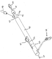
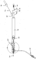
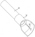
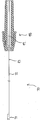
본 발명의 도식적인 실시예는 도 1에서 투시도로 도시된다. 장치(10)는 외측 시스(outer sheath, 20) 및 외측 시스(20)로 결합된 장치 바디(90)(본 실시예에서 한 손에 보유되도록 구성된 핸들)를 포함한다. 이러한 실시예에서, 외측 시스는 외측 시스가 핸들에 대해 이동될 수 없도록(예를 들면, 고정된 상태에서 이 둘은 서로 결합됨) 핸들에 고정된다. 외측 시스(20)는 스텐트가 이동에 앞서 구속된(예를 들면, 신장된) 상태에 있을 때 스텐트가 중공 부재 내에 배열될 수 있도록 구성된 중공 부재이다. A schematic embodiment of the present invention is shown in perspective in FIG. 1. The
장치 바디(90)에 인접한 위치에서 도 1의 실시예의 일부분은 도 2A에서 투시도로 도시되고, 도 3에서 횡단면도로 도시된다. 이러한 도면은 장치 바디로 결합되고(본 실시예에서 장치 바디에 대해 미끄럼가능하게 장착됨), 또한 본 실시예에서 통로를 가지며 외측 시스(20) 내에 끼워맞춤되도록 구성된 요소(40)로 결합된 사용자-조작식 요소(50)를 포함한 장치(10)를 도시한다. 도 2A 및 도 3A에 도시된 실시예에서, 사용자-조작식 요소(50)는 블록(51)에 의해 요소(40)로 결합되고, 장치 바디(90) 상체 미끄럼 가능하게 장착된다. 몇몇 실시예에서, 블록(51)은 도 3A에 도시된 위치를 향하여 사용자-조작식 요소(50)를 편향시키기 위한 편향 요소(스프링과 같은)를 포함할 수 있다. 그 외의 다른 실시예에서, 블록(51)은 편향 요소를 포함하지 않는다. A portion of the embodiment of FIG. 1 in a position adjacent to the
장치(10)의 사용자-조작식 요소(50), 블록(51) 및 요소(40)는 근위 및 원위 방향으로 이동가능하고(장치의 종방향 축(도시되지 않음)을 따라), 일반적으로 그 외의 다른 방향으로 구속된다. 따라서, 사용자-조작식 요소(50)의 근위방향 움직임(proximal movement)(근위 측면(92)을 향하여)에 따라 요소(40)의 근위방향 움직임이 야기되며, 사용자-조작식 요소(50)의 원위방향 움직임(distal movement)(원위 측면(91)을 향하여)에 따라 요소(40)의 원위방향 움직임이 야기된다. 도시된 실시예에서, 사용자-조작식 요소(50)가 이동하는(원위 또는 근위방향으로) 거리는 동일한 거리만큼의 요소(40)의 움직임으로 변환된다. 이러한 변환은 요구 시 속도가 증가되거나(gear up) 또는 감소될 수 있다(gear down). 하기에 상세히 기술된 바와 같이, 요소(40)는 스텐트-연결 요소가 스텐트의 루멘 내에서 원위 방향으로 이동되는 적어도 일부 시간 동안 외측 시스로부터 원위 방향으로 스텐트를 이동시키고 이와 맞물리는 스텐트-연결 요소(45)로 결합된다. The user-
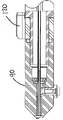
도 2A는 외측 시스(20)의 외측으로 결합된(미끄럼 가능하게) 요소(25)를 포함할 수 있는 장치(10)를 도시한다. 요소(25)는 외측 시스의 외측 표면을 따라 상대적으로 자유롭게 미끄럼가능하도록 구성될 수 있으며, 유도기(introducer)의 지혈 밸브(hemostasis valve)와 결합되도록 구성될 수 있다(도 3B에 도시됨). 특히, 이는 장치의 외측 시스가 유도기 내에서 그리고 요소(20) 내에서 상대적으로 자유롭게 미끄럼 가능할지라고 유체가 장치의 핸들을 향하여 후방으로 흐르지 않도록 지혈 밸브와 결합되고 유도기 내에 부분적으로 끼워맞춤되도록 구성될 수 있다. 효과적으로, 요소(25)는 장치의 외측 시스가 삽입되는 유도기와 장치의 외측 시스 사이의 마찰을 감소시키는 기능을 할 수 있으며, 동시에 환자의 외관과 외측 시스 사이에 실질적인 유체 밀봉을 유지시킨다. 2A shows an
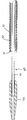
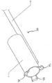
도 1, 도 4 및 도 5에 따라서, 외측 시스(20)는 장치 바디(90)로부터 원위 방향으로 연장된다. 또한, 장치(10)는 내측 요소(60)를 포함하며, 상기 내측 요소의 일부분은 외측 시스(20) 내에 배열된다. 내측 요소(60)(보다 특히, 선호되는 실시예에서 도 2D에 도시된 바와 같이 내측 슬리브(61))는 이의 원위 단부가 노즈 콘(nose cone, 150)으로 결합된다. 시스(20)에 의해 축방향으로 구속되지 않는 내측 요소(60)(이 둘은 이들이 접촉하지 않기에 충분하고 상이한 직경을 가짐)는 외측 시스(20)에 대해 노즈 콘(150)의 움직임을 돕고, 가이드와이어가 이를 통해 통과할 수 있도록 크기가 형성된다(노즈 콘(150)과 같이). 방사선 마커(radiopaque marker, 27)는 스텐트의 배치를 돕는 수단을 제공하기 위하여 외측 시스(20)를 따라 임의의 적합한 위치에 위치될 수 있다. 예를 들어, 마커(27) 및 외측 시스(20)의 원위 단부로부터의 거리는 스텐트의 배치된 상태에서 제공되는 스텐트의 정상적인 길이일 수 있다. 도 5는 외측 시스(20) 내에서 스텐트(30)의 원위 단부(31)를 도시한다. 몇몇 실시예에서, 요소(40)와 스텐트-연결 요소(45) 모두는 내측 요소(60)로 부착되지 않는다. 이에 따라, 요소(40)는 내측 요소(60)가 고정된 상태에서 내측 요소(60) 위에서 그리고 근위 방향으로 이동될 수 있다. 유사하게, 스텐트-연결 요소(45)는 원위 방향으로 이동될 수 있으며, 내측 요소(60)가 고정되어 있는 동안 내측 요소(60) 위에서 원위 방향으로 이동될 수 있다. 1, 4 and 5, the
도 2A 및 도 3A에 관하여, 그리고 또한 도 2C에 관하여 언급하면, 사용자-조작식 요소(50)의 허용가능한 근위-원위 이동이 스토퍼(stopper, 120)의 위치뿐만 아니라 장치 바디(90) 내에서 슬롯(52)의 길이에 의해 구속된다. 도 2A에 도시된 스토퍼(120)의 제 1 위치(121)는 슬롯(52)의 전체 길이보다 작게 사용자-조작식 요소(50)의 원위 이동을 제한한다. 바람직하게, 제 1 부분(121)은 스텐트-연결 요소(45)가 외측 시스(20) 내에 배열되는 사용자-조작식 요소(50)의 최원위 위치에 해당한다. 이는 스텐트(30)의 전진을 위한 적합한 형상에 해당한다. 바람직하게, 스토퍼(120)는 즉 스프링을 이용하여 제 1 위치(121)로 편향된다. 도 2C 및 도 3A에서, 스토퍼(120)는 도시된 바와 같이 사용자-조작식 요소(50)가 미끄럼 가능하도록 제 2 위치(122)(도 2C에 도시됨)로 회전한다. With reference to FIGS. 2A and 3A and also with reference to FIG. 2C, the allowable proximal distal movement of the user-operated
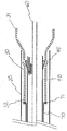
도 2D는 장치(10)의 선호되는 실시예의 서브-조립체의 횡단면도이며, 상기 서브-조립체는 가이드와이어를 수용하도록 구성되며 내측 요소(60)의 길이를 연장시키는 내측 슬리브(61)의 형태인 내측 요소(60)의 선호되는 실시예를 포함한다. 내측 요소(60)는 Loctite® 4014 접착제와 같이 임의의 적합한 방식으로 원위 단부(또는 임의의 그 외의 다른 적합한 위치)가 내측 슬리브(61)로 고정될 수 있는 중간 슬리브(intermediate sleeve, 62)를 포함할 수 있다. 또한, 중간 슬리브(62)(하이포튜브일 수 있음)는 내측 요소(60)의 근위 단부로 연장될 수 있다. 또한, 내측 요소(60)는 솔더링(soldering)과 같이 임의의 적합한 방식으로 원위 단부(또는 임의의 그 외의 다른 적합한 위치)에서 중간 슬리브(62)로 연결된 외측 슬리브(63)(하이포튜브일 수 있음)를 포함할 수 있으며, 또한 외측 슬리브(62)는 내측 요소(60)의 근위 단부로 연장될 수 있다. 또한, 내측 요소(60)는 솔더링과 같이 임의의 적합한 방식으로 근위 단부(또는 임의의 그 외의 다른 적합한 위치)가 외측 슬리브(63)로 연결된 이동-제한 슬리브(travel-limiting sleeve, 64)를 포함할 수 있다. 슬리브(64)는 장치 바디(90)에 대해 내측 요소(60)의 이동을 제한하도록 구성될 수 있다. 보다 특히, 슬리브(64)는 장치 바디(90)의 공동(cavity, 55)의 근위 개구부와 상충되도록(interfere)(이의 크기로 인해) 구성될 수 있으며(도 3A에 도시됨), 블록(51)과 원위 방향으로 상충되도록 구성될 수 있다(루어 피팅(100)이 Y-어댑터(95)와 우선적으로 상충되지 않는다면).2D is a cross-sectional view of a sub-assembly of the preferred embodiment of the
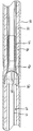
도 3B는, 요소(25)가 유도기(35)의 지혈 밸브의 밀봉부(31)와 연결되는, 유도기(35)와 요소(25) 사이의 상호작동을 도시하는 확대된 횡단면도이다. FIG. 3B is an enlarged cross sectional view showing the interaction between the
도 3C는 장치(10)의 선호되는 실시예의 서브-조립체의 횡단면도이며, 상기 서브-조립체는 Loctite® 접착제(예를 들면, 4014, 4305, 3321, 등등)들 중 하나와 같은 적합한 접착제 또는 숄더(57)에서 말단을 이루는 압축 끼워맞춤(press fit)에 의해 블록(51)으로 적합하게 고정된 근위 하이포튜브(41)의 형태인 요소(40)의 선호되는 실시예를 포함한다. 블록(51)은 핀(54)을 통해 사용자-조작식 요소(50)로 고정되며, 상기 핀은 요소(50)로 결합될 수 있고 블록(51)으로 압축끼워맞춤되거나 또는 결합될 수 있다. 또한, 요소(40)는 근위 단부에서 Loctite® 4305를 이용하는 것과 같은 임의의 적합한 방식으로 원위 하이포튜브(41)로 연결되고, 원위 단부에서 접착제를 이용하는 것과 같은 임의의 적합한 방식으로 지지 튜브(support tube, 46)로 연결된(차례로 접착제와 같은 임의의 적합한 방식으로 스텐트-연결 요소(45)로 연결됨) 중간 튜브(42)를 포함할 수 있다. 또한, 요소(40)는 근위 하이포튜브(41)의 원위 단부와 접하고, 중간 튜브(42) 위에 위치되는 지지 튜브(43)를 포함할 수 있다. 지지 튜브(43)는 임의의 적합한 접착제를 이용하여 임의의 적합한 위치에서 중간 튜브(42)로 연결될 수 있다. 지지 튜브는 중간 튜브(42)의 강성을 증가시키도록 구성될 수 있다. 또한, 요소(40)는 지지 튜브(43)의 원위 단부와 접하고, 중간 튜브(42) 위에서 쓰레드된(threaded) 리시싱 스톱(resheathing stop, 44)을 포함할 수 있다. 상기 리시싱 스톱(44)은 임의의 적합한 접착제를 이용하여 임의의 적합한 위치에서 중간 튜브(42)로 연결될 수 있다. 리시싱 스톱(44)은 제거 공정(delivery process) 동안 리-시스되어야(re-sheathed) 하는 외측 시스(20)(본 도면에 도시되지 않음)에 의해 둘러싸여진 스텐트의 근위 움직임을 방지하도록 구성될 수 있다. 또한, 도시된 서브-조립체는 스테인리스스틸 리테이너(58)에 의해 제 위치에 고정되고, 내측 요소(60)(보다 특히 내측 요소(60)의 선호되는 실시예의 일부분인 외측 하이포튜브)의 외측 주위에서 유체의 역류를 방지하도록 구성된 실리콘 밀봉부(56)를 포함한다. 3C is a cross-sectional view of a sub-assembly of a preferred embodiment of the
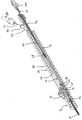
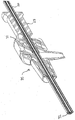
도 6에 따라서, 요소(40)는 요소의 일부분이 외측 시스(20) 내에 배열되도록 연장된다. 바람직하게, 요소(40)는 중공구조이며, 이의 통로는 내부에 위치된 내측 튜브(60)의 일부분을 수용한다. 본 요소의 대안의 실시예는 비-중공구조이다. According to FIG. 6,
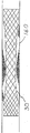
도 6 및 도 7에 관해 언급하면, 요소(40)는 본 실시예에서 삽(shovel) 또는 국자(scoop)와 같은 형태인 스텐트-연결 요소(45)로 결합된다. 보다 특히, 도시된 선호되는 실시예에서, 요소(40)의 중간 튜브(42)는 스텐트-연결 요소(45)로 연결된 지지 튜브(46)로 연결된다. 스텐트-연결 요소(45)는 스텐트(30)의 루멘 내에 적어도 부분적으로 위치된다. 요소(40)가 사용자-조작식 요소(50)의 원위 움직임에 응답하여 원위 방향으로 이동함에 따라 스텐트-연결 요소(45)는 스텐트(30)와 맞물리고, 외측 시스(20)를 따라 상기 스텐트를 진행시킨다. 선호되는 실시예에서, 스텐트-연결 부분(45)의 근위 움직임에 따라 스텐트(30)는 움직이지 않는다. 이와 같은 방식으로 요소(40)의 원위 및 근위 움직임이 반복적으로 왕복운동함에 따라 외측 시스(20)로부터 배출될 때까지 스텐트(30)는 전진한다. 따라서, 종래 기술의 당업자에게 자명한 바와 같이, 사용자가 스텐트-연결 요소(45)에 의해 스텐트의 다수의 연결부를 통해 외측 시스(20)로부터 스텐트(30)를 원위 방향으로 전진시킬 수 있으며, 여기서 스텐트(30)의 원위 단부와 근위 단부 사이에 각각의 연결부가 형성되고, 외측 시스(20)의 기계적이고 부수적인 인출(withdraw) 없이 스텐트(30)를 원위 방향으로 이동시키도록 장치(10)의 도시된 실시예가 구성되며, 각각의 연결부(사용자-조작식 요소(50))가 장치 바디(90)의 근위 단부에서 떨어져서 또는 이에 위치되도록 사용자가 최근위 지점과 장치를 접촉시키고, 스텐트(30)가 원위 방향으로 이동되지 않는 기간에 의해 임의의 후속 연결부로부터 분리된다. 스텐트-연결 요소(45)는 피로 응력 파괴 및 이와 유사한 것을 견디는 것을 돕고 스텐트(30)의 루멘 내에서 근위 방향으로 미끄러짐에 따라 요소(45)가 내측을 향하여 접히도록 하는 둥글고 덤벨-형태의 단부가 제공된 가요성 슬롯(flex slot, 48)을 포함할 수 있다. 바람직하게, 스텐트-연결 부분(45)의 성능은 도 7에 도시된 바와 같이 적합한 형태를 선택함으로써 구현된다. 대안의 실시예는 힌지 고정된 가요성이거나 또는 스텐트를 전진시키기 위하여 그 외의 다른 변형 형태인 스텐트-연결 부분을 이용할 수 있다. 스텐트-연결 부분의 형상은 배치되는 스텐트의 타입에 가장 적합하도록 선택될 수 있다. 스텐트(30)가 참조 문헌으로 일체 구성된 미국 특허 제 7,018,401호에 공개된 종류와 같이 짜여진 자체-팽창식 스텐트일 때, 바람직하게 스텐트 연결 요소(45)는 (a) 스텐트를 원위 방향으로 이동시킬 때 스텐트(30)의 마주보는 측면 상에서 와이어 교차부와 연결되고, (b) 스텐트의 루멘 내에서 근위 방향으로 미끄러지고 내측을 향하여 접혀지도록(적어도 부분적으로 스텐트-연결 요소의 가요성 슬롯(48)으로 인해) 구성된다(도면에 도시된 바와 같이). With reference to FIGS. 6 and 7, the
도 8은 스텐트 전진 공정의 도식적인 도면을 도시한다. 스텐트(30)의 원위 단부(31)는 외측 시스(20)를 빠져나가고, 팽창된다. 요소(40)는 화살표로 도시된 바와 같이 원위 방향과 근위 방향으로 이동한다. 스텐트-연결 요소(45)가 원위 방향으로 이동함에 따라 스텐트(30)와 맞물려 이를 전진시키며, 이에 따라 스텐트를 외측 시스(20) 밖으로 밀어낸다. 스텐트-연결 요소(45)의 형태로 인해 스텐트-연결 요소(45)가 근위 방향으로 이동할 때에는 스텐트(30)가 전진하지 않는다. 대신에, 스텐트-연결 요소(45)의 형상에 따라 외측 시스에 대해 스텐트의 축방향 위치를 방해하지 않고 사용자-조작식 요소(50)의 근위방향 움직임 동안 스텐트(30)의 일부분(예를 들면, 와이어 부분)들과 만나고 이 위에서 이동함에 따라 상기 스텐트-연결 요소는 내측으로 굽어질 수 있다. 바람직하게, 스텐트(30)는 장치 바디(90)에 대한 외측 시스(20)의 움직임 없이(환자의 신체 움직임, 진동, 등등에 의해 야기된 우발적인 움직임과는 달리) 그리고 외측 시스(20)의 기계적이고 부수적인 인출 없이 전진할 수 있다(advancement). 8 shows a schematic diagram of a stent advance process. The
도 9 및 도 10은 혈관(body vessel) 내에 있는 스텐트의 배치 상태를 도식적으로 도시한다. 도 9는 구속되거나 또는 신장된 형상의 스텐트(30)를 도시한다. 이는 스텐트가 장치(10)의 외측 시스(20) 내에 있을 때 스텐트(30)의 형상의 실례이다. 도 10은 스텐트가 외측 시스(20)로부터 빠져나갈 때 취할 수 있는 자체-팽창식 스텐트의 한 상태인, 혈관(160)내에서 팽창된 상태의 스텐트(30)를 도시한다. 9 and 10 diagrammatically show the placement of the stent in the body vessel. 9 shows a
몇몇 실시예에서, 또한 본 발명의 장치는 스텐트가 시스로부터 완전히 진행하지 않도록 제공되고, 전진 및/또는 배치 단계 동안 오퍼레이터가 스텐트를 리-시스(re-sheath) 할 수 있도록 구성된 스텐트-리텐션 요소(stent-retention element)를 포함한다. 도 11 및 도 12A에 따라서, 장치(10)는 스텐트(30)의 근위 단부(32)로 결합된 스텐트-리텐션 요소(70)를 포함한다. 선호되는 실시예에서, 심지어 스텐트 연결 요소(45)가 근위 방향의 움직임 동안 스텐트(30)의 근위 단부(32)가 외측 시스(20) 내에 있는 한 스텐트(30)와 스텐트-리텐션 요소(70)의 원위 부분(71) 사이에 접촉이 형성된다. 스텐트(30)의 근위 단부(32)가 외측 시스(20)의 외측으로 진행할 때, 스텐트(30)는 스텐트-리텐션 요소(70)의 원위 부분(71)의 가장 큰 폭(도면에 도시된 반경방향으로 얻어진)보다 큰 반경까지 팽창된다. 이에 따라, 스텐트-리텐션 요소(70)와 스텐트(30) 사이의 접촉이 해제되며, 스텐트(30)의 배치는 완료된다. 따라서, 스텐트-리텐션 요소(70)는 스텐트(30)의 근위 부분(특히 스텐트-리텐션 요소(70)로 결합된 근위 부분)이 외측 시스(20) 내에 배열되도록 제공된 외측 시스(20)로 근접하게 스텐트(30)를 인출할 수 있다(오퍼레이터에 의해). In some embodiments, the apparatus of the present invention is also provided such that the stent does not proceed completely from the sheath and is configured to allow the operator to re-sheath the stent during the advance and / or placement phases. (stent-retention element). According to FIGS. 11 and 12A, the
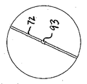
도 2A, 3A 및 도 11-12에 따라서, 스텐트-리텐션 요소(70)의 근위 부분(72)(도 3B에 도시됨)은 스텐트(30)를 외측 시스(20)로 인접하게 인출하는 것을 돕고, 스텐트(30)의 근위 부분이 외측 시스(20) 내에 배열되는 스텐트-리텐션 라인으로서 특징으로 하는 케이블 또는 이와 유사한 장치이다. 스텐트-리텐션 요소(70)의 윈위 부분(71)은 스텐트(30)의 짜여진 버젼 내에서 개구부와 맞물리는 다수의 반경방향으로 돌출된 프롱(prong, 73)이 제공된 튜빙(tubing)(하이포튜브)의 일부분일 수 있다. 상기 튜빙은 임의의 적합한 방식으로(솔더링을 통해) 근위 부분(72)으로 결합될 수 있다. According to FIGS. 2A, 3A and 11-12, the proximal portion 72 (shown in FIG. 3B) of the stent-
도 1 및 도 2A에 도시된 바와 같이, Y-어댑터(95)는 장치 바디(90)의 근위 부분으로 결합될 수 있다. 내측 튜브(60)는 직선 암(96)을 통해 배치될 수 있으며, 근위 부분(72)은 Y-어댑터(95)의 각을 형성하는 암(97)을 통해 배치될 수 있다. 도 2B에 도시된 바와 같이, 스텐트-리텐션 요소 위치 마커(stent-retention element position marker, 93)는 라인(72)으로 결합될 수 있으며, 스텐트-리텐션 요소로 결합된 스텐트의 상대 위치에 대해 라인을 따라 위치될 수 있다. 예를 들어, 열 흡수 튜빙(heat shrink tubing)의 일부분일 수 있는 마커는 각을 형성하는 암(97)의 주변으로 연장될 때 스텐트가 외측 시스(20)로부터 완전히 제거되도록 라인을 따라 위치될 수 있다. 이와 같은 방식으로, 오퍼레이터는 스텐트가 외측 시스로부터 멀리 제거되도록 이동시키는 시각적 인디케이터(visual indicator)를 가진다. 도 1 및 도 2A는 스텐트-리텐션 요소의 조작이 가능하게 사용자가 보유할 수 있도록 스텐트-리텐션 요소가 임의의 적합한 방식으로(예를 들면, LOCTITE® 접착제를 통해) 라인(72)으로 결합된 핑거 요소(finger element, 98)를 포함할 수 있는 것을 도시한다. 도 12B는 핑거 요소(98)와 라인(72)(도시된 바와 같이 서로 고정된 내측 및 외측 부품들을 가진) 사이에서의 실례의 연결 위치(99)(접착제 또는 이와 유사한 것)를 도시하며, 스텐트-리텐션 요소(70)의 선호되는 실시예를 도시한다. As shown in FIGS. 1 and 2A, the Y-
바람직하게 장치(10)는 측면 포트(side port, 110)(장치 바디(90)로 결합된) 및 외측 시스(20)와 내측 튜브(60)의 플러싱(flushing)을 허용하는 루어 피팅(100)(내측 튜브(60)의 근위 단부(62)에 결합됨)을 각각 포함한다. 이러한 플러싱은 함염물(saline)을 이용할 수 있으며, 수술에 앞서 수행될 수 있다. 본 발명의 장치의 대안의 실시예는 외측 시스(20) 및 내측 튜브(60)를 플러싱하기 위한 대안의 형상을 포함할 수 있거나 또는 플러싱을 허용하도록 구성되지 않을 수 있다. 도 3D는 장치(10)의 상면도이며, 도 3E에 보다 상세히 도시된 장치 바디(90)의 원위 단부 근처에서의 상세 단면도를 도시한다. The
도 2C에 관하여 언급하면, 스토퍼(120)의 제 2 위치(122)에 따라 사용자-조작식 요소(50)는 슬롯(52)의 전체 길이를 원위 방향으로 이동시킬 수 있다. 사용자-조작식 요소(50)의 최원위 부분은 스텐트-연결 요소(45)가 외측 시스(20)의 외측에(원위 위치) 배열되는, 이에 따라 스텐트(30)가 팽창된 상태에서 외측 시스(20)로부터 제거되는 영역 내의 위치에 해당한다. 스텐트-리텐션 요소(70)의 원위 부분(71)으로부터 분리되는 위치에서 스텐트는 외측 시스(20)로 더 이상 인출되지 않을 수 있다(withdraw). 게다가, 팽창된 상태에서 스텐트는 스텐트-연결 요소(45) 위에 방사상 간격(radial clearance)을 가질 것이다. 본 발명의 장치의 대안의 실시예는 사용자-조작식 요소(50)의 이동(travel)을 제한하기 위해 그 외의 다른 형상을 이용할 수 있거나 또는 조절가능한 이동-제한 특징부를 갖지 않는다. Referring to FIG. 2C, according to the
도 13 및 도 14는 스텐트-리텐션 요소(70)의 근위 부분(72)으로 결합된 캡춰 장치(capture device, 80)를 포함한 본 발명의 장치의 그 외의 다른 실시예를 도시한다. 캡춰 장치(80)는 스텐트-연결 요소(45)가 스텐트(30)를 진행시킴에 따라 근위 부분(72)의 적당한 크기를 릴리즈하기 위해(release) 제공된다. 캡춰 장치(80)는 외측 시스(20)로부터 스텐트(30)의 완전한 배치에 앞서 스텐트(30)의 원위 이동을 중단시키기 위해 제공된 스톱(stop)을 포함한다. (적합한 위치에서 근위 부분(72)으로 결합된 하이포튜브와 같은 튜빙의 일부분일 수 있는) 스톱은 추가 전진이 스텐트 배치를 야기할 수 있는 지점에 오퍼레이터 피드백(operator feedback)을 제공한다(따라서, 스톱은 스텐트가 더 이상 인출될 수 없는 위치의 인디케이터로서 이용될 수 있음). 여기서, 오퍼레이터는 스텐트-리텐션 요소(70) 상에서 근위 방향으로 잡아당김으로써 재위치설정하기 위하여 외측 시스(20) 내부로 스텐트(30)를 인출하거나 또는 배치 스톱 레버(81)(스텐트-리텐션 요소의 원위방향 전진을 유지시키고 스톱이 배치 스톱 레버를 우회시킬 수 있음)를 아래로 밀고(depress) 사용자-조작식 요소(50)에 의해 전진을 유지시킴으로써 스텐트 배치를 수행하도록 선택될 수 있다. 13 and 14 show other embodiments of the device of the invention, including a
오퍼레이터가 재위치설정을 위해 외측 시스(20)로 스텐트(30)를 인출하기 위해 선택한다면, 오퍼레이터는 장치 바디(90)로부터 캡취 장치(80)를 분리시키고(도시된 실시예에서) 오퍼레이터가 스텐트-리텐션 요소(70)의 근위 부분(72)을 근접하게 잡아당김으로써 스텐트(30)를 인출할 수 있는 리텐션 풀 레버(retention pull lever, 84)를 조작할 수 있다. 외측 시스(20) 내부로 스텐트(30)를 인출한 후, 캡춰 장치(80)의 스프링(83)과 리텐션 풀리(retention pulley, 82)는 스텐트-리텐션 요소(70)의 초과 슬랙(excess slack)을 축적하도록 조작된다. 이러한 실시예에서, 스텐트-리텐션 요소(70)의 근위 부분(72)은 장치 바디 내에서 중앙에 배열되지 않은 장치 바디(90)의 일부분을 통해 쓰레드된다. 캡춰 장치를 포함하는 본 발명의 장치의 대안의 실시예는 자동식 캡춰 장치와 같은 캡춰 장치(80)와 상이하게 구성된 캡춰 장치를 포함할 수 있다. 게다가, 캡춰 장치(80)는 핑거 요소(98) 대신에 도 1에 도시된 장치(10)의 실시예에서 각을 형성하는 암(97)으로 결합될 수 있다. If the operator chooses to withdraw the
본 발명의 장치는 에틸렌 옥사이드 가스를 이용하는 멸균 기술과 같이 임의의 적합한 기술을 이용하여 멸균한 뒤 백, 파우치, 박스 또는 그 외의 다른 적합한 용기 내에 이용 가능하고 패킹 가능하다. 상기 장치를 통한 멸균 가스의 흐름을 허용하기 위하여 노즈 콘의 근위 단부와 외측 시스의 원위 단부 사이에 작은 간격이 제공될 수 있다. 이러한 용기는 용기 내측에 포함되거나 또는 용기 상에 프린트되는 장치를 이용하기 위한 인스트럭션(instruction)을 포함할 수 있다. 상기 장치가 이의 용기로부터 제거된 후, 함염물(saline)은 외측 시스 및 이의 내용물 및 내측 튜브를 플러싱하기 위해 이용될 수 있다. 그 뒤 외측 시스와 노즈 콘 사이의 간격은 노즈 콘이 결합되는 내측 튜브를 근위 방향으로 잡아당김으로써 폐쇄될 수 있다. 수술이 혈관을 스텐트 시술하는 단계(stenting)를 포함한다면, 적합한 위치 내에 장치를 위치설정하기 위한 임의의 적합한 기술이 이용될 수 있다(예를 들어 Seldinger 기술). 장치의 노즈 콘(임의의 적합한 가요성 팁일 수 있는)은 방사선 불투과성일 수 있으며, 장치를 위한 최원위 마커(distal-most marker)가 형성된다. 임의의 적합한 재료(백금 밴드 또는 임의의 적합한 백금 합금으로 제조되는 밴드와 같은)로 제조될 수 있는 그 외의 다른 방사선 불투과성 마커(radio opaque marker)는 장치를 위한 최근위 마커를 형성하기 위하여 외측 시스(상기 언급된 바와 같이), 요소(40) 또는 내측 요소와 같이 노즈 콘에 인접한 장치의 일부분으로 결합될 수 있다. 상기 2가지의 마커는 스텐트의 정확한 배열이 보장되도록 오퍼레이터가 관련자(interest)의 상처(lesion)에 대해 상기 장치를 배열함으로써 이용될 수 있다. The apparatus of the present invention is sterilized using any suitable technique, such as sterilization techniques using ethylene oxide gas, and then available and packable in bags, pouches, boxes or other suitable containers. A small gap can be provided between the proximal end of the nose cone and the distal end of the outer sheath to allow the flow of sterile gas through the device. Such a container may include instructions for using an apparatus contained within or printed on the container. After the device is removed from its container, the saline can be used to flush the outer sheath and its contents and inner tube. The gap between the outer sheath and the nose cone can then be closed by pulling inwardly the inner tube to which the nose cone is coupled. If the surgery involves stenting a blood vessel, any suitable technique for positioning the device within a suitable location may be used (eg Seldinger technology). The nose cone (which may be any suitable flexible tip) of the device may be radiopaque and a distal-most marker for the device formed. Other radio opaque markers, which may be made of any suitable material (such as a platinum band or a band made of any suitable platinum alloy), may be provided with an outer sheath to form the most recent marker for the device. (As mentioned above), it may be coupled to a portion of the device adjacent to the nose cone, such as
본 발명의 방법은 시스(예를 들면, 외측 시스(20))로부터 스텐트를 그리고 관형 구조물로 원위 방향으로 이동시키기 위한 스텐트 전진 방법(stent advancement method)을 포함한다. 몇몇 실시예에서, 관형 구조물은 동물 조직(animal tissue)(인간의 혈관과 같이)이다. 그 외의 다른 실시예에서, 관형 구조물은 동물 조직이 아니며, 관습에 따라 장치 또는 스텐트 전진 기술을 이용하는 것을 고려하는 의사와 같이 한 사람 또는 여러 사람에 대해 스텐트 전진을 실연하거나 또는 주어진 장치 기술을 테스트하기 위해 이용될 수 있는 폴리머 구조물을 포함한다. The method includes a stent advancement method for moving the stent from the sheath (eg, the outer sheath 20) and distal to the tubular structure. In some embodiments, the tubular structure is animal tissue (such as human blood vessels). In other embodiments, the tubular structure is not animal tissue and demonstrates stent advancement or testing a given device technique for one or several persons, such as a physician considering using a device or stent advancement technique as customary. Polymer structures that can be used for the purpose.
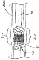
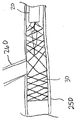
본 발명의 스텐트 전진 방법의 몇몇 실시예는 스텐트-연결 요소(예를 들면, 스텐트-연결 요소(45)와 원위 단부와 근위 단부 사이의 스텐트를 반복적으로 연결시킴으로써 시스(예를 들면, 외측 시스(20))로부터 그리고 관형 구조물로 스텐트(예를 들면, 스텐트(30))를 원위 방향으로 이동시키는 단계를 포함하고, 여기서 적어도 2개의 연결부들이 비-연결 주기(period)로 분리되고, 스텐트가 시스로부터 원위 방향으로 이동됨에 따라 관형 구조물에 대해 시스의 축방향 위치를 가변시킴으로써 관형 구조물 내에서 스텐트의 축방향 밀집 상태(density)를 가변시키는 단계를 포함한다. 스텐트가 시스로부터 원위 방향으로 이동됨에 따라, 장치의 나머지 부분은 관형 구조물에 대해 오퍼레이터에 의해 근위 방향으로 인출되고, 이에 따라 스텐트의 배치된 부분은 배치되어지는 관형 구조물(예를 들면, 인간의 조직)에 대해 고정된 상태로 유지된다. 장치의 나머지 부분이 인출되는 속도는 스텐트의 중방향 밀집상태를 가변시킴으로써 가변될 수 있고, 인출 속도가 상대적으로 느릴수록 스텐트의 축방향 밀집상태가 증가되는 반면, 속도가 빠를수록 스텐트의 축방향 밀집상태가 감소된다. 예를 들어, 도 15A에 도시된 바와 같이 동맥(200)의 협착된 부분(210)을 따라 관형 구조물의 개방성(patency)을 유지시키기 위해 상대적으로 큰 후프 강도가 요구되는 위치에서 스텐트의 축방향 밀집상태를 증가시키는 것이 선호될 수 있다. 예를 들어, 도 15B에 도시된 바와 같이 혈관(250)의 해부학적 측면 브랜치(anatomical side branch, 260)에서 적합할 수 있는 제 2 스텐트의 침투 위치에서 또는 바람직하거나 또는 예상되는 측면으로부터 스텐트의 섹션으로 유체가 흐르는 위치에서 스텐트의 축방향 밀집상태를 감소시키는 것이 선호될 수 있다. Some embodiments of the stent advancing method of the present invention provide a sheath (eg, an outer sheath (eg, an outer sheath) by repeatedly connecting the stent-connection element (eg, the stent-
본 발명의 스텐트 전진 방법의 몇몇 실시예는 스텐트-연결 요소(예를 들면, 스텐트-연결 요소(45))와 원위 단부와 근위 단부 사이의 스텐트를 반복적으로 연결시킴으로써 시스(예를 들면, 외측 시스(20))로부터 그리고 관형 구조물 내부로 스텐트(예를 들면, 스텐트(30))를 원위 방향으로 이동시키는 단계를 포함하고, 여기서 2개 이상의 연결부들은 비-연결 주기로 분리되고, 시스 내에 배열되는 스텐트-리텐션 요소(예를 들면, 스텐트-리텐션 요소(70))와 스텐트를 근위 단부에서 연결시키는 단계를 포함한다. Some embodiments of the stent advancement method of the present invention provide a sheath (eg, an outer sheath) by repeatedly connecting the stent-connection element (eg, stent-connection element 45) and the stent between the distal and proximal ends. (20) and moving the stent (eg, stent 30) in the distal direction into the tubular structure, wherein the two or more connections are separated in a non-connection period and arranged in the sheath. Connecting the retention element (eg, stent-retention element 70) and the stent at the proximal end.
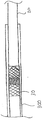
몇몇 실시예에서, 시스로부터 원위 방향으로 스텐트를 이동시키는 연결부들은 도면에 도시된 본 발명의 장치와 같이 스텐트가 원위 방향으로 이동됨에 따라 시스를 기계적으로 그리고 부수적으로 인출시키지 않도록 구성된 장치를 이용하여 구현될 수 있다. 이러한 실시예에서, 관형 구조물은 혈관 또는 덕트 또는 폴리머 튜브(300)(도 15C에 도시됨)와 같이 동물 조직(animal tissue)이 아닌 관형 구조물과 같은 해부학적 관형 구조물일 수 있다. 이와 달리, 몇몇 실시예에서, 상기 방법은 스텐트의 근위 단부에서 시스 내에 배열된 스텐트-리텐션 요소와 스텐트를 연결하는 단계를 포함할 수 있다. 스텐트-리텐션 요소는 스텐트-리텐션 라인을 포함할 수 있으며, 이러한 방법은 스텐트가 시스로부터 부분적으로 이동된 후 스텐트 리텐션 라인을 이동시킴으로써 시스 내부로 재차 스텐트를 인출시키는 단계를 포함할 수 있다. 오퍼레이터는 오퍼레이터의 엄지손가락을 이용하여 사용자-조작식 요소(예를 들면, 사용자-조작식 요소(50))를 이동시킴으로써 스텐트를 작동시킬 수 있다. 상기 스텐트는 짜여질 수 있으며(woven), 스텐트-연결 요소는 연결부들이 스텐트를 이동시키는 동안 원위 방향으로 이동되고 스텐트의 다수의 와이어 교차부와 연결될 수 있으며, 스텐트-연결 요소는 비-연결 주기 동안 스텐트의 루멘 내에서 근위방향으로 미끄러질 수 있다. In some embodiments, the connections for moving the stent in the distal direction from the sheath are implemented using a device configured to not mechanically and incidentally pull the sheath as the stent moves in the distal direction, such as the device of the present invention shown in the figures. Can be. In such embodiments, the tubular structure may be an anatomical tubular structure, such as a tubular structure that is not an animal tissue, such as a vessel or duct or polymer tube 300 (shown in FIG. 15C). Alternatively, in some embodiments, the method may include connecting the stent with the stent-retention element arranged in the sheath at the proximal end of the stent. The stent-retention element may comprise a stent-retention line, and the method may include drawing the stent back into the sheath by moving the stent retention line after the stent has been partially moved from the sheath. . The operator can operate the stent by moving the user-operated element (eg, user-operated element 50) using the operator's thumb. The stent can be woven and the stent-connecting element can be distally displaced while the connections move the stent and connected with a plurality of wire intersections of the stent, and the stent-connecting element during the non-connection cycle. It may slide proximally in the lumen of the stent.
몇몇의 본 발명의 방법은 시스로부터 그리고 관형 구조물 내부로 스텐트를 전진시키는 방법에 대한 어떠한 또는 그 외의 다른 것을 지시하는 단계(instructing)의 방법이다. 본 발명의 스텐트 전진 지시 방법의 몇몇 실시예는 시스 내에 배열된 스텐트(예를 들면, 스텐트(30)) 및 시스(예를 들면, 외측 시스(20))를 포함하는 스텐트 이송 장치(예를 들면, 장치(10))를 이용하는 방법에 대해 사람을 지시하는 단계를 포함한다. 이러한 지시 단계는 사람에게 후속 단계들을 실연하는 단계(demonstrating), 스텐트-연결 요소(예를 들면, 스텐트-연결 요소(45))와 근위 단부와 원위 단부 사이의 스텐트를 반복적으로 연결함으로써 시스로부터 그리고 관형 구조물 내부로 스텐트를 원위 방향으로 이동시키는 단계를 포함하고, 여기서 적어도 2개의 연결부들이 비-연결 주기로 분리되고, 스텐트가 시스로부터 원위 방향으로 이동됨에 따라 관형 구조물에 대해 시스의 축방향 위치를 가변시킴으로써 관형 구조물 내에서 스텐트의 축방향 밀집상태를 가변시키는 단계를 포함한다. Some of the methods of the present invention are methods of instructing indicating something or something else about how to advance the stent from the sheath and into the tubular structure. Some embodiments of the stent forward pointing method of the present invention provide a stent transfer device (eg, a stent (eg, stent 30) and a sheath (eg, an outer sheath 20) arranged within the sheath. Instructing a person as to how to use the
본 발명의 스텐트 전진 지시 방법의 몇몇 실시예는 시스 내에 배열된 스텐트(예를 들면, 스텐트(30))와 시스(예를 들면, 외측 시스(20))를 포함하는 스텐트 이송 장치(예를 들면, 장치(10))를 이용하는 방법에 대해 사람을 지시하는 단계를 포함한다. 이러한 지시 단계는 사람에게 후속 단계들을 실연하는 단계(demonstrating), 스텐트-연결 요소(예를 들면, 스텐트-연결 요소(45))와 근위 단부와 원위 단부 사이의 스텐트를 반복적으로 연결함으로써 시스로부터 그리고 관형 구조물 내부로 스텐트를 원위 방향으로 이동시키는 단계를 포함하고, 여기서 적어도 2개의 연결부들이 비-연결 주기로 분리되고, 시스 내에 위치된 스텐트-리텐션 요소(예를 들어, 스텐트-리텐션 요소(70))와 스텐트를 스텐트의 근위 단부와 연결하는 단계를 포함할 수 있다. Some embodiments of the stent forward instructing method of the present invention include a stent transfer device (eg, a stent (eg, stent 30) and a sheath (eg, an outer sheath 20) arranged in the sheath. Instructing a person as to how to use the
이러한 지시 방법은 몇몇 실시예에서 사람들 앞에서 시연(live demonstration)에 의해 또는 그 외의 다른 실시예에서 사람에 대해 실시된 레코드되거나(recorded) 또는 시뮬레이트된 실연(simulated demonstration)에 의해 수행될 수 있다. 레코드된 실연(recorded demonstration)의 실례는 사람에 의해 수행되고, 카메라에 캡취된 것이다. 시뮬레이트된 실연의 실시예는 실제 수행된 것이 아니며, 대신에 컴퓨터 시스템 그리고 그래픽 프로그램을 이용하여 생성된다. 레코드되거나 시뮬레이트된 실연의 경우, 실연(demonstration)은 DVD 또는 임의의 적합한 비디오 파일(.mpg, .mov., .qt, .rm, .swf 또는 .wmv 파일과 같은)과 같은 임의의 적합한 형태로 존재할 수 있으며, 지시 단계는 임의의 적합한 컴퓨터 시스템을 이용하여 시청자에 대해 실연을 상연함으로써 수행될 수 있다. 시청자 또는 시청자들은 실연을 상연할 수 있다. 예를 들어, 시청자는 인터넷 또는 시청자가 파일에 접속하는 임의의 적합한 컴퓨터 시스템을 이용하여 레코드되거나 또는 시뮬레이트된 실연 파일에 접속할 수 있다. 도 16에 도시됨.This directed method may be performed by live demonstrations in front of people in some embodiments or by recorded or simulated demonstrations performed on people in other embodiments. An example of a recorded demonstration is performed by a person and captured by a camera. Embodiments of the simulated demonstration are not actually performed, but are instead created using a computer system and a graphics program. In the case of a recorded or simulated demonstration, the demonstration may be in any suitable form, such as a DVD or any suitable video file (such as a .mpg, .mov., .Qt, .rm, .swf or .wmv file). It may be present and the instruction step may be performed by performing a demonstration on the viewer using any suitable computer system. Viewers or viewers can stage a demonstration. For example, the viewer can access the recorded or simulated demonstration file using the Internet or any suitable computer system to which the viewer accesses the file. Shown in FIG. 16.
해부학적 구조물(anatomical structure) 내부로 스텐트를 이동시키는 단계를 포함하는 본 발명의 방법의 실시예에서, 이러한 방법을 수행하기 위해 이용된 장치는 스텐트 전진을 개시하기 위해 환자 내의 선호되는 위치에 배열되고, 스텐트-연결 요소의 이러한 움직임(예를 들어, 래칭 움직임(ratcheting movement))은 스텐트의 원위 단부(수술 중 스텐트의 위치를 보다 용이하게 보기 위하여 하나 또는 이보다 많은 방사선 불투과성 마커가 제공될 수 있음)가 장치의 외측 시스로부터 제거되지만 해부학적 구조물과 접촉하도록 팽창하는 정도는 아니도록 개시된다. 스텐트의 원위 단부는 오퍼레이터가 요구하는 정도로 근접 위치되며 스텐트-리텐션 요소가 이용된다면, 스텐트-리텐션 요소는 장치를 재위치설정하고 스텐트를 리시스하기 위해(resheath) 근위 방향으로 잡아당겨질 수 있으며, 스텐트는 오퍼레이터가 요구하는 정도록 원위에 위치된다면 전체 장치는 근위방향으로 인출될 수 있으며, 배치 공정이 지속된다. In an embodiment of the method of the invention comprising moving the stent into an anatomical structure, the device used to perform this method is arranged at a preferred location in the patient to initiate stent advancement. This movement of the stent-connected element (eg, a ratcheting movement) may be provided with one or more radiopaque markers to more easily view the position of the stent during surgery. ) Is removed from the outer sheath of the device but not to the extent that it expands to contact the anatomical structure. If the distal end of the stent is positioned as close as required by the operator and the stent-retention element is used, the stent-retention element can be pulled in the proximal direction to reposition the device and to restent the stent. If the stent is positioned distal to the operator's requirements, the entire device can be drawn out proximally and the placement process continues.
본 발명의 장치의 다양한 특징들은 상용으로 이용가능한 의료용 재료로 제조될 수 있다. 예를 들어, 노즈 콘(150)은 폴리에테르 블록 아미드(펜실베니아주, 필라델피아의 Arkema Inc로부터 입수가능한 PEBAX® 레신과 같은)로 제조될 수 있다. 내측 요소(60)의 원위 부분(내측 슬리브(61)와 같은)은 폴리이미드로부터 제조될 수 있으며, 스테인리스 스틸 하이포튜브(304 또는 316L 스테인리스 스틸과 같은)로 제조된 보다 근접한 부분으로 결합될 수 있다. 내측 요소(60)(예를 들어, 외측 슬리브(63)로 결합된 루어 피팅(100)은 폴리카보네이트로 제조될 수 있다. 외측 시스(20)는 브레이디드 폴리에스테르 블록 아미드(braided polyether block amide)(예를 들어, 브레이디드 PEBAX® 레신)로 제조될 수 있다. 장치 바디(90), 사용자-조작식 요소(50), 블록(51) 및 스토퍼(120)는 ABS(아크릴로니트릴 부타디엔 스티렌) 플라스틱, 폴리카보네이트 또는 DELRIN® 아세탈 레신(DuPont으로부터 입수가능함)으로 제조될 수 있다. 스토퍼(120)는 상기 언급된 바와 같이 이를 편향시키는 스테인리스 스틸 스프링으로 결합될 수 있다. 요소(40)는 폴리이미드로 제조된 샤프트(또는 선호되는 실시예에서 폴리이미드 또는 니티놀 하이포튜브로 제조된 일련의 샤프트)를 가질 수 있으며, 스텐트-연결 요소(45)는 적합한 접착제(예를 들어, 시아노아크릴레이트를 포함하는 LOCTITE® 접착제)를 이용하여 폴리이미드 샤프트로 결합된 니티놀 하이포튜브(예를 들어, 튜브(46))의 짧은 부분 및 니티놀 하이포튜브의 짧은 부분으로 용접되고(예를 들어, 레이저 용접된) 요구된 형태로 구성된 니티놀 하이포튜브의 일부분을 포함할 수 있거나 또는 이에 결합될 수 있다. 스텐트-리텐션 요소(70)는 나이론, FEP(불화 에틸렌 프로필렌), 튜빙 또는 PET(폴리에스테르) 튜빙과 같은 재료가 덮여진 꼬아진 스테인리스 스틸 와이어(근위 부분(72)으로 이용되는) 및 스테인리스 스틸 하이포튜브로 제조될 수 있는 원위 부분(71)을 포함할 수 있다. 게다가, 스텐트와 외측 시스 사이의 접촉과 같이 본 발명의 장치를 이용하는 동안 접촉할 수 있거나 또는 접촉하는 부분들 사이의 마찰을 감소시키기 위한 단계가 수행될 수 있다. Various features of the device of the present invention may be made of a commercially available medical material. For example,
본 발명의 장치는, 와이어와 같은 다수의 스트랜드로부터 짜여진 스텐트를 포함하는, 자체-팽창식 스텐트를 이동시키는데(deliver) 이용될 수 있다. 이용될 수 있는 직조 기술(weaving technique)의 몇몇의 실시예는 참조 문헌으로 일체구성된 미국 특허 제 6,792,979호 및 7,048,014호에 공개된 기술을 포함한다. 짜여진 스텐트(woven stent)의 스트랜드(strand)는 스텐트 스트랜드가 니티놀로 제조된 와이어일 때 니티놀 하이포튜브와 같은 재료의 작은 세그먼트를 이용하여 서로 결합된 스트랜드 단부(예를 들어, 와이어 단부) 내에서 말단을 이룰 수 있다. 스텐트는 임의의 열 처리 및 어닐링 처리 동안 형성될 수 있는 스텐트 표면으로부터 옥사이드 층을 제거하기 위한 임의의 적합한 기술을 통해 비활성화될 수 있으며(passivate), 이에 따라 스텐트 재료의 표면 다듬질과 부식 저항성이 개선된다. 본 발명의 장치(스텐트-연결 요소(45)에 의해 연결될 수 있는 스트랜드 크로싱을 포함한)가 이용될 수 있는 스텐트를 위한 적합한 스텐트 제조 기술은 참조 문헌으로 일체 구성된 미국 특허 출원 제 11/876,666호를 기초로 한다. The apparatus of the present invention can be used to deliver self-expandable stents, including stents woven from multiple strands such as wires. Some examples of usable weaving techniques include those disclosed in U.S. Patent Nos. 6,792,979 and 7,048,014, which are incorporated by reference. Strands of woven stents are terminated within strand ends (eg, wire ends) joined together using small segments of material such as nitinol hypotubes when the stent strand is a wire made of nitinol. Can be achieved. The stent can be passivated through any suitable technique for removing the oxide layer from the stent surface that can be formed during any heat and annealing treatments, thereby improving the surface finish and corrosion resistance of the stent material. . Suitable stent fabrication techniques for stents in which the apparatus of the present invention (including strand crossings that can be connected by stent-connecting elements 45) can be used are based on US patent application Ser. No. 11 / 876,666, which is incorporated by reference. Shall be.
본 발명의 장치 및 방법은 공개된 특정 형태에 제한되지 않는다. 게다가, 이는 청구항의 범위 내에 있는 모든 변형물, 균등물 및 대체물을 포함한다. 예를 들어, 도면에 도시된 본 발명의 장치의 실시예가 오퍼레이터 인풋에 응답하여 동일한 거리로 이동되는 사용자-조작식 요소 및 스텐트-연결 요소를 포함할지라도, 본 발명의 장치의 그 외의 다른 실시예는 1:1이 아닌 스텐트-연결 요소가 이동하는 거리와 사용자-조작식 요소가 이동하는 거리 사이의 비율을 형성하는 기어 또는 그 외의 다른 메커니즘을 포함할 수 있다(왕복운동형 요소의 거리는 사용자-조작식 요소의 거리보다 크거나 또는 작을 수 있음). 게다가, 그 외의 다른 실시예는 참조문헝으로 일체 구성된 미국 특허 제 6,514,261호 또는 미국 특허 제 5,968,052호에 기술된 것과 유사한 스퀴즈-트리거 메커니즘(squeeze-trigger mechanism)을 통해 또는 회전하는 동안 스텐트와 연결되지 않고 주어진 회전의 일부 동안 스텐트와 연결되도록 구성된 캡 부분을 가지며 병진운동보다는 회전하는 스텐트-연결 요소를 통해 원위 방향으로 전진시키기 위하여 스텐트의 주기적인 연결을 구현하기 위한 그 외의 다른 구조물을 이용할 수 있다. 게다가, 그 외의 다른 실시예는 캠에 의해 스텐트-연결 요소로 결합된 회전식 사용자-조작식 인풋(도면에 도시된 바와 같이 트랜스레이션 인풋이기보다는)과 같은 오퍼레이터 인풋의 그 외의 다른 형태를 통하는 것과 같이 스텐트-연결 요소(스텐트-연결 요소(45)와 같이)의 왕복운동의 그 외의 다른 형태를 이용할 수 있다. 청구항은 제한사항이 구"~을 위한 수단" 또는 "~을 위한 단계"를 각각 이용하여 주어진 청구항에 명확히 언급되지 않는 한 수단-추가 또는 단계-추가 기능 한계점을 포함하는 것으로 해석되어서는 않된다. The apparatus and method of the present invention is not limited to the specific forms disclosed. In addition, it includes all modifications, equivalents and substitutions that fall within the scope of the claims. For example, although an embodiment of the apparatus of the present invention shown in the figures includes a user-operated element and a stent-connecting element that are moved the same distance in response to operator input, other embodiments of the apparatus of the present invention May include gears or other mechanisms that form a ratio between the distance that the stent-connecting element travels and the distance that the user-operated element travels (not the 1: 1 distance) May be greater or less than the distance of the manipulating element). In addition, other embodiments are not connected to the stent during rotation or through a squeeze-trigger mechanism similar to that described in US Pat. No. 6,514,261 or US Pat. No. 5,968,052, all of which is incorporated by reference. Other structures may be used to implement the periodic connection of the stent to advance distally through the rotating stent-connecting element with a cap portion configured to engage the stent during a given portion of rotation. In addition, other embodiments may be via other forms of operator inputs, such as rotary user-operated inputs (rather than translation inputs as shown in the drawing) coupled to the stent-connected elements by cams. Other forms of reciprocation of the stent-connecting element (such as stent-connecting element 45) may be used. A claim should not be construed as including a means-addition or step-additional functional limitation unless the limitations are explicitly stated in a given claim using the phrase “means for” or “step for” respectively.
Claims (20)
-외측 시스 내에 배열된 스텐트-연결 요소를 포함하는 장치로서,
스텐트는 스텐트-연결 요소에 의해 스텐트의 적어도 두 연결 주기를 통해 외측 시스로부터 원위 방향으로 이동가능하며,
각각의 상기 연결 주기는 외측 시스의 기계적이고 부수적인 인출 없이 스텐트를 원위 방향으로 이동시키도록 구성되며, 각각의 상기 연결 주기는 스텐트를 원위 방향으로 이동시키지 않도록 구성된 스텐트-연결 요소에 의해 스텐트의 비-연결 주기로 분리되는 것을 특징으로 하는 장치.Includes an outer sheath,
A device comprising a stent-connecting element arranged in an outer sheath,
The stent is movable distal from the outer sheath through at least two connection cycles of the stent by the stent-connecting element,
Each said linking period is configured to move the stent in the distal direction without mechanical and incidental withdrawal of the outer sheath, and each of said linking periods is determined by the stent-connecting element configured to not move the stent in the distal direction. The device being separated by a connection cycle.
Applications Claiming Priority (3)
| Application Number | Priority Date | Filing Date | Title |
|---|---|---|---|
| US86245606P | 2006-10-22 | 2006-10-22 | |
| US60/862,456 | 2006-10-22 | ||
| PCT/US2007/082165 WO2008051941A2 (en) | 2006-10-22 | 2007-10-22 | Devices and methods for stent advancement |
Related Parent Applications (1)
| Application Number | Title | Priority Date | Filing Date |
|---|---|---|---|
| KR1020097010368A Division KR101333994B1 (en) | 2006-10-22 | 2007-10-22 | Devices and methods for stent advancement |
Related Child Applications (1)
| Application Number | Title | Priority Date | Filing Date |
|---|---|---|---|
| KR1020147027841A Division KR101659197B1 (en) | 2006-10-22 | 2007-10-22 | Devices and methods for stent advancement |
Publications (1)
| Publication Number | Publication Date |
|---|---|
| KR20130095317A true KR20130095317A (en) | 2013-08-27 |
Family
ID=41429654
Family Applications (2)
| Application Number | Title | Priority Date | Filing Date |
|---|---|---|---|
| KR1020137018619A KR20130095317A (en) | 2006-10-22 | 2007-10-22 | Devices and methods for stent advancement |
| KR1020147027841A KR101659197B1 (en) | 2006-10-22 | 2007-10-22 | Devices and methods for stent advancement |
Family Applications After (1)
| Application Number | Title | Priority Date | Filing Date |
|---|---|---|---|
| KR1020147027841A KR101659197B1 (en) | 2006-10-22 | 2007-10-22 | Devices and methods for stent advancement |
Country Status (11)
| Country | Link |
|---|---|
| US (1) | US8876881B2 (en) |
| EP (2) | EP2083767B1 (en) |
| JP (1) | JP5455633B2 (en) |
| KR (2) | KR20130095317A (en) |
| AU (1) | AU2007309087B2 (en) |
| BR (1) | BRPI0717389A2 (en) |
| CA (1) | CA2667322C (en) |
| HK (1) | HK1140405A1 (en) |
| IL (4) | IL198303A (en) |
| MX (2) | MX344492B (en) |
| WO (1) | WO2008051941A2 (en) |
Cited By (1)
| Publication number | Priority date | Publication date | Assignee | Title |
|---|---|---|---|---|
| WO2020213881A1 (en) * | 2019-04-18 | 2020-10-22 | 주식회사 엠아이텍 | Stent delivery device |
Families Citing this family (26)
| Publication number | Priority date | Publication date | Assignee | Title |
|---|---|---|---|---|
| US7018401B1 (en) | 1999-02-01 | 2006-03-28 | Board Of Regents, The University Of Texas System | Woven intravascular devices and methods for making the same and apparatus for delivery of the same |
| EP3150177B1 (en) | 2006-10-22 | 2021-06-02 | Idev Technologies, Inc. | Methods for securing strand ends and the resulting devices |
| EP2083767B1 (en) | 2006-10-22 | 2019-04-03 | IDEV Technologies, INC. | Devices for stent advancement |
| US20100305686A1 (en) * | 2008-05-15 | 2010-12-02 | Cragg Andrew H | Low-profile modular abdominal aortic aneurysm graft |
| US8968210B2 (en) | 2008-10-01 | 2015-03-03 | Covidien LLP | Device for needle biopsy with integrated needle protection |
| US9186128B2 (en) | 2008-10-01 | 2015-11-17 | Covidien Lp | Needle biopsy device |
| US9782565B2 (en) | 2008-10-01 | 2017-10-10 | Covidien Lp | Endoscopic ultrasound-guided biliary access system |
| US20110190662A1 (en) * | 2008-10-01 | 2011-08-04 | Beacon Endoscopic Corporation | Rapid exchange fna biopsy device with diagnostic and therapeutic capabilities |
| US11298113B2 (en) | 2008-10-01 | 2022-04-12 | Covidien Lp | Device for needle biopsy with integrated needle protection |
| US9149376B2 (en) * | 2008-10-06 | 2015-10-06 | Cordis Corporation | Reconstrainable stent delivery system |
| CN101779992B (en) * | 2009-01-19 | 2012-08-22 | 加奇生物科技(上海)有限公司 | Conveying device for retrievable self-eject nervi cerebrales stent |
| US9572652B2 (en) * | 2009-12-01 | 2017-02-21 | Altura Medical, Inc. | Modular endograft devices and associated systems and methods |
| US9023095B2 (en) * | 2010-05-27 | 2015-05-05 | Idev Technologies, Inc. | Stent delivery system with pusher assembly |
| WO2012040240A1 (en) | 2010-09-20 | 2012-03-29 | Altura Medical, Inc. | Stent graft delivery systems and associated methods |
| KR20140024848A (en) * | 2011-01-14 | 2014-03-03 | 이데브 테크놀로지스, 아이엔씨. | Stent delivery system with pusher assembly |
| US9913741B2 (en) | 2011-07-05 | 2018-03-13 | Cook Medical Technologies Llc | Control handle for self-expandable medical devices |
| CA2881535A1 (en) | 2012-08-10 | 2014-02-13 | Altura Medical, Inc. | Stent delivery systems and associated methods |
| US20140180380A1 (en) | 2012-12-20 | 2014-06-26 | Sanford Health | Stent Deployment Device and Methods for Use |
| US9737426B2 (en) | 2013-03-15 | 2017-08-22 | Altura Medical, Inc. | Endograft device delivery systems and associated methods |
| CN103586582B (en) * | 2013-11-28 | 2015-08-19 | 哈尔滨工业大学 | A kind of laser-induced combustion self-propagating reaction assistant brazing connects C fthe method of/Al composite and TiAl |
| US20150297379A1 (en) * | 2014-04-22 | 2015-10-22 | Abbott Cardiovascular Systems Inc. | System for continuous stent advancement |
| CN107530161A (en) | 2015-04-22 | 2018-01-02 | 艾纽梅德公司 | Personalized prosthese and dispositions method |
| US10022255B2 (en) | 2016-04-11 | 2018-07-17 | Idev Technologies, Inc. | Stent delivery system having anisotropic sheath |
| EP3443940A4 (en) * | 2016-04-12 | 2020-08-19 | Suzhou Innomed Medical Device Co., Ltd | Vascular stent conveying system and duct assembly thereof |
| KR101902781B1 (en) * | 2016-11-16 | 2018-10-01 | (주) 태웅메디칼 | Electrocautery stent delivery system with a mono-polar tip |
| CN112438824A (en) * | 2019-09-03 | 2021-03-05 | 上海微创心通医疗科技有限公司 | Medical implant delivery device |
Family Cites Families (489)
| Publication number | Priority date | Publication date | Assignee | Title |
|---|---|---|---|---|
| US2836181A (en) | 1955-01-17 | 1958-05-27 | Chemstrand Corp | Flexible nylon tube and method for preparing same |
| US2936257A (en) | 1956-12-04 | 1960-05-10 | Consolidation Coal Co | Method and apparatus for splicing electrical mining cable |
| US3620218A (en) | 1963-10-31 | 1971-11-16 | American Cyanamid Co | Cylindrical prosthetic devices of polyglycolic acid |
| US3463197A (en) | 1966-06-20 | 1969-08-26 | Raybestos Manhattan Inc | Wire-braided hydraulic hose |
| GB1205743A (en) | 1966-07-15 | 1970-09-16 | Nat Res Dev | Surgical dilator |
| US3479670A (en) | 1966-10-19 | 1969-11-25 | Ethicon Inc | Tubular prosthetic implant having helical thermoplastic wrapping therearound |
| US3868956A (en) | 1972-06-05 | 1975-03-04 | Ralph J Alfidi | Vessel implantable appliance and method of implanting it |
| GB1565828A (en) | 1975-12-02 | 1980-04-23 | Plastiques Ind Soc | Implantable surgical pipeline |
| DE3019996A1 (en) | 1980-05-24 | 1981-12-03 | Institute für Textil- und Faserforschung Stuttgart, 7410 Reutlingen | HOHLORGAN |
| SE445884B (en) | 1982-04-30 | 1986-07-28 | Medinvent Sa | DEVICE FOR IMPLANTATION OF A RODFORM PROTECTION |
| US4503569A (en) | 1983-03-03 | 1985-03-12 | Dotter Charles T | Transluminally placed expandable graft prosthesis |
| US5067957A (en) | 1983-10-14 | 1991-11-26 | Raychem Corporation | Method of inserting medical devices incorporating SIM alloy elements |
| US5190546A (en) | 1983-10-14 | 1993-03-02 | Raychem Corporation | Medical devices incorporating SIM alloy elements |
| US4665906A (en) | 1983-10-14 | 1987-05-19 | Raychem Corporation | Medical devices incorporating sim alloy elements |
| CA1246956A (en) | 1983-10-14 | 1988-12-20 | James Jervis | Shape memory alloys |
| US5693083A (en) * | 1983-12-09 | 1997-12-02 | Endovascular Technologies, Inc. | Thoracic graft and delivery catheter |
| US5669936A (en) | 1983-12-09 | 1997-09-23 | Endovascular Technologies, Inc. | Endovascular grafting system and method for use therewith |
| DK151404C (en) | 1984-05-23 | 1988-07-18 | Cook Europ Aps William | FULLY FILTER FOR IMPLANTATION IN A PATIENT'S BLOOD |
| US4580568A (en) | 1984-10-01 | 1986-04-08 | Cook, Incorporated | Percutaneous endovascular stent and method for insertion thereof |
| US4997440A (en) | 1985-04-25 | 1991-03-05 | American Cyanamid Company | Vascular graft with absorbable and nonabsorbable components |
| SE447061B (en) | 1985-06-10 | 1986-10-27 | Medinvent Sa | INFO DEVICE, SPEC FOR IMPLEMENTATION IN A LIVE ORGANISM |
| US5102417A (en) | 1985-11-07 | 1992-04-07 | Expandable Grafts Partnership | Expandable intraluminal graft, and method and apparatus for implanting an expandable intraluminal graft |
| US4733665C2 (en) | 1985-11-07 | 2002-01-29 | Expandable Grafts Partnership | Expandable intraluminal graft and method and apparatus for implanting an expandable intraluminal graft |
| DE3640745A1 (en) | 1985-11-30 | 1987-06-04 | Ernst Peter Prof Dr M Strecker | Catheter for producing or extending connections to or between body cavities |
| EP0556940A1 (en) | 1986-02-24 | 1993-08-25 | Robert E. Fischell | Intravascular stent |
| SU1457921A1 (en) | 1987-03-10 | 1989-02-15 | Харьковский научно-исследовательский институт общей и неотложной хирургии | Self-fixing prosthesis of blood vessel |
| US5527337A (en) | 1987-06-25 | 1996-06-18 | Duke University | Bioabsorbable stent and method of making the same |
| US5059211A (en) | 1987-06-25 | 1991-10-22 | Duke University | Absorbable vascular stent |
| US4969458A (en) | 1987-07-06 | 1990-11-13 | Medtronic, Inc. | Intracoronary stent and method of simultaneous angioplasty and stent implant |
| EP0380668B1 (en) | 1987-10-08 | 1996-12-27 | Terumo Kabushiki Kaisha | Instrument and apparatus for securing inner diameter of lumen of tubular organ |
| US5133732A (en) | 1987-10-19 | 1992-07-28 | Medtronic, Inc. | Intravascular stent |
| US4877030A (en) | 1988-02-02 | 1989-10-31 | Andreas Beck | Device for the widening of blood vessels |
| DE3902364A1 (en) | 1988-02-02 | 1989-08-10 | Plastik Fuer Die Medizin Pfm | Endoprosthesis and device for widening vessel and organ paths |
| US5019090A (en) | 1988-09-01 | 1991-05-28 | Corvita Corporation | Radially expandable endoprosthesis and the like |
| SE8803444D0 (en) | 1988-09-28 | 1988-09-28 | Medinvent Sa | A DEVICE FOR TRANSLUMINAL IMPLANTATION OR EXTRACTION |
| CA1322628C (en) | 1988-10-04 | 1993-10-05 | Richard A. Schatz | Expandable intraluminal graft |
| US5019085A (en) | 1988-10-25 | 1991-05-28 | Cordis Corporation | Apparatus and method for placement of a stent within a subject vessel |
| US4950227A (en) | 1988-11-07 | 1990-08-21 | Boston Scientific Corporation | Stent delivery system |
| US5425739A (en) | 1989-03-09 | 1995-06-20 | Avatar Design And Development, Inc. | Anastomosis stent and stent selection system |
| US4960410A (en) | 1989-03-31 | 1990-10-02 | Cordis Corporation | Flexible tubular member for catheter construction |
| US4994071A (en) | 1989-05-22 | 1991-02-19 | Cordis Corporation | Bifurcating stent apparatus and method |
| US5015253A (en) | 1989-06-15 | 1991-05-14 | Cordis Corporation | Non-woven endoprosthesis |
| US5171262A (en) | 1989-06-15 | 1992-12-15 | Cordis Corporation | Non-woven endoprosthesis |
| DE9010130U1 (en) | 1989-07-13 | 1990-09-13 | American Medical Systems, Inc., Minnetonka, Minn., Us | |
| IE73670B1 (en) | 1989-10-02 | 1997-07-02 | Medtronic Inc | Articulated stent |
| US5545208A (en) | 1990-02-28 | 1996-08-13 | Medtronic, Inc. | Intralumenal drug eluting prosthesis |
| US5107852A (en) | 1990-04-02 | 1992-04-28 | W. L. Gore & Associates, Inc. | Catheter guidewire device having a covering of fluoropolymer tape |
| US5221261A (en) * | 1990-04-12 | 1993-06-22 | Schneider (Usa) Inc. | Radially expandable fixation member |
| IL94138A (en) | 1990-04-19 | 1997-03-18 | Instent Inc | Device for the treatment of constricted fluid conducting ducts |
| US5180376A (en) | 1990-05-01 | 1993-01-19 | Cathco, Inc. | Non-buckling thin-walled sheath for the percutaneous insertion of intraluminal catheters |
| US5484425A (en) | 1990-05-01 | 1996-01-16 | Cathco, Inc. | Radiopaque non-kinking thin-walled introducer sheath |
| JPH05509008A (en) | 1990-05-18 | 1993-12-16 | スタック、リチャード・エス | bioabsorbable stent |
| US5360443A (en) | 1990-06-11 | 1994-11-01 | Barone Hector D | Aortic graft for repairing an abdominal aortic aneurysm |
| US5159920A (en) | 1990-06-18 | 1992-11-03 | Mentor Corporation | Scope and stent system |
| US5064435A (en) | 1990-06-28 | 1991-11-12 | Schneider (Usa) Inc. | Self-expanding prosthesis having stable axial length |
| AR246020A1 (en) | 1990-10-03 | 1994-03-30 | Hector Daniel Barone Juan Carl | A ball device for implanting an intraluminous aortic prosthesis, for repairing aneurysms. |
| US5135536A (en) | 1991-02-05 | 1992-08-04 | Cordis Corporation | Endovascular stent and method |
| DE4104702C2 (en) | 1991-02-15 | 1996-01-18 | Malte Neuss | Implants for organ pathways in spiral form |
| US5116365A (en) | 1991-02-22 | 1992-05-26 | Cordis Corporation | Stent apparatus and method for making |
| AU662520B2 (en) | 1991-03-04 | 1995-09-07 | U.S. Composites Corp. | Asymmetric braiding of improved fiber reinforced products |
| RU2086209C1 (en) | 1991-03-08 | 1997-08-10 | Игаки Кейдзи | Vascular shunt, carrier and device for shunt fastening |
| USRE38653E1 (en) | 1991-03-08 | 2004-11-16 | Kabushikikaisha Igaki Iryo Sekkei | Luminal stent, holding structure therefor and device for attaching luminal stent |
| USRE38711E1 (en) | 1991-03-08 | 2005-03-15 | Kabushikikaisha Igaki Iryo Sekkei | Luminal stent, holding structure therefor and device for attaching luminal stent |
| US5433729A (en) * | 1991-04-12 | 1995-07-18 | Incontrol, Inc. | Atrial defibrillator, lead systems, and method |
| US5350398A (en) | 1991-05-13 | 1994-09-27 | Dusan Pavcnik | Self-expanding filter for percutaneous insertion |
| US5256158A (en) | 1991-05-17 | 1993-10-26 | Act Medical, Inc. | Device having a radiopaque marker for endoscopic accessories and method of making same |
| SE9101839L (en) | 1991-06-14 | 1992-10-12 | Ams Medinvent Sa | DEVICE FOR TRANSLUMINAL REMOVAL OR IMPLANTATION OF A STENT AND APPARATUS INCLUDING A SOUND DEVICE |
| US5591172A (en) | 1991-06-14 | 1997-01-07 | Ams Medinvent S.A. | Transluminal implantation device |
| USD359802S (en) | 1991-06-28 | 1995-06-27 | Cook Incorporated | Vascular stent |
| US5304220A (en) | 1991-07-03 | 1994-04-19 | Maginot Thomas J | Method and apparatus for implanting a graft prosthesis in the body of a patient |
| FR2678508B1 (en) | 1991-07-04 | 1998-01-30 | Celsa Lg | DEVICE FOR REINFORCING VESSELS OF THE HUMAN BODY. |
| US5232648A (en) | 1991-07-19 | 1993-08-03 | United States Surgical Corporation | Bioabsorbable melt spun fiber based on glycolide-containing copolymer |
| CA2117088A1 (en) | 1991-09-05 | 1993-03-18 | David R. Holmes | Flexible tubular device for use in medical applications |
| WO1993006792A1 (en) | 1991-10-04 | 1993-04-15 | Scimed Life Systems, Inc. | Biodegradable drug delivery vascular stent |
| US5662713A (en) | 1991-10-09 | 1997-09-02 | Boston Scientific Corporation | Medical stents for body lumens exhibiting peristaltic motion |
| US5366504A (en) | 1992-05-20 | 1994-11-22 | Boston Scientific Corporation | Tubular medical prosthesis |
| EP0536610B1 (en) * | 1991-10-11 | 1997-09-03 | Angiomed GmbH & Co. Medizintechnik KG | Stenosis dilatation device |
| JP2961287B2 (en) | 1991-10-18 | 1999-10-12 | グンゼ株式会社 | Biological duct dilator, method for producing the same, and stent |
| CA2079417C (en) | 1991-10-28 | 2003-01-07 | Lilip Lau | Expandable stents and method of making same |
| US5372600A (en) | 1991-10-31 | 1994-12-13 | Instent Inc. | Stent delivery systems |
| US5211658A (en) | 1991-11-05 | 1993-05-18 | New England Deaconess Hospital Corporation | Method and device for performing endovascular repair of aneurysms |
| US5261916A (en) | 1991-12-12 | 1993-11-16 | Target Therapeutics | Detachable pusher-vasoocclusive coil assembly with interlocking ball and keyway coupling |
| DE59205857D1 (en) | 1992-02-03 | 1996-05-02 | Schneider Europ Ag | Catheter with a stent |
| US5683448A (en) | 1992-02-21 | 1997-11-04 | Boston Scientific Technology, Inc. | Intraluminal stent and graft |
| US5405377A (en) | 1992-02-21 | 1995-04-11 | Endotech Ltd. | Intraluminal stent |
| US5282823A (en) | 1992-03-19 | 1994-02-01 | Medtronic, Inc. | Intravascular radially expandable stent |
| US5201757A (en) | 1992-04-03 | 1993-04-13 | Schneider (Usa) Inc. | Medial region deployment of radially self-expanding stents |
| WO1995014500A1 (en) | 1992-05-01 | 1995-06-01 | Beth Israel Hospital | A stent |
| EP0639958A1 (en) | 1992-05-08 | 1995-03-01 | Schneider (Usa) Inc. | Esophageal stent and delivery tool |
| US5405378A (en) | 1992-05-20 | 1995-04-11 | Strecker; Ernst P. | Device with a prosthesis implantable in the body of a patient |
| US5772668A (en) | 1992-06-18 | 1998-06-30 | American Biomed, Inc. | Apparatus for placing an endoprosthesis |
| US5342387A (en) | 1992-06-18 | 1994-08-30 | American Biomed, Inc. | Artificial support for a blood vessel |
| AU682003B2 (en) | 1992-06-26 | 1997-09-18 | Schneider (Usa) Inc. | Catheter with expandable wire mesh tip |
| US5306294A (en) | 1992-08-05 | 1994-04-26 | Ultrasonic Sensing And Monitoring Systems, Inc. | Stent construction of rolled configuration |
| US5707376A (en) * | 1992-08-06 | 1998-01-13 | William Cook Europe A/S | Stent introducer and method of use |
| CA2141208C (en) | 1992-08-06 | 2004-10-26 | Zaza A. Kavteladze | A prosthetic device for sustaining a blood-vessel or hollow organ lumen |
| US6336938B1 (en) | 1992-08-06 | 2002-01-08 | William Cook Europe A/S | Implantable self expanding prosthetic device |
| US5382259A (en) | 1992-10-26 | 1995-01-17 | Target Therapeutics, Inc. | Vasoocclusion coil with attached tubular woven or braided fibrous covering |
| ES2089342T3 (en) | 1992-10-31 | 1996-10-01 | Schneider Europ Ag | DISPOSITION OF INTRODUCTION OF A SELF-EXPANDING ENDOPROTESIS. |
| US5376077A (en) * | 1992-12-04 | 1994-12-27 | Interventional Technologies, Inc. | Introducer sheath with seal protector |
| US5443458A (en) | 1992-12-22 | 1995-08-22 | Advanced Cardiovascular Systems, Inc. | Multilayered biodegradable stent and method of manufacture |
| DE4300285A1 (en) | 1993-01-08 | 1994-07-14 | Wolf Gmbh Richard | Instrument for implanting and extracting stents |
| US20050059889A1 (en) | 1996-10-16 | 2005-03-17 | Schneider (Usa) Inc., A Minnesota Corporation | Clad composite stent |
| EP0773751B1 (en) | 1993-01-19 | 2001-10-31 | Schneider (Usa) Inc. | Implantable composite filament |
| US5630840A (en) | 1993-01-19 | 1997-05-20 | Schneider (Usa) Inc | Clad composite stent |
| IL108455A (en) | 1993-01-27 | 1997-04-15 | Instent Inc | Vascular and coronary stents |
| US5478355A (en) | 1993-03-18 | 1995-12-26 | United States Surgical Corporation | Method for improving the in vivo strength retention of a bioabsorbable implantable medical device and resulting medical device |
| US5474563A (en) | 1993-03-25 | 1995-12-12 | Myler; Richard | Cardiovascular stent and retrieval apparatus |
| US6090115A (en) | 1995-06-07 | 2000-07-18 | Intratherapeutics, Inc. | Temporary stent system |
| AU6495794A (en) | 1993-03-30 | 1994-10-24 | Instent Inc. | Temporary stent system |
| WO1994023786A1 (en) | 1993-04-13 | 1994-10-27 | Boston Scientific Corporation | Prosthesis delivery system |
| ES2114964T3 (en) | 1993-04-23 | 1998-06-16 | Schneider Europ Ag | ENDOPROTESIS WITH A COAT OF ELASTIC MATERIAL COATING AND METHOD FOR APPLYING THE COAT ON ENDOPROTESIS. |
| US5464650A (en) | 1993-04-26 | 1995-11-07 | Medtronic, Inc. | Intravascular stent and method |
| US5480423A (en) | 1993-05-20 | 1996-01-02 | Boston Scientific Corporation | Prosthesis delivery |
| US5391172A (en) | 1993-05-24 | 1995-02-21 | Advanced Cardiovascular Systems, Inc. | Stent delivery system with coaxial catheter handle |
| CA2362337C (en) | 1993-06-25 | 2005-08-02 | Merrell Pharmaceuticals Inc. | Novel intermediates for the preparation of antihistaminic 4-diphenylmethyl/diphenylmethoxy piperidine derivatives |
| US5458615A (en) * | 1993-07-06 | 1995-10-17 | Advanced Cardiovascular Systems, Inc. | Stent delivery system |
| US5411549A (en) | 1993-07-13 | 1995-05-02 | Scimed Life Systems, Inc. | Selectively expandable, retractable and removable stent |
| EP0662806B1 (en) | 1993-07-23 | 2001-04-11 | Cook Incorporated | A flexible stent having a pattern formed from a sheet of material |
| US5669880A (en) | 1993-08-24 | 1997-09-23 | Cordis Corporation | Stent delivery system |
| GB2281865B (en) | 1993-09-16 | 1997-07-30 | Cordis Corp | Endoprosthesis having multiple laser welded junctions,method and procedure |
| WO1995009586A1 (en) | 1993-10-01 | 1995-04-13 | Emory University | Self-expanding intraluminal composite prosthesis |
| US5389106A (en) | 1993-10-29 | 1995-02-14 | Numed, Inc. | Impermeable expandable intravascular stent |
| RU2089131C1 (en) | 1993-12-28 | 1997-09-10 | Сергей Апполонович Пульнев | Stent-expander |
| US5609627A (en) | 1994-02-09 | 1997-03-11 | Boston Scientific Technology, Inc. | Method for delivering a bifurcated endoluminal prosthesis |
| US6051020A (en) | 1994-02-09 | 2000-04-18 | Boston Scientific Technology, Inc. | Bifurcated endoluminal prosthesis |
| US6165213A (en) | 1994-02-09 | 2000-12-26 | Boston Scientific Technology, Inc. | System and method for assembling an endoluminal prosthesis |
| US5507769A (en) | 1994-10-18 | 1996-04-16 | Stentco, Inc. | Method and apparatus for forming an endoluminal bifurcated graft |
| US5415664A (en) | 1994-03-30 | 1995-05-16 | Corvita Corporation | Method and apparatus for introducing a stent or a stent-graft |
| US6165210A (en) | 1994-04-01 | 2000-12-26 | Gore Enterprise Holdings, Inc. | Self-expandable helical intravascular stent and stent-graft |
| AU2255195A (en) | 1994-04-06 | 1995-10-30 | William Cook Europe A/S | A medical article for implantation into the vascular system of a patient |
| DE69510986T2 (en) | 1994-04-25 | 1999-12-02 | Advanced Cardiovascular System | Radiation-opaque stent markings |
| EP0858298A4 (en) | 1994-04-29 | 1999-04-07 | Boston Scient Corp | Medical prosthetic stent and method of manufacture |
| US5554181A (en) | 1994-05-04 | 1996-09-10 | Regents Of The University Of Minnesota | Stent |
| EP0759730B1 (en) | 1994-05-19 | 1999-02-10 | Scimed Life Systems, Inc. | Improved tissue supporting devices |
| US5476508A (en) | 1994-05-26 | 1995-12-19 | Tfx Medical | Stent with mutually interlocking filaments |
| DE69518435T3 (en) | 1994-06-08 | 2004-07-22 | CardioVascular Concepts, Inc., Portola Valley | A branching graft manufacturing system |
| US5683451A (en) | 1994-06-08 | 1997-11-04 | Cardiovascular Concepts, Inc. | Apparatus and methods for deployment release of intraluminal prostheses |
| US5824041A (en) | 1994-06-08 | 1998-10-20 | Medtronic, Inc. | Apparatus and methods for placement and repositioning of intraluminal prostheses |
| DE4420142C2 (en) | 1994-06-09 | 2002-06-20 | Angiomed Ag | Device for expanding a stenosis |
| US5454795A (en) | 1994-06-27 | 1995-10-03 | Target Therapeutics, Inc. | Kink-free spiral-wound catheter |
| US5629077A (en) | 1994-06-27 | 1997-05-13 | Advanced Cardiovascular Systems, Inc. | Biodegradable mesh and film stent |
| EP1221307B1 (en) | 1994-07-08 | 2010-02-17 | ev3 Inc. | System for performing an intravascular procedure |
| US5575817A (en) | 1994-08-19 | 1996-11-19 | Martin; Eric C. | Aorto femoral bifurcation graft and method of implantation |
| US5527324A (en) | 1994-09-07 | 1996-06-18 | Krantz; Kermit E. | Surgical stent |
| AU708360B2 (en) | 1994-09-15 | 1999-08-05 | C.R. Bard Inc. | Hooked endoprosthesis |
| ES2235174T3 (en) | 1994-10-17 | 2005-07-01 | Kabushikikaisha Igaki Iryo Sekkei | STENT RELEASE OF MEDICINAL PRODUCT. |
| US5527282A (en) | 1994-12-09 | 1996-06-18 | Segal; Jerome | Vascular dilatation device and method |
| US6059752A (en) | 1994-12-09 | 2000-05-09 | Segal; Jerome | Mechanical apparatus and method for dilating and irradiating a site of treatment |
| US5755708A (en) | 1994-12-09 | 1998-05-26 | Segal; Jerome | Mechanical apparatus and method for deployment of expandable prosthesis |
| US5674277A (en) | 1994-12-23 | 1997-10-07 | Willy Rusch Ag | Stent for placement in a body tube |
| IT1278164B1 (en) * | 1995-01-20 | 1997-11-17 | Trode Srl X | CORONARY ENDOPROTESIS AND METHOD FOR ITS REALIZATION |
| US5575818A (en) * | 1995-02-14 | 1996-11-19 | Corvita Corporation | Endovascular stent with locking ring |
| US6039755A (en) | 1997-02-05 | 2000-03-21 | Impra, Inc., A Division Of C.R. Bard, Inc. | Radially expandable tubular polytetrafluoroethylene grafts and method of making same |
| US6451047B2 (en) | 1995-03-10 | 2002-09-17 | Impra, Inc. | Encapsulated intraluminal stent-graft and methods of making same |
| US6053943A (en) | 1995-12-08 | 2000-04-25 | Impra, Inc. | Endoluminal graft with integral structural support and method for making same |
| US6264684B1 (en) | 1995-03-10 | 2001-07-24 | Impra, Inc., A Subsidiary Of C.R. Bard, Inc. | Helically supported graft |
| DE69518337T2 (en) | 1995-03-10 | 2001-02-01 | Impra Inc | ENDOLUMINAL ENCLOSED STENT AND MANUFACTURING METHOD |
| US6579314B1 (en) | 1995-03-10 | 2003-06-17 | C.R. Bard, Inc. | Covered stent with encapsulated ends |
| US6124523A (en) | 1995-03-10 | 2000-09-26 | Impra, Inc. | Encapsulated stent |
| US5571168A (en) | 1995-04-05 | 1996-11-05 | Scimed Lifesystems Inc | Pull back stent delivery system |
| DE69632844T2 (en) | 1995-04-12 | 2005-07-14 | Corvita Europe | Self-expanding stent for introducing a medical device into a body cavity and manufacturing process |
| BE1009277A3 (en) | 1995-04-12 | 1997-01-07 | Corvita Europ | Guardian self-expandable medical device introduced in cavite body, and method of preparation. |
| BE1009278A3 (en) | 1995-04-12 | 1997-01-07 | Corvita Europ | Guardian self-expandable medical device introduced in cavite body, and medical device with a stake as. |
| CA2218072A1 (en) | 1995-04-14 | 1996-10-17 | Schneider (Usa) Inc. | Rolling membrane stent delivery device |
| US5645558A (en) | 1995-04-20 | 1997-07-08 | Medical University Of South Carolina | Anatomically shaped vasoocclusive device and method of making the same |
| US5911731A (en) | 1995-04-20 | 1999-06-15 | Target Therapeutics, Inc. | Anatomically shaped vasoocclusive devices |
| US8790363B2 (en) | 1995-04-20 | 2014-07-29 | DePuy Synthes Products, LLC | Three dimensional, low friction vasoocclusive coil, and method of manufacture |
| US6638291B1 (en) | 1995-04-20 | 2003-10-28 | Micrus Corporation | Three dimensional, low friction vasoocclusive coil, and method of manufacture |
| US6171326B1 (en) | 1998-08-27 | 2001-01-09 | Micrus Corporation | Three dimensional, low friction vasoocclusive coil, and method of manufacture |
| US5667523A (en) | 1995-04-28 | 1997-09-16 | Impra, Inc. | Dual supported intraluminal graft |
| US5702373A (en) | 1995-08-31 | 1997-12-30 | Target Therapeutics, Inc. | Composite super-elastic alloy braid reinforced catheter |
| US5807398A (en) | 1995-04-28 | 1998-09-15 | Shaknovich; Alexander | Shuttle stent delivery catheter |
| US5534007A (en) | 1995-05-18 | 1996-07-09 | Scimed Life Systems, Inc. | Stent deployment catheter with collapsible sheath |
| EP0744163B1 (en) | 1995-05-26 | 1999-11-24 | Schneider (Europe) GmbH | Stent expansion system using a pulsated fluid medium |
| US5700269A (en) | 1995-06-06 | 1997-12-23 | Corvita Corporation | Endoluminal prosthesis deployment device for use with prostheses of variable length and having retraction ability |
| US5591199A (en) | 1995-06-07 | 1997-01-07 | Porter; Christopher H. | Curable fiber composite stent and delivery system |
| RU2157146C2 (en) | 1995-06-13 | 2000-10-10 | ВИЛЬЯМ КУК Европа, A/S | Device for performing implantation in blood vessels and hollow organs |
| FR2735967B1 (en) | 1995-06-27 | 1998-03-06 | Perouse Implant Lab | VASCULAR SURGERY TOOL AND ITS USE |
| US5713948A (en) * | 1995-07-19 | 1998-02-03 | Uflacker; Renan | Adjustable and retrievable graft and graft delivery system for stent-graft system |
| US5628754A (en) | 1995-08-01 | 1997-05-13 | Medtronic, Inc. | Stent delivery guide catheter |
| US5769882A (en) | 1995-09-08 | 1998-06-23 | Medtronic, Inc. | Methods and apparatus for conformably sealing prostheses within body lumens |
| DK171865B1 (en) | 1995-09-11 | 1997-07-21 | Cook William Europ | Expandable endovascular stent |
| US5702418A (en) | 1995-09-12 | 1997-12-30 | Boston Scientific Corporation | Stent delivery system |
| US5758562A (en) | 1995-10-11 | 1998-06-02 | Schneider (Usa) Inc. | Process for manufacturing braided composite prosthesis |
| US6689162B1 (en) | 1995-10-11 | 2004-02-10 | Boston Scientific Scimed, Inc. | Braided composite prosthesis |
| US5669924A (en) | 1995-10-26 | 1997-09-23 | Shaknovich; Alexander | Y-shuttle stent assembly for bifurcating vessels and method of using the same |
| US5591195A (en) | 1995-10-30 | 1997-01-07 | Taheri; Syde | Apparatus and method for engrafting a blood vessel |
| GB9522332D0 (en) | 1995-11-01 | 1996-01-03 | Biocompatibles Ltd | Braided stent |
| ES2131253T3 (en) | 1995-11-14 | 1999-07-16 | Schneider Europ Gmbh | DEVICE FOR THE IMPLEMENTATION OF AN ENDOPROTESIS. |
| US5913896A (en) | 1995-11-28 | 1999-06-22 | Medtronic, Inc. | Interwoven dual sinusoidal helix stent |
| EP0868154B1 (en) | 1995-12-08 | 2003-10-01 | Impra, Inc. | Method for making an endoluminal graft with integral structural support |
| US6042605A (en) | 1995-12-14 | 2000-03-28 | Gore Enterprose Holdings, Inc. | Kink resistant stent-graft |
| ES2293653T3 (en) | 1995-12-14 | 2008-03-16 | Gore Enterprise Holdings, Inc. | REINFORCEMENT OF STENT RESISTANT TO RETORCIMIENTO. |
| JPH09173469A (en) | 1995-12-27 | 1997-07-08 | Sumitomo Bakelite Co Ltd | Lumen stent and its manufacture |
| US6168622B1 (en) | 1996-01-24 | 2001-01-02 | Microvena Corporation | Method and apparatus for occluding aneurysms |
| JP2872628B2 (en) | 1996-02-05 | 1999-03-17 | スタンレー電気株式会社 | Manufacturing method of liquid crystal display element |
| JPH09215753A (en) | 1996-02-08 | 1997-08-19 | Schneider Usa Inc | Self-expanding stent made of titanium alloy |
| US5749921A (en) * | 1996-02-20 | 1998-05-12 | Medtronic, Inc. | Apparatus and methods for compression of endoluminal prostheses |
| JP3815622B2 (en) | 1996-03-07 | 2006-08-30 | エム イー ディー インスティチュート,インク | Inflatable stent |
| US6533805B1 (en) | 1996-04-01 | 2003-03-18 | General Surgical Innovations, Inc. | Prosthesis and method for deployment within a body lumen |
| US6629981B2 (en) | 2000-07-06 | 2003-10-07 | Endocare, Inc. | Stent delivery system |
| US5891191A (en) | 1996-04-30 | 1999-04-06 | Schneider (Usa) Inc | Cobalt-chromium-molybdenum alloy stent and stent-graft |
| US5718159A (en) | 1996-04-30 | 1998-02-17 | Schneider (Usa) Inc. | Process for manufacturing three-dimensional braided covered stent |
| US6592617B2 (en) | 1996-04-30 | 2003-07-15 | Boston Scientific Scimed, Inc. | Three-dimensional braided covered stent |
| UA58485C2 (en) | 1996-05-03 | 2003-08-15 | Медінол Лтд. | Method for manufacture of bifurcated stent (variants) and bifurcated stent (variants) |
| US6017319A (en) | 1996-05-24 | 2000-01-25 | Precision Vascular Systems, Inc. | Hybrid tubular guide wire for catheters |
| US5670161A (en) | 1996-05-28 | 1997-09-23 | Healy; Kevin E. | Biodegradable stent |
| US5709701A (en) | 1996-05-30 | 1998-01-20 | Parodi; Juan C. | Apparatus for implanting a prothesis within a body passageway |
| US5699880A (en) | 1996-06-03 | 1997-12-23 | Mr. Safety Check Systems Inc | Brake adjustment indicator |
| US6312454B1 (en) | 1996-06-13 | 2001-11-06 | Nitinol Devices & Components | Stent assembly |
| US5797952A (en) | 1996-06-21 | 1998-08-25 | Localmed, Inc. | System and method for delivering helical stents |
| US5928279A (en) | 1996-07-03 | 1999-07-27 | Baxter International Inc. | Stented, radially expandable, tubular PTFE grafts |
| US6077295A (en) | 1996-07-15 | 2000-06-20 | Advanced Cardiovascular Systems, Inc. | Self-expanding stent delivery system |
| US5728150A (en) | 1996-07-29 | 1998-03-17 | Cardiovascular Dynamics, Inc. | Expandable microporous prosthesis |
| AU4489197A (en) | 1996-09-20 | 1998-04-14 | Sid D. Fleischman | Radially expanding prostheses and systems for their deployment |
| EP1275352A3 (en) | 1996-09-20 | 2003-06-11 | Converge Medical, Inc. | Radially expanding prostheses and systems for their deployment |
| US5954764A (en) | 1996-09-20 | 1999-09-21 | Parodi; Juan Carlos | Device for concurrently placing an endovascular expander with an endovascular prosthesis |
| US6293955B1 (en) | 1996-09-20 | 2001-09-25 | Converge Medical, Inc. | Percutaneous bypass graft and securing system |
| US5972017A (en) | 1997-04-23 | 1999-10-26 | Vascular Science Inc. | Method of installing tubular medical graft connectors |
| WO1998019630A2 (en) | 1996-11-07 | 1998-05-14 | Vascular Science Inc. | Tubular medical graft connectors |
| US5941908A (en) | 1997-04-23 | 1999-08-24 | Vascular Science, Inc. | Artificial medical graft with a releasable retainer |
| US5976178A (en) | 1996-11-07 | 1999-11-02 | Vascular Science Inc. | Medical grafting methods |
| JP4082736B2 (en) | 1996-11-07 | 2008-04-30 | セント ジュード メディカル エーティージー, インコーポレイテッド | Medical graft connectors and fasteners |
| US6261315B1 (en) | 1997-10-28 | 2001-07-17 | St. Jude Medical Cardiovascular Group, Inc. | Tubular body structure marking methods and apparatus |
| US6120432A (en) | 1997-04-23 | 2000-09-19 | Vascular Science Inc. | Medical grafting methods and apparatus |
| US6036702A (en) | 1997-04-23 | 2000-03-14 | Vascular Science Inc. | Medical grafting connectors and fasteners |
| EP1011458A2 (en) | 1996-11-08 | 2000-06-28 | Russell A. Houser | Percutaneous bypass graft and securing system |
| US5860998A (en) | 1996-11-25 | 1999-01-19 | C. R. Bard, Inc. | Deployment device for tubular expandable prosthesis |
| US5968052A (en) | 1996-11-27 | 1999-10-19 | Scimed Life Systems Inc. | Pull back stent delivery system with pistol grip retraction handle |
| US5776142A (en) * | 1996-12-19 | 1998-07-07 | Medtronic, Inc. | Controllable stent delivery system and method |
| EP0955912A1 (en) | 1996-12-31 | 1999-11-17 | Cook Urological Inc. | Ureteral stone occluder having a braided filter |
| EP0953001A1 (en) | 1997-01-10 | 1999-11-03 | Biocompatibles Limited | Polymers |
| DE19703482A1 (en) | 1997-01-31 | 1998-08-06 | Ernst Peter Prof Dr M Strecker | Stent |
| US6241757B1 (en) | 1997-02-04 | 2001-06-05 | Solco Surgical Instrument Co., Ltd. | Stent for expanding body's lumen |
| US5720735A (en) | 1997-02-12 | 1998-02-24 | Dorros; Gerald | Bifurcated endovascular catheter |
| US5830229A (en) | 1997-03-07 | 1998-11-03 | Micro Therapeutics Inc. | Hoop stent |
| US5824053A (en) | 1997-03-18 | 1998-10-20 | Endotex Interventional Systems, Inc. | Helical mesh endoprosthesis and methods of use |
| US5843168A (en) | 1997-03-31 | 1998-12-01 | Medtronic, Inc. | Double wave stent with strut |
| ATE361040T1 (en) | 1997-04-15 | 2007-05-15 | Schneider Usa Inc | PROSTHESIS WITH SELECTED WELDED CROSSED FILES |
| US6136007A (en) | 1997-04-17 | 2000-10-24 | St. Jude Medical Cardiovascular Group, Inc, | Apparatus for handling tubing used in medical procedures |
| US20020087046A1 (en) | 1997-04-23 | 2002-07-04 | St. Jude Medical Cardiovascular Group, Inc. | Medical grafting methods and apparatus |
| US5836966A (en) | 1997-05-22 | 1998-11-17 | Scimed Life Systems, Inc. | Variable expansion force stent |
| AU7288298A (en) | 1997-06-05 | 1998-12-21 | Vascular Science Inc. | Minimally invasive medical bypass methods and apparatus using partial relocationof tubular body conduit |
| US6258080B1 (en) | 1997-07-01 | 2001-07-10 | Target Therapeutics, Inc. | Kink-free spiral-wound catheter |
| US5906619A (en) | 1997-07-24 | 1999-05-25 | Medtronic, Inc. | Disposable delivery device for endoluminal prostheses |
| US6245103B1 (en) | 1997-08-01 | 2001-06-12 | Schneider (Usa) Inc | Bioabsorbable self-expanding stent |
| JPH1157021A (en) | 1997-08-13 | 1999-03-02 | Atsusato Kitamura | Stent |
| US6048338A (en) | 1997-10-15 | 2000-04-11 | Scimed Life Systems, Inc. | Catheter with spiral cut transition member |
| DE69836764T2 (en) | 1997-11-14 | 2007-10-04 | Boston Scientific Ltd., St. Michael | CATHETER WITH MULTIPLE CASE FOR INTRODUCING A PROSTHESIS |
| US6156062A (en) | 1997-12-03 | 2000-12-05 | Ave Connaught | Helically wrapped interlocking stent |
| US7070607B2 (en) | 1998-01-27 | 2006-07-04 | The Regents Of The University Of California | Bioabsorbable polymeric implants and a method of using the same to create occlusions |
| US20070093889A1 (en) | 1999-01-27 | 2007-04-26 | Wu Benjamin M | Non-Fragmenting Low Friction Bioactive Absorbable Coils for Brain Aneurysm Therapy |
| WO1999044538A1 (en) | 1998-01-27 | 1999-09-10 | The Regents Of The University Of California | Biodegradable polymer/protein based coils for intralumenal implants |
| US5944738A (en) | 1998-02-06 | 1999-08-31 | Aga Medical Corporation | Percutaneous catheter directed constricting occlusion device |
| US6280467B1 (en) | 1998-02-26 | 2001-08-28 | World Medical Manufacturing Corporation | Delivery system for deployment and endovascular assembly of a multi-stage stented graft |
| US6042588A (en) | 1998-03-03 | 2000-03-28 | Scimed Life Systems, Inc | Stent delivery system |
| EP2198813B1 (en) | 1998-03-05 | 2012-08-29 | Boston Scientific Limited | Intraluminal stent |
| US6019778A (en) | 1998-03-13 | 2000-02-01 | Cordis Corporation | Delivery apparatus for a self-expanding stent |
| US6425898B1 (en) | 1998-03-13 | 2002-07-30 | Cordis Corporation | Delivery apparatus for a self-expanding stent |
| EP0943300A1 (en) | 1998-03-17 | 1999-09-22 | Medicorp S.A. | Reversible action endoprosthesis delivery device. |
| US6520983B1 (en) | 1998-03-31 | 2003-02-18 | Scimed Life Systems, Inc. | Stent delivery system |
| US6264689B1 (en) | 1998-03-31 | 2001-07-24 | Scimed Life Systems, Incorporated | Low profile medical stent |
| US6776791B1 (en) | 1998-04-01 | 2004-08-17 | Endovascular Technologies, Inc. | Stent and method and device for packing of same |
| US6015424A (en) | 1998-04-28 | 2000-01-18 | Microvention, Inc. | Apparatus and method for vascular embolization |
| US6306105B1 (en) | 1998-05-14 | 2001-10-23 | Scimed Life Systems, Inc. | High performance coil wire |
| US6172617B1 (en) | 1998-07-02 | 2001-01-09 | Louisiana State University | Controller interface device |
| US6656218B1 (en) | 1998-07-24 | 2003-12-02 | Micrus Corporation | Intravascular flow modifier and reinforcement device |
| US6159239A (en) | 1998-08-14 | 2000-12-12 | Prodesco, Inc. | Woven stent/graft structure |
| US6554798B1 (en) | 1998-08-18 | 2003-04-29 | Medtronic Minimed, Inc. | External infusion device with remote programming, bolus estimator and/or vibration alarm capabilities |
| US20010032010A1 (en) | 1998-08-26 | 2001-10-18 | Thomas O. Hoover | Medical prosthesis |
| US6120522A (en) | 1998-08-27 | 2000-09-19 | Scimed Life Systems, Inc. | Self-expanding stent delivery catheter |
| US6296622B1 (en) | 1998-12-21 | 2001-10-02 | Micrus Corporation | Endoluminal device delivery system using axially recovering shape memory material |
| WO2000018330A1 (en) | 1998-09-30 | 2000-04-06 | Impra, Inc. | Delivery mechanism for implantable stent |
| US6248112B1 (en) | 1998-09-30 | 2001-06-19 | C. R. Bard, Inc. | Implant delivery system |
| US6102890A (en) | 1998-10-23 | 2000-08-15 | Scimed Life Systems, Inc. | Catheter having improved proximal shaft design |
| DK1124608T3 (en) | 1998-10-29 | 2006-04-03 | Medtronic Minimed Inc | reservoir connector |
| DE19855421C2 (en) | 1998-11-02 | 2001-09-20 | Alcove Surfaces Gmbh | Implant |
| US6660030B2 (en) | 1998-12-11 | 2003-12-09 | Endologix, Inc. | Bifurcation graft deployment catheter |
| US6102932A (en) | 1998-12-15 | 2000-08-15 | Micrus Corporation | Intravascular device push wire delivery system |
| US7655030B2 (en) * | 2003-07-18 | 2010-02-02 | Boston Scientific Scimed, Inc. | Catheter balloon systems and methods |
| US6942654B1 (en) | 2000-01-19 | 2005-09-13 | Scimed Life Systems, Inc. | Intravascular catheter with axial member |
| JP2003524456A (en) | 1999-01-27 | 2003-08-19 | ザ リージェンツ オブ ザ ユニバーシティ オブ カリフォルニア | Biodegradable polymer protein-based coils for use as luminal implants |
| US7018401B1 (en) * | 1999-02-01 | 2006-03-28 | Board Of Regents, The University Of Texas System | Woven intravascular devices and methods for making the same and apparatus for delivery of the same |
| PT1148839E (en) | 1999-02-01 | 2008-12-12 | Univ Texas | Woven bifurcated and trifurcated stents and methods for making the same |
| EP3173035A1 (en) | 1999-02-01 | 2017-05-31 | Board of Regents, The University of Texas System | Woven intravascular devices |
| US6558414B2 (en) | 1999-02-02 | 2003-05-06 | Impra, Inc. | Partial encapsulation of stents using strips and bands |
| US6398803B1 (en) | 1999-02-02 | 2002-06-04 | Impra, Inc., A Subsidiary Of C.R. Bard, Inc. | Partial encapsulation of stents |
| DE19948783C2 (en) | 1999-02-18 | 2001-06-13 | Alcove Surfaces Gmbh | Implant |
| US6248122B1 (en) | 1999-02-26 | 2001-06-19 | Vascular Architects, Inc. | Catheter with controlled release endoluminal prosthesis |
| EP1156758B1 (en) | 1999-02-26 | 2008-10-15 | LeMaitre Vascular, Inc. | Coiled stent |
| US5976155A (en) | 1999-03-05 | 1999-11-02 | Advanced Cardiovascular Systems, Inc. | System for removably securing a stent on a catheter assembly and method of use |
| US20020169474A1 (en) | 1999-03-08 | 2002-11-14 | Microvena Corporation | Minimally invasive medical device deployment and retrieval system |
| US6352531B1 (en) * | 1999-03-24 | 2002-03-05 | Micrus Corporation | Variable stiffness optical fiber shaft |
| US6379365B1 (en) | 1999-03-29 | 2002-04-30 | Alexis Diaz | Stent delivery catheter system having grooved shaft |
| US6319275B1 (en) | 1999-04-07 | 2001-11-20 | Medtronic Ave, Inc. | Endolumenal prosthesis delivery assembly and method of use |
| DE60042520D1 (en) | 1999-04-15 | 2009-08-20 | Smart Therapeutics Inc | INTRAVASCULAR STENT FOR THE TREATMENT OF LESIONS OF NEUROVASCULAR BLOOD VESSELS |
| US6146415A (en) | 1999-05-07 | 2000-11-14 | Advanced Cardiovascular Systems, Inc. | Stent delivery system |
| US6726712B1 (en) | 1999-05-14 | 2004-04-27 | Boston Scientific Scimed | Prosthesis deployment device with translucent distal end |
| US6375676B1 (en) | 1999-05-17 | 2002-04-23 | Advanced Cardiovascular Systems, Inc. | Self-expanding stent with enhanced delivery precision and stent delivery system |
| US6607551B1 (en) | 1999-05-20 | 2003-08-19 | Scimed Life Systems, Inc. | Stent delivery system with nested stabilizer |
| US6858034B1 (en) | 1999-05-20 | 2005-02-22 | Scimed Life Systems, Inc. | Stent delivery system for prevention of kinking, and method of loading and using same |
| US6290673B1 (en) | 1999-05-20 | 2001-09-18 | Conor Medsystems, Inc. | Expandable medical device delivery system and method |
| US6270521B1 (en) | 1999-05-21 | 2001-08-07 | Cordis Corporation | Stent delivery catheter system for primary stenting |
| US7628803B2 (en) | 2001-02-05 | 2009-12-08 | Cook Incorporated | Implantable vascular device |
| US8382822B2 (en) | 1999-06-02 | 2013-02-26 | Cook Medical Technologies Llc | Implantable vascular device |
| US6398802B1 (en) | 1999-06-21 | 2002-06-04 | Scimed Life Systems, Inc. | Low profile delivery system for stent and graft deployment |
| US6440161B1 (en) | 1999-07-07 | 2002-08-27 | Endologix, Inc. | Dual wire placement catheter |
| US6613075B1 (en) | 1999-10-27 | 2003-09-02 | Cordis Corporation | Rapid exchange self-expanding stent delivery catheter system |
| DE29919625U1 (en) | 1999-11-08 | 2000-01-05 | Lindenberg Helmut | Application cutlery for inserting stents |
| US6331184B1 (en) | 1999-12-10 | 2001-12-18 | Scimed Life Systems, Inc. | Detachable covering for an implantable medical device |
| DE60107651T2 (en) | 2000-01-31 | 2005-05-19 | Advanced Cardiovascular Systems, Inc., Santa Clara | SELF-EXPANDING STENT WITH INCREASED FEEDING ACCURACY |
| US6325822B1 (en) | 2000-01-31 | 2001-12-04 | Scimed Life Systems, Inc. | Braided stent having tapered filaments |
| US6296661B1 (en) | 2000-02-01 | 2001-10-02 | Luis A. Davila | Self-expanding stent-graft |
| WO2001056505A1 (en) | 2000-02-04 | 2001-08-09 | Wilson-Cook Medical, Inc. | Stent introducer apparatus |
| US6942688B2 (en) | 2000-02-29 | 2005-09-13 | Cordis Corporation | Stent delivery system having delivery catheter member with a clear transition zone |
| US6468301B1 (en) | 2000-03-27 | 2002-10-22 | Aga Medical Corporation | Repositionable and recapturable vascular stent/graft |
| US7156860B2 (en) | 2000-05-26 | 2007-01-02 | Wallsten Medical S.A. | Balloon catheter |
| US6475184B1 (en) | 2000-06-14 | 2002-11-05 | Scimed Life Systems, Inc. | Catheter shaft |
| US6773446B1 (en) | 2000-08-02 | 2004-08-10 | Cordis Corporation | Delivery apparatus for a self-expanding stent |
| US6589273B1 (en) * | 2000-10-02 | 2003-07-08 | Impra, Inc. | Apparatus and method for relining a blood vessel |
| DE10049814B4 (en) | 2000-10-09 | 2006-10-19 | Universitätsklinikum Freiburg | Device for supporting surgical procedures within a vessel, in particular for minimally invasive explantation and implantation of heart valves |
| EP1208816B1 (en) | 2000-10-13 | 2005-12-14 | Medtronic AVE Inc. | Hydraulic stent delivery system |
| US7037330B1 (en) | 2000-10-16 | 2006-05-02 | Scimed Life Systems, Inc. | Neurovascular stent and method |
| US6562064B1 (en) | 2000-10-27 | 2003-05-13 | Vascular Architects, Inc. | Placement catheter assembly |
| US6749627B2 (en) | 2001-01-18 | 2004-06-15 | Ev3 Peripheral, Inc. | Grip for stent delivery system |
| US6736839B2 (en) | 2001-02-01 | 2004-05-18 | Charles Cummings | Medical device delivery system |
| US8038708B2 (en) | 2001-02-05 | 2011-10-18 | Cook Medical Technologies Llc | Implantable device with remodelable material and covering material |
| EP1258230A3 (en) | 2001-03-29 | 2003-12-10 | CardioSafe Ltd | Balloon catheter device |
| KR100457630B1 (en) * | 2001-04-04 | 2004-11-18 | (주) 태웅메디칼 | Flexible self-expandable stent and methods for making the stent for lumen |
| US6660031B2 (en) * | 2001-04-11 | 2003-12-09 | Scimed Life Systems, Inc. | Multi-length delivery system |
| US20050021123A1 (en) | 2001-04-30 | 2005-01-27 | Jurgen Dorn | Variable speed self-expanding stent delivery system and luer locking connector |
| GB0114939D0 (en) | 2001-06-19 | 2001-08-08 | Angiomed Ag | Luer connector portion |
| GB0110551D0 (en) * | 2001-04-30 | 2001-06-20 | Angiomed Ag | Self-expanding stent delivery service |
| US6926732B2 (en) * | 2001-06-01 | 2005-08-09 | Ams Research Corporation | Stent delivery device and method |
| EP3072479B1 (en) | 2001-06-27 | 2018-09-26 | Salviac Limited | A catheter |
| DE60230143D1 (en) | 2001-07-06 | 2009-01-15 | Angiomed Ag | DISTRIBUTION SYSTEM WITH A SLIDER ARRANGEMENT FOR A SELF-EXPANDING STENT AND A QUICK-CHANGE CONFIGURATION |
| US6599296B1 (en) * | 2001-07-27 | 2003-07-29 | Advanced Cardiovascular Systems, Inc. | Ratcheting handle for intraluminal catheter systems |
| US6755854B2 (en) * | 2001-07-31 | 2004-06-29 | Advanced Cardiovascular Systems, Inc. | Control device and mechanism for deploying a self-expanding medical device |
| US6866669B2 (en) * | 2001-10-12 | 2005-03-15 | Cordis Corporation | Locking handle deployment mechanism for medical device and method |
| US6939352B2 (en) * | 2001-10-12 | 2005-09-06 | Cordis Corporation | Handle deployment mechanism for medical device and method |
| US6962597B2 (en) | 2001-10-24 | 2005-11-08 | Scimed Life Systems, Inc. | Inner member support block |
| US20030135266A1 (en) | 2001-12-03 | 2003-07-17 | Xtent, Inc. | Apparatus and methods for delivery of multiple distributed stents |
| US7270668B2 (en) | 2001-12-03 | 2007-09-18 | Xtent, Inc. | Apparatus and methods for delivering coiled prostheses |
| US7309350B2 (en) * | 2001-12-03 | 2007-12-18 | Xtent, Inc. | Apparatus and methods for deployment of vascular prostheses |
| US7137993B2 (en) | 2001-12-03 | 2006-11-21 | Xtent, Inc. | Apparatus and methods for delivery of multiple distributed stents |
| US6699273B2 (en) | 2002-02-04 | 2004-03-02 | Scimed Life Systems, Inc. | Sleeve welding collar |
| US7785340B2 (en) | 2002-02-04 | 2010-08-31 | Boston Scientific Scimed, Inc. | Bonding sleeve for medical device |
| US6989024B2 (en) | 2002-02-28 | 2006-01-24 | Counter Clockwise, Inc. | Guidewire loaded stent for delivery through a catheter |
| US6866679B2 (en) | 2002-03-12 | 2005-03-15 | Ev3 Inc. | Everting stent and stent delivery system |
| US7052511B2 (en) * | 2002-04-04 | 2006-05-30 | Scimed Life Systems, Inc. | Delivery system and method for deployment of foreshortening endoluminal devices |
| US7105016B2 (en) * | 2002-04-23 | 2006-09-12 | Medtronic Vascular, Inc. | Integrated mechanical handle with quick slide mechanism |
| US7550002B2 (en) | 2002-04-30 | 2009-06-23 | Olympus Corporation | Stent delivery device |
| US20050085892A1 (en) | 2002-05-01 | 2005-04-21 | Olympus Corporation | Stent delivery device |
| US20040117004A1 (en) | 2002-05-16 | 2004-06-17 | Osborne Thomas A. | Stent and method of forming a stent with integral barbs |
| EP1513472B1 (en) | 2002-05-31 | 2015-12-09 | Cook Medical Technologies LLC | Stent introducer apparatus |
| AU2003256331A1 (en) | 2002-06-28 | 2004-01-19 | Cook Critical Care | Introducer sheath |
| US7001420B2 (en) | 2002-07-01 | 2006-02-21 | Advanced Cardiovascular Systems, Inc. | Coil reinforced multilayered inner tubular member for a balloon catheter |
| US7608058B2 (en) | 2002-07-23 | 2009-10-27 | Micrus Corporation | Stretch resistant therapeutic device |
| WO2004016201A2 (en) | 2002-08-15 | 2004-02-26 | Cook Incorporated | Stent and method of forming a stent with integral barbs |
| EP1396239B1 (en) | 2002-09-09 | 2004-11-10 | Abbott Laboratories Vascular Enterprises Limited | Delivery system for delivering a self-expanding stent |
| US9655753B2 (en) | 2002-09-30 | 2017-05-23 | Board Of Regents, The University Of Texas System | Stent delivery system and method of use |
| US20040093056A1 (en) | 2002-10-26 | 2004-05-13 | Johnson Lianw M. | Medical appliance delivery apparatus and method of use |
| US7316708B2 (en) | 2002-12-05 | 2008-01-08 | Cardiac Dimensions, Inc. | Medical device delivery system |
| EP1589903B1 (en) | 2003-01-15 | 2016-01-13 | Angiomed GmbH & Co. Medizintechnik KG | Trans-luminal surgical device |
| US20040143286A1 (en) | 2003-01-17 | 2004-07-22 | Johnson Eric G. | Catheter with disruptable guidewire channel |
| US7309349B2 (en) | 2003-01-23 | 2007-12-18 | Cordis Corporation | Friction reducing lubricant for stent loading and stent delivery systems |
| US7611528B2 (en) | 2003-01-24 | 2009-11-03 | Medtronic Vascular, Inc. | Stent-graft delivery system |
| US6859986B2 (en) | 2003-02-20 | 2005-03-01 | Cordis Corporation | Method system for loading a self-expanding stent |
| WO2004080504A2 (en) | 2003-03-10 | 2004-09-23 | Wilson-Cook Medical, Inc. | Stent introducer apparatus |
| US20050209672A1 (en) * | 2004-03-02 | 2005-09-22 | Cardiomind, Inc. | Sliding restraint stent delivery systems |
| US8016869B2 (en) | 2003-03-26 | 2011-09-13 | Biosensors International Group, Ltd. | Guidewire-less stent delivery methods |
| US7637934B2 (en) | 2003-03-31 | 2009-12-29 | Merit Medical Systems, Inc. | Medical appliance optical delivery and deployment apparatus and method |
| US7527632B2 (en) | 2003-03-31 | 2009-05-05 | Cordis Corporation | Modified delivery device for coated medical devices |
| US20040267348A1 (en) * | 2003-04-11 | 2004-12-30 | Gunderson Richard C. | Medical device delivery systems |
| US7655039B2 (en) | 2003-05-23 | 2010-02-02 | Boston Scientific Scimed, Inc. | Stents with attached looped ends |
| US20030216803A1 (en) * | 2003-05-28 | 2003-11-20 | Ledergerber Walter J. | Textured and drug eluting stent-grafts |
| US7241308B2 (en) | 2003-06-09 | 2007-07-10 | Xtent, Inc. | Stent deployment systems and methods |
| US7794489B2 (en) | 2003-09-02 | 2010-09-14 | Abbott Laboratories | Delivery system for a medical device |
| JP4713478B2 (en) | 2003-09-02 | 2011-06-29 | アボット・ラボラトリーズ | Medical device delivery system |
| US7867268B2 (en) | 2003-09-24 | 2011-01-11 | Boston Scientific Scimed, Inc. | Stent delivery system for self-expanding stent |
| GB0322511D0 (en) | 2003-09-25 | 2003-10-29 | Angiomed Ag | Lining for bodily lumen |
| US20050080475A1 (en) | 2003-10-14 | 2005-04-14 | Xtent, Inc. A Delaware Corporation | Stent delivery devices and methods |
| US7867271B2 (en) | 2003-11-20 | 2011-01-11 | Advanced Cardiovascular Systems, Inc. | Rapid-exchange delivery systems for self-expanding stents |
| US8840663B2 (en) | 2003-12-23 | 2014-09-23 | Sadra Medical, Inc. | Repositionable heart valve method |
| US20050137696A1 (en) | 2003-12-23 | 2005-06-23 | Sadra Medical | Apparatus and methods for protecting against embolization during endovascular heart valve replacement |
| CN101947146B (en) | 2003-12-23 | 2014-08-06 | 萨德拉医学公司 | Relocatable heart valve |
| US7824442B2 (en) | 2003-12-23 | 2010-11-02 | Sadra Medical, Inc. | Methods and apparatus for endovascularly replacing a heart valve |
| US8052749B2 (en) | 2003-12-23 | 2011-11-08 | Sadra Medical, Inc. | Methods and apparatus for endovascular heart valve replacement comprising tissue grasping elements |
| US7329279B2 (en) | 2003-12-23 | 2008-02-12 | Sadra Medical, Inc. | Methods and apparatus for endovascularly replacing a patient's heart valve |
| US7381219B2 (en) | 2003-12-23 | 2008-06-03 | Sadra Medical, Inc. | Low profile heart valve and delivery system |
| US20050137687A1 (en) | 2003-12-23 | 2005-06-23 | Sadra Medical | Heart valve anchor and method |
| US20050137686A1 (en) | 2003-12-23 | 2005-06-23 | Sadra Medical, A Delaware Corporation | Externally expandable heart valve anchor and method |
| US7887574B2 (en) | 2003-12-23 | 2011-02-15 | Scimed Life Systems, Inc. | Stent delivery catheter |
| US20050137691A1 (en) | 2003-12-23 | 2005-06-23 | Sadra Medical | Two piece heart valve and anchor |
| US9526609B2 (en) | 2003-12-23 | 2016-12-27 | Boston Scientific Scimed, Inc. | Methods and apparatus for endovascularly replacing a patient's heart valve |
| US20050137694A1 (en) | 2003-12-23 | 2005-06-23 | Haug Ulrich R. | Methods and apparatus for endovascularly replacing a patient's heart valve |
| US7824443B2 (en) | 2003-12-23 | 2010-11-02 | Sadra Medical, Inc. | Medical implant delivery and deployment tool |
| US7445631B2 (en) | 2003-12-23 | 2008-11-04 | Sadra Medical, Inc. | Methods and apparatus for endovascularly replacing a patient's heart valve |
| US8579962B2 (en) | 2003-12-23 | 2013-11-12 | Sadra Medical, Inc. | Methods and apparatus for performing valvuloplasty |
| US7988724B2 (en) | 2003-12-23 | 2011-08-02 | Sadra Medical, Inc. | Systems and methods for delivering a medical implant |
| US7326236B2 (en) | 2003-12-23 | 2008-02-05 | Xtent, Inc. | Devices and methods for controlling and indicating the length of an interventional element |
| US7959666B2 (en) | 2003-12-23 | 2011-06-14 | Sadra Medical, Inc. | Methods and apparatus for endovascularly replacing a heart valve |
| US8182528B2 (en) | 2003-12-23 | 2012-05-22 | Sadra Medical, Inc. | Locking heart valve anchor |
| US8343213B2 (en) | 2003-12-23 | 2013-01-01 | Sadra Medical, Inc. | Leaflet engagement elements and methods for use thereof |
| US8603160B2 (en) | 2003-12-23 | 2013-12-10 | Sadra Medical, Inc. | Method of using a retrievable heart valve anchor with a sheath |
| US9005273B2 (en) | 2003-12-23 | 2015-04-14 | Sadra Medical, Inc. | Assessing the location and performance of replacement heart valves |
| US7748389B2 (en) | 2003-12-23 | 2010-07-06 | Sadra Medical, Inc. | Leaflet engagement elements and methods for use thereof |
| US7402170B2 (en) * | 2003-12-30 | 2008-07-22 | Scimed Life Systems, Inc. | Crimp and weld wire connection |
| US7553323B1 (en) | 2004-01-08 | 2009-06-30 | Perez Juan I | Steerable endovascular graft delivery system |
| US20050154439A1 (en) | 2004-01-08 | 2005-07-14 | Gunderson Richard C. | Medical device delivery systems |
| US20050209670A1 (en) * | 2004-03-02 | 2005-09-22 | Cardiomind, Inc. | Stent delivery system with diameter adaptive restraint |
| US20050209671A1 (en) * | 2004-03-02 | 2005-09-22 | Cardiomind, Inc. | Corewire actuated delivery system with fixed distal stent-carrying extension |
| US7651521B2 (en) * | 2004-03-02 | 2010-01-26 | Cardiomind, Inc. | Corewire actuated delivery system with fixed distal stent-carrying extension |
| US7766960B2 (en) * | 2004-04-30 | 2010-08-03 | Novostent Corporation | Delivery catheter that controls foreshortening of ribbon-type prostheses and methods of making and use |
| US7527643B2 (en) | 2004-05-28 | 2009-05-05 | Cook Incorporated | Exchangeable delivery system for expandable prosthetic devices |
| US8317859B2 (en) | 2004-06-28 | 2012-11-27 | J.W. Medical Systems Ltd. | Devices and methods for controlling expandable prostheses during deployment |
| US20050288766A1 (en) | 2004-06-28 | 2005-12-29 | Xtent, Inc. | Devices and methods for controlling expandable prostheses during deployment |
| US8500785B2 (en) | 2004-07-13 | 2013-08-06 | Boston Scientific Scimed, Inc. | Catheter |
| EP1786365A1 (en) | 2004-08-26 | 2007-05-23 | Cook, Inc. | Delivery system with controlled frictional properties |
| DE102004046840A1 (en) | 2004-09-27 | 2006-04-06 | Forschungszentrum Karlsruhe Gmbh | Application device for compression sleeves |
| US20060074478A1 (en) | 2004-09-28 | 2006-04-06 | Feller Frederick Iii | Thin film medical device and delivery system |
| ES2478283T3 (en) * | 2004-11-10 | 2014-07-21 | Boston Scientific Scimed, Inc. | Atraumatic vascular endoprosthesis with reduced deployment force |
| EP1656963B1 (en) | 2004-11-10 | 2007-11-21 | Creganna Technologies Limited | Stent delivery catheter assembly |
| US20060136034A1 (en) | 2004-12-20 | 2006-06-22 | Vascular Architects, Inc. | Delivery catheter and method |
| US7578838B2 (en) | 2005-01-12 | 2009-08-25 | Cook Incorporated | Delivery system with helical shaft |
| DE102005003632A1 (en) | 2005-01-20 | 2006-08-17 | Fraunhofer-Gesellschaft zur Förderung der angewandten Forschung e.V. | Catheter for the transvascular implantation of heart valve prostheses |
| US7918880B2 (en) | 2005-02-16 | 2011-04-05 | Boston Scientific Scimed, Inc. | Self-expanding stent and delivery system |
| US20070118207A1 (en) | 2005-05-04 | 2007-05-24 | Aga Medical Corporation | System for controlled delivery of stents and grafts |
| DE102005020785A1 (en) | 2005-05-04 | 2006-11-09 | Jotec Gmbh | Delivery system with a self-expanding braid stent |
| US8652193B2 (en) | 2005-05-09 | 2014-02-18 | Angiomed Gmbh & Co. Medizintechnik Kg | Implant delivery device |
| EP1885287A2 (en) | 2005-05-13 | 2008-02-13 | Alveolus Inc. | Intravascular implant delivery device with anchoring features and associated method |
| FR2885794B1 (en) | 2005-05-19 | 2007-08-17 | Perouse Soc Par Actions Simpli | NECESSARY FOR LANDING A CAVITY TREATMENT BODY AND METHOD FOR PREPARING A TREATMENT BODY THEREFOR |
| US7371252B2 (en) | 2005-06-02 | 2008-05-13 | Cordis Neurovascular, Inc. | Stretch resistant embolic coil delivery system with mechanical release mechanism |
| US7367987B2 (en) | 2005-06-02 | 2008-05-06 | Cordis Neurovascular, Inc. | Stretch resistant embolic coil delivery system with mechanical release mechanism |
| US7377932B2 (en) | 2005-06-02 | 2008-05-27 | Cordis Neurovascular, Inc. | Embolic coil delivery system with mechanical release mechanism |
| US7371251B2 (en) | 2005-06-02 | 2008-05-13 | Cordis Neurovascular, Inc. | Stretch resistant embolic coil delivery system with mechanical release mechanism |
| JP4481880B2 (en) | 2005-06-03 | 2010-06-16 | オリンパスメディカルシステムズ株式会社 | Stent placement device |
| US7500989B2 (en) | 2005-06-03 | 2009-03-10 | Edwards Lifesciences Corp. | Devices and methods for percutaneous repair of the mitral valve via the coronary sinus |
| US20060282149A1 (en) | 2005-06-08 | 2006-12-14 | Xtent, Inc., A Delaware Corporation | Apparatus and methods for deployment of multiple custom-length prostheses (II) |
| GB0512319D0 (en) * | 2005-06-16 | 2005-07-27 | Angiomed Ag | Catheter device variable pusher |
| US20070043420A1 (en) * | 2005-08-17 | 2007-02-22 | Medtronic Vascular, Inc. | Apparatus and method for stent-graft release using a cap |
| US9254211B2 (en) | 2005-10-06 | 2016-02-09 | Cordis Corporation | Stent delivery system using a steerable guide wire |
| US7717923B2 (en) | 2005-11-30 | 2010-05-18 | Wilson-Cook Medical Inc. | Over the endoscope introducer for stents |
| US20070156223A1 (en) | 2005-12-30 | 2007-07-05 | Dennis Vaughan | Stent delivery system with improved delivery force distribution |
| US7691124B2 (en) | 2006-01-31 | 2010-04-06 | Codman & Shurtleff, Inc. | Delivery of therapeutic devices |
| US20070203563A1 (en) | 2006-02-13 | 2007-08-30 | Stephen Hebert | System for delivering a stent |
| US7582101B2 (en) | 2006-02-28 | 2009-09-01 | Cordis Development Corporation | Heated mechanical detachment for delivery of therapeutic devices |
| US7344558B2 (en) | 2006-02-28 | 2008-03-18 | Cordis Development Corporation | Embolic device delivery system |
| US7621946B2 (en) | 2006-03-06 | 2009-11-24 | Boston Scientific Scimed, Inc. | Implantable medical endoprosthesis delivery system with hub |
| US20070208405A1 (en) | 2006-03-06 | 2007-09-06 | Boston Scientific Scimed, Inc. | Stent delivery catheter |
| US20070219617A1 (en) | 2006-03-17 | 2007-09-20 | Sean Saint | Handle for Long Self Expanding Stent |
| EP1998716A4 (en) | 2006-03-20 | 2010-01-20 | Xtent Inc | Apparatus and methods for deployment of linked prosthetic segments |
| US8092508B2 (en) | 2006-03-30 | 2012-01-10 | Stryker Corporation | Implantable medical endoprosthesis delivery system |
| US9211206B2 (en) | 2006-04-13 | 2015-12-15 | Medtronic Vascular, Inc. | Short handle for a long stent |
| US20070250151A1 (en) | 2006-04-24 | 2007-10-25 | Scimed Life Systems, Inc. | Endovascular aortic repair delivery system with anchor |
| US8690935B2 (en) | 2006-04-28 | 2014-04-08 | DePuy Synthes Products, LLC | Stent delivery system with threaded engagement and method |
| US8721701B2 (en) | 2006-05-18 | 2014-05-13 | DePuy Synthes Products, LLC | Vascular occlusion device deployment system with gripping feature opened by a collapsible reaction chamber |
| US8535368B2 (en) | 2006-05-19 | 2013-09-17 | Boston Scientific Scimed, Inc. | Apparatus for loading and delivering a stent |
| US8585732B2 (en) | 2006-06-14 | 2013-11-19 | DePuy Synthes Products, LLC | Retrieval device with sidewall grippers |
| US9510962B2 (en) | 2006-06-16 | 2016-12-06 | Olympus Corporation | Stent delivery system |
| US8133265B2 (en) | 2006-06-30 | 2012-03-13 | Olympus Medical Systems Corp. | Guide catheter, and stent delivery system |
| EP2083767B1 (en) | 2006-10-22 | 2019-04-03 | IDEV Technologies, INC. | Devices for stent advancement |
| EP3150177B1 (en) | 2006-10-22 | 2021-06-02 | Idev Technologies, Inc. | Methods for securing strand ends and the resulting devices |
| DE102006053748B3 (en) | 2006-11-09 | 2008-04-10 | Jotec Gmbh | Insert system for inserting and releasing e.g. endovascular stent, has fixing system with cover unit including pivoting units axially extending in proximal direction of insert system, and retaining unit arranged proximal to cover unit |
| WO2008063496A2 (en) | 2006-11-13 | 2008-05-29 | Flexible Stenting Solutions, Llc | Delivery system catheter with rotating distal end |
| WO2008091409A1 (en) | 2007-01-25 | 2008-07-31 | Boston Scientific Limited | Endoscope with preloaded or preloadable stent |
| ATE526888T1 (en) | 2007-03-08 | 2011-10-15 | Boston Scient Ltd | SYSTEM FOR DELIVERING A DETACHABLE IMPLANTABLE PRODUCT |
| US8486132B2 (en) | 2007-03-22 | 2013-07-16 | J.W. Medical Systems Ltd. | Devices and methods for controlling expandable prostheses during deployment |
| KR100822045B1 (en) | 2007-04-23 | 2008-04-15 | (주) 태웅메디칼 | Proximal release type stent delivery device |
| US7981148B2 (en) | 2007-05-16 | 2011-07-19 | Boston Scientific Scimed, Inc. | Stent delivery catheter |
| US20080300667A1 (en) | 2007-05-31 | 2008-12-04 | Bay Street Medical | System for delivering a stent |
| US20090030495A1 (en) | 2007-07-25 | 2009-01-29 | Abbott Laboratories Vascular Enterprises Limited | System for controlled prosthesis deployment |
| US20090082841A1 (en) | 2007-09-26 | 2009-03-26 | Boston Scientific Corporation | Apparatus for securing stent barbs |
| US8114144B2 (en) | 2007-10-17 | 2012-02-14 | Abbott Cardiovascular Systems Inc. | Rapid-exchange retractable sheath self-expanding delivery system with incompressible inner member and flexible distal assembly |
| US8298276B2 (en) | 2007-12-03 | 2012-10-30 | Olympus Medical Systems Corp. | Stent delivery system, stent placement method, and stent attachment method |
| US20090149936A1 (en) | 2007-12-05 | 2009-06-11 | Cook Incorporated | Reinforced delivery catheter |
| EP2244775B1 (en) | 2007-12-26 | 2018-02-28 | Cook Medical Technologies LLC | Deployment catheter and delivery system thereof |
| US7566342B2 (en) | 2007-12-27 | 2009-07-28 | Cook Incorporated | Delivery system for medical device |
| US7963987B2 (en) | 2007-12-28 | 2011-06-21 | Cook Medical Technologies Llc | Sequential implant delivery system |
| US20090182407A1 (en) | 2008-01-14 | 2009-07-16 | Boston Scientific Scimed, Inc. | Luer or clamp-type suture release apparatus and method for loading and delivering a stent |
| US7806919B2 (en) * | 2008-04-01 | 2010-10-05 | Medtronic Vascular, Inc. | Double-walled stent system |
| US8882821B2 (en) | 2008-05-02 | 2014-11-11 | Cook Medical Technologies Llc | Cartridge delivery system for delivery of medical devices |
| US8308792B2 (en) | 2008-05-30 | 2012-11-13 | Cordis Corporation | Device for loading self-expanding stents |
| US8034094B2 (en) | 2008-06-11 | 2011-10-11 | Olympus Medical Systems Corp. | Stent delivery system and stent delivery method |
| US20100042198A1 (en) | 2008-08-18 | 2010-02-18 | Burton David G | Single piece double wall dilation balloon catheter |
| US20100042199A1 (en) | 2008-08-18 | 2010-02-18 | Burton David G | Dilation balloon catheter and methods of use thereof |
| US9023095B2 (en) * | 2010-05-27 | 2015-05-05 | Idev Technologies, Inc. | Stent delivery system with pusher assembly |
| DE202010007592U1 (en) | 2010-05-27 | 2010-10-14 | Idev Technologies, Inc. | Stent delivery system with slider assembly |
-
2007
- 2007-10-22 EP EP07844525.1A patent/EP2083767B1/en active Active
- 2007-10-22 MX MX2013003190A patent/MX344492B/en unknown
- 2007-10-22 AU AU2007309087A patent/AU2007309087B2/en not_active Ceased
- 2007-10-22 BR BRPI0717389-0A2A patent/BRPI0717389A2/en not_active IP Right Cessation
- 2007-10-22 EP EP19154024.4A patent/EP3494937B1/en active Active
- 2007-10-22 MX MX2009004292A patent/MX2009004292A/en active IP Right Grant
- 2007-10-22 KR KR1020137018619A patent/KR20130095317A/en active Application Filing
- 2007-10-22 CA CA2667322A patent/CA2667322C/en not_active Expired - Fee Related
- 2007-10-22 JP JP2009534804A patent/JP5455633B2/en not_active Expired - Fee Related
- 2007-10-22 WO PCT/US2007/082165 patent/WO2008051941A2/en active Application Filing
- 2007-10-22 KR KR1020147027841A patent/KR101659197B1/en active IP Right Grant
- 2007-10-22 US US11/876,764 patent/US8876881B2/en active Active
-
2009
- 2009-04-22 IL IL198303A patent/IL198303A/en active IP Right Grant
-
2010
- 2010-07-16 HK HK10106939.9A patent/HK1140405A1/en not_active IP Right Cessation
-
2012
- 2012-07-10 IL IL220860A patent/IL220860A/en active IP Right Grant
-
2016
- 2016-04-21 IL IL245331A patent/IL245331A/en active IP Right Grant
- 2016-12-14 IL IL249562A patent/IL249562A0/en unknown
Cited By (1)
| Publication number | Priority date | Publication date | Assignee | Title |
|---|---|---|---|---|
| WO2020213881A1 (en) * | 2019-04-18 | 2020-10-22 | 주식회사 엠아이텍 | Stent delivery device |
Also Published As
| Publication number | Publication date |
|---|---|
| EP2083767A2 (en) | 2009-08-05 |
| IL198303A (en) | 2012-08-30 |
| AU2007309087B2 (en) | 2012-07-05 |
| BRPI0717389A2 (en) | 2014-04-01 |
| MX344492B (en) | 2016-12-16 |
| JP2010507459A (en) | 2010-03-11 |
| EP3494937A1 (en) | 2019-06-12 |
| EP3494937B1 (en) | 2024-04-17 |
| US20080097572A1 (en) | 2008-04-24 |
| MX2009004292A (en) | 2009-08-12 |
| US8876881B2 (en) | 2014-11-04 |
| WO2008051941A8 (en) | 2009-06-04 |
| IL198303A0 (en) | 2010-02-17 |
| EP2083767B1 (en) | 2019-04-03 |
| HK1140405A1 (en) | 2010-10-15 |
| CA2667322C (en) | 2016-09-13 |
| CA2667322A1 (en) | 2008-05-02 |
| IL220860A (en) | 2016-05-31 |
| IL245331A0 (en) | 2016-06-30 |
| WO2008051941A3 (en) | 2008-06-19 |
| AU2007309087A1 (en) | 2008-05-02 |
| KR20140129361A (en) | 2014-11-06 |
| IL245331A (en) | 2016-12-29 |
| IL249562A0 (en) | 2017-02-28 |
| KR101659197B1 (en) | 2016-09-22 |
| JP5455633B2 (en) | 2014-03-26 |
| WO2008051941A2 (en) | 2008-05-02 |
Similar Documents
| Publication | Publication Date | Title |
|---|---|---|
| KR101333994B1 (en) | Devices and methods for stent advancement | |
| KR20130095317A (en) | Devices and methods for stent advancement | |
| US11007074B2 (en) | Stent delivery system with pusher assembly | |
| CN104921856B (en) | Propulsion component, stent conveying device and the method for manufacturing propulsion component | |
| JP2010507459A5 (en) | ||
| EP3134036A2 (en) | System for continuous stent advancement | |
| AU2012202653B2 (en) | Devices and methods for stent advancement |
Legal Events
| Date | Code | Title | Description |
|---|---|---|---|
| A107 | Divisional application of patent | ||
| A201 | Request for examination | ||
| E902 | Notification of reason for refusal | ||
| E601 | Decision to refuse application | ||
| J201 | Request for trial against refusal decision | ||
| A107 | Divisional application of patent |