JP5455633B2 - Devices and methods for stent advancement - Google Patents
Devices and methods for stent advancement Download PDFInfo
- Publication number
- JP5455633B2 JP5455633B2 JP2009534804A JP2009534804A JP5455633B2 JP 5455633 B2 JP5455633 B2 JP 5455633B2 JP 2009534804 A JP2009534804 A JP 2009534804A JP 2009534804 A JP2009534804 A JP 2009534804A JP 5455633 B2 JP5455633 B2 JP 5455633B2
- Authority
- JP
- Japan
- Prior art keywords
- stent
- outer sheath
- engagement
- engaging
- handle
- Prior art date
- Legal status (The legal status is an assumption and is not a legal conclusion. Google has not performed a legal analysis and makes no representation as to the accuracy of the status listed.)
- Expired - Fee Related
Links
Images


Classifications
-
- A—HUMAN NECESSITIES
- A61—MEDICAL OR VETERINARY SCIENCE; HYGIENE
- A61F—FILTERS IMPLANTABLE INTO BLOOD VESSELS; PROSTHESES; DEVICES PROVIDING PATENCY TO, OR PREVENTING COLLAPSING OF, TUBULAR STRUCTURES OF THE BODY, e.g. STENTS; ORTHOPAEDIC, NURSING OR CONTRACEPTIVE DEVICES; FOMENTATION; TREATMENT OR PROTECTION OF EYES OR EARS; BANDAGES, DRESSINGS OR ABSORBENT PADS; FIRST-AID KITS
- A61F2/00—Filters implantable into blood vessels; Prostheses, i.e. artificial substitutes or replacements for parts of the body; Appliances for connecting them with the body; Devices providing patency to, or preventing collapsing of, tubular structures of the body, e.g. stents
- A61F2/82—Devices providing patency to, or preventing collapsing of, tubular structures of the body, e.g. stents
- A61F2/856—Single tubular stent with a side portal passage
-
- A—HUMAN NECESSITIES
- A61—MEDICAL OR VETERINARY SCIENCE; HYGIENE
- A61F—FILTERS IMPLANTABLE INTO BLOOD VESSELS; PROSTHESES; DEVICES PROVIDING PATENCY TO, OR PREVENTING COLLAPSING OF, TUBULAR STRUCTURES OF THE BODY, e.g. STENTS; ORTHOPAEDIC, NURSING OR CONTRACEPTIVE DEVICES; FOMENTATION; TREATMENT OR PROTECTION OF EYES OR EARS; BANDAGES, DRESSINGS OR ABSORBENT PADS; FIRST-AID KITS
- A61F2/00—Filters implantable into blood vessels; Prostheses, i.e. artificial substitutes or replacements for parts of the body; Appliances for connecting them with the body; Devices providing patency to, or preventing collapsing of, tubular structures of the body, e.g. stents
- A61F2/82—Devices providing patency to, or preventing collapsing of, tubular structures of the body, e.g. stents
- A61F2/86—Stents in a form characterised by the wire-like elements; Stents in the form characterised by a net-like or mesh-like structure
- A61F2/90—Stents in a form characterised by the wire-like elements; Stents in the form characterised by a net-like or mesh-like structure characterised by a net-like or mesh-like structure
-
- A—HUMAN NECESSITIES
- A61—MEDICAL OR VETERINARY SCIENCE; HYGIENE
- A61F—FILTERS IMPLANTABLE INTO BLOOD VESSELS; PROSTHESES; DEVICES PROVIDING PATENCY TO, OR PREVENTING COLLAPSING OF, TUBULAR STRUCTURES OF THE BODY, e.g. STENTS; ORTHOPAEDIC, NURSING OR CONTRACEPTIVE DEVICES; FOMENTATION; TREATMENT OR PROTECTION OF EYES OR EARS; BANDAGES, DRESSINGS OR ABSORBENT PADS; FIRST-AID KITS
- A61F2/00—Filters implantable into blood vessels; Prostheses, i.e. artificial substitutes or replacements for parts of the body; Appliances for connecting them with the body; Devices providing patency to, or preventing collapsing of, tubular structures of the body, e.g. stents
- A61F2/95—Instruments specially adapted for placement or removal of stents or stent-grafts
- A61F2/9522—Means for mounting a stent or stent-graft onto or into a placement instrument
-
- A—HUMAN NECESSITIES
- A61—MEDICAL OR VETERINARY SCIENCE; HYGIENE
- A61F—FILTERS IMPLANTABLE INTO BLOOD VESSELS; PROSTHESES; DEVICES PROVIDING PATENCY TO, OR PREVENTING COLLAPSING OF, TUBULAR STRUCTURES OF THE BODY, e.g. STENTS; ORTHOPAEDIC, NURSING OR CONTRACEPTIVE DEVICES; FOMENTATION; TREATMENT OR PROTECTION OF EYES OR EARS; BANDAGES, DRESSINGS OR ABSORBENT PADS; FIRST-AID KITS
- A61F2/00—Filters implantable into blood vessels; Prostheses, i.e. artificial substitutes or replacements for parts of the body; Appliances for connecting them with the body; Devices providing patency to, or preventing collapsing of, tubular structures of the body, e.g. stents
- A61F2/95—Instruments specially adapted for placement or removal of stents or stent-grafts
- A61F2/962—Instruments specially adapted for placement or removal of stents or stent-grafts having an outer sleeve
- A61F2/966—Instruments specially adapted for placement or removal of stents or stent-grafts having an outer sleeve with relative longitudinal movement between outer sleeve and prosthesis, e.g. using a push rod
-
- B—PERFORMING OPERATIONS; TRANSPORTING
- B23—MACHINE TOOLS; METAL-WORKING NOT OTHERWISE PROVIDED FOR
- B23K—SOLDERING OR UNSOLDERING; WELDING; CLADDING OR PLATING BY SOLDERING OR WELDING; CUTTING BY APPLYING HEAT LOCALLY, e.g. FLAME CUTTING; WORKING BY LASER BEAM
- B23K26/00—Working by laser beam, e.g. welding, cutting or boring
- B23K26/20—Bonding
- B23K26/21—Bonding by welding
-
- A—HUMAN NECESSITIES
- A61—MEDICAL OR VETERINARY SCIENCE; HYGIENE
- A61F—FILTERS IMPLANTABLE INTO BLOOD VESSELS; PROSTHESES; DEVICES PROVIDING PATENCY TO, OR PREVENTING COLLAPSING OF, TUBULAR STRUCTURES OF THE BODY, e.g. STENTS; ORTHOPAEDIC, NURSING OR CONTRACEPTIVE DEVICES; FOMENTATION; TREATMENT OR PROTECTION OF EYES OR EARS; BANDAGES, DRESSINGS OR ABSORBENT PADS; FIRST-AID KITS
- A61F2/00—Filters implantable into blood vessels; Prostheses, i.e. artificial substitutes or replacements for parts of the body; Appliances for connecting them with the body; Devices providing patency to, or preventing collapsing of, tubular structures of the body, e.g. stents
- A61F2/95—Instruments specially adapted for placement or removal of stents or stent-grafts
- A61F2/9517—Instruments specially adapted for placement or removal of stents or stent-grafts handle assemblies therefor
-
- A—HUMAN NECESSITIES
- A61—MEDICAL OR VETERINARY SCIENCE; HYGIENE
- A61F—FILTERS IMPLANTABLE INTO BLOOD VESSELS; PROSTHESES; DEVICES PROVIDING PATENCY TO, OR PREVENTING COLLAPSING OF, TUBULAR STRUCTURES OF THE BODY, e.g. STENTS; ORTHOPAEDIC, NURSING OR CONTRACEPTIVE DEVICES; FOMENTATION; TREATMENT OR PROTECTION OF EYES OR EARS; BANDAGES, DRESSINGS OR ABSORBENT PADS; FIRST-AID KITS
- A61F2/00—Filters implantable into blood vessels; Prostheses, i.e. artificial substitutes or replacements for parts of the body; Appliances for connecting them with the body; Devices providing patency to, or preventing collapsing of, tubular structures of the body, e.g. stents
- A61F2/95—Instruments specially adapted for placement or removal of stents or stent-grafts
- A61F2/954—Instruments specially adapted for placement or removal of stents or stent-grafts for placing stents or stent-grafts in a bifurcation
-
- A—HUMAN NECESSITIES
- A61—MEDICAL OR VETERINARY SCIENCE; HYGIENE
- A61F—FILTERS IMPLANTABLE INTO BLOOD VESSELS; PROSTHESES; DEVICES PROVIDING PATENCY TO, OR PREVENTING COLLAPSING OF, TUBULAR STRUCTURES OF THE BODY, e.g. STENTS; ORTHOPAEDIC, NURSING OR CONTRACEPTIVE DEVICES; FOMENTATION; TREATMENT OR PROTECTION OF EYES OR EARS; BANDAGES, DRESSINGS OR ABSORBENT PADS; FIRST-AID KITS
- A61F2/00—Filters implantable into blood vessels; Prostheses, i.e. artificial substitutes or replacements for parts of the body; Appliances for connecting them with the body; Devices providing patency to, or preventing collapsing of, tubular structures of the body, e.g. stents
- A61F2/95—Instruments specially adapted for placement or removal of stents or stent-grafts
- A61F2002/9534—Instruments specially adapted for placement or removal of stents or stent-grafts for repositioning of stents
-
- A—HUMAN NECESSITIES
- A61—MEDICAL OR VETERINARY SCIENCE; HYGIENE
- A61F—FILTERS IMPLANTABLE INTO BLOOD VESSELS; PROSTHESES; DEVICES PROVIDING PATENCY TO, OR PREVENTING COLLAPSING OF, TUBULAR STRUCTURES OF THE BODY, e.g. STENTS; ORTHOPAEDIC, NURSING OR CONTRACEPTIVE DEVICES; FOMENTATION; TREATMENT OR PROTECTION OF EYES OR EARS; BANDAGES, DRESSINGS OR ABSORBENT PADS; FIRST-AID KITS
- A61F2/00—Filters implantable into blood vessels; Prostheses, i.e. artificial substitutes or replacements for parts of the body; Appliances for connecting them with the body; Devices providing patency to, or preventing collapsing of, tubular structures of the body, e.g. stents
- A61F2/95—Instruments specially adapted for placement or removal of stents or stent-grafts
- A61F2/962—Instruments specially adapted for placement or removal of stents or stent-grafts having an outer sleeve
- A61F2/966—Instruments specially adapted for placement or removal of stents or stent-grafts having an outer sleeve with relative longitudinal movement between outer sleeve and prosthesis, e.g. using a push rod
- A61F2002/9665—Instruments specially adapted for placement or removal of stents or stent-grafts having an outer sleeve with relative longitudinal movement between outer sleeve and prosthesis, e.g. using a push rod with additional retaining means
-
- A—HUMAN NECESSITIES
- A61—MEDICAL OR VETERINARY SCIENCE; HYGIENE
- A61F—FILTERS IMPLANTABLE INTO BLOOD VESSELS; PROSTHESES; DEVICES PROVIDING PATENCY TO, OR PREVENTING COLLAPSING OF, TUBULAR STRUCTURES OF THE BODY, e.g. STENTS; ORTHOPAEDIC, NURSING OR CONTRACEPTIVE DEVICES; FOMENTATION; TREATMENT OR PROTECTION OF EYES OR EARS; BANDAGES, DRESSINGS OR ABSORBENT PADS; FIRST-AID KITS
- A61F2220/00—Fixations or connections for prostheses classified in groups A61F2/00 - A61F2/26 or A61F2/82 or A61F9/00 or A61F11/00 or subgroups thereof
- A61F2220/0025—Connections or couplings between prosthetic parts, e.g. between modular parts; Connecting elements
- A61F2220/005—Connections or couplings between prosthetic parts, e.g. between modular parts; Connecting elements using adhesives
-
- A—HUMAN NECESSITIES
- A61—MEDICAL OR VETERINARY SCIENCE; HYGIENE
- A61F—FILTERS IMPLANTABLE INTO BLOOD VESSELS; PROSTHESES; DEVICES PROVIDING PATENCY TO, OR PREVENTING COLLAPSING OF, TUBULAR STRUCTURES OF THE BODY, e.g. STENTS; ORTHOPAEDIC, NURSING OR CONTRACEPTIVE DEVICES; FOMENTATION; TREATMENT OR PROTECTION OF EYES OR EARS; BANDAGES, DRESSINGS OR ABSORBENT PADS; FIRST-AID KITS
- A61F2250/00—Special features of prostheses classified in groups A61F2/00 - A61F2/26 or A61F2/82 or A61F9/00 or A61F11/00 or subgroups thereof
- A61F2250/0014—Special features of prostheses classified in groups A61F2/00 - A61F2/26 or A61F2/82 or A61F9/00 or A61F11/00 or subgroups thereof having different values of a given property or geometrical feature, e.g. mechanical property or material property, at different locations within the same prosthesis
- A61F2250/0015—Special features of prostheses classified in groups A61F2/00 - A61F2/26 or A61F2/82 or A61F9/00 or A61F11/00 or subgroups thereof having different values of a given property or geometrical feature, e.g. mechanical property or material property, at different locations within the same prosthesis differing in density or specific weight
- A61F2250/0017—Special features of prostheses classified in groups A61F2/00 - A61F2/26 or A61F2/82 or A61F9/00 or A61F11/00 or subgroups thereof having different values of a given property or geometrical feature, e.g. mechanical property or material property, at different locations within the same prosthesis differing in density or specific weight differing in yarn density
-
- B—PERFORMING OPERATIONS; TRANSPORTING
- B23—MACHINE TOOLS; METAL-WORKING NOT OTHERWISE PROVIDED FOR
- B23K—SOLDERING OR UNSOLDERING; WELDING; CLADDING OR PLATING BY SOLDERING OR WELDING; CUTTING BY APPLYING HEAT LOCALLY, e.g. FLAME CUTTING; WORKING BY LASER BEAM
- B23K2101/00—Articles made by soldering, welding or cutting
- B23K2101/32—Wires
-
- B—PERFORMING OPERATIONS; TRANSPORTING
- B23—MACHINE TOOLS; METAL-WORKING NOT OTHERWISE PROVIDED FOR
- B23K—SOLDERING OR UNSOLDERING; WELDING; CLADDING OR PLATING BY SOLDERING OR WELDING; CUTTING BY APPLYING HEAT LOCALLY, e.g. FLAME CUTTING; WORKING BY LASER BEAM
- B23K2103/00—Materials to be soldered, welded or cut
- B23K2103/08—Non-ferrous metals or alloys
- B23K2103/14—Titanium or alloys thereof
-
- D—TEXTILES; PAPER
- D10—INDEXING SCHEME ASSOCIATED WITH SUBLASSES OF SECTION D, RELATING TO TEXTILES
- D10B—INDEXING SCHEME ASSOCIATED WITH SUBLASSES OF SECTION D, RELATING TO TEXTILES
- D10B2509/00—Medical; Hygiene
- D10B2509/06—Vascular grafts; stents
Landscapes
- Health & Medical Sciences (AREA)
- Engineering & Computer Science (AREA)
- Biomedical Technology (AREA)
- Cardiology (AREA)
- Oral & Maxillofacial Surgery (AREA)
- Transplantation (AREA)
- Heart & Thoracic Surgery (AREA)
- Vascular Medicine (AREA)
- Life Sciences & Earth Sciences (AREA)
- Animal Behavior & Ethology (AREA)
- General Health & Medical Sciences (AREA)
- Public Health (AREA)
- Veterinary Medicine (AREA)
- Physics & Mathematics (AREA)
- Optics & Photonics (AREA)
- Plasma & Fusion (AREA)
- Mechanical Engineering (AREA)
- Media Introduction/Drainage Providing Device (AREA)
- Prostheses (AREA)
- Materials For Medical Uses (AREA)
Description
関連出願の相互参照
本出願は、2006年10月22日に出願された米国特許仮出願第60/862,456号に対する優先権を主張し、その全内容は、参照により明確に組み入れられる。
CROSS-REFERENCE TO RELATED APPLICATIONS This application claims priority to U.S. Provisional Patent Application No. 60 / 862,456, filed Oct. 22, 2006, the entire contents of which are expressly incorporated by reference.
1. 分野
本発明は、概して、体管もしくは導管においてまたは検査もしくは実演のために使用される構造体(ポリマーチューブなど)等におけるステント留置のためのデバイスおよび方法、ならびにステント留置に関して一人または複数の個人を指導する方法に関する。
1. Field The present invention generally relates to devices and methods for stent placement, such as in a body tube or conduit or in a structure (such as a polymer tube) used for examination or demonstration, and one or more of the stent placement. It relates to the method of teaching individuals.
2. 関連技術の説明
ステント送達デバイスの例は、米国特許第5,372,600号(特許文献1);第5,433,723号(特許文献2);第5,707,376号(特許文献3);第5,772,668号(特許文献4);第5,776,142号(特許文献5);第5,968,052号(特許文献6);第6,514,261号(特許文献7);第6,599,296号(特許文献8);第7,052,511号(特許文献9);第7,122,050号(特許文献10);米国特許出願公開第20030040772号(特許文献11);および米国特許出願公開第20050021123号(特許文献12)に含まれる。
2. Description of Related Art Examples of stent delivery devices are US Pat. No. 5,372,600 (Patent Document 1); 5,433,723 (Patent Document 2); No. 5,776,142 (Patent Document 5); 5,968,052 (Patent Document 6); 6,514,261 (Patent Document 7); 6,599,296 (Patent Document 8); 7,052,511 (Patent Document 9); US Patent Application Publication No. 20030040772 (Patent Document 11); and US Patent Application Publication No. 20050021123 (Patent Document 12).
本デバイス(ステント展開デバイスとして特徴付けられもよい)のいくつかの態様は、外側シース;遠位端および近位端を有する、外側シース内に配置されたステント;少なくとも部分的にステントの内腔内に位置付けられたステント係合要素;ならびにステントの近位端に連結されたステント保持要素を含み、このデバイスは、ステント係合要素が、ステントに係合しかつこれを、少なくとも部分的に外側シースの外に、遠位に前進させるように往復様式で操作され得;かつステントの近位端が外側シース内に配置されているという条件で、ステント係合要素の近位運動の間、ステント保持要素がステントと接触を保つように、構成される。 Some aspects of the device (which may be characterized as a stent deployment device) include: an outer sheath; a stent disposed within the outer sheath having a distal end and a proximal end; at least partially the lumen of the stent the stent engaging element positioned within; includes concatenated stent retention element at the proximal end of and the stent, the device is a stent-engaging element, the engage and this stent, at least partially outside outside the sheath may be engineered in a reciprocating manner to advance distally; with the proviso that the proximal end of and stent Ru Tei is disposed within the outer sheath, while the proximal movement of the stent-engaging element, the stent A retention element is configured to maintain contact with the stent.
本デバイスのいくつかの態様は、外側シース;内腔、遠位端、および近位端を有する、外側シース内に配置されたステント;ガイドワイヤを受けるように構成された、少なくとも部分的にステントの内腔内に位置付けられた内部要素;ならびに少なくとも部分的にステントの内腔内に位置付けられ、かつ内部要素が固定されているあいだ遠位および近位に動くことが可能であるステント係合要素を含み、このデバイスは、ステントを遠位に推進しない非係合期間によって分離される、ステント係合要素によるステント係合の少なくとも二つの期間を経て少なくとも部分的に外側シースの外にステントを遠位に推進するように、構成される。 Some aspects of the device include an outer sheath; a stent disposed within the outer sheath having a lumen, a distal end, and a proximal end; at least partially a stent configured to receive a guide wire An inner element positioned within the lumen of the stent; and a stent engaging element positioned at least partially within the lumen of the stent and capable of moving distally and proximally while the inner element is secured The device includes disengaging the stent at least partially out of the outer sheath via at least two periods of stent engagement by the stent engaging element, separated by a non-engaging period that does not propel the stent distally. Configured to propel up.
本デバイスのいくつかの態様は、外側シース;近位端を有するハンドルに対して外側シースが動けないように外側シースに連結されたハンドル;内腔、遠位端、および近位端を有する、外側シース内に配置されたステント;ならびに少なくとも部分的にステントの内腔内に位置付けられたステント係合要素を含み、このデバイスは、ステントを遠位に推進し、かつステントを遠位に推進しない非係合期間によって分離される、ステント係合要素によるステント係合の少なくとも二つの期間を経て、ユーザーが、外側シースの外に遠位にステントを前進させ得;かつ係合の各々の期間を引き起こすデバイスとの、ユーザーの最も近い接触箇所が、ハンドルの近位端にまたはその遠位に位置するように、構成される。 Some aspects of the device include an outer sheath; a handle coupled to the outer sheath such that the outer sheath cannot move relative to a handle having a proximal end; having a lumen, a distal end, and a proximal end; A stent disposed within the outer sheath; and a stent engaging element positioned at least partially within the lumen of the stent, the device propelling the stent distally and not propelling the stent distally Through at least two periods of stent engagement by the stent engaging element, separated by a non-engagement period, the user can advance the stent distally out of the outer sheath; and each period of engagement It is configured such that the user's closest point of contact with the triggering device is located at or distal to the proximal end of the handle.
本デバイスのいくつかの態様は、外側シース;遠位端および近位端を有する、外側シース内に配置されたステント;(ステント係合要素として特徴付けられてもよい)ステント係合部分を有する、少なくとも部分的に外側シース内に配置された往復要素;往復要素に連結された、ユーザーによる駆動が可能な要素;ならびにステントの近位端に連結されたステント保持要素を含み、ステント係合部分が、ステントに係合しかつこれを、少なくとも部分的に外側シースの外に、遠位に前進させるように、往復様式で操作可能であり;かつステントの近位端が外側シース内に配置されているという条件で、ステント係合部分の近位運動の間、ステント保持要素が、ステントと接触を保つ。 Some aspects of the device have an outer sheath; a stent disposed within the outer sheath having a distal end and a proximal end; a stent engaging portion (which may be characterized as a stent engaging element) A reciprocating element disposed at least partially within the outer sheath; a user-actuable element coupled to the reciprocating element; and a stent retaining element coupled to the proximal end of the stent; Is operable in a reciprocating manner to engage the stent and advance it distally , at least partially out of the outer sheath; and the proximal end of the stent is disposed within the outer sheath with the proviso that Tei Ru, during proximal movement of the stent engaging portion, the stent retaining element, maintain contact with the stent.
本デバイスのいくつかの態様は、外側シース;遠位端および近位端を有する、外側シース内に配置されたステント;外側シースに連結されたデバイス体;ステント係合部分を有する、少なくとも部分的に外側シース内に配置された往復要素;ならびにデバイス体上にマウントされかつ往復要素に連結された、ユーザーによる駆動が可能な要素を含み、このデバイスは、ステント係合部分が、ステントに係合しかつこれを、少なくとも部分的に外側シースの外に前進させるように、往復様式で操作可能であり、かつステント係合部分がステントを前進させるために、外側シースがデバイス体に対して動く必要がないように、構成される。 Some aspects of the device include an outer sheath; a stent disposed within the outer sheath having a distal end and a proximal end; a device body coupled to the outer sheath; a stent engaging portion, at least partially A reciprocating element disposed within the outer sheath; and a user actuable element mounted on the device body and coupled to the reciprocating element, wherein the stent engaging portion engages the stent. And is operable in a reciprocating manner to advance it at least partially out of the outer sheath and the outer sheath needs to move relative to the device body in order for the stent engaging portion to advance the stent. Configured so that there is no.
本デバイスのいくつかの態様は、外側シース;遠位端および近位端を有する、外側シース内に配置されたステント;外側シースに連結されたデバイス体;ステント係合部分を有する、少なくとも部分的に外側シース内に配置された中空往復要素;デバイス体上にマウントされかつ中空往復要素に連結された、ユーザーによる駆動が可能な要素;ステントの近位端に連結されたステント保持要素;ならびにその一部が少なくとも部分的に中空往復要素内にある、少なくとも部分的に外側シース内に配置された内部チューブを含み、前記中空往復要素は、(a)ユーザーによる駆動が可能な要素を遠位に動かすユーザー応じて遠位、および(b)ユーザーによる駆動が可能な要素を近位に動かすユーザーに応じて近位に動くように操作可能であり;前記ステント係合部分は、ステントに係合しかつこれを、少なくとも部分的に外側シースの外に前進させるように、往復様式で操作可能であり;前記外側シースは、前記ステント係合部分がステントを前進させるために、デバイス体に対して動く必要がなく;前記ステント保持要素は、ステントの近位端が外側シース内に配置されているという条件で、ステント係合部分の近位運動の間、ステントと接触を保ち;かつ前記ステント保持要素は、ステントの近位部分が外側シース内に配置されているという条件で、ステントを外側シース内へ近位に引き戻すように操作可能である。 Some aspects of the device include an outer sheath; a stent disposed within the outer sheath having a distal end and a proximal end; a device body coupled to the outer sheath; a stent engaging portion, at least partially A hollow reciprocating element disposed within the outer sheath; a user-driven element mounted on the device body and coupled to the hollow reciprocating element; a stent retaining element coupled to the proximal end of the stent; An inner tube disposed at least partially within the outer sheath, at least partially within the hollow reciprocating element, the hollow reciprocating element comprising: (a) a user-driven element distally Is operable to move distally in response to a moving user, and (b) to move proximally in response to a user moving a user-driven element proximally; Serial stent engaging portion, the engaging and this stent, to advance out of the at least partially the outer sheath is operable in a reciprocating manner; said outer sheath, said stent engaging portion stent to advance the, there is no need to move the device body; said stent holding element, with the proviso that the proximal end of the stent Ru Tei is disposed within the outer sheath, while the proximal movement of the stent engaging portion , maintaining contact with the stent; and the stent holding element, with the proviso that the proximal portion of the stent Ru Tei is disposed within the outer sheath, the stent is capable of operation to pull back proximally into the outer sheath.
本ステント前進方法のいくつかの態様は、往復要素の複数の往復運動を使用して体管内に配置されたシース内に配置されたステントを前進させる段階を含み、各々の往復運動は、往復要素の遠位運動および往復要素の近位運動を含み;ステントは、往復要素の各々の遠位運動に応じて遠位に前進し;ステントは、往復要素の各々の近位運動に応じて前進せず;かつ往復要素の各々の遠位運動は、シースの別個の近位運動と同時に生じない。 Some aspects of the stent advancement method include advancing a stent disposed within a sheath disposed within a body vessel using a plurality of reciprocating motions of the reciprocating element, each reciprocating motion comprising a reciprocating element The distal movement of the reciprocating element; the stent is advanced distally in response to the distal movement of each of the reciprocating elements; and the stent is advanced in response to the proximal movement of each of the reciprocating elements. And the distal movement of each of the reciprocating elements does not occur simultaneously with the separate proximal movement of the sheath.
本ステント前進方法のいくつかの態様は、ステント係合要素とステントとをその遠位端と近位端との間で繰り返し係合することによって、シースの外にかつチューブ状構造体内へステントを遠位に推進する段階であって、該係合の少なくとも二つが非係合期間によって分離される、段階;およびステントをシースの外に遠位に推進する時に、チューブ状構造体に対するシースの軸方向の位置を変化させることによって、チューブ状構造体内のステントの軸方向密度を変化させる段階を含む。 Some aspects of the stent advancement method include the repeated engagement of the stent engaging element and the stent between their distal and proximal ends to place the stent out of the sheath and into the tubular structure. Pushing distally, wherein at least two of the engagements are separated by a disengagement period; and the axis of the sheath relative to the tubular structure when pushing the stent distally out of the sheath Changing the axial density of the stent within the tubular structure by changing the position of the direction.
本ステント前進指導方法のいくつかの態様は、人に以下の段階を実演することを含む、シースおよび該シースに配置されたステントを含むステント送達デバイスをどのように使用するかに関して人を指導することを含む:ステント係合要素とステントとをその遠位端と近位端との間で繰り返し係合することによって、シースの外にかつチューブ状構造体内へステントを遠位に推進する段階であって、該係合の少なくとも二つが非係合期間によって分離される、段階;およびステントをシースの外に遠位に推進する時に、チューブ状構造体に対するシースの軸方向の位置を変化させることによって、チューブ状構造体内のステントの軸方向密度を変化させる段階。 Some aspects of the present stent advancement guidance method instruct a person on how to use a stent delivery device comprising a sheath and a stent disposed in the sheath, including demonstrating the following steps to the person: Including: propagating the stent distally out of the sheath and into the tubular structure by repeatedly engaging the stent engaging element and the stent between their distal and proximal ends Wherein at least two of the engagements are separated by a non-engagement period; and changing the axial position of the sheath relative to the tubular structure when the stent is driven distally out of the sheath To change the axial density of the stent within the tubular structure.
本デバイスおよび方法のいずれかの任意の態様は、記載される特徴および/または段階を含む(comprise)/含む(include)/含む(contain)/有するよりもむしろ、それらからなり得る、または本質的にそれらからなり得る。 Any aspect of any of the present devices and methods may consist of, or consist essentially of, include / include / contain / include the described features and / or steps. Can consist of them.
これらの態様およびその他に関連する詳細は、以下で提供される。
[1]
外側シースと、
遠位端および近位端を有する、外側シース内に配置されたステントと、
少なくとも部分的にステントの内腔内に位置付けられたステント係合要素と、
ステントの近位端に連結されたステント保持要素と
を含み、
ステント係合要素が、ステントを係合しかつこれを、少なくとも部分的に外側シースの外に、遠位に前進させるように往復様式で操作され得;かつ
ステントの近位端が外側シース内に配置されているという条件で、ステント係合要素の近位運動の間、ステント保持要素がステントと接触を保つ
ように構成された、デバイス。
[2]
ハンドルに対して外側シースが動けないように外側シースに連結されたハンドルと、
通路を有する要素によってステント係合要素にも連結された、ハンドルに連結された、ユーザーによる駆動が可能な要素と
をさらに含む、[1]記載のデバイス。
[3]
ユーザーによる駆動が可能な要素の遠位前進を制限する、第一の位置に付勢されたストッパー
をさらに含む、[2]記載のデバイス。
[4]
ガイドワイヤを受けるように構成された、通路を有する要素内に位置付けられた部分を有する内部要素
をさらに含む、[2]記載のデバイス。
[5]
ユーザーによる駆動が可能な要素が、ハンドルのスロット内で可動である、[2]記載のデバイス。
[6]
ステントが展開長を有し、外側シースが遠位端を有し、かつデバイスが
外側シースに連結され、かつ実質的にステントの展開長に相当する距離だけ外側シースの遠位端から隔たったマーカー
をさらに含む、[1]記載のデバイス。
[7]
ハンドルに連結されたサイドポート
をさらに含む、[2]記載のデバイス。
[8]
イントロデューサーの止血弁と相互作用するように構成された、外側シースの外側に連結され得る要素
をさらに含む、[1]記載のデバイス。
[9]
ハンドルに対して外側シースが動けないように外側シースに連結されたハンドルと、
ハンドルに連結されたYアダプターと
をさらに含み、
ステント保持要素が、遠位部分と、Yアダプターの分岐の外側から、分岐、ハンドル、および外側シースの部分を経由して、ステント保持要素の該遠位部分に伸びるステント保持ラインとを含む、
[1]記載のデバイス。
[10]
ステントが編まれており、かつステント係合要素が、(a)ステントを遠位に推進する場合に、ステントの、ステント係合要素と向かい合う側で、ワイヤ交点に係合し、かつ(b)ステントの内腔内で内側に折り畳まれかつ近位にスライドするように構成された、[1]記載のデバイス。
[11]
外側シースと、
近位端を有するハンドルに対して外側シースが動けないように外側シースに連結されたハンドルと、
遠位端および近位端を有する、外側シース内に配置されたステントと、
ステントの遠位端と近位端との間でステントに係合するように構成されたステント係合要素と
を含み、
ユーザーが、ステント係合要素によるステントの複数の係合によって外側シースの外に遠位にステントを前進させ得;各々の係合が
ステントの近位端と遠位端との間で生じ、
機械による、外側シースの同時の引き込みを伴わずに遠位にステントを推進し、かつ
ステントを遠位に推進しない期間によって、いかなるその後の係合からも分離され、かつ
各々の係合を引き起こすデバイスとの、ユーザーの最も近い接触箇所が、ハンドルの近位端にまたはその遠位に位置する
ように構成された、デバイス。
[12]
通路を有する要素によってステント係合要素にも連結された、ハンドルに連結された、ユーザーによる駆動が可能な要素
をさらに含む、[11]記載のデバイス。
[13]
ユーザーによる駆動が可能な要素の遠位前進を制限する、第一の位置に付勢されたストッパー
をさらに含む、[12]記載のデバイス。
[14]
ガイドワイヤを受けるように構成された、通路を有する要素内に位置付けられた部分を有する内部要素
をさらに含む、[12]記載のデバイス。
[15]
ユーザーによる駆動が可能な要素が、ハンドルのスロット内で可動である、[12]記載のデバイス。
[16]
ステントが展開長を有し、外側シースが遠位端を有し、かつデバイスが、
外側シースに連結され、かつ実質的にステントの展開長に相当する距離だけ外側シースの遠位端から隔たったマーカー
をさらに含む、[11]記載のデバイス。
[17]
ハンドルに連結されたサイドポート
をさらに含む、[12]記載のデバイス。
[18]
イントロデューサーの止血弁と相互作用するように構成された、外側シースの外側に連結され得る要素
をさらに含む、[11]記載のデバイス。
[19]
ハンドルに連結されたYアダプターと、
遠位部分と、Yアダプターの分岐の外側から、分岐、ハンドル、および外側シースの部分を経由して、ステント保持要素の該遠位部分に伸びるステント保持ラインとを含む、ステントの近位端に連結されたステント保持要素と
をさらに含む、[11]記載のデバイス。
[20]
ステントの近位端に連結されたステント保持要素
をさらに含む、[11]記載のデバイス。
[21]
ステントが編まれており、かつステント係合要素が、(a)ステントを遠位に推進する場合に、ステントの、ステント係合要素と向かい合う側で、ワイヤ交点に係合し、かつ(b)ステントの内腔内で内側に折り畳まれかつ近位にスライドするように構成された、[11]記載のデバイス。
[22]
外側シースと、
近位端を有するハンドルに対して外側シースが動けないように外側シースに連結されたハンドルと、
内腔、遠位端、および近位端を有する、外側シース内に配置されたステントと、
少なくとも部分的にステントの内腔内に位置付けられたステント係合要素と
を含み、
ステントを遠位に推進し、かつステントを遠位に推進しない非係合期間によって分離される、ステント係合要素によるステント係合の少なくとも二つの期間を経て、ユーザーが、外側シースの外に遠位にステントを前進させ得;かつ
係合の各々の期間を引き起こすデバイスとの、ユーザーの最も近い接触箇所が、ハンドルの近位端にまたはその遠位に位置する
ように構成された、デバイス。
[23]
通路を有する要素によってステント係合要素にも連結された、ハンドルに連結された、ユーザーによる駆動が可能な要素
をさらに含む、[22]記載のデバイス。
[24]
ユーザーによる駆動が可能な要素の遠位前進を制限する、第一の位置に付勢されたストッパー
をさらに含む、[23]記載のデバイス。
[25]
ガイドワイヤを受けるように構成された、通路を有する要素内に位置付けられた部分を有する内部要素
をさらに含む、[23]記載のデバイス。
[26]
ユーザーによる駆動が可能な要素が、ハンドルのスロット内で可動である、[23]記載のデバイス。
[27]
ステントが展開長を有し、外側シースが遠位端を有し、かつデバイスが、
外側シースに連結され、かつ実質的にステントの展開長に相当する距離だけ外側シースの遠位端から隔たったマーカー
をさらに含む、[22]記載のデバイス。
[28]
ハンドルに連結されたサイドポート
をさらに含む、[23]記載のデバイス。
[29]
イントロデューサーの止血弁と相互作用するように構成された、外側シースの外側に連結され得る要素
をさらに含む、[22]記載のデバイス。
[30]
ハンドルに連結されたYアダプターと、
遠位部分と、Yアダプターの分岐の外側から、分岐、ハンドル、および外側シースの部分を経由して、ステント保持要素の該遠位部分に伸びるステント保持ラインとを含む、ステントの近位端に連結されたステント保持要素と
をさらに含む、[22]記載のデバイス。
[31]
ステントの近位端に連結されたステント保持要素
をさらに含む、[22]記載のデバイス。
[32]
ステントが編まれており、かつステント係合要素が、(a)ステントを遠位に推進する場合に、ステントの、ステント係合要素と向かい合う側で、ワイヤ交点に係合し、かつ(b)ステントの内腔内で内側に折り畳まれかつ近位にスライドするように構成された、[22]記載のデバイス。
[33]
外側シースと、
内腔、遠位端、および近位端を有する、外側シース内に配置されたステントと、
ガイドワイヤを受けるように構成された、少なくとも部分的にステントの内腔内に位置付けられた内部要素と、
少なくとも部分的にステントの内腔内に位置付けられ、内部要素が固定されているあいだ遠位および近位に動くことが可能なステント係合要素と
を含み、
ステントを遠位に推進しない非係合期間によって分離される、ステント係合要素によるステント係合の少なくとも二つの期間を経て少なくとも部分的に外側シースの外にステントを遠位に推進するように構成された、
デバイス。
[34]
ハンドルに対して外側シースが動けないように外側シースに連結されたハンドルと、
通路を有する要素によってステント係合要素にも連結された、ハンドルに連結された、ユーザーによる駆動が可能な要素と
をさらに含む、[33]記載のデバイス。
[35]
ユーザーによる駆動が可能な要素の遠位前進を制限する、第一の位置に付勢されたストッパー
をさらに含む、[34]記載のデバイス。
[36]
ユーザーによる駆動が可能な要素が、ハンドルのスロット内で可動である、[34]記載のデバイス。
[37]
ステントが展開長を有し、外側シースが遠位端を有し、かつデバイスが、
外側シースに連結され、かつ実質的にステントの展開長に相当する距離だけ外側シースの遠位端から隔たったマーカー
をさらに含む、[33]記載のデバイス。
[38]
ハンドルに連結されたサイドポート
をさらに含む、[34]記載のデバイス。
[39]
イントロデューサーの止血弁と相互作用するように構成された、外側シースの外側に連結され得る要素
をさらに含む、[33]記載のデバイス。
[40]
ハンドルに対して外側シースが動けないように外側シースに連結されたハンドルと、
ハンドルに連結されたYアダプターと、
遠位部分と、Yアダプターの分岐の外側から、分岐、ハンドル、および外側シースの部分を経由して、ステント保持要素の該遠位部分に伸びるステント保持ラインとを含む、ステントの近位端に連結されたステント保持要素と
をさらに含む、[33]記載のデバイス。
[41]
ステントの近位端に連結されたステント保持要素
をさらに含む、[33]記載のデバイス。
[42]
ステント係合要素が、ステントの内腔内で内側に折り畳まれかつ近位にスライドするようにも構成された、[33]記載のデバイス。
[43]
外側シースと、
ハンドルに対して外側シースが動けないように外側シースに連結されたハンドルと、
遠位端および近位端を有する、外側シース内に配置されたステントと、
ステントの遠位端と近位端との間でステントに係合するように構成されたステント係合要素と
を含むデバイスであって、
ステントを遠位に推進しない非係合期間によって分離される、ステント係合要素によるステント係合の少なくとも二つの期間を経て少なくとも部分的に外側シースの外にステントが推進され得るように、該デバイスが構成され、かつチューブ状構造体に対する外側シースの軸方向の位置を変化させることによって、ステントがチューブ状構造体内へ送達される時に、ユーザーがステントの軸方向密度を変化させ得るように、該デバイスおよびステントが構成された、
前記デバイス。
[44]
通路を有する要素によってステント係合要素にも連結された、ハンドルに連結された、ユーザーによる駆動が可能な要素
をさらに含む、[43]記載のデバイス。
[45]
ユーザーによる駆動が可能な要素の遠位前進を制限する、第一の位置に付勢されたストッパー
をさらに含む、[44]記載のデバイス。
[46]
ガイドワイヤを受けるように構成された、通路を有する要素内に位置付けられた部分を有する内部要素
をさらに含む、[44]記載のデバイス。
[47]
ユーザーによる駆動が可能な要素が、ハンドルのスロット内で可動である、[44]記載のデバイス。
[48]
ステントが展開長を有し、外側シースが遠位端を有し、かつデバイスが、
外側シースに連結され、かつ実質的にステントの展開長に相当する距離だけ外側シースの遠位端から隔たったマーカー
をさらに含む、[43]記載のデバイス。
[49]
ハンドルに連結されたサイドポート
をさらに含む、[44]記載のデバイス。
[50]
イントロデューサーの止血弁と相互作用するように構成された、外側シースの外側に連結され得る要素
をさらに含む、[43]記載のデバイス。
[51]
ハンドルに連結されたYアダプターと、
遠位部分と、Yアダプターの分岐の外側から、分岐、ハンドル、および外側シースの部分を経由して、ステント保持要素の該遠位部分に伸びるステント保持ラインとを含む、ステントの近位端に連結されたステント保持要素と
をさらに含む、[43]記載のデバイス。
[52]
ステントの近位端に連結されたステント保持要素
をさらに含む、[43]記載のデバイス。
[53]
ステントが編まれており、かつステント係合要素が、(a)ステントを遠位に推進する場合に、ステントの、ステント係合要素と向かい合う側で、ワイヤ交点に係合し、かつ(b)ステントの内腔内で内側に折り畳まれかつ近位にスライドするように構成された、[43]記載のデバイス。
[54]
ステント係合要素とステントとをその遠位端と近位端との間で繰り返し係合することによって、シースの外にかつチューブ状構造体内へステントを遠位に推進する段階であって、該係合の少なくとも二つが非係合期間によって分離される、段階;および
ステントをシースの外に遠位に推進する時に、チューブ状構造体に対するシースの軸方向の位置を変化させることによって、チューブ状構造体内のステントの軸方向密度を変化させる段階
を含む、ステント前進方法。
[55]
チューブ状構造体が、動物組織である、[54]記載のステント前進方法。
[56]
シース内に位置付けられているステント保持要素とステントとをその近位端で係合する段階
をさらに含む、[55]記載のステント前進方法。
[57]
ステント保持要素がステント保持ラインを含む、ステント前進方法であって、
ステントをシースの外に部分的に推進した後に、ステント保持ラインを動かすことによってステントをシース内へ引き戻す段階
をさらに含む、[56]記載のステント前進方法。
[58]
操作者が、操作者の親指でユーザーによる駆動が可能な要素を動かすことによってステントの推進を遂行する、[57]記載のステント前進方法。
[59]
ステントが編まれており、ステント係合要素が、ステントの複数のワイヤ交点に係合しかつステントを推進する係合のあいだ遠位に動き、かつ非係合期間のあいだ、ステント係合要素がステントの内腔内で近位にスライドする、[58]記載のステント前進方法。
[60]
チューブ状構造体が、動物の部分ではない、[54]記載のステント前進方法。
[61]
シース内に位置付けられているステント保持要素とステントとをその近位端で係合する段階
をさらに含む、[60]記載のステント前進方法。
[62]
ステント保持要素がステント保持ラインを含む、ステント前進方法であって、
ステントをシースの外に部分的に推進した後に、ステント保持ラインを動かすことによってステントをシース内へ引き戻す段階
をさらに含む、[61]記載のステント前進方法。
[63]
操作者が、操作者の親指でユーザーによる駆動が可能な要素を動かすことによってステントの推進を遂行する、[62]記載のステント前進方法。
[64]
ステントが編まれており、ステント係合要素が、ステントの複数のワイヤ交点に係合しかつステントを推進する係合のあいだ遠位に動き、かつ非係合期間のあいだ、ステント係合要素がステントの内腔内で近位にスライドする、[63]記載のステント前進方法。
[65]
ステント係合要素とステントとをその遠位端と近位端との間で繰り返し係合することによって、シースの外にかつチューブ状構造体内へステントを遠位に推進する段階であって、該係合の少なくとも二つが非係合期間によって分離される、段階;および
シース内に位置付けられているステント保持要素とステントとをその近位端で係合する段階
を含む、ステント前進方法。
[66]
チューブ状構造体が、動物組織である、[65]記載のステント前進方法。
[67]
ステント保持要素がステント保持ラインを含む、ステント前進方法であって、
ステントをシースの外に部分的に推進した後に、ステント保持ラインを動かすことによってステントをシース内へ引き戻す段階
をさらに含む、[66]記載のステント前進方法。
[68]
操作者が、操作者の親指でユーザーによる駆動が可能な要素を動かすことによってステントの推進を遂行する、[67]記載のステント前進方法。
[69]
ステントが編まれており、ステント係合要素が、ステントの複数のワイヤ交点に係合しかつステントを推進する係合のあいだ遠位に動き、かつ非係合期間のあいだ、ステント係合要素がステントの内腔内で近位にスライドする、[68]記載のステント前進方法。
[70]
チューブ状構造体が、動物の部分ではない、[65]記載のステント前進方法。
[71]
ステント保持要素がステント保持ラインを含む、ステント前進方法であって、
ステントをシースの外に部分的に推進した後に、ステント保持ラインを動かすことによってステントをシース内へ引き戻す段階
をさらに含む、[70]記載のステント前進方法。
[72]
操作者が、操作者の親指でユーザーによる駆動が可能な要素を動かすことによってステントの推進を遂行する、[71]記載のステント前進方法。
[73]
ステントが編まれており、ステント係合要素が、ステントの複数のワイヤ交点に係合しかつステントを推進する係合のあいだ遠位に動き、かつ非係合期間のあいだ、ステント係合要素がステントの内腔内で近位にスライドする、[72]記載のステント前進方法。
[74]
人に、
ステント係合要素とステントとをその遠位端と近位端との間で繰り返し係合することによって、シースの外にかつチューブ状構造体内へステントを遠位に推進する段階であって、該係合の少なくとも二つが非係合期間によって分離される、段階;および
ステントをシースの外に遠位に推進する時に、チューブ状構造体に対するシースの軸方向の位置を変化させることによって、チューブ状構造体内のステントの軸方向密度を変化させる段階
を実演することを含む、シースおよび該シースに配置されたステントを含むステント送達デバイスをどのように使用するかに関して人を指導すること
を含むステント前進指導方法。
[75]
実演において、チューブ状構造が、動物組織である、[74]記載のステント前進指導方法。
[76]
指導が、人に
シース内に位置付けられているステント保持要素とステントとをその近位端で係合する段階
を実演することをさらに含む、[75]記載のステント前進指導方法。
[77]
ステント保持要素がステント保持ラインを含み、かつ指導が、人に
ステントをシースの外に部分的に推進した後に、ステント保持ラインを動かすことによってステントをシース内へ引き戻す段階
を実演することをさらに含む、[76]記載のステント前進指導方法。
[78]
実演において、ステントを推進する段階が、操作者が操作者の親指でユーザーによる駆動が可能な要素を動かすことによって遂行される、[77]記載のステント前進指導方法。
[79]
実演において、ステントを推進する係合が、ステントの複数のワイヤ交点に係合しかつ遠位に動くステント係合要素によって遂行され、かつ非係合期間のあいだ、ステント係合要素がステントの内腔内で近位にスライドする、[78]記載のステント前進指導方法。
[80]
実演において、チューブ状構造体が、動物の部分ではない、[74]記載のステント前進指導方法。
[81]
指導が、人に
シース内に位置付けられているステント保持要素とステントとをその近位端で係合する段階
を実演することをさらに含む、[80]記載のステント前進指導方法。
[82]
ステント保持要素がステント保持ラインを含み、かつ指導が、人に
ステントをシースの外に部分的に推進した後に、ステント保持ラインを動かすことによってステントをシース内へ引き戻す段階
を実演することをさらに含む、[81]記載のステント前進指導方法。
[83]
実演において、ステントを推進する段階が、操作者が操作者の親指でユーザーによる駆動が可能な要素を動かすことによって遂行される、[82]記載のステント前進指導方法。
[84]
実演において、ステントを推進する係合が、ステントの複数のワイヤ交点に係合しかつ遠位に動くステント係合要素によって遂行され、かつ非係合期間のあいだ、ステント係合要素がステントの内腔内で近位にスライドする、[83]記載のステント前進指導方法。
[85]
人に、
ステント係合要素とステントとをその遠位端と近位端との間で繰り返し係合することによって、シースの外にかつチューブ状構造体内へステントを遠位に推進する段階であって、該係合の少なくとも二つが非係合期間によって分離される、段階;および
シース内に位置付けられているステント保持要素とステントとをその近位端で係合する段階
を実演することを含む、シースおよび該シースに配置されたステントを含むステント送達デバイスをどのように使用するかに関して人を指導すること
を含むステント前進指導方法。
[86]
実演において、チューブ状構造体が、動物組織である、[85]記載のステント前進指導方法。
[87]
ステント保持要素がステント保持ラインを含み、かつ指導が、人に
ステントをシースの外に部分的に推進した後に、ステント保持ラインを動かすことによってステントをシース内へ引き戻す段階
を実演することをさらに含む、[86]記載のステント前進指導方法。
[88]
実演において、ステントを推進する段階が、操作者が操作者の親指でユーザーによる駆動が可能な要素を動かすことによって遂行される、[87]記載のステント前進指導方法。
[89]
実演において、ステントを推進する係合が、ステントの複数のワイヤ交点に係合しかつ遠位に動くステント係合要素によって遂行され、かつ非係合期間のあいだ、ステント係合要素がステントの内腔内で近位にスライドする、[88]記載のステント前進指導方法。
[90]
実演において、チューブ状構造体が、動物の部分ではない、[85]記載のステント前進指導方法。
[91]
ステント保持要素がステント保持ラインを含み、かつ指導が、人に
ステントをシースの外に部分的に推進した後に、ステント保持ラインを動かすことによってステントをシース内へ引き戻す段階
を実演することをさらに含む、[90]記載のステント前進指導方法。
[92]
実演において、ステントを推進する段階が、操作者が操作者の親指でユーザーによる駆動が可能な要素を動かすことによって遂行される、[91]記載のステント前進指導方法。
[93]
実演において、ステントを推進する係合が、ステントの複数のワイヤ交点に係合しかつ遠位に動くステント係合要素によって遂行され、かつ非係合期間のあいだ、ステント係合要素がステントの内腔内で近位にスライドする、[92]記載のステント前進指導方法。
Details relating to these aspects and others are provided below.
[1]
An outer sheath;
A stent disposed within the outer sheath having a distal end and a proximal end;
A stent engaging element positioned at least partially within the lumen of the stent;
A stent retaining element coupled to the proximal end of the stent;
Including
A stent engaging element may be manipulated in a reciprocating manner to engage the stent and advance it distally, at least partially out of the outer sheath; and
The stent retaining element remains in contact with the stent during the proximal movement of the stent engaging element provided that the proximal end of the stent is disposed within the outer sheath.
Device configured.
[2]
A handle coupled to the outer sheath such that the outer sheath cannot move relative to the handle;
A user-actuable element connected to the handle, connected to the stent-engaging element by an element having a passage;
The device according to [1], further comprising:
[3]
Stopper biased to the first position to limit the distal advancement of user-driven elements
The device according to [2], further comprising:
[4]
An internal element having a portion positioned within an element having a passage configured to receive a guide wire
The device according to [2], further comprising:
[5]
The device according to [2], wherein the user actuatable element is movable in a slot of the handle.
[6]
The stent has a deployed length, the outer sheath has a distal end, and the device
A marker connected to the outer sheath and spaced from the distal end of the outer sheath by a distance substantially corresponding to the deployed length of the stent
The device according to [1], further comprising:
[7]
Side port connected to the handle
The device according to [2], further comprising:
[8]
An element that can be coupled to the outside of the outer sheath, configured to interact with the hemostasis valve of the introducer
The device according to [1], further comprising:
[9]
A handle coupled to the outer sheath such that the outer sheath cannot move relative to the handle;
With Y adapter connected to the handle
Further including
The stent retaining element includes a distal portion and a stent retaining line extending from the outside of the Y adapter bifurcation, through the portion of the bifurcation, handle, and outer sheath to the distal portion of the stent retaining element.
[1] The device described in.
[10]
The stent is knitted and the stent engaging element (a) engages the wire intersection on the side of the stent facing the stent engaging element when propelling the stent distally; and (b) The device of [1], configured to fold inward and slide proximally within the lumen of the stent.
[11]
An outer sheath;
A handle coupled to the outer sheath such that the outer sheath cannot move relative to the handle having a proximal end;
A stent disposed within the outer sheath having a distal end and a proximal end;
A stent engaging element configured to engage the stent between a distal end and a proximal end of the stent;
Including
The user may advance the stent distally out of the outer sheath by multiple engagements of the stent with the stent engaging elements;
Occurs between the proximal and distal ends of the stent,
Propelling the stent distally without simultaneous withdrawal of the outer sheath by the machine, and
Separated from any subsequent engagement by a period during which the stent is not driven distally, and
The user's closest point of contact with the device causing each engagement is located at or distal to the proximal end of the handle
Device configured.
[12]
User-driven element connected to the handle connected to the stent engaging element by an element having a passage
The device according to [11], further comprising:
[13]
Stopper biased to the first position to limit the distal advancement of user-driven elements
The device according to [12], further comprising:
[14]
An internal element having a portion positioned within an element having a passage configured to receive a guide wire
The device according to [12], further comprising:
[15]
The device of [12], wherein the user actuatable element is movable within a slot of the handle.
[16]
The stent has a deployed length, the outer sheath has a distal end, and the device comprises:
A marker connected to the outer sheath and spaced from the distal end of the outer sheath by a distance substantially corresponding to the deployed length of the stent
The device according to [11], further comprising:
[17]
Side port connected to the handle
The device according to [12], further comprising:
[18]
An element that can be coupled to the outside of the outer sheath, configured to interact with the hemostasis valve of the introducer
The device according to [11], further comprising:
[19]
A Y adapter connected to the handle;
At the proximal end of the stent, including a distal portion and a stent retention line that extends from the outside of the Y adapter bifurcation, through the bifurcation, handle, and outer sheath portion to the distal portion of the stent retention element. Connected stent retaining elements and
The device according to [11], further comprising:
[20]
Stent retention element coupled to the proximal end of the stent
The device according to [11], further comprising:
[21]
The stent is knitted and the stent engaging element (a) engages the wire intersection on the side of the stent facing the stent engaging element when propelling the stent distally; and (b) The device of [11], wherein the device is configured to fold inward and slide proximally within the lumen of the stent.
[22]
An outer sheath;
A handle coupled to the outer sheath such that the outer sheath cannot move relative to the handle having a proximal end;
A stent disposed within the outer sheath having a lumen, a distal end, and a proximal end;
A stent engaging element positioned at least partially within the lumen of the stent;
Including
After at least two periods of stent engagement by the stent-engaging element, which are separated by a non-engagement period that drives the stent distally and does not push the stent distally, the user is distant from the outer sheath. Can advance the stent to a position; and
The user's closest point of contact with the device that causes each period of engagement is located at or distal to the proximal end of the handle
Device configured.
[23]
User-driven element connected to the handle connected to the stent engaging element by an element having a passage
The device of [22], further comprising:
[24]
Stopper biased to the first position to limit the distal advancement of user-driven elements
The device according to [23], further comprising:
[25]
An internal element having a portion positioned within an element having a passage configured to receive a guide wire
The device according to [23], further comprising:
[26]
The device of [23], wherein the user actuatable element is movable within a slot of the handle.
[27]
The stent has a deployed length, the outer sheath has a distal end, and the device comprises:
A marker connected to the outer sheath and spaced from the distal end of the outer sheath by a distance substantially corresponding to the deployed length of the stent
The device of [22], further comprising:
[28]
Side port connected to the handle
The device according to [23], further comprising:
[29]
An element that can be coupled to the outside of the outer sheath, configured to interact with the hemostasis valve of the introducer
The device of [22], further comprising:
[30]
A Y adapter connected to the handle;
At the proximal end of the stent, including a distal portion and a stent retention line that extends from the outside of the Y adapter bifurcation, through the bifurcation, handle, and outer sheath portion to the distal portion of the stent retention element. Connected stent retaining elements and
The device of [22], further comprising:
[31]
Stent retention element coupled to the proximal end of the stent
The device of [22], further comprising:
[32]
The stent is knitted and the stent engaging element (a) engages the wire intersection on the side of the stent facing the stent engaging element when propelling the stent distally; and (b) The device of [22], configured to fold inward and slide proximally within a lumen of a stent.
[33]
An outer sheath;
A stent disposed within the outer sheath having a lumen, a distal end, and a proximal end;
An internal element configured to receive a guide wire and positioned at least partially within the lumen of the stent;
A stent engaging element positioned at least partially within the lumen of the stent and movable distally and proximally while the internal element is secured;
Including
Configured to propel the stent distally out of the outer sheath at least partially through at least two periods of stent engagement by the stent engaging element, separated by a non-engaging period that does not propel the stent distally Was
device.
[34]
A handle coupled to the outer sheath such that the outer sheath cannot move relative to the handle;
A user-actuable element connected to the handle, connected to the stent-engaging element by an element having a passage;
The device of [33], further comprising:
[35]
Stopper biased to the first position to limit the distal advancement of user-driven elements
The device of [34], further comprising:
[36]
The device of [34], wherein the user actuatable element is movable within a slot of the handle.
[37]
The stent has a deployed length, the outer sheath has a distal end, and the device comprises:
A marker connected to the outer sheath and spaced from the distal end of the outer sheath by a distance substantially corresponding to the deployed length of the stent
The device of [33], further comprising:
[38]
Side port connected to the handle
The device of [34], further comprising:
[39]
An element that can be coupled to the outside of the outer sheath, configured to interact with the hemostasis valve of the introducer
The device of [33], further comprising:
[40]
A handle coupled to the outer sheath such that the outer sheath cannot move relative to the handle;
A Y adapter connected to the handle;
At the proximal end of the stent, including a distal portion and a stent retention line that extends from the outside of the Y adapter bifurcation, through the bifurcation, handle, and outer sheath portion to the distal portion of the stent retention element. Connected stent retaining elements and
The device of [33], further comprising:
[41]
Stent retention element coupled to the proximal end of the stent
The device of [33], further comprising:
[42]
The device of [33], wherein the stent engaging element is also configured to fold inward and slide proximally within the lumen of the stent.
[43]
An outer sheath;
A handle coupled to the outer sheath such that the outer sheath cannot move relative to the handle;
A stent disposed within the outer sheath having a distal end and a proximal end;
A stent engaging element configured to engage the stent between a distal end and a proximal end of the stent;
A device comprising:
The device so that the stent can be propelled at least partially out of the outer sheath via at least two periods of stent engagement by the stent engaging element, separated by a non-engaging period that does not propel the stent distally. And changing the axial position of the outer sheath relative to the tubular structure such that when the stent is delivered into the tubular structure, the user can change the axial density of the stent. Device and stent configured,
Said device.
[44]
User-driven element connected to the handle connected to the stent engaging element by an element having a passage
The device of [43], further comprising:
[45]
Stopper biased to the first position to limit the distal advancement of user-driven elements
The device of [44], further comprising:
[46]
An internal element having a portion positioned within an element having a passage configured to receive a guide wire
The device of [44], further comprising:
[47]
The device of [44], wherein the user actuatable element is movable within a slot of the handle.
[48]
The stent has a deployed length, the outer sheath has a distal end, and the device comprises:
A marker connected to the outer sheath and spaced from the distal end of the outer sheath by a distance substantially corresponding to the deployed length of the stent
The device of [43], further comprising:
[49]
Side port connected to the handle
The device of [44], further comprising:
[50]
An element that can be coupled to the outside of the outer sheath, configured to interact with the hemostasis valve of the introducer
The device of [43], further comprising:
[51]
A Y adapter connected to the handle;
At the proximal end of the stent, including a distal portion and a stent retention line that extends from the outside of the Y adapter bifurcation, through the bifurcation, handle, and outer sheath portion to the distal portion of the stent retention element. Connected stent retaining elements and
The device of [43], further comprising:
[52]
Stent retention element coupled to the proximal end of the stent
The device of [43], further comprising:
[53]
The stent is knitted and the stent engaging element (a) engages the wire intersection on the side of the stent facing the stent engaging element when propelling the stent distally; and (b) The device of [43], configured to fold inward and slide proximally within the lumen of the stent.
[54]
Pushing the stent distally out of the sheath and into the tubular structure by repeatedly engaging the stent-engaging element and the stent between its distal and proximal ends, comprising: At least two of the engagements are separated by a non-engagement period; and
Changing the axial density of the stent within the tubular structure by changing the axial position of the sheath relative to the tubular structure as the stent is driven distally out of the sheath.
A method of advancing the stent.
[55]
The stent advancement method according to [54], wherein the tubular structure is animal tissue.
[56]
Engaging the stent-retaining element positioned within the sheath with the stent at its proximal end
The stent advancement method of [55], further comprising:
[57]
A stent advancement method, wherein the stent retention element includes a stent retention line comprising:
After partially pushing the stent out of the sheath, pulling the stent back into the sheath by moving the stent retention line
The stent advancement method of [56], further comprising:
[58]
The stent advancement method of [57], wherein the operator performs propulsion of the stent by moving an element that can be driven by the user with the thumb of the operator.
[59]
The stent is knitted and the stent engaging element engages a plurality of wire intersections of the stent and moves distally during engagement to drive the stent and during the non-engagement period the stent engaging element The stent advancement method of [58], wherein the stent advances proximally within the lumen of the stent.
[60]
The stent advancement method of [54], wherein the tubular structure is not part of an animal.
[61]
Engaging the stent-retaining element positioned within the sheath with the stent at its proximal end
The stent advancement method of [60], further comprising:
[62]
A stent advancement method, wherein the stent retention element includes a stent retention line comprising:
After partially pushing the stent out of the sheath, pulling the stent back into the sheath by moving the stent retention line
The stent advancement method of [61], further comprising:
[63]
The stent advancement method of [62], wherein the operator performs the propulsion of the stent by moving an element that can be driven by the user with the thumb of the operator.
[64]
The stent is knitted and the stent engaging element engages a plurality of wire intersections of the stent and moves distally during engagement to drive the stent and during the non-engagement period the stent engaging element The stent advancement method of [63], wherein the stent advances proximally within the lumen of the stent.
[65]
Pushing the stent distally out of the sheath and into the tubular structure by repeatedly engaging the stent-engaging element and the stent between its distal and proximal ends, comprising: At least two of the engagements are separated by a non-engagement period; and
Engaging the stent-retaining element positioned within the sheath with the stent at its proximal end
A method of advancing the stent.
[66]
The stent advancement method according to [65], wherein the tubular structure is animal tissue.
[67]
A stent advancement method, wherein the stent retention element includes a stent retention line comprising:
After partially pushing the stent out of the sheath, pulling the stent back into the sheath by moving the stent retention line
The stent advancement method of [66], further comprising:
[68]
The stent advancement method according to [67], wherein the operator performs the propulsion of the stent by moving an element that can be driven by the user with the thumb of the operator.
[69]
The stent is knitted and the stent engaging element engages a plurality of wire intersections of the stent and moves distally during engagement to drive the stent and during the non-engagement period the stent engaging element The stent advancement method of [68], wherein the stent advances proximally within the lumen of the stent.
[70]
The stent advancement method of [65], wherein the tubular structure is not part of an animal.
[71]
A stent advancement method, wherein the stent retention element includes a stent retention line comprising:
After partially pushing the stent out of the sheath, pulling the stent back into the sheath by moving the stent retention line
The stent advancement method of [70], further comprising:
[72]
The stent advancement method according to [71], wherein the operator performs the propulsion of the stent by moving an element that can be driven by the user with the thumb of the operator.
[73]
The stent is knitted and the stent engaging element engages a plurality of wire intersections of the stent and moves distally during engagement to drive the stent and during the non-engagement period the stent engaging element The stent advancement method of [72], wherein the stent advances proximally within the lumen of the stent.
[74]
In person,
Pushing the stent distally out of the sheath and into the tubular structure by repeatedly engaging the stent-engaging element and the stent between its distal and proximal ends, comprising: At least two of the engagements are separated by a non-engagement period; and
Changing the axial density of the stent within the tubular structure by changing the axial position of the sheath relative to the tubular structure as the stent is driven distally out of the sheath.
Instructing a person on how to use a stent delivery device comprising a sheath and a stent disposed in the sheath
A stent advancement instruction method including:
[75]
In the demonstration, the stent advancement guidance method according to [74], wherein the tubular structure is animal tissue.
[76]
Guidance is for people
Engaging the stent-retaining element positioned within the sheath with the stent at its proximal end
The stent advancement instruction method according to [75], further comprising:
[77]
The stent retention element includes a stent retention line, and guidance is provided to the person.
After partially pushing the stent out of the sheath, pulling the stent back into the sheath by moving the stent retention line
The stent advancement instruction method according to [76], further including:
[78]
In the demonstration, the stent advancement method according to [77], wherein the step of propelling the stent is performed by the operator moving an element that can be driven by the user with the thumb of the operator.
[79]
In the demonstration, the engagement that pushes the stent is accomplished by a stent engaging element that engages and moves distally at the plurality of wire intersections of the stent, and during the disengagement period, the stent engaging element is within the stent. The stent advancement instruction method according to [78], wherein the stent advancement is slid proximally in the cavity.
[80]
In the demonstration, the stent advancement guidance method according to [74], wherein the tubular structure is not a part of an animal.
[81]
Guidance is for people
Engaging the stent-retaining element positioned within the sheath with the stent at its proximal end
The stent advancement instruction method according to [80], further including:
[82]
The stent retention element includes a stent retention line, and guidance is provided to the person.
After partially pushing the stent out of the sheath, pulling the stent back into the sheath by moving the stent retention line
The stent advancement instruction method according to [81], further comprising:
[83]
In the demonstration, the stent advancement method according to [82], wherein the step of propelling the stent is performed by the operator moving an element that can be driven by the user with the thumb of the operator.
[84]
In the demonstration, the engagement that pushes the stent is accomplished by a stent engaging element that engages and moves distally at the plurality of wire intersections of the stent, and during the disengagement period, the stent engaging element is within the stent. The stent advancement instruction method according to [83], wherein the stent advancement guide slides proximally in the cavity.
[85]
In person,
Pushing the stent distally out of the sheath and into the tubular structure by repeatedly engaging the stent-engaging element and the stent between its distal and proximal ends, comprising: At least two of the engagements are separated by a non-engagement period; and
Engaging the stent-retaining element positioned within the sheath with the stent at its proximal end
Instructing a person on how to use a stent delivery device comprising a sheath and a stent disposed in the sheath
A stent advancement instruction method including:
[86]
In the demonstration, the stent advancement guidance method according to [85], wherein the tubular structure is animal tissue.
[87]
The stent retention element includes a stent retention line, and guidance is provided to the person.
After partially pushing the stent out of the sheath, pulling the stent back into the sheath by moving the stent retention line
The stent advancement instruction method according to [86], further comprising:
[88]
In the demonstration, the stent advancement guidance method according to [87], wherein the step of propelling the stent is performed by the operator moving an element that can be driven by the user with the thumb of the operator.
[89]
In the demonstration, the engagement that pushes the stent is accomplished by a stent engaging element that engages and moves distally at the plurality of wire intersections of the stent, and during the disengagement period, the stent engaging element is within the stent. The stent advancement guidance method according to [88], wherein the stent advancement guide slides proximally in the cavity.
[90]
In the demonstration, the stent advancement guidance method according to [85], wherein the tubular structure is not part of an animal.
[91]
The stent retention element includes a stent retention line, and guidance is provided to the person.
After partially pushing the stent out of the sheath, pulling the stent back into the sheath by moving the stent retention line
The stent advancement instruction method according to [90], further comprising:
[92]
In the demonstration, the method of guiding stent advancement according to [91], wherein the step of propelling the stent is performed by the operator moving an element that can be driven by the user with the thumb of the operator.
[93]
In the demonstration, the engagement that pushes the stent is accomplished by a stent engaging element that engages and moves distally at the plurality of wire intersections of the stent, and during the disengagement period, the stent engaging element is within the stent. The stent advancement guidance method according to [92], wherein the stent advancement guidance slides proximally in the cavity.
以下の図面は、一例として図示し、限定ではない。それらは、本送達デバイスの二つの異なる態様を図示し、その第二番目の態様は、図13および14において登場する。それらは、ステント密度が送達の間変わり得る様式(図15A〜15C)および本実演技術の一つの図式(図16)も図示する。 The following drawings are shown by way of example and not limitation. They illustrate two different embodiments of the present delivery device, the second embodiment of which appears in FIGS. They also illustrate the manner in which stent density can change during delivery (FIGS. 15A-15C) and one schematic of the present demonstration technique (FIG. 16).
同一の符号は、必ずしも同一の構造体を示さない。むしろ、同じ符号は、同様の特徴または同様の機能性を有する特徴を示すために使用され得る。図を明瞭にするために、各々の態様のすべての特徴が、その態様が登場するすべての図において標示されるわけではない。 The same reference numbers do not necessarily indicate the same structure. Rather, the same reference numbers may be used to indicate similar features or features with similar functionality. For clarity of illustration, not all features of each aspect are labeled in every figure in which that aspect appears.
例示的な態様の説明
「含む(comprise)」(ならびに「含む(comprises)」および「含む(comprising)」などの含む(comprise)の任意の語形)、「有する(have)」(ならびに「有する(has)」および「有する(having)」などの有する(have)の任意の語形)、「含む(contain)」(ならびに「含む(contains)」および「含む(containing)」などの含む(contain)の任意の語形)、および「含む(include)」(ならびに「含む(includes)」および「含む(including)」などの含む(include)の任意の語形)という用語は、制約のない(open-ended)連結動詞である。結果として、一つまたは複数の要素を「含む(comprises)」、「有する(has)」、「含む(contains)」、または「含む(includes)」デバイスまたは方法は、それらの一つまたは複数の要素を保有するが、それらの一つまたは複数の要素または段階のみを保有することに限定されない。同様に、一つまたは複数の機構を「含む(comprises)」、「有する(has)」、「含む(contains)」、または「含む(includes)」デバイスの要素または方法の段階は、それらの一つまたは複数の機構を保有するが、それらの一つまたは複数の特徴のみを保有することに限定されない。さらに、特定の方法で構成された構造体は、少なくともその方法で構成されなければならないが、特定されない方法または複数の方法で構成されてもよい。
Description of exemplary embodiments “comprise” (and any word form of “comprise” including “comprises” and “comprising”), “have” (and “having” any word form of “have” such as “has” and “having”), “contain” (and “contain” such as “contains” and “containing”) Any word form) and "include" (and any word form of include, such as "includes" and "including") are open-ended It is a connecting verb. As a result, a device or method that “comprises,” “has,” “contains,” or “includes” one or more elements may include one or more of those elements Having elements, but not limited to having only one or more of those elements or steps. Similarly, a device element or method step “comprises”, “has”, “contains”, or “includes” one or more features may be Possesses one or more features, but is not limited to possessing only one or more features thereof. Furthermore, the structure configured in a specific method must be configured in at least the method, but may be configured in an unspecified method or a plurality of methods.
本デバイスおよび方法のいずれかの任意の態様は、記載される特徴および/または段階を含む(comprise)/含む(include)/含む(contain)/有するよりもむしろ、それらからなり得る、または本質的にそれらからなり得る。 Any aspect of any of the present devices and methods may consist of, or consist essentially of, include / include / contain / include the described features and / or steps. Can consist of them.
「a」および「an」という用語は、この開示が別途明確に必要としない限り、一つまたは複数として定義される。「実質的に」および「約」という用語は、与えられた値または状態に少なくとも近い(かつそれを含む)として定義される(好ましくはその10%以内、より好ましくはその1%以内、およびより好ましくはその0.1%以内)。 The terms “a” and “an” are defined as one or more unless the disclosure clearly requires otherwise. The terms “substantially” and “about” are defined as (preferably within 10%, more preferably within 1%, and more) of at least (and including) a given value or condition. Preferably within 0.1% thereof).
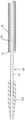
本デバイスの例示的な態様は、図1において全体像として登場する。デバイス10は、外側シース20および外側シース20に連結されたデバイス体90(この態様において、一つの手に把持されるように構成されたハンドルである)を含む。この態様において、外側シースは、ハンドルに対して外側シースが動けないようにハンドルに連結される(つまり、その二つが、固定関係で互いに連結される)。外側シース20は、ステントが送達の前に制約された(例えば、伸長した)状態にある場合に、ステントがその中に配置され得るように構成された中空部材である。
An exemplary embodiment of the device appears as an overview in FIG. The
デバイス体90の近くの、図1の態様の一部が、図2Aにおいて全体像として、および図3において断面図として図示される。これらの図は、デバイス体90に連結され(かつ、この態様において、デバイス体90に対してスライド可能なようにマウントされ)、かつこの態様において通路を有しかつ外側シース20内に適合するように構成された要素40にも連結されるユーザーによる駆動が可能な要素50を、デバイス10が含むことを示す。図2Aおよび3Aにおいて示される態様において、ユーザーによる駆動が可能な要素50は、デバイス体90にスライド可能なようにマウントされ、かつブロック51を介して要素40に連結される。いくつかの態様において、ブロック51は、図3Aにおいて示される位置に向けてユーザーによる駆動が可能な要素50を付勢する(スプリングなどの)付勢要素を含み得る。その他の態様において、ブロック51は、付勢要素を含まない。
A portion of the embodiment of FIG. 1 near the
デバイス10の、ユーザーによる駆動が可能な要素50、ブロック51、および要素40は、近位および遠位方向(デバイスの縦軸(示されない)に沿っている)において可動であり、概して、その他の方向では制約される。したがって、ユーザーによる駆動が可能な要素50の近位運動(近位側92に向かう)は、要素40の近位運動を引き起こし、ユーザーによる駆動が可能な要素50の遠位運動(遠位側91に向かう)は、要素40の遠位運動を引き起こす。描かれる態様において、ユーザーによる駆動が可能な要素50が(近位にまたは遠位に)動く距離は、要素40の同じ距離の運動へ変換すると考えられる。この変換は、望ましいように拡大または縮小とすることができる。以下でより詳細に説明するように、要素40は、ステント係合要素がステントの内腔内で遠位に動かされる時の少なくとも一部の間、搭載されたステントに係合しかつこれを外側シースから遠位に推進するステント係合要素45に連結される。
User-driven
図2Aは、デバイス10が、外側シース20の外側に(スライド可能なように)連結される要素25を含み得ることも示す。要素25は、外側シースの外表面に沿って比較的自由にスライドするように構成され得、それは、イントロデューサーの止血弁と相互作用するように構成され得る(図3Bを参照されたい)。具体的に、それは、部分的にイントロデューサーの内側で適合し、液がデバイスのハンドルに向けて逆流しないように、止血弁と相互作用するように構成され得るが、それでもデバイスの外側シースは、要素20およびイントロデューサー内で比較的自由にスライドし得る。効果的に、要素25は、外側シースと患者の外部との間の実質的な流体封止を維持しながら、デバイスの外側シースとデバイスの外側シースが挿入されるイントロデューサーとの間の摩擦を軽減するように作用し得る。
FIG. 2A also shows that the
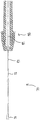
図1、4、および5に関して、外側シース20は、デバイス体90から遠位に伸びる。デバイス10は、内部要素60も含み、その一部は、外側シース20内に位置する。内部要素60(および好ましい態様においてより具体的には、以下で記載される図2Dにおいて示されるような内側スリーブ61)は、その遠位端でノーズコーン150に連結される。シース20によって軸方向に制約されない(その二つが、それらが触れない十分に異なる直径を有するという点で)、内部要素60は、外側シース20に対するノーズコーン150の動きを容易にし、これは、ガイドワイヤが(ノーズコーン150と同様に)それを通って通過し得るようなサイズとされる。放射線不透過性マーカー27は、ステントの展開を補助するための手段を提供するために、外側シース20に沿った任意の適した位置に置かれ得る。例えば、外側シース20の遠位端とマーカー27との距離は、その展開状態において送達されるステントの基準長であり得る。図5は、外側シース20内のステント30の遠位端31を図示する。いくつかの態様において、要素40もステント係合要素45も、内部要素60に取り付けられない。結果として、要素40は、近位に内部要素60上を動かされ得るが、内部要素60は、固定されている。同様に、ステント係合要素45は、近位にかつ遠位に内部要素60上を動かされ得るが、内部要素60は、固定されている。
With reference to FIGS. 1, 4, and 5, the
図2Aおよび3Aに戻って、かつ図2Cにも関して、ユーザーによる駆動が可能な要素50の許容可能な近位-遠位移動は、ストッパー120の位置と同様に、デバイス体90におけるスロット52の長さによって制約される。図2Aにおいて示されるストッパー120の第一の位置121は、ユーザーによる駆動が可能な要素50の遠位移動を、スロット52の全長未満に限定する。好ましくは、第一の位置121は、ステント係合要素45が外側シース20内に残るユーザーによる駆動が可能な要素50の最遠位位置に相当する。これは、ステント30の前進に対する適切な配置に相当する。ストッパー120は、好ましくは、例えばスプリングで第一の位置121に付勢される。図2Cおよび3Aにおいて、ストッパー120は、示されるように、ユーザーによる駆動が可能な要素50がそれを過ぎてスライドすることを可能にする第二の位置122(図2Cにおいてそのように標示される)まで回転している。
Returning to FIGS. 2A and 3A and with respect to FIG. 2C, the allowable proximal-to-distal movement of the user-driven
図2Dは、内部要素60の長さを伸ばしかつガイドワイヤを受けるように構成された内側スリーブ61の形式で内部要素60の好ましい態様を含む、デバイス10の好ましい態様の部分組立品の断面図である。内部要素60は、Loctite(登録商標)4014接着剤などの任意の適したやり方で内側スリーブ61にその遠位端(または任意のその他の適した位置)で固定され得る中間スリーブ62を含んでもよい。中間スリーブ62(ハイポチューブであり得る)は、内部要素60の近位端まで伸びてもよい。内部要素60は、はんだ付けを介するなどの任意の適した様式で、中間スリーブ62にその遠位端(または任意のその他の適した位置)で接続される外側スリーブ63(ハイポチューブであり得る)を含んでもよく;外側スリーブ63は、内部要素60の近位端まで伸びてもよい。内部要素60は、はんだ付けを介するなどの任意の適した様式で、外側スリーブ63にその遠位端(または任意のその他の適した位置)で接続される移動限定スリーブ64を含んでもよい。スリーブ64は、デバイス体90に対して内部要素60の移動を制限するように構成され得る。より具体的には、スリーブ64は、デバイス体90の空洞55の近位開口(標示されない)に(そのサイズにより)干渉するように構成され得(図3Aを参照されたい)、それは、遠位でブロック51に干渉するように構成され得る(ルアー(Luer)フィッティング100が、Yアダプター95に第一に干渉しない場合)。
FIG. 2D is a cross-sectional view of a subassembly of a preferred embodiment of the
図3Bは、拡大断面図であり、要素25とイントロデューサー35との間の相互作用を示す。ここで、要素25は、イントロデューサー35の止血弁の封止31と相互作用している。
FIG. 3B is an enlarged cross-sectional view showing the interaction between
図3Cは、肩57で終結するプレスばめまたはLoctite(登録商標)接着剤(例えば、4014、4305、3321など)の一つ等の適した接着剤などの任意の適した様式でブロック51に固定された近位ハイポチューブ41の形態で要素40の好ましい態様を含む、デバイス10の好ましい態様の部分組立品の断面図である。ブロック51は、要素50およびプレスばめに接着し得るまたはブロック51に接着し得るピン54を介してユーザーによる駆動が可能な要素50に固定される。要素40は、Loctite(登録商標)4305の使用などの任意の適した様式でその近位端で近位ハイポチューブ41に、かつ接着剤の使用などの任意の適した様式でその遠位端で支持チューブ46(接着剤などの任意の適した様式でステント係合要素45に順に接続される)に接続される中間チューブ42を含んでもよい。要素40は、中間チューブ42上に位置付けられかつ近位ハイポチューブ41の遠位端に隣接する支持チューブ43を含んでもよい。支持チューブ43は、任意の適した接着剤を使用して任意の適した位置で中間チューブ42に接続され得る。支持チューブは、中間チューブ42の剛性を増加させるように構成され得る。要素40は、中間チューブ42上に通されかつ支持チューブ43の遠位端に隣接する再被覆ストップ44を含んでもよい。再被覆ストップ44は、任意の適した接着剤を使用して任意の適した位置で中間チューブ42に接続され得る。再被覆ストップ44は、送達プロセス中ステントが再被覆される場合、外側シース20によって取り囲まれる(本図において示されない)ステントの近位運動を防ぐように構成され得る。描かれる部分組立品は、内部要素60の外側(およびより具体的には、内部要素60の好ましい態様の一部である外側ハイポチューブ)の周りで流体の逆流を防ぐようにデザインされかつステンレススチールリテーナー58によって適所に維持されるシリコンシール56も含む。
FIG. 3C shows
図6に関して、要素40は、その一部が、外側シース20内に位置するように伸びる。好ましくは、要素40は、中空であり、その通路は、その中に位置している内部チューブ60の一部を収容する。本要素の代わりの態様は、非中空である場合がある。
With reference to FIG. 6,
図6〜7に関して、要素40は、本態様においてシャベルまたはスコップのように形作られているステント係合要素45に連結される。より具体的には、描かれる好ましい態様において、要素40の中間チューブ42は、ステント係合要素45に接続されている支持チューブ46に接続される。ステント係合要素45は、少なくとも部分的にステント30の内腔内に位置付けられる。ユーザーによる駆動が可能な要素50の遠位運動に応じて要素40が遠位に動く時、ステント係合要素45は、ステント30に係合し、それを外側シース20に沿って前進させる。好ましい態様において、ステント係合部分45の近位への動きは、ステント30の動きを引き起こさない。この様式での要素40の繰り返される往復の遠位および近位への動きは、それが外側シース20を出るまで、ステント30の前進を引き起こす。したがって、当業者は、デバイス10の図示される態様が、ステント係合要素45によるステントの複数の係合によって外側シース20の外に遠位にユーザーがステント30を前進させ得るように構成され、各々の係合が、ステント30の近位端と遠位端との間で生じ、機械による、外側シース20の同時の引き込みを伴わずに遠位にステント30を推進し、かつ遠位にステント30を推進しない期間によって任意のその後の係合から分離され;かつ各々の係合を引き起こすデバイス10との、ユーザーの最も近い接触箇所(ユーザーによる駆動が可能な要素50で生じる)が、デバイス体90の近位端にまたはその遠位に位置することを、理解すると考えられる。ステント係合要素45は、疲労ストレス破壊および同様のものを緩和するのを助けかつ要素45がそれがステント30の内腔内で近位にスライドする時に内側に折り畳まれることを可能にする丸いダンベル状端が提供されるフレックススロット48を含み得る。好ましくは、ステント係合部分45の動作は、図7において描かれるように、適当な形状選択によって達成される。代わりの態様は、ステント前進を達成するために、屈曲する、ヒンジで連結される、またはそうでなければ形状を変えるステント係合部分を採用する場合がある。ステント係合部分の構造形は、展開されるステントのタイプに最も良く合うように選ばれ得る。ステント30が、参照により組み入れられる米国特許第7,018,401号において開示される種類などの編まれた自己展開式ステントである場合、ステント係合要素45は、好ましくは、(a)ステントを遠位に推進する場合に、ステント30の、ステント係合要素と向かい合う側で、ワイヤ交点に係合する、および(b)ステントの内腔内で(少なくとも部分的にステント係合要素のフレックススロット48により)内側に折り畳まれかつ近位にスライドするように(図において示されるように)構成される。
6-7,
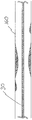
図8は、ステント前進プロセスの図式描写を提供する。ステント30の遠位端31は、外側シース20を出て、広がっている。要素40は、矢印によって示されるように、近位におよび遠位に動く。ステント係合要素45が遠位に移動する時、それは、ステント30に係合しかつ前進させ、したがって、それを外側シース20の外に推進する。ステント係合要素45の形状により、ステント係合要素45が近位に移動する場合、ステント30の前進は生じない。その代りに、ステント係合要素45の形状は、外側シースに対するステントの軸方向の位置を妨げることなく、ユーザーによる駆動が可能な要素50の近位運動の間、それがステント30の部分(例えば、ワイヤ部分)上を動きかつそれらとぶつかる時に、それが内側に曲がることを可能にする。好ましくは、ステント30の前進は、(患者の体運動、振動などによって引き起こされる偶発的な動きは別として)機械による、外側シース20の同時の引き込みを伴わずに、かつデバイス体90に対する外側シース20の動きを伴わずに達成される。
FIG. 8 provides a schematic depiction of the stent advancement process. The
図9〜10は、体管におけるステント展開を図式的に図示する。図9は、制約されたまたは伸長した形状のステント30を描く。これは、デバイス10の外側シース20内にある場合のステント30の構造形の例である。図10は、体管160における広がった状態におけるステント30を示し、自己展開式ステントが外側シース20を出る場合にとり得る一つの状態である。
9-10 schematically illustrate stent deployment in a body vessel. FIG. 9 depicts a
いくつかの態様において、本デバイスは、ステントがシースの外に完全に前進していないという条件で、前進および/または展開プロセスの間に操作者がステントを再被覆することを可能にするように構成されたステント保持要素を含んでもよい。図11および12Aに関して、デバイス10は、ステント30の近位端32に連結されたステント保持要素70を含む。好ましい態様において、ステント保持要素70の遠位部分71とステント30との間の接触は、ステント係合要素45の近位運動の間でさえも、ステント30の近位端32が外側シース20内にある限り存在する。ステント30の近位端32が外側シース20の外側に前進する場合、ステント30は、ステント保持要素70の遠位部分71の(図において示される半径方向においてとられる)最大幅よりも大きな半径まで広がる。結果として、ステント30とステント保持要素70との間の接触が終わり、ステント30の展開が完了する。従って、ステント保持要素70は、ステント30の近位部分(具体的には、ステント保持要素70に連結された近位部分)が外側シース20内に配置されているという条件で、(操作者による実行によって)外側シース20内へ近位にステント30を引き戻すように操作可能である。
In some embodiments, the device allows the operator to recoat the stent during the advancement and / or deployment process, provided that the stent is not fully advanced out of the sheath. A configured stent retaining element may be included. With reference to FIGS. 11 and 12A, the
図2A、3A、および11〜12に関して、ステント保持要素70の近位部分72(図3Bにおいても見られる)は、ステント30の近位部分が外側シース20内に配置されているという条件で、外側シース20内への近位へのステント30の引き戻しを容易にしかつステント保持ラインとして特徴付けられ得るケーブルまたは同様のデバイスである。ステント保持要素70の遠位部分71は、ステント30の編まれたバージョンにおいて開口部に係合する複数の放射状に突き出たプロング73が提供される管状材料の部品(ハイポチューブなど)であり得る。管状材料は、任意の適したやり方で(はんだ付けを使用するなど)近位部分72に連結され得る。
Figure 2A, 3A, and with respect to 11 to 12, (also seen in FIG. 3B) the
図1および2Aにおいて示されるように、Yアダプター95は、デバイス体90の近位部分に連結され得る。内部チューブ60は、直線状アーム96を介して置かれ得、近位部分72は、Yアダプター95の角度のついたアーム97を介して置かれ得る。図2Bにおいて示されるように、ステント保持要素位置マーカー93は、ライン72に連結され得、ステント保持要素に連結されているステントの相対位置にラインに沿って位置付けられ得る。例えば、熱収縮管状材料の部品であり得るマーカーは、それが角度のついたアーム97の縁の部分内へ及んだ際に、ステントが外側シース20を完全に出るように、ラインに沿って位置付けられ得る。この方式で、操作者は、ステントがどれほど遠く外側シースを出たかを伝える視覚インジケーターを有する。図1および2Aは、ステント保持要素が、ステント保持要素の操作が可能になるよう把持するものをユーザーに提供するために、任意の適した様式で(例えば、LOCTITE(登録商標)接着剤を使用して)ライン72に連結されたフィンガー要素98を含み得ることも示す。図12Bは、ステント保持要素70の好ましい態様を示し、断面におけるフィンガー要素98であり、ライン72とフィンガー要素98(示されるように、一緒に通される内部および外部構成要素を有し得る)との間の例としての接続位置99(接着剤または同様のものに対する)を示す。
As shown in FIGS. 1 and 2A, the
好ましくは、デバイス10は、それぞれ外側シース20および内部チューブ60の洗浄を可能にするための(デバイス体90に連結された)サイドポート110および(内部チューブ60の近位端62に連結された)ルアーフィッティング100を含む。洗浄は、生理食塩水を用いてよく、手順の前に行われ得る。本デバイスの代わりの態様は、外側シース20および内部チューブ60を洗浄するための代わりのデザインを含む場合がある、または洗浄を可能にするように構成されない場合がある。図3Dは、デバイス10の上面図であり、図3Eにおいてより詳細に示されているデバイス体90の遠位端の近くの詳細な切断図を明らかにする。
Preferably, the
図2Cに関して、ストッパー120の第二の位置122は、ユーザーによる駆動が可能な要素50がスロット52の全長を遠位に移動することを可能にする。ユーザーによる駆動が可能な要素50の最遠位位置は、ステント係合要素45が、外側シース20の外側(遠位)に存在し、それ故にステント30が外側シース20の外に推進されかつその広がった状態にある領域にある位置に相当する。ステント保持要素70の遠位部分71から脱連結されるこの位置におけるステントは、もはや外側シース20内へ引き込まれない。さらに、広がった状態のステントは、ステント係合要素45上に半径方向の間隙を有すると考えられる。本デバイスの代わりの態様は、ユーザーによる駆動が可能な要素50の移動を限定するためのその他のデザインを採用する場合があり、または調整可能な移動限定機能を有さない場合がある。
With reference to FIG. 2C, the
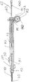
図13〜14は、ステント保持要素70の近位部分72に連結された捕獲デバイス80を含む本デバイスの別の態様を描く。捕獲デバイス80は、ステント係合要素45がステント30を前進させる時に、近位部分72の適当な量を放出する役目を果たす。捕獲デバイス80は、外側シース20からのステント30の全展開の前に、ステント30の遠位前進を停止させる役目を果たすストップを含む。ストップ(適当な位置で近位部分72に連結されるハイポチューブなどの管状材料の部品であり得る)は、さらなる前進がステント展開を引き起こすと考えられるポイントで操作者フィードバックを提供する(したがって、ストップが、ステント引き込みがもはや可能ではない位置のインジケーターとして使用され得る)。ここで、操作者は、ステント保持要素70上で近位に引くことによって再度の位置調整のために外側シース20内へステント30を引き込むこと、または展開ストップレバー81(ストップが展開ストップレバーを回避するのを可能にし、ステント保持要素の継続遠位前進を可能にする)を押し下げ、かつユーザーによる駆動が可能な要素50を介する前進を継続することによってステント展開を進めることを選択することができる。
FIGS. 13-14 depict another embodiment of the present device that includes a
操作者が、再度の位置調整のために外側シース20内へステント30を引き込むことを選択する場合、操作者は、(描かれる態様において)デバイス体90から捕獲デバイス80を脱連結させ、かつ操作者が近位にステント保持要素70の近位部分72を引くことによってステント30を引き込むことを進めることを可能にする保持引きレバー84を作動させ得る。ステント30の外側シース20内への引き込みの後、捕獲デバイス80の保持滑車82およびスプリング83は、ステント保持要素70の過剰な緩みを蓄積するように操作する。本態様において、ステント保持要素70の近位部分72は、デバイス体内に中心に配置されないデバイス体90の部分を通って通され得る。捕獲デバイスを含む本デバイスの代わりの態様は、自動化捕獲デバイスなどの捕獲デバイス80とは異なって構成される捕獲デバイスを含む場合がある。さらに、捕獲デバイス80は、フィンガー要素98の代わりに、図1において示されるデバイス10の態様における角度のついたアーム97に連結され得る。
If the operator chooses to retract the
本デバイスは、使い捨てであり得、エチレンオキシドガスを使用する滅菌などの任意の適した技術を使用して滅菌された後に、バッグ、ポーチ、ボックス、またはその他の適した容器に包装され得る。滅菌ガスがデバイス全体を流れることを可能にするために、外側シースの遠位端とノーズコーンの近位端との間に小さなギャップがあり得る。容器は、容器上に印刷されたまたは容器の内側に含まれた、デバイスを使用するための取扱説明書を含み得る。デバイスがその容器から除去された後、外側シースおよびその内容物および内部チューブを洗浄するために生理食塩水が使用され得る。次いで、ノーズコーンと外側シースとの間のギャップは、ノーズコーンが連結されている内部チューブ上で近位に引くことによって閉じられ得る。手順が血管をステントすることに関与する場合、デバイスを適当な位置に位置付けるための任意の適した技術が使用され得る(例えば、Seldinger技術など)。デバイスのノーズコーン(任意の適した柔軟性チップであり得る)は、放射線不透過性であり得、デバイスに対する最遠位マーカーを示し得る。任意の適した材料(白金バンドまたは任意の適した白金合金から作られたバンドなど)から作られた別の放射線不透過性マーカーは、デバイスに対する最近位マーカーを作り出すために、(上で議論されるように)外側シース、要素40、または内部要素に対してなど、ノーズコーンに対して近位であるデバイスの部分に連結され得る。これらの二つのマーカーは、ステントの正確な展開を可能にするために、対象となる病変に対してデバイスを位置付けるために操作者によって使用され得る。
The device can be disposable and can be packaged in a bag, pouch, box, or other suitable container after sterilization using any suitable technique, such as sterilization using ethylene oxide gas. There may be a small gap between the distal end of the outer sheath and the proximal end of the nose cone to allow sterilization gas to flow through the device. The container may include instructions for using the device printed on the container or contained within the container. After the device is removed from the container, saline can be used to clean the outer sheath and its contents and inner tube. The gap between the nose cone and the outer sheath can then be closed by pulling proximally over the inner tube to which the nose cone is connected. If the procedure involves stenting a blood vessel, any suitable technique for positioning the device in place can be used (eg, Seldinger technique, etc.). The nose cone of the device (which can be any suitable flexible tip) can be radiopaque and can represent the most distal marker for the device. Another radiopaque marker made from any suitable material (such as a platinum band or a band made from any suitable platinum alloy) is discussed above (in order to create a proximal marker for the device). As can be coupled to the portion of the device that is proximal to the nose cone, such as to the outer sheath,
本方法は、シース(例えば、外側シース20)の外にかつチューブ状構造体内へ、ステントを遠位に推進するためのステント前進方法を含む。いくつかの態様において、チューブ状構造体は、動物組織(ヒト血管など)である。その他の態様において、チューブ状構造体は、動物組織ではなく、与えられたデバイス技術をテストする、または彼もしくは彼女の実践においてデバイスもしくはステント前進技術を使用することを考えている医師などの一人もしくは複数の人にステント前進を実演するために使用され得るポリマー構造体を含む。 The method includes a stent advancement method for propelling the stent distally out of a sheath (eg, outer sheath 20) and into a tubular structure. In some embodiments, the tubular structure is animal tissue (such as human blood vessels). In other embodiments, the tubular structure is not animal tissue, but one person, such as a doctor who is considering testing a given device technology or using device or stent advancement technology in his or her practice or It includes a polymer structure that can be used to demonstrate stent advancement to multiple people.
本ステント前進方法のいくつかの態様は、ステント係合要素(例えば、ステント係合要素45)とステントとをその遠位端と近位端との間で繰り返し係合することによって、シース(例えば、外側シース20)の外にかつチューブ状構造体内へ、ステント(例えば、ステント30)を遠位に推進する段階であって、該係合の少なくとも二つが非係合期間によって分離される、段階;および、ステントをシースの外に遠位に推進する時に、チューブ状構造体に対するシースの軸方向の位置を変化させることによって、チューブ状構造体内でステントの軸方向密度を変化させる段階を含む。ステントをシースの外に遠位に推進する時に、デバイスの残部は、ステントの展開部分が、それが展開されるチューブ状構造体(例えば、ヒト組織)に対して固定されたままであるように、チューブ状構造体に対して操作者によって近位に引き込まれる。デバイスの残部が引き込まれる速度は、ステントの軸方向密度を変化させるために変化させられ得;より遅い引き込み速度は、ステントの軸方向密度を増加させ、より速い速度は、ステントの軸方向密度を減少させる。例えば、図15Aにおいて示されるように動脈200の狭窄領域210に沿ってなど、チューブ状構造体の開存性を維持するためにより大きなフープ強度が必要とされる位置において、ステントの軸方向密度を増加させることが望ましい場合がある。例えば、側面からステントのセクションへの流体の流れが期待されるもしくは望ましい位置において、または第二ステントの貫通の位置で、ステントの軸方向密度を減少させることが望ましい場合があり、どちらも図15Bにおいて示されるように管250の解剖学的側枝260で当てはまり得る。
Some aspects of the stent advancement method may include a sheath (e.g., stent engagement element 45 (e.g., stent engagement element 45)) by repeatedly engaging a stent (e.g., stent engagement element 45) between its distal and proximal ends. , Pushing the stent (eg, stent 30) distally out of the outer sheath 20) and into the tubular structure, wherein at least two of the engagements are separated by a non-engagement period And changing the axial density of the stent within the tubular structure by changing the axial position of the sheath relative to the tubular structure as the stent is driven distally out of the sheath. When propelling the stent distally out of the sheath, the remainder of the device is such that the deployed portion of the stent remains fixed relative to the tubular structure (eg, human tissue) in which it is deployed. It is pulled proximally by the operator with respect to the tubular structure. The rate at which the rest of the device is retracted can be varied to change the axial density of the stent; a slower retraction rate increases the axial density of the stent, and a faster rate increases the axial density of the stent. Decrease. For example, at a location where greater hoop strength is required to maintain the patency of the tubular structure, such as along the
本ステント前進方法のいくつかの態様は、ステント係合要素(例えば、ステント係合要素45)とステントとをその遠位端と近位端との間で繰り返し係合することによって、シース(例えば、外側シース20)の外にかつチューブ状構造体内へ、ステント(例えば、ステント30)を遠位に推進する段階であって、該係合の少なくとも二つが非係合期間によって分離される、段階;およびシース内に位置付けられているステント保持要素(例えば、ステント保持要素70)とステントとをその近位端で係合する段階を含む。 Some aspects of the present stent advancement method may include a sheath (eg, , Pushing the stent (eg, stent 30) distally out of the outer sheath 20) and into the tubular structure, wherein at least two of the engagements are separated by a non-engagement period And engaging the stent at its proximal end with a stent retaining element (eg, stent retaining element 70) positioned within the sheath.
いくつかの態様において、ステントをシースから遠位に推進する係合は、図において示される本デバイスのバージョンなどの、ステントが遠位に推進される時に、機械によりシースを同時に引き込むことがないように構成されたデバイスを使用して達成され得る。それらの態様におけるチューブ状構造体は、管もしくは導管などの解剖学的チューブ状構造体またはポリマーチューブ300(図15Cを参照されたい)などの動物組織ではないチューブ状構造体であり得る。とにかく、いくつかの態様において、方法は、シース内に位置付けられているステント保持要素とステントとをその近位端で係合する段階も含み得る。ステント保持要素は、ステント保持ラインを含み得、方法は、ステントをシースの外に部分的に推進した後に、ステント保持ラインを動かすことによってステントをシース内へ引き戻す段階も含み得る。操作者は、操作者の親指でユーザーによる駆動が可能な要素(例えば、ユーザーによる駆動が可能な要素50)を動かすことによってステントの推進を遂行し得る。ステントは編まれていてよく、ステント係合要素はステントの複数のワイヤ交点に係合しかつステントを推進する係合の間遠位に動き得、ステント係合要素は、非係合期間のあいだステントの内腔内で近位にスライドし得る。 In some embodiments, engagement of distally driven the stent from the sheath, such as the version of the device shown in FIG, when the stent is urged distally, simultaneously pulling write Mukoto sheath by mechanical Can be achieved using a device configured to not . The tubular structure in these embodiments can be an anatomical tubular structure such as a tube or conduit or a tubular structure that is not animal tissue such as a polymer tube 300 (see FIG. 15C). Regardless, in some aspects, the method may also include engaging the stent holding element positioned within the sheath and the stent at their proximal ends. The stent retaining element can include a stent retaining line, and the method can also include pulling the stent back into the sheath by moving the stent retaining line after partially pushing the stent out of the sheath. An operator may perform stent propulsion by moving a user-driven element (eg, user-driven element 50) with the operator's thumb. The stent may be knitted so that the stent engaging element can engage the plurality of wire intersections of the stent and move distally during engagement to propel the stent, and the stent engaging element can be moved during the non-engagement period. It can slide proximally within the lumen of the stent.
本方法のいくつかは、ステントをシースの外にかつチューブ状構造体内へ、どのように前進させるかに関して別人または他人を指導する方法である。本ステント前進指導方法のいくつかの態様は、シース(例えば、外側シース20)およびシースに配置されたステント(例えば、ステント30)を含むステント送達デバイス(例えば、デバイス10)をどのように使用するかに関して人を指導することを含む。指導は、人に以下の段階を実演することを含み得る:ステント係合要素(例えば、ステント係合要素45)とステントとをその遠位端と近位端との間で繰り返し係合することによって、シースの外にかつチューブ状構造体内へ、ステントを遠位に推進する段階であって、該係合の少なくとも二つが非係合期間によって分離される、段階;および、ステントをシースの外に遠位に推進する時に、チューブ状構造体に対するシースの軸方向の位置を変化させることによって、チューブ状構造体内でステントの軸方向密度を変化させる段階。 Some of the methods are methods of instructing another person or another on how to advance the stent out of the sheath and into the tubular structure. Some aspects of the present stent advancement method how to use a stent delivery device (eg, device 10) that includes a sheath (eg, outer sheath 20) and a stent (eg, stent 30) disposed in the sheath. Including teaching people about Instructions may include demonstrating the following steps to a person: repeatedly engaging a stent engaging element (eg, stent engaging element 45) and a stent between its distal and proximal ends. Pushing the stent distally out of the sheath and into the tubular structure, wherein at least two of the engagements are separated by a non-engagement period; and Changing the axial density of the stent within the tubular structure by changing the axial position of the sheath relative to the tubular structure when propelled distally.
本ステント前進指導方法のいくつかの態様は、シース(例えば、外側シース20)および該シースに配置されたステント(例えば、ステント30)を含むステント送達デバイス(例えば、デバイス10)をどのように使用するかに関して人を指導することを含む。指導は、人に以下の段階を実演することを含み得る:ステント係合要素(例えば、ステント係合要素45)とステントとをその遠位端と近位端との間で繰り返し係合することによって、シースの外にかつチューブ状構造体内へ、ステントを遠位に推進する段階であって、該係合の少なくとも二つが非係合期間によって分離される、段階;およびシース内に位置付けられているステント保持要素(例えば、ステント保持要素70)とステントとをその近位端で係合する段階。 Some aspects of the present stent advancement method how to use a stent delivery device (eg, device 10) that includes a sheath (eg, outer sheath 20) and a stent (eg, stent 30) disposed in the sheath. Including teaching people about what to do. Instructions may include demonstrating the following steps to a person: repeatedly engaging a stent engaging element (eg, stent engaging element 45) and a stent between its distal and proximal ends. Pushing the stent distally out of the sheath and into the tubular structure, wherein at least two of the engagements are separated by a non-engagement period; and positioned in the sheath Engaging a stent retaining element (eg, stent retaining element 70) and a stent at its proximal end.
指導方法は、いくつかの態様において人が出席する生の実演によって、かつその他の態様においては人に対して再生される記録されたまたはシミュレーションされた実演によって遂行され得る。記録された実演の例は、人によって実行され、カメラで捕えられたものである。シミュレーションされた実演の例は、実際には生じなかったが、その代わりにコンピューターシステムおよびグラフィックプログラムを使用して生成されたものである。記録されたまたはシミュレーションされた実演のケースで、実演は、DVDまたは任意の適したビデオファイル(.mpg、.mov.、.qt、.rm、.swf、または.wmvファイルなど)などの任意の適した形式で存在し得、指導は、任意の適したコンピューターシステムを使用して視聴者に対して実演を再生することによって遂行され得る。視聴者または複数の視聴者は、実演を再生させることができる。例えば、視聴者は、インターネットまたは視聴者にファイルへのアクセスを提供する任意の適したコンピューターシステムを使用して、記録されたまたはシミュレーションされた実演ファイルにアクセスし得る。図16を参照されたい。 The teaching method may be performed in some aspects by live performances attended by a person and in other aspects by recorded or simulated performances that are played back to the person. An example of a recorded demonstration was performed by a person and captured with a camera. Examples of simulated demonstrations did not actually occur, but instead were generated using a computer system and a graphics program. In the case of a recorded or simulated demonstration, the demonstration can be any DVD, or any suitable video file (such as an .mpg, .mov., .Qt, .rm, .swf, or .wmv file) It can exist in any suitable form and the instruction can be accomplished by playing the performance to the viewer using any suitable computer system. The viewer or multiple viewers can play the demonstration. For example, the viewer may access the recorded or simulated demonstration file using the Internet or any suitable computer system that provides the viewer with access to the file. See FIG.
解剖学的構造体へのステント送達に関与する本方法、およびステント前進を開始するために患者内の望ましい位置でその方法を遂行するために使用されるデバイスの態様において、ステント係合要素の運動(例えば、ラチェット運動)を、ステントの遠位端(手技の間、その位置のより簡単な観察を可能にするために、一つまたは複数の放射線不透過性マーカーが提供されてもよい)がデバイスの外側シースを出るが、それが解剖学的構造体に接触するまで広がるほどではないように、始めることができる。ステントの遠位端が操作者がそれを欲する所の近位であり、かつステント保持要素が使用される場合、ステント保持要素は、ステントを再被覆し、かつデバイスを再度位置調整するために、近位に引かれ得;ステントが、操作者が望む遠位に在る場合、デバイス全体は、近位に引き込まれ得、かつ展開プロセスは継続され得る。 In the embodiment of the method involved in stent delivery to an anatomical structure and the device used to perform the method at a desired location within a patient to initiate stent advancement, motion of the stent engaging element (E.g., ratchet motion) when the distal end of the stent (one or more radiopaque markers may be provided to allow easier observation of its position during the procedure) The outer sheath of the device can be started so that it does not spread out until it contacts the anatomy. If the distal end of the stent is proximal to where the operator wants it and a stent retaining element is used, the stent retaining element will re-cover the stent and realign the device If the stent is at the distal location desired by the operator, the entire device can be withdrawn proximally and the deployment process can be continued.
本デバイスの異なる機構は、市販されている医療グレード材料から作られ得る。例えば、ノーズコーン150は、ポリエーテルブロックアミド(Arkema Inc, Philadelphia, PAから入手可能なPEBAX(登録商標)樹脂など)から作られ得る。内部要素60の遠位部分(内側スリーブ61など)は、ポリイミドから作られ得、ステンレススチールハイポチューブ(304または316Lステンレススチールなど)から作られたより近位の部分に連結され得る。内部要素60(例えば、外側スリーブ63)に連結されたルアーフィッティング100は、ポリカーボネートから作られ得る。外側シース20は、編組ポリエーテルブロックアミド(例えば、編組PEBAX(登録商標)樹脂)から作られ得る。デバイス体90、ユーザーによる駆動が可能な要素50、ブロック51、およびストッパー120は、ABS(アクリロニトリルブタジエンスチレン)プラスチック、ポリカーボネート、またはDELRIN(登録商標)アセタール樹脂(DuPontから入手可能)から作られ得る。ストッパー120は、上で記載されるようにそれを付勢するステンレススチールスプリングに連結され得る。要素40は、ポリイミドから形成されたシャフト(または好ましい態様におけるように、ポリイミドまたはニチノールハイポチューブから作られているシャフトのシリーズ)を有し得、ステント係合要素45は、適した接着剤(例えば、シアノアクリレートを含むLOCTITE(登録商標)接着剤)でポリイミドシャフトに連結されたニチノールハイポチューブの短い部品(例えば、チューブ46)および望ましい形状に形造られかつそのニチノールハイポチューブの短い部品に溶接(例えば、レーザー溶接)されたニチノールハイポチューブの部品を含み得るまたはそれに連結され得る。ステント保持要素70は、ナイロン、FEP(フッ素化エチレンプロピレン)管状材料、またはPET(ポリエステル)管状材料などの材料で覆われている撚り合わせたステンレススチールワイヤ(近位部分72として使用される)を含み得、遠位部分71は、ステンレススチールハイポチューブから作られ得る。さらに、ステントと外側シースとの間の接触などの、本デバイスの使用中に互いに接触するまたは接触し得るパーツ間の摩擦を軽減するための段階がとられ得る。
Different features of the device can be made from commercially available medical grade materials. For example,
本デバイスは、ワイヤなどの複数のストランドから編まれたステントを含む、編まれている自己展開式ステントを送達するために使用され得る。使用され得る製織技術のいくつかの例は、参照により組み入れられる米国特許第6,792,979号および第7,048,014号におけるものを含む。編まれたステントのストランドは、ストランド端(例えば、ワイヤ端)において終結し得、次いで、ステントストランドがニチノールから作られたワイヤである場合、ニチノールハイポチューブなどの材料の小さなセグメントを使用して接合される。ステントは、ステント表面から任意の熱処置およびアニーリングの間に形成され得る酸化被膜を除去するために、任意の適した技術によって不動態化され得、したがって、ステント材料の表面仕上げおよび耐食性を改善し得る。本デバイスとともに使用され得るステントに適したステント作製技術(ステント係合要素45によって係合され得るストランドクロッシングを含む)は、参照により組み入れられる米国特許出願第11/876,666号に規定される。
The device can be used to deliver knitted self-expanding stents, including stents knitted from multiple strands such as wires. Some examples of weaving techniques that can be used include those in US Pat. Nos. 6,792,979 and 7,048,014, which are incorporated by reference. The strands of a knitted stent can be terminated at the strand end (eg, wire end) and then joined using a small segment of material such as Nitinol hypotube if the stent strand is a wire made from Nitinol Is done. The stent can be passivated by any suitable technique to remove the oxide film from the stent surface that can form during any thermal treatment and annealing, thus improving the surface finish and corrosion resistance of the stent material. obtain. Suitable stent fabrication techniques for stents that can be used with the device, including strand crossings that can be engaged by
本デバイスおよび方法は、開示される特定の形式に限定されることを意図していないことが理解されるべきである。むしろ、それらは、特許請求の範囲の範囲内に収まるすべての改変、等価物、および代替物を包含するべきである。例えば、図において示される本デバイスの態様は、操作者からの動力に応じて同じ距離を動く、ステント係合要素およびユーザーによる駆動が可能な要素を含んだが、本デバイスのその他の態様は、(往復要素の距離が、ユーザーによる駆動が可能な要素の距離より大きいまたはそれ未満であり得るように)1:1ではない、ユーザーによる駆動が可能な要素が動く距離とステント係合要素が動く結果として生じる距離との間の比を作り出すギアまたはその他のメカニズムを含む可能性があると考えられる。それに加えて、さらにその他の態様は、参照により組み入れられる米国特許第5,968,052号もしくは参照により組み入れられる米国特許第6,514,261号において示されるものと同様の引き金を引くメカニズムを使用する、または並進するよりもむしろ回転しかつ与えられた回転の一部の間ステントを係合し、その回転の別の部分の間ステントを係合しないように構成されたカム部分を保有するステント係合要素を用いるなどの、ステントを遠位に前進させるためにステントの周期的係合を達成するためのその他の構造体を採用し得る。それに加えて、さらにその他の態様は、カムを介してステント係合要素に連結された(図において示されるように、並進入力よりもむしろ)回転するユーザーによる駆動が可能な動力などの操作者からの動力の別の形式を用いるなどの、ステント係合要素(ステント係合要素45など)の往復運動のその他の形式を採用し得る。 It should be understood that the devices and methods are not intended to be limited to the particular forms disclosed. Rather, they should encompass all modifications, equivalents, and alternatives falling within the scope of the claims. For example, the embodiment of the device shown in the figure includes a stent-engaging element and a user-driven element that move the same distance in response to power from an operator, but other aspects of the device are ( The result of moving the stent-engaging element and the distance that the user-driven element is moved, not 1: 1 (so that the distance of the reciprocating element can be greater than or less than the distance of the element that can be driven by the user) It may be possible to include gears or other mechanisms that produce a ratio between the resulting distances. In addition, yet other embodiments use rather than use a triggering mechanism similar to that shown in U.S. Pat.No. 5,968,052 or U.S. Pat. Using a stent engaging element that has a cam portion configured to rotate and engage the stent during a portion of a given rotation and not engage the stent during another portion of the rotation, etc. Other structures for achieving periodic engagement of the stent to advance the stent distally may be employed. In addition, yet another aspect is from an operator, such as a power that can be driven by a rotating user (rather than a translational input, as shown) coupled to a stent engaging element via a cam. Other forms of reciprocation of the stent engaging element (such as stent engaging element 45) may be employed, such as using other forms of power.
特許請求の範囲は、そのような限定がそれぞれ「〜のための手段」または「〜のための段階」という語句を使用して与えられた特許請求の範囲において明確に列挙されない限り、手段-プラス-または段階-プラス-機能限定を含むものとして解釈されるべきではない。 The claims are intended to be means-plus unless such a limitation is expressly recited in the claims given using the phrase "means for" or "step for", respectively. -Or should not be construed as including stage-plus-function limitations.
Claims (15)
ハンドルに対して固定されている外側シースに連結されたハンドルと、
外側シース内に配置されたステントであって、ワイヤ交点で交差する複数の編まれたワイヤを含むステントと、
外側シース内に配置されたステント係合要素と
を含み、
前記ステントが、ステント係合要素によるステント係合の少なくとも二つの期間を経て外側シースの外に遠位に推進可能であり、該少なくとも二つの期間が、ステント係合要素がワイヤ交点の少なくとも一部と係合する第一の係合期間と、ステント係合要素が他のワイヤ交点の少なくとも一部と係合する第二の係合期間とを含み、係合の該期間の各々が、機械による、外側シースの同時の引き込みを伴わずに遠位にステントを推進するよう構成され、かつ係合の該期間の各々が、ステントを遠位に推進しないように構成されたステント係合要素によるステントの非係合期間によって分離される、デバイス。 An outer sheath;
A handle coupled to an outer sheath secured to the handle;
A stent disposed within an outer sheath, comprising a plurality of braided wires intersecting at wire intersections ;
A stent engaging element disposed within the outer sheath,
The stent is propellable distally out of the outer sheath via at least two periods of stent engagement by the stent engaging element, the at least two periods of which the stent engaging element is at least part of the wire intersection And a second engagement period in which the stent engaging element engages at least a portion of the other wire intersection , each of the engagement periods being machine dependent A stent with a stent-engaging element configured to propel the stent distally without simultaneous retraction of the outer sheath and each of the periods of engagement configured to not propel the stent distally Device separated by a period of disengagement.
ステントを遠位に推進する前記段階が、係合の少なくとも二つの期間のあいだ、機械による、外側シースの同時の引き込みを伴わずに、外側シース内に配置されたステント係合要素によりステントを係合することを含み、該係合の少なくとも二つの期間が、ステント係合要素がワイヤ交点の少なくとも一部と係合する第一の係合期間と、ステント係合要素が他のワイヤ交点の少なくとも一部と係合する第二の係合期間とを含み、係合の該期間の各々が、ステントを遠位に推進しない、ステント係合要素によるステントの非係合期間によって分離されている、ステント前進方法。 Distally propelling a stent disposed within an outer sheath into a tubular structure that is not part of an animal, the stent comprising a plurality of braided wires intersecting at wire intersections; A method comprising: an outer sheath coupled to the handle and secured to the handle;
The step of pushing the stent distally engages the stent by a stent engaging element disposed within the outer sheath without simultaneous mechanical withdrawal of the outer sheath during at least two periods of engagement. The at least two periods of engagement include a first engagement period in which the stent engaging element engages at least a portion of the wire intersection, and at least one of the other wire intersections in the stent engaging element. A second engagement period that engages a portion, each of the engagement periods being separated by a non-engagement period of the stent by the stent engagement element that does not propel the stent distally; Stent advancement method.
Applications Claiming Priority (3)
| Application Number | Priority Date | Filing Date | Title |
|---|---|---|---|
| US86245606P | 2006-10-22 | 2006-10-22 | |
| US60/862,456 | 2006-10-22 | ||
| PCT/US2007/082165 WO2008051941A2 (en) | 2006-10-22 | 2007-10-22 | Devices and methods for stent advancement |
Related Child Applications (1)
| Application Number | Title | Priority Date | Filing Date |
|---|---|---|---|
| JP2012209331A Division JP5847045B2 (en) | 2006-10-22 | 2012-09-24 | Devices and methods for stent advancement |
Publications (3)
| Publication Number | Publication Date |
|---|---|
| JP2010507459A JP2010507459A (en) | 2010-03-11 |
| JP2010507459A5 JP2010507459A5 (en) | 2012-11-08 |
| JP5455633B2 true JP5455633B2 (en) | 2014-03-26 |
Family
ID=41429654
Family Applications (1)
| Application Number | Title | Priority Date | Filing Date |
|---|---|---|---|
| JP2009534804A Expired - Fee Related JP5455633B2 (en) | 2006-10-22 | 2007-10-22 | Devices and methods for stent advancement |
Country Status (11)
| Country | Link |
|---|---|
| US (1) | US8876881B2 (en) |
| EP (2) | EP2083767B1 (en) |
| JP (1) | JP5455633B2 (en) |
| KR (2) | KR20130095317A (en) |
| AU (1) | AU2007309087B2 (en) |
| BR (1) | BRPI0717389A2 (en) |
| CA (1) | CA2667322C (en) |
| HK (1) | HK1140405A1 (en) |
| IL (4) | IL198303A (en) |
| MX (2) | MX344492B (en) |
| WO (1) | WO2008051941A2 (en) |
Families Citing this family (27)
| Publication number | Priority date | Publication date | Assignee | Title |
|---|---|---|---|---|
| US7018401B1 (en) | 1999-02-01 | 2006-03-28 | Board Of Regents, The University Of Texas System | Woven intravascular devices and methods for making the same and apparatus for delivery of the same |
| EP3150177B1 (en) | 2006-10-22 | 2021-06-02 | Idev Technologies, Inc. | Methods for securing strand ends and the resulting devices |
| EP2083767B1 (en) | 2006-10-22 | 2019-04-03 | IDEV Technologies, INC. | Devices for stent advancement |
| US20100305686A1 (en) * | 2008-05-15 | 2010-12-02 | Cragg Andrew H | Low-profile modular abdominal aortic aneurysm graft |
| US8968210B2 (en) | 2008-10-01 | 2015-03-03 | Covidien LLP | Device for needle biopsy with integrated needle protection |
| US9186128B2 (en) | 2008-10-01 | 2015-11-17 | Covidien Lp | Needle biopsy device |
| US9782565B2 (en) | 2008-10-01 | 2017-10-10 | Covidien Lp | Endoscopic ultrasound-guided biliary access system |
| US20110190662A1 (en) * | 2008-10-01 | 2011-08-04 | Beacon Endoscopic Corporation | Rapid exchange fna biopsy device with diagnostic and therapeutic capabilities |
| US11298113B2 (en) | 2008-10-01 | 2022-04-12 | Covidien Lp | Device for needle biopsy with integrated needle protection |
| US9149376B2 (en) * | 2008-10-06 | 2015-10-06 | Cordis Corporation | Reconstrainable stent delivery system |
| CN101779992B (en) * | 2009-01-19 | 2012-08-22 | 加奇生物科技(上海)有限公司 | Conveying device for retrievable self-eject nervi cerebrales stent |
| US9572652B2 (en) * | 2009-12-01 | 2017-02-21 | Altura Medical, Inc. | Modular endograft devices and associated systems and methods |
| US9023095B2 (en) * | 2010-05-27 | 2015-05-05 | Idev Technologies, Inc. | Stent delivery system with pusher assembly |
| WO2012040240A1 (en) | 2010-09-20 | 2012-03-29 | Altura Medical, Inc. | Stent graft delivery systems and associated methods |
| KR20140024848A (en) * | 2011-01-14 | 2014-03-03 | 이데브 테크놀로지스, 아이엔씨. | Stent delivery system with pusher assembly |
| US9913741B2 (en) | 2011-07-05 | 2018-03-13 | Cook Medical Technologies Llc | Control handle for self-expandable medical devices |
| CA2881535A1 (en) | 2012-08-10 | 2014-02-13 | Altura Medical, Inc. | Stent delivery systems and associated methods |
| US20140180380A1 (en) | 2012-12-20 | 2014-06-26 | Sanford Health | Stent Deployment Device and Methods for Use |
| US9737426B2 (en) | 2013-03-15 | 2017-08-22 | Altura Medical, Inc. | Endograft device delivery systems and associated methods |
| CN103586582B (en) * | 2013-11-28 | 2015-08-19 | 哈尔滨工业大学 | A kind of laser-induced combustion self-propagating reaction assistant brazing connects C fthe method of/Al composite and TiAl |
| US20150297379A1 (en) * | 2014-04-22 | 2015-10-22 | Abbott Cardiovascular Systems Inc. | System for continuous stent advancement |
| CN107530161A (en) | 2015-04-22 | 2018-01-02 | 艾纽梅德公司 | Personalized prosthese and dispositions method |
| US10022255B2 (en) | 2016-04-11 | 2018-07-17 | Idev Technologies, Inc. | Stent delivery system having anisotropic sheath |
| EP3443940A4 (en) * | 2016-04-12 | 2020-08-19 | Suzhou Innomed Medical Device Co., Ltd | Vascular stent conveying system and duct assembly thereof |
| KR101902781B1 (en) * | 2016-11-16 | 2018-10-01 | (주) 태웅메디칼 | Electrocautery stent delivery system with a mono-polar tip |
| KR102244846B1 (en) * | 2019-04-18 | 2021-04-28 | 주식회사 엠아이텍 | Stent delivery device |
| CN112438824A (en) * | 2019-09-03 | 2021-03-05 | 上海微创心通医疗科技有限公司 | Medical implant delivery device |
Family Cites Families (489)
| Publication number | Priority date | Publication date | Assignee | Title |
|---|---|---|---|---|
| US2836181A (en) | 1955-01-17 | 1958-05-27 | Chemstrand Corp | Flexible nylon tube and method for preparing same |
| US2936257A (en) | 1956-12-04 | 1960-05-10 | Consolidation Coal Co | Method and apparatus for splicing electrical mining cable |
| US3620218A (en) | 1963-10-31 | 1971-11-16 | American Cyanamid Co | Cylindrical prosthetic devices of polyglycolic acid |
| US3463197A (en) | 1966-06-20 | 1969-08-26 | Raybestos Manhattan Inc | Wire-braided hydraulic hose |
| GB1205743A (en) | 1966-07-15 | 1970-09-16 | Nat Res Dev | Surgical dilator |
| US3479670A (en) | 1966-10-19 | 1969-11-25 | Ethicon Inc | Tubular prosthetic implant having helical thermoplastic wrapping therearound |
| US3868956A (en) | 1972-06-05 | 1975-03-04 | Ralph J Alfidi | Vessel implantable appliance and method of implanting it |
| GB1565828A (en) | 1975-12-02 | 1980-04-23 | Plastiques Ind Soc | Implantable surgical pipeline |
| DE3019996A1 (en) | 1980-05-24 | 1981-12-03 | Institute für Textil- und Faserforschung Stuttgart, 7410 Reutlingen | HOHLORGAN |
| SE445884B (en) | 1982-04-30 | 1986-07-28 | Medinvent Sa | DEVICE FOR IMPLANTATION OF A RODFORM PROTECTION |
| US4503569A (en) | 1983-03-03 | 1985-03-12 | Dotter Charles T | Transluminally placed expandable graft prosthesis |
| US5067957A (en) | 1983-10-14 | 1991-11-26 | Raychem Corporation | Method of inserting medical devices incorporating SIM alloy elements |
| US5190546A (en) | 1983-10-14 | 1993-03-02 | Raychem Corporation | Medical devices incorporating SIM alloy elements |
| US4665906A (en) | 1983-10-14 | 1987-05-19 | Raychem Corporation | Medical devices incorporating sim alloy elements |
| CA1246956A (en) | 1983-10-14 | 1988-12-20 | James Jervis | Shape memory alloys |
| US5693083A (en) * | 1983-12-09 | 1997-12-02 | Endovascular Technologies, Inc. | Thoracic graft and delivery catheter |
| US5669936A (en) | 1983-12-09 | 1997-09-23 | Endovascular Technologies, Inc. | Endovascular grafting system and method for use therewith |
| DK151404C (en) | 1984-05-23 | 1988-07-18 | Cook Europ Aps William | FULLY FILTER FOR IMPLANTATION IN A PATIENT'S BLOOD |
| US4580568A (en) | 1984-10-01 | 1986-04-08 | Cook, Incorporated | Percutaneous endovascular stent and method for insertion thereof |
| US4997440A (en) | 1985-04-25 | 1991-03-05 | American Cyanamid Company | Vascular graft with absorbable and nonabsorbable components |
| SE447061B (en) | 1985-06-10 | 1986-10-27 | Medinvent Sa | INFO DEVICE, SPEC FOR IMPLEMENTATION IN A LIVE ORGANISM |
| US5102417A (en) | 1985-11-07 | 1992-04-07 | Expandable Grafts Partnership | Expandable intraluminal graft, and method and apparatus for implanting an expandable intraluminal graft |
| US4733665C2 (en) | 1985-11-07 | 2002-01-29 | Expandable Grafts Partnership | Expandable intraluminal graft and method and apparatus for implanting an expandable intraluminal graft |
| DE3640745A1 (en) | 1985-11-30 | 1987-06-04 | Ernst Peter Prof Dr M Strecker | Catheter for producing or extending connections to or between body cavities |
| EP0556940A1 (en) | 1986-02-24 | 1993-08-25 | Robert E. Fischell | Intravascular stent |
| SU1457921A1 (en) | 1987-03-10 | 1989-02-15 | Харьковский научно-исследовательский институт общей и неотложной хирургии | Self-fixing prosthesis of blood vessel |
| US5527337A (en) | 1987-06-25 | 1996-06-18 | Duke University | Bioabsorbable stent and method of making the same |
| US5059211A (en) | 1987-06-25 | 1991-10-22 | Duke University | Absorbable vascular stent |
| US4969458A (en) | 1987-07-06 | 1990-11-13 | Medtronic, Inc. | Intracoronary stent and method of simultaneous angioplasty and stent implant |
| EP0380668B1 (en) | 1987-10-08 | 1996-12-27 | Terumo Kabushiki Kaisha | Instrument and apparatus for securing inner diameter of lumen of tubular organ |
| US5133732A (en) | 1987-10-19 | 1992-07-28 | Medtronic, Inc. | Intravascular stent |
| US4877030A (en) | 1988-02-02 | 1989-10-31 | Andreas Beck | Device for the widening of blood vessels |
| DE3902364A1 (en) | 1988-02-02 | 1989-08-10 | Plastik Fuer Die Medizin Pfm | Endoprosthesis and device for widening vessel and organ paths |
| US5019090A (en) | 1988-09-01 | 1991-05-28 | Corvita Corporation | Radially expandable endoprosthesis and the like |
| SE8803444D0 (en) | 1988-09-28 | 1988-09-28 | Medinvent Sa | A DEVICE FOR TRANSLUMINAL IMPLANTATION OR EXTRACTION |
| CA1322628C (en) | 1988-10-04 | 1993-10-05 | Richard A. Schatz | Expandable intraluminal graft |
| US5019085A (en) | 1988-10-25 | 1991-05-28 | Cordis Corporation | Apparatus and method for placement of a stent within a subject vessel |
| US4950227A (en) | 1988-11-07 | 1990-08-21 | Boston Scientific Corporation | Stent delivery system |
| US5425739A (en) | 1989-03-09 | 1995-06-20 | Avatar Design And Development, Inc. | Anastomosis stent and stent selection system |
| US4960410A (en) | 1989-03-31 | 1990-10-02 | Cordis Corporation | Flexible tubular member for catheter construction |
| US4994071A (en) | 1989-05-22 | 1991-02-19 | Cordis Corporation | Bifurcating stent apparatus and method |
| US5015253A (en) | 1989-06-15 | 1991-05-14 | Cordis Corporation | Non-woven endoprosthesis |
| US5171262A (en) | 1989-06-15 | 1992-12-15 | Cordis Corporation | Non-woven endoprosthesis |
| DE9010130U1 (en) | 1989-07-13 | 1990-09-13 | American Medical Systems, Inc., Minnetonka, Minn., Us | |
| IE73670B1 (en) | 1989-10-02 | 1997-07-02 | Medtronic Inc | Articulated stent |
| US5545208A (en) | 1990-02-28 | 1996-08-13 | Medtronic, Inc. | Intralumenal drug eluting prosthesis |
| US5107852A (en) | 1990-04-02 | 1992-04-28 | W. L. Gore & Associates, Inc. | Catheter guidewire device having a covering of fluoropolymer tape |
| US5221261A (en) * | 1990-04-12 | 1993-06-22 | Schneider (Usa) Inc. | Radially expandable fixation member |
| IL94138A (en) | 1990-04-19 | 1997-03-18 | Instent Inc | Device for the treatment of constricted fluid conducting ducts |
| US5180376A (en) | 1990-05-01 | 1993-01-19 | Cathco, Inc. | Non-buckling thin-walled sheath for the percutaneous insertion of intraluminal catheters |
| US5484425A (en) | 1990-05-01 | 1996-01-16 | Cathco, Inc. | Radiopaque non-kinking thin-walled introducer sheath |
| JPH05509008A (en) | 1990-05-18 | 1993-12-16 | スタック、リチャード・エス | bioabsorbable stent |
| US5360443A (en) | 1990-06-11 | 1994-11-01 | Barone Hector D | Aortic graft for repairing an abdominal aortic aneurysm |
| US5159920A (en) | 1990-06-18 | 1992-11-03 | Mentor Corporation | Scope and stent system |
| US5064435A (en) | 1990-06-28 | 1991-11-12 | Schneider (Usa) Inc. | Self-expanding prosthesis having stable axial length |
| AR246020A1 (en) | 1990-10-03 | 1994-03-30 | Hector Daniel Barone Juan Carl | A ball device for implanting an intraluminous aortic prosthesis, for repairing aneurysms. |
| US5135536A (en) | 1991-02-05 | 1992-08-04 | Cordis Corporation | Endovascular stent and method |
| DE4104702C2 (en) | 1991-02-15 | 1996-01-18 | Malte Neuss | Implants for organ pathways in spiral form |
| US5116365A (en) | 1991-02-22 | 1992-05-26 | Cordis Corporation | Stent apparatus and method for making |
| AU662520B2 (en) | 1991-03-04 | 1995-09-07 | U.S. Composites Corp. | Asymmetric braiding of improved fiber reinforced products |
| RU2086209C1 (en) | 1991-03-08 | 1997-08-10 | Игаки Кейдзи | Vascular shunt, carrier and device for shunt fastening |
| USRE38653E1 (en) | 1991-03-08 | 2004-11-16 | Kabushikikaisha Igaki Iryo Sekkei | Luminal stent, holding structure therefor and device for attaching luminal stent |
| USRE38711E1 (en) | 1991-03-08 | 2005-03-15 | Kabushikikaisha Igaki Iryo Sekkei | Luminal stent, holding structure therefor and device for attaching luminal stent |
| US5433729A (en) * | 1991-04-12 | 1995-07-18 | Incontrol, Inc. | Atrial defibrillator, lead systems, and method |
| US5350398A (en) | 1991-05-13 | 1994-09-27 | Dusan Pavcnik | Self-expanding filter for percutaneous insertion |
| US5256158A (en) | 1991-05-17 | 1993-10-26 | Act Medical, Inc. | Device having a radiopaque marker for endoscopic accessories and method of making same |
| SE9101839L (en) | 1991-06-14 | 1992-10-12 | Ams Medinvent Sa | DEVICE FOR TRANSLUMINAL REMOVAL OR IMPLANTATION OF A STENT AND APPARATUS INCLUDING A SOUND DEVICE |
| US5591172A (en) | 1991-06-14 | 1997-01-07 | Ams Medinvent S.A. | Transluminal implantation device |
| USD359802S (en) | 1991-06-28 | 1995-06-27 | Cook Incorporated | Vascular stent |
| US5304220A (en) | 1991-07-03 | 1994-04-19 | Maginot Thomas J | Method and apparatus for implanting a graft prosthesis in the body of a patient |
| FR2678508B1 (en) | 1991-07-04 | 1998-01-30 | Celsa Lg | DEVICE FOR REINFORCING VESSELS OF THE HUMAN BODY. |
| US5232648A (en) | 1991-07-19 | 1993-08-03 | United States Surgical Corporation | Bioabsorbable melt spun fiber based on glycolide-containing copolymer |
| CA2117088A1 (en) | 1991-09-05 | 1993-03-18 | David R. Holmes | Flexible tubular device for use in medical applications |
| WO1993006792A1 (en) | 1991-10-04 | 1993-04-15 | Scimed Life Systems, Inc. | Biodegradable drug delivery vascular stent |
| US5662713A (en) | 1991-10-09 | 1997-09-02 | Boston Scientific Corporation | Medical stents for body lumens exhibiting peristaltic motion |
| US5366504A (en) | 1992-05-20 | 1994-11-22 | Boston Scientific Corporation | Tubular medical prosthesis |
| EP0536610B1 (en) * | 1991-10-11 | 1997-09-03 | Angiomed GmbH & Co. Medizintechnik KG | Stenosis dilatation device |
| JP2961287B2 (en) | 1991-10-18 | 1999-10-12 | グンゼ株式会社 | Biological duct dilator, method for producing the same, and stent |
| CA2079417C (en) | 1991-10-28 | 2003-01-07 | Lilip Lau | Expandable stents and method of making same |
| US5372600A (en) | 1991-10-31 | 1994-12-13 | Instent Inc. | Stent delivery systems |
| US5211658A (en) | 1991-11-05 | 1993-05-18 | New England Deaconess Hospital Corporation | Method and device for performing endovascular repair of aneurysms |
| US5261916A (en) | 1991-12-12 | 1993-11-16 | Target Therapeutics | Detachable pusher-vasoocclusive coil assembly with interlocking ball and keyway coupling |
| DE59205857D1 (en) | 1992-02-03 | 1996-05-02 | Schneider Europ Ag | Catheter with a stent |
| US5683448A (en) | 1992-02-21 | 1997-11-04 | Boston Scientific Technology, Inc. | Intraluminal stent and graft |
| US5405377A (en) | 1992-02-21 | 1995-04-11 | Endotech Ltd. | Intraluminal stent |
| US5282823A (en) | 1992-03-19 | 1994-02-01 | Medtronic, Inc. | Intravascular radially expandable stent |
| US5201757A (en) | 1992-04-03 | 1993-04-13 | Schneider (Usa) Inc. | Medial region deployment of radially self-expanding stents |
| WO1995014500A1 (en) | 1992-05-01 | 1995-06-01 | Beth Israel Hospital | A stent |
| EP0639958A1 (en) | 1992-05-08 | 1995-03-01 | Schneider (Usa) Inc. | Esophageal stent and delivery tool |
| US5405378A (en) | 1992-05-20 | 1995-04-11 | Strecker; Ernst P. | Device with a prosthesis implantable in the body of a patient |
| US5772668A (en) | 1992-06-18 | 1998-06-30 | American Biomed, Inc. | Apparatus for placing an endoprosthesis |
| US5342387A (en) | 1992-06-18 | 1994-08-30 | American Biomed, Inc. | Artificial support for a blood vessel |
| AU682003B2 (en) | 1992-06-26 | 1997-09-18 | Schneider (Usa) Inc. | Catheter with expandable wire mesh tip |
| US5306294A (en) | 1992-08-05 | 1994-04-26 | Ultrasonic Sensing And Monitoring Systems, Inc. | Stent construction of rolled configuration |
| US5707376A (en) * | 1992-08-06 | 1998-01-13 | William Cook Europe A/S | Stent introducer and method of use |
| CA2141208C (en) | 1992-08-06 | 2004-10-26 | Zaza A. Kavteladze | A prosthetic device for sustaining a blood-vessel or hollow organ lumen |
| US6336938B1 (en) | 1992-08-06 | 2002-01-08 | William Cook Europe A/S | Implantable self expanding prosthetic device |
| US5382259A (en) | 1992-10-26 | 1995-01-17 | Target Therapeutics, Inc. | Vasoocclusion coil with attached tubular woven or braided fibrous covering |
| ES2089342T3 (en) | 1992-10-31 | 1996-10-01 | Schneider Europ Ag | DISPOSITION OF INTRODUCTION OF A SELF-EXPANDING ENDOPROTESIS. |
| US5376077A (en) * | 1992-12-04 | 1994-12-27 | Interventional Technologies, Inc. | Introducer sheath with seal protector |
| US5443458A (en) | 1992-12-22 | 1995-08-22 | Advanced Cardiovascular Systems, Inc. | Multilayered biodegradable stent and method of manufacture |
| DE4300285A1 (en) | 1993-01-08 | 1994-07-14 | Wolf Gmbh Richard | Instrument for implanting and extracting stents |
| US20050059889A1 (en) | 1996-10-16 | 2005-03-17 | Schneider (Usa) Inc., A Minnesota Corporation | Clad composite stent |
| EP0773751B1 (en) | 1993-01-19 | 2001-10-31 | Schneider (Usa) Inc. | Implantable composite filament |
| US5630840A (en) | 1993-01-19 | 1997-05-20 | Schneider (Usa) Inc | Clad composite stent |
| IL108455A (en) | 1993-01-27 | 1997-04-15 | Instent Inc | Vascular and coronary stents |
| US5478355A (en) | 1993-03-18 | 1995-12-26 | United States Surgical Corporation | Method for improving the in vivo strength retention of a bioabsorbable implantable medical device and resulting medical device |
| US5474563A (en) | 1993-03-25 | 1995-12-12 | Myler; Richard | Cardiovascular stent and retrieval apparatus |
| US6090115A (en) | 1995-06-07 | 2000-07-18 | Intratherapeutics, Inc. | Temporary stent system |
| AU6495794A (en) | 1993-03-30 | 1994-10-24 | Instent Inc. | Temporary stent system |
| WO1994023786A1 (en) | 1993-04-13 | 1994-10-27 | Boston Scientific Corporation | Prosthesis delivery system |
| ES2114964T3 (en) | 1993-04-23 | 1998-06-16 | Schneider Europ Ag | ENDOPROTESIS WITH A COAT OF ELASTIC MATERIAL COATING AND METHOD FOR APPLYING THE COAT ON ENDOPROTESIS. |
| US5464650A (en) | 1993-04-26 | 1995-11-07 | Medtronic, Inc. | Intravascular stent and method |
| US5480423A (en) | 1993-05-20 | 1996-01-02 | Boston Scientific Corporation | Prosthesis delivery |
| US5391172A (en) | 1993-05-24 | 1995-02-21 | Advanced Cardiovascular Systems, Inc. | Stent delivery system with coaxial catheter handle |
| CA2362337C (en) | 1993-06-25 | 2005-08-02 | Merrell Pharmaceuticals Inc. | Novel intermediates for the preparation of antihistaminic 4-diphenylmethyl/diphenylmethoxy piperidine derivatives |
| US5458615A (en) * | 1993-07-06 | 1995-10-17 | Advanced Cardiovascular Systems, Inc. | Stent delivery system |
| US5411549A (en) | 1993-07-13 | 1995-05-02 | Scimed Life Systems, Inc. | Selectively expandable, retractable and removable stent |
| EP0662806B1 (en) | 1993-07-23 | 2001-04-11 | Cook Incorporated | A flexible stent having a pattern formed from a sheet of material |
| US5669880A (en) | 1993-08-24 | 1997-09-23 | Cordis Corporation | Stent delivery system |
| GB2281865B (en) | 1993-09-16 | 1997-07-30 | Cordis Corp | Endoprosthesis having multiple laser welded junctions,method and procedure |
| WO1995009586A1 (en) | 1993-10-01 | 1995-04-13 | Emory University | Self-expanding intraluminal composite prosthesis |
| US5389106A (en) | 1993-10-29 | 1995-02-14 | Numed, Inc. | Impermeable expandable intravascular stent |
| RU2089131C1 (en) | 1993-12-28 | 1997-09-10 | Сергей Апполонович Пульнев | Stent-expander |
| US5609627A (en) | 1994-02-09 | 1997-03-11 | Boston Scientific Technology, Inc. | Method for delivering a bifurcated endoluminal prosthesis |
| US6051020A (en) | 1994-02-09 | 2000-04-18 | Boston Scientific Technology, Inc. | Bifurcated endoluminal prosthesis |
| US6165213A (en) | 1994-02-09 | 2000-12-26 | Boston Scientific Technology, Inc. | System and method for assembling an endoluminal prosthesis |
| US5507769A (en) | 1994-10-18 | 1996-04-16 | Stentco, Inc. | Method and apparatus for forming an endoluminal bifurcated graft |
| US5415664A (en) | 1994-03-30 | 1995-05-16 | Corvita Corporation | Method and apparatus for introducing a stent or a stent-graft |
| US6165210A (en) | 1994-04-01 | 2000-12-26 | Gore Enterprise Holdings, Inc. | Self-expandable helical intravascular stent and stent-graft |
| AU2255195A (en) | 1994-04-06 | 1995-10-30 | William Cook Europe A/S | A medical article for implantation into the vascular system of a patient |
| DE69510986T2 (en) | 1994-04-25 | 1999-12-02 | Advanced Cardiovascular System | Radiation-opaque stent markings |
| EP0858298A4 (en) | 1994-04-29 | 1999-04-07 | Boston Scient Corp | Medical prosthetic stent and method of manufacture |
| US5554181A (en) | 1994-05-04 | 1996-09-10 | Regents Of The University Of Minnesota | Stent |
| EP0759730B1 (en) | 1994-05-19 | 1999-02-10 | Scimed Life Systems, Inc. | Improved tissue supporting devices |
| US5476508A (en) | 1994-05-26 | 1995-12-19 | Tfx Medical | Stent with mutually interlocking filaments |
| DE69518435T3 (en) | 1994-06-08 | 2004-07-22 | CardioVascular Concepts, Inc., Portola Valley | A branching graft manufacturing system |
| US5683451A (en) | 1994-06-08 | 1997-11-04 | Cardiovascular Concepts, Inc. | Apparatus and methods for deployment release of intraluminal prostheses |
| US5824041A (en) | 1994-06-08 | 1998-10-20 | Medtronic, Inc. | Apparatus and methods for placement and repositioning of intraluminal prostheses |
| DE4420142C2 (en) | 1994-06-09 | 2002-06-20 | Angiomed Ag | Device for expanding a stenosis |
| US5454795A (en) | 1994-06-27 | 1995-10-03 | Target Therapeutics, Inc. | Kink-free spiral-wound catheter |
| US5629077A (en) | 1994-06-27 | 1997-05-13 | Advanced Cardiovascular Systems, Inc. | Biodegradable mesh and film stent |
| EP1221307B1 (en) | 1994-07-08 | 2010-02-17 | ev3 Inc. | System for performing an intravascular procedure |
| US5575817A (en) | 1994-08-19 | 1996-11-19 | Martin; Eric C. | Aorto femoral bifurcation graft and method of implantation |
| US5527324A (en) | 1994-09-07 | 1996-06-18 | Krantz; Kermit E. | Surgical stent |
| AU708360B2 (en) | 1994-09-15 | 1999-08-05 | C.R. Bard Inc. | Hooked endoprosthesis |
| ES2235174T3 (en) | 1994-10-17 | 2005-07-01 | Kabushikikaisha Igaki Iryo Sekkei | STENT RELEASE OF MEDICINAL PRODUCT. |
| US5527282A (en) | 1994-12-09 | 1996-06-18 | Segal; Jerome | Vascular dilatation device and method |
| US6059752A (en) | 1994-12-09 | 2000-05-09 | Segal; Jerome | Mechanical apparatus and method for dilating and irradiating a site of treatment |
| US5755708A (en) | 1994-12-09 | 1998-05-26 | Segal; Jerome | Mechanical apparatus and method for deployment of expandable prosthesis |
| US5674277A (en) | 1994-12-23 | 1997-10-07 | Willy Rusch Ag | Stent for placement in a body tube |
| IT1278164B1 (en) * | 1995-01-20 | 1997-11-17 | Trode Srl X | CORONARY ENDOPROTESIS AND METHOD FOR ITS REALIZATION |
| US5575818A (en) * | 1995-02-14 | 1996-11-19 | Corvita Corporation | Endovascular stent with locking ring |
| US6039755A (en) | 1997-02-05 | 2000-03-21 | Impra, Inc., A Division Of C.R. Bard, Inc. | Radially expandable tubular polytetrafluoroethylene grafts and method of making same |
| US6451047B2 (en) | 1995-03-10 | 2002-09-17 | Impra, Inc. | Encapsulated intraluminal stent-graft and methods of making same |
| US6053943A (en) | 1995-12-08 | 2000-04-25 | Impra, Inc. | Endoluminal graft with integral structural support and method for making same |
| US6264684B1 (en) | 1995-03-10 | 2001-07-24 | Impra, Inc., A Subsidiary Of C.R. Bard, Inc. | Helically supported graft |
| DE69518337T2 (en) | 1995-03-10 | 2001-02-01 | Impra Inc | ENDOLUMINAL ENCLOSED STENT AND MANUFACTURING METHOD |
| US6579314B1 (en) | 1995-03-10 | 2003-06-17 | C.R. Bard, Inc. | Covered stent with encapsulated ends |
| US6124523A (en) | 1995-03-10 | 2000-09-26 | Impra, Inc. | Encapsulated stent |
| US5571168A (en) | 1995-04-05 | 1996-11-05 | Scimed Lifesystems Inc | Pull back stent delivery system |
| DE69632844T2 (en) | 1995-04-12 | 2005-07-14 | Corvita Europe | Self-expanding stent for introducing a medical device into a body cavity and manufacturing process |
| BE1009277A3 (en) | 1995-04-12 | 1997-01-07 | Corvita Europ | Guardian self-expandable medical device introduced in cavite body, and method of preparation. |
| BE1009278A3 (en) | 1995-04-12 | 1997-01-07 | Corvita Europ | Guardian self-expandable medical device introduced in cavite body, and medical device with a stake as. |
| CA2218072A1 (en) | 1995-04-14 | 1996-10-17 | Schneider (Usa) Inc. | Rolling membrane stent delivery device |
| US5645558A (en) | 1995-04-20 | 1997-07-08 | Medical University Of South Carolina | Anatomically shaped vasoocclusive device and method of making the same |
| US5911731A (en) | 1995-04-20 | 1999-06-15 | Target Therapeutics, Inc. | Anatomically shaped vasoocclusive devices |
| US8790363B2 (en) | 1995-04-20 | 2014-07-29 | DePuy Synthes Products, LLC | Three dimensional, low friction vasoocclusive coil, and method of manufacture |
| US6638291B1 (en) | 1995-04-20 | 2003-10-28 | Micrus Corporation | Three dimensional, low friction vasoocclusive coil, and method of manufacture |
| US6171326B1 (en) | 1998-08-27 | 2001-01-09 | Micrus Corporation | Three dimensional, low friction vasoocclusive coil, and method of manufacture |
| US5667523A (en) | 1995-04-28 | 1997-09-16 | Impra, Inc. | Dual supported intraluminal graft |
| US5702373A (en) | 1995-08-31 | 1997-12-30 | Target Therapeutics, Inc. | Composite super-elastic alloy braid reinforced catheter |
| US5807398A (en) | 1995-04-28 | 1998-09-15 | Shaknovich; Alexander | Shuttle stent delivery catheter |
| US5534007A (en) | 1995-05-18 | 1996-07-09 | Scimed Life Systems, Inc. | Stent deployment catheter with collapsible sheath |
| EP0744163B1 (en) | 1995-05-26 | 1999-11-24 | Schneider (Europe) GmbH | Stent expansion system using a pulsated fluid medium |
| US5700269A (en) | 1995-06-06 | 1997-12-23 | Corvita Corporation | Endoluminal prosthesis deployment device for use with prostheses of variable length and having retraction ability |
| US5591199A (en) | 1995-06-07 | 1997-01-07 | Porter; Christopher H. | Curable fiber composite stent and delivery system |
| RU2157146C2 (en) | 1995-06-13 | 2000-10-10 | ВИЛЬЯМ КУК Европа, A/S | Device for performing implantation in blood vessels and hollow organs |
| FR2735967B1 (en) | 1995-06-27 | 1998-03-06 | Perouse Implant Lab | VASCULAR SURGERY TOOL AND ITS USE |
| US5713948A (en) * | 1995-07-19 | 1998-02-03 | Uflacker; Renan | Adjustable and retrievable graft and graft delivery system for stent-graft system |
| US5628754A (en) | 1995-08-01 | 1997-05-13 | Medtronic, Inc. | Stent delivery guide catheter |
| US5769882A (en) | 1995-09-08 | 1998-06-23 | Medtronic, Inc. | Methods and apparatus for conformably sealing prostheses within body lumens |
| DK171865B1 (en) | 1995-09-11 | 1997-07-21 | Cook William Europ | Expandable endovascular stent |
| US5702418A (en) | 1995-09-12 | 1997-12-30 | Boston Scientific Corporation | Stent delivery system |
| US5758562A (en) | 1995-10-11 | 1998-06-02 | Schneider (Usa) Inc. | Process for manufacturing braided composite prosthesis |
| US6689162B1 (en) | 1995-10-11 | 2004-02-10 | Boston Scientific Scimed, Inc. | Braided composite prosthesis |
| US5669924A (en) | 1995-10-26 | 1997-09-23 | Shaknovich; Alexander | Y-shuttle stent assembly for bifurcating vessels and method of using the same |
| US5591195A (en) | 1995-10-30 | 1997-01-07 | Taheri; Syde | Apparatus and method for engrafting a blood vessel |
| GB9522332D0 (en) | 1995-11-01 | 1996-01-03 | Biocompatibles Ltd | Braided stent |
| ES2131253T3 (en) | 1995-11-14 | 1999-07-16 | Schneider Europ Gmbh | DEVICE FOR THE IMPLEMENTATION OF AN ENDOPROTESIS. |
| US5913896A (en) | 1995-11-28 | 1999-06-22 | Medtronic, Inc. | Interwoven dual sinusoidal helix stent |
| EP0868154B1 (en) | 1995-12-08 | 2003-10-01 | Impra, Inc. | Method for making an endoluminal graft with integral structural support |
| US6042605A (en) | 1995-12-14 | 2000-03-28 | Gore Enterprose Holdings, Inc. | Kink resistant stent-graft |
| ES2293653T3 (en) | 1995-12-14 | 2008-03-16 | Gore Enterprise Holdings, Inc. | REINFORCEMENT OF STENT RESISTANT TO RETORCIMIENTO. |
| JPH09173469A (en) | 1995-12-27 | 1997-07-08 | Sumitomo Bakelite Co Ltd | Lumen stent and its manufacture |
| US6168622B1 (en) | 1996-01-24 | 2001-01-02 | Microvena Corporation | Method and apparatus for occluding aneurysms |
| JP2872628B2 (en) | 1996-02-05 | 1999-03-17 | スタンレー電気株式会社 | Manufacturing method of liquid crystal display element |
| JPH09215753A (en) | 1996-02-08 | 1997-08-19 | Schneider Usa Inc | Self-expanding stent made of titanium alloy |
| US5749921A (en) * | 1996-02-20 | 1998-05-12 | Medtronic, Inc. | Apparatus and methods for compression of endoluminal prostheses |
| JP3815622B2 (en) | 1996-03-07 | 2006-08-30 | エム イー ディー インスティチュート,インク | Inflatable stent |
| US6533805B1 (en) | 1996-04-01 | 2003-03-18 | General Surgical Innovations, Inc. | Prosthesis and method for deployment within a body lumen |
| US6629981B2 (en) | 2000-07-06 | 2003-10-07 | Endocare, Inc. | Stent delivery system |
| US5891191A (en) | 1996-04-30 | 1999-04-06 | Schneider (Usa) Inc | Cobalt-chromium-molybdenum alloy stent and stent-graft |
| US5718159A (en) | 1996-04-30 | 1998-02-17 | Schneider (Usa) Inc. | Process for manufacturing three-dimensional braided covered stent |
| US6592617B2 (en) | 1996-04-30 | 2003-07-15 | Boston Scientific Scimed, Inc. | Three-dimensional braided covered stent |
| UA58485C2 (en) | 1996-05-03 | 2003-08-15 | Медінол Лтд. | Method for manufacture of bifurcated stent (variants) and bifurcated stent (variants) |
| US6017319A (en) | 1996-05-24 | 2000-01-25 | Precision Vascular Systems, Inc. | Hybrid tubular guide wire for catheters |
| US5670161A (en) | 1996-05-28 | 1997-09-23 | Healy; Kevin E. | Biodegradable stent |
| US5709701A (en) | 1996-05-30 | 1998-01-20 | Parodi; Juan C. | Apparatus for implanting a prothesis within a body passageway |
| US5699880A (en) | 1996-06-03 | 1997-12-23 | Mr. Safety Check Systems Inc | Brake adjustment indicator |
| US6312454B1 (en) | 1996-06-13 | 2001-11-06 | Nitinol Devices & Components | Stent assembly |
| US5797952A (en) | 1996-06-21 | 1998-08-25 | Localmed, Inc. | System and method for delivering helical stents |
| US5928279A (en) | 1996-07-03 | 1999-07-27 | Baxter International Inc. | Stented, radially expandable, tubular PTFE grafts |
| US6077295A (en) | 1996-07-15 | 2000-06-20 | Advanced Cardiovascular Systems, Inc. | Self-expanding stent delivery system |
| US5728150A (en) | 1996-07-29 | 1998-03-17 | Cardiovascular Dynamics, Inc. | Expandable microporous prosthesis |
| AU4489197A (en) | 1996-09-20 | 1998-04-14 | Sid D. Fleischman | Radially expanding prostheses and systems for their deployment |
| EP1275352A3 (en) | 1996-09-20 | 2003-06-11 | Converge Medical, Inc. | Radially expanding prostheses and systems for their deployment |
| US5954764A (en) | 1996-09-20 | 1999-09-21 | Parodi; Juan Carlos | Device for concurrently placing an endovascular expander with an endovascular prosthesis |
| US6293955B1 (en) | 1996-09-20 | 2001-09-25 | Converge Medical, Inc. | Percutaneous bypass graft and securing system |
| US5972017A (en) | 1997-04-23 | 1999-10-26 | Vascular Science Inc. | Method of installing tubular medical graft connectors |
| WO1998019630A2 (en) | 1996-11-07 | 1998-05-14 | Vascular Science Inc. | Tubular medical graft connectors |
| US5941908A (en) | 1997-04-23 | 1999-08-24 | Vascular Science, Inc. | Artificial medical graft with a releasable retainer |
| US5976178A (en) | 1996-11-07 | 1999-11-02 | Vascular Science Inc. | Medical grafting methods |
| JP4082736B2 (en) | 1996-11-07 | 2008-04-30 | セント ジュード メディカル エーティージー, インコーポレイテッド | Medical graft connectors and fasteners |
| US6261315B1 (en) | 1997-10-28 | 2001-07-17 | St. Jude Medical Cardiovascular Group, Inc. | Tubular body structure marking methods and apparatus |
| US6120432A (en) | 1997-04-23 | 2000-09-19 | Vascular Science Inc. | Medical grafting methods and apparatus |
| US6036702A (en) | 1997-04-23 | 2000-03-14 | Vascular Science Inc. | Medical grafting connectors and fasteners |
| EP1011458A2 (en) | 1996-11-08 | 2000-06-28 | Russell A. Houser | Percutaneous bypass graft and securing system |
| US5860998A (en) | 1996-11-25 | 1999-01-19 | C. R. Bard, Inc. | Deployment device for tubular expandable prosthesis |
| US5968052A (en) | 1996-11-27 | 1999-10-19 | Scimed Life Systems Inc. | Pull back stent delivery system with pistol grip retraction handle |
| US5776142A (en) * | 1996-12-19 | 1998-07-07 | Medtronic, Inc. | Controllable stent delivery system and method |
| EP0955912A1 (en) | 1996-12-31 | 1999-11-17 | Cook Urological Inc. | Ureteral stone occluder having a braided filter |
| EP0953001A1 (en) | 1997-01-10 | 1999-11-03 | Biocompatibles Limited | Polymers |
| DE19703482A1 (en) | 1997-01-31 | 1998-08-06 | Ernst Peter Prof Dr M Strecker | Stent |
| US6241757B1 (en) | 1997-02-04 | 2001-06-05 | Solco Surgical Instrument Co., Ltd. | Stent for expanding body's lumen |
| US5720735A (en) | 1997-02-12 | 1998-02-24 | Dorros; Gerald | Bifurcated endovascular catheter |
| US5830229A (en) | 1997-03-07 | 1998-11-03 | Micro Therapeutics Inc. | Hoop stent |
| US5824053A (en) | 1997-03-18 | 1998-10-20 | Endotex Interventional Systems, Inc. | Helical mesh endoprosthesis and methods of use |
| US5843168A (en) | 1997-03-31 | 1998-12-01 | Medtronic, Inc. | Double wave stent with strut |
| ATE361040T1 (en) | 1997-04-15 | 2007-05-15 | Schneider Usa Inc | PROSTHESIS WITH SELECTED WELDED CROSSED FILES |
| US6136007A (en) | 1997-04-17 | 2000-10-24 | St. Jude Medical Cardiovascular Group, Inc, | Apparatus for handling tubing used in medical procedures |
| US20020087046A1 (en) | 1997-04-23 | 2002-07-04 | St. Jude Medical Cardiovascular Group, Inc. | Medical grafting methods and apparatus |
| US5836966A (en) | 1997-05-22 | 1998-11-17 | Scimed Life Systems, Inc. | Variable expansion force stent |
| AU7288298A (en) | 1997-06-05 | 1998-12-21 | Vascular Science Inc. | Minimally invasive medical bypass methods and apparatus using partial relocationof tubular body conduit |
| US6258080B1 (en) | 1997-07-01 | 2001-07-10 | Target Therapeutics, Inc. | Kink-free spiral-wound catheter |
| US5906619A (en) | 1997-07-24 | 1999-05-25 | Medtronic, Inc. | Disposable delivery device for endoluminal prostheses |
| US6245103B1 (en) | 1997-08-01 | 2001-06-12 | Schneider (Usa) Inc | Bioabsorbable self-expanding stent |
| JPH1157021A (en) | 1997-08-13 | 1999-03-02 | Atsusato Kitamura | Stent |
| US6048338A (en) | 1997-10-15 | 2000-04-11 | Scimed Life Systems, Inc. | Catheter with spiral cut transition member |
| DE69836764T2 (en) | 1997-11-14 | 2007-10-04 | Boston Scientific Ltd., St. Michael | CATHETER WITH MULTIPLE CASE FOR INTRODUCING A PROSTHESIS |
| US6156062A (en) | 1997-12-03 | 2000-12-05 | Ave Connaught | Helically wrapped interlocking stent |
| US7070607B2 (en) | 1998-01-27 | 2006-07-04 | The Regents Of The University Of California | Bioabsorbable polymeric implants and a method of using the same to create occlusions |
| US20070093889A1 (en) | 1999-01-27 | 2007-04-26 | Wu Benjamin M | Non-Fragmenting Low Friction Bioactive Absorbable Coils for Brain Aneurysm Therapy |
| WO1999044538A1 (en) | 1998-01-27 | 1999-09-10 | The Regents Of The University Of California | Biodegradable polymer/protein based coils for intralumenal implants |
| US5944738A (en) | 1998-02-06 | 1999-08-31 | Aga Medical Corporation | Percutaneous catheter directed constricting occlusion device |
| US6280467B1 (en) | 1998-02-26 | 2001-08-28 | World Medical Manufacturing Corporation | Delivery system for deployment and endovascular assembly of a multi-stage stented graft |
| US6042588A (en) | 1998-03-03 | 2000-03-28 | Scimed Life Systems, Inc | Stent delivery system |
| EP2198813B1 (en) | 1998-03-05 | 2012-08-29 | Boston Scientific Limited | Intraluminal stent |
| US6019778A (en) | 1998-03-13 | 2000-02-01 | Cordis Corporation | Delivery apparatus for a self-expanding stent |
| US6425898B1 (en) | 1998-03-13 | 2002-07-30 | Cordis Corporation | Delivery apparatus for a self-expanding stent |
| EP0943300A1 (en) | 1998-03-17 | 1999-09-22 | Medicorp S.A. | Reversible action endoprosthesis delivery device. |
| US6520983B1 (en) | 1998-03-31 | 2003-02-18 | Scimed Life Systems, Inc. | Stent delivery system |
| US6264689B1 (en) | 1998-03-31 | 2001-07-24 | Scimed Life Systems, Incorporated | Low profile medical stent |
| US6776791B1 (en) | 1998-04-01 | 2004-08-17 | Endovascular Technologies, Inc. | Stent and method and device for packing of same |
| US6015424A (en) | 1998-04-28 | 2000-01-18 | Microvention, Inc. | Apparatus and method for vascular embolization |
| US6306105B1 (en) | 1998-05-14 | 2001-10-23 | Scimed Life Systems, Inc. | High performance coil wire |
| US6172617B1 (en) | 1998-07-02 | 2001-01-09 | Louisiana State University | Controller interface device |
| US6656218B1 (en) | 1998-07-24 | 2003-12-02 | Micrus Corporation | Intravascular flow modifier and reinforcement device |
| US6159239A (en) | 1998-08-14 | 2000-12-12 | Prodesco, Inc. | Woven stent/graft structure |
| US6554798B1 (en) | 1998-08-18 | 2003-04-29 | Medtronic Minimed, Inc. | External infusion device with remote programming, bolus estimator and/or vibration alarm capabilities |
| US20010032010A1 (en) | 1998-08-26 | 2001-10-18 | Thomas O. Hoover | Medical prosthesis |
| US6120522A (en) | 1998-08-27 | 2000-09-19 | Scimed Life Systems, Inc. | Self-expanding stent delivery catheter |
| US6296622B1 (en) | 1998-12-21 | 2001-10-02 | Micrus Corporation | Endoluminal device delivery system using axially recovering shape memory material |
| WO2000018330A1 (en) | 1998-09-30 | 2000-04-06 | Impra, Inc. | Delivery mechanism for implantable stent |
| US6248112B1 (en) | 1998-09-30 | 2001-06-19 | C. R. Bard, Inc. | Implant delivery system |
| US6102890A (en) | 1998-10-23 | 2000-08-15 | Scimed Life Systems, Inc. | Catheter having improved proximal shaft design |
| DK1124608T3 (en) | 1998-10-29 | 2006-04-03 | Medtronic Minimed Inc | reservoir connector |
| DE19855421C2 (en) | 1998-11-02 | 2001-09-20 | Alcove Surfaces Gmbh | Implant |
| US6660030B2 (en) | 1998-12-11 | 2003-12-09 | Endologix, Inc. | Bifurcation graft deployment catheter |
| US6102932A (en) | 1998-12-15 | 2000-08-15 | Micrus Corporation | Intravascular device push wire delivery system |
| US7655030B2 (en) * | 2003-07-18 | 2010-02-02 | Boston Scientific Scimed, Inc. | Catheter balloon systems and methods |
| US6942654B1 (en) | 2000-01-19 | 2005-09-13 | Scimed Life Systems, Inc. | Intravascular catheter with axial member |
| JP2003524456A (en) | 1999-01-27 | 2003-08-19 | ザ リージェンツ オブ ザ ユニバーシティ オブ カリフォルニア | Biodegradable polymer protein-based coils for use as luminal implants |
| US7018401B1 (en) * | 1999-02-01 | 2006-03-28 | Board Of Regents, The University Of Texas System | Woven intravascular devices and methods for making the same and apparatus for delivery of the same |
| PT1148839E (en) | 1999-02-01 | 2008-12-12 | Univ Texas | Woven bifurcated and trifurcated stents and methods for making the same |
| EP3173035A1 (en) | 1999-02-01 | 2017-05-31 | Board of Regents, The University of Texas System | Woven intravascular devices |
| US6558414B2 (en) | 1999-02-02 | 2003-05-06 | Impra, Inc. | Partial encapsulation of stents using strips and bands |
| US6398803B1 (en) | 1999-02-02 | 2002-06-04 | Impra, Inc., A Subsidiary Of C.R. Bard, Inc. | Partial encapsulation of stents |
| DE19948783C2 (en) | 1999-02-18 | 2001-06-13 | Alcove Surfaces Gmbh | Implant |
| US6248122B1 (en) | 1999-02-26 | 2001-06-19 | Vascular Architects, Inc. | Catheter with controlled release endoluminal prosthesis |
| EP1156758B1 (en) | 1999-02-26 | 2008-10-15 | LeMaitre Vascular, Inc. | Coiled stent |
| US5976155A (en) | 1999-03-05 | 1999-11-02 | Advanced Cardiovascular Systems, Inc. | System for removably securing a stent on a catheter assembly and method of use |
| US20020169474A1 (en) | 1999-03-08 | 2002-11-14 | Microvena Corporation | Minimally invasive medical device deployment and retrieval system |
| US6352531B1 (en) * | 1999-03-24 | 2002-03-05 | Micrus Corporation | Variable stiffness optical fiber shaft |
| US6379365B1 (en) | 1999-03-29 | 2002-04-30 | Alexis Diaz | Stent delivery catheter system having grooved shaft |
| US6319275B1 (en) | 1999-04-07 | 2001-11-20 | Medtronic Ave, Inc. | Endolumenal prosthesis delivery assembly and method of use |
| DE60042520D1 (en) | 1999-04-15 | 2009-08-20 | Smart Therapeutics Inc | INTRAVASCULAR STENT FOR THE TREATMENT OF LESIONS OF NEUROVASCULAR BLOOD VESSELS |
| US6146415A (en) | 1999-05-07 | 2000-11-14 | Advanced Cardiovascular Systems, Inc. | Stent delivery system |
| US6726712B1 (en) | 1999-05-14 | 2004-04-27 | Boston Scientific Scimed | Prosthesis deployment device with translucent distal end |
| US6375676B1 (en) | 1999-05-17 | 2002-04-23 | Advanced Cardiovascular Systems, Inc. | Self-expanding stent with enhanced delivery precision and stent delivery system |
| US6607551B1 (en) | 1999-05-20 | 2003-08-19 | Scimed Life Systems, Inc. | Stent delivery system with nested stabilizer |
| US6858034B1 (en) | 1999-05-20 | 2005-02-22 | Scimed Life Systems, Inc. | Stent delivery system for prevention of kinking, and method of loading and using same |
| US6290673B1 (en) | 1999-05-20 | 2001-09-18 | Conor Medsystems, Inc. | Expandable medical device delivery system and method |
| US6270521B1 (en) | 1999-05-21 | 2001-08-07 | Cordis Corporation | Stent delivery catheter system for primary stenting |
| US7628803B2 (en) | 2001-02-05 | 2009-12-08 | Cook Incorporated | Implantable vascular device |
| US8382822B2 (en) | 1999-06-02 | 2013-02-26 | Cook Medical Technologies Llc | Implantable vascular device |
| US6398802B1 (en) | 1999-06-21 | 2002-06-04 | Scimed Life Systems, Inc. | Low profile delivery system for stent and graft deployment |
| US6440161B1 (en) | 1999-07-07 | 2002-08-27 | Endologix, Inc. | Dual wire placement catheter |
| US6613075B1 (en) | 1999-10-27 | 2003-09-02 | Cordis Corporation | Rapid exchange self-expanding stent delivery catheter system |
| DE29919625U1 (en) | 1999-11-08 | 2000-01-05 | Lindenberg Helmut | Application cutlery for inserting stents |
| US6331184B1 (en) | 1999-12-10 | 2001-12-18 | Scimed Life Systems, Inc. | Detachable covering for an implantable medical device |
| DE60107651T2 (en) | 2000-01-31 | 2005-05-19 | Advanced Cardiovascular Systems, Inc., Santa Clara | SELF-EXPANDING STENT WITH INCREASED FEEDING ACCURACY |
| US6325822B1 (en) | 2000-01-31 | 2001-12-04 | Scimed Life Systems, Inc. | Braided stent having tapered filaments |
| US6296661B1 (en) | 2000-02-01 | 2001-10-02 | Luis A. Davila | Self-expanding stent-graft |
| WO2001056505A1 (en) | 2000-02-04 | 2001-08-09 | Wilson-Cook Medical, Inc. | Stent introducer apparatus |
| US6942688B2 (en) | 2000-02-29 | 2005-09-13 | Cordis Corporation | Stent delivery system having delivery catheter member with a clear transition zone |
| US6468301B1 (en) | 2000-03-27 | 2002-10-22 | Aga Medical Corporation | Repositionable and recapturable vascular stent/graft |
| US7156860B2 (en) | 2000-05-26 | 2007-01-02 | Wallsten Medical S.A. | Balloon catheter |
| US6475184B1 (en) | 2000-06-14 | 2002-11-05 | Scimed Life Systems, Inc. | Catheter shaft |
| US6773446B1 (en) | 2000-08-02 | 2004-08-10 | Cordis Corporation | Delivery apparatus for a self-expanding stent |
| US6589273B1 (en) * | 2000-10-02 | 2003-07-08 | Impra, Inc. | Apparatus and method for relining a blood vessel |
| DE10049814B4 (en) | 2000-10-09 | 2006-10-19 | Universitätsklinikum Freiburg | Device for supporting surgical procedures within a vessel, in particular for minimally invasive explantation and implantation of heart valves |
| EP1208816B1 (en) | 2000-10-13 | 2005-12-14 | Medtronic AVE Inc. | Hydraulic stent delivery system |
| US7037330B1 (en) | 2000-10-16 | 2006-05-02 | Scimed Life Systems, Inc. | Neurovascular stent and method |
| US6562064B1 (en) | 2000-10-27 | 2003-05-13 | Vascular Architects, Inc. | Placement catheter assembly |
| US6749627B2 (en) | 2001-01-18 | 2004-06-15 | Ev3 Peripheral, Inc. | Grip for stent delivery system |
| US6736839B2 (en) | 2001-02-01 | 2004-05-18 | Charles Cummings | Medical device delivery system |
| US8038708B2 (en) | 2001-02-05 | 2011-10-18 | Cook Medical Technologies Llc | Implantable device with remodelable material and covering material |
| EP1258230A3 (en) | 2001-03-29 | 2003-12-10 | CardioSafe Ltd | Balloon catheter device |
| KR100457630B1 (en) * | 2001-04-04 | 2004-11-18 | (주) 태웅메디칼 | Flexible self-expandable stent and methods for making the stent for lumen |
| US6660031B2 (en) * | 2001-04-11 | 2003-12-09 | Scimed Life Systems, Inc. | Multi-length delivery system |
| US20050021123A1 (en) | 2001-04-30 | 2005-01-27 | Jurgen Dorn | Variable speed self-expanding stent delivery system and luer locking connector |
| GB0114939D0 (en) | 2001-06-19 | 2001-08-08 | Angiomed Ag | Luer connector portion |
| GB0110551D0 (en) * | 2001-04-30 | 2001-06-20 | Angiomed Ag | Self-expanding stent delivery service |
| US6926732B2 (en) * | 2001-06-01 | 2005-08-09 | Ams Research Corporation | Stent delivery device and method |
| EP3072479B1 (en) | 2001-06-27 | 2018-09-26 | Salviac Limited | A catheter |
| DE60230143D1 (en) | 2001-07-06 | 2009-01-15 | Angiomed Ag | DISTRIBUTION SYSTEM WITH A SLIDER ARRANGEMENT FOR A SELF-EXPANDING STENT AND A QUICK-CHANGE CONFIGURATION |
| US6599296B1 (en) * | 2001-07-27 | 2003-07-29 | Advanced Cardiovascular Systems, Inc. | Ratcheting handle for intraluminal catheter systems |
| US6755854B2 (en) * | 2001-07-31 | 2004-06-29 | Advanced Cardiovascular Systems, Inc. | Control device and mechanism for deploying a self-expanding medical device |
| US6866669B2 (en) * | 2001-10-12 | 2005-03-15 | Cordis Corporation | Locking handle deployment mechanism for medical device and method |
| US6939352B2 (en) * | 2001-10-12 | 2005-09-06 | Cordis Corporation | Handle deployment mechanism for medical device and method |
| US6962597B2 (en) | 2001-10-24 | 2005-11-08 | Scimed Life Systems, Inc. | Inner member support block |
| US20030135266A1 (en) | 2001-12-03 | 2003-07-17 | Xtent, Inc. | Apparatus and methods for delivery of multiple distributed stents |
| US7270668B2 (en) | 2001-12-03 | 2007-09-18 | Xtent, Inc. | Apparatus and methods for delivering coiled prostheses |
| US7309350B2 (en) * | 2001-12-03 | 2007-12-18 | Xtent, Inc. | Apparatus and methods for deployment of vascular prostheses |
| US7137993B2 (en) | 2001-12-03 | 2006-11-21 | Xtent, Inc. | Apparatus and methods for delivery of multiple distributed stents |
| US6699273B2 (en) | 2002-02-04 | 2004-03-02 | Scimed Life Systems, Inc. | Sleeve welding collar |
| US7785340B2 (en) | 2002-02-04 | 2010-08-31 | Boston Scientific Scimed, Inc. | Bonding sleeve for medical device |
| US6989024B2 (en) | 2002-02-28 | 2006-01-24 | Counter Clockwise, Inc. | Guidewire loaded stent for delivery through a catheter |
| US6866679B2 (en) | 2002-03-12 | 2005-03-15 | Ev3 Inc. | Everting stent and stent delivery system |
| US7052511B2 (en) * | 2002-04-04 | 2006-05-30 | Scimed Life Systems, Inc. | Delivery system and method for deployment of foreshortening endoluminal devices |
| US7105016B2 (en) * | 2002-04-23 | 2006-09-12 | Medtronic Vascular, Inc. | Integrated mechanical handle with quick slide mechanism |
| US7550002B2 (en) | 2002-04-30 | 2009-06-23 | Olympus Corporation | Stent delivery device |
| US20050085892A1 (en) | 2002-05-01 | 2005-04-21 | Olympus Corporation | Stent delivery device |
| US20040117004A1 (en) | 2002-05-16 | 2004-06-17 | Osborne Thomas A. | Stent and method of forming a stent with integral barbs |
| EP1513472B1 (en) | 2002-05-31 | 2015-12-09 | Cook Medical Technologies LLC | Stent introducer apparatus |
| AU2003256331A1 (en) | 2002-06-28 | 2004-01-19 | Cook Critical Care | Introducer sheath |
| US7001420B2 (en) | 2002-07-01 | 2006-02-21 | Advanced Cardiovascular Systems, Inc. | Coil reinforced multilayered inner tubular member for a balloon catheter |
| US7608058B2 (en) | 2002-07-23 | 2009-10-27 | Micrus Corporation | Stretch resistant therapeutic device |
| WO2004016201A2 (en) | 2002-08-15 | 2004-02-26 | Cook Incorporated | Stent and method of forming a stent with integral barbs |
| EP1396239B1 (en) | 2002-09-09 | 2004-11-10 | Abbott Laboratories Vascular Enterprises Limited | Delivery system for delivering a self-expanding stent |
| US9655753B2 (en) | 2002-09-30 | 2017-05-23 | Board Of Regents, The University Of Texas System | Stent delivery system and method of use |
| US20040093056A1 (en) | 2002-10-26 | 2004-05-13 | Johnson Lianw M. | Medical appliance delivery apparatus and method of use |
| US7316708B2 (en) | 2002-12-05 | 2008-01-08 | Cardiac Dimensions, Inc. | Medical device delivery system |
| EP1589903B1 (en) | 2003-01-15 | 2016-01-13 | Angiomed GmbH & Co. Medizintechnik KG | Trans-luminal surgical device |
| US20040143286A1 (en) | 2003-01-17 | 2004-07-22 | Johnson Eric G. | Catheter with disruptable guidewire channel |
| US7309349B2 (en) | 2003-01-23 | 2007-12-18 | Cordis Corporation | Friction reducing lubricant for stent loading and stent delivery systems |
| US7611528B2 (en) | 2003-01-24 | 2009-11-03 | Medtronic Vascular, Inc. | Stent-graft delivery system |
| US6859986B2 (en) | 2003-02-20 | 2005-03-01 | Cordis Corporation | Method system for loading a self-expanding stent |
| WO2004080504A2 (en) | 2003-03-10 | 2004-09-23 | Wilson-Cook Medical, Inc. | Stent introducer apparatus |
| US20050209672A1 (en) * | 2004-03-02 | 2005-09-22 | Cardiomind, Inc. | Sliding restraint stent delivery systems |
| US8016869B2 (en) | 2003-03-26 | 2011-09-13 | Biosensors International Group, Ltd. | Guidewire-less stent delivery methods |
| US7637934B2 (en) | 2003-03-31 | 2009-12-29 | Merit Medical Systems, Inc. | Medical appliance optical delivery and deployment apparatus and method |
| US7527632B2 (en) | 2003-03-31 | 2009-05-05 | Cordis Corporation | Modified delivery device for coated medical devices |
| US20040267348A1 (en) * | 2003-04-11 | 2004-12-30 | Gunderson Richard C. | Medical device delivery systems |
| US7655039B2 (en) | 2003-05-23 | 2010-02-02 | Boston Scientific Scimed, Inc. | Stents with attached looped ends |
| US20030216803A1 (en) * | 2003-05-28 | 2003-11-20 | Ledergerber Walter J. | Textured and drug eluting stent-grafts |
| US7241308B2 (en) | 2003-06-09 | 2007-07-10 | Xtent, Inc. | Stent deployment systems and methods |
| US7794489B2 (en) | 2003-09-02 | 2010-09-14 | Abbott Laboratories | Delivery system for a medical device |
| JP4713478B2 (en) | 2003-09-02 | 2011-06-29 | アボット・ラボラトリーズ | Medical device delivery system |
| US7867268B2 (en) | 2003-09-24 | 2011-01-11 | Boston Scientific Scimed, Inc. | Stent delivery system for self-expanding stent |
| GB0322511D0 (en) | 2003-09-25 | 2003-10-29 | Angiomed Ag | Lining for bodily lumen |
| US20050080475A1 (en) | 2003-10-14 | 2005-04-14 | Xtent, Inc. A Delaware Corporation | Stent delivery devices and methods |
| US7867271B2 (en) | 2003-11-20 | 2011-01-11 | Advanced Cardiovascular Systems, Inc. | Rapid-exchange delivery systems for self-expanding stents |
| US8840663B2 (en) | 2003-12-23 | 2014-09-23 | Sadra Medical, Inc. | Repositionable heart valve method |
| US20050137696A1 (en) | 2003-12-23 | 2005-06-23 | Sadra Medical | Apparatus and methods for protecting against embolization during endovascular heart valve replacement |
| CN101947146B (en) | 2003-12-23 | 2014-08-06 | 萨德拉医学公司 | Relocatable heart valve |
| US7824442B2 (en) | 2003-12-23 | 2010-11-02 | Sadra Medical, Inc. | Methods and apparatus for endovascularly replacing a heart valve |
| US8052749B2 (en) | 2003-12-23 | 2011-11-08 | Sadra Medical, Inc. | Methods and apparatus for endovascular heart valve replacement comprising tissue grasping elements |
| US7329279B2 (en) | 2003-12-23 | 2008-02-12 | Sadra Medical, Inc. | Methods and apparatus for endovascularly replacing a patient's heart valve |
| US7381219B2 (en) | 2003-12-23 | 2008-06-03 | Sadra Medical, Inc. | Low profile heart valve and delivery system |
| US20050137687A1 (en) | 2003-12-23 | 2005-06-23 | Sadra Medical | Heart valve anchor and method |
| US20050137686A1 (en) | 2003-12-23 | 2005-06-23 | Sadra Medical, A Delaware Corporation | Externally expandable heart valve anchor and method |
| US7887574B2 (en) | 2003-12-23 | 2011-02-15 | Scimed Life Systems, Inc. | Stent delivery catheter |
| US20050137691A1 (en) | 2003-12-23 | 2005-06-23 | Sadra Medical | Two piece heart valve and anchor |
| US9526609B2 (en) | 2003-12-23 | 2016-12-27 | Boston Scientific Scimed, Inc. | Methods and apparatus for endovascularly replacing a patient's heart valve |
| US20050137694A1 (en) | 2003-12-23 | 2005-06-23 | Haug Ulrich R. | Methods and apparatus for endovascularly replacing a patient's heart valve |
| US7824443B2 (en) | 2003-12-23 | 2010-11-02 | Sadra Medical, Inc. | Medical implant delivery and deployment tool |
| US7445631B2 (en) | 2003-12-23 | 2008-11-04 | Sadra Medical, Inc. | Methods and apparatus for endovascularly replacing a patient's heart valve |
| US8579962B2 (en) | 2003-12-23 | 2013-11-12 | Sadra Medical, Inc. | Methods and apparatus for performing valvuloplasty |
| US7988724B2 (en) | 2003-12-23 | 2011-08-02 | Sadra Medical, Inc. | Systems and methods for delivering a medical implant |
| US7326236B2 (en) | 2003-12-23 | 2008-02-05 | Xtent, Inc. | Devices and methods for controlling and indicating the length of an interventional element |
| US7959666B2 (en) | 2003-12-23 | 2011-06-14 | Sadra Medical, Inc. | Methods and apparatus for endovascularly replacing a heart valve |
| US8182528B2 (en) | 2003-12-23 | 2012-05-22 | Sadra Medical, Inc. | Locking heart valve anchor |
| US8343213B2 (en) | 2003-12-23 | 2013-01-01 | Sadra Medical, Inc. | Leaflet engagement elements and methods for use thereof |
| US8603160B2 (en) | 2003-12-23 | 2013-12-10 | Sadra Medical, Inc. | Method of using a retrievable heart valve anchor with a sheath |
| US9005273B2 (en) | 2003-12-23 | 2015-04-14 | Sadra Medical, Inc. | Assessing the location and performance of replacement heart valves |
| US7748389B2 (en) | 2003-12-23 | 2010-07-06 | Sadra Medical, Inc. | Leaflet engagement elements and methods for use thereof |
| US7402170B2 (en) * | 2003-12-30 | 2008-07-22 | Scimed Life Systems, Inc. | Crimp and weld wire connection |
| US7553323B1 (en) | 2004-01-08 | 2009-06-30 | Perez Juan I | Steerable endovascular graft delivery system |
| US20050154439A1 (en) | 2004-01-08 | 2005-07-14 | Gunderson Richard C. | Medical device delivery systems |
| US20050209670A1 (en) * | 2004-03-02 | 2005-09-22 | Cardiomind, Inc. | Stent delivery system with diameter adaptive restraint |
| US20050209671A1 (en) * | 2004-03-02 | 2005-09-22 | Cardiomind, Inc. | Corewire actuated delivery system with fixed distal stent-carrying extension |
| US7651521B2 (en) * | 2004-03-02 | 2010-01-26 | Cardiomind, Inc. | Corewire actuated delivery system with fixed distal stent-carrying extension |
| US7766960B2 (en) * | 2004-04-30 | 2010-08-03 | Novostent Corporation | Delivery catheter that controls foreshortening of ribbon-type prostheses and methods of making and use |
| US7527643B2 (en) | 2004-05-28 | 2009-05-05 | Cook Incorporated | Exchangeable delivery system for expandable prosthetic devices |
| US8317859B2 (en) | 2004-06-28 | 2012-11-27 | J.W. Medical Systems Ltd. | Devices and methods for controlling expandable prostheses during deployment |
| US20050288766A1 (en) | 2004-06-28 | 2005-12-29 | Xtent, Inc. | Devices and methods for controlling expandable prostheses during deployment |
| US8500785B2 (en) | 2004-07-13 | 2013-08-06 | Boston Scientific Scimed, Inc. | Catheter |
| EP1786365A1 (en) | 2004-08-26 | 2007-05-23 | Cook, Inc. | Delivery system with controlled frictional properties |
| DE102004046840A1 (en) | 2004-09-27 | 2006-04-06 | Forschungszentrum Karlsruhe Gmbh | Application device for compression sleeves |
| US20060074478A1 (en) | 2004-09-28 | 2006-04-06 | Feller Frederick Iii | Thin film medical device and delivery system |
| ES2478283T3 (en) * | 2004-11-10 | 2014-07-21 | Boston Scientific Scimed, Inc. | Atraumatic vascular endoprosthesis with reduced deployment force |
| EP1656963B1 (en) | 2004-11-10 | 2007-11-21 | Creganna Technologies Limited | Stent delivery catheter assembly |
| US20060136034A1 (en) | 2004-12-20 | 2006-06-22 | Vascular Architects, Inc. | Delivery catheter and method |
| US7578838B2 (en) | 2005-01-12 | 2009-08-25 | Cook Incorporated | Delivery system with helical shaft |
| DE102005003632A1 (en) | 2005-01-20 | 2006-08-17 | Fraunhofer-Gesellschaft zur Förderung der angewandten Forschung e.V. | Catheter for the transvascular implantation of heart valve prostheses |
| US7918880B2 (en) | 2005-02-16 | 2011-04-05 | Boston Scientific Scimed, Inc. | Self-expanding stent and delivery system |
| US20070118207A1 (en) | 2005-05-04 | 2007-05-24 | Aga Medical Corporation | System for controlled delivery of stents and grafts |
| DE102005020785A1 (en) | 2005-05-04 | 2006-11-09 | Jotec Gmbh | Delivery system with a self-expanding braid stent |
| US8652193B2 (en) | 2005-05-09 | 2014-02-18 | Angiomed Gmbh & Co. Medizintechnik Kg | Implant delivery device |
| EP1885287A2 (en) | 2005-05-13 | 2008-02-13 | Alveolus Inc. | Intravascular implant delivery device with anchoring features and associated method |
| FR2885794B1 (en) | 2005-05-19 | 2007-08-17 | Perouse Soc Par Actions Simpli | NECESSARY FOR LANDING A CAVITY TREATMENT BODY AND METHOD FOR PREPARING A TREATMENT BODY THEREFOR |
| US7371252B2 (en) | 2005-06-02 | 2008-05-13 | Cordis Neurovascular, Inc. | Stretch resistant embolic coil delivery system with mechanical release mechanism |
| US7367987B2 (en) | 2005-06-02 | 2008-05-06 | Cordis Neurovascular, Inc. | Stretch resistant embolic coil delivery system with mechanical release mechanism |
| US7377932B2 (en) | 2005-06-02 | 2008-05-27 | Cordis Neurovascular, Inc. | Embolic coil delivery system with mechanical release mechanism |
| US7371251B2 (en) | 2005-06-02 | 2008-05-13 | Cordis Neurovascular, Inc. | Stretch resistant embolic coil delivery system with mechanical release mechanism |
| JP4481880B2 (en) | 2005-06-03 | 2010-06-16 | オリンパスメディカルシステムズ株式会社 | Stent placement device |
| US7500989B2 (en) | 2005-06-03 | 2009-03-10 | Edwards Lifesciences Corp. | Devices and methods for percutaneous repair of the mitral valve via the coronary sinus |
| US20060282149A1 (en) | 2005-06-08 | 2006-12-14 | Xtent, Inc., A Delaware Corporation | Apparatus and methods for deployment of multiple custom-length prostheses (II) |
| GB0512319D0 (en) * | 2005-06-16 | 2005-07-27 | Angiomed Ag | Catheter device variable pusher |
| US20070043420A1 (en) * | 2005-08-17 | 2007-02-22 | Medtronic Vascular, Inc. | Apparatus and method for stent-graft release using a cap |
| US9254211B2 (en) | 2005-10-06 | 2016-02-09 | Cordis Corporation | Stent delivery system using a steerable guide wire |
| US7717923B2 (en) | 2005-11-30 | 2010-05-18 | Wilson-Cook Medical Inc. | Over the endoscope introducer for stents |
| US20070156223A1 (en) | 2005-12-30 | 2007-07-05 | Dennis Vaughan | Stent delivery system with improved delivery force distribution |
| US7691124B2 (en) | 2006-01-31 | 2010-04-06 | Codman & Shurtleff, Inc. | Delivery of therapeutic devices |
| US20070203563A1 (en) | 2006-02-13 | 2007-08-30 | Stephen Hebert | System for delivering a stent |
| US7582101B2 (en) | 2006-02-28 | 2009-09-01 | Cordis Development Corporation | Heated mechanical detachment for delivery of therapeutic devices |
| US7344558B2 (en) | 2006-02-28 | 2008-03-18 | Cordis Development Corporation | Embolic device delivery system |
| US7621946B2 (en) | 2006-03-06 | 2009-11-24 | Boston Scientific Scimed, Inc. | Implantable medical endoprosthesis delivery system with hub |
| US20070208405A1 (en) | 2006-03-06 | 2007-09-06 | Boston Scientific Scimed, Inc. | Stent delivery catheter |
| US20070219617A1 (en) | 2006-03-17 | 2007-09-20 | Sean Saint | Handle for Long Self Expanding Stent |
| EP1998716A4 (en) | 2006-03-20 | 2010-01-20 | Xtent Inc | Apparatus and methods for deployment of linked prosthetic segments |
| US8092508B2 (en) | 2006-03-30 | 2012-01-10 | Stryker Corporation | Implantable medical endoprosthesis delivery system |
| US9211206B2 (en) | 2006-04-13 | 2015-12-15 | Medtronic Vascular, Inc. | Short handle for a long stent |
| US20070250151A1 (en) | 2006-04-24 | 2007-10-25 | Scimed Life Systems, Inc. | Endovascular aortic repair delivery system with anchor |
| US8690935B2 (en) | 2006-04-28 | 2014-04-08 | DePuy Synthes Products, LLC | Stent delivery system with threaded engagement and method |
| US8721701B2 (en) | 2006-05-18 | 2014-05-13 | DePuy Synthes Products, LLC | Vascular occlusion device deployment system with gripping feature opened by a collapsible reaction chamber |
| US8535368B2 (en) | 2006-05-19 | 2013-09-17 | Boston Scientific Scimed, Inc. | Apparatus for loading and delivering a stent |
| US8585732B2 (en) | 2006-06-14 | 2013-11-19 | DePuy Synthes Products, LLC | Retrieval device with sidewall grippers |
| US9510962B2 (en) | 2006-06-16 | 2016-12-06 | Olympus Corporation | Stent delivery system |
| US8133265B2 (en) | 2006-06-30 | 2012-03-13 | Olympus Medical Systems Corp. | Guide catheter, and stent delivery system |
| EP2083767B1 (en) | 2006-10-22 | 2019-04-03 | IDEV Technologies, INC. | Devices for stent advancement |
| EP3150177B1 (en) | 2006-10-22 | 2021-06-02 | Idev Technologies, Inc. | Methods for securing strand ends and the resulting devices |
| DE102006053748B3 (en) | 2006-11-09 | 2008-04-10 | Jotec Gmbh | Insert system for inserting and releasing e.g. endovascular stent, has fixing system with cover unit including pivoting units axially extending in proximal direction of insert system, and retaining unit arranged proximal to cover unit |
| WO2008063496A2 (en) | 2006-11-13 | 2008-05-29 | Flexible Stenting Solutions, Llc | Delivery system catheter with rotating distal end |
| WO2008091409A1 (en) | 2007-01-25 | 2008-07-31 | Boston Scientific Limited | Endoscope with preloaded or preloadable stent |
| ATE526888T1 (en) | 2007-03-08 | 2011-10-15 | Boston Scient Ltd | SYSTEM FOR DELIVERING A DETACHABLE IMPLANTABLE PRODUCT |
| US8486132B2 (en) | 2007-03-22 | 2013-07-16 | J.W. Medical Systems Ltd. | Devices and methods for controlling expandable prostheses during deployment |
| KR100822045B1 (en) | 2007-04-23 | 2008-04-15 | (주) 태웅메디칼 | Proximal release type stent delivery device |
| US7981148B2 (en) | 2007-05-16 | 2011-07-19 | Boston Scientific Scimed, Inc. | Stent delivery catheter |
| US20080300667A1 (en) | 2007-05-31 | 2008-12-04 | Bay Street Medical | System for delivering a stent |
| US20090030495A1 (en) | 2007-07-25 | 2009-01-29 | Abbott Laboratories Vascular Enterprises Limited | System for controlled prosthesis deployment |
| US20090082841A1 (en) | 2007-09-26 | 2009-03-26 | Boston Scientific Corporation | Apparatus for securing stent barbs |
| US8114144B2 (en) | 2007-10-17 | 2012-02-14 | Abbott Cardiovascular Systems Inc. | Rapid-exchange retractable sheath self-expanding delivery system with incompressible inner member and flexible distal assembly |
| US8298276B2 (en) | 2007-12-03 | 2012-10-30 | Olympus Medical Systems Corp. | Stent delivery system, stent placement method, and stent attachment method |
| US20090149936A1 (en) | 2007-12-05 | 2009-06-11 | Cook Incorporated | Reinforced delivery catheter |
| EP2244775B1 (en) | 2007-12-26 | 2018-02-28 | Cook Medical Technologies LLC | Deployment catheter and delivery system thereof |
| US7566342B2 (en) | 2007-12-27 | 2009-07-28 | Cook Incorporated | Delivery system for medical device |
| US7963987B2 (en) | 2007-12-28 | 2011-06-21 | Cook Medical Technologies Llc | Sequential implant delivery system |
| US20090182407A1 (en) | 2008-01-14 | 2009-07-16 | Boston Scientific Scimed, Inc. | Luer or clamp-type suture release apparatus and method for loading and delivering a stent |
| US7806919B2 (en) * | 2008-04-01 | 2010-10-05 | Medtronic Vascular, Inc. | Double-walled stent system |
| US8882821B2 (en) | 2008-05-02 | 2014-11-11 | Cook Medical Technologies Llc | Cartridge delivery system for delivery of medical devices |
| US8308792B2 (en) | 2008-05-30 | 2012-11-13 | Cordis Corporation | Device for loading self-expanding stents |
| US8034094B2 (en) | 2008-06-11 | 2011-10-11 | Olympus Medical Systems Corp. | Stent delivery system and stent delivery method |
| US20100042198A1 (en) | 2008-08-18 | 2010-02-18 | Burton David G | Single piece double wall dilation balloon catheter |
| US20100042199A1 (en) | 2008-08-18 | 2010-02-18 | Burton David G | Dilation balloon catheter and methods of use thereof |
| US9023095B2 (en) * | 2010-05-27 | 2015-05-05 | Idev Technologies, Inc. | Stent delivery system with pusher assembly |
| DE202010007592U1 (en) | 2010-05-27 | 2010-10-14 | Idev Technologies, Inc. | Stent delivery system with slider assembly |
-
2007
- 2007-10-22 EP EP07844525.1A patent/EP2083767B1/en active Active
- 2007-10-22 MX MX2013003190A patent/MX344492B/en unknown
- 2007-10-22 AU AU2007309087A patent/AU2007309087B2/en not_active Ceased
- 2007-10-22 BR BRPI0717389-0A2A patent/BRPI0717389A2/en not_active IP Right Cessation
- 2007-10-22 EP EP19154024.4A patent/EP3494937B1/en active Active
- 2007-10-22 MX MX2009004292A patent/MX2009004292A/en active IP Right Grant
- 2007-10-22 KR KR1020137018619A patent/KR20130095317A/en active Application Filing
- 2007-10-22 CA CA2667322A patent/CA2667322C/en not_active Expired - Fee Related
- 2007-10-22 JP JP2009534804A patent/JP5455633B2/en not_active Expired - Fee Related
- 2007-10-22 WO PCT/US2007/082165 patent/WO2008051941A2/en active Application Filing
- 2007-10-22 KR KR1020147027841A patent/KR101659197B1/en active IP Right Grant
- 2007-10-22 US US11/876,764 patent/US8876881B2/en active Active
-
2009
- 2009-04-22 IL IL198303A patent/IL198303A/en active IP Right Grant
-
2010
- 2010-07-16 HK HK10106939.9A patent/HK1140405A1/en not_active IP Right Cessation
-
2012
- 2012-07-10 IL IL220860A patent/IL220860A/en active IP Right Grant
-
2016
- 2016-04-21 IL IL245331A patent/IL245331A/en active IP Right Grant
- 2016-12-14 IL IL249562A patent/IL249562A0/en unknown
Also Published As
| Publication number | Publication date |
|---|---|
| EP2083767A2 (en) | 2009-08-05 |
| IL198303A (en) | 2012-08-30 |
| AU2007309087B2 (en) | 2012-07-05 |
| BRPI0717389A2 (en) | 2014-04-01 |
| MX344492B (en) | 2016-12-16 |
| JP2010507459A (en) | 2010-03-11 |
| EP3494937A1 (en) | 2019-06-12 |
| EP3494937B1 (en) | 2024-04-17 |
| US20080097572A1 (en) | 2008-04-24 |
| MX2009004292A (en) | 2009-08-12 |
| US8876881B2 (en) | 2014-11-04 |
| WO2008051941A8 (en) | 2009-06-04 |
| IL198303A0 (en) | 2010-02-17 |
| EP2083767B1 (en) | 2019-04-03 |
| HK1140405A1 (en) | 2010-10-15 |
| CA2667322C (en) | 2016-09-13 |
| CA2667322A1 (en) | 2008-05-02 |
| IL220860A (en) | 2016-05-31 |
| IL245331A0 (en) | 2016-06-30 |
| WO2008051941A3 (en) | 2008-06-19 |
| AU2007309087A1 (en) | 2008-05-02 |
| KR20140129361A (en) | 2014-11-06 |
| IL245331A (en) | 2016-12-29 |
| IL249562A0 (en) | 2017-02-28 |
| KR101659197B1 (en) | 2016-09-22 |
| KR20130095317A (en) | 2013-08-27 |
| WO2008051941A2 (en) | 2008-05-02 |
Similar Documents
| Publication | Publication Date | Title |
|---|---|---|
| JP6109245B2 (en) | Devices and methods for stent advancement | |
| JP5455633B2 (en) | Devices and methods for stent advancement | |
| JP2010507459A5 (en) | ||
| US11007074B2 (en) | Stent delivery system with pusher assembly | |
| JP6313360B2 (en) | Stent delivery system with pusher assembly | |
| US20150297379A1 (en) | System for continuous stent advancement | |
| AU2012202653B2 (en) | Devices and methods for stent advancement |
Legal Events
| Date | Code | Title | Description |
|---|---|---|---|
| A521 | Request for written amendment filed |
Free format text: JAPANESE INTERMEDIATE CODE: A523 Effective date: 20101015 |
|
| A621 | Written request for application examination |
Free format text: JAPANESE INTERMEDIATE CODE: A621 Effective date: 20101015 |
|
| A977 | Report on retrieval |
Free format text: JAPANESE INTERMEDIATE CODE: A971007 Effective date: 20120511 |
|
| A131 | Notification of reasons for refusal |
Free format text: JAPANESE INTERMEDIATE CODE: A131 Effective date: 20120523 |
|
| A601 | Written request for extension of time |
Free format text: JAPANESE INTERMEDIATE CODE: A601 Effective date: 20120823 |
|
| A602 | Written permission of extension of time |
Free format text: JAPANESE INTERMEDIATE CODE: A602 Effective date: 20120830 |
|
| A524 | Written submission of copy of amendment under article 19 pct |
Free format text: JAPANESE INTERMEDIATE CODE: A524 Effective date: 20120921 |
|
| A521 | Request for written amendment filed |
Free format text: JAPANESE INTERMEDIATE CODE: A523 Effective date: 20120924 |
|
| A02 | Decision of refusal |
Free format text: JAPANESE INTERMEDIATE CODE: A02 Effective date: 20130328 |
|
| A521 | Request for written amendment filed |
Free format text: JAPANESE INTERMEDIATE CODE: A523 Effective date: 20130726 |
|
| A521 | Request for written amendment filed |
Free format text: JAPANESE INTERMEDIATE CODE: A821 Effective date: 20130726 |
|
| A521 | Request for written amendment filed |
Free format text: JAPANESE INTERMEDIATE CODE: A523 Effective date: 20130912 |
|
| A911 | Transfer to examiner for re-examination before appeal (zenchi) |
Free format text: JAPANESE INTERMEDIATE CODE: A911 Effective date: 20130918 |
|
| TRDD | Decision of grant or rejection written | ||
| A01 | Written decision to grant a patent or to grant a registration (utility model) |
Free format text: JAPANESE INTERMEDIATE CODE: A01 Effective date: 20131225 |
|
| A61 | First payment of annual fees (during grant procedure) |
Free format text: JAPANESE INTERMEDIATE CODE: A61 Effective date: 20140107 |
|
| R150 | Certificate of patent or registration of utility model |
Ref document number: 5455633 Country of ref document: JP Free format text: JAPANESE INTERMEDIATE CODE: R150 Free format text: JAPANESE INTERMEDIATE CODE: R150 |
|
| R250 | Receipt of annual fees |
Free format text: JAPANESE INTERMEDIATE CODE: R250 |
|
| R250 | Receipt of annual fees |
Free format text: JAPANESE INTERMEDIATE CODE: R250 |
|
| R250 | Receipt of annual fees |
Free format text: JAPANESE INTERMEDIATE CODE: R250 |
|
| R250 | Receipt of annual fees |
Free format text: JAPANESE INTERMEDIATE CODE: R250 |
|
| R250 | Receipt of annual fees |
Free format text: JAPANESE INTERMEDIATE CODE: R250 |
|
| LAPS | Cancellation because of no payment of annual fees |