KR20130055537A - Method for reducing the energy consumption in a wireless communication terminal and communication terminal implementing said method - Google Patents
Method for reducing the energy consumption in a wireless communication terminal and communication terminal implementing said method Download PDFInfo
- Publication number
- KR20130055537A KR20130055537A KR1020120130185A KR20120130185A KR20130055537A KR 20130055537 A KR20130055537 A KR 20130055537A KR 1020120130185 A KR1020120130185 A KR 1020120130185A KR 20120130185 A KR20120130185 A KR 20120130185A KR 20130055537 A KR20130055537 A KR 20130055537A
- Authority
- KR
- South Korea
- Prior art keywords
- frequency band
- signals
- circuit
- communication terminal
- wireless communication
- Prior art date
Links
Images
Classifications
-
- H—ELECTRICITY
- H04—ELECTRIC COMMUNICATION TECHNIQUE
- H04W—WIRELESS COMMUNICATION NETWORKS
- H04W52/00—Power management, e.g. TPC [Transmission Power Control], power saving or power classes
- H04W52/02—Power saving arrangements
-
- H—ELECTRICITY
- H04—ELECTRIC COMMUNICATION TECHNIQUE
- H04B—TRANSMISSION
- H04B7/00—Radio transmission systems, i.e. using radiation field
- H04B7/02—Diversity systems; Multi-antenna system, i.e. transmission or reception using multiple antennas
- H04B7/04—Diversity systems; Multi-antenna system, i.e. transmission or reception using multiple antennas using two or more spaced independent antennas
- H04B7/08—Diversity systems; Multi-antenna system, i.e. transmission or reception using multiple antennas using two or more spaced independent antennas at the receiving station
-
- H—ELECTRICITY
- H04—ELECTRIC COMMUNICATION TECHNIQUE
- H04W—WIRELESS COMMUNICATION NETWORKS
- H04W52/00—Power management, e.g. TPC [Transmission Power Control], power saving or power classes
- H04W52/02—Power saving arrangements
- H04W52/0209—Power saving arrangements in terminal devices
- H04W52/0251—Power saving arrangements in terminal devices using monitoring of local events, e.g. events related to user activity
-
- H—ELECTRICITY
- H04—ELECTRIC COMMUNICATION TECHNIQUE
- H04W—WIRELESS COMMUNICATION NETWORKS
- H04W52/00—Power management, e.g. TPC [Transmission Power Control], power saving or power classes
- H04W52/02—Power saving arrangements
- H04W52/0209—Power saving arrangements in terminal devices
- H04W52/0261—Power saving arrangements in terminal devices managing power supply demand, e.g. depending on battery level
- H04W52/0274—Power saving arrangements in terminal devices managing power supply demand, e.g. depending on battery level by switching on or off the equipment or parts thereof
-
- H—ELECTRICITY
- H04—ELECTRIC COMMUNICATION TECHNIQUE
- H04W—WIRELESS COMMUNICATION NETWORKS
- H04W52/00—Power management, e.g. TPC [Transmission Power Control], power saving or power classes
- H04W52/04—TPC
- H04W52/52—TPC using AGC [Automatic Gain Control] circuits or amplifiers
-
- H—ELECTRICITY
- H04—ELECTRIC COMMUNICATION TECHNIQUE
- H04W—WIRELESS COMMUNICATION NETWORKS
- H04W88/00—Devices specially adapted for wireless communication networks, e.g. terminals, base stations or access point devices
- H04W88/02—Terminal devices
- H04W88/06—Terminal devices adapted for operation in multiple networks or having at least two operational modes, e.g. multi-mode terminals
-
- Y—GENERAL TAGGING OF NEW TECHNOLOGICAL DEVELOPMENTS; GENERAL TAGGING OF CROSS-SECTIONAL TECHNOLOGIES SPANNING OVER SEVERAL SECTIONS OF THE IPC; TECHNICAL SUBJECTS COVERED BY FORMER USPC CROSS-REFERENCE ART COLLECTIONS [XRACs] AND DIGESTS
- Y02—TECHNOLOGIES OR APPLICATIONS FOR MITIGATION OR ADAPTATION AGAINST CLIMATE CHANGE
- Y02D—CLIMATE CHANGE MITIGATION TECHNOLOGIES IN INFORMATION AND COMMUNICATION TECHNOLOGIES [ICT], I.E. INFORMATION AND COMMUNICATION TECHNOLOGIES AIMING AT THE REDUCTION OF THEIR OWN ENERGY USE
- Y02D30/00—Reducing energy consumption in communication networks
- Y02D30/70—Reducing energy consumption in communication networks in wireless communication networks
Landscapes
- Engineering & Computer Science (AREA)
- Computer Networks & Wireless Communication (AREA)
- Signal Processing (AREA)
- Transceivers (AREA)
- Transmitters (AREA)
- Amplifiers (AREA)
- Mobile Radio Communication Systems (AREA)
- Telephone Function (AREA)
- Radio Transmission System (AREA)
Abstract
Description
본 발명은 주로 무선 통신 단말기, 즉 더 구체적으로는 도메스틱(domestic) 환경에서의 비디오, 오디오 또는 데이터 신호와 같은 신호들의 브로드밴드 송신을 위한 단말기에서의 에너지 소비를 감소시키는 방법에 관한 것이다.The present invention relates primarily to a method of reducing energy consumption in a wireless communication terminal, more specifically a terminal for broadband transmission of signals such as video, audio or data signals in a domestic environment.
본 발명은 더 구체적으로 표준 IEEE 802.11n에 따라 동작하며, 동시에 수 개의 주파수 채널을 채용하는 단말기들의 프레임워크(framework)에서 적용된다.The invention is more specifically applied in the framework of terminals operating in accordance with standard IEEE 802.11n and employing several frequency channels at the same time.
표준 IEEE 802.11 a/b/g 또는 11n에 따른 WiFi 기술은 현재 도메스틱 환경에서 브로드밴드 무선 송신을 위해 가장 널리 이용되는 기술이다.WiFi technology according to standard IEEE 802.11 a / b / g or 11n is currently the most widely used technology for broadband wireless transmission in the domestic environment.
표준 IEEE 802.11n은 IEEE 802.11a/b/g 표준에 대해 몇몇 개선사항을 제공한다. 특히, 이 최신 표준은 간섭들에 의해 크게 영향을 받는(dominated), 도메스틱 환경과 같은 환경에서의 전송들의 비트레이트와 이들의 견고함(robustness)의 개선을 가능하게 하는 다중 안테나 기술인 MIMO(Multiple Input Multiple Output) 기술의 이용을 허용한다.The standard IEEE 802.11n provides several improvements over the IEEE 802.11a / b / g standard. In particular, the latest standard is MIMO (Multiple Input), a multi-antenna technology that enables improved bitrate of transmissions in environments such as domestic environments and their robustness, which are heavily dominated by interferences. Multiple Output) technology.
표준 IEEE 802.11n은 2.4에서 2.5GHz 대역 및 4.9에서 5.9GHz 사이의 대역에서 동작한다. 이 두 대역은 이하의 설명에서 2.4GHz 대역 및 5GHz대역이라고 부른다. 이 대역들 모두에서 동시에 동작하는 통신 단말기들이 현재 존재한다. 예를 들어, 이 종류의 단말기는 THOMSON Licensing의 이름으로 프랑스 특허 n° 2 911 739에서 언급된다.Standard IEEE 802.11n operates in the 2.4 to 2.5 GHz band and the 4.9 to 5.9 GHz band. These two bands are referred to as 2.4GHz band and 5GHz band in the following description. There are currently communication terminals operating simultaneously in both of these bands. For example, this kind of terminal is mentioned in French patent n ° 2 911 739 under the name of THOMSON Licensing.
2.4GHz 대역 및 5GHz 대역에서 동작하는 무선 통신 단말기는 그에 따라 2.4GHz 대역에서의 신호 및 5GHz 대역에서의 신호를 동시에 수신 및/또는 송신할 수 있다. 일반적으로, 5GHz 대역은 비디오의 송신을 위해 이용되고 2.4GHz 대역은 데이터의 송신을 위해 이용된다.A wireless communication terminal operating in the 2.4 GHz band and the 5 GHz band can thus simultaneously receive and / or transmit a signal in the 2.4 GHz band and a signal in the 5 GHz band. In general, the 5 GHz band is used for transmission of video and the 2.4 GHz band is used for transmission of data.
5GHz 대역과 2.4GHz 대역에서 동시에 기능할 수 있도록 하기 위하여, 전형적으로 기존의 통신 단말기 솔루션들은 대응하는 주파수 대역에서 동작하고 RF 회로들을 경유하는 베이스밴드 디지털 회로로의 인터페이스들 및 별개의 안테나들과 연관된 FEM(front-end modules)로 구성된다.In order to be able to function simultaneously in the 5 GHz band and the 2.4 GHz band, conventional communication terminal solutions typically operate in the corresponding frequency band and are associated with separate antennas and interfaces to baseband digital circuits via RF circuits. It consists of front-end modules (FEM).
알려진 바와 같이, 프런트 엔드(front-end) 모듈들은 송신될 신호들을 증폭하는 전력 증폭기들을 포함한다.As is known, front-end modules include power amplifiers that amplify the signals to be transmitted.
표준 시스템들에서, 송신 경로당 하나의 전력 증폭기가 있다. 그러나, 전력 증폭기들은 많은 에너지를 이용한다. 또한, MIMO 기술을 이용하는 시스템들에 구현되는 변조들은 매우 양호한 선형성을 갖는 전력 증폭기를 요구하는데, 이는 효율성이 양호하지 못한 것을 의미한다.In standard systems, there is one power amplifier per transmission path. However, power amplifiers use a lot of energy. In addition, modulations implemented in systems using MIMO technology require a power amplifier with very good linearity, which means that the efficiency is not good.
그러나, 사용자 단말기들의 수의 급증은 이 단말기들의 에너지 소비가 최적화되어야 하는 것을 요구한다. 현재, 사용자 단말기들의 소비를 감소시키기 위해 구현되는 주된 기술들은 스탠바이(standby)를 이용하거나 전력 증폭기들의 입력에서 무선 주파수 전력을 감소시킴으로써 안테나들을 통해 방사되고 방출되는 에너지를 감소시키는 것이다. 그러나, 클래스 A에서 기능하는 전력 증폭기에서, 이것의 성극(polarisation) 포인트는 수정되지 않고 컴포넌트들에 의해 낭비(dissipate)되는 전력은 입력에서의 신호의 전력에 관계없이 높게 유지된다. 이런 문제들을 극복하기 위해 여러 솔루션이 제안되어왔고 특히 특허 출원 US2003/0162513 A1에서 언급된다.However, the proliferation of the number of user terminals requires that the energy consumption of these terminals be optimized. Currently, the main techniques implemented to reduce the consumption of user terminals are to reduce the energy radiated and emitted through the antennas by using standby or by reducing radio frequency power at the input of the power amplifiers. However, in a power amplifier functioning in class A, its polarization point is not modified and the power dissipated by the components remains high regardless of the power of the signal at the input. Several solutions have been proposed to overcome these problems and are mentioned in particular in patent application US2003 / 0162513 A1.
결과적으로, 본 발명의 목적은, 환경, 요구되는 비트레이트 및 서비스 품질과 같은 단말기 동작 조건에 따라 무선 통신 단말기에 의해 소비되는 전력이 동적으로 감소되도록 하는 것을 가능하게 하는 무선 통신 단말기에서의 에너지 소비를 감소시키기 위한 새로운 방법을 제안하는 것이다.As a result, it is an object of the present invention to consume energy in a wireless communication terminal which makes it possible to dynamically reduce the power consumed by the wireless communication terminal according to the terminal, operating conditions such as environment, required bitrate and quality of service. It is to propose a new way to reduce.
그에 따라, 본 발명은, 적어도 제1 및 제2 주파수 대역에서 비디오, 오디오, 또는 데이터 신호들을 동시에 송신 및/또는 수신할 수 있는 무선 통신 단말기에서의 에너지 소비 감소 방법으로서, 무선 통신 단말기는 제1 주파수 대역에서 동작하는 N≥1인 N개의 경로의 제1 회로 및 제2 주파수 대역에서 동작하는 M≥1인 M개의 경로의 제2 회로를 포함하고, 제1 및 제2 회로들은 N개 및 M개의 전력 증폭기를 각각 포함하는 프런트 엔드 모듈들에 각각 결합되고, 프런트 엔드 모듈들은 안테나 시스템에 연결되는 방법을 제안하는데, 상기 방법은 이하의 단계들을 포함하는 것을 특징으로 한다:Accordingly, the present invention provides a method for reducing energy consumption in a wireless communication terminal capable of simultaneously transmitting and / or receiving video, audio, or data signals in at least first and second frequency bands, the wireless communication terminal comprising: A first circuit of N paths with N≥1 operating in a frequency band and a second circuit of M paths with M≥1 operating in a second frequency band, the first and second circuits being N and M A method is proposed, each coupled to front end modules each including two power amplifiers, the front end modules being coupled to an antenna system, the method comprising the following steps:
- 송신된 신호들 및/또는 제어 데이터로부터 수신된 신호들을 추출하는(extracting) 단계,Extracting received signals from transmitted signals and / or control data,
- 충돌(conflict)이 없고 추출된 제어 데이터에 따른 경우이면, 제1 또는 데2 주파수 대역들 중 하나의 신호들을 다른 주파수 대역의 프런트-엔드 모듈의 전력 증폭기를 통해 송신하고, 상기 신호들의 주파수 대역의 프런트-엔드 모듈의 전력 증폭기를 디스커넥트(disconnect)하는 단계.If there is no conflict and according to the extracted control data, the signals of one of the first or second frequency bands are transmitted through the power amplifier of the front-end module of the other frequency band and the frequency bands of the signals Disconnecting the power amplifier of the front-end module of the controller.
실시예에 따르면, 제어 데이터는 송신된 전력 또는 TPC(Transmit Power Control)에 대한 데이터 및/또는 QoS(Quality of Services)에 대한 데이터 중에서 선택된다. 또한, 제1 주파수 대역은 5GHz 주파수 대역이고 제2 주파수 대역은 2.4GHz 주파수 대역이다. 실시예에 따르면, 두 개의 주파수 대역의 신호들을 수신하는 프런트-엔드 모듈의 증폭기들 중 적어도 하나는 두 개의 대역 2.4GHz 및 5GHz를 커버할 수 있는 브로드밴드 증폭기이다. 바람직하게는, N개 또는 M개의 경로의 회로들은 수 개의 입력 및 수 개의 출력을 구비한 MIMO 회로들이다.According to an embodiment, the control data is selected from data for transmitted power or transmit power control (TPC) and / or data for quality of services (QoS). The first frequency band is a 5 GHz frequency band and the second frequency band is a 2.4 GHz frequency band. According to an embodiment, at least one of the amplifiers of the front-end module receiving signals of two frequency bands is a broadband amplifier that can cover two bands 2.4 GHz and 5 GHz. Preferably, the N or M path circuits are MIMO circuits with several inputs and several outputs.
본 발명의 또 다른 특징에 따르면, 충돌이 없거나 전력 증폭기가 충분한 대역폭을 가진다면, 제1 또는 제2 주파수 대역들 중 하나의 신호들은 다른 주파수 대역의 프런트-엔드 모듈의 전력 증폭기를 통해 통과하고, 상기 신호들의 주파수 대역의 프런트-엔드 모듈의 전력 증폭기는 디스커넥트된다.According to another feature of the invention, if there is no collision or if the power amplifier has sufficient bandwidth, the signals of one of the first or second frequency bands pass through the power amplifier of the front-end module of the other frequency band, The power amplifier of the front-end module in the frequency band of the signals is disconnected.
본 발명의 또 다른 특징에 따르면, 2.4GHz 주파수 대역의 신호들은 5GHz 대역의 프런트-엔드 모듈의 전력 증폭기들 중 적어도 하나를 통해 송신된다.According to another feature of the invention, signals in the 2.4 GHz frequency band are transmitted via at least one of the power amplifiers of the front-end module in the 5 GHz band.
본 발명은 또한 제1 주파수 대역에서 동작하는 N≥1인 N개의 경로의 제1 회로 및 제2 주파수 대역에서 동작하는 M≥1인 M개의 경로의 제2 회로를 포함하고, 제1 및 제2 주파수 대역에서 비디오, 오디오 또는 데이터 신호들을 송신 및/또는 수신할 수 있는 무선 통신 단말기로서, 제1 및 제2 회로들은 N개 및 M개의 전력 증폭기를 각각 포함하는 프런트-엔드 모듈들에 각각 결합되고, 프런트-엔드 모듈들은 안테나 시스템에 연결되는 무선 통신 단말기에 관한 것인데, 이는 이하를 포함하는 것으로 특징으로 한다:The invention also includes a first circuit of N paths of N≥1 operating in a first frequency band and a second circuit of M paths of M≥1 operating in a second frequency band, wherein the first and second A wireless communication terminal capable of transmitting and / or receiving video, audio or data signals in a frequency band, the first and second circuits being coupled to front-end modules, each containing N and M power amplifiers, respectively. The front-end modules relate to a wireless communication terminal which is connected to an antenna system, which comprises:
- 제어 데이터로부터 방출되고 및/또는 수신되는 신호들을 추출하기 위한 수단,Means for extracting signals emitted and / or received from control data,
- 제1 주파수 대역에서의 버스트(burst) 및 제2 주파수 대역에서의 버스트의 방출 동안에 충돌 유무를 검출하기 위하여 송신 인스턴트들을 비교하는 수단, 및Means for comparing transmission instants to detect the presence of a collision during bursts in the first frequency band and bursts in the second frequency band, and
충돌이 없고 추출된 제어 데이터에 따른 경우이면, 제1 또는 제2 주파수 대역들 중 하나의 신호들을 다른 주파수 대역의 프런트-엔드 모듈의 전력 증폭기를 통해 송신하고, 상기 신호들의 주파수 대역의 프런트-엔드 모듈의 전력 증폭기를 디스커넥트하기 위한 수단.If there is no collision and according to the extracted control data, the signals of one of the first or second frequency bands are transmitted through the power amplifier of the front-end module of the other frequency band, and the front-end of the frequency band of the signals Means for disconnecting the power amplifier of the module.
실시예에 따르면, 상기 수단은 제어 데이터를 수신하고 처리하기 위해 입력에서 제1 및 제2 회로들에 연결되는 커맨드 회로를 포함하고, 커맨드 회로 출력은 M<N이면 M개 또는 N<M이면 N개의 스위칭 회로들을 제어하고, 스위칭 회로에서 입력들은 제2 회로의 M개의 경로 중 하나에 연결되고, 한 출력은 M개의 전력 증폭기 중 하나에 연결되고, 다른 출력은 합산기(summation) 회로를 통해 N개의 전력 증폭기 중 하나에 연결되고, 상기 합산기 회로의 다른 입력이 제1 회로의 N개의 경로 중 하나에 연결된다.According to an embodiment, said means comprises a command circuit coupled to the first and second circuits at an input for receiving and processing control data, wherein the command circuit output is M if M <N or N if N <M Control the two switching circuits, in which the inputs are connected to one of the M paths of the second circuit, one output is connected to one of the M power amplifiers, and the other output is connected via a summation circuit. And the other input of the summer circuit is connected to one of the N paths of the first circuit.
따라서, 사용자 단말기의 소비를 제한하기 위해, 두 개의 대역 2.4GHz 및 5GHz를 커버할 수 있는 광대역 전력 증폭기들을 이용하여, 바람직하게는 대역 당 하나의 증폭기를 이용하여, 구현되는 증폭기들의 수를 동적으로 최소화하려는 시도가 이루어진다.Thus, to limit the consumption of the user terminal, using broadband power amplifiers that can cover two bands 2.4 GHz and 5 GHz, preferably one amplifier per band, dynamically varying the number of amplifiers implemented. Attempts are made to minimize.
본 발명의 다른 특징들 및 이점들이 이하의 상세한 설명을 읽으면 더 명백해질 것인데, 이 상세한 설명은 첨부된 도면들과 관련하여 상세히 언급된다:
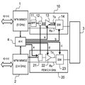
도 1은 본 발명에 따른 통신 단말기의 블록도이다.
도 2는 5GHz MIMO 회로의 더 상세한 다이어그램이다.
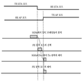
도 3은 시간에 따라 TPC 커맨드의 타이밍과 동작 모드의 선택을 도시한다.
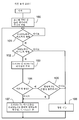
도 4는 본 발명에 따른 방법을 설명하는 흐름도이다.Other features and advantages of the present invention will become more apparent upon reading the following detailed description, which is described in detail in conjunction with the accompanying drawings:
1 is a block diagram of a communication terminal according to the present invention.
2 is a more detailed diagram of a 5 GHz MIMO circuit.
Figure 3 shows the timing of TPC commands and selection of operating modes over time.
4 is a flow chart illustrating a method according to the present invention.
도 1에서, 2.4GHz 대역과 5GHz 대역에서 비디오, 오디오 또는 데이터 신호들을 동시에 방출 및/또는 수신할 수 있는 무선 통신 단말기가 블록 형식으로 도시된다.In FIG. 1, a wireless communication terminal capable of simultaneously emitting and / or receiving video, audio or data signals in the 2.4 GHz band and the 5 GHz band is shown in block form.
본 발명은 다중 입력 및 다중 출력의 MIMO 회로들을 포함하는 단말기들에 대해 언급할 것이지만, 이것이 단일 입력 및 단일 출력의 SISO 회로 또는 그에 상당하는 임의의 회로에 적용될 수 있다는 것이 당업자에게 명백하다.Although the present invention will refer to terminals comprising multiple input and multiple output MIMO circuits, it will be apparent to those skilled in the art that this can be applied to single input and single output SISO circuits or any equivalent circuit.
더 구체적으로, 단말기는 MIMO 회로(1)를 포함한다. MIMO 회로(1)는 N×N 회로인데, 다시 말해서 이것은 5GHz 대역에서 MIMO 신호들을 수신하는 N개의 입력 단자 및 MIMO 신호들을 송신하는 N개의 출력 단자를 포함한다(N≥1).More specifically, the terminal comprises a
N×N MIMO 신호들은 안테나 시스템(3)으로 또는 안테나 시스템으로부터 프런트-엔드 모듈(10)을 통해 송신 및/또는 수신된다. 도 1에는, 프런트-엔드 모듈의 송신 채널만이 도시되어 있다. 도시된 프런트-엔드 모듈(10)의 송신 채널은 출력이 합산기(12)에 연결되는 필터(11)를 포함하는데, 합산기의 역할은 이하에서 설명될 것이다. 합산기의 출력은 전력 증폭기(13)의 입력에 연결되는데, 이 전력 증폭기는 도시된 실시예에서는 광대역 증폭기이다. 이 증폭기는 제어 회로(4)로부터의 신호에 의해 액티브되며, 제어 회로의 역할은 이하에서 설명될 것이다. 증폭기(13)의 출력은 스위칭 회로(14)에 연결되고, 스위칭 회로는 광대역 또는 이중 대역 다중 액세스, 전방향(omni-directional) 또는 섹터 기반 안테나 시스템에 의해 구성될 수 있는 안테나 시스템(3)에 연결된다. 더욱이, 스위칭 회로는 송신 모드(TX) 또는 수신 모드(RX)에서 안테나 시스템의 연결을 인에이블링한다.N × N MIMO signals are transmitted and / or received via the front-
통신 단말기는 또한 2.4GHz 대역에 대해 제2 MIMO 회로(2)를 포함하고, 이 MIMO 회로는 M×M 송신/수신 경로 또는 채널을 포함한다. 따라서, MIMO 회로(2)는 MIMO 신호들을 수신하는 M개의 입력 단자와 MIMO 신호들을 송신하는 M개의 출력 단자를 포함한다(M≥1, N과 M은 같거나 다를 수 있음).The communication terminal also includes a
M개의 단자는 각각의 송신/수신 증폭 채널이 도 1에서 도시된 바와 같이 스위칭 회로(21), 스위칭 회로(21)의 출력에 연결되고 제어 회로로부터의 신호를 통해 제어되는 전력 증폭기(22) 및 송신(TX) 경로와 수신(RX) 경로 간의 스위칭을 인에이블링하는 스위칭 회로(23)를 포함하는 프런트-엔드 모듈(20)에 연결된다.The M terminals comprise a
도 1에 도시된 바와 같이, 제어 회로(4)는 MIMO 회로(1)와 MIMO 회로(2)로부터 신호들을 수신하고 스위칭 회로(21), 5GHz 및 2.4GHz 프런트-엔드 모듈들 각각의 증폭 채널의 전력 증폭기들(13 및 22) 및 스위칭 회로들(14 및 23)에게 각각 제어 신호들을 송신한다.As shown in FIG. 1, the control circuit 4 receives signals from the
본 발명에 따르면, 제어 회로(4)는 두 개의 MIMO 회로(1 및 2)로부터 동적으로 정보를 수신하여 5GHz 및 2.4GHz 증폭 채널들에 각각 대응하는 프런트-엔드 모듈들(10 및 20)을 제어한다.According to the invention, the control circuit 4 dynamically receives information from the two
도 1에 도시된 바와 같이, 회로(4)의 제1 출력은 전력 증폭기(13)를 액티브시키거나 디스에이블링하는 방식으로 전력 증폭기에 연결된다. 제2 출력 b는 광대역 프런트-엔드 모듈(10)의 Tx/Rx(송신/수신) 스위치(14)에 연결된다. 제3 출력 c는 2.4GHz 송신 채널의 Tx/Rx 스위치(23)에 연결된다. 출력 d는 모듈(20)의 전력 증폭기(22)에 연결되어 전력 증폭기를 액티브하거나 디스에이블링하고, 출력 e는 합산기(12)를 통해 5GHz 신호와 동일한 채널에서 2.4GHz 신호의 송신을 인에이블링하도록 스위칭 회로(21)에 연결된다.As shown in FIG. 1, the first output of the circuit 4 is connected to the power amplifier in a manner that activates or disables the
따라서, 제어 회로(4)를 이용하여, 두 개의 동작 모드, 즉 정상 동작 모드와 감소된 전력 동작 모드가 운용되고, 이는 이후 더 자세한 방식으로 설명될 것이다.Thus, using the control circuit 4, two operating modes, namely a normal operating mode and a reduced power operating mode, are operated, which will be described later in more detail.
본 발명에 따른 전력 소비의 감소 방법을 이제 특히 도 4를 참조하여 설명한다.The method of reducing power consumption according to the invention is now described with particular reference to FIG. 4.
기본 프로세스를 기술하는 도 4의 기능적 흐름도에 도시된 바와 같이, 본 프로세스는 데이터의 주기적 추출(100)로 시작하며, 이 데이터는 설명되는 본 실시예에서는 TPC(Transmit Power Control) 데이터 및 QoS(Quality of Service) 데이터이다.As shown in the functional flow diagram of FIG. 4 describing the basic process, the process begins with
TPC 데이터는 MIMO 회로 그 자체로부터 획득된다. 도 2에서, 5GHz 대역에서 동작하는 MIMO 회로(1)가 개략적으로 도시된다. 2.4GHz 대역을 위한 MIMO 회로는 TPC 데이터 분석을 제외하고는 동일한 기본 구조를 가진다. MIMO 회로(1)는 그에 따라 2.4GHz 송신의 시간적(temporal) 신호 표시(representative)를 도 1의 제어 회로(4)로 보내는 데에 이용되는 단일 프로세서를 도면 부호 1a에서 포함한다. 또한, MIMO 회로(1)는 변조 회로를 도면 부호 1c에서 포함하고, 프런트 엔드 모듈의 송신 채널(Tx)을 통해 보내질 데이터를 인에이블링하는 아날로그 디지털 컨버터가 도면 부호 1d에서 변조 회로에 후속한다. 마찬가지로, 신호 프로세서(1a)는 프런트-엔드 모듈의 수신 채널(Rx)로부터 신호들을 수신하는 프런트-엔드 모듈에 연결되는 복조 회로(1b)에 연결된다.TPC data is obtained from the MIMO circuit itself. In FIG. 2, a
당업자에게 알려진 방법에서, TPC 프레임들은, 일반적으로 MCS(Modulation Coding Scheme)라고 불리는 특정 변조 및 코딩 기법(scheme)에 따라 무선 접속을 통해 액세스 포인트를 스테이션(station: STA)에 접속시킴으로써 획득된다. 스테이션은 전력 송신에 관한 정보의 아이템(TPC)을 액세스 포인트로 주기적으로 보낸다. 이 정보를 이용하여, 액세스 포인트와 스테이션 간의 거리와 전파 조건들에 따라, 액세스 포인트에 요구되는 출력의 전력이 계산될 수 있다.In a method known to those skilled in the art, TPC frames are obtained by connecting an access point to a station (STA) via a wireless connection in accordance with a particular modulation and coding scheme, commonly referred to as a Modulation Coding Scheme (MCS). The station periodically sends an item of information about the power transmission (TPC) to the access point. Using this information, the power of the output required for the access point can be calculated according to the distance between the access point and the station and the propagation conditions.
또한, QoS는 송신될 데이터의 유형, 즉 예를 들어 데이터 또는 비디오에 따라 액세스 포인트에 의해 정의된다. 따라서, 비디오 신호들은 5GHz MIMO 회로를 통해 표준 방식으로 송신되고, 5GHz 채널들의 처리에 우선권이 주어진다. 동작 타이밍의 분석이 제어 회로(4)에 의해 수행된다.In addition, QoS is defined by the access point according to the type of data to be transmitted, ie data or video. Thus, video signals are transmitted in a standard manner via 5 GHz MIMO circuitry, and priority is given to the processing of 5 GHz channels. Analysis of the operation timing is performed by the control circuit 4.
본 발명에 따른 전력 소비의 감소 방법의 제2 단계에서, 2.4GHz에서 버스트의 송신이 있었는지, 즉, 다시 말해서 2.4GHz 프런트-엔드 모듈을 통해 송신하는 신호들이 있는지를 확인하는 체크가 도면 부호 101에서 이루어진다. 응답이 부정이면, 동작이 도면 부호 101에서 다시 시작한다. 응답이 긍정이면, 5GHz 버스트 송신은 도면 부호 102에서 검토된다(studied). 응답이 부정이면, 도면 부호 106의 박스에 도시된 바와 같이 정상 동작으로 넘어간다. 응답이 긍정이면, 회로(4)는 도면 부호 103에서 2.4GHz 신호들과 5GHz 신호들 간의 송신 타이밍을 분석한다. 도면 부호 104에서, 시간적 충돌이 존재하는지 여부, 즉 신호들이 동시에 송신되어야만 하는지 그렇지 않은지를 결정한다. 신호들이 동시에 송신되지 않는다면, 도면 부호 107에서, 2.4GHz에서 MIMO 회로로부터 송신될 신호들은 2.4GHz에서 신호들을 송신할 수 있는 광대역 증폭기들을 포함하는 송신 채널들을 갖는 5GHz 신호 프런트-엔드 모듈들에 라우팅되고, 2.4GHz 프런트-엔드 모듈의 전력 증폭기들(22)은 비동작 상태로 들어간다.In a second step of the method of reducing power consumption according to the invention, a check is made to see if there is a transmission of a burst at 2.4 GHz, ie there are signals to be transmitted via the 2.4 GHz front-end module. Is done in If the response is negative, the operation starts again at 101. If the response is positive, then the 5 GHz burst transmission is studied at 102. If the response is negative, then go to normal operation as shown in
시간적 충돌이 있는 경우, 특정 실시예에 따르면, 도면 부호 105에서, 5GHz 프런트-엔드 모듈(10)의 광대역 전력 증폭기들의 선형성이 검사되어, 이 선형성이 충분한지를 결정한다. 부정 응답의 경우에, 회로는 정상 동작을 계속 한다(106). 긍정 응답의 경우에, 2.4GHz에서 송신되는 신호들은 5GHz 프런트-엔드 모듈(10)로 라우팅된다(107). 프런트-엔드 모듈(10)의 광대역 전력 증폭기들의 이 제어 단계가 선택적이라는 것은 당업자에게는 자명하다.If there is a temporal collision, according to a particular embodiment, at 105, the linearity of the broadband power amplifiers of the 5 GHz front-
따라서, 제어기 회로(4)는 두 가지 가능한 동작 모드에 따라 단말기[또는 AP(액세스 포인트)]의 최적 동작 모드를 결정하는데, 두 가지 가능한 동작 모드는 다음과 같다:Thus, the controller circuit 4 determines the optimal mode of operation of the terminal (or AP (access point)) according to two possible modes of operation, the two possible modes of operation being:
- 도 1의 두 개의 프런트-엔드 모듈(10 및 20)이 동시에 이용되는 정상 동작 모드(2.4GHz 및 5GHz),Normal operating mode (2.4 GHz and 5 GHz) in which two front-
- 전력 증폭기들이 충분한 대역폭을 갖는 경우에 동시 전송으로 또는 시분할 방식으로(in time sharing) 5GHz 신호들 및 2.4GHz 신호들 모두를 송신하고 수신하는 광대역 프런트-엔드 모듈(10)만을 이용하는 소비 전력 감소 동작 모드.Power consumption reduction operation using only broadband front-
전력 증폭기의 클래스 및 효율에 의존하는 주어진 대역폭 및 동시 송신의 경우, 송신되는 전력이 단말기 레벨에서 정의된 제한보다 작으면, 2.4GHz에서 송신되는 신호는 5GHz 프런트-엔드 모듈의 광대역 송신 채널의 입력에서 더해질 수 있다. 결과적으로, 2.4GHz에서의 프런트-엔드 모듈의 전력 증폭기들은 디스에이블링되고, 시스템의 전력 소비를 감소시킨다.For a given bandwidth and simultaneous transmission, depending on the class and efficiency of the power amplifier, if the transmitted power is less than the limit defined at the terminal level, then the signal transmitted at 2.4 GHz is at the input of the wideband transmission channel of the 5 GHz front-end module. Can be added. As a result, the power amplifiers of the front-end module at 2.4 GHz are disabled and reduce the power consumption of the system.
5 / 2.4GHz에서의 시분할 방식의 송신의 경우, 제어 회로(4)는 시스템의 전력 소비를 제한하기 위해 동작 모드들을 관리한다. 도 3은 시간에 따라 상이한 동작들이 프런트-엔드 모듈들을 제어하기 위해 수행되는 순서를 도식적으로 도시한다. 따라서, 시작에서, AP(access point)는 무선접속에 의해 스테이션(STA)에 접속 연결되고, 단말기는 스테이션으로부터 수신된 TPC 정보를 디코딩하고 그에 따라 아날로그/디지털 컨버터로 5GHz에서 MIMO 회로의 출력 전력을 제어한다. 그 후, 제어 회로는 광대역 송신 채널들의 기능을 인에이블링하는 최적 구성을 계산하고, 가능하다면 광대역 프런트-엔드 모듈을 통해 송신할 2.4GHz 신호들의 믹싱(mix)을 계산한다.For time division transmission at 5 / 2.4 GHz, the control circuit 4 manages the operating modes to limit the power consumption of the system. 3 diagrammatically illustrates the order in which different operations are performed to control front-end modules over time. Thus, at the beginning, an access point (AP) is connected to the station (STA) by wireless connection, and the terminal decodes the TPC information received from the station and accordingly outputs the output power of the MIMO circuit at 5 GHz with an analog / digital converter. To control. The control circuit then calculates an optimal configuration that enables the function of the wideband transmission channels and, if possible, a mix of 2.4 GHz signals to transmit via the wideband front-end module.
동일한 수의 입력-출력 단자(terminal)를 갖는 MIMO 회로들과 관련하여 본 발명을 설명하였다. 본 발명은 상이한 수의 입력-출력 단자(N×N' 및/또는 M×M')를 갖는 MIMO 회로에 적용될 수 있다. 또한, N 및 M은 동일하거나 상이할 수 있다.The present invention has been described in connection with MIMO circuits having the same number of input-output terminals. The present invention can be applied to a MIMO circuit having different numbers of input-output terminals (N × N 'and / or M × M'). In addition, N and M may be the same or different.
N=M이면, 이 경우, 솔루션은 N개의 전력 증폭기를 구현할 뿐이므로 비용과 전력 소비 면에서 최적이다.If N = M, then the solution only implements N power amplifiers, which is optimal in terms of cost and power consumption.
N<M이면, 2.4GHz MIMO 회로의 일부 전력 증폭기들은 전력 소비를 감소시키기 위해 5GHz 채널들의 프런트-엔드 모듈에 연결될 수 있다.If N <M, some power amplifiers of the 2.4 GHz MIMO circuit may be connected to the front-end module of the 5 GHz channels to reduce power consumption.
Claims (10)
상기 무선 통신 단말기는
상기 제1 주파수 대역에서 동작하는 N≥1인 N개의 경로의 제1 회로(1), 및
상기 제2 주파수 대역에서 동작하는 M≥1인 M개의 경로의 제2 회로(2)
를 포함하고,
상기 제1 및 제2 회로들은 N 및 M 전력 증폭기(13, 22)를 각각 포함하는 프런트-엔드(front end) 모듈들에 각각 결합되고, 상기 프런트-엔드 모듈들은 안테나 시스템(3)에 연결되어있고,
상기 방법은,
제어 데이터로부터 수신된 및/또는 송신된 신호들을 추출하는 단계,
상기 제1 주파수 대역에서의 버스트(burst) 및 상기 제2 주파수 대역에서의 버스트의 방출 동안에 충돌이 있는지를 검출하기 위해 송신 인스턴트들(instants)을 비교하는 단계,
충돌이 없고 추출된 제어 데이터에 따른 경우에는, 상기 제1 또는 제2 주파수 대역 중 하나의 신호들을 다른 주파수 대역의 상기 프런트-엔드 모듈의 전력 증폭기(13)를 통해 송신하고, 상기 신호들의 상기 주파수 대역의 상기 프런트-엔드 모듈의 상기 전력 증폭기(22)를 디스커넥트(disconnect)하는 단계
를 포함하는 것을 특징으로 하는, 무선 통신 단말기에서의 에너지 소비 감소 방법.A method of reducing energy consumption in a wireless communication terminal capable of simultaneously transmitting and / or receiving signals in at least first and second frequency bands, the method comprising:
The wireless communication terminal
First circuit 1 of N paths with N ≧ 1 operating in the first frequency band, and
Second circuit 2 of M paths with M≥1 operating in the second frequency band
Lt; / RTI >
The first and second circuits are respectively coupled to front end modules comprising N and M power amplifiers 13, 22, respectively, which are connected to an antenna system 3. There is,
The method comprises:
Extracting received and / or transmitted signals from control data,
Comparing transmission instants to detect if there is a collision during the burst in the first frequency band and the burst in the second frequency band,
If there is no collision and according to the extracted control data, the signals of one of the first or second frequency bands are transmitted through the power amplifier 13 of the front-end module of another frequency band, and the frequencies of the signals Disconnecting the power amplifier 22 of the front-end module of the band
A method of reducing energy consumption in a wireless communication terminal, comprising: a.
충돌이 없거나 상기 전력 증폭기가 충분한 대역폭을 갖는다면, 상기 제1 또는 제2 주파수 대역 중 하나의 상기 신호들은 다른 주파수 대역의 상기 프런트-엔드 모듈의 전력 증폭기를 통해 통과하고, 상기 신호들의 상기 주파수 대역의 상기 프런트-엔드 모듈의 상기 전력 증폭기는 디스커넥트되는 것을 특징으로 하는, 무선 통신 단말기에서의 에너지 소비 감소 방법.The method of claim 1,
If there is no collision or if the power amplifier has sufficient bandwidth, the signals of one of the first or second frequency bands pass through the power amplifier of the front-end module of another frequency band and the frequency bands of the signals And said power amplifier of said front-end module is disconnected.
상기 제어 데이터는 송신되는 전력 또는 TPC(Transmit Power Control)에 대한 데이터 및/또는 QoS(Quality Of Services)에 대한 데이터 중에서 선택되는 것을 특징으로 하는, 무선 통신 단말기에서의 에너지 소비 감소 방법.The method according to claim 1 or 2,
And the control data is selected from data for power transmitted or data for transmit power control (TPC) and / or data for quality of services (QoS).
상기 제1 주파수 대역은 5GHz 주파수 대역이고 상기 제2 주파수 대역은 2.4GHz 주파수 대역인 것을 특징으로 하는, 무선 통신 단말기에서의 에너지 소비 감소 방법.4. The method according to any one of claims 1 to 3,
And said first frequency band is a 5 GHz frequency band and said second frequency band is a 2.4 GHz frequency band.
2.4GHz 주파수 대역의 신호들은 5GHz 주파수 대역의 상기 프런트-엔드 모듈의 전력 증폭기들 중 적어도 하나를 통해 송신되는 것을 특징으로 하는, 무선 통신 단말기에서의 에너지 소비 감소 방법.5. The method according to any one of claims 1 to 4,
Signals in the 2.4 GHz frequency band are transmitted through at least one of the power amplifiers of the front-end module in the 5 GHz frequency band.
상기 제1 및 제2 회로들은 MIMO 회로들인 것을 특징으로 하는, 무선 통신 단말기에서의 에너지 소비 감소 방법.The method according to any one of claims 1 to 5,
And said first and second circuits are MIMO circuits.
상기 무선 통신 단말기는 상기 제1 주파수 대역에서 동작하는 N≥1인 N개의 경로의 제1 회로(1) 및 상기 제2 주파수 대역에서 동작하는 M≥1인 M개의 경로의 제2 회로(2)를 포함하고, 상기 제1 및 제2 회로들은 N개 및 M개의 전력 증폭기를 각각 포함하는 프런트-엔드 모듈들(10, 20)에 각각 결합되고, 상기 프런트-엔드 모듈들은 안테나 시스템에 연결되고,
상기 단말기는,
제어 데이터로부터 수신된 및/또는 방출된 신호들을 추출하기 위한 수단,
상기 제1 주파수 대역에서의 버스트 및 상기 제2 주파수 대역에서의 버스트의 방출 동안에 충돌이 있는지를 검출하기 위해 송신 인스턴트들을 비교하기 위한 수단,
충돌이 없고 추출된 제어 데이터에 따른 경우에는, 상기 제1 또는 제2 주파수 대역 중 하나의 신호들을 다른 주파수 대역의 상기 프런트-엔드 모듈의 전력 증폭기(13)를 통해 송신하고, 상기 신호들의 상기 주파수 대역의 상기 프런트-엔드 모듈의 상기 전력 증폭기(22)를 디스커넥트(disconnect)하기 위한 수단
을 포함하는 것을 특징으로 하는 무선 통신 단말기.A wireless communication terminal capable of transmitting and / or receiving video, audio or data signals in first and second frequency bands,
The wireless communication terminal has a first circuit 1 of N paths with N≥1 operating in the first frequency band and a second circuit 2 of M paths with M≥1 operating in the second frequency band. Wherein the first and second circuits are respectively coupled to front-end modules 10 and 20 that each include N and M power amplifiers, the front-end modules connected to an antenna system,
The terminal comprises:
Means for extracting received and / or emitted signals from control data,
Means for comparing transmission instants to detect if there is a collision during the burst in the first frequency band and the burst in the second frequency band,
If there is no collision and according to the extracted control data, the signals of one of the first or second frequency bands are transmitted through the power amplifier 13 of the front-end module of another frequency band, and the frequencies of the signals Means for disconnecting the power amplifier 22 of the front-end module of the band
Wireless communication terminal comprising a.
상기 수단은, 상기 제어 데이터를 수신하고 처리하기 위해 입력에서 상기 제1 및 제2 MIMO 회로들에 연결된 커맨드 회로(4)를 포함하고, 커맨드 회로 출력은, 입력들이 상기 제2 MIMO 회로의 M개의 경로 중 하나에 연결되고 한 출력이 M개의 전력 증폭기 중 하나에 연결되고, 다른 출력이 합산기 회로를 통해 N개의 전력 증폭기 중 하나에 연결되는, (M<N이면) M개의 또는 (N<M이면) N개의 스위칭 회로를 제어하고, 상기 합산기 회로의 다른 입력은 MIMO 회로의 N개의 경로 중 하나에 연결되는 것을 특징으로 하는 무선 통신 단말기.The method of claim 7, wherein
The means comprises a command circuit 4 connected at the input to the first and second MIMO circuits for receiving and processing the control data, the command circuit output being M inputs of the second MIMO circuit. M or (N <M), connected to one of the paths, one output connected to one of the M power amplifiers, and the other output connected to one of the N power amplifiers through a summer circuit. Back side) controlling N switching circuits, the other input of the summer circuit being connected to one of the N paths of a MIMO circuit.
두 개의 주파수 대역의 상기 신호들을 수신하는 상기 프런트-엔드 모듈의 상기 증폭기들 중 적어도 하나는 광대역 증폭기인 것을 특징으로 하는 무선 통신 단말기.9. The method according to claim 7 or 8,
And at least one of said amplifiers of said front-end module receiving said signals in two frequency bands is a wideband amplifier.
제1항 내지 제6항 중 어느 한 항에 따른 방법을 구현하기 위한 것인 것을 특징으로 하는 무선 통신 단말기.10. The method according to any one of claims 7 to 9,
A wireless communication terminal for implementing the method according to any one of claims 1 to 6.
Applications Claiming Priority (2)
| Application Number | Priority Date | Filing Date | Title |
|---|---|---|---|
| FR1160526A FR2983016A1 (en) | 2011-11-18 | 2011-11-18 | METHOD FOR REDUCING POWER CONSUMPTION IN A WIRELESS COMMUNICATION TERMINAL AND COMMUNICATION TERMINAL USING THE SAME |
| FR1160526 | 2011-11-18 |
Publications (1)
| Publication Number | Publication Date |
|---|---|
| KR20130055537A true KR20130055537A (en) | 2013-05-28 |
Family
ID=47010428
Family Applications (1)
| Application Number | Title | Priority Date | Filing Date |
|---|---|---|---|
| KR1020120130185A KR20130055537A (en) | 2011-11-18 | 2012-11-16 | Method for reducing the energy consumption in a wireless communication terminal and communication terminal implementing said method |
Country Status (6)
| Country | Link |
|---|---|
| US (1) | US9380527B2 (en) |
| EP (1) | EP2595434A1 (en) |
| JP (1) | JP6035120B2 (en) |
| KR (1) | KR20130055537A (en) |
| CN (1) | CN103124426B (en) |
| FR (1) | FR2983016A1 (en) |
Cited By (1)
| Publication number | Priority date | Publication date | Assignee | Title |
|---|---|---|---|---|
| KR20160001414A (en) * | 2014-06-27 | 2016-01-06 | 에스케이텔레콤 주식회사 | Method for managing power of dual-band ap |
Families Citing this family (3)
| Publication number | Priority date | Publication date | Assignee | Title |
|---|---|---|---|---|
| US10020852B2 (en) * | 2013-09-26 | 2018-07-10 | Georgia Tech Research Corporation | Schnorr-euchner expansions and their fast implementations |
| KR20150049947A (en) * | 2013-10-31 | 2015-05-08 | 삼성전기주식회사 | Adaptive dual banded mimo wifi apparatus, and operation method thereof |
| US9496932B1 (en) * | 2015-05-20 | 2016-11-15 | Dell Products Lp | Systems and methods of dynamic MIMO antenna configuration and/or reconfiguration for portable information handling systems |
Family Cites Families (26)
| Publication number | Priority date | Publication date | Assignee | Title |
|---|---|---|---|---|
| JP2003258653A (en) * | 2002-02-26 | 2003-09-12 | Toshiba Corp | Mobile radio terminal |
| JP2003284093A (en) | 2002-03-27 | 2003-10-03 | Sanyo Electric Co Ltd | Stereoscopic image processing method and apparatus therefor |
| CN1698274B (en) * | 2002-07-30 | 2012-07-18 | 美商智慧财产权授权股份有限公司 | System and method for multiple-input multiple-output (MIMO) radio communication |
| KR100837821B1 (en) * | 2003-02-14 | 2008-06-13 | 삼성전자주식회사 | Apparatus and method for controlling of amplifier to reduce power |
| EP1450486A1 (en) * | 2003-02-20 | 2004-08-25 | TDK Corporation | Multi-Mode Filter |
| JP3838237B2 (en) * | 2003-04-30 | 2006-10-25 | ソニー株式会社 | Wireless communication system, transmitting apparatus and receiving apparatus |
| JP2005348116A (en) * | 2004-06-03 | 2005-12-15 | Sharp Corp | Radio communication device |
| EP1603353B8 (en) * | 2004-06-03 | 2009-08-05 | Option | Method and device for managing simultaneous connections of a mobile telecommunications device to different networks |
| JP4578294B2 (en) | 2005-03-18 | 2010-11-10 | 株式会社エヌ・ティ・ティ・データ三洋システム | Stereoscopic image display device, stereoscopic image display method, and computer program |
| JP4774791B2 (en) * | 2005-04-06 | 2011-09-14 | 日立金属株式会社 | High frequency module |
| US7868700B2 (en) | 2005-11-28 | 2011-01-11 | Paragon Communications Ltd. | Method and apparatus for reducing current consumption of MIMO systems |
| US7643439B2 (en) | 2006-06-08 | 2010-01-05 | Metalink Ltd. | Reducing power consumption in a receiver |
| FR2911739A1 (en) | 2007-01-22 | 2008-07-25 | Thomson Licensing Sa | TERMINAL AND METHOD FOR THE SIMULTANEOUS TRANSMISSION OF VIDEOS AND HIGH SPEED DATA. |
| EP2260579B1 (en) | 2008-02-25 | 2011-11-23 | Telefonaktiebolaget L M Ericsson (publ) | A method of and a device for precoding transmit data signals in a wireless mimo communication system |
| JP2010074514A (en) * | 2008-09-18 | 2010-04-02 | Toshiba Corp | Radio transmitter |
| US8406712B2 (en) * | 2009-04-29 | 2013-03-26 | Clearwire Ip Holdings Llc | Extended range voice over IP WiMAX device |
| US8548406B2 (en) | 2009-05-05 | 2013-10-01 | Lg Electronics Inc. | Method of transmitting reference signal in multiple antenna system |
| US8477011B2 (en) * | 2009-05-08 | 2013-07-02 | Icontrol, Inc. | mLOCK device and associated methods |
| US8559383B2 (en) * | 2009-11-20 | 2013-10-15 | Nokia Corporation | Multiradio control |
| US8351877B2 (en) * | 2010-12-21 | 2013-01-08 | Dali Systems Co. Ltfd. | Multi-band wideband power amplifier digital predistorition system and method |
| KR101678438B1 (en) * | 2010-04-05 | 2016-11-22 | 엘지전자 주식회사 | Transmitter having multiple antennas |
| US9154166B2 (en) * | 2010-06-03 | 2015-10-06 | Broadcom Corporation | Front-end module network |
| US9203496B2 (en) * | 2010-11-12 | 2015-12-01 | Golba Llc | Dynamic allocation of transceivers and frequency channels in MIMO systems |
| US8681809B2 (en) * | 2011-01-10 | 2014-03-25 | Qualcomm Incorporated | Dynamic enabling and disabling of CLTD operation via HS SCCH orders |
| US20120282875A1 (en) * | 2011-05-02 | 2012-11-08 | Sharp Laboratories Of America, Inc. | Disabling transceivers while servicing emergency messages |
| US8670797B2 (en) * | 2011-10-04 | 2014-03-11 | Qualcomm Incorporated | Multi-antenna wireless device with power amplifiers having different characteristics |
-
2011
- 2011-11-18 FR FR1160526A patent/FR2983016A1/en not_active Withdrawn
-
2012
- 2012-10-18 EP EP12188938.0A patent/EP2595434A1/en not_active Withdrawn
- 2012-11-16 KR KR1020120130185A patent/KR20130055537A/en not_active Application Discontinuation
- 2012-11-16 JP JP2012252060A patent/JP6035120B2/en not_active Expired - Fee Related
- 2012-11-18 US US13/680,100 patent/US9380527B2/en not_active Expired - Fee Related
- 2012-11-19 CN CN201210469110.3A patent/CN103124426B/en not_active Expired - Fee Related
Cited By (1)
| Publication number | Priority date | Publication date | Assignee | Title |
|---|---|---|---|---|
| KR20160001414A (en) * | 2014-06-27 | 2016-01-06 | 에스케이텔레콤 주식회사 | Method for managing power of dual-band ap |
Also Published As
| Publication number | Publication date |
|---|---|
| CN103124426A (en) | 2013-05-29 |
| JP6035120B2 (en) | 2016-11-30 |
| FR2983016A1 (en) | 2013-05-24 |
| JP2013110741A (en) | 2013-06-06 |
| US20130128783A1 (en) | 2013-05-23 |
| US9380527B2 (en) | 2016-06-28 |
| EP2595434A1 (en) | 2013-05-22 |
| CN103124426B (en) | 2018-02-09 |
Similar Documents
| Publication | Publication Date | Title |
|---|---|---|
| CN108768434B (en) | Radio frequency circuit, terminal and signal transmission control method | |
| CN101569113B (en) | Wcdma power saving with transmit diversity | |
| US8462671B2 (en) | Terminal having a variable duplex capability | |
| TWI603596B (en) | Mobile device | |
| EP3540969B1 (en) | Multiway switch, radio frequency system, and communication device | |
| US20120021697A1 (en) | Radio frequency signal processing circuit and quadrature power amplifier | |
| US9503149B1 (en) | Electronic device and control method thereof | |
| US11750270B2 (en) | Multiple-input multiple-output (MIMO) repeater system | |
| CN110971245B (en) | Radio frequency circuit, control method thereof and mobile terminal | |
| CN101548469A (en) | Current comsumption reduction with low power amplifier | |
| CN103348600A (en) | Concurrent-access dual-band terminal operating in two adjacent bands | |
| CN102833884A (en) | Dual-mode mobile communication terminal | |
| US8532595B1 (en) | Optimized power amplifier and switching power supply topology | |
| US9380527B2 (en) | Method for reducing the energy consumption in a wireless communication terminal and communication terminal implementing said method | |
| CN108123743B (en) | W L AN base station signal receiving and transmitting method based on multiple sectors | |
| CN113382484B (en) | Customer premises equipment | |
| EP2154793A2 (en) | Dynamic switching system and method between single and multiple antenna transmission | |
| KR101045760B1 (en) | An active radio antenna divider for vhf using a directional coupler | |
| WO2022111632A1 (en) | Network device, user terminal, chip, and wireless communication system and method | |
| US20080108312A1 (en) | Switchable transceiver for relay station | |
| CN213152052U (en) | Signal transceiving circuit and electronic device | |
| KR100609588B1 (en) | Triple band type mobile terminal of having a diversity function | |
| WO2016185871A1 (en) | Wireless communication device | |
| KR100620744B1 (en) | Wireless telecommunication terminal and method for receving gps signal using antennas | |
| CN116388793A (en) | Radio frequency front-end circuit and electronic equipment |
Legal Events
| Date | Code | Title | Description |
|---|---|---|---|
| A201 | Request for examination | ||
| E902 | Notification of reason for refusal | ||
| E601 | Decision to refuse application |