KR20120104485A - Recording medium, reproducing device, and integrated circuit - Google Patents
Recording medium, reproducing device, and integrated circuit Download PDFInfo
- Publication number
- KR20120104485A KR20120104485A KR1020117004122A KR20117004122A KR20120104485A KR 20120104485 A KR20120104485 A KR 20120104485A KR 1020117004122 A KR1020117004122 A KR 1020117004122A KR 20117004122 A KR20117004122 A KR 20117004122A KR 20120104485 A KR20120104485 A KR 20120104485A
- Authority
- KR
- South Korea
- Prior art keywords
- data
- stream
- file
- sub
- picture
- Prior art date
Links
Images


Classifications
-
- G—PHYSICS
- G11—INFORMATION STORAGE
- G11B—INFORMATION STORAGE BASED ON RELATIVE MOVEMENT BETWEEN RECORD CARRIER AND TRANSDUCER
- G11B20/00—Signal processing not specific to the method of recording or reproducing; Circuits therefor
- G11B20/10—Digital recording or reproducing
- G11B20/12—Formatting, e.g. arrangement of data block or words on the record carriers
-
- H—ELECTRICITY
- H04—ELECTRIC COMMUNICATION TECHNIQUE
- H04N—PICTORIAL COMMUNICATION, e.g. TELEVISION
- H04N5/00—Details of television systems
- H04N5/76—Television signal recording
- H04N5/84—Television signal recording using optical recording
- H04N5/85—Television signal recording using optical recording on discs or drums
-
- G—PHYSICS
- G11—INFORMATION STORAGE
- G11B—INFORMATION STORAGE BASED ON RELATIVE MOVEMENT BETWEEN RECORD CARRIER AND TRANSDUCER
- G11B20/00—Signal processing not specific to the method of recording or reproducing; Circuits therefor
- G11B20/10—Digital recording or reproducing
- G11B20/12—Formatting, e.g. arrangement of data block or words on the record carriers
- G11B20/1217—Formatting, e.g. arrangement of data block or words on the record carriers on discs
- G11B20/1251—Formatting, e.g. arrangement of data block or words on the record carriers on discs for continuous data, e.g. digitised analog information signals, pulse code modulated [PCM] data
-
- G—PHYSICS
- G11—INFORMATION STORAGE
- G11B—INFORMATION STORAGE BASED ON RELATIVE MOVEMENT BETWEEN RECORD CARRIER AND TRANSDUCER
- G11B27/00—Editing; Indexing; Addressing; Timing or synchronising; Monitoring; Measuring tape travel
- G11B27/10—Indexing; Addressing; Timing or synchronising; Measuring tape travel
- G11B27/102—Programmed access in sequence to addressed parts of tracks of operating record carriers
- G11B27/105—Programmed access in sequence to addressed parts of tracks of operating record carriers of operating discs
-
- G—PHYSICS
- G11—INFORMATION STORAGE
- G11B—INFORMATION STORAGE BASED ON RELATIVE MOVEMENT BETWEEN RECORD CARRIER AND TRANSDUCER
- G11B27/00—Editing; Indexing; Addressing; Timing or synchronising; Monitoring; Measuring tape travel
- G11B27/10—Indexing; Addressing; Timing or synchronising; Measuring tape travel
- G11B27/19—Indexing; Addressing; Timing or synchronising; Measuring tape travel by using information detectable on the record carrier
- G11B27/28—Indexing; Addressing; Timing or synchronising; Measuring tape travel by using information detectable on the record carrier by using information signals recorded by the same method as the main recording
- G11B27/30—Indexing; Addressing; Timing or synchronising; Measuring tape travel by using information detectable on the record carrier by using information signals recorded by the same method as the main recording on the same track as the main recording
- G11B27/3027—Indexing; Addressing; Timing or synchronising; Measuring tape travel by using information detectable on the record carrier by using information signals recorded by the same method as the main recording on the same track as the main recording used signal is digitally coded
-
- H—ELECTRICITY
- H04—ELECTRIC COMMUNICATION TECHNIQUE
- H04N—PICTORIAL COMMUNICATION, e.g. TELEVISION
- H04N13/00—Stereoscopic video systems; Multi-view video systems; Details thereof
- H04N13/10—Processing, recording or transmission of stereoscopic or multi-view image signals
- H04N13/106—Processing image signals
- H04N13/161—Encoding, multiplexing or demultiplexing different image signal components
-
- H—ELECTRICITY
- H04—ELECTRIC COMMUNICATION TECHNIQUE
- H04N—PICTORIAL COMMUNICATION, e.g. TELEVISION
- H04N13/00—Stereoscopic video systems; Multi-view video systems; Details thereof
- H04N13/10—Processing, recording or transmission of stereoscopic or multi-view image signals
- H04N13/106—Processing image signals
- H04N13/172—Processing image signals image signals comprising non-image signal components, e.g. headers or format information
- H04N13/178—Metadata, e.g. disparity information
-
- H—ELECTRICITY
- H04—ELECTRIC COMMUNICATION TECHNIQUE
- H04N—PICTORIAL COMMUNICATION, e.g. TELEVISION
- H04N13/00—Stereoscopic video systems; Multi-view video systems; Details thereof
- H04N13/10—Processing, recording or transmission of stereoscopic or multi-view image signals
- H04N13/106—Processing image signals
- H04N13/172—Processing image signals image signals comprising non-image signal components, e.g. headers or format information
- H04N13/183—On-screen display [OSD] information, e.g. subtitles or menus
-
- H—ELECTRICITY
- H04—ELECTRIC COMMUNICATION TECHNIQUE
- H04N—PICTORIAL COMMUNICATION, e.g. TELEVISION
- H04N13/00—Stereoscopic video systems; Multi-view video systems; Details thereof
- H04N13/10—Processing, recording or transmission of stereoscopic or multi-view image signals
- H04N13/189—Recording image signals; Reproducing recorded image signals
-
- H—ELECTRICITY
- H04—ELECTRIC COMMUNICATION TECHNIQUE
- H04N—PICTORIAL COMMUNICATION, e.g. TELEVISION
- H04N5/00—Details of television systems
- H04N5/76—Television signal recording
- H04N5/91—Television signal processing therefor
- H04N5/92—Transformation of the television signal for recording, e.g. modulation, frequency changing; Inverse transformation for playback
-
- H—ELECTRICITY
- H04—ELECTRIC COMMUNICATION TECHNIQUE
- H04N—PICTORIAL COMMUNICATION, e.g. TELEVISION
- H04N9/00—Details of colour television systems
- H04N9/79—Processing of colour television signals in connection with recording
- H04N9/80—Transformation of the television signal for recording, e.g. modulation, frequency changing; Inverse transformation for playback
- H04N9/82—Transformation of the television signal for recording, e.g. modulation, frequency changing; Inverse transformation for playback the individual colour picture signal components being recorded simultaneously only
- H04N9/8205—Transformation of the television signal for recording, e.g. modulation, frequency changing; Inverse transformation for playback the individual colour picture signal components being recorded simultaneously only involving the multiplexing of an additional signal and the colour video signal
- H04N9/8227—Transformation of the television signal for recording, e.g. modulation, frequency changing; Inverse transformation for playback the individual colour picture signal components being recorded simultaneously only involving the multiplexing of an additional signal and the colour video signal the additional signal being at least another television signal
-
- G—PHYSICS
- G11—INFORMATION STORAGE
- G11B—INFORMATION STORAGE BASED ON RELATIVE MOVEMENT BETWEEN RECORD CARRIER AND TRANSDUCER
- G11B20/00—Signal processing not specific to the method of recording or reproducing; Circuits therefor
- G11B20/10—Digital recording or reproducing
- G11B20/10527—Audio or video recording; Data buffering arrangements
- G11B2020/10537—Audio or video recording
- G11B2020/10592—Audio or video recording specifically adapted for recording or reproducing multichannel signals
- G11B2020/10611—3D video data
-
- G—PHYSICS
- G11—INFORMATION STORAGE
- G11B—INFORMATION STORAGE BASED ON RELATIVE MOVEMENT BETWEEN RECORD CARRIER AND TRANSDUCER
- G11B2220/00—Record carriers by type
- G11B2220/20—Disc-shaped record carriers
- G11B2220/25—Disc-shaped record carriers characterised in that the disc is based on a specific recording technology
- G11B2220/2537—Optical discs
- G11B2220/2541—Blu-ray discs; Blue laser DVR discs
Abstract
BD-ROM 디스크에는 메인 뷰와 서브 뷰의 비디오 스트림의 쌍 및 그래픽스 스트림이 기록되어 있다. 서브 뷰 비디오 스트림에는 메타데이터가 GOP마다 배치되어 있다. 메타데이터는 오프셋 정보를 포함한다. 오프셋 정보는 GOP를 구성하는 복수의 픽처에 대한 오프셋 제어를 규정한다. 오프셋 제어에서는 그래픽스 플레인에 수평방향의 오프셋이 부여되고, 그 그래픽스 플레인이 각 비디오 플레인에 합성된다. 서브 뷰 비디오 스트림은 패킷화 되어서 트랜스포트 스트림에 다중화되어 있다. 각 TS패킷의 헤더는 TS 우선도 플래그를 포함한다. 메타데이터를 포함하는 TS 패킷과 서브 뷰 픽처를 포함하는 TS 패킷에서는 TS 우선도 플래그의 값이 다르다.On the BD-ROM disc, a pair of video streams and a graphics stream of a main view and a subview are recorded. In the sub-view video stream, metadata is arranged for each GOP. The metadata includes offset information. The offset information specifies offset control for a plurality of pictures constituting the GOP. In the offset control, a horizontal offset is given to the graphics plane, and the graphics plane is synthesized in each video plane. The subview video stream is packetized and multiplexed onto the transport stream. The header of each TS packet includes a TS priority flag. In a TS packet including metadata and a TS packet including subview pictures, values of the TS priority flag are different.
Description
본 발명은 입체 시 영상, 즉 3차원(3D) 영상의 재생기술에 관한 것으로, 특히, 기록매체 상에서의 스트림 데이터의 구조에 관한 것이다.BACKGROUND OF THE
최근, 3D 영상에 대한 일반적인 관심이 높아지고 있다. 예를 들어 유원지에서는 3D 영상을 이용한 어트랙션(attraction)이 인기를 끌고 있다. 또, 전국 각지에서 3D 영상의 영화를 상영하는 영화관이 증가하고 있다. 그와 같은 3D 영상에 대한 관심이 높아짐에 따라서 3D 영상을 각 가정에서도 재생 가능하게 하기 위한 기술의 개발이 진행되고 있다. 그 기술에서는 3D 영상 콘텐츠를 고화질인 채로 광 디스크 등의 휴대형 기록매체에 기록하는 것이 요구된다. 또, 2D 재생장치에 대한 그 기록매체의 호환성이 요구된다. 즉, 그 기록매체에 기록된 3D 영상 콘텐츠로부터 2D 재생장치는 2D 영상을 재생할 수 있고, 3D 재생장치는 3D 영상을 재생할 수 있는 것이 바람직하다. 여기서, 「2D 재생장치」란 평면 시 영상, 즉 2 차원(2D) 영상만을 재생 가능한 종래의 재생장치를 의미하고, 「3D 재생장치」란 3D 영상을 재생 가능한 재생장치를 의미한다. 또, 본 명세서에서는 3D 재생장치가 종래의 2D 영상도 재생 가능한 경우를 상정한다. In recent years, general interest in 3D video is increasing. At amusement parks, for example, attraction using 3D images is gaining popularity. In addition, movie theaters showing 3D video films are increasing all over the country. As the interest in such 3D images increases, development of a technology for reproducing 3D images in each home is progressing. The technique requires recording 3D video contents on a portable recording medium such as an optical disk with high image quality. In addition, compatibility of the recording medium with the 2D playback apparatus is required. That is, it is preferable that the 2D playback device can play back the 2D video from the 3D video content recorded on the recording medium, and the 3D playback device can play back the 3D video. Here, "2D playback device" refers to a conventional playback device capable of playing back planar video, that is, two-dimensional (2D) video only, and "3D playback device" refers to a playback device that can play back 3D video. In this specification, it is assumed that the 3D playback apparatus can also reproduce a conventional 2D video.
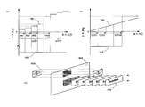
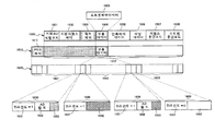
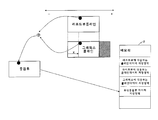
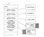
도 109는 3D 영상 콘텐츠가 기록된 광 디스크에 대하여 2D 재생장치에 대한 호환성을 확보하기 위한 기술을 나타내는 모식도이다(예를 들어 특허문헌 1 참조). 광 디스크(PDS)에는 2종류의 비디오 스트림이 저장되어 있다. 일방(一方)은 2D/레프트 뷰 비디오 스트림이고, 타방(他方)은 라이트 뷰 비디오 스트림이다. 「2D/레프트 뷰 비디오 스트림」은 3D 영상의 재생에서는 시청자의 왼쪽 눈에 보이는 2D 영상, 즉 「레프트 뷰」를 나타내고, 2D 영상의 재생에서는 그 2D 영상 그 자체를 나타낸다. 「라이트 뷰 비디오 스트림」은 3D 영상의 재생에서 시청자의 오른쪽 눈에 보이는 2D 영상, 즉 「라이트 뷰」를 나타낸다. 좌우의 비디오 스트림 사이에서는 프레임 레이트는 동일하지만, 프레임의 표시시기는 프레임 주기의 절반만큼 어긋나 있다. 예를 들어 각 비디오 스트림의 프레임 레이트가 1초간에 24 프레임일 때 2D/레프트 뷰 비디오 스트림과 라이트 뷰 비디오 스트림의 각 프레임이 1/48초마다 교호로 표시된다.109 is a schematic diagram showing a technique for ensuring compatibility with a 2D playback apparatus for an optical disk on which 3D video content is recorded (see
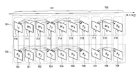
각 비디오 스트림은 도 109에 나타낸 것과 같이, 광 디스크(PDS) 상에서는 복수의 익스텐트(EX1A-C), EX2A-C로 분할되어 있다. 각 익스텐트는 GOP(그룹 오브 픽처)를 하나 이상 포함하고, 광 디스크 드라이브에 의해 일괄해서 판독된다. 이하, 2D/레프트 뷰 비디오 스트림에 속하는 익스텐트를 「2D/레프트 뷰 익스텐트」라고 하고, 라이트 뷰 비디오 스트림에 속하는 익스텐트를 「라이트 뷰 익스텐트」라고 한다. 2D/레프트 뷰 익스텐트(EX1A-C)와 라이트 뷰 익스텐트(EX2A-C)는 교호로 광 디스크(PDS)의 트랙(TRC) 상에 배치되어 있다. 인접하는 2개의 익스텐트 EX1A+EX2A, EX1B+EX2B, EX1C+EX2C의 사이에서는 재생시간이 동일하다. 이와 같은 익스텐트의 배치를 「인터리브 배치」라고 한다. 인터리브 배치로 기록된 익스텐트 군은 이하에 설명하는 것과 같이 3D 영상의 재생과 2D 영상의 재생의 양쪽에서 이용된다.As shown in FIG. 109, each video stream is divided into a plurality of extents EX1A-C and EX2A-C on the optical disk PDS. Each extent contains one or more GOPs (group of pictures), which are collectively read by an optical disk drive. Hereinafter, extents belonging to the 2D / left view video stream are referred to as "2D / left view extents", and extents belonging to the light view video stream are referred to as "light view extents". The 2D / left view extents EX1A-C and the light view extents EX2A-C are alternately arranged on the track TRC of the optical disk PDS. The playback time is the same between two adjacent extents EX1A + EX2A, EX1B + EX2B, and EX1C + EX2C. Such arrangement of extents is referred to as "interleave arrangement". The extent group recorded in the interleaved arrangement is used for both reproduction of 3D video and reproduction of 2D video as described below.
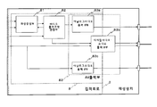
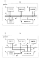
2D 재생장치(PL2)에서는 광 디스크 드라이브(DD2)가 광 디스크(PDS) 상의 익스텐트 중 2D/레프트 뷰 익스텐트(EX1A-C)만을 선두에서부터 차례로 판독하는 한편, 라이트 뷰 익스텐트(EX2A-C)의 판독을 스킵한다. 또, 영상 디코더(VDC)가 광 디스크 드라이브(DD2)에 의해 판독된 익스텐트를 순차 영상 프레임(VFL)으로 복호 한다. 이에 의해 표시장치(DS2)에는 레프트 뷰만이 표시되므로, 시청자에게는 통상의 2D 영상이 보인다.In the 2D playback device PL2, the optical disk drive DD2 reads only the 2D / left view extents EX1A-C from the beginning of the extents on the optical disk PDS from the beginning, while reading the light view extents EX2A-C. Skip The video decoder VDC decodes the extent read by the optical disk drive DD2 into a sequential video frame VFL. As a result, only the left view is displayed on the display device DS2, so that the viewer can see a normal 2D image.
3D 재생장치(PL3)에서는 광 디스크 드라이브(DD3)가 광 디스크(PDS)로부터 2D/레프트 뷰 익스텐트와 라이트 뷰 익스텐트를 교호로, 부호로 나타내면 EX1A, EX2A, EX1B, EX2B, EX1C, EX2C의 순으로 판독한다. 또, 판독된 각 익스텐트로부터 2D/레프트 뷰 비디오 스트림은 좌 영상 디코더(VDL)에 보내지고, 라이트 뷰 비디오 스트림은 우 영상 디코더(VDR)에 보내진다. 각 영상 디코더(VDL, VDR)는 교호로 각 비디오 스트림을 영상 프레임(VFL, VFR)으로 복호 한다. 이에 의해 표시장치(DS3)에는 레프트 뷰와 라이트 뷰가 교호로 표시된다. 한편, 셔터 안경(SHG)은 좌우의 렌즈를 표시장치(DS3)에 의한 화면의 전환에 동기하여 교호로 불투명하게 한다. 따라서, 셔터 안경(SHG)을 쓴 시청자에게는 표시장치(DS3)에 표시된 영상이 3D 영상으로 보인다.In the 3D playback device PL3, the optical disk drive DD3 alternates between 2D / left view extents and light view extents from the optical disc PDS, and in the order of EX1A, EX2A, EX1B, EX2B, EX1C, and EX2C. Read it. Also, from each read extent, the 2D / Left View video stream is sent to the left picture decoder VDL, and the right view video stream is sent to the right picture decoder VDR. Each video decoder VDL and VDR alternately decodes each video stream into video frames VFL and VFR. As a result, the left view and the right view are alternately displayed on the display device DS3. On the other hand, the shutter glasses SHG make the left and right lenses alternately opaque in synchronization with the switching of the screen by the display device DS3. Therefore, an image displayed on the display device DS3 is seen as a 3D image to the viewer wearing the shutter glasses SHG.
광 디스크에 한정하지 않고, 기록매체에 3D 영상 콘텐츠를 저장할 때에는 상기와 같이 익스텐트의 인터리브 배치를 이용한다. 이에 의해 그 기록매체를 2D 영상의 재생과 3D 영상의 재생의 양쪽에서 이용할 수 있다.The interleaved arrangement of extents is used as described above when storing 3D video content on a recording medium, without being limited to an optical disc. As a result, the recording medium can be used for both reproduction of 2D video and reproduction of 3D video.
영상 콘텐츠는 일반적으로 비디오 스트림 외에 자막 및 대화화면 등의 그래픽스 영상을 나타내는 그래픽스 스트림을 포함한다. 3D 영상 콘텐츠로부터 재생되는 영상에서는 이들 그래픽스 영상도 3차원화 된다. 여기서, 그 3차원화의 수법에는 2 플레인 모드와 1 플레인+오프셋 모드가 있다. 2 플레인 모드의 3D 영상 콘텐츠는 레프트 뷰와 라이트 뷰의 각 그래픽스 영상을 나타내는 그래픽스 스트림의 쌍을 포함한다. 2 플레인 모드의 재생장치는 각 그래픽스 스트림으로부터 개별로 레프트 뷰와 라이트 뷰의 그래픽스 플레인을 생성한다. 1 플레인+오프셋 모드의 3D 영상 콘텐츠는 2D 그래픽스 영상을 나타내는 그래픽스 스트림과 그에 대한 오프셋 정보를 포함한다. 1 플레인+오프셋 모드의 재생장치는 먼저 그래픽스 스트림에서 하나의 그래픽스 플레인을 생성하고, 다음에 오프셋 정보에 따라서 그 그래픽스 플레인에 수평방향의 오프셋을 부여한다. 이에 의해 그 그래픽스 스트림으로부터 레프트 뷰와 라이트 뷰의 그래픽스 플레인의 쌍이 생성된다. 어느 모드에서도 표시장치의 화면에는 레프트 뷰와 라이트 뷰의 그래픽스 영상이 교호로 표시된다. 그 결과, 시청자에게는 이들 그래픽스 영상이 3D 영상으로 보인다.The video content generally includes, in addition to the video stream, a graphics stream representing graphics images such as subtitles and interactive screens. In graphics reproduced from 3D image contents, these graphics images are also three-dimensionalized. Here, there are two plane modes and one plane + offset mode. The 3D video content in the two plane mode includes a pair of graphics streams representing each graphics video of the left view and the right view. A playback device in two plane mode creates a graphics plane of left view and light view separately from each graphics stream. The 3D video content in one plane + offset mode includes a graphics stream representing a 2D graphics video and offset information thereof. The playback device in one plane + offset mode first generates one graphics plane from the graphics stream, and then gives the graphics plane a horizontal offset in accordance with the offset information. This generates a pair of left and right view graphics planes from the graphics stream. In either mode, graphic images of left view and light view are alternately displayed on the screen of the display device. As a result, these graphics images appear to the viewer as 3D images.
3D 영상 콘텐츠에 그래픽스 스트림과 오프셋 정보를 다른 파일로 포함하는 경우, 1 플레인+오프셋 모드의 재생장치는 이들 파일을 개별로 처리하고, 얻어진 데이터에 의거하여 레프트 뷰와 라이트 뷰의 그래픽스 영상의 쌍을 재생한다. 여기서, 그래픽스 영상과 오프셋 정보는 일반적으로 프레임 주기로 변경된다. 그러나 오프셋 정보를 저장한 파일을 프레임 표시시마다 판독하여 해석하는 것은 「처리가 시간에 맞지 않아서 영상을 올바르게 표시할 수 없다」라고 하는 위험성이 있다. 따라서, 처리를 프레임 주기에 확실히 동기시키기 위해서는 미리 메모리 상에 오프셋 정보를 전개해 둘 필요가 있다. 그 경우, 그래픽스 스트림 1개당 오프셋 정보의 총량은 크므로 오프셋 정보를 포함하는 파일을 전개하는데 필요한 내장 메모리의 용량은 커질 수밖에 없다. 또, 하나의 씬에 복수의 그래픽스 영상이 존재하는 경우에는 내장 메모리는 더 큰 용량을 필요로 한다. 이와 같이, 3D 영상 콘텐츠에 그래픽스 스트림과 오프셋 정보를 다른 파일로 포함하는 경우에는 내장 메모리의 용량의 삭감은 곤란하다.If the 3D video content includes the graphics stream and the offset information in different files, the playback device in one plane + offset mode processes these files separately, and based on the data obtained, pairs the graphics video in the left view and the light view. Play it. Here, the graphics image and the offset information are generally changed in the frame period. However, there is a risk that reading and analyzing a file storing offset information every frame display means that the image cannot be displayed correctly because the processing is not timed. Therefore, in order to surely synchronize the processing to the frame period, it is necessary to expand the offset information on the memory in advance. In this case, since the total amount of offset information per graphics stream is large, the capacity of the built-in memory required for developing the file containing the offset information is inevitably increased. In addition, when a plurality of graphics images exist in one scene, the internal memory requires a larger capacity. As described above, when the graphics stream and the offset information are included in different files in the 3D video content, it is difficult to reduce the capacity of the internal memory.
상기의 문제점을 해소하는 것을 목적으로 오프셋 정보는 비디오 스트림 중에 예를 들어 GOP 간격으로 저장된다. 이에 의해 재생장치 내의 디코더는 비디오 스트림을 복호 하면서 그 비디오 스트림으로부터 오프셋 정보를 추출할 수 있다. 그 결과, 재생장치는 그래픽스 스트림과 오프셋 정보의 사이의 대응관계를 확실히 유지할 수 있다. 또, 내장 메모리는 예를 들어 1 GOP당의 오프셋 정보를 전개하는데 충분한 용량을 가지면 좋다. 따라서, 다양한 그래픽스 스트림을 포함하는 3D 영상 콘텐츠에 대한 대응과 내장 메모리의 용량의 삭감을 용이하게 양립시킬 수 있다.Offset information is stored in the video stream, for example at GOP intervals, for the purpose of solving the above problem. This allows the decoder in the playback apparatus to extract the offset information from the video stream while decoding the video stream. As a result, the playback apparatus can surely maintain the correspondence between the graphics stream and the offset information. In addition, the internal memory may have a sufficient capacity, for example, to develop offset information per one GOP. Therefore, it is possible to easily cope with the 3D video content including various graphics streams and reduce the capacity of the built-in memory.
여기서, 재생장치 내의 디코더에 비디오 스트림으로부터 오프셋 정보를 추출하는 기능을 탑재하는 구체적인 수단으로는 다양한 것이 상정된다. 예를 들어 그 기능을 비디오 스트림의 복호 처리 전용의 하드웨어에 포함하는 수단도, 그 하드웨어와는 다른 하드웨어 또는 소프트웨어로 실현되는 수단도 상정 가능하다. 그러나 이들 수단별로 비디오 스트림이나 오프셋 정보의 데이터 구조를 변경하는 것은 바람직하지 않다.Here, a variety of concrete means are conceived as a specific means for mounting a function of extracting offset information from a video stream in a decoder in the playback apparatus. For example, a means of including the function in hardware dedicated to the decoding processing of the video stream, or a means realized by hardware or software different from the hardware can also be assumed. However, it is not desirable to change the data structure of the video stream or offset information for each of these means.
본 발명의 목적은 상기의 문제점을 해결하는 것에 있으며, 특히, 재생장치에 탑재된 비디오 스트림에서 오프셋 정보를 추출하는 기능의 여러 형태에서 공통으로 이용 가능한 데이터 구조로 비디오 스트림과 오프셋 정보를 일체적으로 기록한 기록매체를 제공하는 것에 있다.SUMMARY OF THE INVENTION An object of the present invention is to solve the above problems, and in particular, the video stream and the offset information are integrated into a data structure commonly available in various forms of the function of extracting the offset information from the video stream mounted in the playback apparatus. The present invention provides a recorded recording medium.
본 발명에 의한 기록매체에는 메인 뷰 비디오 스트림, 서브 뷰 비디오 스트림 및 그래픽스 스트림이 기록되고 있다. 메인 뷰 비디오 스트림은 입체 시 영상의 메인 뷰를 구성하는 메인 뷰 픽처를 포함한다. 서브 뷰 비디오 스트림은 입체 시 영상의 서브 뷰를 구성하는 서브 뷰 픽처와 메타데이터를 포함한다. 그래픽스 스트림은 평면 시 그래픽스 영상을 구성하는 그래픽스 데이터를 포함한다. 메인 뷰 픽처는 재생될 때 메인 뷰 비디오 플레인에 묘사되고, 서브 뷰 픽처는 재생될 때 서브 뷰 비디오 플레인에 묘사되며, 그래픽스 데이터는 재생될 때 그래픽스 플레인에 묘사된다. 메타데이터는 서브 뷰 비디오 스트림을 구성하는 GOP 마다 배치되며, 오프셋 정보를 포함한다. 오프셋 정보는 GOP를 구성하는 복수의 픽처에 대한 오프셋 제어를 규정하는 제어정보이다. 오프셋 제어는 그래픽스 플레인에 수평좌표의 좌 방향과 우 방향의 각 오프셋을 부여하여 메인 뷰 비디오 플레인과 서브 뷰 비디오 플레인의 각각에 합성하는 처리이다. 서브 뷰 비디오 스트림은 트랜스포트 스트림(TS)에 다중화되어 있다. TS를 구성하는 TS 패킷의 헤더는 당해 TS 패킷의 우선도를 나타내는 TS 우선도 플래그를 포함한다. 메타데이터를 포함하는 TS 패킷의 TS 우선도 플래그는 서브 뷰 픽처를 포함하는 TS 패킷의 TS 우선도 플래그와 값이 다르다.The main view video stream, the sub view video stream and the graphics stream are recorded on the recording medium according to the present invention. The main view video stream includes a main view picture constituting a main view of a stereoscopic image. The sub view video stream includes sub view pictures and metadata constituting a sub view of a stereoscopic image. The graphics stream includes graphics data constituting a planar graphics image. The main view picture is depicted in the main view video plane when played back, the sub view picture is depicted in the sub view video plane when played back, and the graphics data is depicted in the graphics plane when played back. The metadata is disposed for each GOP constituting the sub-view video stream and includes offset information. The offset information is control information for specifying offset control for a plurality of pictures constituting the GOP. Offset control is a process of giving the graphics plane respective offsets in the left and right directions of the horizontal coordinates to synthesize each of the main view video plane and the sub view video plane. The sub-view video stream is multiplexed on the transport stream TS. The header of the TS packet constituting the TS includes a TS priority flag indicating the priority of the TS packet. The TS priority flag of a TS packet including metadata has a different value from the TS priority flag of a TS packet including a subview picture.
본 발명에 의한 기록매체는 재생장치의 복호부에 TS 우선도 플래그의 값에 따라서 메타데이터를 포함하는 TS 패킷과 서브 뷰 픽처를 포함하는 TS 패킷을 분리시킬 수 있다. 따라서, 그 복호부에서는 메타데이터를 포함하는 TS 패킷에서 오프셋 정보를 추출하는 기능부와 서브 뷰 픽처를 포함하는 TS 패킷에서 비 압축의 픽처를 복호 하는 기능부가 따로따로 탑재되어도 좋다. 그 경우, 이들 기능부의 구체적인 형태는 서로 독립적으로 설계 가능하다. 한편, 이들 기능부가 일체화되어 있는 복호부에서는 TS 우선도 플래그의 값에 관계없이 서브 뷰 비디오 스트림을 포함하는 TS 패킷을 모두 그 일체화된 기능부에 처리시키면 좋다. 이와 같이, 본 발명에 의한 기록매체는 재생장치에 탑재된 비디오 스트림에서 오프셋 정보를 추출하는 기능의 여러 형태에서 공통으로 이용 가능한 데이터 구조로 비디오 스트림과 오프셋 정보를 일체적으로 기록할 수 있다.The recording medium according to the present invention can separate the TS packet including the meta data and the TS packet including the sub view picture according to the value of the TS priority flag in the decoding unit of the playback apparatus. Therefore, the decoding unit may be separately equipped with a function unit for extracting offset information from a TS packet including metadata and a function unit for decoding an uncompressed picture from a TS packet including a subview picture. In that case, the specific forms of these functional units can be designed independently of each other. On the other hand, in the decoding unit in which these functional units are integrated, all TS packets including the sub-view video stream may be processed in the integrated functional unit regardless of the value of the TS priority flag. As described above, the recording medium according to the present invention can integrally record the video stream and the offset information in a data structure commonly available in various forms of the function of extracting the offset information from the video stream mounted in the playback apparatus.
도 1은 본 발명의 실시 예 1에 의한 기록매체를 사용하는 홈시어터 시스템을 나타내는 모식도이다.
도 2는 도 1에 나타낸 BD-ROM 디스크(101) 상의 데이터 구조를 나타내는 모식도이다.
도 3(a), (b)는 BD-ROM 디스크 상의 메인 TS와 서브 TS의 각각에 다중화된 엘리멘터리 스트림의 일람표이다.
도 4는 다중화 스트림 데이터(400) 내에서의 TS 패킷의 배치를 나타내는 모식도이다.
도 5(a)는 TS 헤더(501H)의 데이터 구조를 나타내는 모식도이다. (b)는 다중화 스트림 데이터를 구성하는 TS 패킷(501)의 열의 형식을 나타내는 모식도이다. (c)는 다중화 스트림 데이터의 TS 패킷 열로 구성된 소스 패킷(502)의 열의 형식을 나타내는 모식도이다. (d)는 일련의 소스 패킷(502)이 연속적으로 기록된 BD-ROM 디스크의 볼륨영역 상의 섹터 군의 모식도이다.
도 6은 PG 스트림(600)의 데이터 구조를 나타내는 모식도이다.
도 7은 베이스 뷰 비디오 스트림(701)과 라이트 뷰 비디오 스트림(702)의 픽처를 표시시간 순으로 나타내는 모식도이다.
도 8은 비디오 스트림(800)의 데이터 구조의 상세를 나타내는 모식도이다.
도 9는 PES 패킷 열(902)로의 비디오 스트림(901)의 저장방법의 상세를 나타내는 모식도이다.
도 10은 베이스 뷰 비디오 스트림(1001)과 디펜던트 뷰 비디오 스트림(1002)의 각 픽처에 할당된 PTS와 DTS의 사이의 관계를 나타내는 모식도이다.
도 11은 디펜던트 뷰 비디오 스트림(1100)이 포함하는 오프셋 메타데이터(1110)의 데이터 구조를 나타내는 모식도이다.
도 12는 도 11에 나타낸 오프셋 메타데이터(1110)의 서식(Syntax)을 나타내는 표이다.
도 13(a), (b)는 PG 플레인(1310)과 IG 플레인(1320)에 대한 오프셋 제어를 나타내는 모식도이다. (c)는 (a), (b)에 나타낸 그래픽스 플레인이 나타내는 2D 그래픽스 영상에서 시청자(1330)에게 지각되는 3D 그래픽스 영상을 나타내는 모식도이다.
도 14(a), (b)는 오프셋 시퀀스의 구체적인 예를 나타내는 그래프이다. (c)는 (a), (b)에 나타낸 오프셋 시퀀스에 따라서 재현되는 3D 그래픽스 영상을 나타내는 모식도이다.
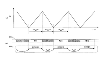
도 15는 디펜던트 뷰 비디오 스트림 내의 VAU#1(1500)을 저장한 PES 패킷(1510)과 그 PES 패킷(1510)에서 생성되는 TS 패킷 열(1520)을 나타내는 모식도이다.
도 16은 도 15에 나타낸 제 1 그룹(1521)과 제 2 그룹(1522)의 각각에 속하는 TS 패킷이 동일한 TS 우선도의 값을 나타내는 경우의 TS 패킷 열(1620)을 나타내는 모식도이다.
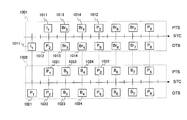
도 17(a)은 복호 스위치 정보(1750)의 데이터 구조를 나타내는 모식도이다. (b), (c)는 베이스 뷰 비디오 스트림(1701)과 디펜던트 뷰 비디오 스트림(1702)의 각 픽처에 할당된 복호 카운터의 예 1710, 1720, 1730, 1740을 나타내는 모식도이다.
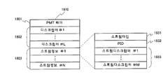
도 18은 PMT(1810)의 데이터 구조를 나타내는 모식도이다.
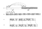
도 19는 BD-ROM 디스크 상에서의 다중화 스트림 데이터의 물리적인 배치를 나타내는 모식도이다.
도 20(a)은 BD-ROM 디스크 상에 개별로 연속해서 기록된 메인 TS(2001)와 서브 TS(2002)의 배치를 나타내는 모식도이다. (b)는 본 발명의 실시 예 1에 의한 BD-ROM 디스크(101) 상에 교호로 기록된 디펜던트 뷰 데이터블록 D[0], D[1], D[2], …와 베이스 뷰 데이터블록 B[0], B[1], B[2], …의 배치를 나타내는 모식도이다. (c), (d)는 각각 인터리브 배치로 기록된 디펜던트 뷰 데이터블록 군 D[n]와 베이스 뷰 데이터블록 군B[n]의 각 익스텐트 ATC 시간의 예를 나타내는 모식도이다(n=0, 1, 2).
도 21은 익스텐트 블록 군(1901-1903)에 대한 2D 재생모드와 L/R 모드에서의 각 재생경로(2101, 2102)를 나타내는 모식도이다.
도 22는 2D 클립정보파일(01000.clpi)(231)의 데이터 구조를 나타내는 모식도이다.
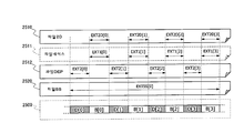
도 23(a)은 엔트리 맵(2230)의 데이터 구조를 나타내는 모식도이다. (b)는 파일 2D(241)에 속하는 소스 패킷 군(2310) 중 엔트리 맵(2230)에 의해 각 EP_ID(2305)에 대응되어 있는 것을 나타내는 모식도이다. (c)는 그 소스 패킷 군(2310)에 대응하는 BD-ROM 디스크 상의 데이터블록 군 D[n], B[n](n=0, 1, 2, 3, …)를 나타내는 모식도이다.
도 24(a)는 도 23에 나타낸 익스텐트 기점(2(242))의 데이터 구조를 나타내는 모식도이다. (b)는 디펜던트 뷰 클립정보파일(02000.clpi)(232)에 포함되는 익스텐트 기점(2420)의 데이터 구조를 나타내는 모식도이다. (c)는 3D 재생모드의 재생장치(102)에 의해 파일 SS(244A)로부터 추출된 베이스 뷰 데이터블록 B[0], B[1], B[2], …를 나타내는 모식도이다. (d)는 파일 DEP(02000.m2ts)(242)에 속하는 디펜던트 뷰 익스텐트 EXT2[0], EXT2[1], …와 익스텐트 기점(2420)이 나타내는 SPN(2422)의 사이의 대응관계를 나타내는 모식도이다. (e)는 파일 SS(244A)에 속하는 익스텐트 SS EXTSS[0]와 BD-ROM 디스크 상의 익스텐트 블록의 사이의 대응관계를 나타내는 모식도이다.
도 25는 BD-ROM 디스크 상에 기록된 하나의 익스텐트 블록(2500)과 파일 2D(2510), 파일 베이스(2511), 파일 DEP(2512) 및 파일 SS(2520)의 각 익스텐트 군 사이의 대응관계를 나타내는 모식도이다.
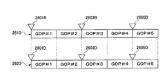
도 26은 베이스 뷰 비디오 스트림(2610)과 디펜던트 뷰 비디오 스트림(2620)으로 설정된 엔트리 포인트의 예를 나타내는 모식도이다.
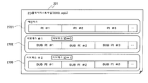
도 27은 2D 플레이리스트 파일의 데이터 구조를 나타내는 모식도이다.
도 28은 도 27에 나타낸 PI#N의 데이터 구조를 나타내는 모식도이다.
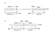
도 29(a), (b)는 각각 CC가 "5", "6"일 때 접속 대상의 2개의 재생 구간(2901, 2902) 사이의 관계를 나타내는 모식도이다.
도 30은 2D 플레이리스트 파일(00001.mpls)(221)이 나타내는 PTS와 파일 2D(01000.m2ts)(241)에서 재생되는 부분의 사이의 대응관계를 나타내는 모식도이다.
도 31은 3D 플레이리스트 파일의 데이터 구조를 나타내는 모식도이다.
도 32는 도 31에 나타낸 3D 플레이리스트 파일(222)의 메인 패스(3101)가 포함하는 STN 테이블(3205)을 나타내는 모식도이다.
도 33은 도 31에 나타낸 STN 테이블 SS(3130)의 데이터 구조를 나타내는 모식도이다.
도 34는 3D 플레이리스트 파일(00002.mpls)(222)이 나타내는 PTS와 파일 SS(01000.ssif)(244A)에서 재생되는 부분의 사이의 대응관계를 나타내는 모식도이다.
도 35는 도 2에 나타낸 인덱스 파일(index.bdmv)(211)의 데이터 구조를 나타내는 모식도이다.
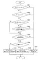
도 36은 도 1에 나타낸 재생장치(102)가 6종류의 판별처리를 이용하여 재생 대상의 플레이리스트 파일을 선택하는 처리의 플로차트이다.
도 37은 2D 재생장치(3700)의 기능 블록도이다.
도 38은 도 37에 나타낸 플레이어 변수 기억부(3736)가 포함하는 시스템 파라미터(SPRM)의 일람표이다.
도 39는 도 37에 나타낸 재생제어부(3735)에 의한 2D 플레이리스트 재생처리의 플로차트이다.
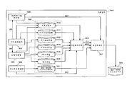
도 40은 도 37에 나타낸 시스템 타깃 디코더(3725)의 기능 블록도이다.
도 41(a)은 도 40에 나타낸 PG 디코더(4072)가 PG 스트림 내의 하나의 데이터 엔트리로부터 그래픽스 오브젝트를 복호 하는 처리의 플로차트이다. (b)-(e)는 그 처리에 따라서 변화하는 그래픽스 오브젝트를 나타내는 모식도이다.
도 42는 3D 재생장치(4200)의 기능 블록도이다.
도 43은 도 42에 나타낸 플레이어 변수 기억부(4236)가 포함하는 SPRM(27)와 SPRM(28)의 데이터 구조를 나타내는 표이다.
도 44는 도 42에 나타낸 재생제어부(4235)에 의한 3D 플레이리스트 재생처리의 플로차트이다.
도 45는 도 42에 나타낸 시스템 타깃 디코더(4225)가 제 1 수단으로 오프셋 메타데이터의 추출 기능을 탑재하고 있는 경우에서의 기능 블록도이다.
도 46은 도 42에 나타낸 시스템 타깃 디코더(4225)가 제 2 수단으로 오프셋 메타데이터의 추출 기능을 탑재하고 있는 경우에서의 비디오 스트림의 처리 계통을 나타내는 기능 블록도이다.
도 47은 도 42에 나타낸 플레인 가산부(4226)의 기능 블록도이다.
도 48은 도 47에 나타낸 각 크로핑 처리부(4731-4734)에 의한 오프셋 제어의 플로차트이다.
도 49(b)는 제 2 크로핑 처리부(4632)에 의한 오프셋 제어로 가공되기 전의 PG 플레인 데이터 GP를 나타내는 모식도이다. (a), (c)는 각각 우 방향의 오프셋이 부여된 PG 플레인 데이터(RGP)와 좌 방향의 오프셋이 부여된 PG 플레인 데이터(LGP)를 나타내는 모식도이다.
도 50은 디펜던트 뷰 비디오 스트림 내의 VAU#1(5000)을 저장한 PES 패킷(5010) 및 그 PES 패킷(5010)에서 생성되는 TS 패킷 열(5020)을 나타내는 모식도이다.
도 51은 도 50에 나타낸 TS 패킷 열(5020)에서 오프셋 메타데이터를 추출하는 시스템 타깃 디코더(5125) 내의 비디오 스트림의 처리 계통을 나타내는 기능 블록도이다.
도 52(a)는 보완 함수를 이용하는 오프셋 메타데이터(5200)의 데이터 구조를 나타내는 모식도이다. (b)는 보완 함수를 구성하는 요소의 종류를 나타내는 그래프이다. (c)는 (a)에 나타낸 오프셋 시퀀스 ID=0, 1, 2의 각 오프셋 시퀀스로부터 3D 재생장치에 의해 산정된 오프셋 값를 나타내는 그래프이다.
도 53은 서브 패스를 복수 포함하는 3D 플레이리스트 파일(5300)의 데이터 구조 및 그에 의해 참조되는 파일 2D(5310)와 2개의 파일 DEP(5321, 5322)의 데이터 구조를 나타내는 모식도이다.
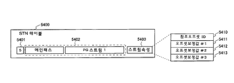
도 54는 하나의 스트림 데이터에 대하여 오프셋 보정 값가 복수 설정된 STN 테이블(5400)을 나타내는 모식도이다.
도 55(a)-(c)는 32인치, 50인치 및 100인치의 각 화면 SCA, SCB, SCC에 표시된 레프트 뷰와 라이트 뷰의 사이의 시차 PRA, PRB, PRC를 나타내는 모식도이다.
도 56(a)은 화면 사이즈와 출력 오프셋 보정 값의 사이의 대응 표를 나타내는 모식도이다. (b)는 화면 사이즈와 출력 오프셋 보정 값의 사이의 함수를 나타내는 그래프이다.
도 57은 출력 오프셋 보정에 필요한 3D 재생장치의 요소를 나타내는 기능 블록도이다.
도 58(a)은 정지화상만을 나타내는 디펜던트 뷰 비디오 스트림(5800)의 데이터 구조를 나타내는 모식도이다. (b)는 그와 같은 3D 플레이리스트 파일을 따라서 재생되는 레프트 뷰 비디오 플레인의 열(5821), 라이트 뷰 비디오 플레인의 열(5822) 및 그래픽스 플레인의 열(5830)을 나타내는 모식도이다.
도 59는 레프트 뷰와 라이트 뷰의 사이의 어긋남을 보상하는 처리를 실행하는 표시장치(103)의 기능 블록도이다.
도 60(a)은 3D 영상을 촬영하는 한 쌍의 비디오 카메라(CML, CMR)의 수평 화각(HAL, HAR)을 모식적으로 나타내는 평면도이다. (b), (c)는 각각 좌측의 비디오 카메라(CML)로 촬영된 레프트 뷰(LV)와 우측의 비디오 카메라(CMR)로 촬영된 라이트 뷰(RV)를 나타내는 모식도이다. (d), (e)는 각각 가공 후의 좌 영상 플레인이 나타내는 레프트 뷰(LV)와 가공 후의 우 영상 플레인이 나타내는 라이트 뷰(RV)를 나타내는 모식도이다.
도 61(a)은 3D 영상을 촬영하는 한 쌍의 비디오 카메라(CML, CMR)의 수직 화각(VAL, VAR)을 모식적으로 나타내는 평면도이다. (b)는 좌측의 비디오 카메라(CML)로 촬영된 레프트 뷰(LV)와 우측의 비디오 카메라(CMR)로 촬영된 라이트 뷰(RV)를 나타내는 모식도이다. (c)는 가공 후의 좌 영상 플레인이 나타내는 레프트 뷰(LV)와 가공 후의 우 영상 플레인이 나타내는 라이트 뷰(RV)를 나타내는 모식도이다.
도 62(a)는 그래픽스 플레인(GPL)이 나타내는 그래픽스 영상의 일 예를 나타내는 모식도이다. (b), (c)는 각각 그래픽스 플레인(GPL)에 우 방향과 좌 방향의 오프셋을 부여하는 처리를 나타내는 모식도이다. (d), (e)는 각각 우 방향과 좌 방향의 오프셋이 부여된 그래픽스 플레인(GP1, GP2)이 나타내는 그래픽스 영상을 나타내는 모식도이다.
도 63은 BD-ROM 디스크 상의 PG 스트림 또는 IG 스트림으로부터 재생되는 그래픽스 플레인 및 재생장치에 의해 생성되는 그래픽스 플레인에 대해서 규정된 그래픽 부품의 배치에 관한 조건을 나타내는 모식도이다.
도 64(a1), (a2)는 모두 동일한 레터박스 표시의 화면을 나타내는 모식도이다. (b), (c)는 각각 주 영상 플레인에 131픽셀의 오프셋을 상 방향과 하 방향에 부여한 때의 각 화면을 나타내는 모식도이다. (d)는 주 영상 플레인에 51픽셀의 오프셋을 상 방향에 부여한 때의 화면을 나타내는 모식도이다.
도 65는 비디오 시프트에 필요한 재생장치 내의 구성을 나타내는 기능 블록도이다.
도 66(a)은 SPRM(32)와 SPRM(33)의 각 데이터 구조를 나타내는 표이다. (b)는 레터박스 표시의 영상 콘텐츠에서의 플레이리스트 파일 내의 STN 테이블을 나타내는 모식도이다.
도 67(a)-(c)는 각각 업 모드, 키프 모드 및 다운 모드의 비디오 시프트부(6501)에 의해 처리된 주 영상 플레인(VPA, VPB, VPC)을 나타내는 모식도이다. (d)-(f)는 각각 업 모드, 키프 모드 및 다운 모드의 제 2 크로핑 처리부(4632)에 의해 처리된 PG 플레인(PGD, PGE, PGF)을 나타내는 모식도이다. (g)-(i)는 각각 업 모드, 키프 모드 및 다운 모드의 제 2 가산부(4642)에 의해 합성된 플레인 데이터(PLG, PLH, PLI)를 나타내는 모식도이다.
도 68(a)은 레터박스 표시의 영상 콘텐츠에서의 플레이리스트 파일 내의 STN 테이블의 다른 예를 나타내는 모식도이다. (b)는 (a)에 나타낸 STN 테이블에서의 비디오 시프트 모드(6812)를 포함하는 복수의 스트림 속성정보(6803)의 등록순서를 나타내는 모식도이다.
도 69는 비디오 시프트에 필요한 재생장치 내의 구성의 다른 예를 나타내는 기능 블록도이다.
도 70(a)은 플레이어 변수 기억부(4236) 내의 SPRM(37)의 데이터 구조를 나타내는 모식도이다. (b)는 PG 스트림이 나타내는 자막의 배경색이 무색 투명하게 설정되었을 경우에 화면(SCR)에 표시되는 영상(IMG)과 자막(SUB)을 나타내는 모식도이다. (c)는 자막의 배경색이 SPRM(37)에 저장된 색 좌표치로 설정되었을 경우에 화면(SCR)에 표시되는 영상(IMG)과 자막(SUB)을 나타내는 모식도이다.
도 71(a)은 레터박스 표시의 영상 콘텐츠에서의 플레이리스트 파일 내의 STN 테이블의 또 다른 예를 나타내는 모식도이다. (b)는 비디오 시프트에 필요한 재생장치 내의 구성의 또 다른 예를 나타내는 기능 블록도이다.
도 72(a)는 키프 모드에 대응하는 자막(SB1, SB2)을 나타내는 모식도이다. (b)는 다운 모드에 대응하는 자막(SBD, SB2)을 나타내는 모식도이다. (c)는 키프 모드로 표시되는 자막(SB1)을 나타내는 모식도이다. (d)는 비디오 상 이동시의 자막(7110)이 STN 테이블에 등록되지 않은 경우에 업 모드로 표시되는 자막(SB3)을 나타내는 모식도이다.
도 73(a), (b)는 각각 BD-ROM 디스크 상의 제 1 서브 TS와 제 2 서브 TS에 다중화된 엘리멘터리 스트림의 일람표이다.
도 74는 본 발명의 실시 예 2에 의한 STN 테이블 SS(3130)의 데이터 구조를 나타내는 모식도이다.
도 75는 본 발명의 실시 예 2에 의한 시스템 타깃 디코더(7525)의 기능 블록도이다.
도 76은 2 플레인 모드의 플레인 가산부(7526)의 부분적인 기능 블록도이다.
도 77(a), (b), (c)은 2D PG 스트림이 나타내는 레프트 뷰 그래픽스 영상(GOB0)과 라이트 뷰 PG 스트림이 나타내는 라이트 뷰 그래픽스 영상(GOB1-3)을 나타내는 모식도이다. (d), (e), (f)는 각각 (a), (b), (c)에 나타낸 레프트 뷰 그래픽스 영상에 대한 오프셋 제어를 나타내는 모식도이다.
도 78은 본 발명의 실시 예 3에 의한 기록장치(7800)의 기능 블록도이다.
도 79(a), (b)는 3D 영상의 한 씬의 표시에 이용되는 레프트 뷰 픽처와 라이트 뷰 픽처를 나타내는 모식도이다. (c)는 도 78에 나타낸 비디오 인코더(7802)에 의해 이들 픽처로부터 산출된 깊이 정보를 나타내는 모식도이다.
도 80은 도 78에 나타낸 기록장치(7800)를 이용하여 BD-ROM 디스크에 영화 콘텐츠를 기록하는 방법의 플로차트이다.
도 81은 인접하는 데이터블록 사이에 익스텐트 ATC 시간을 일치시키는 방법을 나타내는 모식도이다.
도 82(a)-(c)는 시차 영상을 이용하는 방법에 의한 3D 영상(입체 시 영상)의 재생원리를 설명하기 위한 모식도이다.
도 83은 2D 영상(MVW)과 깊이 맵(DPH)의 조합에서 레프트 뷰(LVW)와 라이트 뷰(RVW)를 구성하는 예를 나타내는 모식도이다.
도 84는 2D 재생모드의 재생장치 내의 재생처리계통을 나타내는 블록도이다.
도 85(a)는 도 84에 나타낸 재생처리계통이 2D 재생모드로 동작하고 있는 동안에 리드 버퍼(3721)에 축적되는 데이터량(DA)의 변화를 나타내는 그래프이다. (b)는 재생 대상의 익스텐트 블록(8510)과 2D 재생모드에서의 재생경로(8520)의 사이의 대응관계를 나타내는 모식도이다.
도 86은 BD-ROM 디스크에 관한 점프거리 SJUMP와 최대 점프시간 TJUMP _ MAX의 사이의 대응 표의 일 예이다.
도 87은 3D 재생모드의 재생장치 내의 재생처리계통을 나타내는 블록도이다.
도 88(a), (b)는 하나의 익스텐트 블록에서 3D 영상이 심리스로 재생될 때 도 87에 나타낸 RB1(4221), RB2(4222)에 축적되는 데이터량(DA1, DA2)의 변화를 나타내는 그래프이다. (c)는 그 익스텐트 블록(8810)과 3D 재생모드에서의 재생경로(8820)의 사이의 대응관계를 나타내는 모식도이다.
도 89(b)는 (M+1)번째(정수 M은 1 이상이다)의 익스텐트 블록(8901)과 (M+2)번째의 익스텐트 블록(8902) 및 이들 익스텐트 블록(8901, 8902)과 3D 재생모드에서의 재생경로(8920)의 사이의 대응관계를 나타내는 모식도이다. (a)는 이들 익스텐트 블록(8901, 8902)에서 연속해서 3D 영상이 심리스로 재생될 때 RB1(4221), RB2(4222)에 축적되는 데이터량(DA1, DA2)의 변화 및 이들의 합 DA1+DA2의 변화를 나타내는 그래프 군이다.
도 90(a), (b)는 도 89(b)에 나타낸 2개의 익스텐트 블록(8901, 8902)에서 연속해서 3D 영상이 심리스로 재생될 때 RB1(4221), RB2(4222)에 축적되는 데이터량(DA1, DA2)의 변화를 나타내는 그래프이다.
도 91은 3D 재생모드의 시스템 타깃 디코더(4225) 내에 구비된 비디오 스트림의 처리계통을 나타내는 블록도이다.
도 92(a), (b)는 각각 베이스 뷰 전송속도 REXT1[n]와 디펜던트 뷰 전송속도 REXT2[n]의 익스텐트 단위에서의 합계를 제한한 경우에서의 각 전송속도 REXT1, REXT2의 시간적인 변화를 나타내는 그래프이다. (c)는 (a), (b)에 나타낸 베이스 뷰 전송속도 REXT1 와 디펜던트 뷰 전송속도 REXT2를 더한 값의 시간적인 변화를 나타내는 그래프이다.
도 93은 시스템 타깃 디코더 내에서 소스 디 패킷다이저로부터 PID 필터에 전송되는 TS 패킷과 ATC 시간의 사이의 관계를 나타내는 모식도이다.
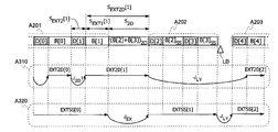
도 94(a)는 하나의 익스텐트 페어에 대하여 베이스 뷰 전송속도 REXT1[n]와 디펜던트 뷰 전송속도 REXT2[n]의 조합별로 최대 익스텐트 사이즈 maxSEXT1[n], maxSEXT2[n]를 나타내는 표이다. (b)는 층 경계(LB)의 뒤에 배치된 익스텐트 블록(9402)의 선두에 위치하는 익스텐트 페어 EXT1[n], EXT2[n]에서 베이스 뷰 데이터블록 B[n]를 디펜던트 뷰 데이터블록 D[n]의 앞에 배치한 경우를 나타내는 모식도이다.
도 95(a), (b)는 도 94(b)에 나타낸 2개의 익스텐트 블록(9401, 9402)에서 연속해서 3D 영상이 심리스로 재생될 때 RB1와 RB2의 각각에 축적되는 데이터량(DA1, DA2)의 변화를 나타내는 그래프이다.
도 96(a)은 익스텐트 블록의 도중에 위치하는 익스텐트 페어 중에서 데이터블록의 순서가 역전하고 있는 배치에 대한 익스텐트 기점의 데이터 구조(Syntax)를 나타내는 모식도이다. (b)는 파일 베이스에 속하는 베이스 뷰 익스텐트 EXT1[k](k=0, 1, 2, …)와 익스텐트 기점이 나타내는 익스텐트 개시 플래그의 사이의 대응관계를 나타내는 모식도이다. (c)는 파일 DEP에 속하는 디펜던트 뷰 익스텐트 EXT2[k]와 익스텐트 개시 플래그의 사이의 대응관계를 나타내는 모식도이다. (d)는 파일 SS에 속하는 익스텐트 SS EXTSS[0]와 BD-ROM 디스크 상의 익스텐트 블록의 사이의 대응관계를 나타내는 모식도이다.
도 97(c)은 RB1(4221)에 요구되는 용량이 가장 큰 데이터블록의 배치를 나타내는 모식도이다. (a), (b)는 (c)에 나타낸 익스텐트 블록(9701, 9702)에서 연속해서 3D 영상이 심리스로 재생될 때에 RB1(4221), RB2(4222)의 각각에 축적되는 데이터량(DA1, DA2)의 변화를 나타내는 그래프이다. (f)는 RB2(4222)에 요구되는 용량이 가장 큰 데이터블록의 배치를 나타내는 모식도이다. (d), (e)는 (f)에 나타낸 익스텐트 블록(9703, 9704)에서 연속해서 3D 영상이 심리스로 재생될 때 RB1(4221), RB2(4222)의 각각에 축적되는 데이터량(DA1, DA2)의 변화를 나타내는 그래프이다.
도 98(c)은 데이터블록의 순서가 역전하고 있는 익스텐트 페어를 도중에 포함하는 익스텐트 블록(9810)을 나타내는 모식도이다. (a), (b)는 (c)에 나타낸 익스텐트 블록(9801)에서 연속해서 3D 영상이 심리스로 재생될 때 RB1(4221), RB2(4222)의 각 축적 데이터량(DA1, DA2)의 변화를 나타내는 그래프이다.
도 99는 데이터블록의 순서가 역전하고 있는 익스텐트 페어를 도중에 포함하는 익스텐트 블록(9900)과 AV 스트림 파일(9910-9920)의 사이의 대응관계를 나타내는 모식도이다.
도 100은 BD-ROM 디스크의 층 경계(LB)의 전후에 기록된 데이터블록 군의 배치 1을 나타내는 모식도이다.
도 101은 도 100에 나타낸 배치 1의 데이터블록 군에 대한 2D 재생모드에서의 재생경로(A110)와 3D 재생모드에서의 재생경로(A120)를 나타내는 모식도이다.
도 102는 BD-ROM 디스크의 층 경계(LB)의 전후에 기록된 데이터블록 군의 배치 2를 나타내는 모식도이다.
도 103은 도 102에 나타낸 배치 2의 데이터블록 군에 대한 2D 재생모드에서의 재생경로(A310)와 3D 재생모드에서의 재생경로(A320)를 나타내는 모식도이다.
도 104는 도 103에 나타낸 제 2 익스텐트 블록(A202)의 후단에 위치하는 3D 재생전용블록 B[3]SS의 판독시간 SEXT1[3]/RUD72와 RB2(4222)의 용량의 하한의 사이의 관계를 나타내는 그래프이다.
도 105는 파일 베이스(A501)와 파일 DEP(A502)의 각 익스텐트 EXT1[k], EXT2[k](정수 k는 0 이상이다)에 대하여 설정된 엔트리 포인트(A510, A520)를 나타내는 모식도이다.
도 106(a)은 인접하는 베이스 뷰 데이터블록과 디펜던트 뷰 데이터블록의 사이에 익스텐트 ATC 시간이 다르고, 또한 비디오 스트림의 재생시간이 다를 때의 재생경로를 나타내는 모식도이다. (b)는 인접하는 베이스 뷰 데이터블록과 디펜던트 뷰 데이터블록의 사이에 비디오 스트림의 재생시간이 동일할 때의 재생경로를 나타내는 모식도이다.
도 107(a)은 멀티앵글에 대응하는 다중화 스트림 데이터의 재생경로를 나타내는 모식도이다. (b)는 BD-ROM 디스크 상에 기록된 데이터블록 군(A701)과 이들에 대한 L/R 모드에서의 재생경로(A702)를 나타내는 모식도이다. (c)는 앵글별 스트림 데이터(Ak, Bk, Ck)를 구성하는 익스텐트 블록을 나타내는 모식도이다.
도 108은 멀티앵글 기간을 구성하는 데이터블록 군(A801) 및 이들에 대한 2D 재생모드에서의 재생경로(A810)와 L/R 모드에서의 재생경로(A820)를 나타내는 모식도이다.
도 109는 3D 영상 콘텐츠가 기록된 광 디스크에 대하여 2D 재생장치에 대한 호환성을 확보하기 위한 기술을 나타내는 모식도이다.
도 110은 본 발명의 실시 예 4에 의한 집적회로(3)를 이용하여 실현된 재생장치의 기능 블록도이다.
도 111은 도 110에 나타낸 스트림 처리부(5)의 대표적인 구성을 나타내는 기능 블록도이다.
도 112는 도 110에 나타낸 스위칭부(53)가 DMAC인 경우에서의 스위칭부(53)의 주변의 기능 블록도이다.
도 113은 도 110에 나타낸 AV 출력부(8)의 대표적인 구성을 나타내는 기능 블록도이다.
도 114는 화상중첩처리에서의 메모리 2의 이용방법의 일 예를 나타내는 모식도이다.
도 115는 도 114에 나타낸 메모리 2를 이용하여 레프트 뷰 플레인에 그래픽스 플레인을 중첩하는 방법을 나타내는 모식도이다.
도 116은 도 114에 나타낸 메모리 2를 이용하여 라이트 뷰 플레인에 그래픽스 플레인을 중첩하는 방법을 나타내는 모식도이다.
도 117은 화상중첩처리에서의 메모리 2의 이용방법의 다른 예를 나타내는 모식도이다.
도 118은 도 113에 나타낸 AV 출력부(8)와 재생장치의 데이터 출력부의 상세한 기능 블록도이다.
도 119(a), (b)는 도 110에 나타낸 집적회로(3)에 대하여 그 내부에 배치된 제어 버스 및 데이터 버스의 토폴러지의 예를 나타내는 모식도이다.
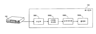
도 120은 표시장치에 탑재된 실시 예 4에 의한 집적회로와 그 주변부의 구성을 나타내는 기능 블록도이다.
도 121은 도 120에 나타낸 AV 출력부(8)의 상세한 기능 블록도이다.
도 122는 도 110에 나타낸 집적회로(3)를 이용한 재생장치에 의한 재생처리의 플로차트이다.
도 123은 도 122에 나타낸 각 스텝 S1-6의 상세를 나타내는 플로차트이다.1 is a schematic diagram showing a home theater system using a recording medium according to
FIG. 2 is a schematic diagram showing the data structure on the BD-
3 (a) and 3 (b) show a list of elementary streams multiplexed on each of the main TS and the sub TS on the BD-ROM disc.
4 is a schematic diagram showing the arrangement of TS packets in the multiplexed
Fig. 5A is a schematic diagram showing the data structure of the
6 is a schematic diagram showing the data structure of the PG stream 600.
7 is a schematic diagram showing pictures of the base
8 is a schematic diagram showing details of a data structure of a
9 is a schematic diagram showing details of a method of storing the
10 is a schematic diagram illustrating a relationship between the PTS and the DTS allocated to each picture of the base
FIG. 11 is a schematic diagram illustrating a data structure of offset
12 is a table illustrating a format (Syntax) of the offset
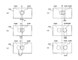
13 (a) and 13 (b) are schematic diagrams illustrating offset control of the
14 (a) and 14 (b) are graphs showing specific examples of offset sequences. (c) is a schematic diagram which shows the 3D graphics image reproduced according to the offset sequence shown to (a) and (b).
15 is a schematic diagram showing a
FIG. 16 is a schematic diagram showing a
FIG. 17A is a schematic diagram showing the data structure of the
18 is a schematic diagram illustrating a data structure of the
19 is a schematic diagram showing the physical arrangement of multiplexed stream data on a BD-ROM disc.
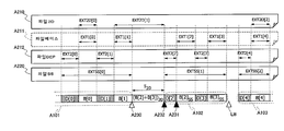
FIG. 20A is a schematic diagram showing the arrangement of the
Fig. 21 is a schematic diagram showing the
Fig. 22 is a schematic diagram showing the data structure of the 2D clip information file (01000.clpi) 231. Figs.
FIG. 23A is a schematic diagram illustrating the data structure of the
FIG. 24A is a schematic diagram showing the data structure of the
25 shows a correspondence relationship between one
FIG. 26 is a schematic diagram illustrating an example of an entry point set to a base
Fig. 27 is a schematic diagram showing the data structure of a 2D playlist file.
FIG. 28 is a schematic diagram illustrating a data structure of PI # N shown in FIG. 27.
29A and 29B are schematic diagrams showing the relationship between two
FIG. 30 is a schematic diagram showing a correspondence relationship between the PTS indicated by the 2D playlist file (00001.mpls) 221 and the portion reproduced in the
Fig. 31 is a schematic diagram showing the data structure of a 3D playlist file.
FIG. 32 is a schematic diagram showing an STN table 3205 included in the
33 is a schematic diagram showing the data structure of the
Fig. 34 is a schematic diagram showing the correspondence between the PTS indicated by the 3D playlist file (00002.mpls) 222 and the part reproduced in the file SS (01000.ssif) 244A.
FIG. 35 is a schematic diagram showing the data structure of the index file (index.bdmv) 211 shown in FIG.
FIG. 36 is a flowchart of a process in which the
37 is a functional block diagram of the
FIG. 38 is a list of system parameters SPRM included in the player
FIG. 39 is a flowchart of 2D playlist playback processing by the
40 is a functional block diagram of the
FIG. 41A is a flowchart of a process in which the PG decoder 4042 shown in FIG. 40 decodes a graphics object from one data entry in the PG stream. (b)-(e) is a schematic diagram which shows the graphics object which changes with the process.
42 is a functional block diagram of the
FIG. 43 is a table showing the data structures of the
FIG. 44 is a flowchart of 3D playlist playback processing by the
FIG. 45 is a functional block diagram in the case where the
FIG. 46 is a functional block diagram showing a video stream processing system in the case where the
FIG. 47 is a functional block diagram of the
48 is a flowchart of offset control by the cropping processing units 4731-4734 shown in FIG. 47.
FIG. 49 (b) is a schematic diagram showing the PG plane data GP before being processed by the offset control by the second cropping processing unit 4452. (a) and (c) are schematic diagrams showing the PG plane data RGP to which the offset in the right direction is given and the PG plane data LGP to which the offset in the left direction is applied, respectively.
50 is a schematic diagram showing a
FIG. 51 is a functional block diagram illustrating a processing system of a video stream in the
52 (a) is a schematic diagram illustrating a data structure of offset
Fig. 53 is a schematic diagram showing the data structure of the
54 is a schematic diagram illustrating an STN table 5400 in which a plurality of offset correction values are set for one stream data.
55 (a) to 55 (c) are schematic diagrams showing the parallax PRA, PRB, and PRC between the left view and the light view displayed on each screen SCA, SCB, SCC of 32 inches, 50 inches, and 100 inches.
Fig. 56A is a schematic diagram showing a correspondence table between the screen size and the output offset correction value. (b) is a graph showing a function between the screen size and the output offset correction value.
Fig. 57 is a functional block diagram showing elements of the 3D playback apparatus required for output offset correction.
58A is a schematic diagram showing the data structure of the dependent
59 is a functional block diagram of the
FIG. 60A is a plan view schematically illustrating horizontal angles of view HAL and HAR of a pair of video cameras CML and CMR for capturing a 3D image. (b) and (c) are schematic diagrams showing the left view LV captured by the left video camera CML and the light view RV captured by the right video camera CMR, respectively. (d) and (e) are schematic diagrams showing the left view LV indicated by the left image plane after the processing and the light view RV indicated by the right image plane after the processing, respectively.
FIG. 61A is a plan view schematically illustrating the vertical angles of view VAL and VAR of a pair of video cameras CML and CMR for capturing a 3D image. (b) is a schematic diagram which shows the left view LV picked up by the left video camera CML and the light view RV picked up by the right video camera CMR. (c) is a schematic diagram which shows the left view LV which the left video plane after a process shows, and the light view RV which the right video plane after a process shows.
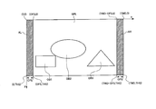
FIG. 62A is a schematic diagram illustrating an example of a graphics image represented by the graphics plane GPL. FIG. (b) and (c) are schematic diagrams which show the process of giving an offset of a right direction and a left direction to graphics plane GPL, respectively. (d) and (e) are schematic diagrams showing the graphics images indicated by the graphics planes GP1 and GP2 given the offsets in the right direction and the left direction, respectively.
FIG. 63 is a schematic diagram showing conditions relating to arrangement of graphics components defined for a graphics plane reproduced from a PG stream or an IG stream on a BD-ROM disc and a graphics plane produced by a reproduction device. FIG.
64 (a1) and (a2) are schematic views showing the screen of the same letterbox display. (b) and (c) are schematic diagrams showing respective screens when the main image plane is given an offset of 131 pixels in the upper direction and the lower direction, respectively. (d) is a schematic diagram which shows the screen at the time of giving 51 pixel offset to an image direction to a main video plane.
65 is a functional block diagram showing a configuration in a playback device required for video shift.
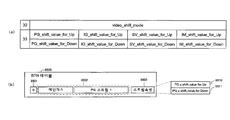
FIG. 66A is a table showing the data structures of the
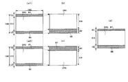
67A to 67C are schematic diagrams showing the main image planes VPA, VPB, and VPC processed by the
Fig. 68 (a) is a schematic diagram showing another example of the STN table in the playlist file in the video content of letterbox display. (b) is a schematic diagram showing the registration procedure of the plurality of
69 is a functional block diagram illustrating another example of the configuration in the playback apparatus required for video shift.
FIG. 70A is a schematic diagram showing the data structure of the
Fig. 71A is a schematic diagram showing still another example of the STN table in the playlist file in the video content of letterbox display. (b) is a functional block diagram showing still another example of the configuration in the playback apparatus required for video shift.
Fig. 72 (a) is a schematic diagram showing the subtitles SB1 and SB2 corresponding to the keep mode. (b) is a schematic diagram which shows the subtitles SBD and SB2 corresponding to a down mode. (c) is a schematic diagram showing the subtitle SB1 displayed in the keep mode. (d) is a schematic diagram showing the subtitle SB3 displayed in the up mode when the
73 (a) and 73 (b) show a list of elementary streams multiplexed on a first sub TS and a second sub TS on a BD-ROM disc, respectively.
74 is a schematic diagram showing the data structure of the
75 is a functional block diagram of a
76 is a partial functional block diagram of
77 (a), (b) and (c) are schematic diagrams showing the left view graphics image GOB0 indicated by the 2D PG stream and the light view graphics image GOB1-3 indicated by the light view PG stream. (d), (e) and (f) are schematic diagrams showing the offset control for the left view graphics image shown in (a), (b) and (c), respectively.
78 is a functional block diagram of a
79 (a) and 79 (b) are schematic diagrams illustrating a left view picture and a light view picture used for displaying one scene of a 3D image. (c) is a schematic diagram showing depth information calculated from these pictures by the
80 is a flowchart of a method for recording movie content on a BD-ROM disc using the
81 is a schematic diagram illustrating a method of matching extent ATC time between adjacent data blocks.
82 (a)-(c) are schematic diagrams for explaining the principle of reproduction of a 3D image (stereoscopic image) by a method using a parallax image.
83 is a schematic diagram illustrating an example of configuring a left view LVW and a light view RVW in a combination of a 2D image MVW and a depth map DPH.
84 is a block diagram showing a playback processing system in the playback device in the 2D playback mode.
FIG. 85A is a graph showing a change in the amount of data DA accumulated in the
86 is an example of the correspondence table between jump distance S JUMP and maximum jump time T JUMP _ MAX for the BD-ROM disc.
87 is a block diagram showing a playback processing system in the playback device in 3D playback mode.
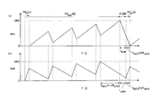
88A and 88B show changes in the amount of data DA1 and DA2 accumulated in the
FIG. 89 (b) shows the extent blocks 8901 and (M + 2) th extent blocks 8902 of the (M + 1) th (integer M is 1 or more), and the extent blocks 8901 and 8902, and 3D. It is a schematic diagram showing the correspondence relationship between the
90 (a) and 90 (b) show data accumulated in the
FIG. 91 is a block diagram showing a processing system of a video stream provided in the
Figure 92 (a), (b) are each base view transfer rate R EXT1 [n] and D pendant view transfer rate R EXT2 [n] for each transmission rate in case of limiting the sum of the extent a unit of R EXT1, R This graph shows the temporal change of EXT2 . (c) is a graph showing the temporal change of the value obtained by adding the base view transmission rate R EXT1 and the dependent view transmission rate R EXT2 shown in (a) and (b).
FIG. 93 is a schematic diagram illustrating a relationship between a TS packet and an ATC time transmitted from a source depacketizer to a PID filter in a system target decoder. FIG.
94 (a) shows the maximum extent sizes maxS EXT1 [n] and maxS EXT2 [n] for each combination of base view transmission rate R EXT1 [n] and dependent view transmission rate R EXT2 [n] for one extent pair. Table to show. (b) shows the base view data block B [n] in the extent view EXT1 [n] and EXT2 [n] located at the head of the
95A and 95B show the amount of data DA1 and RB2 accumulated in each of RB1 and RB2 when 3D images are seamlessly reproduced successively in the two
FIG. 96 (a) is a schematic diagram showing the data structure Syntax of the extent starting point for the arrangement in which the order of the data blocks is reversed among the extent pairs located in the middle of the extent block. (b) is a schematic diagram showing the correspondence between the base view extent EXT1 [k] (k = 0, 1, 2, ...) belonging to the file base and the extent start flag indicated by the extent origin. (c) is a schematic diagram showing the correspondence between the dependent view extent EXT2 [k] belonging to the file DEP and the extent start flag. (d) is a schematic diagram showing the correspondence between the extent SS EXTSS [0] belonging to the file SS and the extent blocks on the BD-ROM disc.
FIG. 97C is a schematic diagram showing the arrangement of data blocks having the largest capacity required for the
FIG. 98 (c) is a schematic diagram showing an
FIG. 99 is a schematic diagram showing a correspondence relationship between an
100 is a schematic
FIG. 101 is a schematic diagram showing the playback path A110 in the 2D playback mode and the playback path A120 in the 3D playback mode for the data block group of
Fig. 102 is a schematic diagram showing the
FIG. 103 is a schematic diagram showing the playback path A310 in the 2D playback mode and the playback path A320 in the 3D playback mode for the data block group of
FIG. 104 shows the reading time S EXT1 [3] / R UD72 and the lower limit of the capacity of the
FIG. 105 is a schematic diagram showing entry points A510 and A520 set for each of the extents EXT1 [k] and EXT2 [k] (the integer k is zero or more) of the file base A501 and the file DEP A502.
Fig. 106 (a) is a schematic diagram showing a playback path when the extent ATC time is different between the adjacent base view data block and the dependent view data block, and the playback time of the video stream is different. (b) is a schematic diagram showing a reproduction path when the reproduction time of a video stream is the same between adjacent base view data blocks and dependent view data blocks.
Fig. 107 (a) is a schematic diagram showing a reproduction path of multiplexed stream data corresponding to multi-angles. (b) is a schematic diagram showing a group of data blocks A701 recorded on a BD-ROM disc and a reproduction path A702 in the L / R mode for them. (c) is a schematic diagram which shows the extent block which comprises stream data Ak, Bk, Ck for each angle.
Fig. 108 is a schematic diagram showing the data block group A801 constituting the multi-angle period, the playback path A810 in the 2D playback mode, and the playback path A820 in the L / R mode.
Fig. 109 is a schematic diagram showing a technique for ensuring compatibility with a 2D playback apparatus for an optical disk on which 3D video content is recorded.
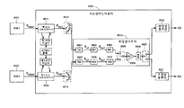
110 is a functional block diagram of a playback apparatus realized using the
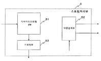
FIG. 111 is a functional block diagram illustrating a typical configuration of the
FIG. 112 is a functional block diagram of the periphery of the
FIG. 113 is a functional block diagram showing a typical configuration of the
114 is a schematic diagram illustrating an example of a method of using the
FIG. 115 is a schematic diagram illustrating a method of superposing a graphics plane on the left view plane using the
FIG. 116 is a schematic diagram illustrating a method of superposing a graphics plane on the light view plane using the
117 is a schematic diagram showing another example of the method of using the
FIG. 118 is a detailed functional block diagram of the
119 (a) and (b) are schematic diagrams showing examples of the topology of the control bus and the data bus disposed therein with respect to the
120 is a functional block diagram showing a configuration of an integrated circuit and a peripheral portion thereof according to the fourth embodiment mounted in the display device.
FIG. 121 is a detailed functional block diagram of the
FIG. 122 is a flowchart of playback processing by the playback apparatus using the
FIG. 123 is a flowchart showing the details of each step S1-6 shown in FIG. 122.
이하, 본 발명의 가장 바람직한 실시 예에 관한 기록매체 및 재생장치에 대하여 도면을 참조하면서 설명한다.Hereinafter, a recording medium and a reproduction device according to the most preferred embodiment of the present invention will be described with reference to the drawings.
《실시 예 1》Example 1
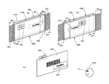
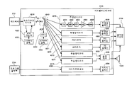
도 1은 본 발명의 실시 예 1에 의한 기록매체를 사용하는 홈시어터 시스템을 나타내는 모식도이다. 이 홈시어터 시스템은 시차 영상을 이용한 3D 영상(입체 시 영상)의 재생 방식을 채용하고, 특히 표시 방식으로 계시분리방식을 채용하고 있다(상세는《보충》참조). 도 1을 참조하면, 이 홈시어터 시스템은 기록매체(101)를 재생대상으로 하고, 재생장치(102), 표시장치(103), 셔터 안경(104) 및 리모컨(105)을 포함한다. 재생장치(102)와 표시장치(103)는 도 1에 나타낸 것과 같이 서로 독립적인 장치이다. 그 외에, 재생장치(102)와 표시장치(103)가 일체화되고 있어도 좋다.1 is a schematic diagram showing a home theater system using a recording medium according to
기록매체(101)는 판독 전용 블루레이 디스크(등록상표)(BD:Blu-ray Disc), 즉 BD-ROM 디스크이다. 기록매체(101)는 그 외의 휴대형 기록매체, 예를 들어 DVD 등 다른 방식에 의한 광 디스크, 리무버블 하드디스크 드라이브(HDD), 또는 SD 메모리 카드 등의 반도체 메모리 장치라도 좋다. 그 기록매체, 즉 BD-ROM 디스크(101)는 3D 영상에 의한 영화 콘텐츠를 저장하고 있다. 이 콘텐츠는 그 3D 영상의 레프트 뷰와 라이트 뷰의 각각을 나타내는 비디오 스트림을 포함한다. 또, 그 콘텐츠는 그 3D 영상의 깊이 맵(depth map)을 나타내는 비디오 스트림을 포함하고 있어도 좋다. 이들 비디오 스트림은 후술과 같이 데이터블록 단위로 BD-ROM 디스크(101) 상에 배치되고, 후술하는 파일 구조를 이용하여 액세스 된다. 레프트 뷰 또는 라이트 뷰를 나타내는 비디오 스트림은 2D 재생장치와 3D 재생장치의 각각에 의해 그 콘텐츠를 2D 영상으로 재생하는데 이용된다. 한편, 레프트 뷰와 라이트 뷰의 각각을 나타내는 비디오 스트림의 쌍, 또는 레프트 뷰 또는 라이트 뷰의 어느 하나와 깊이 맵의 각각을 나타내는 비디오 스트림의 쌍은 3D 재생장치에 의해 그 콘텐츠를 3D 영상으로 재생하는데 이용된다.The
재생장치(102)는 BD-ROM 드라이브(121)를 탑재하고 있다. BD-ROM 드라이브(121)는 BD-ROM 방식에 준거한 광 디스크 드라이브이다. 재생장치(102)는 BD-ROM 드라이브(121)를 이용하여 BD-ROM 디스크(101)로부터 콘텐츠를 판독한다. 또, 재생장치(102)는 그 콘텐츠를 영상 데이터/음성 데이터에 복호 한다. 여기서, 재생장치(102)는 3D 재생장치이며, 그 콘텐츠를 2D 영상과 3D 영상의 어느 것으로도 재생 가능하다. 이하, 2D 영상과 3D 영상의 각각을 재생할 때의 재생장치(102)의 동작 모드를 「2D 재생모드」, 「3D 재생모드」라고 한다. 2D 재생모드에서는 영상 데이터는 레프트 뷰 또는 라이트 뷰의 어느 일방의 영상 프레임을 포함한다. 3D 재생모드에서는 영상 데이터는 레프트 뷰와 라이트 뷰의 양쪽의 영상 프레임을 포함한다.The
또, 3D 재생모드는 레프트/라이트(L/R) 모드와 깊이 모드로 구분할 수 있다. 「L/R 모드」에서는 레프트 뷰와 라이트 뷰의 각각을 나타내는 비디오 스트림의 조합으로부터 레프트 뷰와 라이트 뷰의 영상 프레임의 쌍이 재생된다. 「깊이 모드」에서는 레프트 뷰 또는 라이트 뷰의 어느 하나와 깊이 맵의 각각을 나타내는 비디오 스트림의 조합으로부터 레프트 뷰와 라이트 뷰의 영상 프레임의 쌍이 재생된다. 재생장치(102)는 L/R 모드를 구비한다. 또, 재생장치(102)는 깊이 모드를 구비하고 있어도 좋다.In addition, the 3D playback mode can be classified into a left / right (L / R) mode and a depth mode. In the "L / R mode", a pair of video frames of left view and right view is reproduced from a combination of video streams representing the left view and the right view. In the "depth mode", a pair of left and right view video frames is reproduced from a combination of a left view or a right view and a video stream representing each of the depth maps. The
재생장치(102)는 HDMI(High-Definition Multimedia Interface) 케이블(122)로 표시장치(103)에 접속되어 있다. 재생장치(102)는 영상 데이터/음성 데이터를 HDMI 방식의 영상신호/음성 신호로 변환하고, HDMI 케이블(122)을 통해 표시장치(103)에 전송한다. 2D 재생모드에서는 영상신호에는 레프트 뷰 또는 라이트 뷰의 어느 일방의 영상 프레임이 다중화되어 있다. 3D 재생모드에서는 영상신호에는 레프트 뷰와 라이트 뷰의 양쪽의 영상 프레임이 시분할로 다중화되어 있다. 또,재생장치(102)는 HDMI 케이블(122)을 통해 표시장치(103)의 사이에서 CEC 메시지를 교환한다. 이에 의해 재생장치(102)는 3D 영상의 재생에 대응 가능한가 여부를 표시장치(103)에 문의할 수 있다.The
표시장치(103)는 액정 디스플레이이다. 표시장치(103)는 그 외에, 플라스마 디스플레이 및 유기 EL 디스플레이 등, 다른 방식의 플랫 패널 디스플레이 또는 프로젝터라도 좋다. 표시장치(103)는 영상신호에 따라서 화면(131) 상에 영상을 표시하고, 음성 신호에 따라서 내장의 스피커로부터 음성을 발생시킨다. 표시장치(103)는 3D 영상의 재생에 대응 가능하다. 2D 영상의 재생시에 화면(131) 상에는 레프트 뷰 또는 라이트 뷰의 어느 일방이 표시된다. 3D 영상의 재생시에 화면(131) 상에는 레프트 뷰와 라이트 뷰가 교호로 표시된다.The
표시장치(103)는 좌우 신호 송신부(132)를 포함한다. 좌우 신호 송신부(132)는 좌우 신호(LR)를 적외선 또는 무선으로 셔터 안경(104)에 송출한다. 좌우 신호(LR)는 현시점에서 화면(131)에 표시되는 영상이 레프트 뷰와 라이트 뷰의 어느 것인지를 나타낸다. 3D 영상의 재생시, 표시장치(103)는 영상신호에 부수하는 제어신호로부터 레프트 뷰 프레임과 라이트 뷰 프레임을 식별함으로써 프레임의 전환을 검지한다. 또, 표시장치(103)는 좌우 신호 송신부(132)에 검지된 프레임의 전환에 동기하여 좌우 신호(LR)를 변화시킨다.The
셔터 안경(104)은 2매의 액정표시패널(141L, 141R)과 좌우 신호 수신부(142)를 포함한다. 각 액정표시패널(141L, 141R)은 좌우의 각 렌즈 부분을 구성하고 있다. 좌우 신호 수신부(142)는 좌우 신호(LR)를 수신하고, 그 변화에 따라서 좌우의 액정표시패널(141L, 141R)에 신호를 보낸다. 각 액정표시패널(141L, 141R)은 그 신호에 따라서 광을 그 전체에서 동일하게 투과시키거나 또는 차단한다. 특히, 좌우 신호(LR)가 레프트 뷰의 표시를 나타낼 때 왼쪽 눈 측의 액정표시패널(141L)은 광을 투과시키고, 오른쪽 눈 측의 액정표시패널(141R)은 광을 차단한다. 좌우 신호(LR)가 라이트 뷰의 표시를 나타낼 때는 그 역이다. 이와 같이, 2매의 액정표시패널(141L, 141R)은 프레임의 전환과 동기하여 교호로 광을 투과시킨다. 그 결과, 시청자가 셔터 안경(104)을 쓰고 화면(131)을 보았을 때 레프트 뷰는 그 시청자의 왼쪽 눈에만 비치고, 라이트 뷰는 그 오른쪽 눈에만 비친다. 그때 그 시청자에게는 각 눈에 비치는 영상 간의 차가 동일한 입체에 대한 양 눈 시차로 지각되므로 그 영상이 입체적으로 보인다.The
리모컨(105)은 조작부와 송신부를 포함한다. 조작부는 복수의 버튼을 포함한다. 각 버튼은 전원의 온 오프, 또는 BD-ROM 디스크(101)의 재생 개시 또는 정지 등, 재생장치(102) 또는 표시장치(103)의 각 기능에 대응되어 있다. 조작부는 사용자에 의한 각 버튼의 눌림을 검출하고, 그 버튼의 식별정보를 신호로 송신부에 전달한다. 송신부는 그 신호를 적외선 또는 무선에 의한 신호(IR)로 변환하여 재생장치(102) 또는 표시장치(103)에 송출한다. 한편, 재생장치(102)와 표시장치(103)는 각각 그 신호(IR)를 수신하고, 그 신호(IR)가 나타내는 버튼을 특정하여 그 버튼에 대응된 기능을 실행한다. 이렇게 하여 사용자는 재생장치(102) 또는 표시장치(103)을 원격 조작할 수 있다.The
<BD-ROM 디스크 상의 데이터 구조><Data structure on BD-ROM disk>
도 2는 BD-ROM 디스크(101) 상의 데이터 구조를 나타내는 모식도이다. 도 2를 참조하면, BD-ROM 디스크(101) 상의 데이터 기록영역의 최 내주부에는 BCA(Burst Cutting Area)(201)이 설치되어 있다. BCA에 대해서는 BD-ROM 드라이브(121)에 의한 액세스만이 허가되며, 애플리케이션 프로그램에 의한 액세스는 금지된다. 이에 의해 BCA(201)는 저작권 보호기술에 이용된다. BCA(201)보다 바깥쪽의 데이터 기록영역에서는 내주에서 외주에 향하여 트랙이 나선 형상으로 연장하고 있다. 도 2에는 트랙(202)이 모식적으로 횡 방향으로 연장되어서 묘사되어 있다. 그 좌측은 디스크(101)의 내주부를 나타내고, 우측은 외주부를 나타낸다. 도 2에 나타낸 것과 같이, 트랙(202)는 내주로부터 순서대로 리드인 영역(202A), 볼륨 영역(202B) 및 리드아웃 영역(202C)을 포함한다. 리드인 영역(202A)은 BCA(201)의 바로 외주 측에 설치되어 있다. 리드인 영역(202A)은 볼륨 영역(202B)에 기록된 데이터의 사이즈 및 물리 어드레스 등, BD-ROM 드라이브(121)에 의한 볼륨 영역(202B)으로의 액세스에 필요한 정보를 포함한다. 리드아웃 영역(202C)은 데이터 기록영역의 최 외주부에 설치되며, 볼륨 영역(202B)의 종단을 나타낸다. 볼륨 영역(202B)은 영상 및 음성 등의 애플리케이션 데이터를 포함한다.2 is a schematic diagram showing the data structure on the BD-
볼륨 영역(202B)은 「섹터」라고 불리는 소 영역(202D)으로 분할되어 있다. 섹터의 사이즈는 공통이며, 예를 들어 2048 바이트이다. 각 섹터(202D)에는 볼륨 영역(202B)의 선단에서부터 순서대로 일련번호가 할당되어 있다. 이 일련번호는 논리블록번호(LBN)라고 불리며, BD-ROM 디스크(101) 상의 논리 어드레스에 이용된다. BD-ROM 디스크(101)로부터의 데이터의 판독에서는 수신처의 섹터의 LBN가 지정됨으로써 판독대상의 데이터가 특정된다. 이렇게 하여 볼륨 영역(202B)은 섹터 단위로 액세스 가능하다. 또, BD-ROM 디스크(101) 상에서는 논리 어드레스가 물리 어드레스와 실질적으로 동일하다. 특히, LBN이 연속하고 있는 영역에서는 물리 어드레스도 실질적으로 연속하고 있다. 따라서, BD-ROM 드라이브(121)는 LBN이 연속하고 있는 섹터로부터 데이터를 그 광 픽업에 시크를 실시하게 하지 않고 연속해서 판독할 수 있다.The
볼륨 영역(202B)에 기록된 데이터는 소정의 파일 시스템으로 관리된다. 그 파일 시스템으로는 UDF(Universal Disc Format)가 채용되고 있다. 그 파일 시스템은 그 외에 ISO9660라도 좋다. 그 파일 시스템에 따라서 볼륨 영역(202B)에 기록된 데이터는 디렉터리/파일 형식으로 표현된다(상세는《보충》참조). 즉, 이들 데이터는 디렉터리 단위 또는 파일 단위로 액세스 가능하다.Data recorded in the
≪BD-ROM 디스크 상의 디렉터리/파일 구조≫≪Directory / File Structure on BD-ROM Disk≫
또, 도 2는 BD-ROM 디스크(101)의 볼륨 영역(202B)에 저장된 데이터의 디렉터리/파일 구조를 나타낸다. 도 2를 참조하면, 이 디렉터리/파일 구조에서는 루트(ROOT) 디렉터리(203)의 아래에 BD 무비(BDMV:BD Movie) 디렉터리(210)가 놓여있다. BDMV 디렉터리(210)의 아래에는 인덱스 파일(index.bdmv)(211)과 무비 오브젝트 파일(MovieObject.bdmv)(212)이 놓여있다.2 shows a directory / file structure of data stored in the
인덱스 파일(211)은 BD-ROM 디스크(101)에 기록된 콘텐츠의 전체를 관리하기 위한 정보이다. 특히, 그 정보는 그 콘텐츠를 재생장치(102)에 인식시키기 위한 정보 및 인덱스 테이블을 포함한다. 인덱스 테이블은 그 콘텐츠를 구성하는 타이틀과 재생장치(102)의 동작을 제어하기 위한 프로그램의 사이의 대응 표이다. 그 프로그램을 「오브젝트」라고 한다. 오브젝트의 종류에는 무비 오브젝트와 BD-J(BD Java (등록상표) 오브젝트가 있다.The
무비 오브젝트 파일(212)은 일반적으로 복수의 무비 오브젝트를 포함한다. 각 무비 오브젝트는 내비게이션 커멘드의 열을 포함한다. 내비게이션 커멘드는 일반적인 DVD 플레이어에 의한 재생처리와 동일한 재생처리를 재생장치(102)에 실행시키기 위한 제어지령이다. 내비게이션 커멘드의 종류에는 예를 들어 타이틀에 대응하는 플레이리스트 파일의 판독 명령, 플레이리스트 파일이 나타내는 AV 스트림 파일의 재생 명령 및 다른 타이틀로의 천이 명령이 있다. 내비게이션 커멘드는 인터프리터형 언어로 기술되고, 재생장치(102)에 포함된 인터프리터, 즉 작업제어 프로그램에 의해 해독되어 그 제어부에 원하는 작업을 실행시킨다. 내비게이션 커멘드는 오피코드와 오퍼랜드로 이루어진다. 오피코드는 타이틀의 분기와 재생 및 연산 등, 재생장치(102)에 실행시켜야 할 조작의 종류를 나타낸다. 오퍼랜드는 타이틀 번호 등, 그 조작의 대상의 식별정보를 나타낸다. 재생장치(102)의 제어부는 예를 들어 사용자의 조작에 따라서 각 무비 오브젝트를 호출하고, 그 무비 오브젝트에 포함되는 내비게이션 커멘드를 열의 순으로 실행한다. 이에 의해 재생장치(102)는 일반적인 DVD 플레이어와 마찬가지로, 먼저 표시장치(103)에 메뉴를 표시하고 사용자에게 커멘드를 선택하게 한다. 재생장치(102)는 다음에, 선택된 커멘드에 따라서 타이틀의 재생 개시/정지 및 다른 타이틀로의 전환 등, 재생되는 영상의 진행을 동적으로 변화시킨다.The
또, 도 2를 참조하면, BDMV 디렉터리(210)의 아래에는 플레이리스트(PLAYLIST) 디렉터리(220), 클립 정보(CLIPINF) 디렉터리(230), 스트림(STREAM) 디렉터리(240), BD-J 오브젝트(BDJO:BD Java Object) 디렉터리(250) 및 Java 아카이브(JAR:Java Archive) 디렉터리(260)가 놓여있다.2, a playlist (PLAYLIST) directory 220, a clip information (CLIPINF)
STREAM 디렉터리(240)의 아래에는 3종류의 AV 스트림 파일(01000.m2ts)(241), (02000.m2ts)(242), (03000.m2ts)(243) 및 입체 시 인터리브 파일(SSIF:Stereoscopic Interleaved File) 디렉터리(244)가 놓여있다. SSIF 디렉터리(244)의 아래에는 2종류의 AV 스트림 파일(01000.ssif)(244A), (02000.ssif)(244B)가 놓여있다.Under the
「AV 스트림 파일」은 BD-ROM 디스크(101) 상에 기록된 영상 콘텐츠의 본체 중 파일 시스템이 정하는 파일 형식으로 정렬된 것을 말한다. 여기서, 영상 콘텐츠의 본체는 일반적으로 영상·음성·자막 등을 나타내는 각종의 스트림 데이터, 즉 엘리멘터리 스트림이 다중화된 스트림 데이터를 의미한다. 다중화 스트림 데이터는 메인 트랜스포트 스트림(TS)과 서브 TS로 대별된다. 「메인 TS」는 프라이머리 비디오 스트림으로 베이스 뷰 비디오 스트림을 포함하는 다중화 스트림 데이터를 말한다. 「베이스 뷰 비디오 스트림」은 단독으로 재생 가능하며, 2D 영상을 나타내는 비디오 스트림을 말한다. 이 2D 영상을 「베이스 뷰」 또는 「메인 뷰」라고 한다. 「서브 TS」는 프라이머리 비디오 스트림으로 디펜던트 뷰 비디오 스트림을 포함하는 다중화 스트림 데이터를 말한다. 「디펜던트 뷰 비디오 스트림」은 그 재생에 베이스 뷰 비디오 스트림을 필요로 하며, 그 베이스 뷰 비디오 스트림과의 조합으로 3D 영상을 나타내는 비디오 스트림을 말한다. 디펜던트 뷰 비디오 스트림의 종류에는 라이트 뷰 비디오 스트림, 레프트 뷰 비디오 스트림 및 깊이 맵 스트림이 있다. 「라이트 뷰 비디오 스트림」은 베이스 뷰가 3D 영상의 레프트 뷰일 때 그 3D 영상의 라이트 뷰를 나타내는 비디오 스트림이다. 「레프트 뷰 비디오 스트림」은 그 역이다. 「깊이 맵 스트림」은 베이스 뷰가 가상적인 2D 화면에 대한 3D 영상의 투영일 때 그 3D 영상의 깊이 맵을 나타내는 스트림 데이터이다. 디펜던트 뷰 비디오 스트림이 나타내는 2D 영상 또는 깊이 맵을 「디펜던트 뷰」 또는 「서브 뷰」라고 한다.The "AV stream file" means that the main body of the video content recorded on the BD-
AV 스트림 파일은 내장의 다중화 스트림 데이터의 종류에 의해 파일 2D, 파일 디펜던트(이하, 파일 DEP라고 한다) 및 인터리브 파일(이하, 파일 SS라고 한다)로 나눌 수 있다. 「파일 2D 」는 2D 재생모드에서의 2D 영상의 재생에 이용되는 AV 스트림 파일로, 메인 TS를 포함하는 것을 말한다. 「파일 DEP」는 서브 TS를 포함하는 AV 스트림 파일을 말한다. 「파일 SS」는 동일한 3D 영상을 나타내는 메인 TS와 서브 TS의 쌍을 포함하는 AV 스트림 파일을 말한다. 파일 SS는 특히, 메인 TS를 어느 하나의 파일 2D와 공유하고, 서브 TS를 어느 하나의 파일 DEP와 공유한다. 즉, BD-ROM 디스크(101)의 파일 시스템에서는 메인 TS는 파일 SS와 파일 2D의 어느 것으로도 액세스 가능하고, 서브 TS는 파일 SS와 파일 DEP의 어느 것으로도 액세스 가능하다. 이와 같이, BD-ROM 디스크(101) 상에 기록된 일련의 데이터를 다른 파일에 공유시키고, 어느 파일로도 액세스 가능하게 하는 구조를 「파일의 크로스 링크」라고 한다.An AV stream file can be divided into a
도 2에 나타낸 예에서는 제 1 AV 스트림 파일(01000.m2ts)(241)은 파일 2D 이며, 제 2 AV 스트림 파일(02000.m2ts)(242)과 제 3 AV 스트림 파일(03000.m2ts)(243)은 모두 파일 DEP이다. 이와 같이, 파일 2D와 파일 DEP는 STREAM 디렉터리(240)의 아래에 놓인다. 제 1 AV 스트림 파일, 즉 파일 2D(241)가 포함하는 베이스 뷰 비디오 스트림은 3D 영상의 레프트 뷰를 나타낸다. 제 2 AV 스트림 파일, 즉 제 1 파일 DEP(242)가 포함하는 디펜던트 뷰 비디오 스트림은 라이트 뷰 비디오 스트림을 포함한다. 제 3 AV 스트림 파일, 즉 제 2 파일 DEP(243)가 포함하는 디펜던트 뷰 비디오 스트림은 깊이 맵 스트림을 포함한다.In the example shown in Fig. 2, the first AV stream file (01000.m2ts) 241 is a
또, 도 2에 나타낸 예에서는 제 4 AV 스트림 파일(01000.ssif)(244A)과 제 5 AV 스트림 파일(02000.ssif)(244B)은 모두 파일 SS이다. 이와 같이, 파일 SS는 SSIF 디렉터리(244)의 아래에 놓인다. 제 4 AV 스트림 파일, 즉 제 1 파일 SS(244A)는 파일 2D(241)와 메인 TS, 특히 베이스 뷰 비디오 스트림을 공유하고, 제 1 파일 DEP(242)와 서브 TS, 특히 라이트 뷰 비디오 스트림을 공유한다. 제 5 AV 스트림 파일, 즉 제 2 파일 SS(244B)는 제 1 파일 2D(241)와 메인 TS, 특히 베이스 뷰 비디오 스트림을 공유하고, 제 3 파일 DEP(243)와 서브 TS, 특히 깊이 맵 스트림을 공유한다.In the example shown in Fig. 2, both the fourth AV stream file (01000.ssif) 244A and the fifth AV stream file (02000.ssif) 244B are file SSs. As such, file SS is placed under
CLIPINF 디렉터리(230)에는 3종류의 클립정보파일(01000.clpi)(231), (02000.clpi)(232), (03000.clpi)(233)이 놓여있다. 「클립정보파일」은 파일 2D와 파일 DEP에 일 대 일로 대응된 파일이며, 특히 각 파일의 엔트리 맵을 포함하는 것을 말한다. 「엔트리 맵」은 각 파일이 나타내는 장면의 표시시간과 그 장면이 기록된 각 파일 내의 어드레스의 사이의 대응 표이다. 클립정보파일 중 파일 2D에 대응되어 있는 것을 「2D 클립정보파일」이라고 하고, 파일 DEP에 대응되어 있는 것을 「디펜던트 뷰 클립정보파일」이라고 한다. 도 2에 나타낸 예에서는 제 1 클립정보파일(01000.clpi)(231)은 2D 클립정보파일이며, 파일 2D(241)에 대응되어 있다. 제 2 클립정보파일(02000.clpi)(232)과 제 3 클립정보파일(03000.clpi)(233)은 모두 디펜던트 뷰 클립정보파일이며, 각각 제 1 파일 DEP(242)와 제 2 파일 DEP(243)에 대응되어 있다.In the
PLAYLIST 디렉터리(220)에는 3종류의 플레이리스트 파일(00001.mpls)(221), (00002.mpls)(222), (00003.mpls)(223)이 놓여있다. 「플레이리스트 파일」은 AV 스트림 파일의 재생경로, 즉 AV 스트림 파일의 재생대상의 부분과 그 재생순서를 규정하는 파일을 말한다. 플레이리스트 파일의 종류에는 2D 플레이리스트 파일과 3D 플레이리스트 파일이 있다. 「2D 플레이리스트 파일」은 파일 2D의 재생경로를 규정한다. 「3D 플레이리스트 파일」은 2D 재생모드의 재생장치에 대해서는 파일 2D의 재생경로를 규정하고, 3D 재생모드의 재생장치에 대해서는 파일 SS의 재생경로를 규정한다. 도 2에 나타낸 예에서는 제 1 플레이리스트 파일(00001.mpls)(221)은 2D 플레이리스트 파일이며, 파일 2D(241)의 재생경로를 규정한다. 제 2 플레이리스트 파일(00002.mpls)(222)은 3D 플레이리스트 파일이며, 2D 재생모드의 재생장치에 대해서는 파일 2D(241)의 재생경로를 규정하고, L/R 모드의 3D 재생장치에 대해서는 제 1 파일 SS(244A)의 재생경로를 규정한다. 제 3 플레이리스트 파일(00003.mpls)(223)은 3D 플레이리스트 파일이며, 2D 재생모드의 재생장치에 대해서는 파일 2D(241)의 재생경로를 규정하고, 깊이 모드의 3D 재생장치에 대해서는 제 2 파일 SS(244B)의 재생경로를 규정한다.In the PLAYLIST directory 220, three kinds of playlist files (00001.mpls) 221, (00002.mpls) 222, and (00003.mpls) 223 are placed. The "playlist file" refers to a reproduction path of an AV stream file, i.e., a file defining a portion to be reproduced of the AV stream file and its reproduction order. There are two kinds of playlist files: 2D playlist files and 3D playlist files. The " 2D Playlist File " defines a playback path of the
BDJO 디렉터리(250)에는 BD-J 오브젝트 파일(XXXXX.bdjo)(251)이 놓여있다. BD-J 오브젝트 파일(251)은 BD-J 오브젝트를 하나 포함한다. BD-J 오브젝트는 바이트 코드 프로그램이며, 재생장치(102)에 탑재된 Java 가상 머신에 타이틀의 재생 처리 및 그래픽스 영상의 묘사 처리를 실행시킨다. BD-J 오브젝트는 Java 언어 등의 컴파일러형 언어로 기술되어 있다. BD-J 오브젝트는 애플리케이션 관리테이블과 참조대상의 플레이리스트 파일의 식별정보를 포함한다. 「애플리케이션 관리테이블」은 Java 가상 머신에 실행시켜야 할 Java 애플리케이션 프로그램과 그 실행 시기, 즉 라이프 사이클의 대응 표이다. 「참조 대상의 플레이리스트 파일의 식별정보」는 재생 대상의 타이틀에 대응하는 플레이리스트 파일을 식별하기 위한 정보이다. Java 가상 머신은 사용자의 조작 또는 애플리케이션 프로그램에 따라서 각 BD-J 오브젝트를 호출하고, 그 BD-J 오브젝트에 포함되는 애플리케이션 관리테이블에 따라서 Java 애플리케이션 프로그램을 실행한다. 이에 의해 재생장치(102)는 재생되는 각 타이틀의 영상의 진행을 동적으로 변화시키거나 또는 표시장치(103)에 그래픽스 영상을 타이틀의 영상과는 독립적으로 표시시킨다.In the
JAR 디렉터리(260)에는 JAR 파일(YYYYY.jar)(261)이 놓여있다. JAR 파일(261)은 BD-J 오브젝트가 나타내는 애플리케이션 관리테이블에 따라서 실행되어야 할 Java 애플리케이션 프로그램의 본체를 일반적으로 복수 포함한다. 「Java 애플리케이션 프로그램」은 BD-J 오브젝트와 마찬가지로, Java 언어 등의 컴파일러형 언어로 기술된 바이트코드 프로그램이다. Java 애플리케이션 프로그램의 종류에는 Java 가상 머신에 타이틀의 재생처리를 실행시키는 것 및 Java 가상 머신에 그래픽스 영상의 묘사 처리를 실행시키는 것이 포함된다. JAR 파일(261)은 Java 아카이브 파일이며, 재생장치(102)에 판독된 때에 그 내부의 메모리에서 전개된다. 이에 의해 그 메모리 중에 Java 애플리케이션 프로그램이 저장된다.A JAR file (YYYYY.jar) 261 is placed in the
≪다중화 스트림 데이터의 구조≫«Structure of Multiplexed Stream Data»
도 3(a)은 BD-ROM 디스크(101) 상의 메인 TS에 다중화된 엘리멘터리 스트림의 일람표이다. 메인 TS는 MPEG-2 트랜스포트 스트림(TS) 형식의 디지털 스트림이며, 도 2에 나타낸 파일 2D(241)에 포함된다. 도 3(a)을 참조하면, 메인 TS는 프라이머리 비디오 스트림(301), 프라이머리 오디오 스트림(302A, 302B) 및 프레젠테이션 그래픽스(PG) 스트림(303A, 303B)을 포함한다. 메인 TS는 그 외에 인터렉티브 그래픽스(IG) 스트림(304), 세컨더리 오디오 스트림(305) 및 세컨더리 비디오 스트림(306)을 포함해도 좋다.FIG. 3A is a list of elementary streams multiplexed on the main TS on the BD-
프라이머리 비디오 스트림(301)은 영화의 주 영상을 나타내고, 세컨더리 비디오 스트림(306)은 부 영상을 나타낸다. 여기서, 주 영상이란 영화의 본편의 영상 등, 콘텐츠의 주요한 영상을 의미하며, 예를 들어 화면 전체에 표시되는 것을 나타낸다. 한편, 부 영상이란 예를 들어 주 영상 중에 작은 화면으로 표시되는 영상과 같이, 픽처 인 픽처 방식을 이용하여 주 영상과 동시에 화면에 표시되는 영상을 의미한다. 프라이머리 비디오 스트림(301)과 세컨더리 비디오 스트림(306)은 모두 베이스 뷰 비디오 스트림이다. 각 비디오 스트림(301, 306)은 MPEG-2, MPEG-4 AVC, 또는 SMPTE VC-1 등의 동화상 압축 부호화 방식으로 부호화되어 있다.The
프라이머리 오디오 스트림(302A, 302B)은 영화의 주 음성을 나타낸다. 여기서, 2개의 프라이머리 오디오 스트림(302A, 302B)의 사이에서는 언어가 다르다. 세컨더리 오디오 스트림(305)은 대화 화면의 조작에 수반하는 효과음 등, 주 음성과 중첩되어야 할(믹싱되어야 할) 부 음성을 나타낸다. 각 오디오 스트림(302A, 302B, 305)은 AC-3, 돌비 디지털 플러스(Dolby Digital Plus: 「돌비 디지털」은 등록상표), MLP(Meridian Lossless Packing: 등록상표), DTS(Digital Theater System: 등록상표), DTS-HD, 또는 리니어 PCM(Pulse Code Modulation) 등의 방식으로 부호화되어 있다.Primary audio streams 302A, 302B represent the main voice of the movie. Here, the language is different between the two
각 PG 스트림(303A, 303B)은 그래픽스에 의한 자막 등, 프라이머리 비디오 스트림(301)이 나타내는 영상에 중첩해서 표시되어야 할 그래픽스 영상을 나타낸다. 2개의 PG 스트림(303A, 303B)의 사이에서는 예를 들어 자막의 언어가 다르다. IG 스트림(304)은 표시장치(103)의 화면(131) 상에 대화화면을 구성하기 위한 그래픽스 사용자 인터페이스(GUI) 용의 그래픽 부품 및 그 배치를 나타낸다.Each
엘리멘터리 스트림(301-306)은 패킷 식별자(PID)에 의해 식별된다. PID의 할당은 예를 들어 다음과 같다. 하나의 메인 TS는 프라이머리 비디오 스트림을 한 개만 포함하므로 프라이머리 비디오 스트림(301)에는 16 진수치 0x1011가 할당된다. 하나의 메인 TS에 다른 엘리멘터리 스트림이 종류별로 최대 32개까지 다중화 가능할 때 프라이머리 오디오 스트림(302A, 302B)에는 0x1100에서 0x111F까지 중 어느 하나가 할당된다. PG 스트림(303A, 303B)에는 0x1200에서 0x121F까지 중 어느 하나가 할당된다. IG 스트림(304)에는 0x1400에서 0x141F까지 중 어느 하나가 할당된다. 세컨더리 오디오 스트림(305)에는 0x1A00에서 0x1A1F까지 중 어느 하나가 할당된다. 세컨더리 비디오 스트림(306)에는 0x1B00에서 0x1B1F까지 중 어느 하나가 할당된다.Elementary streams 301-306 are identified by packet identifier (PID). PID allocation is as follows, for example. Since one main TS includes only one primary video stream, the hexadecimal value 0x1011 is assigned to the
도 3(b)은 BD-ROM 디스크(101) 상의 서브 TS에 다중화된 엘리멘터리 스트림의 일람표이다. 서브 TS는 MPEG-2 TS 형식의 다중화 스트림 데이터이며, 도 2에 나타낸 각 파일 DEP(242, 243)에 포함된다. 도 3(b)을 참조하면, 서브 TS는 2개의 프라이머리 비디오 스트림(311R, 311D)을 포함한다. 그 일방(311R)은 라이트 뷰 비디오 스트림이고, 타방(311D)은 깊이 맵 스트림이다. 또, 이들 프라이머리 비디오 스트림(311R, 311D)은 다른 파일 DEP(242, 243)에 따로따로 다중화되어도 좋다. 라이트 뷰 비디오 스트림(311R)은 메인 TS 내의 프라이머리 비디오 스트림(301)이 3D 영상의 레프트 뷰를 나타낼 때 그 3D 영상의 라이트 뷰를 나타낸다. 깊이 맵 스트림(311D)은 메인 TS 내의 프라이머리 비디오 스트림(301)과의 조합으로 3D 영상을 나타낸다. 서브 TS는 그 외에 세컨더리 비디오 스트림(312R, 312D)을 포함해도 좋다. 그 일방(312R)은 라이트 뷰 비디오 스트림이고, 타방(312D)은 깊이 맵 스트림이다. 그 라이트 뷰 비디오 스트림(312R)은 메인 TS 내의 세컨더리 비디오 스트림(306)이 3D 영상의 레프트 뷰를 나타낼 때 그 3D 영상의 라이트 뷰를 나타낸다. 그 깊이 맵 스트림(312D)은 메인 TS 내의 세컨더리 비디오 스트림(306)의 조합으로 3D 영상을 나타낸다.FIG. 3B is a list of elementary streams multiplexed on a sub TS on the BD-
엘리멘터리 스트림 311R, …, 312D에 대한 PID의 할당은 예를 들어 다음과 같다. 프라이머리 비디오 스트림(311R, 311D)에는 각각 0x1012, 0x1013이 할당된다. 하나의 서브 TS에 다른 엘리멘터리 스트림이 종류별로 최대 32개까지 다중화 가능할 때 세컨더리 비디오 스트림(312R, 312D)에는 0x1B20에서 0x1B3F까지 중 어느 하나가 할당된다.
도 4는 다중화 스트림 데이터(400) 내에서의 TS 패킷의 배치를 나타내는 모식도이다. 이 패킷 구조는 메인 TS와 서브 TS에서 공통이다. 다중화 스트림 데이터(400) 내에서는 각 엘리멘터리 스트림 401, 402, 403, 404는 TS 패킷 421, 422, 423, 424의 열로 변환되고 있다. 예를 들어 먼저 비디오 스트림(401)에서는 각 프레임(401A) 또는 각 필드가 하나의 PES(Packetized Elementary Stream) 패킷(411)으로 변환된다. 다음에, 각 PES 패킷(411)이 일반적으로 복수의 TS 패킷(421)으로 변환된다. 마찬가지로, 오디오 스트림(402), PG 스트림(403) 및 IG 스트림(404)은 각각 일단 PES 패킷 412, 413, 414의 열로 변환된 후, TS 패킷 422, 423, 424의 열로 변환된다. 최후에, 각 엘리멘터리 스트림 401, 402, 403, 404에서 얻어진 TS 패킷 421, 422, 423, 424가 한 개의 스트림 데이터(400)로 시분할로 다중화된다.4 is a schematic diagram showing the arrangement of TS packets in the multiplexed
도 5(b)는 다중화 스트림 데이터를 구성하는 TS 패킷 열의 형식을 나타내는 모식도이다. 각 TS 패킷(501)은 188바이트 길이의 패킷이다. 도 5(b)를 참조하면, 각 TS 패킷(501)은 TS 페이로드(501P)와 어뎁테이션(adaptation) 필드(이하, AD 필드라고 한다)(501A)의 적어도 어느 하나 및 TS 헤더(501H)를 포함한다. TS 페이로드(501P)와 AD 필드(501A)는 양쪽을 합해서 184바이트 길이의 데이터 영역이다. TS 페이로드(501P)는 PES 패킷의 저장영역으로 이용된다. 도 4에 나타낸 PES 패킷(411-414)은 각각 일반적으로 복수의 부분으로 분할되고, 각 부분이 다른 TS 페이로드(501P)에 저장된다. AD 필드(501A)는 TS 페이로드(501P)의 데이터량이 184바이트에 못 미칠 때 스터핑 바이트(즉 더미 데이터)를 저장하기 위한 영역이다. AD 필드(501A)는 그 외에 TS 패킷(501)이 예를 들어 후술하는 PCR일 때 그 정보의 저장영역으로 이용된다. TS 헤더(501H)는 4바이트 길이의 데이터 영역이다.5B is a schematic diagram showing the format of a TS packet string constituting multiplexed stream data. Each
도 5(a)는 TS 헤더(501H)의 데이터 구조를 나타내는 모식도이다. 도 5(a)를 참조하면, TS 헤더(501H)는 TS 우선도(transport_priority)(511), PID(512) 및 AD 필드 제어(adaptation_field_control)(513)를 포함한다. PID(512)는 동일한 TS 패킷(501) 내의 TS 페이로드(501P)에 저장된 데이터가 속하는 엘리멘터리 스트림의 PID를 나타낸다. TS 우선도(511)는 PID(512)가 나타내는 값이 공통되는 TS 패킷 군 중에서의 TS 패킷(501)의 우선도를 나타낸다. AD 필드 제어(513)는 TS 패킷(501) 내에서의 AD 필드(501A)와 TS 페이로드(501P)의 각각의 유무를 나타낸다. 예를 들어 AD 필드 제어(513)가 "1"을 나타낼 때 TS 패킷(501)은 AD 필드(501A)를 포함하지 않고 TS 페이로드(501P)를 포함한다. AD 필드 제어(513)가 "2"를 나타낼 때는 그 역이다. AD 필드 제어(513)가 "3"을 나타낼 때 TS 패킷(501)은 AD 필드(501A)와 TS 페이로드(501P)의 양쪽을 포함한다.Fig. 5A is a schematic diagram showing the data structure of the
도 5(c)는 다중화 스트림 데이터의 TS 패킷 열로 구성된 소스 패킷 열의 형식을 나타내는 모식도이다. 도 5(c)를 참조하면, 각 소스 패킷(502)은 192바이트 길이의 패킷이며, 도 5(b)에 나타낸 TS 패킷(501)의 하나와 4바이트 길이의 헤더(TP_Extra_Header)(502H)를 포함한다. TS 패킷(501)이 BD-ROM 디스크(101)에 기록될 때 그 TS 패킷(501)에 헤더(502H)가 부여됨으로써 소스 패킷(502)은 구성된다. 헤더(502H)는 ATS(Arrival_Time_Stamp)를 포함한다. 「ATS」는 시각정보이며, 재생장치(102)에 의해 다음과 같이 이용된다: 소스 패킷(502)이 BD-ROM 디스크(101)로부터 재생장치(102) 내의 시스템 타깃 디코더에 보내진 때 그 소스 패킷(502)에서 TS 패킷(502P)이 추출되어 시스템 타깃 디코더 내의 PID 필터에 전송된다. 그 헤더(502H) 내의 ATS는 그 전송이 개시되어야 할 시각을 나타낸다. 여기서, 「시스템 타깃 디코더」는 다중화 스트림 데이터로부터 엘리멘터리 스트림을 분리하여 개별로 복호하는 장치를 말한다. 시스템 타깃 디코더와 그것에 의한 ATS의 이용의 상세에 대하여는 후술한다.Fig. 5C is a schematic diagram showing the format of a source packet string composed of TS packet strings of multiplexed stream data. Referring to FIG. 5 (c), each
도 5(d)는 일련의 소스 패킷(502)이 연속적으로 기록된 BD-ROM 디스크(101)의 볼륨 영역(202B) 상의 섹터 군의 모식도이다. 도 5(d)를 참조하면, 일련의 소스 패킷(502)은 32개씩, 3개의 연속하는 섹터 521, 522, 523에 기록되어 있다. 이는 32개의 소스 패킷의 데이터량 192바이트×32=6144바이트가 3개의 섹터의 합계 사이즈 2048바이트×3=6144바이트와 같은 것에 기인한다. 이와 같이, 3개의 연속하는 섹터 521, 522, 523에 기록된 32개의 소스 패킷(502)을 「얼라인드 유닛(Aligned Unit)」(520)이라고 한다. 재생장치(102)는 BD-ROM 디스크(101)에서 소스 패킷(502)을 얼라인드 유닛(520)마다, 즉 32개씩 판독한다. 섹터 군 521, 522, 523, …은 선두에서부터 순서대로 32개씩으로 분할되며, 각각이 하나의 오류정정부호(ECC) 블록(530)을 구성하고 있다. BD-ROM 드라이브(121)는 ECC 블록(530)마다 오류정정처리를 한다.FIG. 5D is a schematic diagram of a sector group on the
≪PG 스트림의 데이터 구조≫≪Data structure of PG stream≫
도 6은 PG 스트림(600)의 데이터 구조를 나타내는 모식도이다. 도 6을 참조하면, PG 스트림(600)은 복수의 데이터 엔트리 #1, #2, …를 포함한다. 각 데이터 엔트리는 PG 스트림(600)의 표시단위(디스플레이 세트)를 나타내고, 재생장치(102)에 한 장의 그래픽스 플레인을 구성하는데 필요한 데이터로 이루어진다. 여기서, 「그래픽스 플레인」이란 2D 그래픽스 영상을 나타내는 그래픽스 데이터에서 생성되는 플레인 데이터를 말한다. 「플레인 데이터」란 화소 데이터의 이차원 배열이며, 그 배열의 사이즈는 영상 프레임의 해상도와 같다. 1 세트의 화소 데이터는 색 좌표치와 α값(불투명도)의 조합으로 이루어진다. 색 좌표치는 RGB치 또는 YCrCb치로 나타낸다. 그래픽스 플레인의 종류에는 PG 플레인, IG 플레인, 이미지 플레인 및 온 스크린 디스플레이(OSD) 플레인이 포함된다. PG 플레인은 메인 TS 내의 PG 스트림에서 생성된다. IG 플레인은 메인 TS 내의 IG 스트림에서 생성된다. 이미지 플레인은 BD-J 오브젝트에 따라서 생성된다. OSD 플레인은 재생장치(102)의 펌웨어에 따라서 생성된다.6 is a schematic diagram showing the data structure of the PG stream 600. Referring to FIG. 6, the PG stream 600 includes a plurality of
또, 도 6을 참조하면, 각 데이터 엔트리는 복수의 기능 세그먼트를 포함한다. 이들 기능 세그먼트는 선두에서부터 순서대로 표시 제어 세그먼트(Presentation Control Segment:PCS), 윈도 정의 세그먼트(Window Define Segment:WDS), 펠릿 정의 세그먼트(Pallet Define Segment:PDS) 및 오브젝트 정의 세그먼트(Object Define Segment:ODS)를 포함한다.6, each data entry includes a plurality of functional segments. These functional segments are presented in order from the beginning to the Presentation Control Segment (PCS), the Window Define Segment (WDS), the Pellet Define Segment (PDS), and the Object Define Segment (ODS). ).
WDS는 그래픽스 플레인 내의 직사각형 영역, 즉 윈도를 규정한다. 구체적으로는 WDS는 윈도 ID(611), 윈도 위치(612) 및 윈도 사이즈(613)를 포함한다. 윈도 ID(611)는 WDS의 식별정보(ID)이다. 윈도 위치(612)는 그래픽스 플레인 내에서의 윈도의 위치, 예를 들어 윈도의 좌측 상단 각의 좌표를 나타낸다. 윈도 사이즈(613)는 윈도의 높이와 폭을 나타낸다.WDS defines a rectangular area, or window, within the graphics plane. Specifically, the WDS includes a
PDS는 소정 종류의 컬러 ID와 색 좌표치(예를 들어 휘도 Y, 적색 차 Cr, 청색 차 Cb, 불투명도α)의 사이의 대응관계를 규정한다. 구체적으로는 PDS는 펠릿 ID(621)와 컬러 룩 업 테이블(CLUT)(622)을 포함한다. 펠릿 ID(621)는 PDS의 ID이다. CLUT(622)는 그래픽스 오브젝트의 묘사에 이용되는 색의 일람표이다. CLUT(622)에는 256색이 등록 가능하고, 0에서 255까지의 컬러 ID가 하나씩 각 색에 할당되어 있다. 또, 컬러 ID=255는 「무색 투명」하게 일정하게 할당되어 있다.The PDS defines a correspondence relationship between a predetermined kind of color ID and color coordinate values (e.g., luminance Y, red difference Cr, blue difference Cb, opacity α). Specifically, the PDS includes a
ODS는 일반적으로 복수로 하나의 그래픽스 오브젝트를 나타낸다. 「그래픽스 오브젝트」란 그래픽스 화상을 화소 코드와 컬러 ID의 사이의 대응관계로 표현하는 데이터이다. 그래픽스 오브젝트는 런 렝스 부호화 방식(run-length coding method)을 이용하여 압축된 후에 분할되어서 각 ODS에 분배되고 있다. 또, 각 ODS는 오브젝트 ID, 즉 그래픽스 오브젝트의 ID를 포함한다.ODS generally represents one graphics object in plural. "Graphics object" is data representing a graphics image in a correspondence relationship between a pixel code and a color ID. The graphics object is compressed after using a run-length coding method, divided, and distributed to each ODS. Each ODS also includes an object ID, that is, an ID of a graphics object.
PCS는 동일한 데이터 엔트리에 속하는 디스플레이 세트의 상세를 나타내고, 특히, 그래픽스 오브젝트를 이용한 화면 구성을 규정한다. 그 화면 구성의 종류는 컷 인/아웃(Cut-In/Out), 페이드인/아웃(Fade-In/Out), 색 변화(Color Change), 스크롤(Scroll) 및 와이프 인/아웃(Wipe-In/Out)을 포함한다. 구체적으로는 PCS는 오브젝트 표시위치(601), 크로핑 정보(602), 참조 윈도 ID(603), 참조 펠릿 ID(604) 및 참조 오브젝트 ID(605)를 포함한다. 오브젝트 표시위치(601)는 그래픽스 오브젝트가 표시되어야 할 그래픽스 플레인 내의 위치, 예를 들어 그래픽스 오브젝트가 표시되어야 할 영역의 좌측 상단 각의 좌표를 WDS가 규정하는 윈도 내의 좌표로 나타낸다. 크로핑 정보(602)는 크로핑 처리에 의해 그래픽스 오브젝트 중에서 절취되어야 할 직사각형 형상의 부분의 범위를 나타낸다. 그 범위는 예를 들어 좌측 상단 각의 좌표, 높이 및 폭으로 규정된다. 실제로는 그 부분을 오브젝트 표시위치(601)가 나타내는 위치에 묘사할 수 있다. 참조 윈도 ID(603), 참조 펠릿 ID(604) 및 참조 오브젝트 ID(605)는 각각 그래픽스 오브젝트의 묘사 처리에서 참조되어야 할 WDS, PDS 및 그래픽스 오브젝트의 ID를 나타낸다. 콘텐츠 공급자는 PCS 내의 이들 파라미터를 이용하여 재생장치(102)에 화면 구성을 지시한다. 이에 의해 예를 들어 「어느 자막을 서서히 소거하면서 다음의 자막을 표시시킨다」라고 하는 시각 효과를 재생장치(102)에 실현시킬 수 있다.The PCS shows the details of the display sets belonging to the same data entry, and in particular, defines the screen configuration using graphics objects. The types of screen composition are Cut-In / Out, Fade-In / Out, Color Change, Scroll, and Wipe-In. / Out). Specifically, the PCS includes an
≪IG 스트림의 데이터 구조≫`` Data structure of the IG stream ''
또, 도 4를 참조하면, IG 스트림(404)은 대화 구성 세그먼트(Interactive Composition Segment:ICS), PDS 및 ODS를 포함한다. PDS와 ODS는 PG 스트림(403)에 포함되는 것과 동일한 기능 세그먼트이다. 특히, ODS가 포함하는 그래픽스 오브젝트는 버튼 및 팝업메뉴 등, 대화 화면을 구성하는 GUI용 그래픽 부품을 나타낸다. ICS는 이들 그래픽스 오브젝트를 이용한 대화 조작을 규정한다. 구체적으로는 ICS는 버튼 및 팝업메뉴 등, 사용자 조작에 따라서 상태가 변화하는 그래픽스 오브젝트의 각각에 대하여 취할 수 있는 상태, 즉, 노멀, 셀렉티드 및 액티브의 각 상태를 규정한다. 또, ICS는 버튼 정보를 포함한다. 버튼 정보는 사용자가 버튼 등에 대해서 확정 조작을 실시한 때에 재생장치가 실행해야 할 커멘드를 포함한다.4, the
≪비디오 스트림의 데이터 구조≫«Data Stream Data Structure»
비디오 스트림에 포함되는 각 픽처는 1 프레임 또는 1 필드를 나타내고, MPEG-2 또는 MPEG-4 AVC 등의 동화상 압축 부호화 방식에 의해 압축되어 있다. 그 압축에는 픽처의 공간방향 및 시간방향에서의 용장성(冗長性)이 이용된다. 여기서, 공간방향에서의 용장성만을 이용하는 픽처의 부호화를 「픽처 내 부호화」라고 한다. 한편, 시간방향에서의 용장성, 즉, 표시순서가 연속하는 복수의 픽처 사이에서의 데이터의 근사성을 이용하는 픽처의 부호화를 「픽처 간 예측 부호화」라고 한다. 픽처 간 예측 부호화에서는 먼저 부호화 대상의 픽처에 대하여 표시시간이 앞 또는 뒤에 있는 다른 픽처가 참조 픽처로 설정된다. 다음에, 부호화 대상의 픽처와 그 참조 픽처의 사이에 모션 벡터가 검출되며, 그것을 이용하여 참조 픽처에 대한 모션 보상(motion compensation)이 이루어진다. 또, 모션 보상에 의해 얻어진 픽처와 부호화 대상의 픽처의 사이의 차분치가 요구되며, 그 차분치로부터 공간방향에서의 용장성이 제거된다. 이렇게 하여 각 픽처의 데이터량이 압축된다.Each picture included in the video stream represents one frame or one field and is compressed by a moving picture compression coding scheme such as MPEG-2 or MPEG-4 AVC. The compression is used for redundancy in the spatial and temporal directions of the picture. Here, coding of a picture using only redundancy in the spatial direction is referred to as "in picture coding". On the other hand, coding of a picture using redundancy in the time direction, that is, approximation of data between a plurality of pictures in which the display order is continuous is referred to as "inter picture prediction coding". In inter picture prediction encoding, another picture whose display time is earlier or later than the picture to be encoded is first set as the reference picture. Next, a motion vector is detected between the picture to be encoded and its reference picture, and motion compensation is performed for the reference picture using it. In addition, a difference value between the picture obtained by motion compensation and the picture to be encoded is required, and redundancy in the spatial direction is removed from the difference value. In this way, the data amount of each picture is compressed.
도 7은 베이스 뷰 비디오 스트림(701)과 라이트 뷰 비디오 스트림(702)의 픽처를 표시시간 순으로 나타내는 모식도이다. 도 7을 참조하면, 베이스 뷰 비디오 스트림(701)은 픽처 710, 711, 712, …, 719(이하, 베이스 뷰 픽처라고 한다)를 포함하고ㄴ, 라이트 뷰 비디오 스트림(702)은 픽처 720, 721, 722, …, 729(이하, 라이트 뷰 픽처라고 한다)를 포함한다. 베이스 뷰 픽처(710-719)는 일반적으로 복수의 GOP(731, 732)로 분할되어 있다. 「GOP」는 I픽처를 선두로 하는 복수 매의 연속하는 픽처의 열을 말한다. GOP는 일반적으로 I픽처 외에 P픽처와 B픽처를 포함한다. 여기서, 「I(Intra) 픽처」는 픽처 내 부호화에 의해 압축된 픽처를 말한다. 「P(Predictive) 픽처」는 픽처 간 예측 부호화에 의해 압축된 픽처이며, 표시시간이 그것보다 앞인 한 장의 픽처가 참조 픽처로 이용된 것을 말한다. 「B(Bidirectionally Predivtive) 픽처」는 픽처 간 예측 부호화에 의해 압축된 픽처이며, 표시시간이 그것보다 앞 또는 뒤에 있는 2매의 픽처가 참조 픽처로 이용된 것을 말한다. B픽처 중 다른 픽처에 대한 픽처 간 예측 부호화에서 참조 픽처로 이용되는 것을 특히 「Br(reference B) 픽처」라고 한다.7 is a schematic diagram showing pictures of the base
도 7에 나타낸 예에서는 각 GOP(731, 732) 내의 베이스 뷰 픽처가 이하의 순으로 압축된다. 제 1 GOP(731)에서는 먼저 선두의 베이스 뷰 픽처가 I0픽처(710)에 압축된다. 여기서, 하부의 숫자는 각 픽처에 표시시간 순으로 할당된 일련번호를 나타낸다. 다음에, 4번째의 베이스 뷰 픽처가 I0픽처(710)를 참조 픽처로 P3픽처( 713)에 압축된다. 여기서, 도 7에 나타낸 각 화살표는 선단의 픽처가 후단의 픽처에 대한 참조 픽처임을 나타낸다. 이어서, 2, 3번째의 베이스 뷰 픽처가 I0픽처(710)와 P3픽처(713)를 참조 픽처로 각각 Br1픽처(711), Br2픽처(712)에 압축된다. 또, 7번째의 베이스 뷰 픽처가 P3픽처(713)를 참조 픽처로 P6픽처(716)에 압축된다. 이어서, 4, 5번째의 베이스 뷰 픽처가 P3픽처(713)와 P6픽처(716)을 참조 픽처로 각각 Br4픽처(714), Br5픽처(715)에 압축된다. 마찬가지로, 제 2 GOP(732)에서는 먼저 선두의 베이스 뷰 픽처가 I7픽처(717)에 압축된다. 다음에 3번째의 베이스 뷰 픽처가 I7픽처(717)를 참조 픽처로 P9픽처(719)에 압축된다. 이어서, 2번째의 베이스 뷰 픽처가 I7픽처(717)와 P9픽처(719)를 참조 픽처로 Br8픽처(718)에 압축된다.In the example shown in FIG. 7, base view pictures in the
베이스 뷰 비디오 스트림(701)에서는 각 GOP(731, 732)가 그 선두에 I픽처를 반드시 포함하므로 베이스 뷰 픽처는 GOP마다 복호 가능하다. 예를 들어 제 1 GOP(731)에서는 먼저 I0픽처(710)가 단독으로 복호 된다. 다음에, 복호 후의 I0픽처(710)를 이용하여 P3픽처(713)가 복호 된다. 이어서, 복호 후의 I0픽처(710)와 P3픽처(713)를 이용하여 Br1픽처(711)와 Br2픽처(712)가 복호 된다. 후속하는 픽처 군 714, 715, …도 이와 같이 복호 된다. 이렇게 하여 베이스 뷰 비디오 스트림(701)은 단독으로 복호 가능하고, 또 GOP 단위에서의 랜덤 액세스가 가능하다.In the base
또, 도 7을 참조하면, 라이트 뷰 픽처(720-729)는 픽처 간 예측 부호화로 압축되어 있다. 그러나 그 부호화 방법은 베이스 뷰 픽처(710-719)의 부호화 방법과는 다르며, 영상의 시간방향에서의 용장성에 더하여 좌우의 영상 간의 용장성도 이용한다. 구체적으로는 각 라이트 뷰 픽처(720-729)의 참조 픽처가 도 7에 화살표로 나타낸 것과 같이, 라이트 뷰 비디오 스트림(702)에서 뿐만이 아니라 베이스 뷰 비디오 스트림(701)에서도 선택된다. 특히, 각 라이트 뷰 픽처(720-729)와 그 참조 픽처로 선택된 베이스 뷰 픽처는 표시시각이 실질적으로 동일하다. 이들 픽처는 3D 영상의 동일한 장면의 라이트 뷰와 레프트 뷰의 쌍, 즉 시차 영상을 나타낸다. 이와 같이, 라이트 뷰 픽처(720-729)는 베이스 뷰 픽처(710-719)와 일 대 일로 대응한다. 특히, 이들 픽처 간에서는 GOP 구조가 공통이다.7, the light view pictures 720 to 729 are compressed by inter picture prediction coding. However, the encoding method is different from the encoding method of the base view pictures 710 to 719. In addition to the redundancy in the temporal direction of the image, the redundancy between the left and right images is also used. Specifically, the reference picture of each light view picture 720-729 is selected not only in the light
도 7에 나타낸 예에서는 먼저 제 1 GOP(731) 내의 선두의 라이트 뷰 픽처가 베이스 뷰 비디오 스트림(701) 내의 I0픽처(710)를 참조 픽처로 P0픽처(720)에 압축된다. 이들 픽처(710, 720)는 3D 영상의 선두 프레임의 레프트 뷰와 라이트 뷰를 나타낸다. 다음에, 4번째의 라이트 뷰 픽처가 P0픽처(720)와 베이스 뷰 비디오 스트림(701) 내의 P3픽처(713)를 참조 픽처로 P3픽처(723)에 압축된다. 이어서, 2번째의 라이트 뷰 픽처가 P0픽처(720)와 P3픽처(723)에 더하여 베이스 뷰 비디오 스트림(701) 내의 Br1픽처(711)를 참조 픽처로 B1픽처(721)에 압축된다. 마찬가지로, 3번째의 라이트 뷰 픽처가 P0픽처(720)와 P3픽처(730)에 더하여 베이스 뷰 비디오 스트림(701) 내의 Br2픽처(712)를 참조 픽처로 B2픽처(722)에 압축된다. 이후의 라이트 뷰 픽처(724-729)에 대해서도 마찬가지로, 그 라이트 뷰 픽처와 표시시각이 실질적으로 동일한 베이스 뷰 픽처가 참조 픽처로 이용된다.In the example shown in FIG. 7, the first right view picture in the
상기와 같은 좌우의 영상 사이의 상관관계를 이용한 동화상 압축 부호화 방식으로는 MVC(Multiview Video Coding)로 불리는 MPEG-4 AVC/H.264의 수정규격이 알려져 있다. MVC는 ISO/IEC MPEG와 ITU-T VCEG의 공동 프로젝트인 JVT(Joint Video Team)에 의해 2008년 7월에 책정된 것이며, 복수의 시점으로 보이는 영상을 종합해서 부호화하기 위한 규격이다. MVC에서는 영상 간 예측 부호화에 영상의 시간방향에서의 유사성뿐만이 아니라 시점이 다른 영상 간의 유사성도 이용된다. 그 예측 부호화에서는 각 시점에서 본 영상을 개별로 압축하는 예측 부호화보다 영상의 압축률이 높다.As a moving picture compression coding scheme using the correlation between left and right images as described above, a modified standard of MPEG-4 AVC / H.264 called MVC (Multiview Video Coding) is known. MVC was established in July 2008 by JVT (Joint Video Team), a joint project between ISO / IEC MPEG and ITU-T VCEG. In MVC, not only similarity in time direction of an image but also similarity between images having different viewpoints are used for predictive encoding between images. In the predictive encoding, the compression ratio of the image is higher than that of the predictive encoding in which the image viewed from each viewpoint is individually compressed.
상기와 같이, 각 라이트 뷰 픽처(720-729)의 압축에는 베이스 뷰 픽처가 참조 픽처로 이용된다. 따라서, 베이스 뷰 비디오 스트림(701)과는 달리 라이트 뷰 비디오 스트림(702)을 단독으로 복호 할 수 없다. 그러나 시차 영상 간의 차이는 일반적으로 적으며, 즉 레프트 뷰와 라이트 뷰의 사이의 상관은 높다. 따라서, 라이트 뷰 픽처는 일반적으로 베이스 뷰 픽처보다 압축률이 현저하게 높고, 즉 데이터량이 현저하게 작다.As described above, the base view picture is used as the reference picture for the compression of each light view picture 720-729. Therefore, unlike the base
깊이 맵 스트림에 포함되는 깊이 맵은 베이스 뷰 픽처(710-719)와 일 대 일로 대응하고, 그 베이스 뷰 픽처가 나타내는 2D 영상에 대한 깊이 맵을 나타낸다. 각 깊이 맵은 베이스 뷰 픽처(710-719)와 마찬가지로 MPEG-2 또는 MPEG-4 AVC 등의 동화상 압축 부호화 방식에 의해 압축되어 있다. 특히, 그 부호화 방식에서는 픽처간 예측 부호화가 이용된다. 즉, 각 깊이 맵이 다른 깊이 맵을 참조 픽처로 이용하여 압축된다. 또, 깊이 맵 스트림은 베이스 뷰 비디오 스트림(701)과 마찬가지로 GOP 단위로 분할되며, 각 GOP가 그 선두에 I픽처를 반드시 포함한다. 따라서, 깊이 맵은 GOP마다 복호 가능하다. 단, 깊이 맵 자체는 2D 영상의 각부의 깊이를 화소별로 나타내는 정보에 지나지 않으므로 깊이 맵 스트림을 단독으로 영상의 재생에 이용할 수 없다.The depth map included in the depth map stream corresponds one-to-one with the base view pictures 710-719, and represents a depth map for the 2D image represented by the base view picture. Each depth map is compressed by a moving picture compression coding scheme such as MPEG-2 or MPEG-4 AVC, similar to the base view pictures 710-719. In particular, in the coding scheme, inter-picture prediction coding is used. That is, each depth map is compressed using a different depth map as a reference picture. Similarly to the base
예를 들어 도 3(b)에 나타낸 2개의 프라이머리 비디오 스트림(311R, 311D)과 마찬가지로, 동일한 베이스 뷰 비디오 스트림에 대응하는 라이트 뷰 비디오 스트림과 깊이 맵 스트림은 동일한 부호화 방식으로 압축되어 있다. 예를 들어 라이트 뷰 비디오 스트림이 MVC의 포맷으로 부호화되고 있을 때 깊이 맵 스트림도 MVC의 포맷으로 부호화되고 있다. 그 경우, 재생장치(102)는 3D 영상의 재생시에 부호화 방식을 일정하게 유지한 채로 L/R 모드와 깊이 모드의 전환을 원활하게 실현할 수 있다.For example, like the two primary video streams 311R and 311D shown in Fig. 3B, the light view video stream and the depth map stream corresponding to the same base view video stream are compressed by the same encoding scheme. For example, when the light view video stream is encoded in the MVC format, the depth map stream is also encoded in the MVC format. In this case, the
도 8은 비디오 스트림(800)의 데이터 구조의 상세를 나타내는 모식도이다. 이 데이터 구조는 베이스 뷰 비디오 스트림과 디펜던트 뷰 비디오 스트림에서 실질적으로 공통이다. 도 8을 참조하면, 비디오 스트림(800)은 일반적으로 복수의 비디오 시퀀스 #1, #2, …로 구성되어 있다. 「비디오 시퀀스」는 하나의 GOP(810)를 구성하는 픽처 군 811, 812, 813, 814, …에 개별로 헤더 등의 부가정보를 조합한 것이다. 이 부가정보와 각 픽처의 조합을 「비디오 액세스 유닛(VAU)」라고 한다. 즉, 각 GOP(810, 820)에서는 픽처마다 하나의 VAU#1, #2, …가 구성되어 있다. 각 픽처는 VAU 단위로 비디오 스트림(800)에서 판독 가능하다.8 is a schematic diagram showing details of a data structure of a
또, 도 8은 베이스 뷰 비디오 스트림 내에서 각 비디오 시퀀스의 선단에 위치하는 VAU#1(831)의 구조를 나타낸다. VAU#1(831)은 액세스 유닛(AU) 식별코드(831A), 시퀀스 헤더(831B), 픽처 헤더(831C), 보충 데이터(831D) 및 압축 픽처 데이터(831E)를 포함한다. 2번째 이후의 VAU#2는 시퀀스 헤더(831B)를 포함하지 않는 점을 제외하고 VAU#1(831)과 동일한 구조이다. AU 식별코드(831A)는 VAU#1(831)의 선단을 나타내는 소정의 부호이다. 시퀀스 헤더(831B)는 GOP 헤더라고도 하며, VAU#1(831)을 포함하는 비디오 시퀀스#1의 식별번호를 포함한다. 또, 시퀀스 헤더(831B)는 GOP(810)의 전체에서 공통되는 정보, 예를 들어 해상도, 프레임 레이트, 어스펙트 비 및 비트레이트를 포함한다. 픽처 헤더(831C)는 자신에게 고유의 식별번호, 비디오 시퀀스#1의 식별번호 및 픽처의 복호에 필요한 정보, 예를 들어 부호화 방식의 종류를 나타낸다. 보충 데이터(831D)는 픽처의 복호 이외에 관한 부가적인 정보, 예를 들어 클로즈드 캡션을 나타내는 문자 정보, GOP 구조에 관한 정보 및 타임코드정보를 포함한다. 보충 데이터(831D)는 특히 복호 스위치 정보를 포함한다(상세는 후술한다). 보충 데이터(831D)는 포함하는 데이터의 종류에 따라서 하나의 VAU에 복수 설정되어 있어도 좋다. 압축 픽처 데이터(831E)는 베이스 뷰 픽처를 포함한다. VAU#1(831)은 그 외에 필요에 따라서 패딩 데이터(831F), 시퀀스 종단(終端) 코드(831G) 및 스트림 종단 코드(831H)의 어느 하나 또는 모두를 포함해도 좋다. 패딩 데이터(831F)는 더미 데이터이다. 그 사이즈를 압축 픽처 데이터(831E)의 사이즈에 맞춰서 조절함으로써 VAU#1(831)의 비트레이트를 소정치로 유지할 수 있다. 시퀀스 종단 코드(831G)는 VAU#1(831)이 비디오 시퀀스#1의 후단에 위치하는 것을 나타낸다. 스트림 종단 코드(831H)는 베이스 뷰 비디오 스트림(800)의 후단을 나타낸다.8 shows the structure of
또, 도 8은 디펜던트 뷰 비디오 스트림 내에서 각 비디오 시퀀스의 선단에 위치하는 VAU#1(832)의 구조도 나타낸다. VAU#1(832)는 서브 AU 식별코드(832A), 서브 시퀀스 헤더(832B), 픽처 헤더(832C), 보충 데이터(832D) 및 압축 픽처 데이터(832E)를 포함한다. 2번째 이후의 VAU#2는 서브 시퀀스 헤더(832B)를 포함하지 않는 점을 제외하고 VAU#1(832)과 동일한 구조이다. 서브 AU 식별코드(832A)는 VAU#1(832)의 선단을 나타내는 소정의 부호이다. 서브 시퀀스 헤더(832B)는 VAU#1(832)를 포함하는 비디오 시퀀스#1의 식별번호를 포함한다. 또, 서브 시퀀스 헤더(832B)는 GOP(810)의 전체에서 공통되는 정보, 예를 들어 해상도, 프레임 레이트, 어스펙트 비 및 비트레이트를 포함한다. 특히, 이들 값은 베이스 뷰 비디오 스트림의 대응하는 GOP에 대하여 설정된 값, 즉 VAU#1(831)의 시퀀스 헤더(831B)가 나타내는 값과 같다. 픽처 헤더(832C)는 자신에게 고유의 식별번호, 비디오 시퀀스#1의 식별번호 및 픽처의 복호에 필요한 정보, 예를 들어 부호화 방식의 종류를 나타낸다. 보충 데이터(832D)는 오프셋 메타데이터만을 포함한다(상세는 후술한다). 여기서, 보충 데이터의 종류에는 오프셋 메타데이터를 포함하는 것(832D) 외에도 픽처의 복호 이외에 관한 부가적인 정보, 예를 들어 클로즈드 캡션을 나타내는 문자 정보, GOP 구조에 관한 정보, 타임 코드 정보 및 복호 스위치 정보를 포함하는 것이 있다. 따라서, VAU#1(832)는 보충 데이터(832D)에 더하여 다른 보충 데이터를 하나 이상 포함하고 있어도 좋다. 압축 픽처 데이터(832E)는 디펜던트 뷰 픽처를 포함한다. VAU#1(832)는 그 외에 필요에 따라서 패딩 데이터(832F), 시퀀스 종단 코드(832G) 및 스트림 종단 코드(832H)의 어느 하나 또는 모두를 포함해도 좋다. 패딩 데이터(832F)는 더미 데이터이다. 그 사이즈를 압축 픽처 데이터(832E)의 사이즈에 맞춰서 조절함으로써 VAU#1(832)의 비트레이트를 소정치로 유지할 수 있다. 시퀀스 종단 코드(832G)는 VAU#1(832)가 비디오 시퀀스#1의 후단에 위치하는 것을 나타낸다. 스트림 종단 코드(832H)는 디펜던트 뷰 비디오 스트림(800)의 후단을 나타낸다.8 also shows the structure of
VAU의 각부의 구체적인 내용은 비디오 스트림(800)의 부호화 방식마다 다르다. 예를 들어 그 부호화 방식이 MPEG-4 AVC 또는 MVC일 때 도 8에 나타낸 VAU의 각부는 하나의 NAL(Network Abstraction Layer) 유닛으로 구성된다. 구체적으로는 AU 식별코드(831A), 시퀀스 헤더(831B), 픽처 헤더(831C), 보충 데이터(831D), 압축 픽처 데이터(831E), 패딩 데이터(831F), 시퀀스 종단 코드(831G) 및 스트림 종단 코드(831H)는 각각 AU 딜리미터(Access Unit Delimiter), SPS(시퀀스 파라미터 세트), PPS(픽처 파라미터 세트), SEI(Supplemental Enhancement Information), 뷰컴퍼넌트, 필러 데이터(Filler Data), 엔드 오브 시퀀스(End of Sequence) 및 엔드 오브 스트림(End of Stream)에 상당한다. 특히, VAU#1(832)에서는 오프셋 메타데이터를 포함하는 보충 데이터(832D)는 하나의 NAL 유닛으로 구성되며, 그 NAL 유닛은 오프셋 메타데이터 이외의 데이터를 포함하지 않는다.The specific content of each part of the VAU is different for each encoding scheme of the
도 9는 PES 패킷 열(902)로의 비디오 스트림(901)의 저장방법의 상세를 나타내는 모식도이다. 이 저장방법은 베이스 뷰 비디오 스트림과 디펜던트 뷰 비디오 스트림에서 공통이다. 도 9를 참조하면, 실제의 비디오 스트림(901)에서는 픽처가 표시시간 순이 아니라 부호화 순으로 다중화되어 있다. 예를 들어 베이스 뷰 비디오 스트림의 VAU에는 도 9에 나타낸 것과 같이, 선두에서부터 순서대로 I0픽처(910), P3픽처(911), B1픽처(912), B2픽처(913), …가 저장되어 있다. 여기서, 하부의 숫자는 각 픽처에 표시시간 순으로 할당된 일련번호를 나타낸다. P3픽처(911)의 부호화에는 I0픽처(910)가 참조 픽처로 이용되고, B1픽처(912)와 B2픽처(913)의 각 부호화에는 I0픽처(910)와 P3픽처(911)가 참조 픽처로 이용된다. 이들 VAU가 하나씩 다른 PES 패킷(920), 921, 922, 923, …에 저장된다. 각 PES 패킷(920), …은 PES 페이로드(920P)와 PES 헤더(920H)를 포함한다. VAU는 PES 페이로드(920P)에 저장된다. 한편, PES 헤더(920H)는 동일한 PES 패킷(920)의 PES 페이로드(920P)에 저장된 픽처의 표시 시각, 즉 PTS(Presentation Time-Stamp) 및 그 픽처의 복호 시각, 즉 DTS(Decoding Time-Stamp)를 포함한다.9 is a schematic diagram showing details of a method of storing the
도 9에 나타낸 비디오 스트림(901)과 마찬가지로, 도 3, 4에 나타낸 다른 엘리멘터리 스트림도 일련의 PES 패킷의 각 PES 페이로드에 저장된다. 또 각 PES 패킷의 PES 헤더는 그 PES 패킷의 PES 페이로드에 저장된 데이터의 PTS를 포함한다.Like the
도 10은 베이스 뷰 비디오 스트림(1001)과 디펜던트 뷰 비디오 스트림(1002)의 각 픽처에 할당된 PTS와 DTS의 사이의 관계를 나타내는 모식도이다. 도 10을 참조하면, 양 비디오 스트림(1001, 1002)의 사이에서는 3D 영상의 동일한 프레임 또는 필드를 나타내는 한 쌍의 픽처에 대하여 동일한 PTS 및 동일한 DTS가 할당되어 있다. 예를 들어 3D 영상의 선두의 프레임 또는 필드는 베이스 뷰 비디오 스트림(1001)의 I1픽처(1011)와 디펜던트 뷰 비디오 스트림(1002)의 P1픽처(1021)의 조합으로 재현된다. 따라서, 이들 픽처의 쌍(1011, 1021)에서는 PTS가 동일하고, 또한 DTS가 동일하다. 여기서, 하부의 숫자는 각 픽처에 DTS의 순으로 할당된 일련번호를 나타낸다. 또, 디펜던트 뷰 비디오 스트림(1002)이 깊이 맵 스트림일 때 P1픽처(1021)는 I1픽처(1011)에 대한 깊이 맵을 나타내는 I픽처로 치환된다. 마찬가지로, 각 비디오 스트림(1001, 1002)의 2번째의 픽처, 즉, P2픽처(1012, 1022)의 쌍에서는 PTS가 동일하고, 또한 DTS가 동일하다. 각 비디오 스트림(1001, 1002)의 3번째의 픽처, 즉 Br3픽처(1013)와 B3픽처(1023)의 쌍에서는 PTS와 DTS가 모두 공통이다. Br4픽처(1014)와 B4픽처(1024)의 쌍에서도 동일하다.10 is a schematic diagram illustrating a relationship between the PTS and the DTS allocated to each picture of the base
베이스 뷰 비디오 스트림(1001)과 디펜던트 뷰 비디오 스트림(1002)의 사이에서 PTS가 동일하고, 또한 DTS가 동일한 픽처를 포함하는 VAU의 쌍을 「3D VAU」라고 한다. 도 10에 나타낸 PTS와 DTS의 할당에 의해, 3D 재생모드의 재생장치(102) 내의 디코더에 베이스 뷰 비디오 스트림(1001)과 디펜던트 뷰 비디오 스트림(1002)을 3D VAU 단위로 병렬로 처리시키는 것을 용이하게 할 수 있다. 이에 의해 3D 영상의 동일한 프레임 또는 필드를 나타내는 한 쌍의 픽처가 디코더에 의해 확실히 병렬로 처리된다. 또, 각 GOP의 선두의 3D VAU에서는 시퀀스 헤더가 동일한 해상도, 동일한 프레임 레이트 및 동일한 어스펙트 비를 포함한다. 특히, 그 프레임 레이트는 2D 재생모드에서 베이스 뷰 비디오 스트림(1001)이 단독으로 복호 될 때의 값과 같다.A pair of VAUs in which the PTSs are identical and the DTSs contain the same picture between the base
[오프셋 메타데이터][Offset metadata]
도 11은 디펜던트 뷰 비디오 스트림(1100)이 포함하는 오프셋 메타데이터(1110)의 데이터 구조를 나타내는 모식도이다. 도 12는 그 오프셋 메타데이터(offset_metadata)(1110)의 서식(Syntax)을 나타내는 표이다. 도 11을 참조하면, 오프셋 메타데이터(1110)는 각 비디오 시퀀스(즉, 각 GOP)의 선단에 위치하는 VAU#1 내의 보충 데이터(1101)에 저장되어 있다. 도 11, 12를 참조하면, 오프셋 메타데이터(1110)는 PTS(1111), 오프셋 시퀀스 ID(offset_sequence_id)(1112) 및 오프셋 시퀀스(offset_sequence)(1113)를 포함한다. PTS(1111)는 VAU#1 내의 압축 픽처 데이터가 나타내는 프레임, 즉, 각 GOP의 최초의 프레임의 PTS와 같다.FIG. 11 is a schematic diagram illustrating a data structure of offset
오프셋 시퀀스 ID(1112)는 오프셋 시퀀스(1113)에 차례로 할당된 일련번호 0, 1, 2, …, M이다. 정수 M은 1 이상이며, 오프셋 시퀀스(1113)의 총수(number_of_offset_sequence)를 나타낸다. 비디오 플레인에 합성되어야 할 그래픽스 플레인에는 오프셋 시퀀스 ID(1112)가 할당된다. 이에 의해 각 그래픽스 플레인에 오프셋 시퀀스(1113)가 대응되어 있다. 여기서, 「비디오 플레인」이란 비디오 시퀀스가 포함하는 픽처에서 생성되는 플레인 데이터, 즉 화소 데이터의 이차원 배열을 말한다. 그 배열의 사이즈는 영상 프레임의 해상도와 같다. 1세트의 화소 데이터는 색 좌표치(RGB치 또는 YCrCb치)와α값의 조합으로 이루어진다.The offset
각 오프셋 시퀀스(1113)는 프레임 번호(1121)와 오프셋 정보(1122, 1123)의 대응 표이다. 프레임 번호(1121)는 하나의 비디오 시퀀스(예를 들어 비디오 시퀀스#1)가 나타내는 프레임 #1, #2, …, #N에 표시 순으로 할당된 일련번호 1, 2, …, N이다. 도 12에서는 프레임 번호(1121)는 정수치 변수 i로 나타내고 있다. 정수 N은 1 이상이며, 그 비디오 시퀀스가 포함하는 프레임의 총수(number_of_displayed_frames_in_GOP)를 나타낸다. 각 오프셋 정보(1122, 1123)는 하나의 그래픽스 플레인에 대한 오프셋 제어를 규정하는 제어정보이다.Each offset
「오프셋 제어」란 그래픽스 플레인에 수평좌표의 좌 방향과 우 방향의 각 오프셋을 부여하여 베이스 뷰 비디오 플레인과 디펜던트 뷰 비디오 플레인의 각각에 합성하는 처리를 말한다. 「그래픽스 플레인에 수평방향의 오프셋을 부여한다」는 것은 그 그래픽스 플레인 내에서 각 화소 데이터를 수평방향으로 변위시키는 것을 말한다. 이에 의해 하나의 그래픽스 플레인으로부터 레프트 뷰와 라이트 뷰를 나타내는 그래픽스 플레인의 쌍이 생성된다. 그 쌍에서 재생되는 2D 그래픽스 영상의 각부의 표시위치는 원래의 표시위치에서 좌우로 어긋나 있다. 이들 변위가 시청자에게 양 눈 시차로 착각됨으로써 레프트 뷰와 라이트 뷰의 쌍이 그 시청자에게는 하나의 3D 그래픽스 영상으로 보인다."Offset control" refers to a process of giving the graphics plane respective offsets in the left and right directions of the horizontal coordinates to synthesize each of the base view video plane and the dependent view video plane. "Give a horizontal offset to the graphics plane" means to displace each pixel data in the graphics plane in the horizontal direction. This produces a pair of graphics planes representing the left view and the right view from one graphics plane. The display positions of the respective portions of the 2D graphics image reproduced in the pair are shifted left and right from the original display positions. These displacements are mistaken for the viewer by binocular disparity, so the pair of left view and light view appear to the viewer as a 3D graphics image.
오프셋은 방향과 크기로 정해진다. 따라서, 도 11, 12에 나타낸 것과 같이, 각 오프셋 정보는 오프셋 방향(Plane_offset_direction)(1122)과 오프셋 값(Plane_offset_value)(1123)를 포함한다. 오프셋 방향(1122)은 3D 그래픽스 영상의 깊이가 화면보다 앞이나 안쪽인지를 나타낸다. 오프셋 방향(1122)의 값에 의해 원래의 2D 그래픽스 영상의 표시위치에 대한 레프트 뷰와 라이트 뷰의 각 표시위치의 방향이 왼쪽 또는 오른쪽으로 정해진다. 오프셋 값(1123)는 원래의 2D 그래픽스 영상의 표시위치와 레프트 뷰와 라이트 뷰의 각 표시위치의 사이의 거리를 수평방향의 화소 수로 나타낸다.The offset is determined by direction and magnitude. Therefore, as shown in Figs. 11 and 12, each offset information includes an offset direction (Plane_offset_direction) 1122 and an offset value (Plane_offset_value) 1123. The offset
도 13(a), (b)는 PG 플레인(1310)과 IG 플레인(1320)에 대한 오프셋 제어를 나타내는 모식도이다. 이들 오프셋 제어에서는 레프트 뷰 비디오 플레인(1301)과 라이트 뷰 비디오 플레인(1302)의 각각에 2종류의 그래픽스 플레인(1310, 1320)이 합성된다. 여기서, 「레프트 뷰/라이트 뷰 비디오 플레인」이란 베이스 뷰 비디오 스트림과 디펜던트 뷰 비디오 스트림의 조합으로 생성되는 레프트 뷰/라이트 뷰를 나타내는 비디오 플레인을 말한다. 이하의 설명에서는 PG 플레인(1310)이 나타내는 자막(1311)을 화면보다 앞에 표시하고, IG 플레인(1320)이 나타내는 버튼(1321)을 화면보다 안쪽에 표시하는 경우를 상정한다.13 (a) and 13 (b) are schematic diagrams illustrating offset control of the
도 13(a)을 참조하면, PG 플레인(1310)에는 우 방향의 오프셋이 부여된다. 구체적으로는 먼저, PG 플레인(1310) 내의 각 화소 데이터의 위치가 레프트 뷰 비디오 플레인(1301) 내의 대응하는 화소 데이터의 위치에서 오프셋 값와 같은 화소 수(SFP)만큼 오른쪽으로(가상적으로) 이동한다. 다음에, 레프트 뷰 비디오 플레인(1301)의 범위보다 우측에(가상적으로) 돌출해 있는 PG 플레인(1310)의 우단의 띠 형상 영역(1312)을 「절취한다」. 즉, 그 영역(1312)의 화소 데이터 군을 파기한다. 한편, PG 플레인(1310)의 좌단에 투명한 띠 형상 영역(1313)을 추가한다. 그 띠 형상 영역(1313)의 폭은 우단의 띠 형상 영역(1312)의 폭, 즉 오프셋 값(SFP)와 같다. 이렇게 하여 PG 플레인(1310)에서 레프트 뷰를 나타내는 PG 플레인이 생성되고, 레프트 뷰 비디오 플레인(1301)에 합성된다. 특히, 그 레프트 뷰 PG 플레인에서는 자막(1311)의 표시위치가 원래의 표시위치보다 오른쪽으로 오프셋 값(SFP)만큼 어긋나 있다.Referring to FIG. 13A, the
한편, IG 플레인(1320)에는 좌 방향의 오프셋이 부여된다. 구체적으로는 먼저, IG 플레인(1320) 내의 각 화소 데이터의 위치가 레프트 뷰 비디오 플레인(1301) 내의 대응하는 화소 데이터의 위치에서 오프셋 값와 같은 화소 수(SFI)만큼 왼쪽으로(가상적으로) 이동한다. 다음에, 레프트 뷰 비디오 플레인(1310)의 범위보다 좌측으로(가상적으로) 돌출해 있는 IG 플레인(1320)의 좌단의 띠 형상 영역(1322)을 절취한다. 한편, IG 플레인(1320)의 우단에 투명한 띠 형상 영역(1323)을 추가한다. 그 띠 형상 영역(1323)의 폭은 좌단의 띠 형상 영역(1322)의 폭, 즉 오프셋 값(SFI)와 같다. 이렇게 하여 IG 플레인(1320)에서 레프트 뷰를 나타내는 IG 플레인이 생성되고, 레프트 뷰 비디오 플레인(1301)에 합성된다. 특히, 그 레프트 뷰 IG 플레인에서는 버튼(1321)의 표시위치가 원래의 표시위치보다 왼쪽으로 오프셋 값(SFI)만큼 어긋나 있다.On the other hand, the
도 13(b)을 참조하면, PG 플레인(1310)에는 좌 방향의 오프셋이 부여되고, IG 플레인(1320)에는 우 방향의 오프셋이 부여된다. 즉, 상기의 조작을 PG 플레인(1310)과 IG 플레인(1320)에서 반대로 하면 좋다. 그 결과, 각 플레인 데이터(1310, 1320)로부터 라이트 뷰를 나타내는 플레인 데이터가 생성되고, 라이트 뷰 비디오 플레인(1320)에 합성된다. 특히, 라이트 뷰 PG 플레인에서는 자막(1311)의 표시위치가 원래의 표시위치보다 왼쪽으로 오프셋 값(SFP)만큼 어긋나 있다. 한편, 라이트 뷰 IG 플레인에서는 버튼(1321)의 표시위치가 원래의 표시위치보다 오른쪽으로 오프셋 값(SFI)만큼 어긋나 있다.Referring to FIG. 13B, an offset in the left direction is given to the
도 13(c)은 (a), (b)에 나타낸 그래픽스 플레인이 나타내는 2D 그래픽스 영상에서 시청자(1330)에게 지각되는 3D 그래픽스 영상을 나타내는 모식도이다. 이들 그래픽스 플레인이 나타내는 2D 그래픽스 영상이 화면(1340)에 교호로 표시될 때 시청자(1330)에게는 도 13(c)에 나타낸 것과 같이, 자막(1331)은 화면(1340)보다 앞으로 보이고, 버튼(1332)은 화면(1340)보다 안쪽으로 보인다. 각 3D 그래픽스 영상(1331, 1332)과 화면(1340) 사이의 거리는 오프셋 값(SFP, SFI)에 의해 조절 가능하다.FIG. 13C is a schematic diagram illustrating a 3D graphics image perceived by the
도 14(a), (b)는 오프셋 시퀀스의 구체적인 예를 나타내는 그래프이다. 각 그래프에서는 오프셋 방향이 화면보다 앞을 나타낼 때 오프셋 값가 정(正)이다. 도 14(a)는 도 14(b) 중 최초의 GOP, GOP1의 표시기간에서의 그래프를 확대한 것이다. 도 14(a)를 참조하면, 계단 형상의 그래프(1401)는 오프셋 시퀀스 ID=0의 오프셋 시퀀스, 즉 오프셋 시퀀스[0]의 오프셋 값를 나타낸다. 한편, 수평인 그래프(1402)는 오프셋 시퀀스 ID=1의 오프셋 시퀀스, 즉 오프셋 시퀀스[1]의 오프셋 값를 나타낸다. 오프셋 시퀀스[0]의 오프셋 값(1401)는 최초의 GOP의 표시기간 GOP1에서는 프레임 FR1, FR2, FR3, …, FR15, …의 순으로 계단 형상으로 증가하고 있다. 도 14(b)를 참조하면, 그 오프셋 값(1401)의 계단 형상의 증가는 2번째 이후의 각 GOP의 표시기간 GOP2, GOP3, …, GOP40, …에서도 동일하게 계속된다. 1프레임당의 증가량이 충분히 작으므로 도 14(b)에서는 오프셋 값(1401)가 선형으로 연속적으로 증가하고 있는 것처럼 보인다. 한편, 오프셋 시퀀스[1]의 오프셋 값(1402)는 최초의 GOP의 표시기간 GOP1에서는 부(負)의 일정치로 유지되고 있다. 도 14(b)를 참조하면, 그 오프셋 값(1402)는 40번째의 GOP의 표시기간 GOP40의 종료시, 정의 값으로 급증한다. 이와 같이 오프셋 값는 불연속으로 변화해도 좋다.14 (a) and 14 (b) are graphs showing specific examples of offset sequences. In each graph, the offset value is positive when the offset direction is ahead of the screen. Fig. 14A is an enlarged graph of the display period of the first GOP and GOP1 in Fig. 14B. Referring to Fig. 14A, a stepped
도 14(c)는 도 14(a), (b)에 나타낸 오프셋 시퀀스에 따라서 재현되는 3D 그래픽스 영상을 나타내는 모식도이다. 자막의 3D 영상(1403)이 오프셋 시퀀스[0]에 따라서 표시될 때 그 3D 영상(1403)은 화면(1404)의 바로 앞에서 서서히 튀어나오는 것처럼 보인다. 한편, 버튼의 3D 영상(1405)이 오프셋 시퀀스[1]에 따라서 표시될 때 그 3D 영상(1405)은 화면(1404)보다 안쪽에 고정되어 있는 상태에서 갑자기 화면(1404)보다 앞으로 튀어나오는 것처럼 보인다. 이와 같이, 프레임 단위에서의 오프셋 값의 증감의 패턴을 오프셋 시퀀스마다 여러가지로 변화시킨다. 이에 의해 복수의 3D 그래픽스 영상에 대하여 개개의 깊이의 변화를 다양하게 표현할 수 있다.FIG. 14C is a schematic diagram showing a 3D graphics image reproduced according to the offset sequence shown in FIGS. 14A and 14B. When the
[오프셋 메타데이터와 TS 우선도의 사이의 관계] [Relationship Between Offset Metadata and TS Priority]
도 15는 디펜던트 뷰 비디오 스트림 내의 VAU#1(1500)을 저장한 PES 패킷(1510)과 그 PES 패킷(1510)에서 생성되는 TS 패킷 열(1520)을 나타내는 모식도이다. VAU#1(1500)은 도 8에 나타낸 VAU#1(832)와 마찬가지로 비디오 시퀀스의 선단에 위치한다. 따라서, VAU#1(1500)에 포함되는 보충 데이터의 적어도 하나(1504)는 오프셋 메타데이터(1509)만으로 구성된다. 도 15에는 오프셋 메타데이터(1509)만으로 구성되는 보충 데이터(1504)가 사선부로 나타나 있다. VAU#1(1500)은 PES 패킷(1510)의 PES 페이로드(1512)에 저장되어 있다. 그 PES 패킷(1510)의 PES 헤더(1511)는 VAU#1(1500) 내의 압축 픽처 데이터(1505)에 할당된 DTS와 PTS를 포함한다. PES 패킷(1510)은 선두에서부터 순서대로 TS 패킷 열(1520)에 저장되어 있다. 이에 의해 TS 패킷 열(1520)은 선두에서부터 순서대로 3개의 그룹(1521, 1522, 1523)으로 나눌 수 있다. 제 1 그룹(1521)은 PES 헤더(1511), 서브 AU 식별코드(1501), 서브 시퀀스 헤더(1502) 및 픽처 헤더(1503)를 저장하고 있다. 제 2 그룹(1522)은 오프셋 메타데이터(1509)만으로 구성되는 보충 데이터(1504)만을 저장하고 있다. 제 3 그룹(1513)은 압축 픽처 데이터(1505), 패딩 데이터(1506), 시퀀스 종단 코드(1507) 및 스트림 종단 코드(1508)를 저장하고 있다. 여기서, VAU#1(1500)가 오프셋 메타데이터 이외의 보충 데이터를 포함하는 경우, 이들 보충 데이터는 제 1 그룹(1521) 또는 제 3 그룹(1513)에 저장된다. 제 1 그룹(1521)의 후단에 위치하는 TS 패킷(1530)은 일반적으로 AD 필드(1532)를 포함한다. 이에 의해 그 TS 페이로드(1533)에는 오프셋 메타데이터(1509)만으로 구성되는 보충 데이터(1504)가 혼입하지 않는다. 마찬가지로, 제 2 그룹(1522)의 후단에 위치하는 TS 패킷(1550)은 일반적으로 AD 필드(1552)를 포함한다. 이에 의해 그 TS 페이로드(1553)로는 압축 픽처 데이터(1505)는 물론, 오프셋 메타데이터(1509)만으로 구성되는 보충 데이터(1504) 이외의 데이터는 모두 혼입하지 않는다. 이렇게 하여 오프셋 메타데이터(1509)만으로 구성되는 보충 데이터(1504)는 제 2 그룹(1522)에 속하는 TS 패킷(1540, 1550)의 TS 페이로드(1542, 1553)에만 저장된다. 한편, 압축 픽처 데이터(1505)는 제 3 그룹(1523)에 속하는 TS 패킷(1560)의 TS 페이로드(1562)에만 저장된다.15 is a schematic diagram showing a
또, 도 15를 참조하면, 제 1 그룹(1521)에 속하는 TS 패킷(1530)에서는 TS 헤더(1531)가 나타내는 TS 우선도의 값이 "0"으로 설정되어 있다. 마찬가지로, 제 3 그룹(1523)에 속하는 TS 패킷(1560)에서는 TS 헤더(1561)가 나타내는 TS 우선도의 값이 "0"으로 설정되어 있다. 한편, 제 2 그룹(1522)에 속하는 TS 패킷(1540, 1550)에서는 TS 헤더(1541, 1551)가 나타내는 TS 우선도의 값이 "1"로 설정되어 있다. 또, 값의 설정은 역이라도 좋다. 이와 같이, 제 2 그룹(1522)에 속하는 TS 패킷은 다른 그룹(1521, 1523)에 속하는 TS 패킷과는 TS 우선도의 값이 다르다. 따라서, 재생장치(102) 내의 시스템 타깃 디코더는 TS 우선도를 이용하여 제 2 그룹(1522)에 속하는 TS 패킷을 용이하게 선별할 수 있다.15, in the
도 15와 달리, 제 1 그룹(1521)과 제 2 그룹(1522)의 각각 속하는 TS 패킷이 동일한 TS 우선도의 값을 나타내도 좋다. 도 16은 그 경우의 TS 패킷 열(1620)을 나타내는 모식도이다. 도 15에 나타낸 TS 패킷 열(1520)과 마찬가지로, TS 패킷 열(1620)은 선두에서부터 순서대로 3개의 그룹(1621, 1622, 1623)으로 나눌 수 있다. 제 1 그룹(1621)은 PES 헤더(1511), 서브 AU 식별코드(1501), 서브 시퀀스 헤더(1502) 및 픽처 헤더(1503)를 저장하고 있다. 제 2 그룹(1622)은 오프셋 메타데이터(1509)만으로 구성되는 보충 데이터(1504)만을 저장하고 있다. 제 3 그룹 (1613)은 압축 픽처 데이터(1505), 패딩 데이터(1506), 시퀀스 종단 코드(1507) 및 스트림 종단 코드(1508)를 저장하고 있다. 여기서, VAU#1(1500)이 오프셋 메타데이터 이외의 보충 데이터를 포함하는 경우, 이들 보충 데이터는 제 1 그룹(1621) 또는 제 3 그룹(1613)에 저장된다. 도 16에는 오프셋 메타데이터(1509)만으로 구성되는 보충 데이터(1504)가 사선부로 나타나고, PES 패킷(1510) 내에서 그 보충 데이터보다 앞에 배치되는 데이터 1511,1501-1503이 점이 첨부된 영역으로 나타나고 있다. 제 1 그룹(1621)과 제 2 그룹(1622)의 각각에 속하는 TS 패킷(1630, 1640, 1650)에서는 모두 TS 헤더(1631, 1641, 1651)가 나타내는 TS 우선도의 값이 "1"로 설정되어 있다. 한편, 제 3 그룹(1623)에 속하는 TS 패킷(1660)에서는 TS 헤더(1661)가 나타내는 TS 우선도의 값이 "0"으로 설정되어 있다. 또, 값의 설정은 역이라도 좋다. 이 경우에도 오프셋 메타데이터(1509)만으로 구성되는 보충 데이터(1504)를 저장한 TS 패킷은 압축 픽처 데이터(1505)를 저장한 TS 패킷과는 TS 우선도의 값이 다르다. 따라서, 재생장치(102) 내의 시스템 타깃 디코더는 TS 우선도를 이용하여 오프셋 메타데이터(1509)만으로 구성되는 보충 데이터(1504)를 저장한 TS 패킷 군을 압축 픽처 데이터(1505)를 저장한 TS 패킷 군에서 용이하게 분리할 수 있다.Unlike FIG. 15, TS packets belonging to the
[복호 스위치 정보][Decryption switch information]
도 17(a)은 복호 스위치 정보(1750)의 데이터 구조를 나타내는 모식도이다. 복호 스위치 정보(1750)는 도 8에 나타낸 베이스 뷰 비디오 스트림과 디펜던트 뷰 비디오 스트림의 각 VAU에서 그 보충 데이터에 저장되어 있다. 단, 디펜던트 뷰 비디오 스트림의 각 GOP의 선두에 위치하는 VAU#1(832)에서는 복호 스위치 정보(1750)는 오프셋 메타데이터를 포함하는 보충 데이터(832D)와는 다른 보충 데이터에 저장된다. 보충 데이터(831D, 832D)는 특히, MPEG-4 AVC, MVC에서는 NAL 유닛의 일종"SEI"에 상당한다. 복호 스위치 정보(1750)는 재생장치(102) 내의 디코더에 다음에 복호 해야 할 VAU를 용이하게 특정시키기 위한 정보이다. 여기서, 그 디코더는 후술하는 것과 같이, 베이스 뷰 비디오 스트림과 디펜던트 뷰 비디오 스트림을 VAU 단위로 교호로 복호 한다. 그때 그 디코더는 일반적으로 각 VAU에 부여된 DTS가 나타내는 시각에 맞춰서 다음에 복호 해야 할 VAU를 특정한다. 그러나 디코더의 종류에는 DTS를 무시하고 VAU를 순차 계속해서 복호 하는 경우도 많다. 이와 같은 디코더에 있어 각 VAU가 DTS에 더하여 복호 스위치 정보(1750)를 포함하는 것은 바람직하다.FIG. 17A is a schematic diagram showing the data structure of the
도 17(a)을 참조하면, 복호 스위치 정보(1750)는 다음 액세스 유닛 타입(1751), 다음 액세스 유닛 사이즈(1752) 및 복호 카운터(1753)를 포함한다. 다음 액세스 유닛 타입(1751)은 다음에 복호 되어야 할 VAU가 베이스 뷰 비디오 스트림과 디펜던트 뷰 비디오 스트림의 어느 것에 속하는지를 나타낸다. 예를 들어 다음 액세스 유닛 타입(1751)의 값이 "1"일 때는 다음에 복호 되어야 할 VAU는 베이스 뷰 비디오 스트림에 속하고, "2"일 때는 디펜던트 뷰 비디오 스트림에 속한다. 다음 액세스 유닛 타입(1751)의 값이 "0"일 때는 현재의 VAU가 복호 대상의 스트림의 후단에 위치하고, 다음에 복호 되어야 할 VAU가 존재하지 않는다. 다음 액세스 유닛 사이즈(1752)는 다음에 복호 되어야 할 VAU의 사이즈를 나타낸다. 재생장치(102) 내의 디코더는 다음 액세스 유닛 사이즈(1752)를 참조함으로써 VAU의 구조 자체를 해석하는 일 없이 그 사이즈를 특정할 수 있다. 따라서, 디코더는 버퍼로부터 VAU를 용이하게 추출할 수 있다. 복호 카운터(1753)는 그것이 속하는 VAU가 복호 되어야 할 차례를 나타낸다. 그 차례는 베이스 뷰 비디오 스트림 내의 I픽처를 포함하는 VAU로부터 셀 수 있다.Referring to FIG. 17A, the
도 17(b)은 베이스 뷰 비디오 스트림(1701)과 디펜던트 뷰 비디오 스트림(1702)의 각 픽처에 할당된 복호 카운터의 일 예(1710, 1720)를 나타내는 모식도이다. 도 17(b)을 참조하면, 복호 카운터(1710, 1720)는 양 비디오 스트림(1701, 1702)의 사이에서 교호로 증가된다. 예를 들어 베이스 뷰 비디오 스트림(1701) 내의 I픽처를 포함하는 VAU(1711)에 대하여 복호 카운터(1710)로"1"이 할당된다. 다음에 복호 되어야 할 디펜던트 뷰 비디오 스트림(1702) 내의 P픽처를 포함하는 VAU(1721)에 대하여 복호 카운터(1720)로"2"가 할당된다. 또, 그 다음에 복호 되어야 할 베이스 뷰 비디오 스트림(1701) 내의 P픽처를 포함하는 VAU(1712)에 대하여 복호 카운터(1710)로"3"이 할당된다. 그 할당에 의해, 어떠한 문제가 원인으로 재생장치(102) 내의 디코더가 어느 VAU를 잘못 판독한 때에도 그에 따라서 누락한 픽처를 디코더는 복호 카운터(1710, 1720)로부터 바로 특정할 수 있다. 따라서, 디코더는 에러 처리를 적절하면서도 신속하게 실행할 수 있다.FIG. 17B is a schematic diagram showing examples 1710 and 1720 of a decoding counter assigned to each picture of the base
도 17(b)에 나타낸 예에서는 베이스 뷰 비디오 스트림(1701)의 3번째의 VAU(1713)의 판독에 에러가 생겨서 Br픽처가 누락하고 있다. 그러나 디코더는 디펜던트 뷰 비디오 스트림(1702)의 2번째의 VAU(1722)에 포함되는 P픽처의 복호 처리에서 그 VAU(1722)로부터 복호 카운터(1720)를 판독하여 보유하고 있다. 따라서, 디코더는 다음에 처리해야 할 VAU의 복호 카운터(1710)를 예측할 수 있다. 구체적으로는 그 P픽처를 포함하는 VAU(1722) 내의 복호 카운터(1720)는"4"이므로 다음에 판독되어야 할 VAU의 복호 카운터(1710)는"5"라고 예측된다. 그러나 실제로는 다음에 판독된 VAU는 베이스 뷰 비디오 스트림(1701)의 4번째의 VAU(1714)였으므로 그 복호 카운터(1710)는"7"이다. 이것으로부터 디코더는 VAU를 1개 잘못 판독했음을 검출할 수 있다. 따라서, 디코더는 다음의 에러 처리를 실행할 수 있다:「디펜던트 뷰 비디오 스트림(1702)의 3번째의 VAU(1723)로부터 추출된 B픽처에 대해서는 참조해야 할 Br픽처가 누락하고 있으므로 복호 처리를 스킵한다」. 이와 같이, 디코더는 복호 처리마다 복호 카운터(1710, 1720)를 체크한다. 이에 의해 디코더는 VAU의 판독 에러를 신속히 검출할 수 있고, 또한 적절한 에러 처리를 신속하게 실행할 수 있다. 그 결과, 재생 영상으로의 노이즈의 혼입을 방지할 수 있다.In the example shown in Fig. 17B, an error occurs in reading the
도 17(c)은 베이스 뷰 비디오 스트림(1701)과 디펜던트 뷰 비디오 스트림(1702)의 각 픽처에 할당된 복호 카운터의 다른 예(1730, 1740)를 나타내는 모식도이다. 도 17(c)을 참조하면, 복호 카운터(1730, 1740)는 각 비디오 스트림(1701, 1702)에서 따로따로 증가된다. 따라서, 복호 카운터(1730, 1740)는 동일한 3D VAU에 속하는 한 쌍의 픽처 간에서 동일하다. 그 경우, 디코더는 베이스 뷰 비디오 스트림(1701)의 VAU를 1개 복호 한 시점에서는 다음과 같이 예측할 수 있다:「그 복호 카운터(1730)가 다음에 복호 되어야 할 디펜던트 뷰 비디오 스트림(1702)의 VAU의 복호 카운터(1740)와 같다」. 한편, 디코더는 디펜던트 뷰 비디오 스트림(1702)의 VAU를 1개 복호 한 시점에서는 다음과 같이 예측할 수 있다:「그 복호 카운터(1740)에 1을 더한 값이 다음에 복호 되어야 할 베이스 뷰 비디오 스트림(1701)의 VAU의 복호 카운터(1730)와 같다」. 따라서, 디코더는 어느 시점에서도 복호 카운터(1730, 1740)로부터 VAU의 판독 에러를 신속하게 검출할 수 있고, 또한 적절한 에러 처리를 신속하게 실행할 수 있다. 그 결과, 재생 영상으로의 노이즈의 혼입을 방지할 수 있다.FIG. 17C is a schematic diagram illustrating other examples 1730 and 1740 of the decoding counters assigned to the pictures of the base
≪AV 스트림 파일에 포함되는 그 외의 TS 패킷≫`` Other TS packets included in the AV stream file ''
AV 스트림 파일에 포함되는 TS 패킷의 종류에는 도 3에 나타낸 엘리멘터리 스트림으로부터 변환된 것 이외에도 PAT(Program Association Table), PMT(Program Map Table) 및 PCR(Program Clock Reference)가 있다. PCR, PMT 및 PAT는 유럽 디지털 방송규격으로 정해진 것이며, 본래는 하나의 프로그램을 구성하는 퍼셜 트랜스포트 스트림을 규정하는 역할을 갖는다. PCR, PMT 및 PAT를 이용함으로써 AV 스트림 파일도 그 퍼셜 트랜스포트 스트림과 동일하게 규정된다. 구체적으로는 PAT는 동일한 AV 스트림 파일에 포함되는 PMT의 PID를 나타낸다. PAT 자신의 PID는 0이다. PMT는 동일한 AV 스트림 파일에 포함되는 영상·음성·자막 등을 나타내는 각 엘리멘터리 스트림의 PID와 그 속성정보를 포함한다. 또, PMT는 그 AV 스트림 파일에 관한 각종의 디스크립터(기술자라고도 한다)를 포함한다. 디스크립터에는 특히, 그 AV 스트림 파일의 카피의 허가/금지를 나타내는 카피 컨트롤 정보가 포함된다. PCR는 자신에게 할당된 ATS에 대응시켜야 할 STC(System Time Clock)의 값을 나타내는 정보를 포함한다. 여기서, 「STC」는 재생장치(102) 내의 디코더에 의해 PTS 및 DTS의 기준으로 이용되는 클록이다. 그 디코더는 PCR를 이용하여 ATC에 STC를 동기시킨다.The types of TS packets included in the AV stream file include PAT (Program Association Table), PMT (Program Map Table) and PCR (Program Clock Reference) in addition to those converted from the elementary stream shown in FIG. PCR, PMT, and PAT are defined in the European Digital Broadcasting Standard, and originally have a role of defining a primary transport stream constituting a program. By using PCR, PMT, and PAT, the AV stream file is also defined in the same manner as the special transport stream. Specifically, PAT indicates the PID of PMT included in the same AV stream file. The PID of the PAT itself is zero. The PMT includes PIDs and attribute information of respective elementary streams representing video, audio, subtitles, and the like included in the same AV stream file. The PMT also includes various descriptors (also referred to as descriptors) related to the AV stream file. The descriptor includes, in particular, copy control information indicating permission / prohibition of copying of the AV stream file. The PCR includes information indicating a value of the system time clock (STC) to correspond to the ATS assigned to it. Here, "STC" is a clock used as a reference for PTS and DTS by the decoder in the
도 18은 PMT(1810)의 데이터 구조를 나타내는 모식도이다. PMT(1810)는 PMT 헤더(1801), 디스크립터(1802) 및 스트림 정보(1803)를 포함한다. PMT 헤더(1801)는 PMT(1810)에 포함되는 데이터의 길이 등을 나타낸다. 각 디스크립터(1802)는 PMT(1810)를 포함하는 AV 스트림 파일의 전체에 관한 디스크립터이다. 앞에서 설명한 카피 컨트롤 정보는 디스크립터(1802)의 하나에 포함된다. 스트림 정보(1803)는 AV 스트림 파일에 포함되는 각 엘리멘터리 스트림에 관한 정보이며, 하나씩 다른 엘리멘터리 스트림에 할당되어 있다. 각 스트림 정보(1803)는 스트림 타입(1831), PID(1832) 및 스트림 디스크립터(1833)를 포함한다. 스트림 타입(1831)은 그 엘리멘터리 스트림의 압축에 이용된 코덱의 식별정보 등을 포함한다. PID(1832)는 그 엘리멘터리 스트림의 PID를 나타낸다. 스트림 디스크립터(1833)는 그 엘리멘터리 스트림의 속성정보, 예를 들어 프레임 레이트 및 어스펙트 비를 포함한다.18 is a schematic diagram illustrating a data structure of the
PCR, PMT 및 PAT를 이용함으로써 재생장치(102) 내의 디코더에 AV 스트림 파일을 유럽 디지털 방송규격에 준거한 퍼셜 트랜스포트 스트림과 마찬가지로 처리시킬 수 있다. 이에 의해 BD-ROM 디스크(101)용의 재생장치와 유럽 디지털 방송규격에 준거한 단말장치의 사이의 호환성을 확보할 수 있다.By using PCR, PMT, and PAT, the decoder in the
≪다중화 스트림 데이터의 인터리브 배치≫`` Interleaving Arrangement of Multiplexed Stream Data ''
3D 영상의 심리스 재생에는 베이스 뷰 비디오 스트림과 디펜던트 뷰 비디오 스트림의 BD-ROM 디스크(101) 상에서의 물리적인 배치가 중요하다. 여기서, 「심리스 재생」이란 다중화 스트림 데이터로부터 영상과 음성을 중단되는 일 없이 매끄럽게 재생하는 것을 말한다.The physical arrangement of the base view video stream and the dependent view video stream on the BD-
도 19는 BD-ROM 디스크(101) 상에서의 다중화 스트림 데이터의 물리적인 배치를 나타내는 모식도이다. 도 19를 참조하면, 다중화 스트림 데이터는 복수의 데이터블록 D[n], B[n](n=0, 1, 2, 3, …)로 분할되어서 BD-ROM 디스크(101) 상에 배치되어 있다. 여기서, 「데이터블록」이란 BD-ROM 디스크(101) 상의 연속영역, 즉 물리적으로 연속하는 복수의 섹터에 기록된 일련의 데이터를 말한다. BD-ROM 디스크(101)에서는 물리 어드레스가 논리 어드레스와 실질적으로 동일하므로 각 데이터블록 내에서는 LBN도 연속하고 있다. 따라서, BD-ROM 드라이브(121)는 하나의 데이터블록을 광 픽업에 시크를 실시하게 하는 일 없이 연속해서 판독할 수 있다. 이하, 메인 TS에 속하는 데이터블록 B[n]를 「베이스 뷰 데이터블록」이라고 하고, 서브 TS에 속하는 데이터블록 D[n]를 「디펜던트 뷰 데이터블록」이라고 한다. 특히, 라이트 뷰 비디오 스트림을 포함하는 데이터블록을 「라이트 뷰 데이터블록」이라고 하고, 깊이 맵 스트림을 포함하는 데이터블록을 「깊이 맵 데이터블록」이라고 한다.19 is a schematic diagram showing the physical arrangement of multiplexed stream data on the BD-
각 데이터블록 B[n], D[n]는 BD-ROM 디스크(101)의 파일 시스템에서는 파일 2D 또는 파일 DEP 내의 하나의 익스텐트로 액세스 가능하다. 즉, 각 데이터블록의 논리 어드레스는 파일 2D 또는 파일 DEP의 파일 엔트리로부터 알 수 있다(상세는《보충》참조).Each data block B [n], D [n] is accessible by one extent in
도 19에 나타낸 예에서는 파일 2D(01000.m2ts)(241)의 파일 엔트리(1910)가 베이스 뷰 데이터블록 B[n]의 각 사이즈와 그 선단의 LBN을 나타낸다. 따라서, 각 베이스 뷰 데이터블록 B[n]는 파일 2D(241)의 익스텐트 EXT2D[n]로 액세스 가능하다. 이하, 파일 2D(241)에 속하는 익스텐트 EXT2D[n]를 「2D 익스텐트」라고 한다. 한편, 파일 DEP(02000.m2ts)(242)의 파일 엔트리(1920)가 디펜던트 뷰 데이터블록 D[n]의 각 사이즈와 그 선단의 LBN을 나타낸다. 따라서, 각 디펜던트 뷰 데이터블록 D[n]는 디펜던트 뷰 데이터블록이고, 파일 DEP(242)의 익스텐트 EXT2[n]로 액세스 가능하다. 이하, 파일 DEP(242)에 속하는 익스텐트 EXT2[n]를 「디펜던트 뷰 익스텐트」라고 한다.In the example shown in FIG. 19, the
도 19를 참조하면, 데이터블록 군은 BD-ROM 디스크(101) 상의 트랙에 따라서 연속적으로 기록되고 있다. 또, 베이스 뷰 데이터블록 B[n]와 디펜던트 뷰 데이터블록 D[n]는 하나씩 교호로 배치되어 있다. 이와 같은 데이터블록 군의 배치를 「인터리브 배치」라고 한다. 특히, 인터리브 배치로 기록된 일련의 데이터블록 군을 「익스텐트 블록」이라고 한다. 도 19에는 3개의 익스텐트 블록(1901, 1902, 1903)이 나타나 있다. 최초의 2개의 익스텐트 블록(1901, 1902)와 같이 익스텐트 블록의 사이는 다중화 스트림 데이터 이외의 데이터(NAV)의 기록영역에 의해 분리된다. 또, BD-ROM 디스크(101)가 다층 디스크인 경우, 즉 기록층을 복수 포함하는 경우, 도 19에 나타낸 2번째와 3번째의 익스텐트 블록(1902, 1903)과 같이 익스텐트 블록의 사이는 기록층간의 경계(LB)에 의해서도 분리된다. 이렇게 하여 일련의 다중화 스트림 데이터는 일반적으로 복수의 익스텐트 블록으로 분할되어서 배치되어 있다. 그 경우, 재생장치(102)가 그 다중화 스트림 데이터로부터 영상을 심리스로 재생하기 위해서는 각 익스텐트 블록에서 재생되는 영상을 심리스로 접속해야 한다. 이하, 이를 위해 재생장치(102)가 필요로 하는 처리를 「익스텐트 블록간의 심리스한 접속」이라고 한다.Referring to Fig. 19, data block groups are continuously recorded in accordance with tracks on the BD-
각 익스텐트 블록(1901-1903)은 2종류의 데이터블록 D[n], B[n]의 각각을 동일한 수씩 포함한다. 또, 인접하는 데이터블록의 쌍 D[n], B[n]에서는 익스텐트 ATC 시간이 동일하다. 여기서, 「ATC(Arrival Time Clock)」는 ATS의 기준으로 되어야 할 클록을 의미한다. 또, 「익스텐트 ATC 시간」은 ATC의 값으로 정의되고, 하나의 익스텐트 내의 소스 패킷에 부여된 ATS의 범위, 즉, 그 익스텐트의 선두의 소스 패킷의 ATS에서 다음의 익스텐트의 선두의 소스 패킷의 ATS까지의 시간간격을 나타낸다. 즉, 익스텐트 ATC 시간은 그 익스텐트 내의 소스 패킷을 모두 재생장치(102) 내에서 리드 버퍼로부터 시스템 타깃 디코더에 전송하는데 필요한 시간과 같다. 여기서, 「리드 버퍼」는 재생장치(102) 내의 버퍼메모리이며, BD-ROM 디스크(101)로부터 판독된 데이터블록을 시스템 타깃 디코더에 보낼 때까지 일시적으로 저장한다. 리드 버퍼의 상세에 대하여는 후술한다. 도 19에 나타낸 예에서는 3개의 익스텐트 블록(1901-1903)이 서로 심리스로 접속되므로 데이터블록의 각 쌍 D[n], B[n](n=0, 1, 2, …)에서 익스텐트 ATC 시간이 동일하다.Each extent block 191-1903 includes the same number of each of the two types of data blocks D [n] and B [n]. The extent ATC time is the same for the pair D [n] and B [n] of adjacent data blocks. Here, "Arrival Time Clock (ATC)" means a clock to be the reference of the ATS. The "extent ATC time" is defined by the value of ATC, and is the range of the ATS given to the source packet in one extent, that is, the ATS of the source packet at the head of the next extent in the ATS of the source packet at the head of the extent. Indicates the time interval up to. In other words, the extent ATC time is equal to the time required to transmit all source packets in the extent from the read buffer to the system target decoder in the
인접하는 데이터블록의 각 쌍 D[n], B[n]에서는 선두에 위치하는 VAU는 동일한 3D VAU에 속하고, 특히, 동일한 3D 영상을 나타내는 GOP의 선두의 픽처를 포함한다. 예를 들어 디펜던트 뷰 데이터블록 D[n]가 라이트 뷰 데이터블록인 경우, 각 라이트 뷰 데이터블록 D[n]의 선단은 라이트 뷰 비디오 스트림의 P픽처를 포함하고, 선두의 베이스 뷰 데이터블록 B[n]의 선단은 베이스 뷰 비디오 스트림의 I픽처를 포함한다. 그 라이트 뷰 비디오 스트림의 P픽처는 그 베이스 뷰 비디오 스트림의 I픽처가 나타내는 2D 영상을 레프트 뷰로 할 때의 라이트 뷰를 나타낸다. 특히, 그 P픽처는 도 7에 나타낸 것과 같이, 그 I픽처를 참조 픽처로 압축되어 있다. 따라서, 3D 재생모드의 재생장치(102)는 어느 데이터블록의 쌍 D[n], B[n]에서도 3D 영상의 재생을 개시할 수 있다. 즉, 인터럽트 재생 등, 비디오 스트림의 랜덤 액세스를 필요로 하는 처리가 가능하다. 디펜던트 뷰 데이터블록 D[n]가 깊이 맵 데이터블록인 경우도 마찬가지이다.In each pair D [n], B [n] of adjacent data blocks, the VAU located at the head belongs to the same 3D VAU, and in particular, contains the picture of the head of the GOP representing the same 3D video. For example, if the dependent view data block D [n] is a light view data block, the leading end of each light view data block D [n] includes the P picture of the light view video stream, and the leading base view data block B The leading edge of [n] contains the I picture of the base view video stream. The P picture of the light view video stream represents a light view when the left view is a 2D video image represented by an I picture of the base view video stream. In particular, the P picture is compressed with the I picture as a reference picture, as shown in FIG. Therefore, the
또, 인터리브 배치에서는 인접하는 데이터블록의 쌍 D[n], B[n] 중 디펜던트 뷰 데이터블록 D[n]가 베이스 뷰 데이터블록 B[n]보다 앞에 배치된다. 이는 일반적으로 디펜던트 뷰 데이터블록 D[n]가 베이스 뷰 데이터블록 B[n]보다 데이터량이 작은, 즉 비트레이트가 낮은 것에 기인하다. 예를 들어 라이트 뷰 데이터블록 D[n]에 포함되는 픽처는 베이스 뷰 데이터블록 B[n]에 포함되는 픽처를 참조 픽처로 압축되어 있다. 따라서, 그 라이트 뷰 데이터블록 D[n]의 사이즈 SEXT2[n]는 일반적으로 그 베이스 뷰 데이터블록 B[n]의 사이즈 SEXT1[n] 이하이다: SEXT2[n]≤SEXT1[n]. 한편, 깊이 맵의 화소당 데이터량, 즉 깊이치의 비트 수는 일반적으로 베이스 뷰 픽처의 화소당 데이터량, 즉 색 좌표치와 α값의 비트수의 합보다 작다. 또, 도 3(a), (b)에 나타낸 것과 같이, 메인 TS는 서브 TS와는 달리 프라이머리 비디오 스트림 외에도 프라이머리 오디오 스트림 등의 엘리멘터리 스트림을 포함한다. 따라서, 깊이 맵 데이터블록의 사이즈 SEXT3[n]는 일반적으로 베이스 뷰 데이터블록 B[n]의 사이즈 SEXT1[n]이하이다: SEXT3[n]≤SEXT1[n].In the interleaved arrangement, the dependent view data block D [n] is arranged before the base view data block B [n] among pairs D [n] and B [n] of adjacent data blocks. This is generally because the dependent view data block D [n] has a smaller amount of data, that is, a lower bit rate than the base view data block B [n]. For example, a picture included in the right view data block D [n] is compressed to a picture included in the base view data block B [n] as a reference picture. Thus, the size S EXT2 [n] of the write view data block D [n] is generally less than or equal to the size S EXT1 [n] of the base view data block B [n]: S EXT2 [n] ≦ S EXT1 [n ]. On the other hand, the data amount per pixel of the depth map, that is, the number of bits of the depth value, is generally smaller than the sum of the data amount per pixel of the base view picture, that is, the number of bits of the color coordinate value and the α value. As shown in Figs. 3A and 3B, unlike the sub TS, the main TS includes an elementary stream such as a primary audio stream in addition to the primary video stream. Therefore, the size S EXT3 [n] of the depth map data block is generally equal to or less than the size S EXT1 [n] of the base view data block B [n]: S EXT3 [n] ≦ S EXT1 [n].
[다중화 스트림 데이터를 데이터블록으로 분할하는 의의][The significance of splitting multiplexed stream data into data blocks]
재생장치(102)는 BD-ROM 디스크(101)에서 3D 영상을 심리스로 재생하기 위해서는 메인 TS와 서브 TS를 병렬로 처리해야 한다. 그러나 그 처리에 이용 가능한 리드 버퍼의 용량은 일반적으로 한정되어 있다. 특히, BD-ROM 디스크(101)로부터 리드 버퍼에 연속해서 판독할 수 있는 데이터량에는 한계가 있다. 따라서, 재생장치(102)는 메인 TS와 서브 TS를 익스텐트 ATC 시간이 동일한 부분의 쌍으로 분할하여 판독해야 한다.The
도 20(a)은 어느 BD-ROM 디스크 상에 개별로 연속해서 기록된 메인 TS(2001)와 서브 TS(2002)의 배치를 나타내는 모식도이다. 재생장치(102)가 이들의 메인 TS(2001)와 서브 TS(2002)를 병렬로 처리할 때 도 20(a)에 실선의 화살표 (1)-(4)로 나타낸 것과 같이, BD-ROM 드라이브(121)는 메인 TS(2001)와 서브 TS(2002)를 교호로 익스텐트 ATC 시간이 동일한 부분씩 판독한다. 그때 BD-ROM 드라이브(121)는 도 20(a)에 점선의 화살표로 나타낸 것과 같이, 판독처리의 도중에 BD-ROM 디스크 상의 판독대상 영역을 크게 변화시키지 않으면 안 된다. 예를 들어 화살표 (1)이 나타내는 메인 TS(2001)의 선단 부분이 판독된 때 BD-ROM 드라이브(121)는 광 픽업에 의한 판독동작을 일단 정지하고, BD-ROM 디스크의 회전 속도를 올린다. 이에 의해 화살표 (2)가 나타내는 서브 TS(2002)의 선단 부분이 기록된 BD-ROM 디스크 상의 섹터를 신속하게 광 픽업의 위치까지 이동시킨다. 이와 같이, 광 픽업의 판독동작을 일단 정지시키고, 그 사이에 다음의 판독대상 영역 상에 광 픽업을 위치하게 하기 위한 조작을 「점프」라고 한다. 도 20(a)에 나타낸 점선의 화살표는 판독처리의 도중에 필요한 각 점프의 범위를 나타낸다. 각 점프의 기간 중, 광 픽업에 의한 판독처리는 정지하고, 디코더에 의한 복호 처리만이 진행한다. 도 20(a)에 나타낸 예에서는 점프가 과대하므로 판독처리를 복호 처리 시간에 늦지 않도록 하기가 어렵다. 그 결과, 심리스 재생을 확실하게 지속하기가 어렵다.FIG. 20A is a schematic diagram showing the arrangement of the
도 20(b)은 본 발명의 실시 예 1에 의한 BD-ROM 디스크(101) 상에 교호로 기록된 디펜던트 뷰 데이터블록 D[0], D[1], D[2], …와 베이스 뷰 데이터블록 B[0], B[1], B[2], …의 배치를 나타내는 모식도이다. 도 20(b)을 참조하면, 메인 TS와 서브 TS는 각각 복수의 데이터블록으로 분할되어서 교호로 배치되어 있다. 그 경우, 재생장치(102)는 3D 영상의 재생시에 도 20(b)에 화살표 (1)-(4)로 나타낸 것과 같이, 데이터블록 D[0], B[0], D[1], B[1], …을 선두에서부터 차례로 판독한다. 그 것만으로 재생장치(102)는 메인 TS와 서브 TS를 교호로 판독하는 것을 원활하게 실현할 수 있다. 특히, 그 판독처리에서는 점프가 발생하지 않으므로 3D 영상의 심리스 재생이 확실하게 지속 가능하다.20 (b) shows the dependent view data blocks D [0], D [1], D [2],... Alternately recorded on the BD-
[인접하는 데이터블록 간에 익스텐트 ATC 시간을 일치시키는 의의][The significance of matching extent ATC time between adjacent data blocks]
도 20(c)은 인터리브 배치로 기록된 디펜던트 뷰 데이터블록 군 D[n]와 베이스 뷰 데이터블록 군 B[n]의 각 익스텐트 ATC 시간의 일 예를 나타내는 모식도이다(n=0, 1, 2). 도 20(c)을 참조하면, 각 디펜던트 뷰 데이터블록 D[n]와 그 직후의 베이스 뷰 데이터블록 B[n]의 쌍에서는 익스텐트 ATC 시간이 동일하다. 예를 들어 선두의 데이터블록의 쌍 D[0], B[0]에서는 익스텐트 ATC 시간이 모두 1초로 동일하다. 따라서, 각 데이터블록 D[0], B[0]이 재생장치(102) 내의 리드 버퍼에 판독된 때 그 중의 모든 TS 패킷이 동일한 1초간에 리드 버퍼에서 시스템 타깃 디코더에 보내진다. 마찬가지로, 2번째의 데이터블록의 쌍 D[1], B[1]에서는 익스텐트 ATC 시간이 모두 0.7초로 동일하므로 동일한 0.7초간에 각 데이터블록 내의 모든 TS 패킷이 리드 버퍼에서 시스템 타깃 디코더에 보내진다.20 (c) is a schematic diagram showing an example of each extent ATC time of the dependent view data block group D [n] and the base view data block group B [n] recorded in an interleaved arrangement (n = 0, 1, 2). Referring to FIG. 20C, the extent ATC time is the same in each pair of view data blocks D [n] and immediately after the base view data blocks B [n]. For example, in the pair D [0] and B [0] of the leading data block, the extent ATC time is the same as 1 second. Therefore, when each data block D [0], B [0] is read into the read buffer in the
도 20(d)은 인터리브 배치로 기록된 디펜던트 뷰 데이터블록 군 D[n]와 베이스 뷰 데이터블록 군 B[n]의 각 익스텐트 ATC 시간의 다른 예를 나타내는 모식도이다. 도 20(d)을 참조하면 모든 데이터블록 D[n], B[n]에서 익스텐트 ATC 시간이 1초로 동일하다. 따라서, 각 데이터블록 D[n], B[n]가 재생장치(102) 내의 리드 버퍼에 판독된 때 어느 데이터블록에서도 동일한 1초간에 모든 TS 패킷이 리드 버퍼에서 시스템 타깃 디코더에 보내진다.FIG. 20D is a schematic diagram showing another example of the extent ATC times of the dependent view data block group D [n] and the base view data block group B [n] recorded in the interleaved arrangement. Referring to FIG. 20 (d), the extent ATC time is equal to 1 second in all data blocks D [n] and B [n]. Therefore, when each data block D [n], B [n] is read into the read buffer in the
상기와 같이, 디펜던트 뷰 데이터블록은 일반적으로 베이스 뷰 데이터블록보다 압축률이 높다. 따라서, 디펜던트 뷰 데이터블록의 복호처리의 속도는 일반적으로 베이스 뷰 데이터블록의 복호처리의 속도보다 낮다. 한편, 익스텐트 ATC 시간이 동일할 때 디펜던트 뷰 데이터블록은 일반적으로 베이스 뷰 데이터블록보다 데이터량이 작다. 따라서, 도 20(c), (d)와 같이, 인접하는 데이터블록 간에 익스텐트 ATC 시간이 동일할 때 복호 대상의 데이터가 시스템 타깃 디코더에 공급되는 속도는 그 디코더의 처리속도와 균형을 유지하기 쉽다. 즉, 시스템 타깃 디코더는 특별히 인터럽트 재생에서도 베이스 뷰 데이터블록의 복호처리와 디펜던트 뷰 데이터블록의 복호처리를 용이하게 동기 시킬 수 있다.As described above, the dependent view data block generally has a higher compression rate than the base view data block. Therefore, the speed of the decoding process of the dependent view data block is generally lower than the speed of the decoding process of the base view data block. On the other hand, when the extent ATC time is the same, the dependent view data block generally has a smaller amount of data than the base view data block. Therefore, as shown in Figs. 20 (c) and 20 (d), when the extent ATC time is the same between adjacent data blocks, the speed at which the data to be decoded is supplied to the system target decoder can be easily balanced with the processing speed of the decoder. . That is, the system target decoder can easily synchronize decoding processing of the base view data block and decoding processing of the dependent view data block even in interrupt reproduction.
[데이터량이 작은 데이터블록을 앞에 두는 의의][Significance of data block with small data volume]
3D 재생모드의 재생장치(102)는 각 익스텐트 블록의 선두에 위치하는 데이터블록을 판독할 때 또는 재생개시위치의 데이터블록을 판독할 때 먼저 그 데이터블록을 모두 리드 버퍼에 판독한다. 그 사이, 그 데이터블록은 시스템 타깃 디코더에는 인계되지 않는다. 그 판독이 완료한 후, 재생장치(102)는 그 데이터블록을 다음의 데이터블록과 병렬로 시스템 타깃 디코더에 인계한다. 이 처리를 「프리로드」라고 한다.The
프리로드의 기술적 의의는 다음과 같다. L/R 모드에서는 디펜던트 뷰 데이터블록의 복호에 베이스 뷰 데이터블록이 필요하다. 따라서, 복호 후의 데이터를 출력처리까지 보유하기 위한 버퍼를 필요 최소한의 용량으로 유지하기 위해서는 이들 데이터블록을 시스템 타깃 디코더에 동시에 공급하여 복호 시키는 것이 바람직하다. 한편, 깊이 모드에서는 복호 후의 베이스 뷰 픽처와 깊이 맵의 쌍으로부터 시차 화상을 나타내는 비디오 플레인의 쌍을 생성하는 처리가 필요하다. 따라서, 복호 후의 데이터를 그 처리까지 보유하기 위한 버퍼를 필요 최소한의 용량으로 유지하기 위해서는 베이스 뷰 데이터블록과 깊이 맵 데이터블록을 시스템 타깃 디코더에 동시에 공급하여 복호 시키는 것이 바람직하다. 그러므로, 프리로드에 의해 익스텐트 블록의 선두 또는 재생개시위치의 데이터블록의 전체를 미리 리드 버퍼에 판독해 둔다. 이에 의해 그 데이터블록과 후속하는 데이터블록을 리드 버퍼로부터 시스템 타깃 디코더에 동시에 전송하여 복호 시킬 수 있다. 또, 이후의 데이터블록의 쌍도 시스템 타깃 디코더에 동시에 복호 시킬 수 있다.The technical significance of preload is as follows. In the L / R mode, the base view data block is required for decoding the dependent view data block. Therefore, in order to maintain a buffer for retaining the decoded data until the output processing at the minimum capacity, it is preferable to simultaneously supply and decode these data blocks to the system target decoder. On the other hand, in the depth mode, a process of generating a pair of video planes representing a parallax image from the pair of the decoded base view picture and the depth map is required. Therefore, in order to maintain a buffer for retaining the decoded data until its processing at the minimum capacity, it is preferable to simultaneously supply and decode the base view data block and the depth map data block to the system target decoder. Therefore, by preloading, the entirety of the data block at the beginning of the extent block or the reproduction start position is read in the read buffer in advance. As a result, the data block and subsequent data blocks can be simultaneously transmitted from the read buffer to the system target decoder and decoded. Further, subsequent pairs of data blocks can be decoded simultaneously by the system target decoder.
프리로드에서는 최초로 판독되는 데이터블록의 전체가 리드 버퍼에 축적된다. 따라서, 리드 버퍼에는 적어도 그 데이터블록의 사이즈와 동일한 용량이 요구된다. 여기서, 리드 버퍼의 용량을 최소한으로 유지하기 위해서는 프리로드의 대상으로 여겨지는 데이터블록의 사이즈를 가능한 한 축소해야 한다. 한편, 인터럽트 재생 등의 랜덤 액세스에서는 어느 데이터블록의 쌍도 재생개시위치에 선택될 수 있다. 그러므로, 어느 데이터블록의 쌍에서도 데이터량이 작은 쪽을 앞에 둔다. 이에 의해 리드 버퍼의 용량을 최소한으로 유지할 수 있다.In preload, the entire data block read first is stored in the read buffer. Therefore, the read buffer requires at least the same capacity as the size of the data block. Here, in order to keep the capacity of the read buffer to a minimum, the size of the data block considered to be the preload target should be reduced as much as possible. On the other hand, in random access such as interrupt reproduction, any pair of data blocks can be selected at the reproduction start position. Therefore, the data amount of any pair of data blocks is preceded by the smaller one. As a result, the capacity of the read buffer can be kept to a minimum.
≪데이터블록에 대한 AV 스트림 파일의 크로스 링크≫`` Crosslink AV Stream File to Data Block ''
도 19에 나타낸 데이터블록 군에 대하여 AV 스트림 파일의 크로스 링크는 다음과 같이 실현된다. 파일 SS(01000.ssif)(244A)의 파일 엔트리(1940)는 각 익스텐트 블록(1901-1903)을 하나의 익스텐트로 간주하여 각 사이즈와 그 선단의 LBN를 나타낸다. 따라서, 각 익스텐트 블록(1901-1903)은 파일 SS(244A)의 익스텐트 EXTSS[0], EXTSS[1], EXTSS[2]로 액세스 가능하다. 이하, 파일 SS(244A)에 속하는 익스텐트 EXTSS[0], EXTSS[1], EXTSS[2]를 「익스텐트 SS」라고 한다. 각 익스텐트 SSEXTSS[0], EXTSS[1], EXTSS[2]는 파일 2D(241)와는 베이스 뷰 데이터블록 B[n]를 공유하고, 파일 DEP(242)와는 디펜던트 뷰 데이터블록 D[n]를 공유한다.For the data block group shown in Fig. 19, the cross link of the AV stream file is realized as follows. The
≪익스텐트 블록 군에 대한 재생경로≫`` Playback Paths for Extent Block Groups ''
도 21은 익스텐트 블록 군(1901-1903)에 대한 2D 재생모드에서의 재생경로(2101)를 나타내는 모식도이다. 2D 재생모드의 재생장치(102)는 파일 2D(241)를 재생한다. 따라서, 2D 재생모드에서의 재생경로(2101)가 나타내는 것과 같이, 각 익스텐트 블록(1901-1903)에서 베이스 뷰 데이터블록 B[n](n=0, 1, 2, …)가 차례로 2D 익스텐트 EXT2D[0], EXT2D[1], EXT2D[2]로 판독된다. 구체적으로는, 먼저 선두의 익스텐트 블록(1901)에서 선두의 베이스 뷰 데이터블록 B[0]이 판독되고, 그 직후의 디펜던트 뷰 데이터블록 D[0]의 판독이 최초의 점프 J2D1에 의해 스킵된다. 다음에 2번째의 베이스 뷰 데이터블록 B[1]이 판독되고, 그 직후의 데이터(NAV)와 디펜던트 뷰 데이터블록 D[1]의 판독이 2번째의 점프 JNAV에 의해 스킵된다. 이어서, 2번째 이후의 익스텐트 블록(1902, 1903) 내에서도 마찬가지로 베이스 뷰 데이터블록의 판독과 점프가 반복된다.Fig. 21 is a schematic diagram showing a
2번째의 익스텐트 블록(1902)과 3번째의 익스텐트 블록(1903)의 사이에 발생하는 점프 JLY는 층 경계(LB)를 넘는 롱 점프이다. 「롱 점프」는 점프 중에서도 시크 시간이 긴 것의 총칭이며, 구체적으로는 점프거리가 소정의 임계치를 넘는 것을 말한다. 「점프거리」란 점프기간 중에 판독조작이 스킵되는 BD-ROM 디스크(101) 상의 영역의 길이를 말한다. 점프거리는 통상 그 부분의 섹터 수로 나타낸다. 롱 점프의 정의에 이용되는 임계치는 BD-ROM의 규격에서는 예를 들어 40000 섹터로 규정되어 있다. 그러나 그 임계치는 BD-ROM 디스크의 종류와 BD-ROM 드라이브의 판독처리에 관한 성능에 의존한다. 롱 점프는 특히 포커스 점프와 트랙 점프를 포함한다. 「포커스 점프」는 기록층의 전환에 수반하는 점프이며, 광 픽업의 초점거리를 변화시키는 처리를 포함한다. 「트랙 점프」는 광 픽업을 BD-ROM 디스크(101)의 반경방향으로 이동시키는 처리를 포함한다.The jump J LY occurring between the
또, 도 21은 익스텐트 블록 군(1901-1903)에 대한 L/R 모드에서의 재생경로(2102)도 나타낸다. L/R 모드의 재생장치(102)는 제 1 파일 SS(244A)를 재생한다. 따라서, L/R 모드에서의 재생경로(2102)가 나타내는 것과 같이, 각 익스텐트 블록(1901-1903)이 차례로 익스텐트 SS EXTSS[0], EXTSS[1], EXTSS[2]로 판독된다. 구체적으로는, 먼저 선두의 익스텐트 블록(1901)에서 데이터블록 D[0], B[0], D[1], B[1]이 연속해서 판독되고, 그 직후의 데이터(NAV)의 판독이 최초의 점프 JNAV에 의해 스킵된다. 다음에 2번째의 익스텐트 블록(1902)에서 데이터블록 D[2], …, B[3]이 연속해서 판독된다. 그 직후에 기록층의 전환에 수반하는 롱 점프 JLY가 발생하고, 이어서 3번째의 익스텐트 블록(1903)에서 데이터블록 D[4], B[4], …가 연속해서 판독된다.21 also shows a
익스텐트 블록(1901-1903)을 파일 SS(244A)의 익스텐트로 판독하나 때 재생장치(102)는 파일 SS(244A)의 파일 엔트리(1940)로부터 각 익스텐트 SS EXTSS[0], EXTSS[1], …의 선단의 LBN과 그 사이즈를 판독하여 BD-ROM 드라이브(121)에 인계한다. BD-ROM 드라이브(121)는 그 LBN에서 그 사이즈의 데이터를 연속해서 판독한다. 이러한 처리는 데이터블록 군을 파일 DEP(242)와 파일 2D(241)의 각 익스텐트로 판독하는 처리보다 BD-ROM 드라이브(121)의 제어가 다음의 2점 (A), (B)에서 간단하다: (A) 재생장치(102)는 1개소의 파일 엔트리를 이용하여 각 익스텐트를 차례로 참조하면 좋가; (B) 판독대상의 익스텐트의 총수가 실질상 반감하므로, BD-ROM 드라이브(121)에 인계되어야 할 LBN과 사이즈의 쌍의 총수가 적다. 단, 재생장치(102)는 익스텐트 SS EXTSS[0], EXTSS[1], …을 판독한 후, 각각을 디펜던트 뷰 데이터블록과 베이스 뷰 데이터블록으로 분리하여 디코더에 인계하지 않으면 안 된다. 그 분리처리에는 클립정보파일이 이용된다. 그 상세에 대하여는 후술한다.When the extent block 1901-1903 is read as the extent of the
도 19에 나타낸 것과 같이, 각 익스텐트 블록(1901-1903)의 실제의 판독에서는 BD-ROM 드라이브(121)는 각 데이터블록의 후단에서 다음의 데이터블록의 선단까지의 사이에 제로 섹터 천이 J0를 실시한다. 「제로 섹터 천이」란 2개의 연속하는 데이터블록 사이에서의 광 픽업의 이동을 말한다. 제로 섹터 천이가 이루어지는 기간(이하, 제로 섹터 천이기간이라고 한다 )에서는 광 픽업은 판독동작을 일단 정지하고 대기한다. 그 의미로 제로 섹터 천이는 「점프거리가 0 섹터와 같은 점프」라고도 간주할 수 있다. 제로 섹터 천이기간의 길이, 즉 제로 섹터 천이시간은 BD-ROM 디스크(101)의 회전에 의한 광 픽업의 위치의 이동시간 외에 오류정정처리에 수반하는 오버헤드를 포함해도 좋다. 「오류정정처리에 수반하는 오버헤드」란 2개의 데이터블록의 경계가 ECC 블록의 경계와 일치하고 있지 않을 때 그 ECC 블록을 이용한 오류정정처리가 2회 행해지는 것에 기인한 여분의 시간을 말한다. 오류정정처리에는 하나의 ECC 블록의 전체가 필요하다. 따라서, 하나의 ECC 블록이 2개의 연속하는 데이터블록에 공유되어 있을 때 어느 데이터블록의 판독처리에서도 그 ECC 블록의 전체가 판독되어서 오류정정처리에 이용된다. 그 결과, 이들 데이터블록을 1개 판독할 때마다 그 데이터블록 외에 최대 32 섹터의 여분의 데이터가 판독된다. 오류정정처리에 수반하는 오버헤드는 그 여분의 데이터의 판독시간의 합계, 즉 32[섹터]×2048[바이트]×8[비트/바이트]×2[회]/판독속도로 평가된다. 또, 각 데이터블록을 ECC 블록 단위로 구성함으로써 오류정정처리에 수반하는 오버헤드가 제로 섹터 천이시간에서 제외되어도 좋다.As shown in Fig. 19, in the actual reading of each extent block 1901-1903, the BD-
≪클립정보파일≫≪Clip Information File≫
도 22는 제 1 클립정보파일(01000.clpi), 즉 2D 클립정보파일(231)의 데이터 구조를 나타내는 모식도이다. 디펜던트 뷰 클립정보파일(02000.clpi)(232), (03000.clpi)(233)도 동일한 데이터 구조를 갖는다. 이하에서는 먼저 2D 클립정보파일(231)의 데이터 구조를 예로 해서 클립정보파일 전반에 공통되는 데이터 구조를 설명한다. 그 후, 디펜던트 뷰 클립정보파일에 대하여 2D 클립정보파일과의 데이터 구조상의 차이점을 설명한다.FIG. 22 is a schematic diagram showing the data structure of the first clip information file (01000.clpi), that is, the 2D
도 22를 참조하면, 2D 클립정보파일(231)은 클립정보(2210), 스트림 속성정보(2220), 엔트리 맵(2230) 및 3D 메타데이터(2240)를 포함한다. 3D 메타데이터(2240)는 익스텐트 기점(2242)을 포함한다.Referring to FIG. 22, the 2D clip information file 231 includes
클립정보(2210)는 시스템 레이트(2211), 재생개시시각(2212) 및 재생종료시각(2213)을 포함한다. 시스템 레이트(2211)는 파일 2D(01000.m2ts)(241)에 대한 시스템 레이트를 규정한다. 여기서, 2D 재생모드의 재생장치(102)는 파일 2D(241)에 속하는 TS 패킷을 리드 버퍼로부터 시스템 타깃 디코더에 전송한다. 「시스템 레이트」는 그 전송속도의 상한치를 의미한다. 그 전송속도가 시스템 레이트 이하로 억제되도록 파일 2D(241)에서는 소스 패킷의 ATS의 간격이 설정되어 있다. 재생개시시각(2212)은 파일 2D(241)의 선두의 VAU의 PTS, 예를 들어 선두의 영상 프레임의 PTS를 나타낸다. 재생종료시각(2212)은 파일 2D(241)의 후단의 VAU의 PTS에서 소정량 지연된 STC의 값, 예를 들어 최후의 영상 프레임의 PTS에 1 프레임당 재생시간을 더한 값을 나타낸다.The
스트림 속성정보(2220)는 파일 2D(241)에 포함되는 각 엘리멘터리 스트림의 PID(2221)와 그 속성정보(2222)의 사이의 대응 표이다. 속성정보(2222)는 비디오 스트림, 오디오 스트림, PG 스트림 및 IG 스트림의 각각에서 다르다. 예를 들어 프라이머리 비디오 스트림의 PID 0x1011에 대응된 속성정보는 그 비디오 스트림의 압축에 이용된 코덱의 종류, 그 비디오 스트림을 구성하는 각 픽처의 해상도, 어스펙트 비 및 프레임 레이트를 포함한다. 한편, 프라이머리 오디오 스트림의 PID 0x1100에 대응된 속성정보는 그 오디오 스트림의 압축에 이용된 코덱의 종류, 그 오디오 스트림에 포함되는 채널 수, 언어 및 샘플링 주파수를 포함한다. 속성정보(2222)는 재생장치(102)에 의해 디코더의 초기화에 이용된다.The
[엔트리 맵]Entry map
도 23(a)은 엔트리 맵(2230)의 데이터 구조를 나타내는 모식도이다. 도 23(a)을 참조하면, 엔트리 맵(2230)은 테이블(2300)을 포함한다. 테이블(2300)은 메인 TS에 다중화된 비디오 스트림과 동수이며, 각 비디오 스트림에 하나씩 할당되어 있다. 도 23(a)에서는 각 테이블(2300)이 할당 처의 비디오 스트림의 PID로 구별되고 있다. 각 테이블(2300)은 엔트리 맵 헤더(2301)와 엔트리 포인트(2302)를 포함한다. 엔트리 맵 헤더(2301)는 그 테이블(2300)에 대응된 PID와 그 테이블(2300)에 포함되는 엔트리 포인트(2302)의 총수를 포함한다. 엔트리 포인트(2302)는 PTS(2303)와 소스 패킷 번호(SPN)(2304)의 쌍을 하나씩 다른 엔트리 포인트 ID(EP_ID)(2305)에 대응시킨다. PTS(2303)는 엔트리 맵 헤더(2301)가 나타내는 PID의 비디오 스트림에 포함되는 어느 하나의 I픽처의 PTS와 동일하다. SPN(2304)은 그 I픽처가 저장된 소스 패킷 군의 선두의 SPN과 동일하다. 「SPN」이란 하나의 AV 스트림 파일에 속하는 소스 패킷 군에 선두에서부터 순서대로 할당된 일련번호를 말한다. SPN은 그 AV 스트림 파일 내에서의 각 소스 패킷의 어드레스로 이용된다. 2D 클립정보파일(231) 내의 엔트리 맵(2230)에서는 SPN은 파일 2D(241)에 속하는 소스 패킷 군, 즉 메인 TS를 구성하는 소스 패킷 군에 할당된 번호를 의미한다. 따라서, 엔트리 포인트(2302)는 파일 2D(241)에 포함되는 각 I픽처의 PTS와 어드레스, 즉 SPN의 사이의 대응관계를 나타낸다.FIG. 23A is a schematic diagram illustrating the data structure of the
엔트리 포인트(2302)는 파일 2D(241) 내의 모든 I픽처에 대하여 설정되어 있지 않아도 좋다. 단, I픽처가 GOP의 선두에 위치하고, 또한 그 I픽처의 선두를 포함하는 TS 패킷이 2D 익스텐트의 선두에 위치할 때는 그 I픽처에는 엔트리 포인트(2302)를 설정해야 한다.The
도 23(b)은 파일 2D(241)에 속하는 소스 패킷 군(2310) 중 엔트리 맵(2230)에 의해 각 EP_ID(2305)에 대응되어 있는 것을 나타내는 모식도이다. 도 23(c)은 그 소스 패킷 군(2310)에 대응하는 BD-ROM 디스크(101) 상의 데이터블록 군 D[n], B[n](n=0, 1, 2, 3, …)를 나타내는 모식도이다. 재생장치(102)는 파일 2D(241)에서 2D 영상을 재생할 때 엔트리 맵(2230)을 이용하여 임의의 장면을 나타내는 프레임의 PTS에서 그 프레임을 포함하는 소스 패킷의 SPN을 특정한다. 구체적으로는 재생 개시위치로 특정의 엔트리 포인트의 PTS, 예를 들어 PTS=360000이 지정되었을 때 먼저, 재생장치(102)는 엔트리 맵(2230)에서 그 PTS에 대응된 SPN=3200을 검색한다. 다음에, 재생장치(102)는 그 SPN과 소스 패킷 1개당 데이터량 192바이트의 곱을 구하고, 또 그 곱을 섹터 1개당 데이터량 2048바이트로 나누었을 때의 몫, SPN×192/2048을 구한다. 도 5(c), (d)에서 이해되는 것과 같이, 그 값은 메인 TS 중 그 SPN이 할당된 소스 패킷보다 앞의 부분이 기록된 섹터의 총수와 같다. 도 23(b)에 나타낸 예에서는 그 값 3200×192/2048=300은 SPN이 0에서 3199까지인 소스 패킷 군(2311)이 기록된 섹터의 총수와 같다. 이어서, 재생장치(102)는 파일 2D(241)의 파일 엔트리를 참조하고, 2D 익스텐트 군이 기록된 섹터 군의 선두에서부터 세어서 (상기의 총수+1)번째의 섹터의 LBN을 특정한다. 도 23(c)에 나타낸 예에서는 2D 익스텐트 EXT2D[0], EXT2D[1], EXT2D[2], …로 액세스 가능한 베이스 뷰 데이터블록 B[0], B[1], B[2], …가 기록된 섹터 군 중 선두에서부터 세어서 301번째의 섹터의 LBN이 특정된다. 재생장치(102)는 그 LBN을 BD-ROM 드라이브(121)에 지정한다. 이에 의해 그 LBN의 섹터로부터 순서대로 베이스 뷰 데이터블록 군이 얼라인드 유닛 단위로 판독된다. 또, 재생장치(102)는 최초로 판독된 얼라인드 유닛에서 재생개시위치의 엔트리 포인트가 나타내는 소스 패킷을 선택하고, 그들로부터 I픽처를 추출하여 복호 한다. 그 이후, 후속의 픽처는 먼저 복호 된 픽처를 이용하여 순차 복호 된다. 이렇게 하여 재생장치(102)는 파일 2D(241)로부터 특정의 PTS 이후의 2D 영상을 재생할 수 있다.FIG. 23B is a schematic diagram illustrating that the
또, 엔트리 맵(2230)은 빨리 감기 재생 및 되감기 재생 등의 특수재생의 효율적인 처리에 유리하다. 예를 들어 2D 재생모드의 재생장치(102)는 먼저 엔트리 맵(2230)을 참조하여 재생개시위치, 예를 들어 PTS=360000 이후의 PTS를 포함하는 엔트리 포인트, EP_ID=2, 3, …에서 SPN=3200, 4800, …을 차례로 판독한다. 다음에, 재생장치(102)는 파일 2D(241)의 파일 엔트리를 이용하여 각 SPN에 대응하는 섹터의 LBN을 특정한다. 이어서, 재생장치(102)는 각 LBN를 BD-ROM 드라이브(121)에 지정한다. 이에 의해 각 LBN의 섹터로부터 얼라인드 유닛이 판독된다. 또, 재생장치(102)는 각 얼라인드 유닛에서 각 엔트리 포인트가 나타내는 소스 패킷을 선택하고, 그들로부터 I픽처를 추출하여 복호 한다. 이렇게 하여 재생장치(102)는 2D 익스텐트 군 EXT2D[n] 자체를 해석하는 일 없이 파일 2D(241)에서 I픽처를 선택적으로 재생할 수 있다.The
[익스텐트 기점][Extent origin]
도 24(a)는 익스텐트 기점(2242)의 데이터 구조를 나타내는 모식도이다. 도 24(a)를 참조하면, 「익스텐트 기점(extent_Start_Point)」(2242)는 베이스 뷰 익스텐트 ID(EXT1_ID)(2411)와 SPN(2412)을 포함한다. EXT1_ID(2411)는 파일 SS(01000.ssif)(244A)에 속하는 베이스 뷰 데이터블록에 선두에서부터 순서대로 할당된 일련번호이다. SPN(2412)는 각 EXT1_ID(2411)에 하나씩 할당되며, 그 EXT1_ID(2411)로 식별되는 베이스 뷰 데이터블록의 선단에 위치하는 소스 패킷의 SPN와 동일하다. 여기서, 그 SPN은 파일 SS(244A)에 속하는 베이스 뷰 데이터블록 군에 포함되는 소스 패킷에 선두에서부터 순서대로 할당된 일련번호이다.24A is a schematic diagram showing the data structure of the
도 19에 나타낸 익스텐트 블록(1901-1903)에서는 각 베이스 뷰 데이터블록 B[0], B[1], B[2], …는 파일 2D(241)와 파일 SS(244A)에 공유된다. 그러나 기록층 간의 경계 등, 롱 점프의 필요한 개소에 배치된 데이터블록 군은 일반적으로 파일 2D(241) 또는 파일 SS(244A)의 어느 하나에만 속하는 베이스 뷰 데이터블록을 포함한다(상세는《보충》참조). 따라서, 익스텐트 기점(2242)이 나타내는 SPN(2412)은 파일 2D(241)에 속하는 2D 익스텐트의 선단에 위치하는 소스 패킷의 SPN과는 일반적으로 다르다. In the extent blocks 1901-1903 shown in Fig. 19, each base view data block B [0], B [1], B [2],... Is shared between
도 24(b)는 제 2 클립정보파일(02000.clpi), 즉 디펜던트 뷰 클립정보파일 (232)에 포함되는 익스텐트 기점(2420)의 데이터 구조를 나타내는 모식도이다. 도 24(b)을 참조하면, 익스텐트 기점(2420)은 디펜던트 뷰 익스텐트 ID(EXT2_ID)(2421)와 SPN(2422)를 포함한다. EXT2_ID(2421)는 파일 SS(244A)에 속하는 디펜던트 뷰 데이터블록에 선두에서부터 순서대로 할당된 일련번호이다. SPN(2422)은 각 EXT2_ID(2421)에 하나씩 할당되며, 그 EXT2_ID(2421)로 식별되는 디펜던트 뷰 데이터블록의 선단에 위치하는 소스 패킷의 SPN과 동일하다. 여기서, 그 SPN은 파일 SS(244A)에 속하는 디펜던트 뷰 데이터블록 군에 포함되는 소스 패킷에 선두에서부터 순서대로 할당된 일련번호이다.FIG. 24B is a schematic diagram showing the data structure of the
도 24(d)는 파일 DEP(02000.m2ts)(242)에 속하는 디펜던트 뷰 익스텐트 EXT2[0], EXT2[1], …와 익스텐트 기점(2420)이 나타내는 SPN(2422)의 사이의 대응관계를 나타내는 모식도이다. 도 19에 나타낸 것과 같이, 디펜던트 뷰 데이터블록은 파일 DEP(242)와 파일 SS(244A)에 공유된다. 따라서, 도 24(d)에 나타낸 것과 같이, 익스텐트 기점(2420)이 나타내는 각 SPN(2422)은 각 디펜던트 뷰 익스텐트 EXT2[0], EXT2[1], …의 선단에 위치하는 소스 패킷의 SPN과 동일하다.24 (d) shows the dependent view extents EXT2 [0], EXT2 [1],... Belonging to the file DEP (02000.m2ts) 242. And the
2D 클립정보파일(231)의 익스텐트 기점(2242)과 디펜던트 뷰 클립정보파일 (232)의 익스텐트 기점(2420)은 이하에 설명하는 것과 같이, 파일 SS(244A)에서 3D 영상이 재생될 때 각 익스텐트 SS에 포함되는 데이터블록의 경계의 검출에 이용된다.The extent origin 2224 of the 2D clip information file 231 and the
도 24(e)는 파일 SS(244A)에 속하는 익스텐트 SS EXTSS[0]와 BD-ROM 디스크(101) 상의 익스텐트 블록의 사이의 대응관계를 나타내는 모식도이다. 도 24(e)를 참조하면, 그 익스텐트 블록은 인터리브 배치의 데이터블록 군 D[n], B[n](n=0, 1, 2, …)를 포함한다. 또, 이하의 설명은 그 외의 배치에서도 동일하게 성립한다. 그 익스텐트 블록은 하나의 익스텐트 SS EXTSS[0]로 액세스 가능하다. 또, 그 익스텐트 SS EXTSS[0] 중에서 베이스 뷰 데이터블록 B[n]에 포함되는 소스 패킷의 수는 익스텐트 기점(2242)에서 EXT1_ID=n+1, n의 각각 대응하는 SPN간의 차 A(n+1)-An과 동일하다. 여기서, A0=0으로 한다. 한편, 디펜던트 뷰 데이터블록 D[n+1]에 포함되는 소스 패킷의 수는 익스텐트 기점(2420)에서 EXT2_ID=n+1, n의 각각에 대응하는 SPN간의 차 B(n+1)-Bn과 같다. 여기서, B0=0으로 한다.FIG. 24E is a schematic diagram showing the correspondence relationship between the extent SS EXTSS [0] belonging to the
3D 재생모드의 재생장치(102)는 파일 SS(244A)에서 3D 영상을 재생할 때 각 클립정보파일(231, 232)의 엔트리 맵과 익스텐트 기점(2242, 2420)을 이용한다. 이에 의해 재생장치(102)는 임의의 장면의 라이트 뷰를 나타내는 프레임의 PTS에서 그 프레임의 구성에 필요한 디펜던트 뷰 데이터블록이 기록된 섹터의 LBN을 특정한다. 구체적으로는 먼저, 재생장치(102)는 예를 들어 디펜던트 뷰 클립정보파일 (232)의 엔트리 맵에서 그 PTS에 대응된 SPN을 검색한다. 만일, 그 SPN이 나타내는 소스 패킷이 파일 DEP(242)의 3번째의 디펜던트 뷰 익스텐트 EXT2[2], 즉 디펜던트 뷰 데이터블록 D[2]에 포함되는 경우를 상정한다. 다음에, 재생장치(102)는 디펜던트 뷰 클립정보파일(232)의 익스텐트 기점(2420)이 나타내는 SPN(2422) 중에서 목표의 SPN 이하에서 최대의 것"B2"와 그에 대응하는 EXT2_ID"2"를 검색한다. 이어서, 재생장치(102)는 2D 클립정보파일(231)의 익스텐트 기점(2242)에서 그 EXT2_ID"2"와 동일한 EXT1_ID에 대응하는 SPN(2412)의 값"A2"를 검색한다. 또, 재생장치(102)는 검색된 SPN의 합 B2+A2를 구한다. 도 24(e)로부터 이해되는 것과 같이, 그 합 B2+A2는 익스텐트 SS EXTSS[0] 중에서 3번째의 디펜던트 뷰 데이터블록 D[2]보다 앞에 배치된 소스 패킷의 총수와 동일하다. 따라서, 그 합 B2+A2와 소스 패킷 1개당 데이터량 192바이트의 곱을 섹터 1개당 데이터량 2048바이트로 나누었을 때의 몫 (B2+A2)×192/2048은 익스텐트 SS EXTSS[0]의 선두에서부터 3번째의 디펜던트 뷰 데이터블록 D[2]의 직전까지의 섹터 수와 동일하다. 이 몫을 이용하여 파일 SS(244A)의 파일 엔트리를 참조하면, 그 디펜던트 뷰 데이터블록 D[2]의 선단이 기록된 섹터의 LBN를 특정할 수 있다.The
재생장치(102)는 상기와 같이 LBN을 특정한 후, 그 LBN을 BD-ROM 드라이브(121)에 지정한다. 이에 의해 그 LBN의 섹터 이후에 기록된 익스텐트 SS EXTSS[0]의 부분, 즉 3번째의 디펜던트 뷰 데이터블록 D[2] 이후의 데이터블록 군 D[2], B[2], D[3], B[3], …이 얼라인드 유닛 단위로 판독된다.The
또, 재생장치(102)는 익스텐트 기점(2242, 2420)을 이용하여 판독된 익스텐트 SS로부터 디펜던트 뷰 데이터블록과 베이스 뷰 데이터블록을 교호로 추출한다. 예를 들어 도 24(e)에 나타낸 익스텐트 SS EXTSS[0]에서 데이터블록 군 D[n], B[n](n=0, 1, 2, …)이 차례로 판독될 때를 상정한다. 먼저, 재생장치(102)는 익스텐트 SS EXTSS[0]의 선두에서부터 B1개의 소스 패킷을 최초의 디펜던트 뷰 데이터블록 D[0]으로 추출한다. 다음에, 재생장치(102)는 B1번째의 소스 패킷과 그것에 이어지는 (A1-1)개의 소스 패킷의 합계 A1개의 소스 패킷을 최초의 베이스 뷰 데이터블록 B[0]으로 추출한다. 이어서, 재생장치(102)는 (B1+A1)번째의 소스 패킷과 그것에 이어지는 (B2-B1-1)개의 소스 패킷의 합계 (B2-B1)개의 소스 패킷을 두 번째의 디펜던트 뷰 데이터블록 D[1]으로 추출한다. 또, 재생장치(102)는 (A1+B2)번째의 소스 패킷과 그것에 이어지는 (A2-A1-1)개의 소스 패킷의 합계 (A2-A1)개의 소스 패킷을 2번째의 베이스 뷰 데이터블록 B[1]으로 추출한다. 그 이후도 재생장치(102)는 마찬가지로 판독되는 소스 패킷의 수로부터 익스텐트 SS 내의 데이터블록 사이의 경계를 검출하여 디펜던트 뷰 데이터블록과 베이스 뷰 데이터블록을 교호로 추출한다. 추출된 베이스 뷰 데이터블록과 디펜던트 뷰 데이터블록은 병렬로 시스템 타깃 디코더에 인계되어 복호 된다.In addition, the
이렇게 하여 3D 재생모드의 재생장치(102)는 파일 SS(244A)에서 특정의 PTS 이후의 3D 영상을 재생할 수 있다. 그 결과, 재생장치(102)는 BD-ROM 드라이브(121)의 제어에 관한 상기의 이점 (A), (B)를 실제로 향유할 수 있다.In this way, the
≪파일 베이스≫≪File base≫
도 24(c)는 3D 재생모드의 재생장치(102)에 의해 파일 SS(244A)로부터 추출된 베이스 뷰 데이터블록 B[0], B[1], B[2], …를 나타내는 모식도이다. 도 24(c)을 참조하면, 이들 베이스 뷰 데이터블록 B[n](n=0, 1, 2, …)이 포함하는 소스 패킷 군에 선두에서부터 순서대로 SPN을 할당할 때 각 데이터블록 B[n]의 선단에 위치하는 소스 패킷의 SPN은 익스텐트 기점(2242)이 나타내는 SPN(2412)과 동일하다. 이들 베이스 뷰 데이터블록 군 B[n]와 같이, 익스텐트 기점을 이용하여 하나의 파일 SS로부터 추출되는 베이스 뷰 데이터블록 군을 「파일 베이스」라고 한다. 또, 파일 베이스에 포함되는 베이스 뷰 데이터블록을 「베이스 뷰 익스텐트」라고 한다. 도 24(e)에 나타낸 것과 같이, 각 베이스 뷰 익스텐트 EXT1[0], EXT1[1], …은 클립정보파일 내의 익스텐트 기점(2242, 2420)에 의해 참조된다.Fig. 24C shows base view data blocks B [0], B [1], B [2],... Extracted from the
베이스 뷰 익스텐트 EXT1[n]는 2D 익스텐트 EXT2D[n]와 베이스 뷰 데이터블록 B[n]를 공유한다. 따라서, 파일 베이스는 파일 2D와 동일한 메인 TS를 포함한다. 그러나 베이스 뷰 익스텐트 EXT1[n]는 2D 익스텐트 EXT2D[n]와는 달리 어느 파일의 파일 엔트리에 의해도 참조되지 않는다. 상기와 같이, 베이스 뷰 익스텐트 EXT1[n]는 클립정보파일 내의 익스텐트 기점을 이용하여 파일 SS 내의 익스텐트 SS EXTSS[·]로부터 추출된다. 이와 같이, 파일 베이스는 본래의 파일과는 달리 파일엔트리를 포함하지 않고, 또한 베이스 뷰 익스텐트의 참조에 익스텐트 기점을 필요로 한다. 이러한 의미로 파일 베이스는 「가상적인 파일」이다. 특히, 파일 베이스는 파일 시스템에서는 인식되지 않고, 도 2에 나타낸 디렉터리/파일 구조에는 나타나지 않는다.Base view extent EXT1 [n] shares base view data block B [n] with 2D extent EXT2D [n]. Thus, the file base contains the same main TS as
도 25는 BD-ROM 디스크(101) 상에 기록된 하나의 익스텐트 블록(2500)과 파일 2D(2510), 파일 베이스(2511), 파일 DEP(2512) 및 파일 SS(2520)의 각 익스텐트 군의 사이의 대응관계를 나타내는 모식도이다. 도 25를 참조하면, 익스텐트 블록(2500)은 디펜던트 뷰 데이터블록 D[n]와 베이스 뷰 데이터블록 B[n]를 포함한다(n=…, 0, 1, 2, 3, …). 베이스 뷰 데이터블록 B[n]는 2D 익스텐트 EXT2D[n]로 파일 2D(2510)에 속한다. 디펜던트 뷰 데이터블록 D[n]는 디펜던트 뷰 익스텐트 EXT2[n]로 파일 DEP(2512)에 속한다. 익스텐트 블록(2500)의 전체가 하나의 익스텐트 SS EXTSS[0]로 파일 SS(2520)에 속한다. 따라서, 익스텐트 SS EXTSS[0]은 2D 익스텐트 EXT2D[n]와는 베이스 뷰 데이터블록 B[n]를 공유하고, 디펜던트 뷰 익스텐트 EXT2[n]와는 디펜던트 뷰 데이터블록 D[n]를 공유한다. 익스텐트 SS EXTSS[0]은 재생장치(102)에 판독된 후, 디펜던트 뷰 데이터블록 D[n]와 베이스 뷰 데이터블록 B[n]으로 분리된다. 이들 베이스 뷰 데이터블록 B[n]는 베이스 뷰 익스텐트 EXT1[n]로 파일 베이스(2511)에 속한다. 익스텐트 SS EXTSS[0] 내에서의 베이스 뷰 익스텐트 EXT1[n]와 디펜던트 뷰 익스텐트 EXT2[n]의 사이의 경계는 파일 2D(2510)와 파일 DEP(2512)의 각각에 대응된 클립정보파일 내의 익스텐트 기점을 이용하여 특정된다.25 shows one
≪디펜던트 뷰 클립정보파일≫`` Independent view clip information file ''
디펜던트 뷰 클립정보파일은 도 22-24에 나타낸 2D 클립정보파일과 데이터 구조가 동일하다. 따라서, 이하의 설명에서는 디펜던트 뷰 클립정보파일과 2D 클립정보파일 사이의 차이점에 대하여 설명하고 동일한 점에 대한 설명은 상기의 설명을 원용한다.The dependent view clip information file has the same data structure as the 2D clip information file shown in Figs. 22-24. Therefore, in the following description, the difference between the dependent view clip information file and the 2D clip information file will be described, and the description for the same point uses the above description.
디펜던트 뷰 클립정보파일은 2D 클립정보파일과는 주로 다음의 2점 (i), (ii)에서 다르다: (i) 스트림 속성정보에 조건이 부과되어 있다; (ii) 엔트리 포인트에 조건이 부과되어 있다.The dependent view clip information file differs from the 2D clip information file mainly in the following two points (i) and (ii): (i) Conditions are imposed on the stream attribute information; (ii) Conditions are imposed on entry points.
(i) 베이스 뷰 비디오 스트림과 디펜던트 뷰 비디오 스트림이 L/R 모드의 재생장치(102)에 의해 3D 영상의 재생에 이용되는 것일 때 도 7에 나타낸 것과 같이, 디펜던트 뷰 비디오 스트림은 베이스 뷰 비디오 스트림을 이용하여 압축되어 있다. 그때 디펜던트 뷰 비디오 스트림은 베이스 뷰 비디오 스트림과 비디오 스트림 속성이 동일하다. 여기서, 베이스 뷰 비디오 스트림에 관한 비디오 스트림 속성정보는 2D 클립정보파일의 스트림 속성정보(2220) 내에서 PID=0x1011에 대응되어 있다. 한편, 디펜던트 뷰 비디오 스트림에 관한 비디오 스트림 속성정보는 디펜던트 뷰 클립정보파일의 스트림 속성정보 내에서 PID=0x1012 또는 0x1013에 대응되어 있다. 따라서, 이들 비디오 스트림 속성정보 사이에서는 도 22에 나타낸 각 항목, 즉, 코덱, 해상도, 어스펙트 비 및 프레임 레이트가 일치해야 한다. 코덱의 종류가 일치하고 있으면, 베이스 뷰 픽처와 디펜던트 뷰 픽처의 사이에 부호화에서의 참조관계가 성립하므로 각 픽처를 복호 할 수 있다. 해상도, 어스펙트 비 및 프레임 레이트가 모두 일치하고 있으면, 좌우의 영상의 화면표시를 동기 시킬 수 있다. 그러므로, 이들 영상을 3D 영상으로 시청자에게 위화감을 주는 일 없이 보이게 할 수 있다.(i) When the base view video stream and the dependent view video stream are used for reproduction of 3D video by the
(ii) 디펜던트 뷰 클립정보파일의 엔트리 맵은 디펜던트 뷰 비디오 스트림에 할당된 테이블을 포함한다. 그 테이블은 도 23(a)에 나타낸 테이블(2300)과 마찬가지로 엔트리 맵 헤더와 엔트리 포인트를 포함한다. 엔트리 맵 헤더는 대응하는 디펜던트 뷰 비디오 스트림의 PID, 즉 0x1012 또는 0x1013를 나타낸다. 각 엔트리 포인트는 한 쌍의 PTS와 SPN을 하나의 EP_ID에 대응시키고 있다. 각 엔트리 포인트의 PTS는 디펜던트 뷰 비디오 스트림에 포함되는 어느 하나의 GOP의 선두의 픽처의 PTS와 동일하다. 각 엔트리 포인트의 SPN은 동일한 엔트리 포인트에 속하는 PTS가 나타내는 픽처가 저장된 소스 패킷 군의 선두의 SPN과 동일하다. 여기서, SPN은 파일 DEP에 속하는 소스 패킷 군, 즉 서브 TS를 구성하는 소스 패킷 군에 선두에서부터 순서대로 할당된 일련번호를 의미한다. 각 엔트리 포인트의 PTS는 2D 클립정보파일의 엔트리 맵 중 베이스 뷰 비디오 스트림에 할당된 테이블 내의 엔트리 포인트의 PTS와 일치해야 한다. 즉, 동일한 3D VAU에 포함되는 한 쌍의 픽처의 일방을 포함하는 소스 패킷 군의 선두에 엔트리 포인트가 설정되어 있을 때는 항상 타방을 포함하는 소스 패킷 군의 선두에도 엔트리 포인트가 설정되어 있지 않으면 안 된다.(ii) The entry map of the dependent view clip information file includes a table assigned to the dependent view video stream. The table includes an entry map header and an entry point similarly to the table 2300 shown in Fig. 23A. The entry map header indicates the PID of the corresponding dependent view video stream, i.e. 0x1012 or 0x1013. Each entry point associates a pair of PTS and SPN with one EP_ID. The PTS of each entry point is the same as the PTS of the leading picture of any one GOP included in the dependent view video stream. The SPN of each entry point is the same as the SPN at the head of the source packet group in which the picture indicated by the PTS belonging to the same entry point is stored. Here, the SPN means a serial number assigned in order from the beginning to the source packet group belonging to the file DEP, that is, the source packet group constituting the sub TS. The PTS of each entry point must match the PTS of the entry points in the table assigned to the base view video stream of the entry map of the 2D clip information file. In other words, when an entry point is set at the beginning of a source packet group including one of a pair of pictures included in the same 3D VAU, the entry point must also be set at the beginning of the source packet group including the other. .
도 26은 베이스 뷰 비디오 스트림(2610)과 디펜던트 뷰 비디오 스트림(2620)으로 설정된 엔트리 포인트의 예를 나타내는 모식도이다. 각 비디오 스트림(2610, 2620)에서는 선두에서부터 세어서 동일한 차례의 GOP가 동일한 재생기간의 영상을 나타낸다. 도 26을 참조하면, 베이스 뷰 비디오 스트림(2610)에서는 선두에서부터 세어서 홀수 번째에 위치하는 GOP#1, GOP#3, GOP#5의 각 선두에 엔트리 포인트 2601B, 2603B, 2605B가 설정되어 있다. 그것에 아울러, 디펜던트 뷰 비디오 스트림(2620)에서도 선두에서부터 세어서 홀수 번째에 위치하는 GOP#1, GOP#3, GOP#5의 각 선두에 엔트리 포인트 2601D, 2603D , 2605D가 설정되어 있다. 그 경우, 재생장치(102)는 예를 들어 GOP#3에서 3D 영상의 재생을 개시할 때 대응하는 엔트리 포인트(2603B, 2603D)의 SPN에서 파일 SS 내의 재생개시위치의 SPN을 바로 산정할 수 있다. 특히, 엔트리 포인트(2603B, 2603D)가 모두 데이터블록의 선단에 설정되어 있을 때 도 24(e)로부터 이해되는 것과 같이 엔트리 포인트(2603B, 2603D)의 SPN의 합이 파일 SS 내의 재생개시위치의 SPN과 동일하다. 도 24(e)의 설명에서 설명한 것과 같이 그 소스 패킷의 수로부터는 파일 SS 내의 재생개시위치의 부분이 기록된 섹터의 LBN를 산정할 수 있다. 이렇게 하여 3D 영상의 재생에서도 인터럽트 재생 등, 비디오 스트림의 랜덤 액세스를 필요로 하는 처리의 응답속도를 향상시킬 수 있다.FIG. 26 is a schematic diagram illustrating an example of an entry point set to a base
≪2D 플레이리스트 파일≫≪2D Playlist File≫
도 27은 2D 플레이리스트 파일의 데이터 구조를 나타내는 모식도이다. 도 2에 나타낸 제 1 플레이리스트 파일(00001.mpls)(221)은 이 데이터 구조를 갖는다. 도 27을 참조하면, 2D 플레이리스트 파일(221)은 메인 패스(2701)와 2개의 서브 패스(2702, 2703)를 포함한다.Fig. 27 is a schematic diagram showing the data structure of a 2D playlist file. The first playlist file (00001.mpls) 221 shown in FIG. 2 has this data structure. Referring to FIG. 27, the
메인 패스(2701)는 플레이아이템 정보(PI)의 배열이며, 파일 2D(241)의 주요한 재생경로, 즉 재생대상의 부분과 그 재생순서를 규정한다. 각 PI는 고유의 플레이아이템 ID=#N(N=1, 2, 3, …)로 식별된다. 각 PI#n은 주요한 재생경로의 다른 재생구간을 한 쌍의 PTS로 규정한다. 그 쌍의 일방은 그 재생구간의 개시시각(In-Time)을 나타내고, 타방은 종료시각(Out-Time)을 나타낸다. 또, 메인 패스(2701) 내에서의 PI의 순서는 재생경로 내에서의 대응하는 재생구간의 순서를 나타낸다.The
각 서브 패스(2702, 2703)는 서브 플레이아이템 정보(SUB_PI)의 배열이며, 파일 2D(241)의 주요한 재생경로에 병렬에 부수 가능한 재생경로를 규정한다. 그 재생경로는 파일 2D(241) 중 메인 패스(2701)가 나타내는 부분과는 다른 부분과 그 재생순서를 의미한다. 그 외에, 그 재생경로는 파일 2D(241)와는 다른 파일 2D에 다중화된 스트림 데이터의 재생대상 부분과 그 재생순서를 의미해도 좋다. 그 재생경로가 의미하는 스트림 데이터는 메인 패스(2701)에 따라서 파일 2D(241)로부터 재생되는 2D 영상과 동시에 재생되어야 할 다른 2D 영상을 나타낸다. 그 다른 2D 영상은 예를 들어 픽처 인 픽처 방식에서의 부 영상, 브라우저 화면, 팝업메뉴, 또는 자막을 포함한다. 서브 패스(2702, 2703)에는 2D 플레이리스트 파일(221)로의 등록순으로 일련번호"0", "1"가 할당되어 있다. 그 일련번호는 서브 패스 ID로 각 서브 패스(2702, 2703)의 식별에 이용된다. 각 서브 패스(2702, 2703)에서는 SUB_PI가 고유의 서브 플레이아이템 ID=#M(M=1, 2, 3, …)로 식별된다. 각 SUB_PI#M는 재생경로가 다른 재생구간을 한 쌍의 PTS로 규정한다. 그 쌍의 일방은 그 재생 구간의 재생개시시각을 나타내고, 타방은 재생종료시각을 나타낸다. 또, 각 서브 패스(2702, 2703) 내에서의 SUB_PI의 순서는 재생경로 내에서의 대응하는 재생구간의 순서를 나타낸다.Each
도 28은 PI#N의 데이터 구조를 나타내는 모식도이다. 도 28을 참조하면, PI#n은 참조클립정보(2801), 재생개시시각(In_Time)(2802), 재생종료시각(Out_Time)(2803), 커넥션 컨디션(2804) 및 스트림 선택 테이블(이하, STN(Stream Number) 테이블이라고 한다)(2805)을 포함한다. 참조클립정보(2801)는 2D 클립정보파일(231)을 식별하기 위한 정보이다. 재생개시시각(2802)과 재생종료시각(2803)은 파일 2D(241)의 재생대상 부분의 선단과 후단의 각 PTS를 나타낸다. 커넥션 컨디션(2804)은 재생개시시각(2802)과 재생종료시각(2803)에 의해 규정된 재생구간에서의 영상을 1개 앞의 PI#(N-1)에 의해 규정된 재생구간에서의 영상에 접속할 때의 조건을 규정한다. STN 테이블(2805)은 재생개시시각(2802)에서 재생종료시각(2803)까지의 사이에 재생장치(102) 내의 디코더에 의해 파일 2D(241)로부터 선택 가능한 엘리멘터리 스트림의 일람표이다.28 is a schematic diagram illustrating a data structure of PI # N. Referring to Fig. 28, PI # n includes
SUB_PI의 데이터 구조는 도 28에 나타낸 PI의 데이터 구조와 참조클립정보, 재생개시시각 및 재생종료시각을 포함하는 점에서 공통된다. 특히, SUB_PI의 재생개시시각과 재생종료시각은 PI의 그들과 동일한 시간 축 상의 값으로 나타낸다. 또, SUB_PI는 「SP 커넥션 컨디션」이라고 하는 필드를 포함한다. SP 커넥션 컨디션은 PI의 커넥션 컨디션과 동일한 의미를 갖는다.The data structure of SUB_PI is common in that it includes the data structure of the PI shown in FIG. 28, reference clip information, playback start time and playback end time. In particular, the playback start time and playback end time of SUB_PI are represented by values on the same time axis as those of PI. The SUB_PI also includes a field called "SP connection condition." The SP connection condition has the same meaning as the PI connection condition.
[커넥션 컨디션][Connection condition]
커넥션 컨디션(이하, CC라고 한다)(2804)은 "1", "5", "6"의 3종류의 값을 취할 수 있다. CC(2804)가 "1"일 때 PI#N에 의해 규정되는 파일 2D(241)의 부분에서 재생되는 영상은 직전의 PI#(N-1)에 의해 규정되는 파일 2D(241)의 부분에서 재생되는 영상과는 반드시 심리스로 접속되지 않아도 좋다. 한편, CC(2804)가 "5"또는"6"일 때 이들 양쪽의 영상이 반드시 심리스로 접속되지 않으면 안 된다.The connection condition (hereinafter referred to as CC) 2804 can take three kinds of values of "1", "5", and "6". When the
도 29(a), (b)는 각각 CC가 "5", "6"일 때 접속대상의 2개의 재생구간(2901, 2902)의 사이의 관계를 나타내는 모식도이다. 여기서, PI#(N-1)는 파일 2D(241)의 제 1 부분(2901)을 규정하고, PI#n은 파일 2D(241)의 제 2 부분(2902)을 규정한다. 도 29(a)를 참조하면, CC가 "5"일 때 2개의 PI#(N-1), PI#N의 사이에서 STC가 중단되고 있어도 좋다. 즉, 제 1 부분(2901)의 후단의 PTS#1와 제 2 부분(2902)의 선단의 PTS#2는 불연속이어도 좋다. 단, 몇 개의 제약조건이 만족되지 않으면 안 된다. 예를 들어 제 1 부분(2901)에 이어서 제 2 부분(2902)을 디코더에 공급한 때에도 그 디코더가 복호처리를 매끄럽게 지속할 수 있도록 각 부분(2901, 2902)이 작성되어 있지 않으면 안 된다. 또, 제 1 부분(2901)에 포함되는 오디오 스트림의 최후의 프레임을 제 2 부분(2902)에 포함되는 오디오 스트림의 선두 프레임과 중복시키지 않으면 안 된다. 한편, 도 29(b)를 참조하면, CC가 "6"일 때 제 1 부분(2901)과 제 2 부분(2902)은 디코더의 복호 처리상 일련의 부분으로 취급할 수 있는 것이 아니면 안 된다. 즉, 제 1 부분(2901)과 제 2 부분(2902)의 사이에서는 STC와 ATC가 모두 연속이 아니면 안 된다. 마찬가지로, SP 커넥션 컨디션이 "5"또는"6"일 때 인접하는 2개의 SUB_PI에 의해 규정되는 파일 2D의 부분 사이에서는 STC와 ATC가 모두 연속이 아니면 안 된다.29A and 29B are schematic diagrams showing the relationship between two
[STN 테이블][STN table]
도 28을 다시 참조하면, STN 테이블(2805)은 스트림 등록정보의 배열이다. 「스트림 등록정보」란 재생개시시각(2802)에서 재생종료시각(2803)까지의 사이에 메인 TS로부터 재생대상으로 선택 가능한 엘리멘터리 스트림을 개별로 나타내는 정보이다. 스트림 번호(STN)(2806)는 스트림 등록정보에 개별로 할당된 일련번호이며, 재생장치(102)에 의해 각 엘리멘터리 스트림의 식별에 이용된다. 또, STN(2806)은 동일한 종류의 엘리멘터리 스트림의 사이에서는 선택의 우선순위를 나타낸다. 스트림 등록정보는 스트림 엔트리(2809)와 스트림 속성정보(2810)를 포함한다. 스트림 엔트리(2809)는 스트림 패스 정보(2807)와 스트림 식별정보(2808)를 포함한다. 스트림 패스 정보(2807)는 선택 대상의 엘리멘터리 스트림이 속하는 파일 2D를 나타내는 정보이다. 예를 들어 스트림 패스 정보(2807)가 "메인 패스"를 나타낼 때 그 파일 2D는 참조클립정보(2801)가 나타내는 2D 클립정보파일에 대응하는 것이다. 한편, 스트림 패스 정보(2807)가 "서브 패스 ID=1"을 나타낼 때 선택 대상의 엘리멘터리 스트림이 속하는 파일 2D는 서브 패스 ID=1의 서브 패스에 포함되는 SUB_PI의 참조클립정보가 나타내는 2D 클립정보파일에 대응하는 것이다. 그 SUB_PI가 규정하는 재생개시시각 또는 재생종료시각의 어느 하나는 STN 테이블(2805)을 포함하는 PI가 규정하는 재생개시시각(2802)에서 재생종료시각(2803)까지의 기간에 포함된다. 스트림 식별정보(2808)는 스트림 패스 정보(2807)에 의해 특정되는 파일 2D에 다중화되어 있는 엘리멘터리 스트림의 PID를 나타낸다. 이 PID가 나타내는 엘리멘터리 스트림이 재생개시시각(2802)에서 재생종료시각(2803)까지의 사이에 선택 가능하다. 스트림 속성정보(2810)는 각 엘리멘터리 스트림의 속성정보를 나타낸다. 예를 들어 오디오 스트림, PG 스트림 및 IG 스트림의 각 속성정보는 언어의 종류를 나타낸다.Referring back to FIG. 28, STN table 2805 is an arrangement of stream properties. &Quot; Stream registration information " is information which individually represents an elementary stream that can be selected for playback from the main TS from the
[2D 플레이리스트 파일에 따른 2D 영상의 재생][Playback of 2D video according to 2D playlist file]
도 30은 2D 플레이리스트 파일(00001.mpls)(221)이 나타내는 PTS와 파일 2D(01000.m2ts)(241)에서 재생되는 부분의 사이의 대응관계를 나타내는 모식도이다. 도 30을 참조하면, 2D 플레이리스트 파일(221)의 메인 패스(2701)에서는 PI#1은 재생개시시각(IN1)을 나타내는 PTS#1과 재생종료시각(OUT1)을 나타내는 PTS#2를 규정한다. PI#1의 참조클립정보는 2D 클립정보파일(01000.clpi)(231)을 나타낸다. 재생장치(102)는 2D 플레이리스트 파일(221)에 따라서 2D 영상을 재생할 때 먼저 PI#1에서 PTS#1, #2를 판독한다. 다음에, 재생장치(102)는 2D 클립정보파일(231)의 엔트리 맵을 참조하여 PTS#1, #2에 대응하는 파일 2D(241) 내의 SPN#1, #2를 검색한다. 이어서, 재생장치(102)는 SPN#1, #2에서 각각에 대응하는 섹터 수를 산정한다. 또, 재생장치(102)는 이들 섹터 수와 파일 2D(241)의 파일 엔트리를 이용하여 재생 대상의 2D 익스텐트 군 EXT2D[0], …, EXT2D[n]가 기록된 섹터 군(P1)의 선단의 LBN#1과 후단의 LBN#2를 특정한다. 섹터 수의 산정과 LBN의 특정은 도 23(b), (c)를 이용하여 설명했던 것과 같다. 재생장치(102)는 최후에 LBN#1에서 LBN#2까지의 범위를 BD-ROM 드라이브(121)에 지정한다. 이에 의해 그 범위의 섹터 군(P1)에서 2D 익스텐트 군 EXT2D[0], …, EXT2D[n]에 속하는 소스 패킷 군이 판독된다. 마찬가지로, PI#2가 나타내는 PTS#3, #4의 쌍은 먼저 2D 클립정보파일(231)의 엔트리 맵을 이용하여 SPN#3, #4의 쌍으로 변환된다. 다음에, 파일 2D(241)의 파일 엔트리를 이용하여 SPN#3, #4의 쌍이 LBN#3, #4의 쌍으로 변환된다. 또, LBN#3에서 LBN#4까지의 범위의 섹터 군(P2)에서 2D 익스텐트 군에 속하는 소스 패킷 군이 판독된다. PI#3이 나타내는 PTS#5, #6의 쌍에서 SPN#5, #6의 쌍으로의 변환, SPN#5, #6의 쌍에서 LBN#5, #6의 쌍으로의 변환 및 LBN#5에서 LBN#6까지의 범위의 섹터 군(P3)으로부터의 소스 패킷 군의 판독도 동일하다. 이렇게 하여 재생장치(102)는 2D 플레이리스트 파일(221)의 메인 패스(2701)에 따라서 파일 2D(241)에서 2D 영상을 재생할 수 있다.FIG. 30 is a schematic diagram showing a correspondence relationship between the PTS indicated by the 2D playlist file (00001.mpls) 221 and the portion reproduced in the
2D 플레이리스트 파일(221)은 엔트리 마크(3001)를 포함해도 좋다. 엔트리 마크(3001)는 메인 패스(2701) 중 실제로 재생이 개시되어야 할 시점을 나타낸다. 예를 들어 도 30에 나타낸 것과 같이, PI#1에 대하여 복수의 엔트리 마크(3001)가 설정되어도 좋다. 엔트리 마크(3001)는 특히 선두검색 재생에서 재생개시위치의 검색에 이용된다. 예를 들어 2D 플레이리스트 파일(221)이 영화 타이틀의 재생경로를 규정할 때 엔트리 마크(3001)는 각 챕터의 선두에 부여된다. 이에 의해 재생장치(102)는 그 영화 타이틀을 챕터마다 재생할 수 있다.The
≪3D 플레이리스트 파일≫≪3D Playlist File≫
도 31은 3D 플레이리스트 파일의 데이터 구조를 나타내는 모식도이다. 도 2에 나타낸 제 2 플레이리스트 파일(00002.mpls)(222)은 이 데이터 구조를 갖는다. 제 3 플레이리스트 파일(00003.mpls)(223)도 마찬가지이다. 도 31을 참조하면, 3D 플레이리스트 파일(222)은 메인 패스(3101), 서브 패스(3102) 및 확장 데이터(3103)를 포함한다.Fig. 31 is a schematic diagram showing the data structure of a 3D playlist file. The second playlist file (00002.mpls) 222 shown in FIG. 2 has this data structure. The same applies to the third playlist file (00003.mpls) 223. Referring to FIG. 31, the
메인 패스(3101)는 도 3(a)에 나타낸 메인 TS의 재생경로를 규정한다. 따라서, 메인 패스(3101)는 도 27에 나타낸 2D 플레이리스트 파일(221)의 메인 패스(2701)와 실질적으로 동일하다. 즉, 2D 재생모드의 재생장치(102)는 3D 플레이리스트 파일(222)의 메인 패스(3101)에 따라서 파일 2D(241)에서 2D 영상을 재생할 수 있다. 한편, 메인 패스(3101)는 도 27에 나타낸 메인 패스(2701)와는 다음의 점에서 다르다: 각 PI의 STN 테이블은 어느 하나의 그래픽스 스트림의 PID에 하나의 STN을 대응시키고 있을 때에는 그 STN에 하나의 오프셋 시퀀스 ID를 할당하고 있다.The
서브 패스(3102)는 도 3(b)에 나타낸 서브 TS의 재생경로, 즉 파일 DEP(242 또는 243)의 재생경로를 규정한다. 서브 패스(3102)의 데이터 구조는 도 27에 나타낸 2D 플레이리스트 파일(241)의 서브 패스(2702, 2703)의 데이터 구조와 동일하다. 따라서, 그 동일한 데이터 구조의 상세, 특히 SUB_PI의 데이터 구조의 상세에 대한 설명은 도 27을 이용한 설명을 원용한다.The
서브 패스(3102)의 SUB_PI#N(N=1, 2, 3, …)는 메인 패스(3101)의 PI#N와 일 대 일로 대응한다. 또, 각 SUB_PI#N이 규정하는 재생개시시각과 재생종료시각은 각각 대응하는 PI#N이 규정하는 재생개시시각과 재생종료시각과 동일하다. 또, 서브 패스(3102)는 서브 패스 타입(3110)을 포함한다. 「서브 패스 타입」은 일반적으로 메인 패스와 서브 패스의 사이에서 재생처리가 동기해야할지 여부를 나타낸다. 3D 플레이리스트 파일(222)에서는 특히 서브 패스 타입(3110)이 3D 재생모드의 종류, 즉 서브 패스(3102)에 따라서 재생되어야 할 디펜던트 뷰 비디오 스트림의 종류를 나타낸다. 도 31에서는 서브 패스 타입(3110)은 그 값이 「3D L/R」이므로 3D 재생모드가 L/R 모드인 것, 즉 라이트 뷰 비디오 스트림이 재생대상이라는 것을 나타낸다. 한편, 서브 패스 타입(3110)은 그 값이 「3D 깊이」일 때 3D 재생모드가 깊이 모드인 것, 즉 깊이 맵 스트림이 재생 대상이라는 것을 나타낸다. 3D 재생모드의 재생장치(102)는 서브 패스 타입(3110)의 값이 「3D L/R」또는 「3D 깊이」임을 검출한 때 메인 패스(3101)에 따른 재생처리와 서브 패스(3102)에 따른 재생처리를 동기 시킨다.SUB_PI # N (N = 1, 2, 3, ...) of the
확장 데이터(3103)는 3D 재생모드의 재생장치(102)에 의해서만 해석되는 부분이며, 2D 재생모드의 재생장치(102)에는 무시된다. 확장 데이터(3103)는 특히 확장 스트림 선택 테이블(3130)을 포함한다. 「확장 스트림 선택 테이블(STN_table_SS)」(이하, STN 테이블 SS라고 한다)는 3D 재생모드에서 메인 패스(3101) 내의 각 PI가 나타내는 STN 테이블에 추가되어야 할 스트림 등록정보의 배열이다. 이 스트림 등록정보는 서브 TS로부터 재생대상으로 선택 가능한 엘리멘터리 스트림을 나타낸다.The
[STN 테이블][STN table]
도 32는 3D 플레이리스트 파일(222)의 메인 패스(3101)가 포함하는 STN 테이블(3205)을 나타내는 모식도이다. 도 32를 참조하면, STN(3206)=5, 6, …, 11이 할당된 스트림 식별정보(3208)가 PG 스트림 또는 IG 스트림의 PID를 나타낸다. 그 경우, STN(3206)=5, 6, …, 11이 할당된 스트림 속성정보(3210)는 참조 오프셋 ID(3201)와 오프셋 보정 값(3202)을 더 포함한다.32 is a schematic diagram showing an STN table 3205 included in the
파일 DEP(242)에서는 도 11에 나타낸 것과 같이, 각 비디오 시퀀스의 VAU#1에 오프셋 메타데이터(1110)가 배치되어 있다. 참조 오프셋 ID(stream_ref_offset_id)(3201)는 그 오프셋 메타데이터(1110)가 포함하는 오프셋 시퀀스 ID(1112)의 어느 하나와 동일하다. 즉, 참조 오프셋 ID(3201)는 그 오프셋 메타데이터(1110)가 포함하는 복수의 오프셋 시퀀스 중에서 STN(3206)=5, 6, …, 11의 각각에 대응되어야 할 오프셋 시퀀스를 규정한다.In the
오프셋 보정 값(stream_offset_adjustment)(3202)는 참조 오프셋 ID(3201)가 규정하는 오프셋 시퀀스에 포함되는 각 오프셋 값에 더해져야 할 값을 나타낸다. 오프셋 보정 값(3202)은 예를 들어 표시장치(103)의 화면의 사이즈가 3D 영상 콘텐츠의 작성시에 상정되어 있는 사이즈와는 다른 경우, 재생장치(102)에 의해 각 오프셋 값에 더해진다. 이에 의해 레프트 뷰와 라이트 뷰의 2D 그래픽스 영상 사이에서의 양 눈 시차가 적정한 범위로 유지된다.The offset correction value (stream_offset_adjustment) 3202 indicates a value to be added to each offset value included in the offset sequence defined by the reference offset
[STN 테이블 SS][STN table SS]
도 33은 STN 테이블 SS(3130)의 데이터 구조를 나타내는 모식도이다. 도 33을 참조하면, STN 테이블 SS(3130)는 스트림 등록정보 열 3301, 3302, 3303, …을 포함한다. 스트림 등록정보 열 3301, 3302, 3303, …은 메인 패스(3101) 내의 PI#1, #2, #3, …에 개별로 대응하고, 3D 재생모드의 재생장치(102)에 의해 대응하는 PI 내의 STN 테이블에 포함되는 스트림 등록정보 열과 조합되어서 이용된다. 각 PI에 대한 스트림 등록정보 열(3301)은 팝업 기간의 오프셋(Fixed_offset_during_Popup)(3311)과 디펜던트 뷰 비디오 스트림의 스트림 등록정보 열(3312)을 포함한다.33 is a schematic diagram showing the data structure of the
팝업 기간의 오프셋(3311)은 IG 스트림에서 팝업메뉴가 재생되는지 여부를 나타낸다. 3D 재생모드의 재생장치(102)는 그 오프셋(3311)의 값에 의해 비디오 플레인과 그래픽스 플레인의 각 표시 모드(presentation mode)를 바꾼다. 여기서, 비디오 플레인의 표시 모드에는 베이스 뷰(B)-디펜던트 뷰(D) 표시 모드와 B-B 표시 모드의 2종류가 있다. 그래픽스 플레인의 표시 모드에는 1 플레인+오프셋 모드와 1 플레인+제로 오프셋 모드의 2종류가 있다. 예를 들어 팝업 기간의 오프셋(3311)의 값이 "0"일 때 IG 스트림에서는 팝업메뉴가 재생되지 않는다. 그때 비디오 플레인의 표시 모드로 B-D표시 모드가 선택되고, 그래픽스 플레인의 표시 모드로 1 플레인+오프셋 모드가 선택된다. 한편, 팝업 기간의 오프셋(3311)의 값이 "1"일 때 IG 스트림에서 팝업메뉴가 재생된다. 그때 비디오 플레인의 표시 모드로 B-B표시 모드가 선택되고, 그래픽스 플레인의 표시 모드로 1 플레인+제로 오프셋 모드가 선택된다.The offset 3311 of the popup period indicates whether or not the popup menu is played in the IG stream. The
「B-D표시 모드」에서는 재생장치(102)가 레프트 뷰와 라이트 뷰의 비디오 플레인을 교호로 출력한다. 따라서, 표시장치(103)의 화면에는 레프트 뷰와 라이트 뷰의 프레임이 교호로 표시되므로 시청자에게는 그들이 3D 영상으로 보인다. 「B-B표시 모드」에서는 재생장치(102)가 동작 모드를 3D 재생모드로 유지한 채로(특히, 프레임 레이트를 3D 재생시의 값, 예를 들어 48 프레임/초로 유지한 채로), 베이스 뷰 비디오 스트림에서 복호 된 플레인 데이터만을 1 프레임당 2회씩 출력한다. 따라서, 표시장치(103)의 화면에는 레프트 뷰와 라이트 뷰의 어느 하나의 비디오 플레인 밖에 표시되지 않으므로 시청자에게는 그들이 2D 영상으로밖에 보이지 않는다.In the "B-D display mode", the
「1 플레인+오프셋 모드」에서는 재생장치(102)가 오프셋 제어에 의해 메인 TS 내의 그래픽스 스트림에서 레프트 뷰와 라이트 뷰의 그래픽스 플레인의 쌍을 생성하여 교호로 출력한다. 이에 의해 표시장치(103)의 화면에는 레프트 뷰와 라이트 뷰의 그래픽스 플레인이 교호로 표시되므로 시청자에게는 그들이 3D 그래픽스 영상으로 보인다. 「1 플레인+제로 오프셋 모드」에서는 재생장치(102)가 동작 모드를 3D 재생모드로 유지한 채로 오프셋 제어를 일시적으로 정지시키고, 메인 TS 내의 그래픽스 스트림에서 복호 된 그래픽스 플레인을 1 프레임당 2회씩 출력한다. 따라서, 표시장치(103)의 화면에는 레프트 뷰와 라이트 뷰의 어느 하나의 그래픽스 플레인 밖에 표시되지 않으므로 시청자에게는 그들이 2D 그래픽스 영상으로밖에 보이지 않는다.In the "one plane + offset mode", the
3D 재생모드의 재생장치(102)는 PI마다 팝업 기간의 오프셋(3311)을 참조하여 IG 스트림에서 팝업메뉴가 재생될 때는 B-B표시 모드와 1 플레인+제로 오프셋 모드를 선택한다. 이에 의해 팝업메뉴가 표시되는 동안, 다른 3D 영상이 일시적으로 2D 영상으로 변경되므로 팝업메뉴의 시인성(視認性) 및 조작성이 향상한다.The
디펜던트 뷰 비디오 스트림의 스트림 등록정보 열(3312)은 서브 TS에서 재생 대상으로 선택 가능한 디펜던트 뷰 비디오 스트림을 나타내는 스트림 등록정보를 포함한다. 이 스트림 등록정보 열(3312)은 대응하는 PI 내의 STN 테이블에 포함되는 스트림 등록정보 열 중 베이스 뷰 비디오 스트림을 나타내는 것과 조합되어서 이용된다. 3D 재생모드의 재생장치(102)는 STN 테이블 내의 어느 하나의 스트림 등록정보를 판독할 때 그 스트림 등록정보에 조합된 STN 테이블 SS 내의 스트림 등록정보 열도 자동으로 판독한다. 이에 의해 재생장치(102)는 2D 재생모드를 단지 3D 재생모드로 전환할 때 설정이 완료된 STN 및 언어 등의 스트림 속성을 동일하게 유지할 수 있다.The
도 33을 참조하면, 디펜던트 뷰 비디오 스트림의 스트림 등록정보 열(3312)은 일반적으로 복수의 스트림 등록정보(SS_dependet_view_block)(3320)를 포함한다. 이것들은 대응하는 PI 내의 스트림 등록정보 중 베이스 뷰 비디오 스트림을 나타내는 것과 동수이다. 각 스트림 등록정보(3320)는 STN(3321), 스트림 엔트리(3322) 및 스트림 속성정보(3323)를 포함한다. STN(3321)은 스트림 등록정보(3320)에 개별로 할당된 일련번호이며, 대응하는 PI 내의 조합 대상의 스트림 등록 정보의 STN과 동일하다. 스트림 엔트리(3322)는 서브 패스 ID 참조정보(ref_to_Subpath_id)(3331), 스트림 파일참조정보(ref_to_subClip_entry_id)(3332) 및 PID(ref_to_stream_PID_subclip)(3333)를 포함한다. 서브 패스 ID 참조정보(3331)는 디펜던트 뷰 비디오 스트림의 재생경로를 규정하는 서브 패스의 서브 패스 ID를 나타낸다. 스트림 파일참조정보(3332)는 그 디펜던트 뷰 비디오 스트림이 저장된 파일 DEP를 식별하기 위한 정보이다. PID(3333)는 그 디펜던트 뷰 비디오 스트림의 PID이다. 스트림 속성정보(3323)는 그 디펜던트 뷰 비디오 스트림의 속성, 예를 들어 프레임 레이트, 해상도 및 비디오 포맷을 포함한다. 특히, 그들은 대응하는 PI에 포함되는 조합 대상의 스트림 등록정보가 나타내는 베이스 뷰 비디오 스트림의 속성과 공통이다.Referring to FIG. 33, a
[3D 플레이리스트 파일에 따른 3D 영상의 재생][3D video playback according to 3D playlist file]
도 34는 3D 플레이리스트 파일(00002.mpls)(222)이 나타내는 PTS와 파일 SS(01000.ssif)(244A)에서 재생되는 부분의 사이의 대응관계를 나타내는 모식도이다. 도 34를 참조하면, 3D 플레이리스트 파일(222)의 메인 패스(3401)에서는 PI#1은 재생개시시각(IN1)을 나타내는 PTS#1과 재생종료시각(OUT1)을 나타내는 PTS#2를 규정한다. PI#1의 참조클립정보는 2D 클립정보파일(01000.clpi)(231)을 나타낸다. 한편, 서브 패스 타입이 「3D L/R」를 나타내는 서브 패스(3402)에서는 SUB_PI#1이 PI#1와 동일한 PTS#1, #2를 규정한다. SUB_PI#1의 참조클립정보는 디펜던트 뷰 클립정보파일(02000.clpi)(232)을 나타낸다.Fig. 34 is a schematic diagram showing the correspondence between the PTS indicated by the 3D playlist file (00002.mpls) 222 and the part reproduced in the file SS (01000.ssif) 244A. Referring to FIG. 34, in the
재생장치(102)는 3D 플레이리스트 파일(222)에 따라서 3D 영상을 재생할 때 먼저 PI#1과 SUB_PI#1에서 PTS#1, #2를 판독한다. 다음에, 재생장치(102)는 2D 클립정보파일(231)의 엔트리 맵을 참조하여 PTS#1, #2에 대응하는 파일 2D(241) 내의 SPN#1, #2를 검색한다. 그것과 병행하여 재생장치(102)는 디펜던트 뷰 클립정보파일 (232)의 엔트리 맵을 참조하여 PTS#1, #2에 대응하는 파일 DEP(242) 내의 SPN#11, #12를 검색한다. 이어서, 재생장치(102)는 도 24(e)의 설명에서 설명한 것과 같이, 각 클립정보파일(231, 232)의 익스텐트 기점(2242, 2420)을 이용하여 파일 SS(244A)의 선두에서부터 재생개시위치까지의 소스 패킷 수 SPN#21을 SPN#1, #11에서 산정한다. 재생장치(102)는 마찬가지로, 파일 SS(244A)의 선두에서부터 재생종료위치까지의 소스 패킷 수 SPN#22를 SPN#2, #12에서 산정한다. 또, 재생장치(102)는 SPN#21, #22의 각각에 대응하는 섹터 수를 산정한다. 이어서, 재생장치(102)는 이들 섹터 수와 파일 SS(244A)의 파일 엔트리를 이용하여 재생대상의 익스텐트 SS 군 EXTSS[0], …, EXTSS[n]가 기록된 섹터 군(P11)의 선단의 LBN#1과 후단의 LBN#2를 특정한다. 섹터 수의 산정과 LBN의 특정은 도 24(e)의 설명에서 설명한 것과 동일하다. 최후에, 재생장치(102)는 LBN#1에서 LBN#2까지의 범위를 BD-ROM 드라이브(121)에 지정한다. 이에 의해 그 범위의 섹터 군(P11)에서 익스텐트 SS 군 EXTSS[0], …, EXTSS[n]에 속하는 소스 패킷 군이 판독된다. 마찬가지로, PI#2와 SUB_PI#2가 나타내는 PTS#3, #4의 쌍은 먼저 클립정보파일(231, 232)의 각 엔트리 맵을 이용하여 SPN#3, #4의 쌍과 SPN#13, #14의 쌍으로 변환된다. 다음에, SPN#3, #13에서는 파일 SS(244A)의 선두에서부터 재생개시위치까지의 소스 패킷 수 SPN#23이 산정되고, SPN#4, #14에서는 파일 SS(244A)의 선두에서부터 재생종료위치까지의 소스 패킷 수 SPN#24가 산정된다. 이어서, 파일 SS(244A)의 파일 엔트리를 이용하여 SPN#23, #24의 쌍이 LBN#3, #4의 쌍으로 변환된다. 또, LBN#3에서 LBN#4까지의 범위의 섹터 군(P12)에서 익스텐트 SS 군에 속하는 소스 패킷 군이 판독된다.The
상기의 판독처리와 병행하여 재생장치(102)는 도 24(e)의 설명에서 설명한 것과 같이 각 클립정보파일(231, 232)의 익스텐트 기점(2242, 2420)을 이용하여 각 익스텐트 SS에서 베이스 뷰 익스텐트를 추출하고, 남은 디펜던트 뷰 익스텐트와 병렬로 복호 한다. 이렇게 하여 재생장치(102)는 3D 플레이리스트 파일(222)에 따라서 파일 SS(244A)에서 3D 영상을 재생할 수 있다.In parallel with the above read processing, the
≪인덱스 파일≫≪Index file≫
도 35는 도 2에 나타낸 인덱스 파일(index.bdmv)(211)의 데이터 구조를 나타내는 모식도이다. 도 35를 참조하면, 인덱스 파일(211)은 인덱스 테이블(3510), 3D 존재 플래그(3520) 및 2D/3D 기호 플래그(3530)를 포함한다.FIG. 35 is a schematic diagram showing the data structure of the index file (index.bdmv) 211 shown in FIG. Referring to FIG. 35, an
인덱스 테이블(3510)은 「퍼스트 플레이」(3501), 「탑 메뉴」(3502) 및 「타이틀 k」(3503)(k=1, 2, …, n : n은 1 이상의 정수)라고 하는 항목을 포함한다. 각 항목에는 무비 오브젝트 MVO-2D, MVO-3D, …, 또는 BD-J 오브젝트 BDJO-2D, BDJO-3D, …중 어느 하나가 대응되어 있다. 사용자의 조작 또는 애플리케이션 프로그램에 의해 타이틀 또는 메뉴가 호출될 때마다 재생장치(102)의 제어부는 인덱스 테이블(3510)이 대응하는 항목을 참조한다. 또, 제어부는 그 항목에 대응되어 있는 오브젝트를 BD-ROM 디스크(101)로부터 호출하고, 그것에 따라서 여러 처리를 실행한다. 구체적으로는 항목 「퍼스트 플레이」(3501)에는 디스크(101)가 BD-ROM 드라이브(121)에 삽입된 때에 호출되어야 할 오브젝트가 지정되어 있다. 항목 「탑 메뉴」(3502)에는 예를 들어 사용자의 조작으로 「메뉴에 돌아가라」라고 하는 커멘드가 입력된 때에 표시장치(103)에 메뉴를 표시시키기 위한 오브젝트가 지정되어 있다. 항목 「타이틀 k」(3503)에는 디스크(101) 상의 콘텐츠를 구성하는 타이틀이 개별로 할당되어 있다. 예를 들어 사용자의 조작에 의해 재생대상의 타이틀이 지정되었을 때 그 타이틀이 할당되어 있는 항목 「타이틀 k」에는 그 타이틀에 대응하는 AV 스트림 파일에서 영상을 재생하기 위한 오브젝트가 지정되어 있다.The index table 3510 includes items such as "first play" 3501, "top menu" 3502, and "title k" 3503 (k = 1, 2, ..., n: n is an integer of 1 or more). Include. Each item includes a movie object MVO-2D, MVO-3D,... Or BD-J objects BDJO-2D, BDJO-3D,... Any one of them corresponds. Each time a title or menu is called by a user's operation or an application program, the control unit of the
도 35에 나타낸 예에서는 항목 「타이틀 1」과 항목 「타이틀 2」가 2D 영상의 타이틀에 할당되어 있다. 항목 「타이틀 1」에 대응되어 있는 무비 오브젝트 MVO-2D는 2D 플레이리스트 파일(00001.mpls)(221)을 이용한 2D 영상의 재생처리에 관한 명령 군을 포함한다. 재생장치(102)에 의해 항목 「타이틀 1」이 참조된 때 그 무비 오브젝트 MVO-2D에 따라서 2D 플레이리스트 파일(221)이 디스크(101)로부터 판독되고, 그것에 규정된 재생경로를 따라서 2D 영상의 재생처리가 실행된다. 항목 「타이틀 2」에 대응되어 있는 BD-J 오브젝트 BDJO-2D는 2D 플레이리스트 파일(221)을 이용한 2D 영상의 재생처리에 관한 애플리케이션 관리테이블을 포함한다. 재생장치(102)에 의해 항목 「타이틀 2」가 참조된 때 그 BD-J 오브젝트 BDJO-2D 내의 애플리케이션 관리테이블에 따라서 JAR 파일(261)에서 Java 애플리케이션 프로그램이 호출되어서 실행된다. 이에 의해 2D 플레이리스트 파일(221)이 디스크(101)로부터 판독되고, 그것에 규정된 재생경로를 따라서 2D 영상의 재생처리가 실행된다.In the example shown in FIG. 35, the items "
또, 도 35에 나타낸 예에서는 항목 「타이틀 3」과 항목 「타이틀 4」가 3D 영상의 타이틀에 할당되어 있다. 항목 「타이틀 3」에 대응되어 있는 무비 오브젝트 MVO-3D는 2D 플레이리스트 파일(221)을 이용한 2D 영상의 재생처리에 관한 명령 군에 더하여 3D 플레이리스트 파일(00002.mpls)(222), (00003. mpls)(223)의 어느 하나를 이용한 3D 영상의 재생처리에 관한 명령 군을 포함한다. 항목 「타이틀 4」에 대응되어 있는 BD-J 오브젝트 BDJO-3D에서는 애플리케이션 관리테이블이 2D 플레이리스트 파일(221)을 이용한 2D 영상의 재생처리에 관한 Java 애플리케이션 프로그램에 더하여 3D 플레이리스트 파일(222, 223)의 어느 하나를 이용한 3D 영상의 재생처리에 관한 Java 애플리케이션 프로그램을 규정한다.In the example shown in Fig. 35, items "
3D 존재 플래그(3520)는 BD-ROM 디스크(101)에 3D 영상 콘텐츠가 기록되어 있는가 여부를 나타내는 플래그이다. 재생장치(102)는 BD-ROM 드라이브(121)에 BD-ROM 디스크(101)가 삽입되었을 때 먼저 그 3D 존재 플래그(3520)를 체크한다. 3D 존재 플래그(3520)가 오프인 경우, 재생장치(102)는 3D 재생모드를 선택할 필요가 없다. 따라서, 재생장치(102)는 표시장치(103)에 대하여 HDMI 인증을 실시하는 일 없이 2D 재생모드로 신속하게 이행할 수 있다. 여기서, 「HDMI 인증」이란 재생장치(102)가 HDMI 케이블(122)을 통해 표시장치(103)와의 사이에서 CEC 메시지를 교환하고, 3D 영상의 재생에 대응 가능한가 여부 등을 표시장치(103)에 문의하는 처리를 말한다. HDMI 인증이 스킵됨으로써 BD-ROM 디스크(101)의 삽입에서 2D 영상의 재생개시까지의 시간이 단축된다.The 3D
2D/3D 기호 플래그(3530)는 재생장치와 표시장치가 모두 2D 영상과 3D 영상의 어느 재생에도 대응 가능할 때 3D 영상의 재생을 우선으로 해야할지 여부를 지정하는 플래그이다. 2D/3D 기호 플래그(3530)는 콘텐츠 공급자에 의해 설정된다. 재생장치(102)는 BD-ROM 디스크(101)의 3D 존재 플래그(3520)가 온일 때 이어서 2D/3D 기호 플래그(3530)를 더 체크한다. 2D/3D 기호 플래그(3530)가 온인 경우, 재생장치(102)는 사용자에게 재생모드를 선택시키는 일 없이 HDMI 인증을 실시하고, 그 결과에 의해 2D 재생모드와 3D 재생모드의 어느 것으로 동작한다. 즉, 재생장치(102)는 재생모드의 선택 화면을 표시하지 않는다. 따라서, HDMI 인증의 결과, 표시장치(103)가 3D 영상의 재생에 대응 가능하면, 재생장치(102)는 3D 재생모드로 기동할 수 있다. 이에 의해 프레임 레이트의 전환 등, 2D 재생모드로부터 3D 재생모드로의 이행 처리에 기인하는 기동의 지연을 회피할 수 있다.The 2D /
[3D 영상 타이틀의 선택시에서의 플레이리스트 파일의 선택][Selection of Playlist File at Selection of 3D Video Title]
도 35에 나타낸 예에서는 재생장치(102)는 인덱스 테이블(3510)의 항목 「타이틀 3」을 참조했을 때 무비 오브젝트 MVO-3D 에 따라서 먼저 다음의 판별처리를 한다: (1) 3D 존재 플래그(3520)가 온인가 오프인가, (2) 재생장치(102) 자신이 3D 영상의 재생에 대응하고 있는지 여부, (3) 2D/3D 기호 플래그(3530)가 온인가 오프인가, (4) 사용자가 3D 재생모드를 선택하고 있는지 여부, (5) 표시장치(103)가 3D 영상의 재생에 대응하고 있는지 여부 및 (6) 재생장치(102)의 3D 재생모드가 L/R 모드와 깊이 모드의 어느 것인가. 다음에, 재생장치(102)는 이들 판별결과에 의해 어느 하나의 플레이리스트 파일(221-223)을 재생 대상으로 선택한다. 한편, 재생장치(102)는 항목 「타이틀 4」를 참조했을 때 BD-J 오브젝트 BDJO-3D 내의 애플리케이션 관리테이블에 따라서 JAR 파일(261)로부터 Java 애플리케이션 프로그램을 호출하여 실행한다. 이에 의해 먼저 상기의 판별처리 (1)-(6)가 이루어지고, 다음에 그 판별결과에 의해 플레이리스트 파일의 선택이 이루어진다.In the example shown in FIG. 35, the
도 36은 상기의 판별처리 (1)-(6)을 이용하여 재생대상의 플레이리스트 파일을 선택하는 처리의 플로차트이다. 여기서, 그 선택처리의 전제로 재생장치(102)가 제 1 플래그와 제 2 플래그를 포함할 때를 상정한다. 제 1 플래그는 재생장치(102)가 3D 영상의 재생에 대응 가능한가 여부를 나타낸다. 예를 들어 제 1 플래그가 "0"일 때는 재생장치(102)는 2D 영상의 재생에만 대응 가능하고, "1"일 때는 3D 영상의 재생에도 대응 가능하다. 제 2 플래그는 3D 재생모드가 L/R 모드와 깊이 모드의 어느 것인지를 나타낸다. 예를 들어 제 2 플래그가 "0"일 때 3D 재생모드는 L/R 모드이며, "1"일 때 깊이 모드이다. 또, 3D 존재 플래그(3520)와 2D/3D 기호 플래그(3530)의 각각이 온일 때의 값을 "1"로 하고, 오프일 때의 값을 "0"으로 한다.36 is a flowchart of a process of selecting a playlist file to be played back using the above discrimination process (1)-(6). It is assumed here that the
스텝 S3601에서는 재생장치(102)는 3D 존재 플래그(3520)의 값을 체크한다. 그 값이 "1"일 때 처리는 스텝 S3602로 진행된다. 그 값이 "0"일 때 처리는 스텝 S3607로 진행된다.In step S3601, the
스텝 S3602에서는 재생장치(102)는 제 1 플래그의 값을 체크한다. 그 값이 "1"일 때 처리는 스텝 S3603로 진행된다. 그 값이 "0"일 때 처리는 스텝 S3607로 진행된다.In step S3602, the
스텝 S3603에서는 재생장치(102)는 2D/3D 기호 플래그(3530)의 값을 체크한다. 그 값이 "0"일 때 처리는 스텝 S3604로 진행된다. 그 값이 "1"일 때 처리는 스텝 S3605로 진행된다.In step S3603, the
스텝 S3604에서는 재생장치(102)는 표시장치(103)에 메뉴를 표시시키고, 사용자에게 2D 재생모드와 3D 재생모드의 어느 하나를 선택하게 한다. 사용자가 리모컨(105) 등을 조작하여 3D 재생모드를 선택한 때 처리는 스텝 S3605로 진행되어, 2D 재생모드를 선택한 때 처리는 스텝 S3607로 진행된다.In step S3604, the
스텝 S3605에서는 재생장치(102)는 HDMI 인증을 실시하여 표시장치(103)가 3D 영상의 재생에 대응하고 있는지 여부를 체크한다. 구체적으로는 재생장치(102)는 HDMI 케이블(122)을 통해 표시장치(103)와의 사이에서 CEC 메시지를 교환하고, 표시장치(103)가 3D 영상의 재생에 대응하고 있는지 여부를 표시장치(103)에 문의한다. 표시장치(103)가 3D 영상의 재생에 대응하고 있을 때 처리는 스텝 S3606로 진행된다. 표시장치(103)가 3D 영상의 재생에 대응하고 있지 않을 때 처리는 스텝 S3607로 진행된다.In step S3605, the
스텝 S3606에서는 재생장치(102)는 제 2 플래그의 값을 체크한다. 그 값이 "0"일 때 처리는 스텝 S3608로 진행된다. 그 값이 "1"일 때 처리는 스텝 S3609로 진행된다.In step S3606, the
스텝 S3607에서는 재생장치(102)는 2D 플레이리스트 파일(221)을 재생대상으로 선택한다. 또, 그때 재생장치(102)는 표시장치(103)에 3D 영상의 재생이 선택되지 않았던 이유를 표시시켜도 좋다. 그 후, 처리는 종료한다.In step S3607, the
스텝 S3608에서는 재생장치(102)는 L/R 모드용의 3D 플레이리스트 파일(222)을 재생대상으로 선택한다. 그 후, 처리는 종료한다.In step S3608, the
스텝 S3609에서는 재생장치(102)는 깊이 모드용의 3D 플레이리스트 파일(222)을 재생 대상으로 선택한다. 그 후, 처리는 종료한다.In step S3609, the
<2D 재생장치의 구성> <Configuration of 2D Playback Device>
2D 재생모드의 재생장치(102)는 BD-ROM 디스크(101)에서 2D 영상 콘텐츠를 재생할 때 2D 재생장치로 동작한다. 도 37은 2D 재생장치(3700)의 기능 블록도이다. 도 37을 참조하면, 2D 재생장치(3700)는 BD-ROM 드라이브(3701), 재생부(3702) 및 제어부(3703)를 포함한다. 재생부(3702)는 리드 버퍼(3721), 시스템 타깃 디코더(3725) 및 플레인 가산부(3726)을 포함한다. 제어부(3703)는 동적 시나리오 메모리(3731), 정적 시나리오 메모리(3732), 사용자 이벤트 처리부(3733), 프로그램 실행부(3734), 재생제어부(3735) 및 플레이어 변수 기억부(3736)를 포함한다. 재생부(3702)와 제어부(3703)는 서로 다른 집적회로에 탑재되어 있다. 그 외에 양쪽이 단일의 집적회로에 통합되어 있어도 좋다.The
BD-ROM 드라이브(3701)는 내부에 BD-ROM 디스크(101)가 삽입되었을 때 그 디스크(101)에 레이저 광을 조사하여 그 반사광의 변화를 검출한다. 또, 그 반사광의 광량의 변화로부터 디스크(101)에 기록된 데이터를 판독한다. 구체적으로는 BD-ROM 드라이브(3701)는 광 픽업, 즉 광학 헤드를 구비하고 있다. 그 광학 헤드는 반도체 레이저, 콜리메이터 렌즈, 빔 스플리터, 대물렌즈, 집광렌즈 및 광검출기를 포함한다. 반도체 레이저에서 출사된 광 빔은 콜리메이터 렌즈, 빔 스플리터 및 대물렌즈를 순서대로 통과하여 디스크(101)의 기록층에 모인다. 모인 광 빔은 그 기록층에서 반사/회절된다. 그 반사/회절광은 대물렌즈, 빔 스플리터 및 집광렌즈를 통과하여 광검출기에 모인다. 광검출기는 그 집광량에 따른 레벨의 재생신호를 생성한다. 또, 그 재생신호로부터 데이터가 복조된다.The BD-
BD-ROM 드라이브(3701)는 재생제어부(3735)로부터의 요구에 따라서 BD-ROM 디스크(101)에서 데이터를 판독한다. 그 데이터 중 파일 2D의 익스텐트, 즉 2D 익스텐트는 리드 버퍼(3721)에 전송되고, 동적 시나리오 정보는 동적 시나리오 메모리(3731)에 전송되며, 정적 시나리오 정보는 정적 시나리오 메모리(3732)에 전송된다. 「동적 시나리오 정보」는 인덱스 파일, 무비 오브젝트 파일 및 BD-J 오브젝트 파일을 포함한다. 「정적 시나리오 정보」는 2D 플레이리스트 파일과 2D 클립정보파일을 포함한다.The BD-
리드 버퍼(3721), 동적 시나리오 메모리(3731) 및 정적 시나리오 메모리(3732)는 모두 버퍼메모리이다. 리드 버퍼(3721)로는 재생부(3702) 내의 메모리 소자가 이용되고, 동적 시나리오 메모리(3731) 및 정적 시나리오 메모리(3732)로는 제어부(3703) 내의 메모리 소자가 이용된다. 그 외에 단일의 메모리 소자의 다른 영역이 이들 버퍼메모리(3721, 3731, 3732)의 일부 또는 전부로 이용되어도 좋다.The
시스템 타깃 디코더(3725)는 리드 버퍼(3721)에서 2D 익스텐트를 소스 패킷 단위로 판독하여 다중분리처리를 실행하고, 분리된 각 엘리멘터리 스트림에 대하여 복호 처리를 실행한다. 여기서, 각 엘리멘터리 스트림의 복호에 필요한 정보, 예를 들어 코덱의 종류 및 스트림의 속성은 미리 재생제어부(3735)에서 시스템 타깃 디코더(3725)에 보내지고 있다. 또, 시스템 타깃 디코더(3725)는 복호 후의 프라이머리 비디오 스트림, 세컨더리 비디오 스트림, IG 스트림 및 PG 스트림을 각각 주 영상 플레인 데이터, 부 영상 플레인 데이터, IG 플레인 데이터 및 PG 플레인 데이터로 VAU 단위로 송출한다. 또, 시스템 타깃 디코더(3725)는 복호 후의 프라이머리·오디오 스트림과 세컨더리 오디오 스트림을 믹싱하여 표시장치(103)의 내장 스피커(103A) 등 음성 출력장치에 송출한다. 그 외에 시스템 타깃 디코더(3725)는 프로그램 실행부(3734)로부터 그래픽스 데이터를 수신한다. 그 그래픽스 데이터는 메뉴 등의 GUI용 그래픽 부품을 화면에 표시하기 위한 것이며, JPEG 또는 PNG 등의 라스터 데이터로 표현되고 있다. 시스템 타깃 디코더(3725)는 그 그래픽스 데이터를 처리하여 이미지 플레인 데이터로 송출한다. 또, 시스템 타깃 디코더(3725)의 상세에 대하여는 후술한다.The
플레인 가산부(3726)는 시스템 타깃 디코더(3725)에서 주 영상 플레인 데이터, 부 영상 플레인 데이터, IG 플레인 데이터, PG 플레인 데이터 및 이미지 플레인 데이터를 수신하고, 그들을 서로 중첩하여 하나의 영상 프레임 또는 필드로 합성한다. 합성 후의 영상 데이터는 표시장치(103)에 송출되어서 그 화면에 표시된다.The
사용자 이벤트 처리부(3733)는 리모컨(105) 또는 재생장치(102)의 프런트 패널을 통해 사용자의 조작을 검출하고, 그 조작의 종류에 따라서 프로그램 실행부(3734) 또는 재생제어부(3735)에 처리를 의뢰한다. 예를 들어 사용자가 리모컨(105)의 버튼을 눌러서 팝업메뉴의 표시를 지시한 때 사용자 이벤트 처리부(3733)는 그 눌림을 검출하여 그 버튼을 식별한다. 또, 사용자 이벤트 처리부(3733)는 프로그램 실행부(3734)에 그 버튼에 대응하는 커멘드의 실행, 즉 팝업메뉴의 표시처리를 의뢰한다. 한편, 예를 들어 사용자가 리모컨(105)의 빨리 감기 또는 되감기 버튼을 눌렀을 때 사용자 이벤트 처리부(3733)는 그 눌림을 검출하여 그 버튼을 식별한다. 또, 사용자 이벤트 처리부(3733)는 또 재생제어부(3735)에 현재 재생 중의 플레이리스트의 빨리 감기 또는 되감기 처리를 의뢰한다.The
프로그램 실행부(3734)는 프로세서이며, 동적 시나리오 메모리(3731)에 저장된 무비 오브젝트 파일 및 BD-J 오브젝트 파일로부터 프로그램을 판독하여 실행한다. 또, 프로그램 실행부(3734)는 각 프로그램에 따라서 다음의 제어를 실시한다: (1) 재생제어부(3735)에 대하여 플레이리스트 재생처리를 명령한다; (2) 메뉴용 또는 게임용의 그래픽스 데이터를 PNG 또는 JPEG의 라스터 데이터로 생성하고, 그것을 시스템 타깃 디코더(3725)에 전송하여 다른 영상 데이터에 합성시킨다. 이러한 제어의 구체적인 내용은 프로그램의 설계를 통해서 비교적 자유롭게 설계할 수 있다. 즉, 이러한 제어내용은 BD-ROM 디스크(101)의 오서링 공정 중 무비 오브젝트 파일 및 BD-J 오브젝트 파일의 프로그래밍 공정에 의해 정해진다.The
재생제어부(3735)는 2D 익스텐트 및 인덱스 파일 등, 각종의 데이터를 BD-ROM 디스크(101)에서 리드 버퍼(3721), 동적 시나리오 메모리(3731) 및 정적 시나리오 메모리(3732)에 전송하는 처리를 제어한다. 그 제어에는 도 2에 나타낸 디렉터리/파일 구조를 관리하는 파일 시스템이 이용된다. 즉, 재생제어부(3735)는 파일 오픈용의 시스템 콜을 이용하여 BD-ROM 드라이브(3701)에 각종의 파일을 각 버퍼메모리 3721, 3731, 3732에 전송시킨다. 여기서, 「파일 오픈」이란 다음의 일련의 처리를 말한다. 먼저, 시스템 콜에 의해 파일 시스템에 검색 대상의 파일명이 부여되고, 그 파일명이 디렉터리/파일 구조로부터 검색된다. 그 검색에 성공했을 때 재생제어부(3735) 내의 메모리에는 먼저 전송대상의 파일의 파일 엔트리가 전송되고, 그 메모리 내에 FCB(File Control Block)가 생성된다. 그 후, 전송대상의 파일의 파일 핸들이 파일 시스템에서 재생제어부(3735)에 되돌려진다. 이후, 재생제어부(3735)는 그 파일 핸들을 BD-ROM 드라이브(3701)에 제시함으로써 BD-ROM 드라이브(3701)에 그 전송대상의 파일을 BD-ROM 디스크(101)에서 각 버퍼메모리(3721, 3731, 3732)에 전송시킬 수 있다.The
재생제어부(3735)는 BD-ROM 드라이브(3701)와 시스템 타깃 디코더(3725)를 제어하여 파일 2D로부터 영상 데이터와 음성 데이터를 복호 시킨다. 구체적으로는 재생제어부(3735)는 먼저 프로그램 실행부(3734)로부터의 명령, 또는 사용자 이벤트 처리부(3733)로부터의 의뢰에 따라서 정적 시나리오 메모리(3732)에서 2D 플레이리스트 파일을 판독하여 그 내용을 해석한다. 다음에, 재생제어부(3735)는 그 해석된 내용, 특히 재생경로에 따라서 BD-ROM 드라이브(3701)와 시스템 타깃 디코더(3725)에 재생대상의 파일 2D를 지정하고, 그 판독 처리 및 복호 처리를 지시한다. 이와 같은 플레이리스트 파일에 따른 재생처리를 「플레이리스트 재생처리」라고 한다.The
그 외에 재생제어부(3735)는 정적 시나리오 정보를 이용하여 플레이어 변수 기억부(3736)에 각종의 플레이어 변수를 설정한다. 또, 재생제어부(3735)는 이들 플레이어 변수를 참조하여 시스템 타깃 디코더(3725)에 복호 대상의 엘리멘터리 스트림을 지정하고, 또한 각 엘리멘터리 스트림의 복호에 필요한 정보를 제공한다.In addition, the
플레이어 변수 기억부(3736)는 플레이어 변수를 기억하기 위한 레지스터 군이다. 플레이어 변수의 종류에는 시스템 파라미터(SPRM)와 범용의 파라미터(GPRM)가 있다. SPRM는 재생장치(102)의 상태를 나타낸다. 도 38은 SPRM의 일람표이다. 도 38을 참조하면, 각 SPRM에는 일련번호(3801)가 할당되고, 각 일련번호(3801)에 변수치(3802)가 개별로 대응되어 있다. SPRM는 예를 들어 64개이며, 각각이 나타내는 의미는 이하와 같다. 여기서, 괄호 안의 숫자는 일련번호(3801)를 나타낸다.The player
SPRM(0) : 언어 코드SPRM (0): Language Code
SPRM(1) : 프라이머리 오디오 스트림 번호SPRM (1): Primary audio stream number
SPRM(2) : 자막 스트림 번호SPRM (2): Subtitle Stream Number
SPRM(3) : 앵글 번호SPRM (3): Angle Number
SPRM(4) : 타이틀 번호SPRM (4): Title Number
SPRM(5) : 챕터 번호SPRM (5): Chapter Number
SPRM(6) : 프로그램 번호SPRM (6): Program Number
SPRM(7) : 셀 번호SPRM (7): Cell Number
SPRM(8) : 선택 키 정보SPRM (8): Selection Key Information
SPRM(9) : 내비게이션 타이머SPRM (9): Navigation Timer
SPRM(10) : 재생시각정보SPRM (10): Playback Time Information
SPRM(11) : 가라오케용 믹싱 모드SPRM (11): Mixing Mode for Karaoke
SPRM(12) : 시청제한용 나라정보SPRM (12): Country Information for City Hall Restriction
SPRM(13) : 시청제한레벨SPRM (13): Parental Control Level
SPRM(14) : 플레이어 설정치(비디오)SPRM (14): Player Settings (Video)
SPRM(15) : 플레이어 설정치(오디오)SPRM (15): Player Setpoint (Audio)
SPRM(16) : 오디오 스트림용 언어 코드SPRM (16): Language code for audio stream
SPRM(17) : 오디오 스트림용 언어 코드(확장)SPRM (17): Language code for audio stream (extended)
SPRM(18) : 자막 스트림용 언어 코드SPRM (18): Language code for subtitle stream
SPRM(19) : 자막 스트림용 언어 코드(확장)SPRM (19): Language code for the subtitle stream (extended)
SPRM(20) : 플레이어 리젼 코드SPRM (20): Player Region Code
SPRM(21) : 세컨더리 비디오 스트림 번호SPRM 21: Secondary Video Stream Number
SPRM(22) : 세컨더리 오디오 스트림 번호SPRM 22: Secondary audio stream number
SPRM(23) : 재생상태SPRM (23): Playback Status
SPRM(24) -SPRM(63): 예비SPRM (24) -SPRM (63): Spare
SPRM(10)는 복호 처리 중의 픽처의 PTS를 나타내고, 그 픽처가 복호 되어서 주 영상 플레인 메모리에 기입될 때마다 갱신된다. 따라서, SPRM(10)를 참조하면 현재의 재생시점을 알 수 있다.The
SPRM(13)의 시청제한 레벨은 소정의 제한 연령을 나타내고, BD-ROM 디스크(101)에 기록된 타이틀의 시청에 대한 시청제한 제어에 이용된다. SPRM(13)의 값은 재생장치(102)의 사용자에 의해 재생장치(102)의 OSD 등을 이용하여 설정된다. 여기서, 「시청제한 제어」란 시청자의 연령에 의해 타이틀의 시청을 제한하는 처리를 말한다. 재생장치(102)는 각 타이틀에 대한 시청제한 제어를 예를 들어 다음과 같이 실시한다. 재생장치(102)는 먼저 BD-ROM 디스크(101)로부터 그 타이틀의 시청이 허가된 시청자의 연령을 판독하여 SPRM(13)의 값과 비교한다. 그 연령이 SPRM(13)의 값 이상이면 재생장치(102)는 그 타이틀의 재생을 계속한다. 그 연령이 SPRM(13)의 값 미만이면 재생장치(102)는 그 타이틀의 재생을 정지한다.The parental level of the
SPRM(16)의 오디오 스트림용 언어 코드 및 SPRM(18)의 자막 스트림용 언어 코드는 재생장치(102)의 디폴트의 언어 코드를 나타낸다. 이들은 재생장치(102)의 OSD 등을 이용하여 사용자에게 변경시킬 수도 있으며, 프로그램 실행부(3734)를 통해서 애플리케이션 프로그램으로 변경시킬 수도 있다. 예를 들어 SPRM(16)가 「영어」를 나타내고 있을 때 재생제어부(3735)는 플레이리스트 재생처리에서 먼저 현시점에서의 재생구간을 나타내는 PI, 즉 현재 PI가 포함하는 STN 테이블에서 「영어」의 언어 코드를 포함하는 스트림 엔트리를 검색한다. 다음에, 재생제어부(3735)는 그 스트림 엔트리의 스트림 식별정보로부터 PID를 추출하여 시스템 타깃 디코더(3725)에 인계한다. 이에 의해 그 PID의 오디오 스트림이 시스템 타깃 디코더(3725)에 의해 선택되어서 복호 된다. 이러한 처리는 무비 오브젝트 파일 또는 BD-J 오브젝트 파일을 이용하여 재생제어부(3735)에 실행시킬 수 있다.The language code for the audio stream of the
플레이어 변수는 재생처리 중 재생제어부(3735)에 의해 재생 상태의 변화에 따라서 갱신된다. 특히, SPRM(1), SPRM(2), SPRM(21) 및 SPRM(22)가 갱신된다. 이것들은 순서대로 처리 중의 오디오 스트림, 자막 스트림, 세컨더리 비디오 스트림 및 세컨더리 오디오 스트림의 각 STN를 나타낸다. 예를 들어 프로그램 실행부(3734)에 의해 SPRM(1)이 변경되었을 때를 상정한다. 먼저, 재생제어부(3735)는 변경 후의 SPRM(1)이 나타내는 STN를 이용하여 현재 PI 내의 STN 테이블에서 그 STN를 포함하는 스트림 엔트리를 검색한다. 다음에, 재생제어부(3735)는 그 스트림 엔트리 내의 스트림 식별정보로부터 PID를 추출하여 시스템 타깃 디코더(3725)에 인계한다. 이에 의해 그 PID의 오디오 스트림이 시스템 타깃 디코더(3725)에 의해 선택되어서 복호 된다. 이렇게 하여 재생 대상의 오디오 스트림이 전환된다. 마찬가지로, 재생대상의 자막 및 세컨더리 비디오 스트림을 전환할 수도 있다.The player variable is updated in accordance with the change of the playback state by the
≪2D 플레이리스트 재생처리≫≪2D Playlist Playback Processing≫
도 39는 재생제어부(3735)에 의한 2D 플레이리스트 재생처리의 플로차트이다. 2D 플레이리스트 재생처리는 2D 플레이리스트 파일에 따른 플레이리스트 재생처리이며, 재생제어부(3735)가 정적 시나리오 메모리(3732)에서 2D 플레이리스트 파일을 판독함으로써 개시된다.39 is a flowchart of 2D playlist playback processing by the
스텝 S3901에서는 재생제어부(3735)는 먼저 2D 플레이리스트 파일 내의 메인 패스로부터 PI를 1개 판독하여 현재 PI로 설정한다. 다음에, 재생제어부(3735)는 그 현재 PI의 STN 테이블에서 재생대상의 엘리멘터리 스트림의 PID를 선택하고, 또한 이들의 복호에 필요한 속성정보를 특정한다. 선택된 PID와 속성정보는 시스템 타깃 디코더(3725)에 지시된다. 또, 재생제어부(3735)는 2D 플레이리스트 파일 내의 서브 패스로부터 현재 PI에 부수하는 SUB_PI를 특정한다. 그 후, 처리는 스텝 S3902로 진행된다.In step S3901, the
스텝 S3902에서는 재생제어부(3735)는 현재 PI에서 참조클립정보, 재생개시시각(IN1)을 나타내는 PTS#1 및 재생종료시각(OUT1)을 나타내는 PTS#2를 판독한다. 그 참조클립정보로부터 재생대상의 파일 2D에 대응하는 2D 클립정보파일이 특정된다. 또, 현재 PI에 부수하는 SUB_PI가 존재할 때는 그들로부터도 동일한 정보가 판독된다. 그 후, 처리는 스텝 S3903로 진행된다.In step S3902, the
스텝 S3903에서는 재생제어부(3735)는 2D 클립정보파일의 엔트리 맵을 참조하여 PTS#1, #2에 대응하는 파일 2D 내의 SPN#1, #2를 검색한다. SUB_PI가 나타내는 PTS의 쌍도 마찬가지로 SPN의 쌍으로 변환된다. 그 후, 처리는 스텝 S3904로 진행된다.In step S3903, the
스텝 S3904에서는 재생제어부(3735)는 SPN#1, #2에서 각각에 대응하는 섹터 수를 산정한다. 구체적으로는 재생제어부(3735)는 먼저 SPN#1, #2의 각각과 소스 패킷 1개당의 데이터량 192바이트의 곱을 구한다. 다음에, 재생제어부(3735)는 각 곱을 섹터 1개당의 데이터량 2048바이트로 나누고 그 몫을 구한다: N1=SPN#1×192/2048, N2=SPN#2×192/2048. 몫 N1, N2는 메인 TS 중 SPN#1, #2의 각각이 할당된 소스 패킷보다 앞의 부분이 기록된 섹터의 총수와 동일하다. SUB_PI가 나타내는 PTS의 쌍에서 변환된 SPN의 쌍도 마찬가지로 섹터 수의 쌍으로 변환된다. 그 후, 처리는 스텝 S3905에 진행된다.In step S3904, the
스텝 S3905에서는 재생제어부(3735)는 스텝 S3904에서 얻어진 섹터 수 N1, N2의 각각에서 재생대상의 2D 익스텐트 군의 선단과 후단의 LBN를 특정한다. 구체적으로는 재생제어부(3735)는 재생대상의 파일 2D의 파일 엔트리를 참조하여 2D 익스텐트 군이 기록된 섹터 군의 선두에서부터 세어서 (N1+1)번째의 섹터의 LBN=LBN#1과 (N2+1)번째의 섹터의 LBN=LBN#2를 특정한다. 또, 재생제어부(3735)는LBN#1에서 LBN#2까지의 범위를 BD-ROM 드라이브(121)에 지정한다. SUB_PI가 나타내는 PTS의 쌍에서 변환된 섹터 수의 쌍도 마찬가지로 LBN의 쌍으로 변환되어서 BD-ROM 드라이브(121)에 지정된다. 그 결과, 지정된 범위의 섹터 군에서 2D 익스텐트 군에 속하는 소스 패킷 군이 얼라인드 유닛 단위로 판독된다. 그 후, 처리는 스텝 S3906로 진행된다.In step S3905, the
스텝 S3906에서는 재생제어부(3735)는 메인 패스에 미처리의 PI가 남아 있는가 여부를 체크한다. 남아 있을 때는 처리가 스텝 S3901에서 반복된다. 남아 있지 않을 때는 처리가 종료한다.In step S3906, the
≪시스템 타깃 디코더≫≪System target decoder≫
도 40은 시스템 타깃 디코더(3725)의 기능 블록도이다. 도 40을 참조하면, 시스템 타깃 디코더(3725)는 소스 디 패킷다이저(4010), ATC 카운터(4020), 제 1의 27MHz 클록(4030), PID 필터(4040), STC 카운터(STC1)(4050), 제 2의 27MHz 클록(4060), 주 영상 디코더(4070), 부 영상 디코더(4071), PG 디코더(4072), IG 디코더(4073), 주 음성 디코더(4074), 부 음성 디코더(4075), 이미지 프로세서(4080), 주 영상 플레인 메모리(4090), 부 영상 플레인 메모리(4091), PG 플레인 메모리(4092), IG 플레인 메모리(4093), 이미지 플레인 메모리(4094) 및 음성 믹서(4095)를 포함한다.40 is a functional block diagram of a
소스 디 패킷다이저(4010)는 리드 버퍼(3721)로부터 소스 패킷을 판독하고, 그 중에서 TS 패킷을 인출하여 PID 필터(4040)에 송출한다. 또, 소스 디 패킷다이저(4010)는 그 송출시각을 각 소스 패킷의 ATS가 나타내는 시각에 맞춘다. 구체적으로는 소스 디 패킷다이저(4010)는 먼저 ATC 카운터(4020)가 생성하는 ATC의 값을 감시한다. 여기서, ATC의 값은 ATC 카운터(4020)에 의해 제 1의 27MHz 클록(4030)의 클록 신호의 펄스에 따라서 증가된다. 다음에, 소스 디 패킷다이저(4010)는 ATC의 값이 소스 패킷의 ATS와 일치한 순간 그 소스 패킷에서 인출된 TS 패킷을 PID 필터(4040)에 전송한다. 이와 같은 송출시각의 조절에 의해 소스 디 패킷다이저(4010)에서 PID 필터(4040)로의 TS 패킷의 평균전송속도는 도 22에 나타낸 2D 클립정보파일(231) 내의 시스템 레이트(2211)에서 규정되는 값 RTS를 넘지 않는다.The source depacketizer 4010 reads the source packet from the
PID 필터(4040)믐 먼저 소스 디 패킷다이저(4010)로부터 송출된 TS 패킷이 포함하는 PID를 감시한다. 그 PID가 재생제어부(3735)로부터 미리 지정된 PID에 일치한 때 PID 필터(4040)는 그 TS 패킷을 선택하고, 그 PID가 나타내는 엘리멘터리 스트림의 복호에 적합한 디코더(4070-4075)에 전송한다. 예를 들어 PID가 0x1011일 때 그 TS 패킷은 주 영상 디코더(4070)에 전송된다. 한편, PID가 0x1B00-0x1B1F, 0x1100-0x111F, 0x1A00-0x1A1F, 0x1200-0x121F 및 0x1400-0x141F의 각 범위에 속할 때 TS 패킷은 각각 부 영상 디코더(4071), 주 음성 디코더(4074), 부 음성 디코더(4075), PG 디코더(4072) 및 IG 디코더(4073)에 전송된다.
또, PID 필터(4040)는 각 TS 패킷의 PID를 이용하여 그 TS 패킷 중에서 PCR를 검출한다. PID 필터(4040)는 그때 STC 카운터(4050)의 값을 소정치로 설정한다. 여기서, STC 카운터(4050)의 값은 제 2의 27MHz 클록(4060)의 클록 신호의 펄스에 따라서 증가된다. 또, STC 카운터(4050)에 설정되어야 할 값은 미리 재생제어부(3735)에서 PID 필터(4040)에 지시되고 있다. 각 디코더(4070-4075)는 STC 카운터(4050)의 값을 STC로 이용한다. 구체적으로는 각 디코더(4070-4075)는 먼저 PID 필터(4040)로부터 수신한 TS 패킷을 PES 패킷으로 재구성한다. 다음에, 각 디코더(4070-4075)는 그 PES 페이로드가 포함하는 데이터의 복호 처리의 시기를 그 PES 헤더에 포함되는 PTS 또는 DTS가 나타내는 시각에 따라서 조절한다.The
주 영상 디코더(4070)는 도 40에 나타낸 것과 같이, 트랜스포트 스트림 버퍼(TB:Transport Stream Buffer)(4001), 다중화 버퍼(MB:Multiplexing Buffer)(4002), 엘리멘터리 스트림 버퍼(EB:Elementary Stream Buffer)(4003), 압축 영상 디코더(DEC)(4004) 및 복호 픽처 버퍼(DPB:Decoded Picture Buffer)(4005)를 포함한다.As shown in FIG. 40, the
TB(4001), MB(4002) 및 EB(4003)는 모두 버퍼메모리이며, 각각 주 영상 디코더(4070)에 내장의 메모리 소자의 한 영역을 이용한다. 그 외에 이들의 어느 하나 또는 모두가 다른 메모리 소자로 분리되고 있어도 좋다. TB(4001)는 PID 필터(4040)로부터 수신된 TS 패킷을 그대로 축적한다. MB(4002)는 TB(4001)에 축적된 TS 패킷에서 복원된 PES 패킷을 축적한다. 또, TB(4001)에서 MB(4002)에 TS 패킷이 전송될 때 그 TS 패킷에서 TS 헤더가 제거된다. EB(4003)는 PES 패킷에서 부호화 된 VAU를 추출하여 저장한다. 그 VAU에는 압축 픽처, 즉, I픽처, B픽처 및 P픽처가 저장되어 있다. 또, MB(4002)에서 EB(4003)로 데이터가 전송될 때 그 PES 패킷에서 PES 헤더가 제거된다.The
DEC(4004)는 압축 픽처의 복호 처리에 특화한 하드웨어 디코더이며, 특히 그 복호 처리의 가속기 기능을 구비한 LSI로 구성되어 있다. DEC(4004)는 EB(4003) 내의 각 VAU에서 픽처를 원래의 PES 패킷에 포함되는 DTS가 나타내는 시각에 복호 한다. DEC(4004)는 그 외에, 도 12에 나타낸 복호 스위치 정보(1250)를 이용하여 각 VAU에서 픽처를 그 DTS에 관계없이 순차 복호 해도 좋다. 그 복호 처리에서는 DEC(4004)는 미리 그 VAU의 헤더를 해석하고, 그 VAU 내에 저장된 압축 픽처의 압축 부호화 방식과 스트림 속성을 특정하여 그들에 의해 복호 방법을 선택한다. 여기서, 그 압축 부호화 방식은 예를 들어 MPEG-2, MPEG-4 AVC 및 VC1를 포함한다. 또, DEC(4004)는 복호 된 비 압축의 픽처를 DPB(4005)에 전송한다.The
DPB(4005)는 TB(4001), MB(4002) 및 EB(4003)와 동일한 버퍼메모리이며, 주 영상 디코더(4070)에 내장의 메모리 소자의 한 영역을 이용한다. DPB(4005)는 그 외에 다른 버퍼메모리(4001, 4002, 4003)와는 다른 메모리 소자로 분리되어 있어도 좋다. DPB(4005)는 복호 후의 픽처를 일시적으로 보유한다. DEC(4004)에 의해 P픽처 또는 B픽처가 복호 될 때 DPB(4005)는 DEC(4004)로부터의 지시에 따라서 보유하고 있는 복호 후의 픽처에서 참조 픽처를 검색하여 DEC(4004)에 제공한다. 또, DPB(4005)는 보유하고 있는 각 픽처를 원래의 PES 패킷에 포함되는 PTS가 나타내는 시각에 주 영상 플레인 메모리(4090)에 기입한다.The
부 영상 디코더(4071)는 주 영상 디코더(4070)와 동일한 구성을 포함한다. 부 영상 디코더(4071)는 먼저 PID 필터(4040)로부터 수신된 세컨더리 비디오 스트림의 TS 패킷을 비 압축의 픽처에 복호 한다. 다음에, 부 영상 디코더(4071)는 그 PES 패킷에 포함되는 PTS가 나타내는 시각에 비 압축의 픽처를 부 영상 플레인 메모리(4091)에 기입한다.The sub picture decoder 4041 includes the same configuration as the
PG 디코더(4072)는 PID 필터(4040)로부터 수신된 TS 패킷을 비 압축의 그래픽스 오브젝트에 복호하고, 그 PES 패킷에 포함되는 PTS가 나타내는 시각에 PG 플레인 메모리(4092)에 기입한다.The PG decoder 4042 decodes the TS packet received from the
도 41(a)은 PG 디코더(4072)가 PG 스트림 내의 하나의 데이터 엔트리로부터 그래픽스 오브젝트를 복호 하는 처리의 플로차트이다. 이 처리는 PG 디코더(4072)가 PID 필터(4040)로부터 도 6에 나타낸 하나의 데이터 엔트리를 구성하는 TS 패킷 군을 수신한 때에 개시된다. 도 41(b)-(e)는 그 처리에 따라서 변화하는 그래픽스 오브젝트를 나타내는 모식도이다.41 (a) is a flowchart of a process in which the PG decoder 4042 decodes a graphics object from one data entry in the PG stream. This processing is started when the PG decoder 4042 receives a TS packet group constituting one data entry shown in FIG. 6 from the
스텝 S4101에서는 PG 디코더(4072)는 먼저 PCS 내의 참조 오브젝트 ID(605)와 동일한 오브젝트 ID를 갖는 ODS를 특정한다. 다음에, PG 디코더(4072)는 특정된 ODS에서 그래픽스 오브젝트를 복호 하여 오브젝트 버퍼에 기입한다. 여기서, 「오브젝트 버퍼」는 PG 디코더(4072)에 내장의 버퍼메모리이다. 도 41(b)에 나타낸 「스마일 마크」(FOB)는 오브젝트 버퍼에 기입된 그래픽스 오브젝트의 예를 나타낸다.In step S4101, the PG decoder 4042 first specifies an ODS having the same object ID as the
스텝 S4102에서는 PG 디코더(4072)는 PCS 내의 크로핑 정보(602)에 따라서 크로핑 처리를 실시하고, 그래픽스 오브젝트로부터 그 일부를 절취하여 오브젝트 버퍼에 기입한다. 도 41(c)에서는 스마일 마크(FOB)의 좌우의 양단부에서 띠 형상 영역 LST, RST가 절취되어서 나머지의 부분(OBJ)이 오브젝트 버퍼에 기입되고 있다.In step S4102, the PG decoder 4042 performs the cropping process in accordance with the cropping
스텝 S4103에서는 PG 디코더(4072)는 먼저 PCS 내의 참조 윈도 ID(603)와 동일한 윈도 ID를 갖는 WDS를 특정한다. 다음에, PG 디코더(4072)는 특정된 WDS가 나타내는 윈도 위치(612)와 PCS 내의 오브젝트 표시위치(601)에서 그래픽스 플레인에서의 그래픽스 오브젝트의 표시위치를 결정한다. 도 41(d)에서는 그래픽스 플레인(GPL)에서의 윈도 WIN의 좌측 상단의 위치와 그래픽스 오브젝트(OBJ)의 좌측 상단의 위치(DSP)가 결정된다.In step S4103, the PG decoder 4042 first specifies a WDS having the same window ID as the
스텝 S4104에서는 PG 디코더(4072)는 오브젝트 버퍼 내의 그래픽스 오브젝트를 스텝 S4103에서 결정된 표시위치에 기입한다. 그때 PG 디코더(4072)는 WDS가 나타내는 윈도 사이즈(613)를 이용하여 그래픽스 오브젝트를 묘사하는 범위를 결정한다. 도 41(d)에서는 그래픽스 오브젝트(OBJ)가 그래픽스 플레인(GPL)에 좌측 상단의 위치(DSP)에서 윈도 WIN의 범위 내에서 기입되고 있다.In step S4104, the PG decoder 4042 writes the graphics object in the object buffer to the display position determined in step S4103. The PG decoder 4042 then uses the
스텝 S4105에서는 PG 디코더(4072)는 먼저 PCS 내의 참조 펠릿 ID(604)와 동일한 펠릿 ID를 갖는 PDS를 특정한다. 다음에, PG 디코더(4072)는 PDS 내의 CLUT(622)를 이용하여 그래픽스 오브젝트 내의 각 화소 데이터가 나타내야 할 색 좌표치를 결정한다. 도 41(e)에서는 그래픽스 오브젝트(OBJ) 내의 각 화소의 색이 결정되고 있다. 이렇게 하여 하나의 데이터 엔트리가 포함하는 그래픽스 오브젝트의 묘사 처리가 완료한다. 스텝 S4101-4105는 그 그래픽스 오브젝트와 동일한 PES 패킷에 포함되는 PTS가 나타내는 시각까지 실행된다.In step S4105, the PG decoder 4042 first specifies a PDS having the same pellet ID as the
IG 디코더(4073)는 PID 필터(4040)로부터 수신된 TS 패킷을 비 압축의 그래픽스 오브젝트에 복호 한다. 또, IG 디코더(4073)는 이들의 TS 패킷으로부터 복원된 PES 패킷에 포함되는 PTS가 나타내는 시각에 그 비 압축의 그래픽스 오브젝트를 IG 플레인 메모리(4093)에 기입한다. 이들의 처리의 상세는 PG 디코더(4072)에 의한 것과 동일하다.The
주 음성 디코더(4074)는 먼저 PID 필터(4040)로부터 수신된 TS 패킷을 내장의 버퍼에 축적한다. 다음에, 주 음성 디코더(4074)는 그 버퍼 내의 TS 패킷 군에서 TS 헤더와 PES 헤더를 제거하고, 남은 데이터를 비 압축의 LPCM 음성 데이터에 복호 한다. 또, 주 음성 디코더(4074)는 그 음성 데이터를 원래의 PES 패킷에 포함되는 PTS가 나타내는 시각에 음성 믹서(4095)에 송출한다. 여기서, 주 음성 디코더(4074)는 TS 패킷에 포함되는 프라이머리 오디오 스트림의 압축 부호화 방식 및 스트림 속성에 의해 압축 음성 데이터의 복호 방법을 선택한다. 그 압축 부호화 방식은 예를 들어 AC-3 또는 DTS를 포함한다.The main voice decoder 4044 first stores the TS packets received from the
부 음성 디코더(4075)는 주 음성 디코더(4074)와 동일한 구성을 포함한다. 부 음성 디코더(4075)는 먼저 PID 필터(4040)로부터 수신된 세컨더리 오디오 스트림의 TS 패킷 군에서 PES 패킷을 복원하고, 그 PES 페이로드가 포함하는 데이터를 비 압축의 LPCM 음성 데이터에 복호 한다. 다음에, 부 음성 디코더(4075)는 그 PES 헤더가 포함하는 PTS가 나타내는 시각에 그 비 압축의 LPCM 음성 데이터를 음성 믹서(4095)에 송출한다. 여기서, 부 음성 디코더(4075)는 TS 패킷에 포함되는 세컨더리 오디오 스트림의 압축 부호화 방식 및 스트림 속성에 의해 압축 음성 데이터의 복호 방법을 선택한다. 그 압축 부호화 방식은 예를 들어 돌비 디지털 플러스 또는 DTS-HD LBR를 포함한다.The
음성 믹서(4095)는 주 음성 디코더(4074)와 부 음성 디코더(4075)의 각각에서 비 압축의 음성 데이터를 수신하고, 그들을 이용하여 믹싱을 한다. 또, 음성 믹서(4095)는 그 믹싱에 의해 얻어진 합성음을 표시장치(103)의 내장 스피커(103A) 등에 송출한다.The
이미지 프로세서(4080)는 프로그램 실행부(3734)로부터 그래픽스 데이터, 즉 PNG 또는 JPEG의 라스터 데이터를 수신한다. 이미지 프로세서(4080)는 그때 그 그래픽스 데이터에 대한 렌더링 처리를 실시하여 이미지 플레인 메모리(4094)에 기입한다.The
<3D 재생장치의 구성><Configuration of 3D playback device>
3D 재생모드의 재생장치(102)는 BD-ROM 디스크(101)에서 3D 영상 콘텐츠를 재생할 때 3D 재생장치로 동작한다. 그 구성의 기본부분은 도 37, 40에 나타낸 2D 재생장치의 구성과 동일하다. 따라서, 이하에서는 2D 재생장치의 구성으로부터의 확장 부분 및 변경 부분에 대하여 설명하고, 기본 부분의 상세에 대한 설명은 상기의 2D 재생장치에 대한 설명을 원용한다. 또, 2D 플레이리스트 재생처리에 이용되는 구성은 2D 재생장치의 구성과 동일하다. 따라서, 그 상세에 대한 설명도 상기의 2D 재생장치에 대한 설명을 원용한다. 이하의 설명에서는 3D 플레이리스트 파일에 따른 3D 영상의 재생처리, 즉 3D 플레이리스트 재생처리를 상정한다.The
도 42는 3D 재생장치(4200)의 기능 블록도이다. 3D 재생장치(4200)는 BD-ROM 드라이브(4201), 재생부(4202) 및 제어부(4203)를 포함한다. 재생부(4202)는 스위치(4220), 제 1 리드 버퍼(이하, RB1라고 한다)(4221), 제 2 리드 버퍼(이하, RB2라고 한다)(4222), 시스템 타깃 디코더(4225), 플레인 가산부(4226) 및 HDMI 통신부(4227)를 포함한다. 제어부(4203)는 동적 시나리오 메모리(4231), 정적 시나리오메모리(4232), 사용자 이벤트 처리부(4233), 프로그램 실행부(4234), 재생제어부(4235) 및 플레이어 변수 기억부(4236)을 포함한다. 재생부(4202)와 제어부(4203)는 서로 다른 집적회로에 탑재되어 있다. 그 외에 양자가 단일의 집적회로에 통합되어 있어도 좋다. 특히, 동적 시나리오 메모리(4231), 정적 시나리오 메모리(4232), 사용자 이벤트 처리부(4233) 및 프로그램 실행부(4234)는 도 37에 나타낸 2D 재생장치 내의 것과 동일하다. 따라서, 이들의 상세에 대한 설명은 상기의 2D 재생장치에 대한 설명을 원용한다.42 is a functional block diagram of the
재생제어부(4235)는 3D 플레이리스트 재생처리를 프로그램 실행부(4234) 등에서 명해진 때 정적 시나리오 메모리(4232)에 저장된 3D 플레이리스트 파일에서 PI를 차례로 판독하여 현재 PI로 설정한다. 재생제어부(4235)는 현재 PI를 설정할 때마다 먼저 그 STN 테이블과 그 3D 플레이리스트 파일 내의 STN 테이블 SS에 따라서 시스템 타깃 디코더(4225)와 플레인 가산부(4226)의 동작조건을 설정한다. 구체적으로는 재생제어부(4235)는 복호 대상의 엘리멘터리 스트림의 PID를 선택하여 그 엘리멘터리 스트림의 복호에 필요한 속성정보와 함께 시스템 타깃 디코더(4225)에 인계한다. 선택된 PID가 나타내는 엘리멘터리 스트림 중에 PG 스트림 또는 IG 스트림이 포함되어 있는 경우, 재생제어부(4235)는 이들의 스트림 데이터에 할당된 참조 오프셋 ID(3201)와 오프셋 보정 값(3202)을 특정하여 플레이어 변수 기억부(4236) 내의 SPRM(27)과 SPRM(28)의 각각에 설정한다. 또, 재생제어부(4235)는 STN 테이블 SS 이 나타내는 팝업 기간의 오프셋(3311)에 의해 각 플레인 데이터의 표시 모드를 선택하고, 시스템 타깃 디코더(4225)와 플레인 가산부(4226)에 지시한다.The
다음에, 재생제어부(4235)는 현재 PI에 따라서 도 24(e)의 설명에서 설명한 순서로 판독 대상의 익스텐트 SS가 기록된 섹터 군의 LBN의 범위를 BD-ROM 드라이브(4201)에 지시한다. 한편, 재생제어부(4235)는 정적 시나리오 메모리(4232)에 저장된 클립정보파일 내의 익스텐트 기점을 이용하여 각 익스텐트 SS 내의 데이터블록의 경계를 나타내는 정보를 생성한다. 그 정보는 예를 들어 그 익스텐트 SS의 선두에서부터 각 경계까지의 소스 패킷 수를 나타낸다. 또, 재생제어부(4235)는 그 정보를 스위치(4220)에 인계한다.Next, the
플레이어 변수 기억부(4236)는 2D 재생장치 내의 것(3736)과 마찬가지로, 도 38에 나타낸 SPRM을 포함한다. 그러나 도 38과는 달리 SPRM(24)은 도 36에 나타낸 제 1 플래그를 포함하고, SPRM(25)는 제 2 플래그를 포함한다. 그 경우, SPRM(24)가 "0"일 때는 재생장치(102)가 2D 영상의 재생에만 대응 가능하고, "1"일 때는 3D 영상의 재생에도 대응 가능하다. SPRM(25)가 "0"일 때는 재생장치(102)가 L/R 모드이고, "1"일 때는 깊이 모드이다. 또, SPRM(25)가 "2"일 때는 재생장치(102)가 2D 재생모드이다.The player variable storage section 4336 includes the SPRM shown in FIG. 38, similar to the 3736 in the 2D playback device. However, unlike FIG. 38, the
또, 플레이어 변수 기억부(4236)에서는 도 38과는 달리 SPRM(27)은 각 그래픽스 플레인에 대한 참조 오프셋 ID의 저장영역을 포함하고, SPRM(28)은 각 그래픽스 플레인에 대한 오프셋 보정 값의 저장영역을 포함한다. 도 43은 SPRM(27)과 SPRM(28)의 데이터 구조를 나타내는 표이다. 도 43을 참조하면, SPRM(27)은 4종류의 참조 오프셋 ID(4310-4313)를 저장하는 영역을 포함한다. 이들의 참조 오프셋 ID는 PG 플레인에 대한 것(PG_ref_offset_id)(4310), IG 플레인에 대한 것(IG_ref_offset_id)(4311), 부 영상 플레인에 대한 것(SV_ref_offset_id)(4312) 및 이미지 플레인에 대한 것(IM_ref_offset_id)(4313)이다. SPRM(28)는 4종류의 오프셋 보정 값(4320-4323)를 저장하는 영역을 포함한다. 이들의 오프셋 보정 값는 PG 플레인에 대한 것(PG_offset_adjustment)(4320), IG 플레인에 대한 것(IG_offset_adjustment)(4321), 부 영상 플레인에 대한 것(SV_offset_adjustment)(4322) 및 이미지 플레인에 대한 것(IM_offset_adjustment)(4323)이다.In the player variable storage section 436, unlike in FIG. 38, the
BD-ROM 드라이브(4201)는 도 37에 나타낸 2D 재생장치 내의 것(3701)과 동일한 구성요소를 포함한다. BD-ROM 드라이브(4201)는 재생제어부(4235)로부터 LBN의 범위가 지시된 때 그 범위가 나타내는 BD-ROM 디스크(101) 상의 섹터 군으로부터 데이터를 판독한다. 특히, 파일 SS의 익스텐트, 즉 익스텐트 SS에 속하는 소스 패킷 군은 BD-ROM 드라이브(4201)에서 스위치(4220)에 전송된다. 여기서, 각 익스텐트 SS는 도 19에 나타낸 것과 같이, 베이스 뷰와 디펜던트 뷰의 데이터블록의 쌍을 1개 이상 포함한다. 이들 데이터블록은 다른 리드 버퍼(4221, 4222)에 병렬로 전송되지 않으면 안 된다. 따라서, BD-ROM 드라이브(4201)에는 2D 재생장치 내의 BD-ROM 드라이브(3701) 이상의 액세스 스피드가 요구된다.The BD-
스위치(4220)는 BD-ROM 드라이브(4201)로부터는 익스텐트 SS를 수신한다. 한편, 스위치(4220)는 재생제어부(4235)로부터는 그 익스텐트 SS에 포함되는 각 데이터블록의 경계를 나타내는 정보, 즉 그 익스텐트 SS의 선두에서부터 각 경계까지의 소스 패킷 수를 수신한다. 또, 스위치(4220)는 그 정보를 이용하여 각 익스텐트 SS로부터 베이스 뷰 익스텐트를 추출하여 RB1(4221)에 송출하고, 디펜던트 뷰 익스텐트를 추출하여 RB2(4222)에 송출한다.The
RB1(4221)와 RB2(4222)는 모두 재생부(4202) 내의 메모리 소자를 이용한 버퍼메모리이다. 특히, 단일의 메모리 소자 내의 다른 영역이 RB1(4221), RB2(4222)로 이용된다. 그 외에 다른 메모리 소자가 개별로 RB1(4221), RB2(4222)로 이용되어도 좋다. RB1(4221)는 스위치(4220)로부터 베이스 뷰 익스텐트를 수신하여 저장한다. RB2(4222)는 스위치(4220)로부터 디펜던트 뷰 익스텐트를 수신하여 저장한다.
시스템 타깃 디코더(4225)는 3D 플레이리스트 재생처리에서는 먼저 재생제어부(4235)로부터 복호 대상의 스트림 데이터의 PID와 그 복호에 필요한 속성정보를 수신한다. 다음에, 시스템 타깃 디코더(4225)는 RB1(4221)에 저장된 베이스 뷰 익스텐트와 RB2(4222)에 저장된 디펜던트 뷰 익스텐트에서 교호로 소스 패킷을 판독한다. 이어서, 시스템 타깃 디코더(4225)는 재생제어부(4235)로부터 수신된 PID가 나타내는 엘리멘터리 스트림을 각 소스 패킷에서 분리하여 복호 한다. 또, 시스템 타깃 디코더(4225)는 복호 후의 엘리멘터리 스트림을 그 종류별로 내장의 플레인 메모리에 기입한다. 베이스 뷰 비디오 스트림은 좌 영상 플레인 메모리에 기입되고, 디펜던트 뷰 비디오 스트림은 우 영상 플레인 메모리에 기입된다. 한편, 세컨더리 비디오 스트림은 부 영상 플레인 메모리에 기입되고, IG 스트림은 IG 플레인 메모리에 기입되며, PG 스트림은 PG 플레인 메모리에 기입된다. 여기서, 세컨더리 비디오 스트림이 베이스 뷰와 디펜던트 뷰의 비디오 스트림의 쌍으로 이루어지는 경우, 부 영상 플레인 메모리는 레프트 뷰와 라이트 뷰의 양쪽의 플레인 데이터에 대하여 개별로 준비된다. 시스템 타깃 디코더(4225)는 그 외에, 프로그램 실행부(4234)로부터의 그래픽스 데이터, 예를 들어 JPEG 또는 PNG 등의 라스터 데이터에 대해서 렌더링 처리를 실시하여 이미지 플레인 메모리에 기입한다.The
시스템 타깃 디코더(4225)는 좌 영상 플레인 메모리와 우 영상 플레인 메모리로부터의 플레인 데이터의 출력 모드를 다음과 같이 B-D표시 모드와 B-B표시 모드의 어느 하나에 대응시킨다. 재생제어부(4235)로부터 B-D표시 모드가 지시된 때 시스템 타깃 디코더(4225)는 좌 영상 플레인 메모리와 우 영상 플레인 메모리에서 교호로 플레인 데이터를 출력한다. 한편, 재생제어부(4235)로부터 B-B표시 모드가 지시된 때 시스템 타깃 디코더(4225)는 동작 모드를 3D 재생모드로 유지한 채로 좌 영상 플레인 메모리와 우 영상 플레인 메모리의 어느 하나에서만 플레인 데이터를 1프레임당 2회씩 출력한다.The
재생제어부(4235)에서 1 플레인+오프셋 모드가 지시된 때 시스템 타깃 디코더(4225)는 디펜던트 뷰 비디오 스트림에서 각 비디오 시퀀스의 선두의 VAU를 판독할 때마다 그 VAU에서 오프셋 메타데이터(1110)를 판독한다. 그 비디오 시퀀스의 재생구간에서는 시스템 타깃 디코더(4225)는 먼저 각 VAU와 함께 동일한 PES 패킷에 저장된 PTS와 그 VAU의 압축 픽처 데이터가 나타내는 프레임의 번호를 특정한다. 다음에, 시스템 타깃 디코더(4225)는 오프셋 메타데이터로부터 그 프레임 번호에 대응된 오프셋 정보를 판독하고, 특정된 PTS가 나타내는 시각에 플레인 가산부(4226)에 송출한다.When one plane + offset mode is instructed by the
플레인 가산부(4226)는 시스템 타깃 디코더(4225)로부터 각종의 플레인 데이터를 수신하고, 그들을 서로 중첩하여 하나의 프레임 또는 필드로 합성한다. 특히, L/R 모드에서는 좌 영상 플레인 데이터는 레프트 뷰 비디오 플레인을 나타내고, 우 영상 플레인 데이터는 라이트 뷰 비디오 플레인을 나타낸다. 따라서, 플레인 가산부(4226)는 좌 영상 플레인 데이터에는 레프트 뷰를 나타내는 다른 플레인 데이터를 중첩하고, 우 영상 플레인 데이터에는 라이트 뷰를 나타내는 다른 플레인 데이터를 중첩한다. 한편, 깊이 모드에서는 우 영상 플레인 데이터는 좌 영상 플레인 데이터가 나타내는 비디오 플레인에 대한 깊이 맵을 나타낸다. 따라서, 플레인 가산부(4226)는 먼저 양쪽의 영상 플레인 데이터로부터 레프트 뷰와 라이트 뷰의 비디오 플레인 데이터의 쌍을 생성한다. 그 후, 플레인 가산부(4226)는 L/R 모드에서의 합성처리와 마찬가지로 합성처리를 실행한다.The
플레인 가산부(4226)는 재생제어부(4235)로부터 부 영상 플레인, PG 플레인, IG 플레인, 또는 이미지 플레인의 표시 모드로 1 플레인+오프셋 모드 또는 1 플레인+제로 오프셋 모드가 지시되었을 때 시스템 타깃 디코더(4225)로부터 수신된 플레인 데이터에 대하여 오프셋 제어를 실시한다. 이에 의해 각 플레인 데이터로부터 레프트 뷰와 라이트 뷰의 플레인 데이터의 쌍이 생성된다.The
특히, 1 플레인+오프셋 모드가 지시된 때 플레인 가산부(4226)는 먼저 플레이어 변수 기억부(4236) 내의 SPRM(27)으로부터 각 그래픽스 플레인에 대한 참조 오프셋 ID(4310-4313)를 판독한다. 다음에, 플레인 가산부(4226)는 시스템 타깃 디코더(4225)로부터 수신한 오프셋 정보를 참조하여 각 참조 오프셋 ID(4310-4313)가 나타내는 오프셋 시퀀스(1113)에 속하는 오프셋 정보, 즉 오프셋 방향(1122)과 오프셋 값(1123)의 쌍을 검색한다. 이어서, 플레인 가산부(4226)는 플레이어 변수 기억부(4236) 내의 SPRM(28)로부터 각 그래픽스 플레인에 대한 오프셋 보정 값(4320-4323)를 판독하여 대응하는 오프셋 값에 더한다. 플레인 가산부(4226)는 그 후, 각 오프셋 값를 이용하여 대응하는 그래픽스 플레인에 대하여 오프셋 제어를 실시한다.Specifically, when one plane + offset mode is indicated, the
한편, 1 플레인+제로 오프셋 모드가 지시된 때 플레인 가산부(4226)는 SPRM(27), SPRM(28)의 어느 것도 참조하는 일 없이 각 그래픽스 플레인에 대한 오프셋 값를"0"으로 오프셋 제어를 실시한다. 따라서, 동일한 플레인 데이터가 레프트 뷰와 라이트 뷰의 각각을 나타내는 그래픽스 플레인으로 반복하고, 다른 플레인 데이터에 합성된다.On the other hand, when one plane + zero offset mode is instructed, the
HDMI 통신부(4227)는 HDMI 케이블(122)로 표시장치(103)에 접속되고, HDMI 케이블(122)을 통해서 표시장치(103)의 사이에서 CEC 메시지를 교환한다. 이에 의해 HDMI 통신부(4227)는 표시장치(103)에 대하여 HDMI 인증을 실시하고, 3D 영상의 재생에 대응 가능한가 여부를 표시장치(103)에 문의한다.The
≪3D 플레이리스트 재생처리≫≪3D Playlist Playback Processing≫
도 44는 재생제어부(4235)에 의한 3D 플레이리스트 재생처리의 플로차트이다. 3D 플레이리스트 재생처리는 재생제어부(4235)가 정적 시나리오 메모리(4232)에서 3D 플레이리스트 파일을 판독함으로써 개시된다.44 is a flowchart of 3D playlist playback processing by the
스텝 S4401에서는 재생제어부(4235)는 먼저 3D 플레이리스트 파일 내의 메인 패스로부터 PI를 하나 판독하고, 현재의 PI로 설정한다. 다음에, 재생제어부(4235)는 그 현재 PI의 STN 테이블에서 재생대상의 엘리멘터리 스트림의 PID를 선택하고, 또한 이들의 복호에 필요한 속성정보를 특정한다. 또, 재생제어부(4235)는 3D 플레이리스트 파일 내의 STN 테이블 SS 중 현재 PI에 대응하는 것으로부터 재생대상의 엘리멘터리 스트림으로 추가되어야 할 것의 PID를 선택하고, 또한 이들의 복호에 필요한 속성정보를 특정한다. 선택된 PID와 속성정보는 시스템 타깃 디코더(4225)에 지시된다. 재생제어부(4235)는 그 외에, 3D 플레이리스트 파일 내의 서브 패스로부터 현재 PI와 동시에 참조되어야 할 SUB_PI를 특정하고, 현재의 SUB_PI로 설정한다. 그 후, 처리는 스텝 S4402로 진행된다.In step S4401, the
스텝 S4402에서는 재생제어부(4235)는 STN 테이블 SS가 나타내는 팝업 기간의 오프셋에 의해 각 플레인 데이터의 표시 모드를 선택하고, 시스템 타깃 디코더(4225)와 플레인 가산부(4226)에 지시한다. 특히, 팝업 기간의 오프셋의 값이 "0"일 때 비디오 플레인의 표시 모드로 B-D표시 모드가 선택되고, 그래픽스 플레인의 표시 모드로 1 플레인+오프셋 모드가 선택된다. 한편, 팝업 기간의 오프셋의 값이 "1"일 때 비디오 플레인의 표시 모드로 B-B표시 모드가 선택되고, 그래픽스 플레인의 표시 모드로 1 플레인+제로 오프셋 모드가 선택된다. 그 후, 처리는 스텝 S4403로 진행된다.In step S4402, the
스텝 S4403에서는 그래픽스 플레인의 표시 모드로 1 플레인+오프셋 모드와 1 플레인+제로 오프셋 모드의 어느 것이 선택되었는지를 체크한다. 1 플레인+오프셋 모드가 선택된 경우, 처리는 스텝 S4404로 진행된다. 한편, 1 플레인+제로 오프셋 모드가 선택된 경우, 처리는 스텝 S4405로 진행된다.In step S4403, it is checked whether one of the one plane + offset mode and the one plane + zero offset mode is selected as the display mode of the graphics plane. If one plane + offset mode is selected, the process proceeds to step S4404. On the other hand, when one plane + zero offset mode is selected, the process proceeds to step S4405.
스텝 S4404에서는 재생제어부(4235)는 현재 PI의 STN 테이블을 참조하여 선택된 PID가 나타내는 엘리멘터리 스트림 중에서 PG 스트림 또는 IG 스트림을 검출한다. 또, 재생제어부(4235)는 이들의 스트림 데이터에 할당된 참조 오프셋 ID와 오프셋 보정 값를 특정하여 플레이어 변수 기억부(4236) 내의 SPRM(27)과 SPRM(28)의 각각으로 설정한다. 그 후, 처리는 스텝 S4405로 진행된다.In step S4404, the
스텝 S4405에서는 재생제어부(4235)는 현재의 PI와 SUB_PI의 각각으로부터 참조클립정보, 재생개시시각(IN1)을 나타내는 PTS#1 및 재생종료시각(OUT1)을 나타내는 PTS#2를 판독한다. 그 참조클립정보로부터 재생대상의 파일 2D와 파일 DEP의 각각에 대응하는 클립정보파일이 특정된다. 그 후, 처리는 스텝 S4406로 진행된다.In step S4405, the
스텝 S4406에서는 재생제어부(4235)는 스텝 S4405에서 특정된 클립정보파일의 각 엔트리 맵을 참조하여 PTS#1, #2에 대응하는 파일 2D 내의 SPN#1, #2와 파일 DEP 내의 SPN#11, #12를 검색한다. 또, 재생제어부(4235)는 도 24를 이용하여 설명한 것과 같이, 각 클립정보파일의 익스텐트 기점을 이용하여 파일 SS의 선두에서부터 재생개시위치까지의 소스 패킷 수 SPN#21을 SPN#1, #11로부터 산정하고, 파일 SS의 선두에서부터 재생종료위치까지의 소스 패킷 수 SPN#22를 SPN#2, #12로부터 산정한다. 구체적으로는 재생제어부(4235)는 먼저, 2D 클립정보파일의 익스텐트 기점이 나타내는 SPN 중에서 SPN#1 이하에서 최대의 것"Am"를 검색하고, 디펜던트 뷰 클립정보파일의 익스텐트 기점이 나타내는 SPN 중에서 SPN#11 이하에서 최대의 것"Bm"를 검색한다. 이어서, 재생제어부(4235)는 검색된 SPN의 합 Am+Bm를 구해서 SPN#21로 결정한다. 다음에, 재생제어부(4235)는 2D 클립정보파일의 익스텐트 기점이 나타내는 SPN 중에서 SPN#2보다 크면서 최소의 것"An"를 검색하고, 디펜던트 뷰 클립정보파일의 익스텐트 기점이 나타내는 SPN 중에서 SPN#12보다 크면서 최소의 것"Bn"를 검색한다. 이어서, 재생제어부(4235)는 검색된 SPN의 합 An+Bn를 구해서 SPN#22로 결정한다. 그 후, 처리는 스텝 S4407로 진행된다.In step S4406, the
스텝 S4407에서는 재생제어부(4235)는 스텝 S4406에서 결정된 SPN#21, #22를 섹터 수의 쌍 N1, N2로 변환한다. 구체적으로는 재생제어부(4235)는 먼저 SPN#21과 소스 패킷 1개당의 데이터량 192바이트의 곱을 구한다. 다음에, 재생제어부(4235)는 그 곱을 섹터 1개당의 데이터량 2048바이트로 나누었을 때의 몫 SPN#21×192/2048을 구한다. 이 몫은 파일 SS의 선두에서부터 재생개시위치의 직전까지의 섹터 수 N1과 동일하다. 마찬가지로, 재생제어부(4235)는 SPN#22로부터 몫 SPN#22×192/2048을 구한다. 이 몫은 파일 SS의 선두에서부터 재생종료위치의 직전까지의 섹터 수 N2와 동일하다. 그 후, 처리는 스텝 S4408로 진행된다.In step S4407, the
스텝 S4408에서는 재생제어부(4235)는 스텝 S4407에서 얻어진 섹터 수 N1, N2의 각각에서 재생대상의 익스텐트 SS 군의 선단과 후단의 LBN을 특정한다. 구체적으로는 재생제어부(4235)는 재생대상의 파일 SS의 파일 엔트리를 참조하여 익스텐트 SS 군이 기록된 섹터 군의 선두에서부터 세어서 (N1+1)번째의 섹터의 LBN=LBN#1과 (N2+1)번째의 섹터의 LBN=LBN#2를 특정한다. 또, 재생제어부(4235)는LBN#1에서 LBN#2까지의 범위를 BD-ROM 드라이브(4201)에 지정한다. 그 결과, 지정된 범위의 섹터 군에서 익스텐트 SS 군에 속하는 소스 패킷 군이 얼라인드 유닛 단위로 판독된다. 그 후, 처리는 스텝 S4409로 진행된다.In step S4408, the
스텝 S4409에서는 재생제어부(4235)는 스텝 S4406에서 이용된 클립정보파일의 익스텐트 기점을 다시 이용하여 익스텐트 SS 군에 포함되는 디펜던트 뷰 데이터블록과 베이스 뷰 데이터블록의 사이의 경계를 나타내는 정보(이하, 데이터블록 경계 정보라고 한다)를 생성하여 스위치(4220)에 송출한다. 구체적인 예로 재생개시위치를 나타내는 SPN#21이 각 익스텐트 기점이 나타내는 SPN의 합 An+Bn과 동일하고, 재생종료위치를 나타내는 SPN#22가 각 익스텐트 기점이 나타내는 SPN의 합 Am+Bm과 동일할 때를 상정한다. 그때 재생제어부(4235)는 각 익스텐트 기점에서 SPN의 차의 열, A(n+1)-An, B(n+1)-Bn, A(n+2) -A(n+1), B(n+2) -B(n+1), …, Am-A(m-1), Bm-B(m-1)를 구하고, 데이터블록 경계 정보로 스위치(4220)에 송출한다. 도 24(e)에 나타낸 것과 같이, 이 열은 익스텐트 SS에 포함되는 각 데이터블록의 소스 패킷 수를 나타낸다. 스위치(4220)는 BD-ROM 드라이브(4201)로부터 수신되는 익스텐트 SS의 소스 패킷 수를 0으로부터 카운트하고, 그 카운트가 데이터블록 경계 정보가 나타내는 SPN의 차와 일치할 때마다 소스 패킷의 송출 처를 RB1(4221)와 RB2(4222)의 사이에서 전환하고, 또한 카운트를 0에 리셋트 한다. 그 결과, 익스텐트 SS의 선두에서부터 {B(n+1)-Bn}개의 소스 패킷은 최초의 디펜던트 뷰 익스텐트로 RB2(4222)에 송출되고, 이어서 {A(n+1)-An}개의 소스 패킷은 최초의 베이스 뷰 익스텐트로 RB1(4221)에 송출된다. 이후도 마찬가지로, 스위치(4220)에 의해 수신되는 소스 패킷의 수가 데이터블록 경계정보가 나타내는 SPN의 차와 일치할 때마다 익스텐트 SS로부터 디펜던트 뷰 익스텐트와 베이스 뷰 익스텐트가 교호로 추출된다.In step S4409, the
스텝 S4410에서는 재생제어부(4235)는 메인 패스에 미처리의 PI가 남아 있는지 여부를 체크한다. 남아 있을 때는 처리가 스텝 S4401에서 반복된다. 남아 있지 않을 때는 처리가 종료한다.In step S4410, the
≪시스템 타깃 디코더≫≪System target decoder≫
시스템 타깃 디코더(4225)에 디펜던트 뷰 비디오 스트림으로부터 오프셋 메타데이터를 추출하는 기능을 탑재하는 구체적인 수단으로는 다음의 2종류가 상정된다. 제 1 수단에서는 시스템 타깃 디코더(4225)에 TS 우선도 필터와 오프셋 메타데이터 처리부가 주 영상 디코더로부터 독립한 모듈로 탑재된다. TS 우선도 필터는 TS 우선도 플래그의 값에 따라서 오프셋 메타데이터를 포함하는 TS 패킷과 디펜던트 뷰 픽처를 포함하는 TS 패킷을 선별한다. 오프셋 메타데이터 처리부는 오프셋 메타데이터를 포함하는 TS 패킷에서 오프셋 정보를 추출한다. 제 2 수단에서는 디펜던트 뷰 비디오 스트림을 포함하는 TS 패킷이 TS 우선도 플래그의 값에 관계없이 시스템 타깃 디코더(4225) 내의 주 영상 디코더에 보내진다. 주 영상 디코더는 디펜던트 뷰 비디오 스트림의 복호 처리와 병행하여 디펜던트 뷰 비디오 스트림으로부터 오프셋 정보를 추출한다.As the specific means for mounting the
(제 1 수단)(First means)
도 45는 제 1 수단에 의한 시스템 타깃 디코더(4225)의 기능 블록도이다. 도 45에 나타낸 구성요소는 도 40에 나타낸 2D 재생장치의 것(3724)과는 다음의 점에서 다르다: (A) 리드 버퍼로부터 각 디코더로의 입력 계통이 이중화되고 있다; (B) TS 우선도 필터와 오프셋 메타데이터 처리부가 설치되어 있다. 한편, 주 음성 디코더, 부 음성 디코더, 음성 믹서, 이미지 프로세서 및 각 플레인 메모리는 도 40에 나타낸 2D 재생장치의 것과 동일하다. 따라서, 이하에서는 도 45에 나타낸 구성요소 중, 도 40에 나타낸 것과는 다른 것에 대하여 설명한다. 한편, 동일한 구성요소의 상세에 대한 설명은 도 40에 대한 설명을 원용한다. 또, 각 영상 디코더는 모두 동일한 구조를 가지므로 이하에서는 주 영상 디코더(4515)의 구조에 대하여 설명한다. 동일한 설명은 다른 영상 디코더의 구조에 대해서도 성립한다.45 is a functional block diagram of a
제 1 소스 디 패킷다이저(4511)는 RB1(4221)로부터 소스 패킷을 판독하고, 또 그 중에서 TS 패킷을 인출하여 제 1 PID 필터(4513)에 송출한다. 제 2 소스 디 패킷다이저(4512)는 RB2(4222)로부터 소스 패킷을 판독하고, 또 그 중에서 TS 패킷을 추출하여 제 2 PID 필터(4514)에 송출한다. 또, 각 소스 디 패킷다이저(4511, 4512)는 각 TS 패킷의 송출시각을 각 소스 패킷의 ATS가 나타내는 시각에 맞춘다. 그 동기방법은 도 40에 나타낸 소스 디 패킷다이저(4010)에 의한 방법과 동일하다. 따라서, 그 상세에 대한 설명은 도 40에 대한 설명을 원용한다. 이와 같은 송출시각의 조절에 의해 제 1 소스 디 패킷다이저(4511)로부터 제 1 PID 필터(4513)로의 TS 패킷의 평균전송속도는 2D 클립정보파일이 나타내는 시스템 레이트 RTS1를 넘지 않는다. 마찬가지로, 제 2 소스 디 패킷다이저(4512)로부터 제 2 PID 필터(4514)로의 TS 패킷의 평균전송속도는 디펜던트 뷰 클립정보파일이 나타내는 시스템 레이트 RTS2를 넘지 않는다.The
제 1 PID 필터(4513)는 제 1 소스 디 패킷다이저(4511)로부터 TS 패킷을 수신할 때마다 그 PID를 선택 대상의 PID와 비교한다. 그 선택 대상의 PID는 재생제어부(4235)에 의해 미리 3D 플레이리스트 파일 내의 STN 테이블에 따라서 지정되어 있다. 양쪽의 PID가 일치했을 때 제 1 PID 필터(4513)는 그 TS 패킷을 그 PID에 할당된 디코더에 전송한다. 예를 들어, PID가 0x1011일 때 그 TS 패킷은 주 영상 디코더(4515) 내의 TB1(4501)에 전송된다. 그 외에, PID가 0x1B00-0x1B1F, 0x1100-0x111F, 0x1A00-0x1A1F, 0x1200-0x121F 및 0x1400-0x141F의 각 범위에 속할 때 대응하는 TS 패킷은 각각 부 영상 디코더, 주 음성 디코더, 부 음성 디코더, PG 디코더 및 IG 디코더에 전송된다.Each time the
제 2 PID 필터(4514)는 제 2 소스 디 패킷다이저(4512)로부터 TS 패킷을 수신할 때마다 그 PID를 선택 대상의 PID와 비교한다. 그 선택대상의 PID는 재생제어부(4235)에 의해 미리 3D 플레이리스트 파일 내의 STN 테이블 SS에 따라서 지정되고 있다. 양쪽의 PID가 일치했을 때 제 2 PID 필터(4514)는 그 TS 패킷을 그 PID에 할당된 디코더 또는 TS 우선도 필터(4551)에 전송한다. 예를 들어, PID가 0x1012 또는 0x1013일 때 그 TS 패킷은 TS 우선도 필터(4551)에 전송된다. 그 외에 PID가 0x1B20-0x1B3F, 0x1220-0x127F 및 0x1420-0x147F의 각 범위에 속할 때 대응하는 TS 패킷은 각각 부 영상 디코더, PG 디코더 및 IG 디코더에 전송된다.Each time the
TS 우선도 필터(4551)는 제 2 PID 필터(4514)로부터 TS 패킷을 수신하고, 각각의 TS 헤더(501H)로부터 TS 우선도(511)를 판독한다. 여기서, 제 2 PID 필터(4514)로부터 TS 우선도 필터(4551)에는 PID=0x1012 또는 0x1013의 TS 패킷이 전송된다. 즉, 이들의 TS 패킷은 디펜던트 뷰 비디오 스트림을 저장하고 있다.The TS priority filter 4451 receives the TS packet from the second PID filter 4414 and reads the
도 15에 나타낸 TS 패킷 열(1520) 중 제 1 그룹(1521)과 제 3 그룹(1523)에서는 TS 우선도가 "0"이고, 제 2 그룹(1522)에서는 TS 우선도가 "1"이다. TS 우선도 필터(4551)는 그 TS 패킷 열(1520)중에서 TS 우선도=0의 TS 패킷을 주 영상 디코더(4515) 내의 TB2(4508)에 전송하고, TS 우선도=1의 TS 패킷을 오프셋 메타데이터 처리부(4552)에 전송한다. 도 15에 나타낸 것과 같이, TS 우선도=1의 TS 패킷은 제 2 그룹(1522)에 속하므로 그 TS 페이로드는 오프셋 메타데이터(1509)만으로 구성되는 보충 데이터(1504)만을 포함한다. 따라서, 디펜던트 뷰 비디오 스트림 내의 VAU#1 중 오프셋 메타데이터(1509)만으로 구성되는 보충 데이터는 오프셋 메타데이터 처리부(4552)에 전송되고, 나머지는 다른 보충 데이터도 포함하여 주 영상 디코더(4515)에 전송된다.The TS priority is "0" in the
도 16에 나타낸 TS 패킷 열(1620) 중 제 1 그룹(1621)과 제 2 그룹(1622)에서는 TS 우선도가 "1"이고, 제 3 그룹(1623)에서는 TS 우선도가 "0"이다. TS 우선도 필터(4551)는 그 TS 패킷 열(1620) 중에서 TS 우선도=0의 TS 패킷을 주 영상 디코더(4515) 내의 TB2(4508)에 전송하고, TS 우선도=1의 TS 패킷을 TB2(4508)와 오프셋 메타데이터 처리부(4552)의 양쪽에 전송한다. 따라서, 디펜던트 뷰 비디오 스트림 내의 VAU#1이 주 영상 디코더(4515)에 전송되는 한편, 서브 AU 식별코드에서 보충 데이터까지는 오프셋 메타데이터 처리부(4552)에도 전송된다.In the
주 영상 디코더(4515)는 TB1(4501), MB1(4502), EB1(4503), TB2(4508), MB2(4509), EB2(4510), 버퍼 스위치(4506), DEC(4504), DPB(4505) 및 픽처 스위치(4507)를 포함한다. TB1(4501), MB1(4502), EB1(4503), TB2(4508), MB2(4509), EB2(4510) 및 DPB(4505)는 모두 버퍼메모리이다. 각 버퍼메모리는 주 영상 디코더(4515)에 내장된 메모리 소자의 한 영역을 이용한다. 그 외에, 이들의 버퍼메모리의 어느 하나 또는 모두가 다른 메모리 소자로 분리되고 있어도 좋다.The
TB1(4501)는 베이스 뷰 비디오 스트림을 포함하는 TS 패킷을 제 1 PID 필터(4513)로부터 수신하고 그대로 축적한다. MB1(4502)는 TB1(4501)에 축적된 TS 패킷에서 PES 패킷을 복원하여 축적한다. 그때 각 TS 패킷에서 TS 헤더가 제거된다. EB1(4503)는 MB1(4502)에 축적된 PES 패킷에서 부호화된 VAU를 추출하여 축적한다. 그때 각 PES 패킷에서 PES 헤더가 제거된다.The
TB2(4508)는 디펜던트 뷰 비디오 스트림을 포함하는 TS 패킷을 TS 우선도 필터(4551)로부터 수신하고 그대로 축적한다. MB2(4509)는 TB2(4508)에 축적된 TS 패킷에서 PES 패킷을 복원하여 축적한다. 그때 각 TS 패킷에서 TS 헤더가 제거된다. EB2(4510)는 MB2(4509)에 축적된 PES 패킷에서 부호화된 VAU를 추출하여 축적한다. 그때 각 PES 패킷에서 PES 헤더가 제거된다.The
버퍼 스위치(4506)는 EB1(4503)와 EB2(4510)의 각각에 축적된 VAU의 헤더를 DEC(4504)로부터의 요구에 따라서 전송한다. 또, 버퍼 스위치(4506)는 그 VAU의 압축 픽처 데이터를 원래의 PES 패킷에 포함되는 DTS가 나타내는 시각에 DEC(4504)에 전송한다. 여기서, 베이스 뷰 비디오 스트림과 디펜던트 뷰 비디오 스트림의 사이에서는 동일한 3D VAU에 속하는 한 쌍의 픽처의 DTS가 동일하다. 따라서, 버퍼 스위치(4506)는 DTS의 동일한 한 쌍의 VAU 중 EB1(4503)에 축적된 쪽을 먼저 DEC(4504)에 전송한다. 그 외에, 버퍼 스위치(4506)는 그 VAU 내의 복호 스위치 정보(1750)를 DEC(4504)에 답신시켜도 좋다. 그 경우, 버퍼 스위치(4506)는 그 복호 스위치 정보(1750)를 사용하여 다음의 VAU를 EB1(4503)와 EB2(4510)의 어느 것에서 전송해야할지를 결정할 수 있다.The
DEC(4504)는 도 40에 나타낸 DEC(4004)와 마찬가지로, 압축 픽처의 복호 처리에 특화한 하드웨어 디코더이며, 특히 그 복호 처리의 가속기 기능을 구비한 LSI로 구성되어 있다. DEC(4504)는 버퍼 스위치(4506)로부터 전송된 압축 픽처 데이터를 순차 복호 한다. 그 복호 처리에서는 DEC(4504)는 미리 각 VAU의 헤더를 해석하고, 그 VAU 내에 저장된 압축 픽처의 압축 부호화 방식과 스트림 속성을 특정하여, 그들에 따라서 복호 방법을 선택한다. 여기서, 그 압축 부호화 방식은 예를 들어 MPEG-2, MPEG-4 AVC, MVC 및 VC1를 포함한다. 또, DEC(4504)는 복호 된 비 압축의 픽처를 DPB(4505)에 전송한다.The
DPB(4505)는 DEC(4504)에 의해 복호 된 비 압축의 픽처를 일시적으로 보유한다. DEC(4504)가 P픽처 및 B픽처를 복호 할 때 DPB(4505)는 DEC(4504)로부터의 요구에 따라서 보유되고 있는 비 압축의 픽처 중에서 참조 픽처를 검색하여 DEC(4504)에 제공한다.The
픽처 스위치(4507)는 DPB(4505)로부터 비 압축의 각 픽처를 원래의 PES 패킷에 포함되는 PTS가 나타내는 시각에 좌 영상 플레인 메모리(4520)와 우 영상 플레인 메모리(4521)의 어느 하나에 기입한다. 여기서, 동일한 3D VAU에 속하는 베이스 뷰 픽처와 디펜던트 뷰 픽처는 PTS가 동일하다. 따라서, 픽처 스위치(4507)는 DPB(4505)에 보유된 PTS의 동일한 한 쌍의 픽처 중 베이스 뷰 픽처를 먼저 좌 영상 플레인 메모리(4520)에 기입하고, 이어서 디펜던트 뷰 픽처를 우 영상 플레인 메모리(4521)에 기입한다.The
오프셋 메타데이터 처리부(4552)는 주 영상 디코더(4515)와 동일한 칩 상에 탑재되고 있지만, 주 영상 디코더(4515)는 다른 모듈로 구성되어 있다. 그 외에, 오프셋 메타데이터 처리부(4552)는 주 영상 디코더(4515)와는 다른 칩 상에 탑재되고 있어도 좋다. 또, 오프셋 메타데이터 처리부(4552)는 전용의 하드웨어로 구성되어도 좋고, 범용의 하드웨어를 소프트웨어로 제어함으로써 실현되어도 좋다. 오프셋 메타데이터 처리부(4552)는 TS 우선도 필터(4551)로부터 전송된 TS 패킷 군을 해석하여 이들의 TS 페이로드에 저장된 보충 데이터로부터 오프셋 메타데이터를 판독한다.The offset metadata processing unit 4452 is mounted on the same chip as the
도 15에 나타낸 TS 패킷 열(1520)에서는 VAU#1과 함께 동일한 PES 패킷에 속하는 PES 헤더는 주 영상 디코더(4515)에 전송되는 TS 패킷 군에 저장되어 있다. 따라서, 오프셋 메타데이터 처리부(4552)는 VAU#1이 나타내는 프레임의 PTS를 오프셋 메타데이터로부터 판독한다. 한편, 도 16에 나타낸 TS 패킷 열(1620)에서는 그 PES 헤더는 오프셋 메타데이터 처리부(4552)에 전송되는 TS 패킷 군에도 저장되어 있다. 따라서, 오프셋 메타데이터 처리부(4552)는 VAU#1이 나타내는 프레임의 PTS를 그 PES 헤더와 오프셋 메타데이터의 어느 것에서 판독해도 좋다.In the
오프셋 메타데이터 처리부(4552)는 그 PTS가 나타내는 시각에서 프레임 주기에 프레임 번호를 0에서 하나씩 증가한다. 또, 오프셋 메타데이터 처리부(4552)는 그 증가에 동기하여 각 프레임 번호에 대응된 오프셋 정보를 오프셋 메타데이터로부터 검색하고, 플레인 가산부(4226)에 송출한다. 여기서, TS 우선도 필터(4551)에 의해 압축 픽처 데이터는 도 15, 16의 어느 것에 나타낸 TS 패킷 열(1520, 1620)로부터도 오프셋 메타데이터 처리부(4552)에는 전송되지 않는다. 따라서, 오프셋 메타데이터 처리부(4552)는 압축 픽처 데이터에 방해되는 일 없이 오프셋 정보를 확실하게 관리할 수 있다.The offset metadata processing unit 4452 increments the frame number from 0 to one in the frame period at the time indicated by the PTS. In addition, the offset metadata processing unit 4452 searches for offset information corresponding to each frame number from the offset metadata in synchronization with the increase, and transmits the offset information to the
(제 2 수단)(Second means)
도 46은 제 2 수단에 의한 시스템 타깃 디코더(4225)가 포함하는 비디오 스트림의 처리계통을 나타내는 기능 블록도이다. 도 46에 나타낸 시스템 타깃 디코더(4225)는 도 45에 나타낸 것과는 주 영상 디코더(4615) 내의 DEC(4604)의 기능이 다르다. 그 외의 요소는 동일하다. 도 46에서는 도 45에 나타낸 요소와 동일한 요소에는 동일한 부호가 첨부되고 있다. 또, 이들의 동일한 요소의 상세에 대하여는 도 45에 나타낸 요소에 대한 설명을 원용한다.FIG. 46 is a functional block diagram showing a processing system of a video stream included in the
DEC(4604)는 도 45에 나타낸 DEC(4504)와 마찬가지로, 압축 픽처의 복호 처리에 특화한 하드웨어 디코더이며, 특히, 그 복호 처리의 가속기 기능을 구비한 LSI로 구성되어 있다. DEC(4604)는 버퍼 스위치(4506)로부터 전송된 압축 픽처 데이터를 순차 복호하고, 복호 된 비 압축의 픽처를 DPB(4505)에 전송한다. 또, DEC(4604)는 디펜던트 뷰 비디오 스트림으로부터 각 비디오 시퀀스의 선두의 VAU를 판독할 때마다 그 VAU로부터 오프셋 메타데이터를 판독한다. 그 비디오 시퀀스의 재생구간에서는 DEC(4604)는 먼저 각 VAU와 함께 동일한 PES 패킷에 저장된 PTS와 그 VAU의 압축 픽처 데이터가 나타내는 프레임의 번호를 특정한다. 다음에, DEC(4604)는 오프셋 메타데이터로부터 그 프레임 번호에 대응된 오프셋 정보를 판독하고, 특정된 PTS가 나타내는 시각에 플레인 가산부(4226)에 송출한다.Similar to the
≪플레인 가산부≫≪Plane addition department≫
도 47은 플레인 가산부(4226)의 기능 블록도이다. 도 47을 참조하면, 플레인 가산부(4226)는 시차 영상 생성부(4710), 스위치(4720), 4개의 크로핑 처리부(4731-4734) 및 4개의 가산부(4741-4744)를 포함한다.47 is a functional block diagram of the
시차 영상 생성부(4710)는 시스템 타깃 디코더(4225)로부터 좌 영상 플레인 데이터(4701)와 우 영상 플레인 데이터(4702)를 수신한다. L/R 모드의 재생장치(102)에서는 좌 영상 플레인 데이터(4701)는 레프트 뷰 비디오 플레인을 나타내고, 우 영상 플레인 데이터(4702)는 라이트 뷰 비디오 플레인을 나타낸다. 그때 시차 영상 생성부(4710)는 각 비디오 플레인(4701, 4702)을 그대로 스위치(4720)에 송출한다. 한편, 깊이 모드의 재생장치(102)에서는 좌 영상 플레인 데이터(4701)는 2D 영상의 비디오 플레인을 나타내고, 우 영상 플레인 데이터(4702)는 그 2D 영상에 대한 깊이 맵을 나타낸다. 그때 시차 영상 생성부(4710)는 먼저 그 깊이 맵으로부터 그 2D 영상의 각부의 양 눈 시차를 계산한다. 다음에, 시차 영상 생성부(4710)는 좌 영상 플레인 데이터(4701)를 가공하여 비디오 플레인에서의 그 2D 영상의 각부의 표시위치를 계산된 양 눈 시차에 의해 좌우로 이동시킨다. 이에 의해 레프트 뷰와 라이트 뷰를 나타내는 비디오 플레인의 쌍이 생성된다. 또, 시차 영상 생성부(4710)는 그 비디오 플레인의 쌍을 좌 영상과 우 영상의 플레인 데이터의 쌍으로 스위치(4720)에 송출한다.The
스위치(4720)는 재생제어부(4235)로부터 B-D표시 모드가 지시된 때 PTS의 동일한 좌 영상 플레인 데이터(4701)와 우 영상 플레인 데이터(4702)를 그 순서로 제 1 가산부(4741)에 송출한다. 스위치(4720)는 재생제어부(4235)로부터 B-B표시 모드가 지시된 있을 때 PTS의 동일한 좌 영상 플레인 데이터(4701)와 우 영상 플레인 데이터(4702)의 일방을 1 프레임당 2회씩 제 1 가산부(4741)에 송출하고, 타방을 파기한다.The
제 1 크로핑 처리부(4731)는 시차 영상 생성부(4710)와 스위치(4720)의 쌍과 동일한 구성을 입력부에 포함한다. 부 영상 플레인 데이터가 레프트 뷰와 라이트 뷰의 쌍인 경우에는 이들의 구성이 이용된다. 특히, 깊이 모드의 재생장치(102)에서는 부 영상 플레인 데이터의 쌍은 제 1 크로핑 처리부(4731) 내의 시차 영상 생성부에 의해 레프트 뷰와 라이트 뷰의 플레인 데이터의 쌍으로 변환된다. 재생제어부(4235)로부터 B-D표시 모드가 지시된 때 레프트 뷰와 라이트 뷰의 플레인 데이터가 교호로 제 1 가산부(4741)에 송출된다. 한편, 재생제어부(4235)로부터 B-B표시 모드가 지시된 때 레프트 뷰와 라이트 뷰의 플레인 데이터의 일방이 1 프레임당 2회씩 제 1 가산부(4741)에 송출되고, 타방은 파기된다.The
재생제어부(4235)에서 1 플레인+오프셋 모드가 지시된 때 제 1 크로핑 처리부(4731)는 부 영상 플레인 데이터(4703)에 대하여 오프셋 제어를 다음과 같이 실시한다. 제 1 크로핑 처리부(4731)는 먼저 시스템 타깃 디코더(4225)로부터 오프셋 정보(4707)를 수신한다. 그때 제 1 크로핑 처리부(4731)는 플레이어 변수 기억부(4236) 내의 SPRM(27)(4751)로부터 부 영상 플레인에 대한 참조 오프셋 ID(SV_ref_offset_id)(4312)를 판독한다. 다음에, 제 1 크로핑 처리부(4731)는 그 참조 오프셋 ID(4312)가 나타내는 오프셋 시퀀스에 속하는 오프셋 정보를 시스템 타깃 디코더(4225)로부터 수신한 오프셋 정보(4707) 중에서 검색한다. 이어서, 제 1 크로핑 처리부(4731)는 플레이어 변수 기억부(4236) 내의 SPRM(28)(4752)으로부터 부 영상 플레인에 대한 오프셋 보정 값(SV_offset_adjustment)(4322)를 판독하고, 검색된 오프셋 값에 더한다. 제 1 크로핑 처리부(4731)는 그 후, 그 오프셋 값를 이용하여 부 영상 플레인 데이터(4703)에 대하여 오프셋 제어를 실시한다. 그 결과, 부 영상 플레인 데이터(4703)는 레프트 뷰와 라이트 뷰를 나타내는 한 쌍의 부 영상 플레인 데이터로 변환되어서 교호로 송출된다.When one plane + offset mode is instructed by the
여기서, SPRM(27)(4751)과 SPRM(28)(4752)의 각 값은 일반적으로 현재 PI가 완전히 전환될 때마다 재생제어부(4235)에 의해 갱신된다. 그 외에 프로그램 실행부(4234)가 무비 오브젝트 또는 BD-J 오브젝트에 따라서 SPRM(27)(4751)과 SPRM(28)(4752)의 각 값을 설정해도 좋다.Here, the respective values of the
한편, 재생제어부(4235)에서 1 플레인+제로 오프셋 모드가 지시된 때 제 1 크로핑 처리부(4731)는 오프셋 제어를 실행하는 일 없이 부 영상 플레인 데이터(4703)를 그대로 2회 반복해서 송출한다.On the other hand, when one plane + zero offset mode is instructed by the
마찬가지로, 제 2 크로핑 처리부(4732)는 PG 플레인에 대한 참조 오프셋 ID(PG_ref_offset_id)(4310)와 오프셋 보정 값(PG_offset_adjustment)(4320)를 이용하여 PG 플레인 데이터(4704)에 대하여 오프셋 제어를 실시한다. 제 3 크로핑 처리부(4733)는 IG 플레인에 대한 참조 오프셋 ID(IG_ref_offset_id)(4311)와 오프셋 보정 값(IG_offset_adjustment)(4321)를 이용하여 IG 플레인 데이터(4705)에 대하여 오프셋 제어를 실시한다. 제 4 크로핑 처리부(4734)는 이미지 플레인에 대한 참조 오프셋 ID(IM_ref_offset_id)(4313)와 오프셋 보정 값(IM_offset_adjustment)(4323)를 이용하여 이미지 플레인 데이터(4706)에 대하여 오프셋 제어를 실시한다.Similarly, the
[오프셋 제어의 플로차트][Flowchart of Offset Control]
도 48은 각 크로핑 처리부(4731-4734)에 의한 오프셋 제어의 플로차트이다. 각 크로핑 처리부(4731-4734)는 시스템 타깃 디코더(4225)로부터 오프셋 정보(4707)를 수신했을 때에 오프셋 제어를 개시한다. 이하, 제 2 크로핑 처리부(4732)가 PG 플레인 데이터(4704)에 대하여 오프셋 제어를 실행하는 경우를 예로 든다. 다른 크로핑 처리부(4731, 4733, 4734)는 각각 부 영상 플레인 데이터(4703), IG 플레인 데이터(4705) 및 이미지 플레인 데이터(4706)에 대하여 동일한 처리를 실행한다.48 is a flowchart of offset control by each cropping processing unit 4731-4734. Each cropping processing unit 4731-4734 starts offset control when the offset
스텝 S4801에서는 제 2 크로핑 처리부(4732)는 먼저 시스템 타깃 디코더(4225)로부터 PG 플레인 데이터 4704를 수신한다. 그때 제 2 크로핑 처리부(4732)는 SPRM(27)(4751)에서 PG 플레인에 대한 참조 오프셋 ID(PG_ref_offset_id)(4310)를 판독한다. 다음에, 제 2 크로핑 처리부(4731)는 그 참조 오프셋 ID(4310)가 나타내는 오프셋 시퀀스에 속하는 오프셋 정보를 시스템 타깃 디코더(4225)로부터 수신한 오프셋 정보(4707) 중에서 검색한다. 그 후, 처리는 스텝 S4802로 진행된다.In step S4801, the second
스텝 S4802에서는 제 2 크로핑 처리부(4732)는 SPRM(28)(4752)으로부터 PG 플레인에 대한 오프셋 보정 값(PG_offset_adjustment)(4320)를 판독하고, 스텝 S4801에서 검색된 오프셋 값에 더한다. 그 후, 처리는 스텝 S4803로 진행된다.In step S4802, the second
스텝 S4803에서는 제 2 크로핑 처리부(4732)는 스위치(4720)에 의해 선택된 비디오 플레인 데이터가 레프트 뷰와 라이트 뷰의 어느 것을 나타내는지 체크한다. 비디오 플레인 데이터가 레프트 뷰를 나타낼 때 처리는 스텝 S4804로 진행된다. 비디오 플레인 데이터가 라이트 뷰를 나타낼 때 처리는 스텝 S4807로 진행된다.In step S4803, the second
스텝 S4804에서는 제 2 크로핑 처리부(4732)는 검색된 오프셋 방향의 값을 체크한다. 이하에서는 다음의 경우를 상정한다: 오프셋 방향의 값이 "0"일 때는 3D 그래픽스 영상의 깊이가 화면보다 앞이며, 오프셋 방향의 값이 "1"일 때는 안쪽이다. 그 경우, 오프셋 방향의 값이 "0"일 때 처리는 스텝 S4805로 진행된다. 오프셋 방향의 값이 "1"일 때 처리는 스텝 S4806으로 진행된다.In step S4804, the second
스텝 S4805에서는 제 2 크로핑 처리부(4732)는 PG 플레인 데이터(4704)에 우 방향의 오프셋을 부여한다. 즉, PG 플레인 데이터(4704)가 포함하는 각 화소 데이터의 위치를 오프셋 값만큼 오른쪽으로 이동시킨다. 그 후, 처리는 스텝 S4810으로 진행된다.In step S4805, the second
스텝 S4806에서는 제 2 크로핑 처리부(4732)는 PG 플레인 데이터(4704)에 좌 방향의 오프셋을 부여한다. 즉, PG 플레인 데이터(4704)가 포함하는 각 화소 데이터의 위치를 오프셋 값만큼 왼쪽으로 이동시킨다. 그 후, 처리는 스텝 S4810으로 진행된다.In step S4806, the second
스텝 S4807에서는 제 2 크로핑 처리부(4732)는 검색된 오프셋 방향의 값을 체크한다. 오프셋 방향의 값이 "0"일 때 처리는 스텝 S4808으로 진행된다. 오프셋 방향의 값이 "1"일 때 처리는 스텝 S4809로 진행된다.In step S4807, the second
스텝 S4808에서는 스텝 S4805와는 반대로 제 2 크로핑 처리부(4732)는 PG 플레인 데이터(4704)에 좌 방향의 오프셋을 부여한다. 즉, PG 플레인 데이터(4704)가 포함하는 각 화소 데이터의 위치를 오프셋 값만큼 왼쪽으로 이동시킨다. 그 후, 처리는 스텝 S4810으로 진행된다.In step S4808, in contrast to step S4805, the second
스텝 S4809에서는 스텝 S4806과는 반대로 제 2 크로핑 처리부(4732)는 PG 플레인 데이터(4704)에 우 방향의 오프셋을 부여한다. 즉, PG 플레인 데이터(4704)가 포함하는 각 화소 데이터의 위치를 오프셋 값만큼 오른쪽으로 이동시킨다. 그 후, 처리는 스텝 S4810으로 진행된다.In step S4809, in contrast to step S4806, the second
스텝 S4810에서는 제 2 크로핑 처리부(4732)는 처리 후의 PG 플레인 데이터(4704)를 제 3 크로핑 처리부(4734)에 송출한다. 그 후, 처리는 종료한다.In step S4810, the second
[오프셋 제어에 의한 플레인 데이터의 변화][Change of Plane Data by Offset Control]
도 49(b)는 제 2 크로핑 처리부(4732)에 의한 오프셋 제어로 가공되기 전의 PG 플레인 데이터(GP)를 나타내는 모식도이다. 도 49(b)를 참조하면, PG 플레인 데이터(GP)는 자막"I Love you"를 나타내는 화소 데이터 군, 즉 자막 데이터 STL을 포함한다. 그 자막 데이터(STL)은 PG 플레인 데이터(GP)의 좌단으로부터 거리 D0에 위치한다.FIG. 49B is a schematic diagram showing PG plane data GP before being processed by the offset control by the second
도 49(a)는 우 방향의 오프셋이 부여된 PG 플레인 데이터(RGP)를 나타내는 모식도이다. 도 49(a)를 참조하면, 제 2 크로핑 처리부(4732)는 PG 플레인 데이터(GP)에 우 방향의 오프셋을 부여하는 경우, PG 플레인 데이터(GP) 내의 각 화소 데이터의 위치를 원래의 위치에서 오프셋 값와 동일한 화소 수(OFS)만큼 오른쪽으로 이동시킨다. 구체적으로는 제 2 크로핑 처리부(4732)는 먼저 크로핑 처리에 의해 PG 플레인 데이터(GP)의 우단에서 오프셋 값와 동일한 폭(OFS)의 띠 형상 영역(AR1)에 포함되는 화소 데이터를 제거한다. 다음에, 제 2 크로핑 처리부(4732)는 PG 플레인 데이터(GP)의 좌단에 화소 데이터를 부가하여 폭(OFS)의 띠 형상 영역(AL1)을 구성한다. 여기서, 그 영역(AL1)에 포함되는 화소 데이터는 투명하게 설정된다. 이렇게 하여 우 방향의 오프셋이 부여된 PG 플레인 데이터(RGP)를 얻을 수 있다. 실제로 자막 데이터(STL)는 그 PG 플레인 데이터(RGP)의 좌단으로부터 거리 DR에 위치하고, 그 거리 DR는 원래의 거리 D0에 오프셋 값 OFS를 더한 값과 동일하다: DR=D0+OFS.Fig. 49A is a schematic diagram showing PG plane data RGP given an offset in the right direction. Referring to FIG. 49A, when the second
도 49(c)는 좌 방향의 오프셋이 부여된 PG 플레인 데이터(LGP)를 나타내는 모식도이다. 도 49(c)를 참조하면, 제 2 크로핑 처리부(4732)는 PG 플레인 데이터(GP)에 좌 방향의 오프셋을 부여하는 경우, PG 플레인 데이터(GP) 내의 각 화소 데이터의 위치를 원래의 위치에서 오프셋 값와 동일한 화소 수(OFS)만큼 왼쪽으로 이동시킨다. 구체적으로는 제 2 크로핑 처리부(4732)는 먼저, 크로핑 처리에 의해 PG 플레인 데이터(GP)의 좌단에서 오프셋 값와 동일한 폭(OFS)의 띠 형상 영역(AL2)에 포함되는 화소 데이터를 제거한다. 다음에, 제 2 크로핑 처리부(4732)는 PG 플레인 데이터(GP)의 우단에 화소 데이터를 부가하고, 폭(OFS)의 띠 형상 영역(AR2)을 구성한다. 여기서, 그 영역(AR2)에 포함되는 화소 데이터는 투명하게 설정된다. 이렇게 하여 좌 방향의 오프셋이 부여된 PG 플레인 데이터(LGP)를 얻을 수 있다. 실제로 자막 데이터(STL)는 그 PG 플레인 데이터(LGP)의 좌단으로부터 거리 DL에 위치하고, 그 거리 DL는 원래의 거리 D0로부터 오프셋 값 OFS를 뺀 값과 동일하다: DL=D0-OFS.FIG. 49C is a schematic diagram showing PG plane data (LGP) to which an offset in the left direction is given. Referring to FIG. 49 (c), when the second
도 47을 다시 참조하면, 제 1 가산부(4741)는 스위치(4720)로부터 비디오 플레인 데이터를 수신하고, 제 1 크로핑 처리부(4731)로부터 부 영상 플레인 데이터를 수신한다. 제 1 가산부(4741)는 그때 이들 비디오 플레인 데이터와 부 영상 플레인 데이터를 1세트씩 중첩하여 제 2 가산부(4742)에 인계한다. 제 2 가산부(4742)는 제 2 크로핑 처리부(4732)로부터 PG 플레인 데이터를 수신하고, 제 1 가산부(4741)로부터의 플레인 데이터에 중첩하여 제 3 가산부(4743)에 인계한다. 제 3 가산부(4743)는 제 3 크로핑 처리부(4733)로부터 IG 플레인 데이터를 수신하고, 제 2 가산부(4742)로부터의 플레인 데이터에 중첩하여 제 4 가산부(4744)에 인계한다. 제 4 가산부(4744)는 제 4 크로핑 처리부(4734)로부터 이미지 플레인 데이터를 수신하고, 제 3 가산부(4743)로부터의 플레인 데이터에 중첩하여 표시장치(103)에 송출한다. 여기서, 각 가산부(4741-4744)는 플레인 데이터의 중첩에 α합성을 이용한다. 이렇게 하여 좌 영상 플레인 데이터(4701)와 우 영상 플레인 데이터(4702)의 각각에 도 47에 화살표(4700)로 나타낸 순서로 부 영상 플레인 데이터(4703), PG 플레인 데이터(4704), IG 플레인 데이터(4705) 및 이미지 플레인 데이터(4706)가 중첩된다. 그 결과, 각 플레인 데이터가 나타내는 영상은 표시장치(103)의 화면상에 좌 영상 플레인 또는 우 영상 플레인, 부 영상 플레인, IG 플레인, PG 플레인 및 이미지 플레인의 순으로 중첩된 것처럼 표시된다.Referring again to FIG. 47, the first adder 4471 receives video plane data from the
플레인 가산부(4724)는 상기의 처리 외에 4개의 가산부(4741-4744)에 의해 합성된 플레인 데이터의 출력형식을 표시장치(103) 등, 그 데이터의 출력 처의 장치에 의한 3D 영상의 표시방식에 맞춰서 변환한다. 예를 들어 출력 처의 장치가 계시분리방식을 이용할 때 플레인 가산부(4724)는 합성 후의 플레인 데이터를 하나의 영상 프레임 또는 필드로 송출한다. 한편, 출력 처의 장치가 렌티큘러 렌즈를 이용할 때 플레인 가산부(4724)는 내장의 버퍼메모리를 이용하여 레프트 뷰와 라이트 뷰의 플레인 데이터의 쌍을 하나의 영상 프레임 또는 필드에 합성하여 송출한다. 구체적으로는 플레인 가산부(4724)는 먼저 합성된 레프트 뷰 플레인 데이터를 일단 그 버퍼메모리에 저장하여 보유한다. 이어서, 플레인 가산부(4724)는 라이트 뷰 플레인 데이터를 합성하고, 버퍼메모리에 보유된 레프트 뷰 플레인 데이터와 또 합성한다. 그 합성에서는 레프트 뷰와 라이트 뷰의 각 플레인 데이터가 종 방향으로 가늘고 긴 직사각형의 소 영역으로 분할되고, 각 소 영역이 하나의 프레임 또는 필드 중에 횡 방향으로 교호로 나열되어서 하나의 프레임 또는 필드로 재구성된다. 이렇게 하여 레프트 뷰와 라이트 뷰의 플레인 데이터의 쌍이 하나의 영상 프레임 또는 필드에 합성된다. 플레인 가산부(4724)는 그 합성 후의 영상 프레임 또는 필드를 출력 처의 장치에 송출한다.In addition to the above process, the plane adding unit 4724 displays the output format of the plane data synthesized by the four adding units 4471-4744, and displays the 3D image by the
<실시 예 1의 효과><Effect of Example 1>
본 발명의 실시 예 1에 의한 BD-ROM 디스크(101)에서는 디펜던트 뷰 비디오 스트림을 구성하는 각 비디오 시퀀스의 선두의 VAU를 저장한 TS 패킷 열에 대하여 TS 우선도가 도 15, 16에 나타낸 것과 같이 할당되어 있다. 특히, 오프셋 메타데이터를 저장하는 TS 패킷 군과 압축 픽처 데이터를 저장하고 있는 TS 패킷 군에서는 TS 우선도의 값이 다르다. 그 경우, 시스템 타깃 디코더(4225)에는 도 45에 나타낸 제 1 수단과 도 46에 나타낸 제 2 수단의 어느 것에 의해 오프셋 메타데이터의 추출기능이 실현되고 있어도 좋다. 제 1 수단에 의한 시스템 타깃 디코더(4225)는 TS 우선도를 이용하여 오프셋 메타데이터를 저장하는 TS 패킷을 다른 TS 패킷으로부터 용이하게 선별할 수 있다. 따라서, 주 영상 디코더(4515)와 오프셋 메타데이터 처리부(4552)는 다른 형태로 탑재 가능하다. 특히, 주 영상 디코더(4515)가 하드웨어로 구성되어 있어도 그것에 관계없이 오프셋 메타데이터 처리부(4552)는 전용의 하드웨어로 구성되어도 범용의 하드웨어를 이용하여 소프트웨어에 의해 실현되어도 좋다. 한편, 제 2 수단에 의한 시스템 타깃 디코더(4225)에서는 주 영상 디코더(4615)가 디펜던트 뷰 비디오 스트림의 복호 기능과 오프셋 메타데이터의 추출 기능의 양쪽을 병렬로 실행 가능하다. 따라서, 디펜던트 뷰 비디오 스트림을 포함하는 TS 패킷은 모두 TS 우선도에 관계없이 주 영상 디코더(4615)에 인계되면 좋다. 이와 같이, 본 발명의 실시 예 1에 의한 BD-ROM 디스크(101)에 기록된 디펜던트 뷰 비디오 스트림과 오프셋 메타데이터의 데이터 구조는 시스템 타깃 디코더(4225)가 제 1 수단과 제 2 수단의 어느 것에 의한 구성이어도 공통으로 이용 가능하다.In the BD-
<변형 예><Variation example>
(1-A) 비디오 스트림(1-A) video stream
본 발명의 실시 예 1에 의한 L/R 모드에서는 베이스 뷰 비디오 스트림이 레프트 뷰를 나타내고, 디펜던트 뷰 비디오 스트림이 라이트 뷰를 나타낸다. 반대로 베이스 뷰 비디오 스트림이 라이트 뷰를 나타내고, 디펜던트 뷰 비디오 스트림이 레프트 뷰를 나타내도 좋다.In the L / R mode according to the first embodiment of the present invention, the base view video stream represents the left view, and the dependent view video stream represents the right view. Conversely, the base view video stream may represent a right view and the dependent view video stream may represent a left view.
본 발명의 실시 예 1에 의한 BD-ROM 디스크(101)에서는 베이스 뷰 비디오 스트림과 디펜던트 뷰 비디오 스트림은 다른 TS에 다중화되어 있다. 그 외에 베이스 뷰 비디오 스트림과 디펜던트 뷰 비디오 스트림이 하나의 TS에 다중화되어 있어도 좋다.In the BD-
(1-B) 오프셋 메타데이터(1-B) offset metadata
(1-B-1) 오프셋 메타데이터는 디펜던트 뷰 비디오 스트림에 대신하여 베이스 뷰 비디오 스트림에 저장되어도 좋다. 그 경우에도 오프셋 메타데이터는 바람직하게는 각 비디오 시퀀스의 선두에 위치하는 VAU 내의 보충 데이터에 저장된다. 또, 3D 플레이리스트 파일은 베이스 뷰 비디오 스트림과 디펜던트 뷰 비디오 스트림의 어느 것이 오프셋 메타데이터를 포함하는가를 나타내는 플래그를 구비하고 있어도 좋다. 이에 의해 각 스트림 데이터의 작성의 자유도를 향상시킬 수 있다. 또, 그 플래그에 대해서는 「CC=5, 6에 의해 심리스로 접속되는 PI 사이에서는 변경을 금지한다」라고 규정되어도 좋다.The (1-B-1) offset metadata may be stored in the base view video stream instead of the dependent view video stream. Even in that case, the offset metadata is preferably stored in supplementary data in the VAU located at the head of each video sequence. The 3D playlist file may also include a flag indicating which of the base view video stream and the dependent view video stream includes offset metadata. As a result, the degree of freedom in creating each stream data can be improved. The flag may be defined as "prohibit change between PIs connected seamlessly by CC = 5,6".
(1-B-2) 오프셋 메타데이터는 각 비디오 시퀀스(즉, 각 GOP)의 선두뿐만이 아니라 각 VAU(즉, 각 프레임 또는 필드)에 저장되어도 좋다. 그 외에 콘텐츠마다 오프셋 메타데이터의 간격이 임의의 값에 예를 들어 3 프레임 이상으로 설정되어도 좋다. 그 경우, 바람직하게는 각 비디오 시퀀스의 선두의 VAU에는 반드시 오프셋 메타데이터가 저장되고, 또한 그 직전의 오프셋 메타데이터와의 간격이 3 프레임 이상이도록 제한된다. 이에 의해 재생장치에 오프셋 정보의 변경처리를 인터럽트 재생처리와 확실히 병행시킬 수 있다.The (1-B-2) offset metadata may be stored in each VAU (ie, each frame or field) as well as at the head of each video sequence (ie, each GOP). In addition, the interval of offset metadata for each content may be set to an arbitrary value, for example, 3 frames or more. In that case, preferably, the offset metadata is always stored in the VAU at the head of each video sequence, and the interval with the immediately preceding offset metadata is limited to three frames or more. As a result, the processing for changing the offset information can be reliably combined with the interrupt playback processing in the playback apparatus.
(1-B-3) 오프셋 메타데이터는 비디오 스트림에 저장되는데 대신하여 독립적인 스트림 데이터로 메인 TS 또는 서브 TS에 다중화되어도 좋다. 그 경우, 오프셋 메타데이터에는 고유의 PID가 할당된다. 시스템 타깃 디코더는 그 PID를 이용하여 오프셋 메타데이터를 다른 스트림 데이터로부터 분리한다. 그 외에 오프셋 메타데이터는 먼저 전용의 버퍼메모리에 프리로드되고, 그 후 재생처리를 수신해도 좋다. 그 경우, 오프셋 메타데이터는 일정한 프레임 간격으로 저장된다. 이에 의해 오프셋 메타데이터에 대해서는 PTS가 불필요하므로 PES 헤더의 데이터량이 삭감된다. 그 결과, 프리로드용의 버퍼의 용량을 절약할 수 있다.(1-B-3) Offset metadata is stored in the video stream, but may be multiplexed into the main TS or sub TS as independent stream data. In that case, a unique PID is assigned to the offset metadata. The system target decoder uses the PID to separate the offset metadata from other stream data. In addition, the offset metadata may be first preloaded into a dedicated buffer memory, and then received a reproduction process. In that case, the offset metadata is stored at regular frame intervals. As a result, since the PTS is unnecessary for the offset metadata, the data amount of the PES header is reduced. As a result, the capacity of the preload buffer can be saved.
(1-B-4) 오프셋 메타데이터는 VAU의 보충 데이터에 저장되는데 대신하여 비디오 워터마크를 이용하여 비디오 스트림에 매입되어도 좋다. 또, 오프셋 메타데이터는 오디오 워터마크를 이용하여 오디오 스트림에 매입되어도 좋다.The (1-B-4) offset metadata is stored in the supplementary data of the VAU but may be embedded in the video stream using a video watermark instead. The offset metadata may also be embedded in the audio stream using the audio watermark.
(1-B-5) 본 발명의 실시 예 1에 의한 서브 TS에서는 도 15에 나타낸 것과 같이, 제 1 그룹(1521)과 제 2 그룹(1522)의 각 후단에 위치하는 TS 패킷(1530, 1550)은 일반적으로 AD 필드(1532, 1552)를 포함한다. 이에 의해 3개의 그룹(1521-1523)이 서로 분리되어 있다. 그 외에 디펜던트 뷰 비디오 스트림 내의 VAU#1(1500)에 대하여 패딩 데이터(1506)의 사이즈가 조정됨으로써 3개의 그룹(1521-1523)이 서로 분리되어도 좋다.(1-B-5) In the sub TS according to the first embodiment of the present invention, as illustrated in FIG. 15,
(1-B-6) 오프셋 메타데이터를 포함하는 TS 패킷이 시스템 타깃 디코더에 의해 TS 우선도에 대신하여 PID에 따라서 선별되어도 좋다. 도 50은 디펜던트 뷰 비디오 스트림 내의 VAU#1(5000)을 저장한 PES 패킷(5010) 및 그 PES 패킷(5010)에서 생성되는 TS 패킷 열(5020)을 나타내는 모식도이다. VAU#1(5000)은 비디오 시퀀스의 선단에 위치하므로 오프셋 메타데이터(5009)만으로 구성되는 보충 데이터(5004)를 포함한다. PES 패킷(5010)의 PES 페이로드(5012)는 VAU#1(5000)을 저장하고, 그 PES 헤더(5011)는 VAU#1(5000) 내의 압축 픽처 데이터(5005)에 할당된 DTS와 PTS를 포함한다. PES 패킷(5010)은 선두에서부터 순서대로 TS 패킷 열(5020)에 저장되어 있다. 이에 의해 TS 패킷 열(5020)은 선두에서부터 순서대로 3개의 그룹(5021, 5022, 5023)으로 나눌 수 있다. 제 1 그룹(5021)은 PES 헤더(5011), 서브 AU 식별코드(5001), 서브 시퀀스 헤더(5002) 및 픽처 헤더(5003)를 포함한다. 제 2 그룹(5022)은 오프셋 메타데이터(5009)만으로 구성되는 보충 데이터(5004)를 포함한다. 제 3 그룹(5013)은 압축 픽처 데이터(5005), 패딩 데이터(5006), 시퀀스 종단 코드(5007) 및 스트림 종단 코드(5008)를 포함한다. 도 50에는 오프셋 메타데이터(5009)만으로 구성되는 보충 데이터(5004)가 사선부로 나타나고, PES 패킷(5010) 내에서 그 보충 데이터보다 앞에 배치되는 데이터(5011,5001-5003)가 점이 첨부된 영역에서 나타나 있다. 도 15에 나타낸 TS 패킷 열(1520)과 마찬가지로, 제 1 그룹(5021)과 제 2 그룹(5022)의 각 후단에 위치하는 TS 패킷(5030, 5050)은 일반적으로 AD 필드(5032, 5052)를 포함한다. 이에 의해 3개의 그룹(5021-5023)이 서로 분리되어 있다. 제 1 그룹(5021)과 제 3 그룹(5023)의 각각에 속하는 TS 패킷(5030, 5060)에서는 어느 TS 헤더(5031, 5061)도 PID=0x1012를 나타낸다. 여기서, 제 1 그룹(5021)에 속하는 TS 패킷(5030)에서는 TS 헤더(5031)가 PID=0x1022를 나타내도 좋다. 한편, 제 2 그룹(5022)에 속하는 TS 패킷(5040, 5050)에서는 TS 헤더(5041, 5051)는 PID=0x1022를 나타낸다. 16 진수치 「0x1022」는 다른 엘리멘터리 스트림에 할당된 16 진수치 이외이면 다른 값이어도 좋다. 이렇게 하여 제 2 그룹(5022)에 속하는 TS 패킷은 특히 제 3 그룹(5023)에 속하는 TS 패킷과는 PID가 다르다. 따라서, 시스템 타깃 디코더는 PID를 이용하여 제 2 그룹에 속하는 TS 패킷을 용이하게 선별할 수 있다.(1-B-6) TS packets containing offset metadata may be selected by the system target decoder according to the PID instead of the TS priority. 50 is a schematic diagram showing a
시스템 타깃 디코더는 도 50에 나타낸 TS 패킷 열(5020)로부터 오프셋 메타데이터를 이하와 같이 추출한다. 도 51은 그 시스템 타깃 디코더(5125) 내의 비디오 스트림의 처리계통을 나타내는 기능 블록도이다. 도 51에 나타낸 시스템 타깃 디코더(5125)는 도 45에 나타낸 것 4225는 달리 TS 우선도 필터(4551)를 포함하지 않는다. 그 외의 요소는 동일하다. 도 51에서는 도 45에 나타낸 요소와 동일한 요소에는 동일한 부호가 첨부되고 있다. 또, 이들 동일한 요소의 상세에 대하여는 도 45에 나타낸 요소에 대한 설명을 원용한다.The system target decoder extracts the offset metadata from the
제 2 PID 필터(4514)는 PID=0x1012의 TS 패킷을 주 영상 디코더(4515) 내의 TB2(4508)에 전송하고, PID=0x1022의 TS 패킷을 오프셋 메타데이터 처리부(4552)에 전송한다. 여기서, PID=0x1022의 TS 패킷은 TB2(ㄴ4508)에 병렬로 전송되어도 좋다. 이렇게 하여 오프셋 메타데이터를 포함하는 TS 패킷은 오프셋 메타데이터 처리부(4552)에 전송된다.The
또, 오프셋 메타데이터를 포함하는 TS 패킷을 서브 TS로부터 선별하기 위해서는 TS 우선도와 PID가 모두 다른 데이터가 이용되어도 좋다. TS 우선도 및 PID와 마찬가지로 TS 패킷별로 다른 값을 설정 가능한 데이터이면, 상기의 선별에 이용 가능한 것은 상기의 실시 예로부터 당업자에게는 자명하다.In addition, in order to select TS packets including offset metadata from sub-TSs, data having different TS priorities and PIDs may be used. As with TS priority and PID, as long as the data can set different values for each TS packet, it is apparent to those skilled in the art from the above embodiments that the data can be used for the above sorting.
(1-B-7) 본 발명의 실시 예 1에 의한 오프셋 메타데이터(1110)는 도 11에 나타낸 것과 같이, 오프셋 정보를 각 프레임에 부여한다. 그 외에 비디오 스트림이 인터레이스 방식의 프레임(예를 들어 60i)을 나타내고 있는 경우, 표시단위는 프레임이 아니라 필드이다. 그 경우, 오프셋 메타데이터는 오프셋 정보를 각 필드에 부여하는 것이라도 각 프레임을 구성하는 필드의 쌍에 부여하는 것이라도 좋다.(1-B-7) The offset
(1-B-8) 본 발명의 실시 예 1에 의한 오프셋 메타데이터에서는 각 오프셋 시퀀스가 프레임마다 오프셋 값를 규정한다. 그 외에, 각 오프셋 시퀀스가 표시시간마다 오프셋 값의 경시변화를 나타내는 함수, 즉 보완 함수를 규정해도 좋다. 그 경우, 3D 재생장치는 표시시간마다 보완 함수를 이용하여 그 표시시간에 포함되는 각 프레임에서의 오프셋 값를 산정한다.(1-B-8) In the offset metadata according to the first embodiment of the present invention, each offset sequence defines an offset value for each frame. In addition, each offset sequence may define a function indicating a change over time of the offset value at each display time, that is, a complementary function. In that case, the 3D playback apparatus calculates the offset value in each frame included in the display time by using the complementary function for each display time.
도 52(a)는 보완 함수를 이용하는 오프셋 메타데이터(5200)의 데이터 구조를 나타내는 모식도이다. 도 52(a)를 참조하면, 오프셋 메타데이터(5200)는 오프셋 시퀀스 ID(5210)와 오프셋 시퀀스(5220)의 대응 표를 포함한다. 오프셋 시퀀스(5220)는 기점 오프셋 값(offset_start)(5221), 종점 오프셋 값(offset_end)(5222), 오프셋 함수 ID(offset_func_id)(5223) 및 오프셋 시간 간격(offset_duration)(5224)을 포함한다. 오프셋 메타데이터(5200)가 디펜던트 뷰 비디오 스트림 내의 하나의 비디오 시퀀스에 저장되어 있을 때 기점 오프셋 값(5221)는 그 비디오 시퀀스가 나타내는 최초의 프레임에서의 오프셋 값를 나타낸다. 종점 오프셋 값(5222)는 다음의 비디오 시퀀스가 나타내는 최초의 프레임에서의 오프셋 값를 나타낸다. 오프셋 함수 ID(5223)는 보완 함수의 종류를 규정한다. 그 보완 함수의 종류는 그 비디오 시퀀스의 표시시간에서의 오프셋 값의 변화의 형상을 나타낸다. 오프셋 시간간격(5224)은 그 비디오 시퀀스의 표시시간의 길이를 나타낸다.52 (a) is a schematic diagram illustrating a data structure of offset
도 52(b)는 보완 함수를 구성하는 요소의 종류를 나타내는 그래프이다. 도 52(b)를 참조하면, x축은 표시시간을 나타내고, y축은 오프셋 값를 나타낸다. 여기서, 오프셋 값의 부호는 3D 그래픽스 영상의 깊이가 화면보다 안쪽인지 앞인지로 정해진다. 보완 함수의 구성요소로는 직선 형상(LNR), 볼록 형상(CVX) 및 오목형상(CCV)의 3종류가 준비되어 있다. 직선 형상(LNR)은 선형 함수 y=ax+b로 정의되고, 볼록 형상(CVX)과 오목형상(CCV)은 2차 곡선 y=ax2+bx+c, 3차 곡선 y=ax3+bx2+cx+d, 또는 감마 곡선 y=a(x+b)1/r+c로 정의된다. 여기서, 정수 a, b, c, d는 파라미터이며, 각 요소의 양단 A, B의 xy좌표, 즉, 표시시각과 그 시점에서의 오프셋 값의 쌍으로 정해진다. 한편, 정수 r는 따로 규정되며, 각 오프셋 시퀀스에 저장된다. 보완 함수의 종류는 이들의 요소 LNR, CVX, CCV의 단체, 또는 조합으로 정의된다.52B is a graph showing the types of elements constituting the complementary function. Referring to Fig. 52B, the x-axis represents the display time and the y-axis represents the offset value. Here, the sign of the offset value is determined by whether the depth of the 3D graphics image is inside or ahead of the screen. As the components of the complementary function, three types of linear shape LNR, convex shape CVX, and concave shape CCV are prepared. The straight line shape (LNR) is defined by the linear function y = ax + b, the convex shape (CVX) and the concave shape (CCV) are quadratic curve y = ax 2 + bx + c, cubic curve y = ax 3 + bx 2 + cx + d, or gamma curve y = a (x + b) 1 / r + c. Here, the constants a, b, c and d are parameters and are determined by a pair of xy coordinates of both ends A and B of each element, that is, a display time and an offset value at that time. On the other hand, the integer r is separately defined and stored in each offset sequence. The types of complementary functions are defined by their elements LNR, CVX, CCV entities, or a combination.
도 52(c)는 도 52(a)에 나타낸 오프셋 시퀀스 ID=0, 1, 2의 각 오프셋 시퀀스로부터 3D 재생장치에 의해 산정된 오프셋 값를 나타내는 그래프이다. 그 그래프의 횡축은 각 오프셋 시퀀스를 저장하는 비디오 시퀀스의 최초의 프레임이 표시된 시각에서 경과한 시간을 나타낸다. 각 검은 원(A0, B0, A1, B1, A2, B2)의 좌표치는 기점 오프셋 값(5221) 또는 종점 오프셋 값(5222)의 어느 하나와 오프셋 시간간격(5224)으로 규정된다. 한 쌍의 검은 원(A0+B0, A1+B1, A2+B2)의 사이를 접속하는 실선의 그래프(GR0, GR1, GR2)는 각각 보완 함수를 나타낸다. 각 보완 함수는 오프셋 함수 ID(5223)로 규정된 종류와 양단의 검은 원(A0+B0, A1+B1, A2+B2)의 좌표치 결정된다. 오프셋 시퀀스 ID=0의 오프셋 시퀀스에서는 오프셋 함수 ID(5223)가 「직선」을 나타내므로 양단의 검은 원(A0, B0)의 사이가 직선 형상(LNR)의 그래프#0 (GR0)로 접속된다. 오프셋 시퀀스 ID=1의 오프셋 시퀀스에서는 오프셋 함수 ID(5423)가 「곡선#1」을 나타내므로 양단의 검은 원(A1, B1)의 사이가 단일의 볼록 형상(CVX)의 그래프#1(GR1)로 접속된다. 오프셋 시퀀스 ID=2의 오프셋 시퀀스에서는 오프셋 함수 ID(5423)가 「곡선#2」을 나타내므로 양단의 검은 원(A2, B2)의 사이가 볼록 형상(CVX)과 오목형상(CCV)의 조합으로 이루어지는 그래프#2(GR2)로 접속된다. 흰색 원은 각 프레임의 표시시각과 그 프레임에서의 오프셋 값의 쌍을 나타낸다. 그 오프셋 값는 각 그래프(GR0, GR1, GR2)가 나타내는 보완 함수를 이용하여 3D 재생장치에 의해 산정된다. 이러한 그래프(GR0, GR1, GR2)로부터 용이하게 이해되는 것과 같이, 기점 오프셋 값(5221), 종점 오프셋 값(5222), 오프셋 함수 ID(5223) 및 오프셋 시간간격(5224)의 조합만으로도 다양한 오프셋 값의 변화, 즉 3D 그래픽스 영상의 깊이의 변화를 표현할 수 있다. 따라서, 3D 그래픽스 영상의 표현력을 해치는 일 없이 오프셋 메타데이터 전체의 사이즈를 삭감할 수 있다.FIG. 52C is a graph showing an offset value calculated by the 3D playback apparatus from each offset sequence of offset sequence ID = 0, 1, 2 shown in FIG. 52 (a). The horizontal axis of the graph represents the time elapsed from the time when the first frame of the video sequence storing each offset sequence was displayed. The coordinate value of each black circle A0, B0, A1, B1, A2, B2 is defined by either an origin offset
(1-C) 3D 영상의 AV 스트림 파일에서는 도 18에 나타낸 PMT(1810)에 3D 영상의 재생방식에 관한 데이터가 추가되어도 좋다. 그 경우, PMT(1810)는 PMT 헤더(1801), 디스크립터(1802) 및 스트림 정보(1803)에 더하여 3D 디스크립터를 포함한다. 3D 디스크립터는 3D 영상의 재생방식에 관해서 AV 스트림 파일 전체에 공통하는 정보이며, 특히, 3D 방식 정보를 포함한다. 3D 방식 정보는 L/R 모드 또는 깊이 모드 등, 3D 영상의 AV 스트림 파일의 재생방식을 나타낸다. 각 스트림 정보(1803)는 스트림 타입(1831), PID(1832) 및 스트림 디스크립터(1833)에 더하여 3D 스트림 디스크립터를 포함한다. 3D 스트림 디스크립터는 AV 스트림 파일에 포함되는 엘리멘터리 스트림별로 3D 영상의 재생방식에 관한 정보를 나타낸다. 특히, 비디오 스트림의 3D 스트림 디스크립터는 3D 표시타입을 포함한다. 3D 표시타입은 그 비디오 스트림이 나타내는 영상을 L/R 모드로 표시할 때 그 영상이 레프트 뷰와 라이트 뷰의 어느 것인지를 나타낸다. 또, 3D 표시타입은 그 비디오 스트림이 나타내는 영상을 깊이 모드로 표시할 때 그 영상이 2D 영상과 깊이 맵의 어느 것인지를 나타낸다. 이와 같이, PMT가 3D 영상의 재생방식에 관한 정보를 포함할 때 그 영상의 재생계통은 AV 스트림 파일만으로부터도 그 정보를 취득할 수 있다. 따라서, 이와 같은 데이터 구조는 예를 들어 방송파로 3D 영상 콘텐츠를 반포할 경우에 유효하다.In the (1-C) AV stream file of the 3D video, data relating to the playback method of the 3D video may be added to the
(1-D) 클립정보파일(1-D) Clip Information File
디펜던트 뷰 클립정보파일은 도 22에 나타낸 것과 같은 동일한 스트림 속성정보(2220) 중 디펜던트 뷰 비디오 스트림의 PID=0x1012, 0x1013에 할당되어 있는 비디오 스트림 속성정보에 소정의 플래그를 포함해도 좋다. 그 플래그가 온일 때는 디펜던트 뷰 비디오 스트림이 베이스 뷰 비디오 스트림을 참조하는 것임을 나타낸다. 또, 그 비디오 스트림 속성정보가 참조 처의 베이스 뷰 비디오 스트림에 관한 정보를 포함해도 좋다. 그 정보는 3D 영상 콘텐츠가 규정의 포맷대로 작성되어 있는지 여부를 소정의 툴로 검증하는 경우, 비디오 스트림 사이의 대응관계를 확인하는데 이용할 수 있다.The dependent view clip information file may include a predetermined flag in the video stream attribute information assigned to PID = 0x1012 and 0x1013 of the dependent view video stream among the same
본 발명의 실시 예 1에서는 클립정보파일에 포함되는 익스텐트 기점(2242, 2420)에서 베이스 뷰 익스텐트와 디펜던트 뷰 익스텐트의 각 사이즈를 산출할 수 있다. 그 외에 각 익스텐트의 사이즈의 일람표가 예를 들어 클립정보파일에 메타데이터의 일부로 저장되어도 좋다.In the first embodiment of the present invention, each size of the base view extent and the dependent view extent can be calculated from the
(1-E) 플레이리스트 파일(1-E) Playlist File
(1-E-1) 도 31에 나타낸 3D 플레이리스트 파일(222)은 서브 패스를 1개 포함한다. 그 외에 3D 플레이리스트 파일이 서브 패스를 복수 포함해도 좋다. 예를 들어, 일방의 서브 패스의 서브 패스 타입이 「3D L/R」이고, 타방의 서브 패스의 서브 패스 타입이 「3D 깊이」라도 좋다. 그 3D 플레이리스트 파일에 따라서 3D 영상이 재생될 때 이들 2종류의 서브 패스가 변환됨으로써 재생장치(102)를 L/R 모드와 깊이 모드의 사이에서 용이하게 전환할 수 있다. 특히, 그 변경처리는 3D 플레이리스트 파일 그 자체를 전환하는 처리보다 신속하게 실행 가능하다.(1-E-1) The
복수의 디펜던트 뷰 비디오 스트림이 각각 공통의 베이스 뷰 비디오 스트림과의 조합으로 동일한 3D 영상을 표현해도 좋다. 단, 이들의 디펜던트 뷰 비디오 스트림의 사이에서는 동일한 장면의 레프트 뷰와 라이트 뷰의 사이의 시차가 다르다. 이들의 디펜던트 뷰 비디오 스트림은 하나의 서브 TS에 다중화되어 있어도 좋고, 다른 서브 TS로 분리되고 있어도 좋다. 그 경우, 3D 플레이리스트 파일은 서브 패스를 복수 포함한다. 각 서브 패스는 다른 디펜던트 뷰 비디오 스트림을 참조한다. 그 3D 플레이리스트 파일에 따라서 3D 영상이 재생될 때에 서브 패스가 전환됨으로써 재생장치(102)에 3D 영상의 깊이감을 용이하게 변화시킬 수 있다. 특히, 그 처리는 3D 플레이리스트 파일 그 자체를 전환하는 처리보다 신속하게 실행 가능하다.A plurality of dependent view video streams may represent the same 3D video in combination with a common base view video stream, respectively. However, the time difference between the left view and the right view of the same scene is different among these dependent view video streams. These dependent view video streams may be multiplexed in one sub-TS or may be separated into another sub-TS. In that case, the 3D playlist file includes a plurality of subpaths. Each sub pass references a different dependent view video stream. When the 3D video is played back in accordance with the 3D playlist file, the sub path is switched to easily change the depth of the 3D video in the
도 53은 서브 패스를 복수 포함하는 3D 플레이리스트 파일(5300)의 데이터 구조 및 그에 의해 참조되는 파일 2D(5310)와 2개의 파일 DEP(5321, 5322)의 데이터 구조를 나타내는 모식도이다. 파일 2D(5310)는 PID=0x1011의 베이스 뷰 비디오 스트림을 포함한다. 파일 DEP#1(5321)은 PID=0x1012의 디펜던트 뷰 비디오 스트림#1을 포함한다. 파일 DEP#2(5322)는 PID=0x1013의 디펜던트 뷰 비디오 스트림#2를 포함한다. 디펜던트 뷰 비디오 스트림#1, #2는 각각 파일 2D(5310) 내의 베이스 뷰 비디오 스트림의 조합에 의해 동일한 3D 영상을 표현한다. 그러나 디펜던트 뷰 비디오 스트림#1, #2의 사이에서는 동일한 장면의 레프트 뷰와 라이트 뷰의 사이의 시차가 다르다. 또, 오프셋 시퀀스 ID와 동일한 오프셋 시퀀스가 동일한 프레임 번호에 대하여 다른 오프셋 값를 규정한다.Fig. 53 is a schematic diagram showing the data structure of the
한편, 3D 플레이리스트 파일(5300)은 메인 패스(5330)와 2개의 서브 패스(5331, 5332)를 포함한다. 메인 패스(5330)의 PI#1은 파일 2D(5310), 특히 베이스 뷰 비디오 스트림을 참조한다. 각 서브 패스(5331, 5332)의 SUB_PI#1은 메인 패스(5330)의 PI#1와 재생시간이 공통이다. 서브 패스#1(5331)의 SUB_PI#1은 파일 DEP#1(5321), 특히 디펜던트 뷰 비디오 스트림#1을 참조한다. 서브 패스#2(5332)의 SUB_PI#1은 파일 DEP#2(5322), 특히 디펜던트 뷰 비디오 스트림#2를 참조한다. 메인 패스(5330)의 PI#2 및 각 서브 패스(5331, 5332)의 SUB_PI#2도 동일하다.Meanwhile, the
그 3D 플레이리스트 파일(5300)을 이용한 3D 플레이리스트 재생처리에서는 재생장치(102)는 미리 사용자 또는 애플리케이션 프로그램에 재생 대상의 서브 패스를 선택시킨다. 그 외에 재생장치(102)는 재생대상의 서브 패스를 표시장치(103)의 화면 사이즈 또는 시청자의 동공 간 거리를 이용하여 선택해도 좋다. 이와 같은 서브 패스의 선택 처리에 의해 레프트 뷰와 라이트 뷰의 비디오 플레인 사이의 시차를 용이하게 변화시킬 수 있다. 또, 디펜던트 뷰 비디오 스트림의 전환에 수반하여 오프셋 정보가 변화하므로 파일 2D(5310)가 포함하는 PG 스트림 또는 IG 스트림으로부터 재생되는 그래픽스 플레인의 오프셋이 변화한다. 그러한 결과, 3D 영상의 깊이감을 용이하게 변화시킬 수 있다.In the 3D playlist playback process using the
(1-E-2) 도 31에 나타낸 3D 플레이리스트 파일에서는 베이스 뷰 비디오 스트림은 메인 패스(3101) 내의 STN 테이블(3205)에 등록되고, 디펜던트 뷰 비디오 스트림은 확장 데이터(3103) 내의 STN 테이블 SS(3130)에 등록되어 있다. 그 외에 디펜던트 뷰 비디오 스트림은 STN 테이블에 등록되어 있어도 좋다. 그 경우, STN 테이블은 등록된 비디오 스트림이 베이스 뷰와 디펜던트 뷰의 어느 것을 나타내는 것인지를 나타내는 플래그를 포함해도 좋다.(1-E-2) In the 3D playlist file shown in FIG. 31, the base view video stream is registered in the STN table 3205 in the
(1-E-3) 본 발명의 실시 예 1에 의한 BD-ROM 디스크(101)에는 2D 플레이리스트 파일과 3D 플레이리스트 파일이 따로따로 기록되고 있다. 그 외에, 도 31에 나타낸 서브 패스(3102)가 확장 데이터(3103)와 마찬가지로 3D 재생모드의 재생장치(102)에 의해서만 참조되는 영역에 기록되어도 좋다. 그 경우, 서브 패스(3102)가 2D 재생모드의 재생장치(102)를 오동작시킬 위험성은 없으므로 3D 플레이리스트 파일을 그대로 2D 플레이리스트 파일로 이용할 수 있다. 그 결과, BD-ROM 디스크의 오서링이 간단하게 된다.(1-E-3) In the BD-
(1-E-4) PG 스트림과 IG 스트림의 각각 대한 참조 오프셋 ID와 오프셋 보정 값는 STN 테이블(3205)에 대신하여 STN 테이블 SS(3130)에 저장되어도 좋다. 그 외에 이것들은 클립정보파일 내의 스트림 속성정보(2220)에 저장되어도 좋다. 또, 참조 오프셋 ID는 PG 스트림 내의 각 데이터 엔트리에 저장되어 있어도 좋고, IG 스트림 내의 각 페이지에 저장되어 있어도 좋다.(1-E-4) The reference offset ID and offset correction value for each of the PG stream and the IG stream may be stored in the
(1-E-5) 3D 플레이리스트 파일에 참조 오프셋 ID를 설정하는 경우, PI 사이의 심리스 접속에 관해서 이하의 제약조건이 규정되어도 좋다. 예를 들어, 도 53에 나타낸 메인 패스(5330)의 PI#2에 CC=5가 설정되어 있는 경우, PI#1과 PI#2의 각각이 규정하는 재생구간의 영상은 심리스로 접속되지 않으면 안 된다. 그 경우, PI#1과 PI#2는 참조 오프셋 ID의 값의 변경과 디펜던트 뷰 비디오 스트림에 포함되는 오프셋 시퀀스의 총수, 즉 엔트리 수의 변경이 모두 금지된다. 또, 오프셋 보정 값의 변경과 그 엔트리 수의 변경이 모두 금지되어도 좋다. 이 제약 조건에 의해, 재생장치(102)는 현재 PI를 PI#1에서 PI#2로 변경하는 경우, SPRM(27)의 갱신 처리를 스킵 할 수 있다. 따라서, 심리스 접속에 관한 처리의 부담이 경감되므로 그 처리의 신뢰성을 더 향상시킬 수 있다. 그 결과, 3D 영상의 화질을 더 향상시킬 수 있다.(1-E-5) In the case of setting the reference offset ID in the 3D playlist file, the following constraints may be defined regarding the seamless connection between the PIs. For example, when CC = 5 is set in
(1-E-6) STN 테이블에서는 하나의 스트림 데이터에 대하여 오프셋 보정 값가 복수 설정되어도 좋다. 도 54는 이와 같은 STN 테이블(5400)을 나타내는 모식도이다. 도 54를 참조하면, 그 STN 테이블(5400)에서는 하나의 STN(5401)에 PG 스트림(1)의 스트림 엔트리(5402)와 스트림 속성정보(5403)가 대응되어 있다. 그 스트림 속성정보(5403)는 하나의 참조 오프셋 ID(5410)와 함께 3종류의 오프셋 보정 값#1-#3(5411-5413)를 포함한다. 이들 오프셋 보정 값는 PG 스트림(1)에서 재생되는 그래픽스 플레인에 부여되어야 할 오프셋, 표시장치의 화면 사이즈에 의해 변화시키는데 이용된다.In the (1-E-6) STN table, a plurality of offset correction values may be set for one stream data. 54 is a schematic diagram illustrating the STN table 5400. Referring to FIG. 54, in the STN table 5400, a
여기서, 오프셋 보정 값의 종류와 화면 사이즈의 사이의 대응관계가 미리 규정되고 있는 경우를 상정한다. 구체적으로는 오프셋 보정 값#1(5411), 오프셋 보정 값#2(5412), 오프셋 보정 값#3(5413)은 각각 화면 사이즈가 0-33인치, 34-66인치 및 67인치 이상의 각 범위 내에 속할 때 이용된다. 각 오프셋 보정 값(5411-5413)는 다음의 조건을 만족하도록 설정된다: 그래픽스 플레인의 오프셋에 의해 생기는 레프트 뷰와 라이트 뷰의 그래픽스 영상 간의 시차의 최대치가 일반적인 시청자의 동공 간 거리 이하(특히, 시청자가 아이인 경우는 5cm 이하)이다. 그 조건이 만족되는 한, 그 시차는 시청자의 동공 간 거리를 넘지 않으므로 그 시청자에게 멀미(motion sickness)나 안정피로(eye strain)가 생길 위험성을 저감시킬 수 있다.It is assumed here that a correspondence relationship between the type of offset correction value and the screen size is defined in advance. Specifically, the offset correction value # 1 (5411), the offset correction value # 2 (5412), the offset correction value # 3 (5413), respectively, the screen size is within the range of 0-33 inches, 34-66 inches and 67 inches or more, respectively. It is used when it belongs. Each offset correction value 5411-5413 is set to satisfy the following conditions: The maximum parallax between the left and right view graphics images caused by the offset of the graphics plane is less than or equal to the distance between pupils of a typical viewer (especially, the viewer). Is 5 cm or less). As long as the condition is satisfied, the parallax does not exceed the distance between the viewer's pupils, thereby reducing the risk of motion sickness or eye strain in the viewer.
재생장치(102)의 재생제어부(4235)는 현재 PI의 전환에 수반하여 하나의 스트림 데이터에 할당된 오프셋 보정 값의 총수가 변경될 때마다 실제로 이용하여야 할 오프셋 보정 값를 표시장치(103)의 화면 사이즈에 맞춰서 선택한다. 구체적으로는 재생제어부(4235)는 먼저 필요하면 HDMI 인증을 실시하여 표시장치(103)의 화면 사이즈를 취득한다. 다음에, 재생제어부(4235)는 표시장치(103)의 화면 사이즈가 0-33인치,34-66인치 및 67인치 이상의 어느 범위 내에 속하는지에 맞춰서 오프셋 보정 값#1-#3(5411-5413)의 어느 하나를 선택하고, 그 종류를 나타내는 정보를 플레이어 변수로 플레이어 변수 기억부(4236)에 저장한다. 이에 의해 오프셋 보정 값의 선택 처리가 다시 실행될 때까지 재생제어부(4235)는 각 STN 테이블에서 그 플레이어 변수가 나타내는 종류의 오프셋 보정 값를 선택하고, 그 값으로 SPRM(28)의 값을 갱신한다.The
(1-F) 도 35에 나타낸 인덱스 파일(211)은 타이틀 전체에서 공통되는 3D 존재 플래그(3520)와 2D/3D 기호 플래그(3530)를 포함한다. 그 외에, 인덱스 파일이 타이틀별로 다른 3D 존재 플래그 또는 2D/3D 기호 플래그를 설정하고 있어도 좋다.(1-F) The
(1-G) SPRM(27), SPRM(28)(1-G) SPRM (27), SPRM (28)
(1-G-1) 프로그램 실행부(4234)는 무비 오브젝트 또는 BD-J 오브젝트에 따라서 SPRM(27)과 SPRM(28)의 각 치를 설정해도 좋다. 즉, 재생장치(102)는 애플리케이션 프로그램에 참조 오프셋 ID와 오프셋 보정 값를 설정시켜도 좋다. 또, 이와 같은 애플리케이션 프로그램은 인덱스 테이블(3510)의 항목 「퍼스트 플레이」(3501)에 대응되어 있는 오브젝트에 제한되어도 좋다.(1-G-1) The
(1-G-2) 재생제어부(4235)는 그래픽스 플레인에 부여되어야 할 오프셋을 시청자에게 조정시켜도 좋다. 구체적으로는 예를 들어 시청자가 리모컨(105) 또는 재생장치(102)의 프런트 패널을 조작하여 오프셋 보정 값의 설정을 요구한 때 먼저 사용자 이벤트 처리부(4233)가 그 요구를 접수하고 재생제어부(4235)에 통지한다. 다음에, 재생제어부(4235)는 그 요구에 따라서 오프셋을 조정하기 위한 조작화면을 표시장치(103)에 표시시킨다. 여기서, 그 조작화면의 표시에는 재생장치(102)의 OSD가 이용된다. 또, 재생제어부(4235)는 그 조작화면을 이용하여 시청자에게 조정 대상의 그래픽스 플레인과 오프셋 값의 증감을 리모컨(105) 등의 조작으로 선택하게 한다. 이어서, 재생제어부(4235)는 SPRM(28)을 갱신하여 선택된 그래픽스 플레인에 대응하는 오프셋 보정 값에 소정치를 더하거나 또는 뺀다. 바람직하게는 재생제어부(4235)는 그 조정처리 동안 재생부(4202)에 그래픽스 플레인의 재생처리를 계속시킨다. 여기서, 재생부(4202)는 조작화면과 그래픽스 영상의 어느 하나의 앞에 표시되는 쪽을 반투명으로 하고, 또는 조작화면을 그래픽스 영상보다 앞에 표시한다. 이에 의해 조작화면이 표시되어도 그래픽스 영상은 보이므로 화면의 휘도 및 색조의 조정과 마찬가지로 시청자에게 오프셋 값의 증감의 효과를 즉석에서 확인시킬 수 있다.The
(1-G-3) 도 47에 나타낸 각 크로핑 처리부(4731-4734)는 SPRM(27)이 나타내는 참조 오프셋 ID로 특정되는 오프셋 시퀀스를 오프셋 제어에 이용한다. 반대로 각 크로핑 처리부(4731-4734)는 소정의 SPRM이 나타내는 오프셋 시퀀스 ID로 특정되는 오프셋 시퀀스를 오프셋 제어에는 이용하지 않도록 해도 좋다. 즉, 그 SPRM은 오프셋 제어에서 마스크 되어야 할 오프셋 시퀀스 ID(PG_ref_offset_id_mask, IG_ref_offset_id_mask, SV_ref_offset_id_mask, IM_ref_offset_id_mask)를 나타낸다. 그 경우, 각 크로핑 처리부(4731-4734)는 시스템 타깃 디코더(4225)로부터 수신한 오프셋 정보(4707) 중 마스크 된 오프셋 시퀀스 ID 이외에 대응하는 것 중에서 최대의 오프셋 값를 포함하는 것을 선택해도 좋다. 이에 의해 부 영상 플레인, PG 플레인, IG 플레인 및 이미지 플레인의 각각의 나타내는 그래픽스 영상의 깊이를 용이하게 일치시킬 수 있다. 그 결과, 각 스트림 데이터의 작성의 자유도를 향상시킬 수 있다.(1-G-3) Each cropping processing unit 4731-4734 shown in Fig. 47 uses the offset sequence specified by the reference offset ID indicated by the
(1-H) 재생장치(102)가 OSD로 독자적인 메뉴를 표시할 때에는 그 메뉴의 2D 영상을 나타내는 그래픽스 플레인, 즉 OSD 플레인에 대하여 오프셋 제어를 실시해도 좋다. 그 경우, 재생장치(102)는 오프셋 정보로 그 메뉴의 표시시각에 시스템 타깃 디코더(4225)에 의해 송출된 오프셋 정보 중에서 오프셋 방향이 화면보다 앞이고, 또한 오프셋 값가 최대인 것을 선택해도 좋다. 이에 의해 그 메뉴를 자막 등, 3D 영상 콘텐츠로부터 재생되는 3D 그래픽스 영상의 어느 것보다도 앞에 표시할 수 있다.(1-H) When the
그 외에, 재생장치(102)가 OSD 플레인에 대한 오프셋 정보를 미리 구비하고 있어도 좋다. 그 오프셋 정보에는 특정의 오프셋 시퀀스 ID, 예를 들어 offset_id=0이 할당된다. 또, 오프셋 시퀀스 ID=0의 오프셋 정보에 대해서는 다음의 조건 (1), (2)가 규정되어도 좋다: (1) 오프셋 방향은 화면보다 앞을 나타낸다. (2) 오프셋 값는 오프셋 시퀀스 ID≠0의 오프셋 정보 중 프레임 번호가 동일하고, 또한 오프셋 방향이 화면보다 앞인 것 중에서 최대의 오프셋 값와 동일하다. 이 규정에 의해, 재생장치(102)는 시스템 타깃 디코더(4225)에 의해 송출된 오프셋 정보중에서는 오프셋 정보를 선택하지 않아도 되므로 OSD 플레인에 대한 오프셋 제어를 간단하게 할 수 있다. 또, 각 크로핑 처리부(4731-4734)는 시스템 타깃 디코더(4225)로부터 수신한 오프셋 정보(4707) 중에 SPRM(27)이 나타내는 참조 오프셋 ID를 검출할 수 없었던 경우에 오프셋 시퀀스 ID=0의 오프셋 정보를 대용해도 좋다.In addition, the
(1-I) 3D 재생장치에서는 SPRM(13)에 시청제한 레벨이 설정되어 있는데 더하여 SPRM(30)에 3D 시청제한 레벨이 설정되어 있어도 좋다. 3D 시청제한 레벨은 소정의 제한 연령을 나타내고, BD-ROM 디스크(101)에 기록된 3D 영상 타이틀의 시청에 대한 시청제한 제어에 이용된다. SPRM(13)의 값과 마찬가지로, SPRM(30)의 값은 3D 재생장치의 사용자에 의해 3D 재생장치의 OSD 등을 이용하여 설정된다. 3D 재생장치는 각 3D 영상 타이틀에 대한 시청제한 제어를 예를 들어 다음과 같이 실시한다. 3D 재생장치는 먼저, 그 타이틀을 2D 재생모드로 시청하는 것이 허가된 시청자의 연령을 BD-ROM 디스크(101)로부터 판독하고, SPRM(13)의 값과 비교한다. 그 연령이 SPRM(13)의 값 미만이면 3D 재생장치는 그 타이틀의 재생을 정지한다. 그 연령이 SPRM(13)의 값 이상이면 3D 재생장치는 이어서 그 타이틀을 3D 재생모드로 시청하는 것이 허가된 시청자의 연령을 BD-ROM 디스크(101)로부터 판독하고, SPRM(30)의 값과 비교한다. 그 연령이 SPRM(30)의 값 이상이면 3D 재생장치는 그 타이틀을 3D 재생모드로 재생한다. 그 연령이 SPRM(30)의 값 미만이고 SPRM(13)의 값 이상이면 3D 재생장치는 그 타이틀을 2D 재생모드로 재생한다. 이렇게 하여 연령에 의한 동공 간 거리의 상위를 고려하여 「일정한 연령 미만의 아이에게는 3D 영상을 2D 영상으로밖에 보이지 않는다」 등의 시청제한 제어를 실현할 수 있다. 이 시청제한 제어는 바람직하게는 도 36에 나타낸 재생 대상의 플레이리스트 파일을 선택하는 처리에서 「표시장치가 3D 영상에 대응하고 있다」라고 판정되었을 때 즉 스텝 S3605에서 「Yes」라고 판정되었을 때에 이루어진다. 또, SPRM(30)에는 제한 연령에 대신하여 3D 재생모드의 허가/금지를 나타내는 값이 설정되고, 3D 재생장치는 그 값에 따라서 3D 재생모드의 유효/무효를 판단해도 좋다.In the (1-I) 3D playback apparatus, the parental level is set in the
(1-J) 3D 재생장치에서는 「2D 재생모드와 3D 재생모드의 어느 것이 우선되어야하는가」를 나타내는 값이 SPRM(31)으로 설정되어 있어도 좋다. SPRM(31)의 값은 3D 재생장치의 사용자에 의해 3D 재생장치의 OSD 등을 이용하여 설정된다. 3D 재생장치는 도 36에 나타낸 재생 대상의 플레이리스트 파일을 선택하는 처리에서의 스텝 S3603에서 2D/3D 기호 플래그와 함께 SPRM(31)을 참조한다. 그들이 모두 2D 재생모드를 나타내고 있을 때는 3D 재생장치는 2D 재생모드를 선택한다. 2D/3D 기호 플래그와 SPRM(31)이 모두 3D 재생모드를 나타내고 있을 때는 3D 재생장치는 재생모드의 선택 화면을 표시하는 일 없이 스텝 S3605, 즉 HDMI 인증을 실시한다. 그 결과, 표시장치가 3D 영상의 재생에 대응 가능하면, 3D 재생장치는 3D 재생모드를 선택한다. 2D/3D 기호 플래그와 SPRM(31)이 다른 재생모드를 나타내고 있을 때는 3D 재생장치는 스텝 S3604를 실행하고, 즉 재생모드의 선택 화면을 표시하여 사용자에게 재생모드를 선택시킨다. 그 외에, 애플리케이션 프로그램에 재생모드를 선택시켜도 좋다. 이렇게 하여 3D 영상 콘텐츠에 2D/3D 기호 플래그가 설정되어 있어도 그 값이 나타내는 재생모드가 SPRM(31)이 나타내는 재생모드, 즉, 사용자가 미리 설정한 재생모드와 일치하지 않을 때에만 사용자에게 다시 재생모드를 선택시키도록 할 수 있다.(1-J) In the 3D playback apparatus, a value indicating "which of the 2D playback mode and the 3D playback mode should take priority" may be set to the
BD-J 오브젝트 등의 애플리케이션 프로그램은 SPRM(31)을 참조하여 재생모드를 선택해도 좋다. 또, 도 36에 나타낸 스텝 S3604에서 사용자에게 재생모드를 선택시킬 때 선택 화면에 표시되는 메뉴의 초기 상태가 SPRM(31)의 값에 따라서 결정되어도 좋다. 예를 들어 SPRM(31)의 값이 2D 재생모드의 우선을 나타내는 경우에는 2D 재생모드의 선택 버튼에 커서를 맞춘 상태에서 메뉴가 표시되고, 3D 재생모드의 우선을 나타내는 경우에는 3D 재생모드의 선택 버튼에 커서를 맞춘 상태에서 메뉴가 표시된다. 그 외에, 3D 재생장치는 부, 모, 아이 등, 복수의 사용자의 어카운트를 관리하는 기능을 가질 때 현시점에서 로그인하고 있는 사용자의 어카운트에 맞춰서 SPRM(31)의 값을 설정해도 좋다.An application program such as a BD-J object may select the playback mode with reference to the
SPRM(31)의 값은 「2D 재생모드와 3D 재생모드의 어느 것이 우선되어야할 것인가」에 더하여 「2D 재생모드와 3D 재생모드의 어느 것이 항상 설정되어야할 것인가」를 나타내도 좋다. 「2D 재생모드가 항상 설정되어야 한다」를 SPRM(31)의 값이 나타내는 경우, 3D 재생장치는 2D/3D 기호 플래그의 값에 관계없이 항상 2D 재생모드를 선택한다. 그 경우, SPRM(25)의 값은 2D 재생모드를 나타내도록 설정된다. 「3D 재생모드가 항상 설정되어야 한다」를 SPRM(31)의 값이 나타내는 경우, 3D 재생장치는 2D/3D 기호 플래그의 값에 관계없이 재생모드의 선택 화면을 표시하는 일 없이 HDMI 인증을 실시한다. 그 경우, SPRM(25)의 값은 3D 재생모드(L/R 모드 또는 깊이 모드)를 나타내도록 설정된다. 이렇게 하여 3D 영상 콘텐츠에 2D/3D 기호 플래그가 설정되어 있어도 사용자가 미리 설정한 재생모드가 항상 우선되도록 할 수 있다.The value of the
(1-K) 재생장치(102)는 사용자에게 동공 간 거리를 예비의 SPRM, 예를 들어 SPRM(32)에 등록시켜도 좋다. 그 경우, 레프트 뷰와 라이트 뷰의 그래픽스 영상 간에서의 시차의 최대치가 SPRM(32)에 등록된 값을 넘지 않도록 재생장치(102)는 오프셋 보정 값를 조정할 수 있다. 구체적으로는 재생장치(102)는 시스템 타깃 디코더로부터 출력되는 각 오프셋 값에 대하여 다음의 연산을 실시하면 좋다. 재생장치(102)는 먼저, SPRM(32)의 값과 표시장치(103)의 화면의 폭(수평 방향의 길이)의 비를 구하고, 또 그 비와 표시장치(103)의 수평 화소 수의 곱을 구한다. 이 곱은 오프셋 제어에 의해 그래픽스 플레인에 부여되어도 좋은 오프셋의 상한의 2배를 나타낸다. 다음에, 재생장치(102)는 각 오프셋 값의 2배를 그 곱과 비교한다. 어느 하나의 오프셋 값의 2배가 그 곱 이상일 때 재생장치(102)는 그 오프셋 값를 포함하는 오프셋 시퀀스의 ID를 특정하고, 그 ID가 나타내는 그래픽스 플레인에 대한 오프셋 보정 값를 줄인다. 그때의 감소량은 오프셋 값의 2배와 상기의 곱의 차의 절반 이상으로 설정되면 좋다. 이렇게 하여 레프트 뷰와 라이트 뷰의 그래픽스 영상 간에서의 시차의 최대치가 시청자의 동공 간 거리를 넘지 않으므로 그 시청자에게 멀미나 안정피로가 생길 위험성을 저감 시킬 수 있다.(1-K) The reproducing
(1-L) 출력 오프셋 보정(1-L) output offset correction
(1-L-1) 계시분리방식에서는 레프트 뷰와 라이트 뷰의 사이의 시차가 수평 방향의 화소 수로 표현되므로 그 시차의 실제의 크기는 표시장치의 화면 사이즈, 즉 화소의 크기에 의존한다. 한편, 3D 영상의 깊이감은 그 시차의 실제의 크기로 정해진다. 따라서, 어느 화면 사이즈에서도 3D 영상의 깊이감이 그 3D 영상의 박력을 해치는 일도, 시청자의 눈을 과도하게 지치게 할 일도 없게 하기 위해서는 레프트 뷰와 라이트 뷰의 사이의 시차를 화면 사이즈에 맞춰서 조절할 필요가 있다. 그 조절의 하나의 방법으로 3D 재생장치는 플레인 가산부에 의해 합성된 최종적인 프레임 데이터에 대하여 또 오프셋을 부여한다. 그때의 오프셋의 부여방법은 1 플레인+오프셋 모드에 의해 그래픽스 플레인에 오프셋을 부여하는 방법과 동일하다. 이와 같이, 최종적인 프레임 데이터에 대해서 또 더해지는 오프셋 제어를 「출력 오프셋 보정」이라고 한다.In the (1-L-1) time-separation separation method, the parallax between the left view and the right view is expressed by the number of pixels in the horizontal direction, so the actual size of the parallax depends on the screen size of the display device, that is, the size of the pixel. On the other hand, the sense of depth of the 3D image is determined by the actual size of the parallax. Therefore, it is necessary to adjust the parallax between the left view and the light view to fit the screen size so that the depth of the 3D image does not hurt the force of the 3D image or excessively tired the viewer's eyes at any screen size. have. As a way of adjustment, the 3D playback apparatus gives another offset to the final frame data synthesized by the plane adder. The method of giving an offset at that time is the same as the method of giving an offset to the graphics plane by one plane + offset mode. In this way, the offset control added to the final frame data is referred to as "output offset correction".
도 55(a)-(c)는 32 인치, 50 인치 및 100 인치의 각 화면(SCA, SCB, SCC)에 표시된 레프트 뷰와 라이트 뷰의 사이의 시차(PRA, PRB, PRC)를 나타내는 모식도이다. 각 도면에 실선으로 그려져 있는 상(LA1, LA2, LB, LC1, LC2)은 레프트 뷰를 나타내고, 점선으로 그려져 있는 상(RA1, RA2, RB, RC1, RC2)은 라이트 뷰를 나타낸다. 여기서, 「영상 콘텐츠에서는 그 3D 영상이 50 인치의 화면에 표시되었을 때에 그 깊이감이 최적이도록 레프트 뷰와 라이트 뷰의 사이의 시차가 설정되어 있다」라고 하는 경우를 상정한다. 도 55(b)를 참조하면, 그 영상 콘텐츠가 나타내는 3D 영상이 50 인치의 화면(SCB)에 표시되었을 때 레프트 뷰(LB)와 라이트 뷰(RB)의 사이의 시차는 최적치(PRB)와 동일하다.55 (a) to 55 (c) are schematic diagrams showing the parallaxes PRA, PRB, and PRC between the left view and the light view displayed on the screens SCA, SCB, and SCC of 32 inches, 50 inches, and 100 inches. . Images LA1, LA2, LB, LC1, LC2 drawn in solid lines in each drawing represent left views, and images RA1, RA2, RB, RC1, RC2 drawn in dashed lines represent light views. Here, suppose that "in video content, when the 3D video is displayed on a 50-inch screen, the parallax between the left view and the light view is set so that the sense of depth is optimal." Referring to FIG. 55 (b), when the 3D image represented by the video content is displayed on the 50-inch screen SCB, the parallax between the left view LB and the light view RB is equal to the optimum value PRB. Do.
도 55(a)에 가는 선으로 그려져 있는 레프트 뷰(LA1)와 라이트 뷰(RA1)의 사이의 시차(DA)는 도 55(b)에 그려져 있는 레프트 뷰(LB)와 라이트 뷰(RB)의 사이의 시차(PRB)와 수평 방향의 화소 수가 동일하다. 한편, 32 인치의 화면(SCA)의 화소는 50 인치의 화면(SCB)의 화소보다 작다. 따라서, 가는 선으로 그려져 있는 레프트 뷰(LA1)와 라이트 뷰(RA1)의 사이의 시차(DA)로부터 생기는 3D 영상의 깊이감은 일반적으로 최적인 것보다 약하다. 그 경우, 출력 오프셋 보정에 의해 레프트 뷰와 라이트 뷰의 사이의 시차를 소정의 보정 값(CRA)의 2배 증대시킨다. 도 55(a)에 굵은 선으로 그려져 있는 레프트 뷰(LA2)와 라이트 뷰(RA2)의 사이의 시차(PRA)는 출력 오프셋 보정 후의 것을 나타낸다. 이와 같이, 레프트 뷰와 라이트 뷰의 사이의 시차가 증대할 때 3D 영상의 깊이감이 강조되므로 그 3D 영상의 박력이 잘 손상되지 않는다.The parallax DA between the left view LA1 and the light view RA1 drawn with a thin line in FIG. The parallax between them is equal to the number of pixels in the horizontal direction. On the other hand, the pixel of the 32-inch screen SCA is smaller than the pixel of the 50-inch screen SCB. Therefore, the depth of 3D image resulting from parallax DA between left view LA1 and light view RA1 drawn with thin lines is generally weaker than optimal. In that case, the parallax between the left view and the right view is increased by twice the predetermined correction value CRA by the output offset correction. The parallax PRA between the left view LA2 and the light view RA2 drawn in bold lines in FIG. 55 (a) shows that after the output offset correction. As described above, when the parallax between the left view and the light view increases, the depth of the 3D image is emphasized, so that the force of the 3D image is not impaired.
도 55(c)에 가는 선으로 그려져 있는 레프트 뷰(LC1)와 라이트 뷰(RC1)의 사이의 시차(DC)는 도 55(b)에 그려져 있는 레프트 뷰(LB)와 라이트 뷰(RB)의 사이의 시차(PRB)와 수평 방향의 화소 수가 동일하다. 한편, 100 인치의 화면(SCC)의 화소는 50 인치의 화면(SCB)의 화소보다 크다. 따라서, 가는 선으로 그려져 있는 레프트 뷰(LC1)와 라이트 뷰(RC1)의 사이의 시차(DC)로부터 생기는 3D 영상의 깊이감은 일반적으로 최적인 것보다 강하다. 그 경우, 출력 오프셋 보정에 의해 레프트 뷰와 라이트 뷰의 사이의 시차를 소정의 보정 값(CRC)의 2배 감소시킨다. 도 55(c)에 굵은 선으로 그려져 있는 레프트 뷰(LC2)와 라이트 뷰(RC2)의 사이의 시차(PRC)는 출력 오프셋 보정 후의 것을 나타낸다. 이와 같이 레프트 뷰와 라이트 뷰의 사이의 시차가 감소할 때 3D 영상의 깊이감이 억제되므로 시청자의 눈이 피곤하지 않다.The parallax DC between the left view LC1 and the light view RC1 drawn by a thin line in FIG. The parallax between them is equal to the number of pixels in the horizontal direction. On the other hand, the pixel of the 100-inch screen SCC is larger than the pixel of the 50-inch screen SBC. Therefore, the sense of depth of the 3D image resulting from the parallax DC between the left view LC1 and the light view RC1 drawn in thin lines is generally stronger than optimal. In that case, the parallax between the left view and the right view is reduced by twice the predetermined correction value CRC by output offset correction. The parallax PRC between left view LC2 and light view RC2 drawn in bold lines in FIG. 55 (c) indicates that after output offset correction. In this way, when the parallax between the left view and the light view is reduced, the depth of the 3D image is suppressed, so that the viewer's eyes are not tired.
도 55(a), (c)에 나타낸 것과 같은 보정 값 CRA, CRC를 「출력 오프셋 보정 값」라고 한다. 영상 콘텐츠는 인덱스 파일, 플레이리스트 파일, 또는 클립정보파일 중에 화면 사이즈와 출력 오프셋 보정 값의 사이의 대응 표를 저장하고 있다. 도 56(a)은 그 대응 표를 나타내는 모식도이다. 도 56(a)을 참조하면, 출력 오프셋 보정 값는 10 인치 간격으로 나타낸 화면 사이즈의 범위별로 설정되어 있다. 각 출력 오프셋 보정 값의 크기는 수평 방향의 화소 수를 나타내고, 부호는 레프트 뷰와 라이트 뷰의 사이의 시차의 증감을 나타낸다. 또, 화면 사이즈의 범위는 10 인치 간격 이외라도 좋다. 그 대응 표는 규격 또는 사용자에 의해 설정된다. 또, 복수 종류의 대응 표가 3D 재생장치에 미리 기록되고, 영상 콘텐츠가 그 재생에서 이용되어야 할 종류를 그 식별자로 규정해도 좋다.Correction values CRA and CRC as shown in Figs. 55A and 55C are referred to as "output offset correction values". The video content stores a correspondence table between the screen size and the output offset correction value in the index file, playlist file, or clip information file. Fig. 56 (a) is a schematic diagram showing the corresponding table. Referring to Fig. 56A, the output offset correction value is set for each range of screen sizes shown at 10 inch intervals. The magnitude of each output offset correction value represents the number of pixels in the horizontal direction, and the sign represents the increase or decrease of the parallax between the left view and the right view. In addition, the screen size may be in a range other than 10 inches. The corresponding table is set by the specification or user. Incidentally, a plurality of kinds of correspondence tables may be recorded in advance in the 3D playback apparatus, and the type of video content to be used in the playback may be defined by the identifier.
(1-L-2) 3D 재생장치는 출력 오프셋 보정 값의 선택에 상기의 대응 표에 대신하여 소정의 함수를 이용하여도 좋다. 도 56(b)은 그 함수를 나타내는 그래프이다. 그 그래프의 횡축은 화면 사이즈를 인치로 나타내고, 종축은 출력 오프셋 보정 값를 부호의 화소 수로 나타낸다. 3D 재생장치는 그 그래프가 나타내는 함수를 이용하여 표시장치의 화면 사이즈로부터 출력 오프셋 보정 값를 산정한다. 그 그래프가 나타내는 것과 같이, 화면 사이즈가 50 인치보다 작을수록 출력 오프셋 보정 값는 큰 정치(正値)로 결정되고, 50 인치보다 클수록 큰 부치(負値)로 결정된다. 또, 화면 사이즈가 32 인치 이하에서는 출력 오프셋 보정 값는 실질적으로 일정한 정치로 유지되고, 103 인치 이상에서는 실질적으로 일정한 부치로 유지된다.(1-L-2) The 3D playback apparatus may use a predetermined function in selecting the output offset correction value instead of the corresponding table. Fig. 56 (b) is a graph showing the function. The horizontal axis of the graph represents the screen size in inches, and the vertical axis represents the output offset correction value in the number of signed pixels. The 3D playback apparatus calculates an output offset correction value from the screen size of the display apparatus using the function represented by the graph. As the graph shows, the output offset correction value is determined to be larger as the screen size is smaller than 50 inches, and as a large butt when it is larger than 50 inches. In addition, when the screen size is 32 inches or less, the output offset correction value is kept at a substantially constant state, and at 103 inches or more, it is kept at a substantially constant butch.
(1-L-3) 영상 콘텐츠가 그 오서링시에 상정된 화면 사이즈의 최적치(assumed_TV_size_when_authoring)를 포함하고, 3D 재생장치가 그 최적치에 의거하여 출력 오프셋 보정 값를 결정해도 좋다. 예를 들어 표시장치의 화면 사이즈가 그 최적치를 넘었을 때 3D 재생장치는 먼저 3D 영상의 프레임 사이즈를 그 최적치까지 축소한다. 다음에, 3D 재생장치는 각 프레임의 주위에 검은 프레임을 합성하여 그 프레임과 검은 프레임의 전체의 사이즈를 표시장치의 화면 사이즈에 일치시킨다. 또, 3D 재생장치는 출력 오프셋 보정 값를 조절하여 검은 프레임 내에 표시되는 레프트 뷰와 라이트 뷰의 사이의 시차의 크기를 최적치와 동일한 사이즈의 화면 전체에 레프트 뷰와 라이트 뷰가 표시되는 경우의 시차의 크기와 일치시킨다. 이에 의해 3D 영상의 깊이감을 오서링시에 상정된 것에 유지할 수 있다.(1-L-3) The video content may include an optimum value (assumed_TV_size_when_authoring) of the screen size assumed at the time of authoring, and the 3D playback apparatus may determine the output offset correction value based on the optimum value. For example, when the screen size of the display device exceeds its optimum value, the 3D playback device first reduces the frame size of the 3D image to its optimum value. Next, the 3D playback apparatus synthesizes a black frame around each frame to match the size of the frame and the entire black frame to the screen size of the display device. In addition, the 3D playback apparatus adjusts the output offset correction value to adjust the size of the parallax between the left view and the light view displayed in the black frame, and the size of the parallax when the left view and the light view are displayed on the entire screen having the same size as the optimum value. Matches As a result, the sense of depth of the 3D image can be maintained at what was assumed during authoring.
(1-L-4) 도 57은 출력 오프셋 보정에 필요한 3D 재생장치의 요소를 나타내는 기능 블록도이다. 도 57에 나타낸 3D 재생장치(5700)는 도 42에 나타낸 것(4200)과는 출력 오프셋 보정 값 적용부(5701)를 포함하는 점에서 다르다. 그 외의 요소는 동일하다. 도 57에서는 도 42에 나타낸 요소와 동일한 요소에는 동일한 부호가 부여되어 있다. 또, 이들 동일한 요소의 상세한 것에 대하여는 도 42에 나타낸 요소에 대한 설명을 원용한다.(1-L-4) FIG. 57 is a functional block diagram showing elements of the 3D playback apparatus required for output offset correction. The
플레이어 변수 기억부(4236)는 SPRM(35)에 출력 오프셋 보정 값를 저장한다. 그 출력 오프셋 보정 값는 HDMI 통신부(4237)가 HDMI 인증에 의해 표시장치(103)로부터 취득한 화면 사이즈에 의거하여 재생제어부(4235)가 도 56(a) 또는 (b)에 나타낸 대응 표 또는 함수를 이용하여 결정한다. 그 외에, BD-J 오브젝트 등의 애플리케이션 프로그램이 SPRM(35)의 값을 자동으로 설정하거나 또는 GUI를 이용하여 사용자에게 설정시켜도 좋다.The player
출력 오프셋 보정 값 적용부(5701)는 SPRM(35)이 나타내는 출력 오프셋 보정 값를 이용하여 플레인 가산부(4226)에 의해 합성된 레프트 뷰와 라이트 뷰의 각 프레임 데이터에 오프셋을 부여한다. 출력 오프셋 보정 값 적용부(5701)에 의한 프레임 데이터에 대한 출력 오프셋 보정은 도 49에 나타낸 제 2 크로핑 처리부(4732)에 의한 PG 플레인 데이터(GP)에 대한 오프셋 제어와 동일하다.The output offset correction
(1-L-5) SPRM(35)에는 출력 오프셋 보정 값에 대신하여 표시장치(103)의 화면 사이즈가 저장되어도 좋다. 그 경우, 출력 오프셋 보정 값 적용부(5701)는 도 56(a)에 나타낸 대응 표로부터 SPRM(35)이 나타내는 화면 사이즈에 대응된 출력 오프셋 보정 값를 검색한다.The screen size of the
(1-L-6) 또, 플레이어 변수 기억부(4236)는 SPRM(36)에 출력 오프셋 보정 값 알파를 저장해도 좋다. 출력 오프셋 보정 값 알파는 정의 수치를 나타낸다. 출력 오프셋 보정 값 적용부(5701)는 SPRM(35)이 나타내는 출력 오프셋 보정 값와 SPRM(36)이 나타내는 출력 오프셋 보정 값 알파의 곱을 실제의 출력 오프셋 보정 값로 이용한다. 이에 의해 출력 오프셋 보정에 의한 3D 영상의 깊이의 조절을 화면 사이즈뿐만 아니라 시청자의 연령에도 의존시킬 수 있다. 예를 들어 어른보다 동공 간 거리의 짧은 유아가 시청자에게 포함되는 경우, 작은 화면 사이즈에 대한 출력 오프셋 보정에서는 출력 오프셋 보정 값 알파가 1보다 작게 설정되고, 큰 화면 사이즈에 대한 출력 오프셋 보정에서는 1보다 크게 설정된다. 이에 의해 화면 사이즈에 관계없이 3D 영상의 깊이감을 약하게 할 수 있다.(1-L-6) In addition, the player
프로그램 실행부(42340 또는 재생제어부(4235)는 GUI 또는 OSD를 이용하여 사용자에게 출력 오프셋 보정 값 알파를 설정시켜도 좋다. 그 경우, 설정 가능한 출력 오프셋 보정 값 알파의 크기는 예를 들어 「3D 영상의 깊이감이 강하다」, 「보통이다」, 「약하다」라고 하는 3단계로 표현되어도 좋다. 그 외에, 출력 오프셋 보정 값 알파가 영상 콘텐츠가 포함하는 비디오 스트림 내의 보충 데이터, PMT 내의 디스크립터, 또는 플레이리스트 파일 내의 PI에 저장되어도 좋다. 이에 의해 비디오 스트림이 나타내는 장면마다 출력 오프셋 보정 값 알파를 변화시킬 수 있다. 특히, 깊이감이 강한 장면에서는 출력 오프셋 보정 값가 감소하도록 출력 오프셋 보정 값 알파를 설정할 수 있다.The program execution unit 42340 or the
(1-L-7) 출력 오프셋 보정 값를 화면 사이즈에 대신하여 시청자와 화면의 사이의 거리에 의해 변화시켜도 좋다. 또, 출력 오프셋 보정 값 알파를 그 거리에 의존시켜도 좋다. 그 경우, 예를 들어 도 1에 나타낸 셔터 안경(104)에 거리 센서를 탑재하여 표시장치(103)의 화면(131)으로부터의 거리를 계측하게 한다. 그 거리는 수시로 셔터 안경(104)에서 표시장치(103)에 무선으로 전달되고, 또 표시장치(103)로부터 HDMI 케이블(122)을 통해서 재생장치(102)에 전달된다. 재생장치(102)는 그 거리를 이용하여 출력 오프셋 보정 값 또는 출력 오프셋 보정 값 알파를 선택한다.(1-L-7) The output offset correction value may be changed by the distance between the viewer and the screen instead of the screen size. The output offset correction value alpha may be dependent on the distance. In that case, for example, the distance sensor is mounted on the
(1-L-8) 표시장치(103)가 프로젝터인 경우, 영상은 렌즈에 의해 확대되어서 스크린상에 투영된다. 따라서, 스크린상의 표시영역의 사이즈는 프로젝터와 스크린의 사이의 거리에 의해 변화한다. 그 경우, 프로젝터는 표시영역의 사이즈를 예를 들어 다음의 2개의 방법의 어느 하나로 결정한다. 제 1 방법에서는 먼저, 프로젝터와 스크린의 사이의 거리가 계측되고, 다음에 그 거리와 프로젝터의 광학계의 특성, 특히 투영 광의 스프레드 앵글(spread angle)과의 사이의 관계로부터 표시영역의 사이즈가 산정된다. 여기서, 그 거리의 계측에는 프로젝터에 탑재된 거리 센서가 이용된다. 예를 들어, 그 거리 센서는 먼저 스크린에 대하여 적외 등의 레이저광을 조사하여 그 스크린으로부터의 반사광을 검출하는 동시에, 레이저광의 조사로부터 반사광의 검출까지의 경과시간을 계측한다. 다음에, 거리 센서는 그 경과시간부터 프로젝터와 스크린의 사이의 거리를 산정한다. 제 2 방법에서는 프로젝터는 먼저, 스크린에 선분(線分) 등의 표준도형을 투영하는 동시에, OSD 등으로 시청자에게 그 표준도형의 스크린상에서의 사이즈를 계측하여 입력하도록 재촉한다. 다음에, 프로젝터는 시청자에 의해 입력된 표준도형의 사이즈로부터 표시영역의 사이즈를 산정한다.When the (1-L-8)
(1-M) 영상 콘텐츠에는 예를 들어 가라오케에서 가사의 표시에 이용되는 것과 같이, 정지화상에 자막 등의 그래픽스 영상이 중첩되어서 표시되고, 또한 그 그래픽스 영상만이 빈번하게 갱신되는 것이 있다. 이와 같은 콘텐츠가 3D 영상 콘텐츠로 형성되고 있는 경우, 오프셋 메타데이터가 배치된 VAU는 시퀀스 종단 코드를 더 포함한다. 재생장치(102)는 이와 같은 VAU를 복호한 때에는 그 오프셋 메타데이터로부터 얻어진 오프셋 정보를 보유하고, 새로운 오프셋 메타데이터를 포함하는 VAU가 복호 될 때까지 변경하지 않는다.(1-M) In some video contents, graphics images such as subtitles are superimposed on still images, such as those used for displaying lyrics in karaoke, and only those graphics images are frequently updated. When such content is formed of 3D video content, the VAU in which the offset metadata is arranged further includes a sequence termination code. The
도 58(a)은 정지화상만을 나타내는 디펜던트 뷰 비디오 스트림(5800)의 데이터 구조를 나타내는 모식도이다. 디펜던트 뷰 비디오 스트림(5800)의 각 VAU는 하나의 정지화상을 나타낸다. 그 경우, 각 VAU의 후단에는 시퀀스 종단 코드(5803, 5804)가 배치되어 있다. 한편, 각 VAU의 보충 데이터(5801, 5802)에는 오프셋 메타데이터(5811, 5812)가 배치되어 있다. VAU#1의 오프셋 메타데이터(5811)는 오프셋 시퀀스 ID=0의 오프셋 시퀀스[0]를 포함한다. 그 오프셋 시퀀스[0]는 프레임#1의 오프셋 정보만을 포함한다. 마찬가지로, VAU#2의 오프셋 메타데이터(5812)에서는 오프셋 시퀀스[0]는 프레임#1의 오프셋 정보만을 포함한다.58A is a schematic diagram showing the data structure of the dependent
여기서, 3D 플레이리스트 파일이 다음의 사항 (1), (2)를 규정하고 있는 경우를 상정한다: (1) 디펜던트 뷰 비디오 스트림(5300)의 각 VAU가 나타내는 정지화상을 10초 간격으로 전환한다. (2) 각 정지화상에 그래픽스 스트림이 나타내는 그래픽스 영상을 중첩해서 표시한다. 도 58(b)은 이와 같은 3D 플레이리스트 파일을 따라서 재생되는 레프트 뷰 비디오 플레인의 열(5821), 라이트 뷰 비디오 플레인의 열(5822) 및 그래픽스 플레인의 열(5830)을 나타내는 모식도이다. 도 58(b)에서는 정지화상이 전환된 시점의 각 비디오 플레인이 사선으로 나타나 있다. 레프트 뷰 비디오 플레인의 열(5821)에서는 최초의 비디오 플레인(5841)이 나타내는 정지화상이 최초의 10초의 기간(5861)에 반복해서 재생되고, 다음의 비디오 플레인(5851)이 나타내는 정지화상이 다음의 10초의 기간(5871)에 반복해서 재생된다. 라이트 뷰 비디오 플레인의 열(5822)에서는 최초의 비디오 플레인(5842)이 나타내는 정지화상이 최초의 10초의 기간(5862)에 반복해서 재생되고, 다음의 비디오 플레인(5852)이 나타내는 정지화상이 다음의 10초의 기간(5872)에 반복해서 재생된다.It is assumed here that the 3D playlist file specifies the following matters (1) and (2): (1) The still picture indicated by each VAU of the dependent
재생장치(102)는 디펜던트 뷰 비디오 스트림(5800)의 VAU#1을 복호하는 동시에, 그 오프셋 메타데이터(5811)로부터 프레임#1의 오프셋 정보를 판독한다. 또, 재생장치(102)는 그 시퀀스 종단 코드(5803)를 검출한다. 그때 재생장치(102)는 프레임#1의 오프셋 정보를 보유한다. 이에 의해 최초의 10초의 기간(5861)에서는 그래픽스 플레인의 열(5830)에 부여되는 오프셋이 보유된 오프셋 정보에서 정해지는 것으로 일정하게 유지된다. 즉, 그래픽스 영상의 깊이가 일정하게 유지된다.The
VAU#1의 복호로부터 10초간이 경과했을 때 재생장치(102)는 VAU#2를 복호 함과 동시에 그 오프셋 메타데이터(5812)로부터 프레임#1의 새로운 오프셋 정보를 판독한다. 또, 재생장치(102)는 그 시퀀스 종단 코드(5804)를 검출한다. 그때 재생장치(102)는 프레임#1의 오프셋 정보를 보유한다. 이에 의해 다음의 10초의 기간(5871)에서는 그래픽스 플레인의 열(5830)에 부여되는 오프셋이 새롭게 보유된 오프셋 정보에서 정해지는 것으로 변경된 후, 일정하게 유지된다. 즉, 그래픽스 영상이 새로운 깊이로 일정하게 유지된다.When 10 seconds have elapsed from the decoding of the
이와 같이, VAU가 시퀀스 종단 코드를 포함할 때는 재생장치(102)에 기존의 오프셋 정보를 그대로 보유시킨다. 이에 의해 비디오 스트림이 정지화상만으로 구성되어 있는 경우에도 재생장치(102)에 그래픽스 플레인에 대한 오프셋 제어를 확실히 계속시킬 수 있다.In this way, when the VAU includes the sequence termination code, the
(1-N) 레프트 뷰와 라이트 뷰의 사이의 어긋남 보상(1-N) Shift Compensation between Left View and Light View
레프트 뷰와 라이트 뷰의 사이에 「어긋남(misalignment)」이 생기는 경우가 있다. 본 발명의 실시 예 1에 의한 재생장치(102) 또는 표시장치(103)는 이하에 설명하는 수단을 이용하여 그 어긋남을 보상한다. 이에 의해 그 어긋남이 시청자에게 위화감을 줄 위험성을 회피할 수 있다.There may be a "misalignment" between the left view and the right view. The
재생장치(102)는 상기의 어긋남의 보상 처리에, 도 42에 나타낸 기능부를 이용한다. 한편, 표시장치(103)가 그 보상 처리를 실시해도 좋다. 도 59는 그 보상 처리를 실행하는 표시장치(103)의 기능 블록도이다. 도 59를 참조하면, 표시장치(103)는 수신부(5901), 스트림 처리부(5902), 신호 처리부(5903) 및 출력부(5904)를 구비하고 있다. 수신부(5901)는 재생장치(102)의 외에, BD-ROM 디스크, 반도체 메모리 장치, 외부 네트워크 및 방송파 등의 각종 매체로부터 다중화 스트림 데이터를 수신하여 스트림 처리부(5902)에 인계한다. 스트림 처리부(5902)는 그 다중화 스트림 데이터로부터 영상, 음성, 그래픽스 등, 각종의 데이터를 분리하여 신호 처리부(5903)에 인계한다. 신호 처리부(5903)는 이들 데이터를 개별로 복호 하여 출력부(5904)에 인계한다. 출력부(5904)는 복호 된 각 데이터를 소정의 형식으로 변환하여 출력한다. 출력부(5904)의 출력은 영상/음성 그 자체이다. 그 외에, HDMI 방식 등의 영상신호/음성 신호라도 좋다. 도 59에 나타낸 요소 5901, 5902, 5903 및 5904 중 디스크 드라이브, 표시 패널 및 스피커 등의 기계적인 부분 이외는 1 이상의 집적회로에 탑재되어 있다.The reproducing
(1-N-1) 레프트 뷰와 라이트 뷰의 사이의 수평 방향의 어긋남(1-N-1) horizontal shift between left view and right view
도 60(a)은 3D 영상을 촬영하는 한 쌍의 비디오 카메라(CML, CMR)의 수평 화각(HAL, HAR)을 모식적으로 나타내는 평면도이다. 도 60(a)을 참조하면, 한 쌍의 비디오 카메라(CML, CMR)는 수평 방향으로 나열되어 있다. 좌측의 비디오 카메라(CML)는 레프트 뷰를 촬영하고, 우측의 비디오 카메라(CMR)는 라이트 뷰를 촬영한다. 이들 비디오 카메라(CML, CMR)의 수평 화각(HAL, HAR)은 크기는 동일하지만 위치는 다르다. 따라서, 좌측의 비디오 카메라(CML)의 수평 화각(HAL)에만 포함되는 영역(AL)과 우측의 비디오 카메라(CMR)의 수평 화각(HAR)에만 포함되는 영역(AR)이 생긴다. 양쪽의 수평 화각(HAL, HAR)의 공통 부분에 위치하는 피사체(OBC)는 어느 비디오 카메라(CML, CMR)에도 비친다. 그러나 좌측의 비디오 카메라(CML)의 수평 화각(HAL)에만 포함되는 영역(AL)에 위치하는 피사체(OBL)는 좌측의 비디오 카메라(CML)에 밖에 비치지 않고, 우측의 비디오 카메라(CMR)의 수평 화각(HAR)에만 포함되는 영역(AR)에 위치하는 피사체(OBR)는 우측의 비디오 카메라(CMR)에 밖에 비치지 않는다.FIG. 60A is a plan view schematically illustrating horizontal angles of view HAL and HAR of a pair of video cameras CML and CMR for capturing a 3D image. Referring to FIG. 60A, the pair of video cameras CML and CMR are arranged in the horizontal direction. The video camera CML on the left photographs the left view, and the video camera CMR on the right photographs the light view. The horizontal angles of view HAL and HAR of these video cameras CML and CMR are the same in size but different in position. Therefore, an area AL included only in the horizontal angle of view HAL of the left video camera CML and an area AR included only in the horizontal angle of view HAR of the right video camera CMR are generated. The subject OBC located at the common part of both horizontal angles of view HAL and HAR is reflected on any of the video cameras CML and CMR. However, the subject OBL located in the area AL included only in the horizontal angle of view HAL of the left video camera CML is only reflected by the left video camera CML, and is horizontal in the right video camera CMR. The subject OBR positioned in the area AR included only in the field of view HAR is only reflected by the video camera CMR on the right side.
도 60(b)은 좌측의 비디오 카메라(CML)로 촬영된 레프트 뷰(LV)를 나타내는 모식도이며, 도 60(c)은 우측의 비디오 카메라(CMR)로 촬영된 라이트 뷰(RV)를 나타내는 모식도이다. 도 60(b), (c)를 참조하면, 좌측의 비디오 카메라(CML)의 수평 화각(HAL)에만 포함되는 영역(AL)은 레프트 뷰(LV)에 그 좌단에 따라서 연장하고 있는 띠 형상 영역으로 포함된다. 그러나 그 띠 형상 영역(AL)은 라이트 뷰(RV)에는 포함되지 않는다. 한편, 우측의 비디오 카메라(CMR)의 수평 화각(HAR)에만 포함되는 영역(AR)은 라이트 뷰(RV)에 그 우단을 따라서 연장하고 있는 띠 형상 영역으로 포함된다. 그러나 그 띠 형상 영역(AR)은 레프트 뷰(LV)에는 포함되지 않는다. 따라서, 도 60(a)에 나타낸 3개의 피사체 OBL, OBC, OBR 중 우측의 피사체(OBR)는 레프트 뷰(LV)에는 포함되지 않고, 좌측의 피사체(OBL)는 라이트 뷰(RV)에는 포함되지 않는다. 그 결과, 좌측의 피사체(OBL)는 시청자의 왼쪽 눈에밖에 비치지 않고, 우측의 피사체(OBR)는 오른쪽 눈에밖에 비치지 않는다. 그 경우, 레프트 뷰(LV)와 라이트 뷰(RV)는 시청자에게 위화감을 줄 위험성이 있다.FIG. 60 (b) is a schematic diagram showing the left view LV photographed by the left video camera CML, and FIG. 60 (c) is a schematic diagram showing the light view RV captured by the right video camera CMR. to be. Referring to FIGS. 60B and 60C, the area AL included only in the horizontal angle of view HAL of the left video camera CML extends along the left end of the left view LV. It is included. However, the strip-shaped area AL is not included in the light view RV. On the other hand, the area AR included only in the horizontal angle of view HAR of the video camera CMR on the right is included in the light view RV as a band-shaped area extending along the right end thereof. However, the band-shaped area AR is not included in the left view LV. Accordingly, the right side object OBR of the three subjects OBL, OBC, and OBR shown in FIG. 60A is not included in the left view LV, and the left side object OBL is not included in the light view RV. Do not. As a result, the left subject OBL is only visible to the viewer's left eye, and the right subject OBR is only visible to the right eye. In that case, the left view LV and the light view RV are in danger of causing discomfort to the viewer.
BD-ROM 디스크(101)에서는 레프트 뷰(LV)와 라이트 뷰(RV)의 각 프레임에 포함되는 상기의 띠 형상 영역(AL, AR)의 폭(WDH)을 나타내는 정보가 디펜던트 뷰 비디오 스트림에 저장되어 있다. 그 저장장소는 각 비디오 시퀀스의 선두에 위치하는 VAU의 보충 데이터이다. 단, 그 보충 데이터는 도 11에 나타낸 오프셋 메타데이터(1110)를 포함하는 보정 데이터는 별도이다. 한편, 재생장치(102)에서는 시스템 타깃 디코더(4225)가 디펜던트 뷰 비디오 스트림으로부터 상기의 띠 형상 영역(AL, AR)의 폭(WDH)을 나타내는 정보를 판독한다. 또, 시스템 타깃 디코더(4225)는 그 정보를 플레인 가산부(4226) 내의 시차 영상 생성부(4710) 또는 표시장치(103) 내의 출력부(5904)에 전달한다. 표시장치(103) 내의 수신부(5901)가 BD-ROM 디스크 등의 정보매체로부터 3D 영상 콘텐츠를 바로 판독하는 경우, 상기의 정보는 표시장치(103) 내의 신호 처리부(5903)에 의해 디펜던트 뷰 비디오 스트림으로부터 판독되어서 출력부(5904)에 전달된다. 시차 영상 생성부(4710) 또는 출력부(5904)(이하, 시차 영상 생성부(4710) 등이라 한다)는 그 정보를 이용하여 좌 영상 플레인과 우 영상 플레인을 가공하고, 상기의 띠 형상 영역(AL, AR)을 배경색 또는 흑색으로 동일하게 전부 칠한다. 즉, 각 띠 형상 영역(AL, AR)에 포함되는 화소 데이터를 동일한 배경색 또는 흑색의 데이터로 재기록한다.In the BD-
도 60(d), (e)는 각각 가공 후의 좌 영상 플레인이 나타내는 레프트 뷰(LV)와 가공 후의 우 영상 플레인이 나타내는 라이트 뷰(RV)를 나타내는 모식도이다. 도 60(d)을 참조하면, 좌측의 비디오 카메라(CML)의 수평 화각(HAL)에만 포함되는 영역(AL)은 폭(WDH)의 흑색대(BL)로 숨겨져 있다. 한편, 도 60(e)을 참조하면, 우측의 비디오 카메라(CMR)의 수평 화각(HAR)에만 포함되는 영역(AR)은 폭(WDH)의 흑색대(BR)로 숨겨져 있다. 그러한 결과, 시청자의 각 눈에는 레프트 뷰(LV)와 라이트 뷰(RV)로 공통되는 영역밖에 비치지 않으므로 그 시청자에게 위화감을 줄 위험성을 회피할 수 있다.60 (d) and 60 (e) are schematic diagrams showing the left view LV indicated by the left image plane after the processing and the light view RV indicated by the right image plane after the processing, respectively. Referring to FIG. 60D, the area AL included only in the horizontal angle of view HAL of the left video camera CML is hidden by the black band BL having the width WDH. Meanwhile, referring to FIG. 60E, the area AR included only in the horizontal angle of view HAR of the video camera CMR on the right is hidden by the black band BR having the width WDH. As a result, since each viewer's eyes only have an area common to the left view LV and the light view RV, the risk of causing discomfort to the viewer can be avoided.
또, 시차 영상 생성부(4710) 등은 도 49에 나타낸 크로핑 처리와 마찬가지로 해서, 좌 영상 플레인과 우 영상 플레인의 각각으로부터 상기의 띠 형상 영역(AL, AR) 중 외측의 절반의 영역에 포함되는 화소 데이터를 제거해도 좋다. 그 경우, 시차 영상 생성부(4710) 등은 각 띠 형상 영역(AL, AR)의 나머지 절반의 영역을 배경색 또는 흑색으로 동일하게 전부 칠하는 동시에, 그 반대 측의 단부에 각 띠 형상 영역(AL, AR)의 절반의 폭의 배경색 또는 흑색의 띠 형상 영역을 부가한다. 이에 의해 시청자의 어느 눈에도 레프트 뷰(LV)와 라이트 뷰(RV)에서 공통되는 영역이 나타내는 영상이 화면의 중앙에 비치고, 배경색 또는 흑색의 띠가 화면의 양단에 비친다. 그 결과, 시청자에게 위화감을 줄 위험성을 회피할 수 있다.Also, the parallax
그 외에, 시차 영상 생성부(4710) 등은 좌 영상 플레인과 우 영상 플레인을 다음과 같이 처리해도 좋다. 시차 영상 생성부(4710) 등은 먼저, 도 49에 나타낸 크로핑 처리와 마찬가지로 해서 각 영상 플레인으로부터 상기의 띠 형상 영역(AL, AR) 내의 화소 데이터를 제거한다. 다음에, 시차 영상 생성부(4710) 등은 스케일링 처리에 의해, 나머지의 영역 내의 화소 데이터로부터 각 영상 플레인을 재구성한다. 이에 의해 나머지의 영역이 나타내는 영상이 프레임 전체에 확대 표시된다. 그 결과, 시청자의 각 눈에는 레프트 뷰(LV)와 라이트 뷰(RV)에서 공통되는 영역밖에 비치지 않으므로 그 시청자에게 위화감을 줄 위험성을 회피할 수 있다.In addition, the parallax
(1-N-2) 레프트 뷰와 라이트 뷰의 사이의 수직 방향이 어긋남(1-N-2) vertical shift between left view and light view
도 61(a)은 3D 영상을 촬영하는 한 쌍의 비디오 카메라(CML, CMR)의 수직 화각(VAL, VAR)을 모식적으로 나타내는 평면도이다. 도 61(a)을 참조하면, 이들 비디오 카메라(CML, CMR)의 수직 화각(VAL, VAR)은 크기는 동일하지만 위치는 다르다. 따라서, 좌측의 비디오 카메라(CML)의 수직 화각(VAL)에만 포함되는 영역(AT)과 우측의 비디오 카메라(CMR)의 수직 화각(VAR)에만 포함되는 영역(AB)이 생긴다. 양쪽의 수직 화각(VAL, VAR)의 공통 부분에 위치하는 피사체(OBJ)는 어느 비디오 카메라(CML, CMR)에도 비친다. 그러나 좌측의 비디오 카메라(CML)의 수직 화각(VAL)에만 포함되는 영역(AT)에 위치하는 피사체는 좌측의 비디오 카메라(CML)에 밖에 비치지 않고, 우측의 비디오 카메라(CMR)의 수직 화각(VAR)에만 포함되는 영역(AB)에 위치하는 피사체는 우측의 비디오 카메라(CMR)에 밖에 비치지 않는다.FIG. 61A is a plan view schematically illustrating the vertical angles of view VAL and VAR of a pair of video cameras CML and CMR for capturing a 3D image. Referring to FIG. 61A, the vertical angles of view VAL and VAR of the video cameras CML and CMR are the same in size but different in position. Therefore, an area AT included only in the vertical angle of view VAL of the left video camera CML and an area AB included only in the vertical angle of view VAR of the right video camera CMR are generated. The subject OBJ located at the common part of both vertical angles of view VAL and VAR is reflected on any of the video cameras CML and CMR. However, the subject located in the area AT included only in the vertical angle of view VAL of the video camera CML on the left is only reflected on the video camera CML on the left, and the vertical angle of view VAR of the video camera CMR on the right. ), The subject located in the area AB included only in the image) is reflected only by the video camera CMR on the right side.
도 61(b)은 좌측의 비디오 카메라(CML)로 촬영된 레프트 뷰(LV)와 우측의 비디오 카메라(CMR)로 촬영된 라이트 뷰(RV)를 나타내는 모식도이다. 도 61(b)을 참조하면, 좌측의 비디오 카메라(CML)의 수직 화각(VAL)에만 포함되는 영역(AT)은 레프트 뷰(LV)에 그 상단을 따라서 연장하고 있는 띠 형상 영역으로 포함된다. 그러나 그 띠 형상 영역(AT)은 라이트 뷰(RV)에는 포함되지 않는다. 한편, 우측의 비디오 카메라(CMR)의 수직 화각(VAR)에만 포함되는 영역(AB)은 라이트 뷰(RV)에 그 하단을 따라서 연장하고 있는 띠 형상 영역으로 포함된다. 그러나 그 띠 형상 영역(AB)은 레프트 뷰(LV)에는 포함되지 않는다. 또, 띠 형상 영역(AT, AB)의 위치는 레프트 뷰(LV)와 라이트 뷰(RV)에서 역인 경우도 있다. 이와 같이, 레프트 뷰(LV)와 라이트 뷰(RV)에서 상기의 띠 형상 영역(AT, AB)의 유무가 다른 경우, 도 61(a)에 나타낸 피사체(OBJ)의 수직 방향의 위치는 레프트 뷰(LV)와 라이트 뷰(RV)에서 띠 형상 영역(AT, AB)의 높이(HGT)만큼 어긋난다. 그 결과, 시청자의 왼쪽 눈에 비치는 피사체(OBJ)와 오른쪽 눈에 비치는 피사체(OBJ)는 수직 방향의 위치가 다르므로 그 시청자에게 위화감을 줄 위험성이 있다.FIG. 61 (b) is a schematic diagram showing the left view LV captured by the left video camera CML and the light view RV captured by the right video camera CMR. Referring to FIG. 61B, the area AT included only in the vertical angle of view VAL of the left video camera CML is included in the left view LV as a band-shaped area extending along the upper end thereof. However, the band-shaped area AT is not included in the light view RV. On the other hand, the area AB included only in the vertical angle of view VAR of the right video camera CMR is included in the light view RV as a band-shaped area extending along the lower end thereof. However, the strip-shaped area AB is not included in the left view LV. In addition, the position of the strip | belt-shaped area | regions AT and AB may be reversed in the left view LV and the light view RV. As described above, when the existence of the band-shaped areas AT and AB differs between the left view LV and the light view RV, the vertical position of the subject OBJ shown in FIG. 61 (a) is left view. The LV and the light view RV are shifted by the height HGT of the strip-shaped regions AT and AB. As a result, the subject OBJ reflected in the viewer's left eye and the subject OBJ reflected in the right eye are different from each other in the vertical direction, and there is a risk of discomfort to the viewer.
BD-ROM 디스크(101)에서는 레프트 뷰(LV)와 라이트 뷰(RV)의 각 프레임에 포함되는 상기의 띠 형상 영역(AT, AB)의 높이(HGT)를 나타내는 정보가 디펜던트 뷰 비디오 스트림에 저장되어 있다. 그 저장장소는 각 비디오 시퀀스의 선두에 위치하는 VAU의 보충 데이터이다. 단, 그 보충 데이터는 도 11에 나타낸 오프셋 메타데이터(1110)를 포함하는 보정 데이터는 별도이다. 한편, 재생장치(102)에서는 시스템 타깃 디코더(4225)가 디펜던트 뷰 비디오 스트림으로부터 상기의 띠 형상 영역(AT, AB_의 높이(HGT)를 나타내는 정보를 판독한다. 또, 시스템 타깃 디코더(4225)는 그 정보를 플레인 가산부(4226) 내의 시차 영상 생성부(4710) 또는 표시장치(103) 내의 출력부(5904)에 전달한다. 표시장치(103) 내의 수신부(5901)가 BD-ROM 디스크 등의 정보 매체로부터 3D 영상 콘텐츠를 직접적으로 판독하는 경우, 상기의 정보는 표시장치(103) 내의 신호 처리부(5903)에 의해 디펜던트 뷰 비디오 스트림으로부터 판독되어서 출력부(5904)에 전달된다.In the BD-
시차 영상 생성부(4710) 또는 출력부(5904)(이하, 시차 영상 생성부(4710) 등이라 생략)는 상기의 띠 형상 영역(AT, AB)의 높이(HGT)를 이용하여 좌 영상 플레인과 우 영상 플레인을 다음의 순서로 가공한다. 시차 영상 생성부(4710) 등은 먼저, 좌 영상 플레인 내의 화소 데이터의 위치를 아래 방향으로 높이(HGT)의 절반(HGT/2)만큼 이동시키고, 우 영상 플레인 내의 화소 데이터의 위치를 위 방향으로 높이(HGT)의 절반(HGT/2)만큼 이동시킨다. 이에 의해 각 영상 플레인 중 상기의 띠 형상 영역(AT, AB) 이외의 영역이 나타내는 영상과 화면에서 수직 방향의 중심이 일치한다. 한편, 좌 영상 플레인에서는 상단에서 띠 형상 영역(AT)의 상반분(上半分)이 제거되고, 하단에서 높이 HDT/2의 띠 형상 영역에 빈 영역이 생긴다. 우 영상 플레인에서는 하단에서 띠 형상 영역(AB)의 하반분이 제거되고, 상단에서 높이 HDT/2의 띠 형상 영역에 빈 영역이 생긴다. 다음에, 시차 영상 생성부(4710) 등은 각 띠 형상 영역을 배경색 또는 흑색으로 동일하게 전부 칠한다. 즉, 각 띠 형상 영역에 포함되는 화소 데이터를 동일한 배경색 또는 흑색의 데이터로 재기록한다.The parallax
도 61(c)은 가공 후의 좌 영상 플레인이 나타내는 레프트 뷰(LV)와 가공 후의 우 영상 플레인이 나타내는 라이트 뷰(RV)를 나타내는 모식도이다. 도 61(c)을 참조하면, 레프트 뷰(LV)와 라이트 뷰(RV)는 수직 방향의 중심 위치가 일치하고 있다. 따라서, 도 61(a)에 나타낸 피사체(OBJ)의 수직 방향의 위치는 레프트 뷰(LV)와 라이트 뷰(RV)에서 동일하다. 한편, 레프트 뷰(LV)의 상단에서는 좌측의 비디오 카메라(CML)의 수직 화각(VAL)에만 포함되는 영역(AT)이 높이(HGT/2)의 흑색대(BT)로 숨겨지고, 라이트 뷰(RV)의 하단에서는 우측의 비디오 카메라(CMR)의 수직 화각(VAR)에만 포함되는 영역(AB)이 높이(HGT/2)의 흑색대(BB)로 숨겨져 있다. 또, 레프트 뷰(LV)의 하단에는 높이(HGT/2)의 흑색대(BB)가 부가되고, 라이트 뷰(RV)의 상단에는 높이(HGT/2)의 흑색대(BT)가 부가되고 있다. 그러한 결과, 시청자의 각 눈에는 레프트 뷰(LV)와 라이트 뷰(RV)에서 공통되는 영역밖에 비치지 않고, 또한 각 눈에 비치는 피사체의 수직 방향의 위치가 일치한다. 이렇게 하여 그 시청자에게 위화감을 줄 위험성을 회피할 수 있다.FIG. 61 (c) is a schematic diagram showing a left view LV represented by a left image plane after processing and a light view RV represented by a right image plane after processing. Referring to FIG. 61C, the left view LV and the right view RV coincide with each other in the vertical center position. Accordingly, the vertical position of the subject OBJ shown in FIG. 61A is the same in the left view LV and the right view RV. On the other hand, in the upper part of the left view LV, the area AT included only in the vertical angle of view VAL of the left video camera CML is hidden by the black band BT of the height HGT / 2. At the lower end of the RV), the area AB included only in the vertical angle of view VAR of the video camera CMR on the right side is hidden by the black band BB of the height HGT / 2. Moreover, the black band BB of the height HGT / 2 is added to the lower end of the left view LV, and the black band BT of the height HGT / 2 is added to the upper end of the light view RV. . As a result, each eye of the viewer is reflected only in a region common to the left view LV and the light view RV, and the positions of the subjects reflected in each eye in the vertical direction coincide with each other. In this way, the risk of causing discomfort to the viewer can be avoided.
그 외에, 시차 영상 생성부(4710) 등은 좌 영상 플레인과 우 영상 플레인을 다음과 같이 처리해도 좋다. 플레인 가산부(4126)는 먼저, 도 49에 나타낸 크로핑 처리와 마찬가지로, 각 영상 플레인으로부터 상기의 띠 형상 영역(AT, AB) 내의 화소 데이터를 제거한다. 다음에, 시차 영상 생성부(4710)는 스케일링 처리에 의해 나머지의 영역 내의 화소 데이터로부터 각 영상 플레인을 재구성한다. 이에 의해 나머지의 영역이 나타내는 영상이 프레임 전체에 확대 표시되므로 시청자의 각 눈에는 레프트 뷰(LV)와 라이트 뷰(RV)에서 공통되는 영역밖에 비치지 않는다. 또, 각 눈에 비치는 피사체의 수직 방향의 위치가 일치한다. 이렇게 하여 그 시청자에게 위화감을 줄 위험성을 회피할 수 있다.In addition, the parallax
(1-N-3) 레프트 뷰와 라이트 뷰의 사이의 그래픽스 영상의 어긋남(1-N-3) Shift of graphics image between left view and right view
1 플레인+오프셋 모드의 재생장치가 하나의 그래픽스 플레인에 큰 오프셋을 부여하여 한 쌍의 그래픽스 플레인을 생성하는 경우, 그 쌍의 일방의 좌단부 또는 우단부에 타방의 우단부 또는 좌단부에는 포함되지 않는 영역이 생길 수 있다.When a playback device of one plane + offset mode gives a large offset to one graphics plane to generate a pair of graphics planes, it is not included in the other right end or the left end of one pair of left or right ends of the pair. Areas that do not exist.
도 62(a)는 그래픽스 플레인(GPL)이 나타내는 그래픽스 영상의 일 예를 나타내는 모식도이다. 도 62(a)를 참조하면, 그 그래픽스 플레인(GPL)은 3종류의 그래픽 부품 OB1, OB2, OB3를 나타낸다. 특히, 좌측의 그래픽 부품(OB1)의 좌단은 그래픽스 플레인(GPL)의 좌단으로부터 거리(D1)에 위치하고, 우측의 그래픽 부품(OB3)의 우단은 그래픽스 플레인(GPL)의 우단으로부터 거리(D3)에 위치한다. 도 62(b), (c)는 각각 그래픽스 플레인(GPL)에 우 방향과 좌 방향의 오프셋을 부여하는 처리를 나타내는 모식도이다. 도 62(b)를 참조하면, 도 49에 나타낸 크로핑 처리와 마찬가지로, 그래픽스 플레인(GPL)의 우단으로부터는 오프셋 값와 동일한 폭(OFS)의 띠 형상 영역(AR1)이 제거되고, 좌단에는 폭(OFS)의 투명한 띠 형상 영역(AL1)이 부가되고 있다. 이에 의해 각 그래픽 부품(OB1-OB3)의 수평 방향의 위치가 원래의 위치로부터 오프셋 값에 동일한 거리(OFS)만큼 오른쪽으로 이동하고 있다. 한편, 도 62(b)을 참조하면, 그래픽스 플레인(GPL)의 좌단으로부터는 폭(OFS)의 띠 형상 영역(AL2)이 제거되고, 우단에는 폭(OFS)의 투명한 띠 형상 영역(AR2)이 부가되고 있다. 이에 의해 각 그래픽 부품(OB1-OB3)의 수평 방향의 위치가 원래의 위치로부터 거리(OFS)만큼 왼쪽으로 이동하고 있다.FIG. 62A is a schematic diagram illustrating an example of a graphics image represented by the graphics plane GPL. FIG. Referring to Fig. 62A, the graphics plane GPL shows three kinds of graphic components OB1, OB2, and OB3. In particular, the left end of the left graphic part OB1 is located at a distance D1 from the left end of the graphics plane GPL, and the right end of the right graphic part OB3 is located at a distance D3 from the right end of the graphics plane GPL. Located. 62 (b) and 62 (c) are schematic diagrams illustrating processing of giving an offset in the right direction and the left direction to the graphics plane GPL, respectively. Referring to FIG. 62 (b), similar to the cropping process shown in FIG. 49, the strip-shaped region AR1 having the same width OFS as the offset value is removed from the right end of the graphics plane GPL, and the width ( The transparent strip | belt-shaped area | region AL1 of OFS is added. Thereby, the position of the horizontal direction of each graphic component OB1-OB3 is moved to the right by the distance OFS equal to an offset value from an original position. On the other hand, referring to FIG. 62 (b), the strip-shaped area AL2 of the width OFS is removed from the left end of the graphics plane GPL, and the transparent strip-shaped area AR2 of the width OFS is formed at the right end. Is being added. Thereby, the position of the horizontal direction of each graphic component OB1-OB3 is moved to the left by the distance OFS from an original position.
도 62(b), (c)를 더 참조하면, 오프셋 값와 동일한 거리(OFS)는 좌측의 그래픽 부품(OB1)의 좌단과 그래픽스 플레인(GPL)의 좌단의 사이의 거리(D1)보다 크고, 우측의 그래픽 부품(OB3)의 우단과 그래픽스 플레인(GPL)의 우단의 사이의 거리(D3)보다 크다. 따라서, 우 방향의 오프셋이 부여된 그래픽스 플레인(GP1)에서는 우측의 그래픽 부품(OB3)의 우단의 일부(MP3)가 누락되고, 좌 방향의 오프셋이 부여된 그래픽스 플레인(GP2)에서는 좌측의 그래픽 부품(OB1)의 좌단의 일부(MP1)가 누락되어 있다. 그러나 좌측의 그래픽 부품(OB1)의 누락 부분(MP1)은 우 방향의 오프셋이 부여된 그래픽스 플레인(GP1)에는 포함되고, 우측의 그래픽 부품(OB3)의 누락 부분(MP3)은 좌 방향의 오프셋이 부여된 그래픽스 플레인(GP2)에는 포함되어 있다. 그 결과, 이들의 누락 부분(MP1, MP3)은 시청자의 한쪽 눈에 밖에 비치지 않으므로 시청자에게 위화감을 줄 위험성이 있다.Referring to Figs. 62 (b) and (c), the distance OFS equal to the offset value is greater than the distance D1 between the left end of the graphic component OB1 on the left side and the left end of the graphics plane GPL, and the right side. Is greater than the distance D3 between the right end of the graphics component OB3 and the right end of the graphics plane GPL. Therefore, in the graphics plane GP1 to which the offset in the right direction is given, a part MP3 of the right end of the graphic component OB3 on the right is missing, and in the graphics plane GP2 to which the offset in the left direction is assigned, the graphic component on the left is left. A part MP1 of the left end of OB1 is missing. However, the missing part MP1 of the left graphic part OB1 is included in the graphics plane GP1 to which the offset in the right direction is given, and the missing part MP3 of the right graphic part OB3 has the offset in the left direction. It is included in the assigned graphics plane GP2. As a result, these missing portions MP1 and MP3 are only visible to one eye of the viewer, and there is a risk of discomfort to the viewer.
재생장치(102)에서는 플레인 가산부(4226) 내의 각 크로핑 처리부(4731-4734)가 오프셋 정보(4707)를 이용하여 그래픽스 플레인(GPL)에 대한 오프셋 제어를 실시한다. 그때 각 크로핑 처리부(4731-4734)는 또, 그래픽스 플레인(GPL)의 좌단 또는 우단으로부터 띠 형상 영역을 절취한다. 즉, 그 띠 형상 영역 내의 화소 데이터를 투명색의 데이터로 재기록한다. 각 띠 형상 영역은 그래픽스 플레인(GPL)의 좌단 또는 우단에 따라서 연장하고 있으며, 그 폭이 오프셋 값와 동일하다. 그 외에, 표시장치(103) 내의 출력부(5904)가 시스템 타깃 디코더(42250 또는 표시장치(103) 내의 신호 처리부(5903)로부터 오프셋 정보를 수신하고, 그 오프셋 정보를 이용하여 그래픽스 플레인(GPL)의 좌단 또는 우단으로부터 띠 형상 영역을 절취해도 좋다. 도 62(b), (c)에는 절취 대상의 띠 형상 영역(AS1, AS2)가 나타나고 있다. 우 방향의 오프셋이 부여된 그래픽스 플레인(GP1)에서는 절취 대상의 띠 형상 영역(AS1)이 좌측의 그래픽 부품(OB1)의 누락 부분(MP1)을 포함한다. 좌 방향의 오프셋이 부여된 그래픽스 플레인(GP2)에서는 절취 대상의 띠 형상 영역(AS2)가 우측의 그래픽 부품(OB3)의 누락 부분(MP3)을 포함한다.In the
도 62(d), (e)는 각각 우 방향과 좌 방향의 오프셋이 부여된 그래픽스 플레인(GP1, GP2)이 나타내는 그래픽스 영상을 나타내는 모식도이다. 도 62(d), (e)를 참조하면, 이들 그래픽스 플레인(GP1, GP2)에서는 3종류의 그래픽 부품(OB1-OB3)의 형상이 일치하고 있다. 그 결과, 시청자의 각 눈에는 공통의 그래픽스 영상밖에 비치지 않는다. 이렇게 하여 그 시청자에게 위화감을 줄 위험성을 회피할 수 있다.62 (d) and 62 (e) are schematic diagrams showing the graphics images indicated by the graphics planes GP1 and GP2 given the offsets in the right direction and the left direction, respectively. Referring to Figs. 62 (d) and (e), in these graphics planes GP1 and GP2, the shapes of the three types of graphic components OB1-OB3 coincide. As a result, each viewer's eyes only have a common graphics image. In this way, the risk of causing discomfort to the viewer can be avoided.
그 외에, BD-ROM 디스크(101) 상의 PG 스트림 또는 IG 스트림으로부터 재생되는 그래픽스 플레인 및 재생장치(102)에 의해 생성되는 그래픽스 플레인에 대하여 그래픽 부품의 배치에 관한 다음의 조건이 규정되어도 좋다. 도 63은 그 조건을 나타내는 모식도이다. 도 63을 참조하면, 그래픽스 플레인(GPL)에는 좌측 상단 각을 원점(0,0)으로 하는 xy직교좌표가 설정되어 있다. x좌표와 y좌표는 각각 그래픽스 플레인(GPL)의 수평좌표와 수직좌표이다. 여기서, 그래픽스 플레인(GPL)의 우측 하단 각의 좌표를(TWD, THG)로 한다. 그 xy좌표를 이용하여 상기의 조건은 다음과 같이 규정된다: 각 프레임에서 그래픽 부품(OB1, OB2, OB3)은 다음의 4점(OFS, 0), (TWD-OFS, 0), (TWD-OFS, THG), (OFS, THG)를 정점으로 하는 직사각형 영역 내에 배치되지 않으면 안 된다. 즉, 그래픽스 플레인(GPL)의 좌단과 우단의 각각을 따라서 연장하고 있는 폭(OFS)의 띠 형상 영역(AL, AR)에서는 그래픽 부품의 배치가 금지된다. 도 62(b), (c)로부터 명백한 것과 같이, 이들 띠 형상 영역(AL, AR)은 오프셋 제어에 의해 절취된다. 따라서, 이들 띠 형상 영역(AL, AR)으로의 그래픽 부품의 배치가 금지되고 있으면, 그래픽스 플레인(GPL)에 오프셋이 부여된 후에도 그래픽 부품의 형상에 변화는 없다. 그 결과, 시청자의 각 눈에는 공통의 그래픽스 영상밖에 비치지 않으므로 그 시청자에게 위화감을 줄 위험성을 회피할 수 있다.In addition, the following conditions regarding the arrangement of the graphics components with respect to the graphics plane reproduced from the PG stream or the IG stream on the BD-
(1-O) 레터박스 표시(1-O) Letterbox Display
영상 콘텐츠의 오서링시에 상정되어 있는 화면 사이즈는 디지털 텔레비전 방송에서 채용되고 있는 풀 HD와 영화에서 채용되고 있는 시네마스코프(cinemascope)(등록상표)로 다르다. 풀 HD의 어스펙트 비는 16:9(≒1.78:1)인데 대해 시네마스코프의 어스펙트 비는 2.35:1이다. 따라서, BD-ROM 디스크에 기록된 가정용의 영화 콘텐츠에서는 각 영상 프레임의 상하에 수평 방향의 흑색 띠가 부가되어 있다. 이에 의해 영상 프레임과 흑색 띠의 전체의 어스펙트 비가 16:9로 조절되고 있다. 이러한 표시 방식을 「레터박스 표시」라고 한다.The screen size assumed at the time of authoring the video content differs from full HD adopted in digital television broadcasting and cinemascope (registered trademark) employed in movies. The aspect ratio of full HD is 16: 9 (≒ 1.78: 1) while that of cinemascopes is 2.35: 1. Therefore, in the home movie contents recorded on the BD-ROM disc, horizontal black bands are added above and below each video frame. As a result, the aspect ratio of the video frame and the black band is adjusted to 16: 9. This display system is called "letter box display."
도 64의 (a1), (a2)는 모두 동일한 레터박스 표시의 화면을 나타내는 모식도이다. 도 64의 (a1), (a2)를 참조하면, 화면 전체의 해상도는 1920 픽셀×1080 픽셀이고, 어스펙트 비는 16:9이다. 한편, 영상의 표시영역(DRG)의 해상도는 1920 픽셀×818 픽셀이고, 어스펙트 비는 약 2.35:1이다. 표시영역(DRG)의 상하에는 높이 131 픽셀의 흑색 띠(BT, BB)가 수평 방향으로 연장하고 있다.64 (a1) and (a2) are schematic diagrams showing screens of the same letter box display. Referring to Figs. 64A and 64A, the resolution of the entire screen is 1920 pixels x 1080 pixels, and the aspect ratio is 16: 9. On the other hand, the resolution of the display area DRG of the image is 1920 pixels x 818 pixels, and the aspect ratio is about 2.35: 1. Black bands BT and BB of 131 pixels in height extend in the horizontal direction above and below the display area DRG.
이와 같은 레터박스 표시가 3D 영상의 표시에 채용되는 경우, 자막을 표시 영역(DRG)이 아니라 상하 어느 것의 흑색 띠(BT, BB)에 표시하는 것이 바람직하다. 이에 의해 3D 영상과 자막이 분리되므로 어느 것의 깊이가 앞이라도 양쪽을 시청자에게 확실히 보일 수 있다. 그러나 흑색 띠(BT, BB)의 높이 131 픽셀은 자막을 표시하는데 반드시 충분하지는 않다. 그 경우, 재생장치(102)에서는 플레인 가산부(4226)가 주 영상 플레인에 수직 방향의 오프셋을 부여한다. 이 오프셋 제어를 「비디오 시프트」라고 한다. 비디오 시프트에는 「키프(Keep)」, 「업(Up)」, 「다운(Down)」의 3종류가 있다. 키프 모드에서는 주 영상 플레인에는 수직 방향의 오프셋이 부여되지 않는다. 따라서, 도 64의 (a1), (a2)에 나타낸 영상 프레임에서는 어느 흑색 띠(BT, BB)의 높이도 131 픽셀로 유지된다. 업 모드에서는 주 영상 플레인에 상 방향의 오프셋이 부여된다. 도 64(b)는 주 영상 플레인에 131 픽셀의 오프셋을 상 방향으로 부여한 때의 화면을 나타내는 모식도이다. 도 64(b)를 참조하면, 위쪽의 흑색 띠(BT)는 제거되고, 아래쪽의 흑색 띠(BB)의 높이가 2배로 증가하고 있다. 다운 모드에서는 주 영상 플레인에 아래 방향의 오프셋이 부여된다. 도 64(c)은 주 영상 플레인에 131 픽셀의 오프셋을 아래 방향으로 부여한 때의 화면을 나타내는 모식도이다. 도 64(c)를 참조하면, 아래쪽의 흑색 띠(BB)는 제거되고, 위쪽의 흑색 띠(BT)의 높이가 2배로 증가하고 있다. 이와 같이, 플레인 가산부(4226)는 비디오 시프트를 업과 다운의 어느 하나의 모드로 실행함으로써 상하 어느 것의 흑색 띠(BT, BB)의 높이를 자막의 표시에 충분한 값까지 증가시킨다.When such letterbox display is employed for the display of 3D images, it is preferable to display the subtitles on the black bands BT and BB on either the upper or the lower side instead of the display area DRG. As a result, the 3D video and the subtitle are separated, so that both can be clearly seen by the viewer, even if the depth of any of them is forward. However, the
수직 방향의 오프셋의 크기는 131 픽셀 이외라도 좋다. 도 64(d)는 주 영상 플레인에 51 픽셀의 오프셋을 상 방향으로 부여했을 때의 화면을 나타내는 모식도이다. 도 64(d)를 참조하면, 위쪽의 흑색 띠(BT)의 높이는 131-51=80 픽셀까지 줄어들고, 아래쪽의 흑색 띠(BB)의 높이는 131+51=182 픽셀까지 증가하고 있다. 이하에서는 오프셋의 크기가 131 픽셀인 경우를 상정한다.The size of the offset in the vertical direction may be other than 131 pixels. FIG. 64 (d) is a schematic diagram showing a screen when a 51-pixel offset is given to the main video plane in the upward direction. Referring to FIG. 64 (d), the height of the upper black band BT is reduced to 131-51 = 80 pixels, and the height of the lower black band BB is increased to 131 + 51 = 182 pixels. In the following, it is assumed that the size of the offset is 131 pixels.
도 65는 비디오 시프트에 필요한 재생장치(102) 내의 구성을 나타내는 기능 블록도이다. 도 65에 나타낸 구성은 도 47에 나타낸 구성과는 비디오 시프트부(6501), SPRM(32)(6502) 및 SPRM(33)(6503)을 포함하는 점에서 다르다. 그 이외는 동일하다. 따라서, 도 65에서는 도 47에 나타낸 요소와 동일한 요소에는 동일한 부호가 부여되고 있다. 또, 그들 동일한 요소의 상세에 대하여는 도 47에 나타낸 요소에 대한 설명을 원용한다.65 is a functional block diagram showing the configuration of the
SPRM(32)과 SPRM(33)의 각각이 나타내는 값은 프로그램 실행부(4234)에 의해 BD-J 오브젝트 등의 애플리케이션 프로그램, 또는 GUI를 통한 사용자의 지시에 따라서 설정된다. 또, SPRM(33)이 나타내는 값은 재생제어부(4235)에 의해 플레이리스트 파일에 따라서 갱신된다.The values indicated by each of the
도 66(a)은 SPRM(32)과 SPRM(33)의 각 데이터 구조를 나타내는 표이다. 도 66(a)을 참조하면, SPRM(32)은 비디오 시프트 모드(video_shift_mode)를 나타내는 파라미터를 저장한다. 그 파라미터는 3종류의 비디오 시프트 모드에 대응하며, 「0」, 「1」, 「2」의 3개의 값을 취할 수 있다. SPRM(33)은 비디오가 위로 이동할 때의 시프트치와 비디오가 아래로 이동할 때의 시프트치의 쌍을 4 종류 저장한다. 이들의 시프트치는 PG 플레인에 대한 쌍(PG_shift_value_for_Up, PG_shift_value_for_Down), IG 플레인에 대한 쌍(IG_shift_value_for_Up, IG_shift_value_for_Down), 부 영상 플레인에 대한 쌍(SV_shift_value_for_Up, SV_shift_value_for_Down) 및 이미지 플레인에 대한 쌍(IM_shift_value_for_Up, IM_shift_value_for_Down)로 이루어진다. 비디오가 위로 이동할 때의 시프트치와 비디오가 아래로 이동할 때의 시프트치는 각각 상 방향과 하 방향의 각 오프셋이 주 영상 플레인에 부여된 때에 PG 플레인 등에 부여되어야 할 수직 방향의 오프셋의 크기를 나타낸다.66A is a table showing the data structures of the
도 66(b)은 레터박스 표시의 영상 콘텐츠에서의 플레이리스트 파일 내의 STN 테이블을 나타내는 모식도이다. 도 66(b)을 참조하면, STN 테이블(6600)에서는 하나의 STN(6601)에 PG 스트림(1)의 스트림 엔트리(6602)와 스트림 속성정보(6603)가 대응되어 있다. 그 스트림 속성정보(6603)는 비디오가 위로 이동할 때의 시프트치(PG_y_shift_value_for_Up)(6610)과 비디오가 아래로 이동할 때의 시프트치(PG_y_shift_value_for_Down)(6611)를 포함한다. 이에 의해 이들 시프트치는 PI 마다 설정 가능하다. IG 스트림 등, 다른 스트림 데이터에 대해서도 마찬가지로 각 시프트치는 설정 가능하다. 재생제어부(4235)는 각 PI 내의 STN 테이블에서 시프트치를 판독하고, 그 값으로 SPRM(33)이 나타내는 값을 갱신한다.Fig. 66 (b) is a schematic diagram showing an STN table in a playlist file in the video content of letterbox display. Referring to FIG. 66 (b), in the STN table 6600, one
비디오 시프트부(6501)는 스위치(4720)로부터 좌 영상 플레인 데이터(4701)와 우 영상 플레인 데이터(4702)를 교호로 수신한다. 비디오 시프트부(6501)는 그 수신시마다 플레이어 변수 기억부(4236) 내의 SPRM(32)을 참조하여 그 값이 나타내는 비디오 시프트 모드로 주 영상 플레인에 수직 방향의 오프셋을 부여한다. 그 후, 비디오 시프트부(6501)는 주 영상 플레인을 제 2 가산부(4742)에 송출한다.The
도 67(a)-(c)는 각각 업 모드, 키프 모드 및 다운 모드의 비디오 시프트부(6501)에 의해 처리된 주 영상 플레인(VPA, VPB, VPC)을 나타내는 모식도이다. SPRM(32)이 키프 모드를 나타낼 때 비디오 시프트부(6501)는 주 영상 플레인에 수직 방향의 오프셋을 부여하지 않는다. 이에 의해 도 67(b)에 나타낸 것과 같이, 주 영상 플레인(VPB) 내의 상하의 흑색 띠(BT, BB)의 높이는 131 픽셀로 유지된다. SPRM(32)이 업 모드를 나타낼 때 비디오 시프트부(6501)는 도 49에 나타낸 크로핑 처리와 마찬가지로, 먼저 원래의 주 영상 플레인(VPB)의 상단부로부터 높이 131 픽셀의 흑색 띠(BT)를 절취한다. 다음에, 비디오 시프트부(6501)는 도 67(a)에 나타낸 것과 같이, 주 영상 플레인(VPA)의 하단부에 높이 131 픽셀의 흑색 띠(AB)를 부가한다. 이에 의해 주 영상 플레인 중 절취된 흑색 띠(BT) 이외에 포함되는 화소 데이터의 위치가 131 픽셀 상 방향으로 이동한다. 한편, 하단부의 흑색 띠(BB+AB)의 높이가 131×2=262 픽셀로 증가한다. SPRM(32)이 다운 모드를 나타낼 때 비디오 시프트부(6501)는 원래의 주 영상 플레인(VPB)의 하단부로부터 높이 131 픽셀의 흑색 띠(BB)를 절취하고, 도 67(c)에 나타낸 것과 같이, 주 영상 플레인(VPC)의 상단부에 높이 131 픽셀의 흑색 띠(AT)를 부가한다. 이에 의해 주 영상 플레인 중 절취된 흑색 띠 이외에 포함되는 화소 데이터의 위치가 131 픽셀 아래 방향으로 이동한다. 한편, 상단부의 흑색 띠(BT+AT)의 높이가 131×2=262 픽셀로 증가한다.67A to 67C are schematic diagrams showing the main image planes VPA, VPB, and VPC processed by the
도 65를 다시 참조하면, 제 2 크로핑 처리부(4732)는 시스템 타깃 디코더(4225)로부터 PG 플레인 데이터(4704)를 수신할 때마다 SPRM(32)(6502)과 SPRM(33)(6503)을 참조하여 이들의 값에 따라서 PG 플레인(4704)에 수직 방향의 오프셋을 부여한다. 또, 1 플레인+오프셋 모드이면 제 2 크로핑 처리부(4732)는 PG 플레인(4704)에 수평 방향의 오프셋을 부여한다. 그 후, 제 2 크로핑 처리부(4732)는 PG 플레인(4704)을 제 2 가산부(4742)에 송출한다.Referring back to FIG. 65, each time the second
도 67(d)-(f)는 각각 업 모드, 키프 모드 및 다운 모드의 제 2 크로핑 처리부(4732)에 의해 처리된 PG 플레인(PGD, PGE, PGF)을 나타내는 모식도이다. SPRM(32)(6502)이 키프 모드를 나타낼 때 제 2 크로핑 처리부(4732)는 PG 플레인(PGE)에 수직 방향의 오프셋을 부여하지 않는다. 이에 의해 도 67(e)에 나타낸 것과 같이, PG 플레인(PGE) 내의 자막(SUB)는 원래의 위치에 유지된다. SPRM(32)이 업 모드를 나타낼 때 제 2 크로핑 처리부(4732)는 먼저, SPRM(33)(6503)으로부터 PG 플레인에 대한 비디오가 위로 이동할 때의 시프트치(PG_shift_value_for_Up)a를 판독한다. 다음에, 제 2 크로핑 처리부(4732)는 도 49에 나타낸 크로핑 처리와 마찬가지로, 크기가 비디오가 위로 이동할 때의 시프트치 a와 동일한 아래 방향의 오프셋을 PG 플레인(PGE)에 부여한다. 구체적으로는 제 2 크로핑 처리부(4732)는 먼저, 원래의 PG 플레인(PGE)의 하단부로부터 높이 a픽셀의 띠 형상 영역(SBE)을 절취한다. 다음에, 제 2 크로핑 처리부(4732)는 도 67(d)에 나타낸 것과 같이, PG 플레인(PGD)의 상단부에 높이 a픽셀의 띠 형상 영역(STD)를 부가한다. 이에 의해 자막(SUB)의 위치가 a픽셀의 아래 방향으로 이동한다. SPRM(32)이 다운 모드를 나타낼 때 제 2 크로핑 처리부(4732)는 먼저 SPRM(33)(6503)로부터 PG 플레인에 대한 비디오가 아래로 이동할 때의 시프트치(PG_shift_value_for_Down)b를 판독한다. 다음에, 제 2 크로핑 처리부(4732)는 도 49에 나타낸 크로핑 처리와 마찬가지로, 크기가 비디오가 아래로 이동할 때의 시프트치 b와 동일한 상 방향의 오프셋을 PG 플레인(PGE)에 부여한다. 구체적으로는 제 2 크로핑 처리부(4732)는 먼저, 원래의 PG 플레인(PGE)의 상단부로부터 높이 b픽셀의 띠 형상 영역(STE)을 절취한다. 다음에, 제 2 크로핑 처리부(4732)는 도 67(f)에 나타낸 것과 같이, PG 플레인(PGF)의 하단부에 높이 b픽셀의 띠 형상 영역(SBF)을 부가한다. 이에 의해 자막(SUB)의 위치가 b픽셀의 상 방향으로 이동한다.67 (d)-(f) are schematic diagrams showing the PG planes PGD, PGE, and PGF processed by the second
제 2 가산부(4742)는 제 2 크로핑 처리부(4732)로부터 PG 플레인 데이터를 수신하고, 비디오 시프트부(6501)로부터의 주 영상 플레인 데이터에 중첩하여 제 3 가산부(4743)에 인계한다. 도 67(g)-(i)는 각각 업 모드, 키프 모드 및 다운 모드의 제 2 가산부(4742)에 의해 합성된 플레인 데이터(PLG, PLH, PLI)를 나타내는 모식도이다. 키프 모드에서는 도 67(h)에 나타낸 것과 같이, 자막(SUB)은 주 영상(MVW)과 중첩되어서 표시된다. 업 모드에서는 도 67(g)에 나타낸 것과 같이, 자막(SUB)이 주 영상(MVW)보다 아래에 위치하는 흑색 띠(BBG) 중에 표시된다. 이는 비디오가 위로 이동할 때의 시프트치 a를 조절함으로써 실현 가능하다. 다운 모드에서는 도 67(i)에 나타낸 것과 같이, 자막(SUB)은 주 영상(MVW)보다 위에 위치하는 흑색 띠(BTI) 중에 표시된다. 이는 비디오가 아래로 이동할 때의 시프트치 b를 조절함으로써 실현 가능하다.The second adder 4472 receives the PG plane data from the
레터박스 표시에서는 흑색 띠에 PG 플레인이 나타내는 자막 외에, IG 플레인이 나타내는 대화 화면, 부 영상 플레인이 나타내는 영상, 또는 이미지 플레인이 나타내는 팝업메뉴가 표시되어도 좋다. 그러한 경우에도 흑색 띠의 높이를 상기와 동일한 방법으로 적절히 조절할 수 있다.In the letter box display, in addition to the caption indicated by the PG plane, a dialog screen indicated by the IG plane, an image indicated by the sub-image plane, or a pop-up menu indicated by the image plane may be displayed on the black band. Even in such a case, the height of the black strip can be appropriately adjusted in the same manner as described above.
(1-O-1) 도 65에 나타낸 구성에서는 제 2 크로핑 처리부(4732)는 SPRM(33)(6503)으로부터 비디오상가 위/아래로 이동할 때의 시프트치를 판독한다. 그 외에, 제 2 크로핑 처리부(4732)가 직접 플레이리스트 파일로부터 비디오가 위/아래로 이동할 때의 시프트치를 판독해도 좋다.(1-O-1) In the configuration shown in FIG. 65, the second
(1-O-2) 도 67(a), (c)에 나타낸 흑색 띠(BT, BB)의 높이는 131 픽셀 이외라도 좋고, 또 가변이어도 좋다. 그 값은 애플리케이션 프로그램 또는 사용자에 따라서 플레이어 변수 기억부(4236) 내의 어느 하나의 SPRM에 설정되어도 좋다.(1-O-2) The heights of the black bands BT and BB shown in Figs. 67 (a) and 67 (c) may be other than 131 pixels or may be variable. The value may be set in any of the SPRMs in the player
(1-O-3) 도 67(d), (f)에서는 제 2 크로핑 처리부(4732)가 PG 플레인(PGE)에 포함되는 거의 모든 화소 데이터의 위치를 상하방향으로 이동시킨다. 그 외에, PG 디코더가 SPRM(33)(6503)을 참조하여 PCS가 나타내는 오브젝트 표시위치를 변경해도 좋다. 예를 들어, PCS가 오브젝트 표시위치=(x, y)를 나타내고, 또한 SPRM(33)(6503)이 비디오가 위로 이동할 때의 시프트치="a"를 나타낼 때 PG 디코더는 오브젝트 표시위치를 좌표(x, y+a)로 변경한다. 이에 의해 도 67(d)에 나타낸 자막(SUB)과 마찬가지로, PG 스트림이 나타내는 그래픽스 오브젝트는 PCS가 나타내는 오브젝트 표시위치보다 아래에 표시된다. 그래픽스 오브젝트의 표시위치를 상 방향으로 이동시키는 경우도 마찬가지이다. 또, PCS는 비디오가 위/아래로 이동할 때의 시프트치를 저장하고 있어도 좋다.(1-O-3) In Figs. 67 (d) and (f), the second
(1-O-4) 업 모드 및 다운 모드에서는 도 67(d), (f)에 나타낸 것과 같이, PG 플레인의 상하가 절취된다. 그때 그래픽스 오브젝트의 상하가 절취되지 않도록 그래픽스 오브젝트의 배치 가능한 영역이 소정의 범위에 미리 제한되어 있어도 좋다. 구체적인 예로 PG 플레인의 높이×폭이 HGT×WDH이고, 비디오가 위도 이동할 때의 시프트치가 "a"이며, 또한 비디오가 아래로 이동할 때의 시프트치가 "b"인 경우를 상정한다. 도 67(e)을 참조하면, 그 경우에 그래픽스 오브젝트의 배치는 다음과 같은 수평 방향의 띠 형상 영역 내에 제한된다: 좌측 상단 각(PUL)의 xy좌표=(0, b), 우측 하단 각(PDR)의 xy좌표=(WDH, HGT-a). 더 정확하게는 PG 스트림은 다음의 조건을 만족한다: (A) PCS가 나타내는 오브젝트 표시위치는 상기의 띠 형상 영역 내이다; (B) 만일 그래픽스 오브젝트가 오브젝트 표시위치에 표시되었을 때 그 표시범위는 상기의 띠 형상 영역의 범위를 넘지 않는다; (C) WDS가 나타내는 윈도 위치는 상기의 띠 형상 영역 내이다; (D) 만일 윈도가 윈도 위치로 설정되었을 때 그 범위는 상기의 띠 형상 영역의 범위를 넘지 않는다. 이렇게 하여 그래픽스 오브젝트의 상하가 절취되는 것을 방지할 수 있다.In the (1-O-4) up mode and the down mode, as shown in Figs. 67 (d) and (f), the PG plane is cut off. At this time, the area | region which can be arrange | positioned of a graphics object may be restrict | limited to a predetermined range previously so that the top and bottom of a graphics object may not be cut off. As a specific example, assume that the height X width of the PG plane is HGT x WDH, the shift value when the video moves latitude is "a", and the shift value when the video moves down is "b". Referring to Fig. 67 (e), in that case, the arrangement of the graphics objects is limited in the horizontal band-shaped area as follows: xy coordinate of the upper left angle PUL = (0, b), the lower right angle ( PDR) xy coordinate = (WDH, HGT-a). More precisely, the PG stream satisfies the following conditions: (A) The object display position indicated by the PCS is in the above band-shaped area; (B) if the graphics object is displayed at the object display position, the display range does not exceed the above band-shaped area; (C) The window position indicated by the WDS is in the band-shaped region described above; (D) If the window is set to the window position, the range does not exceed the range of the band-shaped area described above. In this way, the top and bottom of the graphics object can be prevented from being cut off.
(1-O-5) 도 68(a)은 레터박스 표시의 영상 콘텐츠에서의 플레이리스트 파일 내의 STN 테이블의 다른 예를 나타내는 모식도이다. 도 68(a)을 참조하면, STN 테이블(6800)에서는 하나의 STN(6801)에 PG 스트림(1)의 스트림 엔트리(6802)와 스트림 속성정보(6803)가 대응되어 있다. 그 스트림 속성정보(6803)는 비디오 위/아래로 이동할 때의 시프트치(6810, 6811)에 더하여 비디오 시프트 모드(6812)를 포함한다. 그 경우, 재생장치(102)는 비디오 시프트에 다음의 구성을 이용하여도 좋다.(1-O-5) FIG. 68 (a) is a schematic diagram illustrating another example of the STN table in the playlist file in the video content of letterbox display. Referring to FIG. 68 (a), in the STN table 6800, one
도 69는 비디오 시프트에 필요한 재생장치(102) 내의 구성의 다른 예를 나타내는 기능 블록도이다. 도 69에 나타낸 구성은 도 65에 나타낸 구성과는 비디오 시프트부(6901)와 SPRM(34)(6904)가 다르다. 그 이외는 동일하다. 따라서, 도 69에서는 도 65에 나타낸 요소와 동일한 요소에는 동일한 부호가 부여되어 있다. 또, 이들의 동일한 요소의 상세에 대하여는 도 65에 나타낸 요소에 대한 설명을 원용한다.69 is a functional block diagram illustrating another example of the configuration in the
도 66(a)에 나타낸 것과 같이, SPRM(32)은 비디오 시프트 모드를 나타내고, SPRM(33)은 비디오가 위로 이동할 때의 시프트치와 비디오가 아래로 이동할 때의 시프트치를 나타낸다. 이들을 나타내는 파라미터의 값은 재생제어부(4235)에 의해 도 68(a)에 나타낸 것과 같은 플레이리스트 파일 내의 STN 테이블에 따라서 갱신된다. 또, 플레이어 변수 기억부(4236)에서는 비디오 시프트를 실시할지 여부를 온 오프로 나타내는 플래그가 SPRM(34)에 저장되어 있다. 그 플래그의 값은 프로그램 실행부(4234)에 의해 애플리케이션 프로그램 또는 사용자에 따라서 설정된다. 비디오 시프트부(6901)는 스위치(4720)로부터 좌 영상 플레인 데이터(4701)와 우 영상 플레인 데이터(4702)의 어느 하나를 수신할 때마다 먼저 SPRM(34) 내의 플래그를 참조하여 비디오 시프트를 실시할지 여부를 결정한다. 예를 들어, 그 플래그의 값이 "1"일 때 비디오 시프트부(6901)는 계속해서 SPRM(32)을 참조하고, 그 값이 나타내는 비디오 시프트 모드로 주 영상 플레인에 수직 방향의 오프셋을 부여한다. 한편, 그 플래그의 값이 "0"일 때 비디오 시프트부(6901)는 비디오 시프트를 실시하는 일 없이 주 영상 플레인을 제 2 가산부(4742)에 송출한다. 마찬가지로, 제 2 크로핑 처리부(4732)는 시스템 타깃 디코더(4225)로부터 PG 플레인 데이터(4704)를 수신할 때마다 먼저 SPRM(34)(6904)를 참조하여 PG 플레인(4704)에 수직 방향의 오프셋을 부여할지 여부를 결정한다. 예를 들어, 그 플래그의 값이 "1"일 때 제 2 크로핑 처리부(4732)는 계속해서 SPRM(32)과 SPRM(33)을 참조하고, 이들의 값에 따라서 PG 플레인(4704)에 수직 방향의 오프셋을 부여한다. 한편, 그 플래그의 값이 "0"일 때 제 2 크로핑 처리부(4732)는 PG 플레인(4704)에 수직 방향의 오프셋을 부여하지 않는다.As shown in Fig. 66 (a), the
(1-O-6) 도 68(a)에 나타낸 것과 같은 비디오 시프트 모드(6812)를 포함하는 스트림 속성정보(6803)가 복수 STN 테이블에 등록되어 있는 경우, 비디오 시프트 모드의 동일한 스트림 속성정보가 연속하도록 등록순서가 설정된다. 도 68(b)은 그 등록순서를 나타내는 모식도이다. 도 68(b)을 참조하면, STN 테이블에서는 스트림 번호(STN)(5-13)에 9 종류의 PG 스트림(1-9)의 PID가 등록되어 있다. PG 스트림(1-3)의 비디오 시프트 모드는 키프 모드로 설정되고, PG 스트림(4, 5)의 비디오 시프트 모드는 업 모드로 설정되며, PG 스트림(6-9)의 비디오 시프트 모드는 다운 모드로 설정되어 있다. 그 경우, PG 스트림(1-3)에는 연속하는 3개의 STN=1-3이 할당되고, PG 스트림(4, 5)에는 연속하는 2개의 STN=4, 5가 할당되며, PG 스트림(6-9)에는 연속하는 4개의 STN=6-9가 할당된다. 재생장치(102)는 리모컨(105)으로부터 자막 전환 버튼의 눌림이 통지될 때마다 자막표시에 이용하여야 할 PG 스트림을 PG 스트림(1-9) 중에서, 도 68(b)에 나타낸 등록순서로 선택한다. 여기서, 그 선택조작 동안, 영상과 자막의 화면표시는 모두 계속되므로 자막 전환 버튼이 눌려졌을 때에 영상과 자막의 표시위치는 일반적으로 변화한다. 그러나 STN 테이블에는 도 68(b)에 나타낸 것과 같이, 동일한 비디오 시프트 모드의 PG 스트림이 연속해서 등록되어 있다. 따라서, 일반적으로는 자막 전환 버튼이 복수 회 눌린 후에 비로소 영상과 자막의 표시위치는 변화한다. 이와 같이 변화의 빈도가 억제되므로 PG 스트림의 선택조작이 영상과 자막을 보기 어렵게 하는 것을 방지할 수 있다.(1-O-6) When the
(1-O-7) 재생장치(102)는 비디오 시프트 모드를 전환하는 경우, 페이드인/아웃 등의 시각효과를 이용하여 영상과 자막의 표시위치를 매끄럽게 변화시켜도 좋다. 또, 바람직하게는 자막의 표시위치의 변화를 영상의 표시위치의 변화보다 지연시킨다. 이에 의해 비디오 시프트 모드의 전환에 수반하는 영상과 자막의 표시위치의 변화가 시청자에게 불쾌감을 주는 것을 방지할 수 있다.(1-O-7) When switching the video shift mode, the
(1-O-8) PG 스트림 내의 PDS에서는 컬러 ID=255에 무색 투명이 할당되고, WDS에서는 윈도 내의 배경색에 컬러 ID=255가 할당되어 있다. 따라서, PG 스트림이 자막을 나타낼 때 그 자막의 배경색이 무색 투명하게 설정된다. 도 70(b)은 그 경우에 화면(SCR)에 표시되는 영상(IMG)과 자막(SUB)을 나타내는 모식도이다. 도 70(b)을 참조하면, 자막(SUB)의 표시범위를 나타내는 윈도(WIN1)에서는 배경색이 무색 투명하다. 따라서, 그 윈도(WIN1) 내에서는 영상(IMG)과 자막(SUB)이 중첩되어서 표시된다.In the PDS in the PG stream, colorless transparency is assigned to color ID = 255, and color ID = 255 is assigned to the background color in the window in WDS. Therefore, when the PG stream represents a subtitle, the background color of the subtitle is set to be colorless and transparent. FIG. 70B is a schematic diagram showing the image IMG and the subtitle SUB displayed on the screen SCR in that case. Referring to FIG. 70B, the background color is colorless and transparent in the window WIN1 indicating the display range of the subtitle SUB. Therefore, in the window WIN1, the image IMG and the subtitle SUB are superimposed and displayed.
한편, 재생장치(102)는 컬러 ID=255에 흑 등의 불투명한 색을 할당해도 좋다. 도 70(a)은 플레이어 변수 기억부(4236) 내의 SPRM(37)의 데이터 구조를 나타내는 모식도이다. 도 70(a)을 참조하면, SPRM(37)에는 자막의 배경색의 색 좌표치가 저장된다. 그 값은 프로그램 실행부(4234)에 의해 애플리케이션 프로그램 또는 사용자에 따라서 미리 설정된다. SPRM(37)에 색 좌표치가 설정되어 있을 때 시스템 타깃 디코더(4225) 내의 PG 디코더는 PDS가 나타내는 설정에 관계없이 그 색 좌표치를 컬러 ID=255에 할당한다. 도 70(c)은 그 경우에 화면(SCR)에 표시되는 영상(IMG)과 자막(SUB)을 나타내는 모식도이다. 여기서, SPRM(37)이 나타내는 색 좌표치는 흑 등의 불투명한 색이다. 도 70(c)을 참조하면, 자막(SUB)의 표시범위를 나타내는 윈도(WIN2)에서는 배경색이 그 불투명한 색이다. 따라서, 그 윈도(WIN2)내에서는 영상(IMG)이 배경색으로 숨겨지고, 자막(SUB)만이 표시된다. 이렇게 하여 영상과 자막을 시청자에게 확실히 보일 수 있다.On the other hand, the
(1-O-9) 비디오 시프트 모드의 전환과 동시에, PG 스트림이 나타내는 그래픽스 영상의 표시위치뿐만이 아니라 PG 스트림 그 자체가 변경되어도 좋다. 도 71 (a)은 레터박스 표시의 영상 콘텐츠에서의 플레이리스트 파일 내의 STN 테이블의 또 다른 예를 나타내는 모식도이다. 도 71(a)을 참조하면, STN 테이블(7100)에서는 하나의 STN(7101)에 PG 스트림(1)의 스트림 엔트리(7102)와 스트림 속성정보(7103)가 대응되어 있다. 그 스트림 속성정보(7103)는 비디오가 위로 이동할 때의 자막(7110)과 비디오가 아래로 이동할 때의 자막(7111)을 포함한다. 비디오가 위로 이동할 때의 자막(7110)과 비디오가 아래로 이동할 때의 자막(7111)은 비디오 시프트 모드로 업 모드와 다운 모드가 각각 선택될 때에 선택되어야 할 PG 스트림의 PID를 나타낸다. 비디오가 위로 이동할 때의 자막(7110)과 비디오가 아래로 이동할 때의 자막(7111)의 각각이 나타내는 PG 스트림에서는 처음부터 자막의 표시위치가 주 영상 플레인의 하단부와 상단부의 각 흑색 띠 내로 설정되어 있다. 그 경우, 재생장치(102)는 비디오 시프트에 다음의 구성을 이용하여도 좋다.Simultaneously with the (1-O-9) switching of the video shift mode, not only the display position of the graphics video indicated by the PG stream but also the PG stream itself may be changed. Fig. 71A is a schematic diagram showing still another example of the STN table in the playlist file in the video content of letterbox display. Referring to FIG. 71 (a), in the STN table 7100, a
도 71(b)은 비디오 시프트에 필요한 재생장치(102) 내의 구성의 또 다른 예를 나타내는 기능 블록도이다. 도 71(b)에 나타낸 구성은 도 65에 나타낸 구성과는 다음의 점이 다르다: (A) 비디오 시프트 모드가 전환될 때마다 재생제어부(7135)는 새롭게 선택되어야 할 PG 스트림의 PID를 PG 디코더(4072)에 지시한다; (B) 제 2 크로핑 처리부(4732)는 PG 플레인(4704)에 수직 방향의 오프셋을 부여하지 않는다; (C) 플레이어 변수 기억부(4236)에는 SPRM(33)과 SPRM(34)이 설정되어 있지 않아도 좋다. 그 이외는 동일하다. 따라서, 도 71(b)에서는 도 65에 나타낸 요소와 동일한 요소에는 동일한 부호가 부여되어 있다. 또, 이들 동일한 요소의 상세에 대하여는 도 65에 나타낸 요소에 대한 설명을 원용한다.FIG. 71B is a functional block diagram showing still another example of the configuration in the
SPRM(32)(6502)이 나타내는 비디오 시프트 모드는 프로그램 실행부(4234)에 의해 애플리케이션 프로그램 또는 사용자에 따라서 변경된다. 재생제어부(7135)는 SPRM(32)(6502)의 값의 변경을 검출할 때마다 도 71(a)에 나타낸 것과 같은 STN 테이블을 참조한다. 이에 의해 재생제어부(7135)는 그 중에서 변경 후의 비디오 시프트 모드에 대응하는 PG 스트림의 PID를 검색하여 PG 디코더(4072)에 인계한다. 구체적으로는 SPRM(32)(6502)이 업 모드를 나타낼 때는 비디오가 위로 이동할 때의 자막(7110)이 나타내는 PID가 검색되고, SPRM(32)(6502)이 다운 모드를 나타낼 때는 비디오가 아래로 이동할 때의 자막(7111)이 나타내는 PID가 검색되며, SPRM(32)(6502)가 키프 모드를 나타낼 때는 스트림 엔트리(7102)가 나타내는 PID가 검색된다. 그 결과, PG 디코더(4072)에 의해 복호 되는 PG 플레인(4704)은 비디오 시프트 모드에 대응하는 자막을 나타낸다.The video shift mode indicated by the SPRM 32 (6502) is changed by the
도 72(a)는 키프 모드에 대응하는 자막(SB1, SB2)을 나타내는 모식도이다. 도 72(b)는 다운 모드에 대응하는 자막(SBD, SB2)을 나타내는 모식도이다. 도 72(a)을 참조하면, 키프 모드에서는 영상의 표시영역(VP1)의 하단부에 수평 방향의 자막(SB1)이 영상과 중첩해서 표시되고, 우단부에 수직 방향의 자막(SB2)이 영상과 중첩해서 표시된다. 또, 영상의 표시 영역(VP1)의 상하에 높이 131 픽셀의 흑색 띠(BT, BB)가 표시된다. 도 72(b)를 참조하면, 다운 모드에서는 영상의 표시영역(VP2)의 위쪽에 높이 262 픽셀의 흑색 띠(BT2)가 표시된다. 만일 PG 플레인에 수직 방향의 오프셋을 부여하여 수평 방향의 자막(SB1)의 표시위치를 위쪽의 흑색 띠(BT2) 중으로 이동시켰을 경우, 수직 방향의 자막(SB2)의 표시위치(SB20)는 화면보다 위로 벗어나 버린다. 이에 대해, 비디오가 아래로 이동할 때의 자막(7111)이 나타내는 PG 스트림은 수평 방향의 자막(SBD)을 나타내고, 그 표시위치는 위쪽의 흑색 띠(BT2) 내에 미리 설정되어 있다. 따라서, 재생제어부(7135)는 키프 모드에서 수평 방향의 자막(SB1)을 나타내는 PG 스트림을 다운 모드에서는 비디오가 아래로 이동할 때의 자막(7111)이 나타내는 PG 스트림으로 변경한다. 한편, 재생제어부(7135)는 키프 모드에서 수직 방향의 자막(SB2)을 나타내는 PG 스트림을 다운 모드에서도 그대로 이용한다. 이에 의해 다운 모드에서는 도 72(b)에 나타낸 것과 같이, 수평 방향의 자막(SBD)을 위쪽의 흑색 띠(BT2) 중에 표시하고, 또한 수직 방향의 자막(SB2)을 키프 모드에서의 자막과 마찬가지로, 영상의 표시영역(VP2)의 우단부에 영상과 중첩해서 표시할 수 있다. 업 모드에서도 동일하다.Fig. 72 (a) is a schematic diagram showing the subtitles SB1 and SB2 corresponding to the keep mode. Fig. 72 (b) is a schematic diagram showing the subtitles SBD, SB2 corresponding to the down mode. Referring to FIG. 72 (a), in the keep mode, the subtitle SB1 in the horizontal direction overlaps the image at the lower end of the display area VP1 of the image, and the subtitle SB2 in the vertical direction is displayed at the lower end of the image. Overlaid. Further, black bands BT and BB having a height of 131 pixels are displayed above and below the display area VP1 of the image. Referring to FIG. 72B, a black band BT2 having a height of 262 pixels is displayed above the display area VP2 of the image in the down mode. If a vertical offset is given to the PG plane to move the display position of the subtitle SB1 in the horizontal direction to the upper black band BT2, the display position SB20 of the subtitle SB2 in the vertical direction is larger than the screen. Get out of the way. In contrast, the PG stream indicated by the
비디오가 위로 이동할 때의 자막(7110), 비디오가 아래로 이동할 때의 자막(7111), 또는 스트림 엔트리(7102)가 STN 테이블에 등록되지 않을 때 PG 디코더(4072)는 재생제어부(7135)로부터 새로운 PID가 지시되지 않으므로 그 시점에서 보유하고 있는 PID를 그대로 유지한다. 그 경우, 제 2 크로핑 처리부(4732)는 PG 플레인(4704)에 수직 방향의 오프셋을 부여해도 좋다. 그 오프셋은 비디오 시프트부(6501)에 의해 주 영상 플레인(4701, 4702)에 부여되는 오프셋과 동일하다. 도 72(c)은 키프 모드로 표시되는 자막(SB1)을 나타내는 모식도이다. 도 72(d)는 비디오가 위로 이동할 때의 자막(7110)이 STN 테이블에 등록되어 있지 않은 경우에 업 모드로 표시되는 자막(SB3)을 나타내는 모식도이다. 도 72(c)를 참조하면, 키프 모드에서는 영상의 표시영역(VP1)의 하단부에 자막(SB1)이 영상과 중첩해서 표시된다. 또, 영상의 표시영역(VP1)의 상하에 높이 131 픽셀의 흑색 띠(BT, BB)가 표시된다. 도 72(d)를 참조하면, 업 모드에서는 영상의 표시영역(VP2)의 아래쪽에 높이 262 픽셀의 흑색 띠(BB2)가 표시된다. 만일 자막(SB1)의 표시위치가 키프 모드에서의 위치에 유지되었을 경우, 그 자막(SB1)의 아래쪽이 흑색 띠(BB2)와 중첩되어서 표시되어 버린다. 이에 대해, 제 2 크로핑 처리부(4732)가 PG 플레인(4704)에 수직 방향의 오프셋을 부여한 경우, 업 모드의 자막(SB3)을 키프 모드의 자막(SB1)과 마찬가지로, 도 72(d)에 나타낸 것과 같이, 영상의 표시영역(VP2)의 하단부에 흑색 띠(BB2)로부터 떨어져서 표시할 수 있다.When the
《실시 예 2》`` Example 2 ''
본 발명의 실시 예 2에 의한 BD-ROM 디스크는 PG 스트림과 IG 스트림에 대해서도 베이스 뷰와 디펜던트 뷰의 쌍을 포함한다. 한편, 본 발명의 실시 예 2에 의한 재생장치는 2 플레인 모드를 구비한다. 「2 플레인 모드」는 그래픽스 플레인의 표시 모드의 1개이다. 서브 TS가 베이스 뷰와 디펜던트 뷰의 그래픽스 스트림을 모두 포함할 때 2 플레인 모드의 재생장치는 각 그래픽스 스트림으로부터 레프트 뷰와 라이트 뷰의 그래픽스 플레인 데이터를 복호 해서 교호로 출력한다. 이에 의해 이들 그래픽스 스트림으로부터 3D 그래픽스 영상을 재생할 수 있다. 이러한 점을 제외하고 실시 예 2에 의한 BD-ROM 디스크와 재생장치는 실시 예 1에 의한 것과 구성 및 기능이 동일하다. 따라서, 이하에서는 실시 예 2에 의한 BD-ROM 디스크와 재생장치 중, 실시 예 1에 의한 것으로부터의 변경부분 및 확장부분에 대하여 설명한다. 실시 예 1에 의한 BD-ROM 디스크와 재생장치와 동일한 부분에 대해서는 상기의 실시 예 1에 대한 설명을 원용한다.The BD-ROM disc according to the second embodiment of the present invention includes a base view and a dependent view pair for the PG stream and the IG stream. On the other hand, the playback apparatus according to the second embodiment of the present invention has a two plane mode. The "two plane mode" is one of the display modes of the graphics plane. When the sub TS includes both the base view and the dependent view graphics streams, the playback device in the two plane mode decodes the graphics plane data of the left view and the right view from each graphics stream and alternately outputs them. Thereby, 3D graphics video can be reproduced from these graphics streams. Except for this, the BD-ROM disc and the playback apparatus according to the second embodiment have the same structure and function as those of the first embodiment. Therefore, the following describes the changed part and the expanded part from the first embodiment of the BD-ROM disc and the playback apparatus according to the second embodiment. For the same parts as the BD-ROM disc and the playback apparatus according to the first embodiment, the description of the first embodiment will be used.
<서브 TS의 데이터 구조><Data structure of sub TS>
도 73(a)은 BD-ROM 디스크(101) 상의 제 1 서브 TS에 다중화된 엘리멘터리 스트림의 일람표이다. 제 1 서브 TS는 MPEG-2 TS 형식의 다중화 스트림 데이터이고, L/R 모드용의 파일(DEP)에 포함된다. 도 73(a)을 참조하면, 제 1 서브 TS는 프라이머리 비디오 스트림(7311), 레프트 뷰 PG 스트림(7312A, 7312B), 라이트 뷰 PG 스트림(7313A, 7313B), 레프트 뷰 IG 스트림(7314), 라이트 뷰 IG 스트림(7315) 및 세컨더리 비디오 스트림(7316)을 포함한다. 프라이머리 비디오 스트림(7311)은 라이트 뷰 비디오 스트림이고, 도 3(a)에 나타낸 메인 TS 내의 프라이머리 비디오 스트림(301)이 3D 영상의 레프트 뷰를 나타낼 때 그 3D 영상의 라이트 뷰를 나타낸다. 레프트 뷰와 라이트 뷰의 PG 스트림의 쌍(7312A+7313A, 7312B+7313B)은 자막 등의 그래픽스 영상을 3D 영상으로 표시할 때 그 레프트 뷰와 라이트 뷰의 쌍을 나타낸다. 레프트 뷰와 라이트 뷰의 IG 스트림의 쌍(7314, 7315)은 대화화면의 그래픽스 영상을 3D 영상으로 표시할 때 그 레프트 뷰와 라이트 뷰의 쌍을 나타낸다. 세컨더리 비디오 스트림(7316)은 라이트 뷰 비디오 스트림이며, 메인 TS 내의 세컨더리 비디오 스트림(306)이 3D 영상의 레프트 뷰를 나타낼 때 그 3D 영상의 라이트 뷰를 나타낸다.73 (a) is a list of elementary streams multiplexed on the first sub TS on the BD-
엘리멘터리 스트림(7311-7316)에 대한 PID의 할당은 예를 들어 다음과 같다. 프라이머리 비디오 스트림(7311)에는 0x1012가 할당된다. 하나의 서브 TS에 다른 엘리멘터리 스트림이 종류별로 최대 32개까지 다중화 가능할 때 레프트 뷰 PG 스트림(7312A, 7312B)에는 0x1220에서 0x123F까지의 어느 하나가 할당되고, 라이트 뷰 PG 스트림(7313A, 7313B)에는 0x1240에서 0x125F까지의 어느 하나가 할당된다. 레프트 뷰 IG 스트림(7314)에는 0x1420에서 0x143F까지 의 어느 하나가 할당되고, 라이트 뷰 IG 스트림(7315)에는 0x1440에서 0x145F까지의 어느 하나가 할당된다. 세컨더리 비디오 스트림(7316)에는 0x1B20에서 0x1B3F까지의 어느 하나가 할당된다.The allocation of the PID to the elementary streams 7311-7316 is as follows, for example. The
도 73(b)은 BD-ROM 디스크(101) 상의 제 2 서브 TS에 다중화된 엘리멘터리 스트림의 일람표이다. 제 2 서브 TS는 MPEG-2 TS 형식의 다중화 스트림 데이터이며, 깊이 모드용의 파일(DEP)에 포함된다. 그 외에, 제 2 서브 TS는 제 1 서브 TS와 동일한 파일(DEP)에 다중화되어 있어도 좋다. 도 73(b)을 참조하면, 제 2 서브 TS는 프라이머리 비디오 스트림(7321), 깊이 맵 PG 스트림(7323A, 7323B), 깊이 맵 IG 스트림(7324) 및 세컨더리 비디오 스트림(7326)을 포함한다. 프라이머리 비디오 스트림(7321)은 깊이 맵 스트림이며, 메인 TS 내의 프라이머리 비디오 스트림(301)과의 조합으로 3D 영상을 나타낸다. 깊이 맵 PG 스트림(7323A, 7323B)은 메인 TS 내의 PG 스트림(323A, 323B)이 나타내는 2D 영상이 가상적인 2D 화면으로의 3D 영상의 투영으로 이용될 때 그 3D 영상의 깊이 맵을 나타내는 PG 스트림으로 이용된다. 깊이 맵 IG 스트림(7324)은 메인 TS 내의 IG 스트림(304)이 나타내는 2D 영상이 가상적인 2D 화면으로의 3D 영상의 투영으로 이용될 때 그 3D 영상의 깊이 맵을 나타내는 IG 스트림으로 이용된다. 세컨더리 비디오 스트림(7326)은 깊이 맵 스트림이며, 메인 TS 내의 세컨더리 비디오 스트림(306)과의 조합으로 3D 영상을 나타낸다.73 (b) shows a list of elementary streams multiplexed on the second sub TS on the BD-
엘리멘터리 스트림(7321-7326)에 대한 PID의 할당은 예를 들어 다음과 같다. 프라이머리 비디오 스트림(7321)에는 0x1013가 할당된다. 하나의 서브 TS에 다른 엘리멘터리 스트림이 종류별로 최대 32개까지 다중화 가능할 때 깊이 맵 PG 스트림(7323A, 7323B)에는 0x1260에서 0x127F까지의 어느 하나가 할당된다. 깊이 맵 IG 스트림(7324)에는 0x1460에서 0x147F까지의 어느 하나가 할당된다. 세컨더리 비디오 스트림(7326)에는 0x1B40에서 0x1B5F까지의 어느 하나가 할당된다.The allocation of the PID to the elementary streams 7121-7326 is as follows, for example. The
<STN 테이블 SS의 데이터 구조><Data structure of STN table SS>
도 74는 본 발명의 실시 예 2에 의한 STN 테이블 SS(3130)의 데이터 구조를 나타내는 모식도이다. 도 74를 참조하면, STN 테이블 SS(3130) 내의 각 스트림 등록정보 열 3301, 3302, 3303, …은 도 33에 나타낸 팝업 기간의 오프셋(3311)과 디펜던트 뷰 비디오 스트림의 스트림 등록정보 열(3312) 외에, PG 스트림의 스트림 등록정보 열(7413)과 IG 스트림의 스트림 등록정보 열(7414)을 포함한다.74 is a schematic diagram showing the data structure of the
PG 스트림의 스트림 등록정보 열(7413)은 서브 TS로부터 재생대상으로 선택 가능한 PG 스트림을 나타내는 스트림 등록정보를 포함한다. IG 스트림의 스트림 등록정보 열(7414)은 서브 TS로부터 재생 대상으로 선택 가능한 IG 스트림을 나타내는 스트림 등록정보를 포함한다. 이러한 스트림 등록정보 열(7413, 7414)은 각각 대응하는 PI 내의 STN 테이블에 포함되는 스트림 등록정보 열 중 PG 스트림 및 IG 스트림을 나타내는 것과 조합되어서 이용된다. 3D 재생모드의 재생장치(102)는 STN 테이블 내의 어느 하나의 스트림 등록정보를 판독할 때 그 스트림 등록정보에 조합된 STN 테이블 SS 내의 스트림 등록정보 열도 자동으로 판독한다. 이에 의해 재생장치(102)는 2D 재생모드를 단지 3D 재생모드로 전환할 때 설정이 완료한 STN 및 언어 등의 스트림 속성을 동일하게 유지할 수 있다.The stream property column 7741 of the PG stream includes stream property information indicating a PG stream that can be selected for playback from the sub TS. The stream property column 7204 of the IG stream includes stream property information indicating the IG stream selectable from the sub TS as a playback target. These
도 74를 더 참조하면, PG 스트림의 스트림 등록정보 열(7413)은 일반적으로 복수의 스트림 등록정보(7431)를 포함한다. 이것들은 대응하는 PI 내에 포함되는 PG 스트림의 스트림 등록정보와 동일한 수이다. IG 스트림의 스트림 등록정보 열(7414)도 동일한 스트림 등록정보를 포함한다. 그들은 대응하는 PI 내에 포함되는 IG 스트림의 스트림 등록정보와 동일한 수이다.Referring further to FIG. 74, the stream property column 7741 of the PG stream generally includes a plurality of stream properties 7471. These are the same number as the stream properties of the PG stream included in the corresponding PI. The stream property column 7204 of the IG stream also includes the same stream property. They are the same number as the stream properties of the IG stream contained in the corresponding PI.
각 스트림 등록정보(7431)는 STN(7441), 입체 시 플래그(is_SS_PG)(7442), 베이스 뷰 스트림 엔트리(stream_entry_for_base_view)(7443), 디펜던트 뷰 스트림 엔트리(stream_entry_for_depentdent_view)(7444) 및 스트림 속성정보(7445)를 포함한다. STN(7441)은 스트림 등록정보(7431)에 개별로 할당된 일련번호이며, 대응하는 PI 내에서 조합 대상의 스트림 등록정보에 할당된 STN와 동일하다. 입체 시 플래그(7442)는 BD-ROM 디스크(101)가 베이스 뷰와 디펜던트 뷰의 PG 스트림을 모두 포함하는지 여부를 나타낸다. 입체 시 플래그(7442)가 온일 때 서브 TS는 양쪽의 PG 스트림을 포함한다. 따라서, 베이스 뷰 스트림 엔트리(7443), 디펜던트 뷰 스트림 엔트리(7444) 및 스트림 속성정보(7445)의 어느 필드도 재생장치에 의해 판독된다. 입체 시 플래그(7442)가 오프일 때 이들의 필드(7443-7445)는 모두 재생장치에 무시된다. 베이스 뷰 스트림 엔트리(7443)와 디펜던트 뷰 스트림 엔트리(7444)는 모두 서브 패스 ID 참조정보(7421), 스트림 파일 참조정보(7422) 및 PID(7423)를 포함한다. 서브 패스 ID 참조정보(7421)는 하나의 서브 패스의 서브 패스 ID를 나타내고, 그 서브 패스는 베이스 뷰와 디펜던트 뷰의 각 PG 스트림의 재생경로를 규정한다. 스트림 파일 참조정보(7422)는 각 PG 스트림이 저장된 파일(DEP)을 식별하기 위한 정보이다. PID(7423)는 각 PG 스트림의 PID이다. 스트림 속성정보(7445)는 각 PG 스트림의 속성, 예를 들어 언어의 종류를 포함한다.Each stream property 7711 is composed of an
또, PG 스트림의 스트림 등록정보(7431)는 STN 테이블 SS에 대신하여 STN 테이블에 저장되어 있어도 좋다. 그 경우, 그 스트림 등록정보(7431)는 메인 TS 내의 PG 스트림의 스트림 등록정보, 특히 그 스트림 속성정보에 저장된다.The stream registration information 7711 of the PG stream may be stored in the STN table instead of the STN table SS. In that case, the stream registration information 7711 is stored in the stream registration information of the PG stream in the main TS, in particular, the stream attribute information.
<시스템 타깃 디코더><System Target Decoder>
도 75는 본 발명의 실시 예 2에 의한 시스템 타깃 디코더(7525)의 기능 블록도이다. 도 75를 참조하면, PG 디코더(7501)는 도 45에 나타낸 PG 디코더는 달리 2 플레인 모드에 대응 가능하다. 구체적으로는 PG 디코더(7501)는 베이스 뷰 PG 디코더(7511)와 디펜던트 뷰 PG 디코더(7512)를 포함한다. 베이스 뷰 PG 디코더(7511)는 도 3(a)에 나타낸 메인 TS 내의 PG 스트림(303A, 303B)에 더하여 도 73(a)에 나타낸 제 1 서브 TS 내의 레프트 뷰 PG 스트림(7312A, 7312B)을 플레인 데이터에 복호 한다. 디펜던트 뷰 PG 디코더(7512)는 도 73(a)에 나타낸 제 1 서브 TS 내의 라이트 뷰 PG 스트림(7313A, 7313B) 및 도 73(b)에 나타낸 제 2 서브 TS 내의 깊이 맵 PG 스트림(7323A, 7323B)을 플레인 데이터에 복호 한다. 부 영상 디코더와 IG 디코더 모두 동일한 한 쌍의 디코더를 포함한다. 또, 시스템 타깃 디코더(7525)는 한 쌍의 PG 플레인 메모리(7521, 7522)를 포함한다. 베이스 뷰 PG 디코더(7511)는 플레인 데이터를 레프트 뷰 PG 플레인 메모리(7521)에 기입하고, 디펜던트 뷰 PG 디코더(7512)는 플레인 데이터를 라이트 뷰 PG 플레인 메모리(7522)에 기입한다. IG 플레인 메모리와 이미지 플레인 메모리 모두 동일한 구성이다. 또, 시스템 타깃 디코더(7525)는 그래픽스 플레인 메모리로부터의 플레인 데이터의 출력을 2 플레인 모드, 1 플레인+오프셋 모드 및 1 플레인+제로 오프셋 모드의 각각에 대응시킨다. 특히, 재생제어부(4235)에서 2 플레인 모드가 지시된 때 시스템 타깃 디코더(7525)는 한 쌍의 PG 플레인 메모리(7521, 7522)로부터 플레인 가산부(7526)에 플레인 데이터를 교호로 송출한다.75 is a functional block diagram of a
<플레인 가산부><Plane adding part>
도 76은 2 플레인 모드의 플레인 가산부(7526)의 부분적인 기능 블록도이다. 도 76을 참조하면, 플레인 가산부(7526)는 도 47에 나타낸 것(4226)과 마찬가지로, 시차 영상 생성부(4710), 스위치(4720), 제 1 가산부(4741) 및 제 2 가산부(4742)를 포함한다. 또, 플레인 가산부(7526)는 PG 플레인 데이터(7604, 7605)의 입력부에 제 2 시차 영상 생성부(7610)와 제 2 스위치(7620)를 포함한다. 동일한 구성은 부 영상 플레인 데이터, IG 플레인 데이터 및 이미지 플레인 데이터의 각 입력부에도 포함된다.76 is a partial functional block diagram of
제 2 시차 영상 생성부(7610)는 시스템 타깃 디코더(7525)로부터 레프트 뷰 PG 플레인 데이터(7604)와 라이트 뷰 PG 플레인 데이터(7605)를 수신한다. L/R 모드의 재생장치(102)에서는 레프트 뷰 PG 플레인 데이터(7604)는 레프트 뷰 PG 플레인을 나타내고, 라이트 뷰 PG 플레인 데이터(7605)는 라이트 뷰 PG 플레인을 나타낸다. 그때 제 2 시차 영상 생성부(7610)는 각 플레인 데이터(7604, 7605)를 그대로 제 2 스위치(7620)에 송출한다. 한편, 깊이 모드의 재생장치(102)에서는 레프트 뷰 PG 플레인 데이터(7604)는 2D 그래픽스 영상의 PG 플레인을 나타내고, 라이트 뷰 PG 플레인 데이터(7605)는 그 2D 그래픽스 영상에 대한 깊이 맵을 나타낸다. 그때 제 2 시차 영상 생성부(7610)는 먼저, 그 깊이 맵으로부터 그 2D 그래픽스 영상의 각부의 양 눈 시차를 계산한다. 다음에, 제 2 시차 영상 생성부(7610)는 레프트 뷰 PG 플레인 데이터(7604)를 가공하여 PG 플레인에서의 그 2D 그래픽스 영상의 각부의 표시위치를 계산된 양 눈 시차에 따라서 좌우로 이동시킨다. 이에 의해 레프트 뷰와 라이트 뷰를 나타내는 PG 플레인의 쌍이 생성된다. 또, 제 2 시차 영상 생성부(7610)는 그 PG 플레인의 쌍을 제 2 스위치(7620)에 송출한다.The second
제 2 스위치(7620)는 PTS의 동일한 레프트 뷰 PG 플레인 데이터(7604)와 라이트 뷰 PG 플레인 데이터(7605)를 그 순서로 제 2 크로핑 처리부(4732)에 송출한다. 2 플레인 모드의 제 2 크로핑 처리부(4732)는 각 PG 플레인 데이터(7604, 7605)를 그대로 제 2 가산부(4742)에 송출한다. 제 2 가산부(4742)는 제 1 가산부(4741)로부터의 플레인 데이터에 각 PG 플레인 데이터(7604, 7605)를 중첩해서 제 3 가산부(4743)에 인계한다. 그 결과, 좌 영상 플레인 데이터(7601)에는 레프트 뷰 PG 플레인이 중첩되고, 우 영상 플레인 데이터(7602)에는 라이트 뷰 PG 플레인이 중첩된다.The
2 플레인 모드의 제 2 크로핑 처리부(4732)는 도 47에 나타낸 1 플레인+오프셋 모드의 것과 마찬가지로, 오프셋 보정 값를 이용하여 각 PG 플레인 데이터(7604, 7605)에 수평 방향의 오프셋을 부여하여도 좋다. 이에 의해 3D 그래픽스 영상의 깊이감을 표시장치(103)의 화면 사이즈에 맞춰서 미조정할 수 있다. 그 외에, 제 2 크로핑 처리부(4732)는 도 65, 69에 나타낸 1 플레인+오프셋 모드의 것과 마찬가지로, 비디오를 위/아래로 이동할 때의 시프트치를 이용하여 각 PG 플레인 데이터(7604, 7605)에 수직 방향의 오프셋을 부여하여도 좋다. 이에 의해 3D 영상이 레터박스 표시로 재현될 때 자막 등의 3D 그래픽스 영상을 3D 영상보다 위 또는 아래에 위치하는 흑색 띠 상에 재현할 수 있다.The second
<2 플레인 모드에서의 오프셋 정보의 용도><Use of Offset Information in Two-Plane Mode>
2 플레인 모드의 제 2 크로핑 처리부(4732)는 오프셋 정보(4704)를 이용하여 레프트 뷰 또는 라이트 뷰의 그래픽스 플레인에 대해서 오프셋 제어를 실시해도 좋다. 그 오프셋 제어에는 이하에 설명하는 이점이 있다.The second
L/R 모드에서는 도 73(a)에 나타낸 제 1 서브 TS 내의 레프트 뷰 PG 스트림에 대신하여 메인 TS 내의 2D 영상용 PG 스트림(이하, 2D PG 스트림이라고 한다)이 레프트 뷰 PG 플레인 데이터로 이용되어도 좋다. 즉, 도 74에 나타낸 베이스 뷰 스트림 엔트리(7443)에서 서브 패스 ID 참조정보(7421)는 메인 패스를 나타내고, 스트림 파일 참조정보(7422)는 2D PG 스트림이 저장된 파일 2D 를 나타내며, PID(7423)는 2D PG 스트림의 PID를 나타낸다. 그 경우, 제 1 서브 TS는 레프트 뷰 PG 스트림을 포함하지 않아도 좋으므로 3D 영상 콘텐츠의 데이터량을 삭감할 수 있다. 그러나 그 반면 3D 그래픽스 영상에 다음의 문제가 생길 위험성이 있다.In the L / R mode, the 2D video PG stream (hereinafter referred to as 2D PG stream) in the main TS is used as the left view PG plane data instead of the left view PG stream in the first sub TS shown in FIG. good. That is, in the base view stream entry 7741 shown in FIG. 74, the sub path ID reference information 7701 indicates the main path, the stream file reference information 7742 indicates the
도 77(a), (b), (c)는 2D PG 스트림이 나타내는 레프트 뷰 그래픽스 영상(GOB0)과 라이트 뷰 PG 스트림이 나타내는 라이트 뷰 그래픽스 영상(GOB1-3)을 나타내는 모식도이다. 도 77(a)-(c)를 참조하면, 화면(SCR) 내의 실선은 레프트 뷰 그래픽스 영상(GOB0)을 나타내고, 점선은 라이트 뷰 그래픽스 영상(GOB1-3)을 나타낸다. 도 77(a), (b), (c)의 순으로 그래픽스 영상 간의 거리 Δ1,Δ2,Δ3은 작으므로(Δ1<Δ2<Δ3), 3D 그래픽스 영상과 화면(SCR)의 깊이의 차가 작다. 따라서, 그래픽스 영상의 쌍이 도 77(a), (b), (c)의 순으로 표시될 때 3D 그래픽스 영상은 화면(SCR)에서 앞으로 튀어나온 것처럼 보인다. 레프트 뷰 그래픽스 영상(GOB0)이 자막을 나타낼 때 그 영상(GOB0)은 2D 영상으로도 이용되므로 그 표시위치는 도 77(a), (b), (c)의 사이에서 일정하다. 한편, 라이트 뷰 그래픽스 영상(GOB1-3)의 표시위치는 도 77(a), (b), (c)의 순으로 왼쪽으로 이동한다. 따라서, 그래픽스 영상 간의 중심위치 C1, C2, C3가 도 77(a), (b), (c)의 순으로 왼쪽으로 이동한다. 즉, 자막의 3D 그래픽스 영상은 좌 방향으로 이동하는 것처럼 보인다. 이와 같은 자막의 이동은 시청자에게 위화감을 줄 위험성이 있다.77 (a), (b) and (c) are schematic diagrams showing the left view graphics image GOB0 indicated by the 2D PG stream and the light view graphics image GOB1-3 indicated by the light view PG stream. 77 (a)-(c), the solid line in the screen SCR represents the left view graphics image GOB0, and the dotted line represents the light view graphics image GOB1-3. Since the distances Δ1, Δ2, Δ3 between the graphics images are small (Δ1 <Δ2 <Δ3) in the order of Figs. 77 (a), (b), and (c), the difference between the depth of the 3D graphics image and the screen SCR is small. Therefore, when the pair of graphics images is displayed in the order of FIGS. 77 (a), (b), and (c), the 3D graphics image appears to protrude forward from the screen SCR. When the left view graphics image GOB0 represents a subtitle, the image GOB0 is also used as a 2D image, and thus its display position is constant between Figs. 77 (a), (b) and (c). On the other hand, the display position of the light view graphics image GOB1-3 moves to the left in the order of Figs. 77 (a), (b), and (c). Therefore, the center positions C1, C2, and C3 between the graphics images move to the left in the order of Figs. 77 (a), (b), and (c). In other words, the 3D graphics image of the subtitle appears to move to the left direction. There is a risk of shifting subtitles such as viewers.
2 플레인 모드의 제 2 크로핑 처리부(4732)는 오프셋 정보에 따른 오프셋 제어를 다음과 같이 이용하여 3D 그래픽스 영상의 수평 방향에서의 이동을 막는다. 도 77(d), (e), (f)는 각각 도 77(a), (b), (c)에 나타낸 레프트 뷰 그래픽스 영상에 대한 오프셋 제어를 나타내는 모식도이다. 도 77(d)-(f)를 참조하면, 화면(SCR) 내의 실선은 오프셋 제어 후의 레프트 뷰 그래픽스 영상(GOB4-6)을 나타내고, 가는 점선은 오프셋 제어 전의 레프트 뷰 그래픽스 영상(GOB0)을 나타내며, 굵은 점선은 라이트 뷰 그래픽스 영상(GOB1-3)을 나타낸다. 제 2 크로핑 처리부(4732)는 레프트 뷰 PG 플레인에 대하여, 도 77(d), (e), (f)에 화살표로 나타낸 오프셋 OFS1, OFS2, OFS3를 차례로 부여한다. 이에 의해 오프셋 제어 후의 레프트 뷰 그래픽스 영상(GOB4-6)은 오프셋 제어 전의 것(GOB0)보다 오른쪽으로 이동한다. 그 결과, 도 77(d)-(f)에서는 그래픽스 영상 간의 중심위치(C0)가 일정하게 유지되므로 3D 그래픽스 영상은 수평 방향으로는 이동하지 않는 것처럼 보인다. 이렇게 하여 2D PG 스트림을 레프트 뷰 PG 스트림으로 이용하는 것이 시청자에게 위화감을 줄 위험성을 회피할 수 있다.The
《실시 예 3》`` Example 3 ''
이하, 본 발명의 실시 예 3으로 본 발명의 실시 예 1, 2에 의한 기록매체의 기록장치 및 기록방법에 대하여 설명한다. 그 기록장치는 이른바 오서링 장치로 불리는 것이다. 오서링 장치는 통상 반포용의 영화 콘텐츠의 제작 스튜디오에 설치되고, 오서링 스태프에 의해 사용된다. 기록장치는 오서링 스태프의 조작에 따라서 먼저 영화 콘텐츠를 소정의 압축 부호화 방식으로 AV 스트림 파일로 변환한다. 기록장치는 다음에 시나리오를 생성한다. 「시나리오」는 영화 콘텐츠에 포함되는 각 타이틀의 재생방법을 규정한 정보이며, 구체적으로는 동적 시나리오 정보와 정적 시나리오 정보를 포함한다. 이어서, 기록장치는 AV 스트림 파일 및 시나리오로부터 BD-ROM 디스크용의 볼륨 이미지를 생성한다. 기록장치는 최후에 그 볼륨 이미지를 기록매체에 기록한다.The recording apparatus and the recording method of the recording medium according to the first and second embodiments of the present invention will be described as the third embodiment of the present invention. The recording device is called a so-called authoring device. An authoring apparatus is normally installed in the production studio of the film content for distribution, and is used by the authoring staff. The recording apparatus first converts the movie content into an AV stream file by a predetermined compression encoding method in accordance with the operation of the authoring staff. The recording device then generates a scenario. The "scenario" is information that defines a method of playing each title included in the movie content, and specifically includes dynamic scenario information and static scenario information. The recording apparatus then creates a volume image for the BD-ROM disc from the AV stream file and the scenario. The recording device eventually records the volume image on the recording medium.
도 78은 그 기록장치(7800)의 기능 블록도이다. 도 78을 참조하면, 그 기록장치(7800)는 데이터베이스부(7801), 비디오 인코더(7802), 소재제작부(7803), 시나리오 생성부(7804), BD 프로그램 제작부(7805), 다중화 처리부(7806) 및 포맷 처리부(7807)를 포함한다.78 is a functional block diagram of the
데이터베이스부(7801)는 기록장치에 내장된 불휘발성 기억장치이며, 특히 HDD이다. 데이터베이스부(7801)는 그 외에 기록장치에 외부에 부착된 HDD라도 좋고, 기록장치에 내장의, 또는 외부에 부착된 불휘발성 반도체 메모리 장치라도 좋다.The
비디오 인코더(7802)는 비 압축의 비트 맵 데이터 등의 영상 데이터를 오서링 스태프으로부터 접수하고, MPEG-4 AVC, MVC, 또는 MPEG-2 등의 압축 부호화 방식에서 압축한다. 이에 의해 주 영상의 데이터는 프라이머리 비디오 스트림으로 변환되고, 부 영상의 데이터는 세컨더리 비디오 스트림으로 변환된다. 특히, 3D 영상의 데이터는 MVC 등의 다 시점 부호화 방식을 이용하여, 도 7에 나타낸 것과 같은 베이스 뷰 비디오 스트림과 디펜던트 뷰 비디오 스트림의 쌍으로 변환된다. 즉, 레프트 뷰를 나타내는 비디오 프레임의 열은 그 자신의 픽처 간에서의 예측 부호화에 의해 베이스 뷰 비디오 스트림으로 변환된다. 한편, 라이트 뷰를 나타내는 비디오 프레임의 열은 그 자신의 픽처 뿐만이 아니라 베이스 뷰 픽처와의 사이의 예측 부호화에 의해 디펜던트 뷰 비디오 스트림으로 변환된다. 또, 라이트 뷰를 나타내는 비디오 프레임의 열이 베이스 뷰 비디오 스트림으로 변환되고, 레프트 뷰를 나타내는 비디오 프레임의 열이 디펜던트 뷰 비디오 스트림으로 변환되어도 좋다. 변환 후의 각 비디오 스트림(7812)은 데이터베이스부(7801)에 보존된다.The
비디오 인코더(7802)는 픽처 간 예측 부호화의 처리과정에서 레프트 뷰와 라이트 뷰의 사이에서의 각 영상의 모션 벡터를 검출하고, 그들로부터 각 3D 영상의 깊이 정보를 산출한다. 도 79(a), (b)는 3D 영상의 한 장면의 표시에 이용되는 레프트 뷰 픽처와 라이트 뷰 픽처를 나타내는 모식도이며, (c)는 비디오 인코더(7802)에 의해 이들 픽처로부터 산출된 깊이 정보를 나타내는 모식도이다.The
비디오 인코더(7802)는 레프트 뷰와 라이트 뷰의 각 픽처의 압축에 이들의 픽처간의 용장성(冗長性)을 이용한다. 즉, 비디오 인코더(7802)는 압축 전의 양 픽처를 8×8 또는 16×16의 화소 매트릭스마다, 즉 매크로 블록마다 비교하여 양 픽처 간에서의 각 영상의 모션 벡터를 검출한다. 구체적으로는 도 79(a), (b)에 나타낸 것과 같이, 먼저 레프트 뷰 픽처(7901)와 라이트 뷰 픽처(7902)는 각각 매크로 블록(7903)의 매트릭스로 분할된다. 다음에, 양 픽처(7901, 7902) 간에 이미지 데이터가 매크로 블록(7903)마다 비교되고, 그 결과로부터 각 영상의 모션 벡터가 검출된다. 예를 들어, 「집」의 영상(7904)을 나타내는 영역은 양 픽처(7901, 7902) 간에서 실질적으로 동일하다. 따라서, 이들 영역으로부터는 모션 벡터가 검출되지 않는다. 한편, 「공」의 영상(7905)을 나타내는 영역은 양 픽처(7901, 7902) 간에 다르므로 이들 영역으로부터는 그 영상(7905)의 모션 벡터가 검출된다.The
비디오 인코더(7802)는 검출된 모션 벡터를 각 픽처(7901, 7902)의 압축에 이용한다. 한편, 비디오 인코더(7802)는 그 모션 벡터를 「집」의 영상(7904) 및 「공」의 영상(7905) 등, 각 영상의 양 눈 시차의 계산에 이용한다. 또, 비디오 인코더(7802)는 각 영상의 양 눈 시차로부터 그 영상의 깊이를 산출한다. 그 깊이를 나타내는 정보는 도 79(c)에 나타낸 것과 같이, 각 픽처(7901, 7902)의 매크로 블록의 매트릭스와 동일한 사이즈의 매트릭스(7906)에 정리된다. 이 매트릭스(7906) 내의 블록(7907)은 각 픽처(7901, 7902) 내의 매크로 블록(7903)과 일 대 일로 대응한다. 각 블록(7907)은 대응하는 매크로 블록(7903)이 나타내는 영상의 깊이를 예를 들어 8 비트의 심도로 나타낸다. 도 79에 나타낸 예에서는 「공」의 영상(7905)의 깊이가 매트릭스(7906)의 영역(7908) 내의 각 블록에 기록된다. 그 영역(7908)은 그 영상(7905)을 나타내는 각 픽처(7901, 7902) 내의 영역의 전체에 대응한다.
비디오 인코더(7802)는 깊이 정보를 이용하여 레프트 뷰 또는 라이트 뷰에 대한 깊이 맵을 생성해도 좋다. 그 경우, 비디오 인코더(7802)는 레프트 뷰 또는 라이트 뷰의 스트림 데이터와 깊이 맵 스트림의 각각을 그 자신이 포함하는 픽처 간에서의 예측 부호화를 이용하여 베이스 뷰 비디오 스트림과 깊이 맵 스트림으로 변환한다. 변환 후의 각 비디오 스트림(7812)은 데이터베이스부(7801)에 보존된다.
또, 비디오 인코더(7802)는 그 깊이 정보를 이용하여, 도 60(b), (c)에 나타낸 레프트 뷰(LV)와 라이트 뷰(RV)의 일방에 밖에 포함되지 않는 수직 방향의 띠 형상 영역(AL, AR)의 폭(WDH) 및 도 61(b), (c)에 나타낸 레프트 뷰(LV)와 라이트 뷰(RV)의 일방에 밖에 포함되지 않는 수평 방향의 띠 형상 영역(AT, AB)의 높이(HGT)를 산정한다. 실제로 이들 띠 형상 영역이 물체의 영상을 포함하고 있으면 그 영상의 모션 벡터가 레프트 뷰에서 라이트 뷰에, 또는 그 역으로의 프레임 아웃을 나타내는 것으로 검출된다. 비디오 인코더(7802)는 그 모션 벡터로부터 각 띠 형상 영역의 폭 또는 높이를 산정할 수 있다. 산정된 폭과 높이를 나타내는 정보(이하, 마스크 영역 정보라고 한다)(7811)는 데이터베이스부(7801)에 보존된다.Moreover, the
비디오 인코더(7802)는 그 외에, 2D 영상의 데이터로부터 세컨더리 비디오 스트림을 부호화할 때에 오서링 스태프의 조작에 따라서 부 영상 플레인에 대한 오프셋 정보(7810)를 작성해도 좋다. 작성된 오프셋 정보(7810)는 데이터베이스부(7801)에 보존된다.In addition, the
소재제작부(7803)는 비디오 스트림 이외의 엘리멘터리 스트림, 예를 들어 오디오 스트림(7813), PG 스트림(7814) 및 IG 스트림(7815)을 작성하여 데이터베이스부(7801)에 보존한다. 예를 들어, 소재제작부(7803)는 오서링 스태프으로부터 비 압축의 LPCM 음성 데이터를 접수하고, 그것을 AC-3 등의 압축 부호화 방식으로 부호화하여 오디오 스트림(7813)으로 변환한다. 소재제작부(7803)는 그 외에, 오서링 스태프으로부터 자막정보파일을 접수하고, 그에 따라서 PG 스트림(7814)을 작성한다. 자막정보파일은 자막을 나타내는 이미지 데이터 또는 텍스트 데이터, 그 자막의 표시시기 및 그 자막에 더해져야 할 페이드인/아웃 등의 시각효과를 규정한다. 또, 소재제작부(7803)는 오서링 스태프으로부터 비트 맵 데이터와 메뉴 파일을 접수하고, 그들에 따라서 IG 스트림(7815)을 작성한다. 비트 맵 데이터는 메뉴의 이미지를 나타낸다. 메뉴 파일은 그 메뉴에 배치되는 각 버튼 상태의 천이 및 각 버튼에 더해져야 할 시각 효과를 규정한다.The
또, 소재제작부(7803)는 오서링 스태프의 조작에 따라서 PG 스트림(7814)과 IG 스트림(7815)의 각각에 대한 오프셋 정보(7810)를 작성한다. 그 경우, 소재제작부(7803)는 비디오 인코더(7802)에 의해 생성된 깊이 정보(DPI)를 이용하여 3D 그래픽스 영상의 깊이를 3D 영상의 깊이에 맞춰도 좋다. 그 경우, 3D 영상의 깊이가 프레임마다 격렬하게 변화할 때에는 소재제작부(7803)는 깊이 정보(DPI)를 이용하여 작성된 오프셋 값의 열을 또 로우패스 필터(low-path filter)로 처리하여 프레임마다의 변화를 저감시켜도 좋다. 이렇게 하여 작성된 오프셋 정보(7810)는 데이터베이스부(7801)에 보존된다.In addition, the
시나리오 생성부(7804)는 오서링 스태프으로부터 GUI 경유로 접수된 지시에 따라서 BD-ROM 시나리오 데이터(7817)를 작성하고, 데이터베이스부(7801)에 보존한다. BD-ROM 시나리오 데이터(7817)는 데이터베이스부(7801)에 보존된 각 엘리멘터리 스트림(7812-7816)의 재생방법을 규정한다. BD-ROM 시나리오 데이터(7817)는 도 2에 나타낸 파일 군 중 인덱스 파일(211), 무비 오브젝트 파일(212) 및 플레이리스트 파일(221-223)을 포함한다. 또, 시나리오 생성부(7804)는 파라미터 파일(PRF)를 작성하여 다중화 처리부(7806)에 송출한다. 파라미터 파일(PRF)은 데이터베이스부(7801)에 보존된 엘리멘터리 스트림(7812-7815) 중에서 메인 TS와 서브 TS의 각각에 다중화되어야 할 스트림 데이터를 규정한다.The
BD 프로그램 제작부(7805)는 오서링 스태프에 대하여 BD-J 오브젝트 및 Java 애플리케이션 프로그램의 프로그래밍 환경을 제공한다. BD 프로그램 제작부(7805)는 GUI를 통해서 사용자로부터의 요구를 접수하고, 그 요구에 따라서 각 프로그램의 소스코드를 작성한다. 또, BD 프로그램 제작부(7805)는 BD-J 오브젝트로부터 BD-J 오브젝트 파일(251)을 작성하고, Java 애플리케이션 프로그램을 JAR 파일(261)에 압축한다. 이들 프로그램 파일 군(BDP)은 포맷 처리부(7807)에 송출된다.The BD
여기서, BD-J 오브젝트가 다음과 같이 프로그래밍 되는 경우를 상정한다: BD-J 오브젝트는 도 42에 나타낸 프로그램 실행부(4234)에 GUI용의 그래픽스 데이터를 시스템 타깃 디코더(4225)에 송출시킨다. 또, BD-J 오브젝트는 시스템 타깃 디코더(4225)에 그 그래픽스 데이터를 이미지 플레인 데이터로 처리시키고, 플레인 가산부(4226)에 이미지 플레인 데이터를 1 플레인+오프셋 모드로 송출시킨다. 그 경우, BD 프로그램 제작부(7805)는 이미지 플레인에 대한 오프셋 정보(7810)를 작성하여 데이터베이스부(7801)에 보존한다. BD 프로그램 제작부(7305)는 그 오프셋 정보(7310)의 작성에 비디오 인코더(7802)에 의해 생성된 깊이 정보(DPI)를 이용하여도 좋다.It is assumed here that the BD-J object is programmed as follows: The BD-J object transmits graphics data for GUI to the
다중화 처리부(7806)는 파라미터 파일(PRF)에 따라서 데이터베이스부(7801)에 보존되고 있는 각 엘리멘터리 스트림(7812-7815)을 MPEG2-TS 형식의 스트림 파일에 다중화한다. 구체적으로는 도 4에 나타낸 것과 같이, 먼저 각 엘리멘터리 스트림(7812-7815)이 하나의 소스 패킷 열로 변환되고, 다음에 각 열의 소스 패킷이 한 개의 다중화 스트림 데이터로 정리된다. 이렇게 하여 메인 TS와 서브 TS가 작성된다. 이들 다중화 스트림 데이터(MSD)는 포맷 처리부(7807)에 송출된다.The
또, 다중화 처리부(7806)는 데이터베이스부(7801)에 보존되어 있는 오프셋 정보(7810)에 의거하여 오프셋 메타데이터를 작성한다. 도 11에 나타낸 것과 같이, 작성된 오프셋 메타데이터(1110)는 디펜던트 뷰 비디오 스트림 내에 저장된다. 그때 데이터베이스부(7801)에 보존되어 있는 마스크 영역 정보(7811)는 오프셋 메타데이터와 함께 디펜던트 뷰 비디오 스트림 내에 저장된다. 또, 다중화 처리부(7806)는 각 그래픽스 데이터를 가공하여 좌우의 각 영상 프레임 내에서의 그래픽 부품의 배치를 조정해도 좋다. 이에 의해 각 그래픽스 플레인이 나타내는 3D 그래픽스 영상이 다른 그래픽스 플레인이 나타내는 3D 그래픽스 영상과 동일한 시 방향으로 중첩되어서 표시되는 것을 다중화 처리부(7806)는 방지할 수 있다. 그 외에, 다중화 처리부(7306)는 각 그래픽스 플레인에 대한 오프셋 값를 조정하여 각 3D 그래픽스 영상이 다른 깊이에 표시되도록 할 수 있다.In addition, the
또, 다중화 처리부(7806)는 2D 클립정보파일과 디펜던트 뷰 클립정보파일을 이하의 순서 (I)-(IV)로 작성한다: (I) 파일 2D와 파일 DEP의 각각에 대하여, 도 23에 나타낸 엔트리 맵(2230)을 생성한다. (II) 각 파일의 엔트리 맵을 이용하여, 도 24(a), (b)에 나타낸 익스텐트 기점(2242, 2420)을 작성한다. 그때 인접하는 데이터블록 간에 익스텐트 ATC 시간을 일치시킨다(후술 참조). 또, 2D 익스텐트, 베이스 뷰 익스텐트, 디펜던트 뷰 익스텐트 및 익스텐트 SS의 각 사이즈가 소정의 조건을 만족하도록 익스텐트의 배치를 설계한다(이들의 조건에 대해서는《보충》참조). (III) 메인 TS와 서브 TS의 각각에 다중화되어야 할 엘리멘터리 스트림으로부터 도 22에 나타낸 스트림 속성정보(2220)를 추출한다. (IV) 도 22에 나타낸 것과 같이, 엔트리 맵(2230), 3D 메타데이터(2240) 및 스트림 속성정보(2220)의 조합을 클립정보(2210)에 대응시킨다. 이렇게 하여 각 클립정보파일(CLI)이 작성되고, 포맷 처리부(7307)에 송출된다.Further, the
포맷 처리부(7807)는 데이터베이스부(7801)에 보존된 BD-ROM 시나리오 데이터(7817), BD 프로그램 제작부(7805)에 의해 제작된 BD-J 오브젝트 파일 등의 프로그램 파일 군(BDP) 및 다중화 처리부(7806)에 의해 생성된 다중화 스트림 데이터(MSD)와 클립정보파일(CLI)로부터 도 2에 나타낸 디렉터리 구조의 BD-ROM 디스크이미지(7820)를 작성한다. 그 디렉터리 구조에서는 파일 시스템으로 UDF가 이용된다.The
포맷 처리부(7807)는 파일 2D , 파일 DEP 및 파일 SS의 각 파일 엔트리를 작성할 때 2D 클립정보파일과 디펜던트 뷰 클립정보파일의 각각에 포함되는 엔트리 맵과 3D 메타데이터를 참조한다. 이에 의해 엔트리 포인트와 익스텐트 기점의 각 SPN이 할당 기술자의 작성에 이용된다. 특히, 도 19에 나타낸 것과 같은 데이터블록의 인터리브 배치가 표현되도록 각 할당 기술자가 나타내야 할 LBN의 값과 익스텐트의 사이즈가 결정된다. 그 결과, 각 베이스 뷰 데이터블록은 파일 SS와 파일 2D에 공유되며, 각 디펜던트 뷰 데이터블록은 파일 SS와 파일 DEP에 공유된다.The
<BD-ROM 디스크 이미지의 기록방법><How to record a BD-ROM disk image>
도 80은 도 78에 나타낸 기록장치(7800)를 이용하여 BD-ROM 디스크에 영화 콘텐츠를 기록하는 방법의 플로차트이다. 이 방법은 예를 들어 기록장치(7800)의 전원 투입에 의해 개시된다.80 is a flowchart of a method for recording movie content on a BD-ROM disc using the
스텝 S8001에서는 BD-ROM 디스크에 기록되어야 할 엘리멘터리 스트림, 프로그램 및 시나리오 데이터가 작성된다. 즉, 비디오 인코더(7802)는 비디오 스트림(7812)을 작성한다. 소재제작부(7803)는 오디오 스트림(7813), PG 스트림(7814) 및 IG 스트림(7815)을 작성한다. 시나리오 생성부(7804)는 BD-ROM 시나리오 데이터(7817)를 작성한다. 작성된 이들 데이터(7812-7817)는 데이터베이스부(7801)에 보존된다. 한편, 비디오 인코더(7802)는 오프셋 정보(7810)와 마스크 영역 정보(7811)를 작성하여 데이터베이스부(7801)에 보존한다. 소재제작부(7803)는 오프셋 정보(7810)를 작성하여 데이터베이스부(7801)에 보존한다. 시나리오 생성부(7804)는 파라미터 파일(PRF)를 작성하여 다중화 처리부(7806)에 송출한다. BD 프로그램 제작부(7805)는 BD-J 오브젝트 파일과 JAR 파일을 포함하는 프로그램 파일 군(BDP)를 작성하여 포맷 처리부(7807)에 송출하고, 오프셋 정보(7810)를 작성하여 데이터베이스부(7801)에 보존한다. 그 후, 처리는 스텝 S8002로 진행된다.In step S8001, elementary streams, programs and scenario data to be recorded on the BD-ROM disc are created. In other words,
스텝 S8002에서는 다중화 처리부(7806)는 데이터베이스부(7801)에 보존된 오프셋 정보(7810)에 의거하여 오프셋 메타데이터를 작성한다. 작성된 오프셋 메타데이터는 마스크 영역 정보(7811)과 함께, 디펜던트 뷰 비디오 스트림 내에 저장된다. 그 후, 처리는 스텝 S8003로 진행된다.In step S8002, the
스텝 S8003에서는 다중화 처리부(7806)는 파라미터 파일(PRF)에 따라서 데이터베이스부(7801)로부터 각 엘리멘터리 스트림(7812-7815)을 판독하여 MPEG2-TS 형식의 스트림 파일에 다중화한다. 그 후, 처리는 스텝 S8004로 진행된다.In step S8003, the
스텝 S8004에서는 다중화 처리부(7806)는 2D 클립정보파일과 디펜던트 뷰 클립정보파일을 작성한다. 특히, 엔트리 맵과 익스텐트 기점의 작성에서는 인접하는 데이터블록 간에 익스텐트 ATC 시간이 일치된다. 또, 2D 익스텐트, 베이스 뷰 익스텐트, 디펜던트 뷰 익스텐트 및 익스텐트 SS의 사이즈가 소정의 조건을 만족하도록 설계된다. 그 후, 처리는 스텝 S8005로 진행된다.In step S8004, the
스텝 S8005에서는 포맷 처리부(7807)는 BD-ROM 시나리오 데이터(7817), 프로그램 파일 군(BDP), 다중화 스트림 데이터(MDS) 및 클립정보파일(CLI)로부터 BD-ROM 디스크 이미지(7820)를 작성한다. 그 후, 처리는 스텝 S8006로 진행된다.In step S8005, the
스텝 S8006에서는 BD-ROM 디스크 이미지(7820)가 BD-ROM 프레스용 데이터로 변환된다. 또, 이 데이터는 BD-ROM 디스크의 원반에 기록된다. 그 후, 처리는 스텝 S8007로 진행된다.In step S8006, the BD-
스텝 S8007에서는 스텝 S8006에서 얻어진 원반을 프레스 공정에 이용하여 BD-ROM 디스크(101)의 대량생산을 실시한다. 이렇게 하여 처리가 종료한다.In step S8007, the master disk obtained in step S8006 is used for a press process to mass-produce the BD-
<익스텐트 ATC 시간을 일치시키는 방법><How to match extent ATC time>
도 81은 인접하는 데이터블록 간에 익스텐트 ATC 시간을 일치시키는 방법을 나타내는 모식도이다. 먼저, 베이스 뷰 데이터블록에 저장되는 소스 패킷(이하, SP1라고 한다)과 디펜던트 뷰 데이터블록에 저장되는 소스 패킷(이하, SP2라고 한다)에는 동일한 ATC 시간 축으로 ATS가 부여된다. 도 81을 참조하면, 직사각형(8110, 8120)은 각각 SP1#p(p=0, 1, 2, 3, …, k, k+1, …, i, i+1)와 SP2#q(q=0, 1, 2, 3, …, m, m+1, …, j)를 나타낸다. 이들 직사각형(8110, 8120)은 ATC의 시간 축 방향으로 각 소스 패킷의 ATS의 순으로 나열되어 있다. 각 직사각형(8110, 8120)의 선두의 위치는 그 소스 패킷의 ATS의 값을 나타낸다. 각 직사각형(8110, 8120)의 길이(AT1)는 3D 재생장치가 1개의 소스 패킷을 리드 버퍼로부터 시스템 타깃 디코더에 전송하는데 필요로 하는 시간을 나타낸다.81 is a schematic diagram illustrating a method of matching extent ATC time between adjacent data blocks. First, an ATS is applied to a source packet stored in the base view data block (hereinafter referred to as SP1) and a source packet stored in the dependent view data block (hereinafter referred to as SP2) on the same ATC time axis. Referring to FIG. 81,
SP1#0의 ATS A1로부터 익스텐트 ATC 시간 TEXT가 경과 할 때까지의 기간에 리드 버퍼로부터 시스템 타깃 디코더에 전송되는 SP1, 즉 SP1#0, 1, 2, …, k는 (n+1)번째의 베이스 뷰 익스텐트 EXT1[n]로 하나의 베이스 뷰 데이터블록에 저장된다. 마찬가지로, SP1#(k+1)의 ATS A3로부터 익스텐트 ATC 시간 TEXT가 경과할 때까지의 기간에 리드 버퍼로부터 시스템 타깃 디코더에 전송되는 SP1, 즉 SP1#(k+1), …, i는 (n+2)번째의 베이스 뷰 익스텐트 EXT1[n+1]로 다음의 베이스 뷰 데이터블록에 저장된다.SP1 transmitted from the read buffer to the system target decoder during the period from the ATS A1 of
한편, (n+1)번째의 디펜던트 뷰 익스텐트 EXT2[n]로 하나의 디펜던트 뷰 데이터블록에 저장되어야 할 SP2는 다음과 같이 선택된다. 먼저, SP1#0의 ATS A1와 익스텐트 ATC 시간 TEXT의 합, 즉 (n+2)번째의 베이스 뷰 익스텐트 EXT1[n+1]의 선두에 위치하는 SP1#(k+1)의 ATS A3=A1+TEXT가 구해진다. 다음에, SP1#0의 ATS A1로부터 SP1#(k+1)의 ATS A3까지의 기간에 리드 버퍼로부터 시스템 타깃 디코더로의 전송이 개시되는 SP2, 즉 SP2#0, 1, 2, …, m이 선택된다. 따라서, 선두의 SP2, 즉 SP2#0의 ATS A2는 반드시 선두의 SP1, 즉 SP1#0의 ATS A1 이상이다: A2≥A1. 또, SP2#0-m의 ATS는 모두 SP1#(k+1)의 ATS A3 미만이다. 여기서, 최후의 SP2, 즉 SP#m의 전송완료는 SP1#(k+1)의 ATS A3 이후라도 좋다.Meanwhile, the SP2 to be stored in one dependent view data block as the (n + 1) th dependent view extent EXT2 [n] is selected as follows. First, the sum of ATS A1 of
마찬가지로, (n+2)번째의 디펜던트 뷰 익스텐트 EXT2[n+1]로 하나의 디펜던트 뷰 데이터블록에 저장되어야 할 SP2는 다음과 같이 선택된다. 먼저, (n+3)번째의 베이스 뷰 익스텐트의 선두에 위치하는 SP1#(i+1)의 ATS A5=A3+TEXT가 구해진다. 다음에, SP1#(k+1)의 ATS A3로부터 SP1#(i+1)의 ATS A5까지의 기간에 리드 버퍼로부터 시스템 타깃 디코더로의 전송이 개시되는 SP2, 즉 SP2#(m+1)-j가 선택된다. 따라서, 선두의 SP2, 즉 SP2#(m+1)의 ATS A4는 반드시 선두의 SP1, 즉 SP1#(k+1)의 ATS A3 이상이다: A4≥A3. 또, SP2#(m+1)-j의 ATS는 모두 SP1#(i+1)의 ATS A5 미만이다.Similarly, the SP2 to be stored in one dependent view data block with the (n + 2) th dependent view extent EXT2 [n + 1] is selected as follows. First, ATS A5 = A3 + T EXT of SP1 # (i + 1) located at the head of the (n + 3) th base view extent is obtained. Next, in the period from ATS A3 of SP1 # (k + 1) to ATS A5 of SP1 # (i + 1), SP2 which starts transmission from the read buffer to the system target decoder, that is, SP2 # (m + 1) -j is selected. Therefore, the ATS A4 of the first SP2, that is, SP2 # (m + 1), is always equal to or greater than the ATS A3 of the first SP1, that is, SP1 # (k + 1): A4≥A3. In addition, all ATS of SP2 # (m + 1) -j is less than ATS A5 of SP1 # (i + 1).
《실시 예 4》`` Example 4 ''
도 110은 본 발명의 실시 예 4에 의한 집적회로(3)를 이용하여 실현된 재생장치의 기능 블록도이다. 이 재생장치는 앞에서 설명한 실시 예에서 설명된 구조의 데이터를 재생한다.110 is a functional block diagram of a playback apparatus realized using the
매체 IF부(1)는 매체로부터 데이터를 수신하거나 또는 판독하고, 집적회로(3)에 전송한다. 여기서, 그 데이터는 앞에서 설명한 실시 예에서 설명한 구조의 데이터를 포함한다. 예를 들어 매체가 광 디스크나 하드 디스크인 경우, 매체 IF부(1)는 디스크 드라이버이다. 매체가 SD 카드나 USB 메모리 등의 반도체 메모리인 경우, 매체 IF부(1)는 카드 IF이다. 매체가 CATV 등을 포함하는 방송파인 경우, 매체 IF부(1)는 CAN 튜너나 Si 튜너이다. 매체가 이더넷(ethernet)(등록상표), 무선 LAN, 무선 공중회선 등의 네트워크인 경우, 매체 IF부(1)는 네트워크 IF이다.The medium IF
메모리(2)는 매체로부터 수신되거나 또는 판독된 데이터를 일단 저장하고, 또는 집적회로(3)에서의 처리 도중의 데이터를 일시적으로 저장한다. 메모리(2)로는 SDRAM(Synchronous Dynamic Random Access Memory), DDRxSDRAM(Double-Date-RatexSynchronous Dynamic Random Access Memory;x=1, 2,3, …) 등이 이용된다. 또, 메모리(2)는 임의의 개수가 구비되어 있으면 좋고, 필요에 따라서 단수라도 복수라도 상관없다.The
집적회로(3)는 매체 IF부(1)로부터 전송된 데이터에 대하여 영상·음성 처리를 시행하는 시스템 LSI이다. 집적회로(3)는 주 제어부(6), 스트림 처리부(5), 신호 처리부(7), 메모리 제어부(9) 및 AV 출력부(8)를 포함한다.The
주 제어부(6)는 프로그램 메모리와 프로세서 코어를 가진다. 프로그램 메모리에는 미리 OS 등의 기본 소프트가 저장되어 있다. 프로세서 코어는 타이머 기능이나 할당 기능을 갖고, 프로그램 메모리 등에 저장된 프로그램에 따라서 집적회로(3) 전체의 제어를 실시한다.The
스트림 처리부(5)는 주 제어부(6)의 제어하에 매체로부터 매체 IF부(1) 경유로 전송된 데이터를 수신하고, 집적회로(3) 내의 데이터 버스를 경유하여 메모리(2)에 저장하거나 또는 수신한 데이터를 영상계 데이터, 음성계 데이터로 분리한다. 앞에서 설명한 것과 같이, 2D/레프트 뷰 AV 스트림 파일은 레프트 뷰 비디오 스트림을 포함하고, 라이트 뷰 AV 스트림 파일은 라이트 뷰 비디오 스트림을 포함한다. 또, 매체 상의 데이터는 2D/레프트 뷰 AV 스트림 파일과 라이트 뷰 AV 스트림 파일이 몇 개의 익스텐트로 분할된 상태로 교호로 배치된 것이다. 여기서, 매체 상의 데이터 중 레프트 뷰 비디오 스트림을 포함하는 부분은 왼쪽 눈 용 데이터이고, 라이트 뷰 비디오 스트림을 포함하는 부분은 오른쪽 눈 용 데이터이다. 주 제어부(6)는 집적회로(3)가 왼쪽 눈 용 데이터를 수신했을 경우는 메모리(2) 내의 제 1 영역에 데이터가 저장되도록 스트림 처리부(5)를 제어하고, 오른쪽 눈 용 데이터를 수신했을 경우는 메모리(2) 내의 제 2 영역에 데이터가 저장되도록 스트림 처리부(5)를 제어한다. 또, 메모리(20에서의 제 1, 제 2 영역은 단일의 메모리가 논리적으로 영역 분할된 것이어도 좋고, 물리적으로 다른 메모리라도 좋다. 또, 실시 예 4에서는 왼쪽 눈 용 데이터를 메인 뷰 데이터로 하고, 오른쪽 눈 용 데이터를 서브 뷰 데이터로 설명을 계속했지만, 오른쪽 눈 용 데이터가 메인 뷰 데이터이고, 왼쪽 눈 용 데이터가 서브 뷰 데이터라도 상관없다.The
신호 처리부(7)는 주 제어부(6)의 제어하에 스트림 처리부(5)가 분리한 영상계 데이터 및 음성계 데이터를 적절한 방법으로 복호 한다. 영상계 데이터는 MPEG-2, MPEG-4 AVC, MPEG-4 MVC, SMPTE VC-1 등의 방식으로 압축 부호화되어서 기록되고 있다. 음성계 데이터는 돌비 AC-3, Dolby Digital Plus, MLP, DTS, DTS-HD, 리니어 PCM 등의 방식으로 압축 부호화되어서 기록되고 있다. 신호 처리부(7)는 이것들에 대응한 방식으로 복호 한다. 또, 신호 처리부(7)의 모델은 예를 들어 도 45에 나타낸 TS 우선도 필터와 각종 디코더의 조합에 상당하는 것이어도 좋고, 도 46에 나타낸 각종 디코더에 상당하는 것이어도 좋다. 또, 신호 처리부(7)는 라이트 뷰 비디오 스트림 중에서 메타데이터를 추출하고, AV 출력부(8)에 통지한다. 또, 앞에서 설명한 것과 같이 메타데이터는 라이트 뷰 비디오 스트림을 구성하는 GOP 마다 배치되어 있으며, 오프셋 정보와 오프셋 식별자의 쌍을 복수 포함한다.The
신호 처리부(7)의 모델이 도 45에 나타낸 TS 우선도 필터와 각종 디코더의 조합에 상당하는 경우, 신호 처리부(7)는 먼저 오른쪽 눈 용 데이터에 포함되는 TS 패킷의 TS 우선도 플래그를 감시하고, 이들 값으로부터 메타데이터를 포함하는 TS 패킷을 선별한다. 다음에, 신호 처리부(7)는 픽처 데이터를 포함하는 TS 패킷으로부터 비 압축의 픽처 데이터를 복호 하는 처리와 메타데이터를 포함하는 TS 패킷으로부터 메타데이터를 추출하는 처리를 다른 모듈로 병렬로 실시한다. 한편, 신호 처리부(7)의 모델이 도 46에 나타낸 각종 디코더에 상당하는 경우, 신호 처리부(7)에서는 오른쪽 눈 용 데이터에 포함되는 TS 패킷이 TS 우선도 플래그의 값에 관계없이 동일한 디코더에 보내진다. 그 디코더는 이들의 TS 패킷으로부터 비 압축의 픽처 데이터를 복호 하는 처리와 함께, 메타데이터를 추출하는 처리를 실행한다. 이와 같이, 앞에서 설명한 실시 예에서 설명한 구조의 데이터라면 신호 처리부(7)는 어느 모델이어도 그 데이터로부터 비 압축의 픽처 데이터를 복호 하는 처리와 메타데이터를 추출하는 처리를 양호하게 실행할 수 있다.When the model of the
메모리 제어부(9)는 집적회로(3) 내의 각 기능 블록에서 메모리(2)로의 액세스를 조정한다.The
AV 출력부(8)는 주 제어부(6)의 제어하에 신호 처리부(7)에 의해 복호 된 영상계 데이터를 서로 중첩하고, 이들의 영상계 데이터에 포맷 변환 등을 실시하여 집적회로(3)의 밖으로 출력한다.The
도 111은 스트림 처리부(5)의 대표적인 구성을 나타내는 기능 블록도이다. 스트림 처리부(5)는 디바이스 스트림 IF부(51), 다중 분리부(52) 및 스위칭부(53)를 구비한다.111 is a functional block diagram illustrating a typical configuration of the
디바이스 스트림 IF부(51)는 매체 IF부(1)와 집적회로(3)의 사이의 데이터 전송용 인터페이스이다. 예를 들어, 매체가 광 디스크나 하드 디스크인 경우, 디바이스 스트림 IF부(51)는 SATA(Serial Advanced Technology Attachment), ATAPI(Advanced Technology Attachment Packet Interface), 또는 PATA(Parallel Advanced Technology Attachment)에 상당한다. 매체가 SD 카드나 USB 메모리 등의 반도체 메모리인 경우, 디바이스 스트림 IF부(51)는 카드 IF에 상당한다. 매체가 CATV 등을 포함하는 방송파 등인 경우, 디바이스 스트림 IF부(51)는 튜너 IF에 상당한다. 매체가 이더넷, 무선 LAN, 또는 무선 공중회선 등의 네트워크인 경우, 디바이스 스트림 IF부(51)는 네트워크 IF에 상당한다. 또, 매체의 종류에 따라서는 디바이스 스트림 IF부(51)가 매체 IF부(1)의 기능의 일부를 대신도 상관없고, 반대로 매체 IF부(1)가 집적회로(3)에 내장되고, 디바이스 스트림 IF부(51)로 이용되어도 상관없다.The device stream IF
다중 분리부(52)는 매체로부터 전송된 데이터 중 영상·음성을 포함하는 재생 데이터로부터 영상계 데이터와 음성계 데이터를 분리한다. 앞에서 설명한 각 익스텐트는 영상·음성·PG(자막)·IG(메뉴) 등의 각 소스 패킷으로 구성되어 있다. 단, 서브 뷰 데이터는 음성을 포함하지 않는 경우도 있다. 각 익스텐트는 각 소스 패킷에 포함되어 있는 PID(식별자)에 따라서 영상계·음성계의 각 TS 패킷으로 분리되어서 신호 처리부(7)에 전송된다. 처리가 완료된 데이터는 직접, 또는 일단 메모리(2)에 저장된 후에 신호 처리부(7)에 전송된다. 또, 다중 분리부(52)의 모델은 예를 들어 도 45에 나타낸 소스 디 패킷다이저, PID 필터에 해당한다.The multiplexing
스위칭부(53)는 디바이스 스트림 IF부(51)가 수신한 데이터의 출력 처 또는 저장 처를 전환한다. 구체적으로는 디바이스 스트림 IF부(51)가 왼쪽 눈 용 데이터를 수신했을 때는 스위칭부(53)는 그 데이터의 출력 처 또는 저장 처를 메모리(2) 내의 제 1 영역으로 하고, 오른쪽 눈 용 데이터를 수신했을 때는 메모리(2) 내의 제 2 영역으로 한다. 여기서, 스위칭부(53)는 예를 들어 DMAC(Direct Memory Access Controller)이다. 도 112는 스위칭부(53)가 DMAC인 경우에서의 스위칭부(53)의 주변의 기능 블록도이다. DMAC(53)는 주 제어부(6)의 제어하에 수신 데이터와 저장 처 어드레스를 메모리 제어부(9)에 송신한다. 수신 데이터는 디바이스 스트림 IF부(51)가 수신한 데이터이며, 저장 처 어드레스는 그 수신 데이터의 저장 처의 어드레스이다. 구체적으로는 어드레스(1)가 메모리(2) 내의 제 1 영역의 어드레스이고, 어드레스(2)가 제 2 영역의 어드레스인 경우를 상정한다. 수신 데이터가 왼쪽 눈 용 데이터일 때 DMAC(53)는 메모리 제어부(9)에 어드레스(1)를 송신하고, 수신 데이터가 오른쪽 눈 용 데이터일 때 어드레스(2)를 송신한다. 메모리 제어부(9)는 DMAC(53)로부터 송신된 저장 처 어드레스에 따라서 메모리(2)에 수신 데이터를 저장한다. 이렇게 하여 수신 데이터의 종류에 의해 그 출력 처 또는 저장 처가 전환된다. 또, 주 제어부(6) 대신에 스위칭부(53)를 제어하는 전용의 회로가 설치되어도 상관없다.The switching
여기에서는 스트림 처리부(5)의 대표적인 구성으로 디바이스 스트림 IF부(51), 다중 분리부(52) 및 스위칭부(53)에 대하여 설명했다. 그러나 스트림 처리부(5)가 암호 엔진부, 시큐어 관리부, 또는 다이렉트 메모리 액세스용의 컨트롤러 등을 더 구비하고 있어도 좋다. 암호 엔진부는 수신한 암호화 데이터나 키 데이터 등을 복호 한다. 시큐어 관리부는 비밀키를 보유하고, 매체와 재생장치의 사이의 기기 인증 프로토콜 등의 실행제어를 실시한다. 또, 지금까지는 매체로부터 수신한 데이터를 메모리(2)에 저장할 때 그 데이터가 왼쪽 눈 용 데이터와 오른쪽 눈 용 데이터의 어느 것인지에 의해 스위칭부(53)가 그 데이터의 저장 처를 전환하는 경우에 대하여 설명해 왔다. 그러나 매체로부터 수신한 데이터를 일단 메모리(2)에 저장한 후에 다중 분리부(52)에 전송할 때 그 데이터로부터 왼쪽 눈 용 데이터와 오른쪽 눈 용 데이터가 분리되어도 좋다.Here, the device stream IF
도 113은 AV 출력부(8)의 대표적인 구성을 나타내는 기능 블록도이다. AV 출력부(8)는 화상 중첩부(86), 비디오 출력 포맷 변환부(87) 및 오디오 비디오 출력 IF부(88)를 구비한다.FIG. 113 is a functional block diagram showing a typical configuration of the
화상 중첩부(81)는 복호 된 영상계 데이터를 중첩한다. 구체적으로는 레프트 뷰 비디오 데이터 또는 라이트 뷰 비디오 데이터에 PG(자막) 또는 IG(메뉴)를 픽처 단위로 중첩한다. 화상 중첩부(81)의 모델은 예를 들어 도 47에 나타나 있다.The
도 114는 화상중첩처리에서의 메모리(2)의 이용방법의 일 예를 나타내는 모식도이다. 메모리(2)는 레프트 뷰에 대응하는 플레인 데이터 저장영역, 라이트 뷰에 대응하는 플레인 데이터 저장영역, 그래픽스에 대응하는 플레인 데이터 저장영역 및 화상 중첩 후 데이터 저장영역을 포함한다. 각 플레인 데이터 저장영역은 복호 된 데이터가 대응하는 플레인에 묘사되기 전에 일단 저장되는 영역이다. 화상 중첩 후 데이터 저장영역은 그래픽스 플레인과 레프트 뷰 플레인 또는 라이트 뷰 플레인이 중첩된 후에 그 데이터가 저장되는 영역이다. 여기서, 플레인은 메모리(2) 중의 영역이어도 좋고, 가상적인 공간이어도 좋다.114 is a schematic diagram illustrating an example of a method of using the
도 115와 도 116은 도 114에 나타낸 메모리(2)를 이용한 화상중첩처리를 나타내는 모식도이다. 화상 중첩부(81)는 먼저, 신호 처리부(7)가 추출한 메타데이터에 포함되는 오프셋 정보에 의거하여 그래픽스 플레인에 오프셋을 부여한다. 다음에, 화상 중첩부(81)는 오프셋이 부여된 그래픽스 플레인을 영상 플레인에 중첩한다. 구체적으로는 도 115에서는 그래픽스 플레인에 +X의 오프셋이 부여되고, 그 후 그 그래픽스 플레인이 레프트 뷰 플레인에 중첩된다. 한편, 도 116에서는 그래픽스 플레인에 ―X의 오프셋이 부여되고, 그 후 그 그래픽스 플레인이 라이트 뷰 플레인에 중첩된다. 여기서, 값 X는 오프셋 값이며, 화소 수로 나타낸다. 또, 이들의 중첩 처리에서는 각 도면에 나타낸 것과 같이, 수평 방향의 좌표가 동일한 화소 데이터끼리 합성된다. 중첩 후의 데이터는 메모리(2) 내의 화상 중첩 후 데이터 저장영역에 저장된다.115 and 116 are schematic diagrams showing an image overlapping process using the
도 117은 화상중첩처리에서의 메모리(2)의 이용방법의 다른 예를 나타내는 모식도이다. 또, 메모리(2)는 「오프셋이 완료한 그래픽스에 대응하는 플레인 데이터 저장영역(레프트 뷰 중첩용, 라이트 뷰 중첩용)」를 구비하고 있다. 이들의 플레인 데이터 저장영역에는 오프셋이 부여된 그래픽스 플레인이 레프트 뷰 플레인과 라이트 뷰 플레인의 각각에 중첩되기 전에 일단 저장된다. 예를 들어, 화상 중첩부(81)는 그래픽스 플레인에 +X의 오프셋을 부여하고, 「오프셋이 완료한 그래픽스에 대응하는 플레인 데이터 저장영역(레프트 뷰 중첩용)」에 일단 저장한다. 그 후, 화상 중첩부(81)는 그 플레인 데이터 저장영역으로부터 그래픽스 플레인을 판독하여 레프트 뷰 플레인에 중첩하고, 얻어진 결과를 화상 중첩 후 데이터 저장영역에 저장한다. 한편, 화상 중첩부(81)는 그래픽스 플레인에 ―X의 오프셋을 부여하고, 「오프셋이 완료한 그래픽스에 대응하는 플레인 데이터 저장영역(라이트 뷰 중첩용)」에 일단 저장한다. 그 후, 화상 중첩부(81)는 그 플레인 데이터 저장영역으로부터 그래픽스 플레인을 판독하여 라이트 뷰 플레인에 중첩하고, 얻어진 결과를 화상 중첩 후 데이터 저장영역에 저장한다.117 is a schematic diagram showing another example of the method of using the
비디오 출력 포맷 변환부(82)는 복호 후 또는 중첩 후의 영상계 데이터에 대하여 리사이즈 처리, IP 변환 처리, 노이즈 축소 처리, 또는 프레임 레이트 변환 처리 등을 필요에 따라서 실시한다. 리사이즈 처리는 영상의 사이즈를 확대/축소하는 처리이다. IP 변환 처리는 프로그래시브 방식과 인터레이스 방식의 사이에서 주사방식을 변환하는 처리이다. 노이즈 축소 처리는 영상으로부터 노이즈를 제거하는 처리이다. 프레임 레이트 변환 처리는 프레임 레이트를 변환하는 처리이다. 비디오 출력 포맷 변환부(82)는 처리 후의 데이터를 화상 중첩부(81) 또는 오디오 비디오 출력 IF부(83)에 송출한다.The video output
오디오 비디오 출력 IF부(83)는 비디오 출력 포맷 변환부(82)에 의해 처리된 영상계 데이터와 복호 된 음성계 데이터를 부호화 처리 등에 의해 소정의 데이터 송신형식으로 변환한다. 또, 후술하는 것과 같이, 오디오 비디오 출력 IF부(83)의 일부는 집적회로(3)의 밖에 구비되어도 상관없다.The audio-video output IF
도 118은 AV 출력부(8)와 재생장치의 데이터 출력부의 상세한 기능 블록도이다. AV 출력부(8) 및 재생장치의 데이터 출력부는 복수의 데이터 송신형식에 대응하고 있다. 구체적으로는 도 118에 나타낸 것과 같이, 오디오 비디오 출력 IF부(83)는 아날로그 비디오 출력 IF부(83a), 아날로그 오디오 출력 IF부(83c) 및 디지털 오디오 출력 IF부(83b)를 구비하고 있다.118 is a detailed functional block diagram of the
아날로그 비디오 출력 IF부(83a)는 비디오 출력 포맷 변환부(82)에 의해 처리된 영상계 데이터를 아날로그 영상신호형식으로 변환하여 출력한다. 아날로그 비디오 출력 IF부(83a)는 예를 들어 NTSC, PAL 및 SECAM의 어느 하나의 방식에 대응한 콤퍼짓(composite) 비디오 인코더, S 영상신호(Y/C 분리)용 인코더, 컴포넌트 영상신호용 인코더 및 D/A 컨버터(DAC)를 포함한다.The analog video output IF
디지털 오디오 비디오 출력 IF부(83b)는 복호 된 음성계 데이터와 비디오 출력 포맷 변환부(82)에 의해 처리된 영상계 데이터를 일체화하고, 또 암호화한다. 그 후, 디지털 오디오 비디오 출력 IF부(83b)는 암호화 데이터를 데이터 송신규격에 맞춰서 부호화하여 출력한다. 예를 들어 도 42에 나타낸 HDMI 통신부가 디지털 오디오 비디오 출력 IF부(83b)에 해당한다.The digital audio video output IF unit 83b integrates and encrypts the decoded audio system data and the video system data processed by the video
아날로그 오디오 출력 IF부(83c)는 복호 된 음성계 데이터를 D/A 변환하여 아날로그 음성 데이터를 출력한다. 오디오 DAC 등이 아날로그 오디오 출력 IF부(83c)에 해당한다.The analog audio output IF
AV 출력부(8) 및 재생장치의 데이터 출력부는 영상계 데이터 및 음성계 데이터의 송신형식을 표시장치 스피커(4)의 서포트하는 데이터 수신장치 또는 데이터 입력 단자에 의존하여 전환 가능하다. 또, AV 출력부(8) 및 재생장치의 데이터 출력부는 이들의 송신형식을 사용자에게 선택하게 하는 것도 가능하다. 또, 동일한 콘텐츠로부터 변환된 데이터를 단일의 송신 형식만이 아니라 복수의 송신형식으로 병렬로 송신하는 것도 가능하다.The
여기에서는 AV 출력부(8)의 대표적인 구성으로 화상 중첩부(81), 비디오 출력 포맷 변환부(82) 및 오디오 비디오 출력 IF부(83)에 대하여 설명했다. 그러나 AV 출력부(8)는 그래픽스 엔진부 등을 더 구비하고 있어도 좋다. 그래픽스 엔진부는 신호 처리부(7)에 의해 복호 된 데이터에 대하여 필터 처리, 화면 합성, 곡선 묘사, 3D 표시 등의 그래픽스 처리를 실행한다.Here, the
이상이 실시 예 4에 의한 재생장치의 구성에 대한 설명이다. 또, 집적회로(3)에는 앞에서 설명한 기능 블록의 모두가 내장되어 있지 않아도 좋다. 반대로 메모리(2)가 집적회로(3)에 내장되어 있어도 좋다. 또, 실시 예 4에서는 주 제어부(6)와 신호 처리부(7)를 서로 독립인 기능 블록으로 설명했다. 그러나 주 제어부(6)가 신호 처리부(7)의 처리의 일부를 실시해도 상관없다.The above is a description of the configuration of the playback apparatus according to the fourth embodiment. In addition, the
집적회로(3) 내의 기능 블록 사이를 접속하는 제어 버스 및 데이터 버스의 토폴로지는 각 기능 블록의 처리의 순서 및 내용에 맞춰서 선택되면 좋다. 도 119(a), (b)는 집적회로(3) 내의 제어 버스 및 데이터 버스의 토폴러지의 예를 나타내는 모식도이다. 도 119(a)를 참조하면, 제어 버스(21)와 데이터 버스(22)는 모두 각 기능 블록(5-9)을 다른 모든 기능 블록에 직결시키도록 배치되어 있다. 그 외에, 도 119(b)에 나타낸 것과 같이, 데이터 버스(23)는 각 기능 블록(5-8)을 메모리 제어부(9)에만 직결시키도록 배치되어도 좋다. 그 경우, 각 기능 블록(5-8)은 메모리 제어부(9), 또 메모리(2)를 개재하여 데이터를 다른 기능 블록에 전송한다.The topology of the control bus and data bus connecting between the functional blocks in the
집적회로(3)는 단일의 칩에 탑재된 LSI에 대신하여 다중 칩 모듈이어도 좋다. 그 경우, 집적회로(3)를 구성하는 복수의 칩은 하나의 패키지에 밀봉되어 있으므로 집적회로(3)는 외관상 단일의 LSI이다. 집적회로(3)는 그 외에 FPGA(Field Programmable Gate Array) 또는 리컨피규러블 프로세서를 이용하여 구성되어도 좋다. FPGA는 제조 후에 프로그램 가능한 LSI이다. 리컨피규러블 프로세서는 내부의 회로 셀 간의 접속 및 각 회로 셀의 설정을 재구성 가능한 LSI이다.The
<집적회로(3)의 표시장치로의 탑재><Mounting of the
상기의 집적회로(3)와 동일한 집적회로를 표시장치에 탑재하고, 실시 예 4에 의한 재생장치가 실시하는 상기의 처리를 그 표시장치에 실시하게 해도 상관없다. 도 120은 그 표시장치에 탑재된 집적회로와 그 주변부의 구성을 나타내는 기능 블록도이다. 도 120을 참조하면, 집적회로(3)는 매체 IF부(1)와 메모리(2)를 이용하여 매체 IF부(1)가 수신한 데이터에 대하여 상기의 신호 처리와 동일한 처리를 실행한다. 집적회로(3)에 의해 처리된 영상계 데이터는 표시 구동부(10)에 보내진다. 표시 구동부(10)는 그 영상계 데이터에 따라서 표시 패널(11)을 제어한다. 그 결과, 그 영상계 데이터는 표시 패널(11)의 화면상에 영상으로 출력된다. 한편, 집적회로(3)에 의해 처리된 음성계 데이터는 스피커(12)를 통해 음성으로 출력된다.The integrated circuit same as the
도 121은 도 120에 나타낸 AV 출력부(8)의 상세한 기능 블록도이다. AV 출력부(8)는 도 118에 나타낸 것과는 달리, 비디오 출력 IF부(84)와 오디오 출력 IF부(85)를 구비하고 있다. 비디오 출력 IF부(84)와 오디오 출력 IF부(85)는 집적회로(3)의 내부와 외부의 어느 것에 설치되어 있어도 좋다. 비디오 출력 IF부(84)는 비디오 출력 포맷 변환부(82)로부터 표시 구동부(10)에 영상계 데이터를 전송한다. 오디오 출력 IF부(85)는 신호 처리부(7)로부터 스피커(12)에 음성계 데이터를 전송한다. 또, 비디오 출력 IF부(84)와 오디오 출력 IF부(85)는 각각 복수 구비되어 있어도 좋다. 또, 비디오 출력 IF부(84)와 오디오 출력 IF부(85)는 일체화되어 있어도 좋다.FIG. 121 is a detailed functional block diagram of the
<집적회로(3)를 이용한 재생장치에 의한 재생처리><Reproduction processing by the reproducing apparatus using the
도 122는 집적회로(3)를 이용한 재생장치에 의한 재생처리의 플로차트이다. 그 재생처리는 광 디스크가 디스크 드라이버에 삽입되는 등, 매체 IF부(1)가 매체에 데이터 수신 가능하게 접속되었을 때에 개시된다. 그 재생처리에서는 재생장치는 매체로부터 데이터를 수신하여 복호 한다. 그 후, 재생장치는 복호 후의 데이터를 영상신호 및 음성 신호로 출력한다.122 is a flowchart of the reproduction processing by the reproduction apparatus using the
스텝 S1에서는 매체 IF부(1)가 매체로부터 데이터를 수신하고, 또는 판독하여 스트림 처리부(5)에 전송한다. 그 후, 처리는 스텝 S2로 진행된다.In step S1, the medium IF
스텝 S2에서는 스트림 처리부(5)는 스텝 S1에서 수신되고, 또는 판독된 데이터로부터 영상계 데이터와 음성계 데이터를 분리한다. 그 후, 처리는 스텝 S3로 진행된다.In step S2, the
스텝 S3에서는 신호 처리부(7)는 스텝 S2에서 분리된 각 데이터를 그 부호화 방식에 적합한 방법으로 복호 한다. 또, 신호 처리부(7)는 그 복호 처리와 병행하여 오른쪽 눈 용 데이터 중에서 메타데이터를 추출하고, AV 출력부(8)에 통지한다. 여기서, 신호 처리부(7)는 오른쪽 눈 용 데이터에 포함되는 TS 패킷의 TS 우선도 플래그를 감시하고, 메타데이터를 포함하는 TS 패킷을 선별해도 좋다. 그것과는 별도로 신호 처리부(7)는 동일한 디코더가 TS 패킷으로부터 비 압축의 픽처 데이터를 복호 하는 처리와 메타데이터를 추출하는 처리의 양쪽을 실시해도 좋다. 그 후, 처리는 스텝 S4로 진행된다.In step S3, the
스텝 S4에서는 AV 출력부(8)는 스텝 S3에서 복호 된 영상계 데이터에 대하여 중첩 처리를 실행한다. 그때 AV 출력부(8)는 필요하게 따라서 스텝 S3에서 추출된 메타데이터로부터 오프셋 정보를 검색하여 이용한다. 그 후, 처리는 스텝 S5로 진행된다.In step S4, the
스텝 S5에서는 AV 출력부(8)는 스텝 S2-4에서 처리된 영상계 데이터 및 음성계 데이터를 출력한다. 그 후, 처리는 스텝 S6으로 진행된다.In step S5, the
스텝 S6에서는 주 제어부(6)가 재생처리를 속행해야할지 여부를 판단한다. 매체 IF부(1)에 의해 매체로부터 새롭게 수신되어야 하거나, 또는 판독되어야 할 데이터가 남아 있는 등의 경우 스텝 S1로부터 처리가 반복된다. 한편, 광 디스크가 디스크 드라이버로부터 인출되거나, 또는 사용자로부터 재생 정지가 지시된 경우 등에 의해 매체 IF부(1)가 매체로부터의 데이터 수신, 또는 판독을 종료시킨 경우 처리는 종료한다.In step S6, the
도 123은 도 122에 나타낸 각 스텝 S1-6의 상세를 나타내는 플로차트이다. 도 122에 나타낸 각 스텝 S101-110은 주 제어부(6)의 제어하에 이루어진다. 스텝 S101-103은 주로 스텝 S1의 상세에 상당하고, 스텝 S104는 주로 스텝 S2의 상세에 상당하며, 스텝 S105는 주로 스텝 S3의 상세에 상당하고, 스텝 S106-108은 주로 스텝 S4의 상세에 상당하며, 스텝 S109, S110는 주로 스텝 S5의 상세에 상당한다.FIG. 123 is a flowchart showing the details of each step S1-6 shown in FIG. 122. Each step S101-110 shown in FIG. 122 is made under the control of the
스텝 S101에서는 디바이스 스트림 IF부(51)는 매체 IF부(1)를 통해 매체로부터 재생 대상의 데이터보다 먼저 그 데이터의 재생에 필요한 데이터, 예를 들어 플레이리스트 파일 및 클립정보파일을 수신하거나 또는 판독한다. 또, 디바이스 스트림 IF부(51)는 메모리 제어부(9)를 개재하여 그 데이터를 메모리(2)에 저장한다. 그 후, 처리는 스텝 S102로 진행된다.In step S101, the device stream IF
스텝 S102에서는 주 제어부(6)는 클립정보파일에 포함되는 스트림 속성정보로부터 매체에 저장되어 있는 영상 데이터와 음성 데이터의 각각의 부호화 방식을 식별한다. 또, 주 제어부(6)는 식별된 부호화 방식에 대응하는 복호 처리를 실행할 수 있도록 신호 처리부(7)의 초기화를 실시한다. 그 후, 처리는 스텝 S103로 진행된다.In step S102, the
스텝 S103에서는 디바이스 스트림 IF부(51)는 매체 IF부(1)를 통해 매체로부터 재생 대상의 영상 데이터와 음성 데이터를 수신하거나 또는 판독한다. 특히, 이들 데이터는 익스텐트 단위로 수신되거나 또는 판독된다. 또, 디바이스 스트림 IF부(51)는 이들 데이터를 스위칭부(53)와 메모리 제어부(9)를 경유하여 메모리(2)에 저장한다. 특히, 왼쪽 눈 용 데이터가 수신되거나 또는 판독된 때 주 제어부(6)는 스위칭부(53)를 제어하여 왼쪽 눈 용 데이터의 저장 처를 메모리(2) 내의 제 1 영역에 전환시킨다. 한편, 오른쪽 눈 용 데이터가 수신되거나 또는 판독된 때 주 제어부(6)는 스위칭부(53)를 제어하여 오른쪽 눈 용 데이터의 저장 처를 메모리(2) 내의 제 2 영역에 전환시킨다. 그 후, 처리는 스텝 S104로 진행된다.In step S103, the device stream IF
스텝 S104에서는 메모리(2)에 저장된 데이터는 스트림 처리부(5) 내의 다중 분리부(52)에 전송된다. 다중 분리부(52)는 먼저 그 데이터를 구성하는 각 소스 패킷으로부터 PID를 판독한다. 다음에, 다중 분리부(52)는 그 PID에 따라서 그 소스 패킷에 포함되는 TS 패킷이 영상계 데이터와 음성계 데이터의 어느 것인지를 식별한다. 또, 다중 분리부(52)는 식별 결과에 따라서 각 TS 패킷을 신호 처리부(7) 내의 대응하는 디코더에 전송한다. 여기서, 신호 처리부(7)는 오른쪽 눈 용 데이터에 포함되는 TS 패킷의 TS 우선도 플래그를 감시하여, 메타데이터를 포함하는 TS 패킷을 주 영상 디코더와는 다른 전용의 모듈, 즉 오프셋 메타데이터 처리부에 보내도 좋다. 그 후, 처리는 스텝 S105로 진행된다.In step S104, the data stored in the
스텝 S105에서는 신호 처리부(7) 내에서는 각 디코더가 전송된 TS 패킷을 적절한 방법으로 복호 한다. 또, 신호 처리부(7)는 그 복호 처리와 병행하여 오른쪽 눈 용 데이터 중에서 메타데이터를 추출하고, AV 출력부(8)에 통지한다. 여기서, 그 추출 처리는 주 영상 디코더와는 다른 오프셋 메타데이터 처리부가 실시해도 좋고, 주 영상 디코더가 복호 처리와 동시에 실시해도 좋다. 그 후, 처리는 스텝 S106로 진행된다.In step S105, each decoder in the
스텝 S106에서는 신호 처리부(7)에서 복호 된 레프트 뷰 비디오 스트림 및 라이트 뷰 비디오 스트림의 각 픽처가 비디오 출력 포맷 변환부(82)에 보내진다. 비디오 출력 포맷 변환부(82)는 이들 픽처를 표시장치(4)의 해상도에 맞춰서 리사이즈 한다. 그 후, 처리는 스텝 S107로 진행된다.In step S106, each picture of the left view video stream and the right view video stream decoded by the
스텝 S107에서는 화상 중첩부(81)는 스텝 S106에서 리사이즈 된 픽처로 이루어지는 비디오 플레인 데이터를 비디오 출력 포맷 변환부(82)로부터 수신한다. 한편, 화상 중첩부(81)는 신호 처리부(7)로부터 복호 후의 PG 플레인 데이터와 IG 플레인 데이터를 수신한다. 또, 화상 중첩부(81)는 이들 플레인 데이터를 서로 중첩한다. 그 후, 처리는 스텝 S108로 진행된다.In step S107, the
스텝 S108에서는 비디오 출력 포맷 변환부(82)는 스텝 S107에서 중첩된 플레인 데이터를 화상 중첩부(81)로부터 수신한다. 또, 비디오 출력 포맷 변환부(82)는 그 플레인 데이터에 대하여 IP 변환을 실시한다. 그 후, 처리는 스텝 S109로 진행된다.In step S108, the video output
스텝 S109에서는 오디오 비디오 출력 IF부(83)는 비디오 출력 포맷 변환부(82)로부터는 스텝 S108에서 IP 변환을 받은 영상계 데이터를 수신하고, 신호 처리부(7)로부터는 복호 후의 음성계 데이터를 받는다. 또, 오디오 비디오 출력 IF부(83)는 이들 데이터에 대하여 표시장치 스피커(4)에 의한 데이터 출력 방식, 또는 각각으로의 데이터 송신 방식에 따라서 부호화 처리 및 D/A 변환 등을 실시한다. 이에 의해 영상계 데이터와 음성계 데이터는 각각 아날로그 출력형식 또는 디지털 출력형식으로 변환된다. 예를 들어, 아날로그 출력형식의 영상계 데이터에는 콤퍼짓 영상신호, S 영상신호 및 컴포넌트 영상신호 등이 포함된다. 또, 디지털 출력 형식으로는 HDMI 등이 서포트되고 있다. 그 후, 처리는 스텝 S110으로 진행된다.In step S109, the audio and video output IF
스텝 S110에서는 오디오 비디오 출력 IF부(83)는 스텝 S109에서 처리된 영상계 데이터 및 음성계 데이터를 표시장치 스피커(4)에 송신한다. 그 후, 처리는 스텝 S6으로 진행된다. 또, 스텝 S6에 대해서는 상기의 설명을 원용한다.In step S110, the audio and video output IF
상기의 각 스텝에서는 데이터가 처리될 때마다 그 결과가 메모리(2)에 일시적으로 저장되어도 좋다. 또, 스텝 S106 및 S108에서의 비디오 출력 포맷 변환부(82)에 의한 리사이즈 처리 및 IP 변환처리는 필요에 따라서 생략되어도 좋다. 또, 이들의 처리에 더하여, 또는 그러한 처리에 대신하여 노이즈 축소 처리(noise reduction) 및 프레임 레이트 변환 처리 등, 다른 처리가 이루어져도 좋다. 또, 가능한 것에 대해서는 처리 순서가 변경되어도 좋다.In each of the above steps, the result may be temporarily stored in the
도 120에 나타낸 표시장치로 재생처리를 실행하는 경우에도 그 재생처리의 플로차트는 기본적으로는 도 122, 123에 나타낸 것과 동일하다. 도 120, 121에 나타낸 각 기능 블록은 도 110, 113에 나타낸 각 기능 블록과 마찬가지로 동작한다.Even when the reproduction processing is performed with the display device shown in FIG. 120, the flowchart of the reproduction processing is basically the same as that shown in FIGS. Each of the functional blocks shown in FIGS. 120 and 121 operates similarly to the respective functional blocks shown in FIGS. 110 and 113.
《보충》"supplement"
<3D 영상의 재생방법의 원리><Principle of the playback method of 3D image>
3D 영상의 재생 방법은 홀로그래피 기술(holographic technique)을 이용하는 방법과 시차 영상을 이용하는 방법의 2개로 대별된다.The 3D image reproduction method is roughly divided into two methods, a method using a holographic technique and a method using a parallax image.
홀로그래피 기술을 이용하는 방법의 특징은 현실의 입체적인 물체로부터 인간의 시각에 부여되는 광학적인 정보와 거의 완전히 동일한 정보를 시청자의 시각에 부여함으로써 그 시청자에게 영상 중의 물체를 입체적으로 보이게 하는 점에 있다. 그러나 이 방법을 동화상 표시에 이용하는 기술은 이론상 확립되어 있다. 그러나 그 동화상 표시에 필요한 방대한 연산을 실시간으로 처리 가능한 컴퓨터 및 1mm당 수천 개라고 하는 초 고해상도의 표시장치는 모두 현재의 기술에서는 아직 실현이 매우 어렵다. 따라서, 이 방법을 상업용으로 실용화하는 목표는 현시점에서는 거의 서 있지 않다.The characteristic of the method using the holography technology is to give the viewer three-dimensionally the object in the image by giving the viewer's view the information almost identical to the optical information given to the human's view from the three-dimensional object in reality. However, the technique which uses this method for moving picture display is theoretically established. However, both computers and ultra high resolution displays of thousands per 1 mm are capable of real-time processing of a large amount of operations required for displaying a moving image. Therefore, the goal of putting this method into commercial use is hardly present at present.
「시차 영상」이란 하나의 장면을 보는 시청자의 각 눈에 비치는 2D 영상의 쌍, 즉, 레프트 뷰와 라이트 뷰의 쌍을 말한다. 시차 영상을 이용하는 방법의 특징은 하나의 장면의 레프트 뷰와 라이트 뷰를 시청자의 각 눈에만 보이도록 재생함으로써 그 시청자에게 그 장면을 입체적으로 보이게 하는 점에 있다.A "parallax image" refers to a pair of 2D images, that is, a left view and a light view, that are reflected in each eye of a viewer who views one scene. A characteristic of the method of using a parallax image is that the left view and the light view of a scene are reproduced to be visible only to the viewer's eyes so that the viewer can see the scene in three dimensions.
도 82(a)-(c)는 시차 영상을 이용하는 방법에 의한 3D 영상(입체 시 영상)의 재생원리를 설명하기 위한 모식도이다. 도 82(a)는 시청자(VWR)가 얼굴의 정면에 놓인 입방체(CBC)를 보고 있는 광경의 상면도이다. 도 82(b), (c)는 각각 그때에 시청자(VWR)의 왼쪽 눈(LEY), 오른쪽 눈(REY)에 보이는 입방체(CBC)의 외관을 2D 영상으로 나타내는 모식도이다. 도 82(b), (c)를 비교하면 명백한 것과 같이, 각 눈에 보이는 입방체(CBC)의 외관은 조금 다르다. 이 외관의 차, 즉 양 눈 시차로부터 시청자(VWR)는 입방체(CBC)를 입체적으로 인식할 수 있다. 따라서, 시차 영상을 이용하는 방법에서는 먼저 하나의 장면, 예를 들어 도 82(a)에 나타낸 입방체(CBC)에 대하여 시점이 다른 좌우의 2D 영상, 예를 들어 도 82(b)에 나타낸 입방체(CBC)의 레프트 뷰 및 도 82(c)에 나타낸 그 라이트 뷰를 준비한다. 여기서, 각 시점의 위치는 시청자(VWR)의 양 눈 시차로부터 결정된다. 다음에, 각 2D 영상을 시청자(VWR)의 각각의 눈에만 보이도록 재생한다. 이에 의해 시청자(VWR)에게는 화면에 재생되는 그 장면, 즉 입방체(CBC)의 영상이 입체적으로 보인다. 이와 같이, 시차 영상을 이용하는 방법은 홀로그래피 기술을 이용하는 방법과는 달리 단지 2개의 시점으로 보이는 2D 영상을 준비하는 것만으로 좋은 점에서 유리하다.82 (a)-(c) are schematic diagrams for explaining the principle of reproduction of a 3D image (stereoscopic image) by a method using a parallax image. FIG. 82A is a top view of the scene where the viewer VWR is looking at the cube CBC placed in front of the face. 82 (b) and 82 (c) are schematic diagrams each showing the appearance of a cube CBC seen in the left eye LEY and the right eye REY of the viewer VWR at that time in 2D images. As apparent when comparing Figs. 82 (b) and 82 (c), the appearance of the cube CBC visible to each eye is slightly different. From this difference in appearance, i.e., binocular disparity, the viewer VWR can three-dimensionally recognize the cube CBC. Therefore, in the method using the parallax image, first, a scene, for example, the left and right 2D images having different viewpoints with respect to the cube CBC shown in FIG. 82 (a), for example, the cube CBC shown in FIG. 82 (b) ), And the light view shown in Fig. 82 (c) is prepared. Here, the position of each viewpoint is determined from the parallax of both eyes of the viewer VWR. Next, each 2D image is reproduced so as to be visible only to each eye of the viewer VWR. As a result, the viewer VWR displays the scene reproduced on the screen, that is, the image of the cube CBC in three dimensions. As described above, the method using the parallax image is advantageous in that, unlike the method using the holography technique, it is only good to prepare a 2D image which is viewed from only two viewpoints.
시차 영상을 이용하는 방법에 대해서는 그것을 구체화하기 위한 방식이 다양하게 제안되고 있다. 이러한 방식은 좌우의 2D 영상을 시청자의 각각의 눈에 어떻게 보이게 하는가 하는 관점으로부터 계시분리방식, 렌티큘러 렌즈를 이용하는 방식 및 2색 분리방식 등으로 나눌 수 있다.As for the method of using the parallax image, various methods have been proposed for specifying the parallax image. Such a method can be divided into a time-sensitive separation method, a method using a lenticular lens, a two-color separation method, and the like from the viewpoint of how the left and right 2D images are displayed to the viewer's eyes.
계시분리방식에서는 화면에 좌우의 2D 영상을 일정시간씩 교호로 표시하는 한편, 시청자에게 셔터 안경을 통해서 화면을 관찰시킨다. 여기서, 셔터 안경은 각 렌즈가 예를 들어 액정패널로 형성되어 있다. 각 렌즈는 화면상의 2D 영상의 전환에 동기하여 교호로 광을 그 전체에서 동일하게 투과시키거나 또는 차단한다. 즉, 각 렌즈는 시청자의 눈을 주기적으로 막는 셔터로 기능한다. 더 상세하게 말하면, 화면상에 왼쪽 영상이 표시되는 기간에서는 셔터 안경은 좌측의 렌즈에는 광을 투과시키고, 우측의 렌즈에는 광을 차단시킨다. 반대로, 화면상에 오른쪽 영상이 표시되는 기간에서는 셔터 안경은 우측의 렌즈에는 광을 투과시키고 좌측의 렌즈에는 광을 차단시킨다. 이에 의해 시청자의 눈에는 좌우의 영상의 잔상이 중첩되어서 하나의 3D 영상으로 보인다.In the time-sensitive separation method, the left and right 2D images are alternately displayed on the screen for a predetermined time while the viewer observes the screen through the shutter glasses. In the shutter glasses, each lens is formed of, for example, a liquid crystal panel. Each lens alternately transmits or blocks light equally in its entirety in synchronization with the switching of the 2D image on the screen. That is, each lens functions as a shutter that periodically blocks the viewer's eyes. More specifically, in the period in which the left image is displayed on the screen, the shutter glasses transmit light to the left lens and block the light to the right lens. On the contrary, in the period in which the right image is displayed on the screen, the shutter glasses transmit light to the right lens and block the light to the left lens. As a result, afterimages of the left and right images are superimposed on the viewer's eyes and appear as one 3D image.
계시분리방식에서는 상기와 같이, 좌우의 영상을 일정 주기로 교호로 표시한다. 예를 들어 2D 영상의 재생에서 1초당 24매의 영상 프레임이 표시될 때 3D 영상의 재생에서는 좌우의 영상을 맞춰서 1초당 48매의 영상 프레임이 표시된다. 따라서, 이 방식에는 화면의 재기록을 빠르게 실행할 수 있는 표시장치가 매우 적합하다.In the time division method, the left and right images are alternately displayed at regular intervals as described above. For example, when 24 image frames are displayed per second in reproduction of a 2D image, 48 image frames are displayed per second while matching the left and right images in the reproduction of the 3D image. Therefore, a display device capable of quickly rewriting the screen is very suitable for this method.
렌티큘러 렌즈를 이용하는 방식에서는 좌우의 각 영상프레임을 세로 방향으로 가늘고 긴 직사각형의 소 영역으로 분할하고, 하나의 화면 안에 좌우의 영상프레임의 각 소 영역을 횡 방향으로 교호로 나열하여 동시에 표시한다. 여기서, 화면의 표면은 렌티큘러 렌즈로 덮여 있다. 렌티큘러 렌즈는 가늘고 긴 볼록한 렌즈(hog-backed lense)를 복수 평행하게 나열하여 한 장의 시트 형상으로 한 것이다. 각 볼록한 렌즈는 화면의 표면을 세로 방향으로 연장하고 있다. 렌티큘러 렌즈를 통해서 상기 좌우의 영상 프레임을 시청자에게 보이게 할 때 좌 영상프레임의 표시영역으로부터의 광은 시청자의 왼쪽 눈에만 결상하고, 우 영상프레임의 표시영역으로부터의 광은 오른쪽 눈에만 결상하도록 할 수 있다. 이렇게 해서 좌우의 눈에 비치는 영상 간에서의 양안 시차에 의해 시청자에게는 3D 영상이 보인다. 또, 이 방식에서는 렌티큘러 렌즈에 대신하여 동일한 기능을 갖는 액정소자 등의 다른 광학부품이 이용되어도 좋다. 그 외에, 예를 들어 좌 영상프레임의 표시영역에는 종(縱) 편광의 필터를 설치하고, 우 영상프레임의 표시영역에는 횡(橫) 편광의 필터를 설치해도 좋다. 그때 시청자에게는 편광 안경을 통해서 화면을 보게 한다. 여기서, 그 편광 안경에서는 좌측의 렌즈에 종 편광 필터가 설치되고, 또한 우측의 렌즈에 옆 편광 필터가 설치되어 있다. 따라서, 좌우의 영상이 시청자의 각각의 눈에만 보이므로 시청자에게 3D 영상을 보이게 할 수 있다.In the method using a lenticular lens, each of the left and right image frames is divided into small and long rectangular regions in the vertical direction, and the respective small regions of the left and right image frames are arranged alternately in the horizontal direction and displayed simultaneously. Here, the surface of the screen is covered with a lenticular lens. A lenticular lens is a sheet-like sheet formed by arranging a plurality of hog-backed lenses in parallel. Each convex lens extends the surface of the screen in the longitudinal direction. When the left and right image frames are shown to the viewer through the lenticular lens, light from the display area of the left image frame is imaged only to the viewer's left eye, and light from the display area of the right image frame is only imaged to the right eye. have. In this way, the viewer sees the 3D image due to the binocular disparity between the left and right eyes. In this system, another optical component such as a liquid crystal element having the same function may be used in place of the lenticular lens. In addition, for example, a vertically polarized filter may be provided in the display region of the left image frame, and a horizontally polarized filter may be provided in the display region of the right image frame. The viewer then sees the screen through polarized glasses. Here, in the polarizing glasses, the longitudinal polarizing filter is provided on the left lens, and the side polarizing filter is provided on the right lens. Therefore, since the left and right images are visible only to the viewer's eyes, the viewer can make the 3D images visible to the viewer.
시차 영상을 이용하는 방법에서는 3D 영상 콘텐츠가 처음부터 좌우의 영상의 조합으로 구성되어 있는 경우 외에 2D 영상과 깊이 맵의 조합으로 구성되어 있어도 좋다. 그 2D 영상은 재생 대상의 3D 영상으로부터 가상적인 2D 화면으로의 투영을 나타내고, 깊이 맵은 그 2D 화면에 대한 그 3D 영상의 각부의 깊이를 화소별로 나타낸다. 3D 영상 콘텐츠가 2D 영상과 깊이 맵의 조합으로 구성되어 있을 때 3D 재생장치 또는 표시장치는 먼저 이들 조합으로부터 좌우의 영상을 구성하고, 다음에 이들 영상으로부터 상기의 방식 중 어느 하나로 3D 영상을 재현한다.In the method using parallax video, the 3D video content may be composed of a combination of a 2D video and a depth map in addition to the combination of left and right video from the beginning. The 2D image represents projection from the 3D image to be reproduced onto the virtual 2D screen, and the depth map represents the depth of each part of the 3D image to the 2D screen pixel by pixel. When the 3D image content is composed of a combination of a 2D image and a depth map, the 3D playback device or display device first composes the left and right images from these combinations, and then reproduces the 3D image from any of the above methods from these images. .
도 83은 2D 영상(MVW)과 깊이 맵(DPH)의 조합으로부터 레프트 뷰(LVW)와 라이트 뷰(RVW)를 구성하는 예를 나타내는 모식도이다. 도 83을 참조하면, 2D 영상(MVW)에서는 배경(BGV) 중에 원판(DSC)이 표시되어 있다. 깊이 맵(DPH)은 그 2D 영상(MVW) 내의 각부의 깊이를 화소별로 나타낸다. 그 깊이 맵(DPH)에 의하면, 2D 영상(MVW) 중 원판(DSC)의 표시영역(DA1_의 깊이가 화면보다 앞이고, 또한 배경(BGV)의 표시영역(DA2)의 깊이가 화면보다 안쪽이다. 재생장치 내에서는 시차 영상 생성부(PDG)가 먼저 깊이 맵(DPH)이 나타내는 각부의 깊이로부터 2D 영상(MVW) 내의 각부의 양 눈 시차를 계산한다. 다음에, 시차 영상 생성부(PDG)는 2D 영상(MVW) 내의 각부의 표시위치를 계산된 양 눈 시차에 따라서 좌우에 이동시켜서 레프트 뷰(LVW)와 라이트 뷰(RVW)를 구성한다. 도 83에 나타낸 예에서는 시차 영상 생성부(PDG)는 2D 영상(MVW) 내의 원판(DSC)의 표시위치에 대하여 레프트 뷰(LVW) 내의 원판(DSL)의 표시위치를 그 양 눈 시차의 절반 S1만큼 오른쪽으로 이동시키고, 라이트 뷰(RVW) 내의 원판(DSR)의 표시위치를 그 양 눈 시차의 절반 S1만큼 왼쪽으로 이동시킨다. 이에 의해 시청자에게는 원판(DSC)이 화면보다 앞으로 보인다. 한편, 시차 영상 생성부(PDG)는 2D 영상(MVW) 내의 배경(BGV)의 표시위치에 대하여 레프트 뷰(LVW) 내의 배경(BGL)의 표시위치를 그 양 눈 시차의 절반 S2만큼 왼쪽으로 이동키고, 라이트 뷰(RVW) 내의 배경(BGR)의 표시위치를 그 양 눈 시차의 절반 S2만큼 오른쪽으로 이동시킨다. 이에 의해 시청자에게는 배경(BGV)이 화면보다 안쪽으로 보인다.83 is a schematic diagram illustrating an example of configuring a left view LVW and a light view RVW from a combination of a 2D image MVW and a depth map DPH. Referring to FIG. 83, in the 2D image MVW, the original plate DSC is displayed in the background BGV. The depth map DPH represents the depth of each part in the 2D image MVW for each pixel. According to the depth map DPH, the depth of the display area DA1_ of the original plate DSC in the 2D image MVW is ahead of the screen, and the depth of the display area DA2 of the background BGV is inward of the screen. In the playback apparatus, the parallax image generating unit PDG first calculates the parallax of both eyes in each part of the 2D image MVW from the depth of each unit indicated by the depth map DPH. ) Moves the display position of each part in the 2D image MVW from side to side in accordance with the calculated two eye parallaxes to form a left view LVW and a light view RVW. PDG shifts the display position of the disc DSL in the left view LVW to the right relative to the display position of the disc DSC in the 2D image MVW by half S1 of the parallax of both eyes, and the light view RVW. The display position of the original disc DSR is shifted to the left by half S1 of the parallax of both eyes. The listener sees the disc (DSC) in front of the screen, while the parallax image generating unit PDG displays the display position of the background BGL in the left view LVW with respect to the display position of the background BGV in the 2D image MVW. Moves the display position of the background BGR in the light view RVW to the right by half S2 of both eyes parallax, thereby allowing the viewer to display the background BGV. It looks inward than the screen.
시차 영상을 이용하는 방법에 의한 3D 영상의 재생 시스템은 영화관 및 유원지의 어트랙션 등에서 이용되는 것에 대해서는 이미 확립되어서 일반적으로 사용되고 있다. 따라서, 그 방법은 3D 영상을 재생 가능한 홈시어터 시스템의 실용화에도 유효하다. 본 발명의 실시 예에서는 시차 영상을 이용하는 방법 중 계시분리방식 또는 편광 안경을 이용한 방식을 상정한다. 단, 본 발명은 이들 방식과는 다른 방식에 대해서도 이들이 시차 영상을 이용하고 있는 한 적용 가능하다. 그것은 상기의 실시형태의 설명으로부터 당업자에게는 명백하다.Background Art [0002] A system for reproducing a 3D image by a method using a parallax image has already been established and generally used for use in attractions of movie theaters and amusement parks. Therefore, the method is also effective for practical use of a home theater system capable of reproducing 3D video. In an embodiment of the present invention, a method using a time-sensitive separation method or polarized glasses is used. However, the present invention can be applied to methods other than these methods as long as they use parallax images. It is apparent to those skilled in the art from the description of the above embodiment.
<BD-ROM 디스크 상의 파일 시스템><File system on BD-ROM disk>
BD-ROM 디스크(101)의 파일 시스템으로 UDF가 이용될 때 도 2에 나타내는 볼륨 영역(202b)은 일반적으로 복수의 디렉터리, 파일 세트 기술자 및 종단 기술자의 각각이 기록된 영역을 포함한다. 「디렉터리」는 동일한 디렉터리를 구성하는 데이터 군이다. 「파일 세트 기술자」는 루트 디렉터리의 파일 엔트리가 기록되어 있는 섹터의 LBN을 나타낸다. 「종단 기술자」는 파일 세트 기술자의 기록영역의 종단을 나타낸다.When the UDF is used as the file system of the BD-
각 디렉터리는 공통의 데이터구조를 갖는다. 각 디렉터리는 특히 파일 엔트리, 디렉터리 파일 및 하위 파일 군을 포함한다.Each directory has a common data structure. Each directory contains in particular file entries, directory files, and subfile groups.
「파일 엔트리」는 기술자 태그, ICB(Information Control Block) 태그 및 할당 기술자를 포함한다. 「기술자 태그」는 그 기술자 태그를 포함하는 데이터의 종류가 파일 엔트리임을 나타낸다. 예를 들어 기술자 태그의 값이 "261"일 때 그 데이터의 종류는 파일 엔트리이다. 「ICB 태그」는 그 파일 엔트리 자신의 속성정보를 나타낸다. 「할당 기술자」는 동일한 디렉터리에 속하는 디렉터리 파일이 기록된 섹터의 LBN을 나타낸다.The "file entry" includes a descriptor tag, an information control block (ICB) tag, and an allocation descriptor. "Descriptor tag" indicates that the kind of data including the descriptor tag is a file entry. For example, when the value of the descriptor tag is "261", the type of data is a file entry. "ICB tag" represents attribute information of the file entry itself. "Assignment Descriptor" indicates the LBN of a sector in which a directory file belonging to the same directory is recorded.
「디렉터리 파일」은 하위 디렉터리의 파일 식별 기술자와 하위 파일의 파일 식별 기술자를 일반적으로 복수씩 포함한다. 「하위 디렉터리의 파일 식별 기술자」는 그 디렉터리의 아래에 놓인 하위 디렉터리에 액세스하기 위한 정보이다. 이 파일 식별 기술자는 그 하위 디렉터리의 식별정보, 디렉터리 명의 길이, 파일 엔트리 어드레스 및 디렉터리 명 그 자체를 포함한다. 특히 파일 엔트리 어드레스는 그 하위 디렉터리의 파일 엔트리가 기록된 섹터의 LBN을 나타낸다. 「하위 파일의 파일 식별 기술자」는 그 디렉터리의 아래에 놓인 하위 파일에 액세스하기 위한 정보이다. 이 파일 식별 기술자는 그 하위 파일의 식별정보, 파일명의 길이, 파일 엔트리 어드레스 및 파일명 그 자체를 포함한다. 특히 파일 엔트리 어드레스는 그 하위 파일의 파일 엔트리가 기록된 섹터의 LBN을 나타낸다. 「하위 파일의 파일 엔트리」는 후술하는 것과 같이, 하위 파일의 본체를 구성하는 데이터의 어드레스 정보를 포함한다.The "directory file" generally includes a plurality of file identification descriptors of subdirectories and file identification descriptors of subordinate files. The file identification descriptor of a subdirectory is information for accessing a subdirectory under the directory. This file identification descriptor includes the identification information of the subdirectory, the length of the directory name, the file entry address, and the directory name itself. In particular, the file entry address indicates the LBN of the sector in which the file entry of the subdirectory is recorded. The "file identification descriptor of a subfile" is information for accessing a subordinate file placed under the directory. This file identification descriptor includes identification information of the subordinate file, the length of the file name, the file entry address and the file name itself. In particular, the file entry address indicates the LBN of the sector in which the file entry of the lower file is recorded. The "file entry of the lower file" includes address information of data constituting the main body of the lower file, as described later.
파일 세트 기술자와 하위 디렉터리/파일의 파일 식별 기술자를 차례로 더듬어 가면, 볼륨 영역(202B)에 기록된 임의의 디렉터리/파일의 파일 엔트리에 액세스 할 수 있다. 구체적으로는 먼저 파일 세트 기술자로부터 루트 디렉터리의 파일 엔트리가 특정되고, 그 파일 엔트리 내의 할당 기술자로부터 루트 디렉터리의 디렉터리 파일이 특정된다. 다음에, 그 디렉터리 파일로부터 루트 디렉터리 아래의 디렉터리의 파일 식별 기술자가 검출되고. 그 중의 파일 엔트리 어드레스로부터 그 디렉터리의 파일 엔트리가 특정된다. 또, 그 파일 엔트리 내의 할당 기술자로부터 그 디렉터리의 디렉터리 파일이 특정된다. 이어서, 그 디렉터리 파일 중 하위 디렉터리 또는 하위 파일의 파일 식별 기술자 내의 파일 엔트리 어드레스로부터 그 하위 디렉터리 또는 하위 파일의 파일 엔트리가 특정된다.By following the file set descriptor followed by the file identification descriptor of the subdirectory / file, the file entry of any directory / file recorded in the
「하위 파일」은 각각 익스텐트와 파일 엔트리를 포함한다. 「익스텐트」는 일반적으로 복수이며, 각각 디스크 상의 논리어드레스, 즉 LBN이 연속하고 있는 데이터 열이다. 익스텐트의 전체가 하위 파일의 본체를 구성한다. 「파일 엔트리」는 기술자 태그, ICB 태그 및 할당 기술자를 포함한다. 「기술자 태그」는 그 기술자 태그를 포함하는 데이터의 종류가 파일 엔트리임을 나타낸다. 「ICB 태그」는 그 파일 엔트리 자신의 속성정보를 나타낸다. 「할당 기술자」는 각 익스텐트에 대하여 하나씩 설치되고, 볼륨 영역(202B) 상에서의 각 익스텐트의 배치, 구체적으로는 각 익스텐트 사이즈와 그 선단의 LBN을 나타낸다. 따라서, 각 할당 기술자를 참조함으로써 각 익스텐트에 액세스할 수 있다. 그 외에, 각 할당 기술자의 상위 2 비트는 그 할당 기술자가 나타내는 LBN의 섹터에 익스텐트가 실제로 기록되어 있는가 여부를 나타낸다. 즉, 그 상위 2비트가 "0"일 때 그 섹터에는 익스텐트가 할당이 완료되고, 또한 기록이 완료되었음을 나타내고, "1"일 때 그 섹터에 익스텐트가 할당이 완료되었으나 미기록임을 나타낸다.The "subfile" contains an extent and a file entry, respectively. An "extent" is generally a plurality of logical addresses on a disk, that is, a data sequence in which LBNs are continuous. The entire extent constitutes the body of the child file. The "file entry" includes a descriptor tag, an ICB tag, and an allocation descriptor. "Descriptor tag" indicates that the kind of data including the descriptor tag is a file entry. "ICB tag" represents attribute information of the file entry itself. An "assignment descriptor" is provided for each extent one by one, and indicates the arrangement of each extent on the
UDF를 이용한 상기의 파일 시스템과 마찬가지로 볼륨 영역(202B)에 대한 파일 시스템에서는 일반적으로 볼륨 영역(202B)에 기록된 각 파일이 복수의 익스텐트로 분할되고 있을 때 상기의 할당 기술자와 같이, 각 익스텐트의 배치를 나타내는 정보가 볼륨 영역(202B)에 아울러 기록된다. 그 정보를 참조함으로써 각 익스텐트의 배치, 특히 그 논리어드레스를 알 수 있다.In the file system for the
<데이터블록과 익스텐트 블록의 사이즈><Size of data block and extent block>
도 19에 나타내는 것과 같이 BD-ROM 디스크(101) 상의 다중화 스트림 데이터는 디펜던트 뷰 데이터블록 D[n]과 베이스 뷰 데이터블록 B[n]으로 분할되어서 배치되어 있다(n=0, 1, 2, 3, …). 또, 이들 데이터블록 군 D[n], B[n]은 트랙에 따라서 인터리브 배치로 연속적으로 기록됨으로써 복수의 익스텐트 블록(1901-1903)을 구성하고 있다. 이들 익스텐트 블록(1901-1903)으로부터 2D 영상과 3D 영상의 어느 것을 심리스로 재생하기 위해서는 각 데이터블록과 각 익스텐트 블록(1901-1903) 사이즈는 재생장치(102)의 성능에 의거한 이하의 조건을 만족하면 좋다.As shown in FIG. 19, the multiplexed stream data on the BD-
≪2D 재생모드의 성능에 근거하는 조건≫≪Condition based on performance of 2D playback mode≫
도 84는 2D 재생모드의 재생장치(102) 내의 재생처리계통을 나타내는 블록도이다. 도 84를 참조하면, 그 재생처리계통은 도 37에 나타내는 BD-ROM 드라이브(3701), 리드 버퍼(3721) 및 시스템 타깃 디코더(3725)를 포함한다. BD-ROM 드라이브(3701)는 BD-ROM 디스크(101)로부터 2D 익스텐트를 판독하고, 판독속도 RUD54로 리드 버퍼(3721)에 전송한다. 시스템 타깃 디코더(3725)는 리드 버퍼(3721) 내에 축적된 각 2D 익스텐트로부터 소스 패킷을 평균 전송속도 REXT2D로 판독하고, 영상 데이터(VD)와 음성 데이터(AD)에 복호한다.84 is a block diagram showing a playback processing system in the
평균 전송속도 REXT2D는 시스템 타깃 디코더(3725)가 각 소스 패킷으로부터 TS 패킷을 추출하는 처리의 평균속도의 192/188배와 같고, 일반적으로 2D 익스텐트별로 다르다. 평균 전송속도 REXT2D의 최대치 RMAX2D는 파일 2D에 대한 시스템 레이트 RTS의 192/188배와 같다. 여기서, 계수 192/188은 소스 패킷과 TS 패킷 사이의 바이트수의 비와 같다. 평균 전송속도 REXT2D는 통상 비트/초로 나타내며, 구체적으로는 비트 단위로 나타내는 2D 익스텐트 사이즈를 익스텐트 ATC 시간으로 나눈 때의 값과 같다. 「비트 단위로 나타내는 익스텐트 사이즈」는 그 익스텐트 내의 소스 패킷 수와 소스 패킷 1개당 비트수(=192[바이트]×8[비트/바이트])의 곱과 같다.The average transfer rate R EXT2D is equal to 192/188 times the average rate of the process by which the
판독속도 RUD54는 통상 비트/초로 나타내고, 평균 전송속도 REXT2D의 최고치 RMAX2D보다 높은 값, 예를 들어 54Mbps로 설정된다: RUD54>RMAX2D. 이에 의해 BD-ROM 드라이브(3701)가 BD-ROM 디스크(101)로부터 하나의 2D 익스텐트를 판독하고 있는 동안 시스템 타깃 디코더(3725)의 복호처리에 수반하는 리드 버퍼(3721)의 언더 플로가 방지된다.Reading rate R UD54 is normally bit / sec indicates, the average transfer rate of the high R EXT2D R MAX2D higher than, for example, is set to 54Mbps: R UD54> R MAX2D. This prevents underflow of the
도 85(a)는 2D 재생모드에서의 동작 중 리드 버퍼(3721)에 축적되는 데이터량(DA)의 변화를 나타내는 그래프이다. 도 85(b)는 재생 대상의 익스텐트 블록(8510)과 2D 재생모드에서의 재생경로(8520) 사이의 대응관계를 나타내는 모식도이다. 도 85(b)를 참조하면, 재생경로(8520)에 따라서 익스텐트 블록(8310) 내의 각 베이스 뷰 데이터블록 B[n](n=0, 1, 2, …)가 하나의 2D 익스텐트 EXT2D[n]으로 BD-ROM 디스크(101)로부터 리드 버퍼(3721)에 판독된다. 도 85(a)를 참조하면, 각 2D 익스텐트 EXT2D[n]의 판독기간 PR2D[n]에서는 축적 데이터량(DA)은 판독속도 RUD54와 평균 전송속도 REXT2D[n] 사이의 차 RUD54-REXT2D[n]과 같은 속도로 증가한다. 한편, 2개의 연속하는 2D 익스텐트 EXT2D[n-1], EXT2D[n]의 사이에서는 점프 J2D[n]가 생긴다. 그 점프 기간 PJ2D[n]에서는 디펜던트 뷰 데이터블록 D[n]의 판독이 스킵 되므로 BD-ROM 디스크(101)로부터의 데이터의 판독이 정지한다. 따라서, 점프 기간 PJ2D[n]에서는 축적 데이터량(DA)은 평균 전송속도 REXT2D[n]로 감소한다.FIG. 85A is a graph showing a change in the amount of data DA accumulated in the
BD-ROM 드라이브(8301)에 의한 판독/전송동작은 실제로는 도 85(a)의 그래프로부터 시사되는 연속적인 것이 아니라 단속적인 것이다. 이에 의해 각 2D 익스텐트의 판독기간 PR2D[n]에 축적 데이터량(DA)이 리드 버퍼(3721)의 용량을 넘는 것, 즉 리드 버퍼(3721)의 오버플로가 방지된다. 즉, 도 85(a)의 그래프는 실제로는 계단 형상인 증감을 직선적인 증감으로 근사적으로 나타내는 것이다.The read / transfer operation by the BD-ROM drive 8301 is actually intermittent, not continuous, as suggested from the graph of FIG. 85 (a). This prevents the accumulated data amount DA from exceeding the capacity of the
도 85(b)에 나타내는 익스텐트 블록(8510)에서 2D 영상을 심리스로 재생하기 위해서는 이하의 조건 [1],[2]가 만족되면 좋다.In order to seamlessly reproduce the 2D video in the
[1] 각 점프 기간 PJ2D[n]에서는 리드 버퍼(3721)로부터 시스템 타깃 디코더(3725)로의 데이터 공급을 지속시켜서 그 디코더(3725)에 연속적인 출력을 확보시키지 않으면 안 된다. 여기에는 다음의 조건이 만족되면 좋다: 각 2D 익스텐트 EXT2D[n] 사이즈 SEXT2D[n]은 그 판독기간 PR2D[n]에서 다음의 점프 기간 PJ2D[n+1]에 걸쳐서 리드 버퍼(3721)로부터 시스템 타깃 디코더(3725)에 전송되는 데이터량과 같다. 그 경우, 도 85(a)에 나타내는 것과 같이 축적 데이터량(DA)은 그 점프 기간 PJ2D[n+1]의 종료시, 그 판독기간 PR2D[n]의 개시시에서의 양을 밑돌지 않는다. 즉, 각 점프 기간 PJ2D[n]에서는 리드 버퍼(3721)로부터 시스템 타깃 디코더(3725)로의 데이터 공급이 지속하고, 특히 리드 버퍼(3721)는 언더플로를 일으키지 않는다. 여기서, 판독기간 PR2D[n]의 길이는 2D 익스텐트 EXT2D[n] 사이즈 SEXT2D[n]을 판독속도 RUD54로 나눈 값 SEXT2D[n]/RUD54와 같다. 따라서, 각 2D 익스텐트 EXT2D[n] 사이즈 SEXT2D[n]은 다음의 식(1)의 우변에서 나타내는 최소 익스텐트 사이즈 이상이면 좋다: [1] In each jump period PJ 2D [n], data supply from the

식 (1)에서는 점프시간 TJUMP-2D[n]은 점프 기간 PJ2D[n]의 길이이며, 초 단위로 나타낸다. 한편, 판독속도 RUD54와 평균 전송속도 REXT2D는 모두 비트/초로 나타낸다. 따라서, 식 (1)에서는 평균 전송속도 REXT2D를 수 「8」로 나누고, 2D 익스텐트 사이즈 SEXT2D[n]의 단위를 비트에서 바이트로 변환하고 있다. 즉, 2D 익스텐트 사이즈 SEXT2D[n]은 바이트 단위로 나타낸다. 함수 CEIL()는 괄호 내의 수치의 소수점 이하의 끝수를 올리는 조작을 의미한다.In equation (1), the jump time T JUMP-2D [n] is the length of the jump period PJ 2D [n] and is expressed in units of seconds. On the other hand, both the read rate R UD54 and the average transfer rate R EXT2D are expressed in bits / second. Therefore, in the formula (1), the average transfer rate R EXT2D is divided by the number "8", and the unit of the 2D extent size S EXT2D [n] is converted from bit to byte. That is, the 2D extent size S EXT2D [n] is expressed in byte units. The function CEIL () implies an operation to round up the fractional part of a number in parentheses.
[2] 리드 버퍼(3721)의 용량은 유한하므로 점프시간 TJUMP -2D[n]의 최대치는 제한된다. 즉, 점프 기간 PJ2D[n]의 직전에 축적 데이터량(DA)이 리드 버퍼(3721)의 용량에 가득해도 점프시간 TJUMP -2D[n]이 지나치게 길면, 점프 기간 PJ2D[n] 중에 축적 데이터량(DA)가 0에 달하여 리드 버퍼(3721)의 언더플로가 생길 위험성이 있다. 이하, BD-ROM 디스크(101)에서 리드 버퍼(3721)로의 데이터 공급이 끊어져 있는 상태에서 축적 데이터량(DA)이 리드 버퍼(3721)의 용량으로부터 0에 도달할 때까지의 시간, 즉, 심리스 재생을 보증할 수 있는 점프시간 TJUMP -2D의 최대치를 「최대 점프시간 TJUMP _ MAX」라고 한다.[2] Since the capacity of the
광 디스크의 규격에서는 통상 점프거리와 최대 점프시간 사이의 관계가 광 디스크 드라이브의 액세스 스피드 등으로 결정되어 있다. 도 86은 BD-ROM 디스크에 관한 점프거리 SJUMP와 최대 점프시간 TJUMP _ MAX 사이의 대응 표의 일 예이다. 도 86을 참조하면, 점프거리 SJUMP는 섹터 단위로 나타내고, 최대 점프시간 TJUMP _ MAX는 m초 단위로 나타내고 있다. 1 섹터는 2048 바이트와 같다. 점프거리 SJUMP가 0섹터, 1-10000섹터, 10001-20000섹터, 20001-40000섹터, 40001섹터-1/10스트로크 및 1/10스트로크 이상의 각 범위에 속할 때 최대 점프시간 TJUMP_MAX는 각각 0m초, 250m초, 300m초, 350m초, 700m초 및 1400m초이다. 점프거리 SJUMP가 0 섹터와 같을 때의 최대 점프시간 TJUMP _ MAX는 제로 섹터 천이시간 TJUMP0와 같다. 단, 도 86의 예에서는 제로 섹터 천이시간 TJUMP0는 0 m초로 간주하고 있다.In the standard of the optical disc, the relationship between the jump distance and the maximum jump time is usually determined by the access speed of the optical disc drive or the like. 86 is an example of the correspondence table between jump distance S JUMP and maximum jump time T JUMP _ MAX for the BD-ROM disc. Referring to FIG. 86, the jump distance S JUMP is represented in sector units, and the maximum jump time T JUMP _ MAX is expressed in m seconds units. One sector equals 2048 bytes. The maximum jump time T JUMP_MAX is 0 msec each when the jump distance S JUMP is in the range of 0 sector, 1-10000 sector, 10001-20000 sector, 20001-40000 sector, 40001 sector-1 / 10 stroke and 1/10 stroke or more. , 250 msec, 300 msec, 350 msec, 700 msec and 1400 msec. The maximum jump time T JUMP _ MAX when the jump distance S JUMP is equal to zero sector is equal to the zero sector transition time T JUMP0 . In the example of FIG. 86, however, the zero sector transition time T JUMP0 is regarded as 0 m seconds.
이상으로부터 식 (1)에 대입되어야 할 점프시간 TJUMP -2D[n]은 BD-ROM 디스크의 규격에 의해 점프거리별로 규정된 최대 점프시간 TJUMP _ MAX이다. 구체적으로는 도 86의 표에서 2D 익스텐트 EXT2D[n-1], EXT2D[n]간에서의 점프거리 SJUMP, 즉, (n+1)번째의 2D 익스텐트 EXT2D[n]의 후단에서 (n+2)번째의 2D 익스텐트 EXT2D[n+1]의 선단까지의 섹터 수에 대응하는 최대 점프시간 TJUMP _ MAX이 점프시간 TJUMP-2D[n]으로 식 (1)에 대입된다.From the above, the jump time T JUMP -2D [n] to be substituted in Equation (1) is the maximum jump time T JUMP _ MAX defined for each jump distance by the standard of the BD-ROM disc. Specifically, in the table of FIG. 86, the jump distance S JUMP between 2D extents EXT2D [n-1] and EXT2D [n], that is, (n + 1) at the rear end of the (n + 1)
2개의 2D 익스텐트 EXT2D[n], EXT2D[n+1]간의 점프 J2D[n]에서는 그 점프시간 TJUMP -2D[n]이 최대 점프시간 TJUMP _ MAX에 제한되므로 그 점프거리 SJUMP, 즉 2개의 2D 익스텐트 EXT2D[n], EXT2D[n+1]의 간격도 제한된다. 이 점프거리 SJUMP의 최대치와 같이, 점프시간 TJUMP가 최대 점프시간 TJUMP_MAX에 동일할 때에서의 점프거리 SJUMP를 「최대 점프거리 SJUMP_MAX」라고 한다. 2D 영상의 심리스 재생에는 2D 익스텐트 사이즈가 식 (1)을 만족하는 것에 더하여 2D 익스텐트의 간격이 최대 점프거리 SJUMP_MAX 이하인 것이 필요하다.Since the two 2D extents EXT2D [n], EXT2D [n + 1] jump J 2D [n] between the jump time T JUMP -2D [n] is limited to the maximum jump time T JUMP _ MAX the jump distance S JUMP, That is, the spacing between two 2D extents EXT2D [n] and EXT2D [n + 1] is also limited. It is referred to as the jump distance S JUMP as the maximum value of the jump time T JUMP up jump time T equal to "the maximum jump distance S JUMP_MAX" JUMP a jump distance S of the stand when the JUMP_MAX. Seamless playback of 2D images requires that the 2D extent size satisfy the expression (1), and that the interval of the 2D extents is equal to or less than the maximum jump distance S JUMP_MAX .
각 익스텐트 블록 내에서는 2D 익스텐트의 간격은 디펜던트 뷰 데이터블록 사이즈와 같다. 따라서, 그 사이즈가 최대 점프거리 SJUMP _ MAX 이하로 제한된다. 구체적으로는 2D 익스텐트간의 최대 점프시간 TJUMP _ MAX가 도 86에 규정된 최소치 250초로 제한될 때 그 2D 익스텐트의 간격, 즉 디펜던트 뷰 데이터블록 사이즈는 대응하는 최대 점프거리 SJUMP _ MAX=10000 섹터 이하로 제한된다.Within each extent block, the spacing of the 2D extents is equal to the dependent view datablock size. Therefore, the size is the maximum jump distance S JUMP _ MAX It is limited to the following. Specifically, the maximum jump time between 2D extents T JUMP _ MAX is also the minimum value defined in 86 when the limit of 250 seconds interval of the 2D extent, that is, di pendant view data block size corresponds to the maximum jump distance S JUMP _ MAX = 10000 Limited to below sectors.
다른 기록 층에 배치된 2개의 익스텐트 블록 간을 심리스로 접속할 때 앞의 익스텐트 블록의 후단에 위치하는 (n+1)번째의 2D 익스텐트 EXT2D[n]으로부터 뒤의 익스텐트 블록의 선단에 위치하는 (n+2)번째의 2D 익스텐트 EXT2D[n+1]까지 롱 점프가 발생한다. 그 롱 점프는 포커스 점프 등, 기록 층의 전환 조작을 수반한다. 따라서, 그 롱 점프에 필요한 시간은 도 86의 표에 규정된 최대 점프시간 TJUMP _ MAX에 더하여 기록 층의 전환 조작에 필요로 하는 시간, 즉 「층 전환시간」을 더 포함한다. 「층 전환시간」은 예를 들어 350m초이다. 그 결과, (n+1)번째의 2D 익스텐트 EXT2D[n] 사이즈가 만족해야할 할 식 (1)에서는 점프시간 TJUMP -2D[n]은 2개의 파라미터 TJ[n], TL[n]의 합으로 정해진다: TJUMP-2D[n]=TJ[n]+TL[n]. 제 1 파라미터 TJ[n]은 BD-ROM 디스크의 규격에 의해 롱 점프의 점프거리 SJUMP에 대하여 규정된 최대 점프시간 TJUMP _ MAX를 나타낸다. 그 최대 점프시간 TJUMP _ MAX는 도 86의 표에서 (n+1)번째의 2D 익스텐트 EXT2D[n]의 후단에서 (n+2)번째의 2D 익스텐트 EXT2D[n+1]의 선단까지의 섹터 수에 대응된 값과 같다. 제 2 파라미터 TL[n]은 층 전환시간, 예를 들어 350m초를 나타낸다. 따라서, 2개의 2D 익스텐트 EXT2D[n], EXT2D[n+1]의 간격은 도 86의 표에서 롱 점프의 최대 점프시간 TJUMP _ MAX로부터 층 전환시간을 뺀 값에 대응하는 최대 점프거리 SJUMP _ MAX 이하로 제한된다.When seamlessly connecting two extent blocks arranged in different recording layers, the position (n + 1) at the end of the next extent block from the (n + 1)
≪3D 재생모드의 성능에 의거한 조건≫ ≪Condition based on performance of 3D playback mode≫
[0639] 도 87은 3D 재생모드의 재생장치(102) 내의 재생처리계통을 나타내는 블록도이다. 도 87을 참조하면, 그 재생처리계통은 도 42에 나타내는 BD-ROM 드라이브(4201), 스위치(4220), RB1(4221), RB2(4222) 및 시스템 타깃 디코더(4225)를 포함한다. BD-ROM 드라이브(4101)는 BD-ROM 디스크(101)로부터 익스텐트 SS를 판독하고, 판독속도 RUD72로 스위치(4220)에 전송한다. 스위치(4220)는 각 익스텐트 SS를 베이스 뷰 데이터블록과 디펜던트 뷰 데이터블록으로 분리한다. 베이스 뷰 데이터블록은 RB1(4221)에 저장되고, 디펜던트 뷰 데이터블록은 RB2(4222)에 저장된다. 시스템 타깃 디코더(4225)는 RB1(4221) 내의 각 베이스 뷰 데이터블록으로부터는 소스 패킷을 베이스 뷰 전송속도 REXT1로 판독하고, RB2(4222) 내의 각 디펜던트 뷰 데이터블록으로부터는 소스 패킷을 디펜던트 뷰 전송속도 REXT2로 판독한다. 또, 시스템 타깃 디코더(4225)는 판독된 베이스 뷰 데이터블록과 디펜던트 뷰 데이터블록의 쌍을 영상데이터(VD)와 음성데이터(AD)에 복호한다.87 is a block diagram showing a playback processing system in the
베이스 뷰 전송속도 REXT1과 디펜던트 뷰 전송속도 REXT2는 각각 시스템 타깃 디코더(4225)가 베이스 뷰 데이터블록과 디펜던트 뷰 데이터블록의 각 소스 패킷으로부터 TS 패킷을 추출하는 처리의 평균속도의 192/188배와 같다. 베이스 뷰 전송속도 REXT1의 최고치 RMAX1는 파일 2D에 대한 시스템 레이트 RTS1의 192/188배와 같다. 디펜던트 뷰 전송속도 REXT2의 최고치 RMAX2는 파일 DEP에 대한 시스템 레이트 RTS2의 192/188배와 같다. 각 전송속도 REXT1, REXT2는 통상 비트/초로 나타내며, 구체적으로는 비트 단위로 나타내는 각 데이터블록 사이즈를 익스텐트 ATC 시간으로 나눈 때의 값과 같다. 익스텐트 ATC 시간은 그 데이터블록 내의 소스 패킷을 모두 RB1(4221) 또는 RB2(4222)에서 시스템 타깃 디코더(4125)에 전송하는데 필요한 시간과 같다.Base view transmission rate R EXT1 and dependent view transmission rate R EXT2 are each 192 / of the average rate of processing for the
판독속도 RUD72는 통상 비트/초로 나타내고, 전송속도 REXT1, REXT2의 어느 최고치 RMAX1, RMAX2보다 높은 값, 예를 들어 72Mbps로 설정된다: RUD72>RMAX1, RUD72>RMAX2. 이에 의해 BD-ROM 드라이브(4201)에 의해 BD-ROM 디스크(101)로부터 하나의 익스텐트 SS를 판독하고 있는 동안, 시스템 타깃 디코더(4225)의 복호 처리에 수반하는 RB1(4221)과 RB2(4222)의 언더플로가 방지된다.Reading rate R UD72 is normally bit / represents seconds, the transmission rate R EXT1, any peak of the R EXT2 R MAX1, higher than the R MAX2, for example, is set to 72Mbps: R UD72> R MAX1, R UD72> R MAX2. As a result, while one extent SS is being read from the BD-
[익스텐트 블록 내에서의 심리스 접속][Seamless Connection in Extent Block]
도 88(a), (b)는 하나의 익스텐트 블록에서 3D 영상이 심리스로 재생될 때 RB1(4221)과 RB2(4222)에 축적되는 데이터량(DA1, DA2)의 변화를 나타내는 그래프이다. 도 88(c)은 그 익스텐트 블록(8810)과 3D 재생모드에서의 재생경로(8820) 사이의 대응관계를 나타내는 모식도이다. 도 88(c)을 참조하면, 재생경로(8820)에 따라서 익스텐트 블록(8810)의 전체가 하나의 익스텐트 SS로 일괄해서 판독된다. 그 후, 스위치(4420)에 의해 그 익스텐트 SS로부터 디펜던트 뷰 데이터블록 D[k]와 베이스 뷰 데이터블록 B[k]가 분리된다(k=…, n, n+1, n+2, …).88 (a) and (b) are graphs showing changes in the amounts of data DA1 and DA2 accumulated in the
BD-ROM 드라이브(4101)에 의한 판독/전송동작은 실제로는 도 88(a), (b)의 각 그래프로부터 시사되는 연속적인 것이 아니라 단속적인 것이다. 이에 의해 각 데이터블록 D[k], B[k]의 판독기간 PRD[k], PRB[k]에서는 RB1(4221)과 RB2(4222)의 오버플로가 방지된다. 즉, 도 88(a), (b)의 각 그래프는 실제로는 계단 형상인 증감을 직선적인 증감으로 근사적으로 나타내는 것이다.The read / transfer operation by the BD-ROM drive 4101 is actually intermittent, not continuous, as suggested from the graphs of Figs. 88 (a) and (b). This prevents the overflow of
도 88(a), (b)를 참조하면, (n+1)번째의 디펜던트 뷰 데이터블록 D[n]의 판독기간 PRD[n]에서는 RB2(4222)의 축적 데이터량(DA2)은 판독속도 RUD72와 디펜던트 뷰 전송속도 REXT2[n] 사이의 차 RUD72-REXT2[n]과 같은 속도로 증가하고, RB1(4221)의 축적 데이터량(DA1)은 베이스 뷰 전송속도 REXT1[n-1]로 감소한다. 도 88(c)을 참조하면, (n+1)번째의 디펜던트 뷰 데이터블록 D[n]에서 (n+1)번째의 베이스 뷰 데이터블록 B[n]까지는 제로 섹터 천이 J0[2n]이 발생한다. 도 88(a), (b)에 나타내는 것과 같이 제로 섹터 천이기간 PJ0[n]에서는 RB1(4221)의 축적 데이터량(DA1)은 베이스 뷰 전송속도 REXT1[n-1]로 계속해서 감소하고, RB2(4222)의 축적 데이터량(DA2)은 디펜던트 뷰 전송속도 REXT2[n]으로 감소한다.88 (a) and (b), in the read period PR D [n] of the (n + 1) th dependent view data block D [n], the accumulated data amount DA2 of the
도 88(a), (b)를 더 참조하면, (n+1)번째의 베이스 뷰 데이터블록 B[n]의 판독기간 PRB[n]에서는 RB1(4221)의 축적 데이터량(DA1)은 판독속도 RUD72와 베이스 뷰 전송속도 REXT1[n] 사이의 차 RUD72-REXT1[n]과 같은 속도로 증가한다. 한편, RB2(4222)의 축적 데이터량(DA2)은 디펜던트 뷰 전송속도 REXT2[n]으로 계속해서 감소한다. 도 88(c)을 더 참조하면, 그 베이스 뷰 데이터블록 B[n]으로부터 다음의 디펜던트 뷰 데이터블록 D[n+1]까지는 제로 섹터 천이 J0[2n+1]이 발생한다. 도 88(a), (b)에 나타내는 것과 같이 제로 섹터 천이기간 PJ0[2n+1]에서는 RB1(4221)의 축적 데이터량(DA1)은 베이스 뷰 전송속도 REXT1[n]으로 감소하고, RB2(4222)의 축적 데이터량(DA2)은 디펜던트 뷰 전송속도 REXT2[n]으로 계속해서 감소한다.88 (a) and (b) further, in the read period PR B [n] of the (n + 1) th base view data block B [n], the accumulated data amount DA1 of the
하나의 익스텐트 블록(8810)에서 3D 영상을 심리스로 재생하기 위해서는 이하의 조건 [3],[4]가 만족되면 좋다.In order to seamlessly reproduce a 3D image in one
[3] (n+1)번째의 베이스 뷰 데이터블록 B[n] 사이즈 SEXT1[n]은 적어도 그 판독기간 PRB[n]으로부터 다음의 베이스 뷰 데이터블록 B[n+1]의 판독기간 PRB[n+1]의 직전까지 RB1(4221)에서 시스템 타깃 디코더(4125)에 전송되는 데이터량과 같다. 그 경우, 도 88(a)에 나타내는 것과 같이 다음의 베이스 뷰 데이터블록 B[n+1]의 판독기간 PRB[n+1]의 직전에서는 RB1(4221)의 축적 데이터량(DA1)이 (n+1)번째의 베이스 뷰 데이터블록 B[n]의 판독기간 PRB[n]의 직전에서의 양을 밑돌지 않는다. 여기서, (n+1)번째의 베이스 뷰 데이터블록 B[n]의 판독기간 PRB[n]의 길이는 그 베이스 뷰 데이터블록 B[n]의 사이즈 SEXT1[n]을 판독속도 RUD72로 나눈 값 SEXT1[n]/RUD72와 같다. 한편, (n+2)번째의 디펜던트 뷰 데이터블록 D[n+1]의 판독기간 PRD[n+1]의 길이는 그 디펜던트 뷰 데이터블록 D[n+1]의 사이즈 SEXT2[n+1]를 판독속도 RUD72로 나눈 값 SEXT2[n+1]/RUD72와 같다. 따라서, 그 베이스 뷰 데이터블록 B[n] 사이즈 SEXT1[n]은 다음의 식(2)의 우변에서 나타내는 최소 익스텐트 사이즈 이상이면 좋다:[3] The (n + 1) th base view data block B [n] size S EXT1 [n] is at least the read period of the next base view data block B [n + 1] from the read period PR B [n] It is equal to the amount of data transmitted from the

[4] (n+1)번째의 디펜던트 뷰 데이터블록 D[n] 사이즈 SEXT2[n]은 적어도 그 판독기간 PRD[n]에서 다음의 디펜던트 뷰 데이터블록 D[n+1]의 판독기간 PRD[n+1]의 직전까지 RB2(4222)에서 시스템 타깃 디코더(4225)에 전송되는 데이터량과 같다. 그 경우, 도 88(b)에 나타내는 것과 같이 다음의 디펜던트 뷰 데이터블록 D[n+1]의 판독기간 PRD[n+1]의 직전에서는 RB2(4222)의 축적 데이터량(DA2)이 (n+1)번째의 디펜던트 뷰 데이터블록 D[n]의 판독기간 PRD[n]의 직전에서의 양을 밑돌지 않는다. 여기서, (n+1)번째의 디펜던트 뷰 데이터블록 D[n]의 판독기간 PRD[n]의 길이는 그 디펜던트 뷰 데이터블록 D[n] 사이즈 SEXT2[n]을 판독속도 RUD72로 나눈 값 SEXT2[n]/RUD72와 같다. 따라서, 그 디펜던트 뷰 데이터블록 D[n] 사이즈 SEXT2[n]은 다음의 식(3)의 우변에서 나타내는 최소 익스텐트 사이즈 이상이면 좋다:[4] The (n + 1) th dependent view data block D [n] size S EXT2 [n] is the value of the next dependent view data block D [n + 1] at least in the read period PR D [n]. It is equal to the amount of data transmitted from the

[익스텐트 블록간의 심리스 접속][Seamless connection between extent blocks]
도 89(b)는 (M+1)번째 (정수 M은 1 이상이다)의 익스텐트 블록(8901)과 (M+2)번째의 익스텐트 블록(8902) 및 이들 익스텐트 블록(8901, 8902)과 3D 재생모드에서의 재생경로(8920) 사이의 대응관계를 나타내는 모식도이다. 도 89(b)를 참조하면, 2개의 익스텐트 블록(8901, 8902) 사이는 층 경계(LB) 또는 다른 데이터의 기록영역에 의해 분리되어 있다. 재생경로(8920)에 따라서 먼저 (M+1)번째의 익스텐트 블록(8901)의 전체가 (M+1)번째의 익스텐트 SS EXTSS[M]로 일괄해서 판독된다. 그 직후에 점프 J[M]가 발생한다. 이어서, (M+2)번째의 익스텐트 블록(8902)이 (M+2)번째의 익스텐트 SS EXTSS[M+1]로 일괄해서 판독된다.Fig. 89 (b) shows the extent blocks 8901 and (M + 2) th extent blocks 8902 of the (M + 1) th (integer M is 1 or more), and the extent blocks 8901 and 8902 and 3D. It is a schematic diagram which shows the correspondence relationship between the
도 89(a)는 2개의 익스텐트 블록(8901, 8902)으로부터 연속해서 3D 영상이 심리스로 재생될 때 RB1(4221), RB2(4222)에 축적되는 데이터량(DA1, DA2)의 변화 및 이들의 합 DA1+DA2의 변화를 나타내는 그래프 군이다. 도 89(a)에서는 일점 쇄선의 그래프는 RB1(4221)에 축적되는 데이터량(DA1)의 변화를 나타내고, 점선의 그래프는 RB2(4222)에 축적되는 데이터량(DA2)의 변화를 나타내며, 실선의 그래프는 양 데이터량의 합 DA1+DA2의 변화를 나타낸다. 여기서, 실선의 그래프는 데이터블록이 1개 판독될 때마다 생기는 작은 변화를 평균화하여 직선적으로 근사한 것이다. 또, 제로 섹터 천이시간 TJUMP0는"0초"로 간주하고 있다.FIG. 89 (a) shows changes in the amounts of data DA1 and DA2 accumulated in the
도 89(a)를 참조하면, (M+1)번째의 익스텐트 블록(8901)의 전체가 BD-ROM 디스크(101)에서 RB1(4221), RB2(4222)에 판독되는 기간 PRBLK[M]에서는 이들에 축적되는 데이터량(DA1, DA2)도 증대한다. 구체적으로는 (M+1)번째의 익스텐트 블록(8901) 전체의 판독기간 PRBLK[M] 중 축적 데이터량의 합 DA1+DA2는 판독속도 RUD72와 평균 전송속도 REXTSS[M] 사이의 차 RUD72-REXTSS[M]와 같은 속도로 증가한다. 그 평균 전송속도 REXTSS[M]는 (M+1)번째의 익스텐트 블록(8901) 전체 사이즈, 즉 (M+1)번째의 익스텐트 SS EXTSS[M] 사이즈 SEXTSS[M]를 그 익스텐트 ATC 시간 TEXTSS로 나눈 값으로 평가된다.Referring to FIG. 89 (a), the period PR BLK [M] in which the entirety of the (M + 1)
(M+1)번째의 익스텐트 블록(8901)의 후단의 베이스 뷰 데이터블록이 RB1(4221)에 판독된 시점에서 축적 데이터량의 합 DA1+DA2는 최대치에 달한다. 그 직후의 점프 J[M]의 기간 PJ[M]에서는 축적 데이터량의 합 DA1+DA2는 평균 전송속도 REXTSS[M]로 감소한다. 따라서, 축적 데이터량의 합 DA1+DA2의 최대치를 충분히 크게 조절함으로써 점프 J[M] 중에서의 RB1(4221), RB2(4222)의 언더플로도 방지할 수 있다. 그 결과, 2개의 익스텐트 블록(8901, 8902)을 심리스로 접속할 수 있다.The sum DA1 + DA2 of the accumulated data amounts reaches a maximum when the base view data block at the rear end of the (M + 1)
축적 데이터량의 합 DA1+DA2의 최대치는 (M+1)번째의 익스텐트 블록(8901) 사이즈로 정해진다. 따라서, (M+1)번째의 익스텐트 블록(8901)을 (M+2)번째의 익스텐트 블록(8902)에 심리스로 접속하기 위해서는 (M+1)번째의 익스텐트 블록(8901) 사이즈, 즉 (M+1)번째의 익스텐트 SS EXTSS[M] 사이즈 SEXTSS[M]가 다음의 조건 [5]를 만족하면 좋다.The maximum value of the sum DA1 + DA2 of the accumulated data amounts is determined by the size of the (M + 1)
[5] (M+1)번째의 익스텐트 블록(8901)의 선단에 위치하는 디펜던트 뷰 데이터블록 D의 판독기간 PRD[m]에서는 프리로드가 이루어진다(정수 m은 1 이상이다). 그 프리로드 기간 PRD[m]에서는 아직 그 디펜던트 뷰 데이터블록 D에 대응하는 베이스 뷰 데이터블록 B가 RB1(4221)에는 저장되어 있지 않으므로, 디펜던트 뷰 데이터블록 D를 RB2(4222)에서 시스템 타깃 디코더(4225)에 전송할 수 없다. 따라서, 그 프리로드 기간 PRD[m]에서는 그 직전의 점프 J[M-1]의 기간에 이어서 M번째의 익스텐트 블록의 데이터가 RB2(4222)에서 시스템 타깃 디코더(4225)에 전송된다. 이에 의해 시스템 타깃 디코더(4225)로의 데이터 공급이 유지된다. 마찬가지로 (M+2)번째의 익스텐트 블록(8902)의 선단에 위치하는 디펜던트 뷰 데이터블록 D의 판독기간 PRD[n]에서도 프리로드가 이루어진다(정수 N은 m+1 이상이다). 따라서, 그 프리로드 기간 PRD[n]에서는 그 직전의 점프 J[M]의 기간에 이어서 (M+1)번째의 익스텐트 블록(8901)의 데이터가 RB2(4222)로부터 시스템 타깃 디코더(4225)에 전송된다. 이에 의해 시스템 타깃 디코더(4225)로의 데이터 공급이 유지된다. 그러므로, 점프 J[M] 중에서의 RB1(4221), RB2(4222)의 언더플로를 방지하기 위해서는 (M+1)번째의 익스텐트 SS EXTSS[M]의 익스텐트 ATC 시간 TEXTSS가 적어도 (M+1)번째의 익스텐트 블록(8901)에서의 프리로드 기간 PRD[m]의 종료시점 T0에서 (M+2)번째의 익스텐트 블록(8902)에서의 프리로드 기간 PRD[n]의 종료시점 T1까지의 기간의 길이와 같으면 좋다. 즉, (M+1)번째의 익스텐트 SS EXTSS[M] 사이즈 SEXTSS[M]는 적어도 그 기간 T0-T1에 RB1(4221)과 RB2(4222)로부터 시스템 타깃 디코더(4225)에 전송되는 데이터량의 합과 같으면 좋다.[5] Preload is performed in the read period PR D [m] of the dependent view data block D located at the tip of the (M + 1) th extent block 8901 (an integer m is 1 or more). In the preload period PR D [m], since the base view data block B corresponding to the dependent view data block D is not yet stored in the
도 89(a)로부터 명백한 것과 같이, 기간 T0-T1의 길이는 (M+1)번째의 익스텐트 블록(8901)의 판독기간 PRBLK[M]의 길이, 점프 J[M]의 점프시간 TJUMP[M] 및 익스텐트 블록(8901, 8902) 간에서의 프리로드 기간 PRD[n], PRD[m]의 길이의 차 TDIFF[M]를 합한 값과 같다. 또, (M+1)번째의 익스텐트 블록(8901)의 판독기간 PRBLK[M]의 길이는 (M+1)번째의 익스텐트 SS EXTSS[M] 사이즈 SEXTSS[M]를 판독속도 RUD72로 나눈 값 SEXTSS[M]/RUD72와 같다. 따라서, (M+1)번째의 익스텐트 SS EXTSS[M] 사이즈 SEXTSS[M]는 다음의 식 (4)의 우변에서 나타내는 최소 익스텐트 사이즈 이상이면 좋다:As is apparent from Fig. 89 (a), the length of the period T0-T1 is the length of the read period PR BLK [M] of the (M + 1)
여기서, 각 프리로드 기간 PRD[m], PRD[n]의 길이는 각 익스텐트 블록(8901, 8902)의 선단에 위치하는 디펜던트 뷰 데이터블록 D 사이즈 SEXT2[m], SEXT2[n]을 판독속도 RUD72로 나눈 값 SEXT2[m]/RUD72, SEXT2[n]/RUD72와 같다. 따라서, 프리로드 기간 PRD[m], PRD[n]의 길이의 차 TDIFF는 이들 값의 차와 같다: TDIFF=SEXT2[n]/RUD72-SEXT2[m]/RUD72. 또, 식 (4)의 우변은 식 (1)-(3)의 우변과 마찬가지로 바이트 단위의 정수치로 나타내도 좋다.Here, the lengths of the respective preload periods PR D [m] and PR D [n] are dependent view data blocks D size S EXT2 [m], S EXT2 [n] located at the tip of each
또, 다중화 스트림 데이터의 복호처리를 다음과 같이 개선하는 경우에는 식 (4)의 우변에서 차 TDIFF를 0으로 간주해도 좋다. 먼저 다중화 스트림 데이터의 전체에서의 차 TDIFF의 최대치, 즉 차 TDIFF의 워스트 값을 미리 구해 둔다. 다음에, 그 다중화 스트림 데이터를 재생할 때 그 복호 처리의 개시시점을 그 판독의 개시시점보다 차 TDIFF의 워스트치와 동일한 시간만큼 늦춘다.In addition, when the decoding process of multiplexed stream data is improved as follows, the difference T DIFF may be regarded as 0 on the right side of Expression (4). First, the maximum value of the difference T DIFF in the entire multiplexed stream data, that is, the worst value of the difference T DIFF is obtained in advance. Next, when reproducing the multiplexed stream data, the start time of the decoding process is delayed by the same time as that of the difference T DIFF from the start time of the readout.
≪리드 버퍼의 용량을 삭감하기 위한 조건≫`` Conditions for reducing the capacity of the lead buffer ''
도 90(a), (b)는 도 89(b)에 나타낸 2개의 익스텐트 블록(8901, 8902)으로부터 연속해서 3D 영상이 심리스로 재생될 때 RB1(4221), RB2(4222)에 축적되는 데이터량(DA1, DA2)의 변화를 나타내는 그래프이다. 도 90(a)을 참조하면, (M+1)번째의 익스텐트 블록(8901)의 후단의 베이스 뷰 데이터블록 B[n-1]이 RB1(4221)에 판독된 시점에서 RB1(4221)의 축적 데이터량(DA1)은 극대치(DM1)에 달한다. 또, 그 직후의 점프 J[M]의 기간 PJ[M]에서 (M+2)번째의 익스텐트 블록(8902)의 프리로드 기간 PRD[n]에 걸쳐서 축적 데이터량(DA1)은 베이스 뷰 전송속도 REXT1[n-1]로 감소한다. 따라서, 그 프리로드 기간 PRD[n]의 종료까지 축적 데이터량(DA1)이 0에 달하는 것을 방지하기 위해서는 축적 데이터량(DA1)의 극대치(DM1)가 점프 기간 PJ[M]와 프리로드 기간 PRD[n]에서 RB1(4221)로부터 시스템 타깃 디코더(4225)에 전송되는 데이터량 이상이면 좋다. 즉, 축적 데이터량(DA1)의 극대치(DM1)는 점프 기간 PJ[M]의 길이 TJUMP[M]와 프리로드 기간 PRD[n]의 길이 SEXT2[n]/RUD72의 합에 베이스 뷰 전송속도 REXT1[n-1]를 곱한 값 이상이면 좋다: DM1≥(TJUMP[M]+SEXT2[n]/RUD72)×REXT1[n-1]. 여기서, 점프 기간 PJ[M]의 길이 TJUMP[M]가 점프 J[M]의 최대 점프시간 TJUMP_MAX와 같고, 또한 베이스 뷰 전송속도 REXT1[n-1]이 최대치 RMAX1과 같을 때 축적 데이터량(DA1)의 극대치(DM1)는 가장 크다. 따라서, RB1(4221)에는 그때의 극대치(DM1) 이상의 용량 RB1이 요구된다: RB1≥(TJUMP _ MAX+SEXT2[n]/RUD72)×REXT1.90 (a) and 90 (b) show data accumulated in the
한편, 도 90(b)을 참조하면, (M+1)번째의 익스텐트 블록(8901)의 후단의 베이스 뷰 데이터블록 B[n-1]의 판독이 개시된 시점에서 RB2(4222)의 축적 데이터량(DA2)은 극대치(DM2)에 달한다. 또, 그 베이스 뷰 데이터블록 B[n-1]의 판독기간에서 (M+2)번째의 익스텐트 블록(8902)의 프리로드 기간 PRD[n]에 걸쳐서 축적 데이터량(DA2)은 디펜던트 뷰 전송속도 REXT2[n-1]로 감소한다. 따라서, 그 프리로드 기간 PRD[n]의 종료까지 시스템 타깃 디코더(4225)로의 데이터 공급을 유지하기 위해서는 축적 데이터량(DA2)의 극대치(DM2)가 베이스 뷰 데이터블록 B[n-1]의 판독기간, 점프 기간 PJ[M] 및 프리로드 기간 PRD[n]에서 RB2(4222)로부터 시스템 타깃 디코더(4225)에 전송되는 데이터량 이상이면 좋다. 즉, 축적 데이터량(DA2)의 극대치(DM2)는 베이스 뷰 데이터블록 B[n-1]의 판독기간의 길이 SEXT1[n-1]/RUD72, 점프 기간 PJ[M]의 길이 TJUMP[M] 및 프리로드 기간 PRD[n]의 길이 SEXT2[n]/RUD72의 합에 디펜던트 뷰 전송속도 REXT2[n-1]를 곱한 값 이상이면 좋다: DM2≥(SEXT1[n-1]/RUD72+TJUMP[M]+SEXT2[n]/RUD72)×REXT2[n-1]. 여기서, 점프 기간 PJ[M]의 길이 TJUMP[M]가 점프 J[M]의 최대 점프시간 TJUMP _ MAX와 같고, 또한 디펜던트 뷰 전송속도 REXT2[n-1]이 최대치 RMAX2와 같을 때 축적 데이터량(DA2)의 극대치(DM2)는 가장 크다. 따라서, RB2(4222)에는 그때의 극대치(DM2) 이상의 용량 RB2이 요구된다: RB2≥(SEXT1[n-1]/RUD72+TJUMP_MAX+SEXT2[n]/RUD72)×RMAX2. 또, 어느 디펜던트 뷰 데이터블록도 인터럽트 재생에 의해 최초로 판독되는 데이터블록이 될 수 있으므로 RB2(4222)의 용량 RB2는 어느 디펜던트 뷰 데이터블록 사이즈도 밑돌아서는 안 된다: RB2≥SEXT2[k](정수 k는 임의).On the other hand, referring to Fig. 90 (b), the accumulated data amount of the
상기와 같이, 각 리드 버퍼(4121, 4122)의 용량 RB1, RB2의 하한치는 데이터블록 사이즈 SEXT1[k], SEXT2[k]로 정해진다. 따라서, 각 용량 RB1, RB2의 절약을 목적으로 각 데이터블록 사이즈 SEXT1[k], SEXT2[k]의 상한치, 즉 최대 익스텐트 사이즈를 이하의 조건 [6]으로 제한한다.As described above, the lower limits of the capacitors RB1 and RB2 of the read buffers 4121 and 4122 are determined by the data block sizes S EXT1 [k] and S EXT2 [k]. Therefore, for the purpose of saving the respective capacities RB1 and RB2, the upper limit of each data block size S EXT1 [k] and S EXT2 [k], that is, the maximum extent size is limited to the following condition [6].
[6] 도 19에 나타낸 것과 같이, 각 익스텐트 블록(1901-1903) 내의 베이스 뷰 데이터블록 B[k]는 파일 2D와 파일 SS에 공유되어 있다. 따라서, 베이스 뷰 데이터블록 B[k]의 사이즈 SEXT1[k]는 식 (1)을 만족해야 한다. 한편, RB1(4221)의 용량 RB1을 가능한 한 축소하려면 베이스 뷰 데이터블록 B[k] 사이즈 SEXT1[k]는 2D 익스텐트의 최소 익스텐트 사이즈의 하한치 이하이면 좋다. 즉, 그 사이즈 SEXT1[k]는 다음의 식 (5)의 우변에서 나타내는 최대 익스텐트 사이즈 이하이면 좋다:[6] As shown in FIG. 19, the base view data block B [k] in each extent block 1901-1901 is shared between the

여기서, 2D 익스텐트의 최소 익스텐트 사이즈의 하한치는 식(1)의 우변의 분모에 포함되는 평균 전송속도 REXT2D를 그 최고치 RMAX2D로 치환한 형태로 평가되고 있다. 점프시간 TJUMP -2D_ MIn은 각 익스텐트 블록(1901-1903) 내에서 필요한 점프시간의 최소치, 즉 2D 익스텐트 간의 최대 점프시간 TJUMP _ MAX의 최소치이다. 구체적으로는 점프시간 TJUMP -2D_ MIn은 도 86의 표로 규정된 최소치 250초로 설정된다. 한편, 2D 익스텐트의 간격은 디펜던트 뷰 데이터블록 D[k]의 사이즈 SEXT2[k]와 같다. 따라서, 점프시간 TJUMP -2D_ MIN가 250초로 설정될 때 디펜던트 뷰 데이터블록 D[k]의 사이즈 SEXT2[k]는 도 86의 표에서 최대 점프시간 TJUMP _ MAX=250초에 대응된 최대 점프거리 SJUMP_MAX=10000 섹터 이하로 제한된다. 즉, 디펜던트 뷰 데이터블록의 최대 익스텐트 사이즈는 10000 섹터이다.Here, the lower limit of the minimum extent size of the 2D extent is evaluated in such a manner that the average transmission rate R EXT2D included in the denominator on the right side of Equation (1) is replaced with the maximum value R MAX2D . The jump time T JUMP -2D_ MIn is the minimum value of the minimum value of the jump time required in each extent block (1901-1903), that is, the maximum jump time between 2D extents T JUMP _ MAX. Specifically, the jump time T JUMP -2D_ MIn is set to a minimum value of 250 seconds specified table of Figure 86. On the other hand, the interval of the 2D extent is equal to the size S EXT2 [k] of the dependent view data block D [k]. Thus, the jump time T JUMP -2D_ the MIN is set to 250 seconds when the pendant D view size of the data block D [k] S EXT2 [k ] corresponds to the maximum jump time T JUMP _ MAX = 250 seconds in the table of Figure 86 The maximum jump distance S JUMP_MAX = 10000 sectors or less. That is, the maximum extent size of the dependent view data block is 10000 sectors.
≪종합≫≪General≫
복수의 익스텐트 블록에서 2D 영상과 3D 영상의 어느 것을 심리스로 재생하기 위해서는 상기의 조건 [1]-[6]이 모두 만족되면 좋다. 특히 각 데이터블록과 각 익스텐트 블록 사이즈는 다음의 조건 1-5을 만족하면 좋다.In order to seamlessly reproduce either 2D video or 3D video in a plurality of extent blocks, all of the above conditions [1] to [6] may be satisfied. In particular, each data block and each extent block size may satisfy the following conditions 1-5.
조건 1: 2D 익스텐트 사이즈 SEXT2D는 식 (1)을 만족한다.Condition 1: 2D extent size S EXT2D satisfies equation (1).
조건 2: 베이스 뷰 데이터블록 사이즈 SEXT1는 식 (2)을 만족한다.Condition 2: The base view data block size S EXT1 satisfies equation (2).
조건 3: 디펜던트 뷰 데이터블록 사이즈 SEXT2는 식 (3)을 만족한다.Condition 3: The dependent view data block size S EXT2 satisfies equation (3).
조건 4: 익스텐트 블록 사이즈 SEXTSS는 식 (4)을 만족한다.Condition 4: Extent block size S EXTSS satisfies equation (4).
조건 5: 베이스 뷰 데이터블록 사이즈 SEXT1는 식 (5)을 만족한다.Condition 5: The base view data block size S EXT1 satisfies equation (5).
≪조건 1의 변형 예≫`` Modification example of condition 1 ''
도 21에 나타내는 2D 재생모드의 재생경로(2101)로부터 명백한 것과 같이, 2D 재생모드에서는 점프가 빈번하게 발생한다. 따라서, 심리스 재생을 더 확실하게 실시하기 위해서는 식 (1)의 우변에서 나타내는 2D 익스텐트의 최소 익스텐트 사이즈에 마진(여유량)을 더 추가하는 것이 바람직하다. 그러나 그 마진의 추가에 의해 조건 5, 즉 식 (5)가 변경되는 것은 리드 버퍼의 용량의 증대를 초래할 수 있으므로 회피되어야 한다. 식 (5)를 변경하지 않도록 마진을 추가하는 방법에는 다음의 3종류가 있다.As is apparent from the
제 1 방법은 식 (1)의 우변의 분모에 포함되는 평균 전송속도 REXT2D를 그 최대치 RMAX로 치환함으로써 2D 익스텐트의 최소 익스텐트 사이즈에 마진을 추가한다. 즉, 조건 1은 2D 익스텐트 사이즈 SEXT2D가 식 (1)에 대신하여 다음의 식 (6)을 만족하는 것으로 변경된다:The first method adds a margin to the minimum extent size of the 2D extent by replacing the average rate R EXT2D included in the denominator on the right side of Equation (1) with its maximum value R MAX . That is,

여기서, 식(5)에는 식(1)의 우변의 분모에 포함되는 평균 전송속도 REXT2D를 그 최고치 RMAX2D로 치환한 표식이 이용되고 있다. 따라서, 식(1)이 식(6)으로 변경되어도 식(5)은 변경되지 않는다.In formula (5), the mark which substituted the average transmission rate R EXT2D contained in the denominator of the right side of Formula (1) by the highest value R MAX2D is used. Therefore, even if equation (1) is changed to equation (6), equation (5) does not change.
제 2 방법은 2D 익스텐트의 익스텐트 ATC 시간을 ΔT초 연장함으로써 2D 익스텐트의 최소 익스텐트 사이즈에 마진을 추가한다. 즉, 조건 1은 2D 익스텐트 사이즈 SEXT2D가 식 (1)에 대신하여 다음의 식 (7A) 또는 (7B)을 만족하는 것으로 변경된다:The second method adds a margin to the minimum extent size of the 2D extent by extending the extent ATC time of the 2D extent by ΔT seconds. That is,

제 3 방법은 식 (1)의 우변에 포함되는 평균 전송속도 REXT2D를 모두 그 최대치 RMAX로 치환함으로써 2D 익스텐트의 최소 익스텐트 사이즈에 마진을 추가한다. 즉, 조건 1은 2D 익스텐트 사이즈 SEXT2D가 식 (1)에 대신하여 다음의 식 (8)을 만족하는 것으로 변경된다:The third method adds a margin to the minimum extent size of the 2D extent by replacing all of the average transmission rate R EXT2D included in the right side of the equation (1) with its maximum value R MAX . That is,
이 방법에서는 최소 익스텐트 사이즈에 더 큰 마진을 추가할 수 있다. 그러나 그 반면, 2D 익스텐트의 비트 레이트가 낮은 경우에도 그 사이즈를 충분히 크게 확보해야 한다. 따라서, 마진의 크기와 BD-ROM 디스크에 대한 데이터의 기록효율의 비교형량이 필요하다.This way you can add a larger margin to the minimum extent size. On the other hand, however, even when the bit rate of the 2D extent is low, the size must be sufficiently large. Therefore, a comparative type of margin size and recording efficiency of data on a BD-ROM disc is required.
또, 제 2 방법을 채용하는 경우, 2D 영상의 심리스 재생의 확실성을 리드 버퍼의 용량의 삭감보다 우선시켜도 좋은 것이면 식(5)을 다음의 식(9)으로 변경해도 좋다: In the case where the second method is adopted, the formula (5) may be changed to the following formula (9) as long as the reliability of the seamless reproduction of the 2D video may be prioritized over the reduction of the read buffer capacity:
<스트림 데이터의 전송속도><Transmission Speed of Stream Data>
도 91은 3D 재생모드의 시스템 타깃 디코더(4225) 내에 구비된 비디오 스트림의 처리계통을 나타내는 블록도이다. 도 91을 참조하면, 그 처리계통은 도 45에 나타낸 한 쌍의 소스 디 패킷다이저(4511, 4512), 한 쌍의 PID 필터(4513, 4514) 및 주 영상 디코더(4515)를 포함한다.FIG. 91 is a block diagram showing a processing system of a video stream provided in the
제 1 소스 디 패킷다이저(4511)는 RB1(4221) 내의 각 베이스 뷰 데이터블록으로부터 소스 패킷을 베이스 뷰 전송속도 REXT1로 판독한다. 또, 제 1 소스 디 패킷다이저(4511)는 그 소스 패킷 중에서 TS 패킷을 추출하여 제 1 PID 필터(4513)에 전송한다. 그 전송의 평균속도는 최고로 파일 2D에 대한 시스템 레이트 RTS1까지 달한다. 따라서, 베이스 뷰 전송속도 REXT1의 최고치 RMAX1는 그 시스템 레이트 RTS1의 192/188배와 같다. 제 1 PID 필터(4513)는 베이스 뷰 비디오 스트림을 포함하는 TS 패킷을 주 영상 디코더(4515) 내의 TB1(4501)에 보낸다. TB1(4501)는 그 TS 패킷으로부터 PES 패킷을 복원하고, 평균속도 Rx1로 MB1(4502)에 전송한다. MB1(4502)는 그 PES 패킷으로부터 베이스 뷰 비디오 스트림의 VAU를 추출하고, 평균속도 Rbx1로 EB1(4503)에 전송한다.The first source de packetizer 4511 reads a source packet from each base view data block in the
제 2 소스 디 패킷다이저(4512)는 RB2(42222) 내의 각 디펜던트 뷰 데이터블록으로부터 소스 패킷을 디펜던트 뷰 전송속도 REXT2로 판독한다. 또, 제 2 소스 디 패킷다이저(4512)는 그 소스 패킷 중에서 TS 패킷을 추출하여 제 2 PID 필터(4514)에 전송한다. 그 전송의 평균속도는 최고로 파일 DEP에 대한 시스템 레이트(RTS2)까지 달한다. 따라서, 디펜던트 뷰 전송속도 REXT2의 최고치 RMAX2는 그 시스템 레이트(RTS2)의 192/188배와 같다. 제 2 PID 필터(4514)는 디펜던트 뷰 비디오 스트림을 포함하는 TS 패킷을 주 영상 디코더(4515) 내의 TB2(4508)에 보낸다. TB2(4508)는 그 TS 패킷으로부터 PES 패킷을 복원하고, 평균속도(Rx2)로 MB2(4509)에 전송한다. MB2(4509)는 그 PES 패킷으로부터 디펜던트 뷰 비디오 스트림의 VAU를 추출하고, 평균속도 Rbx2로 EB2(4510)에 전송한다.The
EB1(4503)과 EB2(4510)의 각각 축적된 VAU는 버퍼 스위치(4506)에 의해 교호로 DEC(4504)에 전송되고, DEC(4504)에 의해 비 압축의 픽처 데이터에 복호 된다. 여기서, 도 7에 나타낸 것과 같이, 디펜던트 뷰 픽처는 베이스 뷰 픽처를 참조하여 압축되고 있다. 따라서, 디펜던트 뷰 비디오 스트림은 베이스 뷰 비디오 스트림보다 평균적인 비트레이트가 낮다. 그러므로, 파일 DEP에 대한 시스템 레이트(RTS2)는 파일 2D에 대한 시스템 레이트(RTS1)보다 낮게 설정되면 충분하다. 예를 들어 파일 2D에 대한 시스템 레이트(RTS1)가 45Mbps 이하로 설정될 때 파일 DEP에 대한 시스템 레이트(RTS2)는 30Mbps 이하로 설정되면 충분하다: RTS1≤45Mbps, RTS2≤30Mbps.The accumulated VAUs of the
여기서, 시스템 레이트 RTS1, RTS2의 합계가 일정한 임계치 이하로 제한되는 경우를 상정한다. 그 임계치는 시스템 타깃 디코더(4225)에 할당된 전송 대역의 폭 이하로 설정되며, 예를 들어 60Mbps와 같다: RTS1+RTS2≤60Mbps. 그 경우, 파일 2D에 대한 시스템 레이트(RTS1)가 45Mbps로 설정되면 파일 DEP에 대한 시스템 레이트(RTS2)는 15Mbps 이하로 제한된다: RTS1=45Mbps, RTS2≤15Mbps. 각 비디오 스트림의 비트레이트가 평균적인 값에 유지되고 있는 한 시스템 레이트 RTS1, RTS2의 합계에 대한 그러한 제한은 상기의 전송 대역을 효율 좋게 이용하는데 유리하다. 그러나 실제로는 디펜던트 뷰 비디오 스트림의 비트레이트가 일시적으로 베이스 뷰 비디오 스트림의 비트레이트를 넘는 경우는 있다. 예를 들어 자연의 풍경을 나타내는 3D 영상에서 베이스 뷰(예를 들어 레프트 뷰)의 초점이 돌연 벗어나서 디펜던트 뷰(예를 들어 라이트 뷰)의 초점만이 맞는 경우, 그와 같은 비트레이트의 역전이 생긴다. 그 경우, 베이스 뷰 전송속도 REXT1는 시스템 레이트 RTS1=45Mbps보다 상당히 낮음에도 불구하고 디펜던트 뷰 전송속도 REXT2는 시스템 레이트 RTS2≤15Mbps(정확하게는 그 192/188≒1.02배. 이하, 특별히 필요하지 않은 한 그 계수는 1로 간주한다)를 넘을 수가 없다. 이와 같이, 시스템 레이트 RTS1, RTS2의 합계가 제한되고 있는 경우, 디펜던트 뷰 전송속도 REXT2가 디펜던트 뷰 비디오 스트림의 비트레이트의 일시적인 상승에는 대응할 수 없다.It is assumed here that the sum of the system rates R TS1 and R TS2 is limited to a certain threshold or less. The threshold is set below the width of the transmission band allocated to the
그 대응을 가능하게 하기 위해서는 시스템 레이트 RTS1, RTS2의 합계에 대신하여 베이스 뷰 전송속도 REXT1[n]와 디펜던트 뷰 전송속도 REXT2[n]의 익스텐트 단위에서의 합계를 제한하면 좋다: REXT1[n]+REXT2[n]≤60Mbps. 그 베이스 뷰 전송속도 REXT1[n]는 파일 베이스 내의 (n+1)번째의 익스텐트 EXT1[n]를 포함하는 소스 패킷을 전송할 때의 평균치이며, 그 디펜던트 뷰 전송속도 REXT2[n]는 파일 DEP 내의 (n+1)번째의 익스텐트 EXT2[n]를 포함하는 소스 패킷을 전송할 때의 평균치이다. 도 92(a), (b)는 각각 그 경우에서의 베이스 뷰 전송속도 REXT1와 디펜던트 뷰 전송속도 REXT2의 시간적인 변화를 나타내는 그래프이다. 도 92(a)를 참조하면, 베이스 뷰 전송속도 REXT1는 제 1 시각(T0)에서 최고치 RMAX1≒45Mbps에서 급락하고, 제 1 시각(T0)에서 제 2 시각(T1)까지의 기간(Tstr) 중 저 레벨=15Mbps에 머물러 있다. 도 92(b)에서 실선의 그래프(GR1)가 나타내는 것과 같이, 디펜던트 뷰 전송속도 REXT2는 베이스 뷰 전송속도 REXT1의 변화에 대하여 상보적으로 변화할 수 있다. 특히, 상기의 기간(Tstr)에는 피크(P1)가 최고치 RMAX2≒30Mbps까지 도달할 수 있다. 이와 같이, 베이스 뷰 전송속도 REXT1[n]와 디펜던트 뷰 전송속도 REXT2[n]의 합계가 익스텐트 단위로 제한되고 있는 경우, 디펜던트 뷰 전송속도 REXT2는 디펜던트 뷰 비디오 스트림의 비트레이트의 일시적인 상승에도 대응할 수 있다.To enable this correspondence, instead of the sum of the system rates R TS1 and R TS2, the sum in extent units of the base view transmission rate R EXT1 [n] and the dependent view transmission rate R EXT2 [n] may be limited: R EXT1 [n] + R EXT2 [n] ≤ 60 Mbps. The base view transmission rate R EXT1 [n] is an average value when transmitting the source packet including the (n + 1) th extent EXT1 [n] in the file base, and the dependent view transmission rate R EXT2 [n] is This is an average value when a source packet including the (n + 1) th extent EXT2 [n] in the file DEP is transmitted. 92A and 92B are graphs showing temporal changes of the base view transmission rate R EXT1 and the dependent view transmission rate R EXT2 in each case. Referring to FIG. 92 (a), the base-view transmission rate R EXT1 plunges at the maximum value R MAX1 ? 45Mbps at the first time T0, and the period T from the first time T0 to the second time T1. str ) stays at low level = 15Mbps. As Figure 92 (b) is a graph (GR1) of a solid line shown in, pendant de-view transmission rate R EXT2 may be complementarily changed with the change in the base view transfer rate R EXT1. In particular, in the above period T str , the peak P1 may reach the maximum value R MAX2 ≒ 30 Mbps. Thus, if the sum of the base view transmission rate R EXT1 [n] and the dependent view transmission rate R EXT2 [n] is limited in extent units, the dependent view transmission rate R EXT2 is the bit rate of the dependent view video stream. It can also cope with the temporary rise of.
시스템 타깃 디코더(4225)에 할당된 전송 대역을 스트림 데이터의 전송에 더 효율 좋게 이용하기 위해서는 파일 DEP에 대한 시스템 레이트(RTS2)를 더 높게 설정하는 것이 바람직하다. 도 92(c)는 도 92(a), (b)에 나타낸 베이스 뷰 전송속도 REXT1와 디펜던트 뷰 전송속도 REXT2를 더한 값의 시간적인 변화를 나타내는 그래프이다. 도 92(c)에서 실선의 그래프(GR3)의 오목부(CV)가 나타내는 것과 같이, 베이스 뷰 전송속도 REXT1와 디펜던트 뷰 전송속도 REXT2의 합은 제 1 시각(T0)에서 제 2 시각(T1)까지의 기간(Tstr) 중 임계치 60Mbps를 밑돌고 있다. 이는 도 92(b)에서 실선의 그래프(GR1)가 나타내는 것과 같이 디펜던트 뷰 전송속도 REXT2가 파일 DEP에 대한 시스템 레이트 RTS2=30Mbps 이하로 제한되고 있는 것에 기인한다. 도 92(a)가 나타내는 것과 같이 그 기간(Tstr)에서는 베이스 뷰 전송속도 REXT1는 15Mbps까지 강하하고 있으므로 전송 대역폭에는 적어도 그 값과 임계치의 사이의 차 60-15=45Mbps와 동일할 여유가 남아 있다. 따라서, 파일 DEP에 대한 시스템 레이트(RTS2)는 30Mbps보다 높은 범위, 바람직하게는 파일 2D에 대한 시스템 레이트(RTS1)와 동일한 범위, 예를 들어 45Mbps 이하로 설정된다: RTS1≤45Mbps, RTS2≤45Mbps. 도 92(b), (c)에는 각각 그 경우에서의 디펜던트 뷰 전송속도 REXT2 및 베이스 뷰 전송속도 REXT1와 디펜던트 뷰 전송속도 REXT2의 합이 점선의 그래프(GR2, GR4)로 나타내고 있다. 도 92(b)에서 점선의 그래프(GR2)가 나타내는 것과 같이 디펜던트 뷰 전송속도 REXT2의 피크(P2)는 30Mbps를 넘을 수 있다. 그 결과, 도 92(c)에서 점선의 그래프(GR4)가 나타내는 것과 같이 베이스 뷰 전송속도 REXT1와 디펜던트 뷰 전송속도 REXT2의 합은 상기의 기간(Tstr) 중 임계치 60Mbps의 근방에 유지된다. 이렇게 하여 상기의 전송 대역의 이용 효율을 더 향상시킬 수 있다.In order to more efficiently use the transmission band allocated to the
단, 파일 DEP에 대한 시스템 레이트(RTS2)를 파일 2D에 대한 시스템 레이트(RTS1)와 동일한 정도로 높은 값으로 설정한 경우, 이들의 합 RTS1+RTS2는 일반적으로 시스템 타깃 디코더(4225)의 전송 대역폭보다 높다. 한편, 베이스 뷰 전송속도 REXT1[n]와 디펜던트 뷰 전송속도 REXT2[n]는 모두 평균치이므로 이들의 합계에 임계치를 설치해도 전송속도의 순시치의 합계가 그 임계치를 넘는 것까지는 제한되지 않는다. 구체적인 예로 각 시스템 레이트 RTS1, RTS2가 45Mbps로 설정되고, 각 익스텐트의 익스텐트 ATC 시간이 3초간이며, 또한 그 전반의 1.5초간에서는 전송속도의 합계가 30Mbps로 유지되고 있는 경우를 상정한다. 그 경우, 후반의 1.5초간에서 각 전송속도가 만일 시스템 레이트 45Mbps까지 상승했다고 하더라도 익스텐트 전체에서 평균된 전송속도의 합계는 60Mbps로 억제된다. 따라서, 베이스 뷰 전송속도 REXT1[n]와 디펜던트 뷰 전송속도 REXT2[n]의 합계를 60Mbps 이하로 제한해도 전송속도의 순시치의 합계가 90Mbps까지 상승하는 것을 막을 수 없다. 이와 같이, 베이스 뷰 전송속도 REXT1[n]와 디펜던트 뷰 전송속도 REXT2[n]의 합계를 제한하는 것만으로는 시스템 타깃 디코더(4225)의 전송 대역이 포화할 위험성이 제로는 아니다.However, when the system rate (R TS2 ) for the file DEP is set to a value as high as the same as the system rate (R TS1 ) for the
시스템 타깃 디코더(4225)의 전송 대역이 포화할 위험성을 더 저감 시키는 것을 목적으로 전송속도의 합계에 대한 제한을 또 다음과 같이 변경해도 좋다. 도 93은 시스템 타깃 디코더 내에서 소스 디 패킷다이저로부터 PID 필터에 전송되는 TS 패킷과 ATC 시간의 사이의 관계를 나타내는 모식도이다. 도 93을 참조하면, 상단의 직사각형(9310)은 베이스 뷰 익스텐트를 구성하는 TS 패킷, TS1#p(p=0, 1, 2, 3, …, k, k+1, k+2)의 전송기간을 나타내고, 하단의 직사각형(9320)은 디펜던트 뷰 익스텐트를 구성하는 TS 패킷, TS2#q(q=0, 1, 2, 3, …, m-1, m, m+1)의 전송기간을 나타낸다. 이들 직사각형(9310, 9320)은 ATC의 시간 축 방향으로 TS 패킷의 전송 순으로 나열되어 있다. 각 직사각형(9310, 9320)의 선두의 위치는 그 TS 패킷의 전송 개시시각을 나타낸다. 각 직사각형(9310, 9320)의 길이(AT1, AT2)는 1개의 TS 패킷이 리드 버퍼로부터 시스템 타깃 디코더에 전송되는데 필요한 시간을 나타낸다. 3D 재생장치는 하나의 TS 패킷을 소스 디 패킷다이저로부터 전송하기 시작할 때마다 그 전송 개시시각을 기점으로 하는 소정 시간 길이, 예를 들어 1초간의 윈도(WIN1, WIN2, WIN3)를 설정한다. 또, 3D 재생장치는 각 윈도(WIN1, WIN2, WIN3) 내에서 TS1와 TS2의 각 전송속도를 평균하고, 이들의 평균치의 합계를 소정의 임계치 이하로 제한한다. 도 93에 나타낸 예에서는 먼저 TS1#0의 전송 개시시각(A1)을 기점으로 하는 제 1 윈도(WIN1)가 설정되고, 그 중에서 전송되는 TS1#0-k와 TS2#0-m에 대하여 전송속도의 합계가 임계치 이하로 제한된다. 마찬가지로, TS2#0의 전송 개시시각(A2)을 기점으로 하는 제 2 윈도(WIN2) 중에서 전송되는 TS1#0-(k+1)와 TS2#0-m에 대하여 전송속도의 합계가 임계치 이하로 제한되며, TS1#1의 전송 개시시각(A3)을 기점으로 하는 제 3 윈도(WIN3) 중에서 전송되는 TS1#1-(k+1)와 TS2#0-(m+1)에 대하여 전송속도의 합계가 임계치 이하로 제한된다. 이와 같이, 일정 길이의 윈도를 TS 패킷 당의 전송 시간씩 어긋나게 하면서 각 윈도에서의 평균전송속도의 합계를 소정의 임계치 이하로 제한한다. 이에 의해 윈도가 짧을수록 시스템 타깃 디코더(4225)의 전송 대역이 포화할 위험성이 저감한다.In order to further reduce the risk of saturation of the transmission band of the
파일 DEP에 대한 시스템 레이트(RTS2)가 파일 베이스에 대한 시스템 레이트(RTS1)와 동일한 정도로 높게 설정되는 경우, 디펜던트 뷰 전송속도 REXT2도 동일한 정도까지 상승하는 경우가 상정된다. (n+1)번째의 디펜던트 뷰 익스텐트에 대한 전송속도 REXT2[n]가 그와 같이 상승했을 경우, 전송속도의 합계에 대한 제한으로부터 (n+1)번째의 베이스 뷰 익스텐트에 대한 전송속도 REXT1[n]는 최고치 RMAX1보다 현저하게 강하한다. 한편, 최대 익스텐트 사이즈의 정의식(5)에서는 분모에 포함되는 평균 전송속도 REXT2D가 그 최고치(RMAX2D)로 평가된다. 또, (n+1)번째의 베이스 뷰 익스텐트의 익스텐트 ATC 시간은 그 최대 익스텐트 사이즈와 베이스 뷰 전송속도 REXT1[n]의 비로 나타내는 값을 상한으로 한다. 따라서, 그 상한은 실제의 익스텐트 ATC 시간보다 현저하게 길다. (n+1)번째의 베이스 뷰 익스텐트와 (n+1)번째의 디펜던트 뷰 익스텐트는 익스텐트 ATC 시간이 공통이므로 그 디펜던트 뷰 익스텐트의 사이즈는 최대이고, 디펜던트 뷰 전송속도 REXT2[n]와 상기의 익스텐트 ATC 시간의 상한의 곱과 동일하다. 그 사이즈는 심리스 재생에 실제로 필요한 값보다 현저하게 크므로 RB2의 용량의 삭감이 방해된다. 따라서, 파일 DEP에 대한 시스템 레이트(RTS2)를 파일 베이스에 대한 시스템 레이트(RTS1)와 동일한 정도로 높게 설정하는 경우, 바람직하게는 최대 익스텐트 사이즈에 대한 조건 5, 즉 식(5)을 다음의 식(10)으로 변경한다:When the system rate R TS2 for the file DEP is set as high as the same as the system rate R TS1 for the file base, it is assumed that the dependent view transmission rate R EXT2 also rises to the same degree. Baud rate R for the (n + 1) th dependent view extent R EXT2 [n] rises as such, transfer rate for the (n + 1) th base view extent from the limit on the sum of the baud rates R EXT1 [n] drops significantly below peak R MAX1 . On the other hand, in the definition (5) of the maximum extent size, the average transmission rate R EXT2D included in the denominator is evaluated as its maximum value R MAX2D . The extent ATC time of the (n + 1) th base view extent is the upper limit of a value expressed by the ratio of the maximum extent size and the base view transmission rate R EXT1 [n]. Thus, the upper limit is significantly longer than the actual extent ATC time. The (n + 1) th base view extent and the (n + 1) th dependent view extent have a common extent ATC time, so that the size of the dependent view extent is the maximum, and the dependent view transfer rate R EXT2 [n] Is equal to the product of the upper limit of the extent ATC time. Since the size is significantly larger than the value actually required for seamless reproduction, the reduction of the capacity of RB2 is hindered. Therefore, when setting the system rate R TS2 for the file DEP as high as the same as the system rate R TS1 for the file base, preferably the

식(10)의 우변에서는 분모에 포함되는 전송속도로 2D 익스텐트에 대한 평균전송속도의 최고치(RMAX2D), 또는 전송속도의 최고치의 합계 RMAX1+RMAX2와 디펜던트 뷰 전송속도 REXT2의 사이의 차의 어느 낮은 쪽이 채용된다. 여기서, 전송속도의 최고치의 합계 RMAX1+RMAX2는 시스템 레이트의 합계 RTS1+RTS2의 192/188배와 동일하다. 따라서, 디펜던트 뷰 전송속도 REXT2가 시스템 레이트와 동일한 정도까지 상승하는 경우에는 상기의 차로 최대 익스텐트 사이즈가 평가된다. 이에 의해 베이스 뷰 익스텐트의 익스텐트 ATC 시간의 상한은 실제의 익스텐트 ATC 시간에 가까운 값으로 억제된다. 그러므로, 디펜던트 뷰 익스텐트의 사이즈는 심리스 재생에 실제로 필요한 값 정도로 억제된다. 이렇게 하여 RB2의 용량을 충분히 작게 유지할 수 있다.(10) right side of the peak of the average transmission rate of the 2D extent to the transmission speed included in the denominator of (R MAX2D), or the sum of the peak of the transmission rate R MAX1 + R MAX2 and di pendant view transfer rate R EXT2 between the Which lower side of the car is employed. Here, the sum R MAX1 + R MAX2 of the maximum value of the transmission rate is equal to 192/188 times the sum R TS1 + R TS2 of the system rate. Therefore, when the dependent view transmission rate R EXT2 rises to the same level as the system rate, the maximum extent size is evaluated with the above difference. Thereby, the upper limit of the extent ATC time of the base view extent is suppressed to a value close to the actual extent ATC time. Therefore, the size of the dependent view extent is suppressed to the value actually required for seamless playback. In this way, the capacity of RB2 can be kept small enough.
<파일 DEP에 대한 시스템 레이트가 높은 경우의 데이터블록의 배치>Arrangement of data blocks when the system rate for the file DEP is high
도 94(a)는 하나의 익스텐트 페어에 대하여 베이스 뷰 전송속도 REXT1[n]와 디펜던트 뷰 전송속도 REXT2[n]의 조합별로 최대 익스텐트 사이즈 maxSEXT1[n], maxSEXT2[n]를 나타내는 표이다. 여기서, 「익스텐트 페어」란 파일 베이스에 포함되는 (n+1)번째의 베이스 뷰 익스텐트와 파일 DEP에 포함되는 (n+1)번째의 디펜던트 뷰 익스텐트의 쌍을 말한다(n=0, 1, 2, …). 최대 익스텐트 사이즈 maxSEXT2[n], maxSEXT2[n]는 식(5)을 이용하여 계산된 값이다. 식 (5)가 2D 재생모드의 BD-ROM 드라이브의 판독속도(RUD54)를 포함하는 것으로부터 명백한 것과 같이 최대 익스텐트 사이즈 maxSEXT2[n], maxSEXT2[n]는 BD-ROM 드라이브의 성능에 의존한다. 따라서, 도 94(a)에 나타낸 값은 일 예에 지나지 않는다.94 (a) shows the maximum extent sizes maxS EXT1 [n] and maxS EXT2 [n] for each combination of base view transmission rate R EXT1 [n] and dependent view transmission rate R EXT2 [n] for one extent pair. Table to show. Here, an "extent pair" means a pair of (n + 1) th base view extents included in the file base and (n + 1) th dependent view extents included in the file DEP (n = 0, 1, 2, …). The maximum extent size maxS EXT2 [n] and maxS EXT2 [n] are values calculated using Equation (5). As apparent from Equation (5) includes the read speed (R UD54 ) of the BD-ROM drive in 2D playback mode, the maximum extent sizes maxS EXT2 [n] and maxS EXT2 [n] depend on the performance of the BD-ROM drive. Depends. Therefore, the value shown in FIG. 94A is only an example.
도 94(a)를 참조하면, 베이스 뷰 전송속도 REXT1[n]가 45Mbps이고, 또한 디펜던트 뷰 전송속도 REXT2[n]가 15Mbps일 때 디펜던트 뷰 익스텐트의 최대 익스텐트 사이즈 maxSEXT2[n]는 6MB이다. 반대로 베이스 뷰 전송속도 REXT1[n]가 15Mbps이고, 또한 디펜던트 뷰 전송속도 REXT2[n]가 45Mbps일 때 디펜던트 뷰 익스텐트의 최대 익스텐트 사이즈 maxSEXT2[n]는 8MB이다. 도 90을 이용하여 설명한 것과 같이, 각 익스텐트 블록의 선두에 위치하는 디펜던트 뷰 데이터블록의 사이즈가 클수록 리드 버퍼에 요구되는 용량은 크다. 따라서, 익스텐트 블록의 프리로드 기간에 디펜던트 뷰 전송속도 REXT2[n]가 상승하는 것은 디펜던트 뷰 익스텐트의 최대 익스텐트 사이즈 maxSEXT2[n]가 증대하여 리드 버퍼의 용량의 삭감을 방해하므로 바람직하지 않다.Referring to FIG. 94 (a), the maximum extent size of the dependent view extent maxS EXT2 [n] when the base view transmission rate R EXT1 [n] is 45 Mbps and the dependent view transmission rate R EXT2 [n] is 15 Mbps Is 6MB. Conversely, when the base view rate R EXT1 [n] is 15 Mbps and the dependent view rate R EXT2 [n] is 45 Mbps, the maximum extent size of the dependent view extent maxS EXT2 [n] is 8 MB. As described with reference to FIG. 90, the larger the size of the dependent view data block located at the head of each extent block, the larger the capacity required for the read buffer. Therefore, the increase in the dependent view transmission rate R EXT2 [n] during the preload period of the extent block is not preferable because the maximum extent size of the dependent view extent maxS EXT2 [n] increases, which hinders the reduction of the read buffer capacity. not.
이에, 익스텐트 블록의 선두에 위치하는 익스텐트 페어 EXT1[n], EXT2[n]에서 디펜던트 뷰 전송속도 REXT2[n]가 베이스 뷰 전송속도 REXT1[n]를 넘는 경우에는 베이스 뷰 데이터블록 B[n]를 디펜던트 뷰 데이터블록 D[n]의 앞에 배치한다. 즉, 그 익스텐트 페어 중에서 사이즈가 작은 데이터블록을 사이즈가 큰 데이터블록보다 앞에 배치한다. 이에 의해 이하에 나타낸 것과 같이 리드 버퍼의 용량을 작게 유지할 수 있다.Therefore, if the dependent view transmission rate R EXT2 [n] exceeds the base view transmission rate R EXT1 [n] at the extent pairs EXT1 [n] and EXT2 [n] located at the head of the extent block, the base view data block B [n] is placed before the dependent view data block D [n]. That is, among the extent pairs, the smaller data block is placed before the larger data block. As a result, as shown below, the capacity of the read buffer can be kept small.
도 94(b)는 층 경계(LB)를 사이에 두고 배치된 2개의 익스텐트 블록(9401, 9402)에 대하여 상기의 배치를 채용한 경우를 나타내는 모식도이다. 도 94(b)를 참조하면, 파일 베이스(9411)와 파일 DEP(9412)의 사이에서의 익스텐트 페어 중, (n+1)번째의 익스텐트 페어 EXT1[n], EXT2[n]가 M번째의 익스텐트 블록(9402)의 선두에 배치되어 있다. 그 익스텐트 페어에서는 디펜던트 뷰 전송속도 REXT2[n]가 베이스 뷰 전송속도 REXT1[n]보다 높으므로 디펜던트 뷰 데이터블록 D[n]는 베이스 뷰 데이터블록 B[n]보다 사이즈가 크다. 따라서, 그 익스텐트 페어에서는 베이스 뷰 데이터블록 B[n]가 디펜던트 뷰 데이터블록 D[n]의 앞에 배치되어 있다. 한편, (n-1)번째, n번째 및 (n+2)번째의 익스텐트 페어 EXT1[k], EXT2[k](k=n-2, n-1, n+1)에서는 디펜던트 뷰 전송속도 REXT2[k]가 베이스 뷰 전송속도 REXT1[k]보다 낮으므로 디펜던트 뷰 데이터블록 D[k]는 베이스 뷰 데이터블록 B[k]보다 사이즈가 작다. 따라서, 이들 익스텐트 페어에서는 디펜던트 뷰 데이터블록 D[k]가 베이스 뷰 데이터블록 B[k]의 앞에 배치되어 있다.FIG. 94 (b) is a schematic diagram showing a case where the above arrangement is adopted for the two
도 95(a), (b)는 도 94(b)에 나타낸 2개의 익스텐트 블록(9401, 9402)에서 연속해서 3D 영상이 심리스로 재생될 때에 RB1와 RB2의 각각에 축적되는 데이터량(DA1, DA2)의 변화를 나타내는 그래프이다. 실선의 그래프(G1P, G2P)는 M번째의 익스텐트 블록(9402)의 선두에 배치된 (n+1)번째의 익스텐트 페어 EXT1[n], EXT2[n]에서 베이스 뷰 데이터블록 B[n]가 디펜던트 뷰 데이터블록 D[n]의 앞에 배치되어 있을 때의 축적 데이터량(DA1, DA2)의 변화를 나타낸다. 점선의 그래프(G1Q, G2Q)는 그 익스텐트 페어 EXT1[n], EXT2[n]에서 디펜던트 뷰 데이터블록 D[n]가 베이스 뷰 데이터블록 B[n]의 앞에 배치되어 있을 때의 축적 데이터량(DA1, DA2)의 변화를 나타낸다.95A and 95B show the amount of data DA1 and RB2 accumulated in each of RB1 and RB2 when 3D images are seamlessly reproduced successively in the two
도 95(a)를 참조하면, (M-1)번째의 익스텐트 블록(9401)의 후단의 베이스 뷰 데이터블록 B[n-1]가 RB1에 판독된 시점에서 RB1의 축적 데이터량(DA1)은 극대치(DM10, DM11)에 달한다. 또, 그 직후의 점프 기간 PJ[M]에서 M번째의 익스텐트 블록(9402)의 프리로드 기간 PRB[n], PRD[n]에 걸쳐서 축적 데이터량(DA1)은 베이스 뷰 전송속도 REXT1[n-1]로 감소한다. 여기서, (n+1)번째의 익스텐트 페어 EXT1[n], EXT2[n]에서는 베이스 뷰 데이터블록 B[n]가 디펜던트 뷰 데이터블록 D[n]보다 사이즈가 작다. 따라서, 베이스 뷰 데이터블록 B[n]가 디펜던트 뷰 데이터블록 D[n]의 앞에 배치되어 있을 때의 프리로드 기간 PRB[n]의 길이 SEXT1[n]/RUD72는 역의 배치에서의 프리로드 기간 PRD[n]의 길이 SEXT2[n]/RUD72보다 짧다. 그 결과, 베이스 뷰 데이터블록 B[n]가 디펜던트 뷰 데이터블록 D[n]의 앞에 배치되어 있을 때의 축적 데이터량(DA1)의 극대치(DM11)는 역의 배치에서의 극대치(DM10)보다 낮다.Referring to FIG. 95 (a), when the base view data block B [n-1] at the rear of the (M-1) th extent block 9401 is read into RB1, the accumulated data amount DA1 of RB1 is It reaches maximum value (DM10, DM11). The accumulated data amount DA1 is the base view transfer rate R EXT1 over the preload periods PR B [n] and PR D [n] of the
도 95(b)를 참조하면, (M-1)번째의 익스텐트 블록(9401)의 후단의 베이스 뷰 데이터블록 B[n-1]의 판독이 개시된 시점에서 RB2의 축적 데이터량(DA2)은 극대치(DM20, DM21)에 달한다. 또, 그 베이스 뷰 데이터블록 B[n-1]의 판독기간부터 M번째의 익스텐트 블록(9402)의 프리로드 기간 PRB[n], PRD[n]에 걸쳐서 축적 데이터량(DA2)은 디펜던트 뷰 전송속도 REXT2[n-1]로 감소한다. 여기서, 베이스 뷰 데이터블록 B[n]가 디펜던트 뷰 데이터블록 D[n]의 앞에 배치되어 있을 때의 프리로드 기간 PRB[n]의 길이 SEXT1[n]/RUD72는 역의 배치에서의 프리로드 기간 PRD[n]의 길이 SEXT2[n]/RUD72보다 짧다. 그 결과, 베이스 뷰 데이터블록 B[n]가 디펜던트 뷰 데이터블록 D[n]의 앞에 배치되어 있을 때의 축적 데이터량(DA2)의 극대치(DM21)는 역의 배치에서의 극대치(DM20)보다 낮다.Referring to FIG. 95 (b), when the reading of the base view data block B [n-1] at the rear end of the (M-1) th extent block 9401 is started, the accumulated data amount DA2 of RB2 is maximum. (DM20, DM21). The accumulated data amount DA2 is decoded from the read period of the base view data block B [n-1] to the preload periods PR B [n] and PR D [n] of the
상기와 같이, 익스텐트 블록의 선두에 배치된 익스텐트 페어 중에서는 사이즈가 작은 데이터블록을 사이즈가 큰 데이터블록보다 앞에 배치했을 경우, 리드 버퍼의 용량을 작게 유지할 수 있다.As described above, in the extent pairs arranged at the head of the extent block, when the smaller data block is disposed in front of the larger data block, the read buffer can be kept small.
마찬가지로, 인터럽트 재생의 개시가능위치에 배치된 익스텐트 페어에서도 사이즈가 작은 데이터블록을 사이즈가 큰 데이터블록보다 앞에 배치한다. 이에 의해 리드 버퍼의 용량을 작게 유지할 수 있다. 그 경우, 익스텐트 블록의 선두에 한정되지 않고, 도중에 위치하는 익스텐트 페어 중에서도 데이터블록의 순서가 역전할 수 있다. 도 96(a)은 이와 같은 배치에 대한 익스텐트 기점의 데이터 구조(Syntax)를 나타내는 모식도이다. 이 익스텐트 기점(Extent_Start_Point)은 도 24(a), (b)에 나타낸 익스텐트 기점과 마찬가지로 파일 2D와 파일 DEP의 각각에 대하여 설정된다. 도 96(a)을 참조하면, 그 익스텐트 기점에서는 익스텐트 ID(extent_id)와 SPN(SPN_extent_start)의 각 쌍에 하나의 익스텐트 개시 플래그(is_located_first_in_extent_pair)가 할당되어 있다.Similarly, in the extent pairs arranged at the start positions of interrupt reproduction, the smaller data blocks are placed before the larger data blocks. As a result, the capacity of the read buffer can be kept small. In this case, the order of the data blocks can be reversed among the extent pairs located in the middle, without being limited to the head of the extent block. Fig. 96 (a) is a schematic diagram showing the data structure Syntax of the extent starting point for this arrangement. This extent starting point (Extent_Start_Point) is set for each of the
도 96(b)은 파일 베이스에 속하는 베이스 뷰 익스텐트 EXT1[k](k=0, 1, 2, …)와 익스텐트 기점이 나타내는 익스텐트 개시 플래그의 사이의 대응관계를 나타내는 모식도이다. 도 96(c)은 파일 DEP에 속하는 디펜던트 뷰 익스텐트 EXT2[k]와 익스텐트 개시 플래그의 사이의 대응관계를 나타내는 모식도이다. 도 96(d)은 파일 SS에 속하는 익스텐트 SS EXTSS[0]와 BD-ROM 디스크 상의 익스텐트 블록의 사이의 대응관계를 나타내는 모식도이다. 도 96(b), (c)를 참조하면, 익스텐트 ID가 동일한 익스텐트 페어 EXT1[k], EXT2[k]에서는 익스텐트 개시 플래그의 값이 반대로 설정되어 있다. 특히, 익스텐트 개시 플래그의 값이 "1"인 익스텐트는"0"인 익스텐트보다 소스 패킷이 적다. 도 96(d)을 참조하면, 익스텐트 개시 플래그의 값이 "1"인 익스텐트는"0"인 익스텐트보다 앞에 배치되어 있다. 이와 같이, 익스텐트 개시 플래그는 익스텐트 페어 EXT1[n], EXT2[n] 중 어느 익스텐트가 앞에 배치되어 있는지를 나타낸다. 따라서, 익스텐트 개시 플래그의 값으로부터 익스텐트 페어 EXT1[n], EXT2[n] 중에서의 데이터블록의 배치를 알 수 있다. 그러므로, 익스텐트 페어 간에 데이터블록의 순서가 달라도 재생제어부(4235)는 익스텐트 기점을 이용하여 각 익스텐트 SS의 선두에서부터 데이터블록 간의 각 경계까지의 소스 패킷 수를 스위치(4220)에 알릴 수 있다. 그 결과, 스위치(4220)는 익스텐트 SS로부터 베이스 뷰 익스텐트와 디펜던트 뷰 익스텐트를 분리할 수 있다.Fig. 96 (b) is a schematic diagram showing a correspondence relationship between base view extents EXT1 [k] (k = 0, 1, 2, ...) belonging to a file base and the extent start flag indicated by the extent origin. Fig. 96 (c) is a schematic diagram illustrating a correspondence relationship between dependency view extent EXT2 [k] belonging to file DEP and extent start flag. Fig. 96 (d) is a schematic diagram showing a correspondence relationship between extent SS EXTSS [0] belonging to the file SS and extent blocks on a BD-ROM disc. 96 (b) and (c), in the extent pairs EXT1 [k] and EXT2 [k] having the same extent ID, the value of the extent start flag is set in reverse. In particular, an extent having an extent start flag value of "1" has fewer source packets than an extent having "0". Referring to Fig. 96 (d), an extent whose value of the extent start flag is "1" is disposed before an extent of "0". In this way, the extent start flag indicates which of the extent pairs EXT1 [n] and EXT2 [n] is placed in front. Therefore, the arrangement of data blocks in the extent pairs EXT1 [n] and EXT2 [n] can be known from the value of the extent start flag. Therefore, even if the order of data blocks is different between extent pairs, the
각 익스텐트 페어 중에서 데이터블록의 순서가 일정한 경우, RB1와 RB2의 각 용량의 하한치는 도 90을 이용하여 다음과 같이 산정된다: RB1≥(TJUMP _ MAX+SEXT2[n]/RUD72)×RMAX1, RB2≥max{(SEXT1[n-1]/RUD72+TJUMP _ MAX+SEXT2[n]/RUD72)×RMAX2, SEXT2[n]}. 이에 대하여 익스텐트 블록의 도중에 위치하는 익스텐트 페어 중에서 데이터블록의 순서가 역전해도 좋은 경우 RB1와 RB2의 각 용량의 하한치는 이하와 같이 변경된다.If the order of the data block from each pair certain extent, the lower limit value of each capacity of RB1 and RB2 is estimated as follows with reference to Fig 90: RB1≥ (T JUMP _ MAX + S EXT2 [n] / R UD72) × R MAX1, RB2≥max {(S EXT1 [n-1] / R UD72 + T JUMP _ MAX + S EXT2 [n] / R UD72) × R MAX2, S EXT2 [n]}. On the other hand, when the order of data blocks may be reversed among the extent pairs located in the middle of the extent block, the lower limit of each capacity of RB1 and RB2 is changed as follows.
도 97(c)은 RB1(4221)에 요구되는 용량이 가장 큰 데이터블록의 배치를 나타내는 모식도이다. 도 97(c)을 참조하면, (M-1)번째의 익스텐트 블록(9701)과 M번째의 익스텐트 블록(9702)은 층 경계(LB)를 사이에 두고 배치되어 있다(정수 M는 2 이상이다). M번째의 익스텐트 블록(9702)의 선두에는 (n+1)번째의 익스텐트 페어 D[n], B[n]가 배치되며, 특히 디펜던트 뷰 데이터블록 D[n]가 베이스 뷰 데이터블록 B[n]의 앞에 위치한다(정수 n은 0 이상이다). 한편, (M-1)번째의 익스텐트 블록(9701)의 후단에는 n번째의 익스텐트 페어 D[n-1], B[n-1]가 배치되고, 특히 베이스 뷰 데이터블록 B[n-1]가 디펜던트 뷰 데이터블록 D[n-1]의 앞에 위치한다.FIG. 97C is a schematic diagram showing the arrangement of data blocks having the largest capacity required for the
도 97(a), (b)는 도 97(c)에 나타낸 익스텐트 블록(9701, 9702)에서 연속해서 3D 영상이 심리스로 재생될 때에 RB1(4221), RB2(42222)의 각각에 축적되는 데이터량(DA1, DA2)의 변화를 나타내는 그래프이다. 도 97(a)을 참조하면, n번째의 베이스 뷰 데이터블록 B[n-1]가 RB1(4221)에 판독된 시점에서 RB1(4221)의 축적 데이터량(DA1)은 극대치(DM1)에 달한다. 그 직후의 디펜던트 뷰 데이터블록 D[n-1]의 판독기간 ΔT1에서 층 경계(LB)를 넘는 롱 점프의 기간 ΔT2 및 M번째의 익스텐트 블록(9702)의 프리로드 기간 ΔT3에 걸쳐서 RB1(4221)에는 데이터블록이 판독되지않으므로 그 축적 데이터량(DA1)은 감소한다. 이들 기간 ΔT1-ΔT3에서는 먼저 (n-1)번째까지의 베이스 뷰 데이터블록 B[k](k=…, n-3, n-2)가 평균전송속도 REXT1[…, n-3, n-2]로 전송되고, 계속해서 n번째의 베이스 뷰 데이터블록 B[n-1]가 평균전송속도 REXT1[n-1]로 전송된다. 프리로드 기간 ΔT3의 종료까지 축적 데이터량(DA1)이 0에 달하는 것을 막으려면 그 종료시점보다 n번째의 베이스 뷰 데이터블록 B[n-1]의 익스텐트 ATC 시간 TEXT1[n-1]만큼 앞의 시점에서 축적 데이터량(DA1)이 적어도 그 베이스 뷰 데이터블록 B[n-1]의 사이즈 SEXT1[n-1]와 동일하면 좋다. 따라서, 축적 데이터량(DA1)의 극대치(DM1)는 그 사이즈 SEXT1[n-1]보다 나머지 기간 ΔT1+ΔT2+ΔT3-TEXT1[n-1]에서 RB1(4221)로부터 시스템 타깃 디코더(4225)에 전송되는 데이터량 REXT1[…, n-3, n-2]×(ΔT1+ΔT2+ΔT3-TEXT1[n-1]) 이상 크면 좋다. 즉, RB1(4221)에는 그 극대치(DM1) 이상의 용량(RB1)이 요구된다: RB1≥SEXT1[n-1]+REXT1[…, n-3, n-2]×(ΔT1+ΔT2+ΔT3-TEXT1[n-1]). 여기서, 롱 점프의 시간 ΔT2는 그 롱 점프의 최대 점프시간 TJUMP _ MAX로 평가된다.97A and 97B show data stored in each of
도 97(f)은 RB2(4222)에 요구되는 용량이 가장 큰 데이터블록의 배치를 나타내는 모식도이다. 도 97(f)을 참조하면, (n-1)번째의 익스텐트 블록(9703)과 N번째의 익스텐트 블록(9704)은 층 경계(LB)를 사이에 두고 배치되어 있다(정수 n은 2 이상이다). N번째의 익스텐트 블록(9704)의 선두에는 (n+1)번째의 익스텐트 페어 D[n], B[n]가 배치되고, 특히 디펜던트 뷰 데이터블록 D[n]가 베이스 뷰 데이터블록 B[n]의 뒤에 위치한다. 한편, (n-1)번째의 익스텐트 블록(9703)의 후단에는 n번째의 익스텐트 페어 D[n-1], B[n-1]가 배치되고, 특히 베이스 뷰 데이터블록 B[n-1]가 디펜던트 뷰 데이터블록 D[n-1]의 뒤에 위치한다.FIG. 97 (f) is a schematic diagram showing the arrangement of data blocks having the largest capacity required for the
도 97(d), (e)는 도 97(f)에 나타낸 익스텐트 블록(9703, 9704)으로부터 연속해서 3D 영상이 심리스로 재생될 때에 RB1(4221), RB2(42222)의 각각에 축적되는 데이터량(DA1, DA2)의 변화를 나타내는 그래프이다. 도 97(e)을 참조하면, n번째의 디펜던트 뷰 데이터블록 D[n-1]가 RB2(42222)에 판독된 시점에서 RB2(4222)의 축적 데이터량(DA2)은 극대치(DM2)에 달한다. 그 직후의 베이스 뷰 데이터블록 B[n-1]의 판독기간ΔT4에서 층 경계(LB)를 넘는 롱 점프의 기간 ΔT5 및 N번째의 익스텐트 블록(9704)의 프리로드 기간 ΔT6에 걸쳐서 RB2(4222)에는 데이터블록이 판독되지 않으므로 그 축적 데이터량(DA2)은 감소한다. 이들 기간 ΔT4-ΔT6에서는 먼저 (n-1)번째까지의 디펜던트 뷰 데이터블록 D[k](k=…, n-3, n-2)가 평균전송속도 REXT2[…, n-3, n-2]로 전송되고, 이어서 n번째의 디펜던트 뷰 데이터블록 D[n-1]가 평균전송속도 REXT2[n-1]로 전송된다. 프리로드 기간 ΔT6의 종료까지 축적 데이터량(DA2)이 0에 달하는 것을 막으려면 그 종료시점보다 n번째의 디펜던트 뷰 데이터블록 D[n-1]의 익스텐트 ATC 시간 TEXT2[n-1]만큼 앞의 시점에서 축적 데이터량(DA2)이 적어도 그 디펜던트 뷰 데이터블록 D[n-1]의 사이즈 SEXT2[n-1]와 동일하면 좋다. 따라서, 축적 데이터량(DA2)의 극대치(DM2)는 그 사이즈 SEXT2[n-1]보다 나머지 기간ΔT4+ΔT5+ΔT6-TEXT2[n-1]에서 RB2(4222)로부터 시스템 타깃 디코더(4225)에 전송되는 데이터량 REXT2[…, n-3, n-2]×(ΔT4+ΔT5+ΔT6-TEXT2[n-1]) 이상 크면 좋다. 즉, RB2(4222)에는 그 극대치(DM2) 이상의 용량(RB2)이 요구된다: RB2≥SEXT2[n-1]+REXT2[…, n-3, n-2]×(ΔT4+ΔT5+ΔT6-TEXT2[n-1]). 여기서, 롱 점프의 시간 ΔT5는 그 롱 점프의 최대 점프시간 TJUMP _ MAX로 평가된다.97 (d) and (e) show data accumulated in each of
익스텐트 블록의 도중에 위치하는 익스텐트 페어 중에서 데이터블록의 순서가 역전해도 좋은 경우는 그 익스텐트 페어에 대한 조건 2, 3, 즉 식(2), (3)은 이하와 같이 변경된다.If the order of the data blocks may be reversed among the extent pairs located in the middle of the extent block, the
도 98(c)은 데이터블록의 순서가 역전하고 있는 익스텐트 페어를 도중에 포함하는 익스텐트 블록(9810)을 나타내는 모식도이다. 도 98(c)을 참조하면, (n+2)번째의 익스텐트 페어 D[n+1], B[n+1]에서는 디펜던트 뷰 데이터블록 D[n+1]가 베이스 뷰 데이터블록 B[n]의 뒤에 위치한다. 그 전후의 익스텐트 페어 D[n], B[n], D[n+1], B[n+1]에서는 베이스 뷰 데이터블록 B[n], B[n+1]가 디펜던트 뷰 데이터블록 D[n], D[n+1]의 뒤에 위치한다.FIG. 98 (c) is a schematic diagram showing an
도 98(a), (b)는 도 98(c)에 나타낸 익스텐트 블록(9801)으로부터 연속해서 3D 영상이 심리스로 재생될 때에 RB1(4221), RB2(4222)의 각 축적 데이터량(DA1, DA2)의 변화를 나타내는 그래프이다. 여기서, 제로 섹터 천이 기간은 다른 기간에 비하여 충분히 짧기 때문에 무시되고 있다. 도 98(a), (b)를 참조하면, (n+1)번째의 디펜던트 뷰 데이터블록 D[n]의 판독기간 PRD[n]에서는 RB2(4222)의 축적 데이터량(DA2)은 판독속도 RUD72와 디펜던트 뷰 전송속도 REXT2[n]의 사이의 차 RUD72-REXT2[n]과 동일한 속도로 증가하고, RB1(4221)의 축적 데이터량(DA1)은 베이스 뷰 전송속도 REXT1[n-1]로 감소한다. (n+1)번째의 베이스 뷰 데이터블록 B[n]의 판독기간 PRB[n]에서는 RB1(4221)의 축적 데이터량(DA1)은 판독속도 RUD72와 베이스 뷰 전송속도 REXT1[n]의 사이의 차 RUD72-REXT1[n]과 동일한 속도로 증가한다. 한편, RB2(4222)의 축적 데이터량(DA2)은 디펜던트 뷰 전송속도 REXT2[n]로 감소한다. (n+2)번째의 베이스 뷰 데이터블록 B[n+1]의 판독기간 PRB[n+1]에서는 RB1(4221)의 축적 데이터량(DA1)은 판독속도 RUD72와 베이스 뷰 전송속도 REXT1[n+1]의 사이의 차 RUD72-REXT1[n+1]와 동일한 속도로 계속 증가한다. 한편, RB2(4222)의 축적 데이터량(DA2)은 디펜던트 뷰 전송속도 REXT2[n+1]로 계속 감소한다. 또, (n+2)번째의 디펜던트 뷰 데이터블록 D[n+1]의 판독기간 PRD[n+1]에서는 RB2(4222)의 축적 데이터량(DA2)은 판독속도 RUD72와 디펜던트 뷰 전송속도 REXT2[n+1]의 사이의 차 RUD72-REXT2[n+1]과 동일한 속도로 증가하고, RB1(4221)의 축적 데이터량(DA1)은 베이스 뷰 전송속도 REXT1[n]로 감소한다. 이어서, (n+3)번째의 디펜던트 뷰 데이터블록 D[n+2]의 판독기간 PRD[n+2]에서는 RB2(4222)의 축적 데이터량(DA2)은 판독속도 RUD72와 디펜던트 뷰 전송속도 REXT2[n+2]의 사이의 차 RUD72-REXT2[n+2]와 동일한 속도로 계속 증가하고, RB1(4221)의 축적 데이터량(DA1)은 베이스 뷰 전송속도 REXT1[n+1]로 계속 감소한다.98 (a) and (b) show the accumulated amount of data DA1, RB14221 and RB24222 when the 3D video is seamlessly reproduced continuously from the extent block 9801 shown in FIG.98 (c). It is a graph showing the change of DA2). Here, the zero sector transition period is ignored because it is sufficiently shorter than other periods. Referring to Figs. 98 (a) and (b), in the read period PR D [n] of the (n + 1) th dependent view data block D [n], the accumulated data amount DA2 of the
이 경우, 익스텐트 블록(9810)에서 3D 영상을 심리스로 재생하기 위해서는 먼저, (n+1)번째의 디펜던트 뷰 데이터블록 D[n]의 익스텐트 ATC 시간이 그 판독기간 PRD[n]의 개시시점으로부터 다음의 디펜던트 뷰 데이터블록 D[n+1]의 판독기간 PRD[n+1]의 개시시점까지의 시간 이상이면 좋다. 다음에, (n+1)번째와 (n+2)번째의 베이스 뷰 데이터블록 B[n], B[n+1]의 익스텐트 ATC 시간이 이들 판독기간 PRB[n], PRB[n+1]의 개시시점으로부터 다음의 베이스 뷰 데이터블록 B[n+2]의 판독기간 PRB[n+2]의 개시시점까지의 시간 이상이면 좋다. 이러한 조건은 n번째의 익스텐트 페어 중에서 익스텐트 B(EXTB)가 익스텐트 A(EXTA)보다 앞에 위치하는 경우를 상정할 때 상기의 식(2), (3)에 대신하여 다음의 식 (2A), (3A)로 나타낸다:In this case, in order to seamlessly reproduce the 3D image in the

여기서, 식 (2A)은 식 (2)에 포함되는 베이스 뷰 데이터블록 B[n]의 사이즈 SEXT1[n], 디펜던트 뷰 데이터블록 D[n+1]의 사이즈 SEXT2[n+1] 및 베이스 뷰 전송속도 REXT1[n]를 각각 익스텐트 A의 사이즈 SEXTA[n], 익스텐트 B의 사이즈 SEXTB[n+1] 및 익스텐트 A에 대한 평균 전송속도 REXTA[n]로 변경함으로써 얻을 수 있다. 식 (3A)은 식 (3)에 포함되는 베이스 뷰 데이터블록 B[n]의 사이즈 SEXT1[n], 디펜던트 뷰 데이터블록 D[n]의 사이즈 SEXT2[n] 및 디펜던트 뷰 전송속도 REXT2[n]를 각각 익스텐트 A의 사이즈 SEXTA[n], 익스텐트 B의 사이즈 SEXTB[n] 및 익스텐트 B에 대한 평균 전송속도 REXTB[n]로 변경함으로써 얻을 수 있다. 또, 식 (2A), (3A) 모두 제로 섹터 천이 기간의 길이 TJUMP0는 0으로 간주되고 있다.Equation (2A) is the size S EXT1 [n] of the base view data block B [n] included in equation (2), and the size S EXT2 [n + 1] of the dependent view data block D [n + 1]. And base view baud rate R EXT1 [n] to size S extent A EXTA [n] of extent A, size S EXTB [n + 1] of extent B and average baud rate R EXTA [n] for extent A, respectively. Can be. Equation (3A) is the size S EXT1 [n] of the base view data block B [n] included in equation (3), the size S EXT2 [n] and the dependent view transmission rate of the dependent view data block D [n]. R EXT2 [n] can be obtained by changing the size S EXTA [n] of extent A, the size S EXTB [n] of extent B, and the average transfer rate R EXTB [n] for extent B, respectively. In addition, in the formulas (2A) and (3A), the length T JUMP0 of the zero sector transition period is regarded as zero.
도 99는 데이터블록의 순서가 역전하고 있는 익스텐트 페어를 도중에 포함하는 익스텐트 블록(9900)과 AV 스트림 파일(9910-9920)의 사이의 대응관계를 나타내는 모식도이다. 도 99를 참조하면, 3번째의 익스텐트 페어 D[2], B[2]에서는 디펜던트 뷰 데이터블록 D[2]가 베이스 뷰 데이터블록 B[2]의 뒤에 위치한다. 그 외의 익스텐트 페어 D[k], B[k](k=0, 1, 3)에서는 베이스 뷰 데이터블록 B[k]가 디펜던트 뷰 데이터블록 D[k]의 뒤에 위치한다. 베이스 뷰 데이터블록 B[n](n=0, 1, 2, 3, …)는 각각 하나의 베이스 뷰 익스텐트 EXT1[n]로 파일 베이스(9911)에 속한다. 디펜던트 뷰 데이터블록 D[n]는 각각 하나의 디펜던트 뷰 익스텐트 EXT2[n]로 파일 DEP(9912)에 속한다. 익스텐트 블록(9900)의 전체는 하나의 익스텐트 SS EXTSS[0]으로 파일 SS(9920)에 속한다. 또, 베이스 뷰 데이터블록 B[n](n=0, 1, 2, 3, …)는 2D 익스텐트 EXT2D[n]로 파일 2D(9910)에 속한다. 여기서, 2개의 연속하는 베이스 뷰 데이터블록 B[1], B[2]는 하나의 2D 익스텐트 EXT2D[1]로 참조된다. 이에 의해 그 2D 익스텐트 EXT2D[1]의 사이즈 SEXT2D[1]는 그 직후에 배치된 2개의 디펜던트 뷰 데이터블록 D[2], D[3]의 전체의 사이즈 SEXT2[2]+SEXT2[3]이 크더라도 식(1)을 만족할 수 있다.FIG. 99 is a schematic diagram showing a correspondence relationship between an
<층 경계의 전후에서의 재생경로의 분리><Separation of reproduction path before and after layer boundary>
도 21에서는 2D 재생모드에서의 재생경로(2101)와 3D 재생모드에서의 재생경로(2102)는 모두 층 경계(LB)를 넘기 위한 롱 점프(JLY)의 직전에 동일한 베이스 뷰 데이터블록 B[3]을 통과한다. 즉, 그 베이스 뷰 데이터블록 B[3]은 2D 재생모드의 재생장치(102)로부터는 두 번째의 2D 익스텐트 EXT2D[1]로 판독되고, 3D 재생모드의 재생장치(102)로부터는 익스텐트 SS EXTSS[1] 내의 최후의 데이터블록으로 판독된다. 롱 점프(JLY) 중에 시스템 타깃 디코더에 의해 처리되어야 할 데이터량은 2D 재생모드에서는 조건 1에 의해 그 베이스 뷰 데이터블록 B[3] 단체의 사이즈로 확보된다. 한편, 3D 재생모드에서는 조건 4에 의해 두 번째의 익스텐트 블록(1902) 전체의 사이즈로 확보된다. 따라서, 조건 1에 의해 베이스 뷰 데이터블록 B[3]에 요구되는 최소 익스텐트 사이즈는 조건 2에 의한 최소 익스텐트 사이즈보다 일반적으로 크다. 그러므로, RB1(4221)의 용량은 3D 재생모드에서의 심리스 재생에 필요 최소한의 값보다 크지 않으면 안 된다. 또, 그 베이스 뷰 데이터블록 B[3]과 그 직전에 위치하는 디펜던트 뷰 데이터블록 D[3]에서는 익스텐트 ATC 시간이 동일하다. 따라서, 그 디펜던트 뷰 데이터블록 D[3]의 사이즈는 조건 2에 의해 그 데이터블록 D[3]에 요구되는 최소 익스텐트 사이즈보다 일반적으로 크다. 그러므로, RB2(4222)의 용량은 3D 재생모드에서의 심리스 재생에 필요 최소한의 값보다 일반적으로 크다. 이와 같이, 도 21에 나타낸 배치에서는 2개의 익스텐트 블록(1902, 1903) 간의 심리스인 접속은 가능하지만, RB1(4221), RB2(4222)의 용량이 충분히 크게 확보되지 않으면 안 된다.In Fig. 21, both the
롱 점프(JLY) 중에서의 영상의 심리스 재생을 가능하게 한 채로 RB1(4221), RB2(4222)의 용량을 더 삭감하기 위해서는 층 경계(LB) 등, 그 롱 점프(JLY)의 필요한 위치의 전후에서 데이터블록 군의 배치를 인터리브 배치로부터 변경하여 2D 재생모드와 3D 재생모드의 사이에서 재생경로를 분리하면 좋다. 이와 같은 변경의 패턴에는 예를 들어 이하에 설명하는 2종류의 배치 1, 2가 있다. 배치 1, 2 모두 재생경로는 롱 점프(JLY)의 직전에 동작 모드 마다 다른 베이스 뷰 데이터블록을 통과한다. 그 결과, 후술하는 것과 같이 재생장치(102)에 RB1(4221), RB24222)의 용량을 필요 최소한으로 유지시킨 채로 롱 점프(JLY) 중에서의 영상의 심리스 재생을 용이하게 실현시킬 수 있다.The required position of the long jump (J LY) in order to further reduce the capacity while enabling a seamless playback of the video from among RB1 (4221), RB2 (4222 ) layer border (LB) and so on, and long jump (J LY) The arrangement of the data block groups may be changed from the interleaved arrangement before and after to separate the reproduction path between the 2D reproduction mode and the 3D reproduction mode. There are two types of
≪배치 1≫
도 100은 BD-ROM 디스크(101)의 층 경계(LB)의 전후에 기록된 데이터블록 군의 배치 1을 나타내는 모식도이다. 도 100을 참조하면, 층 경계(LB)의 직전에는 제 1 익스텐트 블록(A001)이 배치되고, 층 경계(LB)의 직후에는 제 2 익스텐트 블록(A002)이 배치되어 있다. 각 익스텐트 블록(A001, A002) 내에서는 디펜던트 뷰 데이터블록 D[n]와 베이스 뷰 데이터블록 B[n]가 인터리브 배치를 구성하고 있다(n=…, 0, 1, 2, 3, …). 특히, n번째의 익스텐트 페어 D[n], B[n]에서는 익스텐트 ATC 시간이 동일하다. 또, 배치 1에서는 제 1 익스텐트 블록(A001)의 후단 B[1]과 층 경계(LB)의 사이에 하나의 베이스 뷰 데이터블록 B[2]2D가 배치되어 있다. 그 베이스 뷰 데이터블록 B[2]2D는 제 2 익스텐트 블록(A002) 내의 선단의 베이스 뷰 데이터블록 B[2]SS와 비트 단위(bit-for-bit)로 일치한다. 이하, 전자 B[2]2D를 「2D 재생전용블록」이라고 하고, 후자 B[2]SS를 「SS 재생전용블록」이라고 한다.FIG. 100 is a schematic
도 100에 나타낸 베이스 뷰 데이터블록 중 SS 재생전용블록 B[2]SS 이외는 파일 2D(A010)의 익스텐트, 즉 2D 익스텐트 EXT2D[·]로 액세스 가능하다. 예를 들어, 제 1 익스텐트 블록(A001) 내의 최후로부터 두 번째의 베이스 뷰 데이터블록 B[0], 최훙후의 베이스 뷰 데이터블록 B[1]과 2D 재생전용블록 B[2]2D의 쌍B[1]+B[2]2D 및 제 2 익스텐트 블록(A002) 내의 두 번째의 베이스 뷰 데이터블록 B[3]은 각각 단일의 2D 익스텐트 EXT2D[0], EXT2D[1], EXT2D[2]로 액세스 가능하다. 한편, 도 100에 나타낸 디펜던트 뷰 데이터블록 D[n](n=…, 0, 1, 2, 3, …)는 각각 파일 DEP(A012)의 단일의 익스텐트, 즉 디펜던트 뷰 익스텐트 EXT2[n]로 액세스 가능하다.Of the base view data blocks shown in FIG. 100, except for the SS reproduction-only block B [2] SS , the extents of the
도 100에 나타낸 데이터블록 군에서는 AV 스트림 파일의 크로스링크가 다음과 같이 실현된다. 각 익스텐트 블록(A001, A002)의 전체는 파일 SS(A020)의 단일의 익스텐트 EXTSS[0], EXTSS[1]로 액세스 가능하다. 따라서, 각 익스텐트 블록(A001, A002) 내의 베이스 뷰 데이터블록 B[0], B[1], B[3]은 파일 2D(A010)와 파일 SS(A020)에 공유된다. 그에 대하여 2D 재생전용블록 B[2]2D는 층 경계(LB)의 직전에 위치하는 2D 익스텐트 EXT2D[1]의 일부로만 액세스 가능하다. 한편, SS 재생전용블록 B[2]SS는 층 경계(LB)의 직후의 익스텐트 SS EXTSS[1]의 일부로만 액세스 가능하다. 그러므로, 2D 재생전용블록 B[2]2D 이외의 베이스 뷰 데이터블록 B[0], B[1], B[2]SS, B[3]은 파일 베이스(A011)의 익스텐트, 즉 베이스 뷰 익스텐트 EXT1[n](n=0, 1, 2, 3)로 익스텐트 SS EXTSS[0], EXTSS[1]로부터 추출 가능하다.In the data block group shown in FIG. 100, crosslinking of an AV stream file is realized as follows. The entirety of each extent block A001, A002 is accessible by a single extent EXTSS [0], EXTSS [1] of the file SS A020. Therefore, base view data blocks B [0], B [1], and B [3] in each extent block A001, A002 are shared between the
도 101은 도 100에 나타낸 배치 1의 데이터블록 군에 대한 2D 재생모드에서의 재생경로(A110)와 3D 재생모드에서의 재생경로(A120)를 나타내는 모식도이다. 2D 재생모드의 재생장치(102)는 파일 2D(A010)를 재생한다. 따라서, 2D 재생모드에서의 재생경로(A110)가 나타내는 것과 같이, 먼저 제 1 익스텐트 블록(A001) 내의 최후로부터 두 번째의 베이스 뷰 데이터블록 B[0]이 최초의 2D 익스텐트 EXT2D[0]으로 판독되고, 그 직후의 디펜던트 뷰 데이터블록 D[1]의 판독이 최초의 점프(J2D1)에 의해 스킵된다. 다음에, 제 1 익스텐트 블록(A001) 내의 최후의 베이스 뷰 데이터블록 B[1]과 그 직후의 2D 재생전용블록 B[2]2D의 쌍 B[1]+B[2]2D가 두 번째의 2D 익스텐트 EXT2D[1]으로 연속해서 판독된다. 그 직후의 층 경계(LB)에서는 롱 점프(JLY)가 생겨서 제 2 익스텐트 블록(A002)의 선단에 위치하는 3개의 데이터블록 D[2], B[2]SS, D[3]의 판독이 스킵된다. 이어서, 제 2 익스텐트 블록(8902) 내의 두 번째의 베이스 뷰 데이터블록 B[3]이 3번째의 2D 익스텐트 EXT2D[2]로 판독된다. 한편, 3D 재생모드의 재생장치(102)는 파일 SS(A020)를 재생한다. 따라서, 3D 재생모드에서의 재생경로(A120)가 나타내는 것과 같이, 먼저 제 1 익스텐트 블록(A001)의 전체가 최초의 익스텐트 SS EXTSS[0]으로 연속해서 판독된다. 그 직후에 롱 점프(JLY)가 생겨서 2D 재생전용블록 B[2]2D의 판독이 스킵된다. 이어서, 제 2 익스텐트 블록(A002)의 전체가 두 번째의 익스텐트 SS EXTSS[1]로 연속해서 판독된다.FIG. 101 is a schematic diagram showing the playback path A110 in the 2D playback mode and the playback path A120 in the 3D playback mode for the data block group of
도 100에 나타낸 것과 같이, 2D 재생모드에서는 2D 재생전용블록 B[2]2D는 판독되지만 SS 재생전용블록 B[2]SS의 판독은 스킵된다. 반대로 3D 재생모드에서는 2D 재생전용블록 B[2]2D의 판독은 스킵되지만 SS 재생전용블록 B[2]SS는 판독된다. 그러나 양쪽의 데이터블록 B[2]2D , B[2]SS는 비트 단위로 일치하고 있으므로 어느 재생모드에서도 재생되는 베이스 뷰 비디오 프레임은 동일하다. 이와 같이, 배치 1에서는 롱 점프(JLY)의 전후에서 2D 재생모드에서의 재생경로(A110)와 3D 재생모드에서의 재생경로(A120)가 분리되어 있다. 따라서, 도 21에 나타낸 배치와는 달리 층 경계(LB)의 직전에 위치하는 2D 익스텐트 EXT2D[1]의 사이즈 SEXT2D[1]와 그 직전의 디펜던트 뷰 데이터블록 D[1]의 사이즈 SEXT2[1]가 이하와 같이 따로따로 결정 가능하다.As shown in Fig. 100, in the 2D playback mode, the 2D playback-only block B [2] 2D is read out, but the reading of the SS playback-only block B [2] SS is skipped. In contrast, in the 3D reproduction mode, reading of the 2D reproduction dedicated block B [2] 2D is skipped, but the SS reproduction dedicated block B [2] SS is read. However, since both data blocks B [2] 2D and B [2] SS coincide bit by bit, the base view video frames reproduced in any playback mode are the same. Thus, in
그 2D 익스텐트 EXT2D[1]의 사이즈 SEXT2D[1]는 베이스 뷰 데이터블록 B[1]의 사이즈 SEXT1[1]와 2D 재생전용블록 B[2]2D의 사이즈 S2D의 합 SEXT1[1]+S2D와 동일하다. 따라서, 2D 영상을 심리스로 재생하기 위해서는 먼저, 그 합 SEXT1[1]+S2D가 조건 1을 만족하면 좋다. 여기서, 식 (1)의 우변에는 점프시간 Tjump -2D로 롱 점프(JLY)의 최대 점프시간 Tjump _ max가 대입된다. 다음에, 2D 재생전용블록 B[2]2D의 후단으로부터 제 2 익스텐트 블록(A002) 내의 최초의 2D 익스텐트 EXT2D[2]=B[3]까지의 섹터 수가 2D 재생장치의 능력에 맞춰서 규정된 롱 점프(JLY)의 최대 점프거리 Sjump _ max 이하이면 좋다.The size of the 2D extent EXT2D [1] S EXT2D [1] is the base view data block B [1] size S EXT1 [1] and 2D reproduction-only block B [2] the sum S EXT1 of size S 2D of the 2D [1 ] + S Same as 2D . Therefore, in order to seamlessly reproduce the 2D image, first, the sum S EXT1 [1] + S 2D may satisfy
한편, 3D 영상을 심리스로 재생하기 위해서는 먼저, 최초의 익스텐트 SS EXTSS[0]의 후단에 위치하는 디펜던트 뷰 데이터블록 D[1]과 베이스 뷰 데이터블록 B[1]의 각 사이즈 SEXT2[1], SEXT1[1]가 조건 3, 2를 만족하면 좋다. 여기서, 롱 점프(JLY)의 발생에 관계없이 식(3), (2)의 각 우변에는 제로 섹터 천이 시간 TJUMP0[2n+1], TJUMP0[2n+2]로 제로 섹터 천이 시간의 전형적인 값이 대입되면 좋다. 다음에, 최초의 익스텐트 SS EXTSS[0]의 사이즈가 조건 4를 만족하면 좋다. 또, 그 익스텐트 SS EXTSS[0]의 후단으로부터 다음의 익스텐트 SS EXTSS[1]의 선단까지의 섹터 수가 3D 재생장치의 능력에 맞춰서 규정된 롱 점프(JLY)의 최대 점프거리 Sjump_max 이하이면 좋다.On the other hand, in order to seamlessly reproduce the 3D image, first, each size S EXT2 [1] of the dependent view data block D [1] and the base view data block B [1] located at the rear of the first extent SS EXTSS [0] is used. ], S EXT1 [1] may satisfy the
층 경계(LB)의 직전에 위치하는 2D 익스텐트 EXT2D[1] 중 최초의 익스텐트 SS EXTSS[0]에 공유되는 것은 앞쪽에 위치하는 베이스 뷰 데이터블록 B[1] 뿐이다. 따라서, 2D 재생전용블록 B[2]2D의 사이즈(S2D)를 적절히 확대함으로써 2D 익스텐트 EXT2D[1]의 사이즈 SEXT2D[1]=SEXT1[1]+S2D를 일정에 유지한 채로 베이스 뷰 데이터블록 B[1]의 사이즈 SEXT1[1]을 더 작게 제한할 수 있다. 그 경우, 그 베이스 뷰 데이터블록 B[1]의 익스텐트 ATC 시간이 단축된다. 그러므로, 그 직전에 위치하는 디펜던트 뷰 데이터블록 D[1]의 사이즈 SEXT2[1]도 더 작게 제한할 수 있다.Among the 2D extents EXT2D [1] located immediately before the layer boundary LB, the first extent SS EXTSS [0] shared by only the front base view data block B [1] is shared. Therefore, the size of the 2D extent EXT2D [1] S EXT2D [1] = S EXT1 [1] + S 2D is kept constant by expanding the size (S 2D ) of the 2D playback-only block B [2] 2D appropriately. The size S EXT1 [1] of the view data block B [1] can be restricted smaller. In that case, the extent ATC time of the base view data block B [1] is shortened. Therefore, the size S EXT2 [1] of the dependent view data block D [1] located immediately before it can also be limited smaller.
SS 재생전용블록 B[2]SS는 2D 재생전용블록 B[2]2D와 비트 단위로 일치하고 있으므로 2D 재생전용블록 B[2]2D의 사이즈(S2D)의 확대는 SS 재생전용블록 B[2]SS의 직전에 위치하는 디펜던트 뷰 데이터블록 D[2]의 사이즈를 확대시킨다. 그러나 그 사이즈는 도 21에 나타낸 층 경계(LB)의 직전에 위치하는 디펜던트 뷰 데이터블록 D[3]의 사이즈보다는 충분히 작게 할 수 있다. 이렇게 하여 RB1(4221), RB2(4222)의 각 용량을 3D 영상의 심리스 재생에 필요 최소한의 값에 더 접근시킬 수 있다. 그 결과, 배치 1에서는 재생장치(102) 내에 확보되어야 할 리드 버퍼의 용량을 필요 최소한으로 억제한 채로 롱 점프 중에 2D 영상과 3D 영상의 어느 것을 심리스로 재생할 수가 있도록 각 데이터블록의 사이즈를 설계할 수 있다.SS play only block B [2] SS matches 2D play only block B [2] 2D bitwise, so 2D play only block B [2] 2D size (S 2D ) can be expanded to SS play only block B [ 2] Enlarge the size of the dependent view data block D [2] located immediately before the SS . However, the size can be made sufficiently smaller than that of the dependent view data block D [3] located immediately before the layer boundary LB shown in FIG. In this way, the respective capacities of the
배치 1에서는 2D 재생전용블록 B[2]2D의 복제 데이터가 제 1 익스텐트 블록(A001) 중에 단일의 SS 재생전용블록 B[2]SS로 배치되어 있다. 그 외에, 그 복제 데이터가 2개 이상의 SS 재생전용블록에 분할되어서 배치되어도 좋다.In
≪배치 2≫
도 102는 BD-ROM 디스크(101)의 층 경계(LB)의 전후에 기록된 데이터블록 군의 배치 2를 나타내는 모식도이다. 도 102를 도 100과 비교하면, 배치 2는 배치 1과는 주로 SS 재생전용블록 B[2]SS, B[3]SS를 포함하는 익스텐트 블록(A202)이 층 경계(LB)의 직전에 배치되어 있는 점에서 다르다.FIG. 102 is a schematic diagram showing the
도 102를 참조하면, 층 경계(LB)의 앞에는 제 1 익스텐트 블록(A201), 2D 재생전용블록(B[2]+B[3])2D 및 제 2 익스텐트 블록(A202)이 차례로 배치되고, 층 경계(LB)의 뒤에는 제 3 익스텐트 블록(A203)이 배치되어 있다. 각 익스텐트 블록(A201-A203) 내에서는 디펜던트 뷰 데이터블록 D[n]와 베이스 뷰 데이터블록 B[n]가 인터리브 배치를 구성하고 있다(n=…, 0, 1, 2, 3, 4, …). 특히, n번째의 익스텐트 페어 D[n], B[n]에서는 익스텐트 ATC 시간이 동일하다. 제 2 익스텐트 블록(A202)에서는 제 1 익스텐트 블록(A201)의 후단에 위치하는 데이터블록 D[1], B[1]과도, 제 3 익스텐트 블록(A203)의 선단에 위치하는 데이터블록 D[4], B[4]와도 스트림 데이터의 내용이 연속하고 있다. 제 2 익스텐트 블록(A202)에 포함되는 베이스 뷰 데이터블록은 모두 SS 재생전용블록 B[2]SS, B[3]SS이며, 이들 전체 B[2]SS+B[3]SS는 그 앞에 위치하는 2D 재생전용블록 (B[2]+B[3])2D와 비트 단위로 일치한다.Referring to FIG. 102, the first extent block A201, the 2D playback-only block B [2] + B [3], 2D, and the second extent block A202 are sequentially disposed in front of the layer boundary LB. The third extent block A203 is disposed behind the layer boundary LB. In each extent block A201-A203, the dependent view data block D [n] and the base view data block B [n] constitute an interleaved arrangement (n =…, 0, 1, 2, 3, 4, …). In particular, the extent ATC times are the same for the nth extent pair D [n] and B [n]. In the second extent block A202, the data blocks D [1] and B [1] located at the rear end of the first extent block A201 and the data blocks D [4 located at the front end of the third extent block A203 are also present. ] And B [4] continue the contents of the stream data. The base view data blocks included in the second extent block A202 are all SS playback-only blocks B [2] SS and B [3] SS , and all of these B [2] SS + B [3] SS are located before them. 2D read only block (B [2] + B [3]) matches 2D bit by bit.
도 102에 나타낸 베이스 뷰 데이터블록 중 SS 재생전용블록 B[2]SS, B[3]SS 이외는 파일 2D(A210)의 익스텐트 EXT2D[0], EXT2D[1], EXT2D[2]로 액세스 가능하다. 특히, 제 1 익스텐트 블록(A201) 내의 최후의 베이스 뷰 데이터블록 B[1]과 2D 재생전용블록(B[2]+B[3])2D의 쌍은 단일의 2D 익스텐트 EXT2D[1]로 액세스 가능하다. 또, 제 2 익스텐트 블록(A202) 이외의 익스텐트 블록(A201, A203) 내의 베이스 뷰 데이터블록 B[0], B[1], B[4]는 파일 베이스(A211)의 익스텐트 EXT1[0], EXT1[1], EXT1[4]로 파일 SS(A220)의 익스텐트 EXTSS[0], EXTSS[1]로부터도 추출 가능하다. 그에 대하여 2D 재생전용블록(B[2]+B[3])2D는 2D 익스텐트 EXT2D[1]의 일부로만 액세스 가능하다. 한편, SS 재생전용블록 B[2]SS, B[3]SS는 각각 베이스 뷰 익스텐트 EXT1[2], EXT1[3]으로 익스텐트 SS EXTSS[1]로부터 추출 가능하다.In the base view data blocks shown in FIG. 102, except for the SS reproduction-only blocks B [2] SS and B [3] SS , they can be accessed by the extents EXT2D [0], EXT2D [1], and EXT2D [2] of the
도 103은 도 102에 나타낸 배치 2의 데이터블록 군에 대한 2D 재생모드에서의 재생경로(A310)와 3D 재생모드에서의 재생경로(A320)를 나타내는 모식도이다. 2D 재생모드의 재생장치(102)는 파일 2D(A210)를 재생한다. 따라서, 2D 재생모드에서의 재생경로(A310)가 나타내는 것과 같이, 먼저 제 1 익스텐트 블록(A201) 내의 최후로부터 두 번째의 베이스 뷰 데이터블록 B[0]이 최초의 2D 익스텐트 EXT2D[0]로 판독되고, 그 직후의 디펜던트 뷰 데이터블록 D[1]의 판독이 최초의 점프(J2D1)에 의해 스킵된다. 다음에, 제 1 익스텐트 블록(A201) 내의 최후의 베이스 뷰 데이터블록 B[1]과 그 직후의 2D 재생전용블록 (B[2]+B[3])2D의 쌍이 두 번째의 2D 익스텐트 EXT2D[1]로 연속해서 판독된다. 그 직후에 롱 점프(JLY)가 생겨서 제 2 익스텐트 블록(A202)의 판독 및 제 3 익스텐트 블록(A203)의 선단에 위치하는 디펜던트 뷰 데이터블록 D[4]의 판독이 스킵된다. 이어서, 제 3 익스텐트 블록(A203) 내의 최초의 베이스 뷰 데이터블록 B[4]가 3번째의 2D 익스텐트 EXT2D[2]로 판독된다. 3D 재생모드의 재생장치(102)는 파일 SS(A220)를 재생한다. 따라서, 3D 재생모드에서의 재생경로(A320)가 나타내는 것과 같이, 먼저 제 1 익스텐트 블록(A201)의 전체가 제 1 익스텐트 SS EXTSS[0]으로 연속해서 판독된다. 그 직후에 점프 JEX가 생겨서 2D 재생전용블록(B[2]+B[3])2D의 판독이 스킵된다. 다음에, 제 2 익스텐트 블록(A202)의 전체가 제 2 익스텐트 SS EXTSS[1]으로 연속해서 판독된다. 그 직후에, 층 경계(LB)를 넘기 위한 롱 점프(JLY)가 생긴다. 이어서, 제 3 익스텐트 블록(A203)의 전체가 제 3 익스텐트 SS EXTSS[2]로 연속해서 판독된다.FIG. 103 is a schematic diagram showing the playback path A310 in the 2D playback mode and the playback path A320 in the 3D playback mode for the data block group of
도 103에 나타낸 것과 같이 2D 재생모드에서는 2D 재생전용블록(B[2]+B[3])2D는 판독되지만 SS 재생전용블록 B[2]SS, B[3]SS의 판독은 스킵된다. 반대로 3D 재생모드에서는 2D 재생전용블록(B[2]+B[3])2D의 판독은 스킵되지만 SS 재생전용블록 B[2]SS, B[3]SS는 판독된다. 그러나 2D 재생전용블록(B[2]+B[3])2D와 SS 재생전용블록의 전체 B[2]SS+B[3]SS는 비트 단위로 일치하고 있으므로 어느 재생모드에서도 재생되는 베이스 뷰 비디오 프레임은 동일하다. 이와 같이, 배치 2에서는 롱 점프(JLY)의 전후에 2D 재생모드에서의 재생경로(A310)와 3D 재생모드에서의 재생경로(A320)가 분리되어 있다. 따라서, 층 경계(LB)의 직전에 위치하는 2D 익스텐트 EXT2D[1]의 사이즈 SEXT2D[1]와 그 직전의 디펜던트 뷰 데이터블록 D[1]의 사이즈 SEXT2[1]가 이하와 같이 따로따로 결정 가능하다.As shown in Fig. 103, in the 2D reproduction mode, the 2D reproduction only block (B [2] + B [3]) 2D is read, but the SS reproduction only blocks B [2] SS and B [3] SS are skipped. In contrast, in the 3D playback mode, 2D read only blocks (B [2] + B [3]) 2D reading is skipped, but SS read only blocks B [2] SS and B [3] SS are read. However, 2D play-only block (B [2] + B [3]) The base view, which is played in any play mode, because the entire B [2] SS + B [3] SS of 2D and SS play-only block match bit by bit. Video frames are the same. Thus, in
그 2D 익스텐트 EXT2D[1]의 사이즈 SEXT2D[1]는 베이스 뷰 데이터블록 B[1]의 사이즈 SEXT1[1]와 2D 재생전용블록(B[2]+B[3])2D의 사이즈(S2D)의 합 SEXT1[1]+S2D와 같다. 따라서, 2D 영상을 심리스로 재생하기 위해서는 먼저, 그 합 SEXT1[1]+S2D가 조건 1을 만족하면 좋다. 여기서, 식(1)의 우변에는 점프시간 Tjump -2D로 롱 점프(JLY)의 최대 점프시간 Tjump _ max가 대입된다. 다음에, 2D 재생전용블록(B[2]+B[3])2D의 후단으로부터 제 3 익스텐트 블록(A203) 내의 최초의 2D 익스텐트 EXT2D[2]=B[4]까지의 섹터 수가 2D 재생장치의 능력에 맞춰서 규정된 롱 점프(JLY)의 최대 점프거리 Sjump _ max 이하이면 좋다.The 2D extent EXT2D size of [1] S EXT2D [1] is the base view data block size of B [1] S EXT1 [1 ] and 2D reproduction-only block (B [2] + B [ 3]) the size of the 2D ( S 2D ) is equal to S EXT1 [1] + S 2D . Therefore, in order to seamlessly reproduce the 2D image, first, the sum S EXT1 [1] + S 2D may satisfy
한편, 3D 영상을 심리스로 재생하기 위해서는 먼저, 제 1 익스텐트 SS EXTSS[0]의 후단에 위치하는 디펜던트 뷰 데이터블록 D[1]과 베이스 뷰 데이터블록 B[1]의 각 사이즈 SEXT2[1], SEXT1[1]이 조건 3, 2를 만족하면 좋다. 여기서, 점프 JEX의 발생에 관계없이 식(3), (2)의 각 우변에는 제로 섹터 천이 시간 TJUMP0[2n+1], TJUMP0[2n+2]로 제로 섹터 천이 시간의 전형적인 값이 대입되면 좋다. 다음에, 제 2 익스텐트 SS EXTSS[1]의 후단에 위치하는 디펜던트 뷰 데이터블록 D[3]과 SS 재생전용블록 B[3]SS의 각 사이즈 SEXT2[3], SEXT1[3]가 조건 3, 2를 만족하면 좋다. 여기서, 롱 점프(JLY)의 발생에 관계없이 식(3), (2)의 각 우변에는 제로 섹터 천이 시간 TJUMP0[2n+1], TJUMP0[2n+2]로 제로 섹터 천이 시간의 전형적인 값이 대입되면 좋다.On the other hand, in order to seamlessly reproduce the 3D image, first, each size S EXT2 [1] of the dependent view data block D [1] and the base view data block B [1] located at the rear end of the first extent SS EXTSS [0] ], S EXT1 [1] may satisfy the
2D 익스텐트 EXT2D[1] 중 익스텐트 SS EXTSS[1]에 공유되는 것은 앞쪽에 위치하는 베이스 뷰 데이터블록 B[1]뿐이다. 따라서, 2D 재생전용블록(B[2]+B[3])2D의 사이즈(S2D)를 적절히 확대함으로써 2D 익스텐트 EXT2D[1]의 사이즈 SEXT2D[1]=SEXT1[1]+S2D를 일정하게 유지한 채로 베이스 뷰 데이터블록 B[1]의 사이즈 SEXT1[1]을 더 작게 제한할 수 있다. 그에 따라서 그 직전의 디펜던트 뷰 데이터블록 D[1]의 사이즈 SEXT2[1]도 더 작게 제한할 수 있다.Of the 2D extents EXT2D [1], only shared in the extent SS EXTSS [1] is the base view data block B [1] located in front. Therefore, the size of the 2D extent EXT2D [1] by appropriately expanding the size (S 2D ) of the 2D playback-only block (B [2] + B [3]) 2D S EXT2D [1] = S EXT1 [1] + S 2D The size S EXT1 [1] of the base view data block B [1] can be limited smaller while keeping the constant. Accordingly, the size S EXT2 [1] of the immediately preceding dependent view data block D [1] can be further limited.
여기서, 3D 재생전용블록의 전체 B[2]SS+B[3]SS는 2D 재생전용블록(B[2]+B[3])2D와 비트 단위로 일치하고 있다. 따라서, 2D 재생전용블록(B[2]+B[3])2D의 사이즈(S2D)가 확대하면 각 3D 재생전용블록 B[2]SS, B[3]SS의 직전에 위치하는 디펜던트 뷰 데이터블록 D[2], D[3]의 사이즈가 확대한다. 그러나 하나의 2D 재생전용블록(B[2]+B[3])2D에 대하여 3D 재생전용블록은 2개 B[2]SS, B[3]SS로 분할되고 있다. 그 결과, 각 3D 재생전용블록 B[2]SS, B[3]SS의 사이즈를 충분히 작게 할 수 있다. 이렇게 하여 RB1(4221), RB2(4222)의 각 용량은 3D 영상의 심리스 재생에 필요 최소한의 값까지 더 삭감 가능하다. 그 결과, 배치 2에서는 재생장치(102) 내에 확보되어야 할 리드 버퍼의 용량을 필요 최소한으로 억제한 채로 2D 영상과 3D 영상의 어느 것을 심리스로 재생할 수 있도록 각 데이터블록의 사이즈를 설계할 수 있다.Here, the total B [2] SS + B [3] SS of the 3D reproduction dedicated block coincides bit by bit with the 2D reproduction dedicated block (B [2] + B [3]) 2D . Therefore, if the size of the 2D dedicated block (B [2] + B [3]) 2D is enlarged (S 2D ), the dependency placed immediately before each of the 3D dedicated read blocks B [2] SS and B [3] SS is determined. The size of the view data blocks D [2] and D [3] is enlarged. However, one 2D playback-only block (B [2] + B [3]) For 2D , the 3D playback-only block is divided into two B [2] SS and B [3] SS . As a result, the sizes of the respective 3D reproduction dedicated blocks B [2] SS and B [3] SS can be made sufficiently small. In this way, the respective capacities of the
도 90을 이용하여 설명한 것과 같이 롱 점프의 직전에 위치하는 익스텐트 블록의 후단에 배치된 데이터블록의 사이즈가 작을수록 RB2(4222)의 용량의 하한은 작다. 따라서, 배치 2는 바람직하게는 이하의 2개의 조건이 만족되도록 설계된다. 그 경우, 3D 재생전용블록 B[2]SS, B[3]SS를 포함하는 제 2 익스텐트 블록(A202)에 서 각 데이터블록의 사이즈가 충분히 작다. 그 결과, RB2(4222)의 용량의 하한을 더 저감 시킬 수 있다.As described with reference to FIG. 90, the smaller the size of the data block disposed at the rear end of the extent block located immediately before the long jump, the smaller the lower limit of the capacity of the
제 1 조건은 제 2 익스텐트 블록(A202)의 직전에 배치되는 2D 재생전용블록(B[2]+B[3])2D의 사이즈에 상한을 정한다. 예를 들어 도 103을 더 참조하면, 2D 재생전용블록(B[2]+B[3])2D의 사이즈(S2D)는 20000 섹터 이하로 제한된다. 이 상한치는 2D 재생장치의 점프 성능에 의존한다. 제 2 조건은 3D 재생전용블록 B[2]SS, B[3]SS의 익스텐트 ATC 시간에 상한 TEXT _3D MAX를 정한다. 즉, 3D 재생전용블록 B[2]SS, B[3]SS의 사이즈가 식(1)에 대신하여 다음의 식을 만족한다: SEXT1[n]≤REXT1[n]×TEXT_3D_MAX. 상한 TEXT _3D_ MAX는 예를 들어 0.5초로 설정된다.The first condition is the upper limit determined in 2D reproduction-only block (B [2] + B [ 3]) that the size of the 2D placed immediately before the second extent block (A202). For example, referring further to FIG. 103, the size S 2D of 2D playback-only block B [2] + B [3] 2D is limited to 20000 sectors or less. This upper limit depends on the jump performance of the 2D playback device. The second condition determines the upper limit T EXT _3D MAX at the extent ATC time of the 3D playback-only blocks B [2] SS and B [3] SS . That is, the sizes of the 3D playback-only blocks B [2] SS and B [3] SS satisfy the following equation instead of equation (1): S EXT1 [n] ≦ R EXT1 [n] × T EXT_3D_MAX . The upper limit T EXT _3D_ MAX is set to 0.5 seconds, for example.
도 104는 도 103에 나타낸 제 2 익스텐트 블록(A202)의 후단에 위치하는 3D 재생전용블록 B[3]SS의 판독시간 SEXT1[3]/RUD72와 RB2(4222)의 용량의 하한의 사이의 관계를 나타내는 그래프이다. 도 104를 참조하면, 3D 재생전용블록 B[3]SS의 판독이 개시된 시점에서 RB2(4222)의 축적 데이터량(DA2)은 극대치(DM2)에 달한다. 그 극대치(DM2)는 3D 재생전용블록 B[3]SS의 판독기간의 길이 SEXT1[3]/RUD72, 롱 점프에 필요한 시간 TLY 및 프리로드 기간의 길이 SEXT2[4]/RUD72의 합에 디펜던트 뷰 전송속도 REXT2[3]을 곱한 값 이상이다: DM2≥(SEXT1[3]/RUD72+TLY+SEXT2[4]/RUD72)×REXT2[3]. 따라서, 만일 3D 재생전용블록 B[3]SS의 사이즈가 더 큰 값 SL[3]이면 그 판독기간의 길이 SL[3]/RUD72가 증대하므로 도 104에 점선으로 나타낸 것과 같이, RB2(4222)의 축적 데이터량(DA2)의 극대치(DM20)가 증대한다. 그러므로, 상기의 2개의 조건으로 3D 재생전용블록 B[2]SS, B[3]SS의 각 사이즈를 작게 제한한다. 이에 의해 RB2(4222)의 용량의 하한을 더 저감 시킬 수 있다.FIG. 104 shows the reading time S EXT1 [3] / R UD72 and the lower limit of the capacity of the
또, 조건 4를 만족하기 위해서는 각 익스텐트 블록의 선두에 위치하는 데이터블록의 사이즈, 즉 프리로드 기간의 길이를 충분히 크게 확보해야 한다. 그러므로, 익스텐트 블록의 선두에 위치하는 3D 재생전용블록에 대해서는 그 익스텐트 ATC 시간이 상한 TEXT _3D_ MAX를 넘어도 좋다.In order to satisfy
배치 2는 층 경계(LB)의 앞 외에 인터럽트 재생의 개시가능위치에 설치되어도 좋다. 도 102에는 인터럽트 재생의 개시가능위치, 즉 엔트리 포인트가 기록된 BD-ROM 디스크 상의 위치가 삼각형(A230, A231, A232)의 정점에서 나타나 있다. 흰 삼각형(A230)으로 나타낸 엔트리 포인트는 2D 재생모드에서의 인터럽트 재생의 개시가능위치를 나타낸다. 검은 삼각형(A231, A232)으로 나타낸 엔트리 포인트는 3D 재생모드에서의 인터럽트 재생의 개시가능위치를 나타낸다. 개개의 3D 재생전용블록 B[2]SS, B[3]SS는 2D 재생전용블록(B[2]+B[3])2D보다 사이즈가 충분히 작으므로 대응하는 디펜던트 뷰 데이터블록 D[2], D[3]의 사이즈도 충분히 작다. 그 결과, 3D 재생모드에서의 인터럽트 재생시에 엔트리 포인트(A231, A232)로의 액세스 개시로부터 데이터블록 D[2], B[2]SS의 복호 개시까지 필요한 시간이 짧다. 즉, 3D 재생모드에서의 인터럽트 재생은 기동이 빠르다.
배치 2에서는 2D 재생전용블록(B[2]+B[3])2D의 복제 데이터가 2개의 SS 재생전용블록 B[2]SS, B[3]SS으로 분할되어 배치되어 있다. 그 외에, 그 복제 데이터가 단일의 SS 재생전용블록이어도 좋고, 또는 3개 이상의 SS 재생전용블록으로 분할되어 배치되어도 좋다.In
<익스텐트 페어 플래그><Ext pair flag>
도 105는 파일 베이스(A501)와 파일 DEP(A502)의 각 익스텐트 EXT1[k], EXT2[k](정수 k는 0 이상이다)에 대하여 설정된 엔트리 포인트(A510, A520)를 나타내는 모식도이다. 파일 베이스(A501)의 엔트리 포인트(A510)는 2D 클립정보파일의 엔트리 맵으로 정의되고, 파일 DEP(A502)의 엔트리 포인트(A520)는 디펜던트 뷰 클립정보파일의 엔트리 맵으로 정의된다. 각 엔트리 포인트(A510, A520)는 특히 익스텐트 페어 플래그를 포함한다. 「익스텐트 페어 플래그」는 파일 베이스(A501)의 엔트리 포인트와 파일 DEP(A502)의 엔트리 포인트가 동일한 PTS를 나타낼 때 각각의 설정된 익스텐트 EXT1[i], EXT2[j]가 각 파일(A501, A502)의 선두에서부터 동일한 순서인지 여부(i=j 또는 i≠j)를 나타낸다. 도 105를 참조하면, (n+1)번째 (정수 n은 1 이상이다)의 베이스 뷰 익스텐트 EXT1[n]에 설정된 최초의 엔트리 포인트(A530)의 PTS는 (n-1)번째의 디펜던트 뷰 익스텐트 EXT2[n-1]에 설정된 최후의 엔트리 포인트(A540)의 PTS와 동일하다. 따라서, 각 엔트리 포인트(A530, A540)의 익스텐트 페어 플래그의 값은"0"으로 설정된다. 마찬가지로, (n+1)번째의 베이스 뷰 익스텐트 EXT1[n]에 설정된 최후의 엔트리 포인트(A531)의 PTS는 (n+1)번째의 디펜던트 뷰 익스텐트 EXT2[n+1]에 설정된 최초의 엔트리 포인트(A541)의 PTS와 동일하다. 따라서, 각 엔트리 포인트(A531, A541)의 익스텐트 페어 플래그의 값은"0"으로 설정된다. 그 외의 엔트리 포인트(A510, A520)는 PTS가 동일할 때는 설정 처의 익스텐트 EXT1[·], EXT2[·]의 순서도 동일하므로 익스텐트 페어 플래그의 값은"1"로 설정된다.FIG. 105 is a schematic diagram showing entry points A510 and A520 set for each of the extents EXT1 [k] and EXT2 [k] (the integer k is zero or more) of the file base A501 and the file DEP A502. The entry point A510 of the file base A501 is defined as the entry map of the 2D clip information file, and the entry point A520 of the file DEP A502 is defined as the entry map of the dependent view clip information file. Each entry point A510, A520 includes in particular an extent pair flag. The "extent pair flag" indicates that when the entry point of the file base A501 and the entry point of the file DEP (A502) indicate the same PTS, each of the set extents EXT1 [i] and EXT2 [j] is set to each file A501 or A502. Indicates whether or not (i = j or i ≠ j) in the same order from the beginning of. Referring to Fig. 105, the PTS of the first entry point A530 set in the (n + 1) th (integer n is 1 or more) base view extent EXT1 [n] is the (n-1) th dependent view. It is the same as the PTS of the last entry point A540 set in extent EXT2 [n-1]. Therefore, the value of the extent pair flag of each entry point A530, A540 is set to "0". Similarly, the PTS of the last entry point A531 set in the (n + 1) th base view extent EXT1 [n] is the first entry set in the (n + 1) th dependent view extent EXT2 [n + 1]. It is the same as PTS of point A541. Therefore, the value of the extent pair flag of each entry point A531, A541 is set to "0". The other entry points A510 and A520 have the same order of the extents EXT1 [·] and EXT2 [·] when the PTSs are the same, so the value of the extent pair flag is set to "1".
3D 재생모드의 재생장치(102)는 인터럽트 재생을 개시할 때에 재생개시위치의 엔트리 포인트의 익스텐트 페어 플래그를 참조하여 그 값이 "1"인 경우에 그 엔트리 포인트로부터 실제로 재생을 개시한다. 그 값이 "0"인 경우에는 재생장치(102)는 그 엔트리 포인트의 전후로부터 익스텐트 페어 플래그의 값이 "1"인 다른 엔트리 포인트를 찾아서 그 다른 엔트리 포인트로부터 재생을 개시한다. 이렇게 하여 n번째의 디펜던트 뷰 익스텐트 EXT2[n]가 확실히 n번째의 베이스 뷰 익스텐트 EXT1[n]보다 먼저 판독된다. 그 결과, 인터럽트 재생처리를 간단하게 할 수 있다.The
익스텐트 페어 플래그=0의 엔트리 포인트의 간격은 그에 대응하는 표시시간의 길이가 일정한 초 수 이하, 예를 들어 1 GOP당 표시시간 길이의 최대치의 2배 이하가 되도록 제한되어도 좋다. 이에 의해 인터럽트 재생의 개시시, 익스텐트 페어 플래그=1의 엔트리 포인트의 탐색에 수반하는 재생 개시까지의 대기 시간을 단축할 수 있다. 그 외에, 익스텐트 페어 플래그=0의 엔트리 포인트의 다음의 엔트리 포인트에서는 익스텐트 페어 플래그의 값이 "1"로 제한되어도 좋다. 또, 앵글 전환 플래그가 익스텐트 페어 플래그로 대용되어도 좋다. 여기서, 「앵글 전환 플래그」란 멀티앵글에 대응하는 콘텐츠에서 엔트리 맵 내에 준비된 플래그로, 다중화 스트림 데이터에서의 앵글의 전환 위치를 나타낸다(멀티앵글에 대해서는 후술 참조).The interval between entry points of extent pair flags = 0 may be limited such that the length of the display time corresponding thereto is not more than a certain number of seconds, for example, not more than twice the maximum value of the display time length per 1 GOP. As a result, it is possible to shorten the waiting time until the start of playback accompanying the search for an entry point of extent pair flag = 1 at the start of interrupt playback. In addition, the value of the extent pair flag may be limited to "1" at the next entry point after the entry point of extent pair flag = 0. FIG. In addition, the angle switch flag may be substituted with an extent pair flag. Here, the "angle switching flag" is a flag prepared in the entry map in the content corresponding to the multi-angle, and indicates the switching position of the angle in the multiplexed stream data (see later for multi-angle).
<데이터블록 간에서의 재생기간의 일치><Matching of Play Periods Between Data Blocks>
또, 익스텐트 ATC 시간이 동일한 데이터블록의 쌍에서는 재생기간이 일치하고, 또한 비디오 스트림의 재생시간이 동일해도 좋다. 즉, 이들 데이터블록 간에 VAU의 수가 동일해도 좋다. 그 의의는 다음과 같다.Also, in a pair of data blocks having the same extent ATC time, the reproduction period may be the same, and the reproduction time of the video stream may be the same. In other words, the number of VAUs may be the same between these data blocks. The significance is as follows.
도 106(a)은 인접하는 베이스 뷰 데이터블록과 디펜던트 뷰 데이터블록의 사이에서 익스텐트 ATC 시간이 다르고, 또한 비디오 스트림의 재생시간이 다를 때의 재생경로를 나타내는 모식도이다. 도 106(a)을 참조하면, 선두의 베이스 뷰 데이터블록 B[0]의 재생시간은 4초간이며, 선두의 디펜던트 뷰 데이터블록 D[0]의 재생시간은 1초간이다. 여기서, 디펜던트 뷰 데이터블록 D[0]의 복호에 필요한 베이스 뷰 비디오 스트림의 부분은 그 디펜던트 뷰 데이터블록 D[0]과 동일한 재생시간을 갖는다. 따라서, 재생장치 내의 리드 버퍼의 용량을 절약하기 위해서는 도 106(a)에 화살표(ARW1)로 나타낸 것과 같이 재생장치에 베이스 뷰 데이터블록 B[0]과 디펜던트 뷰 데이터블록 D[0]을 교호로 동일한 재생시간씩, 예를 들어 1초간 씩 판독시키는 것이 바람직하다. 그러나 그 경우, 도 106(a)에 점선으로 나타낸 것과 같이 판독 처리의 도중에 점프가 생긴다. 그 결과, 판독 처리를 복호 처리 시간에 늦지 않도록 하기가 어려우므로 심리스 재생을 확실히 지속하는 것이 어렵다.Fig. 106 (a) is a schematic diagram showing a reproduction path when the extent ATC time is different and the reproduction time of the video stream is different between adjacent base view data blocks and dependent view data blocks. Referring to Fig. 106A, the playback time of the leading base view data block B [0] is four seconds, and the playback time of the leading dependent view data block D [0] is one second. Here, the portion of the base view video stream required for decoding of the dependent view data block D [0] has the same playback time as that of the dependent view data block D [0]. Therefore, in order to save the capacity of the read buffer in the playback apparatus, the base view data block B [0] and the dependent view data block D [0] are alternated in the playback apparatus as shown by the arrow ARW1 in Fig. 106 (a). It is preferable to read out the same reproduction time for each second, for example, for one second. In that case, however, a jump occurs in the middle of the read processing as indicated by the dotted line in Fig. 106 (a). As a result, it is difficult to ensure that the read processing is not delayed in the decoding processing time, so that it is difficult to reliably continue seamless reproduction.
도 106(b)은 인접하는 베이스 뷰 데이터블록과 디펜던트 뷰 데이터블록의 사이에서 비디오 스트림의 재생시간이 동일할 때의 재생경로를 나타내는 모식도이다. 도 106(b)에 나타낸 것과 같이 인접하는 한 쌍의 데이터블록의 사이에서 비디오 스트림의 재생시간이 동일해도 좋다. 예를 들어 선두의 데이터블록의 쌍 B[0], D[0]에서는 비디오 스트림의 재생시간이 모두 1초로 동일하고, 두 번째의 데이터블록의 쌍 B[1], D[1]에서는 비디오 스트림의 재생시간이 모두 0.7초로 동일하다. 그 경우, 3D 재생모드의 재생장치는 도 106(b)에 화살표(ARW2)로 나타낸 것과 같이 데이터블록 B[0], D[0], B[1], D[1], …을 선두에서부터 차례로 판독한다. 그것만으로 재생장치는 메인 TS와 서브 TS를 교호로 동일한 재생시간씩 판독하는 것을 매끄럽게 실현할 수 있다. 특히, 그 판독 처리에서는 점프가 생기지 않으므로 3D 영상의 심리스 재생이 확실히 지속 가능하다.FIG. 106B is a schematic diagram showing a playback path when the playback time of a video stream is the same between adjacent base view data blocks and dependent view data blocks. As shown in Fig. 106B, the playback time of the video stream may be the same between a pair of adjacent data blocks. For example, the playback time of a video stream is equal to 1 second in the pairs B [0] and D [0] of the first data block, and in the second pair of data blocks B [1] and D [1], the video stream is the same. The playback time of is equal to 0.7 seconds. In that case, the playback device in the 3D playback mode has the data blocks B [0], D [0], B [1], D [1],... As shown by arrow ARW2 in FIG. 106 (b). Are read sequentially from the beginning. By this means, the playback apparatus can smoothly realize reading the main TS and the sub TS alternately by the same playback time. In particular, since the jump does not occur in the read processing, seamless reproduction of the 3D video is surely sustainable.
실제로는 인접하는 베이스 뷰 데이터블록과 디펜던트 뷰 데이터블록의 사이에서 익스텐트 ATC 시간이 동일하면 판독 처리에 점프를 일으키게 하는 일 없이 복호 처리의 동기를 유지할 수 있다. 따라서, 재생기간 또는 비디오 스트림의 재생시간이 동일하지 않아도 도 106(b)에 나타낸 경우와 마찬가지로, 재생장치는 데이터블록 군을 선두에서부터 차례로 판독하는 것만으로 3D 영상의 심리스 재생을 확실히 지속할 수 있다.In fact, if the extent ATC time is the same between the adjacent base view data block and the dependent view data block, the decoding process can be kept synchronized without causing a jump in the read process. Therefore, even if the reproduction period or the reproduction time of the video stream is not the same, as in the case shown in FIG. .
인접하는 베이스 뷰 데이터블록과 디펜던트 뷰 데이터블록의 사이에서는 VAU의 어느 하나의 헤더의 수, 또는 PES 헤더의 수가 동일해도 좋다. 데이터블록 간에서의 복호 처리의 동기에는 이들 헤더가 이용된다. 따라서, 데이터블록 간에 헤더의 수가 동일하면 VAU 그 자체의 수가 동일하지 않아도 복호 처리의 동기를 유지하는 것은 비교적 용이하다. 또, VAU 그 자체의 수가 동일한 경우와는 달리, VAU의 데이터가 모두 동일한 데이터블록 내에 다중화되어 있지 않아도 좋다. 그러므로 BD-ROM 디스크(101)의 오서링 공정에서 스트림 데이터의 다중화의 자유도가 높다.The number of any one header or the number of PES headers may be the same between adjacent base view data blocks and dependent view data blocks. These headers are used to synchronize decoding processing between data blocks. Therefore, if the number of headers is the same between data blocks, it is relatively easy to keep the decoding process synchronized even if the number of VAUs themselves is not the same. Unlike the case where the number of VAUs is the same, the data of the VAUs do not have to be multiplexed in the same data block. Therefore, the degree of freedom of multiplexing of the stream data in the authoring process of the BD-
인접하는 베이스 뷰 데이터블록과 디펜던트 뷰 데이터블록의 사이에서는 엔트리 포인트의 수가 동일해도 좋다. 도 105를 다시 참조하면, 익스텐트 페어 플래그=0의 엔트리 포인트(A530, A540, A531, A541)를 제외하면 파일 베이스(A501)와 파일 DEP(A502)에서는 선두에서부터 동일한 순서의 익스텐트 EXT1[k], EXT2[k]가 동일한 수의 엔트리 포인트(A510, A520)를 포함한다. 2D 재생모드와 3D 재생모드는 점프의 유무는 다르다. 그러나 데이터블록 간에 엔트리 포인트의 수가 동일할 때 재생시간도 실질적으로 동일하다. 따라서, 점프의 유무에 관계없이 복호 처리의 동기를 유지하는 것은 용이하다. 또, VAU 그 자체의 수가 동일한 경우와는 달리 VAU의 데이터의 전부가 동일한 데이터블록 내에 다중화되어 있지 않아도 좋다. 그러므로, BD-ROM 디스크(101)의 오서링 공정에서 스트림 데이터의 다중화의 자유도가 높다.The number of entry points may be the same between adjacent base view data blocks and dependent view data blocks. Referring back to FIG. 105, except for the entry points A530, A540, A531, and A541 of extent pair flag = 0, in the file base A501 and the file DEP A502, the extents EXT1 [k], EXT2 [k] contains the same number of entry points A510, A520. The 2D playback mode and the 3D playback mode have different jumps. However, when the number of entry points between data blocks is the same, the reproduction time is also substantially the same. Therefore, it is easy to maintain the synchronization of the decoding process with or without jumps. Unlike the case where the number of VAUs is the same, all of the data of the VAUs do not have to be multiplexed in the same data block. Therefore, the degree of freedom of multiplexing of the stream data in the authoring process of the BD-
<멀티앵글><Multi-angle>
도 107(a)은 멀티앵글에 대응하는 다중화 스트림 데이터의 재생경로를 나타내는 모식도이다. 도 107(a)을 참조하면, 그 다중화 스트림 데이터에는 베이스 뷰, 라이트 뷰 및 깊이 맵의 3종류의 스트림 데이터(L, R, D)가 다중화되어 있다. 예를 들어 L/R 모드에서는 베이스 뷰와 라이트 뷰의 스트림 데이터(L, R)가 병렬로 재생된다. 또, 멀티앵글 기간(PANG)에서 재생되는 부분에는 앵글(시야각)별의 스트림 데이터(Ak, Bk, Ck)가 다중화되어 있다(k=0, 1, 2, …, n). 각 앵글의 스트림 데이터(Ak, Bk, Ck)는 재생시간이 앵글 체인지 간격에 동일한 부분으로 분할되어 있다. 또, 각 부분(Ak, Bk, Ck)에는 베이스 뷰, 라이트 뷰 및 깊이 맵의 각 스트림 데이터가 다중화되어 있다. 멀티앵글 기간(PANG)에서는 사용자의 조작 또는 애플리케이션 프로그램의 지시에 따라서 앵글별의 스트림 데이터(Ak, Bk, Ck)의 사이에서 재생 대상을 전환할 수 있다.Fig. 107 (a) is a schematic diagram showing a reproduction path of multiplexed stream data corresponding to multi-angles. Referring to Fig. 107 (a), three types of stream data (L, R, D) of a base view, a light view, and a depth map are multiplexed into the multiplexed stream data. For example, in the L / R mode, stream data L and R of the base view and the write view are reproduced in parallel. Further, stream data Ak, Bk, and Ck for each angle (viewing angle) are multiplexed in a portion reproduced in the multi-angle period P ANG (k = 0, 1, 2, ..., n). The stream data Ak, Bk, and Ck of each angle are divided into parts whose reproduction time is equal to the angle change interval. In each of the portions Ak, Bk, and Ck, the stream data of the base view, the light view, and the depth map are multiplexed. In the multi-angle period P ANG , the playback target can be switched between the stream data Ak, Bk, Ck for each angle in accordance with a user's operation or an instruction of an application program.
도 107(b)은 BD-ROM 디스크 상에 기록된 데이터블록 군(A701)과 그들에 대한 L/R 모드에서의 재생경로(A702)를 나타내는 모식도이다. 그 데이터블록 군(A701)은 도 107(a)에 나타낸 스트림 데이터(L, R, D, Ak, Bk, Ck)를 포함한다. 도 107(b)을 참조하면, 그 데이터블록 군(A701)에서는 통상의 스트림 데이터(L, R, D)에 더하여 앵글별의 스트림 데이터(Ak, Bk, Ck)가 인터리브 배치로 기록되어 있다. L/R 모드에서는 재생경로(A702)가 나타내는 것과 같이 라이트 뷰 데이터블록(R)과 베이스 뷰 데이터블록(L)은 판독되며, 깊이 맵 데이터블록(D)의 판독은 점프에 의해 스킵된다. 또, 앵글별의 스트림 데이터(Ak, Bk, Ck) 중 선택된 것의 데이터블록 A0, B1, …, Cn은 판독되며, 그 외의 데이터블록의 판독은 점프에 의해 스킵된다.Fig. 107 (b) is a schematic diagram showing a group of data blocks A701 recorded on a BD-ROM disc and a reproduction path A702 in the L / R mode for them. The data block group A701 includes stream data L, R, D, Ak, Bk, and Ck shown in Fig. 107 (a). Referring to Fig. 107 (b), in the data block group A701, stream data Ak, Bk, Ck for each angle is recorded in an interleaved arrangement in addition to the normal stream data L, R, and D. In the L / R mode, as shown by the reproduction path A702, the write view data block R and the base view data block L are read, and the read of the depth map data block D is skipped by a jump. Further, the data blocks A0, B1,... Of the selected one of the stream data Ak, Bk, Ck for each angle are selected. , Cn is read, and reading of other data blocks is skipped by a jump.
도 107(c)은 앵글별의 스트림 데이터(Ak, Bk, Ck)를 구성하는 익스텐트 블록을 나타내는 모식도이다. 도 107(c)을 참조하면, 각 앵글의 스트림 데이터(Ak, Bk, Ck)에서는 3종류의 데이터블록(L, R, D)이 인터리브 배치를 구성하고 있다. L/R 모드에서는 재생경로(A702)가 나타내는 것과 같이 앵글별의 스트림 데이터(Ak, Bk, Ck) 중 선택된 것 A0, B1, …, Cn로부터 라이트 뷰 데이터블록(R)과 베이스 뷰 데이터블록(L)이 판독된다. 한편, 다른 데이터블록의 판독은 점프에 의해 스킵된다.Fig. 107 (c) is a schematic diagram showing extent blocks constituting stream data Ak, Bk, and Ck for each angle. Referring to Fig. 107 (c), in the stream data Ak, Bk, and Ck of each angle, three types of data blocks L, R, and D constitute an interleaved arrangement. In the L / R mode, as shown by the reproduction path A702, one of the angle-specific stream data Ak, Bk, Ck is selected from A0, B1,... The light view data block R and the base view data block L are read from Cn. On the other hand, reading of another data block is skipped by a jump.
또, 각 앵글의 스트림 데이터(Ak, Bk, Ck)에서는 베이스 뷰, 라이트 뷰 및 깊이 맵의 각 스트림 데이터가 단일의 다중화 스트림 데이터에 포함되어 있어도 좋다. 단, 그 기록 레이트는 2D 재생장치에서 재생 가능한 시스템 레이트의 범위로 억제하지 않으면 안 된다. 또, 그 다중화 스트림 데이터와 다른 3D 영상의 다중화 스트림 데이터의 사이에서는 시스템 타깃 디코더에 전송되어야 할 스트림 데이터(TS)의 수가 다르다. 따라서, 3D 플레이리스트 파일 내의 각 PI는 재생 대상의 TS의 수를 나타내는 플래그를 포함해도 좋다. 그 플래그를 이용하여 이들 다중화 스트림 데이터를 하나의 3D 플레이리스트 파일 중에서 전환할 수 있다. 3D 재생모드에서 2개의 TS를 재생 대상으로 규정하는 PI에서는 그 플래그가 2TS를 나타낸다. 한편, 상기의 다중화 스트림 데이터와 같은 단일의 TS를 재생 대상으로 규정하는 PI에서는 그 플래그가 1TS를 나타낸다. 3D 재생장치는 그 플래그의 값에 따라서 시스템 타깃 디코더의 설정을 전환할 수 있다. 또, 그 플래그는 커넥션 컨디션(CC)의 값으로 표현되어도 좋다. 예를 들어 CC가 "7"을 나타낼 때는 2TS에서 1TS로의 이행을 나타내고, "8"을 나타낼 때는 1TS에서 2TS로의 이행을 나타낸다.In the stream data Ak, Bk, and Ck of each angle, each stream data of the base view, the light view, and the depth map may be included in a single multiplexed stream data. However, the recording rate must be suppressed within a range of system rates that can be reproduced by the 2D playback apparatus. The number of stream data TS to be transmitted to the system target decoder is different between the multiplexed stream data and the multiplexed stream data of another 3D video. Therefore, each PI in the 3D playlist file may include a flag indicating the number of TSs to be played back. The flag can be used to switch these multiplexed stream data in one 3D playlist file. In the PI that defines two TSs as playback targets in the 3D playback mode, the flag indicates 2TS. On the other hand, in the PI that prescribes a single TS such as the multiplexed stream data as a reproduction target, the flag indicates 1 TS. The 3D playback apparatus can switch the setting of the system target decoder according to the value of the flag. The flag may be expressed by the value of the connection condition CC. For example, when CC represents "7", the transition from 2TS to 1TS is represented, and when "CC" represents "8", the transition from 1TS to 2TS is represented.
도 108은 멀티앵글 기간을 구성하는 데이터블록 군(A801) 및 그들에 대한 2D 재생모드에서의 재생경로(A810)와 L/R 모드에서의 재생경로(A820)를 나타내는 모식도이다. 도 108을 참조하면, 그 데이터블록 군(A801)은 3종류의 앵글 체인지 구간 ANG1#k, ANG2#k, ANG3#k(k=1, 2, …, 6, 7)의 인터리브 배치로 이루어진다. 「앵글 체인지 구간」은 하나의 앵글에서 본 영상의 스트림 데이터가 연속해서 저장된 일련의 데이터블록 군을 말한다. 종류가 다른 앵글 체인지 구간에서는 영상의 앵글이 다르다. 각 종류의 k번째의 앵글 체인지 구간 ANG1#k, ANG2#k, ANG3#k는 서로 인접한다. 각 앵글 체인지 구간 ANGm#k(m=1, 2, 3)는 하나의 익스텐트 블록으로 이루어지며, 즉 하나의 익스텐트 SS EXTSS[k]로 참조된다(k=10, 11, …, 23). 이에 의해 복수의 앵글 체인지 구간이 하나의 익스텐트 SS EXTSS[k]를 구성하는 경우보다 리드 버퍼의 용량을 삭감할 수 있다. 또, 각 익스텐트 블록은 디펜던트 뷰 데이터블록(R)과 베이스 뷰 데이터블록(L)을 하나씩 포함한다. 이들 데이터블록의 쌍 R, L은 n번째의 디펜던트 뷰 익스텐트 EXT2[n]와 n번째의 베이스 뷰 익스텐트 EXT1[n]의 쌍으로 참조된다(정수 n은 0 이상이다).Fig. 108 is a schematic diagram showing the data block group A801 constituting the multi-angle period, the playback path A810 in the 2D playback mode, and the playback path A820 in the L / R mode. Referring to Fig. 108, the data block group A801 is composed of interleaved arrangement of three kinds of angle change sections ANG1 # k, ANG2 # k, and ANG3 # k (k = 1, 2, ..., 6, 7). The "angle change section" refers to a series of data block groups in which stream data of a video viewed from one angle is continuously stored. In angle change sections of different types, the angles of the images are different. The kth angle change sections ANG1 # k, ANG2 # k, and ANG3 # k of each kind are adjacent to each other. Each angle change section ANGm # k (m = 1, 2, 3) is composed of one extent block, that is, referred to as one extent SS EXTSS [k] (k = 10, 11, ..., 23). As a result, the capacity of the read buffer can be reduced more than in the case where the plurality of angle change sections constitute one extent SS EXTSS [k]. In addition, each extent block includes one dependent view data block (R) and one base view data block (L). The pairs R and L of these data blocks are referred to as pairs of the nth dependent view extent EXT2 [n] and the nth base view extent EXT1 [n] (integer n is zero or more).
각 익스텐트 블록의 사이즈는 조건 1-4을 만족한다. 특히, 조건 1에서 고려되어야 할 점프는 2D 재생모드에서의 재생경로(A810)가 나타내는 다른 앵글 체인지 구간의 판독을 스킵하기 위한 점프 JANG -2D이다. 한편, 조건 4에서 고려되어야 할 점프는 L/R 모드에서의 재생경로(A820)가 나타내는 다른 앵글 체인지 구간의 판독을 스킵하기 위한 점프 JANG - LR이다. 각 재생경로(A810, A820)가 나타내는 것과 같이 어느 점프 JANG -2D, JANG - LR도 일반적으로 앵글의 전환, 즉 판독되어야 할 앵글 체인지 구간의 종류의 전환을 포함한다.The size of each extent block satisfies condition 1-4. In particular, the jump to be considered in
도 108을 더 참조하면, 각 앵글 체인지 구간은 베이스 뷰 데이터블록(L)을 1개 포함한다. 따라서, 베이스 뷰 익스텐트 EXT1[·]의 익스텐트 ATC 시간은 앵글 체인지 구간의 길이의 최대치 TANG 이하로 제한된다. 예를 들어 앵글의 전환을 표시 시간 2초당 1회의 비율로 실행 가능하게 하기 위해서는 앵글 체인지 구간의 길이의 최대치 TANG를 2초간으로 제한해야 한다. 그 결과, 베이스 뷰 익스텐트 EXT1[·]의 익스텐트 ATC 시간은 2초 이하로 제한된다. 그러므로, 조건 5는 베이스 뷰 익스텐트의 사이즈 SEXT1가 식(5)에 대신하여 다음의 식(11)을 만족하는 것으로 변경된다:Referring to FIG. 108 further, each angle change section includes one base view data block (L). Therefore, the extent ATC time of the base view extent EXT1 [·] is limited to less than or equal to the maximum value T ANG of the length of the angle change section. For example, in order to enable angle switching at a rate of once every 2 seconds, the maximum value T ANG of the length of the angle change section must be limited to 2 seconds. As a result, the extent ATC time of the base view extent EXT1 [·] is limited to 2 seconds or less. Therefore,

또, 식 (5)의 우변에 대신하여 식 (9)의 우변이 비교되어도 좋다. 또, 식 (7A) 또는 (7B)에 나타낸 2D 익스텐트의 익스텐트 ATC 시간에 대한 연장시간 ΔT와 마찬가지로 앵글 체인지 구간의 길이의 최대치 TANG는 GOP의 길이, 또는 소정시간 당 재생 가능한 익스텐트 수의 상한으로부터 결정되어도 좋다. 또, 그 연장시간 ΔT는 멀티앵글에서는 0으로 설정되어도 좋다.In addition, the right side of Formula (9) may be compared instead of the right side of Formula (5). In addition, similar to the extension time ΔT with respect to the extent ATC time of the 2D extent shown in formula (7A) or (7B), the maximum value T ANG of the length of the angle change section is determined from the length of the GOP or the upper limit of the number of extents that can be reproduced per predetermined time. May be determined. The extension time DELTA T may be set to zero in the multi-angle.
<방송, 통신회로를 경유한 데이터 배신(配信)><Distribution of data via broadcasting and communication circuits>
본 발명의 실시 예에 의한 기록매체는 광 디스크의 외에, 예를 들어 SD 메모리 카드를 포함하는 휴대형 반도체 메모리 장치 등, 패키지 미디어로 이용 가능한 리모트 미디어 전반을 포함한다. 또, 상기의 실시 예의 설명에서는 미리 데이터가 기록된 광 디스크, 즉 BD-ROM 또는 DVD-ROM 등의 기존의 판독전용의 광 디스크를 예로 들고 있다. 그러나 본 발명의 실시 예는 이것들에 한정되는 것은 아니다. 예를 들어 방송으로 또는 네트워크 경유로 배신된 3D 영상의 콘텐츠를 단말장치에 의해 BD-RE 또는 DVD-RAM 등의 기존의 기입 가능한 광 디스크에 기입할 때 실시 예 1에 의한 익스텐트의 배치가 이용되어도 좋다. 여기서, 그 단말장치는 재생장치에 포함되어 있어도 좋고, 재생장치는 다른 장치라도 좋다.The recording medium according to an embodiment of the present invention includes not only an optical disk but also a remote media generally available as package media, such as a portable semiconductor memory device including an SD memory card. Incidentally, in the description of the above embodiment, an optical disc in which data has been recorded in advance, that is, an existing read-only optical disc such as a BD-ROM or a DVD-ROM is taken as an example. However, embodiments of the present invention are not limited to these. For example, even if the arrangement of extents according to the first embodiment is used when writing contents of a 3D image broadcast or via a network to an existing writable optical disc such as a BD-RE or a DVD-RAM by a terminal device, good. Here, the terminal device may be included in the playback device, and the playback device may be another device.
<반도체 메모리 카드의 재생><Playback of Semiconductor Memory Cards>
본 발명의 실시 예에 의한 기록매체로 광 디스크에 대신하여 반도체 메모리 카드를 이용했을 때의 재생장치의 데이터 판독부에 대하여 설명한다.A data reading section of a playback apparatus when a semiconductor memory card is used in place of an optical disk as a recording medium according to an embodiment of the present invention will be described.
재생장치 중 광 디스크로부터 데이터를 판독하는 부분은 예를 들어 광 디스크 드라이브에 의해 구성된다. 이에 대해, 반도체 메모리 카드로부터 데이터를 판독하는 부분은 전용의 인터페이스(I/F)로 구성된다. 더 상세하게는 재생장치에 카드 슬롯이 설치되고, 그 내부에 상기의 I/F가 탑재된다. 그 카드 슬롯에 반도체 메모리 카드가 삽입될 때 그 I/F를 통해서 그 반도체 메모리 카드가 재생장치와 전기적으로 접속된다. 또, 반도체 메모리 카드로부터 데이터가 그 I/F를 통해서 재생장치에 판독된다.The portion of the reproducing apparatus for reading data from the optical disc is constituted by, for example, an optical disc drive. On the other hand, the part which reads out data from a semiconductor memory card is comprised by the dedicated interface I / F. More specifically, a card slot is provided in the playback apparatus, and the above I / F is mounted therein. When the semiconductor memory card is inserted into the card slot, the semiconductor memory card is electrically connected to the playback apparatus through the I / F. In addition, data is read from the semiconductor memory card to the playback apparatus via the I / F.
<BD-ROM 디스크 상의 데이터에 대한 저작권 보호기술>Copyright protection technology for data on BD-ROM discs
여기서, 이후의 보충사항의 전제로 BD-ROM 디스크에 기록되어 있는 데이터의 저작권을 보호하기 위한 구조에 대하여 설명한다.Here, a structure for protecting the copyright of the data recorded on the BD-ROM disc will be described on the premise of the following supplementary details.
BD-ROM 디스크에 기록된 데이터의 일부가 예를 들어 저작권의 보호 또는 데이터의 비닉성(秘匿性)의 향상의 관점에서 암호화되어 있는 경우가 있다. 그 암호화 데이터는 예를 들어 비디오 스트림, 오디오 스트림, 또는 그 외의 스트림을 포함한다. 그 경우, 암호화 데이터는 이하와 같이 해독된다.Some of the data recorded on the BD-ROM disc may be encrypted, for example, from the viewpoint of copyright protection or improvement of the confidentiality of the data. The encrypted data includes, for example, a video stream, an audio stream, or other stream. In that case, the encrypted data is decrypted as follows.
재생장치에는 미리 BD-ROM 디스크 상의 암호화 데이터를 해독하기 위한 「키」의 생성에 필요한 데이터의 일부, 즉 디바이스 키가 기억되어 있다. 한편, BD-ROM 디스크에는 그 「키」의 생성에 필요한 데이터의 다른 일부, 즉 MKB(미디어 키 블록)와 그 「키」자체의 암호화 데이터, 즉 암호화 타이틀 키가 기록되어 있다. 디바이스 키, MKB 및 암호화 타이틀 키는 서로 대응되며, 또 도 2에 나타내는 BD-ROM 디스크(101) 상의 BCA(201)에 기록된 특정의 ID, 즉 볼륨 ID에도 대응되어 있다. 디바이스 키, MKB, 암호화 타이틀 키 및 볼륨 ID의 조합이 정당하지 않으면, 암호화 데이터의 해독은 할 수 없다. 즉, 이들 조합이 정당한 경우에만 상기의 「키」, 즉 타이틀 키가 생성된다. 구체적으로는 먼저 디바이스 키, MKB 및 볼륨 ID를 이용하여 암호화 타이틀 키가 복호된다. 그것에 따라서 타이틀 키를 도출할 수 있었을 때에만 그 타이틀 키를 상기의 「키」로 이용하여 암호화 데이터를 해독할 수 있다.The reproducing apparatus stores, in advance, a part of data necessary for generating a "key" for decrypting the encrypted data on the BD-ROM disc, that is, a device key. On the other hand, another part of data necessary for generating the "key", that is, MKB (media key block) and encrypted data of the "key" itself, that is, an encrypted title key, is recorded on the BD-ROM disc. The device key, MKB, and encrypted title key correspond to each other, and also correspond to a specific ID recorded in the
BD-ROM 디스크 상의 암호화 데이터를 재생장치에 의해 재생하려고 해도 예를 들어 그 BD-ROM 디스크 상의 암호화 타이틀 키, MKB 및 볼륨 ID에 미리 대응된 디바이스 키가 그 재생장치 내에 기억되어 있지 않으면 그 암호화 데이터를 재생할 수 없다. 왜냐하면, 그 암호화 데이터의 해독에 필요한 키, 즉 타이틀 키는 MKB, 디바이스 키 및 볼륨 ID의 정당한 조합으로 암호화 타이틀 키를 복호하지 않으면 도출할 수 없기 때문이다.Even if the encrypted data on the BD-ROM disc is to be reproduced by the playback apparatus, for example, if the device key corresponding to the encrypted title key, MKB, and volume ID on the BD-ROM disk is not stored in the playback apparatus, the encrypted data. Can not play. This is because a key necessary for decrypting the encrypted data, that is, the title key cannot be derived unless the encrypted title key is decrypted by a proper combination of the MKB, the device key, and the volume ID.
BD-ROM 디스크에 기록되어야 할 비디오 스트림과 오디오 스트림의 적어도 어느 하나의 저작권을 보호하기 위해서는 먼저 보호 대상의 스트림을 타이틀 키로 암호화하여 BD-ROM 디스크에 기록한다. 다음에, MKB, 디바이스 키 및 볼륨 ID의 조합으로부터 키를 생성하고, 그 키로 상기의 타이틀 키를 암호화하여 암호화 타이틀 키로 변환한다. 또, MKB, 볼륨 ID 및 암호화 타이틀 키를 BD-ROM 디스크에 기록한다. 그 BD-ROM 디스크에서는 상술한 키의 생성에 이용된 디바이스 키를 구비한 재생장치로밖에 암호화된 비디오 스트림 및/또는 오디오 스트림을 디코더로 복호 할 수 없다. 이렇게 해서 BD-ROM 디스크에 기록된 데이터의 저작권을 보호할 수 있다.In order to protect at least one copyright of a video stream and an audio stream to be recorded on a BD-ROM disc, the stream to be protected is first encrypted with a title key and recorded on the BD-ROM disc. Next, a key is generated from the combination of the MKB, the device key, and the volume ID, and the title key is encrypted with the key and converted into an encrypted title key. Also, the MKB, volume ID, and encrypted title key are recorded on the BD-ROM disc. In the BD-ROM disc, the encrypted video stream and / or audio stream can be decoded by the decoder only by the playback device having the device key used for generation of the above-mentioned key. In this way, the copyright of the data recorded on the BD-ROM disc can be protected.
이상에서 설명한 BD-ROM 디스크에서의 데이터의 저작권 보호의 구조는 BD-ROM 디스크 이외에도 적용 가능하다. 예를 들어 판독기입 가능한 반도체 메모리장치, 특히 SD카드 등의 휴대성 반도체 메모리 카드에도 적용 가능하다.The structure of copyright protection of data on the BD-ROM disc described above is applicable in addition to the BD-ROM disc. For example, the present invention can be applied to a readable semiconductor memory device, particularly a portable semiconductor memory card such as an SD card.
<전자배신을 이용한 기록매체로의 데이터 기록><Data recording to recording medium using electronic delivery>
전자배신을 이용하여 본 발명의 실시형태에 의한 재생장치에 3D 영상의 AV스트림 파일 등의 데이터(이하, 배신 데이터라고 한다)를 전달하고, 또 그 재생장치에 그 배신 데이터를 반도체 메모리 카드에 기록시키는 처리에 대하여 이하에 설명한다. 또, 이하의 동작은 상기의 재생장치에 대신하여 그 처리에 특화한 단말장치에 의해 이루어져도 좋다. 또, 기록 처의 반도체 메모리 카드가 SD메모리 카드인 경우를 상정한다.Electronic distribution is used to transfer data such as an AV stream file of a 3D video (hereinafter referred to as distribution data) to a playback device according to an embodiment of the present invention, and to record the delivery data to the playback device on a semiconductor memory card. The processing to be described will be described below. In addition, the following operation may be performed by a terminal apparatus specialized in the processing in place of the above-described playback apparatus. It is also assumed that the recording memory semiconductor memory card is an SD memory card.
재생장치는 상기와 같이 카드 슬롯을 구비하고 있다. 그 카드 슬롯에는 SD메모리 카드가 삽입되어 있다. 이 상태에서 재생장치는 먼저 네트워크상의 배신 서버에 배신 데이터의 송신요구를 송출한다. 이때 재생장치는 SD메모리 카드로부터 그 식별정보를 판독하여 그 식별정보를 송신요구와 함께 배신 서버에 송출한다. SD메모리 카드의 식별정보는 예를 들어 그 SD메모리 카드 고유의 식별번호, 더 구체적으로는 그 SD메모리 카드의 일련번호이다. 이 식별정보는 상술한 볼륨 ID로 이용된다.The playback apparatus is provided with a card slot as described above. The SD memory card is inserted into the card slot. In this state, the playback apparatus first sends a request for transmission of distribution data to a distribution server on the network. At this time, the playback apparatus reads the identification information from the SD memory card and sends the identification information to the delivery server together with the transmission request. The identification information of the SD memory card is, for example, an identification number unique to the SD memory card, more specifically, a serial number of the SD memory card. This identification information is used as the volume ID described above.
배신 서버에는 배신 데이터가 저장되어 있다. 그 배신 데이터 중 비디오 스트림 및/또는 오디오 스트림 등, 암호화에 의한 보호의 필요한 데이터는 소정의 타이틀 키를 이용하여 암호화되어 있다. 그 암호화 데이터는 동일한 타이틀 키로 복호가 가능하다.The distribution data is stored in the distribution server. Among the distribution data, necessary data for encryption protection, such as a video stream and / or an audio stream, are encrypted using a predetermined title key. The encrypted data can be decrypted with the same title key.
배신 서버는 재생장치와 공통의 비밀키로 디바이스 키를 보유하고 있다. 또, 배신 서버는 SD메모리 카드와 공통의 MKB를 보유하고 있다. 배신 서버는 재생장치로부터 배신 데이터의 송신요구와 SD메모리 카드의 식별정보를 접수한 때 먼저 디바이스 키, MKB 및 그 식별정보로부터 키를 생성하고, 그 키로 타이틀 키를 암호화하여 암호화 타이틀 키를 생성한다.The distribution server holds the device key as a secret key common to the playback apparatus. The delivery server also has a MKB common to the SD memory card. The delivery server first generates a key from the device key, the MKB and the identification information, and generates an encrypted title key by encrypting the title key with the key when receiving the request for transmission of the delivery data and identification information of the SD memory card from the playback apparatus. .
배신 서버는 다음에 공개키 정보를 생성한다. 그 공개키 정보는 예를 들어 상술한 MKB, 암호화 타이틀 키, 서명정보, SD메모리 카드의 식별번호 및 디바이스 리스트를 포함한다. 서명 정보는 예를 들어 공개키 정보의 해시치를 포함한다. 디바이스 리스트는 무효로 해야 할 디바이스, 즉, 배신 데이터 중의 암호화 데이터를 부정하게 재생할 위험성이 있는 디바이스의 리스트이다. 그 리스트에는 예를 들어 재생장치의 디바이스 키, 재생장치의 식별번호, 재생장치에 내장된 디코더 등, 각종 부품의 식별번호, 또는 기능(프로그램)이 특정되어 있다.The distribution server then generates the public key information. The public key information includes, for example, the above-described MKB, encrypted title key, signature information, identification number of the SD memory card, and device list. The signature information includes, for example, a hash value of the public key information. The device list is a list of devices to be invalidated, that is, devices that are in danger of illegally playing encrypted data in the distribution data. In the list, for example, identification numbers of various components, such as device keys of the playback apparatus, identification numbers of the playback apparatus, decoders embedded in the playback apparatus, and functions (programs) are specified.
또, 배신 서버는 배신 데이터와 공개키 정보를 재생장치에 송출한다. 재생장치는 그들을 수신하여 카드 슬롯 내의 전용 I/F를 통해 SD메모리 카드에 기록한다.The delivery server also sends delivery data and public key information to the playback apparatus. The playback device receives them and records them on the SD memory card via dedicated I / F in the card slot.
SD메모리 카드에 기록된 배신 데이터 중 암호화 데이터는 예를 들어 공개키 정보를 이하와 같이 이용하여 복호된다. 먼저 공개키 정보의 인증으로 다음의 3종류의 체크 (1)-(3)를 한다. 또, 그들은 어떠한 순서로 이루어져도 좋다.The encrypted data among the distribution data recorded on the SD memory card is decrypted using, for example, public key information as follows. First, the following three types of checks (1) to (3) are performed for authentication of public key information. Also, they may be made in any order.
(1) 공개키 정보에 포함되는 SD메모리 카드의 식별정보가 카드 슬롯에 삽입되어 있는 SD메모리 카드에 기억되어 있는 식별번호와 일치하는지 여부.(1) Whether the identification information of the SD memory card included in the public key information matches the identification number stored in the SD memory card inserted in the card slot.
(2) 공개키 정보로부터 산출되는 해시치가 서명 정보에 포함되는 해시치와 일치하는지 여부.(2) Whether the hash value calculated from the public key information matches the hash value included in the signature information.
(3) 공개키 정보가 나타내는 디바이스 리스트로부터 당해 재생장치가 제외되어 있는가 여부. 구체적으로는 디바이스 리스트로부터 당해 재생장치의 디바이스 키가 제외되고 있는가 여부.(3) Whether the playback apparatus is excluded from the device list indicated by the public key information. Specifically, is the device key of the playback apparatus excluded from the device list?
상술한 체크 (1)-(3)중 어느 하나의 결과가 부정적일 때 재생장치는 암호화 데이터의 복호처리를 중지한다. 반대로, 상술한 체크 (1)-(3)의 모든 결과가 긍정적일 때 재생장치는 공개키 정보의 정당성을 인정하고, 디바이스 키, MKB 및 SD메모리 카드의 식별정보를 이용하여 공개키 정보 내의 암호화 타이틀 키를 타이틀 키에 복호한다. 또, 재생장치는 그 타이틀 키를 이용하여 암호화 데이터를 예를 들어 비디오 스트림 및/또는 오디오 스트림으로 복호한다.When the result of any of the above checks (1) to (3) is negative, the playback apparatus stops the decryption processing of the encrypted data. On the contrary, when all the results of the above checks (1) to (3) are positive, the playback apparatus recognizes the validity of the public key information and uses the device key, MKB, and SD memory card identification information to encrypt the encrypted title in the public key information. Decode the key into a title key. Also, the playback device decrypts the encrypted data into a video stream and / or an audio stream, for example, using the title key.
이상의 구조에는 다음의 이점이 있다. 전자 배신시에 이미 부정사용의 위험성이 있는 재생장치, 부품 및 기능(프로그램) 등이 알려져 있는 경우, 이들 식별정보가 디바이스 리스트에 열거되고, 공개키 정보의 일부로 배신된다. 한편, 배신 데이터를 요구한 재생장치는 반드시 그 디바이스 리스트 내의 식별정보를 그 재생장치 및 그 부품 등의 식별정보와 비교해야 한다. 이에 의해 그 재생장치 또는 그 부품 등이 디바이스 리스트에 나타나 있으면, 비록, SD메모리 카드의 식별번호, MKB, 암호화 타이틀 키 및 디바이스 키의 조합이 정당해도 그 재생장치는 공개키 정보를 배신 데이터 내의 암호화 데이터의 복호에는 이용할 수 없다. 이렇게 해서 배신 데이터의 부정사용을 효과적으로 억제할 수 있다.The above structure has the following advantages. If a reproduction device, a part, a function (program), or the like, which has a risk of illegal use, is already known at the time of electronic distribution, these identification information are listed in the device list and distributed as part of the public key information. On the other hand, the playback apparatus requesting the distribution data must compare the identification information in the device list with the identification information of the playback apparatus and its parts. As a result, if the playback apparatus or parts thereof appear in the device list, even if the combination of the identification number, MKB, encryption title key and device key of the SD memory card is justified, the playback apparatus encrypts the public key information in the distribution data. It cannot be used for decoding data. In this way, misuse of the distribution data can be effectively suppressed.
반도체 메모리 카드의 식별정보는 반도체 메모리 카드 내의 기록영역 중 특히 비닉성이 높은 기록영역에 저장하는 것이 바람직하다. 왜냐하면, 만일 그 식별정보, 예를 들어 SD메모리 카드에서는 그 일련번호가 부정하게 개찬된 경우, SD메모리 카드의 불법복제가 용이하게 실행 가능하게 되어 버리기 때문이다. 즉, 그 개찬의 결과, 동일한 식별정보를 갖는 반도체 메모리 카드가 복수 존재하게 되면, 상술한 체크(1)에서는 정규품과 위법한 복제품의 식별을 할 수 없게 되기 때문이다. 따라서, 반도체 메모리 카드의 식별정보는 비닉성이 높은 기록영역에 기록하여 부정한 개찬으로부터 보호되지 않으면 안 된다.It is preferable to store the identification information of the semiconductor memory card in a recording area of particularly high confidentiality among the recording areas in the semiconductor memory card. This is because if the identification information, for example, the SD memory card is incorrectly changed, illegal copying of the SD memory card can be easily performed. That is, as a result of the modification, when there are a plurality of semiconductor memory cards having the same identification information, the above-mentioned check (1) prevents the identification of a regular article and an illegal copy. Therefore, the identification information of the semiconductor memory card must be recorded in a highly confidential recording area and protected from false alteration.
반도체 메모리 카드의 식별정보는 반도체 메모리 카드 내의 기록영역 중 특히 비닉성이 높은 기록영역에 저장하는 것이 바람직하다. 왜냐하면, 만일 그 식별정보, 예를 들어 SD메모리 카드에서는 그 일련번호가 부정하게 개찬된 경우, SD메모리 카드의 불법복제가 용이하게 실행 가능하게 되어 버리기 때문이다. 즉, 그 개찬의 결과, 동일한 식별정보를 갖는 반도체 메모리 카드가 복수 존재하게 되면, 상술한 체크(1)에서는 정규품과 위법한 복제품의 식별을 할 수 없게 되기 때문이다. 따라서, 반도체 메모리 카드의 식별정보는 비닉성이 높은 기록영역에 기록하여 부정한 개찬으로부터 보호되지 않으면 안 된다.It is preferable to store the identification information of the semiconductor memory card in a recording area of particularly high confidentiality among the recording areas in the semiconductor memory card. This is because if the identification information, for example, the SD memory card is incorrectly changed, illegal copying of the SD memory card can be easily performed. That is, as a result of the modification, when there are a plurality of semiconductor memory cards having the same identification information, the above-mentioned check (1) prevents the identification of a regular article and an illegal copy. Therefore, the identification information of the semiconductor memory card must be recorded in a highly confidential recording area and protected from false alteration.
반도체 메모리 카드 내에 이와 같은 비닉성이 높은 기록영역을 구성하는 수단은 예를 들어 다음과 같다. 먼저 통상의 데이터용의 기록영역(이하, 제 1 기록영역이라고 한다)에서 전기적으로 분리된 다른 기록영역(이하, 제 2 기록영역이라고 한다)이 설치된다. 다음에, 제 2 기록영역으로의 액세스 전용의 제어회로가 반도체 메모리 카드 내에 설치된다. 이에 의해 제 2 기록영역에는 그 제어회로를 개재해서만 액세스가 가능하도록 한다. 예를 들어 제 2 기록영역에는 암호화된 데이터만이 기록되고, 그 암호화된 데이터를 복호하기 위한 회로가 제어회로 내에 포함된다. 이에 의해 제 2 기록영역 내의 데이터로의 액세스는 그 데이터를 제어회로에 복호시키지 않으면 불가능하다. 그 외에, 제 2 기록영역 내의 각 데이터의 어드레스를 제어회로에만 보유시켜도 좋다. 그 경우, 제 2 기록영역 내의 데이터의 어드레스는 제어회로에밖에 특정할 수 없다.The means for constructing such a highly confidential recording area in the semiconductor memory card is as follows, for example. First, another recording area (hereinafter referred to as a second recording area) electrically separated from the normal data recording area (hereinafter referred to as first recording area) is provided. Next, a control circuit dedicated to accessing the second recording area is provided in the semiconductor memory card. This makes it possible to access the second recording area only via the control circuit. For example, only encrypted data is recorded in the second recording area, and a circuit for decrypting the encrypted data is included in the control circuit. As a result, access to data in the second recording area is impossible unless the data is decoded by the control circuit. In addition, the address of each data in the second recording area may be retained only in the control circuit. In that case, the address of the data in the second recording area can be specified only by the control circuit.
반도체 메모리 카드의 식별정보가 제 2 기록영역에 기록되었을 경우, 재생장치상에서 동작하는 애플리케이션 프로그램은 전자 배신을 이용하여 배신 서버로부터 데이터를 취득하여 반도체 메모리 카드에 기록하는 경우, 다음과 같은 처리를 실행한다. 먼저 그 애플리케이션 프로그램은 메모리 카드 I/F를 개재하여 상기의 제어회로에 대하여 제 2 기록영역에 기록된 반도체 메모리 카드의 식별정보로의 액세스 요구를 발행한다. 제어회로는 그 요구에 따라서 먼저 제 2 기록영역으로부터 그 식별정보를 판독한다. 제어회로는 다음에, 메모리 카드 I/F를 개재하여 상기의 애플리케이션 프로그램에 그 식별정보를 보낸다. 그 애플리케이션 프로그램은 그 후, 그 식별정보와 함께 배신 데이터의 송신요구를 배신 서버에 송출한다. 또, 애플리케이션 프로그램은 그 요구에 따라서 배신 서버로부터 수신되는 공개키 정보와 배신 데이터를 메모리 카드 I/F를 개재하여 반도체 메모리 카드 내의 제 1 기록영역에 기록한다.When the identification information of the semiconductor memory card is recorded in the second recording area, the application program running on the playback apparatus executes the following processing when the data is acquired from the distribution server using electronic distribution and recorded on the semiconductor memory card. do. First, the application program issues an access request to the control circuit to the identification information of the semiconductor memory card recorded in the second recording area via the memory card I / F. The control circuit first reads the identification information from the second recording area in accordance with the request. The control circuit then sends the identification information to the application program via the memory card I / F. The application program then sends a delivery request for delivery data to the delivery server together with the identification information. The application program also records the public key information and the distribution data received from the delivery server in the first recording area in the semiconductor memory card via the memory card I / F in response to the request.
또, 상기의 애플리케이션 프로그램은 반도체 메모리 카드 내의 제어회로에 대하여 상기의 액세스 요구를 발행하기 전에 그 애플리케이션 프로그램 자체의 개찬의 유무를 체크하는 것이 바람직하다. 그 체크에는 예를 들어 X.509에 준거한 디지털 증명서가 이용되어도 좋다. 또, 배신 데이터는 상기와 같이, 반도체 메모리 카드 내의 제 1 기록영역에 기록되면 좋고, 그 배신 데이터로의 액세스는 반도체 메모리 카드 내의 제어회로에 의해 제어되지 않아도 좋다.In addition, it is preferable that the above application program checks whether the application program itself is altered before issuing the access request to the control circuit in the semiconductor memory card. For example, a digital certificate conforming to X.509 may be used for the check. As described above, the distribution data may be recorded in the first recording area in the semiconductor memory card, and access to the distribution data may not be controlled by the control circuit in the semiconductor memory card.
<실시간 리코딩에의 적용><Application to Real Time Recording>
본 발명의 실시 예에서는 AV스트림 파일 및 플레이리스트 파일은 오서링 시스템에서의 프리리코딩 기술에 의해 BD-ROM 디스크에 기록되어서 사용자에게 공급되는 것을 전제로 하였다. 그러나 AV스트림 파일 및 플레이리스트 파일은 실시간 리코딩에 의해, BD-RE 디스크, BD-R 디스크, 하드 디스크, 또는 반도체 메모리 카드 등의 기록가능한 기록매체(이하, BD-RE 디스크 등이라고 한다)에 기록되어서 사용자에게 공급되는 것이어도 좋다. 그 경우, AV스트림 파일은 아날로그 입력신호를 기록장치가 실시간으로 복호함으로써 얻어진 트랜스포트 스트림이라도 좋다. 그 외에, 기록장치가 디지털 입력한 트랜스포트 스트림을 퍼셜화함으로써 얻어지는 트랜스포트 스트림이라도 좋다.In the embodiment of the present invention, it is assumed that the AV stream file and the playlist file are recorded on the BD-ROM disc and supplied to the user by a pre-recording technique in the authoring system. However, AV stream files and playlist files are recorded on recordable recording media (hereinafter referred to as BD-RE discs) such as BD-RE discs, BD-R discs, hard discs, or semiconductor memory cards by real-time recording. It may be supplied to the user. In this case, the AV stream file may be a transport stream obtained by decoding the analog input signal in real time. In addition, the transport stream may be obtained by subjecting the transport stream digitally input by the recording apparatus.
실시간 리코딩을 실행하는 기록장치는 비디오 인코더, 오디오 인코더, 멀티플렉서 및 소스 패킷다이저를 포함한다. 비디오 인코더는 비디오 신호를 부호화하여 비디오 스트림으로 변환한다. 오디오 인코더는 오디오 신호를 부호화하여 오디오 스트림으로 변환한다. 멀티플렉서는 비디오 스트림과 오디오 스트림을 다중화하여 MPEG2-TS형식의 디지털 스트림으로 변환한다. 소스 패킷다이저는 MPEG2-TS형식의 디지털 스트림 내의 TS 패킷을 소스 패킷으로 변환한다. 기록장치는 각 소스 패킷을 AV스트림 파일에 저장하고, BD-RE 디스크 등에 기록한다.Recording apparatus for performing real time recording includes a video encoder, an audio encoder, a multiplexer and a source packetizer. The video encoder encodes the video signal and converts it into a video stream. The audio encoder encodes the audio signal and converts it into an audio stream. The multiplexer multiplexes the video and audio streams into a digital stream in MPEG2-TS format. The source packetizer converts TS packets in a digital stream of MPEG2-TS format into source packets. The recording apparatus stores each source packet in an AV stream file and records it in a BD-RE disc or the like.
AV스트림 파일의 기록처리와 병행하여 기록장치의 제어부는 클립정보파일과 플레이리스트 파일을 메모리 상에서 생성하여 BD-RE 디스크 등에 기록한다. 구체적으로는 사용자에 의해 녹화 처리가 요구된 때 제어부는 먼저 AV스트림 파일에 맞춰서 클립정보파일을 생성하여 BD-RE 디스크 등에 기록한다. 그 경우, 외부로부터 수신되는 트랜스포트 스트림으로부터 비디오 스트림 내의 하나의 GOP의 선두가 검출될 때마다, 또는 비디오 인코더에 의해 비디오 스트림 내의 하나의 GOP가 생성될 때마다 제어부는 그 GOP의 선두에 위치하는 I픽처의 PTS와 그 GOP의 선두가 저장된 소스 패킷의 SPN을 취득한다. 또, 제어부는 그 PTS와 SPN과의 쌍을 하나의 엔트리포인트로 클립정보파일의 엔트리 맵에 추기한다. 여기서, 그 엔트리포인트에는 「is_angle_change 플래그」가 추가된다. is_angle_change 플래그는 그 GOP의 선두가 IDR 픽처일 때는"온"으로 설정되고, 그 GOP의 선두가 IDR 픽처는 아닐 때는"오프"로 설정된다. 또, 클립정보파일 내에는 스트림 속성정보가 기록대상의 스트림의 속성에 따라서 설정된다. 이렇게 해서 AV스트림 파일과 클립정보파일이 BD-RE 디스크 등에 기록된 후, 제어부는 그 클립정보파일 내의 엔트리 맵을 이용하여 플레이리스트 파일을 생성하고, BD-RE 디스크 등에 기록한다.In parallel with the recording processing of the AV stream file, the control unit of the recording apparatus generates a clip information file and a playlist file on the memory and records them in a BD-RE disc or the like. Specifically, when a recording process is requested by the user, the control unit first generates a clip information file in accordance with the AV stream file and records it in a BD-RE disc or the like. In that case, whenever the head of one GOP in the video stream is detected from the transport stream received from the outside, or whenever one GOP in the video stream is generated by the video encoder, the control unit is located at the head of the GOP. Obtain the SPN of the source packet in which the PTS of the I picture and the head of the GOP are stored. The control unit adds the pair of the PTS and the SPN as an entry point to the entry map of the clip information file. Here, the "is_angle_change flag" is added to the entry point. The is_angle_change flag is set to "on" when the head of the GOP is an IDR picture, and "off" when the head of the GOP is not an IDR picture. In the clip information file, stream attribute information is set according to the attribute of a stream to be recorded. In this way, after the AV stream file and the clip information file are recorded on the BD-RE disc or the like, the control unit generates a playlist file using the entry map in the clip information file and records the BD file on the BD-RE disc.
<매니지드 카피><Managed copy>
또, 본 발명의 실시 예에 의한 재생장치는 매니지드 카피에 의해 BD-ROM 디스크(101) 상의 디지털 스트림을 다른 기록매체에 기록해도 좋다. 「매니지드 카피」는 BD-ROM 디스크 등의 판독전용 기록매체로부터 기록 가능한 기록매체에 디지털 스트림, 플레이리스트 파일, 클립정보파일 및 애플리케이션 프로그램을 카피하는 것을 서버와의 통신에 의한 인증이 성공한 경우에만 허가하기 위한 기술을 말한다. 그 기록 가능한 기록매체는 BD-R, BD-RE, DVD-R, DVD-RW 및 DVD-RAM 등의 기록 가능한 광 디스크, 하드 디스크 및 SD메모리 카드, 메모리 스틱(등록상표), 콤팩트 플래시(등록상표), 스마트미디어(등록상표) 및 멀티미디어 카드(등록상표) 등의 휴대성 반도체 메모리장치를 포함한다. 매니지드 카피는 판독전용 기록매체에 기록된 데이터의 백업 횟수의 제한 및 백업 처리에 대한 과금을 가능하게 한다.In addition, the playback apparatus according to the embodiment of the present invention may record the digital stream on the BD-
BD-ROM 디스크로부터 BD-R 디스크 또는 BD-RE 디스크로의 매니지드 카피가 이루어지는 경우, 양 디스크의 기록용량이 동일할 때는 카피 원의 디스크에 기록된 비트 스트림이 그대로 차례로 카피되면 좋다.When managed copy is made from a BD-ROM disc to a BD-R disc or a BD-RE disc, when the recording capacities of both discs are the same, the bit streams recorded on the disc of the copy source may be copied as they are.
매니지드 카피가 이종(異種)의 기록매체 간에 이루어질 때는 트랜스 코드가 필요하다. 「트랜스 코드」란 카피 원의 디스크에 기록되어 있는 디지털 스트림을 카피 처의 기록매체의 애플리케이션 포맷에 적합하게 하기 위한 처리를 말한다. 트랜스 코드는 예를 들어 MPEG2-TS형식에서 MPEG2 프로그램 스트림 형식으로 변환하는 처리 및 비디오 스트림과 오디오 스트림의 각각에 할당되어 있는 비트레이트를 낮게 해서 재부호화하는 처리를 포함한다. 트랜스 코드에서는 상술한 실시간 리코딩에 의해 AV스트림 파일, 클립정보파일 및 플레이리스트 파일이 생성되지 않으면 안 된다.Transcodes are required when managed copies are made between heterogeneous recording media. The "trans code" refers to a process for adapting a digital stream recorded on a copy original disk to an application format of a copy recording medium. The trans code includes, for example, a process of converting from the MPEG2-TS format to the MPEG2 program stream format, and a process of lowering and recoding the bitrates allocated to each of the video stream and the audio stream. In the trans code, the AV stream file, the clip information file, and the playlist file must be generated by the real time recording described above.
<데이터구조의 기술방법><Description method of data structure>
본 발명의 실시 예에 의한 데이터구조 중 「소정 형의 정보가 복수 존재한다」라고 하는 반복구조는 for문에 제어 변수의 초기치와 반복조건을 기술함으로써 정의된다. 또, 「소정의 조건이 성립할 때에 소정의 정보가 정의된다」라고 하는 데이터구조는 if문에 그 조건과 그 조건의 성립시에 설정되어야 할 변수를 기술함으로써 정의된다. 이와 같이 실시 예에 의한 데이터구조는 고급 프로그래밍 언어에 의해 기술된다. 따라서, 그 데이터구조는 「구문 분석」, 「최적화」, 「자원 할당」 및 「코드 생성」이라고 하는 컴파일러에 의한 번역 과정을 거쳐서, 컴퓨터에 의해 판독 가능한 코드로 변환되어서 기록매체에 기록된다. 고급 프로그래밍 언어에서의 기술에 의해, 그 데이터구조는 오브젝트 지향언어에서의 클래스 구조체의 메소드 이외의 부분, 구체적으로는 그 클래스 구조체에서의 배열형의 멤버 변수로 취급되어서 프로그램의 일부를 이룬다. 즉, 그 데이터구조는 프로그램과 실질적으로 동등하다. 따라서, 그 데이터구조는 컴퓨터 관련의 발명으로 보호를 받아야 한다.In the data structure according to an embodiment of the present invention, a repetition structure of "a plurality of predetermined types of information exists" is defined by describing an initial value and a repetition condition of a control variable in a for statement. The data structure " predetermined information is defined when a predetermined condition is established " is defined by describing the condition and a variable to be set when the condition is established in the if statement. As such, the data structure according to the embodiment is described by a high-level programming language. Therefore, the data structure is converted into computer readable codes and recorded on a recording medium after a translation process by a compiler such as "syntax analysis", "optimization", "resource allocation", and "code generation". By description in a high-level programming language, the data structure forms part of the program by treating it as a member variable of an array type in the object structure, specifically an array type member in that class structure. That is, the data structure is substantially equivalent to a program. Thus, the data structure must be protected by computer-related inventions.
<재생 프로그램에 의한 플레이리스트 파일, 클립정보파일의 관리><Manage Playlist File, Clip Information File by Playback Program>
플레이리스트 파일과 AV스트림 파일이 기록매체에 기록될 때 그 기록매체에는 재생 프로그램이 실행형식의 파일로 기록된다. 재생 프로그램은 컴퓨터에 플레이리스트 파일에 따라서 AV스트림 파일을 재생시킨다. 재생 프로그램은 기록매체로부터 컴퓨터 내의 메모리장치에 로드된 후, 그 컴퓨터에 의해 실행된다. 그 로드 처리는 컴파일 처리 또는 링크 처리를 포함한다. 이러한 처리에 의해, 재생 프로그램은 메모리장치 내에서는 복수의 섹션으로 분할된다. 이들 섹션은 text 섹션, data 섹션, bss 섹션 및 stack 섹션을 포함한다. text 섹션은 재생 프로그램의 코드 열, 변수의 초기치 및 재기록 불가의 데이터를 포함한다. data 섹션은 초기치를 갖는 변수 및 재기록 가능한 데이터를 포함한다. data 섹션은 특히 기록매체 상에 기록된 수시로 액세스 되는 파일을 포함한다. bss 섹션은 초기치를 갖지 않는 변수를 포함한다. bss 섹션 내의 데이터는 text 섹션 내의 코드가 나타내는 명령에 따라서 참조된다. 컴파일 처리 또는 링크 처리에서는 컴퓨터 내의 RAM에 bss 섹션용의 영역이 확보된다. stack 섹션은 필요에 따라서 일시적으로 확보되는 메모리 영역이다. 재생 프로그램에 의한 각 처리에서는 로컬 변수가 일시적으로 사용된다. stack 섹션은 이러한 로컬 변수를 포함한다. 프로그램의 실행이 개시될 때 bss 섹션 내의 변수는 제로로 초기화되고, stack 섹션에는 필요한 메모리 영역이 확보된다.When the playlist file and the AV stream file are recorded on the recording medium, the playback program is recorded on the recording medium as an executable file. The playback program causes the computer to play back the AV stream file in accordance with the playlist file. The playback program is loaded from the recording medium into the memory device in the computer and then executed by the computer. The load process includes a compile process or a link process. By this processing, the reproduction program is divided into a plurality of sections in the memory device. These sections include a text section, a data section, a bss section, and a stack section. The text section contains the code string of the playback program, the initial value of the variable, and non-rewritable data. The data section contains variables with initial values and rewritable data. The data section contains frequently accessed files, especially those recorded on the record carrier. The bss section contains variables that do not have initial values. The data in the bss section is referenced according to the instructions represented by the code in the text section. In the compilation process or the link process, an area for the bss section is reserved in RAM in the computer. The stack section is a memory area that is temporarily reserved as needed. In each process by the playback program, local variables are used temporarily. The stack section contains these local variables. When the program starts running, the variables in the bss section are initialized to zero, and the stack section reserves the necessary memory.
플레이리스트 파일 및 클립정보파일은 상술한 것과 같이, 기록매체 상에서는 이미 컴퓨터에 의해 판독 가능한 코드로 변환되어 있다. 따라서, 이들 파일은 재생 프로그램의 실행시, text 섹션 내의 「재기록 불가의 데이터」, 또는 data 섹션 내의 「수시로 액세스 되는 파일」로 관리된다. 즉, 플레이리스트 파일 및 클립정보파일은 재생 프로그램의 실행시에 그 구성요소 중에 포함된다. 그러므로, 플레이리스트 파일 및 클립정보파일은 재생 프로그램에서 단순한 데이터의 제시를 넘은 역할을 담당한다.As described above, the playlist file and clip information file are already converted into computer readable codes on the recording medium. Therefore, these files are managed as "non-rewritable data" in the text section or "files accessed at any time" in the data section when the playback program is executed. In other words, the playlist file and the clip information file are included among the components when the playback program is executed. Therefore, the playlist file and the clip information file play a role beyond just presenting the data in the reproduction program.
본 발명은 입체 시 영상의 재생 기술에 관한 것으로, 상기와 같이 TS 우선도 플래그를 이용하여 TS 패킷을 식별한다. 이와 같이, 본 발명은 분명하게 산업상 이용 가능하다. The present invention relates to a reproduction technology of a stereoscopic video image, and identifies TS packets using the TS priority flag as described above. As such, the present invention is clearly industrially applicable.
1500 디펜던트 뷰 비디오 스트림 내의 VAU#1
1510 PES 패킷
1512 PES 페이로드
1520 TS 패킷 열
1521 TS 패킷 열(1520)의 제 1 그룹
1522 TS 패킷 열(1520)의 제 2 그룹
1523 TS 패킷 열(1520)의 제 3 그룹
1530 제 1 그룹(1521)의 후단에 위치하는 TS 패킷
1531 TS 패킷(1530)의 TS 헤더
1532 TS 패킷(1530)의 AD 필드
1533 TS 패킷(1530)의 TS 페이로드
1540 제 2 그룹(1522)에 속하는 TS 패킷
1541 TS 패킷(1540)의 TS 헤더
1542 TS 패킷(1540)의 TS 페이로드
1550 제 2 그룹(1522)의 후단에 위치하는 TS 패킷
1551 TS 패킷(1550)의 TS 헤더
1552 TS 패킷(1550)의 AD 필드
1553 TS 패킷(1550)의 TS 페이로드
1560 제 3 그룹(1523)에 속하는 TS 패킷
1561 TS 패킷(1560)의 TS 헤더
1562 TS 패킷(1560)의 TS 페이로드
1510 PES Packets
1512 PES Payload
1520 TS Packet Column
First group of 1521
1522 Second Group of
1523 Third Group of
1530 TS packet located at the rear end of the
TS header of the 1531
AD field of the 1532
TS payload in 1533
1540 TS packet belonging to
TS header in 1541
TS payload of 1542
1550 The TS packet located at the rear end of the
TS header of 1551
AD field of the 1552
TS payload in 1553
1560 TS packet belonging to
TS headers in 1561
TS payload of 1562
Claims (4)
상기 메인 뷰 비디오 스트림은 입체 시 영상(stereoscopic video images)의 메인 뷰를 구성하는 메인 뷰 픽처를 포함하고,
상기 서브 뷰 비디오 스트림은 입체 시 영상의 서브 뷰를 구성하는 서브 뷰 픽처와 메타데이터를 포함하며,
상기 그래픽스 스트림은 평면 시 그래픽스 영상을 구성하는 그래픽스 데이터를 포함하고,
상기 메인 뷰 픽처는 재생될 때에 메인 뷰 비디오 플레인에 묘사(rendering)되며,
상기 서브 뷰 픽처는 재생될 때에 서브 뷰 비디오 플레인에 묘사되고,
상기 그래픽스 데이터는 재생될 때에 그래픽스 플레인에 묘사되며,
상기 메타데이터는 상기 서브 뷰 비디오 스트림을 구성하는 그룹 오브 픽처(GOP)마다 배치되며, 오프셋 정보를 포함하고,
상기 오프셋 정보는 GOP를 구성하는 복수의 픽처에 대한 오프셋 제어를 규정하는 제어정보이며,
상기 오프셋 제어는 상기 그래픽스 플레인에 수평좌표의 좌 방향과 우 방향의 각 오프셋을 부여하여 메인 뷰 비디오 플레인과 서브 뷰 비디오 플레인의 각각에 합성하는 처리이고,
상기 서브 뷰 비디오 스트림은 트랜스포트 스트림(TS)에 다중화되고,
상기 TS를 구성하는 TS 패킷의 헤더는 당해 TS 패킷의 우선도를 나타내는 TS 우선도 플래그를 포함하며,
상기 메타데이터를 포함하는 TS 패킷의 TS 우선도 플래그는 상기 서브 뷰 픽처를 포함하는 TS 패킷의 TS 우선도 플래그와 값이 다른 기록매체.A recording medium on which a main view video stream, a sub view video stream, and a graphics stream are recorded.
The main view video stream includes a main view picture constituting a main view of stereoscopic video images,
The sub view video stream includes sub view pictures and metadata constituting a sub view of a stereoscopic image.
The graphics stream includes graphics data constituting a planar graphics image,
The main view picture is rendered in the main view video plane when played back,
The sub view picture is depicted in the sub view video plane when played back,
The graphics data is depicted in the graphics plane when played back,
The metadata is disposed for each group of pictures (GOP) constituting the sub-view video stream, and includes offset information.
The offset information is control information for defining offset control for a plurality of pictures constituting the GOP,
The offset control is a process of giving the graphics plane respective offsets in the left and right directions of a horizontal coordinate to synthesize each of the main view video plane and the sub view video plane,
The sub-view video stream is multiplexed onto a transport stream (TS),
The header of the TS packet constituting the TS includes a TS priority flag indicating the priority of the TS packet.
And a TS priority flag of the TS packet including the metadata is different from a TS priority flag of the TS packet including the sub-view picture.
상기 기록매체에는 메인 뷰 비디오 스트림, 서브 뷰 비디오 스트림 및 그래픽스 스트림이 기록되고,
상기 메인 뷰 비디오 스트림은 입체 시 영상의 메인 뷰를 구성하는 메인 뷰 픽처를 포함하며,
상기 서브 뷰 비디오 스트림은 입체 시 영상의 서브 뷰를 구성하는 서브 뷰 픽처와 메타데이터를 포함하고,
상기 그래픽스 스트림은 평면 시 그래픽스 영상을 구성하는 그래픽스 데이터를 포함하며,
상기 메인 뷰 픽처는 재생될 때에 메인 뷰 비디오 플레인에 묘사되고,
상기 서브 뷰 픽처는 재생될 때에 서브 뷰 비디오 플레인에 묘사되며,
상기 그래픽스 데이터는 재생될 때에 그래픽스 플레인에 묘사되고,
상기 메타데이터는 상기 서브 뷰 비디오 스트림의 그룹 오브 픽처(GOP)마다 배치되고, 오프셋 정보를 포함하며,
상기 오프셋 정보는 GOP를 구성하는 복수의 픽처에 대한 오프셋 제어를 규정하는 제어정보이고,
상기 오프셋 제어는 상기 그래픽스 플레인에 수평좌표의 좌 방향과 우 방향의 각 오프셋을 부여하여 메인 뷰 비디오 플레인과 서브 뷰 비디오 플레인의 각각에 합성하는 처리이며,
상기 서브 뷰 비디오 스트림은 트랜스포트 스트림(TS)에 다중화되고,
상기 TS를 구성하는 TS 패킷의 헤더는 당해 TS 패킷의 우선도를 나타내는 TS 우선도 플래그를 포함하며,
상기 메타데이터를 포함하는 TS 패킷의 TS 우선도 플래그는 상기 서브 뷰 픽처를 포함하는 TS 패킷의 TS 우선도 플래그와는 값이 다르며,
상기 기록매체로부터 데이터를 판독하는 판독부와,
상기 판독부에 의해 판독된 스트림 데이터를 비디오 플레인과 그래픽스 플레인의 적어도 어느 하나에 복호 하는 복호부와,
상기 스트림 데이터에 포함되는 TS 패킷의 TS 우선도 플래그를 감시하여 상기 메타데이터를 포함하는 TS 패킷을 추출하는 TS 우선도 필터부와,
상기 TS 우선도 필터부에 의해 추출된 TS 패킷으로부터 메타데이터를 추출하는 메타데이터 처리부와,
상기 메타데이터 처리부에 의해 추출된 메타데이터가 포함하는 오프셋 정보에 따라서 상기 그래픽스 플레인에 대하여 오프셋 제어를 실행하는 플레인 합성부를 구비한 재생장치.A reproducing apparatus for reproducing an image from a recording medium,
A main view video stream, a sub view video stream, and a graphics stream are recorded on the recording medium;
The main view video stream includes a main view picture constituting a main view of a stereoscopic image,
The sub view video stream includes sub view pictures and metadata constituting sub views of stereoscopic images.
The graphics stream includes graphics data constituting a planar graphics image,
The main view picture is depicted in the main view video plane when played back,
The sub view picture is depicted in the sub view video plane when played back,
The graphics data is depicted in the graphics plane when played back,
The metadata is arranged for each group of pictures (GOP) of the sub-view video stream, and includes offset information,
The offset information is control information for defining offset control for a plurality of pictures constituting the GOP,
The offset control is a process of giving the graphics plane respective offsets in the left and right directions of a horizontal coordinate to synthesize each of the main view video plane and the sub view video plane,
The sub-view video stream is multiplexed onto a transport stream (TS),
The header of the TS packet constituting the TS includes a TS priority flag indicating the priority of the TS packet.
The TS priority flag of the TS packet including the metadata is different from the TS priority flag of the TS packet including the sub-view picture.
A reading unit for reading data from the recording medium;
A decoding unit for decoding the stream data read by the reading unit into at least one of a video plane and a graphics plane;
A TS priority filter unit for monitoring a TS priority flag of the TS packet included in the stream data and extracting a TS packet including the metadata;
A metadata processing unit for extracting metadata from the TS packets extracted by the TS priority filter unit;
And a plane synthesizing unit for performing offset control on the graphics plane according to the offset information included in the metadata extracted by the metadata processing unit.
상기 복호부는 상기 TS 우선도 필터부에 의해 추출되지 않은 TS 패킷을 복호 하는 것을 특징으로 하는 재생장치.The method of claim 2,
And the decoding unit decodes TS packets not extracted by the TS priority filter unit.
상기 메인 뷰 비디오 스트림은 입체 시 영상의 메인 뷰를 구성하는 픽처 데이터를 포함하고,
상기 서브 뷰 비디오 스트림은 입체 시 영상의 서브 뷰를 구성하는 픽처 데이터와 메타데이터를 포함하며,
상기 그래픽스 스트림은 평면 시 그래픽스 영상을 구성하는 그래픽스 데이터를 포함하고,
상기 메타데이터는 상기 서브 뷰 비디오 스트림을 구성하는 그룹 오브 픽처(GOP)마다 배치되고, 오프셋 정보를 포함하며,
상기 오프셋 정보는 GOP를 구성하는 복수의 픽처에 대한 오프셋 제어를 규정하는 제어정보이고,
상기 메인 뷰 비디오 스트림은 메인 뷰 트랜스포트 스트림(TS)으로 다중화된 후, 복수의 메인 뷰 데이터 군으로 분할되며,
상기 서브 뷰 비디오 스트림은 서브 뷰 TS로 다중화된 후, 복수의 서브 뷰 데이터 군으로 분할되고,
상기 일련의 데이터에서 상기 메인 뷰 데이터 군과 상기 서브 뷰 데이터 군은 교호로 배치되어 있으며,
상기 그래픽스 스트림은 상기 메인 뷰 TS와 상기 서브 뷰 TS의 어느 하나 또는 양쪽에 다중화되어 있고, 상기 메인 뷰 데이터 군과 상기 서브 뷰 데이터 군의 적어도 어느 하나는 상기 그래픽스 데이터를 포함하고,
상기 서브 뷰 TS를 구성하는 TS 패킷의 헤더는 당해 TS 패킷의 우선도를 나타내는 TS 우선도 플래그를 포함하며,
상기 메타데이터를 포함하는 TS 패킷의 TS 우선도 플래그는 상기 서브 뷰를 구성하는 픽처 데이터를 포함하는 TS 패킷의 TS 우선도 플래그와는 값이 다르며,
상기 반도체 집적회로는,
상기 반도체 집적회로의 제어를 실행하는 주 제어부와,
상기 일련의 데이터를 수신하여 상기 반도체 집적회로의 내부 또는 외부에 설치된 메모리에 일단 저장한 후, 상기 픽처 데이터와 상기 그래픽스 데이터에 다중 분리하는 스트림 처리부와,
상기 픽처 데이터와 상기 그래픽스 데이터를 각각 디코드하는 신호 처리부와.
디코드된 상기 픽처 데이터를 출력하는 AV 출력부를 구비하고 있고,
상기 스트림 처리부는 수신한 상기 일련의 데이터의 저장 처를 상기 메모리 내의 제 1 영역과 제 2 영역의 사이에서 전환하는 스위칭부를 구비하고 있으며,
상기 주 제어부는 상기 메인 뷰 데이터 군에 속해 있는 픽처 데이터를 상기 제 1 영역에 저장하도록 상기 스위칭부를 제어하고, 상기 서브 뷰 데이터 군에 속해 있는 픽처 데이터를 상기 제 2 영역에 저장하도록 상기 스위칭부를 제어하며,
상기 디코드된 픽처 데이터 중 상기 메인 뷰 데이터 군에 속해 있는 데이터는 상기 메모리 내의 제 3 영역에 저장되고, 상기 제 3 영역은 메인 뷰 비디오 플레인에 대응하고 있으며,
상기 디코드된 픽처 데이터 중 상기 서브 뷰 데이터 군에 속해 있는 데이터는 상기 메모리 내의 제 4 영역에 저장되고, 상기 제 4 영역은 서브 뷰 비디오 플레인에 대응하고 있으며,
상기 디코드된 그래픽스 데이터는 상기 메모리 내의 제 5 영역에 저장되고, 상기 제 5의 영역은 그래픽스 플레인에 대응하고 있으며,
상기 AV 출력부는 상기 디코드된 픽처 데이터와 상기 디코드된 그래픽스 데이터를 중첩하는 화상 중첩부를 구비하고 있고,
상기 신호 처리부는 상기 일련의 데이터에 포함되는 TS 패킷의 TS 우선도 플래그를 감시하여 상기 메타데이터를 추출하며,
상기 화상 중첩부는 추출된 메타데이터에 포함되는 오프셋 정보에 의거하여 상기 그래픽스 플레인에 수평좌표의 +방향 및 -방향의 각 오프셋을 부여하여 상기 메인 뷰 비디오 플레인과 상기 서브 뷰 비디오 플레인의 각각에 중첩하고,
상기 AV 출력부는 상기 디코드된 픽처 데이터를 상기 디코드된 그래픽스 데이터가 중첩된 후에 출력하는 것을 특징으로 하는 반도체 집적회로.A semiconductor integrated circuit that receives a series of data including a main view video stream, a sub-view video stream, and a graphics stream to perform image signal processing.
The main view video stream includes picture data constituting a main view of a stereoscopic image,
The sub view video stream includes picture data and metadata constituting a sub view of a stereoscopic image.
The graphics stream includes graphics data constituting a planar graphics image,
The metadata is arranged for each group of pictures (GOP) constituting the sub-view video stream, and includes offset information.
The offset information is control information for defining offset control for a plurality of pictures constituting the GOP,
The main view video stream is multiplexed into a main view transport stream (TS), and then divided into a plurality of main view data groups,
The sub-view video stream is multiplexed into sub-view TSs, and then divided into a plurality of sub-view data groups,
The main view data group and the sub view data group are alternately arranged in the series of data,
The graphics stream is multiplexed on one or both of the main view TS and the sub view TS, at least one of the main view data group and the sub view data group includes the graphics data,
The header of the TS packet constituting the sub-view TS includes a TS priority flag indicating the priority of the TS packet.
The TS priority flag of the TS packet including the metadata is different from the TS priority flag of the TS packet including the picture data constituting the subview.
The semiconductor integrated circuit,
A main controller for controlling the semiconductor integrated circuit;
A stream processing unit which receives the series of data and stores the data in a memory installed inside or outside of the semiconductor integrated circuit, and then multiplely separates the picture data and the graphics data;
A signal processor which decodes the picture data and the graphics data, respectively;
An AV output section for outputting the decoded picture data,
The stream processing unit includes a switching unit for switching the storage of the received series of data between the first area and the second area in the memory,
The main controller controls the switching unit to store picture data belonging to the main view data group in the first area, and controls the switching unit to store picture data belonging to the sub view data group in the second area. ,
Among the decoded picture data, data belonging to the main view data group is stored in a third region in the memory, and the third region corresponds to a main view video plane.
Among the decoded picture data, data belonging to the sub-view data group is stored in a fourth region in the memory, and the fourth region corresponds to a sub-view video plane.
The decoded graphics data is stored in a fifth region in the memory, the fifth region corresponding to a graphics plane,
The AV output unit includes an image superimposing unit overlapping the decoded picture data and the decoded graphics data,
The signal processing unit monitors a TS priority flag of a TS packet included in the series of data and extracts the metadata,
The image superimposition unit superimposes each of the main view video plane and the sub-view video plane by giving the graphics plane respective offsets in the + and − directions of the horizontal coordinates based on the offset information included in the extracted metadata. ,
And the AV output unit outputs the decoded picture data after the decoded graphics data overlaps.
Applications Claiming Priority (2)
| Application Number | Priority Date | Filing Date | Title |
|---|---|---|---|
| JPJP-P-2009-164289 | 2009-07-10 | ||
| JP2009164289 | 2009-07-10 |
Publications (1)
| Publication Number | Publication Date |
|---|---|
| KR20120104485A true KR20120104485A (en) | 2012-09-21 |
Family
ID=43429028
Family Applications (1)
| Application Number | Title | Priority Date | Filing Date |
|---|---|---|---|
| KR1020117004122A KR20120104485A (en) | 2009-07-10 | 2010-07-07 | Recording medium, reproducing device, and integrated circuit |
Country Status (13)
| Country | Link |
|---|---|
| US (2) | US8150238B2 (en) |
| EP (1) | EP2453661B1 (en) |
| JP (2) | JP4676579B2 (en) |
| KR (1) | KR20120104485A (en) |
| CN (1) | CN102138335B (en) |
| BR (1) | BRPI1004221A2 (en) |
| DK (1) | DK2453661T3 (en) |
| ES (1) | ES2649556T3 (en) |
| MX (1) | MX2011002003A (en) |
| RU (1) | RU2541128C2 (en) |
| TW (1) | TWI453736B (en) |
| WO (1) | WO2011004600A1 (en) |
| ZA (1) | ZA201101480B (en) |
Families Citing this family (50)
| Publication number | Priority date | Publication date | Assignee | Title |
|---|---|---|---|---|
| US20110013888A1 (en) * | 2009-06-18 | 2011-01-20 | Taiji Sasaki | Information recording medium and playback device for playing back 3d images |
| JP4957831B2 (en) * | 2009-08-18 | 2012-06-20 | ソニー株式会社 | REPRODUCTION DEVICE AND REPRODUCTION METHOD, RECORDING DEVICE AND RECORDING METHOD |
| US8817072B2 (en) * | 2010-03-12 | 2014-08-26 | Sony Corporation | Disparity data transport and signaling |
| US9456204B2 (en) * | 2010-03-16 | 2016-09-27 | Universal Electronics Inc. | System and method for facilitating configuration of a controlling device via a 3D sync signal |
| JP2011216937A (en) * | 2010-03-31 | 2011-10-27 | Hitachi Consumer Electronics Co Ltd | Stereoscopic image display device |
| JP5505637B2 (en) * | 2010-06-24 | 2014-05-28 | ソニー株式会社 | Stereoscopic display device and display method of stereoscopic display device |
| KR101645465B1 (en) * | 2010-07-23 | 2016-08-04 | 삼성전자주식회사 | Apparatus and method for generating a three-dimension image data in portable terminal |
| KR20120056929A (en) * | 2010-09-20 | 2012-06-05 | 엘지전자 주식회사 | Mobile terminal and operation control method thereof |
| US9143783B2 (en) * | 2011-01-19 | 2015-09-22 | Telefonaktiebolaget L M Ericsson (Publ) | Indicating bit stream subsets |
| US20120224037A1 (en) * | 2011-03-02 | 2012-09-06 | Sharp Laboratories Of America, Inc. | Reducing viewing discomfort for graphical elements |
| JP5355606B2 (en) * | 2011-03-03 | 2013-11-27 | 日本電信電話株式会社 | Stereo video encoding method, apparatus, and program |
| JP5639007B2 (en) * | 2011-05-17 | 2014-12-10 | 日本電信電話株式会社 | 3D video viewing apparatus, 3D video viewing method, and 3D video viewing program |
| US8923686B2 (en) * | 2011-05-20 | 2014-12-30 | Echostar Technologies L.L.C. | Dynamically configurable 3D display |
| JP5914838B2 (en) * | 2011-05-23 | 2016-05-11 | パナソニックIpマネジメント株式会社 | Image display device |
| JP2012249019A (en) * | 2011-05-26 | 2012-12-13 | Sony Corp | Recording device, recording method, reproducing device, reproducing method, program and recording and reproducing device |
| WO2012164920A1 (en) * | 2011-06-01 | 2012-12-06 | パナソニック株式会社 | Video processing device, transmission device, video processing system, video processing method, transmission method, computer program and integrated circuit |
| JP6058257B2 (en) * | 2011-07-06 | 2017-01-11 | アイキューブド研究所株式会社 | Image output apparatus, image output method, and program |
| US20130046856A1 (en) * | 2011-08-15 | 2013-02-21 | Telefonaktiebolaget L M Ericsson (Publ) | Event-triggered streaming of windowed video content |
| US9560334B2 (en) * | 2011-09-08 | 2017-01-31 | Qualcomm Incorporated | Methods and apparatus for improved cropping of a stereoscopic image pair |
| WO2013046281A1 (en) * | 2011-09-30 | 2013-04-04 | パナソニック株式会社 | Video processing apparatus and video processing method |
| JP2013110540A (en) * | 2011-11-18 | 2013-06-06 | Sony Corp | Image data transmitting device, image data transmitting method, image data receiving device, and image data receiving method |
| WO2013100960A1 (en) * | 2011-12-28 | 2013-07-04 | Intel Corporation | Method of and apparatus for performing an objective video quality assessment using non-intrusive video frame tracking |
| JPWO2013099289A1 (en) * | 2011-12-28 | 2015-04-30 | パナソニック株式会社 | REPRODUCTION DEVICE, TRANSMISSION DEVICE, REPRODUCTION METHOD, AND TRANSMISSION METHOD |
| US9241167B2 (en) | 2012-02-17 | 2016-01-19 | Microsoft Technology Licensing, Llc | Metadata assisted video decoding |
| JP5924108B2 (en) | 2012-05-09 | 2016-05-25 | セイコーエプソン株式会社 | Image display device and shutter device |
| KR102147475B1 (en) | 2012-07-11 | 2020-08-26 | 한국전자통신연구원 | Method and system for processing mpeg data |
| WO2014010955A1 (en) * | 2012-07-11 | 2014-01-16 | 한국전자통신연구원 | Method and system for processing mpeg data |
| EP2699006A1 (en) * | 2012-08-16 | 2014-02-19 | ESSILOR INTERNATIONAL (Compagnie Générale d'Optique) | Pictures positioning on display elements |
| JP6140416B2 (en) * | 2012-10-10 | 2017-05-31 | サターン ライセンシング エルエルシーSaturn Licensing LLC | Information processing apparatus, information processing method, and program |
| JP6151010B2 (en) * | 2012-11-29 | 2017-06-21 | 株式会社東芝 | Information processing apparatus and display control method |
| US20140212115A1 (en) * | 2013-01-31 | 2014-07-31 | Hewlett Packard Development Company, L.P. | Optical disc with three-dimensional viewing depth |
| KR102095272B1 (en) * | 2013-10-10 | 2020-04-01 | 삼성디스플레이 주식회사 | Display device and driving method thereof |
| TW201528775A (en) | 2014-01-02 | 2015-07-16 | Ind Tech Res Inst | Depth map aligning method and system |
| JP2015136060A (en) | 2014-01-17 | 2015-07-27 | ソニー株式会社 | Communication device, communication data generation method, and communication data processing method |
| JP2015136057A (en) * | 2014-01-17 | 2015-07-27 | ソニー株式会社 | Communication device, communication data generation method, and communication data processing method |
| US9348495B2 (en) | 2014-03-07 | 2016-05-24 | Sony Corporation | Control of large screen display using wireless portable computer and facilitating selection of audio on a headphone |
| JP6379636B2 (en) | 2014-04-30 | 2018-08-29 | ソニー株式会社 | Information processing apparatus, information recording medium, image processing method, and program |
| US10750198B2 (en) | 2014-05-22 | 2020-08-18 | Qualcomm Incorporated | Maximum palette parameters in palette-based video coding |
| EP3118854B1 (en) * | 2014-09-10 | 2019-01-30 | Panasonic Intellectual Property Corporation of America | Recording medium, playback device, and playback method |
| JP6197771B2 (en) * | 2014-09-25 | 2017-09-20 | 株式会社Jvcケンウッド | Image joining apparatus, imaging apparatus, image joining method, and image joining program |
| JP2016081553A (en) * | 2014-10-17 | 2016-05-16 | パナソニック インテレクチュアル プロパティ コーポレーション オブ アメリカPanasonic Intellectual Property Corporation of America | Record medium, reproducing method and reproduction apparatus |
| US10122987B2 (en) * | 2015-11-13 | 2018-11-06 | Vefxi Corporation | 3D system including additional 2D to 3D conversion |
| US10225542B2 (en) * | 2015-11-13 | 2019-03-05 | Vefxi Corporation | 3D system including rendering with angular compensation |
| US10121280B2 (en) * | 2015-11-13 | 2018-11-06 | Vefxi Corporation | 3D system including rendering with three dimensional transformation |
| US10148933B2 (en) * | 2015-11-13 | 2018-12-04 | Vefxi Corporation | 3D system including rendering with shifted compensation |
| CN107645647A (en) * | 2017-09-21 | 2018-01-30 | 京信通信系统(中国)有限公司 | A kind of multichannel audio-video frequency transmission method and device |
| US10958958B2 (en) * | 2018-08-21 | 2021-03-23 | International Business Machines Corporation | Intelligent updating of media data in a computing environment |
| JP7395901B2 (en) * | 2019-09-19 | 2023-12-12 | ヤマハ株式会社 | Content control device, content control method and program |
| CN111147770B (en) * | 2019-12-18 | 2023-07-07 | 广东保伦电子股份有限公司 | Multi-channel video window superposition display method, electronic equipment and storage medium |
| WO2021142601A1 (en) * | 2020-01-14 | 2021-07-22 | Citrix Systems, Inc. | Content resolution adjustment for passive display devices |
Family Cites Families (28)
| Publication number | Priority date | Publication date | Assignee | Title |
|---|---|---|---|---|
| US5325477A (en) * | 1991-12-02 | 1994-06-28 | Xerox Corporation | Method and apparatus for generating and displaying freeform strokes |
| US6502199B2 (en) | 1995-09-29 | 2002-12-31 | Matsushita Electric Industrial Co., Ltd. | Method and an apparatus for reproducing bitstream having non-sequential system clock data seamlessly therebetween |
| TW436777B (en) | 1995-09-29 | 2001-05-28 | Matsushita Electric Ind Co Ltd | A method and an apparatus for reproducing bitstream having non-sequential system clock data seamlessly therebetween |
| EP0888018B1 (en) | 1996-02-28 | 2006-06-07 | Matsushita Electric Industrial Co., Ltd. | Optical disk having plural streams of digital video data recorded thereon in interleaved manner, and apparatuses and methods for recording on, and reproducing from, the optical disk |
| WO1998025413A1 (en) | 1996-12-04 | 1998-06-11 | Matsushita Electric Industrial Co., Ltd. | Optical disc for high resolution and three-dimensional image recording, optical disc reproducing device, and optical disc recording device |
| US6925250B1 (en) | 1997-08-29 | 2005-08-02 | Matsushita Electric Industrial Co., Ltd. | Optical disc for recording high resolution and normal image, optical disc player, optical disc recorder, and playback control information generator |
| JP4481444B2 (en) * | 2000-06-30 | 2010-06-16 | 株式会社東芝 | Image encoding device |
| US6760042B2 (en) * | 2000-09-15 | 2004-07-06 | International Business Machines Corporation | System and method of processing MPEG streams for storyboard and rights metadata insertion |
| US20040017831A1 (en) * | 2002-04-05 | 2004-01-29 | Jian Shen | System and method for processing SI data from multiple input transport streams |
| DE602004026650D1 (en) * | 2003-02-28 | 2010-05-27 | Panasonic Corp | Recording medium, reproducing apparatus, recording program and reproduction method |
| US7426329B2 (en) | 2003-03-06 | 2008-09-16 | Microsoft Corporation | Systems and methods for receiving, storing, and rendering digital video, music, and pictures on a personal media player |
| US7561779B2 (en) * | 2003-03-13 | 2009-07-14 | Panasonic Corporation | Video data processor having converting section for producing NTSC- or PAL-compliant synthetic video data |
| RU2282946C2 (en) * | 2003-12-25 | 2006-08-27 | Александр Александрович Сухов | Method for transferring visual information |
| WO2005076622A1 (en) * | 2004-02-06 | 2005-08-18 | Sony Corporation | Information processing device, information processing method, program, and data structure |
| KR100561417B1 (en) | 2004-02-09 | 2006-03-16 | 삼성전자주식회사 | Information storage medium recorded interactive graphic stream for the transition of AV data reproducing state, and reproducing method and apparatus thereof |
| KR100677129B1 (en) * | 2004-09-03 | 2007-02-02 | 삼성전자주식회사 | Storage medium recording interactive graphic stream and reproducing apparatus and method thereof |
| CN101053031A (en) * | 2004-10-07 | 2007-10-10 | 松下电器产业株式会社 | Information storage medium, TS packet judgment apparatus, and data reproduction apparatus |
| JP4275611B2 (en) * | 2004-12-02 | 2009-06-10 | ソニー株式会社 | REPRODUCTION DEVICE, REPRODUCTION METHOD AND REPRODUCTION PROGRAM, RECORDING MEDIUM, AND DATA STRUCTURE |
| WO2006109716A1 (en) * | 2005-04-07 | 2006-10-19 | Matsushita Electric Industrial Co., Ltd. | Recording medium, reproducing device, recording method, and reproducing method |
| CN1977333B (en) * | 2005-04-22 | 2010-09-29 | 索尼株式会社 | Recording device, recording method, reproducing device, reproducing method |
| US20090119706A1 (en) * | 2005-12-16 | 2009-05-07 | Stepframe Media, Inc. | Generation and Delivery of Stepped-Frame Content Via MPEG Transport Streams |
| EP2105032A2 (en) | 2006-10-11 | 2009-09-30 | Koninklijke Philips Electronics N.V. | Creating three dimensional graphics data |
| US8463019B2 (en) * | 2007-07-19 | 2013-06-11 | JVC Kenwood Corporation | Pseudo 3D image generation device, image encoding device, image encoding method, image transmission method, image decoding device, and image decoding method |
| WO2009083863A1 (en) * | 2007-12-20 | 2009-07-09 | Koninklijke Philips Electronics N.V. | Playback and overlay of 3d graphics onto 3d video |
| WO2010010709A1 (en) * | 2008-07-24 | 2010-01-28 | パナソニック株式会社 | Playback device capable of stereoscopic playback, playback method, and program |
| US8208790B2 (en) * | 2009-05-19 | 2012-06-26 | Panasonic Corporation | Recording medium, reproducing device, encoding device, integrated circuit, and reproduction output device |
| US8659592B2 (en) * | 2009-09-24 | 2014-02-25 | Shenzhen Tcl New Technology Ltd | 2D to 3D video conversion |
| JP4481361B2 (en) | 2009-10-08 | 2010-06-16 | 株式会社半導体エネルギー研究所 | Semiconductor device |
-
2010
- 2010-07-07 CN CN2010800024773A patent/CN102138335B/en active Active
- 2010-07-07 KR KR1020117004122A patent/KR20120104485A/en not_active Application Discontinuation
- 2010-07-07 DK DK10796911.5T patent/DK2453661T3/en active
- 2010-07-07 RU RU2011107253/08A patent/RU2541128C2/en not_active IP Right Cessation
- 2010-07-07 JP JP2010546127A patent/JP4676579B2/en active Active
- 2010-07-07 WO PCT/JP2010/004439 patent/WO2011004600A1/en active Application Filing
- 2010-07-07 ES ES10796911.5T patent/ES2649556T3/en active Active
- 2010-07-07 BR BRPI1004221-0A patent/BRPI1004221A2/en not_active IP Right Cessation
- 2010-07-07 MX MX2011002003A patent/MX2011002003A/en active IP Right Grant
- 2010-07-07 EP EP10796911.5A patent/EP2453661B1/en active Active
- 2010-07-09 TW TW099122676A patent/TWI453736B/en not_active IP Right Cessation
-
2011
- 2011-01-20 JP JP2011010026A patent/JP5451656B2/en not_active Expired - Fee Related
- 2011-02-22 US US13/031,780 patent/US8150238B2/en active Active
- 2011-02-24 ZA ZA2011/01480A patent/ZA201101480B/en unknown
-
2012
- 2012-02-17 US US13/399,196 patent/US8467664B2/en not_active Expired - Fee Related
Also Published As
| Publication number | Publication date |
|---|---|
| ES2649556T3 (en) | 2018-01-12 |
| MX2011002003A (en) | 2011-03-29 |
| JP2011130468A (en) | 2011-06-30 |
| US8467664B2 (en) | 2013-06-18 |
| EP2453661A1 (en) | 2012-05-16 |
| RU2541128C2 (en) | 2015-02-10 |
| TW201118867A (en) | 2011-06-01 |
| RU2011107253A (en) | 2013-08-20 |
| EP2453661B1 (en) | 2017-08-30 |
| WO2011004600A1 (en) | 2011-01-13 |
| TWI453736B (en) | 2014-09-21 |
| US8150238B2 (en) | 2012-04-03 |
| US20110142426A1 (en) | 2011-06-16 |
| DK2453661T3 (en) | 2017-10-30 |
| ZA201101480B (en) | 2012-06-27 |
| JPWO2011004600A1 (en) | 2012-12-20 |
| JP5451656B2 (en) | 2014-03-26 |
| JP4676579B2 (en) | 2011-04-27 |
| BRPI1004221A2 (en) | 2020-09-15 |
| CN102138335A (en) | 2011-07-27 |
| CN102138335B (en) | 2013-02-06 |
| US20120147141A1 (en) | 2012-06-14 |
| EP2453661A4 (en) | 2016-03-30 |
Similar Documents
| Publication | Publication Date | Title |
|---|---|---|
| JP5451656B2 (en) | Recording medium, reproducing apparatus, and integrated circuit | |
| JP5551654B2 (en) | Semiconductor integrated circuit | |
| JP4714307B2 (en) | Recording medium, playback device, encoding device, integrated circuit, and playback output device | |
| US8270807B2 (en) | Recording medium, playback device, and integrated circuit | |
| JP4642939B2 (en) | Recording medium, reproducing apparatus, and integrated circuit | |
| WO2010113454A1 (en) | Recording medium, reproducing device, and integrated circuit | |
| JPWO2011080911A1 (en) | Display device and method, transmission device and method, and reception device and method | |
| KR20110132546A (en) | Recording medium, reproduction device, and integrated circuit |
Legal Events
| Date | Code | Title | Description |
|---|---|---|---|
| WITN | Application deemed withdrawn, e.g. because no request for examination was filed or no examination fee was paid |