EP2699006A1 - Pictures positioning on display elements - Google Patents
Pictures positioning on display elements Download PDFInfo
- Publication number
- EP2699006A1 EP2699006A1 EP12306006.3A EP12306006A EP2699006A1 EP 2699006 A1 EP2699006 A1 EP 2699006A1 EP 12306006 A EP12306006 A EP 12306006A EP 2699006 A1 EP2699006 A1 EP 2699006A1
- Authority
- EP
- European Patent Office
- Prior art keywords
- pictures
- display
- positioning
- wearer
- related parameter
- Prior art date
- Legal status (The legal status is an assumption and is not a legal conclusion. Google has not performed a legal analysis and makes no representation as to the accuracy of the status listed.)
- Withdrawn
Links
Images
Classifications
-
- H—ELECTRICITY
- H04—ELECTRIC COMMUNICATION TECHNIQUE
- H04N—PICTORIAL COMMUNICATION, e.g. TELEVISION
- H04N13/00—Stereoscopic video systems; Multi-view video systems; Details thereof
- H04N13/10—Processing, recording or transmission of stereoscopic or multi-view image signals
- H04N13/106—Processing image signals
- H04N13/128—Adjusting depth or disparity
-
- H—ELECTRICITY
- H04—ELECTRIC COMMUNICATION TECHNIQUE
- H04N—PICTORIAL COMMUNICATION, e.g. TELEVISION
- H04N13/00—Stereoscopic video systems; Multi-view video systems; Details thereof
- H04N13/10—Processing, recording or transmission of stereoscopic or multi-view image signals
- H04N13/106—Processing image signals
- H04N13/167—Synchronising or controlling image signals
-
- H—ELECTRICITY
- H04—ELECTRIC COMMUNICATION TECHNIQUE
- H04N—PICTORIAL COMMUNICATION, e.g. TELEVISION
- H04N13/00—Stereoscopic video systems; Multi-view video systems; Details thereof
- H04N13/30—Image reproducers
- H04N13/332—Displays for viewing with the aid of special glasses or head-mounted displays [HMD]
- H04N13/344—Displays for viewing with the aid of special glasses or head-mounted displays [HMD] with head-mounted left-right displays
-
- H—ELECTRICITY
- H04—ELECTRIC COMMUNICATION TECHNIQUE
- H04N—PICTORIAL COMMUNICATION, e.g. TELEVISION
- H04N13/00—Stereoscopic video systems; Multi-view video systems; Details thereof
- H04N13/30—Image reproducers
- H04N13/398—Synchronisation thereof; Control thereof
-
- H—ELECTRICITY
- H04—ELECTRIC COMMUNICATION TECHNIQUE
- H04N—PICTORIAL COMMUNICATION, e.g. TELEVISION
- H04N2213/00—Details of stereoscopic systems
- H04N2213/002—Eyestrain reduction by processing stereoscopic signals or controlling stereoscopic devices
Definitions
- the invention relates to pictures positioning system and method for positioning pictures on display elements of a binocular displaying device.
- a binocular displaying device comprises a right display element and a left display element, respectively designed to be placed in front of a corresponding eye of a wearer, and to display right and left pictures.
- Such a binocular displaying device is generally designed for an average wearer. As a result, it may present the drawback of not being optimized for the actual wearer. Consequently, it can quickly give rise to the wearer suffering dizziness and nausea.
- Setting means may be used to adapt a binocular displaying device to a particular wearer. However, such setting means are fastidious to use.
- One object of the invention is to provide pictures positioning system and method that do not present the drawbacks mentioned hereinabove.
- one object of the invention is to provide pictures positioning system and method enabling information content to be viewed while limiting visual fatigue and discomfort for the wearer of a binocular displaying device. Moreover, one object of the invention is to provide pictures positioning system and method making the setting easier.
- the invention proposes a pictures positioning method for positioning pictures on display elements of a binocular displaying device, the binocular displaying device comprising a right display element and a left display element, respectively designed to be placed in front of a corresponding eye of a wearer, and to display right and left pictures, the binocular displaying device comprising measurement means, the method comprising:
- the at least one wearer related parameter may comprise the interpupillary distance of the wearer in far vision.
- the at least one wearer related parameter may further or instead comprise the distance between the center of the left pupil and the top of the wearer's nose in far vision, and the distance between the center of the right pupil and the top of the wearer's nose in far vision.
- the providing step may be repeated several times during right and left videos display.
- the pictures positioning method may comprise a pictures generation step during which right and left pictures to be displayed are generated based on the determined right and left display positioning.
- the right and left pictures may be generated by setting pictures margins based on the determined right and left display positioning.
- the right and left pictures are generated from right and left pictures or data to be displayed received from a source device.
- the invention further proposes a computer program product comprising one or more stored sequences of instructions that are accessible to a processor and which, when executed by the processor, causes the processor to carry out steps of the method.
- the invention further proposes a computer readable medium carrying one or more sequences of instructions of the computer program product.
- the invention further proposes a pictures positioning system for positioning pictures on display elements of a binocular displaying device, the binocular displaying device comprising a right display element and a left display element, respectively designed to be placed in front of a corresponding eye of a wearer, and to display right and left pictures, the binocular displaying device comprising measurement means, the system comprising:
- the invention further proposes a binocular displaying system comprising:
- the picture positioning system may thus generate right and left pictures with right and left display positioning of the right and left pictures on the right and left display elements adapted to the wearer's physiology.
- the picture positioning system may further generate stereoscopic right and left pictures with perspective adapted to the wearer's physiology.
- Embodiments of the present invention may include apparatuses for performing the operations herein.
- This apparatus may be specially constructed for the desired purposes, or it may comprise a general purpose computer or Digital Signal Processor ("DSP") selectively activated or reconfigured by a computer program stored in the computer.
- DSP Digital Signal Processor
- Such a computer program may be stored in a computer readable storage medium, such as, but is not limited to, any type of disk including floppy disks, optical disks, CD-ROMs, magnetic-optical disks, read-only memories (ROMs), random access memories (RAMs) electrically programmable read-only memories (EPROMs), electrically erasable and programmable read only memories (EEPROMs), magnetic or optical cards, or any other type of media suitable for storing electronic instructions, and capable of being coupled to a computer system bus.
- a computer readable storage medium such as, but is not limited to, any type of disk including floppy disks, optical disks, CD-ROMs, magnetic-optical disks, read-only memories (ROMs), random access memories (RAMs) electrically programmable read-only memories (EPROMs), electrically erasable and programmable read only memories (EEPROMs), magnetic or optical cards, or any other type of media suitable for storing electronic instructions, and capable of being coupled to a computer system bus.
- Figure 1 represents a wearer 1, a binocular displaying device 2, and a pictures positioning system 3 according to some embodiments of the invention.
- the binocular displaying device 2 comprises a right display element 4 R and a left display element 4 L , respectively designed to be placed in front of a corresponding eye of the wearer 1, and to display right and left pictures.
- the right and left pictures are right and left stereoscopic pictures.
- the right and left pictures may be two identical pictures.
- the right and left display elements 4 R , 4 L may be display screens, for example LCD (liquid crystal display) screens.
- the display screens may be opaque screens or see-thru screens. More generally, the right and left display elements 4 R , 4 L may be any type of display elements.
- the pictures positioning system 3 may be embedded in the binocular displaying device 2, or may be a remote device configured to communicate with the binocular displaying device 2.
- the pictures positioning system 3 comprises display positioning determination means 7 configured to determine a right display positioning of a right picture on the right display element 4 R , and to determine a left display positioning of a left picture on the left display element 4 L . The determination is made based on at least one wearer 1 related parameter.
- the display positioning determination means 7 are automatic means.
- system 3 further comprises providing means 5 configured to provide the at least one wearer 1 related parameter.
- the at least one wearer related parameter may comprise the interpupillary distance of the wearer 1 in far vision.
- the interpupillary distance is defined in the standard ISO 13666:1998.
- the at least one wearer related parameter may further or instead comprise two half interpupillary distances respectively defined by the distance between the center of the left pupil and the top of the wearer's nose in far vision, and the distance between the center of the right pupil and the top of the wearer's nose in far vision.
- the providing means 5 are configured to obtain the at least one wearer related parameter from a measurement.
- the measurement may be performed by using measurement means, for example right and left cameras 6 L and 6 R , embedded in the binocular displaying device 2, as symbolized by arrows F M,L and F M,R .
- the measurement may be performed periodically, for instance during right and left videos generation.
- the display positioning determination means 7 are configured to receive the at least one wearer related parameter, as symbolized by arrow F UP .
- the display positioning determination means 7 determine right and left display positioning of right and left pictures on the right and left display elements 4 R , 4 L , based on the received wearer 1 related parameter. For instance, the right and left display positioning may be determined by determining pictures margins to be set.
- the system 1 further comprises generating means 8 configured to receive the right and left display positioning, as symbolized by arrow F POS , and to generate right and left pictures based on the received right and left display positioning.
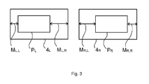
- Figure 3 shows the right display element 4 R and the left display element 4 L displaying respectively a right picture P R and a left picture P L .
- a first left margin M R,L is set between the left edge of the right display element 4 R and the left edge of the right picture P R .
- a first right margin M R,R is set between the right edge of the right display element 4 R and the right edge of the right picture P R .
- a second left margin M L,L is set between the left edge of the left display element 4 L and the left edge of the left picture P L .
- a second right margin M L,R is set between the right edge of the left display element 4 L and the right edge of the left picture P L .
- the right and left pictures are synthetized, for example when the wearer is playing a video game.
- the margins may then be set during the synthetizing.
- right and left picture are generated from right and left pictures or data to be displayed received from a source device, for example when the wearer is watching a movie.
- the margins may then be set by processing the received pictures.
- the size of the received pictures may have to be reduced to allow the positioning.
- the generated right and left stereoscopic pictures are transmitted to the right and left display elements 4 R , 4 L , as symbolized by arrows F P,R and F P,L .
- the right and left pictures are then displayed on the right and left display elements 4 R , 4 L .
- the method comprises:
- the pictures positioning method may be implemented by the pictures positioning system 3 disclosed above.
- At least one wearer 1 related parameter is provided.
- Step S1 comprises a measurement operation during which the at least one wearer related parameter is measured.
- the measurement may be performed by using right and left cameras 6 L and 6 R embedded in the binocular viewing device 2.
- Step S1 may be implemented periodically, for instance during right and left videos generation.
- right and left display positioning of right and left pictures on the right and left display elements 4 R , 4 L are determined based on the at least one wearer 1 related parameter.
- Step S2 is implemented automatically, for instance by determining margins to be set to adapt the display to the interpupillary distance (or half interpupillary distances) of the wearer.
- the distance between the center of the right picture and the center of the left picture may for example be determined to correspond to the interpupillary distance of the wearer.
- a shift may be provided depending on the half interpupillary distances.
- the generating step S3 right and left pictures are generated based on the received right and left display positioning.
- the generating step may comprise a synthetizing operation during which pictures are synthetized, or a processing operation during which received pictures are processed.
- the generating step S3 may instead comprises a setting on display elements to adjust their internal display margin, if they have this possibility.
- the setting may be performed by internal register programming, for example by I 2 C bus (Inter-Integrated Circuit) or any control register access by a processor unit.
- a mechanical adjustment may also be provided.
- the generated right and left stereoscopic pictures are transmitted to the right and left display elements 4 R , 4 L , and are displayed on the right and left display elements 4 R , 4 L .
Landscapes
- Engineering & Computer Science (AREA)
- Multimedia (AREA)
- Signal Processing (AREA)
- Eye Examination Apparatus (AREA)
- Testing, Inspecting, Measuring Of Stereoscopic Televisions And Televisions (AREA)
- Controls And Circuits For Display Device (AREA)
Abstract
A pictures positioning method for positioning pictures on display elements (4R, 4L) of a binocular displaying device (2),
the binocular displaying device comprising a right display element and a left display element, respectively designed to be placed in front of a corresponding eye of a wearer, and to display right and left pictures, the binocular displaying device comprising measurement means,
the method comprising:
- a providing step during which at least one wearer related parameter is provided, the providing step comprising a measurement operation during which the at least one wearer related parameter is measured, the measurement operation being performed by using the measurement means embedded in the binocular displaying device,
- a display positioning determination step during which:
- a right display positioning of the right picture on the right display element is determined,
- a left display positioning of the left picture on the left display element is determined,
the display positioning determination step being performed based on the at least one wearer related parameter.
Description
- The invention relates to pictures positioning system and method for positioning pictures on display elements of a binocular displaying device.
- The discussion of the background of the invention herein is included to explain the context of the invention. This is not to be taken as an admission that any of the material referred to was published, known or part of the common general knowledge at the priority date of any of the claims.
- A binocular displaying device comprises a right display element and a left display element, respectively designed to be placed in front of a corresponding eye of a wearer, and to display right and left pictures.
- Such a binocular displaying device is generally designed for an average wearer. As a result, it may present the drawback of not being optimized for the actual wearer. Consequently, it can quickly give rise to the wearer suffering dizziness and nausea.
- Setting means may be used to adapt a binocular displaying device to a particular wearer. However, such setting means are fastidious to use.
- One object of the invention is to provide pictures positioning system and method that do not present the drawbacks mentioned hereinabove.
- In particular, one object of the invention is to provide pictures positioning system and method enabling information content to be viewed while limiting visual fatigue and discomfort for the wearer of a binocular displaying device. Moreover, one object of the invention is to provide pictures positioning system and method making the setting easier.
- To this end, the invention proposes a pictures positioning method for positioning pictures on display elements of a binocular displaying device, the binocular displaying device comprising a right display element and a left display element, respectively designed to be placed in front of a corresponding eye of a wearer, and to display right and left pictures, the binocular displaying device comprising measurement means,
the method comprising: - a providing step during which at least one wearer related parameter is provided, the providing step comprising a measurement operation during which the at least one wearer related parameter is measured, the measurement operation being performed by using the measurement means embedded in the binocular displaying device,
- a display positioning determination step during which:
- a right display positioning of the right picture on the right display element is determined,
- a left display positioning of the left picture on the left display element is determined,
- Thus, right and left pictures are simply and automatically displayed depending on at least one wearer related parameter so that said wearer views the information content under conditions that are best adapted to the wearer's physiology. Consequently, the physiological fatigue is minimized.
- The at least one wearer related parameter may comprise the interpupillary distance of the wearer in far vision.
- The at least one wearer related parameter may further or instead comprise the distance between the center of the left pupil and the top of the wearer's nose in far vision, and the distance between the center of the right pupil and the top of the wearer's nose in far vision.
- When the right and left display elements are respectively designed to display right and left videos, each video comprising a set of pictures, the providing step may be repeated several times during right and left videos display.
- The pictures positioning method may comprise a pictures generation step during which right and left pictures to be displayed are generated based on the determined right and left display positioning.
- For instance, the right and left pictures may be generated by setting pictures margins based on the determined right and left display positioning.
- In some embodiments of the invention, the right and left pictures are generated from right and left pictures or data to be displayed received from a source device.
- The invention further proposes a computer program product comprising one or more stored sequences of instructions that are accessible to a processor and which, when executed by the processor, causes the processor to carry out steps of the method.
- The invention further proposes a computer readable medium carrying one or more sequences of instructions of the computer program product.
- The invention further proposes a pictures positioning system for positioning pictures on display elements of a binocular displaying device, the binocular displaying device comprising a right display element and a left display element, respectively designed to be placed in front of a corresponding eye of a wearer, and to display right and left pictures, the binocular displaying device comprising measurement means,
the system comprising: - providing means configured to provide at least one wearer related parameter, the providing means being configured to measure the at least one wearer related parameter, the measurement being performed by using the measurement means embedded in the binocular displaying device,
- display positioning determination means configured to:
- determine a right display positioning of the right picture on the right display element,
- determine a left display positioning of the left picture on the left display element,
- The invention further proposes a binocular displaying system comprising:
- a binocular displaying device comprising a right display element and a left display element, respectively designed to be placed in front of a corresponding eye of a wearer, and to display right and left pictures, the binocular displaying device comprising measurement means configured to measure at least one wearer related parameter,
- a remote pictures positioning system configured to:
- ○ receive the at least one wearer related parameter, and, based on the at least one wearer related parameter:
- ○ generate a right picture to be displayed on the right display element,
- ○ generate a left picture to be displayed on the left display element.
- ○ receive the at least one wearer related parameter, and, based on the at least one wearer related parameter:
- The picture positioning system may thus generate right and left pictures with right and left display positioning of the right and left pictures on the right and left display elements adapted to the wearer's physiology. The picture positioning system may further generate stereoscopic right and left pictures with perspective adapted to the wearer's physiology.
- Unless specifically stated otherwise, as apparent from the following discussions, it is appreciated that throughout the specification discussions utilizing terms such as "computing", "calculating", "generating", or the like, refer to the action and/or processes of a computer or computing system, or similar electronic computing device, that manipulate and/or transform data represented as physical, such as electronic, quantities within the computing system's registers and/or memories into other data similarly represented as physical quantities within the computing system's memories, registers or other such information storage, transmission or display devices.
- Embodiments of the present invention may include apparatuses for performing the operations herein. This apparatus may be specially constructed for the desired purposes, or it may comprise a general purpose computer or Digital Signal Processor ("DSP") selectively activated or reconfigured by a computer program stored in the computer. Such a computer program may be stored in a computer readable storage medium, such as, but is not limited to, any type of disk including floppy disks, optical disks, CD-ROMs, magnetic-optical disks, read-only memories (ROMs), random access memories (RAMs) electrically programmable read-only memories (EPROMs), electrically erasable and programmable read only memories (EEPROMs), magnetic or optical cards, or any other type of media suitable for storing electronic instructions, and capable of being coupled to a computer system bus.
- The processes and displays presented herein are not inherently related to any particular computer or other apparatus. Various general purpose systems may be used with programs in accordance with the teachings herein, or it may prove convenient to construct a more specialized apparatus to perform the desired method. The desired structure for a variety of these systems will appear from the description below. In addition, embodiments of the present invention are not described with reference to any particular programming language. It will be appreciated that a variety of programming languages may be used to implement the teachings of the inventions as described herein.
- Non limiting embodiments of the invention will now be described with reference to the accompanying drawing wherein:
- ○
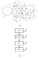
Figure 1 is a schematic block diagram representing a wearer, a binocular displaying device, and a pictures positioning system according to some embodiments of the invention, - ○
Figure 2 is a flow chart showing steps of a pictures positioning method according to some embodiments of the invention, and - ○
Figure 3 is a schematic diagram representing right and left pictures displayed on right and left display elements of the binocular displaying device. - Elements in the figures are illustrated for simplicity and clarity and have not necessarily been drawn to scale. For example, the dimensions of some of the elements in the figure may be exaggerated relative to other elements to help improve the understanding of the embodiments of the present invention.
-
Figure 1 represents awearer 1, abinocular displaying device 2, and apictures positioning system 3 according to some embodiments of the invention. - The
binocular displaying device 2 comprises aright display element 4R and aleft display element 4L, respectively designed to be placed in front of a corresponding eye of thewearer 1, and to display right and left pictures. For instance, the right and left pictures are right and left stereoscopic pictures. Alternatively, the right and left pictures may be two identical pictures. - The right and
left display elements display elements - The
pictures positioning system 3 may be embedded in the binocular displayingdevice 2, or may be a remote device configured to communicate with the binocular displayingdevice 2. - The
pictures positioning system 3 comprises display positioning determination means 7 configured to determine a right display positioning of a right picture on theright display element 4R, and to determine a left display positioning of a left picture on theleft display element 4L. The determination is made based on at least onewearer 1 related parameter. - According to some embodiments of the invention, the display positioning determination means 7 are automatic means.
- In these embodiments, the
system 3 further comprises providingmeans 5 configured to provide the at least onewearer 1 related parameter. - The at least one wearer related parameter may comprise the interpupillary distance of the
wearer 1 in far vision. The interpupillary distance is defined in the standard ISO 13666:1998. - The at least one wearer related parameter may further or instead comprise two half interpupillary distances respectively defined by the distance between the center of the left pupil and the top of the wearer's nose in far vision, and the distance between the center of the right pupil and the top of the wearer's nose in far vision.
- According to some embodiments of the invention, the providing
means 5 are configured to obtain the at least one wearer related parameter from a measurement. - The measurement may be performed by using measurement means, for example right and left cameras 6L and 6R, embedded in the binocular displaying
device 2, as symbolized by arrows FM,L and FM,R. - The measurement may be performed periodically, for instance during right and left videos generation.
- The display positioning determination means 7 are configured to receive the at least one wearer related parameter, as symbolized by arrow FUP.
- The display positioning determination means 7 then determine right and left display positioning of right and left pictures on the right and left
display elements wearer 1 related parameter. For instance, the right and left display positioning may be determined by determining pictures margins to be set. - The
system 1 further comprises generating means 8 configured to receive the right and left display positioning, as symbolized by arrow FPOS, and to generate right and left pictures based on the received right and left display positioning. - For instance, pictures margins are set based on the determined right and left display positioning.
Figure 3 shows theright display element 4R and theleft display element 4L displaying respectively a right picture PR and a left picture PL. - A first left margin MR,L is set between the left edge of the
right display element 4R and the left edge of the right picture PR. A first right margin MR,R is set between the right edge of theright display element 4R and the right edge of the right picture PR. A second left margin ML,L is set between the left edge of theleft display element 4L and the left edge of the left picture PL. A second right margin ML,R is set between the right edge of theleft display element 4L and the right edge of the left picture PL. - According to some embodiments of the invention, the right and left pictures are synthetized, for example when the wearer is playing a video game. The margins may then be set during the synthetizing.
- According to other embodiments of the invention, right and left picture are generated from right and left pictures or data to be displayed received from a source device, for example when the wearer is watching a movie. The margins may then be set by processing the received pictures. In some cases, the size of the received pictures may have to be reduced to allow the positioning.
- Then, the generated right and left stereoscopic pictures are transmitted to the right and left
display elements display elements - Referring to
figure 2 , we are describing below a pictures positioning method according to an example embodiment of the invention. The method comprises: - 1) a providing step S1,
- 2) a display positioning determination step S2,
- 3) a generating step S3, and
- 4) a displaying step S4.
- The pictures positioning method may be implemented by the
pictures positioning system 3 disclosed above. - During the providing step S1 at least one
wearer 1 related parameter is provided. - Step S1 comprises a measurement operation during which the at least one wearer related parameter is measured.
- As disclosed above, the measurement may be performed by using right and left cameras 6L and 6R embedded in the
binocular viewing device 2. - Step S1 may be implemented periodically, for instance during right and left videos generation.
- During the display positioning determination step S2 right and left display positioning of right and left pictures on the right and left
display elements wearer 1 related parameter. - Step S2 is implemented automatically, for instance by determining margins to be set to adapt the display to the interpupillary distance (or half interpupillary distances) of the wearer. The distance between the center of the right picture and the center of the left picture may for example be determined to correspond to the interpupillary distance of the wearer. Moreover, a shift may be provided depending on the half interpupillary distances.
- During the generating step S3 right and left pictures are generated based on the received right and left display positioning. As disclosed above, the generating step may comprise a synthetizing operation during which pictures are synthetized, or a processing operation during which received pictures are processed.
- The generating step S3 may instead comprises a setting on display elements to adjust their internal display margin, if they have this possibility. For instance, the setting may be performed by internal register programming, for example by I2C bus (Inter-Integrated Circuit) or any control register access by a processor unit. A mechanical adjustment may also be provided.
- During the displaying step S4, the generated right and left stereoscopic pictures are transmitted to the right and left
display elements display elements - The invention has been described above with the aid of embodiments without limitation of the general inventive concept.
Claims (11)
- A pictures positioning method for positioning pictures (PR, PL) on display elements (4R, 4L) of a binocular displaying device (2),
the binocular displaying device comprising a right display element and a left display element, respectively designed to be placed in front of a corresponding eye of a wearer, and to display right and left pictures, the binocular displaying device comprising measurement means,
the method comprising:- a providing step during which at least one wearer related parameter is provided, the providing step comprising a measurement operation during which the at least one wearer related parameter is measured, the measurement operation being performed by using the measurement means embedded in the binocular displaying device,- a display positioning determination step during which:the display positioning determination step being performed based on the at least one wearer related parameter.○ a right display positioning of the right picture on the right display element is determined,○ a left display positioning of the left picture on the left display element is determined, - The pictures positioning method according to claim 1, wherein the at least one wearer related parameter comprises the interpupillary distance of the wearer in far vision.
- The pictures positioning method according to claim 1 or 2, wherein the at least one wearer related parameter comprises the distance between the center of the left pupil and the top of the wearer's nose in far vision, and the distance between the center of the right pupil and the top of the wearer's nose in far vision.
- The pictures positioning method according to one of claims 1 to 3, wherein the right and left display elements are respectively designed to display right and left videos, each video comprising a set of pictures, the providing step being repeated several times during right and left videos display.
- The pictures positioning method according to one of claims 1 to 4, comprising a pictures generation step during which right and left pictures to be displayed are generated based on the determined right and left display positioning.
- The pictures positioning method according to claim 5, wherein the right and left pictures are generated by setting pictures margins based on the determined right and left display positioning.
- The pictures positioning method according to one of claims 5 or 6, wherein the right and left pictures are generated from right and left pictures or data to be displayed received from a source device.
- A computer program product comprising one or more stored sequences of instructions that are accessible to a processor and which, when executed by the processor, causes the processor to carry out the steps of any of claims 1 to 7.
- A computer readable medium carrying one or more sequences of instructions of the computer program product of claim 8.
- A pictures positioning system (3) for positioning pictures (PR, PL) on display elements (4R, 4L) of a binocular displaying device (2), the binocular displaying device comprising a right display element and a left display element, respectively designed to be placed in front of a corresponding eye of a wearer, and to display right and left pictures, the binocular displaying device comprising measurement means, the system comprising:- providing means configured to provide at least one wearer related parameter, the providing means being configured to measure the at least one wearer related parameter, the measurement being performed by using the measurement means embedded in the binocular displaying device,- display positioning determination means configured to:the display positioning determination being performed based on the at least one wearer related parameter.○ determine a right display positioning of the right picture on the right display element,○ determine a left display positioning of the left picture on the left display element,
- A binocular displaying system comprising:- a binocular displaying device (2) comprising a right display element and a left display element, respectively designed to be placed in front of a corresponding eye of a wearer, and to display right and left pictures, the binocular displaying device comprising measurement means configured to measure at least one wearer related parameter,- a remote pictures positioning system (3) configured to:○ receive the at least one wearer related parameter, and, based on the at least one wearer related parameter:○ generate a right picture to be displayed on the right display element,○ generate a left picture to be displayed on the left display element.
Priority Applications (5)
| Application Number | Priority Date | Filing Date | Title |
|---|---|---|---|
| EP12306006.3A EP2699006A1 (en) | 2012-08-16 | 2012-08-16 | Pictures positioning on display elements |
| PCT/EP2013/066855 WO2014026957A1 (en) | 2012-08-16 | 2013-08-13 | Pictures positioning on display elements |
| US14/421,959 US9661297B2 (en) | 2012-08-16 | 2013-08-13 | Pictures positioning on display elements |
| CN201380043638.7A CN104584548B (en) | 2012-08-16 | 2013-08-13 | Picture positioning on display element |
| EP13759454.5A EP2885912B1 (en) | 2012-08-16 | 2013-08-13 | Pictures positioning on display elements |
Applications Claiming Priority (1)
| Application Number | Priority Date | Filing Date | Title |
|---|---|---|---|
| EP12306006.3A EP2699006A1 (en) | 2012-08-16 | 2012-08-16 | Pictures positioning on display elements |
Publications (1)
| Publication Number | Publication Date |
|---|---|
| EP2699006A1 true EP2699006A1 (en) | 2014-02-19 |
Family
ID=46875708
Family Applications (2)
| Application Number | Title | Priority Date | Filing Date |
|---|---|---|---|
| EP12306006.3A Withdrawn EP2699006A1 (en) | 2012-08-16 | 2012-08-16 | Pictures positioning on display elements |
| EP13759454.5A Active EP2885912B1 (en) | 2012-08-16 | 2013-08-13 | Pictures positioning on display elements |
Family Applications After (1)
| Application Number | Title | Priority Date | Filing Date |
|---|---|---|---|
| EP13759454.5A Active EP2885912B1 (en) | 2012-08-16 | 2013-08-13 | Pictures positioning on display elements |
Country Status (4)
| Country | Link |
|---|---|
| US (1) | US9661297B2 (en) |
| EP (2) | EP2699006A1 (en) |
| CN (1) | CN104584548B (en) |
| WO (1) | WO2014026957A1 (en) |
Families Citing this family (2)
| Publication number | Priority date | Publication date | Assignee | Title |
|---|---|---|---|---|
| US10488920B2 (en) * | 2017-06-02 | 2019-11-26 | Htc Corporation | Immersive headset system and control method thereof |
| CN107396097B (en) * | 2017-09-01 | 2019-05-10 | 京东方科技集团股份有限公司 | A kind of method and apparatus of the parallax test of virtual reality device |
Citations (5)
| Publication number | Priority date | Publication date | Assignee | Title |
|---|---|---|---|---|
| JPH07129095A (en) * | 1993-11-02 | 1995-05-19 | Shin Sangyo Souzou Center:Kk | Three dimensional image information terminal device |
| JPH085955A (en) * | 1994-06-17 | 1996-01-12 | Sanyo Electric Co Ltd | Device and method for displaying virtual image type stereoscopic picture |
| US6449309B1 (en) * | 1996-03-12 | 2002-09-10 | Olympus Optical Co., Ltd. | Stereoscopic display that controls binocular parallax between two images and controls image reconstitution according to parallax data |
| KR20090076539A (en) * | 2008-01-09 | 2009-07-13 | 에스케이 텔레콤주식회사 | Apparatus for displaying three-dimensional image and method for controlling location of display in the apparatus |
| JP2010124191A (en) * | 2008-11-19 | 2010-06-03 | Canon Inc | Video image display device |
Family Cites Families (33)
| Publication number | Priority date | Publication date | Assignee | Title |
|---|---|---|---|---|
| US3053135A (en) * | 1960-05-09 | 1962-09-11 | Tanaka Nawokich | Refractor for presenting pictures in three dimensional effect |
| US3543666A (en) * | 1968-05-06 | 1970-12-01 | Sidney Kazel | Automatic ranging and focusing system |
| US5625408A (en) * | 1993-06-24 | 1997-04-29 | Canon Kabushiki Kaisha | Three-dimensional image recording/reconstructing method and apparatus therefor |
| EP0679919B1 (en) * | 1994-04-21 | 2000-07-12 | Sega Enterprises, Ltd. | Head mounted display |
| JPH08146341A (en) * | 1994-11-25 | 1996-06-07 | Olympus Optical Co Ltd | Image display device |
| JP3672951B2 (en) * | 1994-12-13 | 2005-07-20 | オリンパス株式会社 | Image display device |
| JPH1070742A (en) * | 1996-08-29 | 1998-03-10 | Olympus Optical Co Ltd | Twin-lens video display device |
| JP3651204B2 (en) * | 1996-12-18 | 2005-05-25 | トヨタ自動車株式会社 | Stereoscopic image display device, stereoscopic image display method, and recording medium |
| JPH10246865A (en) * | 1997-03-04 | 1998-09-14 | Olympus Optical Co Ltd | Visual display device |
| KR100406945B1 (en) * | 2001-02-19 | 2003-11-28 | 삼성전자주식회사 | Wearable display apparatus |
| US7224382B2 (en) * | 2002-04-12 | 2007-05-29 | Image Masters, Inc. | Immersive imaging system |
| US8094927B2 (en) * | 2004-02-27 | 2012-01-10 | Eastman Kodak Company | Stereoscopic display system with flexible rendering of disparity map according to the stereoscopic fusing capability of the observer |
| RU2322771C2 (en) * | 2005-04-25 | 2008-04-20 | Святослав Иванович АРСЕНИЧ | Stereo-projection system |
| US7515344B2 (en) * | 2006-01-04 | 2009-04-07 | Vuzlx Corporation | Binocular display with improved contrast uniformity |
| FR2906899B1 (en) | 2006-10-05 | 2009-01-16 | Essilor Int | DISPLAY DEVICE FOR STEREOSCOPIC VISUALIZATION. |
| DE102007055026B4 (en) * | 2007-11-15 | 2011-04-28 | Fraunhofer-Gesellschaft zur Förderung der angewandten Forschung e.V. | Method and device for autostereoscopic display of image information |
| WO2009109750A1 (en) * | 2008-03-04 | 2009-09-11 | Procyon Instruments Limited | Binocular pupillometers |
| WO2009116663A1 (en) * | 2008-03-21 | 2009-09-24 | Takahashi Atsushi | Three-dimensional digital magnifier operation supporting system |
| WO2010034727A1 (en) * | 2008-09-24 | 2010-04-01 | Essilor International (Compagnie Generale D'optique) | Method for determining the inset of a progressive addition lens |
| US8317325B2 (en) * | 2008-10-31 | 2012-11-27 | Cross Match Technologies, Inc. | Apparatus and method for two eye imaging for iris identification |
| US8970690B2 (en) * | 2009-02-13 | 2015-03-03 | Metaio Gmbh | Methods and systems for determining the pose of a camera with respect to at least one object of a real environment |
| RU2541128C2 (en) * | 2009-07-10 | 2015-02-10 | Панасоник Корпорэйшн | Recording medium, playback device and integrated circuit |
| IL200627A (en) * | 2009-08-27 | 2014-05-28 | Erez Berkovich | Method for varying dynamically a visible indication on display |
| US8619163B2 (en) * | 2009-09-18 | 2013-12-31 | Canon Kabushiki Kaisha | Solid state imaging using a correction parameter for correcting a cross talk between adjacent pixels |
| EP2509065B1 (en) * | 2009-12-04 | 2016-11-23 | NLT Technologies, Ltd. | Stereoscopic display device, method for generating image data for stereoscopic display, and program therefor |
| US8665177B2 (en) * | 2010-02-05 | 2014-03-04 | Kopin Corporation | Touch sensor for controlling eyewear |
| US20110304695A1 (en) * | 2010-06-10 | 2011-12-15 | Lg Electronics Inc. | Mobile terminal and controlling method thereof |
| US9025252B2 (en) | 2011-08-30 | 2015-05-05 | Microsoft Technology Licensing, Llc | Adjustment of a mixed reality display for inter-pupillary distance alignment |
| US9560960B2 (en) * | 2011-10-19 | 2017-02-07 | Albert John Hofeldt | Amblyometer for balancing bridging rivalrous binocular vision |
| US9147111B2 (en) * | 2012-02-10 | 2015-09-29 | Microsoft Technology Licensing, Llc | Display with blocking image generation |
| JP5167439B1 (en) * | 2012-02-15 | 2013-03-21 | パナソニック株式会社 | Stereoscopic image display apparatus and stereoscopic image display method |
| ES2836790T3 (en) * | 2012-03-01 | 2021-06-28 | Shamir Optical Ind Ltd | Method and system for improving an ophthalmic prescription |
| US9050035B2 (en) * | 2012-03-22 | 2015-06-09 | The Curators Of The University Of Missouri | Device to measure pupillary light reflex in infants and toddlers |
-
2012
- 2012-08-16 EP EP12306006.3A patent/EP2699006A1/en not_active Withdrawn
-
2013
- 2013-08-13 US US14/421,959 patent/US9661297B2/en active Active
- 2013-08-13 EP EP13759454.5A patent/EP2885912B1/en active Active
- 2013-08-13 WO PCT/EP2013/066855 patent/WO2014026957A1/en active Application Filing
- 2013-08-13 CN CN201380043638.7A patent/CN104584548B/en active Active
Patent Citations (5)
| Publication number | Priority date | Publication date | Assignee | Title |
|---|---|---|---|---|
| JPH07129095A (en) * | 1993-11-02 | 1995-05-19 | Shin Sangyo Souzou Center:Kk | Three dimensional image information terminal device |
| JPH085955A (en) * | 1994-06-17 | 1996-01-12 | Sanyo Electric Co Ltd | Device and method for displaying virtual image type stereoscopic picture |
| US6449309B1 (en) * | 1996-03-12 | 2002-09-10 | Olympus Optical Co., Ltd. | Stereoscopic display that controls binocular parallax between two images and controls image reconstitution according to parallax data |
| KR20090076539A (en) * | 2008-01-09 | 2009-07-13 | 에스케이 텔레콤주식회사 | Apparatus for displaying three-dimensional image and method for controlling location of display in the apparatus |
| JP2010124191A (en) * | 2008-11-19 | 2010-06-03 | Canon Inc | Video image display device |
Also Published As
| Publication number | Publication date |
|---|---|
| CN104584548A (en) | 2015-04-29 |
| WO2014026957A1 (en) | 2014-02-20 |
| CN104584548B (en) | 2017-10-03 |
| US20150222870A1 (en) | 2015-08-06 |
| EP2885912A1 (en) | 2015-06-24 |
| US9661297B2 (en) | 2017-05-23 |
| EP2885912B1 (en) | 2018-01-10 |
Similar Documents
| Publication | Publication Date | Title |
|---|---|---|
| CN106461951B (en) | Method and display device using pixel redistribution optimization | |
| US9734554B2 (en) | Compensation for viewing with common vision abnormalities | |
| CN103533340B (en) | The bore hole 3D player method of mobile terminal and mobile terminal | |
| US9307228B2 (en) | Depth of field maintaining apparatus, 3D display system and display method | |
| EP2608109B1 (en) | Method and device for estimating the optical power of corrective lenses in a pair of eyeglasses worn by a spectator | |
| WO2014209820A1 (en) | Adjusting a near-eye display device | |
| KR20150104458A (en) | Method for Displaying 3-Demension Image and Display Apparatus Thereof | |
| US20110187834A1 (en) | Recording device and recording method, image processing device and image processing method, and program | |
| CN107924229B (en) | Image processing method and device in virtual reality equipment | |
| Guan et al. | Stereoscopic depth constancy | |
| CN110278432B (en) | Naked eye 3D display screen 3D parameter manual calibration method and electronic equipment | |
| EP2885912B1 (en) | Pictures positioning on display elements | |
| WO2016132688A1 (en) | Information processing apparatus, information processing method, and storage medium | |
| US11140376B2 (en) | Method for calibrating a binocular displaying device | |
| US20120007819A1 (en) | Automatic Convergence Based on Touchscreen Input for Stereoscopic Imaging | |
| US8983125B2 (en) | Three-dimensional image processing device and three dimensional image processing method | |
| EP2629537A2 (en) | Display apparatus and method for adjusting three-dimensional effects | |
| EP2873242B1 (en) | Stereoscopic pictures generation | |
| US20130300730A1 (en) | Lcd system and method for displaying image therein | |
| CN102892023A (en) | Display apparatus with 3D structure and control method thereof | |
| CN115348437B (en) | Video processing method, device, equipment and storage medium | |
| US20180124373A1 (en) | Method for providing continuous motion parallax effect using an auto-stereoscopic display, corresponding device, computer program product and computer-readable carrier medium | |
| CN113873234A (en) | Automatic calibration method for 3D parameters of naked eye 3D display screen and related equipment | |
| CN113940622A (en) | Visual fusion intersection angle measuring method, device and storage medium | |
| JP2010258886A (en) | Image pickup device, program and image pickup method |
Legal Events
| Date | Code | Title | Description |
|---|---|---|---|
| AK | Designated contracting states |
Kind code of ref document: A1 Designated state(s): AL AT BE BG CH CY CZ DE DK EE ES FI FR GB GR HR HU IE IS IT LI LT LU LV MC MK MT NL NO PL PT RO RS SE SI SK SM TR |
|
| AX | Request for extension of the european patent |
Extension state: BA ME |
|
| PUAI | Public reference made under article 153(3) epc to a published international application that has entered the european phase |
Free format text: ORIGINAL CODE: 0009012 |
|
| STAA | Information on the status of an ep patent application or granted ep patent |
Free format text: STATUS: THE APPLICATION IS DEEMED TO BE WITHDRAWN |
|
| 18D | Application deemed to be withdrawn |
Effective date: 20140820 |