KR20120101427A - Method and apparatus for treating substrates - Google Patents
Method and apparatus for treating substrates Download PDFInfo
- Publication number
- KR20120101427A KR20120101427A KR1020127014173A KR20127014173A KR20120101427A KR 20120101427 A KR20120101427 A KR 20120101427A KR 1020127014173 A KR1020127014173 A KR 1020127014173A KR 20127014173 A KR20127014173 A KR 20127014173A KR 20120101427 A KR20120101427 A KR 20120101427A
- Authority
- KR
- South Korea
- Prior art keywords
- radiation
- substrate
- liquid
- radicals
- radiation source
- Prior art date
Links
Images


Classifications
-
- B—PERFORMING OPERATIONS; TRANSPORTING
- B08—CLEANING
- B08B—CLEANING IN GENERAL; PREVENTION OF FOULING IN GENERAL
- B08B7/00—Cleaning by methods not provided for in a single other subclass or a single group in this subclass
-
- B—PERFORMING OPERATIONS; TRANSPORTING
- B08—CLEANING
- B08B—CLEANING IN GENERAL; PREVENTION OF FOULING IN GENERAL
- B08B3/00—Cleaning by methods involving the use or presence of liquid or steam
- B08B3/04—Cleaning involving contact with liquid
- B08B3/10—Cleaning involving contact with liquid with additional treatment of the liquid or of the object being cleaned, e.g. by heat, by electricity or by vibration
-
- B—PERFORMING OPERATIONS; TRANSPORTING
- B08—CLEANING
- B08B—CLEANING IN GENERAL; PREVENTION OF FOULING IN GENERAL
- B08B6/00—Cleaning by electrostatic means
-
- B—PERFORMING OPERATIONS; TRANSPORTING
- B08—CLEANING
- B08B—CLEANING IN GENERAL; PREVENTION OF FOULING IN GENERAL
- B08B7/00—Cleaning by methods not provided for in a single other subclass or a single group in this subclass
- B08B7/0035—Cleaning by methods not provided for in a single other subclass or a single group in this subclass by radiant energy, e.g. UV, laser, light beam or the like
- B08B7/0057—Cleaning by methods not provided for in a single other subclass or a single group in this subclass by radiant energy, e.g. UV, laser, light beam or the like by ultraviolet radiation
-
- G—PHYSICS
- G03—PHOTOGRAPHY; CINEMATOGRAPHY; ANALOGOUS TECHNIQUES USING WAVES OTHER THAN OPTICAL WAVES; ELECTROGRAPHY; HOLOGRAPHY
- G03F—PHOTOMECHANICAL PRODUCTION OF TEXTURED OR PATTERNED SURFACES, e.g. FOR PRINTING, FOR PROCESSING OF SEMICONDUCTOR DEVICES; MATERIALS THEREFOR; ORIGINALS THEREFOR; APPARATUS SPECIALLY ADAPTED THEREFOR
- G03F1/00—Originals for photomechanical production of textured or patterned surfaces, e.g., masks, photo-masks, reticles; Mask blanks or pellicles therefor; Containers specially adapted therefor; Preparation thereof
- G03F1/68—Preparation processes not covered by groups G03F1/20 - G03F1/50
- G03F1/82—Auxiliary processes, e.g. cleaning or inspecting
-
- H—ELECTRICITY
- H01—ELECTRIC ELEMENTS
- H01L—SEMICONDUCTOR DEVICES NOT COVERED BY CLASS H10
- H01L21/00—Processes or apparatus adapted for the manufacture or treatment of semiconductor or solid state devices or of parts thereof
- H01L21/67—Apparatus specially adapted for handling semiconductor or electric solid state devices during manufacture or treatment thereof; Apparatus specially adapted for handling wafers during manufacture or treatment of semiconductor or electric solid state devices or components ; Apparatus not specifically provided for elsewhere
- H01L21/67005—Apparatus not specifically provided for elsewhere
- H01L21/67011—Apparatus for manufacture or treatment
- H01L21/67017—Apparatus for fluid treatment
- H01L21/67028—Apparatus for fluid treatment for cleaning followed by drying, rinsing, stripping, blasting or the like
- H01L21/6704—Apparatus for fluid treatment for cleaning followed by drying, rinsing, stripping, blasting or the like for wet cleaning or washing
- H01L21/67051—Apparatus for fluid treatment for cleaning followed by drying, rinsing, stripping, blasting or the like for wet cleaning or washing using mainly spraying means, e.g. nozzles
Landscapes
- Physics & Mathematics (AREA)
- General Physics & Mathematics (AREA)
- Optics & Photonics (AREA)
- Engineering & Computer Science (AREA)
- Computer Hardware Design (AREA)
- Manufacturing & Machinery (AREA)
- Condensed Matter Physics & Semiconductors (AREA)
- Microelectronics & Electronic Packaging (AREA)
- Power Engineering (AREA)
- Cleaning Or Drying Semiconductors (AREA)
- Physical Or Chemical Processes And Apparatus (AREA)
- Exposure Of Semiconductors, Excluding Electron Or Ion Beam Exposure (AREA)
- Physical Water Treatments (AREA)
- Cleaning By Liquid Or Steam (AREA)
Abstract
본 출원은 기판의 적어도 부분 영역의 처리를 위한 다수의 방법 및 장치를 설명한다. 상기 방법들에서, 각각의 방법에 따라 원하는 효과를 달성하기 위해, 적어도 하나의 액체가 기판의 적어도 하나의 부분 영역에 도포되고, 전자기 방사선이 이 액체 내에 도입된다. 일 방법에서, 액체의 도포에 앞서 UV 방사선에 의해 액체 내에 래디칼이 생성되고, 래디칼의 생성은 기판에 액체를 도포하기 직전에 발생하여, 래디칼의 적어도 일부가 기판에 도달하게 된다. 이온이 기판의 표면의 적어도 부분 영역 및 상기 기판의 인접 표면층으로부터 제거되는 일 방법에서, 상기 기판의 적어도 부분 영역 상에 액체 필름을 형성하기 위해 주위 온도를 초과하여 가열된 액체가 기판에 도포되고, 전자기 방사선은 방사선의 적어도 일부가 기판 표면에 도달하도록 상기 액체 필름 내에 도입된다. 소수성 표면의 적어도 일부가 친수성 표면 특성을 얻도록 적어도 부분적으로 소수성 기판 표면을 갖는 기판의 표면 특성을 변화시키는 방법에서, 그 표면 특성이 변화될 기판의 표면의 적어도 부분 영역에 액체가 도포되고, 그 표면 특성이 변화될 상기 기판의 표면의 적어도 부분 영역 상에 상기 액체를 통해 사전 결정된 파장의 범위의 UV 방사선이 안내된다. 방법은 연속하여 및/또는 병행하여 임의의 원하는 순서로 공통 장치 내에서 수행될 수 있다.The present application describes a number of methods and apparatus for the treatment of at least partial regions of a substrate. In the above methods, in order to achieve the desired effect according to each method, at least one liquid is applied to at least one partial region of the substrate, and electromagnetic radiation is introduced into this liquid. In one method, radicals are generated in the liquid by UV radiation prior to application of the liquid, and the generation of radicals occurs immediately prior to applying the liquid to the substrate, such that at least a portion of the radicals reach the substrate. In one method wherein ions are removed from at least a partial region of the surface of the substrate and an adjacent surface layer of the substrate, a liquid heated above ambient temperature is applied to the substrate to form a liquid film on the at least partial region of the substrate, Electromagnetic radiation is introduced into the liquid film such that at least some of the radiation reaches the substrate surface. In a method of varying the surface properties of a substrate having at least partially hydrophobic substrate surface such that at least a portion of the hydrophobic surface obtains hydrophilic surface properties, a liquid is applied to at least a portion of the surface of the substrate whose surface properties are to be changed, UV radiation of a predetermined range of wavelengths is directed through the liquid onto at least a partial region of the surface of the substrate whose surface properties are to be changed. The method may be performed in a common apparatus in any desired order in succession and / or in parallel.
Description
본 발명은 액체가 기판의 적어도 부분 영역에 공급되고 방사선이 액체 내에 도입되는, 기판을 처리하기 위한 방법 및 장치에 관한 것이다.
The present invention relates to a method and apparatus for processing a substrate, wherein liquid is supplied to at least a partial region of the substrate and radiation is introduced into the liquid.
반도체의 분야에서, 예를 들어 포토마스크가 이들의 제조 중에 그리고 현장에서 사용 중의 모두에, 상이한 처리 단계, 특히 세척 단계로 노출되어야 하는 것이 공지되어 있다. 특히 습식 세척 프로세스에 마스크를 노출시키는 것이 공지되어 있다. 이러한 습식 세척 프로세스에서, 그에 인가된 프로세스 매체에 의해 세척될 표면의 더 양호한 습윤을 가능하게 하기 위해, 세척될 표면이 친수성 표면 특징을 가지면 유리하다. 그러나, 상이한 현상에 기인하여, 포토마스크의 표면은 종종 그 세척에 앞서 소수성인데, 이는 한편으로는 흡수된 물 분자의 배향에 의해, 다른 한편으로는 얇은 유기층에 의해 발생될 수 있다.In the field of semiconductors, it is known, for example, that photomasks must be exposed to different processing steps, in particular cleaning steps, both during their manufacture and in use in the field. In particular, it is known to expose the mask to a wet cleaning process. In this wet cleaning process, it is advantageous if the surface to be cleaned has hydrophilic surface characteristics in order to enable better wetting of the surface to be cleaned by the process medium applied thereto. However, due to different phenomena, the surface of the photomask is often hydrophobic prior to its cleaning, which can be generated on the one hand by the orientation of the absorbed water molecules and on the other by the thin organic layer.
따라서, 마스크가 질소 또는 산소 분위기와 같은 가스 분위기 내에 있는 동안, 그 습식 에칭에 앞서 마스크를 UV 방사선으로 조사하는 것이 당 기술 분야에 공지되어 있다. 이 프로세스에서, 종종 약 172 nm의 파장을 갖는 UV 방사선이 사용된다.Thus, while the mask is in a gaseous atmosphere, such as a nitrogen or oxygen atmosphere, it is known in the art to irradiate the mask with UV radiation prior to its wet etching. In this process, UV radiation is often used with a wavelength of about 172 nm.
가스 분위기 내의 이러한 UV 방사선은 산소 원자에 의한 표면에서의 탄화수소의 산화, 산소 원자에 의한 기판의 표면에서의 금속의 산화, 광자에 의한 친수성 분자 습윤층의 제거 및 UV 에너지에 의한 흡착된 이온의 활성화와 같은 다수의 상이한 프로세스를 개시할 수 있다. 특히, 소수성 표면 영역은 친수성 표면 영역으로 변화될 수도 있다. 그러나, UV 방사선의 광자는 종종 높은 에너지에 의해 방해받지 않고 기판의 표면과 충돌한다. 이러한 것은 기판 내에, 특히 기판 상의 미세 구조체 내에 응력 및/또는 이완(relaxation) 프로세스를 유도할 수 있다.These UV radiations in the gas atmosphere are characterized by oxidation of hydrocarbons on the surface by oxygen atoms, oxidation of metals on the surface of substrates by oxygen atoms, removal of hydrophilic molecular wet layers by photons and activation of adsorbed ions by UV energy. Many different processes, such as In particular, the hydrophobic surface region may be changed to a hydrophilic surface region. However, photons of UV radiation often collide with the surface of the substrate without being interrupted by high energy. This can lead to stress and / or relaxation processes in the substrate, in particular in the microstructures on the substrate.
이러한 것은 따라서 구조체의 변위를 유도할 수도 있는데, 이는 기판의 사용성에 부정적인 영향을 미칠 수 있다.This may thus induce displacement of the structure, which may negatively affect the usability of the substrate.
액체 필름이 기판 상에 적어도 국부적으로 형성되고 UV 방사선이 액체 필름 내에 도입되는, 표면의 이러한 준비 후의 습윤 처리를 제공하는 것이 또한 공지되어 있다. 이 프로세스에서, 액체 및 UV 방사선은 그 내부에 래디칼을 생성하기 위해 UV 방사선의 대부분이 액체 필름 내에 흡수되도록 매칭된다. 특히, 예를 들어 희석된 과산화수소수 또는 오존수(O3-H2O) 내에 수산기 래디칼을 생성하는 것이 공지되어 있다. 이러한 수산기 래디칼은 이들이 존재하는 경우에 기판 표면 상의 금속을 손상시키지 않고 기판 표면으로부터 유기 재료의 선택적 용해를 야기한다.It is also known to provide a wetting treatment after this preparation of the surface in which a liquid film is formed at least locally on the substrate and UV radiation is introduced into the liquid film. In this process, liquid and UV radiation are matched such that most of the UV radiation is absorbed in the liquid film to produce radicals therein. In particular, it is known to produce hydroxyl radicals, for example in diluted hydrogen peroxide water or ozone water (O 3 -H 2 O). Such hydroxyl radicals, when present, cause selective dissolution of organic materials from the substrate surface without damaging the metal on the substrate surface.
이러한 방법은 예를 들어 US 2006/0207629 A1호에 개시되어 있다. 특히, 예를 들어 오존수, 과산화수소수, 암모니아수, 과산화수소 용액, 황산, 유기산 및 이들의 혼합물로 제조된 얇은 액체 필름이 도포된다. 다음에, UV 방사선이 래디칼을 생성하기 위해 UV 방사선에 투과되고 액체 필름과 접촉하는 윈도우를 경유하여 액체 필름 내에 도입된다. 또한,, UV 방사선 소스 및 액체 필름은 다수의 래디칼이 생성되도록 매칭되어, UV 방사선의 높은 흡수율, 가능한 경우 완전한 흡수가 액체 필름 내에 발생하게 된다.Such a method is disclosed, for example, in US 2006/0207629 A1. In particular, thin liquid films made of, for example, ozone water, hydrogen peroxide water, ammonia water, hydrogen peroxide solution, sulfuric acid, organic acids and mixtures thereof are applied. Next, UV radiation is introduced into the liquid film via a window that is transmitted to the UV radiation and in contact with the liquid film to produce radicals. In addition, the UV radiation source and the liquid film are matched to produce a large number of radicals such that a high absorption rate, possibly complete absorption, of the UV radiation occurs in the liquid film.
전술된 오염물, 특히 유기 오염물의 제거 후에, 기판 표면으로부터 잔류 이온을 또한 제거하는 것이 유용할 수 있다. 이 목적을 위한 공지의 방법은 표면을 헹굼하기 위해 일반적으로 가열된 액체, 특히 탈이온화수(DI 수)를 사용한다. 여기서, 잔류 이온의 완전한 제거를 위해, 액체의 더 긴 도포 시간 또는 액체의 높은 온도가 요구되는 문제점이 발생할 수 있다. 높은 온도는 액체를 위한 가열 프로세스가 그 내부에 오염을 유도할 수 있는 점에서 문제가 될 수도 있다. 이는 온도가 각각의 액체의 비등점에 근접하여 상승될 때 특히 사실이다. 온도 감응 기판 또는 기판층의 처리시에, 이온의 용해도는 원하는 값 미만인 것도 추가로 가능하다. 감소된 온도를 보상하기 위해 도포 시간을 연장하는 것은 효율 고려사항의 관점에서 바람직하지 않다.
After removal of the above-mentioned contaminants, in particular organic contaminants, it may be useful to also remove residual ions from the substrate surface. Known methods for this purpose generally use heated liquid, in particular deionized water (DI water), to rinse the surface. Here, a problem may arise in which a longer application time of the liquid or a higher temperature of the liquid is required for complete removal of residual ions. Higher temperatures may be problematic in that the heating process for the liquid may lead to contamination therein. This is especially true when the temperature is raised near the boiling point of each liquid. In the treatment of the temperature sensitive substrate or the substrate layer, it is further possible that the solubility of the ions is less than the desired value. Extending the application time to compensate for the reduced temperature is undesirable in view of efficiency considerations.
공지의 처리 방법으로부터 시작하여, 본 발명의 목적은 기판의 처리를 위한 향상된 장치 및 향상된 방법을 제공하는 것이다. 본 발명의 일 양태에 따르면, 소수성 기판 표면의 생성이 향상되어야 한다. 다른 양태에 따르면, 기판 표면의 세척이 향상되어야 한다. 본 발명의 또 다른 양태에 따르면, 기판 표면으로부터 이온의 제거가 향상되어야 한다.
Starting from known processing methods, it is an object of the present invention to provide an improved apparatus and improved method for the processing of substrates. According to one aspect of the invention, the production of hydrophobic substrate surfaces should be improved. In another embodiment, cleaning of the substrate surface should be improved. According to another aspect of the invention, the removal of ions from the substrate surface should be improved.
본 발명에 따르면, 이들 양태의 하나 이상은 청구항 1에 따른 방법, 청구항 14에 따른 방법, 청구항 27에 따른 방법, 청구항 32에 따른 방법, 청구항 37에 따른 방법 또는 청구항 42에 따른 장치에 의해 해결될 수 있다. 본 발명의 다른 실시예는 각각의 종속 청구항에 청구되어 있다.According to the invention, one or more of these aspects can be solved by a method according to
특히, 기판의 세척을 위한 방법이 제공되는데, 이 방법에서 액체가 상기 기판의 적어도 부분 영역에 도포되고, 액체를 기판에 도포하기 전에 UV 방사선에 의해 래디칼이 그 내에 생성되고, 상기 래디칼의 생성은 기판에 액체를 도포하기 직전에 발생하여, 래디칼의 적어도 일부가 기판에 도달하게 된다. 동시에, 액체를 기판에 도포하기 이전에 액체를 전처리함으로써, 액체가 기판 표면에 도달하기 전에 오존과 같은 원하지 않는 반응성 성분이 파괴되거나 실질적으로 감소되는 것이 보장될 수 있다.In particular, a method is provided for cleaning a substrate, in which a liquid is applied to at least a partial region of the substrate, radicals are produced therein by UV radiation before the liquid is applied to the substrate, and the production of radicals Occurs immediately prior to applying liquid to the substrate such that at least a portion of the radical reaches the substrate. At the same time, by pretreating the liquid prior to applying the liquid to the substrate, it can be ensured that unwanted reactive components such as ozone are destroyed or substantially reduced before the liquid reaches the substrate surface.
기판에 액체를 도포하기 직전에 래디칼을 생성함으로써, 그 내에 활성화된 래디칼을 갖는 매체의 유동의 의도된 방향에 의해, 이들 래디칼의 적어도 일부가 기판에 도달하고 따라서 기판 표면의 향상된 세척이 달성될 수 있는 것이 보장될 수 있다. 바람직하게는, UV 방사선은 래디칼의 활성화를 유지하고 및/또는 다른 래디칼을 생성하기 위해 래디칼 또는 래디칼용 전구체를 포함하고 기판에 도포된 활성화된 액체에 의해 형성된 기판 상의 액체 필름 내에 또한 도입될 수 있다. 이와 같이 함으로써, 액체 내의 래디칼의 유효 기간은 연장될 수 있어, 기판 표면의 향상된 세척을 유도한다.By generating radicals immediately prior to applying liquid to the substrate, by the intended direction of flow of the medium with the radicals activated therein, at least some of these radicals reach the substrate and thus an improved cleaning of the substrate surface can be achieved. Can be guaranteed. Preferably, UV radiation can also be introduced into a liquid film on a substrate formed by an activated liquid applied to the substrate and containing radicals or precursors for radicals to maintain activation of radicals and / or to produce other radicals. . By doing so, the shelf life of the radicals in the liquid can be extended, leading to improved cleaning of the substrate surface.
기판에 액체를 도포하기 전에 액체 내에 도입되고 상기 기판 상의 액체 필름 내에 도입되는 UV 방사선은 적어도 부분적으로 동일한 방사선 소스에 의해 방출될 수 있어, 따라서 방법을 간단화한다. 기판의 표면 영역의 국부적인 세척을 위해, 래디칼을 포함하는 액체를 세척될 기판의 선택된 표면 영역에 제한하는 것이 가능하다.The UV radiation introduced into the liquid and introduced into the liquid film on the substrate prior to applying the liquid to the substrate can be emitted by at least partially the same radiation source, thus simplifying the method. For local cleaning of the surface area of the substrate, it is possible to limit the liquid comprising radicals to the selected surface area of the substrate to be cleaned.
래디칼을 생성하기 위해, 140 nm 내지 280 nm, 액체에 따라 140 nm 내지 200 nm의 범위의 파장을 갖는 UV 방사선이 사용될 수 있고, 이는 대부분의 액체에서 높은 흡수율을 갖는다. 바람직하게는 언급된 파장의 범위의 UV 방사선은 이 UV 방사선의 적어도 50%, 특히 그 80%가 액체 내에 흡수되도록 액체에 매칭되어야 한다.To produce radicals, UV radiation having a wavelength in the range from 140 nm to 280 nm, depending on the liquid, from 140 nm to 200 nm can be used, which has a high absorption in most liquids. Preferably UV radiation in the range of the mentioned wavelengths should be matched to the liquid such that at least 50%, in particular 80%, of this UV radiation is absorbed in the liquid.
일 실시예에서, UV 방사선은 액체가 UV 방사선 소스를 따라 유동하는 동안 기판에 액체를 도포하기 전에 액체 내에 도입되고, 한편으로는 UV 방사선은 UV 방사선에 의한 가능하게는 래디칼의 바로 이후의 생성을 용이하게 하기 위해 액체의 분자 구조의 파괴를 야기하도록 선택된다. 액체는 따라서 래디칼의 효율적인 생성을 위해 준비되고, 액체 내의 바람직하지 않은 반응성 성분은 액체의 도포에 앞서 감소되거나 파괴된다. 따라서, 이들 성분은 기판 표면에 접촉하지 않거나 단지 더 약화된 형태로만 접촉한다. 이는 예를 들어 액체가 운동 중인 동안 적합한 전구체 및 중간 생성물을 생성함으로써 발생하는데, 이는 이 동역학이 각각의 파괴 또는 분해를 용이하게 하고 균질화하기 때문이다. 액체의 유동 방향은 액체가 기판을 향해 유동하고 래디칼의 생성이 기판에 액체를 도포하기 직전에 발생하도록 선택된다. 적합한 UV 방사선을 선택함으로써, 한편으로는 액체의 전처리 및 다른 한편으로는 래디칼의 생성이 달성될 수 있다.In one embodiment, the UV radiation is introduced into the liquid prior to applying the liquid to the substrate while the liquid flows along the UV radiation source, while the UV radiation causes the production of possibly subsequent radicals by UV radiation. To facilitate the destruction of the molecular structure of the liquid. The liquid is thus prepared for efficient production of radicals, and undesirable reactive components in the liquid are reduced or destroyed prior to application of the liquid. Thus, these components do not contact the substrate surface or only in a weaker form. This occurs, for example, by producing suitable precursors and intermediates while the liquid is in motion, because this kinetics facilitate and homogenize each breakdown or decomposition. The direction of flow of the liquid is selected such that the liquid flows towards the substrate and generation of radicals occurs just before applying the liquid to the substrate. By selecting suitable UV radiation, pretreatment of the liquid on the one hand and production of radicals on the other hand can be achieved.
액체로서, 이하의 것, 즉 오존수, 수소수, DI 수, H2O2, CO2-H2O, 그 내부에 용해된 O2 가스를 갖는 DI 수, NH4OH, 아세트산, 시트르산, TMAH, HNO3, HCl, H3PO4 또는 이들의 혼합물 중 적어도 하나가 사용될 수 있다. 더욱이, 당 기술 분야에 공지되어 있는 바와 같이, 과산화수소 용액, 황산 또는 다른 유기산이 사용될 수 있고, 래디칼의 생성 직전의 매체의 분해는 특정 폐기를 필요로 하는 화학물의 사용을 불필요하게 할 수 있다. 기판은 예를 들어, 이하의 것, 즉 반도체의 제조를 위한 포토마스크, 반도체, 특히 Si-웨이퍼, Ge-웨이퍼, GaAs-웨이퍼 또는 InP-웨이퍼, 평판 패널 기판, 다층 세라믹 기판 또는 예를 들어 반도체의 제조에 사용될 수 있는 세척될 임의의 다른 기판 중 하나일 수 있다. 이러한 기판은 상이한 형상 및 크기를 가질 수 있다. 세척 중에, 이하의 것, 즉 탄소, 탄화수소, 유기 오염물 뿐만 아니라 포지티브 레지스트, 네거티브 레지스트 및 이온 주입된 레지스트와 같은 유기 기능층(organic functional layers), 엠보싱 및 임프린트(imprint) 재료, 응력 버퍼 및 언더필(underfill) 재료, 래커(lacquer), 염료, 바이오 재료 및 또한 박테리아 중 적어도 하나가 래디칼의 도움에 의해 기판으로부터 적어도 부분적으로 제거될 수 있다.As liquids, the following, i.e. ozone water, hydrogen water, DI water, H 2 O 2 , CO 2 -H 2 O, DI water with O 2 gas dissolved therein, NH 4 OH, acetic acid, citric acid, TMAH At least one of HNO 3 , HCl, H 3 PO 4 or mixtures thereof can be used. Moreover, as is known in the art, hydrogen peroxide solution, sulfuric acid or other organic acids can be used, and decomposition of the medium immediately before the production of radicals can obviate the use of chemicals that require specific disposal. Substrates are for example the following, ie photomasks for the manufacture of semiconductors, semiconductors, in particular Si-wafers, Ge-wafers, GaAs-wafers or InP-wafers, flat panel substrates, multilayer ceramic substrates or for example semiconductors It can be one of any other substrates to be cleaned that can be used for the preparation of. Such substrates may have different shapes and sizes. During the cleaning, organic functional layers such as carbon, hydrocarbons, organic contaminants as well as positive resists, negative resists and ion implanted resists, embossing and imprint materials, stress buffers and underfills ( At least one of the underfill material, lacquer, dye, bio material and also bacteria can be at least partially removed from the substrate with the help of radicals.
본 발명의 다른 양태에 따르면, 기판의 표면 및 상기 기판의 인접 표면층으로부터 이온을 제거하기 위한 방법이 제공되고, 상기 기판의 적어도 부분 영역 상에 액체 필름을 형성하기 위해 상기 기판 상에 주위 온도를 초과하여 가열되는 액체가 도포되고, 상기 액체 필름 내에 전자기 방사선이 도입되어 상기 방사선의 적어도 일부가 상기 기판의 표면에 도달하게 된다. 전자기 방사선은 이에 의해 기판 표면 상에 잔류 이온을 타격할 때 증가된 이온 이동도를 야기한다. 더욱이, 전자기 방사선은 액체의 온도를 증가시킬 수 있고 및/또는 그 내부에 래디칼을 생성할 수 있고, 흡수될 때 그 모두가 이온의 제거를 용이하게 할 수 있다.According to another aspect of the invention, a method for removing ions from a surface of a substrate and an adjacent surface layer of the substrate is provided, wherein an ambient temperature is exceeded on the substrate to form a liquid film on at least a partial region of the substrate. And the heated liquid is applied, and electromagnetic radiation is introduced into the liquid film such that at least a portion of the radiation reaches the surface of the substrate. Electromagnetic radiation thereby causes increased ion mobility when striking residual ions on the substrate surface. Moreover, electromagnetic radiation can increase the temperature of the liquid and / or generate radicals therein, all of which can facilitate the removal of ions when absorbed.
일 실시예에서, 액체는 기판 상의 그 도포 직전에 및/또는 도포 중에 전자기 방사선에 의해 적어도 부분적으로 가열되고, 이에 의해 이와 같이 가열된 액체가 기판에 도달하기 전에 적은 에너지 손실이 발생한다. 대안적으로 또는 부가적으로, 액체는 전자기 방사선을 도포하기 전에 사용 지점으로 예열되어 전달될 수 있다. 액체는 예를 들어 주위 온도와 액체의 비등점 사이의 범위의 온도로 가열될 수 있다. 증가된 압력 하에서 방법을 행하고 따라서 비등점에 도달하기 전에 더 고온으로 액체를 가열하는 것도 또한 가능하다.In one embodiment, the liquid is at least partially heated by electromagnetic radiation shortly before and / or during its application on the substrate, whereby less energy loss occurs before such heated liquid reaches the substrate. Alternatively or additionally, the liquid may be preheated and delivered to the point of use before applying the electromagnetic radiation. The liquid may for example be heated to a temperature in the range between the ambient temperature and the boiling point of the liquid. It is also possible to carry out the method under increased pressure and thus to heat the liquid to a higher temperature before reaching the boiling point.
액체로서, 예를 들어 이하의 것, 즉 오존수, 수소수, DI 수, H2O2, CO2-H2O, 그 내부에 용해된 O2 가스를 갖는 DI 수 또는 이들의 혼합물 중 하나가 사용될 수 있다.As the liquid, for example, ozone water, hydrogen water, DI water, H 2 O 2 , CO 2 -H 2 O, DI water having O 2 gas dissolved therein, or a mixture thereof, for example, Can be used.
일 실시예에서, UV 방사선, 특히 190 nm 초과의 파장을 갖는 UV 방사선이 액체 내에 도입되고, 그 적어도 50%, 특히 그 적어도 80%는 기판의 표면과 액체 필름 사이의 계면에 도달한다. 대안적으로 또는 부가적으로, IR 방사선이 액체 필름 내에 도입될 수 있고, 이는 예를 들어 액체 필름의 원위치 가열(in-situ heating)을 위해 사용될 수 있다. 이 경우에, IR 방사선의 적어도 50%가 기판의 표면과 액체 필름 사이의 계면에 도달해야 한다. UV 방사선 및 IR 방사선은 동일한 방사선 소스를 경유하여 도입될 수 있다. 방사선의 적어도 일부는 액체 필름 내에 래디칼을 생성할 수 있다.In one embodiment, UV radiation, in particular UV radiation having a wavelength above 190 nm, is introduced into the liquid, at least 50% of which, in particular at least 80%, reaches the interface between the surface of the substrate and the liquid film. Alternatively or additionally, IR radiation can be introduced into the liquid film, which can be used, for example, for in-situ heating of the liquid film. In this case, at least 50% of the IR radiation must reach the interface between the surface of the substrate and the liquid film. UV radiation and IR radiation can be introduced via the same radiation source. At least some of the radiation may produce radicals in the liquid film.
다른 양태에 따르면, 적어도 부분적으로 소수성 기판 표면을 갖는 기판의 표면 특성을 변화시키는 방법이 제공되는데, 상기 방법에서 상기 소수성 기판 표면의 적어도 일부가 친수성 표면 특성을 얻는다. 이를 달성하기 위해, 그 표면 특성이 변화될 기판 표면의 적어도 부분 영역에 액체가 도포되고, 그 표면 특성이 변화될 상기 기판의 표면의 적어도 부분 영역 상에 상기 액체를 통해 사전 결정된 파장의 범위의 UV 방사선이 안내된다. 액체 내의 특히 고에너지 단파 방사선의 흡수에 기인하여, 기판 표면의 영역 내의 응력과 관련하는 문제점이 실질적으로 감소되거나 완전히 극복될 수 있다. 액체는 또한 건조 조건에 비교하여 낮은 방사선 에너지에서 소수성 표면층의 제거를 용이하게 하고, 따라서 또한 기판 표면에서 응력의 추가의 감소를 가능하게 한다.According to another aspect, a method of changing the surface properties of a substrate having at least partially hydrophobic substrate surface is provided, wherein at least a portion of the hydrophobic substrate surface obtains hydrophilic surface properties. To achieve this, a liquid is applied to at least a partial region of the substrate surface whose surface properties are to be changed, and UV in a range of predetermined wavelengths through the liquid on at least a partial region of the surface of the substrate whose surface properties are to be changed. The radiation is guided. Due to the absorption of particularly high energy shortwave radiation in the liquid, the problems associated with stresses in the area of the substrate surface can be substantially reduced or completely overcome. The liquid also facilitates the removal of the hydrophobic surface layer at low radiation energy as compared to the drying conditions, and thus also enables further reduction of stress at the substrate surface.
액체를 통한 양호한 투과를 달성하기 위해, UV 방사선의 사전 결정된 파장 범위는 190 nm 초과이고, 상기 사전 결정된 파장 범위 내의 UV 방사선의 적어도 80%가 기판의 표면에 도달해야 한다. 액체로서, 이하의 것, 즉 오존수, 수소수, DI 수, CO2-물 또는 이들의 혼합물 중 적어도 하나가 사용될 수 있다. 다른 액체가 또한 사용될 수 있다. 특히, DI 수가 또한 사용될 수 있다.In order to achieve good transmission through the liquid, the predetermined wavelength range of UV radiation is greater than 190 nm and at least 80% of the UV radiation within the predetermined wavelength range must reach the surface of the substrate. As the liquid, at least one of the following, i.e., ozone water, hydrogen water, DI water, CO 2 -water, or a mixture thereof may be used. Other liquids may also be used. In particular, DI numbers can also be used.
전술된 상이한 방법들은 완전한 방법으로 유리하게 조합될 수 있고, 이들 방법들 중 개별의 방법은 동일한 또는 또한 변경하는 액체 내에서 순차적으로 및/또는 병행하여 행해진다. 특히, 개별 방법들 사이에서 기판을 취급할 필요 없이 단일 장치 내에서 이들 방법들을 행하는 것이 가능하다.The different methods described above can be advantageously combined in a complete manner, with the individual of these methods being done sequentially and / or in parallel in the same or also changing liquid. In particular, it is possible to carry out these methods in a single device without having to handle the substrate between the individual methods.
다른 양태에 따르면, 기판을 수용하기 위한 기판 홀더와, 입구 및 출구를 갖는 유동 챔버를 형성하는 하우징과, 제1 방사선 소스와, 상기 기판 홀더와 상기 하우징 사이에 상대 이동을 생성하기 위한 유닛을 포함하는 기판을 처리하기 위한 장치가 제공된다. 제1 방사선 소스는 상기 유동 챔버 내로 방사선을 방출하도록 배열되고 UV 방사선을 방출하는 것이 또한 가능하다. 상대 이동을 생성하기 위한 유닛은 상기 기판 홀더에 대해 상기 하우징을 배열하는 것이 가능하여 출구가 기판 홀더를 향해 지향되어 출구를 나오는 액체가 기판 홀더 상의 기판 상에 직접 유동하게 된다.According to another aspect, a substrate holder for receiving a substrate, a housing forming a flow chamber having an inlet and an outlet, a first radiation source, and a unit for generating relative movement between the substrate holder and the housing An apparatus for processing a substrate is provided. The first radiation source is arranged to emit radiation into the flow chamber and it is also possible to emit UV radiation. The unit for generating relative movement is capable of arranging the housing relative to the substrate holder such that an outlet is directed towards the substrate holder such that liquid exiting the outlet flows directly onto the substrate on the substrate holder.
이러한 장치는 제1 방사선 소스를 경유하여 기판에 도포된 액체 내로의 방사선, 특히 UV 방사선의 도입을 가능하게 한다. 이는 예를 들어 래디칼의 생성을 위한 전구체 및 중간 생성물을 생성하기 위해 또는 직접적으로 액체 내에 래디칼을 생성하기 위해 상기 방법에 설명된 바와 같이 사용될 수 있다. 그러나, 기판 상에 액체의 도포 중에 액체를 가열하는 것도 또한 가능하다.Such a device enables the introduction of radiation, in particular UV radiation, into a liquid applied to a substrate via a first radiation source. This can be used, for example, as described in the above method to produce precursors and intermediate products for the production of radicals or to generate radicals directly in a liquid. However, it is also possible to heat the liquid during the application of the liquid onto the substrate.
제1 방사선 소스는 하우징으로부터 상기 출구를 통해 방사선을 또한 방출하도록 배열되는 것이 가능하다. 이는 기판 상으로의 액체 도포 이전에 뿐만 아니라 그 후에도 액체 내로의 방사선의 도입을 가능하게 하여, 래디칼의 활성화를 유지하고 또는 다른 래디칼을 생성한다. 또한, 액체의 추가의 가열 또는 소정 온도에서의 액체의 유지가 달성될 수 있다. 더욱이, 기판 상으로의 액체 도포에 앞서 액체 내에 방사선을 도입하는데 사용된 동일한 방사선 소스는 또한 소수성 표면을 친수성 표면으로 변경하는 것을 달성하고 또는 기판 표면으로부터 이온의 제거를 위해 간단한 방식으로 사용될 수 있다.It is possible that the first radiation source is arranged to also emit radiation through the outlet from the housing. This allows the introduction of radiation into the liquid not only before or after liquid application onto the substrate, thus maintaining the activation of the radicals or producing other radicals. In addition, further heating of the liquid or maintenance of the liquid at a predetermined temperature can be achieved. Moreover, the same radiation source used to introduce radiation into the liquid prior to liquid application onto the substrate can also be used in a simple manner to achieve the change of the hydrophobic surface to the hydrophilic surface or to remove ions from the substrate surface.
일 실시예에서, 제1 방사선 소스는 상기 유동 챔버 내에 적어도 부분적으로 배열된다. 하우징은 예를 들어 출구 개구를 포함할 수 있고, 제1 방사선 소스는 출구 개구 내에, 특히 실질적으로 그 중간부에 적어도 부분적으로 배열될 수 있다. 출구 개구 및 제1 방사선 소스는 기판에 대한 하우징의 단일 주사 이동 중에 기판의 완전한 세척을 가능하게 하기 위해, 세척될 기판의 폭의 연장부보다 크거나 적어도 부분적으로 동일한 길이의 연장부를 가질 수 있다. 일 실시예에서, 제1 방사선 소스는 UV 범위의 방사선을 방출하는 제1 램프를 포함하고, 제1 램프는 부가적으로 IR 범위의 방사선을 방출할 수 있다. 제1 방사선 소스는 부가적으로 제1 램프와는 주로 상이한 파장 범위의 방사선을 방출하는 적어도 제2 램프를 포함할 수 있다. 예로서, 제2 램프는 IR 방사선을 방출할 수 있고, 이 경우에 제1 램프는 IR 방사선을 방출하지 않고 또는 예를 들어 상이한 파장의 범위의 UV 방사선을 방출할 수 있다. 방사선 소스는 따라서 제1 및 제2 램프를 각각 제어함으로써 프로세스의 요구에 매칭될 수 있다. 제1 방사선 소스가 추가의 램프를 갖는 것이 또한 가능하다.In one embodiment, a first radiation source is at least partially arranged in the flow chamber. The housing may, for example, comprise an outlet opening, and the first radiation source may be arranged at least partially in the outlet opening, in particular substantially in the middle thereof. The outlet opening and the first radiation source may have an extension of length greater than or at least partially equal to the extension of the width of the substrate to be cleaned to enable complete cleaning of the substrate during a single scan movement of the housing relative to the substrate. In one embodiment, the first radiation source includes a first lamp that emits radiation in the UV range, and the first lamp may additionally emit radiation in the IR range. The first radiation source may additionally include at least a second lamp that emits radiation in a wavelength range that is primarily different from the first lamp. By way of example, the second lamp may emit IR radiation, in which case the first lamp may emit no IR radiation or for example UV radiation in a range of different wavelengths. The radiation source can thus be matched to the needs of the process by controlling the first and second lamps respectively. It is also possible for the first radiation source to have an additional lamp.
일 실시예에 따르면, 커버가 제1 및/또는 제2 램프와 하우징 내의 유동 챔버 사이에 제공되고, 적어도 하나의 커버는 적어도 UV 방사선에 실질적으로 투과된다. 이러한 커버는 유동 챔버 내에 오염물을 도입하는 위험 없이 개별 램프의 교체를 가능하게 한다. 이 점에서, 커버는 하나의 평면 내에서 적어도 제1 및/또는 제2 램프를 완전히 둘러싼다. 커버의 재료는 예를 들어 석영일 수 있다.According to one embodiment, a cover is provided between the first and / or second lamp and the flow chamber in the housing, and at least one cover is substantially transparent to at least UV radiation. This cover allows the replacement of individual lamps without the risk of introducing contaminants into the flow chamber. In this respect, the cover completely surrounds at least the first and / or the second lamp in one plane. The material of the cover can be quartz, for example.
제1 및/또는 제2 램프는 유동 챔버를 통해 연장할 수 있고 유동 챔버 전체에 걸쳐 균질한 방사선을 제공할 수 있는 종방향 또는 막대 램프일 수 있다. 제1 램프는 특히 140 nm 내지 280 nm, 액체에 따라 140 nm 내지 200 nm의 파장 범위의 UV 방사선 및 일 실시예에서 이 파장 범위의 UV 방사선을 대부분, 즉 50% 초과를 방출할 수 있다. 제2 램프는 예를 들어 180 nm 초과의 파장 범위의 방사선 및/또는 IR 방사선을 방출할 수 있다. 여기서, 상이한 프로세스 결과가 달성될 수 있다. 180 nm 초과의 방사선은 예를 들어 주로 140 내지 280 nm, 액체에 따라 140 nm 내지 200 nm의 범위의 방사선에 의해 유동 챔버 내의 래디칼의 생성을 후속적으로 용이하게 하기 위해 유동 챔버 내의 특정 액체의 분해를 주로 야기할 수 있다.The first and / or second lamps may be longitudinal or bar lamps that may extend through the flow chamber and may provide homogeneous radiation throughout the flow chamber. The first lamp can in particular emit most, ie more than 50%, of UV radiation in the wavelength range from 140 nm to 280 nm, depending on the liquid, from 140 nm to 200 nm and in one embodiment UV radiation in this wavelength range. The second lamp may, for example, emit radiation and / or IR radiation in the wavelength range above 180 nm. Here, different process results can be achieved. Radiation greater than 180 nm may cause decomposition of certain liquids in the flow chamber to subsequently facilitate the production of radicals in the flow chamber, for example, by radiation in the range of mainly 140 to 280 nm, depending on the liquid. Can cause mainly.
부가적으로, 적어도 하나의 제2 방사선 소스가 하우징의 유동 챔버 외부에 제공될 수 있어 하우징의 출구에 인접한 영역 내로 방사선을 방출하게 된다. 이러한 방사선 소스는 주로 유동 챔버 내에 방사선을 방출하지 않을 수 있지만, 적용 가능하면 유동 챔버를 나오는 액체에 의해 기판 상에 형성된 액체 필름 내로 방사선을 방출할 수 있다. 제2 방사선 소스는 제1 방사선 소스와는 상이한 파장 범위에서 방사선을 주로 방출할 수 있지만, 이는 실질적으로 동일한 방사선을 방출하는 것도 또한 고려된다. 특히, 제2 방사선 소스는 180 nm 초과의 파장 범위의 UV 방사선 및/또는 IR 방사선을 방출할 수 있다.In addition, at least one second radiation source may be provided outside the flow chamber of the housing to emit radiation into an area adjacent the outlet of the housing. Such a radiation source may not mainly emit radiation in the flow chamber, but if applicable it may emit radiation into a liquid film formed on the substrate by the liquid exiting the flow chamber. The second radiation source can mainly emit radiation in a different wavelength range than the first radiation source, but it is also contemplated to emit substantially the same radiation. In particular, the second radiation source can emit UV radiation and / or IR radiation in the wavelength range above 180 nm.
제1 및 제2 방사선 소스 및 가능하게는 그 개별 램프를 개별적으로 및 독립적으로 제어하는 것이 가능한 제어 유닛이 제공될 수 있다. 이는 각각의 프로세스 요구에 따라 기판에 도포된 액체 내로 방사선의 도입의 매칭을 가능하게 한다.A control unit capable of controlling the first and second radiation sources and possibly their respective lamps individually and independently can be provided. This allows matching of the introduction of radiation into the liquid applied to the substrate in accordance with the respective process requirements.
본 발명이 도면을 참조하여 이하에 더 상세히 설명될 것이다.
The invention will be explained in more detail below with reference to the drawings.
도 1은 본 발명에 따른 처리 장치의 개략 평면도.
도 2는 라인 I-I를 따른 도 1의 장치의 개략 단면도.
도 3은 본 발명의 대안 실시예에 따른 도 2와 유사한 개략 단면도.
도 4는 본 발명의 다른 대안 실시예에 따른 도 2와 유사한 개략 단면도.
도 5는 본 발명의 또 다른 실시예에 따른 도 2와 유사한 개략 단면도.1 is a schematic plan view of a processing apparatus according to the present invention;
2 is a schematic cross-sectional view of the apparatus of FIG. 1 along line II.
3 is a schematic cross-sectional view similar to FIG. 2 in accordance with an alternative embodiment of the present invention.
4 is a schematic cross-sectional view similar to FIG. 2 in accordance with another alternative embodiment of the present invention.
5 is a schematic cross-sectional view similar to FIG. 2 in accordance with another embodiment of the present invention.
상부, 하부, 좌측 또는 우측과 같은, 이하의 설명에서 사용되는 임의의 방향 언급은 도면을 참조하고, 바람직한 배열일 수 있을지라도 용례를 한정하는 것으로서 해석되어서는 안된다.Any direction references used in the following descriptions, such as top, bottom, left or right, refer to the drawings and should not be construed as limiting the application, although they may be in a preferred arrangement.
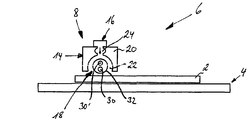
도 1은 기판(2)을 처리하기 위한 장치(1) 상에 개략 평면도를 도시하고 있고, 도 2는 라인 I-I를 따른 장치(1)의 개략 단면도를 도시하고 있다.1 shows a schematic plan view on an
장치(1)는 도포 유닛(6)용 기판 홀더라 칭하게 될 기판용 수용기로 기본적으로 이루어진다. 기판 홀더(4) 및 도포 유닛(6)은 포지티브 압력 또는 네거티브 압력이 적절한 수단에 의해 발생될 수 있는, 도시되어 있지 않은 압력 챔버 내에 배열될 수 있다.The
기판 홀더(4)는, 도면에서 볼 수 있는 바와 같이, 또한 직사각형인 기판(2)을 수용하기 위한 편평한 직사각형 플레이트이다. 기판 홀더(4)는 처리될 기판(2)의 형상에 매칭될 수 있는 다른 형상을 가질 수 있다. 기판 홀더(4)는 도포 유닛(6)을 경유하여 기판(2) 상에 도포될 수 있는 액체를 위한 도시되어 있지 않은 배수구를 갖는다.The
도포 유닛(6)은 주요부(8)와, 양방향 화살표(A, B)에 의해 도시되어 있는 바와 같이, 가동 방식으로 주요부(8)를 지지하는 지지부(10)로 이루어진다. 특히, 지지부(10)는 지지 아암(12)을 갖고, 이 지지 아암은 일 단부에서 주요부(8)에 연결되어 있고, 지지 아암의 다른 단부는 도시되어 있지 않은 구동부에 연결되어 있다. 양방향 화살표(A, B)에 의해 도시되어 있는 바와 같이, 구동부는 예를 들어 지지 아암(10) 및 따라서 주요부(8)의 피벗 이동 및/또는 선형 이동을 제공할 수 있다. 이 방식으로, 주요부(8)는 상기 기판의 부분 영역 또는 전체 표면의 처리를 가능하게 하기 위해, 상기 기판 홀더(4) 상에 수용되는 기판(2)을 가로질러 이동될 수 있다. 더욱이, 기판 홀더(4) 상에 수용된 기판(2)의 표면과 주요부(8) 사이의 거리를 조정하기 위해 지지 아암(10)이 상승 이동을 행하는 것도 또한 가능하다.The
대안적으로 또는 부가적으로, 기판(2)과 주요부(8) 사이의 상대 이동을 제공하기 위해 기판 홀더용 이동 기구를 제공하는 것이 또한 가능하다.Alternatively or additionally, it is also possible to provide a movement mechanism for the substrate holder to provide relative movement between the
주요부(8)는 하우징(14), 유체 포트(16) 및 방사선 소스(18)로 본질적으로 이루어진다. 하우징(14)은 본질적으로 본체(20)의 전체 길이를 가로질러 연장하는 유동 챔버(22)를 그 종방향 연장부에 형성하는 세장형 입방형 본체(20)를 갖는다. 유동 챔버(22)는 이하에서 본 명세서에 더 상세히 설명되는 바와 같이, 그 완전한 폭을 가로질러 기판에 액체를 도포하는 것을 가능하게 하기 위해, 기판(2)의 폭 연장부보다 큰 길이 연장부를 갖는다. 유동 챔버는 더 작은 치수를 갖는 것이 또한 가능하다. 유동 챔버(22)의 내부면은 특히 UV 방사선에 대해 높은 반사율을 갖도록 설계되고, 반면에 IR 방사선은 실질적으로 흡수될 수 있다.The
유동 챔버(20)는 실질적으로 원형 단면 형상을 갖는다. 유동 챔버(22)는 본체(20)의 저부측을 향해 개방되어, 본체가 처리될 기판(2)을 향해 지향된 출구 개구를 형성하게 된다. 유동 챔버(22)의 상부 부분에서, 도관(24)은 본체(20) 내에 제공되고, 유동 챔버(22)에 본질적으로 평행하게 연장한다. 도관(24)은 도관(24)을 경유하여 유동 챔버(22) 내로 유체를 안내하기 위해, 복수의 위치에서 유동 챔버(22)에 유동적으로 연결된다. 이 점에서, 도관(24)은 실질적으로 그 전체 길이에 걸쳐 유동 챔버(22) 내로 유체를 안내하는 것이 가능하다. 도관(24)은 또한 유체 포트(16)에 연결된다.
유체 포트(16)는 하나 이상의 유체가 이를 경유하여 유체 포트(16)로 안내될 수 있는, 도시되어 있지 않은 도관에 연결된다. 복수의 유체가 이 도관을 경유하여 유체 포트에 동시에 또는 순차적으로 안내될 수 있는 것이 가능하다. 예를 들어 상이한 유체가 유체 포트에 안내될 수 있는 복수의 도관을 제공하는 것이 또한 가능하다. 유체로서, 예를 들어 액체가 고려될 수 있지만, 이들이 유동 챔버(22)로 안내되기 전에, 예를 들어 유체 포트(16) 및 도관(24) 내의 액체와 혼합될 수 있는 가스를 유체 포트로 안내하는 것도 또한 가능하다. 도 2에는, 유체 포트(16)로부터 도관(24)을 경유하여 유동 챔버(22) 내로 그리고 하우징(14) 외부로의 유체의 유동을 지시하고 있는 화살표가 도시되어 있다.
방사선 소스(18)는 종방향으로 연장하는 형상을 갖고, 실질적으로 그 중간부에서 전체 유동 챔버(22)를 따라 연장된다. 방사선 소스(18)는 램프(30)의 방사선에 실질적으로 투과되는 커버(32)에 의해 둘러싸인 막대 램프(30)를 갖는다. 막대 램프는 적어도 사전 결정된 파장의 범위의 UV 방사선을 방출하는 유형이다. 막대 램프(30)가 광범위한 파장의 스펙트럼을 가로질러 방사선을 방출하고 특히 UV 방사선 및 IR 방사선을 방출하는 것이 또한 가능하다.The
예를 들어 석영 글래스로 이루어질 수 있는 커버(32)는 유동 챔버(22) 내에서 막대 램프(30)를 완전히 둘러싸고, 유동 챔버(22) 내의 유체에 대해 이 막대 램프를 격리시킨다. 커버는 예를 들어 본체(20)로부터 유동 챔버(22)의 단부벽을 통해 연장할 수 있다. 이는 예를 들어 유동 챔버(22)에 액세스할 필요 없이, 교체 또는 유지 보수 목적으로 막대 램프(30)에 액세스하는 것이 가능할 수 있다. 유동 챔버(22) 내의 그 배열에 기인하여, 커버(32)는 유동 챔버(22)의 내부벽과 함께, 도관(24)을 경유하여 유동 챔버(22) 내로 안내되는 유체를 위한 유동 경로를 형성한다. 이러한 유체는 커버(32) 주위로, 따라서 전체적으로 방사선 소스(18) 주위로 유동한다. 막대 램프(30)에 의해 방출된 방사선은 따라서 유동 경로를 따라 유동하는 임의의 유체 내로 도입된다. 더욱이, 커버(32)는 본체(20)의 저부면을 넘어 연장하고, 따라서 본체(20)의 출구 개구 내로 부분적으로 연장한다. 따라서, 막대 램프로부터 방출된 방사선이 또한 기판 홀더(4)를 향해 또는 그 위의 기판(2) 상으로 유동 챔버(22)를 나오는 것이 가능하다. 특히, 방사선은 기판(2) 상에 액체 필름을 도입할 수 있고, 이 액체 필름은 예를 들어 유동 챔버(22)를 통해 기판 상으로 유동하는 액체에 의해 형성된다.A
도 3은 기판(2)을 처리하기 위한 장치(1)의 대안 실시예의 도 2와 유사한 개략 측면도를 도시하고 있다. 이 실시예를 설명할 때, 동일한 또는 유사한 요소가 제공되는 한 이전과 동일한 도면 부호가 사용된다.3 shows a schematic side view similar to FIG. 2 of an alternative embodiment of the
장치(1)는 또한, 기판을 수용하기 위한 기판 홀더(4) 및 도포 유닛(6)으로 실질적으로 이루어진다. 기판 홀더는 도 1 및 도 2와 관련하여 전술된 바와 동일한 방식으로 설계될 수 있다.The
도포 유닛(6)은 또한, 주요부(8) 및 지지부로 이루어지고, 이 지지부는 도 3에는 도시되어 있지 않지만, 도 1 및 도 2와 관련하여 전술된 바와 동일한 디자인을 가질 수 있다. 주요부(8)는 또한, 하우징(14), 유체 포트(16) 및 방사선 소스(18)로 실질적으로 이루어지고, 하우징(14) 및 유체 포트는 도 1 및 도 2와 관련하여 전술된 바와 동일한 디자인을 가질 수 있다.The
방사선 소스(18)는 또한, 세장형 형상을 갖고, 유동 챔버(22)를 통해 중간부에서 실질적으로 연장한다. 방사선 소스(18)는 이 실시예에서 막대 램프(30, 30')를 갖고, 이들 막대 램프는 막대 램프(30, 30')의 방사선에 실질적으로 투과되는 커버(32)에 의해 둘러싸인다. 막대 램프(30, 30')는 도 3에 서로의 위에 도시되어 있지만, 이들은 또한 커버(32) 내에 상이한 방식으로 배열될 수도 있다. 막대 램프는 동일한 또는 상이한 유형일 수 있고, 이들 중 적어도 하나는 사전 결정된 파장의 범위의 UV 방사선을 방출한다. 특히, 양 막대 램프(30, 30')가 상이한 파장의 범위의 UV 방사선을 방출하는 것이 가능하다. 상부 막대 램프(30')는 예를 들어 180 nm 초과의 파장 범위의 UV 방사선을 적어도 부분적으로 또는 주로 방출할 수 있고, 반면에 하부 막대 램프(30)는 140 내지 280 nm, 액체에 따라 140 nm 내지 200 nm의 파장 범위의 UV 방사선을 적어도 부분적으로 또는 주로 방출한다. 막대 램프(30, 30') 중 하나 또는 모두는 소정량의 IR 방사선 또는 다른 방사선을 또한 방출할 수 있다.The
커버(32)는 유동 챔버(22) 내에서 막대 램프(30, 30')를 완전히 둘러싸고, 상기 유동 챔버(22) 내의 유체에 대해 이 막대 램프들을 격리시킨다. 이 점에서, 커버(32)는 도 1 및 도 2와 관련하여 전술된 커버와 동일한 디자인을 가질 수 있다. 더욱이, 다른 막대 램프가 커버(32) 내에 수용되는 것이 또한 가능하고, 이 막대 램프는 상이한 방사선 또는 또한 동일한 방사선을 각각 방출할 수 있다. 막대 램프(30, 30')의 배열 및 선택에 의해, 원하는 방사선 프로파일(그 방출된 파장 및 공간 분포에 대해)이 유동 챔버(22) 내에 그리고 본체(20)의 출구 개구를 경유하여 유동 챔버를 넘어 생성될 수 있다.The
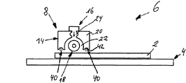
도 4는 기판(2)을 처리하기 위한 장치(1)의 다른 대안 실시예의 도 2와 유사한 개략 단면도를 도시하고 있다. 이 실시예를 설명할 때, 동일한 또는 유사한 요소가 제공되는 한, 이전과 동일한 도면 부호가 사용될 것이다.FIG. 4 shows a schematic cross-sectional view similar to FIG. 2 of another alternative embodiment of the
장치(1)는 또한, 기판을 수용하기 위한 기판 홀더(4) 및 도포 유닛(6)으로 실질적으로 이루어진다. 기판 홀더(4)는 도 1 및 도 2와 관련하여 전술된 바와 동일한 방식으로 설계될 수 있다.The
도포 유닛(6)은 또한, 주요부(8) 및 지지부로 이루어지고, 이 지지부는 도 4에는 도시되어 있지 않지만, 도 1 및 도 2와 관련하여 전술된 것과 동일한 디자인을 가질 수 있다.The
주요부(8)는 또한, 하우징(14), 유체 포트(16) 및 방사선 소스(18)로 실질적으로 이루어진다. 부가적으로, 2개의 다른 방사선 소스(40)가 제공된다. 하우징(14)은 세장형 입방형 본체(20)를 갖는 도 1 및 도 2와 관련하여 전술된 것과 유사한 디자인을 가질 수 있다. 본체(20) 내의 유동 챔버(22) 및 도관(24)은 도 1 및 도 2와 관련하여 전술된 것과 동일한 디자인을 갖는다. 이는 또한 유체 포트(16)에 대해서도 동일하다.The
본체(20)의 저부측에는, 출구 개구의 양 측면 상에서 본체의 길이를 따라 연장하는 리세스(42)가 제공된다. 리세스는 다른 방사선 소스(40)를 적어도 부분적으로 수용하도록 치수 설정된다. 리세스(42)의 표면은 방사선 소스(40)의 방사선을 위한 반사면을 가질 수 있다.On the bottom side of the
방사선 소스(18)는 도 1 및 도 2와 관련하여 설명된 것과 동일한 디자인을 가질 수 있고, 또는 도 3과 관련하여 설명된 디자인을 또한 가질 수도 있다.The
방사선 소스(40)는 본체(20)의 각각의 리세스(42) 내에 수용된 본체(20)의 길이에 걸쳐 연장하는 막대 램프를 각각 포함한다. 이는 도 4에는 도시되어 있지 않지만, 방사선 소스(40)는 막대 램프의 방사선에 실질적으로 투과되는 커버를 각각 포함할 수 있고, 이 커버는 주위에 대해, 특히 유동 챔버를 나오는 임의의 액체에 대해 막대 램프를 격리시킨다. 방사선 소스(40)의 막대 램프는 동일한 또는 상이한 유형일 수 있고, 또한 방사선 소스(18)의 막대 램프(30, 30')와 상이한 유형일 수도 있다. 2개의 방사선 소스(40)를 제공하는 대신에, 도 4에 도시되어 있는 바와 같이, 단지 하나의 방사선 소스(40)를 제공하는 것도 또한 가능하다.The
도 5는 기판(2)을 처리하기 위한 장치(1)의 다른 실시예의 도 2와 유사한 개략 단면도를 도시하고 있다. 이 실시예의 설명에서, 또한, 동일한 또는 유사한 요소가 제공되는 한, 이전과 동일한 도면 부호가 사용된다.FIG. 5 shows a schematic cross-sectional view similar to FIG. 2 of another embodiment of an
장치(1)는 또한, 기판을 수용하기 위한 기판 홀더(4) 및 도포 유닛(6)으로 실질적으로 이루어진다. 기판 홀더(4)는 도 1 및 도 2와 관련하여 전술된 바와 동일한 방식으로 설계될 수 있다.The
도포 유닛(6)은 또한, 주요부(8) 및 도 5에는 도시되어 있지 않은 지지부로 이루어진다. 이하에서 본 명세서에 설명되는 주요부(8)가 기판을 완전히 덮는 것이 가능한 한, 지지부의 가동성은 생략될 수도 있다. 단지 거리 조정, 뿐만 아니라 주요부 아래에 기판을 위치시키기 위한 가동성만이 요구될 수 있다.The
주요부(8)는 하우징(14), 복수의 유체 포트(16) 및 복수의 방사선 소스(18)로 본질적으로 이루어진다. 하우징은 처리될 기판의 형상에 매칭되는 본체(20)로 이루어진다. 본체(20)에는, 본체의 저부측으로 개방되는 유동 챔버(22)가 형성되고, 개구는 처리될 기판의 치수에 본질적으로 대응한다. 유동 챔버(22)의 내부벽은 반사성이다. 유동 챔버(22)의 상부측은 복수의 도관(24)을 경유하여 복수의 유체 포트(16)(6개가 여기에 도시되어 있음)를 경유하여 연결된다.The
복수의 방사선 소스(18)(6개가 여기에 도시되어 있음)가 유동 챔버(22) 내에 제공되고, 이 방사선 소스는 유동 챔버(22)를 통해 종방향 또는 횡방향으로 연장된다. 따라서, 상이한 유동 경로가 유동 챔버(22)의 벽과 방사선 소스(18) 사이, 뿐만 아니라 개별 방사선 소스들 사이에 형성된다. 방사선 소스(18)는 도 1 및 도 2와 관련하여 설명된 것 또는 도 3과 관련하여 설명된 것과 동일한 디자인을 가질 수 있다.A plurality of radiation sources 18 (six are shown here) are provided in the
부가적으로, 2개의 추가의 방사선 소스(40)가 제공된다. 하우징(14)은 세장형 입방형 본체(20)를 갖는 도 1 및 도 2와 관련하여 전술된 것과 유사한 디자인을 갖고, 본체(20) 내의 유동 챔버(22) 및 도관(24)은 도 1 및 도 2와 관련하여 전술된 것과 동일한 디자인을 갖는다. 이는 또한 유체 포트(16)에 대해서도 또한 동일하다.In addition, two
전술된 막대 램프는 다른 막대 램프에 독립적으로 개별적으로 막대 램프를 제어하거나 구동하는 것이 가능한 제어 유닛에 각각 접속된다. 그러나 막대 램프를 사용하는 대신에, 유동 챔버의 길이를 가로질러 실질적으로 균질한 방사선 프로파일을 제공하는 것이 가능해야 하는 다른 램프/방사체를 사용하는 것이 또한 가능하다.The bar lamps described above are each connected to a control unit capable of controlling or driving the bar lamps independently of other bar lamps. However, instead of using a rod lamp, it is also possible to use other lamps / radiators which should be able to provide a substantially homogeneous radiation profile across the length of the flow chamber.
이하, 장치(1)의 작동이 도면과 관련하여 더 상세히 설명될 것이다.The operation of the
기판(2)의 표면의 처리를 위해, 도포 유닛(6)의 주요부(8)는 기판 홀더(4) 상의 기판(2) 위로 이동될 수 있다. 기판의 전체 표면이 처리되어야 하면, 주요부(8)는 이하에서 본 명세서에 설명되는 처리 중에 기판을 가로질러 이동될 수 있는데, 도 5에 따른 실시예가 사용되지 않으면, 기판을 완전히 커버할 수 있다.For the treatment of the surface of the
다음에, 유체, 특히 액체가 유체 포트(16), 도관(24) 및 유동 챔버(22)를 가로질러 적어도 처리될 기판의 표면에 도포된다. 방사선이 제1 방사선 소스(18) 및/또는 방사선 소스(40)를 경유하여 상기 유체 내에 도입된다. 방사선은 기판을 처리하기 위해 및/또는 기판 특성을 변경하기 위해 유체 상에 작용하도록 하기 위해, 그리고 원하는 처리를 행하기 위해, 기판 상에 직접 작용하도록 선택된다. 이와 같이 함으로써, 기판의 표면을 위한 상이한 처리 가능성이 제공되고, 이는 국부적으로 제한될 수 있고 또는 기판의 전체 표면 상에서 행해질 수도 있다.Next, a fluid, in particular a liquid, is applied to the surface of the substrate to be treated at least across the
이하, 이들 처리 가능성의 몇몇이 이들 예에 한정되지 않고 더 상세히 설명된다. 포토마스크의 처리가 예로서 제공될 것이다.Some of these processing possibilities are described below in more detail, without being limited to these examples. Processing of the photomask will be provided as an example.
먼저, 적어도 부분적으로 소수성 기판 표면을 갖는 기판(2)의 표면 특성을 친수성 기판 표면으로 변화시키는 것이 설명된다. 이러한 것을 달성하기 위해, 기판(2) 상에 액체 필름을 형성하기 위해, DI 수와 같은 액체가 유동 챔버(22)를 경유하여 처리될 기판 표면 상에 유체로서 도포될 수 있다. UV 방사선이 방사선 소스(18 또는 40)를 경유하여 이 액체 필름 내로 도입될 수 있고, 액체와 UV 방사선의 파장 범위가 서로 매칭되어, UV 방사선의 상당한 부분이 액체와 기판 표면 사이의 계면에 도달하게 된다. UV 방사선은 이제, 이전의 소수성 기판 표면을 친수성 표면으로 변화시키도록 작용한다.First, it is described to change the surface properties of the
액체 필름을 통한 UV 방사선의 양호한 투과를 얻기 위해, 여기서 사용된 UV 방사선의 파장 범위는 예를 들어 190 nm 초과이다. 이러한 파장 범위를 제공하기 위해, 이 파장 범위에서 방출하는 대응 막대 램프가 제어되거나 구동될 수 있는 반면에, 가능하게는 다른 램프는 제어되거나 구동되지 않는다. 언급된 파장 범위를 사용할 때, 이하의 것, 즉 오존수, 수소수, DI 수 또는 이들의 혼합물 중 하나가 또한, 액체로서 사용될 수 있다.In order to obtain good transmission of UV radiation through the liquid film, the wavelength range of the UV radiation used here is for example greater than 190 nm. To provide this wavelength range, corresponding bar lamps emitting in this wavelength range can be controlled or driven, while possibly other lamps are not controlled or driven. When using the mentioned wavelength range, one of the following, i.e. ozone water, hydrogen water, DI water or mixtures thereof, may also be used as the liquid.
다음에, 기판 표면의 세척이 설명될 것이고, 이 기판 표면은 예를 들어 전술된 바와 같이 친수성 표면을 갖도록 처리되어 있고 래디칼과의 상호 작용에 의해 더 양호하게 제거될 수 있는 오염물을 갖는다.Next, the cleaning of the substrate surface will be explained, which substrate surface is treated to have a hydrophilic surface, for example as described above, and has contaminants that can be better removed by interaction with radicals.
여기서, 또한,, 액체는 유동 챔버(22)를 경유하여 세척될 기판(2)의 표면에 도포된다. 액체가 방사선 소스(18) 주위에서 유동하는 동안, UV 방사선이 방사선 소스(18)에 의해 액체 내로 방출된다. 이 방사선은 특히 액체 내의 래디칼의 생성을 야기한다. 이 생성은 액체가 기판에 도포되기 직전에 발생하여, 매우 짧은 붕괴 시간을 갖는 이와 같이 생성된 래디칼의 적어도 일부가 기판(2)에 접촉하게 된다. 방사선 소스(18)의 방사선은 유동 챔버(22)에 제한되지 않기 때문에, 이는 또한 기판(2) 상에 액체에 의해 형성된 액체 필름 내에 도입되고, 따라서 추가의 래디칼을 생성하고 및/또는 이미 생성된 래디칼의 활성화를 부분적으로 유지한다.Here, also, the liquid is applied to the surface of the
도포 유닛(6)의 대응 이동에 의해, 기판의 부분 영역 또는 전체 표면을 선택적으로 세척하는 것이 가능하다.By corresponding movement of the
액체 및 그 내부에 도입된 방사선은 원하는 효과를 달성하기 위해 다시 서로 매칭된다. 래디칼의 생성을 위해, 특히 140 내지 280 nm, 액체에 따라 140 nm 내지 200 nm의 파장 범위의 UV 방사선이 적합하다. 언급된 파장 범위의 UV 방사선은 UV 방사선의 적어도 50% 및 특히 그 80%가 흡수되도록 사용된 액체에 매칭될 수 있다.The liquid and the radiation introduced therein are again matched with each other to achieve the desired effect. For the production of radicals, in particular UV radiation in the wavelength range of 140 nm to 280 nm, depending on the liquid, is suitable. UV radiation in the mentioned wavelength range can be matched to the liquid used so that at least 50% and especially 80% of the UV radiation is absorbed.
사용된 액체에 따라, 래디칼의 생성은 또한 액체의 UV 유도 분해에 의해 촉진될 수 있고, 이는 액체가 래디칼 소스(18) 주위로 유동하는 동안에 발생할 수 있다. 이 목적을 위해, UV 방사선은 한편으로는 또한 UV 방사선에 의해 래디칼의 바로 이어지는 생성을 촉진하기 위해, 액체의 분자 구조의 파괴가 발생되도록 선택되어야 한다. 180 nm 초과의 파장을 갖는 UV 방사선이 특히 이러한 분해를 위해 적합하다. 따라서 도 3에 도시되어 있는 방사선 소스(18)의 실시예에서, 상부 막대 램프가 분해를 촉진하는 것, 즉 180 nm를 초과하는 파장을 갖는 UV광을 방출하는 것이고, 반면에 하부 막대 램프는 래디칼의 생성을 촉진하는 것, 즉 140 내지 280 nm, 액체에 따라 140 nm 내지 200 nm의 파장을 갖는 UV광을 방출하는 것이면 유리할 수 있다. DI 수를 예로서 취하면, 140 nm 내지 200 nm의 파장 범위가 래디칼의 생성을 위해 적합할 수 있고, 반면에 다른 액체에 대해서는 140 nm 내지 280 nm의 더 높은 파장의 범위가 적합할 수도 있다.Depending on the liquid used, the production of radicals can also be promoted by UV induced decomposition of the liquid, which can occur while the liquid flows around the
이들 파장 범위는 명백하게 한정적인 것은 아니고, 액체에 따라 다양할 수 있지만, 오존수, 수소수, DI 수, H2O2, CO2-H2O, 그 내부에 용해된 O2-가스를 갖는 DI 수, NH4OH, 유기산, TMAH, HNO3, HCl, H2SO4 또는 이들의 혼합물과 같은, 포토마스크를 세척하기 위해 일반적으로 사용되는 다수의 액체에 적용 가능하다.These wavelength ranges are not necessarily of apparently limited, but may vary depending on the liquid, ozone water, be a small number, DI can, H 2 O 2, CO 2 -H 2 O, the O 2 dissolved therein - DI having a gas Applicable to many liquids commonly used for washing photomasks, such as water, NH 4 OH, organic acids, TMAH, HNO 3 , HCl, H 2 SO 4 or mixtures thereof.
마지막으로, 이온이 예를 들어 전술된 바와 같이 처리되어 있는 기판(2)의 표면 또는 인접 표면층으로부터 제거되어야 하는 처리가 설명된다.Finally, a treatment is described in which ions must be removed from the surface or adjacent surface layer of the
이 처리를 위해, 주위 온도를 초과하여 가열되는 액체가, 기판(2)의 적어도 부분 영역 상에 액체 필름을 형성하기 위해, 유동 챔버(22)를 경유하여 기판 상에 도포된다. 방사선이 방사선 소스(18, 40) 중 적어도 하나를 경유하여 이 액체 필름 내에 도입되고, 방사선 및 액체는 서로 매칭되어, 방사선의 적어도 일부가 기판 표면에 도달하게 된다. 전자기 방사선은 이것이 기판 표면 상에 잔류 이온을 타격할 때 증가된 이온 이동도를 발생시킨다. 더욱이, 방사선은 액체 내에 흡수되는 한, 또한 온도 증가 및/또는 래디칼의 생성을 야기할 수도 있고, 이는 모두 이온의 제거를 촉진할 수 있다. 특히, 액체는 예를 들어 높은 IR 부분을 갖는 방사선 소스에 의해 그 도포 중에 직접 가열될 수 있다. 액체의 증가된 온도가 또한 액체 내의 이온의 용해도를 증가시키는 한, 액체는 그 비등점까지 가열될 수 있다.For this treatment, a liquid that is heated above the ambient temperature is applied onto the substrate via the
액체로서, 예를 들어 이하의 액체, 즉 오존수, 수소수, DI 수, H2O2, CO2-H2O, 그 내부에 용해된 O2-가스를 갖는 DI 수 또는 이들의 혼합물 중 하나가 사용될 수 있다. DI 수가 특히 더 고온에서 적합하다. 방사선으로서, 특히 190 nm 초과의 파장 범위의 UV 방사선이 적합한데, 이는 너무 강하게 흡수되지 않고 이온을 이동시키고 제거하는 원하는 효과를 촉진한다. 액체의 원위치 가열을 제공할 수 있는 한, IR 방사선이 또한 양호하게 적합하다.As a liquid, for example, one of the following liquids: ozone water, hydrogen water, DI water, H 2 O 2 , CO 2 -H 2 O, DI water with O 2 -gas dissolved therein or mixtures thereof Can be used. DI numbers are particularly suitable at higher temperatures. As radiation, UV radiation in particular in the wavelength range above 190 nm is suitable, which promotes the desired effect of moving and removing ions without being absorbed too strongly. IR radiation is also well suited as long as it can provide in-situ heating of the liquid.
상기 처리는 원하는 바에 따라 조합될 수 있고, 설명된 바와 같이 순차적으로 또는 부분적으로 또는 완전히 동시에 행해질 수 있다.The treatments can be combined as desired and can be performed sequentially, partially or completely simultaneously as described.
본 발명은 정확한 실시예에 한정되지 않고 다수의 실시예와 관련하여 위의 본 명세서에 설명되어 있다.
The invention is not limited to the exact embodiments but is described herein above in connection with a number of embodiments.
1: 장치 2: 기판
4: 기판 홀더 6: 도포 유닛
8: 주요부 10: 지지부
12: 지지 아암 14: 하우징
16: 유체 포트 18: 방사선 소스
20: 본체 22: 유동 챔버
24: 도관 30: 램프
32: 커버 40: 방사선 소스1: device 2: substrate
4: substrate holder 6: coating unit
8: main part 10: support part
12: support arm 14: housing
16: fluid port 18: radiation source
20: main body 22: flow chamber
24: conduit 30: lamp
32: cover 40: radiation source
Claims (62)
상기 기판의 적어도 부분 영역에 액체를 도포하는 단계와,
상기 액체를 기판에 도포하기 전에 UV 방사선에 의해 상기 액체 내에 래디칼을 생성하는 단계를 포함하고,
상기 래디칼의 생성은 상기 기판에 액체를 도포하기 직전에 발생하여, 래디칼의 적어도 일부가 상기 기판에 도달하게 되는 방법.
A method for cleaning at least a partial region of a substrate, the method comprising:
Applying a liquid to at least a partial region of the substrate;
Generating radicals in the liquid by UV radiation prior to applying the liquid to the substrate,
The generation of radicals occurs immediately prior to applying liquid to the substrate such that at least a portion of the radicals reach the substrate.
상기 기판에 도포된 액체는 기판 위에 액체 필름을 형성하고, 상기 액체 필름 내로 UV 방사선이 도입되어 상기 액체 필름 내의 래디칼의 활성화를 유지하고 및/또는 추가 래디칼을 생성하는 방법.
The method of claim 1,
The liquid applied to the substrate forms a liquid film on the substrate and UV radiation is introduced into the liquid film to maintain activation of radicals in the liquid film and / or to generate additional radicals.
상기 기판에 액체를 도포하기 전에 액체 내에 그리고 상기 기판 상의 액체 필름 내로 도입된 상기 UV 방사선은 적어도 부분적으로 동일한 방사선 소스에 의해 방출되는 방법.
The method of claim 2,
Wherein the UV radiation introduced into the liquid and into the liquid film on the substrate prior to applying the liquid to the substrate is at least partially emitted by the same radiation source.
상기 래디칼을 포함하는 액체는 상기 기판의 선택된 표면 영역에 제한되는 방법.
4. The method according to any one of claims 1 to 3,
The radical-containing liquid is confined to a selected surface area of the substrate.
래디칼을 생성하기 위해, 본질적으로 140 nm 내지 280 nm, 액체에 따라 140 nm 내지 200 nm의 범위의 파장을 갖는 UV 방사선이 사용되고, 상기 UV 방사선의 적어도 50%는 래디칼을 생성하기 위해 액체 내에 흡수되는 방법.
5. The method according to any one of claims 1 to 4,
In order to generate radicals, UV radiation having a wavelength in the range of essentially 140 nm to 280 nm, depending on the liquid, 140 nm to 200 nm is used and at least 50% of the UV radiation is absorbed in the liquid to produce radicals. Way.
140 nm 내지 280 nm, 액체에 따라 140 nm 내지 200 nm의 범위의 파장을 갖는 UV 방사선의 적어도 80%가 흡수되는 방법.
The method of claim 5,
At least 80% of the UV radiation having a wavelength ranging from 140 nm to 280 nm, depending on the liquid, from 140 nm to 200 nm.
상기 흡수는 상기 언급된 범위의 사용된 파장에 사용된 액체를 매칭함으로써 달성되는 방법.
The method according to claim 5 or 6,
Said absorption is achieved by matching a liquid used to a used wavelength in the above-mentioned range.
UV 방사선은 액체가 UV 방사선 소스를 따라 유동하는 동안 액체를 도포하기 전에 액체 내에 도입되는 방법.
8. The method according to any one of claims 1 to 7,
UV radiation is introduced into the liquid prior to applying the liquid while the liquid flows along the UV radiation source.
UV 방사선은 기판 표면과 원하지 않는 반응을 회피하고 및/또는 또한 UV 방사선에 의한 래디칼의 바로 이후의 생성을 가능하게 하기 위해 액체의 분자 구조가 파괴되도록 선택되는 방법.
The method of claim 8,
UV radiation is chosen such that the molecular structure of the liquid is destroyed in order to avoid unwanted reactions with the substrate surface and / or also to enable the immediate generation of radicals by UV radiation.
액체로서, 이하의 것, 즉 오존수, 수소수, DI 수, H2O2, CO2-H2O, 내부에 용해된 O2 가스를 갖는 DI 수, NH4OH, 유기산, 시트르산, TMAH, HNO3, HCl, H2SO4, H3PO4 또는 이들의 혼합물 중 적어도 하나가 사용되는 방법.
10. The method according to any one of claims 1 to 9,
As a liquid, the following may be used: ozone water, hydrogen water, DI water, H 2 O 2 , CO 2 -H 2 O, DI water with O 2 gas dissolved therein, NH 4 OH, organic acid, citric acid, TMAH, At least one of HNO 3 , HCl, H 2 SO 4 , H 3 PO 4, or a mixture thereof.
상기 기판은 이하의 것, 즉 마스크, 특히 반도체의 제조를 위한 포토마스크, 반도체, 특히 Si-웨이퍼, Ge-웨이퍼, GaAs-웨이퍼 또는 InP-웨이퍼, 평판 패널 기판, 다층 세라믹 기판 중 하나인 방법.
11. The method according to any one of claims 1 to 10,
The substrate is one of the following: a mask, in particular a photomask for the manufacture of semiconductors, semiconductors, in particular Si-wafers, Ge-wafers, GaAs-wafers or InP-wafers, flat panel substrates, multilayer ceramic substrates.
이하의 것, 즉 유기 오염물 뿐만 아니라 포지티브 레지스트, 네거티브 레지스트 및 이온 주입된 레지스트와 같은 유기 기능층, 탄소, 탄화수소, 엠보싱 및 임프린트 재료, 응력 버퍼 및 언더필(underfill) 재료, 래커, 염료, 바이오 재료 및 또한 박테리아 중 적어도 하나가 래디칼의 도움에 의해 기판으로부터 적어도 부분적으로 제거되는 방법.
12. The method according to any one of claims 1 to 11,
Organic functional layers such as positive, negative and ion implanted resists as well as organic contaminants, carbon, hydrocarbons, embossing and imprint materials, stress buffers and underfill materials, lacquers, dyes, bio materials and And at least one of the bacteria is at least partially removed from the substrate with the help of radicals.
액체는 상기 기판의 세척될 국부 영역에 도포되는 방법.
13. The method according to any one of claims 1 to 12,
Liquid is applied to the localized area to be cleaned of the substrate.
상기 기판의 적어도 부분 영역 상에 액체 필름을 형성하기 위해 상기 기판 상에 주위 온도를 초과하여 가열되는 액체를 도포하는 단계와,
상기 액체 필름 내에 전자기 방사선을 도입하여 상기 방사선의 적어도 일부가 상기 기판의 표면에 도달하게 하는 단계를 포함하는 방법.
A method for removing ions from at least a partial region of a surface of a substrate and an adjacent surface layer of the substrate, the method comprising:
Applying a liquid that is heated above ambient temperature to form a liquid film on at least a partial region of the substrate,
Introducing electromagnetic radiation into the liquid film such that at least a portion of the radiation reaches the surface of the substrate.
상기 액체는 상기 기판 상에 액체를 도포하는 중에 전자기 방사선에 의해 가열되는 방법.
15. The method of claim 14,
The liquid is heated by electromagnetic radiation during application of the liquid onto the substrate.
상기 액체는 전자기 방사선에 노출되기 전에 예열되는 방법.
16. The method according to claim 14 or 15,
The liquid is preheated before exposure to electromagnetic radiation.
상기 액체는 주위 온도와 액체의 비등점 사이의 범위의 온도로 가열되는 방법.The method according to any one of claims 14 to 16,
The liquid is heated to a temperature in the range between the ambient temperature and the boiling point of the liquid.
상기 방법은 증가된 압력 하에서 행해지는 방법.
18. The method according to any one of claims 14 to 17,
Said method being performed under increased pressure.
액체로서, 이하의 것, 즉 오존수, 수소수, DI 수, H2O2, CO2-H2O, 내부에 용해된 O2 가스를 갖는 DI 수 또는 이들의 혼합물 중 적어도 하나가 사용되는 방법.
The method according to any one of claims 14 to 18,
As a liquid, at least one of the following, i.e. ozone water, hydrogen water, DI water, H 2 O 2 , CO 2 -H 2 O, DI water having O 2 gas dissolved therein or mixtures thereof is used .
UV 방사선이 액체 필름 내에 도입되는 방법.
The method according to any one of claims 14 to 19,
UV radiation is introduced into the liquid film.
190 nm 초과의 파장을 갖는 적어도 UV 방사선이 액체 내에 도입되고, 상기 UV 방사선의 적어도 50%는 상기 기판의 표면과 상기 액체 필름 사이의 계면에 도달하는 방법.
21. The method of claim 20,
At least UV radiation having a wavelength greater than 190 nm is introduced into the liquid, and at least 50% of the UV radiation reaches an interface between the surface of the substrate and the liquid film.
190 nm 초과의 파장을 갖는 UV 방사선의 적어도 80%가 상기 계면에 도달하는 방법.
The method of claim 21,
At least 80% of the UV radiation having a wavelength greater than 190 nm reaches said interface.
IR 방사선이 액체 필름 내에 도입되는 방법.
The method according to any one of claims 14 to 22,
Wherein IR radiation is introduced into the liquid film.
IR 방사선의 적어도 50%가 상기 기판의 표면과 액체 필름 사이의 계면에 도달하는 방법.
24. The method of claim 23,
At least 50% of the IR radiation reaches the interface between the surface of the substrate and the liquid film.
상기 UV 방사선 및 상기 IR 방사선은 동일한 방사선 소스를 경유하여 도입되는 방법.
24. The method according to any one of claims 20 to 23,
The UV radiation and the IR radiation are introduced via the same radiation source.
상기 방사선의 적어도 일부는 액체 필름 내에 래디칼을 생성하는 방법.
The method according to any one of claims 14 to 25,
At least a portion of the radiation generates radicals in the liquid film.
표면 특성이 변화될 표면의 적어도 부분 영역에 액체를 도포하는 단계와,
표면 특성이 변화될 상기 기판의 표면의 적어도 부분 영역에 상기 액체를 통해 사전 결정된 파장의 범위의 UV 방사선을 안내하는 단계를 포함하는 방법.
A method of changing the surface properties of a substrate having at least partially hydrophobic substrate surface such that at least a portion of the hydrophobic surface obtains hydrophilic surface properties,
Applying a liquid to at least a partial region of the surface whose surface properties are to be changed,
Directing UV radiation in a range of predetermined wavelengths through the liquid to at least a portion of the surface of the substrate whose surface properties are to be changed.
상기 사전 결정된 파장 범위는 190 nm 초과의 파장을 갖는 UV 방사선을 포함하는 방법.
28. The method of claim 27,
Said predetermined wavelength range comprises UV radiation having a wavelength greater than 190 nm.
상기 사전 결정된 파장 범위 내의 UV 방사선의 적어도 80%가 상기 기판의 표면에 도달하는 방법.
29. The method of claim 28,
At least 80% of the UV radiation within the predetermined wavelength range reaches the surface of the substrate.
액체로서, 이하의 것, 즉 오존수, 수소수, DI 수, H2O2, CO2-H2O, 내부에 용해된 O2 가스를 갖는 DI 수, NH4OH, 유기산, TMAH, HNO3, HCl, H2SO4 또는 이들의 혼합물 중 적어도 하나가 사용되는 방법.
30. The method according to any one of claims 27 to 29,
As liquids, the following, i.e. ozone water, hydrogen water, DI water, H 2 O 2 , CO 2 -H 2 O, DI water with O 2 gas dissolved therein, NH 4 OH, organic acids, TMAH, HNO 3 At least one of HCl, H 2 SO 4 or a mixture thereof.
상기 액체는 DI 수인 방법.
31. The method of claim 30,
The liquid is DI water.
이하의 방법, 즉 제27항 내지 제31항 중 어느 한 항에 따른 방법, 제1항 내지 제13항 중 어느 한 항에 따른 방법 및 제14항 내지 제26항 중 어느 한 항에 따른 방법 중 적어도 2개가 순차적으로 행해지는 방법.
As a method for processing a substrate,
A method according to any one of claims 27 to 31, a method according to any one of claims 1 to 13, and a method according to any one of claims 14 to 26. At least two are done sequentially.
상기 방법들 중 적어도 2개는 상기 언급된 순서로 순차적으로 행해지는 방법.
33. The method of claim 32,
At least two of the methods are performed sequentially in the order mentioned above.
상기 방법들 중 2개는 병행하여 행해지는 방법.
34. The method according to claim 32 or 33,
Two of the above methods are done in parallel.
상기 방법들은 동일한 장치 내에서 행해지는 방법.
The method of any one of claims 32 to 34, wherein
The methods are performed in the same apparatus.
상기 기판은 상기 방법들을 행하는 사이에 상기 장치 내에 남아있는 방법.
36. The method of claim 35,
The substrate remains in the apparatus between performing the methods.
이하의 방법, 즉 제27항 내지 제31항 중 어느 한 항에 따른 방법, 제1항 내지 제13항 중 어느 한 항에 따른 방법 및 제14항 내지 제26항 중 어느 한 항에 따른 방법 중 적어도 2개가 병행하여 행해지는 방법.
As a method for processing a substrate,
A method according to any one of claims 27 to 31, a method according to any one of claims 1 to 13, and a method according to any one of claims 14 to 26. At least two are done in parallel.
상기 모든 방법들은 병행하여 행해지는 방법.
39. The method of claim 37,
All the above methods are performed in parallel.
상기 방법들 중 2개는 상기 언급된 순서로 순차적으로 행해지는 방법.
39. The method of claim 37,
Two of the above methods are performed sequentially in the order mentioned above.
상기 방법들은 동일한 장치 내에서 행해지는 방법.
40. The method of claim 39,
The methods are performed in the same apparatus.
상기 기판은 상기 방법들을 행하는 사이에 상기 장치 내에 남아있는 방법.
41. The method of claim 40,
The substrate remains in the apparatus between performing the methods.
상기 기판을 수용하기 위한 기판 홀더와,
입구 및 출구를 갖는 유동 챔버를 형성하는 하우징과,
상기 유동 챔버 내에 방사선을 방출하도록 배열되고, UV 방사선을 방출하는 것이 가능한 제1 방사선 소스와,
상기 기판 홀더와 상기 하우징 사이에 상대 이동을 생성하기 위한 유닛으로서, 상기 유닛은 상기 기판 홀더에 대해 상기 하우징을 배열하는 것이 가능하여 상기 출구가 상기 기판 홀더를 향해 지향되어 상기 출구를 나오는 액체가 상기 기판 홀더 상의 기판 상으로 직접 유동하게 되는, 유닛을 포함하는 장치.
An apparatus for processing a substrate,
A substrate holder for accommodating the substrate;
A housing forming a flow chamber having an inlet and an outlet;
A first radiation source arranged to emit radiation within the flow chamber, the first radiation source capable of emitting UV radiation,
A unit for generating relative movement between the substrate holder and the housing, the unit being capable of arranging the housing relative to the substrate holder such that the outlet is directed towards the substrate holder such that liquid exiting the outlet is And a unit, which flows directly onto the substrate on the substrate holder.
상기 제1 방사선 소스는 상기 하우징으로부터 상기 출구를 통해 방사선을 또한 방출하도록 배열되는 장치.
43. The method of claim 42,
And the first radiation source is arranged to also emit radiation through the outlet from the housing.
상기 제1 방사선 소스는 상기 유동 챔버 내에 적어도 부분적으로 배열되는 장치.
The method of claim 42 or 43, wherein
And the first radiation source is at least partially arranged in the flow chamber.
상기 하우징은 출구 개구를 포함하고, 상기 제1 방사선 소스는 상기 출구 개구 내에 적어도 부분적으로 배열되는 장치.
The method of any one of claims 42-44,
The housing comprises an outlet opening, and wherein the first radiation source is at least partially arranged in the outlet opening.
상기 제1 방사선 소스는 실질적으로 상기 출구 개구의 중간부에 배열되는 장치.
The method of claim 45,
And the first radiation source is arranged substantially in the middle of the outlet opening.
상기 출구 개구 및 상기 제1 방사선 소스는 세척될 기판의 폭의 연장부보다 크거나 적어도 동일한 길이의 연장부를 갖는 장치.
47. The method of claim 45 or 46,
And the outlet opening and the first radiation source have an extension of length greater than or equal to the extension of the width of the substrate to be cleaned.
상기 제1 방사선 소스는 UV 범위의 방사선을 방출하는 제1 램프를 포함하는 장치.
A method according to any one of claims 42 to 47,
Wherein the first radiation source comprises a first lamp that emits radiation in the UV range.
상기 제1 램프는 IR 범위의 방사선을 방출하는 장치.
49. The method of claim 48,
Wherein the first lamp emits radiation in the IR range.
상기 제1 방사선 소스는 상기 제1 램프와는 대부분 상이한 파장 범위의 방사선을 방출하는 적어도 제2 램프를 포함하는 장치.
The method of claim 48 or 49,
The first radiation source comprises at least a second lamp that emits radiation in a wavelength range that is mostly different than the first lamp.
적어도 하나의 커버가 상기 제1 및/또는 제2 램프와 상기 유동 챔버 사이에 제공되고, 상기 적어도 하나의 커버는 UV 방사선에 실질적으로 투과되는 장치.
51. The method of any of claims 48-50.
At least one cover is provided between the first and / or second lamp and the flow chamber, and the at least one cover is substantially transparent to UV radiation.
상기 적어도 하나의 커버는 하나의 평면 내에서 상기 제1 및/또는 제2 램프를 완전히 둘러싸는 장치.
52. The method of claim 51,
Said at least one cover completely surrounding said first and / or second lamp in one plane.
상기 제1 및/또는 제2 램프는 막대 램프인 장치.
The method of any one of claims 48-52,
Wherein the first and / or second lamps are bar lamps.
상기 제1 램프는 특히 140 nm 내지 280 nm, 액체에 따라 140 nm 내지 200 nm의 파장 범위의 UV 방사선을 방출하는 장치.
The method of any one of claims 48-53,
The first lamp in particular emits UV radiation in the wavelength range from 140 nm to 280 nm, depending on the liquid.
상기 제1 램프는 140 nm 내지 280 nm, 액체에 따라 140 nm 내지 200 nm의 파장 범위의 UV 방사선을 주로 방출하는 장치.
49. The method of claim 48,
The first lamp is a device that mainly emits UV radiation in the wavelength range of 140 nm to 280 nm, depending on the liquid 140 nm to 200 nm.
상기 제2 램프는 180 nm 초과의 파장 범위의 UV 방사선을 방출하는 장치.
The method of any one of claims 48-55,
Wherein the second lamp emits UV radiation in the wavelength range greater than 180 nm.
상기 제2 램프는 IR 방사선을 방출하는 장치.
The method of any one of claims 50-56,
And the second lamp emits IR radiation.
상기 적어도 하나의 제2 방사선 소스는 상기 하우징의 유동 챔버 외부에 제공되어 상기 하우징의 출구에 인접한 영역 내로 방사선을 방출하게 되는 장치.
The method of any one of claims 42-57,
Wherein the at least one second radiation source is provided outside the flow chamber of the housing to emit radiation into an area adjacent the outlet of the housing.
상기 제2 방사선 소스는 제1 방사선 소스와는 대부분 상이한 파장 범위의 방사선을 방출하는 장치.
59. The method of claim 58,
Wherein the second radiation source emits radiation in a wavelength range that is mostly different than the first radiation source.
상기 제2 방사선 소스는 180 nm 초과의 파장 범위의 UV 방사선을 방출하는 장치.
The method of claim 58 or 59,
The second radiation source emits UV radiation in a wavelength range greater than 180 nm.
상기 제2 방사선 소스는 IR 방사선을 방출하는 장치.
61. The method of any of claims 58-60,
And the second radiation source emits IR radiation.
상기 제1 및 제2 방사선 소스를 개별적으로 및 독립적으로 제어하는 것이 가능한 제어 유닛이 제공되는 장치.62. The method of any of claims 58-61,
A control unit is provided that is capable of controlling the first and second radiation sources individually and independently.
Applications Claiming Priority (4)
| Application Number | Priority Date | Filing Date | Title |
|---|---|---|---|
| US25763309P | 2009-11-03 | 2009-11-03 | |
| US61/257,633 | 2009-11-03 | ||
| DE102009058962A DE102009058962B4 (en) | 2009-11-03 | 2009-12-18 | Method and device for treating substrates |
| DE102009058962.7 | 2009-12-18 |
Publications (1)
| Publication Number | Publication Date |
|---|---|
| KR20120101427A true KR20120101427A (en) | 2012-09-13 |
Family
ID=43828929
Family Applications (1)
| Application Number | Title | Priority Date | Filing Date |
|---|---|---|---|
| KR1020127014173A KR20120101427A (en) | 2009-11-03 | 2010-03-15 | Method and apparatus for treating substrates |
Country Status (10)
| Country | Link |
|---|---|
| US (3) | US9662684B2 (en) |
| EP (1) | EP2496367B1 (en) |
| JP (1) | JP5766197B2 (en) |
| KR (1) | KR20120101427A (en) |
| CN (1) | CN102791391B (en) |
| CA (1) | CA2778288C (en) |
| DE (1) | DE102009058962B4 (en) |
| HK (1) | HK1175141A1 (en) |
| SG (1) | SG10201407169UA (en) |
| WO (1) | WO2011054405A2 (en) |
Cited By (5)
| Publication number | Priority date | Publication date | Assignee | Title |
|---|---|---|---|---|
| KR20150084643A (en) * | 2014-01-14 | 2015-07-22 | 타이완 세미콘덕터 매뉴팩쳐링 컴퍼니 리미티드 | Cleaning module, cleaning apparatus and method of cleaning photomask |
| KR20180057697A (en) * | 2015-09-24 | 2018-05-30 | 서스 마이크로텍 포토마스크 이큅먼트 게엠베하 운트 코. 카게 | Method for treating substrates with an aqueous liquid medium exposed to UV radiation |
| KR20190124759A (en) * | 2017-03-01 | 2019-11-05 | 서스 마이크로텍 포토마스크 이큅먼트 게엠베하 운트 코. 카게 | Device for applying a liquid medium exposed to UV radiation to a substrate |
| US10622226B2 (en) | 2016-10-19 | 2020-04-14 | Semes Co. Ltd. | Method and apparatus for cleaning component of substrate processing apparatus |
| WO2020123510A1 (en) * | 2018-12-14 | 2020-06-18 | Tokyo Electron Limited | Roughness reduction methods for materials using illuminated etch solutions |
Families Citing this family (21)
| Publication number | Priority date | Publication date | Assignee | Title |
|---|---|---|---|---|
| JP2013045961A (en) * | 2011-08-25 | 2013-03-04 | Dainippon Screen Mfg Co Ltd | Substrate cleaning method, substrate cleaning liquid and substrate processing apparatus |
| DE102012008220A1 (en) * | 2012-04-25 | 2013-10-31 | Süss Microtec Photomask Equipment Gmbh & Co. Kg | Method for cleaning photomasks using megasonic |
| US9339853B2 (en) * | 2012-12-04 | 2016-05-17 | The Boeing Company | Surface materials for decontamination with decontaminants |
| US8764905B1 (en) * | 2013-03-14 | 2014-07-01 | Intel Corporation | Cleaning organic residues from EUV optics and masks |
| CN103691714B (en) * | 2013-12-19 | 2015-12-02 | 合肥京东方光电科技有限公司 | A kind of cleaning device and cleaning method |
| JP6357319B2 (en) * | 2014-02-17 | 2018-07-11 | 株式会社プレテック | Method and apparatus for cleaning substrate to be cleaned |
| CN104007610B (en) * | 2014-06-12 | 2018-03-06 | 深圳市华星光电技术有限公司 | The cleaning method and device of mask |
| KR102296739B1 (en) * | 2014-10-27 | 2021-09-01 | 삼성전자 주식회사 | Method of manufacturing integrated circuit device using photomask cleaning composition |
| DE102015011229B4 (en) * | 2015-08-27 | 2020-07-23 | Süss Microtec Photomask Equipment Gmbh & Co. Kg | Device for applying a liquid medium exposed to UV radiation to a substrate |
| DE102015011228B4 (en) * | 2015-08-27 | 2017-06-14 | Süss Microtec Photomask Equipment Gmbh & Co. Kg | Device for applying a liquid medium exposed to UV radiation to a substrate |
| DE102015011177B4 (en) | 2015-08-27 | 2017-09-14 | Süss Microtec Photomask Equipment Gmbh & Co. Kg | Device for applying a liquid medium exposed to UV radiation to a substrate |
| US9966266B2 (en) | 2016-04-25 | 2018-05-08 | United Microelectronics Corp. | Apparatus for semiconductor wafer treatment and semiconductor wafer treatment |
| US10416575B2 (en) * | 2016-11-16 | 2019-09-17 | Suss Microtec Photomask Equipment Gmbh & Co. Kg | Apparatus and method for cleaning a partial area of a substrate |
| JP2018163980A (en) | 2017-03-24 | 2018-10-18 | 株式会社Screenホールディングス | Substrate processing method and substrate processing apparatus |
| JP2017113753A (en) * | 2017-03-30 | 2017-06-29 | 株式会社トクヤマ | Cleaning method and cleaning device |
| CN107203094B (en) * | 2017-07-03 | 2020-07-24 | 京东方科技集团股份有限公司 | Mask plate cleaning device and method |
| CN108380569A (en) * | 2018-03-02 | 2018-08-10 | 常州瑞择微电子科技有限公司 | High concentration OH free radical generating means |
| CN108816870B (en) * | 2018-04-08 | 2021-05-25 | 苏州珮凯科技有限公司 | Regeneration method of ceramic annular part of WxZ process in thin film manufacturing process of semiconductor 8-inch wafer |
| CN110112084A (en) * | 2019-05-22 | 2019-08-09 | 长江存储科技有限责任公司 | Semicoductor device washing apparatus |
| CN111906093A (en) * | 2020-07-15 | 2020-11-10 | 常州瑞择微电子科技有限公司 | Large-area photon generation spray head |
| CN112435938A (en) * | 2020-11-11 | 2021-03-02 | 深圳市华星光电半导体显示技术有限公司 | Substrate cleaning apparatus and substrate cleaning method |
Family Cites Families (20)
| Publication number | Priority date | Publication date | Assignee | Title |
|---|---|---|---|---|
| JP2623497B2 (en) * | 1988-03-07 | 1997-06-25 | ウシオ電機株式会社 | Ozone water activation device |
| US5068040A (en) | 1989-04-03 | 1991-11-26 | Hughes Aircraft Company | Dense phase gas photochemical process for substrate treatment |
| JPH04277748A (en) | 1991-03-06 | 1992-10-02 | Mitsubishi Paper Mills Ltd | Planographic printing plate |
| US5814156A (en) * | 1993-09-08 | 1998-09-29 | Uvtech Systems Inc. | Photoreactive surface cleaning |
| US5789755A (en) | 1996-08-28 | 1998-08-04 | New Star Lasers, Inc. | Method and apparatus for removal of material utilizing near-blackbody radiator means |
| US6869487B1 (en) | 1997-05-09 | 2005-03-22 | Semitool, Inc. | Process and apparatus for treating a workpiece such as a semiconductor wafer |
| JPH11121417A (en) * | 1997-10-09 | 1999-04-30 | Mitsubishi Electric Corp | Treating system and treating method for semiconductor substrates |
| NL1012389C1 (en) * | 1999-06-18 | 2000-12-19 | Remmen Uv Techniek Van | Ultraviolet lamp and shower head with a lamp. |
| DE10130999A1 (en) * | 2000-06-29 | 2002-04-18 | D M S Co | Multifunction cleaning module of a manufacturing device for flat screens and cleaning device using the same |
| JP2002110611A (en) * | 2000-10-04 | 2002-04-12 | Texas Instr Japan Ltd | Method and apparatus for cleaning semiconductor wafer |
| JP4038557B2 (en) * | 2002-04-16 | 2008-01-30 | リアライズ・アドバンストテクノロジ株式会社 | Resist removing apparatus and resist removing method |
| JP3776092B2 (en) * | 2003-03-25 | 2006-05-17 | 株式会社ルネサステクノロジ | Etching apparatus, etching method, and manufacturing method of semiconductor device |
| US7921859B2 (en) * | 2004-12-16 | 2011-04-12 | Sematech, Inc. | Method and apparatus for an in-situ ultraviolet cleaning tool |
| JP5140916B2 (en) * | 2005-10-07 | 2013-02-13 | 富士通株式会社 | Photochemical treatment apparatus and photochemical treatment method |
| US20070093406A1 (en) | 2005-10-24 | 2007-04-26 | Omoregie Henryson | Novel cleaning process for masks and mask blanks |
| JP2007149972A (en) * | 2005-11-28 | 2007-06-14 | Matsushita Electric Ind Co Ltd | Electronic device cleaning device and electronic device cleaning method |
| NL1030589C2 (en) * | 2005-12-05 | 2007-06-06 | Houston R & D Consultancy B V | Cleaning system for fluid conduit, e.g. beer tap system or water pipe, comprises UV radiation source connected to radiation guide inside conduit |
| JP5019156B2 (en) * | 2006-08-21 | 2012-09-05 | ウシオ電機株式会社 | Excimer lamp device |
| JP2008108997A (en) * | 2006-10-27 | 2008-05-08 | Shibuya Kogyo Co Ltd | Cleaning device |
| WO2008107933A1 (en) * | 2007-03-07 | 2008-09-12 | Fujitsu Limited | Cleaning device and cleaning method |
-
2009
- 2009-12-18 DE DE102009058962A patent/DE102009058962B4/en active Active
-
2010
- 2010-03-15 EP EP10710543.9A patent/EP2496367B1/en active Active
- 2010-03-15 CN CN201080050483.6A patent/CN102791391B/en active Active
- 2010-03-15 SG SG10201407169UA patent/SG10201407169UA/en unknown
- 2010-03-15 JP JP2012537306A patent/JP5766197B2/en active Active
- 2010-03-15 CA CA2778288A patent/CA2778288C/en active Active
- 2010-03-15 US US13/505,385 patent/US9662684B2/en active Active
- 2010-03-15 WO PCT/EP2010/001629 patent/WO2011054405A2/en active Application Filing
- 2010-03-15 KR KR1020127014173A patent/KR20120101427A/en not_active Application Discontinuation
-
2013
- 2013-02-21 HK HK13102212.3A patent/HK1175141A1/en unknown
-
2017
- 2017-05-18 US US15/598,344 patent/US20170320108A1/en not_active Abandoned
- 2017-05-18 US US15/598,361 patent/US10265739B2/en active Active
Cited By (8)
| Publication number | Priority date | Publication date | Assignee | Title |
|---|---|---|---|---|
| KR20150084643A (en) * | 2014-01-14 | 2015-07-22 | 타이완 세미콘덕터 매뉴팩쳐링 컴퍼니 리미티드 | Cleaning module, cleaning apparatus and method of cleaning photomask |
| US9857680B2 (en) | 2014-01-14 | 2018-01-02 | Taiwan Semiconductor Manufacturing Company, Ltd. | Cleaning module, cleaning apparatus and method of cleaning photomask |
| US10747105B2 (en) | 2014-01-14 | 2020-08-18 | Taiwan Semiconductor Manufacturing Company, Ltd. | Cleaning module, cleaning apparatus and method of cleaning photomask |
| US11237478B2 (en) | 2014-01-14 | 2022-02-01 | Taiwan Semiconductor Manufacturing Company, Ltd. | Cleaning module, cleaning apparatus and method of cleaning photomask |
| KR20180057697A (en) * | 2015-09-24 | 2018-05-30 | 서스 마이크로텍 포토마스크 이큅먼트 게엠베하 운트 코. 카게 | Method for treating substrates with an aqueous liquid medium exposed to UV radiation |
| US10622226B2 (en) | 2016-10-19 | 2020-04-14 | Semes Co. Ltd. | Method and apparatus for cleaning component of substrate processing apparatus |
| KR20190124759A (en) * | 2017-03-01 | 2019-11-05 | 서스 마이크로텍 포토마스크 이큅먼트 게엠베하 운트 코. 카게 | Device for applying a liquid medium exposed to UV radiation to a substrate |
| WO2020123510A1 (en) * | 2018-12-14 | 2020-06-18 | Tokyo Electron Limited | Roughness reduction methods for materials using illuminated etch solutions |
Also Published As
| Publication number | Publication date |
|---|---|
| US20170320108A1 (en) | 2017-11-09 |
| US10265739B2 (en) | 2019-04-23 |
| US20170252781A1 (en) | 2017-09-07 |
| WO2011054405A2 (en) | 2011-05-12 |
| CA2778288C (en) | 2016-01-19 |
| EP2496367A2 (en) | 2012-09-12 |
| SG10201407169UA (en) | 2014-12-30 |
| US9662684B2 (en) | 2017-05-30 |
| JP5766197B2 (en) | 2015-08-19 |
| EP2496367B1 (en) | 2016-02-10 |
| CA2778288A1 (en) | 2011-05-12 |
| US20120211024A1 (en) | 2012-08-23 |
| DE102009058962A1 (en) | 2011-05-05 |
| HK1175141A1 (en) | 2013-06-28 |
| CN102791391A (en) | 2012-11-21 |
| DE102009058962B4 (en) | 2012-12-27 |
| JP2013510332A (en) | 2013-03-21 |
| CN102791391B (en) | 2016-05-25 |
| WO2011054405A3 (en) | 2012-06-28 |
Similar Documents
| Publication | Publication Date | Title |
|---|---|---|
| US10265739B2 (en) | Method and apparatus for treating substrates | |
| KR100677661B1 (en) | Apparatus and method for irradiating ultraviolet light | |
| JP2013510332A5 (en) | ||
| TW201202841A (en) | Light processing apparatus and light processing method | |
| TWI679503B (en) | Substrate processing device, substrate processing method, and ultraviolet irradiation means selecting method | |
| JP5317852B2 (en) | UV irradiation equipment | |
| JP6738414B2 (en) | Method of treating a substrate with an aqueous liquid medium exposed to ultraviolet light | |
| JP2001300451A (en) | Ultraviolet irradiation device | |
| WO2020183920A1 (en) | Substrate treatment method and substrate treatment device | |
| JP2001176865A (en) | Processing apparatus and method of processing | |
| JP6447292B2 (en) | Light processing equipment | |
| JP2015103545A (en) | Light source device, and desmear treatment device | |
| US10722925B2 (en) | Treatment head, treatment system and method for treating a local surface area of a substrate | |
| JP6459578B2 (en) | Optical processing apparatus and optical processing method | |
| JP3059348U (en) | Temperature control device of UV lamp in UV irradiation device | |
| JP2016219656A (en) | Optical processing apparatus and optical processing method | |
| KR20220095258A (en) | Substrate processing apparatus and a substrate processing method | |
| US20200075354A1 (en) | Device for applying to a substrate a liquid medium which is exposed to uv radiation | |
| WO2016125433A1 (en) | Optical processing device and optical processing method | |
| CN115513032A (en) | Apparatus for processing substrate and method for processing substrate |
Legal Events
| Date | Code | Title | Description |
|---|---|---|---|
| A201 | Request for examination | ||
| E902 | Notification of reason for refusal | ||
| E601 | Decision to refuse application | ||
| J201 | Request for trial against refusal decision | ||
| J301 | Trial decision |
Free format text: TRIAL NUMBER: 2016101002667; TRIAL DECISION FOR APPEAL AGAINST DECISION TO DECLINE REFUSAL REQUESTED 20160502 Effective date: 20180319 |