KR20110137759A - Connecting device of spiral pipe - Google Patents
Connecting device of spiral pipe Download PDFInfo
- Publication number
- KR20110137759A KR20110137759A KR1020110124528A KR20110124528A KR20110137759A KR 20110137759 A KR20110137759 A KR 20110137759A KR 1020110124528 A KR1020110124528 A KR 1020110124528A KR 20110124528 A KR20110124528 A KR 20110124528A KR 20110137759 A KR20110137759 A KR 20110137759A
- Authority
- KR
- South Korea
- Prior art keywords
- corrugated pipe
- spiral corrugated
- socket
- packing
- spiral
- Prior art date
Links
Images
Classifications
-
- F—MECHANICAL ENGINEERING; LIGHTING; HEATING; WEAPONS; BLASTING
- F16—ENGINEERING ELEMENTS AND UNITS; GENERAL MEASURES FOR PRODUCING AND MAINTAINING EFFECTIVE FUNCTIONING OF MACHINES OR INSTALLATIONS; THERMAL INSULATION IN GENERAL
- F16L—PIPES; JOINTS OR FITTINGS FOR PIPES; SUPPORTS FOR PIPES, CABLES OR PROTECTIVE TUBING; MEANS FOR THERMAL INSULATION IN GENERAL
- F16L33/00—Arrangements for connecting hoses to rigid members; Rigid hose connectors, i.e. single members engaging both hoses
- F16L33/22—Arrangements for connecting hoses to rigid members; Rigid hose connectors, i.e. single members engaging both hoses with means not mentioned in the preceding groups for gripping the hose between inner and outer parts
- F16L33/223—Arrangements for connecting hoses to rigid members; Rigid hose connectors, i.e. single members engaging both hoses with means not mentioned in the preceding groups for gripping the hose between inner and outer parts the sealing surfaces being pressed together by means of a member, e.g. a swivel nut, screwed on or into one of the joint parts
-
- F—MECHANICAL ENGINEERING; LIGHTING; HEATING; WEAPONS; BLASTING
- F16—ENGINEERING ELEMENTS AND UNITS; GENERAL MEASURES FOR PRODUCING AND MAINTAINING EFFECTIVE FUNCTIONING OF MACHINES OR INSTALLATIONS; THERMAL INSULATION IN GENERAL
- F16L—PIPES; JOINTS OR FITTINGS FOR PIPES; SUPPORTS FOR PIPES, CABLES OR PROTECTIVE TUBING; MEANS FOR THERMAL INSULATION IN GENERAL
- F16L19/00—Joints in which sealing surfaces are pressed together by means of a member, e.g. a swivel nut, screwed on or into one of the joint parts
- F16L19/06—Joints in which sealing surfaces are pressed together by means of a member, e.g. a swivel nut, screwed on or into one of the joint parts in which radial clamping is obtained by wedging action on non-deformed pipe ends
- F16L19/07—Joints in which sealing surfaces are pressed together by means of a member, e.g. a swivel nut, screwed on or into one of the joint parts in which radial clamping is obtained by wedging action on non-deformed pipe ends adapted for use in socket or sleeve connections
Landscapes
- Engineering & Computer Science (AREA)
- General Engineering & Computer Science (AREA)
- Mechanical Engineering (AREA)
- Joints That Cut Off Fluids, And Hose Joints (AREA)
Abstract
Description
본 발명은 나선형 주름관 연결구에 관한 것으로서, 보다 상세하게는, 나선형 주름관의 타물체와의 접속에 있어서 실링 기능이 우수하고, 접속 공정시 패킹 등 부품의 파손을 방지할 수 있는 나선형 주름관 연결구에 관한 것이다.
The present invention relates to a spiral corrugated pipe connector, and more particularly, to a spiral corrugated pipe connector that is excellent in sealing function in connection with other objects of the spiral corrugated pipe and can prevent damage to parts such as packing during the connection process. .
일반적으로 나선형 주름관은 유체 저항이 환상형 주름관보다 작고, 유체가 가진 열의 관 외부와의 열교환이 용이하며, 자유롭게 구부릴 수 있도록 설계된 관으로서, 관과 관, 열저장탱크, 보일러 등에 연결하는 방식이 용접 방식이 아닌 나사 결합 방식의 연결구가 있으나, 패킹 등의 부품들이 열팽창/수축 계수차에 의하여 누수되는 폐단이 있다.In general, spiral corrugated pipes have a smaller fluid resistance than annular corrugated pipes, are easy to exchange heat with the outside of the pipes, and are designed to bend freely.The connection between pipes, pipes, heat storage tanks, boilers, etc. There is a screw-in connector rather than a screw, but there is a closed end where components such as packing leak due to thermal expansion / shrinkage coefficient difference.
또한, 패킹(실러)이 없는 메탈 조인 방식(플랫 or 조인트 방식)이 있으나 관의 끝단 연결부 프레야 가공이 현장에서는 불가능하며, 조임 토크가 크기 때문에 작업 능률이 저하되는 폐단이 있다.
In addition, there is a metal joining method (flat or joint method) without the packing (sealer), but the end connection of the pipe is not possible in the field, and there is a closed end that the working efficiency is reduced due to the large tightening torque.
본 발명은 상기한 기술적 과제를 해결하기 위하여 안출된 것으로서, 적은 결합력으로도 충분한 수밀성을 보장할 수 있는 나선형 주름관 연결구를 제공하는 것을 그 목적으로 한다.
The present invention has been made to solve the above technical problem, it is an object of the present invention to provide a spiral corrugated pipe connector that can ensure sufficient water tightness even with a small bonding force.
본 발명에 따른 나선형 주름관 연결구는, 나선형 주름관의 일단부가 삽입되는 소켓과, 상기 소켓에 상기 나선형 주름관이 고정되도록 상기 소켓에 체결되는 넛트와, 상기 나선형 주름관의 일단부와 상기 소켓 사이에 위치되는 패킹으로 구성되고, 상기 패킹은 상기 나선형 주름관의 끝단이 감싸지도록 끼워지는 실링부가 포함된다.The spiral corrugated pipe connector according to the present invention includes a socket into which one end of the spiral corrugated pipe is inserted, a nut fastened to the socket so that the spiral corrugated pipe is fixed to the socket, and a packing located between one end of the spiral corrugated pipe and the socket. Consists of, the packing includes a sealing portion that is fitted so that the end of the spiral corrugated pipe is wrapped.
또한, 상기 나선형 주름관에 결합되고, 상기 패킹과 상기 넛트 사이에 위치되는 지지링을 포함할 수 있다.It may also include a support ring coupled to the spiral corrugated pipe and positioned between the packing and the nut.
또한, 상기 패킹은 상기 실링부로부터 상기 넛트 방향으로 연장되어 상기 나선형 주름관의 외주면에 밀착되는 연장부를 포함할 수 있다.In addition, the packing may include an extension part which extends in the nut direction from the sealing part to be in close contact with the outer circumferential surface of the spiral corrugated pipe.
또한, 상기 소켓에는, 상기 패킹의 실링부와 상기 실링부에 끼워진 나선형 주름관의 끝단이 삽입되는 요홈부가 형성될 수 있다.In addition, the socket may be provided with a groove portion into which the sealing portion of the packing and the end of the spiral corrugated pipe fitted into the sealing portion are inserted.
또한, 상기 실링부는, 상기 나선형 주름관의 끝단이 끼워진 상태로 상기 요홈부에 억지끼움되는 두께를 가질 수 있다.In addition, the sealing portion may have a thickness that is forcibly fitted into the groove portion in a state where the end of the spiral corrugated pipe is fitted.
또한, 상기 요홈부는, 상기 소켓의 내주면으로부터 상기 넛트를 향하여 돌출된 돌출관부에 의하여 형성될 수 있다.The recess may be formed by a protruding tube portion protruding toward the nut from the inner circumferential surface of the socket.
또한, 상기 실링부는, 상기 나선형 주름관의 끝단 외주면에 밀착되고, 상기 연장부가 일체로 연장되는 외측 실링부와, 상기 나선형 주름관의 끝단 내주면에 밀착되는 내측 실링부를 포함할 수 있다.In addition, the sealing part may include an outer sealing part in close contact with the outer peripheral surface of the end of the spiral corrugated pipe, the extension part integrally and an inner sealing part in close contact with the inner peripheral surface of the end of the spiral corrugated pipe.
또한, 상기 실링부는, 상기 요홈부의 깊이에 대응되는 길이로 형성될 수 있다.In addition, the sealing portion may be formed to a length corresponding to the depth of the groove portion.
또한, 상기 지지링은 상기 나선형 주름관의 외주면에 나사 결합될 수 있다.In addition, the support ring may be screwed to the outer peripheral surface of the spiral corrugated pipe.
또한, 상기 실링부에는 상기 나선형 주름관의 끝단이 삽입되는 홈이 형성될 수 있다.In addition, the sealing portion may be formed with a groove into which the end of the spiral corrugated pipe is inserted.
또한, 상기 홈은 나선형 홈으로 형성될 수 있다.In addition, the groove may be formed as a spiral groove.
또한, 상기 패킹은 탄성변형이 가능한 재질로 이루어질 수 있다.In addition, the packing may be made of a material capable of elastic deformation.
또한, 상기 패킹은 상기 나선형 주름관과 나사 결합될 수 있다.In addition, the packing may be screwed with the spiral corrugated pipe.
또한, 상기 소켓은 외경이 내측으로부터 상기 넛트 방향으로 갈수록 크게 되도록 경사지게 형성될 수 있다.In addition, the socket may be formed to be inclined so that an outer diameter becomes larger toward the nut from the inside.
또한, 상기 소켓의 내경은 내측으로부터 상기 넛트 방향을 향하여 내경이 점차 크게 되도록 형성될 수 있다.In addition, the inner diameter of the socket may be formed so that the inner diameter gradually increases from the inside toward the nut direction.
또한, 상기 패킹은 외경이 상기 소켓의 내측 방향을 향하여 점차 작아지도록 형성될 수 있다.
In addition, the packing may be formed so that the outer diameter gradually decreases toward the inner direction of the socket.
본 발명에 따른 나선형 주름관 연결구는, 타물체와의 접속부분인 나선형 주름관의 끝단에 패킹을 나사 결합시킨 후 소켓에 형성된 요홈부에 억지끼움 결합시킴으로써 1차적으로 수밀성을 확보할 수 있는 효과를 가진다.The spiral corrugated pipe connector according to the present invention has an effect of primarily securing watertightness by screwing a packing to an end of a spiral corrugated pipe, which is a connection portion with another object, and then forcing a fitting to a recess formed in the socket.
또한, 본 발명에 따른 나선형 주름관 연결구는, 상기 패킹을 상기 소켓의 내주면과 상기 나선형 주름관의 외주면 사이에 개재되는 외측 실링부 및 상기 외측 실링부에서 절곡 연장되고, 상기 요홈부의 내주면과 상기 나선형 주름관의 내주면 사이에 개재되는 내측 실링부를 포함하도록 구성함으로써 상기 외측 실링부와 내측 실링부에 의하여 이중으로 실링할 수 있으므로 수밀성을 2차적으로 증대시킬 수 있는 효과를 가진다.In addition, the spiral corrugated pipe connector according to the invention, the packing is extended between the outer sealing portion and the outer sealing portion interposed between the inner peripheral surface of the socket and the outer peripheral surface of the spiral corrugated pipe, the inner peripheral surface of the groove portion and the spiral corrugated pipe By including the inner sealing portion interposed between the inner circumferential surface can be double sealing by the outer sealing portion and the inner sealing portion has an effect that can increase the water-tightness secondary.
또한, 본 발명에 따른 나선형 주름관 연결구는, 상기 패킹을 탄성변형이 용이한 재질 또는 흑연 재질로 구비하고, 상기 패킹은 이를 고정시키는 넛트 및 지지링의 압착력에 의하여 결합됨으로써 상기 나선형 주름관의 열변형시 상기 패킹과 상기 나선형 주름관 사이에 틈새가 생기는 것을 방지할 수 있는 효과를 가진다.In addition, the spiral corrugated pipe connector according to the present invention, the packing is made of a material that is easily elastic deformation or graphite, the packing is coupled by the pressing force of the nut and the support ring for fixing it when the thermal deformation of the spiral corrugated pipe The gap between the packing and the spiral corrugated pipe can be prevented from occurring.
아울러, 본 발명에 따른 나선형 주름관 연결구는, 상술한 바와 같이 이중으로 실링되는 효과를 가지므로, 작은 결합력을 가지고도 접속부분을 연결할 수 있는 효과를 가진다.
In addition, since the spiral corrugated pipe connector according to the present invention has the effect of double sealing as described above, it has the effect of connecting the connection portion even with a small coupling force.
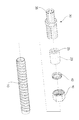
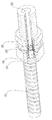
도 1은 본 발명에 따른 나선형 주름관 연결구의 일실시예를 나타낸 분해 사시도이고,
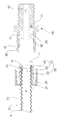
도 2는 도 1의 구성 중 소켓과 넛트에 의하여 고정되고 나선형 주름관에 나사 결합된 패킹을 나타낸 분해사시도이며,
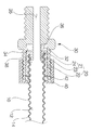
도 3은 도 2의 결합단면도이고,
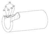
도 4는 도 1의 구성 중 패킹을 나타낸 부분 절개사시도이며,
도 5는 본 발명의 일실시예에 따른 나선형 주름관 연결구를 나타낸 부분 절개 사시도이다.1 is an exploded perspective view showing an embodiment of a spiral corrugated pipe connector according to the present invention,
Figure 2 is an exploded perspective view showing the packing fixed by the socket and the nut of the configuration of Figure 1 screwed to the spiral corrugated pipe,
3 is a cross-sectional view of the combination of FIG.
Figure 4 is a partial cutaway perspective view showing the packing of the configuration of Figure 1,
Figure 5 is a partially cut perspective view showing a spiral corrugated pipe connector according to an embodiment of the present invention.
이하, 본 발명에 따른 나선형 주름관 연결구의 일실시예를 첨부된 도면을 참조하여 상세하게 설명하기로 한다.Hereinafter, an embodiment of a spiral corrugated pipe connector according to the present invention will be described in detail with reference to the accompanying drawings.
도 1은 본 발명에 따른 나선형 주름관 연결구의 일실시예를 나타낸 분해 사시도이고, 도 2는 도 1의 구성 중 소켓과 넛트에 의하여 고정되고 나선형 주름관에 나사 결합된 패킹을 나타낸 분해사시도이며, 도 3은 도 2의 결합단면도이고, 도 4는 도 1의 구성 중 패킹을 나타낸 부분 절개사시도이며, 도 5는 본 발명의 일실시예에 따른 나선형 주름관 연결구를 나타낸 부분 절개 사시도이다.1 is an exploded perspective view showing an embodiment of a spiral corrugated pipe connector according to the present invention, Figure 2 is an exploded perspective view showing a packing fixed to the spiral corrugated pipe by a socket and a nut of the configuration of Figure 1, Figure 3 2 is a cross-sectional view of the coupling of Figure 2, Figure 4 is a partial cutaway perspective view showing the packing of the configuration of Figure 1, Figure 5 is a partially cut perspective view showing a spiral corrugated pipe connector according to an embodiment of the present invention.
본 발명의 일실시예에 따른 나선형 주름관 연결구는, 도 1에 도시된 바와 같이, 나선형 주름관(10)의 일단부가 삽입되는 소켓(30)과, 상기 나선형 주름관(10)의 일단부와 상기 소켓(30) 사이에 위치되는 패킹(20)을 포함한다.Spiral corrugated pipe connector according to an embodiment of the present invention, as shown in Figure 1, one end of the spiral
상기 패킹(20)은 상기 나선형 주름관(10)과 다른 나선형 주름관(10) 또는 타물체와의 접속을 위하여 필요한 부품에 개재되어 상기 나선형 주름관(10) 내부를 흐르는 유체의 누수를 방지하는 실링(Sealing) 기능을 수행한다. 보통 이와 같은 기능을 수행하는 상기 패킹(20)은, 탄성변형이 용이한 재질로 이루어질 수 있다. 이와 같이 탄성변형이 용이한 재질로는 보통 고무 재질의 유연한 재질이 채택될 수 있음은 당연하다.The
상기 나선형 주름관(10)은 유체가 내부를 흐르면서 외부와 쉽게 열전달이 이루어지도록 열전달율이 우수한 재질로 이루어짐이 바람직하다.The spiral
또한, 상기 나선형 주름관(10)의 끝단에는 상기 패킹(20)에 의하여 상기 나선형 주름관(10)의 단부가 감싸지도록 상기 패킹(20)이 나사 결합된다. 이를 위해 상기 패킹(20)에는 상기 나선형 주름관(10)의 외주면에 형성된 나사부(수나사부)에 대응되는 나사부(암나사부)가 형성된다.In addition, the
보다 상세하게는, 상기 패킹(20)은, 도 4에 도시된 바와 같이, 상기 나선형 주름관(10)의 끝단이 삽입되어 결합되도록 상기 나선형 주름관(10)에 대응되게 실린더형으로 형성된다. More specifically, the
또한, 상기 패킹(20)은, 상기 나선형 주름관(10)의 단부쪽으로 접근할수록 외경이 감소하는 테이퍼진 단면을 가지도록 형성될 수 있다.In addition, the
구체적으로 상기 패킹(20)은, 내측단부에 상기 나선형 주름관(10)의 끝단이 감싸지도록 끼워지는 실링부(21)와, 상기 실링부(21)로부터 연장되어 상기 나선형 주름관(10)의 일단부가 상기 실링부(21)에 끼워지면 상기 나선형 주름관(10)의 외주면에 밀착되는 연장부(22)를 포함한다.In detail, the
여기서, 상기 실링부(21)는 상기 나선형 주름관(10)의 외주면(14)이 밀착되는 외측 실링부(23)와 상기 외측 실링부(23)와 끝단에서 연결되고 상기 나선형 주름관(10)의 내주면(12)이 밀착되는 내측 실링부(24)로 구성된다.Here, the sealing
상기 외측 실링부(23)와 상기 연장부(22)는 상기 나선형 주름관(10)의 외주면에 밀착되도록 서로 일체형으로 연결된다.The
상기 외측 실링부(23)와 상기 내측 실링부(24)로 구성된 상기 실링부(21)는 도 4에 도시된 바와 같이, 대략 "ㄷ"자 형상의 단면을 가지도록 형성되고, 상기 외측 실링부(23)와 상기 내측 실링부(24) 사이에는 가느다란 홈(25)이 형성된다.As shown in FIG. 4, the
상기 홈(25)은 상기 나선형 주름관(10)의 끝단이 나사 결합되도록 나선형 홈으로 형성될 수 있다.The
상기 나선형 주름관(10)의 끝단이 끼워지는 상기 외측 실링부(23)는 도 2의 도면부호 "t1"과 같은 두께를 가진다. The
끝단이 상기 실링부(21)에 결합된 상태의 상기 나선형 주름관(10)의 일단부는 상기 소켓(30)과 결합된다.One end of the spiral
상기 소켓(30)의 내부는 유체가 통과하도록 유동홀(35)이 형성되고, 상기 유동홀(35)에 해당하는 상기 소켓(30)의 내부에는 도 2 및 도 5에 도시된 바와 같이, 상기 나선형 주름관(10)의 끝단과 상기 나선형 주름관(10)의 끝단에 결합된 상기 실링부(21)가 삽입되는 요홈부(32)가 형성된다.A
상기 요홈부(32)는, 도 2 및 도 3에 도시된 바와 같이, 상기 소켓의 내주면으로부터 후술하는 넛트(40)를 향하여 돌출된 돌출관부(36)에 의하여 형성된다. 2 and 3, the
여기서, 상기 요홈부(32)는 상기 나선형 주름관(10)의 끝단이 끼워진 상기 실링부(21)가 억지끼움되는 너비(도 2의 도면부호 "t2" 참조)로 형성됨이 바람직하다. 즉, 도 2의 도면부호 "t1"로 표시되는 상기 실링부(21) 두께보다 도 2의 도면부호 "t2"로 표시되는 상기 요홈부(32)의 너비가 약간 작게 형성됨으로써, 상기 실링부(21)에 끼워진 상기 나선형 주름관(10)의 끝단이 상기 요홈부(32)에 삽입될 때 억지끼움된다.Here, the
이처럼, 상기 실링부(21)가 상기 요홈부(32)에 억지끼움되는 경우에는, 상기 나선형 주름관(10)이 후술하는 넛트(40)에 의하여 소켓(30)에 고정되어 있지 않는 동안에도 가고정되어 그 결합 공정이 손쉬워지는 이점을 가진다.In this way, when the
또한, 상기 실링부(21)가 상기 요홈부(32)에 끼워지면, 상기 요홈부(32)의 내주면(36)과 외주면(34)(상기 소켓(30)의 내주면(34)에 해당됨)에 더욱 밀착되므로 수밀성이 우수해지는 이점이 있다.In addition, when the
아울러, 상기 패킹(20)은 상술한 바와 같이 탄성변형이 용이한 재질 또는 미끄러운 흑연 재질로 이루어진 바, 상기 요홈부(32)에 억지끼움이 용이한 것은 당연하다.In addition, the
한편, 상기 요홈부(32)는 상술한 바와 같이 테이퍼진 형상의 상기 패킹(20)이 결합된 상태의 상기 나선형 주름관(10)의 단부가 용이하게 상기 요홈부(32)로 삽입될 수 있도록, 내측으로부터 외측(도면상 우측)으로 갈수록 외경이 점차 커지는 테이퍼진 형상으로 형성된다.On the other hand, the
여기서, 상기 패킹(20)은 고무와 같은 탄성변형이 용이한 재질로 형성되므로, 상기 요홈부(32)에 삽입되는 과정이 용이하면서도, 상기 요홈부(32)에 상기 실링부(21)가 삽입된 이후에는 작은 외력만으로는 상기 요홈부(32)로부터 쉽게 이탈되지 않으므로 상기 소켓(30)에 대한 상기 나선형 주름관(10)의 가고정성이 우수하다.Here, the
한편, 상기 실링부(21)는 상기 요홈부(32)의 형성 깊이(![]()
![]()
![]()
![]()
본 발명의 일실시예에 따른 나선형 주름관 연결구는, 도 1 내지 도 3 및 도 5에 도시된 바와 같이, 상기 요홈부(32)에 가결합된 상기 나선형 주름관(10)을 고정하는 지지링(42)을 더 포함한다.The spiral corrugated pipe connector according to the embodiment of the present invention, as shown in FIGS. 1 to 3 and 5, a
상기 지지링(42)은 상기 소켓(30) 및 후술하는 넛트(40)에 의하여 외부로 노출되지 않도록 상기 나선형 주름관(10)에 결합되어 상기 패킹(20)을 지지하는 역할을 한다.The
아울러, 본 발명의 일실시예에 따른 나선형 주름관 연결구는, 상기 소켓(30)의 외주면(38)에 결합되어 상기 지지링(42)을 외부로부터 차폐함과 아울러 상기 지지링(42)을 압압하는 넛트(40)를 더 포함한다.In addition, the spiral corrugated pipe connector according to an embodiment of the present invention is coupled to the outer
여기서, 상기 지지링(42)은 상기 넛트(40)에 의하여 상기 나선형 주름관(10)과 상기 소켓(30)을 최종적으로 결합시키기 전에 상기 패킹(20)이 유동되지 않도록 지지하는 역할을 한다.Here, the
특히, 상기 지지링(42)은 상기 나선형 주름관(10)의 외주면에 끼워지도록 상기 나선형 주름관(10)의 외주면에 형성된 수나사부와 대응되는 암나사부가 상기 지지링(42)의 내측면에 형성된다.In particular, the
여기서, 상기 지지링(42)은 필요 이상으로 길게 형성될 필요는 없고 적어도 한 피치 이상의 암나사부가 형성되기에 부족함이 없는 정도의 길이를 가지면 충분하다.Here, the
이와 같이, 상기 지지링(42)은 상기 나선형 주름관(10)의 외주면에 나사 결합되는 바, 상기 패킹(20)이 결합된 상태의 상기 나선형 주름관(10)의 끝단을 상기 요홈부(32)에 삽입한 후 상기 지지링(42)을 상기 패킹(20)이 배치된 측으로 나사 회전 이동시켜 상기 패킹(20)를 지지/고정(더블넛팅)하도록 한다.In this way, the
이때, 상기 지지링(42)의 외경(φ)은 적어도 상기 나선형 주름관(10)에 결합되는 상기 지지링(42)이 상기 나선형 주름관(10)의 외주면과 상기 소켓(30)의 내주면(34) 사이로 삽입 체결될 수 있는 크기로 형성된다. At this time, the outer diameter φ of the
이는, 상기 지지링(42)이 상기 나선형 주름관(10)의 외주면과 상기 소켓(30)의 내주면(34) 사이에 삽입 체결됨으로써 상기 패킹(20)을 보다 강한 압착력으로 상기 요홈부(32)에 결합시키기 위함이다.This is because the
한편, 상기 소켓(30)의 외주면(38)에는 수나사부가 형성되고, 상기 넛트(40)의 내주면에는 상기 소켓(30)의 수나사부에 대응되는 암나사부가 형성되어, 상기 넛트(40)는 상기 소켓(30)의 외주면(38)에 나사 결합된다.Meanwhile, a male screw portion is formed on an outer
상기 소켓(30)의 외주면은 도 2에 도시된 바와 같이, 상기 넛트(40)가 최초로 나사 결합되는 선단부로 갈수록 그 직경이 커지도록 형성되어 있는 반면, 상기 넛트(40)의 내주면은 상기 소켓(30)의 외주면에 최초로 결합되는 부분의 직경이 상기 소켓(30)에 체결되는 거리에 따라 점점 줄어드는 형상으로 형성된다.As shown in FIG. 2, the outer circumferential surface of the
이와 같이 형성된 상기 넛트(40)가 상기 소켓(30)의 외주면에 나사 결합되면 상기 소켓(30)의 선단부의 직경이 상기 넛트(40)의 압착력 내지는 결합력에 의하여 점점 작아지면서 상기 소켓(30)의 내부에 삽입된 상기 패킹(20)을 압착하게 되고, 이와 같은 상기 패킹(20)의 압착력은 상기 나선형 주름관(10)의 접속부 실링 기능을 더욱 향상시키는 이점을 제공하게 된다.When the
특히, 상기 넛트(40)는 상기 소켓(30)에 나사 결합되면서 그 이전 결합 공정에 의하여 결합된 상기 지지링(42)을 상기 요홈부(32)가 형성된 방향으로 밀착시킴으로써 상기 소켓(30)의 중심방향으로 뿐만 아니라 상기 요홈부(32) 방향으로도 상기 패킹(20)을 압착함으로써 보다 큰 수밀성을 보장하는 이점을 제공한다.In particular, the
이처럼, 본 발명의 일실시예에 따른 나선형 주름관 연결구는, 상기 소켓(30)에 상기 요홈부(32)를 형성하고, 상기 요홈부(32)에 상기 나선관(10)을 직접 접촉 체결방식이 아닌 상기 실링부(21)를 포함하여 구성된 상기 패킹(20)이 개재되는 간접 접촉 체결방식을 적용함과 아울러 상기 패킹(20)을 상기 넛트(40) 및 상기 지지링(42)에 의하여 더욱 압착시켜 상기 소켓(30)에 최종적으로 상기 나선형 주름관(10)을 연결시킴으로써, 제품의 수밀성을 크게 향상시키고 결합 공정이 용이하도록 하는 이점이 창출된다.As such, in the spiral corrugated pipe connector according to the embodiment of the present invention, the
상기와 같이 구성되는 본 발명의 일실시예에 따른 나선형 주름관 연결구의 결합 공정을 첨부된 도면을 참조하여 순서대로 설명하면 다음과 같다.Referring to the coupling process of the spiral corrugated pipe connector according to an embodiment of the present invention configured as described above in order with reference to the accompanying drawings as follows.
먼저, 도 1에 도시된 바와 같이, 상기 나선형 주름관(10)의 외주면에 상기 넛트(40)를 먼저 끼운 다음 상기 지지링(42)을 나사 결합시킨다.First, as shown in FIG. 1, the
다음으로, 상기 나선형 주름관(10)의 끝단에 상기 패킹(20)을 회전시키면서 나사 결합시킨다.Next, screw the
그리고, 상기 패킹(20)이 나사 결합된 상태의 상기 나선형 주름관(10)의 끝단을 상기 소켓(30)의 상기 요홈부(32)가 형성된 방향으로 이동시켜 상기 실링부(21)를 상기 요홈부(32)에 억지끼움 결합시킨다.The end of the spiral corrugated
이와 같이, 상기 요홈부(32)에 상기 패킹(20)이 나사 결합된 상태의 상기 나선형 주름관(10)을 가고정시킨 후 상기 지지링(42)을 회전 이동시켜 상기 패킹(20)을 견고하게 지지/고정(더블넛팅)하도록 한 후 상기 나선형 주름관(10)의 외주면과 상기 소켓(30)의 내주면(34) 사이로 삽입 회전시킨다.As such, after temporarily fixing the spiral corrugated
마지막으로, 상기 넛트(40)를 상기 소켓(30)에 나사 결합시키면 본 발명에 따른 나선형 주름관 연결구의 결합 공정이 완료되게 된다.Finally, when the
이상, 본 발명의 일실시예에 따른 나선형 주름관 연결구의 구성 및 결합 공정 등을 첨부된 도면을 참조하여 상세하게 설명하였다. 그러나, 본 발명의 실시예가 반드시 이에 한정되는 것은 아니며, 본 발명이 속하는 기술분야에서 통상의 지식을 가진 자에 의해 본 발명과 균등한 범위에 속하는 다양한 변형 또는 다른 실시예의 구현이 가능함은 당연하다. 따라서, 본 발명의 진정한 권리범위는 이어지는 특허청구범위에 의하여 정해져야 할 것이다. Or more, with reference to the accompanying drawings, the configuration and bonding process of the spiral corrugated pipe connector according to an embodiment of the present invention was described in detail. However, embodiments of the present invention are not necessarily limited thereto, and it is obvious that various modifications or other embodiments falling within the scope equivalent to the present invention may be implemented by those skilled in the art. Therefore, the true scope of the present invention will be defined by the claims that follow.
10: 나선형 주름관 12: 나선형 주름관의 내주면
14: 나선형 주름관의 외주면 20: 패킹
22: 연장부 23: 외측 실링부
24: 내측 실링부 25: 홈
30: 소켓 32: 요홈부
34: 소켓의 내주면 35: 유동홀
36: 요홈부의 내주면 38: 소켓의 외주면
40: 넛트 42: 지지링
t1: 패킹의 두께 t2: 요홈부의 너비
![]()
![]()
φ: 지지링의 외경10: spiral corrugated pipe 12: inner circumferential surface of the spiral corrugated pipe
14: outer circumferential surface of the spiral corrugated pipe 20: packing
22: extension part 23: outer sealing part
24: inner sealing portion 25: groove
30: socket 32: groove
34: inner circumferential surface of the socket 35: flow hole
36: inner circumferential surface of the recess 38: outer circumferential surface of the socket
40: nut 42: support ring
t1: thickness of packing t2: width of groove
![]()
![]()
φ: outer diameter of support ring
Claims (16)
상기 소켓에 상기 나선형 주름관이 고정되도록 상기 소켓에 체결되는 넛트와;
상기 나선형 주름관의 일단부와 상기 소켓 사이에 위치되는 패킹으로 구성되고,
상기 패킹은 상기 나선형 주름관의 끝단이 감싸지도록 끼워지는 실링부가 포함된 나선형 주름관 연결구.
A socket into which one end of the spiral corrugated pipe is inserted;
A nut fastened to the socket to fix the spiral corrugated pipe to the socket;
A packing located between one end of the spiral corrugated pipe and the socket,
The packing is spiral corrugated pipe connector including a sealing portion is inserted so that the end of the spiral corrugated pipe wrapped.
상기 나선형 주름관에 결합되고, 상기 패킹과 상기 넛트 사이에 위치되는 지지링을 포함하는 나선형 주름관 연결구.
The method according to claim 1,
And a support ring coupled to the spiral corrugated pipe, the support ring being positioned between the packing and the nut.
상기 패킹은 상기 실링부로부터 상기 넛트 방향으로 연장되어 상기 나선형 주름관의 외주면에 밀착되는 연장부를 포함하는 나선형 주름관 연결구.
The method according to claim 1,
The packing is spiral corrugated pipe connector including an extension extending in the nut direction from the sealing portion in close contact with the outer peripheral surface of the spiral corrugated pipe.
상기 소켓에는,
상기 패킹의 실링부와 상기 실링부에 끼워진 나선형 주름관의 끝단이 삽입되는 요홈부가 형성된 나선형 주름관 연결구.
The method according to any one of claims 1 to 3,
In the socket,
Spiral corrugated pipe connector formed with a groove portion for inserting the sealing portion of the packing and the end of the spiral corrugated pipe fitted to the sealing portion.
상기 실링부는,
상기 나선형 주름관의 끝단이 끼워진 상태로 상기 요홈부에 억지끼움되는 두께를 가지는 나선형 주름관 연결구.
The method of claim 4,
The sealing unit,
Spiral corrugated pipe connector having a thickness that is forcibly fitted to the groove portion with the end of the spiral corrugated pipe fitted.
상기 요홈부는, 상기 소켓의 내주면으로부터 상기 넛트를 향하여 돌출된 돌출관부에 의하여 형성된 나선형 주름관 연결구.
The method of claim 4,
The groove portion is a spiral corrugated pipe connector formed by a protruding tube portion protruding toward the nut from the inner peripheral surface of the socket.
상기 실링부는,
상기 나선형 주름관의 끝단 외주면에 밀착되고, 상기 연장부가 일체로 연장되는 외측 실링부와;
상기 나선형 주름관의 끝단 내주면에 밀착되는 내측 실링부를 포함하는 나선형 주름관 연결구.
The method according to claim 3,
The sealing unit,
An outer sealing part in close contact with an outer circumferential surface of the end of the spiral corrugated pipe, the extension part integrally extending;
Spiral corrugated pipe connector including an inner sealing portion in close contact with the inner peripheral surface of the end of the spiral corrugated pipe.
상기 실링부는,
상기 요홈부의 깊이에 대응되는 길이로 형성된 나선형 주름관 연결구.
The method of claim 4,
The sealing unit,
Spiral corrugated pipe connector formed with a length corresponding to the depth of the groove portion.
상기 지지링은 상기 나선형 주름관의 외주면에 나사 결합되는 나선형 주름관 연결구.
The method according to claim 2,
The support ring is a spiral corrugated pipe connector screwed to the outer peripheral surface of the spiral corrugated pipe.
상기 실링부에는 상기 나선형 주름관의 끝단이 삽입되는 홈이 형성된 나선형 주름관 연결구.
The method according to any one of claims 1 to 3,
Spiral corrugated pipe connector formed with a groove in the sealing portion is inserted into the end of the spiral corrugated pipe.
상기 홈은 나선형 홈으로 형성된 나선형 주름관 연결구.
The method according to claim 10,
The groove is a spiral corrugated pipe connector formed by a spiral groove.
상기 패킹은 탄성변형이 가능한 재질로 이루어진 나선형 주름관 연결구.
The method according to any one of claims 1 to 3,
The packing is a spiral corrugated pipe connector made of a material capable of elastic deformation.
상기 패킹은 상기 나선형 주름관과 나사 결합되는 나선형 주름관 연결구.
The method according to any one of claims 1 to 3,
The packing is a spiral corrugated pipe end connection screwed with the spiral corrugated pipe.
상기 소켓은 외경이 내측으로부터 상기 넛트 방향으로 갈수록 크게 되도록 경사지게 형성된 나선형 주름관 연결구.
The method according to any one of claims 1 to 3,
The socket is a spiral corrugated pipe connector formed so as to be inclined so that the outer diameter becomes larger toward the nut from the inside.
상기 소켓의 내경은 내측으로부터 상기 넛트 방향을 향하여 내경이 점차 크게 되도록 형성된 나선형 주름관 연결구.
The method according to any one of claims 1 to 3,
Spiral corrugated pipe connector formed so that the inner diameter of the socket is gradually increased from the inner side toward the nut direction.
상기 패킹은 외경이 상기 소켓의 내측 방향을 향하여 점차 작아지도록 형성된 나선형 주름관 연결구.The method according to any one of claims 1 to 3,
The packing is spiral corrugated pipe connector formed so that the outer diameter is gradually reduced toward the inner direction of the socket.
Priority Applications (1)
| Application Number | Priority Date | Filing Date | Title |
|---|---|---|---|
| KR1020110124528A KR20110137759A (en) | 2011-11-25 | 2011-11-25 | Connecting device of spiral pipe |
Applications Claiming Priority (1)
| Application Number | Priority Date | Filing Date | Title |
|---|---|---|---|
| KR1020110124528A KR20110137759A (en) | 2011-11-25 | 2011-11-25 | Connecting device of spiral pipe |
Related Parent Applications (1)
| Application Number | Title | Priority Date | Filing Date |
|---|---|---|---|
| KR1020090089153A Division KR20110031762A (en) | 2009-09-21 | 2009-09-21 | Connecting device of spiral pipe |
Related Child Applications (1)
| Application Number | Title | Priority Date | Filing Date |
|---|---|---|---|
| KR1020130046705A Division KR101539407B1 (en) | 2013-04-26 | 2013-04-26 | Connecting device of spiral pipe |
Publications (1)
| Publication Number | Publication Date |
|---|---|
| KR20110137759A true KR20110137759A (en) | 2011-12-23 |
Family
ID=45503918
Family Applications (1)
| Application Number | Title | Priority Date | Filing Date |
|---|---|---|---|
| KR1020110124528A KR20110137759A (en) | 2011-11-25 | 2011-11-25 | Connecting device of spiral pipe |
Country Status (1)
| Country | Link |
|---|---|
| KR (1) | KR20110137759A (en) |
Cited By (2)
| Publication number | Priority date | Publication date | Assignee | Title |
|---|---|---|---|---|
| WO2021137326A1 (en) * | 2019-12-31 | 2021-07-08 | 엘지전자 주식회사 | Display device |
| KR20210001671U (en) * | 2020-01-10 | 2021-07-20 | 김민재 | Bellows pipe connecting structure |
-
2011
- 2011-11-25 KR KR1020110124528A patent/KR20110137759A/en active Application Filing
Cited By (3)
| Publication number | Priority date | Publication date | Assignee | Title |
|---|---|---|---|---|
| WO2021137326A1 (en) * | 2019-12-31 | 2021-07-08 | 엘지전자 주식회사 | Display device |
| US11823596B2 (en) | 2019-12-31 | 2023-11-21 | Lg Electronics Inc. | Display device |
| KR20210001671U (en) * | 2020-01-10 | 2021-07-20 | 김민재 | Bellows pipe connecting structure |
Similar Documents
| Publication | Publication Date | Title |
|---|---|---|
| KR20110031762A (en) | Connecting device of spiral pipe | |
| RU2659946C2 (en) | Fitting for mounting on threaded pipe connection and method of fitting mounting on threaded pipe connection | |
| JPH033837B2 (en) | ||
| KR101195280B1 (en) | Apparatus for connecting a insertional pipe | |
| JP4939826B2 (en) | How to assemble pipe fittings | |
| JP6059252B2 (en) | Connection method for connecting a connecting member with an insulated conduit | |
| KR20120105917A (en) | Flexible pipe connector | |
| JP6112842B2 (en) | Pipe joint structure | |
| JP5269178B2 (en) | How to assemble pipe fittings | |
| KR101489711B1 (en) | Connector for branch pipe | |
| KR101392564B1 (en) | Hose Connector | |
| KR20110137759A (en) | Connecting device of spiral pipe | |
| KR101218352B1 (en) | Conneting device for pipe | |
| KR20130066643A (en) | Connecting device of spiral pipe | |
| JP2005061549A (en) | Pipe joint structure for valve and resin pipe, and connecting method using the same | |
| KR20140100697A (en) | The Fitting For Gas Flexible Hose | |
| CN210510591U (en) | Multi-sealing quick-insertion type joint of stainless steel corrugated pipe | |
| CN208311740U (en) | A kind of hose coupling | |
| KR101700063B1 (en) | Hose Connector | |
| KR20130075098A (en) | Structure of rubber-seal for mechanical fitting and it's applied mechanical fitting | |
| WO2006112604A1 (en) | Rubber packing for pipe connection | |
| JP4593409B2 (en) | Expandable flexible joint structure | |
| KR200181270Y1 (en) | A reducer for flare pipe | |
| JP2014109295A (en) | Pipe joint structure | |
| KR200387796Y1 (en) | Rigid plastic conduit yoke |
Legal Events
| Date | Code | Title | Description |
|---|---|---|---|
| A107 | Divisional application of patent | ||
| A201 | Request for examination | ||
| A302 | Request for accelerated examination | ||
| E902 | Notification of reason for refusal | ||
| E601 | Decision to refuse application | ||
| A107 | Divisional application of patent |