JP4939826B2 - How to assemble pipe fittings - Google Patents
How to assemble pipe fittings Download PDFInfo
- Publication number
- JP4939826B2 JP4939826B2 JP2006084668A JP2006084668A JP4939826B2 JP 4939826 B2 JP4939826 B2 JP 4939826B2 JP 2006084668 A JP2006084668 A JP 2006084668A JP 2006084668 A JP2006084668 A JP 2006084668A JP 4939826 B2 JP4939826 B2 JP 4939826B2
- Authority
- JP
- Japan
- Prior art keywords
- resin short
- claw portion
- joint
- seal ring
- pipe
- Prior art date
- Legal status (The legal status is an assumption and is not a legal conclusion. Google has not performed a legal analysis and makes no representation as to the accuracy of the status listed.)
- Active
Links
Images


Landscapes
- Joints With Sleeves (AREA)
- Branch Pipes, Bends, And The Like (AREA)
- Joints Allowing Movement (AREA)
- Quick-Acting Or Multi-Walled Pipe Joints (AREA)
Abstract
Description
本発明は、給水・給湯、冷温水、冷却水などの配管に用いられ、それら配管の一端部を給水栓等の器具に接続するのに用いられる管継手の組立て方法に関する。 The present invention relates to a method of assembling a pipe joint used for piping such as water / hot water supply, cold / hot water, and cooling water, and connecting one end of the piping to an instrument such as a water tap.
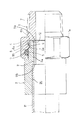
給水・給湯等の配管に用いられる管継手として、例えば、図4に示すような管継手が提案されている(例えば、特許文献1参照。)。この管継手は、給水栓等の器具に接続可能でかつ一端に受口部20を開口した継手本体21と、継手本体21の受口部20に挿入される樹脂製短管(特許文献1では「ソケット」と称す。)22と、継手本体21の受口部20の外周に設けられた雄ねじ23に螺合されるナット(押輪)24と、受口部20の開口端内周と樹脂製短管22の外周との間に介在されるワッシャ25、Oリング26、環状リーフ27とを備える。
As a pipe joint used for piping such as water supply and hot water supply, for example, a pipe joint as shown in FIG. 4 has been proposed (see, for example, Patent Document 1). This pipe joint includes a
この管継手の現場施工に際しては、先ず、継手本体21を給水栓等器具に接続する一方、樹脂製短管22にワッシャ25、Oリング26、環状リーフ27、更にはナット24をこの順で挿入しておき、樹脂製短管22に給水管Pを挿入して接着接合したうえで、樹脂製短管22をこの挿入側先端が継手本体21の受口部20に該受口部20内のストッパーリブ28に当接するまで挿入するとともに、ナット24を継手本体21に締付けるというものである。
When constructing the pipe joint in the field, first, the
しかしながら、上記管継手では、現場での施工終了後に、ナット24の締付け不足を確認し難いという締付け管理面での問題がある。このため、振動や外部からの荷重等によりナット24の締付けが緩むと、給水管P内の水が漏洩する可能性がある。また、ナット24を継手本体21に対し締付ける構造上、呼び径が小口径でも、継手本体21の外周及びナット24の外周に六角形や八角形など多角形の工具掛け部21a、24aを形成しておく必要があるため、その分だけ継手本体21及びナット24が大きくなり、継手全体の材料コストアップ、大型化を招き、重量的にも重くなるという難点があった。
However, the above-described pipe joint has a problem in tightening management in that it is difficult to confirm the shortage of tightening of the
本発明はこのような問題を解決するためになされたものであり、その目的とするところは、前述した従来の管継手のようなナット(押輪)の使用を省略化することでコスト低減、小型化、コンパクト化を図り得、またナットの締付け作業の省略化により組立て作業性の向上を図れ、しかも施工後のナットの緩み問題も解消できて水漏れ事故の発生を確実に防止できて信頼性の高い管継手の組立て方法を提供することにある。 The present invention has been made to solve such problems, and the object of the present invention is to reduce the cost and size by omitting the use of a nut (push wheel) like the conventional pipe joint described above. The assembly workability can be improved by eliminating the tightening work of the nut, and the problem of loosening of the nut after installation can be solved, and the occurrence of water leakage accidents can be surely prevented and reliability is improved. An object of the present invention is to provide a method for assembling a pipe joint having a high height.
本発明の管継手の組立て方法は、請求項1に記載のように、少なくとも一端に受口部を有する継手本体と、この継手本体の前記受口部に挿入可能とする樹脂製短管とを備えている管継手の組立て方法において、前記継手本体は、前記受口部の内周に、軸方向内方に向かって窄まり状のテーパと軸方向に対し直角の垂直部とを有する環状の内向き爪部が設けられており、前記樹脂製短管は、前記受口部内への挿入側部の外周に、先窄まり状のテーパと軸方向に対し直角の垂直部とを有し、前記内向き爪部に抜止め状に係合され拡縮径変形可能な環状の外向き爪部が設けられており、前記樹脂製短管の挿入側部の内径は、前記樹脂製短管の後端開口部の内径より小さくなっており、前記継手本体は、前記内向き爪部に加え、前記内向き爪部の軸方向内方側に配され軸方向に対し直角の垂直面が設けられており、前記継手本体および前記樹脂製短管のいずれか一方を、他方の前記挿入側部および前記受口部のいずれかに圧入し、その圧入に伴い、前記樹脂製短管の前記外向き爪部は、該先窄まり状のテーパを前記継手本体内の前記内向き爪部のテーパに摺接し、該内向き爪部で縮径されながら該内向き爪部を乗り越えて前記外向き爪部の弾性復元作用により、該内向き爪部の垂直部に前記外向き爪部の垂直部を互いに対向させるように係合し、しかる後、前記樹脂製短管内にインコアを挿入し、該インコアの軸方向内方側の端が前記垂直面に対向し軸方向外方側の端が前記樹脂製短管の挿入側部の内周に入るよう前記インコアを前記樹脂製短管の挿入側部の内周に嵌合することを特徴を有するものである。
このような構成によれば、樹脂製短管を継手本体の受口部に圧入するだけで内向き爪部と外向き爪部とが互いに抜止め状に係合するため、樹脂製短管を継手本体に抜止め状に簡易迅速に接続することができる。
また、前記樹脂製短管の挿入側部の内周にインコアを嵌合することができる。これによれば、インコアにより樹脂製短管の挿入側部が縮径変形するのを防止する補強機能を発揮し、樹脂製短管が受口部から抜出るのをより確実に防止することができる。
The pipe joint assembling method of the present invention comprises, as described in
According to such a configuration, since the inward claw portion and the outward claw portion are engaged with each other only by press-fitting the resin short tube into the receiving portion of the joint body, the resin short tube is It can be easily and quickly connected to the joint body in a retaining manner.
Moreover, an in-core can be fitted to the inner periphery of the insertion side portion of the resin short pipe. According to this, the reinforcement function which prevents the insertion side part of the resin short pipe from being reduced in diameter by the in-core is demonstrated, and the resin short pipe can be more reliably prevented from being pulled out from the receiving part. it can.
また、本発明の管継手の組立て方法は、請求項2に記載のように、少なくとも一端に受口部を有する継手本体と、この継手本体の前記受口部に挿入可能とする短管状の樹脂製短管と、前記受口部に挿入された樹脂製短管の挿入側部の外周と前記受口部の内周との間に介在されたシールリングとを備えている管継手の組立て方法において、前記継手本体は、前記受口部の内周に、前記シールリングが嵌合状に収容される環状のシールリング収容凹溝と、該シールリング収容凹溝の軸方向外方側に配され軸方向内方に向かって窄まり状のテーパ、及び軸方向に対し直角の垂直部を有し、径方向内方へ向かって突出する環状の内向き爪部と、が設けられており、前記樹脂製短管は、その挿入側部の外周に、前記内向き爪部に抜止め状に係合されるとともに前記シールリングの内径部を押圧し、先窄まり状のテーパと軸方向に対し直角の垂直部とを有する環状の拡縮径変形可能な外向き爪部が径方向外方へ向かって突出するように設けられており、前記樹脂製短管の挿入側部の内径は、前記樹脂製短管の後端開口部の内径より小さくなっており、前記継手本体は、前記シールリング収容凹溝の軸方向内方側に配され軸方向に対し直角の垂直面がさらに設けられており、前記シールリングを前記継手本体内の前記シールリング収容凹溝内に収容し、前記継手本体および前記樹脂製短管のいずれか一方を、他方の前記挿入側部および前記受口部のいずれかに圧入し、その圧入に伴い、前記外向き爪部が、そのテーパを前記継手本体内の前記シールリングの内径部に摺接して、前記外向き爪部が前記内向き爪部を乗り越える途上で該シールリングを前記シールリング収容凹溝内に押し付けるよう圧縮させながら該シールリング内を通過し、前記シールリング内を通過後、該テーパを前記継手本体内の内向き爪部のテーパに摺接し、該内向き爪部で縮径されながら該内向き爪部を乗り越えて前記外向き爪部の弾性復元作用により該内向き爪部の垂直部に前記外向き爪部の垂直部を互いに対向させるように係合し、しかる後、前記樹脂製短管内にインコアを挿入し、該インコアの軸方向内方側の端が前記垂直面に対向し軸方向外方側の端が前記樹脂製短管の挿入側部の内周に入るよう前記インコアを前記樹脂製短管の挿入側部の内周に嵌合することに特徴を有するものである。
このような構成によれば、樹脂製短管を継手本体の受口部に圧入するだけで内向き爪部と外向き爪部とが互いに抜止め状に係合するため、樹脂製短管を継手本体に抜止め状にかつシール状に簡易迅速に接続することができる。
また、前記樹脂製短管の挿入側部の内周にインコアを嵌合することができる。これによれば、インコアにより樹脂製短管の挿入側部が縮径変形するのを防止する補強機能を発揮し、樹脂製短管が受口部から抜出るのをより確実に防止することができる。
The pipe joint assembling method according to the present invention includes, as described in
According to such a configuration, since the inward claw portion and the outward claw portion are engaged with each other only by press-fitting the resin short tube into the receiving portion of the joint body, the resin short tube is It can be easily and quickly connected to the joint body in a retaining manner and in a sealing manner.
Moreover, an in-core can be fitted to the inner periphery of the insertion side portion of the resin short pipe. According to this, the reinforcement function which prevents the insertion side part of the resin short pipe from being reduced in diameter by the in-core is demonstrated, and the resin short pipe can be more reliably prevented from being pulled out from the receiving part. it can.
請求項1又は2記載の管継手の組立て方法は、請求項3記載のように、前記樹脂製短管に樹脂管の一端部を接合することができる。また請求項4記載のように、前記樹脂製短管は前記受口部に相対回転可能に挿入可能である。これによれば、樹脂製短管に樹脂管を接合した後でも、給水栓、バルブ等の器具に継手本体をねじ込むことができ、このねじ込みにより簡易に取付けることができる。
The pipe joint assembling method according to
本発明によれば、樹脂製短管を継手本体の受口部に挿入するだけで樹脂製短管を継手本体に抜止め状にかつシール状に接続することができ、前述した従来の管継手のような多角形の工具掛け部を有するナット(押輪)は省略することができ、これに伴い継手本体の工具掛け部の外径も小さくすることができるのでコスト低減、小型化、コンパクト化を図ることができ、しかもナットの締付け作業を省略でき樹脂製短管を継手本体の受口部に挿入するだけの簡単な作業で足りるため組立て作業性に優れ、しかも施工後のナットの緩みや締付け不足の問題も解消できて水漏れ事故の発生を確実に防止できる。 According to the present invention, it is possible to connect the resin short pipe to the joint main body in a retaining shape and in a seal shape by simply inserting the resin short pipe into the receiving portion of the joint main body. The nut (press ring) having a polygonal tool hanger as shown in the figure can be omitted, and the outer diameter of the tool hanger of the joint body can be reduced accordingly, thereby reducing costs, downsizing and downsizing. It is possible to reduce the tightening work of the nut, and it is easy to insert the resin short pipe into the joint receiving part. The assembly workability is excellent, and the nut is loosened and tightened after installation. The shortage problem can be solved and the occurrence of a water leak accident can be surely prevented.
本発明の好適な実施形態を図面に基づき説明する。図1は本発明の一実施例を示す管継手の半欠截断面図、図2は図1の管継手の組立て過程を示す断面図である。 A preferred embodiment of the present invention will be described with reference to the drawings. FIG. 1 is a cross-sectional view of a pipe joint according to one embodiment of the present invention, and FIG. 2 is a cross-sectional view showing an assembly process of the pipe joint of FIG.
本発明の組立て方法に係る管継手は、図1に示すように、継手本体1、樹脂製短管2、およびシールリング3などからなる。
As shown in FIG. 1, the pipe joint according to the assembling method of the present invention includes a
図1、図2(a)に示すように、継手本体1は金属材料や樹脂材料などからなり、一端に樹脂製短管2を挿入可能とする受口部4を開口し、この受口部4の内周にシールリング3が収容される環状のシールリング収容凹溝5と、このシールリング収容凹溝5より軸方向内奥側に並べて配され、軸方向内方に向かって窄まり状のテーパ6aと軸方向に対し直角の垂直部6bを有する断面鋸歯形状で環状の内向き爪部6と、内向き爪部6の軸方向内方側に配され軸方向に対し直角の垂直面12とを設けている。継手本体1の他端の外周には、給水栓やバルブ等の器具にねじ込み可能な雄ねじ7を設けている。継手本体1の受口部4の外周には多角形の工具掛け部1aを設けている。なお、図示例の継手本体1はストレート型であるが、エルボ型やティ−型などの場合もある。また、図示例の継手本体1はこれの他端の外周に雄ねじを設けてあるが、他端の内周に雌ねじを設けることもある。
As shown in FIG. 1 and FIG. 2 (a), the
図1、図2(a)に示すように、樹脂製短管2は、ポリブテン、ポリエチレン、塩化ビニルなど樹脂材料で図示例のごとくストレート、或いは図外のエルボ形状などに形成される。樹脂製短管2の受口部4への挿入側部は継手本体1の受口部4に相対回転可能に挿入可能な径小に形成され、この挿入側部の外周には、前記内向き爪部6の断面鋸歯形状とは逆向きの断面鋸歯形状に形成されて先窄まり状のテーパ8aと軸方向に対し直角の垂直部8bを有する拡縮径変形可能な外向き爪部8が環状に設けられている。樹脂製短管2の後端開口部の内径は、図1に二点鎖線で示すように、樹脂製短管2の材料と同じようにポリブテン、ポリエチレン、塩化ビニルなど樹脂材料からなる樹脂管Pの一端部が挿入されて熱融着または電気融着で接合できるように構成している。樹脂製短管2と樹脂管Pの一端部との接合手段としては熱融着・電気融着以外に、接着手段でも可能である。
樹脂製短管2の挿入側部の内周には、樹脂製短管2が継手本体1に抜止め状に接続された後にPPS、PPE等硬質樹脂や金属材料などからなるインコア9が嵌合されるようになっている。樹脂製短管2の挿入側部2aの内径は、樹脂製短管2の後端開口部2bの内径より小さくなっている。
As shown in FIGS. 1 and 2 (a), the resin
An in-
上記継手本体1の内向き爪部6と樹脂製短管2の外向き爪部8との位置関係については、図1のように、樹脂製短管2が継手本体1の受口部4内に所定深さにまで挿入されると、内向き爪部6と外向き爪部8とが互いに抜止め状に係合するように設定されている。
As for the positional relationship between the
シールリング3はOリング等からなって、樹脂製短管2の挿入側部の外径より小さい内径部を有する。シールリング3はこれの内径部が受口部4の内周面より径方向内方へ突出するように継手本体1のシールリング収容凹溝5内に嵌め込まれることで収容される。
The
次に、上記管継手の組立て要領について図2を参照にして説明する。
先ず、図2(a)に示すように、シールリング3を継手本体1内のシールリング収容凹溝5内に収容する。次いで、同図(b)のように、樹脂製短管2の挿入側部に継手本体1の受口部4を圧入するか、または樹脂製短管2の挿入側部を継手本体1の受口部4に圧入する。その圧入に伴い、樹脂製短管2の外向き爪部8が、テーパ8aを継手本体1内のシールリング3の内径部に摺接し、シールリング3をシールリング収容凹溝5内に押し付けるよう圧縮させながら該シールリング3内を通過する。樹脂製短管2の外向き爪部8は、シールリング3内を通過後、該テーパ8aを継手本体1内の内向き爪部6のテーパ6aに摺接し、該内向き爪部6で縮径されながら該内向き爪部6を乗り越えて弾性復元作用により該内向き爪部6の垂直部6bに垂直部8bを対向させるように係合する。この係合により樹脂製短管2が受口部4から抜け出るのを防止される状態が得られるとともに、シールリング3が継手本体1の受口部4の内周と樹脂製短管2の挿入側部の外周との間で圧縮されてその間で水漏れのないシール状態が得られる。最後に、同図(c)に示すインコア9が樹脂製短管2内に挿入され、図1のようにインコア9の軸方向内方側の端9aが垂直面12に対向し軸方向外方側の端9bが樹脂製短管2の挿入側部2aの内周に入るようインコア9を樹脂製短管2の挿入側部の内周に嵌合されて組立てを完了する。
Next, the assembly procedure of the pipe joint will be described with reference to FIG.
First, as shown in FIG. 2A, the
インコア9を樹脂製短管2の挿入側部の内周に嵌合することで、組立て後、樹脂製短管2に抜出し方向の引張力が強く働いた場合も樹脂製短管2の挿入側部が縮径するのを確実に防止することができ、樹脂製短管2の抜止め対策を万全なものとする。
By inserting the in-
この組立て状態では樹脂製短管2は継手本体1に対し相対回転可能であるので、樹脂製短管2に給水用等の樹脂管Pを接合した後でも、継手本体1の雄ねじ7を給水栓、バルブ等の器具(図示せず)にねじ込むことができて該器具に継手本体1を取付けることができる。
In this assembled state, since the resin
上記実施例の管継手では、継手本体1において内向き爪部6がシールリング3の収容されるシールリング収容凹溝5より軸方向内奥側に並べて配されるが、これに代えて、図3に他の実施例を示すように、継手本体1の受口部4の内周に設けた環状のシールリング収容凹溝5の軸方向外方側に、軸方向内方に向かって窄まり状のテーパ10a、軸方向に平行な平坦頂部10b、及び軸方向に対し直角の垂直部10cを有する断面台形状の内向き爪部10を径方向内方へ向かって突出するように環状に設けることもできる。この場合、継手本体1には、シールリング収容凹溝5の軸方向内方側に配され軸方向に対し直角の垂直面12がさらに設けられる。一方、樹脂製短管2の挿入側部の外周には、前記内向き爪部10の断面台形状とは逆向きの断面台形状であって、先窄まり状のテーパ11a、軸方向に平行な平坦頂部11b、及び軸方向に対し直角の垂直部11cを有する拡縮径変形可能な外向き爪部11を径方向外方へ向かって突出するように環状に設けている。樹脂製短管2の挿入側部2aの内径は、樹脂製短管2の後端開口部2bの内径より小さくなっている。
In the pipe joint of the above embodiment, the
このような構成の管継手を組立てるには、先ず、上記実施例の場合と同様に、シールリング3を継手本体1内のシールリング収容凹溝5内に収容する。次いで、樹脂製短管2の挿入側部に継手本体1の受口部4を圧入するか、または樹脂製短管2の挿入側部を継手本体1の受口部4に圧入する。その圧入に伴い、樹脂製短管2の外向き爪部11がテーパ11aを継手本体1の内向き爪部10のテーパ10aに摺接し、内向き爪部10で縮径されながら該内向き爪部10の平坦頂部10bを乗り越えて弾性復元作用により該内向き爪部10の垂直部10cに垂直部11cを対向させるように係合する。その際、外向き爪部11が内向き爪部10を乗り越えた後に弾性復元できない場合は該外向き爪部11を後述するインコア9等で拡げて復元させる。
また外向き爪部11が内向き爪部10を乗り越える途上で、該外向き爪部11の平坦頂部11bがシールリング3の内径部に摺接し、該シールリング3をシールリング収容凹溝5内に押し付けるよう圧縮させてこの圧縮状態を維持する。
最後に、インコア9が樹脂製短管2内に挿入され、インコア9の軸方向内方側の端9aが垂直面12に対向し軸方向外方側の端9bが樹脂製短管2の挿入側部2aの内周に入るようインコア9を該樹脂製短管2の挿入側部の内周に嵌合されて組立てを完了する。
In order to assemble the pipe joint having such a configuration, first, the
Further, on the way the outward claw portion 11 gets over the
Finally, the
上記のように樹脂製短管2の外向き爪部11が内向き爪部10に係合することにより樹脂製短管2が継手本体1の受口部4から抜け出るのを防止される状態が得られるとともに、シールリング3が継手本体1の受口部4の内周と樹脂製短管2の外向き爪部11との間で圧縮されてその間で水漏れのないシール状態が得られる。
この実施例のように継手本体1の内向き爪部10をシールリング収容凹溝5の軸方向外方側に設ける構成によると、図1に示す上記実施例の継手本体1に比較して継手本体1の軸方向長さの短縮化、小型化を図ることができる。
As described above, when the outward claw portion 11 of the resin
According to the configuration in which the
なお、上記実施形態では、継手本体1の他端部を給水栓等器具に接続する場合について説明したが、継手本体1の他端側にも一端側の受口部4と同じ受口部を設けてこの受口部にも、一端側の樹脂製短管2と同一構成の樹脂製短管2を同様に挿入接続することで、両端の樹脂製短管2にそれぞれ接合する樹脂管Pどうしを接続する形態の管継手とすることもできる。
In addition, although the said embodiment demonstrated the case where the other end part of the coupling
1 継手本体
2 樹脂製短管
2a 挿入側部
2b 後端開口部
3 シールリング
4 受口部
5 シールリング収容凹溝
6a、10a テーパ
6b、10c 垂直部
6、10 内向き爪部
8a、11a テーパ
8b、11c 垂直部
8、11 外向き爪部
9 インコア
9a 軸方向内方側の端
9b 軸方向外方側の端
12 垂直面
1
2a Insertion side
2b
9a Axial inner end
9b Axial outer end
12 Vertical plane
Claims (4)
前記継手本体は、前記受口部の内周に、軸方向内方に向かって窄まり状のテーパと軸方向に対し直角の垂直部とを有する環状の内向き爪部が設けられており、
前記樹脂製短管は、前記受口部内への挿入側部の外周に、先窄まり状のテーパと軸方向に対し直角の垂直部とを有し、前記内向き爪部に抜止め状に係合され拡縮径変形可能な環状の外向き爪部が設けられており、
前記樹脂製短管の挿入側部の内径は、前記樹脂製短管の後端開口部の内径より小さくなっており、
前記継手本体は、前記内向き爪部に加え、前記内向き爪部の軸方向内方側に配され軸方向に対し直角の垂直面が設けられており、
前記継手本体および前記樹脂製短管のいずれか一方を、他方の前記挿入側部および前記受口部のいずれかに圧入し、
その圧入に伴い、
前記樹脂製短管の前記外向き爪部は、該先窄まり状のテーパを前記継手本体内の前記内向き爪部のテーパに摺接し、該内向き爪部で縮径されながら該内向き爪部を乗り越えて前記外向き爪部の弾性復元作用により、該内向き爪部の垂直部に前記外向き爪部の垂直部を互いに対向させるように係合し、
しかる後、前記樹脂製短管内にインコアを挿入し、該インコアの軸方向内方側の端が前記垂直面に対向し軸方向外方側の端が前記樹脂製短管の挿入側部の内周に入るよう前記インコアを前記樹脂製短管の挿入側部の内周に嵌合することを特徴とする、管継手の組立て方法。 In a method of assembling a pipe joint comprising a joint body having a receiving part at least at one end, and a resin short pipe that can be inserted into the receiving part of the joint body,
The joint body is provided with an annular inward claw portion having a taper tapered inward in the axial direction and a vertical portion perpendicular to the axial direction on the inner periphery of the receiving portion,
The resin short tube has a tapered shape and a perpendicular portion perpendicular to the axial direction on the outer periphery of the insertion side portion into the receiving portion, and is secured to the inward claw portion. An annular outward claw portion that is engaged and deformable to expand and contract is provided.
The inner diameter of the insertion side portion of the resin short tube is smaller than the inner diameter of the rear end opening of the resin short tube,
In addition to the inward claw portion, the joint body is provided on the axially inward side of the inward claw portion and provided with a vertical surface perpendicular to the axial direction.
Either one of the joint main body and the resin short pipe is press-fitted into one of the other insertion side part and the receiving part,
With the press fit,
The outward claw portion of the resin short pipe is in contact with the taper of the tapered shape in contact with the taper of the inward claw portion in the joint body, and the inward claw portion is reduced in diameter by the inward claw portion. Engage so that the vertical portions of the outward claws are opposed to each other by the elastic restoring action of the outward claws over the claws,
Thereafter, an in-core is inserted into the resin short tube, the axially inner end of the in- core is opposed to the vertical surface, and the axially outer end is the inner side of the insertion side of the resin short tube. A method for assembling a pipe joint, wherein the in-core is fitted to the inner circumference of the insertion side portion of the resin short pipe so as to enter the circumference .
前記継手本体は、前記受口部の内周に、前記シールリングが嵌合状に収容される環状のシールリング収容凹溝と、該シールリング収容凹溝の軸方向外方側に配され軸方向内方に向かって窄まり状のテーパ、及び軸方向に対し直角の垂直部を有し、径方向内方へ向かって突出する環状の内向き爪部と、が設けられており、
前記樹脂製短管は、その挿入側部の外周に、前記内向き爪部に抜止め状に係合されるとともに前記シールリングの内径部を押圧し、先窄まり状のテーパと軸方向に対し直角の垂直部とを有する環状の拡縮径変形可能な外向き爪部が径方向外方へ向かって突出するように設けられており、
前記樹脂製短管の挿入側部の内径は、前記樹脂製短管の後端開口部の内径より小さくなっており、
前記継手本体は、前記シールリング収容凹溝の軸方向内方側に配され軸方向に対し直角の垂直面がさらに設けられており、
前記シールリングを前記継手本体内の前記シールリング収容凹溝内に収容し、
前記継手本体および前記樹脂製短管のいずれか一方を、他方の前記挿入側部および前記受口部のいずれかに圧入し、
その圧入に伴い、
前記外向き爪部が、そのテーパを前記継手本体内の前記シールリングの内径部に摺接して、前記外向き爪部が前記内向き爪部を乗り越える途上で該シールリングを前記シールリング収容凹溝内に押し付けるよう圧縮させながら該シールリング内を通過し、
前記シールリング内を通過後、該テーパを前記継手本体内の内向き爪部のテーパに摺接し、該内向き爪部で縮径されながら該内向き爪部を乗り越えて前記外向き爪部の弾性復元作用により該内向き爪部の垂直部に前記外向き爪部の垂直部を互いに対向させるように係合し、
しかる後、前記樹脂製短管内にインコアを挿入し、該インコアの軸方向内方側の端が前記垂直面に対向し軸方向外方側の端が前記樹脂製短管の挿入側部の内周に入るよう前記インコアを前記樹脂製短管の挿入側部の内周に嵌合することを特徴とする、管継手の組立て方法。 A joint body having a receiving part at least at one end, a short tubular resin short pipe that can be inserted into the receiving part of the joint body, and an insertion side part of the resin short pipe inserted into the receiving part In a method for assembling a pipe joint comprising a seal ring interposed between the outer periphery of the receiving portion and the inner periphery of the receiving portion,
The joint body includes an annular seal ring receiving groove in which the seal ring is received in a fitting manner on an inner periphery of the receiving portion, and an axially disposed shaft on the outer side in the axial direction of the seal ring receiving groove. A taper tapered toward the inside in the direction, and an annular inward claw portion having a perpendicular portion perpendicular to the axial direction and projecting radially inward,
The resin short pipe is engaged with the inward claw portion in a retaining manner on the outer periphery of the insertion side portion and presses the inner diameter portion of the seal ring, and has a tapered shape and an axial direction. An annular outwardly deformable claw portion having a right-angled vertical portion is provided so as to protrude radially outward,
The inner diameter of the insertion side portion of the resin short tube is smaller than the inner diameter of the rear end opening of the resin short tube,
The joint main body is further provided with a vertical surface that is disposed on the axially inner side of the seal ring housing groove and is perpendicular to the axial direction.
Receiving the seal ring in the seal ring receiving groove in the joint body;
Either one of the joint main body and the resin short pipe is press-fitted into one of the other insertion side part and the receiving part,
With the press fit,
The outward claw portion slidably contacts the taper with the inner diameter portion of the seal ring in the joint main body, and the seal ring is inserted into the seal ring receiving recess on the way the outward claw portion gets over the inward claw portion. Passing through the seal ring while compressing to press into the groove,
After passing through the seal ring, the taper is brought into sliding contact with the taper of the inward claw portion in the joint main body, and the diameter of the inward claw portion is reduced to overcome the inward claw portion and Engage the vertical part of the inward claw part with the vertical part of the inward claw part so as to oppose each other by elastic restoring action,
Thereafter, an in-core is inserted into the resin short tube, the axially inner end of the in- core is opposed to the vertical surface, and the axially outer end is the inner side of the insertion side of the resin short tube. A method for assembling a pipe joint, wherein the in-core is fitted to the inner circumference of the insertion side portion of the resin short pipe so as to enter the circumference .
Priority Applications (1)
| Application Number | Priority Date | Filing Date | Title |
|---|---|---|---|
| JP2006084668A JP4939826B2 (en) | 2006-03-27 | 2006-03-27 | How to assemble pipe fittings |
Applications Claiming Priority (1)
| Application Number | Priority Date | Filing Date | Title |
|---|---|---|---|
| JP2006084668A JP4939826B2 (en) | 2006-03-27 | 2006-03-27 | How to assemble pipe fittings |
Related Child Applications (1)
| Application Number | Title | Priority Date | Filing Date |
|---|---|---|---|
| JP2011265603A Division JP5269178B2 (en) | 2011-12-05 | 2011-12-05 | How to assemble pipe fittings |
Publications (2)
| Publication Number | Publication Date |
|---|---|
| JP2007255685A JP2007255685A (en) | 2007-10-04 |
| JP4939826B2 true JP4939826B2 (en) | 2012-05-30 |
Family
ID=38630127
Family Applications (1)
| Application Number | Title | Priority Date | Filing Date |
|---|---|---|---|
| JP2006084668A Active JP4939826B2 (en) | 2006-03-27 | 2006-03-27 | How to assemble pipe fittings |
Country Status (1)
| Country | Link |
|---|---|
| JP (1) | JP4939826B2 (en) |
Cited By (4)
| Publication number | Priority date | Publication date | Assignee | Title |
|---|---|---|---|---|
| JP2017101757A (en) * | 2015-12-02 | 2017-06-08 | 株式会社オンダ製作所 | Assembling method of joint |
| JP2017125549A (en) * | 2016-01-13 | 2017-07-20 | 株式会社オンダ製作所 | Joint for piping |
| JP2018004084A (en) * | 2017-09-05 | 2018-01-11 | 株式会社オンダ製作所 | Assembling method of joint |
| JP2019070448A (en) * | 2019-02-05 | 2019-05-09 | 株式会社オンダ製作所 | Pipe joint |
Families Citing this family (6)
| Publication number | Priority date | Publication date | Assignee | Title |
|---|---|---|---|---|
| JP5396024B2 (en) * | 2008-01-30 | 2014-01-22 | Jfe継手株式会社 | Plug-in fittings |
| JP5396023B2 (en) * | 2008-01-30 | 2014-01-22 | Jfe継手株式会社 | Plug-in fittings |
| JP5430160B2 (en) * | 2009-01-29 | 2014-02-26 | 昭和物産株式会社 | Joint for connecting pipes and tubes. |
| JP6624435B2 (en) * | 2015-12-16 | 2019-12-25 | 株式会社オンダ製作所 | Piping fittings |
| CN107631111B (en) * | 2017-09-13 | 2023-08-15 | 浙江兆翔车业股份有限公司 | Motorcycle oil pipe joint with buffer function |
| JP7360430B2 (en) * | 2021-09-17 | 2023-10-12 | 前澤給装工業株式会社 | How to connect piping used in air conditioning equipment |
Family Cites Families (4)
| Publication number | Priority date | Publication date | Assignee | Title |
|---|---|---|---|---|
| JPS59141283A (en) * | 1983-01-31 | 1984-08-13 | 新興化学工業株式会社 | Metal foil insulating adhesive sheet |
| JPH02105687A (en) * | 1988-10-14 | 1990-04-18 | Hitachi Ltd | Television signal transmission system |
| JPH0759804B2 (en) * | 1990-07-25 | 1995-06-28 | 日本メンテック株式会社 | Mantle protection tube for cable-stayed bridge cable and erection method of mantle protection tube |
| JPH11155974A (en) * | 1997-12-02 | 1999-06-15 | Nohmi Bosai Ltd | Sprinkler extinguishing equipment |
-
2006
- 2006-03-27 JP JP2006084668A patent/JP4939826B2/en active Active
Cited By (4)
| Publication number | Priority date | Publication date | Assignee | Title |
|---|---|---|---|---|
| JP2017101757A (en) * | 2015-12-02 | 2017-06-08 | 株式会社オンダ製作所 | Assembling method of joint |
| JP2017125549A (en) * | 2016-01-13 | 2017-07-20 | 株式会社オンダ製作所 | Joint for piping |
| JP2018004084A (en) * | 2017-09-05 | 2018-01-11 | 株式会社オンダ製作所 | Assembling method of joint |
| JP2019070448A (en) * | 2019-02-05 | 2019-05-09 | 株式会社オンダ製作所 | Pipe joint |
Also Published As
| Publication number | Publication date |
|---|---|
| JP2007255685A (en) | 2007-10-04 |
Similar Documents
| Publication | Publication Date | Title |
|---|---|---|
| JP4939826B2 (en) | How to assemble pipe fittings | |
| JP6948372B2 (en) | Pipe fitting | |
| JP2799562B2 (en) | Resin pipe fittings | |
| WO2012128152A1 (en) | Pipe joint | |
| JP5269178B2 (en) | How to assemble pipe fittings | |
| JP2010007820A (en) | Pipe joint for plastic resin pipe | |
| US20090167017A1 (en) | Plug connector for piping | |
| JP2008038924A (en) | Pipe joint | |
| JP4564427B2 (en) | Connection structure between metal pipe and pipe joint | |
| WO2008107680A2 (en) | Compression fittings for steel pipes | |
| JP5818855B2 (en) | Pipe fitting | |
| JP2018017293A (en) | Pressure-proof pipe joint and pressure-proof pipe joint structure | |
| JP2007255684A (en) | Pipe joint | |
| JP4810267B2 (en) | Pipe fitting | |
| JP5433157B2 (en) | Pipe fitting | |
| JP4839157B2 (en) | Pipe fitting | |
| JPS5833437B2 (en) | pipe connecting device | |
| WO2011001376A1 (en) | Pipe coupling | |
| JP2002039467A (en) | Sleeve type pipe joint | |
| KR970028028A (en) | Tube joint | |
| KR200197297Y1 (en) | A coupler for piping of pipe | |
| JP2003097775A (en) | Detachment prevention ring of plastic pipe | |
| JP2013245695A (en) | Pipe body coupling tool, method of coupling pipe body | |
| KR101806374B1 (en) | Pipe connector for earthquake-proof | |
| JP3972287B2 (en) | Sleeve type fitting |
Legal Events
| Date | Code | Title | Description |
|---|---|---|---|
| A621 | Written request for application examination |
Free format text: JAPANESE INTERMEDIATE CODE: A621 Effective date: 20090114 |
|
| A977 | Report on retrieval |
Free format text: JAPANESE INTERMEDIATE CODE: A971007 Effective date: 20110218 |
|
| A131 | Notification of reasons for refusal |
Free format text: JAPANESE INTERMEDIATE CODE: A131 Effective date: 20110301 |
|
| A521 | Request for written amendment filed |
Free format text: JAPANESE INTERMEDIATE CODE: A523 Effective date: 20110502 |
|
| A02 | Decision of refusal |
Free format text: JAPANESE INTERMEDIATE CODE: A02 Effective date: 20110906 |
|
| A521 | Request for written amendment filed |
Free format text: JAPANESE INTERMEDIATE CODE: A523 Effective date: 20111205 |
|
| A911 | Transfer to examiner for re-examination before appeal (zenchi) |
Free format text: JAPANESE INTERMEDIATE CODE: A911 Effective date: 20111212 |
|
| TRDD | Decision of grant or rejection written | ||
| A01 | Written decision to grant a patent or to grant a registration (utility model) |
Free format text: JAPANESE INTERMEDIATE CODE: A01 Effective date: 20120131 |
|
| A01 | Written decision to grant a patent or to grant a registration (utility model) |
Free format text: JAPANESE INTERMEDIATE CODE: A01 |
|
| A61 | First payment of annual fees (during grant procedure) |
Free format text: JAPANESE INTERMEDIATE CODE: A61 Effective date: 20120227 |
|
| FPAY | Renewal fee payment (event date is renewal date of database) |
Free format text: PAYMENT UNTIL: 20150302 Year of fee payment: 3 |
|
| R150 | Certificate of patent or registration of utility model |
Ref document number: 4939826 Country of ref document: JP Free format text: JAPANESE INTERMEDIATE CODE: R150 Free format text: JAPANESE INTERMEDIATE CODE: R150 |
|
| R250 | Receipt of annual fees |
Free format text: JAPANESE INTERMEDIATE CODE: R250 |
|
| R250 | Receipt of annual fees |
Free format text: JAPANESE INTERMEDIATE CODE: R250 |
|
| R250 | Receipt of annual fees |
Free format text: JAPANESE INTERMEDIATE CODE: R250 |
|
| S533 | Written request for registration of change of name |
Free format text: JAPANESE INTERMEDIATE CODE: R313533 |
|
| R350 | Written notification of registration of transfer |
Free format text: JAPANESE INTERMEDIATE CODE: R350 |