KR20110036791A - Endoscopic stapling devices and methods - Google Patents
Endoscopic stapling devices and methods Download PDFInfo
- Publication number
- KR20110036791A KR20110036791A KR1020107023263A KR20107023263A KR20110036791A KR 20110036791 A KR20110036791 A KR 20110036791A KR 1020107023263 A KR1020107023263 A KR 1020107023263A KR 20107023263 A KR20107023263 A KR 20107023263A KR 20110036791 A KR20110036791 A KR 20110036791A
- Authority
- KR
- South Korea
- Prior art keywords
- staple
- tissue
- anvil
- housing
- stapler
- Prior art date
Links
Images


Classifications
-
- A—HUMAN NECESSITIES
- A61—MEDICAL OR VETERINARY SCIENCE; HYGIENE
- A61B—DIAGNOSIS; SURGERY; IDENTIFICATION
- A61B17/00—Surgical instruments, devices or methods, e.g. tourniquets
- A61B17/11—Surgical instruments, devices or methods, e.g. tourniquets for performing anastomosis; Buttons for anastomosis
- A61B17/115—Staplers for performing anastomosis in a single operation
-
- A—HUMAN NECESSITIES
- A61—MEDICAL OR VETERINARY SCIENCE; HYGIENE
- A61B—DIAGNOSIS; SURGERY; IDENTIFICATION
- A61B17/00—Surgical instruments, devices or methods, e.g. tourniquets
- A61B17/068—Surgical staplers, e.g. containing multiple staples or clamps
- A61B17/072—Surgical staplers, e.g. containing multiple staples or clamps for applying a row of staples in a single action, e.g. the staples being applied simultaneously
-
- A—HUMAN NECESSITIES
- A61—MEDICAL OR VETERINARY SCIENCE; HYGIENE
- A61B—DIAGNOSIS; SURGERY; IDENTIFICATION
- A61B17/00—Surgical instruments, devices or methods, e.g. tourniquets
- A61B17/00234—Surgical instruments, devices or methods, e.g. tourniquets for minimally invasive surgery
-
- A—HUMAN NECESSITIES
- A61—MEDICAL OR VETERINARY SCIENCE; HYGIENE
- A61B—DIAGNOSIS; SURGERY; IDENTIFICATION
- A61B17/00—Surgical instruments, devices or methods, e.g. tourniquets
- A61B17/064—Surgical staples, i.e. penetrating the tissue
- A61B17/0644—Surgical staples, i.e. penetrating the tissue penetrating the tissue, deformable to closed position
-
- A—HUMAN NECESSITIES
- A61—MEDICAL OR VETERINARY SCIENCE; HYGIENE
- A61B—DIAGNOSIS; SURGERY; IDENTIFICATION
- A61B17/00—Surgical instruments, devices or methods, e.g. tourniquets
- A61B17/068—Surgical staplers, e.g. containing multiple staples or clamps
- A61B17/072—Surgical staplers, e.g. containing multiple staples or clamps for applying a row of staples in a single action, e.g. the staples being applied simultaneously
- A61B17/07207—Surgical staplers, e.g. containing multiple staples or clamps for applying a row of staples in a single action, e.g. the staples being applied simultaneously the staples being applied sequentially
-
- A—HUMAN NECESSITIES
- A61—MEDICAL OR VETERINARY SCIENCE; HYGIENE
- A61B—DIAGNOSIS; SURGERY; IDENTIFICATION
- A61B17/00—Surgical instruments, devices or methods, e.g. tourniquets
- A61B17/10—Surgical instruments, devices or methods, e.g. tourniquets for applying or removing wound clamps, e.g. containing only one clamp or staple; Wound clamp magazines
-
- A—HUMAN NECESSITIES
- A61—MEDICAL OR VETERINARY SCIENCE; HYGIENE
- A61B—DIAGNOSIS; SURGERY; IDENTIFICATION
- A61B17/00—Surgical instruments, devices or methods, e.g. tourniquets
- A61B17/11—Surgical instruments, devices or methods, e.g. tourniquets for performing anastomosis; Buttons for anastomosis
- A61B17/115—Staplers for performing anastomosis in a single operation
- A61B17/1155—Circular staplers comprising a plurality of staples
-
- A—HUMAN NECESSITIES
- A61—MEDICAL OR VETERINARY SCIENCE; HYGIENE
- A61F—FILTERS IMPLANTABLE INTO BLOOD VESSELS; PROSTHESES; DEVICES PROVIDING PATENCY TO, OR PREVENTING COLLAPSING OF, TUBULAR STRUCTURES OF THE BODY, e.g. STENTS; ORTHOPAEDIC, NURSING OR CONTRACEPTIVE DEVICES; FOMENTATION; TREATMENT OR PROTECTION OF EYES OR EARS; BANDAGES, DRESSINGS OR ABSORBENT PADS; FIRST-AID KITS
- A61F5/00—Orthopaedic methods or devices for non-surgical treatment of bones or joints; Nursing devices; Anti-rape devices
- A61F5/0003—Apparatus for the treatment of obesity; Anti-eating devices
- A61F5/0013—Implantable devices or invasive measures
- A61F5/0083—Reducing the size of the stomach, e.g. gastroplasty
-
- A—HUMAN NECESSITIES
- A61—MEDICAL OR VETERINARY SCIENCE; HYGIENE
- A61B—DIAGNOSIS; SURGERY; IDENTIFICATION
- A61B17/00—Surgical instruments, devices or methods, e.g. tourniquets
- A61B17/064—Surgical staples, i.e. penetrating the tissue
-
- A—HUMAN NECESSITIES
- A61—MEDICAL OR VETERINARY SCIENCE; HYGIENE
- A61B—DIAGNOSIS; SURGERY; IDENTIFICATION
- A61B17/00—Surgical instruments, devices or methods, e.g. tourniquets
- A61B17/32—Surgical cutting instruments
- A61B17/3205—Excision instruments
- A61B17/32053—Punch like cutting instruments, e.g. using a cylindrical or oval knife
-
- A—HUMAN NECESSITIES
- A61—MEDICAL OR VETERINARY SCIENCE; HYGIENE
- A61B—DIAGNOSIS; SURGERY; IDENTIFICATION
- A61B17/00—Surgical instruments, devices or methods, e.g. tourniquets
- A61B2017/00535—Surgical instruments, devices or methods, e.g. tourniquets pneumatically or hydraulically operated
- A61B2017/00539—Surgical instruments, devices or methods, e.g. tourniquets pneumatically or hydraulically operated hydraulically
-
- A—HUMAN NECESSITIES
- A61—MEDICAL OR VETERINARY SCIENCE; HYGIENE
- A61B—DIAGNOSIS; SURGERY; IDENTIFICATION
- A61B17/00—Surgical instruments, devices or methods, e.g. tourniquets
- A61B2017/00743—Type of operation; Specification of treatment sites
- A61B2017/00818—Treatment of the gastro-intestinal system
-
- A—HUMAN NECESSITIES
- A61—MEDICAL OR VETERINARY SCIENCE; HYGIENE
- A61B—DIAGNOSIS; SURGERY; IDENTIFICATION
- A61B17/00—Surgical instruments, devices or methods, e.g. tourniquets
- A61B17/068—Surgical staplers, e.g. containing multiple staples or clamps
- A61B17/072—Surgical staplers, e.g. containing multiple staples or clamps for applying a row of staples in a single action, e.g. the staples being applied simultaneously
- A61B2017/07214—Stapler heads
- A61B2017/07271—Stapler heads characterised by its cartridge
-
- A—HUMAN NECESSITIES
- A61—MEDICAL OR VETERINARY SCIENCE; HYGIENE
- A61B—DIAGNOSIS; SURGERY; IDENTIFICATION
- A61B17/00—Surgical instruments, devices or methods, e.g. tourniquets
- A61B17/30—Surgical pincettes without pivotal connections
- A61B2017/306—Surgical pincettes without pivotal connections holding by means of suction
-
- A—HUMAN NECESSITIES
- A61—MEDICAL OR VETERINARY SCIENCE; HYGIENE
- A61F—FILTERS IMPLANTABLE INTO BLOOD VESSELS; PROSTHESES; DEVICES PROVIDING PATENCY TO, OR PREVENTING COLLAPSING OF, TUBULAR STRUCTURES OF THE BODY, e.g. STENTS; ORTHOPAEDIC, NURSING OR CONTRACEPTIVE DEVICES; FOMENTATION; TREATMENT OR PROTECTION OF EYES OR EARS; BANDAGES, DRESSINGS OR ABSORBENT PADS; FIRST-AID KITS
- A61F5/00—Orthopaedic methods or devices for non-surgical treatment of bones or joints; Nursing devices; Anti-rape devices
- A61F5/0003—Apparatus for the treatment of obesity; Anti-eating devices
- A61F5/0013—Implantable devices or invasive measures
Landscapes
- Health & Medical Sciences (AREA)
- Life Sciences & Earth Sciences (AREA)
- Surgery (AREA)
- General Health & Medical Sciences (AREA)
- Public Health (AREA)
- Biomedical Technology (AREA)
- Heart & Thoracic Surgery (AREA)
- Veterinary Medicine (AREA)
- Engineering & Computer Science (AREA)
- Animal Behavior & Ethology (AREA)
- Nuclear Medicine, Radiotherapy & Molecular Imaging (AREA)
- Molecular Biology (AREA)
- Medical Informatics (AREA)
- Gastroenterology & Hepatology (AREA)
- Child & Adolescent Psychology (AREA)
- Obesity (AREA)
- Nursing (AREA)
- Orthopedic Medicine & Surgery (AREA)
- Vascular Medicine (AREA)
- Surgical Instruments (AREA)
Abstract
Description
본 발명은 대체로 내시경 수술을 시행하기 위한 시스템 및 방법의 분야에 관한 것으로서, 상세하게는 체강(body cavity) 내의 조직을 내시경을 이용하여 스테이플로 고정하기 위한 시스템 및 방법에 관한 것이다.FIELD OF THE INVENTION The present invention generally relates to the field of systems and methods for performing endoscopic surgery, and in particular, to systems and methods for stabilizing tissue in a body cavity using endoscopy.
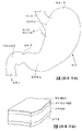
사람의 위(S)의 해부학적 그림 및 관련 특징부가 도 1A에 도시되어 있다. 식도(E)는 입으로부터 위(S)의 근위부(proximal portion)로 음식을 전달한다. z-라인 또는 위식도 접합부(gastroesophageal junction)(Z)는 식도의 얇은 조직과 위 벽의 두꺼운 조직 사이의 불규적적으로 형성된 경계부이다. 위식도 접합 구역(G)은 식도(E)의 원위부(distal portion), z-라인, 그리고 위(S)의 근위부를 둘러싸는 구역이다.An anatomical picture and associated features of the stomach S of a human are shown in FIG. 1A. The esophagus (E) delivers food from the mouth to the proximal portion of the stomach (S). The z-line or gastroesophageal junction (Z) is a randomly formed boundary between the thin tissue of the esophagus and the thick tissue of the stomach wall. The gastroesophageal junction region (G) is a region surrounding the distal portion of the esophagus (E), the z-line, and the proximal portion of the stomach (S).
위(S)는 근위 단부에 있는 위저부(fundus)(F)와 원위 단부에 있는 전정부(antrum)(A)를 포함하고 있다. 전정부(A)는 소장의 근위 구역인 십이지장(D)에 부착되어 있는 유문(pylorus)(P)에 영양분을 공급한다. 유문(P)에는 십이지장(D)으로부터 위로 음식물이 역류하는 것을 방지하는 괄약근이 있다. 십이지장(D)으로부터 멀리 위치되어 있는 소장의 중간 구역은, 공장(jejunum)(J)이다.The stomach (S) comprises a fundu (F) at the proximal end and an anterior (A) at the distal end. The anterior gland (A) nourishes the pylorus (P) attached to the duodenum (D), the proximal section of the small intestine. The pylorus (P) has a sphincter that prevents food from flowing back from the duodenum (D). The middle section of the small intestine, located far from the duodenum (D), is the jejunum (J).
도 1B는 위 벽을 형성하는 조직 층을 나타내고 있다. 가장 바깥층은 장막층 또는 장막(S)이고 가장 안쪽층은 위 내부의 막을 형성하는 점막층 또는 점막(MUC)이다. 점막하조직(submucosa)(SM) 및 다층의 근육층(M)은 점막과 장막 사이에 위치되어 있다.1B shows the tissue layer forming the stomach wall. The outermost layer is the membrane layer or the membrane (S) and the innermost layer is the mucosal layer or mucosa (MUC) forming the inner membrane of the stomach. Submucosa (SM) and the multilayered muscle layer (M) are located between the mucosa and the mucosa.
체강 내에서 조직에 스테이플(staple)과 같은 파스너를 내시경을 이용하여 부착시키는 다수의 사용예가 있다. 이러한 사용예 중에서 몇 가지 사용예는 체강의 조직에 주름 또는 접힘부(fold)와 같은 조직 구조를 형성하는 것을 포함한다.There are many examples of use of endoscopes to attach fasteners, such as staples, to tissue within the body cavity. Some of these uses include forming tissue structures such as wrinkles or folds in the tissue of the body cavity.
국제출원일이 2004년 10월 8일인 국제특허출원의 공개공보 제WO 2005/037152호 그리고 2006년 5월 23일자로 출원된 미국 특허출원 제11/439,461호를 포함하는 몇 가지 종래의 사용예는, 위 내에 형성된 조직 구조에 의료용 임플란트가 결합되는 방법을 기술하고 있다. 이러한 사용예에 따르면, 체중 감소를 유도하는 장치(예를 들면, 위 속으로 음식물이 유입되는 것을 제한하는 것 및/또는 막는 것, 및/또는 위의 일부분을 점유하는 것에 의해)가 위 조직으로부터 형성된 조직 터널 또는 주름에 결합될 수 있다.Some conventional uses, including WO 2005/037152 and International Patent Application No. 11 / 439,461, filed May 23, 2006, have an international application date of October 8, 2004, It describes how a medical implant is coupled to a tissue structure formed within the stomach. According to this use, a device for inducing weight loss (e.g., by limiting and / or preventing food from entering the stomach, and / or by occupying a portion of the stomach) from the stomach tissue It may bind to tissue tunnels or folds formed.
예를 들면, 미국특허출원 제11/439,461호는 체중 감소를 유도하는 제한적 및/또는 차단적 임플란트 시스템을 기술하고 있다. 한 가지 실시예에서, 유연성이 있는 루프가 위의 위식도 접합 구역에 형성된 조직의 주름(plication)에 결합되어 있다. 유동 제한적 및/또는 차단적 임플란트와 같은 임플란트가 상기 루프를 통과하여 위 내에 유지되어 있다.For example, US patent application Ser. No. 11 / 439,461 describes a restrictive and / or blocking implant system that induces weight loss. In one embodiment, a flexible loop is attached to a plication of tissue formed in the gastroesophageal junction region of the stomach. Implants, such as flow restricting and / or blocking implants, pass through the loop and remain in the stomach.
다른 예에서는, 조직의 주름 자체가 필요한 처리를 제공하는데 충분할 수 있다. 예를 들면, 상기 주름은 국제공개공보 WO 2005/037152호 및 2006년 10월 3일자로 출원된 미국특허출원 제11/542,457호의 공개공보 제2007-0219571호에 개시되어 있는 바와 같이 위의 부피를 감소시키거나 위 내부에 유동 제한부를 형성하는데 사용될 수 있다. In other instances, wrinkles of the tissue itself may be sufficient to provide the necessary treatment. For example, the folds may be provided with the above volume as disclosed in WO 2005/037152 and US Patent Application No. 11 / 542,457, filed October 3, 2006. It can be used to reduce or to form a flow restriction inside the stomach.
다른 타입의 임플란트가 다양한 목적을 위해 상기와 같은 주름 또는 다른 조직 구조에 결합될 수 있다. 이러한 임플란트는, 예를 들면, 위식도 역류 질환(gastro-esophageal reflux disease)의 치료를 위한 인공판막(prosthetic valve), 위 전기자극장치(gastric stimulator), pH 측정기(pH monitor) 그리고 위 또는 위장관(GI tract) 내의 다른 장소로 약물, 바이오로직스(biologics:생물학적 약물) 또는 세포를 방출하는 약물 용출 장치(drug eluting device)를 포함한다. 상기와 같은 약물 용출 장치는 수술후 외상, 궤양(ulcer), 열상(laceration) 등에 도움이 되는 렙틴(leptin)(포만감을 일으키는 호르몬), 그렐린(Ghrelin)(허기진 느낌을 일으키는 호르몬), 옥트레오타이드(octreotide)(그렐린 레벨을 낮추어서 허기진 느낌을 감소시키는 약물), 인슐린, 화학 치료제(chemotherapeutic agent), 천연 바이오로직스(예를 들면, 성장 인자, 사이토카인(cytokine))를 방출하는 것을 포함할 수 있다. 또 다른 임플란트는, 특정 세포 타입이 부착되어 성장하고 생물학적으로 활성인 유전자 산물(biologically-active gene product)을 위장관에 제공할 수 있는 플랫폼, 및/또는 치료 목적을 위해 국소적인 방사선 발생원을 제공할 수 있는 방사선 발생원용 플랫폼을 제공하거나, 진단 리간드(diagnostic ligand)가 고정되어 특정의 정상적인 상태 또는 병적인 상태의 증거를 위해 위장관을 샘플조사하는데 사용되는 플랫폼을 제공하거나, 카메라 및 다른 이미지 수집 장치를 통하여 위장관을 촬상하는 고정 지점(anchor point)을 제공할 수 있는 타입으로 될 수 있다.Other types of implants may be incorporated into such wrinkles or other tissue structures for various purposes. Such implants may include, for example, prosthetic valves, gastric stimulators, pH monitors and gastric or gastrointestinal tracts for the treatment of gastro-esophageal reflux disease. Other locations within the GI tract include drug eluting devices that release drugs, biologics or cells. Such drug eluting devices may include leptin (hormones that cause satiety), ghrelin (hormones that cause feelings of hunger), and octreotide, which may help post-operative trauma, ulcers, laceration, etc. octreotide (drugs that lower ghrelin levels to reduce hunger), insulin, chemotherapeutic agents, and natural biologics (eg, growth factors, cytokines). Another implant may provide a platform on which certain cell types can be attached and provide a biologically-active gene product to the gastrointestinal tract, and / or provide a source of local radiation for therapeutic purposes. Provide a platform for the radiation source that is present, a diagnostic ligand that is immobilized to provide a platform for sampling the gastrointestinal tract for evidence of certain normal or pathological conditions, or through cameras and other image acquisition devices. It may be of a type capable of providing an anchor point for imaging the gastrointestinal tract.
상기한 종래의 사용예는, 장막 조직(다시 말해서, 위의 외측 표면에 있는 조직)의 구역이 서로 접촉된 상태로 유지되도록 조직의 주름, 포켓 또는 터널을 형성하는 것의 장점에 관한 것이다. 시간이 경과함에 따라, 대향하는 양쪽 장막층 사이에 형성된 접착부는 위의 운동 및 이식된 장치에 의해 가해지는 힘에도 불구하고 오랜 기간에 걸쳐서 주름/포켓/조직이 유지되는 것을 가능하게 하는 강력한 결합을 형성한다. The prior use example described above relates to the advantage of forming wrinkles, pockets or tunnels of tissues such that the zones of the membrane tissue (ie, the tissue on the outer surface of the stomach) remain in contact with each other. Over time, the bond formed between both opposing membrane layers creates a strong bond that enables wrinkles / pockets / tissues to be retained over a long period of time despite the forces exerted by the above movements and implanted devices. Form.
주름이 형성되는 사용예와 관계없이, 보다 침습적인(invasive) 수술 방법이나 복강경 수술 방법을 이용하는 것 보다 식도 아래로 내려가는 장치를 이용하여 위 내에서 수행되는 여러 단계를 이용하여 주름을 형성하는 것이 훨씬 바람직하다. 본 발명은 입을 통하여 위 속으로 들어가서 위 벽에 장막-대-장막의 주름을 형성하도록 사용될 수 있는 내시경식 스테이플러(endoscopic stapler)를 기술한다.Regardless of the type of use in which the wrinkle is formed, it is much better to form the wrinkle using several steps performed in the stomach using a device that goes down the esophagus than with a more invasive or laparoscopic procedure. desirable. The present invention describes an endoscopic stapler that can be used to enter the stomach through the mouth and form a crease of the membrane-to-them into the stomach wall.
하난의 실시형태에 있어서, 본 발명은 조직에 스테이플을 부착시키는 스테이플러 장치(14)를 포함하고 있다. 이 장치는 (i) 제1 부재 또는 스테이플 하우징(28) 및 스테이플 하우징(28)에 대해 독립적으로 이동가능한 스테이플 홀더(78)를 가지고 있는 제 1 또는 스테이플 부재(25); (ii) 제2 부재 또는 앤빌 하우징(30) 및 앤빌 하우징(30) 상에 지지되어 있는 앤빌(96)을 가지고 있는 제 2 또는 앤빌 부재(27); 그리고 (iii) 스테이플 하우징(28) 내에서 제1 후퇴 위치로부터 제2 확장 위치까지의 이동을 위해 스테이플 홀더(78)에 작동가능하게 연결되어 있는 구동 부재(68)와, 구동 부재(68)의 후퇴 위치로부터 확장 위치까지의 이동이 (i) 스테이플 홀더를 스테이플 하우징(78)에 대하여 앤빌(96)(Al) 쪽으로 이동시키고, (ii) 앤빌 부재(27)를 스테이플 부재(A2) 쪽으로 이동시키도록, 스테이플 부재(25) 및 앤빌 부재(27)에 작동가능하게 결합되어 있는 암 조립체(32)를 포함하고 있는 구동 조립체(29); 를 포함하고 있다.In a Hanan embodiment, the present invention includes a
구동 부재(68)의 후퇴 위치로부터 확장 위치까지의 이동이 (i) 스테이플 홀더를 스테이플 하우징에 대하여 앤빌(Al) 쪽으로 이동시키고, (ii) 앤빌 부재를 스테이플 부재(A2) 쪽으로 이동시키고, (iii) 앤빌을 앤빌 하우징에 대하여 스테이플 홀더(A3) 쪽으로 이동시키도록, 앤빌(96)은 앤빌 하우징(30) 내에서 독립적으로 이동가능하게 될 수 있고, 암 조립체(32)는 앤빌(96)에 작동가능하게 결합될 수 있다.Movement from the retracted position to the extended position of the drive member 68 (i) moves the staple holder with respect to the staple housing towards the anvil (Al), (ii) moves the anvil member towards the staple member A2, and (iii ), The
구동 조립체(106)가 후퇴 위치로부터 확장 위치까지 이동할 때 앤빌(96)을 스테이플 홀더(78)(A3) 쪽으로 이동시키기 위해 앤빌 부재(27)는 암 조립체(32)에 작동가능하게 연결되어 있는 구동 링크(114)를 포함할 수 있다.When the
대체 실시형태로서, 상기 앤빌은, 앤빌 하우징 내에서의 독립적인 유압 구동에 의해 앤빌 하우징과 독립적으로 스테이플 홀더쪽으로 구동될 수 있다. 앤빌 구동 동작은, 스테이플 홀더가 스테이플 하우징 내에서 구동되고 있을 때 일어나는 것이 바람직하다.As an alternative embodiment, the anvil may be driven towards the staple holder independently of the anvil housing by independent hydraulic drive in the anvil housing. The anvil drive operation preferably occurs when the staple holder is being driven in the staple housing.
스테이플 홀더(78) 및 앤빌(96)은, 암 조립체(32), 챔버(21)와 함께 형성하는 대향하는 표면을 가질 수 있고, 구동 부재(68)의 제1 위치로부터 제2 위치까지의 이동에 의해 챔버 내에 포획된 조직을 압착하여 압축된 조직 접힘부를 형성한다.The
상기 챔버는, 탄성중합체 막 또는 주름잡힌(pleated) 막(24)과 같은, 막(membrane)에 의해 덮혀 있어서, 막에 진공을 가함으로써 조직이 챔버 속으로 흡입될 수 있다. 상기 탄성중합체 막은, 막의 한 쪽에 조직을 챔버 속으로 흡입하기 위한 개구(26)를 가질 수 있고, 챔버에 진공을 가한 상태에서, 구동 부재(68)의 후퇴 위치로부터 확장 위치까지의 이동에 의해 조직이 챔버에서 상기 개구와 대향하는 쪽으로 흡입된다. The chamber is covered by a membrane, such as an elastomeric membrane or a
상기 구동 부재는 스테이플 하우징(25) 내에서 이동하며, 스테이플 하우징(25)의 슬롯(64) 내에서 이동하는 적어도 하나의 핀(84)을 가지고 있는 디스크(68)를 포함하여, 구동 부재의 확장 위치쪽으로의 이동 범위를 핀(84)이 슬롯(64) 내에서 이동할 수 있는 범위로 제한할 수 있다. 상기 스테이플러 장치는, 디스크가 후퇴 위치로부터 확장 위치까지 이동할 때 암 조립체를 바깥쪽으로 펼치기 위해서, 상기 디스크(68)를 암 조립체(32)에 피벗가능하게 연결시키는 적어도 하나의 암 스프레더(113)를 더 포함할 수 있다.The drive member extends in the drive member, including a
상기 구동 부재는 구동 피스톤(106)을 포함할 수 있고, 구동 피스톤(106) 내에서의 제1 후퇴 위치와 제2 확장 위치 사이의 이동을 위한 스테이플 피스톤(116) 및 하나 이상의 스테이플을 스테이플 홀더(78)에 맞물리게 하기 위해 구동 시스톤에 부착된 스테이플 푸셔(76)를 더 포함할 수 있고, 상기 스테이플 푸셔(staple pusher)가 상기 스테이플 피스톤(116)과 함께 후퇴 위치로부터 확장 위치까지 이동할 때, 하나 이상의 스테이플을 상기 스테이플 홀더로부터 앤빌(96)에 대하여 발사한다.The drive member may comprise a
스테이플 홀더(78)는 환형 배열의 스테이플을 유지하도록 설계될 수 있고, 스테이플 푸셔(78)는 환형 배열의 스테이플을 스테이플 홀더에 동시에 맞물리게 하고 스테이플 홀더로부터 동시에 발사되도록 설계될 수 있다. 스테이플 홀더(78)는 구동 부재(68)와 함께 스테이플 하우징(28) 내에서 후퇴 위치와 확장 위치 사이로 이동하도록 스테이플 하우징(28) 속으로 삽입되는 교체가능한 스테이플 카트리지로 될 수 있다. 상기 구동 부재는, 상기 스테이플러 장치에 수용된 상태에서, 상기 스테이플 카트리지를 결합시키며, 상기 스테이플 카트리지의 제1 부재 하우징 내에서의 각운동을 방지하는 적어도 하나의 축방향으로 뻗어 있는 포스트(84)를 가지고 있는 디스크(68)를 포함할 수 있다.The
상기 스테이플러 장치는, 스테이플 카트리지-측 보강 링(83)을 더 포함할 수 있고, 상기 스테이플 카트리지-측 보강 링(83)은 스테이플 카트리지(78)에 마주 대하게 배치되어 있으며, 스테이플을 수용하고 상기 스테이플 카트리지-측 보강 링(83)을 상기 스테이플 카트리지를 향하는 스테이플로 고정된 조직 쪽에 부착시키기 위한 개구(85)를 가지고 있다.The stapler device may further comprise a staple cartridge-
상기 스테이플러 장치는, 스테이플 피스톤(116)에 장착되어 있으며, 스테이플 피스톤(116)의 후퇴 위치로부터 확장 위치까지의 이동에 의해 조직 접힘부가 스테이플로 고정될 때, 스테이플 홀더(78)와 앤빌(96) 사이에 유지된 조직 접힘부에 구멍을 내는 조직 커터(86)를 더 포함할 수 있다.The stapler device is mounted to the
제2 부재(30)는, 압축가능한 커팅 보드(99)를 포함할 수 있고, 상기 커팅 보드와의 최초 접촉 지점을 넘어서 스테이플 피스톤(116)이 이동하는 것에 의해 상기 조직 커터(86)가 전진할 수 있다. 커팅 보드(99a)는 상기 커터에 의해 잘릴 수 있는 실리콘과 같은 재료로 형성될 수 있다. 다른 실시예에서는, 커팅 보드(99d)가 커터의 이동과 반대되는 방향으로 탄성 변형된다.The
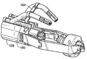
상기 스테이플러 장치는, 상기 스테이플 부재 및 앤빌 부재 중의 하나 위에 지지된 얼라인먼트 핀(160, 168), 및 상기 스테이플 부재 및 앤빌 부재 중의 다른 하나 위에 지지된 핀-수용 부싱(164, 170)을 더 포함할 수 있고, 상기 얼라인먼트 핀 및 핀-수용 부싱은, 스테이플 피스톤의 확장 위치쪽으로의 이동에 의해 상기 얼라인먼트 핀이 상기 핀-수용 부싱과 결합되고, 스테이플 피스톤(116)의 확장 위치쪽으로의 추가적인 이동에 의해 스테이플이 발사될 때 상기 2개의 부재가 축방향의 정렬상태를 유지하도록 위치되어 있다. 상기 얼라인먼트 핀 및 핀-수용 부싱 중의 하나는 스프링 가압하에서 후퇴될 수 있다.The stapler device further includes alignment pins 160, 168 supported on one of the staple member and the anvil member, and pin-receiving
상기 스테이플러 장치는, 상기 스테이플러 장치에 유압 유체를 전달하는 샤프트(16)의 원위 단부에 지지될 수 있고, 상기 스테이플러 장치의 스테이플 부재(25) 및 앤빌 부재(27)는 각각 근위 부재 및 원위 부재로 될 수 있고, 상기 샤프트는 상기 스테이플러 장치의 근위 부재에 작동가능하게 연결되어 있다.The stapler device may be supported at the distal end of the
본 발명은 조직 접힘부(tissue fold)를 포획하여 스테이플로 고정시키기 위한 방법도 개시하고 있는데, 상기 방법은,The present invention also discloses a method for capturing and stapling a tissue fold, the method comprising:
(a) 제1 및 제2 상대적으로 이동가능한 부재(25, 27)와 상기 제1 및 제2 상대적으로 이동가능한 부재(25, 27) 사이에 뻗어 있는 막(24)에 의해 형성된 진공 챔버(21) 속으로 조직 접힘부를 흡입하는 단계;(a) a
(b) 상기 제1 및 제2 상대적으로 이동가능한 부재(25, 27) 내에서의 스테이플 홀더 및 앤빌의 독립적인 이동과, 제2 상대적으로 이동가능한 부재(27)를 제1 상대적으로 이동가능한 부재(25) 쪽으로 이동시키는 것에 의해, 상기 제1 및 제2 상대적으로 이동가능한 부재(25, 27) 내에 각각 수용되어 있는 스테이플 홀더(78) 및 앤빌(96)를 서로를 향해 전진이동시키는 단계;(b) independent movement of the staple holder and the anvil within the first and second relatively
(c) 상기 전진이동시키는 단계 동안 계속적으로 진공을 가함으로써, 조직 접힘부가 상기 스테이플 홀더와 앤빌 사이에 포획될 때까지 조직을 상기 챔버(21) 속으로 계속하여 흡입하는 단계; 그리고(c) continuing to inhale tissue into the chamber (21) until the tissue fold is captured between the staple holder and the anvil by continuously applying vacuum during the step of forwarding; And
(d) 포획된 조직 접힘부를 스테이플로 고정시키는 단계;(d) stapling the captured tissue folds;
를 포함하고 있다.
It includes.
관련된 실시형태로서, 본 발명은 위 조직을 스테이플로 고정시키기 위한 의료 기구(10)를 포함하고 있다. 이 의료 기구는, 상기한 스테이플러 장치(14); 근위 단부 핸들 및 원위 단부를 가지고 있는 샤프트(16); 상기 샤프트의 원위 단부를 상기 스테이플러 장치의 제1 근위 부재에 연결시키는 관절연결 섹션(128); 그리고 1,500 psi 이상의 압력하에서 유압 유체를 스테이플 부재(25)의 구동 메카니즘(106)으로 전달할 수 있는 상기 샤프트 내에 수용되어 있는 유압 유체 라인(130);을 포함하고 있고, 상기 관절연결 섹션 내의 유압 유체 라인은 상기 샤프트에 대한 상기 스테이플러 장치의 축에서 벗어난 이동을 수용하도록 코일형 또는 사인곡선형 구성을 가지고 있다.In a related embodiment, the present invention includes a
관절연결 섹션(128)은 유압 유체 라인(130)의 코일형 또는 사인곡선형 부분에 걸쳐서 형성된 복수의 링크(132)로 이루어진 척추형상부(spine)를 가질 수 있다. 상기 스테이플러 장치는 유압식으로 구동되는 구동 부재(68) 및 유압식으로 구동되는 스테이플 피스톤(116)을 포함할 수 있고, 상기 샤프트(16) 및 관절연결 섹션(128)은 상기 구동 부재 및 스테이플 피스톤을 위한 별개의 유압 유체 라인(130)을 가질 수 있고, 상기 유압 유체 라인(130)은 상기 관절연결 섹션 내에 끼워넣어진 형태의(interleaved) 코일 구성을 가질 수 있다.
The
관련된 실시형태로서, 본 발명은, 샤프트를 스테이플 장치에 신속하게 부착시키거나 스테이플 장치로부터 신속하게 분리시키기 위해, 샤프트의 원위 단부와 유압식으로 작동되는 스테이플 장치의 스테이플 부재의 근위 표면 사이에 스냅식 결합구조를 제공한다. 상기 결합구조는, 샤프트의 원위 단부에 있는 플레이트로서, 상기 플레이트의 입력측에 있는 개구에 부착된 유압 라인으로부터 압력하에서 유압 유체를 공급하기 위한 하나 이상의 개구 및 각각의 개구에 인접해 있는 결합 에지를 가지고 있는, 상기 플레이트를 포함할 수 있다. 스테이플 장치의 플레이트-수용 표면은, 유체를 스테이플 장치 속으로 수용하도록 위치된 개구를 포함하고 있고, 상기 개구는 상기 플레이트-수용 표면의 출력측에서 스테이플 장치 내의 유압 공급 라인과 연통하고, 근위 표면은 각각의 개구에 인접한 언더컷 보스를 포함하고 있다. 작동시에는, 샤프트 플레이트가 스테이플-장치 표면에 마주 대하게 배치되고, 상기 장치 플레이트의 보스의 언더컷 구역 내에서 샤프트 플레이트 상에 상기 결합 에지를 고정시키기 위해 약간 회전되어, 상기 플레이트와 각각의 개구의 표면 사이에 배치된 O-링을 압축하고, 정렬된 개구들 사이의 연결부를 밀봉시킨다. 샤프트 플레이트 상의 잠금 메카니즘(lock 메카니즘)은, 일단 유체-공급 개구가 수용되면 상기 장치 표면을 맞닿게하여 샤프트 플레이트를 회전 운동에 대해 고정시킨다.
As a related embodiment, the present invention provides a snap coupling between the distal end of a shaft and the proximal surface of a staple member of a hydraulically actuated staple device for quickly attaching or detaching a shaft to or from a staple device. Provide structure. The coupling structure is a plate at the distal end of the shaft, having a coupling edge adjacent each opening and at least one opening for supplying hydraulic fluid under pressure from a hydraulic line attached to the opening at the input side of the plate. Which may include the plate. The plate-receiving surface of the staple device includes an opening positioned to receive fluid into the staple device, the opening communicating with a hydraulic supply line in the staple device at the output side of the plate-receiving surface, the proximal surface being respectively It includes an undercut boss adjacent to the opening. In operation, a shaft plate is disposed opposite the staple-device surface, and slightly rotated to fix the engagement edge on the shaft plate within the undercut zone of the boss of the device plate, so that the surface of the plate and each opening The O-rings disposed in between are compressed and the connections between the aligned openings are sealed. A lock mechanism on the shaft plate secures the shaft plate against rotational motion by abutting the device surface once the fluid-supply opening is received.
다른 실시형태로서, 본 발명은 조직에 스테이플을 부착시키는 스테이플러 장치(14)를 포함하고 있다. 이 장치는, 스테이플 하우징(28) 및 스테이플 홀더(78)를 가지고 있는 제1 스테이플 부재(25); 앤빌 하우징(30) 및 앤빌(96)을 가지고 있는 제2 앤빌 부재(27); 그리고 (i) 스테이플 하우징(28) 내에서 후퇴 위치로부터 확장 위치까지의 이동을 위한 구동 부재(68), (ii) 스테이플 하우징 내에 형성된 하나 이상의 슬롯(64) 내에서 이동하여, 상기 구동 부재의 후퇴 위치와 확장 위치 사이의 이동을 상기 핀의 상기 슬롯 내에서의 이동의 한계로 제한하는, 상기 구동 부재에 부착되어 있는 하나 이상의 핀(84), (iii) 구동 부재(68)의 후퇴 위치로부터 확장 위치까지의 이동이 스테이플 홀더를 앤빌(Al) 쪽으로 이동시키도록, 스테이플 부재 및 앤빌 부재에 작동가능하게 결합되어 있는 암 조립체(32), 그리고 (iv) 상기 구동 부재가 제1 위치로부터 제2 위치까지 이동할 때 상기 암 조립체를 바깥쪽으로 펼치기 위해, 상기 구동 부재를 상기암 조립체에 피벗가능하게 연결시키는 적어도 하나의 암 스프레더(113)를 포함하고 있는 구동 조립체; 를 포함하고 있다. In another embodiment, the present invention includes a
상기 슬롯 내에서의 핀의 후퇴 위치에서 확장 위치까지의 이동이 암 조립체를 바깥쪽으로 이동시키도록, 암 스프레더(113)는 상기 핀 및 암 조립체에 피벗가능하게 연결될 수 있다. 그 결과 상기 암 스프레더는 스테이플 보디와 암 조립체 사이에 트러스형 지지부를 제공할 수 있다. The
구동 부재(68)는, 구동 부재가 후퇴 위치로부터 확장 위치까지 이동될 때, 스테이플 홀더(78)를 스테이플 하우징(28) 내에서 전진시킬 수 있고, 암 조립체(32)는, 구동 부재가 후퇴 위치로부터 확장 위치까지 이동될 때, 앤빌(96)을 앤빌 하우징 내에서 전진시킬 수 있다.
The
또 다른 실시형태로서, 본 발명은 조직 내에 절단부를 형성하기 위한 장치(14)를 포함하고 있다. 이 장치는, 하우징(28) 및 구동 피스톤(116) 그리고 후퇴 위치와 확장 위치 사이에서 상기 구동 피스톤과 함께 이동하기 위해 상기 구동 피스톤에 부착된 커터(86)를 가지고 있는 제1 부재(25); 그리고 하우징(30) 및 커팅 보드(99)를 가지고 있는 제2 부재를 포함하고 있다. 상기 제1 부재는 커터(86)를 후퇴 위치로부터 확장 위치까지 이동시키는 구동 피스톤(116)을 가지고 있고, 상기 커터(86)는 커팅 보드(99)와 접촉하여 상기 2개의 부재 사이에 배치된 조직에 구멍을 형성하고, 상기 커팅 보드(99)는 상기 커터(86)가 커팅 보드와의 최초 접촉 지점을 넘어서 커팅 보드(99)의 방향으로 전진할 수 있게 하는 탄성 커팅 표면을 가지고 있다. 커팅 보드(99a)는 커터에 의해 잘릴 수 있는 실리콘과 같은 재료로 형성될 수 있다. 다른 실시예에서는, 커팅 보드(99d)가 커터의 확장 위치쪽으로의 이동과 반대되는 방향으로 탄성 변형된다.
As another embodiment, the present invention includes an
다른 실시형태로서, 본 발명은 스테이플을 조직에 부착시키는 스테이플러 장치(14)를 포함하고 있다. 이 장치는, 제1 스테이플 하우징(28) 및 스테이플 홀더(78)를 가지고 있는 제1 스테이플 부재; 제2 앤빌 하우징(30) 및 앤빌(96)을 가지고 있는 제2 앤빌 부재; 상기 스테이플 홀더와 앤빌 사이에 조직을 포획하기 위해 상기 스테이플 홀더를 상기 앤빌에 인접하게 이동시키도록, 스테이플 부재 하우징 내에서의 후퇴 위치로부터 확장 위치까지의 이동을 위한 구동 부재(68)와, 스테이플을 스테이플 홀더로부터 조직을 관통하여 앤빌에 대해 밀어붙이기 위해 제1 부재에서의 제1 후퇴 위치와 제2 확장 위치 사이에서 이동가능한 제1 부재 내의 스테이플 피스톤(116)을 포함하고 있는 구동 조립체; 상기 스테이플 부재 및 앤빌 부재 중의 하나에 지지되어 있는 얼라인먼트 핀(160, 168); 그리고 상기 스테이플 부재 및 앤빌 부재 중의 다른 하나에 지지되어 있는 핀-수용 부싱(164, 170)를 포함하고 있고, 상기 얼라인먼트 핀 및 핀-수용 부싱은, 스테이플 피스톤의 확장 위치쪽으로의 이동에 의해 상기 얼라인먼트 핀이 상기 핀-수용 부싱과 결합되고, 스테이플 피스톤(116)의 확장 위치쪽으로의 추가적인 이동에 의해 스테이플이 발사될 때 상기 2개의 부재가 축방향의 정렬상태를 유지하도록 위치되어 있다.In another embodiment, the present invention includes a
상기 얼라인먼트 핀(160, 168) 및 핀-수용 부싱(164, 170) 중의 하나는 스프링 가압하에서 후퇴될 수 있다.One of the alignment pins 160, 168 and the pin-receiving
상기 구동 부재(68)는, 구동 부재가 후퇴 위치로부터 확장 위치까지 이동될 때, 스테이플 홀더(78)를 스테이플 하우징(28) 내에서 전진시킬 수 있고, 암 조립체(32)는, 구동 부재가 후퇴 위치로부터 확장 위치까지 이동될 때, 앤빌(96)을 앤빌 하우징 내에서 전진시킬 수 있다.
The
또 다른 실시형태로서, 본 발명은 조직 접힘부를 포획하여 고정시키기 위한 조직 포획 장치(14)를 포함하고 있다. 이 조직 포획 장치는, 하우징(30) 및 제1-부재 하우징 내에서 독립적으로 이동가능한 제1 조직-접촉 플레이트(78)를 가지고 있는 제1 부재(25)와 하우징(30) 및 제2-부재 하우징 내에서 독립적으로 이동가능한 제2 조직-접촉 플레이트(96)를 가지고 있는 제2 부재(27)를 포함하고 있다. 상기 장치의 구동 조립체(29)는, 제1-부재 하우징(28) 내에서 후퇴 위치로부터 확장 위치까지의 이동을 위해 제1 조직-접촉 플레이트(78)에 작동가능하게 연결되어 있는 구동 부재(68)와, 구동 부재(68)의 후퇴 위치로부터 확장 위치까지의 이동이 (i) 제1 조직-접촉 플레이트(78)를 제1-부재 하우징 내에서 제2-조직 접촉 부재(96)(Al)쪽으로 이동시키고, (ii) 앤빌 부재(27)를 스테이플 부재(A2) 쪽으로 이동시키도록, 제1 부재(25) 및 제2 부재(27)에 작동가능하게 결합되어 있는 암 조립체(32)를 포함하고 있다. 탄성중합체 막 또는 주름잡힌 막과 같은, 막이 상기 2개의 부재 사이에 뻗어 있으며 상기 2개의 조직-접촉 플레이트 사이에 조직 포획 챔버를 형성하고, 상기 챔버에 진공을 가할 때, 조직을 상기 챔버 속으로 흡입하는 개구를 가지고 있다. 상기 2개의 부재에 작동가능하게 결합되어 있는 팽창 부재 또는 레이저(37)는, 구동 부재가 후퇴 위치로부터 확장 위치까지 이동할 때, 상기 막의 상기 개구에 대향하는 쪽에서, 상기 챔버 막을 바깥쪽으로 팽창시키도록 작동하여, 조직이 상기 2개의 조직-접촉 플레이트 사이에 고정됨으로써 포획될 때까지, 상기 2개의 조직-접촉 플레이트 사이의 상기 챔버 속으로 조직이 흡입되게 한다.
As yet another embodiment, the present invention includes a
본 발명은 또한 조직 접힘부를 포획하기 위한 방법을 개시하고 있는데, 상기 방법은, The invention also discloses a method for capturing tissue folds, which method comprises
(a) 제1 및 제2 상대적으로 이동가능한 부재(25, 27)와 상기 제1 및 제2 상대적으로 이동가능한 부재(25, 27) 사이에 뻗어 있는, 탄성중합체 막 또는 주름잡힌 막(24)과 같은, 막에 의해 형성된 진공 챔버(21) 속으로 조직(17)을 흡입하는 단계;(a) an elastomeric film or
(b) 상기 제1 및 제2 상대적으로 이동가능한 부재(25, 27) 내에서의 제1 조직-접촉 플레이트(78) 및 제2 조직-접촉 플레이트(96)의 독립적인 이동과, 제2 상대적으로 이동가능한 부재(27)를 제1 상대적으로 이동가능한 부재(25) 쪽으로 이동시키는 것에 의해, 상기 제1 및 제2 상대적으로 이동가능한 부재(25, 27) 내에 각각 수용되어 있는 제1 조직-접촉 플레이트(78) 및 제2 조직-접촉 플레이트(96)를 서로를 향해 전진이동시키는 단계; 그리고(b) independent movement of the first tissue-contacting
(c) 상기 전진이동시키는 단계 동안 계속적으로 진공을 가함으로써, 조직 접힘부(17a)가 상기 제1 조직-접촉 플레이트와 제2 조직-접촉 플레이트 사이에 포획될 때까지 조직을 상기 챔버(21) 속으로 계속하여 흡입하는 단계; (c) continuously applying vacuum during the advancing step, thereby allowing tissue to be captured until the
를 포함하고 있다.
It includes.
본 발명의 상기한 목적 및 특징과 본 발명의 다른 목적 및 특징은 아래의 본 발명의 상세한 설명을 첨부된 도면과 함께 이해하면 더욱 잘 알 수 있다. The above objects and features of the present invention and other objects and features of the present invention can be better understood when the following detailed description of the present invention is understood in conjunction with the accompanying drawings.
도 1A는 종래 기술에서 알려져 있는 바와 같이, 사람의 위와 소장의 일부분을 개략적으로 나태내는 그림이다.
도 1B는 종래 기술에서 알려져 있는 바와 같이, 위 벽의 일부분의 단면 사시도로서, 위 벽을 형성하는 조직의 복수의 층을 나타내고 있다.
도 2는 본 발명의 한 실시예에 따라 제작된 내시경식 스테이플 고정 시스템(endoscopic stapling system) 또는 기구를 나타내고 있다.
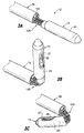
도 3A 내지 도 3C는 3개의 다른 위치에 있는 도 2의 내시경식 스테이플 고정 시스템의 스테이플러 헤드 또는 장치를 나타내는 사시도이다.
도 4는 막(membrane)이 제거된 상태의 스테이플러 헤드 또는 장치의 사시도로서, 상기 장치의 제1 부재 및 제2 부재를 나타내고 있다.
도 5는 도 4의 스테이플러 장치의 스테이플 하우징의 근위 단부의 사시도이다.
도 6은 도 4의 스테이플러 장치의 스테이플 하우징의 원위 단부의 사시도이다.
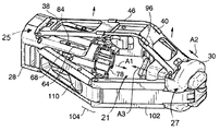
도 7은 압축 및 스테이플 고정 작동을 하는 동안 스테이플 하우징내의 여러 요소들이 전진할 수 있는 것을 나타내는 분해 사시도이다.
도 8은 스테이플 보강 장치의 평면도이다.
도 9는 스테이플 카트리지의 측면도이다.
도 10은 도 6과 유사한 스테이플 하우징의 사시도로서, 스테이플 하우징 내에 있는 도 7의 여러 요소들 중의 일부를 나타내고 있다.
도 11A 내지 도 11D는 유압 챔버 및 피스톤의 일련의 개략도로서, 조직 압축 및 스테이플 고정을 하는 동안의 전형적인 유압 시스템의 작동을 나타내고 있다.
도 11E는 도 11D와 유사한 도면으로서 대체 형태의 피스톤 구성을 나타내고 있다.
도 12는 도 4의 스테이플러 헤드의 앤빌 하우징의 사시도이다.
도 13은 앤빌 지지부의 사시도이다.
도 14는 앤빌의 평면도이다.
도 15A는 커팅 장치 및 제1 실시예의 커팅 보드의 측면 단면도이다.
도 15B는 커팅 장치 및 제2 실시예의 커팅 보드의 측면 단면도이다.
도 16은 도 4의 스테이플러 헤드의 힌지식 암 조립체의 사시도이다.
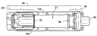
도 17은 신체 속으로 도입하기 위한 위치에 있는 도 4의 스테이플러 헤드의 평면도로서, 스테이플러 헤드의 막(membrane) 및 막 레이저(membrane raiser)는 명료함을 위해 도시되어 있지 않다.
도 18은 도 17과 유사한 도면으로서 도 17에서 보이지 않는 부분을 나타내고 있다.
도 19는 부분적으로 팽창된 중간 위치에 있는 스테이플러 헤드의 사시도이다.
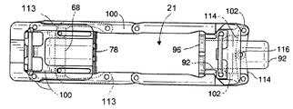
도 20은 도 17과 유사한 평면도로서, 스테이플러 헤드가 중간 위치에 있는 상태를 나타내고 있다.
도 21은 도 20과 유사한 평면도로서 도 20에서 보이지 않는 부분을 나타내고 있다.
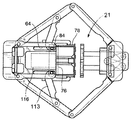
도 22는 완전히 팽창된, 완전 압축 위치에 있는 스테이플러 헤드의 사시도이다.
도 23은 도 20과 유사한 평면도로서, 스테이플러 헤드가 완전 압축 위치에 있는 상태를 나타내고 있다.
도 24는 도 23과 유사한 평면도로서 도 23에서 보이지 않는 부분을 나타내고 있다.
도 25A 내지 도 25C는 스테이플 하우징, 스테이플 카트리지 및 막 레이저의 일부분을 나타내는 사시도로서, 스테이플 카트리지를 스테이플 하우징으로부터 분리시키는 단계를 나타내고 있다.
도 26은 스테이플 헤드가 제거된 상태의 도 2의 스테이플러 기구의 사시도이다.
도 27A는 도 2의 스테이플러의 관절연결 섹션의 평면도로서, 끼워넣어진 형태의(interleaved) 구동 유체 라인을 나타내고 있다.
도 27B는 길이방향으로 팽창가능한 형상을 가지고 있는 대체 형태의 구동 유체 라인을 나타내고 있다.
도 28은 도 2의 스테이플러 기구의 핸들의 측면 단면도이다.
도 29는 도 2의 스테이플러 기구의 핸들의 사시도이다.
도 30A 및 도 30B는 스테이플 하우징의 근위부 표면의 평면도로서, 스테이플러 핸들의 단부 플레이트를 스테이플 하우징에 부착시키는 방법을 나타내고 있다.
도 31A 내지 도 31E는 도 2의 스테이플러 시스템을 사용하여 위에 주름을 형성하는 것을 개략적으로 나타내는 일련의 그림이다.
도 32A 내지 도 32C는 도 2의 스테이플러 시스템을 이용하여 위에 주름을 형성하기 위해 위 벽 조직을 포획하여, 압축한 다음, 스테이플로 고정시키는 것을 나타내는 일련의 사시도로서, 스테이플러 시스템의 막은 도시되어 있지 않다.
도 33은 신체 조직에 형성된 주름의 평면도이다.
도 34 및 도 35는 부가적인 도구를 구비하고 있는 대체형태의 스테이플러 헤드의 사시도이다.
도 36 및 도 37은 본 발명의 스테이플러 장치 내의 스테이플러-얼라인먼트 구조의 대체 실시예를 나타내고 있다.1A is a schematic representation of a portion of a person's stomach and small intestine, as is known in the art.
1B is a cross-sectional perspective view of a portion of the stomach wall, as known in the art, showing multiple layers of tissue forming the stomach wall.
FIG. 2 illustrates an endoscopic stapling system or instrument constructed in accordance with one embodiment of the present invention.
3A-3C are perspective views of the stapler head or device of the endoscope staple fixation system of FIG. 2 in three different positions.
4 is a perspective view of a stapler head or device with the membrane removed, showing a first member and a second member of the device.
5 is a perspective view of the proximal end of the staple housing of the stapler device of FIG. 4.
6 is a perspective view of the distal end of the staple housing of the stapler device of FIG. 4.
7 is an exploded perspective view showing the various elements in the staple housing may advance during compression and staple fastening operation.
8 is a plan view of the staple reinforcement device.
9 is a side view of the staple cartridge.
FIG. 10 is a perspective view of a staple housing similar to FIG. 6, showing some of the various elements of FIG. 7 within the staple housing.
11A-11D are a series of schematic diagrams of the hydraulic chamber and piston, illustrating the operation of a typical hydraulic system during tissue compression and staple fixation.
FIG. 11E is a view similar to FIG. 11D showing an alternative form of piston configuration. FIG.
12 is a perspective view of the anvil housing of the stapler head of FIG. 4.
13 is a perspective view of the anvil support.
14 is a plan view of the anvil.
15A is a side cross-sectional view of the cutting device and the cutting board of the first embodiment.
Fig. 15B is a side sectional view of the cutting device and the cutting board of the second embodiment.
16 is a perspective view of the hinged arm assembly of the stapler head of FIG. 4.
FIG. 17 is a plan view of the stapler head of FIG. 4 in a position for introduction into the body, wherein the membrane and membrane laser of the stapler head are not shown for clarity.
FIG. 18 is a view similar to FIG. 17, showing parts not visible in FIG. 17.
19 is a perspective view of the stapler head in a partially inflated intermediate position.
20 is a plan view similar to FIG. 17, showing a state where the stapler head is in an intermediate position.
FIG. 21 is a plan view similar to FIG. 20, showing parts not visible in FIG. 20.
22 is a perspective view of the stapler head in the fully inflated, fully compressed position.
FIG. 23 is a plan view similar to FIG. 20 showing the stapler head in the fully compressed position.
FIG. 24 is a plan view similar to FIG. 23, showing portions not visible in FIG. 23.
25A-25C are perspective views showing portions of the staple housing, the staple cartridge and the membrane laser, illustrating the step of detaching the staple cartridge from the staple housing.
FIG. 26 is a perspective view of the stapler mechanism of FIG. 2 with the staple head removed. FIG.
FIG. 27A is a plan view of the articulation section of the stapler of FIG. 2 showing an interleaved drive fluid line. FIG.
27B shows an alternate form of drive fluid line having a longitudinally expandable shape.
28 is a side cross-sectional view of the handle of the stapler mechanism of FIG. 2.
FIG. 29 is a perspective view of the handle of the stapler mechanism of FIG. 2. FIG.
30A and 30B are plan views of the proximal surface of the staple housing, illustrating a method of attaching the end plate of the stapler handle to the staple housing.
31A-31E are a series of illustrations schematically illustrating the formation of wrinkles on the top using the stapler system of FIG. 2.
32A-32C are a series of perspective views illustrating the capture and compression of gastric wall tissue to form a crease in the stomach using the stapler system of FIG. 2, followed by stapling, wherein the membrane of the stapler system is not shown. .
33 is a plan view of wrinkles formed in body tissue.
34 and 35 are perspective views of alternative stapler heads with additional tools.
36 and 37 show an alternative embodiment of the stapler-alignment structure in the stapler device of the present invention.
본 출원은 내시경식 파스너-부착 장치를 기술하는데, 바람직한 실시예에서 이 내시경식 파스너-부착 장치는 입을 통하여 위 속으로 들어가서 위 조직을 주름잡히게 하는 데 사용될 수 있다. The present application describes an endoscopic fastener-attaching device, which in a preferred embodiment can be used to enter the stomach through the mouth and wrinkle the stomach tissue.
조직이 진공의 사용을 수반하지 않는 다른 구성요소(예를 들면,그래스퍼(grasper))를 사용하여 안쪽으로 흡입될 수 있지만, 개시된 실시예에서는, 조직이 진공 챔버 속으로 흡입된다. 위 벽의 내측 부분이 안쪽으로 흡입되면, 위 외측에 있는 장막 조직 섹션은 서로 마주 대하게 위치된다. 개시된 파스너 부착 장치는 조직의 대향하는 섹션이 서로 접촉하도록 이동되게 하고, 적어도 조직의 대향하는 섹션 사이에 장막 접합이 형성될 수 있는 시간까지 조직 섹션을 함께 유지시키는 파스너를 부착시킨다. 이러한 단계의 각각은 위의 내부에서 전적으로 수행될 수 있으므로 임의의 수술적 개입 또는 복강경시술적 개입에 대한 필요성을 배제시킬 수 있다. 하나 이상의 주름이 형성된 후에는, 위 내에서의 체류를 위해 의료 장치(상기한 타입의 의료 장치에만 국한되는 것은 아님)가 상기 주름에 결합될 수 있다.The tissue may be sucked inwards using other components (eg, grasper) that do not involve the use of a vacuum, but in the disclosed embodiment, the tissue is sucked into the vacuum chamber. When the inner part of the gastric wall is sucked inwards, the membrane tissue sections outside the stomach are positioned opposite each other. The disclosed fastener attachment device allows the opposing sections of tissue to be moved in contact with each other and attaches the fasteners that hold the tissue sections together until at least the time when a mesenteric bond can be formed between the opposing sections of tissue. Each of these steps can be performed entirely internally in the stomach, thus eliminating the need for any surgical or laparoscopic intervention. After one or more wrinkles have been formed, a medical device (not limited to the above-described type of medical device) may be coupled to the wrinkles for retention in the stomach.
개시된 실시예는 상기 파스너-부착 장치를 사용하여 주름에 구멍이나 절개부를 형성하는 선택적인 특징을 포함한다. 이러한 구멍 또는 절개부는 의료용 임플란트의 일부분이 구멍/절개부를 통과하거나 구멍/절개부에 연결될 수 있도록 형성될 수 있거나, 최종적인 조직 결합의 강도에 기여하는 치유 반응(healing response)을 유발하도록 형성될 수 있다.The disclosed embodiments include optional features for forming holes or cutouts in the corrugations using the fastener-attaching device. Such holes or incisions may be formed such that a portion of the medical implant may pass through or connect to the hole / incision, or may be formed to induce a healing response that contributes to the strength of the final tissue bond. have.
아래에 제시된 실시예의 설명에서, 파스너-부착 장치는 스테이플러로 표현되어 있고, 대표적인 방법은 위 조직에 주름을 형성하는 것에 관한 것이다. 그러나, 본 명세서에 기술된 실시예는 다른 타입의 파스너를 부착하는 것, 그리고 주름 형성외의 목적으로 스테이플 또는 다른 파스너를 부착하는 것에 대해 동일한 적용성을 가지고 있는 특징을 포함한다. 보다 상세하게는, 본 명세서에서 "스테이플" 이라는 용어는, (i) 조직을 관통할 수 있고, (ii) 앤빌에 대해 가압되었을 때 파스너를 조직에 고정시키고 조직 접힘부와 함께 고정된 상태로 조직을 유지하도록 주름이 잡히는 하나 이상의 레그(leg) 부재를 가지고 있는 임의의 타입의 파스너를 지칭하는 것으로 사용되고 있다. 개시된 실시예 및 방법은 소화기(GI 시스템) 외측의 신체 부분에 사용될 수도 있다. 부가적으로, 개시된 실시예는 원형의 스테이플 고정 및 동심원식 구멍의 절개를 특별히 다루고 있지만, 직선형 스테이플 고정 뿐만 아니라 절개작업이 없는 원형 또는 직선형 스테이플 고정이 수행될 수 있는 여러가지 변형을 고려할 수 있다. In the description of the embodiments presented below, the fastener-attaching device is represented by a stapler and a representative method relates to the formation of wrinkles in the gastric tissue. However, embodiments described herein include features that have the same applicability for attaching different types of fasteners, and for attaching staples or other fasteners for purposes other than pleating. More specifically, the term "staple" herein refers to (i) penetrating tissue, and (ii) securing the fastener to the tissue when pressed against the anvil and holding the tissue together with the tissue fold. It is used to refer to any type of fastener that has one or more leg members that are crimped to hold. The disclosed embodiments and methods may be used for body parts outside the digestive system (GI system). Additionally, the disclosed embodiments specifically address circular staple fixation and incision of concentric circular holes, but various modifications may be contemplated in which straight staple fixation as well as round or straight staple fixation without cutting can be performed.
도 2는 조직을 스테이플로 고정하는 시스템 또는 기구(10)의 한 실시예를 나타내고 있는데, 상기 기구는 필요에 따라 외과수술적 사용 또는 복강경시술적 사용 뿐만 아니라 내시경적 사용에 적합하다.2 shows an embodiment of a system or
대체로, 도시된 시스템(12)은 샤프트(16)의 원위 부분에 위치된 스테이플러 헤드 또는 장치(14)를 가지고 있는 스테이플러 또는 스테이플러 기구(12)를 포함한다. 샤프트(16) 상의 핸들(18)은 스테이플러 헤드(14)의 관절연결 및 조직 포획, 조직 압축의 작동, 그리고 스테이플러 헤드(14)의 스테이플고정 기능을 컨트롤한다. 상기 시스템의 진공 발생원(20) 및 유체 공급원(31)은, 아래에 설명되어 있는 바와 같이, 조직 포획, 압축 및 스테이플고정에 사용하기 위해 핸들(18)에 유체연통가능하게 결합되어 있다. 진공 발생원(20)은 작동실의 벽에 있는 커플링을 통하여 액세스할 수 있는 "진공 청소기(house vacuum)", 보조 흡입 펌프로 될 수 있다. 스테이플러는 사용자가 진공 발생원과 스테이플러 사이의 공기유동을 컨트롤할 수 있게 하는 스위치(21)를 포함할 수 있다.In general, the illustrated
스테이플러 장치는 스테이플로 고정시키기 위해 조직 접힘부를 포획하는 기능도 수행하므로, 본 명세서에서 조직 접힘부를 고정시키는, 예를 들면, 조직 접힘부의 측면부를 고정시키는 조직 포획 장치로 지칭되기도 한다. 이 조직 포획 장치는 조직을 포획하는 동안, 예를 들면, 별개의 스테이플고정 메카니즘없이, 독립적으로 작동할 수 있거나, 도시되어 있는 바와 같이, 스테이플고정 요소와 결합될 수 있다. Since the stapler device also performs the function of capturing the tissue folds for stapling, it is also referred to herein as a tissue capture device for securing the tissue folds, for example, for securing the side portions of the tissue folds. This tissue capture device may operate independently during tissue capture, for example, without a separate staple fixation mechanism, or may be associated with a staple fixation element, as shown.
유체 공급원(31)은 구동 유체(예를 들면, 물, 소금물, 오일, 가스)의 단일 공급원 또는 복수의 공급원으로 될 수 있지만, 각 경우에 있어서, 유체 공급원은 2개의 유압 라인(조직 압축을 위한 유압 라인 및 스테이플고정을 위한 유압 라인) 각각으로의 유동을 컨트롤하기 위해 따로 사용되는 2개의 액추에이터를 포함하는 것이 바람직하다. 상기 시스템의 내시경(22)은 샤프트(16) 내의 루멘(lumen)을 통하여 삽입될 수 있으며, 주름을 형성하는 과정을 볼 수 있게 해준다. 상기 시스템은, 스테이플러(12)를 수용하기 위한 루멘을 가지고 있는 내시경 가이드 튜브(23)와 같은, 오버튜브(overtube)를 선택적으로 포함할 수 있다.The
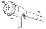
도 3A를 참고하면, 스테이플러의 덮개 또는 막(24)은 스테이플러 헤드(14) 내에 진공 챔버(21)(도 17 내지 도 23 참고)를 형성하기 위해 스테이플러 메카니즘을 둘러싼다. 사용하는 동안 조직이 진공 챔버속으로 흡입될 수 있도록 주름이 잡히게 될 조직을 향하고 있는 쪽은 막(24)에 의해 덮혀있지 않은 채로 남아 있다. 예를 들면, 도 3B에 도시되어 있는 바와 같이 막(24)은 측면 개구(26)를 포함할 수 있다. 막(24)은 진공 챔버(21) 속으로 흡입된 조직을 수용하도록 부피가 팽창되는 진공 챔버(21)를 형성할 수 있는 실리콘, 탄성중합체 재료, 또는 임의의 다른 비탄성 또는 탄성의 유연한 재료 또는 주름진 마일라 필름(pleated mylar film)과 같은, 변형가능한 생체적합성이 있는 재료로 형성되는 것이 바람직하다. 도 3A 내지 도 3C에는 또한 도 26 및 도 27과 관련하여 아래에 기술되어 있는, 상기 기구 샤프트를 스테이플 헤드에 연결시키는 관절연결 섹션(128)도 도시되어 있다.With reference to FIG. 3A, the cover or
상기 막의 적어도 일부분은 적어도 부분적으로 투명하다. 적어도 부분적으로 투명한 상태로 되기 위해서는, 상기 막은, 스테이플 부착 전에 조직의 적절한 양이 스테이플러 헤드 속으로 포획되는 것을 확인(내시경 관찰을 통하여)하도록 사용자가 상기 막을 통하여 충분히 잘 볼 수 있게 해주는 재료로 형성되거나, 또는 이러한 재료를 일부 포함한다. 상기 개구(26)는 개구(26) 주변 구역을 강화시키는 재료로 형성된 보강 섹션(27)으로 둘러싸여질 수 있다. 이 보강 섹션(27)은 막 재료의 두꺼운 부분 및/또는 고 경도의 재료로 형성될 수 있다. 대체 실시형태로서, 보강 리브(reinforcing rib) 또는 다른 구조 또는 요소가 막 재료 내부나 표면에 형성되거나, 막 재료에 끼워넣어질 수 있다.
At least a portion of the membrane is at least partially transparent. In order to be at least partially transparent, the membrane may be formed of a material that allows the user to see through the membrane sufficiently to ensure that an adequate amount of tissue is captured into the stapler head prior to staple attachment (or through an endoscope observation) or Or some of these materials. The
스테이플러 헤드 또는 장치Stapler head or device
스테이플러 헤드(14)는 주름 부위로 삽입되는 동안에는 최소의 외형을 가지고, 그런 다음에는 큰 내부 부피를 가지는 훨씬 큰 외형의 장치로 변형되도록 설계되어 있다. 예를 들면, 한 실시예에서 진공 챔버는 0.2 세제곱 인치의 초기 내부 부피와, 0.6 세제곱 인치의 팽창된 부피(다시 말해서, 진공 챔버 내에 위치된 스테이플러 헤드 구성요소에 의해 점유된 부피를 제외한 후의 챔버 내부 부피)를 가질 수 있다. 이러한 큰 내부 부피는 큰 부피의 조직이 진공 챔버 속으로 흡입되어 스테이플로 고정될 수 있게 한다. 이러한 식으로, 삽입을 위한 침습적인 기술(invasive technique)을 필요로 하지 않고서 스테이플러 헤드는 큰 주름을 만든다. 스테이플러 헤드의 이러한 특징으로 인해, 최소의 동작 및 힘을 이용하여 제자리에서 스테이플러 헤드의 부피 팽창을 가능하게 된다. 특히, 도 32A 내지 도 32C 및 도 33과 관련하여 아래에서 알 수 있는 바와 같이, 주름의 사이즈는, 도 33에 도시되어 있는 바와 같이 2개의 환형 스테이플 배열이 되도록 조직에 부착된 스테이플이 스테이플로 고정된 조직의 가장자리로부터 충분히 이격되어, 스테이플 주위에서 조직이 파열되는 위험을 최소화하도록 하는 크기로 될 수 있다.The
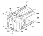
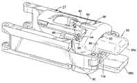
스테이플러 헤드의 특징부는 도 4 내지 도 10에 도시되어 있다. 명료함을 위해서, 상기 도면에는 막이 도시되어 있지 않다. 도 4를 참고하면, 스테이플러 헤드(14)는 대체로 근위 스테이플 하우징(28)을 포함하는 제1 스테이플 부재(25)와, 원위 앤빌 하우징(30)을 포함하는 제2 앤빌 부재(27), 그리고 아래에 설명되어 있는 바와 같이 상기 2개의 하우징을 작동가능하게 연결하는 적어도 하나의 기다란 부재로서 바람직하게는 한 쌍의 힌지식 암 조립체(32)를 포함하고 있다.The features of the stapler head are shown in FIGS. 4-10. For clarity, no membrane is shown in this figure. Referring to FIG. 4, the
스테이플 하우징 및 앤빌 하우징은, 조직이 스테이플 하우징과 앤빌 하우징 각각의 접촉 표면 사이에서 압축될 수 있도록 배열되어 있다. 개시된 실시예에서는, 상기 접촉 표면이 스테이플 하우징의 스테이플 유지 부분, 다시 말해서, 스테이플 홀더의 외측 표면과 앤빌 하우징의 앤빌에 있다. 상기 장치의 조직-포획 작동만 고려하면, 스테이플 홀더(78)(도 7에 도시되어 있음)는 전방 조직-접촉 표면(83)을 가지고 있는 제1 조직-포획 플레이트로서 기능하고, 앤빌(96)(도 13 및 도 14에 도시되어 있음)은 상기 전방 조직-접촉 표면(83)과 마주 대하는 조직 접촉 표면(103)을 가지고 있는 제2 조직-포획 플레이트로서 기능하고, 상기 2개의 표면은, 도 32A 내지 도 32C와 관련하여 보다 상세하게 아래에 설명되어 있는 바와 같이, 상기 장치의 작동 동안에 조직 접힘부를 포획하는 역할을 한다.The staple housing and the anvil housing are arranged such that tissue can be compressed between the contact surface of each of the staple housing and the anvil housing. In the disclosed embodiment, the contact surface is at the staple retaining portion of the staple housing, ie the outer surface of the staple holder and the anvil of the anvil housing. Considering only the tissue-capturing operation of the device, the staple holder 78 (shown in FIG. 7) functions as a first tissue-capturing plate having an anterior tissue-contacting
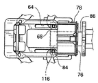
암 조립체(32)는 스테이플러 헤드(14)의 대향하는 양 쪽에 있는 스테이플 하우징(28)과 앤빌 하우징(30) 사이에 뻗어 있다. 근위 핀(34) 및 원위 핀(36)은 암 조립체(32)를 스테이플 하우징(28) 및 앤빌 하우징(30)에 대해 각각 피벗가능하게 결합시킨다. 막 레이저(raiser)(37)를 포함하는 팽창 부재도 스테이플 하우징(28)과 앤빌 하우징(30) 사이에 뻗어 있다. 비록 막(24)이 도 4에 도시되어 있지는 않지만, 막 레이저(37)는 막의 개구(26)(도 3B 참고) 반대쪽에 위치되어 있다는 사실을 알고 있어야 한다. 도시된 실시예에서, 막 레이저(37)는, 핀(42)에 의해 스테이플 하우징에 피벗가능하게 장착된 링크(38), 핀(44)에 의해 앤빌 하우징에 피벗가능하게 장착된 상응하는 링크(40) 및 상기 링크(38, 40)를 서로 결합시키는 스프링 와이어(46)를 포함하고 있다.
The
스테이플 하우징Staple housing
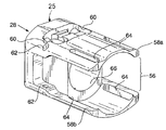
스테이플러 헤드 구성요소를 보다 상세하게 살펴보면, 스테이플 하우징(28)은 도 5 및 도 6에 있는 다른 구성요소들로부터 분리되어 있는 것으로 보여질 수 있다. 도 5에 도시되어 있는 바와 같이, 스테이플 하우징의 근위 표면(48)은 입력 포트(50a, 50b)를 포함하고 있고, 조직 압축, 스테이플고정, 및 스테이플러 헤드의 선택적인 커팅 작용의 유압 작동을 위해 상기 입력 포트(50a, 50b)를 통하여 유체가 유입된다. 유체 누출을 최소화하기 위해 시일(51)이 상기 입력 포트(50a, 50b)를 둘러싸고 있다.Looking at the stapler head component in more detail, the
진공 포트(52)는 조직 포획을 위해 진공 챔버 내에 부압을 발생시키도록 선택적으로 작동되는 진공 발생원(20)(도 2)에 유체연통되게 결합되어 있다. 진공 포트(52)는 스테이플러 샤프트(16)(도 2) 내의 가요성 튜브(도시되어 있지 않음)에 의해 진공 발생원(20)에 연결되어 있다. 장착 구멍(54)은 관절연결 섹션(128)을 통하여 스테이플러 헤드(14)를 샤프트(16)에 장착하기 위해 사용된다.The
스테이플 하우징(28)은 개방된 측면 섹션(56) 위 아래에 상부 섹션 및 하부 섹션(58a, 58b)을 포함하고 있다. 상부 섹션(58a)은 리세스(60)을 포함하고 있고, 이 리세스(60) 내에는 링크(38)(도 4)용 피벗 핀(42)이 장착되어 있다. 도 6에 가장 잘 도시되어 있는 바와 같이, 보어(62)가 상부 섹션 및 하부 섹션(58a, 58b)에 위치되어 암 조립체(32)용 근위 피벗 포인트로서 역할을 하는 핀(34)(도 4)을 수용한다. 가이드 슬롯(64)이 상부 섹션 및 하부 섹션(58a, 58b)을 관통하여 길이방향으로 뻗어 있다.The
도 6을 참고하면, 유압 챔버(66)가 스테이플 하우징(28) 내에 배치되어 있다. 유압 챔버(66)(도 6) 내에는 스테이플러의 조직 압축 및 스테이플고정 기능을 구동시키는 전용 유압 회로가 있다. 유압 챔버(66)는 유체 입력 포트(50a, 50b)(도 5)에 유체연통되게 결합되어 있다. 도 11A 내지 도 11D와 관련하여 보다 상세하게 아래에 설명되어 있는 바와 같이, 입력 포트(50a, 50b)를 통하여 유압 챔버(66) 속으로 유입된 유체는 조직을 압축하도록 다른 구성요소에 작용하고, 스테이플 및 커팅 요소로 하여 압축된 조직을 관통하게 하는 유압 피스톤의 시스템(도시되어 있지 않음)을 순차적으로 전진시킨다.Referring to FIG. 6, a
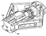
도 7은 압축, 스테이플고정, 및 커팅을 위해 유압 시스템에 의해 구동되는 스테이플러 헤드의 구성요소를 나타내고 있다. 명료함을 도모하기 위해서, 상기 구성요소들은 스테이플 하우징으로부터 분리된 상태로 그리고 서로 분리된 상태로 도시되어 있다. 본 논의에서는, 유압 시스템에 의해 구동되는 구성요소를 설명한다. 유압 시스템 자체는 도 11A 내지 도 11D와 관련하여 아래에 기술되어 있다.7 shows the components of a stapler head driven by a hydraulic system for compression, staple fastening, and cutting. For the sake of clarity, the components are shown separated from the staple housing and from each other. In this discussion, the components driven by the hydraulic system are described. The hydraulic system itself is described below in connection with FIGS. 11A-11D.
특히, 도 7은 스테이플 하우징에서 디스크(68)의 형태를 취하고 있는 구동 부재를 나타내고 있다. 조립된 상태의 하우징에서는, 디스크(68)가 유압식 압축 피스톤(도 11A 내지 도 11E에 도시된 피스톤(106))에 의해 멀리 밀려나가도록 위치되어 있다. 도 11A 내지 도 11E에서 볼 수 있는 바와 같이, 구동 부재는 도 11A에 도시된 제1 후퇴 위치와 도 11C 및 도 11D에 도시된 제2 확장 위치 사이에서 이동가능하다. 도시된 구동 부재는 피스톤(106)과는 분리된 상태에서 피스톤(106)에 의해 구동되지만, 상기 2개의 구성요소는 단일체 부재, 다시 말해서, 피스톤 및 디스크 양자 모두를 포함하는 단일체 구동 부재로 형성될 수 있다. 아래에서 알 수 있는 바와 같이, 상기 구동 부재는, 스테이플 하우징 및 앤빌 하우징의 접촉 표면을 서로를 향하게 함으로써 구동 부재를 멀리(구동 부재의 확장 위치쪽으로) 전진시키는 것에 의해 조직 압축을 실행하도록 암 조립체(32), 앤빌 하우징 및 스테이플 하우징에 결합되어 있다. 디스크(68), 디스크의 구동 피스톤(106), 및 2개의 하우징을 결합시키는 암 조립체(32)의 결합체는 도 10에서 부재번호 29로 표시된 구동 조립체로 총칭(總稱)된다. 이 구동 조립체는 앤빌 부재 내에 구동 링크(114)를 더 포함할 수 있고, 상기 구동 링크는 아래에 기술되어 있는 바와 같이 암 조립체(32)에 작동가능하게 연결되어 있다.In particular, FIG. 7 shows a drive member in the form of a
도 7에 잘 도시되어 있는 바와 같이, 디스크(68)는 장착 보어(70), 중심 개구(72) 및 얼라인먼트 포스트(74)를 포함하고 있다. 도 10을 잠시 참고하면, 조립된 상태의 스테이플러 헤드에서는, 디스크(68)가 스테이플러 하우징(28)에 결합되어 있고, 디스크의 스테이플러 하우징에서의 축방향의 이동은, 하우징의 가이드 슬롯(64) 및 디스크(68)의 장착 보어(70)를 통하여 뻗어 있는 핀(84)에 의해 제한된다.As best seen in FIG. 7,
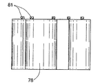
스테이플 하우징(28)의 일부분은 조직 속으로 발사될 스테이플을 수용하고 있고, 다시 말해서, 상기 스테이플을 수용하여 채워져 있다. 스테이플은 스테이플 하우징 상의 스테이플 카트리지(78)와 같은, 스테이플 홀더 내에 수용되어 있다. 스테이플 홀더는 다수의 상이한 구성을 가질 수 있다. 예를 들면, 스테이플 홀더는 스테이플 하우징과 일체로 된 부분, 또는 스테이플 하우징에 장착되거나 부착된 별개의 부분으로 될 수 있고, 및/또는 스테이플 홀더는 스테이플고정 전에 조직 압축을 실행하기 위해 스테이플 하우징의 몸체에 대해 이동가능하게 될 수 있다. 상기 예들 중의 임의의 경우에 있어서, 스테이플 홀더는 제거가능한/교체가능한 스테이플 카트리지로 될 수 있고, 및/또는 스테이플 홀더는 부가적인 스테이플을 스테이플 홀더에 삽입함으로써 리필가능하게 될 수 있다. 다른 실시예에서는, 스테이플 홀더가 교체가능하지도 않고 리필가능하지도 않게, 다시 말해서, 1회용품으로 될 수 있다.A portion of the
개시된 실시예, 스테이플 홀더는 스테이플을 발사한 후에 다른 스테이플 카트리지와 교체될 수 있는 교체가능한 스테이플 카트리지(78)이다. 본 실시예에서는, 스테이플 발사 전에 조직을 압축하기 위해 스테이플 카트리지가 스테이플 하우징의 몸체에 대해 이동가능하다.In the disclosed embodiment, the staple holder is a
도 7을 다시 참고하면, 압축 피스톤에 의해 디스크를 멀리 전진이동시키는 것에 의해 스테이플 카트리지가 제1 후퇴 위치로부터 제2 확장 위치까지 멀리 밀려나가서 스테이플 카트리지와 앤빌 사이에 배치된 조직을 압축하도록, 스테이플 카트리지(78)가 디스크(68)에 대해 먼 위치에 스테이플 하우징 내에 위치될 수 있다. 스테이플 카트리지를 스테이플러 헤드 속으로 삽입하는 동안 스테이플 카트리지의 외측에 있는 그루브(79)는 얼라인먼트 포스트(74)의 대응하는 부분 위를 미끄럼이동한다. 도 10은 스테이플 카트리지를 스테이플 하우징에 장전하기 전의 얼라인먼트 포스트를 나타내고 있다. 상기 도면에 도시되어 있는 바와 같이, 얼라인먼트 포스트(74)는 스테이플 카트리지를 얼라인먼트 포스트에 장전하는 것을 용이하게 하기 위해 테이퍼진 단부를 가질 수 있다. 스테이플러가 작동하는 동안 얼라인먼트 포스트는 스테이플 카트리지가 스테이플 하우징(28) 내에서 각운동하지 못하게 고정시킨다는 것을 알 수 있다.Referring back to FIG. 7, the staple cartridge is pushed away from the first retracted position to the second extended position by compressing the disk away by the compression piston to compress the tissue disposed between the staple cartridge and the anvil. 78 may be located in the staple housing at a location remote to the
도 7을 다시 참고하면, 스테이플 카트리지(78)는 도 33에 도시된 스테이플(158)와 같은, 스테이플을 각각 수용하는 다수의 스테이플 배치부(80)를 포함하고 있다. 스테이플 카트리지는, 도 8에 도시되어 있으며 "내시경식 주름형성 장치 및 방법(ENDOSCOPIC PLICATION DEVICES AND METHODS)" 이라는 이름으로 2006년 10월 3일자로 출원된 미국특허출원 제11/542,457호로서, 2007년 9월 20일자로 공개된 미국 출원공개공보 US 20070219571호에 상세하게 개시되어 있는 타입의 스테이플 라인 보강 장치(83)를 유지하기 위해서 보스(81)를 구비하고 있다. 간단히 요약하면, 이러한 타입의 보강 장치(83)는 스테이플 카트리지의 원위 표면에 위치될 수 있는 링 또는 다른 요소로 될 수 있다. 상기 링이 스테이플 카트리지에 배치되면, 링의 개구(85)는 스테이플 카트리지 내에 있는 복수의 스테이플 중의 몇개의 스테이플의 돌출부(prong)와 정렬된다. 스테이플이 스테이플 카트리지로부터 튀어나오면, 상기 돌출부가 상기 개구(85)를 통과하여 링(83)을 인접한 신체 조직에 고정시킨다.Referring again to FIG. 7,
도 7 및 도 9를 참고하면, 스테이플 카트리지의 앤빌을 향하는 쪽에 있는 다수의 언더컷 보스(81)는 보강 장치(83)를 스테이플 카트리지의 표면의 제위치에 고정시키기 위해 사용될 수 있다. 버섯형 보스, 갈고리형 보스 및 경사진 보스와 같은 다른 양적인(positive) 형상의 보스가 동일한 목적을 수행하기 위해 사용될 수 있다. 스테이플 카트리지의 표면에 형성된 포켓 또는 그루브와 같은 음적인(negative) 형상이, 보강 장치(83) 상의 대응하는 부분과 결합되도록 사용될 수도 있다. 다른 대체 실시형태로서, 상기 보강 장치는 접착제를 사용하여 스테이플 카트리지 상의 제위치에 고정될 수 있다.7 and 9, a number of
도시된 실시예에서는, 커터 요소(86)가 디스크(68)의 중심 개구(72)(도 7)를 통하여 뻗어 있다. 상기 커터 요소는 날카로운 벽과 루멘(87)을 가지고 있는 튜브형 펀치로서 도시되어 있지만, 다른 대체 형태로 제공될 수 있다. 도 10의 조립된 상태의 도면에서 볼 수 있는 바와 같이, 스테이플 푸셔(76)는 디스크로부터 멀리 떨어져서 커터 요소에 장착되어 있다. 스테이플 푸셔(76)는, 스테이플 푸셔(76)가 스테이플 카트리지(78) 속으로 전진하여, 스테이플을 스테이플 카트리지로부터 밀어낼 때 스테이플 카트리지의 스테이플 배치부(80) 속으로 미끄럼이동하도록 구성된 푸셔 요소(82)를 포함하고 있다. 유압 챔버(66) 내의 유압식으로 구동되는 스테이플 피스톤(도 11A 내지 도 11E에 부재번호 116으로 도시되어 있음; 피스톤(106)에 의해서 형성된 유압 챔버 내에서 지지되는 것)은 스테이플러 피스톤의 전진이동이 스테이플 푸셔(76) 및 커터 요소(86)를 원위 방향(distal direction)으로 전진이동시키도록 커터 요소(86)에 결합되어 있다.
In the embodiment shown, the
유체 구동 시스템Fluid drive system
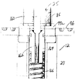
조직 압축, 스테이플고정 및 커팅을 작동시키도록 사용된 유체 구동 시스템은 다양한 방식으로 구성될 수 있다. 아래의 문단은, 본 실시예에서는 유압 시스템인 유체 구동 시스템에 대한 한 가지 바람직한 구성을 기술한다. 도 11A 및 도 11B는, 조직 압축 및 스테이플고정 단계 동안에 스테이플 하우징(28)의 유압 챔버(66) 내의 유체 유동을 개략적으로 나타내고 있다. 도 11A를 참고하면, 압축 피스톤(106)은 유압 챔버(66) 내에 배치되어 있다. 디스크(68)(도 7 및 도 10에도 도시되어 있음)는 피스톤(106)과 접촉하고 있거나 피스톤(106)으로부터 약간 떨어져서 위치되어 있다. 압축 피스톤(106)은 내부(111)를 둘러싸고 있는 측면 벽(110) 및 후방 벽(108)을 가지고 있는 대체로 컵형상이다. O-링 시일(112)은 측면 벽(110)의 근위 부분에서 이격되어 있다. 채널(115)은 O-링 시일(112) 사이에서 측면 벽(110)을 관통하여 형성되어 있다.The fluid drive system used to operate tissue compression, staple fixation and cutting may be configured in a variety of ways. The following paragraph describes one preferred configuration for a fluid drive system, which in this embodiment is a hydraulic system. 11A and 11B schematically illustrate fluid flow in the
스테이플 피스톤(116)이라고 칭하는 제2 피스톤이 후방 벽(108)에 맞닿은 상태로 압축 피스톤(106)의 내부(111)에 위치되어 있다. 도 11A 내지 도 11D에 도시되어 있지는 않지만, 스테이플 푸셔(76)가 위에 놓여있는 상태의 커팅 요소(86)(도 7참고)가 스테이플 피스톤(116)과 접촉상태로 있거나 약간 떨어진 상태로 위치되어 있다. O-링 시일(118)은 압축 피스톤 내의 채널(115)에 대해 먼 쪽에 있는 스테이플 피스톤(116)의 일부를 둘러싸고 있다.A second piston, referred to as
제1 유체 채널(120)은 스테이플러 하우징(28) 내의 유체 포트(50a)로부터 유압 챔버(66)의 근위 섹션(proximal section)까지 뻗어 있다. 제2 유체 채널(122)은 스테이플러 하우징(28) 내의 유체 포트(50b)로부터 유압 챔버(66)의 보다 먼 쪽의 원위 섹션(distal section)까지 뻗어 있다. 압축 피스톤 실린더에 대항하는 유체 포트(50a) 및 유체 채널(120)로부터의 유체 유동이 도 11A에 표시되어 있다. 유압 챔버(66) 내의 유체 압력이 압축 피스톤(106) 내에 스테이플러 피스톤(116)을 가지고 있는 상태로 압축 피스톤(106)을 도 11A에 도시되어 있는 제1 후퇴 위치로부터 도 11 C 및 도 11 D에 도시되어 있는 제2 확장 위치까지 멀어지는 방향으로 전진시킨다. 도 11B는 압축 피스톤(106)의 이동의 끝부분, 다시 말해서, 완전히 확장된 위치로 접근하고 있는 압축 피스톤(106)을 나타내고 있다. 압축 피스톤이 도 11C에 도시되어 있는 압축 피스톤의 이동의 끝부분에 도달하면, 압축 피스톤(106)의 채널(115)이 스테이플러 하우징(28)의 채널(122)과 정렬되어, 유체가 유체 포트(50b)를 통하여 들어와서 채널(122)을 경유하여 압축 피스톤(106)의 내부로 들어올 수 있게 된다. 유체가 압축 피스톤의 내부로 들어오면, 도 11D에 도시되어 있는 바와 같이 스테이플 피스톤을 도 11A 내지 도 11C에 도시되어 있는 제1 후퇴 위치로부터 도 11D에 도시되어 있는 제2 확장 위치로 멀리 이동시킨다. 도 11E에 도시되어 있는 대체 실시예에서는, 커팅 요소(86)를 별도로 구동시키기 위해 제3 피스톤(117)이 제공된다. 이 실시예에서는, 제3 구동 유체 포트(50c)로 유입된 유체가 제3 피스톤(117)을 제1 후퇴 위치로부터 제2 확장 위치(도시되어 있지 않음)까지 전진시킨다. 피스톤(106, 116 및 117) 및 관련 유체 경로는, 압축 피스톤(106)이 조직-압축 위치로 이동하고 스테이플러 피스톤(116)이 스테이플고정 위치로 이동할 때까지 유체가 스테이플러 피스톤의 내부로 들어가서 커팅 피스톤(117)을 전진시킬 수 없도록, 배치될 수 있다.The first
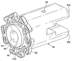
앤빌 부재(27)의 앤빌 하우징(도 4에서 부재번호 30으로 표시되어 있음)은 도 12를 참고하여 아래에서 설명한다. 앤빌 하우징(30)은 힌지식 암 조립체(32)의 원위 단부에 있는 피벗 핀(36)을 수용하는 장착 보어(88)를 포함하고 있다. 앤빌 하우징(30)의 상부 섹션은 링크(40)(도 4 참고)용 피벗 핀(44)이 장착되어 있는 섹션(94)을 포함하고 있다.The anvil housing of the anvil member 27 (denoted by
중심 보어(90)가 앤빌 하우징(30)을 관통하여 길이방향으로 뻗어 있다. 앤빌 지지부(92)(도 13 참고)는 상기 중심 보어 내에서 길이방향으로 미끄럼이동할 수 있다. 중심 보어(90) 및 앤빌 지지부(92) 양자 모두는 중심 보어 내에서의 피스톤의 회전을 방지하기 위해서 평평한 베어링 표면을 가진 비원형 단면(예를 들면, 도시되어 있는 것과 같은 직사각형 단면)을 가지도록 형성되는 것이 바람직하다.A
도 13은 앤빌 하우징(30)으로부터 분리된 상태의 앤빌 지지부(92)를 나타내고 있다. 앤빌 지지부(92)의 원위부는 상부 플레이트(95a)와 하부 플레이트(95b)로 분리되어 있다. 상부 플레이트(95a)는 하부 플레이트(95b)에 있는 유사한 보어와 축방향으로 정렬되어 있는 보어(93)를 가지고 있다. 앤빌 지지부(92)의 근위부는 앤빌(96)을 지지한다. 도 14에 도시되어 있는 바와 같이, 앤빌(96)은 복수의 함입부(98)를 포함하고 있으며, 상기 복수의 함입부(98)는 스테이플이 스테이플 카트리지로부터 배출될 때, 각각의 스테이플 레그(leg)가 상기 함입부들 중의 하나와 맞물리고, 이로 인해 스테이플 레그가 접히거나 주름이 잡히게 되도록 위치되어 있다. 도시된 실시예에서, 상기 앤빌은, 오프셋된 스테이플의 2개의 환형 링으로서, 하나의 링당 5개의 스테이플을 가지고 있는 스테이플 배열에 맞도록 설계되어 있다. 중심 개구(97)는 앤빌(96)을 관통하여 뻗어 있으며 앤빌 지지부(92)의 루멘과 인접해 있다. 13 shows the
앤빌(96) 및 스테이플 카트리지(78)(도 7 참고)는 스테이플로 고정될 조직에 힘을 가하는 스테이플러 헤드의 2 부분이다. 도 9 및 도 14에 도시되어 있는 바와 같이, 바람직한 앤빌 및 스테이플 카트리지는, 조직과 접촉하는 앤빌/스테이플 카트리지 표면적의 크기가 가능한 한 작게 되도록, 앤빌(96)의 함입부(98) 및 스테이플 카트리지(78)의 스테이플 배치부(80) 주위에 최소량의 재료를 사용하도록 설계되어 있다. 일정한 힘이 가해질 경우, 힘이 가해지는 면적이 작을수록 보다 작은 면적의 조직이 앤빌과 스테이플 카트리지 사이에서 압착되기 때문에, 힘이 가해지는 면적이 큰 경우에 비해서 보다 작은 면적의 조직에 손상이 가해진다. 그러나, 압착되는 조직은, 힘이 보다 작은 면적에 걸쳐서 분포되기 때문에 주어진 힘으로부터 보다 큰 압력을 받는다. 다시 말해서, 힘이 가해지는 면적이 최소화되면 보다 작은 힘으로 보다 큰 압력을 조직에 가하게 된다. 이것은 기계적인 관점에서 볼 때 유리한데, 그 이유는 스테이플러 헤드가 보다 큰 면적의 스테이플 카트리지 및 앤빌로 필요한 만큼의 큰 힘을 제공하거나 견딜 필요가 없기 때문이다.
도 7을 참고하면, 도시된 실시예에서는, 스테이플 카트리지(78)가 외측 벽을 가지고 있고, 상기 외측 벽은 스테이플 카트리지 내에 수용된 스테이플의 외형을 따라 형성되어, 외측 스테이플 위치결정부 또는 슬롯(80a)을 둘러싸는 다수의 페달(73)을 형성하고 있고, 내측 스테이플 위치결정부(80b)에 인접하여, 상기 페달과 페달 사이에 그루브(79)가 배치되어 있다. 각각의 스테이플 위치결정부를 스테이플 카트리지 재료에 의해 완전히 둘러싸여지게 제공하기 보다는, 스테이플 위치결정부(80a, 80b) 각각이 후방 벽(71a) 및 이 후방 벽에 부착된 유지 요소를 포함하고 있고, 상기 유지 요소는, 유지 요소와 후방 벽 사이에 스테이플을 유지시키도록 위치되는 것이 바람직하다. 도 7에서, 상기 유지 요소는 후방 벽(71)으로부터 안쪽으로 만곡되어 있는 한 쌍의 윙(wing)(71b)을 포함하고 있고, 상기 한 쌍의 윙은 스테이플을 스테이플 위치결정부 내에 유지시키기에 충분하게 경계를 이루고 있지만, 바람직하게는 전체 외주부 둘레로 경계를 이루고 있지 않은 슬롯을 형성하고 있다. 앤빌은 도 13에 도시되어 있는 바와 같이 유사한 페달 배치를 가지고 있다. 도 13을 다시 참고하면, 조직을 커팅하는 동안 먼쪽으로 전진하는 커팅 요소(86)가 플레이트(99)와 접촉하게 전진하도록, 플레이트(99)가 앤빌(96) 상에 위치되어 있다. 한 가지 실시예로서, 플레이트(99)는 앤빌의 개구(97) 내에 놓일 수 있다. "커팅 보드"라고도 표현되는 플레이트(99)는 구멍(101)을 가지고 있고, 이 구멍(101)은 포획된 조직의 압력을 완화하여, 펀치 및 플레이트가 폐쇄된 공간을 만드는 상태인 유압 고정(hydraulic locking)을 방지한다. 접촉이 이루어진 후에 커팅 요소(86)를 이동시키는 것이 바람직하다면, 압력은 상기 폐쇄된 공간의 내측에서 증가하여 계속적인 이동을 못하게 저항한다. 이것은 조직 커팅을 방지하거나 조직 커팅에 부정적으로 영향을 미칠 수 있다.Referring to FIG. 7, in the illustrated embodiment, the
커팅 보드는 커팅 요소(86)의 전진에 대항하는 단단한 스톱부로서 기능하지 않도록 설계되는 것이 바람직하다. 커팅 요소(86)가 커팅 보드에 의해 정지되면, 스테이플러 피스톤도 정지되어 불완전한 스테이플 형성이 이루어질 수 있다. 따라서, 조직이 커팅되는 동안 및 그 후에 커팅 요소(86)가 커팅 보드를 뚫고 들어가거나 변위시킬 수 있는 것, 다시 말해서 커터가 커팅 보드와의 최초 접촉이 이루어진 후 약간 전진할 수 있는 것이 바람직하다.The cutting board is preferably designed not to function as a rigid stop against advancement of the cutting
도 15A 및 15B는 전진하여 2개의 다른 실시예의 커팅 보드에 접촉된 커팅 요소(86)를 각각 도시하고 있다. 도 15A의 실시예에 있어서는, 커팅 보드(99a)의 재료는 도시된 바와 같이 전진하는 커팅 요소가 절단 또는 침투하게 되는 탄성중합체 실리콘과 같은 비교적 연질의 재료이다. 이러한 재료는 스테이플 포메이션의 최종 단계시에 커팅 요소의 날카로운 원위 단부가 커팅 보드 내로 이동하는 것을 가능하게 해준다. 도 15B의 실시예에 있어서는, 커팅 보드(99b)는 그것의 후방의 탄성중합체 스프링(99c)과 같은 압축가능한 물체와 함께 위치되는 경질의 재료로 이루어질 수 있다. 도면에서, 이 스프링은 O-링이다. 커팅 보드(99b)에 대한 커팅 요소(86)의 전진은 커팅 보드가 스프링(99c)에 대항하여 원위부쪽으로 변위되는 것을 야기한다. 전진하는 커팅 요소(86)는 O-링이 압축됨에 따라 증가하는 저항을 받게 된다. 코일형 와이어, 스프링 와셔 및 리프 스프링과 같은 다른 스프링 형상 및 재료가 동일한 결과를 성취하는 데 사용될 수도 있다. 커팅 보드(99b)의 표면상의 챔퍼(99d)가, 커팅 요소(86)가 커팅 보드로 가압 접촉될 때, 커팅 요소(86)의 정렬을 도울 수 있다.
15A and 15B respectively show cutting
암 조립체Arm assembly
이하에 암 조립체(32)의 구성을 살펴본다. 도 16은 스테이플러 헤드의 다른 요소들과 분리된 암 조립체(32)를 도시하고 있다. 대체적으로, 각각의 암 조립체는 스테이플 하우징에 피벗가능하게 결합된 제1 암 섹션(100)과, 제1 암 섹션과 앤빌 하우징 사이에 피벗가능하게 결합된 제2 암 섹션(102)을 가지고 있다. 도시의 실시예에서는 나타나지는 않지만, 부가적인 암 섹션이 제1 및 제2 암 섹션 사이에 위치될 수도 있다. The configuration of the
즉, 각각의 암 조립체는 서로 연결되어 힌지(104)를 형성하는 근위 암(100) 및 원위 암(102)을 구비하고 있다. 각각의 근위 암(100)은 길이방향 절결부(108)와, 절결부(108) 내에 피벗가능하게 장착된 암 스프레더(113)를 가지고 있다. 각각의 암 스프레더(113)의 원위 단부는 보어(112)를 구비하고 있다. 보어(112) 내에 핀(84)이 위치된다. 도 10과 관련하여 살펴본 바와 같이, 이 핀(84)은 디스크(68)를 관통하여 뻗어 있고, 스테이플러 하우징의 하부 및 상부 섹션의 슬롯(64)(도 6) 내에서 주행하는 양 단부를 가지고 있다. 따라서, 스테이플러 하우징 내에서의 디스크(68)의 길이방향 운동은 대응하는 슬롯(64) 내에서 핀(84)을 전진시켜, 암 스프레더(113)가 핀(84)에 대해 피벗운동하도록 만들고, 그에 따라 암 조립체(32)를 바깥쪽으로 구동시킨다. 암 조립체(32)의 운동과 관련한 추가적인 설명은 아래의 소제목 스테이플러 헤드 작동의 설명 부분에서 이루어진다. That is, each arm assembly has a
암 조립체의 원위 암(102)은 전술한 바와 같이 앤빌 하우징(30)(도 4)에 피벗가능하게 장착된 핀(36)을 구비하고 있다. 한 쌍의 구동 링크(114)가 제공되고, 각각의 구동 링크(114)는 대응하는 원위 암(102)에 피벗가능하게 부착된 제1 단부와, 공통 핀(116)에 피벗가능하게 결합된 제2 단부를 가지고 있다. 조립된 스테이플러 헤드에 있어서, 핀(116)은 앤질 지지부의 상부 및 하부 플레이트(95a, 95b)(도 12의 플레이트(95a, 95b) 참조)의 보어(93) 내에 위치된다. 아래의 소제목 스테이플러 헤드 작동의 설명 부분에서 상세히 설명되는 바와 같이, 암 스프레더(113)가 암 조립체(32)를 바깥쪽으로 구동시킬 때, 구동 링크(114)는 핀(116)상에서 앤빌 지지부를 근위 방향으로 밀도록 작동하여, 앤빌이 스테이플 카트리지를 향해 근위부쪽으로 전진하게 만든다. The
선택적으로, 앤빌은 앤빌 하우징 내에서 지지되는 직접적인 유압 구동 메카니즘에 의해 암 어셈블리에 독립적으로 앤빌 하우징 내에서 구동될 수도 있다. 바람직하게는, 2개의 하우징 내의 구동 메카니즘은 스테이플 홀더 및 앤빌이 개별 하우징 내에서 서로를 향해 동시에 이동되도록 조합된다.
Alternatively, the anvil may be driven in the anvil housing independent of the arm assembly by a direct hydraulic drive mechanism supported in the anvil housing. Preferably, the drive mechanism in the two housings is combined such that the staple holder and the anvil are moved simultaneously toward each other in separate housings.
스테이플러 헤드 작동Stapler head operation
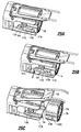
이하에 암 조립체가 진공 챔버를 팽창시키고 흡인을 이용하여 챔버 내로 도입된 조직을 압축시키도록 작용하는 방식을 중심으로 설명한다. 챔버 팽창에 앞선 초기 단계로서, 스테이플러 헤드는 막(24)의 개구(26)가 주름 생성이 요구되는 위치에서 조직과 접촉한 상태로 위치된다. 진공 발생원(20)(도 2)이 막에 의해 한정되는 진공 챔버 내부에 진공을 도입하도록 활성화된다. 개구(26)(도 3B)와 접촉하고 있는 조직은 스테이플 하우징(28)과 앤빌 하우징(30) 사이의 진공 챔버 내로 흡입된다. 조직이 흡입된 후, 스테이플러의 외형이 변화되어, 막 내의 챔버의 체적을 팽창시킨다. The following describes the manner in which the arm assembly acts to expand the vacuum chamber and compress the tissue introduced into the chamber using suction. As an initial step prior to chamber expansion, the stapler head is positioned with the
팽창 이전의 스테이플러 헤드(28)의 유선(流線)형 위치가 도 4, 도 17 및 도 18에 도시되어 있다. 구체적으로, 힌지형 암 조립체(32) 및 막 레이저(37)는 대체로 직선적으로 배향되어 있다. 근위 암(100)은 챔버 팽창 및 조직 압축을 위한 구동 암으로서 기능한다. 이 근위 암(100)의 동작은 압력을 받은 물이 스테이플 하우징의 유압 회로 내로 강제 도입될 때 개시된다. 도 19를 참조하면, 유체 압력은 디스크(68)를 전진시킨다(도 19에는 도시되지 않았지만 압축 피스톤(106)의 작동에 의해). 다음으로, 디스크(68)가 도 19 내지 도 21에 도시된 바와 같이 스테이플 카트리지(78)를 앤빌(96) 쪽으로 밀어, 스테이플 카트리지(78)가 스테이플 하우징(28)으로부터 더 확장되게 만든다. The streamlined position of the
디스크(68)와 암 스프레더(113)는 양자 모두가 핀(84)에 결합되어 있다. 이런 이유로, 스테이플 하우징(28) 내에서의 디스크(68)의 길이방향 운동은 핀(84)을 대응하는 슬롯(64) 내에서 원위부쪽으로 이동시킬 것이다. 암 스프레더(113)는 결과적으로 핀(84)에 대해 피벗운동하여, 근위 암(100)을 바깥쪽으로 구동시킬 것이다. 힌지(104)에서의 근위 암(100)의 바깥방향 운동은 원위 암(102)도 힌지(104)에서 바깥쪽으로 피벗운동하도록 만들어, 근위 암(100)과 원위 암(102) 사이에 일정 각도를 형성한다. 자연히, 암(100, 102) 사이의 각도의 형성은 암의 떨어진 양 단부간의 유효 길이를 단축시켜, 원위 암(102)의 원위 핀(36)이 앤빌 하우징(30)을 스테이플 카트리지 쪽으로 이동시키게 만든다. 원위 암(102)의 피벗운동은 또한 구동 링크(114)가 핀(116)에서 작동하여 앤빌 지지부를 근위부쪽 방향으로 밀게 만든다. 이는 앤빌 지지부를 앤빌 하우징에 대해 근위부쪽 방향으로 이동시키는 동시에, 앤빌 하우징도 근위부쪽으로 이동시킨다. Both
기본적으로, 유압 구동되는 피스톤의 하나의 동작이 도 19 내지 도 21에서 화살표(A1, A2, A3)로 나타내진 적어도 3가지 동작을 발생시킨다. 이러한 3가지 동작은: 앤빌(96)을 향한 방향으로의 스테이플 하우징에 대한 스테이플 카트리지(78) 이동(화살표(A1)), 스테이플 하우징(28)을 향한 앤빌 하우징(30) 이동(화살표(A2)); 및 카트리지를 향한 방향으로의 앤빌 하우징(30)에 대한 앤빌(96) 자체 이동을 포함한다. 이러한 스테이플 카트리지를 향한 앤빌의 복합 동작은 압축 피스톤의 작은 변위가 스테이플러의 그립 내의 조직을 신속하게 압축하는 것을 가능하게 해준다. 이러한 동작의 증식은 또한 근위(피동) 암과 원위(구동) 암 사이의 힌지(104)에서의 각도를 가능한 한 크게 유지시킴으로써 2개의 하우징 간의 힘전달도 향상시킨다. Basically, one action of the hydraulically driven piston produces at least three actions indicated by arrows A1, A2, A3 in FIGS. 19 to 21. These three operations are: moving the
서로를 향한 2개의 하우징(28, 30)의 상대 동작은 또한 스테이플러 헤드의 상부의 상향 링크(38, 40) 및 이들을 상호연결하는 스프링 와이어(46)도 구동시킨다. 링크 및 스프링 와이어는 함께 막의 상부를 상승시켜, 압축시 조직의 팽창을 수용하기 위한 보다 큰 체적을 발생시킨다. The relative operation of the two
도 22 내지 도 24에 도시된 바와 같이, 스테이플 하우징(28)의 슬롯(64) 내에서의 핀(84)의 이동이 이동 한계에 도달할 때, 조직의 압축은 정지된다. 따라서, 슬롯 및 대응하는 구성요소들은 스테이플러측의 조직 접촉 표면과 스테이플러 헤드의 앤빌측의 조직 접촉 표면 사이에 소정의 이격 거리를 설정하기 위한 치수로 되어 있다. 위벽 겹쳐 접기에 사용하기 위한 이격 거리의 예로는 대략 0.06-0.07 인치(예컨대, 5.5 mm 길이의 레그를 가진 스테이플과 함께 사용할 경우) 또는 6.5 mm 길이의 레그를 가진 스테이플의 경우 0.109 인치를 구비할 수 있다. 유압 회로 내로의 부가적인 압력을 적용하여도 더 이상 조직을 압축하지는 않을 것이다. As shown in FIGS. 22-24, when the movement of the
또한, 피스톤 구성으로 인해, 스테이플 고정 작용은 조직 압축이 완료될 때까지 효과적으로 차단된다. 이런 구성 때문에, 유체 압축의 완료 이전에 유체 포트(50b)(도 11A)를 통해 스테이플 유체 채널(122)로 도입되는 유체는, 압축 피스톤(106)의 2개의 O-링이 입구(114)에 안착될 때까지는 누출될 것이다. 이러한 설계는 조기 스테이플 발사를 방지한다. In addition, due to the piston configuration, the staple fixation action is effectively blocked until tissue compression is completed. Because of this configuration, fluid introduced into the staple
완전히 압축된 상태에서는, 암 스프레더(113)는 스테이플러 헤드의 길이방향 중심선에 거의 수직하게 된다. 일단 조직이 카트리지(78)와 앤빌(96) 사이에서 압축되면, 조직은 스테이플 고정이 준비된 상태가 된다. In the fully compressed state, the
스테이플 고정은 포트(50b)(도 5)를 통해 유압 유체를 도입함으로써 개시된다. 스테이플 피스톤이 전진하여, 커팅 요소(86)(도 7 및 도 10)를 앤빌(96) 쪽으로 민다. 스테이플 푸셔(76)가 커터(86)에 장착되어 있기 때문에, 이 동작은 스테이플 푸셔(76)를 카트리지(78)를 통해 이동시키고, 동시에 모든 스테이플을 조직 속으로 민다. 스테이플 피스톤의 이동은 내부 스톱부에 의해 제한되고, 최적의 스테이플 포메이션을 성취하도록 사전에 설정된다.Staple fixation is initiated by introducing hydraulic fluid through
압축시, 암 조립체(32)의 힌지(104)에서의 각도가 최소값에 도달하면, 스테이플과 앤빌 하우징의 이격에 저항하는 데 필요한 힘이 증가한다. 이러한 힘은 스테이플 압착력이 스테이플 피스톤에 의해 앤빌에 가해질 때 더 증가한다. 이를 보상하기 위해, 암 스프레더(113)는 이러한 힘의 적어도 일부를 디스크(68)로 전달하기 위한 변위 스트럿으로서 기능한다. 이러한 힘은, 푸셔 디스크에 의한 반응이 없다면, 암(100, 102)을 펴지게 할 것이고, 조직에 대한 압축을 해제시킬 수 있어, 불완전한 스테이플 포메이션 또는 조직 절단을 야기할 수 있다. 이런 식으로, 트러스형 구조가 힘 변위를 위해 생성된다. Upon compression, when the angle at the
스테이플이 형성되었을 때, 스테이플 압력은 해제되고, 스프링(도시되어 있지 않음)은 스테이플 푸셔(72)를 본래 위치로 복귀시킨다. 유체 압력의 해제는 막 레이저(37)상의 변형된 스프링 와이어(46)가 스테이플 헤드를 그것의 최소 프로파일 형태로 복귀시키고 주름을 스테이플러로부터 해방시키는 것을 가능하게 해줄 것이다. 일단 환자 몸체 외부로 나오면, 사용된 스테이플 카트리지는 축출되고 새로운 스테이플 카트리지가 설치된다. When staples are formed, the staple pressure is released and a spring (not shown) returns the
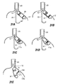
도 25A 내지 도 25C는 제거가능한 스테이플 카트리지(78)를 스테이플 하우징 내에 유지시키는 한가지 방법을 도시하고 있다. 카트리지는 스테이플 하우징 내에 스프링 장착되고, 각각이 받침대(172)에 대해 피벗가능한 2개의 래치(170)(도면에서는 하나만 보임)에 의해 유지된다. 도시된 바와 같이, 받침대(172)는 핀(84)에 의해 디스크(68)에 결합될 수 있다. 각각의 래치(170)는 카트리지의 대응하는 캐치(176)에 맞물리는 캐치(174)를 구비하고 있다. 래치(170)는 캐치(174)를 카트리지 쪽으로 안쪽으로 가압하도록 스프링 가압되어 있는 것이 바람직하다. 25A-25C illustrate one method of retaining a
도 25B에 화살표(P)로 나타내진 바와 같이 각각의 래치(170)의 근위 단부(175)를 누르면, 래치가 스프링 가압력에 저항하여 피벗운동하게 되어, 스테이플 카트리지의 축출을 야기한다. 그런 다음, 도 25C에 도시된 바와 같이 새로운 스테이플 카트리지가 그것의 그루브(79)가 얼라인먼트 포스트(74)와 정렬된 상태로 위치된 다음, 스테이플 하우징을 향해 밀어 넣어진다. 새로운 카트리지가 정위치로 슬라이드할 때, 캐치(174)가 캐치(176)의 경사진 근위 부분(178) 위를 타고 넘게 된다. 일단 캐치(174)가 캐치(176)의 원위 단부(180) 위를 통과하면, 캐치(174)는 스프링 가압력으로 인해 카트리지 쪽으로 안쪽으로 떨어져 내려, 카트리지와 결합된다. 카트리지가 적정하게 밀봉되었을 때, 래치가 새로운 카트리지와 맞물릴 때 클릭이 감지되거나 클릭음이 들리게 될 것이다.
Pressing the proximal end 175 of each
스테이플 고정시의 스테이플러 얼라인먼트Stapler Alignment at Staple Fixation
작동에 있어, 2개의 스테이플러 부재가 함께 접합되면, 조직 접힘부가 스테이플 카트리지의 외면과 앤빌의 대향면 사이에 포획된다. 조직 접힘부의 스테이플 고정 직전 및 스테이플 고정시의 이러한 조직 포획이 발생할 때, 포획된 조직 영역들의 두께 및/또는 압축성의 편차가 편심된 즉 축이탈된 스테이플 고정 작업을 초래하여, 스테이플 레그가 대응하는 앤빌 함입부 내의 위치를 벗어나 수용되도록 만들고, 그 결과 하나 이상의 스테이플이 예컨대 스테이플 레그가 완전히 접혀지지 않는 등과 같이 불완전하게 체결되거나, 스테이플 어레이가 장치의 중심축에 대해 벗어나, 예컨대 몇몇의 스테이플이 스테이플 고정된 접힘부의 중심의 구멍 절단부에 너무 근접하게 되는 것을 초래할 수 있다. In operation, when the two stapler members are joined together, the tissue fold is captured between the outer surface of the staple cartridge and the opposite surface of the anvil. When such tissue capture occurs immediately before staple fixation and at staple fixation of the tissue fold, deviations in the thickness and / or compressibility of the captured tissue regions result in an eccentric, deviated staple fixation operation, so that the staple legs have corresponding anvils. To be received out of position in the recess, such that one or more staples are incompletely fastened, for example, the staple legs are not fully folded, or the staple array is off about the central axis of the device, for example, some staples are staple fixed. This can lead to being too close to the hole cut in the center of the fold.
카트리지 내의 각각의 스테이플 어레이(예컨대, 5개씩의 스테이플로 이루어지는 2개의 동심 어레이)에 대해 스테이플 고정 작업이 성공적으로 이루어지는 것을 보장하기 위해, 본 발명의 장치는 스테이플 고정 작업의 직전이나 스테이플 고정 작업시에 장치의 근위 및 원위 부재들을 축방향 얼라인먼트 상태로 유지하기 위한 얼라인먼트 구조를 구비할 수 있다. 이러한 얼라인먼트 구조가 도 36 및 도 37에 측단면도로 도시되어 있다. 도 36에는 원위 부재(27)에 앤빌(96) 및 커팅 보드(99a)를 그리고 근위 부재(25)에 커터(86)를 구비하고 있는 스테이플 장치(12)의 일부분이 도시되어 있다. 작동에 있어, 도 22 및 도 23에 도시된 바와 같이, 상기 2개의 부재와, 상기 2개의 부재상에서 지지되는 스테이플 카트리지 및 앤빌은 처음에는 카트리지와 앤빌의 대향면들 사이에 조직 접힘부를 포획하기 위해 함께 이동된다. 그런 다음, 스테이플 피스톤(116)은 도 24에 도시된 바와 같이 후퇴 위치로부터 확장 위치로 이동되어 도시된 바와 같이 커터를 커팅 보드(99a)에 접촉하도록 이동시키고 스테이플 카트리지 내의 스테이플을 앤빌에 대해 구동시킨다. In order to ensure that the staple fastening operation is successful for each staple array in the cartridge (e.g., two concentric arrays of five staples), the device of the present invention is provided immediately before or during the staple fastening operation. And an alignment structure for maintaining the proximal and distal members of the device in an axial alignment. This alignment structure is shown in side cross-sectional views in FIGS. 36 and 37. 36 shows a portion of a
이러한 얼라인먼트 구조는 커터(86)와 함께 이동하도록 커터(86) 내에 축방향으로 유지된 핀과, 앤빌(96)과 함께 축방향으로 이동하도록 앤빌(96)에 부착된 하우징(27)의 일부분 내에 지지된 부싱(164)에 형성된 핀 수용 슬롯을 구비하고 있다. 도 36에 도시된 실시예에 있어서, 부싱(164)은 하우징(27) 내에서 스프링(166)에 의해, 부싱을 향한 핀의 운동에 저항하는 방향으로 스프링 가압되어 있어, 이제 포획된 조직 속으로 침투된 커터와 부착된 핀이 부싱의 경사진 단부 내에 안착하는 것을 가능하게 해준다. 커터, 핀, 및 스테이플 푸셔는 계속해서 제2 부재를 향해 이동하여, 결국 조직에 구멍을 형성하고, 스테이플 카트리지로부터 스테이플을 조직 속으로 그리고 앤빌에 대해 발사하여, 2개의 장치 부재는 축방향 얼라인먼트 상태로 유지되어, 대응하는 앤빌 함입부에 대해 정렬되어 위치된 모든 스테이플에 의해 스테이플 고정 작업이 발생하게 된다. 이러한 작업이 완료되었을 때, 스테이플 피스톤 및 구동 부재는 스테이플 고정된 조직을 해방시키도록 후퇴하고 장치를 그것의 선형 상태로 복귀시킨다. This alignment structure includes a pin axially held in the
도 37에 도시된 장치(12)의 실시예는 직전에 설명한 실시예와 유사하지만, 이 실시예에서 커터의 하우징 내에 지지되는 얼라인먼트 핀(168)은 제2 부재의 방향으로 스프링(174)에 의해 스프링 가압되어 있고, 핀 수용 슬롯(170)은 부재(27) 내의 앤빌(도시되어 있지 않음) 아래에서 지지되는 고정위치 부싱(172) 내에 존재한다. 이 실시예에 있어, 일단 핀이 처음으로 부싱 슬롯 내에 안착되었을 때, 2개의 부재의 서로를 향한 동작은, 스테이플 피스톤이 완전 확장 위치를 향해 계속 이동하여 전술한 바와 같이 2개의 부재 사이에 포획된 조직을 절단하고 스테이플 고정함에 따라, 제2 부재 반대쪽 방향으로의 핀의 이동에 의해 조절된다.
The embodiment of the
스테이플러 샤프트 및 핸들Stapler shaft and handle
도 2를 다시 참조하면, 핸들(18)과 스테이플러 헤드(14)를 연결하는 스테이플러 샤프트(16)는 상부 소화관의 굴곡에 순응할 정도로 충분히 가요성이면서도, 스테이플러 헤드를 회전시키기 위한 충분한 토크를 전달하는 성능을 보유한다. 샤프트는 식도 가이드 튜브(23)에 밀어 넣어지는 것을 가능하게 해줄 정도로 충분한 강성을 가지고 형성된다. Referring back to FIG. 2, the
도 26은 샤프트로부터 스테이플러 헤드가 제거된 상태에서의 샤프트(16)의 원위 부분을 도시하고 있다. 도시된 바와 같이, 샤프트(16)는 스테이플 고정 작업을 볼 수 있게 하기 위해 내시경이 통과하여 전진하는 내시경 루멘(124)을 구비하고 있다. 수술 과정시에 유용한 다른 기구들을 수용하기 위해 측부 루멘(126)도 제공될 수 있다. FIG. 26 shows the distal portion of the
스테이플러 헤드가 샤프트에 대해 관절운동하는 것을 가능하게 해주도록, 관절연결 섹션(128)이 샤프트(16)의 원위 단부에서 샤프트(16)와 스테이플러 헤드(14) 사이에 위치된다. 진공 발생원 및 유압 유체의 공급원에 결합되는 배관이 핸들로부터 샤프트(16) 및 관절연결 섹션(128)을 통해 뻗어 있다. An
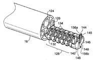
도 27A는 유압 유체 라인(130)에 사용될 수 있는 한가지 구성을 도시하고 있다. 사용시에, 유압 유체 라인은 스테이플러의 관절연결 섹션에서 심하게 휘어지고 신장되게 된다. 유압 유체 라인은 또한 1,500 psi를 초과할 수 있는 유체 압력을 여러 차례 받게 된다. 일반적으로, 산업계에 적용되고 있는 유압 라인은 가요성이고, 사용시에 길이 변화를 수용하는 여분을 두고 있는 배관으로 이루어지는 작동 루프를 가진다. 유압 라인의 도시된 구성은 특히 공간적 제약을 갖는 내시경식 장치에 적합한 단순한 형상에 대한 해법의 구성이다. 한가지 바람직한 유압 라인은 굽힘시에 유효 길이를 수용할 수 있도록 길이방향으로 확장가능한 형상으로 형상변경되는 부분을 가진 튜브(130)이다. 튜브의 길이방향으로 확장가능한 부분은 바람직하게는 스테이플러(12)의 관절연결 섹션(128) 내에 위치된다. 한가지 바람직한 설계에 있어, 길이방향으로 확장가능한 형상은 도 27A에 도시된 바와 같은 코일 형상이다. 대체 실시예에 있어서는, 튜브(130)는 사각형 또는 불규칙한 물결치는 형상(도 27B)과 같이 다른 형태로 길이방향으로 확장가능한 형상으로 형성될 수도 있다. 27A illustrates one configuration that may be used for hydraulic
튜브(130)의 바람직한 재료는 스테인리스 스틸 하이포튜브이지만, 다른 재료로 대체될 수도 있다. 바람직한 스테이플러 구성에 있어, 2개의 구동 유체 라인이 제공되며, 그 중 하나는 조직 압축에 구동력을 제공하기 위한 구동 유체 라인이고, 다른 하나는 스테이플 적용(및 절단)에 구동력을 제공하기 위한 구동 유체 라인이다. 본 실시예에 있어서, 튜브는 도 27A에 도시된 바와 같이 함께 코일을 형성하고 있다. 대체 실시예에 있어서는, 2개 이상의 코일형 튜브가 하나의 튜브가 다른 튜브 내부에 겹쳐지는 식으로 위치될 수도 있다. 관절연결 섹션이 굽혀질 때는, 코일형 튜브에 힘이 가해져 굽힘에 따라 코일형 튜브(130)도 굽혀지고 길이가 변하게 된다. 이러한 동작중에는 코일형 튜브는 마치 코일형 와이어와 같은 동태를 나타내고, 따라서 길이를 변화시키고 굽혀질 수 있으며, 튜브의 루멘을 통한 흐름을 손상시키거나 유압 시스템의 어느 쪽 단부의 연결부에도 과도한 응력을 부과하는 일없이 관절연결 섹션의 외형선을 따른다. The preferred material of
유체 라인의 길이방향으로 확장가능한 형상은 장치의 관절연결 또는 굽힘가능한 섹션을 지나는 치료제나 세척제를 공급하기 위한 카테터 또는 내시경식 장치와 같은 다른 유형의 관절연결형 의료 장치의 작업 단부에 유체를 공급하는 것을 가능하게 해주는 데 사용되기에도 적합할 수 있다. The longitudinally expandable shape of the fluid line is intended to supply fluid to the working end of another type of articulated medical device, such as a catheter or endoscopic device for supplying a therapeutic agent or cleaning agent through the articulated or bendable section of the device. It may also be suitable to be used to make it possible.
도 26을 다시 참조하면, 관절연결 섹션(128)은 한 쌍의 풀 케이블(pull cable)(도 26에는 하나만 도시됨) 위에 매달린 복수의 링크(132)로 형성된 척추형상부를 포함하고 있다. 한가지 실시예에 있어서, 풀 케이블의 연결은 스테이플러 헤드(14)가 대략 한쪽 방향(도 3B)의 90도로부터 반대쪽 방향(도 3C)의 175도까지의 동작 범위를 통해 2개의 방향으로 관절연결되는 것을 가능하게 해준다. 각각의 풀 케이블은 스테이플러 헤드에 또는 스테이플러 하우징(28)의 최원위 링크(132)와 같은 스테이플러 헤드에 인접한 곳에 고정된다. Referring back to FIG. 26, the
풀 케이블(134)의 근위 부분은 샤프트(16)의 길이를 따라 연장되어 핸들(18)에서 끝난다. 도 28을 참조하면, 핸들(18)은 스테이플 헤드를 위로 또는 아래로 관절연결시키기 위해 시계방향 또는 반시계방향으로 선택적으로 회전될 수 있는 회전 노브(136)를 구비하고 있다. 한쪽 방향으로의 회전은 풀 케이블 중의 하나에 인장력을 가하여, 스테이플러 헤드가 아래로 굽혀지게 만드는 한편, 반대 방향으로의 회전은 다른 하나의 풀 케이블에 인장력을 주어 스테이플러 헤드가 위로 굽혀지게 만든다. The proximal portion of the
한가지 바람직한 핸들의 구성에 있어서, 노브(136)는 내부 나사 보어(138)를 구비하고 있다. 노브(136)는 핸들(18) 내부에 일부가 구속되어 핸들 내부에서 고정적으로 유지되지만 자유롭게 회전할 수 있다. 외부 나사면을 가진 캐리지(140)가 노브의 내부 나사 보어(138) 내에 위치된다. 보어(138)의 나사는 캐리지(140)의 나사와 맞물림되어, 노브의 회전이 캐리지(140)가 핸들 내에서 병진운동하게 만들지만, 캐리지는 회전하지는 않는다. In one preferred configuration of the handle, the
케이블(134a, 134b)로서 도 28에 표시된 2개의 풀 케이블의 각각은 핸들의 다른 부재에서 끝난다. 케이블(134a)은 슬라이딩 캐리지상에 장착되어 있고, 케이블(134b)은 핸들(18)의 정지부에 장착되어 있다. 각각의 케이블은 대응하는 외피를 통해 뻗어 있다. 케이블(134a)은 핸들(18)의 정지부에 고정된 근위 단부를 가진 외피(135a)를 통해 뻗어 있다. 케이블(134b)은 슬라이딩 캐리지에 장착된 근위 단부를 가진 외피(135b)를 통해 뻗어 있다. Each of the two full cables shown in FIG. 28 as
케이블(134a, 134b) 및 외피(135a, 135b)는 한쪽 방향으로의 캐리지의 병진운동이 스테이플러 헤드가 한쪽 방향으로 굽혀지도록 만들 것이고, 다른 방향으로의 캐리지의 병진운동이 스테이플러 헤드가 또 다른 방향으로 굽혀지도록 만들 것이다. The
도 28을 참조하면, 노브(136)가 회전하여 캐리지(140)가 도면의 좌측으로 병진운동하게 만들면, 케이블(134a)이 인장되고, 케이블(134b)은 이완되어, 스테이플러 헤드가 제1 방향으로(예컨대 위쪽으로) 관절운동하게 만들 것이다. 반대방향으로의 노브(136)의 회전은 캐리지를 도면의 우측으로 병진운동시켜, 케이블(134a)의 인장력을 해제하고, 케이블(134b) 위의 외피(135b)를 스테이플러 헤드의 원위 단부 쪽으로 밀어, 외피(135)가 샤프트(16)의 원위 부분에 대항하여 전진됨에 따라, 스테이펄러 헤드가 제2 방향(예컨대 아래쪽으로) 관절운동하게 만들 것이다. 외피(135b)의 근위 부분은 캐리지가 원위부쪽으로 이동할 때 인장력을 받게 되는 것을 방지할 정도로 충분한 작동 거리를 구비하고 있다. 이러한 노브의 위치결정은 스테이플러 관절연결에 필요한 손의 운동이 스테이플러의 회전 방향과 관계없이 항상 동일하다는 점에서 유리하다. 또한, 나사 노브의 사용은 노브가 그것의 회전 위치를 유지시키기 위한 잠금장치 없이 제공되더라도 굽힘 각도의 의도하지 않은 이완을 방지할 수 있다. Referring to FIG. 28, when the
도 28 및 도 29를 참조하면, 내시경 루멘(124)은 스테이플러의 중심축을 따라 뻗어 있다. 루멘의 위치설정과 내시경(124)에 대한 관절 노브의 동축 관계는 내시경 및 스테이플러가 서로에 대해 간섭함이 없이 독립적으로 회전되는 것을 가능하게 해준다. 따라서, 사용자가 신체 내에서의 스테이플러 헤드(14)의 회전 방향을 변경시킬 것을 선택하면, 사용자는 내시경의 회전 위치를 유지하면서 핸들(18) 및 샤프트(16)를 회전시킬 수 있다. 28 and 29, the
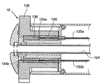
비용 효율을 위해, 샤프트(16) 및 핸들(18)이 살균되어 재사용되는 것을 허용하면서, 스테이플러(12)는 폐기되는 것을 허용하도록 설계될 수 있다. 스테이플러 헤드를 샤프트(16)에 제거가능하게 결합시키기 위한 하나의 메카니즘이 도시되어 있다. 하지만, 다른 나머지 메카니즘은 내장된다(예컨대, 슬립 커플링 타입 장치). 도 26을 참조하면, 단부 플레이트(142)는 링크(132) 중 최원위 링크에 장착되어 있다. 각각의 단부 플레이트(142) 및 대응하는 스테이플러의 후면은 단부 플레이트와 스테이플러 헤드가 서로 걸음되게 해주는 래치 구조를 구비하고 있다. For cost effectiveness, the
단부 플레이트(142)는 페그(peg)(145)(스프링 핀의 형태일 수 있다)를 가진 캔틸레버 핀(144), 중심 개구(146), 및 가장자리를 따른 한 쌍의 U-자형 캐치 즉 걸음 에지(148)를 구비하고 있다. 유압 공급 구멍 즉 개구(156a, 156b)가 단부 플레이트(142)를 통해 형성되어 있다. 스테이플러 헤드에 유압 유체를 공급하는 유압 튜브(도 27의 튜브(130) 참조)는 바람직하게는 단부 플레이트에 용접되어 유체가 튜브로부터 공급 구멍(156a, 156b)을 통해 안내되도록 해준다. The
도 30A 및 도 30B는 도 5에 대해 약간 수정된 스테이플 하우징의 후면(48a)을 도시하고 있다. 이 변형된 후면(48a)에 있어서는, 유압 입력 포트 즉 개구(50a, 50b)가 도시된 바와 같이 재위치되어 있다. 또한, 후면(48a)은 정렬 핀(152)과 구멍(154)에 더하여, 언더컷 보스(150) 형태의 한 쌍의 캐치 즉 걸음 에지를 구비하도록 수정되었다. 스테이플러 장치에 대한 샤프트의 스냅-온 연결;30A and 30B show the
도 30A 및 도 30B는 스테이플 하우징의 후면(48a)에 대해 위치된 단부 플레이트(142)를 보여 주고 있다. 관절연결 섹션(128)의 다른 부분들은 명료함을 위해 도시되지 않았다. 스테이플러 헤드를 샤프트(16)에 부착하기 위해, 핸들 조립체에 부착된 단부 플레이트(142)는 도 30A에 도시된 바와 같이 스테이플 하우징의 후면(48a)에 대해 가압된다. 단부 플레이트가 밀어질 때, 단부 플레이트는 시계방향으로 회전되어, 캔틸레버 핀(144)의 페그(145)(도 26)가 스테이플 하우징의 후면의 구멍(154)에 걸음되게 만든다. 이러한 래치가 걸음되었을 때, 단부 플레이트(142)의 유압 공급 구멍(156a, 156b)은 도 30B에 도시된 바와 같이 상승하여 스테이플 헤드의 유압 입구(50a, 50b)와 일직선을 이룬다. 이와 동시에, U-자형 캐치(148) 주변의 단부 플레이트 부분은 언더컷 보스(152) 아래를 슬라이딩한다. 단부 플레이트를 누르면 유압 입력 포트(50a, 50b)를 에워싼 면밀봉 O-링을 압축하게 된다. O-링상의 압축력은 캐치와 단부 플레이트에 돌출하는 언더컷 보스의 결합에 의해 유지된다. 스테이플러 헤드를 하우징으로부터 제거하기 위해, 스테이플러 하우징은 단부 플레이트(142)를 후면(48a)으로부터 분리시키도록 반시계방향으로 비틀어진다. 그런 다음, 스테이플러 샤프트와 핸들은 새로운 스테이플러 헤드의 장착을 위한 준비로서 살균될 수 있다.
30A and 30B show the
예시적인 수술과정Exemplary Surgery
다음으로, 특히 도 31 내지 도 33을 참조하여, 위 벽 조직에 주름을 형성하는 것으로 하여 시스템(10)을 사용하는 방법의 예를 설명한다. Next, with reference to FIGS. 31 to 33 in particular, an example of a method of using the
첫 번째 단계로서(도 2), 내시경식 가이드 튜브(23)가 입과 식도를 경유하여 위로 전진된다. 내시경(22)이 스테이플러 핸들(도시되어 있지 않음)의 내시경 채널 내로 삽입되고, 스테이플러 핸들의 루멘 아래로 전진된다. 스테이플러/내시경은 위를 향해 내시경식 가이드 튜브를 동시에 통과한다. 일단 스테이플러 및 내시경이 위의 위식도 접합부 부위에 도달하면, 스테이플러의 위치는 유지되는 한편, 내시경은 위 속으로 더 전진된다. As a first step (FIG. 2), the
스테이플러 헤드(14)가 위의 원하는 깊이 및 위치로 전진된다. 스테이플러 핸들에 대한 관절연결 제어를 이용하여, 스테이플러 헤드의 각도 배향을 조절하여 도 31A에 도시된 바와 같이 사전확인된 목표 조직에서의 스테이플러 헤드(12)의 위치결정을 가능하게 해준다. 막(24)의 개구(26)가 목표 조직에 접하여 위치된다. 내시경(22)이 도시된 바와 같이 뒤로 굽은 자세로 위치된다. The
진공 발생원(20)(도 2)이 신체 외부의 핸들상의 진공 포트에 결합되고, 조직(17)을 흡입하기 위해 진공 압력이 도 31B 및 도 32A에 도시된 바와 같이 개구(26)를 통해 막(24)에 의해 형성된 진공 챔버 내로 인가된다. 목표 조직의 취득이 스테이플러 헤드상의 투명 막(24)의 벽을 통해 내시경에 의해 쉽게 확인될 것이다. A vacuum source 20 (FIG. 2) is coupled to a vacuum port on a handle outside the body, and a vacuum pressure is applied through the
유체 공급원이 핸들에 결합된다. 일단 충분한 양의 조직이 취득되었다는 것이 시각적으로 확인되면, 유체가 도입되어 도 32B 및 도 31C에 도시된 바와 같이 조직의 압축과 암 조립체(32) 및 막 레이저(37)의 팽창이 이루어진다. 도면에서 볼 수 있는 바와 같이, 암 조립체 및 막의 팽창은 조직 압축시에 많은 양의 조직이 진공 챔버 내로 취득되어 챔버 내로 변위되는 것을 가능하게 해준다. 앞서 살펴 본 바와 같이, 수술시에 도 32B 및 도 31C에서 스테이플러 홀더 및 앤빌의 더 "위쪽에서의" 조직의 챔버 내로의 흡입은 조직의 스테이플 고정되는 부분 주변에 비교적 큰 여유분의 조직을 제공하여, 스테이플 고정되는 조직 부분 근방에서의 조직의 찢어짐 또는 조직 접힘의 약화의 위험성을 감소시킨다. 포획된 조직 접힘부가 17a로 나타내져 있다. The fluid source is coupled to the handle. Once visually confirmed that a sufficient amount of tissue has been obtained, fluid is introduced to compress the tissue and expand the
일단 조직이 압축되면, 도 31D 및 도 32C에 도시된 바와 같이, 부가적인 유압 유체가 도입되어, 조직의 스테이플 고정 및 절단이 이루어져, 도 33에서 17b로 나타내진 주름을 형성한다. 그런 다음, 압축 및 스테이플 고정용 유압 공급원은 비활성화되어 유압 회로 내의 유체 압력을 해방시킨다. 유압이 해방되면, 막 레이저(37)의 스프링 와이어는 스테이플러 헤드를 원래의 유선(流線)형 형태로 복원시키는 것을 도와, 도 31E에 도시된 바와 같이 스테이플러 헤드가 조직으로부터 후퇴하는 것을 가능하게 해준다. 스테이플러 헤드는 당해 스테이플러 헤드가 주름(P)으로부터 멀어지도록 이동하는 것에 도움을 주도록 샤프트에 대해 관절운동할 수 있다. Once the tissue is compressed, additional hydraulic fluid is introduced, as shown in FIGS. 31D and 32C, to staple and cut the tissue, forming the corrugation shown by 17b in FIG. 33. Then, the hydraulic source for compression and staple fixing is deactivated to release the fluid pressure in the hydraulic circuit. Once the hydraulic pressure is released, the spring wire of the
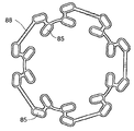
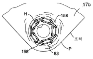
도 33에 도시된 바람직한 주름 구성에 있어, 스테이플(158)은 5개씩의 스테이플로 이루어진 2개의 동심 링으로 배열되어 있고, 도시된 바와 같이 스테이플 보강 장치(83)가 스테이플들에 의해 유지되어 있으며, 스테이플 패턴 둘레로 힘을 분배시키고 있다. 주름(P)은 커팅 요소에 의해 형성된 구멍(H)을 포함하고 있으며, 이 구멍을 통해 다양한 임플란트 또는 다양한 임플란트용 앵커들이 배치될 수 있다. In the preferred corrugation configuration shown in FIG. 33, the
다수의 주름이 필요한 경우에는, 스테이플러(12)를 내시경식 가이드 튜브로부터 짧은 시간에 후퇴시키고, 도 25A 내지 도 25C와 관련하여 설명한 방식으로 스테이플 카트리지를 교체한다. 상기 과정은 모든 원하는 주름이 형성될 때까지 반복된다. If a large number of corrugations are required, the
시스템은 여기에 개시된 방법을 이용하여 스테이플 고정 시술을 수행하기 위한 여러 가지 개시된 구성품을 사용하도록 사용자에게 안내하는 용법 안내와 함께 묶음구성될 수 있다.
The system can be bundled with usage instructions to guide the user to use the various disclosed components to perform a staple fixation procedure using the methods disclosed herein.
대체 실시예Alternative embodiment
상기한 스테이플러의 기본적인 구조(architecture)는 다른 스테이플 고정 도구에 대한 기초로 사용될 수 있다. 도 34 내지 도 35는 막과 막 레이저가 제거되어 있으며, 스테이플 하우징(28)이 도구의 부착을 위해 변경되어 있는 변형 실시예의 스테이플러를 나타내고 있다. 도 34에 도시되어 있는 바와 같이, 스테이플 하우징(28)은 도구(162)를 수용하도록 구성된 한 쌍의 그루브(160)를 포함하고 있다. 도구(162)는 도 35에 도시되어 있는 바와 같이 상기 그루브(160) 내에 배치되어 스테이플 하우징에 장착될 수 있다. 이러한 장착은 상기 도구를 작동시키는 안정적인 베이스를 제공한다. 상기 도구는 자체-관절연결될 수 있거나, 스테이플 하우징(28)이 상기 도구를 체강(body cavity) 속에 삽입시키기 위한 유선형 상태의 위치와 도 35에 도시되어 있는 것과 같은 전개된 위치 사이에서 이동시키는 장치(164)를 구비할 수 있다. 도 35에 도시되어 있는 것과 유사한 도구가, 조직을 스테이플로 고정할 수 있도록 스테이플 카트리지와 앤빌 사이에 도달하고 조직을 포획하여 스테이플 카트리지와 앤빌 사이의 위치로 상기 조직을 끌어당김으로써 조직 포획을 위해 사용될 수 있거나, 그렇지 않으면 앤빌 및 스테이플 카트리지에 부가되거나 앤빌 및 스테이플 카트리지를 대신하는 다양한 특징부에 의해 변형될 수 있다. 스테이플러를 사용하는 것이 유익할 수 있는 수술은, 예를 들면, 위성형술(gastroplasty), 소공조정술(stoma adjustment), 용종절제술(polyectomy), 리드 플레이스먼트(lead placement), 출혈조절술(bleeding control), 천공술(perforation) 또는 구멍폐쇄술(hole closure), 생체검사(biopsy) 및 종양제거술(tumor removal)을 포함한다.
The basic architecture of the stapler described above can be used as the basis for other staple fastening tools. 34-35 show a variant of the stapler in which the membrane and the membrane laser have been removed and the
개시된 시스템은 상기한 압축 및 스테이플고정 기능을 수행하는 간편한 실시예를 제공한다. 그러나, 많은 다른 광범위하게 변형되는 기구 또는 시스템이 본 발명의 기술영역 내에서 대체 실시형태로서 사용될 수 있다. 또한, 개시된 실시예의 특징들은 여러가지 방식으로 서로 결합되거나 다른 특징들과 결합되어 부가적인 실시예를 만들어낼 수 있다. 따라서, 본 명세서에 개시된 실시예는 내시경식 조직 주름 형성에 유용한 시스템의 대표적인 예로서 취급되어야 하며, 청구된 본 발명의 기술영역을 제한하기 위해 사용되어서는 않된다.The disclosed system provides a simple embodiment for performing the compression and staple fastening functions described above. However, many other widely modified mechanisms or systems may be used as alternative embodiments within the technical scope of the present invention. In addition, the features of the disclosed embodiments can be combined with one another or with other features in various ways to yield additional embodiments. Accordingly, the embodiments disclosed herein should be treated as representative examples of systems useful for endoscopic tissue wrinkle formation and should not be used to limit the technical scope of the claimed invention.
우선권의 기초가 된 것을 포함하여 상기한 모든 특허, 특허 출원 및 인쇄된 공보는 참고로 본 명세서에 포함되어 있다.All of the above patents, patent applications, and printed publications, including those upon which priority is based, are incorporated herein by reference.
Claims (39)
스테이플 하우징(28) 및 스테이플 하우징(28)에 대해 독립적으로 이동가능한 스테이플 홀더(78)를 가지고 있는 스테이플 부재(25);
앤빌 하우징(30) 및 앤빌 하우징(30) 상에 지지되어 있는 앤빌(96)을 가지고 있는 앤빌 부재(27); 그리고
스테이플 하우징(28) 내에서 후퇴 위치로부터 확장 위치까지의 이동을 위해 스테이플 홀더(78)에 작동가능하게 연결되어 있는 구동 부재(68)와, 구동 부재(68)의 후퇴 위치로부터 확장 위치까지의 이동이 (i) 스테이플 홀더를 스테이플 하우징(78)에 대하여 앤빌(96)(Al) 쪽으로 이동시키고, (ii) 앤빌 부재(27)를 스테이플 부재(A2) 쪽으로 이동시키도록, 스테이플 부재(25) 및 앤빌 부재(27)에 작동가능하게 결합되어 있는 암 조립체(32)를 포함하고 있는 구동 조립체(29);
를 포함하고 있는 것을 특징으로 하는 스테이플러 장치.A stapler device 14 for attaching staples to tissue,
A staple member 25 having a staple housing 28 and a staple holder 78 that is independently movable relative to the staple housing 28;
An anvil member 27 having an anvil housing 30 and an anvil 96 supported on an anvil housing 30; And
A drive member 68 operatively connected to the staple holder 78 for movement from the retracted position to the extended position in the staple housing 28 and from the retracted position to the extended position of the drive member 68; The staple member 25 and the (i) staple holder to move toward the anvil 96 (Al) with respect to the staple housing 78, and (ii) to move the anvil member 27 toward the staple member A2. A drive assembly 29 comprising an arm assembly 32 operatively coupled to the anvil member 27;
Stapler device comprising a.
제 1 항의 스테이플러 장치(14);
근위 단부 핸들 및 원위 단부를 가지고 있는 샤프트(16);
상기 샤프트의 원위 단부를 상기 스테이플러 장치의 제1 근위 부재에 연결시키는 관절연결 섹션(128); 그리고
적어도 약 1,000 psi의 압력하에서 유압 유체를 스테이플 부재의 구동 메카니즘으로 전달하기 위한 상기 샤프트 내에 수용되어 있는 유압 유체 라인(130);
을 포함하고 있고,
상기 관절연결 섹션 내의 유압 유체 라인은 상기 샤프트에 대한 상기 스테이플러 장치의 축에서 벗어난 이동을 수용하도록 코일형 또는 사인곡선형 구성을 가지고 있는 것을 특징으로 하는 의료 기구.A medical instrument 10 for stapling stomach tissue,
A stapler device of claim 1;
A shaft 16 having a proximal end handle and a distal end;
Articulation section (128) connecting the distal end of the shaft to a first proximal member of the stapler device; And
A hydraulic fluid line (130) contained within said shaft for delivering hydraulic fluid to a drive mechanism of a staple member at a pressure of at least about 1,000 psi;
It contains,
And wherein the hydraulic fluid line in the articulation section has a coiled or sinusoidal configuration to accommodate off-axis movement of the stapler device relative to the shaft.
하우징(30) 및 제1-부재 하우징 내에서 독립적으로 이동가능한 제1 조직-접촉 플레이트(78)를 가지고 있는 제1 부재(25);
하우징(30) 및 제2-부재 하우징 내에서 독립적으로 이동가능한 제2 조직-접촉 플레이트(96)를 가지고 있는 제2 부재(27);
제1-부재 하우징(28) 내에서 후퇴 위치로부터 확장 위치까지의 이동을 위해 제1 조직-접촉 플레이트(78)에 작동가능하게 연결되어 있는 구동 부재(68)와, 구동 부재(68)의 후퇴 위치로부터 확장 위치까지의 이동이 (i) 제1 조직-접촉 플레이트(78)를 제1-부재 하우징 내에서 제2-조직 접촉 부재(96)(Al)쪽으로 이동시키고, (ii) 앤빌 부재(27)를 스테이플 부재(A2) 쪽으로 이동시키도록, 제1 부재(25) 및 제2 부재(27)에 작동가능하게 결합되어 있는 암 조립체(32)를 포함하고 있는 구동 조립체(29);
상기 2개의 부재 사이에 뻗어 있으며 상기 2개의 조직-접촉 플레이트 사이에 조직 포획 챔버를 형성하고, 상기 챔버에 진공을 가할 때, 조직을 상기 챔버 속으로 흡입하는 개구를 가지고 있는 탄성중합체 막; 그리고
구동 부재가 후퇴 위치로부터 확장 위치까지 이동할 때, 상기 탄성중합체 막의 상기 개구에 대향하는 쪽에서, 상기 탄성중합체 막을 바깥쪽으로 팽창시켜서, 조직이 상기 2개의 조직-접촉 플레이트 사이에 고정될 때까지, 상기 2개의 조직-접촉 플레이트 사이의 상기 챔버 속으로 조직이 흡입되게 하는, 상기 2개의 부재에 작동가능하게 결합되어 있는 팽창 부재(37);
를 포함하고 있는 것을 특징으로 하는 조직 포획 장치.A tissue capture device 14 for capturing and securing a tissue fold,
A first member 25 having a housing 30 and a first tissue-contacting plate 78 independently movable within the first-member housing;
A second member 27 having a second tissue-contacting plate 96 movable independently within the housing 30 and the second-member housing;
Retraction of drive member 68 and drive member 68 operably connected to first tissue-contacting plate 78 for movement from the retracted position to the extended position within first-member housing 28. The movement from the position to the extended position (i) moves the first tissue-contacting plate 78 toward the second-tissue contact member 96 (Al) in the first-member housing, and (ii) the anvil member ( A drive assembly 29 including an arm assembly 32 operatively coupled to the first member 25 and the second member 27 to move the 27 toward the staple member A2;
An elastomeric membrane extending between the two members and forming an tissue capture chamber between the two tissue-contacting plates and having an opening to suck tissue into the chamber when vacuum is applied to the chamber; And
When the drive member moves from the retracted position to the extended position, on the side opposite to the opening of the elastomeric membrane, the elastomeric membrane is inflated outward until the tissue is fixed between the two tissue-contacting plates; An expansion member (37) operatively coupled to the two members for causing tissue to be sucked into the chamber between two tissue-contacting plates;
Tissue capture device comprising a.
(a) 제1 및 제2 상대적으로 이동가능한 부재(25, 27)와 상기 제1 및 제2 상대적으로 이동가능한 부재(25, 27) 사이에 뻗어 있는 탄성중합체 막(24)에 의해 형성된 진공 챔버(21) 속으로 조직 접힘부를 흡입하는 단계;
(b) 상기 제1 및 제2 상대적으로 이동가능한 부재(25, 27) 내에서의 스테이플 홀더 및 앤빌의 독립적인 이동과, 제2 상대적으로 이동가능한 부재(27)를 제1 상대적으로 이동가능한 부재(25) 쪽으로 이동시키는 것에 의해, 상기 제1 및 제2 상대적으로 이동가능한 부재(25, 27) 내에 각각 수용되어 있는 스테이플 홀더(78) 및 앤빌(96)를 서로를 향해 전진이동시키는 단계;
(c) 상기 전진이동시키는 단계 동안 계속적으로 진공을 가함으로써, 조직 접힘부가 상기 스테이플 홀더와 앤빌 사이에 포획될 때까지 조직을 상기 챔버(21) 속으로 계속하여 흡입하는 단계; 그리고
(d) 포획된 조직 접힘부를 스테이플로 고정시키는 단계;
를 포함하는 것을 특징으로 하는 조직 접힘부를 포획하여 스테이플로 고정시키는 방법.A method for capturing and stapling tissue folds,
(a) a vacuum chamber formed by an elastomeric film 24 extending between the first and second relatively movable members 25, 27 and the first and second relatively movable members 25, 27. (21) inhaling the tissue fold into it;
(b) independent movement of the staple holder and the anvil within the first and second relatively movable members 25, 27 and the first relatively movable member of the second relatively movable member 27. Moving the staple holder (78) and the anvil (96) received in the first and second relatively movable members (25, 27), respectively, towards each other by moving towards (25);
(c) continuing to inhale tissue into the chamber (21) until the tissue fold is captured between the staple holder and the anvil by continuously applying vacuum during the step of forwarding; And
(d) stapling the captured tissue folds;
And stapling and securing the tissue fold, characterized in that it comprises a staple.
제 1 항의 스테이플러 장치(14);
근위 단부 핸들 및 원위 단부를 가지고 있는 샤프트(16);
상기 샤프트의 원위 단부를 상기 스테이플러 장치의 제1 근위 부재에 연결시키는 관절연결 섹션(128); 그리고
1,500 psi 이상의 압력하에서 유압 유체를 스테이플 부재(25)의 구동 메카니즘(106)으로 전달할 수 있는 상기 샤프트 내에 수용되어 있는 유압 유체 라인(130);
을 포함하고 있고,
상기 관절연결 섹션 내의 유압 유체 라인은 상기 샤프트에 대한 상기 스테이플러 장치의 축에서 벗어난 이동을 수용하도록 코일형 또는 사인곡선형 구성을 가지고 있는 것을 특징으로 하는 의료 기구.A medical instrument 10 for stapling stomach tissue,
A stapler device of claim 1;
A shaft 16 having a proximal end handle and a distal end;
Articulation section (128) connecting the distal end of the shaft to a first proximal member of the stapler device; And
A hydraulic fluid line (130) contained within said shaft capable of delivering hydraulic fluid to a drive mechanism (106) of the staple member (25) at a pressure of at least 1,500 psi;
It contains,
And wherein the hydraulic fluid line in the articulation section has a coiled or sinusoidal configuration to accommodate off-axis movement of the stapler device relative to the shaft.
샤프트의 원위 단부에 있는 플레이트로서, 상기 플레이트의 입력측에 있는 개구에 부착된 유압 라인으로부터 압력하에서 유압 유체를 공급하기 위한 하나 이상의 개구 및 각각의 개구에 인접해 있는 결합 에지를 가지고 있는, 상기 플레이트;
유체를 스테이플 장치 속으로 수용하도록 위치된 개구 및 각각의 개구에 인접한 언더컷 보스를 포함하는 스테이플 장치 상의 플레이트-수용 표면으로서, 상기 개구는 상기 플레이트-수용 표면의 출력측에서 스테이플 장치 내의 유압 공급 라인과 연통하고, 샤프트 플레이트가 스테이플-장치 표면에 마주 대하게 배치되고, 상기 장치 플레이트의 보스의 언더컷 구역 내에서 샤프트 플레이트 상에 상기 결합 에지를 고정시키기 위해 약간 회전될 때, 상기 플레이트와 각각의 개구의 표면 사이에 배치된 O-링이 압축되어, 정렬된 개구들 사이의 연결부를 밀봉하도록 구성된, 상기 플레이트-수용 표면; 그리고
일단 유체-공급 개구가 수용되면 상기 장치 표면을 맞닿게하여 샤프트 플레이트를 회전 운동에 대해 고정시키는 샤프트 플레이트 상의 잠금 메카니즘;
을 포함하고 있는 것을 특징으로 하는 스냅식 결합구조.In a medical instrument 12 having a hydraulically driven device 14 for capturing and / or stapling tissue and an elongated shaft 16 for delivering hydraulic fluid to the device, hydraulically with the distal end of the shaft A snap coupling structure between the proximal surface of a staple member of an actuated staple device,
A plate at the distal end of the shaft, the plate having one or more openings for supplying hydraulic fluid under pressure from a hydraulic line attached to the opening on the input side of the plate and a coupling edge adjacent each opening;
A plate-receiving surface on a staple device comprising an opening positioned to receive fluid into the staple device and an undercut boss adjacent to each opening, the opening communicating with a hydraulic supply line in the staple device at the output side of the plate-receiving surface. And between the plate and the surface of each opening when the shaft plate is disposed opposite the staple-device surface and slightly rotated to fix the engagement edge on the shaft plate within the undercut zone of the boss of the device plate. The plate-receiving surface configured to compress the O-ring disposed in the seal to seal the connection between the aligned openings; And
A locking mechanism on the shaft plate once the fluid-supply opening is received to abut the device surface to secure the shaft plate against rotational motion;
Snap type coupling structure comprising a.
스테이플 하우징(28) 및 스테이플 홀더(78)를 가지고 있는 제1 스테이플 부재(25);
앤빌 하우징(30) 및 앤빌(96)을 가지고 있는 제2 앤빌 부재(27); 그리고
(i) 스테이플 하우징(28) 내에서 후퇴 위치로부터 확장 위치까지의 이동을 위한 구동 부재(68), (ii) 스테이플 하우징 내에 형성된 하나 이상의 슬롯(64) 내에서 이동하여, 상기 구동 부재의 후퇴 위치와 확장 위치 사이의 이동을 상기 핀의 상기 슬롯 내에서의 이동의 한계로 제한하는, 상기 구동 부재에 부착되어 있는 하나 이상의 핀(84), (iii) 구동 부재(68)의 후퇴 위치로부터 확장 위치까지의 이동이 스테이플 홀더를 앤빌(Al) 쪽으로 이동시키도록, 스테이플 부재 및 앤빌 부재에 작동가능하게 결합되어 있는 암 조립체(32), 그리고 (iv) 상기 구동 부재가 제1 위치로부터 제2 위치까지 이동할 때 상기 암 조립체를 바깥쪽으로 펼치기 위해, 상기 구동 부재를 상기암 조립체에 피벗가능하게 연결시키는 적어도 하나의 암 스프레더(113)를 포함하고 있는 구동 조립체;
를 포함하는 것을 특징으로 하는 스테이플러 장치.A stapler device 14 for attaching staples to tissue,
A first staple member 25 having a staple housing 28 and a staple holder 78;
A second anvil member 27 having an anvil housing 30 and an anvil 96; And
(i) the drive member 68 for movement from the retracted position to the extended position in the staple housing 28, (ii) the retracted position of the drive member, moving in one or more slots 64 formed in the staple housing. And an extended position from the retracted position of one or more of the pins 84, (iii) the drive member 68 attached to the drive member, which limits the movement between and the extended position to a limit of movement in the slot of the pin. An arm assembly 32 operatively coupled to the staple member and the anvil member, and (iv) the drive member from the first position to the second position, such that the movement up to moves the staple holder toward the anvil (Al) A drive assembly including at least one arm spreader (113) pivotally connecting the drive member to the arm assembly to unfold the arm assembly outward as it moves;
Stapler device comprising a.
하우징(28) 및 구동 피스톤(116) 그리고 후퇴 위치와 확장 위치 사이에서 상기 구동 피스톤과 함께 이동하기 위해 상기 구동 피스톤에 부착된 커터(86)를 가지고 있는 제1 부재(25); 그리고
하우징(30) 및 커팅 보드(99)를 가지고 있는 제2 부재;
를 포함하고 있고,
상기 커터(86)는 커팅 보드(99)와 접촉하여 상기 2개의 부재 사이에 배치된 조직에 구멍을 형성하고, 상기 커팅 보드(99)는 상기 커터(86)가 커팅 보드와의 최초 접촉 지점을 넘어서 커팅 보드(99)의 방향으로 전진할 수 있게 하는 탄성 커팅 표면을 가지고 있는 것을 특징으로 하는 조직 내에 절단부를 형성하는 장치.An apparatus 14 for forming cuts in tissue,
A first member (25) having a housing (28) and a drive piston (116) and a cutter (86) attached to the drive piston for moving with the drive piston between a retracted position and an extended position; And
A second member having a housing 30 and a cutting board 99;
It contains,
The cutter 86 contacts the cutting board 99 to form a hole in the tissue disposed between the two members, and the cutting board 99 marks the initial point of contact of the cutter 86 with the cutting board. Apparatus for forming a cut in a tissue, characterized in that it has an elastic cutting surface that allows advancement in the direction of the cutting board (99).
제1 스테이플 하우징(28) 및 스테이플 홀더(78)를 가지고 있는 제1 스테이플 부재;
제2 앤빌 하우징(30) 및 앤빌(96)을 가지고 있는 제2 앤빌 부재;
상기 스테이플 홀더와 앤빌 사이에 조직을 포획하기 위해 상기 스테이플 홀더를 상기 앤빌에 인접하게 이동시키도록, 스테이플 부재 하우징 내에서의 후퇴 위치로부터 확장 위치까지의 이동을 위한 구동 부재(68)와, 스테이플을 스테이플 홀더로부터 조직을 관통하여 앤빌에 대해 밀어붙이기 위해 제1 부재에서의 제1 후퇴 위치와 제2 확장 위치 사이에서 이동가능한 제1 부재 내의 스테이플 피스톤(116)을 포함하고 있는 구동 조립체;
상기 스테이플 부재 및 앤빌 부재 중의 하나에 지지되어 있는 얼라인먼트 핀(160, 168); 그리고
상기 스테이플 부재 및 앤빌 부재 중의 다른 하나에 지지되어 있는 핀-수용 부싱(164, 170);
를 포함하고 있고,
상기 얼라인먼트 핀 및 핀-수용 부싱은, 스테이플 피스톤의 확장 위치쪽으로의 이동에 의해 상기 얼라인먼트 핀이 상기 핀-수용 부싱과 결합되고, 스테이플 피스톤(116)의 확장 위치쪽으로의 추가적인 이동에 의해 스테이플이 발사될 때 상기 2개의 부재가 축방향의 정렬상태를 유지하도록 위치되어 있는 것을 특징으로 하는 스테이플러 장치.A stapler device 14 for attaching a staple to tissue,
A first staple member having a first staple housing 28 and a staple holder 78;
A second anvil member having a second anvil housing 30 and an anvil 96;
A staple with a drive member 68 for movement from a retracted position to an extended position in a staple member housing to move the staple holder adjacent the anvil to capture tissue between the staple holder and the anvil; A drive assembly including a staple piston (116) in the first member that is movable between a first retracted position and a second extended position in the first member to push against the anvil through the tissue from the staple holder;
Alignment pins (160, 168) supported on one of the staple member and the anvil member; And
A pin-receiving bushing (164, 170) supported by the other of the staple member and the anvil member;
It contains,
The alignment pin and the pin-receiving bushing engage the alignment pin with the pin-receive bushing by moving the staple piston toward the extended position, and the staple is fired by the further movement of the staple piston 116 toward the extended position. And the two members are positioned so as to maintain their axial alignment.
하우징(30) 및 제1-부재 하우징 내에서 독립적으로 이동가능한 제1 조직-접촉 플레이트(78)를 가지고 있는 제1 부재(25);
하우징(30) 및 제2-부재 하우징 내에서 독립적으로 이동가능한 제2 조직-접촉 플레이트(96)를 가지고 있는 제2 부재(27);
제1-부재 하우징(28) 내에서 후퇴 위치로부터 확장 위치까지의 이동을 위해 제1 조직-접촉 플레이트(78)에 작동가능하게 연결되어 있는 구동 부재(68)와, 구동 부재(68)의 후퇴 위치로부터 확장 위치까지의 이동이 (i) 제1 조직-접촉 플레이트(78)를 제1-부재 하우징 내에서 제2-조직 접촉 부재(96)(Al)쪽으로 이동시키고, (ii) 앤빌 부재(27)를 스테이플 부재(A2) 쪽으로 이동시키도록, 제1 부재(25) 및 제2 부재(27)에 작동가능하게 결합되어 있는 암 조립체(32)를 포함하고 있는 구동 조립체(29);
상기 2개의 부재 사이에 뻗어 있으며 상기 2개의 조직-접촉 플레이트 사이에 조직 포획 챔버를 형성하고, 상기 챔버에 진공을 가할 때, 조직을 상기 챔버 속으로 흡입하는 개구를 가지고 있는 막; 그리고
구동 부재가 후퇴 위치로부터 확장 위치까지 이동할 때, 상기 막의 상기 개구에 대향하는 쪽에서, 상기 챔버 막을 바깥쪽으로 팽창시키도록 작동하여, 조직이 상기 2개의 조직-접촉 플레이트 사이에 고정됨으로써 포획될 때까지, 상기 2개의 조직-접촉 플레이트 사이의 상기 챔버 속으로 조직이 흡입되게 하는, 상기 2개의 부재에 작동가능하게 결합되어 있는 팽창 부재 또는 레이저(37);
를 포함하고 있는 것을 특징으로 하는 조직 포획 장치.A tissue capture device 14 for capturing and securing a tissue fold,
A first member 25 having a housing 30 and a first tissue-contacting plate 78 independently movable within the first-member housing;
A second member 27 having a second tissue-contacting plate 96 movable independently within the housing 30 and the second-member housing;
Retraction of drive member 68 and drive member 68 operably connected to first tissue-contacting plate 78 for movement from the retracted position to the extended position within first-member housing 28. The movement from the position to the extended position (i) moves the first tissue-contacting plate 78 toward the second-tissue contact member 96 (Al) in the first-member housing, and (ii) the anvil member ( A drive assembly 29 including an arm assembly 32 operatively coupled to the first member 25 and the second member 27 to move the 27 toward the staple member A2;
A membrane extending between the two members and having a tissue capture chamber between the two tissue-contacting plates, the membrane having an opening to suck tissue into the chamber when vacuum is applied to the chamber; And
When the drive member moves from the retracted position to the extended position, on the side opposite the opening of the membrane, it operates to inflate the chamber membrane outward until the tissue is captured by being fixed between the two tissue-contacting plates, An expandable member or laser (37) operatively coupled to the two members for causing tissue to be sucked into the chamber between the two tissue-contacting plates;
Tissue capture device comprising a.
(a) 제1 및 제2 상대적으로 이동가능한 부재(25, 27)와 상기 제1 및 제2 상대적으로 이동가능한 부재(25, 27) 사이에 뻗어 있는 탄성중합체 막(24)에 의해 형성된 진공 챔버(21) 속으로 조직(17)을 흡입하는 단계;
(b) 상기 제1 및 제2 상대적으로 이동가능한 부재(25, 27) 내에서의 제1 조직-접촉 플레이트(78) 및 제2 조직-접촉 플레이트(96)의 독립적인 이동과, 제2 상대적으로 이동가능한 부재(27)를 제1 상대적으로 이동가능한 부재(25) 쪽으로 이동시키는 것에 의해, 상기 제1 및 제2 상대적으로 이동가능한 부재(25, 27) 내에 각각 수용되어 있는 제1 조직-접촉 플레이트(78) 및 제2 조직-접촉 플레이트(96)를 서로를 향해 전진이동시키는 단계; 그리고
(c) 상기 전진이동시키는 단계 동안 계속적으로 진공을 가함으로써, 조직 접힘부(17a)가 상기 제1 조직-접촉 플레이트와 제2 조직-접촉 플레이트 사이에 포획될 때까지 조직을 상기 챔버(21) 속으로 계속하여 흡입하는 단계;
를 포함하는 것을 특징으로 하는 조직 접힘부를 포획하는 방법.As a method for capturing tissue folds,
(a) a vacuum chamber formed by an elastomeric film 24 extending between the first and second relatively movable members 25, 27 and the first and second relatively movable members 25, 27. (21) inhaling tissue (17);
(b) independent movement of the first tissue-contacting plate 78 and the second tissue-contacting plate 96 within the first and second relatively movable members 25, 27, and a second relative The first tissue-contacting received in the first and second relatively movable members 25, 27, respectively, by moving the movable member 27 toward the first relatively movable member 25. Moving the plate 78 and the second tissue-contacting plate 96 toward each other; And
(c) continuously applying vacuum during the advancing step, thereby allowing tissue to be captured until the tissue fold 17a is captured between the first tissue-contacting plate and the second tissue-contacting plate. Continuing inhaling into the stomach;
How to capture a tissue folded portion comprising a.
Applications Claiming Priority (2)
| Application Number | Priority Date | Filing Date | Title |
|---|---|---|---|
| US12/050,169 US8020741B2 (en) | 2008-03-18 | 2008-03-18 | Endoscopic stapling devices and methods |
| US12/050,169 | 2008-03-18 |
Publications (1)
| Publication Number | Publication Date |
|---|---|
| KR20110036791A true KR20110036791A (en) | 2011-04-11 |
Family
ID=40719922
Family Applications (1)
| Application Number | Title | Priority Date | Filing Date |
|---|---|---|---|
| KR1020107023263A KR20110036791A (en) | 2008-03-18 | 2009-03-18 | Endoscopic stapling devices and methods |
Country Status (10)
| Country | Link |
|---|---|
| US (13) | US8020741B2 (en) |
| EP (2) | EP2478849A3 (en) |
| JP (1) | JP5551148B2 (en) |
| KR (1) | KR20110036791A (en) |
| CN (3) | CN103800042B (en) |
| AT (1) | ATE546100T1 (en) |
| AU (1) | AU2009225570B2 (en) |
| CA (1) | CA2719716C (en) |
| ES (1) | ES2383993T3 (en) |
| WO (1) | WO2009117533A2 (en) |
Families Citing this family (750)
| Publication number | Priority date | Publication date | Assignee | Title |
|---|---|---|---|---|
| CN101810521B (en) | 2001-08-27 | 2015-05-13 | 辛尼科有限责任公司 | Satiation devices and methods |
| US6675809B2 (en) | 2001-08-27 | 2004-01-13 | Richard S. Stack | Satiation devices and methods |
| US7097665B2 (en) | 2003-01-16 | 2006-08-29 | Synecor, Llc | Positioning tools and methods for implanting medical devices |
| US7146984B2 (en) | 2002-04-08 | 2006-12-12 | Synecor, Llc | Method and apparatus for modifying the exit orifice of a satiation pouch |
| US8070743B2 (en) | 2002-11-01 | 2011-12-06 | Valentx, Inc. | Devices and methods for attaching an endolumenal gastrointestinal implant |
| US9060844B2 (en) | 2002-11-01 | 2015-06-23 | Valentx, Inc. | Apparatus and methods for treatment of morbid obesity |
| US20070084897A1 (en) | 2003-05-20 | 2007-04-19 | Shelton Frederick E Iv | Articulating surgical stapling instrument incorporating a two-piece e-beam firing mechanism |
| US9060770B2 (en) | 2003-05-20 | 2015-06-23 | Ethicon Endo-Surgery, Inc. | Robotically-driven surgical instrument with E-beam driver |
| US7960935B2 (en) | 2003-07-08 | 2011-06-14 | The Board Of Regents Of The University Of Nebraska | Robotic devices with agent delivery components and related methods |
| US8206456B2 (en) | 2003-10-10 | 2012-06-26 | Barosense, Inc. | Restrictive and/or obstructive implant system for inducing weight loss |
| US20050247320A1 (en) | 2003-10-10 | 2005-11-10 | Stack Richard S | Devices and methods for retaining a gastro-esophageal implant |
| US20050187565A1 (en) | 2004-02-20 | 2005-08-25 | Baker Steve G. | Tissue fixation devices and a transoral endoscopic gastroesophageal flap valve restoration device and assembly using same |
| US7632287B2 (en) | 2004-02-20 | 2009-12-15 | Endogastric Solutions, Inc. | Tissue fixation devices and assemblies for deploying the same |
| US8181840B2 (en) | 2004-03-19 | 2012-05-22 | Tyco Healthcare Group Lp | Tissue tensioner assembly and approximation mechanism for surgical stapling device |
| EP1740132B1 (en) | 2004-04-26 | 2014-12-31 | Synecor, LLC | Restrictive and/or obstructive implant for inducing weight loss |
| US11890012B2 (en) | 2004-07-28 | 2024-02-06 | Cilag Gmbh International | Staple cartridge comprising cartridge body and attached support |
| US8215531B2 (en) | 2004-07-28 | 2012-07-10 | Ethicon Endo-Surgery, Inc. | Surgical stapling instrument having a medical substance dispenser |
| US20060116697A1 (en) | 2004-11-30 | 2006-06-01 | Esophyx, Inc. | Flexible transoral endoscopic gastroesophageal flap valve restoration device and method |
| US20060167481A1 (en) | 2005-01-25 | 2006-07-27 | Esophyx, Inc. | Slitted tissue fixation devices and assemblies for deploying the same |
| US20070005082A1 (en) | 2005-06-29 | 2007-01-04 | Esophyx, Inc. | Apparatus and method for manipulating stomach tissue and treating gastroesophageal reflux disease |
| US20070038232A1 (en) | 2005-08-12 | 2007-02-15 | Kraemer Stefan J M | Apparatus and method for securing the stomach to the diaphragm for use, for example, in treating hiatal hernias and gastroesophageal reflux disease |
| US20070194079A1 (en) | 2005-08-31 | 2007-08-23 | Hueil Joseph C | Surgical stapling device with staple drivers of different height |
| US8991676B2 (en) | 2007-03-15 | 2015-03-31 | Ethicon Endo-Surgery, Inc. | Surgical staple having a slidable crown |
| US7669746B2 (en) | 2005-08-31 | 2010-03-02 | Ethicon Endo-Surgery, Inc. | Staple cartridges for forming staples having differing formed staple heights |
| US11246590B2 (en) | 2005-08-31 | 2022-02-15 | Cilag Gmbh International | Staple cartridge including staple drivers having different unfired heights |
| US10159482B2 (en) | 2005-08-31 | 2018-12-25 | Ethicon Llc | Fastener cartridge assembly comprising a fixed anvil and different staple heights |
| US9237891B2 (en) | 2005-08-31 | 2016-01-19 | Ethicon Endo-Surgery, Inc. | Robotically-controlled surgical stapling devices that produce formed staples having different lengths |
| US11484312B2 (en) | 2005-08-31 | 2022-11-01 | Cilag Gmbh International | Staple cartridge comprising a staple driver arrangement |
| US7934630B2 (en) | 2005-08-31 | 2011-05-03 | Ethicon Endo-Surgery, Inc. | Staple cartridges for forming staples having differing formed staple heights |
| US9055942B2 (en) | 2005-10-03 | 2015-06-16 | Boston Scienctific Scimed, Inc. | Endoscopic plication devices and methods |
| US20070088373A1 (en) | 2005-10-18 | 2007-04-19 | Endogastric Solutions, Inc. | Invaginator for gastroesophageal flap valve restoration device |
| US20070106317A1 (en) | 2005-11-09 | 2007-05-10 | Shelton Frederick E Iv | Hydraulically and electrically actuated articulation joints for surgical instruments |
| US9161754B2 (en) | 2012-12-14 | 2015-10-20 | Endogastric Solutions, Inc. | Apparatus and method for concurrently forming a gastroesophageal valve and tightening the lower esophageal sphincter |
| US20110295295A1 (en) | 2006-01-31 | 2011-12-01 | Ethicon Endo-Surgery, Inc. | Robotically-controlled surgical instrument having recording capabilities |
| US7753904B2 (en) | 2006-01-31 | 2010-07-13 | Ethicon Endo-Surgery, Inc. | Endoscopic surgical instrument with a handle that can articulate with respect to the shaft |
| US8708213B2 (en) | 2006-01-31 | 2014-04-29 | Ethicon Endo-Surgery, Inc. | Surgical instrument having a feedback system |
| US7845537B2 (en) | 2006-01-31 | 2010-12-07 | Ethicon Endo-Surgery, Inc. | Surgical instrument having recording capabilities |
| US8820603B2 (en) | 2006-01-31 | 2014-09-02 | Ethicon Endo-Surgery, Inc. | Accessing data stored in a memory of a surgical instrument |
| US11224427B2 (en) | 2006-01-31 | 2022-01-18 | Cilag Gmbh International | Surgical stapling system including a console and retraction assembly |
| US11793518B2 (en) | 2006-01-31 | 2023-10-24 | Cilag Gmbh International | Powered surgical instruments with firing system lockout arrangements |
| US20110024477A1 (en) | 2009-02-06 | 2011-02-03 | Hall Steven G | Driven Surgical Stapler Improvements |
| US11278279B2 (en) | 2006-01-31 | 2022-03-22 | Cilag Gmbh International | Surgical instrument assembly |
| US9861359B2 (en) | 2006-01-31 | 2018-01-09 | Ethicon Llc | Powered surgical instruments with firing system lockout arrangements |
| US20110006101A1 (en) | 2009-02-06 | 2011-01-13 | EthiconEndo-Surgery, Inc. | Motor driven surgical fastener device with cutting member lockout arrangements |
| US8186555B2 (en) | 2006-01-31 | 2012-05-29 | Ethicon Endo-Surgery, Inc. | Motor-driven surgical cutting and fastening instrument with mechanical closure system |
| US20120292367A1 (en) | 2006-01-31 | 2012-11-22 | Ethicon Endo-Surgery, Inc. | Robotically-controlled end effector |
| US8992422B2 (en) | 2006-03-23 | 2015-03-31 | Ethicon Endo-Surgery, Inc. | Robotically-controlled endoscopic accessory channel |
| US20070225562A1 (en) | 2006-03-23 | 2007-09-27 | Ethicon Endo-Surgery, Inc. | Articulating endoscopic accessory channel |
| US9579088B2 (en) | 2007-02-20 | 2017-02-28 | Board Of Regents Of The University Of Nebraska | Methods, systems, and devices for surgical visualization and device manipulation |
| US8679096B2 (en) | 2007-06-21 | 2014-03-25 | Board Of Regents Of The University Of Nebraska | Multifunctional operational component for robotic devices |
| CA2991346C (en) | 2006-06-22 | 2020-03-10 | Board Of Regents Of The University Of Nebraska | Magnetically coupleable robotic devices and related methods |
| US8322455B2 (en) | 2006-06-27 | 2012-12-04 | Ethicon Endo-Surgery, Inc. | Manually driven surgical cutting and fastening instrument |
| JP4702216B2 (en) * | 2006-08-03 | 2011-06-15 | オムロンヘルスケア株式会社 | Electronic blood pressure monitor and control method thereof |
| ES2527923T3 (en) | 2006-09-02 | 2015-02-02 | Barosense, Inc. | Intestinal sleeves and associated deployment systems and methods |
| US9314361B2 (en) | 2006-09-15 | 2016-04-19 | Boston Scientific Scimed, Inc. | System and method for anchoring stomach implant |
| US10568652B2 (en) | 2006-09-29 | 2020-02-25 | Ethicon Llc | Surgical staples having attached drivers of different heights and stapling instruments for deploying the same |
| US8220690B2 (en) | 2006-09-29 | 2012-07-17 | Ethicon Endo-Surgery, Inc. | Connected surgical staples and stapling instruments for deploying the same |
| US10130359B2 (en) | 2006-09-29 | 2018-11-20 | Ethicon Llc | Method for forming a staple |
| US11980366B2 (en) | 2006-10-03 | 2024-05-14 | Cilag Gmbh International | Surgical instrument |
| WO2008085994A2 (en) | 2007-01-08 | 2008-07-17 | Endogastric Solutions | Connected fasteners, delivery device and method |
| US8684253B2 (en) | 2007-01-10 | 2014-04-01 | Ethicon Endo-Surgery, Inc. | Surgical instrument with wireless communication between a control unit of a robotic system and remote sensor |
| US11291441B2 (en) | 2007-01-10 | 2022-04-05 | Cilag Gmbh International | Surgical instrument with wireless communication between control unit and remote sensor |
| US8652120B2 (en) | 2007-01-10 | 2014-02-18 | Ethicon Endo-Surgery, Inc. | Surgical instrument with wireless communication between control unit and sensor transponders |
| US11039836B2 (en) | 2007-01-11 | 2021-06-22 | Cilag Gmbh International | Staple cartridge for use with a surgical stapling instrument |
| US8540128B2 (en) | 2007-01-11 | 2013-09-24 | Ethicon Endo-Surgery, Inc. | Surgical stapling device with a curved end effector |
| JP5070300B2 (en) | 2007-03-07 | 2012-11-07 | コヴィディエン・アクチェンゲゼルシャフト | Mucosal resection stapler |
| US8893946B2 (en) | 2007-03-28 | 2014-11-25 | Ethicon Endo-Surgery, Inc. | Laparoscopic tissue thickness and clamp load measuring devices |
| US8931682B2 (en) | 2007-06-04 | 2015-01-13 | Ethicon Endo-Surgery, Inc. | Robotically-controlled shaft based rotary drive systems for surgical instruments |
| US11564682B2 (en) | 2007-06-04 | 2023-01-31 | Cilag Gmbh International | Surgical stapler device |
| US8308040B2 (en) | 2007-06-22 | 2012-11-13 | Ethicon Endo-Surgery, Inc. | Surgical stapling instrument with an articulatable end effector |
| US7753245B2 (en) | 2007-06-22 | 2010-07-13 | Ethicon Endo-Surgery, Inc. | Surgical stapling instruments |
| US11849941B2 (en) | 2007-06-29 | 2023-12-26 | Cilag Gmbh International | Staple cartridge having staple cavities extending at a transverse angle relative to a longitudinal cartridge axis |
| JP5591696B2 (en) | 2007-07-12 | 2014-09-17 | ボード オブ リージェンツ オブ ザ ユニバーシティ オブ ネブラスカ | Biopsy elements, arm devices, and medical devices |
| CN101827559B (en) | 2007-07-18 | 2013-05-29 | 压力感应器公司 | Endoscopic implant system |
| JP2010536435A (en) | 2007-08-15 | 2010-12-02 | ボード オブ リージェンツ オブ ザ ユニバーシティ オブ ネブラスカ | Medical inflation, attachment and delivery devices and associated methods |
| CA2695619C (en) | 2007-08-15 | 2015-11-24 | Board Of Regents Of The University Of Nebraska | Modular and cooperative medical devices and related systems and methods |
| US20090171383A1 (en) | 2007-12-31 | 2009-07-02 | David Cole | Gastric space occupier systems and methods of use |
| US8561870B2 (en) | 2008-02-13 | 2013-10-22 | Ethicon Endo-Surgery, Inc. | Surgical stapling instrument |
| US8573465B2 (en) | 2008-02-14 | 2013-11-05 | Ethicon Endo-Surgery, Inc. | Robotically-controlled surgical end effector system with rotary actuated closure systems |
| RU2493788C2 (en) | 2008-02-14 | 2013-09-27 | Этикон Эндо-Серджери, Инк. | Surgical cutting and fixing instrument, which has radio-frequency electrodes |
| US7866527B2 (en) | 2008-02-14 | 2011-01-11 | Ethicon Endo-Surgery, Inc. | Surgical stapling apparatus with interlockable firing system |
| US7819298B2 (en) | 2008-02-14 | 2010-10-26 | Ethicon Endo-Surgery, Inc. | Surgical stapling apparatus with control features operable with one hand |
| US8657174B2 (en) | 2008-02-14 | 2014-02-25 | Ethicon Endo-Surgery, Inc. | Motorized surgical cutting and fastening instrument having handle based power source |
| US11986183B2 (en) | 2008-02-14 | 2024-05-21 | Cilag Gmbh International | Surgical cutting and fastening instrument comprising a plurality of sensors to measure an electrical parameter |
| US8636736B2 (en) | 2008-02-14 | 2014-01-28 | Ethicon Endo-Surgery, Inc. | Motorized surgical cutting and fastening instrument |
| US8758391B2 (en) | 2008-02-14 | 2014-06-24 | Ethicon Endo-Surgery, Inc. | Interchangeable tools for surgical instruments |
| US9179912B2 (en) | 2008-02-14 | 2015-11-10 | Ethicon Endo-Surgery, Inc. | Robotically-controlled motorized surgical cutting and fastening instrument |
| US20090206131A1 (en) | 2008-02-15 | 2009-08-20 | Ethicon Endo-Surgery, Inc. | End effector coupling arrangements for a surgical cutting and stapling instrument |
| US10390823B2 (en) | 2008-02-15 | 2019-08-27 | Ethicon Llc | End effector comprising an adjunct |
| US11272927B2 (en) | 2008-02-15 | 2022-03-15 | Cilag Gmbh International | Layer arrangements for surgical staple cartridges |
| EP2257227A4 (en) * | 2008-03-14 | 2014-03-26 | Safestitch Medical Inc | Hernia stapler with integrated mesh manipulator |
| US8870049B2 (en) | 2008-03-14 | 2014-10-28 | Transenterix, Inc. | Hernia stapler |
| US8020741B2 (en) * | 2008-03-18 | 2011-09-20 | Barosense, Inc. | Endoscopic stapling devices and methods |
| US8181838B2 (en) | 2008-09-10 | 2012-05-22 | Tyco Healthcare Group Lp | Surgical stapling device |
| PL3476312T3 (en) | 2008-09-19 | 2024-03-11 | Ethicon Llc | Surgical stapler with apparatus for adjusting staple height |
| US7857186B2 (en) | 2008-09-19 | 2010-12-28 | Ethicon Endo-Surgery, Inc. | Surgical stapler having an intermediate closing position |
| US8210411B2 (en) | 2008-09-23 | 2012-07-03 | Ethicon Endo-Surgery, Inc. | Motor-driven surgical cutting instrument |
| US11648005B2 (en) | 2008-09-23 | 2023-05-16 | Cilag Gmbh International | Robotically-controlled motorized surgical instrument with an end effector |
| US9005230B2 (en) | 2008-09-23 | 2015-04-14 | Ethicon Endo-Surgery, Inc. | Motorized surgical instrument |
| US9386983B2 (en) | 2008-09-23 | 2016-07-12 | Ethicon Endo-Surgery, Llc | Robotically-controlled motorized surgical instrument |
| US8608045B2 (en) | 2008-10-10 | 2013-12-17 | Ethicon Endo-Sugery, Inc. | Powered surgical cutting and stapling apparatus with manually retractable firing system |
| US8231042B2 (en) | 2008-11-06 | 2012-07-31 | Tyco Healthcare Group Lp | Surgical stapler |
| US7934631B2 (en) * | 2008-11-10 | 2011-05-03 | Barosense, Inc. | Multi-fire stapling systems and methods for delivering arrays of staples |
| US8281974B2 (en) | 2009-01-14 | 2012-10-09 | Tyco Healthcare, Group LP | Surgical stapler with suture locator |
| EP2648625A4 (en) * | 2009-01-29 | 2017-06-07 | Kirk Promotion LTD. | Stomach instrument and method |
| US8517239B2 (en) | 2009-02-05 | 2013-08-27 | Ethicon Endo-Surgery, Inc. | Surgical stapling instrument comprising a magnetic element driver |
| US8444036B2 (en) | 2009-02-06 | 2013-05-21 | Ethicon Endo-Surgery, Inc. | Motor driven surgical fastener device with mechanisms for adjusting a tissue gap within the end effector |
| JP2012517287A (en) | 2009-02-06 | 2012-08-02 | エシコン・エンド−サージェリィ・インコーポレイテッド | Improvement of driven surgical stapler |
| US8906037B2 (en) | 2009-03-18 | 2014-12-09 | Endogastric Solutions, Inc. | Methods and devices for forming a tissue fold |
| US8961539B2 (en) | 2009-05-04 | 2015-02-24 | Boston Scientific Scimed, Inc. | Endoscopic implant system and method |
| US8146790B2 (en) | 2009-07-11 | 2012-04-03 | Tyco Healthcare Group Lp | Surgical instrument with safety mechanism |
| US8267301B2 (en) | 2009-08-19 | 2012-09-18 | Tyco Healthcare Group Lp | Surgical stapler |
| US8430292B2 (en) | 2009-10-28 | 2013-04-30 | Covidien Lp | Surgical fastening apparatus |
| US8322590B2 (en) | 2009-10-28 | 2012-12-04 | Covidien Lp | Surgical stapling instrument |
| JP2013514835A (en) | 2009-12-17 | 2013-05-02 | ボード オブ リージェンツ オブ ザ ユニバーシティ オブ ネブラスカ | Modular and collaborative medical devices and related systems and methods |
| US8220688B2 (en) | 2009-12-24 | 2012-07-17 | Ethicon Endo-Surgery, Inc. | Motor-driven surgical cutting instrument with electric actuator directional control assembly |
| US8851354B2 (en) | 2009-12-24 | 2014-10-07 | Ethicon Endo-Surgery, Inc. | Surgical cutting instrument that analyzes tissue thickness |
| US8608046B2 (en) | 2010-01-07 | 2013-12-17 | Ethicon Endo-Surgery, Inc. | Test device for a surgical tool |
| US10743854B2 (en) | 2010-01-20 | 2020-08-18 | Micro Interventional Devices, Inc. | Tissue closure device and method |
| EP2525722A4 (en) | 2010-01-20 | 2017-12-27 | Micro Interventional Devices, Inc. | Tissue repair implant and delivery device and method |
| US10959840B2 (en) | 2010-01-20 | 2021-03-30 | Micro Interventional Devices, Inc. | Systems and methods for affixing a prosthesis to tissue |
| US9980708B2 (en) | 2010-01-20 | 2018-05-29 | Micro Interventional Devices, Inc. | Tissue closure device and method |
| US10058314B2 (en) | 2010-01-20 | 2018-08-28 | Micro Interventional Devices, Inc. | Tissue closure device and method |
| WO2011146853A2 (en) | 2010-05-21 | 2011-11-24 | Barosense, Inc. | Tissue-acquisition and fastening devices and methods |
| US8783543B2 (en) | 2010-07-30 | 2014-07-22 | Ethicon Endo-Surgery, Inc. | Tissue acquisition arrangements and methods for surgical stapling devices |
| EP2600758A1 (en) * | 2010-08-06 | 2013-06-12 | Board of Regents of the University of Nebraska | Methods and systems for handling or delivering materials for natural orifice surgery |
| US8360296B2 (en) | 2010-09-09 | 2013-01-29 | Ethicon Endo-Surgery, Inc. | Surgical stapling head assembly with firing lockout for a surgical stapler |
| US9282962B2 (en) | 2010-09-30 | 2016-03-15 | Ethicon Endo-Surgery, Llc | Adhesive film laminate |
| US9629814B2 (en) | 2010-09-30 | 2017-04-25 | Ethicon Endo-Surgery, Llc | Tissue thickness compensator configured to redistribute compressive forces |
| CA2812553C (en) | 2010-09-30 | 2019-02-12 | Ethicon Endo-Surgery, Inc. | Fastener system comprising a retention matrix and an alignment matrix |
| US11849952B2 (en) | 2010-09-30 | 2023-12-26 | Cilag Gmbh International | Staple cartridge comprising staples positioned within a compressible portion thereof |
| US10945731B2 (en) | 2010-09-30 | 2021-03-16 | Ethicon Llc | Tissue thickness compensator comprising controlled release and expansion |
| US9168038B2 (en) | 2010-09-30 | 2015-10-27 | Ethicon Endo-Surgery, Inc. | Staple cartridge comprising a tissue thickness compensator |
| US9433419B2 (en) | 2010-09-30 | 2016-09-06 | Ethicon Endo-Surgery, Inc. | Tissue thickness compensator comprising a plurality of layers |
| US9320523B2 (en) | 2012-03-28 | 2016-04-26 | Ethicon Endo-Surgery, Llc | Tissue thickness compensator comprising tissue ingrowth features |
| US9517063B2 (en) | 2012-03-28 | 2016-12-13 | Ethicon Endo-Surgery, Llc | Movable member for use with a tissue thickness compensator |
| US9220501B2 (en) | 2010-09-30 | 2015-12-29 | Ethicon Endo-Surgery, Inc. | Tissue thickness compensators |
| US9307989B2 (en) | 2012-03-28 | 2016-04-12 | Ethicon Endo-Surgery, Llc | Tissue stapler having a thickness compensator incorportating a hydrophobic agent |
| US11812965B2 (en) | 2010-09-30 | 2023-11-14 | Cilag Gmbh International | Layer of material for a surgical end effector |
| US9301753B2 (en) | 2010-09-30 | 2016-04-05 | Ethicon Endo-Surgery, Llc | Expandable tissue thickness compensator |
| US9364233B2 (en) | 2010-09-30 | 2016-06-14 | Ethicon Endo-Surgery, Llc | Tissue thickness compensators for circular surgical staplers |
| US9332974B2 (en) | 2010-09-30 | 2016-05-10 | Ethicon Endo-Surgery, Llc | Layered tissue thickness compensator |
| US9211120B2 (en) | 2011-04-29 | 2015-12-15 | Ethicon Endo-Surgery, Inc. | Tissue thickness compensator comprising a plurality of medicaments |
| US9414838B2 (en) | 2012-03-28 | 2016-08-16 | Ethicon Endo-Surgery, Llc | Tissue thickness compensator comprised of a plurality of materials |
| US9314246B2 (en) | 2010-09-30 | 2016-04-19 | Ethicon Endo-Surgery, Llc | Tissue stapler having a thickness compensator incorporating an anti-inflammatory agent |
| US20120080498A1 (en) | 2010-09-30 | 2012-04-05 | Ethicon Endo-Surgery, Inc. | Curved end effector for a stapling instrument |
| US11298125B2 (en) | 2010-09-30 | 2022-04-12 | Cilag Gmbh International | Tissue stapler having a thickness compensator |
| US8695866B2 (en) | 2010-10-01 | 2014-04-15 | Ethicon Endo-Surgery, Inc. | Surgical instrument having a power control circuit |
| US9125654B2 (en) * | 2011-03-14 | 2015-09-08 | Ethicon Endo-Surgery, Inc. | Multiple part anvil assemblies for circular surgical stapling devices |
| US10603044B2 (en) | 2011-04-27 | 2020-03-31 | Covidien Lp | Surgical instruments for use with diagnostic scanning devices |
| CA2834649C (en) | 2011-04-29 | 2021-02-16 | Ethicon Endo-Surgery, Inc. | Staple cartridge comprising staples positioned within a compressible portion thereof |
| US11207064B2 (en) | 2011-05-27 | 2021-12-28 | Cilag Gmbh International | Automated end effector component reloading system for use with a robotic system |
| US9072535B2 (en) | 2011-05-27 | 2015-07-07 | Ethicon Endo-Surgery, Inc. | Surgical stapling instruments with rotatable staple deployment arrangements |
| WO2013048595A1 (en) | 2011-06-10 | 2013-04-04 | Board Of Regents Of The University Of Nebraska | Methods, systems, and devices relating to surgical end effectors |
| RU2463969C1 (en) * | 2011-07-07 | 2012-10-20 | Государственное учреждение здравоохранения Научно-исследовательский институт скорой помощи имени Н.В. Склифосовского Департамента здравоохранения г. Москвы | Method of operative treatment of patients with complicated ulcer disease of stomach and esophagus |
| US9089353B2 (en) | 2011-07-11 | 2015-07-28 | Board Of Regents Of The University Of Nebraska | Robotic surgical devices, systems, and related methods |
| US20130066338A1 (en) | 2011-09-09 | 2013-03-14 | Richard Romley | Methods and devices for manipulating and fastening tissue |
| US9572571B2 (en) | 2011-09-09 | 2017-02-21 | Endogastric Solutions, Inc. | Methods and devices for manipulating and fastening tissue |
| US9955957B2 (en) | 2011-09-09 | 2018-05-01 | Endogastric Solutions, Inc. | Methods and devices for manipulating and fastening tissue |
| US8998060B2 (en) * | 2011-09-13 | 2015-04-07 | Ethicon Endo-Surgery, Inc. | Resistive heated surgical staple cartridge with phase change sealant |
| US9050084B2 (en) | 2011-09-23 | 2015-06-09 | Ethicon Endo-Surgery, Inc. | Staple cartridge including collapsible deck arrangement |
| US8708212B2 (en) | 2011-10-18 | 2014-04-29 | Covidien Lp | Tilt top anvil with torsion spring |
| US9016547B2 (en) | 2011-10-26 | 2015-04-28 | Covidien Lp | EEA tilt top anvil with ratchet/locking mechanism |
| EP2785497B1 (en) | 2011-12-02 | 2022-10-26 | Boston Scientific Scimed, Inc. | Positioning device and articulation assembly for remote positioning of a tool |
| US9173657B2 (en) | 2011-12-15 | 2015-11-03 | Ethicon Endo-Surgery, Inc. | Devices and methods for endoluminal plication |
| US9113866B2 (en) | 2011-12-15 | 2015-08-25 | Ethicon Endo-Surgery, Inc. | Devices and methods for endoluminal plication |
| US9314362B2 (en) | 2012-01-08 | 2016-04-19 | Vibrynt, Inc. | Methods, instruments and devices for extragastric reduction of stomach volume |
| US8382775B1 (en) | 2012-01-08 | 2013-02-26 | Vibrynt, Inc. | Methods, instruments and devices for extragastric reduction of stomach volume |
| EP2806941B1 (en) | 2012-01-10 | 2021-10-27 | Board of Regents of the University of Nebraska | Systems and devices for surgical access and insertion |
| US9010605B2 (en) | 2012-01-12 | 2015-04-21 | Covidien Lp | Sliding sleeve for circular stapling instrument reloads |
| EP2804539B1 (en) * | 2012-01-13 | 2019-05-22 | Boston Scientific Scimed, Inc. | Tissue-acquisition device |
| US9044230B2 (en) | 2012-02-13 | 2015-06-02 | Ethicon Endo-Surgery, Inc. | Surgical cutting and fastening instrument with apparatus for determining cartridge and firing motion status |
| US9022274B2 (en) | 2012-02-15 | 2015-05-05 | Covidien Lp | Circular stapler with increased lumen diameter |
| US8992547B2 (en) | 2012-03-21 | 2015-03-31 | Ethicon Endo-Surgery, Inc. | Methods and devices for creating tissue plications |
| US9078653B2 (en) | 2012-03-26 | 2015-07-14 | Ethicon Endo-Surgery, Inc. | Surgical stapling device with lockout system for preventing actuation in the absence of an installed staple cartridge |
| US9198662B2 (en) | 2012-03-28 | 2015-12-01 | Ethicon Endo-Surgery, Inc. | Tissue thickness compensator having improved visibility |
| BR112014024098B1 (en) | 2012-03-28 | 2021-05-25 | Ethicon Endo-Surgery, Inc. | staple cartridge |
| JP6224070B2 (en) | 2012-03-28 | 2017-11-01 | エシコン・エンド−サージェリィ・インコーポレイテッドEthicon Endo−Surgery,Inc. | Retainer assembly including tissue thickness compensator |
| MX358135B (en) | 2012-03-28 | 2018-08-06 | Ethicon Endo Surgery Inc | Tissue thickness compensator comprising a plurality of layers. |
| JP2015531608A (en) | 2012-05-01 | 2015-11-05 | ボード オブ リージェンツ オブ ザ ユニバーシティ オブ ネブラスカ | Single-hole robotic equipment and related systems and methods |
| US9039649B2 (en) | 2012-05-31 | 2015-05-26 | Valentx, Inc. | Devices and methods for gastrointestinal bypass |
| US9681975B2 (en) | 2012-05-31 | 2017-06-20 | Valentx, Inc. | Devices and methods for gastrointestinal bypass |
| US9451960B2 (en) | 2012-05-31 | 2016-09-27 | Valentx, Inc. | Devices and methods for gastrointestinal bypass |
| US9101358B2 (en) | 2012-06-15 | 2015-08-11 | Ethicon Endo-Surgery, Inc. | Articulatable surgical instrument comprising a firing drive |
| US9351734B2 (en) | 2012-06-19 | 2016-05-31 | Covidien Lp | Spring loaded anvil retainer |
| JP6228196B2 (en) | 2012-06-22 | 2017-11-08 | ボード オブ リージェンツ オブ ザ ユニバーシティ オブ ネブラスカ | Locally controlled robotic surgical device |
| US9119657B2 (en) | 2012-06-28 | 2015-09-01 | Ethicon Endo-Surgery, Inc. | Rotary actuatable closure arrangement for surgical end effector |
| US9289256B2 (en) | 2012-06-28 | 2016-03-22 | Ethicon Endo-Surgery, Llc | Surgical end effectors having angled tissue-contacting surfaces |
| US9072536B2 (en) | 2012-06-28 | 2015-07-07 | Ethicon Endo-Surgery, Inc. | Differential locking arrangements for rotary powered surgical instruments |
| US20140001231A1 (en) | 2012-06-28 | 2014-01-02 | Ethicon Endo-Surgery, Inc. | Firing system lockout arrangements for surgical instruments |
| US20140005718A1 (en) | 2012-06-28 | 2014-01-02 | Ethicon Endo-Surgery, Inc. | Multi-functional powered surgical device with external dissection features |
| US9125662B2 (en) | 2012-06-28 | 2015-09-08 | Ethicon Endo-Surgery, Inc. | Multi-axis articulating and rotating surgical tools |
| US9364230B2 (en) | 2012-06-28 | 2016-06-14 | Ethicon Endo-Surgery, Llc | Surgical stapling instruments with rotary joint assemblies |
| BR112014032776B1 (en) | 2012-06-28 | 2021-09-08 | Ethicon Endo-Surgery, Inc | SURGICAL INSTRUMENT SYSTEM AND SURGICAL KIT FOR USE WITH A SURGICAL INSTRUMENT SYSTEM |
| US9028494B2 (en) | 2012-06-28 | 2015-05-12 | Ethicon Endo-Surgery, Inc. | Interchangeable end effector coupling arrangement |
| US9561038B2 (en) | 2012-06-28 | 2017-02-07 | Ethicon Endo-Surgery, Llc | Interchangeable clip applier |
| US9282974B2 (en) | 2012-06-28 | 2016-03-15 | Ethicon Endo-Surgery, Llc | Empty clip cartridge lockout |
| US9101385B2 (en) | 2012-06-28 | 2015-08-11 | Ethicon Endo-Surgery, Inc. | Electrode connections for rotary driven surgical tools |
| JP6290201B2 (en) | 2012-06-28 | 2018-03-07 | エシコン・エンド−サージェリィ・インコーポレイテッドEthicon Endo−Surgery,Inc. | Lockout for empty clip cartridge |
| US11202631B2 (en) | 2012-06-28 | 2021-12-21 | Cilag Gmbh International | Stapling assembly comprising a firing lockout |
| CA2869449A1 (en) * | 2012-07-02 | 2014-01-09 | Boston Scientific Scimed, Inc. | Stapler for forming multiple tissue plications |
| US10213205B2 (en) | 2012-07-06 | 2019-02-26 | Covidien Lp | T-slot tilt anvil for circular stapling instrument |
| US9770305B2 (en) | 2012-08-08 | 2017-09-26 | Board Of Regents Of The University Of Nebraska | Robotic surgical devices, systems, and related methods |
| WO2014025399A1 (en) | 2012-08-08 | 2014-02-13 | Board Of Regents Of The University Of Nebraska | Robotic surgical devices, systems, and related methods |
| US9675359B2 (en) | 2012-10-10 | 2017-06-13 | Covidien Lp | Surgical instrument with preload assembly |
| US9572572B2 (en) | 2012-11-09 | 2017-02-21 | Covidien Lp | Circular stapler mechanical lockout |
| US9351724B2 (en) | 2013-01-11 | 2016-05-31 | Covidien Lp | Circular stapling instrument |
| US9386984B2 (en) | 2013-02-08 | 2016-07-12 | Ethicon Endo-Surgery, Llc | Staple cartridge comprising a releasable cover |
| US9554794B2 (en) | 2013-03-01 | 2017-01-31 | Ethicon Endo-Surgery, Llc | Multiple processor motor control for modular surgical instruments |
| MX368026B (en) | 2013-03-01 | 2019-09-12 | Ethicon Endo Surgery Inc | Articulatable surgical instruments with conductive pathways for signal communication. |
| BR112015021082B1 (en) | 2013-03-01 | 2022-05-10 | Ethicon Endo-Surgery, Inc | surgical instrument |
| US9757264B2 (en) | 2013-03-13 | 2017-09-12 | Valentx, Inc. | Devices and methods for gastrointestinal bypass |
| US9345481B2 (en) | 2013-03-13 | 2016-05-24 | Ethicon Endo-Surgery, Llc | Staple cartridge tissue thickness sensor system |
| WO2014152418A1 (en) | 2013-03-14 | 2014-09-25 | Board Of Regents Of The University Of Nebraska | Methods, systems, and devices relating to force control surgical systems |
| US9867620B2 (en) * | 2013-03-14 | 2018-01-16 | Covidien Lp | Articulation joint for apparatus for endoscopic procedures |
| US9592056B2 (en) | 2013-03-14 | 2017-03-14 | Covidien Lp | Powered stapling apparatus |
| US20140263541A1 (en) | 2013-03-14 | 2014-09-18 | Ethicon Endo-Surgery, Inc. | Articulatable surgical instrument comprising an articulation lock |
| US9629629B2 (en) | 2013-03-14 | 2017-04-25 | Ethicon Endo-Surgey, LLC | Control systems for surgical instruments |
| US9743987B2 (en) | 2013-03-14 | 2017-08-29 | Board Of Regents Of The University Of Nebraska | Methods, systems, and devices relating to robotic surgical devices, end effectors, and controllers |
| WO2014150388A1 (en) | 2013-03-15 | 2014-09-25 | Boston Scientific Scimed, Inc. | System for controlling a tissue-stapling operation with pressurized fluid |
| WO2014144220A1 (en) | 2013-03-15 | 2014-09-18 | Board Of Regents Of The University Of Nebraska | Robotic surgical devices, systems, and related methdos |
| CN104042292A (en) | 2013-03-15 | 2014-09-17 | 柯惠Lp公司 | Surgical anastomosis device comprising assemblies capable of being repeatedly utilized |
| WO2014158108A2 (en) * | 2013-03-26 | 2014-10-02 | Şahi̇n Mustafa | An anvil cap of a multiple umbrella type for circular staplers |
| US9795384B2 (en) | 2013-03-27 | 2017-10-24 | Ethicon Llc | Fastener cartridge comprising a tissue thickness compensator and a gap setting element |
| US9572577B2 (en) | 2013-03-27 | 2017-02-21 | Ethicon Endo-Surgery, Llc | Fastener cartridge comprising a tissue thickness compensator including openings therein |
| US9332984B2 (en) | 2013-03-27 | 2016-05-10 | Ethicon Endo-Surgery, Llc | Fastener cartridge assemblies |
| ITRM20130217A1 (en) * | 2013-04-10 | 2014-10-11 | Longo Antonio | SURGICAL SUTURATOR |
| BR112015026109B1 (en) | 2013-04-16 | 2022-02-22 | Ethicon Endo-Surgery, Inc | surgical instrument |
| US9826976B2 (en) | 2013-04-16 | 2017-11-28 | Ethicon Llc | Motor driven surgical instruments with lockable dual drive shafts |
| US9574644B2 (en) | 2013-05-30 | 2017-02-21 | Ethicon Endo-Surgery, Llc | Power module for use with a surgical instrument |
| US9532780B2 (en) | 2013-06-12 | 2017-01-03 | Covidien Lp | EEA anvil snap ring activator |
| US9668740B2 (en) | 2013-06-14 | 2017-06-06 | Covidien Lp | Anvil assembly with sliding sleeve |
| AU2013393223B2 (en) | 2013-06-17 | 2018-10-25 | Covidien Lp | Surgical instrument with lockout mechanism |
| US10085746B2 (en) | 2013-06-28 | 2018-10-02 | Covidien Lp | Surgical instrument including rotating end effector and rotation-limiting structure |
| US9358004B2 (en) * | 2013-06-28 | 2016-06-07 | Covidien Lp | Articulating apparatus for endoscopic procedures |
| US9750503B2 (en) | 2013-07-11 | 2017-09-05 | Covidien Lp | Methods and devices for performing a surgical anastomosis |
| WO2015009949A2 (en) | 2013-07-17 | 2015-01-22 | Board Of Regents Of The University Of Nebraska | Robotic surgical devices, systems and related methods |
| BR112016003329B1 (en) | 2013-08-23 | 2021-12-21 | Ethicon Endo-Surgery, Llc | SURGICAL INSTRUMENT |
| US9445813B2 (en) | 2013-08-23 | 2016-09-20 | Ethicon Endo-Surgery, Llc | Closure indicator systems for surgical instruments |
| US9693773B2 (en) | 2013-09-11 | 2017-07-04 | Covidien Lp | Anvil assembly with sliding sleeve |
| KR20160107157A (en) * | 2013-11-04 | 2016-09-13 | 퀵링 메디컬 테크놀로지즈 리미티드 | Surgical Stapler |
| US9517070B2 (en) | 2013-11-13 | 2016-12-13 | Covidien Lp | Anvil assembly and delivery system |
| US9554802B2 (en) | 2013-11-13 | 2017-01-31 | Covidien Lp | Anvil assembly with frangible retaining member |
| MX369672B (en) | 2013-12-17 | 2019-11-15 | Standard Bariatrics Inc | Resection line guide for a medical procedure and method of using same. |
| US9681870B2 (en) | 2013-12-23 | 2017-06-20 | Ethicon Llc | Articulatable surgical instruments with separate and distinct closing and firing systems |
| US9642620B2 (en) | 2013-12-23 | 2017-05-09 | Ethicon Endo-Surgery, Llc | Surgical cutting and stapling instruments with articulatable end effectors |
| US9763662B2 (en) | 2013-12-23 | 2017-09-19 | Ethicon Llc | Fastener cartridge comprising a firing member configured to directly engage and eject fasteners from the fastener cartridge |
| US9839428B2 (en) | 2013-12-23 | 2017-12-12 | Ethicon Llc | Surgical cutting and stapling instruments with independent jaw control features |
| US20150173756A1 (en) | 2013-12-23 | 2015-06-25 | Ethicon Endo-Surgery, Inc. | Surgical cutting and stapling methods |
| US9724092B2 (en) | 2013-12-23 | 2017-08-08 | Ethicon Llc | Modular surgical instruments |
| US9962161B2 (en) | 2014-02-12 | 2018-05-08 | Ethicon Llc | Deliverable surgical instrument |
| US9693777B2 (en) | 2014-02-24 | 2017-07-04 | Ethicon Llc | Implantable layers comprising a pressed region |
| JP6462004B2 (en) | 2014-02-24 | 2019-01-30 | エシコン エルエルシー | Fastening system with launcher lockout |
| BR112016021943B1 (en) | 2014-03-26 | 2022-06-14 | Ethicon Endo-Surgery, Llc | SURGICAL INSTRUMENT FOR USE BY AN OPERATOR IN A SURGICAL PROCEDURE |
| US10201364B2 (en) | 2014-03-26 | 2019-02-12 | Ethicon Llc | Surgical instrument comprising a rotatable shaft |
| US9826977B2 (en) | 2014-03-26 | 2017-11-28 | Ethicon Llc | Sterilization verification circuit |
| US9913642B2 (en) | 2014-03-26 | 2018-03-13 | Ethicon Llc | Surgical instrument comprising a sensor system |
| US20150272557A1 (en) | 2014-03-26 | 2015-10-01 | Ethicon Endo-Surgery, Inc. | Modular surgical instrument system |
| US9724096B2 (en) | 2014-03-29 | 2017-08-08 | Standard Bariatrics, Inc. | End effectors, surgical stapling devices, and methods of using same |
| EP3125796B1 (en) | 2014-03-29 | 2024-03-06 | Standard Bariatrics Inc. | Surgical stapling devices |
| US10561422B2 (en) | 2014-04-16 | 2020-02-18 | Ethicon Llc | Fastener cartridge comprising deployable tissue engaging members |
| JP6612256B2 (en) | 2014-04-16 | 2019-11-27 | エシコン エルエルシー | Fastener cartridge with non-uniform fastener |
| US20150297222A1 (en) | 2014-04-16 | 2015-10-22 | Ethicon Endo-Surgery, Inc. | Fastener cartridges including extensions having different configurations |
| US10426476B2 (en) | 2014-09-26 | 2019-10-01 | Ethicon Llc | Circular fastener cartridges for applying radially expandable fastener lines |
| JP6532889B2 (en) | 2014-04-16 | 2019-06-19 | エシコン エルエルシーEthicon LLC | Fastener cartridge assembly and staple holder cover arrangement |
| CN106456176B (en) | 2014-04-16 | 2019-06-28 | 伊西康内外科有限责任公司 | Fastener cartridge including the extension with various configuration |
| US9913643B2 (en) | 2014-05-09 | 2018-03-13 | Covidien Lp | Interlock assemblies for replaceable loading unit |
| WO2015188347A1 (en) | 2014-06-12 | 2015-12-17 | Covidien Lp | Surgical stapling apparatus |
| US10045781B2 (en) | 2014-06-13 | 2018-08-14 | Ethicon Llc | Closure lockout systems for surgical instruments |
| US9867619B2 (en) | 2014-06-24 | 2018-01-16 | Covidien Lp | System for delivering an anvil assembly to a surgical site |
| US9861367B2 (en) | 2014-06-24 | 2018-01-09 | Covidien Lp | Anvil assembly delivery systems |
| JP6405041B2 (en) | 2014-07-04 | 2018-10-17 | コヴィディエン リミテッド パートナーシップ | Loading unit with delivery member for a surgical stapling device |
| US9757133B2 (en) | 2014-07-09 | 2017-09-12 | Covidien Lp | Methods and devices for performing a surgical anastomosis |
| BR112017004361B1 (en) | 2014-09-05 | 2023-04-11 | Ethicon Llc | ELECTRONIC SYSTEM FOR A SURGICAL INSTRUMENT |
| US11311294B2 (en) | 2014-09-05 | 2022-04-26 | Cilag Gmbh International | Powered medical device including measurement of closure state of jaws |
| US9737301B2 (en) | 2014-09-05 | 2017-08-22 | Ethicon Llc | Monitoring device degradation based on component evaluation |
| WO2016037158A1 (en) | 2014-09-05 | 2016-03-10 | Standard Bariatrics, Inc. | Sleeve gastrectomy calibration tube and method of using same |
| EP3868322A1 (en) | 2014-09-12 | 2021-08-25 | Board of Regents of the University of Nebraska | Quick-release effectors and related systems |
| US10105142B2 (en) | 2014-09-18 | 2018-10-23 | Ethicon Llc | Surgical stapler with plurality of cutting elements |
| US11523821B2 (en) | 2014-09-26 | 2022-12-13 | Cilag Gmbh International | Method for creating a flexible staple line |
| BR112017005981B1 (en) | 2014-09-26 | 2022-09-06 | Ethicon, Llc | ANCHOR MATERIAL FOR USE WITH A SURGICAL STAPLE CARTRIDGE AND SURGICAL STAPLE CARTRIDGE FOR USE WITH A SURGICAL INSTRUMENT |
| US10076325B2 (en) | 2014-10-13 | 2018-09-18 | Ethicon Llc | Surgical stapling apparatus comprising a tissue stop |
| US9924944B2 (en) | 2014-10-16 | 2018-03-27 | Ethicon Llc | Staple cartridge comprising an adjunct material |
| US11141153B2 (en) | 2014-10-29 | 2021-10-12 | Cilag Gmbh International | Staple cartridges comprising driver arrangements |
| US10517594B2 (en) | 2014-10-29 | 2019-12-31 | Ethicon Llc | Cartridge assemblies for surgical staplers |
| US9844376B2 (en) | 2014-11-06 | 2017-12-19 | Ethicon Llc | Staple cartridge comprising a releasable adjunct material |
| EP3689257B1 (en) | 2014-11-11 | 2024-01-03 | Board of Regents of the University of Nebraska | Robotic device with compact joint design and related systems and methods |
| US10085744B2 (en) | 2014-12-08 | 2018-10-02 | Covidien Lp | Loading unit attachment band for surgical stapling instrument |
| US9855045B2 (en) | 2014-12-09 | 2018-01-02 | Covidien Lp | Anvil assembly delivery system |
| US10736636B2 (en) | 2014-12-10 | 2020-08-11 | Ethicon Llc | Articulatable surgical instrument system |
| WO2016090594A1 (en) | 2014-12-11 | 2016-06-16 | Covidien Lp | Surgical stapling loading unit |
| EP3229708B1 (en) | 2014-12-11 | 2019-08-28 | Covidien LP | Stapler with automatic lockout mechanism |
| WO2016095112A1 (en) | 2014-12-17 | 2016-06-23 | Covidien Lp | Surgical stapling device with firing indicator |
| US9844374B2 (en) | 2014-12-18 | 2017-12-19 | Ethicon Llc | Surgical instrument systems comprising an articulatable end effector and means for adjusting the firing stroke of a firing member |
| US9987000B2 (en) | 2014-12-18 | 2018-06-05 | Ethicon Llc | Surgical instrument assembly comprising a flexible articulation system |
| US10117649B2 (en) | 2014-12-18 | 2018-11-06 | Ethicon Llc | Surgical instrument assembly comprising a lockable articulation system |
| US20190083090A1 (en) * | 2014-12-18 | 2019-03-21 | QuickRing Medical Technologies, Ltd. | Surgical stabilizer |
| US10085748B2 (en) | 2014-12-18 | 2018-10-02 | Ethicon Llc | Locking arrangements for detachable shaft assemblies with articulatable surgical end effectors |
| US9968355B2 (en) | 2014-12-18 | 2018-05-15 | Ethicon Llc | Surgical instruments with articulatable end effectors and improved firing beam support arrangements |
| US10188385B2 (en) | 2014-12-18 | 2019-01-29 | Ethicon Llc | Surgical instrument system comprising lockable systems |
| US9844375B2 (en) | 2014-12-18 | 2017-12-19 | Ethicon Llc | Drive arrangements for articulatable surgical instruments |
| MX2017008108A (en) | 2014-12-18 | 2018-03-06 | Ethicon Llc | Surgical instrument with an anvil that is selectively movable about a discrete non-movable axis relative to a staple cartridge. |
| US10022126B2 (en) | 2015-01-07 | 2018-07-17 | Covidien Lp | Loading unit locking collar |
| US10117656B2 (en) | 2015-01-07 | 2018-11-06 | Covidien Lp | Loading unit locking collar |
| US10039549B2 (en) | 2015-01-07 | 2018-08-07 | Covidien Lp | Loading unit retention clip for surgical stapling instrument |
| US10517601B2 (en) | 2015-02-15 | 2019-12-31 | Covidien Lp | Surgical stapling device with firing indicator of unitary construction |
| US10182816B2 (en) | 2015-02-27 | 2019-01-22 | Ethicon Llc | Charging system that enables emergency resolutions for charging a battery |
| US11154301B2 (en) | 2015-02-27 | 2021-10-26 | Cilag Gmbh International | Modular stapling assembly |
| US9993258B2 (en) | 2015-02-27 | 2018-06-12 | Ethicon Llc | Adaptable surgical instrument handle |
| US10180463B2 (en) | 2015-02-27 | 2019-01-15 | Ethicon Llc | Surgical apparatus configured to assess whether a performance parameter of the surgical apparatus is within an acceptable performance band |
| US10045776B2 (en) | 2015-03-06 | 2018-08-14 | Ethicon Llc | Control techniques and sub-processor contained within modular shaft with select control processing from handle |
| US9924961B2 (en) | 2015-03-06 | 2018-03-27 | Ethicon Endo-Surgery, Llc | Interactive feedback system for powered surgical instruments |
| US10687806B2 (en) | 2015-03-06 | 2020-06-23 | Ethicon Llc | Adaptive tissue compression techniques to adjust closure rates for multiple tissue types |
| US9808246B2 (en) | 2015-03-06 | 2017-11-07 | Ethicon Endo-Surgery, Llc | Method of operating a powered surgical instrument |
| US9895148B2 (en) | 2015-03-06 | 2018-02-20 | Ethicon Endo-Surgery, Llc | Monitoring speed control and precision incrementing of motor for powered surgical instruments |
| US10245033B2 (en) | 2015-03-06 | 2019-04-02 | Ethicon Llc | Surgical instrument comprising a lockable battery housing |
| US10617412B2 (en) | 2015-03-06 | 2020-04-14 | Ethicon Llc | System for detecting the mis-insertion of a staple cartridge into a surgical stapler |
| US9993248B2 (en) | 2015-03-06 | 2018-06-12 | Ethicon Endo-Surgery, Llc | Smart sensors with local signal processing |
| US10441279B2 (en) | 2015-03-06 | 2019-10-15 | Ethicon Llc | Multiple level thresholds to modify operation of powered surgical instruments |
| JP2020121162A (en) | 2015-03-06 | 2020-08-13 | エシコン エルエルシーEthicon LLC | Time dependent evaluation of sensor data to determine stability element, creep element and viscoelastic element of measurement |
| US9901342B2 (en) | 2015-03-06 | 2018-02-27 | Ethicon Endo-Surgery, Llc | Signal and power communication system positioned on a rotatable shaft |
| US10052044B2 (en) | 2015-03-06 | 2018-08-21 | Ethicon Llc | Time dependent evaluation of sensor data to determine stability, creep, and viscoelastic elements of measures |
| US10433844B2 (en) | 2015-03-31 | 2019-10-08 | Ethicon Llc | Surgical instrument with selectively disengageable threaded drive systems |
| US10881408B2 (en) | 2015-04-22 | 2021-01-05 | Covidien Lp | Interlock assembly for replaceable loading units |
| US10426480B2 (en) | 2015-04-29 | 2019-10-01 | Covidien Lp | Cutting ring assembly with rigid cutting member |
| US9987001B2 (en) | 2015-06-12 | 2018-06-05 | Covidien Lp | Surgical anastomosis apparatus |
| US10182818B2 (en) | 2015-06-18 | 2019-01-22 | Ethicon Llc | Surgical end effectors with positive jaw opening arrangements |
| US10111668B2 (en) | 2015-07-02 | 2018-10-30 | Covidien Lp | Anvil assembly with snap backup ring |
| US9974536B2 (en) | 2015-07-02 | 2018-05-22 | Covidien Lp | Anvil assemblies and delivery systems |
| US10117655B2 (en) | 2015-07-22 | 2018-11-06 | Covidien Lp | Loading unit locking band for surgical stapling instrument |
| US10085756B2 (en) | 2015-07-24 | 2018-10-02 | Covidien Lp | Anvil assembly and anvil assembly delivery system |
| US10117675B2 (en) | 2015-07-28 | 2018-11-06 | Covidien Lp | Trocar tip protector |
| CA2994823A1 (en) | 2015-08-03 | 2017-02-09 | Board Of Regents Of The University Of Nebraska | Robotic surgical devices, systems and related methods |
| US10617418B2 (en) | 2015-08-17 | 2020-04-14 | Ethicon Llc | Implantable layers for a surgical instrument |
| MX2022009705A (en) | 2015-08-26 | 2022-11-07 | Ethicon Llc | Surgical staples comprising hardness variations for improved fastening of tissue. |
| US11058426B2 (en) | 2015-08-26 | 2021-07-13 | Cilag Gmbh International | Staple cartridge assembly comprising various tissue compression gaps and staple forming gaps |
| JP6828018B2 (en) | 2015-08-26 | 2021-02-10 | エシコン エルエルシーEthicon LLC | Surgical staple strips that allow you to change the characteristics of staples and facilitate filling into cartridges |
| US10357252B2 (en) | 2015-09-02 | 2019-07-23 | Ethicon Llc | Surgical staple configurations with camming surfaces located between portions supporting surgical staples |
| MX2022006189A (en) | 2015-09-02 | 2022-06-16 | Ethicon Llc | Surgical staple configurations with camming surfaces located between portions supporting surgical staples. |
| US10285837B1 (en) | 2015-09-16 | 2019-05-14 | Standard Bariatrics, Inc. | Systems and methods for measuring volume of potential sleeve in a sleeve gastrectomy |
| US9980730B2 (en) | 2015-09-21 | 2018-05-29 | Covidien Lp | Loading unit locking collar with rotational actuated release |
| US10105139B2 (en) | 2015-09-23 | 2018-10-23 | Ethicon Llc | Surgical stapler having downstream current-based motor control |
| US10238386B2 (en) | 2015-09-23 | 2019-03-26 | Ethicon Llc | Surgical stapler having motor control based on an electrical parameter related to a motor current |
| US10327769B2 (en) | 2015-09-23 | 2019-06-25 | Ethicon Llc | Surgical stapler having motor control based on a drive system component |
| US10363036B2 (en) | 2015-09-23 | 2019-07-30 | Ethicon Llc | Surgical stapler having force-based motor control |
| US10085751B2 (en) | 2015-09-23 | 2018-10-02 | Ethicon Llc | Surgical stapler having temperature-based motor control |
| US10076326B2 (en) | 2015-09-23 | 2018-09-18 | Ethicon Llc | Surgical stapler having current mirror-based motor control |
| US10299878B2 (en) | 2015-09-25 | 2019-05-28 | Ethicon Llc | Implantable adjunct systems for determining adjunct skew |
| US10111684B2 (en) | 2015-09-25 | 2018-10-30 | Covidien Lp | Adapter assembly including a removable trocar assembly |
| US10980539B2 (en) | 2015-09-30 | 2021-04-20 | Ethicon Llc | Implantable adjunct comprising bonded layers |
| US11890015B2 (en) | 2015-09-30 | 2024-02-06 | Cilag Gmbh International | Compressible adjunct with crossing spacer fibers |
| US10524788B2 (en) | 2015-09-30 | 2020-01-07 | Ethicon Llc | Compressible adjunct with attachment regions |
| US10736633B2 (en) | 2015-09-30 | 2020-08-11 | Ethicon Llc | Compressible adjunct with looping members |
| US10542992B2 (en) | 2015-10-19 | 2020-01-28 | Covidien Lp | Loading unit with stretchable bushing |
| EP3364885B1 (en) | 2015-10-20 | 2020-12-02 | Covidien LP | Circular stapler with tissue gap indicator assembly |
| EP3364886B1 (en) | 2015-10-21 | 2021-12-01 | Covidien LP | Annular knife for surgical stapler |
| US10512466B2 (en) | 2015-11-05 | 2019-12-24 | Covidien Lp | Adapter assembly for surgical device |
| WO2017079970A1 (en) | 2015-11-13 | 2017-05-18 | Covidien Lp | Circular stapler with audible indicator mechanism |
| CN108289684B (en) | 2015-12-07 | 2021-08-31 | 柯惠有限合伙公司 | Anvil assembly and delivery system |
| US10390835B2 (en) | 2015-12-10 | 2019-08-27 | Covidien Lp | Surgical fastener apparatus with linear position sensor |
| US10265068B2 (en) | 2015-12-30 | 2019-04-23 | Ethicon Llc | Surgical instruments with separable motors and motor control circuits |
| US10368865B2 (en) | 2015-12-30 | 2019-08-06 | Ethicon Llc | Mechanisms for compensating for drivetrain failure in powered surgical instruments |
| US10292704B2 (en) | 2015-12-30 | 2019-05-21 | Ethicon Llc | Mechanisms for compensating for battery pack failure in powered surgical instruments |
| US10524797B2 (en) | 2016-01-13 | 2020-01-07 | Covidien Lp | Adapter assembly including a removable trocar assembly |
| JP6619103B2 (en) | 2016-02-04 | 2019-12-11 | コヴィディエン リミテッド パートナーシップ | Circular stapler with visual indicator mechanism |
| CN108882932B (en) | 2016-02-09 | 2021-07-23 | 伊西康有限责任公司 | Surgical instrument with asymmetric articulation configuration |
| US10245030B2 (en) | 2016-02-09 | 2019-04-02 | Ethicon Llc | Surgical instruments with tensioning arrangements for cable driven articulation systems |
| US11213293B2 (en) | 2016-02-09 | 2022-01-04 | Cilag Gmbh International | Articulatable surgical instruments with single articulation link arrangements |
| US10603042B2 (en) | 2016-02-10 | 2020-03-31 | Covidien Lp | Flexible circular stapler |
| US10398439B2 (en) | 2016-02-10 | 2019-09-03 | Covidien Lp | Adapter, extension, and connector assemblies for surgical devices |
| US11224426B2 (en) | 2016-02-12 | 2022-01-18 | Cilag Gmbh International | Mechanisms for compensating for drivetrain failure in powered surgical instruments |
| US10448948B2 (en) | 2016-02-12 | 2019-10-22 | Ethicon Llc | Mechanisms for compensating for drivetrain failure in powered surgical instruments |
| US10258331B2 (en) | 2016-02-12 | 2019-04-16 | Ethicon Llc | Mechanisms for compensating for drivetrain failure in powered surgical instruments |
| US10603101B2 (en) | 2016-03-26 | 2020-03-31 | Paul Joseph Weber | Apparatus, systems and methods for minimally invasive dissection of tissues |
| US10893899B2 (en) | 2016-03-26 | 2021-01-19 | Paul Weber | Apparatus and systems for minimally invasive dissection of tissues |
| US11510730B2 (en) | 2016-03-26 | 2022-11-29 | Paul Joseph Weber | Apparatus and methods for minimally invasive dissection and modification of tissues |
| US10617413B2 (en) | 2016-04-01 | 2020-04-14 | Ethicon Llc | Closure system arrangements for surgical cutting and stapling devices with separate and distinct firing shafts |
| US10314582B2 (en) | 2016-04-01 | 2019-06-11 | Ethicon Llc | Surgical instrument comprising a shifting mechanism |
| US10531874B2 (en) | 2016-04-01 | 2020-01-14 | Ethicon Llc | Surgical cutting and stapling end effector with anvil concentric drive member |
| US11284890B2 (en) | 2016-04-01 | 2022-03-29 | Cilag Gmbh International | Circular stapling system comprising an incisable tissue support |
| US10542991B2 (en) | 2016-04-01 | 2020-01-28 | Ethicon Llc | Surgical stapling system comprising a jaw attachment lockout |
| US10492783B2 (en) | 2016-04-15 | 2019-12-03 | Ethicon, Llc | Surgical instrument with improved stop/start control during a firing motion |
| US10426467B2 (en) | 2016-04-15 | 2019-10-01 | Ethicon Llc | Surgical instrument with detection sensors |
| US10357247B2 (en) | 2016-04-15 | 2019-07-23 | Ethicon Llc | Surgical instrument with multiple program responses during a firing motion |
| US10828028B2 (en) | 2016-04-15 | 2020-11-10 | Ethicon Llc | Surgical instrument with multiple program responses during a firing motion |
| US11607239B2 (en) | 2016-04-15 | 2023-03-21 | Cilag Gmbh International | Systems and methods for controlling a surgical stapling and cutting instrument |
| US10456137B2 (en) | 2016-04-15 | 2019-10-29 | Ethicon Llc | Staple formation detection mechanisms |
| US10405859B2 (en) | 2016-04-15 | 2019-09-10 | Ethicon Llc | Surgical instrument with adjustable stop/start control during a firing motion |
| US11179150B2 (en) | 2016-04-15 | 2021-11-23 | Cilag Gmbh International | Systems and methods for controlling a surgical stapling and cutting instrument |
| US10335145B2 (en) | 2016-04-15 | 2019-07-02 | Ethicon Llc | Modular surgical instrument with configurable operating mode |
| US10433840B2 (en) | 2016-04-18 | 2019-10-08 | Ethicon Llc | Surgical instrument comprising a replaceable cartridge jaw |
| US20170296173A1 (en) | 2016-04-18 | 2017-10-19 | Ethicon Endo-Surgery, Llc | Method for operating a surgical instrument |
| US11317917B2 (en) | 2016-04-18 | 2022-05-03 | Cilag Gmbh International | Surgical stapling system comprising a lockable firing assembly |
| US10595871B2 (en) | 2016-05-10 | 2020-03-24 | Covidien Lp | Insertion instrument, adapter assemblies and protector assemblies for a flexible circular stapler |
| JP7176757B2 (en) | 2016-05-18 | 2022-11-22 | バーチャル インシジョン コーポレイション | ROBOTIC SURGICAL DEVICES, SYSTEMS AND RELATED METHODS |
| JP6957532B2 (en) | 2016-06-24 | 2021-11-02 | エシコン エルエルシーEthicon LLC | Staple cartridges including wire staples and punched staples |
| USD850617S1 (en) | 2016-06-24 | 2019-06-04 | Ethicon Llc | Surgical fastener cartridge |
| US10542979B2 (en) | 2016-06-24 | 2020-01-28 | Ethicon Llc | Stamped staples and staple cartridges using the same |
| USD826405S1 (en) | 2016-06-24 | 2018-08-21 | Ethicon Llc | Surgical fastener |
| USD822206S1 (en) | 2016-06-24 | 2018-07-03 | Ethicon Llc | Surgical fastener |
| USD847989S1 (en) | 2016-06-24 | 2019-05-07 | Ethicon Llc | Surgical fastener cartridge |
| US11141162B2 (en) | 2016-07-08 | 2021-10-12 | Covidien Lp | Loading unit locking collar with linearly actuated release |
| US11452522B2 (en) | 2016-08-15 | 2022-09-27 | Covidien Lp | Circular stapling device with articulating anvil retainer assembly |
| CN116269696A (en) | 2016-08-25 | 2023-06-23 | 内布拉斯加大学董事会 | Quick release tool coupler and related systems and methods |
| CA3035064A1 (en) | 2016-08-30 | 2018-03-08 | Board Of Regents Of The University Of Nebraska | Robotic device with compact joint design and an additional degree of freedom and related systems and methods |
| US11298123B2 (en) | 2016-10-21 | 2022-04-12 | Covidien Lp | Surgical end effectors |
| US10743859B2 (en) | 2016-10-21 | 2020-08-18 | Covidien Lp | Surgical end effectors |
| US10617409B2 (en) | 2016-10-21 | 2020-04-14 | Covidien Lp | Surgical end effectors |
| US10499922B2 (en) | 2016-11-04 | 2019-12-10 | Covidien Lp | Stapling device with self-releasing knife carrier pusher |
| US10426470B2 (en) | 2016-11-04 | 2019-10-01 | Covidien Lp | Stapling device with releasable knife carrier |
| WO2018098319A1 (en) | 2016-11-22 | 2018-05-31 | Board Of Regents Of The University Of Nebraska | Improved gross positioning device and related systems and methods |
| CN115553922A (en) | 2016-11-29 | 2023-01-03 | 虚拟切割有限公司 | User controller with user presence detection and related systems and methods |
| WO2018112199A1 (en) | 2016-12-14 | 2018-06-21 | Virtual Incision Corporation | Releasable attachment device for coupling to medical devices and related systems and methods |
| US10779823B2 (en) | 2016-12-21 | 2020-09-22 | Ethicon Llc | Firing member pin angle |
| CN110099619B (en) | 2016-12-21 | 2022-07-15 | 爱惜康有限责任公司 | Lockout device for surgical end effector and replaceable tool assembly |
| US20180168615A1 (en) | 2016-12-21 | 2018-06-21 | Ethicon Endo-Surgery, Llc | Method of deforming staples from two different types of staple cartridges with the same surgical stapling instrument |
| US10682138B2 (en) | 2016-12-21 | 2020-06-16 | Ethicon Llc | Bilaterally asymmetric staple forming pocket pairs |
| US20180168625A1 (en) | 2016-12-21 | 2018-06-21 | Ethicon Endo-Surgery, Llc | Surgical stapling instruments with smart staple cartridges |
| US10835245B2 (en) | 2016-12-21 | 2020-11-17 | Ethicon Llc | Method for attaching a shaft assembly to a surgical instrument and, alternatively, to a surgical robot |
| US10667811B2 (en) | 2016-12-21 | 2020-06-02 | Ethicon Llc | Surgical stapling instruments and staple-forming anvils |
| US10945727B2 (en) | 2016-12-21 | 2021-03-16 | Ethicon Llc | Staple cartridge with deformable driver retention features |
| US10426471B2 (en) | 2016-12-21 | 2019-10-01 | Ethicon Llc | Surgical instrument with multiple failure response modes |
| US11191540B2 (en) | 2016-12-21 | 2021-12-07 | Cilag Gmbh International | Protective cover arrangements for a joint interface between a movable jaw and actuator shaft of a surgical instrument |
| US10537325B2 (en) | 2016-12-21 | 2020-01-21 | Ethicon Llc | Staple forming pocket arrangement to accommodate different types of staples |
| MX2019007311A (en) | 2016-12-21 | 2019-11-18 | Ethicon Llc | Surgical stapling systems. |
| US10881401B2 (en) | 2016-12-21 | 2021-01-05 | Ethicon Llc | Staple firing member comprising a missing cartridge and/or spent cartridge lockout |
| US11419606B2 (en) | 2016-12-21 | 2022-08-23 | Cilag Gmbh International | Shaft assembly comprising a clutch configured to adapt the output of a rotary firing member to two different systems |
| US10448950B2 (en) | 2016-12-21 | 2019-10-22 | Ethicon Llc | Surgical staplers with independently actuatable closing and firing systems |
| US10736629B2 (en) | 2016-12-21 | 2020-08-11 | Ethicon Llc | Surgical tool assemblies with clutching arrangements for shifting between closure systems with closure stroke reduction features and articulation and firing systems |
| US11134942B2 (en) | 2016-12-21 | 2021-10-05 | Cilag Gmbh International | Surgical stapling instruments and staple-forming anvils |
| JP7010956B2 (en) | 2016-12-21 | 2022-01-26 | エシコン エルエルシー | How to staple tissue |
| US10993715B2 (en) | 2016-12-21 | 2021-05-04 | Ethicon Llc | Staple cartridge comprising staples with different clamping breadths |
| US11684367B2 (en) | 2016-12-21 | 2023-06-27 | Cilag Gmbh International | Stepped assembly having and end-of-life indicator |
| US10687810B2 (en) | 2016-12-21 | 2020-06-23 | Ethicon Llc | Stepped staple cartridge with tissue retention and gap setting features |
| US20180168609A1 (en) | 2016-12-21 | 2018-06-21 | Ethicon Endo-Surgery, Llc | Firing assembly comprising a fuse |
| US10537324B2 (en) | 2016-12-21 | 2020-01-21 | Ethicon Llc | Stepped staple cartridge with asymmetrical staples |
| US10973516B2 (en) | 2016-12-21 | 2021-04-13 | Ethicon Llc | Surgical end effectors and adaptable firing members therefor |
| US11241232B2 (en) | 2017-01-24 | 2022-02-08 | Covidien Lp | Surgical stapling device with resettable anvil assembly |
| CN110198674A (en) | 2017-01-25 | 2019-09-03 | 柯惠Lp公司 | Circular stapling device and application method |
| US10888309B2 (en) | 2017-01-31 | 2021-01-12 | Covidien Lp | Surgical fastener devices with geometric tubes |
| US10542993B2 (en) | 2017-02-24 | 2020-01-28 | Covidien Lp | Anvil assembly of circular stapling device including alignment splines |
| EP3592251A4 (en) | 2017-03-09 | 2020-11-25 | Covidien LP | Surgical stapling device with audible indicator mechanism |
| WO2018161301A1 (en) | 2017-03-09 | 2018-09-13 | Covidien Lp | End effector assembly for circular stapler apparatus |
| EP3600078B1 (en) | 2017-03-23 | 2022-06-22 | Covidien LP | Circular stapling device with alignment splines |
| US10342534B2 (en) | 2017-03-23 | 2019-07-09 | Covidien Lp | Surgical stapling device with releasable knife carrier |
| US10881409B2 (en) | 2017-05-02 | 2021-01-05 | Covidien Lp | Rotation assembly for a surgical device |
| US11596400B2 (en) | 2017-06-09 | 2023-03-07 | Covidien Lp | Handheld electromechanical surgical system |
| US11045199B2 (en) | 2017-06-09 | 2021-06-29 | Covidien Lp | Handheld electromechanical surgical system |
| US10932784B2 (en) | 2017-06-09 | 2021-03-02 | Covidien Lp | Handheld electromechanical surgical system |
| US10813639B2 (en) | 2017-06-20 | 2020-10-27 | Ethicon Llc | Closed loop feedback control of motor velocity of a surgical stapling and cutting instrument based on system conditions |
| US10881399B2 (en) | 2017-06-20 | 2021-01-05 | Ethicon Llc | Techniques for adaptive control of motor velocity of a surgical stapling and cutting instrument |
| USD879808S1 (en) | 2017-06-20 | 2020-03-31 | Ethicon Llc | Display panel with graphical user interface |
| US10327767B2 (en) | 2017-06-20 | 2019-06-25 | Ethicon Llc | Control of motor velocity of a surgical stapling and cutting instrument based on angle of articulation |
| USD879809S1 (en) | 2017-06-20 | 2020-03-31 | Ethicon Llc | Display panel with changeable graphical user interface |
| US11382638B2 (en) | 2017-06-20 | 2022-07-12 | Cilag Gmbh International | Closed loop feedback control of motor velocity of a surgical stapling and cutting instrument based on measured time over a specified displacement distance |
| US10390841B2 (en) | 2017-06-20 | 2019-08-27 | Ethicon Llc | Control of motor velocity of a surgical stapling and cutting instrument based on angle of articulation |
| US10307170B2 (en) | 2017-06-20 | 2019-06-04 | Ethicon Llc | Method for closed loop control of motor velocity of a surgical stapling and cutting instrument |
| US11090046B2 (en) | 2017-06-20 | 2021-08-17 | Cilag Gmbh International | Systems and methods for controlling displacement member motion of a surgical stapling and cutting instrument |
| US10779820B2 (en) | 2017-06-20 | 2020-09-22 | Ethicon Llc | Systems and methods for controlling motor speed according to user input for a surgical instrument |
| US10881396B2 (en) | 2017-06-20 | 2021-01-05 | Ethicon Llc | Surgical instrument with variable duration trigger arrangement |
| US11517325B2 (en) | 2017-06-20 | 2022-12-06 | Cilag Gmbh International | Closed loop feedback control of motor velocity of a surgical stapling and cutting instrument based on measured displacement distance traveled over a specified time interval |
| US10646220B2 (en) | 2017-06-20 | 2020-05-12 | Ethicon Llc | Systems and methods for controlling displacement member velocity for a surgical instrument |
| US11071554B2 (en) | 2017-06-20 | 2021-07-27 | Cilag Gmbh International | Closed loop feedback control of motor velocity of a surgical stapling and cutting instrument based on magnitude of velocity error measurements |
| US10888321B2 (en) | 2017-06-20 | 2021-01-12 | Ethicon Llc | Systems and methods for controlling velocity of a displacement member of a surgical stapling and cutting instrument |
| US10980537B2 (en) | 2017-06-20 | 2021-04-20 | Ethicon Llc | Closed loop feedback control of motor velocity of a surgical stapling and cutting instrument based on measured time over a specified number of shaft rotations |
| US10368864B2 (en) | 2017-06-20 | 2019-08-06 | Ethicon Llc | Systems and methods for controlling displaying motor velocity for a surgical instrument |
| US10624633B2 (en) | 2017-06-20 | 2020-04-21 | Ethicon Llc | Systems and methods for controlling motor velocity of a surgical stapling and cutting instrument |
| USD890784S1 (en) | 2017-06-20 | 2020-07-21 | Ethicon Llc | Display panel with changeable graphical user interface |
| US11653914B2 (en) | 2017-06-20 | 2023-05-23 | Cilag Gmbh International | Systems and methods for controlling motor velocity of a surgical stapling and cutting instrument according to articulation angle of end effector |
| US11324503B2 (en) | 2017-06-27 | 2022-05-10 | Cilag Gmbh International | Surgical firing member arrangements |
| US11266405B2 (en) | 2017-06-27 | 2022-03-08 | Cilag Gmbh International | Surgical anvil manufacturing methods |
| US10993716B2 (en) | 2017-06-27 | 2021-05-04 | Ethicon Llc | Surgical anvil arrangements |
| US10828029B2 (en) * | 2017-06-27 | 2020-11-10 | Ethicon Llc | Surgical stapler with independently actuated drivers to provide varying staple heights |
| US10772629B2 (en) | 2017-06-27 | 2020-09-15 | Ethicon Llc | Surgical anvil arrangements |
| US10856869B2 (en) | 2017-06-27 | 2020-12-08 | Ethicon Llc | Surgical anvil arrangements |
| US10631859B2 (en) | 2017-06-27 | 2020-04-28 | Ethicon Llc | Articulation systems for surgical instruments |
| US11678880B2 (en) | 2017-06-28 | 2023-06-20 | Cilag Gmbh International | Surgical instrument comprising a shaft including a housing arrangement |
| EP4070740A1 (en) | 2017-06-28 | 2022-10-12 | Cilag GmbH International | Surgical instrument comprising selectively actuatable rotatable couplers |
| US11246592B2 (en) | 2017-06-28 | 2022-02-15 | Cilag Gmbh International | Surgical instrument comprising an articulation system lockable to a frame |
| USD906355S1 (en) | 2017-06-28 | 2020-12-29 | Ethicon Llc | Display screen or portion thereof with a graphical user interface for a surgical instrument |
| US10903685B2 (en) | 2017-06-28 | 2021-01-26 | Ethicon Llc | Surgical shaft assemblies with slip ring assemblies forming capacitive channels |
| US10716614B2 (en) | 2017-06-28 | 2020-07-21 | Ethicon Llc | Surgical shaft assemblies with slip ring assemblies with increased contact pressure |
| USD851762S1 (en) | 2017-06-28 | 2019-06-18 | Ethicon Llc | Anvil |
| US20190000459A1 (en) | 2017-06-28 | 2019-01-03 | Ethicon Llc | Surgical instruments with jaws constrained to pivot about an axis upon contact with a closure member that is parked in close proximity to the pivot axis |
| US10211586B2 (en) | 2017-06-28 | 2019-02-19 | Ethicon Llc | Surgical shaft assemblies with watertight housings |
| USD869655S1 (en) | 2017-06-28 | 2019-12-10 | Ethicon Llc | Surgical fastener cartridge |
| US11259805B2 (en) | 2017-06-28 | 2022-03-01 | Cilag Gmbh International | Surgical instrument comprising firing member supports |
| US10765427B2 (en) | 2017-06-28 | 2020-09-08 | Ethicon Llc | Method for articulating a surgical instrument |
| USD854151S1 (en) | 2017-06-28 | 2019-07-16 | Ethicon Llc | Surgical instrument shaft |
| US11564686B2 (en) | 2017-06-28 | 2023-01-31 | Cilag Gmbh International | Surgical shaft assemblies with flexible interfaces |
| US10932772B2 (en) | 2017-06-29 | 2021-03-02 | Ethicon Llc | Methods for closed loop velocity control for robotic surgical instrument |
| US11007022B2 (en) | 2017-06-29 | 2021-05-18 | Ethicon Llc | Closed loop velocity control techniques based on sensed tissue parameters for robotic surgical instrument |
| US10898183B2 (en) | 2017-06-29 | 2021-01-26 | Ethicon Llc | Robotic surgical instrument with closed loop feedback techniques for advancement of closure member during firing |
| US10398434B2 (en) | 2017-06-29 | 2019-09-03 | Ethicon Llc | Closed loop velocity control of closure member for robotic surgical instrument |
| US10258418B2 (en) | 2017-06-29 | 2019-04-16 | Ethicon Llc | System for controlling articulation forces |
| US10987107B2 (en) | 2017-07-05 | 2021-04-27 | Covidien Lp | Surgical stapling device |
| US11471155B2 (en) | 2017-08-03 | 2022-10-18 | Cilag Gmbh International | Surgical system bailout |
| US11974742B2 (en) | 2017-08-03 | 2024-05-07 | Cilag Gmbh International | Surgical system comprising an articulation bailout |
| US11944300B2 (en) | 2017-08-03 | 2024-04-02 | Cilag Gmbh International | Method for operating a surgical system bailout |
| US11304695B2 (en) | 2017-08-03 | 2022-04-19 | Cilag Gmbh International | Surgical system shaft interconnection |
| US11090054B2 (en) | 2017-08-07 | 2021-08-17 | Covidien Lp | Stapling device with resettable tilt anvil assembly |
| US10828026B2 (en) | 2017-08-08 | 2020-11-10 | Covidien Lp | Tiltable anvil assembly |
| WO2019036490A1 (en) | 2017-08-14 | 2019-02-21 | Standard Bariatrics, Inc. | End effectors, surgical stapling devices, and methods of using same |
| US10695069B2 (en) | 2017-08-23 | 2020-06-30 | Covidien Lp | Circular stapling device with offset spline tip |
| WO2019041315A1 (en) | 2017-09-01 | 2019-03-07 | Covidien Lp | Circular stapling device with position ribs |
| JP7405432B2 (en) * | 2017-09-27 | 2023-12-26 | バーチャル インシジョン コーポレイション | Robotic surgical device with tracking camera technology and related systems and methods |
| US11399829B2 (en) | 2017-09-29 | 2022-08-02 | Cilag Gmbh International | Systems and methods of initiating a power shutdown mode for a surgical instrument |
| US10729501B2 (en) | 2017-09-29 | 2020-08-04 | Ethicon Llc | Systems and methods for language selection of a surgical instrument |
| USD907648S1 (en) | 2017-09-29 | 2021-01-12 | Ethicon Llc | Display screen or portion thereof with animated graphical user interface |
| US10743872B2 (en) | 2017-09-29 | 2020-08-18 | Ethicon Llc | System and methods for controlling a display of a surgical instrument |
| USD907647S1 (en) | 2017-09-29 | 2021-01-12 | Ethicon Llc | Display screen or portion thereof with animated graphical user interface |
| USD917500S1 (en) | 2017-09-29 | 2021-04-27 | Ethicon Llc | Display screen or portion thereof with graphical user interface |
| US10765429B2 (en) | 2017-09-29 | 2020-09-08 | Ethicon Llc | Systems and methods for providing alerts according to the operational state of a surgical instrument |
| US10796471B2 (en) | 2017-09-29 | 2020-10-06 | Ethicon Llc | Systems and methods of displaying a knife position for a surgical instrument |
| US11134944B2 (en) | 2017-10-30 | 2021-10-05 | Cilag Gmbh International | Surgical stapler knife motion controls |
| US11090075B2 (en) | 2017-10-30 | 2021-08-17 | Cilag Gmbh International | Articulation features for surgical end effector |
| US10779903B2 (en) | 2017-10-31 | 2020-09-22 | Ethicon Llc | Positive shaft rotation lock activated by jaw closure |
| US10842490B2 (en) | 2017-10-31 | 2020-11-24 | Ethicon Llc | Cartridge body design with force reduction based on firing completion |
| US11324507B2 (en) | 2017-11-03 | 2022-05-10 | Covidien Lp | Device and method for attachment of a stomal sleeve |
| US10743875B2 (en) | 2017-12-15 | 2020-08-18 | Ethicon Llc | Surgical end effectors with jaw stiffener arrangements configured to permit monitoring of firing member |
| US10687813B2 (en) | 2017-12-15 | 2020-06-23 | Ethicon Llc | Adapters with firing stroke sensing arrangements for use in connection with electromechanical surgical instruments |
| US10779826B2 (en) | 2017-12-15 | 2020-09-22 | Ethicon Llc | Methods of operating surgical end effectors |
| US10966718B2 (en) | 2017-12-15 | 2021-04-06 | Ethicon Llc | Dynamic clamping assemblies with improved wear characteristics for use in connection with electromechanical surgical instruments |
| US11071543B2 (en) | 2017-12-15 | 2021-07-27 | Cilag Gmbh International | Surgical end effectors with clamping assemblies configured to increase jaw aperture ranges |
| US11033267B2 (en) | 2017-12-15 | 2021-06-15 | Ethicon Llc | Systems and methods of controlling a clamping member firing rate of a surgical instrument |
| US11197670B2 (en) | 2017-12-15 | 2021-12-14 | Cilag Gmbh International | Surgical end effectors with pivotal jaws configured to touch at their respective distal ends when fully closed |
| US10828033B2 (en) | 2017-12-15 | 2020-11-10 | Ethicon Llc | Handheld electromechanical surgical instruments with improved motor control arrangements for positioning components of an adapter coupled thereto |
| US10869666B2 (en) | 2017-12-15 | 2020-12-22 | Ethicon Llc | Adapters with control systems for controlling multiple motors of an electromechanical surgical instrument |
| US10779825B2 (en) | 2017-12-15 | 2020-09-22 | Ethicon Llc | Adapters with end effector position sensing and control arrangements for use in connection with electromechanical surgical instruments |
| US10743874B2 (en) | 2017-12-15 | 2020-08-18 | Ethicon Llc | Sealed adapters for use with electromechanical surgical instruments |
| US11006955B2 (en) | 2017-12-15 | 2021-05-18 | Ethicon Llc | End effectors with positive jaw opening features for use with adapters for electromechanical surgical instruments |
| US11020112B2 (en) | 2017-12-19 | 2021-06-01 | Ethicon Llc | Surgical tools configured for interchangeable use with different controller interfaces |
| US11045270B2 (en) | 2017-12-19 | 2021-06-29 | Cilag Gmbh International | Robotic attachment comprising exterior drive actuator |
| USD910847S1 (en) | 2017-12-19 | 2021-02-16 | Ethicon Llc | Surgical instrument assembly |
| US10835330B2 (en) | 2017-12-19 | 2020-11-17 | Ethicon Llc | Method for determining the position of a rotatable jaw of a surgical instrument attachment assembly |
| US10716565B2 (en) | 2017-12-19 | 2020-07-21 | Ethicon Llc | Surgical instruments with dual articulation drivers |
| US10729509B2 (en) | 2017-12-19 | 2020-08-04 | Ethicon Llc | Surgical instrument comprising closure and firing locking mechanism |
| US11311290B2 (en) | 2017-12-21 | 2022-04-26 | Cilag Gmbh International | Surgical instrument comprising an end effector dampener |
| US20190192148A1 (en) * | 2017-12-21 | 2019-06-27 | Ethicon Llc | Stapling instrument comprising a tissue drive |
| US11129680B2 (en) | 2017-12-21 | 2021-09-28 | Cilag Gmbh International | Surgical instrument comprising a projector |
| US11076853B2 (en) | 2017-12-21 | 2021-08-03 | Cilag Gmbh International | Systems and methods of displaying a knife position during transection for a surgical instrument |
| US11013564B2 (en) | 2018-01-05 | 2021-05-25 | Board Of Regents Of The University Of Nebraska | Single-arm robotic device with compact joint design and related systems and methods |
| US11497501B2 (en) | 2018-03-26 | 2022-11-15 | Covidien Lp | Circular stapling device with A-frame splines |
| US10952734B2 (en) | 2018-04-23 | 2021-03-23 | Covidien Lp | Stapling device with cut ring biasing member |
| US11298126B2 (en) | 2018-05-02 | 2022-04-12 | Covidien Lp | Shipping wedge for end effector installation onto surgical devices |
| US11116500B2 (en) | 2018-06-28 | 2021-09-14 | Covidien Lp | Surgical fastener applying device, kits and methods for endoscopic procedures |
| US11197676B2 (en) | 2018-06-28 | 2021-12-14 | Covidien Lp | Tie-down method for anvil assembly delivery system |
| US11241234B2 (en) | 2018-08-14 | 2022-02-08 | Covidien Lp | Anvil assembly with self-retaining backup member |
| US10856870B2 (en) | 2018-08-20 | 2020-12-08 | Ethicon Llc | Switching arrangements for motor powered articulatable surgical instruments |
| US11253256B2 (en) | 2018-08-20 | 2022-02-22 | Cilag Gmbh International | Articulatable motor powered surgical instruments with dedicated articulation motor arrangements |
| US11083458B2 (en) | 2018-08-20 | 2021-08-10 | Cilag Gmbh International | Powered surgical instruments with clutching arrangements to convert linear drive motions to rotary drive motions |
| US11207065B2 (en) | 2018-08-20 | 2021-12-28 | Cilag Gmbh International | Method for fabricating surgical stapler anvils |
| US11324501B2 (en) | 2018-08-20 | 2022-05-10 | Cilag Gmbh International | Surgical stapling devices with improved closure members |
| US10912559B2 (en) | 2018-08-20 | 2021-02-09 | Ethicon Llc | Reinforced deformable anvil tip for surgical stapler anvil |
| USD914878S1 (en) | 2018-08-20 | 2021-03-30 | Ethicon Llc | Surgical instrument anvil |
| US11039834B2 (en) | 2018-08-20 | 2021-06-22 | Cilag Gmbh International | Surgical stapler anvils with staple directing protrusions and tissue stability features |
| US11045192B2 (en) | 2018-08-20 | 2021-06-29 | Cilag Gmbh International | Fabricating techniques for surgical stapler anvils |
| US11291440B2 (en) | 2018-08-20 | 2022-04-05 | Cilag Gmbh International | Method for operating a powered articulatable surgical instrument |
| US10779821B2 (en) | 2018-08-20 | 2020-09-22 | Ethicon Llc | Surgical stapler anvils with tissue stop features configured to avoid tissue pinch |
| US10842492B2 (en) | 2018-08-20 | 2020-11-24 | Ethicon Llc | Powered articulatable surgical instruments with clutching and locking arrangements for linking an articulation drive system to a firing drive system |
| WO2020037649A1 (en) | 2018-08-24 | 2020-02-27 | Covidien Lp | Powered circular stapling device |
| US10973544B2 (en) | 2018-10-02 | 2021-04-13 | Covidien Lp | Retaining mechanism for trocar assembly |
| US11141163B2 (en) | 2018-10-04 | 2021-10-12 | Covidien Lp | Circular stapling device with anvil rotation locking structure |
| US11065005B2 (en) | 2018-11-07 | 2021-07-20 | Covidien Lp | Reload assembly for a circular stapling device |
| US11147561B2 (en) | 2018-11-28 | 2021-10-19 | Covidien Lp | Reload assembly for a circular stapling device |
| US11389263B2 (en) | 2018-12-13 | 2022-07-19 | Covidien Lp | Lockout mechanisms for surgical instruments |
| US11903658B2 (en) | 2019-01-07 | 2024-02-20 | Virtual Incision Corporation | Robotically assisted surgical system and related devices and methods |
| US11166728B2 (en) | 2019-02-08 | 2021-11-09 | Covidien Lp | Reload assembly for a circular stapling device |
| US11547411B2 (en) | 2019-02-22 | 2023-01-10 | Covidien Lp | Anastomosis wound protector |
| US11529144B2 (en) | 2019-02-22 | 2022-12-20 | Covidien Lp | Encapsulated plug assembly for electromechanical surgical devices |
| US11331782B2 (en) | 2019-03-01 | 2022-05-17 | Covidien Lp | Reload assembly for a circular stapling device |
| US11337701B2 (en) | 2019-03-01 | 2022-05-24 | Covidien Lp | Devices and methods for assembling adapter assemblies |
| US11147553B2 (en) | 2019-03-25 | 2021-10-19 | Cilag Gmbh International | Firing drive arrangements for surgical systems |
| US11147551B2 (en) | 2019-03-25 | 2021-10-19 | Cilag Gmbh International | Firing drive arrangements for surgical systems |
| US11172929B2 (en) | 2019-03-25 | 2021-11-16 | Cilag Gmbh International | Articulation drive arrangements for surgical systems |
| US11696761B2 (en) | 2019-03-25 | 2023-07-11 | Cilag Gmbh International | Firing drive arrangements for surgical systems |
| US11457921B2 (en) | 2019-03-26 | 2022-10-04 | Covidien Lp | Anvil assembly for surgical stapling instrument |
| US11534164B2 (en) | 2019-04-05 | 2022-12-27 | Covidien Lp | Strain gauge stabilization in a surgical device |
| US11596410B2 (en) | 2019-04-05 | 2023-03-07 | Covidien Lp | Surgical stapling device |
| US11660116B2 (en) | 2019-04-16 | 2023-05-30 | Covidien Lp | Trocar assemblies for adapter assemblies for surgical stapling instruments |
| US11344330B2 (en) | 2019-04-16 | 2022-05-31 | Covidien Lp | Trocar assemblies for adapter assemblies for surgical stapling instruments |
| US11419631B2 (en) | 2019-04-16 | 2022-08-23 | Covidien Lp | Trocar assemblies for adapter assemblies for surgical stapling instruments |
| US11317945B2 (en) | 2019-04-16 | 2022-05-03 | Covidien Lp | Trocar assemblies for adapter assemblies for surgical stapling instruments |
| US11839378B2 (en) | 2019-04-19 | 2023-12-12 | Covidien Lp | Circular stapling instruments |
| US11399838B2 (en) | 2019-04-22 | 2022-08-02 | Covidien Lp | Reload assembly for circular stapling devices |
| US11246599B2 (en) | 2019-04-25 | 2022-02-15 | Covidien Lp | End effector for circular stapling instrument |
| US11648009B2 (en) | 2019-04-30 | 2023-05-16 | Cilag Gmbh International | Rotatable jaw tip for a surgical instrument |
| US11432816B2 (en) | 2019-04-30 | 2022-09-06 | Cilag Gmbh International | Articulation pin for a surgical instrument |
| US11471157B2 (en) | 2019-04-30 | 2022-10-18 | Cilag Gmbh International | Articulation control mapping for a surgical instrument |
| US11452528B2 (en) | 2019-04-30 | 2022-09-27 | Cilag Gmbh International | Articulation actuators for a surgical instrument |
| US11426251B2 (en) | 2019-04-30 | 2022-08-30 | Cilag Gmbh International | Articulation directional lights on a surgical instrument |
| US11903581B2 (en) | 2019-04-30 | 2024-02-20 | Cilag Gmbh International | Methods for stapling tissue using a surgical instrument |
| US11253254B2 (en) | 2019-04-30 | 2022-02-22 | Cilag Gmbh International | Shaft rotation actuator on a surgical instrument |
| CA3139541A1 (en) | 2019-05-31 | 2020-12-03 | Covidien Lp | Circular stapling device |
| US11690624B2 (en) | 2019-06-21 | 2023-07-04 | Covidien Lp | Reload assembly injection molded strain gauge |
| US11446035B2 (en) | 2019-06-24 | 2022-09-20 | Covidien Lp | Retaining mechanisms for trocar assemblies |
| US11123101B2 (en) | 2019-07-05 | 2021-09-21 | Covidien Lp | Retaining mechanisms for trocar assemblies |
| US11523817B2 (en) | 2019-06-27 | 2022-12-13 | Covidien Lp | Endoluminal pursestring device |
| US11224497B2 (en) | 2019-06-28 | 2022-01-18 | Cilag Gmbh International | Surgical systems with multiple RFID tags |
| US11553971B2 (en) | 2019-06-28 | 2023-01-17 | Cilag Gmbh International | Surgical RFID assemblies for display and communication |
| US11350938B2 (en) | 2019-06-28 | 2022-06-07 | Cilag Gmbh International | Surgical instrument comprising an aligned rfid sensor |
| US11478241B2 (en) | 2019-06-28 | 2022-10-25 | Cilag Gmbh International | Staple cartridge including projections |
| US11259803B2 (en) | 2019-06-28 | 2022-03-01 | Cilag Gmbh International | Surgical stapling system having an information encryption protocol |
| US11638587B2 (en) | 2019-06-28 | 2023-05-02 | Cilag Gmbh International | RFID identification systems for surgical instruments |
| US11219455B2 (en) | 2019-06-28 | 2022-01-11 | Cilag Gmbh International | Surgical instrument including a lockout key |
| US11660163B2 (en) | 2019-06-28 | 2023-05-30 | Cilag Gmbh International | Surgical system with RFID tags for updating motor assembly parameters |
| US11291451B2 (en) | 2019-06-28 | 2022-04-05 | Cilag Gmbh International | Surgical instrument with battery compatibility verification functionality |
| US11464601B2 (en) | 2019-06-28 | 2022-10-11 | Cilag Gmbh International | Surgical instrument comprising an RFID system for tracking a movable component |
| US11426167B2 (en) | 2019-06-28 | 2022-08-30 | Cilag Gmbh International | Mechanisms for proper anvil attachment surgical stapling head assembly |
| US11399837B2 (en) | 2019-06-28 | 2022-08-02 | Cilag Gmbh International | Mechanisms for motor control adjustments of a motorized surgical instrument |
| US11246678B2 (en) | 2019-06-28 | 2022-02-15 | Cilag Gmbh International | Surgical stapling system having a frangible RFID tag |
| US11771419B2 (en) | 2019-06-28 | 2023-10-03 | Cilag Gmbh International | Packaging for a replaceable component of a surgical stapling system |
| US11376098B2 (en) | 2019-06-28 | 2022-07-05 | Cilag Gmbh International | Surgical instrument system comprising an RFID system |
| US11051807B2 (en) | 2019-06-28 | 2021-07-06 | Cilag Gmbh International | Packaging assembly including a particulate trap |
| US11523822B2 (en) | 2019-06-28 | 2022-12-13 | Cilag Gmbh International | Battery pack including a circuit interrupter |
| US11497492B2 (en) | 2019-06-28 | 2022-11-15 | Cilag Gmbh International | Surgical instrument including an articulation lock |
| US11627959B2 (en) | 2019-06-28 | 2023-04-18 | Cilag Gmbh International | Surgical instruments including manual and powered system lockouts |
| US11684434B2 (en) | 2019-06-28 | 2023-06-27 | Cilag Gmbh International | Surgical RFID assemblies for instrument operational setting control |
| US11298132B2 (en) | 2019-06-28 | 2022-04-12 | Cilag GmbH Inlernational | Staple cartridge including a honeycomb extension |
| US11298127B2 (en) | 2019-06-28 | 2022-04-12 | Cilag GmbH Interational | Surgical stapling system having a lockout mechanism for an incompatible cartridge |
| EP3996574A1 (en) * | 2019-07-10 | 2022-05-18 | Boston Scientific Scimed, Inc. | Systems and devices for fastening tissue |
| US11357509B2 (en) | 2019-07-11 | 2022-06-14 | Covidien Lp | Reload assembly for a circular stapling device |
| US11192227B2 (en) | 2019-07-16 | 2021-12-07 | Covidien Lp | Reload assembly for circular stapling devices |
| US11890006B2 (en) * | 2019-07-24 | 2024-02-06 | Boston Scientific Scimed, Inc. | Systems, devices, and related methods for fastening tissue |
| WO2021016436A1 (en) * | 2019-07-24 | 2021-01-28 | Boston Scientific Scimed, Inc. | Fastening device |
| US11464510B2 (en) | 2019-07-26 | 2022-10-11 | Covidien Lp | Reload assembly with knife carrier lockout |
| US11253255B2 (en) | 2019-07-26 | 2022-02-22 | Covidien Lp | Knife lockout wedge |
| US11399825B2 (en) | 2019-10-28 | 2022-08-02 | Covidien Lp | Reload assembly with knife carrier lockout |
| EP4054492A4 (en) | 2019-11-04 | 2023-11-01 | Standard Bariatrics, Inc. | Systems and methods of performing surgery using laplace's law tension retraction during surgery |
| US11553918B2 (en) | 2019-12-16 | 2023-01-17 | Covidien Lp | Reload assembly with knife carrier lockout |
| US11234698B2 (en) | 2019-12-19 | 2022-02-01 | Cilag Gmbh International | Stapling system comprising a clamp lockout and a firing lockout |
| US11504122B2 (en) | 2019-12-19 | 2022-11-22 | Cilag Gmbh International | Surgical instrument comprising a nested firing member |
| US11304696B2 (en) | 2019-12-19 | 2022-04-19 | Cilag Gmbh International | Surgical instrument comprising a powered articulation system |
| USD944985S1 (en) | 2019-12-19 | 2022-03-01 | Covidien Lp | Positioning guide cuff |
| US11529137B2 (en) | 2019-12-19 | 2022-12-20 | Cilag Gmbh International | Staple cartridge comprising driver retention members |
| US11529139B2 (en) | 2019-12-19 | 2022-12-20 | Cilag Gmbh International | Motor driven surgical instrument |
| US11576672B2 (en) | 2019-12-19 | 2023-02-14 | Cilag Gmbh International | Surgical instrument comprising a closure system including a closure member and an opening member driven by a drive screw |
| US11559304B2 (en) | 2019-12-19 | 2023-01-24 | Cilag Gmbh International | Surgical instrument comprising a rapid closure mechanism |
| US11607219B2 (en) | 2019-12-19 | 2023-03-21 | Cilag Gmbh International | Staple cartridge comprising a detachable tissue cutting knife |
| USD944984S1 (en) | 2019-12-19 | 2022-03-01 | Covidien Lp | Tubular positioning guide |
| US11931033B2 (en) | 2019-12-19 | 2024-03-19 | Cilag Gmbh International | Staple cartridge comprising a latch lockout |
| US11197675B2 (en) | 2019-12-19 | 2021-12-14 | Covidien Lp | Positioning guide for surgical instruments and surgical instrument systems |
| US11911032B2 (en) | 2019-12-19 | 2024-02-27 | Cilag Gmbh International | Staple cartridge comprising a seating cam |
| US11464512B2 (en) | 2019-12-19 | 2022-10-11 | Cilag Gmbh International | Staple cartridge comprising a curved deck surface |
| US11701111B2 (en) | 2019-12-19 | 2023-07-18 | Cilag Gmbh International | Method for operating a surgical stapling instrument |
| US11291447B2 (en) | 2019-12-19 | 2022-04-05 | Cilag Gmbh International | Stapling instrument comprising independent jaw closing and staple firing systems |
| US11844520B2 (en) | 2019-12-19 | 2023-12-19 | Cilag Gmbh International | Staple cartridge comprising driver retention members |
| US11446029B2 (en) | 2019-12-19 | 2022-09-20 | Cilag Gmbh International | Staple cartridge comprising projections extending from a curved deck surface |
| US11730481B2 (en) | 2020-01-06 | 2023-08-22 | Covidien Lp | Assemblies for retaining a trocar assembly |
| US11517317B2 (en) | 2020-01-06 | 2022-12-06 | Covidien Lp | Trocar release assemblies for a surgical stapler |
| US11911038B2 (en) | 2020-01-13 | 2024-02-27 | Covidien Lp | Cut optimization for excessive tissue conditions |
| US11523828B2 (en) | 2020-01-28 | 2022-12-13 | Covidien Lp | Sealed reload assembly for stapling device |
| US11622767B2 (en) | 2020-02-19 | 2023-04-11 | Covidien Lp | Sealed trocar assembly for stapling device |
| US11547438B2 (en) | 2020-02-24 | 2023-01-10 | Covidien Lp | Tip protector for ensuring trocar insertion |
| US11382630B2 (en) | 2020-02-25 | 2022-07-12 | Covidien Lp | Surgical stapling device with two part knife assembly |
| US11779343B2 (en) | 2020-02-26 | 2023-10-10 | Covidien Lp | Staple reload assembly with releasable knife |
| US11298152B2 (en) | 2020-02-28 | 2022-04-12 | Covidien Lp | Trocar retaining mechanism including band support |
| US11272998B2 (en) | 2020-03-04 | 2022-03-15 | Covidien Lp | Strain gage fixation in tension |
| US11350939B2 (en) | 2020-03-24 | 2022-06-07 | Covidien Lp | Retaining mechanisms for trocar assemblies |
| US11426169B2 (en) | 2020-03-24 | 2022-08-30 | Covidien Lp | Retaining mechanisms for trocar assemblies |
| US11426170B2 (en) | 2020-03-24 | 2022-08-30 | Covidien Lp | Retaining mechanisms for trocar assemblies |
| US11653925B2 (en) | 2020-05-21 | 2023-05-23 | Covidien Lp | Tissue relaxation monitoring for optimized tissue stapling |
| US11547405B2 (en) | 2020-05-22 | 2023-01-10 | Covidien Lp | Surgical stapling device |
| USD967421S1 (en) | 2020-06-02 | 2022-10-18 | Cilag Gmbh International | Staple cartridge |
| USD975851S1 (en) | 2020-06-02 | 2023-01-17 | Cilag Gmbh International | Staple cartridge |
| USD966512S1 (en) | 2020-06-02 | 2022-10-11 | Cilag Gmbh International | Staple cartridge |
| USD975850S1 (en) | 2020-06-02 | 2023-01-17 | Cilag Gmbh International | Staple cartridge |
| USD976401S1 (en) | 2020-06-02 | 2023-01-24 | Cilag Gmbh International | Staple cartridge |
| USD975278S1 (en) | 2020-06-02 | 2023-01-10 | Cilag Gmbh International | Staple cartridge |
| USD974560S1 (en) | 2020-06-02 | 2023-01-03 | Cilag Gmbh International | Staple cartridge |
| CN111671480B (en) * | 2020-06-12 | 2023-09-22 | 妙思医疗科技(上海)有限公司 | Endoscopic stapling device for performing fundoplication |
| US11553921B2 (en) | 2020-07-15 | 2023-01-17 | Covidien Lp | Surgical stapling device with flexible shaft |
| US11547412B2 (en) | 2020-07-22 | 2023-01-10 | Covidien Lp | Surgical instruments and methods of assembly |
| US11871925B2 (en) | 2020-07-28 | 2024-01-16 | Cilag Gmbh International | Surgical instruments with dual spherical articulation joint arrangements |
| US11877744B2 (en) | 2020-08-14 | 2024-01-23 | Covidien Lp | Low-cost powered stapler with end stop selection |
| US11627966B2 (en) | 2020-08-26 | 2023-04-18 | Covidien Lp | Surgical stapling device |
| US11801054B2 (en) | 2020-09-22 | 2023-10-31 | Covidien Lp | Surgical stapler with oval tool assembly |
| US11712509B2 (en) | 2020-10-02 | 2023-08-01 | Covidien Lp | Seal assembly for circular stapling instrument |
| US11534259B2 (en) | 2020-10-29 | 2022-12-27 | Cilag Gmbh International | Surgical instrument comprising an articulation indicator |
| US11844518B2 (en) | 2020-10-29 | 2023-12-19 | Cilag Gmbh International | Method for operating a surgical instrument |
| US11779330B2 (en) | 2020-10-29 | 2023-10-10 | Cilag Gmbh International | Surgical instrument comprising a jaw alignment system |
| US11931025B2 (en) | 2020-10-29 | 2024-03-19 | Cilag Gmbh International | Surgical instrument comprising a releasable closure drive lock |
| US11452526B2 (en) | 2020-10-29 | 2022-09-27 | Cilag Gmbh International | Surgical instrument comprising a staged voltage regulation start-up system |
| US11717289B2 (en) | 2020-10-29 | 2023-08-08 | Cilag Gmbh International | Surgical instrument comprising an indicator which indicates that an articulation drive is actuatable |
| US11617577B2 (en) | 2020-10-29 | 2023-04-04 | Cilag Gmbh International | Surgical instrument comprising a sensor configured to sense whether an articulation drive of the surgical instrument is actuatable |
| USD1013170S1 (en) | 2020-10-29 | 2024-01-30 | Cilag Gmbh International | Surgical instrument assembly |
| US11517390B2 (en) | 2020-10-29 | 2022-12-06 | Cilag Gmbh International | Surgical instrument comprising a limited travel switch |
| USD980425S1 (en) | 2020-10-29 | 2023-03-07 | Cilag Gmbh International | Surgical instrument assembly |
| US11896217B2 (en) | 2020-10-29 | 2024-02-13 | Cilag Gmbh International | Surgical instrument comprising an articulation lock |
| US11627967B2 (en) | 2020-11-23 | 2023-04-18 | Covidien Lp | Trans-anastomotic insertion device |
| US11653915B2 (en) | 2020-12-02 | 2023-05-23 | Cilag Gmbh International | Surgical instruments with sled location detection and adjustment features |
| US11744581B2 (en) | 2020-12-02 | 2023-09-05 | Cilag Gmbh International | Powered surgical instruments with multi-phase tissue treatment |
| US11653920B2 (en) | 2020-12-02 | 2023-05-23 | Cilag Gmbh International | Powered surgical instruments with communication interfaces through sterile barrier |
| US11890010B2 (en) | 2020-12-02 | 2024-02-06 | Cllag GmbH International | Dual-sided reinforced reload for surgical instruments |
| US11627960B2 (en) | 2020-12-02 | 2023-04-18 | Cilag Gmbh International | Powered surgical instruments with smart reload with separately attachable exteriorly mounted wiring connections |
| US11849943B2 (en) | 2020-12-02 | 2023-12-26 | Cilag Gmbh International | Surgical instrument with cartridge release mechanisms |
| US11678882B2 (en) | 2020-12-02 | 2023-06-20 | Cilag Gmbh International | Surgical instruments with interactive features to remedy incidental sled movements |
| US11737751B2 (en) | 2020-12-02 | 2023-08-29 | Cilag Gmbh International | Devices and methods of managing energy dissipated within sterile barriers of surgical instrument housings |
| US11944296B2 (en) | 2020-12-02 | 2024-04-02 | Cilag Gmbh International | Powered surgical instruments with external connectors |
| US11877750B2 (en) | 2021-01-21 | 2024-01-23 | Covidien Lp | Surgical stapler with powered and manual functions |
| US11986187B2 (en) | 2021-01-29 | 2024-05-21 | Covidien Lp | Circular stapling device with integrated visualization device |
| US11786241B2 (en) | 2021-02-16 | 2023-10-17 | Covidien Lp | Surgical stapling device including a hydraulic staple formation mechanism |
| US11749877B2 (en) | 2021-02-26 | 2023-09-05 | Cilag Gmbh International | Stapling instrument comprising a signal antenna |
| US11950777B2 (en) | 2021-02-26 | 2024-04-09 | Cilag Gmbh International | Staple cartridge comprising an information access control system |
| US11751869B2 (en) | 2021-02-26 | 2023-09-12 | Cilag Gmbh International | Monitoring of multiple sensors over time to detect moving characteristics of tissue |
| US11730473B2 (en) | 2021-02-26 | 2023-08-22 | Cilag Gmbh International | Monitoring of manufacturing life-cycle |
| US11744583B2 (en) | 2021-02-26 | 2023-09-05 | Cilag Gmbh International | Distal communication array to tune frequency of RF systems |
| US11723657B2 (en) | 2021-02-26 | 2023-08-15 | Cilag Gmbh International | Adjustable communication based on available bandwidth and power capacity |
| US11701113B2 (en) | 2021-02-26 | 2023-07-18 | Cilag Gmbh International | Stapling instrument comprising a separate power antenna and a data transfer antenna |
| US11950779B2 (en) | 2021-02-26 | 2024-04-09 | Cilag Gmbh International | Method of powering and communicating with a staple cartridge |
| US11980362B2 (en) | 2021-02-26 | 2024-05-14 | Cilag Gmbh International | Surgical instrument system comprising a power transfer coil |
| US11925349B2 (en) | 2021-02-26 | 2024-03-12 | Cilag Gmbh International | Adjustment to transfer parameters to improve available power |
| US11696757B2 (en) | 2021-02-26 | 2023-07-11 | Cilag Gmbh International | Monitoring of internal systems to detect and track cartridge motion status |
| US11793514B2 (en) | 2021-02-26 | 2023-10-24 | Cilag Gmbh International | Staple cartridge comprising sensor array which may be embedded in cartridge body |
| US11812964B2 (en) | 2021-02-26 | 2023-11-14 | Cilag Gmbh International | Staple cartridge comprising a power management circuit |
| US11717291B2 (en) | 2021-03-22 | 2023-08-08 | Cilag Gmbh International | Staple cartridge comprising staples configured to apply different tissue compression |
| US11826042B2 (en) | 2021-03-22 | 2023-11-28 | Cilag Gmbh International | Surgical instrument comprising a firing drive including a selectable leverage mechanism |
| US11806011B2 (en) | 2021-03-22 | 2023-11-07 | Cilag Gmbh International | Stapling instrument comprising tissue compression systems |
| US11759202B2 (en) | 2021-03-22 | 2023-09-19 | Cilag Gmbh International | Staple cartridge comprising an implantable layer |
| US11826012B2 (en) | 2021-03-22 | 2023-11-28 | Cilag Gmbh International | Stapling instrument comprising a pulsed motor-driven firing rack |
| US11723658B2 (en) | 2021-03-22 | 2023-08-15 | Cilag Gmbh International | Staple cartridge comprising a firing lockout |
| US11737749B2 (en) | 2021-03-22 | 2023-08-29 | Cilag Gmbh International | Surgical stapling instrument comprising a retraction system |
| WO2022204078A1 (en) | 2021-03-23 | 2022-09-29 | Standard Bariatrics, Inc. | Systems and methods for preventing tissue migration in surgical staplers |
| US11849944B2 (en) | 2021-03-24 | 2023-12-26 | Cilag Gmbh International | Drivers for fastener cartridge assemblies having rotary drive screws |
| US11786239B2 (en) | 2021-03-24 | 2023-10-17 | Cilag Gmbh International | Surgical instrument articulation joint arrangements comprising multiple moving linkage features |
| US11896218B2 (en) | 2021-03-24 | 2024-02-13 | Cilag Gmbh International | Method of using a powered stapling device |
| US11786243B2 (en) | 2021-03-24 | 2023-10-17 | Cilag Gmbh International | Firing members having flexible portions for adapting to a load during a surgical firing stroke |
| US11896219B2 (en) | 2021-03-24 | 2024-02-13 | Cilag Gmbh International | Mating features between drivers and underside of a cartridge deck |
| US11849945B2 (en) | 2021-03-24 | 2023-12-26 | Cilag Gmbh International | Rotary-driven surgical stapling assembly comprising eccentrically driven firing member |
| US11903582B2 (en) | 2021-03-24 | 2024-02-20 | Cilag Gmbh International | Leveraging surfaces for cartridge installation |
| US11832816B2 (en) | 2021-03-24 | 2023-12-05 | Cilag Gmbh International | Surgical stapling assembly comprising nonplanar staples and planar staples |
| US11744603B2 (en) | 2021-03-24 | 2023-09-05 | Cilag Gmbh International | Multi-axis pivot joints for surgical instruments and methods for manufacturing same |
| US11857183B2 (en) | 2021-03-24 | 2024-01-02 | Cilag Gmbh International | Stapling assembly components having metal substrates and plastic bodies |
| US11793516B2 (en) | 2021-03-24 | 2023-10-24 | Cilag Gmbh International | Surgical staple cartridge comprising longitudinal support beam |
| US11944336B2 (en) | 2021-03-24 | 2024-04-02 | Cilag Gmbh International | Joint arrangements for multi-planar alignment and support of operational drive shafts in articulatable surgical instruments |
| US11553920B2 (en) | 2021-05-03 | 2023-01-17 | Covidien Lp | Trocar retainer assembly for surgical stapler |
| US11490894B1 (en) | 2021-05-12 | 2022-11-08 | Covidien Lp | Surgical device with grease filter |
| US11642131B2 (en) | 2021-05-17 | 2023-05-09 | Covidien Lp | Devices and methods for shortening a rectal stump during a lower anterior resection procedure |
| US11612400B2 (en) | 2021-05-24 | 2023-03-28 | Covidien Lp | Trocar assembly with bearing assembly for load sharing |
| US20220378425A1 (en) | 2021-05-28 | 2022-12-01 | Cilag Gmbh International | Stapling instrument comprising a control system that controls a firing stroke length |
| US11819208B2 (en) | 2021-08-05 | 2023-11-21 | Covidien Lp | Handheld electromechanical surgical device with strain gauge drift detection |
| US11737759B2 (en) | 2021-08-05 | 2023-08-29 | Covidien Lp | Surgical stapling device accommodating prolapsed tissue |
| US11744592B2 (en) | 2021-08-05 | 2023-09-05 | Covidien Lp | Handheld electromechanical stapler with tissue thickness detection |
| US11883028B2 (en) | 2021-09-08 | 2024-01-30 | Covidien Lp | Systems and methods for post-operative anastomotic leak detection |
| US11717299B2 (en) | 2021-10-12 | 2023-08-08 | Covidien Lp | Surgical stapling device with probiotics |
| US11957337B2 (en) | 2021-10-18 | 2024-04-16 | Cilag Gmbh International | Surgical stapling assembly with offset ramped drive surfaces |
| US11877745B2 (en) | 2021-10-18 | 2024-01-23 | Cilag Gmbh International | Surgical stapling assembly having longitudinally-repeating staple leg clusters |
| US11980363B2 (en) | 2021-10-18 | 2024-05-14 | Cilag Gmbh International | Row-to-row staple array variations |
| US11937816B2 (en) | 2021-10-28 | 2024-03-26 | Cilag Gmbh International | Electrical lead arrangements for surgical instruments |
| NL2032224B1 (en) | 2022-06-20 | 2024-01-08 | Amt Medical B V | anastomosis clip |
Family Cites Families (305)
| Publication number | Priority date | Publication date | Assignee | Title |
|---|---|---|---|---|
| US599383A (en) * | 1898-02-22 | Liquids in form of a stream | ||
| US1408865A (en) * | 1921-07-13 | 1922-03-07 | Selden S Cowell | Collapsible funnel |
| US2084061A (en) * | 1935-02-21 | 1937-06-15 | Henry E Morton | Keyway forming machine |
| US3663965A (en) * | 1970-06-08 | 1972-05-23 | Henry L Lee Jr | Bacteria-resistant percutaneous conduit device |
| US4207890A (en) | 1977-01-04 | 1980-06-17 | Mcneilab, Inc. | Drug-dispensing device and method |
| US4134405A (en) * | 1977-01-10 | 1979-01-16 | Smit Julie A | Catheter and intestine tube and method of using the same |
| US4315509A (en) * | 1977-01-10 | 1982-02-16 | Smit Julie A | Insertion and removal catheters and intestinal tubes for restricting absorption |
| WO1980000007A1 (en) * | 1978-06-02 | 1980-01-10 | A Rockey | Medical sleeve |
| US4246893A (en) * | 1978-07-05 | 1981-01-27 | Daniel Berson | Inflatable gastric device for treating obesity |
| US4331277A (en) * | 1980-05-23 | 1982-05-25 | United States Surgical Corporation | Self-contained gas powered surgical stapler |
| US4467804A (en) | 1980-10-20 | 1984-08-28 | American Cyanamid Company | Anastomotic device |
| US4441215A (en) * | 1980-11-17 | 1984-04-10 | Kaster Robert L | Vascular graft |
| US4383634A (en) * | 1981-05-26 | 1983-05-17 | United States Surgical Corporation | Surgical stapler apparatus with pivotally mounted actuator assemblies |
| US4417360A (en) | 1981-07-31 | 1983-11-29 | Manoutchehr Moasser | Nontraumatic prosthetic valve with magnetic closure |
| US4416267A (en) | 1981-12-10 | 1983-11-22 | Garren Lloyd R | Method and apparatus for treating obesity |
| US4899747A (en) * | 1981-12-10 | 1990-02-13 | Garren Lloyd R | Method and appartus for treating obesity |
| US4403604A (en) | 1982-05-13 | 1983-09-13 | Wilkinson Lawrence H | Gastric pouch |
| US4485805A (en) | 1982-08-24 | 1984-12-04 | Gunther Pacific Limited Of Hong Kong | Weight loss device and method |
| US4607618A (en) | 1983-02-23 | 1986-08-26 | Angelchik Jean P | Method for treatment of morbid obesity |
| US4612933A (en) | 1984-03-30 | 1986-09-23 | Senmed, Inc. | Multiple-load cartridge assembly for a linear surgical stapling instrument |
| US4617932A (en) | 1984-04-25 | 1986-10-21 | Elliot Kornberg | Device and method for performing an intraluminal abdominal aortic aneurysm repair |
| GB8422863D0 (en) | 1984-09-11 | 1984-10-17 | Univ London | Sewing machine |
| US4648383A (en) * | 1985-01-11 | 1987-03-10 | Angelchik Jean P | Peroral apparatus for morbid obesity treatment |
| US4723547A (en) * | 1985-05-07 | 1988-02-09 | C. R. Bard, Inc. | Anti-obesity balloon placement system |
| FR2600524B1 (en) * | 1986-01-13 | 1991-10-18 | Galtier Claude | ARTIFICIAL ESOPHAGUS. |
| US4694827A (en) | 1986-01-14 | 1987-09-22 | Weiner Brian C | Inflatable gastric device for treating obesity and method of using the same |
| SE453258B (en) | 1986-04-21 | 1988-01-25 | Medinvent Sa | ELASTIC, SELF-EXPANDING PROTEST AND PROCEDURE FOR ITS MANUFACTURING |
| US4848367A (en) | 1987-02-11 | 1989-07-18 | Odis L. Avant | Method of effecting dorsal vein ligation |
| US5542949A (en) | 1987-05-14 | 1996-08-06 | Yoon; Inbae | Multifunctional clip applier instrument |
| DE8708978U1 (en) | 1987-06-29 | 1987-11-12 | Gip Gastrointestinale Produkte Vertriebs Gmbh, 8221 Grabenstaett, De | |
| US5084061A (en) * | 1987-09-25 | 1992-01-28 | Gau Fred C | Intragastric balloon with improved valve locating means |
| US4997084A (en) * | 1988-05-13 | 1991-03-05 | Opielab, Inc. | Packaging system for disposable endoscope sheaths |
| US4925446A (en) | 1988-07-06 | 1990-05-15 | Transpharm Group Inc. | Removable inflatable intragastrointestinal device for delivering beneficial agents |
| US4846836A (en) | 1988-10-03 | 1989-07-11 | Reich Jonathan D | Artificial lower gastrointestinal valve |
| US4946440A (en) | 1988-10-05 | 1990-08-07 | Hall John E | Evertible membrane catheter and method of use |
| US4969896A (en) | 1989-02-01 | 1990-11-13 | Interpore International | Vascular graft prosthesis and method of making the same |
| US5431673A (en) | 1989-02-17 | 1995-07-11 | American Biomed, Inc. | Distal atherectomy catheter |
| DK0574378T3 (en) * | 1989-06-28 | 1996-03-11 | David S Zimmon | Balloon tamponade device |
| US5314473A (en) | 1989-07-20 | 1994-05-24 | Godin Norman J | Prosthesis for preventing gastric reflux into the esophagus |
| CH680263A5 (en) | 1989-07-20 | 1992-07-31 | Norman Godin | |
| US5163952A (en) | 1990-09-14 | 1992-11-17 | Michael Froix | Expandable polymeric stent with memory and delivery apparatus and method |
| US5006106A (en) * | 1990-10-09 | 1991-04-09 | Angelchik Jean P | Apparatus and method for laparoscopic implantation of anti-reflux prosthesis |
| US5088979A (en) * | 1990-10-11 | 1992-02-18 | Wilson-Cook Medical Inc. | Method for esophageal invagination and devices useful therein |
| US5234454A (en) | 1991-08-05 | 1993-08-10 | Akron City Hospital | Percutaneous intragastric balloon catheter and method for controlling body weight therewith |
| US5662713A (en) | 1991-10-09 | 1997-09-02 | Boston Scientific Corporation | Medical stents for body lumens exhibiting peristaltic motion |
| US5290217A (en) * | 1991-10-10 | 1994-03-01 | Earl K. Sipes | Method and apparatus for hernia repair |
| US5478003A (en) | 1991-10-18 | 1995-12-26 | United States Surgical Corporation | Surgical apparatus |
| US5720776A (en) * | 1991-10-25 | 1998-02-24 | Cook Incorporated | Barb and expandable transluminal graft prosthesis for repair of aneurysm |
| US5211658A (en) | 1991-11-05 | 1993-05-18 | New England Deaconess Hospital Corporation | Method and device for performing endovascular repair of aneurysms |
| CA2087132A1 (en) * | 1992-01-31 | 1993-08-01 | Michael S. Williams | Stent capable of attachment within a body lumen |
| US5405377A (en) * | 1992-02-21 | 1995-04-11 | Endotech Ltd. | Intraluminal stent |
| US5259399A (en) | 1992-03-02 | 1993-11-09 | Alan Brown | Device and method of causing weight loss using removable variable volume intragastric bladder |
| US5355897A (en) | 1992-04-16 | 1994-10-18 | Ethicon, Inc. | Method of performing a pyloroplasty/pylorectomy using a stapler having a shield |
| US5401241A (en) * | 1992-05-07 | 1995-03-28 | Inamed Development Co. | Duodenal intubation catheter |
| US5246456A (en) | 1992-06-08 | 1993-09-21 | Wilkinson Lawrence H | Fenestrated gastric pouch |
| US5263629A (en) | 1992-06-29 | 1993-11-23 | Ethicon, Inc. | Method and apparatus for achieving hemostasis along a staple line |
| US5327914A (en) | 1992-09-02 | 1994-07-12 | Shlain Leonard M | Method and devices for use in surgical gastroplastic procedure |
| US5345949A (en) | 1992-09-02 | 1994-09-13 | Shlain Leonard M | Methods for use in surgical gastroplastic procedure |
| US5306300A (en) * | 1992-09-22 | 1994-04-26 | Berry H Lee | Tubular digestive screen |
| US5601224A (en) | 1992-10-09 | 1997-02-11 | Ethicon, Inc. | Surgical instrument |
| DE4236210C1 (en) | 1992-10-27 | 1994-04-14 | Olympus Optical Europ | Tubular implant for use in percutaneous feeding |
| US5403326A (en) * | 1993-02-01 | 1995-04-04 | The Regents Of The University Of California | Method for performing a gastric wrap of the esophagus for use in the treatment of esophageal reflux |
| US5480423A (en) | 1993-05-20 | 1996-01-02 | Boston Scientific Corporation | Prosthesis delivery |
| US5609624A (en) * | 1993-10-08 | 1997-03-11 | Impra, Inc. | Reinforced vascular graft and method of making same |
| US5486187A (en) * | 1994-01-04 | 1996-01-23 | Schenck; Robert R. | Anastomosis device and method |
| US5597107A (en) * | 1994-02-03 | 1997-01-28 | Ethicon Endo-Surgery, Inc. | Surgical stapler instrument |
| GB9405790D0 (en) | 1994-03-23 | 1994-05-11 | Univ London | Sewing device |
| CA2145723A1 (en) * | 1994-03-30 | 1995-10-01 | Steven W. Hamblin | Surgical stapling instrument with remotely articulated stapling head assembly on rotatable support shaft |
| US5529235A (en) | 1994-04-28 | 1996-06-25 | Ethicon Endo-Surgery, Inc. | Identification device for surgical instrument |
| US5470007A (en) | 1994-05-02 | 1995-11-28 | Minnesota Mining And Manufacturing Company | Laparoscopic stapler with overload sensor and interlock |
| US5489058A (en) | 1994-05-02 | 1996-02-06 | Minnesota Mining And Manufacturing Company | Surgical stapler with mechanisms for reducing the firing force |
| US5653743A (en) | 1994-09-09 | 1997-08-05 | Martin; Eric C. | Hypogastric artery bifurcation graft and method of implantation |
| US5571116A (en) * | 1994-10-02 | 1996-11-05 | United States Surgical Corporation | Non-invasive treatment of gastroesophageal reflux disease |
| US5484694A (en) * | 1994-11-21 | 1996-01-16 | Eastman Kodak Company | Imaging element comprising an electrically-conductive layer containing antimony-doped tin oxide particles |
| US5632432A (en) | 1994-12-19 | 1997-05-27 | Ethicon Endo-Surgery, Inc. | Surgical instrument |
| US5514176A (en) | 1995-01-20 | 1996-05-07 | Vance Products Inc. | Pull apart coil stent |
| AU719980B2 (en) | 1995-02-22 | 2000-05-18 | Menlo Care, Inc. | Covered expanding mesh stent |
| CH688174A5 (en) * | 1995-03-28 | 1997-06-13 | Norman Godin | Prosthesis to oppose the gastric reflux into the esophagus. |
| US5628786A (en) | 1995-05-12 | 1997-05-13 | Impra, Inc. | Radially expandable vascular graft with resistance to longitudinal compression and method of making same |
| US5706998A (en) * | 1995-07-17 | 1998-01-13 | United States Surgical Corporation | Surgical stapler with alignment pin locking mechanism |
| US5749918A (en) | 1995-07-20 | 1998-05-12 | Endotex Interventional Systems, Inc. | Intraluminal graft and method for inserting the same |
| US5839639A (en) | 1995-08-17 | 1998-11-24 | Lasersurge, Inc. | Collapsible anvil assembly and applicator instrument |
| US5771903A (en) | 1995-09-22 | 1998-06-30 | Kirk Promotions Limited | Surgical method for reducing the food intake of a patient |
| US6102922A (en) | 1995-09-22 | 2000-08-15 | Kirk Promotions Limited | Surgical method and device for reducing the food intake of patient |
| US5785684A (en) | 1996-02-06 | 1998-07-28 | Zimmon Science Corporation | Apparatus and method for the deployment of an esophagastric balloon tamponade device |
| ATE218052T1 (en) | 1995-11-27 | 2002-06-15 | Schneider Europ Gmbh | STENT FOR USE IN A PHYSICAL PASSAGE |
| US5762255A (en) | 1996-02-20 | 1998-06-09 | Richard-Allan Medical Industries, Inc. | Surgical instrument with improvement safety lockout mechanisms |
| US5800514A (en) | 1996-05-24 | 1998-09-01 | Meadox Medicals, Inc. | Shaped woven tubular soft-tissue prostheses and methods of manufacturing |
| US6119913A (en) | 1996-06-14 | 2000-09-19 | Boston Scientific Corporation | Endoscopic stapler |
| US5855601A (en) * | 1996-06-21 | 1999-01-05 | The Trustees Of Columbia University In The City Of New York | Artificial heart valve and method and device for implanting the same |
| US6016848A (en) * | 1996-07-16 | 2000-01-25 | W. L. Gore & Associates, Inc. | Fluoropolymer tubes and methods of making same |
| US5957920A (en) * | 1997-08-28 | 1999-09-28 | Isothermix, Inc. | Medical instruments and techniques for treatment of urinary incontinence |
| US5856445A (en) * | 1996-10-18 | 1999-01-05 | Washington University | Serine substituted mutants of BCL-XL /BCL-2 associated cell death regulator |
| NL1004827C2 (en) | 1996-12-18 | 1998-06-19 | Surgical Innovations Vof | Device for regulating blood circulation. |
| US5846260A (en) * | 1997-05-08 | 1998-12-08 | Embol-X, Inc. | Cannula with a modular filter for filtering embolic material |
| US6258120B1 (en) | 1997-12-23 | 2001-07-10 | Embol-X, Inc. | Implantable cerebral protection device and methods of use |
| US5868141A (en) | 1997-05-14 | 1999-02-09 | Ellias; Yakub A. | Endoscopic stomach insert for treating obesity and method for use |
| US5976158A (en) * | 1997-06-02 | 1999-11-02 | Boston Scientific Corporation | Method of using a textured ligating band |
| US5848964A (en) | 1997-06-06 | 1998-12-15 | Samuels; Shaun Lawrence Wilkie | Temporary inflatable filter device and method of use |
| US6245088B1 (en) | 1997-07-07 | 2001-06-12 | Samuel R. Lowery | Retrievable umbrella sieve and method of use |
| ATE286687T1 (en) | 1997-07-17 | 2005-01-15 | Schneider Europ Gmbh | STENT AND PRODUCTION METHOD THEREOF |
| DE19731834A1 (en) | 1997-07-24 | 1999-06-17 | Ernst Peter Prof Dr M Strecker | Implantation device |
| US5820584A (en) | 1997-08-28 | 1998-10-13 | Crabb; Jerry A. | Duodenal insert and method of use |
| FR2768324B1 (en) | 1997-09-12 | 1999-12-10 | Jacques Seguin | SURGICAL INSTRUMENT FOR PERCUTANEOUSLY FIXING TWO AREAS OF SOFT TISSUE, NORMALLY MUTUALLY REMOTE, TO ONE ANOTHER |
| US5887594A (en) * | 1997-09-22 | 1999-03-30 | Beth Israel Deaconess Medical Center Inc. | Methods and devices for gastroesophageal reflux reduction |
| US6120534A (en) | 1997-10-29 | 2000-09-19 | Ruiz; Carlos E. | Endoluminal prosthesis having adjustable constriction |
| US6086600A (en) | 1997-11-03 | 2000-07-11 | Symbiosis Corporation | Flexible endoscopic surgical instrument for invagination and fundoplication |
| US5993473A (en) | 1997-11-19 | 1999-11-30 | Chan; Yung C. | Expandable body device for the gastric cavity and method |
| US6254642B1 (en) * | 1997-12-09 | 2001-07-03 | Thomas V. Taylor | Perorally insertable gastroesophageal anti-reflux valve prosthesis and tool for implantation thereof |
| US5910144A (en) | 1998-01-09 | 1999-06-08 | Endovascular Technologies, Inc. | Prosthesis gripping system and method |
| AU1923999A (en) | 1998-01-30 | 1999-08-16 | Vascular Science Inc. | Medical graft connector or plug structures, and methods of making and installingsame |
| US5938697A (en) | 1998-03-04 | 1999-08-17 | Scimed Life Systems, Inc. | Stent having variable properties |
| US5947983A (en) | 1998-03-16 | 1999-09-07 | Boston Scientific Corporation | Tissue cutting and stitching device and method |
| US6740098B2 (en) | 1998-05-11 | 2004-05-25 | Surgical Connections, Inc. | Surgical stabilizer devices and methods |
| US6113609A (en) | 1998-05-26 | 2000-09-05 | Scimed Life Systems, Inc. | Implantable tissue fastener and system for treating gastroesophageal reflux disease |
| US6206930B1 (en) * | 1998-08-10 | 2001-03-27 | Charlotte-Mecklenburg Hospital Authority | Absorbable tissue expander |
| US6460543B1 (en) | 1998-08-13 | 2002-10-08 | Obtech Medical Ag | Non-injection port food intake restriction device |
| AU6131499A (en) | 1998-08-27 | 2000-03-21 | Endonetics, Inc. | Lower esophageal bulking device |
| US6264700B1 (en) | 1998-08-27 | 2001-07-24 | Endonetics, Inc. | Prosthetic gastroesophageal valve |
| EP1109511B1 (en) | 1998-08-31 | 2003-11-26 | Wilson-Cook Medical Inc. | Anti-reflux esophageal prosthesis |
| FR2783153B1 (en) * | 1998-09-14 | 2000-12-01 | Jerome Dargent | GASTRIC CONSTRICTION DEVICE |
| US6238335B1 (en) | 1998-12-11 | 2001-05-29 | Enteric Medical Technologies, Inc. | Method for treating gastroesophageal reflux disease and apparatus for use therewith |
| US6425916B1 (en) | 1999-02-10 | 2002-07-30 | Michi E. Garrison | Methods and devices for implanting cardiac valves |
| US6159146A (en) | 1999-03-12 | 2000-12-12 | El Gazayerli; Mohamed Mounir | Method and apparatus for minimally-invasive fundoplication |
| US6098629A (en) | 1999-04-07 | 2000-08-08 | Endonetics, Inc. | Submucosal esophageal bulking device |
| US6251131B1 (en) * | 1999-04-30 | 2001-06-26 | Allegiance Corporation | Absorbent ice bag |
| EP1180004A1 (en) * | 1999-05-18 | 2002-02-20 | Silhouette Medical Inc. | Surgical weight control device |
| US6821285B2 (en) | 1999-06-22 | 2004-11-23 | Ndo Surgical, Inc. | Tissue reconfiguration |
| US6506196B1 (en) * | 1999-06-22 | 2003-01-14 | Ndo Surgical, Inc. | Device and method for correction of a painful body defect |
| WO2003099137A2 (en) | 1999-06-22 | 2003-12-04 | Ndo Surgical, Inc. | Method and devices for tissue reconfiguration |
| US6663639B1 (en) | 1999-06-22 | 2003-12-16 | Ndo Surgical, Inc. | Methods and devices for tissue reconfiguration |
| US6494888B1 (en) | 1999-06-22 | 2002-12-17 | Ndo Surgical, Inc. | Tissue reconfiguration |
| US6835200B2 (en) | 1999-06-22 | 2004-12-28 | Ndo Surgical. Inc. | Method and devices for tissue reconfiguration |
| US8574243B2 (en) | 1999-06-25 | 2013-11-05 | Usgi Medical, Inc. | Apparatus and methods for forming and securing gastrointestinal tissue folds |
| US7160312B2 (en) * | 1999-06-25 | 2007-01-09 | Usgi Medical, Inc. | Implantable artificial partition and methods of use |
| US6245087B1 (en) | 1999-08-03 | 2001-06-12 | Embol-X, Inc. | Variable expansion frame system for deploying medical devices and methods of use |
| EP1211988B1 (en) | 1999-08-12 | 2010-02-17 | Potencia Medical AG | Stoma opening forming apparatus |
| US6358197B1 (en) * | 1999-08-13 | 2002-03-19 | Enteric Medical Technologies, Inc. | Apparatus for forming implants in gastrointestinal tract and kit for use therewith |
| US7662161B2 (en) * | 1999-09-13 | 2010-02-16 | Rex Medical, L.P | Vascular hole closure device |
| FR2799118B1 (en) | 1999-10-01 | 2002-07-12 | Medical Innovation Dev | ADJUSTABLE GASTRIC IMPLANT |
| IT1315260B1 (en) | 1999-12-07 | 2003-02-03 | Valerio Cigaina | REMOVABLE GASTRIC BANDAGE |
| EP1108400A1 (en) * | 1999-12-13 | 2001-06-20 | Biomedix S.A. | Removable fixation apparatus for a prosthesis in a body vessel |
| US6547776B1 (en) | 2000-01-03 | 2003-04-15 | Curon Medical, Inc. | Systems and methods for treating tissue in the crura |
| IL151136A0 (en) | 2000-02-10 | 2003-04-10 | Obtech Medical Ag | Controlled heartburn and reflux disease treatment apparatus |
| US6607555B2 (en) | 2000-02-15 | 2003-08-19 | Eva Corporation | Delivery catheter assembly and method of securing a surgical component to a vessel during a surgical procedure |
| MXPA00001922A (en) | 2000-02-24 | 2002-03-08 | De Hayos Garza Andres | Percutaneous intra-gastric balloon catheter for obesity treatment. |
| US6503264B1 (en) * | 2000-03-03 | 2003-01-07 | Bioenterics Corporation | Endoscopic device for removing an intragastric balloon |
| US7399304B2 (en) | 2000-03-03 | 2008-07-15 | C.R. Bard, Inc. | Endoscopic tissue apposition device with multiple suction ports |
| FR2805986B1 (en) * | 2000-03-13 | 2002-10-11 | Districlass Madical | INTRA-GASTRIC DEVICE WITH VARIABLE VOLUME |
| JP4939717B2 (en) | 2000-05-02 | 2012-05-30 | ウィルソン−クック メディカル インコーポレイテッド | Catheter with reversible sleeve O.D. T.A. Introducing device for L |
| US6592596B1 (en) | 2000-05-10 | 2003-07-15 | Scimed Life Systems, Inc. | Devices and related methods for securing a tissue fold |
| JP2004520853A (en) | 2000-05-19 | 2004-07-15 | シー・アール・バード・インク | Tissue capture suturing device and method |
| US6540789B1 (en) | 2000-06-15 | 2003-04-01 | Scimed Life Systems, Inc. | Method for treating morbid obesity |
| US6572629B2 (en) * | 2000-08-17 | 2003-06-03 | Johns Hopkins University | Gastric reduction endoscopy |
| US20020082621A1 (en) | 2000-09-22 | 2002-06-27 | Schurr Marc O. | Methods and devices for folding and securing tissue |
| WO2002026168A2 (en) | 2000-09-29 | 2002-04-04 | Tricardia, Llc | Venous valvuloplasty device |
| US6736828B1 (en) * | 2000-09-29 | 2004-05-18 | Scimed Life Systems, Inc. | Method for performing endoluminal fundoplication and apparatus for use in the method |
| US7334717B2 (en) | 2001-10-05 | 2008-02-26 | Tyco Healthcare Group Lp | Surgical fastener applying apparatus |
| US7033373B2 (en) | 2000-11-03 | 2006-04-25 | Satiety, Inc. | Method and device for use in minimally invasive placement of space-occupying intragastric devices |
| US6572627B2 (en) | 2001-01-08 | 2003-06-03 | Shlomo Gabbay | System to inhibit and/or control expansion of anatomical features |
| US7229453B2 (en) | 2001-01-23 | 2007-06-12 | Ams Research Corporation | Pelvic floor implant system and method of assembly |
| AU2002242071B2 (en) | 2001-01-31 | 2006-10-19 | Rex Medical, Inc. | Apparatus and method for stapling and resectioning gastro-esophageal tissue |
| US7011094B2 (en) * | 2001-03-02 | 2006-03-14 | Emphasys Medical, Inc. | Bronchial flow control devices and methods of use |
| ES2240479T3 (en) | 2001-03-09 | 2005-10-16 | Jose Rafael Garza Alvarez | INTRAGASTRIC BALL SET. |
| US6535764B2 (en) | 2001-05-01 | 2003-03-18 | Intrapace, Inc. | Gastric treatment and diagnosis device and method |
| US7020531B1 (en) * | 2001-05-01 | 2006-03-28 | Intrapace, Inc. | Gastric device and suction assisted method for implanting a device on a stomach wall |
| US20050143760A1 (en) | 2001-05-01 | 2005-06-30 | Imran Mir A. | Endoscopic gastric constriction device |
| US6592597B2 (en) | 2001-05-07 | 2003-07-15 | Ethicon Endo-Surgery, Inc. | Adhesive for attaching buttress material to a surgical fastening device |
| WO2002091961A1 (en) | 2001-05-17 | 2002-11-21 | Wilson-Cook Medical, Inc. | Intragastric device for treating obesity |
| US6916332B2 (en) | 2001-05-23 | 2005-07-12 | Scimed Life Systems, Inc. | Endoluminal fundoplication device and related method for installing tissue fastener |
| US6558400B2 (en) * | 2001-05-30 | 2003-05-06 | Satiety, Inc. | Obesity treatment tools and methods |
| US7083629B2 (en) * | 2001-05-30 | 2006-08-01 | Satiety, Inc. | Overtube apparatus for insertion into a body |
| US20020188354A1 (en) | 2001-06-12 | 2002-12-12 | Peghini Paolo Lino | Device to treat obesity by obstructing gastric outlet |
| US6627206B2 (en) | 2001-07-25 | 2003-09-30 | Greg A. Lloyd | Method and apparatus for treating obesity and for delivering time-released medicaments |
| US6632227B2 (en) * | 2001-08-24 | 2003-10-14 | Scimed Life Systems, Inc. | Endoscopic resection devices |
| US6845776B2 (en) | 2001-08-27 | 2005-01-25 | Richard S. Stack | Satiation devices and methods |
| US6675809B2 (en) | 2001-08-27 | 2004-01-13 | Richard S. Stack | Satiation devices and methods |
| US7097665B2 (en) | 2003-01-16 | 2006-08-29 | Synecor, Llc | Positioning tools and methods for implanting medical devices |
| US20040117031A1 (en) | 2001-08-27 | 2004-06-17 | Stack Richard S. | Satiation devices and methods |
| CN101810521B (en) | 2001-08-27 | 2015-05-13 | 辛尼科有限责任公司 | Satiation devices and methods |
| US6790237B2 (en) | 2001-10-09 | 2004-09-14 | Scimed Life Systems, Inc. | Medical stent with a valve and related methods of manufacturing |
| US7461767B2 (en) | 2005-06-03 | 2008-12-09 | Tyco Healthcare Group Lp | Battery powered surgical instrument |
| US6740121B2 (en) | 2001-11-09 | 2004-05-25 | Boston Scientific Corporation | Intragastric stent for duodenum bypass |
| US6755869B2 (en) | 2001-11-09 | 2004-06-29 | Boston Scientific Corporation | Intragastric prosthesis for the treatment of morbid obesity |
| CA2467918A1 (en) | 2001-12-20 | 2003-07-03 | Rex Medical, L.P. | Apparatus and method for treating gastroesophageal reflux disease |
| JP4230915B2 (en) | 2001-12-21 | 2009-02-25 | シムチャ ミロ | Annuloplasty ring transplantation system |
| US6733512B2 (en) | 2002-03-07 | 2004-05-11 | Mcghan Jim J. | Self-deflating intragastric balloon |
| JP2003287553A (en) * | 2002-03-28 | 2003-10-10 | Fujitsu Ltd | Probe card and substrate for manufacturing the probe card |
| US6752828B2 (en) | 2002-04-03 | 2004-06-22 | Scimed Life Systems, Inc. | Artificial valve |
| US7335210B2 (en) * | 2002-04-03 | 2008-02-26 | Julie Ann Smit | Endoscope and tools for applying sealants and adhesives and intestinal lining for reducing food absorption |
| US7146984B2 (en) | 2002-04-08 | 2006-12-12 | Synecor, Llc | Method and apparatus for modifying the exit orifice of a satiation pouch |
| EP3042630A1 (en) | 2002-04-08 | 2016-07-13 | Boston Scientific Scimed, Inc. | Satiation devices and methods |
| EP1410389A2 (en) | 2002-04-18 | 2004-04-21 | Koninklijke Philips Electronics N.V. | Read-only record carrier with recordable area in subcode channel |
| US8241308B2 (en) | 2002-04-24 | 2012-08-14 | Boston Scientific Scimed, Inc. | Tissue fastening devices and processes that promote tissue adhesion |
| US6960233B1 (en) | 2002-12-10 | 2005-11-01 | Torax Medical, Inc. | Methods and apparatus for improving the function of biological passages |
| KR20050010765A (en) | 2002-05-07 | 2005-01-28 | 에이엠에스 리써치 코오포레이션 | Urethral prosthesis with tensioning member |
| CA2485249A1 (en) * | 2002-05-09 | 2003-11-20 | Thomas D. Egan | Gastric bypass prosthesis |
| EP1501581B1 (en) | 2002-05-09 | 2009-07-22 | Reshape Medical | Medical balloon system for treating obesity |
| US6790214B2 (en) | 2002-05-17 | 2004-09-14 | Esophyx, Inc. | Transoral endoscopic gastroesophageal flap valve restoration device, assembly, system and method |
| JP4551214B2 (en) | 2002-06-17 | 2010-09-22 | タイコ ヘルスケア グループ エルピー | Annular support structure |
| US6773440B2 (en) * | 2002-07-02 | 2004-08-10 | Satiety, Inc. | Method and device for use in tissue approximation and fixation |
| US20040098043A1 (en) | 2002-07-09 | 2004-05-20 | Trout Hugh H. | Delivery apparatus for use during a surgical procedure and method of using the same |
| US20040133219A1 (en) | 2002-07-29 | 2004-07-08 | Peter Forsell | Multi-material constriction device for forming stoma opening |
| US6746460B2 (en) * | 2002-08-07 | 2004-06-08 | Satiety, Inc. | Intra-gastric fastening devices |
| US7211114B2 (en) | 2002-08-26 | 2007-05-01 | The Trustees Of Columbia University In The City Of New York | Endoscopic gastric bypass |
| US20040044364A1 (en) | 2002-08-29 | 2004-03-04 | Devries Robert | Tissue fasteners and related deployment systems and methods |
| US7297150B2 (en) * | 2002-08-29 | 2007-11-20 | Mitralsolutions, Inc. | Implantable devices for controlling the internal circumference of an anatomic orifice or lumen |
| US6981978B2 (en) * | 2002-08-30 | 2006-01-03 | Satiety, Inc. | Methods and devices for maintaining a space occupying device in a relatively fixed location within a stomach |
| US7033384B2 (en) * | 2002-08-30 | 2006-04-25 | Satiety, Inc. | Stented anchoring of gastric space-occupying devices |
| US7214233B2 (en) * | 2002-08-30 | 2007-05-08 | Satiety, Inc. | Methods and devices for maintaining a space occupying device in a relatively fixed location within a stomach |
| US8105345B2 (en) | 2002-10-04 | 2012-01-31 | Medtronic, Inc. | Anastomosis apparatus and methods |
| ES2632965T3 (en) | 2002-10-04 | 2017-09-18 | Covidien Lp | Pneumatically Motorized Surgical Stapling Device |
| US7220237B2 (en) | 2002-10-23 | 2007-05-22 | Satiety, Inc. | Method and device for use in endoscopic organ procedures |
| US7229428B2 (en) * | 2002-10-23 | 2007-06-12 | Satiety, Inc. | Method and device for use in endoscopic organ procedures |
| US9060844B2 (en) | 2002-11-01 | 2015-06-23 | Valentx, Inc. | Apparatus and methods for treatment of morbid obesity |
| US7037344B2 (en) | 2002-11-01 | 2006-05-02 | Valentx, Inc. | Apparatus and methods for treatment of morbid obesity |
| US7794447B2 (en) * | 2002-11-01 | 2010-09-14 | Valentx, Inc. | Gastrointestinal sleeve device and methods for treatment of morbid obesity |
| US20090149871A9 (en) | 2002-11-01 | 2009-06-11 | Jonathan Kagan | Devices and methods for treating morbid obesity |
| US8070743B2 (en) | 2002-11-01 | 2011-12-06 | Valentx, Inc. | Devices and methods for attaching an endolumenal gastrointestinal implant |
| US7837669B2 (en) * | 2002-11-01 | 2010-11-23 | Valentx, Inc. | Devices and methods for endolumenal gastrointestinal bypass |
| EP1555970B1 (en) | 2002-11-01 | 2014-09-24 | Valentx, Inc. | Apparatus for treatment of morbid obesity |
| US7608114B2 (en) | 2002-12-02 | 2009-10-27 | Gi Dynamics, Inc. | Bariatric sleeve |
| US7025791B2 (en) | 2002-12-02 | 2006-04-11 | Gi Dynamics, Inc. | Bariatric sleeve |
| BR0316956A (en) | 2002-12-02 | 2005-10-25 | Gi Dynamics Inc | Gastrointestinal implant device; treatment method; method of treating type 2 diabetes; delivery system for placing a gastrointestinal implant device in a body; removal device for removing a gastrointestinal implant device from the body; and delivery appliance |
| US7695446B2 (en) | 2002-12-02 | 2010-04-13 | Gi Dynamics, Inc. | Methods of treatment using a bariatric sleeve |
| KR100954560B1 (en) * | 2003-01-10 | 2010-04-23 | 삼성전자주식회사 | Method for recovering received data error in mobile communication system serving multimedia broadcast/multicast service |
| US20040249367A1 (en) | 2003-01-15 | 2004-12-09 | Usgi Medical Corp. | Endoluminal tool deployment system |
| US20040143342A1 (en) | 2003-01-16 | 2004-07-22 | Stack Richard S. | Satiation pouches and methods of use |
| US7291160B2 (en) * | 2003-03-17 | 2007-11-06 | Delegge Rebecca | Intragastric catheter |
| US20060058829A1 (en) * | 2003-03-19 | 2006-03-16 | Sampson Douglas C | Intragastric volume-occupying device |
| US6981980B2 (en) * | 2003-03-19 | 2006-01-03 | Phagia Technology | Self-inflating intragastric volume-occupying device |
| WO2004087014A2 (en) | 2003-03-28 | 2004-10-14 | Gi Dynamics, Inc. | Anti-obesity devices |
| US7175638B2 (en) * | 2003-04-16 | 2007-02-13 | Satiety, Inc. | Method and devices for modifying the function of a body organ |
| US8221492B2 (en) | 2003-04-24 | 2012-07-17 | Cook Medical Technologies | Artificial valve prosthesis with improved flow dynamics |
| US7731757B2 (en) | 2003-06-01 | 2010-06-08 | Reflux Corporation | Obesity treatment |
| CN1859874A (en) * | 2003-06-16 | 2006-11-08 | 伊西康内外科公司 | Surgical system with stapling instrument and retractor |
| BR0302240B8 (en) * | 2003-06-24 | 2013-02-19 | semi-stationary balloon in the gastric antrum with anchor rod for weight loss induction in humans. | |
| KR20030068070A (en) * | 2003-06-26 | 2003-08-19 | 이정환 | The method of endoscopic ballooning for the treatment of obesity |
| US20090259236A2 (en) * | 2003-07-28 | 2009-10-15 | Baronova, Inc. | Gastric retaining devices and methods |
| US20050055365A1 (en) * | 2003-09-09 | 2005-03-10 | I.V. Ramakrishnan | Scalable data extraction techniques for transforming electronic documents into queriable archives |
| US20050075654A1 (en) | 2003-10-06 | 2005-04-07 | Brian Kelleher | Methods and devices for soft tissue securement |
| US8206456B2 (en) * | 2003-10-10 | 2012-06-26 | Barosense, Inc. | Restrictive and/or obstructive implant system for inducing weight loss |
| US20050247320A1 (en) | 2003-10-10 | 2005-11-10 | Stack Richard S | Devices and methods for retaining a gastro-esophageal implant |
| US7097650B2 (en) | 2003-10-14 | 2006-08-29 | Satiety, Inc. | System for tissue approximation and fixation |
| US7914543B2 (en) | 2003-10-14 | 2011-03-29 | Satiety, Inc. | Single fold device for tissue fixation |
| US20050080444A1 (en) * | 2003-10-14 | 2005-04-14 | Kraemer Stefan J.M. | Transesophageal gastric reduction device, system and method |
| US20050085787A1 (en) * | 2003-10-17 | 2005-04-21 | Laufer Michael D. | Minimally invasive gastrointestinal bypass |
| US7347863B2 (en) | 2004-05-07 | 2008-03-25 | Usgi Medical, Inc. | Apparatus and methods for manipulating and securing tissue |
| CN2664601Y (en) * | 2003-12-18 | 2004-12-22 | 马剑文 | Tubular anastomat needle pointing seat possessing lighting device |
| US7147140B2 (en) | 2003-12-30 | 2006-12-12 | Ethicon Endo - Surgery, Inc. | Cartridge retainer for a curved cutter stapler |
| CA2556228C (en) | 2004-02-13 | 2014-05-13 | Satiety, Inc. | Methods for reducing hollow organ volume |
| US8147561B2 (en) | 2004-02-26 | 2012-04-03 | Endosphere, Inc. | Methods and devices to curb appetite and/or reduce food intake |
| US8252009B2 (en) | 2004-03-09 | 2012-08-28 | Ethicon Endo-Surgery, Inc. | Devices and methods for placement of partitions within a hollow body organ |
| US20060195139A1 (en) | 2004-03-23 | 2006-08-31 | Michael Gertner | Extragastric devices and methods for gastroplasty |
| US7255675B2 (en) | 2004-03-23 | 2007-08-14 | Michael Gertner | Devices and methods to treat a patient |
| CA2561193A1 (en) | 2004-03-26 | 2005-10-20 | Satiety, Inc. | Systems and methods for treating obesity |
| GB2413769B (en) | 2004-04-06 | 2007-02-21 | Medevert Ltd | Ureteric stents |
| EP1740132B1 (en) | 2004-04-26 | 2014-12-31 | Synecor, LLC | Restrictive and/or obstructive implant for inducing weight loss |
| US20050267596A1 (en) | 2004-05-03 | 2005-12-01 | Fulfillium, Inc. A Delaware Corporation | Devices and systems for gastric volume control |
| US7520884B2 (en) | 2004-05-07 | 2009-04-21 | Usgi Medical Inc. | Methods for performing gastroplasty |
| US7918869B2 (en) | 2004-05-07 | 2011-04-05 | Usgi Medical, Inc. | Methods and apparatus for performing endoluminal gastroplasty |
| US7112186B2 (en) | 2004-05-26 | 2006-09-26 | Shah Tilak M | Gastro-occlusive device |
| US8475476B2 (en) | 2004-06-01 | 2013-07-02 | Cook Medical Technologies Llc | System and method for accessing a body cavity |
| US7803195B2 (en) | 2004-06-03 | 2010-09-28 | Mayo Foundation For Medical Education And Research | Obesity treatment and device |
| JP4856067B2 (en) | 2004-07-09 | 2012-01-18 | ジーアイ・ダイナミックス・インコーポレーテッド | Method and apparatus for positioning a gastrointestinal sleeve |
| EP1804888B1 (en) | 2004-10-15 | 2013-12-25 | Bfkw, Llc | Bariatric device |
| US7436773B2 (en) | 2004-12-07 | 2008-10-14 | International Business Machines Corporation | Packet flow control in switched full duplex ethernet networks |
| US20060155259A1 (en) | 2005-01-13 | 2006-07-13 | Maclay Alistair | Stomach balloon that can be inserted and removed via mouth |
| CN2772447Y (en) * | 2005-01-26 | 2006-04-19 | 苏州天臣国际医疗科技有限公司 | Surgical binder |
| US7785291B2 (en) | 2005-03-01 | 2010-08-31 | Tulip Medical Ltd. | Bioerodible self-deployable intragastric implants |
| US7699863B2 (en) | 2005-03-01 | 2010-04-20 | Tulip Medical Ltd. | Bioerodible self-deployable intragastric implants |
| US7674271B2 (en) | 2005-05-04 | 2010-03-09 | InTailor Surgical, Inc. | Endoluminal gastric ring and method |
| ATE518497T1 (en) | 2005-05-23 | 2011-08-15 | Synecor Llc | RESTRICTIVE AND/OR OBSTRUCTIVE IMPLANT SYSTEM TO ADD WEIGHT LOSS |
| US7828812B2 (en) | 2005-06-13 | 2010-11-09 | Ethicon Endo-Surgery, Inc. | Surgical suturing apparatus with needle release system |
| US7896894B2 (en) * | 2005-08-05 | 2011-03-01 | Ethicon Endo-Surgery, Inc. | Apparatus for single pass gastric restriction |
| US7398908B2 (en) * | 2005-08-15 | 2008-07-15 | Tyco Healthcare Group Lp | Surgical stapling instruments including a cartridge having multiple staple sizes |
| US7771440B2 (en) * | 2005-08-18 | 2010-08-10 | Ethicon Endo-Surgery, Inc. | Method and apparatus for endoscopically performing gastric reduction surgery in a single pass |
| US7896890B2 (en) * | 2005-09-02 | 2011-03-01 | Ethicon Endo-Surgery, Inc. | Method and apparatus for endoscopically performing gastric reduction surgery in a single step |
| US20080190989A1 (en) | 2005-10-03 | 2008-08-14 | Crews Samuel T | Endoscopic plication device and method |
| ES2343973T3 (en) | 2005-10-03 | 2010-08-13 | Barosense, Inc. | ENDOSCOPIC FOLDING DEVICES. |
| US9055942B2 (en) | 2005-10-03 | 2015-06-16 | Boston Scienctific Scimed, Inc. | Endoscopic plication devices and methods |
| US20070100369A1 (en) | 2005-10-31 | 2007-05-03 | Cragg Andrew H | Intragastric space filler |
| ATE529077T1 (en) | 2005-12-22 | 2011-11-15 | Wilson Cook Medical Inc | STOMACH Pouch FOR THE TREATMENT OF OBESITY |
| US20070239284A1 (en) | 2005-12-22 | 2007-10-11 | Skerven Gregory J | Coiled intragastric member for treating obesity |
| US8726909B2 (en) | 2006-01-27 | 2014-05-20 | Usgi Medical, Inc. | Methods and apparatus for revision of obesity procedures |
| US7575144B2 (en) * | 2006-01-31 | 2009-08-18 | Ethicon Endo-Surgery, Inc. | Surgical fastener and cutter with single cable actuator |
| US20070191870A1 (en) | 2006-02-10 | 2007-08-16 | Endogastric Solutions, Inc. | Transesophageal gastric reduction method and device for practicing same |
| US20070191871A1 (en) | 2006-02-10 | 2007-08-16 | Endogastric Solutions, Inc. | Transesophageal gastric reduction method and device for reducing the size of a previously formed gastric reduction pouch |
| US7881797B2 (en) | 2006-04-25 | 2011-02-01 | Valentx, Inc. | Methods and devices for gastrointestinal stimulation |
| US7819836B2 (en) | 2006-06-23 | 2010-10-26 | Gi Dynamics, Inc. | Resistive anti-obesity devices |
| US7615064B2 (en) | 2006-07-26 | 2009-11-10 | J.n Tailor Surgical, Inc. | Endolumenal gastric ring with suspended impeding member |
| DE102006035788A1 (en) | 2006-07-28 | 2008-01-31 | Contros Systems & Solutions Gmbh | Device for acquiring measured data |
| US20080097510A1 (en) | 2006-09-01 | 2008-04-24 | Albrecht Thomas E | Method for inducing weight loss with a patient |
| ES2527923T3 (en) | 2006-09-02 | 2015-02-02 | Barosense, Inc. | Intestinal sleeves and associated deployment systems and methods |
| US20090125040A1 (en) | 2006-09-13 | 2009-05-14 | Hambly Pablo R | Tissue acquisition devices and methods |
| US9314361B2 (en) | 2006-09-15 | 2016-04-19 | Boston Scientific Scimed, Inc. | System and method for anchoring stomach implant |
| US8469976B2 (en) | 2006-10-04 | 2013-06-25 | Ethicon Endo-Surgery, Inc. | Methods of organ reconfiguration |
| US7766208B2 (en) * | 2007-01-24 | 2010-08-03 | Medtronic Vascular, Inc. | Low-profile vascular closure systems and methods of using same |
| AU2008251300B2 (en) | 2007-05-12 | 2014-05-29 | Boston Scientific Scimed, Inc. | Devices and methods for stomach partitioning |
| US8142469B2 (en) | 2007-06-25 | 2012-03-27 | Reshape Medical, Inc. | Gastric space filler device, delivery system, and related methods |
| CN101827559B (en) | 2007-07-18 | 2013-05-29 | 压力感应器公司 | Endoscopic implant system |
| US20090030284A1 (en) * | 2007-07-18 | 2009-01-29 | David Cole | Overtube introducer for use in endoscopic bariatric surgery |
| US20090171383A1 (en) | 2007-12-31 | 2009-07-02 | David Cole | Gastric space occupier systems and methods of use |
| US8020741B2 (en) | 2008-03-18 | 2011-09-20 | Barosense, Inc. | Endoscopic stapling devices and methods |
| US7934631B2 (en) | 2008-11-10 | 2011-05-03 | Barosense, Inc. | Multi-fire stapling systems and methods for delivering arrays of staples |
-
2008
- 2008-03-18 US US12/050,169 patent/US8020741B2/en active Active
- 2008-03-21 US US12/053,066 patent/US7909223B2/en active Active
- 2008-03-21 US US12/053,257 patent/US20090236401A1/en not_active Abandoned
- 2008-03-21 US US12/053,239 patent/US20090236392A1/en not_active Abandoned
- 2008-03-21 US US12/053,199 patent/US20090236398A1/en not_active Abandoned
- 2008-03-21 US US12/052,885 patent/US7708181B2/en active Active
- 2008-03-21 US US12/053,182 patent/US7913892B2/en not_active Expired - Fee Related
- 2008-03-21 US US12/052,874 patent/US7721932B2/en active Active
- 2008-03-21 US US12/053,027 patent/US7909219B2/en not_active Expired - Fee Related
- 2008-03-21 US US12/052,997 patent/US7909222B2/en active Active
- 2008-03-21 US US12/053,010 patent/US7922062B2/en not_active Expired - Fee Related
-
2009
- 2009-03-18 JP JP2011500938A patent/JP5551148B2/en active Active
- 2009-03-18 CN CN201310157921.4A patent/CN103800042B/en active Active
- 2009-03-18 EP EP12156139.3A patent/EP2478849A3/en not_active Withdrawn
- 2009-03-18 KR KR1020107023263A patent/KR20110036791A/en not_active Application Discontinuation
- 2009-03-18 ES ES09722297T patent/ES2383993T3/en active Active
- 2009-03-18 AT AT09722297T patent/ATE546100T1/en active
- 2009-03-18 AU AU2009225570A patent/AU2009225570B2/en not_active Ceased
- 2009-03-18 CN CN201410480496.7A patent/CN104434253B/en active Active
- 2009-03-18 EP EP09722297A patent/EP2265192B1/en active Active
- 2009-03-18 WO PCT/US2009/037586 patent/WO2009117533A2/en active Application Filing
- 2009-03-18 CA CA2719716A patent/CA2719716C/en not_active Expired - Fee Related
- 2009-03-18 CN CN200980117983.4A patent/CN102065778B/en not_active Expired - Fee Related
-
2011
- 2011-03-21 US US13/053,133 patent/US8864008B2/en active Active
-
2014
- 2014-09-16 US US14/487,936 patent/US9636114B2/en active Active
Also Published As
Similar Documents
| Publication | Publication Date | Title |
|---|---|---|
| KR20110036791A (en) | Endoscopic stapling devices and methods | |
| CA2760698C (en) | Plication tagging device and method |
Legal Events
| Date | Code | Title | Description |
|---|---|---|---|
| WITN | Application deemed withdrawn, e.g. because no request for examination was filed or no examination fee was paid |