KR20110015010A - Optical element and color combiner - Google Patents
Optical element and color combiner Download PDFInfo
- Publication number
- KR20110015010A KR20110015010A KR1020107027669A KR20107027669A KR20110015010A KR 20110015010 A KR20110015010 A KR 20110015010A KR 1020107027669 A KR1020107027669 A KR 1020107027669A KR 20107027669 A KR20107027669 A KR 20107027669A KR 20110015010 A KR20110015010 A KR 20110015010A
- Authority
- KR
- South Korea
- Prior art keywords
- light
- reflective polarizer
- color
- dichroic filter
- filter
- Prior art date
Links
Images

Classifications
-
- G—PHYSICS
- G02—OPTICS
- G02B—OPTICAL ELEMENTS, SYSTEMS OR APPARATUS
- G02B27/00—Optical systems or apparatus not provided for by any of the groups G02B1/00 - G02B26/00, G02B30/00
- G02B27/10—Beam splitting or combining systems
- G02B27/14—Beam splitting or combining systems operating by reflection only
- G02B27/144—Beam splitting or combining systems operating by reflection only using partially transparent surfaces without spectral selectivity
-
- G—PHYSICS
- G02—OPTICS
- G02B—OPTICAL ELEMENTS, SYSTEMS OR APPARATUS
- G02B27/00—Optical systems or apparatus not provided for by any of the groups G02B1/00 - G02B26/00, G02B30/00
- G02B27/28—Optical systems or apparatus not provided for by any of the groups G02B1/00 - G02B26/00, G02B30/00 for polarising
- G02B27/283—Optical systems or apparatus not provided for by any of the groups G02B1/00 - G02B26/00, G02B30/00 for polarising used for beam splitting or combining
Landscapes
- Physics & Mathematics (AREA)
- General Physics & Mathematics (AREA)
- Optics & Photonics (AREA)
- Spectroscopy & Molecular Physics (AREA)
- Polarising Elements (AREA)
- Video Image Reproduction Devices For Color Tv Systems (AREA)
- Optical Elements Other Than Lenses (AREA)
- Liquid Crystal (AREA)
Abstract
광학 요소, 이 광학 요소를 사용한 색상 조합기, 및 이 색상 조합기를 사용한 이미지 프로젝터가 기술된다. 광학 요소는 색상 선택성 이색 필터 및 반사 편광기를 포함한다. 색상 선택성 이색 필터 각각을 수직으로 통과하는 선이 대략 45도로 반사 편광기와 만난다. 광학 요소는 또한 색상 선택성 이색 필터에 인접하게 위치된 지연기를 포함할 수 있다. 색상 조합기는 광학 요소에 결합된 부분-반사성 광원을 포함한다. 상이한 색상들을 갖는 비편광 광이 이색 필터를 통해 색상 조합기에 입사될 수 있고, 원하는 편광 상태의 조합된 광이 색상 조합기로부터 출사될 수 있다. 원하지 않는 편광 상태를 갖는 광이 색상 조합기 내에서 원하는 편광 상태로 재순환될 수 있어, 광 이용 효율이 증가되게 한다. 이미지 프로젝터는 이미지형성원(imaging source) 및 프로젝션 요소에 결합된 색상 조합기를 포함하여, 조합된 광의 제1 부분이 프로젝션 요소로 지향되게 하고, 조합된 광의 제2 부분이 다시 색상 조합기 내로 재순환되게 한다.An optical element, a color combiner using this optical element, and an image projector using this color combiner are described. The optical element includes a color selective dichroic filter and a reflective polarizer. A line passing vertically through each of the color-selective dichroic filters meets the reflective polarizer at approximately 45 degrees. The optical element may also include a retarder positioned adjacent to the color selective dichroic filter. The color combiner includes a partially reflective light source coupled to the optical element. Unpolarized light with different colors can be incident on the color combiner through the dichroic filter, and the combined light of the desired polarization state can be emitted from the color combiner. Light having an undesired polarization state can be recycled to the desired polarization state in the color combiner, resulting in increased light utilization efficiency. The image projector includes a color combiner coupled to the imaging source and the projection element such that the first portion of the combined light is directed to the projection element and the second portion of the combined light is recycled back into the color combiner. .
Description
이미지를 스크린 상에 투사하는 데 사용되는 투사 시스템은 조명 광을 발생시키기 위해 상이한 색상들을 가진, 발광 다이오드(LED)와 같은 다수의 색상 광원을 사용할 수 있다. 여러 광학 요소들이 LED와 이미지 디스플레이 유닛 사이에 배치되어 LED로부터의 광을 조합하여 이미지 디스플레이 유닛으로 전달한다. 이미지 디스플레이 유닛은 이미지를 광에 부여하기 위해 다양한 방법을 사용할 수 있다. 예를 들어, 이미지 디스플레이 유닛은 투과성 또는 반사성 액정 디스플레이에서와 같이 편광을 사용할 수 있다.Projection systems used to project an image onto a screen may use multiple color light sources, such as light emitting diodes (LEDs), with different colors to generate illumination light. Several optical elements are disposed between the LED and the image display unit to combine the light from the LED and deliver it to the image display unit. The image display unit can use various methods to impart an image to light. For example, the image display unit can use polarization as in a transmissive or reflective liquid crystal display.
이미지 휘도는 프로젝션 시스템의 중요한 파라미터이다. 유색 광원의 휘도와, 광을 이미지 디스플레이 유닛으로 수집, 조합, 균질화 및 분배하는 효율은 모두 휘도에 영향을 미친다. 현대의 프로젝터 시스템의 크기가 감소함에 따라, 유색 광원에 의해 생성되는 열을 소형 프로젝터 시스템 내에서 소산될 수 있는 낮은 수준으로 유지함과 동시에 적당한 수준의 출력 휘도를 유지할 필요성이 있다. 광원에 의한 과도한 전력 소비 없이 적당한 수준의 휘도를 갖는 광 출력을 제공하도록 증가된 효율로 다수의 유색 광을 조합하는 광 조합 시스템에 대한 필요성이 있다. 또한, 광 조합기 내의 파장 민감성 구성요소의 열화를 최소화시키는 방식으로 상이한 파장 스펙트럼들의 광을 지향시키는 광 조합 시스템에 대한 필요성이 있다.Image luminance is an important parameter of the projection system. The luminance of the colored light source and the efficiency of collecting, combining, homogenizing and distributing light to the image display unit both affect the luminance. As the size of modern projector systems decreases, there is a need to keep the heat generated by the colored light sources at a low level that can be dissipated within the small projector system while maintaining a moderate level of output brightness. There is a need for a light combining system that combines multiple colored lights with increased efficiency to provide light output with moderate levels of brightness without excessive power consumption by the light source. There is also a need for a light combining system that directs light of different wavelength spectra in a manner that minimizes degradation of wavelength sensitive components in the light combiner.
일반적으로, 본 설명은 광학 요소, 이 광학 요소를 사용한 색상 조합기(color combiner), 이 색상 조합기를 사용한 이미지 프로젝터에 관한 것이다. 일 태양에서, 광학 요소는 제1 색상 선택성 이색 필터(color selective dichroic filter), 제2 색상 선택성 이색 필터, 및 반사 편광기를 포함한다. 이색 필터 및 반사 편광기는 제1 및 제2 색상 선택성 이색 필터 각각을 수직으로 통과하는 제1 및 제2 선이 각각 대략 45도로 반사 편광기와 만나도록 배치된다. 일 실시예에서, 광학 요소는 반사기를 추가로 포함하며, 반사기는 반사기에 수직한 선이 또한 대략 45도로 반사 편광기와 만나도록 배치된다. 다른 실시예에서, 반사 편광기는 콜레스테릭(cholesteric) 반사 편광기 및 맥네일(MacNeille) 반사 편광기로부터 선택된다. 또 다른 실시예에서, 반사 편광기는 제1 프리즘과 제2 프리즘 사이에 배치되어, 제1 및 제2 색상 선택성 이색 필터 각각이 프리즘 면에 인접하게 배치된다.In general, the present description relates to an optical element, a color combiner using the optical element, and an image projector using the color combiner. In one aspect, the optical element comprises a first color selective dichroic filter, a second color selective dichroic filter, and a reflective polarizer. The dichroic filter and the reflective polarizer are arranged such that the first and second lines passing vertically through the first and second color selective dichroic filters respectively meet the reflective polarizer at approximately 45 degrees, respectively. In one embodiment, the optical element further comprises a reflector, the reflector being arranged such that a line perpendicular to the reflector also meets the reflective polarizer at approximately 45 degrees. In another embodiment, the reflective polarizer is selected from a cholesteric reflective polarizer and a MacNeille reflective polarizer. In another embodiment, the reflective polarizer is disposed between the first prism and the second prism such that each of the first and second color selective dichroic filters is disposed adjacent to the prism face.
또 다른 실시예에서, 반사 편광기는 제1 편광 방향에 대해 정렬된 직교(Cartesian) 반사 편광기이고, 광학 요소는 제1 및 제2 지연기(retarder)를 추가로 포함하며, 제1 및 제2 지연기는 상기 제1 및 제2 선이 반사 편광기와 만나기 전에 각각 제1 및 제2 지연기를 수직으로 통과하도록 배치된다. 일 실시예에서, 제1 및 제2 지연기 각각은 제1 편광 방향에 45도로 정렬된다.In another embodiment, the reflective polarizer is a Cartesian reflective polarizer aligned with respect to the first polarization direction, the optical element further comprising first and second retarders, the first and second delays The groups are arranged such that the first and second lines pass vertically through the first and second retarders, respectively, before they meet the reflective polarizer. In one embodiment, each of the first and second retarders is aligned at 45 degrees to the first polarization direction.
일 태양에서, 광학 요소는 제1 색상 선택성 이색 필터, 제2 색상 선택성 이색 필터, 및 반사 편광기를 포함한다. 이색 필터 및 반사 편광기는 제1 및 제2 색상 선택성 이색 필터 각각을 수직으로 통과하는 제1 및 제2 선이 각각 대략 45도로 반사 편광기와 만나도록 배치된다. 일 실시예에서, 광학 요소는 제3 이색 필터를 추가로 포함하며, 제3 이색 필터는 제3 이색 필터에 수직한 선이 대략 45도로 반사 편광기와 만나도록 배치된다. 다른 실시예에서, 반사 편광기는 콜레스테릭 반사 편광기이다. 또 다른 실시예에서, 반사 편광기는 맥네일 반사 편광기이다. 또 다른 실시예에서, 반사 편광기는 제1 프리즘과 제2 프리즘 사이에 배치되어, 제1 및 제2 색상 선택성 이색 필터 각각이 프리즘 면에 인접하게 배치된다.In one aspect, the optical element includes a first color selective dichroic filter, a second color selective dichroic filter, and a reflective polarizer. The dichroic filter and the reflective polarizer are arranged such that the first and second lines passing vertically through the first and second color selective dichroic filters respectively meet the reflective polarizer at approximately 45 degrees, respectively. In one embodiment, the optical element further comprises a third dichroic filter, wherein the third dichroic filter is disposed such that a line perpendicular to the third dichroic filter meets the reflective polarizer at approximately 45 degrees. In another embodiment, the reflective polarizer is a cholesteric reflective polarizer. In yet another embodiment, the reflective polarizer is a Mcnail reflective polarizer. In another embodiment, the reflective polarizer is disposed between the first prism and the second prism such that each of the first and second color selective dichroic filters is disposed adjacent to the prism face.
또 다른 실시예에서, 반사 편광기는 제1 편광 방향에 대해 정렬된 직교 반사 편광기이고, 광학 요소는 제1, 제2 및 제3 지연기를 추가로 포함하며, 제1, 제2 및 제3 지연기는 상기 제1, 제2 및 제3 선이 반사 편광기와 만나기 전에 각각 제1, 제2 및 제3 지연기를 수직으로 통과하도록 배치된다. 일 실시예에서, 제1, 제2 및 제3 지연기 각각은 제1 편광 방향에 45도로 정렬된다.In yet another embodiment, the reflective polarizer is an orthogonal reflective polarizer aligned with respect to the first polarization direction, the optical element further comprises first, second and third retarders, and the first, second and third retarders The first, second and third lines are arranged to pass vertically through the first, second and third retarders, respectively, before they meet the reflective polarizer. In one embodiment, each of the first, second and third retarders is aligned at 45 degrees to the first polarization direction.
일 태양에서, 색상 조합기는 광학 요소, 이색 필터 각각을 향하여 광을 방출하도록 배치된 광원, 및 조합된 유색 광 출력을 투과시키도록 배치된 출력 영역을 포함한다. 일 실시예에서, 광원은 발광 다이오드(LED)를 포함한다. 다른 실시예에서, LED 각각은 반사 표면을 포함한다. 또 다른 실시예에서, 조합된 유색 광 출력은 편광된다.In one aspect, the color combiner includes an optical element, a light source disposed to emit light towards each of the dichroic filters, and an output region disposed to transmit the combined colored light output. In one embodiment, the light source comprises a light emitting diode (LED). In another embodiment, each of the LEDs includes a reflective surface. In yet another embodiment, the combined colored light output is polarized.
일 태양에서, 이미지 프로젝터는 색상 조합기, 및 조합된 유색 광 출력의 제1 부분을 프로젝션 요소로 지향시키도록 배치된 이미저(imager)를 포함한다. 일 실시예에서, 조합된 유색 광 출력의 제2 부분은 다시 출력 영역을 통해 색상 조합기로 재순환된다. 다른 실시예에서, 이미저는 LCOS 이미저, 미세거울 어레이(micromirror array), 및 투과성 LCD 이미저로부터 선택된다.In one aspect, the image projector includes a color combiner and an imager arranged to direct a first portion of the combined colored light output to the projection element. In one embodiment, the second portion of the combined colored light output is recycled back through the output area to the color combiner. In another embodiment, the imager is selected from an LCOS imager, a micromirror array, and a transmissive LCD imager.
본 명세서 전반에 걸쳐, 유사한 도면 부호가 유사한 요소를 지시하는 첨부 도면을 참조한다.
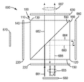
도 1은 편광 빔 스플리터(polarizing beam splitter)의 사시도.
도 2는 1/4 파장 지연기(quarter-wave retarder)를 구비한 편광 빔 스플리터의 사시도.
도 3a는 폴리싱된(polished) 면을 구비한 편광 빔 스플리터를 도시하는 개략 평면도.
도 3b는 광학 요소 및 시준 도광부(collimating lightguide)의 개략 평면도.
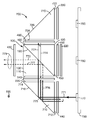
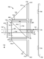
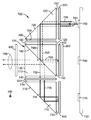
도 4a 내지 도 4c는 색상 조합기의 개략 평면도.
도 5는 프로젝터의 개략도.
도 6a 내지 도 6b는 색상 조합기의 개략 평면도.
도 7a 내지 도 7c는 색상 조합기의 개략 평면도.
도면은 반드시 축척대로 도시된 것은 아니다. 도면에 사용된 동일한 도면 부호는 동일한 구성요소를 지칭한다. 그러나, 주어진 도면에서 구성요소를 지칭하기 위한 도면 부호의 사용은 동일한 도면 부호로 표시된 다른 도면의 구성요소를 제한하고자 하는 것이 아님을 이해할 것이다.Throughout this specification, reference is made to the accompanying drawings where like reference numerals designate like elements.
1 is a perspective view of a polarizing beam splitter.
2 is a perspective view of a polarizing beam splitter with a quarter-wave retarder.
3A is a schematic plan view showing a polarizing beam splitter having a polished surface;
3B is a schematic plan view of the optical element and collimating lightguide.
4A-4C are schematic plan views of color combiners.
5 is a schematic diagram of a projector.
6A-6B are schematic plan views of color combiners.
7A-7C are schematic plan views of color combiners.
The drawings are not necessarily drawn to scale. Like numbers used in the drawings refer to like elements. However, it will be understood that the use of a reference numeral to refer to a component in a given figure is not intended to limit the components of another figure denoted by the same reference numeral.
본 명세서에 기술된 광학 요소는, 상이한 파장 스펙트럼 광들을 수광하고 이 상이한 파장 스펙트럼 광들을 포함한 조합된 광 출력을 생성하는 색상 조합기로서 구성될 수 있다. 일 태양에서, 수광된 광 입력은 비편광되고(unpolarized), 조합된 광 출력은 비편광된다. 일 실시예에서, 조합된 광 출력의 일부분은 다시 색상 조합기 내로 재순환될 수 있다. 일 태양에서, 수광된 광 입력은 비편광되고, 조합된 광 출력은 원하는 방향으로 편광된다. 일 실시예에서, 원하지 않는 편광 방향을 갖는 수광된 광은 재순환되고 원하는 편광 방향으로 회전되어, 광 이용 효율을 개선시킨다. 몇몇 실시예에서, 조합된 광은 수광된 광 각각과 동일한 에텐듀(etendue)를 갖는다. 조합된 광은 광의 하나 초과의 파장 스펙트럼을 포함하는 다색의 조합된 광일 수 있다. 조합된 광은 수광된 광 각각의 시간 시퀀스화된(time sequenced) 출력일 수 있다. 일 태양에서, 광의 상이한 파장 스펙트럼 각각은 상이한 유색 광(예컨대, 적색, 녹색 및 청색)에 대응하고, 조합된 광 출력은 백색 광이거나, 또는 시간 시퀀스화된 적색, 녹색 및 청색 광이다. 본 명세서에 제공되는 설명을 위해, "유색 광" 및 "파장 스펙트럼 광" 둘 모두는 사람의 눈으로 볼 수 있는 경우에 특정 색에 상관될 수 있는 파장 스펙트럼 범위를 갖는 광을 의미하도록 의도된다. 보다 일반적인 용어 "파장 스펙트럼 광"은, 예를 들어 적외선 광을 비롯한 광의 가시 및 다른 파장 스펙트럼 둘 모두를 지칭한다.The optical element described herein may be configured as a color combiner that receives different wavelength spectral lights and produces a combined light output comprising these different wavelength spectral lights. In one aspect, the received light input is unpolarized and the combined light output is unpolarized. In one embodiment, a portion of the combined light output may be recycled back into the color combiner. In one aspect, the received light input is unpolarized and the combined light output is polarized in the desired direction. In one embodiment, received light having an undesired polarization direction is recycled and rotated in the desired polarization direction to improve light utilization efficiency. In some embodiments, the combined light has the same etendue as each of the received lights. The combined light can be multicolor combined light that includes more than one wavelength spectrum of light. The combined light may be a time sequenced output of each of the received lights. In one aspect, each of the different wavelength spectra of light corresponds to a different colored light (eg, red, green and blue) and the combined light output is white light or time sequenced red, green and blue light. For the purposes provided herein, both "colored light" and "wavelength spectral light" are intended to mean light having a wavelength spectral range that can be correlated to a particular color when viewed by the human eye. The more general term “wavelength spectral light” refers to both visible and other wavelength spectra of light, including, for example, infrared light.
또한, 본 명세서에 제공되는 설명을 위해, 용어 "향하는(facing)"은 하나의 요소의 표면으로부터의 수직선이 역시 다른 하나의 요소에 수직한 광학 경로를 따르도록 배치되는 그러한 하나의 요소를 지칭한다. 다른 요소를 향하는 하나의 요소는 서로 인접하게 배치되는 요소들을 포함할 수 있다. 다른 요소를 향하는 하나의 요소는 하나의 요소에 수직한 광선이 또한 다른 하나의 요소에도 수직하도록 광학체(optics)에 의해 분리되는 요소들을 추가로 포함한다.Furthermore, for the purposes of the description provided herein, the term “facing” refers to one such element in which vertical lines from the surface of one element are arranged along an optical path that is also perpendicular to the other element. . One element facing another element may comprise elements arranged adjacent to each other. One element facing the other element further comprises elements separated by optics such that the light ray perpendicular to one element is also perpendicular to the other element.
2개 이상의 비편광 유색 광이 광학 요소로 지향될 때, 각각은 반사 편광기에 의해 편광에 따라 분할된다. 후술되는 일 실시예에 따르면, 유색 광 조합 시스템은 상이한 유색 비편광 광원들로부터 비편광 광을 수광하고, 하나의 원하는 방향으로 편광되는 조합된 광 출력을 생성한다. 일 태양에서, 최대 3개의 수광된 유색 광이 편광 빔 스플리터(PBS) 내의 반사 편광기에 의해 편광(예컨대, s-편광 및 p-편광, 또는 좌우 원형 편광)에 따라 각각 분할된다. 하나의 편광 방향의 수광된 광은 재순환되어 원하는 편광 방향이 된다.When two or more unpolarized colored lights are directed to an optical element, each is divided according to polarization by a reflective polarizer. According to one embodiment described below, the colored light combining system receives unpolarized light from different colored unpolarized light sources and produces a combined light output that is polarized in one desired direction. In one aspect, up to three received colored lights are each split according to polarization (eg, s-polarized and p-polarized, or left and right circularly polarized) by a reflective polarizer in a polarizing beam splitter (PBS). The received light in one polarization direction is recycled to the desired polarization direction.
일 태양에 따르면, PBS는 반사 편광기를 포함하는데, 반사 편광기는 3개의 유색 광 각각으로부터의 광이 대략 45도 각도로 반사 편광기와 만나도록 위치된다. 반사 편광기는 맥네일 편광기, 와이어 그리드(wire grid) 편광기, 다층 광학 필름 편광기, 또는 원형 편광기, 예컨대 콜레스테릭 액정 편광기와 같은 임의의 공지된 반사 편광기일 수 있다. 일 실시예에 따르면, 다층 광학 필름 편광기가 바람직한 반사 편광기일 수 있다. 반사 편광기는 2개의 프리즘들의 대각 면(diagonal face)들 사이에 배치될 수 있거나, 또는 펠리클(pellicle)과 같은 자립형(free-standing) 필름일 수 있다. 몇몇 실시예들에서, 반사 편광기가 2개의 프리즘들 사이에 배치될 때, PBS 광 이용 효율이 개선된다. 이 실시예에서는, 그렇지 않다면 광 경로로부터 이탈할, PBS를 통해 이동하는 광의 일부가 프리즘 면으로부터 내부 전반사(total internal reflection, TIR)를 겪고 광 경로에 재합류할 수 있다. 적어도 이러한 이유로, 하기의 설명은 반사 편광기가 2개의 프리즘들의 대각 면들 사이에 배치되는 PBS에 관한 것이지만, PBS가 펠리클로서 사용될 때 동일한 방식으로 기능할 수 있음이 이해될 것이다. 일 태양에서, PBS 프리즘의 외부 면 모두는 PBS에 입사되는 광이 내부 전반사를 겪도록 고도로 폴리싱된다. 이러한 방식으로, 광이 PBS 내에 수용되며, 이 광은 부분적으로 균질화되면서 여전히 에텐듀를 보존한다.According to one aspect, the PBS comprises a reflective polarizer wherein the reflective polarizer is positioned such that light from each of the three colored lights meets the reflective polarizer at an approximately 45 degree angle. The reflective polarizer can be any known reflective polarizer such as a McNeill polarizer, a wire grid polarizer, a multilayer optical film polarizer, or a circular polarizer such as a cholesteric liquid crystal polarizer. According to one embodiment, the multilayer optical film polarizer may be a preferred reflective polarizer. The reflective polarizer may be disposed between the diagonal faces of the two prisms, or may be a free-standing film such as a pellicle. In some embodiments, when the reflective polarizer is disposed between two prisms, the PBS light utilization efficiency is improved. In this embodiment, some of the light traveling through the PBS that would otherwise deviate from the light path may experience total internal reflection (TIR) from the prism face and rejoin the light path. For at least this reason, the following description relates to a PBS in which the reflective polarizer is disposed between the diagonal faces of the two prisms, but it will be understood that the PBS can function in the same way when used as a pellicle. In one aspect, all of the outer faces of the PBS prism are highly polished such that light incident on the PBS undergoes total internal reflection. In this way, light is received in the PBS, which partially homogenizes and still preserves etendue.
일 태양에 따르면, 색상 선택성 이색 필터와 같은 파장 선택성 필터가 상이한 유색 광원 각각으로부터의 입력 광의 경로 내에 배치된다. 이색 필터 각각은, 입력 광이 거의 수직 입사로 필터와 만나서 s- 및 p-편광된 광의 분할을 최소화하고 색상 변환(color shifting)을 최소화하도록 위치된다. 이색 필터 각각은, 인접한 입력 광원의 파장 스펙트럼을 갖는 광을 투과시키고 다른 입력 광원들 중 적어도 하나의 입력 광원의 파장 스펙트럼을 갖는 광을 반사하도록 선택된다. 몇몇 실시예들에서, 이색 필터 각각은, 인접한 입력 광원의 파장 스펙트럼을 갖는 광을 투과시키고 다른 입력 광원들 모두의 파장 스펙트럼을 갖는 광을 반사하도록 선택된다. 일 태양에서, 이색 필터 각각은, 각각의 이색 필터의 표면의 수직선은 대략 45도의 인터셉트 각도(intercept angle)로 반사 편광기와 교차하도록 반사 편광기에 대해 위치된다. 이색 필터의 표면의 수직선은 이색 필터의 표면에 수직으로 지나는 선을 의미한다. 일 실시예에서, 인터셉트 각도는 35 내지 55도, 40 내지 50도, 43 내지 48도, 또는 44.5 내지 45.5도 범위이다.According to one aspect, a wavelength selective filter, such as a color selective dichroic filter, is disposed in the path of input light from each of the different colored light sources. Each dichroic filter is positioned such that the input light meets the filter at nearly normal incidence to minimize splitting of the s- and p-polarized light and to minimize color shifting. Each dichroic filter is selected to transmit light having a wavelength spectrum of an adjacent input light source and reflect light having a wavelength spectrum of at least one input light source among other input light sources. In some embodiments, each dichroic filter is selected to transmit light having a wavelength spectrum of an adjacent input light source and reflect light having a wavelength spectrum of all other input light sources. In one aspect, each dichroic filter is positioned relative to the reflective polarizer such that the vertical line of the surface of each dichroic filter intersects the reflective polarizer with an intercept angle of approximately 45 degrees. The vertical line on the surface of the dichroic filter means a line passing perpendicular to the surface of the dichroic filter. In one embodiment, the intercept angle ranges from 35 to 55 degrees, 40 to 50 degrees, 43 to 48 degrees, or 44.5 to 45.5 degrees.
일 태양에서, 원하지 않는 편광 방향의 입력 광은 다시 광원을 향하여 지향됨으로써 재순환되는데, 여기서 입력 광은 표면, 예를 들어 부분-반사성 LED로부터 반사된다. 일 실시예에서, 각각의 입력 광으로부터 프리즘 면으로의 광 경로 내에 지연기가 배치되어, 광원으로부터의 광이 PBS 프리즘 면에 입사되기 전에 이색 필터 및 지연기를 통과하도록 한다. 원하지 않는 편광 방향을 갖는 광이 다시 재순환되어 LED로부터 반사되고, 지연기를 2회 통과하여, 원하는 편광 방향으로 변경된다.In one aspect, the input light in the undesired polarization direction is recycled by being directed back towards the light source, where the input light is reflected from the surface, for example a partially reflective LED. In one embodiment, a retarder is disposed in the light path from each input light to the prism face such that light from the light source passes through the dichroic filter and retarder before being incident on the PBS prism face. Light having an undesired polarization direction is recycled and reflected back from the LED, passed through the retarder twice, and changed to the desired polarization direction.
몇몇 실시예들에서, 지연기는 이색 필터와 광원 사이에 배치된다. 다른 실시예들에서, 이색 필터는 지연기와 광원 사이에 배치된다. 이색 필터, 지연기 및 광원 배향 모두의 특정 조합은, 색상 조합기로서 구성될 때, 단일 편광 방향의 조합된 광을 효율적으로 생성하는, 보다 작고 보다 집약적인 광학 요소를 가능하게 하도록 상호작용한다. 일 태양에 따르면, 지연기는 반사 편광기의 편광 방향에 대략 45도로 정렬된 1/4 파장 지연기이다. 일 실시예에서, 정렬은 반사 편광기의 편광 방향에 35 내지 55도, 40 내지 50도, 43 내지 48도, 또는 44.5 내지 45.5도일 수 있다.In some embodiments, the retarder is disposed between the dichroic filter and the light source. In other embodiments, the dichroic filter is disposed between the retarder and the light source. Certain combinations of both dichroic filters, retarders and light source orientations, when configured as color combiners, interact to enable smaller and more intensive optical elements that efficiently produce combined light in a single polarization direction. According to one aspect, the retarder is a quarter-wave retarder aligned approximately 45 degrees to the polarization direction of the reflective polarizer. In one embodiment, the alignment can be 35 to 55 degrees, 40 to 50 degrees, 43 to 48 degrees, or 44.5 to 45.5 degrees in the polarization direction of the reflective polarizer.
일 태양에서, 제1 유색 광은 청색 광을 포함하고, 제2 유색 광은 녹색 광을 포함하며, 제3 유색 광은 적색 광을 포함하고, 유색 광 조합기는 적색 광, 청색 광 및 녹색 광을 조합하여, 편광된 백색 광을 생성한다. 일 태양에서, 제1 유색 광은 청색 광을 포함하고, 제2 유색 광은 녹색 광을 포함하며, 제3 유색 광은 적색 광을 포함하고, 유색 광 조합기는 적색, 녹색 및 청색 광을 조합하여, 시간 시퀀스화된 편광된 적색, 녹색 및 청색 광을 생성한다. 일 태양에서, 제1, 제2 및 제3 유색 광 각각은 별개의 광원 내에 배치된다. 다른 태양에서, 3개의 유색 광들 중 하나보다 많은 광이 광원들 중 하나 내로 조합된다.In one aspect, the first colored light comprises blue light, the second colored light comprises green light, the third colored light comprises red light, and the colored light combiner comprises red light, blue light and green light. In combination, produces polarized white light. In one aspect, the first colored light comprises blue light, the second colored light comprises green light, the third colored light comprises red light, and the colored light combiner combines red, green and blue light. Produces time sequenced polarized red, green and blue light. In one aspect, each of the first, second and third colored lights is disposed in a separate light source. In another aspect, more than one of the three colored lights is combined into one of the light sources.
일 태양에 따르면, 반사성 편광 필름은 다층 광학 필름을 포함한다. PBS는 p-편광된 제2 유색 광과 s-편광된 제1 및 제3 유색 광을 포함하는 제1 조합된 광 출력을 생성한다. 제1 조합된 광 출력은 제2 유색 광이 필터를 통과할 때 제2 유색 광의 편광을 선택적으로 변경시키는 색상 선택성 적층형 지연 필터(color-selective stacked retardation filter)를 통과할 수 있다. 그러한 색상 선택성 적층형 지연 필터는 예를 들어 미국 콜로라도주 볼더 소재의 컬러링크 인크(ColorLink Inc)로부터 입수가능하다. 필터는 동일한 편광(예컨대, s-편광)을 갖도록 조합된 제1, 제2 및 제3 유색 광을 포함하는 제2 조합된 광 출력을 생성한다. 제2 조합된 출력은 이미지를 생성하도록 편광된 광을 변조하는 투과성 또는 반사성 디스플레이 기구의 조사(illumination)에 유용하다.According to one aspect, the reflective polarizing film comprises a multilayer optical film. PBS produces a first combined light output comprising p-polarized second colored light and s-polarized first and third colored light. The first combined light output may pass through a color-selective stacked retardation filter that selectively alters the polarization of the second colored light as the second colored light passes through the filter. Such color selective stacked delay filters are available, for example, from ColorLink Inc, Boulder, Colorado. The filter produces a second combined light output comprising first, second and third colored light that are combined to have the same polarization (eg, s-polarized light). The second combined output is useful for illumination of a transmissive or reflective display device that modulates the polarized light to produce an image.
광은 PBS에 입사될 때 시준되거나, 수렴하거나, 발산할 수 있다. PBS에 입사되는 수렴 또는 발산 광은 PBS의 면 또는 단부 중 하나를 통해 손실될 수 있다. 그러한 손실을 피하기 위해, 프리즘 기반 PBS의 외부 면 모두는 PBS 내에서의 내부 전반사(TIR)를 가능하게 하도록 폴리싱될 수 있다. TIR을 가능하게 하는 것은 PBS에 입사되는 광의 이용을 개선하여, 일정 범위의 각도 내에서 PBS에 입사되는 광의 실질적으로 전부가 원하는 면을 통해 PBS로부터 출사되도록 재지향된다.Light can be collimated, converged, or divergent when incident on the PBS. Converging or diverging light incident on the PBS can be lost through either the face or the end of the PBS. To avoid such losses, all of the outer faces of the prism-based PBS can be polished to enable total internal reflection (TIR) within the PBS. Enabling TIR improves the utilization of light incident on the PBS, so that substantially all of the light incident on the PBS is redirected from the PBS through the desired plane within a range of angles.
각각의 유색 광의 편광 성분이 편광 회전 반사기로 통과할 수 있다. 편광 회전 반사기는 편광 회전 반사기 내에 배치된 지연기의 유형 및 배향에 따라 편광 성분의 크기를 변경시키고 광의 전파 방향을 역전시킨다. 편광 회전 반사기는 이색 필터와 같은 파장 선택성 거울 및 지연기를 포함할 수 있다. 지연기는 1/8 파장 지연기, 1/4 파장 지연기 등과 같은 임의의 원하는 지연을 제공할 수 있다. 본 명세서에 기술된 실시예들에서, 1/4 파장 지연기 및 관련 이색 반사기를 사용하는 것이 이롭다. 선형 편광된 광은 광 편광 축에 45°의 각도로 정렬된 1/4 파장 지연기를 통과할 때 원형 편광된 광으로 변경된다. 색상 조합기 내의 1/4 파장 지연기/반사기와 반사 편광기로부터의 후속 반사는 색상 조합기로부터 효율적인 조합된 광 출력을 생성한다. 대조적으로, 선형 편광된 광은 다른 지연기를 통해 다른 배향으로 통과할 때 어느 정도까지 s-편광과 p-편광(타원형 또는 선형) 사이의 편광 상태로 변경되고, 조합기의 보다 낮은 효율을 유발할 수 있다.The polarization component of each colored light may pass through the polarization rotating reflector. The polarization rotating reflector changes the size of the polarization component and reverses the direction of propagation of light depending on the type and orientation of the retarder disposed within the polarization rotating reflector. The polarization rotating reflector may include a wavelength selective mirror and a retarder such as a dichroic filter. The retarder can provide any desired delay, such as a 1/8 wavelength retarder, a quarter wavelength retarder, and the like. In the embodiments described herein, it is advantageous to use a quarter wave retarder and associated dichroic reflector. Linearly polarized light is converted into circularly polarized light as it passes through a quarter-wave retarder aligned at an angle of 45 ° to the optical polarization axis. Subsequent reflections from the quarter wavelength retarder / reflector and the reflective polarizer in the color combiner produce efficient combined light output from the color combiner. In contrast, linearly polarized light changes to a degree of polarization between s-polarized and p-polarized (elliptical or linear) as it passes through different retarders in different orientations, and can lead to lower efficiency of the combiner. .
프리즘, 반사 편광기, 1/4 파장 지연기, 거울, 필터 또는 다른 구성요소를 비롯한 광학 요소의 구성요소들은 적합한 광학 접착제에 의해 함께 접합될 수 있다. 구성요소들을 함께 접합시키도록 사용되는 광학 접착제는 광학 요소에 사용되는 프리즘의 굴절률보다 더 낮은 굴절률을 갖는다. 완전히 함께 접합된 광학 요소는 조립, 취급 및 사용 중의 정렬 안정성을 비롯한 여러 이점들을 제공한다.The components of the optical element, including prisms, reflective polarizers, quarter wave retarders, mirrors, filters or other components, may be bonded together by a suitable optical adhesive. The optical adhesive used to bond the components together has a refractive index lower than the refractive index of the prism used for the optical element. Optical elements bonded together completely provide several advantages including alignment stability during assembly, handling and use.
전술된 실시예는 도면 및 하기의 그 관련 설명을 참조하여 보다 용이하게 이해될 수 있다.The above-described embodiments can be more easily understood with reference to the drawings and the related description below.
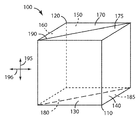
도 1은 PBS의 사시도이다. PBS(100)는 프리즘(110, 120)의 대각 면들 사이에 배치되는 반사 편광기(190)를 포함한다. 프리즘(110)은 2개의 단부 면(175, 185)과, 사이에 90° 각도를 갖는 제1 및 제2 프리즘 면(130, 140)을 포함한다. 프리즘(120)은 2개의 단부 면(170, 180)과, 사이에 90° 각도를 갖는 제3 및 제4 프리즘 면(150, 160)을 포함한다. 제1 프리즘 면(130)은 제3 프리즘 면(150)에 평행하고, 제2 프리즘 면(140)은 제4 프리즘 면(160)에 평행하다. "제1", "제2", "제3" 및 "제4"로 도 1에 도시된 4개의 프리즘 면의 식별은 하기의 논의에서 PBS(100)의 설명을 명확하게 하는 역할을 한다. 제1 반사 편광기(190)는 직교 반사 편광기 또는 비-직교 반사 편광기일 수 있다. 비-직교 반사 편광기는 맥네일(MacNeille) 편광기와 같이, 무기 유전체의 순차적 침착에 의해 생성된 것과 같은 다층 무기 필름을 포함할 수 있다. 직교 반사 편광기는 편광 축 방향을 갖고, 와이어-그리드 편광기(wire-grid polarizer)와, 다층 중합체 라미네이트의 압출 및 후속 연신에 의해 생성될 수 있는 것과 같은 중합체 다층 광학 필름 둘 모두를 포함한다. 일 실시예에서, 반사 편광기(190)는 하나의 편광 축이 제1 편광 방향(195)에 평행하고 제2 편광 방향(196)에 수직하도록 정렬된다. 일 실시예에서, 제1 편광 방향(195)은 s-편광 방향일 수 있고, 제2 편광 방향(196)은 p-편광 방향일 수 있다. 도 1에 도시된 바와 같이, 제1 편광 방향(195)은 단부 면(170, 175, 180, 185)의 각각에 수직하다.1 is a perspective view of a PBS.
직교 반사 편광기 필름은, 완전히 시준되지 않고 중앙 광 빔 축으로부터 발산하거나 비스듬한 입력 광선을 높은 효율로 통과시키는 능력을 편광 빔 스플리터에 제공한다. 직교 반사 편광기 필름은 유전체 또는 중합체 재료의 다수의 층을 포함하는 중합체 다층 광학 필름을 포함할 수 있다. 유전체 필름의 사용은 낮은 광 감쇠 및 높은 광 통과 효율의 이점을 가질 수 있다. 다층 광학 필름은 미국 특허 제5,962,114호(존자(Jonza) 등) 또는 미국 특허 제6,721,096호(브루존(Bruzzone) 등)에 기술된 것과 같은 중합체 다층 광학 필름을 포함할 수 있다.The orthogonal reflective polarizer film provides the polarizing beam splitter with the ability to pass through the oblique input beam at high efficiency or diverge from the central light beam axis without fully collimating. The quadrature reflective polarizer film may comprise a polymeric multilayer optical film comprising multiple layers of dielectric or polymeric material. The use of dielectric films can have the advantages of low light attenuation and high light passing efficiency. Multilayer optical films may include polymeric multilayer optical films such as those described in US Pat. No. 5,962,114 (Jonza et al.) Or US Pat. No. 6,721,096 (Bruzzone et al.).
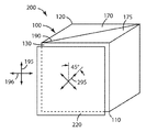
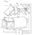
도 2는 몇몇 실시예에 사용된 바와 같은, PBS에 대한 1/4 파장 지연기의 정렬의 사시도이다. 1/4 파장 지연기는 입사 광의 편광 상태를 변경시키도록 사용될 수 있다. PBS 지연기 시스템(200)은 제1 및 제2 프리즘(110, 120)을 구비한 PBS(100)를 포함한다. 1/4 파장 지연기(220)가 제1 프리즘 면(130)에 인접하게 배치된다. 반사 편광기(190)는 제1 편광 방향(195)에 대해 정렬된 직교 반사 편광기 필름이다. 1/4 파장 지연기(220)는 제1 편광 방향(195)에 45°로 정렬될 수 있는 1/4 파장 편광 방향(295)을 포함한다. 도 2가 제1 편광 방향(195)에 시계 방향으로 45°로 정렬된 편광 방향(295)을 도시하지만, 편광 방향(295)은 그 대신에 제1 편광 방향(195)에 반시계 방향으로 45°로 정렬될 수 있다. 몇몇 실시예에서, 1/4 파장 편광 방향(295)은 제1 편광 방향(195)에 임의의 각도 배향으로, 예를 들어 반시계 방향으로 90°로부터 시계 방향으로 90°까지 정렬될 수 있다. 전술된 바와 같이 지연기를 대략 +/- 45°로 배향시키는 것이 유리할 수 있는데, 왜냐하면 선형 편광된 광이 편광 방향에 대해 그렇게 정렬된 1/4 파장 지연기를 통과할 때 원형 편광된 광이 생성되기 때문이다. 1/4 파장 지연기의 다른 배향은 거울로부터의 반사시, p-편광된 광으로 완전히 변환되지 않은 s-편광된 광, 및 s-편광된 광으로 완전히 변환되지 않은 p-편광된 광을 유발하여, 본 설명의 다른 부분에 기술된 광학 요소의 감소된 효율을 초래할 수 있다.2 is a perspective view of an alignment of a quarter wave retarder relative to PBS, as used in some embodiments. The quarter wave retarder may be used to change the polarization state of incident light.
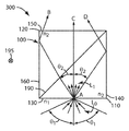
도 3a는 폴리싱된 PBS(300) 내의 광선의 경로의 평면도를 도시한다. 일 실시예에 따르면, 프리즘(110, 120)의 제1, 제2, 제3 및 제4 프리즘 면(130, 140, 150, 160)은 폴리싱된 외부 표면이다. 다른 실시예에 따르면, PBS(300)의 외부 면 모두(도시되지 않은 단부 면을 포함함)는 PBS(300) 내에서 비스듬한 광선의 TIR을 제공하는 폴리싱된 면이다. 폴리싱된 외부 표면은 프리즘(110, 120)의 굴절률 "n2"보다 작은 굴절률 "n1"을 갖는 재료와 접촉한다. TIR은 특히 PBS 내로 지향된 광이 중앙 축을 따라 시준되지 않을 때, 즉 입사 광이 수렴하거나 발산할 때, PBS(300) 내에서의 광 이용을 개선한다. 적어도 일부 광은 제3 프리즘 면(150)을 통해 출사될 때까지 내부 전반사에 의해 PBS(300) 내에 갇힌다. 몇몇 경우에서, 광의 실질적으로 전부는 제3 프리즘 면(150)을 통해 출사될 때까지 내부 전반사에 의해 PBS(300) 내에 갇힌다.3A shows a top view of a path of light rays in
도 3a에 도시된 바와 같이, 광선 L0가 각도 θ1의 범위 내에서 제1 프리즘 면(130)에 입사된다. PBS(300) 내의 광선 L1은 TIR 조건이 프리즘 면(140, 160)과 단부 면(도시되지 않음)에서 충족되도록 각도 θ2의 범위 내에서 전파된다. 광선 "AB", "AC" 및 "AD"는 제3 프리즘 면(150)을 통해 출사되기 전에 상이한 입사각으로 반사 편광기(190)와 교차하는, PBS(300)를 통한 많은 광 경로 중 3가지를 나타낸다. 광선 "AB" 및 "AD" 둘 모두는 또한 출사 전에 각각 프리즘 면(140, 160)에서 TIR을 겪는다. 각도 θ1 및 θ2의 범위는 PBS(300)의 단부 면에서 반사가 또한 일어날 수 있도록 하는 소정의 원추각(a cone of angles)일 수 있음을 이해하여야 한다. 일 실시예에서, 반사 편광기(190)는 상이한 편광의 광을 넓은 범위의 입사각에 걸쳐 효율적으로 분할시키도록 선택된다. 광을 넓은 범위의 입사각에 걸쳐 분할시키는 데에 중합체 다층 광학 필름이 특히 적합하다. 맥네일 편광기 및 와이어-그리드 편광기를 비롯한 다른 반사 편광기가 사용될 수 있지만, 편광된 광을 분할시키기에 덜 효율적이다. 맥네일 편광기는 설계 각도와는 실질적으로 상이한 입사각, 전형적으로는 편광 선택성 표면에 45도이거나 PBS의 입력 면에 수직인 입사각에서 광을 효율적으로 투과시키지 못한다. 맥네일 편광기를 사용하는 편광된 광의 효율적 분할은 수직선으로부터 약 6 또는 7도 미만의 입사각으로 제한될 수 있는데, 그 이유는 몇몇의 더 큰 각도에서 p-편광 상태의 상당한 반사가 일어날 수 있고, 몇몇의 더 큰 각도에서 s-편광 상태의 상당한 투과가 또한 일어날 수 있기 때문이다. 둘 모두의 효과는 맥네일 편광기의 분할 효율을 감소시킬 수 있다. 와이어-그리드 편광기를 사용하는 편광된 광의 효율적 분할은 전형적으로 와이어의 일측에 인접한 공기 갭을 필요로 하고, 와이어-그리드 편광기가 보다 높은 굴절률의 매질 내에 침지될 때 효율이 저하된다. 편광된 광을 분할시키는 데 사용되는 와이어-그리드 편광기가 예를 들어 PCT 공보 WO 2008/1002541호에 나타나 있다.As shown in FIG. 3A, light ray L 0 is incident on
일 태양에서, 도 3b는 제1, 제2 및 제3 광원(320, 330, 340) 각각과 PBS(300) 사이에 배치되는 광 터널(350)을 포함하는, 색상 조합기로서 구성되는 광학 요소(310)를 도시한다. 광 터널(350)은, 광원으로부터 발생되는 광을 부분적으로 시준시키고 광이 PBS에 입사되는 각도를 감소시키는 데 유용할 수 있다. 제1, 제2 및 제3 광원(320, 330, 340)은 제1, 제2 및 제3 비편광 유색 광(321, 331, 341)을 방출하며, 이 유색 광은 광 터널(350)을 통해 이동하고, (각각) 제1, 제2 및 제3 편광 회전 반사기(360, 370, 380)를 통해 PBS(300) 내로 이동하며, 색상 선택성 적층형 지연 편광기(390)를 통과하고, 제1 방향으로 편광된 제1, 제2 및 제3 유색 광(322, 332, 342)으로서 광학 요소(310)로부터 출사된다. 편광 회전 반사기(360, 370, 380)는 다른 부분에 더 상세히 설명될 것이지만, 일반적으로는 이색 필터 및 지연기를 포함한다. 인접한 광원에 대한 지연기 및 이색 필터의 위치는 편광 구성요소 각각의 원하는 경로에 의존하며, 도면들을 참조하여 다른 부분에 기술된다. 광 터널(350)은 광학 요소(310)를 위한 선택적 구성요소이며, 하기의 색상 조합기의 설명에서 생략된다. 이들 광 터널은 직선형 또는 곡선형 면을 가질 수 있거나, 그들은 렌즈 시스템에 의해 대체될 수 있다. 각각의 응용의 특정 상세 사항에 따라 상이한 접근법이 바람직할 수 있고, 당업자는 특정 응용을 위한 최적의 접근법을 선택하는 데 어려움이 없을 것이다.In one aspect, FIG. 3B illustrates an optical element configured as a color combiner, including a
몇몇 실시예들에서, 예를 들어 유색 광들 중 하나 이상의 광의 편광 방향의 회전이 요구되지 않는 경우에, 색상 선택성 적층형 지연 편광기(390)는 선택적이다. 몇몇 실시예들에서, 광학 요소(310)는 비편광 광원을 조합된 비편광 광으로 조합시키도록 구성될 수 있고, 색상 선택성 적층형 지연 편광기(390)는 요구되지 않는다.In some embodiments, for example, if no rotation of the polarization direction of one or more of the colored lights is required, the color selective
일 태양에서, 반사 편광기(190)는 콜레스테릭 액정 편광기와 같은 원형 편광기일 수 있다. 이러한 태양에 따르면, 편광 회전 반사기(360, 370, 380)는 어떠한 관련된 지연기도 없이 이색 필터를 포함하고, 색상 선택성 적층형 지연 편광기(390)는 생략된다. 일 실시예에서, 제1, 제2 및 제3 비편광 유색 광(321, 331, 341)은 광 터널(350)을 통해 이동하고, (각각) 제1, 제2 및 제3 편광 회전 반사기(360, 370, 380)를 통해 PBS(300) 내로 이동하며, 제1, 제2 및 제3 비편광(좌원 및 우원 편광) 유색 광(322, 332, 342)으로서 색상 조합기(310)로부터 출사된다.In one aspect,
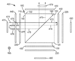
일 태양에서, 도 4a 내지 도 4c는 PBS(100)를 포함하는 색상 조합기(400)의 개략 평면도이다. 색상 조합기(400)는 다른 부분에 기술된 바와 같이 다양한 광원과 함께 사용될 수 있다. 색상 조합기(400)의 다양한 구성요소의 기능을 더 명확하게 설명하기 위해, 제1, 제2 및 제3 부분-반사성 광원(470, 480, 490)으로부터 방출된 각각의 편광의 광선의 경로가 도 4a 내지 도 4c에 도시되어 있다. PBS(100)는 다른 부분에 기술된 바와 같이 제1 편광 방향(195)에 대해 정렬된 반사 편광기(190)를 포함한다. 일 태양에서, 반사 편광기(190)는 중합체 다층 광학 필름을 포함할 수 있다. 제1, 제2 및 제3 파장 선택성 필터(440, 450, 460)가 각각 제2, 제3 및 제4 프리즘 면(140, 150, 160)을 향하여 배치된다. 제1, 제2 및 제3 파장 선택성 필터(440, 450, 460) 각각은, 광의 제1, 제2 및 제3 파장 스펙트럼을 투과시키고 광의 다른 파장 스펙트럼을 반사시키도록 선택된 이색 필터일 수 있다.In one aspect, FIGS. 4A-4C are schematic top views of a
지연기(220)가 제1, 제2 및 제3 파장 선택성 필터(440, 450, 460) 각각을 향하여 배치된다. 지연기(220), 파장 선택성 필터(440, 450, 460) 및 부분-반사성 광원(470, 480, 490)은 다른 부분에 기술된 바와 같이, 광의 하나의 편광 방향을 투과시키고 광의 다른 편광 상태를 재순환시키도록 상호작용한다. 일 실시예에서, 색상 조합기(400) 내의 각각의 지연기(220)는 제1 편광 방향(195)에 45°로 배향된 1/4 파장 지연기이다.A
색상 조합기(400)는 또한 제1 프리즘 면(130)을 향하여 배치된 필터(430)를 포함하며, 이 필터(430)는 광의 적어도 하나의 선택된 파장 스펙트럼의 편광 방향을 광의 적어도 다른 선택된 파장 스펙트럼의 편광 방향을 변경시키지 않고서 변경시킬 수 있다. 일 태양에서, 필터(430)는 컬러셀렉트(ColorSelect)(등록상표) 필터(미국 콜로라도주 볼더 소재의 컬러링크(등록상표) 인크.로부터 입수가능함)와 같은 색상 선택성 적층형 지연 편광기이다.The
부분-반사성 광원(470, 480, 490) 각각은 적어도 부분적으로 광 반사성인 표면을 갖는다. 각각의 광원은 또한 적어도 부분적으로 반사성일 수 있는 기판(substrate) 상에 장착된다. 반사성 광원 및 선택적으로 반사성 기판은 색상 조합기와 상호작용하여 광을 재순환시켜 효율을 향상시킨다. 또 다른 태양에 따르면, 다른 부분에 기술된 바와 같이, 광원을 편광 빔 스플리터로부터 분리시키는 간격을 제공하기 위해 광 터널 또는 집광 렌즈가 제공될 수 있다. 조합된 광 출력의 균일도를 증가시키기 위해 색상 조합기의 출력부에 적분기(integrator)가 제공될 수 있다. 일 태양에 따르면, 각각의 부분-반사성 광원(470, 480, 490)은 하나 이상의 발광 다이오드(LED)를 포함한다. 다양한 광원, 예를 들어 레이저, 레이저 다이오드, 유기 LED(OLED) 및 비-고체 광원, 예를 들어 적당한 집광기 또는 반사기를 갖는 초고압(UHP) 할로겐 또는 제논 램프가 사용될 수 있다. 본 발명에 유용한 광원, 광 터널, 렌즈 및 광 적분기가, 그 개시 내용이 본 명세서에 전체적으로 포함된, 예를 들어 동시 계류 중인 미국 특허 출원 제60/938,834호에 더 상세히 기술되어 있다.Each of the partially reflective
이제, 비편광 제1 유색 광(471)이 s-편광된 제1 유색 광(479)으로서 색상 조합기(400)로부터 출사되는 도 4a를 참조하여 제1 유색 광(471)의 경로가 기술될 것이다. 제1 광원(470)에 의해 비편광 제1 유색 광(471)이 제1 이색 필터(440), 지연기(220)를 통해 주입되고, 제2 프리즘 면(140)을 통해 PBS(100)에 입사되며, 반사 편광기(190)와 만나고, p-편광된 제1 유색 광(472) 및 s-편광된 제1 유색 광(473)으로 분할된다. s-편광된 제1 유색 광(473)은 반사 편광기(190)로부터 반사되고, 제1 프리즘 면(130)을 통해 PBS(100)로부터 출사되며, 변경되지 않은 상태로 필터(430)를 통과하여, s-편광된 제1 유색 광(479)이 된다.The path of the first
p-편광된 제1 유색 광(472)은 반사 편광기(190)를 투과하고, 제4 프리즘 면(160)을 통해 PBS(100)로부터 출사되며, 제3 이색 필터(460)로부터 반사되고, p-편광된 제1 유색 광(474)으로서 제4 프리즘 면(160)을 통해 PBS(100)에 재입사된다. p-편광된 제1 유색 광(474)은 반사 편광기(190)를 통과하고, 제2 프리즘 면(140)을 통해 PBS(100)로부터 출사되며, 지연기(220)를 통과할 때 제1 방향 원형 편광된 제1 유색 광(475)으로 변경된다. 제1 방향 원형 편광된 제1 유색 광(475)은 제1 이색 필터(440)를 통과하여 원형 편광된 광(476)이 되고, 이는 부분-반사성 제1 광원(470)으로부터 반사되며, 원형 편광의 방향을 변경시켜 제2 방향 원형 편광된 제1 유색 광(477)으로서 이색 필터(440)를 통과한다. 제2 방향 원형 편광된 제1 유색 광(477)은 지연기(220)를 통과하여 s-편광된 제1 유색 광(478)이 되고, 이는 제2 면(140)을 통해 PBS(100)에 입사되며, 반사 편광기(190)로부터 반사되고, 제1 프리즘 면(130)을 통해 PBS(100)로부터 출사되며, 변경되지 않은 상태로 필터(430)를 통과하여서, s-편광된 제1 유색 광(479)이 된다.The p-polarized first
이제, 비편광 제2 유색 광(481)이 s-편광된 제2 유색 광(487)으로서 색상 조합기(400)로부터 출사되는 도 4b를 참조하여 제2 유색 광(481)의 경로가 기술될 것이다. 제2 부분-반사성 광원(480)에 의해 비편광 제2 유색 광(481)이 지연기(220) 및 제2 이색 필터(450)를 통해 주입되고, 제3 프리즘 면(150)을 통해 PBS(100)에 입사되며, 반사 편광기(190)와 만나고, p-편광된 제2 유색 광(482) 및 s-편광된 제1 유색 광(483)으로 분할된다. p-편광된 제2 유색 광(482)은 변경되지 않은 상태로 반사 편광기(190)를 통과하고, 제1 프리즘 면(130)을 통해 PBS(100)로부터 출사되며, 필터(430)를 통과하여, 편광 방향을 변경시켜서, s-편광된 제2 유색 광(487)이 된다.The path of the second
s-편광된 제2 유색 광(483)은 반사 편광기(190)로부터 반사되고, 제4 프리즘 면(160)을 통해 PBS(100)로부터 출사되며, 제3 이색 필터(460)로부터 반사되고, s-편광된 제2 유색 광(484)으로서 제4 프리즘 면(160)을 통해 PBS(100)에 입사된다. s-편광된 제2 유색 광(484)은 반사 편광기(190)로부터 반사되고, 제3 프리즘 면(150)을 통해 PBS(100)로부터 출사되며, 제2 이색 필터(450)를 통과하고, 지연기(220)를 통과할 때 원형 편광된 제2 유색 광(485)으로 변경된다. 원형 편광된 제2 유색 광(485)은 제2 부분-반사성 광원(480)으로부터 반사되고, 원형 편광의 방향을 변경시키며, 지연기(220)를 통과하여, p-편광된 제2 유색 광(486)으로 변경된다. p-편광된 제2 유색 광(486)은 제2 이색 필터(450)를 통과하고, 제3 프리즘 면(150)을 통해 PBS(100)에 입사되며, 반사 편광기(190)를 통과하고, 제1 프리즘 면(130)을 통해 PBS(100)로부터 출사되며, 필터(430)를 통과할 때 s-편광된 제2 유색 광(487)으로 변경된다.The s-polarized second
이제, 비편광 제3 유색 광(491)이 s-편광된 제3 유색 광(499)으로서 색상 조합기(400)로부터 출사되는 도 4c를 참조하여 제3 유색 광(491)의 경로가 기술될 것이다. 제3 부분-반사성 광원(490)에 의해 비편광 제3 유색 광(491)이 지연기(220) 및 제3 이색 필터(460)를 통해 주입되고, 제4 프리즘 면(160)을 통해 PBS(100)에 입사되며, 반사 편광기(190)와 만나고, p-편광된 제3 유색 광(492) 및 s-편광된 제3 유색 광(493)으로 분할된다. p-편광된 제3 유색 광(492)은 반사 편광기(190)를 통과하고, 제2 프리즘 면(140)을 통해 PBS(100)로부터 출사되며, 지연기(220)를 통과할 때 원형 편광된 제2 유색 광(495)으로 변경된다. 원형 편광된 제2 유색 광(495)은 제1 이색 필터(440)로부터 반사되어 원형 편광의 방향을 변경시키고, 지연기(220)를 통과할 때 s-편광된 제3 유색 광(498)으로 변경된다. s-편광된 제3 유색 광(498)은 제2 프리즘 면(140)을 통해 PBS(100)에 입사되고, 반사 편광기(190)로부터 반사되며, 제1 프리즘 면(130)을 통해 PBS(100)로부터 출사되고, 변경되지 않은 상태로 필터(430)를 통과하여서, s-편광된 제3 유색 광(499)이 된다.Now, the path of the third
s-편광된 제3 유색 광(493)은 반사 편광기(190)로부터 반사되고, 제3 프리즘 면(150)을 통해 PBS(100)로부터 출사되며, 제2 이색 필터(450)로부터 반사되고, s-편광된 제3 유색 광(494)으로서 제3 프리즘 면(150)을 통해 PBS(100)에 입사된다. s-편광된 제3 유색 광(494)은 반사 편광기(190)로부터 반사되고, 제4 프리즘 면(160)을 통해 PBS(100)로부터 출사되며, 제3 이색 필터(460)를 통과하고, 지연기(220)를 통과할 때 원형 편광된 제3 유색 광(495)으로 변경되며, 제3 부분-반사성 광원(490)으로부터 반사되어 원형 편광의 방향을 변경시키고, 지연기(220)를 통과할 때 p-편광된 제3 유색 광(496)으로 변경된다. p-편광된 제3 유색 광(496)은 제3 이색 필터(460)를 통과하고, 제4 프리즘 면(160)을 통해 PBS(100)에 입사되며, 반사 편광기(190)를 통과하고, 제2 프리즘 면(140)을 통해 PBS(100)로부터 출사된다. p-편광된 제3 유색 광(496)은 지연기(220)를 통과할 때 원형 편광된 제3 유색 광(495)으로 변경되고, 제1 이색 필터(440)로부터 반사되어 원형 편광의 방향을 변경시키며, 지연기(220)를 통과할 때 s-편광된 제3 유색 광(497)으로 변경된다. s-편광된 제3 유색 광(497)은 제2 프리즘 면(140)을 통해 PBS(100)에 입사되고, 반사 편광기(190)로부터 반사되며, 제1 프리즘 면(130)을 통해 PBS(100)로부터 출사되고, 변경되지 않은 상태로 s-편광된 제2 유색 광(497)으로서 필터(430)를 통과한다.The s-polarized third
일 실시예에서, 제1 유색 광(470)은 청색 광이고, 제2 유색 광(480)은 녹색 광이며, 제3 유색 광(490)은 적색 광이다. 이 실시예에 따르면, 이색 필터(440)는 적색 광 반사 및 청색 광 투과 이색 필터이고, 이색 필터(450)는 적색 광 반사 및 녹색 광 투과 이색 필터이며, 이색 필터(460)는 녹색과 청색 광 반사 및 적색 광 투과 이색 필터이다. 일 실시예에 따르면, 필터(430)는 녹색 광의 편광 방향을 변경시키면서 적색 및 청색 광 둘 모두가 편광 변경 없이 투과될 수 있게 하는 GM 컬러셀렉트(등록상표) 필터이다. 다른 실시예에 따르면, 필터(430)는 적색 및 청색 광의 편광 방향을 변경시키면서 녹색 광이 편광 변경 없이 투과될 수 있게 하는 MG 컬러셀렉트(등록상표) 필터이다.In one embodiment, the first
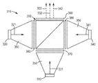
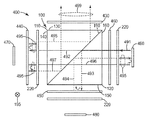
일 태양에서, 도 7a 내지 도 7c는 본 설명의 다른 태양에 따른 색상 조합기의 개략 평면도이다. 도 7a 내지 도 7c에서, PBS(100)를 포함하는 전개된 색상 조합기(700)를 통해 제1 내지 제3 광선(771, 781, 791)의 경로가 기술된다. 전개된 색상 조합기(700)는 도 4a 내지 도 4c를 참조하여 기술된 광 조합기(400)의 일 실시예일 수 있고, 다른 부분에 기술된 바와 같이 다양한 광원과 함께 사용될 수 있다. 전개된 색상 조합기(700)의 다양한 구성요소의 기능을 더욱 명확하게 설명하기 위해, 평면(730) 상에 위치되는 제1, 제2 및 제3 부분-반사성 광원(770, 780, 790)으로부터 방출되는 각각의 편광의 광선의 경로가 도 7a 내지 도 7c에 도시되어 있다. 일 실시예에서, 평면(730)은 3개의 광원에 공통되는 열교환기를 포함할 수 있다.In one aspect, FIGS. 7A-7C are schematic top views of a color combiner according to another aspect of the present description. In FIGS. 7A-7C, the path of the first through
전개된 색상 조합기(700)는 (다른 부분에 기술된) PBS(100)의 제2 프리즘 면(140) 및 제4 프리즘 면(160) 각각을 향하여 배치되는 제3 프리즘(710) 및 제4 프리즘(720)을 포함한다. 제3 프리즘(710) 및 제4 프리즘(720)은 각각 "방향전환 프리즘(turning prism)"이다. 평면(730) 상에 위치되는 제1 및 제3 광원(770, 790)으로부터 방출되는 제1 및 제3 광(771, 791)이 각각 제2 및 제4 프리즘 면(140, 160)에 수직한 방향으로 PBS(100)에 입사되도록 제3 및 제4 프리즘(710, 720)에 의해 방향전환된다.The
제3 프리즘(710)은 제5 및 제6 프리즘 면(712, 714)과, 그들 사이의 대각 프리즘 면(916)을 포함한다. 제5 및 제6 프리즘 면(712, 714)은 "방향전환 프리즘 면"이다. 제5 프리즘 면(712)은, 제1 광원(770)으로부터 제1 광(771)을 수광하고 광을 제2 프리즘 면(140)으로 지향시키도록 위치된다. 제4 프리즘(720)은 제7 및 제8 프리즘 면(722, 724)과, 그들 사이의 대각 프리즘 면(726)을 포함한다. 제7 및 제8 프리즘 면(722, 724)은 또한 "방향전환 프리즘 면"이다. 제7 프리즘 면(722)은 제3 광원(790)으로부터 제3 광(791)을 수광하고 광을 제4 프리즘 면(160)으로 지향시키도록 위치된다.The
제5, 제6, 제7 및 제8 프리즘 면(712, 714, 722, 724)과 대각 프리즘 면(716, 726)은 다른 부분에 기술된 바와 같이 TIR의 보존을 위해 폴리싱될 수 있다. 제3 및 제4 프리즘(710, 720)의 대각 프리즘 면(716, 726)은 또한 금속 코팅, 유전체 코팅, 유기 또는 무기 간섭 적층체, 또는 반사를 향상시키기 위한 조합을 포함할 수 있다.Fifth, sixth, seventh, and eighth prism faces 712, 714, 722, 724 and diagonal prism faces 716, 726 may be polished to preserve the TIR as described elsewhere. Diagonal prism faces 716, 726 of third and
제1, 제2 및 제3 파장 선택성 필터(440, 450, 460)가 각각 제2, 제3 및 제4 프리즘 면(140, 150, 160)을 향하여 배치된다. 제1, 제2 및 제3 파장 선택성 필터(440, 450, 460) 각각은, 광의 제1, 제2 및 제3 파장 스펙트럼을 투과시키고 광의 다른 파장 스펙트럼을 반사시키도록 선택된 이색 필터일 수 있다. 도 7a 내지 도 7c에 도시된 바와 같이, 제2 및 제3 파장 선택성 필터(450, 460)가 각각 제3 및 제4 프리즘 면(150, 160)을 향하여 그리고 그에 인접하게 배치되는 반면에, 제1 파장 선택성 필터는 다른 부분에 기술된 바와 같이, 제2 프리즘 면(140)을 향하지만 그에 인접하지 않게 배치된다.First, second, and third wavelength
지연기(220)가 제1, 제2 및 제3 파장 선택성 필터(440, 450, 460) 각각을 향하여 배치된다. 지연기(220), 파장 선택성 필터(440, 450, 460) 및 부분-반사성 광원(770, 780, 790)은 다른 부분에 기술된 바와 같이, 광의 하나의 편광 방향을 투과시키고 광의 다른 편광 상태를 재순환시키도록 상호작용한다. 일 실시예에서, 전개된 색상 조합기(700) 내의 각각의 지연기(220)는 제1 편광 방향(195)에 45°로 배향된 1/4 파장 지연기이다.A
도 7a 내지 도 7c에 도시된 일 실시예에서, 제1 파장 선택성 필터(440) 및 관련 지연기(220)가 각각 제5 및 제6 프리즘 면(712, 714)을 향하여 배치되고, 또한 PBS(100)의 제2 프리즘 면(140)을 향한다. 일 실시예에서, 제3 파장 선택성 필터(460) 및 관련 지연기(220)가 각각 제8 및 제7 프리즘 면(724, 722)을 향하여 배치되고, 또한 PBS(100)의 제4 프리즘 면(160)을 향한다. 다른 실시예(도시되지 않음)에서, 제1 파장 선택성 필터(440) 및 관련 지연기(220)가 제2 파장 선택성 필터(450) 및 관련 지연기(220)의 위치설정과 유사한 방식으로 서로를 향하여(예컨대, 서로 인접하게) 위치된다. 이 경우에, 제1 파장 선택성 필터(440) 및 지연기(220)는 제5 프리즘 면(712)에 인접하게, 또는 제2 프리즘 면(140)에 인접하게 배치될 수 있다. 원칙적으로, 전개된 광 조합기(700)는 광선의 경로에 대한 각각의 배향이 변경되지 않으면, 즉 각각이 광선의 경로에 실질적으로 수직하면, 파장 선택성 필터와 관련 지연기 사이의 분리에 관계없이 기능할 수 있다. 그러나, 대각 프리즘 면(716, 726)으로부터의 반사의 특성에 따라, 이들 면으로부터의 반사에 의해 도입되는 다소간의 편광 합성(polarization mixing)이 있을 수 있다. 이 편광 합성은 광 효율의 손실을 초래할 수 있고, 파장 선택성 필터(440, 460)를 프리즘 면(140, 160)에 더욱 근접하게 배치시킴으로써 최소화될 수 있다.In the embodiment shown in FIGS. 7A-7C, the first wavelength
파장 선택성 필터(440, 450, 460) 각각은 도 7a 내지 도 7c에 도시된 바와 같이 관련 1/4 파장 지연기(220)로부터 분리될 수 있다. 또한, 파장 선택성 필터(440, 450, 460) 각각은 인접한 1/4 파장 지연기(220)와 직접 접촉할 수 있다. 대안적으로, 파장 선택성 필터(440, 450, 460) 각각은 광학 접착제에 의해 인접한 1/4 파장 지연기(220)에 접착될 수 있다. 광학 접착제는 경화성 접착제일 수 있다. 광학 접착제는 또한 감압 접착제일 수 있다.Each of the wavelength
전개된 광 조합기(700)는 2색 조합기일 수 있다. 이 실시예에서, 파장 선택성 필터(440, 450, 460)들 중 2개는, 각각 제1 및 제2 유색 광을 투과시키고 광의 다른 색을 반사시키도록 선택되는 제1 및 제2 이색 필터이다. 제3 반사기는 거울이다. 거울이란 광의 실질적으로 모든 색을 반사시키도록 선택되는 정반사기(specular reflector)를 의미한다. 제1 및 제2 유색 광은 스펙트럼 범위에서 최소의 중첩을 가질 수 있지만, 원하는 경우에 상당한 중첩이 있을 수 있다.The developed
도 7a 내지 도 7c에 도시된 일 실시예에서, 전개된 광 조합기(700)는 3색 조합기이다. 이 실시예에서, 파장 선택성 필터(440, 450, 460)는, 각각 제1, 제2 및 제3 유색 광을 투과시키고 광의 다른 색을 반사시키도록 선택되는 제1, 제2 및 제3 이색 필터이다. 일 태양에서, 제1, 제2 및 제3 유색 광은 스펙트럼 범위에서 최소의 중첩을 갖지만, 원하는 경우에 상당한 중첩이 있을 수 있다. 이 실시예의 전개된 광 조합기(700)를 사용하는 방법은 제1 색상을 갖는 제1 광(771)을 제1 이색 필터(440)를 향하여 지향시키는 단계, 제2 색상을 갖는 제2 광(781)을 제2 이색 필터(450)를 향하여 지향시키는 단계, 제3 색상을 갖는 제3 광(791)을 제3 이색 필터(460)를 향하여 지향시키는 단계, 및 PBS(100)의 제2 면(130)으로부터 조합된 광을 수광하는 단계를 포함한다. 제1, 제2 및 제3 광(771, 781, 791) 각각의 경로가 도 7a 내지 도 7c를 참조하여 추가로 기술된다.In one embodiment shown in FIGS. 7A-7C, the developed
일 실시예에서, 제1, 제2 및 제3 광(771, 781, 791) 각각은 비편광 광일 수 있고, 조합된 광은 편광된다. 다른 실시예에서, 제1, 제2 및 제3 광(771, 781, 791) 각각은 적색, 녹색 및 청색 비편광 광일 수 있고, 조합된 광은 편광된 백색 광일 수 있다. 제1, 제2 및 제3 광(771, 781, 791) 각각은 도 4a 내지 도 4c를 참조하여 다른 부분에 기술된 바와 같은 광을 포함할 수 있다.In one embodiment, each of the first, second and
일 태양에서, 전개된 광 조합기(700)는 도 3b에 기술된 바와 같이 선택적인 광 터널(350)을 포함할 수 있다. 광 터널(350)은, 광원으로부터 발생되는 광을 부분적으로 시준시키고 광이 PBS(100)에 입사되는 각도를 감소시키는 데 유용할 수 있다. 광 터널(350)은 전개된 색상 조합기(700)를 위한 선택적인 구성요소이고, 또한 본 명세서에 기술된 색상 조합기 및 스플리터 중 임의의 것을 위한 선택적인 구성요소일 수 있다. 광 터널은 직선형 또는 곡선형 면을 가질 수 있거나, 그들은 렌즈 시스템에 의해 대체될 수 있다. 각각의 응용의 특정 상세 사항에 따라 상이한 접근법이 바람직할 수 있고, 당업자는 특정 응용을 위한 최적의 접근법을 선택하는 데 어려움이 없을 것이다.In one aspect, the deployed
전개된 색상 조합기(700)는 또한 제1 프리즘 면(130)을 향하여 배치된 필터(430)를 포함하며, 이 필터(430)는 광의 적어도 하나의 선택된 파장 스펙트럼의 편광 방향을 광의 적어도 다른 선택된 파장 스펙트럼의 편광 방향을 변경시키지 않고서 변경시킬 수 있다. 일 태양에서, 필터(430)는 컬러셀렉트(등록상표) 필터(미국 콜로라도주 볼더 소재의 컬러링크(등록상표) 인크.로부터 입수가능함)와 같은 색상 선택성 적층형 지연 편광기이다.The
부분-반사성 광원(770, 780, 790) 각각은 적어도 부분적으로 광 반사성인 표면을 구비한다. 각각의 광원은 또한 적어도 부분적으로 반사성일 수 있는 평면(730) 상에 장착된다. 반사성 광원 및 선택적으로 반사성 평면은 전개된 색상 조합기와 상호작용하여, 광을 재순환시키고 효율을 개선한다. 또 다른 태양에 따르면, 다른 부분에 기술된 바와 같이, 광원을 편광 빔 스플리터로부터 분리시키는 간격을 제공하기 위해 광 터널 또는 집광 렌즈가 제공될 수 있다. 조합된 광 출력의 균일도를 증가시키기 위해 색상 조합기의 출력부에 적분기가 제공될 수 있다. 일 태양에 따르면, 각각의 부분-반사성 광원(770, 780, 790)은 하나 이상의 발광 다이오드(LED)를 포함한다. 다양한 광원, 예를 들어 레이저, 레이저 다이오드, 유기 LED(OLED) 및 비-고체 광원, 예를 들어 적당한 집광기 또는 반사기를 갖는 초고압(UHP) 할로겐 또는 제논 램프가 사용될 수 있다. 본 발명에 유용한 광원, 광 터널, 렌즈 및 광 적분기가, 그 개시 내용이 본 명세서에 전체적으로 포함된, 예를 들어 동시 계류 중인 미국 특허 출원 제60/938,834호에 더 상세히 기술되어 있다.Each of the partially-
이제, 비편광 제1 유색 광(771)이 s-편광된 제1 유색 광(779)으로서 전개된 색상 조합기(700)로부터 출사되는 도 7a를 참조하여 제1 유색 광(771)의 경로가 기술될 것이다. 제1 광원(770)에 의해 비편광 제1 유색 광(771)이 제1 이색 필터(440)를 통해 주입되고, 제5 프리즘 면(712)을 통해 제3 프리즘(710)에 입사되며, 대각 프리즘 면(716)으로부터 반사되고, 제6 프리즘 면(714)을 통해 제3 프리즘(710)으로부터 출사된다. 비편광 제1 유색 광(771)은 지연기(220)를 통과하고, 제2 프리즘 면(140)을 통해 PBS(100)에 입사되며, 반사 편광기(190)와 만나고, p-편광된 제1 유색 광(772) 및 s-편광된 제1 유색 광(773)으로 분할된다. s-편광된 제1 유색 광(773)은 반사 편광기(190)로부터 반사되고, 제1 프리즘 면(130)을 통해 PBS(100)로부터 출사되며, 변경되지 않은 상태로 필터(430)를 통과하여, s-편광된 제1 유색 광(779)이 된다.The path of the first
p-편광된 제1 유색 광(772)은 반사 편광기(190)를 투과하고, 제4 프리즘 면(160)을 통해 PBS(100)로부터 출사되며, 제3 이색 필터(460)로부터 반사되고, p-편광된 제1 유색 광(774)으로서 제4 프리즘 면(160)을 통해 PBS(100)에 재입사된다. p-편광된 제1 유색 광(774)은 반사 편광기(190)를 통과하고, 제2 프리즘 면(140)을 통해 PBS(100)로부터 출사되며, 지연기(220)를 통과할 때 제1 방향 원형 편광된 제1 유색 광(775)으로 변경된다. 제1 방향 원형 편광된 제1 유색 광(775)은 제6 프리즘 면(714)을 통해 제3 프리즘(710)에 입사되고, 대각 프리즘 면(716)으로부터 반사되어 제2 방향 원형 편광된 제1 유색 광으로 변경되며, 제5 프리즘 면(712)을 통해 제3 프리즘(710)으로부터 출사되고, 변경되지 않은 상태로 제1 이색 필터(440)를 통과하며, 부분-반사성 제1 광원(770)으로부터 반사되어 제1 방향 원형 편광된 제1 유색 광으로 변경되고, 이색 필터(440)를 통과한다. 제1 방향 원형 편광된 제1 유색 광은 제5 프리즘 면(712)을 통해 제3 프리즘(710)에 입사되고, 대각 프리즘 면(716)으로부터 반사되어 원형 편광의 방향을 제2 방향 원형 편광된 제1 유색 광(776)으로 변경시키며, 제6 프리즘 면(714)을 통해 제3 프리즘(710)으로부터 출사된다. 제2 방향 원형 편광된 제1 유색 광(776)은 지연기(220)를 통과하여 s-편광된 제1 유색 광(777)이 되고, 이는 제2 면(140)을 통해 PBS(100)에 입사되고, 반사 편광기(190)로부터 반사되며, 제1 프리즘 면(130)을 통해 PBS(100)로부터 출사되고, 변경되지 않은 상태로 필터(430)를 통과하여 s-편광된 제1 유색 광(779)이 된다.The p-polarized first
이제, 비편광 제2 유색 광(781)이 s-편광된 제2 유색 광(787)으로서 전개된 색상 조합기(700)로부터 출사되는 도 7b를 참조하여 제2 유색 광(781)의 경로가 기술될 것이다. 제2 부분-반사성 광원(780)에 의해 비편광 제2 유색 광(781)이 지연기(220) 및 제2 이색 필터(450)를 통해 주입되고, 제3 프리즘 면(150)을 통해 PBS(100)에 입사되며, 반사 편광기(190)와 만나고, p-편광된 제2 유색 광(782) 및 s-편광된 제1 유색 광(783)으로 분할된다. p-편광된 제2 유색 광(782)은 변경되지 않은 상태로 반사 편광기(190)를 통과하고, 제1 프리즘 면(130)을 통해 PBS(100)로부터 출사되며, 필터(430)를 통과하여, 편광 방향을 변경시켜서, s-편광된 제2 유색 광(787)이 된다.The path of the second
s-편광된 제2 유색 광(783)은 반사 편광기(190)로부터 반사되고, 제4 프리즘 면(160)을 통해 PBS(100)로부터 출사되며, 제3 이색 필터(460)로부터 반사되고, s-편광된 제2 유색 광(784)으로서 제4 프리즘 면(160)을 통해 PBS(100)에 입사된다. s-편광된 제2 유색 광(784)은 반사 편광기(190)로부터 반사되고, 제3 프리즘 면(150)을 통해 PBS(100)로부터 출사되며, 제2 이색 필터(450)를 통과하고, 지연기(220)를 통과할 때 원형 편광된 제2 유색 광(785)으로 변경된다. 원형 편광된 제2 유색 광(785)은 제2 부분-반사성 광원(780)으로부터 반사되고, 원형 편광의 방향을 변경시키며, 지연기(220)를 통과하여, p-편광된 제2 유색 광(786)으로 변경된다. p-편광된 제2 유색 광(786)은 제2 이색 필터(450)를 통과하고, 제3 프리즘 면(150)을 통해 PBS(100)에 입사되며, 반사 편광기(190)를 통과하고, 제1 프리즘 면(130)을 통해 PBS(100)로부터 출사되며, 필터(430)를 통과할 때 s-편광된 제2 유색 광(787)으로 변경된다.s-polarized second
이제, 비편광 제3 유색 광(791)이 s-편광된 제3 유색 광(796)으로서 전개된 색상 조합기(700)로부터 출사되는 도 7c를 참조하여 제3 유색 광(791)의 경로가 기술될 것이다. 제3 부분-반사성 광원(790)에 의해 비편광 제3 유색 광(791)이 지연기(220)를 통해 주입되고, 제7 프리즘 면(722)을 통해 제4 프리즘(720)에 입사되며, 대각 프리즘 면(726)으로부터 반사되고, 제8 프리즘 면(724)을 통해 제4 프리즘(720)으로부터 출사된다. 비편광 제3 유색 광(791)은 제3 이색 필터(460)를 통과하고, 제4 프리즘 면(160)을 통해 PBS(100)에 입사되며, 반사 편광기(190)와 만나고, p-편광된 제3 유색 광(792) 및 s-편광된 제3 유색 광(793)으로 분할된다. p-편광된 제3 유색 광(792)은 반사 편광기(190)를 통과하고, 제2 프리즘 면(140)을 통해 PBS(100)로부터 출사되며, 지연기(220)를 통과할 때 제1 방향 원형 편광된 제2 유색 광(794)으로 변경된다. 제1 방향 원형 편광된 제2 유색 광(794)은 제6 프리즘 면(714)을 통해 제3 프리즘(710)에 입사되고, 대각 프리즘 면(716)으로부터 반사되어 원형 편광의 방향을 제2 방향 원형 편광된 제2 유색 광으로 변경시키며, 제5 프리즘 면(712)을 통해 제3 프리즘(710)으로부터 출사되고, 제1 이색 필터(440)로부터 반사되어 다시 원형 편광의 방향을 제1 방향 원형 편광된 제2 유색 광으로 변경시키며, 제5 프리즘 면(712)을 통해 제3 프리즘(710)에 입사되고, 대각 프리즘 면(716)으로부터 반사되며, 다시 원형 편광의 방향을 제2 방향 원형 편광된 제2 유색 광(775)으로 변경시킨다. 제2 방향 원형 편광된 제2 유색 광(775)은 제6 프리즘 면(714)을 통해 제3 프리즘(710)으로부터 출사되고, 지연기(220)를 통과할 때 s-편광된 제3 유색 광(796)으로 변경된다. s-편광된 제3 유색 광(796)은 제2 프리즘 면(140)을 통해 PBS(100)에 입사되고, 반사 편광기(190)로부터 반사되며, 제1 프리즘 면(130)을 통해 PBS(100)로부터 출사되고, 변경되지 않은 상태로 필터(430)를 통과하여서, s-편광된 제3 유색 광(796)이 된다.The path of the third
s-편광된 제3 유색 광(793)은 반사 편광기(190)로부터 반사되고, 제3 프리즘 면(150)을 통해 PBS(100)로부터 출사되며, 제2 이색 필터(450)로부터 반사되고, s-편광된 제3 유색 광(797)으로서 제3 프리즘 면(150)을 통해 PBS(100)에 입사된다. s-편광된 제3 유색 광(797)은 반사 편광기(190)로부터 반사되고, 제4 프리즘 면(160)을 통해 PBS(100)로부터 출사되며, 제3 이색 필터(460)를 통과하고, 제8 프리즘 면(724)을 통해 제4 프리즘(720)에 입사되며, 대각 프리즘 면(726)으로부터 반사되고, 제7 프리즘 면(722)을 통해 제4 프리즘(720)으로부터 출사된다. s-편광된 제3 유색 광(797)은 지연기(220)를 통과할 때 원형 편광된 제3 유색 광(798)으로 변경되고, 이어서 제3 부분-반사성 광원(790)으로부터 반사되어 원형 편광의 방향을 변경시키며, 지연기(220)를 통과할 때 p-편광된 제3 유색 광(799)으로 변경된다. p-편광된 제3 유색 광(799)은 제7 프리즘 면(722)을 통해 제4 프리즘(720)에 입사되고, 대각 프리즘 면(726)으로부터 반사되며, 제8 프리즘 면(724)을 통해 제4 프리즘(720)으로부터 출사되고, 제3 이색 필터(460)를 통과하며, 제4 프리즘 면(160)을 통해 PBS(100)에 입사되고, 반사 편광기(190)를 통과한다. 그리고 나서, p-편광된 제3 유색 광(799)은 전개된 색상 조합기(700)를 통해 전술한 p-편광된 제3 유색 광(792)과 동일한 경로를 따르고, s-편광된 제3 유색 광(796)으로서 전개된 색상 조합기(700)로부터 출사된다.The s-polarized third
일 실시예에서, 제1 유색 광(771)은 청색 광이고, 제2 유색 광(781)은 녹색 광이며, 제3 유색 광(791)은 적색 광이다. 이 실시예에 따르면, 이색 필터(440)는 적색 광 반사 및 청색 광 투과 이색 필터이고, 이색 필터(450)는 적색 광 반사 및 녹색 광 투과 이색 필터이며, 이색 필터(460)는 녹색과 청색 광 반사 및 적색 광 투과 이색 필터이다. 일 실시예에 따르면, 필터(430)는 녹색 광의 편광 방향을 변경시키면서 적색 및 청색 광 둘 모두가 편광 변경 없이 투과될 수 있게 하는 GM 컬러셀렉트(등록상표) 필터이다. 다른 실시예에 따르면, 필터(430)는 적색 및 청색 광의 편광 방향을 변경시키면서 녹색 광이 편광 변경 없이 투과될 수 있게 하는 MG 컬러셀렉트(등록상표) 필터이다.In one embodiment, the first
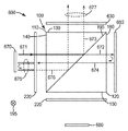
일 태양에서, 도 6a 및 도 6b는 PBS(100)를 포함하는 광 조합기(600)의 개략 평면도이다. 색상 조합기(600)는 다른 부분에 기술된 바와 같이 다양한 광원과 함께 사용될 수 있다. 일 실시예에서, 도 6a 및 도 6b는 색상 조합기(600) 내에서 조합되는, 제1 부분-반사성 광원(670) 내에 포함되는 두 가지 이상의 색상(예컨대, 적색 및 청색), 및 제3 색상(예컨대, 녹색)을 포함하는 제2 부분-반사성 광원(680)을 도시한다. 이 실시예에서, 색상 조합기(600)는 다른 실시예들에서 보이는 몇몇 구성요소들을 제외시키는데, 그 이유는 색상 조합기가 광 경로 내에 위치되는 이색 필터의 사용을 필요로 하지 않을 수 있기 때문이다.In one aspect, FIGS. 6A and 6B are schematic top views of
색상 조합기(600)의 다양한 구성요소의 기능을 더 명확하게 설명하기 위해, 제1 및 제2 광원(670, 680)으로부터 방출된 각각의 편광의 광선의 경로가 도 6a 및 도 6b에 도시되어 있다. PBS(100)는 다른 부분에 기술된 바와 같이 제1 편광 방향(195)에 대해 정렬된 반사 편광기(190)를 포함한다. 일 태양에서, 반사 편광기(190)는 중합체 다층 광학 필름을 포함할 수 있다. 제1 및 제2 지연기(220)가 각각 제2 및 제3 프리즘 면(140, 150)을 향하여 배치된다. 거울(660)이 제4 프리즘 면(160)을 향하여 배치된다.To more clearly illustrate the function of the various components of the
지연기(220), 거울(660) 및 부분-반사성 광원(670, 680)은 다른 부분에 기술된 바와 같이, 광의 하나의 편광 방향을 투과시키고 광의 다른 편광 상태를 재순환시키도록 상호작용한다. 일 실시예에서, 색상 조합기(600) 내의 각각의 지연기(220)는 제1 편광 방향(195)에 45°로 배향된 1/4 파장 지연기이다.The
색상 조합기(600)는 또한 제1 프리즘 면(130)을 향하여 배치된 필터(630)를 포함하며, 이 필터(630)는 광의 적어도 하나의 선택된 파장 스펙트럼의 편광 방향을 광의 적어도 다른 선택된 파장 스펙트럼의 편광 방향을 변경시키지 않고서 변경시킬 수 있다. 일 태양에서, 필터(630)는 컬러셀렉트(등록상표) 필터(미국 콜로라도주 볼더 소재의 컬러링크(등록상표) 인크.로부터 입수가능함)와 같은 색상 선택성 적층형 지연 편광기이다.The
부분-반사성 광원(670, 680) 각각은 적어도 부분적으로 광 반사성인 표면을 구비한다. 각각의 광원은 또한 적어도 부분적으로 반사성일 수 있는 기판 상에 장착된다. 반사성 광원 및 선택적으로 반사성 기판은 색상 조합기와 상호작용하여 광을 재순환시켜 효율을 향상시킨다. 또 다른 태양에 따르면, 다른 부분에 기술된 바와 같이, 광원을 편광 빔 스플리터로부터 분리시키는 간격을 제공하기 위해 광 터널 또는 렌즈가 제공될 수 있다. 조합된 광 출력의 균일도를 증가시키기 위해 광 조합기의 출력부에 적분기가 제공될 수 있다. 일 태양에 따르면, 각각의 부분-반사성 광원(670, 680)은 하나 이상의 발광 다이오드(LED)를 포함한다. 다양한 광원, 예를 들어 레이저, 레이저 다이오드, 유기 LED(OLED) 및 비-고체 광원, 예를 들어 적당한 수집기 또는 반사기를 갖는 초고압(UHP) 할로겐 또는 제논 램프가 사용될 수 있다. 본 발명에 유용한 광원, 광 터널, 및 광 적분기가, 그 개시 내용이 본 명세서에 전체적으로 포함된, 예를 들어 동시 계류 중인 미국 특허 출원 제60/938,834호에 더 상세히 기술되어 있다.Each partially reflective
이제, 비편광 제1 광(671)이 s-편광된 제1 광(677)으로서 색상 조합기(600)로부터 출사되는 도 6a를 참조하여 제1 부분-반사성 광원(670)으로부터의 광의 경로가 기술될 것이다. 제1 부분-반사성 광원(670)이 제1 유색 광 및 제2 유색 광을 포함할 수 있고 이들 유색 광 각각에 대한 경로가 색상 조합기(600)를 통해 동일할 것임이 이해될 것이다. 제1 부분-반사성 광원(670)에 의해 제1 광(671)이 지연기(220)를 통해 주입되고, 제2 프리즘 면(140)을 통해 PBS(100)에 입사되며, 반사 편광기(190)와 만나는데, 반사 편광기에서 제1 광은 p-편광된 제1 광(672) 및 s-편광된 제1 광(673)으로 분할된다. s-편광된 제1 광(673)은 반사 편광기(190)로부터 반사되고, 제1 프리즘 면(130)을 통해 PBS(100)로부터 출사되며, 변경되지 않은 상태로 s-편광된 제1 광(677)으로서 필터(630)를 통과한다.The path of light from the first partially reflective
p-편광된 제1 광(672)은 반사 편광기(190)를 통과하고, 제4 프리즘 면(160)을 통해 PBS(100)로부터 출사되며, 변경되지 않은 상태로 거울(660)로부터 반사되고, p-편광된 제1 광(674)으로서 제4 프리즘 면(160)을 통해 PBS(100)에 입사된다. p-편광된 제1 광(674)은 반사 편광기(190)를 통과하고, 제2 프리즘 면(140)을 통해 PBS(100)로부터 출사되며, 지연기(220)를 통과할 때 원형 편광된 제1 광(675)으로 변경되고, 부분-반사성 제1 광원(670)으로부터 반사되어 원형 편광의 방향을 변경시키며, 지연기(220)를 통과할 때 s-편광된 제1 광(676)으로 변경된다. s-편광된 제1 광(676)은 제2 프리즘 면을 통해 PBS(100)에 입사되고, 반사 편광기(190)로부터 반사되며, 제1 프리즘 면(130)을 통해 PBS(100)로부터 출사되고, 변경되지 않은 상태로 s-편광된 제1 광(677)으로서 필터(630)를 통과한다.The p-polarized first light 672 passes through the
이제, 비편광 제2 광(681)이 s-편광된 제2 광(687)으로서 색상 조합기(600)로부터 출사되는 도 6b를 참조하여 제2 부분-반사성 광원(680)으로부터의 광의 경로가 기술될 것이다. 제2 부분-반사성 광원(680)에 의해 제2 광(681)이 지연기(220)를 통해 주입되고, 제3 프리즘 면(150)을 통해 PBS(100)에 입사되며, 반사 편광기(190)와 만나는데, 반사 편광기에서 제2 광은 p-편광된 제2 광(682) 및 s-편광된 제2 광(683)으로 분할된다. p-편광된 제2 광(682)은 반사 편광기(190)를 통과하고, 제1 프리즘 면(130)을 통해 PBS(100)로부터 출사되며, 필터(630)를 통과할 때 s-편광된 제2 광(687)으로 변경된다.The path of light from the second partially-
s-편광된 제2 광(683)은 반사 편광기(190)로부터 반사되고, 제4 프리즘 면(160)을 통해 PBS(100)로부터 출사되며, 변경되지 않은 상태로 거울(660)로부터 반사되고, s-편광된 제2 광(684)으로서 제4 프리즘 면(160)을 통해 PBS(100)에 입사된다. s-편광된 제2 광(684)은 반사 편광기(190)로부터 반사되고, 제3 프리즘 면(150)을 통해 PBS(100)로부터 출사되며, 지연기(220)를 통과할 때 원형 편광된 제2 광(685)으로 변경되고, 제2 부분-반사성 광원(680)으로부터 반사되어 원형 편광의 방향을 변경시키며, 지연기(220)를 통과할 때 p-편광된 제2 광(686)으로 변경된다. p-편광된 제2 광(686)은 제3 프리즘 면(150)을 통해 PBS(100)에 입사되고, 반사 편광기(190)를 통과하며, 제1 프리즘 면(130)을 통해 PBS(100)로부터 출사되고, 필터(630)를 통과할 때 s-편광된 제2 광(677)으로 변경된다.s-polarized second light 683 is reflected from
일 실시예에서, 제1 광(671)은 동일한 패키지, 예를 들어 오스람 옵토 세미컨덕터즈(Osram Opto Semiconductors)로부터 상표명 오스타(OSTAR)(등록상표) SMP 시리즈 LED로 입수가능한 것 내에서 청색 광 및 적색 광을 포함한다. 이 실시예에서, 제2 유색 광(681)은 녹색 광이다. 일 실시예에 따르면, 필터(630)는 녹색 광의 편광 방향을 변경시키면서 적색 및 청색 광 둘 모두가 편광 변경 없이 투과될 수 있게 하는 GM 컬러셀렉트(등록상표) 필터이다. 다른 실시예에 따르면, 필터(630)는 적색 및 청색 광의 편광 방향을 변경시키면서 녹색 광이 편광 변경 없이 투과될 수 있게 하는 MG 컬러셀렉트(등록상표) 필터이다.In one embodiment, the
3색 광 조합 시스템 내의 광원은 동시 계류 중인 미국 특허 출원 제60/638834호에 기술된 바와 같이 순차적으로 활성화될 수 있다. 일 태양에 따르면, 시간 시퀀스는 3색 광 조합 시스템으로부터 조합된 광 출력을 수광하는 프로젝션 시스템 내의 투과성 또는 반사성 이미지형성 장치와 동기화된다. 일 태양에 따르면, 시간 시퀀스는 투사된 이미지의 깜박임(flickering)의 출현을 피하고 투사된 비디오 이미지의 무지개 현상(color break up)과 같은 동잡음(motion artifact)의 출현을 피할 정도로 충분히 빠른 속도로 반복된다.The light sources in the tri-color light combining system can be activated sequentially as described in co-pending US patent application 60/638834. According to one aspect, the time sequence is synchronized with a transmissive or reflective imaging device within the projection system that receives the combined light output from the tricolor light combining system. According to one aspect, the time sequence repeats at a speed fast enough to avoid the appearance of flickering of the projected image and to avoid the appearance of motion artifacts such as color break up of the projected video image. do.
도 5는 3색 광 조합 시스템(502)을 포함하는 프로젝터(500)를 도시한다. 3색 광 조합 시스템(502)은 출력 영역(504)에서 조합된 광 출력을 제공한다. 일 실시예에서, 출력 영역(504)에서의 조합된 광 출력은 편광된다. 출력 영역(504)에서의 조합된 광 출력은 광 엔진 광학계(506)를 통해 프로젝터 광학계(508)로 통과한다.5 shows a
광 엔진 광학계(506)는 렌즈(522, 524) 및 반사기(526)를 포함한다. 프로젝터 광학계(508)는 렌즈(528), 빔 스플리터(530) 및 프로젝션 렌즈(532)를 포함한다. 프로젝션 렌즈(532)들 중 하나 이상은 투사된 이미지(512)에 대한 초점 조정을 제공하도록 빔 스플리터(530)에 대해 이동가능할 수 있다. 반사성 이미지형성 장치(510)가 프로젝터 광학계 내의 광의 편광 상태를 조절하여, PBS를 통해 프로젝션 렌즈 내로 통과하는 광의 강도가 조절되어 투사된 이미지(512)를 생성하도록 할 것이다. 반사성 이미지형성 장치(510)의 작동과 광원(516, 518, 520)의 시퀀싱(sequencing)을 동기화시키기 위해 반사성 이미지형성 장치(510) 및 광원(516, 518, 520)에 제어 회로(514)가 결합된다. 일 태양에서, 출력 영역(504)에서의 조합된 광의 제1 부분은 프로젝터 광학계(508)를 통해 지향되고, 조합된 광 출력의 제2 부분은 다시 출력 영역(504)을 통해 색상 조합기(502) 내로 재순환된다. 조합된 광의 제2 부분은 예를 들어 거울, 반사 편광기, 반사성 LCD 등으로부터의 반사에 의해 색상 조합기 내로 다시 재순환될 수 있다. 도 5에 도시된 배열은 예시적이며, 개시된 광 조합 시스템은 다른 프로젝션 시스템과도 또한 사용될 수 있다. 하나의 대안적인 태양에 따르면, 투과성 이미지형성 장치가 사용될 수 있다.The
일 태양에 따르면, 전술한 바와 같은 유색 광 조합 시스템은 3색(백색) 출력을 생성한다. 반사성 편광 필름을 갖는 편광 빔 스플리터의 편광 특성(s-편광된 광에 대한 반사 및 p-편광된 광에 대한 투과)이 광원의 넓은 범위의 입사각에 대하여 낮은 감도를 갖기 때문에 시스템은 높은 효율을 갖는다. 색상 조합기 내의 광원으로부터의 광의 시준을 개선하기 위해 추가의 시준 구성요소가 사용될 수 있다. 소정 정도의 시준이 없으면, 입사각(angle of incidence, AOI), TIR의 손실 또는 TIR을 방해하는 증가된 소멸파 결합(evanescent coupling), 및/또는 PBS 내에서의 열화된 편광 식별 및 기능의 함수로서 이색 반사율의 변동과 관련된 상당한 광 손실이 있을 것이다. 본 발명에서, 편광 빔 스플리터는 광이 내부 전반사에 의해 수용되게 하고 요구되는 표면을 통해서만 방출되도록 하는 광파이프로서 기능한다.According to one aspect, the colored light combination system as described above produces a three color (white) output. The system has high efficiency because the polarization properties (reflection for s-polarized light and transmission for p-polarized light) of a polarizing beam splitter with a reflective polarizing film have low sensitivity to a wide range of angles of incidence of the light source. . Additional collimation components can be used to improve collimation of light from the light source in the color combiner. Without some degree of collimation, as a function of angle of incidence (AOI), loss of TIR or increased evanescent coupling that interferes with TIR, and / or degraded polarization identification and function within PBS There will be significant light loss associated with variations in dichroic reflectivity. In the present invention, the polarizing beam splitter functions as a light pipe that allows light to be received by total internal reflection and emitted only through the required surface.
본 발명은 바람직한 실시예들을 참조하여 설명되었지만, 당업자는 본 발명의 사상 및 범주로부터 벗어남이 없이 형태 및 상세 사항에 있어서 변경이 이루어질 수 있음을 인식할 것이다.Although the present invention has been described with reference to preferred embodiments, those skilled in the art will recognize that changes may be made in form and detail without departing from the spirit and scope of the invention.
Claims (71)
제2 색상 선택성 이색 필터;
반사 편광기를 포함하고,
각각 제1 색상 선택성 이색 필터 및 제2 색상 선택성 이색 필터를 수직으로 통과하는 제1 및 제2 선(line)이 대략 45도로 반사 편광기와 만나는 광학 요소.A first color selective dichroic filter;
A second color selective dichroic filter;
Includes a reflective polarizer,
Wherein the first and second lines perpendicularly passing through the first color selective dichroic filter and the second color selective dichroic filter respectively meet the reflective polarizer at approximately 45 degrees.
각각 제1 및 제2 색상 선택성 이색 필터 각각을 향하여 광을 방출하도록 구성된 제1 및 제2 광원; 및
조합된 유색 광 출력을 투과시키도록 배치된 출력 영역을 포함하는 색상 조합기.An optical element of claim 2; And
First and second light sources configured to emit light towards each of the first and second color selective dichroic filters, respectively; And
And a color combiner comprising an output region arranged to transmit combined colored light output.
각각 제1, 제2 및 제3 색상 선택성 이색 필터 각각을 향하여 광을 방출하도록 구성된 제1, 제2 및 제3 광원; 및
조합된 유색 광 출력을 투과시키도록 배치된 출력 영역을 포함하는 색상 조합기.An optical element of claim 3; And
First, second and third light sources configured to emit light towards each of the first, second and third color selective dichroic filters, respectively; And
And a color combiner comprising an output region arranged to transmit combined colored light output.
조합된 유색 광 출력의 제1 부분을 프로젝션 요소로 지향시키도록 배치된 이미저(imager)를 포함하는 이미지 프로젝터.18. The color combiner of claim 13 or 17;
An image projector comprising an imager arranged to direct a first portion of the combined colored light output to a projection element.
제1, 제2, 제3, 및 제4 프리즘 면,
제1 프리즘 면이 제3 프리즘 면에 대향하도록 제1 프리즘과 제2 프리즘 사이에 배치된 반사 편광기를 포함하는 편광 빔 스플리터(polarizing beam splitter);
제1 프리즘 면을 향하여 배치되고, 광의 적어도 하나의 선택된 색상의 편광 방향을 광의 적어도 다른 선택된 색상의 편광 방향을 변경시키지 않고서 변경시킬 수 있는 색상 선택성 편광 회전 필터;
각각 제2, 제3 및 제4 프리즘 면을 향하여 배치된 제1, 제2 및 제3 이색 필터; 및
제2, 제3 및 제4 프리즘 면 각각을 향하여 배치된 제1, 제2 및 제3 지연기를 포함하고,
제1 지연기는 제1 이색 필터와 제2 프리즘 면 사이에 있고, 제2 및 제3 이색 필터 각각은 제2 및 제3 지연기와 각각의 프리즘 면 사이에 있는 색상 조합기.First and second prisms,
First, second, third, and fourth prism faces,
A polarizing beam splitter comprising a reflective polarizer disposed between the first prism and the second prism such that the first prism face faces the third prism face;
A color selective polarization rotation filter disposed toward the first prism face and capable of changing the polarization direction of at least one selected color of light without changing the polarization direction of at least another selected color of light;
First, second and third dichroic filters disposed toward the second, third and fourth prism faces, respectively; And
A first, second and third retarder disposed toward each of the second, third and fourth prism faces,
The first retarder is between the first dichroic filter and the second prism face, and the second and third dichroic filters are each between the second and third retarder and each prism face.
반사성 방출 표면, 각각의 지연기, 및 이색 필터는 제1 비편광 광원으로부터의 광을 재순환시키도록 상호작용하는 색상 조합기.27. The method of claim 26, further comprising a first unpolarized light source that is at least partially reflective and has an emitting surface capable of emitting light towards the second, third or fourth prism face,
The reflective emitting surface, each retarder, and the dichroic filter interact to recycle light from the first non-polarized light source.
제26항의 색상 조합기를 제공하는 단계;
제1, 제2 및 제3 색상의 비편광 광을 각각 제1, 제2 및 제3 프리즘 면을 향하여 지향시키는 단계; 및
색상 선택성 편광 회전 필터로부터, 조합된 편광된 광을 수광하는 단계를 포함하는 방법.As a method of combining light,
Providing the color combiner of claim 26;
Directing unpolarized light of the first, second, and third colors towards the first, second, and third prism faces, respectively; And
Receiving the combined polarized light from the color selective polarization rotation filter.
제1 이색 필터에 대략 직교하게 배치되는 제2 이색 필터;
제1 이색 필터를 향하여 그리고 제2 이색 필터에 대략 직교하게 배치되는 제3 이색 필터;
제2 이색 필터를 향하여 그리고 제1 이색 필터 및 제3 이색 필터 둘 모두에 대략 직교하게 배치되는 색상 선택성 편광 회전 필터;
제1 이색 필터와 제3 이색 필터 사이에 배치되는 반사 편광기 - 반사 편광기는 제1, 제2 및 제3 이색 필터 각각으로부터의 수직선이 대략 45도로 반사 편광기와 교차하도록 배치됨 - ; 및
각각 제1, 제2 및 제3 이색 필터 각각에 인접하게 배치되는 제1, 제2 및 제3 지연기를 포함하는 색상 조합기.A first dichroic filter;
A second dichroic filter disposed substantially orthogonally to the first dichroic filter;
A third dichroic filter disposed towards and substantially perpendicular to the first dichroic filter;
A color selective polarization rotation filter disposed towards the second dichroic filter and approximately orthogonally to both the first dichroic filter and the third dichroic filter;
A reflective polarizer disposed between the first dichroic filter and the third dichroic filter, wherein the reflective polarizer is disposed such that vertical lines from each of the first, second, and third dichroic filters cross the reflective polarizer at approximately 45 degrees; And
And a first, second and third retarder disposed adjacent to each of the first, second and third dichroic filters respectively.
반사성 방출 표면, 각각의 지연기, 및 이색 필터는 제1 비편광 광원으로부터의 광을 재순환시키도록 상호작용하는 색상 조합기.45. The method of claim 44, further comprising a first non-polarization light source that is at least partially reflective and has an emitting surface capable of emitting light towards the first, second or third dichroic filter,
The reflective emitting surface, each retarder, and the dichroic filter interact to recycle light from the first non-polarized light source.
제44항의 색상 조합기를 제공하는 단계;
제1, 제2 및 제3 색상의 비편광 광을 각각 제1, 제2 및 제3 이색 필터를 향하여 지향시키는 단계; 및
색상 선택성 편광 회전 필터로부터, 조합된 편광된 광을 수광하는 단계를 포함하는 방법.As a method of combining light,
Providing the color combiner of claim 44;
Directing unpolarized light of the first, second, and third colors towards the first, second, and third dichroic filters, respectively; And
Receiving the combined polarized light from the color selective polarization rotation filter.
제1 이색 필터에 평행하게 그리고 제1 이색 필터를 향하여 배치되는 제2 이색 필터;
제1 이색 필터 및 제2 이색 필터 둘 모두에 직교하게 배치되는 제3 이색 필터;
제3 이색 필터를 향하여 그리고 제1 이색 필터 및 제2 이색 필터 둘 모두에 직교하게 배치되는 색상 선택성 편광 회전 필터; 및
제1 이색 필터와 제2 이색 필터 사이에 배치되는 반사 편광기 - 반사 편광기는 제1, 제2 및 제3 이색 필터 각각으로부터의 수직선이 대략 45도로 반사 편광기와 교차하도록 배치됨 - 를 포함하는 색상 조합기.A first dichroic filter;
A second dichroic filter disposed parallel to and towards the first dichroic filter;
A third dichroic filter disposed perpendicular to both the first dichroic filter and the second dichroic filter;
A color selective polarization rotation filter disposed towards the third dichroic filter and orthogonally to both the first dichroic filter and the second dichroic filter; And
And a reflective polarizer disposed between the first dichroic filter and the second dichroic filter, wherein the reflective polarizer is disposed such that vertical lines from each of the first, second and third dichroic filters intersect the reflective polarizer at approximately 45 degrees.
제1 이색 필터와 반사 편광기 사이에 배치된 제1 지연기;
반사 편광기와의 사이에 제2 이색 필터가 있도록 배치된 제2 지연기; 및
반사 편광기와의 사이에 제3 이색 필터가 있도록 배치된 제3 지연기를 추가로 포함하며,
반사 편광기는 제1 편광 방향에 대해 정렬된 직교 반사 편광기를 포함하는 색상 조합기.The method of claim 59,
A first retarder disposed between the first dichroic filter and the reflective polarizer;
A second retarder disposed such that there is a second dichroic filter between the reflective polarizer; And
And further comprising a third retarder disposed such that there is a third dichroic filter between the reflective polarizer,
The reflective polarizer comprises a quadrature reflective polarizer aligned with respect to the first polarization direction.
반사 편광기의 제1 면을 향하는 제1 이색 필터;
반사 편광기의 제2 면을 향하는 제2 이색 필터;
제1 이색 필터에 대략 직교하게 배치되고 반사 편광기의 제1 면을 향하는 반사기; 및
제2 이색 필터에 대략 직교하게 배치되고 반사 편광기의 제2 면을 향하는 색상 선택성 편광 회전 필터를 포함하며,
반사기, 색상 선택성 편광 회전 필터, 제1 이색 필터 및 제2 이색 필터 각각으로부터의 수직선이 대략 45도로 반사 편광기와 교차하는 색상 조합기.A reflective polarizer having a first side and a second side;
A first dichroic filter facing the first side of the reflective polarizer;
A second dichroic filter facing the second side of the reflective polarizer;
A reflector disposed substantially perpendicular to the first dichroic filter and facing the first side of the reflective polarizer; And
A color selective polarization rotation filter disposed substantially orthogonal to the second dichroic filter and facing the second side of the reflective polarizer,
And a color combiner wherein vertical lines from each of the reflector, color selective polarization rotation filter, first dichroic filter, and second dichroic filter intersect the reflective polarizer with approximately 45 degrees.
반사 편광기는 제1 편광 방향에 대해 정렬된 직교 반사 편광기를 포함하는 색상 조합기.65. The apparatus of claim 64, further comprising first and second retarders disposed between the first and second dichroic filters and the reflective polarizer, respectively,
The reflective polarizer comprises a quadrature reflective polarizer aligned with respect to the first polarization direction.
반사 편광기는 제1 편광 방향에 대해 정렬된 직교 반사 편광기를 포함하는 색상 조합기.66. The apparatus of claim 65, further comprising first, second, and third retarders disposed between the first, second, and third dichroic filters and the reflective polarizer, respectively.
The reflective polarizer comprises a quadrature reflective polarizer aligned with respect to the first polarization direction.
Applications Claiming Priority (4)
| Application Number | Priority Date | Filing Date | Title |
|---|---|---|---|
| US5327008P | 2008-05-15 | 2008-05-15 | |
| US61/053,270 | 2008-05-15 | ||
| US9513808P | 2008-09-08 | 2008-09-08 | |
| US61/095,138 | 2008-09-08 |
Publications (1)
| Publication Number | Publication Date |
|---|---|
| KR20110015010A true KR20110015010A (en) | 2011-02-14 |
Family
ID=41318966
Family Applications (1)
| Application Number | Title | Priority Date | Filing Date |
|---|---|---|---|
| KR1020107027669A KR20110015010A (en) | 2008-05-15 | 2008-12-18 | Optical element and color combiner |
Country Status (7)
| Country | Link |
|---|---|
| US (1) | US20110149547A1 (en) |
| EP (1) | EP2286296A4 (en) |
| JP (1) | JP2011524019A (en) |
| KR (1) | KR20110015010A (en) |
| CN (1) | CN102084283A (en) |
| TW (1) | TW200947102A (en) |
| WO (1) | WO2009139798A1 (en) |
Families Citing this family (24)
| Publication number | Priority date | Publication date | Assignee | Title |
|---|---|---|---|---|
| US10073264B2 (en) | 2007-08-03 | 2018-09-11 | Lumus Ltd. | Substrate-guide optical device |
| JP2011075669A (en) | 2009-09-29 | 2011-04-14 | Hitachi Consumer Electronics Co Ltd | Projection type image display device |
| KR20130108359A (en) | 2010-09-22 | 2013-10-02 | 쓰리엠 이노베이티브 프로퍼티즈 컴파니 | Tilted dichroic color combiner iii |
| CN106019616B (en) * | 2010-09-29 | 2020-03-03 | 株式会社尼康 | Speckle reduction device and projector |
| DE102011051818A1 (en) * | 2011-07-13 | 2013-01-17 | Technische Universität Berlin | A method of mixing light rays of different colors, light beam combining device and their use |
| WO2013028394A2 (en) | 2011-08-19 | 2013-02-28 | 3M Innovative Properties Company | Projection subsystem |
| US9784985B2 (en) * | 2011-10-24 | 2017-10-10 | 3M Innovative Properties Company | Titled dichroic polarizing beamsplitter |
| CN102621789B (en) * | 2012-04-20 | 2014-06-18 | 杭州研明光电技术有限公司 | Compact liquid crystal projection light engine system using mixed light source |
| US10477194B2 (en) | 2012-04-25 | 2019-11-12 | 3M Innovative Properties Company | Two imager projection device |
| US9958699B2 (en) | 2012-12-21 | 2018-05-01 | 3M Innovative Properties Company | Hybrid polarizing beam splitter |
| CN103592770A (en) * | 2013-11-19 | 2014-02-19 | 苏州大学 | RGB three-color light beam combiner and manufacturing method thereof |
| IL232197B (en) | 2014-04-23 | 2018-04-30 | Lumus Ltd | Compact head-mounted display system |
| US20180017735A1 (en) * | 2016-07-13 | 2018-01-18 | Futurewei Technologies, Inc. | Wavelength Division Multiplexer/Demultiplexer with Flexibility of Optical Adjustment |
| CA2992213C (en) | 2016-10-09 | 2023-08-29 | Yochay Danziger | Aperture multiplier using a rectangular waveguide |
| KR20230084335A (en) | 2016-11-08 | 2023-06-12 | 루머스 리미티드 | Light-guide device with optical cutoff edge and corresponding production methods |
| WO2018100582A1 (en) * | 2016-12-02 | 2018-06-07 | Lumus Ltd. | Optical system with compact collimating image projector |
| KR102537642B1 (en) | 2017-07-19 | 2023-05-26 | 루머스 리미티드 | LCOS lighting via LOE |
| JP2019105806A (en) * | 2017-12-14 | 2019-06-27 | 日東電工株式会社 | Projector and optical member used for projector |
| IL259518B2 (en) | 2018-05-22 | 2023-04-01 | Lumus Ltd | Optical system and method for improvement of light field uniformity |
| US11415812B2 (en) | 2018-06-26 | 2022-08-16 | Lumus Ltd. | Compact collimating optical device and system |
| JP6881535B2 (en) * | 2019-09-26 | 2021-06-02 | セイコーエプソン株式会社 | Image light generation module and image display device |
| KR20240059655A (en) | 2019-12-08 | 2024-05-07 | 루머스 리미티드 | Optical systems with compact image projector |
| US11366311B2 (en) | 2020-04-01 | 2022-06-21 | Panasonic Intellectual Property Management Co., Ltd. | Display device |
| JP7002061B2 (en) * | 2020-04-01 | 2022-02-10 | パナソニックIpマネジメント株式会社 | Display device |
Family Cites Families (34)
| Publication number | Priority date | Publication date | Assignee | Title |
|---|---|---|---|---|
| US28729A (en) * | 1860-06-19 | Sash-fastener | ||
| US3497283A (en) * | 1966-08-24 | 1970-02-24 | Bausch & Lomb | Color selection polarizing beam splitter |
| US5067799A (en) * | 1989-12-27 | 1991-11-26 | Honeywell Inc. | Beam combining/splitter cube prism for color polarization |
| US5882774A (en) * | 1993-12-21 | 1999-03-16 | Minnesota Mining And Manufacturing Company | Optical film |
| US6486997B1 (en) * | 1997-10-28 | 2002-11-26 | 3M Innovative Properties Company | Reflective LCD projection system using wide-angle Cartesian polarizing beam splitter |
| US6147734A (en) * | 1998-12-17 | 2000-11-14 | Dai Nippon Printing Co., Ltd. | Bidirectional dichroic circular polarizer and reflection/transmission type liquid-crystal display device |
| US6550919B1 (en) * | 1999-03-26 | 2003-04-22 | Unaxis Balzers Aktiengesellschaft | Spectral light division and recombination configuration as well as process for the spectrally selective modulation of light |
| JP3554520B2 (en) * | 1999-07-08 | 2004-08-18 | シャープ株式会社 | Image display device |
| US6636276B1 (en) * | 1999-09-09 | 2003-10-21 | International Business Machines Corporation | Projection display system with at least two reflective light valves |
| US6490081B1 (en) * | 2000-07-28 | 2002-12-03 | The Board Of Trustees Of The Leland Stanford Junior University | Method of amplifying optical signals using doped materials with extremely broad bandwidths |
| KR20030088142A (en) * | 2001-04-20 | 2003-11-17 | 쓰리엠 이노베이티브 프로퍼티즈 컴파니 | Methods and apparatus for positioning optical prisms |
| JP4568457B2 (en) * | 2001-07-31 | 2010-10-27 | 株式会社リコー | Projection device |
| JP2003057600A (en) * | 2001-08-01 | 2003-02-26 | Prokia Technology Co Ltd | Projection display device using two light valves |
| CN100450189C (en) * | 2001-08-06 | 2009-01-07 | Jds单相公司 | Color management system having a prism to compensate for optical aberrations and to enhance contrast |
| US6857747B2 (en) * | 2001-08-06 | 2005-02-22 | Advanced Digital Optics, Inc. | Color management system |
| JP2003066373A (en) * | 2001-08-15 | 2003-03-05 | Prokia Technology Co Ltd | Projection type display device |
| US7352513B2 (en) * | 2001-09-12 | 2008-04-01 | Lightmaster Systems, Inc. | Prism assemblies and kernel configurations for use in projection systems |
| US6816309B2 (en) * | 2001-11-30 | 2004-11-09 | Colorlink, Inc. | Compensated color management systems and methods |
| US6961179B2 (en) * | 2001-11-30 | 2005-11-01 | Colorlink, Inc. | Compensated color management systems and methods |
| JP4064666B2 (en) * | 2001-12-20 | 2008-03-19 | 株式会社リコー | Projection device |
| US20060203352A1 (en) * | 2003-06-24 | 2006-09-14 | Pashley Michael D | Method and apparatus for recycling reflected light in optical systems as e.g. projection display |
| US7360900B2 (en) * | 2004-03-10 | 2008-04-22 | Seiko Epson Corporation | Illuminating apparatus, image display apparatus, and projector |
| EP1763697A4 (en) * | 2004-07-06 | 2009-10-28 | Colorlink Inc | Illumination systems |
| US7320521B2 (en) * | 2004-07-12 | 2008-01-22 | Next Wave Optics, Inc. | Optical engine architectures |
| US7364302B2 (en) * | 2004-08-09 | 2008-04-29 | 3M Innovative Properties Company | Projection display system using multiple light sources and polarizing element for using with same |
| WO2006057001A2 (en) * | 2004-11-29 | 2006-06-01 | Genoa Color Technologies Ltd. | Multi-primary color projection display |
| US7261453B2 (en) * | 2005-01-25 | 2007-08-28 | Morejon Israel J | LED polarizing optics for color illumination system and method of using same |
| US7445340B2 (en) * | 2005-05-19 | 2008-11-04 | 3M Innovative Properties Company | Polarized, LED-based illumination source |
| US7673993B2 (en) * | 2005-12-22 | 2010-03-09 | 3M Innovative Properties Company | Projection system using reflective polarizers |
| US20080018861A1 (en) * | 2006-07-18 | 2008-01-24 | Colorlink, Inc. | Light collectors for projection systems |
| WO2008016753A2 (en) * | 2006-08-01 | 2008-02-07 | Colorlink, Inc. | Compensation schemes for lcos projection systems using form birefringent polarization beam splitters |
| US20080231953A1 (en) * | 2007-03-22 | 2008-09-25 | Young Garrett J | System and Method for LED Polarization Recycling |
| JP5164421B2 (en) * | 2007-04-24 | 2013-03-21 | キヤノン株式会社 | Color separation / synthesis optical system and image projection apparatus using the same |
| US7821713B2 (en) * | 2007-05-18 | 2010-10-26 | 3M Innovative Properties Company | Color light combining system for optical projector |
-
2008
- 2008-12-18 KR KR1020107027669A patent/KR20110015010A/en not_active Application Discontinuation
- 2008-12-18 JP JP2011509464A patent/JP2011524019A/en not_active Ceased
- 2008-12-18 CN CN2008801302567A patent/CN102084283A/en active Pending
- 2008-12-18 WO PCT/US2008/087369 patent/WO2009139798A1/en active Application Filing
- 2008-12-18 US US12/991,934 patent/US20110149547A1/en not_active Abandoned
- 2008-12-18 EP EP08874323A patent/EP2286296A4/en not_active Withdrawn
- 2008-12-26 TW TW097151073A patent/TW200947102A/en unknown
Also Published As
| Publication number | Publication date |
|---|---|
| JP2011524019A (en) | 2011-08-25 |
| EP2286296A1 (en) | 2011-02-23 |
| EP2286296A4 (en) | 2011-09-07 |
| WO2009139798A1 (en) | 2009-11-19 |
| CN102084283A (en) | 2011-06-01 |
| US20110149547A1 (en) | 2011-06-23 |
| TW200947102A (en) | 2009-11-16 |
Similar Documents
| Publication | Publication Date | Title |
|---|---|---|
| US8485667B2 (en) | Optical element and colored light combiner using same | |
| KR20110015010A (en) | Optical element and color combiner | |
| US20110235175A1 (en) | Polarization converting color combiner | |
| US7821713B2 (en) | Color light combining system for optical projector | |
| US8654444B2 (en) | Polarization converting color combiner | |
| KR20100099747A (en) | Light combiner | |
| KR20110084328A (en) | High durability color combiner | |
| US20100277796A1 (en) | Light combiner |
Legal Events
| Date | Code | Title | Description |
|---|---|---|---|
| WITN | Application deemed withdrawn, e.g. because no request for examination was filed or no examination fee was paid |