KR20100129764A - System and method for reduced pressure charging - Google Patents
System and method for reduced pressure charging Download PDFInfo
- Publication number
- KR20100129764A KR20100129764A KR1020107022792A KR20107022792A KR20100129764A KR 20100129764 A KR20100129764 A KR 20100129764A KR 1020107022792 A KR1020107022792 A KR 1020107022792A KR 20107022792 A KR20107022792 A KR 20107022792A KR 20100129764 A KR20100129764 A KR 20100129764A
- Authority
- KR
- South Korea
- Prior art keywords
- chamber
- compressible
- compressive
- fluid
- foot
- Prior art date
Links
Images

Classifications
-
- A—HUMAN NECESSITIES
- A61—MEDICAL OR VETERINARY SCIENCE; HYGIENE
- A61M—DEVICES FOR INTRODUCING MEDIA INTO, OR ONTO, THE BODY; DEVICES FOR TRANSDUCING BODY MEDIA OR FOR TAKING MEDIA FROM THE BODY; DEVICES FOR PRODUCING OR ENDING SLEEP OR STUPOR
- A61M1/00—Suction or pumping devices for medical purposes; Devices for carrying-off, for treatment of, or for carrying-over, body-liquids; Drainage systems
- A61M1/80—Suction pumps
- A61M1/82—Membrane pumps, e.g. bulbs
-
- A—HUMAN NECESSITIES
- A61—MEDICAL OR VETERINARY SCIENCE; HYGIENE
- A61M—DEVICES FOR INTRODUCING MEDIA INTO, OR ONTO, THE BODY; DEVICES FOR TRANSDUCING BODY MEDIA OR FOR TAKING MEDIA FROM THE BODY; DEVICES FOR PRODUCING OR ENDING SLEEP OR STUPOR
- A61M1/00—Suction or pumping devices for medical purposes; Devices for carrying-off, for treatment of, or for carrying-over, body-liquids; Drainage systems
- A61M1/71—Suction drainage systems
- A61M1/74—Suction control
- A61M1/742—Suction control by changing the size of a vent
-
- A—HUMAN NECESSITIES
- A61—MEDICAL OR VETERINARY SCIENCE; HYGIENE
- A61M—DEVICES FOR INTRODUCING MEDIA INTO, OR ONTO, THE BODY; DEVICES FOR TRANSDUCING BODY MEDIA OR FOR TAKING MEDIA FROM THE BODY; DEVICES FOR PRODUCING OR ENDING SLEEP OR STUPOR
- A61M1/00—Suction or pumping devices for medical purposes; Devices for carrying-off, for treatment of, or for carrying-over, body-liquids; Drainage systems
- A61M1/71—Suction drainage systems
- A61M1/74—Suction control
- A61M1/743—Suction control by changing the cross-section of the line, e.g. flow regulating valves
-
- A—HUMAN NECESSITIES
- A61—MEDICAL OR VETERINARY SCIENCE; HYGIENE
- A61M—DEVICES FOR INTRODUCING MEDIA INTO, OR ONTO, THE BODY; DEVICES FOR TRANSDUCING BODY MEDIA OR FOR TAKING MEDIA FROM THE BODY; DEVICES FOR PRODUCING OR ENDING SLEEP OR STUPOR
- A61M1/00—Suction or pumping devices for medical purposes; Devices for carrying-off, for treatment of, or for carrying-over, body-liquids; Drainage systems
- A61M1/80—Suction pumps
- A61M1/81—Piston pumps, e.g. syringes
-
- A—HUMAN NECESSITIES
- A61—MEDICAL OR VETERINARY SCIENCE; HYGIENE
- A61M—DEVICES FOR INTRODUCING MEDIA INTO, OR ONTO, THE BODY; DEVICES FOR TRANSDUCING BODY MEDIA OR FOR TAKING MEDIA FROM THE BODY; DEVICES FOR PRODUCING OR ENDING SLEEP OR STUPOR
- A61M1/00—Suction or pumping devices for medical purposes; Devices for carrying-off, for treatment of, or for carrying-over, body-liquids; Drainage systems
- A61M1/90—Negative pressure wound therapy devices, i.e. devices for applying suction to a wound to promote healing, e.g. including a vacuum dressing
- A61M1/96—Suction control thereof
-
- A—HUMAN NECESSITIES
- A61—MEDICAL OR VETERINARY SCIENCE; HYGIENE
- A61M—DEVICES FOR INTRODUCING MEDIA INTO, OR ONTO, THE BODY; DEVICES FOR TRANSDUCING BODY MEDIA OR FOR TAKING MEDIA FROM THE BODY; DEVICES FOR PRODUCING OR ENDING SLEEP OR STUPOR
- A61M27/00—Drainage appliance for wounds or the like, i.e. wound drains, implanted drains
-
- A—HUMAN NECESSITIES
- A61—MEDICAL OR VETERINARY SCIENCE; HYGIENE
- A61H—PHYSICAL THERAPY APPARATUS, e.g. DEVICES FOR LOCATING OR STIMULATING REFLEX POINTS IN THE BODY; ARTIFICIAL RESPIRATION; MASSAGE; BATHING DEVICES FOR SPECIAL THERAPEUTIC OR HYGIENIC PURPOSES OR SPECIFIC PARTS OF THE BODY
- A61H7/00—Devices for suction-kneading massage; Devices for massaging the skin by rubbing or brushing not otherwise provided for
-
- A—HUMAN NECESSITIES
- A61—MEDICAL OR VETERINARY SCIENCE; HYGIENE
- A61M—DEVICES FOR INTRODUCING MEDIA INTO, OR ONTO, THE BODY; DEVICES FOR TRANSDUCING BODY MEDIA OR FOR TAKING MEDIA FROM THE BODY; DEVICES FOR PRODUCING OR ENDING SLEEP OR STUPOR
- A61M1/00—Suction or pumping devices for medical purposes; Devices for carrying-off, for treatment of, or for carrying-over, body-liquids; Drainage systems
- A61M1/90—Negative pressure wound therapy devices, i.e. devices for applying suction to a wound to promote healing, e.g. including a vacuum dressing
- A61M1/92—Negative pressure wound therapy devices, i.e. devices for applying suction to a wound to promote healing, e.g. including a vacuum dressing with liquid supply means
-
- A—HUMAN NECESSITIES
- A61—MEDICAL OR VETERINARY SCIENCE; HYGIENE
- A61M—DEVICES FOR INTRODUCING MEDIA INTO, OR ONTO, THE BODY; DEVICES FOR TRANSDUCING BODY MEDIA OR FOR TAKING MEDIA FROM THE BODY; DEVICES FOR PRODUCING OR ENDING SLEEP OR STUPOR
- A61M2205/00—General characteristics of the apparatus
- A61M2205/07—General characteristics of the apparatus having air pumping means
- A61M2205/078—General characteristics of the apparatus having air pumping means foot operated
Landscapes
- Health & Medical Sciences (AREA)
- Heart & Thoracic Surgery (AREA)
- Animal Behavior & Ethology (AREA)
- General Health & Medical Sciences (AREA)
- Anesthesiology (AREA)
- Biomedical Technology (AREA)
- Hematology (AREA)
- Life Sciences & Earth Sciences (AREA)
- Veterinary Medicine (AREA)
- Engineering & Computer Science (AREA)
- Public Health (AREA)
- Vascular Medicine (AREA)
- Otolaryngology (AREA)
- Media Introduction/Drainage Providing Device (AREA)
- Surgical Instruments (AREA)
- External Artificial Organs (AREA)
Abstract
감압 치료 시스템은 사용자의 발 아래에 위치가능하며 팽창 상태와 압축 상태 사이에서 이동가능한 압축성 챔버를 포함한다. 압축성 챔버는 주입구 및 배출구를 포함한다. 주입구 밸브는 압축성 챔버 내의 유체가 주입구를 통해 배출되는 것을 방지하도록 주입구와 유체를 교환하고, 배출구 밸브는 유체가 배출구를 통해 압축성 챔버로 유입되는 것을 방지하도록 배출구와 유체를 교환한다. 편향 부재는 압축성 챔버를 팽창 상태로 편향시키도록 압축성 챔버 내에 배치되고, 매니폴드는 조직 부위에 위치가능하며 압축성 챔버의 주입구와 유체를 교환한다. The decompression treatment system includes a compressible chamber that is positionable below the user's foot and is movable between an inflated state and a compressed state. The compressible chamber includes an inlet and an outlet. The inlet valve exchanges fluid with the inlet port to prevent fluid in the compressive chamber from discharging through the inlet port, and the outlet valve exchanges fluid with the outlet port to prevent fluid from entering the compressive chamber through the outlet port. The biasing member is disposed within the compressive chamber to deflect the compressive chamber into an expanded state, and the manifold is located at the tissue site and exchanges fluid with the inlet of the compressive chamber.

Description
본원은 2008년 3월 13일에 출원된 미국 가출원번호 61/036,391을 기초로 우선권을 주장하며, 그 내용은 이하 참조로서 도입된다. This application claims priority based on US Provisional Application No. 61 / 036,391, filed March 13, 2008, the contents of which are incorporated herein by reference.
본원은 일반적으로 조직 치료 시스템에 관한 것으로, 구체적으로 감압 충전 시스템 및 방법에 관한 것이다. FIELD The present disclosure generally relates to tissue treatment systems and, more particularly, to reduced pressure filling systems and methods.
임상 연구 및 실무는, 조직 부위에 인접하여 감압을 제공하는 것이 조직 부위에서 새로운 조직의 성장을 증가시키고 가속화하는 것을 밝혀왔다. 이러한 현상의 적용은 수없이 이루어졌으나, 감압의 적용은 특히 상처 치료에 성공적이었다. 이러한 치료(의료계에서는 "음압 상처 치료법", "음압 치료법" 또는 "진공 치료법"으로 자주 불려짐)는 많은 장점들을 제공하며, 상기 장점들은 빠른 치유와 육아 조직의 증가된 형성을 포함한다. 일반적으로, 감압은 다공성 패드 또는 다른 매니폴드 장치를 통해 조직에 적용된다. 다공성 패드는 감압을 조직에 분배할 수 있고 조직으로부터 인출된 유체를 채널링하는 셀 또는 구멍을 포함한다. 다공성 패드는 주로 치료를 용이하게 하는 다른 컴포넌트를 구비한 드레싱에 도입된다. Clinical studies and practice have shown that providing decompression adjacent to tissue sites increases and accelerates the growth of new tissue at the tissue sites. The application of this phenomenon has been numerous, but the application of decompression has been particularly successful in wound healing. Such treatment (often referred to as "negative pressure wound therapy", "negative pressure therapy" or "vacuum therapy" in the medical system) offers many advantages, including fast healing and increased formation of granulation tissue. Generally, the reduced pressure is applied to the tissue through a porous pad or other manifold device. The porous pad includes cells or holes that can distribute the reduced pressure to the tissue and channel the fluid drawn from the tissue. Porous pads are often introduced in dressings with other components to facilitate treatment.
감압 치료 시스템은 감압원, 예컨대 조직 부위에 전달되는 감압을 생성하는 동력을 제공받는 펌프를 포함할 수 있다. 그러나, 이러한 감압원은 대부분 부피가 크거나 사용자의 눈에 잘 띄며, 발 치료 시스템과 결합하여 사용되도록 용이하게 구성되지 않는다. The decompression treatment system can include a powered pump to generate a decompression delivered to a decompression source, such as a tissue site. However, most of these sources of decompression are bulky or visible to the user and are not readily configured for use in conjunction with a foot treatment system.
본 발명은 감압 충전 시스템 및 방법을 제공하는 것을 목적으로 한다. It is an object of the present invention to provide a reduced pressure filling system and method.
종래의 감압 치료 시스템에 의해 제시되는 문제점은 여기에 기술되는 설명적인 실시예의 시스템 및 방법에 의해 해결된다. 일 설명적인 실시예에서, 감압 치료 시스템은 사용자의 발 아래에 위치되는 압축성 주머니를 포함한다. 압축성 주머니는 챔버벽에 의해 실질적으로 둘러싸인 챔버를 포함하고, 압축성 주머니는 팽창 상태와 압축 상태 사이에서 이동가능하여 감압을 생성한다. 탄성 부재는 압축성 주머니를 팽창 상태로 편향시키도록 챔버벽과 결합되어 동작한다. 매니폴드는 사용자의 조직 부위에 위치되고 압축성 주머니의 챔버와 유체를 교환한다. Problems presented by conventional decompression therapy systems are addressed by the systems and methods of the illustrative embodiments described herein. In one illustrative embodiment, the decompression treatment system includes a compressible pouch positioned under the foot of the user. The compressive bladder comprises a chamber substantially surrounded by the chamber wall, the compressive bladder being movable between the inflated and compressed states to create a reduced pressure. The elastic member operates in conjunction with the chamber wall to bias the compressive bag into the expanded state. The manifold is located at the tissue site of the user and exchanges fluid with the chamber of the compressible bag.
다른 설명적인 실시예에서, 감압 치료 시스템이 제공된다. 감압 치료 시스템은 사용자의 발 아래에 배치가능하고 팽창 상태와 압축 상태 사이에서 이동가능한 압축성 챔버를 포함한다. 압축성 챔버는 주입구 및 배출구를 포함한다. 주입구 밸브는 주입구와 유체를 교환하여 압축성 챔버 내의 유체가 주입구로부터 배출되는 것을 방지하고, 배출구 밸브는 배출구와 유체를 교환하여 유체가 배출구를 통해 압축성 챔버로 유입되는 것을 방지한다. 편향 부재는 압축성 챔버 내에 배치되어 압축성 챔버를 팽창 상태로 편향시키고, 매니폴드는 조직 부위에 배치가능하며 압축성 챔버의 주입구와 유체를 교환한다. In another illustrative embodiment, a decompression treatment system is provided. The decompression treatment system includes a compressible chamber that is deployable under a user's foot and is movable between an inflated state and a compressed state. The compressible chamber includes an inlet and an outlet. The inlet valve exchanges fluid with the inlet to prevent fluid in the compressive chamber from being discharged from the inlet, and the outlet valve exchanges fluid with the outlet to prevent fluid from entering the compressive chamber through the outlet. The biasing member is disposed in the compressive chamber to deflect the compressive chamber into an expanded state, and the manifold is deployable at the tissue site and exchanges fluid with the inlet of the compressive chamber.
여전히 다른 설명적인 실시예에서, 감압 치료 시스템이 제공되고 사용자의 발 아래에 배치가능한 압축성 주머니를 포함한다. 압축성 주머니는 챔버를 포함하고 팽창 상태와 압축 상태 사이에서 이동가능하다. 상기 시스템은, 챔버 내에 배치되어 압축성 주머니를 팽창 상태로 편향시키는 편향 부재를 더 포함한다. 제 1 가변-부피 캐비티 및 제 2 가변-부피 캐비티를 구비한 압력 조절기가 제공된다. 제 1 가변-부피 캐비티는 압축성 주머니의 챔버와 유체를 교환하도록 연결되고, 매니폴드는 조직 부위에 배치가능하며 압력 조절기의 제 2 가변-부피 캐비티와 유체를 교환한다. In yet another illustrative embodiment, a decompression therapy system is provided and includes a compressible pouch that is deployable under a user's foot. The compressible bag includes a chamber and is movable between an inflated state and a compressed state. The system further includes a biasing member disposed in the chamber for biasing the compressive bag into the expanded state. A pressure regulator is provided having a first variable-volume cavity and a second variable-volume cavity. The first variable-volume cavity is connected to exchange fluid with the chamber of the compressible bag, and the manifold is deployable at the tissue site and exchanges fluid with the second variable-volume cavity of the pressure regulator.
또 다른 설명적인 실시예에서, 사용자에 의해 사용되는 감압 조직 치료 시스템에 감압을 제공하는 방법이 제공된다. 상기 방법은 사용자의 발로 압축성 주머니를 압축시키는 단계 및 압축성 주머니가 팽창함에 따라 압축성 주머니의 챔버 내에 감압을 생성하는 단계를 포함한다. In yet another illustrative embodiment, a method of providing decompression to a decompression tissue treatment system used by a user is provided. The method includes compressing the compressible bag with the user's feet and creating a decompression in the chamber of the compressible bag as the compressible bag expands.
설명적인 실시예의 다른 목적, 특징 및 효과가 이어지는 도면 및 상세한 설명을 참조로 명백하게 될 것이다. Other objects, features and effects of the illustrative embodiments will become apparent with reference to the following drawings and detailed description.
도 1은 설명적인 실시예에 따른 압축성 주머니 시스템을 구비한 감압 치료 시스템의 개략도를 도시한다.
도 2는 도 1의 압축성 주머니 시스템의 사시도를 도시한다.
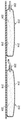
도 3a는 도 2 중 3-3에서 취해진 압축성 주머니 시스템의 측단면도를 도시하며, 주머니 시스템은 팽창 상태로 도시된다.
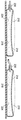
도 3b는 도 2 중 3-3에서 취해진 압축성 주머니 시스템의 측단면도를 도시하며, 주머니 시스템은 압축 상태로 도시된다.
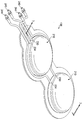
도 4는 설명적인 실시예에 따른 압축성 주머니 시스템 및 압력 조절기의 개략도를 도시한다.
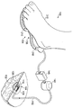
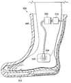
도 5는 설명적인 실시예에 따른 압축성 주머니 시스템을 구비한 회복용 신발을 도시한다. 1 shows a schematic diagram of a decompression treatment system with a compressible bag system according to an illustrative embodiment.
2 shows a perspective view of the compressible bag system of FIG. 1.
3A shows a cross-sectional side view of the compressible bladder system taken in 3-3 of FIG. 2, with the bladder system shown in an inflated state.
FIG. 3B shows a cross-sectional side view of the compressible bag system taken in 3-3 of FIG. 2, wherein the bag system is shown in a compressed state.
4 shows a schematic diagram of a compressible bag system and a pressure regulator in accordance with an illustrative embodiment.
5 illustrates a recovery shoe with a compressible pouch system according to an illustrative embodiment.
이어지는 바람직한 실시예에 대한 상세한 설명에서, 그 일부를 형성하는 첨부된 도면이 참조되며, 이는 본 발명이 구현될 수 있는 특정한 바람직한 실시예의 설명으로서 도시된다. 이 실시예는 통상의 기술자가 본 발명을 구현할 수 있도록 상세한 설명이 충분히 기술되며, 다른 실시예가 이용될 수 있고 논리적, 구조적, 기계적, 전기적 그리고 화학적 변경이 본 발명의 사상 또는 범위로부터 벗어나지 않은 채 수행될 수 있다. 통상의 기술자가 본 발명을 구현할 수 있도록 하는데 필수적이지 않은 설명을 피하기 위해, 통상의 기술자에게 알려진 특정 정보에 대한 설명은 생략될 수 있다. 따라서, 이어지는 상세한 설명은 제한적으로 해석되지 않고, 본 발명의 범위는 오직 첨부된 청구범위에 의해서만 정의된다. In the following detailed description of the preferred embodiments, reference is made to the accompanying drawings, which form a part thereof, which is shown as a description of a particular preferred embodiment in which the invention may be implemented. This embodiment has been described in detail so that a person skilled in the art can implement the invention, other embodiments may be utilized, and logical, structural, mechanical, electrical, and chemical changes may be made without departing from the spirit or scope of the invention. Can be. The description of specific information known to those skilled in the art may be omitted in order to avoid descriptions that are not essential to enabling those skilled in the art to implement the present invention. The following detailed description, therefore, is not to be taken in a limiting sense, and the scope of the present invention is defined only by the appended claims.
여기에서 사용되는 용어 "감압(reduced pressure)"은 일반적으로 치료 대상이 되는 조직 부위에서의 주변 압력보다 더 낮은 압력을 의미한다. 대부분의 경우, 이러한 감압은 환자가 위치하는 장소에서의 대기압보다 더 작을 것이다. 대안적으로, 감압은 조직 부위에서의 조직에 관련된 유체정역학적 압력보다 더 낮을 수 있다. 비록 용어 "진공" 및 "음압"이 조직 부위에 가해지는 압력을 기술하도록 사용될 수 있을지라도, 조직 부위에 작용되는 실제 압력 감소는 일반적으로 완전한 진공과 관련된 압력 감소보다 매우 낮을 수 있다. 감압은 조직 부위의 영역에서 유체의 흐름을 초기 생성할 수 있다. 조직 부위 주변의 유체정역학적 압력이 요구되는 감압에 접근함에 따라, 흐름이 진정될 수 있으며, 그리고 나서 감압이 유지된다. 그 외 지시하지 않은 경우, 여기에 기술된 압력 값은 게이지 압력이다. 유사하게, 감압의 증가에 대한 참조는 일반적으로 절대 압력의 감소를 의미하며, 동시에 감압의 감소는 일반적으로 절대 압력의 증가를 의미한다. As used herein, the term "reduced pressure" generally means a pressure lower than the ambient pressure at the tissue site being treated. In most cases, this decompression will be less than atmospheric pressure at the location of the patient. Alternatively, the decompression may be lower than the hydrostatic pressure associated with the tissue at the tissue site. Although the terms "vacuum" and "negative pressure" can be used to describe the pressure exerted on the tissue site, the actual pressure reduction applied to the tissue site may generally be much lower than the pressure reduction associated with complete vacuum. Decompression can initially produce a flow of fluid in the region of the tissue site. As the hydrostatic pressure around the tissue site approaches the required decompression, the flow can calm down and then the decompression is maintained. Unless otherwise indicated, the pressure values described herein are gauge pressures. Similarly, reference to an increase in decompression generally means a decrease in absolute pressure, while a decrease in decompression generally means an increase in absolute pressure.
여기에 사용되는 용어 "조직 부위(tissue site)"는 임의의 조직에 위치하거나 그 안에 위치한 상처 또는 결함을 의미하며, 상기 조직은 골 조직, 지방 조직, 근육 조직, 신경 조직, 피부 조직, 혈관 조직, 연결 조직, 연골, 힘줄 또는 인대를 포함하지만 이에 제한되지는 않는다. 용어 "조직 부위"는 상처가 나거나 결함이 있지 않은 임의의 조직 영역을 더 의미할 수 있지만, 그 대신 추가적이 조직의 성장을 더하거나 촉진시키도록 요구되는 영역을 포함할 수 있다. 예를 들어, 감압 조직 치료는, 채취되어 다른 조직 부위에 이식될 수 있는 추가적인 조직을 성장시키도록 특정 조직 영역에서 사용될 수 있다. As used herein, the term "tissue site" refers to a wound or defect located in or within any tissue, the tissue comprising bone tissue, adipose tissue, muscle tissue, nerve tissue, skin tissue, vascular tissue. , Connective tissue, cartilage, tendons or ligaments. The term "tissue site" may further mean any tissue area that is not wounded or defective, but may instead comprise a region required to add or promote growth of tissue. For example, decompression tissue treatment can be used in certain tissue areas to grow additional tissue that can be harvested and implanted into other tissue sites.
도 1을 참조하면, 설명적인 실시예에 따른 감압 치료 시스템(100)은 환자의 조직 부위(108)에 위치된 감압 드레싱(104)을 포함한다. 감압 드레싱(104)은 감압원(134)으로부터 공급되는 감압을 분배하기 위해 조직 부위(108)에 인접하여 위치되거나 조직 부위(108)에 접촉하여 위치되는 분배 매니폴드(122)를 포함할 수 있다. 분배 매니폴드(122)는 감압을 조직 부위(108)에 제공하는 생체흡수성 또는 비-생체흡수성의 임의의 물질일 수 있다. 일 실시예에서, 분배 매니폴드(122)는 다공성 폼이며 흐름 채널로 기능하는 복수의 상호연결된 셀 또는 구멍을 포함한다. 다공성 폼은 폴리우레탄, 오픈-셀, 텍사스 샌 안토니오에 위치한 Kinetic Concepts, Inc.가 제조한 GranuFoam® 드레싱과 같은 망형 폼일 수 있다. 오픈-셀 폼이 사용되는 경우, 다공성 및 구멍 사이즈는 변경될 수 있으나, 일 실시예에서, 오픈-셀 폼과 연관된 구멍 사이즈는 약 400 내지 600 마이크론이다. 흐름 채널은 개방된 셀을 구비한 분배 매니폴드(122)의 일부에 걸쳐 유체 교환을 가능하게 한다. 셀 및 흐름 채널은 형상 및 사이즈가 균일할 수 있거나, 또는 패턴화되거나 랜덤하게 변형된 형상 및 사이즈를 포함할 수 있다. 매니폴드의 셀의 형상 및 사이즈에 대한 변경은 흐름 채널에 대한 변경을 야기하며, 이러한 특성은 분배 매니폴드(122)를 통과하는 유체의 흐름 특성을 변경하도록 사용될 수 있다. Referring to FIG. 1, a
분배 매니폴드(122)는 감압 치료 시스템(100)의 사용 후 환자의 신체로부터 제거될 필요가 없는 생체흡수성 물질로 구성될 수도 있다. 적절한 생체흡수성 물질은 PLA(polylactic acid)와 PGA(polyglycolic acid)의 폴리머 혼합을 포함할 수 있지만 이에 제한되지는 않는다. 폴리머 혼합은 폴리카보네이트(polycarbonates), 폴리퓨머레이트(polyfumarates), 폴리하이드록시부타레이트(polyhydroxybutarates), 폴리하이드록시발러레이트(polyhydroxyvalerates), 폴리사카라이드(polysaccharides), 폴리아미노산(polyaminoacids) 및 카프라락톤(capralactones)을 포함할 수도 있지만 이에 제한되지는 않는다. 분배 매니폴드(122)는 새로운 세포 성장을 위한 스캐폴드(scaffold)로서 더 기능할 수 있으며, 스캐폴드 물질은 세포 성장을 촉진하기 위해 분배 매니폴드(122)와 결합하여 사용될 수 있다. 스캐폴드는 세포의 성장 또는 조직의 형성을 향상시키거나 촉진시키도록 사용되는 물질 또는 구조, 예컨대 세포 성장을 위한 형판을 제공하는 3차원 다공성 구조이다. 스캐폴드 물질의 설명적인 예는 인산칼슘(calcium phosphate), 콜라겐(collagen), PLA/PGA, 산호 하이드록시 아파타이트(coralhydroxy apatites), 탄산염(carbonates) 또는 처리된 동종 이식편 물질(allograft materials)을 포함한다. 일 예에서, 스캐폴드 물질은 높은 공극 분율(void-fraction)을 가진다(즉, 공기의 함량이 높음).Dispensing
분배 매니폴드(122)는 도관(112)에 의해 감압원(134)에 유체를 교환하도록 연결된다. 도관(112)은 분배 매니폴드(122)에 인접하여 배치된 관 어댑터(118)를 통해 분배 매니폴드(122)와 유체를 교환할 수 있다. 드레이프(128)는 분배 매니폴드(122) 위에 위치되고 조직 부위(108)에서 감압을 유지하기 위해 조직 부위(108)의 주변을 밀봉할 수 있다.
도 1에 도시된 실시예에서, 감압원(134)은 사용자에 의해 수동으로 구동되어 조직 부위에 감압을 제공하는 압축성 주머니 시스템(138)이다. 압축성 주머니 시스템(138)은 이하 도 2 및 도 3을 참조로 보다 상세하게 기술된다. 감압 드레싱(104) 및 조직 부위(108)로 감압을 전달하는 것은, 조직 부위(108)로부터의 삼출물의 배출을 유지하고, 조직 부위(108) 주변의 조직으로 혈액의 흐름을 증가시키고, 그리고 조직 부위(108)에 미세장력(microstrain)을 생성함으로써 새로운 조직의 성장을 조장한다. In the embodiment shown in FIG. 1, the
여전히 도 1을 참조하면, 캐니스터(142)가 감압원(134)과 조직 부위(108) 사이에 유체를 교환하도록 연결되어 조직 부위(108)로부터 추출된 삼출물 및 다른 유체를 수집할 수 있다. 캐니스터(142)는 도관(112)에 유체를 교환하도록 연결된 주입구 및 감압원(134)에 유체를 교환하도록 연결된 배출구를 포함한다. 액체-공기 분리기(미도시), 예컨대 소수성 필터는 캐니스터(142)의 배출구와 결합되어 액체가 배출구를 통해 캐니스터(142)로부터 배출되는 것을 방지하도록 동작할 수 있다. 액체-공기 분리기는 감압원(134)이 삼출물 및 다른 생물학적 오염성 물질에 의해 오염되는 것을 방지한다. 캐니스터(142)를 대체하거나 캐니스터(142)에 추가하여, 감압 치료 시스템(100)은 삼출물 및 다른 액체를 조직 부위에 또는 그 근처에 저장할 수 있는 추가적인 드레싱 컴포넌트를 조직 부위(108)에 포함할 수 있다. 예를 들어, 조직 부위(108)에 배치된 감압 드레싱(104)은 분배 매니폴드(122)에 추가하여, 감압 드레싱(104) 내에 액체를 저장할 수 있는 하나 또는 그 이상의 흡수층을 포함할 수 있다. 이러한 드레싱의 액체 저장 능력은 캐니스터(142)를 대신하여 또는 캐니스터(142)에 추가하여 사용될 수 있다. Still referring to FIG. 1, the
압력 조절기(148)는 압축성 주머니 시스템(138)과 캐니스터(142) 사이에 유체를 교환하도록 연결되어 캐니스터(142) 및 조직 부위(108)에 전달되는 압력의 크기를 조절하고 제어할 수 있다. 압력 조절기는 감압 또는 양압(positive pressure)을 조절하거나 제어할 수 있는 임의의 장치일 수 있다. 일 실시예에서, 압력 제어기(148)는 조직 부위(108)에 전달되는 감압이 임계치를 넘지 않도록 보장하기 위해 제공된다. 다른 말로, 압력 조절기는 조직 부위(108)에 공급되는 절대 압력이 너무 낮지 않도록 보장한다. 환기구(미도시)는 압력 조절기(148)와 연결되어, 필요한 감압보다 더 많은 감압이 압축성 주머니 시스템(138)에 의해 제공되는 경우 압력 조절기 내의 절대 압력을 증가시킬 수 있다. 환기구는, 압력 조절기(148) 내의 절대 압력이 기결정된 값 아래로 감소하는 경우 주변 공기를 압력 조절기로 유입시킴으로써 동작할 수 있다. The
캐니스터(142) 및 압력 조절기(148)에 추가하여, 감압 치료 시스템(100)은 조직 부위(108)에 감압 치료를 작용하는 것을 더 용이하게 하는 센서, 처리 유닛, 알람 지시기, 메모리, 데이터베이스, 소프트웨어, 디스플레이 유닛 및 사용자 인터페이스를 포함할 수도 있다. 일 예에서, 센서(미도시)는 감압원(134)에 또는 그 근처에 배치되어 감압원(134)에 의해 생성된 원 압력(source pressure)을 결정할 수 있다. 센서는 감압원(134)에 의해 전달되는 감압을 모니터링하고 제어하는 처리 유닛과 통신할 수 있다. In addition to
도 2, 도 3a 및 도 3b를 참조하면, 압축성 주머니 시스템(138)은 한 쌍의 압축성 주머니들(210)을 포함한다. 각각의 압축성 주머니(210)는 실질적으로 챔버(218)를 둘러싸는 챔버벽(214)을 포함한다. 압축성 주머니(210)는 팽창 상태(도 3a 참조)와 압축 상태(도 3b 참조) 사이에서 이동가능하다. 편향 부재(224) 또는 탄성 부재는 챔버(218) 내에 배치되어 압축성 주머니(210)를 팽창 상태로 편향시킨다. 일 실시예에서, 편향 부재(224)는 오픈-셀 폼, 예컨대 분배 매니폴드(122)에 사용되는 것과 유사한 망형 폴리우레탄 폼이다. 다른 실시예에서, 편향 부재는 스프링, 스펀지 또는 압축성 주머니(210)의 압축 후 압축성 주머니(210)를 팽창 상태로 복원시킬 수 있는 임의의 다른 타입의 탄성 물질 또는 구조물일 수 있다. 여전히 다른 실시예에서, 편향 부재(224)는 챔버(218)의 외부에 배치되고 압축성 주머니(210)를 팽창 상태로 가압하는 편향 효과를 여전히 가질 수 있다. 예를 들어, 편향 부재(224)는 챔버벽(214)에 결합되거나, 용접되거나, 부착되거나 또는 일체로 구성된 탄성 물질을 포함하여 챔버벽(214)이 탄성적으로 팽창 상태로 복원하도록 유발할 수 있다. 일 실시예에서, 편향 부재(224)는 추가적인 구조물, 컴포넌트 또는 물질을 구비하지 않은 챔버벽(214)을 포함할 수 있다. 보다 구체적으로, 챔버벽(214)이 충분한 탄성 물질로 만들어지는 경우, 챔버벽(214)은 압축력이 제거된 후 압축성 주머니(210)를 팽창 상태로 복원시킬 수 있다. 2, 3A, and 3B, the
각각의 압축성 주머니(210)의 챔버(218)는 주입구(230) 및 배출구(234)를 포함한다. 주입구 밸브(240)는 주입구(230)와 유체를 교환하여 챔버(218)로부터 배출되는 유체가 주입구(230)를 통해 이동하는 것을 방지한다. 배출구 밸브(244)는 배출구(234)와 유체를 교환하여 유체가 배출구(234)를 통해 챔버(218)로 유입되는 것을 방지한다. 도 2에 도시된 바와 같이, 주입구 밸브(240) 및 배출구 밸브(244)는 도관 내에 배치되어 주입구(230) 및 배출구(234)와 각각 유체를 교환하도록 연결될 수 있다. 대안적으로, 주입구 밸브(240) 및 배출구 밸브(244)는 압축성 주머니(210)의 주입구 및 배출구 포트에 보다 직접적으로 결합되거나 그 안에 배치될 수 있다. 주입구 밸브(240) 및 배출구 밸브(244)는 선택적으로 유체의 흐름을 억제하거나 방해하기 위한 임의의 특정 타입의 밸브일 수 있으나, 일 실시예에서, 밸브(240, 244)는 단방향 밸브, 예컨대 유체의 흐름을 한 방향으로 허용하고 다른 방향으로의 유체의 흐름을 방지하는 체크 밸브이다. 압축성 주머니(210)와 함께 사용될 수 있는 체크 밸브의 일 예는 챔버벽(214)의 구멍 위에 배치된 플래퍼(flapper)를 포함한 플래퍼 타입 밸브이다. 구멍의 일측 상의 유체 압력이 형성됨에 따라, 플래퍼는 개방 상태로 이동하여 구멍을 통한 유체의 교환을 가능하게 한다. 구멍의 타측 상의 유체 압력이 증가함에 따라, 플래퍼는 구멍에 반대하여 이동되어 유체의 교환을 차단한다. The
여전히 도 2, 도 3a 및 도 3b를 참조하면서 도 1을 더 참조하면, 동작 시 압축성 주머니(210)는 사용자의 발(310) 아래에 위치한다. 압축성 주머니(210) 중 하나는 바람직하게 발(310)의 발뒤꿈치 영역(314) 아래에 배치되고, 압축성 주머니(210) 중 다른 하나는 바람직하게 발(310)의 앞발 영역(318) 아래에 배치된다. 사용자의 체중이 특정의 압축성 주머니(210)에 작용함에 따라, 압축성 주머니(210)는 압축 상태(도 3b 참조)로 압축되고 챔버(218) 내의 기체(예컨대, 공기)는 배출구(234) 및 배출구 밸브(244)를 통해 배출된다. 챔버(218)로부터 배출된 기체는 주입구 밸브(240)의 존재로 인해 주입구(230)로부터 배출되는 것이 방지된다. 사용자의 체중이 압축된 압축성 주머니(210)로부터 들어올려짐에 따라, 압축성 주머니(210)는 팽창 상태로 이동하기 시작한다. 팽창 상태로의 압축성 주머니(210)의 이동은 편향 부재(224)에 의해 도움을 받는다. 압축성 주머니(210)가 팽창함에 따라, 챔버(218)의 부피는 증가하며, 이는 압축성 주머니(210) 주변의 주변 압력에 대해 챔버(218) 내에 감압을 생성한다. 챔버(218) 내의 이러한 감압은 주입구 밸브(240) 및 주입구(230)를 통해 챔버(218)로 유체를 흡입한다. 유체는 배출구 밸브(244)의 존재로 인해 배출구(234)를 통해 챔버(218)로 유입되는 것이 방지된다. 팽창 도중 압축성 주머니(210)에 의해 생성된 감압은, 매니폴드(122)를 압축성 주머니(210)의 주입구(230)에 유체를 교환하도록 연결함으로써 분배 매니폴드(122)에 전달될 수 있다. Still referring to FIGS. 2, 3A, and 3B and further referring to FIG. 1, in operation, the
발(310)의 발뒤꿈치 영역(314) 및 앞발 영역(318) 아래에 압축성 주머니(210)가 배치되는 것은, 사용자가 주기적으로 체중을 발뒤꿈치 영역(314)에 작용하고 그리고 나서 앞발 영역(318)에 작용함으로써 보다 일관된 감압의 작용을 가능하게 한다. 이러한 체중 분배 요법은 일반적인 걷기 또는 달리기 운동과 일관되며, 압축성 주머니 시스템(138)은 특히 사용자가 걷거나 달리고 있는 도중 감압을 생성하기에 적합하다. 사용자가 체중을 발뒤꿈치 영역(314)으로 분배함에 따라, 발뒤꿈치 영역(314) 아래의 압축성 주머니(210)는 압축 상태로 압축된다. 사용자의 체중이 앞발 영역(318)으로 이동함에 따라, 앞발 영역(318) 아래의 압축성 주머니(210)는 압축 상태로 압축된다. 체중을 앞발 영역(318)으로 이동하는 것은 발뒤꿈치 영역(314) 근처의 압축성 주머니(210)에 작용되는 압축력을 경감하며, 그에 의해 발뒤꿈치 영역 아래의 압축성 주머니(210)가 팽창되고 감압을 생성하도록 한다. 사용자의 체중이 다시 발뒤꿈치 영역(314)으로 이동하는 경우, 앞발 영역(318) 아래의 압축성 주머니(210)는 팽창하며, 그에 의해 감압을 생성한다. 이러한 사이클은 사용자가 걷기를 지속함에 따라 계속되며, 이는 감압의 생성을 가능하게 한다. The placement of the
도 4를 참조하면, 압축성 주머니 시스템(138)와 유사한 압축성 주머니 시스템(408)이 도시된다. 압축성 주머니 시스템(138)은 한 쌍의 압축성 주머니들(410)을 포함한다. 각각의 압축성 주머니(410)는 실질적으로 챔버(418)를 둘러싸는 챔버벽(414)을 포함한다. 압축성 주머니(410)는 도 3a 및 도 3b를 참조로 전술된 바와 유사하게 팽창 상태와 압축 상태 사이에서 이동가능하다. 편향 부재 또는 탄성 부재(미도시)는 챔버(418) 내에 배치되어 압축성 주머니(410)를 팽창 상태로 편향시킨다. 편향 부재는 전술된 편향 부재(224)와 구조 및 기능이 유사하다. Referring to FIG. 4, a
각각의 압축성 주머니(410)의 챔버(418)는 주입구(430) 및 배출구(434)를 포함한다. 주입구 밸브(440)는 주입구(430)와 유체를 교환하여 챔버(418)로부터 배출된 유체가 주입구(430)를 통해 이동하는 것을 방지한다. 배출구 밸브(444)는 배출구(434)와 유체를 교환하여 유체가 배출구(434)를 통해 챔버(418)로 유입되는 것을 방지한다. 도 4에 도시된 바와 같이, 주입구 밸브(440) 및 배출구 밸브(444)는 도관 내에 배치되어 주입구(430) 및 배출구(434)와 각각 유체를 교환하도록 연결된다. 대안적으로, 주입구 밸브(440) 및 배출구 밸브(444)는 압축성 주머니(410)의 주입구 및 배출구 포트에 보다 직접적으로 결합되거나 그 안에 배치될 수 있다. 주입구 밸브(440) 및 배출구 밸브(444)는 전술된 밸브와 구조 및 기능이 유사하다. The
도 4에 도시된 실시예에서, 압축성 주머니 시스템(408)은 제 1 가변-부피 캐비티(464) 및 제 2 가변-부피 캐비티(468)을 구비한 압력 조절기(460)를 포함한다. 일 실시예에서, 캐비티(460, 468)는 압축 상태(미도시)와 팽창 상태(도 4 참조) 사이에서 이동가능한 공통 피스톤 벽(472)을 공유하여 캐비티(460, 468)와 관련된 부피를 변경한다. 캐비티(460, 468)는 칸막이(476)에 의해 서로 유체가 교환되지 않도록 분리된다. 일 설명적인 실시예에서, 칸막이(476)는 충분한 탄성 물질로 형성된 벨로우(bellows)일 수 있다. In the embodiment shown in FIG. 4, the
캐비티(460, 468) 각각은 배출구(미도시) 및 단방향 밸브(미도시)를 포함하여, 피스톤 벽(472)이 압축 상태로 이동한 경우 캐비티(460, 468) 내의 공기 또는 다른 기체가 캐비티(460, 468)로부터 배출될 수 있도록 한다. 사용자는 피스톤 벽에 압축력을 작용함으로써 피스톤 벽(472)을 압축 상태로 위치시킬 수 있다. Each of the
각각의 압축성 주머니(410)의 배출구(434)는 제 1 가변-부피 캐비티(468)에 유체를 교환하도록 연결된다. 피스톤 벽(472)이 압축 상태에 위치하는 경우, 배출구(434)로부터의 양압 기체는 피스톤 벽(472)을 팽창 상태(도 4 참조)를 향해 편향시킬 수 있다. 피스톤 벽(472)이 팽창 상태를 향해 이동함에 따라, 제 2 가변-부피 캐비티(468)의 부피는 증가하며, 이는 제 2 가변-부피 캐비티(468) 내에 감압을 생성한다. 제 2 가변-부피 캐비티(468)의 팽창 도중 압축성 주머니(410) 및 압력 조절기(460)에 의해 생성된 감압은 매니폴드(122)를 압력 조절기(460)의 제 2 가변 부피 캐비티(468)에 유체를 교환하도록 연결함으로써 분배 매니폴드(122)에 전달될 수 있다. The
도 5를 참조하면, 설명적인 실시예에 따른 감압 치료 시스템(500)은 여기에 기술된 임의의 압축성 주머니 시스템과 유사할 수 있는 압축성 주머니 시스템(5121)을 구비한 신발(508)을 포함한다. 일 실시예에서, 압축성 주머니 시스템(512)은 압력 조절기(516) 및 캐니스터(520)와 유체를 교환하도록 연결된다. 캐니스터(520)는 조직 부위(528)에 위치된 감압 드레싱(524)에 유체를 교환하도록 연결될 수 있다. 압축성 주머니 시스템(512) 및/또는 압력 조절기(516)에 의해 생성된 감압은 바람직하게 분배 매니폴드(미도시)를 포함한 감압 드레싱(524)을 통해 조직 부위(528)에 전달된다. 조직 부위(528)가 신발(508) 내에 안정된 발의 측면인 것으로 도시되었지만, 조직 부위(528)는 대신 발의 발바닥 영역 또는 발 또는 하단부(lower extremities)의 임의의 다른 영역에 위치될 수 있다. 대안적으로, 조직 부위(528)는 신체의 다른 부위에 위치할 수 있다. Referring to FIG. 5, a
신발(508)은 부츠, 워커, 신경장애용 워커 또는 임의의 다른 타입의 지지용 또는 치료용 신발일 수 있다. 신발(508)은 특히 당뇨병 발 궤양 및 다른 발과 관련된 부상 및 상처를 치료하기 위해 압축성 주머니 시스템(512)과 함께 장착된 경우 잘 맞을 수 있다. 신발(508)은 환자의 발의 부상 영역의 압력을 경감하도록 설계될 수 있어, 그에 의해 환자가 보행을 유지할 수 있도록 한다. 환자가 보행함에 따라, 압축성 주머니 시스템(512)은 전술한 바와 같이 감압을 생성하도록 구동된다. 이러한 감압은 환자의 부상 또는 상처로 전달되어 감압 치료를 통한 치료를 개선할 수 있다.
사용자에 의해 사용되는 감압 치료 시스템에 감압을 제공하는 방법이 제공된다. 상기 방법은 사용자의 발로 압축성 주머니를 압축하는 단계 및 압축성 주머니가 팽창함에 따라 압축성 주머니의 챔버 내에 감압을 생성하는 단계를 포함한다. 압축성 주머니는 여기에 기술된 임의의 압축성 주머니 또는 압축성 주머니 시스템과 유사할 수 있다. 일 실시예에서, 상기 방법은 사용자의 발로 제 2 압축성 주머니를 압축하는 단계 및 제 2 압축성 주머니가 팽창함에 따라 제 2 압축성 주머니의 제 2 챔버 내에 제 2 감압을 생성하는 단계를 더 포함할 수 있다. 제 2 감압은 실질적응로 제 1 감압과 동일할 수 있거나, 대안적으로 보다 높거나 낮은 압력일 수 있다. 두 개의 압축성 주머니가 제공되는 경우, 제 1 압축성 주머니는 발의 앞발 영역 아래에 배치되고 사용자가 체중을 앞발 영역에 위치시키는 경우 압축된다. 제 2 압축성 주머니는 발의 발뒤꿈치 영역에 위치되고 사용자가 체중을 발뒤꿈치 영역에 위치시키는 경우 압축된다. 이러한 방식으로, 압축성 주머니 둘 모두는 보행 시 사용자의 한 걸음 도중에 압축되고 팽창된다. A method of providing decompression to a decompression therapy system used by a user is provided. The method includes compressing the compressible bag with the user's feet and creating a decompression in the chamber of the compressible bag as the compressible bag expands. The compressible bag may be similar to any compressible bag or compressible bag system described herein. In one embodiment, the method may further comprise compressing the second compressible bag with the user's feet and generating a second reduced pressure in the second chamber of the second compressible bag as the second compressible bag expands. . The second reduced pressure may be substantially the same as the first reduced pressure, or alternatively may be a higher or lower pressure. If two compressible pockets are provided, the first compressible pocket is placed below the forefoot area of the foot and compressed when the user places the weight in the forefoot area. The second compressible pouch is located in the heel area of the foot and is compressed when the user places the weight in the heel area. In this way, both compressible bags are compressed and inflated during one step of the user when walking.
여기에 기술된 압축성 주머니가 사용자의 발 아래에 위치되지만, 압축성 주머니는 대신에 신체 또는 임의의 다른 물체의 또 다른 부위로부터 힘을 작용함으로써 압축될 수 있다. 추가적으로, 두 개의 압축성 주머니들을 구비하는 압축성 주머니 시스템이 도시되었지만, 하나의 압축성 주머니가 사용될 수 있거나, 대안적으로 두 개를 초과하는 다수의 압축성 주머니들이 사용될 수 있다. 일 설명적인 실시예에서, 다수의 압축성 주머니가 사용되는 경우, 압축성 주머니 각각은 유체 교환에 대해 독립적이고, 각각의 압축성 주머니는 압축성 주머니의 주입구 및 배출구와 결합된 단방향 밸브 또는 장치를 포함한다. While the compressible pouch described herein is located under the foot of the user, the compressible pouch can instead be compressed by exerting a force from another part of the body or any other object. Additionally, although a compressible bag system is shown having two compressible bags, one compressible bag may be used, or alternatively more than two compressible bags may be used. In one illustrative embodiment, where multiple compressible bags are used, each of the compressive bags is independent of fluid exchange, each compressive bag comprising a unidirectional valve or device coupled with the inlet and outlet of the compressible bag.
여기에 기술된 압력 조절기는 압축성 주머니 시스템에 의해 공급되는 압력을 조절하거나 제어하도록 기능할 수 있다. 압력 조절기(460)와 관련하여, 압력 조절기는 양압이 압력 조절기에 공급되는 경우 조직 부위로 감압을 제공하도록 더 사용될 수 있다. 압력 조절기의 사용이 일부 실시예에서 바람직한 반면, 다른 실시예에서, 압력 조절기는 생략될 수 있다. 별개의 압력 조절기를 포함하지 않는 이 실시예에서, 압축성 주머니는 사이즈, 형상 및 압축성 주머니 및 편향 부재를 위해 사용되는 물질을 기반으로 하여 자기조절을 하도록 구성될 수 있다. 예를 들어, 일 실시예에서, 조직 부위 및 조직 부위로 연결되는 도관 내 감압이 증가함에 따라, 압축성 주머니는 압축성 주머니의 편향 부재 또는 챔버의 탄성이, 붕괴된 상태를 유지하려는 압축성 주머니의 성향을 극복할 수 있는 한 추가적인 감압의 공급을 계속한다. 조직 부위로 이어지는 도관 내 감압의 크기로 인해 편향 부재 또는 챔버벽이 압축 후 더 이상 팽창할 수 없는 경우, 압축성 주머니는 더 이상 추가적인 감압을 생성하지 않을 것이다. The pressure regulator described herein may function to regulate or control the pressure supplied by the compressible bag system. In connection with the
전술한 바로부터, 의미 있는 효과를 가지는 본 발명이 제공되었음이 명백해졌다. 본 발명이 오직 몇 가지 형태로만 도시되었지만, 이는 제한적으로 해석되지 않으며 본 발명의 사상으로부터 벗어나지 않은 채 다양한 변경 및 변형이 허용될 수 있다. From the foregoing, it is clear that the present invention has been provided with a significant effect. Although the invention has been shown in only a few forms, it is not to be construed as limiting and various changes and modifications may be permitted without departing from the spirit of the invention.
100: 감압 치료 시스템 104: 감압 드레싱
108: 조직 부위 112: 도관
122: 분배 매니폴드 128: 드레이프
134: 감압원 138: 압축성 주머니 시스템
142: 캐니스터 148: 압력 조절기100: decompression treatment system 104: decompression dressing
108: tissue region 112: conduit
122: distribution manifold 128: drape
134: decompression source 138: compressible bag system
142: canister 148: pressure regulator
Claims (27)
상기 압축성 주머니를 상기 팽창 상태로 편향시키도록 상기 챔버벽과 결합되어 동작하는 탄성 부재; 및
상기 사용자의 조직 부위에 위치되고 상기 압축성 주머니의 상기 챔버와 유체를 교환하는 매니폴드를 포함하는 감압 치료 시스템.A compressive pouch positioned below the user's foot and having a chamber substantially surrounded by the chamber wall, the compressible pouch being movable between the inflated and compressed states to create a reduced pressure;
An elastic member operatively engaged with the chamber wall to bias the compressive bag into the expanded state; And
And a manifold positioned at the tissue site of the user and in fluid communication with the chamber of the compressive bag.
상기 조직 부위로부터 삼출물을 수집하도록 상기 챔버와 상기 매니폴드 사이에서 유체를 교환하도록 연결된 캐니스터를 더 포함하는 감압 치료 시스템.The method of claim 1,
And a canister coupled to exchange fluid between the chamber and the manifold to collect exudate from the tissue site.
상기 조직 부위로 전달되는 상기 감압을 조절하도록 상기 챔버와 상기 매니폴드 사이에서 유체를 교환하도록 연결된 압력 조절기를 더 포함하는 감압 치료 시스템.The method of claim 1,
And a pressure regulator coupled to exchange fluid between the chamber and the manifold to regulate the decompression delivered to the tissue site.
상기 압축성 주머니는 상기 압축성 주머니가 상기 팽창 상태로 팽창함에 따라 상기 챔버 내에 상기 감압을 생성하는 감압 치료 시스템.The method of claim 1,
And the compressive bladder generates the decompression in the chamber as the compressive bladder expands to the expanded state.
상기 편향 부재는 상기 챔버 내에 배치되는 감압 치료 시스템.The method of claim 1,
And the biasing member is disposed in the chamber.
상기 편향 부재는 오픈-셀 폼(open-cell foam)인 감압 치료 시스템.The method of claim 1,
And said biasing member is an open-cell foam.
상기 편향 부재는 상기 챔버의 외부에 배치되는 감압 치료 시스템.The method of claim 1,
And the biasing member is disposed outside of the chamber.
상기 사용자의 발 아래에 위치되며, 제 2 챔버벽에 의해 실질적으로 둘러싸인 제 2 챔버를 구비하며, 제 2 감압을 생성하도록 팽창 상태와 압축 상태 사이에서 이동가능한 제 2 압축성 주머니;
상기 제 2 압축성 주머니를 상기 팽창 상태로 편향시키도록 상기 제 2 챔버벽과 결합되어 동작하는 제 2 편향 부재를 더 포함하고,
상기 제 2 압축성 주머니의 상기 제 2 챔버는 상기 매니폴드와 유체를 교환하고,
상기 제 1 압축성 주머니는 상기 발의 앞발 영역 아래에 위치되고 상기 제 2 압축성 주머니는 상기 발의 발뒤꿈치 영역 아래에 위치되는 감압 치료 시스템.The method of claim 1,
A second compressible pouch positioned under the user's foot and having a second chamber substantially surrounded by a second chamber wall, the second compressible pouch being movable between an inflated state and a compressed state to produce a second reduced pressure;
A second biasing member operatively engaged with the second chamber wall to bias the second compressive bag into the expanded state,
The second chamber of the second compressible bag exchanges fluid with the manifold,
The first compressible pocket is located below the forefoot region of the foot and the second compressive pocket is located below the heel region of the foot.
상기 압축성 챔버 내의 유체가 상기 주입구를 통해 배출되는 것을 방지하도록 상기 주입구와 유체를 교환하는 주입구 밸브;
유체가 상기 배출구를 통해 상기 압축성 챔버로 유입되는 것을 방지하도록 상기 배출구와 유체를 교환하는 배출구 밸브;
상기 압축성 챔버를 상기 팽창 상태로 편향시키도록 상기 압축성 챔버 내에 배치되는 편향 부재; 및
조직 부위에 위치되고 상기 압축성 챔버의 상기 주입구와 유체를 교환하는 매니폴드를 포함하는 감압 치료 시스템.A compressive chamber positioned under the user's foot and movable between the inflated and compressed states, the compressive chamber having an inlet and an outlet;
An inlet valve for exchanging fluid with the inlet to prevent fluid in the compressive chamber from discharging through the inlet;
An outlet valve for exchanging fluid with the outlet to prevent fluid from entering the compressive chamber through the outlet;
A biasing member disposed in the compressive chamber to bias the compressive chamber into the expanded state; And
And a manifold positioned at the tissue site and in fluid communication with the inlet of the compressive chamber.
상기 조직 부위로부터 삼출물을 수집하도록 상기 압축성 챔버의 상기 주입구와 상기 매니폴드 사이에서 유체를 교환하도록 연결된 캐니스터를 더 포함하는 감압 치료 시스템.The method of claim 9,
And a canister coupled to exchange fluid between the inlet of the compressible chamber and the manifold to collect exudate from the tissue site.
상기 조직 부위에 전달되는 감압을 조절하도록 상기 압축성 챔버의 상기 주입구와 상기 매니폴드 사이에서 유체를 교환하도록 연결된 압력 조절기를 더 포함하는 감압 치료 시스템.The method of claim 9,
And a pressure regulator coupled to exchange fluid between the inlet of the compressive chamber and the manifold to regulate the decompression delivered to the tissue site.
상기 압축성 챔버는 주머니인 감압 치료 시스템.The method of claim 9,
Said compressible chamber being a pocket.
상기 압축성 챔버는 상기 압축성 챔버가 상기 팽창 상태로 팽창함에 따라 감압을 생성하는 감압 치료 시스템.The method of claim 9,
And the compressible chamber generates a reduced pressure as the compressible chamber expands to the expanded state.
상기 편향 부재는 오픈-셀 폼인 감압 치료 시스템.The method of claim 9,
And said biasing member is an open-cell foam.
상기 사용자의 발 아래에 위치되고 팽창 상태와 압축 상태 사이에서 이동가능하며, 제 2 주입구 및 제 2 배출구를 구비하는 제 2 압축성 챔버;
상기 제 2 압축성 챔버 내의 유체가 상기 제 2 주입구를 통해 배출되는 것을 방지하도록 상기 제 2 주입구와 유체를 교환하는 제 2 주입구 밸브;
유체가 상기 제 2 배출구를 통해 상기 제 2 압축성 챔버로 유입되는 것을 방지하도록 상기 제 2 배출구와 유체를 교환하는 제 2 배출구 밸브;
상기 제 2 압축성 챔버를 상기 팽창 상태로 편향시키도록 상기 제 2 압축성 챔버 내에 배치되는 제 2 편향 부재를 더 포함하며,
상기 제 2 압축성 챔버는 상기 매니폴드와 유체를 교환하며,
상기 제 1 압축성 챔버는 상기 발의 앞발 영역 아래에 위치되고 상기 제 2 압축성 챔버는 상기 발의 발뒤꿈치 영역 아래에 위치되는 감압 치료 시스템.The method of claim 9,
A second compressible chamber positioned below the user's foot and movable between an inflated state and a compressed state, the second compressible chamber having a second inlet and a second outlet;
A second inlet valve for exchanging fluid with the second inlet port to prevent fluid in the second compressive chamber from discharging through the second inlet port;
A second outlet valve for exchanging fluid with the second outlet to prevent fluid from entering the second compressible chamber through the second outlet;
A second biasing member disposed in the second compressible chamber to deflect the second compressible chamber into the expanded state,
The second compressible chamber exchanges fluid with the manifold,
The first compressible chamber is located below the forefoot region of the foot and the second compressive chamber is located below the heel region of the foot.
상기 압축성 주머니를 상기 팽창 상태로 편향시키도록 상기 챔버 내에 배치되는 편향 부재;
제 1 가변-부피 캐비티 및 제 2 가변-부피 캐비티를 구비하며, 상기 제 1 가변-부피 캐비티는 상기 압축성 주머니의 상기 챔버에 유체를 교환하도록 연결된 압력 조절기; 및
조직 부위에 위치되고 상기 압력 조절기의 상기 제 2 가변-부피 캐비티와 유체를 교환하는 매니폴드를 포함하는 감압 치료 시스템.A compressive pouch positioned under the user's foot, the compressive pouch having a chamber and movable between an inflated and a compressed state;
A biasing member disposed in the chamber to bias the compressive bag into the expanded state;
A pressure regulator having a first variable-volume cavity and a second variable-volume cavity, the first variable-volume cavity connected to exchange fluid with the chamber of the compressive bag; And
And a manifold located at a tissue site and in fluid communication with the second variable-volume cavity of the pressure regulator.
상기 제 1 가변-부피 캐비티가 상기 챔버로부터 양압의 공기(positively pressured air)를 받음에 따라, 상기 제 1 가변-부피 캐비티는 팽창하도록 구성된 감압 치료 시스템.17. The method of claim 16,
And the first variable-volume cavity is configured to expand as the first variable-volume cavity receives positively pressured air from the chamber.
상기 제 1 가변-부피 캐비티가 팽창함에 따라, 상기 제 2 가변-부피 캐비티는 팽창하고 감압을 생성하도록 구성된 감압 치료 시스템.17. The method of claim 16,
And as the first variable-volume cavity expands, the second variable-volume cavity is configured to expand and produce a reduced pressure.
상기 제 1 가변-부피 캐비티가 상기 챔버로부터 양압의 공기를 받음에 따라, 상기 제 1 가변-부피 캐비티는 팽창하도록 구성되고,
상기 제 1 가변-부피 캐비티가 팽창함에 따라, 상기 제 2 가변-부피 캐비티는 팽창하고 감압을 생성하도록 구성된 감압 치료 시스템.17. The method of claim 16,
As the first variable-volume cavity receives positive pressure air from the chamber, the first variable-volume cavity is configured to expand,
And as the first variable-volume cavity expands, the second variable-volume cavity is configured to expand and produce a reduced pressure.
상기 압력 조절기는 벨로우(bellows) 장치를 포함하는 감압 치료 시스템.17. The method of claim 16,
The pressure regulator includes a bellows device.
상기 챔버는 주입구 및 배출구를 포함하고,
상기 챔버로부터 배출되는 유체가 상기 주입구를 통과하는 것을 방지하도록 상기 주입구와 유체를 교환하는 주입구 밸브; 및
유체가 상기 배출구를 통해 상기 챔버로 유입되는 것을 방지하도록 상기 배출구와 유체를 교환하는 배출구 밸브를 더 포함하는 감압 치료 시스템.17. The method of claim 16,
The chamber comprises an inlet and an outlet;
An inlet valve for exchanging fluid with the inlet to prevent fluid from the chamber from passing through the inlet; And
And an outlet valve for exchanging fluid with the outlet to prevent fluid from entering the chamber through the outlet.
상기 조직 부위로부터 삼출물을 수집하도록 상기 제 2 가변-부피 캐비티와 상기 매니폴드 사이에서 유체를 교환하도록 연결되는 캐니스터를 더 포함하는 감압 치료 시스템.17. The method of claim 16,
And a canister coupled to exchange fluid between the second variable-volume cavity and the manifold to collect exudate from the tissue site.
상기 편향 부재는 오픈-셀 폼인 감압 치료 시스템.17. The method of claim 16,
And said biasing member is an open-cell foam.
상기 사용자의 발 아래에 위치되며, 제 2 챔버를 구비하고 팽창 상태와 압축 상태 사이에서 이동가능한 제 2 압축성 주머니;
상기 제 2 압축성 주머니를 상기 팽창 상태로 편향시키도록 상기 제 2 챔버 내에 배치되는 제 2 편향 부재를 더 포함하고,
상기 제 2 압축성 주머니의 상기 제 2 챔버는 상기 제 1 가변-부피 캐비티와 유체를 교환하고,
상기 제 1 압축성 주머니는 상기 발의 앞발 영역 아래에 위치되고 상기 제 2 압축성 주머니는 상기 발의 발뒤꿈치 영역 아래에 위치되는 감압 치료 시스템.17. The method of claim 16,
A second compressible pouch positioned under the user's foot and having a second chamber and movable between an inflated state and a compressed state;
A second biasing member disposed in the second chamber to deflect the second compressive bag into the expanded state,
The second chamber of the second compressible bag exchanges fluid with the first variable-volume cavity,
The first compressible pocket is located below the forefoot region of the foot and the second compressive pocket is located below the heel region of the foot.
상기 사용자의 발로 압축성 주머니를 압축하는 단계; 및
상기 압축성 주머니가 팽창함에 따라 상기 압축성 주머니의 챔버 내에 상기 감압을 생성하는 단계를 포함하는 감압 제공 방법.A method of providing decompression to a decompression tissue treatment system used by a user, the method comprising:
Compressing a compressible pouch with the foot of the user; And
Generating the reduced pressure in the chamber of the compressible bag as the compressible bag expands.
상기 사용자의 발로 제 2 압축성 주머니를 압축하는 단계; 및
상기 제 2 압축성 주머니가 팽창함에 따라 상기 제 2 압축성 주머니의 제 2 챔버 내에 제 2 감압을 생성하는 단계를 더 포함하는 감압 제공 방법.The method of claim 25,
Compressing a second compressible pouch with the foot of the user; And
Generating a second reduced pressure in a second chamber of the second compressible bag as the second compressible bag expands.
상기 사용자가 체중을 상기 발의 앞발 영역에 위치시키는 경우, 상기 제 1 압축성 주머니는 압축되고,
상기 사용자가 체중을 상기 발의 발뒤꿈치 영역에 위치시키는 경우, 상기 제 2 압축성 주머니는 압축되는 감압 제공 방법.The method of claim 26,
When the user places the weight in the forefoot area of the foot, the first compressible pouch is compressed,
And when the user places weight in the heel region of the foot, the second compressible pouch is compressed.
Applications Claiming Priority (2)
| Application Number | Priority Date | Filing Date | Title |
|---|---|---|---|
| US3639108P | 2008-03-13 | 2008-03-13 | |
| US61/036,391 | 2008-03-13 |
Publications (1)
| Publication Number | Publication Date |
|---|---|
| KR20100129764A true KR20100129764A (en) | 2010-12-09 |
Family
ID=40785382
Family Applications (1)
| Application Number | Title | Priority Date | Filing Date |
|---|---|---|---|
| KR1020107022792A KR20100129764A (en) | 2008-03-13 | 2009-03-13 | System and method for reduced pressure charging |
Country Status (13)
| Country | Link |
|---|---|
| US (3) | US8366644B2 (en) |
| EP (3) | EP2262548B1 (en) |
| JP (2) | JP5122658B2 (en) |
| KR (1) | KR20100129764A (en) |
| CN (1) | CN101959545B (en) |
| AU (1) | AU2009223234B2 (en) |
| BR (1) | BRPI0906141A2 (en) |
| CA (1) | CA2716486C (en) |
| IL (1) | IL207780A0 (en) |
| RU (1) | RU2010138980A (en) |
| TW (1) | TW200946152A (en) |
| WO (1) | WO2009114775A1 (en) |
| ZA (1) | ZA201007284B (en) |
Cited By (1)
| Publication number | Priority date | Publication date | Assignee | Title |
|---|---|---|---|---|
| KR102594468B1 (en) * | 2022-09-16 | 2023-10-25 | 가톨릭관동대학교산학협력단 | Negative Pressure Dressing System |
Families Citing this family (61)
| Publication number | Priority date | Publication date | Assignee | Title |
|---|---|---|---|---|
| GB0325126D0 (en) * | 2003-10-28 | 2003-12-03 | Smith & Nephew | Apparatus with heat |
| US7909805B2 (en) | 2004-04-05 | 2011-03-22 | Bluesky Medical Group Incorporated | Flexible reduced pressure treatment appliance |
| US10058642B2 (en) | 2004-04-05 | 2018-08-28 | Bluesky Medical Group Incorporated | Reduced pressure treatment system |
| GB0409444D0 (en) * | 2004-04-28 | 2004-06-02 | Smith & Nephew | Apparatus |
| US8529548B2 (en) | 2004-04-27 | 2013-09-10 | Smith & Nephew Plc | Wound treatment apparatus and method |
| JP5548454B2 (en) | 2006-10-17 | 2014-07-16 | ブルースカイ・メディカル・グループ・インコーポレーテッド | Auxiliary power negative pressure wound treatment apparatus and method |
| CA2705896C (en) | 2007-11-21 | 2019-01-08 | Smith & Nephew Plc | Wound dressing |
| JP5336508B2 (en) | 2007-11-21 | 2013-11-06 | スミス アンド ネフュー ピーエルシー | Wound dressing |
| WO2009111655A2 (en) | 2008-03-05 | 2009-09-11 | Kcl Licensing Inc. | Dressing and method for applying reduced pressure to and collecting and storing fluid from a tissue site |
| TW200946152A (en) | 2008-03-13 | 2009-11-16 | Kci Licensing Inc | System and method for reduced pressure charging |
| US8002724B2 (en) | 2008-05-15 | 2011-08-23 | Ossur Hf | Circumferential walker |
| GB2470938B (en) * | 2009-06-09 | 2013-07-03 | Polarseal Tapes & Conversions | Actuating apparatus |
| US8814842B2 (en) | 2010-03-16 | 2014-08-26 | Kci Licensing, Inc. | Delivery-and-fluid-storage bridges for use with reduced-pressure systems |
| US20120203144A1 (en) * | 2011-02-07 | 2012-08-09 | Kci Licensing, Inc. | Methods and systems for treating a hoof on an ungulate mammal |
| US9198803B1 (en) | 2011-09-26 | 2015-12-01 | David S. London | Dressing device for offloading and treating an ulcer |
| WO2013090810A1 (en) | 2011-12-16 | 2013-06-20 | Kci Licensing, Inc. | Releasable medical drapes |
| US10940047B2 (en) | 2011-12-16 | 2021-03-09 | Kci Licensing, Inc. | Sealing systems and methods employing a hybrid switchable drape |
| EP3708196A1 (en) | 2012-03-12 | 2020-09-16 | Smith & Nephew PLC | Reduced pressure apparatus and methods |
| US9144530B2 (en) | 2012-05-17 | 2015-09-29 | Nike, Inc. | Compressive therapeutic device |
| GB201216928D0 (en) | 2012-09-21 | 2012-11-07 | I2R Medical Ltd | Portable medical device system |
| KR20150085837A (en) | 2012-11-16 | 2015-07-24 | 케이씨아이 라이센싱 인코포레이티드 | Medical drafe with pattern adhesive layers and method of manufacturing same |
| US10939723B2 (en) | 2013-09-18 | 2021-03-09 | Ossur Hf | Insole for an orthopedic device |
| US9839550B2 (en) | 2013-09-25 | 2017-12-12 | Ossur Hf | Orthopedic device |
| US9839548B2 (en) | 2013-09-25 | 2017-12-12 | Ossur Iceland Ehf | Orthopedic device |
| US9668907B2 (en) | 2013-09-25 | 2017-06-06 | Ossur Iceland Ehf | Orthopedic device |
| EP3470030A1 (en) | 2013-10-28 | 2019-04-17 | KCI Licensing, Inc. | Hybrid sealing tape |
| EP3257486B1 (en) | 2013-10-30 | 2019-06-05 | KCI Licensing, Inc. | Condensate absorbing and dissipating system |
| WO2015065616A1 (en) | 2013-10-30 | 2015-05-07 | Kci Licensing, Inc. | Dressing with sealing and retention intereface |
| EP3744361A1 (en) | 2013-10-30 | 2020-12-02 | KCI Licensing, Inc. | Absorbent conduit and system |
| EP3821859A1 (en) | 2013-10-30 | 2021-05-19 | 3M Innovative Properties Co. | Dressing with differentially sized perforations |
| US10058143B2 (en) | 2013-12-12 | 2018-08-28 | Ossur Hf | Outsole for orthopedic device |
| US11026844B2 (en) | 2014-03-03 | 2021-06-08 | Kci Licensing, Inc. | Low profile flexible pressure transmission conduit |
| USD742017S1 (en) | 2014-03-27 | 2015-10-27 | Ossur Hf | Shell for an orthopedic device |
| WO2015188003A1 (en) | 2014-06-05 | 2015-12-10 | Kci Licensing, Inc. | Dressing with fluid acquisition and distribution characteristics |
| US10391211B2 (en) * | 2015-01-26 | 2019-08-27 | Ossur Iceland Ehf | Negative pressure wound therapy orthopedic device |
| JP6743050B2 (en) | 2015-04-27 | 2020-08-19 | スミス アンド ネフュー ピーエルシーSmith & Nephew Public Limited Company | Pressure reducing device and method |
| US11246975B2 (en) | 2015-05-08 | 2022-02-15 | Kci Licensing, Inc. | Low acuity dressing with integral pump |
| WO2017040045A1 (en) | 2015-09-01 | 2017-03-09 | Kci Licensing, Inc. | Dressing with increased apposition force |
| US10973694B2 (en) | 2015-09-17 | 2021-04-13 | Kci Licensing, Inc. | Hybrid silicone and acrylic adhesive cover for use with wound treatment |
| US11324639B2 (en) * | 2015-09-21 | 2022-05-10 | Brigham And Women's Hospital, Inc. | Negative pressure wound treatment system and method |
| CA3016484A1 (en) | 2016-03-07 | 2017-09-14 | Smith & Nephew Plc | Wound treatment apparatuses and methods with negative pressure source integrated into wound dressing |
| AU2017256692B2 (en) | 2016-04-26 | 2022-03-03 | Smith & Nephew Plc | Wound dressings and methods of use with integrated negative pressure source having a fluid ingress inhibition component |
| CA3038206A1 (en) | 2016-05-03 | 2017-11-09 | Smith & Nephew Plc | Optimizing power transfer to negative pressure sources in negative pressure therapy systems |
| WO2017191158A1 (en) | 2016-05-03 | 2017-11-09 | Smith & Nephew Plc | Systems and methods for driving negative pressure sources in negative pressure therapy systems |
| EP3452129B1 (en) | 2016-05-03 | 2022-03-23 | Smith & Nephew plc | Negative pressure wound therapy device activation and control |
| EP3503857B1 (en) | 2016-08-25 | 2024-04-17 | Smith & Nephew plc | Absorbent negative pressure wound therapy dressing |
| CN106174873A (en) * | 2016-08-29 | 2016-12-07 | 琪尔特有限公司 | A kind of Intelligent correction shoe pad |
| US11564847B2 (en) | 2016-09-30 | 2023-01-31 | Smith & Nephew Plc | Negative pressure wound treatment apparatuses and methods with integrated electronics |
| AU2018229808B2 (en) | 2017-03-08 | 2024-04-11 | Smith & Nephew Plc | Negative pressure wound therapy device control in presence of fault condition |
| WO2018206420A1 (en) | 2017-05-09 | 2018-11-15 | Smith & Nephew Plc | Redundant controls for negative pressure wound therapy systems |
| JP7394746B2 (en) | 2017-09-13 | 2023-12-08 | スミス アンド ネフュー ピーエルシー | Negative pressure wound therapy device and method with integrated electronics |
| GB201718070D0 (en) | 2017-11-01 | 2017-12-13 | Smith & Nephew | Negative pressure wound treatment apparatuses and methods with integrated electronics |
| GB201718054D0 (en) | 2017-11-01 | 2017-12-13 | Smith & Nephew | Sterilization of integrated negative pressure wound treatment apparatuses and sterilization methods |
| US11497653B2 (en) | 2017-11-01 | 2022-11-15 | Smith & Nephew Plc | Negative pressure wound treatment apparatuses and methods with integrated electronics |
| GB201718072D0 (en) | 2017-11-01 | 2017-12-13 | Smith & Nephew | Negative pressure wound treatment apparatuses and methods with integrated electronics |
| WO2019157466A1 (en) | 2018-02-12 | 2019-08-15 | Healyx Labs, Inc. | Negative pressure wound therapy systems, devices, and methods |
| CN112165961A (en) | 2018-04-02 | 2021-01-01 | Ic外科公司 | Negative pressure pump and related method |
| USD898925S1 (en) | 2018-09-13 | 2020-10-13 | Smith & Nephew Plc | Medical dressing |
| AU2020251988A1 (en) * | 2019-03-29 | 2021-10-14 | Solventum Intellectual Properties Company | Negative-pressure treatment with area stabilization |
| WO2020205449A1 (en) | 2019-03-29 | 2020-10-08 | Kci Licensing, Inc. | Negative-pressure treatment with area stabilization |
| US20220184295A1 (en) * | 2020-12-11 | 2022-06-16 | Hisham Alshaer | Manually operated negative pressure wound treatment apparatus coupled with smart feedback system |
Family Cites Families (147)
| Publication number | Priority date | Publication date | Assignee | Title |
|---|---|---|---|---|
| US1355846A (en) | 1920-02-06 | 1920-10-19 | David A Rannells | Medical appliance |
| US2547758A (en) | 1949-01-05 | 1951-04-03 | Wilmer B Keeling | Instrument for treating the male urethra |
| US2632443A (en) | 1949-04-18 | 1953-03-24 | Eleanor P Lesher | Surgical dressing |
| GB692578A (en) | 1949-09-13 | 1953-06-10 | Minnesota Mining & Mfg | Improvements in or relating to drape sheets for surgical use |
| US2682873A (en) | 1952-07-30 | 1954-07-06 | Johnson & Johnson | General purpose protective dressing |
| NL189176B (en) | 1956-07-13 | 1900-01-01 | Hisamitsu Pharmaceutical Co | PLASTER BASED ON A SYNTHETIC RUBBER. |
| US2969057A (en) | 1957-11-04 | 1961-01-24 | Brady Co W H | Nematodic swab |
| US3066672A (en) | 1960-09-27 | 1962-12-04 | Jr William H Crosby | Method and apparatus for serial sampling of intestinal juice |
| DE1848689U (en) * | 1961-12-22 | 1962-03-22 | Medizintechnik Leipzig Veb | SUCTION PUMP FOR SUCTIONING SECRETS FROM THE BREATHING CHANNELS. |
| US3367332A (en) | 1965-08-27 | 1968-02-06 | Gen Electric | Product and process for establishing a sterile area of skin |
| US3520300A (en) | 1967-03-15 | 1970-07-14 | Amp Inc | Surgical sponge and suction device |
| US3568692A (en) * | 1967-11-27 | 1971-03-09 | Bowles Eng Corp | Optical machining process |
| US3568675A (en) | 1968-08-30 | 1971-03-09 | Clyde B Harvey | Fistula and penetrating wound dressing |
| US3682180A (en) | 1970-06-08 | 1972-08-08 | Coilform Co Inc | Drain clip for surgical drain |
| BE789293Q (en) | 1970-12-07 | 1973-01-15 | Parke Davis & Co | MEDICO-SURGICAL DRESSING FOR BURNS AND SIMILAR LESIONS |
| US3826254A (en) | 1973-02-26 | 1974-07-30 | Verco Ind | Needle or catheter retaining appliance |
| US3809087A (en) * | 1973-05-17 | 1974-05-07 | R Lewis | Closed wound suction apparatus having biased plate members |
| DE2527706A1 (en) | 1975-06-21 | 1976-12-30 | Hanfried Dr Med Weigand | DEVICE FOR THE INTRODUCTION OF CONTRAST AGENTS INTO AN ARTIFICIAL INTESTINAL OUTLET |
| DE2640413C3 (en) | 1976-09-08 | 1980-03-27 | Richard Wolf Gmbh, 7134 Knittlingen | Catheter monitor |
| NL7710909A (en) | 1976-10-08 | 1978-04-11 | Smith & Nephew | COMPOSITE STRAPS. |
| GB1562244A (en) | 1976-11-11 | 1980-03-05 | Lock P M | Wound dressing materials |
| US4080970A (en) | 1976-11-17 | 1978-03-28 | Miller Thomas J | Post-operative combination dressing and internal drain tube with external shield and tube connector |
| US4139004A (en) | 1977-02-17 | 1979-02-13 | Gonzalez Jr Harry | Bandage apparatus for treating burns |
| US4184510A (en) | 1977-03-15 | 1980-01-22 | Fibra-Sonics, Inc. | Valued device for controlling vacuum in surgery |
| US4165748A (en) | 1977-11-07 | 1979-08-28 | Johnson Melissa C | Catheter tube holder |
| US4256109A (en) | 1978-07-10 | 1981-03-17 | Nichols Robert L | Shut off valve for medical suction apparatus |
| SE414994B (en) | 1978-11-28 | 1980-09-01 | Landstingens Inkopscentral | VENKATETERFORBAND |
| BR7908937A (en) | 1978-12-06 | 1981-06-30 | Svedman Paul | DEVICE FOR TREATING FABRICS, FOR EXAMPLE, SKIN |
| US4266545A (en) | 1979-04-06 | 1981-05-12 | Moss James P | Portable suction device for collecting fluids from a closed wound |
| US4284079A (en) | 1979-06-28 | 1981-08-18 | Adair Edwin Lloyd | Method for applying a male incontinence device |
| US4261363A (en) | 1979-11-09 | 1981-04-14 | C. R. Bard, Inc. | Retention clips for body fluid drains |
| US4569348A (en) | 1980-02-22 | 1986-02-11 | Velcro Usa Inc. | Catheter tube holder strap |
| US4480638A (en) | 1980-03-11 | 1984-11-06 | Eduard Schmid | Cushion for holding an element of grafted skin |
| US4297995A (en) | 1980-06-03 | 1981-11-03 | Key Pharmaceuticals, Inc. | Bandage containing attachment post |
| US4333468A (en) | 1980-08-18 | 1982-06-08 | Geist Robert W | Mesentery tube holder apparatus |
| US4465485A (en) | 1981-03-06 | 1984-08-14 | Becton, Dickinson And Company | Suction canister with unitary shut-off valve and filter features |
| US4392853A (en) | 1981-03-16 | 1983-07-12 | Rudolph Muto | Sterile assembly for protecting and fastening an indwelling device |
| US4373519A (en) | 1981-06-26 | 1983-02-15 | Minnesota Mining And Manufacturing Company | Composite wound dressing |
| US4392858A (en) | 1981-07-16 | 1983-07-12 | Sherwood Medical Company | Wound drainage device |
| US4419097A (en) | 1981-07-31 | 1983-12-06 | Rexar Industries, Inc. | Attachment for catheter tube |
| AU550575B2 (en) | 1981-08-07 | 1986-03-27 | Richard Christian Wright | Wound drainage device |
| SE429197B (en) | 1981-10-14 | 1983-08-22 | Frese Nielsen | SAR TREATMENT DEVICE |
| DE3146266A1 (en) | 1981-11-21 | 1983-06-01 | B. Braun Melsungen Ag, 3508 Melsungen | COMBINED DEVICE FOR A MEDICAL SUCTION DRAINAGE |
| US4551139A (en) | 1982-02-08 | 1985-11-05 | Marion Laboratories, Inc. | Method and apparatus for burn wound treatment |
| US4475909A (en) | 1982-05-06 | 1984-10-09 | Eisenberg Melvin I | Male urinary device and method for applying the device |
| EP0100148B1 (en) | 1982-07-06 | 1986-01-08 | Dow Corning Limited | Medical-surgical dressing and a process for the production thereof |
| NZ206837A (en) | 1983-01-27 | 1986-08-08 | Johnson & Johnson Prod Inc | Thin film adhesive dressing:backing material in three sections |
| US4548202A (en) | 1983-06-20 | 1985-10-22 | Ethicon, Inc. | Mesh tissue fasteners |
| US4540412A (en) | 1983-07-14 | 1985-09-10 | The Kendall Company | Device for moist heat therapy |
| US4543100A (en) | 1983-11-01 | 1985-09-24 | Brodsky Stuart A | Catheter and drain tube retainer |
| US4525374A (en) | 1984-02-27 | 1985-06-25 | Manresa, Inc. | Treating hydrophobic filters to render them hydrophilic |
| GB2157958A (en) | 1984-05-03 | 1985-11-06 | Ernest Edward Austen Bedding | Ball game net support |
| US4897081A (en) | 1984-05-25 | 1990-01-30 | Thermedics Inc. | Percutaneous access device |
| US5215522A (en) | 1984-07-23 | 1993-06-01 | Ballard Medical Products | Single use medical aspirating device and method |
| GB8419745D0 (en) | 1984-08-02 | 1984-09-05 | Smith & Nephew Ass | Wound dressing |
| US4872450A (en) | 1984-08-17 | 1989-10-10 | Austad Eric D | Wound dressing and method of forming same |
| US4655754A (en) | 1984-11-09 | 1987-04-07 | Stryker Corporation | Vacuum wound drainage system and lipids baffle therefor |
| US4826494A (en) | 1984-11-09 | 1989-05-02 | Stryker Corporation | Vacuum wound drainage system |
| US4605399A (en) | 1984-12-04 | 1986-08-12 | Complex, Inc. | Transdermal infusion device |
| US5037397A (en) | 1985-05-03 | 1991-08-06 | Medical Distributors, Inc. | Universal clamp |
| US4640688A (en) | 1985-08-23 | 1987-02-03 | Mentor Corporation | Urine collection catheter |
| US4710165A (en) | 1985-09-16 | 1987-12-01 | Mcneil Charles B | Wearable, variable rate suction/collection device |
| US4758220A (en) | 1985-09-26 | 1988-07-19 | Alcon Laboratories, Inc. | Surgical cassette proximity sensing and latching apparatus |
| US4733659A (en) | 1986-01-17 | 1988-03-29 | Seton Company | Foam bandage |
| EP0256060A1 (en) | 1986-01-31 | 1988-02-24 | OSMOND, Roger L. W. | Suction system for wound and gastro-intestinal drainage |
| US4838883A (en) | 1986-03-07 | 1989-06-13 | Nissho Corporation | Urine-collecting device |
| JPS62281965A (en) | 1986-05-29 | 1987-12-07 | テルモ株式会社 | Catheter and catheter fixing member |
| GB8621884D0 (en) | 1986-09-11 | 1986-10-15 | Bard Ltd | Catheter applicator |
| GB2195255B (en) | 1986-09-30 | 1991-05-01 | Vacutec Uk Limited | Apparatus for vacuum treatment of an epidermal surface |
| US4743232A (en) | 1986-10-06 | 1988-05-10 | The Clinipad Corporation | Package assembly for plastic film bandage |
| DE3634569A1 (en) | 1986-10-10 | 1988-04-21 | Sachse Hans E | CONDOM CATHETER, A URINE TUBE CATHETER FOR PREVENTING RISING INFECTIONS |
| JPS63135179A (en) | 1986-11-26 | 1988-06-07 | 立花 俊郎 | Subcataneous drug administration set |
| GB8628564D0 (en) | 1986-11-28 | 1987-01-07 | Smiths Industries Plc | Anti-foaming agent suction apparatus |
| GB8706116D0 (en) | 1987-03-14 | 1987-04-15 | Smith & Nephew Ass | Adhesive dressings |
| US4787888A (en) | 1987-06-01 | 1988-11-29 | University Of Connecticut | Disposable piezoelectric polymer bandage for percutaneous delivery of drugs and method for such percutaneous delivery (a) |
| US4863449A (en) | 1987-07-06 | 1989-09-05 | Hollister Incorporated | Adhesive-lined elastic condom cathether |
| US5176663A (en) | 1987-12-02 | 1993-01-05 | Pal Svedman | Dressing having pad with compressibility limiting elements |
| US4906240A (en) | 1988-02-01 | 1990-03-06 | Matrix Medica, Inc. | Adhesive-faced porous absorbent sheet and method of making same |
| US4985019A (en) | 1988-03-11 | 1991-01-15 | Michelson Gary K | X-ray marker |
| GB8812803D0 (en) | 1988-05-28 | 1988-06-29 | Smiths Industries Plc | Medico-surgical containers |
| US4919654A (en) | 1988-08-03 | 1990-04-24 | Kalt Medical Corporation | IV clamp with membrane |
| US5000741A (en) | 1988-08-22 | 1991-03-19 | Kalt Medical Corporation | Transparent tracheostomy tube dressing |
| DE69017479T2 (en) | 1989-01-16 | 1995-07-13 | Roussel Uclaf | Azabicyclohepten derivatives and their salts, processes for their preparation, their use as medicaments and preparations containing them. |
| GB8906100D0 (en) | 1989-03-16 | 1989-04-26 | Smith & Nephew | Laminates |
| US5261893A (en) | 1989-04-03 | 1993-11-16 | Zamierowski David S | Fastening system and method |
| US5100396A (en) | 1989-04-03 | 1992-03-31 | Zamierowski David S | Fluidic connection system and method |
| US5527293A (en) | 1989-04-03 | 1996-06-18 | Kinetic Concepts, Inc. | Fastening system and method |
| US4969880A (en) | 1989-04-03 | 1990-11-13 | Zamierowski David S | Wound dressing and treatment method |
| US5358494A (en) | 1989-07-11 | 1994-10-25 | Svedman Paul | Irrigation dressing |
| JP2719671B2 (en) | 1989-07-11 | 1998-02-25 | 日本ゼオン株式会社 | Wound dressing |
| US5232453A (en) | 1989-07-14 | 1993-08-03 | E. R. Squibb & Sons, Inc. | Catheter holder |
| GB2235877A (en) | 1989-09-18 | 1991-03-20 | Antonio Talluri | Closed wound suction apparatus |
| US5134994A (en) | 1990-02-12 | 1992-08-04 | Say Sam L | Field aspirator in a soft pack with externally mounted container |
| US5092858A (en) | 1990-03-20 | 1992-03-03 | Becton, Dickinson And Company | Liquid gelling agent distributor device |
| JP2941918B2 (en) | 1990-09-19 | 1999-08-30 | テルモ株式会社 | Weighing device |
| US5149331A (en) | 1991-05-03 | 1992-09-22 | Ariel Ferdman | Method and device for wound closure |
| US5278100A (en) | 1991-11-08 | 1994-01-11 | Micron Technology, Inc. | Chemical vapor deposition technique for depositing titanium silicide on semiconductor wafers |
| US5636643A (en) | 1991-11-14 | 1997-06-10 | Wake Forest University | Wound treatment employing reduced pressure |
| US5645081A (en) | 1991-11-14 | 1997-07-08 | Wake Forest University | Method of treating tissue damage and apparatus for same |
| US7198046B1 (en) * | 1991-11-14 | 2007-04-03 | Wake Forest University Health Sciences | Wound treatment employing reduced pressure |
| US5279550A (en) | 1991-12-19 | 1994-01-18 | Gish Biomedical, Inc. | Orthopedic autotransfusion system |
| US5167613A (en) | 1992-03-23 | 1992-12-01 | The Kendall Company | Composite vented wound dressing |
| FR2690617B1 (en) | 1992-04-29 | 1994-06-24 | Cbh Textile | TRANSPARENT ADHESIVE DRESSING. |
| CN2120585U (en) * | 1992-04-29 | 1992-11-04 | 彭新鸾 | Pedal type stomach intestine pressure reducer |
| US5617650A (en) * | 1992-10-23 | 1997-04-08 | Grim; Tracy E. | Vacuum formed conformable shoe |
| DE4306478A1 (en) | 1993-03-02 | 1994-09-08 | Wolfgang Dr Wagner | Drainage device, in particular pleural drainage device, and drainage method |
| US6241747B1 (en) | 1993-05-03 | 2001-06-05 | Quill Medical, Inc. | Barbed Bodily tissue connector |
| US5342376A (en) | 1993-05-03 | 1994-08-30 | Dermagraphics, Inc. | Inserting device for a barbed tissue connector |
| US5344415A (en) | 1993-06-15 | 1994-09-06 | Deroyal Industries, Inc. | Sterile system for dressing vascular access site |
| US5348530A (en) * | 1993-07-29 | 1994-09-20 | Royce Medical Company | Pneumatic ankle brace with bladder and pump arrangement |
| US5437651A (en) | 1993-09-01 | 1995-08-01 | Research Medical, Inc. | Medical suction apparatus |
| US5549584A (en) | 1994-02-14 | 1996-08-27 | The Kendall Company | Apparatus for removing fluid from a wound |
| US5607388A (en) | 1994-06-16 | 1997-03-04 | Hercules Incorporated | Multi-purpose wound dressing |
| US5556375A (en) | 1994-06-16 | 1996-09-17 | Hercules Incorporated | Wound dressing having a fenestrated base layer |
| US5664270A (en) | 1994-07-19 | 1997-09-09 | Kinetic Concepts, Inc. | Patient interface system |
| ZA956968B (en) | 1994-08-22 | 1996-03-29 | Kinetic Concepts Inc | Wound drainage equipment |
| DE29504378U1 (en) | 1995-03-15 | 1995-09-14 | Mtg Medizinisch Tech Geraeteba | Electronically controlled low-vacuum pump for chest and wound drainage |
| DE19517699C2 (en) * | 1995-05-13 | 1999-11-04 | Wilhelm Fleischmann | Device for vacuum sealing a wound |
| GB9523253D0 (en) | 1995-11-14 | 1996-01-17 | Mediscus Prod Ltd | Portable wound treatment apparatus |
| DE19616954C2 (en) * | 1996-04-27 | 2000-02-10 | Heraeus Med Gmbh | Suction pump |
| US6135116A (en) | 1997-07-28 | 2000-10-24 | Kci Licensing, Inc. | Therapeutic method for treating ulcers |
| JPH1142101A (en) * | 1997-07-28 | 1999-02-16 | Fujio Fujimoto | Shoe with ventilating function |
| AU755496B2 (en) | 1997-09-12 | 2002-12-12 | Kci Licensing, Inc. | Surgical drape and suction head for wound treatment |
| GB9719520D0 (en) | 1997-09-12 | 1997-11-19 | Kci Medical Ltd | Surgical drape and suction heads for wound treatment |
| US6071267A (en) | 1998-02-06 | 2000-06-06 | Kinetic Concepts, Inc. | Medical patient fluid management interface system and method |
| US6488643B1 (en) | 1998-10-08 | 2002-12-03 | Kci Licensing, Inc. | Wound healing foot wrap |
| GB9822341D0 (en) * | 1998-10-13 | 1998-12-09 | Kci Medical Ltd | Negative pressure therapy using wall suction |
| US6287316B1 (en) | 1999-03-26 | 2001-09-11 | Ethicon, Inc. | Knitted surgical mesh |
| US7799004B2 (en) | 2001-03-05 | 2010-09-21 | Kci Licensing, Inc. | Negative pressure wound treatment apparatus and infection identification system and method |
| US6856821B2 (en) | 2000-05-26 | 2005-02-15 | Kci Licensing, Inc. | System for combined transcutaneous blood gas monitoring and vacuum assisted wound closure |
| US6006447A (en) | 1999-04-22 | 1999-12-28 | Neal; James R. | Shoe insole with air circulation system |
| US6991643B2 (en) | 2000-12-20 | 2006-01-31 | Usgi Medical Inc. | Multi-barbed device for retaining tissue in apposition and methods of use |
| DE60103248T2 (en) | 2000-02-24 | 2005-06-16 | Venetec International, Inc., San Diego | UNIVERSAL CATHETER MOUNTING SYSTEM |
| US6540705B2 (en) | 2001-02-22 | 2003-04-01 | Core Products International, Inc. | Ankle brace providing upper and lower ankle adjustment |
| US6497669B1 (en) | 2001-06-04 | 2002-12-24 | Rheologics, Inc. | Non-biohazard blood letting system |
| US7004915B2 (en) * | 2001-08-24 | 2006-02-28 | Kci Licensing, Inc. | Negative pressure assisted tissue treatment system |
| US20040010939A1 (en) * | 2001-09-24 | 2004-01-22 | Liu Chang Yuen | Shoes having ventilation devices |
| US6755798B2 (en) * | 2002-02-13 | 2004-06-29 | Aircast, Inc. | Pneumatic achilles sleeve |
| EP1555905A1 (en) * | 2002-11-01 | 2005-07-27 | Otto Bock HealthCare LP | Vacuum-suspended shoe |
| US7051456B2 (en) | 2003-07-29 | 2006-05-30 | Nike, Inc. | Article of footwear incorporating an inflatable chamber |
| US8100887B2 (en) * | 2004-03-09 | 2012-01-24 | Bluesky Medical Group Incorporated | Enclosure-based reduced pressure treatment system |
| JP2006116162A (en) * | 2004-10-25 | 2006-05-11 | Hirosaki Univ | Negative pressure containment system |
| MX2008002882A (en) * | 2005-09-07 | 2008-03-27 | Tyco Healthcare | Wound dressing with vacuum reservoir. |
| US7896823B2 (en) * | 2006-01-17 | 2011-03-01 | Theranova, Llc | Method and apparatus for treating wound using negative pressure therapy |
| US8267908B2 (en) * | 2007-02-09 | 2012-09-18 | Kci Licensing, Inc. | Delivery tube, system, and method for storing liquid from a tissue site |
| US7790946B2 (en) * | 2007-07-06 | 2010-09-07 | Tyco Healthcare Group Lp | Subatmospheric pressure wound therapy dressing |
| TW200946152A (en) * | 2008-03-13 | 2009-11-16 | Kci Licensing Inc | System and method for reduced pressure charging |
-
2009
- 2009-03-13 TW TW098108348A patent/TW200946152A/en unknown
- 2009-03-13 JP JP2010550891A patent/JP5122658B2/en not_active Expired - Fee Related
- 2009-03-13 BR BRPI0906141A patent/BRPI0906141A2/en not_active IP Right Cessation
- 2009-03-13 KR KR1020107022792A patent/KR20100129764A/en not_active IP Right Cessation
- 2009-03-13 CN CN2009801074207A patent/CN101959545B/en not_active Expired - Fee Related
- 2009-03-13 CA CA2716486A patent/CA2716486C/en not_active Expired - Fee Related
- 2009-03-13 US US12/403,911 patent/US8366644B2/en active Active
- 2009-03-13 RU RU2010138980/14A patent/RU2010138980A/en not_active Application Discontinuation
- 2009-03-13 EP EP09719686.9A patent/EP2262548B1/en not_active Not-in-force
- 2009-03-13 AU AU2009223234A patent/AU2009223234B2/en not_active Ceased
- 2009-03-13 WO PCT/US2009/037111 patent/WO2009114775A1/en active Application Filing
- 2009-03-13 EP EP12160167.8A patent/EP2468322B1/en not_active Not-in-force
- 2009-03-13 EP EP12160169.4A patent/EP2468323B1/en not_active Not-in-force
-
2010
- 2010-08-24 IL IL207780A patent/IL207780A0/en unknown
- 2010-10-12 ZA ZA2010/07284A patent/ZA201007284B/en unknown
-
2012
- 2012-10-24 JP JP2012234434A patent/JP5878855B2/en not_active Expired - Fee Related
- 2012-12-27 US US13/728,712 patent/US9827403B2/en active Active
-
2017
- 2017-10-24 US US15/792,265 patent/US10842977B2/en active Active
Cited By (1)
| Publication number | Priority date | Publication date | Assignee | Title |
|---|---|---|---|---|
| KR102594468B1 (en) * | 2022-09-16 | 2023-10-25 | 가톨릭관동대학교산학협력단 | Negative Pressure Dressing System |
Also Published As
| Publication number | Publication date |
|---|---|
| US20090234260A1 (en) | 2009-09-17 |
| JP5878855B2 (en) | 2016-03-08 |
| CA2716486A1 (en) | 2009-09-17 |
| US10842977B2 (en) | 2020-11-24 |
| RU2010138980A (en) | 2012-04-20 |
| AU2009223234A1 (en) | 2009-09-17 |
| CN101959545B (en) | 2013-06-19 |
| CN101959545A (en) | 2011-01-26 |
| US9827403B2 (en) | 2017-11-28 |
| TW200946152A (en) | 2009-11-16 |
| EP2262548A1 (en) | 2010-12-22 |
| ZA201007284B (en) | 2011-06-29 |
| CA2716486C (en) | 2017-06-27 |
| JP2013039412A (en) | 2013-02-28 |
| BRPI0906141A2 (en) | 2016-06-21 |
| JP2011514832A (en) | 2011-05-12 |
| JP5122658B2 (en) | 2013-01-16 |
| US8366644B2 (en) | 2013-02-05 |
| WO2009114775A1 (en) | 2009-09-17 |
| IL207780A0 (en) | 2010-12-30 |
| AU2009223234B2 (en) | 2014-04-24 |
| EP2468323B1 (en) | 2014-10-15 |
| EP2468322B1 (en) | 2015-10-07 |
| EP2468322A1 (en) | 2012-06-27 |
| US20180043142A1 (en) | 2018-02-15 |
| EP2468323A1 (en) | 2012-06-27 |
| US20130116661A1 (en) | 2013-05-09 |
| EP2262548B1 (en) | 2018-09-26 |
Similar Documents
| Publication | Publication Date | Title |
|---|---|---|
| US10842977B2 (en) | System and method for reduced pressure charging | |
| US9352075B2 (en) | Wound healing apparatus for promoting granulation and epithelialization at a tissue site | |
| US9402940B2 (en) | Wound healing system using positive pressure to promote granulation at a tissue site | |
| US20190350798A1 (en) | Foot manifolds, apparatuses, systems, and methods for applying reduced pressure to a tissue site on a foot | |
| EP3034104B1 (en) | Reduced pressure pump having regulated pressure capabilities |
Legal Events
| Date | Code | Title | Description |
|---|---|---|---|
| A201 | Request for examination | ||
| SUBM | Surrender of laid-open application requested |