KR20100055445A - Blind rivet - Google Patents
Blind rivet Download PDFInfo
- Publication number
- KR20100055445A KR20100055445A KR1020107004647A KR20107004647A KR20100055445A KR 20100055445 A KR20100055445 A KR 20100055445A KR 1020107004647 A KR1020107004647 A KR 1020107004647A KR 20107004647 A KR20107004647 A KR 20107004647A KR 20100055445 A KR20100055445 A KR 20100055445A
- Authority
- KR
- South Korea
- Prior art keywords
- rivet
- mandrel
- head
- shoulder
- riveting
- Prior art date
Links
- 238000000034 method Methods 0.000 claims description 45
- 238000011010 flushing procedure Methods 0.000 claims 1
- 230000008901 benefit Effects 0.000 description 7
- 230000006835 compression Effects 0.000 description 7
- 238000007906 compression Methods 0.000 description 7
- 229910000831 Steel Inorganic materials 0.000 description 2
- 230000000712 assembly Effects 0.000 description 2
- 238000000429 assembly Methods 0.000 description 2
- 238000012856 packing Methods 0.000 description 2
- 239000010959 steel Substances 0.000 description 2
- 235000008098 Oxalis acetosella Nutrition 0.000 description 1
- 240000007930 Oxalis acetosella Species 0.000 description 1
- XAGFODPZIPBFFR-UHFFFAOYSA-N aluminium Chemical compound [Al] XAGFODPZIPBFFR-UHFFFAOYSA-N 0.000 description 1
- 229910052782 aluminium Inorganic materials 0.000 description 1
- 238000003780 insertion Methods 0.000 description 1
- 230000037431 insertion Effects 0.000 description 1
- 238000012986 modification Methods 0.000 description 1
- 230000004048 modification Effects 0.000 description 1
- 230000000717 retained effect Effects 0.000 description 1
Images


Classifications
-
- B—PERFORMING OPERATIONS; TRANSPORTING
- B21—MECHANICAL METAL-WORKING WITHOUT ESSENTIALLY REMOVING MATERIAL; PUNCHING METAL
- B21J—FORGING; HAMMERING; PRESSING METAL; RIVETING; FORGE FURNACES
- B21J15/00—Riveting
- B21J15/02—Riveting procedures
- B21J15/04—Riveting hollow rivets mechanically
- B21J15/043—Riveting hollow rivets mechanically by pulling a mandrel
-
- F—MECHANICAL ENGINEERING; LIGHTING; HEATING; WEAPONS; BLASTING
- F16—ENGINEERING ELEMENTS AND UNITS; GENERAL MEASURES FOR PRODUCING AND MAINTAINING EFFECTIVE FUNCTIONING OF MACHINES OR INSTALLATIONS; THERMAL INSULATION IN GENERAL
- F16B—DEVICES FOR FASTENING OR SECURING CONSTRUCTIONAL ELEMENTS OR MACHINE PARTS TOGETHER, e.g. NAILS, BOLTS, CIRCLIPS, CLAMPS, CLIPS OR WEDGES; JOINTS OR JOINTING
- F16B19/00—Bolts without screw-thread; Pins, including deformable elements; Rivets
- F16B19/04—Rivets; Spigots or the like fastened by riveting
- F16B19/08—Hollow rivets; Multi-part rivets
- F16B19/10—Hollow rivets; Multi-part rivets fastened by expanding mechanically
- F16B19/1027—Multi-part rivets
- F16B19/1036—Blind rivets
- F16B19/1045—Blind rivets fastened by a pull - mandrel or the like
- F16B19/1054—Blind rivets fastened by a pull - mandrel or the like the pull-mandrel or the like being frangible
-
- Y—GENERAL TAGGING OF NEW TECHNOLOGICAL DEVELOPMENTS; GENERAL TAGGING OF CROSS-SECTIONAL TECHNOLOGIES SPANNING OVER SEVERAL SECTIONS OF THE IPC; TECHNICAL SUBJECTS COVERED BY FORMER USPC CROSS-REFERENCE ART COLLECTIONS [XRACs] AND DIGESTS
- Y10—TECHNICAL SUBJECTS COVERED BY FORMER USPC
- Y10T—TECHNICAL SUBJECTS COVERED BY FORMER US CLASSIFICATION
- Y10T29/00—Metal working
- Y10T29/49—Method of mechanical manufacture
- Y10T29/49826—Assembling or joining
- Y10T29/49908—Joining by deforming
- Y10T29/49938—Radially expanding part in cavity, aperture, or hollow body
- Y10T29/49943—Riveting
Landscapes
- Engineering & Computer Science (AREA)
- General Engineering & Computer Science (AREA)
- Mechanical Engineering (AREA)
- Insertion Pins And Rivets (AREA)
- Connection Of Plates (AREA)
Abstract
Description
본 발명은 일반적으로 리벳, 특히 블라인드 리벳 조립체에 관한 것이다.The present invention relates generally to rivets, in particular blind rivet assemblies.
맨드릴을 가진 블라인드 리벳들을 고정하는 것은 공지되어 있다. 예를 들어, 참조는 1997년 11월 25일에 Luhm으로 발행된 "추적 잠금장치(Tracking Fastener)"라는 명칭의 미국 특허 제5,689,873호, "리벳들 및 리벳체결의 개선들 및 관계(Improvements in and Relating to Rivets and Riveting)"라는 명칭의 영국 특허 제286,471호 및 "풀 타입 블라인드 리벳체결 조립체들(Pull-Type Blind-Riveting Assemblies)"이라는 명칭의 영국 특허 제2,150,661호로 이루어져야 한다. 그러나, 이러한 리벳들은 리벳 고정 후에 작업물(workpieces)의 외측 표면들을 지나 바깥쪽으로 연장한다. 이것은 불리하게 너무 많은 공간을 차지하고, 조립 동안에 간섭을 당하거나 손해를 입기 쉽다. 더욱 최근에, 깨지기 쉬운 맨드릴들을 사용하는 플러시 블라인드 리벳들(flush blind rivets)이 사용되었다. 더 많은 개선점들이 바람직해지면서, 이러한 구조들이 산업을 크게 향상시켰다.It is known to fix blind rivets with a mandrel. For example, reference is made to US Pat. No. 5,689,873, entitled “Tracking Fastener,” issued November 25, 1997 to Luhm, “Improvements in and Improvements in Rivets and Riveting. Relating to Rivets and Riveting), and British Patent No. 286,471 and "Pull-Type Blind-Riveting Assemblies." However, these rivets extend outward beyond the outer surfaces of the workpieces after riveting. This disadvantageously takes up too much space and is susceptible to interference or damage during assembly. More recently, flush blind rivets using fragile mandrels have been used. As more improvements are desired, these structures have greatly improved the industry.
본 발명의 목적은 맨드릴 헤드가 맨드릴 스템으로부터 절단되지 않고 리벳을 통하여 완전히 당겨지는 블라인드 리벳 조립체를 제공하는 것이다.It is an object of the present invention to provide a blind rivet assembly in which the mandrel head is pulled completely through the rivet without cutting from the mandrel stem.
본 발명에 따르면, 블라인드 리벳 조립체가 제공된다. 본 발명의 다른 양태에서, 블라인드 리벳은 하나 이상의 작업물의 원추형 홈들(countersinks) 내로 수용되는 단부들을 구비하고, 맨드릴 헤드는 멘드릴 스템(stem)으로부터 절단되지 않고 리벳을 통하여 완전히 당겨진다. 본 발명의 또 다른 양태는 바깥으로 테이퍼지는(tapering) 숄더에 위치되는 하나 이상의 리브들(ribs)을 가진 맨드릴을 포함한다. 리벳들을 만들고 고정하는 방법들 또한 제공된다.According to the invention, a blind rivet assembly is provided. In another aspect of the present invention, the blind rivet has ends that are received into conical countersinks of one or more workpieces, and the mandrel head is pulled through the rivet completely without cutting from the mendrel stem. Another aspect of the invention includes a mandrel having one or more ribs positioned on an outwardly tapering shoulder. Methods of making and fixing rivets are also provided.
본 발명에 따른 블라인드 리벳은 본 발명에 따른 블라인드 리벳들의 단부들이 플러시이거나 외측 작업물 표면들로부터 플러시 하에 있기 때문에 종래의 블라인드 리벳들보다 유리하다. 이것은 리벳 헤드들 및 플랜지들을 돌출하는 것과 달리 걸리게 하는 기회가 적은 잠긴 구성요소들의 향상된 내부 패킹 밀도(packing density)를 위한 더 작은 패킹 공간을 달성한다. 또한, 본 발명에 따른 블라인드 리벳은 깨진 맨드릴 헤드(broken mandrel head)를 사용하지 않는다. 그러므로, 깨진 헤드들이 고정한 후에 위치되어야 하는 것이 아니기 때문에 조립체가 덜 비싸고 더 높은 품질을 가지며, 덜커덕거리는 소리 및 전기 회로들의 합선을 발생시킬 수 있는 깨진 헤드들은 느슨하지 않다. 고정 부하들(loads)을 줄이는 것은 깨지기 쉬운 헤드 맨드릴에 비해 풀스루 맨드릴(pull-through mendril)을 위해 필요하고, 이렇게 하여, 고정 도구들의 지속력을 향상시키고, 정기 점검과 향상된 생산성에 기여하는 것 사이에 시간을 연장한다. 또한, 유리하게는, 본 발명에 따른 블라인드 리벳은 작업물의 오직 한 측면으로부터 고정된다. 블라인드 리벳과 맨드릴의 차원 관계들과 형상들은 꾸준히 잠금 성능을 최대화하는 것에 의해서, 예를 들어, 원추형 홈(countersunk) 작업물의 고정 블라인드 리벳을 채우는 적절한 축방향 압축 길이들(axial compression lengths)과 측면 확장 크기 구멍(lateral expansion size hole)을 허락하는 것에 의해서 유리하게 된다. 본 발명의 추가적인 이점들 및 특징들은 첨부된 도면들에 따른 이하의 설명들 및 첨부된 청구항들로부터 명확해질 것이다.The blind rivet according to the invention is advantageous over conventional blind rivets because the ends of the blind rivets according to the invention are either flush or under flush from the outer workpiece surfaces. This achieves a smaller packing space for improved internal packing density of locked components with less chance of catching the rivet heads and flanges unlike protruding. In addition, the blind rivet according to the present invention does not use a broken mandrel head. Therefore, the broken heads are less expensive and have higher quality because the broken heads do not have to be positioned after being fixed, and the broken heads that are likely to produce short circuits and short circuits of rattles and electrical circuits are not loose. Reducing fixed loads is necessary for pull-through mendril compared to a fragile head mandrel, thus improving the sustainability of the fixing tools and contributing to regular checks and improved productivity To extend the time. Advantageously, the blind rivets according to the invention are fixed from only one side of the workpiece. The dimensional relationships and shapes of the blind rivet and mandrel are consistently maximizing the locking performance, for example, by appropriate axial compression lengths and lateral expansion to fill the fixed blind rivet of the conical countersunk workpiece. This is advantageous by allowing a lateral expansion size hole. Further advantages and features of the present invention will become apparent from the following description and the appended claims in accordance with the accompanying drawings.
본 발명에 따르면, 완전히 당겨지고 절단되지 않은 맨드릴은 죄어진 구성요소들 또는 공장으로부터 종래의 절단된 맨드릴 헤드들을 찾기 위한 필요를 유리하게 방지할 수 있는 이점이 있다.According to the present invention, a mandrel that is fully pulled and not cut has the advantage of advantageously avoiding the need to find conventional cut mandrel heads from clamped components or from the factory.
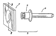
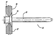
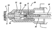
도 1은 리벳 고정 이전에, 본 발명에 따른 블라인드 리벳 조립체의 바람직한 실시예를 나타내는 부분적으로 분해된 사시도이다.
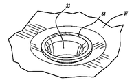
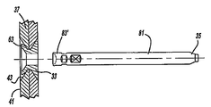
도 2는 리벳 고정 이전에, 블라인드 리벳 조립체의 바람직한 실시예에 사용된 작업물을 나타내는, 도 1의 라인 2-2를 따르는 단면도이다.
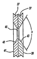
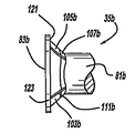
도 3은 리벳 고정 이전에, 블라인드 리벳 조립체의 바람직한 실시예에 사용된 블라인드 리벳 및 맨드릴을 나타내는 측면도이다.
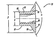
도 4는 리벳 고정 이전에, 블라인드 리벳 조립체의 바람직한 실시예에 사용된 블라인드 리벳을 나타내는 도 1의 라인 2-2를 따르는 단면도이다.
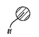
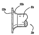
도 5는 리벳 고정 이전에, 블라인드 리벳 조립체의 바람직한 실시예에 사용된 맨드릴을 나타내는 측면도이다.
도 6은 리벳 고정 이전에, 블라인드 리벳 조립체의 바람직한 실시예에 사용되는 맨드릴을 나타내는 도 5의 라인 6-6을 따르는 단면도이다.
도 7은 리벳 고정 이전에, 블라인드 리벳 조립체의 바람직한 실시예에 사용된 맨드릴을 나타내는 도 5의 라인 7-7을 따르는 단면도이다.
도 8은 리벳 고정 이전에, 블라인드 리벳 조립체의 바람직한 실시예에 사용된 맨드릴을 나타내는 부분적인 사시도이다.
도 9는 리벳 고정 이전에, 블라인드 리벳 조립체의 바람직한 실시예에 사용된 맨드릴을 나타내는 부분적인 측면도이다.
도 10은 리벳 고정 이전에, 블라인드 리벳 조립체의 제 1 대안적인 실시예에 사용된 맨드릴을 나타내는 부분적인 측면도이다.
도 11은 리벳 고정 이전에, 블라인드 리벳 조립체의 제 2 대안적인 실시예에 사용된 맨드릴을 나타내는 부분적인 측면도이다.
도 12는 리벳 고정 이전에, 블라인드 리벳 조립체의 제 3 대안적인 실시예에 사용된 맨드릴을 나타내는 부분적인 측면도이다.
도 13은 리벳 고정 이전에, 블라인드 리벳 조립체의 제 4 대안적인 실시예에 사용된 맨드릴을 나타내는 부분적인 측면도이다.
도 14는 리벳 고정 이전에, 블라인드 리벳 조립체의 제 5 대안적인 실시예에 사용된 맨드릴을 나타내는 부분적인 측면도이다.
도 15는 리벳 고정 이전에, 블라인드 리벳 조립체의 제 6 대안적인 실시예에 사용된 맨드릴을 나타내는 부분적인 측면도이다.
도 16은 리벳 고정 이전에, 블라인드 리벳 조립체의 제 7 대안적인 실시예에 사용된 맨드릴을 나타내는 부분적인 측면도이다.
도 17은 리벳 고정 이전에, 블라인드 리벳 조립체의 제 8 대안적인 실시예에 사용된 맨드릴을 나타내는 부분적인 측면도이다.
도 18은 리벳 고정 이전에, 블라인드 리벳 조립체의 제 9 대안적인 실시예에 사용된 맨드릴을 나타내는 부분적인 측면도이다.
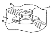
도 19는 리벳 고정 이전에, 작업물을 통해 돌출하는 블라인드 리벳 조립체의 바람직한 실시예를 나타내는 사시도이다.
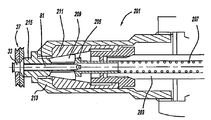
도 20은 리벳 고정 이전에, 고정 툴을 포함하는 블라인드 리벳 조립체의 바람직한 실시예를 나타내는 오 1의 라인 2-2를 따르는 부분 단면도이다.
도 21은 리벳 고정 이전에, 블라인드 리벳 조립체의 바람직한 실시예를 나타내는 도 1의 라인 2-2를 따르는 부분 단면도이다.
도 22는 리벳 고정 이전에, 블라인드 리벳 조립체의 바람직한 실시예를 나타내는, 부분적으로 해체된 측면도이다.
도 23은 리벳 고정 후에, 블라인드 리벳 조립체의 제 1 대안적인 실시예를 나타내는 사시도이다.
도 24는 리벳 고정 후에, 블라인드 리벳 조립체의 바람직한 실시예를 나타내는 블라인드 단부의 평면도이다.
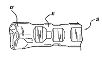
도 25는 리벳 고정 후에, 블라인드 리벳 조립체의 바람직한 실시예에 사용된 맨드릴을 나타내는 사시도이다.
도 26은 리벳 고정 후에, 고정 툴을 포함하는 블라인드 리벳 조립체의 바람직한 실시예를 나타내는 도 1의 라인 2-2를 따르는 단면도이다.
도 27은 리벳 고정 후에, 블라인드 리벳 조립체의 바람직한 실시예를 나타내는 도 1의 라인 2-2를 따르는 부분 단면도이다.
도 28은 리벳 고정 후에, 블라인드 리벳 조립체의 바람직한 실시예를 나타내는 부분적으로 해체된 측면도이다.
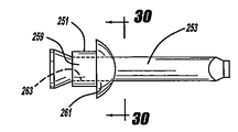
도 29는 리벳 고정 이전에, 블라인드 리벳 조립체의 제 10 대안적인 실시예를 나타내는 측면도이다.
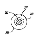
도 30은 리벳 고정 이전에, 리벳 조립체의 제 10 대안적인 실시예를 나타내는 도 29의 라인 30-30을 따르는 단면도이다.
도 31은 리벳 고정 후에, 블라인드 리벳 조립체의 제 10 대안적인 실시예를 나타내는 부분적으로 해체된 측면도이다.
도 32는 리벳 고정 이전에, 리벳 조립체의 제 11 대안적인 실시예를 나타내는 도 29의 라인 30-30을 따르는 단면도이다.1 is a partially exploded perspective view showing a preferred embodiment of the blind rivet assembly according to the invention prior to riveting.
2 is a cross sectional view along line 2-2 of FIG. 1 showing the workpiece used in the preferred embodiment of the blind rivet assembly prior to riveting;
Figure 3 is a side view showing the blind rivets and mandrel used in a preferred embodiment of the blind rivet assembly prior to riveting.
4 is a cross sectional view along line 2-2 of FIG. 1 showing the blind rivet used in the preferred embodiment of the blind rivet assembly prior to riveting.
5 is a side view showing the mandrel used in the preferred embodiment of the blind rivet assembly prior to riveting.
6 is a cross-sectional view along line 6-6 of FIG. 5 showing a mandrel used in a preferred embodiment of the blind rivet assembly prior to riveting.
7 is a cross-sectional view along line 7-7 of FIG. 5 showing the mandrel used in the preferred embodiment of the blind rivet assembly prior to riveting.
8 is a partial perspective view showing the mandrel used in the preferred embodiment of the blind rivet assembly prior to riveting.
9 is a partial side view showing the mandrel used in the preferred embodiment of the blind rivet assembly prior to riveting.
FIG. 10 is a partial side view showing the mandrel used in the first alternative embodiment of the blind rivet assembly prior to riveting.
11 is a partial side view showing a mandrel used in a second alternative embodiment of a blind rivet assembly prior to riveting.
12 is a partial side view showing a mandrel used in a third alternative embodiment of the blind rivet assembly prior to riveting.
13 is a partial side view showing a mandrel used in a fourth alternative embodiment of the blind rivet assembly prior to riveting.
14 is a partial side view showing a mandrel used in a fifth alternative embodiment of the blind rivet assembly prior to riveting.
15 is a partial side view showing a mandrel used in a sixth alternative embodiment of the blind rivet assembly, prior to riveting.
16 is a partial side view showing the mandrel used in the seventh alternative embodiment of the blind rivet assembly, prior to riveting.
17 is a partial side view showing a mandrel used in an eighth alternative embodiment of the blind rivet assembly prior to riveting.
18 is a partial side view showing a mandrel used in a ninth alternative embodiment of the blind rivet assembly, prior to riveting.
19 is a perspective view of a preferred embodiment of a blind rivet assembly projecting through a workpiece prior to rivet fixation.
20 is a partial cross sectional view along line 2-2 of Oh 1 showing a preferred embodiment of a blind rivet assembly including a securing tool prior to riveting.
21 is a partial cross-sectional view along line 2-2 of FIG. 1 showing a preferred embodiment of the blind rivet assembly prior to riveting.
22 is a partially disassembled side view showing a preferred embodiment of the blind rivet assembly prior to riveting.
23 is a perspective view showing a first alternative embodiment of the blind rivet assembly after riveting.
24 is a plan view of the blind end showing a preferred embodiment of the blind rivet assembly after riveting.
25 is a perspective view showing the mandrel used in the preferred embodiment of the blind rivet assembly after riveting.
FIG. 26 is a cross sectional view along line 2-2 of FIG. 1 showing a preferred embodiment of a blind rivet assembly including a securing tool after riveting.
27 is a partial cross sectional view along line 2-2 of FIG. 1 showing a preferred embodiment of the blind rivet assembly after riveting.
28 is a partially disassembled side view showing a preferred embodiment of the blind rivet assembly after riveting.
29 is a side view showing a tenth alternative embodiment of the blind rivet assembly prior to riveting.
30 is a cross sectional view along line 30-30 of FIG. 29 showing a tenth alternative embodiment of the rivet assembly prior to riveting;
Figure 31 is a partially disassembled side view showing a tenth alternative embodiment of the blind rivet assembly after riveting.
32 is a cross sectional view along line 30-30 of FIG. 29 showing an eleventh alternative embodiment of the rivet assembly prior to riveting;
본 발명의 블라인드 리벳 조립체(31)의 바람직한 실시예가 도 1 내지 도 3에 도시된다. 블라인드 리벳 조립체(31)는 블라인드 리벳(33), 맨드릴(35) 및 작업물(37)을 포함한다. 바람직하게는, 작업물(37)은 구성요소 패널들, 박스들, 캐비넷들 또는 전기 컴퓨터의 하우징들, 전기 서버 또는 다른 그러한 장치들이다. 작업물(37)은 내부에 작업물 접점에 위치된 원통형 구멍들(45)에 의해서 연결된 납작한 오목부(43)가 있는 툴측 외측 표면(39) 및 반대 블라인드측 외측 표면(41)을 포함한다. 각각의 원추형 홈(43)은 120°및 90°와 동일하거나 120°와 90° 사이의, 그리고 더욱 바람직하게는, 110°와 90° 사이의 전체 각 α를 가진 일반적으로 원뿔대-원뿔형(frusto-conical) 형상을 구비한다.A preferred embodiment of the
도 3 및 4는 블라인드 리벳(33)을 가장 잘 도시한다. 블라인드 리벳(33)은 몸체(51) 및 툴측 플랜지(53)를 포함한다. 원뿔대-원뿔형 외측 표면(55)은 플랜지(53)의 외측을 따라서 테이퍼지고, 몸체(51)의 외측 표면(57)은 원통형 형상을 구비한다. 관통 보어(through bore)(59)는 블라인드 리벳(33)의 툴 단면(61)과 블라인드 단부 또는 말단부(63) 사이로 연장한다. 관통 보어(59)는 리벳 고정 이전에, 단부들(61, 63) 사이에 일반적으로 일정한 내측 지름을 구비한다. 플랜지(53)의 외측 지름 β는 5.0㎜ 및 5.4㎜와 동일하거나 5.0㎜와 5.4㎜ 사이의 바람직한 치수를 구비하며, 동시에, 리벳 몸체(51)의 외측 지름 φ는 3.08㎜ 및 2.9㎜와 동일하거나 3.08㎜와 2.9㎜ 사이의 치수를 구비한다.3 and 4 best show the
도 5 내지 도 9를 참조하면, 맨드릴(35)의 바람직한 실시예는 축방향으로 연장된 스템(81) 및 측면으로 확장된 헤드(83)를 포함한다. 스템(81)은 대게 원통형이나, 운송 및 툴 제공 동안에 맨드릴에 리벳을 고정하도록 돕는 다양한 오목부들(85) 및 인접한 돌출부들(87)에 의해서 국부적으로 차단된다. 테이퍼진 단부(89) 및 연장부(91)는 고정 툴과 정렬하는 것을 돕기 위해서 헤드(83) 반대쪽의 스템(81)의 단부에 위치된다.5-9, the preferred embodiment of the
헤드(83)는 일반적으로 평평한 블라인드 또는 말단(tail end)(101), 및 숄더(103)을 포함한다. 현재 바람직한 실시예에 따른 숄더(103)는 한 쌍의 서로 다른 각으로 기울어지고 일직선으로 테이퍼진 표면들(105, 107)에 의해서 한정된다. 테이퍼진 표면들(105, 107)은 서로 그리고 스템(81)과 동축을 가진다. 네 개의 리브들(111)이 숄더(103) 상에 위치되고, 숄더(103) 둘레에 등거리로 있다. 리브들(111)은 대게 축방향으로 정렬된 방향으로 연장되나, 기본적으로 숄더(103)와 같은 각으로 오프셋 된다. 리벳 고정 이전에, 맨드릴 헤드(83)의 외측 지름 Ω은 3.5㎜ 및 2.9㎜와 동일하거나 3.5㎜와 2.9㎜ 사이로 되는 것이 바람직하고, 전체 맨드릴 숄더의 소정의 각 Ψ는 110° 및 90°와 동일하거나 110°와 90° 사이로 되는 것이 바람직하다. 또한, 숄더를 포함하지 않는 립(lip)에서, 맨드릴 헤드(83)의 축방향 두께는 리벳 고정 전에 1.0㎜ 및 0.35㎜와 동일하거나 1.0㎜와 0.35㎜ 사이로 되는 것이 바람직하다. 맨드릴 헤드(83)의 외측 지름 Ω은 적절한 구멍 메움(hole filling)과 축 방향 고정 압축을 달성하기 위해 리벳 몸체(51)의 외측 지름 φ보다 크다. 또한, 블라인드 리벳(33) 및 맨드릴(33)은 SAE1066 등급의 스틸(grade SAE1066 steel)로 이루어지는 것이 바람직하다.
도 10은 바람직한 실시예와 같은 대안적인 실시예의 맨드릴(35a)을 도시한다. 그러나, 숄더(103a)는 일직선으로 테이퍼진 원뿔대-원뿔형 표면들(105a, 107a)를 포함하나, 리브들이 없다. 또 다른 대안적인 실시예의 맨드릴(35b)은 도 11에 도시된다. 맨드릴(35b)은 도 9의 표면들과 같은 일직선으로 테이퍼진 원뿔대-원뿔형 표면들(105b, 107b) 및 도 9의 리브들과 같은 리브들(111b)을 포함하는 숄더(103b)를 구비한다. 그럼에도 불구하고, 숄더(103b)의 가장 바깥쪽 부분과 헤드(83b)의 립(123) 사이에 안쪽을 향한 간격 또는 단(段)(121)이 있고, 그것에 의해서 돌출부를 야기한다.Figure 10 shows an
또 다른 실시예의 맨드릴(35c)이 도 12에 도시된다. 숄더(103c)는 립(123c)의 단이진 간격(stepped spacing)(121c) 이외에 단일의 각으로 기울어진 원뿔대-원뿔형 테이퍼를 구비한다. 어떤 리브들도 이러한 전형적인 실시예에서 사용되지 않는다. 이제, 도 13을 참조하면, 대안적인 실시예의 맨드릴(35d)은 숄더(103d)에서 아치모양으로 만곡된 테이퍼, 리브들(111d) 및 안쪽으로 항해 단이진 립(123d)을 제공한다. 대안적인 실시예의 도 14는 아치모양으로 테이퍼진 숄더(103e)를 구비하나, 리브들은 구비하지 않으며, 립(123f)에 대해서 안쪽으로 향한 숄더 간격을 가진다. 도 15는 리브들(111f)과 결합한 아치모양으로 테이퍼진 숄더(103f)를 사용하나, 립(123f)에 대해서 숄더(103f)의 안쪽으로 향한 간격도 없다. 도 16에서 볼 수 있는 바와 같이, 또 다른 대안적인 실시예의 맨드릴(35g)은 아치모양으로 테이퍼진 숄더(103g)를 포함하나 리브들이 없고, 립(123g)에 대해 안쪽으로 향한 숄더 간격이 없다.Another
이제, 도 17을 참조하면, 대안적인 실시예의 맨드릴(35h)은 소정의 말단(101h) 아래로 눌려진 오모한 만곡된 표면(131)을 포함한다. 이것은 리벳 고정 동안에 측면의 압축과 헤드(83h)의 끼우기를 조장한다. 도 18은 리벳 고정 동안 헤드(83i)의 끼워진 특징들을 바꾸기 위해서 말단(101i)으로부터 바깥쪽으로 만곡한 볼록한 표면(133)을 가진 맨드릴(35i)을 대안적으로 도시한다.Referring now to FIG. 17, the
이제, 참조는 리벳 고정 절차들과 구조가 설명될 도 19 내지 도 22로 이루어져야 한다. 리벳 고정 툴(201)은 피스톤 로드(203), 조 푸셔(jaw pusher)(205), 푸셔(205)를 바깥쪽으로 편향하는 압축 스프링(207), 조들(jaws)(209)의 한 세트, 조 케이스(211), 외측 배럴(213) 및 노우즈 피스(nose piece)(215)를 포함한다. 맨드릴(35) 및 리벳(33)은 세팅 툴(210) 내의 삽입 이전에 불룩한 부분(bulge)(87)(도 5 참조) 때문에 억지끼워맞춤(interference fit)을 포함하여 미리 조립된다. 그 후에, 맨드릴(35)의 스템(81)이 노우즈 피스(215) 내로 삽입되고, 조들(209)에 의해서 일시적으로 보유된다.Reference should now be made to FIGS. 19-22 where the rivet fastening procedures and structure will be described. The
다음에, 리벳 툴이 작업물(37) 근처에 위치되어서, 블라인드 리벳의 블라인드 단부와 맨드릴은 작업물(37)의 일치하는 구멍을 통하여 삽입되어서, 툴측 플랜지(53)는 인접한 원추형 홈(43) 내에 완전히 끼워지고, 블라인드 리벳(33)의 툴 단부는 대게 플러시이거나 툴측 작업물의 플러시 외측 표면(39) 아래에 있다. 리벳 고정 전에, 리벳 몸체의 외측 표면과 작업물 구멍의 내측 지름 사이에 약간의 틈이 있는 것은 주목할만하다.Next, the rivet tool is positioned near the
도 20의 프리 리벳 고정 조건과 도 26의 포스트 리벳 고정 조건을 비교하면, 맨드릴의 스템은 고정 툴(201)의 조들 사이에 죄어지고 리벳 플랜지는 노우즈 피스에 접한다. 툴이 작동될 때, 피스톤 로드는 조 케이스의 작동에 기인하여 조들을 안쪽으로 밀어내는 피스톤 작동기에 의해서 뒤로 끌려지게 된다. 대략 1,500 뉴턴(newton)의 힘이 리벳을 통하여 맨드릴을 당기기 위해서 세팅 도구에 의해서 사용되고, 이것은 깨지기 쉬운 핸드타입(hand-type) 맨드릴들을 위해 필요한 것보다 대략 500 뉴턴 더 작다. 맨드릴 헤드가 리벳 몸체 내로 당겨지면, 헤드는 접히며, 맨드릴 헤드를 분리하지 않고 블라인드 리벳을 통하여 완전히 당겨진다. 이 단계에서, 피스톤에 공급되는 전원은 중단되고, 피스톤은 조들을 여는 준비 상태로 돌아가며, 그 후에, 사용된 맨드릴은 고정 툴의 뒤쪽에서 맨드릴 수집 병 내로 진공 추출되고 버려진다. 그 뒤에, 툴은 다음 리벳 고정 작업을 위해 준비한다.Comparing the free rivet fixation condition of FIG. 20 with the post rivet fixation condition of FIG. 26, the stem of the mandrel is clamped between the jaws of the
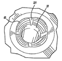
도 24, 25, 27 및 28을 참조하면, 블라인드 리벳 조립체의 바람직한 실시예는 세트이고 완전히 설치된 상태로 도시된다. 맨드릴 헤드(83) 및 특히 바깥으로 테이퍼진 숄더(103)(도 8 및 도 21 참조)는 블라인드측 작업물(37)의 인접한 원추형 홈 내로 블라인드 리벳(33)의 블라인드 단부(63)를 바깥으로 팽창시킨다. 맨드릴 헤드(83)의 풀링 스루(pulling through)는 리벳 몸체를 측면으로 팽창하도록 하고, 억지끼워맞춤 수단 내의 작업물(37)의 구멍(45)(도 2 참조)을 가득 채우며, 동시에, 맨드릴 헤드는 접혀서 83'와 같이 온전하게 남아있고 리벳으로부터 추출된다. 리벳 몸체의 블라인드 단부의 바깥쪽으로 팽창된 컵과 같은 형상인 원추형 홈들 및 리벳 플랜지의 원뿔대-원뿔형 형상들 및 여기에 특정된 바람직한 치수의 관계들(dimensional relationships)은 바람직한 축 방향의 압축과 블라인드 리벳(33)의 단축을 야기한다. 블라인드 리벳(33)의 블라인드 단부(63)는 리벳 고정에 의해서 생긴 팽창된 컵과 같은 형상인 관통 보어(59)를 가지는 리벳 고정 후에, 일치하는 작업물(37)의 블라인드 표면(41)의 (도시된 것과 같은) 플러시 또는 플러시 아래에 위치된다.24, 25, 27 and 28, the preferred embodiment of the blind rivet assembly is shown in a set and fully installed state. The
또한, 리브들(111)(도 8 참조)은 리벳 몸체(33)의 어떠한 상당한 절단 없이, 리벳(33)의 팽창된 말단(63) 내로 축 방향으로 연장된 그루브들(221)을 파내고 만입(灣入)한다. 이 리브들은 토끼풀(shamrock) 같은 패턴을 형성하는 것과 같이 그루브들(221) 사이에 블라인드 단부(63)를 더욱 부풀리고 펼친다. 이것은 또한 블라인드 리벳(33)에 대하여 맨드릴(81)의 풀 스루(pull through)를 완성하는 동안에, 측면 압축 이전에 리벳 몸체의 홈이 파인 영역들에 더욱 집중된 압축 지점들 및 리브들(111), 숄더(103) 및 립(123)(도 8 참조)의 꽉 찬 상태를 만든다. 또한, 리브 및 숄더의 형태는 고정 동안에, 리벳의 블라인드 단부(63)의 얇은 영역들을 펴진다. 측면으로 접히고 축 방향으로 연장된 헤드 변형을 나타내는 맨드릴(81)의 리벳 고정 후 형태는 도 25에서 나타난다.Also, the ribs 111 (see FIG. 8) dig and
도 23은 도 10에 도시된 대안적인 맨드릴(35a)을 사용하는 리벳(33)의 블라인드 단부(63)의 맞춤 상태를 나타낸다. 본 실시예는 어떤 리브로 만들어진 그루브들(rib-created grooves)도 없고 어떤 토끼풀 패턴이 만들어지지도 않는 것을 제외하고, 도 27 및 28의 실시예와 그외에는 유사하다.FIG. 23 shows the fit of the
도 29 내지 31을 참조하면, 본 발명의 블라인드 리벳 조립체(251)의 다른 대안적인 실시예는 맨드릴(253), 블라인드 리벳(255) 및 작업물(257)을 사용한다. 맨드릴(253)은 선택적인 리브들을 가진 테이퍼진 숄더를 가지는 것을 포함하는 위에 미리 개시된 맨드릴 실시예들 중 어떤 것과도 같다. 그러나, 블라인드 리벳(251)은 원통형 몸체(259) 및 아치형으로 반구형이 되거나 팬 헤드 타입(pan-head type)인 툴측 플랜지(261)를 구비한다. 일정하게 규격화된 관통 보어(263)는 전체 블라인드 리벳(251)을 통하여 연장한다. 블라인드 리벳(251) 및 맨드릴(253)은 알루미늄으로 이루어지거나 스틸로 이루어질 수 있다. 또한, 작업물(257)은 항공기 패널들이거나 대안적으로 다른 구성요소들이 될 수 있다. 리벳 고정 동안에, 고정 툴이 리벳(251)을 통하여 맨드릴(253)을 완전히 당겨서, 리벳 몸체(259)의 블라인드 단부는 컵과 같은 형상으로 바깥쪽으로 변형되나, 축 방향으로 절단되지 않는다. 맨드릴(253)의 헤드는 접히나, 미리 개시된 맨드릴 실시예들과 같이 스템으로부터 깨지지 않는다.29 to 31, another alternative embodiment of the
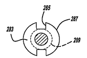
도 32는 또 다른 블라인드 리벳 조립체의 실시예를 도시한다. 본 블라인드 리벳 조립체(281)는 위에 미리 개시된 맨드릴 중 어느 것과도 같은 맨드릴을 포함한다. 블라인드 리벳(283)은 한 쌍의 반대측 슬롯들(285)이 툴측 플랜지(289)의 외주(287)로부터 반경 방향으로 안쪽으로 연장하는 것을 제외하고 도 29에 도시된 것과 같다. 플랜지(289)는 도 29의 플랜지와 같이 리벳 몸체 근처의 하측에 평평한 면을 가지고 그외에는 아치형으로 반구형이 된다.32 illustrates an embodiment of another blind rivet assembly. The blind rivet assembly 281 includes a mandrel such as any of the mandrel previously disclosed above. The
고정된 블라인드 리벳(283)은 항공 작업물을 함께 일시적으로 고정하기 위해 사용되고 그 후에 뚫려지거나 그렇지 않으면 작업물로부터 제거된다. 슬롯들(285)은 리벳으로부터 돌돌 감겨서 뚫린 잔해(curling drilled debris)를 줄이도록 도우며, 슬롯들이 없으면, 리벳의 제거를 방해하거나 구성요소를 바람직하지 못하게 오염시킨다. 도 29 내지 32의 실시예들의 모두에 대하여, 풀 스루 및 절단되지 않은 맨드릴은 죄어진 구성요소들 또는 공장으로부터 종래의 절단된 맨드릴 헤드들을 찾기 위한 필요를 유리하게 방지한다. 그럼에도 불구하고, 도 29 내지 32의 실시예에 따른 블라인드 리벳은 본 발명의 플러시 스타일(flush-style) 실시예들의 많은 바람직한 이점들을 달성하지 않는 것으로 인식되어야 한다.A fixed
본발명의 블라인드 리벳 조립체의 다양한 실시예들이 개시되었지만, 다른 형태들이 사용될 수 있다는 것으로 인식되어야 한다. 예를 들어, 비록 본 발명의 다양한 이점들이 실현되지 않을지라도, 더 많은 또는 더 적은 리브들이 제공될 수 있다. 또한, 여기 개시된 어떤 맨드릴의 형태들도 혼합하여 만들어지거나, 비록 본 발명의 다양한 이점들이 달성되지 않을지라도, 리벳으로 고정된 바람직한 조인트의 구체적인 특징들에 의해서 결정되는 다른 것들과 조화될 수 있다. 또한, 비록 본 발명의 다양한 이점들이 달성되지 않을지라도, 대안적인 맨드릴 스템 오목부들 및 형상들이 사용될 수 있다. 구체적인 치수 관계들이 선호되지만, 많은 이점들이 달성되지 않을 수 있는 다른 치수들이 사용될 수 있는 것으로 인식되어야 한다. 이하의 청구항들이 이것들 및 본 발명의 진정한 정신에 포함되는 개시된 실시예들로부터의 어떤 다른 변경을 포함하는 것으로 의도된다.While various embodiments of the blind rivet assembly of the present invention have been disclosed, it should be appreciated that other forms may be used. For example, more or fewer ribs may be provided, although various benefits of the present invention may not be realized. In addition, any of the forms of the mandrel disclosed herein may be made in combination, or may be coordinated with others determined by the specific features of the preferred joint fixed with rivets, although various advantages of the present invention may not be achieved. In addition, alternative mandrel stem recesses and shapes may be used, although various advantages of the present invention may not be achieved. Although specific dimensional relationships are preferred, it should be appreciated that other dimensions may be used where many advantages may not be achieved. The following claims are intended to cover these and any other modifications from the disclosed embodiments that fall within the true spirit of the invention.
Claims (44)
몸체 및 툴측 플랜지를 포함하고, 몸체는 리벳 고정 이전에 플랜지로부터 블라인드 단부까지 원통형 외측 표면을 포함하며, 플랜지의 표면은 몸체의 외측 표면으로부터 바깥쪽으로 테이퍼진 블라인드 리벳; 및
연장된 스템 및 헤드를 포함하고, 스템은 고정 이전에 리벳을 통하여 연장하며, 헤드는 리벳 고정 이전에 스템보다 측면으로 더 크고, 바깥쪽으로 테이퍼진 숄더가 스템에 인접한 헤드에 위치되는 맨드릴을 포함하고,
헤드는 맨드릴의 스템으로부터 헤드를 절단하지 않고 리벳 고정 동안에 리벳을 통하여 완전히 당겨지며, 맨드릴은 블라인드 리벳을 고정한 후에 버려지고,
고정 동안에 헤드의 풀링 스루(pulling through)는 리벳 몸체의 블라인드 단부를 인접한 원추형 홈 내로 바깥쪽으로 팽창시키며,
리벳의 플랜지는 리벳 고정 후에 인접한 원추형 홈 내에 위치되는 리벳 조립체.At least one workpiece having a second outer surface opposite the first outer surface, the conical groove located on each outer surface connected by a hole;
A body and a tool side flange, the body comprising a cylindrical outer surface from the flange to the blind end prior to riveting, the surface of the flange tapered outwardly from the outer surface of the body; And
An extended stem and head, wherein the stem extends through the rivet prior to fixation, the head is laterally larger than the stem prior to rivet fixation, and includes a mandrel with an outwardly tapered shoulder positioned at the head adjacent to the stem; ,
The head is pulled completely through the rivet during rivet fastening without cutting the head from the stem of the mandrel, the mandrel is discarded after fixing the blind rivet,
During fastening, the pulling through of the head expands the blind end of the rivet body outward into the adjacent conical groove,
The rivet flange is located in an adjacent conical groove after rivet fastening.
맨드릴의 숄더로부터 돌출하는 적어도 하나의 리브를 더 포함하는 리벳 조립체.The method of claim 1,
And at least one rib protruding from the shoulder of the mandrel.
적어도 하나의 리브는 스템의 연장 방향과 대체로 일치하는 방향으로 연장된 적어도 두 개의 리브들을 포함하고, 리벳 몸체는 리벳 고정 동안에 리브들이 블라인드 리벳을 통해 지나간 후에 절단되지 않는 리벳 조립체.The method of claim 2,
At least one rib comprises at least two ribs extending in a direction substantially coincident with the direction of extension of the stem, wherein the rivet body is not cut after the ribs have passed through the blind rivet during riveting.
리벳 고정 동안에 리브는 적어도 블라인드 단부에 인접한 리벳 몸체의 보어 내에 오목한 그루브들을 만드는 리벳 조립체.The method of claim 2,
The rivet assembly during rib riveting makes the recesses at least in the bore of the rivet body adjacent to the blind end.
적어도 하나의 작업물은 한 쌍의 전기 장치 구성요소들을 포함하는 리벳 조립체.The method of claim 1,
At least one workpiece includes a pair of electrical device components.
전기 장치 구성요소들 중 적어도 하나는 컴퓨터 하우징을 포함하는 리벳 조립체.The method of claim 5,
At least one of the electrical device components comprises a computer housing.
맨드릴의 숄더는 테이퍼진 형상인 원뿔대-원뿔형을 구비하는 리벳 조립체.The method of claim 1,
The shoulder of the mandrel is a rivet assembly having a truncated cone-conical shape that is tapered in shape.
맨드릴의 숄더는 두 개의 다르게 굽어진 원뿔대-원뿔형인 테이퍼진 표면들을 포함하는 리벳 조립체.The method of claim 1,
The shoulder of the mandrel is a rivet assembly comprising two differently curved truncated-conical tapered surfaces.
맨드릴의 숄더는 맨드릴의 측면에서 볼 때, 테이퍼진 형상의 만곡부를 구비하는 리벳 조립체.The method of claim 1,
The shoulder of the mandrel has a tapered shape of the rivet assembly when viewed from the side of the mandrel.
스템 반대쪽의 맨드릴 헤드의 단부는 오목한 표면을 더 포함하는 리벳 조립체.The method of claim 1,
The end of the mandrel head opposite the stem further comprises a concave surface.
스템 반대쪽의 맨드릴 헤드의 단부는 볼록한 표면을 더 포함하는 리벳 조립체.The method of claim 1,
The end of the mandrel head opposite the stem further comprises a convex surface.
리벳 고정 동안에 맨드릴의 헤드는 안쪽으로 변형되는 리벳 조립체.The method of claim 1,
The rivet assembly wherein the head of the mandrel is deformed inward during rivet fastening.
리벳 고정 전에 리벳 및 맨드릴의 관계는,
맨드릴 헤드의 외측 지름이 3.5㎜ 및 2.9㎜와 동일하거나 3.5㎜와 2.9㎜ 사이에 있고, 리벳 몸체의 블라인드 단부의 외측 지름은 3.08㎜ 및 2.9㎜와 동일하거나 3.08㎜와 2.9㎜ 사이에 있는 리벳 조립체. The method of claim 1,
The relationship between the rivet and the mandrel before riveting is fixed,
Rivet assembly with outer diameter of mandrel head equal to 3.5 mm and 2.9 mm or between 3.5 mm and 2.9 mm and outer diameter of the blind end of the rivet body equal to 3.08 mm and 2.9 mm or between 3.08 mm and 2.9 mm .
숄더를 제외한 맨드릴 헤드의 축방향 두께는 리벳 고정 전에 1.0㎜ 및 0.35㎜와 동일하거나 1.0㎜와 0.35㎜ 사이에 있고, 맨드릴 숄더의 공칭 각은 리벳 고정 전에 숄더의 일측으로부터 타측까지 측정된 것과 같이 110° 및 90°와 동일하거나 110°와 90° 사이에 있는 리벳 조립체.The method of claim 1,
The axial thickness of the mandrel head, excluding the shoulder, is equal to or between 1.0 mm and 0.35 mm before riveting, and the nominal angle of the mandrel shoulder is 110 as measured from one side of the shoulder to the other before riveting. Rivet assembly equal to or between 110 ° and 90 °.
작업물의 단일측으로부터 작업물에 블라인드 리벳을 작동 가능하게 고정하는 고정 툴을 더 포함하고, 고정 툴은 맨드릴 스템을 작동 가능하게 당기는 적어도 하나의 조 및 툴측 플랜지에 대해서 작동 가능하게 접하는 노우즈 피스를 포함하며, 툴의 피스톤은 리벳을 통하여 맨드릴이 작동 가능하게 당겨지도록 하고, 블라인드 리벳은 맨드릴이 툴 내로 삽입되기 전에 억지끼워맞춤(interference fit)을 통하여 맨드릴에 부착되는 리벳 조립체.The method of claim 1,
And further comprising a securing tool for operatively securing the blind rivet to the workpiece from a single side of the workpiece, the securing tool comprising a nose piece operatively abutting against at least one jaw and the tool side flange for operatively pulling the mandrel stem. Wherein the piston of the tool causes the mandrel to be operatively pulled through the rivet, and the blind rivet is attached to the mandrel through an interference fit before the mandrel is inserted into the tool.
대체로 원뿔대-원뿔형 오목부를 포함하는 적어도 제 2 작업물;
툴 단부 및 맞은편의 블라인드 단부를 포함하고, 관통 보어를 포함하는 블라인드 리벳; 및
적어도 리벳 고정 이전에 리벳의 관통 보어 내에 위치되는 스템, 스템으로부터 블라인드 단부까지 측면으로 확장하는 숄더를 포함하는 맨드릴 헤드 및 적어도 리벳 고정 이전에 맨드릴 숄더로부터 돌출하는 적어도 하나의 리브를 포함하는 맨드릴을 포함하고,
맨드릴 헤드는 리벳 고정 동안에 인접한 오목부 내로 리벳의 블라인드 단부를 바깥쪽으로 팽창시키고,
툴 단부에 인접한 리벳 부분은 적어도 리벳 고정 후에 인접한 오목부 내에 위치된 대체로 원뿔대-원뿔형 표면을 구비하는 리벳 조립체.A first workpiece comprising a generally frusto-conical recess;
At least a second workpiece comprising a generally frusto-conical recess;
A blind rivet comprising a tool end and an opposite blind end, the blind rivet comprising a through bore; And
A mandrel comprising a stem positioned at least in the through bore of the rivet prior to riveting, a mandrel head comprising a shoulder extending laterally from the stem to the blind end and at least one rib protruding from the mandrel shoulder at least prior to riveting and,
The mandrel head inflates the blind end of the rivet outward into the adjacent recess during riveting,
The rivet portion adjacent the tool end has a generally frusto-conical surface located in an adjacent recess at least after riveting.
맨드릴의 헤드는 리벳 고정 동안에 맨드릴의 스템으로부터 헤드를 절단하지 않고 리벳을 통하여 완전히 당겨지는 리벳 조립체.The method of claim 16,
Rivet assembly wherein the head of the mandrel is pulled completely through the rivet without cutting the head from the stem of the mandrel during riveting.
적어도 하나의 리브는 스템의 연장 방향과 대체로 일치하는 방향으로 연장되는 적어도 두 개의 리브들을 포함하고, 리벳 몸체는 리벳 고정 동안에 리브들이 블라인드 리벳을 통하여 지나간 후에 절단되지 않는 리벳 조립체.The method of claim 16,
The at least one rib includes at least two ribs extending in a direction substantially coincident with the direction of extension of the stem, wherein the rivet body is not cut after the ribs have passed through the blind rivet during riveting.
리브는 리벳 고정 동안에 리벳에 오목한 그루브를 만드는 리벳 조립체.The method of claim 16,
The rib is a rivet assembly that makes a recess in the rivet during riveting.
맨드릴의 숄더는 원뿔대-원뿔형인 테이퍼진 형상을 구비하는 리벳 조립체.The method of claim 16,
The shoulder of the mandrel has a tapered shape that is truncated-conical.
맨드릴의 숄더는 두 개의 다르게 굽어진 원뿔대-원뿔형인 테이퍼진 표면들을 포함하는 리벳 조립체.The method of claim 16,
The shoulder of the mandrel is a rivet assembly comprising two differently curved truncated-conical tapered surfaces.
맨드릴의 숄더는 맨드릴의 측면에서 볼 때, 테이퍼진 형상의 만곡부를 구비하는 리벳 조립체.The method of claim 16,
The shoulder of the mandrel has a tapered shape of the rivet assembly when viewed from the side of the mandrel.
리벳 고정 후가 아닌 리벳 고정 전에 리벳의 외측 지름과 작업물의 오목부들을 연결하는 가장 좁은 구멍 부분들 사이에 측면 틈이 있는 리벳 조립체.The method of claim 16,
A rivet assembly with a side gap between the outer diameter of the rivet and the narrowest hole portions connecting the recesses of the workpiece, but not after riveting.
스템 반대쪽의 맨드릴 헤드의 단부는 오목한 표면을 포함하는 리벳 조립체.The method of claim 16,
An end of the mandrel head opposite the stem includes a concave surface.
스템 반대쪽의 맨드릴 헤드의 단부는 볼록한 표면을 포함하는 리벳 조립체.The method of claim 16,
An end of the mandrel head opposite the stem includes a convex surface.
맨드릴의 헤드는 리벳 고정 동안에 안쪽으로 변형되는 리벳 조립체.The method of claim 16,
The head of the mandrel is a rivet assembly that is deformed inward during riveting.
리벳 및 맨드릴의 관계는,
맨드릴 헤드의 외측 지름이 3.5㎜ 및 2.9㎜와 동일하거나 3.5㎜와 2.9㎜ 사이에 있고, 리벳의 블라인드 단부의 외측 지름은 3.08㎜ 및 2.9㎜와 동일하거나 3.08㎜와 2.9㎜ 사이에 있는 리벳 조립체.The method of claim 16,
The relationship between rivets and mandrel,
A rivet assembly in which the outer diameter of the mandrel head is equal to 3.5 mm and 2.9 mm or between 3.5 mm and 2.9 mm and the outer diameter of the blind ends of the rivet is equal to 3.08 mm and 2.9 mm or between 3.08 mm and 2.9 mm.
상기 숄더를 제외한 맨드릴 헤드의 축 방향 두께는 리벳 고정 전에 1.0㎜ 및 0.35㎜와 동일하거나 1.0㎜와 0.35㎜ 사이에 있고, 맨드릴 숄더의 공칭 각은 리벳 고정 전에 숄더의 일측으로부터 타측까지 측정되며, 110° 및 90°와 동일하거나 110°와 90° 사이에 있는 리벳 조립체.The method of claim 16,
The axial thickness of the mandrel head excluding the shoulder is equal to or between 1.0 mm and 0.35 mm before rivet fixation, and the nominal angle of the mandrel shoulder is measured from one side to the other side of the shoulder before rivet fixation. Rivet assembly equal to or between 110 ° and 90 °.
대체로 원뿔대-원뿔형 오목부를 포함하는 적어도 제 2 작업물;
툴 단부 및 맞은편 블라인드 단부를 포함하고, 관통 보어를 포함하는 블라인드 리벳; 및
적어도 리벳 고정 이전에 리벳의 관통 보어 내에 위치되는 스템, 스템으로부터 블라인드 단부까지 측면으로 확장하는 숄더를 포함하는 헤드를 포함하는 맨드릴을 포함하고,
맨드릴 헤드는 리벳 고정 동안에 인접한 오목부 내로 리벳의 블라인드 단부를 바깥쪽으로 팽창시키고,
상기 맨드릴의 헤드는 리벳 고정 동안에 맨드릴의 스템으로부터 헤드를 절단하지 않고 리벳을 통하여 완전히 당겨지며,
리벳의 툴 단부 및 블라인드 단부는 작업물의 툴 표면 및 블라인드 표면의 플러시 또는 플러시 아래에 있고,
맨드릴의 헤드는 리벳 고정 동안에 변형되고, 축소한 측면의 단면적을 구비하는 리벳 조립체.A first workpiece comprising a generally frusto-conical recess;
At least a second workpiece comprising a generally frusto-conical recess;
A blind rivet comprising a tool end and an opposite blind end, the blind rivet comprising a through bore; And
A mandrel comprising a stem positioned at least in the through bore of the rivet prior to riveting, a head including a shoulder extending laterally from the stem to the blind end,
The mandrel head inflates the blind end of the rivet outward into the adjacent recess during riveting,
The head of the mandrel is pulled completely through the rivet without cutting the head from the stem of the mandrel during riveting,
The tool end and the blind end of the rivet are under the flush or flush of the tool surface and the blind surface of the workpiece,
The head of the mandrel is deformed during rivet fastening and has a reduced cross-sectional area of the side.
맨드릴 숄더로부터 돌출하는 적어도 하나의 리브를 더 포함하는 리벳 조립체.The method of claim 29,
And at least one rib protruding from the mandrel shoulder.
적어도 하나의 리브는 스템의 연장 방향과 대체로 일치하는 방향으로 연장된 적어도 두 개의 리브들을 포함하고, 리벳 몸체는 리벳 고정 동안에 리브들이 블라인드 리벳을 통하여 지나간 후에 절단되지 않는 리벳 조립체.The method of claim 30,
At least one rib comprises at least two ribs extending in a direction substantially coincident with the direction of extension of the stem, wherein the rivet body is not cut after the ribs have passed through the blind rivet during riveting.
맨드릴의 숄더는 원뿔대-원뿔형인 테이퍼진 형상을 구비하는 리벳 조립체.The method of claim 29,
The shoulder of the mandrel has a tapered shape that is truncated-conical.
맨드릴의 숄더는 두 개의 다르게 굽어진 원뿔대-원뿔형인 테이퍼진 표면들을 포함하는 리벳 조립체.The method of claim 29,
The shoulder of the mandrel is a rivet assembly comprising two differently curved truncated-conical tapered surfaces.
맨드릴의 숄더는 맨드릴의 측면에서 볼 때, 테이퍼진 형상의 만곡부를 구비하는 리벳 조립체.The method of claim 29,
The shoulder of the mandrel has a tapered shape of the rivet assembly when viewed from the side of the mandrel.
스템 반대쪽의 맨드릴 헤드의 단부는 오목한 표면을 포함하는 리벳 조립체.The method of claim 29,
An end of the mandrel head opposite the stem includes a concave surface.
스템 반대쪽의 맨드릴 헤드의 단부는 볼록한 표면을 포함하는 리벳 조립체.The method of claim 29,
An end of the mandrel head opposite the stem includes a convex surface.
리멧 및 맨드릴의 관계는,
맨드릴 헤드의 외측 지름이 3.5㎜ 및 2.9㎜와 동일하거나 3.5㎜와 2.9㎜ 사이에 있고, 리벳의 블라인드 단부의 외측 지름은 3.08㎜ 및 2.9㎜와 동일하거나 3.08㎜와 2.9㎜ 사이에 있는 리벳 조립체.The method of claim 29,
The relationship between the remets and the mandrel,
A rivet assembly in which the outer diameter of the mandrel head is equal to 3.5 mm and 2.9 mm or between 3.5 mm and 2.9 mm and the outer diameter of the blind ends of the rivet is equal to 3.08 mm and 2.9 mm or between 3.08 mm and 2.9 mm.
상기 숄더를 제외한 맨드릴 헤드의 축 방향 두께는 리벳 고정 전에 1.0㎜ 및 0.35㎜와 동일하거나 1.0㎜와 0.35㎜ 사이에 있고, 맨드릴 숄더의 명목상의 각은 리벳 고정 전에 숄더의 일측으로부터 타측까지 측정되며, 110° 및 90°와 동일하거나 110°와 90° 사이에 있는 리벳 조립체.The method of claim 29,
The axial thickness of the mandrel head excluding the shoulder is equal to or between 1.0 mm and 0.35 mm before rivet fixation, and the nominal angle of the mandrel shoulder is measured from one side to the other side of the shoulder before rivet fixation, Rivet assembly equal to 110 ° and 90 ° or between 110 ° and 90 °.
리벳 고정 후가 아닌 리벳 고정 전에 리벳의 외측 지름과 작업물의 오목부들을 연결하는 가장 좁은 구멍 부분들 사이에 측면 틈이 있는 리벳 조립체.The method of claim 29,
A rivet assembly with a side gap between the outer diameter of the rivet and the narrowest hole portions connecting the recesses of the workpiece, but not after riveting.
(b) 헤드 및 연장된 스템을 가진 맨드릴을 만드는 단계;
(c) 맨드릴이 고정 툴 내에 배치되기 전에 맨드릴에 리벳을 붙이는 단계;
(d) 작업물의 제 1 오목부 내에 완전히 툴측 플랜지를 위치시키는 단계;
(e) 작업물의 인접한 외측 표면을 플러시 또는 플러시 아래에 작업물의 제 2 오목부 내로 리벳의 말단을 바깥쪽으로 팽창시키기 위하여, 맨드릴 스템으로부터 맨드릴 헤드를 절단하지 않고, 리벳 고정 동안에 리벳을 통하여 완전히 맨드릴의 헤드를 당기는 단계를 포함하는 작업물에 리벳을 고정하는 방법.(a) making a rivet having a tool-side flange extending laterally prior to riveting;
(b) making a mandrel having a head and an extended stem;
(c) riveting the mandrel before the mandrel is placed in the stationary tool;
(d) positioning the tool side flange completely within the first recess of the workpiece;
(e) flush the mandrel head out of the mandrel stem without flushing the mandrel head from the mandrel stem to flush out the adjacent outer surface of the work piece into the second recess of the work piece under the flush or outward; A method of securing a rivet to a workpiece comprising the step of pulling the head.
맨드릴의 테이퍼진 숄더 상에 적어도 하나의 리브를 만드는 단계 및 리벳 고정 동안에 리벳을 통하여 리브가 절단되는 것을 방지하는 단계를 더 포함하는 작업물에 리벳을 고정하는 방법.The method of claim 40,
Making at least one rib on the tapered shoulder of the mandrel and preventing the rib from being cut through the rivet during rivet fixation.
리벳 고정 동안에 맨드릴의 헤드를 변형시키는 단계를 더 포함하는 작업물에 리벳을 고정하는 방법.The method of claim 40,
Deforming the head of the mandrel during riveting.
리벳 고정 전에 맨드릴 헤드의 외측 지름이 3.5㎜ 및 2.9㎜와 동일하거나 3.5㎜와 2.9㎜ 사이에 있고, 리벳 몸체의 말단부의 외측 지름은 3.08㎜ 및 2.9㎜와 동일하거나 3.08㎜와 2.9㎜ 사이에 있는 리벳 및 맨드릴의 관계를 만드는 단계를 더 포함하는 작업물에 리벳을 고정하는 방법.The method of claim 40,
Before fixing the rivet, the outer diameter of the mandrel head is equal to 3.5 mm and 2.9 mm or between 3.5 mm and 2.9 mm, and the outer diameter of the distal end of the rivet body is equal to 3.08 mm and 2.9 mm or between 3.08 mm and 2.9 mm A method of securing a rivet to a workpiece further comprising the step of creating a relationship between the rivet and the mandrel.
(a) 고정 툴의 조들 내에 맨드릴 스템을 위치시키는 단계;
(b) 리벳의 툴측 플랜지에 대해서 고정 툴의 노우즈 피스를 접경하는 단계;
(c) 리벳 고정 동안에 작업물의 툴측으로부터 리벳에 대해서 맨드릴을 당기고 제거하는 것에 의해서 독점적으로 리벳 고정을 야기하는 단계; 및
(d) 리벳을 고정한 후에 맨드릴을 버리는 단계를 포함하는 작업물에 리벳을 고정하는 방법.The method of claim 40,
(a) positioning the mandrel stem in the jaws of the stationary tool;
(b) abutting the nose piece of the stationary tool against the tool side flange of the rivet;
(c) causing the rivet fixation exclusively by pulling and removing the mandrel against the rivet from the tool side of the workpiece during rivet fixation; And
(d) A method of securing a rivet to a workpiece comprising the step of discarding the mandrel after securing the rivet.
Applications Claiming Priority (2)
| Application Number | Priority Date | Filing Date | Title |
|---|---|---|---|
| US11/890,302 | 2007-08-03 | ||
| US11/890,302 US7824141B2 (en) | 2007-08-03 | 2007-08-03 | Blind rivet |
Publications (1)
| Publication Number | Publication Date |
|---|---|
| KR20100055445A true KR20100055445A (en) | 2010-05-26 |
Family
ID=40336779
Family Applications (1)
| Application Number | Title | Priority Date | Filing Date |
|---|---|---|---|
| KR1020107004647A KR20100055445A (en) | 2007-08-03 | 2008-07-29 | Blind rivet |
Country Status (6)
| Country | Link |
|---|---|
| US (2) | US7824141B2 (en) |
| EP (1) | EP2188537B1 (en) |
| JP (1) | JP5607527B2 (en) |
| KR (1) | KR20100055445A (en) |
| CN (2) | CN101784801B (en) |
| WO (1) | WO2009020543A1 (en) |
Families Citing this family (18)
| Publication number | Priority date | Publication date | Assignee | Title |
|---|---|---|---|---|
| CN202811735U (en) * | 2009-08-24 | 2013-03-20 | 纽弗莱有限责任公司 | Blind rivet |
| DE102009040102B4 (en) * | 2009-09-04 | 2011-07-07 | Miele & Cie. KG, 33332 | Rivet and basket insert |
| US8696719B2 (en) | 2010-06-03 | 2014-04-15 | Tarsus Medical Inc. | Methods and devices for treating hallux valgus |
| DE102010017296A1 (en) | 2010-06-08 | 2011-12-08 | Newfrey Llc | Blind rivet and mounting arrangement with a blind rivet |
| JP2012077769A (en) | 2010-09-30 | 2012-04-19 | Nippon Pop Rivets & Fasteners Ltd | Blind rivet and fastening method thereof |
| US9138219B2 (en) | 2010-12-29 | 2015-09-22 | Tarsus Medical Inc. | Methods and devices for treating a syndesmosis injury |
| CN103225644A (en) * | 2012-01-30 | 2013-07-31 | 湖北博士隆科技有限公司 | Hollow rivet with double-side countersunk head |
| CN102562753A (en) * | 2012-02-08 | 2012-07-11 | 无锡安士达五金有限公司 | Rivet stem of non-fracture mute blind rivet |
| EP2689867A1 (en) * | 2012-07-27 | 2014-01-29 | GESIPA Blindniettechnik GmbH | Connection element and setting device for a connection element |
| EP2992227A4 (en) | 2013-05-02 | 2016-12-07 | Ornit Agriculture Ind Business And Man Agricultural Coop Ass Ltd | Blind rivet |
| CN105443538A (en) * | 2016-01-11 | 2016-03-30 | 太仓市德浩紧固件有限公司 | Double-protection type fastening rivet |
| CN106015243A (en) * | 2016-07-05 | 2016-10-12 | 任宝全 | Manufacturing method of gradual thinning structure riveting nail for blind hole |
| CN106050845A (en) * | 2016-07-26 | 2016-10-26 | 中国电子科技集团公司第十研究所 | Method for connecting two thin plates by using countersunk riveting bushing |
| CN106168240A (en) * | 2016-08-24 | 2016-11-30 | 江苏昊嘉不锈钢标准件有限公司 | A kind of high intensity riveting column |
| US11384783B2 (en) | 2017-10-31 | 2022-07-12 | Allfast Fastening Systems | Chip break bolt head |
| WO2019133701A1 (en) | 2017-12-27 | 2019-07-04 | Allfast Fastening Systems | Tacking fastener |
| CN114776681B (en) * | 2021-01-22 | 2024-03-22 | 宾科精密部件(中国)有限公司 | Riveting method and riveting structure |
| US20230173589A1 (en) * | 2021-12-03 | 2023-06-08 | Howmet Aerospace Inc. | Blind fastener |
Family Cites Families (162)
| Publication number | Priority date | Publication date | Assignee | Title |
|---|---|---|---|---|
| GB286471A (en) * | 1927-03-22 | 1928-03-08 | Armstrong Whitworth Co Eng | Improvements in and relating to rivets and riveting |
| GB348631A (en) | 1929-11-13 | 1931-05-13 | Hall & Kay Ltd | Improvements in or relating to metal sockets, bushes, ferrules, rivets and the like |
| FR724509A (en) * | 1931-10-14 | 1932-04-28 | Liore Et Olivier Ets | Riveting device |
| US1996128A (en) * | 1933-11-21 | 1935-04-02 | Dardelet Threadlock Corp | Fastener |
| US2146461A (en) * | 1937-01-06 | 1939-02-07 | Aviat Developments Ltd | Method of riveting |
| US2183543A (en) | 1937-06-21 | 1939-12-19 | Carl W Cherry | Rivet and method of applying the same |
| GB532899A (en) * | 1939-08-18 | 1941-02-03 | Stanley Thomas Johnson | Improvements in or relating to tubular rivets |
| US2328023A (en) * | 1942-05-16 | 1943-08-31 | Bocjl Corp | Blind rivet |
| US2371423A (en) * | 1943-04-17 | 1945-03-13 | B F B Engineers Inc | Mandrel extrusion rivet |
| US2371452A (en) * | 1944-03-14 | 1945-03-13 | Jr Milton H Lees | Rivet |
| US2384321A (en) * | 1944-03-29 | 1945-09-04 | Jr Milton H Lees | Rivet construction |
| US2546602A (en) * | 1945-05-14 | 1951-03-27 | Cherry Rivet Company | Rivet with self-locking mandrel |
| GB642664A (en) | 1947-05-23 | 1950-09-06 | Aviat Developments Ltd | Improvements in or relating to feeding appliances |
| US2774098A (en) | 1952-08-19 | 1956-12-18 | Arthur J Tieri | Ophthalmic mounting hinge |
| NL194832A (en) | 1954-02-16 | |||
| BE555416A (en) * | 1956-02-28 | |||
| GB891460A (en) * | 1957-03-25 | 1962-03-14 | Avdel Ltd | Improvements in or relating to blind rivets |
| US2885798A (en) * | 1957-12-23 | 1959-05-12 | United Shoe Machinery Corp | Shoes, heels and lift attachments therefor |
| US3144158A (en) * | 1961-06-13 | 1964-08-11 | Gobin Daude | Device for setting rivets in a wall whitch is accessible on one side only |
| GB1029654A (en) * | 1961-06-19 | 1966-05-18 | Avdel Ltd | Improvements in or relating to fasteners for use in, and to methods of, blind riveting of apertured members |
| US3148578A (en) * | 1961-10-16 | 1964-09-15 | Townsend Company | Rivet and method of riveting |
| NL128418C (en) | 1963-08-30 | |||
| FR1494693A (en) | 1965-05-19 | 1967-09-08 | Olympic Screw & Rivet Corp | Blind rivets |
| GB1145124A (en) * | 1965-08-12 | 1969-03-12 | Avdel Ltd | Fastening devices |
| GB1183049A (en) | 1966-09-16 | 1970-03-04 | Avdel Ltd | Riveting Apparatus |
| US3459447A (en) * | 1966-12-13 | 1969-08-05 | Huck Mfg Co | Flush fastener for panel assembly including soft core material |
| US3424051A (en) * | 1967-03-20 | 1969-01-28 | Huck Mfg Co | Hollow fastener and plug assembly |
| US3438301A (en) * | 1967-04-10 | 1969-04-15 | Emhart Corp | Hollow rivet and pull-stem assembly for blind fastening or the like |
| US3460429A (en) * | 1967-04-19 | 1969-08-12 | Jack La Torre | Expansible fastener with expander therefor |
| GB1228781A (en) * | 1967-08-09 | 1971-04-21 | ||
| FR1553116A (en) | 1967-11-30 | 1969-01-10 | ||
| US3460428A (en) * | 1968-03-07 | 1969-08-12 | Nat Screw & Mfg Co The | Threaded fastener with torque limiting drive portions |
| GB1323873A (en) * | 1969-07-28 | 1973-07-18 | Avdel Ltd | Tubular rivet |
| US3835688A (en) * | 1970-04-30 | 1974-09-17 | J King | Apparatus and method for sizing holes |
| JPS5142793B1 (en) * | 1970-08-11 | 1976-11-17 | ||
| GB1427511A (en) * | 1972-02-14 | 1976-03-10 | Avdel Ltd | Method and apparatus for blind riveting |
| CA995500A (en) * | 1972-04-17 | 1976-08-24 | George Siebol | Blind rivet with recessed expanding head |
| US3750518A (en) * | 1972-06-07 | 1973-08-07 | Illinois Tool Works | Self-drilling blind rivet |
| US3915055A (en) | 1972-10-30 | 1975-10-28 | Lloyd Sylvester Binns | Blind rivet having counterbored sleeve head of double-angle configuration |
| US3875649A (en) * | 1973-01-17 | 1975-04-08 | King John O Jun | Coldworking method and apparatus with frangible head flange |
| US3949535A (en) * | 1973-01-17 | 1976-04-13 | King John O Jun | Coldworked joint held by seamless tubular member |
| US4164807A (en) * | 1974-03-19 | 1979-08-21 | King John O Jun | Method of forming a coldworked joint |
| US3975786A (en) * | 1973-02-05 | 1976-08-24 | Textron, Inc. | Method of forming a rivet of titanium-columbium alloy |
| GB1495592A (en) | 1974-01-18 | 1977-12-21 | Raymond A | Securing members |
| US3922586A (en) | 1974-04-01 | 1975-11-25 | Ite Imperial Corp | Ground fault detecting power outlet |
| GB1548880A (en) * | 1975-07-23 | 1979-07-18 | Tucker Fasteners Ltd | Blind riveting |
| JPS5239964U (en) * | 1976-07-22 | 1977-03-22 | ||
| CA1096666A (en) * | 1976-12-10 | 1981-03-03 | Dieter Mauer | Fastening |
| US4236429A (en) | 1976-12-30 | 1980-12-02 | Gernot Dolch | Blind rivet |
| US4405273A (en) * | 1977-07-19 | 1983-09-20 | Huck Manufacturing Company | Blind fasteners |
| GB1572269A (en) | 1978-03-17 | 1980-07-30 | Advel Ltd | Jaw assembly for blind riveting apparatus |
| CA1162087A (en) * | 1979-06-07 | 1984-02-14 | Ludwig Kraemer | Blind rivet |
| US4407619A (en) | 1979-09-20 | 1983-10-04 | Olympic Fastening Systems | Blind fastener with deformable clamping means |
| US4388031A (en) * | 1980-10-03 | 1983-06-14 | Rodgers Earl T | Blind fastener device |
| US4466048A (en) * | 1980-10-21 | 1984-08-14 | B/K Patent Development Co., Inc. | Electrical shunts for integrated circuit applications |
| US4541032A (en) * | 1980-10-21 | 1985-09-10 | B/K Patent Development Company, Inc. | Modular electrical shunts for integrated circuit applications |
| US4447944A (en) * | 1982-06-16 | 1984-05-15 | The United States Of America As Represented By The Secretary Of The Navy | Method of forming a tubular rivet in fastening relation to a plurality of laminates |
| US4507706A (en) * | 1982-06-18 | 1985-03-26 | Paccar Inc. | Plug-in instrumentation system |
| US4497603A (en) * | 1982-06-28 | 1985-02-05 | Usm Corporation | Pull through blind rivet |
| US4863325A (en) * | 1982-09-28 | 1989-09-05 | Huck Manufacturing Company | Two piece blind fastener with lock spindle construction |
| US4473914A (en) | 1982-09-30 | 1984-10-02 | Huck Manufacturing Company | Method and apparatus for manufacturing a stop and lock shoulder for a blind fastener sleeve |
| US4585382A (en) * | 1983-12-01 | 1986-04-29 | Usm Corporation | Easily removable rivet with tab |
| US4541761A (en) * | 1983-09-26 | 1985-09-17 | Usm Corporation | Easily removed blind rivet |
| US4836728A (en) * | 1983-11-15 | 1989-06-06 | Emhart Industries, Inc. | Blind-riveting assembly |
| DE3343786A1 (en) | 1983-12-03 | 1985-06-13 | Tucker Gmbh, 6300 Giessen | BLIND RIVET BY DRAW TYPE |
| US4659271A (en) * | 1984-02-23 | 1987-04-21 | Monogram Industries, Inc. | Flush break blind fastener |
| GB8517659D0 (en) | 1985-07-12 | 1985-08-21 | Avdel Ltd | Self-plugging blind fastener |
| US4702655A (en) | 1985-08-27 | 1987-10-27 | Huck Manufacturing Company | Fastening system including an improved interference fit blind fastener and method of manufacture |
| FR2587421B1 (en) | 1985-09-18 | 1987-11-20 | Garonne Ets Auriol & Cie | SEMI-TUBULAR RIVET |
| DE3612501A1 (en) | 1986-04-14 | 1987-10-22 | Tucker Gmbh | Metal blind rivet |
| IL82949A0 (en) | 1986-06-26 | 1987-12-20 | Textron Inc | Blind fastener with self-locking collar |
| DE3639870A1 (en) * | 1986-11-21 | 1988-06-01 | Daimler Benz Ag | SECURITY DEVICE FOR DETECTING THE UNAUTHORIZED OPENING OF A HOUSING |
| US4736560A (en) * | 1986-12-01 | 1988-04-12 | Engineered Construction Components (America) | Peel rivet |
| GB8702155D0 (en) * | 1987-01-30 | 1987-03-04 | Avdel Ltd | Break-stem blind rivet |
| US4858067A (en) * | 1987-11-18 | 1989-08-15 | Crl Electronics, Inc. | Modular electronic control housing assembly |
| DE68902323T2 (en) * | 1988-02-12 | 1993-01-28 | Avdel Systems Ltd | BLIND RIVET. |
| GB2220454A (en) * | 1988-05-27 | 1990-01-10 | Avdel Ltd | Blind rivet |
| US4904133A (en) * | 1988-07-11 | 1990-02-27 | Textron Inc. | Fastener with integral locking means |
| US4893390A (en) * | 1988-09-01 | 1990-01-16 | Snyder General Corporation | Method and expander for manufacturing a furnace heat exchanger and plate assembly |
| DE3909143A1 (en) | 1989-03-21 | 1990-09-27 | Basf Ag | METHOD FOR EXAMINING SURFACE STRUCTURES |
| GB8916702D0 (en) * | 1989-07-21 | 1989-09-06 | Avdel Systems Ltd | Repetition riveting apparatus |
| GB2234024B (en) * | 1989-07-22 | 1993-09-29 | Dunlop Ltd | Carbon composite laminated structures |
| JPH0348106U (en) | 1989-09-18 | 1991-05-08 | Nec Corp | Blind rivet |
| US4969785A (en) | 1989-11-01 | 1990-11-13 | Textron, Inc. | Fastener mandrel and method |
| US5651172A (en) * | 1990-01-26 | 1997-07-29 | Ste. Ateliers De La Haute-Garonne-Ets Auriol Et Cie | Process for the assembly of materials and riveting member for carrying out the process |
| DE4003136A1 (en) | 1990-02-02 | 1991-08-08 | Boellhoff & Co | Mandrel for closing blind rivet - has specially shaped transition surface between head and shank |
| US5006024A (en) * | 1990-03-05 | 1991-04-09 | George Siebol | Dual-lock blind fastener |
| US5044850A (en) * | 1990-05-11 | 1991-09-03 | Avdel Corporation | Self plugging blind rivet |
| GB9015648D0 (en) | 1990-07-17 | 1990-09-05 | Tucker Fasteners Ltd | Improved blind riveting assembly |
| US5054977A (en) | 1990-09-18 | 1991-10-08 | Automatic Fastener Corporation | Self plugging blind rivet |
| US5403135A (en) * | 1991-01-11 | 1995-04-04 | Emhart Inc. | Blind rivet nut with pulling mandrel |
| DE4100709A1 (en) | 1991-01-11 | 1992-07-16 | Emhart Inc | BLIND RIVET NUT WITH TIE PIN |
| GB2251909A (en) | 1991-01-18 | 1992-07-22 | Avdel Systems Ltd | Self-plugging blind rivet |
| GB9203251D0 (en) * | 1992-02-15 | 1992-04-01 | Emhart Inc | Blind pin fixing |
| US5378098A (en) * | 1992-12-09 | 1995-01-03 | Textron Inc. | Hole filling blind rivet |
| JPH071318U (en) * | 1993-06-04 | 1995-01-10 | ポップリベット・ファスナー株式会社 | Fasteners that can be installed from one direction |
| JPH07113364B2 (en) | 1993-06-22 | 1995-12-06 | 有限会社新城製作所 | Blind rivet mandrel and its manufacturing equipment |
| US5333980A (en) * | 1993-07-15 | 1994-08-02 | Textron, Inc. | Buckling semi-solid rivet |
| IL106817A0 (en) * | 1993-08-27 | 1993-12-08 | Ornit | Blind rivet |
| US5476350A (en) | 1993-10-28 | 1995-12-19 | Avdel Corporation - Systems Division | Slotted push-in rivet and method of riveting |
| GB9324378D0 (en) * | 1993-11-26 | 1994-01-12 | Emhart Inc | Blind rivet |
| DE4343171C2 (en) * | 1993-12-17 | 1996-08-08 | Gesipa Blindniettechnik | Blind rivet and process for its manufacture |
| JP3048106B2 (en) | 1994-03-18 | 2000-06-05 | 株式会社富士通ゼネラル | Electric carpet |
| US5443344A (en) * | 1994-09-12 | 1995-08-22 | Iowa State University Research Foundation, Inc. | Method and apparatus for attaching two members together from one side thereof |
| GB9501849D0 (en) * | 1995-01-31 | 1995-03-22 | Avdel Systems Ltd | Method of fastening members of an assembly |
| GB9504095D0 (en) * | 1995-03-01 | 1995-04-19 | Emhart Inc | Improved blind rivet |
| US5569006A (en) | 1995-05-11 | 1996-10-29 | Textron, Inc. | Bulb fastener |
| GB9519476D0 (en) * | 1995-09-23 | 1995-11-22 | Emhart Inc | Improved blind rivet |
| USRE38664E1 (en) | 1996-01-11 | 2004-11-30 | Allfast Fastening Systems, Inc. | Method for creating a hole for a permanent fastener that replaces a tacking fastener |
| US5689873A (en) * | 1996-01-11 | 1997-11-25 | Allfast Fastening Systems, Inc. | Tacking fastener |
| US5701231A (en) * | 1996-05-03 | 1997-12-23 | Citicorp Development Center, Inc. | Personal computer enclosure with peripheral device mounting system |
| US5741099A (en) * | 1996-05-17 | 1998-04-21 | Asar Group, Inc. | Self tapping blind setting rivet assembly |
| US5915901A (en) * | 1996-07-12 | 1999-06-29 | Asar Group, Inc. | Blind setting rivet assembly |
| DE19646668A1 (en) | 1996-11-12 | 1998-05-14 | Sfs Ind Holding Ag | Fastener insertable in a blind hole |
| GB9624710D0 (en) * | 1996-11-28 | 1997-01-15 | Milladale Ltd | Blind rivet and method of making the same |
| US5743691A (en) * | 1997-02-03 | 1998-04-28 | Textron Inc. | Clinch-type fastener member |
| US5881989A (en) * | 1997-03-04 | 1999-03-16 | Apple Computer, Inc. | Audio enclosure assembly mounting system and method |
| CN1123702C (en) * | 1997-03-11 | 2003-10-08 | 提托斯国际公开有限公司 | Joint forming device |
| US6276050B1 (en) * | 1998-07-20 | 2001-08-21 | Emhart Inc. | Riveting system and process for forming a riveted joint |
| US5889648A (en) * | 1997-07-25 | 1999-03-30 | Storage Technology Corporation | Seismic cabinet |
| DE19732517A1 (en) * | 1997-07-29 | 1999-02-04 | Bergner Richard Gmbh Co | Process for producing a flush mandrel break at the setting head height on mandrel break blind rivets with remaining mandrel |
| DE29716899U1 (en) * | 1997-09-22 | 1997-11-27 | Avdel Verbindungselemente | Broken mandrel rivet and device for its processing |
| GB2330390B (en) * | 1997-10-10 | 2001-10-17 | Avdel Textron Ltd | Blind riveting |
| US6007287A (en) | 1997-10-30 | 1999-12-28 | Mcdonnell Douglas Corporation | Deformable head fastener |
| US5960667A (en) | 1997-12-23 | 1999-10-05 | Emhart Inc. | Ball device for setting blind riverts |
| JPH11284357A (en) | 1998-03-27 | 1999-10-15 | Mitsubishi Electric Corp | Electronic apparatus casing |
| US5982610A (en) | 1998-05-27 | 1999-11-09 | Reltec Corporation | Multisided communication distribution cabinet having adjustable tie rod |
| WO1999062417A1 (en) * | 1998-06-04 | 1999-12-09 | Synthes Ag Chur | Surgical blind rivet with closing element |
| US6171038B1 (en) * | 1998-11-12 | 2001-01-09 | Textron Inc. | Tapered shank rivet |
| GB2346943A (en) * | 1999-02-19 | 2000-08-23 | Emhart Inc | Blind rivet with circumferential grooves and axial ribs |
| GB2347474A (en) * | 1999-03-03 | 2000-09-06 | Emhart Inc | A blind rivet assembly |
| JP3201379B2 (en) | 1999-03-26 | 2001-08-20 | 日本電気株式会社 | Front plate mold mounting structure for electronic circuit package |
| JP2000346023A (en) | 1999-06-01 | 2000-12-12 | Shinjo Seisakusho:Kk | Blind rivet |
| JP2001020924A (en) * | 1999-07-06 | 2001-01-23 | Shinjo Seisakusho:Kk | Blind rivet |
| DE29919824U1 (en) | 1999-11-12 | 2000-06-21 | Volz Michael Albert | Housing for the rowing machine of vehicle models |
| DE19956675A1 (en) | 1999-11-25 | 2001-05-31 | Daimler Chrysler Ag | Plastic housing for holding an assembly with electrical and electronic components on a circuit board |
| GB2357128A (en) * | 1999-12-07 | 2001-06-13 | Emhart Inc | Blind rivet |
| US6854940B2 (en) * | 1999-12-08 | 2005-02-15 | Newfrey Llc | Closed-end blind rivet with a crimped shank and method of manufacture thereof |
| GB2358053B (en) | 1999-12-14 | 2003-11-19 | Textron Fastening Syst Ltd | Insert and method of installation thereof |
| US6637995B1 (en) | 2000-02-09 | 2003-10-28 | Patrick Michel White | Super-elastic rivet assembly |
| JP2001252741A (en) * | 2000-03-07 | 2001-09-18 | Ricoh Co Ltd | Tightening tool |
| JP2001328425A (en) | 2000-05-19 | 2001-11-27 | Nippon Pop Rivets & Fasteners Ltd | Molding installing device |
| JP2002018544A (en) * | 2000-07-07 | 2002-01-22 | Nippon Pop Rivets & Fasteners Ltd | Tightening device for blind rivet or the like |
| JP3967069B2 (en) * | 2000-09-05 | 2007-08-29 | ポップリベット・ファスナー株式会社 | Connector |
| US6443322B1 (en) * | 2000-10-19 | 2002-09-03 | Fujitsu Network Communications, Inc. | Wall mount enclosure having installation features for multiple separately-installed components |
| US6754066B2 (en) * | 2000-10-27 | 2004-06-22 | Liebert Corporation | UPS cabinet and method of assembly |
| GB2371344A (en) * | 2001-01-23 | 2002-07-24 | Frederick Arthur Summerlin | Blind rivet |
| EP1237245A1 (en) * | 2001-03-02 | 2002-09-04 | Liebert Corporation | Remote distribution cabinet |
| US20030082025A1 (en) * | 2001-10-18 | 2003-05-01 | Ralph Luhm | Blind fasteners and installation methods and apparatus |
| US7322783B2 (en) | 2001-11-01 | 2008-01-29 | Newfrey Llc | Self-drilling pull-through blind rivet and methods of and apparatus for the assembly and setting thereof |
| US6746192B2 (en) * | 2001-12-27 | 2004-06-08 | Textron Inc. | Anti-rotation tacking rivet having ribs |
| JP2003214414A (en) * | 2002-01-22 | 2003-07-30 | Nippon Pop Rivets & Fasteners Ltd | Blind rivet |
| US6898918B2 (en) * | 2002-02-25 | 2005-05-31 | Textron Inc. | Honeycomb rivet |
| GB2388412A (en) * | 2002-05-08 | 2003-11-12 | Emhart Llc | Blind rivet |
| GB2389397B (en) * | 2002-06-06 | 2005-08-03 | Emhart Llc | Peel-type blind rivet |
| GB2389398B (en) * | 2002-06-06 | 2005-08-03 | Emhart Llc | Peel-type blind rivet |
| US6751841B2 (en) * | 2002-06-10 | 2004-06-22 | Sun Microsystems, Inc. | Riveting method |
| GB2392716B (en) * | 2002-09-09 | 2005-09-07 | Emhart Llc | Self-piercing blind fastener |
| BRPI0409305A (en) | 2003-05-14 | 2006-04-11 | Textron Fastening Syst Ltd | blind fastener for insertion into an opening in a workpiece, and method of removing a fastener from a workpiece |
| JP4468711B2 (en) * | 2004-02-16 | 2010-05-26 | ポップリベット・ファスナー株式会社 | Blind rivet |
| AT501877B1 (en) | 2005-05-31 | 2007-09-15 | Sumanjit Dr Ing Singh | RIVET |
| GB2426802B (en) * | 2005-05-31 | 2008-07-16 | Newfrey Llc | A blind rivet, removal system and removal method |
-
2007
- 2007-08-03 US US11/890,302 patent/US7824141B2/en active Active
-
2008
- 2008-07-29 CN CN2008801017784A patent/CN101784801B/en active Active
- 2008-07-29 KR KR1020107004647A patent/KR20100055445A/en not_active Application Discontinuation
- 2008-07-29 WO PCT/US2008/009203 patent/WO2009020543A1/en active Application Filing
- 2008-07-29 EP EP08780344.1A patent/EP2188537B1/en active Active
- 2008-07-29 CN CN201310250724.7A patent/CN103398066B/en active Active
- 2008-07-29 JP JP2010519234A patent/JP5607527B2/en active Active
-
2010
- 2010-10-07 US US12/899,595 patent/US8366363B2/en active Active
Also Published As
| Publication number | Publication date |
|---|---|
| EP2188537B1 (en) | 2020-11-18 |
| EP2188537A4 (en) | 2014-09-17 |
| US7824141B2 (en) | 2010-11-02 |
| US20090031549A1 (en) | 2009-02-05 |
| US20110027042A1 (en) | 2011-02-03 |
| CN103398066B (en) | 2015-11-25 |
| US8366363B2 (en) | 2013-02-05 |
| JP2010535988A (en) | 2010-11-25 |
| WO2009020543A1 (en) | 2009-02-12 |
| JP5607527B2 (en) | 2014-10-15 |
| EP2188537A1 (en) | 2010-05-26 |
| CN101784801A (en) | 2010-07-21 |
| CN101784801B (en) | 2013-06-12 |
| CN103398066A (en) | 2013-11-20 |
Similar Documents
| Publication | Publication Date | Title |
|---|---|---|
| KR20100055445A (en) | Blind rivet | |
| KR20100055444A (en) | Blind rivet | |
| US4364697A (en) | Blind fastener assembly | |
| KR100732306B1 (en) | Blind fastener | |
| US7273338B2 (en) | Blind rivet and method of assembly | |
| EP0331775B1 (en) | Blind fastener for composite material | |
| KR101022132B1 (en) | Blind fastener and method of removing it from a workpiece | |
| US7722303B2 (en) | Frangible blind rivet | |
| JPH061083B2 (en) | Self-closing blind rivet | |
| JPS639127B2 (en) | ||
| CN107923427B (en) | Rivet | |
| KR20000069177A (en) | Blind rivet and method of making same | |
| WO2000061955A1 (en) | Blind fastener with high strength blind head and high clamp and high shear load resistance | |
| US5286151A (en) | Blind fastener | |
| EP0728950A1 (en) | Method of securing members together and fastener therefor | |
| US20050152763A1 (en) | Blind rivet and method to make same | |
| US20030123947A1 (en) | Blind rivet with hollow head | |
| JP2007177886A (en) | Expansion type fastener | |
| JPS60256612A (en) | Rivet assembly | |
| JP4364978B2 (en) | Fastener with lower drilling mechanism | |
| US20050152762A1 (en) | Blind rivet | |
| GB2233059A (en) | Self plugging blind rivets | |
| JPH05157108A (en) | Rivet | |
| JPH05500843A (en) | Blind fastener and manufacturing method |
Legal Events
| Date | Code | Title | Description |
|---|---|---|---|
| A201 | Request for examination | ||
| A302 | Request for accelerated examination | ||
| E601 | Decision to refuse application |