KR20100047854A - Atherectomy devices, systems, and methods - Google Patents
Atherectomy devices, systems, and methods Download PDFInfo
- Publication number
- KR20100047854A KR20100047854A KR1020107002074A KR20107002074A KR20100047854A KR 20100047854 A KR20100047854 A KR 20100047854A KR 1020107002074 A KR1020107002074 A KR 1020107002074A KR 20107002074 A KR20107002074 A KR 20107002074A KR 20100047854 A KR20100047854 A KR 20100047854A
- Authority
- KR
- South Korea
- Prior art keywords
- catheter
- assembly
- tissue
- cutter
- distal end
- Prior art date
Links
Images


Classifications
-
- A—HUMAN NECESSITIES
- A61—MEDICAL OR VETERINARY SCIENCE; HYGIENE
- A61B—DIAGNOSIS; SURGERY; IDENTIFICATION
- A61B17/00—Surgical instruments, devices or methods, e.g. tourniquets
- A61B17/32—Surgical cutting instruments
- A61B17/3205—Excision instruments
- A61B17/3207—Atherectomy devices working by cutting or abrading; Similar devices specially adapted for non-vascular obstructions
- A61B17/320758—Atherectomy devices working by cutting or abrading; Similar devices specially adapted for non-vascular obstructions with a rotating cutting instrument, e.g. motor driven
-
- A—HUMAN NECESSITIES
- A61—MEDICAL OR VETERINARY SCIENCE; HYGIENE
- A61B—DIAGNOSIS; SURGERY; IDENTIFICATION
- A61B17/00—Surgical instruments, devices or methods, e.g. tourniquets
- A61B17/00234—Surgical instruments, devices or methods, e.g. tourniquets for minimally invasive surgery
- A61B2017/00292—Surgical instruments, devices or methods, e.g. tourniquets for minimally invasive surgery mounted on or guided by flexible, e.g. catheter-like, means
- A61B2017/003—Steerable
- A61B2017/00305—Constructional details of the flexible means
- A61B2017/00309—Cut-outs or slits
-
- A—HUMAN NECESSITIES
- A61—MEDICAL OR VETERINARY SCIENCE; HYGIENE
- A61B—DIAGNOSIS; SURGERY; IDENTIFICATION
- A61B17/00—Surgical instruments, devices or methods, e.g. tourniquets
- A61B17/00234—Surgical instruments, devices or methods, e.g. tourniquets for minimally invasive surgery
- A61B2017/00292—Surgical instruments, devices or methods, e.g. tourniquets for minimally invasive surgery mounted on or guided by flexible, e.g. catheter-like, means
- A61B2017/003—Steerable
- A61B2017/00318—Steering mechanisms
- A61B2017/00323—Cables or rods
-
- A—HUMAN NECESSITIES
- A61—MEDICAL OR VETERINARY SCIENCE; HYGIENE
- A61B—DIAGNOSIS; SURGERY; IDENTIFICATION
- A61B17/00—Surgical instruments, devices or methods, e.g. tourniquets
- A61B2017/00681—Aspects not otherwise provided for
- A61B2017/00685—Archimedes screw
-
- A—HUMAN NECESSITIES
- A61—MEDICAL OR VETERINARY SCIENCE; HYGIENE
- A61B—DIAGNOSIS; SURGERY; IDENTIFICATION
- A61B17/00—Surgical instruments, devices or methods, e.g. tourniquets
- A61B17/22—Implements for squeezing-off ulcers or the like on the inside of inner organs of the body; Implements for scraping-out cavities of body organs, e.g. bones; Calculus removers; Calculus smashing apparatus; Apparatus for removing obstructions in blood vessels, not otherwise provided for
- A61B2017/22038—Implements for squeezing-off ulcers or the like on the inside of inner organs of the body; Implements for scraping-out cavities of body organs, e.g. bones; Calculus removers; Calculus smashing apparatus; Apparatus for removing obstructions in blood vessels, not otherwise provided for with a guide wire
- A61B2017/22039—Implements for squeezing-off ulcers or the like on the inside of inner organs of the body; Implements for scraping-out cavities of body organs, e.g. bones; Calculus removers; Calculus smashing apparatus; Apparatus for removing obstructions in blood vessels, not otherwise provided for with a guide wire eccentric
-
- A—HUMAN NECESSITIES
- A61—MEDICAL OR VETERINARY SCIENCE; HYGIENE
- A61B—DIAGNOSIS; SURGERY; IDENTIFICATION
- A61B17/00—Surgical instruments, devices or methods, e.g. tourniquets
- A61B17/22—Implements for squeezing-off ulcers or the like on the inside of inner organs of the body; Implements for scraping-out cavities of body organs, e.g. bones; Calculus removers; Calculus smashing apparatus; Apparatus for removing obstructions in blood vessels, not otherwise provided for
- A61B2017/22038—Implements for squeezing-off ulcers or the like on the inside of inner organs of the body; Implements for scraping-out cavities of body organs, e.g. bones; Calculus removers; Calculus smashing apparatus; Apparatus for removing obstructions in blood vessels, not otherwise provided for with a guide wire
- A61B2017/22042—Details of the tip of the guide wire
- A61B2017/22044—Details of the tip of the guide wire with a pointed tip
-
- A—HUMAN NECESSITIES
- A61—MEDICAL OR VETERINARY SCIENCE; HYGIENE
- A61B—DIAGNOSIS; SURGERY; IDENTIFICATION
- A61B17/00—Surgical instruments, devices or methods, e.g. tourniquets
- A61B17/22—Implements for squeezing-off ulcers or the like on the inside of inner organs of the body; Implements for scraping-out cavities of body organs, e.g. bones; Calculus removers; Calculus smashing apparatus; Apparatus for removing obstructions in blood vessels, not otherwise provided for
- A61B2017/22051—Implements for squeezing-off ulcers or the like on the inside of inner organs of the body; Implements for scraping-out cavities of body organs, e.g. bones; Calculus removers; Calculus smashing apparatus; Apparatus for removing obstructions in blood vessels, not otherwise provided for with an inflatable part, e.g. balloon, for positioning, blocking, or immobilisation
- A61B2017/22065—Functions of balloons
- A61B2017/22068—Centering
-
- A—HUMAN NECESSITIES
- A61—MEDICAL OR VETERINARY SCIENCE; HYGIENE
- A61B—DIAGNOSIS; SURGERY; IDENTIFICATION
- A61B17/00—Surgical instruments, devices or methods, e.g. tourniquets
- A61B17/22—Implements for squeezing-off ulcers or the like on the inside of inner organs of the body; Implements for scraping-out cavities of body organs, e.g. bones; Calculus removers; Calculus smashing apparatus; Apparatus for removing obstructions in blood vessels, not otherwise provided for
- A61B2017/22094—Implements for squeezing-off ulcers or the like on the inside of inner organs of the body; Implements for scraping-out cavities of body organs, e.g. bones; Calculus removers; Calculus smashing apparatus; Apparatus for removing obstructions in blood vessels, not otherwise provided for for crossing total occlusions, i.e. piercing
-
- A—HUMAN NECESSITIES
- A61—MEDICAL OR VETERINARY SCIENCE; HYGIENE
- A61B—DIAGNOSIS; SURGERY; IDENTIFICATION
- A61B17/00—Surgical instruments, devices or methods, e.g. tourniquets
- A61B17/32—Surgical cutting instruments
- A61B17/3205—Excision instruments
- A61B17/3207—Atherectomy devices working by cutting or abrading; Similar devices specially adapted for non-vascular obstructions
- A61B17/320758—Atherectomy devices working by cutting or abrading; Similar devices specially adapted for non-vascular obstructions with a rotating cutting instrument, e.g. motor driven
- A61B2017/320766—Atherectomy devices working by cutting or abrading; Similar devices specially adapted for non-vascular obstructions with a rotating cutting instrument, e.g. motor driven eccentric
-
- A—HUMAN NECESSITIES
- A61—MEDICAL OR VETERINARY SCIENCE; HYGIENE
- A61B—DIAGNOSIS; SURGERY; IDENTIFICATION
- A61B17/00—Surgical instruments, devices or methods, e.g. tourniquets
- A61B17/32—Surgical cutting instruments
- A61B17/3205—Excision instruments
- A61B17/3207—Atherectomy devices working by cutting or abrading; Similar devices specially adapted for non-vascular obstructions
- A61B17/320758—Atherectomy devices working by cutting or abrading; Similar devices specially adapted for non-vascular obstructions with a rotating cutting instrument, e.g. motor driven
- A61B2017/320775—Morcellators, impeller or propeller like means
Landscapes
- Health & Medical Sciences (AREA)
- Surgery (AREA)
- Life Sciences & Earth Sciences (AREA)
- Biomedical Technology (AREA)
- Nuclear Medicine, Radiotherapy & Molecular Imaging (AREA)
- Engineering & Computer Science (AREA)
- Vascular Medicine (AREA)
- Heart & Thoracic Surgery (AREA)
- Medical Informatics (AREA)
- Molecular Biology (AREA)
- Animal Behavior & Ethology (AREA)
- General Health & Medical Sciences (AREA)
- Public Health (AREA)
- Veterinary Medicine (AREA)
- Surgical Instruments (AREA)
Abstract
Description
본 출원은 2008년 4월 10일자로 제출된 미국 가특허출원 제61/013998호(명칭 : "죽종 절제 장치 및 방법")를 우선권으로 주장하며, 본 명세서에서 참조한다.This application claims priority to US Provisional Patent Application No. 61/013998 filed on April 10, 2008, entitled “Adenocarcinoma Apparatus and Method,” which is incorporated herein by reference.
또한, 본 출원은 2007년 10월 22일자로 제출된 미국 가특허출원 제60/981735호(명칭 : "죽종 절제 장치 및 방법")를 우선권으로 주장하며, 본 명세서에서 참조한다.In addition, this application claims priority to US Provisional Patent Application No. 60/981735, entitled “Adenocarcinoma Apparatus and Method,” filed Oct. 22, 2007, which is incorporated herein by reference.
또한, 본 출원은 2006년 6월 30일자로 제출된 미국 가특허출원 제60/806417호(명칭 : "죽종 절제 장치")와 2006년 7월 26일자로 제출된 미국 가특허출원 제60/820475호(명칭 : "죽종 절제 장치")를 우선권으로 주장하는 2006년 10월 19일자로 제출된 공동 계류 미국특허출원 제11/551191호(명칭 : "죽종 절제 장치 및 방법")의 연속인 2006년 12월 6일자로 제출된 공동 계류 미국특허출원 제11/567715호(명칭 : "죽종 절제 장치 및 방법")의 부분 계속인 2007년 6월 29일자로 제출된 공동 계류 미국특허출원 제11/771865호(명칭 : "죽종 절제 장치 및 방법")의 부분 계속이며, 상기 관련 출원을 본 명세서에서 참조한다.In addition, the present application discloses U.S. Provisional Patent Application No. 60/806417 filed June 30, 2006 (named "Adenocarcinoma ablation device") and U.S. Provisional Patent Application No. 60/820475 filed July 26, 2006. 2006, a continuation of co-pending U.S. patent application Ser. No. 11/551191 filed on October 19, 2006, which claims priority (name: "Adenomatosis ablation apparatus"). Co-pending US patent application Ser. No. 11/771865, filed Jun. 29, 2007, which is a partial continuation of co-pending US patent application Ser. A partial continuation of the heading (name: "Adenocarcinoma Resection Apparatus and Method"), which is hereby incorporated by reference.
개관적으로, 본 발명의 장치, 시스템 및 방법은 예컨대, 혈관뿐만 아니라 다른 신체의 부분으로부터 폐색 물질을 제거하기 위한 폐색된 인체 루멘(lumen)의 치료에 관한 것이다.In general, the devices, systems and methods of the present invention relate to the treatment of occluded human lumens, for example, to remove occlusion material from blood vessels as well as other parts of the body.
Ⅰ. 말초 동맥 질환I. Peripheral Arterial Disease
말초 동맥 질환(PAD)은 진행성 질병이다. 이러한 질병에서, 동맥의 병소는 혈류의 차단을 일으키는 플라크(plaque)의 축적 및 신생내막 과형성(neointimal hyperplasia)에 의해 형성된다. 플라크(콜레스테롤, 세포 및 다른 지방 물질의 축적)는 종종 부서지기 쉬워 자연적으로 또는 혈관내 처리 중에 제거될 수 있어 하류 혈관의 색전형성에 이를 수 있다.Peripheral arterial disease (PAD) is a progressive disease. In these diseases, lesions of the arteries are formed by the accumulation of plaques and neointimal hyperplasia, which causes blockage of the blood flow. Plaques (accumulation of cholesterol, cells and other fatty substances) are often brittle and can be removed either naturally or during endovascular treatment, leading to embolization of downstream blood vessels.
미국에서는 치료받지 않고 방치된다면 치사율이 5년에 30퍼센트인 PAD로 1200만 명이 고통받고 있는 것으로 추정된다. PAD를 갖고 있는 환자 중 가장 중증 집단에서는 매년 중증 팔다리 허혈로부터 대략 160,000의 절단이 이루어진다. PAD의 유병율은 연령, 비만 및 당뇨를 포함하는 위험 인자와 함께 높아진다.If left untreated in the United States, it is estimated that 12 million people suffer from PAD, with a mortality rate of 30 percent in five years. In the most severe population of patients with PAD, approximately 160,000 amputations are made from severe limb ischemia each year. The prevalence of PAD increases with risk factors including age, obesity and diabetes.
관광 직경(luminal diamter)을 회복시켜 혈류를 정상 수준으로 증가시키기 위해 폐색물을 감소시키거나 또는 제거하는 혈관내 처치 처리(endovascular clearing procedure)가 공지되어 있다. 플라크의 제거는 질병 조직을 제거하는 데 효과가 있고, 질병을 역전시키는 데 조력한다. 소정의 시간(몇몇의 경우 여러 주) 동안 관광 직경을 유지함으로써 이전의 병적 상태로부터 더 정상적인 상태로의 혈관의 리모델링이 가능하다. 또한, 혈관내 처치 처리의 목적은 혈전증 또는 재협착으로부터의 허혈과 같은 장기간 합병증 및 혈관벽의 천공 또는 색전형성과 같은 단기간의 합병증을 방지하는 것이다.Endovascular clearing procedures are known that reduce or eliminate obstructions to restore the luminal diameter to increase blood flow to normal levels. Removal of plaques is effective in removing diseased tissue and helps to reverse the disease. Retaining the sight diameter for a period of time (in some cases several weeks) allows remodeling of blood vessels from a previous pathological state to a more normal state. In addition, the purpose of the endovascular treatment treatment is to prevent long-term complications such as ischemia from thrombosis or restenosis and short-term complications such as perforation or embolization of the vessel wall.
Ⅱ. 종래의 치료법II. Conventional treatment
심장 동맥 질환과 달리, 다리 동맥 내의 PAD를 포함하는 PAD에 대한 현재의 치료 옵션은 A) 큰 체적의 플라크가 매우 길고 넓게 분산된 병소에 축적되고, B) 저혈류가 혈전 형성 및 플라크 축적을 촉진시키고, C) 다리 동맥은 통상의 움직임 중에 절곡, 비틀림, 신장 및 핀치셧(pinched shut)된다는 적어도 3가지 주요한 이유로 인해 현저한 제한을 갖고 있다. Unlike coronary artery disease, current treatment options for PADs, including PADs in the leg arteries, are: A) large volumes of plaque accumulate in very long and widely dispersed lesions, and B) low blood flow promotes thrombus formation and plaque accumulation And C) the leg artery has significant limitations for at least three major reasons: bending, torsion, kidney and pinched shut during normal movement.
다양한 치료법이 치료 목적을 달성하기 위해 시도되었다. 죽종 절제에서, 플라크는 커팅 제거되거나 또는 적출된다. 회전식 원통형 쉐이버(shaver) 또는 플루트식 커터(fluted cutter)를 포함하는 다양한 구성이 사용되었다. 상기 장치는 안전을 목적으로 하우징에 의해 차폐된 몇몇의 형태를 포함할 수 있다. 상기 장치는 예를 들어 카테터 내의 조직파편을 하류 필터에 포집하거나 또는 조직 파편을 흡인하는 것을 통해 조직 파편을 제거하는 것과 관련될 수 있다. 몇몇의 경우, 특히 심각하게 석회화된 병소를 매우 작은 입자 크기로 분쇄하는데 커터 대신 버어(burr)가 사용될 수 있다. 또한, 흡인은 버어-형 죽종 절제 장치와 함께 사용될 수도 있다. Various therapies have been attempted to achieve therapeutic goals. In atherectomy, plaques are cut off or extracted. Various configurations have been used, including rotary cylindrical shavers or fluted cutters. The device may comprise several forms shielded by the housing for safety purposes. The device may be associated with removing tissue debris, for example, by trapping tissue debris in the catheter in a downstream filter or aspirating tissue debris. In some cases, burrs may be used in place of the cutter, particularly for grinding severely calcified lesions into very small particle sizes. Aspiration may also be used with a burr-type atheromatous ablation device.
최근의 죽종 절제 장치의 일예는 폭스 홀로우 테크놀로지(Fox Hollow Technologies)에서 제조한 SilverHawk® 플라크 절개 시스템이다. SilverHawk는 루멘 처치에 긴 처리 시간이 소요되고, 복합 장치 및 반복적인 카테터의 교환이 요구되고, 색전 조직파편을 생성하고, 혈관벽을 보존하면서 루멘을 개방하는 데 많은 인내심과 주의가 요구되는 비가드식 커터(unguarded cutter) 설계를 사용하는 등의 여러 가지 제한을 갖는다. 사용 시, 의사는 병소를 통해 카테터를 전진시키고, 동맥벽의 플라크를 쉐이빙 제거하여 (커팅 블레이드에 접근하기 위해 피봇되도록 혈관 내에 충분한 여지를 가져야 하는) 카테터의 팁에서 긴 리셉터클(원뿔형 두부)에 플라크를 포집한다. 리셉터클이 가득차면, 카테터는 제거되어야 하고, 리셉터클은 비워지며, 정상 혈류를 회복하도록 충분한 플라크가 제거될 때까지 상기 처리는 반복된다. 상기 처리는 처치의 크기를 확장시키기 위해 큰 직경의 카테터를 교체하는 것을 포함할 수 있다. 카테터의 팁에서의 긴 리셉터클은 대부분 직선 루멘으로 상기 장치의 사용을 제한한다.One example of a recent atypical ablation device is the SilverHawk® plaque dissection system manufactured by Fox Hollow Technologies. SilverHawk is a non-cutter cutter that requires a long processing time for lumen treatment, requires complex device and repetitive catheter exchanges, creates a lot of embolism and opens up the lumen while preserving the vessel wall. (unguarded cutter) has several limitations, such as using a design. In use, the doctor advances the catheter through the lesion, shaves the plaque on the artery wall and places the plaque on the long receptacle (conical head) at the tip of the catheter (which must have enough room in the vessel to pivot to access the cutting blade). Collect. When the receptacle is full, the catheter must be removed, the receptacle is emptied and the process is repeated until enough plaque is removed to restore normal blood flow. The treatment may include replacing a large diameter catheter to expand the size of the treatment. Long receptacles at the tip of the catheter limit the use of the device to mostly straight lumens.
풍선 혈관 성형술은 다른 형태의 혈관내 처리법이다. 풍선 혈관 성형술은 동맥 내의 풍선을 팽창시킴으로써 플라크를 변위 및 압축하여 동맥을 확장 및 개방시키며, 다른 변형예에서는 약제 코팅된 풍선을 포함한다. 풍선 혈관 성형술은 플라크를 압축하는 데 필요한 고압으로부터의 압력 손상을 혈관에 야기시키고 혈관벽의 박리를 야기시킬 수도 있는 것으로 알려져 있다. 이러한 외상은 받아들이기 어려울정도로 높은 재협착율에 이르게 한다. 또한, 이러한 처리는 조직이 스프링 백(spring back)되어 루멘을 폐색할 수 있는 탄성형 플라크 조직의 치료에 효율적이지 않을 수 있다.Balloon angioplasty is another form of endovascular treatment. Balloon angioplasty displaces and compresses plaque by inflating the balloon in the artery to expand and open the artery, and in other variations, includes a drug coated balloon. Balloon angioplasty is known to cause pressure damage from the high pressure needed to compress the plaque to blood vessels and cause vascular wall detachment. This trauma leads to an unacceptably high restenosis rate. In addition, such treatment may not be effective for the treatment of resilient plaque tissue where the tissue may spring back and occlude the lumen.
클리오플라스티(cryoplasty)는 단지 몇 년 동안 유용하였으며 단지 한정된 긍정적인 결과를 제공하였다. 클리오플라스티에 있어서, 중요한 문제는 1년과 같은 장기간 후 재협착된다는 것으로 보인다. 이 기술은 스텐트(stent)가 혈관 개방도를 유지하는 데 사용되지 않는다는 점을 제외하고는 심혈관에 사용된 풍선 혈관 성형술과 유사하다. 클리오플라스티에 의하면, 풍선은 풍선이 도입되는 중에 액화질소 산화물을 가스로 증발시킴으로써 약 섭씨 -10도(화씨 14도)로 냉각된다. 냉동될 때 동맥을 막고 있는 플라크에는 크랙이 발생하여 표준 죽종 절제 처리에서 발생되는 것보다 혈관의 보다 균일한 확장을 허용한다. Clioplasty has been useful for only a few years and has provided only limited positive results. For Clioplasty, an important problem seems to be restenosis after a long period of time, such as one year. This technique is similar to balloon angioplasty used for cardiovascular vessels, except that stents are not used to maintain vessel opening. According to Clioplasty, the balloon is cooled to about -10 degrees Celsius (14 degrees Fahrenheit) by evaporating the liquid nitrogen oxide with gas while the balloon is being introduced. Plaques blocking the arteries when frozen cause cracks to allow for more uniform expansion of blood vessels than occurs with standard atheromatous resection treatment.
다양한 형태의 레이저 죽종 절제술이 개발되었고 복합적인 결과를 가져왔다. 레이저 시스템의 하나의 중요한 제한은 레이저가 직선 루멘에 사용될 때에만 효과적이고, 둥근 사행식(tortuous) 루멘에는 덜 효과적이라는 점이다. 레이저가 제 위치에 있을 때, 플라크를 증발시키는 광의 맥박 빔(pulsating beam)을 방사한다. 레이저 시스템은 레이저 특성으로 인해 석회화 병소를 제거하는데 덜 효과적이었다.Various forms of laser atherosclerosis have been developed and have mixed results. One important limitation of laser systems is that they are only effective when the laser is used for straight lumens and less effective for tortuous lumens. When the laser is in place, it emits a pulsating beam of light that evaporates the plaque. The laser system was less effective in removing calcification lesions due to the laser properties.
스텐팅(stenting)이 치료 옵션으로써 사용될 수도 있다. 스텐트 회피 약제(drug eluding stent)를 포함하는 스텐트 자체는 여러 가지 이유로 주변 혈관계에서 양호하게 실행될 수 없다. 동맥을 재개방하기 위한 충분한 반경 방향 힘을 공급하는 데 필요한 구조적 일체성을 갖는 스텐트는 종종 주변 혈관계의 거친 기계적 환경에서 양호하게 실행될 수 없다. 예를 들어, 주변 혈관계는 현저한 양의 압축, 비틀림, 연장 및 절곡과 조우하게 된다. 이러한 환경은 장기간에 걸쳐 루멘 직경을 유지하기 위한 스텐트의 성능을 결국 저하시키는 스텐트 손상[스트럿 파손(strut fracture), 스텐트 파쇄(stent crushing) 등]에 이르게 할 수 있다. 또한, 스텐팅은 전형적으로는 30퍼센트 이상의 재협착율로 스텐트 내 재협착되기 쉽다. 스텐트 파손 또는 재협착은 후속하는 혈관 바이패스 수술을 필요로 할 수 있으며, 이는 관혈적이고 수용할 수 있는 결과를 초래할 수 있는 병소 또는 동맥 폐색의 형태로 제한된다. 스텐팅은 수술 바이패스 처리 중 선단 또는 말단 연결(anastamosis)이 예상되는 영역에서 권장할만한 것이 아닌데, 이는 상기 영역에서의 스텐트가 바이패스를 어렵게 하거나 불가능하게 하기 때문이다.Stenting may also be used as a treatment option. The stent itself, including the drug eluding stent, cannot perform well in the peripheral vasculature for a variety of reasons. Stents with the structural integrity necessary to supply sufficient radial force to reopen an artery often do not perform well in the harsh mechanical environment of the surrounding vascular system. For example, the peripheral vasculature encounters significant amounts of compression, torsion, extension, and bending. Such an environment can lead to stent damage (strut fracture, stent crushing, etc.) that will eventually degrade the stent's ability to maintain lumen diameter over long periods of time. In addition, the stent is typically prone to restenosis within the stent with a rate of restenosis above 30 percent. Stent failure or restenosis may require subsequent vascular bypass surgery, which is limited in the form of lesions or arterial occlusions that can result in invasive and acceptable results. Stenting is not recommended in areas where tip or anastamosis is expected during surgical bypass treatment, because stents in these areas make bypass difficult or impossible.
한편, 주변의 거친 기계적 상태를 견딜 수 있는 스텐트는 종종 만족할만하게 혈관을 개방시키기에 충분한 반경 방향 힘을 공급하지 않는다. 많은 경우, 의료인은 혈관내 처치 처리를 스텐팅과 조합하는 능력을 갈망하였다. 이러한 스텐팅은 혈관내 처치 처리 이전, 이후 또는 이전 및 이후 모두에서 발생될 수 있다.On the other hand, stents that can withstand the harsh rough mechanical conditions often do not provide sufficient radial force to satisfactorily open the vessel. In many cases, medical personnel crave the ability to combine endovascular treatment with stents. Such stents may occur both before, after or before and after endovascular treatment.
따라서, (혈관과 같은) 인체의 루멘으로부터 사행식 해부학적 구조를 통해 물질을 탐색하여 제거할 수 있는 개선된 죽종 절제를 위한 장치, 시스템 및 방법에 대한 필요성이 남아있으며, 상기 시스템은 처리 시간을 최소화하면서 인체의 루멘 내의 물질을 안전하고 효과적으로 제어된 방식의 쉐이빙 또는 분쇄를 허용하는 특징을 갖는다. 또한, 사행식 해부학적 구조를 통해 탐색하면서 시스템의 말단부의 스티어링을 허용하는 시스템에 대한 필요성이 남아있다. 스티어링 능력은 의사가 사행식 해부학적 구조에 접근하는 데 조력하고, 또한 가이드와이어를 경사지거나 또는 사행식 혈관 갈림/세그먼트로의 입구로 전달하는 데 조력할 수 있다. 이는 본 명세서에서 설명하는 스티어링가능 죽종 절제 카테터 시스템의 변형 역시 "셔틀 카테터"로써의 기능을 할 수 있기 때문에 가능한데, 이때 의사는 말단 팁을 접근되도록 혈관 안으로 조준할 수 있어서 카테터 안으로부터 이 혈관으로 가이드와이어를 전진시킬 수 있다.Thus, there remains a need for devices, systems, and methods for improved atypical ablation that can search for and remove material through meandering anatomical structures from the lumen of the human body (such as blood vessels), and the system can reduce processing time. It is characterized by allowing shaving or grinding of materials in the lumen of the human body in a safe and effective controlled manner while minimizing. There is also a need for a system that allows steering of the distal end of the system while navigating through the meandering anatomical structure. The steering ability may assist the physician in accessing the meandering anatomical structure and may also assist in delivering the guidewire to the inclination or entrance to the meandering branch / segment. This is possible because variations of the steerable atherectomy catheter system described herein can also function as a "shuttle catheter", where the surgeon can aim the distal tip into the vessel to access it and guide it into the vessel from within the catheter. The wire can be advanced.
또한, 스티어링되도록 구성되지만, 관절이 없을 때에는 직선 구성으로 유지되는 장치에 대한 필요성이 남아있다. 일반적으로, 종래의 카테터는 임의의 주어진 기간 동안 패키징 상태로 남겨진 후에도 또는 반복적인 관절을 통해 종종 한 측으로 편향되는 형상을 취하는 것으로 공지되어 있다. 따라서, 이러한 스티어링 특성이 조직 디벌킹 시스템(tissue debulking system)과 조합되는 경우, 상기 장치가 직선 구성으로 의도될 때 조직 디벌킹 시스템이 만족스럽지 못한 절곡부를 가지게 되면 부상의 위험성이 남게 된다.There is also a need for a device that is configured to steer but which remains in a straight configuration when there is no joint. In general, conventional catheter is known to take a shape that is often biased to one side even after being left in a packaged state for any given period or through repetitive joints. Thus, when this steering characteristic is combined with a tissue debulking system, the risk of injury remains if the tissue debulking system has an unsatisfactory bend when the device is intended in a straight configuration.
본 명세서에서 설명하는 장치, 시스템 및 방법은 혈전 절제(thrombectomy) 및/또는 죽종 절제(atherectomy)를 위한 것으로, 인체의 루멘, 특히 혈관계 내의 폐색물을 처치하는 개선된 수단을 갖는 디벌킹 장치를 제공한다. 많은 변형예에서, 상기 장치는 사행 혈관을 통해 탐색하기에 적합하다. 상기 장치 및 방법의 특징은 사행식 질병 혈관을 통해 폐색 물질의 제어식 제거 및 탐색을 허용한다. 몇몇 변형예에서, 상기 방법 및 장치는 인체의 루멘으로부터 상기 장치를 제거할 필요없이 작동 위치로부터 상기 물질을 제거 이송하는 특징도 갖는다. 추가적인 양태는 루멘 벽의 우발적인 커팅을 방지하기 위한 다른 안정 특성뿐만 아니라 제어된 속도의 조직 제거를 포함한다. 본 명세서에서 설명하는 상기 장치 및 방법은 혈관으로부터의 물질 제거에 대해 설명하였으나, 임의의 몇몇의 경우 상기 장치 및 방법은 다른 인체의 일부에서도 적용성을 갖는다. 이하 설명하는 장치의 특징 및 변형예는 커터를 갖는 가요성 본체를 구비하는 구성의 기본 장치와 조합되거나 또는 선택적으로 합체될 수 있고, 상기 커터는 하우징 및 커터를 구비하고, 상기 하우징 및 커터는 서로에 대해 회전할 수 있다는 점을 알아야 한다. 변형예에는 하우징 내에서 회전하는 커터, 커터 주위에서 회전하는 하우징, 및 이들의 조합을 포함한다.The devices, systems, and methods described herein are for thrombectomy and / or atheroectomy, which provide a debulking device with improved means for treating lumens of the human body, particularly obstructions in the vascular system. do. In many variations, the device is suitable for navigation through meandering vessels. Features of the device and method allow for controlled removal and search of obstruction material through meandering disease vessels. In some variations, the method and apparatus also have the feature of removing and transporting the material from the operating position without having to remove the apparatus from the lumen of the human body. Additional aspects include controlled rate of tissue removal as well as other stability characteristics to prevent accidental cutting of the lumen wall. Although the devices and methods described herein have described removal of substances from blood vessels, in some cases the devices and methods are also applicable to parts of other human bodies. The features and variants of the device described below can be combined or optionally integrated with a basic device of a configuration having a flexible body with a cutter, the cutter having a housing and a cutter, the housing and the cutter being mutually Note that you can rotate about. Variations include cutters that rotate in the housing, housings that rotate around the cutter, and combinations thereof.
본 발명의 일 양태에서, 장치, 시스템 및 방법은 물질 디벌킹용 시스템 및 방법을 제공한다. 상기 시스템은 직경을 갖는 조직 제거 조립체를 말단부 또는 말단부 근처에 구비한 카테터를 포함할 수 있다. 편향 부재는 혈관에서 조직을 디벌크하기 위해 상기 조직 제거 조립체를 조작하도록 구성될 수 있다. 상기 조직 제거 조립체는 조직 제거 조립체의 직경의 2배 이상의 혈관 내에 처치된 조직 직경을 생성하도록 구성될 수 있다.In one aspect of the invention, an apparatus, system, and method provide a system and method for material debulking. The system can include a catheter having a tissue removal assembly having a diameter at or near the distal end. The biasing member may be configured to manipulate the tissue removal assembly to debulk the tissue in the blood vessel. The tissue removal assembly may be configured to produce a treated tissue diameter in a vessel at least twice the diameter of the tissue removal assembly.
상기 조직 제거 조립체는 급성 혈전, 기질화 혈전, 죽종, 섬유성 플라크 및 석회화 플라크를 포함하는 조직을 제거하는 크기 및 구성을 가질 수 있다. 조직 제거용 혈관은 제한되는 것은 아니나, 위팔동맥(brachial artery), 온엉덩동맥(common iliac artery), 바깥엉덩동맥(external iliac artery), 속엉덩동맥(internal iliac artery), 넙다리동맥(femoral artery), 대퇴심부동맥(profunda femoris artery), 깊은넙다리동맥(deep femoral artery), 근피 넙다리동맥(proximal superficial femoral artery), 헌터스 캐널 내 동맥(artery in the hunter's canal), 오금동맥(popliteal artery), 뒤정강동맥(posterior tibial artery), 앞정강동맥(anterior tibial artery), 종아리동맥(peroneal artery), 발등동맥(dorsalis pedis artery), 내측 및 외측 발바닥동맥(medial and lateral plantar artery), 발가락동맥(digital artery)을 포함할 수 있다.The tissue removal assembly may have a size and configuration to remove tissue, including acute thrombi, matrix thrombi, atheromatous, fibrous plaques and calcified plaques. Vessels for tissue removal are not limited, but the brachial artery, the common iliac artery, the external iliac artery, the internal iliac artery, and the femoral artery ), Profunda femoris artery, deep femoral artery, proximal superficial femoral artery, artery in the hunter's canal, popliteal artery ), Posterior tibial artery, anterior tibial artery, peroneal artery, dorsalis pedis artery, medial and lateral plantar artery, and toe artery (digital artery).
본 발명의 다른 양태에서, 장치, 시스템 및 방법은 물질을 디벌킹하기 위한 시스템 및 방법을 제공한다. 상기 시스템 및 방법은 길이(L), 직선축(S) 및 편향축(D)을 갖는 편향 세그먼트를 말단부 또는 말단부 근처에 구비한 카테터를 포함할 수 있다. 편향 부재는 상기 카테터에 결합되고, 직선축(S)과 편향축(D) 사이에서 각도(A)를 생성하도록 편향 세그먼트의 길이(L)를 직선축(S)으로부터 편향축(D)으로 편향시키기 위해 카테터의 편향 세그먼트를 조작하도록 구성되고, 상기 각도는 0도와 90도 사이의 범위를 갖는다.In another aspect of the invention, an apparatus, system and method provide a system and method for debulking a material. The system and method may include a catheter having a deflection segment having a length L, a straight axis S, and a deflection axis D near or near the distal end. A deflection member is coupled to the catheter and deflects the length L of the deflection segment from the straight axis S to the deflection axis D to create an angle A between the straight axis S and the deflection axis D. And to manipulate the deflection segment of the catheter so that the angle ranges between 0 and 90 degrees.
본 발명의 다양한 실시예에서, 상기 카테터는 8Fr 이하의 도입기(introducer)를 사용하여 혈관으로 도입되는 크기 및 구성을 갖는다. 또한, 상기 카테터는 8Fr 이하의 도입기에 있는 동안 조영제 주입을 허용하는 크기 및 구성을 갖는다.In various embodiments of the present invention, the catheter has a size and configuration that is introduced into a blood vessel using an inducer of 8 Fr or less. In addition, the catheter is sized and configured to allow contrast agent injection while in the introducer at 8 Fr or less.
본 발명의 다른 양태에서, 장치, 시스템 및 방법은 물질 디벌킹을 제어하기 위한 시스템 및 방법을 제공한다. 상기 시스템 및 방법은 카테터에 결합되고, 편향 제어 장치 및 회전 제어 장치를 구비하는 제어 핸들을 포함할 수 있다. 상기 편향 제어 장치는 상기 카테터의 축으로부터 반경 방향으로 오프셋된 방향으로 카테터의 말단부를 편향시키도록 구성될 수 있고, 상기 회전 제어 장치는 카테터의 말단부를 편향된 상태로 아치형 경로로 회전시키도록 구성될 수 있다.In another aspect of the invention, an apparatus, system and method provide a system and method for controlling material debulking. The system and method may include a control handle coupled to the catheter and having a deflection control device and a rotation control device. The deflection control device may be configured to deflect the distal end of the catheter in a direction radially offset from the axis of the catheter, and the rotation control device may be configured to rotate the distal end of the catheter in an arcuate path in a deflected state. have.
변형예에서, 상기 편향 제어 장치 및 회전 제어 장치는 상기 카테터의 말단부의 편향과, 아치형 경로로의 편향된 상태에서의 카테터의 말단부의 회전 모두를 위해 구성된 편향 및 회전 제어 노브를 포함한다.In a variant, the deflection control device and the rotation control device include a deflection and rotation control knob configured for both deflection of the distal end of the catheter and rotation of the distal end of the catheter in a deflected state in the arcuate path.
다른 변형예에서, 상기 편향 및 회전 제어 노브는 제1 힘이 인가됨으로써 상기 카테터의 말단부를 편향시키도록 구성되고, 상기 편향 및 회전 제어 노브는 제2 힘이 인가됨으로써 상기 카테터의 말단부를 편향된 상태로 아치형 경로로 회전시키도록 구성된다.In another variation, the deflection and rotation control knob is configured to deflect the distal end of the catheter by applying a first force, and the deflection and rotation control knob is deflected with the distal end of the catheter by applying a second force. And to rotate in an arcuate path.
본 발명의 추가적인 양태에서, 장치, 시스템 및 방법은 물질 디벌킹 제어용 시스템 및 방법을 제공한다. 상기 시스템 및 방법은 혈관 내에 도입되는 크기 및 구성을 갖고, 혈관으로부터 조직을 디벌킹하기 위한 회전가능 커터를 갖는 조직 커팅 조립체를 말단부 또는 말단부 근처에 구비하는 카테터 조립체를 포함할 수 있다. 제어 핸들은 상기 카테터 조립체에 결합되고, 상기 조직 커팅 조립체를 스티어링하기 위한 스티어링 수단과, 상기 회전가능 커터를 회전시키기 위한 회전 수단과, 상기 회전가능 커터를 회전시키도록 구성된 회전 수단에 파워를 제공하기 위한 파워 수단과, 상기 회전 수단으로의 파워를 제어하기 위한 온/오프 수단을 구비할 수 있다. 토크 샤프트는 상기 회전 수단으로부터 상기 회전가능 커터로 연장될 수 있고, 상기 카테터 조립체와 제어 핸들의 적어도 일부를 통해 회전가능 커터로부터 리셉터클로 커팅된 조직 이동시키기 위한 흡인 수단을 구비한다.In a further aspect of the invention, the apparatus, system and method provide a system and method for material debulking control. The system and method may include a catheter assembly having a size and configuration introduced into the vessel and having a tissue cutting assembly near or near the distal end with a rotatable cutter for debulking tissue from the vessel. A control handle is coupled to the catheter assembly and provides power to the steering means for steering the tissue cutting assembly, the rotating means for rotating the rotatable cutter, and the rotating means configured to rotate the rotatable cutter. Power means, and on / off means for controlling power to the rotation means. The torque shaft may extend from the rotating means to the rotatable cutter and has suction means for moving the cut tissue from the rotatable cutter into the receptacle through at least a portion of the catheter assembly and the control handle.
본 발명의 추가적인 양태에서, 장치, 시스템 및 방법은 물질 디벌킹 제어용 시스템 및 방법을 제공한다. 상기 시스템 및 방법은 혈관에 도입되는 크기 및 구성을 갖고, 관통하여 연장되는 루멘과, 혈관으로부터 조직을 디벌킹하기 위한 회전가능 커터를 갖는 조직 커팅 조립체를 말단부 또는 말단부 근처에 구비한 카테터 조립체를 포함할 수 있다. 제어 핸들은 상기 카테터 조립체에 결합되고, 상기 조직 제거 조립체를 스티어링하기 위한 스티어링 수단을 포함할 수 있다. 또한, 절곡 프레임은 상기 스티어링 수단에 결합될 수 있고, 칼럼 강도가 감소된 적어도 하나의 섹션을 제1 반경 방향 측면에 갖고, 상기 스티어링 수단에 제1 힘이 인가될 때 제1 반경 방향 측면의 일방으로 상기 조직 커팅 조립체를 편향시키도록 구성된다.In a further aspect of the invention, the apparatus, system and method provide a system and method for material debulking control. The system and method includes a catheter assembly having a tissue cutting assembly at or near the distal end, the tissue cutting assembly having a size and configuration introduced into the vessel, a lumen extending therethrough, and a rotatable cutter for debulking tissue from the vessel. can do. The control handle is coupled to the catheter assembly and may include steering means for steering the tissue removal assembly. The bending frame can also be coupled to the steering means, having at least one section on the first radial side with reduced column strength, and one side of the first radial side when the first force is applied to the steering means. And deflect the tissue cutting assembly.
일 양태에서, 절곡 프레임은 상기 조직 제거 조립체의 편향을 제한하도록 구성될 수 있다. 또한, 상기 절곡 프레임은 상기 카테터 조립체에 결합될 수 있다. 다양한 구성에서, 혈전 절제 및/또는 죽종 절제를 위해 구성된 카테터 조립체는 8Fr 이하의 도입기를 사용하여 혈관으로 도입되는 크기 및 구성을 가질 수 있고, 상기 카테터 조립체는 1회 혈관으로 도입되도록 구성될 수 있다.In one aspect, the bending frame can be configured to limit the deflection of the tissue removal assembly. In addition, the bending frame may be coupled to the catheter assembly. In various configurations, the catheter assembly configured for thrombectomy and / or atherectomy can have a size and configuration that is introduced into the vessel using an introducer of 8 Fr or less, and the catheter assembly can be configured to be introduced into a single vessel. .
본 발명의 다른 양태에서, 장치, 시스템 및 방법은 물질 디벌킹 제어용 시스템 및 방법을 제공한다. 상기 시스템 및 방법은 혈관에 도입되는 크기 및 구성을 갖고, 관통하여 연장되는 루멘과, 혈관으로부터 조직을 디벌킹하기 위한 회전가능 커터를 갖는 조직 커팅 조립체를 말단부 또는 말단부 근처에 구비한 카테터 조립체를 포함할 수 있다. 제어 핸들은 상기 카테터 조립체에 결합되고, 상기 조직 커팅 조립체를 스티어링하기 위한 스티어링 수단을 포함할 수 있다.In another aspect of the invention, an apparatus, system, and method provides a system and method for material debulking control. The system and method includes a catheter assembly having a tissue cutting assembly at or near the distal end, the tissue cutting assembly having a size and configuration introduced into the vessel, a lumen extending therethrough, and a rotatable cutter for debulking tissue from the vessel. can do. The control handle is coupled to the catheter assembly and may include steering means for steering the tissue cutting assembly.
일 실시예에서, 제1 스티어링 부재는 상기 카테터 루멘 내부 또는 외부에 위치되고, 제1 힘이 인가될 때 상기 조직 커팅 조립체를 편향시키도록 구성된다. 제2 스티어링 부재도 상기 스티어링 수단에 결합되고, 상기 제1 힘 및 제2 힘을 제1 스티어링 부재로 진행시키도록 구성될 수 있다. 이러한 구성에서, 상기 제1 힘은 제1 스티어링 부재 및 조직 커팅 조립체를 편향시키고, 상기 제2 힘은 제1 스티어링 부재 및 조직 커팅 조립체를 아치형 경로로 회전시킨다.In one embodiment, a first steering member is located inside or outside the catheter lumen and is configured to deflect the tissue cutting assembly when a first force is applied. A second steering member may also be coupled to the steering means and configured to advance the first force and the second force to the first steering member. In this configuration, the first force deflects the first steering member and the tissue cutting assembly, and the second force rotates the first steering member and the tissue cutting assembly in an arcuate path.
본 명세서에서 설명하는 장치의 변형예는 인체 구조로부터 물질을 제거하도록 구성된 장치를 포함한다. 상기 장치는 혈관 장치일 수 있고, 사행식 해부학적 구조를 탐색하기에 필요한 구조 및 구성을 가질 수 있다. 이와 달리, 상기 장치는 해부학적 구조의 다른 부분에 사용될 때 바람직한 특성을 갖는 커터일 수 있다.Variants of the devices described herein include devices configured to remove material from human structures. The device may be a vascular device and may have the structure and configuration necessary to explore a meandering anatomical structure. Alternatively, the device may be a cutter having desirable properties when used in other parts of the anatomical structure.
임의의 경우에서, 상기 장치의 변형예는, 선단부와 말단부와 관통하여 연장되는 카테터 루멘을 갖는 카테터 본체와, 하나 이상의 개구를 갖는 하우징과 하우징 내에 위치되고 하나 이상의 커팅 에지를 갖는 회전가능 커터를 구비하고 카테터의 말단부에 부착된 커팅 조립체와, 상기 커팅 조립체에 인접하게 위치되고 상기 카테터에 결합되고 회전가능 커터와 독립적으로 회전가능한 스윕 프레임과, 상기 카테터 루멘과 스윕 프레임을 통해 연장되고 회전가능 커터에 결합된 제1 단부 및 회전 기구에 결합되도록 구성된 제2 단부를 구비하는 회전가능 토크 샤프트를 포함하며, 상기 스윕 프레임은 제1 반경 방향 측면 상에 적어도 약한 섹션을 구비하여 스윕 프레임의 압축이 제1 반경 방향 측면을 향한 편향을 야기하여 결국 카테터 본체의 말단부의 편향을 야기하고, 상기 편향된 스윕 프레임의 회전은 스윕 프레임의 선단부의 축에 대해 아치형 경로로 커팅 조립체를 이동시킨다.In any case, a variant of the apparatus includes a catheter body having a catheter lumen extending through the tip and the distal end, a housing having one or more openings and a rotatable cutter positioned within the housing and having one or more cutting edges. And a cutting assembly attached to the distal end of the catheter, a sweep frame positioned adjacent to the cutting assembly and coupled to the catheter and rotatable independently of the rotatable cutter, and extending through the catheter lumen and the sweep frame and into the rotatable cutter. A rotatable torque shaft having a first end coupled and a second end configured to engage the rotating mechanism, the sweep frame having at least a weak section on the first radial side such that compression of the sweep frame is first Causing radially lateral deflection, which eventually leads to deflection of the distal end of the catheter body. And rotation of the deflected sweep frame moves the cutting assembly in an arcuate path with respect to the axis of the tip of the sweep frame.
아래에 설명하는 바와 같이, 스윕 프레임은 임의의 다양한 구성을 가질 수 있다. 그러나 스윕 프레임은 토크 샤프트 및 회전가능 커터와는 독립적으로 카테터의 말단부의 회전과 카테터의 말단부의 절곡을 허용하여야 한다. 몇몇 변형예에서, 스윕 프레임은 카테터 본체와는 독립적으로 회전하고, 다른 변형예에서 스윕 프레임은 카테터 본체와 함께 회전한다. 다른 변형예에서, 카테터 본체의 말단부는 카테터 본체의 선단부가 정지된 상태로 스윕 프레임과 함께 회전한다. 또한, 본 발명의 장치는 카테터 본체의 길이 주위에 위치된 복수의 스윕 프레임을 가질 수 있고, 각각의 스윕 프레임은 카테터의 관련 세그먼트의 절곡을 허용한다. 이러한 스윕 프레임들은 절곡될 수 있고 서로 독립적으로 회전될 수 있다. 이와 달리, 스윕 프레임의 회전 또는 절곡은 필요한 경우 연계될 수 있다.As described below, the sweep frame can have any of a variety of configurations. However, the sweep frame should allow for rotation of the distal end of the catheter and bending of the distal end of the catheter independently of the torque shaft and the rotatable cutter. In some variations, the sweep frame rotates independently of the catheter body, and in other variations, the sweep frame rotates with the catheter body. In another variation, the distal end of the catheter body rotates with the sweep frame with the distal end of the catheter body stationary. In addition, the apparatus of the present invention may have a plurality of sweep frames located around the length of the catheter body, each sweep frame permits bending of the relevant segment of the catheter. These sweep frames can be bent and rotated independently of each other. Alternatively, the rotation or bending of the sweep frame can be associated if necessary.
본 발명의 시스템은 선단부에 결합된 핸들을 더 포함할 수 있고, 상기 스윕 프레임은 핸들과 독립적으로 회전가능하다. 전형적으로, 스윕 프레임은 스윕 부재 또는 스윕 샤프트에 의해 작동된다. 스윕 샤프트는 장치의 선단부 또는 핸들로부터 회전 이동 및 축력을 스윕 프레임으로 전달할 수 있도록 제조된다.The system of the present invention may further comprise a handle coupled to the distal end, wherein the sweep frame is rotatable independently of the handle. Typically, the sweep frame is operated by a sweep member or a sweep shaft. The sweep shaft is manufactured to transmit rotational movement and axial force from the tip or handle of the device to the sweep frame.
몇몇 변형예에서, 스윕 프레임은 최대 각도의 편향으로 스윕 프레임의 선단부의 축으로부터 소정 거리만큼 멀리 커팅 조립체의 편향을 제한하도록 구성된다. 추가적인 변형예에서, 절곡 강성 및 최종 잠재적인 동등힘(apposition force)은 커팅 조립체의 변위 또는 편향각도 및 스윕 프레임을 따르는 축 위치에 따라 변화될 수 있다.In some variations, the sweep frame is configured to limit the deflection of the cutting assembly away from the axis of the tip of the sweep frame by a distance of maximum angle deflection. In further variations, the bending stiffness and final potential apposition force may vary depending on the displacement or deflection angle of the cutting assembly and the axial position along the sweep frame.
추가적인 변형예에서, 스윕 프레임의 약해진 섹션은, 편향될 때 스윕 프레임의 반경 방향 비틀림을 방지하도록 제1 반경 방향 측면으로부터 멀리 주연 방향으로 증가하는 변화 칼럼 강도를 포함한다. 이러한 구성은 절곡되는 중에 스윕 프레임의 약해진 섹션의 비틀림 또는 토션을 방지하기 위한 것이다. 하나의 변형예에서, 스윕 프레임은 제1 반경 방향 측면을 향해 우선적으로 절곡되고 제1 반경 방향 측면으로부터 멀리 칼럼 강도를 증가시키는 것을 달성하도록 스트럿을 포함한다.In a further variant, the weakened section of the sweep frame includes a varying column strength that increases in the circumferential direction away from the first radial side to prevent radial twist of the sweep frame when deflected. This configuration is intended to prevent torsion or torsion of the weakened section of the sweep frame during bending. In one variant, the sweep frame includes struts to achieve preferential bending of the first radial side and increasing column strength away from the first radial side.
변형예에서, 스윕 프레임은 전체적으로 카테터 본체 내에 위치된다. 그러나 추가적인 변형예에서, 스윕 프레임은 카테터의 외부에 노출될 수 있다. 임의의 경우, 스윕 프레임은 카테터의 절곡 및 스티어링을 허용하도록 카테터에 결합된다.In a variant, the sweep frame is located entirely within the catheter body. In a further variation, however, the sweep frame may be exposed to the exterior of the catheter. In any case, the sweep frame is coupled to the catheter to allow bending and steering of the catheter.
본 명세서에서 설명한 스윕 프레임 구조는 이 기술 분야의 당업자에게 설명되고 알려진 바와 같은 임의의 개수의 커팅 조립체와 조합될 수 있다.The sweep frame structure described herein may be combined with any number of cutting assemblies as described and known to those skilled in the art.
예로써, 변형예에서, 커터는 근접 플루트식 커팅부 및 먼 플루트식 커팅부 모두에 위치된 복수의 플루트식 커팅 에지를 포함할 수 있고, 근접 플루트식 커팅부 및 먼 플루트식 커팅부는 커터의 축을 따라 이격되고, 먼 플루트식 커팅부는 근접 플루트식 커팅부보다 적은 플루트식 커팅 에지를 갖고, 커터의 회전 중에 플루트식 커팅 에지는 물질을 인체 루멘으로부터 제거한다.By way of example, in a variant, the cutter may comprise a plurality of fluted cutting edges located in both the near flute cut and the far flute cut, wherein the near flute cut and the far flute cut are arranged in the axis of the cutter. Spaced apart, the distant fluted cut has fewer fluted cutting edges than the near fluted cut, and the fluted cutting edge removes material from the human lumen during rotation of the cutter.
커팅 조립체는 하우징의 외면을 따라 복수의 개구를 갖는 커팅 하우징을 포함할 수 있다. 이와 달리, 하우징은 개방 전방면을 갖는 원통형 하우징일 수 있다. 이러한 개방면 하우징은 하우징이 커터로써 기능하는 경우 (회전가능 커터와 함께 또는 대향 방향으로) 회전할 수 있다. 이와 달리, 개방면 하우징은 정지한 상태로 남겨질 수 있다.The cutting assembly may comprise a cutting housing having a plurality of openings along an outer surface of the housing. Alternatively, the housing may be a cylindrical housing having an open front face. This open surface housing can rotate (with or in opposite directions) with the rotatable cutter when the housing functions as a cutter. Alternatively, the open side housing can be left stationary.
상기 장치의 추가적인 변형예에서, 커팅 조립체는 하우징의 전방으로부터 말단으로 연장되는 확장 부재를 포함할 수 있고, 상기 확장 부재는 관통하여 연장되는 통로를 갖고, 카테터 루멘과 유체 연통되고, 하우징의 전방에 인접한 최대 직경면 및 말단팁에서 작은 직경면을 갖는 테이퍼 형상을 포함하여, 확장 부재가 물질을 통해 전진할 때, 확장 부재는 하우징의 개구 안으로 물질을 제거하여 확장한다.In a further variant of the device, the cutting assembly may comprise an expansion member extending from the front to the end of the housing, the expansion member having a passage extending therethrough and in fluid communication with the catheter lumen and in front of the housing. Including a tapered shape with a small diameter surface at the adjacent maximum diameter surface and the distal tip, when the expansion member advances through the material, the expansion member expands by removing material into the opening of the housing.
또한, 본 발명은 인체로부터 폐색 물질을 디벌킹하기 위한 방법도 포함한다. 이러한 방법은 말단부에 디벌킹 조립체가 부착된 장형 부재를 갖는 카테터를 인체 루멘 내로 전진시키는 단계와, 디벌킹 조립체에 근접하고 카테터의 말단부에 결합된 절곡 프레임 및 커터를 갖는 디벌킹 조립체를 인체 루멘의 폐색 물질에 인접하게 위치시키는 단계와, 카테터의 선단부에서 스윕 부재를 전진시킴으로써 제1 반경 방향 측면의 방향으로 절곡 프레임을 편향시키는 단계와, 카테터를 통해 연장되고 폐색 물질을 디벌킹하도록 적어도 커터와 결합된 토크 샤프트를 회전시키는 단계와, 절곡 프레임을 회전시키고 디벌킹 조립체가 절곡 프레임의 선단부의 축에 대해 아치형 경로로 스위핑하도록 토크 샤프트와 독립적으로 스윕 부재를 회전시키는 단계를 포함할 수 있고, 상기 절곡 프레임은 절곡 프레임의 제1 반경 방향 측 상에 감소되는 칼럼 강도를 갖는 적어도 섹션을 포함하고, 상기 절곡 프레임의 편향은 제1 반경 방향 측면의 방향으로 디벌킹 조립체도 편향하게 한다.The invention also includes a method for debulking obstruction material from the human body. This method includes advancing a catheter having an elongate member having a debulking assembly attached to the distal end into the human lumen, and a debulking assembly having a bending frame and cutter proximate the debulking assembly and coupled to the distal end of the catheter. Positioning adjacent the occlusion material, deflecting the bending frame in the direction of the first radial side by advancing the sweep member at the distal end of the catheter, engaging at least with the cutter to extend through the catheter and debulke the occlusion material Rotating the torque shaft and rotating the sweep member independently of the torque shaft such that the bending frame is rotated and the debulking assembly is swept in an arcuate path with respect to the axis of the tip of the bending frame. The frame is reduced on the first radial side of the bending frame At least a section having rum strength, wherein the deflection of the bending frame also deflects the debulking assembly in the direction of the first radial side.
본 명세서에서 설명하는 바와 같이, 신규한 장치의 변형예에는 디벌킹 장치의 말단부(및 다른 부분)의 편향을 야기하는 하나 이상의 스윕 프레임 및/또는 스윕 튜브를 포함한다. 스윕 프레임은 직선 위치일 때 카테터를 직선으로 유지시킬 수 있기 때문에 종래의 장치를 개선시킨다. 다시 말해서, 스윕 프레임은 상기 장치가 직선 위치로 유도될 때 디벌킹 카테터가 바람직하지 못한 "절곡"으로 진행되는 것을 방지한다. 이러한 바람직하지 못한 세트 절곡은 종래의 스티어링식 카테터에 공통적인 것이다. 바람직하지 못한 세트 절곡을 피하는 것은 디벌킹 장치가 건강한 조직에 의도하지 않은 부수적인 손상을 발생시킬 기회를 감소시킨다. 예로써, 장치가 직선이라고 의사가 추정할 때 종래의 장치는 (복합적인 휘어짐, 장기간 패키징 상태, 가열에의 노출 중 하나로부터의) 절곡이 건강한 조직에 놓여질 수 있다고 추정된다. 명확하게, 이러한 환경에서의 종래의 장치의 동작은 의사가 디벌킹을 목표 조직으로 제한하는 것을 방지한다.As described herein, variations of the novel device include one or more sweep frames and / or sweep tubes that cause deflection of the distal end (and other parts) of the debulking device. The sweep frame improves conventional devices because it can keep the catheter straight when in a straight position. In other words, the sweep frame prevents the debulking catheter from going into an undesirable "bent" when the device is guided to a straight position. Such undesirable set bending is common to conventional steering catheters. Avoiding undesirable set bending reduces the chance that the debulking device will cause unintentional collateral damage to healthy tissue. By way of example, when the physician assumes that the device is a straight line, the conventional device assumes that bending (from one of complex warpage, long-term packaging conditions, exposure to heating) can be placed on healthy tissue. Clearly, the operation of conventional devices in this environment prevents the physician from limiting debulking to the target tissue.
구조의 용이성(예로써, 간단하고 저비용 구조)과는 별도로, 스윕 프레임은 직선 및 편향 위치로의 개선된 전진 커팅 속도를 위해 양호한 칼럼 강도를 제공한다. 이러한 구조는 토크 샤프트 상에서의 외장 붕괴 및 토크 샤프트 주위에서의 나선형 휨이 발생하는 손상 모드를 방지한다는 점이 발견되었다. 또한, 스윕 프레임은 카테터보다 큰 직경으로 양호한 커팅을 위해 훌륭한 동등힘을 제공한다.Apart from the ease of construction (eg, simple and low cost construction), the sweep frame provides good column strength for improved forward cutting speed to straight and deflected positions. This structure has been found to prevent damage modes in which sheath collapse on the torque shaft and helical bending around the torque shaft occur. In addition, the sweep frame provides a good equal force for good cutting with a larger diameter than the catheter.
또한, 편향되도록 압축되어야 하는 스윕 프레임은 스윕 프레임의 절곡부가 양호한 최대 소정의 편향에 도달할 때 절곡부를 형성하는 세그먼트가 더이상 절곡되는 것을 방지하기 위해 기계적으로 간섭하도록 선택적인 "튜닝" 구조를 허용한다.In addition, the sweep frame, which must be compressed to deflect, permits an optional " tuning " structure to mechanically interfere to prevent the segments forming the bend from further bending when the bend of the sweep frame reaches a good maximum predetermined deflection. .
다른 변형예에서, 본 장치의 스윕 프레임은 의사가 비관혈 이미징 수단으로부터 장치의 절곡의 방향성을 결정할 수 있는 특성을 포함할 수 있다. 예를 들어, 스윕 프레임 또는 스윕 프레임에 결합된 카테터는 스윕 프레임의 관절의 방향성 및 지향의 비관혈 결정을 허용하는 하나 이상의 시각화 마스크를 포함할 수 있다. 시각화 마스크는, 편향될 때 형광투시면 안/밖으로 장치 팁의 방향을 보여주기 위한 방사선불투과성 마커(컷아웃 또는 돌기)로써 작용하는 절곡면 외에서 비대칭의 형상을 가질 수 있다. 또한, 마커(marker)는 탄탈늄, 금, 플래티늄 등과 같은 방사선불투과성 물질의 스트라이프/밴드/와이어 등을 부가한 것일 수 있다.In another variation, the sweep frame of the device may include a property that allows the surgeon to determine the direction of bending of the device from non-invasive imaging means. For example, the catheter coupled to the sweep frame or the sweep frame may include one or more visualization masks that allow non-invasive determination of the orientation and orientation of the joints of the sweep frame. The visualization mask may have an asymmetric shape outside the bend surface that acts as a radiopaque marker (cutout or protrusion) to show the direction of the device tip in and out of the fluoroscopic plane when deflected. In addition, the marker may include a stripe / band / wire of radiopaque material such as tantalum, gold, platinum, or the like.
상기 방법 또는 장치의 추가적인 변형예에서, 스윕 부재는 절곡 프레임이 더 절곡되거나 또는 곧게 펴지는 것을 방지하도록 상기 장치에 대해 로킹될 수 있다. 또한, 스위핑되는 것을 방지하기 위해 상기 장치에 대해 독립적으로 로킹될 수 있다.In a further variant of the method or apparatus, the sweep member may be locked against the apparatus to prevent the bending frame from further bending or straightening. It can also be locked independently to the device to prevent it from being swept.
또한, 상기 장치 및 방법은 유체 포트를 통해 유체를 이송하는 것을 포함한다. 유체는 처리를 돕기 위한 약제 또는 다른 물질을 포함할 수 있다.The apparatus and method also includes transferring fluid through a fluid port. The fluid may include a medicament or other material to aid in treatment.
신체 내의 조직을 제거하기 위한 방법의 다른 변형예에서, 상기 방법은 카테터의 말단부에 부착된 디벌킹 조립체를 갖는 카테터를 신체 내로 전진시키는 단계와, 신체 내의 조직 근처에 디벌킹 조립체를 위치시키는 단계와, 카테터의 말단부에 결합된 절곡 프레임을 편향시키기 위해 카테터의 선단부에 말단력을 인가하는 단계와, 절곡 프레임의 선단부의 축에 대해 디벌킹 조립체를 아치형 경로로 스위핑하도록 절곡 프레임을 편향시키면서 절곡 프레임을 회전시키는 단계와, 조직을 제거하도록 적어도 커터에 결합되고 카테터를 통해 연장되는 토크 샤프트를 회전시키는 단계와, 절곡 프레임을 회전시켜 디벌킹 조립체가 절곡 프레임의 선단부의 축에 대해 아치형 경로로 스위핑하게 하도록 토크 샤프트와 독립적으로 스윕 샤프트를 회전시키는 단계를 포함할 수 있다.In another variation of the method for removing tissue in the body, the method includes advancing a catheter with a debulking assembly attached to the distal end of the catheter into the body, positioning the debulking assembly near tissue within the body; Applying a distal force to the distal end of the catheter to deflect the bent frame coupled to the distal end of the catheter, and deflecting the bent frame while deflecting the debulking assembly in an arcuate path with respect to the axis of the distal end of the bent frame. Rotating, rotating a torque shaft at least coupled to the cutter and extending through the catheter to remove tissue, and rotating the bending frame to allow the debulking assembly to sweep in an arcuate path about the axis of the tip of the bending frame. Rotating the sweep shaft independently of the torque shaft It can be included.
상기 방법의 다른 변형예는 축방향으로 절곡되도록 말단부를 편향시켜 카테터를 진행시키는 것이다. 축방향 커트 패턴은 조직을 제거하도록 일련의 반경 방향 위치에서 반복될 수 있다.Another variant of the method is to advance the catheter by deflecting the distal end to be axially bent. The axial cut pattern can be repeated at a series of radial positions to remove tissue.
상기 방법의 다른 변형예는 디벌킹 조립체의 리치를 증가시키기 위해 제1 스윕 프레임에 의해 설정된 방향으로 디벌킹 조립체를 전진시키도록 카테터 본체를 따라 스윕 프레임 또는 제2 절곡부를 위치하여 편향시키는 것이다. 제2 스윕 프레임은 혈관벽과 상호작용하는 카테터 본체로부터의 반응력을 필요로하지 않으면서 플라크 또는 조직에 대항하여 근접한 커터의 등동힘에 대한 반응력을 제공할 수 있다. 제2 절곡 프레임은 디벌킹되는 조직에 대해 커터 각도의 정밀한 제어를 허용하는 데 사용될 수도 있다. 제2 스윕 샤프트는 디벌킹 조립체를 스위핑하도록 회전될 수 있다.Another variant of the method is to position and deflect the sweep frame or second bend along the catheter body to advance the debulking assembly in the direction set by the first sweep frame to increase the richness of the debulking assembly. The second sweep frame can provide a reaction force to the isokinetic force of the cutter in close proximity to the plaque or tissue without requiring a reaction force from the catheter body to interact with the vessel wall. The second bend frame may be used to allow precise control of the cutter angle for the tissue to be debulked. The second sweep shaft can be rotated to sweep the debulking assembly.
본 명세서 설명한 바와 같이, 상기 장치의 몇몇 변형예는 관절 능력을 갖는다. 이러한 관절은 상기 장치를 목표 위치로 스티어링하여 조직 제거의 스위핑 운동을 생성하는 것을 허용한다. 이러한 스티어링 능력은 사행식 해부학적 구조를 통해 가이드와이어를 탐색시키는 데 유용할 수 있다. 예로써, 가이드와이어가 사행식 해부학적 구조를 통해 전진할 때 의사는 종종 혈관 내의 폐색물 또는 혈관계의 사행 특성으로 인한 저항과 조우하게 된다. 의사가 이러한 저항과 조우할 때, 가이드와이어는 디벌킹 카테터 내로 후퇴되거나 또는 그로부터 약간 연장될 수 있다. 따라서, 의사는 가이드와이어를 전진시키기 위해 다시 배향하기 위해 디벌킹 카테터를 스티어링할 수 있다. 가이드와이어가 일단 위치에 놓인 이후, 의사는 조직을 선택적으로 제거하도록 커팅 메커니즘을 구동할 수 있다.As described herein, some variations of the device have articulation capabilities. These joints allow steering the device to the target position to create a sweeping motion of tissue removal. This steering capability can be useful for navigating the guidewire through a meandering anatomical structure. For example, when guidewires advance through meandering anatomical structures, doctors often encounter resistance due to obstructions in the blood vessels or meandering characteristics of the vascular system. When the physician encounters such a resistance, the guidewire may be retracted into or slightly extended from the debulking catheter. Thus, the surgeon can steer the debulking catheter to orient again to advance the guidewire. Once the guidewire is in position, the surgeon can drive the cutting mechanism to selectively remove tissue.
본 명세서에서 설명한 장치는 만곡면을 갖는 하우징의 일부를 구비한 커터 조립체를 가질 수 있고, 커팅면이 개구를 가로질러 회전할 때 커팅면의 일부가 개구를 통해 하우징 외부로 연장되도록 개구가 만곡면에 걸쳐 평면을 형성한다. 다. 또한, 커터 조립체는 커팅 중에 관절될 때 상기 장치의 안전성을 증진시키는 이하 설명한 다양한 다른 특성도 가질 수 있다. 또한, 커터는 하나 이상의 이송 부재에 의해 궁극적으로 제거되는 커팅된 조직을 커터 조립체로 몰아대거나 또는 조종하는 복수의 특징을 가질 수 있다.The apparatus described herein can have a cutter assembly with a portion of a housing having a curved surface, the opening extending through the opening such that a portion of the cutting surface extends out of the housing when the cutting surface rotates across the opening. Form a plane across. All. The cutter assembly may also have a variety of other features described below that enhance the safety of the device when articulated during cutting. The cutter may also have a plurality of features that drive or steer the cut tissue ultimately removed by the one or more transfer members into the cutter assembly.
알 수 있는 바와 같이, 본 명세서에서 설명한 장치는 장치를 통해 물질 및/또는 유체를 이송하는 하나 이상의 이송 부재를 가질 수 있다. 이러한 특성은 처리 중에 상기 위치로부터 조직 및 조직파편을 커팅 제거하는 데 유용하다. 몇몇 변형예에서, 상기 장치는 유체를 분배하고 조직파편을 제거하는 복수의 컨베이어를 포함할 수 있다. 그러나 본 발명의 장치는 처리 중에 생성되는 조직파편 또는 다른 물질을 포획하는 데 사용하기 위한 용기도 가질 수 있다.As can be appreciated, the device described herein can have one or more transfer members for transporting material and / or fluid through the device. This property is useful for cutting away tissue and debris from these locations during processing. In some variations, the device may include a plurality of conveyors for dispensing fluid and removing tissue debris. However, the device of the present invention may also have a container for use in trapping debris or other material produced during processing.
본 명세서의 발명과 함께 사용하기 위한 다른 특성은 상기 장치의 팁에 회전가능하게 결합된 분쇄 버어(grinding burr)의 사용이다. 상기 버어는 커터 조립체와 함께 커팅하는 데 이바지하지 않는 조직을 제거하는 데 유용할 수 있다.Another feature for use with the invention herein is the use of a grinding burr rotatably coupled to the tip of the device. The burr may be useful for removing tissue that does not contribute to cutting with the cutter assembly.
본 명세서에서 설명한 장치는 인체를 통해 전진시키기 위한 가이드와이어를 사용할 수 있다. 이러한 경우, 상기 장치는 카테터 내부에 또는 카테터 주위에 위치된 가이드와이어 루멘을 가질 수 있다. 이와 달리, 가이드와이어 섹션은 상기 장치의 일부에 부착될 수 있다.The device described herein may use a guidewire for advancing through the human body. In this case, the device may have guidewire lumens located within or around the catheter. Alternatively, the guidewire section may be attached to part of the device.
본 발명의 장치는 전형적으로 카테터 조립체 내의 구성요소에 회전 이동을 분배하기 위한 토크 샤프트를 포함한다. 토크 샤프트는 하나 이상의 루멘을 포함할 수 있다. 이와 달리, 토크 샤프트는 중실 또는 중공 부재일 수 있다. 토크 샤프트의 변형예는 반대 방향 권회식 코일, 보강 부재 등과 같은 카테터형 장치로 공지된 양태를 포함할 수도 있다. 몇몇 변형예에서, 토크 샤프트는 샤프트의 내면 또는 외면 주위에 일체로 형성된 이송 부재를 가질 수 있다. 이와 달리, 또는 조합하여, 이송 부재는 본 명세서에서 설명한 바와 같이 토크 샤프트 상에 (또는 안에) 위치될 수 있다.The apparatus of the present invention typically includes a torque shaft for distributing rotational movement to components within the catheter assembly. The torque shaft may comprise one or more lumens. Alternatively, the torque shaft can be a solid or hollow member. Variations of the torque shaft may include aspects known as catheterized devices, such as counter winding coils, reinforcing members, and the like. In some variations, the torque shaft may have a conveying member integrally formed around the inner or outer surface of the shaft. Alternatively, or in combination, the transfer member may be located on (or in) the torque shaft as described herein.
지시부가 본 명세서에서 설명한 시스템에 제공될 수 있으며, 시스템의 다양한 처리 및 사용을 설명할 수 있다. 예로써, 사용 지시부는 카테터의 사용을 설명할 수 있고, 지시부는 상기 카테터 조립체를 혈관으로 도입하여 조직 디벌킹이 필요한 부위 또는 이러한 부위 근처에 상기 조직 커팅 조립체를 위치시키고, 혈관 내의 조직을 디벌킹하도록 조직 제거 조립체를 조작하고, 조직 제거 조립체의 직경에 2배 이상의 혈관 내에 처치된 조직 직경을 생성하고, 처치된 조직을 제거하는 작동법을 포함한다. Indicators may be provided in the systems described herein and may describe various processes and uses of the systems. By way of example, the instructions for use may describe the use of the catheter, and the instructions may introduce the catheter assembly into the blood vessel to position the tissue cutting assembly to or near the site where tissue debulking is needed and debulking the tissue in the blood vessel. Operating the tissue removal assembly to produce a treated tissue diameter in a blood vessel at least twice the diameter of the tissue removing assembly and removing the treated tissue.
카테터의 사용을 설명하는데 사용하기 위한 지시부 또는 방법은, 상기 카테터 조립체를 혈관으로 도입하여 조직 디벌킹이 필요한 부위 또는 이러한 부위 근처에 상기 조직 커팅 조립체를 위치시키고, 편향 제어 장치를 조작하여 카테터의 말단부를 편향시키고, 회전 제어 장치를 조작하여 카테터의 말단부를 아치형 경로로 회전시키는 작동법도 포함할 수 있다.Instructions or methods for use in describing the use of the catheter may include introducing the catheter assembly into a blood vessel to position the tissue cutting assembly at or near the site where tissue debulking is needed and by operating a deflection control device to distal the catheter It may also include an operation of rotating the distal end of the catheter in the arcuate path by deflecting and operating the rotation control device.
카테터의 작동을 설명하는 데 사용하기 위한 추가적인 방법 또는 지시부는, 카테터 조립체를 혈관 안으로 도입시켜 조직 디벌킹이 필요한 부위 또는 이러한 부위 근처에 조직 커팅 조립체를 위치시키고, 상기 카테터의 선단부 또는 선단부 근처에서 스윕 부재를 이동시킴으로써 절곡 프레임의 제1 반경 방향 측면의 방향으로 절곡 프레임을 편향시켜 상기 조직 커팅 조립체가 상기 제1 반경 방향 측면의 방향으로 편향되게 하고, 상기 카테터를 통해 연장되고 상기 적어도 회전가능 커터에 결합된 토크 샤프트를 회전시키고, 상기 절곡 프레임을 회전시키기 위해 토크 샤프트와는 독립적으로 상기 스윕 부재를 이동시켜 상기 조직 커팅 조립체가 절곡 프레임의 선단부의 축에 대해 아치형 경로로 스위핑하게 하고, 폐색 물질을 제거하는 것을 포함할 수 있다.Additional methods or indicators for use in describing the operation of the catheter may include introducing the catheter assembly into the vessel to position the tissue cutting assembly near or at the site where tissue debulking is needed and sweeping near the tip or tip of the catheter. By moving the member, the bending frame is deflected in the direction of the first radial side of the bending frame such that the tissue cutting assembly is deflected in the direction of the first radial side, extending through the catheter and onto the at least rotatable cutter. Rotate the combined torque shaft and move the sweep member independently of the torque shaft to rotate the bending frame, causing the tissue cutting assembly to sweep in an arcuate path with respect to the axis of the tip of the bending frame, May include removing .
상기 카테터의 작동을 설명하는 데 사용하기 위한 추가적인 방법 또는 지시부는, 혈관으로 도입되는 크기 및 구성을 갖고 혈관으로부터 조직을 디벌킹하기 위한 회전가능 커터를 갖는 조직 커팅 조립체를 말단부 또는 말단부 근처에 구비한 카테터를 제공하는 단계와, 상기 카테터 조립체에 결합되고 조직 커팅 조립체를 스티어링하기 위한 스티어링 수단을 갖는 제어 핸들을 제공하는 단계와, 상기 카테터를 엉덩동맥으로 도입하는 단계와, 상기 카테터를 넙다리동맥, 대퇴심부동맥, 헌터스 캐널 내의 동맥, 오금동맥, 정강동맥, 종아리동맥, 발등동맥, 내측 발바닥동맥, 외측 발바닥동맥 또는 발가락동맥으로 전진시키는 단계와, 대퇴동맥, 대퇴심부동맥, 헌터스 캐널 내의 동맥, 오금동맥, 정강동맥, 종아리동맥, 발등동맥, 내측 발바닥동맥, 외측 발바닥동맥 또는 발가락동맥의 목표 위치에 또는 목표 위치 근처에 조직 커팅 조립체를 위치시키는 단계와, 카테터의 말단부가 반경 방향으로 편향되게 하는 제1 힘을 스티어링 수단에 인가하여 스티어링 수단을 작동시키는 단계와, 카테터의 말단부를 반경 방향으로 편향된 상태로 아치형 경로로 회전하게 하는 제2 힘을 스티어링 수단에 인가하여 스티어링 수단을 작동시키는 단계와, 목표 위치를 스위핑하도록 카테터를 말단으로 진행시켜 회전가능 커터가 아치형 경로로 목표 위치로부터 조직을 디벌킹하게 하는 단계와, 디벌킹된 조직을 목표 위치로부터 제거하여 혈관을 치료하는 단계를 포함할 수 있다.Additional methods or indicators for use in describing the operation of the catheter include a tissue cutting assembly at or near the distal end, the tissue cutting assembly having a size and configuration introduced into the vessel and having a rotatable cutter for debulking tissue from the vessel. Providing a catheter, providing a control handle coupled to the catheter assembly and having a steering means for steering a tissue cutting assembly, introducing the catheter into the hip artery, the catheter in the femoral artery, Advancing to the femoral deep artery, artery in the Hunters canal, popliteal artery, tibia, calf artery, instep artery, medial plantar artery, lateral plantar artery or toe artery, and artery in the femoral, femoral aortic and hunters canal , Popliteal artery, tibia, calf artery, instep artery, medial plantar artery, lateral footbar Positioning the tissue cutting assembly at or near the target location of the artery or toe artery, applying a first force to the steering means to radially deflect the distal end of the catheter, actuating the steering means; Applying a second force to the steering means to cause the distal end of the to rotate in the arcuate path in a radially deflected state, and actuating the steering means; advancing the catheter to the end to sweep the target position so that the rotatable cutter moves in the arcuate path. Debulking the tissue from the target location and treating the blood vessel by removing the debulked tissue from the target location.
상기 카테터의 작동을 설명하는 데 사용하기 위한 추가적인 방법 또는 지시부는, 혈관으로 도입되는 크기 및 구성을 갖고 혈관으로부터 조직을 디벌킹하기 위한 회전가능 커터를 갖는 조직 커팅 조립체를 말단부 또는 말단부 근처에 구비한 카테터를 제공하는 단계와, 상기 카테터 조립체에 결합되고 조직 커팅 조립체를 스티어링하기 위한 스티어링 수단을 갖는 제어 핸들을 제공하는 단계와, 상기 카테터를 위팔동맥으로 도입하는 단계와, 상기 카테터를 위팔심부동맥, 위자쪽곁동맥, 아래자쪽곁동맥, 노동맥, 자동맥 또는 위팔갈래 안으로 도입시키는 단계와, 상기 조직 커팅 조립체를 위팔심부동맥, 위자쪽곁동맥, 아래자쪽곁동맥, 노동맥, 자동맥 또는 위팔갈래에서의 목표 위치 또는 목표 위치 근처에 위치시키는 단계와, 카테터의 말단부가 반경 방향으로 편향되게 하는 제1 힘을 스티어링 수단에 인가하여 스티어링 수단을 작동시키는 단계와, 카테터를 축방향으로 이동시켜 회전가능 커터가 목표 위치로부터 조직을 디벌킹하는 것을 허용하는 단계와, 목표 위치로부터 디벌킹된 조직을 제거하여 혈관을 치료하는 단계를 포함할 수 있다.Additional methods or indicators for use in describing the operation of the catheter include a tissue cutting assembly at or near the distal end, the tissue cutting assembly having a size and configuration introduced into the vessel and having a rotatable cutter for debulking tissue from the vessel. Providing a catheter, providing a control handle coupled to the catheter assembly and having a steering means for steering a tissue cutting assembly, introducing the catheter into the upper forearm artery, the catheter into the upper forearm artery, Introducing into the paraparotid artery, paraparotid artery, submandibular artery, carotid artery or forearm, and introducing the tissue cutting assembly into Positioning at or near the target location of the catheter, and the distal end of the catheter Applying a first force to cause the steering means to actuate the steering means, moving the catheter axially to allow the rotatable cutter to debulke tissue from the target position, and from the target position Treating the blood vessels by removing the debulked tissue.
상기에서 알 수 있듯이, 본 명세서에서 설명한 장치, 시스템 및 방법의 양태의 조합이 필요에 따라 조합될 수 있다. 또한, 상기 장치, 시스템 및 방법의 조합 자체는 본 명세서의 개시물의 범위 내에 있다.As can be seen above, combinations of aspects of the devices, systems, and methods described herein can be combined as needed. Moreover, the combinations of the devices, systems and methods themselves are within the scope of the disclosure herein.
본 명세서에서 설명하는 디벌킹 장치, 시스템 및 방법은 상기 언급한 문제점을 처리할 뿐만 아니라 의사가 사행식 해부학적 구조를 통해 디벌킹 장치를 스티어링하고 목표 위치에서 조직을 제거할 수 있게 하는 현저하게 개선된 특징을 제공한다.The debulking devices, systems and methods described herein not only address the above-mentioned problems, but also significantly improve the physician's meandering anatomical structure to allow steering of the debulking device and removal of tissue from the target location. Features.
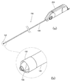
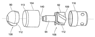
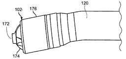
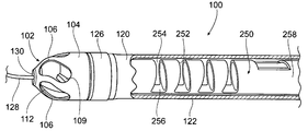
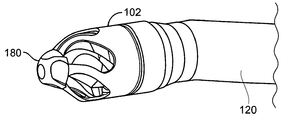
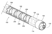
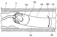
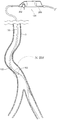
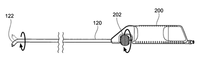
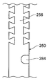
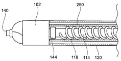
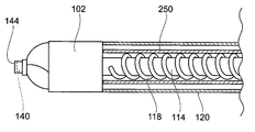
도 1의 (a)는 본 발명에 따른 인체 루멘으로부터 폐색 물질의 제거를 위해 구성된 시스템의 사시도이다.
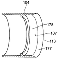
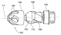
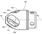
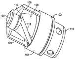
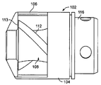
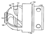
도 1의 (b)는 커팅 조립체의 실시예를 도시한 것으로, 도 1의 (a)에 도시된 시스템의 말단 팁의 확대 사시도이다.
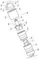
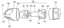
도 2a는 도 1의 (b)의 커팅 조립체를 도시한 사시 분해도이다.
도 2b는 도 2a에 도시된 2 피스 커터의 사시도이다.
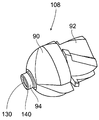
도 3a 내지 3c는 내부 2개의 플루트식 커터와 결합된 커터로서 기능하는 동적 하우징을 갖는 커팅 조립체를 도시한다.
도 3d는 도 3c의 커팅 조립체의 분해도를 도시한다.
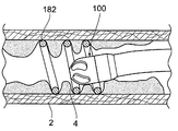
도 3e는 루멘 벽으로부터 동적 하우징 제거 물질과 함께 커팅 조립체의 사시도를 도시한다.
도 4a 및 도 4b는 혈관 벽의 손상을 방지하는 커팅 조립체의 형상부의 배치를 도시한다.
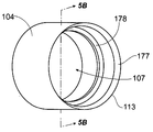
도 5a는 내부 베벨을 구비한 개방 단부 커터 하우징의 변형예의 사시도를 도시한다.
도 5b는 라인 5B-5B를 따라 취해진 도 5a의 개방단 커터의 단면도를 도시한다.
도 6a 및 도 6b는 인체 루멘으로부터 조직을 제거하는 커팅 조립체의 변형예를 도시한다.
도 7a 내지 도 7f는 루멘 내에 장치를 중심 설정하기 위한 추가 변형예를 도시한다.
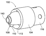
도 8a는 스윕 외장의 실시예를 도시한 것으로, 인체 루멘으로부터 폐색 물질의 제거를 위해 구성된 시스템의 말단부의 부분 단면의 사시도이다.
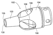
도 8b는 1개의 피스 커터와 함께 커팅 조립체의 추가적인 실시예를 도시한 사시 확대도이다.
도 9는 2개의 피스 커터와 함께 커팅 조립체의 추가적인 실시예를 도시한 사시 확대도이다.
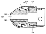
도 10은 도 8a에 도시된 커팅 조립체의 단면도를 도시한다.
도 11a는 하우징의 개방부를 통한 커팅 에지를 도시한다.
도 11b는 도 11a의 커팅 조립체의 측면도를 도시한다.
도 11c는 양의 레이크 각도를 도시하며, 도 11a의 커팅 조립체의 정면도를 도시한다.
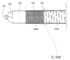
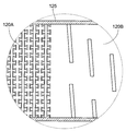
도 12는 확장 부재를 갖는 가드식 하우징의 실시예의 사시도이다.
도 13a 내지 도 13c는 도 12에 도시된 바와 같은 확장 부재를 갖는 디벌킹 장치의 사용을 도시한 측면도이다.
도 14a 및 도 14b는 복수의 전방 커팅면 및 플루트식 커팅면을 갖는 추가적인 실시예를 도시한다.
도 15는 버어 팁을 합체하고 가드식 하우징을 갖는 커팅 조립체의 사시도이다.
도 16a 및 도 16b는 복수의 전방 커팅면, 후방 커팅면 및 플루트식 커팅면을 갖는 차폐식 커터의 변형예를 도시한다.
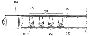
도 17은 이송 부재, 토크 샤프트, 스윕 외장, 카테터 본체를 도시한 것으로, 인체 루멘으로부터 폐색 물질의 제거를 위해 구성된 시스템의 말단부의 부분 단면의 사시도이다.
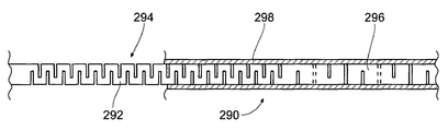
도 18a 및 도 18b는 스윕 부재 또는 카테터 본체의 추가적으로 가능한 변형예를 도시한다.
도 18c는 제2 부에서의 종방향 강성 및 제1 부에서의 절곡을 최대화하면서 최소의 비틀림 손실을 갖는 다중 본체 설계를 포함하는 카테터 본체의 다른 실시예의 측면도이다.
도 18d는 제1 단면의 도브테일 설계의 일 실시예를 도시한 것으로, 도 18c의 제1 및 제2 단면의 상세도이다.
도 18e는 제1 단면의 도브테일 설계의 추가적인 실시예를 도시한 것으로, 도 18c의 제1 단면의 다른 실시예의 상세도이다.
도 18f는 구부러진 말단부를 도시한 것으로, 도 18c의 다중 본체 설계를 포함하는 카테터 본체의 측면도이다.
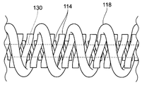
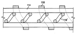
도 19a는 스윕 프레임 및 카테터 본체 내의 이송 부재를 도시한다.
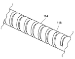
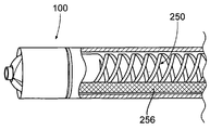
도 19b는 도 17에 도시된 바와 같이, 토크 샤프트의 주변에 권회된 이송 부재의 실시예를 도시한다.
도 19c는 역으로 권회된 코일을 갖는 토크 샤프트 및 이송 부재의 변형예의 부분 단면도를 도시한다.
도 19d는 토크 샤프트 내의 제2 이송 부재를 도시한다.
도 19e는 이송 부재와 같이 감겨진 홈을 포함하는 다른 토크 샤프트의 사시도이다.
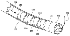
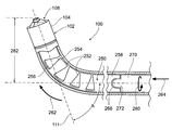
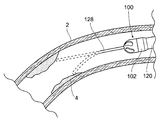
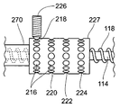
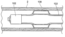
도 20a는 카테터의 말단부의 각도 편향을 야기하는 스윕 프레임을 도시한 것으로, 도 17과 유사한 부분 단면의 사시도이다.
도 20b는 구부러지지 않은 위치에서 스윕 프레임과 함께, 도 20a에 도시된 카테터의 말단부의 측면도이다.
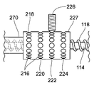
도 20c는 도 20a과 유사한 부분 단면의 사시도로서, 카테터의 말단부의 각도 편향을 야기하는 스윕 프레임에 인접한 스윕 부재를 도시한 것으로, 카테터가 미리 정해진 각도까지 관절 동작하도록 상기 스윕 프레임은 구부러지거나 압축된다.
도 21a 내지 도 21c는 본 명세서에서 설명되는 디벌킹 장치와 함께 사용하는 스윕 프레임의 추가 변형예를 도시한다.
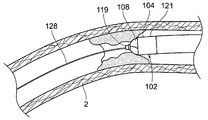
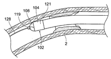
도 22a는 제거하기 위한 병소에 도달하려는 사행식 절곡 주변의 카테터의 말단부의 관절을 도시한다.
도 22b 내지 도 22d는 360도 이상 회전 가능한 스윕과 함께, 커팅 조립체의 스위핑의 변형예를 도시한다.
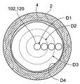
도 22e는 카테터의 직경의 네 배까지 혈관의 루멘을 제거하기 위한 시스템의 기능 및 혈관의 단면도이다.
도 23a 내지 도 23h는 사행식 혈관을 통해 치료 위치로 수동 및 능동 스티어링을 위해 사용되는 디벌킹 시스템을 도시한다.
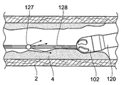
도 24a 내지 도 24c는 사행식 해부학적 구조 및 폐색 물질을 통한 가이드와이어의 탐색을 보조하는 디벌킹 장치의 사용을 도시한다.
도 24d는 혈관 벽에 대해 카테터의 병치 및 혈관 벽의 손상을 막아주는 하우징 윈도우의 배치를 도시한다.
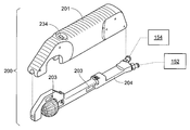
도 25a는 카테터의 말단부의 관절 동작 및 회전하도록 구성되고, 커터 조립체를 구비한 디벌킹 시스템을 위한, 제어 핸들의 확대도를 도시한다.
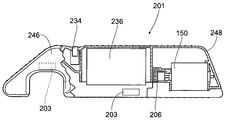
도 25b는 카테터 섀시부로부터 제어 핸들의 기능을 격리하고, 제어 핸들의 기능 요소를 수납하도록 구성된 핸들 베이스부를 도시한 부분 단면의 측면도이다.
도 26a 내지 도 26c는 불균형 요소를 사용하는 것이 가능한 궤도 회전을 위해서도 구성되며, 가변 가요성 말단 길이를 갖는 가요성 말단부의 측면도를 도시한다.
도 27은 토크 샤프트의 회전, 흡인, 관주, 스위핑 및 스티어링을 위한 제어 메커니즘을 포함하며, 핸들 베이스부 내에 스냅 끼움되도록 구성된 카테터 섀시부의 사시도이다.
도 28a 및 도 28b는 도 27에 도시된 바와 같이 스티어링 특징 및 커터 조립체 편향을 위한 미세 튜닝 제어를 위해 구성된 부속 스프링 플런저 및 인덱싱 카세트를 도시한다.
도 29a 및 도 29b는 커터 조립체를 포함하는, 카테터의 말단부를 관절로 잇고 회전하도록 구성된 핸들, 시스템을 위한 제어 핸들을 포함하는, 디벌킹 시스템을 도시한다.
도 30은 흡인 포트의 외부 및 카테터 섀시부의 내로, 카테터를 통해 조직 파편을 흡인하고 커팅하는 시스템, 디벌킹 시스템의 개략도를 도시한다.
도 31a 및 도 31b는 비관혈적 이미징 하에서 장치가 보여지는 경우, 의사가 커터 조립체의 관절의 배향 및 방향을 결정할 수 있도록 가시화 특징을 갖는 스윕 프레임의 변형예를 도시한다.
도 32a 내지 도 32c는 유체 이송 시스템의 예를 제공한다.
도 33은 급속한 교체를 위해 구성되는 장치의 변형예를 도시한다.
도 34는 가이드와이어에 걸쳐 커터 조립체의 팁을 중심 결정하는 예를 도시한다.
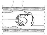
도 35는 코일 또는 스텐트 내의 병소를 제거하는 커팅 조립체를 도시한다.
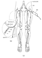
도 36은 하부 수족 내의 동맥의 묘사를 도시한, 인간을 포함한 동물의 하부 수족의 해부도를 도시한다.
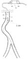
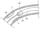
도 37의 (a)는 도 36과 유사한 해부도를 도시하며, 시스템이 병소의 제거를 위한 혈관에 사용되는 시스템용 접근 가능 위치에 대한 대측성 구조를 도시한다.
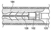
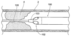
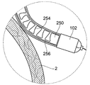
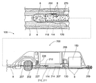
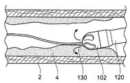
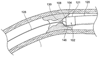
도 37의 (b)는 폐색의 디벌킹을 위한 심부 동맥 내로 사행식 혈관을 통해 그리고 바깥엉덩동맥을 통해 연장되는 카테터(120)를 도시한, 도 37의 (a)의 상세도를 도시한다.
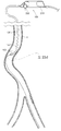
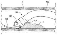
도 38의 (a)는 시스템이 병소를 제거하기 위해 혈관에서 사용되는 추가적으로 가능한 동측의 접근 위치를 도시한, 도 35와 유사한 해부도를 도시한다.
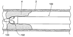
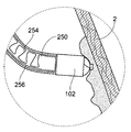
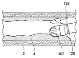
도 38의 (b)는 폐색을 디벌킹하기 위한 전방 경골 동맥 내로, 사행식 혈관을 통해, 오금의 대퇴부 동맥을 통해 연장되는 카테터(120)를 도시한, 도 38의 (a)의 상세도를 도시한다.
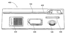
도 39는 사용을 위한 지시 사항에 따라, 다중 피스 키트에 사용하기 위해 결합되는 시스템의 구성품의 세트를 도시한다.
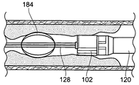
도 40a 및 도 40b는 부가 혈관 성형술, 스텐트 및/또는 기타 약제의 이송을 위한 풍선 또는 기타 메커니즘을 포함하는 디벌킹 카테터의 말단부를 도시한다.
도 41a 및 도 41b는 치료 전 및/또는 후에 목적한 치료 위치의 이미징을 제공하는 센서 및/또는 변환기를 포함하는 디벌킹 시스템의 실시예의 측면도이다.
도 42는 치료 전 및/또는 후에 목적한 치료 위치의 이미징을 제공하는 말단 단부 또는 그 가까이의 이미징 시스템을 포함하는, 디벌킹 시스템의 실시예의 측면도이다.Figure 1 (a) is a perspective view of a system configured for the removal of occlusion material from the human body lumen according to the present invention.
FIG. 1B illustrates an embodiment of a cutting assembly, which is an enlarged perspective view of the distal tip of the system shown in FIG. 1A.
2A is a perspective exploded view of the cutting assembly of FIG. 1B.
FIG. 2B is a perspective view of the two piece cutter shown in FIG. 2A.
3A-3C show a cutting assembly with a dynamic housing that functions as a cutter coupled with two internal flute cutters.
3D shows an exploded view of the cutting assembly of FIG. 3C.
3E shows a perspective view of the cutting assembly with dynamic housing removal material from the lumen wall.
4A and 4B show the placement of the features of the cutting assembly to prevent damage to the vessel wall.
5A shows a perspective view of a variant of an open end cutter housing with an inner bevel.
5B shows a cross-sectional view of the open end cutter of FIG. 5A taken along
6A and 6B show a variation of a cutting assembly that removes tissue from the human lumen.
7A-7F illustrate further variations for centering the device within the lumen.
FIG. 8A illustrates an embodiment of a swept sheath and is a perspective view of a partial cross-section of the distal end of a system configured for removal of obstruction material from a human lumen.
8B is a perspective enlarged view showing a further embodiment of the cutting assembly with one piece cutter.
9 is a perspective enlarged view showing a further embodiment of a cutting assembly with two piece cutters.
FIG. 10 shows a cross-sectional view of the cutting assembly shown in FIG. 8A.
11A shows the cutting edge through the opening of the housing.
FIG. 11B shows a side view of the cutting assembly of FIG. 11A.
FIG. 11C shows a positive rake angle and shows a front view of the cutting assembly of FIG. 11A.
12 is a perspective view of an embodiment of a guarded housing having an expansion member.
13A-13C are side views illustrating the use of a debulking device with an expansion member as shown in FIG. 12.
14A and 14B show additional embodiments having a plurality of front cutting surfaces and fluted cutting surfaces.
15 is a perspective view of a cutting assembly incorporating a burr tip and having a guarded housing.
16A and 16B show a variant of the shielded cutter having a plurality of front cutting surfaces, rear cutting surfaces and flute cutting surfaces.
FIG. 17 is a perspective view of a partial cross-section of the distal end of the system configured for removal of obstruction material from the human lumen, showing the transfer member, torque shaft, sweep sheath, and catheter body.
18A and 18B show further possible variations of the sweep member or catheter body.
18C is a side view of another embodiment of a catheter body including a multi-body design with minimal torsional loss while maximizing longitudinal stiffness in the second portion and bending in the first portion.
FIG. 18D illustrates one embodiment of the dovetail design of the first cross-section and is a detailed view of the first and second cross-sections of FIG. 18C.
FIG. 18E illustrates a further embodiment of the dovetail design of the first cross section, and is a detailed view of another embodiment of the first cross section of FIG. 18C.
FIG. 18F illustrates the bent distal end and is a side view of the catheter body including the multi-body design of FIG. 18C.
19A shows the transfer member in the sweep frame and catheter body.
FIG. 19B shows an embodiment of the conveying member wound around the torque shaft, as shown in FIG. 17.
19C shows a partial cross-sectional view of a variant of the torque shaft and the conveying member having a coil wound backwards.
19D shows the second conveying member in the torque shaft.
19E is a perspective view of another torque shaft including a groove wound like a transfer member.
20A shows a sweep frame causing angular deflection of the distal end of the catheter, and is a perspective view of a partial cross section similar to FIG. 17.
20B is a side view of the distal end of the catheter shown in FIG. 20A, with the sweep frame in an unbent position.
FIG. 20C is a perspective view of a partial cross section similar to FIG. 20A showing the sweep member adjacent the sweep frame causing angular deflection of the distal end of the catheter, the sweep frame being bent or compressed to articulate the catheter to a predetermined angle .
21A-21C show further variations of the sweep frame for use with the debulking device described herein.
22A shows the articulation of the distal end of the catheter around the meandering bend to reach the lesion for removal.
22B-22D show variants of sweeping of the cutting assembly, with sweeps rotatable 360 degrees or more.
22E is a cross-sectional view of the vessel and the function of the system to remove the lumen of the vessel up to four times the diameter of the catheter.
23A-H illustrate a debulking system used for passive and active steering to a treatment position through meandering vessels.
24A-C illustrate the use of a debulking device to assist in the navigation of the guidewire through the meandering anatomical structure and occlusion material.
FIG. 24D shows the placement of the housing window to prevent juxtaposition of the catheter and damage to the vessel wall relative to the vessel wall.
FIG. 25A shows an enlarged view of a control handle for a debulking system with a cutter assembly configured to articulate and rotate the distal end of the catheter.
FIG. 25B is a side view of a partial cross section showing a handle base portion configured to isolate the function of the control handle from the catheter chassis portion and to receive the functional elements of the control handle; FIG.
Figures 26A-26C are also configured for orbital rotation, which makes it possible to use an unbalanced element, and shows a side view of the flexible distal end with the variable flexible distal length.
27 is a perspective view of a catheter chassis portion configured to snap into the handle base portion, including control mechanisms for rotation, suction, irrigation, sweeping and steering of the torque shaft.
28A and 28B show an accessory spring plunger and indexing cassette configured for fine tuning control for steering feature and cutter assembly deflection as shown in FIG. 27.
29A and 29B illustrate a debulking system, including a handle configured for articulating and rotating the distal end of the catheter, including a cutter assembly, a control handle for the system.
30 shows a schematic of a debulking system, a system for sucking and cutting tissue debris through a catheter, outside of the suction port and into the catheter chassis portion.
31A and 31B show a variant of the sweep frame with visualization features such that when the device is viewed under non-invasive imaging, the physician can determine the orientation and orientation of the joints of the cutter assembly.
32A-32C provide an example of a fluid transfer system.
33 shows a variant of the device configured for rapid replacement.
34 shows an example of centering the tip of the cutter assembly over the guidewire.
35 illustrates a cutting assembly for removing lesions in a coil or stent.
36 shows anatomical diagrams of the lower limbs of animals, including humans, depicting depictions of arteries in the lower limbs.
FIG. 37 (a) shows an anatomical view similar to FIG. 36, showing the contralateral structure for the accessible location for the system where the system is used in blood vessels for removal of lesions.
FIG. 37B shows a detailed view of FIG. 37A showing the
FIG. 38A shows an anatomical view similar to FIG. 35, showing an additional possible ipsilateral access location where the system is used in the vessel to remove the lesion.
FIG. 38 (b) shows a detailed view of FIG. 38 (a) showing a
FIG. 39 illustrates a set of components of a system coupled for use in a multi piece kit, according to instructions for use.
40A and 40B show the distal end of a debulking catheter that includes a balloon or other mechanism for the delivery of additional angioplasty, stents and / or other agents.
41A and 41B are side views of an embodiment of a debulking system that includes sensors and / or transducers to provide imaging of a desired treatment location before and / or after treatment.
42 is a side view of an embodiment of a debulking system, including an imaging system at or near the distal end providing imaging of a desired treatment location before and / or after treatment.
본 명세서의 기재 내용은 당업자가 본 발명을 구현할 수 있도록 정확하며 상세하지만, 본 명세서에서 개시된 물리적 실시예는 다른 특정한 구조로 실시될 수도 있는 발명을 단지 예증하는 것에 불과하다. 바람직한 실시예들이 설명되었지만, 세부적인 사항은 청구항에 의해 형성된 본 발명을 벗어나지 않고 변화될 수 있다.While the disclosure herein is accurate and detailed to enable those skilled in the art to practice the invention, the physical embodiments disclosed herein are merely illustrative of the invention, which may be practiced with other specific structures. While the preferred embodiments have been described, the details may be changed without departing from the invention formed by the claims.
본 명세서는 혈관 내의 부드러운 탄성 조직, 칼슘, 혈전 및 플라크를 제거하는 단계를 포함하는, 인체 루멘으로부터 폐색 물질을 제거하기 위한, 카테터 기반 장치, 시스템 및 방법을 개시한다. 예를 들어, 본 발명의 다양한 양태는 혈관의 병든 부분 및 또는 손상된 부분의 치료에 요구되는 시술의 용례를 갖는다. 본 발명의 특징을 구현하는 장치, 시스템 및 방법은 반드시 카테터 기반일 필요는 없는 수술 기술 및 시스템의 용도로도 적합하다.The present disclosure discloses catheter-based devices, systems, and methods for removing occlusion material from human lumen, comprising removing soft elastic tissue, calcium, blood clots, and plaques in blood vessels. For example, various aspects of the present invention have applications for the procedures required for the treatment of diseased and / or damaged portions of blood vessels. Apparatus, systems, and methods embodying the features of the present invention are also suitable for use in surgical techniques and systems that are not necessarily catheter based.
본 장치, 시스템 및 방법은 제한되지 않는 예로서, 정강동맥, 오금동맥, 대퇴심부동맥, 표피넙다리동맥 및 온대퇴부동맥과 같은 다리에서 발견되는 동맥을 포함하는 주변 혈관의 폐색 물질의 연속적인 디벌킹 및 흡인에 특히 적합하다. 이러한 이유로, 본 장치, 시스템 및 방법이 본원에서 설명될 것이다. 그럼에도, 개시된 장치, 시스템 및 방법은 반드시 동맥과 관련될 필요는 없는 인체 내의 임의 부분에서의 다른 장애를 치료하는데 적용 가능한 것으로 이해되어야 한다.The apparatus, system, and method include, but are not limited to, continuous dilation of occlusion materials of peripheral blood vessels, including arteries found in the legs, such as the tibia, the popliteal artery, the femoral core artery, the epidermal femoral artery and the temperate femoral artery. Particularly suitable for bulking and aspiration. For this reason, the present apparatus, system and method will be described herein. Nevertheless, it is to be understood that the disclosed devices, systems, and methods are applicable to the treatment of other disorders in any part of the human body that need not necessarily be associated with an artery.
인체 루멘으로부터 폐색 물질을 제거하기 위해 수술자 또는 의사에 의해 조작되는 카테터 기반 기구 또는 장치에 대해 언급할 때, "선단" 및 "말단"이라는 용어는 사용될 때의 수술자에 대한 기구 또는 장치의 관계 또는 배향을 설명하는데 사용될 수 있다. 그러므로 "선단"이라는 용어는 사용시에 수술자쪽(즉, 장치의 핸들 단부)에 위치되는 기구 또는 장치의 관계 또는 배향을 설명하기 위하여 사용되며, "말단"이라는 용어는 사용시에 수술자로부터 먼쪽(즉, 핸들로부터 떨어져서 카테터 등의 "커터" 단부)에 위치되는 기구 또는 장치의 관계 또는 배향을 설명하기 위해 사용된다.When referring to catheter-based instruments or devices operated by an operator or physician to remove obstructions from the human lumen, the terms "tip" and "end" refer to the relationship or orientation of the instrument or device to the operator when used. It can be used to explain. Thus, the term "tip" is used to describe the relationship or orientation of an instrument or device that is located on the operator's side (ie, the handle end of the device) in use, and the term "end" is used away from the operator (ie, in use). It is used to describe the relationship or orientation of an instrument or device that is located away from the handle and at the "cutter" end of the catheter or the like.
인체 장기 또는 혈관의 부분적인 또는 완전한 차단, 또는 혈관의 플라크에 대해 언급할 때, "선단" 및 "말단"이라는 용어는 심장에 대하여 플라크 또는 차단물의 관계 또는 배향을 설명하는데 사용될 수 있다. 그러므로 "선단"이라는 용어는 심장 쪽에 위치하는 차단물 또는 플라크의 배향 또는 관계를 설명하기 위해 사용되며, "말단"이라는 용어는 심장에서 멀리 위치되는, 즉, 발 쪽 차단물 또는 플라크의 배향 또는 위치를 설명하기 위해 사용된다.When referring to partial or complete blockage of human organs or blood vessels, or plaques of blood vessels, the terms "tip" and "end" may be used to describe the relationship or orientation of the plaque or blockage to the heart. The term "tip" is therefore used to describe the orientation or relationship of a blockage or plaque located at the heart side, and the term "end" is located far from the heart, i.e. the orientation or location of the foot blockage or plaque It is used to describe.
Ⅰ. 시스템 개관I. System overview
A. 시스템 역량A. System Capabilities
도 1의 (a) 및 도 1의 (b)는 혈전 절제 및/또는 죽종 절제에 적합한, 본 발명에 따른 시스템(100)의 예시적인 변형예를 도시한다. 도시한 바와 같이, 시스템(100)은 카테터 본체 또는 카테터 조립체(120)에 부착된 말단 커터 조립체(102)를 포함하고, 카테터 조립체는 선단부에서 제어 핸들(200)과 결합된다. 도면에 도시된 조립체는 예시적인 목적으로만 도시된 것임을 알아야 한다. 이러한 기재 내용의 범위는 다양한 실시예의 특정 양태의 조합뿐만 아니라, 가능하다면 다양한 실시예의 조합을 포함한다.1A and 1B show exemplary variations of the
시스템(100)은 종래의 디벌킹 유형의 장치에 비해 상당한 사용의 용이함, 성능 및 안전성의 장점을 제공한다. 명세서 및 도면을 통하여 더욱 상세하게 설명되는 바와 같이,
시스템(100)은 카테터의 말단 단부에 360도 스티어링 가능한 회전 커팅형 가드식(차폐식) 또는 개방식 커터를 포함할 수 있으며, 카테터는 새로운 혈전으로부터 석회화된 플라크까지의 병소의 연속적인 흡인 및 디벌킹을 허용하도록 구성된 파지형 제어부(즉, 핸들)와 결합된다. 조직 파편은 커팅되었을 때 카테터 내에서 포획되고 연속하여 제거될 수 있다.
본 명세서에서 설명하는 장치, 시스템 및 방법은 (이후 더욱 상세하게 설명하는 바와 같이) 특히, 다른 시스템으로 치료하기에 어려운 병소, 즉, 예를 들어, 무릎 또는 기타 관절 내에 위치된 주연부의 동맥과 같이 생물 역학적 스트레스를 받는 동맥, 사행식 동맥 및 분기부에서 잘 작동한다.The devices, systems and methods described herein are particularly difficult to treat with other systems (as described in greater detail below), such as, for example, arteries in the periphery located within the knee or other joints. Works well in biomechanical stressed arteries, meandering arteries and branches.
장치, 시스템 및 방법은 조직 검사, 종양 제거, 유섬유종 치료, 확대된 전립선 조직과 같은 원치 않는 과형성 조직 또는 탈출된 척추 디스크 물질과 같은 원치 않는 조직의 디벌킹을 포함하는, 폭넓고 다양한 기타 치료를 수행할 수도 있다. 본 명세서에서 설명하는 임의의 장치, 시스템 및 방법은 동맥의 완전한 차단 또는 만성 전체 폐색(CTO)을 치료하기 위한 도구로 사용될 수도 있다. 본 명세서에서 설명하는 가요성, 저(low) 프로파일의 카테터 시스템은 치료 위치로의 용이한 접근을 가능하게 하며, 주변의 건강한 조직에 외상 또는 부수적인 손상을 최소화할 수 있다. 연속적인 흡인 성능에 의해, 장치의 도입, 치료 및 제거 중 주위 조직의 오염이 감소되거나 제거될 수 있다. 또한, 흡인은 그 위치에 잔류하는 카테터로 테스트하기 위해 조직 검사용 조직의 샘플을 인체 외부로 전달하기 위해 사용될 수 있다. 이것은 의사가 악성 조직의 치료에 앞서 실시간으로 결정을 내리는 것을 도와준다.The devices, systems, and methods perform a wide variety of other treatments, including biopsy, tumor removal, treatment of fibroids, debulking of unwanted hyperplasia such as enlarged prostate tissue, or unwanted tissue such as escaped vertebral disc material. You may. Any of the devices, systems, and methods described herein may be used as a tool to treat complete blockage of arteries or chronic total occlusion (CTO). The flexible, low profile catheter system described herein allows for easy access to the treatment site and can minimize trauma or concomitant damage to surrounding healthy tissue. By continuous suction performance, contamination of surrounding tissue can be reduced or eliminated during the introduction, treatment and removal of the device. Aspiration may also be used to deliver a sample of tissue for histology out of the human body for testing with a catheter remaining at that location. This helps doctors make decisions in real time before treating malignant tissue.
커터 조립체(102)의 하우징 또는 차폐부는 커터 결합의 심도를 제한하여 제어된 조직 적출을 유지하여, 의사가 건강한 주변 조직을 부주의하게 커팅하는 것을 막아준다. 시스템의 팁 스티어링 성능으로 인해 의사는 커터(108)를 원하는 조직 제거 부위로 유도할 수 있어서, 주변 조직의 손상을 최소화한다. 커터를 편향시키고 편향된 상태로 아크식으로 스위핑하도록 회전시킴으로써, 카테터는 카테터의 직경보다 큰 플라크 적층물, 종양 또는 조직 덩어리를 절제할 수 있다. 따라서, 작은 접근 채널을 통해 큰 종양을 절제할 수 있어, 환자의 외상을 최소화할 수 있다.The housing or shield of the
본 명세서에서 설명하는 장치, 시스템 및 방법은 혈전의 제거뿐만 아니라, 동정맥(AV)의 혈액 투석 접근 부위(누공 및 합성 이식 조직)의 협착증을 디벌크할 수도 있다. 예를 들어, 커터 하우징을 제거하고 카테터 본체 내에 플루트식 커터를 만입시켜, 적합한 비커팅식 혈전 절제 카테터가 구성될 수 있다.The devices, systems, and methods described herein may debulke not only the removal of thrombus, but also the stenosis of hemodialysis access sites (fistulas and synthetic graft tissue) of the arteriovenous (AV). For example, a suitable non-cutting thrombectomy catheter can be constructed by removing the cutter housing and indenting the flute cutter in the catheter body.
본 명세서에서 설명하는 장치, 시스템 및 방법은 최소의 관혈적(invasive) 수술중, 뼈, 연골, 결체 조직 또는 근육을 절제하는데 사용될 수도 있다. 예를 들어, 커팅 및 버어 요소를 포함하는 카테터는 척추 협착증을 완화하기 위한 라미넥토미(laminectomy) 또는 관절면절제(facetectomy) 수술을 실행하는 동안 척추로 접근하는데 사용될 수 있다. 또한, 이러한 용례에 대해, 카테터는 수술용 삽입 및 탐색을 보조하기 위해, 그 길이의 일부에 강성의 캐뉼러를 배치하거나 또는 강성부 자체를 갖도록 추가로 설계될 수도 있다.The devices, systems, and methods described herein may be used to ablate bone, cartilage, connective tissue, or muscle during minimally invasive surgery. For example, catheters comprising cutting and burr elements can be used to access the spine during laminctomy or facetectomy surgery to relieve spinal stenosis. In addition, for this application, the catheter may be further designed to place a rigid cannula at a portion of its length or to have the rigid portion itself to assist surgical insertion and retrieval.
또한, 스텐트 내 재협착을 디벌킹하고 새로운 병소를 디벌킹함으로써 뇌혈관 순환 및 관상 순환에 있어서의 동맥 병소의 개방성(patency)을 복구하기 위해, 본 명세서에서 설명하는 장치, 시스템 및 방법을 사용할 수 있다.In addition, the devices, systems, and methods described herein can be used to restore the patency of arterial lesions in cerebrovascular and coronary circulation by debulking the restenosis in the stent and debulking new lesions. have.
Ⅱ. 바람직한 기술적 특징II. Desirable technical features
디벌킹 시스템(100)은 유용성을 향상시키기 위해 이후 설명되는 다양한 기술적 특징을 통합할 수 있다.The
A. 커터 조립체A. Cutter Assembly
1. 원통형 하우징 커터 조립체1. Cylindrical Housing Cutter Assembly
도 2a는 전방 커팅 커터 조립체(102)의 예시적인 실시예의 분해도를 도시한다. 이러한 변형예에서, 커터 조립체(102)는 말단면에 위치된 개구(107)를 갖는 원통형 하우징(104)을 포함하여 커터(108)가 말단면을 넘어 연장할 수 있도록 구성된다. 커터(108)는 하나 이상의 커팅 에지를 포함할 수 있다. 도시된 실시예에서, 커팅 에지는 커터(108)를 따라(또는 실질적으로 따라서) 연장되는 제1 세트의 커팅 에지(112) 및 커터(108)의 일부만을 따라 연장되는 제2 커팅 에지(109)를 포함한다. 커팅 에지의 개수는 변할 수 있지만, 커팅 에지는 대체로 커터(108)의 축(111)에 대해 대칭이다.2A shows an exploded view of an exemplary embodiment of the front
또한, 도 2b는 선단부(92)[여기서, 선단 커터부(92)는 커터 코어 어댑터(92)로서 언급될 수도 있음]에 장착되는 말단부(90)를 구비하는 커터(108)의 변형예를 도시한다. 선단 커터부(92)는 정합 피스(140)에서 종단되는 샤프트(94)를 포함하고, 정합 피스(140)는 말단 커터(90)의 전방면의 개구 내로 끼워진다. 커터 조립체(102)는 커터 조립체(102) 및 장치(100)를 통해 가이드와이어의 통행을 허용하는 가이드와이어 루멘(130)을 포함할 수도 있다.2B also shows a variant of the
본 명세서에서 개시된 바와 같이, 커터(108)는 티타늄 니트라이드 등의 내마모성 코팅을 구비하거나 구비하지 않는 티타늄 합급, 코발트 크로뮴, 텅스텐 카바이드, 스테인레스 강 또는 경화 공구와 같은 경질, 내마모성 물질로 제작되는 것이 바람직하다. 그러나 통상적으로 유사한 수술 용도에 공통적으로 사용되는 임의의 물질이 커터에 사용될 수 있다. 커터(108)의 선단 단부의 외측면은 대체로 무디며, 하우징(104)을 지지하도록 설계되었다. 대체로, 이러한 면은 하우징(104)의 내면과 평행할 수 있다.As disclosed herein, the
도 3a 내지 도 3e는 커터 조립체(102)의 추가 변형예를 도시한다. 이러한 변형예에서, 하우징(104)의 전방 에지는 전면 또는 전방 커팅면(113)으로 기능할 수 있다. 일 변형예에서, 커터(108)는 커터의 전방이 둥글게 되거나 부분적으로 공모양을 구비하도록 둥글게 되거나 테이퍼링될 수 있다. 도시한 바와 같이, 전방 커팅면(113)은 하우징(104)의 외측면 상에서 경사질 수 있다. 이러한 경사진 형상은 커팅면(113)이 혈관 벽을 찌르거나 또는 손상시키는 위험을 감소시킨다. 상술한 바와 같이, 전방 커팅면(113)은 장치가 도 3f에 도시된 바와 같이 인체 루멘(2) 내에서 말단 방향으로 전진될 때, 조직 또는 플라크(4)와 맞물려서 이를 제거한다. 본 명세서에서 검토한 바와 같이, 장치(100)의 형상은 장치가 루멘 벽(2)을 과도하게 커팅하는 것을 방지하는 것을 보조하는 가이드와이어(128)를 포함한다.3A-3E show further variations of the
또한, 하우징(104)은 커터(108)와 함께 회전하도록 구성되거나, 고정된 상태로 스크래핑, 스쿠핑(scooping) 또는 치젤(chisel)형 표면으로 기능할 수 있다. 예를 들어, 도 3a 및 도 3b는 카테터 본체(120)를 중심으로 전체 커팅 조립체(102) 회전할 수 있도록 하우징(104)이 커터(108)에 부착될 수 있는 변형예를 도시한다. 시스템은 카테터 본체(120)가 커터 조립체(102)에 결합되는 것을 허용하는 페룰(116)을 포함할 수도 있다. 페룰(116)은 커터 조립체(102) 내에서의 커터(108)의 회전을 위한 베어링면으로 작용할 수도 있다. 도시된 예에서, 커팅 조립체(102)는 하우징(104)을 커터(108)에 고정하기 위해 접합된 오목 핀 캐비티(103)를 포함한다. 도 3b는 도 3a의 커터 조립체(102)의 단면도를 도시한다. 도시된 바와 같이, 이러한 특정한 변형예에서, 전체 커팅 조립체(102)는 회전 하우징(104)을 위한 베어링면을 제공하는 페룰(116)에 대해 회전한다. 하우징(104)의 선단부는 페룰(116)에 대해서 회전하는 반면, 커터(108)의 선단부(92)는 페룰 내에서 회전한다.The
하우징(104)은 당업자에 의해 용이하게 이해될 수 있는 다양한 방식으로 커터(108)에 링크될 수 있다. 예를 들어, 하우징(104)은 하우징과 커터 모두 함께 회전할 수 있도록 접속 포인트(103)를 통해 커터(108)에 부착되거나 직접 링크될 수 있다. 이와 달리, 하우징(104)은 커터(108)보다 더 빠르거나 느리게 회전하도록 기어식일 수 있다. 또 다른 변형예에서, 기어링은 하우징(104)이 커터(108)와 반대 방향으로 회전하는 것을 허용하도록 선택될 수 있다.The
커팅 조립체의 변형예는 하우징(104)의 전방 커팅면(113)으로부터 부분적으로 돌출되는 커터(108)를 포함한다. 다른 변형예에서, 커터(108)는 하우징(104)으로부터 더욱 연장될 수 있거나 또는 조립체는 하우징(104) 내에서 전체적으로 만입된 커터(108)를 구비할 수 있다. 임의의 변형예, 특히 단일 또는 이중 플루트식 커팅 에지 구조가 커터(108)의 말단부에서 사용되는 변형예에서, 커터(108) 상에 플루트(110)의 가장 깊은 부분과 하우징(104)의 커팅면(113)을 정렬함으로써, 조직 파편의 처치를 개선할 수 있다. A variant of the cutting assembly includes a
임의의 경우에, 플루트식 커팅 에지(112)는 조직 파편을 카테터 내로 다시 추진시킨다. 전방 커팅면(113)과 가까운, 하우징의 외부면은 커팅 에지의 커팅 작동으로부터 루멘 벽을 보호하기 위해 매끄러울 수 있다. 커팅 조립체(102)가 편향되는 경우, 하우징(104)의 외부면은 루멘 벽에 대향하여 플러쉬(flush)되고, 커팅 에지가 혈관 벽과 결합하는 것을 방지한다. 커터 조립체가 전방으로 전진될 때, 커터 조립체는 루멘(2) 벽으로부터 돌출된 플라크(4)를 제거하고, 조직 파편은 커터(108)의 플루트식 에지(112)에 의해 후방으로 추진된다.In any case, the
도 3c는 커터(108)가 페룰 내에서 회전하는 반면에, 커팅 조립체(102)의 하우징(104)이 카테터 본체(120) 또는 페룰(116)에 대하여 고정 상태인 커팅 조립체(102)의 추가 변형예를 도시한다. 이러한 실시예에서, 페룰(116)의 내측부는 커터(108)의 선단 단부(92)에 대한 베어링면을 제공할 수 있다. 하우징(104)은 페룰(116)에 부착될 수도 있고, 또한, 회전 커터(108)에 대한 베어링면으로 기능할 수 있다.3C shows a further variation of the cutting
커터(108)는 커터(108)의 커팅면(112)이 조직을 전단하거나 쪼개어 하우징(104) 내의 조직을 포획하도록 하우징(104)에 대해 회전하여, 조직은 이송 부재(118) 및/또는 토크 샤프트(114)로부터의 진공 및 헬리컬형 플루트(110)의 임펠러 작동을 이용하여 선단 방향으로 비워질 수 있다.The
도 3e는 도 3c의 커팅 조립체의 확대도를 도시한다. 또한, 커터(108)는 말단 커팅부(90) 및 선단 커팅부(92)를 구비할 수 있다. 도시된 구성은 선단 커팅부(92)에서는 더 많은 수의 커팅 에지(109 및 112)를 갖고, 커터의 말단부(90)에는 더 적은 수의 커팅 에지(112)를 갖는 장치를 제공한다. 그러나, 변형예는 전형적인 플루트식 커터도 포함한다. 하우징(104)은 커터부(90 및 92) 주위에 장착되고, 카테터 본체(120) 또는 페룰(116) 중 어느 하나에 선택적으로 고정된다. 상술한 바와 같이, 하우징(104)은 커터와 함께 회전하도록 커터에 부착될 수도 있다.FIG. 3E shows an enlarged view of the cutting assembly of FIG. 3C. In addition, the
다른 변형예에서, 커터 조립체(102)의 정합면(140)은 커터 조립체의 개방식 말단 설계의 경우 혈관 벽 또는 가이드와이어 내로의 우발 커팅을 방지하는 완충 장치로 작용하는 커터(108)의 첨단의 무딘 범퍼로 기능할 수 있다. 추가 변형예에서는, 하우징(104)은 (바스켓 또는 메쉬와 같이) 확장될 수 있다. 커터(108)가 하우징 내에서 회전할 때, 하우징은 더 큰 직경을 커트하기 위해 팽창하도록 구성될 수도 있다.In another variation, the
도 3f는 하우징(104)의 말단 개구(117)에 전방 커팅면(113)을 구비한 커팅 조립체(102)를 도시한다. 하우징(104)은 조직의 제거를 보조하기 위해 커터(108)와 함께 회전한다. 상술한 바와 같이, 장치가 인체 루멘(2) 내에서 말단 방향으로 전진될 때, 전방 커팅면(113)은 조직 또는 플라크(4)와 결합하여 이를 제거한다. 이후 개시되는 바와 같이, 가이드와이어(128)를 포함하는 장치의 형상은 장치가 루멘 벽(2)을 과도하게 커팅하는 것의 방지를 돕는다.3F shows the cutting
도 4a 및 도 4b는 전방 커팅에 적합한 커터 조립체(102)를 도시한다. 본 실시예는 커터가 하우징으로부터 말단으로 연장되는, 개방 단부 하우징(104)을 포함한다. 그러나 커터(108)의 말단 팁의 무딘 범퍼(119)는 가이드와이어(128) 또는 과도하게는 루멘 벽(2)으로의 우발 커팅하는 것을 방지하는 완충 장치로 작용한다. 또한, 본 실시예는 커터(108)가 루멘 벽(2) 내로 깊은 측면 커팅하는 것을 부분적으로 막아주는 커터 조립체(102)의 후방 단부에 추가적인 하우징부(121)를 선택적으로 일체화시킬 수 있다.4A and 4B show a
도 2a를 참조하면, 커터를 회전시키고 선단 방향으로 조직 파편을 흡인하거나 당기기 위해 토크 샤프트(114)는 페룰(116), 스윕 프레임(250), 외측 카테터 본체(120) 내부에서 회전한다. 이송 부재(118)의 나사선의 깊이 및 간격과 카테터 본체(120)와 이송 부재(118) 사이의 간극은, 후에 더욱 자세하게 설명되는 바와 같이, 양호한 펌핑 효율을 제공할 수 있도록 선택될 수 있다.Referring to FIG. 2A, the
도 2a에 도시된 바와 같이, 페룰(116)은 커터(108)의 선단면에 대향하여 지지하는 말단 베어링면을 구비할 수 있고, 커터를 하우징(104) 내에서 축 방향으로 안정하게 유지한다. 하우징이 고정 상태인 경우, 페룰(116)은 납땜, 경납땜, 용접, 접착(에폭시), 스웨이징, 크림핑, 가압 끼움, 나사 결합, 스냅 고정 또는 기타 다른 부착 방법을 사용하여 하우징(104)에 견고하게 접합 링크될 수 있다. 도시된 바와 같이, 페룰(116)은 카테터 본체(120)와의 결합을 가능케 하는 구멍 또는 다른 거친 형상부를 가질 수 있다. 본 구조에서는 접착 및 열용융이 채용될 수도 있지만, 이러한 특성이 요구되는 것은 아니다. 여러 차례의 접착은 작은 표면 접촉에 대해 신뢰성이 없고, 열용융은 카테터 본체(120)를 열화시킬 수 있다.As shown in FIG. 2A, the
기계적 로킹 링(126)의 사용은 커팅 조립체(102)가 단축되는 것을 허용한다. 이러한 형상은 사행식 혈관을 탐색하는데 요구되기 때문에 카테터(120)의 말단 섹션(122)의 가요성을 최대화하는데 중요하다. 일 변형예에서, 링 또는 밴드(126)는 페룰(116)을 넘어서 그리고 카테터 본체(120) 상으로 스웨이지될 수 있다. 이는 카테터 본체뿐만 아니라 링/밴드의 일부를 페룰(116)의 개구로 주입시켜 커터 조립체(102)와 카테터 본체(120)의 사이의 강도를 증가시킨다.The use of the
도 5a 및 도 5b는 각각 개방 단부 커터 하우징(104)의 사시도 및 다른 변형예의 측면 단면도를 도시한다. 도시한 바와 같이, 커터 하우징(104)은 원통형 하우징(104)의 전방면에 위치된 개구(107)를 포함한다. 이러한 변형예에서, 하우징(104)의 전방 에지(113)는 정면 또는 전방 커팅면으로 기능할 수 있으며, 하우징(104)의 내측면 상에 경사진 면(177)을 갖는다. 이러한 경사진 형상부는 커팅면(113)이 혈관 벽 내로 추진될 위험을 감소시킨다. 도시한 바와 같이, 커팅 하우징(104)의 몇몇 변형예는 하우징(104) 내에 위치된 베어링면(178)을 포함한다. 추가 변형예에서, 커팅 조립체(102)가 조직을 제거하는 정도를 제어하기 위해, 하우징(104)의 커팅면(177) 또는 말단 단부는 가리비 형상 또는 톱니 형상으로 될 수 있다. 예를 들어, 커팅면(177)은 균일하지 않고 축 방향으로 하우징의 주연부를 따라 변할 수 있다(예를 들어, 커터의 톱니 형상 에지는 하우징의 축 방향 길이를 따라 연장된다).5A and 5B show a perspective view and a side cross-sectional view of another variant of the open
회전하는 터빈형 코어링 커터(172)를 구비한 개방 단부 커터 조립체(102)의 추가 변형예는 도 6a 및 도 6b에 도시된다. 도 6b는 코어링 커터(102)의 측면도를 도시한다. 사용 시, 코어링 커터는 예리한 에지를 조직 사이로 구동시키도록 수동으로 가압될 수 있다. 터빈형 커터(172)는 예리한 실린더 하우징(176)의 내측에 헬리컬형 블레이드(174)를 갖는다.Further variations of the open
코어링 커터(102)의 요소는 가이드와이어에 대하여 하우징(104)을 중심 결정하기 위해 도 7a 내지 도 7f에 도시된 바와 같은 중심 결정 장치(184) 또는 스포크를 구비할 수도 있다. 도시한 바와 같이, 중심 결정 장치(184)는 가이드와이어(128)의 요소를 선택적으로 구비할 수도 있다. 이것은 혈관 벽에 대하여 안전하게 중심 결정되어 플라크의 커팅을 유지하는 것을 돕는다. 스포크(184)는 협착 조직을 뒤로 끌어당기는 임펠러로서 기능할 수도 있으며, 커터의 전진 구동뿐만 아니라, 색전에 의한 폐색을 최소화하기 위한 흡인의 달성을 조력한다.Elements of the
2. 가드식 하우징 커터 조립체2. Guard type housing cutter assembly
a. 커팅 에지 구성a. Cutting edge configuration
도 8a는 조직 제거의 변형예 즉, 커터 조립체(102)가 가드식 하우징(104) 내에 위치하는 디벌킹 시스템(100)을 도시한다. 이 변형예에서, 커터 조립체는 제1 세트의 커팅 에지(112) 및 제2 세트의 커팅 에지(109)를 구비하고, 제1 커팅 에지(112)는 커팅 조립체(102)의 전체 길이[즉, 하우징(104)의 개구(106)에 노출된 전체 길이]를 따라 연장될 수 있다. 반대로, 제2 세트의 커팅 에지(109, 도면에서는 제2 커팅 에지 하나만 도시됨)는 일부만을 따라 연장된다. 그러나 본 명세서에 개시된 장치, 시스템 및 방법의 변형예는 본 명세서에 개시된 바와 같이 또는 당업자에게 공지된 바와 같이 임의의 개수의 커터 구성을 포함할 수 있다. 또한, 도시된 시스템(100)은 하우징(104) 내에 복수의 개구(106)를 도시하지만, 상술한 바와 같이 다른 커팅 조립체(102)는 말단면에 하나의 개구를 갖는 하우징을 구비할 수 있다.8A illustrates a variation of tissue removal, ie, the
도 8b는 커터(108)를 따라서(또는 대체로 커터를 따라서) 연장하는 제1 세트의 커팅 에지(112) 및 커터(108)의 일부만을 따라서 연장하는 제2 커팅 에지(109)를 포함하는 커팅 에지의 변형예를 도시한다. 커팅 에지의 개수는 변할 수 있지만, 대체로 커팅 에지는 커터(108)의 축(111)에 대칭이다. 예를 들어 일 변형예에서, 도시된 커터(108)는 커터(108)에 대해 대칭으로 위치된 한 쌍의 제2 커팅 에지(109) 및 커터(108)의 중심 축(111)에 대해 대칭으로 위치된 한 쌍의 제1 커팅 에지(112)를 구비할 수 있다. 따라서 이러한 구조는 커터(108)의 말단부에 위치된 두 개의 커팅 에지(112) 및 커터(108)의 선단부에 위치된 네 개의 커팅 에지(109, 112)를 갖는다.8B shows a cutting edge comprising a first set of cutting
말단 커팅부에는 소수의 커팅 에지를 갖고 선단 커팅부에는 더 많은 개수의 커팅 에지를 갖는 커터(108)의 제공은 더욱 향상된 커팅 장치를 허용한다. 도시된 바와 같이, 커터(108)는 홈, 채널 또는 플루트(110)(이러한 조합을 "커팅 플루트"로 칭함)에 인접한 커팅 에지(109, 112)로 구성될 수 있다. 커팅 플루트(110)는 커팅된 물질이 시스템(100)을 통해 처치 부위로부터 발출되는 통로를 제공하고, 커터(108)에 의해 생성된 추진력을 개선한다. 헬리컬형 플루트(110) 및 예리한 커팅 에지(112)는 서로 평행할 수 있고, 커터의 회전과 동일 방향으로 선단에서 말단까지 권회될 수 있다. 커터(108)가 회전할 때, 커터(108)는 배출을 위해 조직 파편이 근접하여 이동하도록 하는 임펠러가 된다.The provision of a
커터의 말단부 상의 플루트 개수를 감소시킴으로써, 플루트는 더 깊게 형성될 수 있다. 플루트가 더 깊을수록 플루트에 인접한 커팅 에지는 더 많은 양의 물질을 제거할 수 있다. 그러나 물질 크기의 증가는 제거 중 물질이 갇히거나 카테터(120)를 통해 천천히 이동할 가능성도 증가시킬 수 있다. 이러한 잠재적인 문제를 완화시키고 카테터를 통한 물질 수송의 효율을 높이기 위해, 커터는 수송을 개선하기 위해 물질 크기를 더욱 감소시키도록 물질의 2차 커팅을 제공함으로써, 커팅된 물질의 크기를 감소시키는 커팅 에지의 개수가 커터의 후방을 향해 증가되는 구성을 가질 수 있다.By reducing the number of flutes on the distal end of the cutter, the flute can be formed deeper. The deeper the flute, the more cutting edges adjacent to the flute can remove more material. However, increasing the size of the material may also increase the likelihood of the material being trapped or slowly moving through the
하우징(104)의 개구(106)를 통해 노출되는 커팅 에지(109, 112)의 개수를 제어함으로써, 커팅 결합의 상대량을 제어할 수 있다(커팅 길이 및 커팅 깊이 모두는 커터의 단위 회전당 제거되는 물질의 양을 제어함). 이러한 특징은 시스템(100)에 부과된 최대 토크 부하의 독립적 제어를 가능하게 한다. 하우징(104) 내에 개구(106)에 대한 커팅 에지(122) 그리고 또는 플루트의 형상을 적절히 선택함으로써, 토크의 균형을 더욱 제어할 수 있다. 예를 들어, 시스템에 부과된 토크 부하는 커팅 에지(112 및/또는 109)가 하우징 윈도우(106)를 통과하는 것에 의해 노출될 때 조직의 전단성에 의해 발생된다. 모든 커터 에지가 동시에 전단하는 경우, 하우징 윈도우의 개수가 커팅 에지의 짝수 배일 때를 예로 들어, 토크는 커터의 회전에 주기적으로 변한다. 커터와 윈도우의 개수가 서로에 대해 짝수배가 되지 않도록 조절함으로써[예를 들어 하우징 상에 5개의 윈도우(106) 및 커터(108) 상에 네 개의 커팅 에지를 사용함으로써], 커터(108)의 각각의 회전 사이클 중 더 균일한 토크(전단 작용으로부터의 조직 제거)를 가질 수 있다. 상술한 커팅 에지 구조는 본 명세서에 개시된 모든 커터 조립체에 이용가능하다는 점을 알 수 있다.By controlling the number of cutting
하우징(104) 및 커터(108)의 형상은 바람직한 커팅도를 조정하여 사용될 수 있다. 하우징(104) 및 개구(106)의 방향은 커터(108)의 커팅 깊이를 제한하도록 사용될 수 있다. 또한, 하우징(104)의 말단 단부는 돔 형상이지만, 선단 단부는 원통형 또는 다른 형상을 가질 수 있다. 예를 들어, 하우징에 더 큰 개구 또는 윈도우(106)를 형성함으로써, 커터(108)의 더 큰 부분이 노출될 수 있고 커팅율(소정 회전 속도)이 증가될 수 있다. 하우징(104)의 측벽(105) 또는 볼록부에 커팅 윈도우(106)를 배치시킴으로써, 디벌킹 유효성은 윈도우(106)가 하우징의 원통형부에 존재하는 경우에 비해 병소로의 커터 하우징(104) 정렬에 덜 민감하다. 이것은 종래의 방향성 죽종 절제 카테터의 주요 성능 제한이다. 또한, 하우징의 볼록부에 윈도우(106)를 배치시키는 것은 (후술하는 바와 같은) 시컨트 효과를 발생시킨다.The shape of the
b. 커터 조립체 구성b. Cutter Assembly Configuration
도 9는 커터 조립체(102) 및 페룰(116)의 분해도를 도시한다. 이 변형예에서, 커터 조립체(102)는 하우징의 측벽(105)에 대해 대칭으로 배치된 세 개의 개구(106)를 갖는 하우징(104)을 포함한다. 또한, 도 9는 선단부(92)에 장착되는 말단부(90)를 구비한 커터(108)의 실시예를 도시한다[선단 커터부(92)는 커터 코어 어댑터로도 칭할 수 있음]. 선단 커터부(92)는 하우징(104)으로의 커터(108)의 결합을 위해 정합 피스(140)에서 종결되는 샤프트(94)를 구비한다[정합 피스(140)는 하우징(104)의 전방면에서 중앙 루멘(142)에 안착된다]. 커터(108)는 시스템(100)을 관통하는 가이드와이어의 통과를 위한 통로(130)도 구비할 수 있다.9 shows an exploded view of the
본 발명의 시스템(100)은 단일체 내에 형성된 커터의 실시예를 포함하지만, 말단 및 선단 커터부(90, 92)를 갖는 커터(108)를 제공하는 것은 물질의 최적 선택을 허용한다. 또한, 도시된 바와 같이, 제1 커팅 에지(112)는 양쪽 커터부(90, 92)를 따라 연장될 수 있는 반면, 제2 커팅 에지(109)는 선단 커터부(92)만을 따라서 연장될 수 있다. 이러한 구성으로, 커터부(90, 92)가 커터(108)를 형성하도록 접합될 때, 커터의 말단부(90)는 두 개의 플루트식 커팅 에지를 갖는 반면, 선단 커팅부(92)는 네 개의 플루트식 커팅 에지를 갖는다. 물론, 플루트식 커팅부의 임의의 개수는 본 발명의 범위 내이다. 그러나 변형예는 커터(108)의 선단 단부의 커팅 에지 개수에 비해 커터(108)의 말단 단부에 더 적은 커팅 에지를 포함한다. 또한, 커팅 에지는 커터에 대해 대칭으로 위치될 수 있고, 대칭으로 위치되지 않을 수 있다.Although the
도 10은 커터(108)의 정합 피스(140)를 수용하기 위해 중앙 루멘(142)을 갖는 말단 노우즈부를 구비한 하우징(104)을 도시한다. 이러한 형상은 커터(104)를 하우징(104) 내측에 동심으로 위치시키는 것을 보조한다. 상술한 바와 같이, 커터 조립체(102)의 변형예는 개구(106)를 향해 물질을 분리하기 위한 확장 부재 또는 석회화 플라크와 같은 경질 조직을 분쇄하기 위한 버어 요소의 추가를 포함한다.10 shows a
도 11a 내지 도 15는 시스템(100)에 합체될 수 있는, 가드식 하우징(104)을 포함하는 커팅 조립체(102)의 다양한 추가 예를 도시한다.11A-15 illustrate various additional examples of cutting
도 11a는 개구(106)가 하우징(104)에 헬리컬형 슬롯을 형성하는, 도 8a, 도 8b 및 도 9에 도시된 커팅 조립체를 도시한다. 개구(106)는 커터(108)의 커팅 에지(109, 112)와 정렬될 수 있고, 정렬되지 않을 수 있다. 커팅 향상을 위해, 슬롯(106) 및 커팅 에지(109, 112)는 조직이 커팅 에지에 최대로 노출되도록 정렬될 수 있다. 즉, 커팅 에지(109, 112) 및 개구(106)는 동시 커팅을 허용하기 위해 모든 커팅 에지(109, 112)가 동시에 노출되도록 정렬될 수 있다. 이와 달리, 에지(109, 112) 및 개구의 정렬은 모든 커팅 에지(109, 112)보다는 적은 수가 동시에 노출되도록 구성될 수 있다. 예를 들어, 하나의 커팅 에지가 개구(106)에 의해 노출될 때, 나머지 커팅 에지가 하우징(104) 내에 차폐되도록 정렬될 수 있다. 이러한 구성의 변형예는 임의 개수의 커팅 에지가 임의의 소정 시간에 노출되도록 한다. 또한, 도 11a에 도시된 변형예는 제1 커팅 에지(112) 및 제2 커팅 에지(109) 모두 노출시키기에 충분히 큰 윈도우 또는 개구(106)를 도시한다. 그러나 다른 변형예에서, 윈도우는 커터(108)의 말단 단부에 커팅 에지(112)만 노출되도록 구성될 수 있다.11A shows the cutting assembly shown in FIGS. 8A, 8B, and 9, in which the
커팅 시 장치의 토크 프로파일이 균형되도록 구성된 다른 변형예에서, 커터(108)는 하우징 개구(106)와 정렬되는 플루트(110)의 에지/커팅면(109, 112)의 개수가 회전 사이클에 걸쳐 변하지 않도록 구성될 수 있다. 이것은 조직과 커팅 에지/플루트의 동기식 정수배 결합으로 인해 토크 스파이크 및 주기적 토크 변화로 카테터가 과부하되는 것을 방지한다. 즉, 하우징(104)의 개구(106)를 통해 노출된 커팅면(112)의 길이는 동일하거나 일정하다.In another variation, in which the torque profile of the device is balanced during cutting, the
도 11b에 도시된 변형예에서, 커팅 에지(109, 112)는 커터(108)가 회전할 때 플루트(110) 내의 조직 파편을 포획하도록 구성된다. 대체로, 커터(108)는 시컨트 효과를 갖도록 설계된다. 이러한 효과는 커터(108)에 의한 확실한 조직 결합을 허용한다. 커터(108)가 개구 사이를 회전할 때, 커팅 에지는 아크의 피크에서 커팅 에지가 개구(106)의 평면 위로 약간 돌출하는 아크 사이를 이동한다. 확실한 조직 결합량은 하우징 형상의 적절한 설계에 의한 돌출 거리의 선택으로[예를 들어, 하우징(104)의 곡률 반경 및 윈도우(106)의 크기 및 위치의 조합에 의해] 제어될 수 있다. 커팅 에지(109 또는 112)는 회전할 때 윈도우(106)를 통해 하우징(104) 외부로 연장될 수 있다. 또한, 이러한 구조는 조직 파편을 이송 부재(118)로 몰아내거나 추진시키도록 설계될 수 있다.(도 2a 참조) 이러한 경우, 커터(108) 내의 플루트(110)는 헬리컬형으로 슬롯되어 이송 부재(118)와 유동이 연통하는 상태로 된다.In the variant shown in FIG. 11B, the cutting
또한, 도 11a 및 도 11b는 말단이 만곡된 프로파일을 구비하고, 하우징(104) 면에 인접한 커터(108)의 면을 도시한다. 이러한 만곡된 프로파일을 갖는 하우징 개구(106)는 커팅 에지(112)가 하우징의 외면을 넘어 돌출하도록 허용하는 점을 알 수 있다. 즉, 개구(106)는 하우징(104)의 만곡면에 시컨트를 형성한다. 이러한 형상은 조직이 하우징(104)으로 돌출되지 않는 강성 섬유질 조직 또는 석회화된 경질/강성 물질의 커팅 향상을 허용한다.11A and 11B also show the face of the
도 11c에 도시된 바와 같이, 커터(108)의 변형예는 양의 레이크각(α)을 구비한 커팅 에지(109, 112)를 가질 수 있다 - 즉, 커팅 에지는 커터 회전과 동일 방향으로 예리하게 된다. 이러한 구성은 (조직으로의 물림 및 조직 편향의 회피에 의해) 임펠링 및 커팅 작동의 효율성을 최대화한다.As shown in FIG. 11C, a variant of the
도 12는 커터 조립체(102)의 하우징(104)이 하우징(104)의 전방면으로부터 연장하는 원뿔형, 테이퍼식 또는 확장 연장부(133)를 포함하는 커터 조립체(102)의 변형예를 도시한다. 확장 연장부(133)는 다양한 목적을 제공하도록 구성된다 - 즉 커팅 조립체(102)가 혈관벽을 손상시키는 것을 방지할 수 있다. 또한, 하우징(104)의 전방면의 추가적인 구조 강화는 스트러트가 내향으로 편향되는 경우 회전하는 커터(108)가 실제로 하우징(104)을 커팅하는 가능성을 감소시킨다. 그러나 확장 연장부(133)의 중요한 특징은 하우징(104)에 가이드와이어로부터 개구(106)까지 테이퍼링된 면을 제공하는 것이다. 따라서 확장 연장부(133)가 폐색 물질을 지나서 진행할 때, 확장 연장부(133)는 물질을 커팅 에지 및 개구(106)를 향해 가이드와이어로부터 멀리 확장하거나 가압한다. 커터 조립체(102)의 중앙으로부터 물질을 멀리 확장하기 위해, 확장 연장부(133)는 충분한 반경 방향 강도를 가져야 한다. 일예에서, 확장 연장부(133) 및 하우징(104)은 본 명세서에 개시된 물질의 단일편으로 제조될 수 있다.FIG. 12 shows a variation of the
확장 연장부(133)는 대체로 가이드와이어의 통로용 개구(130)를 구비한다. 또한, 대부분 변형예에서, 확장 연장부(133)의 전방 단부(135)는 폐색 물질이 확장 연장부(133)의 면을 지나서 이동하는 것을 보조하도록 둥근 외형이다. 또한, 확장 연장부(133)의 면은 후술하는 바와 같이 커팅 조립체(102)의 스위핑을 허용하도록 매끄러울 수 있다. 이와 달리, 확장 연장부(133)는 물질을 개구(106)로 유도하는 여러 개의 길이 방향 홈을 구비할 수 있다. 추가 변형예에서, 확장 연장부(133)는 개구(130)를 포함하지 않을 수 있다. 이 경우, 확장 연장부(133)는 폐쇄된 팁까지 완전히 테이퍼링될 수 있다.The
도 13a 내지 도 13c는 확장 연장부(133)를 일체화한 시스템(100)의 사용을 도시한다. 이러한 변형예에서, 장치(100)는 가이드와이어(128)를 넘어서 진행한다. 그러나 가이드와이어(128)의 사용은 선택적이다. 장치(100)가 폐색 물질(4) 또는 플라크에 근접할 때, 확장 연장부(133)는 도 13b에 도시된 바와 같이 커팅 조립체(102)의 개구(106)를 향해서 그리고 시스템(100)의 중앙부로부터 멀어지도록 플라크(4)를 가압한다. 명확히, 확장 연장부(133)는 충분한 반경 방향 강도를 구비하여 폐색 물질을 개구(106)를 향해 가압한다. 그러나 확장 연장부(133)가 원뿔형 또는 테이퍼링된 이러한 변형예에서, 플라크 물질(4)은 개구(106)를 향해 점차 이동된다. 확장 연장부(133)를 구비하지 않은 장치에서, 의사는 플라크(4)에 대향하여 커터를 이동시키도록 과도한 힘을 인가해야 한다. 확장 연장부(133)를 일체화하지 않은 몇몇 경우, 커터는 커터 하우징 사이를 전단하여 장치의 파손으로 이어질 수 있다.13A-13C illustrate the use of
도 13c는 시스템(100)이 전체 폐색 물질(4)을 횡단하는 상황을 도시한다. 그러나 이후 상세히 설명하는 바와 같이, 장치는 혈관 내에서 스위핑 하도록 구성될 수 있다. 이 경우, 의사는 폐색 물질의 횡단 중 또는 통로가 폐색 물질을 지나 생성될 때 폐색 물질을 개방하기 위해 폐색 물질 내에서 시스템(100)을 스윕시키는 것을 선택할 수 있다. 어느 경우에서도, 확장 연장부(133)는 커팅 조립체(102)가 혈관(2) 벽에서 이격되는 것을 유지하는 기능을 갖는다.FIG. 13C shows the situation in which the
도 14a 및 도 14b는 커터(108)의 말단부에 전방 커팅면(113)을 구비한 커터 조립체(102)의 다른 변형예를 도시한다. 이러한 변형예에서, 커터 하우징(104)은 말단 방향으로 이동될 때 전방 커팅면이 조직과 결합하도록 허용하는 두 개 이상의 대형 개구(106)를 갖는다. 커터(108)는 복수의 플루트식 커팅 에지(112)도 포함할 수 있다.14A and 14B show another variation of the
도 15에 도시된 바와 같이, 커터 조립체(102)는 말단부로부터 돌출되는 버어(180)를 구비할 수도 있다. 버어(180)는 임의의 유형의 분쇄면을 구비할 수 있으나, 일 변형예에서, 버어(180)는 무뎌서, 인접한 연질 조직을 상해하지 않고도 심하게 석회화된 조직의 분쇄를 허용하는 (다이아몬드 그릿과 같은) 미세 그릿을 구비한다. 커터(108) 및 버어(180)의 이러한 조합은 버어(180)를 사용하여 커터 조립체(102)가 경질의 협착 조직(예를 들어 석회화 플라크)을 제거하도록 허용하는 반면, 예리한 에지식 쉐이빙 커터(108)는 섬유질, 지방 조직, 평활근 증식 또는 혈전과 같은 연질 조직을 제거한다. 변형예에서, 버어(180)는 흡인을 돕는 헬리컬형 프루트를 구비할 수 있고, 또는 커팅 에지의 일부[예를 들어, 커터(180) 대부분의 말단면]로 일체화될 수 있다.As shown in FIG. 15, the
c. 말단 및 선단 커팅c. End and Tip Cutting
도 16a 및 도 16b는 시스템(100)을 사용하기 위해 채택된 커팅 조립체(102)의 추가 변형예를 도시한다. 도 16b는 도 16a의 커터 조립체(102)의 측면도이다. 본 실시예에서, 커팅 조립체(102)는 복수의 방향성 커팅면(112, 113, 115)을 구비한 커터(108)를 수용하는 대형 윈도우(106)를 포함한다. 커터(108)는 하우징(104) 내에서 회전하기 때문에, 플루트식 커팅 에지(112)는 커터(108)의 회전 방향의 접선 방향으로 커팅한다. 즉, 플루트식 커팅 에지(112)는 스핀될 때 커터(108)의 주연부의 물질을 커팅한다. 또한, 커터(108)는 하나 이상의 전방 및 후방 커팅면(113, 115)을 포함한다. 이러한 커팅면(113, 115)은 카테터가 전방 또는 후방으로 진행할 때 조직과 결합한다. 복수의 방향으로 조직과 결합하여 제거하는 성능은 효과적인 디벌킹에 중요하다고 여겨져왔다. 그러나 본 발명의 커터(108)의 변형예는 하나 또는 두 개의 방향성 커팅면을 갖는 커터(108)를 구비할 수 있다. 예를 들어, 플루트식 커팅 에지(112)는 전방 커팅면(113) 또는 후방 커팅면(115) 중 하나와 결합될 수 있다. 또한 전방, 후방 및 회전 방향으로 디벌킹하는 성능은 커터 조립체가 단단하거나 경질인 조직으로부터 편향될 가능성을 감소시킨다.16A and 16B show further variations of the cutting
B. 카테터 조립체B. Catheter Assembly
1. 카테터 본체1. Catheter body
도 17은 카테터 본체(120)로부터 연장되는 커터 조립체(102)를 구비한 죽종 절제 시스템(100)의 말단부(112)를 도시한다. 후술되는 바와 같이, 카테터 본체(120)는 토크 샤프트(114)를 거쳐 결국 커터 조립체(102)를 구동시키는 회전 기구 또는 모터(150)와, 바람직하게는 핸들(200)에서 결합될 수 있다.FIG. 17 shows the
일반적으로, 혈관 내의 조직의 적절한 디벌킹을 위해, 시스템(100)은 충분한 동등힘(절곡 강성)으로 커터 조립체(102)를 지지할 수 있는 카테터(120)를 구비한다. 카테터 본체(120)는 토크를 충분히 견딜 수 있어(즉, 충분한 토션 강성을 구비함), 의사는 커터 조립체(102)가 혈관(2) 내의 바람직한 각도 위치를 지향하도록 할 수 있다. 또한 시스템(100)은 충분히 추진될 수 있어(즉, 충분한 칼럼 강성을 구비함), 의사가 조직을 관통하여 장치를 진행시킬 때 적절한 커팅을 허용한다. 그러나 이러한 요구들은 너무 강성이어서 사행식이거나 각이 형성된 해부학적 구조에 안정적으로 접근하지 못하는 장치에 대해서는 균형을 이뤄야 한다. 이러한 요구 사항에 대한 균형을 이루기 위해, 시스템(100)의 변형예는 사행식 해부학적 구조에 있어서 (예를 들어 가이드와이어보다 높은 추적 성능을 포함하는) 탐색을 개선하기 위해 더욱 가요성인 말단 팁 위치(122)(예를 들어, 제한하지 않는 예로서 최종 10cm 이내)를 구비할 수 있다. (압축 및 토크에서) 전체 강성은 카테터(120)의 전체 길이에 의존되지만 탐색은 주로 말단 팁 영역(122)에 의해 영향받기 때문에, 이러한 방법은 동시에 여러 변수를 최적화하는 하나의 방법이다.In general, for proper debulking of tissue in the blood vessel, the
증가된 토크 및 추진에 대한 추가 설계는 적절한 중합체 자켓 덮개를 구비한, 브레이드(braid)로부터 권회된 코일 위로 카테터 본체(120) 및/또는 (이후, 더 상세히 설명되는) 스윕 부재(270)를 구성하는 것이다. 이러한 복합 구조는 PTFE와 같은 물질로 제작된 폴리머 라이너 위로 존재할 수 있다. 그러나 다른 변형예는 카테터 본체(120)의 길이를 따라 강성(절곡, 토션 및 압축)의 바람직한 프로파일을 생성하기 위해, 튜브의 길이를 따라 선택적인 커팅부를 갖는 금속 튜브(예를 들어 스테인리스 스틸 또는 니티놀)로 제조된 스윕 부재 및/또는 카테터 본체(120)를 포함한다. 이러한 슬롯식 금속 튜브는 중합체 물질로 씌워지거나 정렬될 수 있고, 또한 친수성, 소수성 또는 약재 결합성(헤파린, 향균제)을 생성하도록 처리될 수 있다. 본 명세서에 개시된 구성은 본 명세서에 개시된 임의의 디벌킹 장치에 적용된다.Further design for increased torque and propulsion constitutes the
카테터 본체(120)는 고밀도폴리에틸렌(HDPE), 폴리에틸렌(PE), 플루오로-폴리머(PTFE), 나일론, 폴리에테르-블록 아미드(PEBAX), 폴리우레탄, 및/또는 실리콘과 같은 물질의 중합체 매트릭스에 개재된 금속 브레이드와 같은, 강화 외장으로 구성될 수도 있다. 외장은 말단보다 선단이 더 강성이다. 이것은 말단에 연질 등급의 폴리머를 사용하고 그리고/또는 말단에 금속 브레이드를 구비하지 않음으로써 달성될 수 있다.The
도 18a 내지 도 18f는 본 명세서에 개시된 디벌킹 시스템에서 사용하는 카테터 본체(120) 및/또는 스윕 부재(270)의 제조시 채용될 수 있는 복합 구조의 가능 변형예를 도시한다. 도 18a는 튜브가 예를 들어 폴리머, 스테인리스 스틸과 같은 금속 또는, 초탄성 니티놀 튜브와 같은 형상 기억 합금 또는 그 조합으로부터 선택될 수 있는 슬롯식 튜브(292)의 복합 구조(290)를 도시한다. 튜브(292)를 따르는 슬롯의 패턴은 카테터 본체(120)의 장축 및/또는 단축을 따라 등급화되는 강성과 같은 바람직한 특성을 달성하도록 조정될 수 있다. 복합 구조(290)는 튜브(292)의 내면 및/또는 외면에 중합체 코팅, 슬리브 또는 라이너(298)를 선택적으로 포함할 수 있다.18A-18F illustrate possible variations of the composite structure that may be employed in the manufacture of the
또한, 도 18a는 제1 영역(294) 및 제2 영역(292)을 갖는 튜브(292)를 도시하고 슬롯의 주파수는 영역들 사이에서 변한다. 사행식 영역을 탐색하도록 설계된 의료 장치에서 볼 수 있는 것과 같이 슬롯식 튜브 구조의 임의의 개수가 본 명세서에서 사용될 수 있다. 이러한 설계- 본 명세서에 개시된 바와 같이 스윕 프레임을 갖는 디벌킹 카테터는 죽종 절제에서 결합될 때 병소의 커팅 및 스티어링 면에서 중요하고 예측하지 못한 개선점을 제공한다.18A also shows a
도 18b는 본 명세서에 개시된 디벌킹 시스템(100)의 변형예로 사용되는 스윕 부재(270) 및/또는 카테터 본체(120)에 채용될 수 있는 복합 구조(300)의 다른 변형예를 도시한다. 도시된 바와 같이, 복합 구조(300)는 브레이드(304)로 덮인 코일 부재(302)를 포함한다. 코일 및 브레이드는 각각 브레이드식/코일식 카테터의 분야에서 통상적으로 공지된 임의의 물질로 제조될 수 있다. 예를 들어, 코일(302)은 초탄성 와이어 또는 리본으로 권회될 수 있다. 반면에 브레이드는 함께 직조되거나 브레이드 가공된 복수의 초탄성 또는 스테인리스 스틸을 포함할 수 있다. 도 18b는 중합체 코팅, 슬리브 또는 라이너(306)로 덮인 브레이드(304)를 도시한다.18B illustrates another variation of a
추가 변형예에서, 카테터 본체(120) 및/또는 스윕 부재(270)는 라이너 또는 중합체 층으로 덮인 나선형 커트 튜브를 포함할 수 있다. 이러한 경우, 나선형 커트 튜브의 각도 뿐아니라 폭은 장치에 바람직한 특성을 부여하도록 선택될 수 있다. 예를 들어, 나선형 커트 튜브는 커팅 조립체를 회전 또는 스위핑 시킬 때 장치의 선단 단부와 커팅 조립체(102) 사이에서 서로 근접한 관계를 유지하면서 장치의 추진성을 최대화하도록 선택될 수 있다.In further variations, the
도 18c는 본 명세서에 개시된 디벌킹 시스템(100)의 변형예를 사용하는 카테터 본체(120) 및/또는 스윕 부재(270)의 다른 변형예를 도시한다. 도시된 바와 같이, 카테터 본체(120)는 제1 부분(120A)에서의 절곡 및 제2 부분(120B)에서의 길이방향 강성을 최대화하면서 최소의 토션 손실을 갖는 복합 본체 설계를 구비할 수 있다. 제어되는 가요성을 제공하면서 도브테일 형상 사이에서 미리 설정된 팽창에 적합한 도브테일 구조를 갖는 제1 부분(120A)이 도시된다. 제2 부분(120B)은 지지부의 선대선 끼워 맞춤을 형성하는 헬리컬형 커트 패턴을 갖고, 헬리컬형 커트 패턴은 토션 인장 및 가압 부하의 절곡 없는 전달을 유지하기 위해 일련의 연속적인 헬리컬형 물질을 생성한다. 이러한 실시예는 도브테일형 구성 요소가 축방향으로 팽창하는 것을 탄성적으로 억제하지만 말단부(120A)가 반경 방향으로 굴곡되는 것을 허용하도록 구성된 탄성 외부 또는 내부 외장 또는 재킷(125)도 포함할 수 있다.18C illustrates another variation of the
도브테일 형상의 선택적 구조를 도시하는, 도 18d 및 도 18e는 제1 부분(120A) 및 제2 부분(120B)의 실시예의 상세도를 도시하며, 도 18d는 종래의 도브테일형 구조를, 도 18e는 서펀타인(serpentine)형 구조를 도시한다. 다른 구조도 가능함을 알 수 있다. 도 18f는 도브테일형 구조의 아크형 팽창으로 제1 부분(120A)이 절곡되고 반경 방향으로 굴곡된 상태의 카테터 본체(120)를 도시한다.18D and 18E show a detailed view of an embodiment of the
마찰을 감소시키기 위해 카테터 본체(120) 내의 이동 구성 요소에 코팅이 도포될 수 있다. 일 실시예에서, 카테터(120) 및 토크 샤프트(114)는 카테터(120) 내의 이동 구성 요소들 사이에서 마찰을 감소시키기 위해 친수성 코팅(폴리비닐 알코올)으로 코팅될 수 있다. 또한, 코팅은 소수성(예를 들어, 파릴렌, PTFE)일 수 있다. 코팅은 사용 중 표면에의 혈액 응고를 감소시키기 위해 헤파린과 함께 주입될 수 있다.Coatings may be applied to the moving components in the
2. 토크 샤프트 및 컨베이어 부재2. Torque shaft and conveyor member
도 19a는 카테터 본체(120) 및 스윕 프레임(250) 내에 토크 샤프트(114)의 배치를 도시하는 시스템(100)의 말단부(122) 변형예의 부분 단면도를 도시한다. 도시된 바와 같이, 시스템(100)의 이러한 변형예는 토크 샤프트(114)의 외부면에 그리고 카테터 본체(120) 내에 위치되는 컨베이어 부재(118)를 포함한다. 컨베이어 부재(118)는 수술 중 생성되는 조직 파편 및 물질을 수술 부위로부터 멀리 이송하는 아르키메데스형 스크류 또는 오거(auger)형 시스템일 수 있다. 어느 경우에도, 이송 부재(118)는 물질을 수술 부위로부터 멀리 선단 방향으로 몰아내는 상승면 또는 블레이드를 구비할 수 있다.(도 19b 참조) 이러한 물질은 카테터 본체의 외측 리셉터클로 이송될 수 있거나, 시스템(100) 내에 저장될 수 있다. 토크 샤프트(114) 및 이송 부재(118)는 카테터 본체의 전체 길이를 따라 가능하게는 핸들(200)까지 연장될 수 있고, 또는 카테터(120)의 일부 길이만을 따라 연장될 수 있다. 도시된 바와 같이, 토크 샤프트(114) 및 컨베이어 부재(118)는 스윕 프레임(250) 내에 끼워진다. 시스템(100)의 몇몇 변형예에서, 조직 파편이 서레이션, 슬롯 또는 스윕 프레임(250)의 개구(252)에 포획되는 것을 방지하기 위해 커버 또는 필름이 스윕 프레임(250)과 토크 샤프트(114) 사이에 배치될 수 있다. 또한 커버 또는 필름은 매끄럽고 저마찰인 면으로서 작용할 수 있다.FIG. 19A shows a partial cross-sectional view of a
도 19c는 커터 조립체(102)에 결합하는 토크 샤프트(114)의 다른 예의 부분 단면도를 도시한다. 물질의 제거를 보조하기 위해, 토크 샤프트(114)는 이송 부재(118)를 형성하기 위해 외부 코일이 적절한(더 큰) 피치로 권회되는, 한 세트의 카운터-권회 코일일 수 있다. 코일을 서로에 대해 반대로 권회하는 것은 회전 중 자동적으로 토크 샤프트(114)를 보강한다. 이와 달리, 토크 샤프트(114)는, 이송 부재(118)로서 작용하는 나선형 릴리프 또는 홈의 일체화로 가요성으로 되는, 플라스틱과 같은 강성 물질로 제작될 수 있다. 토크 샤프트(114)는 임의의 표준 물질로 제조될 수 있지만, 토크 샤프트의 변형예는 제한되지 않는 예로서, PEBAX, 폴리우레탄, 폴리에틸렌, 플루오로폴리머, 파릴렌, 폴리이미드, PEEK 및 PET와 같은 폴리머에 매립된 하나 이상의 금속 코일 및/또는 금속 브레이드를 포함할 수 있다. 이러한 구조는 "추진성"에 대한 칼럼 강도뿐 아니라 토션 강도 및 강성을 최대화하고, 가요성에 대한 절곡 강성을 최소화한다. 이러한 특징은 카테터가 사행식 혈관 사이를 탐색하는 데 중요하고, 카테터의 전체 길이에 걸친 토크의 연속적인 전달을 가능하게 한다.19C shows a partial cross-sectional view of another example of a
복합-코일 구조에서, 내부 코일은 토크 저항 하에 개방되도록 회전 방향과 동일하게 권회되어야 한다. 이것은 가이드와이어 루멘(130)이 회전 중 환자 내에 머무르는 것을 보장한다. 외부 코일(이송 부재)(118)은 내부 코일이 카테터 튜브(120)에 대향하여 권회되는 것을 방지하기 위해 팽창을 상쇄시키도록 내부 코일과 반대로 권회될 수 있다.In the composite-coil structure, the inner coil must be wound in the same direction of rotation to open under torque resistance. This ensures that the
대체로, 가이드와이어 루멘(130)은 가이드와이어를 이송하도록 사용된다. 이러한 경우, 중앙 루멘(130)은 (예를 들어 수경성 코팅 또는 파릴린과 같은) 윤활 물질로 코팅될 수 있거나, 가이드와이어와 함께 권회되는 것을 방지하기 위해 PTFE와 같은 윤활 물질로 제작될 수 있다. 그러나 몇몇 변형예에서, 가이드와이어 섹션은 카테터 본체(120)의 외부 말단부(122) 또는 커터 조립체 하우징(104)에 부착된다(즉, 후술되는 빠른 교환). 또한, 토크 샤프트(114)의 중앙 루멘(130)은 가이드 와이어 대신에 또는 가이드와이어와 함께 수술 부위로 유체를 이송하는데 사용될 수도 있다.In general, the
몇몇 변형예에서, 이송 부재(118)는 [이송 부재(118)를 토크 샤프트(114)까지 커팅함으로써 또는 토크 샤프트(114)를 헬리컬형 홈 또는 돌기와 함께 곧바로 압출성형함으로써] 토크 샤프트(114)와 일체화될 수 있다. 도 19d에 도시된 바와 같은 추가 변형예에서, 추가의 이송 부재(118')가 토크 샤프트(114)의 내측에서 일체화될 수 있고, 여기서 내부 이송 부재(118')는 외부 이송 부재(118)와 반대 방향으로 권회된다. 이러한 구조는 조직 파편의 [외부 이송 부재(118)를 통한] 흡인 및 [내부 이송 부재(118')를 통한] 주입, 또는 그 반대를 가능하게 한다. 이러한 이중 작용은 (1) 점성만에 의해, 또는 헤파린이나 와르파린(쿠마딘)과 같은 항응고제 및/또는 클로피도그렐과 같은 항혈소판제가 부착된 상태로 혈액을 묽게하고, (2) 더 우수한 펌핑 효율을 나타내는 고상 슬러리로 변환시킴으로써 절단된 플라크의 압송성을 개선하고, 그리고/또는 (3) 국부적인 재순환 구역을 형성하여 곧바로 전단되지 않은 색전을 하우징으로 포획하는 유동제어식 제2 방법을 설정함으로써 플라크의 절단성 및 흡인성을 향상시킬 수 있다.In some variations, the conveying
상술한 바와 같이, 이송 부재(118)는 커터(108)와 동일한 방향으로 그리고 조직 파편의 흡인을 수행하는 회전 방향과 동일한 방향으로 권회될 수 있다. 커터(108)의 임펠러 작동은 조직 파편을 더욱 분쇄하기 위해 하우징(104) 및 개구(들)(106, 107)의 내측으로부터 조직 파편을 커팅 에지(들)(112, 109)를 지나 토크 샤프트(114)로 이동시킨다. 커팅 에지(112)의 피치는 흡인을 더욱 최적화하기 위해 이송 부재(118)의 피치와 부합될 수 있다. 이와 달리, 이송 부재(118)의 피치는 물질이 이송 부재(118)로 진입할 때 이동하는 속도를 증가시키도록 변경될 수 있다. 본 명세서에 개시된 바와 같이, 조직 파편은 카테터 핸들(200)까지 연결된 진공 펌프(152)를 구비하거나 구비하지 않은 채로 카테터 본체(120)의 전체 길이 또는 그 일부를 따르는 이송 부재(118)의 작동에 의해 본체 외측으로 배출될 수 있다. 이와 달리, 조직 파편은 저장소 내에 축적되거나 시스템(100)에 부착될 수 있다.As described above, the
물리적인 접촉없이 토크 샤프트(114)를 구동 유닛(150)에 전자기적으로 회전 가능하게 결합시키는 것이 유리할 수 있다. 예를 들어, 토크 샤프트(114)는 토크 샤프트 주위의 외장에 부착되는 튜브형 구조 내에서, 선단 단부에 설치되는 자기극을 구비할 수 있다. 모터(150)의 고정부는 튜브형 구조를 둘러싸는 핸들(200)까지 형성될 수 있다. 이것은 고속 회전 시일을 사용하지 않고 카테터 본체(120)를 통한 연속적인 흡인을 가능하게 한다.It may be advantageous to electromagnetically rotatably couple the
3. 스윕 프레임3. Sweep Frame
도 20a 내지 도 20c는 카테터 본체(120) 내에 위치된 스윕 프레임(250)의 일 실시예를 추가로 도시한다. 스윕 프레임(250)은 카테터(120) 말단부(122)의 축방향 길이(L)가 대체로 시스템(100)의 핸들(200) 또는 카테터의 선단부에 인가되는 힘에 응답하여 절곡되거나 관절 동작을 형성하도록 구성될 수 있다. 인가된 힘은 말단 방향, 선단 방향, 그리고/또는 회전이나 임의의 조합과 같은 다양한 방식으로 인가될 수 있다.20A-20C further illustrate one embodiment of a
도시된 실시예에서, 스윕 프레임(250)은 복수의 서레이션, 슬롯 또는 반원주방향 개구(252)를 갖는 튜브 구조를 포함한다. 전체적으로, 스윕 프레임(250) 상에 개구(252)를 갖는 영역은 감소된 칼럼 강도의 섹션을 스윕 프레임의 제1 반경 방향 측면(254, 즉 개구를 포함하는 측면)에 제공함으로써 프레임(250)을 약화시킨다. 약화되지 않은 스윕 프레임(250)의 부분(256)은 스윕 프레임(250)의 제1 반경 방향 측면(254)보다 큰 칼럼 강도를 유지한다. 이러한 구조는 축방향 힘(264)이 고정 섹션[예를 들어 커터 조립체(102), 및/또는 카테터 본체(120)의 일부]에 대향하여 밀어내도록 스윕 프레임(250)에 인가될 때 시스템(100) 말단부(122)의 편향을 가능하게 한다. 다른 실시예에서, 축방향 힘, 예를 들어 스윕 프레임(250)에 대향하여 고정 섹션[예를 들어 커터 조립체(102)]을 밀어내고 말단부의 편향을 일으키는 힘은 카테터(120) 또는 토크 샤프트(114)에 인가될 수 있다. 도 20c에 도시된 바와 같이, 이러한 축방향 힘은 약화된 칼럼 강도를 갖는 영역이 압축되도록 스윕 프레임(250)을 가압한다[즉, 개구(252)에 인접한 스윕 프레임(250)의 측면이 제1 반경 방향 측면(254)에서 서로를 향해 이동함]. 이것은 차례로 제1 반경 방향 측면(254)을 향하는 방향으로 스파인(spine) 또는 강화된 측면(256)의 편향을 일으킨다. 스윕 프레임(250)이 카테터에 결합될 수 있기 때문에[예를 들어, 카테터 본체(120) 내에 완전히 또는 부분적으로 캡슐화될 수 있음], 스윕 프레임(250)의 편향은 커터 조립체(102)의 축이 스윕 프레임(250)의 선단부(258)의 축과 함께 각도(A)를 형성하도록 제1 반경 방향 측면(254)을 향하는 방향으로 커터 조립체(102) 및 카테터 본체(120)의 말단부(122)의 편향을 발생시킨다.In the illustrated embodiment, the
스윕 프레임(250)은 토크 샤프트(114) 및 회전 가능한 커터(108)와 독립적으로 회전 가능하다. 특정 변형예에서, 스윕 프레임(250)은 카테터 본체(120)에 대해서도 독립적으로 회전 가능하다. 이러한 구조에서, 편향된 스윕 프레임(250)이 회전할 때, 커팅 조립체 및/또는 카테터 말단부(122)는 스윕 프레임(250)의 선단 단부(258)의 축(260)에 대해 아치형 경로로 이동한다. 스윕 프레임(250)은 카테터 본체(120)와 함께 회전하도록 구성될 수도 있다. 이러한 후자의 구성에서, 커터 조립체(102)는 스윕 프레임(250)과 함께 회전할 수도 있지만, 회전 가능한 커터(108)는 여전히 스윕 프레임(250)과 독립적으로 회전할 수 있다.The
도 21a 내지 도 21c는 본 명세서에 개시된 카테터(120) 및 커팅 조립체(102)를 함께 사용하기 위한 스윕 프레임(250)의 추가 변형예를 도시한다. 스윕 프레임(250)을 강조하기 위해, 도 21a 내지 도 21c에서 토크 샤프트(114)는 생략된다. 그러나 예를 들어 도 17에 도시된 바와 같이, 토크 샤프트(114)는 토크 샤프트 및 스윕 프레임이 서로 독립적으로 회전할 수 있도록 스윕 프레임(250)을 관통하여 연장될 수 있다.21A-21C illustrate further variations of the
도 21a는 스윕 프레임(250)의 변형예를 도시하기 위해 카테터 본체(120)가 부분적으로 제거된 디벌킹 시스템(100)의 말단부를 도시한 도면이다. 이 변형예에서, 스윕 프레임(250)은 서레이션, 개구 또는 슬롯(252)을 갖는 레이저 커트 튜브로 구성될 수 있다. 개구(250)는 스윕 프레임(250)의 제1 반경 방향 측면(254)을 따라서 약화 섹션을 형성한다. 제1 반경 방향 측면(254)의 대향 측면(256)은 증가된 칼럼 강도 영역을 포함한다. 따라서 의사가 대체로 스윕 부재(270)를 통해, 시스템(100)의 선단 단부에 축방향 힘을 (예를 들어 말단 방향으로) 인가할 때, 후술하는 바와 같이 축방향 힘은 스윕 프레임(250)이 카테터 본체(120)의 말단부(122) 내의 고정 영역에 대향하여 압축되게 한다(도 20 b 참조). 힘이 스윕 프레임(250)을 가압할 때, 스윕 프레임(250)은 제1 반경 방향 측면(254)을 따라서 약화 섹션에서 압축되도록 가압되어 스윕 프레임(250)의 스파인(256) 또는 연속적인 영역에서 화살표(262, 도 20c 참조)로 표시되는 방향으로 절곡된다. 고정 영역[스윕 프레임(250)이 저항받는 영역]은 커터 조립체(102) 또는 카테터 본체(120)의 말단 영역일 수 있다. 그러나 힘의 인가시 스윕 프레임(250)이 절곡될 수 있는 한 어떤 영역도 충분하다.FIG. 21A shows the distal end of the
개구(252)의 간격 및 크기는 스윕 프레임(250)의 변형시 미리 정해진 절곡을 허용할 수 있도록 선택될 수 있다. 예를 들어, 개구(252)는 오차 범위 90도 또는 시스템(100)이 혈관 내에서 사용될 때 부가적인 안전 측정을 제공하도록 절곡되는 임의각으로 카테터 말단부(122)의 편향을 한정하도록 선택된다. 또한, 인접 개구(252) 사이의 간격 및/또는 개구의 크기는 스윕 프레임(250)에서 변할 수 있다. 예를 들어, 개구(252)의 크기 및/또는 간격은 스윕 프레임(250)의 길이를 따라서 증가 또는 감소될 수 있다. 추가 변형예에서, 개구의 크기 및 간격은 스윕 프레임(250)의 길이를 따라서 역으로 변할 수 있다.The spacing and size of the
도시된 변형예에서, 스윕 프레임(250)의 개구(252) 크기는 스윕 프레임(250)의 제1 반경 방향 측면(254)으로부터 멀어지는 방향으로 증가할 수 있다. 이러한 구조는 토크 샤프트(도시 생략)와의 간섭을 최소화하도록 구성된다.In the variant shown, the
또한, 본 명세서에 개시된 스윕 프레임(250)은 스윕 프레임(250)을 카테터 본체(120)에 접합하는데 보조하는 임의 개수의 형상부를 구비할 수 있다. 예를 들어, 스윕 프레임(250)이 초탄성 또는 형상 기억 합금으로 구성되는 경우, 스윕 프레임(250)은 초탄성/형상 기억 합금 구성 요소와 통상의 금속 샤프트 사이의 접합을 증가시키도록 측벽에 위치된 하나 이상의 개구(253)를 포함할 수 있다.In addition, the
4. 스윕 부재4. Sweep member
도 20c는 화살표(264) 방향으로 표시되는 힘이 인가될 때의 조직 디벌킹 시스템(100)을 도시한다. 상술한 바와 같이, 힘(264)은 시스템(100)의 핸들(200) 또는 선단 단부에서 의사에 의해 인가될 수 있다. 몇몇 변형예에서, 힘은 카테터 본체(120) 내에서 축방향으로 이동가능한 스윕 부재(270)를 사용하여 인가될 수 있다. 스윕 부재(270)는 스윕 프레임(250)을 회전시킬 뿐 아니라 가압하기에 충분한 칼럼 강도를 갖는 와이어 또는 스플라인 또는 튜브형 구조를 포함할 수 있다. 스윕 프레임의 말단 단부는 말단으로 이동이 제한되기 때문에[대체로 커터 조립체(102)가 카테터 본체(120)에 부착되기 때문에], 스윕 프레임은 제1 반경 방향 측면(254)의 방향으로 스파인(256)에서 절곡된다. 도시된 바와 같이, 개구(252) 사이의 간격은 단순히 제1 반경 방향 측면(254)에서 시작하여 스파인(256)으로 연장하도록 감소될 수 있다. 이것은 커팅 조립체(102)의 관절 동작을 발생시켜 각도(A)로 표시된 바와 같이 커팅 조립체의 축(111)이 스윕 프레임(250)의 선단 단부(258)의 축으로부터 오프셋된다. 본 명세서에 개시된 바와 같이, 각도(A)는 도시된 각도로 한정되지 않는다. 대신, 각도는 대상 혈관 또는 인체 루멘에 적합한 임의의 각도를 제공하도록 특정 스윕 프레임(250)의 구조에 따라 미리 정해질 수 있고, 오차 범위 90도 또는 임의의 미리 정해진 각을 이루는 절곡의 범위일 수 있다.20C shows
일 변형예에서, 스윕 부재(270, 스윕 샤프트라고도 칭함)는 (예를 들어 초탄성 합금 또는 의료용 스테인리스 스틸로 구성된) 하이포 튜브형 구조로 제조될 수 있다. 스윕 부재(270)는 카테터(120)가 선단부에서 강성이고 말단부에서 더 가요성이도록 하는 가요성 변화도를 구비할 수 있다. 이것은 장치의 선단 단부에서 생성된 토크의 양호한 전달 뿐아니라 사행식 해부학적 구조에 대한 양호한 탐색을 가능하게 한다. 추가 변형예에서, 스윕 부재(270)는 스윕 프레임(250)으로 회전력을 전달하도록, 초과 압축 또는 신장되는 경향이 아닐 수 있다.In one variation, the sweep member 270 (also referred to as a sweep shaft) may be made of a hypotubular structure (eg, composed of a superelastic alloy or medical stainless steel).
커팅 조립체(102)의 관절 동작시, 의사는 화살표(280)로 도시된 바와 같이 스윕 부재(270)를 추가로 회전시킬 수 있다. 스윕 부재(270)의 회전은 커팅 조립체(102)가 관절 동작할 때 스윕 프레임(250)의 회전이 스윕 프레임(250)의 선단 단부(258)의 축에 대해 아크형 이동이 되도록 한다. 이러한 이동은 가요성 길이(L)를 갖는 커팅 조립체(102)가 화살표(282)로 표시되는 반경을 갖는 아크형으로 이동하도록 한다. 장치의 몇몇 변형예에서, 스윕 프레임(250) 및 스윕 부재(270)는 카테터 본체(120)와 독립적으로 회전할 수 있다. 그러나 카테터 본체(120)가 스윕 프레임(250) 및 스윕 부재(270)와 함께 회전하도록 하는 것은 회전시 스윕 부재(270)의 저항을 감소시킨다. 후자의 경우, 카테터 본체(120)뿐 아니라 커터 하우징(104)은 스윕 프레임(250)과 함께 회전한다. 그러나 회전 가능한 커터(108)(및 토크 샤프트-도시 생략)는 여전히 스윕 프레임(250)과 독립적으로 회전한다.During articulation of the cutting
또한, 상술한 바와 같이, 카테터(120)[또는 커터 조립체(120)]의 직경보다 큰 원형 또는 아크형으로 커팅 조립체(102)를 스윕시키는 성능은 의사가 대상 부위에서 커팅 조립체(102) 자체의 직경보다 상당히 큰 개구를 형성하도록 한다. 이러한 특징은 더 큰 커팅 헤드를 갖는 개별적인 커팅 기구로 시스템(100)을 교환할 필요성을 제거한다. 이러한 특징은 수술 시간을 줄일 뿐 아니라, 시스템(100)이 인체 루멘에 다양한 크기의 개구를 형성할 수 있게 한다.In addition, as described above, the ability of the cutting
또한, 도 20c는 본 명세서에 개시된 시스템(100)의 임의의 변형예에 적용될 수 있는 스윕 부재(270)의 변형예를 도시한다. 몇몇 경우, 스윕 부재(270)를 스윕 프레임(250)으로부터 연결해제하는 것이 바람직할 수 있다. 이러한 경우, 스윕 부재(270)는 스윕 프레임(250)으로부터 연결해제되도록 축방향으로 활주할 수 있다. 그러나 스윕 프레임(250)과의 재결합시, 스윕 부재(270)는 반드시 스윕 프레임(250)을 회전시킬 수 있어야 한다. 따라서 스윕 부재(270) 및 스윕 프레임(250)은 하나 이상의 키 및 키홈을 구비할 수 있다. 도면에서는 선단 단부(258)에 키홈(266)을 갖는 스윕 프레임(250) 및 키(272)를 갖는 스윕 부재(270)를 도시하지만, 회전의 병진을 가능하게 하는 임의 유형의 구조는 본 명세서의 범위 내이다.20C also illustrates a variation of the
도 21a는 가변식 칼럼 강도를 갖는 약화 섹션(268)을 갖는 스윕 프레임(250)을 구비한 시스템(100)의 변형예를 도시한다. 이러한 변형예에서, 스윕 프레임(250)의 칼럼 강도는 제1 반경 방향 측면(254)으로부터 멀어지는 원주 방향으로 증가한다. 칼럼 강도의 증가는 편향시 스윕 프레임(1250)의 반경 방향 비틀림을 방지한다. 도시된 변형예에서, 스윕 프레임(250)은 스윕 프레임(250)의 개구(250) 내에 복수의 강화 아암, 리브, 또는 스트러트(274)를 구비하고, 상기 강화 아암, 리브 또는 스트러트(274)는 스윕 프레임(250)이 절곡될 때 스파인(256)을 향해 절곡되는 것이 바람직하도록 구성된다. 이러한 변형예에서, 제1 반경 방향 측면(254)에 인접한(그러나 이격된) 아암, 리브 또는 스트러트(274)를 갖는 부분은 반경 방향 측면의 칼럼 강도보다는 크지만 나머지 스파인(256)보다는 적은 제2 칼럼 강도를 갖는다. 또한, 가변식 칼럼 강도는 편향시 스윕 프레임(250)의 비틀림을 방지하도록 의도된다.FIG. 21A shows a variation of the
도 21b는 스윕 프레임(250)의 다른 변형예를 도시한다. 이러한 변형예에서, 스윕 프레임은 스윕 프레임(250) 내에 개구(252)를 형성하도록 개별적으로 이격되는 복수의 링(276)을 구비한다. 링은 링(276)에 최종적으로 접합되는 분리식 부재, 폴리머 코팅 또는 분리식 프레임을 통해 스파인 영역(256)에 접합될 수 있다. 상술한 바와 같이, 링은 스윕 프레임(250)의 압축 시 바람직한 소정의 곡률을 달성하는 크기로 이격 또는 변화될 수 있다.21B illustrates another variation of the
도 21c는 직조식, 코일식, 브레이드식 또는 맥관 스텐트와 유사한 레이저 커트 메시 구조를 포함하는 스윕 프레임(250)의 다른 변형예를 도시한다. 스윕 프레임(250) 구조는 스파인(256)으로서 기능하는 강화 섹션을 구비한 와이어 또는 리본 물질을 포함할 수 있다. 예를 들어, 스텐트 구조 스윕 프레임(250)의 일 측은 섹션의 칼럼 강도를 증가시키기 위해 코팅, 고정구 또는 임의의 다른 수단을 통해 처리될 수 있다. 따라서 스텐트 구조 스윕 프레임(250)의 이러한 영역은 스윕 프레임(250)의 스파인(256)으로서 기능한다. 도 21b 및 도 21c의 스파인(256)은 스윕 프레임 각각의 저부를 따라 도시되었지만, 스윕 프레임은 상술한 바와 같이 칼럼 강도의 가변 구역을 제공하도록 제작될 수 있다.FIG. 21C illustrates another variation of a
스윕 프레임은 카테터(120) 내에 배치될 때 차별적인 회전 및 절곡을 허용하는 임의의 구조이도록 도시된 예로부터 변형될 수 있음을 알 수 있다. 스윕 프레임은 제한하지 않는 예로서, 형상 기억 합금, 초탄성 합금, 의료용 스테인리스 스틸 또는 다른 중합체 물질을 포함하는 다양한 물질로 제조될 수 있다. 스윕 프레임(250)의 물질은 방사선 비투과성일 수 있고, 또는 방사선 비투과성이도록 변경될 수 있다. 이러한 경우, 의사는 조직을 커팅하기 전에 스윕 프레임(250)의 만곡을 관찰함으로써 장치의 관절 동작도를 관찰할 수 있다.It will be appreciated that the sweep frame may be deformed from the example shown to be any structure that allows for differential rotation and bending when placed in the
5. 스티어링 및 스위핑5. Steering and Sweeping
도 22a는 상술한 스윕 프레임(250) 및 스윕 부재(270)를 사용할 때 스티어링되는 디벌킹 시스템(100)의 변형예를 도시한다. 시스템(100)의 커팅 조립체(102) 및 말단부(122)의 스티어링성은 다수의 조건 하에서 유용하다. 예를 들어, 도시된 바와 같은 사행식 혈관의 편심 병소를 디벌킹할 때, 커팅 조립체(102)는 많은 양의 협착 물질(4)을 구비한 혈관(2)의 측면을 지향할 수 있다. 물론, 이러한 배향은 노출벽/혈관(2)의 커팅 방지에 유리하고 협착 물질(4)의 커팅에 집중한다. 스티어링성 없는 경우 혈관(2)의 만곡 섹션에서, 커팅 조립체(102)는 만곡부의 외측을 향해 편향되는 경향이 있다. 도 22a에 도시된 바와 같이, 스티어링은 혈관 벽(2)의 우발적 커팅을 회피하기 위해 커팅 조립체(102)가 내향을 지향하도록 한다.22A shows a variation of the
또한, 장치(100)의 스티어링성은 폐색 물질의 커팅시 스위핑 이동을 허용한다. 도 22b는 커팅 조립체(102)의 회전을 도시한다. 도 22c에 도시된 바와 같이, 커팅 조립체(102)가 카테터의 축에 대해 편향될 때, 편향부(102)의 회전은 스위핑 이동을 형성한다. 또한, 커팅 조립체(102)의 회전 또는 관절 동작은 커팅 조립체가 카테터의 축에 대해 편향되도록 허용하는 카테터의 회전 또는 관절 동작을 포함한다.In addition, the steering of the
도 22d는 커팅 조립체(102)가 커팅 조립체(102)의 직경보다 큰 영역을 스윕하는 스위핑 이동을 도시하기 위해 혈관의 축을 따라 취한 정면도를 도시한다. 대부분의 경우, 관절 동작시, 커팅 조립체(102)는 아크형, 완전 원형, 또는 다양한 원의 제어된 궤도를 스윕하도록 회전될 수 있다.22D shows a front view taken along the axis of the vessel to show a sweeping movement in which the cutting
시스템(100)의 사용자는 폐색된 혈관의 길이에 걸쳐 보다 큰 직경 개구의 효과적인 생성을 위해 커팅 조립체(102)의 스윕 이동을 카테터(120)의 축 방향 병진 운동에 결합시킬 수 있다. 이것은 시스템(100)이 물질의 루멘을 "스윕"하도록 구성되기 때문이며, 스윕 특징은 시스템(100)이 루멘 내에 카테터(120)의 단면적보다 16배까지 큰 단면적을 갖는 통로를 형성하는 것과 동일한, 카테터(120) 직경의 약 1배 내지 4배 범위의 비를 갖는 통로(즉, 직경)를 형성하도록 한다. 종래의 동심 운동식 죽종 절제 시스템에서는 루멘을 최대 커트 영역으로 제거하는 성능이 제한되었다.The user of the
디벌킹 장치의 직경보다 큰 직경의 통로를 처치함으로써, 시스템(100)은 혈류 유동에 대한 루멘의 크기와 관련된 임상적 증가를 생성시킨다. (카테터의 직경과 비교하여) 루멘 직경의 약 2배가 되도록 구성된 처치 시스템은 혈류 유동에 대해 이용가능한 면적을 4배로 할 수 있다. 혈관의 작은 직경 또는 큰 직경은 본 발명의 범위 내이지만, 시스템은 직경이 약 1㎜ 내지 약 15㎜ 범위의 혈관을 디벌킹하도록 구성된다. 또한, 시스템(100)은 혈관의 내부 폭, 즉 대략 10㎜를 가로질러 커팅 조립체를 횡단하도록 구성된다.By treating the passage of diameters larger than the diameter of the debulking device, the
예를 들어, 원 면적에 대한 공식(πR2)을 이용하고, 2㎜의 직경을 갖는 카테터를 이용하면, 카테터의 면적은 (3.14 ×12) = 3.14㎜2이다. 이제, 4㎜의 직경을 갖는 처치되는 단면적을 사용하면, 처치되는 루멘의 단면적은 (3.14 ×22) = 12.56㎜2이고, 카테터 단면적의 4배이다. 이제, 8㎜의 직경을 갖는 처치되는 단면적을 사용하면, 처치되는 루멘의 단면적은 (3.14 ×42) = 50.24㎜2이고, 카테터 단면적의 16배이다.For example, using a formula (? R 2 ) for a circle area and using a catheter with a diameter of 2 mm, the area of the catheter is (3.14 x 1 2 ) = 3.14 mm 2 . Now, using the treated cross-sectional area having a diameter of 4 mm, the cross-sectional area of the treated lumen is (3.14 x 2 2 ) = 12.56 mm 2 , which is four times the catheter cross-sectional area. Now, using the treated cross-sectional area having a diameter of 8 mm, the cross-sectional area of the lumens treated is (3.14 x 4 2 ) = 50.24 mm 2 , which is 16 times the catheter cross-sectional area.
도 22e에 도시된 바와 같이, 카테터(120)는 직경(D1)을 갖는다. 스티어링성 및 스윕성은 시스템이 카테터(120)의 단면적보다 크고, 직경(D2, 카테터 직경의 2배), 직경(D3, 카테터 직경의 3배), 직경(D4, 카테터 직경의 4배)을 포함하는 직경을 갖는 루멘을 처치하도록 한다.As shown in FIG. 22E, the
스티어링 및/또는 스위핑에 대해 설명한 이동의 조합은, 장치가 예를 들어 시스템의 선단의 핸들 조립체(200)에서 리드 스크류의 사용으로 가이드와이어를 넘어 배치될 때 실행될 수 있다. 본 명세서에 개시된 시스템의 다른 예에서, 관절 동작의 각도는 시스템(100)이 회전될 때 균일한 방식으로 스윕하도록 고정될 수 있다.The combination of movements described for steering and / or sweeping may be performed when the device is placed over the guidewire, for example with the use of a lead screw in the
또한, 도 22c는 커팅 조립체(102)가 아크형으로 스윕할 때 카테터 본체의 제1 부분 또는 말단부(122)가 화살표(280)로 지시되는 바와 같이 회전되는 카테터 본체(120)를 구비한 디벌킹 시스템(100)의 변형예를 도시한다. 카테터의 제2 부분(137)은 고정 상태이다. 따라서 카테터의 두 부분은 섹션들 사이에서 상대적 운동을 허용하도록 결합될 수 있다. 말단부(122) 및/또는 제2 부분(137)은 스윕 프레임(250) 및/또는 스윕 부재(270)와 일체화될 수 있다.22C also illustrates the debulking with the
상술한 바와 같이, 커팅 조립체(102)가 루멘 내의 궤도로 또는 아크형으로 이동하도록 내부 스윕 프레임(250) 및 스윕 부재(270)가 회전하는 동안 카테터 본체(120)는 고정 상태일 수 있다. 이와 달리, 스윕 프레임(250) 및 스윕 부재(270)는 카테터 본체(120)와 함께 회전하지만, 커팅 조립체(102) 및 토크 샤프트(114)와 독립적으로 회전할 수 있다.As described above, the
또한, 스윕 부재(270)는 제한되지 않는 예로서, 초탄성 합금, 의료용 스테인리스 스틸, 폴리에틸렌(PE), 플루오로-폴리머(PTFE), 나일론 및/또는 폴리에테르-블록 아미드(PEBAX), 폴리우레탄 및/또는 실리콘과 같은 물질의 중합체 매트릭스가 개재된 금속 브레이드로 구성될 수 있다. 또한, 스윕 부재(270)는 역으로 권회된 금속 코일로 제조될 수 있다. 말단 단부는 만곡되며, 만곡된 형상을 보유하고 높은 굴곡도를 견딜 수 있는 물질로 제작되는 것이 바람직하다. 이러한 물질은 제한되지 않는 예로서, PE, 나일론, 폴리에테르에테르케톤(PEEK)과 같은 폴리머, 니켈 티타늄(Nitinol), 또는 스프링 스틸을 포함할 수 있다.In addition, the
상술한 바와 같이, 카테터 본체(120) 및/또는 스윕 부재(270)의 설계시, 절곡, 토션 및 축방향 강도 특성에 대한 양호한 프로파일을 선택하는 것은 디벌킹 카테터 시스템(100)의 전체적 기능을 개선한다. 커팅 조립체(102)를 전진시키고 커팅 조립체를 아크형 이동으로 스윕하는 개선된 성능과는 별도로, 이러한 적절한 특징은 의사의 카테터(120) 스티어링성을 개선한다. 예를 들어, 적절한 특징의 선택은 카테터(120)의 말단부(122)가 핸들(200)의 제어 노브(202) 또는 선단 단부보다 더 많이 또는 덜 회전할 가능성을 감소시킨다.As described above, in designing the
카테터 본체(120)의 스티어링성에 따르는 이러한 특성은 능동 및 수동 스티어링 모두 가능한 시스템(100)을 제공한다. 능동 스티어링은 사행식 해부학적 구조에 대해 스티어링하기위해 말단부의 회전성 및 말단부(122)의 가요성 모두를 일체화할 수 있다. 후술하는 바와 같이, 능동 스티어링은 의사가 사행식 해부학적 구조에 걸쳐 가이드와이어를 구비하거나 또는 구비하지 않은 카테터(120)를 전진시키고, 폐색 물질을 제거하기 위해 전방면 커팅 조립체(102)를 루멘의 측벽으로 유도하도록 한다. 수동 스티어링은 예를 들어 커팅 조립체(102)가 혈관의 절곡부와 접촉할 때까지 카테터(120) 전진을 통합할 수 있다. 스윕 프레임의 제1 반경 방향 측면(254)을 조절하기 위해 절곡부[및 절곡부의 외측 반경까지의 스파인(256)]의 내측 반경까지의 스윕 프레임(250)의 단순 회전으로 가요성 말단부가 혈관과 함께 자연스럽게 또는 선택적으로 절곡되고, 카테터(120)는 계속해서 전진할 수 있다.This characteristic, depending on the steering of the
도 23a 내지 도 23h는 사행식 혈관(2) 사이로 카테터(120)의 전진과, 혈관 분기점의 내측 코너에서 수술 부위로 접근하기 어려운 커팅 조립체(102)의 스티어링을 도시한다. 도 23a 및 도 23b는 절곡부에 접촉할 때까지 카테터 본체(120)가 혈관(2)으로 진행하는 것을 도시한다. 도 23b에 도시된 바와 같이, 혈관 절곡부의 내측 반경 상에 굴곡되지 않은 스윕 프레임(250)의 스파인(256)이 도시된다.23A-23H illustrate the advancement of the
도 23c 및 도 23d는 핸들(200) 상의 스티어링 제어를 사용하여 스윕 프레임(250)을 단순 회전시킴으로써 스윕 프레임의 제1 반경 방향 측면(254)을 절곡부의 내경에 위치설정하는 수동 스티어링을 도시한다. 스윕 프레임의 이러한 회전은 말단부가 혈관과 함께 자연적으로 절곡되는 것을 허용하고, 카테터(120)가 계속해서 전진될 수도 있다. 도 23e 및 도 23f는 혈관(2) 내에서의 다음 절곡부로 전진된 카테터(120) 및 스윕 프레임(250)의 제1 반경 방향 측면을 절곡부의 내경으로 회전시켜서 가요성 말단부가 혈관과 함께 자연스럽게 절곡되는 것을 허용하기 위하여 반복되는 수동 스티어링 과정을 도시한다.23C and 23D show manual steering that positions the first
도 23g 및 도 23h는 물질(4)을 제거하기 위하여 혈관벽 내부에 접근하도록 능동적으로 스티어링되는 카테터(120)를 도시한다. 도시된 바와 같이, 핸들(200) 상의 제어 노브(202)는 전진되어 카테터의 말단부를 편향하고, 노브(202)는 또한 디벌킹을 위해 병소(4)를 가로질러 가요성 말단부를 스윕하도록 회전될 수도 있다.23G and 23H show the
본 발명의 다른 변형예에서, 시스템(100)은 분지된, 비틀어진 또는 다르게는 폐색된 해부학적 구조를 통해 가이드와이어(128)를 안내하려고 하는 의사의 능력을 향상시킬 수 있다. 도 24a에 도시된 변형예에서, 의사가 해부학적 구조를 통해 가이드와이어(128)를 안내함에 따라 혈관(2) 내부의 비틀어진 종류의 해부학적 구조 또는 폐색물(4)이 도시된 바와 같이 가이드와이어(128)의 전진을 방해할 수도 있다. 이러한 경우, 본 발명의 시스템(100)은 의사가 가이드와이어를 카테터(120) 내부로 또는 (도 24b에 도시된 바와 같이) 커팅 조립체(102) 말단까지만 후퇴시키는 것을 허용한다. 그런 후, 시스템(100)은 분지점으로 진행하거나 비틀어진 위치 또는 폐색부를 지나서 전진될 수 있고, (도 24c에 도시된 바와 같이) 관절 동작되어 의사가 폐색부, 심한 절곡부를 지나서 또는 원하는 분지부 내로 가이드와이어(128)를 전진시킬 수 있다.In another variation of the invention, the
전술한 바와 같이, 윈도우(들)(106, 107)의 위치뿐만 아니라 하우징(104)의 형상도 커팅 조립체(102)가 실질적으로 병소와 정렬되거나 일부 임계 공격 각도(critical attack angle)보다 작은 각도로 이에 결합할 때, 효과적으로 절단할 수 있도록 선택될 수 있다. 그러나 상기 임계 각도보다 더 큰 각도로 피봇될 때, 커팅 에지 또는 분쇄 요소는 도 24d에 도시된 바와 같이 병소와 결합하지 않을 것이다. 이는 큰 편향에서, 커팅 조립체(102)의 말단부가 혈관벽에 접근함에 따라, 자동적으로 절단의 깊이를 감소시키고 결국 중요한 각도가 초과된 때 절단하지 않는다는 것을 의미한다. 예를 들어, 커터(108) 말단 팁부가 무뎌서 절단하지 못한다. 커팅 조립체(102)가 외향으로 편향됨에 따라, 무딘 팁부가 혈관과 접촉하여 팁부에 근접한 커팅 에지가 혈관벽에 접촉하지 못하게 한다. 추가로, 커팅 조립체(102)와 조합된 가이드 와이어도 또한 커팅 에지가 혈관벽에 도달하지 못하게 하는 버퍼로서 작용할 수 있다. 도시된 바와 같이, 하우징(104)으로부터 연장하는 가이드와이어의 부분은 최소 절곡 반경으로 절곡할 것이다. 이는 하우징에 가장 가까운 가이드와이어의 부분이 범퍼로서 작용하는 것을 허용하고 커터(108) 및 윈도우(106)가 혈관의 벽과 결합하는 것을 방지한다. 일부 변형예에서, 가변 절곡 반경을 갖는 가이드와이어가 커터(108)를 조직 벽으로부터 이격시켜서 변하는 보호 수준을 제공하도록 선택될 수 있다.As noted above, the location of the window (s) 106, 107 as well as the shape of the
C. 핸들 조립체C. Handle Assembly
도 25a는 시스템(100)에 대한 조작 제어를 제공하도록 구성된 제어 핸들(200)의 일 실시예의 분해도를 나타낸다. 도시된 바와 같이, 핸들(200)은 핸들 베이스부(201) 및 카테터 섀시부(204)를 포함할 수도 있고, 이들은 양자 모두가 서로 스냅결합되거나 또는 서로 결합되어 핸들(200)을 형성할 수도 있다. 핸들 베이스(201) 및 카테터 섀시(204)는 모두 카테터(120) 및 커팅 조립체(102)와 함께 살균한, 일회용의 및 폐기가능한 장치로서 사용자에서 제공될 수도 있다. 두 구성 요소 핸들(200)은 개별 구성 요소, 즉 핸들 베이스(201)와 카테터 섀시(204)의 향상된 제조성 및 카테터 섀시(204)로부터 파워부[예를 들어, 파워 수단(236)] 및 회전 수단(150)의 격리를 허용한다. 핸들(200)은 단일 구성 요소 핸들일 수도 있고 또는 2개 이상의 구성 요소 핸들일 수도 있다는 것을 인식하여야 한다.25A shows an exploded view of one embodiment of a
1. 핸들 베이스1. Handle Base
도 25a 및 도 25b에 도시된 바와 같이, 핸들 기부(201)는 인체공학적 파지부 및 시스템(100)의 작동 제어에 대한 기능적으로 편리한 액세스부를 포함한다. 제1 베이스편(246) 및 제2 베이스편(248)이 서로 결합되어 온/오프 수단(234), 파워 수단(236), 회전 수단(150) 및 회전 수단에 결합된 기어(206)를 포함하는 요소를 수용할 수 있다. 핸들 기부(201)는, 비한정적 예로서, 폴리카보네이트, 아크릴로니트릴-부타디엔-스티렌(ABS), 폴리메틸 메타크릴레이트(PMMA), 폴리술폰, 폴리에틸렌 테레프탈레이트(PET), 고밀도 폴리에틸렌(HDPE), 폴리에틸렌(PE), 나일론, 폴리에테르-블록 아미드(PEBAX), 폴리우레탄, 및/또는 실리콘과 같은 재료의 중합체 매트릭스로 구성될 수도 있다. 도 25b에서 알 수 있는 바와 같이, 결합 수단(203), 예를 들어, 스냅, 클립, 글루, 용접, 열 및 나사 구성이 핸들 베이스(201) 및/또는 카테터 섀시(204)에 제공될 수 있고, 핸들 베이스(201)와 카테터 섀시(204) 사이의 공구 없는 결합을 허용할 수도 있다.As shown in FIGS. 25A and 25B, the
온/오프 수단(234)은 비제한적인 예로서 온/오프, 램프 업 및/또는 램프 다운 및/또는 가변 속도를 포함하는 커터(108)의 회전의 제어에 대한 다양한 제어 옵션을 제공할 수도 있다. 온/오프 수단은 비제한적인 예로서 슬라이드 스위치, 푸시버턴 및/또는 포텐쇼미터(potentiometer)를 포함하는 임의의 다양한 공지된 제어 기구일 수도 있다.The on / off means 234 may provide various control options for the control of the rotation of the
전원(236)은 바람직하게는 온/오프 수단(234) 및 회전 기구(150)에 결합된다. 전원(236)은 비제한적인 예로서 1회용 전지, 재충전가능한 전지 및 커패시터와 같은 다양한 공지된 전원을 포함할 수도 있다. 바람직하게는, 전원(236)은 무부하 내지 과도 토크 및 정지 상태를 포함하는 모든 작동 상태를 통해서 전원(236)을 과도하게 고갈시키지 않고 회전 기구(150)로의 파워의 일관된 공급을 유지하도록 구성된다. 전원은 또한 비제한적인 예로서 미리 정해진 양의 작동 파워, 예를 들어 약 2 내지 약 3시간 동안의 수술 동안 연속적으로 시스템(100)을 작동시키기에 충분한 파워를 가질 수도 있다.The
회전 기구(150)는, 파워가 공급되면, 기어(206)에 회전을 제공한다. 기어(206)는 토크 샤프트(114)(도 30 참조)를 구동하는 카테터 섀시 구동 기어(207)와 맞물린다. 회전 기구(150)(예를 들어, 전기식, 공압식, 유체식, 기체식 또는 다른 회전 시스템)는 커터(108)에 회전 에너지를 전달하는 토크 샤프트(114)에 회전 에너지를 전달한다.
시스템(100)의 변형예는 도시된 바와 같이 핸들(200) 내부에 전체적으로 위치된 회전 기구(150)를 이용하는 것을 포함할 수도 있다. 다른 예로서, 회전 기구(150)는 핸들(200)의 외부 및/또는 수술 현장의 외부(즉, 비살균 구역)에 있고, 시스템의 일부[즉, 토크 샤프트(114)]가 수술 현장의 외부로 연장하여 회전 기구(150)에 결합될 수도 있다.Variations of the
회전 기구(150)는 모터 구동 유닛일 수도 있다. 일 작동 예로서, 4.5볼트로 작동하고 25,000RPM까지의 커팅 속도를 낼 수 있는 모터 구동 유닛이 사용되었다.모터 구동 유닛의 다른 예는 더 높은 토크를 갖고 공칭 6볼트에서 약 12,000RPM으로 작동하는 모터를 공급하는 것을 포함한다. 이는 기어비를 3:1에서 1:1로 변경함으로써 달성되었다.The
다른 실시예에서, 회전 기구(150)는 커팅 효율을 최적화하거나 또는 카테터(120)의 고정된 가요성 말단 길이에 대해 가변 속도를 이용하거나 카테터(120)의 말단 가요성 섹션(122)의 길이를 제어함으로써 추가의 선회 제어를 제공하여 커터(108) 및/또는 커팅 조립체(102)를 자동적으로 선회시키기 위하여 카테터(120) 및 토크 샤프트(114)에 공급되는 속도 및 토크를 변경하는 제어기에 의해서 파워를 공급받을 수도 있다. 가요성 말단부(122)(또는 미리 정해진 부분)의 길이는 제어, 즉 카테터(120) 내부 또는 외부 중 하나 또는 카테터 내부 및 외부 모두에 부재(124)를 포함함으로써 조정될 수도 있다. 부재(124)는 예를 들어 축방향으로 조정가능한 시스(sheath), 와이어 또는 가이드와이어를 포함할 수도 있고, 부재(124)는 가요성 말단부보다 큰 강성을 갖는다. 도 26a에 도시된 바와 같이, 시스(124)가 말단측으로 전진되면, 부가된 강성은 가요성 말단부(122)의 가요성을 감소시킨다. 시스(124)가 인접하게 후퇴되면, 가요성 말단부의 길이는 시스(124)가 후퇴되는 부분에 대하여 증가될 수도 있다(도 26b 참조).In another embodiment, the
선회 제어는 예를 들어 불균형의 요소, 즉 비대칭 커터(108), 하우징(102) 또는 카운터웨이트(123)를 제공함으로써 유도되거나 강화될 수도 있다(도 26c 참조). 토크 샤프트(114)가 커터(108)를 회전시킴에 따라, 비대칭 커터(또는 하우징)는 커터 조립체(102)가 아치형 경로, 즉 선회 경로로 회전하게 한다. 이 아치형 경로의 반경은 조정가능한 가요성 말단부(122)의 길이를 증가시킴으로써 증가될 수도 있고, 역으로 아치형 회전 경로는 조정가능한 가요성 말단부의 길이를 감소시킴에 의해서 감소될 수도 있다.Swivel control may be induced or enhanced, for example by providing an unbalanced element, i.e.,
또한, 피드백 제어를 사용하여 시스템(100)을 혈관 안전 모드에서 작동시켜서 혈관벽이 접근함에 따라 커팅의 비율이 감소되도록 하는 것도 가능하다. 이는 속도 제어를 통해 또는 커터를 하우징(104) 내부에서 축방향으로 후퇴시킴으로써 하우징 윈도우(106, 107) 위로 커팅 블레이드가 관통하는 정도를 감소시킴에 의해서 달성될 수도 있다. 피드백 변수는 광학(적외선) 또는 초음파 변환기에 의해서 또는 다른 변환기(예를 들어, 압력, 전기 임피던스 등)에 의해서 또는 회전 수단(150) 성능을 감시하는 것일 수 있다. 피드백 변수는 또한 예를 들어 토크 과부하 상태에서 커터(108)를 정지시키는 안전 알고리즘에서 사용될 수도 있다.It is also possible to operate the
2. 카테터 섀시2. Catheter Chassis
도 27에서 알 수 있는 바와 같이, 카테터 섀시(204)는 핸들 기부(201)와 카테터(120) 및 커팅 조립체(102)의 기능 사이에서 작동 인터페이스를 제공한다. 카테터 섀시(204)는 카테터 섀시의 말단 단부에 위치된 변형 완화부(234)를 포함하는 카테터(120)의 연장부를 제공하고, [스윕 제어 노브(202), 스프링 플런저(226) 및 인덱싱 카세트(227)를 통한] 커팅 조립체 스티어링 및 스윕핑, [카테터 섀시 기어(207) 및 토크 샤프트(114)를 통한] 커터 회전, [흡인 포트(229)를 통한] 흡인, [플러쉬 포트(129)를 통한] 관주 및 [가이드와이어 루멘(130)을 통한] 가이드와이어를 위한 카테터(120)에 대한 작동적 접근을 제공한다. 수형 포트 및 암형 포트가 특정 기능을 확인하기 위해 제공될 수도 있다. 도 27에서 알 수 있는 바와 같이, 결합 수단(203)이 또한 카테터 섀시(204)에 제공되어 핸들 기부(204)와 카테터 섀시(204) 사이의 도구 없는 결합을 허용할 수도 있다.As can be seen in FIG. 27, the
a. 커트 조립체 스티어링 및 스윕핑a. Cut Assembly Steering and Sweeping
도 27 내지 도 28b는 스윕 제어 노브(202), 스프링 플런저(226) 및 인덱싱 카세트(227)를 도시하고, 이들의 조합은 커팅 조립체(102)의 정밀한 인덱싱(즉, 위치 제어)을 허용한다. 도시된 바와 같이, 스윕 부재(270) 및 토크 샤프트(114)는 스윕 제어 노브(202) 및 인덱싱 카세트(227)를 통해 연장한다. 스윕 제어 노브(202) 및 인덱싱 카세트(227)는 스윕 부재(270)와 결합될 수 있어, 스윕 제어 노브(202)가 회전될 때, 스윕 부재(270) 및 인덱싱 카세트(227)는 조화하여 회전하고, 즉 스윕 제어 노브(202)의 회전 각도가 스윕 부재(270) 및 인덱싱 카세트(227)의 회전 각도와 일치한다. 추가적인 전동 장치가 스윕 제어 노브(202) 및 인덱싱 카세트(227) 중 어느 하나 또는 둘다에 대한 회전의 속도를 조정하기 위해 포함될 수도 있다는 것을 알아야 한다.27-28B show the
도 28a에서 도시된 바와 같이, 인덱싱 카세트(227)는 복수의 인덱싱 멈춤부 또는 디벗(216, divot)을 포함할 수도 있다. 인덱싱 카세트(227)의 이 변형예는 디벗을 포함하지만, 비제한적인 예로서 홈 또는 릿지(ridges)와 같은 다른 형상이 인덱싱 의도로 사용될 수도 있다. 인덱싱 멈춤부(216)는 2배의 이점을 갖는다. 첫 번째로, 이는 의사가 제어 노브(202)를 회전함에 따라 증분 회전 인덱싱을 허용한다. 이 증분 인덱싱은 시스템의 말단 단부와 근접 단부 사이의 오정렬을 거의 또는 전혀 허용하지 않는 시스템(100)의 절곡, 비틀림 및 축방향 강도에 기인하여 허용된다. 인덱싱 멈춤부(216)의 2번째 이점은 스윕 부재(270)를 축방향 말단 방향으로 이동시킴으로써 디벌킹 카테터 시스템(100)의 말단부(122)를 절곡 또는 스티어링하기 위하여 의사가 제어 노브(202)를 축방향으로 전진시킴에 따라 증분 축방향 인덱싱을 허용하는 것이다.As shown in FIG. 28A, the
도시된 바와 같이, 임의의 수의 위치(218, 220, 222, 224)가 인덱싱 카세트(227) 상에 생성될 수 있다. 도 28a에 도시된 바와 같이, 스프링 플런저(226)는 제어 노브(202)가 회전함에 따라 의사에게 촉각적인 피드백을 제공할 수 있다. 의사가 노브(202)를 축방향(228)으로 이동함으로써 디벌킹 시스템(100)을 절곡하거나 스티어링하기를 원하기만 하면, 의사는 바람직하게는 도 28b에 도시된 바와 같이 [스프링 플런저(226)를 통해] 노브(202)의 (예를 들어) 제2 멈춤 위치(220)와 제3 멈춤 위치(222)로의 이동을 느낄 수 있다.As shown, any number of
도시된 바와 같이, 제어 노브(202)는 또한 스윕 프레임(250)(도시 생략)의 약화된 섹션에 대응할 수도 있는 배향 마커(214)를 포함할 수도 있다. 또한, 배향 마커(214)는 스윕 프레임의 스파인(256)에 대향하는 스윕 프레임(250)의 측면에 대응할 수도 있다. 배향 마커(214)가 이러한 방식으로 스윕 프레임과 정렬될 수 있기 때문에, 의사는 카테터(120)가 배향 마커(214)에 대응하는 방향으로 절곡될 것이라는 것을 알 수 있다. 이는 의사가 스윕 제어 노브(202)를 회전시킴에 따라 배향 마커(214)의 배향을 관찰함으로써 인체 루멘 내부에서 스윕하는 커팅 조립체(102)의 배향을 의사가 확인하는 것을 허용한다. 일대일 관계가 상실될 경우에도, 인덱싱 노브(202)는 정해진 단계 또는 증분으로 말단부(122)를 안내하는 미세한 시각적인 제어를 부가한다. 이 제어는 의사가 절단해야할 필요가 있는 영역에서 작업하도록 바로 근접부 내로 커터(108)를 안내할 수 있기 때문에 과도한 이동에 기인하여 위치를 상실하는 것에 비해 유용할 수 있다. 비틀림 강도 뿐만 아니라 삽관성(pushability)을 허용하는 구성을 갖는 죽종 절제 또는 조직 디벌킹 시스템은 의사가 인체 내부의 원하는 치료 부위를 향해서 커팅 조립체(102)를 조종하고자 할 때 더 큰 피드백 및 제어를 허용한다.As shown, the
상술된 바와 같이, 카테터 섀시(204)는 스윕 부재(270)에 결합된 스윕 제어 노브(202)를 포함한다. 스윕 제어 노브(202)는 스윕 부재(270)를 축방향으로 전진시켜서 스윕 프레임(250) 및 카테터(120)의 말단부(122)의 편향을 일으킨다. 또한, 스윕 제어 노브(202)는 토크 샤프트(114) 및 커팅 조립체(102) 내의 회전 가능한 커터(108)에 대하여 독립적으로 회전할 수 있다.As described above, the
도 29a에 도시된 바와 같이, 스윕 제어 노브(202)의 말단 이동은 스윕 부재(270)를 전진시켜서 카테터 팁부 및 커팅 조립체(102)를 편향시킨다. 편향의 정도는 스윕 제어 노브(202)가 전진되는 양에 의해 제어된다. 스윕 부재(270)의 축방향 전진은 스윕 프레임(250)의 최대 편향에 의해서 제한된다. 커터 조립체(102) 및 말단부(122)가 직선이고 편향되지 않게 되는 것을 허용하기 위하여, 스윕 부재(270)는 스윕 제어 노브(202)에 의해서 인접하게 후퇴될 수도 있다. 이는 스윕 프레임(250)으로부터 축방향 힘의 제거를 유발할 수도 있다(일부 변형예에서, 스윕 프레임은 직선 형상으로 설정될 수 있다). 다른 변형예에서, 스윕 제어 노브(202)는 스윕 프레임(250) 및/또는 부재(270)에 대하여 카테터 본체를 후퇴시켜서 카테터 팁부 및 커팅 조립체(102)를 편향시킨다.As shown in FIG. 29A, distal movement of the
도 29b에 도시된 바와 같이, 스윕 제어 노브(202)는 회전되어 아치형으로 커팅 조립체(102)를 스윕할 수 있다. 그렇지만, 커팅 조립체(102)의 스윕핑은 수동 작동, 즉 핸들(200)의 회전을 통해 일어날 수도 있다. 핸들(200)의 변형예는 스윕 기구, 즉 스윕 제어 모터(도시 생략)에 선택적으로 결합될 수 있는 스윕 부재(270)를 포함하여, 자동화된 회전을 활성화시킬 수도 있다. 이는 의사가 어떠한 수동의 노력없이 커터 조립체(102)를 스윕하는 매끄럽고, 연속적이고, 자동화된 수단을 갖는 것을 허용할 수도 있다.As shown in FIG. 29B, the
본 발명의 시스템, 장치 및 방법은 커팅 조립체의 회전이 제어 노브(202)의 회전에 밀접하게 대응하기 때문에 의사가 커팅 조립체(102)의 회전을 정확하게 결정하는 것을 허용한다. 이러한 밀접한 대응은 카테터 본체(120) 및/또는 스윕 부재(270)가 전술된 바와 같이 충분한 굽힘, 비틀림 및 축방향 강도 특성을 갖지 않는다면 얻어질 수 없다. 따라서, 시스템(100)의 추가 양태는 이들 카테터 본체/스윕 부재가 커팅 조립체(102)의 배향의 인덱싱 및 모니터링을 가능하게 하는 스윕 제어 노브(202)를 갖는 핸들(200)에 결합된 때 일어난다. 명백하게, 이 일대일 관계는 말단부(122) 또는 커팅 조립체(102)가 병소, 폐색부 또는 병든 조직에 대해 또는 그 내부에서 충분한 저항과 부딪칠 때 상실될 수 있다. 그러나, 이런 경우, 시스템(100)은 응답이 일대일이 아닐 경우에도 여전히 조직을 디벌크하거나 이의 기능을 수행할 수 있다. 임의의 경우에서, 일대일에 가까운 관계를 유지하고 시스템(100)의 근접부와 말단부 사이의 회전 오정렬을 최소화하는 능력은 치료 부위를 향한 디벌킹 시스템(100)의 스티어링을 허용한다.The system, apparatus, and method of the present invention allow the physician to accurately determine the rotation of the cutting
b. 커터 회전 및 흡인b. Cutter Rotation and Aspiration
도 30은 토크 샤프트(114)가 토크 샤프트 기어(207)를 관통하고 이에 결합된 상태에서 카테터 섀시 기어(토크 샤프트 기어)(207)를 회전시키도록 구성된 모터 기어(206)를 도시한다. 전달 프로펠러(212)는 토크 샤프트(114)에 견고하게 부착되어 카테터(120)로부터 흡인된 조직 파편(8)을 부착된 흡인 저장기 내로 펌핑한다. 토크 샤프트(114)는 하나 이상의 베어링(210)을 포함할 수도 있다. 베어링(210)에 인접한 시일(211)이 흡인된 조직 파편이 베어링(210)을 통해 선단으로 누설되는 것을 방지한다.30 shows a
전술된 바와 같이, 토크 샤프트(114)는 이의 외경 및/또는 중앙 가이드와이어 루멘(130) 내부에 이송 부재 또는 나선형 홈(118)을 가질 수도 있다. 치료가 진행되는 동안, 모터(150)는 기어(206)를 회전 구동한다. 이는 구동 샤프트(208), 전달 프로펠러(212), 토크 샤프트(114) 및 커터(108) 전부의 동일 회전 방향으로의 회전을 유발한다. 따라서, 커터 조립체(102)는 효율적으로 플라크(8)를 절단하고 또한 플라크를 더 작은 조각으로 분쇄하고, 그런 후 파편(8)을 토크 샤프트(114) 상의 나선형 홈(118) 내로 몰아넣을 수 있다. 회전 나선형 홈(118)은 파편을 카테터 섀시(204) 내로 다시 감아내고 그런 후 파편은 전달 프로렐러(212)에 의해 흡인 저장기로 전달된다. 프로펠러(212)는 예를 들면 나사의 형상을 취하거나 일련의 원주 방향으로 배열된 경사진 팬 블레이드의 형상을 취할 수도 있다. 커터(108)는 더 높거나 더 낮은 속도도 본 발명의 범위 내이이지만 약 8,000rpm 내지 약 25,000rpm의 범위의 속도에서 회전될 수 있다. 다른 설계는 카테터 허브(204) 및/또는 핸들 기부(201) 내에 만들어진 흡인 저장기를 가질 수도 있다.As discussed above, the
또한, 시스템(100)은 장치의 작동에 의해 생성된 파편의 배출을 돕기 위하여 진공 소스 또는 펌프(152)를 포함할 수도 있다. 임의의 수의 펌프 또는 진공 소스가 시스템과 조합식으로 사용될 수 있다. 예를 들어, 연동 펌프가 시스템으로부터 물질을 폐기물 용기 내로 몰아내는데 사용될 수도 있다. 또한, 도 25a는 유체 소스(154)에 결합된 시스템(100)을 도시한다. 회전 기구(150)와 마찬가지로, 진공 소스 및/또는 유체 소스가 수술 현장 내부 또는 외부로부터 시스템(100), 예를 들어 핸들(200)에 결합될 수도 있다.The
c. 관주(irrigation)c. Irrigation
도 27은 플러쉬 포트(129)를 갖는 카테터 섀시(204)를 도시한다. 플러쉬 포트(129)는 헤파린 처리된 염류와 같은 유체 또는 임의의 다른 약제를 카테터 본체(120) 및 카테터 섀시(204)에 주입하여 혈액 및 조직 파편이 장치 내의 구성요소 사이의 공간을 막는 것을 방지하는 수단을 제공한다. 또한, 플러쉬 포트(129)는 카테터(120) 내부에서 운동하는 구성요소를 윤활하는 것을 도울 수 있다. 바람직한 유체 경로 중 하나는 카테터 본체(120)와 스윕 부재(270) 사이의 공간에서 카테터(120)의 길이를 따른다. 약제 또는 유체는 말단부(122) 근처의 하나 이상의 개구(131) 또는 커팅 조립체(102)로부터 유출되도록 플러쉬 포트(129)를 통해 도입될 수 있다. 그런 후, 커팅 조립체(102) 근처에서 흘러나오는 약제는 혈관벽 내로 스며들 수 있다. 예를 들어, 혈전 억제, 협착 억제 및/또는 항염증 약제를 사용하는 것은 혈전 절제 또는 죽종 절제 수술 후에 재발협착증을 방지하는 것을 도울 수 있다. 가능한 약제는, 비제한적인 예로서, 에베로리무스, 바이오리무스 및 시로리무스와 같은 라파마이신 및 상사물(analogs); M-프레드니솔론; 인터페론 y-1b; 레프루노미드; 미코페놀산; 미조리빈; 사이클로스포린; 트라닐라스트; 바이오레스트; 타크로리무스; 탁시어스; 클로피도그렐; 라파마이신; 파클리탁셀; 보톡스; 리디케인; 레틴 A 화합물; 글루코사민; 황산콘드로이친; 또는 겔다나마이신 상사물 17-AAG 또는 17-DMAG를 포함할 수도 있다.27 shows a
광범위의 다른 생리활성 물질이 시스템(100)에 의해 운반될 수 있다. 추가적인 예는 헤파린, 공유 헤파린, 또는 다른 트롬빈 억제제, 히루딘, 히루로그, 아가트로반, D-페닐알라닐-L-폴리-L-아지닐 클로로메틸 케톤 또는 다른 항형전제 또는 이들의 혼합물; 우로키나제, 스트렙토키나제, 조직 플라스미노겐 활성제 또는 다른 혈전용해제, 또는 이들의 혼합물; 섬유소용해제; 혈관연축 억제제; 칼슘 채널 차단제; 질산염, 산화 질소, 산화 질소 촉진제 또는 다른 혈관 확장제; Hytrin® 또는 다른 고혈압제; 항균물질 또는 항생물질; 아스피린, 티클로피딘, 글리코프로테인 Ⅱb/Ⅲa 억제제 또는 다른 표면 글리코프로테인 수용체의 억제제 또는 다른 항혈소판제; 콜리친 또는 다른 세포 분열 저지성 물질 또는 다른 미소관 억제제, 디메틸 설폰사이드(DMSO), 레티노이드 또는 다른 안티세크레토리제; 사이토칼라신 또는 다른 액틴 억제제; 또는 리모델링 억제제; 디옥시리보핵산, 안티센스 누클레오타이드 또는 분자 유전 간섭용 다른 제제; 메토트렉세이트 또는 다른 대사길항물질 또는 세포 증식 억제제; 타모시펜 시트레이트, Taxol® 또는 그 유도체 또는 다른 항암화학요법제; 덱사메타존, 덱사메타존 인산나트륨; 덱사메타존 아세테이트 또는 다른 덱사메타존 유도체 또는 다른 항염증 스테로이드 또는 비스테로이드 항염증제; 사이클로스포린 또는 다른 면역억제제; 트라피달 (PDGF 길항제), 안지오펩틴(성장 호르몬 길항제), 안지오게닌, 성장 요인 또는 안티성장 요인 항체, 또는 다른 성장 요인 길항제; 도파민, 브로모크립틴 메실레이트, 페르골라이드 메실레이트 또는 다른 도파민 작용물질; 60Co(반감기 5.3년), 192Ir(73.8일), 32P(14.3일), 111In(68시간), 90Y(64시간), 99mTc(6시간) 또는 다른 방사선 수복제; 요오드 함유 화합물, 바륨 함유 화합물, 금, 탄탈, 백금, 텅스텐 또는 방사선 불투과성제로서 작용하는 다른 중금속; 펩타이드, 단백질, 효소, 세포외 매트릭스 성분, 세포 성분 또는 다른 생물학 제제; 캡토프릴, 에날라프릴 또는 다른 안지오텐신 변환 효소(ACE) 억제제; 아스코르브산, 알파 토코페롤 과산소 디스뮤타아제, 데페로사민, 21-아미노스테로이드(라사로이드) 또는 다른 자유 라디칼 스캐빈저, 철 킬레이터 또는 산화방지제; 14C-, 3H=, 131I-, 21P- 또는 36S-라디오라벨드(radiolabelled) 형태 또는 상술한 것 중 임의의 다른 라디오라벨드 형태; AZT 또는 다른 안티폴리머라제; 아시클로버, 팜시클로버(famciclovir), 리만타딘 히드로클로라이드, 간시클로버 소디움, 노르버(Norvir), 크릭시반 또는 다른 항바이러스제; S-아미노레불린닉산, 메타-테트라히드록시페닐 클로린, 헥사데카플루오로 진크 프탈로시아닌, 테트라메틸 헤마토포르피린, 로다민 123 또는 다른 포토다이나믹 테라피 제제; A431 에피데르모이드 카르시노마 셀과 반응하는, 녹농균 외독소 A에 대한 IgG2 카파 항체(InG2 Kappa antibody against Pseudomonas aeruginosa exotoxin A and reactive with A431 epidermoid carcinoma cells), 사포린 또는 다른 항체 타켓 테라피제에 결합된 노라드레네르직 효소 도파민 베타하이드록시라제에 대한 단일 클론 항체(monoclonal antibody against the noradrenergic enzyme dopamine betahydroxylase conjugated to saporin or other antibody targeted therapy agents); 유전자 치료제; 및 에날라프릴 및 다른 프로드러거; Proscar®; Hytrin® 또는 양성 전립선 비대증(BHP)를 치료하는 다른 제제 또는 이들 중 어느 것의 혼합물; 및 다양한 형태의 소장의 점막밑조직(SIS)(small intestine submucosa)를 포함한다.A wide variety of other bioactive materials may be carried by the
Ⅲ. 부가적인 시스템 구성III. Additional system configuration
A. 에너지 전달A. Energy Transfer
커팅 시스템(102)의 구성은 에너지 전달의 부가적인 모드를 제공할 수 있다. 예를 들어, 시스템(100)이 혈관이 많은 구역에서 조직을 절제할 때 과도한 출혈이 일어날 수 있다(예를 들어, 폐 생체검사 및 절제). 따라서, 에너지가 도전성 커터 조립체[즉, 예를 들어, 하우징(104) 및/또는 커터(108)]를 통해 목표 위치로 전달될 수 있다. 소리 에너지(초음파), 전기 에너지(무선 주파수 전류) 또는 극초단파조차도 이 목적을 위해 사용될 수 있다. 또한, 커터 조립체(102)를 통해 전달된 이들 에너지 소스는 조직(교원질)을 변성하고, 조직을 수축시키고 또는 조직을 제거하는 데 사용될 수도 있다. 추가적으로, 가이드와이어가, 만일 사용된다면, 제거되고, 모두 단독으로 또는 조합 치료로, UV 에너지 전달을 위한 및/또는 방사선 치료를 전달하기 위한 케이블로 교체될 수도 있다.The configuration of the
B. 말단부 시각화B. Distal Visualization
도 31a 및 도 31b는 장치가 비관혈적 이미징, 예를 들어 형광투시법 하에서 관찰될 때 의사가 커팅 조립체(102)의 관절 동작의 배향 및 방향을 결정하는 것을 허용하기 위한 시각화 구성(284)을 갖는 스윕 프레임(250)의 변형예를 도시한다. 도 31a는 프레임이 절곡하는 방향에 직각인 방향인 스윕 프레임(250)의 측면 상에 노치 또는 개구(284)인 시각화 구성(284)의 일 변형예를 도시한다. 일 예에서, 시각화 마크(visualization mark)는 스파인(256)에 대하여 90도에 위치된다. 구성(284)이 스윕 프레임(250)의 우측에 도시되지만, 구성(284)의 위치 및 배향이 의사에게 비관혈적 이미징(non-invasive imaging)을 통해서 스윕 프레임(250)의 절곡의 배향 및 방향을 전달하기만 하면, 어떠한 측면이 사용될 수도 있다.31A and 31B illustrate a sweep with
도 31b는 마킹 물질(marking substance)[예를 들어, 비제한적인 예로서, 스윕 프레임(250) 상에 퇴적된 방사능 불투과성 첨가물 및/또는 고 방사능 불투과성 금속]을 포함하는 배향 구성(284)의 다른 변형예를 도시한다. 임의의 경우, 시각화 구성(284)은 비관혈적 이미징 양식으로 관찰된 때 프레임(250)에 대항하여 충분한 대조를 제공하여야 한다. 또한, 이들 시각화 수단은 예를 들어 노치, 개구, 탭, 돌기 또는 퇴적물과 같은 구성을 포함할 수도 있다.31B illustrates an
도시된 바와 같이, 시각화 구성(284) 둘다는 프레임(250)의 스파인(256)이 의사에 직접 인접할 때 스윕 프레임(250)의 우측에 있다. 이 위치에서, 스윕 프레임의 관절 동작(스파인으로부터 멀어지는 방향으로 일어남)은 스윕 프레임(250)이 의사로부터 멀어지게 편향하게 한다. 따라서, 의사가 장치의 오른쪽으로 시각적 마크(들)(284)를 관찰한 때, 의사는 스윕 프레임(250)의 만곡이 의사로부터 직접적으로 멀어지게 일어날 것이라는 것을 알게 될 것이다. 명확하게, 본 발명은 의사가 시각화 마크(들)(284)를 관찰함으로써 스윕 프레임(250)의 절곡의 배향 및 방향을 결정할 수 있는 한 임의의 수의 시각화 구성 또는 스윕 프레임(250)의 임의의 부분 또는 말단 섹션(122)의 다른 부분 상의 이러한 구성의 배치를 포함한다.As shown, both
C. 플러슁 용액(Flushing Solution)C. Flushing Solution
목표 치료 위치 내로 용액을 주입하는 것(예를 들어, 플러슁)이 바람직할 수도 있다. 주입된 차가운 염류는 혈액 및 다른 조직의 가열을 방지할 수 있어, 혈전 또는 다른 조직 손상의 가능성을 감소시킬 수 있다. 또한, 헤파린 처리된 염류는 혈전을 방지하고 혈액을 묽게 하는 것을 방지할 수 있어 흡인의 효과를 최대화하는 것을 돕는다. 플러쉬(flush)는 앞에서 열거된 바와 같이 혈전 억제, 협착 억제 또는 항염증 약제를 포함할 수도 있다. 이는 재발협착을 방지하는 것을 도울 수 있고 더 양호한 장기간의 개방성을 초래할 수도 있다. 플러쉬는 혈관의 예리한 재감김을 방지하기 위하여 마비성의 또는 길게 작용하는 평활근 이완제를 포함할 수도 있다. 도 32a 내지 도 32c는 시스템(100)을 플러슁 아웃하는 변형예를 도시한다. 플러쉬는 가이드와이어 루멘(130)(도 32a), 카테터 본체(120) 내의 사이드 루멘(132)(도 32b) 및/또는 가이드와이어(128) 내의 사이드포트(127)를 통해 주입될 수도 있다.It may be desirable to inject a solution (eg, flush) into the target treatment location. Infused cold salts can prevent the heating of blood and other tissues, thereby reducing the likelihood of blood clots or other tissue damage. In addition, heparinized salts can prevent blood clots and dilute blood, helping to maximize the effect of aspiration. Flush may include a thrombus suppressor, stenosis suppressor or anti-inflammatory agent as listed above. This may help prevent restenosis and may lead to better long term openness. The flush may include numb or elongated smooth muscle relaxants to prevent sharp rewinding of blood vessels. 32A-32C illustrate a variation of flushing out
플러쉬는 흡인을 용이하게 하기 위하여 플러쉬를 근접하게 가리키는 커터(108)의 말단 단부에서 포트로부터 나올 수 있다. 다르게는, 둥근 면에 걸쳐서 커터 하우징(104)의 말단 단부로부터 플러쉬가 스며나오게 함으로써 유동이 코안다 효과(Coanda effect)에 의해서 후방으로 안내될 수도 있다. 재발협착 억제제는 표면상에서 조직 접착제 또는 벨크로형 구성을 가져서 혈관 내면에 고착되어 약제가 치료 위치에 부착하거나 코팅의 재흡수 또는 용해에 의해 제어되는 타임-릴리즈를 제공하여 효과를 더욱 향상시키는 마이크로캡슐에 의해서 전달될 수 있다. 이러한 벨크로형 구성은 유기 또는 비유기 재료로 만들어진 나노스케일 구조로 구성될 수도 있다. 외계 물질의 체적을 감소시키고 나머지 조직 또는 세포외 매트릭스를 약제, 자극 또는 센서에 노출시키는 것은 이들 기술 중 임의의 것을 보다 효과적으로 만들 수 있다.The flush may come out of the port at the distal end of the
유체를 주입하는 다른 방법은 가이드와이어 루멘(130)의 근접부에서 가압 유체를 공급하는 것이다(예를 들어, 정맥주사용 백을 사용한 중력 및/또는 압력 이송). 사이드 브랜치를 갖는 지혈 시일이 이 용도에 유용하다. 튜오하이-보스트(tuohy-borst) 어댑터가 이를 실행하기 위한 수단의 일 예이다.Another method of injecting fluid is to supply pressurized fluid in the vicinity of the guidewire lumen 130 (eg, gravity and / or pressure transfer using an intravenous bag). Hemostatic seals with side branches are useful for this use. A tuohy-borst adapter is an example of a means for doing this.
흡인된 유체 체적에 대한 주입의 상대량을 균형잡는 것은 혈관 직경에 대한 제어를 허용한다. 스며드는 것보다 더 많은 유체를 흡인하는 것은 혈관을 비우게 하여, 이의 직경을 줄어들게 하고, 죽종 절제 카테터보다 더 큰 직경으로 병소의 커팅을 허용한다. 이는 색전 입자를 포획하기 위하여 요구되는 공격적인 흡인이 커터 블레이드 주위의 동맥을 비게 하여 붕괴시킬 수 있기 때문에 흡인을 이용하는 일부 개방식 커터 설계에는 문제가 된다. 이는 커터가 너무 높은 토크 부하로 인해 꼼작 못할 수 있고, 커터가 혈관을 쉽게 천공할 수 있기 때문에 둘다 성능 문제이다. 여기서 설명된 커터 조립체(102) 설계는 두 문제를 제거하고 또한 덜 공격적인 흡인을 필요로 하기 때문에 효과적이고 사용자에게 더욱 광범위의 제어를 제공한다.Balancing the relative amount of injection relative to the aspired fluid volume allows control over the vessel diameter. Aspirating more fluid than soaking causes the blood vessels to empty, reducing its diameter and allowing cutting of the lesion to a larger diameter than the atheromatous catheter. This is a problem for some open cutter designs that use suction because the aggressive suction required to capture the embolic particles can empty and collapse the arteries around the cutter blade. This is both a performance issue because the cutter can be stuck due to too high torque loads and the cutter can easily puncture blood vessels. The
D. 신속 교환D. Quick Exchange
도 33은 신속 교환을 위해 구성된 시스템(100)의 변형예를 예시한다. 도시된 바와 같이, 시스템(100)은 가이드와이어(128)에 걸쳐서 장치(100)를 전진시키기 위하여 짧은 경로, 루멘 또는 다른 트랙(136)을 포함한다. 그러나, 트랙(136)은 카테터(120)의 전체 길이를 따라 연장하지 않는다. 더욱이, 트랙(136)의 부가적인 부분은 카테터(12)의 말단 단부(134)에 위치되어 가이드와이어(128)를 중심에 오게 한다.33 illustrates a variation of the
이 구성은 단순히 가이드와이어를 단단히 유지하거나 시스템(100)을 가이드와이어에 걸쳐서 밀거나 당김으로써 시스템(100) 및 가이드와이어(128)의 신속한 결합 해제를 허용한다. 이러한 구성의 일 이점은 가이드와이어(128)가 시스템(100)으로부터 결합해제되는 동안 치료 위치에 근접하여 유지될 수도 있다는 점이다. 따라서, 외과의사는 가이드와이어(128)에 의해서 위치로 신속하게 부가적인 장치를 전진시킬 수 있다. 이 구성은 가이드와이어의 대부분이 카테터의 외부에 있기 때문에 가이드와이어(128)로부터의 카테터(120)의 신속한 분리를 허용하고 가이드와이어에 의한 다른 카테터의 도입을 허용한다.This configuration allows for quick disengagement of the
E. 와이어에 의해서E. By wire
도 34에 도시된 바와 같이, 가이드와이어(128)에 의한 커팅 조립체(102)의 팁부의 중심 맞춤은 인체 루멘 또는 혈관(2)에 대한 커팅 조립체(102)의 제어, 접근 및 위치설정을 향상시킨다. 이를 달성하기 위해, 커팅 조립체(102)는 가이드와이어(128)를 수용하기 위한 중앙 루멘(130)을 가질 수 있다. 시스템(100)의 변형예는 토크 샤프트(114), 커터(108) 및 핸들(200)을 포함하는 중심 구성요소의 전부 또는 일부를 통해서 카테터(120)의 길이를 지날 수 있는 중앙 가이드와이어 루멘(130)을 포함한다. 상술한 바와 같이, 가이드와이어(128)는 커팅 조립체(102)의 하우징(104) 또는 다른 비회전 구성요소에 부착될 수 있다. 이러한 경우, 가이드와이어(128)는 바람직하게는 인체 루멘의 폐색된 부분을 통한 장치의 진행을 도울 수 있는 단측 세그먼트일 수도 있다. 그러나, 시스템(100)은 말단부(122)가 가이드와이어와 같이 조종 가능한 것이기 때문에 가이드와이어 없이 작동할 수도 있다.As shown in FIG. 34, the centering of the tip portion of the cutting
F. 복합 치료F. Combined Therapy
본 발명의 장치, 시스템 및 방법은 인체 루멘에 위치된 다른 구조와 결합하여 사용될 수도 있다. 예를 들어, 도 34에 도시된 바와 같이, 혈관을 보호하고 또한 최대 플라크 체적 감소를 허용하는 하나의 방법은 병소 내부에 스텐트, 얇은 팽창가능한 코일 또는 팽창가능한 메쉬(182)와 같은 보호 구조물을 배치시키는 것이다. 이 구조물은 배치 후에 팽창하기 때문에, 얇은 와이어 코일 또는 스트럿은 혈관벽과 실질적으로 같은 평면이 될 때까지 플라크를 통해 반경 방향 외향으로 민다. 얇은 부재의 이 팽창은 플라크 체적의 최소한의 변위를 필요로 하여 풍선 혈관형성술 또는 풍선 팽창식 스텐트 전달에서 발생하는 압력 손상(barotrauma)을 최소화한다. 일단 보호 구조물(182)이 완전히 팽창되면, 죽종 절제는 혈관(2) 내부의 플라크(4)를 절단하여 루멘을 개방시키도록 수행될 수 있다. 혈관벽은 구조 부재(코일 또는 스트럿)가 죽종 절제 커터(108)에 의한 절단에 저항하고 커터 하우징(104) 내부로 함입할 수 없는[따라서 커터(108)에 의해 붙잡히지 않는] 방식으로 배치되기 때문에 팽창된 구조물(182)에 의해서 보호된다. 또한, 스트럿 또는 코일과 정렬하지 않도록 가드식 커터 하우징(106) 상에서 윈도우(106)의 각도를 조정하는 것도 가능하다. 배향에 대한 조정은 코일 또는 스트럿 설계, 커터 하우징 설계 또는 둘다로부터 설명될 수도 있다.The devices, systems and methods of the present invention may be used in combination with other structures located in the human lumen. For example, as shown in FIG. 34, one method of protecting blood vessels and also allowing for maximum plaque volume reduction is to place a protective structure such as a stent, thin inflatable coil or
더욱이, 보호 부재(182)는 비교적 가요적이고 낮은 프로파일(즉, 얇은 요소)을 가질 수 있어, 스텐트와 같이 위치에 남겨질 수도 있다. 이 경우 스텐트는 루멘 개방성을 회복시키기 위해 죽종 절제에 주로 의존하기 때문에, 전개됨에 따라 휠씬 적은 반경 방향 힘을 가하도록 설계될 수도 있다. 이는, 일부 생흡수성 폴리머 및 금속 합금과 같은 높은 강성과 강도를 갖지 않을 수 있는, 더 넓은 범위의 재료의 사용을 허용한다. 또한, 이는 주변 동맥에서 기계적인 힘에 순종하는 보다 탄력 있는 설계를 허용한다. 이는 또한 유동 혼란을 최소화하여, 주변부에서 발견되는 비교적 낮은 유동에 관련된 혈전증과 같은 혈역학적 합병증을 최소화한다. 또한, 죽종 절제가 구조물을 위치시킨 후에 수행되는 지에 관계없이 보호 구조물(182)을 위치시키기 전에 죽종 절제를 수행하는 것을 가능하게 한다.Moreover, the
설명된 바와 같이, 죽종 절제와 스텐팅을 결합시키는 것이 유리할 수도 있다. 병소를 디벌킹함으로써, 더 작은 반경 방향 힘이 동맥을 더 개방하고 루멘 직경을 유지하는 데 요구된다. 디벌킹의 양은 선택된 스텐트(182)의 기계적인 특성과 제휴하여 잘 수행되도록 조정될 수 있다. 더 큰 팽창과 반경 방향 힘을 공급하는 스텐트에 대해서는, 만족스러운 결과를 위해서는 상대적으로 적은 죽종 절제가 요구된다.As described, it may be advantageous to combine atherectomy with stents. By debulking the lesion, smaller radial forces are required to open the artery more and maintain the lumen diameter. The amount of debulking can be adjusted to perform well in partnership with the mechanical properties of the selected
다른 치료 방법은 병소를 충분히 디벌크하는 것이고, 이는 주변 해부학적 구조에 고유한 기계적 조건에 최적화된 스텐트의 배치를 허용할 것이다. 본질적으로, 스텐트는 혈관벽에 대해 자기 자신을 지지하고 가벼운 반경 방향 힘을 공급하여 루멘 개방성을 보존한다. 스텐트는 생흡수성 및/또는 약제 용출성일 수 있고, 흡수 및 용출은 비제한적인 예로서 수일에서 12주까지의 기간에 걸쳐서 일어난다. 4 내지 12주의 기간이 전형적인 상처 치료 반응에서 보여지는 리모델링 및 안정성으로의 복귀의 시간 코스, 특히 스텐트 수술에 따른 동맥의 공지된 리모델링 시간 코스와 잘 조화된다.Another method of treatment is to sufficiently debulk the lesion, which will allow placement of the stent optimized for the mechanical conditions inherent in the surrounding anatomical structure. In essence, the stent supports itself against the vessel wall and supplies light radial force to preserve lumen openness. The stent may be bioabsorbable and / or drug elutable, and absorption and dissolution occur as a non-limiting example over a period of days to 12 weeks. The period of 4 to 12 weeks is in harmony with the time course of remodeling and return to stability seen in typical wound healing reactions, in particular the known remodeling time course of arteries following stent surgery.
부가적으로, 스텐트의 기하학적 구조는 혈액 유동에 소용돌이를 도입함으로써 혈전증을 최소화하도록 최적화될 수 있다. 이는 혈전 형성으로 연결되는 정체 또는 재순환 유동을 최소화 또는 제거하는 효과를 갖는다. 스텐트(182)의 적어도 근접(상류) 부분의 나선형 구조는 이를 달성할 수도 있다. 스텐트의 바로 말단의 유동이 어떠한 정체 또는 재순환 구역을 생성하지 않고, 소용돌이가 또한 이를 방지하는 방식인 것을 보장하는 것이 또한 유리할 수도 있다.Additionally, the stent geometry can be optimized to minimize thrombosis by introducing vortices into the blood flow. This has the effect of minimizing or eliminating stagnation or recycle flow leading to thrombus formation. The spiral structure of at least the near (upstream) portion of the
시스템(100)은 또한 부속 혈관확장술을 위한 커터에 근접한 풍선(138) 또는 다른 기구, 스텐트 및/또는 약제 전달부로 추가 구성될 수도 있다(예를 들어, 도 40a 및 도 40b 참조). 복합식으로, 시스템은(100)은 풍선 약제 전달이 치료되지 않은 혈관 내부의 약제 전달에 비해 보다 균일하고 효과적인 약제 전달일 수도 있기 때문에, 우선 전개되지 않은 기구(138)로 혈관을 디벌크하고(도 40a 참조), 그런 후 약제 코팅된 풍선(138)과 같은 기구를 전개할 수도 있다. 또한, 시스템(100)은 가이드와이어 루멘(130)을 통해 약제 치료를 전달할 수도 있다. 예를 들어, 유체가 루멘을 통해 전달될 수도 있고, 커팅 조립체(102)가 혈관의 플라크 및/또는 벽을 향해 조종된 상태에서, 약제 치료의 제트가 목표 위치를 향해 전달될 수도 있다.The
추가적으로, 시스템(100)은 자가 팽창성 스텐트를 전달하도록 구성될 수도 있다. 이 구성은 사용자에게 편의성을 제공하고 죽종 절제가 수행된 의도된 위치에 부가 치료의 더 큰 확신을 제공한다.Additionally,
G. 추가적인 시스템 구성G. Additional System Configuration
추가적인 구성요소가 여기서 설명된 장치, 시스템 및 방법에 포함될 수도 있다. 예를 들어, 치료 계획을 위하여 플라크를 특징짓고 그리고/또는 플라크 및 벽 두께 및 혈관 직경을 평가하기 위하여 카테터 본체(120)의 말단부(122) 및/또는 커팅 조립체(102) 내로 및/또는 상으로 센서 및/또는 변환기(144)를 포함시키는 것이 바람직할 수 있다(도 41a 및 도 41b 참조). 또한, 변환기(144)는 디벌킹의 진행도 또는 혈관벽까지의 커터(108)의 근접도를 나타내는 것이 요구될 수도 있다. 예를 들어, 카테터 하우징(104) 또는 커터(108) 상에 장착된 압력 센서(144)는 하우징이 혈관벽에 대해 가압되는 경우 발생하는 접촉력의 증가를 감지할 수 있다. 온도 센서(144)는 취약한 플라크를 검출하는 데 사용될 수 있다. 초음파 변환기(144)는 루멘 영역, 플라크 두께 또는 체적 및 벽 두께를 촬영하는 데 사용될 수 있다. 전극(144)은 플라크의 종류와 또한 혈관벽의 사이의 판별을 허용하는, 접촉된 조직의 임피던스를 감지하기 위해 사용될 수 있다. 또한, 전극은 예를 들어 신경 감응을 평가하거나, 평활근을 자극 또는 비활성화하거나, 또는 플라크(조성, 두께 등)를 특징짓기 위하여 에너지의 임펄스를 전달하는 데 사용될 수 있다. 예를 들어, 일시적인 경련이 도입되어 혈관이 더 작은 직경을 갖게 하여 디벌크를 용이하게 하고, 그런 후 전기적으로 또는 약을 사용하여 반대로 만든다. 전기적 에너지는 또한 전기적 자극에 응답하여 세포막이 개방되게 함(전기 천공)으로써 약제 또는 생물학적 제제의 전달을 향상시키기 위하여 가해질 수 있다.Additional components may be included in the devices, systems, and methods described herein. For example, into and / or into the
광학적 간섭성 단층촬영술(OCT)이 플라크 및 벽 두께 측정을 위해 사용될 수 있다. 도 42에 도시된 바와 같이, OCT 장치(146)는 예를 들어 커터 조립체(102)와 결합하여 제공될 수도 있다. 또한, OCT 장치(146)는 가이드와이어 루멘(130)을 통해 목표 영역 내로 도입될 수도 있다. 조종가능한 말단부(122)는 혈관의 중심부 뿐만 아니라 측벽의 제어된 관찰을 허용할 뿐만 아니라 촬영될 수도 있다. OCT 장치(146)와 조합된 전방 커팅 조립체(102)는 혈관을 디벌킹하기 전, 디벌킹하는 동안, 디벌킹한 후의 목표 치료 영역의 촬영을 허용한다. 간단한 염류 플러쉬가 혈액 속의 광파의 흡수를 줄여서 관찰 영역의 촬영을 개선하기 위하여 사용될 수도 있다.Optical coherence tomography (OCT) can be used for plaque and wall thickness measurements. As shown in FIG. 42, the
Ⅳ. 하지 해부학적 구조Ⅳ. Anatomical structure of the lower limb
도 36은 골반 및 다리의 동맥을 도시한다. 전술된 바와 같이, 장치, 시스템 및 방법이 이 주변 구역에서 사용하기 위해 잘 적합하게 된다. 골반으로부터 연장하는 주 동맥은, 골반 내장 및 벽에 혈액의 대부분을 공급하는 속엉덩동맥을 갖는 엉덩동맥이다.36 shows the arteries of the pelvis and legs. As mentioned above, the devices, systems and methods are well suited for use in this peripheral zone. The main artery that extends from the pelvis is the islet artery with the pelvic viscera and the internal islet that supplies most of the blood to the wall.
바깥엉덩동맥은 큰(의사)골반[greater (false) pelvis]을 통해 분지하고 넓적다리로 유입되어 우측 및 좌측 넙다리동맥이 된다. 양측 넙다리동맥은 우세하게 생식기 및 복부의 벽으로 분지를 보낸다. 대퇴심부동맥(또한 깊은넙다리동맥으로 알려져 있음)은 이의 기원 후에 바로 근접 표면넙다리동맥로부터 분지된다. 대퇴심부동맥은 넙다리동맥보다 대퇴부에 더 근접한 넓적다리를 타고 아래로 이동하여 치골근과 장내전근 근육 사이를 흐른다.The lateral artery is branched through the greater (false) pelvis and enters the thigh, becoming the right and left femoral arteries. Bilateral femoral arteries predominantly send branches to the genital and abdominal walls. The femoral deep artery (also known as the deep femoral artery) branches from the proximal superficial femoral artery shortly after its origin. The deep femoral artery travels down the thigh, which is closer to the femur than the femoral artery, and flows between the pubic and intestinal proximal muscles.
대퇴심부동맥은 헌터스 캐널을 관통하여 무릎 관절 후부의 넓적다리의 중간 및 후부, 아주 가요적인 구역으로 아래로 연결되어 오금동맥이 된다. 무릎과 발목 사이에, 오금동맥은 다리의 후방 측면 상으로 내려오고 뒤정강동맥으로 불린다. 무릎 아래에서, 종아리동맥이 뒤정강동맥에서 분지되어 비골 및 종골(둘다 도시되지 않음)의 중간측에 구조를 공급한다. 종아리에서, 앞정강동맥은 오금동맥에서 분지되어 다리의 전방을 따라 흐른다. 발목에서, 이는 발등동맥이 된다. 발목에서, 뒤정강동맥은 내측 및 외측 발바닥동맥으로 나뉜다. 외측 발바닥동맥 및 발등동맥은 합쳐져서 발바닥궁(plantar arch)을 형성한다. 이 궁으로부터, 발가락동맥이 발가락에 공급한다.The femoral deep artery penetrates through the Hunters canal and connects downward into the mid and posterior, highly flexible area of the thigh of the posterior knee joint, becoming a popliteal artery. Between the knee and the ankle, the popliteal artery descends onto the posterior side of the leg and is called the posterior tibia. Under the knee, the calf artery is branched from the posterior tibial artery to supply the structure to the medial side of the fibula and calcaneus (both not shown). In the calf, the anterior tibial artery branches from the popliteal artery and flows along the front of the leg. At the ankle, it becomes the instep artery. At the ankle, the posterior tibia is divided into medial and lateral plantar arteries. The lateral plantar artery and the plantar artery combine to form a plantar arch. From this arch, the toe artery supplies the toes.
A. 죽종 절제 시스템의 대표적인 용도A. Typical Uses of Atheromatous Ablation Systems
전술된 바와 같은 디벌킹 시스템(100)은 하지 내의 동맥으로부터 병소의 제거를 포함하는 폐색된 인체 루멘의 치료를 제공하기 위한 카테터(120)의 단일 삽입, 디벌크된 물질의 제거를 포함하는 카테터(120)의 단일 삽입을 가능하게 한다. 디벌킹 시스템(100)은 상지 및 하지의 동맥을 포함하는 넓은 범위의 혈관에서 디벌킹을 수행하기에 적합하고, 이의 대표적인 예가 예시를 위해 기재될 것이다.The
시스템(100)은 비틀리고 직선인 것을 포함하는 다리에서 발견되는 넓은 범위의 동맥 형상에 사용될 수도 있고, 짧고 긴 혈관, 즉 20㎝ 이상의 혈관에 사용될 수도 있다. 시스템(100)은 시스템이 온넙다리동맥에 근접한 동맥에서 사용될 수 있는 것도 생각되지만 무릎 위에서 넙다리동맥까지의 사용에 매우 적합하다. 시스템은 또한 무릎 아래의 동맥의 사용에도 매우 적합하고, 발목 및/또는 발까지에도 모두 사용될 수도 있다.
넓은 범위의 혈관 사이즈가 다리에서 발견되지만, 이들 모두는 시스템(100)을 사용하여 접근할 수 있다. 카테터(120)의 전형적인 직경은 약 1.0㎜ 내지 약 3.0㎜의 범위이고, 넓은 범위의 목표 위치에 대한 접근을 제공한다. 예를 들어, 엉덩동맥은 직경이 약 6㎜ 내지 약 7㎜의 범위이고, 표면엉덩동맥은 직경이 약 4㎜ 내지 약 7㎜의 범위이고, 오금동맥은 약 3㎜ 내지 약 5㎜의 범위이고, 정강동맥은 약 2㎜ 내지 약 4㎜의 범위이다.While a wide range of vessel sizes are found in the legs, all of these can be accessed using the
대퇴심부동맥 및 넙다리동맥은 예를 들어 이 영역이 넙다리동맥의 바이패스 이식조직용으로 사용가능하게 유지되어야 하기 때문에 스텐트 시술 및/또는 풍선 시술용으로 바람직한 영역보다 더 작은 것으로 발견되었다. 이들 구역에서의 죽종 절제용 장치, 시스템 및 방법은 디벌킹에 대한 양호한 해결책을 제공한다.The femoral deep artery and femoral artery have been found to be smaller than the desired area for stent and / or balloon procedures, for example, because this area must remain available for bypass graft of the femoral artery. Apparatus, systems, and methods for atypical ablation in these areas provide a good solution to debulking.
다양한 선택이 다리 내부에서 목표 위치에의 접근에 위해 존재한다. 접근 및 원하는 목표 영역에 기초하여, 다양한 가능한 작업 길이가 시스템(100)에 대해 존재한다. 예를 들어, 1) 동측 (동일측) 접근 및 무릎 위의 부위까지 아래로; 2) 동측 접근 및 무릎 아래 부위까지 아래로; 3) 대측성(대향측) 접근 및 무릎 위의 부위를 가로질러 이 부위까지 아래로; 및 4) 대측성 접근 및 무릎 아래의 부위를 가로질러서 이 부위까지 아래로와 같이, 4가지 크기 선택이 가능하다. 크기 선택은 넙다리동맥, 팔동맥 등과 같은 다양한 해부학적 접근 지점으로부터의 접근을 고려한다.Various choices exist for access to the target location inside the bridge. Based on the approach and desired target area, various possible working lengths exist for the
시스템(100)의 통상적인 작업 길이는 동측 접근에 대해서는 약 110㎝ 내지 130㎝의 범위이고(도 37 참조), 대측성 접근에 대해서는 가능하게는 무릎 아래까지 연장하는 약 130㎝ 내지 약 150㎝의 범위이다. 대측성 접근은 도입기가 치료 영역을 차단하고 있을 수 있기 때문에 대측성 접근이 바람직하거나 및/또는 필요할 수도 있다.Typical working lengths of the
Ⅴ. 시스템의 사용 지시부Ⅴ. Instructions for using the system
사용 지시부(404)는 추가적으로 화상 안내의 도움을 받는 엉덩동맥에서와 같은 주변의 혈관내 접근 위치를 통해 카테터계 시스템(100)의 사용을 지시할 수 있다. 화상 안내는 형광 투시법, 초음파, 자기 공명, 컴퓨터 단층촬영, 광학적 간섭성 단층촬영 또는 이들의 조합을 포함하지만, 이에 제한되지 않는다.The
시스템(100)은 종래의 디벌킹 장치보다 적은 시간일 걸리는 수술에서 사용될 수 있고, 예를 들어 디벌킹 수술은 45분 이하에서 수행될 수도 있다. 추가적으로, 종래의 디벌킹 시스템에 대해서는 복수의 카테터 교환이 요구되는 데 비해, 시스템(100)의 오직 한번의 삽입이 수술에 요구된다(즉, 카테터 교환이 필요 없다). 이는 시스템(100)이 루멘으로부터 물질들을 "스윕"하도록 구성되고, 스윕 구성은 단일 시스템(100)이 카테터(120)의 직경의 약 1 내지 약 4배까지의 범위의 비율을 갖는 루멘 내에 경로를 생성하는 것을 허용하기 때문이다. 더 작은 그리고 더 큰 직경의 혈관이 본 발명의 범위 내에 있지만, 시스템은 약 1㎜ 내지 약 10㎜의 직경 범위의 혈관을 디벌크하도록 구성된다.
사용 전에, 임상의는 죽종 절제 시스템(100)을 사용하여 미리 정해진 치료가 적용될 특정 혈관 구역을 확인한다. 위치는 치료될 동맥으로의 혈관 접근을 위해 준비된다. 디벌킹 시스템(100)이 살균 패키지로부터 제거될 수도 있다. 시스템(100)의 말단부(122)가 동맥 내에 삽입되어 목표 위치까지 전진된다. 가이드와이어가 수술의 이 단계 동안 사용될 수도 있다. 시스템(100)의 스티어링 능력은 외과의사가 비틀어진 혈관을 통해 목표 위치까지 시스템을 조종하는 것을 돕는 데 이용될 수도 있다. 일단 절단 조립체가 목표 위치에 도달하면, 외과의사는 온/오프 수단(234)을 누르거나 활성화시킴으로써 시스템(100)에 파워를 제공한다. 외과의사는 인체공학적 핸들(200) 상에 오직 한 손으로 시스템(100)의 작동을 제어할 수 있다. 화상 안내 하에서 커터(108)가 원하는 RPM으로 회전하는 상태에서 외과의사는 카테터(120)를 천천히 말단으로 전진시켜서 플라크를 절단 및 제거한다. 외과의사는 아치형 경로로 병소를 스윕 및 절단하는 커팅 조립체(102)의 스윕핑 모션을 생성하도록 시스템(100)의 스윕핑 능력을 사용하여, 카테터(120)의 직경의 4배에 달할 수 있는 혈관 내의 직경 처치를 일으킨다. 절단이 일어남에 따라, 시스템은 먼저 제1 커팅 에지(112)로 물질을 절단하고, 그런 후 카테터(120)의 길이를 통해, 카테터 섀시(204)를 통해, 그리고 흡인 포트(209) 밖으로 용기까지의 용이한 수송을 위하여 절단된 물질을 더 작은 조각으로 추가 절단 또는 분쇄한다.Prior to use, the clinician uses the
원하는 치료에 따라, 시스템(100)은 전술된 것과 같은 복합 치료에 사용될 수도 있다. 예를 들어, 가이드와이어는, 만일 사용된다면, 제거되거나 UV 조사와 같은 추가적인 치료 선택으로 대체될 수도 있다. 또는, 전술한 바와 같은 플러슁 시스템이, 가능하다면 디벌킹 절차 전, 동안 또는 후에 목표 위치 내로 약제를 주입하는데 사용될 수도 있다.Depending on the desired treatment,
병소가 혈관으로부터 제거된 후, 외과의사는 시스템을 끄고, 혈관으로부터 카테터를 서서히 후퇴시킨다. 전체 위치가 처치되고 붕대로 감아진다. 시스템(100)은 병원 또는 시설 가이드라인에 따라서 처리될 수도 있다.After the lesion is removed from the vessel, the surgeon turns off the system and slowly retracts the catheter from the vessel. The entire position is treated and wound with a bandage.
부가적인 또는 다른 지시부가 시스템의 다양한 절차 및 용도를 설명할 수도 있다. 예를 들어, 사용 지시부가 카테터의 사용을 설명할 수도 있고, 지시부는 혈관 내로 카테터 조립체를 도입하고 조직 디벌킹이 필요한 위치에 또는 그 근처에 조직 커팅 조립체를 위치시키고, 조직 제거 조립체를 조작하여 혈관 내의 조직을 디벌크하고, 조직 제거 조립체의 직경의 적어도 2배의 혈관 내부의 제거된 조직 직경을 생성하고, 그리고 제거된 조직을 제거하는 동작을 포함할 수 있다.Additional or other indicators may describe various procedures and uses of the system. For example, the instructions for use may describe the use of the catheter, the instructions for introducing the catheter assembly into the vessel, positioning the tissue cutting assembly at or near the position where tissue debulking is needed, and operating the tissue removal assembly to manipulate the vessel Debulking the tissue within, creating a diameter of the removed tissue within the vessel at least twice the diameter of the tissue removal assembly, and removing the removed tissue.
또한, 카테터의 사용을 설명하는 사용 지시부는 혈관 내로 카테터 조립체를 도입하고 조직 디벌킹이 필요한 위치에 또는 그 근처에 조직 절단 조립체를 위치시키고, 편향 제어 장치를 조작하여 카테터의 말단부를 편향시키고, 그리고 회전 제어 장치를 조작하여 아치형 경로로 카테터의 말단부를 회전시키는 동작을 포함할 수도 있다.In addition, the usage instructions describing the use of the catheter introduce the catheter assembly into the blood vessel, position the tissue cutting assembly at or near the position where tissue debulking is needed, manipulate the deflection control device to deflect the distal end of the catheter, and And operating the rotation control device to rotate the distal end of the catheter in an arcuate path.
카테터의 작동을 설명하는 추가적인 사용 지시부는 혈관 내로 카테터 조립체를 도입하고 조직 디벌킹이 필요한 위치에 또는 그 근처에 조직 커팅 조립체를 위치시키고, 카테터의 근접 단부 또는 그 근처에서 스윕 부재를 이동함으로써 절곡 프레임의 제1 반경 방향 측면으로 절곡 프레임을 편향시켜서, 조직 커팅 조립체가 제1 반경 방향 측면의 방향으로 편향하게 하고, 카테터를 통해 연장하고 적어도 회전가능한 커터에 결합된 토크 샤프트를 회전시키고, 절곡 프레임을 회전시키기 위해 토크 샤프트와는 독립적으로 스윕 부재를 이동시켜서 조직 커팅 조립체가 절곡 프레임의 근접 단부의 축에 대하여 아치형 경로로 스윕하게 하고, 그리고 폐색 물질을 제거하는 동작을 포함할 수도 있다.Additional use instructions describing the operation of the catheter may be provided by introducing the catheter assembly into the vessel, positioning the tissue cutting assembly at or near the location where tissue debulking is needed, and by bending the sweep frame by moving the sweep member at or near the catheter's proximal end. Deflecting the bending frame toward the first radial side of the tissue, causing the tissue cutting assembly to deflect in the direction of the first radial side, rotating the torque shaft extending through the catheter and coupled to at least the rotatable cutter, and Moving the sweep member independently of the torque shaft to rotate to cause the tissue cutting assembly to sweep in an arcuate path about the axis of the proximal end of the bending frame, and to remove the obstruction material.
카테터의 작동을 설명하는 추가적인 사용 지시부는, 혈관 내로 도입되는 크기 및 구성을 갖고, 카테터의 말단 단부에 또는 그 근처에 조직 커팅 조립체를 포함하고, 조직 커팅 조립체가 혈관으로부터 조직을 디벌킹하기 위한 회전 가능한 커터를 포함하는, 카테터를 제공하는 것과, 카테터 조립체에 결합되고 조직 커팅 조립체를 조종하기 위한 스티어링 수단을 포함하는 제어 핸들을 제공하는 것과, 엉덩동맥 내로 카테터를 도입시키는 것과, 넙다리동맥, 대퇴심부동맥, 헌터스 캐널 내의 동맥, 오금동맥, 정강동맥, 종아리동맥, 발등동맥, 내측 발바닥동맥, 외측 발바닥동맥 또는 발가락동맥 내로 카테터를 전진시키는 것과, 넙다리동맥, 대퇴심부동맥, 헌터스 캐널 내의 동맥, 오금동맥, 정강동맥, 종아리동맥, 발등동맥, 내측 발바닥동맥, 외측 발바닥동맥 또는 발가락동맥 내의 목표 위치에 또는 그 근처에 조직 커팅 조립체를 위치설정하는 것과, 카테터의 말단 위치가 반경 방향으로 편향되게 하는 제1 힘을 스티어링 수단에 가함으로써 스티어링 수단을 작동시키는 것과, 말단부가 반경 방향으로 편향되는 동시에 카테터의 말단부가 아치형 경로로 회전하게 하는 제2 힘을 스티어링 수단에 가함으로써 스티어링 수단을 작동시키는 것과, 목표 위치를 스윕하도록 카테터를 말단으로 전진시켜서 회전 가능한 커터가 아치형 경로로 목표 위치로부터 조직을 디벌크하는 것을 허용하는 것과, 목표 위치로부터 디벌크된 조직을 제거하여 혈관을 치료하는 것을 포함할 수도 있다.Additional instructions for use describing the operation of the catheter include a tissue cutting assembly at or near the distal end of the catheter, the size and configuration being introduced into the vessel, and the tissue cutting assembly rotating to debulke tissue from the vessel. Providing a catheter, including a possible cutter, providing a control handle coupled to the catheter assembly and including steering means for manipulating the tissue cutting assembly, introducing the catheter into the artery, the femoral artery, the femur Advancing the catheter into the deep arteries, arteries in the Hunters canal, popliteal artery, tibia, calf artery, instep artery, medial plantar artery, lateral plantar artery, or toe artery, femur artery Artery, popliteal artery, tibia, calf artery, instep artery, medial plantar artery, lateral plantar sinus Or positioning the tissue cutting assembly at or near a target location in the toe artery, actuating the steering means by applying a first force to the steering means that causes the distal position of the catheter to be radially deflected; To actuate the steering means by applying a second force to the steering means that is deflected in the direction and causes the distal end of the catheter to rotate in the arcuate path, and the cutter rotatable by advancing the catheter to the end so as to sweep the target position. Allowing debulking of tissue from the location and treating the blood vessel by removing the debulked tissue from the target location.
Ⅵ. 시스템 키트VI. System kit
도 39가 도시하는 바와 같이, 금방 설명된 시스템(100) 및 장치는 다중편 기능 키트(400)에 사용되기 위해 통합될 수 있다. 시스템(100) 및 장치는 반드시 일정 비율에 따라 도시되지는 않았다는 것을 인식하여야 한다.As shown in FIG. 39, the
키트(400)는 다양한 형태를 취할 수 있다. 도시된 실시예에서, 키트(400)는 살균되고, 감기고, 벗겨서 열리는 조립체를 포함하는 개별 패키지를 갖는다. 키트(400)는 내용물을 유지하는 예를 들어 다이 컷 카드보드(die cut cardboard), 플라스틱 시트 또는 열성형된 플라스틱 재료로부터 만들어진 내부 트레이(402)를 포함할 수도 있다. 또한, 키트(400)는 바람직하게는 상술된 바와 같이 원하는 수술을 수행하기 위하여 키트(400)의 내용물을 사용하는 지시부 또는 안내부(404)를 포함한다.
키트(400)는 조립되고 바로 사용가능한 커팅 조립체(102), 카테터(120) 및 핸들(200)을 포함하는 전술된 바와 같은 디벌킹 시스템(100)의 주 구성요소를 제공한다. 일 실시예에서, 핸들 기부(201)는 카테터 섀시(204)에 결합되지 않을 수도 있다. 나머지 구성요소는 시스템(100)의 배치에 사용되는 선택적인 보조 구성요소, 예를 들어, 통상적인 혈관 접근 시스(406), 통상적인 [예를 들어, 0.356㎜(0.014 인치)] 가이드와이어(128) 및 카테터 플러슁을 위한 헤파린 처리된 염류 및 혈관확장술을 위한 조영제(408)를 담는 백(408)일 수 있다.The
사용 지시부(404)는 물론 변할 수 있다. 사용 지시부(404)는 키트 내에 물리적으로 존재할 수 있고, 또한 별도로 공급될 수 있다. 사용 지시부(404)는 별도의 지시 매뉴얼, 또는 비디오 또는 오디오 레코딩으로 구현될 수 있다. 또한, 사용 지시부(404)는 또한 인터넷 웹 페이지를 통해 입수될 수 있다.The
앞선 기재는 본 발명의 원리를 예시하는 것으로만 고려되어야 한다. 더욱이, 다양한 변형 및 변경이 기술 분야의 숙련된 자에게 바로 일어날 수 있기 때문에, 본 발명을 도시되고 설명된 정확한 구성 및 작동으로 한정하는 것을 바람직하지 않다. 바람직한 실시예가 설명되었지만, 세부 사항은 청구범위에 의해서 한정되는 본 발명을 벗어나지 않고 변경될 수도 있다.The foregoing description should only be considered as illustrating the principles of the invention. Moreover, it is not desirable to limit the invention to the precise construction and operation shown and described, as various variations and modifications may occur immediately to those skilled in the art. While the preferred embodiment has been described, the details may be changed without departing from the invention as defined by the claims.
Claims (24)
혈관 내의 조직을 디벌크하기 위해 상기 조직 제거 조립체를 조작하도록 구성되는 편향 부재를 포함하고,
상기 조직 제거 조립체는 조직 제거 조립체의 직경의 2배 이상의 혈관 내에 처치된 조직 직경을 생성하도록 구성되는
시스템.A catheter, comprising: a catheter having a tissue removal assembly having a diameter near or near the distal end of the catheter,
A biasing member configured to manipulate the tissue removal assembly for debulking tissue in a blood vessel,
The tissue removal assembly is configured to produce a treated tissue diameter in a vessel at least twice the diameter of the tissue removal assembly.
system.
상기 카테터에 결합되고, 직선축(S)과 편향축(D) 사이에서 각도(A)를 생성하도록 편향 세그먼트의 길이(L)를 직선축(S)으로부터 편향축(D)으로 편향시키기 위해 카테터의 편향 세그먼트를 조작하도록 구성되는 편향 부재를 포함하며,
상기 각도는 0도와 90도 사이의 범위를 갖는
시스템.A catheter, comprising: a catheter having a deflection segment having a length L, a straight axis S, and a deflection axis D near or near the distal end of the catheter,
A catheter coupled to the catheter and for deflecting the length L of the deflection segment from the straight axis S to the deflection axis D to create an angle A between the straight axis S and the deflection axis D. A biasing member configured to manipulate a biasing segment of
The angle has a range between 0 degrees and 90 degrees
system.
상기 카테터의 사용을 설명하는 데 사용하기 위한 지시부를 포함하고,
상기 지시부는 상기 카테터를 혈관 안으로 도입하고, 조직 디벌킹이 필요한 부위 또는 이러한 부위 근처에 상기 조직 커팅 조립체를 위치시키고, 혈관 내의 조직을 디벌킹하도록 상기 조직 제거 조립체를 조작하고, 상기 조직 제거 조립체의 직경의 2배 이상의 혈관 내에 처치된 조직 직경을 생성하고, 상기 처치된 조직을
제거하는 작동법을 포함하는
시스템.A catheter assembly comprising: a catheter assembly having a size and configuration introduced into a vessel and having a tissue cutting assembly near or at the distal end of the catheter assembly, the tissue cutting assembly having a rotatable cutter for debulking tissue from the vessel;
Instructions for use in describing the use of the catheter,
The indicator introduces the catheter into the blood vessel, positions the tissue cutting assembly near or near the site where tissue debulking is needed, manipulates the tissue removal assembly to debulke tissue in the blood vessel, Create a treated tissue diameter in a vessel at least twice the diameter and remove the treated tissue
Including operation to remove
system.
상기 편향 제어 장치는 상기 카테터의 축으로부터 반경 방향으로 오프셋되는 방향으로 카테터의 말단부를 편향시키도록 구성되고,
상기 회전 제어 장치는 카테터의 말단부를 편향된 상태에서 아치형 경로로 회전시키도록 구성되는 시스템.A control handle coupled to the catheter and including a deflection control device and a rotation control device,
The deflection control device is configured to deflect the distal end of the catheter in a direction that is radially offset from the axis of the catheter,
And the rotation control device is configured to rotate the distal end of the catheter in an arcuate path in a deflected state.
상기 편향 제어 장치 및 회전 제어 장치는 상기 카테터의 말단부의 편향과, 상기 카테터의 말단부가 편향된 상태에서 아치형 경로로의 카테터의 말단부의 회전 모두를 위해 구성된 편향 및 회전 제어 노브를 포함하는
시스템.The method of claim 4, wherein
The deflection control device and the rotation control device include a deflection and rotation control knob configured for both deflection of the distal end of the catheter and rotation of the distal end of the catheter in an arcuate path with the distal end of the catheter deflected.
system.
상기 편향 및 회전 제어 노브는 제1 힘이 인가됨으로써 상기 카테터의 말단부를 편향시키도록 구성되고,
상기 편향 및 회전 제어 노브는 제2 힘이 인가됨으로써 상기 카테터의 말단부가 편향된 상태에서 아치형 경로로 회전하도록 구성되는
시스템.The method of claim 5,
The deflection and rotation control knob is configured to deflect the distal end of the catheter by applying a first force,
The deflection and rotation control knob is configured to rotate in an arcuate path with the distal end of the catheter being biased by applying a second force.
system.
상기 카테터 조립체에 결합되고, 상기 조직 커팅 조립체를 스티어링하기 위한 스티어링 수단과 상기 회전가능 커터를 회전시키기 위한 회전 수단과 상기 회전가능 커터를 회전시키도록 구성되는 회전 수단에 파워를 제공하기 위한 파워 수단과 상기 회전 수단으로의 파워를 제어하기 위한 온/오프 수단을 포함하는 제어 핸들과,
상기 회전 수단으로부터 상기 회전가능 커터로 연장되고, 상기 카테터 조립체와 제어 핸들의 적어도 일부를 통해 회전가능 커터로부터 리셉터클로 커팅된 조직을 이동시키기 위한 흡인 수단을 포함하는 토크 샤프트를 포함하는
시스템.A catheter assembly comprising: a catheter assembly having a size and configuration introduced into a vessel and having a tissue cutting assembly at or near the distal end of the catheter assembly, the tissue cutting assembly comprising a rotatable cutter for debulking tissue from the vessel;
Power means for providing power to the catheter assembly, the steering means for steering the tissue cutting assembly, the rotating means for rotating the rotatable cutter and the rotating means configured to rotate the rotatable cutter; A control handle including on / off means for controlling power to the rotation means;
A torque shaft extending from the rotating means to the rotatable cutter and including suction means for moving the cut tissue from the rotatable cutter into the receptacle through at least a portion of the catheter assembly and a control handle;
system.
상기 제어 핸들은 핸들 베이스부와 카테터 섀시부를 더 포함하고, 상기 핸들 베이스부는 카테터 섀시에 위치된 토크 샤프트에 회전력을 제공하도록 구성되는
시스템.The method of claim 7, wherein
The control handle further comprises a handle base portion and a catheter chassis portion, wherein the handle base portion is configured to provide rotational force to a torque shaft located in the catheter chassis.
system.
상기 핸들 베이스부 및 카테터 섀시는 상기 제어 핸들의 작동을 위해 공구 를 사용하지 않고 함께 결합되도록 구성되는
시스템.The method of claim 8,
The handle base and the catheter chassis are configured to be coupled together without using a tool for operation of the control handle.
system.
상기 카테터 조립체에 결합되고, 편향 제어 장치 및 회전 제어 장치를 포함하는 제어 핸들과,
상기 카테터의 사용을 설명하는 데 사용하기 위한 지시부를 포함하고,
상기 지시부는 상기 카테터 조립체를 혈관 안으로 도입하고, 조직 디벌킹이 필요한 부위 또는 이러한 부위 근처에 상기 조직 커팅 조립체를 위치시키고, 상기 편향 제어 장치를 조작하여 카테터의 말단부를 편향시키고, 상기 회전 제어 장치를 조작하여 카테터의 말단부를 아치형 경로로 회전시키는 작동법을 포함하는
시스템.A catheter assembly comprising: a catheter assembly having a size and configuration introduced into a vessel and including a tissue cutting assembly at or near the distal end of the catheter assembly, the tissue cutting assembly comprising a rotatable cutter for debulking tissue from the vessel;
A control handle coupled to the catheter assembly, the control handle including a deflection control device and a rotation control device;
Instructions for use in describing the use of the catheter,
The indicator introduces the catheter assembly into the vessel, positions the tissue cutting assembly near or near the site where tissue debulking is needed, operates the deflection control device to deflect the distal end of the catheter, and to rotate the rotation control device. Operating to rotate the distal end of the catheter in an arcuate path
system.
상기 카테터 조립체에 결합되고, 상기 조직 제거 조립체를 스티어링하기 위한 스티어링 수단을 포함하는, 제어 핸들과,
상기 스티어링 수단에 결합된 절곡 프레임을 포함하고,
상기 절곡 프레임은 칼럼 강도가 감소된 적어도 하나의 섹션을 제1 반경 방향 측면에 갖고, 상기 스티어링 수단에 제1 힘이 인가될 때 제1 반경 방향 측면의 일방으로 상기 조직 커팅 조립체를 편향시키도록 구성되는
카테터 시스템.A catheter assembly comprising a tissue removal assembly having a size and configuration introduced into a vessel, the tissue removal assembly including a lumen extending therethrough and a rotatable cutter for debulking tissue from the vessel, at or near the distal end of the catheter assembly Assembly,
A control handle coupled to the catheter assembly, the control handle including steering means for steering the tissue removal assembly;
A bending frame coupled to the steering means,
The bending frame has at least one section on the first radial side with reduced column strength and configured to bias the tissue cutting assembly to one side of the first radial side when a first force is applied to the steering means. felled
Catheter system.
상기 절곡 프레임은 상기 조직 제거 조립체의 편향을 제한하도록 구성되는
시스템.The method of claim 11,
The bending frame is configured to limit the deflection of the tissue removal assembly.
system.
상기 절곡 프레임은 상기 카테터 조립체에 결합되는
시스템.The method of claim 11,
The bending frame is coupled to the catheter assembly
system.
상기 카테터 조립체에 결합되고, 상기 조직 커팅 조립체를 스티어링하기 위한 스티어링 수단을 포함하는 제어 핸들과,
제1 스티어링 부재로서, 상기 카테터 루멘 내에 위치되고, 제1 스티어링 부재에 제1 힘이 인가될 때 상기 조직 커팅 조립체를 편향시키도록 구성되는, 제1 스티어링 부재와,
상기 스티어링 수단에 결합되고, 상기 제1 힘 및 제2 힘을 제1 스티어링 부재로 전달하도록 구성된 제2 스티어링 부재를 포함하며,
상기 제1 힘은 제1 스티어링 부재 및 조직 커팅 조립체를 편향시키고, 상기 제2 힘은 제1 스티어링 부재 및 조직 커팅 조립체를 아치형 경로로 회전시키는
카테터 시스템.A catheter assembly, comprising a tissue cutting assembly having a size and configuration introduced into a vessel, the lumen extending therethrough, and a rotatable cutter for debulking tissue from the vessel at or near the distal end of the catheter assembly, Catheter assembly,
A control handle coupled to the catheter assembly, the control handle including steering means for steering the tissue cutting assembly;
A first steering member, located in the catheter lumen, configured to bias the tissue cutting assembly when a first force is applied to the first steering member;
A second steering member coupled to the steering means, the second steering member configured to transmit the first force and the second force to the first steering member,
The first force deflects the first steering member and the tissue cutting assembly, and the second force causes the first steering member and the tissue cutting assembly to rotate in an arcuate path.
Catheter system.
상기 제2 스티어링 부재는 제1 스티어링 부재에 인접한 카테터 루멘 내에 위치되는, 시스템.The method of claim 14,
And the second steering member is located in a catheter lumen adjacent to the first steering member.
상기 카테터 조립체에 결합되고, 상기 조직 커팅 조립체를 스티어링하기 위한 스티어링 수단 및 상기 회전가능 커터를 회전시키기 위한 회전 수단을 포함하는 제어 핸들과,
상기 카테터의 작동법을 설명하는 데 사용하기 위한 지시부를 포함하며,
상기 지시부는, 상기 카테터 조립체를 혈관으로 도입하여 조직 디벌킹이 필요한 부위 또는 이러한 부위 근처에 상기 조직 커팅 조립체를 위치시키고, 상기 카테터의 선단부 또는 선단부 근처에서 스윕 부재를 이동시킴으로써 절곡 프레임의 제1 반경 방향 측면의 일방으로 절곡 프레임을 편향시켜 상기 조직 커팅 조립체가 상기 제1 반경 방향측의 방향으로 편향되게하고, 상기 카테터를 통해 연장되고 상기 적어도 회전가능 커터에 결합되는 토크 샤프트를 회전시키고, 상기 절곡 프레임을 회전시키기 위해 토크 샤프트와는 독립적으로 상기 스윕 부재를 이동시켜 상기 조직 커팅 조립체가 절곡 프레임의 선단부의 축에 대해 아치형 경로로 스윕하게 하고, 폐색 물질을 제거하는 것을 포함하는
시스템.A catheter assembly comprising a tissue cutting assembly having a size and configuration introduced into a vessel, the tissue cutting assembly including a rotatable cutter for debulking tissue from the vessel near or at the distal end of the catheter assembly and positioned adjacent to the tissue cutting assembly A catheter assembly comprising a bent frame,
A control handle coupled to the catheter assembly, the control handle including steering means for steering the tissue cutting assembly and rotation means for rotating the rotatable cutter;
Instructions for use in explaining the operation of the catheter,
The indicator may be configured to introduce the catheter assembly into a blood vessel to position the tissue cutting assembly at or near the site where tissue debulking is needed, and to move the sweep member near the tip or tip of the catheter, thereby causing a first radius of the bending frame. Deflecting the bending frame to one side of the directional side such that the tissue cutting assembly is deflected in the direction of the first radial side, rotating the torque shaft extending through the catheter and coupled to the at least rotatable cutter, the bending Moving the sweep member independently of the torque shaft to rotate the frame, causing the tissue cutting assembly to sweep in an arcuate path about the axis of the tip of the bending frame and removing obstruction material.
system.
상기 카테터는 8Fr 이하의 도입기를 사용하여 혈관으로 도입되는 크기 및 구성을 갖는
시스템.The method according to any one of claims 1 to 16,
The catheter has a size and configuration that is introduced into the vessel using an introducer of 8 Fr or less
system.
상기 카테터는 8Fr 이하의 도입기에 있는 동안 조영제 주입을 허용하는 크기 및 구성을 갖는
시스템.The method according to any one of claims 1 to 17,
The catheter is sized and configured to allow contrast agent injection while in the introducer at 8Fr or less.
system.
상기 카테터는 조직을 디벌킹하기 위한 크기 및 구성을 갖는
시스템.The method according to any one of claims 1 to 18,
The catheter has a size and configuration for debulking tissue
system.
상기 카테터는 혈전 절제 및/또는 죽종 절제를 위한 크기 및 구성을 갖는
시스템.The method according to any one of claims 1 to 19,
The catheter has a size and configuration for thrombectomy and / or atherectomy
system.
상기 카테터 조립체는 1회만 혈관에 도입되도록 구성되는
시스템.The method according to any one of claims 1 to 20,
The catheter assembly is configured to be introduced into the vessel only once
system.
상기 카테터는 처치된 조직을 제거하기 위한 루멘을 포함하는
시스템.The method according to any one of claims 1 to 21,
The catheter includes a lumen for removing the treated tissue
system.
상기 카테터는 급성 혈전, 기질화 혈전, 죽종, 섬유성 플라크 및 석회화 플라크를 포함하는 조직을 제거하기 위한 크기 및 구성을 갖는
시스템.The method according to any one of claims 1 to 22,
The catheter is sized and configured to remove tissues including acute thrombi, matrix thrombi, atheromatous, fibrous plaques and calcified plaques.
system.
상기 혈관은, 위팔 동맥, 온엉덩동맥, 바깥엉덩동맥, 속엉덩동맥, 넙다리동맥, 대퇴심부동맥, 깊은넙다리동맥, 근피넙다리동맥, 헌터스 캐널 내의 동맥, 오금동맥, 뒤정강동맥, 앞정강동맥, 종아리동맥, 발등동맥, 내측 및 외측 발바닥동맥, 발가락동맥으로 구성된 그룹으로부터 선택되는
시스템.The method according to any one of claims 1 to 23,
The vessels include the upper forearm artery, the isopia artery, the outer isopia, the internal isopia, the femoral artery, the femoral core artery, the deep femoral artery, the myofic femoral artery, the artery in the Hunters canal, the popliteal artery, the posterior tibia, Selected from the group consisting of anterior tibia, calf artery, instep artery, medial and lateral plantar artery, and toe artery
system.
Applications Claiming Priority (6)
| Application Number | Priority Date | Filing Date | Title |
|---|---|---|---|
| US11/771,865 | 2007-06-29 | ||
| US11/771,865 US20080045986A1 (en) | 2006-06-30 | 2007-06-29 | Atherectomy devices and methods |
| US98173507P | 2007-10-22 | 2007-10-22 | |
| US60/981,735 | 2007-10-22 | ||
| US4399808P | 2008-04-10 | 2008-04-10 | |
| US61/043,998 | 2008-04-10 |
Publications (1)
| Publication Number | Publication Date |
|---|---|
| KR20100047854A true KR20100047854A (en) | 2010-05-10 |
Family
ID=40226422
Family Applications (1)
| Application Number | Title | Priority Date | Filing Date |
|---|---|---|---|
| KR1020107002074A KR20100047854A (en) | 2007-06-29 | 2008-06-30 | Atherectomy devices, systems, and methods |
Country Status (7)
| Country | Link |
|---|---|
| EP (1) | EP2164409B1 (en) |
| JP (1) | JP5323824B2 (en) |
| KR (1) | KR20100047854A (en) |
| CN (1) | CN101795630B (en) |
| AU (1) | AU2008271034A1 (en) |
| CA (1) | CA2692463A1 (en) |
| WO (1) | WO2009005779A1 (en) |
Families Citing this family (107)
| Publication number | Priority date | Publication date | Assignee | Title |
|---|---|---|---|---|
| US8361094B2 (en) | 2006-06-30 | 2013-01-29 | Atheromed, Inc. | Atherectomy devices and methods |
| US20080004645A1 (en) | 2006-06-30 | 2008-01-03 | Atheromed, Inc. | Atherectomy devices and methods |
| US8007506B2 (en) | 2006-06-30 | 2011-08-30 | Atheromed, Inc. | Atherectomy devices and methods |
| US8628549B2 (en) | 2006-06-30 | 2014-01-14 | Atheromed, Inc. | Atherectomy devices, systems, and methods |
| US20090018566A1 (en) | 2006-06-30 | 2009-01-15 | Artheromed, Inc. | Atherectomy devices, systems, and methods |
| EP2037822A4 (en) | 2006-06-30 | 2015-10-07 | Atheromed Inc | Atherectomy devices and methods |
| US20080045986A1 (en) | 2006-06-30 | 2008-02-21 | Atheromed, Inc. | Atherectomy devices and methods |
| US9314263B2 (en) | 2006-06-30 | 2016-04-19 | Atheromed, Inc. | Atherectomy devices, systems, and methods |
| US9492192B2 (en) | 2006-06-30 | 2016-11-15 | Atheromed, Inc. | Atherectomy devices, systems, and methods |
| US8961551B2 (en) | 2006-12-22 | 2015-02-24 | The Spectranetics Corporation | Retractable separating systems and methods |
| US9028520B2 (en) | 2006-12-22 | 2015-05-12 | The Spectranetics Corporation | Tissue separating systems and methods |
| US8236016B2 (en) | 2007-10-22 | 2012-08-07 | Atheromed, Inc. | Atherectomy devices and methods |
| US8070762B2 (en) | 2007-10-22 | 2011-12-06 | Atheromed Inc. | Atherectomy devices and methods |
| US9498600B2 (en) | 2009-07-01 | 2016-11-22 | Avinger, Inc. | Atherectomy catheter with laterally-displaceable tip |
| US9788790B2 (en) | 2009-05-28 | 2017-10-17 | Avinger, Inc. | Optical coherence tomography for biological imaging |
| US8062316B2 (en) | 2008-04-23 | 2011-11-22 | Avinger, Inc. | Catheter system and method for boring through blocked vascular passages |
| US9125562B2 (en) | 2009-07-01 | 2015-09-08 | Avinger, Inc. | Catheter-based off-axis optical coherence tomography imaging system |
| EP2424608B1 (en) | 2009-04-28 | 2014-03-19 | Avinger, Inc. | Guidewire support catheter |
| CA2788571A1 (en) * | 2010-02-01 | 2011-08-04 | Andrew Redington | Remote ischemic conditioning for treatment and prevention of restenosis |
| CA2795053A1 (en) | 2010-03-31 | 2011-10-06 | The Hospital For Sick Children | Use of remote ischemic conditioning to improve outcome after myocardial infarction |
| EP2555692A2 (en) | 2010-04-08 | 2013-02-13 | The Hospital For Sick Children | Use of remote ischemic conditioning for traumatic injury |
| US11382653B2 (en) | 2010-07-01 | 2022-07-12 | Avinger, Inc. | Atherectomy catheter |
| JP2013531542A (en) | 2010-07-01 | 2013-08-08 | アビンガー・インコーポレイテッド | An atherectomy catheter having a longitudinally movable drive shaft |
| EP2632352B1 (en) * | 2010-10-28 | 2017-04-12 | Covidien LP | Material removal device |
| CA2862611C (en) | 2011-02-24 | 2020-11-03 | Eximo Medical Ltd. | Hybrid catheter for tissue resection |
| US9415193B2 (en) * | 2011-03-04 | 2016-08-16 | W. L. Gore & Associates, Inc. | Eluting medical devices |
| CA2831306C (en) | 2011-03-28 | 2018-11-20 | Avinger, Inc. | Occlusion-crossing devices, imaging, and atherectomy devices |
| US9949754B2 (en) | 2011-03-28 | 2018-04-24 | Avinger, Inc. | Occlusion-crossing devices |
| US9278938B2 (en) | 2011-06-15 | 2016-03-08 | Takeda Pharmaceutical Company Limited | Production method of imidazole derivatives |
| CN102389328B (en) * | 2011-07-26 | 2013-09-18 | 陈之伟 | Atherosclerotic plaque remover |
| JP2014533147A (en) * | 2011-10-13 | 2014-12-11 | アセローメド, インコーポレイテッド | Atelectomy device, system, and method |
| EP3653151A1 (en) | 2011-10-17 | 2020-05-20 | Avinger, Inc. | Atherectomy catheters and non-contact actuation mechanism for catheters |
| CN102429704B (en) * | 2011-11-07 | 2013-10-30 | 南京仲陆医疗器械有限公司 | Adjustable medical cutting scalpel |
| US9345406B2 (en) | 2011-11-11 | 2016-05-24 | Avinger, Inc. | Occlusion-crossing devices, atherectomy devices, and imaging |
| CN102499734B (en) * | 2011-11-17 | 2013-06-19 | 祖茂衡 | Remover for thrombus in stents |
| US9204868B2 (en) | 2011-12-02 | 2015-12-08 | Interscope, Inc. | Methods and apparatus for removing material from within a mammalian cavity using an insertable endoscopic instrument |
| US8882680B2 (en) | 2011-12-02 | 2014-11-11 | Interscope, Inc. | Insertable endoscopic instrument for tissue removal |
| WO2013172972A1 (en) | 2012-05-14 | 2013-11-21 | Avinger, Inc. | Optical coherence tomography with graded index fiber for biological imaging |
| EP2849661B1 (en) | 2012-05-14 | 2020-12-09 | Avinger, Inc. | Atherectomy catheters with imaging |
| WO2013172974A1 (en) | 2012-05-14 | 2013-11-21 | Avinger, Inc. | Atherectomy catheter drive assemblies |
| US9901715B2 (en) | 2012-09-05 | 2018-02-27 | W. L. Gore Associates, Inc. | Retractable sheath devices, systems, and methods |
| US9498247B2 (en) | 2014-02-06 | 2016-11-22 | Avinger, Inc. | Atherectomy catheters and occlusion crossing devices |
| US11284916B2 (en) | 2012-09-06 | 2022-03-29 | Avinger, Inc. | Atherectomy catheters and occlusion crossing devices |
| US10335173B2 (en) | 2012-09-06 | 2019-07-02 | Avinger, Inc. | Re-entry stylet for catheter |
| EP2892448B1 (en) | 2012-09-06 | 2020-07-15 | Avinger, Inc. | Balloon atherectomy catheters with imaging |
| US9579157B2 (en) | 2012-09-13 | 2017-02-28 | Covidien Lp | Cleaning device for medical instrument and method of use |
| US9949753B2 (en) | 2012-09-14 | 2018-04-24 | The Spectranetics Corporation | Tissue slitting methods and systems |
| JP2015536805A (en) * | 2012-12-12 | 2015-12-24 | コヴィディエン リミテッド パートナーシップ | Debulking catheter |
| US9456872B2 (en) | 2013-03-13 | 2016-10-04 | The Spectranetics Corporation | Laser ablation catheter |
| US10383691B2 (en) | 2013-03-13 | 2019-08-20 | The Spectranetics Corporation | Last catheter with helical internal lumen |
| US9883885B2 (en) | 2013-03-13 | 2018-02-06 | The Spectranetics Corporation | System and method of ablative cutting and pulsed vacuum aspiration |
| US9291663B2 (en) | 2013-03-13 | 2016-03-22 | The Spectranetics Corporation | Alarm for lead insulation abnormality |
| US9283040B2 (en) | 2013-03-13 | 2016-03-15 | The Spectranetics Corporation | Device and method of ablative cutting with helical tip |
| US10835279B2 (en) | 2013-03-14 | 2020-11-17 | Spectranetics Llc | Distal end supported tissue slitting apparatus |
| US10448999B2 (en) | 2013-03-15 | 2019-10-22 | The Spectranetics Corporation | Surgical instrument for removing an implanted object |
| US10842532B2 (en) | 2013-03-15 | 2020-11-24 | Spectranetics Llc | Medical device for removing an implanted object |
| CA2904162A1 (en) | 2013-03-15 | 2014-12-18 | The Hospital For Sick Children | Methods relating to the use of remote ischemic conditioning |
| JP6291025B2 (en) | 2013-03-15 | 2018-03-14 | アビンガー・インコーポレイテッドAvinger, Inc. | Optical pressure sensor assembly |
| US9668765B2 (en) | 2013-03-15 | 2017-06-06 | The Spectranetics Corporation | Retractable blade for lead removal device |
| US9603618B2 (en) | 2013-03-15 | 2017-03-28 | The Spectranetics Corporation | Medical device for removing an implanted object |
| US11096717B2 (en) | 2013-03-15 | 2021-08-24 | Avinger, Inc. | Tissue collection device for catheter |
| US9854979B2 (en) | 2013-03-15 | 2018-01-02 | Avinger, Inc. | Chronic total occlusion crossing devices with imaging |
| WO2014140832A2 (en) | 2013-03-15 | 2014-09-18 | The Hospital For Sick Children | Treatment of erectile dysfunction using remote ischemic conditioning |
| WO2014167423A2 (en) | 2013-03-15 | 2014-10-16 | The Hospital For Sick Children | Methods for modulating autophagy using remote ischemic conditioning |
| EP2967614B1 (en) | 2013-03-15 | 2016-11-30 | National University of Ireland Galway | A device suitable for removing matter from inside the lumen and the wall of a body lumen |
| WO2014151814A1 (en) | 2013-03-15 | 2014-09-25 | The Spectranetics Corporation | Surgical instrument for removing an implanted object |
| US9980743B2 (en) | 2013-03-15 | 2018-05-29 | The Spectranetics Corporation | Medical device for removing an implanted object using laser cut hypotubes |
| EP3513747A1 (en) * | 2013-05-17 | 2019-07-24 | Interscope, Inc. | Insertable endoscopic instrument for tissue removal |
| EP3019096B1 (en) | 2013-07-08 | 2023-07-05 | Avinger, Inc. | System for identification of elastic lamina to guide interventional therapy |
| US9439674B2 (en) * | 2013-07-25 | 2016-09-13 | Cardiovascular Systems, Inc. | Rotational atherectomy device with exchangeable drive shaft and meshing gears |
| CN104586469B (en) * | 2013-11-01 | 2016-09-14 | 上海理工大学 | Local circulation formula thrombosis removes device |
| US9456843B2 (en) * | 2014-02-03 | 2016-10-04 | Covidien Lp | Tissue-removing catheter including angular displacement sensor |
| CA2938972A1 (en) | 2014-02-06 | 2015-08-13 | Avinger, Inc. | Atherectomy catheters and occlusion crossing devices |
| EP3113701B1 (en) | 2014-03-03 | 2020-07-22 | The Spectranetics Corporation | Multiple configuration surgical cutting device |
| US10405924B2 (en) | 2014-05-30 | 2019-09-10 | The Spectranetics Corporation | System and method of ablative cutting and vacuum aspiration through primary orifice and auxiliary side port |
| MX2017000303A (en) | 2014-07-08 | 2017-07-10 | Avinger Inc | High speed chronic total occlusion crossing devices. |
| USD765243S1 (en) | 2015-02-20 | 2016-08-30 | The Spectranetics Corporation | Medical device handle |
| JP6772161B2 (en) * | 2015-02-20 | 2020-10-21 | コーニンクレッカ フィリップス エヌ ヴェKoninklijke Philips N.V. | Atherosclerosis device with imaging |
| USD770616S1 (en) | 2015-02-20 | 2016-11-01 | The Spectranetics Corporation | Medical device handle |
| US10485563B2 (en) * | 2015-03-27 | 2019-11-26 | Terumo Kabushiki Kaisha | Calculus/calculi retrieving device and method |
| CN104758029B (en) * | 2015-04-16 | 2016-03-16 | 黄经春 | A kind of thrombus suction catheter and application thereof |
| WO2017007853A1 (en) * | 2015-07-06 | 2017-01-12 | Avinger, Inc. | Self-alignment mechanism for imaging catheter and drive assembly |
| CA2992272A1 (en) | 2015-07-13 | 2017-01-19 | Avinger, Inc. | Micro-molded anamorphic reflector lens for image guided therapeutic/diagnostic catheters |
| US9943330B2 (en) | 2015-09-10 | 2018-04-17 | Covidien Lp | Tissue-removing catheter with asymmetric window |
| WO2017132247A1 (en) | 2016-01-25 | 2017-08-03 | Avinger, Inc. | Oct imaging catheter with lag correction |
| CN108882948A (en) * | 2016-04-01 | 2018-11-23 | 阿维格公司 | Rotary-cut art conduit with zigzag cutter |
| EP3590446B1 (en) * | 2016-04-25 | 2021-01-06 | Stryker Corporation | Anti-jamming and macerating thrombectomy apparatuses |
| WO2017191644A1 (en) | 2016-05-05 | 2017-11-09 | Eximo Medical Ltd | Apparatus and methods for resecting and/or ablating an undesired tissue |
| WO2017210466A1 (en) | 2016-06-03 | 2017-12-07 | Avinger, Inc. | Catheter device with detachable distal end |
| JP7061080B2 (en) | 2016-06-30 | 2022-04-27 | アビンガー・インコーポレイテッド | Atherectomy catheter with a shaped distal tip |
| CN109715092B (en) * | 2016-09-16 | 2021-07-09 | 泰尔茂株式会社 | Medical instrument |
| CN106691405A (en) * | 2016-12-29 | 2017-05-24 | 天津恒宇医疗科技有限公司 | Superfine OCT (optical coherence tomography) imaging catheter |
| WO2018174023A1 (en) * | 2017-03-24 | 2018-09-27 | テルモ株式会社 | Medical device |
| CN109316224B (en) * | 2017-08-01 | 2024-02-09 | 上海蓝脉医疗科技有限公司 | Thrombus removing device |
| CN108013918B (en) * | 2017-12-26 | 2018-06-29 | 微创心脉医疗科技(上海)有限公司 | One kind takes bolt conduit |
| EP3873360A1 (en) * | 2018-11-01 | 2021-09-08 | Koninklijke Philips N.V. | Atherectomy devices including pre-shaped and curved distal portions and methods |
| US20220211409A1 (en) * | 2019-05-17 | 2022-07-07 | Koninklijke Philips N.V. | Atherectomy devices including positive and negative rake angle cutting blades |
| CN110403677B (en) * | 2019-07-22 | 2020-06-19 | 杭州科锐特医疗设备有限公司 | Power system for paranasal sinus endoscope operation |
| EP4044942A4 (en) * | 2019-10-18 | 2023-11-15 | Avinger, Inc. | Occlusion-crossing devices |
| EP3815632A1 (en) * | 2019-10-30 | 2021-05-05 | Straub Medical AG | Catheter for aspiration, fragmentation and removal of removable material from hollow bodies |
| CN110840527B (en) * | 2019-12-06 | 2021-05-07 | 昆山金泰医疗科技有限公司 | Device for quickly cutting thrombus plaques |
| EP4209184A1 (en) * | 2020-09-03 | 2023-07-12 | Lifetech Scientific (Shenzhen) Co., Ltd. | Medical cutting assembly and volume reduction catheter system |
| WO2022052975A1 (en) * | 2020-09-09 | 2022-03-17 | 杭州诺生医疗科技有限公司 | Interventional punching device and punching method |
| US11304723B1 (en) | 2020-12-17 | 2022-04-19 | Avantec Vascular Corporation | Atherectomy devices that are self-driving with controlled deflection |
| CN113017780B (en) * | 2021-03-02 | 2022-03-08 | 哈尔滨医科大学 | Catheter system integrating ultrasonic imaging and rotational atherectomy of plaque in cavity |
| CN113729853B (en) * | 2021-04-09 | 2023-11-07 | 杭州唯强医疗科技有限公司 | Bolt breaking support, bolt breaking device and bolt taking system |
| BR112023025859A2 (en) * | 2021-06-09 | 2024-02-27 | Hemerion Therapeutics | SYSTEM AND KIT FOR PHOTODYNAMIC THERAPY TREATMENT, METHOD FOR PREPARING THE SYSTEM AND USE OF THE SAME |
Family Cites Families (13)
| Publication number | Priority date | Publication date | Assignee | Title |
|---|---|---|---|---|
| US5041082A (en) * | 1986-06-16 | 1991-08-20 | Samuel Shiber | Mechanical atherectomy system and method |
| US5569275A (en) * | 1991-06-11 | 1996-10-29 | Microvena Corporation | Mechanical thrombus maceration device |
| CA2161640C (en) * | 1993-04-29 | 2005-04-12 | Thomas V. Ressemann | Expandable intravascular occlusion material removal device |
| DE59609303D1 (en) * | 1995-03-28 | 2002-07-11 | Straub Medical Ag | CATHETER FOR DETACHING ABNORMAL DEPOSITS IN HUMAN BLOOD VESSELS |
| JP2001522631A (en) * | 1997-11-07 | 2001-11-20 | プロリフィックス メディカル, インコーポレイテッド | Method and system for treating obstruction in a body lumen |
| AU1927399A (en) * | 1998-01-16 | 1999-08-02 | Lumend, Inc. | Catheter apparatus for treating arterial occlusions |
| US20010031981A1 (en) * | 2000-03-31 | 2001-10-18 | Evans Michael A. | Method and device for locating guidewire and treating chronic total occlusions |
| JP3798983B2 (en) * | 2000-04-05 | 2006-07-19 | パスウェイ メディカル テクノロジーズ インコーポレイテッド | System for removing obstructive substances transluminally |
| US7344546B2 (en) * | 2000-04-05 | 2008-03-18 | Pathway Medical Technologies | Intralumenal material removal using a cutting device for differential cutting |
| US7927784B2 (en) * | 2000-12-20 | 2011-04-19 | Ev3 | Vascular lumen debulking catheters and methods |
| DE602004014623D1 (en) * | 2003-07-31 | 2008-08-07 | Wilson Cook Medical Inc | System for introducing a prosthesis |
| US8012201B2 (en) * | 2004-05-05 | 2011-09-06 | Direct Flow Medical, Inc. | Translumenally implantable heart valve with multiple chamber formed in place support |
| EP1755724A1 (en) * | 2004-06-14 | 2007-02-28 | Applied Medical Resources Corporation | Steerable vascular sheath |
-
2008
- 2008-06-30 CN CN2008801050373A patent/CN101795630B/en active Active
- 2008-06-30 EP EP08779894.8A patent/EP2164409B1/en active Active
- 2008-06-30 KR KR1020107002074A patent/KR20100047854A/en not_active Application Discontinuation
- 2008-06-30 CA CA 2692463 patent/CA2692463A1/en not_active Abandoned
- 2008-06-30 JP JP2010514848A patent/JP5323824B2/en active Active
- 2008-06-30 AU AU2008271034A patent/AU2008271034A1/en not_active Abandoned
- 2008-06-30 WO PCT/US2008/008140 patent/WO2009005779A1/en active Search and Examination
Also Published As
| Publication number | Publication date |
|---|---|
| CN101795630A (en) | 2010-08-04 |
| CN101795630B (en) | 2013-03-06 |
| JP2010532211A (en) | 2010-10-07 |
| CA2692463A1 (en) | 2009-01-08 |
| EP2164409A4 (en) | 2011-07-20 |
| EP2164409A1 (en) | 2010-03-24 |
| WO2009005779A1 (en) | 2009-01-08 |
| EP2164409B1 (en) | 2018-08-08 |
| JP5323824B2 (en) | 2013-10-23 |
| AU2008271034A1 (en) | 2009-01-08 |
Similar Documents
| Publication | Publication Date | Title |
|---|---|---|
| US9308016B2 (en) | Devices, systems, and methods for performing atherectomy including delivery of a bioactive material | |
| US8628549B2 (en) | Atherectomy devices, systems, and methods | |
| US9314263B2 (en) | Atherectomy devices, systems, and methods | |
| US9492192B2 (en) | Atherectomy devices, systems, and methods | |
| EP2164409B1 (en) | Atherectomy system | |
| US11786269B2 (en) | Atherectomy devices and methods | |
| US9198679B2 (en) | Atherectomy devices and methods | |
| US9668767B2 (en) | Atherectomy devices and methods | |
| EP2037821B1 (en) | Atherectomy devices | |
| US20080045986A1 (en) | Atherectomy devices and methods | |
| AU2009234392A1 (en) | Atherectomy devices and methods |
Legal Events
| Date | Code | Title | Description |
|---|---|---|---|
| WITN | Withdrawal due to no request for examination |