JP5323824B2 - Atherotomy devices, systems and methods - Google Patents
Atherotomy devices, systems and methods Download PDFInfo
- Publication number
- JP5323824B2 JP5323824B2 JP2010514848A JP2010514848A JP5323824B2 JP 5323824 B2 JP5323824 B2 JP 5323824B2 JP 2010514848 A JP2010514848 A JP 2010514848A JP 2010514848 A JP2010514848 A JP 2010514848A JP 5323824 B2 JP5323824 B2 JP 5323824B2
- Authority
- JP
- Japan
- Prior art keywords
- catheter
- cutter
- assembly
- tissue
- sweep
- Prior art date
- Legal status (The legal status is an assumption and is not a legal conclusion. Google has not performed a legal analysis and makes no representation as to the accuracy of the status listed.)
- Active
Links
- 0 CC=C1C(C2)(CC(C3)C(C4)C=C4C=*)[*@@]1[C@@]23O Chemical compound CC=C1C(C2)(CC(C3)C(C4)C=C4C=*)[*@@]1[C@@]23O 0.000 description 1
Images


Classifications
-
- A—HUMAN NECESSITIES
- A61—MEDICAL OR VETERINARY SCIENCE; HYGIENE
- A61B—DIAGNOSIS; SURGERY; IDENTIFICATION
- A61B17/00—Surgical instruments, devices or methods, e.g. tourniquets
- A61B17/32—Surgical cutting instruments
- A61B17/3205—Excision instruments
- A61B17/3207—Atherectomy devices working by cutting or abrading; Similar devices specially adapted for non-vascular obstructions
- A61B17/320758—Atherectomy devices working by cutting or abrading; Similar devices specially adapted for non-vascular obstructions with a rotating cutting instrument, e.g. motor driven
-
- A—HUMAN NECESSITIES
- A61—MEDICAL OR VETERINARY SCIENCE; HYGIENE
- A61B—DIAGNOSIS; SURGERY; IDENTIFICATION
- A61B17/00—Surgical instruments, devices or methods, e.g. tourniquets
- A61B17/00234—Surgical instruments, devices or methods, e.g. tourniquets for minimally invasive surgery
- A61B2017/00292—Surgical instruments, devices or methods, e.g. tourniquets for minimally invasive surgery mounted on or guided by flexible, e.g. catheter-like, means
- A61B2017/003—Steerable
- A61B2017/00305—Constructional details of the flexible means
- A61B2017/00309—Cut-outs or slits
-
- A—HUMAN NECESSITIES
- A61—MEDICAL OR VETERINARY SCIENCE; HYGIENE
- A61B—DIAGNOSIS; SURGERY; IDENTIFICATION
- A61B17/00—Surgical instruments, devices or methods, e.g. tourniquets
- A61B17/00234—Surgical instruments, devices or methods, e.g. tourniquets for minimally invasive surgery
- A61B2017/00292—Surgical instruments, devices or methods, e.g. tourniquets for minimally invasive surgery mounted on or guided by flexible, e.g. catheter-like, means
- A61B2017/003—Steerable
- A61B2017/00318—Steering mechanisms
- A61B2017/00323—Cables or rods
-
- A—HUMAN NECESSITIES
- A61—MEDICAL OR VETERINARY SCIENCE; HYGIENE
- A61B—DIAGNOSIS; SURGERY; IDENTIFICATION
- A61B17/00—Surgical instruments, devices or methods, e.g. tourniquets
- A61B2017/00681—Aspects not otherwise provided for
- A61B2017/00685—Archimedes screw
-
- A—HUMAN NECESSITIES
- A61—MEDICAL OR VETERINARY SCIENCE; HYGIENE
- A61B—DIAGNOSIS; SURGERY; IDENTIFICATION
- A61B17/00—Surgical instruments, devices or methods, e.g. tourniquets
- A61B17/22—Implements for squeezing-off ulcers or the like on the inside of inner organs of the body; Implements for scraping-out cavities of body organs, e.g. bones; Calculus removers; Calculus smashing apparatus; Apparatus for removing obstructions in blood vessels, not otherwise provided for
- A61B2017/22038—Implements for squeezing-off ulcers or the like on the inside of inner organs of the body; Implements for scraping-out cavities of body organs, e.g. bones; Calculus removers; Calculus smashing apparatus; Apparatus for removing obstructions in blood vessels, not otherwise provided for with a guide wire
- A61B2017/22039—Implements for squeezing-off ulcers or the like on the inside of inner organs of the body; Implements for scraping-out cavities of body organs, e.g. bones; Calculus removers; Calculus smashing apparatus; Apparatus for removing obstructions in blood vessels, not otherwise provided for with a guide wire eccentric
-
- A—HUMAN NECESSITIES
- A61—MEDICAL OR VETERINARY SCIENCE; HYGIENE
- A61B—DIAGNOSIS; SURGERY; IDENTIFICATION
- A61B17/00—Surgical instruments, devices or methods, e.g. tourniquets
- A61B17/22—Implements for squeezing-off ulcers or the like on the inside of inner organs of the body; Implements for scraping-out cavities of body organs, e.g. bones; Calculus removers; Calculus smashing apparatus; Apparatus for removing obstructions in blood vessels, not otherwise provided for
- A61B2017/22038—Implements for squeezing-off ulcers or the like on the inside of inner organs of the body; Implements for scraping-out cavities of body organs, e.g. bones; Calculus removers; Calculus smashing apparatus; Apparatus for removing obstructions in blood vessels, not otherwise provided for with a guide wire
- A61B2017/22042—Details of the tip of the guide wire
- A61B2017/22044—Details of the tip of the guide wire with a pointed tip
-
- A—HUMAN NECESSITIES
- A61—MEDICAL OR VETERINARY SCIENCE; HYGIENE
- A61B—DIAGNOSIS; SURGERY; IDENTIFICATION
- A61B17/00—Surgical instruments, devices or methods, e.g. tourniquets
- A61B17/22—Implements for squeezing-off ulcers or the like on the inside of inner organs of the body; Implements for scraping-out cavities of body organs, e.g. bones; Calculus removers; Calculus smashing apparatus; Apparatus for removing obstructions in blood vessels, not otherwise provided for
- A61B2017/22051—Implements for squeezing-off ulcers or the like on the inside of inner organs of the body; Implements for scraping-out cavities of body organs, e.g. bones; Calculus removers; Calculus smashing apparatus; Apparatus for removing obstructions in blood vessels, not otherwise provided for with an inflatable part, e.g. balloon, for positioning, blocking, or immobilisation
- A61B2017/22065—Functions of balloons
- A61B2017/22068—Centering
-
- A—HUMAN NECESSITIES
- A61—MEDICAL OR VETERINARY SCIENCE; HYGIENE
- A61B—DIAGNOSIS; SURGERY; IDENTIFICATION
- A61B17/00—Surgical instruments, devices or methods, e.g. tourniquets
- A61B17/22—Implements for squeezing-off ulcers or the like on the inside of inner organs of the body; Implements for scraping-out cavities of body organs, e.g. bones; Calculus removers; Calculus smashing apparatus; Apparatus for removing obstructions in blood vessels, not otherwise provided for
- A61B2017/22094—Implements for squeezing-off ulcers or the like on the inside of inner organs of the body; Implements for scraping-out cavities of body organs, e.g. bones; Calculus removers; Calculus smashing apparatus; Apparatus for removing obstructions in blood vessels, not otherwise provided for for crossing total occlusions, i.e. piercing
-
- A—HUMAN NECESSITIES
- A61—MEDICAL OR VETERINARY SCIENCE; HYGIENE
- A61B—DIAGNOSIS; SURGERY; IDENTIFICATION
- A61B17/00—Surgical instruments, devices or methods, e.g. tourniquets
- A61B17/32—Surgical cutting instruments
- A61B17/3205—Excision instruments
- A61B17/3207—Atherectomy devices working by cutting or abrading; Similar devices specially adapted for non-vascular obstructions
- A61B17/320758—Atherectomy devices working by cutting or abrading; Similar devices specially adapted for non-vascular obstructions with a rotating cutting instrument, e.g. motor driven
- A61B2017/320766—Atherectomy devices working by cutting or abrading; Similar devices specially adapted for non-vascular obstructions with a rotating cutting instrument, e.g. motor driven eccentric
-
- A—HUMAN NECESSITIES
- A61—MEDICAL OR VETERINARY SCIENCE; HYGIENE
- A61B—DIAGNOSIS; SURGERY; IDENTIFICATION
- A61B17/00—Surgical instruments, devices or methods, e.g. tourniquets
- A61B17/32—Surgical cutting instruments
- A61B17/3205—Excision instruments
- A61B17/3207—Atherectomy devices working by cutting or abrading; Similar devices specially adapted for non-vascular obstructions
- A61B17/320758—Atherectomy devices working by cutting or abrading; Similar devices specially adapted for non-vascular obstructions with a rotating cutting instrument, e.g. motor driven
- A61B2017/320775—Morcellators, impeller or propeller like means
Landscapes
- Health & Medical Sciences (AREA)
- Surgery (AREA)
- Life Sciences & Earth Sciences (AREA)
- Biomedical Technology (AREA)
- Nuclear Medicine, Radiotherapy & Molecular Imaging (AREA)
- Engineering & Computer Science (AREA)
- Vascular Medicine (AREA)
- Heart & Thoracic Surgery (AREA)
- Medical Informatics (AREA)
- Molecular Biology (AREA)
- Animal Behavior & Ethology (AREA)
- General Health & Medical Sciences (AREA)
- Public Health (AREA)
- Veterinary Medicine (AREA)
- Surgical Instruments (AREA)
Abstract
Description
本願は、米国仮特許出願第61/013998号(2008年4月10日出願、名称「Atherectomy Devices and Methods」)の利益を主張する。この仮出願は、本明細書において参照により援用される。 This application claims the benefit of US Provisional Patent Application No. 61/013998 (filed Apr. 10, 2008, entitled “Atheteromic Devices and Methods”). This provisional application is incorporated herein by reference.
本願は、米国仮特許出願第61/981735号(2007年10月22日出願、名称「Atherectomy Devices and Methods」)の利益も主張する。この仮出願は、本明細書において参照により援用される。 This application also claims the benefit of US Provisional Patent Application No. 61 / 98,735 (filed Oct. 22, 2007, entitled “Atheteromic Devices and Methods”). This provisional application is incorporated herein by reference.
本願は、同時係属中の米国特許出願第11/771,865号(2007年6月29日出願、名称「Atherectomy Devices and Methods」)の一部継続出願であり、この出願は、同時係属中の米国特許出願第11/567,715号(2006年12月6日出願、名称「Atherectomy Devices and Methods」)の一部継続出願であり、この出願は、同時係属中の米国特許出願第11/551,191号(2006年10月19日出願、名称「Atherectomy Devices and Methods」)の一部継続出願であり、この出願は、米国仮特許出願第60/806,417号(2006年6月30日出願、名称「Atherectomy Devices and Methods」)の利益を主張し、この仮出願は、米国仮特許出願第60/820,475号(2006年6月26日出願、名称「Atherectomy Devices and Methods」)の利益を主張し、これら全ての出願は、本明細書において参照により援用される。 This application is a continuation-in-part of co-pending US patent application Ser. No. 11 / 771,865 (filed Jun. 29, 2007, entitled “Atheteromic Devices and Methods”). US patent application Ser. No. 11 / 567,715 (filed Dec. 6, 2006, entitled “Atheteromic Devices and Methods”), which is a continuation-in-part of co-pending US patent application Ser. No. 11/551. , 191 (filed October 19, 2006, entitled “Atheteromic Devices and Methods”), which is a continuation-in-part of US Provisional Patent Application No. 60 / 806,417 (June 30, 2006). Application, Name “Athetomy Devices and” This provisional application claims the benefit of U.S. Provisional Patent Application No. 60 / 820,475 (filed Jun. 26, 2006, entitled “Atheteromic Devices and Methods”), all of which This application is incorporated herein by reference.
(技術分野)
本デバイス、システム、および方法は、概して、閉塞身体管腔の治療、例えば、血管ならびに他の身体部分からの閉塞物の除去に関する。
(Technical field)
The devices, systems, and methods generally relate to the treatment of occluded body lumens, eg, removal of occlusions from blood vessels and other body parts.
(I.末梢動脈疾患)
末梢動脈疾患(PAD)は、進行性疾患である。この疾患では、血流障害を引き起こす、プラークの蓄積および新生内膜過形成によって、動脈の病変が形成される。プラーク(コレステロール、細胞、および他の脂肪性物質の蓄積)は、しばしば砕けやすく、自然に、または血管内手技中に遊離する場合があり、場合により下流血管の塞栓につながる。
(I. Peripheral artery disease)
Peripheral artery disease (PAD) is a progressive disease. In this disease, arterial lesions are formed by plaque accumulation and neointimal hyperplasia that cause blood flow disturbances. Plaque (accumulation of cholesterol, cells, and other fatty substances) is often friable and can be released spontaneously or during endovascular procedures, possibly leading to embolization of downstream blood vessels.
米国では、1,200万人が、未治療のままだと5年で30パーセントの死亡率を有する、PADに罹患していると推測される。PADを有する患者の最も重症の一部である、重篤な肢虚血による約160,000件の切断が毎年行なわれている。PADの有病率は、加齢、肥満、および糖尿病を含む危険因子とともに、上昇傾向である。 In the United States, it is estimated that 12 million people suffer from PAD, which has a 30 percent mortality rate in 5 years if left untreated. Approximately 160,000 amputations due to severe limb ischemia, one of the most severe cases of patients with PAD, are performed annually. The prevalence of PAD is on the rise, with risk factors including aging, obesity, and diabetes.
障害物を低減または除去して管腔直径を修復し、正常レベルまでの血流の増加を可能にする、血管内開通手技が周知である。プラークを除去するステップには、罹患組織を除去する効果があり、疾患を回復に向かわせるのに役立つ。一定の期間(数週間から何週間もの間)にわたって管腔直径を維持するステップは、以前の病理状態からより正常な状態への血管の再形成を可能にする。また、血管の塞栓または穿刺等の短期合併症、および血栓症または再狭窄による虚血等の長期合併症を防ぐことも、血管内開通手技の目標である。 Intravascular patency procedures are well known that reduce or remove obstructions to restore lumen diameter and allow increased blood flow to normal levels. The step of removing the plaque has the effect of removing the diseased tissue and helps the disease to recover. Maintaining the lumen diameter over a period of time (between weeks and weeks) allows the remodeling of blood vessels from a previous pathological state to a more normal state. It is also the goal of intravascular opening procedures to prevent short-term complications such as vascular embolization or puncture and long-term complications such as ischemia due to thrombosis or restenosis.
(II.従来の治療法)
冠動脈疾患とは違って、脚部の動脈におけるPADを含む、PADの現在の治療の選択肢には、以下の少なくとも3つの主要な理由により、有意な制限がある。(A)非常に長いび漫性病変における、大量のプラーク蓄積、(B)低血流が血栓形成およびプラーク蓄積を促進する、(C)日常的な動きの間に、脚部の動脈が屈曲され、ねじられ、伸縮され、挟まれ閉じられる。
(II. Conventional therapy)
Unlike coronary artery disease, current treatment options for PAD, including PAD in leg arteries, are significantly limited for at least three major reasons: (A) Massive plaque accumulation in very long diffuse lesions, (B) Low blood flow promotes thrombus formation and plaque accumulation, (C) Leg arteries bend during routine movement , Twisted, stretched, pinched and closed.
様々な治療法が、治療目標を達成するために試されてきた。アテローム切除術では、プラークが切り取られるか、または切除される。回転円筒状シェーバまたは溝付きカッターを含む、様々な構造が使用されてきた。デバイスは、安全目的で、筐体による何らかの形の遮蔽を含み得る。デバイスは、例えば、下流フィルタにおいてカテーテル中の破片を捕らえること、または破片を吸引することにより、破片の除去を組み込み得る。場合によっては、特に重度の石灰化病変を非常に小さい粒径に粉砕するために、カッターの代わりにバーが使用され得る。バー型アテローム切除術用デバイスとともに、吸引も使用され得る。 Various therapies have been tried to achieve therapeutic goals. In atherectomy, plaque is excised or excised. Various structures have been used, including rotating cylindrical shavers or fluted cutters. The device may include some form of shielding by the housing for safety purposes. The device may incorporate debris removal, for example, by catching debris in the catheter in the downstream filter, or sucking debris. In some cases, bars can be used instead of cutters to grind particularly calcified lesions to very small particle sizes. Aspiration may also be used with a bar atherectomy device.
アテローム切除術用デバイスの現在の例は、Fox Hollow TechnologiesによるSilverHawk(登録商標)プラーク切除システムである。SilverHawkは、手技が管腔を開けるのにかかる時間の長さを含む、多数の制限を含み、複数のデバイスおよび繰り返しのカテーテル交換を必要とし、塞栓破片を生じ、血管壁を温存しながら管腔を開くために多大な忍耐および配慮を必要とする、無防備のカッター設計を使用する。使用時、医師は、病変を通してカテーテルを前進させ、動脈壁からプラークを削り取り、カテーテルの先端(旋回して切削ブレードを使用可能にするために、血管中で十分な余地がなければならない)における長いレセプタクル(ノーズコーン)の中にプラークを収集する。レセプタクルがいっぱいになるにつれて、カテーテルを除去し、レセプタクルを空にし、清浄な血流を修復するように十分なプラークが除去されるまで手技を反復しなければならない。手技は、開くサイズを拡張するように、カテーテルをより大きい直径のカテーテルと交換するステップを含み得る。カテーテルの先端における長いレセプタクルは、デバイスの使用を、主に真っ直ぐな管腔に限定する。 A current example of an atherectomy device is the SilverHawk® plaque excision system by Fox Hollow Technologies. SilverHawk includes a number of limitations, including the length of time it takes for the procedure to open the lumen, requires multiple devices and repeated catheter exchanges, creates embolic fragments, and preserves the vessel wall Use an unprotected cutter design that requires a great deal of patience and care to open it. In use, the physician advances the catheter through the lesion, scrapes plaque from the arterial wall, and long at the tip of the catheter (there must be enough room in the blood vessel to pivot and enable the cutting blade) Collect plaque in receptacle (nose cone). As the receptacle is full, the procedure must be repeated until the catheter is removed, the receptacle is emptied, and enough plaque is removed to repair clean blood flow. The procedure may include replacing the catheter with a larger diameter catheter to expand the opening size. The long receptacle at the tip of the catheter limits the use of the device primarily to a straight lumen.
バルーン血管形成は、別の種類の血管内手技である。バルーン血管形成は、プラーク取って代わるとともに、動脈中でバルーンを拡張することによってプラークを圧縮することによって、動脈を拡張し、開く。いくつかの変形は、薬剤をコーティングしたバルーンを含む。バルーン血管形成は、プラークを圧縮するために必要とされる高い圧力から、血管への気圧障害を引き起こすことが知られており、また、血管壁の解離も引き起こし得る。この外傷は、容認し難いほど高い再狭窄率につながる。その上、この手技は、弾性型プラーク組織の治療に効率的ではない場合があり、その場合、そのような組織は、復活して管腔を閉塞し得る。 Balloon angioplasty is another type of endovascular procedure. Balloon angioplasty replaces plaque and expands and opens the artery by compressing the plaque by expanding the balloon in the artery. Some variations include drug coated balloons. Balloon angioplasty is known to cause barostatic damage to the blood vessels from the high pressure required to compress the plaques and can also cause dissociation of the vessel walls. This trauma leads to an unacceptably high rate of restenosis. Moreover, this procedure may not be efficient for the treatment of elastic plaque tissue, in which case such tissue may be restored and occlude the lumen.
凍結形成術は、利用可能となって数年しかたっておらず、限定された肯定的な結果しか提供していない。凍結形成術では、主な問題は、1年等の長期間後の再狭窄と思われる。該技法は、血管を開いておくためにステントが使用されないことを除いて、心臓血管で使用されるバルーン血管形成手技と同様である。凍結形成術では、バルーンに進入するときに液体亜酸化窒素を気体に蒸発させることによって、バルーンは約摂氏−10度(華氏14度)まで冷却される。動脈を詰まらせるプラークは、凍るとひび割れて、標準の血管形成手技で発生する、血管のより均一な拡張を可能にする。 Cryoplasty has been available for only a few years and has provided limited positive results. In cryoplasty, the main problem seems to be restenosis after a long period of time such as one year. The technique is similar to the balloon angioplasty procedure used in cardiovascular, except that a stent is not used to keep the vessel open. In cryoplasty, the balloon is cooled to about -10 degrees Celsius (14 degrees Fahrenheit) by evaporating liquid nitrous oxide into a gas as it enters the balloon. Plaques that clog arteries crack when frozen, allowing more uniform dilation of blood vessels, which occurs with standard angioplasty procedures.
種々の形態のレーザアテローム切除術が開発されており、混合した結果がある。レーザシステムの1つの主な制限は、レーザは真っ直ぐな管腔でしか効果的に使用することができず、蛇行性管腔の中または周囲ではあまり効果的ではないことである。レーザは、定位置にあるときに、プラークを蒸発させる脈動する光線を放出する。レーザシステムは、レーザの性質により、石灰化領域を除去するためにはあまり効果的ではなくなっている。 Various forms of laser atherectomy have been developed and have mixed results. One major limitation of laser systems is that lasers can only be used effectively in straight lumens and are less effective in or around tortuous lumens. When in position, the laser emits a pulsating beam that evaporates the plaque. Laser systems are less effective at removing calcified areas due to the nature of the laser.
ステント留置術もまた、治療の選択肢として使用されてきた。単独では、薬剤溶出ステントを含む、ステントは、種々の理由により末梢血管系においてうまく機能できない。十分な半径方向力を供給して動脈を再開するための構造的完全性が必要なステントはしばしば、末梢血管系の過酷な力学的環境においてうまく機能しない。例えば、末梢血管系は、有意量の圧縮、ねじり、伸長、および屈曲に遭遇する。そのような環境は、長期にわたって管腔直径を維持するステントの能力を最終的に低下させる、ステント故障(支柱の破損、ステントの破砕等)につながる場合がある。ステント留置術はまた、典型的には30パーセント以上の再狭窄率で、ステント内再狭窄の影響を受けやすい。ステントの破損または再狭窄は、その後の侵襲的な血管バイパス手術を必要とする場合があり、血管バイパス手術は、容認可能な結果を生じ得る病変または動脈閉塞の種類が限定される。その領域中のステントがバイパスを困難または不可能にするため、ステント留置術は、外科的バイパス手技中に近位または遠位吻合の候補となる領域では妥当ではない。 Stenting has also been used as a treatment option. Alone, including drug eluting stents, stents cannot function well in the peripheral vasculature for a variety of reasons. Stents that require structural integrity to supply sufficient radial force to resume the artery often do not work well in the harsh mechanical environment of the peripheral vasculature. For example, the peripheral vasculature encounters significant amounts of compression, twisting, stretching, and bending. Such an environment can lead to stent failure (strut breakage, stent fracture, etc.) that ultimately reduces the stent's ability to maintain lumen diameter over time. Stent placement is also susceptible to in-stent restenosis, with a restenosis rate typically greater than 30 percent. Stent failure or restenosis may require subsequent invasive vascular bypass surgery, which is limited in the types of lesions or arterial occlusions that can produce acceptable results. Stent placement is not appropriate in areas that are candidates for proximal or distal anastomosis during a surgical bypass procedure because the stent in that area makes bypassing difficult or impossible.
一方で、末梢部の過酷な力学的側面に耐えることが可能であるステントはしばしば、血管を満足に開くのに十分な半径方向力を供給しない。多くの場合、医師は、血管内開通手技をステント留置術と組み合わせる能力を所望する。そのようなステント留置術は、血管内開通手技の前、後、または前後の両方に行い得る。 On the other hand, stents that can withstand the harsh mechanical aspects of the periphery often do not provide enough radial force to satisfactorily open the blood vessels. In many cases, physicians desire the ability to combine endovascular opening procedures with stenting. Such stent placement may be performed before, after, or both before and after the endovascular opening procedure.
したがって、身体管腔(血管等)から物質を取り除く改良型アテローム切除術用システムを可能にする、デバイス、システム、および方法の必要性が残り、その場合、システムは、手技時間を最小限にしながら、身体管腔内の物質を削る、または粉砕する、安全で効率的かつ制御された様式を可能にする特徴を含む。加えて、蛇行性生体構造を通ってナビゲートしながらシステムの遠位部分の操縦を可能にする、システムの必要性が依然として残る。操縦する能力は、医師が蛇行性生体構造にアクセスすることを支援し、さらに、角度を成す、または蛇行性の血管分岐部/区分の入口の中へガイドワイヤを送達することを支援することができる。これは、本明細書で説明される操縦可能なアテローム切除術用カテーテルシステムの変形例が「シャトルカテーテル」としても機能することができるために可能であり、その場合、医師は、遠位先端をアクセスされる血管の中へ向け、カテーテル内からその血管の中へガイドワイヤを前進させることができる。 Thus, there remains a need for devices, systems, and methods that allow improved atherectomy systems to remove material from body lumens (such as blood vessels), in which case the system minimizes procedure time. Including features that allow for a safe, efficient and controlled manner of scraping or crushing material within the body lumen. In addition, there remains a need for a system that allows navigation of the distal portion of the system while navigating through tortuous anatomy. The ability to steer assists the physician in accessing the tortuous anatomy and further assists in delivering the guidewire into the angled or tortuous vessel bifurcation / section entrance. it can. This is possible because a variation of the steerable atherectomy catheter system described herein can also function as a “shuttle catheter”, where the physician A guide wire can be advanced from within the catheter into the vessel to be accessed.
また、操縦するように構成されるが、関節運動されていない時は真っ直ぐな構成のままとなる、デバイスの必要性も依然として残る。概して、形状を成す従来のカテーテルはしばしば、繰り返しの関節運動を通して、または所与の期間にわたって包装の中に残された後でさえも、片側に付勢することが知られている。したがって、そのような操縦特徴が組織デバルキングシステム(debulking system)と組み合わせられると、デバイスが真っ直ぐな構成となることを目的とするときに組織デバルキングシステムに望ましくない屈曲があった場合、損傷の危険性が依然として残る。 There also remains a need for devices that are configured to steer but remain straight when not articulated. In general, shaped conventional catheters are often known to bias unilaterally through repeated articulation or even after being left in the package for a given period of time. Thus, when such a steering feature is combined with a tissue debulking system, if the tissue debulking system has an undesirable bend when the device is intended to be straight, The danger still remains.
本明細書で説明されるデバルキングデバイス(debulking device)、システム、および方法は、上記の問題に対処し、ならびに、有意な改良された特徴を提供して、医師が蛇行性生体構造を通してデバルキングデバイスを操縦し、標的部位で組織を除去することを可能にする。 The debulking devices, systems, and methods described herein address the above problems and provide significant improved features that enable physicians to debulk through serpentine anatomy. The device can be steered and tissue can be removed at the target site.
本明細書で説明されるデバイス、システム、および方法は、血栓切除術および/またはアテローム切除術用を含む、身体管腔、特に血管系内の障害物を取り除く改良型手段を有する、デバルキングデバイスを提供する。多くの変形例で、デバイスは、蛇行性血管を通ってナビゲートするのに適している。デバイスおよび方法の特徴は、閉塞物の制御された除去、および蛇行性かつ罹患した血管を通したナビゲーションを可能にする。いくつかの変形例では、方法およびデバイスはまた、身体管腔からデバイスを除去する必要なく、物質を手術部位から離して運搬する特徴も有する。付加的な側面は、制御された組織除去率、ならびに管腔壁の偶発的な切削を防ぐ他の安全機能を含む。本明細書で説明されるデバイスおよび方法は、血管からの物質の除去について論議するものの、ある場合においては、デバイスおよび方法は、他の身体部分における適用性も有する。下記のデバイスの変形例および特徴は、選択的に、またはカッターヘッドを有する可撓性本体を含む基本デバイスと組み合わせて、組み込まれ得、その場合、カッターヘッドは、筐体およびカッターを含み、筐体およびカッターは、相互に対して回転することが可能であることに留意されたい。変形例は、筐体内で回転するカッター、カッターの周囲で回転する筐体、およびそれらの組み合わせを含む。 The devices, systems, and methods described herein include debulking devices having improved means for removing obstructions in body lumens, particularly vasculature, including for thrombectomy and / or atherectomy I will provide a. In many variations, the device is suitable for navigating through tortuous blood vessels. Device and method features allow controlled removal of obstructions and navigation through tortuous and diseased blood vessels. In some variations, the methods and devices also have the feature of transporting material away from the surgical site without having to remove the device from the body lumen. Additional aspects include controlled tissue removal rates as well as other safety features that prevent accidental cutting of the lumen wall. Although the devices and methods described herein discuss the removal of substances from blood vessels, in some cases the devices and methods also have applicability in other body parts. The device variations and features described below may be incorporated selectively or in combination with a basic device that includes a flexible body with a cutter head, in which case the cutter head includes a housing and a cutter, Note that the body and cutter can rotate relative to each other. Variations include a cutter that rotates within the housing, a housing that rotates around the cutter, and combinations thereof.
本発明の一側面では、デバイス、システム、および方法は、物質をデバルキング(debulking)するためのシステムおよび方法を提供する。システムは、カテーテルの遠位部分またはその付近に組織除去アセンブリを有する、カテーテルを含み得、組織除去アセンブリは、直径を有する。撓み部材は、組織除去アセンブリを操作して血管中の組織をデバルキングするように適合され得る。組織除去アセンブリは、組織除去アセンブリの直径の少なくとも2倍の血管内で開いた組織直径を生成するように適合され得る。 In one aspect of the invention, devices, systems, and methods provide systems and methods for debulking materials. The system can include a catheter having a tissue removal assembly at or near the distal portion of the catheter, the tissue removal assembly having a diameter. The flexure member may be adapted to manipulate the tissue removal assembly to debulk tissue in the blood vessel. The tissue removal assembly may be adapted to produce an open tissue diameter in the blood vessel at least twice the diameter of the tissue removal assembly.
組織除去アセンブリは、急性血栓、組織化血栓、アテローム、線維性プラーク、および石灰化プラークを含む、組織を除去するためにサイズ決定および構成され得る。組織除去のための血管は、上腕動脈、総腸骨動脈、外腸骨動脈、内腸骨動脈、大腿動脈、大腿深動脈、大腿深動脈、近位浅大腿動脈、ハンター管の中の動脈、膝窩動脈、後脛骨動脈、前脛骨動脈、腓骨動脈、足背動脈、内側および外側足底動脈、および指動脈を含み得るが、それらに限定されない。 The tissue removal assembly can be sized and configured to remove tissue, including acute thrombus, structured thrombus, atheroma, fibrous plaque, and calcified plaque. Blood vessels for tissue removal are brachial artery, common iliac artery, external iliac artery, internal iliac artery, femoral artery, deep femoral artery, deep femoral artery, proximal superficial femoral artery, artery in Hunter's canal, It may include, but is not limited to, popliteal artery, posterior tibial artery, anterior tibial artery, radial artery, dorsal artery, medial and lateral plantar artery, and digital artery.
本発明の別の側面では、デバイス、システム、および方法は、物質をデバルキングするためのシステムおよび方法を提供する。システムおよび方法は、カテーテルの遠位部分またはその付近に撓み区分を有する、カテーテルを含み得、撓み区分は、長さLと、直線軸Sと、撓み軸Dとを有する。撓み部材は、カテーテルに連結され、直線軸Sから撓み軸Dまでの撓み区分の長さLを撓ませて、直線軸Sと撓み軸Dとの間に角度Aを生成するよう、カテーテルの撓み区分を操作するように適合され得、角度は、0度から90度の間の範囲を有する。 In another aspect of the invention, devices, systems, and methods provide systems and methods for debulking materials. The system and method may include a catheter having a deflection section at or near the distal portion of the catheter, the deflection section having a length L, a linear axis S, and a deflection axis D. The deflection member is coupled to the catheter and deflects the length L of the deflection section from the linear axis S to the deflection axis D to produce an angle A between the linear axis S and the deflection axis D. The angle can be adapted to manipulate the section, and the angle has a range between 0 and 90 degrees.
本発明の種々の実施形態では、カテーテルは、8Fr以下の導入器を使用して血管に導入するためにサイズ決定および構成される。カテーテルはまた、8Fr以下の導入器の中に存在している間に、造影剤注入を可能にするようにサイズ決定および構成され得る。 In various embodiments of the invention, the catheter is sized and configured for introduction into a blood vessel using an 8Fr or less introducer. The catheter can also be sized and configured to allow contrast agent injection while in an introducer of 8 Fr or less.
本発明のさらに別の側面では、デバイス、システム、および方法は、デバルキングする物質を制御するためのシステムおよび方法を提供する。システムおよび方法は、カテーテルに連結される制御ハンドルをであって、撓み制御デバイスと、回転制御デバイスとを備える、制御ハンドルを含み得る。撓み制御デバイスは、カテーテルの軸から半径方向にオフセットされた方向に、カテーテルの遠位部分を撓ませるものであり得、回転制御デバイスは、カテーテルの遠位部分が撓まされている間に、弓状経路でカテーテルの遠位部分を回転させるように適合され得る。 In yet another aspect of the invention, devices, systems, and methods provide systems and methods for controlling debulking material. The system and method can include a control handle that is coupled to the catheter and comprises a deflection control device and a rotation control device. The deflection control device may be one that deflects the distal portion of the catheter in a direction that is radially offset from the axis of the catheter, while the rotation control device is configured while the distal portion of the catheter is deflected. It can be adapted to rotate the distal portion of the catheter in an arcuate path.
1つの変形例では、撓み制御デバイスおよび回転制御デバイスは、カテーテルの遠位部分の撓みと、カテーテルの遠位部分が撓まされている間に、弓状経路でのカテーテルの遠位部分の回転との両方のために適合される、撓みおよび回転制御ノブを備える。 In one variation, the deflection control device and the rotation control device provide for deflection of the distal portion of the catheter and rotation of the distal portion of the catheter in the arcuate path while the distal portion of the catheter is deflected. And a deflection and rotation control knob adapted for both.
別の変形例では、撓みおよび回転制御ノブは、撓みおよび回転制御ノブへの第1の力の付与による、カテーテルの遠位部分の撓みのために適合され、撓みおよび回転制御ノブは、撓みおよび回転制御ノブへの第2の力の付与によって、カテーテルの遠位部分が撓まされている間に、弓状経路でのカテーテルの遠位部分の回転のために適合される。 In another variation, the deflection and rotation control knob is adapted for deflection of the distal portion of the catheter by applying a first force to the deflection and rotation control knob, wherein the deflection and rotation control knob is Application of a second force to the rotation control knob is adapted for rotation of the distal portion of the catheter in an arcuate path while the distal portion of the catheter is deflected.
本発明の付加的な側面では、デバイス、システム、および方法は、デバルキングする物質を制御するためのシステムおよび方法を提供する。システムおよび方法は、血管に導入されるようにサイズ決定および構成されたカテーテルアセンブリであって、カテーテルアセンブリの遠位端またはその付近に組織切削アセンブリを含む、カテーテルアセンブリを含み得、組織切削アセンブリは、血管から組織をデバルキングするための回転型カッターを含む。制御ハンドルは、カーテルアセンブリに連結され得、制御ハンドルは、組織切削アセンブリを操縦するための操縦手段、回転型カッターを回転させるための回転手段、回転手段であって、回転型カッターを回転させるように適合される回転手段に、電力を提供するための電力手段、および/または回転手段への電力を制御するためのオン/オフ手段を含む。トルクシャフトは、回転手段から回転型カッターまで延在し得、トルクシャフトは、回転型カッターからカテーテルアセンブリを通って、かつ制御ハンドルの少なくとも一部分を通ってレセプタクルまで、切削された組織を移動させるための吸引手段を含む。 In additional aspects of the invention, the devices, systems, and methods provide systems and methods for controlling debulking material. The system and method may include a catheter assembly sized and configured to be introduced into a blood vessel, including a tissue cutting assembly at or near the distal end of the catheter assembly, Including a rotary cutter for debulking tissue from blood vessels. The control handle may be coupled to the cartel assembly, the control handle being a steering means for steering the tissue cutting assembly, a rotating means for rotating the rotary cutter, a rotating means for rotating the rotary cutter Rotating means adapted to include power means for providing power and / or on / off means for controlling power to the rotating means. The torque shaft can extend from the rotating means to the rotary cutter, the torque shaft moving the cut tissue from the rotary cutter through the catheter assembly and through at least a portion of the control handle to the receptacle. Including suction means.
本発明の付加的な側面では、デバイス、システム、および方法は、デバルキングする物質を制御するためのシステムおよび方法を提供する。システムおよび方法は、血管に導入されるようにサイズ決定および構成されたカテーテルアセンブリであって、それを通る管腔と、カテーテルアセンブリの遠位端またはその付近における組織切削アセンブリとを含む、カテーテルアセンブリを含み得、組織除去アセンブリは、血管から組織をデバルキングするための回転型カッターを含む。制御ハンドルは、カテーテルアセンブリに連結され得、制御ハンドルは、組織除去アセンブリを操縦するための操縦手段を含む。加えて、屈曲フレームは、操縦手段に連結され得、屈曲フレームは、屈曲フレームの第1の半径方向側に低減したコラム強度を有する、少なくとも1つの部分を備え、屈曲フレームは、操縦手段に第1の力が与えられると、第1の半径方向側の方向に組織切削アセンブリを撓ませるように適合される。 In additional aspects of the invention, the devices, systems, and methods provide systems and methods for controlling debulking material. The system and method includes a catheter assembly sized and configured to be introduced into a blood vessel, the lumen passing therethrough and a tissue cutting assembly at or near the distal end of the catheter assembly. The tissue removal assembly includes a rotary cutter for debulking tissue from the blood vessel. The control handle may be coupled to the catheter assembly, and the control handle includes steering means for steering the tissue removal assembly. In addition, the bending frame may be coupled to the steering means, the bending frame comprising at least one portion having a reduced column strength on the first radial side of the bending frame, the bending frame being connected to the steering means. When a force of 1 is applied, it is adapted to deflect the tissue cutting assembly in a first radial direction.
一側面では、屈曲フレームは、組織除去アセンブリの撓みを制限するように構成され得る。屈曲フレームはまた、カテーテルセンブリに連結され得る。種々の構成では、血栓切除術および/またはアテローム切除術のために適合されるカテーテルアセンブリは、8Fr以下の導入器を使用して血管に導入するためにサイズ決定および構成され得、カテーテルアセンブリは、血管にわずか1回導入されるように適合され得る。 In one aspect, the flex frame can be configured to limit the deflection of the tissue removal assembly. The flex frame can also be coupled to the catheter assembly. In various configurations, a catheter assembly adapted for thrombectomy and / or atherectomy can be sized and configured for introduction into a blood vessel using an 8Fr or less introducer, the catheter assembly comprising: It can be adapted to be introduced only once into the blood vessel.
本発明の別の側面では、デバイス、システム、および方法は、デバルキングする物質を制御するためのシステムおよび方法を提供する。システムおよび方法は、血管に導入されるようにサイズ決定および構成されたカテーテルアセンブリであって、それを通る管腔と、カテーテルアセンブリの遠位端またはその付近における組織切削アセンブリとを含む、カテーテルアセンブリを含み得、組織切削アセンブリは、血管から組織をデバルキングするための回転型カッターを含む。制御ハンドルは、カテーテルアセンブリに連結され得、制御ハンドルは、組織切削アセンブリを操縦するための操縦手段を含む。 In another aspect of the invention, the devices, systems, and methods provide systems and methods for controlling debulking material. The system and method includes a catheter assembly sized and configured to be introduced into a blood vessel, the lumen passing therethrough and a tissue cutting assembly at or near the distal end of the catheter assembly. The tissue cutting assembly includes a rotary cutter for debulking tissue from a blood vessel. The control handle may be coupled to the catheter assembly, and the control handle includes steering means for steering the tissue cutting assembly.
一実施形態では、第1の操縦部材は、カテーテル管腔内または外部に位置付けられてもよく、第1の操縦部材は、第1の操縦部材に第1の力が与えられると、組織切削アセンブリを撓ませるように適合される。第2の操縦部材もまた、操縦手段に連結し得、第2の操縦部材は、第1の操縦部材に第1の力および第2の力を伝えるように適合される。この構成では、第1の力は、第1の操縦部材および組織切削アセンブリの撓みを引き起こすように適合され、第2の力は、弓状経路での第1の操縦部材および組織切削アセンブリの回転を引き起こすように適合される。 In one embodiment, the first steering member may be positioned within or outside the catheter lumen, and the first steering member is configured to apply a first force to the first steering member when the first cutting member is subjected to the tissue cutting assembly. Adapted to bend. A second steering member may also be coupled to the steering means, and the second steering member is adapted to transmit a first force and a second force to the first steering member. In this configuration, the first force is adapted to cause deflection of the first steering member and tissue cutting assembly, and the second force is rotation of the first steering member and tissue cutting assembly in the arcuate path. Adapted to cause.
本明細書で説明されるデバイスの1つの変形例は、身体構造から物質を除去するように構成されるデバイスを含む。デバイスは、血管デバイスであってもよく、蛇行性生体構造をナビゲートするために必要な構造および構成を有し得る。代替として、デバイスは、生体構造の他の部分で使用されるときに所望される特徴を有する、カッターであり得る。 One variation of the device described herein includes a device configured to remove material from a body structure. The device may be a vascular device and may have the structure and configuration necessary to navigate tortuous anatomy. Alternatively, the device can be a cutter that has the desired characteristics when used in other parts of the anatomy.
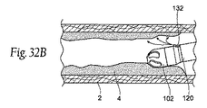
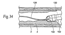
いずれの場合でも、デバイスの変形例は、近位端および遠位端と、それを通って延在するカテーテル管腔とを有する、カテーテル本体と、筐体と、筐体内に位置する回転型カッターとを含む、切削アセンブリであって、筐体が少なくとも1つの開口部を含み、カッターが少なくとも1つの刃先を含む、カテーテルの遠位端に付加される切削アセンブリと、切削アセンブリに隣接して位置する掃引フレームであって、カテーテルに連結され、回転型カッターとは無関係に回転可能な掃引フレームであって、掃引フレームは、掃引フレームの圧縮が第1の半径方向側に向かった撓みを引き起こし、カテーテル本体の遠位端の撓みをもたらすように、第1の半径方向側に少なくとも1つの弱い区間を備え、撓んだ掃引フレームの回転は、掃引フレームの近位端の軸に対し弓状経路で切削アセンブリを移動させる、掃引フレームと、カテーテル管腔および掃引フレームを通って延在し、回転型カッターに連結される第1の端と、回転機構に連結するように適合される第2の端とを有する、回転型トルクシャフトとを備える。 In any case, a variation of the device is a catheter body having a proximal end and a distal end and a catheter lumen extending therethrough, a housing, and a rotary cutter located within the housing. A cutting assembly added to the distal end of the catheter, wherein the housing includes at least one opening and the cutter includes at least one cutting edge, and positioned adjacent to the cutting assembly A sweep frame coupled to the catheter and rotatable independent of the rotary cutter, wherein the sweep frame causes a deflection of the sweep frame compression toward the first radial side; At least one weak section is provided on the first radial side to provide deflection of the distal end of the catheter body, and rotation of the deflected sweep frame may cause the sweep frame to rotate. A sweep frame for moving the cutting assembly in an arcuate path relative to the axis of the proximal end of the tube, a first end extending through the catheter lumen and the sweep frame and coupled to the rotary cutter, and a rotation mechanism A rotary torque shaft having a second end adapted to couple to the rotating torque shaft.
下記のように、掃引フレームは、任意の数の構成を有することができる。しかしながら、掃引フレームは、カテーテルの遠位部分の屈曲、ならびに、トルクシャフトおよび回転型カッターとは無関係にカテーテルのトルクシャフトおよび回転型カッターの回転を可能にするものである。いくつかの変形例では、掃引フレームは、カテーテル本体とは無関係に回転し、他の変形例では、掃引フレームは、カテーテル本体とともに回転する。他の変形例では、カテーテル本体の遠位部分が、掃引フレームとともに回転する一方で、カテーテル本体の近位部分は、静止したままである。加えて、本発明のデバイスは、カテーテル本体の長さの周囲に位置する、任意の数の掃引フレームを有することができ、その場合、各掃引フレームは、カテーテルの関連区分の屈曲を可能にする。これらの掃引フレームは、屈曲することができ、相互とは無関係に回転させることができる。代替として、掃引フレームの屈曲または回転は、そのように所望であれば関連付けることができる。 As described below, the sweep frame can have any number of configurations. However, the sweep frame allows bending of the distal portion of the catheter and rotation of the catheter's torque shaft and rotary cutter independent of the torque shaft and rotary cutter. In some variations, the sweep frame rotates independently of the catheter body, and in other variations, the sweep frame rotates with the catheter body. In other variations, the distal portion of the catheter body rotates with the sweep frame while the proximal portion of the catheter body remains stationary. In addition, the device of the present invention can have any number of sweep frames located around the length of the catheter body, where each sweep frame allows bending of the relevant section of the catheter. . These sweep frames can be bent and rotated independently of each other. Alternatively, sweep frame bending or rotation can be related if so desired.
本発明のシステムはさらに、近位端に連結されるハンドルを含むことができ、掃引フレームは、ハンドルとは無関係に回転可能である。典型的には、掃引フレームは、掃引部材または掃引シャフトによって作動される。掃引シャフトは、デバイスのハンドルまたは近位端から掃引フレームに軸力ならびに回転運動を伝えることができるように、製造される。 The system of the present invention can further include a handle coupled to the proximal end, and the sweep frame is rotatable independently of the handle. Typically, the sweep frame is actuated by a sweep member or sweep shaft. The sweep shaft is manufactured so that axial force as well as rotational movement can be transmitted from the handle or proximal end of the device to the sweep frame.
いくつかの変形例では、掃引フレームは、切削アセンブリの撓みを、撓みの最大角度で掃引フレームの近位端の軸から離れた既定の距離に限定するように構成される。さらなる変形例では、屈曲剛性および得られる潜在的な同等の力は、切削アセンブリの撓み角度または変位とともに、および掃引フレームに沿った軸方向位置とともに変動させることができる。 In some variations, the sweep frame is configured to limit the deflection of the cutting assembly to a predetermined distance away from the axis of the proximal end of the sweep frame at the maximum angle of deflection. In a further variation, the bending stiffness and the resulting potential equivalent force can be varied with the deflection angle or displacement of the cutting assembly and with the axial position along the sweep frame.
さらなる変形例では、掃引フレームの弱い区間は、撓まされたときに掃引フレームの半径方向のねじれを防止するように第1の半径方向側から離れた円周方向に増加する、変動コラム強度を備える。そのような構成は、屈曲時に掃引フレームの弱い区間のねじれまたはねじりを防止することを目的とする。1つの変形例では、掃引フレームは、第1の半径方向側に向かったそのような優先的屈曲、および第1の半径方向から離れた増加するコラム強度を達成するように、支柱を備える。 In a further variation, the weak section of the sweep frame increases the variable column strength, which increases in the circumferential direction away from the first radial side so as to prevent radial twisting of the sweep frame when deflected. Prepare. Such a configuration aims to prevent twisting or twisting of the weak section of the sweep frame when bent. In one variation, the sweep frame comprises struts to achieve such preferential bending towards the first radial side and increasing column strength away from the first radial direction.
ほとんどの変形例では、掃引フレームは、完全にカテーテル本体内に位置する。しかしながら、さらなる変形例では、掃引フレームは、露出されるか、またはカテーテルの外部上にあり得る。いずれの場合でも、掃引フレームは、カテーテルの屈曲および操縦を可能にするように、カテーテルに連結される。 In most variations, the sweep frame is located entirely within the catheter body. However, in a further variation, the sweep frame may be exposed or on the exterior of the catheter. In either case, the sweep frame is coupled to the catheter to allow for bending and steering of the catheter.
本明細書で説明される掃引フレーム構造は、同様に説明されるような、または当業者に公知のような、任意の数の切削アセンブリと組み合わせることができる。 The sweep frame structure described herein can be combined with any number of cutting assemblies as similarly described or known to those skilled in the art.
例えば、変形例では、カッターは、近方溝付き切削部分および遠方波形切削部分の両方の上に位置する、複数の刃先を備えることができ、近方溝付き切削部分および遠方波形切削部分は、カッターの軸に沿って離間し、遠方波形切削部分は、近方溝付き切削部分よりも少ない溝付き刃先を有し、カッターの回転時に、溝付き刃先は、身体管腔から物質を除去する。 For example, in a variation, the cutter can comprise a plurality of cutting edges located on both the near grooved cutting portion and the far undulating cutting portion, wherein the near grooving cutting portion and the far undulating cutting portion are The far corrugated cutting portion, spaced along the cutter axis, has fewer fluted cutting edges than the proximal fluted cutting portion, and when the cutter rotates, the fluted cutting edges remove material from the body lumen.
切削アセンブリは、筐体の外面に沿って複数の開口部を有する、切削筐体を含むことができる。代替として、筐体は、開放前面を有する円筒形筐体となり得る。そのような開放面筐体は、回転することができ(回転型カッターとともに、または反対方向に)、その場合、筐体は、カッターとして機能する。代替として、開放面筐体は、静止したままとなり得る。 The cutting assembly can include a cutting housing having a plurality of openings along an outer surface of the housing. Alternatively, the housing can be a cylindrical housing having an open front. Such an open face housing can rotate (with or without the rotary cutter), in which case the housing functions as a cutter. Alternatively, the open face housing can remain stationary.
デバイスのさらなる変形例では、切削アセンブリは、筐体の前部から遠位に延在する拡張器部材であって、それを通る通路を有し、カテーテル管腔と流体連通している、拡張器部材を含むことができ、拡張器部材が物質を通って前進するにつれて、拡張器部材が筐体の開口部の中へ物質を広げるように、拡張器部材は、遠位先端におけるより小さい直径表面と、筐体の前部に隣接するより大きい直径表面とを有する、先細形状を備える。 In a further variation of the device, the cutting assembly is a dilator member extending distally from the front of the housing, having a passage therethrough and in fluid communication with the catheter lumen. The dilator member may include a member, the dilator member having a smaller diameter surface at the distal tip such that as the dilator member is advanced through the material, the dilator member spreads the material into the opening of the housing. And a tapered shape having a larger diameter surface adjacent to the front of the housing.
本発明はまた、体内から閉塞物をデバルキングするための方法も含む。そのような方法は、身体管腔内の細長い部材の遠位端に付加されるデバルキングアセンブリとともに、細長い部材を有するカテーテルを前進させるステップと、身体管腔中の閉塞物に隣接してデバルキングアセンブリを位置付けるステップであって、デバルキングアセンブリは、カッターと、カテーテルの遠位部分に連結され、デバルキングアセンブリに近接する屈曲フレームとを有し、屈曲フレームは、屈曲フレームの第1の半径方向側に低減したコラム強度を有する、少なくとも1つの部分を備える、ステップと、カテーテルの近位端で掃引部材を移動させることによって、第1の半径方向側の方向に屈曲フレームを撓ませるステップであって、屈曲フレームを撓ませるステップは、第1の半径方向側の方向にデバルキングアセンブリも撓ませる、ステップと、カテーテルを通って延在し、閉塞物をデバルキングするように少なくともカッターに連結される、トルクシャフトを回転させるステップと、屈曲フレームを回転させ、屈曲フレームの近位端の軸に対する弓状経路でデバルキングアセンブリを掃引させるように、トルクシャフトとは無関係に掃引部材を移動させるステップとを含み得る。 The present invention also includes a method for debulking an obstruction from the body. Such a method includes advancing a catheter having an elongated member with a debulking assembly added to the distal end of the elongated member within the body lumen, and debulking adjacent to the obstruction in the body lumen. Positioning the assembly, the debulking assembly having a cutter and a bending frame coupled to the distal portion of the catheter and proximate to the debulking assembly, wherein the bending frame is a first radial direction of the bending frame. Comprising: at least one portion having a reduced column strength on the side; and deflecting the bending frame in the first radial direction by moving the sweep member at the proximal end of the catheter. The step of deflecting the bending frame is also the debulking assembly in the first radial direction. Rotating the torque shaft, extending through the catheter and coupled to at least the cutter to debulk the obstruction; rotating the bending frame relative to the axis of the proximal end of the bending frame; Moving the sweep member independently of the torque shaft to sweep the debulking assembly in an arcuate path.
本明細書で論議されるように、新規のデバイスの変形例は、デバルキングデバイスの遠位部分(および他の部分)の撓みを引き起こすように、1つ以上の掃引フレームおよび/または掃引管を含む。掃引フレームは、真っ直ぐな位置にあるときに、カテーテルが真っ直ぐなままとなることを可能にするため、従来のデバイスを改良する。言い換えれば、掃引フレームは、デバイスが真っ直ぐな位置になるように意図されるときに、デバルキングカテーテルが望ましくない「屈曲」を生じることを防止する。そのような望ましくない設定屈曲は、従来の操縦可能なカテーテルでよく見られる。望ましくない設定された屈曲を回避することにより、デバルキングデバイスが健常組織に不要な巻き添え損害を生成する可能性が低減する。例えば、(多重屈曲後に、包装の中の長期間により、または熱に曝され)屈曲を成す従来のデバイスは、デバイスが真っ直ぐであると医師が想定した場合、健常組織に寄り掛かるようになり得る。明らかに、そのような状況での従来のデバイスの活性化は、医師がデバルキングを標的組織に限定することを妨げる。 As discussed herein, new device variations may include one or more sweep frames and / or sweep tubes to cause deflection of the distal portion (and other portions) of the debulking device. Including. The sweep frame improves upon conventional devices to allow the catheter to remain straight when in a straight position. In other words, the sweep frame prevents the debulking catheter from causing undesirable “bends” when the device is intended to be in a straight position. Such undesirable setting bends are common in conventional steerable catheters. By avoiding undesired set bends, the likelihood that a debulking device will generate unwanted collateral damage to healthy tissue is reduced. For example, a conventional device that makes a bend (after multiple bends, due to long periods of time in the package, or exposed to heat) can become lean against healthy tissue if the doctor assumes that the device is straight . Clearly, activation of conventional devices in such situations prevents physicians from limiting debulking to the target tissue.
構造(例えば、単純かつ安価な構造)を簡単にするだけではなく、掃引フレームは、真っ直ぐな位置および撓み位置での向上した前方切削速度のために、優れたコラム強度を提供する。この構造は、鞘がトルクシャフトに倒れ込み、トルクシャフトをらせん状に包み込む、故障モードを防止することが分かった。また、掃引フレームは、カテーテルよりも大きい直径におけるより良好な切削のために、優れた同等の力を提供する。 In addition to simplifying the structure (eg, a simple and inexpensive structure), the sweep frame provides excellent column strength due to improved forward cutting speed in straight and flex positions. This structure has been found to prevent a failure mode where the sheath falls over the torque shaft and wraps around the torque shaft in a spiral. The sweep frame also provides superior equivalent force for better cutting at larger diameters than the catheter.
加えて、撓むためには圧縮されなければならない掃引フレームを提供することにより、掃引フレームの屈曲部分が所望の最大撓みに到達すると、屈曲部分を形成する区分が機械的に干渉して、さらなる屈曲を防止することができるように、構造を選択的に「調整する」ことを可能にする。 In addition, by providing a sweep frame that must be compressed in order to deflect, when the bent portion of the sweep frame reaches the desired maximum deflection, the sections forming the bent portion mechanically interfere to cause further bending. Allows the structure to be selectively “tuned” so that it can be prevented.
別の実施例では、本デバイスの掃引フレームは、医師が非侵襲性撮像手段からデバイスの屈曲の配向を判定することができるように、特徴を含むことができる。例えば、掃引フレームに連結される掃引フレームまたはカテーテルは、掃引フレームの関節運動の配向および方向の非侵襲性判定を可能にする、1つ以上の可視化マークを含むことができる。可視化マークは、撓まされたときに、蛍光透視平面の中/外へのデバイス先端の方向を示すように、放射線不透過マーカ(切り欠きまたは突起のいずれか)としての役割を果たす屈曲平面から、非対称に成形され得る。マーカはまた、タンタル、金、白金等のような放射線不透過物質のストライプ/バンド/ワイヤ等の付加であり得る。 In another example, the sweep frame of the device can include features so that a physician can determine the orientation of the device's bends from non-invasive imaging means. For example, a sweep frame or catheter coupled to the sweep frame can include one or more visualization marks that allow a non-invasive determination of the articulation orientation and direction of the sweep frame. When the visualization mark is deflected, from the bending plane that serves as a radiopaque marker (either a notch or a protrusion) to indicate the direction of the device tip into / out of the fluoroscopic plane Can be asymmetrically shaped. The marker can also be an addition of a stripe / band / wire etc. of radiopaque material such as tantalum, gold, platinum and the like.
方法またはデバイスのさらなる変形例では、掃引部材は、屈曲フレームがさらに屈曲すること、または屈曲しないことを防止するように、デバイスに対して係止されることができる。それはまた、掃引を防止するように、デバイスに対して独立して係止し得る。 In a further variation of the method or device, the sweep member can be locked to the device to prevent the bending frame from further bending or not bending. It can also lock independently to the device to prevent sweeping.
デバイスおよび方法はまた、流体ポートを通して流体を送達するステップも含む。流体は、手技を支援するように、薬剤または他の物質を含み得る。 The device and method also includes delivering fluid through the fluid port. The fluid may include drugs or other substances to assist in the procedure.
身体通路内の組織を除去するための方法の別の実施形態では、方法は、体内でカテーテルの遠位端に付加されるデバルキングアセンブリを有するカテーテルを前進させるステップと、体内の組織に隣接してデバルキングアセンブリを位置付けるステップと、カテーテルの遠位部分に連結される屈曲フレームを撓ませるように、カテーテルの近位端において遠位力を与えるステップと、屈曲フレームの近位端の軸に対する弓状経路でデバルキングアセンブリを掃引させるように屈曲フレームを撓ませながら、屈曲フレームを回転させるステップと、カテーテルを通って延在し、組織をデバルキングするように少なくともカッターに連結される、トルクシャフトを回転させるステップと、屈曲フレームを回転させ、屈曲フレームの近位端の軸に対する弓状経路でデバルキングアセンブリを掃引させるように、トルクシャフトとは無関係に掃引シャフトを回転させるステップとを含むことができる。 In another embodiment of a method for removing tissue in a body passage, the method includes advancing a catheter having a debulking assembly added to the distal end of the catheter in the body, and adjacent to the tissue in the body. Positioning the debulking assembly, applying a distal force at the proximal end of the catheter to deflect the bending frame coupled to the distal portion of the catheter, and a bow relative to the axis of the proximal end of the bending frame Rotating the flexure frame while deflecting the flexure frame to sweep the debulking assembly in a path, and extending a torque shaft extending through the catheter and coupled to at least the cutter to debulk tissue. Rotating and rotating the bending frame against the axis of the proximal end of the bending frame. That way to sweep the debulking assembly in an arcuate path may include a step of rotating independently of the sweep shaft and torque shaft.
方法の別の変形例は、遠位端を撓ませ、軸方向に切削するようにカテーテルを前進させることである。軸方向パターンは、組織を除去するように連続する半径方向位置で反復することができる。 Another variation of the method is to advance the catheter to deflect the distal end and cut axially. The axial pattern can be repeated at successive radial locations to remove tissue.
方法の別の変形例は、カテーテル本体に沿って第2の屈曲または掃引フレームを位置付け、撓ませて、デバルキングアセンブリの届く範囲を増加させるように、第1の掃引フレームによって設定される方向にデバルキングアセンブリを前進させることである。第2の掃引フレームは、血管壁と相互作用するカテーテル本体からの反力を必要とせずに、プラークまたは組織に対して接近されるカッターの同等の力に、反力を提供することができる。第2の屈曲フレームはまた、デバルキングされる組織に対するカッター角度の正確な制御を可能にするためにも使用することができる。第2の掃引シャフトは、デバルキングアセンブリを掃引させるように回転させることができる。 Another variation of the method is to position and deflect a second bend or sweep frame along the catheter body in a direction set by the first sweep frame to increase the reach of the debulking assembly. To advance the debulking assembly. The second sweep frame can provide a reaction force to the equivalent force of the cutter approached against the plaque or tissue without the need for a reaction force from the catheter body interacting with the vessel wall. The second flex frame can also be used to allow precise control of the cutter angle relative to the debulked tissue. The second sweep shaft can be rotated to sweep the debulking assembly.
本明細書で論議されるように、デバイスのいくつかの変形例には、関節運動する能力がある。この関節運動は、標的部位へのデバイスの操縦、ならびに組織除去の掃引の生成を可能にする。この操縦する能力は、蛇行性生体構造を通してガイドワイヤをナビゲートしようとするときに有用となり得る。例えば、医師はしばしば、血管内の閉塞または血管系の蛇行性質のいずれかにより、蛇行性生体構造を通してガイドワイヤを前進させるときに抵抗に遭遇する。医師がそのような抵抗に遭遇すると、デバルキングカテーテル内に、またはそこからわずかに延在して、ガイドワイヤを引き抜くことができる。次いで、医師は、デバルキングカテーテルを操縦して、前進のためにガイドワイヤを方向付け直すことができる。いったんガイドワイヤが定位置になると、医師は、切削機構を起動して組織を選択的に除去することができる。 As discussed herein, some variations of the device have the ability to articulate. This articulation enables the steering of the device to the target site as well as the generation of a tissue removal sweep. This ability to steer can be useful when trying to navigate a guidewire through tortuous anatomy. For example, physicians often encounter resistance when advancing the guidewire through tortuous anatomy, either due to occlusion within the blood vessel or tortuous nature of the vasculature. When a physician encounters such resistance, the guidewire can be withdrawn into or slightly extended from the debulking catheter. The physician can then maneuver the debulking catheter to redirect the guidewire for advancement. Once the guidewire is in place, the physician can activate the cutting mechanism to selectively remove tissue.
本明細書で説明されるデバイスは、曲面を有するその筐体の一部分を有する、カッターアセンブリを有し得、その場合、切削面が開口部を横断して回転するにつれて、切削面の一部分が開口部を通って筐体から外へ延在するように、開口部は、曲面を横断する平面を形成する。カッターアセンブリはまた、切削している間に関節運動されるとデバイスの安全性を向上させる、以下で説明されるような種々の他の特徴を有し得る。その上、カッターは、1つ以上の運搬部材による最終的な除去のために、カッターアセンブリの中に切削組織を推進または駆動する、多数の特徴を有し得る。 The devices described herein can have a cutter assembly having a portion of its housing that has a curved surface, where a portion of the cutting surface opens as the cutting surface rotates across the opening. The opening forms a plane that crosses the curved surface so as to extend out of the housing through the section. The cutter assembly may also have various other features, as described below, that improve the safety of the device when articulated during cutting. Moreover, the cutter may have a number of features that propel or drive cutting tissue into the cutter assembly for final removal by one or more transport members.
既述のように、本明細書で説明されるデバイスは、デバイスを通して物質および/または流体を運搬する、1つ以上の運搬部材を有し得る。そのような特徴は、手技中に部位から切削組織および破片を除去するために有用である。いくつかの変形例では、デバイスは、複数のコンベヤを含んで、流体を送達し、破片を除去し得る。しかしながら、本発明のデバイスはまた、手技中に生成される破片または他の物質を捕捉する際に使用するための容器を有し得る。 As already mentioned, the devices described herein may have one or more delivery members that carry substances and / or fluids through the device. Such features are useful for removing cutting tissue and debris from the site during the procedure. In some variations, the device may include multiple conveyors to deliver fluids and remove debris. However, the device of the present invention may also have a container for use in capturing debris or other material generated during the procedure.
本明細書の発明とともに使用するための別の特徴は、デバイスの先端に回転可能に連結される、粉砕バーの使用である。バーは、そうでなければカッターアセンブリによる切削を助長しない組織を除去するために有用となり得る。 Another feature for use with the invention herein is the use of a grinding bar that is rotatably coupled to the tip of the device. The bar can be useful for removing tissue that would otherwise not facilitate cutting by the cutter assembly.
本明細書で説明されるデバイスは、身体を通した前進のためにガイドワイヤを使用し得る。そのような場合、デバイスは、カテーテル内または周囲に位置するガイドワイヤを有する。代替として、ガイドワイヤ部は、デバイスの一部分に付加され得る。 The devices described herein may use a guidewire for advancement through the body. In such cases, the device has a guidewire located in or around the catheter. Alternatively, the guide wire portion can be added to a portion of the device.
本発明のデバイスは、典型的には、カッターアセンブリの構成要素に回転運動を送達するように、トルクシャフトを含む。トルクシャフトは、1つ以上の管腔を含み得る。代替として、トルクシャフトは、中実または中空部材であり得る。トルクシャフトの変形例はまた、反対巻きコイル、補強部材等の、カテーテル型デバイスにおいて公知の側面も含む。代替として、または組み合わせて、運搬部材は、本明細書で説明されるように、トルクシャフト上(または内)に配置され得る。 The device of the present invention typically includes a torque shaft to deliver rotational motion to the components of the cutter assembly. The torque shaft can include one or more lumens. Alternatively, the torque shaft can be a solid or hollow member. Variations on the torque shaft also include known aspects of catheter-type devices, such as counter-wound coils, reinforcement members, and the like. Alternatively or in combination, the conveying member may be disposed on (or in) the torque shaft as described herein.
本明細書で説明されるシステムとともに、説明書が提供され得、システムの種々の手順および使用法を説明し得る。例えば、使用説明書は、カテーテルの使用法を説明し得、説明書は、血管にカテーテルアセンブリを導入し、組織のデバルキングを必要としている部位またはその付近に組織切削アセンブリを位置付ける動作と、血管中の組織をデバルキングするように組織除去アセンブリを操作する動作と、組織除去アセンブリの直径の少なくとも2倍の血管内で開いた組織直径を生成する動作と、取り除いた組織を除去する動作とを含む。 Along with the system described herein, instructions can be provided to describe various procedures and uses of the system. For example, the instructions for use may describe the use of the catheter, the instructions for introducing the catheter assembly into the blood vessel, positioning the tissue cutting assembly at or near the site in need of tissue debulking, and in the blood vessel. Manipulating the tissue removal assembly to debulk the tissue, generating an open tissue diameter in the vessel at least twice the diameter of the tissue removal assembly, and removing the removed tissue.
カテーテルの使用法を説明する使用説明書または方法はまた、血管にカテーテルアセンブリを導入し、組織のデバルキングを必要としている部位またはその付近に組織切削アセンブリを位置付ける動作と、撓み制御デバイスを操作し、それによりカテーテルの遠位部分を撓ませる動作と、回転制御デバイスを操作し、それにより弓状経路でカテーテルの遠位部分を回転させる動作とを含み得る。 Instructions or methods describing the use of the catheter also introduce the catheter assembly into the blood vessel, position the tissue cutting assembly at or near the site where tissue debulking is needed, and operate the deflection control device; This may include actuating the distal portion of the catheter and manipulating the rotation control device, thereby rotating the distal portion of the catheter in an arcuate path.
カテーテルの動作を説明する、付加的な使用方法または使用説明書は、血管にカテーテルアセンブリを導入し、組織のデバルキングを必要としている部位またはその付近に組織切削アセンブリを位置付けるステップと、カテーテルの近位端またはその付近で掃引部材を移動させることによって、屈曲フレームの第1の半径方向側の方向に屈曲フレームを撓ませ、それにより組織切削アセンブリを第1の半径方向側の方向に撓ませるステップと、カテーテルを通って延在し、少なくとも回転型カッターに連結される、トルクシャフトを回転させるステップと、屈曲フレームを回転させ、屈曲フレームの近位端の軸に対する弓状経路で組織切削アセンブリを掃引させるために、トルクシャフトとは無関係に掃引部材を移動させるステップと、閉塞物を除去するステップとを含み得る。 Additional methods of use or instructions describing the operation of the catheter include introducing the catheter assembly into a blood vessel, positioning the tissue cutting assembly at or near the site in need of tissue debulking, and proximal of the catheter. Deflecting the flexure frame in a first radial direction of the flexure frame by moving the sweep member at or near the end, thereby deflecting the tissue cutting assembly in the first radial direction; Rotate the torque shaft, extending through the catheter and coupled to at least the rotary cutter, and rotating the bending frame to sweep the tissue cutting assembly in an arcuate path relative to the axis of the proximal end of the bending frame To move the sweep member independently of the torque shaft, It may include removing the.
カテーテルの動作を説明する、付加的な使用方法または使用説明書は、血管に導入されるようにサイズ決定および構成されるカテーテルであって、カテーテルの遠位端またはその付近に組織切削アセンブリを含む、カテーテルを提供するステップであって、組織切削アセンブリは、血管から組織をデバルキングするための回転型カッターを含む、ステップと、カテーテルに連結される制御ハンドルであって、組織切削アセンブリを操縦するための操縦手段を含む、制御ハンドルを提供するステップと、腸骨動脈にカテーテルを導入するステップと、大腿動脈、大腿深動脈、ハンター管の中の動脈、膝窩動脈、脛骨動脈、腓骨動脈、足背動脈、内側足底動脈、外側足底動脈、または指動脈の中にカテーテルを前進させるステップと、大腿動脈、大腿深動脈、ハンター管の中の動脈、膝窩動脈、脛骨動脈、腓骨動脈、足背動脈、内側足底動脈、外側足底動脈、または指動脈中の標的部位またはその付近に組織切削アセンブリを位置付けるステップと、操縦手段に第1の力を与えることによって操縦手段を操作するステップであって、第1の力は、半径方向にカーテルの遠位部分を撓ませる、ステップと、操縦手段に第2の力を与えることによって操縦手段を操作するステップであって、第2の力は、遠位部分が半径方向に撓まされている間に、弓状経路でカテーテルの遠位部分を回転させる、ステップと、標的部位を掃引させるようにカテーテルを遠位に前進させ、それにより回転型カッターが弓状経路で標的部位から組織をデバルキングすることを可能にするステップと、標的部位からデバルキングされた組織を除去し、それにより血管を治療するステップとを含み得る。 An additional method of use or instructions describing the operation of the catheter is a catheter sized and configured to be introduced into a blood vessel, including a tissue cutting assembly at or near the distal end of the catheter Providing a catheter, wherein the tissue cutting assembly includes a rotary cutter for debulking tissue from the blood vessel, and a control handle coupled to the catheter for manipulating the tissue cutting assembly Providing a control handle including a steering means, introducing a catheter into the iliac artery, an artery in the femoral artery, deep femoral artery, Hunter tube, popliteal artery, tibial artery, radial artery, foot Advancing the catheter into the dorsal artery, medial plantar artery, lateral plantar artery, or finger artery; Tissue cutting assembly at or near target site in deep femoral artery, artery in Hunter's canal, popliteal artery, tibial artery, radial artery, dorsal artery, medial plantar artery, lateral plantar artery, or finger artery Positioning and manipulating the steering means by applying a first force to the steering means, the first force deflecting the distal portion of the cartel in the radial direction; Manipulating the steering means by applying a force of two, wherein the second force rotates the distal portion of the catheter in an arcuate path while the distal portion is deflected radially. Advancing the catheter distally to sweep the target site, thereby allowing the rotary cutter to debulk tissue from the target site in an arcuate path; Removing debulking tissue, thereby it may comprise a step of treating vascular.
カテーテルの動作を説明する、付加的な使用方法または使用説明書は、血管に導入されるようにサイズ決定および構成されるカテーテルであって、カテーテルの遠位端またはその付近に組織切削アセンブリを含む、カテーテルを提供するステップであって、組織切削アセンブリは、血管から組織をデバルキングするための回転型カッターを含む、ステップと、カテーテルアセンブリに連結される制御ハンドルであって、組織切削アセンブリを操縦するための操縦手段を含む、制御ハンドルを提供するステップと、上腕動脈にカテーテルを導入するステップと、上腕深動脈、上尺側側動脈、下尺側側動脈、橈骨動脈、尺骨動脈、または上腕分岐の中にカテーテルを前進させるステップと、上腕深動脈、上尺側側動脈、下尺側側動脈、橈骨動脈、尺骨動脈、または上腕分岐中の標的部位またはその付近に組織切削アセンブリを位置付けるステップと、操縦手段に第1の力を与えることによって操縦手段を操作するステップであって、第1の力は、半径方向にカーテルの遠位部分を撓ませる、ステップと、カテーテルを軸方向に移動させ、それにより回転型カッターが弓状経路で標的部位から組織をデバルキングすることを可能にするステップと、標的部位からデバルキングされた組織を除去し、それにより血管を治療するステップとを含み得る。 An additional method of use or instructions describing the operation of the catheter is a catheter sized and configured to be introduced into a blood vessel, including a tissue cutting assembly at or near the distal end of the catheter Providing a catheter, wherein the tissue cutting assembly includes a rotary cutter for debulking tissue from the blood vessel, and a control handle coupled to the catheter assembly for steering the tissue cutting assembly Providing a control handle, including a steering means, introducing a catheter into the brachial artery, brachial deep artery, brachial artery, brachial artery, radial artery, ulnar artery, or brachial branch Advancing the catheter into the brachial deep artery, superior side artery, inferior artery, radial artery, Positioning a tissue cutting assembly at or near a target site in a bone artery or a humeral bifurcation and manipulating the steering means by applying a first force to the steering means, the first force being a radius Deflecting the distal portion of the cartel in a direction, moving the catheter axially, thereby allowing the rotary cutter to debulk tissue from the target site in an arcuate path; Removing the debulked tissue and thereby treating the blood vessel.
本明細書で記述されるように、本明細書で説明されるデバイス、システム、および方法の側面の組み合わせは、必要に応じて組み合わせられてもよい。その上、デバイス、システム、および方法自体の組み合わせは、本開示の範囲内である。
例えば、本発明は以下の項目を提供する。
(項目1)
カテーテルの遠位部分またはその付近に組織除去アセンブリを有する、カテーテルであって、該組織除去アセンブリは、直径を有する、カテーテルと、
該組織除去アセンブリを操作して血管中の組織をデバルキングするように適合される、撓み部材と
を備え、
該組織除去アセンブリは、該組織除去アセンブリの直径の少なくとも2倍の該血管内で開いた組織直径を生成するように適合されている、
システム。
(項目2)
カテーテルの遠位部分またはその付近に撓み区分を有する、カテーテルであって、該撓み区分は、長さLと、直線軸Sと、撓み軸Dとを有する、カテーテルと、
該カテーテルに連結された撓み部材であって、該カテーテルの該撓み区分を操作するように適合され、該直線軸Sから該撓み軸Dまでの該撓み区分の該長さLを撓ませて、該直線軸Sと該撓み軸Dとの間に角度Aを生成し、該角度は、0度から90度の間の範囲を有する、撓み部材と
を備える、システム。
(項目3)
血管に導入されるようにサイズ決定および構成されたカテーテルアセンブリであって、該カテーテルアセンブリは、該カテーテルアセンブリの遠位端またはその付近に組織切削アセンブリを含み、該組織切削アセンブリは、該血管から組織をデバルキングするための回転型カッターを含む、カテーテルアセンブリと、
該カテーテルの使用を説明する使用説明書であって、該血管に該カテーテルアセンブリを導入し、組織のデバルキングを必要としている部位またはその付近に該組織切削アセンブリを位置付ける動作と、該血管中の組織をデバルキングするように該組織除去アセンブリを操作する動作と、該組織除去アセンブリの直径の少なくとも2倍の該血管内で開いた組織直径を生成する動作と、取り除いた組織を除去する動作とを含む、説明書と
を備える、システム。
(項目4)
カテーテルに連結される制御ハンドルであって、撓み制御デバイスと、回転制御デバイスとを備える、制御ハンドルと
を備え、
該撓み制御デバイスは、該カテーテルの軸から半径方向にオフセットされた方向に、該カテーテルの遠位部分を撓ませるように適合され、
該回転制御デバイスは、該カテーテルの該遠位部分が撓まされている間に、弓状経路で該カテーテルの該遠位部分を回転させるように適合されている、
システム。
(項目5)
上記撓み制御デバイスおよび回転制御デバイスは、上記カテーテルの上記遠位部分の撓みと、該カテーテルの該遠位部分が撓まされている間の弓状経路での該カテーテルの該遠位部分の回転との両方のために適合された、撓みおよび回転制御ノブを備える、項目4に記載のシステム。
(項目6)
上記撓みおよび回転制御ノブは、該撓みおよび回転制御ノブへの第1の力の付与による、上記カテーテルの上記遠位部分の撓みのために適合され、該撓みおよび回転制御ノブは、該撓みおよび回転制御ノブへの第2の力の付与によって、該カテーテルの該遠位部分が撓まされている間に、弓状経路での該カテーテルの該遠位部分の回転のために適合されている、項目5に記載のシステム。
(項目7)
血管に導入されるようにサイズ決定および構成されたカテーテルアセンブリであって、該カテーテルアセンブリは、該カテーテルアセンブリの遠位端またはその付近に組織切削アセンブリを含み、該組織切削アセンブリは、該血管から組織をデバルキングするための回転型カッターを含む、カテーテルアセンブリと、
該カテーテルアセンブリに連結された制御ハンドルであって、該制御ハンドルは、該組織切削アセンブリを操縦するための操縦手段と、該回転型カッターを回転させるための回転手段と、該回転型カッターを回転させるように適合された該回転手段に電力を提供するための電力手段と、該回転手段への該電力を制御するためのオン/オフ手段とを含む、制御ハンドルと、
該回転手段から該回転型カッターまで延在するトルクシャフトであって、該トルクシャフトは、該回転型カッターから該カテーテルアセンブリを通って、そして該制御ハンドルの少なくとも一部分を通ってレセプタクルまで、切削された組織を移動させるための吸引手段を含むトルクシャフトと
を備える、システム。
(項目8)
上記制御ハンドルはさらに、ハンドル基部と、カテーテルシャーシ部分とを備え、該ハンドル基部は、該カテーテルシャーシ内に位置付けられた上記トルクシャフトに回転力を提供するように適合されている、項目7に記載のシステム。
(項目9)
上記ハンドル基部およびカテーテルシャーシは、上記制御ハンドルの動作のために、道具を使用せず、ともに連結されるように適合されている、項目8に記載のシステム。
(項目10)
血管に導入されるようにサイズ決定および構成されたカテーテルアセンブリであって、該カテーテルアセンブリは、該カテーテルアセンブリの遠位端またはその付近に組織切削アセンブリを含み、該組織切削アセンブリは、該血管から組織をデバルキングするための回転型カッターを含む、カテーテルアセンブリと、
該カテーテルアセンブリに連結された制御ハンドルであって、撓み制御デバイスと、回転制御デバイスとを備える制御ハンドルと、
該カテーテルの使用を説明する使用説明書であって、該血管に該カテーテルアセンブリを導入し、組織のデバルキングを必要としている部位またはその付近に該組織切削アセンブリを位置付ける動作と、該撓み制御デバイスを操作し、それにより該カテーテルの遠位部分を撓ませる動作と、該回転制御デバイスを操作し、それにより弓状経路で該カテーテルの該遠位部分を回転させる動作とを含む、説明書と
を備える、システム。
(項目11)
血管に導入されるようにサイズ決定および構成されたカテーテルアセンブリであって、該カテーテルアセンブリは、その中を通る管腔と、該カテーテルアセンブリの遠位端またはその付近における組織切削アセンブリとを含み、該組織切削アセンブリは、該血管から組織をデバルキングするための回転型カッターを含む、カテーテルアセンブリと、
該カテーテルアセンブリに連結された制御ハンドルであって、該組織除去アセンブリを操縦するための操縦手段を含む制御ハンドルと、
該操縦手段に連結された屈曲フレームであって、屈曲フレームは、該屈曲フレームの第1の半径方向側に低減されたコラム強度を有する少なくとも1つの部分を備え、該操縦手段に第1の力が与えられると、該第1の半径方向側の方向に該組織切削アセンブリを撓ませるように適合されている、屈曲フレームと
を備える、カテーテルシステム。
(項目12)
上記屈曲フレームは、上記組織除去アセンブリの上記撓みを制限するように構成されている、項目11に記載のシステム。
(項目13)
上記屈曲フレームは、上記カテーテルアセンブリに連結されている、項目11に記載のシステム。
(項目14)
血管に導入されるようにサイズ決定および構成されたカテーテルアセンブリであって、該カテーテルアセンブリは、その中を通る管腔と、該カテーテルアセンブリの遠位端またはその付近における組織切削アセンブリとを含み、該組織切削アセンブリは、該血管から組織をデバルキングするための回転型カッターを含む、カテーテルアセンブリと、
該カテーテルアセンブリに連結された制御ハンドルであって、該組織除去アセンブリを操縦するための操縦手段を含む制御ハンドルと、
該カテーテル管腔内に位置付けられた第1の操縦部材であって、該第1の操縦部材に第1の力が与えられると、該組織切削アセンブリを撓ませるように適合されている、第1の操縦部材と、
該操縦手段に連結された第2の操縦部材であって、該第1の操縦部材に第1の力および第2の力を伝えるように適合された第2の操縦部材と
を備え、
該第1の力は、該第1の操縦部材および該組織切削アセンブリの撓みを引き起こし、
該第2の力は、弓状経路での該第1の操縦部材および該組織切削アセンブリの回転を引き起こす、
カテーテルシステム。
(項目15)
上記第2の操縦部材は、上記第1の操縦部材の近位で上記カテーテル管腔内に位置付けられている、項目14に記載のシステム。
(項目16)
血管に導入されるようにサイズ決定および構成されたカテーテルアセンブリであって、該カテーテルアセンブリは、該カテーテルアセンブリの遠位端またはその付近に組織切削アセンブリを含み、該組織切削アセンブリは、該血管から組織をデバルキングするための回転型カッターと、該組織切削アセンブリの近位に位置付けられた屈曲フレームとを含む、カテーテルアセンブリと、
該カテーテルアセンブリに連結された制御ハンドルであって、該組織除去アセンブリを操縦するための操縦手段と、該回転型カッターを回転させるための回転手段とを含む制御ハンドルと、
該カテーテルの動作を説明する使用説明書であって、
該血管に該カテーテルアセンブリを導入し、組織のデバルキングを必要としている部位またはその付近に該組織切削アセンブリを位置付けるステップと、
該カテーテルの近位端またはその付近で掃引部材を移動させることによって、該屈曲フレームの第1の半径方向側の方向に該屈曲フレームを撓ませ、それにより該組織切削アセンブリを該第1の半径方向側の方向に撓ませるステップと、
該カテーテルを通って延在し、少なくとも該回転型カッターに連結されたトルクシャフトを回転させるステップと、
該屈曲フレームを回転させるために該トルクシャフトとは無関係に該掃引部材を移動させ、該屈曲フレームの近位端の軸に対し弓状経路で該組織切削アセンブリを掃引させるステップと、
閉塞物を除去するステップと
を含む、説明書と
を備える、システム。
(項目17)
上記カテーテルは、8Fr以下の導入器を使用して血管に導入するようにサイズ決定および構成される、項目1〜項目16のいずれか1項に記載のシステム。
(項目18)
上記カテーテルは、8Fr以下の導入器の中に存在している間に、造影剤注入を可能にするようにサイズ決定および構成される、項目1〜項目17のいずれか1項に記載のシステム。
(項目19)
上記カテーテルは、組織のデバルキングのためにサイズ決定および構成されている、項目1〜項目18のいずれか1項に記載のシステム。
(項目20)
上記カテーテルは、血栓切除術および/またはアテローム切除術のためにサイズ決定および構成されている、項目1〜項目19のいずれか1項に記載のシステム。
(項目21)
上記カテーテルアセンブリは、上記血管にわずか1回導入されるように適合されている、項目1〜項目20のいずれか1項に記載のシステム。
(項目22)
上記カテーテルは、取り除いた組織を除去するための管腔を備えている、項目1〜項目21のいずれか1項に記載のシステム。
(項目23)
上記カテーテルは、急性血栓、組織化血栓、アテローム、線維性プラーク、および石灰化プラークを含む、組織を除去するためにサイズ決定および構成されている、項目1〜項目22のいずれか1項に記載のシステム。
(項目24)
上記血管は、上腕動脈、総腸骨動脈、外腸骨動脈、内腸骨動脈、大腿動脈、大腿深動脈、大腿深動脈、近位浅大腿動脈、ハンター管の中の動脈、膝窩動脈、後脛骨動脈、前脛骨動脈、腓骨動脈、足背動脈、内側および外側足底動脈、および指動脈から成る群より選択される、項目1〜項目23のいずれか1項に記載のシステム。
As described herein, combinations of the device, system, and method aspects described herein may be combined as needed. Moreover, combinations of devices, systems, and methods themselves are within the scope of this disclosure.
For example, the present invention provides the following items.
(Item 1)
A catheter having a tissue removal assembly at or near a distal portion of the catheter, the tissue removal assembly having a diameter;
A flexure member adapted to manipulate the tissue removal assembly to debulk tissue in a blood vessel;
With
The tissue removal assembly is adapted to produce an open tissue diameter in the blood vessel that is at least twice the diameter of the tissue removal assembly;
system.
(Item 2)
A catheter having a deflection section at or near the distal portion of the catheter, the deflection section having a length L, a linear axis S, and a deflection axis D;
A deflection member coupled to the catheter, adapted to manipulate the deflection section of the catheter, deflecting the length L of the deflection section from the linear axis S to the deflection axis D; An angle A between the linear axis S and the deflection axis D, the angle having a range between 0 and 90 degrees;
A system comprising:
(Item 3)
A catheter assembly sized and configured to be introduced into a blood vessel, the catheter assembly including a tissue cutting assembly at or near a distal end of the catheter assembly, the tissue cutting assembly from the blood vessel A catheter assembly including a rotary cutter for debulking tissue;
Instructions for use of the catheter, the operation of introducing the catheter assembly into the blood vessel and positioning the tissue cutting assembly at or near a site in need of tissue debulking, and tissue in the blood vessel Manipulating the tissue removal assembly to debulk, generating an open tissue diameter in the blood vessel at least twice the diameter of the tissue removal assembly, and removing the removed tissue With instructions
A system comprising:
(Item 4)
A control handle coupled to the catheter, the control handle comprising a deflection control device and a rotation control device;
With
The deflection control device is adapted to deflect the distal portion of the catheter in a direction radially offset from the axis of the catheter;
The rotation control device is adapted to rotate the distal portion of the catheter in an arcuate path while the distal portion of the catheter is deflected;
system.
(Item 5)
The deflection control device and the rotation control device are configured to cause deflection of the distal portion of the catheter and rotation of the distal portion of the catheter in an arcuate path while the distal portion of the catheter is deflected. 5. The system of
(Item 6)
The deflection and rotation control knob is adapted for deflection of the distal portion of the catheter by applying a first force to the deflection and rotation control knob, wherein the deflection and rotation control knob includes the deflection and rotation control knob. Application of a second force to the rotation control knob is adapted for rotation of the distal portion of the catheter in an arcuate path while the distal portion of the catheter is deflected. The system according to item 5.
(Item 7)
A catheter assembly sized and configured to be introduced into a blood vessel, the catheter assembly including a tissue cutting assembly at or near a distal end of the catheter assembly, the tissue cutting assembly from the blood vessel A catheter assembly including a rotary cutter for debulking tissue;
A control handle coupled to the catheter assembly, wherein the control handle is a steering means for steering the tissue cutting assembly; a rotating means for rotating the rotary cutter; and rotating the rotary cutter A control handle including power means for providing power to the rotating means adapted to cause and on / off means for controlling the power to the rotating means;
A torque shaft extending from the rotating means to the rotary cutter, the torque shaft being cut from the rotary cutter through the catheter assembly and through at least a portion of the control handle to a receptacle. A torque shaft including suction means for moving the affected tissue;
A system comprising:
(Item 8)
The control handle further comprises a handle base and a catheter chassis portion, the handle base being adapted to provide rotational force to the torque shaft positioned within the catheter chassis. System.
(Item 9)
9. The system of
(Item 10)
A catheter assembly sized and configured to be introduced into a blood vessel, the catheter assembly including a tissue cutting assembly at or near a distal end of the catheter assembly, the tissue cutting assembly from the blood vessel A catheter assembly including a rotary cutter for debulking tissue;
A control handle coupled to the catheter assembly, the control handle comprising a deflection control device and a rotation control device;
Instructions for use of the catheter, the operation of introducing the catheter assembly into the blood vessel and positioning the tissue cutting assembly at or near a site in need of tissue debulking; and Instructions for manipulating and thereby deflecting the distal portion of the catheter and manipulating the rotation control device, thereby rotating the distal portion of the catheter in an arcuate path;
A system comprising:
(Item 11)
A catheter assembly sized and configured to be introduced into a blood vessel, the catheter assembly including a lumen therethrough and a tissue cutting assembly at or near the distal end of the catheter assembly; The tissue cutting assembly includes a rotating cutter for debulking tissue from the blood vessel;
A control handle coupled to the catheter assembly, the control handle including steering means for steering the tissue removal assembly;
A bending frame coupled to the steering means, the bending frame comprising at least one portion having a reduced column strength on a first radial side of the bending frame, wherein the first force is applied to the steering means. A bending frame adapted to deflect the tissue cutting assembly in the first radial side direction;
A catheter system comprising:
(Item 12)
12. The system of item 11, wherein the flexure frame is configured to limit the deflection of the tissue removal assembly.
(Item 13)
12. The system of item 11, wherein the flexure frame is coupled to the catheter assembly.
(Item 14)
A catheter assembly sized and configured to be introduced into a blood vessel, the catheter assembly including a lumen therethrough and a tissue cutting assembly at or near the distal end of the catheter assembly; The tissue cutting assembly includes a rotating cutter for debulking tissue from the blood vessel;
A control handle coupled to the catheter assembly, the control handle including steering means for steering the tissue removal assembly;
A first steering member positioned within the catheter lumen, the first steering member being adapted to deflect the tissue cutting assembly when a first force is applied to the first steering member; A steering member of
A second steering member coupled to the steering means, the second steering member adapted to transmit a first force and a second force to the first steering member;
With
The first force causes deflection of the first steering member and the tissue cutting assembly;
The second force causes rotation of the first steering member and the tissue cutting assembly in an arcuate path;
Catheter system.
(Item 15)
15. The system of item 14, wherein the second steering member is positioned within the catheter lumen proximal to the first steering member.
(Item 16)
A catheter assembly sized and configured to be introduced into a blood vessel, the catheter assembly including a tissue cutting assembly at or near a distal end of the catheter assembly, the tissue cutting assembly from the blood vessel A catheter assembly that includes a rotary cutter for debulking tissue and a bending frame positioned proximal to the tissue cutting assembly;
A control handle coupled to the catheter assembly, the control handle including steering means for steering the tissue removal assembly, and rotating means for rotating the rotary cutter;
Instructions for explaining the operation of the catheter,
Introducing the catheter assembly into the blood vessel and positioning the tissue cutting assembly at or near a site in need of tissue debulking;
Moving the sweep member at or near the proximal end of the catheter deflects the bending frame in a first radial direction of the bending frame, thereby causing the tissue cutting assembly to move to the first radius. A step of bending in the direction of the direction side;
Rotating a torque shaft extending through the catheter and coupled to at least the rotary cutter;
Moving the sweep member independent of the torque shaft to rotate the flexure frame and sweeping the tissue cutting assembly in an arcuate path relative to the axis of the proximal end of the flexure frame;
Removing the obstruction and
Including instructions and
A system comprising:
(Item 17)
The system of any one of
(Item 18)
18. A system according to any one of
(Item 19)
19. A system according to any one of
(Item 20)
20. A system according to any one of
(Item 21)
21. A system according to any one of
(Item 22)
22. The system according to any one of
(Item 23)
Item 23. The item of any one of
(Item 24)
The blood vessels are brachial artery, common iliac artery, external iliac artery, internal iliac artery, femoral artery, deep femoral artery, deep femoral artery, proximal superficial femoral artery, artery in Hunter's canal, popliteal artery, 24. A system according to any one of
本開示は、当業者が本発明を実践することを可能にするように、詳細かつ正確であるが、本明細書で開示される物理的実施形態は、他の具体的構造で具体化され得る、本発明を例示するにすぎない。好ましい実施形態が説明されているが、詳細は、請求項によって定義される本発明から逸脱することなく、変更され得る。 Although the present disclosure is detailed and accurate to enable those skilled in the art to practice the invention, the physical embodiments disclosed herein may be embodied in other specific structures. It merely illustrates the invention. While preferred embodiments have been described, the details may be changed without departing from the invention as defined by the claims.
本明細書は、血管中のプラーク、血栓、カルシウム、および軟質弾性組織を除去するステップを含む、身体管腔から閉塞物を除去するための種々のカテーテルを用いたデバイス、システム、および方法を開示する。例えば、本発明の種々の側面は、血管の罹患および/または損傷した部分の治療を必要とする手技での用途を有する。本発明の特徴を具体化する、デバイス、システム、および方法はまた、必ずしもカテーテルを用いるわけではない、システムおよび手術技法とともに使用するためにも適応可能である。 The present specification discloses devices, systems, and methods using various catheters for removing obstructions from body lumens, including removing plaque, thrombus, calcium, and soft elastic tissue in blood vessels. To do. For example, various aspects of the invention have application in procedures that require treatment of diseased and / or damaged portions of blood vessels. Devices, systems, and methods that embody features of the present invention are also adaptable for use with systems and surgical techniques that do not necessarily use catheters.
デバイス、システム、および方法は、非限定的な例として、総大腿動脈、浅大腿動脈、大腿深動脈、膝窩動脈、および脛骨動脈等の、脚部で見出される動脈を含む、末梢血管系中の閉塞物の連続デバルキングおよび吸引に特によく適している。この理由で、デバイス、システム、および方法を、これに関連して説明する。依然として、開示されたデバイス、システム、および方法は、必ずしも動脈関連ではない、体内の他の場所で他の機能不全を治療する際に使用するために適用可能であることを理解されたい。 Devices, systems, and methods in the peripheral vasculature, including, as non-limiting examples, arteries found in the legs, such as the common femoral artery, superficial femoral artery, deep femoral artery, popliteal artery, and tibial artery It is particularly well suited for continuous debulking and suction of obstructions. For this reason, devices, systems, and methods are described in this context. It should be understood that the disclosed devices, systems, and methods are still applicable for use in treating other dysfunctions elsewhere in the body that are not necessarily arterial related.
身体管腔から閉塞物を除去するために、医師または施術者によって操作される、カテーテルを用いた装置またはデバイスを参照すると、「近位」および「遠位」という用語は、使用される時の施術者に対する装置またはデバイスの関係または配向を表すために使用される。したがって、「近位」という用語は、使用時に、施術者に向かって(すなわち、デバイスの「ハンドル」端において)位置付けられる、装置またはデバイスの関係または配向を表すために使用され、「遠位」という用語は、使用時に、施術者から離れて(すなわち、ハンドルから離れたカテーテルまたは同等物の「カッター」端において)位置付けられる、装置またはデバイスの位置または配向を表すために使用される。 Referring to a catheterized device or device operated by a physician or practitioner to remove an obstruction from a body lumen, the terms “proximal” and “distal” Used to represent the relationship or orientation of the device or device to the practitioner. Thus, the term “proximal” is used to describe the relationship or orientation of an apparatus or device that, in use, is positioned towards the practitioner (ie, at the “handle” end of the device) and “distal” The term is used to describe the position or orientation of an apparatus or device that, in use, is positioned away from the practitioner (ie, at the “cutter” end of the catheter or equivalent away from the handle).
血管中のプラーク、あるいは血管または身体器官中の部分的または完全な閉鎖を参照する場合、「近位」および「遠位」という用語は、心臓に対するプラークまたは閉鎖の関係または配向を表すために使用される。したがって、「近位」という用語は、心臓に向かったプラークまたは閉鎖の関係または配向を表すために使用され、「遠位」という用語は、心臓から離れた、すなわち、脚部に向かったプラークまたは閉鎖の位置または配向を表すために使用される。 When referring to plaques in blood vessels, or partial or complete closure in blood vessels or body organs, the terms “proximal” and “distal” are used to describe the relationship or orientation of plaque or closure to the heart Is done. Thus, the term “proximal” is used to describe a plaque or closure relationship or orientation towards the heart, and the term “distal” refers to a plaque or away from the heart, ie towards the leg. Used to represent closure position or orientation.
(I.システム概観)
(A.システム能力)
図1Aおよび1Bは、本発明によるシステム100であって、血栓切除術および/またはアテローム切除術のために適合されたシステム100の例示的変形例を図示する。図示されるように、システム100は、カテーテル本体またはカテーテルアセンブリ120に付加される遠位カッターアセンブリ102を含み、カテーテルアセンブリが近位端において制御ハンドル200に連結される。図に示されたアセンブリは、例示目的のためにすぎないことに留意されたい。本開示の範囲は、種々の実施形態の組み合わせ、ならびに、可能な場合に、種々の実施形態のある側面の組み合わせを含む。
(I. System overview)
(A. System capability)
1A and 1B illustrate an exemplary variation of a
システム100は、従来のデバルキング型のデバイスに優る、大幅な使い易さ、性能、および安全性の利点を提供する。本明細書および図の全体を通して、さらに詳細に説明されるように、システム100は、カテーテルの遠位端において、360度操縦可能な回転切削、防護(遮蔽)または開放のカッターを含み得、カテーテルは、新しい血栓から石灰化プラークに及ぶ病変の連続デバルキングおよび吸引を可能にするように適合される、手持ち式コントローラ(すなわち、ハンドル)に連結される。破片は、切削されるにつれてカテーテル内に閉じ込められ、継続的に除去され得る。
本明細書で説明されるデバイス、システム、および方法は、他のシステムで治療しづらい病変、すなわち、分岐点、蛇行性動脈の中、例えば、膝または他の関節内に位置する、末梢部の動脈等の生体力学的ストレスを受ける動脈の中の病変で特によく機能する(以降でさらに詳細に説明されるように)。 The devices, systems, and methods described herein provide for lesions that are difficult to treat with other systems, i.e., in bifurcations, tortuous arteries, e.g., within a knee or other joint. It works particularly well with lesions in arteries that undergo biomechanical stress, such as arteries (as described in more detail below).
デバイス、システム、および方法はまた、生検、腫瘍摘出、類線維腫治療、肥大前立腺組織等の不要な過形成の組織、または椎間板ヘルニア物質等の他の不要な組織のデバルキングを含む、多種多様な他の治療を行なうこともできる。本明細書で説明されるデバイス、システム、および方法のうちのいずれかはまた、慢性完全閉塞(CTO)または動脈の完全閉鎖を治療する道具として使用され得る。本明細書で説明される、可撓性の低外形カテーテルシステムは、治療部位へのアクセスの容易性を可能にし、周辺健常組織への外傷または巻き添え損傷を最小限にする。連続吸引能力により、デバイスの導入、治療、および除去中の周辺組織の汚染は、低減または排除さえされる。加えて、カテーテルを原位置に残したままで、検査のために生検組織サンプルを体外に輸送するために、吸引を使用することができる。このことは、医師が悪性組織の治療を進める際にリアルタイムの決定を行うことに役立つ。 Devices, systems, and methods are also diverse, including biopsy, tumor removal, fibroid treatment, unwanted hyperplastic tissue such as enlarged prostate tissue, or other unwanted tissue such as disc herniated material Other treatments can also be performed. Any of the devices, systems, and methods described herein can also be used as a tool to treat chronic total occlusion (CTO) or complete closure of an artery. The flexible low profile catheter system described herein allows for easy access to the treatment site and minimizes trauma or collateral damage to surrounding healthy tissue. The continuous suction capability reduces or even eliminates contamination of surrounding tissue during device introduction, treatment, and removal. In addition, aspiration can be used to transport biopsy tissue samples out of the body for examination while leaving the catheter in place. This helps doctors make real-time decisions when proceeding with malignant tissue treatment.
カッターアセンブリ102上の遮蔽体または筐体は、カッター係合の深度を制限することによって組織の制御された切除を維持し、それにより、医師が健常周辺組織に不注意に切り込むことを防ぐ。システムの先端操縦能力は、医師がカッタ−108を組織除去の所望の部位に向かってカッターを方向付けることを可能にし、巻き添え組織損傷を最小限にする。カッターを撓ませ、弧を描いてカッターアセンブリを曲線運動させるように撓みを回転させることによって、カテーテルは、大きなプラーク堆積物、腫瘍、またはカテーテルの直径よりも大きい組織塊を切除することができる。したがって、大きな腫瘍の切除は、小さいアクセスチャネルを通して達成することができ、それにより患者への外傷を最小限にする。
A shield or housing on the
本明細書で説明される、デバイス、システム、および方法はまた、動静脈(AV)血液透析アクセス部位(瘻孔および人工血管移植)における狭窄をデバルキングし、ならびに血栓を除去することもできる。例えば、カッター筐体を除去し、カテーテル本体に溝付きカッターを埋め込むことによって、好適な非切削式血栓切除用カテーテルが構築され得る。 The devices, systems, and methods described herein can also debulk stenosis at the arteriovenous (AV) hemodialysis access sites (fistulas and vascular grafts) and remove thrombus. For example, a suitable non-cutting thrombectomy catheter can be constructed by removing the cutter housing and embedding a fluted cutter in the catheter body.
本明細書で説明される、デバイス、システム、および方法はまた、低侵襲手術手技中に、骨、軟骨、結合組織、または筋肉を切除するために使用することもできる。例えば、椎弓切除術または脊椎関節突起切除術を行って脊髄狭窄を緩和するために、脊椎へのアクセスを獲得するように、切削およびバー要素を含むカテーテルが使用され得る。この用途のために、カテーテルはさらに、その長さの一部にわたって硬いカニューレを通して配備するように設計されるか、または外科的挿入およびナビゲーションを支援するように、それ自体に硬い部分を有し得る。 The devices, systems, and methods described herein can also be used to excise bone, cartilage, connective tissue, or muscle during minimally invasive surgical procedures. For example, a catheter that includes cutting and bar elements may be used to gain access to the spine to perform a laminectomy or spinal arthrotomy to relieve spinal stenosis. For this application, the catheter may be further designed to be deployed through a rigid cannula over a portion of its length, or it may have a rigid portion on itself to assist in surgical insertion and navigation. .
新病変をデバルキングすること、およびステント内再狭窄をデバルキングすることの両方によって、冠循環および脳循環における動脈病変への開通性を修復するために、本明細書で説明されるデバイス、システム、および方法を使用することも可能である。 The devices, systems, and systems described herein to repair patency to arterial lesions in coronary and cerebral circulation, both by debulking new lesions and debulking in-stent restenosis It is also possible to use a method.
(II.望ましい技術的特徴)
デバルキングシステム100は、その有用性を強化するように、種々の技術的特徴を組み込むことができ、それをここで説明する。
(II. Desirable technical features)
The
(A.カッターアセンブリ)
(1.円筒形筐体カッターアセンブリ)
図2Aは、前部切削カッターアセンブリ102の例示的実施形態の分解図を図示する。この変形例では、カッターアセンブリ102は、カッター108が遠位面を越えて延在することを可能にするように適合される、その遠位面上に位置する開口部107を有する、円筒形筐体104を含む。カッター108は、1つ以上の刃先を備え得る。図示した実施形態では、刃先は、カッター108に沿って(または実質的に沿って)延在する、第1組の刃先112と、カッター108の一部分のみに沿って延在する、第2の刃先109とを備える。刃先の数は変動し得るが、典型的には、刃先は、カッター108の軸111に関して対称となる。
(A. Cutter assembly)
(1. Cylindrical housing cutter assembly)
FIG. 2A illustrates an exploded view of an exemplary embodiment of the front
図2Bはまた、近位部分92上に載置される遠位部分90を備える、カッター108の変形例も示す(近位カッター部分92は、カッターコアアダプタ92とも呼ぶことができる)。近位カッター部分92は、嵌合部品140で終端するシャフト94を含み、嵌合部品140は、遠位カッター90の前面の開口部内で入れ子になる。カッターアセンブリ102はまた、カッターアセンブリ102およびデバイス100を通るガイドワイヤの通過を可能にするように、ガイドワイヤ管腔130も含むことができる。
FIG. 2B also shows a variation of the
本明細書で説明されるような、カッター108は、好ましくは、窒化チタン等の耐摩耗性被覆があるか、またはない、硬化工具またはステンレス鋼、炭化タングステン、コバルトクロム、またはチタン合金等の、硬質の耐摩耗材料で作られている。しかしながら、同様の外科的用途に一般的に使用される任意の材料が、カッターに採用され得る。カッター108の近位端の外面は、典型的には鈍的であり、筐体104に対して支えられるように設計されている。典型的には、これらの表面は、筐体104の内面と平行であり得る。
The
図3A−3Eは、カッターアセンブリ102のさらなる変形例を図示する。そのような変形例では、筐体104の前縁は、前部または前方切削面113として機能することができる。1つの変形例では、カッター108は、カッターの前部が丸みを帯びた形状または部分的ボール状の形状を備えるように、先細であるか、または丸みを帯び得る。示されるように、前部切削面113は、筐体104の外面上で傾斜し得る。そのような傾斜特徴は、切削面113が血管壁をえぐる、あるいは損傷する危険性を低減する。上記のように、前方切削面113は、デバイスが図3Fに示されるように身体管腔2内で遠位方向に前進させられると、組織またはプラーク4に係合し、除去する。本明細書で論議されるように、デバイス100の特徴は、デバイスが管腔壁2を過剰に切削することを防止するのを支援するように、ガイドワイヤ128を含む。
3A-3E illustrate a further variation of the
筐体104は、カッター108とともに回転するように構成することができるか、または静止して、こすり取る、すくい取る、またはチゼル型の表面として機能することができるかのいずれかである。例えば、図3Aおよび3Bは、筐体104をカッター108に付加することができ、カテーテル本体120回りでの切削アセンブリ102全体の回転を可能にする、変形例を示す。システムはまた、カッターアセンブリ102へのカテーテル本体120の連結を可能にする、フェルール116を含み得る。フェルール116は、カッターアセンブリ102内でカッター108の回転のための軸受け表面として機能し得る。図示した実施例では、切削アセンブリ102は、カッター108に筐体104を固定するための隣接陥凹ピン空洞103を含む。図3Bは、図3Aのカッターアセンブリ102の断面図を示す。図示されるように、この特定の変形例では、切削アセンブリ102全体は、回転筐体104用の軸受け表面を提供する、フェルール116に対して回転する。カッター108の近位部分92が、フェルール内で回転する一方で、筐体104の近位端は、フェルール116回りで回転する。
The
筐体104は、当業者によってよく理解されるように、種々の方法でカッター108に連結することができる。例えば、筐体104は、両方が一緒に回転するように、接続点103を介してカッター108に直接連結または付加することができる。代替として、筐体104は、カッター108よりも速く、または遅く回転するように連動させることができる。さらに別の変形例では、筐体104がカッター108とは反対の方向に回転することを可能にするように、連動を選択することができる。
The
切削アセンブリの変形例は、筐体104の前方切削面113から部分的に突出する、カッター108を含む。他の変形例では、カッター108は、筐体104からさらに延在することができ、またはアセンブリは、筐体104に完全に埋め込まれるカッター108を備えることができる。ある変形例では、特に、単一または二重溝付き刃先構成がカッター108遠位部分上で使用される場合に、筐体104の切削面113をカッター108上の溝110の再深部と整列させることにより、破片の向上した排除が可能になることが確認された。
A variation of the cutting assembly includes a
いずれの場合でも、溝付き刃先112は、組織破片をカテーテルの中へ押し戻す。前方切削面113の近位にある、筐体の外面は、刃先の切削作用から管腔壁を保護するように平滑となり得る。切削アセンブリ102が撓まされると、筐体104の外面は、管腔壁にぴったりとくっつくようになり、刃先が血管壁に係合することを防止する。カッターアセンブリは、前部に前進させられるにつれて、管腔2の壁から突出するプラーク4を除去し、組織破片は、カッター108の溝付き刃112によって後方へ推進される。
In either case, the
図3Cは、切削アセンブリ102の筐体104が、カテーテル本体120またはフェルール116の周囲で静止したままである一方で、カッター108は、フェルール内で回転する、切削アセンブリ102のさらなる変形例を図示する。この実施形態では、フェルール116の内側部分は、カッター108の近位端92用の軸受け表面を提供し得る。筐体104は、フェルール116に付加され得、また、回転カッター108用の軸受け表面として機能し得る。
FIG. 3C illustrates a further variation of the cutting
カッター108は、筐体104に対して回転し、カッター108上の切削面112が、組織を剪断するか、または裂き、筐体104の内側で組織を捕らえ、組織は、らせん溝110の羽根車作用およびトルクシャフト114および/または運搬部材118からの真空を使用して、近位方向に排出され得る。
The
図3Eは、図3Cの切削アセンブリ分解図を図示する。再度、カッター108は、遠位切削部分90と、近位切削部分92とを含むことができる。図示した構成は、カッターの遠位部分90上のより少ない刃先112と、近位切削部分92上の増加した刃先109および112とを有する、デバイスを提供する。しかしながら、変形例は、従来の溝付きカッターも含む。筐体104は、カッター部分90および92の周囲に載置され、随意で、カテーテル本体120またはフェルール116のいずれかに固定される。上記のように、筐体104はまた、カッターとともに回転するように、カッターに付加することもできる。
FIG. 3E illustrates an exploded view of the cutting assembly of FIG. 3C. Again, the
代替変形例では、カッターアセンブリ102の嵌合面140は、カッターアセンブリが開放された遠位設計であるとすると、ガイドワイヤまたは血管壁への偶発的な切り込みを防止するように緩衝材の役割を果たす、カッター108のまさしく先端における鈍的緩衝器として機能することができる。さらなる変形例では筐体104は、拡張可能(例えば、バスケットまたはメッシュ)となり得る。カッター108が筐体の内側で旋回するにつれて、筐体は、拡張して、より大きい直径を切削するように適合され得る。
In an alternative variation, the
図3Fは、筐体104の遠位開口部117において前方切削面113を有する、切削アセンブリ102を図示する。筐体104は、カッター108と共に回転して、組織の除去を支援する。上記のように、前方切削面113は、デバイスが身体管腔2内で遠位方向に前進させられると、組織またはプラーク4に係合し、除去する。以下で論議されるように、ガイドワイヤ128を含む、デバイスの特徴は、デバイスが管腔壁2を過剰に切削することを防止するのを支援する。
FIG. 3F illustrates the cutting
図4Aおよび4Bは、前方切削のために適合されたカッターアセンブリ102を示す。この実施形態は、カッターが筐体から遠位に延在する、開放端筐体104を含む。しかしながら、カッター108の遠位先端における鈍的緩衝器119は、ガイドワイヤ128への、または過剰に管腔壁2への偶発的な切り込みを防止するように緩衝材の役割を果たす。加えて、この実施形態は、随意で、管腔壁2への深い側面切り込みからカッター108を部分的に遮る、カッターアセンブリ102の後端上の付加的な筐体部分121を組み込むことができる。
4A and 4B show a
図2Aを参照すると、トルクシャフト114は、外カテーテル本体120、掃引フレーム250、およびフェルール116の内側で回転して、カッターを回転させ、組織破片を近位方向に引くか、または吸引する。カテーテル本体120と運搬部材118との間の間隙、ならびに運搬部材118の傾斜およびネジ山の深度は、以降でさらに詳細に説明されるように、所望のポンプ送出有効性を提供するように選択され得る。
Referring to FIG. 2A, the
図2Aで見られるように、フェルール116は、カッター108の近位面に対して支えられるように遠位軸受け表面を有することができ、カッターを筐体104の中で軸方向に安定に保つ。筐体が静止の場合には、フェルール116は、はんだ付け、ロウ付け、溶接、接着剤(エポキシ)、スエージ加工、圧着、圧入、ネジ留め、スナップロック、あるいは付加を使用して、筐体104に堅く結合/連結されることができる。示されるように、フェルール116は、カテーテル本体120との接合を可能にする、穴または他の粗面特徴を有することができる。接着剤および熱定着が構造で採用され得るが、そのような特徴は必要とはされない。しばしば、接着剤は小表面接触に信頼できず、熱定着はカテーテル本体120を劣化させ得る。
As seen in FIG. 2A, the
機械的係止リング126の使用は、切削アセンブリ102が短くなることを可能にする。そのような構造は、血管における蛇行をナビゲートするために必要とされるため、カテーテル120の遠位部122の可撓性を最大限にするために重要である。1つの変形例では、リングまたはバンド126を、カテーテル本体120上に、およびフェルール116を覆ってスエージ加工することができる。これは、リング/バンドの部分ならびにカテーテル本体を、フェルール116の開口部の中へ駆動し、カッターアセンブリ102とカテーテル本体120との間の増加した強度を可能にする。
The use of the
図5Aおよび5Bは、開放端カッター筐体104の別の変形例の各斜視図および断面側面図である。示されるように、カッター筐体104は、円筒形筐体104の前面上に位置する開口部107を含む。この変形例では、筐体104の前縁113は、前部または前方切削面として機能することができ、筐体104の内面上に傾斜面177を有する。そのような傾斜特徴は、切削面113が血管壁の中に駆動する危険性を低減する。示されるように、カッター筐体104のいくつかの変形例は、筐体104内に位置する軸受け表面178を含む。さらなる変形例では、切削アセンブリ102が組織を除去する程度を制御するために、筐体104の遠位端または切削面177は、スカラップ状または鋸歯状となり得る。例えば、均一である代わりに、切削面177は、軸方向に筐体の円周に沿って変動することができる(例えば、カッターの鋸歯状の刃が、筐体の軸方向長さに沿って延在する)。
5A and 5B are a perspective view and a cross-sectional side view of another modified example of the open
開放端カッターアセンブリ102のさらなる変形例は、図6Aおよび6Bに示されるような、転回タービン状コアリングカッター172を備える。図6Bは、コアリングカッター102の側面図を示す。使用中、コアリングカッターは、組織を通して鋭い刃を駆動するように、油圧で押すことができる。タービン状カッター172は、鋭いシリンダ筐体176の内側にらせん翼板174を有する。
A further variation of the open
コアリングカッター102の要素はまた、ガイドワイヤの周囲で筐体104を中心化するように、図7A−7Fに示されるようなスポークまたは中心化デバイス814を有し得る。随意で、中心化デバイス184は、示されるように、ガイドワイヤ128の要素を備え得る。このことは、安全のためにプラークの切削を血管壁の周囲で中心に保つのに役立つ。スポーク184はまた、狭窄組織を後退させる羽根車の役割も果たし、このことは、カッターを前方に駆動し、ならびに吸引を達成して、塞栓を最小限にするのに役立つ。
The elements of the
(2.防護筐体カッターアセンブリ)
(a.刃先構成)
図8Aは、カッターアセンブリ102が防護筐体104内にある、組織を除去またはデバルキングするシステム100の変形例を示す。この変形例では、カッターアセンブリは、第1組の刃先112および第2組の刃先109を含み、その場合、第1の刃先112は、切削アセンブリ102の全長(すなわち、筐体104の開口部の中で露出される全長)に沿って延在し得る。対照的に、第2組の刃先109(図では、1つのそのような第2の刃先のみが可視である)は、一部分のみに沿って延在する。しかしながら、本明細書で説明されるデバイス、システム、および方法の変形例は、本明細書で説明されるような、または当業者に公知であるような、任意の数のカッター構成を含むことができる。その上、図示したシステム100は、筐体104の複数の開口部106を示すが、代替的な切削アセンブリ102は、前述のように、遠位面上に単一開口部を有する筐体を含むことができる。
(2. Protective housing cutter assembly)
(A. Cutting edge configuration)
FIG. 8A shows a variation of the
図8Bは、カッター108に沿って(または実質的に沿って)延在する、第1組の刃先112と、カッター108の一部分のみに沿って延在する、第2の刃先109とを備える、変形例を示す。刃先の数は変動し得るが、典型的には、刃先は、カッター108の軸111に関して対称となる。例えば、1つの変形例では、図示したカッター108は、カッター108に関して対称に位置する1対の第2の刃先109と、カッター108の軸111に関して対称に位置する1対の第1の刃先112とを有する。したがって、そのような構造は、カッター108の遠位部分上に位置する2つの刃先112、およびカッター108の近位部分上上に位置する4つの刃先109および112をもたらす。
FIG. 8B comprises a first set of cutting
カッター108に、遠位切削部分上のより少ない刃先および近位切削部分上の増加した数の刃先を提供すると、より活発な切削デバイスが可能となる。示されるように、カッター108は、溝、チャネル、または縦溝110(組み合わせが「切削溝」と呼ばれる)に隣接する刃先109、112を伴って構成することができる。切削溝110は、切削された物質がシステム100を通して治療部位から退出するための経路を提供し、カッター108によって生成される推進力を向上させる。らせん溝110および鋭い刃先112は、相互に平行であってもよく、カッターの回転と同じように近位から遠位に巻かれ得る。カッター108は、回転すると、排出のために組織破片を近位に移動させる羽根車になる。
Providing
カッターの遠位部分上の溝の数を低減することによって、溝をより深くすることができる。より深い溝は、溝に隣接する刃先が、より大量の物質を除去することを可能にする。しかしながら、物質のサイズを増加させることは、除去中に物質が詰まるか、または物質がカテーテル120を通ってゆっくりと移動する可能性を大きくし得る。この潜在的な問題を軽減し、カテーテルを通した物質の輸送の効率性を増加させるために、カッターは、向上した輸送のために物質のサイズをさらに低減するように物質の第2の切削を提供することによって、切削された物質のサイズを低減する、カッターの後部に向かって増加した数の刃先を伴って構成することができる。
By reducing the number of grooves on the distal portion of the cutter, the grooves can be made deeper. A deeper groove allows the cutting edge adjacent to the groove to remove a greater amount of material. However, increasing the size of the material can increase the likelihood that the material will become clogged during removal or that the material will move slowly through the
筐体104の開口部106を通って露出している刃先109、112の数を制御することによって、相対的な切削係合の量(ともにカッターの単位回転につき除去される組織の量を制御する、切削の長さおよび切り込みの深度の両方)を制御することが可能である。これらの特徴は、システム100に課せされる最大トルク荷重の独立制御を可能にする。筐体104の開口部106に対して溝および/または刃先112の形状を慎重に選択することによって、トルクのバランスをさらに制御することが可能である。例えば、システムに課せられるトルク荷重は、カッター刃112および/または109が筐体窓106を通過することによって露出されているときの組織の剪断によって引き起こされる。例えば、筐体窓の数がカッター刃の偶数の倍数であるときに、全てのカッター刃が同時に剪断する場合、トルクは、カッターの回転とともに周期的に変動する。一方が他方の偶数の倍数とならないようにカッターおよび窓の数を調整することによって(例えば、筐体106上の5つの窓およびカッター108上の4つの刃先を使用することによって)、カッター108の各回転サイクル中に、より均一なトルク(剪断作用による組織除去)を有することが可能である。上記で説明される刃先構成は、本明細書で説明される全てのカッターアセンブリの実施形態に利用可能であることを理解されたい。
By controlling the number of cutting
カッター108および筐体104の形状寸法は、所望の程度の切削に合わせるために使用されることができる。筐体104および開口部106の配向は、カッター108による切削の深度を制限するために使用することができる。加えて、筐体104の遠位端がドーム形であり得る一方で、近位端は円筒形または他の形状を有し得る。例えば、より大きい開口または窓106を筐体に生成することによって、カッター108のさらに大部分が露出され得、切削率が増加し得る(所与の回転速度に対して)。筐体の凸状部分または側壁上に切削窓106を配置することによって、デバルキングの有効性は、窓が筐体の円筒部分上にある場合よりも、病変に対するカッター筐体104の整列に対して、かなり影響を受けにくくなる。このことは、従来の方向性アテローム切除術用カテーテルの主要な性能限界である。加えて、筐体の凸状部分上の窓106の配置は、割線効果(secant effect)を生成する(以下で説明されるとおり)。
The geometry of
(b.カッターアセンブリ構成)
図9は、カッターアセンブリ102およびフェルール116の分解図を図示する。この変形例では、カッターアセンブリ102は、筐体の側壁105に関して対称に配置される、3つの開口部106を有する筐体104を含む。図9はまた、近位部分92上に載置される遠位部分90を備える、カッター108の実施形態も示す(近位カッター部分92は、カッターコアアダプタとも呼ぶことができる)。近位カッター部分92は、カッター108を筐体104に連結するための嵌合部品140で終端するシャフト94を含む(嵌合部品140は、筐体104の前面の中心管腔142内で入れ子になる)。カッター108はまた、システム100を通るガイドワイヤの通過のための通路130も含むことができる。
(B. Cutter assembly configuration)
FIG. 9 illustrates an exploded view of
本発明のシステム100は、単一本体から形成されたカッターの実施形態を含むが、カッター108に遠位および近位90、92のカッター部分を提供することにより、材料の最適な選択が可能になる。加えて、示されるように、第1の刃先112が、両方のカッター部分90、92に沿って延在することができる一方で、2次刃先109は、近位カッター部分92のみに沿って延在し得る。この構成では、カッター部分90、92が接合してカッター108を形成すると、カッターの遠位部分90が、2つの溝付き刃先のみを含む一方で、近位切削部分92は、4つの溝付き刃先を含む。当然ながら、任意の数の溝付き切削部分は、本発明の範囲内である。しかしながら、変形例は、カッター108の近位端上の近位端に対して、カッター108の遠位端上でより少ない刃先を含む。また、刃先は、カッターに関して対称に位置してもしなくてもよい。
The
図10は、カッター108の嵌合部品140を受容するための中心管腔142を伴う遠位突出部を有する、筐体104を示す。そのような特徴は、筐体104の内側で同心円状にカッター104を中心化することを支援する。以下で説明されるように、カッターアセンブリ102の変形例は、石灰化プラーク等の硬組織を粉砕するためのバー要素または開口部106に向かって物質を分離するための拡張器部材の追加を含む。
FIG. 10 shows the
図11A−15は、防護筐体104を含み、システム100に組み込むことができる、切削アセンブリ102の種々のさらなる実施例を示す。
FIGS. 11A-15 illustrate various additional embodiments of the cutting
図11Aは、開口部106が筐体104にらせんスロットを形成する、図8A、8B、および9に示された切削アセンブリを図示する。開口部106は、カッター108の刃先109、112と整列してもしなくてもよい。活発な切削のために、スロット106および刃先109、112は、刃先への組織の暴露を最大限にするように整列することができる。言い換えれば、刃先109、112および開口部106が、整列することがきるため、全ての刃先109、112は、同時切削を可能にするように同時に露出され得る。代替として、開口部および刃109、112の整列は、全てよりも少ない刃先109、112が同時に露出されるように構成され得る。例えば、整列は、1つの刃先が開口部106によって露出されると、残りの刃先が筐体104内で遮蔽されるようなものであり得る。そのような構成の変形例は、任意の数の刃先がいつでも露出されることを可能にする。加えて、図11Aで描写された変形例は、第1の刃先112および第2の刃先109の両方を露出するのに十分大きい、窓または開口部106を示す。しかしながら、代替変形例では、窓は、カッター108の遠位端上の刃先112のみを露出するように構成することができる。
FIG. 11A illustrates the cutting assembly shown in FIGS. 8A, 8B, and 9 where the
しかしながら、切削するときにデバイスのトルクプロファイルを均等にするように適合される、別の変形例では、カッター108は、筐体開口部106と整列する溝110の刃/切削面109、112の数が回転サイクルの全体を通して変動しないように、構成することができる。このことは、同調して組織と係合する複数の刃先/溝により、カテーテルがトルクスパイクおよび周期的トルク変動で過負荷状態となるのを防ぐ。言い換えれば、筐体104の開口部106を通して露出される切削面112の長さは、同じまたは一定のままである。
However, in another variation adapted to equalize the torque profile of the device when cutting, the
図11Bに示された変形例では、切削面109、112は、カッター108が回転するにつれて、溝110内で破片を捕捉するように構成される。典型的には、カッター108は、割線効果を伴って設計され得る。この効果は、カッター108による正の組織係合を可能にする。カッター108が開口部を通って回転するにつれて、刃先は、弧を通って移動し、その場合、弧の頂点において、刃先は、開口部106の平面よりわずかに上側に突出する。正の組織係合の量は、筐体形状の適切な設計を通した突出距離の選択を通して、制御することができる(例えば、窓106の場所およびサイズと筐体104の曲率半径との組み合わせによる)。刃先109または112は、回転するにつれて、窓106を通って筐体104から外へ延在する。この構造はまた、破片を運搬部材118(図2A参照)へと駆動または推進するように設計することもできる。この場合、カッター108内の溝110は、運搬部材118と流体連通したままとなるように、らせん状のスロット付きである。
In the variation shown in FIG. 11B, the cutting surfaces 109, 112 are configured to capture debris within the
図11Aおよび11Bはまた、遠位に湾入した外形を有し、かつ筐体104の表面に近い、カッター108の表面も示す。この湾曲外形がある筐体開口部106は、刃先112が筐体の外面を越えて突出できるようにすることに留意されたい。言い換えれば、開口部106は、筐体104の曲面上で割線を形成する。そのような特徴は、石灰化組織または硬線維組織のような、より硬質である/より堅い物質の向上した切削を可能にし、その場合、そのような組織は、筐体104の中へ突出しない。
FIGS. 11A and 11B also show the surface of the
図11Cに示されるように、カッター108の変形例は、正のすくい角αを伴う刃先109、112を有し得、すなわち、刃先は、カッター回転と同じ方向に向けられる。この構造は、(組織に食い込み、かつ組織撓みを回避することによって)推進および切削作用の有効性を最大限化する。
As shown in FIG. 11C, a variation of
図12は、カッターアセンブリ102の筐体104が、筐体104の前面から延在する、円錐、先細、または拡張器延長部133を含む、カッターアセンブリ102の変形例を示す。拡張器延長部133は、多数の目的を果たすように適合され、つまり、切削アセンブリ102が血管壁を損傷することを防止するのに役立つことができる。加えて、筐体104の前面の追加構造補強は、支柱が内向きに撓んだ場合に、回転カッター108が実際に筐体104を切り抜ける可能性を低減する。しかしながら、拡張器延長部133の1つの重要な特徴は、それが、ガイドワイヤから筐体104の開口部106までの先細表面を提供することである。したがって、拡張器延長部133が閉塞物を通って前進するにつれて、拡張器延長部133は、開口部106および刃先に向かって、物質をガイドワイヤから離して押し進めるか、または広がらせる。カッターアセンブリ102の中心から離して物質を広げるために、拡張器延長部133には、十分な半径方向強度がなければならない。一実施例では、拡張器延長部133および筐体104は、本明細書で論議されるように、単一の材料から製造することができる。
FIG. 12 illustrates a variation of the
拡張器延長部133は、典型的には、ガイドワイヤの通過のための開口部130を含む。加えて、ほとんどの変形例では、拡張器延長部133の前端135は、拡張器133の表面の上へ閉塞物を移動させることを支援するように、丸みを帯びるようになる。その上、拡張器延長部133の表面は、以下で論議されるような切削アセンブリ102の掃引を可能にするように、平滑となり得る。代替として、拡張器延長部133は、物質を開口部106の中へ方向付けるように、多数の縦溝を有することができる。さらなる変形例では、拡張器延長部133は、開口部130を含まなくてもよい。そのような場合、拡張器延長部133は、閉鎖先端まで完全に先細になり得る。
The
図13A−13Cは、拡張部材133を組み込むシステム100の使用法を示す。この変形例では、デバイス100は、ガイドワイヤ128上を前進させられる。しかしながら、ガイドワイヤ128の使用は随意的である。デバイス100がプラークまたは閉塞物4に接近するにつれて、拡張部材133は、図13Bに示されるように、システム100の中心から離して、かつ切削アセンブリ102の開口部106に向かってプラーク4を押し進める。明らかに、拡張部材133には、開口部106に向かって障害物を押し進めるように、十分な半径方向強度がなければならない。しかしながら、拡張部材133が円錐または先細である変形例では、プラーク物質4は、開口部106に向かって徐々に移動させられる。拡張部材133を持たないデバイスでは、医師は、過剰な力を与えて、プラーク4に対してカッターを移動させなければならない。拡張部材133を組み込まない、いくつかの過剰な場合では、カッターは、カッター筐体をすり抜けることが可能な場合があり、デバイスの故障につながる。
13A-13C illustrate the use of the
図13Cは、システム100が閉塞4の全体を横断する状況を図示する。しかしながら、以降で詳細に説明されるように、デバイスは、血管内での掃引のために構成され得る。そのようなものとして、医師は、閉塞の横断中または経路が閉塞を通って生成された後に、閉塞内でシステム100を掃引させて閉塞を開くことを選択し得る。いずれにしても、拡張部材133の性質はまた、切削アセンブリ102を血管2の壁から離間して保つようにも機能する。
FIG. 13C illustrates the situation where the
図14Aおよび14Bは、カッター108の遠位部分上に前方切削面113を有する、カッターアセンブリ102の別の変形例を示す。この変形例では、カッター筐体104は、遠位方向に移動させられたときに、前方切削面113が組織に係合することを可能にする、2つ以上の大きい開口部106を含み得る。カッター108はまた、複数の溝付き刃先112を含み得る。
FIGS. 14A and 14B show another variation of the
図15に示されるように、カッターアセンブリ102はまた、その遠位部分から突出するバー180を有することもできる。バー180は、任意の種類の研磨面を有し得るが、1つの変形例では、このバー180は、鈍的で、隣接軟組織を傷つけずに重度石灰化組織の粉砕を可能にするように、細かい砂粒(ダイヤモンド砂粒等)を有する。バー180およびカッター108のこの組み合わせは、バー180を使用して遠位アセンブリが硬狭窄組織(例えば、石灰化プラーク)を除去することを可能にする一方で、刃の鋭い削りカッター108は、線維組織、脂肪組織、平滑筋増殖、または血栓等の、より軟質の組織を除去する。変形例では、バー180はまた、吸引に役立つようにらせん溝を有することができ、またはバーは、刃先の一部分(例えば、カッター108の最遠位面)に組み込むことができる。
As shown in FIG. 15, the
(c.遠位および近位切削)
図16Aおよび16Bは、システム100とともに使用するために適合された切削アセンブリ102のさらなる変形例を示す。図16Bは、図16Aのカッターアセンブリ102の側面図を示す。この実施形態では、切削アセンブリ102は、複数の指向性切削面112、113、および115を含むカッター108に適応するように、より大きい窓106を含む。カッター108が筐体104内で回転するにつれて、溝付き刃先112は、カッター108の回転方向に正接の方向に切削する。言い換えれば、溝付き刃先112は、転回するにつれて、カッター108の周辺にある物質を切削する。カッター108はまた、1つ以上の前方および後方切削面113、115も含む。これらの切削面113、115は、カテーテルが順方向または後方向に作動されると、組織に係合する。複数の方向で組織に係合し、除去する能力は、効果的なデバルキングに重要であることが示されている。しかしながら、本発明のカッター108の変形例は、1つまたは2つの指向性切削面を伴うカッター108を含むことができる。例えば、溝付き刃先112は、前方113または後方115いずれかの切削面と組み合わせることができる。順方向、後方向、および回転方向にデバルキングする能力はまた、カッターアセンブリが頑強または硬組織からそれる可能性も低減する。
(C. Distal and proximal cutting)
FIGS. 16A and 16B show a further variation of a cutting
(B.カテーテルアセンブリ)
(1.カテーテル本体)
図17は、カテーテル本体120から延在するカッターアセンブリ102を有する、アテローム切除術用システム100の遠位部分122を示す。以下で論議されるように、カテーテル本体120は、望ましくはハンドル200の中で、回転機構またはモータ150に連結することができ、それは最終的に、トルクシャフト114を介してカッターアセンブリ102を駆動する。
(B. Catheter assembly)
(1. Catheter body)
FIG. 17 shows the
一般に、血管内の組織の適正なデバルキングのために、システム100は、望ましくは、十分な同等の力(曲げ剛性)でカッターアセンブリ102を支持することができる、カテーテル120を含む。カテーテル本体120は、医師がカッターアセンブリ102を血管2内の所望の角度位置に向けることができるように、十分にトルク付与可能となる(すなわち、十分なねじれ剛性を有する)べきである。システム100はまた、医師が組織を通してデバイスを前進させる際に適正な切削を可能にするのに十分に押込可能となる(すなわち、十分なコラム剛性を有する)べきである。しかしながら、これらの必要性は、堅すぎて蛇行性または角度を成す生体構造に確実にアクセスできないデバイスを作製することに対して、バランスが保たれなければならない。これらの要件のバランスを保つために、システム100の変形例は、蛇行性生体構造でのナビゲーション(例えば、ガイドワイヤ上をたどる能力を含む)を向上させるように、より融通性のある遠位先端場所122(例えば、非限定的な例として、最後の10cm以内)を有することができる。全体的な剛性(圧縮またはトルクを受けている)はカテーテル120の全長に依存するが、ナビゲーションは主に遠位先端領域122によって影響を受けるため、この方法が、同時にいくつかの可変物を最適化するための1つの方法である。
In general, for proper debulking of tissue within the blood vessel, the
増加したトルクおよび押込のための付加的な設計は、オプションのポリマージャケット被覆を伴って、巻きコイルを覆った編組からカテーテル本体120および/または掃引部材270(以下でさらに詳細に論議される)を構築することである。この複合構造は、PTFE等の材料でできているポリマー裏地の上にあり得る。さらに別の変形例は、カテーテル120の長さに沿って剛性の所望のプロファイル(屈曲、ねじり、および圧縮)を生成するように、管(例えば、ステンレス鋼またはニチノール)の長さに沿って選択的な切り込みを有する金属管から製造される、カテーテル本体120および/または掃引部材を含む。このスロット付き金属管は、ポリマー材料で裏打ちするか、または被覆することができ、さらに、親水性、疎水性、または薬剤結合(ヘパリン、抗菌剤)性質を生じるように処理され得る。本明細書で説明される構成は、本明細書で説明される任意のデバルキングデバイスに該当する。
Additional designs for increased torque and push-in, with optional polymer jacket covering, move the
カテーテル本体120はまた、高密度ポリエチレン(HDPE)、ポリエチレン(PE)、フッ素重合体(PTFE)、ナイロン、ポリエーテルブロックアミド(PEBAX)、ポリウレタン、および/またはシリコーンのような材料のポリマーマトリクスに挟まれた金属編組等の、補強鞘から成ってもよい。鞘は、遠位よりも近位でより堅い。このことは、遠位でより軟質等級のポリマーを使用すること、および/または遠位で金属編組を使用しないことによって達成することができる。
The
図18A−18Fは、本明細書で説明されるデバルキングシステムで使用するためのカテーテル本体120および/または掃引部材270のいずれかを製造するさいに採用することができる、複合構造の可能な変形例を図示する。図18Aは、スロット付き管292の複合構造290を示し、管は、例えば、ポリマー、ステンレス鋼等の金属、超弾性ニチノール管等の形状記憶合金、またはそれらの組み合わせから選択することができる。管292に沿ったスロットのパターンは、カテーテル本体120の長軸および/または短軸に沿った段階的な剛性等の所望の性質を達成するように合わせることができる。構造290は、随意で、管292の内面および/または外面に、ポリマー被覆、スリーブ、または裏地298を含むことができる。
18A-18F illustrate possible variations of a composite structure that can be employed in manufacturing either the
図18Aはまた、第1の領域294および第2の領域296を有するものとして、管292を示し、スロットの頻度が領域の間で変動する。蛇行域へのナビゲーションのために設計された医療デバイスで見出されるもの等の、任意の数のスロット付き管の構成を、本明細書の設計で採用することができる。そのような設計は、本明細書で説明されるような掃引フレームを伴うアテローム切除術・デバルキングカテーテルと組み合わせられると、操縦および病変の切削における有意かつ予期しない改良を提供する。
FIG. 18A also shows the
図18Bは、本明細書で説明されるデバルキングシステム100の変形例とともに使用するためのカテーテル本体120および/または掃引部材270で採用することができる、複合構造300の別の変形例を図示する。図示されるように、構造300は、編組304によって覆われるコイル部材302を含む。コイルおよび編組はそれぞれ、編組/コイル状カテーテルの分野で一般的に知られている任意の材料から製造することができる。例えば、コイル302は、超弾性ワイヤまたはリボンから巻くことができる。編組が、ともに編組された、または織られた、複数の超弾性またはステンレス鋼フィラメントを備えることができる一方で、図18Bはまた、ポリマー被覆、スリーブ、または裏地306によって覆われた編組304も示す。
FIG. 18B illustrates another variation of
さらなる変形例では、カテーテル本体120および/または掃引部材270は、裏地またはポリマー層によって覆われたらせん切断管を備えることができる。そのような場合、らせんの角度ならびに幅は、デバイスに所望の特性を付与するように選択することができる。例えば、らせんは、切削アセンブリを回転または掃引させるときに、切削アセンブリ102とデバイスの近位端のほぼ1対1の関係を維持しながら、デバイスの押込性を最大限化するように選択することができる。
In a further variation, the
図18Cは、本明細書で説明されるデバルキングシステム100の変形例とともに使用するためのカテーテル本体120および/または掃引部材270のさらに別の変形例を示す。図から分かるように、カテーテル本体120は、第1の部分120Aにおける屈曲および第2の部分120Bにおける縦剛性を最大限化しながら最小ねじり損失を有する、多重本体設計を含み得る。第1の部分120Aは、制御された可撓性を提供する、蟻継ぎ特徴の間の所定拡張のために適合される蟻継ぎ構造を有して示されている。第2の部分120Bは、ねじり引張および圧縮荷重の屈曲がない伝達を維持するように、らせん状の一連の不断の材料を生成する、支持材のライン間適合を生成するらせん切断パターンを有して示されている。この実施形態はまた、蟻継ぎ構成要素が軸方向に拡張することを弾性的に制約するように適合されるが、遠位部分120Aが半径方向に屈曲することを可能にする、弾性の外または内の鞘あるいはジャケット125を含み得る。
FIG. 18C illustrates yet another variation of the
図18Dおよび18Eは、第1および第2の部分120Aおよび120Bの実施形態の詳細図を示し、図18Dが従来の蟻継ぎ構造を示し、図18Eが蛇行構成を示す。他の構成も可能であることを理解されたい。図18Fは、半径方向に屈曲した位置のカテーテル本体120を示し、蟻継ぎ構成の弧状拡張を通した第1の部分120Aの屈曲を示す。
18D and 18E show detailed views of an embodiment of the first and
摩擦を低減するように、被覆をカテーテル120の可動構成要素に適用することができる。一実施形態では、カテーテル120およびトルクシャフト114は、カテーテル120の可動構成要素の間の摩擦を低減するように親水性被覆(ポリビニルアルコール)で被覆される。被覆はまた、疎水性(例えば、パリレン、PTFE)でもあり得る。被覆は、使用中の表面上の血液凝固を低減するように、ヘパリンで含浸することができる。
A coating can be applied to the movable component of the
(2.トルクシャフトおよびコンベヤ部材)
図19Aは、カテーテル本体120および掃引フレーム250内でのトルクシャフト114の配置を示す、システム100の遠位部分122の変形例の部分断面図を図示する。示されるように、システム100のこの変形例は、カテーテル本体120内およびトルクシャフト114の外面上に位置する、コンベヤ部材118を含む。コンベヤ部材118は、手技中に生成される破片および物質を手術部位から離して運搬する、オーガー型システムまたはアルキメデス型ネジであり得る。いずれの場合でも、運搬部材118は、手術部位から離して近位方向に物質を駆動する、隆起表面または翼板を有し得る(図19B参照)。そのような物質は、体外のレセプタクルに運搬され得、または、そのような物質は、システム100内に格納され得る。トルクシャフト114および運搬部材118は、カテーテルの全長に沿って、および場合によってはハンドル200の中へ延在し得、または、運搬部材は、カテーテル120の長さの一部分のみに沿って延在し得る。示されるように、トルクシャフト114およびコンベヤ118は、掃引フレーム250内に適合する。システム100のいくつかの変形例では、破片が掃引フレーム250の鋸歯状縁、スロット、または開口部252内に閉じ込められることを防止するように、カバーまたはフィルムを、掃引フレーム250とトルクシャフト114との間に配置することができる。カバーまたはフィルムはまた、平滑な低摩擦表面の役割を果たし得る。
(2. Torque shaft and conveyor member)
FIG. 19A illustrates a partial cross-sectional view of a variation of the
図19Cは、カッターアセンブリ102に連結するトルクシャフト114の代替実施例の部分断面図を示す。物質の除去を支援するために、トルクシャフト114は、運搬部材118を形成するように外側コイルが適正な(より大きい)傾斜で巻かれた、1式の反対巻きコイルであり得る。互に反対にコイルを巻くことにより、回転中にトルクシャフト114を自動的に補強する。代替として、トルクシャフト114は、運搬部材118の役割を果たす、らせん起伏または溝を組み込むことによって可撓性にされる、プラスチック等の硬質材料で作られ得る。シャフト114は、任意の標準材料から製造され得るが、トルクシャフトの変形例は、非限定的な例として、PEBAX、ポリウレタン、ポリエチレン、フッ素重合体、パリレン、ポリイミド、PEEK、およびPET等のポリマーに埋め込まれる、金属編組および/または1つ以上の金属コイルを含み得る。これらの構造は、ねじれ強度および剛性、ならびに「押込性」に対するコラム強度を最大限化し、可撓性のための曲げ剛性を最小限化する。そのような特徴は、蛇行性血管を通るカテーテルのナビゲーションにとって重要であるが、カテーテルの長い全長にわたるトルクの円滑な伝達を可能にする。
FIG. 19C shows a partial cross-sectional view of an alternative embodiment of a
多重コイル構造において、内コイルは、トルク抵抗の下で広がる傾向があるように、回転と同じように巻かれるべきである。このことは、ガイドワイヤ管腔130が回転中に開放したままであることを確実にする。外コイル(運搬部材)118は、拡張に対抗して、内コイルがカテーテル管120に対して拘束することを防ぐように、内コイルとは反対に巻かれる。
In a multi-coil structure, the inner coil should be wound in the same way as rotation so that it tends to spread under torque resistance. This ensures that the
典型的には、ガイドワイヤ管腔130は、ガイドワイヤを送達するために使用される。そのような場合、中心管腔130は、ガイドワイヤとの結合を回避するように、潤滑性材料(例えば、親水性被覆またはパリレン等)で被覆されるか、またはPTFE等の潤滑性材料で作られ得る。しかしながら、いくつかの変形例では、ガイドワイヤ区間は、カテーテル本体120の外側遠位部分122に、またはカッターアセンブリ筐体104に付加される(すなわち、以降で説明される迅速な交換)。また、トルクシャフト114の中心管腔130はまた、ガイドワイヤと同時に、またはガイドワイヤの代わりに、手術部位に流体を送達するために使用され得る。
Typically,
一部の変形例では、運搬部材118は、シャフト114と一体であり得る(トルクシャフト114に運搬部材118を切り込むことによって、またはらせん溝または突起で直接トルクシャフト114を押し出すことによって等)。図19Dに示されるようなさらなる変形例では、付加的な運搬部材118’がトルクシャフトの内側に組み込まれ得、その場合、内部運搬部材118’は、外部運搬部材118とは反対に巻かれる。そのような構成は、(外部運搬部材118を介した)破片の吸引および(内部運搬部材118’を介した)注入、またはその逆を可能にする。
In some variations, the conveying
そのような二重作用は、(1)粘性だけによるか、またはヘパリンあるいはワルファリン(クマジン)等の抗凝血剤、および/またはクロピドグレル等の抗血小板薬の追加を伴うかによらず、血液を薄めることによって、(2)より高いポンプ効率を示す固液スラリに変換することによって切除したプラークのポンプ能力(吸引性)を向上させることによって、および/または(3)局所再循環域を確立することによって剪断されていない塞栓を直接筐体内に閉じ込める、流体制御された2次的方法を確立することによって、プラークを切除および吸引する能力を強化することができる。 Such dual effects can be attributed to either blood (1) by viscosity alone or with the addition of anticoagulants such as heparin or warfarin (coumadin) and / or antiplatelet drugs such as clopidogrel. By thinning, (2) improving the pumping capacity (suction) of the excised plaque by converting to a solid-liquid slurry that exhibits higher pump efficiency, and / or (3) establishing a local recirculation zone By establishing a fluid-controlled secondary method that confines unsheared emboli directly into the housing, the ability to excise and aspirate plaque can be enhanced.
上記のように、運搬部材118は、組織破片の吸引を達成するように、カッター108と同じ方向性で、かつ同じ回転方向に巻くことができる。カッター108の羽根車作用は、筐体104の開口部106、107の内側から、刃先112および109を越えて組織破片を移動させ、さらに破片を粉砕するために、トルクシャフト114の中へ移動させる。刃先112の傾斜は、吸引をさらに最適化するように、運搬部材118の傾斜と一致し得る。代替として、運搬部材118の傾斜は、いったん運搬部材118に進入すると、物質が移動する速度を増加させるように変更され得る。本明細書で論議されるように、破片は、カテーテル本体120の全長または一部分に沿って、およびカテーテルハンドル200に接続される真空ポンプ152の補足の有無にかかわらず、運搬部材118によって体外に排出することができる。代替として、破片は、システム100内にあるか、またはそれに取り付けられる貯留部の中で蓄積され得る。
As described above, the conveying
物理的接触なしで、電磁的にトルクシャフト114を駆動ユニット150に回転可能に連結することが有利であり得る。例えば、トルクシャフト114は、トルクシャフトの周囲で鞘に取り付けられる管状構造内で、近位端において設置される磁極を有することができる。モータ150の静止部分は、管状構造を包囲するハンドル200に内蔵することができる。このことは、高速回転シールを使用せずに、カテーテル本体120を通した連続吸引を可能にする。
It may be advantageous to rotatably connect the
(3.掃引フレーム)
図20A−20Cはさらに、カテーテル本体120内に位置する掃引フレーム250の一実施形態を図示する。掃引フレーム250は、典型的には、カテーテルの近位部分において、またはシステム100のハンドル200において与えられる力に反応して、カテーテル120の遠位部分122の軸方向長さLが屈曲または関節運動することを可能にするように適合され得る。与えられた力は、遠位に方向付けられた方式、近位に方向付けられた方式、および/または回転方式、または任意の組み合わせ等の、種々の方式で提供され得る。
(3. Sweep frame)
20A-20C further illustrate one embodiment of a
図示した実施形態では、掃引フレーム250は、複数の鋸歯状縁、スロット、または半円周開口部252を有する、管構造を備える。全体的に、掃引フレーム250上に開口部252を有する領域は、掃引フレームの第1の半径方向側254(すなわち、開口部を含む側)で低減したコラム強度の部分を提供することによって、フレーム250を弱くする。弱くされない掃引フレーム250の部分256は、掃引フレーム250の第1の半径方向側254よりも大きいコラム強度を維持する。この構造は、軸力264が掃引フレーム250に与えられ、固定部(例えば、カッターアセンブリ102、および/またはカテーテル本体120の一部分)に対してそれを駆動するときに、システム100の遠位部分122の撓みを可能にする。代替実施形態では、軸力は、カテーテル120またはトルクシャフト114に与えられ得、例えば、掃引フレーム250に対して固定部(例えば、カッターアセンブリ102)を駆動し、遠位部分の撓みを引き起こす。図20Cに示されるように、この軸力は、掃引フレーム250を圧縮し、弱くなったコラム強度を伴う領域を圧縮させる(すなわち、開口部252に隣接する掃引フレーム250の側面が、第1の半径方向側254で相互に向かって移動する)。これは順に、第1の半径方向側254に向かった方向にスパインまたは強化された側256の撓みを引き起こす。掃引フレーム250がカテーテルに連結され得る(例えば、カテーテル本体120内に完全はまた部分的に封入され得る)ため、掃引フレーム250の撓みは、第1の半径方向側254に向かった方向に、カテーテル本体120およびカッターアセンブリ102の遠位端122の撓み262を引き起こし、カッターアセンブリ102の軸に、掃引フレーム250の近位部分258の軸との角度Aを形成させる。
In the illustrated embodiment, the
掃引フレーム250は、回転型カッター108およびトルクシャフト114とは無関係に回転可能である。ある変形例では、掃引フレーム250は、カテーテル本体120からも独立して回転可能である。そのような構成では、撓んだ掃引フレーム250が回転するにつれて、切削アセンブリおよび/または遠位カテーテル部分122は、掃引フレーム250の近位端258の軸260に対する弓状経路で移動する。掃引フレーム250はまた、カテーテル本体120とともに回転するように構成することもできる。この後者の構成では、カッターアセンブリ102も掃引フレーム250とともに回転することができる一方で、回転型カッター108は、依然として掃引フレーム250とは無関係に回転することが可能である。
The
図21A−21Cは、本明細書で説明される切削アセンブリ102およびカテーテル120とともに使用するための掃引フレーム250のさらなる変形例を図示する掃引フレーム250を強調する目的で、トルクシャフト114は図21A−21Cから省略されている。しかしながら、例えば、図17に示されるように、トルクシャフト114は、掃引フレーム250を通って延在し得、その場合、トルクシャフトおよび掃引フレームは、相互から独立して回転することができる。
21A-21C are intended to highlight the
図21Aは、掃引フレーム250の変形例を示すように、カテーテル本体120が部分的に除去されている、デバルキングシステム100の遠位図を示す。この変形例では、掃引フレーム250は、鋸歯状縁、開口部、またはスロット252を有する、レーザ切断管から構築され得る。開口部252は、掃引フレーム250の第1の半径方向側254に沿って弱い区間を生成する。第1の半径方向側254とは反対の側256は、増加したコラム強度の領域を備える。したがって、典型的には、以下で論議されるように、掃引部材270を介して、医師がシステム100の近位端において軸力を与える(例えば、遠位方向に)につれて、軸力は、カテーテル本体120の遠位部分122内の固定域に対して掃引フレーム250を圧縮させる(図20B参照)。力が掃引フレーム250を圧縮するにつれて、掃引フレーム250は、強制的に第1の半径方向側254に沿った弱い部分を圧縮させられ、矢印262で示された方向で、掃引フレーム250の連続域またはスパイン256において屈曲を引き起こす(図20C参照)。固定域(それに対して掃引フレーム250が抵抗に遭遇する領域)は、カッターアセンブリ102、またはカテーテル本体120上の遠位域となり得る。しかしながら、加力時に掃引フレーム250が屈曲することが可能である限り、任意の領域が十分となる。
FIG. 21A shows a distal view of the
開口部252の間隔およびサイズは、掃引フレーム250の変形時に既定の屈曲を可能にするように選択することができる。例えば、開口部252は、システム100が血管内で使用されるときに、カテーテルの遠位部分122の撓みを、プラスまたはマイナス90度に、あるいは付加された安全性限界を提供する任意の角度のある屈曲に限定するように選択することができる。また、隣接する開口部252の間の間隔および/または開口部のサイズは、掃引フレーム250において変動することができる。例えば、開口部252の間隔および/またはサイズは、掃引フレーム250の長さに沿って増加または減少することができる。さらなる変形例では、開口部の間隔とサイズとは、掃引フレーム250の長さに沿って逆に変動することができる。
The spacing and size of the
図示した変形例では、掃引フレーム250の開口部252のサイズは、掃引フレーム250の第1の半径方向側254から離れた方向に増加し得る。この構成は、トルクシャフト(図示せず)への干渉を最小限化することが分かった。
In the illustrated variation, the size of the
加えて、本明細書で説明される掃引フレーム250は、掃引フレーム250をカテーテル120に接合することを支援するように任意の数の特徴を有することができる。例えば、掃引フレーム250が超弾性または形状記憶合金から構築される場合では、フレーム250は、超弾性/形状記憶合金構成要素と通常の金属シャフトとの間の結合を増加させるように、側壁に位置する1つ以上の開口部253を含むことができる。
In addition, the
(4.掃引部材)
図20Cは、矢印264の方向に示された力を与えたときの組織デバルキングシステム100を図示する。上記のように、力264は、医師によってシステム100の近位端またはハンドル200において与えられ得る。いくつかの変形例では、力は、カテーテル本体120内で軸方向に移動可能である掃引部材270の使用を通して与えられ得る。掃引部材270は、掃引フレーム250を圧縮し、ならびに回転させるのに十分なコラム強度を有する、管状構造またはスプラインを備えることができる。掃引フレームの遠位端が遠位に移動することができなくなるため(典型的には、カッターアセンブリ102がカテーテル本体120に付加されるため)、掃引フレームは、第1の半径方向側254の方向にスパイン256において屈曲する。示されるように、開口部252の間の間隔は、第1の半径方向側254から始まってスパイン256へと延在して単調に減少し得る。このことは、切削アセンブリの軸111が、角度Aで示されるように、掃引フレーム250の近位端258の軸からオフセットされるように、切削アセンブリ102の関節運動を引き起こす。本明細書で記述されるように、角度Aは、示された角度に限定されない。その代わり、標的血管または身体管腔に適した任意の角度を提供する特定の掃引フレーム250の構造に応じて、角度は、事前に決定することができ、プラスまたはマイナス90度、あるいは任意の既定の角度のある屈曲に及び得る。
(4. Sweep member)
FIG. 20C illustrates the
1つの変形例では、掃引部材270(掃引シャフトとも呼ばれる)は、ハイポチューブ構造(例えば、超弾性合金または医療グレードステンレス鋼から構築される)として製造され得る。掃引部材270は、カテーテル120が遠位部分においてより可撓性であり、近位部分において硬くなるように、様々な程度の可撓性を有することができる。このことは、蛇行性生体構造を通る向上したナビゲーション、ならびにデバイスの近位端において生成されたトルクの向上した伝達を可能にする。さらなる変形例では、掃引部材270は、掃引フレーム250に回転力を伝達しなければならないことを考慮すると、過剰に圧縮または伸長しやすくなるべきではない。
In one variation, the sweep member 270 (also referred to as a sweep shaft) can be manufactured as a hypotube structure (eg, constructed from a superelastic alloy or medical grade stainless steel). The
切削アセンブリ102の関節運動時に、医師はさらに、矢印280によって示されるように掃引部材270を回転させることができる。掃引部材270の回転は、関節運動されたときの掃引フレーム250の回転を引き起こし、掃引フレーム250の近位端258の軸の周囲の弧型運動で切削アセンブリ102の移動を引き起こす。この移動は、可撓性の長さLを有する切削アセンブリ102を、282で示された半径を有する弧を通して移動させる。デバイスのいくつかの変形例では、掃引フレーム250および掃引部材270は、カテーテル本体120とは無関係に回転することができる。しかしながら、カテーテル本体120が掃引フレーム250および掃引部材270とともに回転することを可能にすると、それが回転するにつれて掃引部材270上の抵抗が低減する。この後者の場合、カテーテル本体120ならびにカッター筐体104は、掃引フレーム250とともに回転することができる。しかしながら、回転型カッター108(およびトルクシャフト、図示せず)は、依然として掃引フレーム250とは無関係に回転する。
During articulation of the cutting
また、上記のように、カテーテル120(またはカッターアセンブリ102)の直径よりも大きい弧または円で切削アセンブリ102を掃引させる、この能力は、医師が切削アセンブリ102自体の直径よりも有意に大きい標的部位の開口部を生成することを可能にする。そのような特徴は、システム100をより大きい切削ヘッドを有する別個の切削器具に交換する必要性を排除する。そのような特徴が手技時間を節約するだけでなく、デバイスが身体管腔の可変サイズの開口部を生成することが可能である。
Also, as described above, this ability to sweep the cutting
図20Cはまた、本明細書で示されるシステム100の任意の変形例に適用することができる、掃引部材270の変形例も図示する。場合によっては、掃引フレーム250から掃引部材270を係脱することが望ましいことがある。そのような場合、掃引部材270は、掃引フレーム250を係脱するように軸方向に摺動可能となり得る。しかしながら、掃引フレーム250の再係合時に、掃引部材270はまた、掃引フレーム250を回転させることもできなければならない。したがって、掃引フレーム250および掃引部材270は、1つ以上のキーおよびキー溝を含むことができる。説明図は、近位端258においてキー溝266を有するものとしての掃引フレーム250、およびキー272を有するものとしての掃引部材270を示すが、回転の伝達を可能にする任意の構成が、本開示の範囲内である。
FIG. 20C also illustrates a variation of the
図21Aは、変動コラム強度を有する弱い区間268を備える掃引フレーム250を有する、システム100の変形例を図示する。この変形例では、掃引フレーム250のコラム強度は、第1の半径方向側254から離れる円周方向に増加する。コラム強度の増加は、撓んだときの掃引フレーム250の半径方向のねじれを防止する。図示した変形例では、掃引フレーム250は、掃引フレーム250上の開口部250内で、複数の補強アーム、リブ、または支柱274を備え、その場合、アーム、リブ、または支柱274は、掃引フレーム250が屈曲するにつれて、スパイン256に向かって優先的に屈曲するように構成される。この変形例では、第1の半径方向側254に隣接する(しかし、そこから離間している)アーム、リブ、または支柱274を含む部分は、半径方向側のコラム強度よりも大きいが、残りのスパイン256のコラム強度よりも小さい、第2のコラム強度を備える。再度、変動コラム強度は、撓んだときに掃引フレーム250のねじれを防止することを目的とする。
FIG. 21A illustrates a variation of the
図21Bは、掃引フレーム250の別の変形例を示す。この変形例では、掃引フレームは、掃引フレーム250内で開口部252を生成するように離間した複数のリング276を備える。リングは、別個の部材、ポリマー被覆、または最終的にリング276に接合される別個のフレームを介して、スパイン域256において接合することができる。上記のようにリングは、掃引フレーム250の圧縮時に所望の既定湾曲を達成するように、離間するか、またはサイズが変動することができる。
FIG. 21B shows another variation of the
図21Cは、血管ステントと同様の織物、コイル状、編組、またはレーザ切断メッシュ構造を備える、掃引フレーム250の別の変形例を示す。掃引フレーム250の構造は、スパイン256として機能するように、補強部を有するワイヤまたはリボン材料を備えることができる。例えば、該部分のコラム強度を増加させるように、ステント構造掃引フレーム250の片側を、被覆、固定、または任意の他の手段で処理することができる。したがって、ステント構造掃引フレーム250のこの領域は、掃引フレーム250のスパイン256として機能する。図21Bおよび21Cのスパイン256は、各掃引フレームの底部分に沿うことが示されているが、掃引フレームは、上記で説明されるように、コラム強度の変動領域を提供するように製造することができる。
FIG. 21C shows another variation of the
掃引フレームは、カテーテル120内に配置されたときに優先的な屈曲および回転を可能にする、任意の構造であると示されるものとは異なり得ることを理解されたい。掃引フレームは、非限定的な例として、形状記憶合金、超弾性合金、医療グレードステンレス鋼、または他のポリマー材料を含む、種々の材料から製造することができる。掃引フレーム250の材料は、放射線不透過性となり得るか、または放射線不透過性となるように改変することができる。そのような場合、医師は、組織を切削する前に掃引フレーム250の湾曲部を観察することによって、デバイスの関節運動度を観察できるようになる。
It should be understood that the sweep frame may be different from what is shown to be any structure that allows preferential bending and rotation when placed within the
(5.操縦および掃引)
図22Aは、上記で説明されるような掃引フレーム250および掃引部材270を使用するときに操縦されている、デバルキングシステム100の変形例を図示する。システム100の遠位部分122および切削アセンブリ102を操縦する能力は、多数の条件下で有用である。例えば、示されるような蛇行性血管中の偏心した病変をデバルキングするときに、切削アセンブリ102は、より大量の狭窄物質4を有する血管2の側に向けられるべきである。当然ながら、この配向は、むき出しの壁/血管2に切り込むことを防止するのに役立ち、切削を狭窄組織4に集中させる。操縦する能力なしで、血管2の湾曲区間の中にあると、切削アセンブリ102は、湾曲の外側に向かって付勢する傾向がある。図22Aに示されるように、操縦は、切削アセンブリ102が内側へ向かい、血管壁2の偶発的な切削を回避することを可能にする。
(5. Maneuver and sweep)
FIG. 22A illustrates a variation of
デバイス100を操縦する能力はまた、閉塞物を切削するときに掃引も可能にする。図22Bは、切削アセンブリ102の回転を示す。図22Cに示されるように、切削アセンブリ102がカテーテルの軸に対して撓むと、撓んだ部分102の回転は、掃引を生成する。切削アセンブリ102の回転または関節運動はまた、切削アセンブリがカテーテルの軸に対して撓むことを可能にする、カテーテルの回転または関節運動も含むことに留意されたい。
The ability to steer
図22Dは、切削アセンブリ102の直径よりも大きい領域にわたって切削アセンブリ102を掃引させる、掃引運動を図示するように、血管の軸に沿って得られた正面図を示す。ほとんどの場合、関節運動されると、切削アセンブリ102は、弧、完全な円、または複数の円の制御された軌道で掃引するように回転させられ得る。
FIG. 22D shows a front view taken along the axis of the blood vessel to illustrate the sweep motion that sweeps the cutting
システム100のユーザは、閉塞血管の長さにわたるより大きい直径の開口部の効率的な生成のために、切削アセンブリ102の掃引運動を、カテーテル120の軸方向平行移動に結合させてもよい。このことは、システム100が物質の管腔を「掃引する」ように適合されるためであり、掃引特徴は、システム100が、カテーテル120の直径の約1倍から最大で約4倍に及ぶ比率を有する管腔に、通路(すなわち、直径)を生成することを可能にし、それは、カテーテル120の断面積よりも最大で16倍大きい断面積を有する通路を生成することに等しい。従来の同心円状に動作するアテローム切除術用システムは、管腔を開く能力が切り込みの最大範囲までに制限されている。
Users of the
デバルキングデバイスの直径よりも大きい直径の通路を開くことによって、システム100は、血流用の管腔のサイズの臨床的に関連する増加を生成する。管腔の直径を2倍にするように適合される開通システムは、血流に利用可能な面積を4倍にすることが可能である(カテーテルの直径と比較して)。システムは、直径が約1mmから約15mmに及ぶ血管をデバルキングするように適合されるが、より小さい、およびより大きい直径の血管が本発明の範囲内である。加えて、システム100は、血管の内側の幅、すなわち、約10mmにわたって切削アセンブリを横断させるように適合される。
By opening a passage with a diameter greater than the diameter of the debulking device, the
例えば、円の面積についての式(πR2)を使用し、かつ2mmの半径を伴うカテーテルを使用すると、カテーテルの面積は、(3.14×12)=3.14mm2である。ここで、4mmの直径を有する開いた断面積を使用すると、開いた管腔の面積は、(3.14×22)=12.56mm2であり、カテーテルの断面積の4倍の因数である。ここで、8mmの直径を有する開いた断面積を使用すると、開いた管腔の面積は、(3.14×42)=50.24mm2であり、カテーテルの断面積の16倍の因数である。 For example, using the equation for the area of a circle (πR 2 ) and using a catheter with a radius of 2 mm, the area of the catheter is (3.14 × 1 2 ) = 3.14 mm 2 . Here, using an open cross-sectional area having a diameter of 4 mm, the area of the open lumen is (3.14 × 2 2 ) = 12.56 mm 2 , with a factor of four times the cross-sectional area of the catheter. is there. Here, using an open cross-sectional area having a diameter of 8 mm, the area of the open lumen is (3.14 × 4 2 ) = 50.24 mm 2 , with a factor of 16 times the cross-sectional area of the catheter. is there.
図22Eで見られるように、カテーテル120は、直径D1を有する。操縦および掃引する能力は、システムが、直径D2(カテーテルの直径の2倍)、D3(カテーテルの直径の3倍)、およびD4(カテーテルの直径の4倍)を含む、カテーテル120よりも大きい断面直径を有する、管腔を開くことを可能にする。
As seen in FIG. 22E, the
操縦および/または掃引について説明される運動の組み合わせは、例えば、システムの近位ハンドルアセンブリ200の主ネジの使用によって、(必要ではないものの)デバイスがガイドワイヤの上に配置されたときに、行なわれ得る。本明細書で説明されるシステムの別の側面では、回転されるとシステム100が均一に掃引するように、関節運動の角度が固定され得る。
The combination of motions described for steering and / or sweeping occurs when the device is placed over the guidewire (although not necessary), for example by use of the main screw of the
図22Cはまた、切削アセンブリ102が弧を描いて掃引するにつれて、カテーテル本体の第1または遠位部分122が矢印280で識別されるように回転する、カテーテル本体120を有するデバルキングシステム100の変形例を示す。カテーテルの第2の部分137は、静止したままである。したがって、2部品カテーテルは、部分間の相対運動を可能にするように接合され得る。遠位部分122および/または第2の部分137は、掃引フレーム150および/または掃引部材270を組み込み得る。
FIG. 22C also illustrates a variation of the
上記で説明されるように、カテーテル本体120が静止したままとなることができる一方で、内側掃引フレーム250および掃引部材270は、管腔内で弧または軌道を描いて切削アセンブリ102を移動させるように回転する。代替として、掃引レーム250および掃引部材270は、カテーテル本体120とともに、しかし切削アセンブリ102およびトルクシャフト114とは独立して回転することができる。
As described above, the
再度、掃引部材270は、超弾性合金、医療グレードステンレス鋼、非限定的な例として、ポリエチレン(PE)、フッ素重合体(PTFE)、ナイロン、および/またはポリエーテルブロックアミド(PEBAX)、ポリウレタン、および/またはシリコーンのような材料のポリマーマトリクスに挟まれた金属編組から成ることができる。掃引部材270はまた、反対巻き金属コイルで作ることもできる。その遠位端は、曲線状であり、好ましくは、高度の屈曲に耐え、その湾曲形状を保持することができる材料でできている。そのような材料は、非限定的な例として、PE等のポリマー、ナイロン、ポリエーテルエーテルケトン(PEEK)、ニッケルチタン(ニチノール)、またはバネ鋼を含み得る。
Again, the
上記で説明されるように、カテーテル本体120および/または掃引部材270を設計するときに、曲げ、ねじり、および軸方向強度特性について所望のプロファイルを選択すると、デバルキングカテーテルシステム100の全体的な機能が向上する。切削アセンブリ102を前進させ、弧型運動で切削アセンブリを掃引させる、向上した能力は別として、適正な特性は、医師がカテーテル120を操縦する能力を向上させる。例えば、適正な特性の選択は、カテーテル120の遠位部分122がハンドル200上の近位端または制御ノブ202よりも多く、または少なく回転する可能性を低減する。
As described above, when designing the
これらの特性は、カテーテル120を操縦する能力とともに、能動および受動操縦の両方が可能なシステム100を提供する。能動操縦は、遠位部分122を屈曲させるステップ、および蛇行性生体構造を通して操縦するように遠位部分を回転させるステップの両方を組み込み得る。以下で説明されるように、このことは、医師が、蛇行性生体構造を通したガイドワイヤの有無をとわず、カテーテル120を前進させること、および前向きの切削アセンブリ102を管腔の側壁に方向付けて閉塞物を除去することを可能にする。受動操縦は、例えば、切削アセンブリ102が血管の屈曲に接触するまで、カテーテル120の前進を組み込み得る。屈曲の内側半径まで掃引フレームの第1の半径方向側254(および屈曲の外側半径までスパイン256)を調整するための掃引フレーム250の単純な回転は、可撓性遠位部分が自然に、または優先的に血管とともに屈曲することを可能にし、カテーテル120は、引き続き前進させられ得る。
These characteristics, along with the ability to steer the
図23A−23Hは、蛇行性血管2を通したカテーテル120の前進、および血管分岐部の内側隅部におけるアクセスしにくい治療部位への切削アセンブリ102の操縦を示す。図23Aおよび23Bは、屈曲が接触されるまで、血管2の中へ前進させられたカテーテル120を示す。図23Bで見られるように、屈曲していない掃引フレーム250のスパイン256は、血管屈曲の内側半径上に示されている。
23A-23H illustrate advancement of the
図23Cおよび23Dは、掃引フレームの第1の半径方向側254を屈曲の内側半径へと位置付けるためにハンドル200上の操縦制御機器を使用して、掃引フレーム250を単に回転させることによる、受動操縦を示す。この掃引フレームの回転は、遠位部分が自然に血管とともに屈曲することを可能にし、カテーテル120は、引き続き前進させられ得る。図23Eおよび23Fは、血管2の次の屈曲まで前進させられたカテーテル120、および屈曲の内側半径まで掃引フレーム250の第1の半径方向側を回転させるように反復され、可撓性遠位部分が自然に血管とともに屈曲することを可能にする、受動操縦過程を示す。
23C and 23D show passive maneuvers by simply rotating the
図23Gおよび23Hは、内側血管壁にアクセスして物質4を除去するように能動的に操縦されている、カテーテル120を示す。図から分かるように、ハンドル200上の制御ノブ202は、カテーテルの遠位部分を撓ませるように前進され得るとともに、ノブ202はまた、デバルキングのために病変4にわたって可撓性遠位部分を掃引させるように回転させられ得る。
FIGS. 23G and 23H show the
本発明の別の実施例では、システム100は、分岐、蛇行性、あるいは閉塞した生体構造を通してガイドワイヤ128をナビゲートしようとする医師の能力を向上させることができる。図24Aに示された変形例では、医師が生体構造を通してガイドワイヤ128をナビゲートする際に、生体構造の蛇行性質または血管2内の障害物4が、示されるようにガイドワイヤ128の前進を妨げる場合がある。そのような場合、本発明のシステム100は、医師がガイドワイヤをカテーテル120内または切削アセンブリ102のすぐ遠位に引き抜く(図24Bに示されるように)ことを可能にする。次いで、医師が、障害物や急な屈曲を越えて、または所望の分岐の中へ、ガイドワイヤ128を前進させることができるように、分岐点へと、または蛇行場所または障害物を越えてシステム100を前進させ、関節運動させることができる(図24Cに示されるように)。
In another embodiment of the present invention, the
前述のように、切削アセンブリ102が病変と実質的に整列するか、またはある臨界迎え角未満で病変に係合すると、効果的に切削するように、筐体104の形状ならびに窓106、107の場所を選択することができる。しかしながら、臨界角より大きい角度で旋回されると、刃先または粉砕要素は、図24Dに示されるように、病変に係合しない。このことは、大きい撓みで、切削アセンブリ102の遠位部分が血管壁に接近すると、その切り込みの深度を自動的に低減して、最終的に、臨界角を上回ると切削しないことを意味する。例えば、カッター108の遠位先端は、鈍的であり、切削しない。切削アセンブリ102が外側へ撓まされると、鈍的先端は、血管に接触して、先端の近位にある刃先が血管壁に接触しないようにする。加えて、切削アセンブリ102と組み合わせたガイドワイヤも、緩衝材の役割を果たして、刃先が血管に到達するのを防止することができる。示されるように、筐体104から延在するガイドワイヤの部分は、最小曲げ半径で屈曲する。このことは、筐体に最も近いガイドワイヤの部分が、緩衝材の役割を果たし、カッター108および窓106が血管壁に係合するのを防止することを可能にする。ある変形例では、組織壁からカッター108を離間することによって、様々な程度の保護を提供するように、変動する曲げ半径を伴うガイドワイヤを選択することができる。
As previously described, the shape of the
(C.ハンドルアセンブリ)
図25Aは、システム100用の動作制御機器を提供するように適合された制御ハンドル200の一実施形態の分解図を示す。示されるように、ハンドル200は、ハンドル基礎部分201と、カテーテルシャーシ部分204とを備え得、その両方は、ハンドル200を形成するように、ともにスナップ留めまたは連結され得る。ハンドル基部201およびカテーテルシャーシ204の両方は、カテーテル120および切削アセンブリ102とともに、無菌、単回使用、および使い捨てのデバイスとして、ユーザに提供され得る。2構成要素ハンドル200は、個々の構成要素、すなわち、ハンドル基部201およびカテーテルシャーシ204の向上した製造可能性と、カテーテルシャーシ204からの電力(例えば、電力手段236)および回転手段150の隔離とを可能にする。ハンドル200は、単一構成要素ハンドルであってもよく、または3つ以上の構成要素であり得ることを理解されたい。
(C. Handle assembly)
FIG. 25A shows an exploded view of one embodiment of a
(1.ハンドル基部)
図25Aおよび25Bで見られるように、ハンドル基部201は、人間工学的グリップと、システム100の動作制御機器への機能的に便利なアクセスとを備える。第1の基礎部品246および第2の基礎部品248は、オン/オフ手段234、電力手段236、回転手段150、および回転手段に連結された歯車206を含む要素を収納するように、ともに連結され得る。ハンドル基部201は、非限定的な例として、ポリカーボネート、アクリロニトリル・ブタジエン・スチレン(ABS)、ポリメチルメタクリレート(PMMA)、ポリスルホン、ポリエチレンテレフタレート(PET)、高密度ポリエチレン(HDPE)、ポリエチレン(PE)、ナイロン、ポリエーテルブロックアミド(PEBAX)、ポリウレタン、および/またはシリコーンのような材料のポリマーマトリクスから成り得る。図25Bで見ることができるように、連結手段203、例えば、スナップ、クリップ、接着剤、溶接、熱、およびネジの特徴は、ハンドル基部201および/またはカテーテルシャーシ204上に提供され、ハンドル基部201とカテーテルシャーシ204との間の工具のない連結を可能にし得る。
(1. Handle base)
As seen in FIGS. 25A and 25B, the
オン/オフ手段234は、非限定的な例として、オン/オフ、一定比率での増加および/または一定比率での減少、および/または可変速度を含む、カッター108の回転の制御のための種々の制御オプションを提供し得る。オン/オフ手段は、非限定的な例として、スライドスイッチ、押しボタン、および/または電位差計を含む、種々の既知の制御機構のうちのいずれかであり得る。
The on / off means 234 may be various for controlling rotation of the
電源236は、望ましくは、オン/オフ手段234および回転手段150に連結される。電源236は、非限定的な例として、非再充電可能バッテリ、再充電可能バッテリ、およびコンデンサを含む、種々の既知の電源を備え得る。望ましくは、電源236は、電源236を過剰に消費することなく、過剰なトルクおよび失速状態を通した無荷重を含む、全ての動作状態を通して、回転機構150への電力の一貫した供給を維持するように適合される。電源はまた、既定量の動作電力、例えば、非限定的な例として、約2時間から約3時間の手技中にシステム100を継続的に動作させるのに十分な電力を有し得る。
The
回転手段150は、電源を入れられると、歯車206に回転を提供する。歯車206は、トルクシャフト114を駆動する、カテーテルシャーシ駆動歯車207と噛合う(図30参照)。回転機構150(例えば、電気、空気圧、流体、気体、または他の回転システム)は、トルクシャフト114に回転エネルギーを伝達し、トルクシャフト114は、カッター108に回転エネルギーを提供する。
The rotating means 150 provides rotation to the
システム100の変形例は、示されるように、ハンドル200の完全に内側に位置する回転機構150の使用を含み得る。代替変形例では、回転機構150が、ハンドル200の外側および/または手術野の外側(すなわち、非滅菌域の中)にあり得る一方で、システムの一部分(例えば、トルクシャフト114)は、手術野の外側に延在して、回転機構150に連結する。
Variations of the
回転機構150は、モータ駆動ユニットであり得る。1つの実施例では、4.5ボルトで動作し、最大で25,000RPMの切削速度を生じる、モータ駆動ユニットを使用した。モータ駆動ユニットの別の実施例は、より高いトルクにより約12,000RPMで作動する、公称6ボルトのモータを供給するステップを含んだ。これは、歯車比を3:1から1:1に変更することによって達成された。
The
代替実施例では、回転機構150は、切削効率を最適化するように、または、カテーテル120の固定の可撓性遠位長とともに可変速度を使用して、あるいはカテーテル120の遠位可撓性部分122の長さを制御することによってさらなる軌道制御を提供して、カッター108および/または切削アセンブリ102を自動的に軌道に乗せるように、カテーテル120およびトルクシャフト114に供給される速度およびトルクを変動するコントローラによって電力供給され得る。可撓性遠位部分122(または所定の部分)の長さは、カテーテル120の内側または外側のいずれかに、あるいはカテーテルの内側および外側の両方に、部材124を含むことによって、制御、すなわち調整され得る。部材124は、軸方向に調整可能な鞘、ワイヤ、またはガイドワイヤを備え得、例えば、部材124は、可撓性遠位部分よりも大きい剛性を有する。図26Aで見られるように、鞘124が遠位に前進させられると、その追加剛性が可撓性遠位部分122の可撓性を低減する。鞘124が近位に引っ込められると、可撓性遠位部分の長さは、鞘124が引っ込められた部分に対して増加させられ得る(図26B参照)。
In alternative embodiments, the
軌道制御は、アンバランスの要素、すなわち、例えば、非対称のカッター108、筐体102、またはカウンターウェイト123を提供することによって、誘発または強化され得る(図26C参照)。トルクシャフト114がカッター108を回転させるにつれて、非対称カッター(または筐体)は、カッターアセンブリ102を、弓状経路で、すなわち、軌道経路で回転させる。この弓状経路の半径は、調整可能な可撓性遠位部分122の長さを増加させることによって増加させられ得、逆に、弓状回転経路は、調整可能な可撓性遠位部分の長さを減少させることによって縮小され得る。
Trajectory control can be triggered or enhanced by providing an unbalanced element, ie, for example, an
血管安全モードでシステム100を操作するためにフィードバック制御を使用することも可能であるため、切削率は、血管壁に接近するにつれて減少される。このことは、速度制御を通して、または、筐体104内でカッターを軸方向に引っ込めることにより、筐体窓106、107より上側に切削ブレードが貫通する程度を低減することによって、達成され得る。フィードバック変数はまた、例えば、トルク過負荷状況において、カッター108を停止する安全アルゴリズムで使用され得る。
Since feedback control can also be used to operate the
(2.カテーテルシャーシ)
図27で見ることができるように、カテーテルシャーシ204は、ハンドル基部201とカテーテル120および切削アセンブリ102の機能との間の動作インターフェースを提供する。カテーテルシャーシ204は、カテーテルシャーシの遠位端に位置付けられるひずみ緩和234を含む、カテーテル120の延長部を提供し、カッターアセンブリの操縦および掃引(掃引制御ノブ202、バネプランジャ226、および指標付けカセット227を介する)、カッター回転(カテーテルシャーシ歯車207およびトルクシャフト114を介する)、吸引(吸引ポート229を介する)、洗浄(洗浄ポート129を介する)、およびガイドワイヤ(ガイドワイヤ管腔130)のために、カテーテル120への動作アクセスを提供する。特定の機能を識別するように、雄ポートおよび雌ポートが提供され得る。図27で見ることができるように、ハンドル基部201とカテーテルシャーシ204との間の工具のない連結を可能にするように、連結手段203もまた、カテーテルシャーシ204上に提供され得る。
(2. Catheter chassis)
As can be seen in FIG. 27, the
(a.カッターアセンブリの操縦および掃引)
図27−28Bは、掃引制御ノブ202、バネプランジャ226、および指標付けカセット227を示し、その組み合わせは、切削アセンブリ102の正確な指標付け(すなわち、位置制御)を可能にする。示されるように、掃引部材270およびトルクシャフト114は、掃引制御ノブ202および指標付けカセット227を通って延在する。掃引制御ノブ202および指標付けカセット227が掃引部材270に連結され得るため、掃引制御ノブ202が回転させられると、掃引部材270および指標付けカセット227の両方が一斉に回転し、すなわち、掃引制御ノブ202の回転角は、掃引部材270および指標付けカセット227の回転角に一致する。掃引制御ノブ202および指標付けカセット227のいずれか一方または両方の回転速度を調整するように、付加的な歯車装置が含まれてもよいことを理解されたい。
(A. Steering and sweeping cutter assembly)
FIGS. 27-28B show
図28Aで見られるように、指標付けカセット227は、複数の指標付け停止部またはくぼみ216を含み得る。この指標付けカセット227の変形例はくぼみを含むが、非限定的な例として、溝または隆起等の他の形態もまた、指標付け目的を果たし得る。指標付け停止部216には、二重の有益性があり得る。第1に、それらは、医師が制御ノブ202を回転させる際に、増分回転指標付けを可能にする。この増分指標付けは、システムの遠位端と近位端との間の不整列をほとんどまたは全く許容しない、システム100の曲げ、ねじり、および軸方向強度特性により、可能となる。指標付け停止部216の2次的な利点は、掃引部材270を軸方向に遠位の方向に移動させることによって、デバルキングカテーテルシステム100の遠位部分122を屈曲または操縦するように、医師が制御ノブ202を軸方向に前進させる際に、増分回転指標付けを可能にすることである。
As seen in FIG. 28A, the
示されるように、任意の数の位置218、220、222、224を指標付けカセット227上に生成することができる。図28Aに示されるように、バネプランジャ226は、制御ノブ202が回転する際に、医師に触覚フィードバックを提供することができる。いったん医師がノブ202を軸方向228に移動させることによってデバルキングシステム100を屈曲または操縦することを所望すると、医師は、望ましくは、図28Bに示されるように、(例えば)第2の停止位置220および第3の停止位置222への(バネプランジャ226を介した)ノブ202の移動を感じ得る。
As shown, any number of
示されるように、制御ノブ202はまた、掃引フレーム250の弱い区間(図示せず)に対応し得る、配向マーカ214を含み得る。配向マーカ214はまた、掃引フレームのスパイン256とは反対側の掃引フレーム250の側に対応することもできる。配向マーカ214がそのように掃引フレームと整列し得るため、医師は、カテーテル120が配向マーカ214に対応する方向に屈曲することが分かる。このことは、医師が掃引制御ノブ202を回転させる際に配向マーカ214の配向を観察することによって、身体管腔内で掃引する際の切削アセンブリ102の配向を医師が識別することを可能にする。たとえ1対1の関係が失われる場合があっても、指標付けノブ202は、細かい視覚的制御を追加して、定義されたステップまたは増分で遠位部分122を方向付ける。過剰な運動により位置を失うことに比べ、医師が、切除される必要がある領域で働くべきごく近傍にカッター108を方向付けることができるため、この制御が有用となり得る。押込性ならびにねじり強度を可能にする特徴を有する、アテローム切除術または組織デバルキングシステムは、体内の所望の治療部位に向かって切削アセンブリ102を操縦しようとするときに、医師にさらなるフィードバックおよび制御を可能にする。
As shown, the
上記で説明されるように、カテーテルシャーシ204は、掃引部材270に連結される掃引制御ノブ202を含む。掃引制御ノブ202は、掃引部材270を軸方向に移動させて、掃引フレーム250およびカテーテル120の遠位部分122の撓みを引き起こすことができる。加えて、掃引制御ノブ202は、切削アセンブリ102の中のトルクシャフト114および回転型カッター108に対して独立して回転することができる。
As described above, the
図29Aに示されるように、掃引制御ノブ202の遠位運動は、掃引部材270を前進させて、カテーテル先端および切削アセンブリ102を撓ませる。撓みの程度は、掃引制御ノブ202が前進させられる量によって制御される。掃引部材270の軸方向前進は、掃引フレーム250の最大撓みによって制限される。カッターアセンブリ102および遠位部分122が真っ直ぐとなり、屈曲されないことを可能にするために、掃引部材270は、掃引制御ノブ202によって近位に引き抜かれ得る。このことは、掃引フレーム250からの軸力の除去を引き起こし得る(いくつかの変形例では、掃引フレームを真っ直ぐな構成に設定することができる)。他の変形例では、掃引制御ノブ202は、掃引フレーム250および/または部材270に対してカテーテル本体を引っ込めて、カテーテル先端および切削アセンブリ102を撓ませる。
As shown in FIG. 29A, the distal movement of the
図29Bで示されるように、弧状に切削アセンブリ102を掃引させるように、掃引制御ノブ202を回転させることができる。しかし、切削アセンブリ102の掃引はまた、手動動作、すなわち、ハンドル200の回転を介して生じることもできる。ハンドル200の変形例は、自動回転を作動させるように、掃引機構、すなわち、掃引制御モータ(図示せず)に選択的に連結することができる、掃引部材270を含む。このことは、手動労力なしでカッターアセンブリ102を掃引させるように、医師が円滑で連続的な自動手段を有することを可能にし得る。
As shown in FIG. 29B, the
本発明のシステム、デバイス、および方法は、切削アセンブリの回転が制御ノブ202の回転に密接に対応するため、医師が切削アセンブリ102の回転を正確に判定することを可能にする。そのような密接な対応は、前述のように、カテーテル本体120および/または掃引部材270が十分な曲げ、ねじり、および軸方向強度特性を持たない限り、可能ではない。したがって、これらのカテーテル本体/掃引部材が、カッターアセンブリ102の配向の指標付けおよび監視を可能にする掃引制御ノブ202を有する、ハンドル200に連結されると、システム100のさらなる側面が発生する。明らかに、遠位部分122または切削アセンブリ102が、病変、閉塞、または罹患組織に対して、またはそれらの内側で十分に大きい抵抗に遭遇すると、この1対1の関係が失われ得る。しかしながら、そのような場合、たとえ反応が1対1ではない場合があっても、システム100は、以前として組織をデバルキングし、その機能を果たすことができる。いずれの場合でも、ほぼ1対1の関係を維持し、システム100の近位部分と遠位部分との間の回転不整列を最小限化する能力は、治療部位に向かったデバルキングシステム100の操縦を可能にする。
The systems, devices, and methods of the present invention allow a physician to accurately determine the rotation of the cutting
(b.カッター回転および吸引)
図30は、トルクシャフト114がトルクシャフト歯車207を通過し、それに連結されている、カテーテルシャーシ歯車(トルクシャフト歯車)207の回転のために適合されたモータ歯車206を示す。輸送プロペラ212は、カテーテル120から、取り付けられた吸引貯留部の中へ、吸引した組織破片8をポンプ送出するように、トルクシャフト114に堅く取り付けられ得る。トルクシャフト114は、1つ以上の軸受210を含み得る。軸受210に隣接するシール211は、吸引した組織破片が軸受210を通って近位に漏出することを防止する。
(B. Cutter rotation and suction)
FIG. 30 shows a
前述のように、トルクシャフト114は、その外径上で、および/または中心ガイドワイヤ管腔130内で、運搬部材またはらせん溝118を有し得る。手技の実行中に、モータ150は、歯車206駆動して回転させる。このことは、全て同じ回転で、駆動シャフト208、輸送プロペラ212、トルクシャフト114、およびカッター108の回転を引き起こす。したがって、カッターアセンブリ102は、プラーク8を効果的に切削し、さらにプラークをより小さい断片にさらに粉砕し、次いで、破片8を、トルクシャフト114上のらせん溝188の中へ駆動して戻す。回転らせん溝118は、カテーテルシャーシ204の中へ破片を巻き戻し、次いで、破片は、輸送プロペラ212によって吸引貯留部に輸送される。プロペラ212は、例えば、ネジ、または一連の円周方向に配設された角を成すファンの刃の形態をとることができる。カッター108は、約8,000rpmから約25,000rpmに及ぶ速度で回転させられ得るが、より高い速度およびより低い速度が本発明の範囲内である。代替的な設計は、カテーテルハブ204および/またはハンドル基部201に内蔵される吸引貯留部を有する。
As described above, the
システム100はまた、デバイスの操作によって生成される破片の排出を支援するように、真空源またはポンプ152を含み得る。任意の数のポンプまたは真空源が、システムと組み合わせて使用され得る。例えば、システムから廃棄物容器の中へ物質を駆動するために、蠕動ポンプが使用され得る。図25Aはまた、流体源154に連結されたシステム100も示す。回転機構150と同様に、真空源および/または流体源は、手術野の内側または外側から、例えば、ハンドル200において、システム100に連結され得る。
The
(c.洗浄)
図27は、洗浄ポート129を有するものとしてカテーテルシャーシ204を示す。洗浄ポート129は、血液および組織破片がデバイスの構成要素の間の空間を詰まらせないように、カテーテル本体120およびカテーテルシャーシ204に、ヘパリン添加生理食塩水または任意の他の薬剤等の流体を注入するための手段を提供する。洗浄ポート129はまた、カテーテル120内の可動構成要素を潤滑させるのにも役立つことができる。1つの望ましい流体経路は、カテーテル本体120と掃引部材270との間の空間で、カテーテル120の長さに沿っている。薬剤または流体は、遠位部分122または切削アセンブリ102付近の1つ以上の開口部からの流出のために、洗浄ポート129を介して導入することができる。次いで、切削アセンブリ102付近から流出する薬剤は、血管壁に注入することができる。例えば、血栓阻害薬、狭窄阻害薬、および/または抗炎症薬を使用することにより、血栓切除術またはアテローム切除術後の再狭窄を防止するのに役立ち得る。可能な薬剤は、非限定的な例として、ラパマイシンおよびエベロリムス、バイオリムス、およびシロリムス等の類似体、M−プレドニゾロン、インターフェロンy-lb、レフルノミド、ミコフェノール酸、ミゾリビン、シクロスポリン、トラニラスト、バイオレスト、タクロリムス、タキシウス、クロピドグレル、ラパマイシン、パクリタキセル、ボトックス、リドカイン、レチンA化合物、グルコサミン、コンドロイチン硫酸、またはゲルダナマイシン類似体17-AAGあるいは17-DMAGを含み得る。
(C. Washing)
FIG. 27 shows the
広範囲の他の生体活性材料を、システム100によって送達することができる。さらなる例は、ヘパリン、共有結合ヘパリン、または別のトロンビン阻害剤である、ヒルジン、ヒルログ、アルガトロバン、D−フェニルアラニル−L−ポリ−エル−アルギニルクロロメルチケトン、または別の抗血栓薬剤、あるいはそれらの混合物、ウロキナーゼ、ストレプトキナーゼ、組織プラスミノゲン活性化因子、または別の血栓溶解剤、あるいはそれらの混合物、線維素溶解剤、血管けいれん阻害剤、カルシウムチャネル遮断薬、硝酸塩、一酸化窒素、一酸化窒素プロモータ、または別の血管拡張剤、Hytrin(登録商標)または他の降圧剤、抗菌剤または抗生物質、アスピリン、チクロピジン、糖タンパクIlb/IIIa阻害剤、または表面糖タンパク質受容体の別の阻害剤、あるいは他の抗血小板剤、コルヒチンまたは別の抗有糸分裂剤、あるいは別の微小管阻害剤、ジメチルスルホキシド(DMSO)、レチノイド、または別の抗分泌剤、サイトカラシンまたは別のアクチン阻害剤、またはリモデリング阻害剤、デオキシリボ核酸、分子遺伝学介入のためのアンチセンスヌクレオチドまたは別の薬剤、メトトレキサートまたは別の代謝拮抗剤あるいは増殖抑制剤、クエン酸タモキシフェン、Taxol(登録商標)、またはその誘導体、あるいは他の抗癌化学療法剤、デキサメタゾン、リン酸デキサメタゾンナトリウム、酢酸デキサメタゾン、または別のデキサメタゾン誘導体、または別の消炎ステロイド剤あるいは非ステロイド抗炎症剤、シクロスポリンまたは別の免疫抑制剤、トラピジル(PDGF拮抗薬)、アンギオペプチン(成長ホルモン拮抗薬)、アンギオジェニン、成長因子または抗成長因子抗体、あるいは別の成長因子拮抗薬、ドーパミン、ブロモクリプチンメシレート、ペルゴリドメシレート、または別のドーパミン作用薬、60Co(5.3年の半減期)、192Ir(73.8日の半減期)、32P(14.3日の半減期)、111In(68時間の半減期)、90Y(64時間の半減期)、99mTc(6時間の半減期)、または別の放射線治療剤、ヨード含有化合物、バリウム含有化合物、金、タンタル、白金、タングステン、または放射線不透過剤として機能する別の重金属、ペプチド、タンパク質、酵素、細胞外基質成分、細胞成分、または別の生物学的作用剤、カプトプリル、エナラプリル、または別のアンギテオンシン変換酵素(ACE)阻害剤、アスコルビン酸、アルファ・トコフェロール、スーパーオキシドジスムターゼ、デフェロキサミン、21−アミノステロイド(ラサロイド)、または別のフリーラジカル捕捉剤、鉄キレート剤、酸化防止剤、14C−、3H−、131I−、21P−、または36S−放射標識体、または先述のうちのいずれかの他の放射標識体、エストロゲンまたは別の性ホルモン、AZTまたは他の抗ポリメラーゼ、アシクロビル、ファムシクロビル、塩酸リマンタジン、ガンシクロビルナトリウム、Norvir、Crixivan、または他の抗ウイルス剤、5−アミノレブリン酸、メタテトラヒドロキシフェニルクロリン、ヘキサデカフルオロ鉛フタロシナニン、テトラメチルヘマトロフィリン、ロダミン123、または他の光線力学療法剤、緑膿菌該毒素Aに対抗し、かつA431表皮癌細胞と反応するIgG2カッパ抗体、サポリンと共役したノルアドレナリン作動性酵素ドパミンベータヒドロキシラーゼに対するモノクロナール抗体または他の抗体標的療法剤、遺伝子治療剤、およびエナラプリルならびに他のプロドラッグ、Proscar(登録商標)、Hytrin(登録商標)、または良性前立腺過剰形成(BHP)を治療するための他の薬剤、あるいはこれらのうちのいずれかの混合物、および種々の形態の小腸粘膜下層(SIS)を含み得る。
A wide range of other bioactive materials can be delivered by the
(III.付加的なシステム特徴)
(A.エネルギー送達)
切削アセンブリ102の構造は、エネルギー送達の付加的なモードを提供することができる。例えば、システム100が血管領域の組織を切除すると、過剰な出血が発生し得る(例えば、肺生検および切除)。したがって、導電性カッターアセンブリ(すなわち、例えば、筐体104および/またはカッター108)を介して、標的部位にエネルギーを送達することができる。音響エネルギー(超音波)、電気エネルギー(無線周波電流)、またはマイクロ波さえ、この目的で使用することができる。カッターアセンブリ102を通して送達される、これらのエネルギー源はまた、組織(コラーゲン)を変性させる、組織を収縮させる、または組織を除去するために使用することもできる。随意で、ガイドワイヤは、使用された場合、除去され、UVエネルギー送達用および/または放射線治療(全て独立または併用治療として)を送達するためのケーブルと交換され得る。
(III. Additional system features)
(A. Energy delivery)
The structure of the cutting
(B.遠位部分の可視化)
図31Aおよび31Bは、デバイスが非侵襲性撮像、例えば、蛍光透視法で見られたときに、医師が切削アセンブリ102の関節運動の配向および方向を判定することを可能にする、可視化特徴284を有する、掃引フレーム250の変形例を示す。図30Aは、フレームが屈曲する方向に垂直である掃引フレーム250の側面上の切り欠きまたは開口部284であるとして、可視化特徴284の1つの変形例を示す。一実施例では、可視化マークがスパイン256に対して90度に配置される。特徴284は、掃引フレーム250の右側に示されているが、特徴284の場所および配向が、非侵襲性撮像を介して掃引フレーム250の配向および方向を医師に伝える限り、任意の側が使用され得る。
(B. Visualization of the distal part)
FIGS. 31A and 31B show visualization features 284 that allow a physician to determine the articulation orientation and direction of the cutting
図31Bは、標識物質(例えば、非限定的な例として、放射線不透過添加剤および/または掃引フレーム250に蒸着された高度放射線不透過金属)を備える、配向特徴284の別の変形例を図示する。いずれの場合でも、可視化特徴284は、非侵襲性画像診断法で見られたときに、フレーム250に対する十分な造影を提供しなければならない。これらの可視化手段はまた、例えば、切り欠き、開口部、タブ、突出、または蒸着等の配設を含み得る。
FIG. 31B illustrates another variation of the
示されるように、両方の可視化特徴284は、フレーム250のスパイン256が医師に直接隣接するときに、掃引フレーム250の右側にある。この位置で、掃引フレームの関節運動(スパインから離れた方向に発生する)は、掃引フレーム250を医師から離して撓ませる。したがって、医師がデバイスの右に可視化マーク284を観察すると、医師は、掃引フレーム250の屈曲が医師から直接離れて発生することを知る。明らかに、医師が可視化マーク284を見ることにより掃引フレーム250の屈曲の配向および方向を判定することができるようになる限り、本発明は、掃引フレーム250の任意の部分または遠位部122の他の部分上に、任意の可視化特徴またはそのような特徴の配置を含む。
As shown, both visualization features 284 are on the right side of the
(C.洗浄溶液)
標的治療部位に溶液(例えば、洗浄液)を注入するステップが望ましいことがある。注入した冷たい生理食塩水は、血液および他の組織の加熱を防止することができ、それは、血栓または他の組織損傷の可能性を低減する。ヘパリン添加生理食塩水もまた、血栓を防止して血液を薄くし、吸引の有効性を最大限化するのに役立つことができる。洗浄液はまた、上記に記載されるもの等の、血栓阻害、狭窄阻害、または抗炎症薬を含むこともできる。これは、再狭窄を防止するのに役立ち得、より良好な長期開通性をもたらし得る。洗浄液は、血管の急性反跳を防止するように、麻痺薬または長時間作用型平滑筋弛緩薬を含み得る。図32A−32Cは、システム100から洗浄するステップの変形例を図示する。洗浄液は、ガイドワイヤ管腔130(図32A)、カテーテル本体120の側面管腔132(図32B)、および/またはガイドワイヤ128の側面ポート127(図32C)を通して注入することができる。
(C. Cleaning solution)
It may be desirable to inject a solution (eg, a cleaning solution) into the target treatment site. Injected cold saline can prevent heating of blood and other tissues, which reduces the possibility of thrombus or other tissue damage. Heparinized saline can also help prevent thrombus, thin blood, and maximize the effectiveness of aspiration. The lavage fluid can also include thrombus inhibition, stenosis inhibition, or anti-inflammatory agents such as those described above. This can help prevent restenosis and can provide better long-term patency. The lavage fluid may include a paralytic agent or a long acting smooth muscle relaxant to prevent acute recoil of the blood vessel. 32A-32C illustrate a variation of the cleaning step from the
洗浄液は、洗浄液を近位に向けて吸引を促進する、カッター108の遠位端におけるポートから出てくることができる。代替として、曲面にわたってカッター筐体104の遠位端から洗浄液を染み出させることによって、流動は、コアンダ効果によって後方へ方向付けられ得る。再狭窄阻害剤は、薬剤が治療部位に付着するように血管内面に粘着するよう、および被覆の再吸収または溶解によって制御される持続放出を提供して、有効性をさらに向上させるように、表面上に組織接着剤またはベルクロ状特徴を伴うマイクロカプセルによって運ぶことができる。そのようなベルクロ状特徴は、有機または無機物質でできているナノスケール構造で構築され得る。異物の量を低減し、かつ残りの組織および細胞外基質を薬物、刺激、またはセンサに曝すことにより、これらの技法のうちのいずれかを、さらに効果的にすることができる。
The irrigation liquid can emerge from a port at the distal end of the
流体を注入する別の方法は、ガイドワイヤ管腔130の近位部分において加圧流体を供給することである(例えば、静脈内バッグによる重力および/または圧送)。側枝を有する止血シールがこの目的に有用であり、Tuohy−Borstアダプタは、これを実施する手段の一例である。 Another method of injecting fluid is to supply pressurized fluid at the proximal portion of guidewire lumen 130 (eg, gravity and / or pumping with an intravenous bag). A hemostatic seal with side branches is useful for this purpose, and the Tuohy-Borst adapter is an example of a means to do this.
相対的な吸引される流体量に対する注入の量のバランスを保つことにより、血管径の制御が可能になる。染み込まれるよりも多くの流体を吸引すると、血管が空になり、その直径が縮小し、アテローム切除術用カテーテルよりも大きい直径における病変の切削が可能になる。塞栓性粒子を捕らえるために必要とされる積極的な吸引がカッター刃の周囲の動脈を空にして崩壊させるため、このことは、吸引を使用する特定の開放カッター設計にとって問題となっている。カッターは高過ぎるトルク荷重から動きが取れなくなり得、かつカッターは容易に血管を穿孔し得るため、これは、性能の問題でもある。本明細書で説明されるカッターアセンブリ102は、両方の問題を未然に防ぎ、さらに、あまり積極的でない吸引が有効となることを必要として、ユーザにさらに広範な制御を与える。
By maintaining a balance between the volume of infusion relative to the volume of fluid aspirated relative to, the vessel diameter can be controlled. Aspiration of more fluid than is soaked empties the blood vessel and reduces its diameter, allowing the cutting of lesions at larger diameters than atherectomy catheters. This is a problem for certain open cutter designs that use suction because the aggressive suction required to trap the embolic particles empty and collapse the arteries around the cutter blade. This is also a performance issue because the cutter can become stuck from too high a torque load and the cutter can easily pierce blood vessels. The
(D.迅速な交換)
図33は、迅速な交換のために構成されたシステム100の変形例を図示する。示されるように、システム100は、ガイドワイヤ128上でデバイスを前進させる目的で、短い通路、管腔、または他のトラック136を含む。しかしながら、トラック136は、カテーテル120の全長に沿って延在しない。また、トラック136の付加的な部分は、ガイドワイヤ128を中心化するように、カテーテル120の遠位端134に位置し得る。
(D. Quick exchange)
FIG. 33 illustrates a variation of the
この特徴は、単にガイドワイヤを静止して保持し、ガイドワイヤ上を、システム100を引くかまたは押すことによって、システム100およびガイドワイヤ128の迅速な分断を可能にする。そのような特徴の1つの利益は、ガイドワイヤ128が、システム100から分断されている間に、手技部位の近くにとどまり得ることである。ワイヤのほとんどがカテーテルの外側にあるため、この構造は、ガイドワイヤ128からのカテーテル120の素早い分離、およびガイドワイヤ上で別のカテーテルの導入を可能にする。
This feature allows the
(E.ワイヤ上)
図34に示されるように、ガイドワイヤ128上で切削アセンブリ102の先端を中心化することにより、身体管腔または血管2に対する切削アセンブリ102の制御、アクセス、および位置付けが向上する。このことを達成するために、切削アセンブリ102は、ガイドワイヤ128を収容するように中心管腔130を有することができる。システム100の変形例は、トルクシャフト114、カッター108、およびハンドル200を含む、中心構成要素の全てまたはいくつかを通ってカテーテル120の長さに及び得る、中心ガイドワイヤ管腔130を含む。上記のように、ガイドワイヤ128は、切削アセンブリ102の筐体104または他の非回転構成要素に付加することができる。そのような場合、ガイドワイヤ128は、好ましくは、身体管腔の閉塞部分を通したデバイスのナビゲーションを支援する、短い区分であり得る。しかしながら、遠位部分122がガイドワイヤのように操縦可能であるため、システム100は、ガイドワイヤなしで動作することもできる。
(E. On wire)
As shown in FIG. 34, centering the tip of the cutting
(F.併用治療)
本発明のデバイス、システム、および方法はまた、身体管腔に配置される他の構造と併せて使用され得る。例えば、図34に示されるように、血管を保護し、また最大プラーク量低減を可能にする1つの方法は、病変内で、ステント、薄い拡張可能コイルまたは拡張可能メッシュ182等の保護構造を配備することである。配備後にこの構造が拡張するにつれて、薄いワイヤコイルまたは支柱は、血管壁と略同一平面となるまで、プラークを通って半径方向外向きに押し進む。この薄い部材の拡張は、プラーク量の最小置換を必要とするだけであり、バルーン血管形成またはバルーン拡張ステント送達において生じる圧力外傷を最小限にする。いったん保護構造182が完全に拡張すると、血管2の内側のプラーク4を切り取り、管腔を広げるように、アテローム切除術を行うことができる。構造部材(コイルまたは支柱)がアテローム切除術用カッター108による切削に抵抗し、カッター筐体104に陥入し得ない(それによりカッター108によってつかまれない)方法で配置されるため、血管壁は、拡張した構造182によって保護される。また、支柱またはコイルと整列しないように、防護カッター筐体106上の窓106の角度を調整することも可能である。配向の調整は、コイルまたは支柱設計、カッター筐体設計、または両方において考慮され得る。
(F. Combination treatment)
The devices, systems, and methods of the present invention can also be used in conjunction with other structures placed in body lumens. For example, as shown in FIG. 34, one method of protecting blood vessels and enabling maximum plaque reduction is to deploy a protective structure such as a stent, thin expandable coil or
その上、保護部材182は、比較的可撓性であり、かつ薄型の外形(すなわち、薄い要素)を有することができるため、ステントとして定位置に残され得る。この場合、ステントは、主にアテローム切除術に頼って管腔開通性を修復するため、配備される際に、さらに少ない半径方向力を及ぼすように設計され得る。このことは、より広い範囲の材料の使用を可能にし、その一部には、生体再吸収性重合体および金属合金等ほど高い剛性および強度がなくてもよい。また、このことは、末梢動脈における機械力に従いやすい、より弾力的な設計も可能にする。それはまた、流動の途絶を最小限にして、末梢部で見られる比較的低い流動性と関連する血栓症等の血行性障害を最小限にする。構造を配置した後にアテローム切除術が行なわれるか否かにかかわらず、保護構造182を配置する前にアテローム切除術を行うことも可能である。
Moreover, the
説明されるように、アテローム切除術をステント留置術と連結することが有利であり得る。病変をデバルキングすることによって、動脈をさらに開いて管腔直径を維持するために、より小さい半径方向力が必要とされる。デバルキングの量は、選択したステント182の機械的特性とよく一致して機能するように調整することができる。さらなる拡張および半径方向力を提供するステントについては、満足のいく結果のために、比較的少ないアテローム切除術が必要とされる。
As will be described, it may be advantageous to couple atherectomy with stenting. By debulking the lesion, a smaller radial force is required to further open the artery and maintain the lumen diameter. The amount of debulking can be adjusted to function in good agreement with the mechanical properties of the selected
代替的な治療法は、病変を大幅にデバルキングすることであり、これは、末梢生体構造に固有の機械的条件に最適化されたステントの配置を可能にする。本質的に、ステントは、血管壁に対して自らを支持し、軽度の半径方向力を供給して管腔開通性を保つことができる。ステントは、生体再吸収性および/または薬剤溶出性であってもよく、再吸収または溶出は、非限定的な例として、数日から最大で12週間以上の期間にわたって起こる。4週間から12週間の期間は、典型的な創傷治癒反応で見られるような、再形成および安定への復帰の時間的経過、および、特に、ステント手技後の動脈の既知の再形成の時間的経過とよく一致する。 An alternative treatment is to greatly debulk the lesion, which allows for stent placement optimized for the mechanical conditions inherent in the peripheral anatomy. In essence, the stent can support itself against the vessel wall and provide a mild radial force to maintain lumen patency. The stent may be bioresorbable and / or drug eluting, with resorption or elution occurring, as a non-limiting example, over a period of several days up to 12 weeks or more. A period of 4 to 12 weeks is the time course of remodeling and return to stability, as seen in typical wound healing responses, and in particular the time of known remodeling of the artery after the stent procedure. It agrees well with the course.
加えて、ステント形状は、血流の渦流を誘発することによって血栓症を最小限化するように最適化することができる。これには、血栓形成につながる、停滞または再循環流動を最小限化または排除する効果がある。ステント182の少なくとも近位(上流)部分のらせん状構造が、これを達成し得る。ステントのすぐ遠位の流動が、停滞または再循環域を生成しないことを確実にすることもまた、有益であり得、渦流もまた、これを防ぐ方法である。
In addition, the stent shape can be optimized to minimize thrombosis by inducing vortex flow. This has the effect of minimizing or eliminating stagnation or recirculation flow leading to thrombus formation. A helical structure of at least the proximal (upstream) portion of the
システム100はさらに、補助血管形成術、ステント、および/または薬剤送達のために、カッターの近位にバルーン138または他の機構を伴って構成され得る(例えば、図40Aおよび40B参照)。組み合わせて、システム100は、最初に、配備されていない機構138で血管をデバルキングし(図40A参照)、次いで、薬剤被覆バルーン138等の機構を配備し得る(図40B参照)。何故ならば、切り込まれていない血管内の薬剤送達と比較して、バルーン薬剤送達がより均一で効果的な薬剤送達であり得るからである。システム100はまた、ガイドワイヤ管腔130を通して薬物療法を送達し得る。例えば、流体が管腔を通して送達され得、プラークおよび/または血管壁に向かって操縦された切削アセンブリ102により、薬物療法の噴流が標的部位に送達され得る。
The
システム100は、随意で、自己拡張式ステントを送達するように構成され得る。このことは、ユーザに対する利便性、およびアテローム切除術が行われた意図された場所における補助療法のさらなる確実性を提供する。
The
(G.付加的なシステム特徴)
追加構成要素が、本明細書で説明されるデバイス、システム、および方法に組み込まれ得る。例えば、カテーテル本体120および/または切削アセンブリ102の遠位部分122の中および/または上に、センサおよび/またはトランスデューサ144を組み込んで、治療計画のために、プラークを特徴付ける、および/またはプラークおよびの壁厚さおよび血管直径を評価することが望ましいことがある。トランスデューサ144はまた、デバルキングの進行または血管壁へのカッター108の近接性を示すことが所望され得る。例えば、カテーテル筐体104またはカッター108上に載置される圧力センサ144は、筐体が血管壁に押し付けられた場合に遭遇する接触力の増加を感知することができる。温度センサ144は、不安定プラークを検出するために使用することができる。超音波トランスデューサ144は、内腔面積、プラークの厚さまたは体積、および壁厚さを撮像するために使用することができる。電極144は、プラークおよび血管壁の種類の区別も可能にする、接触組織のインピーダンスを検出するために使用することができる。電極はまた、エネルギーのインパルスを送達して、例えば、神経支配を評価する、平滑筋の刺激または不活性化のいずれかを行う、またはプラークを特徴付ける(組成、厚さ等)ために使用することもできる。例えば、血管をより小さい直径にし、よりデバルキングしやすくし、一過性けいれんが導入され得、次いで、電気的または薬学的のいずれかで逆にされる。また、電気刺激(エレクトロポレーション)に反応して細胞膜を開かせることによって、薬剤または生物剤の送達を向上させるように、電気エネルギーが導入され得る。電気的測定による特徴付けの1つの方法は、電気インピーダンストモグラフィである。
(G. Additional system features)
Additional components can be incorporated into the devices, systems, and methods described herein. For example, sensors and / or
光コヒーレンストモグラフィ(OCT)は、プラークおよび壁の厚さの測定を行うために使用することができる。図42で見られるように、OCTデバイス146は、例えば、カッターアセンブリ102と併せて提供され得る。OCTデバイス146はまた、ガイドワイヤ管腔130を通して標的域に導入され得る。操縦可能な遠位部分122は、血管の中心部分の制御された視認を可能にするだけでなく、側壁も撮像することができる。OCTデバイス146と組み合わせられた前方切削アセンブリ102は、血管をデバルキングする前、間、および後に、標的治療域の撮像を可能にする。血液中の光波の吸収を低減して視認域の撮像を向上させるために、単純な生理食塩水洗浄が使用され得る。
Optical coherence tomography (OCT) can be used to make plaque and wall thickness measurements. As seen in FIG. 42, the
(IV.下肢生体構造)
図36は、骨盤および下肢の動脈を示す。前述のように、デバイス、システム、および方法は、この末梢領域での使用によく適している。骨盤から延在する大動脈は腸骨動脈であり、内腸骨動脈は、骨盤内臓器および骨盤壁に血液の大部分を供給している。
(IV. Lower limb anatomy)
FIG. 36 shows the pelvis and lower limb arteries. As mentioned above, the devices, systems, and methods are well suited for use in this peripheral region. The aorta extending from the pelvis is the iliac artery, which supplies the majority of blood to the pelvic organs and pelvic wall.
外腸骨動脈は、大骨盤を通って分岐し、大腿部に進入して左右大腿動脈になる。両方の大腿動脈は、生殖器および腹壁へと上方に分岐を送る。大腿深動脈(深大腿動脈としても知られる)は、その始点の直後に、浅大腿動脈から分岐する。深大動脈は、大腿動脈よりも大腿骨の近くで大腿を下方に進行し、恥骨筋と長内転筋との間を流れる。 The external iliac artery branches through the large pelvis and enters the thigh to become the left and right femoral arteries. Both femoral arteries route branches upward to the genitals and abdominal wall. The femoral deep artery (also known as the deep femoral artery) branches off the superficial femoral artery immediately after its starting point. The deep aorta travels down the thigh closer to the femur than the femoral artery and flows between the pubic and long adductor muscles.
大腿動脈は、ハンター管を通過し、非常に可撓性の領域である膝関節まで、大腿部の内側後部側を下方に進み続け、そこで膝窩動脈になる。膝と足首との間で、膝窩動脈は、脚部の後面で下方に流れ、後脛骨動脈と呼ばれる。膝の下方で、腓骨動脈は、後脛骨動脈から分岐して、腓骨および踵骨(両方とも図示せず)の内側で構造を提供する。ふくらはぎの中で、前脛骨動脈は、膝窩動脈から分岐し、脚部の前面に沿って流れる。足首で、それは足背動脈になる。足首で、後脛骨動脈は、内側および外側足底動脈に分かれる。外側足底動脈および足背動脈は、合体し足底弓を形成する。この弓から、指動脈はつま先に供給を行なう。 The femoral artery continues down the medial posterior side of the femur through the Hunter tube and to the knee joint, which is a very flexible region, where it becomes the popliteal artery. Between the knee and ankle, the popliteal artery flows down on the posterior surface of the leg and is called the posterior tibial artery. Below the knee, the radial artery branches from the posterior tibial artery to provide structure inside the radius and radius (both not shown). In the calf, the anterior tibial artery branches off the popliteal artery and flows along the anterior surface of the leg. At the ankle, it becomes the dorsal artery. At the ankle, the posterior tibial artery divides into medial and lateral plantar arteries. The lateral plantar artery and dorsal artery join together to form the plantar arch. From this arch, the finger arteries supply the toes.
(A.アテローム切除術用システムの代表的な使用法)
説明されるようなデバルキングシステム100は、下肢の動脈からの病変の除去を含む、閉塞身体管腔の治療を提供するためのカテーテル120の単回挿入を可能にし、カテーテル120の単回挿入は、デバルキングした物質の除去を含む。デバルキングシステム100は、上肢および下肢の動脈を含む、多種多様な血管でデバルキングを行なうように適合され、その代表的な実施例を例証の目的で説明する。
(A. Typical usage of atherectomy system)
The
システム100は、蛇行性構成および真っ直ぐな構成を含む、足で見出される多種多様な動脈構成で使用され得、短い血管および長い血管(すなわち20cm以上)で使用され得る。システム100は、膝より上側から総大腿動脈までの使用によく適しているが、システムは、総大腿動脈の近位にある動脈で使用され得ることを理解されたい。システムはまた、膝より下側の動脈での使用にもよく適しており、足首および/または脚部まで使用され得る。
広範な血管のサイズが脚部で見出される場合があり、その全てがシステム100とともに使用するためにアクセス可能であり得る。カテーテル120の典型的な直径は、約1.0mmから約3.0mmに及び、広範な標的部位へのアクセスを提供する。例えば、総大腿動脈は、直径が約6mmから約7mmに及び、浅大腿動脈は、約4mmから約7mmに及び、膝窩動脈は、約3mmから約5mmに及び、脛骨動脈は、約2mmから約4mmに及ぶ。
A wide range of vessel sizes may be found in the legs, all of which may be accessible for use with the
大腿深大動脈および総大腿動脈は、例えば、この領域が大腿動脈のバイパス移植に利用可能なように残されるべきであるため、ステント留置術および/またはバルーン膨張術にとって、決して望ましいとはいえない領域であることが分かっている。これらの領域でのアテローム切除術用のデバイス、システム、および方法は、デバルキングのための良好な解決法を提供する。 The deep femoral artery and the common femoral artery are areas that are never desirable for stenting and / or balloon dilatation, for example, because this area should be left available for femoral artery bypass grafting I know that. Devices, systems, and methods for atherectomy in these areas provide a good solution for debulking.
脚部内の標的部位へのアクセスのために、種々のオプションが存在する。アクセスおよび所望の標的域に基づいて、種々の可能な作業長さがシステム100に存在する。例えば、1)同側(同じ側)アクセスおよび膝より上側の部位まで、2)同側アクセスおよび膝より下側の部位まで、3)反対側(反対の側)アクセスおよび膝より上側の部位まで、および4)反対側アクセスおよび膝より下側の部位までといった、4つのサイズオプションが利用可能であり得る。サイズのオプションは、大腿動脈、上腕動脈等の種々の解剖学的アクセス点からのアクセスを考慮に入れる。
There are various options for accessing the target site within the leg. There are various possible working lengths in
システム100の典型的な作業長さは、同側アプローチについては約110cmから約130cmに及び(図37参照)、場合によっては膝より下側に延在する反対側アプローチについては約130cmから約150cm(図38参照)に及ぶ。導入器が治療域を封鎖している場合があるため、対側アクセスが望ましく、および/または必要であり得る。
Typical working lengths of the
(V.システムの使用説明書)
使用説明書404は、随意で、画像誘導を用いて、大腿動脈の中等の末梢血管内アクセス部位を介するカテーテルを用いたシステム100の使用法を指図することができる。画像誘導は、蛍光透視法、超音波、磁気共鳴、コンピュータ断層撮影法、光コヒーレンストモグラフィ、またはそれらの組み合わせを含むが、それらに限定されない。
(V. Instruction manual for the system)
The instructions for
システム100は、デバルキングデバイスほど時間がかからない手技で使用され得、例えば、デバルキング手技は、45分以下で行なわれ得る。加えて、従来技術のデバルキングデバイスに複数のカテーテル交換を必要とすることと比較して、システム100の単回挿入のみが手技に必要とされる(すなわち、カテーテルの交換がない)。このことは、システム100が物質の管腔を「掃引させる」ように適合されるためであり、掃引特徴は、システム100が、カテーテル120の直径の約1倍から最大で約4倍に及ぶ比率を有する管腔に、通路(すなわち、直径)を生成することを可能にする。システムは、直径が約1mmから約10mmに及ぶ血管をデバルキングするように適合されるが、より小さい、およびより大きい直径の血管が本発明の範囲内である。
The
使用前に、臨床医は、アテローム切除術用システム100を使用する処方治療が適用される、特定の血管領域を識別する。部位は、治療される動脈への血管アクセスの準備を受ける。デバルキングシステム100が無菌包装から除去され得る。システム100の遠位部分122が動脈に挿入され、標的部位へと前進させられる。ガイドワイヤもまた、この手技の段階中に使用され得る。外科医が蛇行性血管を通して標的部位へとシステムを操縦することを支援するために、システム100の操縦能力が使用され得る。いったん切削アセンブリが標的部位にくると、外科医は、オン/オフ手段234を押すか、または起動することによって、システム100に電力供給する。外科医は、人間工学的ハンドル200上の片手のみで、システム100の動作を制御することが可能である。所望のRPMで回転するカッター108により、画像誘導下で、外科医は、カテーテル120をゆっくりと遠位に前進させて、プラークを切削および除去する。外科医は、切削アセンブリ102の掃引を生成し、弓状経路で病変を掃引して切削するために、システム100の掃引能力を使用することが可能であり、それにより、カテーテル120の直径の最大で4倍であり得る、血管の直径の開通を生じさせる。切削が行なわれるにつれて、システムは、最初に、第1の刃先112で物質を切削し、次いで、カテーテル120の長さを通り、カテーテルシャーシ204を通り、吸引ポート209から出る、容器へのさらに容易な輸送のために、物質をより小さい断片にさらに切削または粉砕する。
Prior to use, the clinician identifies the particular vascular region to which the prescribed treatment using the
所望の治療に応じて、システム100は、前述のような併用治療に使用され得る。例えば、ガイドワイヤは、使用された場合、除去され、紫外線放射等の付加的な治療オプションと交換され得る。または、場合によってはデバルキング手技の前、間、または後に、薬剤を標的部位に注入するために、前述のような洗浄システムが使用され得る。
Depending on the desired treatment, the
病変が血管から除去された後、外科医は、システムの電源を切り、血管からカテーテルをゆっくりと引き抜く。進入場所は、浄化され、包帯をされる。システム100は、病院または施設のガイドラインによって廃棄され得る。
After the lesion is removed from the blood vessel, the surgeon turns off the system and slowly withdraws the catheter from the blood vessel. The entry site is cleaned and bandaged. The
付加的または代替的な説明書は、システムの種々の手技および使用法を説明し得る。例えば、使用説明書は、カテーテルの使用法を説明し得、説明書は、血管にカテーテルアセンブリを導入し、組織のデバルキングを必要としている部位またはその付近に組織切削アセンブリを位置付ける動作と、血管中の組織をデバルキングするように組織除去アセンブリを操作する動作と、組織除去アセンブリの直径の少なくとも2倍の血管内で開いた組織直径を生成する動作と、取り除いた組織を除去する動作とを含む。 Additional or alternative instructions may describe various procedures and usages of the system. For example, the instructions for use may describe the use of the catheter, the instructions for introducing the catheter assembly into the blood vessel, positioning the tissue cutting assembly at or near the site in need of tissue debulking, and in the blood vessel. Manipulating the tissue removal assembly to debulk the tissue, generating an open tissue diameter in the vessel at least twice the diameter of the tissue removal assembly, and removing the removed tissue.
カテーテルの使用法を説明する使用説明書はまた、血管にカテーテルアセンブリを導入し、組織のデバルキングを必要としている部位またはその付近に組織切削アセンブリを位置付ける動作と、撓み制御デバイスを操作し、それによりカテーテルの遠位部分を撓ませる動作と、回転制御デバイスを操作し、それにより弓状経路でカテーテルの遠位部分を回転させる動作とを含み得る。 Instructions explaining how to use the catheter also introduce the catheter assembly into the blood vessel, position the tissue cutting assembly at or near the site where tissue debulking is needed, and operate the deflection control device, thereby The operation may include bending the distal portion of the catheter and manipulating the rotation control device, thereby rotating the distal portion of the catheter in an arcuate path.
カテーテルの動作を説明する付加的な使用説明書は、血管にカテーテルアセンブリを導入し、組織のデバルキングを必要としている部位またはその付近に組織切削アセンブリを位置付けるステップと、カテーテルの近位端またはその付近で掃引部材を移動させることによって、屈曲フレームの第1の半径方向側の方向に屈曲フレームを撓ませ、それにより組織切削アセンブリを第1の半径方向側の方向に撓ませるステップと、カテーテルを通って延在し、少なくとも回転型カッターに連結される、トルクシャフトを回転させるステップと、屈曲フレームを回転させ、屈曲フレームの近位端の軸に対する弓状経路で組織切削アセンブリを掃引させるために、トルクシャフトとは無関係に掃引部材を移動させるステップと、閉塞物を除去するステップとを含み得る。 Additional instructions describing the operation of the catheter include introducing the catheter assembly into the blood vessel, positioning the tissue cutting assembly at or near the site where tissue debulking is needed, and at or near the proximal end of the catheter. Moving the sweeping member at a position to deflect the bending frame in the first radial direction of the bending frame, thereby deflecting the tissue cutting assembly in the first radial direction; Rotating a torque shaft extending at least and coupled to a rotary cutter, and rotating the bending frame to sweep the tissue cutting assembly in an arcuate path relative to the axis of the proximal end of the bending frame. A step of moving the sweep member independently of the torque shaft and a step of removing the obstruction; It may include a flop.
カテーテルの動作を説明する付加的な使用説明書は、血管に導入されるようにサイズ決定および構成されるカテーテルであって、カテーテルの遠位端またはその付近に組織切削アセンブリを含む、カテーテルを提供するステップであって、組織切削アセンブリは、血管から組織をデバルキングするための回転型カッターを含む、ステップと、カテーテルアセンブリに連結される制御ハンドルであって、組織切削アセンブリを操縦するための操縦手段を含む、制御ハンドルを提供するステップと、腸骨動脈にカテーテルを導入するステップと、大腿動脈、大腿深動脈、ハンター管の中の動脈、膝窩動脈、脛骨動脈、腓骨動脈、足背動脈、内側足底動脈、外側足底動脈、または指動脈の中にカテーテルを前進させるステップと、大腿動脈、大腿深動脈、ハンター管の中の動脈、膝窩動脈、脛骨動脈、腓骨動脈、足背動脈、内側足底動脈、外側足底動脈、または指動脈中の標的部位またはその付近に組織切削アセンブリを位置付けるステップと、操縦手段に第1の力を与えることによって操縦手段を操作するステップであって、第1の力は、半径方向にカーテルの遠位部分を撓ませる、ステップと、操縦手段に第2の力を与えることによって操縦手段を操作するステップであって、第2の力は、遠位部分が半径方向に撓まされている間に、弓状経路でカテーテルの遠位部分を回転させる、ステップと、標的部位を掃引させるようにカテーテルを遠位に前進させ、それにより回転型カッターが弓状経路で標的部位から組織をデバルキングすることを可能にするステップと、標的部位からデバルキングされた組織を除去し、それにより血管を治療するステップとを含み得る。 Additional instructions describing the operation of the catheter provide a catheter sized and configured to be introduced into a blood vessel, including a tissue cutting assembly at or near the distal end of the catheter The tissue cutting assembly includes a rotary cutter for debulking tissue from the blood vessel, and a control handle coupled to the catheter assembly, the steering means for steering the tissue cutting assembly Providing a control handle, introducing a catheter into the iliac artery, an artery in the femoral artery, deep femoral artery, hunter tube, popliteal artery, tibial artery, radial artery, dorsal artery, Advancing the catheter into the medial plantus, lateral plantar artery, or finger artery; Positioning a tissue cutting assembly at or near a target site in a vein, artery in a hunter tube, popliteal artery, tibial artery, radial artery, dorsal artery, medial plantar artery, lateral plantar artery, or finger artery Manipulating the steering means by applying a first force to the steering means, the first force deflecting the distal portion of the cartel in the radial direction; and Manipulating the steering means by applying a force, wherein the second force rotates the distal portion of the catheter in an arcuate path while the distal portion is deflected radially. Advancing the catheter distally to sweep the target site, thereby allowing the rotary cutter to debulk tissue from the target site in an arcuate path; Removing the King tissue, thereby may comprise a step of treating vascular.
(VI.システムキット)
図39が示すように、説明されるようなシステム100およびデバイスは、多部品機能キット400で使用するために統合することができる。システム100およびデバイスは、必ずしも一定の縮尺で示されているわけではないことを理解されたい。
(VI. System kit)
As FIG. 39 shows, the
キット400は、種々の形を成すことができる。図示した実施形態では、キット400は、無菌で、包装され、剥がして開くアセンブリを備える、個別包装を備える。キット400は、例えば、内容物を保持する、型抜きした段ボール、プラスチックシート、または熱成形材料で作られた、内部トレイ402を含み得る。キット400はまた、好ましくは、上記で説明されるように、所望の手技を実行するようにキット400の内容物を使用するための説明書または指図書404も含む。
The
キット400は、組み立てられ使える状態である、切削アセンブリ102、カテーテル120、およびハンドル200を含む、説明されるようなデバルキングシステム100の主要構成要素を提供する。一実施形態では、ハンドル基部201は、カテーテルシャーシ204に連結されなくてもよい。残りの構成要素は、システム100の配備で使用されるオプションの補助構成要素、例えば、従来の血管アクセス鞘406、従来の(例えば、0.014インチ)ガイドワイヤ128、カテーテル洗浄用のヘパリン添加生理食塩水および血管造影用の造影剤を含む袋408であり得る。
使用説明書404は、当然ながら、変わり得る。使用説明書404は、キットの中に物理的に存在することができるが、別々に供給することもできる。使用説明書404は、別個の取扱説明書で、または録画あるいは録音で具体化することができる。使用説明書404はまた、インターネットウェブページを通して入手可能にもなり得る。
The instructions for
先述の内容は、本発明の原則を例証するものとして見なされるにすぎない。その上、多数の修正および変更を当業者が想到するので、本発明を、示され、説明される正確な構造および動作に限定することは所望されない。好ましい実施形態を説明したが、詳細は、請求項によって定義される本発明から逸脱することなく変更され得る。 The foregoing is merely considered as illustrative of the principles of the present invention. Moreover, since numerous modifications and changes will occur to those skilled in the art, it is not desired to limit the invention to the precise construction and operation shown and described. While preferred embodiments have been described, the details may be changed without departing from the invention as defined by the claims.
Claims (9)
該体腔内への前進のためにサイズ決定され、構成されたカテーテル本体であって、該カテーテル本体は、中心軸を有し、間隔を空けられた近位端と遠位端とを含む、カテーテル本体と、
該カテーテル本体の近位端に位置決定された制御ハンドルと、
該カテーテル本体の該遠位端に位置決定された外径を有するカッターアセンブリであって、該カッターアセンブリは、閉塞材料を切断するために該中心軸の周りで回転可能なカッターを含み、該カッターアセンブリは、少なくとも1つの開口部を有するハウジングを含み、該カッターは、少なくとも1つのらせん切削面を備え、該ハウジングに対して、該中心軸の周りに回転して、該閉塞材料を切断し、該体腔から該ハウジング内に近位方向に運ぶように構成される、カッターアセンブリと、
該制御ハンドル内に位置決定された駆動機構と、
該駆動機構に連結され、該カテーテル本体を通って延びるトルクシャフトであって、該トルクシャフトは、該カッターに連結されて、該ハウジングに対して、該中心軸の周りで該らせん切削面を回転させる、トルクシャフトと、
該カテーテル本体を該中心軸の周りで回転するための第1の運動の範囲で運動可能な、該制御ハンドル上に位置決定された回転制御機構と、
該カテーテル本体の該遠位端を、該カテーテル本体の中心軸に対して撓ませるための、該第1の運動の範囲とは異なる第2の運動の範囲で運動可能な、該制御ハンドル上に位置決定された撓み制御機構と、
真空ポンプの補助なしで排出するために、該カテーテル本体に沿ってさらに近位方向に、該らせん切削面によって該ハウジング内に運ばれた該閉塞材料を運ぶように、該らせん切削面と共通の方向に該トルクシャフトの周りにらせん状に巻かれたコンベヤ機構と
を備え、該回転制御機構と該撓み制御機構とは、該カテーテル本体の中心軸の周りで該カテーテル本体の遠位端を回転させるために、該第1および第2の運動の範囲で動作可能である一方で、該カテーテル本体の遠位端は、該中心軸の周りの弧において該カッターアセンブリを掃引するように撓むことにより、該カッターアセンブリの外径よりも大きい領域で閉塞材料を切断する、血管デバイス。 A vascular device for cutting and removing material from a body cavity, the device comprising:
A catheter body sized and configured for advancement into the body cavity, the catheter body having a central axis and including a spaced proximal end and a distal end The body,
A control handle positioned at the proximal end of the catheter body;
A cutter assembly having an outer diameter positioned at the distal end of the catheter body, the cutter assembly including a cutter rotatable about the central axis to cut an occlusive material; The assembly includes a housing having at least one opening, the cutter comprising at least one helical cutting surface, rotating about the central axis relative to the housing to cut the occluding material; A cutter assembly configured to carry proximally from the body cavity into the housing;
A drive mechanism positioned in the control handle;
A torque shaft coupled to the drive mechanism and extending through the catheter body, the torque shaft coupled to the cutter for rotating the helical cutting surface about the central axis relative to the housing; Let the torque shaft,
A rotation control mechanism movements possible, which is positioning on the control handle in a first range of motion for rotating the catheter body around the central axis,
The distal end of the catheter body, the catheter for deflecting relative to the central axis of the body, which can exercise a range of different second motion range of the motion first, the control handle A deflection control mechanism positioned at a position;
Common to the helical cutting surface to carry the occlusive material carried into the housing by the helical cutting surface in a more proximal direction along the catheter body for drainage without the assistance of a vacuum pump A conveyor mechanism spirally wound about the torque shaft in a direction, the rotation control mechanism and the deflection control mechanism rotating the distal end of the catheter body about a central axis of the catheter body The distal end of the catheter body bends to sweep the cutter assembly in an arc around the central axis, while being operable in a range of the first and second movements Thereby cutting the occlusive material in an area larger than the outer diameter of the cutter assembly.
前記回転制御機構は、該単一のコントローラに連結され、
前記撓み制御機構は、該単一のコントローラに連結される、請求項1に記載のデバイス。 Further comprising a single controller on the control handle;
The rotation control mechanism is coupled to the single controller;
The device of claim 1, wherein the deflection control mechanism is coupled to the single controller.
前記回転制御機構は、該単一のコントローラの回転運動に応答して、該中心軸の周りで該カテーテル本体を回転させるために、該単一のコントローラに連結され、
前記撓み制御機構は、該単一のコントローラの軸方向運動に応答して、該カテーテル本体の該中心軸に対して、該カテーテル本体を撓ませるために、該単一のコントローラに連結され、
前記トルクシャフトは、該単一のコントローラを通って延びる、請求項1に記載のデバイス。 Axially along the central axis of the catheter body, and further includes a single controller on movements possible the control handle in the direction of rotation about the central axis of the catheter body,
The rotation control mechanism is coupled to the single controller to rotate the catheter body about the central axis in response to the rotational movement of the single controller;
Wherein the deflection control mechanism is responsive to axial movement of the controller of the single, with respect to the central axis of the catheter body, in order to or flexures said catheter body, coupled to the single controller,
The device of claim 1, wherein the torque shaft extends through the single controller.
Applications Claiming Priority (7)
| Application Number | Priority Date | Filing Date | Title |
|---|---|---|---|
| US11/771,865 | 2007-06-29 | ||
| US11/771,865 US20080045986A1 (en) | 2006-06-30 | 2007-06-29 | Atherectomy devices and methods |
| US98173507P | 2007-10-22 | 2007-10-22 | |
| US60/981,735 | 2007-10-22 | ||
| US4399808P | 2008-04-10 | 2008-04-10 | |
| US61/043,998 | 2008-04-10 | ||
| PCT/US2008/008140 WO2009005779A1 (en) | 2007-06-29 | 2008-06-30 | Atherectomy devices, systems, and methods |
Publications (3)
| Publication Number | Publication Date |
|---|---|
| JP2010532211A JP2010532211A (en) | 2010-10-07 |
| JP2010532211A5 JP2010532211A5 (en) | 2012-07-12 |
| JP5323824B2 true JP5323824B2 (en) | 2013-10-23 |
Family
ID=40226422
Family Applications (1)
| Application Number | Title | Priority Date | Filing Date |
|---|---|---|---|
| JP2010514848A Active JP5323824B2 (en) | 2007-06-29 | 2008-06-30 | Atherotomy devices, systems and methods |
Country Status (7)
| Country | Link |
|---|---|
| EP (1) | EP2164409B1 (en) |
| JP (1) | JP5323824B2 (en) |
| KR (1) | KR20100047854A (en) |
| CN (1) | CN101795630B (en) |
| AU (1) | AU2008271034A1 (en) |
| CA (1) | CA2692463A1 (en) |
| WO (1) | WO2009005779A1 (en) |
Families Citing this family (107)
| Publication number | Priority date | Publication date | Assignee | Title |
|---|---|---|---|---|
| US20080045986A1 (en) | 2006-06-30 | 2008-02-21 | Atheromed, Inc. | Atherectomy devices and methods |
| US8361094B2 (en) | 2006-06-30 | 2013-01-29 | Atheromed, Inc. | Atherectomy devices and methods |
| KR20090049051A (en) | 2006-06-30 | 2009-05-15 | 아테로메드, 아이엔씨. | Atherectomy devices and methods |
| US8920448B2 (en) | 2006-06-30 | 2014-12-30 | Atheromed, Inc. | Atherectomy devices and methods |
| US8007506B2 (en) | 2006-06-30 | 2011-08-30 | Atheromed, Inc. | Atherectomy devices and methods |
| US8628549B2 (en) | 2006-06-30 | 2014-01-14 | Atheromed, Inc. | Atherectomy devices, systems, and methods |
| US20090018566A1 (en) | 2006-06-30 | 2009-01-15 | Artheromed, Inc. | Atherectomy devices, systems, and methods |
| US9314263B2 (en) | 2006-06-30 | 2016-04-19 | Atheromed, Inc. | Atherectomy devices, systems, and methods |
| US9492192B2 (en) | 2006-06-30 | 2016-11-15 | Atheromed, Inc. | Atherectomy devices, systems, and methods |
| US9028520B2 (en) | 2006-12-22 | 2015-05-12 | The Spectranetics Corporation | Tissue separating systems and methods |
| US8961551B2 (en) | 2006-12-22 | 2015-02-24 | The Spectranetics Corporation | Retractable separating systems and methods |
| US8070762B2 (en) | 2007-10-22 | 2011-12-06 | Atheromed Inc. | Atherectomy devices and methods |
| US8236016B2 (en) | 2007-10-22 | 2012-08-07 | Atheromed, Inc. | Atherectomy devices and methods |
| US8062316B2 (en) | 2008-04-23 | 2011-11-22 | Avinger, Inc. | Catheter system and method for boring through blocked vascular passages |
| US9125562B2 (en) | 2009-07-01 | 2015-09-08 | Avinger, Inc. | Catheter-based off-axis optical coherence tomography imaging system |
| WO2010129075A1 (en) | 2009-04-28 | 2010-11-11 | Avinger, Inc. | Guidewire support catheter |
| CN102460118B (en) | 2009-05-28 | 2015-03-25 | 阿维格公司 | Optical coherence tomography for biological imaging |
| EP2448502B1 (en) | 2009-07-01 | 2022-04-06 | Avinger, Inc. | Atherectomy catheter with laterally-displaceable tip |
| TW201201764A (en) * | 2010-02-01 | 2012-01-16 | Hospital For Sick Children | Remote ischemic conditioning for treatment and prevention of restenosis |
| KR20190000368A (en) | 2010-03-31 | 2019-01-02 | 더 호스피탈 포 식 칠드런 | Use of remote ischemic conditioning to improve outcome after myocardial infarction |
| WO2011127341A2 (en) | 2010-04-08 | 2011-10-13 | The Hospital For Sick Children | Use of remote ischemic conditioning for traumatic injury |
| US11382653B2 (en) | 2010-07-01 | 2022-07-12 | Avinger, Inc. | Atherectomy catheter |
| US10548478B2 (en) | 2010-07-01 | 2020-02-04 | Avinger, Inc. | Balloon atherectomy catheters with imaging |
| CA2803992C (en) | 2010-07-01 | 2018-03-20 | Avinger, Inc. | Atherectomy catheters with longitudinally displaceable drive shafts |
| KR101518147B1 (en) | 2010-10-28 | 2015-05-06 | 코비디엔 엘피 | Material removal device and method of use |
| WO2012114333A1 (en) * | 2011-02-24 | 2012-08-30 | Ilan Ben Oren | Hybrid catheter for vascular intervention |
| US9415193B2 (en) * | 2011-03-04 | 2016-08-16 | W. L. Gore & Associates, Inc. | Eluting medical devices |
| US9949754B2 (en) | 2011-03-28 | 2018-04-24 | Avinger, Inc. | Occlusion-crossing devices |
| CA2831306C (en) | 2011-03-28 | 2018-11-20 | Avinger, Inc. | Occlusion-crossing devices, imaging, and atherectomy devices |
| PE20141326A1 (en) | 2011-06-15 | 2014-10-16 | Takeda Pharmaceutical | METHOD OF PRODUCTION OF IMIDAZOLE DERIVATIVES |
| CN102389328B (en) * | 2011-07-26 | 2013-09-18 | 陈之伟 | Atherosclerotic plaque remover |
| WO2013056262A1 (en) | 2011-10-13 | 2013-04-18 | Atheromed, Inc. | Atherectomy apparatus, systems and methods |
| EP2768406B1 (en) | 2011-10-17 | 2019-12-04 | Avinger, Inc. | Atherectomy catheters and non-contact actuation mechanism for catheters |
| CN102429704B (en) * | 2011-11-07 | 2013-10-30 | 南京仲陆医疗器械有限公司 | Adjustable medical cutting scalpel |
| US9345406B2 (en) | 2011-11-11 | 2016-05-24 | Avinger, Inc. | Occlusion-crossing devices, atherectomy devices, and imaging |
| CN102499734B (en) * | 2011-11-17 | 2013-06-19 | 祖茂衡 | Remover for thrombus in stents |
| US8882680B2 (en) | 2011-12-02 | 2014-11-11 | Interscope, Inc. | Insertable endoscopic instrument for tissue removal |
| US9204868B2 (en) | 2011-12-02 | 2015-12-08 | Interscope, Inc. | Methods and apparatus for removing material from within a mammalian cavity using an insertable endoscopic instrument |
| US9345398B2 (en) | 2012-05-14 | 2016-05-24 | Avinger, Inc. | Atherectomy catheter drive assemblies |
| EP2849636B1 (en) | 2012-05-14 | 2020-04-22 | Avinger, Inc. | Optical coherence tomography with graded index fiber for biological imaging |
| WO2013172970A1 (en) | 2012-05-14 | 2013-11-21 | Avinger, Inc. | Atherectomy catheters with imaging |
| US10173038B2 (en) | 2012-09-05 | 2019-01-08 | W. L. Gore & Associates, Inc. | Retractable sheath devices, systems, and methods |
| US9498247B2 (en) | 2014-02-06 | 2016-11-22 | Avinger, Inc. | Atherectomy catheters and occlusion crossing devices |
| US10335173B2 (en) | 2012-09-06 | 2019-07-02 | Avinger, Inc. | Re-entry stylet for catheter |
| US11284916B2 (en) | 2012-09-06 | 2022-03-29 | Avinger, Inc. | Atherectomy catheters and occlusion crossing devices |
| US9579157B2 (en) | 2012-09-13 | 2017-02-28 | Covidien Lp | Cleaning device for medical instrument and method of use |
| US9949753B2 (en) | 2012-09-14 | 2018-04-24 | The Spectranetics Corporation | Tissue slitting methods and systems |
| WO2014093158A1 (en) * | 2012-12-12 | 2014-06-19 | Covidien Lp | Debulking catheter |
| US9883885B2 (en) | 2013-03-13 | 2018-02-06 | The Spectranetics Corporation | System and method of ablative cutting and pulsed vacuum aspiration |
| US9456872B2 (en) | 2013-03-13 | 2016-10-04 | The Spectranetics Corporation | Laser ablation catheter |
| US9283040B2 (en) | 2013-03-13 | 2016-03-15 | The Spectranetics Corporation | Device and method of ablative cutting with helical tip |
| US10383691B2 (en) | 2013-03-13 | 2019-08-20 | The Spectranetics Corporation | Last catheter with helical internal lumen |
| US9291663B2 (en) | 2013-03-13 | 2016-03-22 | The Spectranetics Corporation | Alarm for lead insulation abnormality |
| US10835279B2 (en) | 2013-03-14 | 2020-11-17 | Spectranetics Llc | Distal end supported tissue slitting apparatus |
| JP6435280B2 (en) | 2013-03-15 | 2018-12-05 | ナショナル ユニバーシティー オブ アイルランド, ゴールウェイ | A device suitable for removing material from inside the lumen and from the walls of the body lumen |
| US9668765B2 (en) | 2013-03-15 | 2017-06-06 | The Spectranetics Corporation | Retractable blade for lead removal device |
| US10842532B2 (en) | 2013-03-15 | 2020-11-24 | Spectranetics Llc | Medical device for removing an implanted object |
| US9918737B2 (en) | 2013-03-15 | 2018-03-20 | The Spectranetics Corporation | Medical device for removing an implanted object |
| US10098779B2 (en) | 2013-03-15 | 2018-10-16 | The Hospital For Sick Children | Treatment of erectile dysfunction using remote ischemic conditioning |
| CN105228514B (en) | 2013-03-15 | 2019-01-22 | 阿维格公司 | Optical pressure sensor component |
| US11096717B2 (en) | 2013-03-15 | 2021-08-24 | Avinger, Inc. | Tissue collection device for catheter |
| EP2967634B1 (en) | 2013-03-15 | 2019-06-05 | The Spectranetics Corporation | Surgical instrument for removing an implanted object |
| JP2016512709A (en) | 2013-03-15 | 2016-05-09 | ザ・ホスピタル・フォー・シック・チルドレンThe Hospital For Sick Children | Method for modulating autophagy using remote ischemic conditioning |
| US10448999B2 (en) | 2013-03-15 | 2019-10-22 | The Spectranetics Corporation | Surgical instrument for removing an implanted object |
| WO2014143064A1 (en) | 2013-03-15 | 2014-09-18 | Avinger, Inc. | Chronic total occlusion crossing devices with imaging |
| US9980743B2 (en) | 2013-03-15 | 2018-05-29 | The Spectranetics Corporation | Medical device for removing an implanted object using laser cut hypotubes |
| US10252052B2 (en) | 2013-03-15 | 2019-04-09 | The Hospital For Sick Children | Methods relating to the use of remote ischemic conditioning |
| EP2884915B1 (en) * | 2013-05-17 | 2017-09-27 | Interscope, Inc. | Insertable endoscopic instrument for tissue removal |
| EP3019096B1 (en) | 2013-07-08 | 2023-07-05 | Avinger, Inc. | System for identification of elastic lamina to guide interventional therapy |
| US9439674B2 (en) * | 2013-07-25 | 2016-09-13 | Cardiovascular Systems, Inc. | Rotational atherectomy device with exchangeable drive shaft and meshing gears |
| CN104586469B (en) * | 2013-11-01 | 2016-09-14 | 上海理工大学 | Local circulation formula thrombosis removes device |
| US9456843B2 (en) * | 2014-02-03 | 2016-10-04 | Covidien Lp | Tissue-removing catheter including angular displacement sensor |
| EP3102127B1 (en) | 2014-02-06 | 2019-10-09 | Avinger, Inc. | Atherectomy catheter |
| EP3113701B1 (en) | 2014-03-03 | 2020-07-22 | The Spectranetics Corporation | Multiple configuration surgical cutting device |
| US10405924B2 (en) | 2014-05-30 | 2019-09-10 | The Spectranetics Corporation | System and method of ablative cutting and vacuum aspiration through primary orifice and auxiliary side port |
| CN107106190B (en) * | 2014-07-08 | 2020-02-28 | 阿维格公司 | High-speed chronic full-closure crossing device |
| USD770616S1 (en) | 2015-02-20 | 2016-11-01 | The Spectranetics Corporation | Medical device handle |
| USD765243S1 (en) | 2015-02-20 | 2016-08-30 | The Spectranetics Corporation | Medical device handle |
| JP6772161B2 (en) * | 2015-02-20 | 2020-10-21 | コーニンクレッカ フィリップス エヌ ヴェKoninklijke Philips N.V. | Atherosclerosis device with imaging |
| US10485563B2 (en) * | 2015-03-27 | 2019-11-26 | Terumo Kabushiki Kaisha | Calculus/calculi retrieving device and method |
| CN104758029B (en) * | 2015-04-16 | 2016-03-16 | 黄经春 | A kind of thrombus suction catheter and application thereof |
| EP3319680A4 (en) * | 2015-07-06 | 2018-12-19 | Avinger, Inc. | Self-alignment mechanism for imaging catheter and drive assembly |
| WO2017011587A1 (en) | 2015-07-13 | 2017-01-19 | Avinger, Inc. | Micro-molded anamorphic reflector lens for image guided therapeutic/diagnostic catheters |
| US9943330B2 (en) | 2015-09-10 | 2018-04-17 | Covidien Lp | Tissue-removing catheter with asymmetric window |
| JP6927986B2 (en) | 2016-01-25 | 2021-09-01 | アビンガー・インコーポレイテッドAvinger, Inc. | OCT imaging catheter with delay compensation |
| WO2017173370A1 (en) | 2016-04-01 | 2017-10-05 | Avinger, Inc. | Atherectomy catheter with serrated cutter |
| ES2863415T3 (en) * | 2016-04-25 | 2021-10-11 | Stryker Corp | Thrombectomy equipment against obstruction and maceration |
| US11684420B2 (en) | 2016-05-05 | 2023-06-27 | Eximo Medical Ltd. | Apparatus and methods for resecting and/or ablating an undesired tissue |
| WO2017210466A1 (en) | 2016-06-03 | 2017-12-07 | Avinger, Inc. | Catheter device with detachable distal end |
| WO2018006041A1 (en) | 2016-06-30 | 2018-01-04 | Avinger, Inc. | Atherectomy catheter with shapeable distal tip |
| JP7019582B2 (en) * | 2016-09-16 | 2022-02-15 | テルモ株式会社 | Medical device |
| CN106691405A (en) * | 2016-12-29 | 2017-05-24 | 天津恒宇医疗科技有限公司 | Superfine OCT (optical coherence tomography) imaging catheter |
| JP7198744B2 (en) * | 2017-03-24 | 2023-01-04 | テルモ株式会社 | medical device |
| CN109316224B (en) * | 2017-08-01 | 2024-02-09 | 上海蓝脉医疗科技有限公司 | Thrombus removing device |
| CN108013918B (en) * | 2017-12-26 | 2018-06-29 | 微创心脉医疗科技(上海)有限公司 | One kind takes bolt conduit |
| WO2020089415A1 (en) * | 2018-11-01 | 2020-05-07 | Koninklijke Philips N.V. | Atherectomy devices including pre-shaped and curved distal portions and methods |
| WO2020234203A1 (en) * | 2019-05-17 | 2020-11-26 | Koninklijke Philips N.V. | Atherectomy devices including positive and negative rake angle cutting blades |
| CN110403677B (en) * | 2019-07-22 | 2020-06-19 | 杭州科锐特医疗设备有限公司 | Power system for paranasal sinus endoscope operation |
| WO2021076356A1 (en) | 2019-10-18 | 2021-04-22 | Avinger, Inc. | Occlusion-crossing devices |
| EP3815632A1 (en) * | 2019-10-30 | 2021-05-05 | Straub Medical AG | Catheter for aspiration, fragmentation and removal of removable material from hollow bodies |
| CN110840527B (en) * | 2019-12-06 | 2021-05-07 | 昆山金泰医疗科技有限公司 | Device for quickly cutting thrombus plaques |
| EP4209184A1 (en) * | 2020-09-03 | 2023-07-12 | Lifetech Scientific (Shenzhen) Co., Ltd. | Medical cutting assembly and volume reduction catheter system |
| WO2022052975A1 (en) * | 2020-09-09 | 2022-03-17 | 杭州诺生医疗科技有限公司 | Interventional punching device and punching method |
| US11304723B1 (en) | 2020-12-17 | 2022-04-19 | Avantec Vascular Corporation | Atherectomy devices that are self-driving with controlled deflection |
| CN113017780B (en) * | 2021-03-02 | 2022-03-08 | 哈尔滨医科大学 | Catheter system integrating ultrasonic imaging and rotational atherectomy of plaque in cavity |
| CN113729852B (en) * | 2021-04-09 | 2023-06-23 | 杭州唯强医疗科技有限公司 | Bolt taking system |
| CN117715679A (en) * | 2021-06-09 | 2024-03-15 | 海莫因治疗公司 | System for photodynamic therapy treatment |
Family Cites Families (13)
| Publication number | Priority date | Publication date | Assignee | Title |
|---|---|---|---|---|
| US5041082A (en) * | 1986-06-16 | 1991-08-20 | Samuel Shiber | Mechanical atherectomy system and method |
| US5569275A (en) * | 1991-06-11 | 1996-10-29 | Microvena Corporation | Mechanical thrombus maceration device |
| WO1994024946A1 (en) * | 1993-04-29 | 1994-11-10 | Scimed Life Systems, Inc. | Expandable intravascular occlusion material removal device |
| US5873882A (en) * | 1995-03-28 | 1999-02-23 | Straub Medical Ag | Catheter for detaching abnormal deposits from blood vessels in humans |
| EP1030610A1 (en) * | 1997-11-07 | 2000-08-30 | Prolifix Medical, Inc. | Methods and systems for treating obstructions in a body lumen |
| WO1999035977A1 (en) * | 1998-01-16 | 1999-07-22 | Lumend, Inc. | Catheter apparatus for treating arterial occlusions |
| US20010031981A1 (en) * | 2000-03-31 | 2001-10-18 | Evans Michael A. | Method and device for locating guidewire and treating chronic total occlusions |
| US7344546B2 (en) * | 2000-04-05 | 2008-03-18 | Pathway Medical Technologies | Intralumenal material removal using a cutting device for differential cutting |
| DE60121556T2 (en) * | 2000-04-05 | 2007-06-28 | Pathway Medical Technologies, Inc., Redmond | System and method for removing intraluminal material |
| US7927784B2 (en) * | 2000-12-20 | 2011-04-19 | Ev3 | Vascular lumen debulking catheters and methods |
| JP4898985B2 (en) * | 2003-07-31 | 2012-03-21 | クック メディカル テクノロジーズ エルエルシー | System and method for introducing multiple medical devices |
| JP5227588B2 (en) * | 2004-05-05 | 2013-07-03 | ダイレクト フロウ メディカル、 インク. | Stentless heart valve with in situ formed support structure |
| WO2005123169A1 (en) * | 2004-06-14 | 2005-12-29 | Applied Medical Resources Corporation | Steerable vascular sheath |
-
2008
- 2008-06-30 JP JP2010514848A patent/JP5323824B2/en active Active
- 2008-06-30 WO PCT/US2008/008140 patent/WO2009005779A1/en active Search and Examination
- 2008-06-30 CN CN2008801050373A patent/CN101795630B/en active Active
- 2008-06-30 AU AU2008271034A patent/AU2008271034A1/en not_active Abandoned
- 2008-06-30 EP EP08779894.8A patent/EP2164409B1/en active Active
- 2008-06-30 CA CA 2692463 patent/CA2692463A1/en not_active Abandoned
- 2008-06-30 KR KR1020107002074A patent/KR20100047854A/en not_active Application Discontinuation
Also Published As
| Publication number | Publication date |
|---|---|
| EP2164409B1 (en) | 2018-08-08 |
| CA2692463A1 (en) | 2009-01-08 |
| CN101795630B (en) | 2013-03-06 |
| KR20100047854A (en) | 2010-05-10 |
| JP2010532211A (en) | 2010-10-07 |
| WO2009005779A1 (en) | 2009-01-08 |
| EP2164409A1 (en) | 2010-03-24 |
| CN101795630A (en) | 2010-08-04 |
| EP2164409A4 (en) | 2011-07-20 |
| AU2008271034A1 (en) | 2009-01-08 |
Similar Documents
| Publication | Publication Date | Title |
|---|---|---|
| JP5323824B2 (en) | Atherotomy devices, systems and methods | |
| US9492192B2 (en) | Atherectomy devices, systems, and methods | |
| US9308016B2 (en) | Devices, systems, and methods for performing atherectomy including delivery of a bioactive material | |
| US9314263B2 (en) | Atherectomy devices, systems, and methods | |
| US8628549B2 (en) | Atherectomy devices, systems, and methods | |
| US9198679B2 (en) | Atherectomy devices and methods | |
| US10154854B2 (en) | Atherectomy devices and methods | |
| US9668767B2 (en) | Atherectomy devices and methods | |
| JP5722938B2 (en) | Apparatus and method for atherectomy | |
| US8361094B2 (en) | Atherectomy devices and methods | |
| US20110112563A1 (en) | Atherectomy devices and methods | |
| AU2009234392A1 (en) | Atherectomy devices and methods | |
| US20140249554A1 (en) | Atherectomy devices and methods |
Legal Events
| Date | Code | Title | Description |
|---|---|---|---|
| A521 | Request for written amendment filed |
Free format text: JAPANESE INTERMEDIATE CODE: A523 Effective date: 20110624 |
|
| A621 | Written request for application examination |
Free format text: JAPANESE INTERMEDIATE CODE: A621 Effective date: 20110624 |
|
| A521 | Request for written amendment filed |
Free format text: JAPANESE INTERMEDIATE CODE: A523 Effective date: 20120525 |
|
| A131 | Notification of reasons for refusal |
Free format text: JAPANESE INTERMEDIATE CODE: A131 Effective date: 20121226 |
|
| A601 | Written request for extension of time |
Free format text: JAPANESE INTERMEDIATE CODE: A601 Effective date: 20130322 |
|
| A602 | Written permission of extension of time |
Free format text: JAPANESE INTERMEDIATE CODE: A602 Effective date: 20130329 |
|
| A521 | Request for written amendment filed |
Free format text: JAPANESE INTERMEDIATE CODE: A523 Effective date: 20130426 |
|
| TRDD | Decision of grant or rejection written | ||
| A01 | Written decision to grant a patent or to grant a registration (utility model) |
Free format text: JAPANESE INTERMEDIATE CODE: A01 Effective date: 20130620 |
|
| A61 | First payment of annual fees (during grant procedure) |
Free format text: JAPANESE INTERMEDIATE CODE: A61 Effective date: 20130717 |
|
| R150 | Certificate of patent or registration of utility model |
Ref document number: 5323824 Country of ref document: JP Free format text: JAPANESE INTERMEDIATE CODE: R150 Free format text: JAPANESE INTERMEDIATE CODE: R150 |
|
| R250 | Receipt of annual fees |
Free format text: JAPANESE INTERMEDIATE CODE: R250 |
|
| R250 | Receipt of annual fees |
Free format text: JAPANESE INTERMEDIATE CODE: R250 |
|
| R250 | Receipt of annual fees |
Free format text: JAPANESE INTERMEDIATE CODE: R250 |
|
| R250 | Receipt of annual fees |
Free format text: JAPANESE INTERMEDIATE CODE: R250 |
|
| R250 | Receipt of annual fees |
Free format text: JAPANESE INTERMEDIATE CODE: R250 |
|
| R250 | Receipt of annual fees |
Free format text: JAPANESE INTERMEDIATE CODE: R250 |
|
| R250 | Receipt of annual fees |
Free format text: JAPANESE INTERMEDIATE CODE: R250 |
|
| R250 | Receipt of annual fees |
Free format text: JAPANESE INTERMEDIATE CODE: R250 |