KR20090099553A - Rateless encoding in communication systems - Google Patents
Rateless encoding in communication systems Download PDFInfo
- Publication number
- KR20090099553A KR20090099553A KR1020097014554A KR20097014554A KR20090099553A KR 20090099553 A KR20090099553 A KR 20090099553A KR 1020097014554 A KR1020097014554 A KR 1020097014554A KR 20097014554 A KR20097014554 A KR 20097014554A KR 20090099553 A KR20090099553 A KR 20090099553A
- Authority
- KR
- South Korea
- Prior art keywords
- block
- rateless
- decoder
- received
- encoded data
- Prior art date
Links
Images


Classifications
-
- H—ELECTRICITY
- H04—ELECTRIC COMMUNICATION TECHNIQUE
- H04L—TRANSMISSION OF DIGITAL INFORMATION, e.g. TELEGRAPHIC COMMUNICATION
- H04L1/00—Arrangements for detecting or preventing errors in the information received
- H04L1/004—Arrangements for detecting or preventing errors in the information received by using forward error control
- H04L1/0041—Arrangements at the transmitter end
- H04L1/0042—Encoding specially adapted to other signal generation operation, e.g. in order to reduce transmit distortions, jitter, or to improve signal shape
-
- H—ELECTRICITY
- H04—ELECTRIC COMMUNICATION TECHNIQUE
- H04L—TRANSMISSION OF DIGITAL INFORMATION, e.g. TELEGRAPHIC COMMUNICATION
- H04L1/00—Arrangements for detecting or preventing errors in the information received
- H04L1/0001—Systems modifying transmission characteristics according to link quality, e.g. power backoff
- H04L1/0002—Systems modifying transmission characteristics according to link quality, e.g. power backoff by adapting the transmission rate
- H04L1/0003—Systems modifying transmission characteristics according to link quality, e.g. power backoff by adapting the transmission rate by switching between different modulation schemes
-
- H—ELECTRICITY
- H04—ELECTRIC COMMUNICATION TECHNIQUE
- H04L—TRANSMISSION OF DIGITAL INFORMATION, e.g. TELEGRAPHIC COMMUNICATION
- H04L1/00—Arrangements for detecting or preventing errors in the information received
- H04L1/004—Arrangements for detecting or preventing errors in the information received by using forward error control
- H04L1/0056—Systems characterized by the type of code used
- H04L1/0064—Concatenated codes
- H04L1/0065—Serial concatenated codes
-
- H—ELECTRICITY
- H04—ELECTRIC COMMUNICATION TECHNIQUE
- H04L—TRANSMISSION OF DIGITAL INFORMATION, e.g. TELEGRAPHIC COMMUNICATION
- H04L1/00—Arrangements for detecting or preventing errors in the information received
- H04L1/12—Arrangements for detecting or preventing errors in the information received by using return channel
- H04L1/16—Arrangements for detecting or preventing errors in the information received by using return channel in which the return channel carries supervisory signals, e.g. repetition request signals
- H04L1/18—Automatic repetition systems, e.g. Van Duuren systems
- H04L1/1812—Hybrid protocols; Hybrid automatic repeat request [HARQ]
- H04L1/1819—Hybrid protocols; Hybrid automatic repeat request [HARQ] with retransmission of additional or different redundancy
-
- H—ELECTRICITY
- H04—ELECTRIC COMMUNICATION TECHNIQUE
- H04L—TRANSMISSION OF DIGITAL INFORMATION, e.g. TELEGRAPHIC COMMUNICATION
- H04L1/00—Arrangements for detecting or preventing errors in the information received
- H04L1/004—Arrangements for detecting or preventing errors in the information received by using forward error control
- H04L1/0056—Systems characterized by the type of code used
- H04L1/0057—Block codes
-
- Y—GENERAL TAGGING OF NEW TECHNOLOGICAL DEVELOPMENTS; GENERAL TAGGING OF CROSS-SECTIONAL TECHNOLOGIES SPANNING OVER SEVERAL SECTIONS OF THE IPC; TECHNICAL SUBJECTS COVERED BY FORMER USPC CROSS-REFERENCE ART COLLECTIONS [XRACs] AND DIGESTS
- Y02—TECHNOLOGIES OR APPLICATIONS FOR MITIGATION OR ADAPTATION AGAINST CLIMATE CHANGE
- Y02D—CLIMATE CHANGE MITIGATION TECHNOLOGIES IN INFORMATION AND COMMUNICATION TECHNOLOGIES [ICT], I.E. INFORMATION AND COMMUNICATION TECHNOLOGIES AIMING AT THE REDUCTION OF THEIR OWN ENERGY USE
- Y02D30/00—Reducing energy consumption in communication networks
- Y02D30/50—Reducing energy consumption in communication networks in wire-line communication networks, e.g. low power modes or reduced link rate
Abstract
Description
본 발명은 통신 시스템에 관한 것이다.The present invention relates to a communication system.
계층적(layered) 코딩 시스템은 통신 산업에서 널리 알려져 사용된다. 그와 같은 계층적 코딩 시스템의 일례로는 MIMO(Multiple Input, Multiple Output) 구조가 있다. 이들 다중 안테나 시스템은 공간 다중화를 이용하여 스펙트럼 효율을 증가시켜왔다.Layered coding systems are well known and used in the telecommunications industry. An example of such a hierarchical coding system is a multiple input, multiple output (MIMO) structure. These multiple antenna systems have used spectral multiplexing to increase spectral efficiency.
MIMO 시스템은 복수의 송신 안테나와 복수의 수신 안테나를 채용한 시스템이다. MIMO 시스템은 일반적으로 산란이 잘 일어나는 환경에서 SISO (single input single output) 시스템에 비해 더 큰 용량을 얻을 수 있다. 여러 가지 방식을 이용이하여 MIMO 용량을 달성할 수 있는데, 복수의 채널 사용에 걸쳐서 복수의 송신 안테나에는 공간-시간 코드(space-time code)를 적용할 수 있고, 각 계층에 1차원 코드만이 적용되는 경우에는 계층적 구조(a layered structure)가 적용될 수 있다. 계층적 구조의 예로는 벨 연구소가 제안한 V-BLAST와 D-BLAST가 있다. V-BLAST에서는 독립적으로 인코딩된 데이터 스트림들이 서로 다른 송신 안테나들을 통해 전송된다. 그러므로 하나의 계층은 V-BLAST 내의 하나의 안테나를 표현한다. D- BLAST에서는 데이터 스트림/안테나 연관이 주기적으로 순환된다.The MIMO system is a system employing a plurality of transmit antennas and a plurality of receive antennas. MIMO systems can generally achieve greater capacity than single input single output (SISO) systems in well-scattering environments. MIMO capacity can be achieved using a variety of schemes, where space-time codes can be applied to multiple transmit antennas over multiple channel uses, and only one-dimensional code in each layer When applied, a layered structure may be applied. Examples of hierarchical structures are V-BLAST and D-BLAST proposed by Bell Labs. In V-BLAST, independently encoded data streams are transmitted through different transmit antennas. Therefore, one layer represents one antenna in V-BLAST. In D-BLAST, data stream / antenna associations are cycled periodically.
일반적으로 계층적 구조는 임의 시각에 서로 다른 안테나가 서로 다른 계층에 속하고 임의 시각에 각 안테나 지수(antenna index)가 오직 하나의 계층에 속하도록 하는 인터리빙 방식은 어떤 것이든 모두 포함한다. 계층은 시간 함수로서의 안테나의 지수들이다. 설명 목적상 도 1에는 계층적 구조가 도시되어 있는데, 여기서는 시간 지수 1에서 7까지의 계층 1은 안테나 지수 3, 2, 1, 3, 2, 1, 3으로 표현되어 있다.In general, the hierarchical structure includes any interleaving scheme in which different antennas belong to different layers at any time, and each antenna index belongs to only one layer at any time. The layer is the exponents of the antenna as a function of time. For illustrative purposes, a hierarchical structure is shown in FIG. 1, where
[발명의 요약][Summary of invention]
일반적인 일 양상에 따라서, 데이터 블록은 외부 블록 인코더를 사용하여 인코딩되어 블록 출력이 산출된다. 블록 출력은 서브 블록들로 분할된다. 서브 블록들은 내부 레이트리스 인코더를 사용하여 개별적으로 인코딩되어 인코딩된 데이터 스트림이 산출된다. According to one general aspect, a data block is encoded using an outer block encoder to produce a block output. The block output is divided into sub blocks. The sub blocks are individually encoded using an internal rateless encoder to yield an encoded data stream.
일반적인 다른 양상에 따라서, 수신된 인코딩된 데이터는 내부 레이트리스 디코더를 사용하여 디코딩되어 디코딩된 레이트리스 출력 열이 산출된다. 디코딩된 레이트리스 출력 열은 결합되어 블록을 산출하게 된다. 이 블록은 외부 블록 디코더를 사용하여 디코딩된다. According to another general aspect, the received encoded data is decoded using an internal rateless decoder to yield a decoded rateless output string. The decoded rateless output columns are combined to yield a block. This block is decoded using an outer block decoder.
하나 또는 그 이상의 실시예들의 상세 사항은 첨부 도면과 하기의 상세한 설명에 기재된다. 다른 특성들도 상세한 설명, 도면 및 청구범위로부터 명확하게 드러날 것이다.The details of one or more embodiments are set forth in the accompanying drawings and the description below. Other features will also be apparent from the description, drawings, and claims.
도면 전체에서 동일 도면부호는 유사한 구성요소를 표시한다.Like numbers refer to like elements throughout.
도 1은 시간 함수로서의 안테나의 지수를 보여주는 계층적 통신 구조를 도시한 도.1 illustrates a hierarchical communication structure showing the exponent of an antenna as a function of time.
도 2는 본 발명의 일 양상에 따른 통신 시스템의 블록도.2 is a block diagram of a communication system in accordance with an aspect of the present invention.
도 3은 본 발명이 통합될 수 있는 예시적인 MIMO 통신 시스템의 상세 블록도.3 is a detailed block diagram of an exemplary MIMO communication system in which the present invention may be incorporated.
도 4는 본 발명의 일 양상에 따른 방법의 흐름도.4 is a flow chart of a method according to one aspect of the present invention.
도 5a는 본 발명의 다른 양상에 따른 방법의 흐름도.5A is a flow diagram of a method according to another aspect of the present invention.
도 5b는 본 발명의 다른 양상에 따른 방법의 흐름도. 5B is a flow chart of a method according to another aspect of the present invention.
도 6은 본 발명의 일 양상에 따른 장치의 블록도.6 is a block diagram of an apparatus in accordance with an aspect of the present invention.
도 7은 본 발명의 다른 양상에 따른 방법의 흐름도. 7 is a flow chart of a method according to another aspect of the present invention.
도 8은 본 발명의 다른 양상에 따른 장치의 블록도.8 is a block diagram of an apparatus according to another aspect of the present invention.
도 9는 본 발명의 또 다른 양상에 따른 장치의 블록도.9 is a block diagram of an apparatus according to another aspect of the present invention.
도 10은 본 발명의 또 다른 양상에 따른 방법의 흐름도.10 is a flow chart of a method according to another aspect of the present invention.
도 11은 본 발명의 다른 양상에 따른 방법의 흐름도.11 is a flowchart of a method according to another aspect of the present invention.
도 11a는 본 발명의 다른 양상에 따른 방법의 흐름도.11A is a flow diagram of a method according to another aspect of the present invention.
도 12a는 본 발명의 일 양상에 따른 방법의 흐름도.12A is a flow diagram of a method in accordance with an aspect of the present invention.
도 12b는 본 발명의 다른 양상에 따른 방법의 흐름도.12B is a flowchart of a method according to another aspect of the present invention.
도 13은 본 발명의 다른 양상에 따른 방법의 흐름도.13 is a flow chart of a method according to another aspect of the present invention.
도 14는 본 발명의 일 양상에 따른 디코더의 블록도.14 is a block diagram of a decoder in accordance with an aspect of the present invention.
도 15a는 본 발명의 다른 양상에 따른 연쇄 코딩을 이용한 예시적인 송신을 도시한 도.15A illustrates an exemplary transmission using concatenated coding, in accordance with another aspect of the present invention.
도 15b는 본 발명의 다른 양상에 따른 연쇄 코딩을 이용한 예시적인 수신을 도시한 도.FIG. 15B illustrates exemplary reception using chain coding according to another aspect of the present invention. FIG.
도 16은 본 발명의 일 실시예에 따른, 통신 시스템의 송신기측에서 연쇄 코딩을 이용하는 방법의 흐름도.16 is a flowchart of a method of using concatenated coding at a transmitter side of a communication system, in accordance with an embodiment of the present invention.
도 17은 본 발명의 다른 실시예에 따른, 통신 시스템의 송신기측에서 연쇄 코딩을 이용하는 방법의 흐름도.17 is a flowchart of a method of using concatenated coding at the transmitter side of a communication system according to another embodiment of the present invention.
도 18은 본 발명의 일 실시예에 따른, 통신 시스템의 수신기측에서 연쇄 코딩을 이용하는 방법의 흐름도.18 is a flowchart of a method of using concatenated coding at a receiver side of a communication system, in accordance with an embodiment of the present invention.
도 19는 본 발명의 다른 실시예에 따른, 통신 시스템의 수신기측에서 연쇄 코딩을 이용하는 방법의 흐름도.19 is a flowchart of a method of using concatenated coding at the receiver side of a communication system, in accordance with another embodiment of the present invention.
도 20은 본 발명의 일 양상에 따른 장치의 블록도.20 is a block diagram of an apparatus in accordance with an aspect of the present invention.
도 21은 본 발명의 일 양상에 따른 변조 방식 변경 방법의 흐름도.21 is a flowchart of a method of changing a modulation scheme according to an aspect of the present invention.
도 22는 본 발명의 다른 양상에 따른 변조 방식 변경 방법의 흐름도.22 is a flowchart of a method of changing a modulation scheme according to another aspect of the present invention.
도 23은 본 발명의 일 양상에 따른 변조 방식 변경 장치의 블록도.23 is a block diagram of an apparatus for changing a modulation scheme according to an aspect of the present invention.
도 24는 본 발명의 또 다른 양상에 따른 변조 방식 변경 방법의 흐름도.24 is a flowchart of a method of changing a modulation scheme according to another aspect of the present invention.
도 25는 본 발명의 또 다른 양상에 따른 변조 방식 변경 방법의 흐름도.25 is a flowchart of a method of changing a modulation scheme according to another aspect of the present invention.
도 26은 본 발명의 다른 양상에 따른 변조 방식 변경 방법의 흐름도.26 is a flowchart of a method of changing a modulation scheme according to another aspect of the present invention.
도 27은 본 발명의 다른 양상에 따른 변조 방식 변경 방법의 흐름도.27 is a flowchart of a method of changing a modulation scheme according to another aspect of the present invention.
도 28은 본 발명의 또 다른 양상에 따른 변조 방식 변경 방법의 흐름도.28 is a flowchart of a method of changing a modulation scheme according to another aspect of the present invention.
도 29는 본 발명의 다른 양상에 따른 변조 방식 변경 방법의 흐름도.29 is a flowchart of a method of changing a modulation scheme according to another aspect of the present invention.
도 30은 본 발명의 다른 양상에 따른 변조 방식 변경 장치의 블록도.30 is a block diagram of an apparatus for changing a modulation scheme according to another aspect of the present invention.
도 31은 본 발명의 다른 양상에 따른 변조 방식 변경 방법의 흐름도.31 is a flowchart of a method of changing a modulation scheme according to another aspect of the present invention.
도 32는 본 발명의 다른 양상에 따른 변조 방식 변경 방법의 흐름도.32 is a flowchart of a method of changing a modulation scheme according to another aspect of the present invention.
도 33은 본 발명의 다른 양상에 따른 변조 방식 변경 방법의 흐름도.33 is a flowchart of a method of changing a modulation scheme according to another aspect of the present invention.
도 34는 본 발명의 다른 양상에 따른 변조 방식 변경 방법의 흐름도.34 is a flowchart of a method of changing a modulation scheme according to another aspect of the present invention.
예컨대 V-BLAST나 D-BLAST 구조와 같은 계층적 MIMO 시스템에서는 서브채널에 대해 레이트리스(rateless) 코드를 이용하여 에러를 정정할 수 있다. 그와 같은 시스템에서 충분한 정보가 수신되었을 때에 코드워드가 디코딩될 수 있다. 충분한 정보가 수신된 때를 판단하기 위해서 채널 상태, 예컨대 순간 신호 대 잡음비(SNR)가 모니터된다. 상호 정보(mutual information)는 SNR의 함수이다. 이 상호 정보를 시간에 따라 평균함으로써 최대 전송율이 결정될 수 있다. 한 가지 문제는 열악한 상태에서는 코드워드를 디코딩하기 위하여 충분한 상호 정보를 축적하는데 걸리는 시간이 길수가 있다는 것과, 실시간 제약을 가진 시스템, 예컨대 비디오를 스트리밍하는 시스템은 과도한 지연과 에러를 겪을 것이라는 것이다.For example, in a hierarchical MIMO system such as a V-BLAST or D-BLAST structure, an error may be corrected using a rateless code for a subchannel. In such a system the codeword can be decoded when sufficient information has been received. Channel conditions, such as instantaneous signal to noise ratio (SNR), are monitored to determine when sufficient information has been received. Mutual information is a function of SNR. By averaging this mutual information over time, the maximum data rate can be determined. One problem is that under poor conditions it may take a long time to accumulate enough mutual information to decode codewords, and that systems with real-time constraints, such as streaming video, will experience excessive delays and errors.
본 발명의 일 실시예에 따라서 레이트리스 코드로 인코딩된 다음(subsequent)의 코드워드의 전송은 타이밍에 기초하거나, 아니면 수신된 상호 정보의 과대평가를 피하도록 통신 계층의 용량 값을 얻기 위해 SNR 정보와 이에 대응하여 저장된 탐색표(LUT;look up table)를 이용하는 것일 수 있다.The transmission of a subsequent codeword encoded with a rateless code in accordance with an embodiment of the present invention is based on timing or otherwise the SNR information to obtain the capacity value of the communication layer to avoid overestimating received mutual information. And a stored look up table (LUT) corresponding thereto.
도 2와 도 3은 본 발명의 여러 가지 개념을 구현하는 통신 시스템의 송신기(102)와 수신기(104)를 보여준다. 예컨대 도 3은 입력 멀티플렉서(106)와 각자 안테나(109)를 갖고 있는 복수의 채널 인코더(108)를 구비한 송신기(즉, 인코더)를 보여주는 V-BLAST 통신 시스템을 보여준다. 수신기(104)는 디코더(110)와 출력 멀티플렉서(112)를 포함한다. 당업자라면 도 2와 도 3의 통신 시스템은 여기서는 단지 예시적인 것이며 본 발명은 레이트리스 코드를 이용하는 임의의 계층적 통신 시스템(예컨대 모든 MIMO 시스템)에 적용될 수 있음을 잘 알 것이다. 예컨대 송신기와 수신기는 각각 특정한 응용에 따라서 송수신기로 대체될 수 있다. 당업자라면 도 3에는 송신기(102)에 내장된 변조기와 수신기(104)에 내장된 복조기가 간단화를 위해 도시되어 있지 않음을 잘 알 것이다.2 and 3 show a
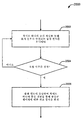
도 4를 참조로 설명하면, 본 발명의 일 실시예에 따라서 코드워드가 레이트리스 코드로 인코딩되어 송신된다(402). 송신 시에 또는 이 송신과 거의 같은 시각에 시구간(time-interval)이 모니터된다(404). 시구간은 일반적으로 미리 정해져 있으며, 송신기가 송신된 코드워드가 수신기에 의해 성공적으로 수신되었다는 것을 추정할 수 있도록 하는 길이를 갖고 있다. 당업자라면 이 시구간은 본 발명의 본질로부터 벗어남이 없이 여러 가지 방식으로 설정되고 모니터될 수 있음을 잘 알 것이다. 예컨대 시구간은 프로세서나 기타 컴퓨팅 매체를 이용하여 인터럽트를 설정하고, 타이밍 플래그 기타 다른 표시자를 가진 클록을 이용하고, 소정의 각 시구간에 대해 독립적인 타이머를 유지함으로써 설정 및 모니터될 수 있다.Referring to FIG. 4, in accordance with an embodiment of the present invention, a codeword is encoded and transmitted in a rateless code (402). The time-interval is monitored 404 at the time of transmission or at about the same time as this transmission. The time period is generally predetermined and has a length that allows the transmitter to estimate that the transmitted codeword has been successfully received by the receiver. Those skilled in the art will appreciate that this time period can be set and monitored in various ways without departing from the spirit of the invention. For example, time periods can be set and monitored by using a processor or other computing medium to set interrupts, using a clock with timing flags or other indicators, and maintaining an independent timer for each predetermined time period.
이 시구간 동안에는 송신기는 응답 신호(ACK) 형태의 표시 신호가 수신되었는지 여부를 판단한다(406). 시구간 동안에 표시 신호(ACK)가 수신된 경우에는 다음 코드워드가 송신된다(410).During this time period, the transmitter determines whether an indication signal in the form of a response signal (ACK) has been received (406). If the indication signal ACK is received during the time period, the next codeword is transmitted (410).
시구간 동안에 표시 신호(ACK)가 수신되지 않은 경우에는 시스템은 마치 소거 플래그가 수신된 것처럼 진행하고(408) 다음 코드의 후속 송신을 강제(force)한다(410). 소거 플래그는 송신기에 의해 반드시 수신되지 않을 수 있지만, 송신기가 코드워드 송신을 위한 시구간에 따르도록 강제함으로써 시스템의 실시간 제약이나 요건은 여전히 충족될 수 있다.If no indication signal ACK is received during the time period, the system proceeds as if an erase flag was received (408) and forces (410) subsequent transmission of the next code. The erasure flag may not necessarily be received by the transmitter, but the real time constraints or requirements of the system can still be met by forcing the transmitter to comply with the time period for the codeword transmission.
도 5a는 본 발명의 다른 실시예를 보여주는데, 여기서는 소거 플래그는 부정 응답(NACK)의 형태로 구체화된다. 따라서 시구간이 만료했을 때에는(504) 표시 신호의 수신 여부와는 상관없이 다음 코드워드가 송신된다(510). 시구간 중에 표시 신호가 수신되면 표시가 긍정 응답(ACK)인지 부정 응답(NACK)인지 여부에 대해 판단된다(506).5A shows another embodiment of the present invention wherein the erasure flag is embodied in the form of a negative acknowledgment (NACK). Therefore, when the time period expires (504), the next codeword is transmitted (510) regardless of whether or not the indication signal is received. When an indication signal is received during the time period, it is determined whether the indication is a positive response (ACK) or a negative response (NACK) (506).
여러 가지 실시예에 따라서 긍정 응답(ACK)은 송신된 코드워드가 성공적으로 수신되었다는 표시, 또는 성공적 수신과 성공적 디코딩의 표시일 수 있다. 부정 응답(NACK)은 송신된 코드워드가 신뢰할 수 없거나 완전히 디코딩될 수 없다는 표시일 수 있다. NACK이 확인되면 송신기는 다음 코드워드를 송신하는데(510) 이용되는 후속 변조 방식을 변경한다(508). 일 실시예에서 NACK는 현재 변조 방식이 디코더측에서 작동하지 않음을 송신기에게 통지하는 기능을 하며, 송신기는 후속 송신을 위한 변조 방식을 변경함으로써 이에 응답한다.According to various embodiments, the acknowledgment (ACK) may be an indication that the transmitted codeword was successfully received, or an indication of successful reception and successful decoding. A negative acknowledgment (NACK) may be an indication that the transmitted codeword cannot be reliable or fully decoded. If the NACK is confirmed, the transmitter changes 508 the subsequent modulation scheme used to transmit the next codeword (510). In one embodiment, the NACK functions to notify the transmitter that the current modulation scheme is not working at the decoder side, and the transmitter responds by changing the modulation scheme for subsequent transmission.
도 5b에 도시된 다른 실시예에 따라서 송신기는 소정 기간 동안 수신된 NACK 수를 모니터 또는 카운트할 수 있다(505). 이 소정 기간(505)은 일반적으로 소정 기간(504)보다 길며 채널이 (NACK의 경우) 실제로 불량한지 아니면 (ACK의 경우 - 도 5c 참조) 양호한지 여부를 확인하도록 선택된다. 수신된 NACK의 수가 소정 기간(505) 중에 수신된 소정의 NACK 수보다 크거나 같다면(516), 송신기는 변조 차수(modulation order)를 (예컨대 16-QAM에서 QPSK로) 낮춤으로써(518) 이에 응답하고, 이에 따라서 수신기로부터 어떤 추가적인 정보도 요구하지 않고(예컨대 변조 변경 지수 등을 요구하지 않고) 다음 코드워드를 송신한다.According to another embodiment shown in FIG. 5B, the transmitter may monitor or count the number of NACKs received during a predetermined period (505). This
반대로, 도 5c에 도시된 바와 같이 수신된 ACK의 수가 소정 기간(505) 중에 수신된 소정의 ACK 수보다 크거나 같다면(522), 송신기는 다음 코드워드의 송신 전에 변조 차수를 (예컨대 QPSL에서 16-QAM으로) 올림으로써(520) 이에 응답한다. 도 5b 및 5c의 실시예도 ACK 및/또는 NACK를 축적하고 카운트하면서 추가적인 코드워드를 계속해서 송신할 수 있다.Conversely, if the number of received ACKs is greater than or equal to the predetermined number of ACKs received during the
도 6은 본 발명의 일 실시예에 따른 송신기(102)의 블록도이다. 송신기(102)는 컨트롤러(600), 프로세서(602) 및 적어도 하나의 메모리/데이터 저장 장치(608)를 포함한다. 프로세서(602)는 전술한 바와 같이 여러 가지 방식으로 여러 가지 본 발명의 타이머 기능을 제공하는데 이용될 수 있는 내장 클록 또는 타이머(604)를 포함한다. 여러 가지 실시예에 따라서 컨트롤러(600)는 주문형 집적 회로(ASIC), 하나 또는 그 이상의 본 발명에 따라서 기능하도록 프로그래밍된 프로세서, 또는 하나 또는 그 이상의 본 발명에 따라 기능하는데 필요한 로직 또는 집적 회로 설계의 임의의 조합일 수 있다. 메모리(608)는 본 발명의 본질에서 벗어남이 없이 여러 가지 형태로 구체화될 수 있다. 예컨대 메모리(608)는 ROM, RAM, 착탈식 디스크 매체, 하드 드라이브, 플래시 메모리, 또는 기타 다른 적당한 저장 장치일 수 있다.6 is a block diagram of a
도 7은 레이트리스 코드로 인코딩된 코드워드를 수신하는 방법(700)의 흐름도를 보여준다. 나타낸 바와 같이 레이트리스 코드로 인코딩된 코드워드가 수신된다(702). 레이트리스 인코딩된 코드워드를 수신하는 동작(702)은 진행 중인 동작이다. 수신 중에 시구간이 만료되었는지를 판단하기 위해 시구간이 모니터된다(704). 시구간이 만료하기 전이라면 코드워드가 성공적으로 수신되고 디코딩되었는지 여부가 (필요하다면 반복적으로) 판단된다(706). 성공적으로 수신 및 디코딩되었다면 코드워드가 성공적으로 수신 및 디코딩되었다는 긍정 표시를 나타내는 표시 신호가 송신되고(708), 다음 코드워드가 수신된다.7 shows a flowchart of a
단계(704)에서 시구간이 만료하고 코드워드의 성공적인 수신과 디코딩이 확인되지 않으면(단계(706)), 수신기는 다음 코드워드의 수신(710)을 가능하게 하도록 표시 신호의 송신(708)을 강제한다. 전술한 바와 같이 이 경우에 표시 신호는 소거 플래그를 포함하거나, 수신 데이터의 소스에게 다음 송신에 이용되는 변조 방식을 변경하라고 통지하는데 이용되는 부정 확인(NACK)으로 구체화된 것을 갖고 있을 수 있다.If the time period expires in
일 실시예에 따라서 송신된(708) 표시 신호는 변조 변경 지수 또는 인코딩된 코드워드의 소스에 대한 다른 변조 방식 변경 명령을 포함할 수 있다. 이것은 특히 인코딩된 코드워드가 성공적으로 수신되지 못하고 그리고/또는 성공적으로 디코딩될 수 없을 때에(예컨대 NACK 신호가 발생되어 수신 데이터의 소스로 되돌아간 경우에) 적용될 수 있다. 전술한 바와 같이 변조 변경 지수나 다른 변조 방식 변경 명령은 소정 시구간 내에서 성공적인 수신 및/또는 디코딩이 여러 번 확인된 경우에 변조 차수의 양의 증가(positive increase)일 수 있다.According to one embodiment, the transmitted
도 8은 디코더(110)의 블록도로서 이 디코더(110)의 일부 구성 요소를 보여준다. 디코더(110)는 수신기(800), 컨트롤러(802), 프로세서(804), 적어도 한 가지 형태의 메모리/데이터 저장 장치(806), 및 클록(808)을 포함한다. 도 7을 참조로 전술한 바와 같이, 디코더(110)는 인코딩된 코드워드를 수신하고 긍정 또는 부정 수신 조건에 응답하여 표시 신호를 인코딩된 코드워드의 소스에 제공한다. 긍정 수신 조건은 일 실시예에서는 인코딩된 코드워드의 성공적인 수신을 포함하며, 다른 실시예에서는 수신된 인코딩된 코드워드의 성공적인 수신과 디코딩을 포함한다. 부정 수신 조건은 일 실시예에서는 수신된 데이터가 신뢰성이 없고 디코딩될 수 없다는 것을 표시하며, 다른 실시예에서는 부정 수신 조건은 수신된 데이터가 디코딩될 수 없다는 것을 표시한다.8 is a block diagram of the
전술한 바와 같이 계층적 MIMO 시스템에서 통신 중에 (비제약적 채널 용량 공식을 이용하여) 계산된 상호 정보는, 특히 예컨대 QPSK 또는 16-QAM과 같은 일반적인 변조 방식이 시스템에 이용되는 경우에, 수신기에서 얻어진 실제 상호 정보보다 훨씬 높을 수 있다. 이것은 다음 번 송신에 악영향을 미치는 상호 정보의 과 평가이다.As described above, the mutual information calculated during communication in a hierarchical MIMO system (using a non-constrained channel capacity formula) is obtained at the receiver, in particular when a general modulation scheme such as QPSK or 16-QAM is used in the system. It can be much higher than the actual mutual information. This is an overestimation of mutual information that adversely affects the next transmission.
이 문제를 극복하고 수신기에서 얻어진 상호 정보의 과대 평가를 피하기 위하여 각 계층에서 변조를 위한 실제 용량 공식이 이용된다. 예컨대 SNR=5 db일 때 QPSK 변조를 위한 용량은 1.7 비트/심볼이다. 폐형(closed form) 용량 공식이 없거나(예컨대 16-QAM 변조를 위한 폐형 용량 공식이 없거나) 용량 계산이 복잡한(예컨대 처리 시간이 너무 많이 드는) 경우에는, 탐색표(LUT)를 이용하여 통신 시스템에서의 계층/채널을 위한 결정된 품질 메트릭과 이용되고 있는 변조 타입에 기초하여 수신된 상호 정보를 얻을 수 있다. 일 실시예에 따라서 품질 메트릭은 계층에서의 신호 대 잡음비(SNR)이다. 더욱이 탐색표(LUT)를 이용하여 통신 시스템에서의 계층/채널을 위한 결정된 품질 메트릭에 기초하여 통신 채널이 지원하는 최적 변조 형식을 얻을 수도 있다.To overcome this problem and avoid overestimating mutual information obtained at the receiver, the actual capacity formula for modulation at each layer is used. For example, when SNR = 5 db, the capacity for QPSK modulation is 1.7 bits / symbol. If there is no closed form capacity formula (e.g. no closed capacity formula for 16-QAM modulation) or if the capacity calculation is complex (e.g. too much processing time), then a lookup table (LUT) is used in the communication system. The received mutual information can be obtained based on the determined quality metric for the layer / channel of < RTI ID = 0.0 > and < / RTI > According to one embodiment, the quality metric is the signal-to-noise ratio (SNR) in the layer. In addition, a lookup table (LUT) may be used to obtain an optimal modulation format supported by the communication channel based on the determined quality metric for the layer / channel in the communication system.
도 9과 도 10을 참조로 설명하면, 본 발명의 추가 실시예에 따른 디코더(110)가 도시되어 있다. 이 디코더의 컨트롤러(900)는 레이트리스 코드로 인코딩된 코드워드를 수신하도록(1002) 구성된다. 레이트리스 코드에서 코드워드는 무한 길이를 갖는 것으로 정의될 수도 있지만, 유한 길이만큼 송신 또는 수신된다. 이러한 적용에 있어서 코드워드(codeword)라는 용어는 실제로 송신 또는 수신되는 무한 길이 "코드워드"의 일부를 나타내는데 자주 사용된다. 프로세서(902)는 코드워드가 송신되는 통신 매체의 품질 메트릭을 계산하도록 구성된다. 메모리(904)는 채널이 지원하는 최적 변조 형식을 결정하는데 이용될 수 있는 탐색표(LUT) 데이터를 저장한다. 이 타입의 LUT 데이터는 특정 통신 시스템에서 이용되는 것으로 알려진 변조 방식 각각에 대한 여러 가지 LUT를 포함할 것이다. 그와 같은 변조 방식의 몇 가지 예로는 BPSK, QPSK 및 16-QAM이 있으나 이에 한정되는 것은 아니다.9 and 10, a
계산된 품질 메트릭은 예컨대 프로세서(902)를 이용하여 통신 매체가 지원하는 최적 변조 형식을 결정하는데(1006) 이용된다. 결정되고 나면 디코더의 컨트롤러는 변경된 변조 방식에 기초하여 다음 번 코드워드를 수신하도록 구성된다. 변경된 변조 방식은 통신 매체가 지원하고 이 통신 매체를 통해 데이터를 전송하는데 이용될 수 있는 결정된 최적 변조 형식으로부터 도출되었다(1008).The calculated quality metric is used, for example, to determine 1006 an optimal modulation format that the communication medium supports using
도 11에 도시된 또 다른 실시예(1100)에 따라서 코드워드 수신(1102) 후에 디코더는 수신된 데이터의 소스가 이용하고 있는 변조 방식을 식별한다(1104). 그 다음, 예컨대 프로세서를 이용하여 통신 채널을 위한 품질 메트릭이 계산된다(1106). 계산된 품질 메트릭(예컨대 채널 또는 계층의 SNR)과 알려진 변조 방식을 이용하여 메모리(904)에 액세스하여 알려진 변조 방식에 대응하는 LUT 값을 얻는다. 통신 매체가 지원하는 최적 변조 형식이 결정된다(1108). 최적 변조 형식은 예컨대 어느 변조 형식의 LUT가 그 계산된 품질 메트릭에서 최고의 예상 용량을 제공하는 지를 판단하는 프로세서에 의해 결정된다. 만일 결정된 최적 변조 형식이 현재 변조 방식과 다르다면(또는 아마도 변경을 정당화할 정도로 충분히 큰 차이를 갖는다면) 최적 변조 방식은 새로운 변조 방식으로 인식된다. 핑퐁 스위칭 효과(ping-pong switching effect)를 피하는 데는 "이력(hysterisis)"값을 이용할 수 있다. 새로운 변조 방식은 송신된 데이터의 소스로 피드백된다(1110). 이 소스는 피드백된 변경된 변조 방식을 이용하여 다음 번의 코드워드를 송신하는 것으로 가정된다. 다음 번의 인코딩된 코드워드는 이 피드백된 변경된 변조 방식을 이용하여 수신된다(1112). 물론 "최적" 형식은 전체적으로 최적일 필요는 없으며, 많은 실시예는 성능은 개선하지만 (최적화할 필요는 없는) 형식을 결정한다.In accordance with another embodiment 1100 shown in FIG. 11, after
도 11a을 참조로 설명하면, 방법(1115)이 나타나 있다. 여러 가지 실시예에서 LUT를 이용하여 수신되고 있는 상호 정보량을 결정할 수도 있다. 방법(1115)은 그와 같은 실시예의 일례이다. 방법(1115)은 레이트리스 코드로 인코딩된 데이터를 수신하는 단계(1002)와 채널에 대한 품질 메트릭(예컨대 SNR)을 결정하는 단계(1004)를 포함한다. 품질 메트릭은 예컨대 메트릭을 계산하거나, 메트릭을 다른 장치로부터 수신하거나 또는 메트릭을 저장 장치로부터 액세스함으로써 결정될 수 있다. 수신된 인코딩된 데이터를 송신하는데 이용된 변조 방식이 식별된다(1104).Referring to FIG. 11A, a
방법(1115)은 식별된 변조 방식/형식과 결정된 품질 메트릭에 기초하여 소정의 추정치, 즉 수신된 인코딩된 데이터의 단위 당 수신되고 있는 상호 정보량의 추정치를 결정하는 단계를 더 포함한다. 추정치 결정 단계는 예컨대 폐형 용량식을 이용하는 것과 같은 여러 가지 방식으로 수행될 수 있다. 방법(1115)은 속도를 증가시킬 수 있고 또한 비폐형(not-closed form) 용량식을 수용할 다른 실시예를 설명한다.The
방법(1115)은 식별된 변조 방식/형식과 결정된 품질 메트릭에 기초하여 특정 LUT에 액세스하는 단계(1120)와 수신된 인코딩된 데이터의 단위 당 수신되고 있는 상호 정보량의 추정치를 제공하는 특정 LUT 내의 엔트리에 액세스하는 단계(1130)를 더 포함한다. 방법(1115)은 액세스된 엔트리에 기초하여 수신된 상호 정보량을 결정하는 단계(1140)를 더 포함한다. 일 실시예에서 LUT는 주어진 변조 형식을 위한 상호 정보를 포함하는 1차원 테이블(예컨대 리스트)이며, 여기서 각 엔트리는 서로 다른 SNR에 대응한다. 다른 실시예에서 LUT는 2차원 테이블(예컨대 매트릭스)이며, 여기서 행은 변조 형식에 대응하고, 열은 SNR에 대응하며, 엔트리는 특정 행(변조 형식)과 열(SNR)을 위한 상호 정보 표시자에 대응한다. 상호 정보 표시자(LUT 내의 엔트리)는 예컨대 식별된 변조 방식과 SNR에 대응하는 용량 공식에 기초하여 결정될 수 있다. 이러한 LUT 이용은 이 출원에서 설명된 여러 가지 개념과 양상을 이용하지 않고도 수행될 수 있으며, 하나 또는 그 이상의 다른 개념 및 양상과 결합하여 이용될 수 있다.The
MIMO 및 기타 다른 통신 시스템에서는, 비록 수신된 상호 정보를 계산하기 위해 용량 산출이 수행되지만, 아쉽게도 이것은 통상적으로 근사일 뿐이며, 시간에 따라 제한적으로만 정확하다. 따라서 수신된 전체 상호 정보가 수신기에 의한 디코딩에 충분한 것으로 선언되더라도 실제로는 코드워드를 디코딩하기에 여전히 불충분할 수 있다.In MIMO and other communication systems, although capacity calculation is performed to calculate the received mutual information, this is unfortunately usually only an approximation and only limited accuracy over time. Thus, even if the received total mutual information is declared sufficient for decoding by the receiver, it may still be insufficient to actually decode the codeword.
본 발명의 일 양상에 따라서 이 불충분은 수신된 코드워드의 정확한 디코딩을 가능하게 하는 것으로 생각되는 통상적인 양 이상으로 수신기에 추가적인 상호 정보를 축적하는 것을 가능하게 함으로써 해결된다. 추가적인 상호 정보의 축적에 따라 디코딩이 성공할 확률은 더 높아진다.According to one aspect of the present invention this insufficiency is solved by making it possible to accumulate additional mutual information in the receiver above the usual amount believed to enable accurate decoding of the received codeword. The probability of decoding success is higher with the accumulation of additional mutual information.
따라서 도 12a와 12b를 참조하여 설명하면, 본 발명의 일 실시예에 따른 방법(1200)이 나타나 있다. 초기에는 레이트리스 코드로 인코딩된 데이터 블록에 대한 데이터가 수신된다(1202). 그 다음에 이 데이터 블록에 대한 초기의 소정량의 상호 정보(MI)가 수신기에 의해 수신되었는지에 대해 판단된다(1203). 이 "초기의 소정량"은 수신기가 수신된 코드워드를 성공적으로 디코딩할 수 있을 만큼 충분하다고 생각되는 양이다. 당업자라면 이 "초기의 소정량"은 통신 시스템마다 다르며, 잡음 등과 같은 임의의 알려진 통신 매체 변수를 고려한다는 것을 잘 알 것이다.12A and 12B, a method 1200 according to one embodiment of the present invention is shown. Initially, data for a block of data encoded with a rateless code is received (1202). It is then determined 1203 whether an initial predetermined amount of mutual information MI for this data block has been received by the receiver. This " initial predetermined amount " is an amount deemed sufficient to allow the receiver to successfully decode the received codeword. Those skilled in the art will appreciate that this "initial predetermined amount" varies from communication system to system, and takes into account any known communication media variable, such as noise.
"초기의 소정량"의 상호 정보가 수신되고 나면, 데이터 블록에 대한 추가적인 인코딩된 데이터가 수신되고(1204), 데이터 블록에 대한 여분의 소정량의 상호 정보가 초기의 소정량 이상으로 수신되었는지 여부에 대해 더 판단된다(1205). 추가량 또는 "여분의 소정량"의 상호 정보가 축적되고 나면, 수신기는 수신된 코드워드를 디코딩하고(1206), 그 다음에 다음 번 수신된 송신을 위해 MI와 인코딩된 코드워드를 계속 수신한다. 이 실시예에서 코드워드의 디코딩(1206)은 초기의 소정량의 인코딩된 데이터 만을 이용하여 수행된다. 도 12b에 도시된 바와 같이 다른 실시예에서 디코딩(1206)은 초기에 수신된 인코딩된 데이터와 추가적으로 수신된 인코딩된 데이터를 모두 이용하여 수행될 수 있다(1208). 데이터 블록에 대한 여분의/추가적인 인코딩된 데이터와 연관된 여분의 축적된 MI를 이용함으로써 수신기에 의한 디코딩 성공 확률이 증가된다.After the "initial predetermined amount" of mutual information is received, additional encoded data for the data block is received (1204), and whether an extra predetermined amount of mutual information for the data block has been received above the initial predetermined amount. Is further determined (1205). After the additional amount or " extra predetermined amount " of mutual information has been accumulated, the receiver decodes the received codeword (1206), and then continues to receive the MI and encoded codeword for the next received transmission. . In this
당업자라면 "여분의 소정량"의 실제량은 본 발명의 본질에서 벗어남이 없이통신 시스템마다 다를 수 있음을 잘 알 것이다.Those skilled in the art will appreciate that the actual amount of the "extra predetermined amount" may vary from communication system to without departing from the spirit of the invention.
다른 실시예에 따라서 축적되는 초기의 상호 정보와 여분의 상호 정보의 양은 타이밍에 기초할 수 있다. 예컨대 도 13을 참조로 설명하면 본 발명의 다른 실시예에 따른 방법(1300)이 나타나 있다. 나타낸 바와 같이 레이트리스 코드로 인코딩된 데이터 블록에 대한 인코딩된 데이터가 수신된다(1302). 그 다음에 인코딩된 데이터와 연관된 초기의 소정량의 MI가 수신되었는지 여부가 판단된다(1304). 이 판단(1304)은 예컨대 시구간 또는 통신 매체의 용량 공식에 기초할 수 있다. 더욱이 주어진 변조 및 신호 대 잡음 비에 대한 용량 공식에 기초하여 수신된 데이터의 단위 당 상호 정보의 추정치를 포함하는 탐색표가 이용될 수 있다. (시구간의 만료나 기타 다른 것에 의해) 디코더가 초기의 소정량의 MI가 수신되었다고 판단하면 수신기는 데이터 블록에 대한 추가적인 인코딩된 데이터를 축적(수신)하기 시작한다(1306). 수신기는 여분의 소정량의 MI가 수신 완료될 때까지(1308) 추가적인 또는 여분의 인코딩된 데이터와 이에 대응하는 MI를 축적한다. 여분의 소정량의 MI에 대한 판단은 시간, 비트 길이, 또는 수신된 데이터의 예상량을 결정하는 임의의 기타 다른 공지된 방법에 기초할 수 있다. 여분의 소정량의 MI가 수신되었다고 판단되었을 때에는 코드워드가 디코딩되고(1310), 수신기/디코더는 시작 단계로 되돌아가서 인코딩된 코드워드의 다음 송신을 수신하기 시작한다.According to another embodiment, the amount of initial mutual information and redundant mutual information accumulated may be based on timing. For example, referring to FIG. 13, a
전술한 바와 같이 제1의 소정의 시구간은 디코더가 인코딩된 코드워드를 성공적으로 수신하여 디코딩할 수 있게 하기에 충분하다고 생각되는 길이이다. 이 제1의 소정의 시구간은 통신 시스템마다 그리고 그와 같은 시스템이 채용한 변조 기법마다 다를 수 있다. 실시예들은 2개의 타이머를 결합하여 하나의 타이머로 할 수 있다.As mentioned above, the first predetermined time period is of a length that is considered sufficient to enable the decoder to successfully receive and decode the encoded codeword. This first predetermined time period may vary for each communication system and for the modulation scheme employed by such a system. Embodiments may combine two timers into one timer.
도 14는 본 발명의 일 실시예에 따른 디코더(1400)를 보여준다. 디코더는 상호 정보(상호 정보량은 수신된 인코딩된 코드워드나 기타 다른 수신된 데이터에 기초하여 산출됨)를 수신하도록 구성된 컨트롤러(1402)를 포함한다. 프로세서(1404)와 메모리(1406)의 적용을 통해 컨트롤러는 초기의 소정량의 상호 정보와 여분의 또는 추가적인 소정량의 상호 정보 모두를 수신하도록 더 구성된다. 일 실시예에서 디코더(1400)는 상호 정보를 수신하도록 구성된 수신기(1410)를 포함할 수 있다.14 shows a
본 발명에 따라서 여분의 또는 추가적인 상호 정보의 축적은 신뢰성을 높일 수 있으나 이것은 통상적으로 추가된 정보로 인한 데이터율 저하라는 불이익이 따라 온다. 게다가 여분의 또는 추가적인 상호 정보의 축적에 따라 디코더가 디코딩할 코드워드의 길이가 더 길어지며, 따라서 일반적으로 디코딩 복잡성이 더 커지게 된다. 이러한 불이익은 많은 응용에 있어서 용인될 수 있다. 그러나 추가적인 상호 정보의 축적으로 인한 디코딩 복잡성의 증가 및/또는 데이터율 저하를 고려하여 일부 실시예는 코드워드에 대해 연쇄 코딩(concatenated coding)을 이용하는데, 여기서 외부 코드는 예컨대 리드 솔로몬이나 BCH 코드와 같은 블록 코드이고 내부 코드는 레이트리스 코드이다.According to the present invention, the accumulation of extra or additional mutual information can increase reliability, but this usually comes with the disadvantage of lowering the data rate due to the added information. In addition, the accumulation of extra or additional mutual information results in a longer codeword to be decoded by the decoder, thus generally resulting in greater decoding complexity. This disadvantage can be tolerated in many applications. However, in view of the increased decoding complexity and / or data rate degradation due to the accumulation of additional mutual information, some embodiments use concatenated coding for codewords, where the outer code is for example a Reed Solomon or BCH code. The same block code and the inner code is a rateless code.
그와 같은 일 실시예에서 먼저 K 정보 비트가 (N,K) 외부 블록 코드를 이용하여 길이 N의 코드워드가 되도록 인코딩된다. 각 코드워드는 더 작은 크기의 서브 블록으로 분해된다. 예컨대 N-비트 코드워드는 각각이 N/4 비트의 길이를 가진 4개의 서브 블록으로 분해된다. 내부 레이트리스 코드는 코드워드의 각 서브 블록에 적용된다. 내부 레이트리스 코드로 인코딩하기 전에 블록 코드워드를 서브 블록으로 분해함으로써 성공적인 디코딩에 필요한 레이트리스 코드워드의 크기가 더 작게 될 것으로 예상되므로 레이트리스 코드워드의 디코딩 복잡성이 줄어들 수 있다. 대안적으로, 레이트리스 코드로 인코딩하기 전에 코드워드를 서브 블록으로 분해함으로써 외부 블록 코드가 더 커질 수 있으며 그에 따라 직렬로 사용된 몇 개의 더 작은 블록 코드로 달성될 수 있는 것보다 주어진 수의 패리티 비트에 대한 더 나은 에러 정정을 제공할 수 있다. 게다가 더 큰 블록 코드는, 예컨대 더 작은 블록 코드는 정정할 수 없었을 버스트를 정정함으로써, 이런 더 작은 블록 코드에 비해 버스트 에러 정정이 더 양호하게 된다. 더욱이 더 큰 블록 코드와 더 작은 레이트리스 코드의 이점들 중 적어도 일부는 동일한 실시예에서 함께 달성될 수 있다.In one such embodiment, the K information bits are first encoded to be codewords of length N using (N, K) outer block codes. Each codeword is decomposed into smaller subblocks. For example, the N-bit codewords are decomposed into four subblocks each of length N / 4 bits. The inner rateless code is applied to each subblock of the codeword. By decomposing the block codeword into sub-blocks before encoding into the inner rateless code, the decoding complexity of the rateless codeword can be reduced because the size of the rateless codeword required for successful decoding is expected to be smaller. Alternatively, the outer block code can be made larger by breaking the codeword into sub-blocks prior to encoding into the rateless code, thus giving a given number of parity than can be achieved with several smaller block codes used in series. It can provide better error correction for bits. In addition, larger block codes have better burst error correction compared to such smaller block codes, for example by correcting bursts that smaller block codes could not correct. Moreover, at least some of the advantages of larger block codes and smaller rateless codes can be achieved together in the same embodiment.
도 15a와 도 15b는 각각 본 발명의 일 실시예에 따라 내부 레이트리스 코드로 인코딩된 코드워드의 송신과 수신에 대한 구성도이다. 도 15a에 도시된 바와 같이, 송신기/인코더 시퀀스는 외부 인코더(1502) 내로 입력되고, 외부 인코더(1502)는 입력 데이터 시퀀스의 블록을 인코딩하여 외부 인코더(1502)의 출력에 서 제공되는 코드워드로 만든다. 분할기(1503)는 데이터 블록 출력을 서브 블록들로 분할하고, 내부 인코더(1504)는 레이트리스 코드를 가지고 이 서브 블록들을 인코딩한다. 인코딩된 송신 시퀀스는 변조기(1506)에 입력되고, 여기서 변조되어 안테나를 통해 송신된다. 도 15b는 수신기/디코더측을 보여주는데, 여기서는 복조기(1508)가 수신된 피변조 신호를 수신하여 복조한다. 내부 레이트리스 코드 디코더(1510)는 서브 블록을 결정하기 위하여 먼저 서브 블록의 레이트리스 코드를 디코딩하고, 그 다음에 결합기(1511)가 서브 블록들을 결합하여 외부 코드워드로 만들고, 이 외부 코드워드는 잔류 에러를 더 제거하고 디코딩을 깨끗이 하기 위해 외부 디코더(1512) 내로 통과된다. 결합기(1511)와 분할기(1503)는 예컨대 소프트웨어 및/또는 하드웨어로 구현될 수 있다. 일 소프트웨어 구현은 레지스터와 적당한 명령어를 이용하고, 일 하드웨어 구현은 시프트 레지스터와 적당한 로직을 이용한다.15A and 15B are diagrams illustrating transmission and reception of codewords encoded with internal rateless codes, respectively, according to an embodiment of the present invention. As shown in FIG. 15A, the transmitter / encoder sequence is input into an
도 16은 본 발명의 다른 실시예에 따라, 인코딩된 데이터를 송신하는 방법(1600)을 보여준다. 데이터가 액세스되고(1602), 이 데이터에 대해 외부 블록 코드가 발생되고(1604), 외부 블록 코드워드는 서브 블록들로 분해된다(1606). 서브 블록으로 분해되고 나면 서브 블록 코드워드는 레이트리스 코드를 이용하여 인코딩된다(1608). 레이트리스 코드로 인코딩되고 나면 서브 블록에 대한 레이트리스 코드워드는 수신기로 송신된다(1610).16 shows a
또 다른 실시예에 따라서 방법(1700)은 데이터의 입력 블록에 대해 외부 블록 코드워드를 발생하고(1710), 그 외부 블록 코드워드의 서브 블록에 대해 내부 레이트리스 코드워드가 결정된다(1720). 그 다음에 방법(1700)은 소정량의 레이트리스 코드워드를 송신하기 시작한다(1730). 제1 시구간이 만료된 후에는(1740), 상기 소정량이 송신된 것으로 가정되며, 방법(1700)은 제2의 소정량의 레이트리스 코드워드를 송신하기 시작한다(1750). 제2 시구간이 만료된 후에는(1750), 상기 제2의 소정량이 송신된 것으로 가정된다. 방법(1700)은 각 서브 블록에 대한 레이트리스 코드워드를 송신하기 위해 반복될 수 있다. 더욱이 일 실시예에서 타이머들은 결합될 수 있다.According to another embodiment, the
도 18 내지 도 20은 수신기측에서의 본 발명의 다른 실시예를 보여준다. 도 18을 참조로 설명하면 수신기는 연쇄 코드로 인코딩된 코드워드에 대한 소정량의 상호 정보를 수신함으로써(1802) 개시한다. 상기 소정량이 수신되면 수신기는 상기 소정량 이상의 여분의 상호 정보량을 축적 또는 수신하는 것을 계속한다(1804). 여분의 상호 정보가 수신되면 수신기는 먼저 내부 레이트리스 코드를 디코딩하여 서브 블록을 결정함으로써(1808) 연쇄 인코딩된 코드워드를 디코딩하도록 구성된다. 내부 레이트리스 코드가 디코딩되면 블록 코드워드를 리졸브(resolve)하도록 서브 블록들이 결합된다(1808). 블록 코드워드가 리졸브되고 나면 잔류 에러를 제거하기 위해 외부 코드가 디코딩된다(1810).18 to 20 show another embodiment of the present invention at the receiver side. Referring to FIG. 18, a receiver begins by receiving 1802 a predetermined amount of mutual information for a codeword encoded with a concatenated code. When the predetermined amount is received, the receiver continues to accumulate or receive the amount of extra mutual information above the predetermined amount (1804). When extra mutual information is received, the receiver is configured to decode the concatenated encoded codeword by first decoding an internal rateless code to determine a subblock (1808). When the inner rateless code is decoded, the subblocks are combined (1808) to resolve the block codeword. After the block codeword is resolved, the outer code is decoded (1810) to remove the residual error.
도 19는 충분한 정보가 수신되었다고 판단하기 위하여 수신기에 의해 타이머가 설정된 다른 실시예를 보여준다. 본 예에서 수신기는 연쇄 코드로 인코딩된 코드워드에 대한 소정량의 상호 정보를 수신하기 시작한다(1902). 제1의 소정 기간(1903)의 만료가 모니터된다. 수신기는 제1의 소정 기간이 만료될 때까지 소정량의 상호 정보를 수신하는 것을 계속한다. 제1의 소정 기간이 만료되면 수신기에서 "여분" 또는 추가적인 상호 정보가 수신(축적)된다(1904). 이 여분의 상호 정보 축적은 제2의 소정 기간 동안 수행된다(1905). 제2의 소정 기간이 만료되면 먼저 내부 레이트리스 코드를 디코딩하여 블록 코드워드의 서브 블록을 결정함으로써(1906) 코드워드가 디코딩된다. 그 다음에 서브 블록들은 결합되어 블록 코드워드를 리졸브한다(1907). 결합되고 나면 외부 블록 코드가 디코딩되어(1908) 잔류 에러를 제거한다.19 shows another embodiment in which a timer is set by a receiver to determine that sufficient information has been received. In this example, the receiver begins receiving 1902 a predetermined amount of mutual information for a codeword encoded with a concatenated code. The expiration of the first
도 20은 본 발명의 일 실시예에 따른 디코더(2000)의 블록도이다. 도시된 바와 같이 디코더(2000)는 컨트롤러(2002), 프로세서(2004) 및 메모리(2006)를 포함한다. 컨트롤러(2002)는 수신기(2010)를 통해 (상호 정보를 제공하는) 인코딩된 코드워드를 수신하도록 구성된다. 프로세서(2004)는 클록(2008)을 포함하며, 상호 정보를 수신하는데 필요한 모든 시구간을 설정하도록 프로그램될 수 있다. 메모리(2006)는 디코더(2000)의 일부이며 예컨대 인코딩된 데이터를 송신하는데 이용되고 있는 변조 방식과 같은 것에 따라서 예컨대 상호 정보 수신을 위한 필수 시구간 또는 기간과 같은 정보를 포함할 수 있다. 디코더(2000)는 서브 블록들이 결합되어 코드워드를 리졸브할 수 있도록 서브 블록의 내부 레이트리스 코드를 디코딩하도록 더 구성된다. 외부 코드의 디코딩은 내부 레이트리스 코드의 디코딩과 서브 블록의 결합에 의해 코드워드가 리졸브된 후에 수행된다.20 is a block diagram of a
당업자라면 컨트롤러와 프로세서는, 함께 기능하면서도 별개로 구성될 수 있으며, 대안적으로는 여기서 설명된 것과 같이 기능하는 대응 프로그램과 로직을 가진 단일의 장치 내에서 구체화될 수 있다.Those skilled in the art will recognize that the controller and processor may be configured separately while functioning together, or alternatively, may be embodied within a single device having corresponding programs and logic that function as described herein.
레이트리스 코드를 채용하는 계층적 통신 시스템에서 응답 신호를 이용하는 것은 전술한 바와 같은 이점을 갖고 있다. 특히 충분한 상호 정보가 수신된 것으로 생각되면 즉시 응답이 전송될 수 있다. 그러나 그와 같은 응답의 전송은 유용하기는 하지만 통신 채널을 완전히 이용하지 못할 수가 있다(예컨대 데이터율을 증가시키도록 채널 전체 용량을 활용하는 것을 못할 수가 있다).Using a response signal in a hierarchical communication system employing a rateless code has the advantages described above. In particular, if sufficient mutual information is deemed to have been received, a response may be sent immediately. However, the transmission of such a response is useful, but may not fully utilize the communication channel (for example, may not be able to utilize the full channel capacity to increase the data rate).
예컨대 각 채널에 대한 변조가 BPSK 또는 QPSK인 경우에 채널은 더 고차의 변조(예컨대 16-QAM)를 지원할 여지가 있으며, 이는 더 높은 데이터율을 지원할 수 있는 것이다.For example, if the modulation for each channel is BPSK or QPSK, the channel is likely to support higher order modulation (eg 16-QAM), which may support higher data rates.
그와 같은 변조 방식 변경이 가능한지 여부를 판단하는데는 몇 가지 방법이 있다. 도 21 내지 34를 참조로 도시되고 설명된 실시예들은 예시적인 것이며 통신 품질 결정의 용법을 보여준다. 당업자라면 본 발명의 본질에서 벗어남이 없이 동일한 개념의 다른 방법 및/또는 실시예도 가능함을 잘 알 것이다.There are several ways to determine whether such a modulation scheme change is possible. The embodiments shown and described with reference to FIGS. 21-34 are exemplary and show usage of communication quality determination. Those skilled in the art will appreciate that other methods and / or embodiments of the same concept are possible without departing from the spirit of the invention.
도 21을 참조로 설명하면 본 발명의 일 실시예에 따른 방법(2100)이 나타나 있다. 초기에는 적어도 하나의 통신 채널을 통한 통신의 품질에 관한 정보가 액세스된다(2102). 액세스된 정보에 기초하여 레이트리스 코드로 인코딩된 채널을 통해 데이터를 전송하는데 이용될 변조 방식에 대한 표시가 제공된다(2104). 이 예에서 통신 채널의 품질에 관한 정보는 미리 지정된 또는 미리 결정된 기간 내의 표시 신호의 발생 빈도일 수 있다.Referring now to FIG. 21, a
도 22는 도 21의 방법의 변형된 실시예를 보여준다. 이 방법(2200)에서는 적어도 하나의 통신 채널을 통한 통신의 품질에 관한 정보가 액세스되고(2202), 표시 신호가 식별된다. 이 액세스의 개시시에 시구간이 설정된다(2208). 이 시구간 동안에 식별된 표시 신호의 발생 회수 또는 빈도가 카운트된다(2206). 이 시구간이 만료되면 품질에 관한 상기 액세스된 정보에 응답하고 이에 기초하여 다음의 데이터를 송신하는 변조 방식이 표시된다(2204). 이 소정 시구간의 길이(2208)는, 예컨대 현재 이용되고 있는 변조 방식에 기초한 임의의 적당한 시간 길이, 예상된 결과에 기초한 추정된 기간 등일 수 있다.FIG. 22 shows a modified embodiment of the method of FIG. 21. In this
도 23은 본 발명의 일 실시예에 따른 장치(2300)를 보여준다. 이 장치는 컨트롤러(2302), 클록(2306)을 가진 프로세서(2304), 메모리(2308), 및 양방향 통신 채널(2310)에의 접속부를 포함한다. 전술한 바와 같이 통신 채널(2310)을 통한 통신의 품질이 결정되어 그 채널에 이용될 변조 방식을 표시하는데 이용된다. 이런 식으로 컨트롤러(2302)는 통신 채널(2310)의 품질에 관한 정보에 액세스한다. 프로세서(2304)는 이 액세스된 품질 정보를 이용하여 통신 채널(2310)을 통해 레이트리스 코드로 인코딩된 데이터의 다음 번 전송을 위한 변경된 변조 방식에 대한 표시를 제공하도록 구성된다.23 shows an
예컨대 프로세서(2304)는 클록(2306)을 가지는 것으로 도시되어 있다. 당업자라면 클록(2306)이 본 발명의 본질에서 벗어남이 없이 여러 가지 많은 방식으로 구현될 수 있음을 잘 알 것이다. 이 예의 목적상 클록(2306)은 컨트롤러(2302)가 통신 채널(2310)의 품질에 관한 정보에 액세스하는 소정 시구간을 설정하는데 이용될 수 있다. 이런 식으로 채널(2310)을 통한 통신 품질의 모니터링은 미리 설정된 또는 미리 결정된 기간으로 제한될 수 있으며, 이는 통신 시스템의 실시간 제약을 충족하는데 도움이 된다.For example,
도 24는 본 발명의 다른 실시예에 따른 방법을 보여준다. 이 예에서 디코더는 적어도 하나의 통신 채널을 통해 표시 신호가 수신되는 발생 빈도를 모니터한다(2402). 이들 표시 신호는 적어도 하나의 통신 채널을 통한 통신의 품질을 나타낸다. 그와 같은 표시 신호의 모니터된 발생 빈도에 기초하여 통신 채널 상에서 데이터를 송신하는데 이용되고 있는 변조 방식이 다음 번의 데이터 송신을 위해 변화 또는 변경될 수 있다(2404). 이러한 변화 또는 변경은 예컨대 더 높은 데이터율을 위해 변조 차수를 증가시키는 명령, 또는 통신 채널이 더 낮은 변조 차수를 더 잘 지원할 수 있다고 판단되었을 때는 비트율은 더 낮게 되나 데이터의 신뢰도는 증가시키도록 변조 차수를 감소시키는 명령일 수 있다.24 shows a method according to another embodiment of the present invention. In this example, the decoder monitors 2302 the frequency of occurrence of an indication signal received over at least one communication channel. These indication signals indicate the quality of communication over at least one communication channel. Based on the monitored frequency of occurrence of such an indication signal, the modulation scheme being used to transmit data on the communication channel can be changed or changed for the next data transmission (2404). Such a change or change may result in, for example, a command to increase the modulation order for a higher data rate, or if the communication channel is better able to support a lower modulation order, the bit rate will be lower but the modulation order will be increased to increase the reliability of the data. It can be a command to reduce.
몇 가지 예시적인 실시예에 따라서 표시 신호의 형태는 응답 신호(예컨대 ACK), 부정 응답 신호(NACK) 또는 그 발생이나 수신이 통신 채널 품질을 결정하는데 이용될 수 있는 임의의 기타 다른 지정 신호일 수 있다. ACK와 NACK의 이용예에 대해서는 전술하였다.According to some exemplary embodiments, the shape of the indication signal may be a response signal (eg, an ACK), a negative response signal (NACK), or any other designated signal whose occurrence or reception may be used to determine communication channel quality. . Examples of the use of ACK and NACK have been described above.
도 25는 도 24의 실시예의 더 변형된 방법을 보여주는데, 여기서는 수신된 표시 신호의 발생 빈도의 모니터링에 시구간이 부여된다. 나타낸 바와 같이, 수신된 표시 신호의 발생 빈도는 소정 시구간 중(2504)에 모니터된다(2502). 소정 시구간이 만료되면(2504), 적어도 하나의 통신 채널을 통해 다음 데이터를 송신하는데 이용되는 변조 방식이, 변조 방식을 최대화하고, 채널이 지원할 수 있는 최고의 데이터율로 데이터율을 증가시키도록 변화된다(2506). 그러나 전술한 바와 같이 통신 채널이 더 높은 변조 차수를 지원못할 수 있으므로 변조 방식의 변화는 더 낮은 차수의 변조를 위한 감소 또는 요구일 수 있다. 실시예들은 채널이 더 높은 차수의 변조를 지원할 수 있는지 여부를 판단하는 방법에 있어 서로 다를 수 있다. 예컨대 일 실시예는 채널을 통해 전송된 데이터에서 모든 에러가 (통상의 순방향 에러 정정 코드를 이용하여) 정정될 것이라는 점이 크게 기대되는 경우에만, 채널이 특정의 변조 형식을 지원할 수 있음을 표명한다.FIG. 25 shows a further modified method of the embodiment of FIG. 24, wherein a time period is given to the monitoring of the frequency of occurrence of the received indication signal. As shown, the frequency of occurrence of the received indication signal is monitored 2502 during a
도 26은 본 발명의 또 다른 실시예에 따른 방법(2600)을 보여준다. 초기에는 수신된 표시 신호의 발생 빈도가 모니터된다(2602). 이 시점에서 "양호한" 처리량(올바르게 수신되고 디코딩되는 단위 시간 당 데이터량)을 개선하거나 아마도 극대화할 것으로 기대되는 변조 형식에 대한 판단이 이루어진다(2604). 결정된 형식은 표시 신호 데이터의 발생 빈도를 이용하여 적어도 하나의 통신 채널이 지원할 수 있는 최적 변조 형식일 수 있다. LUT는 예컨대 (주어진 변조 형식에 대한) ACK 빈도를 지원될 수 있는 최고 변조 형식과 상관시키도록 전개(develop)될 수 있다. 다음 번에 변조 방식을 변화시키는 것(2606)은 채널이 지원하는 결정된 변조 형식을 이용하여 수행된다.26 shows a
도 27은 본 발명의 다른 실시예에 따른 방법(2700)을 보여준다. 이 실시예에서 송신된 데이터의 수신기는 적어도 하나의 통신 채널을 통해 수신된 데이터의 안전한 수신과 디코딩을 표시하는 표시 신호를 발생하여 송신기에 전송한다(2702). 발생되는 표시 신호의 발생 빈도는 모니터된다(2704). 모니터된 표시 신호 발생 빈도에 기초하여 채널을 통해 다음 데이터를 송신하는 변조 방식의 표시는 수신된 데이터의 소스에 제공된다(2706).27 shows a
도 28은 도 27에 나타낸 방법의 변형된 방법(2800)을 보여준다. 이 실시예에서 발생된 표시 신호의 발생 빈도의 모니터링 시간을 조정하기 위하여 소정 시구간이 설정된다(2804). 소정 시구간이 만료되면 수신기는 적어도 하나의 통신 채널을 통해 송신되는 다음 데이터에 대한 변조 방식을 표시한다(2806).FIG. 28 shows a modified
도 29는 본 발명에 따른 방법(2900)의 다른 실시예를 보여준다. 나타낸 바와 같이 수신기는 표시 신호를 발생하여 이것을 수신된 데이터의 소스에 전송하며(2902), 이 표시 신호의 발생 빈도는 모니터된다(2904). 전과 같이 이 실시예에서는 소정 시구간 동안 모니터링 수행된다(2906). 이 시구간이 만료되면 수신기는 적어도 하나의 통신 채널을 통해 다음 데이터를 전송하는데 이용되는 변조 방식을 변경하기 위하여 변조 지수를 들어오는(incoming) 데이터의 소스에 전송한다(2908).29 shows another embodiment of a
이 변조 지수는 송신기/인코더가 인식하여 작용하는 임의 형태의 신호일 수 있다. 예컨대 변조 지수는 수신기로부터 송신기로 피드백되고 있는 다른 데이터의 헤더에 있는 제어 신호일 수 있다. 다른 실시예에서 이것은 표시 신호(ACK 또는 NACK)의 일부일 수 있다. 당업자라면 변조 지수의 형태는 임의의 적당한 형태일 수 있음을 잘 알 것이다.This modulation index can be any type of signal that the transmitter / encoder recognizes and acts on. For example, the modulation index may be a control signal in the header of other data being fed back from the receiver to the transmitter. In other embodiments this may be part of an indication signal (ACK or NACK). Those skilled in the art will appreciate that the form of the modulation index can be any suitable form.
도 30은 본 발명의 일 실시예에 따른 디코더(3000)를 보여준다. 디코더(3000)는 적어도 하나의 통신 채널(3012)을 통해 입력 데이터를 수신하도록 구성된 수신기(3002)를 포함한다. 입력 데이터는 레이트리스 코드로 인코딩될 수 있다. 컨트롤러(3004)는 통신 채널(3012)에 대한 품질 메트릭을 계산하도록 구성된다. 품질 메트릭은 적어도 하나의 통신 채널의 용량을 나타낸다. 품질 메트릭이 계산되고 나면 컨트롤러는 프로세서(3006)와 결합하여 디코더가 상기 계산된 품질 메트릭을 이용하여 변조 지수를 발생하도록 한다. 전술한 바와 같이 변조 지수는 송신된 데이터의 소스에게 통신 채널(3012)을 통해 다음 데이터를 전송하는데 이용되고 있는 변조 방식을 변경하라는 명령을 제공하기 위하여 상기 소스에 피드백되는 제어 신호이다. 디코더(3000)는 메모리/데이터 유닛(3008)과 클록(3010)도 포함한다.30 shows a decoder 3000 according to an embodiment of the present invention. The decoder 3000 includes a
이 실시예에 따라서 품질 메트릭은 통신 채널(3012) 상에서 얻어질 수 있는 품질 정도에 대한 실체적인 판단이다. 그와 같은 품질 메트릭의 일례는 채널(3012)의 신호 대 잡음비(SNR)일 수 있다. 예컨대 현재 변조 방식과 같은 다른 알려진 정보와 함께 채널의 SNR을 이용하여 채널의 이용을 극대화하기 위해 새로운 또는 변경된 변조 방식이 식별될 수 있다. 변조된 데이터를 전송하기 위한 복수의 통신 채널이 있는 계층적 통신 시스템과 같은 시스템에서는 모든 채널에 대한 평균 SNR이 품질 메트릭으로서 이용될 수 있으며, 또는 각 채널에 대한 평균 SNR이 각 채널의 품질 메트릭으로서 이용될 수 있다. 이 평균은 층(layer)들에 대한 평균, 시간에 대한 평균 등일 수 있다. 다른 대안적인 실시예에서는 본 발명의 본질에서 벗어남이 없이 블록 방식 SNR도 이용될 수 있다. 다른 실시예는 품질 메트릭으로서 이용되는 피크 SNR 판단을 포함할 수 있다.According to this embodiment, the quality metric is a practical judgment as to the degree of quality that can be obtained on the
도 31을 참조로 설명하면 본 발명의 일 양상에 따른 디코더(3000)에 의해 구현된 예시적인 방법(3100)이 나타나 있다. 초기에 디코더는 적어도 하나의 통신 채널을 통한 통신의 품질에 관한 정보에 액세스한다(3102). 그 다음 적어도 하나의 통신 채널을 통해 신호를 전송하는데 현재 사용되고 있는 변조 형식에 대한 결정이 이루어진다. 현재 변조 형식이 결정되고 나면 디코더는 그 정보를 액세스된 품질 정보와 함께 이용할 수 있으며, 다음 데이터를 전송하는데 이용되는 변조 형식을 변경하라는 명령을 수반하여 수신된 데이터의 소스에 표시를 제공할 수 있다(3106).Referring to FIG. 31, there is shown an
다른 실시예에 따라서 도 32에 나타낸 바와 같이 방법(3200)은 통신 품질에 관한 정보에 액세스하는 것(3202)과 적어도 하나의 통신 채널 상에서 이용되고 있는 현재 변조 형식을 결정한 것(3204)을 제공한다. 그 다음, 통신 채널의 품질에 관한 상기 액세스된 정보로부터 품질 메트릭(예컨대 SNR 또는 ACK 빈도)이 계산된다(3206). 그 다음, 계산된 품질 메트릭을 알려진 또는 현재 변조 형식과 함께 이용하여 채널을 통해 다음 데이터를 전송하는데 이용될 변조 방식을 표시한다(3208).According to another embodiment, as shown in FIG. 32, the
도 33은 본 발명에 따른 방법(3300)의 다른 실시예를 보여준다. 이 실시예에서 디코더는 레이트리스 코드로 인코딩된 데이터를 수신한다(3302). 디코더는 이 데이터를 이용하여 적어도 하나의 통신 채널이 지원하는 최적 변조 형식에 관한 정보를 제공하는 품질 메트릭을 계산한다(3304).33 shows another embodiment of a
디코더는 상기 계산된 품질 메트릭을 이용하여 상기 수신된 데이터의 소스에게 적어도 하나의 통신 채널을 통해 다음 데이터를 전송하는데 이용되는 변조 방식을 변경하라고 지시한다(3306).The decoder uses the calculated quality metric to instruct the source of received data to change the modulation scheme used to transmit the next data over at least one communication channel (3306).
도 34는 도 33에 나타낸 방법(3300)의 변경된 방법 실시예(3400)를 보여준다. 전과 같이 디코더는 레이트리스 코드로 인코딩된 데이터를 수신하고(3402), 적어도 하나의 통신 채널이 지원하는 최적 변조 형식을 표시하는 품질 메트릭을 계산한다(3404). 그 다음, 디코더는 상기 계산된 품질 메트릭에 응답하여 적어도 하나의 통신 채널을 통해 다음 데이터를 전송하기 위해 상기 수신된 데이터의 소스에 의해 사용될 변조 방식을 표시하는 변조 지수 신호를 발생한다.34 shows a modified
명확하게 본 출원에서 설명된 많은 실시예는 수신기, 송신기, 또는 이 둘 다에 의해 실시될 수 있다.Clearly, many embodiments described in this application may be implemented by a receiver, a transmitter, or both.
특정한 방식을 참조하지 않고 또는 단 한가지 방식을 이용하여 전술하였더라도 여러 가지 방식들 중 하나 또는 그 이상으로 여러 가지 양상, 실시예 및 특성들이 구현될 수 있다. 예컨대 방법, 장치, 방법을 수행하는 장치나 처리 디바이스, 프로그램이나 명령어 세트, 프로그램이나 명령어 세트를 포함하는 장치, 및 컴퓨터 판독 매체 중 하나 또는 그 이상을 이용하여 여러 가지 양상, 실시예 및 특성들이 구현될 수 있다.Various aspects, embodiments, and features may be implemented in one or more of the various manners, even if described above without reference to a specific manner or using only one manner. Various aspects, embodiments, and features may be implemented, for example, using one or more of a method, apparatus, apparatus or processing device performing the method, a program or instruction set, an apparatus including a program or instruction set, and a computer readable medium. Can be.
장치는 예컨대 개별적 또는 집적된 하드웨어, 펌웨어 및 소프트웨어를 포함할 수 있다. 일례로서 장치는 예컨대 마이크로프로세서, 집적 회로 또는 프로그래밍가능한 로직 디바이스를 포함하는, 일반적으로 프로세싱 디바이스를 말하는 프로세서를 포함할 수 있다. 다른 예로서 장치는 하나 또는 그 이상의 프로세스를 실시하기 위한 명령어를 가진 하나 또는 그 이상의 컴퓨터 판독 매체를 포함할 수 있다.The device may comprise, for example, separate or integrated hardware, firmware and software. As one example, an apparatus may include a processor, generally referring to a processing device, including, for example, a microprocessor, an integrated circuit, or a programmable logic device. As another example, an apparatus may include one or more computer readable media having instructions for performing one or more processes.
컴퓨터 판독 매체는 예컨대 하드 디스크, 컴팩트 디스켓, RAM, 또는 ROM과 같은 소프트웨어 캐리어나 기타 다른 저장 장치를 포함할 수 있다. 컴퓨터 판독 매체는 예컨대 명령어를 인코딩하거나 전송하는 포맷된 전자기파도 포함할 수 있다. 명령어는 예컨대 하드웨어, 펌웨어, 소프트웨어 또는 전자기파 내에 있을 수 있다. 명령어는 예컨대 운영 체제, 독립적인 애플리케이션 또는 이들 둘의 조합에서 찾을 수 있다. 그러므로 프로세서는 예컨대 프로세스를 실시하도록 구성된 디바이스와 프로세스를 실시하기 위한 명령어를 가진 컴퓨터 판독 매체를 포함하는 디바이스 모두로서 특징지워질 수 있다.The computer readable medium may include a software carrier or other storage device such as, for example, a hard disk, a compact diskette, a RAM, or a ROM. Computer-readable media can also include, for example, formatted electromagnetic waves that encode or transmit instructions. The instructions may be in hardware, firmware, software or electromagnetic waves, for example. Instructions may be found, for example, in an operating system, in an independent application, or in a combination of both. The processor may therefore be characterized as both a device configured to carry out the process and a device comprising a computer readable medium having instructions for executing the process.
지금까지 많은 실시예들에 대해서 설명하였지만 여러 가지 변경이 가능함은 물론이다. 예컨대 여러 가지 실시예들의 구성요소들은 조합, 보충, 변경 또는 제거되어 다른 실시예들을 구현할 수 있다. 따라서 다른 실시예들은 다음의 청구 범위의 범위 내에 있는 것이다.While many embodiments have been described so far, various changes are possible. For example, the components of the various embodiments can be combined, supplemented, changed or removed to implement other embodiments. Accordingly, other embodiments are within the scope of the following claims.
Claims (10)
Applications Claiming Priority (8)
| Application Number | Priority Date | Filing Date | Title |
|---|---|---|---|
| WOPCT/US06/47912 | 2006-12-14 | ||
| PCT/US2006/047911 WO2008073103A1 (en) | 2006-12-14 | 2006-12-14 | Rateless codes decoding method for communication systems |
| PCT/US2006/047699 WO2008073093A1 (en) | 2006-12-14 | 2006-12-14 | Arq with adaptive modulation for communication systems |
| WOPCT/US06/47699 | 2006-12-14 | ||
| WOPCT/US06/47910 | 2006-12-14 | ||
| PCT/US2006/047910 WO2008073102A1 (en) | 2006-12-14 | 2006-12-14 | Concatenated coding/decoding in communication systems |
| PCT/US2006/047912 WO2008073104A1 (en) | 2006-12-14 | 2006-12-14 | Modulation indication method for communication systems |
| WOPCT/US06/47911 | 2006-12-14 |
Related Child Applications (1)
| Application Number | Title | Priority Date | Filing Date |
|---|---|---|---|
| KR1020157011939A Division KR101784078B1 (en) | 2006-12-14 | 2007-06-25 | Rateless encoding in communication systems |
Publications (1)
| Publication Number | Publication Date |
|---|---|
| KR20090099553A true KR20090099553A (en) | 2009-09-22 |
Family
ID=38950807
Family Applications (2)
| Application Number | Title | Priority Date | Filing Date |
|---|---|---|---|
| KR1020157011939A KR101784078B1 (en) | 2006-12-14 | 2007-06-25 | Rateless encoding in communication systems |
| KR1020097014554A KR20090099553A (en) | 2006-12-14 | 2007-06-25 | Rateless encoding in communication systems |
Family Applications Before (1)
| Application Number | Title | Priority Date | Filing Date |
|---|---|---|---|
| KR1020157011939A KR101784078B1 (en) | 2006-12-14 | 2007-06-25 | Rateless encoding in communication systems |
Country Status (5)
| Country | Link |
|---|---|
| US (1) | US9729274B2 (en) |
| EP (1) | EP2122884B1 (en) |
| JP (1) | JP5297387B2 (en) |
| KR (2) | KR101784078B1 (en) |
| WO (1) | WO2008073144A1 (en) |
Families Citing this family (19)
| Publication number | Priority date | Publication date | Assignee | Title |
|---|---|---|---|---|
| JP5153784B2 (en) * | 2006-12-14 | 2013-02-27 | トムソン ライセンシング | Concatenated encoding / decoding in communication systems |
| KR101311675B1 (en) | 2006-12-14 | 2013-09-25 | 톰슨 라이센싱 | Rateless codes decoding method for communication systems |
| US9729280B2 (en) | 2006-12-14 | 2017-08-08 | Thomson Licensing | ARQ with adaptive modulation for communication systems |
| CN105406941B (en) | 2006-12-14 | 2019-05-10 | 汤姆逊许可证公司 | The modulation indication method and device of communication system |
| KR101784078B1 (en) | 2006-12-14 | 2017-10-10 | 톰슨 라이센싱 | Rateless encoding in communication systems |
| KR101527114B1 (en) * | 2008-04-02 | 2015-06-08 | 삼성전자주식회사 | Apparatus and method for detecting signal based on lattice reduction capable to support different encoding scheme by stream in a multiple input multiple output wireless communication system |
| US8300757B2 (en) | 2008-08-08 | 2012-10-30 | Motorola Mobility Llc | Methods for detection of failure and recovery in a radio link |
| US8457112B2 (en) | 2008-11-07 | 2013-06-04 | Motorola Mobility Llc | Radio link performance prediction in wireless communication terminal |
| US8442021B2 (en) * | 2008-11-07 | 2013-05-14 | Motorola Mobility Llc | Radio link performance prediction in wireless communication terminal |
| KR101570472B1 (en) * | 2009-03-10 | 2015-11-23 | 삼성전자주식회사 | Data processing system with concatenated encoding and decoding structure |
| EP2448337A1 (en) * | 2010-11-02 | 2012-05-02 | Alcatel Lucent | Selection of a power offset table |
| US8724715B2 (en) | 2011-02-17 | 2014-05-13 | Massachusetts Institute Of Technology | Rateless and rated coding using spinal codes |
| US9215457B2 (en) * | 2012-05-18 | 2015-12-15 | Mitsubishi Electric Research Laboratories, Inc. | Method and system for communicating multimedia using reconfigurable rateless codes and decoding in-process status feedback |
| US9160399B2 (en) | 2012-05-24 | 2015-10-13 | Massachusetts Institute Of Technology | System and apparatus for decoding tree-based messages |
| US9270412B2 (en) | 2013-06-26 | 2016-02-23 | Massachusetts Institute Of Technology | Permute codes, iterative ensembles, graphical hash codes, and puncturing optimization |
| CN103986553B (en) * | 2014-04-04 | 2017-03-01 | 浙江大学 | The stop-and-wait transmission method of suitable physical layer no rate coding transmission |
| DE102019123712A1 (en) * | 2019-09-04 | 2021-03-04 | WAGO Verwaltungsgesellschaft mit beschränkter Haftung | DEVICE WITH A FOUNTAIN CODE DECODING UNIT FOR RECONSTRUCTING A CONFIGURATION DATA SET |
| US11792824B2 (en) * | 2020-03-30 | 2023-10-17 | Qualcomm Incorporated | Multicast feedback and retransmission for transport block grouping |
| CN112039562B (en) * | 2020-09-08 | 2021-11-09 | 东南大学 | Progressive coding space shift keying method |
Family Cites Families (92)
| Publication number | Priority date | Publication date | Assignee | Title |
|---|---|---|---|---|
| US5428637A (en) | 1994-08-24 | 1995-06-27 | The United States Of America As Represented By The Secretary Of The Army | Method for reducing synchronizing overhead of frequency hopping communications systems |
| JP3388035B2 (en) | 1994-09-16 | 2003-03-17 | 富士通株式会社 | Data communication system, transmission apparatus and transmission method using hybrid automatic repeat request method |
| US5745502A (en) | 1996-09-27 | 1998-04-28 | Ericsson, Inc. | Error detection scheme for ARQ systems |
| EP1033004A1 (en) * | 1998-09-18 | 2000-09-06 | Hughes Electronics Corporation | Method and constructions for space-time codes for psk constellations for spatial diversity in multiple-element antenna systems |
| US6307487B1 (en) | 1998-09-23 | 2001-10-23 | Digital Fountain, Inc. | Information additive code generator and decoder for communication systems |
| KR20010057145A (en) | 1999-12-18 | 2001-07-04 | 윤종용 | XOR code and serial concatenated encoder/decoder |
| FR2805106A1 (en) * | 2000-02-14 | 2001-08-17 | Mitsubishi Electric Inf Tech | DIGITAL CORRECTIVE ERROR-TYPE CODING TRANSMITTING METHOD |
| JP2001333051A (en) | 2000-05-22 | 2001-11-30 | Matsushita Electric Ind Co Ltd | Radio communication equipment and radio communication method |
| JP3421639B2 (en) | 2000-06-01 | 2003-06-30 | 富士通株式会社 | Communication monitoring control for preventing RF signal interference in an information processing device having a plurality of wireless communication units |
| JP3821636B2 (en) | 2000-08-21 | 2006-09-13 | 松下電器産業株式会社 | COMMUNICATION TERMINAL DEVICE, BASE STATION DEVICE, AND RADIO COMMUNICATION METHOD |
| JP3394528B2 (en) | 2001-03-19 | 2003-04-07 | 松下電器産業株式会社 | Packet transmission system and packet transmission method |
| US7133459B2 (en) * | 2001-05-01 | 2006-11-07 | Texas Instruments Incorporated | Space-time transmit diversity |
| CN100365965C (en) * | 2001-05-08 | 2008-01-30 | 西门子公司 | Method and device for transmitting data in a multi-carrier system comprising parallel concatenated coding and modulation |
| US7130587B2 (en) | 2001-08-22 | 2006-10-31 | National Institute of Information and Communications Technology Incorporated, Administrative Agency | Communication quality estimation method, communication quality estimation apparatus, and communication system |
| US7017104B1 (en) * | 2001-08-24 | 2006-03-21 | Mediatek Inc. | Method and system for decoding block codes by calculating a path metric according to a decision feedback sequence estimation algorithm |
| US20030039226A1 (en) | 2001-08-24 | 2003-02-27 | Kwak Joseph A. | Physical layer automatic repeat request (ARQ) |
| BR0212700A (en) | 2001-08-24 | 2004-08-03 | Interdigital Tech Corp | Base station implementing physical layer auto repeat request |
| KR100571802B1 (en) | 2001-09-03 | 2006-04-17 | 삼성전자주식회사 | Mobile communication system and method for raising communication efficiency |
| EP1449311B1 (en) | 2001-11-16 | 2017-12-13 | Koninklijke Philips N.V. | Radio communication system |
| US7012883B2 (en) | 2001-11-21 | 2006-03-14 | Qualcomm Incorporated | Rate selection for an OFDM system |
| GB2385754B (en) | 2002-02-25 | 2005-01-12 | Toshiba Res Europ Ltd | Adaptive modulation for wireless networks |
| JP2003319458A (en) | 2002-04-24 | 2003-11-07 | Mitsubishi Electric Corp | Communication system and method for controlling communication |
| US7352722B2 (en) | 2002-05-13 | 2008-04-01 | Qualcomm Incorporated | Mitigation of link imbalance in a wireless communication system |
| KR20030092894A (en) | 2002-05-31 | 2003-12-06 | 삼성전자주식회사 | Apparatus for determining report period of channel quality in communication system using high speed data packet access scheme and method thereof |
| US7013116B2 (en) | 2002-06-26 | 2006-03-14 | Lucent Technologies Inc. | MIMO systems having a channel decoder matched to a MIMO detector |
| JP2005531967A (en) * | 2002-06-28 | 2005-10-20 | コーニンクレッカ フィリップス エレクトロニクス エヌ ヴィ | Adaptive rate matching method |
| JP4044797B2 (en) | 2002-07-01 | 2008-02-06 | 松下電器産業株式会社 | Wireless communication apparatus and transmission allocation control method |
| KR101143282B1 (en) | 2002-10-05 | 2012-05-08 | 디지털 파운튼, 인크. | Systematic encoding and decoding of chain reaction codes |
| US8149810B1 (en) | 2003-02-14 | 2012-04-03 | Marvell International Ltd. | Data rate adaptation in multiple-in-multiple-out systems |
| US7813322B2 (en) | 2003-02-19 | 2010-10-12 | Qualcomm Incorporated | Efficient automatic repeat request methods and apparatus |
| US7945280B2 (en) | 2003-02-20 | 2011-05-17 | Fujitsu Limited | Radio channel control method and receiving apparatus |
| JP2004312458A (en) | 2003-04-08 | 2004-11-04 | Matsushita Electric Ind Co Ltd | Base station device and method of adaptive modulation |
| JP4118186B2 (en) | 2003-04-30 | 2008-07-16 | シャープ株式会社 | Data transmitting apparatus, data receiving apparatus, and data communication system |
| US7408913B2 (en) | 2003-05-12 | 2008-08-05 | Lucent Technologies Inc. | Method of real time hybrid ARQ |
| JP3746280B2 (en) | 2003-06-27 | 2006-02-15 | 株式会社東芝 | COMMUNICATION METHOD, COMMUNICATION SYSTEM, AND COMMUNICATION DEVICE |
| JP2005064947A (en) | 2003-08-14 | 2005-03-10 | Matsushita Electric Ind Co Ltd | Radio communication apparatus and reception quality reporting method |
| CN101834610B (en) | 2003-10-06 | 2013-01-30 | 数字方敦股份有限公司 | Method and device for receiving data transmitted from source through communication channel |
| US7508748B2 (en) | 2003-10-24 | 2009-03-24 | Qualcomm Incorporated | Rate selection for a multi-carrier MIMO system |
| US7447148B2 (en) | 2003-10-28 | 2008-11-04 | Ntt Docomo, Inc. | Method for supporting scalable and reliable multicast in TDMA/TDD systems using feedback suppression techniques |
| EP1528832B1 (en) | 2003-11-03 | 2014-01-08 | Alcatel Lucent | Method for distributing a set of data, radiocommunication network and wireless station for implementing the method |
| KR100754727B1 (en) | 2003-11-14 | 2007-09-03 | 삼성전자주식회사 | Method and apparatus for transmitting/receiving control signal via high speed shared control channel in hybrid automatic repeat request system |
| US7472200B1 (en) | 2003-12-03 | 2008-12-30 | Cisco Technology, Inc. | Arrangement in a multi-homed transport endpoint for selecting a source address based on source-destination address pair metrics |
| JP2005167780A (en) | 2003-12-04 | 2005-06-23 | Toshiba Corp | Streaming data transmission device and transmission method |
| US20050136844A1 (en) | 2003-12-09 | 2005-06-23 | Giesberts Pieter-Paul S. | Method and apparatus for automatic data rate control using channel correlation in a wireless communication system |
| JP4446338B2 (en) | 2004-03-22 | 2010-04-07 | ソニー・エリクソン・モバイルコミュニケーションズ株式会社 | Retransmission request method, radio communication system, and receiver |
| JP2005277570A (en) | 2004-03-23 | 2005-10-06 | Fujitsu Ltd | Transmitter, receiver, and retransmission control method |
| US7551589B2 (en) | 2004-04-02 | 2009-06-23 | Lg Electronics Inc. | Frame structure of uplink control information transmission channel in MIMO communication system |
| GB2415111B (en) | 2004-06-08 | 2006-06-14 | Toshiba Res Europ Ltd | Mode selection in mimo devices |
| US7584397B2 (en) | 2004-06-10 | 2009-09-01 | Interdigital Technology Corporation | Method and apparatus for dynamically adjusting data transmission parameters and controlling H-ARQ processes |
| WO2005122426A1 (en) | 2004-06-14 | 2005-12-22 | Samsung Electronics Co., Ltd. | Apparatus and method for controlling transmission mode in a mimo mobile communication system |
| US20050288062A1 (en) | 2004-06-23 | 2005-12-29 | Hammerschmidt Joachim S | Method and apparatus for selecting a transmission mode based upon packet size in a multiple antenna communication system |
| US7684753B2 (en) | 2004-07-21 | 2010-03-23 | Nokia Corporation | Method and device for transmission parameter selection in mobile communications |
| US7590922B2 (en) * | 2004-07-30 | 2009-09-15 | Nokia Corporation | Point-to-point repair request mechanism for point-to-multipoint transmission systems |
| JP4035527B2 (en) | 2004-08-31 | 2008-01-23 | 株式会社東芝 | Communication terminal device and communication method |
| GB2419786C (en) | 2004-10-27 | 2009-10-07 | Toshiba Res Europ Ltd | Multiple list link adaption |
| JP2006129018A (en) | 2004-10-28 | 2006-05-18 | Fujitsu Ltd | Radio communication device and mobile station |
| JP2006129277A (en) | 2004-10-29 | 2006-05-18 | Sharp Corp | Communications device, communication method, communication program, recording medium storing the communication program and communications system |
| JP4457867B2 (en) | 2004-11-25 | 2010-04-28 | 富士通株式会社 | Wireless communication device, mobile station |
| US8428042B1 (en) | 2005-01-10 | 2013-04-23 | Zte (Usa) Inc. | Feedback mechanisms for multicast/broadcast service in wireless communication networks |
| JP2006211017A (en) | 2005-01-25 | 2006-08-10 | Matsushita Electric Ind Co Ltd | Base station apparatus, communication terminal, and resource allocation method |
| US7984018B2 (en) * | 2005-04-18 | 2011-07-19 | Microsoft Corporation | Efficient point-to-multipoint data reconciliation |
| JP4604851B2 (en) | 2005-06-02 | 2011-01-05 | ソニー株式会社 | Transmission device, reception device, transmission processing method, reception processing method, and program thereof |
| KR101129387B1 (en) | 2005-07-12 | 2012-03-27 | 삼성전자주식회사 | Method and apparatus for providing IP datacasting service in Digital Audio Broadcasting system |
| US7539261B2 (en) | 2005-08-22 | 2009-05-26 | Nec Laboratories America, Inc. | Multi-layer coded modulation for non-ergodic block fading channels |
| US7508791B2 (en) | 2005-10-31 | 2009-03-24 | Kyocera Corporation | Wireless communication coding and transmission systems and methods |
| US20070133691A1 (en) * | 2005-11-29 | 2007-06-14 | Docomo Communications Laboratories Usa, Inc. | Method and apparatus for layered rateless coding |
| US9270414B2 (en) | 2006-02-21 | 2016-02-23 | Digital Fountain, Inc. | Multiple-field based code generator and decoder for communications systems |
| US8331425B2 (en) | 2006-02-28 | 2012-12-11 | Kyocera Corporation | Apparatus, system and method for providing a multiple input/multiple output (MIMO) channel interface |
| US7593342B2 (en) | 2006-03-16 | 2009-09-22 | Mitsubishi Electric Research Laboraties, Inc. | Route selection in cooperative relay networks |
| US7673219B2 (en) | 2006-03-16 | 2010-03-02 | Mitsubishi Electric Research Laboratories, Inc. | Cooperative relay networks using rateless codes |
| US20080144562A1 (en) | 2006-03-16 | 2008-06-19 | Draper Stark C | Cooperative Routing in Wireless Networks using Mutual-Information Accumulation |
| US7664198B2 (en) * | 2006-03-21 | 2010-02-16 | Kyocera Corporation | System and method for broadcasting data over a wireless network using rateless codes |
| WO2007111563A2 (en) | 2006-03-24 | 2007-10-04 | Telefonaktiebolaget Lm Ericsson (Publ) | Method and arrangement in a telecommunication system |
| JP4206104B2 (en) | 2006-04-26 | 2009-01-07 | 株式会社日立国際電気 | Wireless communication method and apparatus using adaptive modulation system |
| US7669103B2 (en) * | 2006-05-03 | 2010-02-23 | Alcatel-Lucent Usa Inc. | Encoded transmission |
| US7924761B1 (en) | 2006-09-28 | 2011-04-12 | Rockwell Collins, Inc. | Method and apparatus for multihop network FEC encoding |
| US7823040B2 (en) | 2006-10-11 | 2010-10-26 | Telefonaktiebolaget L M Ericsson (Publ) | Method and apparatus for optimal redundancy version (RV) selection for UMTS HSDPA transmissions |
| CN105406941B (en) | 2006-12-14 | 2019-05-10 | 汤姆逊许可证公司 | The modulation indication method and device of communication system |
| JP5153784B2 (en) | 2006-12-14 | 2013-02-27 | トムソン ライセンシング | Concatenated encoding / decoding in communication systems |
| US9729280B2 (en) | 2006-12-14 | 2017-08-08 | Thomson Licensing | ARQ with adaptive modulation for communication systems |
| KR101784078B1 (en) | 2006-12-14 | 2017-10-10 | 톰슨 라이센싱 | Rateless encoding in communication systems |
| KR101311675B1 (en) | 2006-12-14 | 2013-09-25 | 톰슨 라이센싱 | Rateless codes decoding method for communication systems |
| US8929448B2 (en) * | 2006-12-22 | 2015-01-06 | Sony Corporation | Inter sub-mode decision process in a transcoding operation |
| US8275322B2 (en) | 2008-04-29 | 2012-09-25 | Nec Laboratories America, Inc. | Rateless coding for multiuser interference relay channel |
| EP2293486A1 (en) * | 2009-09-03 | 2011-03-09 | Panasonic Corporation | Feedback scheme for providing feedback on plural transmissions |
| CN103262458B (en) * | 2011-02-28 | 2016-03-09 | 日电(中国)有限公司 | A kind of method and apparatus for adjusting channel quality instruction |
| GB201208389D0 (en) | 2012-05-10 | 2012-06-27 | Samsung Electronics Co Ltd | Integrated circuit, communication unit, wireless communication system and methods therefor |
| US9231736B2 (en) * | 2013-11-20 | 2016-01-05 | Qualcomm Incorporated | Optimizing response interframe space in communication systems |
| US10090957B2 (en) * | 2014-10-06 | 2018-10-02 | Nokia Of America Corporation | Cost effective network interference cancellation for wireless networks |
| US10187314B2 (en) * | 2015-05-22 | 2019-01-22 | Qualcomm Incorporated | Techniques for signal extension signaling |
| CN107735993B (en) * | 2015-06-02 | 2021-07-20 | 阿特拉斯全球技术有限责任公司 | Random access PPDU for WLAN system |
| US9876613B2 (en) | 2015-08-28 | 2018-01-23 | Qualcomm Incorporated | Transport protocol communications reduction |
-
2007
- 2007-06-25 KR KR1020157011939A patent/KR101784078B1/en active IP Right Grant
- 2007-06-25 US US12/448,234 patent/US9729274B2/en not_active Expired - Fee Related
- 2007-06-25 WO PCT/US2007/014848 patent/WO2008073144A1/en active Application Filing
- 2007-06-25 JP JP2009541294A patent/JP5297387B2/en not_active Expired - Fee Related
- 2007-06-25 EP EP07796471.6A patent/EP2122884B1/en not_active Not-in-force
- 2007-06-25 KR KR1020097014554A patent/KR20090099553A/en not_active Application Discontinuation
Also Published As
| Publication number | Publication date |
|---|---|
| US20100067614A1 (en) | 2010-03-18 |
| WO2008073144A1 (en) | 2008-06-19 |
| JP5297387B2 (en) | 2013-09-25 |
| KR20150068447A (en) | 2015-06-19 |
| KR101784078B1 (en) | 2017-10-10 |
| US9729274B2 (en) | 2017-08-08 |
| EP2122884A1 (en) | 2009-11-25 |
| JP2010514262A (en) | 2010-04-30 |
| EP2122884B1 (en) | 2014-06-18 |
Similar Documents
| Publication | Publication Date | Title |
|---|---|---|
| KR101355355B1 (en) | Modulation indication method for communication systems | |
| KR101784078B1 (en) | Rateless encoding in communication systems | |
| KR101311675B1 (en) | Rateless codes decoding method for communication systems | |
| KR101355306B1 (en) | Concatenated coding/decoding in communication systems | |
| KR101367072B1 (en) | Arq with adaptive modulation for communication systems |
Legal Events
| Date | Code | Title | Description |
|---|---|---|---|
| A201 | Request for examination | ||
| E902 | Notification of reason for refusal | ||
| E902 | Notification of reason for refusal | ||
| E601 | Decision to refuse application | ||
| J201 | Request for trial against refusal decision | ||
| A107 | Divisional application of patent | ||
| J301 | Trial decision |
Free format text: TRIAL DECISION FOR APPEAL AGAINST DECISION TO DECLINE REFUSAL REQUESTED 20150407 Effective date: 20160125 |
|
| J121 | Written withdrawal of request for trial | ||
| WITB | Written withdrawal of application |