KR102070528B1 - Skew mirror, how to use and manufacturing method - Google Patents
Skew mirror, how to use and manufacturing method Download PDFInfo
- Publication number
- KR102070528B1 KR102070528B1 KR1020187008341A KR20187008341A KR102070528B1 KR 102070528 B1 KR102070528 B1 KR 102070528B1 KR 1020187008341 A KR1020187008341 A KR 1020187008341A KR 20187008341 A KR20187008341 A KR 20187008341A KR 102070528 B1 KR102070528 B1 KR 102070528B1
- Authority
- KR
- South Korea
- Prior art keywords
- angle
- degrees
- holograms
- wavelength
- hologram
- Prior art date
Links
- 238000004519 manufacturing process Methods 0.000 title description 36
- 238000000034 method Methods 0.000 claims abstract description 63
- 238000009826 distribution Methods 0.000 description 95
- 239000000523 sample Substances 0.000 description 45
- 239000013598 vector Substances 0.000 description 41
- 230000008859 change Effects 0.000 description 28
- 239000010410 layer Substances 0.000 description 28
- 230000003287 optical effect Effects 0.000 description 19
- 230000010287 polarization Effects 0.000 description 12
- 238000001228 spectrum Methods 0.000 description 12
- 239000006185 dispersion Substances 0.000 description 9
- 239000011521 glass Substances 0.000 description 9
- 239000000463 material Substances 0.000 description 8
- 230000008901 benefit Effects 0.000 description 7
- 230000000694 effects Effects 0.000 description 7
- 230000004044 response Effects 0.000 description 7
- 230000008569 process Effects 0.000 description 6
- 238000002835 absorbance Methods 0.000 description 4
- 230000008878 coupling Effects 0.000 description 4
- 238000010168 coupling process Methods 0.000 description 4
- 238000005859 coupling reaction Methods 0.000 description 4
- 230000006870 function Effects 0.000 description 4
- 238000003860 storage Methods 0.000 description 4
- 239000000758 substrate Substances 0.000 description 4
- 238000013519 translation Methods 0.000 description 4
- 230000004075 alteration Effects 0.000 description 3
- 238000013459 approach Methods 0.000 description 3
- 239000011248 coating agent Substances 0.000 description 3
- 238000000576 coating method Methods 0.000 description 3
- 230000001427 coherent effect Effects 0.000 description 3
- 230000001747 exhibiting effect Effects 0.000 description 3
- 239000012530 fluid Substances 0.000 description 3
- 238000005286 illumination Methods 0.000 description 3
- 230000007246 mechanism Effects 0.000 description 3
- 238000012986 modification Methods 0.000 description 3
- 230000004048 modification Effects 0.000 description 3
- 230000000704 physical effect Effects 0.000 description 3
- 229920000642 polymer Polymers 0.000 description 3
- 230000001902 propagating effect Effects 0.000 description 3
- 230000007704 transition Effects 0.000 description 3
- 239000003795 chemical substances by application Substances 0.000 description 2
- 239000011247 coating layer Substances 0.000 description 2
- 235000009508 confectionery Nutrition 0.000 description 2
- 238000013461 design Methods 0.000 description 2
- 239000010408 film Substances 0.000 description 2
- 238000001093 holography Methods 0.000 description 2
- 238000005259 measurement Methods 0.000 description 2
- 238000002310 reflectometry Methods 0.000 description 2
- 239000010409 thin film Substances 0.000 description 2
- 108010010803 Gelatin Proteins 0.000 description 1
- 241000699670 Mus sp. Species 0.000 description 1
- 238000000692 Student's t-test Methods 0.000 description 1
- 238000004458 analytical method Methods 0.000 description 1
- 238000003491 array Methods 0.000 description 1
- QVGXLLKOCUKJST-UHFFFAOYSA-N atomic oxygen Chemical compound [O] QVGXLLKOCUKJST-UHFFFAOYSA-N 0.000 description 1
- 239000013626 chemical specie Substances 0.000 description 1
- 238000004590 computer program Methods 0.000 description 1
- 230000021615 conjugation Effects 0.000 description 1
- 238000011109 contamination Methods 0.000 description 1
- 239000013078 crystal Substances 0.000 description 1
- 230000007547 defect Effects 0.000 description 1
- SOCTUWSJJQCPFX-UHFFFAOYSA-N dichromate(2-) Chemical compound [O-][Cr](=O)(=O)O[Cr]([O-])(=O)=O SOCTUWSJJQCPFX-UHFFFAOYSA-N 0.000 description 1
- 238000005516 engineering process Methods 0.000 description 1
- 238000002474 experimental method Methods 0.000 description 1
- 239000000835 fiber Substances 0.000 description 1
- 238000001914 filtration Methods 0.000 description 1
- 239000005357 flat glass Substances 0.000 description 1
- 229920000159 gelatin Polymers 0.000 description 1
- 239000008273 gelatin Substances 0.000 description 1
- 235000019322 gelatine Nutrition 0.000 description 1
- 235000011852 gelatine desserts Nutrition 0.000 description 1
- 230000014509 gene expression Effects 0.000 description 1
- 238000013507 mapping Methods 0.000 description 1
- 239000012092 media component Substances 0.000 description 1
- 229910052751 metal Inorganic materials 0.000 description 1
- 239000002184 metal Substances 0.000 description 1
- 239000000178 monomer Substances 0.000 description 1
- 229910052760 oxygen Inorganic materials 0.000 description 1
- 239000001301 oxygen Substances 0.000 description 1
- 239000002245 particle Substances 0.000 description 1
- 238000000016 photochemical curing Methods 0.000 description 1
- 238000005498 polishing Methods 0.000 description 1
- 238000012545 processing Methods 0.000 description 1
- 239000011241 protective layer Substances 0.000 description 1
- 210000001747 pupil Anatomy 0.000 description 1
- 239000004065 semiconductor Substances 0.000 description 1
- 230000035945 sensitivity Effects 0.000 description 1
- 229910052709 silver Inorganic materials 0.000 description 1
- 239000004332 silver Substances 0.000 description 1
- -1 silver halide Chemical class 0.000 description 1
- 239000000126 substance Substances 0.000 description 1
- 238000012360 testing method Methods 0.000 description 1
- 238000012546 transfer Methods 0.000 description 1
- 230000000007 visual effect Effects 0.000 description 1
Images


Classifications
-
- G—PHYSICS
- G02—OPTICS
- G02B—OPTICAL ELEMENTS, SYSTEMS OR APPARATUS
- G02B5/00—Optical elements other than lenses
- G02B5/32—Holograms used as optical elements
-
- G—PHYSICS
- G02—OPTICS
- G02B—OPTICAL ELEMENTS, SYSTEMS OR APPARATUS
- G02B7/00—Mountings, adjusting means, or light-tight connections, for optical elements
- G02B7/18—Mountings, adjusting means, or light-tight connections, for optical elements for prisms; for mirrors
- G02B7/182—Mountings, adjusting means, or light-tight connections, for optical elements for prisms; for mirrors for mirrors
- G02B7/1821—Mountings, adjusting means, or light-tight connections, for optical elements for prisms; for mirrors for mirrors for rotating or oscillating mirrors
-
- G—PHYSICS
- G02—OPTICS
- G02B—OPTICAL ELEMENTS, SYSTEMS OR APPARATUS
- G02B26/00—Optical devices or arrangements for the control of light using movable or deformable optical elements
- G02B26/08—Optical devices or arrangements for the control of light using movable or deformable optical elements for controlling the direction of light
- G02B26/10—Scanning systems
- G02B26/105—Scanning systems with one or more pivoting mirrors or galvano-mirrors
-
- G—PHYSICS
- G02—OPTICS
- G02B—OPTICAL ELEMENTS, SYSTEMS OR APPARATUS
- G02B27/00—Optical systems or apparatus not provided for by any of the groups G02B1/00 - G02B26/00, G02B30/00
- G02B27/01—Head-up displays
- G02B27/017—Head mounted
- G02B27/0172—Head mounted characterised by optical features
-
- G—PHYSICS
- G02—OPTICS
- G02B—OPTICAL ELEMENTS, SYSTEMS OR APPARATUS
- G02B5/00—Optical elements other than lenses
- G02B5/18—Diffraction gratings
- G02B5/1847—Manufacturing methods
- G02B5/1857—Manufacturing methods using exposure or etching means, e.g. holography, photolithography, exposure to electron or ion beams
-
- G—PHYSICS
- G02—OPTICS
- G02B—OPTICAL ELEMENTS, SYSTEMS OR APPARATUS
- G02B5/00—Optical elements other than lenses
- G02B5/18—Diffraction gratings
- G02B5/1861—Reflection gratings characterised by their structure, e.g. step profile, contours of substrate or grooves, pitch variations, materials
-
- G—PHYSICS
- G03—PHOTOGRAPHY; CINEMATOGRAPHY; ANALOGOUS TECHNIQUES USING WAVES OTHER THAN OPTICAL WAVES; ELECTROGRAPHY; HOLOGRAPHY
- G03H—HOLOGRAPHIC PROCESSES OR APPARATUS
- G03H1/00—Holographic processes or apparatus using light, infrared or ultraviolet waves for obtaining holograms or for obtaining an image from them; Details peculiar thereto
- G03H1/02—Details of features involved during the holographic process; Replication of holograms without interference recording
- G03H1/024—Hologram nature or properties
- G03H1/0248—Volume holograms
-
- G—PHYSICS
- G03—PHOTOGRAPHY; CINEMATOGRAPHY; ANALOGOUS TECHNIQUES USING WAVES OTHER THAN OPTICAL WAVES; ELECTROGRAPHY; HOLOGRAPHY
- G03H—HOLOGRAPHIC PROCESSES OR APPARATUS
- G03H1/00—Holographic processes or apparatus using light, infrared or ultraviolet waves for obtaining holograms or for obtaining an image from them; Details peculiar thereto
- G03H1/04—Processes or apparatus for producing holograms
- G03H1/0465—Particular recording light; Beam shape or geometry
-
- G—PHYSICS
- G03—PHOTOGRAPHY; CINEMATOGRAPHY; ANALOGOUS TECHNIQUES USING WAVES OTHER THAN OPTICAL WAVES; ELECTROGRAPHY; HOLOGRAPHY
- G03H—HOLOGRAPHIC PROCESSES OR APPARATUS
- G03H1/00—Holographic processes or apparatus using light, infrared or ultraviolet waves for obtaining holograms or for obtaining an image from them; Details peculiar thereto
- G03H1/26—Processes or apparatus specially adapted to produce multiple sub- holograms or to obtain images from them, e.g. multicolour technique
- G03H1/2645—Multiplexing processes, e.g. aperture, shift, or wavefront multiplexing
- G03H1/265—Angle multiplexing; Multichannel holograms
-
- G—PHYSICS
- G03—PHOTOGRAPHY; CINEMATOGRAPHY; ANALOGOUS TECHNIQUES USING WAVES OTHER THAN OPTICAL WAVES; ELECTROGRAPHY; HOLOGRAPHY
- G03H—HOLOGRAPHIC PROCESSES OR APPARATUS
- G03H1/00—Holographic processes or apparatus using light, infrared or ultraviolet waves for obtaining holograms or for obtaining an image from them; Details peculiar thereto
- G03H1/26—Processes or apparatus specially adapted to produce multiple sub- holograms or to obtain images from them, e.g. multicolour technique
- G03H1/28—Processes or apparatus specially adapted to produce multiple sub- holograms or to obtain images from them, e.g. multicolour technique superimposed holograms only
-
- G—PHYSICS
- G02—OPTICS
- G02B—OPTICAL ELEMENTS, SYSTEMS OR APPARATUS
- G02B27/00—Optical systems or apparatus not provided for by any of the groups G02B1/00 - G02B26/00, G02B30/00
- G02B27/01—Head-up displays
- G02B27/017—Head mounted
- G02B27/0172—Head mounted characterised by optical features
- G02B2027/0174—Head mounted characterised by optical features holographic
-
- G—PHYSICS
- G03—PHOTOGRAPHY; CINEMATOGRAPHY; ANALOGOUS TECHNIQUES USING WAVES OTHER THAN OPTICAL WAVES; ELECTROGRAPHY; HOLOGRAPHY
- G03H—HOLOGRAPHIC PROCESSES OR APPARATUS
- G03H1/00—Holographic processes or apparatus using light, infrared or ultraviolet waves for obtaining holograms or for obtaining an image from them; Details peculiar thereto
- G03H1/04—Processes or apparatus for producing holograms
- G03H1/0402—Recording geometries or arrangements
- G03H2001/0415—Recording geometries or arrangements for recording reflection holograms
-
- G—PHYSICS
- G03—PHOTOGRAPHY; CINEMATOGRAPHY; ANALOGOUS TECHNIQUES USING WAVES OTHER THAN OPTICAL WAVES; ELECTROGRAPHY; HOLOGRAPHY
- G03H—HOLOGRAPHIC PROCESSES OR APPARATUS
- G03H1/00—Holographic processes or apparatus using light, infrared or ultraviolet waves for obtaining holograms or for obtaining an image from them; Details peculiar thereto
- G03H1/04—Processes or apparatus for producing holograms
- G03H1/0402—Recording geometries or arrangements
- G03H2001/0439—Recording geometries or arrangements for recording Holographic Optical Element [HOE]
-
- G—PHYSICS
- G03—PHOTOGRAPHY; CINEMATOGRAPHY; ANALOGOUS TECHNIQUES USING WAVES OTHER THAN OPTICAL WAVES; ELECTROGRAPHY; HOLOGRAPHY
- G03H—HOLOGRAPHIC PROCESSES OR APPARATUS
- G03H1/00—Holographic processes or apparatus using light, infrared or ultraviolet waves for obtaining holograms or for obtaining an image from them; Details peculiar thereto
- G03H1/04—Processes or apparatus for producing holograms
- G03H1/0465—Particular recording light; Beam shape or geometry
- G03H2001/0473—Particular illumination angle between object or reference beams and hologram
-
- G—PHYSICS
- G03—PHOTOGRAPHY; CINEMATOGRAPHY; ANALOGOUS TECHNIQUES USING WAVES OTHER THAN OPTICAL WAVES; ELECTROGRAPHY; HOLOGRAPHY
- G03H—HOLOGRAPHIC PROCESSES OR APPARATUS
- G03H1/00—Holographic processes or apparatus using light, infrared or ultraviolet waves for obtaining holograms or for obtaining an image from them; Details peculiar thereto
- G03H1/04—Processes or apparatus for producing holograms
- G03H1/0476—Holographic printer
- G03H2001/0482—Interference based printer
-
- G—PHYSICS
- G03—PHOTOGRAPHY; CINEMATOGRAPHY; ANALOGOUS TECHNIQUES USING WAVES OTHER THAN OPTICAL WAVES; ELECTROGRAPHY; HOLOGRAPHY
- G03H—HOLOGRAPHIC PROCESSES OR APPARATUS
- G03H1/00—Holographic processes or apparatus using light, infrared or ultraviolet waves for obtaining holograms or for obtaining an image from them; Details peculiar thereto
- G03H1/22—Processes or apparatus for obtaining an optical image from holograms
- G03H1/2249—Holobject properties
- G03H2001/2263—Multicoloured holobject
- G03H2001/2265—Achromatic holobject
-
- G—PHYSICS
- G03—PHOTOGRAPHY; CINEMATOGRAPHY; ANALOGOUS TECHNIQUES USING WAVES OTHER THAN OPTICAL WAVES; ELECTROGRAPHY; HOLOGRAPHY
- G03H—HOLOGRAPHIC PROCESSES OR APPARATUS
- G03H1/00—Holographic processes or apparatus using light, infrared or ultraviolet waves for obtaining holograms or for obtaining an image from them; Details peculiar thereto
- G03H1/26—Processes or apparatus specially adapted to produce multiple sub- holograms or to obtain images from them, e.g. multicolour technique
- G03H2001/2605—Arrangement of the sub-holograms, e.g. partial overlapping
- G03H2001/261—Arrangement of the sub-holograms, e.g. partial overlapping in optical contact
- G03H2001/2615—Arrangement of the sub-holograms, e.g. partial overlapping in optical contact in physical contact, i.e. layered holograms
-
- G—PHYSICS
- G03—PHOTOGRAPHY; CINEMATOGRAPHY; ANALOGOUS TECHNIQUES USING WAVES OTHER THAN OPTICAL WAVES; ELECTROGRAPHY; HOLOGRAPHY
- G03H—HOLOGRAPHIC PROCESSES OR APPARATUS
- G03H1/00—Holographic processes or apparatus using light, infrared or ultraviolet waves for obtaining holograms or for obtaining an image from them; Details peculiar thereto
- G03H1/26—Processes or apparatus specially adapted to produce multiple sub- holograms or to obtain images from them, e.g. multicolour technique
- G03H2001/2625—Nature of the sub-holograms
- G03H2001/264—One hologram being a HOE
-
- G—PHYSICS
- G03—PHOTOGRAPHY; CINEMATOGRAPHY; ANALOGOUS TECHNIQUES USING WAVES OTHER THAN OPTICAL WAVES; ELECTROGRAPHY; HOLOGRAPHY
- G03H—HOLOGRAPHIC PROCESSES OR APPARATUS
- G03H1/00—Holographic processes or apparatus using light, infrared or ultraviolet waves for obtaining holograms or for obtaining an image from them; Details peculiar thereto
- G03H1/26—Processes or apparatus specially adapted to produce multiple sub- holograms or to obtain images from them, e.g. multicolour technique
- G03H1/2645—Multiplexing processes, e.g. aperture, shift, or wavefront multiplexing
- G03H2001/266—Wavelength multiplexing
Landscapes
- Physics & Mathematics (AREA)
- General Physics & Mathematics (AREA)
- Optics & Photonics (AREA)
- Engineering & Computer Science (AREA)
- Manufacturing & Machinery (AREA)
- Holo Graphy (AREA)
- Diffracting Gratings Or Hologram Optical Elements (AREA)
- Optical Elements Other Than Lenses (AREA)
Abstract
표면 법선으로 제한될 필요가 없는 반사 축을 갖는, 스큐 미러로 지칭되는 광학 반사형 디바이스가 기술된다. 스큐 미러들의 예들은, 비교적 넓은 범위의 파장들을 가로질러 실질적으로 일정한 반사 축들에 대해 광을 반사시키도록 구성된다. 일부 예들에서, 스큐 미러는 비교적 넓은 범위의 입사각들을 가로질러 실질적으로 일정한 반사 축들을 갖는다. 스큐 미러들의 예시적인 제조 및 사용 방법들이 또한 개시된다. 스큐 미러들은 격자 구조를 포함하는데, 격자 구조는 일부 예들에서 홀로그램을 포함한다.An optically reflective device, referred to as a skew mirror, is described that has a reflection axis that need not be limited to surface normals. Examples of skew mirrors are configured to reflect light about substantially constant reflection axes across a relatively wide range of wavelengths. In some examples, the skew mirror has reflective axes that are substantially constant across a relatively wide range of angles of incidence. Exemplary methods of making and using skew mirrors are also disclosed. Skew mirrors comprise a grating structure, which in some examples comprises a hologram.
Description
삭제delete
종래의 유전체 미러는, 유전율(electric permittivity)이 서로 상이한 재료들의 층들로 표면(전형적으로 유리)을 코팅함으로써 제조된다. 재료들의 층들은 전형적으로, 층 경계들로부터의 프레넬 반사들이 구조적으로 보강되어 큰 순 반사율(net reflectivity)을 생성하도록 배열된다. 이러한 조건이 비교적 넓은 특정 범위의 파장들 및 입사각들에 걸쳐 획득되는 것을 보장함으로써 광대역 유전체 미러들이 설계될 수 있다. 그러나, 층들이 표면 상에 침착되기 때문에, 유전체 미러의 반사 축은 반드시 표면 법선과 일치해야 하는데, 즉, 반사 축은 미러 표면에 수직이다. 반사 축에 대한 이러한 제약조건 때문에, 유전체 미러가 일부 목적에 전적으로 부적절하다. 또한, 유리 유전체 미러들은 비교적 무거운 경향이 있어, 그들이 비교적 경량의 반사형 컴포넌트를 요구하는 응용들에 부적당(suboptimal)하거나 또는 부적절하게 한다.Conventional dielectric mirrors are produced by coating a surface (typically glass) with layers of materials that differ in electrical permittivity. The layers of materials are typically arranged such that the Fresnel reflections from the layer boundaries are structurally reinforced to produce a large net reflectivity. Broadband dielectric mirrors can be designed by ensuring that this condition is obtained over a relatively wide specific range of wavelengths and angles of incidence. However, because the layers are deposited on the surface, the reflection axis of the dielectric mirror must coincide with the surface normal, ie the reflection axis is perpendicular to the mirror surface. Because of these constraints on the reflection axis, dielectric mirrors are wholly unsuitable for some purposes. In addition, glass dielectric mirrors tend to be relatively heavy, making them suboptimal or inadequate for applications requiring relatively lightweight reflective components.
역으로, 종래의 격자(grating) 구조들은, 격자 구조가 존재하는 매체의 표면 법선과는 상이한 반사 축에 대해 광을 반사시킬 수 있다. 그러나, 주어진 입사각에 대해, 종래의 격자 구조들에 대한 반사각들은 전형적으로 입사광의 파장에 따라 함께 변한다. 그에 따라서, 종래의 격자 구조를 사용하여 광을 반사시키는 것은, 반사 축들이 표면 법선과 일치해야 하는 유전체 미러들에 고유한 제약조건을 피한다. 그러나, 일정한 반사 축이 요구되는 경우, 종래의 격자 구조는 전형적으로 주어진 입사각에 대해 단일 파장 또는 매우 좁은 범위의 파장들로 제한된다. 유사하게, 종래의 격자 구조는 일정한 반사 축에 대해 특정 파장의 광을 반사시키기 위해 단일 입사각 또는 매우 좁은 범위의 입사각들로 제한된다. 따라서, 종래의 격자 구조는 임의의 상당한 범위의 파장들 또는 각도들의 입사광에 걸쳐 일정한 반사 축을 갖지 않는다.Conversely, conventional grating structures can reflect light about a reflection axis different from the surface normal of the medium in which the grating structure is present. However, for a given angle of incidence, the angles of reflection for conventional grating structures typically vary together depending on the wavelength of incident light. Accordingly, reflecting light using a conventional grating structure avoids the constraints inherent in dielectric mirrors whose reflection axes must coincide with the surface normal. However, where a constant reflection axis is required, conventional grating structures are typically limited to a single wavelength or a very narrow range of wavelengths for a given angle of incidence. Similarly, conventional grating structures are limited to a single angle of incidence or a very narrow range of angles of incidence to reflect light of a particular wavelength about a constant reflection axis. Thus, conventional grating structures do not have a constant axis of reflection over any significant range of wavelengths or angles of incident light.
따라서, 주어진 입사각에 대한 그 반사각이 다수의 파장들에서 실질적으로 일정하고, 표면 법선으로 제약되지 않는 반사 축에 대해 광을 반사시키는 비교적 단순한 디바이스에 대한 요건들은, 반사형 격자 구조들 또는 유전체 미러들 중 어느 하나를 포함하는 현재 입수가능한 반사형 디바이스들에 의해 충족되지 않는다. 그러므로, 그러한 반사형 디바이스에 대한 필요성이 존재하고, 그러한 필요성은 헤드 마운트 디스플레이 디바이스들에서 극심할 수 있다.Thus, the requirements for a relatively simple device that reflects light about a reflection axis that is substantially constant at multiple wavelengths at a given angle of incidence at a number of wavelengths are reflective grating structures or dielectric mirrors. Is not met by currently available reflective devices including any of the above. Therefore, there is a need for such a reflective device, and such a need can be extreme in head mounted display devices.
당업자는, 도면들이 주로 예시 목적을 위한 것이고 본 명세서에 기술되는 본 발명의 주제의 범주를 제한하는 것으로 의도되지 않는다는 것을 이해할 것이다. 도면은 반드시 축척대로 도시되지는 않고; 일부 경우에, 본 명세서에 개시되는 본 발명의 주제의 다양한 태양들은, 상이한 특징들의 이해를 용이하게 하기 위해 도면들에서 과장되거나 또는 확대되어 도시될 수 있다. 도면들에서, 유사한 도면 부호들은 일반적으로 유사한 특징부들(예컨대, 기능적으로 유사하고/하거나 구조적으로 유사한 요소들)을 지칭한다.
도 1a는 격자 매체에 기록된 홀로그램의 단면도이다.
도 1b는 단일 정현파 홀로그램의 k-공간 표현의 단면도이다.
도 2a는 단일 정현파 홀로그램의 k-공간 표현의 단면도이다.
도 2b는 단일 정현파 홀로그램의 k-공간 표현의 단면도이다.
도 3은 실시예에 따른, 실제 공간에서 스큐 미러(skew mirror)의 반사 특성들을 예시하는 실공간 단면도이다.
도 4a는 실시예에 따른 스큐 미러의 k-공간 표현의 단면도이다.
도 4b는 실시예에 따른 스큐 미러의 k-공간 표현의 단면도이다.
도 5a는 실시예에 따른 스큐 미러의 k-공간 표현의 단면도이다.
도 5b는 실시예에 따른 스큐 미러의 k-공간 표현의 단면도이다.
도 6a는 실시예에 따른 스큐 미러의 반사 특성들을 예시하는 단면도이다.
도 6b는 실시예에 따른 스큐 미러의 k-공간 표현의 단면도이다.
도 6c는 실시예에 따른 스큐 미러의 k-공간 표현의 단면도이다.
도 6d는 실시예에 따른 스큐 미러의 k-공간 표현의 단면도이다.
도 7a는 실시예에 따른 스큐 미러의 k-공간 표현의 단면도이다.
도 7b는 실시예에 따른 스큐 미러의 k-공간 표현의 단면도이다.
도 8a는 실시예에 따른 스큐 미러의 반사 특성들을 예시하는 단면도이다.
도 8b는 실시예에 따른 스큐 미러의 반사 특성들을 예시하는 단면도이다.
도 8c는 실시예에 따른 스큐 미러의 반사 특성들을 예시하는 단면도이다.
도 9a는 실시예에 따른 스큐 미러의 반사 특성들을 예시하는 단면도이다.
도 9b는 실시예에 따른 스큐 미러의 반사 특성들을 예시하는 단면도이다.
도 10a는 실시예에 따른 스큐 미러의 k-공간 표현의 단면도이다.
도 10b는 실시예에 따른 스큐 미러의 반사 특성들을 예시하는 단면도이다.
도 11a는 실시예에 따른 스큐 미러의 반사 특성들을 예시하는 단면도이다.
도 11b는 실시예에 따른 스큐 미러의 반사 특성들을 예시하는 단면도이다.
도 12a는 실시예에 따른 스큐 미러의 반사 특성들을 예시하는 단면도이다.
도 12b는 실시예에 따른 스큐 미러의 반사 특성들을 예시하는 단면도이다.
도 13은 실시예에 따른, 스큐 미러를 제조하기 위한 시스템의 단면도이다.
도 14는 실시예에 따른, 스큐 미러를 제조하는 방법을 예시하는 단면도이다.
도 15는 실시예에 따른 스큐 미러의 반사 특성들을 예시하는 평면도이다.
도 16a는 실시예에 따른, 스큐 미러를 제조하기 위한 시스템을 예시하는 단면도이다.
도 16b는 실시예에 따른, 스큐 미러를 제조하기 위한 시스템을 예시하는 단면도이다.Those skilled in the art will understand that the drawings are primarily for illustrative purposes and are not intended to limit the scope of the subject matter described herein. The drawings are not necessarily drawn to scale; In some cases, various aspects of the subject matter disclosed herein may be exaggerated or enlarged in the drawings to facilitate understanding of different features. In the drawings, like numerals generally refer to similar features (eg, functionally similar and / or structurally similar elements).
1A is a sectional view of a hologram recorded on a lattice medium.
1B is a cross-sectional view of a k-space representation of a single sinusoidal hologram.
2A is a cross-sectional view of a k-space representation of a single sinusoidal hologram.
2B is a cross-sectional view of a k-space representation of a single sinusoidal hologram.
3 is a real space cross-sectional view illustrating reflection characteristics of a skew mirror in real space, according to an embodiment.
4A is a cross-sectional view of a k-space representation of a skew mirror in accordance with an embodiment.
4B is a cross-sectional view of a k-space representation of a skew mirror in accordance with an embodiment.
5A is a cross-sectional view of a k-space representation of a skew mirror in accordance with an embodiment.
5B is a cross-sectional view of a k-space representation of a skew mirror in accordance with an embodiment.
6A is a cross-sectional view illustrating reflective characteristics of a skew mirror in accordance with an embodiment.
6B is a cross-sectional view of a k-space representation of a skew mirror in accordance with an embodiment.
6C is a cross-sectional view of a k-space representation of a skew mirror in accordance with an embodiment.
6D is a cross-sectional view of a k-space representation of a skew mirror in accordance with an embodiment.
7A is a cross-sectional view of a k-space representation of a skew mirror in accordance with an embodiment.
7B is a cross-sectional view of a k-space representation of a skew mirror in accordance with an embodiment.
8A is a cross-sectional view illustrating reflective characteristics of a skew mirror in accordance with an embodiment.
8B is a cross-sectional view illustrating reflective characteristics of a skew mirror in accordance with an embodiment.
8C is a cross-sectional view illustrating reflective characteristics of a skew mirror in accordance with an embodiment.
9A is a cross-sectional view illustrating reflective characteristics of a skew mirror in accordance with an embodiment.
9B is a cross-sectional view illustrating reflective characteristics of a skew mirror in accordance with an embodiment.
10A is a cross-sectional view of a k-space representation of a skew mirror in accordance with an embodiment.
10B is a cross-sectional view illustrating reflective characteristics of a skew mirror in accordance with an embodiment.
11A is a cross-sectional view illustrating reflective characteristics of a skew mirror in accordance with an embodiment.
11B is a cross-sectional view illustrating reflective characteristics of a skew mirror in accordance with an embodiment.
12A is a cross-sectional view illustrating reflective characteristics of a skew mirror in accordance with an embodiment.
12B is a cross-sectional view illustrating reflective characteristics of a skew mirror in accordance with an embodiment.
13 is a cross-sectional view of a system for manufacturing a skew mirror, according to an embodiment.
14 is a cross-sectional view illustrating a method of manufacturing a skew mirror in accordance with an embodiment.
15 is a plan view illustrating reflective characteristics of a skew mirror according to an embodiment.
16A is a cross-sectional view illustrating a system for manufacturing a skew mirror, according to an embodiment.
16B is a cross-sectional view illustrating a system for manufacturing a skew mirror, according to an embodiment.
본 발명의 실시예들은, 체적 홀로그램 또는 다른 격자 구조가 내부에 존재하는 격자 매체를 포함하는 반사형 디바이스를 포함한다. 격자 매체는, 그 내부에 존재하는 격자 구조에 의하여, 그것이 반사 축으로 지칭되는 축에 대해 광을 회절시키게 하는 물리적 특성들을 갖고, 회절각(이후로, 반사각으로 지칭됨)은 주어진 입사각에서 격자 매체 상에 입사되는 광의 다수의 파장들에 대해 1° 미만으로 변한다. 일부 실시예들에서, 상기 현상은 다수의 입사각들에 대해 관찰된다.Embodiments of the present invention include a reflective device that includes a grating medium in which a volume hologram or other grating structure is present. The grating medium has physical properties that cause it to diffract light about an axis called the reflection axis, by means of the grating structure present therein, and the diffraction angle (hereinafter referred to as the reflection angle) is the grating medium at a given angle of incidence. It varies below 1 ° for a number of wavelengths of light incident on the phase. In some embodiments, the phenomenon is observed for multiple incidence angles.
유사하게, 실시예들은 전형적으로 주어진 파장의 입사광에 대한 입사각들의 범위를 가로질러 실질적으로 일정한 반사 축들을 갖고(즉, 반사 축들은 1.0도 미만으로 변하는 반사 축 각도들을 가짐), 이러한 현상은 다양한 파장들의 입사광에서 관찰될 수 있다. 일부 실시예들에서, 반사 축들은 다수의 입사각들의 세트 및 다수의 파장들의 세트의 모든 조합에 대해 실질적으로 일정하게 유지된다.Similarly, embodiments typically have substantially constant reflection axes across the range of incidence angles for incident light of a given wavelength (ie, the reflection axes have reflection axis angles varying less than 1.0 degree), and this phenomenon is due to various wavelengths. Can be observed in their incident light. In some embodiments, the reflection axes remain substantially constant for all combinations of the set of multiple incidence angles and the set of multiple wavelengths.
일부 실시예들에서, 격자 구조는 기록 빔들로 지칭되는 다수의 광 빔들 사이의 간섭에 의해 생성되는 홀로그램을 포함한다. 전형적으로, 격자 구조는 다수의 홀로그램들을 포함하지만, 반드시 그러한 것은 아니다. 다수의 홀로그램들은, 다수의 홀로그램들 사이에서 변하는 각도들(즉, 멀티플렉싱된 각도)로 격자 매체 상에 입사되는 기록 빔들을 사용하여 그리고/또는 다수의 홀로그램들 사이에서 변하는 파장들(즉, 멀티플렉싱된 파장)을 가진 기록 빔들을 사용하여 기록될 수 있다. 일부 실시예들에서, 격자 구조는, 홀로그램이 기록되고 있는 동안 격자 매체 상의 그 입사각들이 변하고/하거나, 홀로그램이 기록되고 있는 동안 그 파장들이 변하는 2개의 기록 빔들을 사용하여 기록되는 홀로그램을 포함한다. 실시예들은, 반사 축이 격자 매체의 표면 법선과 적어도 1.0도만큼; 또는 적어도 2.0도만큼; 또는 적어도 4.0도만큼; 또는 적어도 9.0도만큼 상이한 디바이스를 추가로 포함한다.In some embodiments, the grating structure includes a hologram generated by interference between multiple light beams called recording beams. Typically, the grating structure includes, but is not necessarily so, a plurality of holograms. The multiple holograms use recording beams incident on the grating medium at angles varying between the multiple holograms (ie, multiplexed angles) and / or wavelengths varying between the multiple holograms (ie, multiplexed). Can be recorded using recording beams. In some embodiments, the grating structure includes a hologram recorded using two recording beams whose angles of incidence on the grating medium change while the hologram is being recorded, and / or whose wavelengths change while the hologram is being recorded. Embodiments provide that the axis of reflection is at least 1.0 degree from the surface normal of the grating medium; Or by at least 2.0 degrees; Or by at least 4.0 degrees; Or another device that is at least 9.0 degrees different.
홀로그래피에 대한 k-공간 형식론K-space formalism for holography
k-공간 형식론은 홀로그래픽 기록 및 회절을 분석하기 위한 방법이다. k-공간에서, 전파하는 광파들 및 홀로그램들은, 실제 공간에서의 그들의 분포들의 3차원 푸리에 변환들에 의해 표현된다. 예를 들어, 무한 시준된 단색 참조 빔이 실제 공간 및 k-공간에서 수학식(1)에 의해 표현될 수 있고,k-space formalism is a method for analyzing holographic recording and diffraction. In k-space, propagating light waves and holograms are represented by three-dimensional Fourier transforms of their distributions in real space. For example, an infinitely collimated monochrome reference beam can be represented by equation (1) in real space and k-space,

여기서 ![]()
![]()
![]()
![]()
![]()
![]()
![]()
![]()
![]()
![]()
![]()
![]()
![]()
![]()
다른 중요한 k-공간 분포는 홀로그램들 자체의 그것이다. 체적 위상 홀로그램들은 통상 격자 매체 내의 굴절률의 공간적 변경들로 이루어진다. 전형적으로 ![]()
![]()
![]()
![]()
![]()
![]()
여기서 ![]()
![]()
![]()
![]()
![]()
![]()

여기서 ![]()
![]()
도 1a는 제2 기록 빔(115) 및 제1 기록 빔(114)을 사용하여 격자 매체(110)에 홀로그램(105)을 기록하는 실제 공간 표현을 예시한다. 격자 매체는 전형적으로 간섭 패턴들을 홀로그램들로서 기록하도록 구성되는 기록 층을 포함한다. 도 1a는 기록 층 이외의 격자 매체 컴포넌트들, 예컨대 기록 층에 대한 기판 또는 보호 층으로서의 역할을 할 수 있는 추가 층을 생략한다. 제2 기록 빔(115) 및 제1 기록 빔(114)은 반대 방향으로 전파하고 있다. 제2 기록 빔(115) 및 제1 기록 빔(114) 각각은 전형적으로 서로 동일한 파장을 갖는 평면파 빔들이고, 제1 기록 빔(114)은 전형적으로 어떠한 인코딩된 정보도 포함하지 않으며, 이는 제2 기록 빔에도 또한 존재하지 않는다. 따라서, 신호 빔 및 참조 빔으로 지칭될 수 있는 제1 및 제2 기록 빔들은 전형적으로, 그들이 기록 매체(110) 상에 입사되는 각도들 이외에는 서로 실질적으로 동일하다.1A illustrates a real spatial representation of
도 1b는 제1 및 제2 기록 빔들, 및 홀로그램의 k-공간 표현을 예시한다. 도 1a 및 도 1b에 예시된 홀로그램은, 기록 매체(110)에 기록되고, 반대 방향으로 전파하는 제1 기록 빔(114) 및 제2 기록 빔(115)에 의해 생성되는 단순한 브래그(Bragg) 반사 홀로그램이다. 도 1a는 제2 기록 빔(115) 및 제1 기록 빔(114)이 격자 매체(110)의 반대편 측부들에 충돌하는 것을 도시한다. 제2 기록 빔(115) 및 제1 기록 빔(114) 각각에 대한 모든 ![]()
![]()
![]()
![]()
![]()
![]()
![]()
![]()
도 1b는 도 1a에 의해 실제 공간에 예시된 상황의 k-공간 표현을 도시한다. 기록 빔들은, 기록 k-구(170)의 반대편 측부들 상에 놓이는 포인트형(point-like) k-공간 분포들에 의해 도 1b에 표현되어 있다. 도 1b에 예시된 바와 같이, 제2 기록 빔은 k-공간 분포(162)를 갖고, 제1 기록 빔은 k-공간 분포(163)를 갖는다. 제2 기록 빔 k-공간 분포(162)는 ![]()
![]()
![]()
![]()
![]()
![]()
![]()
![]()
![]()
![]()
![]()
![]()
![]()
![]()
전형적으로, 홀로그램은 실제 공간에서 실수 값인 굴절률 분포를 구성한다. 홀로그램의 2개의 ![]()
![]()
![]()
![]()
![]()
![]()
![]()
![]()
![]()
![]()
![]()
![]()
![]()
![]()
![]()
![]()
![]()
![]()
![]()
![]()
![]()
![]()
일단 기록되면, 홀로그램은 회절된 빔을 생성하기 위해 프로브 빔에 의해 조명될 수 있다. 본 발명의 목적을 위해, 회절된 빔은 프로브 빔의 반사로 간주될 수 있는데, 이는 입사광 빔으로 지칭될 수 있다. 프로브 빔 및 그의 반사된 빔은 반사 축에 의해 각도적으로 이등분된다(즉, 반사 축에 대한 프로브 빔의 입사각은 반사 축에 대한 반사된 빔의 반사각과 동일한 크기를 갖는다). 회절 프로세스는 기록 프로세스의 그것들과 유사하게 k-공간에서의 수학적 및 기하학적 연산들의 세트에 의해 표현될 수 있다. 약한 회절 한계에서, 회절된 빔의 회절된 광 분포는 수학식(4)에 의해 주어지고,Once recorded, the hologram can be illuminated by the probe beam to produce a diffracted beam. For the purposes of the present invention, the diffracted beam may be considered the reflection of the probe beam, which may be referred to as the incident light beam. The probe beam and its reflected beam are angularly bisected by the reflection axis (ie, the angle of incidence of the probe beam with respect to the reflection axis has the same magnitude as the reflection angle of the reflected beam with respect to the reflection axis). The diffraction process can be represented by a set of mathematical and geometrical operations in k-space, similar to those of the recording process. At the weak diffraction limit, the diffracted light distribution of the diffracted beam is given by equation (4),

여기서 ![]()
![]()
![]()
![]()
![]()
![]()
![]()
![]()
![]()
![]()
![]()
![]()
전형적으로, 프로브 빔이 기록용으로 사용되는 기록 빔들 중 하나의 기록 빔과 유사할 때, 컨벌루션의 효과는 기록 동안 교차 상관을 반전시키는 것이고, 회절된 빔은 홀로그램을 기록하는 데 사용되는 다른 기록 빔과 실질적으로 유사할 것이다. 프로브 빔이 기록용으로 사용되는 기록 빔들과는 상이한 k-공간 분포를 가질 때, 홀로그램은 홀로그램을 기록하는 데 사용되는 빔들과는 실질적으로 상이한 회절된 빔을 생성할 수 있다. 또한, 기록 빔들은 전형적으로 상호 간섭성(mutually coherent)이지만, 프로브 빔(및 회절된 빔)은 그렇게 제약되지 않는다는 것에 유의한다. 다파장 프로브 빔은, 각각이 상이한 k-구 반경으로 수학식(4)을 따르는, 단일-파장 빔들의 중첩으로서 분석될 수 있다.Typically, when the probe beam is similar to the recording beam of one of the recording beams used for recording, the effect of convolution is to invert the cross correlation during recording, and the diffracted beam is another recording beam used to record the hologram. Will be substantially similar to When the probe beam has a different k-space distribution than the recording beams used for recording, the hologram can produce a diffracted beam that is substantially different from the beams used to record the hologram. It is also noted that the recording beams are typically mutually coherent, but the probe beam (and diffracted beam) is not so limited. The multiwavelength probe beam can be analyzed as a superposition of single-wavelength beams, each following equation (4) with a different k-sphere radius.
도 2a 및 도 2b는, 도 1a 및 도 1b에 도시된 홀로그램을 조명함으로써 생성되는, 브래그-매칭된 재구성 및 브래그-미스매칭된 재구성의 경우들을 각각 예시한다. 브래그-매칭된 경우 및 브래그-미스매칭된 경우 둘 모두에서, 홀로그램은, 홀로그램을 기록하는 데 사용되는 기록 빔들보다 더 짧은 파장을 갖는 프로브 빔으로 조명된다. 보다 짧은 파장은 보다 긴 파수 벡터에 대응한다. 따라서, 프로브 k-구(172)는 기록 k-구(170)의 반경보다 더 큰 반경을 갖는다. 프로브 k-구(172) 및 기록 k-구(170) 둘 모두가 도 2a 및 도 2b에 나타나 있다.2A and 2B illustrate the cases of Bragg-matched reconstruction and Bragg-mismatched reconstruction, respectively, generated by illuminating the hologram shown in FIGS. 1A and 1B. In both the Bragg-matched and Bragg-mismatched cases, the hologram is illuminated with a probe beam having a shorter wavelength than the recording beams used to record the hologram. Shorter wavelengths correspond to longer wave vectors. Thus, the probe k-
도 2a는, 프로브 빔이, 포인트형이고 프로브 빔 k-구(172) 상에 놓이는 회절된 빔 k-공간 분포(175)(![]()
![]()
![]()
![]()
![]()
![]()
![]()
![]()
![]()
![]()
![]()
![]()
도 2a는 홀로그램에 의한 프로브 빔의 미러형(mirror-like) 회절(이는 반사로 지칭될 수 있음)의 k-공간 표현을 도시하는데, 여기서 k z 축과 관련한 프로브 빔 입사각은 k z 축과 관련한 회절된 빔 반사각과 동일하다. 도 2b는 브래그-미스매칭된 경우의 k-공간 표현을 도시하고, ![]()
![]()
브래그-매칭된 경우와 브래그-미스매칭된 경우를 비교하면, 홀로그램은, 생성한다고 하더라도, 주어진 프로브 파장에 대한 매우 작은 범위의 입력 각도들에 걸친 미러형 회절만을 생성할 것이라는 것이 분명하다. 당업자들은, 이러한 범위가, 홀로그램을 과변조함으로써, 또는 매우 얇은 기록 층을 사용함으로써 다소 연장될 수 있지만; 이러한 단계들이 여전히 보다 넓은 범위의 파장들 및 각도들에 걸쳐 미러형 거동으로 이어질 수는 없다는 것을 인식할 것이다. 이러한 단계들은 또한 바람직하지 않은 색채 분산으로 이어질 수 있다.Comparing the Bragg-matched case with the Bragg-mismatched case, it is clear that the hologram, if produced, will only produce mirrored diffraction over a very small range of input angles for a given probe wavelength. Those skilled in the art can extend this range somewhat by overmodulating the hologram, or by using very thin recording layers; It will be appreciated that these steps may still not lead to mirrored behavior over a wider range of wavelengths and angles. These steps can also lead to undesirable color dispersion.
k-공간에서의 스큐 미러 실시예Skew Mirror Embodiment in k-space
도 1a, 도 1b, 도 2a 및 도 2b는 단일 정현파 격자(sinusoidal grating)에 의해 구성되는 반사 홀로그램을 나타낸다. 예시된 바와 같이, 이러한 홀로그램은 좁은 대역의 파장들 및 입사각들에서 미러형 반사율을 나타낸다. 그러한 홀로그램의 특정 특성들은 코겔닉(Kogelnik)의 주지된 결합파 이론의 적용에 의해 결정될 수 있다. 역으로, 본 발명의 실시예들은, 다수의 격자들을 포함하는 보다 복잡한 격자 구조를 생성함으로써 비교적 넓은 범위의 파장들 및 각도들을 가로질러 신규한 미러형 반사율을 나타낸다.1A, 1B, 2A and 2B show reflective holograms constructed by a single sinusoidal grating. As illustrated, this hologram exhibits a mirrored reflectance at narrow bands of wavelengths and angles of incidence. Specific properties of such holograms can be determined by the application of Kogelnik's well known coupling wave theory. Conversely, embodiments of the present invention exhibit novel mirrored reflectance across a relatively wide range of wavelengths and angles by creating a more complex grating structure that includes multiple gratings.
도 3은 단일 정현파 격자의 브래그 선택도를 예시하는 기하형상을 도시한다. 격자 매체(310)는, 단일 파장 λ0의 입사광(324)을, 주 반사된 광(327)으로서 반사시키는 두께 d의 단일 정현파 격자를 포함한다. 브래그-매칭된 조건에서, 입사광(324)은 각도 θi에서 충돌하고, 각도 θr에서 반사된 광(327)으로서 반사되는데, 두 각도들 모두는 z 축과 관련하여 측정되었다. 입사광(324) 및 반사된 광(327)은 또한 반사 축(338)을 정의하는데, 이 반사 축에 대한 입사각 크기 θi' 및 반사각 크기 θr'는 동일하다. 따라서, 반사 축(338)은 입사광(324) 및 반사된 광(327)의 각도 이등분선이다.3 shows a geometry illustrating Bragg selectivity of a single sinusoidal grating. The
당업자에게 공지되어 있는 바와 같이, 도 3의 정현파 격자는 각도 및 파장 브래그 선택도 둘 모두를 나타낼 것이다. 입사광(324)이 브래그-매칭된 각도가 아닌 각도 θi+Δθi에서 충돌하는 경우, 회절 효율은 브래그-매칭된 회절 효율과 비교하여 감소될 수 있다. 정현파 격자의 선택도는, 수학식(5)에 의해 주어지는 그의 각도 브래그 선택도 ΔθB에 의해 특징지어질 수 있다:As is known to those skilled in the art, the sinusoidal grating of FIG. 3 will exhibit both angle and wavelength Bragg selectivity. When incident light 324 impinges at an angle θ i + Δθ i rather than a Bragg-matched angle, the diffraction efficiency may be reduced compared to the Bragg-matched diffraction efficiency. The selectivity of the sinusoidal grating can be characterized by its angular Bragg selectivity Δθ B given by Equation (5):

당업자들은, 약하게 회절하는 정현파 격자에서, 각도 θi+ΔθB가 각도 회절 효율 플롯에서의 제1 널을 나타냄을 인식할 것이다. 따라서, 양 ΔθB는, 입사각이 브래그-매칭된 각도 θi로부터 ΔθB의 몇몇 배보다 더 많이 벗어날 때 회절이 크게 감소될 수 있다는 점에서 정현파 격자의 각도 폭을 나타내는 것으로 칭해질 수 있다. 유사하게, 약하게 회절하는 정현파 격자의 경우, 당업자는 그 입사각이 ΔθB의 몇몇 배보다 더 많이 변하는 단색 입사광에 대해 반사 축이 상당히 변할 것으로 예상할 것이다.Those skilled in the art will recognize that in a weakly diffracted sinusoidal grating, the angle θ i + Δθ B represents the first null in the angle diffraction efficiency plot. Thus, the amount Δθ B can be said to represent the angular width of the sinusoidal grating in that the diffraction can be greatly reduced when the angle of incidence deviates more than several times Δθ B from the Bragg-matched angle θ i . Similarly, for weakly diffracted sinusoidal gratings, one skilled in the art would expect the reflection axis to change significantly for monochromatic incident light whose incident angle varies more than several times Δθ B.
역으로, 본 발명에 따른 스큐 미러들은, 그 입사각이 ΔθB의 여러 배로 변하는 입사광에 대해 비교적 안정적인 회절 및 실질적으로 일정한 반사 축들을 나타낸다. 일부 스큐 미러 실시예들은 20 × ΔθB의 입사광 입사각들의 범위를 가로질러 실질적으로 일정한 반사 축들을 나타낸다. 실시예들에서, 20 × ΔθB의 입사광 입사각들의 범위를 가로지르는 반사 축 각도들은 0.250도 미만만큼; 또는 0.10도 미만만큼; 또는 0.025도 미만만큼 변화한다.Conversely, skew mirrors according to the present invention exhibit relatively stable diffraction and substantially constant reflection axes for incident light whose incident angle varies several times Δθ B. Some skew mirror embodiments exhibit substantially constant reflection axes across a range of incident light incident angles of 20 × Δθ B. In embodiments, the reflection axis angles across the range of incident light incident angles of 20 × Δθ B by less than 0.250 degrees; Or by less than 0.10 degrees; Or by less than 0.025 degrees.
유사하게, 정현파 격자는, 수학식(6)에 의해 주어지는 그의 파장 브래그 선택도 ΔλB에 의해 특징지어질 수 있다:Similarly, the sinusoidal grating can be characterized by its wavelength Bragg selectivity Δλ B , given by Equation (6):

당업자들은, 약하게 회절하는 정현파 격자에서, 파장 λ0+ΔλB가 파장 회절 효율 플롯에서의 제1 널을 나타냄을 인식할 것이다. 따라서, 양 ΔλB는, 입사 파장이 브래그-매칭된 파장 λ0으로부터 ΔλB의 몇몇 배보다 더 많이 벗어날 때 어떠한 현저한 회절도 발생하지 않을 것이라는 점에서 정현파 격자의 파장 폭을 나타내는 것으로 칭해질 수 있다. 당업자들은 또한, 수학식(5) 및 수학식(6)이 각각 각도만의 변화 및 파장만의 변화에 적용되고 각도 및 파장 둘 모두를 동시에 변경하는 것이 다른 브래그-매칭된 조건을 초래할 수 있다는 것을 인식할 것이다.Those skilled in the art will appreciate that in a weakly diffracted sinusoidal grating, wavelength λ 0 + Δλ B represents the first null in the wavelength diffraction efficiency plot. Thus, the amount Δλ B can be referred to as representing the wavelength width of the sinusoidal grating in that no significant diffraction will occur when the incident wavelength deviates more than several times Δλ B from the Bragg-matched wavelength λ 0 . . Those skilled in the art will also appreciate that Equations (5) and (6) apply to changes in only angles and changes only in wavelengths, respectively, and that changing both angles and wavelengths simultaneously can result in different Bragg-matched conditions. Will recognize.
격자는 또한 그의 회절된 각도 응답에 의해 특징지어질 수 있다. 정현파 격자의 경우, 회절된 각도 응답은 수학식(7)에 의해 표현될 수 있다:The grating can also be characterized by its diffracted angular response. For sinusoidal gratings, the diffracted angular response can be represented by equation (7):

회절된 각도 응답은, 입사각의 작은 변화들 Δθi에 응답하는, 반사각의 변화 Δθr을 표현한다. 반대로, 실제 미러는 수학식(8)에 의해 표현되는 각도 응답을 갖는다:The diffracted angle response represents the change of reflection angle Δθ r in response to small changes Δθ i of the angle of incidence. In contrast, the actual mirror has an angular response represented by equation (8):

수학식(7)에 의해 실질적으로 특징지어지는 회절된 각도 응답을 갖는 디바이스는 격자형(grating-like) 반사 거동을 나타낸다고 칭해질 수 있는 반면, 수학식(8)에 의해 실질적으로 특징지어지는 회절된 각도 응답을 갖는 디바이스는 미러형 반사 거동을 나타낸다고 칭해질 수 있다. 격자형 반사 거동을 나타내는 디바이스는 또한, 반사 축이 디바이스 표면에 수직이 아닌 한, 입사각에 따라 변하는 반사 축을 반드시 나타낼 것인데, 이 경우에 ![]()
![]()
도 3은 반사형 구성의 디바이스 기하형상을 예시한다. 당업자들은, 전술한 분석이 또한 투과형 구성들의 디바이스 기하형상들, 및 하나 또는 둘 모두의 빔들이 디바이스 내의 내부 전반사에 의해 안내되는 디바이스 기하형상들에도 적용된다는 것을 인식할 것이다.3 illustrates the device geometry of the reflective configuration. Those skilled in the art will appreciate that the foregoing analysis also applies to device geometries in transmissive configurations, and to device geometries in which one or both beams are guided by total internal reflection within the device.
도 4a 및 도 4b는 실시예에 따른 k-공간에서의 스큐 미러의 동작을 예시한다. 도 4a는, 실시예에 따른 다파장 미러형 회절을 생성하도록 구성되고 격자 매체에 기록된 홀로그램에 대한 2개의 ![]()
![]()
단일 정현파 격자를 구성하는 (그리고 그에 따라서 "포인트형"으로서 특징지어질 수 있는) 2개의 ![]()
![]()
![]()
![]()
![]()
![]()
![]()
![]()
![]()
![]()
![]()
![]()
![]()
![]()
도 4b는 홀로그램의 다파장 미러형 반사 특성을 예시한다. 포인트형 k-공간 분포(476)(![]()
![]()
![]()
![]()
![]()
![]()
![]()
![]()
![]()
![]()
![]()
![]()
![]()
![]()
![]()
![]()
![]()
![]()
실시예들은 전형적으로, 도 4a에 도시된 바와 같이, 원점 근처의 ![]()
![]()
실시예에 따르면, 스큐 미러 ![]()
![]()
![]()
![]()
도 5a 및 도 5b는 k-공간에서의 스큐 미러를 예시한다. 도 5a 및 도 5b는, 모든 분포들 및 벡터들이 원점에 대해 대략 45o 만큼 회전되었는 것 이외에는, 각각 도 4a 및 도 4b와 동일하다. 도 4b의 논의에 이어서, 도 5b의 스큐 미러가 또한 회절을 생성하는 모든 프로브 빔 파장들 및 각도들에 대해 미러형 회절을 생성한다는 것이 분명하다. 회절은 라인 세그먼트형 ![]()
![]()
도 6a는 실제 공간에서의 스큐 미러의 동작을 예시한다. 스큐 미러(610)는, 스큐 미러 표면(612)에 수직인 z 축과 관련하여 측정된 각도 -13o에서의 반사 축(638)에 의해 특징지어진다. 스큐 미러(610)는 z 축과 관련하여 측정된 내부 입사각 -26o를 갖는 입사광(624)으로 조명된다. 주 반사된 광(627)이, z 축과 관련하여 측정된 내부 반사각 180o로 반사된다.6A illustrates the operation of a skew mirror in real space.
도 6b는 k-공간에서 도 6a의 스큐 미러(610)를 예시한다. 라인 세그먼트형 ![]()
![]()
도 6c는 실시예에 따른 기록 k-구(670)와 라인 세그먼트형 ![]()
![]()
![]()
![]()
![]()
![]()
도 6d는 k-공간에서의 도 6a의 스큐 미러에 의한 청색 입사광의 반사를 예시한다. 프로브 빔 파수 벡터(678)를 갖는 입사광이, z 축과 관련하여 측정된 -26o의 내부 입사각으로 충돌한다. 프로브 빔 파수 벡터(678)의 선단은 청색 k-구(693) 상에 놓여서, 포인트형 프로브 빔 k-공간 분포(676)(![]()
![]()
![]()
![]()
![]()
![]()
당업자들은, k-공간에서의 스큐 미러 특성들을 기술할 때 여기서 전형적으로 사용되는 용어 프로브 빔이, 실제 공간에서의 스큐 미러 반사 특성들을 기술할 때 여기서 전형적으로 사용되는 용어 입사광과 유사하다는 것을 인식할 것이다. 유사하게, k-공간에서의 스큐 미러 특성들을 기술할 때 여기서 전형적으로 사용되는 용어 회절된 빔은, 실제 공간에서의 스큐 미러 특성들을 기술할 때 여기서 전형적으로 사용되는 용어 주 반사된 광과 유사하다. 따라서, 실제 공간에서의 스큐 미러의 반사 특성들을 기술할 때, 입사광이 홀로그램(또는 다른 격자 구조)에 의해 주 반사된 광으로서 반사된다고 진술하는 것이 전형적이지만, 프로브 빔이 홀로그램에 의해 회절되어 회절된 빔을 생성한다고 진술하는 것은 본질적으로 동일한 것을 말한다. 유사하게, k-공간에서의 스큐 미러의 반사 특성들을 기술할 때, 프로브 빔이 홀로그램(또는 다른 격자 구조)에 의해 회절되어 회절된 빔을 생성한다고 진술하는 것이 전형적이지만, 입사광이 격자 구조에 의해 반사되어 주 반사된 광을 생성한다고 진술하는 것은 본 발명의 실시예들의 맥락에서 동일한 의미를 갖는다.Those skilled in the art will recognize that the term probe beam typically used herein when describing skew mirror characteristics in k-space is similar to the term incident light used here when describing skew mirror reflection characteristics in real space. will be. Similarly, the term diffraction beam typically used herein when describing skew mirror properties in k-space is similar to the term principal reflected light that is typically used here when describing skew mirror properties in real space. . Thus, when describing the reflective characteristics of a skew mirror in real space, it is typical to state that the incident light is reflected as the main reflected light by the hologram (or other grating structure), but the probe beam is diffracted by the hologram and diffracted Stating that a beam is created is essentially the same. Similarly, when describing the reflective characteristics of a skew mirror in k-space, it is typical to state that the probe beam is diffracted by the hologram (or other grating structure) to produce a diffracted beam, but the incident light is directed by the grating structure. Stating that it is reflected to produce the main reflected light has the same meaning in the context of embodiments of the present invention.
도 6d에 도시된 바와 같이, 프로브 빔 파수 벡터(678) 및 회절된 빔 파수 벡터(677)는 반드시, 라인 세그먼트형 편광 밀도 분포(680)를 밑변(base)으로서 갖는 실질적으로 이등변 삼각형의 변(leg)들을 형성한다. 이 삼각형의 등각들은 반드시 입사각(608) 및 반사각(609)과 합동인데, 둘 모두는 반사 축(638)과 관련하여 측정된 것이다. 따라서, 스큐 미러(610)는 반사 축(638)에 대해 실질적으로 미러형 방식으로 광을 반사시킨다.As shown in FIG. 6D, the probe
도 6d의 이등변 삼각형 구조는 ![]()
![]()
![]()
![]()
원점을 통과하는 라인으로부터 달리 벗어나는 것이 바람직할 수 있다. 그러한 접근법은 일부 메트릭에 따른 외부 굴절을 수반하는 반사들에서의 순 각도 분산을 감소시킬 수 있다. 유용한 격자 매체의 분산은 전형적으로 매우 낮기 때문에, 원점을 통과하는 직선으로부터의 편차는 작을 수 있다.It may be desirable to otherwise deviate from the line passing through the origin. Such an approach may reduce net angular dispersion in reflections involving external refraction according to some metric. Since the dispersion of useful lattice media is typically very low, the deviation from a straight line through the origin can be small.
도 7a는 k-공간에서의 도 6a의 스큐 미러에 의한 녹색 입사광의 반사를 예시한다. 파수 벡터(778A)를 갖는 입사광이, z 축과 관련하여 측정된 내부 전파 각도 -35o로 충돌한다. 파수 벡터(777A)를 갖는 주 반사된 광이, z 축과 관련하여 측정된 내부 전파 각도 -171o로 반사된다. 입사각(708A) 및 반사각(709A)의 크기들은 둘 모두 반사 축(638)과 관련하여 측정된 22도와 실질적으로 동일하여, 이에 따라 반사 축(638)에 대한 미러형 반사를 구성한다. 편광 밀도 분포(780A)가 또한 도 7a에 예시되어 있다.FIG. 7A illustrates the reflection of green incident light by the skew mirror of FIG. 6A in k-space. Incident light with the
도 7b는 k-공간에서의 도 10a의 스큐 미러에 의한 적색 입사광의 반사를 예시한다. 프로브 빔 파수 벡터(778B)를 갖는 입사광이, z 축과 관련하여 측정된 내부 전파 각도 -35o로 충돌한다. 회절된 빔 파수 벡터(777B)를 갖는 주 반사된 광이, z 축과 관련하여 측정된 내부 전파 각도 -171o로 반사된다. 입사각(708B) 및 반사각(709B)의 크기들은 둘 모두 반사 축(638)과 관련하여 측정된 22o와 실질적으로 동일하여, 이에 따라 반사 축(638)에 대한 미러형 반사를 구성한다. 편광 밀도 분포(780B)가 또한 도 7b에 예시되어 있다.FIG. 7B illustrates the reflection of red incident light by the skew mirror of FIG. 10A in k-space. Incident light with the probe
도 7a 및 도 7b는, 스큐 미러의 무색 반사 특성을 예시하는, 동일한 입사각 및 반사각에서의 녹색 광 및 적색 광의 반사를 도시한다. 당업자들은, 도 6a 내지 도 6d 및 도 7a 및 도 7b의 기하학적 구조들이 구체적으로 예시되지 않은 각도들 및 파장들을 포함하는, 반사를 생성하는 모든 각도/파장 조합들에서 미러형 반사를 생성할 것임을 인식할 것이다.7A and 7B show the reflection of green light and red light at the same angle of incidence and reflection, illustrating the colorless reflection characteristic of the skew mirror. Those skilled in the art will appreciate that the geometries of FIGS. 6A-6D and 7A and 7B will generate mirrored reflections at all angle / wavelength combinations that produce reflection, including angles and wavelengths not specifically illustrated. something to do.
스큐 미러 광학 특성들Skew Mirror Optical Properties
스큐 미러의 실시예들이 내부 전파 각도들과 관련하여 미러형 반사를 달성하여, 관련 경계들에서 스넬의 법칙을 사용하여 외부 각도들이 결정되어야 한다. 이 때문에, 스큐 미러는 외부 파면들에 수차들, 분산, 및/또는 필드 왜곡을 도입할 수 있다. 일부 실시예들에서, 수차들, 분산, 및/또는 필드 왜곡들은 보상 광학계들의 사용에 의해 완화될 수 있다. 일부 실시예들에서, 보상 광학계들은 대칭 관계의 다른 스큐 미러를 포함할 수 있다.Embodiments of a skew mirror achieve mirrored reflection with respect to internal propagation angles such that external angles must be determined using Snell's law at the relevant boundaries. Because of this, the skew mirror can introduce aberrations, dispersion, and / or field distortion into the external wavefronts. In some embodiments, aberrations, dispersion, and / or field distortions may be mitigated by the use of compensation optics. In some embodiments, the compensation optics may include other skew mirrors in a symmetrical relationship.
비교적 얇은 스큐 미러는 얇은 축 상으로의 빔의 투영에 비례하여, 반사된 빔에서의 낮아진 각도 분해능을 도입할 수 있다. 일부 경우에, 이러한 효과를 완화시키기 위해 기록 층의 두께를 증가시키는 것이 유리할 수 있다.Relatively thin skew mirrors can introduce lower angular resolution in the reflected beam in proportion to the projection of the beam onto the thin axis. In some cases, it may be advantageous to increase the thickness of the recording layer to mitigate this effect.
스큐 미러 반사율Skew mirror reflectance
스큐 미러의 실시예들은 완전 또는 부분 반사형일 수 있다. 스큐 미러의 실시예들은 비교적 넓은 파장 대역폭 및 각도 범위에 걸쳐 높은 반사율을 달성하기 위해 비교적 높은 동적 범위의 기록 매체를 요구할 수 있다. 실시예에서, 405 nm에서의 105o 내지 650 nm에서의 20o에 이르기까지 걸쳐 있는 각도 범위를 갖는 스큐 미러는 200 μm 기록 층에서의 183개의 개별 홀로그램들을 요구할 수 있다. 이러한 구성은, 0.03의 최대 굴절률 변조를 갖는 최신의 감광성 기록 매체를 사용하여 대략 7.5%의 반사율을 갖는다. 일부 실시예들에서, 기록 매체 두께를 증가시키는 것은, 회절 선택도가 또한 두께에 따라 증가하기 때문에 증가된 반사율로 이어지지 않을 수 있다.Embodiments of the skew mirror can be fully or partially reflective. Embodiments of skew mirrors may require a relatively high dynamic range of recording medium to achieve high reflectance over a relatively wide wavelength bandwidth and angular range. In an embodiment, a skew mirror having an angular range spanning from 105 o at 405 nm to 20 o at 650 nm may require 183 individual holograms in a 200 μm recording layer. This configuration has a reflectance of approximately 7.5% using the latest photosensitive recording medium having a maximum refractive index modulation of 0.03. In some embodiments, increasing the recording medium thickness may not lead to increased reflectivity because the diffraction selectivity also increases with thickness.
스큐 미러 응용Skew mirror application
전술한 설명은 내부 파장들 및 전파 각도들에 관한 것이지만, 하나의 경우에는 z 방향에서의 두께를 갖는 슬래브형(slab-like) 홀로그램을 설명하였다. 많은 다른 구성들이 본 발명의 범주 내에서 가능하다. 제한을 암시하지 않고서, 몇 가지 예시적인 실시예들이 여기서 예시된다.The foregoing description relates to internal wavelengths and propagation angles, but in one case has described a slab-like hologram with a thickness in the z direction. Many other configurations are possible within the scope of the present invention. Without suggesting a limitation, some exemplary embodiments are illustrated herein.
도 8a는, 격자 매체 내의 격자 구조(805)를 포함하고, 반사 축(861) - 입사광이 이 반사 축에 대해 대칭적으로 굴절됨 - 을 포함하는 스큐 윈도우로 지칭되는 실시예를 예시한다. 스큐 윈도우는 스큐 미러의 투과형 유사체이다. 도 8b는, 스큐 미러를 사용하여 외부 광을 도파관(894)의 안에 또는 밖에 결합시키는, 스큐 커플러(skew coupler) 실시예를 도시한다. 투과형 스큐 커플러들이 또한 가능하다. 도 8c는, 광학 경로를 절첩하고/하거나 이미지를 반전시킬 수 있는, 스큐 프리즘(skew prism) 실시예를 도시한다.FIG. 8A illustrates an embodiment referred to as a skew window that includes a
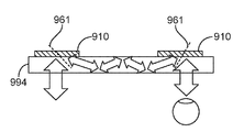
도 9a는 2개의 스큐 커플러들을 갖는 슬래브 도파관(994)에 의해 형성되는 동공 중계 실시예를 예시하는데, 스큐 커플러들 각각은 격자 매체의 표면 법선과는 상이한 반사 축(961)을 갖는 격자 매체(910)를 포함한다. 이러한 디바이스가 균일한 1:1 맵핑으로 입력 광선 대 출력 광선을 중계하도록 구성되기 때문에, 그것은 도파관(994)을 통해 눈 또는 다른 센서로 무한으로 이미지를 송신할 수 있다. 그러한 구성은 다른 응용들 중에서도, 헤드 마운트 디스플레이(HMD)들에 유용할 수 있다. 반전 방향에서, 그것은 아마도 눈 추적의 목적을 위해, 눈의 이미지를 중계할 수 있다. 도 9b는, 큰 어두운 빔을 작은 밝은 빔으로, 그리고/또는 그 반대로 변환시킬 수 있는, 집광기/확산기로서 사용되는 스큐 미러(900)를 도시한다.9A illustrates a pupil relay embodiment formed by a
도 10a 및 도 10b는 스큐 미러의 각도 필터 실시예를 예시한다. 도 10a에서, ![]()
![]()
![]()
![]()
제1 실시예 스큐 미러First embodiment skew mirror
제1 실시예 스큐 미러의 본 발명의 태양들은, 표면 법선에 대해 집합적으로 +13.73도의 평균 반사 축 각도를 갖는 반사 축들에 대해 532 nm의 파장을 갖는 입사광 및 513 nm의 파장을 갖는 입사광을 반사시키도록 구성되는 미러를 포함한다. 추가의 본 발명의 태양에서, -4.660 내지 +1.933도의 범위에 있는 내부 입사각들에서 스큐 미러 상에 입사되는 532 nm 광에 대한 평균 반사 축 각도(+13.759도)는, 532 nm 입사광과 동일한 입사각들에서 스큐 미러 상에 입사되는 513 nm 광에 대한 평균 반사 축 각도(+13.693도)와 0.066도만큼만 상이하다. 따라서, 반사 축들은, -4.660도 내지 +1.993도의 (표면 법선에 대한) 내부 입사각들을 얻는 조건에서, 532 nm 내지 513 nm 파장 범위에 대해 실질적으로 일정하다.Embodiments of the present invention of a skew mirror reflect incident light having a wavelength of 532 nm and incident light having a wavelength of 513 nm with respect to reflection axes having an average reflection axis angle of +13.73 degrees collectively with respect to the surface normal. And a mirror configured to cause the mirror. In a further aspect of the invention, the average reflection axis angle (+13.759 degrees) for 532 nm light incident on the skew mirror at internal incidence angles in the range of -4.660 to +1.933 degrees is equal to the incidence angles as 532 nm incident light. Differs only by 0.066 degrees from the average reflection axis angle (+13.693 degrees) for 513 nm light incident on the skew mirror at. Thus, the reflection axes are substantially constant over the 532 nm to 513 nm wavelength range, under conditions of obtaining internal incidence angles (relative to the surface normal) of -4.660 degrees to +1.993 degrees.
제1 실시예 스큐 미러(1100)는 도 11a 및 도 11b에 예시되어 있다. 제1 실시예 스큐 미러(1100)는 격자 매체(1110) 내에 존재하는 격자 구조(1105)(도 11a 및 도 11b에서 대각선 해치 선들에 의해 도시됨)를 포함한다. 명확화를 위해, 대각선 해치 선들은, 광, 축들, 및 각도들을 나타내는 도면 부호들에 근접한 격자 매체(1110) 내의 영역에서 생략되어 있다. 그러나, 당업자들은 격자 구조(1105)가 전형적으로 전술된 영역을 차지한다는 것을 인식할 것이다. 제1 실시예의 격자 구조(1105)는, 격자 매체(1110) 내에서 서로 적어도 부분적으로 공간적으로 오버랩되는 다수의 홀로그램들을 포함한다.The first
다수의 홀로그램들은 격자 매체 내부 체적 내에 기록되고, 그에 따라서 격자 매체 표면(1112) 아래로 연장된다. 따라서, 그들은 때때로 체적 홀로그램들로 지칭된다. 제1 실시예의 다수의 홀로그램들은, 405 nm의 파장을 갖는 기록 빔들로 기록되는, 48개의 체적 홀로그램들을 포함한다. 48개의 체적 홀로그램들 각각은 전형적으로, 격자 매체(1110) 내의 48개의 체적 홀로그램들 중 다른 체적 홀로그램들 모두와 적어도 부분적으로 공간적으로 오버랩된다. 일부 실시예들에서, 다수의 홀로그램들 각각은 다수의 홀로그램들 중 다른 홀로그램 중의 적어도 하나 - 그러나 전부는 아님 - 와 적어도 부분적으로 공간적으로 오버랩된다. 제1 실시예 스큐 미러의 48개의 홀로그램들을 기록하는 것이, 스큐 미러를 제조하는 제1 방법에서 후술된다. 일부 실시예들에서, 격자 구조는, 1 내지 48개의 홀로그램들; 또는 4 내지 25개의 홀로그램들; 또는 적어도 5개의 홀로그램들; 또는 적어도 9개의 홀로그램들; 또는 적어도 11개의 홀로그램들; 또는 적어도 24개의 홀로그램들을 포함한다.Multiple holograms are recorded in the grating medium internal volume and thus extend below the
제1 실시예 격자 매체(1110)는, Akonia Holographics, LLC(미국 콜로라도주 롱몬트 소재)로부터 입수가능한 AK174-200으로 명명된, 독점적인 감광성 중합체 광학 기록 매체이다. 제1 실시예의 AK174-200 기록 매체는 대략 200 μm 두께이고, 405 nm 광에 대해 대략 1.50의 굴절률, 및 대략 18의 M/#을 갖는다. AK174-200 매체와 같은 광학 기록 매체들은, 격자 구조들이 광학 수단에 의해 기록될 수 있는 격자 매체의 일 유형이다. 격자 매체들은 전형적으로 적어도 70 μm 두께 내지 대략 1.2 mm 두께이지만, 반드시 그러한 것은 아니다. AK174-200 매체는 전형적으로 체적 홀로그램들을 기록하는 결과로서 비교적 작은 수축(통상적으로 약 0.1% 내지 0.2%)을 겪는다. 격자 매체들의 변형예들은 광굴절 결정(photorefractive crystal)들, 중크롬산 젤라틴, 광열 굴절 유리, 및 분산된 할로겐화은 입자들을 함유하는 필름을 포함하지만, 이들로 제한되지 않는다.First
제1 실시예 스큐 미러(1100)의 변형예들은 유리 커버 또는 유리 기판(도 11a 및 도 11b에 도시되지 않음)과 같은 추가 층을 포함할 수 있다. 추가 층은 오염, 수분, 산소, 반응성 화학 종들, 손상 등으로부터 격자 매체를 보호하는 역할을 할 수 있다. 추가 층은 전형적으로 격자 매체(1110)에 매칭되는 굴절률을 갖는다. 추가 층에 대한 굴절률이 통상적으로 격자 매체의 굴절률에 매우 가깝기 때문에, 추가 층과 격자 매체의 계면에서의 광의 굴절은 때때로 무시될 수 있다. 제1 실시예의 경우, 추가 층 및 격자 매체 둘 모두에 대한 굴절률들은 405 nm의 파장을 갖는 광에 대해 대략 1.5이다. 명확화를 위해, 추가 층은 도 11a 및 도 11b에 도시되어 있지 않다.Variations of the first
도 11a에 도시된 바와 같이, 제1 실시예의 격자 구조(1105)는 제1 반사 축(1138)(파선으로 도시됨)에 대해, 제1 입사광(1124A, 1124B)을 반사시키도록 구성되는 물리적 특성을 갖는다. 제1 입사광은 532 nm의 제1 파장을 갖고, 특정 부위(1117)에서 격자 매체(1110) 상에 입사된다. 제1 반사 축(1138)은 격자 매체의 표면 법선(1122)과 +13.759도의 제1 반사 축 각도(1135)(표면 법선에 대한 내부 각도)만큼 상이한데, 여기서 제1 입사광은, -4.660도(제1 입사광(1124A)으로서 도시됨) 내지 +1.933도(제1 입사광(1124B)으로서 도시됨)의, 표면 법선에 대한 제1 내부 입사각(1125A, 1125B)을 가지며, 이는 6.593도의 범위를 생성한다. 제1 입사광에 대한 제1 내부 입사각들은, 표 1에 나타낸 바와 같이, -4.660도 내지 +1.933도에서, 약 0.067도의 각도 간격들로 이격된 100개의 상이한 내부 각도들을 포함한다. 제1 실시예 스큐 미러의 일부 변형예들에서, 제1 입사광에 대한 제1 내부 입사각들은, -4.660도 내지 +1.933도에서, 약 0.67도의 각도 간격들로 이격된 10개의 상이한 내부 각도들을 포함한다. 본 명세서 및 첨부된 청구범위 전체에 걸쳐, 식별된 각도들 및 각도 값들은, 명백히 달리 나타내지 않는 한, 표면 법선에 대한 내부 각도들을 지칭한다.As shown in FIG. 11A, the
도 11a에 도시된 바와 같이, 표면 법선에 대한 -4.660도의 제1 내부 입사각(1125A)을 갖는 제1 입사광(1124A)은, 격자 구조(1105)에 의해 표면 법선에 대한 +32.267도의 제1 내부 반사각(1126A)을 갖는 제1 반사된 광(1127A)으로서 반사된다. 표면 법선에 대한 +1.933도의 제1 내부 입사각(1125B)을 갖는 제1 입사광(1124B)은, +25.668도의 제1 내부 반사각(1126B)을 갖는 제1 반사된 광(1127B)으로서 반사된다. 제1 반사된 광(1127A, 1127B)은 제1 파장을 갖는데, 즉, 제1 실시예에서 제1 반사된 광은 532 nm의 파장을 갖는다. 제1 실시예 스큐 미러에 대한 제1 입사광 각도들, 제1 반사된 광 각도들, 및 제1 반사 축 각도들이 표 1에 나타나 있다.As shown in FIG. 11A, the
[표 1]TABLE 1


입사광과 그의 반사는 반사 축에 의해 이등분되어서, 반사 축에 대한 입사광의 내부 입사각이 반사 축에 대한 반사된 광의 내부 반사각과 동일한 크기를 갖도록 된다. 따라서, 입사광과 그의 반사가 반사 축에 대해 좌우 대칭을 나타낸다고 말할 수 있다.The incident light and its reflection are bisected by the reflection axis such that the internal incident angle of the incident light with respect to the reflection axis has the same magnitude as the internal reflection angle of the reflected light with respect to the reflection axis. Thus, it can be said that the incident light and its reflection exhibit symmetry with respect to the reflection axis.
도 11b에 도시된 바와 같이, 제1 실시예의 격자 구조(1105)는 제2 반사 축(1139)에 대해, 제2 입사광(1130A, 1130B)을 반사시키도록 추가로 구성된다. 제2 입사광은 513 nm의 제2 파장을 갖고, 특정 부위(1117)에서 격자 매체(1110) 상에 입사된다. 특정 부위(1117)는, 제1 입사광 및 제2 입사광 둘 모두가 비추는 격자 매체 표면(1112)의 영역을 포함한다. 제2 반사 축(1139)은 격자 매체의 표면 법선(1122)과 +13.693도의 표면 법선에 대한 제2 반사 축 각도(1136)(내부 각도)만큼 상이한데, 여기서 제2 입사광은, -4.660도 내지 +1.933도의, 표면 법선에 대한 제2 내부 입사각을 갖는다. 제2 내부 입사각은, -4.660도 내지 +1.933도에서, 대략 0.067도의 각도 간격들로 이격된 100개의 상이한 내부 각도들을 포함한다. 제1 실시예 스큐 미러의 일부 변형예들에서, 제2 입사광에 대한 제2 내부 입사각들은, -4.660도 내지 +1.933도에서, 약 0.67도의 각도 간격들로 이격된 10개의 상이한 내부 각도들을 포함한다.As shown in FIG. 11B, the
도 11b에 도시된 바와 같이, 표면 법선에 대한 -4.660도의 제2 내부 입사각(1128A)을 갖는 제2 입사광(1130A)은, 격자 구조(1105)에 의해 표면 법선에 대한 +32.075도의 제2 내부 반사각(1133A)을 갖는 제2 반사된 광(1133A)으로서 반사된다. 표면 법선에 대한 +1.933도의 제2 내부 입사각(1128B)을 갖는 제2 입사광(1130B)은, +25.273도의 제2 내부 반사각(1129B)을 갖는 제2 반사된 광(1133B)으로서 반사된다. 제2 반사된 광(1133A, 1133B)은 제2 파장을 갖는데, 즉, 제1 실시예에서 제2 반사된 광은 513 nm의 파장을 갖는다. 제1 실시예 스큐 미러에 대한 제2 입사광 각도들, 제2 반사된 광 각도들, 및 제2 반사 축 각도들이 표 2에 나타나 있다.As shown in FIG. 11B, the
[표 2]TABLE 2


제1 파장(λ1 = 532 nm)은 제2 파장(λ2 = 513 nm)과 19 nm만큼 상이한데, 이는 ![]()
![]()
제2 반사 축 각도(1136)는 제1 반사 축 각도(1135)와 0.066도만큼 상이하다. 따라서, 제2 반사 축은 제1 반사 축과 실질적으로 일치하고, 이는 제2 반사 축 각도(1136)가 제1 반사 축 각도(1135)와 1.0도 이하로 상이하다는 것을 의미한다. 소정 범위의 파장들을 가로지르는(이 경우에, 0.039의 WF를 가로지르는) 반사 축 각도들 사이의 그러한 작은 차이는, 격자 구조가 비분산성 미러로서 작용한다는 것을 의미한다. 일부 응용들의 경우, 반사 축 각도들 사이의 차이는 WF = 0.030에 대해 0.250도 이하이어야 한다. 유사하게, 일부 다른 응용들의 경우, 반사 축 각도들 사이의 차이는 WF = 0.030에 대해 0.10도 이하와 동일해야 한다.The second
제1 반사 축에 대해, 제1 입사광의 내부 입사각들은 -11.867도 내지 -18.464도의 범위이다. 제2 반사 축에 대해, 제2 입사광의 내부 입사각들은 -11.670도 내지 -18.368도의 범위이다. 따라서, 제1 입사광 및 제2 입사광 각각이 제1 반사 축으로부터 적어도 11.670도 오프셋되어 있다고 말할 수 있다. 실시예들에서, 입사광은 그의 반사 축으로부터 적어도 1.0도의 내부 각도만큼; 적어도 2.0도만큼; 적어도 5.0도만큼; 또는 적어도 9.0도만큼 오프셋되어 있을 수 있다. 입사광의 반사 축으로부터 오프셋되어 있는 입사광을 반사시키도록 구성된 스큐 미러 또는 다른 반사형 디바이스가 일부 응용들에서 유리할 수 있다. 예를 들어, 헤드 마운트 디스플레이에서, 사용자의 눈을 향해 이미지를 반사시키지만 이미지를 다시 그의 공급원을 향해 재귀반사(retroreflect)시키지 않는 것이 유리할 수 있다. 사용자의 눈을 향하는 그러한 반사는 전형적으로, 입사광이 그의 반사 축으로부터 적어도 5.0도의 내부 각도만큼, 그리고 보다 전형적으로는 적어도 9.0도만큼 오프셋되어 있을 것을 요구한다. 유사하게, 내부 전반사를 이용하는 디바이스는 전형적으로, 입사광이 그의 반사 축으로부터 오프셋되어 있을 것을 요구한다.For the first reflection axis, the internal incident angles of the first incident light range from -11.867 degrees to -18.464 degrees. For the second reflection axis, the internal incident angles of the second incident light range from -11.670 degrees to -18.368 degrees. Thus, it can be said that each of the first incident light and the second incident light is offset at least 11.670 degrees from the first reflection axis. In embodiments, the incident light is at least an internal angle of at least 1.0 degree from its reflection axis; By at least 2.0 degrees; By at least 5.0 degrees; Or offset by at least 9.0 degrees. Skew mirrors or other reflective devices configured to reflect incident light offset from the reflection axis of the incident light may be advantageous in some applications. For example, in a head mounted display, it may be advantageous to reflect the image toward the user's eyes but not retroreflect the image back toward its source. Such reflection towards the user's eye typically requires that the incident light is offset from its reflection axis by at least an internal angle of at least 5.0 degrees, and more typically at least 9.0 degrees. Similarly, devices utilizing total internal reflection typically require that incident light is offset from its reflection axis.
입사광 및 그의 반사에 대해 표면 법선에 대한 제1 실시예 외부 각도들이 또한 도 11a 및 도 11b에 예시되어 있다. 도 11a에서 알 수 있는 바와 같이, 제1 입사광(1124A, 1124B)에 대해 표면 법선에 대한 외부 각도들은, -7.000도의 제1 입사광 외부 각도(1113A) 내지 +2.900도의 제1 입사광 외부 각도(1113B)의 범위이다. 도 11b에서 알 수 있는 바와 같이, 제2 입사광(1130A, 1130B)에 대해 표면 법선에 대한 외부 각도들은, -7.000도의 제2 입사광 외부 각도(1115A) 내지 +2.900도의 제2 입사광 외부 각도(1115B)의 범위이다. 제1 반사된 광 외부 각도들(1114A, 1114B) 및 제2 반사된 광 외부 각도들(1116A, 1116B)이 또한 각각 도 11a 및 도 11b에 예시되어 있다. 외부 각도들은 공기 중에 존재하는 스큐 미러로 측정되는데, 이때 스큐 미러/공기 경계에서 굴절이 발생한다. 입사각들 및 반사각들, 및 반사 축 각도들이 표 1 및 표 2에 정리되어 있다.The first embodiment external angles to the surface normal to incident light and its reflection are also illustrated in FIGS. 11A and 11B. As can be seen in FIG. 11A, the external angles to the surface normal for the
제1 실시예의 물리적 특성들은, 실질적으로 일정한 반사 축들에 대해, 다른 파장들을 갖는 광을 반사시키고, 다른 각도들에서 격자 매체 상에 입사되는 광을 반사시키는 것을 가능하게 한다. 예를 들어, 제1 실시예 격자 구조의 반사 특성들은, +13.726도의 평균 반사 축 각도를 갖는 반사 축들에 대해 520.4 nm의 파장을 갖는 광을 반사시키는 것을 가능하게 하는데, 여기서 반사 축 각도들은 -6.862도 내지 +13.726도 범위의 입사각들 및 그 사이(20.588도의 범위)의 모든 각도들에 대해 0.10도 이하로 변한다. 그의 반사 특성들의 다른 예에서, 제1 실시예는 (+13.726°의 평균 반사 축 각도를 갖는) 반사 축들에 대해 입사광을 반사시키도록 구성되는데, 여기서 반사 축 각도들은 503 nm 및 537 nm의 파장들(503 nm 내지 537 nm의 파장들의 연속 스펙트럼을 포함하는, 34 nm, WF = 0.065의 범위)에 대해 0.20도 이하로 변하고, 입사각(표면 법선에 대한 내부 각도)은 -1.174도이다.The physical properties of the first embodiment make it possible to reflect light having different wavelengths and reflect light incident on the grating medium at different angles, for substantially constant reflection axes. For example, the reflective properties of the first embodiment grating structure make it possible to reflect light having a wavelength of 520.4 nm with respect to the reflection axes with an average reflection axis angle of +13.726 degrees, where the reflection axis angles are -6.862. For angles of incidence in the range of degrees to +13.726 degrees and all angles therebetween (range of 20.588 degrees). In another example of its reflection characteristics, the first embodiment is configured to reflect incident light about the reflection axes (with an average reflection axis angle of + 13.726 °), wherein the reflection axis angles are wavelengths of 503 nm and 537 nm. (With a continuous spectrum of wavelengths of 503 nm to 537 nm, 34 nm, in the range of WF = 0.065) and below 0.20 degrees, and the angle of incidence (internal angle to the surface normal) is −1.174 degrees.
명확화를 위해, 도 11a 및 도 11b에서의 광은, 격자 구조(1105)의 중심에 근접하게 존재하는 지점에서 반사되는 것으로 예시되어 있다. 그러나, 당업자들은, 광이 전형적으로 특정 지점에서보다는 오히려 격자 구조 전체에 걸쳐 반사된다는 것을 인식한다.For clarity, the light in FIGS. 11A and 11B is illustrated as being reflected at a point near the center of the
일부 실시예들에서, 제1 입사광 및 제2 입사광은 각각 532 nm 및 513 nm 이외의 파장들을 갖는다. 유사하게, 실시예들은, 표면 법선과 일치할 수 있거나 또는 표면 법선과 상이할 수 있는 제1 및 제2 반사 축들을 포함한다.In some embodiments, the first incident light and the second incident light have wavelengths other than 532 nm and 513 nm, respectively. Similarly, embodiments include first and second reflection axes that may coincide with or differ from the surface normal.
제2 실시예 스큐 미러Second Embodiment Skew Mirror
제2 실시예 스큐 미러의 본 발명의 태양들은, 표면 법선에 대해 집합적으로 +14.62도의 평균 반사 축 각도를 갖는 반사 축들에 대해 532 nm의 파장을 갖는 입사광 및 513 nm의 파장을 갖는 입사광을 반사시키도록 구성되는 미러를 포함한다. 추가의 본 발명의 태양에서, -9.281 내지 -2.665도의 범위에 있는 내부 입사각들에서 스큐 미러 상에 입사되는 532 nm 광에 대한 평균 반사 축 각도(+14.618도)는, 532 nm 입사광과 동일한 입사각들에서 스큐 미러 상에 입사되는 513 nm 광에 대한 평균 반사 축 각도(+14.617도)와 0.001도 미만으로 상이하다. 따라서, 반사 축들은, -9.281도 내지 -2.665도의 (표면 법선에 대한) 내부 입사각들을 얻는 조건에서, 532 nm 내지 513 nm 파장 범위에 대해 실질적으로 일정하다.Embodiments of the present invention of a skew mirror reflect incident light having a wavelength of 532 nm and incident light having a wavelength of 513 nm with respect to reflection axes having an average reflection axis angle of +14.62 degrees collectively with respect to the surface normal. And a mirror configured to cause the mirror. In a further aspect of the invention, the average reflection axis angle (+14.618 degrees) for 532 nm light incident on the skew mirror at internal incidence angles ranging from -9.281 to -2.665 degrees is equal to the incidence angles of 532 nm incident light. Is different from the average reflection axis angle (+14.617 degrees) for 513 nm light incident on the skew mirror at less than 0.001 degrees. Thus, the reflection axes are substantially constant over the 532 nm to 513 nm wavelength range under conditions that obtain internal incidence angles (relative to the surface normal) of -9.281 degrees to -2.665 degrees.
제2 실시예 스큐 미러(1200)는 도 12a 및 도 12b에 예시되어 있다. 제2 실시예 스큐 미러(1200)는 격자 매체(1210) 내에 존재하는 격자 구조(1205)(도 12a 및 도 12b에서 대각선 해치 선들에 의해 도시됨)를 포함한다. 명확화를 위해, 대각선 해치 선들은, 광, 축들, 및 각도들을 나타내는 도면 부호들에 근접한 격자 매체(1210) 내의 영역에서 생략되어 있다. 그러나, 당업자들은 격자 구조(1205)가 전형적으로 전술된 영역을 차지한다는 것을 인식할 것이다. 제2 실시예의 격자 구조(1205)는, 격자 매체(1210) 내에서 서로 적어도 부분적으로 오버랩되는 다수의 홀로그램들을 포함한다. 제2 실시예의 다수의 홀로그램들은, 405 nm의 파장을 갖는 기록 빔들로 기록되는, 49개의 체적 홀로그램들을 포함한다. 49개의 체적 홀로그램들은 격자 매체(1210) 내에서 서로 오버랩되고, 기록 빔 내부 입사각들이 매체 수축을 고려하기 위해 조정되는 것 이외에는, 제1 실시예 스큐 미러와 유사한 방식으로 기록된다. 제2 실시예 스큐 미러의 49개의 홀로그램들을 기록하는 것이, 스큐 미러를 제조하는 제2 방법에서 후술된다.A second
제2 실시예 격자 매체(1210)는, Akonia Holographics, LLC(미국 콜로라도주 롱몬트 소재)로부터 입수가능한 AK233-200으로 명명된, 독점적인 감광성 중합체 광학 기록 매체이다. 제2 실시예의 AK233-200 기록 매체는 대략 200 μm 두께이고, 405 nm의 파장을 갖는 광에 대해 대략 1.50의 굴절률, 및 대략 24의 M/#을 갖는다. AK233-200 매체는 전형적으로 체적 홀로그램들을 기록하는 결과로서 약 0.50% 수축된다.Second
제2 실시예 스큐 미러(1200)의 변형예들은 유리 커버 또는 유리 기판(도 12a 및 도 12b에 도시되지 않음)과 같은 추가 층을 포함할 수 있다. 추가 층은 전형적으로 격자 매체에 매칭되는 굴절률을 갖고, 굴절률 매칭 유체의 박막이 격자 매체(1210)와 추가 층 사이에 존재할 수 있다.Variations of the second
도 12a에 도시된 바와 같이, 제2 실시예의 격자 구조(1205)는 제1 반사 축(1238)(파선으로 도시됨)에 대해, 제1 입사광(1224A, 1224B)을 반사시키도록 구성되는 물리적 특성을 갖는다. 제1 입사광은 532 nm의 제1 파장을 갖고, 특정 부위(1217)에서 격자 매체(1210) 상에 입사된다. 제1 반사 축(1238)은 격자 매체의 표면 법선(1222)과 +14.618도의 표면 법선에 대한 제1 반사 축 각도(1235)(내부 각도)만큼 상이한데, 여기서 제1 입사광은, -9.281도 및 -2.665도를 포함하여, -9.281도 내지 -2.665도(6.616도의 범위)로 존재하는, 표면 법선에 대한 제1 내부 입사각(1225A, 1225B)을 갖는다. 제1 내부 입사각은, -9.281도 내지 -2.665도에서, 대략 0.066도의 각도 간격들로 이격된 101개의 상이한 내부 각도들을 포함한다. 제2 실시예 스큐 미러의 일부 변형예들에서, 제1 입사광에 대한 제1 내부 입사각들은, -9.281도 내지 -2.665도에서, 약 0.66도의 각도 간격들로 이격된 10개의 상이한 내부 각도들을 포함한다.As shown in FIG. 12A, the
도 12a에 도시된 바와 같이, 표면 법선에 대한 -9.281도의 제1 내부 입사각(1225A)을 갖는 제1 입사광(1224A)은, 격자 구조(1205)에 의해 표면 법선에 대한 +38.610도의 제1 내부 반사각(1226A)을 갖는 제1 반사된 광(1227A)으로서 반사된다. 표면 법선에 대한 -2.665도의 제1 내부 입사각(1225B)을 갖는 제1 입사광(1224B)은, +31.836도의 제1 내부 반사각(1226B)을 갖는 제1 반사된 광(1227B)으로서 반사된다. 제1 반사된 광(1224A, 1224B)은 제1 파장을 갖는데, 즉, 제2 실시예에서 제1 반사된 광은 532 nm의 파장을 갖는다. 제2 실시예 스큐 미러에 대한 제1 입사광 각도들, 제1 반사된 광 각도들, 및 제1 반사 축 각도들이 표 3에 나타나 있다.As shown in FIG. 12A, a
[표 3]TABLE 3


도 12b에 도시된 바와 같이, 제2 실시예의 격자 구조(1205)는 제2 반사 축(1239)에 대해 제2 입사광(1230A, 1230B)을 반사시키도록 추가로 구성된다. 제2 입사광은 513 nm의 제2 파장을 갖고, 따라서 제2 파장은 제1 파장과 19nm, 또는 0.036의 파장 분율(WF)만큼 상이하다. 제2 입사광은 특정 부위(1217)에서 격자 매체(1210) 상에 입사된다. 제2 실시예의 특정 부위(1217)는, 제1 입사광 및 제2 입사광 둘 모두가 비추는 격자 매체 표면(1212)의 영역을 포함한다. 제2 반사 축(1239)은 격자 매체의 표면 법선(1222)과 +14.617도의 표면 법선에 대한 제2 반사 축 각도(1236)(내부 각도)만큼 상이한데, 여기서 제2 입사광은, -9.281도 내지 -2.665도의 범위에 걸쳐 있는, 표면 법선에 대한 제2 내부 입사각(1228A, 1228B)을 갖는다. 제2 입사광의 제2 내부 입사각은, -9.281도 내지 -2.665도에서, 대략 0.066도의 각도 간격들로 이격된 101개의 상이한 내부 각도들을 포함한다. 제2 실시예 스큐 미러의 일부 변형예들에서, 제2 입사광에 대한 제2 내부 입사각들은, -9.281도 내지 -2.665도에서, 약 0.66도의 각도 간격들로 이격된 10개의 상이한 내부 각도들을 포함한다.As shown in FIG. 12B, the
도 12b에 도시된 바와 같이, 표면 법선에 대한 -9.281도의 제2 내부 입사각(1228A)을 갖는 제2 입사광(1230A)은, 격자 구조(1205)에 의해 표면 법선에 대한 +38.598도의 제2 내부 반사각(1229A)을 갖는 제2 반사된 광(1233A)으로서 반사된다. 표면 법선에 대한 -2.655도의 제2 내부 입사각(1228B)을 갖는 제2 입사광(1230B)은, +31.836도의 제2 내부 반사각(1229B)을 갖는 제2 반사된 광(1233B)으로서 반사된다. 제2 반사된 광(1233A, 1233B)은 제2 파장을 갖는데, 즉, 제2 실시예에서 제2 반사된 광은 513 nm의 파장을 갖는다. 제2 실시예 스큐 미러(1200)에 대한 제2 입사광 각도들, 제2 반사된 광 각도들, 및 제2 반사 축 각도들이 표 4에 나타나 있다.As shown in FIG. 12B, the
[표 4]TABLE 4


명확화를 위해, 도 12a 및 도 12b에서의 광은, 격자 구조(1205)의 중심에 근접하게 존재하는 지점에서 반사되는 것으로 예시되어 있다. 그러나, 당업자들은, 광이 전형적으로 특정 지점에서보다는 오히려 격자 구조 전체에 걸쳐 반사된다는 것을 인식한다.For clarity, the light in FIGS. 12A and 12B is illustrated as being reflected at a point near the center of the
제2 실시예에서, 제2 반사 축 각도는 제1 반사 축 각도와 WF = 0.036을 가로질러 대략 0.0005도만큼 상이하다. 이러한 매우 낮은 수준의 변화는 반사각들을 측정하는 데 사용되는 계측장비의 정밀도의 수준에 접근할 수 있다. 따라서, 본 발명의 목적을 위해, 제2 반사 축은 제1 반사 축과 상이하지 않다고 말할 수 있다. 일부 응용들의 경우, 반사 축 각도들 사이의 차이는 0.025도 이하이어야 한다. 일부 다른 응용들의 경우, 반사 축 각도들 사이의 차이는 WF > 0.036을 가로질러 0.010도 이하이어야 한다. 제2 실시예 스큐 미러는 이러한 요건들을 충족한다. 스튜던트의 t-테스트(Student's t-test)(양측 검정)는, 제1 반사 축 각도와 제2 반사 축 각도 간의 차이가 없음을 나타낸다(그룹당 N = 101; P = 0.873). 또한, 0.001도 이하의 차이는, 스큐 미러 반사각들을 측정하는 데 사용되는 계측장비의 정밀도가 문제시된다. 따라서, 본 발명의 목적을 위해, 제2 반사 축이 제1 반사 축과 0.001도 이하만큼 상이한 경우, 제2 반사 축은 제1 반사 축과 상이하지 않다고 말할 수 있다.In a second embodiment, the second reflection axis angle is different from the first reflection axis angle by approximately 0.0005 degrees across WF = 0.036. This very low level of change can approach the level of precision of the instrumentation used to measure the reflection angles. Thus, for the purposes of the present invention, it can be said that the second reflection axis is not different from the first reflection axis. For some applications, the difference between the reflection axis angles should be less than 0.025 degrees. For some other applications, the difference between the reflection axis angles should be no more than 0.010 degrees across WF > 0.036. The second embodiment skew mirror meets these requirements. Student's t- test (two-sided test) indicates no difference between the first and second reflection axis angles (N = 101 per group; P = 0.873). In addition, differences of less than 0.001 degrees pose a problem for the precision of the metrology equipment used to measure skew mirror reflection angles. Thus, for the purposes of the present invention, it can be said that when the second reflection axis is different from the first reflection axis by 0.001 degrees or less, the second reflection axis is not different from the first reflection axis.
제2 실시예 스큐 미러의 경우, 제1 반사 축에 대한 제1 입사광의 입사각들은 -17.250도 내지 -23.946도로 다양하다. 제2 반사 축에 대한 제2 입사광의 입사각들은 -17.250도 내지 -23.940도로 다양하다. 따라서, 제1 입사광 및 제2 입사광 각각이 제1 반사 축으로부터 적어도 17.20도 오프셋되어 있다고 말할 수 있다. 제2 실시예 스큐 미러의 경우, 입사광 및 그의 반사에 대해, 반사 축에 대한 입사각들 및 반사각들이 각각 표 3 및 표 4에 정리되어 있다.Second Embodiment For the skew mirror, the incident angles of the first incident light with respect to the first reflection axis vary from -17.250 degrees to -23.946 degrees. Incident angles of the second incident light with respect to the second reflection axis vary from -17.250 degrees to -23.940 degrees. Thus, it can be said that each of the first incident light and the second incident light is offset at least 17.20 degrees from the first reflection axis. Second Embodiment For the skew mirror, for the incident light and its reflection, the incident angles and the reflection angles with respect to the reflection axis are summarized in Tables 3 and 4, respectively.
입사광 및 그의 반사에 대해 표면 법선에 대한 제2 실시예 외부 각도들이 또한 도 12a 및 도 12b에 예시되어 있다. 도 12a에서 알 수 있는 바와 같이, 제1 입사광(1224A, 1224B)에 대해 표면 법선에 대한 외부 각도들은, -14.000도의 제1 입사광 외부 각도(1213A) 내지 -4.000도의 제1 입사광 외부 각도(1213B)의 범위이다. 도 12a에서 알 수 있는 바와 같이, 제2 입사광(1230A, 1230B)에 대해 표면 법선에 대한 외부 각도들은, -14.000도의 제2 입사광 외부 각도(1215A) 내지 -4.000도의 제2 입사광 외부 각도(1215B)의 범위이다. 제1 반사된 광 외부 각도들(1214A, 1214B) 및 제2 반사된 광 외부 각도들(1216A, 1216B)이 또한 각각 도 12a 및 도 12b에 예시되어 있다.Second embodiment external angles to the surface normal to incident light and its reflection are also illustrated in FIGS. 12A and 12B. As can be seen in FIG. 12A, the external angles to the surface normal with respect to the
당업자들은, 입사광 및 그의 반사가 전형적으로 반전되어서, 이전에 반사각이었던 것이 입사각이 되도록 될 수 있고, 그 반대로도 가능하다는 것을 인식할 것이다. 그러나, 본 발명의 목적을 위해, 입사각들의 범위의 언급 또는 설명은, 반사 축의 일 측부 또는 다른 측부 - 그러나 둘 모두는 아님 - 로 배향되는 입사광, 또는 재귀반사된 입사광의 경우에, 반사 축에 대한 0의 입사각을 지칭한다. 따라서, 입사각들의 범위는 반사 축들과 관련하여 양 및 음인 각도들을 포함하지 않는다. 여기서 예시되고 기술되는 바와 같이, 그들 각각의 반사 축들에 대한 입사각들은 음(즉, 시계 방향으로)이다. 그러나, 이러한 관례는 편의상 그리고 단순함을 위해 사용되고, 스큐 미러가 반사 축의 일 측부에 존재하는 입사광만을 반사시킬 수 있음을 교시하거나, 제안하거나, 또는 암시하는 것을 의미하지는 않는다.Those skilled in the art will appreciate that the incident light and its reflection are typically inverted so that what was previously the reflection angle can be the angle of incidence and vice versa. However, for the purposes of the present invention, reference or description of the range of angles of incidence is directed to the reflection axis in the case of incident light, or retroreflected incident light, which is oriented at one side or the other side of the reflection axis, but not both. Refers to the incident angle of zero. Thus, the range of incidence angles does not include angles that are positive and negative with respect to the reflection axes. As illustrated and described herein, the angles of incidence for their respective reflection axes are negative (ie clockwise). However, such a convention is used for convenience and simplicity and does not mean to teach, suggest, or imply that the skew mirror can only reflect incident light present on one side of the reflection axis.
제3 실시예 스큐 미러Third Embodiment Skew Mirror
제3 실시예 스큐 미러는 격자 매체 내에 존재하는 격자 구조를 포함하고, 격자 구조는 격자 매체 내에서 서로 오버랩되는 21개의 체적 홀로그램들을 포함한다.Third Embodiment The skew mirror comprises a grating structure existing in the grating medium, and the grating structure includes 21 volume holograms overlapping each other in the grating medium.
제3 실시예 격자 매체는, Covestro AG(구 Bayer MaterialScience AG)(독일 레버쿠젠 소재)로부터 입수가능한, BAYFOL® HX TP 광중합체 필름으로 명명된, 상업적인 감광성 중합체 광학 기록 매체이다. 제3 실시예의 BAYFOL® HX TP 기록 매체는 대략 70 μm 두께이고, 전형적으로 체적 홀로그램들을 기록하는 결과로서 약 1.0% 수축된다. 따라서, 제3 실시예 격자 매체에 체적 홀로그램들을 기록할 때 수축 보상이 전형적으로 채용된다. 수축 보상은 제3 실시예 스큐 미러를 제조하는 방법에서 후술된다.Third Embodiment Lattice Media is a commercial photosensitive polymer optical recording medium, designated BAYFOL® HX TP photopolymer film, available from Covestro AG (former Bayer MaterialScience AG) (Leverkusen, Germany). The BAYFOL® HX TP recording medium of the third embodiment is approximately 70 μm thick and typically shrinks about 1.0% as a result of recording volume holograms. Therefore, shrink compensation is typically employed when writing volume holograms in a third embodiment grating medium. Shrinkage compensation is described below in the method of manufacturing the third embodiment skew mirror.
제3 실시예 스큐 미러의 변형예들은 유리 커버 또는 유리 기판과 같은 추가 층을 포함할 수 있다. 추가 층은 전형적으로 격자 매체에 매칭되는 굴절률을 갖고, 굴절률 매칭 유체의 박막이 제3 실시예 격자 매체와 추가 층 사이에 존재할 수 있다.Modifications of the third embodiment skew mirror may comprise an additional layer, such as a glass cover or a glass substrate. The additional layer typically has a refractive index that matches the grating medium, and a thin film of refractive index matching fluid may be present between the third embodiment grating medium and the additional layer.
제3 실시예의 격자 구조는 제1 반사 축에 대해 제1 입사광을 반사시키도록 구성되는 물리적 특성을 갖는다. 제1 입사광은 532 nm의 제1 파장을 갖고, 특정 부위에서 격자 매체 상에 입사된다. 제1 반사 축은 격자 매체의 표면 법선과 +9.419도의 표면 법선에 대한 제1 반사 축 각도(내부 각도)만큼 상이한데, 여기서 제1 입사광은, -6.251도 및 +0.334도를 포함하여, -6.251도 내지 +0.334도(6.585도의 범위)로 존재하는, 표면 법선에 대한 내부 각도를 갖는다. 제1 입사광의 내부 각도는 대략 6.59도의 범위에 걸쳐 있는 다수의 각도들을 포함하고, 다수의 각도들은, -6.251도 내지 +0.334도에서, 대략 0.067도의 각도 간격들로 이격된 100개의 상이한 내부 각도들을 포함한다.The grating structure of the third embodiment has a physical property configured to reflect the first incident light with respect to the first reflection axis. The first incident light has a first wavelength of 532 nm and is incident on the grating medium at a particular site. The first reflection axis is different from the surface normal of the grating medium by the first reflection axis angle (internal angle) with respect to the surface normal of +9.419 degrees, where the first incident light is -6.251 degrees, including -6.251 degrees and +0.334 degrees It has an internal angle to the surface normal, which is in the range of from +0.334 degrees (in the range of 6.585 degrees). The inner angle of the first incident light includes a plurality of angles spanning a range of approximately 6.59 degrees, the plurality of angles ranging from -6.251 degrees to +0.334 degrees, representing 100 different inner angles spaced at angular intervals of approximately 0.067 degrees. Include.
표면 법선에 대한 -6.251도의 내부 각도를 갖는 제3 실시예 제1 입사광은, 격자 구조에 의해 표면 법선에 대한 +25.027도의 내부 각도를 갖는 제1 반사된 광으로서 반사된다. 표면 법선에 대한 +0.334도의 내부 각도를 갖는 제1 입사광은, +18.487도의 내부 각도를 갖는 제1 반사된 광으로서 반사된다. 제1 반사된 광은 제1 파장을 갖는데, 즉, 제3 실시예에서 제1 반사된 광은 532 nm의 파장을 갖는다.Third embodiment having an internal angle of -6.251 degrees with respect to the surface normal The first incident light is reflected by the grating structure as first reflected light having an internal angle of +25.027 degrees with respect to the surface normal. The first incident light having an internal angle of +0.334 degrees with respect to the surface normal is reflected as the first reflected light having an internal angle of +18.487 degrees. The first reflected light has a first wavelength, that is, in the third embodiment the first reflected light has a wavelength of 532 nm.
제3 실시예의 격자 구조는 제2 반사 축에 대해 제2 입사광을 반사시키도록 추가로 구성된다. 제2 입사광은 513 nm의 제2 파장을 갖고, 따라서 제2 파장은 제1 파장과 19nm, 또는 0.036의 파장 분율(WF)만큼 상이하다. 제2 입사광은 특정 부위에서 격자 매체 상에 입사된다. 제2 반사 축은 격자 매체의 표면 법선과 +9.400도의 표면 법선에 대한 제2 반사 축 각도(내부 각도)만큼 상이한데, 여기서 제2 입사광은, -6.251도 내지 +0.334도의 범위에 걸쳐 있는, 표면 법선에 대한 내부 각도를 갖는다. 제2 입사광의 내부 각도는, -6.251도 내지 +0.334도에서, 대략 0.067도의 각도 간격들로 이격된 100개의 상이한 내부 각도들을 포함한다.The grating structure of the third embodiment is further configured to reflect the second incident light with respect to the second reflection axis. The second incident light has a second wavelength of 513 nm, so the second wavelength is different from the first wavelength by a wavelength fraction (WF) of 19 nm or 0.036. The second incident light is incident on the grating medium at a particular site. The second reflection axis is different from the surface normal of the grating medium by a second reflection axis angle (internal angle) relative to the surface normal of +9.400 degrees, where the second incident light is in the range of -6.251 degrees to +0.334 degrees. Has an internal angle for. The internal angle of the second incident light includes 100 different internal angles spaced at angular intervals of approximately 0.067 degrees, from -6.251 degrees to +0.334 degrees.
표면 법선에 대한 -6.251도의 내부 각도를 갖는 제3 실시예 제2 입사광은, 격자 구조에 의해 표면 법선에 대한 +24.967도의 내부 각도를 갖는 제2 반사된 광으로서 반사된다. 표면 법선에 대한 +0.334도의 내부 각도를 갖는 제2 입사광은, +18.425도의 내부 각도를 갖는 제2 반사된 광으로서 반사된다. 제2 반사된 광은 제2 파장을 갖는데, 즉, 제3 실시예에서 제2 반사된 광은 513 nm의 파장을 갖는다. 제3 실시예의 제2 반사 축은 제1 반사 축과 실질적으로 일치한다.Third embodiment having an internal angle of -6.251 degrees with respect to the surface normal Second incident light is reflected by the grating structure as second reflected light having an internal angle of +24.967 degrees with respect to the surface normal. The second incident light having an internal angle of +0.334 degrees with respect to the surface normal is reflected as the second reflected light having an internal angle of +18.425 degrees. The second reflected light has a second wavelength, that is, in the third embodiment the second reflected light has a wavelength of 513 nm. The second reflection axis of the third embodiment substantially coincides with the first reflection axis.
표 5는 제1, 제2, 및 제3 실시예 스큐 미러들의 반사 특성들을 요약한다.Table 5 summarizes the reflection characteristics of the first, second, and third embodiment skew mirrors.
[표 5]TABLE 5

반사 축이 일정하게 유지되는 입사각들의 범위는 ΔθB에 관하여 표현될 수 있다. 하기 표 6에 나타낸 바와 같이, 제1 실시예 스큐 미러에 대한 반사 축 각도는, 서로 WF > 0.036만큼 상이한 다수의 파장들에서, >20 × ΔθB의 입사각들의 범위를 갖는 입사광에 대해 0.015도 미만으로 변한다. 제2 실시예 스큐 미러의 경우, 반사 축 각도는, 서로 WF > 0.036만큼 상이한 다수의 파장들에서, > 20 × ΔθB의 입사각들의 범위를 갖는 입사광에 대해 0.020도 미만으로 변한다.The range of angles of incidence in which the reflection axis remains constant can be expressed in terms of Δθ B. As shown in Table 6 below, the reflection axis angle for the first embodiment skew mirror is less than 0.015 degrees for incident light having a range of incidence angles of > 20 × Δθ B at multiple wavelengths that differ from each other by WF > 0.036. Changes to In the case of the second embodiment skew mirror, the reflection axis angle changes to less than 0.020 degrees for incident light having a range of incidence angles of > 20 × Δθ B at multiple wavelengths different from each other by WF > 0.036.
[표 6]TABLE 6

스큐 미러를 제조하는 방법How to make a skew mirror
스큐 미러를 제조하기 위한 예시적인 시스템(1350)이 도 13에 예시되어 있다. 예시적인 시스템(1350)은 제1 미러(1352A)와 제2 미러(1352B) 사이에 배치된 격자 매체(1310)를 포함한다. 제1 및 제2 미러들은, 제1 기록 빔(1354) 및 제2 기록 빔(1355)이 서로 교차하고 간섭하여 격자 매체(1310) 내에 홀로그램(1305)으로서 기록되는 간섭 패턴을 형성하도록 기록 빔들을 지향시키기 위해 배열된다. 홀로그램(1305)은 격자 구조의 일례이다.An
기록 빔들은 홀로그래픽 업계의 당업자들에 의해 때때로 사용되는 관례에 따라 참조 빔 및 신호 빔으로 지칭될 수 있다. 그러나, 제1 및 제2 기록 빔들 각각은 전형적으로 (그들이 격자 매체 상에 입사되는 각도들 이외에는) 서로 동일한 단색 시준된 평면파 빔들이다. 또한, 소위 신호 빔은 전형적으로 그 내부에 어떠한 인코딩된 데이터도 포함하지 않으며, 이는 소위 참조 빔에도 또한 존재하지 않는다. 따라서, 하나의 기록 빔을 신호 빔으로서 그리고 다른 하나의 기록 빔을 참조 빔으로서 지정하는 것은 임의적일 수 있는데, 이때 "신호" 및 "참조"의 지정은, 하나의 기록 빔이 다른 하나의 기록 빔에 존재하지 않는 인코딩된 데이터를 포함하는 것을 나타내기보다는 오히려, 2개의 기록 빔들 사이를 구별하는 역할을 한다.Recording beams may be referred to as reference beams and signal beams in accordance with conventions sometimes used by those skilled in the holographic art. However, each of the first and second recording beams is typically monochromatic collimated plane wave beams that are identical to each other (other than the angles at which they are incident on the grating medium). Also, the so-called signal beam typically does not contain any encoded data therein, which is also not present in the so-called reference beam. Thus, designating one recording beam as a signal beam and another recording beam as a reference beam can be arbitrary, where designation of "signal" and "reference" means that one recording beam is the other recording beam. Rather than indicating that it contains encoded data that does not exist in, it serves to distinguish between the two recording beams.
일부 실시예들에서, 기록 빔들은 서로 상이한 폭들을 가질 수 있거나, 또는 그들은 동일할 수 있다. 기록 빔들은 각각 서로 동일한 세기를 가질 수 있거나, 또는 세기가 빔들 사이에서 상이할 수 있다. 격자 매체(1310)는 전형적으로 제1 프리즘(1359A)과 제2 프리즘(1359B) 사이의 제자리에, 프리즘들 및 격자 매체 둘 모두에 굴절률 매칭된 유체를 사용하여 고정된다. 스큐 축(1361)은 표면 법선(1322)에 대한 스큐 각도(1364)로 존재한다. 제1 및 제2 기록 빔들(1354, 1355)은 각각, 표면 법선(1322)에 대한 제1 기록 빔 내부 각도(1356) 및 제2 기록 빔 내부 각도(1357)로 존재한다. 빔 차이 각도(α)(1358)는 제1 및 제2 기록 빔들(1354, 1355)의 서로에 대한 각도이다. 실시예들에서, α는 0 내지 180도의 범위로 존재한다. 각각의 홀로그램에 대한 스큐 각도(1364)는 수학식(9)에 따라 계산될 수 있고,In some embodiments, the write beams may have different widths from each other, or they may be the same. The recording beams may each have the same intensity as each other, or the intensity may be different between the beams. The
![]()
![]()
여기서 θskew는 스큐 각도, 즉, 표면 법선에 대한 스큐 축의 내부 각도이고;Where θ skew is the skew angle, ie the internal angle of the skew axis with respect to the surface normal;
θR1은 표면 법선에 대한 제1 기록 빔 내부 각도이고;θ R1 is the first recording beam internal angle with respect to the surface normal;
θR2는 표면 법선에 대한 제2 기록 빔 내부 각도이다.θ R2 is the second recording beam internal angle with respect to the surface normal.
도 13에서 알 수 있는 바와 같이, 제1 및 제2 기록 빔들(1354, 1355)은 스큐 축(1361)에 대해 대칭적이어서, 스큐 축에 대한 제1 기록 빔 내부 각도(1366) + 스큐 축에 대한 제2 기록 빔 내부 각도(1367)가 180도와 동일하도록 된다. 스큐 축에 대한 제1 및 제2 기록 빔들의 내부 각도들(1366, 1367)은, 각각 제1 및 제2 기록 빔 내부 각도들(1356, 1357), 및 스큐 각도(1364)로부터 용이하게 계산된다.As can be seen in FIG. 13, the first and
제1 및 제2 기록 빔들 각각은 전형적으로 레이저 광원으로부터 비롯되는 시준된 평면파 빔들이다. 평면파 빔들은 각각의 기록 빔에 대한 다수의 광선 묘사들을 사용하여 예시될 수 있다. 그러나, 명확화를 위해, 도 13에서는, 제1 및 제2 기록 빔들이 각각의 기록 빔에 대한 단일 광선 묘사를 사용하여 예시되어 있다.Each of the first and second recording beams is typically collimated plane wave beams originating from a laser light source. Planar wave beams may be illustrated using multiple ray descriptions for each recording beam. However, for the sake of clarity, in FIG. 13, the first and second recording beams are illustrated using a single ray depiction for each recording beam.
예를 들어, 제1 기록 빔(1354)이 제1 프리즘(1359A)의 공기/프리즘 경계와 교차하고 제2 기록 빔(1355)이 제2 프리즘(1359B)의 공기/프리즘 경계와 교차하는, 공기/프리즘 경계들에서의 굴절은, 도 13에서 엄격하게 정량적으로보다는 오히려 상징적으로 도시되어 있다. 프리즘들이 전형적으로 격자 매체(1310)에 굴절률 매칭되기 때문에, 프리즘/격자 매체 경계에서의 굴절은 통상적으로 무시될 수 있다. 실시예들에서, 격자 매체 및 프리즘들은 각각 대략 1.50의 굴절률을 갖는다.For example, air, where the
(홀로그램들의 집합에 대한 평균 스큐 각도를 포함하는) 홀로그램에 대한 스큐 각도는, 반사 축 각도와 실질적으로 동일할 수 있고, 이는 스큐 각도 또는 평균 스큐 각도가 반사 축 각도의 1.0도 이내에 있음을 의미한다. 당업자들은, 스큐 각도 및 반사 축 각도가 이론적으로 동일할 수 있다는 것을 인식할 것이다. 그러나, 시스템 정밀도 및 정확도의 제한들, 홀로그램들을 기록하는 동안 발생하는 기록 매체의 수축, 및 오차의 다른 공급원들로 인해, 기록 빔 각도들에 기초하여 측정되거나 추정되는 바와 같은 스큐 각도 또는 평균 스큐 각도는, 스큐 미러에 의해 반사되는 광의 반사각들 및 입사각들에 의해 측정되는 바와 같은 반사 축 각도와 완벽하게 매칭되지 않을 수 있다. 그럼에도 불구하고, 매체 수축 및 시스템 결함들이 스큐 각도 및 반사 축 각도를 추정하는 데에 있어서 오차들에 기여하더라도, 기록 빔 각도들에 기초하여 결정되는 스큐 각도는, 입사광 및 그의 반사의 각도들에 기초하여 결정되는 반사 축 각도의 1.0도 이내일 수 있다. 스큐 축/반사 축은 일반적으로, 스큐 미러의 제조를 언급할 때(예를 들어, 스큐 미러 격자 매체에 홀로그램을 기록하는 것을 기술할 때) 스큐 축으로, 그리고 스큐 미러의 광 반사 특성들을 언급할 때 반사 축으로 불린다.The skew angle for the hologram (including the average skew angle for the set of holograms) can be substantially equal to the reflection axis angle, meaning that the skew angle or the average skew angle is within 1.0 degrees of the reflection axis angle. . Those skilled in the art will appreciate that the skew angle and the reflection axis angle may be theoretically the same. However, due to limitations in system precision and accuracy, shrinkage of the recording medium that occurs during recording holograms, and other sources of error, skew angle or average skew angle as measured or estimated based on the recording beam angles May not perfectly match the reflection axis angle as measured by the reflection angles and the incident angles of the light reflected by the skew mirror. Nevertheless, although media shrinkage and system defects contribute to errors in estimating the skew angle and the reflection axis angle, the skew angle determined based on the recording beam angles is based on the angles of incident light and its reflection. It may be within 1.0 degrees of the reflection axis angle determined by. The skew axis / reflection axis is generally referred to as the skew axis when referring to the manufacture of the skew mirror (e.g. when writing a hologram on a skew mirror grating medium) and when referring to the light reflecting properties of the skew mirror. It is called the reflection axis.
제1 및 제2 기록 빔들(1354, 1355)이 격자 매체 상에 입사되는 각도들은, 제1 및 제2 빔 미러들(1352A, 1352B) 각각을 회전시킴으로써 조정된다. 회전 화살표들(1353)에 의해 나타낸, 빔 미러들의 회전은, 입사각들을 조정할 뿐만 아니라, 격자 매체(1310) 내에서 기록 빔들이 서로 간섭하는 위치를 변경시킬 것이다. 따라서, 빔 미러들이 입사각들을 조정하기 위해 회전될 때, 격자 매체(1310) 및 프리즘들(1359A, 1359B)은, 이전에 기록된 홀로그램들과 격자 매체 내의 대략 동일한 위치에 새로운 홀로그램들을 기록하기 위해 병진 이동된다. 격자 매체(1310)의 병진은 병진 화살표(1360)에 의해 나타나 있다.The angles at which the first and
예시적인 시스템(1350)의 변형예에서, 가변 파장 레이저가 제1 및 제2 기록 빔들의 파장을 가변시키는 데 사용된다. 제1 및 제2 기록 빔들의 입사각들은 제1 및 제2 기록 빔들의 파장이 변경되는 동안 일정하게 유지될 수 있지만, 반드시 그러한 것은 아니다.In a variation of the
스큐 미러를 제조하는 제1 방법First method of making a skew mirror
스큐 미러를 제조하는 제1 방법이 도 14에 예시되어 있다. 제1 방법의 스큐 미러는 제1 실시예 스큐 미러(1100)이며, 이는 또한 도 11a 및 도 11b에 예시되어 있고, 이들의 반사 특성들은 전술되어 있다. 제1 방법은 전형적으로 도 13에 예시되고 전술된 예시적인 시스템(1350)과 같은 스큐 미러를 제조하기 위한 시스템을 이용한다. 그러나, 명확화를 위해, 도 14에서는 제1 및 제2 프리즘들이 생략되어 있고, 기록 빔들은 공기/격자 매체 경계들 또는 공기/프리즘 경계들에서의 굴절을 나타내지 않고서 예시되어 있다. 그러나, 당업자들은, 굴절이 전형적으로 공기/프리즘 경계(또는 굴절률 매칭된 프리즘들이 사용되지 않는 경우, 공기/격자 매체 경계)에서 발생하고, 기술된 내부 각도들을 달성하기 위한 시스템 또는 방법을 설계할 때 고려되어야 한다는 것을 인식할 것이다.A first method of making a skew mirror is illustrated in FIG. 14. The skew mirror of the first method is the first
제1 기록 빔(1154) 및 제2 기록 빔(1155)이 제1 실시예 격자 매체(1110)에서 지향되는데, 여기서 기록 빔들은 서로 간섭하여 간섭 패턴을 생성하고, 간섭 패턴은 격자 매체(1110) 내에 체적 홀로그램으로서 기록된다. 기록 빔들은 전형적으로, 외부 공동, 파장 가변 다이오드 레이저(tunable diode laser)로부터의 405 nm 광 빔을 2개의 별개의 빔들로 분할함으로써 생성된다. 광 빔은 편광 빔 스플리터를 사용하여 분할되고, 2개의 별개의 빔들 중 하나의 빔의 극성을 p-편광으로부터 s-편광으로 변경하여, 2개의 별개의 빔들 둘 모두가 s-편광되도록 하기 위해 1/2 파장판이 사용된다. s-편광 빔들 중 하나는 제1 기록 빔(1154)이 되고, s-편광 빔들 중 다른 하나는 제2 기록 빔(1155)이 된다. 제1 및 제2 기록 빔들 각각은 405 nm의 파장을 갖는 시준된 평면파 빔이다.The
제1 실시예 스큐 미러는, 그것이 기록 빔 파장과는 실질적으로 상이한 파장, 및 특히 그보다 상당히 더 긴 파장의 광을 반사시키게 하는 반사 특성들을 갖는 것으로부터 이익을 얻는다. 제1 실시예 홀로그램들이 405 nm 파장 기록 빔들로 기록되는 AK174-200 격자 매체는, 200 μm 두께의 매체에 대해 대략 0.07 흡광도 단위들로 405 nm 광을 흡수한다. 역으로, AK174-200 격자 매체는 425 nm 초과의 가시광 파장의 광에 대해 무시해도 될 정도의 흡광도를 갖는다(200 um당 0.002 미만의 흡광도 단위들에서 보수적으로 추정됨; 무시해도 될 정도의 흡광도는 전형적으로 0과 구별하기 어렵다). 따라서, AK174-200 격자 매체는, 제1 실시예 스큐 미러가 반사시키도록 구성되는 녹색 광(예를 들어, 503 nm 내지 537 nm의 범위)보다 적어도 35배 더 강하게 (405 nm에서의) 기록 빔 광을 흡수한다.The first embodiment skew mirror benefits from having reflective properties that allow it to reflect light of a wavelength substantially different from the recording beam wavelength, and in particular of significantly longer wavelengths. First Embodiment AK174-200 grating medium, in which holograms are recorded with 405 nm wavelength recording beams, absorbs 405 nm light in approximately 0.07 absorbance units for a 200 μm thick medium. Conversely, AK174-200 lattice media have negligible absorbance for light with visible wavelengths above 425 nm (conservatively estimated at absorbance units less than 0.002 per 200 um; negligible absorbance is Typically indistinguishable from zero). Thus, the AK174-200 grating medium is at least 35 times stronger (at 405 nm) than green light (eg, in the range of 503 nm to 537 nm) configured to reflect the first embodiment skew mirror. Absorb light.
제1 실시예 스큐 미러(1100)의 격자 구조(1105)는 격자 매체(1110)에 48개의 체적 홀로그램들을 기록함으로써 생성된다. 48개의 홀로그램들 각각은 그 자신의 고유한 제1 기록 빔 내부 각도(1156) 및 그 자신의 고유한 제2 기록 빔 내부 각도(1157)로 기록된다. 제1 기록 빔 내부 각도(1156)는 격자 매체(1110)의 표면 법선(1122)에 대한 제1 기록 빔(1154)의 내부 각도이고, 제2 기록 빔 내부 각도(1157)는 표면 법선(1122)에 대한 제2 기록 빔(1155)의 내부 각도이다. 빔 차이 각도(α)(1158)는 제1 및 제2 기록 빔들(1154, 1155)의 서로에 대한 각도이다.First embodiment The
제1 실시예 스큐 미러에 대한 제1 및 제2 기록 빔들 각각은 대략 3 mW/㎠의 방사조도를 갖는다. 전형적으로, 48개의 홀로그램들 중 제1 홀로그램이 35 mJ/㎠의 에너지 선량으로 기록되고, 선량은 각각의 후속 홀로그램에 대해 약 1.5%만큼 증가된다. 48개의 홀로그램들 모두를 기록하기 위한 총 에너지 선량은 전형적으로 약 2.5 J/㎠이다. 여기에 기술된 방사조도 및 에너지 선량들은 단지 예시적이다. 스큐 미러들 및 스큐 미러들을 제조하는 방법들의 다른 실시예들은 상이한 수준의 방사조도 및 에너지 선량을 사용할 수 있다.First Embodiment Each of the first and second recording beams for the skew mirror has an irradiance of approximately 3 mW /
제1 홀로그램은 +53.218도의 제1 기록 빔 내부 각도(1156) 및 +154.234도의 제2 기록 빔 내부 각도(1157)를 사용하여 기록되며, 이는 101.016도의 빔 차이 각도(α)(1158)를 생성한다. 48개의 홀로그램들 각각에 대한 스큐 축(1161)은 표면 법선(1122)에 대한 +13.726도의 스큐 각도(1164)를 갖고, 따라서, 48개의 홀로그램들에 대한 평균 스큐 각도가 또한 +13.726도이다. 각각의 홀로그램에 대한 스큐 각도는 상기 수학식(9)에 따라 계산된다. 격자 구조의 각각의 후속 홀로그램에 대해, 제1 및 제2 기록 빔 내부 각도들(1156, 1157)은 전형적으로, 서로 크기가 대략 동일하지만 반대인 부호들을 갖는 양들만큼 변경되며, 이는 스큐 축에 대해 제1 및 제2 기록 빔들의 대칭을 유지한다.The first hologram is recorded using a first recording beam
예를 들어, 제2 홀로그램에 대해, 제1 기록 빔 내부 각도는 +0.091도만큼 변경되고, 제2 기록 빔 내부 각도는 -0.091도만큼 조정되어서, 제1 기록 빔 내부 각도(1156)는 +53.309도가 되고 제2 기록 빔 내부 각도는 +154.143도가 되고; α = 100.834도이도록 된다. 하나의 홀로그램으로부터 다음 홀로그램으로의 기록 빔 내부 각도들의 변화들의 크기들은, 제1 홀로그램으로부터 제2 홀로그램으로의 기록 빔 내부 각도들의 변화들의 경우 0.091도로부터, 제47 홀로그램으로부터 제48 홀로그램으로의 기록 빔 내부 각도들의 변화들의 경우 0.084도까지, 48개의 체적 홀로그램들을 가로질러 약간 변한다(즉, 하나의 홀로그램으로부터 다음 홀로그램으로의 기록 빔 내부 각도들의 변화가 변한다). 그러나, 제1 및 제2 기록 빔 내부 각도들의 각각의 변화에 대해, 변화의 크기는 동일하고 부호는 제1 및 제2 빔 각도들 각각에 대해 반대이다. 제1 실시예 격자 구조(1105)의 마지막(제48) 홀로그램에 대한 제1 및 제2 기록 빔 내부 각도들(1156, 1157)은 각각 +57.332도 및 +150.120도이고, α = 92.788도이다. 일부 실시예들에서, 제1 기록 빔 내부 각도의 변화의 크기는 제2 기록 빔 내부 각도의 변화의 크기와 아주 약간 상이할 수 있으며, 이는 시스템 부정확성, 스넬 효과들, 분산, 또는 홀로그램들을 기록하는 것으로부터 야기되는 격자 매체의 수축을 보상할 수 있다.For example, for the second hologram, the first recording beam internal angle is changed by +0.091 degrees and the second recording beam internal angle is adjusted by -0.091 degrees, such that the first recording beam
격자 매체(1110)의 위치는, 하나의 홀로그램과 다음 홀로그램을 기록하는 사이에 (병진 화살표(1160)에 의해 나타낸 바와 같이) 조정되어서, 48개의 홀로그램들 각각의 적어도 일부가, 48개의 홀로그램들 중 다른 홀로그램들 모두의 적어도 일부와 공유되는 격자 매체 내의 공통 공간에 기록되도록 된다. 따라서, 48개의 홀로그램들 각각은 격자 매체 내의 48개의 홀로그램들 중 다른 홀로그램들 모두와 적어도 부분적으로 공간적으로 오버랩된다.The position of the
제1 기록 빔 내부 각도(1156)는 +53.218 내지 +57.332도의 범위이고(4.114도의 범위), 제2 기록 빔 내부 각도(1157)는 +154.234 내지 +150.120도의 범위이다(4.114도의 범위). 도 14에서 알 수 있는 바와 같이, 제1 방법의 각각의 홀로그램에 대해, 제1 및 제2 기록 빔들(1154, 1155)은 스큐 축(1161)에 대해 대칭적이어서, 스큐 축에 대한 제1 기록 빔의 내부 각도(1166)(제1 홀로그램의 경우 +38.492도) + 스큐 축에 대한 제2 기록 빔의 내부 각도(1167)(제1 홀로그램의 경우 +141.508도)는 180도와 동일하도록 된다(38.492° + 141.508° = 180°). 스큐 축에 대한 제1 및 제2 기록 빔들의 내부 각도들(1166, 1167)은, 제1 및 제2 기록 빔 내부 각도들(1156, 1157) 각각, 및 스큐 각도(1164)로부터 용이하게 계산된다. 제1 및 제2 기록 빔 내부 각도들(이들은 격자 매체의 표면 법선에 대한 내부 각도들로서 정의됨) 및 제1 및 제2 기록 빔들의 스큐 축에 대한 내부 각도들이 표 7에 열거되어 있다. 48개의 체적 홀로그램들을 기록한 후에, AK174-200 기록 매체는 당업자들에게 익숙한 프로세스에 의해 광 경화된다. [더 자세한 내용이 필요하다면 여기로]The first recording beam
빔 차이 각도(α)는 수학식(10) 및 수학식(11)에 따라 KG를 계산하는 데 사용될 수 있다.The beam difference angle α can be used to calculate K G according to equations (10) and (11).

여기서, ![]()
![]()
![]()
![]()
![]()
![]()
![]()
![]()
![]()
![]()
α는 전술된 바와 같은 빔 차이 각도이고;α is the beam difference angle as described above;
λ는 제1 및 제2 기록 빔들의 광의 진공 파장이고; λ is the vacuum wavelength of the light of the first and second recording beams;
n은 홀로그램의 평균 굴절률(홀로그램이 기록되는 격자 매체의 굴절률이 근사치로서 사용되는, "벌크 굴절률"로 지칭됨)이다. n is the average refractive index of the hologram (referred to as "bulk refractive index", in which the refractive index of the grating medium on which the hologram is recorded is used as an approximation).
![]()
![]()
![]()
![]()
제1 실시예 스큐 미러에 대해 사용되는 AK174-200 격자 매체의 경우, n은 405 nm의 광에 대해 1.50으로 추정된다. 제1 실시예 스큐 미러를 제조하기 위해 홀로그램들을 기록하는 데 사용되는 제1 및 제2 기록 빔들의 파장은 405 nm = 405 × 10-9 m이다. 따라서, AK174-200 격자 매체에서 제1 및 제2 기록 빔들에 대해 k = 미터당 2.327 × 10⁷ 라디안(rad/m)이다. 제1 실시예 스큐 미러의 홀로그램들에 대한 KG는, 제1 홀로그램에 대한 3.592 × 10⁷ rad/m 내지 제48 홀로그램에 대한 3.370 × 10⁷ rad/m의 범위이다.In the case of the AK174-200 grating medium used for the first embodiment skew mirror, n is estimated to be 1.50 for light of 405 nm. First Embodiment The wavelength of the first and second recording beams used to record the holograms for producing the skew mirror is 405 nm = 405 x 10 -9 m. Thus, k = 2.327 x 10 7 radians per rad (rad / m) for the first and second recording beams in the AK174-200 grating medium. K G for the holograms of the first embodiment skew mirror ranges from 3.592 × 10 7 rad / m for the first hologram to 3.370 × 10 7 rad / m for the 48th hologram.
임의의 2개의 홀로그램들 사이의 격자 벡터들의 차이의 절대값 |ΔKG|은, 홀로그램 "간격"(즉, 임의의 2개의 홀로그램들에 대한 격자 벡터들이 k-공간에서 서로 얼마나 가까운지)을 설명하기 위한 유용한 메트릭일 수 있다. 각각의 제1 실시예 홀로그램 및 그의 인접한 홀로그램(들)에 대한 |ΔKG|는 비교적 일정하며, 이때 48개의 홀로그램들 모두에 대한 평균 값이 4.715 × 10⁴ rad/m이고 변동 계수는 0.11%이다. 각각의 홀로그램에 대한 인접한 홀로그램(들)은, 각각의 홀로그램에 대한 KG와 비교하여 다음으로 가장 높은 또는 다음으로 가장 낮은 KG를 갖는 홀로그램 또는 홀로그램들로 이루어진다. 각각의 제1 실시예 홀로그램 및 그의 인접한 홀로그램(들)에 대한 |ΔKG|는, 4.70 × 10⁴ 내지 4.73 × 10⁴ rad/m 미만의 범위에 존재한다. 제1 홀로그램과 제48 홀로그램 사이의 |ΔKG|는 2.22 × 10⁶ rad/m이다.The absolute value | ΔK G | of the difference of the grating vectors between any two holograms describes the hologram “interval” (ie how close the grating vectors for any two holograms are to each other in k-space). It can be a useful metric to do. | ΔK G | for each first embodiment hologram and its adjacent hologram (s) is relatively constant, with an average value of 4.715 × 10 4 rad / m and a coefficient of variation of 0.11% for all 48 holograms . (S) adjacent to the hologram for each hologram is made up of a hologram or a hologram as compared with K G for each hologram having the lowest K G to the highest or next to the next. | ΔK G | for each first embodiment hologram and its adjacent hologram (s) is in the range of 4.70 × 10 4 to less than 4.73 × 10 4 rad / m. ΔK G | between the first hologram and the 48th hologram is 2.22 × 10 6 rad / m.
스큐 미러 실시예들에서, 하나의 홀로그램과 인접한 홀로그램 사이의 |ΔKG|(이는 인접 |ΔKG|로 지칭될 수 있음)는, 다수의 홀로그램들에 대한 평균 값을 갖는데, 그 평균 값은 전형적으로 5.0 × 10³ 내지 1.0 × 10⁷ rad/m의 범위, 보다 전형적으로는 1.0 × 10⁴ 내지 5 × 10⁶ rad/m의 범위, 및 보다 더 전형적으로는 1.0 × 10⁴ 내지 1.0 × 10⁶ rad/m의 범위에 존재하지만, 반드시 그러한 것은 아니다. 일부 실시예들에서, 다수의 홀로그램들에 대한 평균 인접 |ΔKG|는 8.0 ×10⁴ 내지 5.0 × 10⁶ rad/m의 범위에 존재하고, 1.0 × 10⁵ 내지 1.0 × 10⁶ rad/m의 범위에 존재할 수도 있다.In skew mirror embodiments, | ΔK G | (which may be referred to as adjacent | ΔK G |) between one hologram and an adjacent hologram, has an average value for multiple holograms, the average value of which is typical. In the range 5.0 × 10 3 to 1.0 × 10 7 rad / m, more typically in the range 1.0 × 10 4 to 5 × 10 6 rad / m, and even more typically 1.0 × 10 4 to 1.0 × 10 6 It is in the range of rad / m, but it is not necessarily so. In some embodiments, the average neighborhood | ΔK G | for a plurality of holograms is in the range of 8.0 × 10 4 to 5.0 × 10 6 rad / m, and from 1.0 × 10 5 to 1.0 × 10 6 rad / m May exist in the range.
일부 실시예들에서, 다수의 홀로그램들에 대한 평균 인접 |ΔKG|는 스큐 미러 성능에 강하게 영향을 미친다. 홀로그램들의 세트에 대한 비교적 작은 평균 인접 |ΔKG|는, 비교적 높은 스큐 미러 이미지 충실도(fidelity)에 대응할 수 있다. 그러나, 홀로그램들의 세트에 대한 인접 |ΔKG|가 비교적 작은 경우, 그 세트 내의 홀로그램들의 총 개수는 홀로그램 세트에 대한 주어진 |ΔKG| 범위에 걸쳐 있기 위해 더 크다. 또한, 격자 매체들에 대한 기록 용량이 전형적으로 동적 범위(통상적으로 M/#으로서 표현됨)에 의해 제한되는 것을 고려하면, 세트 내에 더 많은 홀로그램들을 기록하는 것은 통상적으로, 그 세트 내의 각각의 홀로그램이 보다 약함(즉, 매체 내에 보다 희미하게 기록되어 있음)을 의미한다. 따라서, 홀로그램 세트에 대한 비교적 작은 인접 |ΔKG|를 갖는 것(이는 보다 많은 홀로그램들을 요구하며, 다른 것들은 동일함)과, 그 세트에 대한 보다 큰 인접 |ΔKG|를 갖는 것 - 이는 보다 적은 기록을 가능하게 하지만, 보다 강한 홀로그램들을 가능하게 함 - 사이에 갈등이 존재한다. 보다 적고 보다 강한 홀로그램들은 전형적으로 스큐 미러에 의해 보다 강한 반사율을 야기한다. 더욱이, 비교적 광대역 조명원들(예컨대, 레이저들 대신에 LED)의 사용은, 보다 큰 평균 인접 |ΔKG|를 갖는 스큐 미러에서의 이미지 충실도 손실을 감소시킬 수 있다. 일부 실시예들에서, 다수의 홀로그램들에 대한 평균 인접 |ΔKG|가 5.0 × 10³ rad/m 내지 1.0 × 10⁷ rad/m의 범위에 존재하는 스윗 스폿(sweet spot)이 존재한다. 평균 인접 |ΔKG|가 스윗 스폿 내에 존재하는 스큐 미러들의 실시예들은 전형적으로 이미지 충실도와 반사율의 바람직한 균형을 나타낸다.In some embodiments, the average neighborhood | ΔK G | for multiple holograms strongly affects skew mirror performance. The relatively small average neighborhood | ΔK G | for the set of holograms may correspond to a relatively high skew mirror image fidelity. However, if the adjacent | ΔK G | for a set of holograms is relatively small, the total number of holograms in that set is given by | ΔK G | Bigger to be in range. Also, considering that the recording capacity for grating media is typically limited by dynamic range (typically expressed as M / #), recording more holograms in a set typically means that each hologram in the set is Weaker (ie, more faintly recorded in the medium). Thus, having a relatively small contiguous | ΔK G | for the hologram set (which requires more holograms, the others are the same), and having a larger contiguous | ΔK G | for the set-which is less There is a conflict between enabling recording, but enabling stronger holograms. Less and stronger holograms typically cause stronger reflectance by the skew mirror. Moreover, the use of relatively broadband illumination sources (eg, LEDs instead of lasers) can reduce image fidelity loss in skew mirrors with larger average adjacent | ΔK G | In some embodiments, there is a sweet spot where the mean adjacent | ΔK G | for the multiple holograms is in the range of 5.0 × 10 3 rad / m to 1.0 × 10 7 rad / m. Embodiments of skew mirrors in which the average adjacent ΔK G | is in the sweet spot typically exhibit a desirable balance of image fidelity and reflectance.
제1 실시예 스큐 미러의 48개의 홀로그램들 각각에 대한 α, KG, 및 |ΔKG|에 대한 값들이 표 7에서 발견될 수 있다.The values for α, K G , and | ΔK G | for each of the 48 holograms of the first embodiment skew mirror can be found in Table 7.
[표 7]TABLE 7

스큐 미러를 제조하는 제1 방법의 변형예에서, 전술된 바와 같이 스큐 축에 대해 제1 및 제2 기록 빔들의 대칭을 유지하면서 제1 및 제2 기록 빔 내부 각도들을 계속해서 그리고 동기식으로 조정함으로써 홀로그램이 생성된다. 따라서, 제1 기록 빔이 +53.218도의 제1 기록 빔 내부 각도 내지 +57.332도의 제1 기록 빔 각도로 스캐닝되는 동안 단일 홀로그램이 기록된다. 동시에, 제2 기록 빔은 +154.234도 내지 +150.120도의 제2 기록 빔 내부 각도로 스캐닝된다. 따라서, 단일 홀로그램이 기록되고 있는 동안, α는 101.016도 내지 92.788도로 다양하고, KG는 3.592 × 10⁷ rad/m 내지 3.370 × 10⁷ rad/m로 다양하다. 기록 빔 각도들이 변화함에 따라 비교적 넓은 공간을 가로질러 스미어링(smearing)되기보다는 오히려, 단일 홀로그램이 격자 매체 내의 비교적 콤팩트한 공간에 기록되도록 단일 홀로그램이 기록되고 있는 동안 격자 매체의 위치가 조정된다. 따라서, 단일 홀로그램은, 고유한 제1 기록 빔 및 제2 기록 빔 내부 각도들의 48개의 세트들로 기록되는 48개의 이산 홀로그램들과 매우 유사한 반사 특성들을 나타내고, 단일 홀로그램을 기록하기 위한 총 에너지 선량은 전형적으로 48개의 홀로그램들에 대해서와 대략 동일하다(2.5 J/㎠).In a variant of the first method of manufacturing the skew mirror, by continuously and synchronously adjusting the first and second recording beam internal angles while maintaining the symmetry of the first and second recording beams with respect to the skew axis as described above. Hologram is generated. Thus, a single hologram is recorded while the first recording beam is scanned at a first recording beam internal angle of +53.218 degrees to a first recording beam angle of +57.332 degrees. At the same time, the second recording beam is scanned at an angle inside the second recording beam of +154.234 degrees to +150.120 degrees. Thus, while a single hologram is being recorded, α varies from 101.016 degrees to 92.788 degrees, and K G varies from 3.592 × 10 7 rad / m to 3.370 × 10 7 rad / m. Rather than smearing across a relatively large space as the recording beam angles change, the position of the grid medium is adjusted while the single hologram is being recorded so that the single hologram is recorded in a relatively compact space in the grid medium. Thus, the single hologram exhibits reflective properties very similar to the 48 discrete holograms recorded with 48 sets of unique first recording beam and second recording beam internal angles, and the total energy dose for recording a single hologram is Typically about the same as for 48 holograms (2.5 J / cm 2).
스큐 미러를 제조하는 제2 방법Second method of making a skew mirror
스큐 미러를 제조하는 제2 방법이 후술된다. 제2 방법에 의해 제조되는 스큐 미러는 제2 실시예 스큐 미러(1200)이며, 이는 또한 도 12a 및 도 12b에 예시되어 있고, 이들의 반사 특성들은 전술되어 있다.A second method of manufacturing the skew mirror is described below. The skew mirror manufactured by the second method is the second
제2 방법은, 제1 및 제2 기록 빔 내부 각도들이 제1 방법에 의한 것과는 상이하다는 것 이외에는, 제1 방법과 동일하며, 이는 제1 실시예의 스큐 미러 반사 특성들과는 상이한 제2 실시예 스큐 미러 반사 특성들을 제공한다. 본 예에서, 제2 방법은 제1 방법의 격자 매체(AK174-200)와는 상이한 격자 매체(AK233-200)를 사용하여 수행된다. 제1 실시예와 같이, 제2 실시예 스큐 미러는, 그것이 기록 빔 파장과는 실질적으로 상이한 파장, 및 특히 그보다 상당히 더 긴 파장의 광을 반사시키게 하는 반사 특성들을 갖는 것으로부터 이익을 얻는다.The second method is the same as the first method except that the first and second recording beam internal angles are different from those by the first method, which is different from the skew mirror reflection characteristics of the first embodiment. Provide reflective properties. In this example, the second method is performed using a grating medium AK233-200 different from the grating medium AK174-200 of the first method. Like the first embodiment, the second embodiment skew mirror benefits from having reflective properties that allow it to reflect light of a wavelength substantially different from the recording beam wavelength, and in particular of significantly longer wavelengths.
제2 실시예 스큐 미러(1200)의 격자 구조(1205)는 격자 매체(1210)에 49개의 체적 홀로그램들을 기록함으로써 생성된다. 제2 방법의 49개의 홀로그램들 각각은 그 자신의 고유한 제1 기록 빔 내부 각도 및 그 자신의 고유한 제2 기록 빔 내부 각도로 기록된다. 제1 기록 빔 내부 각도는 격자 매체의 표면 법선에 대한 제1 기록 빔의 내부 각도이고, 제2 기록 빔 내부 각도는 표면 법선에 대한 제2 기록 빔의 내부 각도이다. 제1 실시예 스큐 미러에 대한 제1 및 제2 기록 빔들 각각은 대략 3 mW/㎠의 방사조도를 갖는다. 전형적으로, 49개의 홀로그램들 중 제1 홀로그램이 35 mJ/㎠의 에너지 선량으로 기록되고, 선량은 각각의 후속 홀로그램에 대해 약 1.5%만큼 증가된다. 49개의 홀로그램들 모두를 기록하기 위한 총 선량은 전형적으로 약 2.5 J/㎠이다.Second Embodiment The
제2 방법에 따르면, +55.913도의 제1 기록 빔 내부 각도 및 +153.323도의 제2 기록 빔 내부 각도를 사용하여 제1 홀로그램이 기록된다. 따라서, α는 97.410도이다. 49개의 홀로그램들 각각에 대한 스큐 축은 표면 법선에 대한 +14.618도의 스큐 각도를 갖는다. 각각의 홀로그램에 대한 스큐 각도는 상기 수학식(9)에 따라 계산된다. 격자 구조의 각각의 후속 홀로그램에 대해, 제1 및 제2 기록 빔 내부 각도들은 전형적으로, 서로 크기가 대략 동일하지만 반대인 부호들을 갖는 양들만큼 변경되며, 이는 스큐 축에 대해 제1 및 제2 기록 빔들의 대칭을 유지한다.According to the second method, the first hologram is recorded using the first recording beam inner angle of +55.913 degrees and the second recording beam inner angle of +153.323 degrees. Thus, α is 97.410 degrees. The skew axis for each of the 49 holograms has a skew angle of +14.618 degrees relative to the surface normal. The skew angle for each hologram is calculated according to equation (9) above. For each subsequent hologram of the grating structure, the first and second recording beam internal angles are typically varied by amounts with signs that are approximately equal in size to each other but opposite, which is the first and second writing about the skew axis. Maintain symmetry of the beams.
예를 들어, 제2 방법에 따른 제2 홀로그램을 기록하기 위해, 제1 기록 빔 내부 각도는 +0.095도만큼 변경되고, 제2 기록 빔 내부 각도는 -0.095도만큼 조정되어서, 제1 기록 빔 내부 각도는 +56.008도가 되고 제2 기록 빔 내부 각도는 +153.228도가 되고; α = 97.220도이도록 된다. 하나의 홀로그램으로부터 다음 홀로그램으로의 기록 빔 내부 각도들의 변화들의 크기들은 전형적으로, 제1 홀로그램으로부터 제2 홀로그램으로의 기록 빔 내부 각도들의 변화들의 경우 0.095도의 크기로부터, 제48 홀로그램으로부터 제49 홀로그램으로의 기록 빔 내부 각도들의 변화들의 경우 0.087도의 크기까지, 49개의 체적 홀로그램들을 가로질러 약간 변한다(즉, 하나의 홀로그램으로부터 다음 홀로그램으로의 기록 빔 내부 각도들의 변화가 변한다). 그러나, 변화의 크기는 제1 및 제2 기록 빔 내부 각도들 각각에 대해 동일하고, 변화의 부호는 제1 및 제2 기록 빔 내부 각도들 각각에 대해 반대이다. 제2 실시예 격자 구조의 마지막(제49) 홀로그램에 대한 제1 및 제2 기록 빔 내부 각도들은 각각 +60.252도 및 +148.984도이고, α = 88.732도이다. 일부 실시예들에서, 제1 기록 빔 내부 각도의 변화의 크기는, 시스템 부정확성, 스넬 효과들, 분산, 또는 홀로그램들을 기록하는 것으로부터 야기되는 격자 매체의 수축과 같은 인자들을 보상하기 위해 제2 기록 빔 내부 각도의 변화의 크기와 아주 약간 상이할 수 있다.For example, to record the second hologram according to the second method, the first recording beam internal angle is changed by +0.095 degrees, and the second recording beam internal angle is adjusted by -0.095 degrees, so that the first recording beam internal is The angle is +56.008 degrees and the second recording beam internal angle is +153.228 degrees; α = 97.220 degrees. The magnitudes of the changes in the recording beam internal angles from one hologram to the next hologram are typically from the magnitude of 0.095 degrees for the variations of the recording beam internal angles from the first hologram to the second hologram, from the 48th hologram to the 49th hologram. For the changes of the recording beam internal angles of the X, it changes slightly across the 49 volume holograms to the magnitude of 0.087 degrees (ie, the change of the recording beam internal angles from one hologram to the next hologram changes). However, the magnitude of the change is the same for each of the first and second recording beam inner angles, and the sign of the change is opposite for each of the first and second recording beam inner angles. Second Embodiment The first and second recording beam internal angles for the last (49th) hologram of the grating structure are +60.252 degrees and +148.984 degrees, respectively, α = 88.732 degrees. In some embodiments, the magnitude of the change in angle inside the first recording beam is a second recording to compensate for factors such as system inaccuracy, Snell effects, dispersion, or shrinkage of the grating medium resulting from recording holograms. The magnitude of the change in the angle inside the beam may be very slightly different.
격자 매체의 위치는, 하나의 홀로그램과 다음 홀로그램을 기록하는 사이에 조정되어서, 49개의 홀로그램들 각각의 적어도 일부가, 49개의 홀로그램들 중 다른 홀로그램들 모두의 적어도 일부와 공유되는 공통 공간에 기록되도록 된다. 따라서, 49개의 홀로그램들 각각은 격자 매체 내의 49개의 홀로그램들 중 다른 홀로그램들 모두와 적어도 부분적으로 공간적으로 오버랩된다.The position of the grating medium is adjusted between recording one hologram and the next hologram so that at least a portion of each of the 49 holograms is recorded in a common space shared with at least some of all of the other holograms of the 49 holograms. do. Thus, each of the 49 holograms overlaps at least partially spatially with all of the other holograms of the 49 holograms in the grating medium.
따라서, 제2 방법에 따르면, 제1 기록 빔 내부 각도들은 +55.913 내지 +60.252도의 범위이고(4.339도의 범위), 제2 기록 빔 내부 각도들은 +153.323 내지 +148.984도의 범위이다(4.339도의 범위). 제1 방법에서와 같이, 제2 방법의 각각의 홀로그램에 대해, 제1 및 제2 기록 빔들은 스큐 축에 대해 대칭적이어서, 스큐 축에 대한 제1 기록 빔의 내부 각도(제1 홀로그램의 경우 +41.295도) + 스큐 축에 대한 제2 기록 빔의 내부 각도(제1 홀로그램의 경우 +138.705도) = 180도(41.295° + 138.705° = 180°)이도록 된다. 스큐 축에 대한 제1 및 제2 기록 빔들의 내부 각도들은, 표면 법선에 대한 제1 및 제2 기록 빔 내부 각도들 각각, 및 스큐 각도로부터 용이하게 계산된다. 스큐 미러를 제조하는 제2 방법의 경우, 제1 및 제2 기록 빔 내부 각도들(이들은 격자 매체의 표면 법선에 대한 내부 각도들로서 정의됨) 및 제1 및 제2 기록 빔들의 스큐 축에 대한 내부 각도들이 표 8에 열거되어 있다. 49개의 체적 홀로그램들을 기록한 후에, AK233-200 기록 매체는 당업자들에게 익숙한 프로세스에 의해 광 경화된다. 예를 들어, 일부 실시예들에서, 광 경화는, 실질적으로 모든 광개시제, 광활성 단량체, 또는 다른 광활성 화학물질이 소비될 때까지, 발광 다이오드로부터의 근자외선 균일한 간섭성 광에 대한 노출을 포함한다.Thus, according to the second method, the first recording beam internal angles range from +55.913 to +60.252 degrees (range of 4.339 degrees), and the second recording beam internal angles range from +153.323 to +148.984 degrees (range of 4.339 degrees). As in the first method, for each hologram of the second method, the first and second recording beams are symmetric about the skew axis such that the internal angle of the first recording beam with respect to the skew axis (in case of the first hologram) +41.295 degrees) + internal angle of the second recording beam with respect to the skew axis (+138.705 degrees for the first hologram) = 180 degrees (41.295 degrees + 138.705 degrees = 180 degrees). The internal angles of the first and second recording beams with respect to the skew axis are easily calculated from the skew angle and the first and second recording beam internal angles with respect to the surface normal, respectively. For the second method of manufacturing the skew mirror, the first and second recording beam interior angles (which are defined as interior angles with respect to the surface normal of the grating medium) and the interior of the skew axis of the first and second recording beams The angles are listed in Table 8. After recording 49 volume holograms, the AK233-200 recording medium is photocured by a process familiar to those skilled in the art. For example, in some embodiments, photocuring includes exposure to near ultraviolet uniform coherent light from the light emitting diode until substantially all photoinitiators, photoactive monomers, or other photoactive chemicals are consumed. .
[표 8]TABLE 8

제2 실시예 스큐 미러에 대해 사용되는 AK233-200 격자 매체의 경우, n은 405 nm의 광에 대해 1.50으로 추정된다. 제2 실시예 스큐 미러를 제조하기 위해 홀로그램들을 기록하는 데 사용되는 제1 및 제2 기록 빔들의 파장은 405 nm = 405 × 10-9 m이다. 따라서, AK233-200 격자 매체에서 제1 및 제2 기록 빔들에 대해 k = 2.327 × 10⁷ rad/m이다. 제2 실시예 스큐 미러의 홀로그램들에 대한 KG는, 제1 홀로그램에 대한 3.497 × 10⁷ rad/m 내지 제49 홀로그램에 대한 3.254 × 10⁷ rad/m의 범위이다.In the case of the AK233-200 grating medium used for the second embodiment skew mirror, n is estimated to be 1.50 for light of 405 nm. Second Embodiment The wavelength of the first and second recording beams used to record the holograms for producing the skew mirror is 405 nm = 405 x 10 -9 m. Thus, k = 2.327 × 10 7 rad / m for the first and second recording beams in the AK233-200 grating medium. K G of the second embodiment for example, the skew of the hologram mirror is in the range from 3.254 × 10 7 rad / m to 3.497 × 10 7 rad / m) to (49 hologram for the first hologram.
제2 실시예 홀로그램들에 대한 인접 |ΔKG|는 비교적 일정하며, 이때 49개의 홀로그램들 모두에 대한 평균 값이 5.050 × 10⁴ rad/m이고 변동 계수는 0.47%이다. 각각의 제2 실시예 홀로그램에 대한 인접 |ΔKG|는, 5.01 × 10⁴ 내지 5.10 × 10⁴ rad/m의 범위에 존재한다. 제1 홀로그램과 제49 홀로그램 사이의 |ΔKG|는 2.42 × 10⁶ rad/m이다.The adjacent | ΔK G | for the second embodiment holograms is relatively constant, with an average value of 5.050 × 10 4 rad / m and a coefficient of variation of 0.47% for all 49 holograms. Adjacent | ΔK G | for each second embodiment hologram is in the range of 5.01 × 10 4 to 5.10 × 10 4 rad / m. | ΔK G | between the first and 49th holograms is 2.42 × 10 6 rad / m.
스큐 미러를 제조하는 제2 방법의 변형예에서, 전술된 바와 같이 스큐 축에 대해 제1 및 제2 기록 빔들의 대칭을 유지하면서 제1 및 제2 기록 빔 내부 각도들을 계속해서 그리고 동기식으로 조정함으로써 홀로그램이 생성된다. 따라서, 제1 기록 빔이 +55.913도의 제1 기록 빔 내부 각도 내지 +60.252도의 제1 기록 빔 각도로 스캐닝되는 동안 단일 홀로그램이 기록된다. 동시에, 제2 기록 빔은 +153.323도 내지 +148.984도의 제2 기록 빔 내부 각도로 스캐닝된다. 따라서, 단일 홀로그램은 고유한 제1 기록 빔 및 제2 기록 빔 내부 각도들의 49개의 세트들로 기록되는 49개의 이산 홀로그램들과 동일하다. 단일 홀로그램을 기록하기 위한 총 에너지 선량은 전형적으로 단일 홀로그램에 대해 2.5 J/㎠이다.In a variant of the second method of manufacturing the skew mirror, by continuously and synchronously adjusting the first and second recording beam internal angles while maintaining the symmetry of the first and second recording beams with respect to the skew axis as described above. Hologram is generated. Thus, a single hologram is recorded while the first recording beam is scanned at a first recording beam internal angle of +55.913 degrees to a first recording beam angle of +60.252 degrees. At the same time, the second recording beam is scanned at an angle inside the second recording beam of +153.323 degrees to +148.984 degrees. Thus, a single hologram is equal to 49 discrete holograms recorded with 49 sets of unique first recording beam and second recording beam internal angles. The total energy dose for recording a single hologram is typically 2.5 J /
스큐 미러를 제조하는 제3 방법Third method of making a skew mirror
스큐 미러를 제조하는 제3 방법이 후술된다. 제1 방법과 같이, 제3 방법은 전형적으로 도 13에 예시되고 전술된 예시적인 시스템(1350)과 같은 스큐 미러를 제조하기 위한 시스템을 이용한다.A third method of manufacturing the skew mirror is described below. Like the first method, the third method typically uses a system for manufacturing a skew mirror, such as the
제3 방법에 따르면, 격자 매체에 홀로그램들의 3개의 세트들을 기록함으로써 격자 구조가 생성된다. 제1 홀로그램 세트는 21개의 홀로그램들을 포함하고, 제2 홀로그램 세트는 19개의 홀로그램들을 포함하고, 제3 홀로그램 세트는 16개의 홀로그램들을 포함하여, 총 56개의 홀로그램들이다. 일부 실시예들에서, 제1, 제2, 및 제3 홀로그램 세트들 각각은 적어도 6개의 홀로그램들, 또는 적어도 9개의 홀로그램들을 포함한다. 제1 홀로그램 세트 내의 다수의 홀로그램들 각각은 전형적으로, 제1 홀로그램 세트 내의 다수의 홀로그램들 중 적어도 하나의 다른 홀로그램과 적어도 부분적으로 공간적으로 오버랩되고, 제1 홀로그램 세트 내의 다수의 홀로그램들 중 적어도 하나의 홀로그램은 제2 홀로그램 세트 내의 홀로그램들 중 적어도 하나의 홀로그램과 적어도 부분적으로 공간적으로 오버랩될 수 있다. 일부 실시예들에서, 제1 홀로그램 세트 내의 다수의 홀로그램들 각각은 제1 홀로그램 세트 내의 다수의 홀로그램들 중 다른 홀로그램들 모두와 적어도 부분적으로 공간적으로 오버랩된다.According to the third method, a lattice structure is created by writing three sets of holograms in a lattice medium. The first set of holograms includes 21 holograms, the second set of holograms includes 19 holograms, and the third set of holograms includes 16 holograms, for a total of 56 holograms. In some embodiments, each of the first, second, and third hologram sets includes at least six holograms, or at least nine holograms. Each of the plurality of holograms in the first hologram set is typically at least partially spatially overlapped with at least one other hologram of the plurality of holograms in the first hologram set, and at least one of the plurality of holograms in the first hologram set The hologram of may at least partially spatially overlap with the hologram of at least one of the holograms in the second hologram set. In some embodiments, each of the plurality of holograms in the first hologram set is at least partially spatially overlapped with all of the other holograms of the plurality of holograms in the first hologram set.
유사하게, 제2 홀로그램 세트 내의 다수의 홀로그램들 각각은 전형적으로, 제2 홀로그램 세트 내의 다수의 홀로그램들 중 적어도 하나의 다른 홀로그램과 적어도 부분적으로 공간적으로 오버랩되고, 제2 홀로그램 세트 내의 다수의 홀로그램들 중 적어도 하나의 홀로그램은 제1 홀로그램 세트 또는 제3 홀로그램 세트 내의 홀로그램들 중 적어도 하나의 홀로그램과 적어도 부분적으로 공간적으로 오버랩될 수 있다. 일부 실시예들에서, 제2 홀로그램 세트 내의 다수의 홀로그램들 각각은 제2 홀로그램 세트 내의 다수의 홀로그램들 중 다른 홀로그램들 모두와 적어도 부분적으로 공간적으로 오버랩된다.Similarly, each of the plurality of holograms in the second hologram set is typically at least partially spatially overlapped with at least one other hologram of the plurality of holograms in the second hologram set, and the plurality of holograms in the second hologram set At least one of the holograms may at least partially spatially overlap with the holograms of at least one of the holograms in the first or third hologram set. In some embodiments, each of the plurality of holograms in the second hologram set is at least partially spatially overlapped with all of the other holograms of the plurality of holograms in the second hologram set.
유사하게, 제3 홀로그램 세트 내의 다수의 홀로그램들 각각은 전형적으로, 제3 홀로그램 세트 내의 다수의 홀로그램들 중 적어도 하나의 다른 홀로그램과 적어도 부분적으로 공간적으로 오버랩되고, 제3 홀로그램 세트 내의 다수의 홀로그램들 중 적어도 하나의 홀로그램은 제2 홀로그램 세트 내의 홀로그램들 중 적어도 하나의 홀로그램과 적어도 부분적으로 공간적으로 오버랩될 수 있다. 일부 실시예들에서, 제3 홀로그램 세트 내의 다수의 홀로그램들 각각은 제3 홀로그램 세트 내의 다수의 홀로그램들 중 다른 홀로그램들 모두와 적어도 부분적으로 공간적으로 오버랩된다. 일부 실시예들에서, 제1, 제2, 및 제3 홀로그램 세트들의 모든 홀로그램들은 서로 적어도 부분적으로 공간적으로 오버랩된다.Similarly, each of the plurality of holograms in the third hologram set is typically at least partially spatially overlapped with at least one other hologram of the plurality of holograms in the third hologram set, and the plurality of holograms in the third hologram set At least one of the holograms may be at least partially spatially overlapped with at least one of the holograms in the second set of holograms. In some embodiments, each of the plurality of holograms in the third hologram set is at least partially spatially overlapped with all of the other holograms of the plurality of holograms in the third hologram set. In some embodiments, all holograms of the first, second, and third hologram sets are at least partially spatially overlapped with each other.
56개의 전체 홀로그램들 각각은 제1 및 제2 기록 빔들을 사용하여 기록되며, 이들 기록 빔들 각각은 그 자신의 고유한 제1 기록 빔 내부 각도 및 그 자신의 고유한 제2 기록 빔 내부 각도로 격자 매체 상에 입사된다. 일부 실시예들에서, 모든 제1 및 제2 기록 빔 내부 각도가 고유한 것은 아니다. 예를 들어, 일부 실시예들에서, 서로 동일한 기록 빔 내부 각도들을 갖는 다수의 홀로그램들이 서로 상이한 스큐 미러에서의 위치들에 기입될 수 있다. 제1 기록 빔 내부 각도는 격자 매체의 표면 법선에 대한 제1 기록 빔의 내부 각도이고, 제2 기록 빔 내부 각도는 표면 법선에 대한 제2 기록 빔의 내부 각도이다. 제1 실시예 스큐 미러에 대한 제1 및 제2 기록 빔들 각각은 대략 3 mW/㎠의 방사조도를 갖는 단색 시준된 광 빔이다. 전형적으로, 56개의 홀로그램들 중 제1 홀로그램이 35 mJ/㎠의 에너지 선량으로 기록되고, 선량은 각각의 후속 홀로그램에 대해 약 0.9%만큼 증가된다. 56개의 홀로그램들 모두를 기록하기 위한 총 선량은 전형적으로 약 2.5 J/㎠이다.Each of the 56 total holograms are recorded using first and second recording beams, each of which is grating with its own unique first recording beam internal angle and its own unique second recording beam internal angle. Incident on the medium. In some embodiments, not all first and second recording beam internal angles are unique. For example, in some embodiments, multiple holograms with angles inside the recording beam that are the same as each other may be written at locations in the skew mirror that are different from each other. The first recording beam inner angle is the inner angle of the first recording beam with respect to the surface normal of the grating medium, and the second recording beam inner angle is the inner angle of the second recording beam with respect to the surface normal. First Embodiment Each of the first and second recording beams for the skew mirror is a monochromatic collimated light beam having an irradiance of approximately 3 mW /
제3 방법의 제1 홀로그램 세트는 +43.519도의 제1 기록 빔 내부 각도 및 +163.882도의 제2 기록 빔 내부 각도를 사용하여 기록되는 제1 홀로그램을 포함하며, 이는 120.363도의 빔 차이 각도(α)를 생성한다. 제1 홀로그램의 제1 및 제2 기록 빔들은 13.700도의 스큐 각도를 갖는 스큐 축에 대해 대칭적이다. 제1 홀로그램 세트의 각각의 후속 홀로그램에 대해, 제1 및 제2 기록 빔 내부 각도들은 전형적으로, 서로 크기가 대략 동일하지만 반대인 부호들을 갖는 양들만큼 변경된다. 예를 들어, 제1 홀로그램 세트의 제2 홀로그램을 기록하기 위해, 제1 기록 빔 내부 각도는 +0.351도만큼 변경되고, 제2 기록 빔 내부 각도는 -0.355도만큼 조정되어서, 제1 기록 빔 내부 각도는 +43.870도가 되고 제2 기록 빔 내부 각도는 +163.527도가 되도록 된다(α = 119.657도). 제2 홀로그램의 제1 및 제2 기록 빔들은 13.699도의 스큐 각도를 갖는 스큐 축에 대해 대칭적이다. 하나의 홀로그램으로부터 다음 홀로그램으로의 기록 빔 내부 각도들의 변화들의 크기들은 전형적으로, 제1 홀로그램으로부터 제2 홀로그램으로의 기록 빔 내부 각도들의 변화들의 경우 대략 0.353도의 크기로부터, 제20 홀로그램으로부터 제21 홀로그램으로의 기록 빔 내부 각도들의 변화들의 경우 대략 0.299도의 크기까지, 제1 홀로그램 세트의 21개의 체적 홀로그램들을 가로질러 약간 변한다(즉, 하나의 홀로그램으로부터 다음 홀로그램으로의 기록 빔 내부 각도들의 변화가 변한다). 그러나, 변화의 크기는 제1 및 제2 기록 빔 내부 각도들 각각에 대해 대략 동일하고, 변화의 부호는 제1 및 제2 기록 빔 내부 각도들 각각에 대해 반대이다. 제1 홀로그램 세트의 마지막(제21) 홀로그램에 대한 제1 및 제2 기록 빔 내부 각도들은 각각 +49.960도 및 +157.379도이고, α = 107.419도이다. 제21 홀로그램의 제1 및 제2 기록 빔들은 13.670도의 스큐 각도를 갖는 스큐 축에 대해 대칭적이다.The first set of holograms of the third method includes a first hologram recorded using a first recording beam inner angle of +43.519 degrees and a second recording beam inner angle of +163.882 degrees, which comprises a beam difference angle α of 120.363 degrees. Create The first and second write beams of the first hologram are symmetrical about the skew axis with a skew angle of 13.700 degrees. For each subsequent hologram of the first set of holograms, the first and second write beam internal angles are typically varied by amounts with signs that are approximately the same size but opposite each other. For example, to record the second hologram of the first set of holograms, the first recording beam internal angle is changed by +0.351 degrees, and the second recording beam internal angle is adjusted by −0.355 degrees, so that the first recording beam interior is adjusted. The angle is +43.870 degrees and the second recording beam internal angle is +163.527 degrees (α = 119.657 degrees). The first and second write beams of the second hologram are symmetrical about the skew axis with a skew angle of 13.699 degrees. The magnitudes of the changes in the recording beam internal angles from one hologram to the next hologram are typically from the magnitude of approximately 0.353 degrees in the case of changes in the recording beam internal angles from the first hologram to the second hologram, from the 20th hologram to the 21st hologram. For the changes in the recording beam internal angles to, vary slightly across the 21 volume holograms of the first set of holograms (ie, the change in the recording beam internal angles from one hologram to the next hologram) up to a magnitude of approximately 0.299 degrees. . However, the magnitude of the change is approximately equal for each of the first and second recording beam inner angles, and the sign of the change is opposite for each of the first and second recording beam inner angles. The first and second write beam internal angles for the last (21st) hologram of the first set of holograms are +49.960 degrees and +157.379 degrees, respectively, and α = 107.419 degrees. The first and second recording beams of the twenty-first hologram are symmetrical about the skew axis with a skew angle of 13.670 degrees.
제3 방법에 따르면, 제1 홀로그램 세트의 제1 기록 빔 내부 각도는 +43.519 내지 +49.960도의 범위이고(6.441도의 범위), 제1 홀로그램 세트의 제2 기록 빔 내부 각도는 +163.882 내지 +157.379도의 범위이다(6.503도의 범위). 제1 홀로그램 세트의 각각의 홀로그램에 대해, 제1 기록 빔 및 그 각각의 제2 기록 빔은 스큐 축에 대해 대칭적이다. 따라서, 스큐 축에 대한 제1 기록 빔의 내부 각도(제1 홀로그램의 경우 +29.819도) + 스큐 축에 대한 제2 기록 빔의 내부 각도(제1 홀로그램의 경우 +150.182도)는 180.0도와 동일하다(29.818° + 150.182 = 180.0°). 스큐 축에 대한 제1 및 제2 기록 빔들의 내부 각도들은, 제1 및 제2 기록 빔 내부 각도들 각각, 및 스큐 각도로부터 용이하게 계산된다. 제1 홀로그램 세트의 모든 홀로그램들에 대한 평균 스큐 각도는 13.685도이고, 제1 세트의 모든 스큐 각도들은 평균의 0.015도 이내이다. 스큐 미러를 제조하는 제3 방법의 제1 홀로그램 세트에 대해, 격자 매체의 표면 법선에 대한 제1 및 제2 기록 빔 내부 각도들 및 스큐 축에 대한 내부 각도들이 표 9에 열거되어 있다.According to the third method, the first recording beam internal angle of the first set of holograms is in the range of +43.519 to +49.960 degrees (the range of 6.411 degrees), and the second recording beam internal angle of the first set of holograms is in the range of +163.882 to +157.379 degrees. Range (6.503 degrees). For each hologram of the first set of holograms, the first recording beam and its respective second recording beam are symmetric about the skew axis. Thus, the internal angle of the first recording beam with respect to the skew axis (+29.819 degrees for the first hologram) + the internal angle of the second recording beam with respect to the skew axis (+150.182 degrees for the first hologram) is equal to 180.0 degrees. (29.818 ° + 150.182 = 180.0 °). The internal angles of the first and second recording beams with respect to the skew axis are easily calculated from the skew angles and the first and second recording beam internal angles, respectively. The average skew angle for all holograms of the first set of holograms is 13.685 degrees, and all skew angles of the first set are within 0.015 degrees of the mean. For the first set of holograms of the third method of manufacturing the skew mirror, the first and second recording beam internal angles for the surface normal of the grating medium and the internal angles for the skew axis are listed in Table 9.
많은 스큐 미러 응용들에 대해, 홀로그램들의 세트에 대한 모든 스큐 각도들은 적절한 반사 성능을 달성하기 위해, 그 세트 내의 모든 홀로그램들에 대한 평균 스큐 각도의 2.0도 이내이다. 일부 스큐 미러 응용들에서, 홀로그램들의 세트에 대한 모든 스큐 각도들은 적절한 반사 성능을 달성하기 위해, 홀로그램 세트 평균 스큐 각도의 1.0도 이내이다. 보다 요구가 많은 응용들에 대해, 홀로그램들의 세트의 모든 스큐 각도들은 적절한 반사 성능을 달성하기 위해, 홀로그램 세트 평균 스큐 각도의 0.5도 이내이다. 보다 더 요구가 많은 응용들에 대해, 홀로그램들의 세트의 모든 스큐 각도들은 적절한 반사 성능을 달성하기 위해, 홀로그램 세트 평균 스큐 각도의 0.10도 이내이다. 특히 요구가 많은 응용들에 대해, 홀로그램들의 세트에서의 모든 스큐 각도들은 홀로그램 세트 평균 스큐 각도의 0.01도 이내이다.For many skew mirror applications, all skew angles for a set of holograms are within 2.0 degrees of the average skew angle for all holograms in the set to achieve proper reflection performance. In some skew mirror applications, all skew angles for the set of holograms are within 1.0 degrees of the hologram set average skew angle to achieve proper reflection performance. For more demanding applications, all skew angles of the set of holograms are within 0.5 degrees of the hologram set average skew angle to achieve proper reflection performance. For even more demanding applications, all skew angles of the set of holograms are within 0.10 degrees of the hologram set average skew angle to achieve proper reflection performance. Especially for demanding applications, all skew angles in the set of holograms are within 0.01 degrees of the hologram set average skew angle.
제1 홀로그램 세트의 홀로그램들에 대한 KG는, AK283 감광성 격자 매체 및 405 nm 광에 대한 n = 1.538에 기초하여, 제1 홀로그램에 대한 4.140 × 10⁷ rad/m 내지 제21 홀로그램에 대한 3.846 × 10⁷ rad/m의 범위이며, 이는 k = 2.386 × 10⁷ rad/m를 생성한다. 제3 방법은 500 μm의 두께를 갖는 AK283 격자 매체를 사용하여 실시될 수 있지만, 반드시 그러한 것은 아니다. 제1 홀로그램 세트의 각각의 홀로그램에 대한 인접 |ΔKG|는 1.469 × 10⁵ rad/m이다. 제1 홀로그램과 제21 홀로그램 사이의 |ΔKG|는 2.939 × 10⁶ rad/m이다. 제3 방법의 제1 홀로그램 세트의 21개의 홀로그램들 각각에 대한 α, KG, 및 |ΔKG|에 대한 값들이 표 9에서 발견될 수 있다.K G for the holograms of the first set of holograms is from 4.140 × 10 7 rad / m for the first hologram to 3.846 × for the 21st hologram, based on n = 1.538 for AK283 photosensitive lattice medium and 405 nm light. 10 7 rad / m, which produces k = 2.386 × 10 7 rad / m. The third method can be performed using, but not necessarily, AK283 lattice media having a thickness of 500 μm. The adjacent | ΔK G | for each hologram of the first set of holograms is 1.469 × 10 5 rad / m. ΔK G | between the first and 21st holograms is 2.939 × 10 6 rad / m. The values for α, K G , and | ΔK G | for each of the 21 holograms of the first set of holograms of the third method can be found in Table 9.
제3 방법의 제2 홀로그램 세트는 +53.704도의 제1 기록 빔 내부 각도 및 +153.696도의 제2 기록 빔 내부 각도를 사용하여 기록되는 제1 홀로그램을 포함하며, 이는 α = 99.992도를 생성한다. 제1 홀로그램의 제1 및 제2 기록 빔들은 13.700도의 스큐 각도를 갖는 스큐 축에 대해 대칭적이다. 제2 홀로그램 세트의 제2 홀로그램을 기록하기 위해, 제1 기록 빔 내부 각도는 +0.272도만큼 변경되고, 제2 기록 빔 내부 각도는 -0.275도만큼 조정되어서, 제1 기록 빔 내부 각도는 +53.976도가 되고 제2 기록 빔 내부 각도는 +153.421도가 되도록 된다(α = 99.445도). 제2 홀로그램의 제1 및 제2 기록 빔들은 13.699도의 스큐 각도를 갖는 스큐 축에 대해 대칭적이다. 하나의 홀로그램으로부터 다음 홀로그램으로의 기록 빔 내부 각도들의 변화들의 크기들은 전형적으로, 제1 홀로그램으로부터 제2 홀로그램으로의 기록 빔 내부 각도들의 변화들의 경우 대략 0.274도의 크기로부터, 제18 홀로그램으로부터 제19 홀로그램으로의 기록 빔 내부 각도들의 변화들의 경우 0.252도의 크기까지, 제2 홀로그램 세트의 19개의 체적 홀로그램들을 가로질러 약간 변한다(즉, 하나의 홀로그램으로부터 다음 홀로그램으로의 기록 빔 내부 각도들의 변화가 변한다). 그러나, 변화의 크기는 제1 및 제2 기록 빔 내부 각도들 각각에 대해 대략 동일하고, 변화의 부호는 제1 및 제2 기록 빔 내부 각도들 각각에 대해 반대이다. 제2 홀로그램 세트의 마지막(제19) 홀로그램에 대한 제1 및 제2 기록 빔 내부 각도들은 각각 +58.393도 및 +148.957도이고, α = 90.564도이다. 제19 홀로그램의 제1 및 제2 기록 빔들은 13.675도의 스큐 각도를 갖는 스큐 축에 대해 대칭적이다.The second set of holograms of the third method includes a first hologram recorded using a first recording beam inner angle of +53.704 degrees and a second recording beam inner angle of +153.696 degrees, which produces α = 99.992 degrees. The first and second write beams of the first hologram are symmetrical about the skew axis with a skew angle of 13.700 degrees. To record the second hologram of the second set of holograms, the first recording beam internal angle is changed by +0.272 degrees, and the second recording beam internal angle is adjusted by -0.275 degrees, so that the first recording beam internal angle is +53.976 degrees. Degrees and the second recording beam internal angle becomes +153.421 degrees (α = 99.445 degrees). The first and second write beams of the second hologram are symmetrical about the skew axis with a skew angle of 13.699 degrees. The magnitudes of the changes in the recording beam internal angles from one hologram to the next hologram are typically from the magnitude of approximately 0.274 degrees in the case of changes in the recording beam internal angles from the first hologram to the second hologram, from the eighteenth hologram to the nineteenth hologram. For the changes of the recording beam internal angles to, it varies slightly across the 19 volume holograms of the second set of holograms (ie, the change of the recording beam internal angles from one hologram to the next hologram) up to a magnitude of 0.252 degrees. However, the magnitude of the change is approximately equal for each of the first and second recording beam inner angles, and the sign of the change is opposite for each of the first and second recording beam inner angles. The first and second write beam internal angles for the last (19th) hologram of the second set of holograms are +58.393 degrees and +148.957 degrees, respectively, α = 90.564 degrees. The first and second write beams of the nineteenth hologram are symmetrical about the skew axis with a skew angle of 13.675 degrees.
제2 홀로그램 세트의 홀로그램들에 대한 KG는, 제1 홀로그램에 대한 3.655 × 10⁷ 내지 제19 홀로그램에 대한 3.391 × 10⁷의 범위이다(n = 1.538; k = 2.386 × 10⁷). 제2 홀로그램 세트의 각각의 홀로그램에 대한 인접 |ΔKG|는 1.469 × 10⁵이다. 제1 홀로그램과 제19 홀로그램 사이의 |ΔKG|는 2.645 × 10⁶이다. 제3 방법의 제2 홀로그램 세트의 19개의 홀로그램들 각각에 대한 α, KG, 및 |ΔKG|에 대한 값들이 표 9에서 발견될 수 있다.The
제3 방법에 따르면, 제2 홀로그램 세트의 제1 기록 빔 내부 각도는 +53.704 내지 +58.393도의 범위이고(4.689도의 범위), 제2 홀로그램 세트의 제2 기록 빔 내부 각도는 +153.696 내지 +148.597도의 범위이다(4.736도의 범위). 제2 홀로그램 세트의 각각의 홀로그램에 대해, 제1 기록 빔 및 그 각각의 제2 기록 빔은 스큐 축에 대해 대칭적이다. 따라서, 스큐 축에 대한 제1 기록 빔의 내부 각도(제1 홀로그램의 경우 +40.004도) + 스큐 축에 대한 제2 기록 빔의 내부 각도(제1 홀로그램의 경우 +139.996도)는 180.0도와 동일하다(40.004° + 139.996 = 180.0°). 스큐 축에 대한 제1 및 제2 기록 빔들의 내부 각도들은, 제1 및 제2 기록 빔 내부 각도들 각각, 및 스큐 각도로부터 용이하게 계산된다. 제2 홀로그램 세트의 모든 홀로그램들에 대한 평균 스큐 각도는 13.688도이고, 제1 세트의 모든 스큐 각도들은 평균의 0.013도 이내이다. 스큐 미러를 제조하는 제3 방법의 제2 홀로그램 세트에 대해, 격자 매체의 표면 법선에 대한 제1 및 제2 기록 빔 내부 각도들 및 스큐 축에 대한 내부 각도들이 표 9에 열거되어 있다.According to the third method, the first recording beam internal angle of the second hologram set is in the range of +53.704 to +58.393 degrees (range of 4.689 degrees), and the second recording beam internal angle of the second hologram set is of +153.696 to +148.597 degrees. Range (range of 4.736 degrees). For each hologram of the second set of holograms, the first recording beam and its respective second recording beam are symmetric about the skew axis. Thus, the internal angle of the first recording beam with respect to the skew axis (+40.004 degrees for the first hologram) + the internal angle of the second recording beam with respect to the skew axis (+139.996 degrees for the first hologram) is equal to 180.0 degrees. (40.004 ° + 139.996 = 180.0 °). The internal angles of the first and second recording beams with respect to the skew axis are easily calculated from the skew angles and the first and second recording beam internal angles, respectively. The average skew angle for all holograms of the second set of holograms is 13.688 degrees and all skew angles of the first set are within 0.013 degrees of the mean. For the second set of holograms of the third method of manufacturing the skew mirror, the first and second recording beam internal angles for the surface normal of the grating medium and the internal angles for the skew axis are listed in Table 9.
제3 방법의 제3 홀로그램 세트는 +63.696도의 제1 기록 빔 내부 각도 및 +143.704도의 제2 기록 빔 내부 각도를 사용하여 기록되는 제1 홀로그램을 포함하며, 이는 α = 80.008도를 생성한다. 제1 홀로그램의 제1 및 제2 기록 빔들은 13.700도의 스큐 각도를 갖는 스큐 축에 대해 대칭적이다. 제3 홀로그램 세트의 제2 홀로그램을 기록하기 위해, 제1 기록 빔 내부 각도는 +0.229도만큼 변경되고, 제2 기록 빔 내부 각도는 -0.231도만큼 조정되어서, 제1 기록 빔 내부 각도는 +63.925도가 되고 제2 기록 빔 내부 각도는 +143.473도가 되도록 된다(α = 79.548도). 제1 홀로그램의 제1 및 제2 기록 빔들은 13.699도의 스큐 각도를 갖는 스큐 축에 대해 대칭적이다. 하나의 홀로그램으로부터 다음 홀로그램으로의 기록 빔 내부 각도들의 변화들의 크기들은 전형적으로, 제1 홀로그램으로부터 제2 홀로그램으로의 기록 빔 내부 각도들의 변화들의 경우 대략 0.230도의 크기로부터, 제18 홀로그램으로부터 제19 홀로그램으로의 기록 빔 내부 각도들의 변화들의 경우 대략 0.219도의 크기까지, 제3 홀로그램 세트의 16개의 체적 홀로그램들을 가로질러 약간 변한다(즉, 하나의 홀로그램으로부터 다음 홀로그램으로의 기록 빔 내부 각도들의 변화가 변한다). 그러나, 변화의 크기는 제1 및 제2 기록 빔 내부 각도들 각각에 대해 대략 동일하고, 변화의 부호는 제1 및 제2 기록 빔 내부 각도들 각각에 대해 반대이다. 제3 홀로그램 세트의 마지막(제16) 홀로그램에 대한 제1 및 제2 기록 빔 내부 각도들은 각각 +67.051도 및 +140.313도이고, α = 73.262도이다. 제16 홀로그램의 제1 및 제2 기록 빔들은 13.682도의 스큐 각도를 갖는 스큐 축에 대해 대칭적이다.The third set of holograms of the third method includes a first hologram recorded using a first recording beam inner angle of +63.696 degrees and a second recording beam inner angle of +143.704 degrees, which produces α = 80.008 degrees. The first and second write beams of the first hologram are symmetrical about the skew axis with a skew angle of 13.700 degrees. To record the second hologram of the third set of holograms, the first recording beam internal angle is changed by +0.229 degrees, and the second recording beam internal angle is adjusted by -0.231 degrees, so that the first recording beam internal angle is +63.925 Degrees and the second recording beam internal angle becomes +143.473 degrees (α = 79.548 degrees). The first and second write beams of the first hologram are symmetrical about the skew axis with a skew angle of 13.699 degrees. The magnitudes of the changes in the recording beam internal angles from one hologram to the next hologram are typically from the magnitude of approximately 0.230 degrees in the case of changes in the recording beam internal angles from the first hologram to the second hologram, from the 18th hologram to the 19th hologram. For the changes in the recording beam internal angles to, vary slightly across the 16 volume holograms of the third set of holograms (ie, the change in the recording beam internal angles from one hologram to the next hologram) up to an order of approximately 0.219 degrees. . However, the magnitude of the change is approximately equal for each of the first and second recording beam inner angles, and the sign of the change is opposite for each of the first and second recording beam inner angles. The first and second write beam internal angles for the last (16th) hologram of the third set of holograms are +67.051 degrees and +140.313 degrees, respectively, α = 73.262 degrees. The first and second write beams of the sixteenth hologram are symmetrical about the skew axis with a skew angle of 13.682 degrees.
제3 홀로그램 세트의 홀로그램들에 대한 KG는, 제1 홀로그램에 대한 3.068 × 10⁷ 내지 제16 홀로그램에 대한 2.847 × 10⁷의 범위이다(n = 1.538; k = 2.386 × 10⁷). 제3 홀로그램 세트의 각각의 홀로그램에 대한 인접 |ΔKG|는 1.469 × 10⁵이다. 제1 홀로그램과 제16 홀로그램 사이의 |ΔKG|는 2.204 × 10⁶이다. 제3 방법의 제3 홀로그램 세트의 16개의 홀로그램들 각각에 대한 α, KG, 및 |ΔKG|에 대한 값들이 표 9에서 발견될 수 있다.The
제3 방법에 따르면, 제3 홀로그램 세트의 제1 기록 빔 내부 각도는 +63.696 내지 +67.051도의 범위이고(3.355도의 범위), 제3 홀로그램 세트의 제2 기록 빔 내부 각도는 +143.704 내지 +140.313도의 범위이다(3.391도의 범위). 제3 홀로그램 세트의 각각의 홀로그램에 대해, 제1 기록 빔 및 그 각각의 제2 기록 빔은 스큐 축에 대해 대칭적이다. 따라서, 스큐 축에 대한 제1 기록 빔의 내부 각도(제1 홀로그램의 경우 +49.996도) + 스큐 축에 대한 제2 기록 빔의 내부 각도(제1 홀로그램의 경우 +130.004도)는 180.0도와 동일하다(49.996° + 130.004 = 180.0°). 스큐 축에 대한 제1 및 제2 기록 빔들의 내부 각도들은, 제1 및 제2 기록 빔 내부 각도들 각각, 및 스큐 각도로부터 용이하게 계산된다. 제3 홀로그램 세트의 모든 홀로그램들에 대한 평균 스큐 각도는 13.691도이고, 제1 세트의 모든 스큐 각도들은 평균의 0.009도 이내이다. 스큐 미러를 제조하는 제3 방법의 제3 홀로그램 세트에 대해, 격자 매체의 표면 법선에 대한 제1 및 제2 기록 빔 내부 각도들 및 스큐 축에 대한 내부 각도들이 표 9에 열거되어 있다.According to the third method, the first recording beam internal angle of the third hologram set is in the range of +63.696 to +67.051 degrees (range of 3.355 degrees), and the second recording beam internal angle of the third hologram set is of +143.704 to +140.313 degrees. Range (range of 3.391 degrees). For each hologram of the third set of holograms, the first recording beam and its respective second recording beam are symmetric about the skew axis. Thus, the internal angle of the first recording beam relative to the skew axis (+49.996 degrees for the first hologram) + the internal angle of the second recording beam relative to the skew axis (+130.004 degrees for the first hologram) is equal to 180.0 degrees. (49.996 ° + 130.004 = 180.0 °). The internal angles of the first and second recording beams with respect to the skew axis are easily calculated from the skew angles and the first and second recording beam internal angles, respectively. The average skew angle for all holograms of the third set of holograms is 13.691 degrees and all skew angles of the first set are within 0.009 degrees of the mean. For the third set of holograms of the third method of manufacturing the skew mirror, the first and second recording beam internal angles for the surface normal of the grating medium and the internal angles for the skew axis are listed in Table 9.
[표 9]TABLE 9

다색 스큐 미러 실시예Multicolor Skew Mirror Embodiment
스큐 미러를 제조하는 제3 방법에 의해 제조된 스큐 미러는 다색 스큐 미러로 지칭될 수 있는데, 이는 그의 격자 매체가 실질적으로 일정한 반사 축들에 대해 청색, 녹색, 및 적색 광을 반사시키도록 구성되기 때문이다. 제1 홀로그램 세트는, 격자 매체의 표면 법선과 적어도 2.0도만큼 상이한 실질적으로 일정한 제1 반사 축들에 대해 가시광 스펙트럼의 청색 영역에 존재하는 입사광을 반사시키도록 구성된다. 본 발명의 목적을 위해, 가시광 스펙트럼의 청색 영역의 입사광은 405 nm 내지 492 nm 범위의 파장을 갖는다. 제1 홀로그램 세트는 보다 구체적으로, +13.685도의 평균 반사 축 각도를 갖는 실질적으로 일정한 제1 반사 축들에 대해 463 nm의 파장을 갖는 청색 입사광을 반사시키도록 구성되는데, 여기서 (i) 청색 입사광은 +8.615도 내지 -8.606도의 범위인 (표면 법선에 대한) 내부 입사각들을 갖고, (ii) 내부 입사각들은 적어도 21개의 상이한 입사각들을 포함하며, 이들 각각은 적어도 21개의 상이한 입사각들 중 다른 입사각들 모두로부터 0.52도 이상 분리되어 있다. 일부 실시예들에서, 청색 입사광의 내부 입사각들은 적어도 4개의 상이한 입사각들을 포함하며, 이들 각각은 적어도 4개의 상이한 입사각들 중 다른 입사각들 모두로부터 1.0도 이상 분리되어 있다.The skew mirror produced by the third method of manufacturing the skew mirror may be referred to as a multicolor skew mirror, since its grating medium is configured to reflect blue, green, and red light about substantially constant reflection axes. to be. The first set of holograms is configured to reflect incident light present in the blue region of the visible light spectrum about substantially constant first reflection axes that differ by at least 2.0 degrees from the surface normal of the grating medium. For the purposes of the present invention, incident light in the blue region of the visible light spectrum has a wavelength in the range of 405 nm to 492 nm. The first set of holograms is more specifically configured to reflect blue incident light having a wavelength of 463 nm with respect to substantially constant first reflection axes having an average reflection axis angle of +13.685 degrees, wherein (i) the blue incident light is + Have internal incidence angles (relative to the surface normal) ranging from 8.615 degrees to -8.606 degrees, and (ii) the internal incidence angles include at least 21 different incidence angles, each of which is 0.52 from all of the other incidence angles of at least 21 different incidence angles. It is separated even more. In some embodiments, the internal incidence angles of the blue incident light include at least four different incidence angles, each of which is separated by at least 1.0 degrees from all of the other incidence angles of the at least four different incidence angles.
입사광은 각각 +18.785도 내지 +35.946도의 범위의 (표면 법선에 대한) 내부 반사각으로 반사되고, 반사된 광은 입사광과 동일한 파장을 갖는다. 당업자들은, 입사광 및 그의 반사가 상호교환가능하여, 463 nm 입사광이 +18.785도 내지 +35.946도의 범위인 내부 입사각들을 갖는 경우, 그것이 실질적으로 일정한 반사 축들에 대해 각각 +8.615도 내지 -8.606도의 범위인 내부 반사각들로 반사되도록 된다고 인식한다.Incident light is reflected at an internal reflection angle (relative to the surface normal) in the range of +18.785 degrees to +35.946 degrees, respectively, and the reflected light has the same wavelength as the incident light. Those skilled in the art will appreciate that incident light and its reflections are interchangeable such that when the 463 nm incident light has internal incidence angles ranging from +18.785 degrees to +35.946 degrees, it is in the range of +8.615 degrees to -8.606 degrees for substantially constant reflection axes, respectively. Recognize that it will be reflected at internal reflection angles.
제2 홀로그램 세트는, 격자 매체의 표면 법선과 적어도 2.0도만큼 상이한 실질적으로 일정한 제2 반사 축들에 대해 가시광 스펙트럼의 녹색 영역에 존재하는 입사광을 반사시키도록 구성된다. 본 발명의 목적을 위해, 가시광 스펙트럼의 녹색 영역의 입사광은 493 nm 내지 577 nm 범위의 파장을 갖는다. 제2 홀로그램 세트는 보다 구체적으로, +13.688도의 평균 반사 축 각도를 갖는 실질적으로 일정한 제2 반사 축들에 대해 522 nm의 파장을 갖는 녹색 입사광을 반사시키도록 구성되는데, 여기서 (i) 녹색 입사광은 +7.813도 내지 -8.993도의 범위인 (표면 법선에 대한) 내부 입사각들을 갖고, (ii) 내부 입사각들은 적어도 19개의 상이한 입사각들을 포함하며, 이들 각각은 적어도 19개의 상이한 입사각들 중 다른 입사각들 모두로부터 0.60도 이상 분리되어 있다. 일부 실시예들에서, 녹색 입사광의 내부 입사각들은 적어도 4개의 상이한 입사각들을 포함하며, 이들 각각은 적어도 4개의 상이한 입사각들 중 다른 입사각들 모두로부터 1.2도 이상 분리되어 있다.The second set of holograms is configured to reflect incident light present in the green region of the visible light spectrum about substantially constant second reflection axes that differ by at least 2.0 degrees from the surface normal of the grating medium. For the purposes of the present invention, incident light in the green region of the visible light spectrum has a wavelength in the range of 493 nm to 577 nm. The second set of holograms is more specifically configured to reflect green incident light having a wavelength of 522 nm with respect to substantially constant second reflection axes with an average reflection axis angle of +13.688 degrees, where (i) the green incident light is + Have internal incidence angles (relative to the surface normal) ranging from 7.813 degrees to -8.993 degrees, and (ii) the internal incidence angles include at least 19 different incidence angles, each of which is 0.60 from all of the other incidence angles of at least 19 different incidence angles It is separated even more. In some embodiments, the internal incident angles of the green incident light include at least four different incident angles, each of which is separated by at least 1.2 degrees from all of the other incident angles of the at least four different incident angles.
녹색 입사광은 각각 +19.587도 내지 +36.342도의 범위의 내부 반사각들로 반사되고, 반사된 광은 입사광과 동일한 파장을 갖는다. 당업자들은, 입사광 및 그의 반사가 상호교환가능하여, 522 nm 입사광이 +19.587도 내지 +36.342도의 범위인 내부 입사각을 갖는 경우, 그것이 실질적으로 일정한 반사 축들에 대해 각각 +7.813도 내지 -8.993도의 범위인 내부 반사각으로 반사되도록 된다고 인식한다.Green incident light is reflected at internal reflection angles ranging from +19.587 degrees to +36.342 degrees, respectively, and the reflected light has the same wavelength as the incident light. Those skilled in the art will appreciate that incident light and its reflections are interchangeable such that when the 522 nm incident light has an internal angle of incidence in the range of +19.587 degrees to +36.342 degrees, it is in the range of +7.813 degrees to -8.993 degrees for substantially constant reflection axes, respectively. Recognize that it will be reflected at the internal reflection angle.
제3 홀로그램 세트는, 격자 매체의 표면 법선과 적어도 2.0도만큼 상이한 실질적으로 일정한 제3 반사 축들에 대해 가시광 스펙트럼의 적색 영역에 존재하는 입사광을 반사시키도록 구성된다. 본 발명의 목적을 위해, 가시광 스펙트럼의 적색 영역의 입사광은 610 nm 내지 780 nm 범위의 파장을 갖는다. 제3 홀로그램 세트는 보다 구체적으로, +13.691도의 평균 반사 축 각도를 갖는 실질적으로 일정한 제3 반사 축들에 대해 622 nm의 파장을 갖는 적색 입사광을 반사시키도록 구성되는데, 여기서 (i) 적색 입사광은 +10.370도 내지 -8.391도의 범위인 (표면 법선에 대한) 내부 입사각들을 갖고, (ii) 내부 입사각들은 적어도 16개의 상이한 입사각들을 포함하며, 이들 각각은 적어도 16개의 상이한 입사각들 중 다른 입사각들로부터 0.74도 이상 분리되어 있다. 일부 실시예들에서, 적색 입사광의 내부 입사각들은 적어도 4개의 상이한 입사각들을 포함하며, 이들 각각은 적어도 4개의 상이한 입사각들 중 다른 입사각들 모두로부터 1.5도 이상 분리되어 있다.The third set of holograms is configured to reflect incident light present in the red region of the visible light spectrum about substantially constant third reflection axes that differ by at least 2.0 degrees from the surface normal of the grating medium. For the purposes of the present invention, incident light in the red region of the visible light spectrum has a wavelength in the range of 610 nm to 780 nm. The third set of holograms is more specifically configured to reflect red incident light having a wavelength of 622 nm with respect to substantially constant third reflection axes with an average reflection axis angle of +13.691 degrees, where (i) the red incident light is + Have internal incidence angles (relative to the surface normal) that range from 10.370 degrees to -8.391 degrees, and (ii) the internal incidence angles include at least 16 different incidence angles, each of which is 0.74 degrees from other incidence angles of at least 16 different incidence angles. It is separated. In some embodiments, the internal incident angles of the red incident light include at least four different incident angles, each of which is separated by at least 1.5 degrees from all of the other incident angles of the at least four different incident angles.
적색 입사광은 각각 +17.030도 내지 +35.791도의 범위의 내부 반사각들로 반사되고, 반사된 광은 입사광과 동일한 파장을 갖는다. 당업자들은, 적색 입사광 및 그의 반사가 상호교환가능하여, 622 nm 입사광이 +17.030도 내지 +35.791도의 범위인 내부 입사각을 갖는 경우, 그것이 실질적으로 일정한 반사 축에 대해 각각 +10.370도 내지 -8.391도의 범위인 내부 반사각들로 반사되도록 된다고 인식한다.Red incident light is reflected at internal reflection angles in the range of +17.030 degrees to +35.791 degrees, respectively, and the reflected light has the same wavelength as the incident light. Those skilled in the art will appreciate that red incident light and its reflections are interchangeable such that when the 622 nm incident light has an internal angle of incidence in the range of +17.030 degrees to +35.791 degrees, it ranges from +10.370 degrees to -8.391 degrees for a substantially constant reflection axis, respectively. It is recognized that the reflection is reflected at the internal reflection angles.
전술된 바와 같이, 제1 홀로그램 세트는 +13.7도의 평균 반사 축 각도를 갖는 실질적으로 일정한 반사 축들에 대해 463 nm의 파장을 갖는 청색 입사광을 반사시키도록 구성되는데, 여기서 463 nm 광은, 표면 법선에 대해 -8.6도 내지 +8.6도의 범위인 다수의 내부 각도들로 격자 매체 상에 입사된다. 제2 홀로그램 세트는 +13.7도의 평균 반사 축 각도를 갖는 실질적으로 일정한 반사 축들에 대해 522 nm의 파장을 갖는 녹색 입사광을 반사시키도록 구성되는데, 여기서 522 nm 광은, 표면 법선에 대해 -9.0도 내지 +7.8도의 범위인 다수의 내부 입사각들로 격자 매체 상에 입사된다. 제3 홀로그램 세트는 +13.7도의 평균 반사 축 각도를 갖는 실질적으로 일정한 반사 축들에 대해 622 nm의 파장을 갖는 적색 입사광을 반사시키도록 구성되는데, 여기서 622 nm 광은, 표면 법선에 대해 -8.4도 내지 +10.4도의 범위인 다수의 내부 각도들로 격자 매체 상에 입사된다.As described above, the first set of holograms is configured to reflect blue incident light having a wavelength of 463 nm with respect to substantially constant reflection axes with an average reflection axis angle of +13.7 degrees, wherein the 463 nm light is applied to the surface normal. Is incident on the grating medium at a number of internal angles ranging from -8.6 degrees to +8.6 degrees relative to it. The second set of holograms is configured to reflect green incident light having a wavelength of 522 nm for substantially constant reflection axes with an average reflection axis angle of +13.7 degrees, wherein the 522 nm light is from -9.0 degrees to the surface normal. Incident on the grating medium at a number of internal incidence angles in the range of +7.8 degrees. The third set of holograms is configured to reflect red incident light having a wavelength of 622 nm for substantially constant reflection axes with an average reflection axis angle of +13.7 degrees, wherein the 622 nm light is from -8.4 degrees to the surface normal. Incident on the grating medium at a number of internal angles in the range of +10.4 degrees.
따라서, 다색 스큐 미러의 반사 특성들은 그것이 13.7도의 평균 반사 축 각도를 갖는 실질적으로 일정한 반사 축들에 대해 청색, 녹색, 및 적색 입사광을 반사시킬 수 있게 하는데, 여기서 청색, 녹색, 및 적색 입사광은 표면 법선에 대해 -8.4도 내지 +7.8도의 범위(16.2도의 범위)인 내부 입사각들로 미러 상에 입사된다. 실시예들에서, 스큐 미러의 반사 특성들은 그것이 실질적으로 일정한 반사 축들에 대해 청색, 녹색, 및 적색 입사광을 반사시킬 수 있게 하는데, 여기서 청색, 녹색, 및 적색 입사광은 적어도 4.0도, 또는 적어도 8.0도의 범위에 걸쳐 있는 다수의 내부 입사각들로 격자 매체 상에 입사된다.Thus, the reflective properties of the multicolor skew mirror enable it to reflect blue, green, and red incident light about substantially constant reflection axes with an average reflection axis angle of 13.7 degrees, where the blue, green, and red incident light is a surface normal. Is incident on the mirror at internal incidence angles ranging from -8.4 degrees to +7.8 degrees (range of 16.2 degrees). In embodiments, the reflective characteristics of the skew mirror enable it to reflect blue, green, and red incident light about substantially constant reflection axes, where the blue, green, and red incident light is at least 4.0 degrees, or at least 8.0 degrees. It is incident on the grating medium at a number of internal incidence angles over a range.
스큐 미러를 제조하는 다파장 방법Multiwavelength Method of Making Skew Mirrors
스큐 미러를 제조하는 다파장 방법에서, 6개의 체적 홀로그램들이 AK233-200 격자 매체에 기록되며, 이때 6개의 홀로그램들 각각은 그 자신의 고유한 제1 및 제2 기록 빔 내부 입사각들을 사용하여 기록된다. 추가로, 6개의 체적 홀로그램들 각각에 대해, 제1 및 제2 기록 빔들의 파장들은 가변 파장 레이저를 사용하여, 403 nm 내지 408 nm로 계속해서 그리고 동기식으로 조정된다. 제1 및 제2 기록 빔들의 파장들은 6개의 체적 홀로그램들 각각을 기록하는 동안 서로 동일하게 유지된다. 다파장 방법에 따라 6개의 체적 홀로그램들을 기록할 시에 전달되는 총 에너지 선량은 전형적으로 2.5 J/㎠이지만, 반드시 그러한 것은 아니고, 스큐 미러를 제조하는 다파장 방법에 대한 제1 및 제2 기록 빔 내부 입사각들이 아래의 표 10에 제공되어 있다. 다파장 방법에 의해 제조된 스큐 미러는 전술된 제2 실시예 스큐 미러의 반사 특성들과 동일한 반사 특성들을 갖는다.In a multi-wavelength method of manufacturing a skew mirror, six volume holograms are recorded on the AK233-200 lattice medium, wherein each of the six holograms is recorded using its own unique first and second recording beam internal incidence angles. . In addition, for each of the six volume holograms, the wavelengths of the first and second recording beams are continuously and synchronously adjusted from 403 nm to 408 nm using a variable wavelength laser. The wavelengths of the first and second recording beams remain the same while recording each of the six volume holograms. The total energy dose delivered when recording six volume holograms according to the multiwavelength method is typically 2.5 J /
[표 10]TABLE 10

다른 스큐 미러 실시예Another Skew Mirror Embodiment
스큐 미러의 실시예들은 체적 유전체 매체, 예컨대 감광성 기록 매체를 포함하는 격자 매체에서 창출될 수 있다. 스큐 미러 실시예들은 본 명세서에 기술되는 바와 같이 공간 유전체 변조 스펙트럼을 제약함으로써 형성될 수 있다. 일 실시예에서, 유전체 변조는 감광성 기록 매체에 2개 이상의 간섭성 광 빔들의 간섭 패턴을 기록함으로써 홀로그래픽적으로 달성된다. 다른 실시예들에서, 유전체 변조는 다른 수단에 의해 달성될 수 있다.Embodiments of a skew mirror can be created in a grating medium that includes a volume dielectric medium, such as a photosensitive recording medium. Skew mirror embodiments can be formed by constraining the spatial dielectric modulation spectrum as described herein. In one embodiment, dielectric modulation is accomplished holographically by recording an interference pattern of two or more coherent light beams on the photosensitive recording medium. In other embodiments, dielectric modulation may be accomplished by other means.
도 15는, "나르시스트의 미러(narcissist's mirror)"가, 교차하는 반사 축들(1561)을 가진 여러 개의 스큐 미러들(1500)을 포함하는 다른 스큐 미러 실시예를 예시한다. 나르시스트는 수렴 지점에 앉아서 그 자신의 여러 이미지들을 볼 수 있다.FIG. 15 illustrates another skew mirror embodiment in which a "narcissist's mirror" includes
스큐 미러 제조Skew mirror manufacturer
스큐 미러들은 실시예에 따라 홀로그래픽적으로 기록될 수 있다. 스큐 미러들은 실시예들에 따라 홀로그래픽적으로 기록되거나 또는 비-홀로그래픽 수단에 의해 제조될 수 있다.Skew mirrors may be recorded holographically in some embodiments. Skew mirrors can be holographically recorded or manufactured by non-holographic means in accordance with embodiments.
홀로그래픽 기록Holographic record
도 16a 및 도 16b는 스큐 미러들을 기록하기 위한 추가적인 방법들을 예시한다. 도 16a에서, 실질적으로 시준된 기록 빔들이 원하는 ![]()
![]()
![]()
![]()
![]()
![]()
![]()
![]()
![]()
![]()
일부 실시예들에서, 이러한 기록은 하나의 연속 노출에서 이루어질 수 있고, θ r 및 θ s 는 원하는 분포를 생성하기 위해 계속해서 그리고 동기식으로 조정된다. 다른 실시예들에서, θ r 및 θ s 가 노출 동안 고정되고 노출들 사이에서만 변경되는 별개의 이산 노출들이 사용된다. 또 다른 실시예들은 이러한 방법들을 조합할 수 있다. 일부 실시예들에서, ![]()
![]()
이산 노출들의 경우에, 노출들의 수 및 각도 밀도는 매끄러운 연속 라인 세그먼트형 ![]()
![]()
라인 세그먼트형 ![]()
![]()
![]()
![]()
도 16b는, 격자 매체(1610) 표면에서의 굴절로 인해 달리 액세스가능하지 않은 내부 빔 각도들을 생성하기 위해 제1 프리즘(1659A) 및 제2 프리즘(1659B)이 통합되는 실시예를 예시한다. 이러한 방법은 전형적으로, 예를 들어 도 12b의 스큐 커플러를 제조하는 데 사용된다. 당업자는, 원하는 분포를 달성하기 위해 도 13a 및 도 13b의 구성들을 어떻게 변형시킬지를 용이하게 인지할 것이다.FIG. 16B illustrates an embodiment in which the
일부 실시예들에서, 단일 기록 파장 λ가 전체 라인 세그먼트형 ![]()
![]()
![]()
![]()
다른 제조 방법Other manufacturing methods
스큐 미러를 제조하기 위한 다른 방법들이 본 발명의 범주 내에 있다. 일 실시예에서, 예를 들어, 매우 두꺼운 유전체 층 구조가 종래의 광학 코팅 수단을 사용하여 형성된다. 그 구조는, 전형적으로 종래의 광대역 반사 코팅 설계의 반복에 의해, 서브층들 내에 광대역 반사율을 생성하도록 설계된다. 이어서, 그 두꺼운 구조는 연삭되고 연마되어 코팅 층들에 대한 경사각으로 표면을 생성한다. 생성된 구조는 전형적으로, 연마된 표면보다는 오히려 코팅 층들의 법선에 의해 실질적으로 정의되는 반사 축과 관련하여 미러형 거동을 나타내고, 그에 따라서 스큐 미러를 구성한다. 일부 실시예들에서, 원자적으로 정밀한 제조 방법들은, 외부 표면들과 무관하게 원자 단위로(atom-by-atom) 유전체 구조들을 구성함으로써 스큐 미러들의 제조를 가능하게 한다.Other methods for making a skew mirror are within the scope of the present invention. In one embodiment, for example, a very thick dielectric layer structure is formed using conventional optical coating means. The structure is typically designed to produce broadband reflectance in sublayers by repetition of a conventional broadband reflective coating design. The thick structure is then ground and polished to create a surface at an oblique angle to the coating layers. The resulting structure typically exhibits mirrored behavior with respect to the reflection axis, which is substantially defined by the normal of the coating layers rather than the polished surface, and thus constitutes a skew mirror. In some embodiments, atomically precise methods of manufacturing enable the manufacture of skew mirrors by constructing atomic structures by atom-independent of the outer surfaces.
평평하지 않은 미러Non-flat mirror
스큐 미러들은 다음의 2개의 의미들에서 평평하지 않다고 말할 수 있다: 1) 기록 매체의 물리적 형상이 평평하지 않을 때; 그리고 2) 홀로그래픽 프린지들이 평면이 아닐 때.It can be said that the skew mirrors are not flat in two meanings: 1) when the physical shape of the recording medium is not flat; And 2) when the holographic fringes are not flat.
비-슬래브형 미러Non-slab mirror
스큐 미러들, 광대역 미러들, 및 홀로그래픽 미러들의 예들을 포함하는, 본 발명에 따른 미러들의 실시예들은, 형상이 슬래브형이 아닌 매체에 기록된 홀로그램들을 포함한다. 일례에서, 일 실시예에서는, 기록 층이 균일한 두께로, 그러나 만곡된 표면 상에 캐스팅된다. 다른 예에서, 불균일한 기록 층(예컨대, 쐐기 형상)이 이용된다. 또 다른 예에서, 임의의 형상(예컨대, 구형)이 성형된다. 이러한 비-슬래브형 미러의 경우에, "스큐 미러"라고 명명하는 것이 적절한지 여부는 관련 표면(들)의 기하형상에 의존한다. 비-슬래브형 홀로그래픽 미러들은 전형적으로 광대역 미러형 특성들을 나타낸다.Embodiments of mirrors according to the present invention, including examples of skew mirrors, broadband mirrors, and holographic mirrors, include holograms recorded in a medium that is not slab-shaped in shape. In one example, in one embodiment, the recording layer is cast to a uniform thickness but on a curved surface. In another example, a non-uniform recording layer (eg, wedge shaped) is used. In another example, any shape (eg, spherical) is molded. In the case of such a non-slab mirror, whether it is appropriate to name it "skew mirror" depends on the geometry of the relevant surface (s). Non-slab holographic mirrors typically exhibit broadband mirror type characteristics.
평면이 아닌 홀로그래픽 프린지를 갖는 미러Mirror with holographic fringe rather than plane
일부 실시예들에서, 광학 도수(optical power) 또는 다른 의도적인 수차들을 반사에 도입하는 것이 바람직하다. 이것은, 종래의 포물선형 미러에서 발생하는 바와 같이, 반사 축의 방향을 국부적으로 가변시켜서, 예를 들어, 평면파 입사 빔이 반사되어 구면파 반사된 빔을 형성하도록 함으로써 스큐 미러의 실시예로 달성될 수 있다. 그러한 스큐 미러는, 예를 들어, 도 13의 제조 방법에서의 하나의 수렴 빔 및 하나의 발산 빔을 사용함으로써, 그리고 입사각 대신에 파장을 변경시키면서 기록함으로써 제조될 수 있다. 그러한 미러는 또한, 평평하지 않은 표면 상에 침착된 유전체 층들을 연마함으로써, 또는 개선된 원자적으로 정밀한 제조 방법들을 이용함으로써 제조될 수 있다.In some embodiments, it is desirable to introduce optical power or other intentional aberrations to the reflection. This can be accomplished in an embodiment of a skew mirror by locally varying the direction of the reflection axis, such as occurs in a conventional parabolic mirror, for example by allowing a plane wave incident beam to be reflected to form a spherical wave reflected beam. . Such a skew mirror can be manufactured, for example, by using one converging beam and one diverging beam in the manufacturing method of FIG. 13 and by recording with varying wavelengths instead of angles of incidence. Such mirrors can also be manufactured by polishing dielectric layers deposited on an uneven surface, or by using improved atomically precise manufacturing methods.
다른 제조 실시예Another manufacturing example
일부 홀로그래픽 기록 시스템 실시예들은 미러들, 렌즈들 및 프리즘들을 통합하여, 격자 매체의 병진이, 격자 매체 내의 대략 동일한 위치에서, 가변 기록 빔 내부 각도들로 다수의 홀로그램들을 기록할 필요가 없는 방식으로 제1 및 제2 기록 빔들을 격자 매체로 지향시킨다.Some holographic recording system embodiments incorporate mirrors, lenses and prisms such that the translation of the grating medium does not have to record multiple holograms at variable recording beam internal angles at approximately the same location in the grating medium. Directs the first and second recording beams to the grating medium.
일부 실시예들에서, 커플링 프리즘에 더하여 프리즘이 스큐 미러를 제조하는 데 사용될 수 있다. 일부 실시예들에서, 다양한 커플링 프리즘들 및 평평한 유리 조각들이 사용될 수 있다. 일부 실시예들에서, 다수의 파장들 λ N 의 다수의 빔들 E r_N 및 E s_N 이 사용될 수 있다. 일부 실시예들에서, 다수의 이산 라인 세그먼트형 ![]()
![]()
![]()
![]()
대안적인 실시예 및 변형예Alternative embodiments and variations
첨부 도면에 예시되고/되거나 전술된 다양한 실시예들 및 그 변형예들은 단지 예시적인 것이며, 본 발명의 범주를 제한하는 것으로 의도되지 않는다. 본 발명의 이점이 제공되면 당업자에게 자명해질 본 발명의 여러가지 다른 변형예가 고려됨을 알아야 한다. 첨부된 청구범위에 기초하여 이해되는 본 발명의 모든 변형예들은 본 발명의 범주 내에 포함되도록 의도되고 고려된다.The various embodiments illustrated in the accompanying drawings and / or described above and variations thereof are merely illustrative and are not intended to limit the scope of the invention. It should be appreciated that various other modifications of the invention will be considered which will be apparent to those skilled in the art given the advantages of the invention. All variations of the invention, which are understood on the basis of the appended claims, are intended and considered to be within the scope of the invention.
용어Terms
이 섹션에서 따옴표(" ")로 표시되는 용어 및 문구는, 문맥에서 명백히 달리 나타내지 않는 한, 청구범위를 포함하여, 본 문서 전체에 걸쳐서 이들에 적용되는 이 용어 섹션에서 이들에 기인한 의미를 갖도록 의도된다. 추가로, 적용가능한 경우, 언급된 정의는, 단어 또는 문구의 경우와 무관하게, 정의된 단어 또는 문구의 단수 및 복수 변이에 적용된다.Terms and phrases denoted by quotation marks ("") in this section, unless otherwise indicated in the context, have the meaning attributed to them in this term section that applies to them throughout this document, including the claims. It is intended. In addition, where applicable, the definitions mentioned apply to the singular and plural variations of the defined word or phrase, regardless of the case of the word or phrase.
본 명세서에서 "일 실시예", "실시예", "다른 실시예", "바람직한 실시예", 대안적인 실시예", "일 변형예", "변형예" 및 유사한 문구에 대한 참조는, 그 실시예 또는 변형예와 관련하여 기술되는 특정한 특징, 구조 또는 특성이 적어도 본 발명의 실시예 또는 변형예에 포함됨을 의미한다. 명세서의 여러 곳에 사용되는 "일 실시예에서", "일 변형예에서"의 문구 또는 유사한 문구는 반드시 동일한 실시예 또는 동일한 변형예를 언급하도록 의도되지는 않는다.References herein to "one embodiment", "an embodiment", "another embodiment", "preferred embodiment", alternative embodiment, "one variant", "variant" and similar phrases, It is meant that a particular feature, structure, or characteristic described in connection with the embodiment or variation is included in at least an embodiment or variation of the present invention. Or similar phrases are not necessarily intended to refer to the same embodiment or the same variation.
본 명세서 및 첨부된 청구범위에서 사용되는 용어 "대략적으로"는 소정의 값의 플러스 또는 마이너스 10%를 지칭한다.As used herein and in the appended claims, the term “approximately” refers to a plus or minus 10% of a predetermined value.
본 명세서 및 첨부된 청구범위에서 사용되는 용어 "약"은 소정의 값의 플러스 또는 마이너스 20%를 지칭한다.As used herein and in the appended claims, the term “about” refers to a plus or minus 20% of a predetermined value.
본 명세서 및 첨부된 청구범위에서 사용되는 용어 "일반적으로"는 대체로 또는 대부분을 의미한다.As used in this specification and the appended claims, the term “generally” means broadly or mostly.
반사된 광과 관련하여 본 명세서 및 첨부된 청구범위에서 사용되는 용어 "주로"는, 격자 구조에 의해 반사되는 광을 지칭한다. 인용된 각도로 주로 반사되는 광은, 임의의 다른 각도로 반사되는 것(표면 반사들을 제외함)보다 더 많은 광을 포함한다. 인용된 반사 축에 대해 주로 반사되는 광은, 임의의 다른 반사 축에 대해 반사되는 것(표면 반사들을 제외함)보다 더 많은 반사된 광을 포함한다. 주로 반사된 광을 고려할 때 디바이스 표면에 의해 반사되는 광은 포함되지 않는다.As used in this specification and the appended claims with reference to reflected light, the term “mainly” refers to light reflected by the grating structure. Light that is mainly reflected at the recited angles includes more light than that which is reflected at any other angle (except surface reflections). Light that is mainly reflected about the recited reflection axis includes more reflected light than that which is reflected about any other reflection axis (except surface reflections). Considering primarily reflected light, light reflected by the device surface is not included.
본 명세서 및 첨부된 청구범위에서 사용되는 용어 "반사 축"은, 입사 광선의 반사된 광선에 대한 입사 광선의 각도를 이등분하는 축을 지칭한다. 입사 광선, 반사 축, 및 반사된 광선은 모두, 입사 평면으로 지칭될 수 있는 하나의 공통 평면 내에 존재한다. 스큐 미러에 대한 입사 평면은 표면 법선과 일치할 필요가 없지만, 그러할 수 있다. 반사 축에 대한 입사 광선의 입사각의 크기는 반사 축에 대한 반사된 광선의 반사각의 크기와 동일하다. "반사 축"의 전술한 정의를 위해, 각도들은 내부 각도들이다. 종래의 유전체 미러 및 금속 미러의 경우, 반사 축은 표면 법선과 일치하며, 즉, 반사 축은 입사 평면인 바와 같은 미러 표면에 수직이다. 역으로, 본 발명에 따른 스큐 미러들의 실시예들은 표면 법선과는 상이한 반사 축을 가질 수 있거나, 또는 표면 법선과 일치하는 반사 축을 가질 수 있다. 스큐 미러의 반사 축이 표면 법선과 일치하는지 여부는, 스큐 미러의 입사 평면이 표면 법선과 일치하는지 여부에 독립적이다. 입사각들 및 반사각들은, 통상적으로, 평균 값을 생성하는 데 전형적으로 사용되는 다수의 측정치들(일반적으로 3개 이상의 측정치들)에 의해 경험적으로 결정되지만, 반드시 그러한 것은 아니다.As used herein and in the appended claims, the term "reflection axis" refers to an axis that bisects the angle of the incident light beam with respect to the reflected light beam of the incident light beam. The incident light beam, the reflection axis, and the reflected light beams all exist in one common plane, which may be referred to as the plane of incidence. The plane of incidence on the skew mirror does not have to coincide with the surface normal, but may be. The magnitude of the incident angle of the incident beam with respect to the reflection axis is equal to the magnitude of the reflection angle of the reflected beam with respect to the reflection axis. For the foregoing definition of "reflection axis", the angles are internal angles. In the case of conventional dielectric mirrors and metal mirrors, the reflection axis coincides with the surface normal, ie the reflection axis is perpendicular to the mirror surface as being the plane of incidence. Conversely, embodiments of skew mirrors according to the present invention may have a reflection axis different from the surface normal, or may have a reflection axis coincident with the surface normal. Whether the axis of reflection of the skew mirror coincides with the surface normal is independent of whether the plane of incidence of the skew mirror coincides with the surface normal. Incident angles and reflection angles are typically, but not necessarily, empirically determined by a number of measurements (typically three or more measurements) typically used to produce an average value.
용어 "반사" 및 유사한 용어들은 본 발명에서 "회절"이 대체로 적절한 용어로 고려될 수 있는 일부 경우에 사용된다. 이러한 "반사"의 사용은 스큐 미러들에 의해 나타내지는 미러형 특성들과 일치하고, 잠재적으로 용어를 혼동하는 것의 방지를 돕는다. 예를 들어, 격자 구조가 입사광을 "반사"시키도록 구성된다고 칭해지는 경우, 종래의 숙련자는 격자 구조가 입사광을 "회절"시키도록 구성된다고 말하는 것을 선호할 수 있는데, 이는 격자 구조들이 일반적으로 회절에 의해 광에 작용한다고 생각되기 때문이다. 그러나, 용어 "회절"의 그러한 사용은 "입사광이 실질적으로 일정한 반사 축들에 대해 회절된다"와 같은 표현들을 생성할 것인데, 이는 혼동을 일으킬 수 있다. 따라서, 입사광이 격자 구조에 의해 "반사"된다고 칭해지는 경우, 당업자는, 본 발명의 이점을 고려하여, 격자 구조가 사실상 회절 메커니즘에 의해 광을 "반사"시키고 있음을 인식할 것이다. 종래의 유전체 미러들이 일반적으로, 그러한 반사에서 회절이 작용하는 주된 역할에도 불구하고 광을 "반사"시킨다고 칭해지기 때문에, "반사"의 그러한 사용은 광학계에서 선례가 없는 것은 아니다. 따라서, 당업자들은, 대부분의 "반사"가 회절의 특성들을 포함하고, 스큐 미러 또는 그의 컴포넌트들에 의한 "반사"가 또한 회절을 포함한다는 것을 인식한다.The term "reflection" and similar terms are used herein in some cases where "diffraction" is generally considered to be a suitable term. The use of this "reflection" is consistent with the mirrored properties exhibited by the skew mirrors and potentially helps to avoid confusion of terms. For example, if the grating structure is referred to as being configured to "reflect" the incident light, one of ordinary skill in the art would prefer to say that the grating structure is configured to "diffuse" the incident light, which grating structures are generally diffracted. This is because it is considered to act on light. However, such use of the term "diffraction" will produce expressions such as "incident light is diffracted about substantially constant reflection axes", which can be confusing. Thus, when incident light is referred to as being "reflected" by the grating structure, those skilled in the art will recognize that the grating structure is in effect "reflecting" light by the diffraction mechanism in view of the advantages of the present invention. Since conventional dielectric mirrors are generally referred to as "reflecting" light despite the major role of diffraction in such reflection, such use of "reflection" is not precedent in the optical system. Thus, those skilled in the art recognize that most "reflection" includes the properties of diffraction, and "reflection" by the skew mirror or its components also includes diffraction.
본 명세서 및 첨부된 청구범위에 사용되는 용어 "각도 간격" 및 "각도 간격들"은, 입사각들의 인용된 범위 내에서 스큐 미러 상에 입사되는 다수의 광 빔들 사이의 각도 간격을 지칭한다.As used herein and in the appended claims, the terms “angle spacing” and “angle spacings” refer to the angular spacing between multiple light beams incident on the skew mirror within the recited range of incidence angles.
본 명세서 및 첨부된 청구범위에 사용되는 용어들 "홀로그램" 및 "홀로그래픽 격자"는, 다수의 교차하는 광 빔들 사이의 간섭에 의해 생성되는 간섭 패턴의 기록을 지칭한다. 홀로그램 또는 홀로그래픽 격자가 격자 구조의 일례이다.As used in this specification and the appended claims, the terms “hologram” and “holographic grating” refer to the recording of an interference pattern created by interference between multiple intersecting light beams. Holograms or holographic gratings are one example of grating structures.
다양한 본 발명의 실시예가 본 명세서에서 기술되고 예시되었지만, 당업자는 그 기능을 수행하고 그리고/또는 결과 및/또는 본 명세서에서 기술된 이점 중 하나 이상을 획득하기 위한 다양한 다른 수단 및/또는 구조를 용이하게 고안할 것이고, 이러한 변형예 및/또는 수정예 각각은 본 명세서에서 기술되는 본 발명의 실시예의 범주 내인 것으로 간주된다. 보다 일반적으로, 당업자는, 본 명세서에서 기술된 모든 파라미터, 치수, 재료 및 구성이 예시적인 것으로 의도되고, 실제 파라미터, 치수, 재료 및/또는 구성은 본 발명의 교시 내용이 사용되는 특정 응용 또는 응용들에 의존할 것임을 용이하게 인식할 것이다. 당업자는, 본 명세서에서 기술된 특정한 본 발명의 실시예에 대해 통상적인 것을 넘지 않는 실험을 사용하여 많은 등가물을 인식할 것이거나 확인할 수 있다. 따라서, 전술된 실시예는 오직 예시의 방식으로 제시되며, 첨부된 청구범위 및 이에 대한 등가물의 범주 내에서, 본 발명의 실시예는 구체적으로 기술되고 청구된 것 이외에 달리 실시될 수 있음을 이해해야 한다. 본 발명의 창작적 실시예는 본 명세서에서 기술된 각각의 개별적인 특징, 시스템, 물품, 재료, 키트(kit) 및/또는 방법으로 의도된다. 또한, 둘 이상의 이러한 특징, 시스템, 물품, 재료, 키트 및/또는 방법의 임의의 조합은, 이러한 특징, 시스템, 물품, 재료, 키트 및/또는 방법이 상호 모순되지 않는다면, 본 발명의 창작적 범주 내에 포함된다.While various embodiments of the invention have been described and illustrated herein, those skilled in the art will readily appreciate various other means and / or structures for performing the functions and / or obtaining one or more of the results and / or advantages described herein. Each of these variations and / or modifications is considered to be within the scope of embodiments of the invention described herein. More generally, those skilled in the art are intended to be illustrative of all parameters, dimensions, materials, and configurations described herein, and the actual parameters, dimensions, materials, and / or configurations are specific to the particular application or applications in which the teachings of the present invention are used. It will be readily appreciated that they will depend on them. Those skilled in the art will recognize or identify many equivalents using experiments that do not exceed those typical for the particular embodiments of the invention described herein. Accordingly, it is to be understood that the foregoing embodiments are presented by way of example only, and that, within the scope of the appended claims and equivalents thereto, embodiments of the invention may be practiced otherwise than as specifically described and claimed. . The creative embodiments of the present invention are intended for each individual feature, system, article, material, kit and / or method described herein. In addition, any combination of two or more such features, systems, articles, materials, kits, and / or methods may be used within the scope of the invention unless such features, systems, articles, materials, kits, and / or methods contradict one another. It is included in.
전술된 실시예는 임의의 다양한 방법으로 구현될 수 있다. 예를 들어, 본 명세서에서 개시된 기술을 설계 및 수행하는 실시예는 하드웨어, 소프트웨어 또는 이들의 조합을 사용하여 구현될 수 있다. 소프트웨어로 구현되는 경우, 소프트웨어 코드는, 단일 컴퓨터에 제공되든 또는 다수의 컴퓨터 사이에 분산되든지 간에, 임의의 적절한 프로세서 또는 프로세서의 집합물 상에서 실행될 수 있다.The above described embodiments can be implemented in any of a variety of ways. For example, embodiments that design and perform the techniques disclosed herein may be implemented using hardware, software, or a combination thereof. If implemented in software, the software code may be executed on any suitable processor or collection of processors, whether provided in a single computer or distributed among multiple computers.
추가로, 컴퓨터는 임의의 다수의 형태, 예를 들어, 랙-장착된(rack-mounted) 컴퓨터, 데스크톱 컴퓨터, 랩톱 컴퓨터 또는 태블릿 컴퓨터로 구현될 수 있음을 인식해야 한다. 추가적으로, 컴퓨터는 일반적으로 컴퓨터로 간주되는 디바이스가 아니라, 개인 휴대 정보 단말(PDA), 스마트 폰 또는 임의의 다른 적절한 휴대용 또는 고정식 전자 디바이스를 포함하는 적절한 프로세싱 능력을 가진 디바이스 내에 매립될 수 있다.In addition, it should be appreciated that a computer may be implemented in any of a number of forms, for example, a rack-mounted computer, a desktop computer, a laptop computer, or a tablet computer. In addition, the computer may be embedded in a device having suitable processing capability, including a personal digital assistant (PDA), a smartphone, or any other suitable portable or stationary electronic device, rather than a device generally regarded as a computer.
또한, 컴퓨터는 하나 이상의 입력 및 출력 디바이스를 가질 수 있다. 이러한 디바이스는, 무엇보다도, 사용자 인터페이스를 제시하기 위해 사용될 수 있다. 사용자 인터페이스를 제공하기 위해 사용될 수 있는 출력 디바이스의 예는, 출력의 시각적 제시를 위한 프린터 또는 디스플레이 스크린, 및 출력의 청각적 제시를 위한 스피커 또는 다른 음향 생성 디바이스를 포함한다. 사용자 인터페이스를 위해 사용될 수 있는 입력 디바이스의 예는 키보드, 및 포인팅 디바이스, 예를 들어, 마우스, 터치 패드 및 디지털화 태블릿을 포함한다. 다른 예로, 컴퓨터는 음성 인식을 통해 또는 다른 청각적 포맷으로 입력 정보를 수신할 수 있다.In addition, the computer may have one or more input and output devices. Such a device can be used, among other things, to present a user interface. Examples of output devices that can be used to provide a user interface include a printer or display screen for visual presentation of the output, and a speaker or other sound generating device for an acoustic presentation of the output. Examples of input devices that can be used for the user interface include keyboards and pointing devices such as mice, touch pads, and digitized tablets. As another example, the computer may receive input information through speech recognition or in another audio format.
이러한 컴퓨터는, 로컬 영역 네트워크 또는 광역 네트워크, 예를 들어, 기업 네트워크 및 지능형 네트워크(IN) 또는 인터넷을 포함하는 임의의 적절한 형태의 하나 이상의 네트워크에 의해 상호접속될 수 있다. 이러한 네트워크는 임의의 적절한 기술에 기초할 수 있고, 임의의 적절한 프로토콜에 따라 동작할 수 있고, 무선 네트워크, 유선 네트워크 또는 광섬유 네트워크를 포함할 수 있다.Such computers may be interconnected by any suitable form of one or more networks, including local area networks or wide area networks, such as corporate networks and intelligent networks (IN) or the Internet. Such a network may be based on any suitable technology, may operate according to any suitable protocol, and may include a wireless network, a wired network or a fiber optic network.
본 명세서에 개요가 서술된 (예를 들어, 앞서 개시된 커플링 구조 및 회절 광학 요소를 설계 및 수행하는) 다양한 방법 또는 프로세스는, 다양한 운영 체제 또는 플랫폼 중 임의의 것을 이용하는 하나 이상의 프로세서 상에서 실행가능한 소프트웨어로 코딩될 수 있다. 추가적으로, 이러한 소프트웨어는 다수의 적절한 프로그래밍 언어 및/또는 프로그래밍 또는 스크립팅(scripting) 툴(tool) 중 임의의 것을 사용하여 기입될 수 있고, 프레임워크 또는 가상 머신 상에서 실행되는 실행가능한 기계 언어 코드 또는 중간적 코드로 컴파일링될 수 있다.The various methods or processes outlined herein (eg, for designing and performing the coupling structures and diffractive optical elements disclosed above) are software executable on one or more processors utilizing any of a variety of operating systems or platforms. Can be coded as: In addition, such software may be written using any of a number of suitable programming languages and / or programming or scripting tools, and executable machine language code or intermediate executed on a framework or virtual machine. Can be compiled into code
이와 관련하여, 다양한 본 발명의 개념은, 하나 이상의 컴퓨터 또는 다른 프로세서 상에서 실행되는 경우 앞서 논의된 방법의 다양한 실시예를 구현하는 방법을 수행하는 하나 이상의 프로그램으로 인코딩된 컴퓨터 판독가능 저장 매체(또는 다수의 컴퓨터 판독가능 저장 매체)(예를 들어, 컴퓨터 메모리, 하나 이상의 플로피 디스크, 컴팩트 디스크, 광학 디스크, 자기 테이프, 플래시 메모리, 필드 프로그래밍가능 게이트 어레이 또는 다른 반도체 디바이스의 회로 구성, 또는 다른 비일시적 매체 또는 유형적(tangible) 컴퓨터 저장 매체)로 구현될 수 있다. 컴퓨터 판독가능 매체 또는 매체들은 운반가능할 수 있어서, 그에 저장된 프로그램 또는 프로그램들은, 앞서 논의된 본 발명의 다양한 태양들을 구현하도록 하나 이상의 상이한 컴퓨터 또는 다른 프로세서 상으로 로딩될 수 있다.In this regard, various inventive concepts relate to one or more programs encoded computer readable storage media (or multiples) that perform a method for implementing various embodiments of the methods discussed above when executed on one or more computers or other processors. Computer readable storage media) (e.g., computer memory, one or more floppy disks, compact disks, optical disks, magnetic tape, flash memory, field programmable gate arrays or other semiconductor devices, or other non-transitory media). Or tangible computer storage media. The computer readable medium or the media may be portable such that the program or programs stored thereon may be loaded onto one or more different computers or other processors to implement the various aspects of the present invention discussed above.
용어 "프로그램" 또는 "소프트웨어"는 본 명세서에서, 앞서 논의된 실시예의 다양한 태양들을 구현하도록 컴퓨터 또는 다른 프로세서를 프로그래밍하기 위해 이용될 수 있는 임의의 유형의 컴퓨터 코드 또는 컴퓨터 실행가능 명령어의 세트를 지칭하는 일반적 의미로 사용된다. 추가적으로, 일 태양에 따르면, 실행되는 경우 본 발명의 방법을 수행하는 하나 이상의 컴퓨터 프로그램은 단일 컴퓨터 또는 프로세서 상에 존재할 필요가 없고, 본 발명의 다양한 태양들을 구현하기 위한 다수의 상이한 컴퓨터 또는 프로세서 사이에 모듈 방식으로 분산될 수 있음을 인식해야 한다.The term “program” or “software” refers herein to any type of computer code or set of computer executable instructions that may be used to program a computer or other processor to implement various aspects of the embodiments discussed above. Is used in a general sense. In addition, according to one aspect, one or more computer programs that, when executed, do not need to reside on a single computer or processor to perform the method of the present invention, and are among multiple different computers or processors for implementing various aspects of the present invention. It should be appreciated that it can be distributed in a modular fashion.
컴퓨터 실행가능 명령어는, 하나 이상의 컴퓨터 또는 다른 디바이스에 의해 실행되는 프로그램 모듈과 같은 많은 형태일 수 있다. 일반적으로, 프로그램 모듈은, 특정 작업을 수행하거나 특정한 추상적 데이터 유형을 구현하는 루틴, 프로그램, 오브젝트, 컴포넌트, 데이터 구조 등을 포함한다. 통상적으로, 프로그램 모듈의 기능은 다양한 실시예에서 원하는 대로 결합 또는 분산될 수 있다.Computer-executable instructions may be in many forms, such as program modules, executed by one or more computers or other devices. Generally, program modules include routines, programs, objects, components, data structures, etc. that perform particular tasks or implement particular abstract data types. Typically, the functionality of the program modules may be combined or distributed as desired in various embodiments.
또한, 데이터 구조는 임의의 적절한 형태로 컴퓨터 판독가능 매체에 저장될 수 있다. 예시의 단순화를 위해, 데이터 구조는, 데이터 구조의 위치를 통해 관련되는 필드를 갖는 것으로 도시될 수 있다. 이러한 관계는, 필드 사이의 관계를 전달하는 컴퓨터 판독가능 매체에서의 위치들을 필드에 대한 저장소에 할당함으로써 마찬가지로 달성될 수 있다. 그러나, 데이터 구조의 필드들 내의 정보 사이의 관계를 설정하기 위해, 포인터, 태그 또는 데이터 요소 사이의 관계를 설정하는 다른 메커니즘의 사용을 통하는 것을 포함한, 임의의 적절한 메커니즘이 사용될 수 있다.In addition, the data structure may be stored on the computer readable medium in any suitable form. For simplicity of illustration, the data structure may be shown as having fields that are related through the location of the data structure. This relationship can likewise be accomplished by assigning locations in the computer readable medium that convey the relationship between the fields to the storage for the field. However, any suitable mechanism may be used to establish a relationship between information in the fields of the data structure, including through the use of pointers, tags, or other mechanisms for establishing relationships between data elements.
또한, 다양한 본 발명의 개념은 하나 이상의 방법으로 구현될 수 있고, 그 중의 일례가 제공되었다. 방법의 일부로서 수행되는 동작은 임의의 적절한 방식으로 순서화될 수 있다. 따라서, 예시적인 실시예에서 순차적인 동작으로 도시된 경우에도, 일부 동작을 동시에 수행하는 것을 포함할 수 있는, 예시된 것과 상이한 순서로 동작이 수행되는 실시예가 구성될 수 있다.In addition, various inventive concepts may be implemented in one or more ways, examples of which are provided. The operations performed as part of the method may be ordered in any suitable manner. Thus, even when shown as a sequential operation in the exemplary embodiment, an embodiment may be configured in which the operations are performed in a different order than that illustrated, which may include simultaneously performing some operations.
본 명세서에서 정의되고 사용되는 모든 정의는 사전적 정의, 참조로 통합된 문헌에서의 정의 및/또는 정의된 용어의 통상적 의미에 대한 제어로 이해되어야 한다.All definitions defined and used herein are to be understood as control over dictionary definitions, definitions in documents incorporated by reference, and / or ordinary meanings of the defined terms.
본 명세서 및 청구범위에서 사용된 부정관사 "a" 및 "an"은 명시적으로 반대로 표시되지 않는 한 "적어도 하나"를 의미하는 것으로 이해되어야 한다.As used in this specification and claims, the indefinite articles “a” and “an” are to be understood to mean “at least one” unless expressly indicated to the contrary.
본 명세서에서 명세서 및 청구범위에서 사용된 문구 "및/또는"은, 그렇게 결합된 요소, 즉, 일부 경우에는 결합적으로 존재하고 다른 경우에는 분리적으로 존재하는 요소 중 "하나 또는 둘 모두"를 의미하는 것으로 이해되어야 한다. "및/또는"으로 나열된 다수의 요소는 동일한 방식으로, 즉, 그렇게 결합된 요소 중 "하나 이상"으로 해석되어야 한다. "및/또는" 구에 의해 구체적으로 식별된 요소 이외의 다른 요소는, 그러한 요소와 관련되는 것이 구체적으로 식별되든 관련되지 않는 것으로 구체적으로 식별되든지 간에 임의선택적으로 존재할 수 있다. 따라서, 비제한적인 예로서, "포함하는"과 같은 확장가능(open-ended) 언어와 함께 사용되는 경우 "A 및/또는 B"에 대한 참조는, 일 실시예에서는 오직 A(임의선택적으로 B 이외의 다른 요소를 포함함); 다른 실시예에서는 오직 B(임의선택적으로 A 이외의 다른 요소를 포함함); 또 다른 실시예에서는 A 및 B 둘 모두(임의선택적으로 다른 요소를 포함함) 등을 지칭할 수 있다.As used herein in the specification and in the claims, the phrase “and / or” means “one or both” of such combined elements, ie, elements that are present in combination in some instances and separately in other instances. It should be understood as meaning. Multiple elements listed as “and / or” should be interpreted in the same manner, ie, “one or more” of the elements so combined. An element other than an element specifically identified by the “and / or” phrase may optionally be present whether or not the thing associated with that element is specifically identified as being unrelated or not related. Thus, by way of non-limiting example, reference to "A and / or B" when used with an open-ended language such as "comprising", in one embodiment only A (optionally B). In addition to other elements); In another embodiment, only B (optionally including elements other than A); In another embodiment, both A and B (optionally including other elements) may be referred to.
본 명세서에서 명세서 및 청구범위에서 사용되는 바와 같이, "또는"은 앞서 정의된 "및/또는"과 동일한 의미를 갖는 것으로 이해되어야 한다. 예를 들어, 리스트 내의 항목을 분리하는 경우, "또는" 또는 "및/또는"은 포괄적인 것으로, 즉, 적어도 하나의 포함 뿐만 아니라 다수의 요소 또는 요소들의 리스트 중 하나보다 많이, 그리고 임의선택적으로 추가적인 나열되지 않은 항목들의 포함으로 해석될 것이다. 오직 반대로 명시적으로 나타낸 용어, 예를 들어, "~중 오직 하나" 또는 "~중 정확히 하나" 또는 청구범위에서 사용되는 경우 "~로 이루어진"은, 다수의 요소 또는 요소의 리스트 중 정확히 하나의 요소의 포함을 지칭할 것이다. 일반적으로, 본 명세서에서 사용되는 용어 "또는"은 오직, "어느 하나", "~중 하나", "~중 오직 하나" 또는 "~중 정확히 하나"와 같은 배타성 용어로 선행되는 경우의 배타적 대안을 나타내는 것으로 해석될 것이다(즉, 하나 또는 다른 하나, 그러나 둘 모두는 아님). "~로 본질적으로 이루어진"은, 청구범위에서 사용되는 경우 특허법 분야에서 사용되는 바와 같은 그의 통상적인 의미를 가질 것이다.As used in the specification and claims herein, it is to be understood that "or" has the same meaning as "and / or" as defined above. For example, when separating items in a list, "or" or "and / or" is inclusive, i.e., more than one of a plurality of elements or lists of elements, as well as optionally, including at least one, and optionally It will be interpreted as including an additional unlisted item. The terms explicitly indicated only in reverse, for example, "only one of" or "exactly one of" or "consisting of" when used in the claims, is intended to represent exactly one of a plurality of elements or lists of elements. It will refer to the inclusion of an element. In general, the term "or" as used herein is an exclusive alternative only when preceded by an exclusive term such as "any one", "one of", "only one of" or "exactly one of". It will be interpreted as representing (ie, one or the other, but not both). “Consisting essentially of” will have its conventional meaning as used in the field of patent law when used in the claims.
본 명세서에서 명세서 및 청구범위에서 사용되는 바와 같이, 하나 이상의 요소들의 리스트에 대한 참조에서 문구 "적어도 하나"는, 요소들의 리스트 내에 구체적으로 나열된 각각의 및 모든 요소 중 적어도 하나를 반드시 포함하는 것 및 요소들의 리스트 내의 요소들의 임의의 조합을 배제하는 것이 아니라, 그 요소들의 리스트 내의 요소들 중 임의의 하나 이상으로부터 선택되는 적어도 하나의 요소를 의미하는 것으로 이해되어야 한다. 이러한 정의는 또한, 문구 "적어도 하나"가 지칭하는 요소들의 리스트 내에서 구체적으로 식별된 요소 이외의 요소가, 그러한 요소와 관련되는 것이 구체적으로 식별되든 관련되지 않는 것으로 구체적으로 식별되든지 간에 임의선택적으로 존재할 수 있도록 허용한다. 따라서, 비제한적인 예로, "A 및 B 중 적어도 하나"(또는 등가적으로, "A 또는 B 중 적어도 하나", 또는 등가적으로 "A 및/또는 B 중 적어도 하나")는, 일 실시예에서는, 적어도 하나 - 임의선택적으로 하나보다 많이 포함 - 의 A, 및 B 없음(및 임의선택적으로 B 이외의 요소를 포함함); 다른 실시예에서는, 적어도 하나 - 임의선택적으로 하나보다 많이 포함 -의 B, 및 A 없음(및 임의선택적으로 A 이외의 요소를 포함함); 또 다른 실시예에서는, 적어도 하나 - 임의선택적으로 하나보다 많이 포함 - 의 A 및 적어도 하나 - 임의선택적으로 하나보다 많이 포함 - 의 B(및 임의선택적으로 다른 요소를 포함함) 등을 지칭할 수 있다.As used herein in the specification and in the claims, the phrase “at least one” in a reference to a list of one or more elements must include at least one of each and all elements specifically listed within the list of elements, and Rather than excluding any combination of elements in a list of elements, it is to be understood to mean at least one element selected from any one or more of the elements in the list of elements. This definition may also optionally be determined whether elements other than those specifically identified within the list of elements referred to by the phrase “at least one” are specifically identified as being specifically related or not related to those elements. Allow it to exist. Thus, by way of non-limiting example, "at least one of A and B" (or equivalently, "at least one of A or B", or equivalently "at least one of A and / or B") is one embodiment. , At least one, optionally including more than one, A, and B none (and optionally including elements other than B); In other embodiments, at least one, optionally including more than one, B, and no A (and optionally including elements other than A); In another embodiment, may refer to A of at least one-optionally including more than one-and B of at least one-optionally including more than one-and optionally including other elements; .
상기 명세서에서 뿐만 아니라 청구범위에서, "포함하는(comprising)", "구비하는(including)", "지닌(carrying)", "갖는(having)", "포함한(containing)", "수반하는(involving)", "유지하는(holding)", "구성된(composed of)" 등과 같은 모든 전이 문구는 확장가능한 것으로, 즉, 포함하지만 그로 제한하는 것은 아닌 것을 의미하는 것으로 이해되어야 한다. 단지 전이 문구 "~로 이루어진" 및 "~로 본질적으로 이루어진"은, 미국 특허 상표청의 특허 심사 절차 매뉴얼, 섹션 221.03에 기재된 바와 같이, 각각 폐쇄형 또는 반-폐쇄형 전이 문구여야 할 것이다.In the foregoing specification as well as in the claims, "comprising", "including", "carrying", "having", "containing", "including" All transition phrases such as “including”, “holding”, “composed of”, and the like are to be understood as meaning expandable, that is, including, but not limited to. The transition phrases “consisting of” and “consisting essentially of” should be closed or semi-closed transition phrases, respectively, as described in the Patent Examination Procedures Manual of the US Patent and Trademark Office, section 221.03.
Claims (39)
격자 매체(grating medium) 내에 존재하는 격자 구조를 포함하고,
상기 격자 구조는 제1 입사광을 반사시키도록 구성되고, 상기 제1 입사광은 특정 부위에서 상기 격자 매체 상에 입사되고, 제1 파장 및 상기 격자 매체의 표면 법선에 대한 제1 내부 입사각을 갖고,
상기 제1 입사광은 상기 격자 구조 내의 제1 격자에 의해 제1 반사된 광으로서 주로 반사되고, 상기 제1 반사된 광은 상기 제1 파장 및 상기 표면 법선에 대한 제1 내부 반사각을 갖고,
상기 제1 입사광 및 상기 제1 반사된 광은 상기 표면 법선에 대한 제1 반사 축 각도를 갖는 제1 반사 축에 의해 이등분되고,
상기 격자 구조 내의 제2 격자는 제2 입사광을 반사시키도록 추가로 구성되고, 상기 제2 입사광은 상기 특정 부위에서 상기 격자 매체 상에 입사되고 제2 파장 및 상기 표면 법선에 대한 제2 내부 입사각을 갖고,
상기 제2 입사광은 상기 제2 격자에 의해 제2 반사된 광으로서 주로 반사되고, 상기 제2 반사된 광은 상기 제2 파장 및 상기 표면 법선에 대한 제2 내부 반사각을 갖고,
상기 제2 입사광 및 상기 제2 반사된 광은 상기 표면 법선에 대한 제2 반사 축 각도를 갖는 제2 반사 축에 의해 이등분되고,
상기 제1 및 제2 반사 축 각도들은 상기 표면 법선에 대해 각각 영이 아니고(non-zero),
상기 제1 파장은 상기 제2 파장과 상이한, 장치.As a device,
A lattice structure present in a grating medium,
The grating structure is configured to reflect a first incident light, the first incident light is incident on the grating medium at a specific site, and has a first wavelength and a first internal angle of incidence with respect to the surface normal of the grating medium,
The first incident light is mainly reflected as the first reflected light by the first grating in the grating structure, the first reflected light having a first internal reflection angle with respect to the first wavelength and the surface normal,
The first incident light and the first reflected light are bisected by a first reflection axis having a first reflection axis angle with respect to the surface normal,
A second grating in the grating structure is further configured to reflect a second incident light, the second incident light incident on the grating medium at the particular site and defining a second internal angle of incidence with respect to a second wavelength and the surface normal. Have,
The second incident light is mainly reflected as the second reflected light by the second grating, the second reflected light has a second internal reflection angle with respect to the second wavelength and the surface normal,
The second incident light and the second reflected light are bisected by a second reflection axis having a second reflection axis angle with respect to the surface normal,
The first and second reflection axis angles are each non-zero with respect to the surface normal,
And the first wavelength is different than the second wavelength.
상기 격자 구조는 다수의 체적 홀로그램들을 포함하고,
상기 다수의 체적 홀로그램들 각각은 상기 다수의 체적 홀로그램들 중 적어도 하나의 다른 체적 홀로그램과 공간적으로 오버랩되고,
상기 격자 매체는 적어도 70 μm 두께인, 장치.The method of claim 1,
The lattice structure comprises a plurality of volume holograms,
Each of the plurality of volume holograms spatially overlaps with at least one other volume hologram of the plurality of volume holograms,
And the grating medium is at least 70 μm thick.
상기 다수의 체적 홀로그램들은 적어도 9개의 홀로그램들을 포함하고, 상기 다수의 체적 홀로그램들 각각은 상기 다수의 체적 홀로그램들 중 다른 체적 홀로그램들 모두와 적어도 부분적으로 공간적으로 오버랩되는, 장치.The method of claim 5,
And the plurality of volume holograms comprise at least nine holograms, each of the plurality of volume holograms at least partially spatially overlapping with all of the other volume holograms of the plurality of volume holograms.
상기 격자 구조는 적어도 9개의 체적 홀로그램들을 포함하고,
상기 적어도 9개의 체적 홀로그램들 각각은 상기 적어도 9개의 체적 홀로그램들 중 적어도 하나의 다른 체적 홀로그램과 적어도 부분적으로 공간적으로 오버랩되고,
상기 격자 매체는 적어도 200 μm 두께인, 장치.The method of claim 4, wherein
The lattice structure comprises at least nine volume holograms,
Each of the at least nine volume holograms overlaps at least partially spatially with another volume hologram of at least one of the at least nine volume holograms,
And the grating medium is at least 200 μm thick.
격자 매체 내에 존재하는 격자 구조를 포함하고,
상기 격자 구조는 제1 홀로그램 세트, 제2 홀로그램 세트, 및 제3 홀로그램 세트를 포함하는데, 이들 각각은 복수의 체적 홀로그램들을 포함하고,
상기 제1 홀로그램 세트는 상기 격자 매체의 표면 법선에 대한 제1 평균 반사 축 각도를 갖는 실질적으로 일정한 제1 반사 축에 대해 제1 파장의 입사광을 반사시키도록 구성되고,
상기 제2 홀로그램 세트는 상기 표면 법선에 대한 제2 평균 반사 축 각도를 갖는 제2 반사 축에 대해 제2 파장의 입사광을 반사시키도록 구성되고,
상기 제3 홀로그램 세트는 상기 표면 법선에 대한 제3 평균 반사 축 각도를 갖는 제3 반사 축에 대해 제3 파장의 입사광을 반사시키도록 구성되고,
상기 제1, 제2, 및 제3 평균 반사 축 각도들 각각은 영이 아니고;
상기 제1, 제2, 및 제3 홀로그램 세트들 각각은 적어도 4개의 체적 홀로그램을 포함하고;
상기 제1, 제2, 및 제3 홀로그램 세트들 각각 내에서, 상기 복수의 체적 홀로그램들 각각은 그 세트 내의 상기 복수의 체적 홀로그램들 중 적어도 하나의 다른 체적 홀로그램과 적어도 부분적으로 공간적으로 오버랩되는, 장치.As a device,
A lattice structure present in the lattice medium,
The grating structure comprises a first set of holograms, a second set of holograms, and a third set of holograms, each of which includes a plurality of volume holograms,
The first set of holograms is configured to reflect incident light of a first wavelength about a substantially constant first reflection axis having a first average reflection axis angle with respect to the surface normal of the grating medium,
The second set of holograms is configured to reflect incident light of a second wavelength about a second reflection axis having a second average reflection axis angle with respect to the surface normal,
The third set of holograms is configured to reflect incident light of a third wavelength about a third reflection axis having a third average reflection axis angle with respect to the surface normal,
Each of the first, second, and third average reflection axis angles is non-zero;
Each of the first, second, and third hologram sets comprises at least four volume holograms;
Within each of the first, second, and third hologram sets, each of the plurality of volume holograms at least partially spatially overlaps with another volume hologram of at least one of the plurality of volume holograms in the set, Device.
상기 제1 파장의 입사광, 상기 제2 파장의 입사광, 및 상기 제3 파장의 입사광 각각은, 적어도 4.0도의 범위에 걸쳐 있는 다수의 내부 입사각들로 상기 격자 매체 상에 입사되는, 장치.The method of claim 9,
Wherein the incident light of the first wavelength, the incident light of the second wavelength, and the incident light of the third wavelength are incident on the grating medium at a plurality of internal incidence angles spanning at least 4.0 degrees.
상기 제1, 제2, 및 제3 홀로그램 세트들 각각 내에서, 상기 복수의 체적 홀로그램들 각각은 그 세트 내의 상기 복수의 체적 홀로그램들 중 다른 모든 체적 홀로그램들과 적어도 부분적으로 공간적으로 오버랩되는, 장치.The method of claim 12,
Within each of the first, second, and third hologram sets, each of the plurality of volume holograms at least partially spatially overlaps with all other volume holograms of the plurality of volume holograms in the set .
상기 제1 파장은 청색 파장을 포함하고, 상기 제2 파장은 녹색 파장을 포함하고, 상기 제3 파장은 적색 파장을 포함하는, 장치.The method of claim 12,
The first wavelength comprises a blue wavelength, the second wavelength comprises a green wavelength, and the third wavelength comprises a red wavelength.
상기 장치에서 광을 투영하는 단계를 포함하고,
상기 장치는 격자 구조가 내부에 존재하는 격자 매체를 포함하고,
상기 광은 제1 입사광을 포함하고, 상기 제1 입사광은 특정 부위에서 상기 격자 매체 상에 입사되고 제1 파장 및 격자 매체 표면 법선에 대한 제1 내부 입사각을 갖고,
상기 제1 입사광은 상기 격자 구조의 제1 격자에 의해 제1 반사된 광으로서 주로 반사되고, 상기 제1 반사된 광은 상기 제1 파장 및 상기 표면 법선에 대한 제1 내부 반사각을 갖고,
상기 제1 입사광 및 상기 제1 반사된 광은 상기 표면 법선에 대한 제1 반사 축 각도를 갖는 제1 반사 축에 의해 이등분되고,
상기 광은 제2 입사광을 추가로 포함하고, 상기 제2 입사광은 상기 특정 부위에서 상기 격자 매체 상에 입사되고 제2 파장 및 상기 표면 법선에 대한 제2 내부 입사각을 갖고,
상기 제2 입사광은 상기 격자 구조의 제2 격자에 의해 제2 반사된 광으로서 주로 반사되고, 상기 제2 반사된 광은 상기 제2 파장 및 상기 표면 법선에 대한 제2 내부 반사각을 갖고,
상기 제2 입사광 및 상기 제2 반사된 광은 상기 표면 법선에 대한 제2 반사 축 각도를 갖는 제2 반사 축에 의해 이등분되고,
상기 제1 내부 입사각은 상기 제2 내부 입사각과 동일하고,
상기 제1 반사 축 각도는 상기 표면 법선과 상이하고,
상기 제1 파장은 상기 제2 파장과 상이한, 방법.As a method of using the device,
Projecting light in the device,
The apparatus comprises a lattice medium having a lattice structure therein,
The light includes a first incident light, the first incident light incident on the grating medium at a particular site and having a first internal angle of incidence with respect to the grating medium surface normal,
The first incident light is mainly reflected as the first reflected light by the first grating of the grating structure, the first reflected light having a first internal reflection angle with respect to the first wavelength and the surface normal,
The first incident light and the first reflected light are bisected by a first reflection axis having a first reflection axis angle with respect to the surface normal,
The light further comprises a second incident light, the second incident light incident on the grating medium at the particular site and having a second wavelength and a second internal angle of incidence with respect to the surface normal,
The second incident light is mainly reflected as the second reflected light by the second grating of the grating structure, the second reflected light has a second internal reflection angle with respect to the second wavelength and the surface normal,
The second incident light and the second reflected light are bisected by a second reflection axis having a second reflection axis angle with respect to the surface normal,
The first internal incident angle is equal to the second internal incident angle,
The first reflection axis angle is different from the surface normal,
Wherein the first wavelength is different than the second wavelength.
Applications Claiming Priority (7)
| Application Number | Priority Date | Filing Date | Title |
|---|---|---|---|
| US201562209290P | 2015-08-24 | 2015-08-24 | |
| US62/209,290 | 2015-08-24 | ||
| US201662318917P | 2016-04-06 | 2016-04-06 | |
| US62/318,917 | 2016-04-06 | ||
| US15/174,938 | 2016-06-06 | ||
| US15/174,938 US10180520B2 (en) | 2015-08-24 | 2016-06-06 | Skew mirrors, methods of use, and methods of manufacture |
| PCT/US2016/048499 WO2017035283A1 (en) | 2015-08-24 | 2016-08-24 | Skew mirrors, methods of use, and methods of manufacture |
Publications (2)
| Publication Number | Publication Date |
|---|---|
| KR20180034697A KR20180034697A (en) | 2018-04-04 |
| KR102070528B1 true KR102070528B1 (en) | 2020-01-29 |
Family
ID=58097915
Family Applications (1)
| Application Number | Title | Priority Date | Filing Date |
|---|---|---|---|
| KR1020187008341A KR102070528B1 (en) | 2015-08-24 | 2016-08-24 | Skew mirror, how to use and manufacturing method |
Country Status (7)
| Country | Link |
|---|---|
| US (5) | US10180520B2 (en) |
| EP (1) | EP3341777A4 (en) |
| JP (2) | JP2018526680A (en) |
| KR (1) | KR102070528B1 (en) |
| CN (2) | CN112748487B (en) |
| AU (1) | AU2016311337B2 (en) |
| WO (1) | WO2017035283A1 (en) |
Families Citing this family (61)
| Publication number | Priority date | Publication date | Assignee | Title |
|---|---|---|---|---|
| GB0522968D0 (en) | 2005-11-11 | 2005-12-21 | Popovich Milan M | Holographic illumination device |
| GB0718706D0 (en) | 2007-09-25 | 2007-11-07 | Creative Physics Ltd | Method and apparatus for reducing laser speckle |
| US9335604B2 (en) | 2013-12-11 | 2016-05-10 | Milan Momcilo Popovich | Holographic waveguide display |
| US11726332B2 (en) | 2009-04-27 | 2023-08-15 | Digilens Inc. | Diffractive projection apparatus |
| WO2012136970A1 (en) | 2011-04-07 | 2012-10-11 | Milan Momcilo Popovich | Laser despeckler based on angular diversity |
| EP2748670B1 (en) | 2011-08-24 | 2015-11-18 | Rockwell Collins, Inc. | Wearable data display |
| WO2016020630A2 (en) | 2014-08-08 | 2016-02-11 | Milan Momcilo Popovich | Waveguide laser illuminator incorporating a despeckler |
| US10670876B2 (en) | 2011-08-24 | 2020-06-02 | Digilens Inc. | Waveguide laser illuminator incorporating a despeckler |
| US20150010265A1 (en) | 2012-01-06 | 2015-01-08 | Milan, Momcilo POPOVICH | Contact image sensor using switchable bragg gratings |
| JP6238965B2 (en) | 2012-04-25 | 2017-11-29 | ロックウェル・コリンズ・インコーポレーテッド | Holographic wide-angle display |
| WO2013167864A1 (en) | 2012-05-11 | 2013-11-14 | Milan Momcilo Popovich | Apparatus for eye tracking |
| US9933684B2 (en) * | 2012-11-16 | 2018-04-03 | Rockwell Collins, Inc. | Transparent waveguide display providing upper and lower fields of view having a specific light output aperture configuration |
| WO2014188149A1 (en) | 2013-05-20 | 2014-11-27 | Milan Momcilo Popovich | Holographic waveguide eye tracker |
| WO2015015138A1 (en) | 2013-07-31 | 2015-02-05 | Milan Momcilo Popovich | Method and apparatus for contact image sensing |
| US10359736B2 (en) | 2014-08-08 | 2019-07-23 | Digilens Inc. | Method for holographic mastering and replication |
| US10241330B2 (en) | 2014-09-19 | 2019-03-26 | Digilens, Inc. | Method and apparatus for generating input images for holographic waveguide displays |
| WO2016046514A1 (en) | 2014-09-26 | 2016-03-31 | LOKOVIC, Kimberly, Sun | Holographic waveguide opticaltracker |
| WO2016113534A1 (en) | 2015-01-12 | 2016-07-21 | Milan Momcilo Popovich | Environmentally isolated waveguide display |
| WO2016113533A2 (en) | 2015-01-12 | 2016-07-21 | Milan Momcilo Popovich | Holographic waveguide light field displays |
| US10330777B2 (en) | 2015-01-20 | 2019-06-25 | Digilens Inc. | Holographic waveguide lidar |
| US9632226B2 (en) | 2015-02-12 | 2017-04-25 | Digilens Inc. | Waveguide grating device |
| US10459145B2 (en) | 2015-03-16 | 2019-10-29 | Digilens Inc. | Waveguide device incorporating a light pipe |
| US10591756B2 (en) | 2015-03-31 | 2020-03-17 | Digilens Inc. | Method and apparatus for contact image sensing |
| US11988854B2 (en) | 2015-08-24 | 2024-05-21 | Akonia Holographics Llc | Wide field-of-view holographic skew mirrors |
| US10180520B2 (en) | 2015-08-24 | 2019-01-15 | Akonia Holographics, Llc | Skew mirrors, methods of use, and methods of manufacture |
| EP3359999A1 (en) | 2015-10-05 | 2018-08-15 | Popovich, Milan Momcilo | Waveguide display |
| EP3398007A1 (en) | 2016-02-04 | 2018-11-07 | DigiLens, Inc. | Holographic waveguide optical tracker |
| EP3433659A1 (en) | 2016-03-24 | 2019-01-30 | DigiLens, Inc. | Method and apparatus for providing a polarization selective holographic waveguide device |
| US10317679B2 (en) | 2016-04-04 | 2019-06-11 | Akonia Holographics, Llc | Light homogenization |
| KR102123174B1 (en) * | 2016-04-06 | 2020-06-15 | 아코니아 홀로그래픽스 엘엘씨 | Widefield Holographic Skew Mirror |
| EP3433658B1 (en) | 2016-04-11 | 2023-08-09 | DigiLens, Inc. | Holographic waveguide apparatus for structured light projection |
| US10649143B2 (en) | 2016-06-20 | 2020-05-12 | Akonia Holographics Llc | Polarization management |
| JP7177475B2 (en) * | 2016-08-31 | 2022-11-24 | 国立大学法人宇都宮大学 | Display device and display method of aerial image |
| US11513350B2 (en) | 2016-12-02 | 2022-11-29 | Digilens Inc. | Waveguide device with uniform output illumination |
| WO2018129398A1 (en) | 2017-01-05 | 2018-07-12 | Digilens, Inc. | Wearable heads up displays |
| WO2018194962A1 (en) * | 2017-04-17 | 2018-10-25 | Akonia Holographics Llc | Skew mirror auxiliary imaging |
| EP3692400B1 (en) * | 2017-10-04 | 2023-10-11 | Akonia Holographics, LLC | Comb-shifted skew mirrors |
| CN116149058A (en) | 2017-10-16 | 2023-05-23 | 迪吉伦斯公司 | System and method for multiplying image resolution of pixellated display |
| DE102017124296A1 (en) | 2017-10-18 | 2019-04-18 | Carl Zeiss Jena Gmbh | Lighting device for vehicles |
| US11119261B1 (en) | 2017-11-01 | 2021-09-14 | Akonia Holographics Llc | Coherent skew mirrors |
| KR20200108030A (en) | 2018-01-08 | 2020-09-16 | 디지렌즈 인코포레이티드. | System and method for high throughput recording of holographic gratings in waveguide cells |
| US10914950B2 (en) | 2018-01-08 | 2021-02-09 | Digilens Inc. | Waveguide architectures and related methods of manufacturing |
| KR20200133265A (en) | 2018-03-16 | 2020-11-26 | 디지렌즈 인코포레이티드. | Holographic waveguide with integrated birefringence control and method of manufacturing the same |
| JP6993916B2 (en) * | 2018-03-27 | 2022-01-14 | 株式会社日立エルジーデータストレージ | Light guide plate, light guide plate manufacturing method and image display device |
| WO2019240078A1 (en) | 2018-06-11 | 2019-12-19 | 三菱ケミカル株式会社 | Composition for holographic recording medium, cured product for holographic recording medium, and holographic recording medium |
| DE102018115574A1 (en) | 2018-06-28 | 2020-01-02 | Carl Zeiss Jena Gmbh | Lighting device for vehicles |
| DE102018117001A1 (en) | 2018-07-13 | 2020-01-16 | Carl Zeiss Jena Gmbh | Lighting device for vehicles |
| WO2020023779A1 (en) | 2018-07-25 | 2020-01-30 | Digilens Inc. | Systems and methods for fabricating a multilayer optical structure |
| CN112313745B (en) | 2018-08-09 | 2022-07-05 | 三菱化学株式会社 | Composition for hologram recording medium and hologram recording medium |
| JP7157600B2 (en) * | 2018-09-05 | 2022-10-20 | 株式会社日立エルジーデータストレージ | Light guide plate, light guide plate manufacturing method, and image display device using the same |
| WO2020148665A1 (en) | 2019-01-15 | 2020-07-23 | Lumus Ltd. | Method of fabricating a symmetric light guide optical element |
| CN113692544A (en) | 2019-02-15 | 2021-11-23 | 迪吉伦斯公司 | Method and apparatus for providing holographic waveguide display using integrated grating |
| KR20210134763A (en) | 2019-03-12 | 2021-11-10 | 디지렌즈 인코포레이티드. | Holographic waveguide backlights and related manufacturing methods |
| CN114207492A (en) | 2019-06-07 | 2022-03-18 | 迪吉伦斯公司 | Waveguide with transmission grating and reflection grating and method for producing the same |
| EP4004646A4 (en) | 2019-07-29 | 2023-09-06 | Digilens Inc. | Methods and apparatus for multiplying the image resolution and field-of-view of a pixelated display |
| JP7210406B2 (en) * | 2019-08-23 | 2023-01-23 | 株式会社日立エルジーデータストレージ | Light guide plate, light guide plate manufacturing apparatus, light guide plate manufacturing method, and image display device using the same |
| US11442222B2 (en) | 2019-08-29 | 2022-09-13 | Digilens Inc. | Evacuated gratings and methods of manufacturing |
| US11175509B2 (en) * | 2019-09-30 | 2021-11-16 | Microsoft Technology Licensing, Llc | Tuned waveguides |
| EP4085291A4 (en) * | 2020-02-04 | 2024-02-28 | Ipg Photonics Corp | Achromatic holographic phase masks |
| GB2606400A (en) * | 2021-05-07 | 2022-11-09 | Metamaterial Tech Canada Inc | Device for suppressing specular reflection |
| DE102022113551A1 (en) | 2022-05-30 | 2023-11-30 | Carl Zeiss Ag | Optical fiber with a layer to reduce reflection and retardance |
Citations (1)
| Publication number | Priority date | Publication date | Assignee | Title |
|---|---|---|---|---|
| KR100777910B1 (en) | 2005-03-30 | 2007-11-21 | 후지쯔 가부시끼가이샤 | Hologram recording and reproducing apparatus |
Family Cites Families (55)
| Publication number | Priority date | Publication date | Assignee | Title |
|---|---|---|---|---|
| US4017158A (en) | 1975-03-17 | 1977-04-12 | E. I. Du Pont De Nemours And Company | Spatial frequency carrier and process of preparing same |
| US4447111A (en) | 1982-02-25 | 1984-05-08 | Grumman Aerospace Corporation | Achromatic holographic element |
| US4930847A (en) * | 1987-07-09 | 1990-06-05 | Environmental Research Institute Of Michigan | Multicolor holographic element and apparatus for head-up display applications |
| JPH0223847A (en) | 1988-07-14 | 1990-01-26 | Tokyo Tanabe Co Ltd | Food additive |
| JP2699983B2 (en) | 1989-03-13 | 1998-01-19 | 富士通株式会社 | Head-up display device |
| WO1993003427A2 (en) * | 1991-07-26 | 1993-02-18 | Accuwave Corporation | Photorefractive systems and methods |
| US5877874A (en) * | 1995-08-24 | 1999-03-02 | Terrasun L.L.C. | Device for concentrating optical radiation |
| US6278534B1 (en) * | 1996-11-27 | 2001-08-21 | Kaiser Optical Systems | Dispersive optical device |
| EP0930549A1 (en) * | 1998-01-13 | 1999-07-21 | Holtronic Technologies Limited | Optic for a total internal reflection (TIR) holographic system |
| JPH11265139A (en) * | 1998-03-17 | 1999-09-28 | Asahi Glass Co Ltd | Method for making multilayer volume hologram |
| JP2000089029A (en) | 1998-09-09 | 2000-03-31 | Toppan Printing Co Ltd | Hologram reflection plate and its production and reflection type liquid crystal display device |
| US6208466B1 (en) * | 1998-11-25 | 2001-03-27 | 3M Innovative Properties Company | Multilayer reflector with selective transmission |
| WO2002010803A2 (en) | 2000-08-01 | 2002-02-07 | James Cowan | Directional diffuser |
| US20020093701A1 (en) * | 2000-12-29 | 2002-07-18 | Xiaoxiao Zhang | Holographic multifocal lens |
| US6604839B2 (en) | 2001-06-15 | 2003-08-12 | Lumileds Lighting, U.S., Llc | Multi-chip LED color mixing by diffraction |
| JP4751534B2 (en) * | 2001-07-24 | 2011-08-17 | 大日本印刷株式会社 | Optical system and apparatus using the same |
| US7221512B2 (en) * | 2002-01-24 | 2007-05-22 | Nanoventions, Inc. | Light control material for displaying color information, and images |
| AU2003279909A1 (en) | 2002-07-01 | 2004-01-19 | Toray Plastics (America), Inc. | Patterned deposition of refractive layers for high security holograms |
| US7245408B1 (en) | 2003-10-10 | 2007-07-17 | Zebra Imaging, Inc. | Systems and methods for producing wide field-of-view holographic displays |
| US7576898B2 (en) | 2004-02-17 | 2009-08-18 | E. I. Du Pont De Nemours And Company | Method for using a deep image hologram as a security device and a deep image hologram |
| EP3462227A3 (en) * | 2004-03-29 | 2019-06-19 | Sony Corporation | Optical device, and virtual image display device |
| US20060126181A1 (en) | 2004-12-13 | 2006-06-15 | Nokia Corporation | Method and system for beam expansion in a display device |
| US7321466B2 (en) * | 2005-02-11 | 2008-01-22 | Wasatch Photonics, Inc. | High dispersion diffraction grating including multiple holographic optical elements |
| DE102005018750A1 (en) | 2005-04-22 | 2006-10-26 | Marcus Werner | Method for producing angle-reduced holograms and the integrated reproduction of angle-reduced holograms |
| JP4862298B2 (en) * | 2005-06-30 | 2012-01-25 | ソニー株式会社 | Optical device and virtual image display device |
| JP4810949B2 (en) | 2005-09-29 | 2011-11-09 | ソニー株式会社 | Optical device and image display device |
| US8160411B2 (en) | 2006-12-28 | 2012-04-17 | Nokia Corporation | Device for expanding an exit pupil in two dimensions |
| KR20080064357A (en) * | 2007-01-04 | 2008-07-09 | 삼성전자주식회사 | Method of angular multiplexing in holographic information recording/reproducing apparatus |
| JP2008191527A (en) | 2007-02-07 | 2008-08-21 | Konica Minolta Holdings Inc | Hologram optical element, manufacturing method thereof and image display device |
| US20080309998A1 (en) | 2007-06-13 | 2008-12-18 | Sharp Kabushiki Kaisha | Hologram element deflecting optical beam, hologram element fabricating apparatus, hologram element fabricating method, deflection optical unit, and information recording apparatus and information reconstructing apparatus using deflection optical unit |
| TW200947002A (en) | 2008-05-14 | 2009-11-16 | Ind Tech Res Inst | Gratings at optical fiber side and coupling apparatus using the same |
| JP4518193B2 (en) * | 2008-06-10 | 2010-08-04 | ソニー株式会社 | Optical device and virtual image display device |
| US8233204B1 (en) | 2009-09-30 | 2012-07-31 | Rockwell Collins, Inc. | Optical displays |
| US9075184B2 (en) | 2012-04-17 | 2015-07-07 | Milan Momcilo Popovich | Compact edge illuminated diffractive display |
| CN102667549B (en) * | 2009-11-18 | 2015-08-19 | 日本电气株式会社 | Optical element, light supply apparatus and projecting display |
| FR2957683B1 (en) | 2010-03-17 | 2012-03-23 | Delphi Tech Inc | DIFFRACTIVE COMBINER FOR HIGH COLOR HEAD DISPLAY |
| US8703363B2 (en) | 2011-02-16 | 2014-04-22 | Sabic Innovative Plastic Ip B.V. | Reflection hologram storage method |
| US8189263B1 (en) | 2011-04-01 | 2012-05-29 | Google Inc. | Image waveguide with mirror arrays |
| US20150077312A1 (en) | 2011-05-13 | 2015-03-19 | Google Inc. | Near-to-eye display having adaptive optics |
| GB201114149D0 (en) * | 2011-08-17 | 2011-10-05 | Bae Systems Plc | Projection display |
| US8903207B1 (en) | 2011-09-30 | 2014-12-02 | Rockwell Collins, Inc. | System for and method of extending vertical field of view in head up display utilizing a waveguide combiner |
| US8665178B1 (en) | 2012-03-01 | 2014-03-04 | Google, Inc. | Partially-reflective waveguide stack and heads-up display using same |
| US9274338B2 (en) | 2012-03-21 | 2016-03-01 | Microsoft Technology Licensing, Llc | Increasing field of view of reflective waveguide |
| JP6238965B2 (en) | 2012-04-25 | 2017-11-29 | ロックウェル・コリンズ・インコーポレーテッド | Holographic wide-angle display |
| WO2013167864A1 (en) | 2012-05-11 | 2013-11-14 | Milan Momcilo Popovich | Apparatus for eye tracking |
| US9151881B2 (en) | 2012-11-12 | 2015-10-06 | Kla-Tencor Corporation | Phase grating for mask inspection system |
| US9933684B2 (en) | 2012-11-16 | 2018-04-03 | Rockwell Collins, Inc. | Transparent waveguide display providing upper and lower fields of view having a specific light output aperture configuration |
| EP2929378A1 (en) | 2012-12-10 | 2015-10-14 | BAE Systems PLC | Display comprising an optical waveguide and switchable diffraction gratings and method of producing the same |
| US9349165B2 (en) | 2013-10-23 | 2016-05-24 | Adobe Systems Incorporated | Automatically suggesting regions for blur kernel estimation |
| CN203673215U (en) * | 2014-01-20 | 2014-06-25 | 黄文水 | Black-matrix optical gradually-changing reflection angle super-short focus orthographic projection screen |
| JP6362364B2 (en) | 2014-03-10 | 2018-07-25 | キヤノン株式会社 | Diffraction grating and method of manufacturing diffraction grating |
| US10852838B2 (en) | 2014-06-14 | 2020-12-01 | Magic Leap, Inc. | Methods and systems for creating virtual and augmented reality |
| US10241330B2 (en) | 2014-09-19 | 2019-03-26 | Digilens, Inc. | Method and apparatus for generating input images for holographic waveguide displays |
| CN104777535B (en) * | 2015-03-25 | 2017-05-24 | 东南大学 | Multiplexed volume holographic grating |
| US10180520B2 (en) * | 2015-08-24 | 2019-01-15 | Akonia Holographics, Llc | Skew mirrors, methods of use, and methods of manufacture |
-
2016
- 2016-06-06 US US15/174,938 patent/US10180520B2/en active Active
- 2016-08-24 JP JP2018510345A patent/JP2018526680A/en active Pending
- 2016-08-24 EP EP16840071.1A patent/EP3341777A4/en active Pending
- 2016-08-24 KR KR1020187008341A patent/KR102070528B1/en active IP Right Grant
- 2016-08-24 AU AU2016311337A patent/AU2016311337B2/en active Active
- 2016-08-24 US US15/517,159 patent/US9891363B2/en active Active
- 2016-08-24 CN CN202110170463.2A patent/CN112748487B/en active Active
- 2016-08-24 WO PCT/US2016/048499 patent/WO2017035283A1/en active Application Filing
- 2016-08-24 CN CN201680055621.7A patent/CN108139560B/en active Active
-
2017
- 2017-12-20 US US15/849,532 patent/US10185069B2/en active Active
-
2018
- 2018-12-20 US US16/228,429 patent/US11054564B2/en active Active
-
2021
- 2021-06-22 US US17/355,041 patent/US20210325592A1/en active Pending
- 2021-07-12 JP JP2021115091A patent/JP7399136B2/en active Active
Patent Citations (1)
| Publication number | Priority date | Publication date | Assignee | Title |
|---|---|---|---|---|
| KR100777910B1 (en) | 2005-03-30 | 2007-11-21 | 후지쯔 가부시끼가이샤 | Hologram recording and reproducing apparatus |
Non-Patent Citations (1)
| Title |
|---|
| An experimental study on the validity of diffraction theories, Appl Phys B (2012) 108:89-96* |
Also Published As
| Publication number | Publication date |
|---|---|
| CN108139560B (en) | 2021-02-26 |
| EP3341777A1 (en) | 2018-07-04 |
| CN108139560A (en) | 2018-06-08 |
| US20180113243A1 (en) | 2018-04-26 |
| EP3341777A4 (en) | 2019-08-14 |
| US9891363B2 (en) | 2018-02-13 |
| US10180520B2 (en) | 2019-01-15 |
| AU2016311337B2 (en) | 2019-01-24 |
| JP2021182140A (en) | 2021-11-25 |
| CN112748487A (en) | 2021-05-04 |
| US11054564B2 (en) | 2021-07-06 |
| AU2016311337A1 (en) | 2018-04-12 |
| WO2017035283A1 (en) | 2017-03-02 |
| US10185069B2 (en) | 2019-01-22 |
| KR20180034697A (en) | 2018-04-04 |
| CN112748487B (en) | 2023-08-04 |
| JP2018526680A (en) | 2018-09-13 |
| US20190129081A1 (en) | 2019-05-02 |
| US20170059759A1 (en) | 2017-03-02 |
| US20210325592A1 (en) | 2021-10-21 |
| US20170242176A1 (en) | 2017-08-24 |
| JP7399136B2 (en) | 2023-12-15 |
Similar Documents
| Publication | Publication Date | Title |
|---|---|---|
| KR102070528B1 (en) | Skew mirror, how to use and manufacturing method | |
| US11762198B2 (en) | Pupil equalization | |
| US20210231961A1 (en) | Pupil expansion | |
| US11835746B2 (en) | Coherent skew mirrors | |
| US11774657B2 (en) | Spatially varying skew mirrors | |
| US20200192101A1 (en) | Pupil expansion | |
| JP2019514049A (en) | Wide field of view holographic skew mirror | |
| KR102574653B1 (en) | Comb-shifted skew mirror | |
| TW201825932A (en) | Pupil equalization | |
| TW201835612A (en) | Skew mirrors, methods of use, and methods of manufacture |
Legal Events
| Date | Code | Title | Description |
|---|---|---|---|
| A201 | Request for examination | ||
| E902 | Notification of reason for refusal | ||
| E701 | Decision to grant or registration of patent right | ||
| GRNT | Written decision to grant |