KR100578683B1 - Optical devices and methods of fabrication thereof - Google Patents
Optical devices and methods of fabrication thereof Download PDFInfo
- Publication number
- KR100578683B1 KR100578683B1 KR1019997010586A KR19997010586A KR100578683B1 KR 100578683 B1 KR100578683 B1 KR 100578683B1 KR 1019997010586 A KR1019997010586 A KR 1019997010586A KR 19997010586 A KR19997010586 A KR 19997010586A KR 100578683 B1 KR100578683 B1 KR 100578683B1
- Authority
- KR
- South Korea
- Prior art keywords
- waveguide
- region
- optical
- optical device
- array
- Prior art date
Links
Images


Classifications
-
- G—PHYSICS
- G01—MEASURING; TESTING
- G01N—INVESTIGATING OR ANALYSING MATERIALS BY DETERMINING THEIR CHEMICAL OR PHYSICAL PROPERTIES
- G01N21/00—Investigating or analysing materials by the use of optical means, i.e. using sub-millimetre waves, infrared, visible or ultraviolet light
- G01N21/75—Systems in which material is subjected to a chemical reaction, the progress or the result of the reaction being investigated
- G01N21/77—Systems in which material is subjected to a chemical reaction, the progress or the result of the reaction being investigated by observing the effect on a chemical indicator
- G01N21/7703—Systems in which material is subjected to a chemical reaction, the progress or the result of the reaction being investigated by observing the effect on a chemical indicator using reagent-clad optical fibres or optical waveguides
-
- B—PERFORMING OPERATIONS; TRANSPORTING
- B82—NANOTECHNOLOGY
- B82Y—SPECIFIC USES OR APPLICATIONS OF NANOSTRUCTURES; MEASUREMENT OR ANALYSIS OF NANOSTRUCTURES; MANUFACTURE OR TREATMENT OF NANOSTRUCTURES
- B82Y20/00—Nanooptics, e.g. quantum optics or photonic crystals
-
- G—PHYSICS
- G01—MEASURING; TESTING
- G01N—INVESTIGATING OR ANALYSING MATERIALS BY DETERMINING THEIR CHEMICAL OR PHYSICAL PROPERTIES
- G01N21/00—Investigating or analysing materials by the use of optical means, i.e. using sub-millimetre waves, infrared, visible or ultraviolet light
- G01N21/75—Systems in which material is subjected to a chemical reaction, the progress or the result of the reaction being investigated
- G01N21/77—Systems in which material is subjected to a chemical reaction, the progress or the result of the reaction being investigated by observing the effect on a chemical indicator
- G01N21/7703—Systems in which material is subjected to a chemical reaction, the progress or the result of the reaction being investigated by observing the effect on a chemical indicator using reagent-clad optical fibres or optical waveguides
- G01N21/774—Systems in which material is subjected to a chemical reaction, the progress or the result of the reaction being investigated by observing the effect on a chemical indicator using reagent-clad optical fibres or optical waveguides the reagent being on a grating or periodic structure
-
- G—PHYSICS
- G02—OPTICS
- G02B—OPTICAL ELEMENTS, SYSTEMS OR APPARATUS
- G02B6/00—Light guides; Structural details of arrangements comprising light guides and other optical elements, e.g. couplings
- G02B6/10—Light guides; Structural details of arrangements comprising light guides and other optical elements, e.g. couplings of the optical waveguide type
- G02B6/12—Light guides; Structural details of arrangements comprising light guides and other optical elements, e.g. couplings of the optical waveguide type of the integrated circuit kind
- G02B6/12007—Light guides; Structural details of arrangements comprising light guides and other optical elements, e.g. couplings of the optical waveguide type of the integrated circuit kind forming wavelength selective elements, e.g. multiplexer, demultiplexer
- G02B6/12009—Light guides; Structural details of arrangements comprising light guides and other optical elements, e.g. couplings of the optical waveguide type of the integrated circuit kind forming wavelength selective elements, e.g. multiplexer, demultiplexer comprising arrayed waveguide grating [AWG] devices, i.e. with a phased array of waveguides
- G02B6/12014—Light guides; Structural details of arrangements comprising light guides and other optical elements, e.g. couplings of the optical waveguide type of the integrated circuit kind forming wavelength selective elements, e.g. multiplexer, demultiplexer comprising arrayed waveguide grating [AWG] devices, i.e. with a phased array of waveguides characterised by the wavefront splitting or combining section, e.g. grooves or optical elements in a slab waveguide
-
- G—PHYSICS
- G02—OPTICS
- G02B—OPTICAL ELEMENTS, SYSTEMS OR APPARATUS
- G02B6/00—Light guides; Structural details of arrangements comprising light guides and other optical elements, e.g. couplings
- G02B6/10—Light guides; Structural details of arrangements comprising light guides and other optical elements, e.g. couplings of the optical waveguide type
- G02B6/12—Light guides; Structural details of arrangements comprising light guides and other optical elements, e.g. couplings of the optical waveguide type of the integrated circuit kind
- G02B6/122—Basic optical elements, e.g. light-guiding paths
- G02B6/1225—Basic optical elements, e.g. light-guiding paths comprising photonic band-gap structures or photonic lattices
-
- G—PHYSICS
- G02—OPTICS
- G02B—OPTICAL ELEMENTS, SYSTEMS OR APPARATUS
- G02B6/00—Light guides; Structural details of arrangements comprising light guides and other optical elements, e.g. couplings
- G02B6/24—Coupling light guides
- G02B6/26—Optical coupling means
- G02B6/28—Optical coupling means having data bus means, i.e. plural waveguides interconnected and providing an inherently bidirectional system by mixing and splitting signals
- G02B6/2804—Optical coupling means having data bus means, i.e. plural waveguides interconnected and providing an inherently bidirectional system by mixing and splitting signals forming multipart couplers without wavelength selective elements, e.g. "T" couplers, star couplers
- G02B6/2808—Optical coupling means having data bus means, i.e. plural waveguides interconnected and providing an inherently bidirectional system by mixing and splitting signals forming multipart couplers without wavelength selective elements, e.g. "T" couplers, star couplers using a mixing element which evenly distributes an input signal over a number of outputs
- G02B6/2813—Optical coupling means having data bus means, i.e. plural waveguides interconnected and providing an inherently bidirectional system by mixing and splitting signals forming multipart couplers without wavelength selective elements, e.g. "T" couplers, star couplers using a mixing element which evenly distributes an input signal over a number of outputs based on multimode interference effect, i.e. self-imaging
-
- G—PHYSICS
- G02—OPTICS
- G02B—OPTICAL ELEMENTS, SYSTEMS OR APPARATUS
- G02B6/00—Light guides; Structural details of arrangements comprising light guides and other optical elements, e.g. couplings
- G02B6/24—Coupling light guides
- G02B6/26—Optical coupling means
- G02B6/28—Optical coupling means having data bus means, i.e. plural waveguides interconnected and providing an inherently bidirectional system by mixing and splitting signals
- G02B6/2804—Optical coupling means having data bus means, i.e. plural waveguides interconnected and providing an inherently bidirectional system by mixing and splitting signals forming multipart couplers without wavelength selective elements, e.g. "T" couplers, star couplers
- G02B6/2861—Optical coupling means having data bus means, i.e. plural waveguides interconnected and providing an inherently bidirectional system by mixing and splitting signals forming multipart couplers without wavelength selective elements, e.g. "T" couplers, star couplers using fibre optic delay lines and optical elements associated with them, e.g. for use in signal processing, e.g. filtering
-
- G—PHYSICS
- G02—OPTICS
- G02F—OPTICAL DEVICES OR ARRANGEMENTS FOR THE CONTROL OF LIGHT BY MODIFICATION OF THE OPTICAL PROPERTIES OF THE MEDIA OF THE ELEMENTS INVOLVED THEREIN; NON-LINEAR OPTICS; FREQUENCY-CHANGING OF LIGHT; OPTICAL LOGIC ELEMENTS; OPTICAL ANALOGUE/DIGITAL CONVERTERS
- G02F1/00—Devices or arrangements for the control of the intensity, colour, phase, polarisation or direction of light arriving from an independent light source, e.g. switching, gating or modulating; Non-linear optics
- G02F1/35—Non-linear optics
- G02F1/365—Non-linear optics in an optical waveguide structure
-
- H—ELECTRICITY
- H01—ELECTRIC ELEMENTS
- H01S—DEVICES USING THE PROCESS OF LIGHT AMPLIFICATION BY STIMULATED EMISSION OF RADIATION [LASER] TO AMPLIFY OR GENERATE LIGHT; DEVICES USING STIMULATED EMISSION OF ELECTROMAGNETIC RADIATION IN WAVE RANGES OTHER THAN OPTICAL
- H01S3/00—Lasers, i.e. devices using stimulated emission of electromagnetic radiation in the infrared, visible or ultraviolet wave range
- H01S3/05—Construction or shape of optical resonators; Accommodation of active medium therein; Shape of active medium
- H01S3/06—Construction or shape of active medium
- H01S3/063—Waveguide lasers, i.e. whereby the dimensions of the waveguide are of the order of the light wavelength
-
- G—PHYSICS
- G02—OPTICS
- G02B—OPTICAL ELEMENTS, SYSTEMS OR APPARATUS
- G02B6/00—Light guides; Structural details of arrangements comprising light guides and other optical elements, e.g. couplings
- G02B6/10—Light guides; Structural details of arrangements comprising light guides and other optical elements, e.g. couplings of the optical waveguide type
- G02B6/12—Light guides; Structural details of arrangements comprising light guides and other optical elements, e.g. couplings of the optical waveguide type of the integrated circuit kind
- G02B2006/12133—Functions
- G02B2006/12164—Multiplexing; Demultiplexing
-
- H—ELECTRICITY
- H01—ELECTRIC ELEMENTS
- H01S—DEVICES USING THE PROCESS OF LIGHT AMPLIFICATION BY STIMULATED EMISSION OF RADIATION [LASER] TO AMPLIFY OR GENERATE LIGHT; DEVICES USING STIMULATED EMISSION OF ELECTROMAGNETIC RADIATION IN WAVE RANGES OTHER THAN OPTICAL
- H01S3/00—Lasers, i.e. devices using stimulated emission of electromagnetic radiation in the infrared, visible or ultraviolet wave range
- H01S3/05—Construction or shape of optical resonators; Accommodation of active medium therein; Shape of active medium
- H01S3/06—Construction or shape of active medium
- H01S3/063—Waveguide lasers, i.e. whereby the dimensions of the waveguide are of the order of the light wavelength
- H01S3/0632—Thin film lasers in which light propagates in the plane of the thin film
- H01S3/0635—Thin film lasers in which light propagates in the plane of the thin film provided with a periodic structure, e.g. using distributed feed-back, grating couplers
Landscapes
- Physics & Mathematics (AREA)
- Engineering & Computer Science (AREA)
- Optics & Photonics (AREA)
- General Physics & Mathematics (AREA)
- Chemical & Material Sciences (AREA)
- Plasma & Fusion (AREA)
- Nonlinear Science (AREA)
- Electromagnetism (AREA)
- Life Sciences & Earth Sciences (AREA)
- Microelectronics & Electronic Packaging (AREA)
- Nanotechnology (AREA)
- Health & Medical Sciences (AREA)
- Pathology (AREA)
- Immunology (AREA)
- General Health & Medical Sciences (AREA)
- Biochemistry (AREA)
- Analytical Chemistry (AREA)
- Chemical Kinetics & Catalysis (AREA)
- Biophysics (AREA)
- Crystallography & Structural Chemistry (AREA)
- Signal Processing (AREA)
- Theoretical Computer Science (AREA)
- Optical Integrated Circuits (AREA)
Abstract
본 발명은 광학장치에 관한 것으로, 이러한 광학장치는 도파관의 전달 특성을 결정하는 특성을 가진 포토닉 밴드갭을 구비하는 영역에 의해 경계 지어지는 도파관을 포함한다. 이러한 장치는 예를 들면, 파장 분할 멀티플렉서, 단색성 레이저 또는 화학 센서의 컴포넌트와 같은 역할을 한다. 이는 마이크로프로세서와 같은 전자 컴포넌트를 위한 광학 버스와 같은 역할을 할 수도 있다.The present invention relates to an optical device, wherein the optical device comprises a waveguide bounded by an area having a photonic bandgap having properties that determine the propagation properties of the waveguide. Such devices serve, for example, as components of wavelength division multiplexers, monochromatic lasers or chemical sensors. This may serve as an optical bus for electronic components such as microprocessors.
이러한 장치는 2㎛ 정도의 반경을 가지며 직각으로 구부러진 도파관의 제조를 가능케 하기 때문에 광학 및 광학-전자 집적회로 내에 조합되기에 특히 적합하다.Such devices are particularly suitable for incorporation into optical and optical-electronic integrated circuits because they allow the fabrication of waveguides bent at right angles with a radius of about 2 μm.
Description
본 발명은 포토닉(photonic) 밴드갭에 의해 도파관내 방사선의 전파특성을 제어하는 방법 및 광학장치에 관한 것이고, 특히 포토닉 밴드갭에 의해 방사선의 전송에 영향을 주는 광학장치에 관한 것이다. 이러한 장치는 원하는 파장에서 방사선의 전파를 지지하는 물질을 에칭함으로써 형성된다. 비록 여기서 설명하는 실시예는 가시광에 관계되지만, 관련된 원리는 자외선, 적외선, 테라헤르쯔 및 마이크로파 방사선과 같은 다른 형태의 전자기 방사선의 전파를 제어하기 위한 기술에 동일하게 적용될 수 있다. BACKGROUND OF THE
몇몇 주기적 유전체 구조에서, 소정 격자 방향으로는 전자기 방사선의 전파가 금지될 수 있다. 이러한 구조는 포토닉 갭 구조로서 공지되어 있다. 백그라운드 유전체 재료내 깊은 공기 로드(rod)의 정방형 또는 삼각형 격자에 기초한 구조가 포토닉 밴드갭(photonic band gap : PBG)을 나타낼 수 있다. 밴드갭의 크기 및 위치는 파의 편광 상태, 파의 전파 방향, 포토닉 결정의 크기 및 유전 콘트라스트에 의존한다. 밴드갭의 주파수 범위는 격자 간격 정도이다. 반도체 재료는 이들의 큰 유전상수 때문에 PBG 제조에 이상적이다. 2차원 포토닉 격자가 3차원 밴드갭을 가질 수 있으며, 다시 말하면 평면파 성분이 많을 경우에도 밴드갭이 개방될 수 있는 것으로 나타난다.In some periodic dielectric structures, propagation of electromagnetic radiation may be inhibited in certain grating directions. Such a structure is known as a photonic gap structure. Structures based on square or triangular lattice of deep air rods in the background dielectric material may exhibit a photonic band gap (PBG). The size and position of the bandgap depends on the polarization state of the wave, the direction of propagation of the wave, the size of the photonic crystal and the dielectric contrast. The frequency range of the bandgap is about the lattice spacing. Semiconductor materials are ideal for PBG production because of their large dielectric constant. The two-dimensional photonic grating may have a three-dimensional bandgap, that is, the bandgap can be opened even when there are many plane wave components.
광학 주파수에서 밴드갭을 갖는 포토닉 밴드 구조는 여러 흥미로운 응용을 가진다. 포토닉 밴드갭의 중요 특성은 밴드갭 에너지 범위내에서의 자발 방출을 증진시키거나 중지시킬 수 있는 능력이다. 이는 반도체 레이저 및 발광 다이오드(LED)와 같은 직접 밴드갭 광전자 장치에 대해 중요한 의미를 가진다.Photonic band structures with bandgaps at optical frequencies have several interesting applications. An important property of the photonic bandgap is the ability to enhance or stop spontaneous emission within the bandgap energy range. This is important for direct bandgap optoelectronic devices such as semiconductor lasers and light emitting diodes (LEDs).
포토닉 밴드갭 구조는 또한 형광(레이저 포함) 재료로 제조될 수도 있다. PBG는 이러한 활성 재료를 센서로서 사용 가능하게 할 수 있고 또는 하나의 전이(또는 전이 그룹)가 다른 전이에 비해 더 잘 발생하도록 할 수 있다. Photonic bandgap structures may also be made of fluorescent (including laser) materials. PBG can make this active material available as a sensor or allow one transition (or group of transitions) to occur better than the other.
센서로서, PBG는 구조 내의 공기 홀이 공기로 채워질 때 특정 파장에서 형광을 발하도록 제조될 수 있다. 하지만, 공기 홀이 순수 이산화탄소 또는 일산화탄소와 같은 다른 기체로 채워지면, (일반적인 공기에 비해) 기체의 다른 굴절률이 쉽게 검출될 수 있는 형광 라인으로부터 PBG를 벗어나도록 튜닝시킬 것이다. PBG 구조는 액체 감지에 대해서도 동일한 방식으로 사용될 수 있다.As a sensor, the PBG can be made to fluoresce at a particular wavelength when the air holes in the structure are filled with air. However, if the air holes are filled with other gases, such as pure carbon dioxide or carbon monoxide, the other refractive indices of the gas (compared to normal air) will tune out of the PBG from the fluorescence line, which can be easily detected. The PBG structure can be used in the same way for liquid sensing.
몇몇 레이저 유리는 여러 다른 파장(예를 들면, 네오디뮴 도핑된 GLS 유리)으로 방출한다. 종종, 오로지 하나의 라인만을 증폭하도록 우선적으로 선택하는 것이 바람직하다. 이러한 라인은 라인 그룹의 가장 약한 전이이다. 유리 내 PBG 구조는 원하지 않는 라인의 형광을 방지하고 원하는 파장의 전송을 증진시키는데 사용된다. Some laser glasses emit at different wavelengths (eg, neodymium doped GLS glass). Often, it is desirable to preferentially choose to amplify only one line. This line is the weakest transition of the line group. PBG structures in glass are used to prevent fluorescence of unwanted lines and to enhance the transmission of desired wavelengths.
특히 중요한 응용은 하부에 위치하는 방사 레벨로부터의 직접 전이를 방지함으로써 원하는 유리 내의 높은 에너지 레이저 전이를 만드는 것이다. 전형적인 레이저 장치에서, 하부에 위치하는 전이는 더 강하고 발생하기 쉽다. 하지만, 사용될 수 있었던 높은 에너지 레벨(예를 들면, 스펙트럼의 청색 영역 내의)이 있지만, 이들은 하부 에너지 전이가 모든 에너지를 가지고 있기 때문에 바람직하지 않다. 이러한 레이저 장치내 적합하게 가공된 PBG는 하부 에너지 전이의 발생을 방지할 수 있었고, 이에 따라 높은 에너지 레벨에서 레이저를 발생할 수 있었다.A particularly important application is to create high energy laser transitions in the desired glass by preventing direct transitions from the emission levels located below. In a typical laser device, the underlying transition is stronger and more likely to occur. However, although there are high energy levels that could be used (eg within the blue region of the spectrum), they are undesirable because the lower energy transition has all the energy. Properly processed PBG in such a laser device was able to prevent the occurrence of lower energy transfers, thus generating lasers at high energy levels.
PCT 특허 출원번호 WO 94/16345(매사추세츠 공과대학)에는 포토닉 밴드갭을 가진 구조물로 제조된 광 가이드를 가진 저손실 광학 및 광학-전자 집적 회로를 개시하고 있다. 이 특허는 밴드갭의 중심 주파수 이외에 이러한 도파관의 전송 특성을 결정하기 위한 방법에 관해서는 개시하고 있지 않다. 더욱이, 포토닉 밴드갭과 유전체 도파관 사이의 불리한 상호 작용으로 인해 여기서 설명된 방식으로 동작하지 않는 실시예에 관해 개시하고 있다. 개시된 다른 실시예도 끝이 가늘어지는(tapered) 유전체 도파관내의 후면 반사의 영향으로 인해 기대되는 장점을 제공하지는 않는다.PCT Patent Application No. WO 94/16345 (Massachusetts Institute of Technology) discloses low loss optical and optical-electronic integrated circuits with light guides made of structures with photonic bandgap. This patent does not disclose a method for determining the transmission characteristics of such waveguides in addition to the center frequency of the bandgap. Moreover, embodiments are disclosed that do not operate in the manner described herein due to adverse interactions between the photonic bandgap and the dielectric waveguide. Other disclosed embodiments do not provide the expected benefits due to the influence of back reflections in tapered dielectric waveguides.
에칭된 실리콘 구조는 1993년 10월 발간된 브이. 레만의 J. Electrochem. Soc. Vol.140, No.10, page 2836에 개시되어 있다. 하지만, 광학장치로서 에칭된 실리콘 구조를 사용하는 것에 관해서는 개시되어 있지 않다. 개시된 에칭된 실리콘 구조물은 산성 배스 내에 벌크 실리콘의 균질 슬랩을 위치시켜 에칭함으로써 형성된다. 에칭은 실리콘 슬랩의 두 개의 마주하며 실질적으로 평탄한 면에 전기장을 인가하고 후면을 조사함으로써 수행된다. 그 결과 형성된 구조물은 그 안에 형성된 실질적으로 동일하게 이격된 홀 또는 구멍(pore) 어레이를 가진다. 이러한 홀 또는 구멍은 매크로(macro) 구멍이라 불리고 매크로 구멍의 끝에서 자가 조정 전하 분포의 현상과 관련된 전기화학 반응의 결과 발생한다. Etched silicon structures are published in October 1993. Lehman's J. Electrochem. Soc . Vol. 140, No. 10, page 2836. However, the use of etched silicon structures as optical devices is not disclosed. The disclosed etched silicon structures are formed by placing homogeneous slabs of bulk silicon in an acid bath to etch. Etching is performed by applying an electric field to two opposite and substantially flat sides of the silicon slab and irradiating the back side. The resulting structure has an array of substantially equally spaced holes or pores formed therein. These holes or holes are called macro holes and occur as a result of an electrochemical reaction involving the phenomenon of self-regulating charge distribution at the end of the macro hole.
크라우스 티.에프. 등의 in Nature 1996(1996년 10월 24일) Vol. 383의 699-702페이지에는 포토닉 밴드갭(PBG) 장치에 관해 설명된다. 이러한 장치는 높은 굴절률 실리콘의 반도체 도파관내에 형성된 홀의 균일한 어레이 형태인 2차원 격자이다. 크라우스에 따르면, 소정 각으로 구조물 상에 입사하는 조종가능한 소스로부터의 방사선이 실질적으로 방사선이 입사하는 반대쪽에 위치하는 도파관으로부터 나오는 것을 검출한다. Krauss T.F. Et al. In Nature 1996 (October 24, 1996) Vol. Pages 699-702 of 383 describe photonic bandgap (PBG) devices. Such a device is a two-dimensional grating in the form of a uniform array of holes formed in a semiconductor waveguide of high refractive index silicon. According to Kraus, the radiation from the steerable source incident on the structure at an angle is detected from the waveguide located substantially opposite the radiation incident.
본 발명에 따르면, 내부에 하부-영역 어레이가 배치된 제 2 영역 또는 영역들과 경계를 이루는 제 1 광 투과 재료로 구성된 제 1 영역으로 형성되어 미리 설정된 주파수 또는 주파수들의 방사선에 대해 적어도 일부 비-투과적인 포토닉 밴드갭을 형성하는 도파관을 포함하는 광학장치가 제공되고, 여기서 상기 도파관의 주파수 전송 특성은 상기 제 2 영역 또는 영역들의 전송 특성에 의해 적어도 부분적으로 결정된다.According to the invention, there is at least some non-resistance to radiation of a predetermined frequency or frequencies formed from a first region consisting of a first light transmitting material bordering a second region or regions with a sub-region array disposed therein. An optical device is provided that includes a waveguide forming a transmissive photonic bandgap, wherein the frequency transmission characteristic of the waveguide is determined at least in part by the transmission characteristic of the second region or regions.
포토닉 밴드갭으로 적어도 부분적으로 경계 지어지는 도파관에 의해 연결되는 제 1 다수의 입력 포트 및 제 2 다수의 출력 포트를 포함하는 광학 전달 장치가 제공되고, 여기서 상기 제 1 다수의 포트 중 적어도 하나는 제 1 주파수 범위를 가진 광 신호를 통과시키고, 제 2 다수의 포트 중 적어도 하나는 제 2 주파수 범위를 가진 광 신호를 통과시키며, 상기 제 1 및 제 2 주파수 범위는 상기 포토닉 밴드갭에 의해 결정된다.There is provided an optical transmission device comprising a first plurality of input ports and a second plurality of output ports connected by waveguides at least partially bounded by a photonic bandgap, wherein at least one of the first plurality of ports is Pass an optical signal having a first frequency range, at least one of the second plurality of ports pass an optical signal having a second frequency range, wherein the first and second frequency ranges are determined by the photonic bandgap do.
포토닉 밴드갭에 의해 경계 지어지며 준안정(quasi-stable) 에너지 레벨을 유도하는 도펀트를 함유하는 광 투과 재료로 구성된 영역을 포함하는 활성 광학장치 또한 제공된다. Active optics are also provided that include an area bounded by a photonic bandgap and comprising a region of light transmissive material containing dopants that induce quasi-stable energy levels.
본 발명은 전기 전하 캐리어의 이동에 의해 신호를 전달하는 제 1 영역 및 전자기 방사에 의해 대응 신호를 전달하는 제 2 영역을 구비하는 하이브리드형 광전자 신호 번역 장치 및 상기 제 1 및 제 2 영역 사이에 배치되어 상기 신호를 상기 대응 신호로부터 또는 상기 대응 신호로 변환하는 전기-광 변환기 수단을 제공하고, 여기서 상기 제 2 영역은 포토닉 밴드갭에 의해 적어도 부분적으로 경계 지어지는 제 3 영역을 구비한다.The present invention provides a hybrid optoelectronic signal translation device having a first region for transmitting a signal by movement of an electric charge carrier and a second region for transmitting a corresponding signal by electromagnetic radiation, and disposed between the first and second regions. Providing an electro-optic converter means for converting the signal from or to the corresponding signal, wherein the second region has a third region at least partially bounded by a photonic bandgap.
본 발명은 또한 상기 도파관으로 또는 도파관으로부터 방사선의 전달을 위한 입력 또는 출력 포트를 가지며 포토닉 밴드갭에 의해 한정되는 도파관으로의 결합기를 제공하고, 여기서 상기 입력 및 출력 포트는 상기 도파관으로 또는 도파관으로부터 방사선의 전달을 증진시키기 위한 점차 변화하는 굴절률을 가진 영역을 구비한다.The invention also provides a coupler to or from the waveguide and to the waveguide having an input or output port for the delivery of radiation and defined by a photonic bandgap, wherein the input and output ports are to or from the waveguide. It has an area with a gradually changing refractive index to enhance the delivery of radiation.
또한, 미리 설정된 주파수 또는 모든 주파수들에 대해 적어도 비-투과적인 포토닉 밴드갭을 가진 하부-영역 어레이를 제 2 영역 또는 영역들 내에 형성함으로써 제 1 광 투과 재료로 구성된 제 1 영역 내에 도파관을 형성하는 단계를 포함하는 광학장치 제조 방법이 제공되고, 여기서 상기 도파관의 방사선 투과 특성은 상기 제 2 영역 또는 영역들의 투과 특성에 의해 적어도 부분적으로 결정된다.In addition, a waveguide is formed in the first region made of the first light transmitting material by forming a sub-region array in the second region or regions having a photonic bandgap that is at least non-transmissive for a predetermined frequency or all frequencies. An optical device manufacturing method is provided, wherein the radiation transmission characteristics of the waveguide are determined at least in part by the transmission characteristics of the second region or regions.
본 발명의 일 특징에 따르면, 도파관을 지지하는 기판, 상기 도파관과 광학적으로 연결되는 입력 채널 및 적어도 두 개의 출력 채널을 포함하는 광학장치가 제공되고, 도파관은 제 1 굴절률을 가진 재료로 구성되고 내부에 형성된 영역 어레이를 가지며, 이러한 영역은 도파관의 굴절률과는 다른 굴절률을 가져 장치에 입사하는 방사선의 빔이 적어도 두 개의 출력 빔으로 분할되도록 한다.According to one aspect of the invention, there is provided an optical device comprising a substrate for supporting a waveguide, an input channel optically connected to the waveguide and at least two output channels, the waveguide being constructed of a material having a first refractive index and being internal It has an array of regions formed in the region that has a refractive index that is different from the refractive index of the waveguide such that the beam of radiation incident on the device is split into at least two output beams.
바람직하게는, 출력 빔의 강도는 실질적으로 동일하다.Preferably, the intensity of the output beam is substantially the same.
본 발명의 특히 바람직한 특징에 따르면, 광학장치는 WDDM과 같이 사용된다. WDDM은 파장 멀티플렉서로서 사용될 수 있다.According to a particularly preferred feature of the invention, the optical device is used with WDDM. WDDM can be used as a wavelength multiplexer.
본 발명의 특징에 따르면, 광학장치는 파장으로 인코딩된 다수의 입력 채널로부터 정보 채널 그룹을 분리시키도록 한다.In accordance with a feature of the invention, the optics allow to separate groups of information channels from a plurality of input channels encoded with wavelengths.
본 발명의 다른 특징에 따르면, 에칭된 반도체 기판을 포함하는 장치가 제공되고, 다수의 홀 또는 구멍이 기판에 형성되고, 이러한 홀 또는 구멍은 비균일 특성 및/또는 비균일 홀 간격을 가진다.According to another feature of the invention, an apparatus is provided comprising an etched semiconductor substrate, wherein a plurality of holes or holes are formed in the substrate, which holes or holes have non-uniform properties and / or non-uniform hole spacing.
본 발명의 다른 특징에 따르면, 제 1 굴절률을 가진 도파관을 기판상에 형성하는 단계 및 도파관내에 영역 어레이를 형성하는 단계를 포함하는 광학장치 제조방법이 제공되고, 상기 영역들은 도파관과는 다른 굴절률을 가진다.According to another feature of the invention, there is provided a method of manufacturing an optical device comprising forming a waveguide having a first refractive index on a substrate and forming an array of regions in the waveguide, the regions having different refractive indices than the waveguide. Have
바람직하게는 광학장치는 실리콘 기판과 적어도 하나의 상부에 위치하는 층을 포함하는 에칭된 반도체로부터 형성된다.Preferably the optics are formed from an etched semiconductor comprising a silicon substrate and a layer located on at least one top.
본 발명의 다른 특징에 따르면, 조합 또는 분할을 포함하는 다수의 신호를 멀티플렉싱 또는 디멀티플렉싱하는 방법이 제공되며, 상기 신호는 상술한 바와 같은 광학장치를 사용한다.According to another feature of the invention, there is provided a method of multiplexing or demultiplexing a plurality of signals including combinations or divisions, said signals using an optical device as described above.
본 발명의 추가의 특징에 따르면, 제 1 유전상수를 가지며 제 2 유전상수를 가진 도파관내에 배치된 영역의 어레이를 전자기 신호(들)에 노출하고 상기 신호(들)의 특성을 변화시키기 위해 상기 유전상수 중 적어도 하나를 변화시키는 방법이 제공된다.According to a further feature of the invention, the dielectric for exposing an array of regions having a first dielectric constant and disposed in a waveguide having a second dielectric constant to electromagnetic signal (s) and for changing the characteristics of the signal (s). A method of changing at least one of the constants is provided.
본 발명의 일 특징에 따라 바람직하게 제조된 광학장치의 일례는 파장 분할 디멀티플렉서(wave division demultiplexer : WDDM)이다. WDDM은 데이터를 전달하는 방사선의 단일 입사빔을 다른 파장을 가진 두 개 이상의 빔으로 분할한다. 분할된 빔 각각은 다른 빔에 의해 전달되는 것과는 다른 데이터를 전달한다. 파장은 어떤 파장에서 전송된 데이터가 다른 파장에서 전송된 데이터와 간섭하지 않도록 선택된다. 그 결과, 광섬유와 같은 하나의 데이터 채널이 캐리어 신호의 파장에 의해 인코딩된 여러 다른 데이터 신호를 전달할 수 있다. 따라서, 광섬유의 데이터 전달 능력이 증가된다.One example of an optical device preferably manufactured according to one aspect of the present invention is a wavelength division demultiplexer (WDDM). WDDM splits a single incident beam of radiation carrying data into two or more beams of different wavelengths. Each of the divided beams carries different data than that carried by the other beams. The wavelength is chosen so that data transmitted at one wavelength does not interfere with data transmitted at another wavelength. As a result, one data channel, such as an optical fiber, can carry several different data signals encoded by the wavelength of the carrier signal. Thus, the data transfer capability of the optical fiber is increased.
종래의 WDDM은 채널의 최소 밴드 폭이 커질 수 있다는 문제점을 가지고 있다. 또한, 이러한 장치는 불연속 컴포넌트이며, 정렬하기 어렵고 견고하지 않다. 이들은 또한 편광에 민감하지 않다.The conventional WDDM has a problem that the minimum bandwidth of the channel can be increased. In addition, such a device is a discrete component, difficult to align and not robust. They are also not sensitive to polarization.
파장 멀티플렉서는 다수의 출력 채널에 파장 분할 멀티플렉서(WDM) 인코딩된 입력 신호를 전달하는 장치이고, 미리 설정된 출력 채널 그룹에 선택된 파장 신호 그룹을 동시에 라우팅한다. 그러므로 본 발명의 광학장치를 포함하는 파장 멀티플렉서는 파장 선택도의 추가 특징을 가진다.The wavelength multiplexer is a device that delivers a wavelength division multiplexer (WDM) encoded input signal to multiple output channels, and simultaneously routes selected wavelength signal groups to preset output channel groups. Therefore, the wavelength multiplexer comprising the optical device of the present invention has an additional feature of wavelength selectivity.
분할기는 방사선 전달 데이터의 단일 입사빔을 감소된 파워의 둘 이상의 빔으로 분할한다. 분할된 빔 각각은 동일한 정보를 전달한다. 그 결과, 단일 데이터 채널은 동시에 여러 다른 목적지로 분배될 수 있다. 입력 채널은 다수의 데이터 채널로 구성되고, 각각은 전달 신호의 파장에 따라 인코딩되거나 또는 시간 분할 멀티플렉싱(time division multiplexing : TDM)에 의해 인코딩된다. 이러한 장치에서, 입력 데이터 채널로부터 광학장치로의 모든 데이터 신호 입력은 모든 출력 채널에 대해 동시에 라우팅된다.The splitter splits a single incident beam of radiation transfer data into two or more beams of reduced power. Each split beam carries the same information. As a result, a single data channel can be distributed to several different destinations at the same time. The input channel consists of a plurality of data channels, each encoded according to the wavelength of the transmitted signal or encoded by time division multiplexing (TDM). In such a device, all data signal inputs from the input data channel to the optics are routed simultaneously for all output channels.
파장 분할 멀티플렉서(WDM)는 주어진 파장 인코딩된 입력 데이터 채널을 미리 한정된 출력 채널 하부-그룹으로 라우팅하는 것을 선택적으로 및 동시에 할 수 있다. 출력 채널의 하부-그룹은 각각의 파장 인코딩된 입력 데이터 채널과 다르다. 추가로, 출력 채널의 하부-그룹은 원래의 입력 데이터 채널의 전자기 편광에 따라 추가로 증가 또는 감소된다.The wavelength division multiplexer (WDM) may selectively and simultaneously route a given wavelength encoded input data channel to a predefined output channel sub-group. The sub-group of output channels is different from each wavelength encoded input data channel. In addition, the sub-group of the output channel is further increased or decreased in accordance with the electromagnetic polarization of the original input data channel.
입력 채널은 또한 전자기 편광 상태에 의해 인코딩된다. 이는 입력 채널의 능력을 두 배로 증가시킨다. 하지만, 종래의 회절격자 빔 분할기 또는 멀티플렉서는 단일 채널로부터 분할된 빔이 크게 변화된 강도 또는 파워를 가진다는 단점을 가진다. 기존의 분할기 및 멀티플렉서의 다른 문제점은 출력 채널의 최대 수가 매우 작다는 점이다. 본 발명은 이러한 문제점을 극복하여, 데이터 전달 채널에 사용하기에 적합한 광학장치를 제공하는 것이다.The input channel is also encoded by the electromagnetic polarization state. This doubles the capacity of the input channel. However, the conventional diffraction grating beam splitter or multiplexer has the disadvantage that the beam split from a single channel has a greatly changed intensity or power. Another problem with conventional dividers and multiplexers is that the maximum number of output channels is very small. The present invention overcomes this problem and provides an optical device suitable for use in a data transfer channel.
본 발명의 다른 특징에 따른 광학장치의 예는 광 신호 교차-연결이다. 교차 연결은 다수의 데이터 채널간의 양방향 동시 통신을 가능케 하여 임의의 단일 채널로부터 장치에 입력되는 데이터 신호가 모든 다른 채널에 동시에 분배되도록 한다. 입력 채널은 캐리어 파장, 전자기 편광 상태 또는 시간 분할 멀티플렉싱(TDM)에 의해 인코딩된 데이터 신호를 전달한다. 다음으로, 단일 장치가 여러 세트의 트랜스시버 사이의 양방향 동시 통신을 가능케 하고 이들 모두 간의 높은 채널 분리를 유지한다. 본 교차 연결은 "모드 의존성"이 있어 출력 채널간 파워에 있어서 상당한 변화를 야기한다. 추가로, 파장 선택도는 이러한 교환에 결합하여 목적지 그룹으로 파장 신호 그룹이 라우팅하도록 한다. An example of an optical device according to another aspect of the invention is an optical signal cross-connection. Cross linking enables bidirectional simultaneous communication between multiple data channels, allowing data signals input to the device from any single channel to be distributed to all other channels simultaneously. The input channel carries a data signal encoded by carrier wavelength, electromagnetic polarization state or time division multiplexing (TDM). Next, a single device enables bidirectional simultaneous communication between multiple sets of transceivers and maintains high channel separation between them all. This cross connection is "mode dependent" causing significant changes in power between output channels. In addition, wavelength selectivity couples this exchange to allow a group of wavelength signals to route to a destination group.
바람직하게는, 도파관내에 형성된 영역들의 어레이는 도파관의 표면에 수직인 홀의 축을 가진 정육각형 패턴의 형태이다. 이러한 장치에서, 단일 입력빔은 다수의 출력빔으로 분할된다.Preferably, the array of regions formed in the waveguide is in the form of a regular hexagonal pattern with the axis of the hole perpendicular to the surface of the waveguide. In such a device, a single input beam is split into multiple output beams.
바람직하게 입력빔은 6개의 출력빔으로 분할된다.Preferably the input beam is divided into six output beams.
광학장치는 조합기의 일부로서 사용되고, 이 경우 장치에 입사하는 다수의 입력빔은 단일 출력빔으로 조합된다.The optics are used as part of the combiner, in which case multiple input beams incident on the device are combined into a single output beam.
바람직하게는 도파관의 깊이는 실질적으로 일정하다. 어레이는 도파관을 통해 3차원 패턴으로 위치한다.Preferably the depth of the waveguide is substantially constant. The array is placed in a three-dimensional pattern through the waveguide.
본 발명의 다른 특징에 따라 제조된 광학장치는 일체형 광학 편광 제어기이다. 임의의 파장을 가진 불규칙하게 편광된 입력빔은 TE 및 TM 편광 상태로 분리된다. 본 발명은 이러한 장치를 사용하고, 그 결과 채널의 하부-그룹은 상술된 바와 같이 멀티플렉싱될 뿐만 아니라 편광 멀티플렉싱된다.An optical device manufactured according to another feature of the present invention is an integrated optical polarization controller. Irregularly polarized input beams with arbitrary wavelengths are separated into TE and TM polarized states. The present invention uses such an apparatus, so that the sub-groups of channels are not only multiplexed as described above but also polarized multiplexed.
만일 라인 결함과 같은 결함이 장치내에 유입된다면, 일체형인 평면형 도파관내의 광로에 가파른 굴곡이 형성될 것이다. 여기서, 이는 다른 방법에 의해 구현하기에는 불가능하다.If defects, such as line defects, are introduced into the device, steep bends will form in the optical path in the integral planar waveguide. Here it is impossible to implement by other methods.
추가의 광학장치는 포토닉 밴드갭 필터의 일부로서 사용될 수 있다. 이러한 장치에서, 다른 주기적 격자 내에 '결함'을 포함하는 것은 장치의 성능을 개선시키고, 스톱 밴드의 파장 범위 내에서 좁은 통과 대역을 형성한다.Additional optics can be used as part of the photonic bandgap filter. In such devices, including 'defects' in other periodic gratings improves the performance of the device and forms a narrow passband within the wavelength range of the stop band.
어레이는 예를 들면, 정사각형과 같은 다른 형태이거나 또는 "준주기적(quasi-periodic)"이다. 이는 다른 수의 출력빔(예를 들면, 정사각형 격자에 대해 4 또는 2)을 제공한다. 이러한 예에서, 준주기에 의해 두 개의 직사각형 격자의 중첩으로 구성되는 구조를 의미하고, 이는 다시 비균일 격자를 야기한다. 이는 또한 격자 형태에서 미리 설정된 방식으로 주어진 크기를 따라 변하는 간격 및/또는 패킹 배치일 수 있다. The array is, for example, another form, such as square, or "quasi-periodic". This gives a different number of output beams (
본 발명의 다른 특징에 따라, 에칭된 반도체 기판을 포함하는 장치가 제공되고, 이 장치는 다수의 홀 또는 구멍이 기판에 형성되며, 이러한 홀 또는 구멍은 비균일 특성 및/또는 비균일 홀 간격을 갖는 것을 특징으로 한다.According to another feature of the invention, there is provided an apparatus comprising an etched semiconductor substrate, the apparatus having a plurality of holes or holes formed in the substrate, the holes or holes having non-uniform properties and / or non-uniform hole spacing. It is characterized by having.
에칭 기술은 도파관 빔 분할기 제조와 90°휨에 의해 가능하다. 휨 반경(0의 손실을 가진)은 다른 기술을 사용할 경우 ∼10mm인 현 상태와는 반대로 ∼50㎛이다. 633nm 방사에 대한 가능한 제한은 ∼2㎛이다. 이는 계산 및 통신 응용에 대한 칩-스케일 통합 내 광학적 상호연결을 가능케 한다. Etching techniques are enabled by waveguide beam splitter fabrication and 90 ° bending. The bending radius (with a loss of zero) is ˜50 μm as opposed to the current state of ˜10 mm when using other techniques. Possible limitations on 633 nm emission are -2 μm. This enables optical interconnects in chip-scale integration for computational and communications applications.
홀 또는 구멍은 홀 간격이 미리 설정된 방식으로 변하도록 반도체 기판을 통해 어레이 내에 위치한다.Holes or holes are located in the array through the semiconductor substrate such that the hole spacing varies in a preset manner.
본 발명의 일 특징에 따라, 홀 간격 또는 홀의 반경 변화는 광학장치에 입사하는 방사선의 물리적 특성이 변화될 수 있도록 한다. 따라서, 예를 들면 제 1 및 제 2 인접 행(row) 사이에서 어레이의 에지부를 따라 홀 간격 또는 구멍 간격이 10㎛이고, 어레이에서 홀의 제 2 및 제 3 행 사이에서 홀 간격은 100㎛이다.According to one aspect of the invention, the change in hole spacing or radius of the hole allows the physical properties of the radiation incident on the optics to be changed. Thus, for example, the hole spacing or hole spacing along the edge of the array between the first and second adjacent rows is 10 micrometers and the hole spacing between the second and third rows of holes in the array is 100 micrometers.
인접 행들간의 간격은 한 쌍의 인접 행으로부터 다음 행까지 일정량만큼 증가된다. 홀 또는 구멍은 행 또는 열(column)로 그룹 지어지거나 또는 원형, 삼각형, 정사각형, 나선형 또는 다른 형태의 패턴으로 배열될 수 있다.The spacing between adjacent rows is increased by a certain amount from the pair of adjacent rows to the next row. The holes or holes may be grouped in rows or columns or arranged in a pattern of circles, triangles, squares, spirals or other shapes.
어레이의 행간(또는 열간) 간격의 변화는 선형적으로 또는 비선형적으로 증가한다. 예를 들면 홀 간격 또는 구멍 간격은 'd'로서 정의되고 인접 행들의 간격 사이의 관계 I는 In+1=In+kd이고, 여기서 k는 임의의 양수이다. 이러한 간단한 선형 관계는 이하에서 상세히 설명된다. 간격이 비선형적으로 증가할 것임을 알 수 있다.The change in the spacing (or column) spacing of the array increases linearly or nonlinearly. For example, the hole spacing or hole spacing is defined as 'd' and the relationship I between the spacings of adjacent rows is I n + 1 = I n + kd, where k is any positive number. This simple linear relationship is described in detail below. It can be seen that the spacing will increase nonlinearly.
WDDM에 대해, 가장 적절한 결함은 홀의 마찰의 상대 반경이 증가 또는 감소하는 곳이다.For WDDM, the most appropriate defect is where the relative radius of friction of the hole increases or decreases.
결함 세트는 일정한 방식으로 배치되거나 또는 일정 격자를 통해 불규칙하게 중첩될 수 있다. 결함을 가진 홀의 질은 효과의 효율을 결정한다.Defect sets may be placed in a uniform manner or irregularly overlapped through a certain grid. The quality of the defective hole determines the efficiency of the effect.
가변 굴절률을 가진 매체가 홀 또는 구멍 내에 위치한다. 매체의 굴절률을 변화시키기 위한 수단이 제공된다. 추가로, 비선형성은 도펀트의 존재에 의해 유도되어, 방사선을 흡수 또는 방출하는 준안정 에너지 레벨을 형성한다.Media with variable refractive indices are located in holes or holes. Means are provided for changing the refractive index of the medium. Additionally, nonlinearity is induced by the presence of dopants, forming metastable energy levels that absorb or emit radiation.
홀 또는 구멍 내 매체의 굴절률은 제어기를 통해 변하는 전기장 또는 자기장에 매체를 노출시킴으로써 변한다. 이러한 변경된 장치는 선택적으로 변하는 광학 스위치를 제공한다. 선택적으로 가변 굴절률을 가진 매체는 에칭 또는 결정 성장을 통해 형성된 다중층 구조를 포함한다. The refractive index of the medium in the hole or hole is changed by exposing the medium to a varying electric or magnetic field through the controller. This modified device provides an optical switch that is selectively varied. Optionally, the media with variable refractive index include a multilayer structure formed through etching or crystal growth.
포토닉 밴드갭 구조는 형광(레이저 포함) 재료로 제조될 수 있다. PBG는 이러한 활성 재료를 센서로서 사용할 수 있도록 하고, 또는 하나의 전이(또는 전이 그룹)가 다른 전이보다 더 잘 발생할 수 있도록 한다.Photonic bandgap structures can be made of fluorescent (including laser) materials. PBG makes it possible to use such active materials as sensors, or to allow one transition (or group of transitions) to occur better than another.
센서로서, PBG는 구조물 내의 공기-홀이 공기로 채워질 때 특정 파장에서 형광을 발하도록 제조될 수 있다. 하지만, 공기 홀이 순수 이산화탄소 또는 일산화탄소와 같은 다른 기체로 채워진다면, (공기에 비해) 기체의 다른 굴절률이 쉽게 검출될 수 있는 형광 라인으로부터 PBG를 벗어나도록 튜닝시킬 수 있다. PBG 구조물은 액체 감지에서와 비슷한 방식으로 사용될 수 있었다.As a sensor, the PBG can be made to fluoresce at a particular wavelength when the air-holes in the structure are filled with air. However, if the air holes are filled with other gases, such as pure carbon dioxide or carbon monoxide, the other refractive indices of the gas (relative to air) can be tuned to deviate from the PBG from the fluorescence line, which can be easily detected. The PBG structure could be used in a similar way as in liquid sensing.
몇몇 레이저 유리는 여러 다른 파장(예를 들면, 네오디뮴 도핑된 GLS 유리)에서 방출되고, 하나의 라인만을 우선적으로 증폭시키도록 선택하고자 하며, 이러한 라인은 종종 라인 그룹 중 가장 약한 전이이다. 유리 내 PBG 구조물은 원하지 않는 라인의 형광을 방지하고 요구된 파장의 전송을 증진시킨다.Some laser glasses emit at different wavelengths (eg, neodymium doped GLS glass), and are willing to choose to preferentially amplify only one line, which is often the weakest transition of a group of lines. PBG structures in glass prevent unwanted line fluorescence and enhance the transmission of the required wavelengths.
특히 중요한 응용은 하부에 위치하는 방사 레벨로부터 직접 전이를 방지함으로써 유리 내 높은 에너지 레이저 전이를 가능케 하는 것이다. 전형적인 레이저 장치에서, 하부에 위치하는 전이는 더 강하고 발생하기 더 쉽다. 하지만, 사용되었던 높은 에너지 레벨(예를 들면, 스펙트럼의 청색 영역의)을 사용할 수 있지만, 하부 에너지 전이가 모든 에너지를 가지고 있기 때문에 사용할 수 없다. 이러한 레이저 장치 내의 적절하게 가공된 PBG는 하부 에너지 전이가 발생하는 것을 방지하고, 따라서 높은 에너지 레벨에서 레이저가 발생하도록 한다.A particularly important application is to enable high energy laser transitions in glass by preventing direct transitions from the emission levels located below. In a typical laser device, the underlying transition is stronger and more likely to occur. However, it is possible to use the high energy level that was used (eg in the blue region of the spectrum), but not because the lower energy transition has all the energy. Properly processed PBG in such a laser device prevents the lower energy transition from occurring, thus allowing the laser to be generated at high energy levels.
에너지 내 밴드갭의 에지부에 인접하여 위치하는 광자는 (이들이 멈추는 밴드갭내에서 이들은 정재파) PBG 구조물을 통해 속도가 상당히 감소된다. 투과된(정보 전달) 광자 에너지에 인접한 PBG 영역을 제조함으로써, 광자 스트림은 속도가 느려질 수 있고 - 파 속도가 감소된다. 이는 데이터의 신호 처리가 더욱 신뢰할 수 있는 시간 스케일로 발생하도록 한다(지연 라인이 신호 처리 전기 신호에 사용되는 것과 정확히 같은 방식으로).Photons located adjacent to the edges of the bandgap in energy (where they stop in the bandgap where they stop) are significantly reduced in speed through the PBG structure. By making the PBG region adjacent to the transmitted (information transfer) photon energy, the photon stream can be slowed down-the wave speed is reduced. This allows signal processing of the data to occur on a more reliable time scale (in exactly the same way delay lines are used for signal processing electrical signals).
본 발명의 실시예는 첨부된 도면을 참조로 예시하는 방식으로 설명된다.Embodiments of the present invention are described by way of example with reference to the accompanying drawings.
도 1과 도 2는 파 전파 분석에 사용되는 설명적인 도면.1 and 2 are explanatory diagrams used in wave propagation analysis.
도 3 내지 도 5는 재료의 에너지 밴드 구조를 도시하는 도면.3 to 5 show energy band structures of materials.
도 6은 간단한 3-층 평면형 도파관의 대표도.6 is a representative view of a simple three-layer planar waveguide.
도 7과 도 8은 실리콘 질화물 PBG 도파관내 도파 모드 전파를 도시하는 도면.7 and 8 illustrate waveguide mode propagation in silicon nitride PBG waveguides.
도 9a 내지 도 9c는 여러 장치의 구조를 도시하는 도면.9A-9C illustrate the structure of various devices.
도 10 내지 도 12는 도파 모드 형상을 도시하는 도면.10 to 12 illustrate waveguide mode shapes.
도 13은 도파관내 모드 연결을 도시하는 도면.FIG. 13 illustrates intra-waveguide mode connection. FIG.
도 14 내지 도 18은 여러 구조의 스캐닝 전자 현미경 사진.14 to 18 are scanning electron micrographs of various structures.
도 19a와 도 19b는 각각 적색 및 녹색광의 투과를 도시하는 사진.19A and 19B are photographs showing transmission of red and green light, respectively.
도 20은 도파관내 여러 방사선 모드의 전파를 도시하는 도면.20 illustrates propagation of various radiation modes in a waveguide.
도 21은 광자 밴드갭의 설명적인 도면.21 is an illustrative diagram of a photon bandgap.
도 22는 도파 모드 전파를 도시하는 다른 설명적인 도면.22 is another explanatory diagram showing waveguide mode propagation.
도 23a 내지 도 23n은 면판(face plate)을 제조하는 단계를 도시하는 도면.23A-23N illustrate steps for making a face plate.
도 24는 도 8에 도시된 방법에 의해 제조된 면판.24 is a face plate manufactured by the method shown in FIG. 8.
도 25는 PBG 장치의 개략도.25 is a schematic diagram of a PBG device.
도 26과 도 27은 PBG 구조의 스캐닝 전자 현미경 사진.26 and 27 are scanning electron micrographs of the PBG structure.
도 28 내지 도 32 및 도 35 내지 도 36a와 도 36b는 PBG 구조물을 통한 광의 전파를 도시하는 사진.28-32 and 35-36A and 36B are photographs showing propagation of light through a PBG structure.
도 33과 도 34는 설명적인 도면.33 and 34 are explanatory views.
도 37과 도 38은 PBG 구조물의 개략도.37 and 38 are schematic views of a PBG structure.
도 39 내지 도 41은 PBG 구조물을 사용하는 광학 컴포넌트.39-41 are optical components using PBG structures.
도 39는 '그룹' 디멀티플렉싱 또는 밴드갭 좁히기를 위한 3개의 캐스케이드형 밴드갭 장치의 개략도.39 is a schematic diagram of three cascaded bandgap devices for 'group' demultiplexing or bandgap narrowing.
도 40a는 도 1에 도시된 형태의 여러 광학장치와 결합시키는 완전한 파장 디멀티플렉서(WDM)의 전체적인 개략도. 이러한 장치에서, 디멀티플렉서는 하나는 광학장치를 지지하고 다른 하나는 광전자 검출기 어레이를 지지하는 두 개의 개별 기판으로 구성된다. 기판은 서로 인접하여 둘 사이가 광학적으로 연결되도록 한다. 장치는 단일 일체형 광학 입력 도파관 채널을 가지고, 이는 여러 광학장치에 신호를 라우팅하도록 분할한다. 광학장치로부터 감소된 밴드 폭 출력 신호는 일체형 광학 도파관을 통해 개별-광전자 검출기로 라우팅된다.40A is an overall schematic diagram of a complete wavelength demultiplexer (WDM) incorporating various optics of the type shown in FIG. In such a device, the demultiplexer consists of two separate substrates, one supporting the optics and the other supporting the optoelectronic detector array. The substrates are adjacent to each other such that the two are optically connected. The device has a single integrated optical input waveguide channel, which divides to route signals to several optics. The reduced bandwidth output signal from the optics is routed through the integrated optical waveguide to the individual-photoelectron detector.
도 40b는 하이브리드형 또는 모놀리식 장치의 개략 평면도. 도 40a의 설명에 추가하여, 하이브리형 장치에서, 광전자 검출기는 완전히 다른 재료로 제조되고, 기판 내에 제조된 리세스내로 삽입되어 광학장치를 지지한다. 리세스는 일체형 광학 도파관으로부터 광전자 검출기로의 우수한 광학적 결합을 제공하도록 설계된다. 모놀리식 장치에서, 광전자 검출기는 광학적으로 호환 가능한 재료로 동일 기판상에 제조된다. 이는 광학장치와 광전자 검출기 사이의 결합 계면을 제거하여, 장치의 효율을 더욱 증진시킨다.40B is a schematic plan view of a hybrid or monolithic device. In addition to the description of FIG. 40A, in a hybrid device, the optoelectronic detector is made of a completely different material and is inserted into a recess manufactured in the substrate to support the optics. The recess is designed to provide good optical coupling from the integrated optical waveguide to the optoelectronic detector. In monolithic devices, the optoelectronic detector is made on the same substrate from an optically compatible material. This eliminates the coupling interface between the optics and the optoelectronic detector, further enhancing the efficiency of the device.
도 40c는 개선된 모놀리식 또는 하이브리드형 장치의 일부의 개략도이고, 여기서 전자 증폭 또는 신호 처리 회로는 광학장치를 지지하는 기판상에 제조된다. 다시, 검출기는 모놀리식으로 집적되거나 기판상의 리세스에 삽입될 수 있다.40C is a schematic diagram of a portion of an improved monolithic or hybrid type device wherein an electronic amplification or signal processing circuit is fabricated on a substrate supporting the optical device. Again, the detector can be monolithically integrated or inserted into a recess on the substrate.
도 41a는 광학장치의 개략 평면도이고, 가파른 굴곡부가 일체형의 평면형 도파관의 길이를 따라 결합할 수 있도록 한다. 이는 복잡한 VLSI 광전자 회로의 일부일 수 있다. 이러한 장치에서, 단일 기판상의 광전자 장치의 대규모 집적이 가능하다.41A is a schematic plan view of an optical device, allowing steep bends to couple along the length of an integrated planar waveguide. This can be part of a complex VLSI optoelectronic circuit. In such devices, large scale integration of optoelectronic devices on a single substrate is possible.
도 41b는 일체형 광학 도파관 분할기로서의 역할을 하는 광학장치의 개략 평면도. 이는 더욱 복잡한 VLSI 광학-전자 회로의 일부일 수 있다.41B is a schematic plan view of an optical device serving as an integrated optical waveguide splitter. This may be part of more complex VLSI opto-electronic circuits.
도 42a 내지 도 42d는 다른 통과 대역 갭 재료의 주파수 응답의 그래프. 42A-42D are graphs of the frequency response of different pass band gap materials.
도 42a와 도 42b는 넓은 차단 대역 특성을 도시하고, 도 37a에 도시된 형상에 의해 구현될 수 있다. 도 39에 도시된 바와 같이 이러한 특성을 가진 장치를 케스케이딩함으로써, 도 7c에 도시된 좁은 스톱 밴드를 가진 장치가 구현된다.42A and 42B show a wide cut band characteristic and may be implemented by the shape shown in FIG. 37A. By cascading a device having this characteristic as shown in FIG. 39, a device with a narrow stop band shown in FIG. 7C is implemented.
도 42d는 좁은 통과 대역 특성을 도시하고, 도 37b와 도 37c에 도시된 격자의 결함 예를 포함함으로써 얻어진다.FIG. 42D shows narrow passband characteristics and is obtained by including examples of defects in the gratings shown in FIGS. 37B and 37C.
도 43은 도파관내 여러 굴절률을 가진 매체 사이의 계면을 도시하는 도면.FIG. 43 illustrates the interface between media having various refractive indices in a waveguide; FIG.
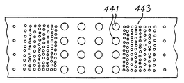
도 44a와 도 44b는 본 발명의 실시예를 도시하는 대표도.44A and 44B are representative views showing embodiments of the present invention.
도 45 내지 도 47은 본 발명의 특징을 도시하는 스캐닝 전자 현미경 사진. 45-47 are scanning electron micrographs showing features of the present invention.
도 48과 도 49는 추가의 실시예의 대표도.48 and 49 are representative views of further embodiments.
도 50 내지 도 57은 본 발명의 컴퓨터 시뮬레이션에 사용되는 그래프.50-57 are graphs used in the computer simulation of the present invention.
포토닉 밴드 구조물은 광학 계산과 광학 통신을 위한 일체형 광학장치와 같은 수동적 응용에 이용할 수 있다. 예를 들면, PBG 필터 장치의 어레이는 완전한 일체형 모놀리식(monolithic) WDM 디멀티플렉서와 같은 기능을 하도록 배치된다. 반면에 대부분의 능동적 응용은 TE 및 TM 편광 상태 모두를 위한 완전한 포토닉 밴드갭을 필요로 하고, 편광 의존성은 수동 광학장치에서 용이하게 사용될 수 있다.Photonic band structures can be used for passive applications such as integrated optics for optical computation and optical communication. For example, an array of PBG filter devices are arranged to function like a fully integrated monolithic WDM demultiplexer. On the other hand, most active applications require a complete photonic bandgap for both TE and TM polarization states, and polarization dependence can be readily used in passive optics.
많은 수동 일체형 광학 응용에 있어서의 중요한 요구사항은 주 밴드갭 영역으로부터의 낮은 투과 손실이다. 도파형 PBG 장치의 모드 구조 및 광대역 전송 특성을 결정하여 선택된 파장 범위에 대한 강력한 전송을 확실히 가능케 하는 방법이 고안되었다. 이러한 방법은 자신을 관통하여 에칭된 공기 로드 매트릭스를 가진 유전체 재료의 무한히 두꺼운 슬랩 내부로 전파하는 전자기파에 대한 포토닉 분산 관계를 계산하기 위해 3차원 평면파 분석[M. Plihal, A. A. Maradudin, Physical Review B, 44, 8565,(1991)와 A. A. Maradudin, A. R. McGrun, Journal of Modern Optics, 41, 275,(1994)]를 사용한다. 다음으로, 표준 도파관 이론이 사용되어 각각의 층에서 전자기(EM) 경계 조건을 풀고, 각각의 에칭된 층에 대한 평균 굴절률을 취함으로써 도파관내에 한정된 낮은 유전 격자 구조에 의해 지지되는 도파 모드를 계산하는데 사용된다. 이러한 3차원적 접근은 공기 로드의 방향을 따라 정렬된 유한 파 전파 벡터 성분을 고려한 것이고, 도파 모드 각과 관련된다. 이러한 유한 '스루 플레인' 파 벡터 성분은 계산된 분산 관계를 상당히 변경시킬 수 있다. 도파관 장치가 실제로 3차원 장치이기 때문에, 여분의 자유도는 무시되지 않아야 하는 것이 바람직하다.An important requirement for many passive integrated optical applications is low transmission loss from the main bandgap region. A method has been devised to determine the mode structure and wideband transmission characteristics of a waveguide PBG device to enable robust transmission over a selected wavelength range. This method uses three-dimensional plane wave analysis to calculate the photonic dispersion relationship for electromagnetic waves propagating into an infinitely thick slab of dielectric material with an air rod matrix etched through it. Plihal, AA Maradudin, Physical Review B, 44, 8565, (1991) and AA Maradudin, AR McGrun, Journal of Modern Optics , 41, 275, (1994). Next, standard waveguide theory is used to calculate the waveguide mode supported by the low dielectric lattice structure defined in the waveguide by solving the electromagnetic (EM) boundary conditions in each layer and taking the average refractive index for each etched layer. Used. This three-dimensional approach takes into account finite wave propagation vector components aligned along the direction of the air rod and is related to the waveguide mode angle. These finite 'through plane' wave vector components can significantly alter the calculated dispersion relationship. Since the waveguide device is actually a three-dimensional device, it is desirable that the extra degrees of freedom should not be ignored.
TE 및 TM 편광된 파와 관련된 에너지 고유치는 계산이 3차원 평면파 분석과 관련되는 한 풀 수 없게 연결되어 있고, 분산 곡선은 일단 계산된 특정 편광 상태와 관련된다.The energy eigenvalues associated with TE and TM polarized waves are inextricably linked as long as the calculations relate to three-dimensional plane wave analysis, and the dispersion curve is associated with a particular polarization state once calculated.
낮은 유전 재료 내의 TM 편광된 파를 위한 포토닉 밴드갭은 존재하지 않는 반면, 상대적으로 낮은 유전 재료는 매우 적은 공기 충전 양에도 불구하고 TE 편광된 파를 위한 중요 포토닉 밴드갭을 지지할 수 있다.There is no photonic bandgap for TM polarized waves in low dielectric materials, while relatively low dielectric materials can support critical photonic bandgaps for TE polarized waves despite very low amounts of air charge. .
도 1과 도 2의 도면을 참조하면, 본 발명의 일 실시예는 스펙트럼의 가시영역 내에서 632.8nm에 중심이 있는 편광 의존 광학 밴드갭을 가지는 도파관용 포토닉 결정(21)을 포함한다. 이러한 구조물은 삼각형 격자 상에 위치하며 실리콘 기판(도시 안됨)상에 성장된 단일 모드 실리콘 질화물 도파관의 코어 및 클래딩(cladding)층을 관통해 에칭되는 공기 구멍(22) 어레이로 구성된다. 이러한 장치는 두 편광 상태 모두에 대해 하부 밴드 에지 아래로 545nm까지 강한 투과를 나타내는 반면, 632.8nm에서 TE 편광된 적색광의 투과를 완전히 금지한다. TM 편광된 적색광은 강하게 투과된다.1 and 2, an embodiment of the present invention includes a
x-y 평면 내 위치하는 평면형 포토닉 결정을 고려하면, 그 높이는 z-방향이다. 광이 공기 로드에 수직으로 전파(하여 파 전파 벡터 k가 z-방향의 성분을 갖지 않는)하는 경우, 파는 전자기(EM)장 성분(도 1을 참조)의 배향(orientation)에 따라 두 개의 구별된 편광 상태로 나누어진다. 이 경우, 자기장 및 전기장 벡터에 대한 맥스웰의 필드 방정식을 각각 풀어 두 개의 독립 포토닉 밴드 도표를 생성한다[M. Plihal AA Maradudin, Physical Review B, 44, 8565, (1991)]. 이러한 시나리오는 '인 플레인(in plane)' 파 전파로서 불린다.Considering the planar photonic crystal located in the xy plane, the height is in the z-direction. When light propagates perpendicular to the air rod (so that the wave propagation vector k does not have a component in the z-direction), the wave is divided into two depending on the orientation of the electromagnetic (EM) field component (see FIG. 1). Divided into polarized states. In this case, Maxwell's field equations for the magnetic and electric field vectors are solved respectively to generate two independent photonic band plots [M. Plihal AA Maradudin, Physical Review B, 44, 8565, (1991)]. This scenario is called 'in plane' wave propagation.
만일 파가 격자평면에 대해 특정 각으로 전파하여 z-방향에서 구해진 유한 파-벡터 성분(k z)이 존재하게 된다면, 전기장 및 자기장 벡터는 격자 평면 내에서 구해진 몇몇 성분을 가질 것이다. (이러한 시나리오는 '스루 플레인(through plane)' 파 전파라 불린다.) 이 경우, 전기장 및 자기장 벡터에 대한 파동 방정식은 풀 수 없고, 분산 관계를 유도하기 위해서는 3차원 고유치 문제를 풀어야만 한다. 하지만, E 및 H 필드 벡터에 대한 해는 결국 동일한 값으로 수렴한다. 결과적으로, 전체 밴드 구조를 유도하기 위해 필드 방정식 중 하나만을 풀 필요가 있다.If the wave propagates at a particular angle with respect to the lattice plane and there is a finite wave-vector component k z obtained in the z-direction, the electric and magnetic field vectors will have some components found in the lattice plane. (These scenarios are called 'through plane' wave propagation.) In this case, the wave equations for the electric and magnetic field vectors cannot be solved, and the three-dimensional eigenvalue problem must be solved to derive the dispersion relationship. However, the solutions for the E and H field vectors eventually converge to the same value. As a result, only one of the field equations needs to be solved to derive the entire band structure.
3차원 평면파 분석을 위해, 주기적 유전체 구조를 통과하는 주파수 ω=ω(k)의 단일 모드 파 E(r)eiωt의 전파는 다음과 같이 표현될 수 있다:For three-dimensional plane wave analysis, the propagation of a single mode wave E (r) e iωt at a frequency ω = ω ( k ) through the periodic dielectric structure can be expressed as:

여기서, r은 3차원 위치 벡터이고, k는 3차원 파 벡터이고, c는 광의 진공 속도 그리고 ε는 유전 함수이다.Where r is a three-dimensional position vector, k is a three-dimensional wave vector, c is the vacuum velocity of light and ε is a dielectric function.
(고체 상태 물리학과 관련된 역격자 공간으로서 알려진) 푸우리에 영역에서, 전기장 벡터는 블로흐(Bloch) 전개에 의해 표현된다:In the Fourier domain (known as the inverse lattice space associated with solid state physics), the electric field vector is represented by the Bloch expansion:

여기서, G는 2차원 역격자 벡터,Where G is the two-dimensional inverse lattice vector,
k는 3차원 파 전파 벡터, k is the three-dimensional wave propagation vector,
r은 3차원 위치 벡터, r is the three-dimensional position vector,
a(k,G)는 3차원 블로흐 벡터 계수.a ( k , G ) is the three-dimensional Bloch vector coefficient.
유전 함수는 푸우리에 급수로 표현된다.The genetic function is expressed as a series to the puuri.

푸우리에 계수 CG는 다음과 같이 주어진다:The puuri coefficient C G is given by:
![]()
![]()
호(Ho)의 행렬 최적화법을 사용하여[C. T. Chan, K. M. Ho, C. M. Soukoulis, Europhysics Letters, 16, 563(1991)], 등변삼각형 격자 내에 위치하는 반경 R의 로드의 2차원 격자에 대한 푸우리에 계수는 다음과 같다:Using the matrix optimization method of Ho [CT Chan, KM Ho, CM Soukoulis, Europhysics Letters , 16, 563 (1991)], the puuri for a two-dimensional lattice of a rod of radius R located within an equilateral triangle lattice The coefficients to are as follows:


여기서, a는 격자 피치, εa는 로드의 유전상수, εb는 백그라운드 유전체의 유전상수, JI(x)는 1차 베셀함수, 및 f는 공기 충진 체적 비율.Where a is the lattice pitch, ε a is the dielectric constant of the rod, ε b is the dielectric constant of the background dielectric, JI (x) is the primary Bessel function, and f is the air fill volume ratio.
식 1을 데카르트 좌표축 x, y, z를 따라 풀고, 전개식(식2, 3)을 치환하면, 이하의 파동 방정식 세트는 역격자 공간 내 전기장 벡터를 나타낸다.Solving
x-성분: 식(7a) x-component: formula (7a)

y-성분: 식(7b) y-component: formula (7b)

z-성분: 식(7c) z-component: formula (7c)

E-필드 벡터는 각각의 데카르트 좌표축 x, y, z를 따라 구해지고,E-field vectors are found along each Cartesian coordinate axis x, y, z,
![]()
![]()
![]()
![]()
ω2/c2은 스칼라 에너지 고유치,ω 2 / c 2 is the scalar energy eigenvalue,

![]()
![]()
이러한 식들과 함께 분리 불가능 3차원 고유치 문제(식 8)는 컴퓨터에 의해 구성되어 풀릴 수 있는 형태를 갖고, 각각의 k 벡터를 갖는다. With these equations, the inseparable three-dimensional eigenvalue problem (Equation 8) is computer-configurable and solved, with each k vector.

Mx-Mz는 괄호로 도시된 데카르트 변수의 수치함수이다. 각각의 함수는 역격자 벡터 G와 G'로 지정된 정사각 소행렬을 구성한다.Mx-Mz is the numerical function of the Cartesian variable, shown in parentheses. Each function constitutes a square submatrix designated by inverse grid vectors G and G '.
이러한 식은 격자 피치 Λ을 가진 실리콘 질화물 백그라운드 유전체(εb=4) 내의 공기 홀(εa=1)의 삼각형 격자에 대해 풀린다. 원시 이동 벡터는:This equation is solved for the triangular lattice of air holes ε a = 1 in the silicon nitride background dielectric ε b = 4 with the lattice pitch Λ. The raw shift vector is:
![]()
![]()
해당 원시 역격자 벡터는:The corresponding raw lattice vector is:

역격자 벡터의 샘플 세트는 다음과 같이 주어진다:A sample set of inverse grid vectors is given by:
![]()
![]()
(m,n은 어드레싱 정수)(m, n is an addressing integer)
k 벡터 샘플은 격자 대칭점에 의해 한정된 감소된 브릴뤼앙 영역 세그먼트 주위에서 선택되어 포토닉 밴드 도표를 구성한다. 여러 kz 값의 계산을 반복함으로써, 분산 곡선의 특성이 고정된 공기 충진 비율에 대해 모드 각 θz의 함수로서 맵핑된다. The k vector sample is selected around the reduced Brillouin area segment defined by the lattice symmetry point to form the photonic band plot. By repeating the calculation of the various k z values, the properties of the dispersion curve are mapped as a function of the mode angle θ z for a fixed air filling rate.
단일 모드로서 분산 곡선의 전개는 0°(평면파 전파에서)에서 90°(정규 입사 또는 '스루 플레인'파 전파)로 증가되고, TE 및 TM 편광된 상태에 대한 에너지 고유치 해는 계산 문제가 관련되는 한 풀 수 없게 되고, 각각의 분산 곡선은 일단 계산된 특정 편광 상태와 관계한다는 것을 나타낸다. 이는 도 3 내지 도 5에 도시되어 있다.As a single mode, the evolution of the dispersion curve increases from 0 ° (at planar wave propagation) to 90 ° (normal incidence or 'through plane' wave propagation), and the energy eigenvalue solution for TE and TM polarized states involves computational problems. Not solved, indicating that each dispersion curve relates to a particular polarization state that has been calculated once. This is illustrated in Figures 3-5.
도 3은 40%의 공기 충진 체적 비율을 가진 실리콘 질화물 백그라운드 유전체 내의 공기 로드의 격자에 대한 밴드 구조를 도시하고, 이는 호(Ho)의 역변환 행렬법과 관련된 81개의 평면파를 사용하는 통상적인 2차원 평면파 분석을 사용하여 계산된다. 2개의 편광 상태에 대한 분산 관계는 비교의 용이함을 위해 중첩된다. 도 5는 kz=0을 가진 3차원 평면파 분석을 사용하여 계산된 '인 플레인' 밴드 구조를 도시한다. 분산 관계는 동일하다. 결과적으로, 도 4의 각각의 분산 곡선은 도 3에 비해 특정 편광 상태와 관계를 가질 수 있다. '스루 플레인' 성분 kz가 증가함에 따라(도 5 참조), T점에서 제 1의 2개의 분산 곡선 아래로 갭이 나타나고, 분산 곡선은 상승하며 약간 눌려진 모양이 된다. 하지만, 곡선의 형상과 퇴화점은 변화되지 않은 상태로 남게 되고, 각각의 분산 곡선은 특정 편광 상태와 관계를 가지게 된다.FIG. 3 shows a band structure for a lattice of air rods in a silicon nitride background dielectric with an air fill volume fraction of 40%, which is a conventional two-dimensional plane wave using 81 plane waves associated with an inverse transformation matrix method of Ho. Calculated using the analysis. Dispersion relationships for the two polarization states are superimposed for ease of comparison. 5 shows an 'in plane' band structure calculated using three-dimensional plane wave analysis with k z = 0. The distribution relationship is the same. As a result, each dispersion curve of FIG. 4 may have a relationship with a specific polarization state compared to FIG. 3. As the 'through plane' component k z increases (see FIG. 5), a gap appears below the first two dispersion curves at point T, and the dispersion curve rises and becomes slightly pressed. However, the shape and degradation point of the curve remain unchanged, and each dispersion curve is associated with a specific polarization state.
단일 3-층 평면형 도파관의 모드 구조(도 6 참조)는 2개의 기본 경계 조건을 풀어 유도될 수 있다. 제 1 조건은 경계에서의 모드 각이 전체 내부 반사에 대한 임계각 θcrit보다 작아야 한다는 것이고, 그렇지 않을 경우 광은 도파관 외부로 빠르게 누설된다.The mode structure of the single three-layer planar waveguide (see FIG. 6) can be derived by solving two basic boundary conditions. The first condition is that the mode angle at the boundary must be less than the critical angle θ crit for the entire internal reflection, otherwise the light leaks out of the waveguide quickly.

n=클래딩의 굴절률,n = refractive index of the cladding,
nc=코어의 굴절률.nc = refractive index of the core.
홀(61)의 크기가 밴드갭 근처에서 λ/4 내지 λ/2 정도이기 때문에, 이들은 진행파에 의해 풀릴 수 없다. 대신에, 에칭된 층은 평균 굴절률에 의해 주어진 감소된 굴절률을 가지는 것을 나타낼 것이다.Since the sizes of the
![]()
![]()
na=홀의 굴절률,na = refractive index of the hole,
nb=유전체의 굴절률.nb = refractive index of the dielectric.
다음으로, 횡 방향 위상 정합 조건은 만들고자 하는 공진 인도된 파에 대한 차수를 충족시켜야 한다.Next, the transverse phase match condition must satisfy the order for the resonant guided wave to be made.
![]()
![]()
m=정수,m = integer,
ψ=경계에서의 위상 변화의 합,ψ = sum of phase changes at the boundary,
Λ=격자 피치.Λ = grid pitch.
k z를 치환하기 위해, 횡 방향 공진 조건은 모드 각의 함수로서 도파 모드의 파장을 제공하도록 재배치된다.To replace k z , the transverse resonance condition is rearranged to provide the wavelength of the waveguide mode as a function of the mode angle.

θz=모드 각,θ z = mode angle,
navg=코어의 평균 굴절률,n avg = average refractive index of the core,
φ(θz, n)=경계에서의 위상 변화,φ (θ z , n) = phase change at boundary,
nb=버퍼층의 평균 굴절률,n b = average refractive index of the buffer layer,
nc=클래딩층의 평균 굴절률,n c = average refractive index of the cladding layer,
d=코어 두께,d = core thickness,
m=모드 수,m = number of modes,
Λ=격자 피치. 식(12)Λ = grid pitch. Formula (12)
도파관 경계로부터의 반사에 따른 위상 변화는 각각의 편광 상태에 대해 다르다. 이는 편광되지 않은 광이 평면형 도파관을 따라 전파하는 동안 편광 상태의 분리를 야기한다.The phase change due to reflection from the waveguide boundary is different for each polarization state. This causes separation of the polarization state while unpolarized light propagates along the planar waveguide.
TM 모드에 대한 위상 변화:Phase shift for TM mode:

TE 모드에 대한 위상 변화:Phase change for TE mode:

n=클래딩의 굴절률,n = refractive index of the cladding,
nc=코어의 굴절률,nc = refractive index of the core,
φz=모드 각. φz = mode angle.
파-유도 모델은 평면파 분석과 조합된다. kz가 0보다 크다면, 도파관 모드 각은 포토닉 밴드 도표(도 7 참조)의 x-축을 따라 각각의 k-벡터와 관계를 가질 수 있다. 하지만, T점에서의 0 모멘텀 k-벡터에 대한 모드 각은 불확실한 상태로 남아 있다.Wave-induced models are combined with plane wave analysis. If k z is greater than zero, the waveguide mode angle may be associated with each k-vector along the x-axis of the photonic band plot (see FIG. 7). However, the mode angle for the zero momentum k-vector at point T remains uncertain.

도파 모드의 파장은 고정된 도파관 형상에 대한 모드 각의 함수로서 계산되고, 이를 3차원 밴드갭 도표상에 중첩시킨다(도 8 참조). 도파 모드 라인이 분산 곡선과 교차하는 점들은 PBG 구조에 의해 지원되는 도파 블로흐 모드의 해를 나타낸다[D. M. Atkin, P. St. J. Russel, T. A. Briks, Journal of Modern Optics, 43, 1996, (1035)]. 이는 특정 파장에서 PBG 구조 전체에 대한 투과를 얻기 위해 어떠한 파 벡터가 여기되어야 하는가를 나타낸다. 도파 모드가 특정 파장에 존재할 수 있는지의 여부가 kz 값의 범위에 대한 분산 곡선의 전개를 조사함으로써 결정된다. 이는 일련의 밴드 도표를 애니메이팅하고, 특정 시험 파장에서 도파 모드 라인과 분산 곡선 사이의 교차점을 구함으로써 도식적으로 얻어진다. 만일 임의의 k z 값에 대해 어떠한 도파 블로흐 모드가 없다면, 포토닉 밴드갭이 그 파장에 존재하게 되고, 이는 정상 도파관 모드가 밴드 구조에 의해 억압되었다는 것을 나타낸다. 이러한 분석을 수행함에 있어, 각각의 분산 곡선이 특정 편광 상태와 관계를 가진다는 것을 명심한다. 격자 구조에 걸쳐 도파 블로흐 모드에 대한 필드 강도 형상은 고유벡터 문제로 돌아가 도파 블로흐 파 벡터에 대한 고유치를 구함으로써 구성된다.The wavelength of the waveguide mode is calculated as a function of the mode angle for the fixed waveguide shape and superimposed on the three-dimensional bandgap diagram (see FIG. 8). The points where the waveguide mode line intersects the dispersion curve represent the solution of waveguide Bloch mode supported by the PBG structure [DM Atkin, P. St. J. Russel, TA Briks, Journal of Modern Optics , 43, 1996, (1035)]. This indicates which wave vector must be excited to obtain transmission over the entire PBG structure at a particular wavelength. Whether the waveguide mode can be at a particular wavelength is determined by examining the evolution of the dispersion curve over a range of k z values. This is diagrammatically obtained by animating a series of band plots and finding the intersection between the waveguide mode line and the dispersion curve at a particular test wavelength. If any k z If there is no waveguide Bloch mode for the value, then a photonic bandgap will be present at that wavelength, indicating that the normal waveguide mode is suppressed by the band structure. In carrying out this analysis, keep in mind that each dispersion curve is related to a particular polarization state. The field intensity shape for the waveguide Bloch mode over the lattice structure is constructed by returning to the eigenvector problem to find the eigenvalues for the waveguide Bloch wave vector.
도 8은 T-J 대칭 방향을 따라 545nm에서 TM 편광된 도파 모드 및 T-X 방향을 따라 600nm에서 TM 편광된 도파 모드의 존재를 도시하는 실리콘 질화물 구조에 대한 '3차원' 밴드 도표의 일례이다. 0 모멘텀점 T 주위에 중심을 둔 파-벡터는 구조에 입사하는 정상 입사와 근접하는 모드에 해당한다(도 7 참조). 이는 전체 내부 반사에 대한 임계각을 초과하는 누설 모드이다. 결과적으로, 도파 모드 라인은 이러한 경계에서 불연속이다. 도 7의 수직선은 전체 내부 반사에 대한 한계를 나타낸다.FIG. 8 is an example of a 'three-dimensional' band plot for a silicon nitride structure showing the presence of TM polarized waveguide mode at 545 nm along the T-J symmetry direction and TM polarized waveguide mode at 600 nm along the T-X direction. The wave-vector centered around the zero momentum point T corresponds to a mode approaching normal incidence entering the structure (see FIG. 7). This is a leakage mode that exceeds the critical angle for total internal reflection. As a result, the waveguide mode line is discontinuous at this boundary. Vertical lines in FIG. 7 represent the limits for total internal reflection.
도파관에서 전파되는 파의 군 속도는 다음과 같이 주어진다:The group velocity of the wave propagating in the waveguide is given by:

이는 분산 관계에 관한 굴곡점(대체로 대칭점)에서 블로흐 파가 놀랍게도 0의 군 속도를 가질 것이라는 것을 나타낸다. 이러한 모드에 광을 직접 결합시킴으로써, 고품질-팩터의 정재파가 형성된다.This indicates that the Bloch wave will have a surprisingly zero group velocity at the bending point (usually symmetry point) with respect to the dispersion relationship. By combining light directly into this mode, a high-quality standing wave is formed.
통상적인 도파관에서, 광은 높은 유전체 영역내에 전체 내부 반사에 의해 한정되고, 낮은 유전체 매체에 의해 둘러싸인다. 도파 모드를 유지하는데 필요한 굴절률 콘트라스트는 매우 작다. 이러한 원리는 PBG 도파관과 관련하여 사용될 수 있다(도 9 참조). 예를 들면, 도파관 구조를 관통해 작은 홀(91)을 에칭함으로써 에칭된 층의 유효 굴절률이 감소된다. 이는 도파관의 에칭된 영역 내 모드 구조물을 변경한다. 광을 포토닉 격자 내에 한정하기 위해, 코어(92)의 유효 굴절률을 클래딩(93) 및 버퍼(94)층의 굴절률보다 높게 유지하는 것이 필요하다. 이러한 조건은 클래딩 및 코어층을 모두 관통해 홀을 에칭함으로써 코어/클래딩 계면에서 충족되는데, 그 이유는 두 층의 유효 굴절률이 동일한 비율로 감소하기 때문이다(도 9a 참조). 주된 문제는 기판 버퍼층에서 발생된다. 실리콘 이산화물/실리콘 질화물 재료 시스템에서, 최대 공기-충진 체적 비율은 40%로 제한되고, 이는 PBG의 최대 대역폭을 제한한다.In conventional waveguides, light is confined by total internal reflection within the high dielectric region and surrounded by the low dielectric medium. The refractive index contrast required to maintain the waveguide mode is very small. This principle can be used in connection with PBG waveguides (see FIG. 9). For example, by etching the
최대 공기-충진 체적 비율은 공기 공동(95)에 의해 도파관의 에칭된 영역을 버퍼층으로부터 격리시킴으로써 확장될 것이다(도 9b 참조). 하지만, 이는 격자 주기보다 많은 재료 시스템에서 응력과 관련된 구조적 문제를 야기한다. 다른 해법은 홀(91)을 오버에칭하여 이들이 격리 버퍼층 내부로 잘 확장되도록 하는 것이다(도 9c 참조). 다시, 이는 코어와 같은 비율로 유효 굴절률을 감소시킨다.The maximum air-filled volume ratio will be expanded by isolating the etched region of the waveguide from the buffer layer by the air cavity 95 (see FIG. 9B). However, this causes structural problems related to stress in more material systems than the lattice period. Another solution is to overetch the
도 10 내지 도 12는 각각의 동작 모드에서의 실리콘 질화물 도파관 구조에 대한 도파 모드 형상의 예를 도시한다. 백분율 숫자는 각 층 내부에서의 모드 강도의 비율을 나타낸다. 추정된 감쇠 또한 도시되어 있다. 도 10에 도시된 형상은 이러한 구조에서 사용되는 가장 일반적인 동작 모드이고, 공기 충진 체적 비율 한계에 근접한다. 큰 비율의 모드가 버퍼층내에 존재한다. 이는 이러한 실리콘 질화물 구조가 두 편광 상태에 대해 도파관 모드를 지원할 수 있어야 한다는 것을 나타낸다. 이러한 도파 모드는 포토닉 격자에 의해 억압되고 이는 가시 스펙트럼에 작용하는 PBG로 설명되었다.10-12 show examples of waveguide mode shapes for silicon nitride waveguide structures in each mode of operation. Percentage numbers represent the ratio of mode intensities within each layer. Estimated attenuation is also shown. The shape shown in FIG. 10 is the most common mode of operation used in this structure and is close to the air fill volume ratio limit. A large proportion of modes is present in the buffer layer. This indicates that such silicon nitride structures must be able to support waveguide modes for both polarization states. This waveguide mode is suppressed by the photonic grating, which has been described as PBG acting on the visible spectrum.
도 11은 전체적으로 절연된 도파관 구조가 매우 작은 절연 공기 갭의 경우에도 잘 한정된 모드를 제공하는 것을 도시한다. 도 10은 에칭이 과도하게 손실되는 도파관 모드를 형성하는 것을 방지하도록 버퍼 영역으로 상당한 거리를 확장시켜야 한다는 것을 나타낸다.FIG. 11 shows that the overall insulated waveguide structure provides a well defined mode even in the case of very small insulated air gaps. 10 indicates that a significant distance must be extended to the buffer region to prevent the formation of waveguide modes in which etch is excessively lost.
실제로, 도파관 장치는 3개의 분리된 단결정 일체형 장치-입력 도파관, PBG 영역 및 출력 도파관으로 구성된다. 저 손실 투과를 위해, 바람직하게는 PBG 영역과 입출력 도파관 사이에 강한 모드 결합이 존재하고, 경계에서 평균 굴절률이 변한다는 것을 명심한다.In practice, the waveguide device consists of three separate single crystal unitary device-input waveguides, a PBG region and an output waveguide. Note that for low loss transmission, there is preferably a strong mode coupling between the PBG region and the input / output waveguide, and the average refractive index changes at the boundary.
비록 광이 경계에서 PBG 영역 내부의 임의의 가능한 모드에 결합되지만, 결합은 두 영역에 큰 모드 오버랩이 있을 때(도 13 참조) 가장 잘 이루어진다. 이상적으로, 도파관 모드는 유전체 계면에서 PBG 도파 모드로 직접 굴절되어야 한다. 경계에서 후면 반사 또한 발생하여 손실을 야기한다. 원하는 특정 파장에 대한 입출력 도파관 모드 각과 형상은 PBG 코어 영역의 상태 두께를 증가 또는 감소시킴으로써 정밀하게-튜닝될 수 있다.Although light is coupled to any possible mode inside the PBG region at the boundary, combining is best done when there is a large mode overlap in both regions (see FIG. 13). Ideally, the waveguide mode should be refracted directly into the PBG waveguide mode at the dielectric interface. Back reflections at the boundary also occur, causing losses. Input and output waveguide mode angles and shapes for a particular desired wavelength can be precisely-tuned by increasing or decreasing the state thickness of the PBG core region.
나노구조(nanostructure)는 스펙트럼 가시영역의 633nm에 중심을 둔 편광-의존 포토닉 밴드갭을 갖도록 제조되었다. 상술된 실시예에 따라 구성된 장치는 광이 PBG 구조를 통해 전파하는 동안의 특성을 육안으로 관찰할 수 있게 한다.Nanostructures were fabricated with a polarization-dependent photonic bandgap centered at 633 nm of the spectral visible region. The device constructed in accordance with the embodiment described above allows the human eye to observe the properties while light propagates through the PBG structure.
본 발명의 특징에 따른 장치는 단일-모드 실리콘 질화물 도파관의 클래딩 및 코어층을 통해 에칭된 공기 구멍 플라즈마의 삼각형 격자에 기초한다(도 8 참조). 도파관은 열적으로 성장된 1.8㎛ 두께의 실리콘 이산화물 기판 버퍼층(n=1.46), 저압 화학 기상 증착(LPCVD)에 의해 증착된 250nm 두께의 실리콘 질화물 도파관층(n=2.02), 및 역시 LPCVD에 의해 증착된 얇은(75-180nm) 실리콘 이산화물 클래딩층으로 구성된다. 다음으로, 웨이퍼가 직접-쓰기 전자빔 리소그래피에 의해 패터닝되고 플라즈마-에칭되어 코어/버퍼 계면으로 확장되는 웰(well)을 형성한다. 웨이퍼는 광학 시험을 위한 개별 장치로 분리된다.An apparatus according to a feature of the present invention is based on a triangular lattice of air hole plasma etched through the cladding and core layer of a single-mode silicon nitride waveguide (see FIG. 8). Waveguides are thermally grown 1.8 μm thick silicon dioxide substrate buffer layer (n = 1.46), 250 nm thick silicon nitride waveguide layer (n = 2.02) deposited by low pressure chemical vapor deposition (LPCVD), and also deposited by LPCVD Thin (75-180nm) silicon dioxide cladding layer. Next, the wafer is patterned by direct-write electron beam lithography and plasma-etched to form a well that extends to the core / buffer interface. Wafers are separated into individual devices for optical testing.
여기서, 인접 구멍들 간에 좁은 리브를 형성하는 저항벽은 직경이 증가됨에 따라 붕괴하는 경향이 있기 때문에, 서브미크론 피치에서 큰 구멍보다 좁은 매우 좁은 구멍을 형성하기가 상당히 쉽다는 것을 알 수 있었다. 50 내지 120nm 범위의 직경을 가진 구멍은 표준 프로세스를 사용하여 제조하기가 매우 쉬웠다. 하지만, 포토닉 밴드갭을 형성하기 위해, 20% 이상의 공기-충진 체적 비율이 요구된다. 본 해법은 초기 등방성 플라즈마 에칭 이후 구멍의 측면 팽창을 허용하는 우수하게-제어된 프로세스를 발전시켰다. 이는 초기 제조 이후 포토닉 밴드갭의 정밀한-튜닝을 가능케 한다.Here, it has been found that resistance walls that form narrow ribs between adjacent holes tend to collapse as the diameter increases, so it is quite easy to form very narrow holes that are narrower than large holes at submicron pitch. Holes with diameters ranging from 50 to 120 nm were very easy to manufacture using standard processes. However, to form a photonic bandgap, an air-filled volume ratio of at least 20% is required. This solution has developed a well-controlled process that allows for lateral expansion of the hole after the initial isotropic plasma etch. This allows for precise-tuning of the photonic bandgap after initial manufacture.
구멍의 팽창을 용이하게 하는 리소그래피와 플라즈마 에칭 프로세스를 사용하여, 500nm 이상의 두께를 가진 도파관 구조 웰(well)을 통해 260nm 피치에서 50-200nm 범위의 직경을 가진 우수한 품질의 구멍을 제조하는 것이 가능하다. 게다가, 구멍 형상은 상술한 절연된 도파관 구조를 형성하도록 변형될 수 있다.Using lithography and plasma etching processes to facilitate the expansion of the holes, it is possible to produce good quality holes with diameters ranging from 50-200 nm at 260 nm pitch through waveguide structure wells having a thickness of 500 nm or more. . In addition, the hole shape can be modified to form the insulated waveguide structure described above.
도 23은 도파형 PBG 구조의 단면도를 도시하는 스캐닝 전자 현미경사진(SEM)이다. 이는 475nm의 전체 깊이로 에칭된 공기 구멍의 260nm 피치 삼각형 격자로 구성된다. 2-단계의 건식 에칭 처리가 실리콘 질화물 코어를 통해 에칭하고 하부에 위치하는 실리콘 이산화물 버퍼층을 통해 분할되는데 사용되어, 주 도파관 코어 하부에 감소된 굴절률의 버퍼층을 형성한다. 구멍의 반정도 아래에, 처리가 변화되었던 지점을 마킹하는 구멍 직경(150 내지 75nm)의 확실한 스텝이 존재하게 된다. 미세한 구멍 직경에도 불구하고, 벽은 양쪽 부분에서 정확하게 등방적이다. 이러한 구조는 도 8에 도시된 영역 내에서 동작하는 큰 공기 충진 비율 장치의 제조시 시작점을 형성한다.FIG. 23 is a scanning electron micrograph (SEM) showing a cross-sectional view of a waveguide PBG structure. It consists of a 260 nm pitch triangular grating of air holes etched to a total depth of 475 nm. A two-step dry etch process is used to etch through the silicon nitride core and split it through the underlying silicon dioxide buffer layer to form a buffer layer of reduced refractive index underneath the main waveguide core. About half below the hole, there is a sure step of the hole diameter (150-75 nm) marking the point where the treatment has changed. Despite the fine pore diameter, the walls are exactly isotropic in both parts. This structure forms a starting point in the manufacture of a large air fill ratio device operating within the region shown in FIG.
초기 플라즈마 에칭 이후, 구멍 직경은 재료-특정 습식 에칭 처리에 의해 실리콘 질화물층으로만 확장될 수 있다. 도 15의 SEM은 300nm 피치 삼각형 격자 구조를 도시한다. 이 경우, 건식 에칭 처리 전이가 실리콘 질화물층의 중간 정도에서 발생한다. 도 15에 확연하게 도시된 직경 스텝은 구멍에 대해 끝이 점점 가늘어지도록 하는 습식 에칭 처리에 의해 둥글어진다. 얇은 클래딩 층은 최상부에 위치하여 보호 캡을 형성한다. 구멍 직경은 버퍼층에서 30nm로 시작하여 질화물층에서 115nm 내지 173nm로 끝이 점점 가늘어지고, 클래딩층에서 95nm의 감소된 직경을 가진다.After the initial plasma etch, the pore diameter can only be extended to the silicon nitride layer by a material-specific wet etch process. The SEM of FIG. 15 shows a 300 nm pitch triangle grating structure. In this case, dry etching process transitions occur in the middle of the silicon nitride layer. The diameter step clearly shown in FIG. 15 is rounded by a wet etch process that causes the tip to taper to the hole. The thin cladding layer is placed on top to form a protective cap. The pore diameter starts at 30 nm in the buffer layer and tapers off from 115 nm to 173 nm in the nitride layer and has a reduced diameter of 95 nm in the cladding layer.
구멍 벽의 등방성은 주의 깊은 사후-에칭 세척 및 건조와 관련되어 사용되는 특정 사전-에칭 프라이밍(priming) 처리에 의해 상당히 증가된다. 이는 급속 및 균일한 에칭 시작 및 정지를 확보한다. 이는 도 16의 SEM에 도시되어 있다. 초기 플라즈마 에칭 처리 전이로 인해 질화물층에 구멍 직경의 스텝(250 내지 175nm)이 형성된다. 구멍 직경은 클래딩층에서 120nm에서 시작한다.The isotropy of the hole walls is significantly increased by the specific pre-etch priming treatment used in connection with careful post-etch cleaning and drying. This ensures rapid and uniform etching start and stop. This is shown in the SEM of FIG. Initial plasma etch process transitions result in pore diameter steps (250-175 nm) formed in the nitride layer. The pore diameter starts at 120 nm in the cladding layer.
산화물 버퍼층에 대해 유사한 처리가 행해져, 원하는 구멍 직경이 얻어지면 다공성 실리콘 질화물 도파관을 언더컷하여 도 9b에 도시된 바와 같은 공기 공동을 형성한다. 불행하게도, 이러한 종류의 구조는 매우 견고하지 않으며 수 격자 주기 이상의 주기가 요구된다면 초기 층 성장 동안 열적 클래딩에 의해 유도된 응력에 의해 붕괴된다. 이는 매우 다공성인 실리콘 이산화물의 벌집 모양을 형성함으로써 방지되고, 더 적은 다공성의 도파관 코어를 지지한다. 이는 실리콘 이산화물 버퍼층으로 좁은 모세관 에칭된 부분을 주의 깊게 확장시킴으로써 달성된다(도 14와 도 16 참조). 그 결과가 도 17의 SEM에 도시되어 있다. 여기서, 실리콘 이산화물 클래딩층은 다공성 실리콘 이산화물 버퍼층의 최상부에 위치하는 실리콘 질화물 도파관 코어(오른쪽 코너 하부에서)의 일부를 드러내도록 제거되었다. 구멍 직경은 실리콘 질화물 도파관 코어에서 135nm이고, 실리콘 이산화물 버퍼층에서 250nm이다. 구멍의 질은 언더-에칭된 버퍼층에서 매우 우수하고, 놀랍게도 직선 구멍 벽을 가진다.A similar treatment is performed on the oxide buffer layer to undercut the porous silicon nitride waveguide once the desired pore diameter is obtained to form an air cavity as shown in FIG. 9B. Unfortunately, this kind of structure is not very robust and is collapsed by stress induced by thermal cladding during initial layer growth if a period longer than a few lattice cycles is required. This is prevented by forming a honeycomb shape of highly porous silicon dioxide and supports less porous waveguide cores. This is accomplished by carefully expanding the narrow capillary etched portion into the silicon dioxide buffer layer (see FIGS. 14 and 16). The results are shown in the SEM of FIG. Here, the silicon dioxide cladding layer was removed to reveal a portion of the silicon nitride waveguide core (at the bottom right corner) located on top of the porous silicon dioxide buffer layer. The pore diameter is 135 nm in the silicon nitride waveguide core and 250 nm in the silicon dioxide buffer layer. The quality of the holes is very good in the under-etched buffer layer and surprisingly has a straight hole wall.
구멍 확장 처리의 전개과정에서 사용된 시험 샘플은 도파관내에 가시 포토닉 밴드갭의 존재를 나타내었다. 이는 2730 행(row)의 공기 구멍으로 구성되었고, 300nm의 피치를 가진 삼각형 격자 내에 위치하며, 블랭킷 도파관층 전체에 대해 에칭된다. 구멍은 40%에 근접하는 공기-충진 체적 비율을 제공하는 200nm의 직경을 가졌다.The test sample used in the development of the hole dilation treatment showed the presence of visible photonic bandgap in the waveguide. It consisted of 2730 rows of air holes, located in a triangular grating with a pitch of 300 nm, and etched over the blanket waveguide layer. The pores had a diameter of 200 nm providing an air-filled volume ratio close to 40%.
홀 제조시, 광학적 산란과 에지 효과를 보상할 필요가 있다. 이는 에칭 홀 또는 홀의 라인에 대한 특정 클록 속도를 관련시킴으로써 얻어진다. 몇몇 예에서, 정확한 레지스트 노출을 위해, 포지티브에서 네거티브로의 '레지스트 플립핑'을 방지하도록 E-빔의 초점을 맞추지 않는 것이 필요하다. In making holes, it is necessary to compensate for optical scattering and edge effects. This is obtained by relating a specific clock speed for an etch hole or a line of holes. In some instances, for accurate resist exposure, it is necessary not to focus the E-beam to prevent 'resist flipping' from positive to negative.
특정 실시예에 따른 장치는 양 편광 상태에 대한 TE 및 TM 편광된 녹색광(545nm)의 강한 투과를 도시한다(도 19a, b 참조). TM 편광된 광에 대한 빔 트랙이 PBG 영역의 양 측면 상에서 확연하게 보이지만, 양 편광 상태에 대한 투과의 추가 확인이 웨이퍼의 최상부 에지에서 밝은 얼룩에 의해 주어진다. 이는 출사빔의 위치를 나타낸다.The device according to a particular embodiment shows the strong transmission of TE and TM polarized green light (545 nm) for both polarization states (see FIGS. 19 a, b). Although the beam track for the TM polarized light is clearly visible on both sides of the PBG region, further confirmation of transmission for both polarization states is given by the bright blotches at the top edge of the wafer. This indicates the position of the exit beam.
전통적인 관점에서, 단파장 도파 모드는 가장 작은 도파관 결함으로부터도 레일리 산란에 의해 강하게 억압될 것이 예상된다. 이러한 규모에서는, 공기 구멍은 절대적으로 거대한 것이다. 632.8nm에서 투과 모드의 편광 민감 억압과 조합된 수 천 개의 홀의 주기에 대한 녹색광의 투과는 적색에서 광학 밴드갭의 존재를 나타낸다.In traditional terms, short waveguide modes are expected to be strongly suppressed by Rayleigh scattering even from the smallest waveguide defects. At this scale, the air holes are absolutely huge. Transmission of green light over a period of thousands of holes combined with polarization sensitive suppression in transmission mode at 632.8 nm indicates the presence of an optical bandgap in red.
PBG 도파관의 구조를 결정하는 다른 방법은 평면파 방법을 사용하여 포토닉 밴드 구조와 동시에 도파관 경계 구조 조건을 푸는 것이다. 평면파 방법이 격자 전체에 대해 많은 샘플 점에서 맥스웰 방정식의 정확한 해를 포함하고, 그 결과는 절대적이고 유효 굴절률의 불확실한 값에 의존하지 않는다. Another method of determining the structure of a PBG waveguide is to solve the waveguide boundary structure conditions simultaneously with the photonic band structure using the planar wave method. The plane wave method involves the exact solution of the Maxwell's equation at many sample points for the entire grating, and the result is absolute and does not depend on the uncertain value of the effective refractive index.
금속화된 도파관의 경우, 경계 조건은 전기장의 x와 y 성분이 두 개의 도파관 경계에서 0으로 감소되는 것을 나타내고, 결과적으로 (전파 파-벡터를 보존하기 위해) z-성분은 최대값이 되어야 한다.In the case of metalized waveguides, the boundary condition indicates that the x and y components of the electric field are reduced to zero at the two waveguide boundaries, and consequently the z-component (to preserve the wave-vector) must be at its maximum. .
양 경계에서 Ex=Ey=0 (z=0,d) 식(16)E x = E y = 0 (z = 0, d) at both boundaries (16)
하지만, 유전체 도파관의 경우, 경계 조건은 약간 다르다. 이 경우, 클래딩 및 기판 버퍼층을 관통하는 순간적인 필드가 존재한다. 결과적으로, 모든 필드 성분은 경계 전체에 대해 연속해야만 한다. 다음으로, 이들은 도파관 코어의 외부로 일정 거리에서 0으로 감소된다.However, for dielectric waveguides, the boundary conditions are slightly different. In this case, there is an instantaneous field through the cladding and substrate buffer layer. As a result, all field components must be continuous across the boundary. Next, they are reduced to zero at some distance to the outside of the waveguide core.
임의의 도파관에 대한 일반적인 경계 조건은 횡 방향 위상 정합 조건에 의해 표현된다.The general boundary condition for any waveguide is represented by the transverse phase match condition.

φ는 도파관 경계로부터의 반사에 따른 위상 변화의 합,φ is the sum of the phase changes with reflection from the waveguide boundary,
m은 정수 모드수,m is the integer mode number,
kz는 도파관 코어내에서 측정된 z-방향을 따라 구해진 전파 파-벡터의 크기,k z is the magnitude of the propagation wave-vector found along the z-direction measured in the waveguide core,
d는 도파관 코어 두께.d is the waveguide core thickness.
이는 도파관이 도 20에 도시된 바와 같이 (도파관의 두께에 대해) 도파관의 횡 방향으로 정수의 모드가 존재할 수 있게 가능케 해야 한다는 것을 효과적으로 설명한다.This effectively explains that the waveguide must enable the existence of an integer mode in the transverse direction of the waveguide (relative to the thickness of the waveguide) as shown in FIG. 20.
횡 방향 위상 정합 조건을 포함하는 평면파 방법을 변경시키기 위해, 필요한 모든 것은 횡 방향 위상 정합 조건을 포함하는 (데카르트 좌표축을 따라 구해진) 블로흐 전개 항을 변경하는 것인데, 그 이유는 이들이 구조 내의 모든 점에서의 필드 성분을 나타내는 것이기 때문이다.In order to change the plane wave method including the transverse phase match condition, all that is necessary is to change the Bloch expansion term (obtained along the Cartesian coordinate axis) including the transverse phase match condition, because they are at all points within the structure. This is because the field component of?
(밴드 구조를 제공하도록 구해진) 3차원 고유계(eigen-system)를 형성하는 방정식의 최종 세트를 통해 결과가 걸러지면, 필요한 모든 것은 원하는 모드수에 대한 위상 정합 조건을 만족하는 kz의 값에 대해 밴드 구조를 계산하는 것임을 알 수 있다.When the result is filtered through the final set of equations (which are obtained to provide a band structure), all that is required is a value of k z that satisfies the phase match condition for the desired number of modes. It can be seen that the band structure is calculated for.
만일 고유계의 해를 구하고 주어진 도파관 형상과 모드수 m에 대한 3차원 밴드 도표를 구성하면, 분산 곡선은 자유공간 파장의 함수로서 전파 모드에 해당하는 파-벡터의 정확한 해를 나타낸다. (간단한 도파관 구조와는 대조적으로, 주기적 구조의 임의의 주어진 파장에서 여러 허용된 모드가 존재할 것이다. 이는 도파 블로흐 모드로 알려져 있다.)If we solve the eigensystem and construct a three-dimensional band plot for the given waveguide shape and mode number m, then the dispersion curve represents the exact solution of the wave-vector corresponding to the propagation mode as a function of the free-space wavelength. (In contrast to the simple waveguide structure, there will be several allowed modes at any given wavelength of the periodic structure. This is known as the waveguide Bloch mode.)
분산 곡선이 주어진 파장에서 구조 내의 허용된 파-전파 벡터의 크기와 방향을 나타내기 때문에, 각각의 및 모든 도파 블로흐 모드에 대한 유효 굴절률의 정확한 값을 계산하기 위해 필요한 모든 정보를 가지게 된다. 게다가, 만일 선택된 파장에서 모든 블로흐 모드에 대한 진정한 유효 굴절률이 알려지면, 반사 계수와 입력 도파관과 PBG 영역 사이의 계면에서의 모드 오버랩이 계산된다. Since the dispersion curve represents the magnitude and direction of the allowed wave-propagation vectors in the structure at a given wavelength, you will have all the information needed to calculate the exact value of the effective refractive index for each and all waveguide Bloch modes. In addition, if the true effective refractive index for all Bloch modes at a selected wavelength is known, the mode overlap at the interface between the reflection coefficient and the input waveguide and the PBG region is calculated.
유효 모드 지수의 계산시, 자유공간 파 전파 벡터와 PBG 격자 영역 내의 파 전파 벡터는 벡터 방정식과 관련된다:In calculating the effective mode index, the free space wave propagation vector and the wave propagation vector in the PBG lattice region are related to the vector equation:
![]()
![]()
k0은 자유공간 파 전파 상수,k 0 is the free space wave propagation constant,
nmode는 전파하는 파로 나타내진 PBG 영역에 대한 유효 모드 지수.n mode is the effective mode index for the PBG region represented by the propagating wave.
그래디언트를 취하면:Taking a gradient:

이제 통상적인 2차원 포토닉 밴드 도표를 고려해보자(도 21 참조). 이는 '인 플레인' 파 전파 벡터(kxy)의 샘플 세트에 대한 고유치 문제를 반복적으로 풀어 구성된다.Consider a conventional two dimensional photonic band plot (see FIG. 21). It is constructed by repeatedly solving the eigenvalue problem for a sample set of 'in plane' wave propagation vectors (k xy ).
샘플 k-벡터는 구조 내의 파 전파 방향과 관계를 가지고 (격자 구조에서 대칭 평면과 관계를 가지고), 또한 주 구조 내의 전파하는 파의 파장과 관계를 가진다. 샘플 k-벡터의 선택은 완전히 임의적이지만, 통상적으로 모든 대칭점을 둘러싸는 감소된 브릴뤼앙 영역 세그먼트 주위에서 k-벡터를 선택할 수 있다.The sample k-vector has a relationship with the direction of wave propagation in the structure (relation with the plane of symmetry in the lattice structure) and also with the wavelength of the propagating wave in the main structure. The choice of sample k-vector is completely arbitrary, but it is typically possible to select the k-vector around the reduced Brillouin area segment surrounding all points of symmetry.


각각의 샘플 k-벡터의 크기를 계산하고 이를 분산 곡선에 의해 나타난 자유공간 k-벡터 해로 나눔으로써, 각각의 모든 분산 곡선상의 각각의 모든 샘플점에 해당하는 유효 모드 지수를 계산할 수 있다.By calculating the magnitude of each sample k-vector and dividing it by the free space k-vector solution represented by the variance curve, the effective mode index corresponding to each and every sample point on each and every variance curve can be calculated.
클래딩층의 굴절률보다 작은 유효 굴절률을 가진 모드는 주변 매체로 손실될 것이다. 이는 방사 모드로서 알려져 있다. 기판 버퍼층의 유효 굴절률보다 작은 유효 굴절률을 가진 모드는 기판으로 누설되어 다시 손실될 것이다. 이는 기판 모드로서 알려져 있다.Modes with an effective refractive index less than the refractive index of the cladding layer will be lost to the surrounding medium. This is known as the radiation mode. Modes with an effective refractive index less than the effective refractive index of the substrate buffer layer will leak into the substrate and be lost again. This is known as the substrate mode.
PBG 구조 내에서 도파 모드의 군 속도(vg)는 유효 모드 지수와 자유공간 파장(λ)을 알고 다음의 식을 이용하여 계산할 수 있다.The group velocity v g of the waveguide mode in the PBG structure can be calculated by knowing the effective mode index and the free space wavelength λ using the following equation.

c=진공에서의 광속c = beam in vacuum
군 속도는 파장에 대한 유효 모드 지수의 그래디언트에 의존한다. 이는 다시 각각의 분산 곡선상의 각각의 모든 k-벡터 샘플점과 관련된 유효 모드 지수를 계산함으로써 계산된다. 관련 분산 곡선에 의해 표시된 파장과 관련된 이러한 데이터를 사용하여, 도파 모드 파장의 함수로서 유효 모드 지수를 나타내는 곡선을 구성할 수 있다. 요구된 그래디언트는 원하는 특정 샘플점 주위에 이러한 곡선의 그래디언트에 의해 직접 주어진다. 선택적으로:The group velocity depends on the gradient of the effective mode index over the wavelength. This is again calculated by calculating the effective mode index associated with each and every k-vector sample point on each variance curve. Using this data related to the wavelength indicated by the relevant dispersion curve, one can construct a curve representing the effective mode index as a function of the waveguide mode wavelength. The required gradient is given directly by the gradient of this curve around the particular sample point desired. Optionally:
삭제delete

이는 전파하는 파의 군 속도가 분산 곡선(밴드 도표에 도시된)의 그래디언트에 직접 관계하는 것을 나타낸다. 분산 곡선상의 각각의 샘플점은 이와 관련된 특정 군 속도를 가진다. 그러므로 입력 도파관과 PBG 영역 사이를 연결하는 모드를 제어함으로써 PBG 구조 내에 투과된 전파 모드의 속도를 선택할 수 있다.This indicates that the group velocity of the propagating wave is directly related to the gradient of the dispersion curve (shown in the band plot). Each sample point on the dispersion curve has a specific group velocity associated with it. Therefore, the speed of the propagation mode transmitted in the PBG structure can be selected by controlling the mode connecting the input waveguide and the PBG region.
예를 들어, 만일 입력 도파관과 PBG 구조 사이의 경계가 정확하게 설계된다면, 입력 도파관을 통과하는 광은 분산 곡선상의 굴곡점에 위치하는 k-벡터를 가진 도파 블로흐 모드로 연결될 것이다. 이 경우, 전파하는 파는 0의 군 속도를 가질 것이고, 정재파는 구조 내에 형성될 것이다. 만일 블로흐 모드를 분산 곡선상의 굴곡점으로부터 약간 떨어져 연결한다면, 파는 매우 작은 군 속도를 가진 구조를 통해 전파될 것이다. 결국, 분산 곡선의 그래디언트가 가장 경사가 급한 점에 위치하는 k-벡터를 가진 도파 블로흐 모드에 연결시킨다면, 전파하는 파는 최대 속도로 통과할 것이다. 이러한 방법으로, 광을 '감쇠' 또는 트랩핑하는데 PBG 구조를 사용할 수 있다.For example, if the boundary between the input waveguide and the PBG structure is designed correctly, the light passing through the input waveguide will be connected in waveguide Bloch mode with a k-vector located at the bending point on the dispersion curve. In this case, the propagating wave will have a group velocity of zero, and the standing wave will form in the structure. If you connect the Bloch mode slightly away from the bending point on the dispersion curve, the wave will propagate through a structure with very small group velocities. Eventually, if the gradient of the dispersion curve is connected to the waveguide Bloch mode with the k-vector at the steepest point, the propagating wave will pass at maximum speed. In this way, the PBG structure can be used to 'dam' or trap light.
선택적으로, PBG 구조 내에서 전파하는 파의 방향을 변화시킴으로써, 전파 속도 및 구조 내에서 전파하는 파의 파장 모두를 변화시킬 수 있다. 이는 광학 지연 라인의 기초를 형성한다.Optionally, by changing the direction of the wave propagating within the PBG structure, both the propagation speed and the wavelength of the wave propagating within the structure can be changed. This forms the basis of the optical delay line.
PBG 도파관 구조 내의 전파하는 파의 파장은 유효 모드 지수와 자유공간 모드 파장(분산 곡선에 의해 표시된)을 알고 이하의 관계식을 사용하여 계산될 수 있다:The wavelength of the propagating wave in the PBG waveguide structure can be calculated using the following relationship knowing the effective mode index and the free space mode wavelength (indicated by the dispersion curve):

선택적으로, PBG 재료 내의 파-전파 벡터의 크기로부터도 알 수 있다:Alternatively, one can also know from the magnitude of the wave-propagation vector in the PBG material:

특정 조건하에서, 구멍의 연속 행은 전파하는 파에 의해 나타내져 강한 회절 평면을 구성하는 것으로 나타난다. 회절 효과는 교차-포트 멀티플렉서 내에서 사용되는 다중빔 분할을 야기한다. Under certain conditions, successive rows of holes are represented by the propagating wave and appear to constitute a strong diffraction plane. The diffraction effect results in multibeam splitting used within the cross-port multiplexer.
구조 내에서 전파하는 파의 파장을 알면, (1차 또는 2차 다중빔 분할과 같은) 회절이 브래그 회절 조건을 제공함으로써 관찰될 수 있는지에 관한 여부를 결정할 수 있다:Knowing the wavelength of the wave propagating within the structure, one can determine whether diffraction (such as primary or secondary multibeam splitting) can be observed by providing Bragg diffraction conditions:
![]()
![]()
m은 회절차수를 나타내는 정수,m is an integer representing the diffraction order,
p u는 연속 회절 평면 사이의 간격, p u is the spacing between successive diffraction planes,
φd는 회절 평면의 법선에 대해 측정된 회절각,φ d is the diffraction angle measured with respect to the normal of the diffraction plane,
φi는 회절 평면의 법선에 대해 측정된 입사각.φ i is the angle of incidence measured with respect to the normal of the diffraction plane.
통상적인 (1차원) 회절 격자에서, 회절차수 m은 회절된 빔의 수에 대한 직접 측정을 제공한다. 예를 들어, m=0이면(0차 회절) 단일 빔일 것이다. 하지만, 2차원 격자 구조에서, 격자의 대칭 평면 수에 해당하는 각각의 회절차수에 대해 한 세트의 빔이 존재한다. 예를 들면, 6중 대칭을 가진 삼각형 격자는 각각의 회절차수에 대해 6개의 빔으로 구성된 세트를 발생시킨다.In a typical (one-dimensional) diffraction grating, the diffraction orders m provide a direct measure of the number of diffracted beams. For example, if m = 0 (zero order diffraction), it would be a single beam. However, in a two-dimensional grating structure, there is a set of beams for each diffraction order corresponding to the number of planes of symmetry of the grating. For example, a triangular grating with six symmetries produces a set of six beams for each diffraction order.
회절빔의 방향은 재료의 파장을 알고 브래그 조건을 사용하여 계산된다. 회절빔이 다른 유효 굴절률을 가지고 격자 내 다른 블로흐 모드에 연결되는 것을 주목한다. The direction of the diffracted beam is calculated by knowing the wavelength of the material and using Bragg conditions. Note that the diffraction beam is connected to different Bloch modes in the grating with different effective refractive indices.
도파 블로흐 모드와 PBG를 포함하는 금속화된 도파관내 해당 유효 굴절률의 해에 대해, 1차 목적은 특정 도파관 모드와 편광 상태에 대해 '인 플레인' 파 벡터(kxy)의 함수로서 도파 블로흐 모드의 파장을 도시하는 정확한 2차원 밴드 도표를 구성하는 것이다.For solutions of waveguided Bloch modes and corresponding effective refractive indices in metallized waveguides including PBG, the primary objective is that of the waveguided Bloch mode as a function of the 'in-plane' wave vector (k xy ) It is to construct an accurate two-dimensional band diagram showing the wavelength.
금속화된 도파관(마이크로파 도관과 같은)에 대해, 횡 방향 위상 정합 조건은 다음과 같이 주어진다:For metalized waveguides (such as microwave conduits), the transverse phase match condition is given by:
![]()
![]()
m은 모드수,m is the number of modes,
d는 도파관 두께.d is the waveguide thickness.
이는 kxy, 및 k0에 독립적인 간단한 함수이다. 결과적으로, 모든 인-플레인 k-벡터 샘플점에 대해 kz의 단일 값을 사용하여 필요한 밴드 도표를 구성할 수 있다.This is a simple function that is independent of k xy , and k 0 . As a result, a single value of k z can be constructed for all in-plane k-vector sample points to construct the required band plot.
원하는 특정 파장에서 도파 모드 해법은 수평 파장 라인과 분산 곡선 사이의 교차점에 의해 표시된다. 예는 실리콘 질화물 PBG 도파관내 도파 모드의 밴드 도표상에서 545nm와 633nm에서 표시되어 있다(도 22 참조). 임의의 파장 또는 편광 상태에 대해 (그 파장에서 교차된 분산 곡선의 수에 해당하는) 여러 도파 블로흐 모드가 있다.The waveguide mode solution at a particular desired wavelength is indicated by the intersection between the horizontal wavelength line and the dispersion curve. An example is shown at 545 nm and 633 nm on the band plot of waveguide mode in silicon nitride PBG waveguide (see FIG. 22). There are several waveguide Bloch modes (corresponding to the number of dispersion curves crossed at that wavelength) for any wavelength or polarization state.
도파 모드에 대한 유효 굴절률을 계산하기 위해, 밴드 도표상에서보다 더 많은 정보가 필요하다. 교차점에 해당하는 '인 플레인' 파 벡터를 알면, 밴드 구조 계산은 약간 다른 kz 값을 사용하여 반복되어야 한다. 실제로, 이는 3차원 분산 표면의 매우 작은 부분을 형성한다. 다음으로, 분산 곡선의 그래디언트가 유효 모드 지수를 제공한다.In order to calculate the effective refractive index for the waveguide mode, more information is needed than on the band plot. Knowing the 'in-plane' wave vector corresponding to the intersection, the band structure calculation should be repeated using slightly different k z values. In practice, this forms a very small part of the three-dimensional dispersion surface. Next, the gradient of the variance curve provides the effective mode index.
PBG를 포함하는 유전체 도파관내의 도파 블로흐 모드와 유효 모드 지수의 해에 대해, 횡 방향 위상 정합 조건은 위상 항에 의존하는 편광을 포함한다. 이는 기판 버퍼 및 클래딩층 내부로 짧은 거리로 관통하는 순간적인 파가 있다는 사실을 반영한다:For solutions of waveguide Bloch mode and effective mode index in dielectric waveguides comprising PBG, the transverse phase match condition includes polarization that depends on the phase term. This reflects the fact that there are momentary waves penetrating into the substrate buffer and cladding layer at short distances:

φ는 2개의 도파관 경계로부터 반사됨에 따른 위상 변화의 합,φ is the sum of the phase changes as reflected from the two waveguide boundaries,
m은 모드수,m is the number of modes,
d는 코어 두께.d is the core thickness.
위상 항 φ는 파-전파 벡터 성분 kxy 및 kz 항으로 위치될 수 있다.The phase term φ may be located in the wave-propagation vector components k xy and k z terms.


nclad/buff는 적절한 클래딩층의 버퍼층의 굴절률.n clad / buff is the refractive index of the buffer layer of the appropriate cladding layer.
각각의 전파하는 파-벡터(블로흐 파-벡터)는 PBG 장치가 유한 두께를 가진다면 3차원일 것이다(예를 들면, k=kx+ky+kz). (금속화된 도파관의 경우와 같은) 특정 경우, 해는 파장에 관계없이 모두 같은 kz 값을 가진다. 통상적인 밴드 도표를 도시할 때, kx 및 ky 벡터 성분은 브릴뤼앙 영역의 대칭점 사이에 한정된 '인 플레인' k-벡터 회로를 선택함으로써 하나의 그래프축상에서 압축된다. 이는 더욱 일반적이고 단일한 조합된 파-벡터 kxy를 발생시키고, 이는 하나의 축을 따라 도시될 수 있다.Each propagating wave-vector (Bloch wave-vector) will be three dimensional if the PBG device has a finite thickness (eg, k = k x + k y + k z ). In certain cases (such as for metallized waveguides), the solutions all have the same k z value regardless of wavelength. When showing a typical band plot, the k x and k y vector components are compressed on one graph axis by selecting an 'in plane' k-vector circuit defined between the symmetry points of the Brillouin region. This results in a more general and single combined wave-vector k xy , which can be shown along one axis.
3차원 분석을 수행하기 위해, 2차원 곡선 대신 3차원 표면으로서의 분산 관계를 고려하는 것이 적절하다. kz-의존성은 새로운 축 상에 이를 맵핑함으로써 보존된다. kx와 ky 파-벡터 성분은 이전과 같이 단일 축 ![]()
![]()
필요한 kz 값 세트를 얻기 위해, kxy 및 kz 샘플값의 2차원 그리드(grid)에 대해 고유치 문제를 가장 먼저 계산해야한다. 이는 통상적인 밴드 도표상에 일반적으로 도시된 2차원 분산 곡선과는 반대로 3차원 분산 표면 세트를 효과적으로 구성한다. 위상 항에 의해 야기된 최대 편차는 -π이고, 범위 전체에 대해 샘플 kz에 민감하다:To obtain the set of k z values needed, the eigenvalue problem must first be calculated for a two-dimensional grid of k xy and k z sample values. This effectively constitutes a set of three-dimensional scattering surfaces as opposed to the two-dimensional scattering curves generally shown on conventional band plots. The maximum deviation caused by the phase term is -π and is sensitive to the sample k z over the whole range:

각각의 분산 표면상의 각각의 샘플점은 특정 유효 모드 지수 및 이와 관련된 모드수를 가진다. 횡방향 위상 조건을 재-배열함으로써 모드수는 이하의 식을 사용하여 계산될 수 있다: Each sample point on each dispersion surface has a particular effective mode index and the number of modes associated with it. By re-arranging the transverse phase condition, the mode number can be calculated using the following equation:
![]()
![]()
이는 특정 분산 표면과 관련된 각각의 3차원 모드수 표면 세트를 효과적으로 구성한다. 다음으로, 정수 모드수에 해당하는 kz의 정확한 값이 다항식 전개를 사용하여 모드 표면 데이터를 결합함으로써 각각의 kxy 샘플점에 대해 알 수 있다.This effectively constitutes each set of three-dimensional modal surfaces associated with a particular scattering surface. Next, the exact value of k z corresponding to the integer mode number can be known for each k xy sample point by combining the modal surface data using polynomial expansion.
일단 정확한 kz 값이 알려지면, 동일한 방법으로 kz의 동일한 값에 유효 모드 지수 데이터를 결합시킴으로써 각각의 kxy 샘플점에 해당하는 정확한 유효 모드 지수를 알 수 있게 된다. Once the exact k z value is known, the effective mode index data corresponding to each k xy sample point can be known by combining the valid mode index data with the same value of k z in the same way.
초기 샘플 그리드의 해 및 다항식 전개의 차수에 의존하여, 도파 블로흐 모드와 유효 모드 지수에 해당하는 매우 정확한 해를 구할 수 있다.Depending on the solution of the initial sample grid and the order of polynomial evolution, a very accurate solution corresponding to the waveguide Bloch mode and the effective mode index can be obtained.
도파 모드가 PBG 구조에 의해 지지되지만, 입력 도파관으로부터 광을 이들에게 직접 연결시킬 필요는 없다. 두 영역 사이의 모드 부정합으로 인한 입력 도파관 및 PBG 구조 사이의 경계에서의 소정의 손실이 있을 것이다. 또한, 경계에서 유효 모드 지수의 변화로 인한 후면 반사가 있을 것이다. 후면 반사 및 투과 계수는 이 경우 이하와 같이 표현될 수 있는 프레넬 방정식을 사용하여 계산될 수 있다:Although the waveguide mode is supported by the PBG structure, there is no need to connect light directly from them to the input waveguide. There will be some loss at the boundary between the input waveguide and the PBG structure due to the mode mismatch between the two regions. There will also be back reflections due to changes in the effective mode index at the boundary. The back reflection and transmission coefficients can in this case be calculated using the Fresnel equation, which can be expressed as:

θwg=(도파관 경계에 대한 법선에 대해 측정된) 도파관 모드 각,θ wg = waveguide mode angle (measured relative to the normal to the waveguide boundary),
θPBG=(도파관 경계에 대한 법선에 대해 측정된) PBG 영역 내의 블로흐 모드 각.θ PBG = Bloch mode angle in the PBG region (measured relative to the normal to the waveguide boundary).
PBG 구조 내 도파 블로흐 모드 각은 다음과 같이 주어진다:The waveguide mode angle in the PBG structure is given by:

입력 도파관 모드 각 φwg는 입력 도파관에 대해 횡방향 위상 정합 조건을 적용하고 모드수, 파장 및 편광 상태의 함수로서 해를 구함으로써 알 수 있다. 이는 다음과 같이 표현될 수 있다:The input waveguide mode angle φ wg can be found by applying a lateral phase matching condition to the input waveguide and solving as a function of the number of modes, wavelength and polarization state. This can be expressed as:

d=도파관 코어의 두께,d = thickness of the waveguide core,
m=모드수.m = number of modes.
kz를 대체하고, 파장의 함수로서 재배열하면, 위상 조건은 이하와 같다:Substituting k z and rearranging as a function of wavelength, the phase condition is:

여기서, 위상 항 φbuff 및 φclad는 다음과 같이 주어진다:Where the phase terms φ buff and φ clad are given as:

적절한 편광 상태를 위해, nclad/buff에 대해 적절한 값을 사용한다.For proper polarization state, use the appropriate value for n clad / buff .
이하는 계산 방법을 요약한 것이다. The following is a summary of the calculation method.
1) 계산 방법에 대한 가장 실용적인 접근은, 선택된 도파관 모드에 대해, 기본 경계 조건을 만족시키기 위해 필요한 값에 근접하는 kz값의 범위에 대해 평면파 해를 포함하는 3차원 표면 맵을 형성하는 것이다. 각각의 분산 밴드에 대한 하나의 분산 표면 맵이 존재하게 될 것이다. 1) The most practical approach to the calculation method is to form, for the selected waveguide mode, a three-dimensional surface map containing plane wave solutions over a range of k z values close to the values needed to satisfy the basic boundary conditions. There will be one scatter surface map for each scatter band.
2) 샘플 k-벡터 및 고유치 해법에 의해 주어진 자유공간 k-벡터 k0의 크기를 계산하고, 하나를 다른 하나로 나눔으로써, 유효 모드 지수를 알 수 있다.2) The effective mode index can be known by calculating the magnitude of the free space k-vector k 0 given by the sample k-vector and the eigenvalue solution, and dividing one by another.
3) 각각의 분산 표면에 대해 유효 모드 지수의 관련값을 사용하여 2단계에 의해 계산함으로써, 각각의 샘플점에서 횡방향 위상 정합 조건에 대한 해를 구하여 kxy 및 kz의 함수로서 모드수의 맵을 발생시킬 수 있다. 각각의 편광 상태에 대한 분리된 모드 지수가 존재할 것이다.3) The solution of the lateral phase matching condition at each sample point is calculated by two steps using the relevant value of the effective mode index for each scattering surface of the number of modes as a function of k xy and k z . You can generate a map. There will be a separate mode index for each polarization state.
4) 다음으로 각각의 분산 표면에 대한 관련 모드수 맵이 스캐닝되고, 순서대로 각각의 kxy 샘플을 선택하고, 선택된 모드수에 가장 근접한 모드값을 찾는다. 이는 선택된 모드수의 각각의 측면에 kz 2개의 가장 근접한 값을 반환할 것이다. 다음으로, 알려진 해를 나타내는 점의 양 측면 중 하나의 샘플점 범위에 대해 곡선을 설명하는 다항식 전개가 구성된다. 정수 모드수에 대한 정확한 kz값은 다항식을 풀어 알 수 있다. 이러한 방법으로, '인 플레인' k-벡터 샘플점(kxy)에 해당하는 새로운 kz값의 정확한 리스트가 구성된다. 각각의 분산 밴드에 대한 하나의 리스트가 제공될 것이다.4) Next, the relevant modal number maps for each scattering surface are scanned, selecting each k xy sample in order, and finding the mode value closest to the selected modal number. This will return
5a) 새로운 두 가지 선택이 있다. 약간 덜 정확한 결과를 위해, 분산 표면(단계 1에서 계산된)으로 돌아가 각각의 인-플레인 k-벡터 샘플점 및 분산 곡선에 대한 kz에 의해 지정된 점에 파장 해를 외삽(extrapolate)할 수 있다.5a) There are two new choices. For slightly less accurate results, we can return to the dispersion surface (calculated in step 1) and extrapolate the wavelength solution to the point specified by k z for each in-plane k-vector sample point and the dispersion curve. .
5b) 또는, (그리고 더욱 정확하게), 각각의 '인 플레인' k-벡터 샘플점 및 분산 곡선에 대해 계산된 정확한 새로운 kz 값을 사용하여 포토닉 밴드갭이 재계산된다. 이는 전체 밴드 구조가 원하는 각각의 분산 곡선에 대해 2회 재계산되어야 하기 때문에 매우 시간이 걸리는 처리일 것이다.5b) Or, (and more precisely), the photonic bandgap is recalculated using the exact new k z values calculated for each 'in plane' k-vector sample point and variance curve. This would be a very time consuming process since the entire band structure would have to be recalculated twice for each desired dispersion curve.
6) 최종 파장값을 사용하여, 통상적인 2차원 포토닉 밴드 도표가 도시된다. 이는 선택된 도파관 모드 및 선택된 '인 플레인' 샘플 파-벡터 kxy에 해당하는 도파 블로흐 모드의 정확한 파장을 나타낸다. 다음으로, 밴드갭의 정확한 위치가 원하는 특정 파장에서 정확한 블로흐 모드 해에서와 같이 이러한 도표로부터 판독된다. 6) Using the final wavelength value, a typical two dimensional photonic band plot is shown. This represents the exact wavelength of the waveguide Bloch mode corresponding to the selected waveguide mode and the selected 'in plane' sample wave-vector k xy . Next, the exact location of the bandgap is read from this plot as in the correct Bloch mode solution at the particular wavelength desired.
7) 새로운 수정된 분산 곡선상의 모든 동일한 점들에 해당하는 최종 유효 모드 지수표가 kz의 정확한 값에 유효 모드 지수 함수를 외삽함으로써 계산되고, 각각의 '인 플레인' k-벡터 샘플점 및 분산 곡선에 대해 계산된다.7) The final effective mode exponent table corresponding to all identical points on the new modified variance curve is calculated by extrapolating the effective mode exponential function to the exact value of k z , and each 'in-plane' k-vector sample point and variance curve Is calculated for.
8) 입력 도파관내 모드 도파 모드 파장은 모드 각의 함수로서 계산된다.8) Mode in Input Waveguide Waveguide mode wavelength is calculated as a function of mode angle.
9) 입력 도파관과 PBG 영역 사이의 경계에서 반사 및 투과 계수는 유효 모드 지수표와 도파 블로흐 모드 각을 사용하여 계산된다.9) The reflection and transmission coefficients at the boundary between the input waveguide and the PBG region are calculated using the effective mode exponent table and the waveguide Bloch mode angle.
10) 입력 도파관과 PBG 도파관 영역 내 모드 형상이 계산되고, 이어서 두 영역 사이의 모드 오버랩이 계산된다.10) The mode shape in the input waveguide and PBG waveguide regions is calculated, and then the mode overlap between the two regions is calculated.
두꺼운 실리콘 이산화물 버퍼층, 250nm 실리콘 질화물 코어 및 두꺼운 실리콘 클래딩층으로 구성된 도파관 구조에 대해 시뮬레이션이 수행되었다. 밴드 구조는 평면파 방법을 사용하여 계산되었고, 25 격자점의 그리드에 대해 고유계를 계산하였다. 도 50은 제 4 분산 밴드에 해당하는 3차원 표면 도표이다. kz 샘플 벡터의 범위는 모드수 범위 0→2(예를 들면, 0=모드0, 5=모드 1)에 해당하도록 선택되었다. 도 51은 4번째 분산 표면에 해당하는 3차원 유효 모드 지수 표면이다. 유효 모드 지수값은 ncore와 0 사이의 범위인 것을 주목한다. nclad 또는 nbuff보다 작은 값을 가진 모드는 PBG 구조내 손실된 방사 모드 또는 기판 모드에 해당한다. 도 52a는 TM 위상 각 맵이고 도 52b는 제 1 분산 표면에 해당하는 TE 위상 각 맵이다. 도 53a 및 도 53b는 TM 및 TE 모드 수 맵이다. 도 54는 각각의 k-벡터 샘플점과 관련된 모드 각이다. (모든 분산 표면에 대해서 동일.) 도 55는 모드 각의 함수로서 입력 도파관 영역 내의 도파 모드의 파장이다. 점선은 TM 모드이고 실선은 TE 모드이다. 도 56은 도파관 모드 1에 대한 밴드 도표이고 도 57은 해당 투과 계수이다.Simulations were performed on a waveguide structure consisting of a thick silicon dioxide buffer layer, a 250 nm silicon nitride core and a thick silicon cladding layer. The band structure was calculated using the plane wave method and the eigenfields were calculated for a grid of 25 grid points. 50 is a three-dimensional surface diagram corresponding to the fourth dispersion band. The range of the k z sample vector was selected to correspond to the
본 발명의 특정 실시예에 따른 전방 플레이트의 제조가 깊은 홀을 제조하는 방법의 예를 통해 이하에서 상세히 설명될 것이다.The manufacture of the front plate according to a particular embodiment of the invention will be described in detail below by way of example of a method of manufacturing a deep hole.
도면의 도 23을 참조하면, 기판(10)은 3-5Ω-cm n-형 <100> 배향 실리콘 웨이퍼를 포함한다. 기판(10)에 홀이 형성된다. 얇은 산화물층(12)이 건조 산소 분위기에서 기판(10)에 대해 웨이퍼를 산화시킴으로써 성장된다. 층(12)의 표면은 포토레지스트(14)로 코팅된다. 포토레지스트층(14)은 직접 기록 전자빔 리소그래피를 사용하여 규칙적인 격자 패턴으로 패터닝되고, 이러한 기술은 당업자에게 공지되어 있으며 전제부에서 인용된 참고 논문에서 레만에 의해 설명된다. 포토레지스트층(14)은 오븐(도시 안됨) 내에서 현상되고 강하게 베이킹되어 표면상의 격자 면에서 원형 윈도우(16)를 남긴다. 실리콘의 표면은 실리콘 이산화물(18)이 플라즈마 에칭에 의해 제거되는 것과 같이 노출되어 포토레지스트가 스트립핑되어 전체적으로 패터닝된 실리콘 이산화물 마스크를 남기도록 한다. 피라미드형 노치(20)가 수산화칼륨(KOH) 에칭에 의해 노출된 실리콘 윈도우내에 형성된다. 에탄올 내의 불화수소산(HF)의 약한 용해가 양극화 처리를 위한 전해질로서 사용된다. 에탄올은 습식제와 같은 역할을 한다.Referring to FIG. 23 of the drawings, the
양극화 처리에 의해 형성된 깊고 큰 구멍의 예가 도 23에 도시되어 있다. 간략함을 위해, 이는 비교적 큰 규모의 구조를 도시하고 있지만, 홀 어레이는 150㎛ 이상의 깊이로 성장될 수 있고 200nm 정도의 균일한 직경을 유지한다.An example of a deep and large hole formed by anodization is shown in FIG. For simplicity, this shows a relatively large scale structure, but the hole array can be grown to a depth of 150 μm or more and maintains a uniform diameter on the order of 200 nm.
양극화 이후, 홀은 반복된 산화에 의해 확장되고 산화물은 포토닉 밴드 구조 응용에 적합한 미세-구조를 형성하도록 스트립핑된다.After anodization, the holes are expanded by repeated oxidation and the oxides are stripped to form micro-structures suitable for photonic band structure applications.
만일 큰 구멍 구조가 반복적으로 산화된다면, 홀은 결국 자신과 인접한 것들을 통해 붕괴하여 홀간의 코너 면에 버팀 없이 서있는 실리콘 기둥을 남긴다. 기둥의 직경은 추가의 산화에 의해 감소되어 버팀 없이 서있는 양자 와이어 어레이를 형성한다. 이러한 처리를 사용하여, 150nm정도로 작은 직경이 얻어진다.If the large hole structure is oxidized repeatedly, the hole eventually collapses through those adjacent to it, leaving behind a pillar of silicon that does not stand on the corner face of the hole. The diameter of the pillar is reduced by further oxidation to form a standing quantum wire array without braces. Using this treatment, a diameter as small as 150 nm is obtained.
매우 작은 격자 크기와 광학 밴드갭을 형성하는데 필요한 공기 구멍의 비교적으로 큰 깊이로 인해, 여기서 스펙트럼의 근적외선 영역 또는 중간 적외선 영역(NIR/MIR)내에 포토닉 밴드 구조를 제조하기가 상당히 어려운 것으로 판명되었다. 본 발명의 일실시예에서, 광학-보조 양극 에칭 처리가 실리콘 내 공기 로드의 0.81㎛ 삼각형 격자에 기초한 2차원 중간-적외선 포토닉 결정의 제조에 사용된다. 45%의 추정 공기 충진 비율을 가진 40㎛ 깊이로 성장된 장치의 '스루 플레인' 투과 특성이 측정을 위해 특별하게 변형된 페르킨-엘머 푸우리에 변환 적외선(FTIR) 분광기를 사용하여 파 전파의 여러 각도와 넓은 스펙트럼 범위에 대해 시험되었다.Due to the very small grating size and the relatively large depth of air holes required to form the optical bandgap, it has proved quite difficult to fabricate photonic band structures in the near infrared or mid-infrared region of the spectrum (NIR / MIR). . In one embodiment of the present invention, an optically-assisted anodic etching treatment is used to make two-dimensional mid-infrared photonic crystals based on a 0.81 μm triangular lattice of air rods in silicon. The 'through-plane' transmission characteristics of a device grown to a depth of 40 μm with an estimated 45% air fill rate have been specifically modified for the measurement of wave propagation using a Perkin-Elmer Fuier Transform Infrared (FTIR) spectrometer. Several angles and wide spectral ranges were tested.
PBG 샘플은 회전 스테이지 상에 장착되고 거울과 반사 현미경 대물렌즈를 사용하여 회전축에서 표면상에 집광된 FTIR 분광기로부터의 광이다. 투과된 광의 일부는 광을 다시 분광기에 연결하는 As2S3 섬유에 의해 모아진다. 섬유는 일반적으로 150㎛의 큰 코어 직경을 가진다. 다른 섬유 단부로부터 방출된 광은 포물선모양의 거울로부터 반사되어 FTIR 분광기 내의 카드뮴 수은 텔루르화합물(CMT) 검출기상에 모아진다.PBG samples are light from an FTIR spectrometer mounted on a rotating stage and focused on a surface at the axis of rotation using a mirror and a reflective microscope objective. Some of the transmitted light is collected by As 2 S 3 fibers that couple the light back to the spectrometer. The fibers generally have a large core diameter of 150 μm. Light emitted from the other fiber end is reflected from a parabolic mirror and collected on a cadmium mercury tellurium compound (CMT) detector in a FTIR spectrometer.
'스루 플레인' 투과 특성은 구조의 평면에 대해 여러 외부 입사각의 넓은 스펙트럼 범위에 걸쳐 측정된다. 스펙트럼 측정은 섬유 링크와 실리콘 기판 내의 흡수 밴드의 효과를 제거한 측정의 각각의 각도에서 선택된 블랭크 실리콘 스펙트럼을 참조하여 만들어진다. 이러한 특정 예에 대해, 포토닉 밴드갭은 법선 입사에 근접한 것으로 알려졌고 그래서 이러한 스펙트럼이 감쇠 레벨을 측정하기 위한 기준으로서 사용된다. (도 7 참조) 60°의 큰 외부 각도 검침 범위가 계면에서의 굴절로 인해 14°의 내부 각도 범위에 해당하고, 장치의 감소된 굴절률을 보상한다. 섬유 링크 내의 흡수 밴드는 스펙트럼 상에 잡음 스파크로서 나타나고, 이중 가장 강한 것은 2500cm에서 나타낸다.'Through plane' transmission properties are measured over a wide spectral range of various external angles of incidence with respect to the plane of the structure. Spectral measurements are made with reference to the selected blank silicon spectra at each angle of the measurement that eliminates the effects of the absorption bands in the fiber link and silicon substrate. For this particular example, the photonic bandgap is known to be close to normal incidence and so this spectrum is used as a reference for measuring the attenuation level. A large external angle metering range of 60 ° corresponds to an internal angle range of 14 ° due to refraction at the interface, compensating for the reduced refractive index of the device. The absorption bands in the fiber link appear as noise sparks on the spectrum, the strongest of which appears at 2500 cm.
PBG 구조는 1500 내지 대략 4800cm-1(2㎛ 내지 6.7㎛)의 강한 감쇠를 야기하였고, 입사각으로서 거의 선형적으로 증가된 감쇠 레벨은 격자의 평면에 법선으로부터 떨어져 이동한다.The PBG structure resulted in strong attenuation of 1500 to approximately 4800 cm −1 (2 μm to 6.7 μm), and the level of attenuation increased almost linearly as the angle of incidence moved away from the normal in the plane of the grating.
이론적으로 예상된 '인 플레인' 밴드 도표와 스펙트럼을 비교하는 것(255개의 평면파를 사용하여 Plihal등의 평면파 방법으로 계산된 [M. Plihal, A. A. Maradudin, Physical Review B, 44, 8565,(1991)])은 둘 사이에 우수한 일치를 제공한다. 하지만, 검출된 밴드갭이 밴드 도표에 의해 예상된 것보다 훨씬 적은 파수로 확장한다. 본 발명의 광학장치는 실질적으로 시준되지 않은 광을 격자 평면 내에서 모든 파 전파를 동시에 여기시키는 장치에 비추고, 사실상 평균 밴드갭은 격자 평면 내에서의 파 전파의 모든 각도에 대해 측정된다. 그러므로 이는 낮은 두 밴드의 평균 파수를 가진 검출된 밴드 에지를 비교한다. '평균' 밴드갭은 1752cm-1 내지 4760cm-1로 확장된다. 검출된 밴드갭 에지는 1500-4800㎝-1로 확장된다. 스펙트럼 잡음에 의한 하부 밴드 애지의 불확실성 때문에 검출된 에지와 예상된 에지 사이에 매우 우수한 일치를 가진다.Comparing spectra with theoretically predicted 'in-plane' band plots (M. Plihal, AA Maradudin, Physical Review B, 44, 8565, (1991), calculated using the Plihal et al. Plane method using 255 plane waves). ]) Provides an excellent match between the two. However, the detected bandgap extends to far fewer frequencies than expected by the band plot. The optics of the present invention illuminate substantially uncollimated light on a device that simultaneously excites all wave propagation within the grating plane, and in fact the average bandgap is measured for all angles of wave propagation within the grating plane. Therefore, this compares the detected band edges with the average frequency of the two lower bands. The 'average' bandgap extends from 1752 cm -1 to 4760 cm -1 . The detected bandgap edge extends to 1500-4800 cm -1 . Due to the uncertainty of the lower band edges due to spectral noise, there is a very good agreement between the detected edge and the expected edge.
통상적으로, 마이크로채널 플레이트는 유리 모세관 튜브를 함께 적층하고, 형성된 격자의 피치를 수 미크론으로 감소시킴으로써 제조된다. 다음으로, 튜브가 광-방출 재료로 코팅된다. 제조 프로세스는 매우 노동집약적이고 (최종 격자 피치에 의해 결정된) 최대 분해능은 모세관 튜브의 붕괴를 야기함 없이 또는 외부 적층 결함을 유입함 없이 섬유 번들을 이끌어 내는데 있어서의 기술적인 어려움에 의해 제한된다. 이러한 문제점은 마이크로채널 플레이트의 최대 직경을 제한한다. 이러한 현존하는 플레이트의 크기는 전형적으로 ∼7mm 격자 피치 및 전체적으로 직경 ∼2cm로 제한된다.Typically, microchannel plates are made by stacking glass capillary tubes together and reducing the pitch of the gratings formed to a few microns. Next, the tube is coated with the light-emitting material. The manufacturing process is very labor intensive and the maximum resolution (determined by the final grating pitch) is limited by the technical difficulties in drawing the fiber bundles without causing the capillary tube to collapse or introducing external stacking defects. This problem limits the maximum diameter of the microchannel plate. The size of these existing plates is typically limited to -7 mm lattice pitch and overall -2 cm in diameter.
마이크로채널 플레이트는 도 23에 개요된 프로세스의 변경을 사용하여 바람직하게 제조된다. 이러한 플레이트를 포함하는 이미지 강화기는 도 24에 개략적으로 도시되어 있다. 이는 상술된 방법으로 제조된 마이크로채널 플레이트 MP의 하나의 표면(S1)상에 물체(O)로부터 방사선을 방출하도록 위치하는 렌즈(1)를 포함한다. 전자가 인광성 스크린(S)상에 부딪치도록 하는 다른 표면(S2)에 대해 포텐셜 차이가 적용된다. 본 발명의 이러한 특징에 따른 장치는 상당히 개선된 분해능(격자 피치가 500nm 이하 또는 기존에 제조된 것보다 적은)을 제공하고, 저가이며 제조가 용이하고, 수십 센티미터 정도의 전체 직경을 가질 수 있고 반도체 기판을 제조하는데 사용된 웨이퍼에 의해서만 제한된다.Microchannel plates are preferably manufactured using variations of the process outlined in FIG. An image intensifier comprising such a plate is shown schematically in FIG. 24. It comprises a
본 발명의 특정 실시예에 따라, 마이크로채널 플레이트는 n-도핑된 저저항(3-5Ω-cm)<100> 실리콘 웨이퍼로 구성된 초기 기판을 사용하여 구성된다. 기판은 200nm 두께의 실리콘-이산화물 마스킹층을 형성하도록 산화된다. (선택적으로 실리콘 질화물 마스킹층은 LPCVD에 의해 증착된다.) 레지스트는 마스킹층상에 스핀되고 원하는 격자 패턴을 형성하기 위해 직접-기록 전자빔 리소그래피에 의해 노출된다. 레지스트가 현상되고 하드-베이킹되어 격자 면에서 원형 윈도우를 형성한다. 이들이 최종적으로 필요한 구멍 직경보다 작다면, 윈도우는 임의의 크기일 수 있다. 다음으로, 웨이퍼는 건식-에칭되고, 레지스트는 전체적으로 패터닝된 산화물(또는 질화물) 마스킹층을 남기도록 스트립핑된다. KOH 에칭은 보호되지 않은 산화물 윈도우의 면에서 피라미드형 노치를 형성한다.According to a particular embodiment of the invention, the microchannel plate is constructed using an initial substrate consisting of n-doped low resistance (3-5Ω-cm) <100> silicon wafers. The substrate is oxidized to form a 200 nm thick silicon-dioxide masking layer. (Optionally, a silicon nitride masking layer is deposited by LPCVD.) The resist is spun on the masking layer and exposed by direct-write electron beam lithography to form the desired grating pattern. The resist is developed and hard-baked to form a circular window at the lattice plane. If they are finally smaller than the required hole diameter, the window can be of any size. Next, the wafer is dry-etched, and the resist is stripped to leave an entirely patterned oxide (or nitride) masking layer. KOH etching forms pyramidal notches in terms of unprotected oxide windows.
다음으로, 오옴 접촉이 양극 에칭 프로세스를 위해 갈륨-인듐 공융을 사용하여 웨이퍼의 후면에 만들어진다. 다음으로, 구멍이 양극 에칭에 의해 필요한 깊이(또는 실제로 웨이퍼를 통해)로 성장된다. 장치는 건조 산소 환경 내에서 산화되고 산화물은 불화수소산 내에서 스트립핑되고, 구멍의 직경을 증가시킨다. 이러한 스테이지는 원하는 구멍 직경을 얻기 위해 반복된다. 최종 산화된 층은 제거되지 않고, 따라서 매우 절연된 코팅을 남긴다.Next, ohmic contacts are made on the backside of the wafer using gallium-indium eutectic for the anode etching process. Next, holes are grown to the required depth (or indeed through the wafer) by anodic etching. The device is oxidized in a dry oxygen environment and the oxide is stripped in hydrofluoric acid, increasing the diameter of the pores. This stage is repeated to obtain the desired hole diameter. The final oxidized layer is not removed, thus leaving a very insulated coating.
웨이퍼는 칼륨수산화물을 사용하여 후면 표면으로부터 에칭되어 후면 표면을 통해 구멍이 붕괴되도록 하고, 그 후 웨이퍼가 다시 산화되어 후면 표면상에 절연층을 형성한다.The wafer is etched from the backside surface using potassium hydroxide to cause holes to collapse through the backside surface, after which the wafer is oxidized again to form an insulating layer on the backside surface.
장치가 광-방출 재료로 코팅되고 마스크를 통해 금속(알루미늄 같은)을 증기화함으로써 전방 및 후면 표면에 전기 접촉이 이루어진다.The device is coated with a light-emitting material and electrical contact is made to the front and back surfaces by vaporizing metal (such as aluminum) through the mask.
마이크로채널 플레이트 내의 각각의 튜브는 포토-멀티플라이어와 같은 역할을 한다. 렌즈에 의해 튜브 아래로 조사된 광자는 광-방출 코팅 내 다수의 전자의 방출을 야기한다. 이러한 전자는 튜브 아래로 전파하여 인광성 스크린을 향하고, 여기서 스크린상에 가시광 섬광을 야기한다. 희미하게 조명된 물체의 증진된 이미지가 스크린상에 나타난다.Each tube in the microchannel plate acts like a photo-multiplier. Photons irradiated down the tube by the lens cause the emission of a large number of electrons in the light-emitting coating. These electrons propagate down the tube towards the phosphorescent screen, causing visible light flash on the screen. An enhanced image of a dimly lit object appears on the screen.
여러 요소가 포토닉 밴드갭의 특징에 영향을 미친다. 이들은: 격자 형상, 유전체 콘트라스트, 구멍 반경 및 파 편광 상태를 포함한다. 삼각형 격자는 가장 넓은 밴드갭을 제공하고, TE 및 TM 편광된 파 모두에 대한 전체 PBG를 형성하는 가능성을 제공한다. 하지만, TM 편광된 밴드갭을 형성하기 위해, 큰 유전체 콘트라스트가 요구된다. 이러한 이유로, 실리콘, 게르마늄 또는 갈륨비소와 같은 반도체 재료가 PBG의 제조시 자연스럽게 선택된다. 하지만, 이러한 재료는 근적외선(NIR)에서 투과적이 된다. 가시영역에서 투과적인 비교적 낮은 지수 재료(실리콘 질화물)로부터 도파관 장치를 제조하였지만, 이는 TE 편광된 밴드갭만을 지지할 수 있다.Several factors influence the characteristics of the photonic bandgap. These include: lattice shape, dielectric contrast, hole radius and wave polarization state. The triangular grating offers the widest bandgap and offers the possibility to form the entire PBG for both TE and TM polarized waves. However, to form a TM polarized bandgap, large dielectric contrast is required. For this reason, semiconductor materials such as silicon, germanium or gallium arsenide are naturally selected in the production of PBG. However, these materials are transparent in near infrared (NIR). The waveguide device was made from a relatively low index material (silicon nitride) that is transparent in the visible region, but it can only support TE polarized bandgap.
PBG에 대한 하나의 응용은 LED 및 레이저와 같은 능동 광학-전자 장치 내에 자발 방출의 제어이다. 이러한 응용을 위해, 모든 방출을 단일 좁은 통과 대역 레이저 모드에 채널링할 3차원 PBG를 형성하는 것이 바람직한 것으로 간주된다. 대부분의 미세공동이 TE 및 TM 편광된 모드의 동일한 수를 지지하기 때문에, 이들 모두는 억압되어야 하고, 그렇지 않을 경우, 파워가 영향받지 않은 편광 상태에 재조사(redirect)될 것이고, 레이저 효율이 약간 개선될 것이다. 하지만, 편광 선택도는 많은 수동 장치에서 유용하다. 예를 들면, 광학 통신 장치의 커패시티는 편광 선택도를 모든 스위칭 컴포넌트에 결합함으로써 두 배가 된다. 편광 선택도 또한 집적된 광학-전자 회로(IOEC)의 집적레벨을 증가시킨다. 이는 또한 진단도구로서도 사용할 수 있다. 제어로서 TM 편광된 광을 사용하여, 산란 또는 회절과 같은 매우 일반적인 광학 효과보다는 PBG로 도파 모드 억압과 같은 일반적이지 않은 광학 특성에 영향을 줄 수 있다. One application for PBG is the control of spontaneous emission in active opto-electronic devices such as LEDs and lasers. For this application, it is considered desirable to form a three-dimensional PBG that will channel all emissions into a single narrow pass band laser mode. Since most microcavities support the same number of TE and TM polarized modes, all of them must be suppressed, otherwise power will be redirected to an unaffected polarization state, with slightly improved laser efficiency Will be. However, polarization selectivity is useful in many passive devices. For example, the capacity of an optical communication device is doubled by coupling polarization selectivity to all switching components. Polarization selectivity also increases the integration level of the integrated optical-electronic circuit (IOEC). It can also be used as a diagnostic tool. Using TM polarized light as control, it is possible to influence uncommon optical properties such as waveguide mode suppression with PBG rather than very common optical effects such as scattering or diffraction.
많은 실제적인 응용은 스톱 밴드로부터 떨어진 파장에서 저손실 투과를 필요로 할 것이다.Many practical applications will require low loss transmission at wavelengths away from the stop band.
도 25에 도시된 실시예에서, 공기 구멍의 여러 행이 삼각형 격자 상에 위치하고, 실리콘 기판(124)상의 실리콘 이산화물 버퍼층(123)상에 형성된 도파관 구조를 가진 산화물 커버층(121) 및 실리콘 질화물 코어(122)를 관통해 플라즈마 에칭된다. 격자 피치는 300nm 또는 260nm이다. 광은 도파관에 엔드-파이어(end-fire) 연결되었고, 격자 영역의 투과 특성이 검사되었다. 장치 설계시, 밴드갭의 양 면 중 하나의 파장에 도파 블로흐 모드의 존재를 보장하기 위해 통상적인 도파 이론과 조합된 3차원 평면파 분석을 사용한다.In the embodiment shown in FIG. 25, several rows of air holes are located on a triangular lattice and an
도파관은 열적으로 성장된 1.8㎛ 두께의 실리콘 이산화물 기판 버퍼층(n=1.46), 250nm 두께의 실리콘 질화물 코어(n=2.02) 및 75nm 두께의 실리콘 이산화물 클래딩층을 포함한다. 코어 및 클래딩층은 모두 저압 화학 기상 증착(LPCVD)에 의해 증착된다. 웨이퍼는 UVIII 레지스트를 사용하는 직접 기록 전자빔 리소그래피에 의해 패터닝되고, 이어서 플라즈마 에칭되어 좁은 등방성 구멍(도 1 참조)을 형성한다. 놀랍게도, 50-120nm 범위의 직경을 가지며 260nm 피치의 삼각형 격자 상에 위치하는 매우 작은 구멍이 리소그래피만을 제어함으로써 형성된다. 하지만, 이는 여전히 너무 작아서 큰 포토닉 밴드갭을 형성할 수 없다. 넓은 구멍을 직접-기록함으로써, 레지스트내 표면 장력은 패턴이 현상되자마자 지워지도록 한다.The waveguide comprises a thermally grown 1.8 μm thick silicon dioxide substrate buffer layer (n = 1.46), a 250 nm thick silicon nitride core (n = 2.02) and a 75 nm thick silicon dioxide cladding layer. Both core and cladding layers are deposited by low pressure chemical vapor deposition (LPCVD). The wafer is patterned by direct write electron beam lithography using UVIII resist and then plasma etched to form narrow isotropic holes (see FIG. 1). Surprisingly, very small holes having diameters in the range of 50-120 nm and located on a triangular lattice of 260 nm pitch are formed by controlling lithography only. However, it is still too small to form a large photonic bandgap. By direct-writing a wide hole, the surface tension in the resist causes the pattern to be cleared as soon as it is developed.
이러한 문제에 대한 해법은 매우 좁은 구멍을 초기에 에칭하고 다음으로 질화물 선택 에칭을 사용하여 질화물 코어층까지 확장시키는 것이다. 이는 또한 초기 제조 이후 포토닉 밴드갭의 정밀한 튜닝을 허용한다(도 26 참조).The solution to this problem is to etch very narrow holes initially and then extend to the nitride core layer using nitride selective etching. This also allows for precise tuning of the photonic bandgap after initial manufacture (see FIG. 26).
통상적인 회절 격자와는 달리, 구멍의 크기는 스톱 밴드에 근접한 파장에서 레일리 분해능 한계 이하이고, 그래서 전파하는 파에 의해 적절하게 분해될 수 없다. 결과적으로, 평균 지수 접근법은 일반적인 도파관 특성의 우수한 접근을 제공하는데 사용될 수 있다. 통상적인 도파관에서, 광은 전체 내부 반사에 의한 낮은 지수 유전체 클래딩에 의해 둘러싸인 높은 지수 유전체 영역 내에 집속된다. 밴드갭 외부의 파장에서 PBG 장치에 대한 투과를 허용하기 위해, 코어의 유효 지수는 반드시 클래딩 및 버퍼층의 유효 지수보다 커야만 한다. 이는 구멍의 반경을 제한하고, 이는 다시 공기 충진 비율(f) 및 PBG의 밴드갭을 제한한다. 하나의 해법은 기판 버퍼층 내부로 깊게 홀을 에칭하는 것이다. 이는 모든 도파관층의 유효 지수를 동일한 비율로 감소시키고, 큰 구멍의 잘 한정된 모드를 유지한다. 이러한 구조는 산화물 버퍼층 내부로 에칭된 좁은 모세관 튜브형 부분을 선택적으로 확장시킴으로써 제조된다. 주위 깊은 제어를 통해, PBG 격자(SEM 도 17 참조)에 우수한 지지를 제공하는 매우 다공성을 가진 실리콘 이산화물 벌집형상부가 형성된다. Unlike conventional diffraction gratings, the pore size is below the Rayleigh resolution limit at wavelengths near the stop band, and thus cannot be adequately resolved by propagating waves. As a result, the mean exponential approach can be used to provide a good approach to general waveguide properties. In a typical waveguide, light is focused in a high exponential dielectric region surrounded by a low exponential dielectric cladding by total internal reflection. To allow transmission for PBG devices at wavelengths outside the bandgap, the effective exponent of the core must be greater than the effective exponent of the cladding and buffer layers. This limits the radius of the holes, which in turn limits the air filling ratio f and the bandgap of the PBG. One solution is to etch holes deep into the substrate buffer layer. This reduces the effective exponent of all waveguide layers at the same rate and maintains a well defined mode of large holes. This structure is produced by selectively expanding the narrow capillary tubular portion etched into the oxide buffer layer. Through deep ambient control, a highly porous silicon dioxide honeycomb is formed that provides good support to the PBG grating (see SEM Figure 17).
선택적으로, 도파관 코어는 격자 영역 하부에 공기 공동을 형성하도록 완전하게 언더컷된다. 이는 밀집하여 패킹된 구멍(SEM3 도 27 참조)에 대해서도 도파 모드를 제공하는 완전하게 절연된 브리지 도파관 구조물을 형성한다. 이러한 장치는 동일한 매체가 PBG 격자의 양 측면 상에 위치한다는 주된 장점을 가진다. 하지만, 브리지 도파관 구조물은 단지 수 개의 격자 주기 이상에 대해 매우 붕괴되기 쉽다. 20 격자 주기 이상을 가지며 60% 이상의 공기 충진 비율을 가진 장치를 제조하는데 성공하였다.Optionally, the waveguide core is completely undercut to form an air cavity below the grating region. This forms a fully insulated bridge waveguide structure that provides a waveguide mode even for tightly packed holes (see SEM3 FIG. 27). Such a device has the main advantage that the same medium is located on both sides of the PBG grating. However, bridge waveguide structures are very susceptible to collapse over more than a few grating periods. It has been successful to manufacture devices with more than 20 lattice cycles and air filling rates of over 60%.
2730행의 공기 구멍(반경 200nm)으로 구성되며, 40%의 공기 충진 비율을 가지며, 삼각형 격자(피치 300nm) 상에 위치하고 그리고 단일 모드 실리콘 질화물 격자(코어 두께 250nm)에 걸쳐 스트립으로서 기록된 장치는 스펙트럼의 가시광 영역 내에 편광 의존 밴드갭의 존재를 나타낸다. 도 28의 사진은 이상으로부터 이러한 장치를 직접 나타낸다. He-Ne 레이저로부터의 적색광(632.8nm)은 장치에 엔드-파이어(end-fire) 연결되고, T-J 격자 대칭 방향을 따라 전파하는 PBG 스트립에 수직하게(사진의 좌측에서 우측으로) 입사된다. The device consists of 2730 rows of air holes (radius 200 nm), has a 40% air fill rate, is placed on a triangular grating (pitch 300 nm) and recorded as a strip over a single mode silicon nitride grating (core thickness 250 nm). It indicates the presence of polarization dependent bandgap in the visible region of the spectrum. The photograph of FIG. 28 shows such an apparatus directly from the above. Red light (632.8 nm) from the He-Ne laser is end-fire connected to the device and is incident perpendicular to the PBG strip propagating along the T-J grating symmetry direction (from left to right in the picture).
광로는 도파관내의 미세-산란으로 인해 나타난다. TM 편광된 적색광이 단일빔으로서 강하게 투과되는 것이 명확하지만(도 28 참조), TE 편광된 적색광은 장치에 의해 완전하게 차단된다(도 29 참조). 도 30과 도 31은 녹색광에 대한 해당 사진이다. TE 편광된 광은 도파관 외부로 수직으로 산란되거나 또는 입사빔 경로를 따라 다시 반사된다. 위로 산란되는 것들 사이에 눈에 띄는 증가는 없다. 튜닝 가능한 염료 레이저를 가진 He-Ne 레이저 소스를 교체함으로써 하부 밴드 에지는 620nm인 것으로 나타난다. 산란이 이러한 효과에 대해 어떠한 영향도 미치지 않는다면, 강한 단일빔 투과는 575nm 이하의 튜닝 가능한 범위의 나머지 이상으로 유지된다. Light paths appear due to micro-scattering in the waveguide. While it is clear that the TM polarized red light is strongly transmitted as a single beam (see FIG. 28), the TE polarized red light is completely blocked by the device (see FIG. 29). 30 and 31 are corresponding photographs of green light. TE polarized light is scattered vertically out of the waveguide or reflected back along the incident beam path. There is no noticeable increase between the scattered ones. By replacing the He-Ne laser source with tunable dye laser, the lower band edge appears to be 620 nm. If scattering has no effect on this effect, strong single beam transmission remains above the remainder of the tunable range of 575 nm or less.
비록 수천의 격자 주기를 통한 강한 단일 빔 투과가 도 28-31에서 관찰되지만, 주기의 수가 상당히 감소한다면 일반적이지 않은 빔 분할 효과가 나타나게 된다. 60행의 공기 구멍(반경 150nm)으로 구성되며, 260nm 피치의 삼각형 격자 상에 위치하고, 그리고 26%의 공기 충진 비율을 가진 장치가 이를 가장 잘 나타낸다. 도 32는 이상으로부터 직접 이러한 장치를 통해 통과하는 광을 도시한다. 웨이퍼의 곡선 에지가 우측에 도시되어 있고, PBG 스트립은 두 개의 정사각형 마커 블록에 의해 경계 지어진 사진의 상부에서 하부로 진행한다. 레이저는 현미경 대물렌즈에 의해 쪼개진 도파관 면(facet)으로 집속되고, T-J 대칭 방향을 따라 광을 방출한다(도 33, 34 참조).Although strong single beam transmission through thousands of grating periods is observed in FIGS. 28-31, an unusual beam splitting effect will result if the number of periods is significantly reduced. The device, which consists of 60 rows of air holes (radius 150 nm), is located on a triangular lattice of 260 nm pitch and has a 26% air fill rate, this is best demonstrated. 32 shows light passing through this device directly from the above. The curved edge of the wafer is shown on the right, and the PBG strip runs from top to bottom of the picture bounded by two square marker blocks. The laser is focused onto the waveguide facet split by the microscope objective lens and emits light along the T-J symmetry direction (see FIGS. 33 and 34).
도 32의 사진은 PBG 구조를 횡단하는 동안 632.8nm(상부 밴드갭 이상)에서의 TE 편광된 적색광의 특성을 나타낸다. 입력빔은 장치에 입사되자마자 6개의 빔으로 분할된다. 3개의 빔은 장치를 통해 투과되고, 2개의 빔은 410에서(PBG 스트립에 대해 측정된)에서 후면 반사되며 그리고 3번째 빔은 입력 빔 경로를 따라 다시 반사된다. 후면-반사된 빔의 궤적은 웨이퍼 에지로부터 장치상에 반사되는 것을 나타내고, 여기서 다시 6개의 빔으로 분할된다. 다른 빔 경로 중 하나의 방향으로 광을 방출시킴으로써 정확하게 동일한 패턴이 얻어진다. 이러한 효과는 격자 대칭 평면으로부터 0차 2차원 회절에 의한 것이다.The photo of FIG. 32 shows the properties of TE polarized red light at 632.8 nm (above the upper bandgap) while crossing the PBG structure. The input beam splits into six beams upon entering the device. Three beams are transmitted through the device, two beams are back reflected at 410 (measured against the PBG strip) and the third beam is reflected back along the input beam path. The trajectory of the back-reflected beams indicates reflection on the device from the wafer edge, where it is further divided into six beams. Exactly the same pattern is obtained by emitting light in the direction of one of the other beam paths. This effect is due to zero-order two-dimensional diffraction from the lattice symmetry plane.
594nm에서 황색광은 장치에 의해 완전하게 차단되고, 2세트의 후면-반사 빔이 있다. 545nm에서 녹색광에 대한 하부 밴드 에지 아래로 훨씬 더 일반적이지 않은 특성을 가진다(도 35의 사진 참조). 비록 2세트의 후면-반사빔이 있지만, 하나의 투과빔만이 있다. 튜닝 가능한 염료 레이저를 사용하여, 상부 밴드 에지가 607nm로 결정되었다. 575nm 이하로 확장된 나머지 튜닝 가능한 범위 이상의 밴드갭이 545-575nm의 하부 밴드갭 에지를 형성한다. TM 편광된 광은 전체 튜닝 가능한 범위에 대해 단일 빔 투과를 제공하였다. 격자 주기를 30으로 감소시킴으로써 후면-반사된 빔의 강도를 증가시키지만, 투과된 빔은 상당히 감쇄된다. 주기수를 20 이하로 감소시키면, 빔 분할이 관찰되기는 하지만 밴드갭은 거의 사라진다.At 594 nm, yellow light is completely blocked by the device and there are two sets of back-reflecting beams. It has a much less common characteristic below the lower band edge for green light at 545 nm (see photo in FIG. 35). Although there are two sets of back-reflected beams, there is only one transmitted beam. Using a tunable dye laser, the upper band edge was determined to be 607 nm. The bandgap over the remaining tunable range extending below 575 nm forms a lower bandgap edge of 545-575 nm. TM polarized light provided single beam transmission over the entire tunable range. Reducing the grating period to 30 increases the intensity of the back-reflected beam, but the transmitted beam is significantly attenuated. If the number of cycles is reduced to 20 or less, the beam splitting is observed but the band gap almost disappears.
도 28에 도시된 것과 유사한 장치는 광대역 편광 선택을 나타낸다. 장치는 하나의 각도로 설정되고, 입력빔은 웨이퍼의 우측 에지 상에서 PBG 스트립의 단부에 인접하여 입사된다. TM 편광된 녹색광은 PBG에 의해 웨이퍼로부터 명확하게 굴절되는 반면(도 36 참조), TE 편광된 녹색광은 PBG에 의해 재반사된다(도 37 참조). 다음으로, 입력 경로를 따라 거의 모두가 쪼개진 웨이퍼 에지로부터 다시 반사된다. 이는 632.8nm 이하의 가시 스펙트럼 전체에 작용하는 광대역 효과이다. 이는 집적된-광학 편광 선택 엘리먼트로서 PBG용 새로운 수동 응용을 나타낸다.A device similar to that shown in FIG. 28 exhibits wideband polarization selection. The device is set at one angle and the input beam is incident adjacent the end of the PBG strip on the right edge of the wafer. TM polarized green light is clearly refracted from the wafer by the PBG (see FIG. 36), while TE polarized green light is reflected back by the PBG (see FIG. 37). Next, almost everything along the input path is reflected back from the broken wafer edge. This is a broadband effect that covers the entire visible spectrum below 632.8 nm. This represents a new passive application for PBG as an integrated-optical polarization selection element.
삼각형 격자에 기초한 PBG 장치는 주의 깊은 설계로 밴드갭으로부터 떨어진 파장에서 효율적인 단일 빔 투과를 제공할 수 있다. 좁은 통과 대역 또한 직사각형 격자에 결함을 유도함으로써 형성될 수 있다. 이는 밴드갭 파장 범위 내에서 매우 좁은 모드를 형성하는 효과를 가진다. 각각이 약간 다르게 튜닝된 결함 모드를 가진 이러한 PBG 장치 어레이는 WDM 통신을 위한 단결정으로 집적된 디멀티플렉서의 기초를 형성할 수 있었다.PBG devices based on triangular gratings can provide efficient single beam transmission at wavelengths away from the bandgap with careful design. Narrow passbands can also be formed by inducing defects in the rectangular grating. This has the effect of forming a very narrow mode within the bandgap wavelength range. These PBG device arrays, each with slightly differently tuned fault modes, could form the basis of a demultiplexer integrated into a single crystal for WDM communications.
격자 주기수를 감소시킴으로써, 큰 파장 범위 이상으로 입력빔을 여러 출력빔으로 분할하는 PBG 장치가 설계될 수 있다. 이러한 효과가 2차원 1차 회절에 기여하기 때문에, 출력빔의 수는 격자 대칭 평면의 수에 의존한다. 여러 구조를 캐스케이딩함으로써, 새로운 형태의 양방향 디멀티플렉서가 구성될 수 있다. 게다가, 결함 모드를 장치에 결합시킴으로써, 협대역 파장 선택 가능한 교차-연결 포트가 만들어질 수 있다. 밴드갭의 편광 의존성은 집적된 광학 편광 선택기로서의 역할을 하는 PBG 장치를 형성하는데 사용될 수 있다.By reducing the grating period, a PBG device can be designed that splits the input beam into multiple output beams over a large wavelength range. Since this effect contributes to two-dimensional first order diffraction, the number of output beams depends on the number of grating symmetry planes. By cascading the various structures, a new type of bidirectional demultiplexer can be constructed. In addition, by coupling the defect mode to the device, a narrowband wavelength selectable cross-connect port can be made. Polarization dependence of the bandgap can be used to form PBG devices that serve as integrated optical polarization selectors.
도 37은 원하는 주파수 특성을 만들기 위해 격자 구조 내에 결함을 유입하는 원리를 도시한다. 도 37a는 삼각형 패킹 배치 내의 홀(130) 어레이를 가진 PBG 격자를 도시한다. 도 37b에서, 이러한 홀의 특정 홀이 격자 내의 남아있는 갭(131)을 버리는 반면, 도 37c에서는 큰 크기의 이러한 홀(132)이 이러한 갭으로 대체된다.37 illustrates the principle of introducing defects into the grating structure to produce the desired frequency characteristics. 37A shows a PBG grating with an array of
도 38은 홀의 행 간격이 점진적으로 증가되는 어레이를 도시한다. 간격 d는 행마다 선형적으로 증가한다. 이러한 배치는 파장 분할 멀티플렉서 내에 결합된다(도 39 참조). 이는 WDM(134)에 의해 분리되고 분리 출력 유도부(136)로 통과되는 입력 방사선 유도부로부터의 방사선을 가진 집적된 광학 칩의 형태를 개략적으로 도시한다. 도 40a-c는 이러한 컴포넌트가 네트워크 배치 내에 결합되는 다른 실시예를 도시한다.38 illustrates an array in which the row spacing of holes is gradually increased. The interval d increases linearly from row to row. This arrangement is combined within the wavelength division multiplexer (see FIG. 39). This schematically illustrates the form of an integrated optical chip with radiation from the input radiation guide portion separated by the WDM 134 and passed to the separate
두 개의 주파수-의존 광학 컴포넌트의 구성이 도 41a와 도 41b에 도시되어 있다. 도 41a는 격자(130) 내 갭(131)이 광을 굴곡부 주위로 유도하는 90°굴곡을 도시하는 반면, 도 41b는 Y-분할기를 도시한다.The configuration of two frequency-dependent optical components is shown in FIGS. 41A and 41B. FIG. 41A shows a 90 ° bend in which the
도 42a 내지 도 42d는 다른 PBG 구조물을 가진 필터의 주파수 특성을 도시한다. 도 42a와 도 42b의 배치는 각각 특성 주파수 f0 상부 및 하부에 위치하는 넓은 스톱 밴드(140)를 가져서 저-통과 대역 필터 및 고-통과 대역 필터를 제공한다. 파상적인 갭 배치는 결함 노드(142)가 좁은 통과 대역을 제공하는 동안 좁은 스톱 밴드(141)를 제공한다. 상부 및 하부 밴드 에지는 참조부호 143과 144로 표시된다.42A-42D show the frequency characteristics of a filter with another PBG structure. The arrangements of FIGS. 42A and 42B have
에너지의 밴드갭의 에지에 인접하여 위치하는 광자는 PBG 구조(밴드갭 그 자체 내에서 멈추고, 이들은 정재파이다)를 통해 속도가 상당히 감소할 것이다. 투과된 (정보 전달) 광자 에너지에 인접한 PBG 영역을 제조함으로써, 광자 스트림이 감속된다. 이는 데이터의 신호 처리가 더욱 신뢰할만한 시간 스케일 내에 발생하도록 한다(지연 라인이 전기 신호 처리에 사용되는 것과 정확하게 동일한 방식으로).Photons located adjacent to the edges of the bandgap of energy will slow down significantly through the PBG structure (which stops within the bandgap itself and these are standing waves). By producing a PBG region adjacent to transmitted (information transfer) photon energy, the photon stream is slowed down. This allows signal processing of the data to occur within a more reliable time scale (in exactly the same way delay lines are used for electrical signal processing).
'인-플레인' 포토닉 밴드갭의 편광 의존성은 3차원으로 확장될 수 있다. 비록 TE 및 TM 편광 상태가 계산에 관한 한 혼합되어 있지만, '3차원' 밴드 도표 내의 각각의 분산 곡선은 특정 편광 상태와 고정적으로 관계될 수 있다. 이러한 원리를 추가로 확장시킴으로써, 밴드갭의 3차원 편광 의존성은 사용 가능한 TE 편광된 밴드갭이 낮은 굴절률 재료 내에 형성되도록 한다.The polarization dependence of the 'in-plane' photonic bandgap can be extended in three dimensions. Although the TE and TM polarization states are mixed as far as the calculations are concerned, each dispersion curve in the 'three-dimensional' band plot can be fixedly related to a particular polarization state. By further extending this principle, the three-dimensional polarization dependence of the bandgap allows the available TE polarized bandgap to be formed in the low refractive index material.
광학 도파관을 연결할 때, 다른 굴절률을 가진 매체 사이의 계면에서 후면-반사로 인한 손실을 가진 엘리먼트가 존재할 것이다. 후면-반사 레벨은 두 매체 사이의 굴절률의 콘트라스트에 비례한다. 포토닉 밴드갭 구조의 주요 요인이 높은 굴절률이기 때문에, 입력 면에 입사하는 파의 상당한 파 반사가 있다. 후면-반사의 실제 레벨은 PBG 구조 내 도파 블로흐 모드의 유효 모드 지수에 의존할 것이다. 이러한 문제점을 극복하고자 하는 하나의 방법이 한 세트의 홀을 유입함으로써 도파관과 포토닉 밴드갭 구조 사이의 경계에 인접한 유효 모드 지수를 분류하는 것이고, 홀의 직경은 PBG 구조 내의 전파하는 블로흐 모드의 파장보다 상당히 작다. 이는 전파하는 파에 감소된 굴절률을 제공하는 영역을 형성한다.When connecting optical waveguides, there will be elements with losses due to back-reflection at the interface between the media with different refractive indices. The back-reflection level is proportional to the contrast of the refractive index between the two media. Since the main factor in the photonic bandgap structure is the high refractive index, there is a significant wave reflection of the wave incident on the input plane. The actual level of back reflection will depend on the effective mode index of the waveguide Bloch mode in the PBG structure. One way to overcome this problem is to classify the effective mode index adjacent to the boundary between the waveguide and the photonic bandgap structure by introducing a set of holes, the diameter of the hole being less than the wavelength of the propagating Bloch mode in the PBG structure. Fairly small. This forms an area that provides a reduced refractive index to the propagating wave.
도 43에서 입력파(I)가 도파관(W)으로 입력되고 다른 굴절률을 가진 영역(R)에 의해 일부 반사된다. 나머지 방사선(T)이 투과된다. 도 44a는 주 포토닉 밴드갭 영역(PBG)이 균일한 크기의 균일하게 이격된 구멍(441)을 포함하는 일실시예를 도시한다. 이러한 영역의 경계에서, 점진적으로 작아지는 크기를 가진 구멍(442)이 주 밴드갭 구조의 격자 위치에 해당하는 격자 위치를 차지한다. 다른 실시예에서(도 44b 참조), 이러한 지수-정합(index-matching) 구멍(443)은 더 작지만 균일한 크기와 이들의 패킹 밀도는 밴드갭 영역으로부터의 거리가 증가함에 따라 감소된다.In FIG. 43, the input wave I is input to the waveguide W and partially reflected by the region R having a different refractive index. The remaining radiation T is transmitted. FIG. 44A illustrates one embodiment where the main photonic bandgap region PBG includes uniformly spaced
에지 효과를 보상하기 위해 그리고 다른 광학 투과 특성을 제공하기 위해, PBG 격자 내의 다른 위치에 다른 크기의 구멍을 제공하는 것이 때로는 바람직하다.In order to compensate for edge effects and to provide different optical transmission properties, it is sometimes desirable to provide holes of different sizes at different locations within the PBG grating.
도 45는 유도 에지에서 구멍 반경이 수정되어 전체 격자에 대해 균일한 구멍을 제공하는 PBG 절연 도파관 부분을 도시하는 SEM이다. SEM의 최상부에서 밝은 균일한 직사각형 형상부는 광을 PBG 장치로 인도하는 메사-절연된(mesa-isolated) 도파관 부분이다.FIG. 45 is an SEM showing PBG insulated waveguide portions in which the hole radius is modified at the leading edge to provide a uniform hole for the entire grating. The bright uniform rectangular shape at the top of the SEM is the mesa-isolated waveguide portion that directs light to the PBG device.
도 46은 격자의 첫 번째 두 행의 구멍 직경이 약간 증가된 PBG 격자의 예이다. (제 1 행의 직경이 격자의 나머지보다 확실히 크다.) SEM은 구멍 형상을 보기 위해 필요한 매우 높은 분해능으로 인해 낟알 모양이다.46 is an example of a PBG grating with slightly increased hole diameters in the first two rows of the grating. (The diameter of the first row is certainly larger than the rest of the grating.) The SEM is grainy due to the very high resolution needed to view the hole shape.
도 47은 (도파관 에지에 가장 인접한) PBG 격자의 첫 번째 두 행에서 점점 변화하는 좀더 확실한 예이다. 이러한 SEM은 또한 도파관 굴곡을 보여준다.FIG. 47 is a more obvious example of a progressive change in the first two rows of a PBG grating (closest to the waveguide edge). This SEM also shows waveguide bending.
도 48은 전자장치에 사용하기 위한 광학 버스의 개략도이다. 실리콘 질화물 도파관(WG)이 반도체 집적회로의 실리콘 기판(SC) 표면상의 포토닉 밴드갭에 의해 형성된다. 예를 들면 에르븀-도핑된 실리카 영역인 전기-광학 트랜스듀서(TEO)는 전기 신호를 광 신호로 변환하고, 이러한 광 신호는 도파관을 통해 예를 들어 애벌란시 다이오드와 관련하여 90° 구부러진 PBG인 광전자 트랜스듀서(TEO)로 전달된다.48 is a schematic diagram of an optical bus for use in an electronic device. Silicon nitride waveguide WG is formed by a photonic bandgap on the surface of silicon substrate SC of a semiconductor integrated circuit. For example, an electro-optic transducer (T EO ), an erbium-doped silica region, converts an electrical signal into an optical signal, which is a PBG bent 90 ° in relation to an avalanche diode via a waveguide. To an optoelectronic transducer (T EO ).
마이크로프로세서 또는 통신장치와 관련하여 사용하기 위한 광학 버스는 예를 들면, 각각이 개별 전자-광학 또는 광전자 트랜스듀서(Rx, Tx)에 연결되는 다수의 광학 도파관(Z1-Z10)을 포함한다. 트랜스듀서는 전기 접촉부(C)를 가진다. 트랜스듀서 쌍 각각은 다른 주파수 통과 대역 특성을 가져 WDM 장치 내의 컴포넌트와 같은 역할을 한다.Optical buses for use in connection with microprocessors or communication devices include, for example, a plurality of optical waveguides Z 1 -Z 10 , each of which is connected to individual electro-optical or optoelectronic transducers Rx, Tx. . The transducer has an electrical contact C. Each transducer pair has different frequency passband characteristics to act as a component in a WDM device.
비록 설명된 실시예는 스펙트럼의 가시 영역에서 동작하지만, 본 나노-제조 처리와 재료 시스템은 적외선에서 사용하기에 적합하고, 모든 주요 광학 통신 윈도우에도 사용할 수 있다. 당업자라면 이러한 파장에서 동작하는 크기로 스케일링하는 것이 비교적 간단하다는 것을 알 수 있을 것이다.Although the described embodiment operates in the visible region of the spectrum, the present nano-fabrication processing and material systems are suitable for use in the infrared and can be used for all major optical communication windows. Those skilled in the art will appreciate that scaling to sizes operating at these wavelengths is relatively simple.
비주기적인 홀 격자를 사용함으로써 광학 필터가 제조될 수도 있다. 상술한 방법으로 제조된 도파관의 주파수-선택 필터 특성은 단일 모드 LED 및 고효율의 좁은 라인 폭 레이저의 개선을 가능케 했다. 수동 필터는 단일 주파수 레이저, 단일-주파수 광학 클록 및 WDM 빔 분할기를 포함하는 광학 컴포넌트를 가능하게 한다.An optical filter may be manufactured by using an aperiodic hole grating. The frequency-selective filter characteristics of waveguides made in the above-described manner have enabled the improvement of single mode LEDs and high efficiency narrow line width lasers. Passive filters enable optical components including single frequency lasers, single-frequency optical clocks and WDM beam splitters.
삼각형 격자 또는 흑연 격자와 같은 특정 격자 구조만이 양 편광 상태로 동작할 수 있다. 그러므로 정사각형 격자 구조는 편광 의존 필터를 제조하는데 사용된다. 격자 구조는 균일한 WDM 채널 응답을 제공하기 위해 콤브형 레이저 또는 콤브형 필터를 제조하도록 설계된다. 광학 지연 라인은 PBG 구조를 제어하기 위한 격자 형상을 사용하여 구성된다. 이는 홀 형상의 조합을 사용하여 준주기적 구조 또는 두 격자의 조합을 형성한다.Only certain grating structures, such as triangular gratings or graphite gratings, can operate in both polarization states. Therefore, square grating structures are used to make polarization dependent filters. The grating structure is designed to fabricate a comb-type laser or comb-type filter to provide a uniform WDM channel response. The optical delay line is constructed using a grating shape for controlling the PBG structure. It uses a combination of hole shapes to form a quasi-periodic structure or a combination of two gratings.
Claims (20)
Applications Claiming Priority (3)
| Application Number | Priority Date | Filing Date | Title |
|---|---|---|---|
| GB9710062.2 | 1997-05-16 | ||
| GBGB9710062.2A GB9710062D0 (en) | 1997-05-16 | 1997-05-16 | Optical devices and methods of fabrication thereof |
| PCT/GB1998/001429 WO1998053351A2 (en) | 1997-05-16 | 1998-05-18 | Optical devices and methods of fabrication thereof |
Publications (2)
| Publication Number | Publication Date |
|---|---|
| KR20010012625A KR20010012625A (en) | 2001-02-26 |
| KR100578683B1 true KR100578683B1 (en) | 2006-05-12 |
Family
ID=10812491
Family Applications (1)
| Application Number | Title | Priority Date | Filing Date |
|---|---|---|---|
| KR1019997010586A KR100578683B1 (en) | 1997-05-16 | 1998-05-18 | Optical devices and methods of fabrication thereof |
Country Status (9)
| Country | Link |
|---|---|
| US (3) | US6640034B1 (en) |
| EP (3) | EP1434069B1 (en) |
| JP (1) | JP3905561B2 (en) |
| KR (1) | KR100578683B1 (en) |
| AU (1) | AU751846B2 (en) |
| CA (1) | CA2287275C (en) |
| DE (2) | DE69839615D1 (en) |
| GB (1) | GB9710062D0 (en) |
| WO (1) | WO1998053351A2 (en) |
Cited By (1)
| Publication number | Priority date | Publication date | Assignee | Title |
|---|---|---|---|---|
| US7675023B2 (en) | 2004-12-30 | 2010-03-09 | Dongbu Electronics Co., Ltd. | Image sensor and method of fabricating the same |
Families Citing this family (235)
| Publication number | Priority date | Publication date | Assignee | Title |
|---|---|---|---|---|
| US7907319B2 (en) | 1995-11-06 | 2011-03-15 | Qualcomm Mems Technologies, Inc. | Method and device for modulating light with optical compensation |
| US6788863B2 (en) * | 1997-05-16 | 2004-09-07 | Mesophotonics Limited | Optical delay device |
| US6735368B2 (en) * | 1997-05-16 | 2004-05-11 | Mesophotonics Limited | Optical delay device |
| GB9710062D0 (en) * | 1997-05-16 | 1997-07-09 | British Tech Group | Optical devices and methods of fabrication thereof |
| KR100703140B1 (en) | 1998-04-08 | 2007-04-05 | 이리다임 디스플레이 코포레이션 | Interferometric modulation and its manufacturing method |
| US8928967B2 (en) | 1998-04-08 | 2015-01-06 | Qualcomm Mems Technologies, Inc. | Method and device for modulating light |
| US20020054732A1 (en) * | 1999-11-02 | 2002-05-09 | Zheng Si Q. | Optical burst scheduling using partitioned channel groups |
| US7167615B1 (en) | 1999-11-05 | 2007-01-23 | Board Of Regents, The University Of Texas System | Resonant waveguide-grating filters and sensors and methods for making and using same |
| US8111401B2 (en) * | 1999-11-05 | 2012-02-07 | Robert Magnusson | Guided-mode resonance sensors employing angular, spectral, modal, and polarization diversity for high-precision sensing in compact formats |
| US6721471B2 (en) * | 2000-03-10 | 2004-04-13 | Tidal Photonics, Inc. | Apparatus and methods relating to fluorescent optical switches |
| GB0008546D0 (en) * | 2000-04-06 | 2000-05-24 | Btg Int Ltd | Optoelectronic devices |
| DE10032579B4 (en) | 2000-07-05 | 2020-07-02 | Robert Bosch Gmbh | Method for producing a semiconductor component and a semiconductor component produced by the method |
| US6674949B2 (en) | 2000-08-15 | 2004-01-06 | Corning Incorporated | Active photonic crystal waveguide device and method |
| US6542682B2 (en) | 2000-08-15 | 2003-04-01 | Corning Incorporated | Active photonic crystal waveguide device |
| JP3923244B2 (en) * | 2000-09-01 | 2007-05-30 | 富士フイルム株式会社 | Optical element |
| US6684008B2 (en) | 2000-09-01 | 2004-01-27 | The University Of British Columbia | Planar photonic bandgap structures for controlling radiation loss |
| JP4619507B2 (en) * | 2000-09-26 | 2011-01-26 | 浜松ホトニクス株式会社 | Optical fiber coupling device, wavelength tunable device, pressure sensor, acceleration sensor, and optical device |
| JP3955723B2 (en) * | 2000-09-29 | 2007-08-08 | 株式会社東芝 | Device simulation method, device simulation system, and recording medium recording simulation program |
| DE10063151B4 (en) * | 2000-12-18 | 2004-03-25 | Fraunhofer-Gesellschaft zur Förderung der angewandten Forschung e.V. | Device and method for analyzing the qualitative and / or quantitative composition of fluids |
| US6936854B2 (en) * | 2001-05-10 | 2005-08-30 | Canon Kabushiki Kaisha | Optoelectronic substrate |
| JP3846228B2 (en) * | 2001-06-07 | 2006-11-15 | 日本電気株式会社 | Waveguide |
| CA2350352A1 (en) * | 2001-06-13 | 2002-12-13 | Linda P.B. Katehi | Planar filters utilizing periodic elctro magnetic bandgap substrates |
| US6819845B2 (en) * | 2001-08-02 | 2004-11-16 | Ultradots, Inc. | Optical devices with engineered nonlinear nanocomposite materials |
| US20030056546A1 (en) * | 2001-09-18 | 2003-03-27 | Claus Richard O. | Photonic crystal materials and devices |
| FR2832513B1 (en) * | 2001-11-21 | 2004-04-09 | Centre Nat Rech Scient | PHOTON CRYSTAL STRUCTURE FOR FASHION CONVERSION |
| EP1326268A1 (en) | 2002-01-07 | 2003-07-09 | Alcatel | A method of forming pores in a semiconductor substrate |
| GB2384319A (en) * | 2002-01-19 | 2003-07-23 | Marconi Optical Components Ltd | Polarisation converter for photonic crystal waveguide |
| US7006719B2 (en) * | 2002-03-08 | 2006-02-28 | Infinera Corporation | In-wafer testing of integrated optical components in photonic integrated circuits (PICs) |
| KR100458678B1 (en) * | 2002-03-20 | 2004-12-03 | 주식회사 럭스퍼트 | Gain-providing optical power equalizer |
| GB0208255D0 (en) * | 2002-04-10 | 2002-05-22 | Imec Inter Uni Micro Electr | Photonic crystal based fiber-to-waveguide coupler for polarisation independent photonic integrated circuits |
| DE10216790A1 (en) * | 2002-04-15 | 2003-11-06 | Forschungszentrum Juelich Gmbh | Arrangement for the targeted excitation of defect resonances in two- and three-dimensional photonic crystals |
| US20030210862A1 (en) * | 2002-05-07 | 2003-11-13 | Vladimir Yankov | Plana holographic multiplexer/demultiplexer utilizing photonic bandgap quasi-crystals with low intrinsic loss and flat top passband |
| US6947649B2 (en) * | 2002-05-31 | 2005-09-20 | Matsushita Electric Industrial Co., Ltd. | Method of adjusting the index of refraction of photonic crystals with laser micromachining to tune transmissions within the bandgap and structure |
| GB2390230B (en) * | 2002-06-07 | 2005-05-25 | Murata Manufacturing Co | Applications of a three dimensional structure |
| DE10236800B3 (en) * | 2002-08-08 | 2004-01-29 | Fraunhofer-Gesellschaft zur Förderung der angewandten Forschung e.V. | Integrable mode transformer for optical ridge waveguides |
| JP4254189B2 (en) * | 2002-10-02 | 2009-04-15 | 株式会社ニコン | Optical element, spectroscopic device, and condensing device |
| US20040086244A1 (en) | 2002-11-05 | 2004-05-06 | Zoorob Majd E. | Optical waveguide structure |
| US6775448B2 (en) * | 2002-11-05 | 2004-08-10 | Mesophotonics Limited | Optical device |
| RU2002130193A (en) * | 2002-11-11 | 2004-05-10 | Ооо "Корнинг" | DISPERSION ELEMENT OF A DEVICE FOR COMPRESSING LASER PULSES BASED ON A PLANAR PHOTON-CRYSTAL STRUCTURE (OPTIONS) |
| US6832029B2 (en) * | 2002-12-17 | 2004-12-14 | Mcnc | Impedance control devices for use in the transition regions of electromagnetic and optical circuitry and methods for using the same |
| TWI289708B (en) | 2002-12-25 | 2007-11-11 | Qualcomm Mems Technologies Inc | Optical interference type color display |
| US7245803B2 (en) * | 2003-02-11 | 2007-07-17 | Luxtera, Inc. | Optical waveguide grating coupler |
| US7407889B2 (en) * | 2003-03-03 | 2008-08-05 | Nippon Sheet Glass Company, Limited | Method of manufacturing article having uneven surface |
| EP1605286A4 (en) * | 2003-03-04 | 2006-04-26 | Nippon Sheet Glass Co Ltd | Waveguide device using photonic crystal |
| EP1605285A4 (en) * | 2003-03-04 | 2006-06-14 | Nippon Sheet Glass Co Ltd | Waveguide device using photonic crystal |
| US6873777B2 (en) * | 2003-03-10 | 2005-03-29 | Japan Aviation Electronics Industry Limited | Two-dimensional photonic crystal device |
| US7006732B2 (en) * | 2003-03-21 | 2006-02-28 | Luxtera, Inc. | Polarization splitting grating couplers |
| US6831302B2 (en) | 2003-04-15 | 2004-12-14 | Luminus Devices, Inc. | Light emitting devices with improved extraction efficiency |
| US7074631B2 (en) * | 2003-04-15 | 2006-07-11 | Luminus Devices, Inc. | Light emitting device methods |
| US7105861B2 (en) * | 2003-04-15 | 2006-09-12 | Luminus Devices, Inc. | Electronic device contact structures |
| US7521854B2 (en) * | 2003-04-15 | 2009-04-21 | Luminus Devices, Inc. | Patterned light emitting devices and extraction efficiencies related to the same |
| US7083993B2 (en) * | 2003-04-15 | 2006-08-01 | Luminus Devices, Inc. | Methods of making multi-layer light emitting devices |
| US7211831B2 (en) * | 2003-04-15 | 2007-05-01 | Luminus Devices, Inc. | Light emitting device with patterned surfaces |
| CN100435346C (en) * | 2003-04-15 | 2008-11-19 | 发光装置公司 | Light emitting devices |
| US7667238B2 (en) * | 2003-04-15 | 2010-02-23 | Luminus Devices, Inc. | Light emitting devices for liquid crystal displays |
| US7084434B2 (en) * | 2003-04-15 | 2006-08-01 | Luminus Devices, Inc. | Uniform color phosphor-coated light-emitting diode |
| US20040259279A1 (en) * | 2003-04-15 | 2004-12-23 | Erchak Alexei A. | Light emitting device methods |
| US7274043B2 (en) * | 2003-04-15 | 2007-09-25 | Luminus Devices, Inc. | Light emitting diode systems |
| US7166871B2 (en) * | 2003-04-15 | 2007-01-23 | Luminus Devices, Inc. | Light emitting systems |
| US7098589B2 (en) | 2003-04-15 | 2006-08-29 | Luminus Devices, Inc. | Light emitting devices with high light collimation |
| US7262550B2 (en) * | 2003-04-15 | 2007-08-28 | Luminus Devices, Inc. | Light emitting diode utilizing a physical pattern |
| CA2465024A1 (en) * | 2003-04-17 | 2004-10-17 | National Research Council Of Canada | Low-loss optical connector |
| JP2004354617A (en) * | 2003-05-28 | 2004-12-16 | Sharp Corp | Photonic crystal and method of manufacturing the same |
| US6968096B2 (en) * | 2003-07-18 | 2005-11-22 | Nippon Sheet Glass Co., Ltd. | Diffraction device using photonic crystal |
| US7344903B2 (en) * | 2003-09-17 | 2008-03-18 | Luminus Devices, Inc. | Light emitting device processes |
| US7206470B2 (en) * | 2003-10-24 | 2007-04-17 | University Of Alabama In Huntsville | Planar lightwave circuit waveguide bends and beamsplitters |
| FR2861854B1 (en) * | 2003-10-30 | 2006-01-13 | Centre Nat Rech Scient | FREQUENCY SELECTIVE LIGHT COUPLING-DECOUPLING DEVICE |
| DE10357875B4 (en) * | 2003-12-11 | 2007-03-08 | Photeon Technologies Gmbh | Arrangement of dielectric structures within an optical medium |
| US7450311B2 (en) | 2003-12-12 | 2008-11-11 | Luminus Devices, Inc. | Optical display systems and methods |
| KR20050065902A (en) * | 2003-12-26 | 2005-06-30 | 한국전자통신연구원 | Method for fabricating nano pore |
| US7773836B2 (en) | 2005-12-14 | 2010-08-10 | Luxtera, Inc. | Integrated transceiver with lightpipe coupler |
| US7342705B2 (en) | 2004-02-03 | 2008-03-11 | Idc, Llc | Spatial light modulator with integrated optical compensation structure |
| JP4025738B2 (en) * | 2004-03-05 | 2007-12-26 | 国立大学法人京都大学 | 2D photonic crystal |
| US7209616B2 (en) * | 2004-05-18 | 2007-04-24 | Paradigm Optics, Incorporated | Method for producing parallel arrays of fibers |
| US7773227B2 (en) * | 2004-06-04 | 2010-08-10 | California Institute Of Technology | Optofluidic microscope device featuring a body comprising a fluid channel and having light transmissive regions |
| US7751048B2 (en) * | 2004-06-04 | 2010-07-06 | California Institute Of Technology | Optofluidic microscope device |
| US20090023239A1 (en) * | 2004-07-22 | 2009-01-22 | Luminus Devices, Inc. | Light emitting device processes |
| US7170666B2 (en) * | 2004-07-27 | 2007-01-30 | Hewlett-Packard Development Company, L.P. | Nanostructure antireflection surfaces |
| US20060038188A1 (en) * | 2004-08-20 | 2006-02-23 | Erchak Alexei A | Light emitting diode systems |
| US7054524B2 (en) * | 2004-08-30 | 2006-05-30 | Energy Conversion Devices, Inc. | Asymmetric photonic crystal waveguide element having symmetric mode fields |
| US20060043400A1 (en) * | 2004-08-31 | 2006-03-02 | Erchak Alexei A | Polarized light emitting device |
| US7509012B2 (en) | 2004-09-22 | 2009-03-24 | Luxtaltek Corporation | Light emitting diode structures |
| US7561323B2 (en) * | 2004-09-27 | 2009-07-14 | Idc, Llc | Optical films for directing light towards active areas of displays |
| US7289221B2 (en) * | 2004-09-27 | 2007-10-30 | Hewlett-Packard Development Company, L.P. | Mach Zehnder photonic crystal sensors and methods |
| US7492979B2 (en) * | 2004-09-27 | 2009-02-17 | Hewlett-Packard Development Company, L.P. | Photonic crystal laser sensors and methods |
| US7813026B2 (en) | 2004-09-27 | 2010-10-12 | Qualcomm Mems Technologies, Inc. | System and method of reducing color shift in a display |
| US7750886B2 (en) | 2004-09-27 | 2010-07-06 | Qualcomm Mems Technologies, Inc. | Methods and devices for lighting displays |
| US7807488B2 (en) | 2004-09-27 | 2010-10-05 | Qualcomm Mems Technologies, Inc. | Display element having filter material diffused in a substrate of the display element |
| KR100585781B1 (en) * | 2004-10-28 | 2006-06-07 | 엘지전자 주식회사 | File transfer method for mobile instant messaging service |
| JP4278597B2 (en) * | 2004-10-29 | 2009-06-17 | 株式会社リコー | Light control element |
| JP2006186090A (en) * | 2004-12-27 | 2006-07-13 | Matsushita Electric Ind Co Ltd | Semiconductor laser device and optical pickup device using the same |
| JP2006184618A (en) * | 2004-12-28 | 2006-07-13 | Kyoto Univ | Two-dimensional photonic crystal and optical functional element using the same |
| US20060140569A1 (en) * | 2004-12-28 | 2006-06-29 | Intel Corporation | Planar waveguides with air thin films used as anti-reflective layers, beam splitters and mirrors |
| JP4429323B2 (en) * | 2005-01-18 | 2010-03-10 | 日本板硝子株式会社 | Waveguide element, method for manufacturing waveguide element, and optical sensor |
| US7692207B2 (en) * | 2005-01-21 | 2010-04-06 | Luminus Devices, Inc. | Packaging designs for LEDs |
| US7170100B2 (en) | 2005-01-21 | 2007-01-30 | Luminus Devices, Inc. | Packaging designs for LEDs |
| KR20060093219A (en) * | 2005-02-21 | 2006-08-24 | 삼성전자주식회사 | Planar lightwave circuit with optical protection layer and integrated optical circuit using the same |
| US20070045640A1 (en) | 2005-08-23 | 2007-03-01 | Erchak Alexei A | Light emitting devices for liquid crystal displays |
| US7317506B2 (en) * | 2005-03-29 | 2008-01-08 | Asml Netherlands B.V. | Variable illumination source |
| US7548302B2 (en) * | 2005-03-29 | 2009-06-16 | Asml Netherlands B.V. | Lithographic apparatus and device manufacturing method |
| US7999353B1 (en) | 2005-04-26 | 2011-08-16 | Northwestern University | Mesoscale pyramids, hole arrays and methods of preparation |
| JP2007017494A (en) * | 2005-07-05 | 2007-01-25 | Sharp Corp | Photonic crystal waveguide |
| US8064127B2 (en) * | 2005-07-08 | 2011-11-22 | The Trustees Of Princeton University | Quasicrystalline structures and uses thereof |
| US7251401B2 (en) * | 2005-09-16 | 2007-07-31 | Matshsita Electric Industrial Co., Ltd. | Fiber coating processing and slitting for non-confined light leakage |
| US20090231714A1 (en) * | 2005-09-19 | 2009-09-17 | Yang Zhao | Transparent anti-reflective article and method of fabricating same |
| WO2007053242A2 (en) * | 2005-09-19 | 2007-05-10 | Wayne State University | Transparent hydrophobic article having self-cleaning and liquid repellant features and method of fabricating same |
| US20080099777A1 (en) * | 2005-10-19 | 2008-05-01 | Luminus Devices, Inc. | Light-emitting devices and related systems |
| JP2007173353A (en) * | 2005-12-20 | 2007-07-05 | Kyoto Univ | Photonic-crystal light emitting diode and its manufacturing method |
| US7916980B2 (en) | 2006-01-13 | 2011-03-29 | Qualcomm Mems Technologies, Inc. | Interconnect structure for MEMS device |
| US7603001B2 (en) | 2006-02-17 | 2009-10-13 | Qualcomm Mems Technologies, Inc. | Method and apparatus for providing back-lighting in an interferometric modulator display device |
| GB2436398B (en) * | 2006-03-23 | 2011-08-24 | Univ Bath | Growth method using nanostructure compliant layers and HVPE for producing high quality compound semiconductor materials |
| JP2007264331A (en) * | 2006-03-29 | 2007-10-11 | Fujikura Ltd | Extended triangular grid photonic bandgap fiber |
| US7768654B2 (en) | 2006-05-02 | 2010-08-03 | California Institute Of Technology | On-chip phase microscope/beam profiler based on differential interference contrast and/or surface plasmon assisted interference |
| US8822894B2 (en) | 2011-01-07 | 2014-09-02 | California Institute Of Technology | Light-field pixel for detecting a wavefront based on a first intensity normalized by a second intensity |
| US9041938B2 (en) | 2006-05-02 | 2015-05-26 | California Institute Of Technology | Surface wave assisted structures and systems |
| KR100736623B1 (en) | 2006-05-08 | 2007-07-09 | 엘지전자 주식회사 | Led having vertical structure and method for making the same |
| US20080231184A1 (en) * | 2006-06-19 | 2008-09-25 | Iowa State University Research Foundation, Inc. | Higher efficiency incandescent lighting using photon recycling |
| US7766498B2 (en) | 2006-06-21 | 2010-08-03 | Qualcomm Mems Technologies, Inc. | Linear solid state illuminator |
| JP4769658B2 (en) * | 2006-07-31 | 2011-09-07 | キヤノン株式会社 | Resonator |
| US7643666B2 (en) * | 2006-08-08 | 2010-01-05 | Asml Netherlands B.V. | Method and apparatus for angular-resolved spectroscopic lithography characterization |
| US20080046077A1 (en) * | 2006-08-15 | 2008-02-21 | C&C Vision International Limited | Multiocular Intraocular Lens Systems |
| US7845841B2 (en) | 2006-08-28 | 2010-12-07 | Qualcomm Mems Technologies, Inc. | Angle sweeping holographic illuminator |
| US8107155B2 (en) | 2006-10-06 | 2012-01-31 | Qualcomm Mems Technologies, Inc. | System and method for reducing visual artifacts in displays |
| JP2010510530A (en) | 2006-10-06 | 2010-04-02 | クォルコム・メムズ・テクノロジーズ・インコーポレーテッド | Optical loss structure integrated into lighting equipment |
| US7855827B2 (en) | 2006-10-06 | 2010-12-21 | Qualcomm Mems Technologies, Inc. | Internal optical isolation structure for integrated front or back lighting |
| EP1943551A2 (en) | 2006-10-06 | 2008-07-16 | Qualcomm Mems Technologies, Inc. | Light guide |
| US7864395B2 (en) | 2006-10-27 | 2011-01-04 | Qualcomm Mems Technologies, Inc. | Light guide including optical scattering elements and a method of manufacture |
| WO2008061356A1 (en) * | 2006-11-21 | 2008-05-29 | Onechip Photonics Inc. | Integrated optics arrangement for wavelength (de)multiplexing in a multi-guide vertical stack |
| US8208776B2 (en) | 2007-01-10 | 2012-06-26 | Nec Corporation | Optical control device |
| US20080170830A1 (en) * | 2007-01-16 | 2008-07-17 | Fujikura Ltd | Photonic band gap fiber and method of producing the same |
| GB0701069D0 (en) * | 2007-01-19 | 2007-02-28 | Univ Bath | Nanostructure template and production of semiconductors using the template |
| US7777954B2 (en) | 2007-01-30 | 2010-08-17 | Qualcomm Mems Technologies, Inc. | Systems and methods of providing a light guiding layer |
| US8110425B2 (en) | 2007-03-20 | 2012-02-07 | Luminus Devices, Inc. | Laser liftoff structure and related methods |
| US7733439B2 (en) * | 2007-04-30 | 2010-06-08 | Qualcomm Mems Technologies, Inc. | Dual film light guide for illuminating displays |
| US20090015142A1 (en) * | 2007-07-13 | 2009-01-15 | 3M Innovative Properties Company | Light extraction film for organic light emitting diode display devices |
| US8179034B2 (en) | 2007-07-13 | 2012-05-15 | 3M Innovative Properties Company | Light extraction film for organic light emitting diode display and lighting devices |
| US8652947B2 (en) * | 2007-09-26 | 2014-02-18 | Wang Nang Wang | Non-polar III-V nitride semiconductor and growth method |
| US8068710B2 (en) | 2007-12-07 | 2011-11-29 | Qualcomm Mems Technologies, Inc. | Decoupled holographic film and diffuser |
| US8654061B2 (en) | 2008-02-12 | 2014-02-18 | Qualcomm Mems Technologies, Inc. | Integrated front light solution |
| WO2009102731A2 (en) | 2008-02-12 | 2009-08-20 | Qualcomm Mems Technologies, Inc. | Devices and methods for enhancing brightness of displays using angle conversion layers |
| US8314933B2 (en) * | 2008-03-04 | 2012-11-20 | California Institute Of Technology | Optofluidic microscope device with photosensor array |
| US20090225319A1 (en) * | 2008-03-04 | 2009-09-10 | California Institute Of Technology | Methods of using optofluidic microscope devices |
| US8325349B2 (en) * | 2008-03-04 | 2012-12-04 | California Institute Of Technology | Focal plane adjustment by back propagation in optofluidic microscope devices |
| JP5152721B2 (en) * | 2008-03-24 | 2013-02-27 | 国立大学法人横浜国立大学 | Semiconductor laser |
| WO2009129264A1 (en) | 2008-04-15 | 2009-10-22 | Qualcomm Mems Technologies, Inc. | Light with bi-directional propagation |
| WO2009137263A2 (en) * | 2008-04-18 | 2009-11-12 | New Jersey Institute Of Technology | Ultra-miniaturized thz communication device and system |
| US8039776B2 (en) | 2008-05-05 | 2011-10-18 | California Institute Of Technology | Quantitative differential interference contrast (DIC) microscopy and photography based on wavefront sensors |
| JP5118772B2 (en) * | 2008-05-23 | 2013-01-16 | ヒューレット−パッカード デベロップメント カンパニー エル.ピー. | Optical interconnect |
| BRPI0913042A2 (en) | 2008-05-28 | 2015-10-13 | Qualcomm Mems Technologies Inc | lighting devices and their manufacturing methods |
| US8358266B2 (en) | 2008-09-02 | 2013-01-22 | Qualcomm Mems Technologies, Inc. | Light turning device with prismatic light turning features |
| US8890271B2 (en) * | 2010-06-30 | 2014-11-18 | Zena Technologies, Inc. | Silicon nitride light pipes for image sensors |
| US9406709B2 (en) | 2010-06-22 | 2016-08-02 | President And Fellows Of Harvard College | Methods for fabricating and using nanowires |
| US8269985B2 (en) | 2009-05-26 | 2012-09-18 | Zena Technologies, Inc. | Determination of optimal diameters for nanowires |
| US9515218B2 (en) | 2008-09-04 | 2016-12-06 | Zena Technologies, Inc. | Vertical pillar structured photovoltaic devices with mirrors and optical claddings |
| US8748799B2 (en) | 2010-12-14 | 2014-06-10 | Zena Technologies, Inc. | Full color single pixel including doublet or quadruplet si nanowires for image sensors |
| US8866065B2 (en) | 2010-12-13 | 2014-10-21 | Zena Technologies, Inc. | Nanowire arrays comprising fluorescent nanowires |
| US9343490B2 (en) | 2013-08-09 | 2016-05-17 | Zena Technologies, Inc. | Nanowire structured color filter arrays and fabrication method of the same |
| US8519379B2 (en) | 2009-12-08 | 2013-08-27 | Zena Technologies, Inc. | Nanowire structured photodiode with a surrounding epitaxially grown P or N layer |
| US8735797B2 (en) | 2009-12-08 | 2014-05-27 | Zena Technologies, Inc. | Nanowire photo-detector grown on a back-side illuminated image sensor |
| US8299472B2 (en) | 2009-12-08 | 2012-10-30 | Young-June Yu | Active pixel sensor with nanowire structured photodetectors |
| US8546742B2 (en) | 2009-06-04 | 2013-10-01 | Zena Technologies, Inc. | Array of nanowires in a single cavity with anti-reflective coating on substrate |
| US9299866B2 (en) | 2010-12-30 | 2016-03-29 | Zena Technologies, Inc. | Nanowire array based solar energy harvesting device |
| US8229255B2 (en) | 2008-09-04 | 2012-07-24 | Zena Technologies, Inc. | Optical waveguides in image sensors |
| US8889455B2 (en) | 2009-12-08 | 2014-11-18 | Zena Technologies, Inc. | Manufacturing nanowire photo-detector grown on a back-side illuminated image sensor |
| US9478685B2 (en) | 2014-06-23 | 2016-10-25 | Zena Technologies, Inc. | Vertical pillar structured infrared detector and fabrication method for the same |
| US8791470B2 (en) | 2009-10-05 | 2014-07-29 | Zena Technologies, Inc. | Nano structured LEDs |
| US8835831B2 (en) | 2010-06-22 | 2014-09-16 | Zena Technologies, Inc. | Polarized light detecting device and fabrication methods of the same |
| US9082673B2 (en) | 2009-10-05 | 2015-07-14 | Zena Technologies, Inc. | Passivated upstanding nanostructures and methods of making the same |
| US9000353B2 (en) | 2010-06-22 | 2015-04-07 | President And Fellows Of Harvard College | Light absorption and filtering properties of vertically oriented semiconductor nano wires |
| US8274039B2 (en) | 2008-11-13 | 2012-09-25 | Zena Technologies, Inc. | Vertical waveguides with various functionality on integrated circuits |
| US8526771B2 (en) * | 2008-09-15 | 2013-09-03 | Hewlett-Packard Development Company, L.P. | In-plane optical wave guide with area based splitter |
| US20100110551A1 (en) * | 2008-10-31 | 2010-05-06 | 3M Innovative Properties Company | Light extraction film with high index backfill layer and passivation layer |
| US7957621B2 (en) | 2008-12-17 | 2011-06-07 | 3M Innovative Properties Company | Light extraction film with nanoparticle coatings |
| KR20110104090A (en) | 2009-01-13 | 2011-09-21 | 퀄컴 엠이엠스 테크놀로지스, 인크. | Large area light panel and screen |
| US8660312B2 (en) * | 2009-01-21 | 2014-02-25 | California Institute Of Technology | Quantitative differential interference contrast (DIC) devices for computed depth sectioning |
| WO2010101776A2 (en) * | 2009-03-02 | 2010-09-10 | Massachusetts Institute Of Technology | Zero group-velocity modes in chalcogenide holey photonic crystal fibers |
| JP5442113B2 (en) | 2009-05-29 | 2014-03-12 | クォルコム・メムズ・テクノロジーズ・インコーポレーテッド | Lighting device and method for manufacturing the lighting device |
| JP5589066B2 (en) * | 2009-06-02 | 2014-09-10 | ナノ‐オプティック デヴァイシズ エルエルシー | Integrated planar optical device based on digital wave holographic method and digital planar holography |
| US8416400B2 (en) * | 2009-06-03 | 2013-04-09 | California Institute Of Technology | Wavefront imaging sensor |
| US8699836B2 (en) * | 2009-07-07 | 2014-04-15 | Alcatel Lucent | Optical coupler |
| EP2488912B1 (en) | 2009-10-12 | 2019-07-24 | The Trustees Of Columbia University In The City Of New York | Waveguide comprising photonic crystal for outcoupling light of specific wavelengths |
| US8267583B2 (en) * | 2009-10-19 | 2012-09-18 | Oracle America, Inc. | Three-dimensional macro-chip including optical interconnects |
| CN102792151B (en) * | 2010-03-23 | 2015-11-25 | 加州理工学院 | For the super resolution optofluidic microscope of 2D and 3D imaging |
| US8848294B2 (en) | 2010-05-20 | 2014-09-30 | Qualcomm Mems Technologies, Inc. | Method and structure capable of changing color saturation |
| SG186072A1 (en) * | 2010-06-25 | 2013-01-30 | Asml Netherlands Bv | Lithographic apparatus and method |
| US8402647B2 (en) | 2010-08-25 | 2013-03-26 | Qualcomm Mems Technologies Inc. | Methods of manufacturing illumination systems |
| US8536545B2 (en) | 2010-09-09 | 2013-09-17 | California Institute Of Technology | Delayed emission detection devices and methods |
| US8902484B2 (en) | 2010-12-15 | 2014-12-02 | Qualcomm Mems Technologies, Inc. | Holographic brightness enhancement film |
| TW201227385A (en) * | 2010-12-16 | 2012-07-01 | Univ Nat Taiwan Science Tech | Method of detecting malicious script and system thereof |
| CN102147492B (en) * | 2011-01-06 | 2012-09-26 | 南京大学 | Micro-structure quasi-phase-matching based method for preparing multidimensional target waveguide grating and bulk grating |
| US8548282B2 (en) * | 2011-01-21 | 2013-10-01 | The Hong Kong Polytechnic University | Fiber in-line Mach-Zehnder interferometer (MZI) device |
| US8742406B1 (en) | 2011-02-16 | 2014-06-03 | Iowa State University Research Foundation, Inc. | Soft lithography microlens fabrication and array for enhanced light extraction from organic light emitting diodes (OLEDs) |
| WO2013066447A1 (en) * | 2011-08-01 | 2013-05-10 | The Trustees Of Columbia University In The City Of New York | Lens-free planar imager and wireless transmitter |
| WO2013059665A1 (en) | 2011-10-19 | 2013-04-25 | The Trustees Of Columbia University In The City Of New York | Ultracompact fabry-perot array for ultracompact hyperspectral imaging |
| US8868734B2 (en) * | 2012-01-11 | 2014-10-21 | Verizon Patent And Licensing Inc. | Network auditing tool |
| US8682129B2 (en) * | 2012-01-20 | 2014-03-25 | Micron Technology, Inc. | Photonic device and methods of formation |
| WO2013148349A1 (en) * | 2012-03-30 | 2013-10-03 | The Trustees Of Columbia University In The City Of New York | Graphene photonics for resonator-enhanced electro-optic devices and all-optical interactions |
| US9874688B2 (en) | 2012-04-26 | 2018-01-23 | Acacia Communications, Inc. | Co-packaging photonic integrated circuits and application specific integrated circuits |
| US9435959B2 (en) | 2012-04-26 | 2016-09-06 | Acacia Communications, Inc. | Coupling of fiber optics to planar grating couplers |
| EP2685297B1 (en) * | 2012-07-13 | 2017-12-06 | Huawei Technologies Co., Ltd. | A process for manufacturing a photonic circuit with active and passive structures |
| US9212948B2 (en) | 2012-11-07 | 2015-12-15 | The Trustees Of Columbia University In The City Of New York | Lossless hyperspectral imaging |
| KR101919419B1 (en) * | 2012-11-08 | 2018-11-19 | 삼성전자주식회사 | Method of fabricating photonic crystal |
| USD758372S1 (en) | 2013-03-13 | 2016-06-07 | Nagrastar Llc | Smart card interface |
| US9888283B2 (en) | 2013-03-13 | 2018-02-06 | Nagrastar Llc | Systems and methods for performing transport I/O |
| US10718901B2 (en) * | 2013-06-26 | 2020-07-21 | Micron Technology, Inc. | Photonic device having a photonic crystal lower cladding layer provided on a semiconductor substrate |
| US9574135B2 (en) * | 2013-08-22 | 2017-02-21 | Nanoco Technologies Ltd. | Gas phase enhancement of emission color quality in solid state LEDs |
| US9702813B2 (en) * | 2014-07-23 | 2017-07-11 | Infineon Technologies Ag | Sensing systems and methods using a coupling structure |
| US11360278B2 (en) | 2014-10-29 | 2022-06-14 | Acacia Communications, Inc. | Optoelectronic ball grid array package with fiber |
| CN107111057A (en) * | 2014-12-29 | 2017-08-29 | Imec 非营利协会 | Photo-coupler |
| EP3065237B1 (en) * | 2015-03-06 | 2020-05-06 | Caliopa NV | A temperature insensitive laser |
| USD864968S1 (en) | 2015-04-30 | 2019-10-29 | Echostar Technologies L.L.C. | Smart card interface |
| CN105044842B (en) * | 2015-09-06 | 2017-12-15 | 中国计量学院 | Multi-channel terahertz ripple power splitter |
| US9986217B2 (en) * | 2016-03-15 | 2018-05-29 | Sutherland Cook Ellwood, JR. | Magneto photonic encoder |
| CN105870551B (en) * | 2016-06-23 | 2018-07-06 | 中国计量大学 | THz wave wave filter based on a variety of dielectric posts |
| CN106249321B (en) * | 2016-09-30 | 2017-11-10 | 深圳市太赫兹系统设备有限公司 | A kind of Terahertz Meta Materials waveguide and device |
| KR20180090107A (en) | 2017-02-02 | 2018-08-10 | 삼성전자주식회사 | Spectrometer and apparatus for measuring substance in body |
| US10763290B2 (en) | 2017-02-22 | 2020-09-01 | Elwha Llc | Lidar scanning system |
| WO2019070783A1 (en) | 2017-10-06 | 2019-04-11 | Corning Incorporated | Assembly having nanoporous surface layer with hydrophobic layer |
| US11237052B2 (en) * | 2017-12-20 | 2022-02-01 | Institut National De La Recherche Scientifique | System and method for infrared spectrometry |
| US11244667B1 (en) * | 2018-01-26 | 2022-02-08 | Hrl Laboratories, Llc | Curved phononic crystal waveguide |
| CN108761638B (en) * | 2018-08-03 | 2020-10-09 | 中国计量大学 | Multi-output-port terahertz wave power divider |
| US10862610B1 (en) | 2019-11-11 | 2020-12-08 | X Development Llc | Multi-channel integrated photonic wavelength demultiplexer |
| US11092675B2 (en) | 2019-11-13 | 2021-08-17 | Lumotive, LLC | Lidar systems based on tunable optical metasurfaces |
| US11187854B2 (en) | 2019-11-15 | 2021-11-30 | X Development Llc | Two-channel integrated photonic wavelength demultiplexer |
| CN110989077A (en) * | 2019-12-25 | 2020-04-10 | 易锐光电科技(安徽)有限公司 | Thin film optical waveguide and method for manufacturing the same |
| CN110989078A (en) * | 2019-12-25 | 2020-04-10 | 易锐光电科技(安徽)有限公司 | Thin film optical waveguide and method for manufacturing the same |
| JP7008303B2 (en) * | 2020-02-27 | 2022-01-25 | アイレック技建株式会社 | Storage inspection equipment |
| US11550102B2 (en) * | 2020-08-31 | 2023-01-10 | Taiwan Semiconductor Manufacturing Co., Ltd. | Structures and methods for high speed interconnection in photonic systems |
| CN112394440A (en) * | 2020-10-28 | 2021-02-23 | 中通服咨询设计研究院有限公司 | Radio frequency band-pass filter based on two-dimensional photonic crystal |
| US11536907B2 (en) | 2021-04-21 | 2022-12-27 | X Development Llc | Cascaded integrated photonic wavelength demultiplexer |
| US11962351B2 (en) | 2021-12-01 | 2024-04-16 | X Development Llc | Multilayer photonic devices with metastructured layers |
| US11429008B1 (en) | 2022-03-03 | 2022-08-30 | Lumotive, LLC | Liquid crystal metasurfaces with cross-backplane optical reflectors |
| US11487183B1 (en) | 2022-03-17 | 2022-11-01 | Lumotive, LLC | Tunable optical device configurations and packaging |
| US11487184B1 (en) | 2022-05-11 | 2022-11-01 | Lumotive, LLC | Integrated driver and self-test control circuitry in tunable optical devices |
| US11493823B1 (en) | 2022-05-11 | 2022-11-08 | Lumotive, LLC | Integrated driver and heat control circuitry in tunable optical devices |
Citations (1)
| Publication number | Priority date | Publication date | Assignee | Title |
|---|---|---|---|---|
| WO1994016345A1 (en) * | 1993-01-08 | 1994-07-21 | Massachusetts Institute Of Technology | Low-loss optical and optoelectronic integrated circuits |
Family Cites Families (36)
| Publication number | Priority date | Publication date | Assignee | Title |
|---|---|---|---|---|
| AU570439B2 (en) | 1983-03-28 | 1988-03-17 | Compression Labs, Inc. | A combined intraframe and interframe transform coding system |
| US4894726A (en) | 1988-07-21 | 1990-01-16 | Trustees Of The University Of Pennsylvania | Methods and apparatus for eliminating Moire interference using quasiperiodic patterns |
| JP2656971B2 (en) * | 1989-02-22 | 1997-09-24 | 日立電線株式会社 | Glass waveguide laser array |
| JPH043501A (en) * | 1990-04-19 | 1992-01-08 | Tsukasa Nagao | Light wave and submillimeter-millimeter wave planar circuit type circulator using magnetooptic material thin film and ferromagnetic thin plate |
| GB9324456D0 (en) | 1993-11-29 | 1994-01-12 | Univ Southampton | Waveguide coupler |
| WO1996011516A1 (en) * | 1994-10-05 | 1996-04-18 | Massachusetts Institute Of Technology | Resonant microcavities employing one-dimensional periodic dielectric waveguides |
| US5784400A (en) * | 1995-02-28 | 1998-07-21 | Massachusetts Institute Of Technology | Resonant cavities employing two dimensionally periodic dielectric materials |
| DE19526734A1 (en) | 1995-07-21 | 1997-01-23 | Siemens Ag | Optical structure and process for its manufacture |
| US5651079A (en) | 1995-08-25 | 1997-07-22 | The United States Of America As Represented By The Administrator Of The National Aeronautics And Space Administration | Photonic switching devices using light bullets |
| US5751466A (en) | 1996-01-11 | 1998-05-12 | University Of Alabama At Huntsville | Photonic bandgap apparatus and method for delaying photonic signals |
| US5802236A (en) | 1997-02-14 | 1998-09-01 | Lucent Technologies Inc. | Article comprising a micro-structured optical fiber, and method of making such fiber |
| US5748057A (en) | 1996-06-03 | 1998-05-05 | Hughes Electronics | Photonic bandgap crystal frequency multiplexers and a pulse blanking filter for use therewith |
| EP0836112A3 (en) | 1996-10-09 | 1998-07-22 | Nec Corporation | Optical switch |
| AU8008198A (en) * | 1997-03-29 | 1998-10-22 | Deutsche Telekom Ag | Fiber-integrated photon crystals and systems |
| GB9710062D0 (en) * | 1997-05-16 | 1997-07-09 | British Tech Group | Optical devices and methods of fabrication thereof |
| DE19720784A1 (en) * | 1997-05-17 | 1998-11-26 | Deutsche Telekom Ag | Integrated optical circuit |
| US5973823A (en) | 1997-07-22 | 1999-10-26 | Deutsche Telekom Ag | Method for the mechanical stabilization and for tuning a filter having a photonic crystal structure |
| US6028693A (en) | 1998-01-14 | 2000-02-22 | University Of Alabama In Huntsville | Microresonator and associated method for producing and controlling photonic signals with a photonic bandgap delay apparatus |
| CN1161295C (en) * | 1998-07-30 | 2004-08-11 | 康宁股份有限公司 | Method of fabricating photonic structures |
| US6134043A (en) | 1998-08-11 | 2000-10-17 | Massachusetts Institute Of Technology | Composite photonic crystals |
| US6175671B1 (en) | 1998-10-01 | 2001-01-16 | Nortel Networks Limited | Photonic crystal waveguide arrays |
| US6278105B1 (en) | 1999-01-25 | 2001-08-21 | Lucent Technologies Inc. | Transistor utilizing photonic band-gap material and integrated circuit devices comprising same |
| US6580534B2 (en) | 1999-01-27 | 2003-06-17 | Lucent Technologies Inc. | Optical channel selector |
| US6134369A (en) | 1999-03-31 | 2000-10-17 | Matsushita Electric Industrial Co. | Compact optical waveguide |
| US6334017B1 (en) * | 1999-10-26 | 2001-12-25 | Corning Inc | Ring photonic crystal fibers |
| EP1168008B1 (en) | 2000-06-21 | 2008-05-14 | Matsushita Electric Industrial Co., Ltd. | Photonic band gap optical fibre |
| US6674949B2 (en) | 2000-08-15 | 2004-01-06 | Corning Incorporated | Active photonic crystal waveguide device and method |
| US6542682B2 (en) | 2000-08-15 | 2003-04-01 | Corning Incorporated | Active photonic crystal waveguide device |
| US6532326B1 (en) * | 2000-09-21 | 2003-03-11 | Ut-Battelle, Llc | Transverse-longitudinal integrated resonator |
| US6597721B1 (en) | 2000-09-21 | 2003-07-22 | Ut-Battelle, Llc | Micro-laser |
| EP1205788A1 (en) | 2000-11-09 | 2002-05-15 | University Of Southampton | Optical parametric devices and methods for making same |
| CA2363277A1 (en) * | 2000-11-17 | 2002-05-17 | Ovidiu Toader | Photonic band gap materials based on spiral posts in a lattice |
| AU2002327226A1 (en) * | 2001-01-12 | 2002-12-16 | California Institute Of Technology | Methods for controlling positions of the guided modes of the photonic crystal waveguides |
| JP3665273B2 (en) * | 2001-05-11 | 2005-06-29 | 株式会社日立製作所 | Chromatic dispersion compensator and optical transmission system using the same |
| WO2003001708A2 (en) * | 2001-06-25 | 2003-01-03 | Massachussets Institute Of Technology | Tunable chromatic dispersion compensation |
| CA2382955A1 (en) * | 2002-04-23 | 2003-10-23 | Stephen W. Leonard | Method of varying optical properties of photonic crystals on fast time scales using energy pulses |
-
1997
- 1997-05-16 GB GBGB9710062.2A patent/GB9710062D0/en active Pending
-
1998
- 1998-05-18 DE DE69839615T patent/DE69839615D1/en not_active Expired - Lifetime
- 1998-05-18 EP EP04075607A patent/EP1434069B1/en not_active Expired - Lifetime
- 1998-05-18 JP JP55010898A patent/JP3905561B2/en not_active Expired - Fee Related
- 1998-05-18 EP EP03078531A patent/EP1408353B1/en not_active Expired - Lifetime
- 1998-05-18 KR KR1019997010586A patent/KR100578683B1/en not_active IP Right Cessation
- 1998-05-18 CA CA002287275A patent/CA2287275C/en not_active Expired - Fee Related
- 1998-05-18 DE DE69839654T patent/DE69839654D1/en not_active Expired - Lifetime
- 1998-05-18 EP EP98921643A patent/EP0981771A2/en not_active Ceased
- 1998-05-18 WO PCT/GB1998/001429 patent/WO1998053351A2/en active IP Right Grant
- 1998-05-18 AU AU74427/98A patent/AU751846B2/en not_active Ceased
-
2001
- 2001-07-23 US US09/910,014 patent/US6640034B1/en not_active Expired - Lifetime
-
2003
- 2003-03-11 US US10/384,551 patent/US6778746B2/en not_active Expired - Lifetime
-
2004
- 2004-02-03 US US10/769,755 patent/US6901194B2/en not_active Expired - Lifetime
Patent Citations (1)
| Publication number | Priority date | Publication date | Assignee | Title |
|---|---|---|---|---|
| WO1994016345A1 (en) * | 1993-01-08 | 1994-07-21 | Massachusetts Institute Of Technology | Low-loss optical and optoelectronic integrated circuits |
Cited By (1)
| Publication number | Priority date | Publication date | Assignee | Title |
|---|---|---|---|---|
| US7675023B2 (en) | 2004-12-30 | 2010-03-09 | Dongbu Electronics Co., Ltd. | Image sensor and method of fabricating the same |
Also Published As
| Publication number | Publication date |
|---|---|
| EP1434069A3 (en) | 2004-07-21 |
| JP2002511952A (en) | 2002-04-16 |
| WO1998053351A3 (en) | 1999-02-04 |
| US6640034B1 (en) | 2003-10-28 |
| WO1998053351A2 (en) | 1998-11-26 |
| KR20010012625A (en) | 2001-02-26 |
| JP3905561B2 (en) | 2007-04-18 |
| GB9710062D0 (en) | 1997-07-09 |
| US6901194B2 (en) | 2005-05-31 |
| EP1408353A1 (en) | 2004-04-14 |
| US6778746B2 (en) | 2004-08-17 |
| US20030174940A1 (en) | 2003-09-18 |
| US20040156610A1 (en) | 2004-08-12 |
| CA2287275C (en) | 2008-04-15 |
| EP1408353B1 (en) | 2008-06-25 |
| DE69839654D1 (en) | 2008-08-07 |
| AU751846B2 (en) | 2002-08-29 |
| DE69839615D1 (en) | 2008-07-24 |
| EP1434069A2 (en) | 2004-06-30 |
| CA2287275A1 (en) | 1998-11-26 |
| EP1434069B1 (en) | 2008-06-11 |
| EP0981771A2 (en) | 2000-03-01 |
| AU7442798A (en) | 1998-12-11 |
Similar Documents
| Publication | Publication Date | Title |
|---|---|---|
| KR100578683B1 (en) | Optical devices and methods of fabrication thereof | |
| EP1219984B1 (en) | Photonic crystal waveguide | |
| US8503839B2 (en) | Composite subwavelength-structured waveguide in optical systems | |
| Charlton et al. | Guided mode analysis, and fabrication of a 2-dimensional visible photonic band structure confined within a planar semiconductor waveguide | |
| US7116878B2 (en) | Optical waveguide structure | |
| WO2005064371A1 (en) | Optical coupling device | |
| JP2006251063A (en) | Optical connector, optical coupling method and optical element | |
| US6782169B2 (en) | System for efficient coupling to photonic crystal waveguides | |
| JP3800088B2 (en) | Photonic crystal waveguide | |
| Lee | Transmission and routing of optical signals in on-chip waveguides for silicon microphotonics | |
| US7110641B2 (en) | Device for directional and wavelength-selective optical coupling | |
| AU2002300151B2 (en) | Optical Devices And Method | |
| JP4062308B2 (en) | Photonic crystal waveguide | |
| US20030118289A1 (en) | Radiation-free optical cavity | |
| Jiang et al. | Theoretical and experimental study of photonic-crystal-based structures for optical communication applications | |
| Prather et al. | Dispersion engineering of photonic crystals | |
| Wang et al. | O-band sub-wavelength grating coupler | |
| JP4313344B2 (en) | Photonic crystal waveguide | |
| Fukazawa et al. | Si photonic wire components and microfilters on SOI substrate | |
| Somnath et al. | Add-drop filter based on TiO2 coated shifted Bragg grating | |
| Gomyo et al. | Optical add-drop multiplexer using PBG with hexagonal-hole lattice PC slab waveguides | |
| Bassi | Characterization of integrated Bragg gratings in silicon-on-insulator | |
| Harvey | Design and fabrication of silicon on insulator optical waveguide devices | |
| JP2003344677A (en) | Photonic crystal optical waveguide |
Legal Events
| Date | Code | Title | Description |
|---|---|---|---|
| A201 | Request for examination | ||
| E902 | Notification of reason for refusal | ||
| E902 | Notification of reason for refusal | ||
| E701 | Decision to grant or registration of patent right | ||
| GRNT | Written decision to grant | ||
| FPAY | Annual fee payment |
Payment date: 20130424 Year of fee payment: 8 |
|
| FPAY | Annual fee payment |
Payment date: 20140221 Year of fee payment: 9 |
|
| FPAY | Annual fee payment |
Payment date: 20150420 Year of fee payment: 10 |
|
| FPAY | Annual fee payment |
Payment date: 20160420 Year of fee payment: 11 |
|
| FPAY | Annual fee payment |
Payment date: 20170419 Year of fee payment: 12 |
|
| FPAY | Annual fee payment |
Payment date: 20180212 Year of fee payment: 13 |
|
| EXPY | Expiration of term |