JP2007264331A - Extended triangular grid photonic bandgap fiber - Google Patents
Extended triangular grid photonic bandgap fiber Download PDFInfo
- Publication number
- JP2007264331A JP2007264331A JP2006089676A JP2006089676A JP2007264331A JP 2007264331 A JP2007264331 A JP 2007264331A JP 2006089676 A JP2006089676 A JP 2006089676A JP 2006089676 A JP2006089676 A JP 2006089676A JP 2007264331 A JP2007264331 A JP 2007264331A
- Authority
- JP
- Japan
- Prior art keywords
- triangular lattice
- extended
- capillary core
- extended triangular
- holes
- Prior art date
- Legal status (The legal status is an assumption and is not a legal conclusion. Google has not performed a legal analysis and makes no representation as to the accuracy of the status listed.)
- Pending
Links
Images


Classifications
-
- G—PHYSICS
- G02—OPTICS
- G02B—OPTICAL ELEMENTS, SYSTEMS OR APPARATUS
- G02B6/00—Light guides; Structural details of arrangements comprising light guides and other optical elements, e.g. couplings
- G02B6/02—Optical fibres with cladding with or without a coating
- G02B6/02295—Microstructured optical fibre
- G02B6/02314—Plurality of longitudinal structures extending along optical fibre axis, e.g. holes
- G02B6/02342—Plurality of longitudinal structures extending along optical fibre axis, e.g. holes characterised by cladding features, i.e. light confining region
- G02B6/02347—Longitudinal structures arranged to form a regular periodic lattice, e.g. triangular, square, honeycomb unit cell repeated throughout cladding
-
- G—PHYSICS
- G02—OPTICS
- G02B—OPTICAL ELEMENTS, SYSTEMS OR APPARATUS
- G02B6/00—Light guides; Structural details of arrangements comprising light guides and other optical elements, e.g. couplings
- G02B6/02—Optical fibres with cladding with or without a coating
- G02B6/02295—Microstructured optical fibre
- G02B6/02314—Plurality of longitudinal structures extending along optical fibre axis, e.g. holes
- G02B6/02319—Plurality of longitudinal structures extending along optical fibre axis, e.g. holes characterised by core or core-cladding interface features
- G02B6/02323—Core having lower refractive index than cladding, e.g. photonic band gap guiding
- G02B6/02328—Hollow or gas filled core
-
- G—PHYSICS
- G02—OPTICS
- G02B—OPTICAL ELEMENTS, SYSTEMS OR APPARATUS
- G02B6/00—Light guides; Structural details of arrangements comprising light guides and other optical elements, e.g. couplings
- G02B6/02—Optical fibres with cladding with or without a coating
- G02B6/02295—Microstructured optical fibre
- G02B6/02314—Plurality of longitudinal structures extending along optical fibre axis, e.g. holes
- G02B6/02319—Plurality of longitudinal structures extending along optical fibre axis, e.g. holes characterised by core or core-cladding interface features
- G02B6/02338—Structured core, e.g. core contains more than one material, non-constant refractive index distribution in core, asymmetric or non-circular elements in core unit, multiple cores, insertions between core and clad
-
- G—PHYSICS
- G02—OPTICS
- G02B—OPTICAL ELEMENTS, SYSTEMS OR APPARATUS
- G02B6/00—Light guides; Structural details of arrangements comprising light guides and other optical elements, e.g. couplings
- G02B6/02—Optical fibres with cladding with or without a coating
- G02B6/02295—Microstructured optical fibre
- G02B6/02314—Plurality of longitudinal structures extending along optical fibre axis, e.g. holes
- G02B6/02319—Plurality of longitudinal structures extending along optical fibre axis, e.g. holes characterised by core or core-cladding interface features
- G02B6/02333—Core having higher refractive index than cladding, e.g. solid core, effective index guiding
Landscapes
- Physics & Mathematics (AREA)
- General Physics & Mathematics (AREA)
- Optics & Photonics (AREA)
- Optical Fibers, Optical Fiber Cores, And Optical Fiber Bundles (AREA)
Abstract
Description
本発明は、フォトニックバンドギャップファイバ(以下、PBGFと略記する)に関し、特に、伝送帯域が広く、紫外光領域から可視光領域、近赤外領域及び遠赤外領域までの光伝送、ファイバレーザ光伝送に用いることができる拡張三角格子(ETL:extended triangular lattice)型PBGFに関する。 The present invention relates to a photonic band gap fiber (hereinafter abbreviated as PBGF), and in particular, has a wide transmission band, optical transmission from an ultraviolet light region to a visible light region, a near infrared region, and a far infrared region, a fiber laser. The present invention relates to an extended triangular lattice (ETL) type PBGF that can be used for optical transmission.
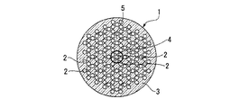
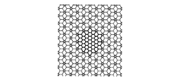
本発明者らは、非特許文献1に開示されている通り、キャピラリーコアを有する拡張三角格子型PBGFを発明した。図1及び図2は、その従来の拡張三角格子型PBGF1,6の構造を示す図である。
図1に示す拡張三角格子型PBGF1は、石英ガラスからなる光ファイバに長手方向に沿って多数の空孔2を規則的に設けてなり、その断面において、ファイバ中心部に7個の空孔2が三角格子状に密集して並べられたキャピラリーコア4が設けられ、その周囲に空孔2と石英ガラス部分3とが拡張三角格子状に配置されたクラッド5が設けられた構造になっている。
As disclosed in Non-Patent
The extended triangular lattice type PBGF 1 shown in FIG. 1 is formed by regularly providing a large number of
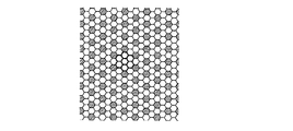
図2に示す拡張三角格子型PBGF6は、ファイバ中央に、中心1個、それを囲む1層目6個、2層目12個、さらにそれを囲む3層目18個、合計37個の空孔2が三角格子状に密に並べられたキャピラリーコア7が設けられ、その周囲に空孔2と石英ガラス部分3とが拡張三角格子状に配置されたクラッド5が設けられた構造になっている。
The extended triangular lattice type PBGF 6 shown in FIG. 2 has a total of 37 holes in the center of the fiber, one in the center, six in the first layer surrounding it, 12 in the second layer, and 18 in the third layer surrounding it. A capillary core 7 in which 2 are closely arranged in a triangular lattice shape is provided, and a
これらの拡張三角格子型PBGF1,6において、キャピラリーコア4,7の空孔2とクラッド5の空孔2とは、同じ孔径になっている。なお、空孔2の断面形状は、PBGFの製造条件、例えば、線引き時の空孔内部とファイバ母材外部との圧力差や温度などによって、円形又は六角形とすることができる。
非特許文献1に記載された拡張三角格子型PBGFは、キャピラリーコアを採用したことで、空孔コア(エアコア)を用いる従来のPBGFに比べ、伝送帯域を大幅に広げることができた。
一方、光ファイバの利用分野は益々広範囲になりつつあり、光ファイバに要求される伝送帯域幅の範囲は、今後益々広がることが予想されることから、広範囲の伝送帯域をもつ光ファイバの提供が切望されている。
The extended triangular lattice type PBGF described in Non-Patent
On the other hand, the field of use of optical fibers is becoming more and more widespread, and the range of transmission bandwidth required for optical fibers is expected to increase further in the future, so it is possible to provide optical fibers with a wide range of transmission bands. Longed for.
本発明は、前記事情に鑑みてなされ、従来のPBGFよりも格段に伝送帯域幅の広い高性能なPBGFの提供を目的とする。 The present invention has been made in view of the above circumstances, and an object of the present invention is to provide a high-performance PBGF having a much wider transmission bandwidth than conventional PBGF.
前記目的を達成するため、本発明は、石英ガラス部分に多数の空孔がファイバ長手方向に沿って設けられ、その空孔が拡張三角格子状に並べられたクラッドを有し、且つ複数の空孔が三角格子状に並べられたキャピラリーコアを有する拡張三角格子型PBGFにおいて、キャピラリーコアの空孔がクラッドの空孔よりも個々の空孔断面積が小さいことを特徴とする拡張三角格子型PBGFを提供する。 In order to achieve the above object, the present invention provides a quartz glass portion provided with a plurality of holes along the longitudinal direction of the fiber, the holes having a clad arranged in an extended triangular lattice, and a plurality of holes. In the extended triangular lattice type PBGF having a capillary core in which holes are arranged in a triangular lattice shape, the expanded triangular lattice type PBGF is characterized in that the pores of the capillary core are smaller in cross-sectional area than the holes of the cladding. I will provide a.
本発明の拡張三角格子型PBGFにおいて、クラッドを構成する拡張三角格子のユニットセルは、断面六角形の多数の空孔が石英ガラスからなる壁を介して拡張三角格子状に並べられてなり、かつキャピラリーコアを構成するユニットセルは、断面六角形の複数の空孔が石英ガラスからなる壁を介して三角格子状に並べられてなり、クラッドを構成する拡張三角格子の壁厚wbと、キャピラリーコアを構成する三角格子の壁厚wcとがwb<wcの関係を満たしていることが好ましい。 In the extended triangular lattice type PBGF of the present invention, the unit cell of the extended triangular lattice constituting the clad has a large number of holes of hexagonal cross section arranged in an extended triangular lattice shape through a wall made of quartz glass, and The unit cell constituting the capillary core is formed by arranging a plurality of holes having a hexagonal cross section in a triangular lattice shape through a wall made of quartz glass, the wall thickness w b of the extended triangular lattice constituting the cladding, and the capillary It is preferable that the wall thickness w c of the triangular lattice constituting the core satisfies the relationship of w b <w c .
本発明の拡張三角格子型PBGFにおいて、キャピラリーコアは、
・中心1個、それを囲む1層6個の合計7個の空孔、
・中心1個、それを囲む1層目6個、2層目12個、3層目18個の合計37個の空孔、・中心1個、それを囲む5層の空孔層の合計91個の空孔、又は
・中心1個、それを囲む7層以上の空孔層、
からなる空孔構造を有していることが好ましい。
In the extended triangular lattice type PBGF of the present invention, the capillary core is
-A total of 7 holes, 1 center and 6 layers surrounding it,
A total of 37 holes including one center, six first layers surrounding it, twelve layers on the second layer, and eighteen layers on the third layer, a total of 91 holes including one center and five layers surrounding the holes. One hole, or one center, seven or more hole layers surrounding it,
It preferably has a pore structure made of
本発明の拡張三角格子型PBGFにおいて、クラッドの拡張三角格子のピッチがΛであるとき、該拡張三角格子の壁厚wbが、0.03Λ≦wb≦0.4Λの関係を満たすことが好ましい。
さらに、キャピラリーコアの三角格子の壁厚wcが0.05Λ≦wc≦0.6Λの関係を満たすことが好ましい。
In the extended triangular lattice type PBGF of the present invention, when the pitch of the extended triangular lattice of the clad is Λ, the wall thickness w b of the extended triangular lattice satisfies the relationship of 0.03Λ ≦ w b ≦ 0.4Λ. preferable.
Furthermore, it is preferable that the wall thickness w c of the triangular lattice of the capillary core satisfies the relationship of 0.05Λ ≦ w c ≦ 0.6Λ.
本発明の拡張三角格子型PBGFにおいて、伝搬パワーの60%以上がキャピラリーコアの領域に集中するコアモードのみが存在し、伝搬パワーの40%以上がキャピラリーコアの領域以外に存在する表面モードが存在しないことが好ましい。 In the extended triangular lattice type PBGF of the present invention, there exists only a core mode in which 60% or more of the propagation power is concentrated in the region of the capillary core, and there exists a surface mode in which 40% or more of the propagation power exists outside the region of the capillary core. Preferably not.
本発明の拡張三角格子型PBGFにおいて、
(a)0.8Λ≦wr≦Λ、0.04Λ≦wb≦0.12Λ、0.12Λ≦wc≦0.25Λで、波長λが0.9≦Γ/λ≦1.8を満たす範囲内、
(b)0.8Λ≦wr≦Λ、0.04Λ≦wb≦0.12Λ、0.25Λ≦wc≦0.35Λで、波長λが0.9≦Γ/λ≦2.4を満たす範囲内、又は
(c)0.8Λ≦wr≦Λ、0.04Λ≦wb≦0.12Λ、0.25Λ≦wc≦0.35Λで、波長λが0.9≦Γ/λ≦2.4(ただし、Λは拡張三角格子のピッチ、wrは拡張三角格子内の石英ガラス部分の径、wbはクラッドの拡張三角格子の壁厚、wcはキャピラリーコアの三角格子の壁厚をそれぞれ表し、Γ=2Λである。)
を満たす範囲内で伝搬モードが存在することが好ましい。
In the extended triangular lattice type PBGF of the present invention,
(A) 0.8Λ ≦ w r ≦ Λ, 0.04Λ ≦ w b ≦ 0.12Λ, 0.12Λ ≦ w c ≦ 0.25Λ, and the wavelength λ is 0.9 ≦ Γ / λ ≦ 1.8. Within the range to meet,
(B) 0.8Λ ≦ w r ≦ Λ, 0.04Λ ≦ w b ≦ 0.12Λ, 0.25Λ ≦ w c ≦ 0.35Λ, and the wavelength λ is 0.9 ≦ Γ / λ ≦ 2.4. Or (c) 0.8Λ ≦ w r ≦ Λ, 0.04Λ ≦ w b ≦ 0.12Λ, 0.25Λ ≦ w c ≦ 0.35Λ, and the wavelength λ is 0.9 ≦ Γ / λ ≦ 2.4 (however, lambda is the extended triangular lattice pitch, w r is the diameter of the quartz glass portion in an extended triangular lattice, w b is the wall thickness of the extended triangular lattice of the cladding, w c is the triangular lattice of the capillary core Represents the wall thickness, respectively, and Γ = 2Λ.)
It is preferable that the propagation mode exists within a range that satisfies the above.
また本発明は、前述した本発明の拡張三角格子型PBGFにおいて、シングルモード動作する拡張三角格子型PBGFを提供する。 The present invention also provides an extended triangular lattice type PBGF that operates in a single mode in the above-described extended triangular lattice type PBGF of the present invention.
前記シングルモード動作する拡張三角格子型PBGFにおいて、クラッドを構成する拡張三角格子のユニットセルは、断面六角形の多数の空孔が石英ガラスからなる壁を介して拡張三角格子状に並べられてなり、かつキャピラリーコアを構成するユニットセルは、断面六角形の複数の空孔が石英ガラスからなる壁を介して三角格子状に並べられてなり、クラッドを構成する拡張三角格子の壁厚wbと、キャピラリーコアを構成する三角格子の壁厚wcとがwb<wcの関係を満たしていることが好ましい。 In the extended triangular lattice type PBGF operating in the single mode, the extended triangular lattice unit cell constituting the clad is formed by arranging a large number of hexagonal cross-section holes in an expanded triangular lattice shape through a wall made of quartz glass. The unit cell constituting the capillary core has a plurality of holes having a hexagonal cross section arranged in a triangular lattice shape through a wall made of quartz glass, and the wall thickness w b of the extended triangular lattice constituting the cladding, The wall thickness w c of the triangular lattice constituting the capillary core preferably satisfies the relationship w b <w c .
前記シングルモード動作する拡張三角格子型PBGFは、クラッドに円形又は六角形の空孔を設け、キャピラリーコアに円形又は六角形の空孔を設けた構成とすることが好ましい。
前記シングルモード動作する拡張三角格子型PBGFにおいて、キャピラリーコアは、中心1個、それを囲む1層6個の合計7個の空孔からなることが好ましい。
The extended triangular lattice type PBGF operating in the single mode preferably has a configuration in which a circular or hexagonal hole is provided in the cladding and a circular or hexagonal hole is provided in the capillary core.
In the extended triangular lattice type PBGF operating in the single mode, the capillary core is preferably composed of a total of seven holes, one center and six layers surrounding it.
前記シングルモード動作する拡張三角格子型PBGFにおいて、クラッドの拡張三角格子のピッチがΛであるとき、該拡張三角格子の壁厚wbが、0.03Λ≦wb≦0.2Λの関係を満たすことが好ましい。
また、キャピラリーコアの三角格子の壁厚wcが0.05Λ≦wc≦0.25Λの関係を満たすことが好ましい。
In the extended triangular lattice type PBGF operating in the single mode, when the pitch of the extended triangular lattice of the cladding is Λ, the wall thickness w b of the extended triangular lattice satisfies the relationship of 0.03Λ ≦ w b ≦ 0.2Λ. It is preferable.
The wall thickness w c of the triangular lattice of the capillary core preferably satisfies the relationship of 0.05Λ ≦ w c ≦ 0.25Λ.
前記シングルモード動作する拡張三角格子型PBGFにおいて、伝搬パワーの60%以上がキャピラリーコアの領域に集中するコアモードのみが存在し、伝搬パワーの40%以上がキャピラリーコアの領域以外に存在する表面モードが存在しないことが好ましい。 In the extended triangular lattice type PBGF operating in the single mode, only the core mode in which 60% or more of the propagation power is concentrated in the capillary core region exists, and the surface mode in which 40% or more of the propagation power exists in the region other than the capillary core region. Is preferably absent.
前記シングルモード動作する拡張三角格子型PBGFにおいて、0.6Λ≦wr≦Λ、0.04Λ≦wb≦0.12Λ、0.06Λ≦wc≦0.18Λで、波長λが0.8≦Γ/λ≦1.8(ただし、Λは拡張三角格子のピッチ、wrは拡張三角格子内の石英ガラス部分の径、wbはクラッドの拡張三角格子の壁厚、wcはキャピラリーコアの三角格子の壁厚をそれぞれ表し、Γ=2Λである。)を満たす範囲内でシングルモードが存在することが好ましい。 In the extended triangular lattice PBGF operating in the single mode, 0.6Λ ≦ w r ≦ Λ, 0.04Λ ≦ w b ≦ 0.12Λ, 0.06Λ ≦ w c ≦ 0.18Λ, and the wavelength λ is 0.8. ≦ Γ / λ ≦ 1.8 (however, lambda is the extended triangular lattice pitch, w r is the diameter of the quartz glass portion in an extended triangular lattice, w b is the wall thickness of the extended triangular lattice of the cladding, w c is the capillary core It is preferable that the single mode exists within a range that satisfies the wall thicknesses of the triangular lattices of Γ and Γ = 2Λ.
本発明の拡張三角格子型PBGFは、空孔が拡張三角格子状に並べられたクラッドを有し、且つ複数の空孔が三角格子状に並べられたキャピラリーコアを有する拡張三角格子型PBGFにおいて、キャピラリーコアの空孔がクラッドの空孔よりも個々の空孔断面積が小さい構造としたので、コアの等価屈折率を高くすることができ、その結果、ファイバの動作領域が広げられ、従来のPBGFよりも格段に広い伝送帯域幅を持った高性能なPBGFを提供することができる。 The extended triangular lattice type PBGF of the present invention is an extended triangular lattice type PBGF having a clad in which holes are arranged in an extended triangular lattice shape and a capillary core in which a plurality of holes are arranged in a triangular lattice shape. Capillary core holes have a structure in which the cross-sectional area of each hole is smaller than that of cladding holes, so that the equivalent refractive index of the core can be increased, and as a result, the operating area of the fiber is widened. It is possible to provide a high-performance PBGF having a much wider transmission bandwidth than PBGF.
以下、図面を参照して本発明の実施形態を説明する。
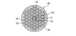
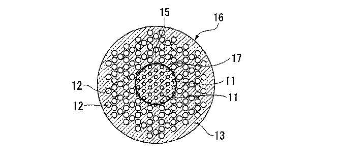
図3は、本発明の拡張三角格子型PBGFの第1実施形態を示す断面図である。本実施形態の拡張三角格子型PBGF10は、石英ガラス部分13に多数の空孔11,12がファイバ長手方向に沿って設けられ、その空孔12が拡張三角格子状に並べられたクラッド15を有し、且つ複数の空孔11が三角格子状に並べられたキャピラリーコア14を有する拡張三角格子型PBGFにおいて、キャピラリーコア14の空孔11がクラッド15の空孔12よりも個々の空孔断面積が小さいことを特徴としている。
Hereinafter, embodiments of the present invention will be described with reference to the drawings.
FIG. 3 is a sectional view showing a first embodiment of the extended triangular lattice type PBGF of the present invention. The extended triangular lattice type PBGF 10 of this embodiment has a
本実施形態の拡張三角格子型PBGF10のキャピラリーコア14は、中心1個、それを囲む1層6個の合計7個の空孔11が三角格子状に配置されている。
The
図4は、本発明の拡張三角格子型PBGFの第2実施形態を示す断面図である。本実施形態の拡張三角格子型PBGF16は、前記第1実施形態の拡張三角格子型PBGF10と同様に構成されているが、中心1個、それを囲む1層目6個、2層目12個、3層目18個の合計37個の空孔11が三角格子状に並べられたキャピラリーコア17を有している点で相違している。
FIG. 4 is a sectional view showing a second embodiment of the extended triangular lattice type PBGF of the present invention. The extended triangular lattice type PBGF 16 of the present embodiment is configured in the same manner as the extended triangular lattice type PBGF 10 of the first embodiment, but has one center, six first layers surrounding it, twelve layers on the second layer, The third layer is different in that it has a
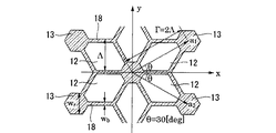
図5は、本発明の拡張三角格子型PBGFのクラッドを構成するユニットセルの構造を例示する要部断面図である。この拡張三角格子のユニットセル構造は、ファイバ横断面において第1のピッチΛで多数の六角形の空孔12が石英ガラスからなる比較的薄い壁18を介して一列に並べられた第1の空孔列と、前記第1のピッチΛの2倍である第2のピッチΓ(Γ=2Λ)で多数の六角形の空孔12が六角形の石英ガラス部分13を介して並べられた第2の空孔列とを交互に多数重ねた周期構造になっている。本例示において、六角形の空孔12は、正六角形ではなく、石英ガラス部分13と接する2辺が他の辺よりも短く、且つ石英ガラス部分13と接する2辺間の長さが他の辺間の長さ(Λ)よりも長い六角形状となっている。また、角度θは30度である。なお、本発明の拡張三角格子型PBGFのクラッドを構成するユニットセルの構造は、本例示にのみ限定されない。
FIG. 5 is a cross-sectional view of a principal part illustrating the structure of a unit cell constituting the cladding of the extended triangular lattice type PBGF of the present invention. This unit cell structure of the extended triangular lattice has a first cavity in which a large number of
図6は、本発明の拡張三角格子型PBGFのキャピラリーコアを構成するユニットセルの構造を例示する要部断面図である。本例示において、キャピラリーコア14,17は、ファイバ断面において、ほぼ正六角形の複数の空孔11が、比較的厚い石英ガラスからなる壁19を介して、三角格子状に配置されている。
FIG. 6 is a cross-sectional view of a principal part illustrating the structure of a unit cell constituting the capillary core of the extended triangular lattice type PBGF of the present invention. In this example, the
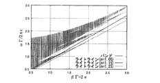
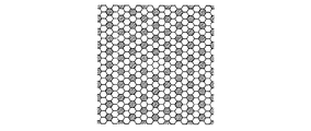
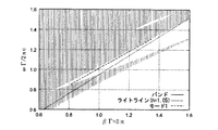
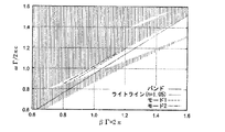
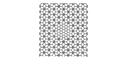
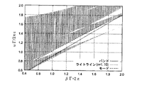
図7に示す拡張三角格子のバンド構造を図8に示す。ただし、石英の屈折率n=1.45とした。図7では、黒い部分が石英ガラス、白い部分が空孔を示す。また、バンド構造は、平面波展開法(非特許文献2参照。)を用いて計算した。 FIG. 8 shows the band structure of the extended triangular lattice shown in FIG. However, the refractive index n of quartz was set to 1.45. In FIG. 7, a black part shows a quartz glass and a white part shows a void | hole. The band structure was calculated using a plane wave expansion method (see Non-Patent Document 2).
図8において、βは伝搬方向(周期構造と垂直な方向)の波数、Γ=2Λは拡張三角格子の格子定数、ωは角周波数、cは光速を表す。また、ライトライン(n=1.05)は光が従来のキャピラリーコア(wc/Λ=0.06)の中で伝搬するときの分散曲線を表し、バンドで囲まれる領域は、周期構造断面内にどの方向にも光が伝搬できない領域、すなわちバンドギャップを表す。 In FIG. 8, β represents the wave number in the propagation direction (direction perpendicular to the periodic structure), Γ = 2Λ represents the lattice constant of the extended triangular lattice, ω represents the angular frequency, and c represents the speed of light. A light line (n = 1.05) represents a dispersion curve when light propagates in a conventional capillary core (w c /Λ=0.06), and a region surrounded by a band is a periodic structure cross section. A region in which light cannot propagate in any direction, that is, a band gap.
PBGFのクラッドにこの拡張三角格子の周期構造を用い、コアに図1、図2に示す従来のキャピラリーコアを用いた場合、その拡張三角格子PBGFのコアに光が導波可能になる帯域はn=1.05のライトラインに隣接し、その上部に存在するバンドギャップとなる。この場合、伝送帯域はほぼライトラインがバンドギャップを横切る範囲となる。 When this extended triangular lattice periodic structure is used for the PBGF cladding and the conventional capillary core shown in FIGS. 1 and 2 is used for the core, the band in which light can be guided to the core of the extended triangular lattice PBGF is n = 1.05 adjacent to the light line, and the band gap existing above it. In this case, the transmission band is almost in the range where the light line crosses the band gap.
キャピラリーコアの壁厚wcを大きくすると、キャピラリーコアの等価屈折率がさらに大きくなるので、その場合のライトラインがさらに下側に傾斜する。図中には、wc/Λ=0.18とした場合(n=1.15)、wc/Λ=0.3とした場合(n=1.23)のライトラインを示している。図示のように、これらのライトラインはさらに広くバンドギャップを横切るので、伝送帯域がさらに広くなる。また、その場合、伝送帯域が周波数の高い領域(短波長側)にシフトするので、所望の伝送帯域に対して、空孔径が大きくても良いことになる。これにより、ファイバが製作しやすくなる。ここでは、キャピラリーコアの等価屈折率は、以下の式(1)の近似を用いた: When the wall thickness w c of the capillary core is increased, the equivalent refractive index of the capillary core is further increased, and the light line in that case is further inclined downward. In the drawing, when the w c /Λ=0.18 (n = 1.15) , shows a light line in the case where the w c /Λ=0.3 (n = 1.23) . As shown in the figure, these light lines cross the band gap more widely, so that the transmission band becomes wider. In this case, since the transmission band is shifted to a high frequency region (short wavelength side), the hole diameter may be larger than the desired transmission band. This makes it easier to manufacture the fiber. Here, the approximation of the following formula (1) was used for the equivalent refractive index of the capillary core:
(ただし、neff,nair,nsilicaは、それぞれコアの平均屈折率、空気の屈折率、石英ガラスの屈折率を表し、Sair,Ssilicaはそれぞれ空気がコア中に占める面積、石英ガラスがコア中に占める面積を表す。)
キャピラリーコアは、図6のようになるので、各面積は、下式(2)、(3)で与えられる。
(Where n eff , n air , and n silica represent the average refractive index of the core, the refractive index of air, and the refractive index of quartz glass, respectively, and S air and S silica represent the area that air occupies in the core, and quartz glass, respectively. Represents the area occupied by the core.)
Since the capillary core is as shown in FIG. 6, each area is given by the following equations (2) and (3).
本発明の拡張三角格子PBGFは、多数本の石英ガラス製のキャピラリーと多数本の石英ガラス製のロッドとを組み合わせ、好ましくはこれらを石英ガラス管に詰め、加熱一体化してファイバ母材を作製し、このファイバ母材を光ファイバ紡糸装置にセットし、通常の光ファイバと同様に線引きして製造することができる。ここで、コアを構成するキャピラリーは肉厚のキャピラリーを用い、クラッドを構成するキャピラリーは肉薄のキャピラリーを用いることが好ましい。 The expanded triangular lattice PBGF of the present invention is a combination of a large number of quartz glass capillaries and a large number of quartz glass rods, which are preferably packed in a quartz glass tube and integrated by heating to produce a fiber preform. The fiber preform can be set in an optical fiber spinning device and drawn in the same manner as a normal optical fiber. Here, it is preferable that a capillary forming the core is a thick capillary and a capillary forming the cladding is a thin capillary.
本発明の拡張三角格子型PBGFは、空孔が拡張三角格子状に並べられたクラッドを有し、且つ複数の空孔が三角格子状に並べられたキャピラリーコアを有する拡張三角格子型PBGFにおいて、キャピラリーコアの空孔がクラッドの空孔よりも個々の空孔断面積が小さい構造としたので、コアの等価屈折率を高くすることができ、その結果、ファイバの動作領域が広げられ、従来のPBGFよりも格段に広い伝送帯域幅を持った高性能なPBGFを提供することができる。 The extended triangular lattice type PBGF of the present invention is an extended triangular lattice type PBGF having a clad in which holes are arranged in an extended triangular lattice shape and a capillary core in which a plurality of holes are arranged in a triangular lattice shape. Capillary core holes have a structure in which the cross-sectional area of each hole is smaller than that of cladding holes, so that the equivalent refractive index of the core can be increased, and as a result, the operating area of the fiber is widened. It is possible to provide a high-performance PBGF having a much wider transmission bandwidth than PBGF.
[比較例1]
図9に示すような、wr/Λ=1、wb/Λ=0.06、wc/Λ=0.06の従来の1層キャピラリーコア(中心に1個、それを囲む6個の合計7個の空孔を有するキャピラリーコア)をもつファイバについて、伝搬モードの分散を計算した。図10はバンドギャップ内の分散を示す。図示のように、Γ/λ=0.85〜1.32で伝搬モードが存在する。ここで、λは波長を表す。
[Comparative Example 1]
As shown in FIG. 9, a conventional single-layer capillary core with w r / Λ = 1, w b /Λ=0.06, w c /Λ=0.06 (one at the center and six enclosing it) The dispersion of the propagation mode was calculated for a fiber having a capillary core having a total of 7 holes. FIG. 10 shows the dispersion within the band gap. As shown in the figure, a propagation mode exists at Γ / λ = 0.85 to 1.32. Here, λ represents a wavelength.
[実施例1]
wc/Λ=0.18の厚さとしたファイバを作製した。図11に示すように、wr/Λ=1、wb/Λ=0.06、wc/Λ=0.18とした1層キャピラリーコア(中心に1個、それを囲む6個の合計7個の空孔を有するキャピラリーコア)をもつファイバについて、伝搬モードの分散を計算した。図12はバンドギャップ内の分散を示す。図示のように、Γ/λ=0.92〜1.74で伝搬モードが存在し、帯域は比較例1のファイバの1.8倍に広がる。図中のモード2は高次モードを表す。
[Example 1]
A fiber with a thickness of w c /Λ=0.18 was produced. As shown in FIG. 11, a one-layer capillary core with w r / Λ = 1, w b /Λ=0.06, w c /Λ=0.18 (one in the center and a total of six surrounding it) The dispersion of the propagation mode was calculated for a fiber having a capillary core with seven holes). FIG. 12 shows the dispersion within the band gap. As shown in the figure, a propagation mode exists at Γ / λ = 0.92 to 1.74, and the bandwidth is 1.8 times that of the fiber of Comparative Example 1.
[実施例2]
図13に示すように、wr/Λ=1、wb/Λ=0.06、wc/Λ=0.3とした1層キャピラリーコア(中心に1個、それを囲む6個の合計7個の空孔を有するキャピラリーコア)をもつファイバについて、伝搬モードの分散を計算した。図14はバンドギャップ内の分散を示す。図示のように、Γ/λ=0.92〜2.35で伝搬モードが存在し、帯域は比較例1のファイバの3倍に広がる。図中のモード2は高次モードを表す。
[Example 2]
As shown in FIG. 13, a one-layer capillary core with w r / Λ = 1, w b /Λ=0.06, and w c /Λ=0.3 (one in the center and a total of six surrounding it) The dispersion of the propagation mode was calculated for a fiber having a capillary core with seven holes). FIG. 14 shows the dispersion within the band gap. As shown in the figure, a propagation mode exists at Γ / λ = 0.92 to 2.35, and the band is three times that of the fiber of Comparative Example 1.
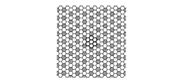
[比較例2]
図15に示すような、wr/Λ=1、wb/Λ=0.06、wc/Λ=0.06の従来の3層キャピラリーコア(中心に1個、それを囲む第1層6個、それを囲む第2層12個、さらにそれを囲む3層目18個の合計37個の空孔を有するキャピラリーコア)をもつファイバについて、伝搬モードの分散を計算した。図16はバンドギャップ内の分散を示す。図示のように、Γ/λ=0.85〜1.18で伝搬モードが存在する。
[Comparative Example 2]
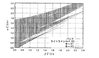
As shown in FIG. 15, a conventional three-layer capillary core with w r / Λ = 1, w b /Λ=0.06, w c /Λ=0.06 (one in the center, the first layer surrounding it) The dispersion of the propagation mode was calculated for a fiber having 6 (capillary cores having a total of 37 vacancies), 12 of the second layer surrounding it, and 18 of the third layer surrounding it. FIG. 16 shows the dispersion within the band gap. As shown in the figure, a propagation mode exists at Γ / λ = 0.85 to 1.18.
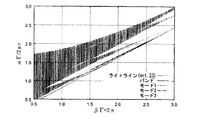
[実施例3]
wcのみを厚くし、wc/Λ=0.30の厚さとしたファイバを作製した。図17に示すように、wr/Λ=1、wb/Λ=0.06、wc/Λ=0.18とした3層キャピラリーコア(中心に1個、それを囲む第1層6個、それを囲む第2層12個、さらにそれを囲む3層目18個の合計37個の空孔を有するキャピラリーコア)をもつファイバについて、伝搬モードの分散を計算した。図18はバンドギャップ内の分散を示す。図示のように、Γ/λ=1.02〜2.20で伝搬モードが存在し、帯域は比較例2のファイバの3.5倍に広がる。図中のモード2、モード3は高次モードを表す。
[Example 3]
thickening the only w c, to produce a fiber that is the thickness of wc / Λ = 0.30. As shown in FIG. 17, a three-layer capillary core with w r / Λ = 1, w b /Λ=0.06, and w c /Λ=0.18 (one at the center, the first layer 6 surrounding it) The dispersion of the propagation mode was calculated for a fiber having a total of 37 vacancies (12 cores, 12 second layers surrounding it, and 18 third layer surrounding it). FIG. 18 shows the dispersion within the band gap. As shown in the figure, a propagation mode exists at Γ / λ = 1.02 to 2.20, and the bandwidth is 3.5 times that of the fiber of Comparative Example 2.
[比較例3]
図19に示すような、wr/Λ=0.7、wb/Λ=0.1、wc/Λ=0.1の従来の3層キャピラリーコア(中心に1個、それを囲む第1層6個、それを囲む第2層12個、さらにそれを囲む3層目18個の合計37個の空孔を有するキャピラリーコア)をもつファイバについて、伝搬モードの分散を計算した。図20はバンドギャップ内の分散を示す。図示のように、Γ/λ=1.0〜1.9で伝搬モードが存在する。
[Comparative Example 3]
As shown in FIG. 19, a conventional three-layer capillary core with w r /Λ=0.7, w b /Λ=0.1, and w c /Λ=0.1 (one at the center, The dispersion of the propagation mode was calculated for a fiber having a capillary core having a total of 37 vacancies (6 layers in one layer, 12 layers in the second layer surrounding it, and 18 layers in the third layer surrounding it). FIG. 20 shows the dispersion within the band gap. As shown in the figure, a propagation mode exists at Γ / λ = 1.0 to 1.9.
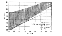
[実施例4]
wcのみを厚くし、wc/Λ=0.20の厚さとしたファイバを作製した。図21に示すように、wr/Λ=0.7、wb/Λ=0.1、wc/Λ=0.2とした3層キャピラリーコア(中心に1個、それを囲む第1層6個、それを囲む第2層12個、さらにそれを囲む3層目18個の合計37個の空孔を有するキャピラリーコア)をもつファイバについて、伝搬モードの分散を計算した。図22はバンドギャップ内の分散を示す。図示のように、Γ/λ=1.02〜2.8で伝搬モードが存在し、帯域は比較例3のファイバの2倍に広がる。図中のモード2、モード3は高次モードを表す。
[Example 4]
Only w c was thickened, and a fiber having a thickness of w c /Λ=0.20 was produced. As shown in FIG. 21, a three-layer capillary core with w r /Λ=0.7, w b /Λ=0.1, and w c /Λ=0.2 (one at the center, the first surrounding it) The propagation mode dispersion was calculated for a fiber having 6 layers, 12 second layers surrounding it, and 18 capillary layers having a total of 37 vacancies in the third layer. FIG. 22 shows the dispersion within the band gap. As shown in the figure, a propagation mode exists at Γ / λ = 1.02 to 2.8, and the bandwidth is twice that of the fiber of Comparative Example 3.
[実施例5]
比較例1と同様なファイバにおいて、wc/Λ=0.12の厚さとし、シングルモード動作するファイバを作製した。図23に示すように、wr/Λ=1、wb/Λ=0.06、wc/Λ=0.12とした1層キャピラリーコア(中心に1個、それを囲む6個の合計7個の空孔を有するキャピラリーコア)をもつファイバについて、伝搬モードの分散を計算した。図24はバンドギャップ内の分散を示す。図示のように、Γ/λ=0.83〜1.60でシングルモードが存在し、動作帯域は比較例1のファイバの1.6倍に広がる。
[Example 5]
In the same fiber as in Comparative Example 1, a fiber that operates in a single mode with a thickness of w c /Λ=0.12 was manufactured. As shown in FIG. 23, a one-layer capillary core with w r / Λ = 1, w b /Λ=0.06, and w c /Λ=0.12 (one in the center and a total of six surrounding it) The dispersion of the propagation mode was calculated for a fiber having a capillary core with seven holes). FIG. 24 shows the dispersion within the band gap. As shown in the figure, a single mode exists at Γ / λ = 0.83 to 1.60, and the operating band is 1.6 times that of the fiber of Comparative Example 1.
10,16…拡張三角格子型PBGF、11,12…空孔、13…石英ガラス部分、14,17…コア、15…クラッド、18,19…壁。
DESCRIPTION OF
Claims (20)
キャピラリーコアの空孔がクラッドの空孔よりも個々の空孔断面積が小さいことを特徴とする拡張三角格子型フォトニックバンドギャップファイバ。 A capillary core in which a large number of holes are provided in a quartz glass portion along the longitudinal direction of the fiber, the holes have a clad arranged in an extended triangular lattice shape, and a plurality of holes are arranged in a triangular lattice shape In the extended triangular lattice type photonic band gap fiber having
An extended triangular lattice type photonic bandgap fiber characterized in that the pores of the capillary core have smaller hole cross-sectional areas than the holes of the cladding.
Priority Applications (5)
| Application Number | Priority Date | Filing Date | Title |
|---|---|---|---|
| JP2006089676A JP2007264331A (en) | 2006-03-29 | 2006-03-29 | Extended triangular grid photonic bandgap fiber |
| CNB200710090918XA CN100561260C (en) | 2006-03-29 | 2007-03-23 | Extended triangular crystal lattice type photonic bandgap fiber |
| US11/693,509 US7551824B2 (en) | 2006-03-29 | 2007-03-29 | Extended triangular lattice type photonic bandgap fiber |
| EP07290376.8A EP1840606B1 (en) | 2006-03-29 | 2007-03-29 | Extended triangular pattice type photonic bandgap fiber |
| US12/430,986 US7831121B2 (en) | 2006-03-29 | 2009-04-28 | Extended triangular lattice type photonic bandgap fiber |
Applications Claiming Priority (1)
| Application Number | Priority Date | Filing Date | Title |
|---|---|---|---|
| JP2006089676A JP2007264331A (en) | 2006-03-29 | 2006-03-29 | Extended triangular grid photonic bandgap fiber |
Publications (1)
| Publication Number | Publication Date |
|---|---|
| JP2007264331A true JP2007264331A (en) | 2007-10-11 |
Family
ID=38226603
Family Applications (1)
| Application Number | Title | Priority Date | Filing Date |
|---|---|---|---|
| JP2006089676A Pending JP2007264331A (en) | 2006-03-29 | 2006-03-29 | Extended triangular grid photonic bandgap fiber |
Country Status (4)
| Country | Link |
|---|---|
| US (2) | US7551824B2 (en) |
| EP (1) | EP1840606B1 (en) |
| JP (1) | JP2007264331A (en) |
| CN (1) | CN100561260C (en) |
Cited By (1)
| Publication number | Priority date | Publication date | Assignee | Title |
|---|---|---|---|---|
| KR101829743B1 (en) | 2017-08-29 | 2018-02-20 | 아이피랩 주식회사 | Three-dimensional lattice structure for tailoring the band gaps |
Families Citing this family (9)
| Publication number | Priority date | Publication date | Assignee | Title |
|---|---|---|---|---|
| JP4025738B2 (en) * | 2004-03-05 | 2007-12-26 | 国立大学法人京都大学 | 2D photonic crystal |
| JP2007264331A (en) * | 2006-03-29 | 2007-10-11 | Fujikura Ltd | Extended triangular grid photonic bandgap fiber |
| US20080046077A1 (en) * | 2006-08-15 | 2008-02-21 | C&C Vision International Limited | Multiocular Intraocular Lens Systems |
| EP2206001B1 (en) | 2007-11-09 | 2014-04-16 | Draka Comteq B.V. | Microbend- resistant optical fiber |
| US8467650B2 (en) | 2007-11-09 | 2013-06-18 | Draka Comteq, B.V. | High-fiber-density optical-fiber cable |
| US20090260397A1 (en) * | 2008-04-21 | 2009-10-22 | Cornejo Ivan A | Glass Structure Having Sub-Micron and Nano-Size Bandgap Structures and Method For Producing Same |
| US8233760B2 (en) * | 2008-10-07 | 2012-07-31 | Corning Incorporated | Ultra low PMD fibers and method of making |
| JP5588451B2 (en) * | 2008-11-07 | 2014-09-10 | ドラカ・コムテツク・ベー・ベー | Small diameter optical fiber |
| CN102323640B (en) * | 2011-09-13 | 2013-05-08 | 中国计量学院 | Bending-resistant single-mode photonic crystal fiber |
Citations (1)
| Publication number | Priority date | Publication date | Assignee | Title |
|---|---|---|---|---|
| JP2006011328A (en) * | 2004-06-29 | 2006-01-12 | Nippon Telegr & Teleph Corp <Ntt> | Photonic crystal fiber |
Family Cites Families (26)
| Publication number | Priority date | Publication date | Assignee | Title |
|---|---|---|---|---|
| GB9710062D0 (en) * | 1997-05-16 | 1997-07-09 | British Tech Group | Optical devices and methods of fabrication thereof |
| EP1086393B1 (en) | 1998-06-09 | 2004-06-02 | Crystal Fibre A/S | A photonic band gap fibre |
| CA2362997C (en) * | 1999-02-19 | 2008-04-29 | Blazephotonics Limited | Improvements in or relating to photonic crystal fibres |
| US6711200B1 (en) * | 1999-09-07 | 2004-03-23 | California Institute Of Technology | Tuneable photonic crystal lasers and a method of fabricating the same |
| GB9929344D0 (en) * | 1999-12-10 | 2000-02-02 | Univ Bath | Improvements in or relating to photonic crystal fibres |
| GB0008546D0 (en) * | 2000-04-06 | 2000-05-24 | Btg Int Ltd | Optoelectronic devices |
| US6792188B2 (en) * | 2000-07-21 | 2004-09-14 | Crystal Fibre A/S | Dispersion manipulating fiber |
| US6598428B1 (en) | 2000-09-11 | 2003-07-29 | Schott Fiber Optics, Inc. | Multi-component all glass photonic band-gap fiber |
| US6778749B2 (en) | 2001-03-20 | 2004-08-17 | Corning Incorporated | Optimized defects in band-gap waveguides |
| JP3842659B2 (en) | 2002-01-31 | 2006-11-08 | 日本電信電話株式会社 | Single mode photonic bandgap fiber and its glass matrix |
| JP2005519319A (en) * | 2002-03-06 | 2005-06-30 | ピレリ・アンド・チ・ソチエタ・ペル・アツィオーニ | A device for bending a light beam, especially in an optical integrated circuit |
| JP2005519321A (en) * | 2002-03-06 | 2005-06-30 | ピレリ・アンド・チ・ソチエタ・ペル・アツィオーニ | Apparatus for crossing light beams, especially in optical integrated circuits |
| US7321712B2 (en) | 2002-12-20 | 2008-01-22 | Crystal Fibre A/S | Optical waveguide |
| WO2004083918A1 (en) | 2003-03-21 | 2004-09-30 | Crystal Fibre A/S | Photonic bandgap optical waveguidewith anti-resonant core boundary |
| JP2005017650A (en) | 2003-06-25 | 2005-01-20 | Nippon Telegr & Teleph Corp <Ntt> | Optical fiber |
| WO2005017582A1 (en) * | 2003-08-13 | 2005-02-24 | Nippon Telegraph And Telephone Corporation | Optical fiber and production method thereof |
| US7224873B2 (en) * | 2003-09-10 | 2007-05-29 | Crystal Fibre A/S | Optical fibres |
| US6804446B1 (en) * | 2003-11-18 | 2004-10-12 | University Of Alabama In Huntsville | Waveguide including at least one photonic crystal region for directing signals propagating therethrough |
| GB0408082D0 (en) | 2004-04-08 | 2004-05-12 | Blazephotonics Ltd | Method for making an optical fibre |
| US20060153512A1 (en) | 2004-04-22 | 2006-07-13 | Falkenstein Paul L | Fused array preform fabrication of holey optical fibers |
| US7505881B2 (en) * | 2004-09-11 | 2009-03-17 | The Board Of Trustees Of The Leland Stanford Junior University | Method and apparatus for modeling the modal properties of optical waveguides |
| WO2006072025A2 (en) * | 2004-12-30 | 2006-07-06 | Imra America, Inc. | Photonic bandgap fibers |
| WO2006080532A1 (en) * | 2005-01-31 | 2006-08-03 | Kyoto University | Two-dimensional photonic crystal |
| US7304309B2 (en) * | 2005-03-14 | 2007-12-04 | Avraham Suhami | Radiation detectors |
| JP4669923B2 (en) * | 2005-03-18 | 2011-04-13 | 国立大学法人京都大学 | Polarization mode converter |
| JP2007264331A (en) * | 2006-03-29 | 2007-10-11 | Fujikura Ltd | Extended triangular grid photonic bandgap fiber |
-
2006
- 2006-03-29 JP JP2006089676A patent/JP2007264331A/en active Pending
-
2007
- 2007-03-23 CN CNB200710090918XA patent/CN100561260C/en not_active Expired - Fee Related
- 2007-03-29 US US11/693,509 patent/US7551824B2/en not_active Expired - Fee Related
- 2007-03-29 EP EP07290376.8A patent/EP1840606B1/en not_active Expired - Fee Related
-
2009
- 2009-04-28 US US12/430,986 patent/US7831121B2/en not_active Expired - Fee Related
Patent Citations (1)
| Publication number | Priority date | Publication date | Assignee | Title |
|---|---|---|---|---|
| JP2006011328A (en) * | 2004-06-29 | 2006-01-12 | Nippon Telegr & Teleph Corp <Ntt> | Photonic crystal fiber |
Cited By (2)
| Publication number | Priority date | Publication date | Assignee | Title |
|---|---|---|---|---|
| KR101829743B1 (en) | 2017-08-29 | 2018-02-20 | 아이피랩 주식회사 | Three-dimensional lattice structure for tailoring the band gaps |
| US11107452B2 (en) | 2017-08-29 | 2021-08-31 | Yong Suk WON | Three-dimensional asymmetric lattice structure for tailoring the band gaps |
Also Published As
| Publication number | Publication date |
|---|---|
| CN101046527A (en) | 2007-10-03 |
| EP1840606A1 (en) | 2007-10-03 |
| US7831121B2 (en) | 2010-11-09 |
| US20090208176A1 (en) | 2009-08-20 |
| EP1840606B1 (en) | 2018-02-14 |
| US20070230885A1 (en) | 2007-10-04 |
| US7551824B2 (en) | 2009-06-23 |
| CN100561260C (en) | 2009-11-18 |
Similar Documents
| Publication | Publication Date | Title |
|---|---|---|
| JP2007264331A (en) | Extended triangular grid photonic bandgap fiber | |
| WO2019071921A1 (en) | Anti-resonant hollow core optical fiber having multiple resonant layers | |
| CN108181684B (en) | Microstructure hollow optical fiber | |
| JP5311417B2 (en) | Optical fiber manufacturing method, optical fiber preform and manufacturing method thereof | |
| JP2013080126A (en) | Polarization-maintaining multi-core optical fiber | |
| WO2003050571A2 (en) | A method and apparatus relating to photonic crystal fibre | |
| WO2013088795A1 (en) | Method for manufacturing photonic band gap fiber | |
| JP2011095332A (en) | Optical fiber manufacturing method | |
| JP2004506954A (en) | Polymer optical waveguide | |
| JP4588113B2 (en) | Photonic bandgap fiber | |
| JP2011033899A (en) | Holey fibers | |
| JP2006017775A (en) | Photonic crystal fiber | |
| JP2006011328A (en) | Photonic crystal fiber | |
| JP4447531B2 (en) | Photonic band gap fiber and manufacturing method thereof | |
| JP5306580B2 (en) | Honeycomb lattice type photonic bandgap fiber and manufacturing method thereof | |
| CN113189697B (en) | Chalcogenide high-birefringence decagonal photonic crystal fiber | |
| JP4447528B2 (en) | Photonic band gap fiber and manufacturing method thereof | |
| US6775450B2 (en) | Micro-structured optical fibers | |
| JP2007127930A (en) | Photonic bandgap fiber and its manufacturing method | |
| CA3179574A1 (en) | Wavelength selective filtering with non-radial array of microstructure elements | |
| JP3865208B2 (en) | Photonic crystal structure optical fiber | |
| JP5191982B2 (en) | Optical fiber | |
| JP4447529B2 (en) | Photonic band gap fiber and manufacturing method thereof | |
| JP4451360B2 (en) | Photonic band gap fiber and manufacturing method thereof | |
| JP5660673B2 (en) | Optical fiber |
Legal Events
| Date | Code | Title | Description |
|---|---|---|---|
| A621 | Written request for application examination |
Free format text: JAPANESE INTERMEDIATE CODE: A621 Effective date: 20081127 |
|
| A977 | Report on retrieval |
Free format text: JAPANESE INTERMEDIATE CODE: A971007 Effective date: 20091228 |
|
| A131 | Notification of reasons for refusal |
Free format text: JAPANESE INTERMEDIATE CODE: A131 Effective date: 20100511 |
|
| A521 | Written amendment |
Free format text: JAPANESE INTERMEDIATE CODE: A523 Effective date: 20100709 |
|
| A131 | Notification of reasons for refusal |
Free format text: JAPANESE INTERMEDIATE CODE: A131 Effective date: 20110823 |
|
| A02 | Decision of refusal |
Free format text: JAPANESE INTERMEDIATE CODE: A02 Effective date: 20120104 |