(第一実施形態)
本発明の第一実施形態に係る内視鏡用穿刺針1を備えた生検システム150について、図1から図10を参照して説明する。図1は本実施形態に係る内視鏡用穿刺針1を備えた生検システム150の全体図である。
(First embodiment)
A biopsy system 150 including an endoscopic puncture needle 1 according to a first embodiment of the present invention will be described with reference to FIGS. 1 to 10. FIG. 1 is an overall view of a biopsy system 150 including an endoscopic puncture needle 1 according to the present embodiment.
[生検システム150]
生検システム150は、図1に示すように、生検に必要な体組織を採取するために使用される医療機器である。生検システム150は、超音波内視鏡100と、内視鏡用穿刺針1(以下、単に「穿刺針1」と称する。)とを備える。
[Biopsy system 150]
Biopsy system 150, as shown in FIG. 1, is a medical device used to collect body tissue required for biopsy. The biopsy system 150 includes an ultrasound endoscope 100 and an endoscopic puncture needle 1 (hereinafter simply referred to as "puncture needle 1").
[超音波内視鏡100]
超音波内視鏡100は、図1に示すように、先端から体内に挿入される挿入部101と、挿入部101の基端に取り付けられた操作部109と、操作部109の側部に一端が接続されたユニバーサルコード112と、ユニバーサルコード112の他端に分岐ケーブル112aを介して接続された光源装置113と、ユニバーサルコード112の他端に分岐ケーブル112bを介して接続された光学的観察部114と、ユニバーサルコード112の他端に分岐ケーブル112cを介して接続された超音波観察部115とを備える。
[Ultrasound endoscope 100]
As shown in FIG. 1, the ultrasound endoscope 100 includes an insertion section 101 that is inserted into the body from the distal end, an operation section 109 attached to the proximal end of the insertion section 101, and one end attached to the side of the operation section 109. a universal cord 112 connected to the universal cord 112, a light source device 113 connected to the other end of the universal cord 112 via a branch cable 112a, and an optical observation section connected to the other end of the universal cord 112 via a branch cable 112b. 114, and an ultrasonic observation unit 115 connected to the other end of the universal cord 112 via a branch cable 112c.
挿入部101は、先端硬質部102、能動湾曲部105および可撓管部106が先端側からこの順に並べて設けられている。
The insertion section 101 is provided with a rigid distal section 102, an active bending section 105, and a flexible tube section 106 arranged in this order from the distal end side.
先端硬質部102は、光学的観察を行うための光学撮像機構103と、超音波観察を行うための超音波走査機構104とを備える。
The rigid tip portion 102 includes an optical imaging mechanism 103 for performing optical observation and an ultrasonic scanning mechanism 104 for performing ultrasonic observation.
光学撮像機構103は、先端硬質部102の斜め前方に視野が向けられた撮像光学系と、撮像光学系を通じて入射した被写体の像を検出するCCDやCMOSなどのイメージセンサと、イメージセンサの動作を制御するCPU等とを備える。
The optical imaging mechanism 103 includes an imaging optical system whose field of view is directed diagonally in front of the rigid tip portion 102, an image sensor such as a CCD or CMOS that detects an image of a subject incident through the imaging optical system, and an image sensor that controls the operation of the image sensor. It is equipped with a CPU and the like for control.
超音波走査機構104は、超音波を出射し、受信する図示しない超音波振動子を備える。超音波走査機構104は、超音波振動子が発した超音波が観察対象に当たって反射した反射波を超音波振動子によって受信し、超音波振動子が受信した超音波に基づいた信号を超音波観察部115へ出力する。
The ultrasonic scanning mechanism 104 includes an ultrasonic transducer (not shown) that emits and receives ultrasonic waves. The ultrasonic scanning mechanism 104 receives, with the ultrasonic transducer, the reflected waves of the ultrasonic waves emitted by the ultrasonic transducer and reflected when they hit the observation target, and performs ultrasonic observation of signals based on the ultrasonic waves received by the ultrasonic transducer. It is output to section 115.
能動湾曲部105は、筒状をなす複数の関節が挿入部101の中心線方向に並べて連結されてなる筒状部材である。能動湾曲部105は、能動湾曲部105の先端に固定され操作部109まで延びる図示しないアングルワイヤを操作部109において牽引操作することによって、所定の方向へ湾曲する能動湾曲部である。本実施形態の能動湾曲部105は、超音波の走査方向に沿って2方向に湾曲可能である。
The active bending portion 105 is a cylindrical member in which a plurality of cylindrical joints are arranged and connected in the direction of the center line of the insertion portion 101 . The active bending section 105 is an active bending section that bends in a predetermined direction by pulling an angle wire (not shown) fixed to the tip of the active bending section 105 and extending to the operation section 109 at the operation section 109 . The active bending section 105 of this embodiment is capable of bending in two directions along the ultrasound scanning direction.
可撓管部106は、管腔組織内や体腔内において先端硬質部102を所望の位置に案内できるように柔軟に形成された筒状部材である。能動湾曲部105と可撓管部106とのそれぞれの内部には、チャンネル107と、送気送水や吸引などを行うための図示しない管路とが設けられている。
The flexible tube section 106 is a cylindrical member that is flexibly formed so that the rigid tip section 102 can be guided to a desired position within the luminal tissue or body cavity. Inside each of the active bending section 105 and the flexible tube section 106, a channel 107 and a conduit (not shown) for performing air supply, water supply, suction, etc. are provided.
チャンネル107は、図1に示すように、穿刺針1を挿通可能な筒状部である。チャンネル107の先端は先端硬質部102の先端で開口され、チャンネル107の基端は操作部109の先端側の側面に開口されている。
As shown in FIG. 1, the channel 107 is a cylindrical portion through which the puncture needle 1 can be inserted. The distal end of the channel 107 is opened at the distal end of the hard distal end portion 102, and the proximal end of the channel 107 is opened at the side surface on the distal end side of the operating section 109.
操作部109は、図1に示すように、超音波内視鏡100を使用する術者が手に持つことができるように形成された外面を有している。操作部109は、アングルワイヤを牽引して能動湾曲部105を湾曲動作させたり、起上用ワイヤを牽引して起上台108を動作させたりするための湾曲操作機構110と、管路を通じて送気、送水、あるいは吸引をするための複数のスイッチ111とを備えている。
As shown in FIG. 1, the operating section 109 has an outer surface formed so that it can be held in the hand of an operator using the ultrasound endoscope 100. The operating section 109 includes a bending operation mechanism 110 for pulling the angle wire to bend the active bending section 105 or for pulling the raising wire to operate the raising table 108, and for supplying air through a conduit. , a plurality of switches 111 for water supply or suction.
光源装置113は、光学撮像機構103によって撮像するための照明光を発するための装置である。
The light source device 113 is a device for emitting illumination light for imaging by the optical imaging mechanism 103.
光学的観察部114は、光学撮像機構103のイメージセンサによって撮像された映像をモニター116に映し出すように構成されている。
The optical observation unit 114 is configured to display an image captured by the image sensor of the optical imaging mechanism 103 on the monitor 116.
超音波観察部115は、超音波走査機構104から出力された信号を受信し、この信号に基づいて画像を生成してモニター116に映し出すようになっている。
The ultrasound observation unit 115 receives the signal output from the ultrasound scanning mechanism 104, generates an image based on this signal, and displays the image on the monitor 116.
[穿刺針1]
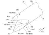
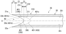
図2は、穿刺針1の斜視図である。図3は、穿刺針1の先端部分において穿刺針1の長手軸に沿った断面を示す縦断面図である。
穿刺針1は、図2に示すように、挿入体2と、操作部8と、スタイレット27とを備える。
[Puncture needle 1]
FIG. 2 is a perspective view of the puncture needle 1. FIG. 3 is a longitudinal cross-sectional view showing a cross section along the longitudinal axis of the puncture needle 1 at the distal end portion of the puncture needle 1. As shown in FIG.
The puncture needle 1 includes an inserter 2, an operating section 8, and a stylet 27, as shown in FIG.
[挿入体2]
挿入体2は、超音波内視鏡100のチャンネル107に挿通可能な細長い部材である。挿入体2は、図2および図3に示すように、針管3と、シース7とを備える。
[Insert body 2]
The inserter 2 is an elongated member that can be inserted into the channel 107 of the ultrasound endoscope 100. The insert body 2 includes a needle tube 3 and a sheath 7, as shown in FIGS. 2 and 3.
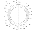
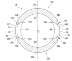
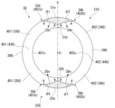
図4は、針管3の斜視図である。図5は、針管3の側面図である。図6は、針管3を軸方向Aの先端から見た正面図であり、長手軸方向において等間隔に断面を配列し、各刃面の断面の向きの変化を模式的に示した図である。図6に示す一点破線は、軸方向Aに等間隔に配列する軸方向Aと垂直な断面と、第一刃面33、第二刃面34、第三刃面35および第四刃面36との交線を表している。図7は、図5に示すX-X断面における針管3の断面図である。図8は、図5に示すY-Y断面における針管3の断面図である。
FIG. 4 is a perspective view of the needle tube 3. FIG. 5 is a side view of the needle tube 3. FIG. 6 is a front view of the needle tube 3 viewed from the tip in the axial direction A, and is a diagram schematically showing changes in the orientation of the cross sections of each blade surface with cross sections arranged at equal intervals in the longitudinal axis direction. . The dotted lines shown in FIG. 6 represent cross sections perpendicular to the axial direction A arranged at equal intervals in the axial direction A, the first blade surface 33, the second blade surface 34, the third blade surface 35, and the fourth blade surface 36. represents the intersection line of FIG. 7 is a sectional view of the needle tube 3 taken along the line XX shown in FIG. FIG. 8 is a sectional view of the needle tube 3 taken along the YY cross section shown in FIG.
針管3は、図4に示すように、管状の管状部30と、管状部30の先端に設けられた第一針先部31および第二針先部32と、を備える。針管3は、操作部8によりシース7内で進退操作可能である。針管3の先端には、第一針先部31および第二針先部32に穿刺された組織を、針管3の内部へ入り込む入口となる開口4が形成されている。針管3の第一針先部31および第二針先部32は、シース7の先端部分の開口から突没可能である。
As shown in FIG. 4, the needle tube 3 includes a tubular portion 30, and a first needle tip portion 31 and a second needle tip portion 32 provided at the tip of the tubular portion 30. The needle tube 3 can be moved forward and backward within the sheath 7 by an operating section 8. An opening 4 is formed at the tip of the needle tube 3 and serves as an entrance through which the tissue punctured by the first needle tip 31 and the second needle tip 32 enters the inside of the needle tube 3. The first needle tip 31 and the second needle tip 32 of the needle tube 3 can protrude and retract from the opening at the distal end of the sheath 7.
針管3の材質としては、可撓性を有しているとともに、外力により曲げられても容易に直線状態に復元する弾性を有する材質であることが好ましい。例えば、針管3の材料としては、ステンレス合金、ニッケルチタン合金、コバルトクロム合金などの合金材料を採用することができる。
The material for the needle tube 3 is preferably a material that is flexible and has elasticity that allows it to easily return to its straight state even if it is bent by an external force. For example, as the material for the needle tube 3, alloy materials such as stainless steel alloy, nickel titanium alloy, cobalt chromium alloy, etc. can be adopted.
第一針先部31は、図4から図6に示すように、第一刃面33と第二刃面34とを有し、第一刃面33と第二刃面34は、鋭利な第一針先31aに向かって延びている。針管3の軸方向Aに沿う方向から見た正面視において、第一刃面33と第二刃面34とは、図6に示すように、第一針先31aと第二針先32aとを通る直線Vに対して対称な形状である。なお、第一刃面33および第二刃面34は平面であっても良いし、僅かに曲面に加工されていてもよい。
As shown in FIGS. 4 to 6, the first needle tip portion 31 has a first blade surface 33 and a second blade surface 34, and the first blade surface 33 and the second blade surface 34 are sharp It extends toward the one stitch point 31a. In a front view seen from the direction along the axial direction A of the needle tube 3, the first blade surface 33 and the second blade surface 34 form the first needle tip 31a and the second needle tip 32a, as shown in FIG. It has a symmetrical shape with respect to the straight line V passing through it. Note that the first blade surface 33 and the second blade surface 34 may be flat or may be processed into slightly curved surfaces.
第一針先部31の外周面31eは、管状部30の外周面30eと連続する曲面であり、同一の径寸法と曲率を有する。また、第一針先部31の内周面31iは、管状部30の内周面30iと連続する曲面であり、同一の径寸法と曲率を有する。第一針先部31は、例えば、管状部30の一部を切り落として第一刃面33と第二刃面34を形成する。
The outer circumferential surface 31e of the first needle tip portion 31 is a curved surface that is continuous with the outer circumferential surface 30e of the tubular portion 30, and has the same diameter and curvature. Moreover, the inner circumferential surface 31i of the first needle tip portion 31 is a curved surface that is continuous with the inner circumferential surface 30i of the tubular portion 30, and has the same diameter size and curvature. The first needle tip portion 31 forms a first blade surface 33 and a second blade surface 34 by cutting off a portion of the tubular portion 30, for example.
第二針先部32は、図4から図6に示すように、第三刃面35と第四刃面36とを有し、第三刃面35と第四刃面36は、鋭利な第二針先32aに向かって延びている。第一針先31aと第二針先32aとは、針管3の軸方向Aに延びる中心軸Oに対して対称な位置に配置されている。針管3の軸方向Aに沿う方向から見た正面視において、第三刃面35と第四刃面36とは、図6に示すように、第一針先31aと第二針先32aとを通る直線Vに対して対称な形状である。なお、第三刃面35および第四刃面36は平面であっても良いし、僅かに曲面に加工されていてもよい。
As shown in FIGS. 4 to 6, the second needle tip portion 32 has a third blade surface 35 and a fourth blade surface 36, and the third blade surface 35 and the fourth blade surface 36 are sharp It extends toward the second needle tip 32a. The first needle tip 31a and the second needle tip 32a are arranged at symmetrical positions with respect to the central axis O extending in the axial direction A of the needle tube 3. In a front view seen from the direction along the axial direction A of the needle tube 3, the third blade surface 35 and the fourth blade surface 36 form the first needle tip 31a and the second needle tip 32a, as shown in FIG. It has a symmetrical shape with respect to the straight line V passing through it. Note that the third blade surface 35 and the fourth blade surface 36 may be flat or may be processed into slightly curved surfaces.
第二針先部32の外周面32eは、管状部30の外周面30eと連続する曲面であり、同一の径寸法と曲率である。また、第二針先部32の内周面32iは、管状部30の内周面30iと連続する曲面であり、同一の径寸法と曲率である。第二針先部32は、例えば、管状部30の一部を切り落として第三刃面35と第四刃面36を形成する。
The outer circumferential surface 32e of the second needle tip portion 32 is a curved surface that is continuous with the outer circumferential surface 30e of the tubular portion 30, and has the same diameter and curvature. Further, the inner circumferential surface 32i of the second needle tip portion 32 is a curved surface that is continuous with the inner circumferential surface 30i of the tubular portion 30, and has the same diameter size and curvature. The second needle tip portion 32 forms a third blade surface 35 and a fourth blade surface 36 by cutting off a portion of the tubular portion 30, for example.
第一針先部31と第二針先部32とは、図4および図5に示すように、第一刃面33と第二刃面34と第三刃面35と第四刃面36とに囲まれた開口4を形成する。開口4は、管状の管状部30の内部空間に連通する。
As shown in FIGS. 4 and 5, the first needle tip 31 and the second needle tip 32 have a first blade surface 33, a second blade surface 34, a third blade surface 35, and a fourth blade surface 36. An opening 4 is formed surrounded by. The opening 4 communicates with the internal space of the tubular section 30 .
図4から図6に示すように、第一刃面33と第三刃面35とは、開口4の縁の第一基端38で連なる。第二刃面34と第四刃面36とは、開口4の縁の第二基端39で連なる。
As shown in FIGS. 4 to 6, the first blade surface 33 and the third blade surface 35 are continuous at the first base end 38 of the edge of the opening 4. As shown in FIGS. The second blade surface 34 and the fourth blade surface 36 are continuous at a second base end 39 of the edge of the opening 4.
第一針先部31と第二針先部32において、図5に示すように、第一針先31aおよび第二針先32aを含む先端領域Z1と、第一基端38および第二基端39を含む基端領域Z3と、先端領域Z1と基端領域Z3の間に位置し、先端領域Z1と基端領域Z3に連なる中間領域Z2と、を定義する。
In the first needle tip part 31 and the second needle tip part 32, as shown in FIG. 39, and an intermediate region Z2 located between the distal region Z1 and the proximal region Z3 and connected to the distal region Z1 and the proximal region Z3.
(第一針先部31の第一刃面33および第二刃面34)
第一刃面33は、図4および図7に示すように、第一針先部31の内周面31iとの交線(第一内側交線33c)が開口4の輪郭の一部を規定する。第二刃面34は、第一針先部31の内周面31iとの交線(第二内側交線34c)が開口4の輪郭の一部を規定する。
(First blade surface 33 and second blade surface 34 of first needle tip 31)
As shown in FIGS. 4 and 7, the first blade surface 33 has a line of intersection (a first inner line of intersection 33c) with the inner circumferential surface 31i of the first needle tip 31, which defines a part of the outline of the opening 4. do. A line of intersection of the second blade surface 34 and the inner circumferential surface 31i of the first needle point 31 (second inner line of intersection 34c) defines a part of the outline of the opening 4.
図7に示すように、針管3(管状部30)の軸方向Aに沿う方向から見た正面視において、先端領域Z1における第一刃面33の法線ベクトル33nは、第一針先31aと第二針先32aとを通る直線Vに直交する方向よりも、先端領域Z1における第三刃面35側に向いている。同様に、同正面視において、先端領域Z1における第二刃面34の法線ベクトル34nは、第一針先31aと第二針先32aとを通る直線Vに直交する方向よりも、先端領域Z1における第四刃面36側に向いている。
As shown in FIG. 7, in a front view seen from the direction along the axial direction A of the needle tube 3 (tubular portion 30), the normal vector 33n of the first blade surface 33 in the tip region Z1 is different from the first needle tip 31a. It faces toward the third blade surface 35 side in the tip region Z1 rather than the direction perpendicular to the straight line V passing through the second needle tip 32a. Similarly, in the front view, the normal vector 34n of the second blade surface 34 in the tip region Z1 is larger than the direction perpendicular to the straight line V passing through the first needle tip 31a and the second needle tip 32a. It faces toward the fourth blade surface 36 side.
さらに、図8に示すように、中間領域Z2における第一刃面33の法線ベクトル33nも、先端領域Z1と同様に、直線Vに直交する方向よりも、中間領域Z2における第三刃面35側に向いている。さらに、中間領域Z2における第二刃面34の法線ベクトル34nも、先端領域Z1と同様に、直線Vに直交する方向よりも、中間領域Z2における第四刃面36側に向いている。
Furthermore, as shown in FIG. 8, the normal vector 33n of the first blade surface 33 in the intermediate region Z2 is also closer to the third blade surface 35 in the intermediate region Z2 than in the direction orthogonal to the straight line V, similarly to the tip region Z1. facing to the side. Furthermore, the normal vector 34n of the second blade surface 34 in the intermediate region Z2 is also oriented toward the fourth blade surface 36 in the intermediate region Z2, rather than the direction perpendicular to the straight line V, similarly to the tip region Z1.
好ましくは、中間領域Z2における第一刃面33の法線ベクトル33nは、図8に示すように第一針先31aおよび第二針先32aを結ぶ直線Vに対して鋭角になる方向に向く 。また、中間領域Z2における第二刃面34の法線ベクトル34nは、第一針先31aおよび第二針先32aを結ぶ直線Vに対して鋭角になる方向に向く。
Preferably, the normal vector 33n of the first blade surface 33 in the intermediate region Z2 is oriented at an acute angle with respect to the straight line V connecting the first needle tip 31a and the second needle tip 32a, as shown in FIG. Further, the normal vector 34n of the second blade surface 34 in the intermediate region Z2 is oriented at an acute angle with respect to the straight line V connecting the first needle tip 31a and the second needle tip 32a.
好ましくは、第一刃面33の法線ベクトル33nおよび第二刃面34の法線ベクトル34nは、図6および図7に示すように、先端領域Z1において、管状部30の円周方向Cと比較して、中心軸Oに近づく方向を向いている。
Preferably, the normal vector 33n of the first blade surface 33 and the normal vector 34n of the second blade surface 34 are aligned with the circumferential direction C of the tubular portion 30 in the tip region Z1, as shown in FIGS. 6 and 7. In comparison, it faces in a direction closer to the central axis O.
図5に示すように、第一刃面33と第二刃面34との交線(第一先端交線31b)は、第一針先部31の内周面31iの先端から第一針先31aまで延びている。なお、第一先端交線31bは、好ましくは、針管3の軸方向Aに沿う方向から見た正面視において直線V上に位置している。
As shown in FIG. 5, the intersection line between the first blade surface 33 and the second blade surface 34 (first tip intersection line 31b) is from the tip of the inner circumferential surface 31i of the first needle tip portion 31 to the first needle tip. It extends to 31a. Note that the first tip intersection line 31b is preferably located on the straight line V when viewed from the front along the axial direction A of the needle tube 3.
第一刃面33と外周面31eとが交差する交線(第一外側交線33b)は、管状部30の円周方向にエッジを有する第一外エッジ33bである。図6から図8に示すように、第一外エッジ33bにおける第一刃面33と外周面31eとのなす角度θ1は、針管3の軸方向Aに沿う方向から見た正面視において、先端領域Z1において鋭角であり、中間領域Z2に近づくほど角度θ1が大きくなり、中間領域Z2において鈍角をなす。
The intersection line (first outer intersection line 33b) where the first blade surface 33 and the outer circumferential surface 31e intersect is a first outer edge 33b having an edge in the circumferential direction of the tubular portion 30. As shown in FIGS. 6 to 8, the angle θ1 between the first blade surface 33 and the outer circumferential surface 31e at the first outer edge 33b is the tip area of the needle tube 3 when viewed from the front along the axial direction A. It is an acute angle in Z1, the angle θ1 becomes larger as it approaches intermediate region Z2, and it becomes an obtuse angle in intermediate region Z2.
第一刃面33と内周面31iとが交差する交線(第一内側交線33c)は、管状部30の円周方向にエッジを有する第一内エッジ33cである。図7および図8に示すように、第一内エッジ33cにおける第一刃面33と内周面31iとのなす角度θ2は、針管3の軸方向Aに沿う方向から見た正面視において、先端領域Z1では鈍角であり、中間領域Z2では鋭角である。
The intersection line (first inner intersection line 33c) where the first blade surface 33 and the inner circumferential surface 31i intersect is a first inner edge 33c having an edge in the circumferential direction of the tubular portion 30. As shown in FIGS. 7 and 8, the angle θ2 between the first blade surface 33 and the inner circumferential surface 31i at the first inner edge 33c is the tip of the needle tube 3 when viewed from the front along the axial direction A. The area Z1 is an obtuse angle, and the intermediate area Z2 is an acute angle.
第二刃面34と外周面31eとが交差する交線(第二外側交線34b)は、管状部30の円周方向にエッジを有する第二外エッジ34bである。図7および図8に示すように、第二外エッジ34bにおける第二刃面34と外周面31eとのなす角度θ3は、針管3の軸方向に沿う方向から見た正面視において、先端領域Z1では鋭角であり、中間領域Z2に近づくほど角度θ3が大きくなり、中間領域Z2では鈍角をなす。
The intersection line (second outer intersection line 34b) where the second blade surface 34 and the outer circumferential surface 31e intersect is a second outer edge 34b having an edge in the circumferential direction of the tubular portion 30. As shown in FIGS. 7 and 8, the angle θ3 between the second blade surface 34 and the outer circumferential surface 31e at the second outer edge 34b is the angle θ3 in the tip region Z1 when viewed from the front along the axial direction of the needle tube 3. The angle θ3 becomes larger as the angle approaches the intermediate region Z2, and becomes an obtuse angle in the intermediate region Z2.
第二刃面34と内周面31iとが交差する交線(第二内側交線34c)は、管状部30の円周方向にエッジを有する第二内エッジ34cである。図7および図8に示すように、第二内エッジ34cにおける第二刃面34と内周面31iとのなす角度θ4は、針管3の軸方向Aに沿う方向から見た正面視において、先端領域Z1では鈍角であり、中間領域Z2では鋭角である。
The intersection line (second inner intersection line 34c) where the second blade surface 34 and the inner circumferential surface 31i intersect is a second inner edge 34c having an edge in the circumferential direction of the tubular portion 30. As shown in FIGS. 7 and 8, the angle θ4 between the second blade surface 34 and the inner circumferential surface 31i at the second inner edge 34c is the tip of the needle tube 3 when viewed from the front along the axial direction A. The area Z1 is an obtuse angle, and the intermediate area Z2 is an acute angle.
(第二針先部32の第三刃面35および第四刃面36)
第三刃面35は、図4および図7に示すように、第二針先部32の内周面32iとの交線(第三内側交線35c)が開口4の輪郭の一部を規定する。第四刃面36は、第二針先部32の内周面32iとの交線(第四内側交線36c)が開口4の輪郭の一部を規定する。
(Third blade surface 35 and fourth blade surface 36 of second needle tip portion 32)
As shown in FIGS. 4 and 7, the third blade surface 35 has a line of intersection with the inner circumferential surface 32i of the second needle tip 32 (third inner line of intersection 35c) that defines a part of the outline of the opening 4. do. The intersection line (fourth inner intersection line 36c) of the fourth blade surface 36 with the inner peripheral surface 32i of the second needle point 32 defines a part of the outline of the opening 4.
図7に示すように、針管3の軸方向Aに沿う方向から見た正面視において、先端領域Z1における第三刃面35の法線ベクトル35nは、第一針先31aと第二針先32aを通る直線Vに直交する方向よりも、先端領域Z1における第一刃面33側に向いている。同様に、同正面視において、先端領域Z1における第四刃面36の法線ベクトル36nは、第一針先31aと第二針先32aとを通る直線Vに直交する方向よりも、先端領域Z1における第二刃面34側に向いている。
As shown in FIG. 7, in a front view seen from the direction along the axial direction A of the needle tube 3, the normal vector 35n of the third blade surface 35 in the tip region Z1 is the first needle tip 31a and the second needle tip 32a. It faces toward the first blade surface 33 side in the tip region Z1 rather than the direction perpendicular to the straight line V passing through. Similarly, in the front view, the normal vector 36n of the fourth blade surface 36 in the tip region Z1 is larger than the direction perpendicular to the straight line V passing through the first needle tip 31a and the second needle tip 32a. It faces toward the second blade surface 34 side.
さらに、図8に示すように、中間領域Z2における第三刃面35の法線ベクトル35nも、先端領域Z1と同様に、直線Vに直交する方向よりも、中間領域Z2における第一刃面33側に向いている。さらに、中間領域Z2における第四刃面36の法線ベクトル36nも、先端領域Z1と同様に、直線Vに直交する方向よりも、中間領域Z2における第二刃面34側に向いている。
Furthermore, as shown in FIG. 8, the normal vector 35n of the third blade surface 35 in the intermediate region Z2 is also closer to the first blade surface 33 in the intermediate region Z2 than in the direction perpendicular to the straight line V, similarly to the tip region Z1. facing to the side. Furthermore, the normal vector 36n of the fourth blade surface 36 in the intermediate region Z2 is also oriented toward the second blade surface 34 in the intermediate region Z2, rather than the direction perpendicular to the straight line V, similarly to the tip region Z1.
好ましくは、中間領域Z2における第三刃面35の法線ベクトル35nは、図6から図8に示すように第一針先31aおよび第二針先32aを結ぶ直線Vに対して鋭角になる方向に向く。また、中間領域Z2における第四刃面36の法線ベクトル36nは、第一針先31aおよび第二針先32aを結ぶ直線Vに対して鋭角になる方向に向く。
Preferably, the normal vector 35n of the third blade surface 35 in the intermediate region Z2 is at an acute angle with respect to the straight line V connecting the first needle tip 31a and the second needle tip 32a, as shown in FIGS. 6 to 8. Head towards. Further, the normal vector 36n of the fourth blade surface 36 in the intermediate region Z2 is oriented at an acute angle with respect to the straight line V connecting the first needle tip 31a and the second needle tip 32a.
好ましくは、第三刃面35の法線ベクトル35nおよび第四刃面36の法線ベクトル36nは、図6および図7に示すように、先端領域Z1において、管状部の30の円周方向Cと比較して、中心軸Oに近づく方向を向いている。
Preferably, the normal vector 35n of the third blade surface 35 and the normal vector 36n of the fourth blade surface 36 are aligned in the circumferential direction C of the tubular portion 30 in the tip region Z1, as shown in FIGS. It is oriented in a direction closer to the central axis O compared to .
図5に示すように、第三刃面35と第四刃面36との交線(第二先端交線32b)は、第二針先部32の内周面32iの先端から第二針先32aまで延びている。なお、第二先端交線32bは、好ましくは、針管3の軸方向Aに沿う方向から見た正面視において直線V上に位置している。
As shown in FIG. 5, the intersection line between the third blade surface 35 and the fourth blade surface 36 (second tip intersection line 32b) is from the tip of the inner circumferential surface 32i of the second needle tip portion 32 to the second needle tip. It extends to 32a. Note that the second tip intersection line 32b is preferably located on the straight line V when viewed from the front in a direction along the axial direction A of the needle tube 3.
第三刃面35と外周面32eとが交差する交線(第三外側交線35b)は、管状部30の円周方向にエッジを有する第三外エッジ35bである。図6から図8に示すように、第三外エッジ35bにおける第三刃面35と外周面32eとのなす角度θ5は、針管3の軸方向Aに沿う方向から見た正面視において、先端領域Z1では鋭角であり、中間領域Z2に近づくほど角度θ5が大きくなり、中間領域Z2において鈍角をなす。
The intersection line (third outer intersection line 35b) where the third blade surface 35 and the outer circumferential surface 32e intersect is a third outer edge 35b having an edge in the circumferential direction of the tubular portion 30. As shown in FIGS. 6 to 8, the angle θ5 between the third blade surface 35 and the outer circumferential surface 32e at the third outer edge 35b is the tip region of the needle tube 3 when viewed from the front along the axial direction A. It is an acute angle at Z1, the angle θ5 becomes larger as it approaches the intermediate region Z2, and it becomes an obtuse angle at the intermediate region Z2.
第三刃面35と内周面32iとが交差する交線(第三内側交線35c)は、管状部30の円周方向にエッジを有する第三内エッジ35cである。図7および図8に示すように、第三内エッジ35cにおける第三刃面35と内周面32iとのなす角度θ6は、針管3の軸方向Aに沿う方向から見た正面視において、先端領域Z1では鈍角であり、中間領域Z2では鋭角である。
The intersection line (third inner intersection line 35c) where the third blade surface 35 and the inner circumferential surface 32i intersect is a third inner edge 35c having an edge in the circumferential direction of the tubular portion 30. As shown in FIGS. 7 and 8, the angle θ6 between the third blade surface 35 and the inner circumferential surface 32i at the third inner edge 35c is the tip of the needle tube 3 when viewed from the front along the axial direction A. The area Z1 is an obtuse angle, and the intermediate area Z2 is an acute angle.
第四刃面36と外周面32eとが交差する交線(第四外側交線36b)は、管状部30の円周方向にエッジを有する第四外エッジ36bである。図7および図8に示すように、第四外エッジ36bにおける第四刃面36と外周面32eとのなす角度θ7は、針管3の軸方向に沿う方向から見た正面視において、先端領域Z1では鋭角であり、中間領域Z2に近づくほど角度θ7が大きくなり、中間領域Z2では鈍角をなす。
The intersection line (fourth outer intersection line 36b) where the fourth blade surface 36 and the outer circumferential surface 32e intersect is a fourth outer edge 36b having an edge in the circumferential direction of the tubular portion 30. As shown in FIGS. 7 and 8, the angle θ7 between the fourth blade surface 36 and the outer circumferential surface 32e at the fourth outer edge 36b is the angle θ7 in the tip region Z1 when viewed from the front along the axial direction of the needle tube 3. The angle θ7 becomes larger as it approaches the intermediate region Z2, and becomes an obtuse angle in the intermediate region Z2.
第四刃面36と内周面32iとが交差する交線(第四内側交線36c)は、管状部30の円周方向にエッジを有する第四内エッジ36cである。図7および図8に示すように、第四内エッジ36cにおける第四刃面36と内周面32iとのなす角度θ8は、針管3の軸方向Aに沿う方向から見た正面視において、先端領域Z1では鈍角であり、中間領域Z2では鋭角である。
The intersection line (fourth inner intersection line 36c) where the fourth blade surface 36 and the inner circumferential surface 32i intersect is a fourth inner edge 36c having an edge in the circumferential direction of the tubular portion 30. As shown in FIGS. 7 and 8, the angle θ8 between the fourth blade surface 36 and the inner circumferential surface 32i at the fourth inner edge 36c is the angle θ8 at the tip when viewed from the front along the axial direction A of the needle tube 3. The area Z1 is an obtuse angle, and the intermediate area Z2 is an acute angle.
シース7は、図3に示すように、好ましくはアウターシース71と、インナーシース74とを備える。
As shown in FIG. 3, the sheath 7 preferably includes an outer sheath 71 and an inner sheath 74.
アウターシース71は、例えば金属製の素線が長手軸を中心軸としてコイル状に巻かれたコイル体72と、コイル体72の先端に固定された筒状の先端チップ73とを備える。
The outer sheath 71 includes a coil body 72 in which, for example, a metal wire is wound into a coil around a longitudinal axis, and a cylindrical tip 73 fixed to the tip of the coil body 72.
コイル体72は、先端と基端を有し、その先端と基端の間においてチャンネル107に挿入可能な外径と、長手軸の延びた内部空間72aを有する。コイル体72を構成する素線は、材質としてはステンレス鋼、形状記憶合金、又は超弾性合金等、形状としては断面円形や断面矩形等、コイル体72の曲がりやすさや復元力に着目して適切に選択される。
The coil body 72 has a distal end and a proximal end, and has an outer diameter that can be inserted into the channel 107 between the distal end and the proximal end, and an internal space 72a in which the longitudinal axis extends. The wires constituting the coil body 72 may be made of stainless steel, shape memory alloy, superelastic alloy, etc., and may have a circular or rectangular cross section, depending on the ease of bending and restoring force of the coil body 72. selected.
先端チップ73は、コイル体72の先端面に固定され、針管3を挿通可能な貫通孔が形成された筒状部材である。
The distal tip 73 is a cylindrical member that is fixed to the distal end surface of the coil body 72 and has a through hole through which the needle tube 3 can be inserted.
インナーシース74は、例えば先端74aと基端とを有する樹脂製の筒状部材である。インナーシース74は、コイル体72の内部空間72aにおいてコイル体72の中心軸と略同軸に設けられている。また、インナーシース74は、内周面74cと外周面74dを有し、内周面74cは針管3が挿入可能な挿通路を形成し、外周面74dは、コイル体72の内部空間72aにおいて、インナーシース74の先端74aと基端の間でコイル体72の隣り合う素線同士を跨って配置されている。この外周面74dは、インナーシース74の先端74aと基端の間でコイル体72が湾曲した際に生じる素線間の隙間をコイル体72の内側から覆う。そのため、インナーシース74は、コイル体72に対してはカバー部材として機能する。インナーシース74の先端74aは、先端チップ73に固定されている。インナーシース74の基端は、操作部109まで延びている。
The inner sheath 74 is, for example, a resin-made cylindrical member having a distal end 74a and a proximal end. The inner sheath 74 is provided approximately coaxially with the central axis of the coil body 72 in the internal space 72a of the coil body 72. In addition, the inner sheath 74 has an inner circumferential surface 74c and an outer circumferential surface 74d, the inner circumferential surface 74c forms an insertion passage into which the needle tube 3 can be inserted, and the outer circumferential surface 74d has an inner circumferential surface 74c and an outer circumferential surface 74d. It is arranged between the distal end 74a and the proximal end of the inner sheath 74, straddling the adjacent strands of the coil body 72. This outer circumferential surface 74d covers the gap between the wires that is created when the coil body 72 is curved between the distal end 74a and the proximal end of the inner sheath 74 from the inside of the coil body 72. Therefore, the inner sheath 74 functions as a cover member for the coil body 72. A distal end 74a of the inner sheath 74 is fixed to the distal tip 73. The proximal end of the inner sheath 74 extends to the operating section 109.
インナーシース74の全長のうち、インナーシース74の先端74aと先端チップ73との固定箇所よりも近位側では、インナーシース74はアウターシース71に対して摺動自在である。
Within the entire length of the inner sheath 74, the inner sheath 74 is slidable relative to the outer sheath 71 on the proximal side of the point where the distal end 74a of the inner sheath 74 and the distal tip 73 are fixed.
なお、シース7は、コイル状のアウターシース71と樹脂製のインナーシース74の二重構造であるが、いずれか一方のみで構成されていてもよい。
Although the sheath 7 has a double structure of a coiled outer sheath 71 and a resin inner sheath 74, it may be composed of only one of them.
[操作部8]
操作部8は、図2に示すように、シース7の基端部に設けられた操作本体9と、操作本体9に連結された取付アダプタ18と、操作本体9の基端側において、針管3の基端部に連結された針スライダ23とを備える。
[Operation unit 8]
As shown in FIG. 2, the operating section 8 includes an operating main body 9 provided at the proximal end of the sheath 7, a mounting adapter 18 connected to the operating main body 9, and a needle tube 3 at the proximal end of the operating main body 9. and a needle slider 23 connected to the proximal end of the needle slider 23.
操作本体9は、針管3およびシース7が挿通可能な管腔を有する。操作本体9の先端側には、取付アダプタ18が取り付けられている。操作本体9の基端側は、管状に形成された針スライダ23に挿入されている。操作本体9と取付アダプタ18、および操作本体9と針スライダ23は、外周面に形成された図示しない溝あるいは凸部等が互いに係合することにより、軸線まわりの相対回転が抑制されつつ軸線方向に摺動可能である。
The operation main body 9 has a lumen through which the needle tube 3 and the sheath 7 can be inserted. A mounting adapter 18 is attached to the distal end side of the operation main body 9. The proximal end side of the operation main body 9 is inserted into a needle slider 23 formed in a tubular shape. The operation main body 9 and the mounting adapter 18, and the operation main body 9 and the needle slider 23, have grooves or protrusions (not shown) formed on their outer peripheral surfaces that engage with each other, so that relative rotation around the axis is suppressed and the operation main body 9 and the needle slider 23 are rotated in the axial direction. It is possible to slide.
針スライダ23は、操作本体9に対して係止された第1の位置から、操作本体9の拡径した部分に当接されたストッパ61に当接する第2の位置まで移動可能である。操作者が、第1の位置と第2の位置との間で針スライダ23を移動させる過程で、針管3の先端は、シース7の先端から突没可能に構成されている。
The needle slider 23 is movable from a first position where it is locked with respect to the operating body 9 to a second position where it abuts against a stopper 61 that abuts the enlarged diameter portion of the operating body 9. The distal end of the needle tube 3 is configured to be able to protrude and retract from the distal end of the sheath 7 while the operator moves the needle slider 23 between the first position and the second position.
取付アダプタ18は、超音波内視鏡100のチャンネル107の先端からのシース7の突出量を調整できるように、操作本体9に対して移動可能に連結されている。取付アダプタ18の先端部は、超音波内視鏡100の基端口金107bに着脱可能である。
The attachment adapter 18 is movably connected to the operating body 9 so that the amount of protrusion of the sheath 7 from the distal end of the channel 107 of the ultrasound endoscope 100 can be adjusted. The distal end of the attachment adapter 18 can be attached to and detached from the proximal mouthpiece 107b of the ultrasound endoscope 100.
針スライダ23は、針管3の基端に固定されている。また、針スライダ23は、操作本体9に対して移動可能となるように操作本体9に連結されている。針管3の基端側は、シース7の基端から突出して針スライダ23に固定されているため、針スライダ23を操作本体9に対して摺動することで、シース7の先端から針管3を突没させることができる。
The needle slider 23 is fixed to the proximal end of the needle tube 3. Further, the needle slider 23 is connected to the operating body 9 so as to be movable relative to the operating body 9. The proximal end of the needle tube 3 protrudes from the proximal end of the sheath 7 and is fixed to the needle slider 23, so by sliding the needle slider 23 against the operation main body 9, the needle tube 3 can be removed from the distal end of the sheath 7. It can be submerged.
針スライダ23は、図2に示すように、ストッパ61と接触する位置までしか操作本体9に対して前進できなくなるように、ストッパ61により移動が規制される。操作本体9に対するストッパ61の固定位置を調節することで、針管3のシース7からの最大突出長を調節することができる。
As shown in FIG. 2, the movement of the needle slider 23 is restricted by the stopper 61 so that it can only advance relative to the operation main body 9 to a position where it comes into contact with the stopper 61. By adjusting the fixed position of the stopper 61 with respect to the operating body 9, the maximum protrusion length of the needle tube 3 from the sheath 7 can be adjusted.
操作本体9の基端側に針スライダ23が限界まで移動した位置に針スライダ23がある状態が、穿刺針1の使用開始前における初期状態である。初期状態では、針管3の先端はシース7内にある。
A state in which the needle slider 23 is located at a position where the needle slider 23 has moved to the limit on the proximal end side of the operation main body 9 is the initial state before the puncture needle 1 starts to be used. In the initial state, the tip of the needle tube 3 is within the sheath 7.
[スタイレット27]
スタイレット27は、針スライダ23の基端部に取り付けられている。スタイレット27は、針管3の内部に挿通される針状部材である。スタイレット27の先端は、針状に限られず、スタイレット27の長手軸に対して交差する面に沿う端面を有していてもよいし、半球面等の曲面を有していてもよい。
[Stylet 27]
Stylet 27 is attached to the proximal end of needle slider 23. The stylet 27 is a needle-like member inserted into the inside of the needle tube 3. The tip of the stylet 27 is not limited to a needle shape, and may have an end surface along a plane intersecting the longitudinal axis of the stylet 27, or may have a curved surface such as a hemispherical surface.
次に、本実施形態の生検システム150の作用について説明する。図9は、穿刺針1の作用を説明するための図である。以下では、体内の病変を対象組織として穿刺針1の針管3を刺入し、針管3の内部を通じて病変の細胞などを回収する生検の処置を例に説明する。なお、上記実施形態の穿刺針1の適応対象は膵頭部への生検のための穿刺には限定されない。
Next, the operation of the biopsy system 150 of this embodiment will be explained. FIG. 9 is a diagram for explaining the action of the puncture needle 1. In the following, a biopsy procedure will be described as an example in which the needle tube 3 of the puncture needle 1 is inserted into a target tissue of a lesion in the body, and cells of the lesion are collected through the inside of the needle tube 3. Note that the application of the puncture needle 1 of the above embodiment is not limited to puncturing the pancreatic head for biopsy.
まず術者は、図1に示す超音波内視鏡100の挿入部101を体内に挿入し、光学撮像機構103で観察しながら、能動湾曲部105を適宜湾曲させつつ対象組織(本実施形態では膵頭部)の付近まで挿入部101の先端部を導入する。導入後、術者は、光学撮像機構103および超音波走査機構104による観察結果に基づいて、生検を行う部位を決定する。例えば、膵頭部に対する生検を行う場合、超音波内視鏡100の挿入部101に設けられた光学撮像機構103及び超音波走査機構104が十二指腸に到達するように、能動湾曲部105を湾曲させた状態としつつ挿入部101を移動させる。
First, the operator inserts the insertion section 101 of the ultrasound endoscope 100 shown in FIG. The distal end of the insertion section 101 is introduced to the vicinity of the pancreatic head). After the introduction, the operator determines the site to perform the biopsy based on the observation results by the optical imaging mechanism 103 and the ultrasonic scanning mechanism 104. For example, when performing a biopsy on the head of the pancreas, the active bending section 105 is bent so that the optical imaging mechanism 103 and the ultrasound scanning mechanism 104 provided in the insertion section 101 of the ultrasound endoscope 100 reach the duodenum. The insertion section 101 is moved while maintaining the same state.
膵頭部に対する生検を超音波内視鏡100を用いて行う場合、穿刺針1の穿刺箇所を超音波内視鏡100の視野に捉えるために、能動湾曲部105を湾曲させる必要がある。特に、本実施形態のように膵頭部に対する生検をする場合には、超音波内視鏡100の能動湾曲部105の性能の限界に近い程度まで能動湾曲部105が湾曲される。
When performing a biopsy on the pancreatic head using the ultrasound endoscope 100, it is necessary to curve the active bending section 105 in order to capture the puncture site of the puncture needle 1 in the field of view of the ultrasound endoscope 100. In particular, when performing a biopsy on the pancreatic head as in this embodiment, the active bending section 105 is curved to a degree close to the performance limit of the active bending section 105 of the ultrasound endoscope 100.
次に、術者は、図1に示す超音波内視鏡100の操作部109に設けられた基端口金107bからチャンネル107の内部へ、穿刺針1の挿入体2を挿入する。そして、術者は、操作部109の取付アダプタ18を基端口金107bに連結する。これにより、穿刺針1の操作部8は、操作部109に対して回転しないように超音波内視鏡100に固定される。
Next, the operator inserts the insertion body 2 of the puncture needle 1 into the channel 107 from the proximal mouthpiece 107b provided on the operating section 109 of the ultrasound endoscope 100 shown in FIG. Then, the operator connects the mounting adapter 18 of the operating section 109 to the proximal cap 107b. Thereby, the operating section 8 of the puncture needle 1 is fixed to the ultrasound endoscope 100 so as not to rotate relative to the operating section 109.
次に、術者は、固定ネジ10(図2参照)を緩め、光学撮像機構103および超音波走査機構104によってシース7および体内を観察しながら、取付アダプタ18と操作本体9とを相対的に摺動させて、超音波内視鏡100の挿入部101の先端からのシース7の突出量を適切な量に調整する。調整後、術者は固定ネジ10を締め込んでシース7の当該突出量を固定する。このとき、超音波内視鏡100の観察光学系の観察視野内にコイル体72の先端が位置されると共に、針スライダ23が第一の位置まで移動する。
Next, the operator loosens the fixing screw 10 (see FIG. 2), and while observing the sheath 7 and the inside of the body using the optical imaging mechanism 103 and the ultrasonic scanning mechanism 104, relatively connects the mounting adapter 18 and the operating body 9. By sliding, the amount of protrusion of the sheath 7 from the distal end of the insertion section 101 of the ultrasound endoscope 100 is adjusted to an appropriate amount. After the adjustment, the operator tightens the fixing screw 10 to fix the protrusion amount of the sheath 7. At this time, the tip of the coil body 72 is positioned within the observation field of the observation optical system of the ultrasound endoscope 100, and the needle slider 23 moves to the first position.
次に、術者は、針管3をコイル体72に対して前進させる。その際、アウターシース71のコイル体72は、能動湾曲部105によってアウターシース71のコイル体72が湾曲された状態であり、コイル体72を構成する素線の間に隙間が生じている。しかし、本実施形態では、インナーシース74が、アウターシース71のコイル体72の内部空間に配され、コイル体72の素線同士の隙間がコイル体72の内側からインナーシース74によって覆われた状態である。その結果、インナーシース74の内部を移動する針管3は、コイル体72が能動湾曲部105の位置で挿入体2が湾曲されても、コイル体72の素線の隙間には引っかかりにくい。
Next, the operator advances the needle tube 3 toward the coil body 72. At this time, the coil body 72 of the outer sheath 71 is in a state where the coil body 72 of the outer sheath 71 is curved by the active bending portion 105, and a gap is created between the wires forming the coil body 72. However, in this embodiment, the inner sheath 74 is arranged in the internal space of the coil body 72 of the outer sheath 71, and the gap between the wires of the coil body 72 is covered by the inner sheath 74 from inside the coil body 72. It is. As a result, the needle tube 3 moving inside the inner sheath 74 is unlikely to be caught in the gap between the wires of the coil body 72 even if the insert body 2 is bent at the position of the active bending portion 105 of the coil body 72.
次に、超音波走査機構104による観察結果に基づいて、生検対象となる対象組織Tまでの距離を考慮しつつストッパ61を移動させて所望の位置でストッパ61を操作本体9に固定し、針管3のシース7からの最大突出長を調節する。
Next, based on the observation results by the ultrasonic scanning mechanism 104, the stopper 61 is moved and fixed to the operation main body 9 at a desired position while taking into account the distance to the target tissue T to be biopsied, The maximum protrusion length of the needle tube 3 from the sheath 7 is adjusted.
次に、術者は、針スライダ23を操作部8の先端側へと前進させる。図9に示すように、針管3がシース7から突出したら、スタイレット27を針管3の内部に引き戻す。これにより、針管3の鋭利な針先(第一針先31aと第二針先32a)により針管3を組織に穿刺可能となる。
Next, the operator advances the needle slider 23 toward the distal end of the operating section 8. As shown in FIG. 9, once the needle tube 3 protrudes from the sheath 7, the stylet 27 is pulled back into the needle tube 3. This allows the needle tube 3 to puncture tissue using the sharp needle tips (first needle tip 31a and second needle tip 32a) of the needle tube 3.
次に、シース7の先端を腸壁に当接させた状態で、針スライダ23を操作部8の先端側へと術者がさらに前進させることにより、図9に示すように、針管3の針先(第一針先31aと第二針先32a)はシース7の先端から突出されると共に組織に穿刺され、生検の対象となる対象組織Tへと押し進められる。このとき、生検対象でない組織が針管3に入り込まないようにするためにスタイレット27は針管3の内部に配置された状態である。
Next, with the distal end of the sheath 7 in contact with the intestinal wall, the operator further advances the needle slider 23 toward the distal end side of the operating section 8, so that the needle in the needle tube 3 is moved as shown in FIG. The tips (the first needle tip 31a and the second needle tip 32a) are projected from the tip of the sheath 7, punctured into tissue, and pushed toward the target tissue T to be biopsied. At this time, the stylet 27 is placed inside the needle tube 3 to prevent tissues that are not targeted for biopsy from entering the needle tube 3.
術者は、組織の内部に差し込まれた針管3の先端側部分の位置情報を、超音波走査機構104によって取得することができる。そのため、術者は、超音波走査機構104において取得された針管3の先端側部分の像を示す超音波画像を図1に示す超音波観察部115によって観察することができる。超音波観察部115に鮮明に映し出された針管3の先端部分の像を参照し、術者は、針管3の針先(第一針先31aと第二針先32a)を、生検の対象となる対象組織Tに到達させる。
The operator can use the ultrasonic scanning mechanism 104 to obtain positional information on the distal end portion of the needle tube 3 inserted into the tissue. Therefore, the operator can observe the ultrasonic image showing the image of the distal end portion of the needle tube 3 obtained by the ultrasonic scanning mechanism 104 using the ultrasonic observation unit 115 shown in FIG. Referring to the image of the tip of the needle tube 3 clearly displayed on the ultrasound observation unit 115, the operator identifies the needle tips (first needle tip 31a and second needle tip 32a) of the needle tube 3 as the target for biopsy. The target tissue T is reached.
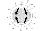
図10は、針スライダ23を操作部8の先端側へ前進させた際の対象組織Tを示す図である。第一刃面33の法線ベクトル33nおよび第二刃面34の法線ベクトル34nは、第一針先31aにおいて、管状部の30の円周方向Cと比較して、中心軸Oに近づく方向を向いている。また、第三刃面35の法線ベクトル35nおよび第四刃面36の法線ベクトル36nは、第二針先32aにおいて、管状部の30の円周方向Cと比較して、中心軸Oに近づく方向を向いている。そのため、針管3は切り取った対象組織Tを針管3の内部に好適に移動させることができる。
FIG. 10 is a diagram showing the target tissue T when the needle slider 23 is advanced toward the distal end side of the operating section 8. As shown in FIG. A normal vector 33n of the first blade surface 33 and a normal vector 34n of the second blade surface 34 are in a direction closer to the central axis O in the first needle tip 31a compared to the circumferential direction C of the tubular portion 30. facing. Further, the normal vector 35n of the third blade surface 35 and the normal vector 36n of the fourth blade surface 36 are more aligned with the central axis O than with the circumferential direction C of the tubular portion 30 at the second needle tip 32a. It's facing the direction you're approaching. Therefore, the needle tube 3 can suitably move the cut target tissue T into the interior of the needle tube 3.
術者が針スライダ23を操作部8の先端側へさらに前進させると、対象組織Tは、第一外エッジ33b、第二外エッジ34b、第三外エッジ35b、第四外エッジ36bにより切り取られる。先端領域Z1において、第一外エッジ33b、第二外エッジ34b、第三外エッジ35b、第四外エッジ36bは鋭角であり、好適に対象組織Tを切り取ることができる。
When the operator further advances the needle slider 23 toward the distal end of the operating section 8, the target tissue T is cut by the first outer edge 33b, the second outer edge 34b, the third outer edge 35b, and the fourth outer edge 36b. . In the tip region Z1, the first outer edge 33b, the second outer edge 34b, the third outer edge 35b, and the fourth outer edge 36b are acute angles, and the target tissue T can be cut out suitably.
針管3への組織の吸引を行うために、術者は、挿入体2および操作部8からスタイレット27を引き抜く。これにより、針管3の先端から針スライダ23の基端まで延びる貫通孔が生じる。術者は、針スライダ23の基端に配されたポートにシリンジ等を接続して針管3内を吸引し、対象組織Tの細胞などを針管3の先端から吸引して採取する。
In order to suction tissue into the needle tube 3, the operator pulls out the stylet 27 from the inserter 2 and the operating section 8. This creates a through hole that extends from the distal end of the needle tube 3 to the proximal end of the needle slider 23. The operator connects a syringe or the like to a port disposed at the proximal end of the needle slider 23 to aspirate the inside of the needle tube 3, and aspirates and collects cells of the target tissue T from the tip of the needle tube 3.
必要量の細胞などが採取できたら、針スライダ23を操作部8の基端側に後退させることによって針管3を組織から抜くと共に、針管3の先端をシース7内に収容する。針管3が組織から抜けたら、超音波内視鏡100の操作部109の基端口金107bから取付アダプタ18をはずし、穿刺針1をチャンネル107から抜去する。最後に超音波内視鏡100を患者から抜去して一連の処置を終了する。
Once the necessary amount of cells and the like have been collected, the needle slider 23 is moved back toward the proximal end of the operating section 8 to remove the needle tube 3 from the tissue, and the distal end of the needle tube 3 is housed in the sheath 7. Once the needle tube 3 has been removed from the tissue, the attachment adapter 18 is removed from the proximal mouthpiece 107b of the operating section 109 of the ultrasound endoscope 100, and the puncture needle 1 is removed from the channel 107. Finally, the ultrasound endoscope 100 is removed from the patient to complete the series of treatments.
本実施形態に係る穿刺針1を備えた生検システム150によれば、体組織への穿刺性が高く(体組織内で穿刺針1が切り込み易く)、切り取った体組織(診断に必要な検体)を穿刺針1の内部に回収しやすい。先端領域Z1における第一刃面33の法線ベクトル33nおよび第二刃面34の法線ベクトル34nは、第一針先31aと第二針先32aとを通る直線Vに直交する方向よりも、先端領域Z1における第三刃面35および第四刃面36側にそれぞれ向いている。また、同正面視において、先端領域Z1における第三刃面35の法線ベクトル35nおよび第四刃面36の法線ベクトル36nは、第一針先31aと第二針先32aとを通る直線Vに直交する方向よりも、先端領域Z1における第一刃面33および第二刃面34側に向いている。そのため、穿刺針1は対象組織Tを針管3の内部に好適に移動させることができる。
According to the biopsy system 150 equipped with the puncture needle 1 according to the present embodiment, the ability to puncture the body tissue is high (the puncture needle 1 easily cuts into the body tissue), and the biopsy system 150 has a high ability to puncture the body tissue (the puncture needle 1 can easily cut into the body tissue), ) can be easily collected inside the puncture needle 1. The normal vector 33n of the first blade surface 33 and the normal vector 34n of the second blade surface 34 in the tip region Z1 are more than the direction perpendicular to the straight line V passing through the first needle tip 31a and the second needle tip 32a. They are respectively facing the third blade surface 35 and fourth blade surface 36 sides in the tip region Z1. In addition, in the same front view, the normal vector 35n of the third blade surface 35 and the normal vector 36n of the fourth blade surface 36 in the tip region Z1 are a straight line V passing through the first needle tip 31a and the second needle tip 32a. It faces toward the first blade surface 33 and second blade surface 34 side in the tip region Z1 rather than the direction perpendicular to . Therefore, the puncture needle 1 can suitably move the target tissue T into the inside of the needle tube 3.
また、穿刺針1は、先端領域Z1において、第一外エッジ33b、第二外エッジ34b、第三外エッジ35b、第四外エッジ36bが鋭角であり、術者が針スライダ23を操作部8の先端側へさらに前進させると、好適に対象組織Tを切り取ることができる。
Further, in the puncture needle 1, the first outer edge 33b, the second outer edge 34b, the third outer edge 35b, and the fourth outer edge 36b are acute angles in the tip region Z1, and the operator moves the needle slider 23 to the operation section 8. By further advancing toward the distal end side, the target tissue T can be suitably cut out.
以上、本発明の第一実施形態について図面を参照して詳述したが、具体的な構成はこの実施形態に限られるものではなく、本発明の要旨を逸脱しない範囲の設計変更等も含まれる。また、上述の実施形態および変形例において示す構成要素は適宜に組み合わせて構成することが可能である。
Although the first embodiment of the present invention has been described above in detail with reference to the drawings, the specific configuration is not limited to this embodiment, and design changes may be made within the scope of the gist of the present invention. . Moreover, the components shown in the above-described embodiments and modified examples can be configured by appropriately combining them.
(変形例1)
上記実施形態において、第一針先部31の外周面31eおよび第二針先部32の外周面32eは加工がなされていなかったが、第一針先部および第二針先部の態様はこれに限定されない。
図11に示す針管3の変形例である針管3Cは、第一針先部31および第二針先部32の外周面にバックカット加工Bが施されている。第一針先部31および第二針先部32は、体組織への刺入性がより高い。つまり、針先31a、32aは、体組織表面へ刺さり易い。また、針管3Cはシース7の内面に針先31a、32aが触れにくく、操作性が高い。
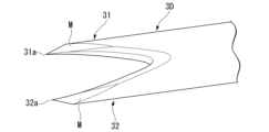
図12に示す針管3の変形例である針管3Dは、先端領域Z1の外周面の少なくとも一部に、内周面(31i、32i)を軸中心とした円錐カットにより形成されるカット面Mが施されている。第一針先部31および第二針先部32は、体組織への刺入性がより高い。つまり、針先31a、32aは、体組織表面へ刺さり易い。また、針管3Dはシース7の内面に針先31a、32aが触れにくく、操作性が高い。
(Modification 1)
In the embodiment described above, the outer circumferential surface 31e of the first needle tip 31 and the outer circumferential surface 32e of the second needle tip 32 were not processed, but this is the aspect of the first needle tip and the second needle tip. but not limited to.
A needle tube 3C, which is a modified example of the needle tube 3 shown in FIG. 11, has backcut processing B applied to the outer peripheral surfaces of the first needle tip portion 31 and the second needle tip portion 32. The first needle tip portion 31 and the second needle tip portion 32 have a higher ability to penetrate body tissue. In other words, the needle tips 31a and 32a easily penetrate into the surface of the body tissue. In addition, the needle tips 31a and 32a of the needle tube 3C are difficult to touch the inner surface of the sheath 7, resulting in high operability.
A needle tube 3D, which is a modified example of the needle tube 3 shown in FIG. 12, has a cut surface M formed by a conical cut centering on the inner circumferential surface (31i, 32i) on at least a part of the outer circumferential surface of the distal end region Z1. It has been subjected. The first needle tip portion 31 and the second needle tip portion 32 have a higher ability to penetrate body tissue. In other words, the needle tips 31a and 32a easily penetrate into the surface of the body tissue. Further, the needle tips 31a and 32a of the needle tube 3D are difficult to touch the inner surface of the sheath 7, and the operability is high.
(第二実施形態)
本発明の第二実施形態に係る内視鏡用穿刺針1Bを備えた生検システム150Bについて、図13から図17を参照して説明する。以降の説明において、既に説明したものと共通する構成については、同一の符号を付して重複する説明を省略する。
(Second embodiment)
A biopsy system 150B including an endoscopic puncture needle 1B according to a second embodiment of the present invention will be described with reference to FIGS. 13 to 17. In the following description, components that are common to those already described will be given the same reference numerals and redundant description will be omitted.
[生検システム150B]
生検システム150Bは、生検の際に体内の組織を採取するために使用される医療機器である。生検システム150Bは、超音波内視鏡100と、内視鏡用穿刺針1B(以下、単に「穿刺針1B」と称する。)とを備える。穿刺針1Bは、挿入体2Bと、操作部8と、スタイレット27とを備える。
[Biopsy system 150B]
The biopsy system 150B is a medical device used to collect tissue within the body during a biopsy. The biopsy system 150B includes an ultrasound endoscope 100 and an endoscopic puncture needle 1B (hereinafter simply referred to as "puncture needle 1B"). Puncture needle 1B includes an inserter 2B, an operating section 8, and a stylet 27.
[挿入体2B]
挿入体2Bは、超音波内視鏡100のチャンネル107に挿通可能な細長い部材である。挿入体2Bは、針管3Bと、シース7とを備える。
[Insert body 2B]
The insert body 2B is an elongated member that can be inserted into the channel 107 of the ultrasound endoscope 100. The insert body 2B includes a needle tube 3B and a sheath 7.
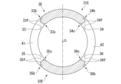
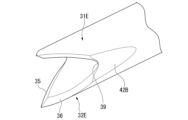
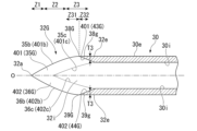
図13は、針管3Bの斜視図である。図14は、針管3Bの側面図である。図15は、針管3Bを軸方向Aの先端から見た正面図であり、長手軸方向において等間隔に断面を配列し、各刃面の断面の向きの変化を模式的に示した図である。図15に示す一点破線は、軸方向Aに等間隔に配列する軸方向Aと垂直な断面と、第一刃面33B、第二刃面34B、第三刃面35Bおよび第四刃面36Bとの交線を表している。図16は、図14に示すX-X断面における針管3Bの断面図である。図17は、図14に示すY-Y断面における針管3Bの断面図である。
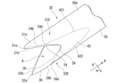
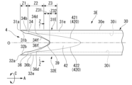
FIG. 13 is a perspective view of the needle tube 3B. FIG. 14 is a side view of the needle tube 3B. FIG. 15 is a front view of the needle tube 3B viewed from the tip in the axial direction A, and is a diagram schematically showing changes in the orientation of the cross sections of each blade surface with cross sections arranged at equal intervals in the longitudinal axis direction. . The dotted lines shown in FIG. 15 indicate cross sections perpendicular to the axial direction A arranged at equal intervals in the axial direction A, the first blade surface 33B, the second blade surface 34B, the third blade surface 35B, and the fourth blade surface 36B. represents the intersection line of FIG. 16 is a cross-sectional view of the needle tube 3B taken along the line XX shown in FIG. FIG. 17 is a sectional view of the needle tube 3B taken along the YY cross section shown in FIG.
針管3Bは、図13に示すように、管状の管状部30と、管状部30の先端に設けられた第一針先部31Bおよび第二針先部32Bと、を備える。針管3Bは、操作部8によりシース7内で進退操作可能である。針管3Bの先端には、第一針先部31Bおよび第二針先部32Bに穿刺された組織を、針管3Bの内部へ入り込む入口となる開口4Bが形成されている。針管3Bの第一針先部31Bおよび第二針先部32Bは、シース7の先端部分の開口から突没可能である。
As shown in FIG. 13, the needle tube 3B includes a tubular portion 30, and a first needle tip portion 31B and a second needle tip portion 32B provided at the tip of the tubular portion 30. The needle tube 3B can be moved forward and backward within the sheath 7 by the operating section 8. An opening 4B is formed at the tip of the needle tube 3B, which serves as an entrance through which the tissue punctured by the first needle tip 31B and the second needle tip 32B enters into the interior of the needle tube 3B. The first needle tip portion 31B and the second needle tip portion 32B of the needle tube 3B can protrude and retract from the opening of the distal end portion of the sheath 7.
第一針先部31Bは、図13および図15に示すように、第一刃面33Bと第二刃面34Bとを有し、第一刃面33Bと第二刃面34Bは、鋭利な第一針先31aに向かって延びている。針管3B(管状部30)の軸方向Aに沿う方向から見た正面視において、第一刃面33Bと第二刃面34Bとは、図15に示すように、第一針先31aと第二針先32aとを通る直線Vに対して対称な形状である。なお、第一刃面33Bおよび第二刃面34Bは平面であっても良いし、僅かに曲面に加工されていてもよい。
As shown in FIGS. 13 and 15, the first needle tip portion 31B has a first blade surface 33B and a second blade surface 34B. It extends toward the one stitch point 31a. In a front view seen from the direction along the axial direction A of the needle tube 3B (tubular portion 30), the first blade surface 33B and the second blade surface 34B are the first needle tip 31a and the second blade surface 34B, as shown in FIG. The shape is symmetrical with respect to the straight line V passing through the needle tip 32a. Note that the first blade surface 33B and the second blade surface 34B may be flat or may be processed into slightly curved surfaces.
第一針先部31Bの外周面31eは、管状部30の外周面30eと連続する曲面であり、同一の径寸法と曲率を有する。また、第一針先部31Bの内周面31iは、管状部30の内周面30iと連続する曲面であり、同一の径寸法と曲率を有する。第一針先部31Bは、例えば、管状部30の一部を切り落として第一刃面33Bと第二刃面34Bを形成する。
The outer circumferential surface 31e of the first needle tip portion 31B is a curved surface that is continuous with the outer circumferential surface 30e of the tubular portion 30, and has the same diameter and curvature. Further, the inner circumferential surface 31i of the first needle tip portion 31B is a curved surface that is continuous with the inner circumferential surface 30i of the tubular portion 30, and has the same diameter size and curvature. The first needle tip portion 31B forms a first blade surface 33B and a second blade surface 34B by cutting off a part of the tubular portion 30, for example.
第二針先部32Bは、図13に示すように、第三刃面35Bと第四刃面36Bとを有し、第三刃面35Bと第四刃面36Bは、鋭利な第二針先32aに向かって延びている。第一針先31aと第二針先32aとは、針管3Bの軸方向Aに延びる中心軸Oに対して対称な位置に配置されている。針管3Bの軸方向Aに沿う方向から見た正面視において、第三刃面35Bと第四刃面36Bとは、図15に示すように、第一針先31aと第二針先32aとを通る直線Vに対して対称な形状である。なお、第三刃面35Bおよび第四刃面36Bは平面であっても良いし、僅かに曲面に加工されていてもよい。
The second needle tip portion 32B has a third blade surface 35B and a fourth blade surface 36B, as shown in FIG. 32a. The first needle tip 31a and the second needle tip 32a are arranged at symmetrical positions with respect to the central axis O extending in the axial direction A of the needle tube 3B. In a front view seen from the direction along the axial direction A of the needle tube 3B, the third blade surface 35B and the fourth blade surface 36B are similar to the first needle tip 31a and the second needle tip 32a, as shown in FIG. It has a symmetrical shape with respect to the straight line V passing through it. Note that the third blade surface 35B and the fourth blade surface 36B may be flat or may be processed into slightly curved surfaces.
第二針先部32Bの外周面32eは、管状部30の外周面30eと連続する曲面であり、同一の径寸法と曲率である。また、第二針先部32Bの内周面32iは、管状部30の内周面30iと連続する曲面であり、同一の径寸法と曲率である。第二針先部32Bは、例えば、管状部30の一部を切り落として第三刃面35Bと第四刃面36Bを形成する。
The outer circumferential surface 32e of the second needle tip portion 32B is a curved surface continuous with the outer circumferential surface 30e of the tubular portion 30, and has the same diameter and curvature. Moreover, the inner circumferential surface 32i of the second needle tip portion 32B is a curved surface that is continuous with the inner circumferential surface 30i of the tubular portion 30, and has the same diameter and curvature. The second needle tip portion 32B forms a third blade surface 35B and a fourth blade surface 36B by cutting off a part of the tubular portion 30, for example.
第一針先部31Bと第二針先部32Bとは、図13から図15に示すように、第一刃面33Bと第二刃面34Bと第三刃面35Bと第四刃面36Bとに囲まれた開口4Bを形成する。開口4Bは、管状の管状部30の内部空間に連通する。
The first needle tip portion 31B and the second needle tip portion 32B are, as shown in FIGS. 13 to 15, a first blade surface 33B, a second blade surface 34B, a third blade surface 35B, and a fourth blade surface 36B. An opening 4B surrounded by is formed. The opening 4B communicates with the internal space of the tubular portion 30.
図13から図15に示すように、第一刃面33Bと第三刃面35Bとは、開口4Bの第一基端38Bで連なる。第二刃面34Bと第四刃面36Bとは、開口4Bの第二基端39Bで連なる。
As shown in FIGS. 13 to 15, the first blade surface 33B and the third blade surface 35B are continuous at the first base end 38B of the opening 4B. The second blade surface 34B and the fourth blade surface 36B are continuous at the second base end 39B of the opening 4B.
第一針先部31Bと第二針先部32Bにおいて、図14に示すように、第一針先31aおよび第二針先32aを含む先端領域Z1と、第一基端38Bおよび第二基端39Bを含む基端領域Z3と、先端領域Z1と基端領域Z3の間に位置し、先端領域Z1と基端領域Z3に連なる中間領域Z2と、を定義する。
In the first needle tip part 31B and the second needle tip part 32B, as shown in FIG. 39B, and an intermediate region Z2 located between the distal region Z1 and the proximal region Z3 and connected to the distal region Z1 and the proximal region Z3.
(第一針先部31Bの第一刃面33Bおよび第二刃面34B)
第一刃面33Bは、図13および図16に示すように、第一針先部31Bの内周面31iとの交線(第一内側交線33Bc)が開口4Bの輪郭の一部を規定する。第二刃面34Bは、第一針先部31Bの内周面31iとの交線(第二内側交線34Bc)が開口4Bの輪郭の一部を規定する。
(First blade surface 33B and second blade surface 34B of first needle tip 31B)
As shown in FIGS. 13 and 16, the first blade surface 33B has an intersection line (first inner intersection line 33Bc) with the inner circumferential surface 31i of the first needle tip 31B that defines a part of the outline of the opening 4B. do. The second blade surface 34B has an intersection line (second inner intersection line 34Bc) with the inner circumferential surface 31i of the first needle tip portion 31B that defines a part of the outline of the opening 4B.
図16に示すように、針管3Bの軸方向Aに沿う方向から見た正面視において、先端領域Z1における第一刃面33Bの法線ベクトル33Bnは、第一針先31aと第二針先32aとを通る直線Vに直交する方向よりも、先端領域Z1における第三刃面35B側に向いている。同様に、同正面視において、先端領域Z1における第二刃面34Bの法線ベクトル34Bnは、第一針先31aと第二針先32aとを通る直線Vに直交する方向よりも、先端領域Z1における第四刃面36B側に向いている。
As shown in FIG. 16, in a front view seen from the direction along the axial direction A of the needle tube 3B, the normal vector 33Bn of the first blade surface 33B in the tip region Z1 is the first needle tip 31a and the second needle tip 32a. It faces toward the third blade surface 35B side in the tip region Z1 rather than the direction perpendicular to the straight line V passing through. Similarly, in the front view, the normal vector 34Bn of the second blade surface 34B in the tip region Z1 is larger than the direction perpendicular to the straight line V passing through the first needle tip 31a and the second needle tip 32a. It faces the fourth blade surface 36B side.
さらに、図17に示すように、中間領域Z2における第一刃面33Bの法線ベクトル33Bnも、先端領域Z1と同様に、直線Vに直交する方向よりも、中間領域Z2における第三刃面35B側に向いている。さらに、中間領域Z2における第二刃面34Bの法線ベクトル34Bnも、先端領域Z1と同様に、直線Vに直交する方向よりも、中間領域Z2における第四刃面36B側に向いている。
Furthermore, as shown in FIG. 17, the normal vector 33Bn of the first blade surface 33B in the intermediate region Z2 is also larger than the direction perpendicular to the straight line V, similarly to the tip region Z1. facing to the side. Furthermore, the normal vector 34Bn of the second blade surface 34B in the intermediate region Z2 is also oriented toward the fourth blade surface 36B in the intermediate region Z2, rather than the direction perpendicular to the straight line V, similarly to the tip region Z1.
好ましくは、中間領域Z2における第一刃面33Bの法線ベクトル33Bnは、図17に示すように第一針先31aおよび第二針先32aを結ぶ直線Vに対して鋭角になる方向を向く。また、中間領域Z2における第二刃面34Bの法線ベクトル34Bnは、第一針先31aおよび第二針先32aを結ぶ直線Vに対して鋭角になる方向を向く。
Preferably, the normal vector 33Bn of the first blade surface 33B in the intermediate region Z2 is oriented at an acute angle with respect to the straight line V connecting the first needle tip 31a and the second needle tip 32a, as shown in FIG. In addition, the normal vector 34Bn of the second blade surface 34B in the intermediate region Z2 is oriented at an acute angle with respect to the straight line V connecting the first needle tip 31a and the second needle tip 32a.
好ましくは、第一刃面33Bの法線ベクトル33Bnは、図15および図16に示すように、先端領域Z1において、管状部30の円周方向Cと比較して、中心軸Oに近づく方向を向いている。
Preferably, the normal vector 33Bn of the first blade surface 33B points in a direction approaching the central axis O compared to the circumferential direction C of the tubular portion 30 in the tip region Z1, as shown in FIGS. 15 and 16. It's suitable.
図14に示すように、第一刃面33Bと第二刃面34Bとの交線(第一先端交線31b)は、第一針先部31Bの内周面31iの先端から第一針先31aまで延びている。なお、第一先端交線31bは、針管3Bの軸方向Aに沿う方向から見た正面視において直線V上に位置している。
As shown in FIG. 14, the intersection line between the first blade surface 33B and the second blade surface 34B (first tip intersection line 31b) is from the tip of the inner peripheral surface 31i of the first needle tip portion 31B to the first needle tip. It extends to 31a. Note that the first tip intersection line 31b is located on the straight line V when viewed from the front in the direction along the axial direction A of the needle tube 3B.
第一刃面33Bは、先端領域Z1においては、先端側に第一切刃面33Cをさらに有している。第一切刃面33Cの法線ベクトルは、直線Vに対して鋭角になる方向を向いており、第一刃面33Bの法線ベクトル33Bnは、第一切刃面33Cの法線ベクトルよりも直線Vに対する角度が小さい鋭角をなす方向に向いている。図13から図16に示すように、第一刃面33Bと第一切刃面33Cとが交差する稜線は、第一先端交線31bから中間領域Z2に向かって延びている。
The first cutting surface 33B further has a first cutting surface 33C on the tip side in the tip region Z1. The normal vector of the first cutting surface 33C is oriented at an acute angle with respect to the straight line V, and the normal vector 33Bn of the first cutting surface 33B is smaller than the normal vector of the first cutting surface 33C. It faces in a direction that forms a small acute angle with respect to straight line V. As shown in FIGS. 13 to 16, the ridgeline where the first cutting surface 33B and the first cutting surface 33C intersect extends from the first tip intersection line 31b toward the intermediate region Z2.
第二刃面34Bは、先端領域Z1においては、先端側に第二切刃面34Cをさらに有している。第二切刃面34Cの法線ベクトルは、直線Vに対して鋭角になる方向を向いており、第二刃面34Bの法線ベクトル34Bnは、第二切刃面34Cの法線ベクトルよりも直線Vに対する角度が小さい鋭角をなす方向に向いている。図13から図16に示すように、第二刃面34Bと第二切刃面34Cとが交差する稜線は、第一先端交線31bから中間領域Z2に向かって延びている。
In the tip region Z1, the second blade surface 34B further has a second cutting edge surface 34C on the tip side. The normal vector of the second cutting edge surface 34C is oriented at an acute angle with respect to the straight line V, and the normal vector 34Bn of the second cutting edge surface 34B is smaller than the normal vector of the second cutting edge surface 34C. It faces in a direction that forms a small acute angle with respect to straight line V. As shown in FIGS. 13 to 16, the ridgeline where the second cutting surface 34B and the second cutting surface 34C intersect extends from the first tip intersection line 31b toward the intermediate region Z2.
第一刃面33Bと外周面31eとが交差する交線(第一外側交線33Bb)は、管状部30の円周方向にエッジを有する第一外エッジ33Bbである。図16および図17に示すように、第一外エッジ33Bbにおける第一刃面33Bと外周面31eとのなす角度θ1は、針管3Bの軸方向Aに沿う方向から見た正面視において、先端領域Z1および中間領域Z2において鋭角をなす。
The intersection line (first outer intersection line 33Bb) where the first blade surface 33B and the outer circumferential surface 31e intersect is a first outer edge 33Bb having an edge in the circumferential direction of the tubular portion 30. As shown in FIGS. 16 and 17, the angle θ1 between the first blade surface 33B and the outer circumferential surface 31e at the first outer edge 33Bb is the tip area of the needle tube 3B when viewed from the front along the axial direction A. It forms an acute angle in Z1 and intermediate region Z2.
第一刃面33Bと内周面31iとが交差する交線(第一内側交線33Bc)は、管状部30の円周方向にエッジを有する第一内エッジ33Bcである。図16および図17に示すように、第一内エッジ33Bcにおける第一刃面33Bと内周面31iとのなす角度θ2は、先端領域Z1および中間領域Z2において鈍角をなす。
The intersection line (first inner intersection line 33Bc) where the first blade surface 33B and the inner circumferential surface 31i intersect is a first inner edge 33Bc having an edge in the circumferential direction of the tubular portion 30. As shown in FIGS. 16 and 17, the angle θ2 between the first blade surface 33B and the inner peripheral surface 31i at the first inner edge 33Bc is an obtuse angle in the tip region Z1 and the intermediate region Z2.
第二刃面34Bと外周面31eとが交差する交線(第二外側交線34Bb)は、管状部30の円周方向にエッジを有する第二外エッジ34Bbである。図16および図17に示すように、第二外エッジ34Bbにおける第二刃面34Bと外周面31eとのなす角度θ3は、先端領域Z1および中間領域Z2において鋭角をなす。
The intersection line (second outer intersection line 34Bb) where the second blade surface 34B and the outer peripheral surface 31e intersect is a second outer edge 34Bb having an edge in the circumferential direction of the tubular portion 30. As shown in FIGS. 16 and 17, the angle θ3 between the second blade surface 34B and the outer peripheral surface 31e at the second outer edge 34Bb is an acute angle in the tip region Z1 and the intermediate region Z2.
第二刃面34Bと内周面31iとが交差する交線(第二内側交線34Bc)は、管状部30の円周方向にエッジを有する第二内エッジ34Bcである。図16および図17に示すように、第二内エッジ34Bcにおける第二刃面34Bと内周面31iとのなす角度θ4は、先端領域Z1および中間領域Z2において鈍角をなす。
The intersection line (second inner intersection line 34Bc) where the second blade surface 34B and the inner circumferential surface 31i intersect is a second inner edge 34Bc having an edge in the circumferential direction of the tubular portion 30. As shown in FIGS. 16 and 17, the angle θ4 between the second blade surface 34B and the inner circumferential surface 31i at the second inner edge 34Bc is an obtuse angle in the tip region Z1 and the intermediate region Z2.
(第二針先部32Bの第三刃面35Bおよび第四刃面36B)
第三刃面35Bは、図13および図16に示すように、第二針先部32Bの内周面32iとの交線(第三内側交線35Bc)が開口4Bの輪郭の一部を規定する。第四刃面36Bは、第二針先部32Bの内周面31iとの交線(第四内側交線36Bc)が開口4Bの輪郭の一部を規定する。
(Third blade surface 35B and fourth blade surface 36B of second needle tip portion 32B)
As shown in FIGS. 13 and 16, the third blade surface 35B has an intersection line (third inner intersection line 35Bc) with the inner peripheral surface 32i of the second needle tip 32B that defines a part of the outline of the opening 4B. do. The intersection line (fourth inner intersection line 36Bc) of the fourth blade surface 36B with the inner circumferential surface 31i of the second needle tip portion 32B defines a part of the outline of the opening 4B.
針管3Bの軸方向Aに沿う方向から見た正面視において、先端領域Z1における第三刃面35Bの法線ベクトル35Bnは、第一針先31aと第二針先32aとを通る直線Vに直交する方向よりも、先端領域Z1における第一刃面33B側に向いている。同様に、同正面視において、先端領域Z1における第四刃面36Bの法線ベクトル36Bnは、第一針先31aと第二針先32aとを通る直線Vに直交する方向よりも、先端領域Z1における第二刃面34B側に向いている。
In a front view seen from the direction along the axial direction A of the needle tube 3B, the normal vector 35Bn of the third blade surface 35B in the tip region Z1 is perpendicular to the straight line V passing through the first needle tip 31a and the second needle tip 32a. It faces toward the first blade surface 33B side in the tip region Z1 rather than the direction in which Similarly, in the front view, the normal vector 36Bn of the fourth blade surface 36B in the tip region Z1 is larger than the direction perpendicular to the straight line V passing through the first needle tip 31a and the second needle tip 32a. It faces the second blade surface 34B side.
さらに、中間領域Z2における第三刃面35Bの法線ベクトル35Bnも、先端領域Z1と同様に、直線Vに直交する方向よりも、中間領域Z2における第一刃面33B側に向いている。さらに、中間領域Z2における第四刃面36Bの法線ベクトル36Bnも、先端領域Z1と同様に、直線Vに直交する方向よりも、中間領域Z2における第二刃面34B側に向いている。
Furthermore, the normal vector 35Bn of the third blade surface 35B in the intermediate region Z2 is also oriented toward the first blade surface 33B in the intermediate region Z2, rather than the direction perpendicular to the straight line V, similarly to the tip region Z1. Furthermore, the normal vector 36Bn of the fourth blade surface 36B in the intermediate region Z2 is also oriented toward the second blade surface 34B in the intermediate region Z2, rather than the direction perpendicular to the straight line V, similarly to the tip region Z1.
好ましくは、中間領域Z2における第三刃面35Bの法線ベクトル35Bnは、図15から図17に示すように第一針先31aおよび第二針先32aを結ぶ直線Vに対して鋭角になる方向を向く。また、中間領域Z2における第四刃面36Bの法線ベクトル36Bnは、第一針先31aおよび第二針先32aを結ぶ直線Vに対して鋭角になる方向を向く。
Preferably, the normal vector 35Bn of the third blade surface 35B in the intermediate region Z2 is at an acute angle with respect to the straight line V connecting the first needle tip 31a and the second needle tip 32a, as shown in FIGS. 15 to 17. facing. Further, the normal vector 36Bn of the fourth blade surface 36B in the intermediate region Z2 is oriented at an acute angle with respect to the straight line V connecting the first needle tip 31a and the second needle tip 32a.
好ましくは、第三刃面35Bの法線ベクトル35Bnは、図15および図16に示すように、先端領域Z1において、管状部30の円周方向Cと比較して、中心軸Oに近づく方向を向いている。
Preferably, the normal vector 35Bn of the third blade surface 35B points in a direction approaching the central axis O compared to the circumferential direction C of the tubular portion 30 in the tip region Z1, as shown in FIGS. 15 and 16. It's suitable.
図14に示すように、第三刃面35Bと第四刃面36Bとの交線(第二先端交線32b)は、第二針先部32Bの内周面32iの先端から第二針先32aまで延びている。なお、第二先端交線32bは、針管3Bの軸線に沿う方向から見た正面視において直線V上に位置している。
As shown in FIG. 14, the intersection line (second tip intersection line 32b) between the third blade surface 35B and the fourth blade surface 36B is from the tip of the inner circumferential surface 32i of the second needle tip portion 32B to the second needle tip. It extends to 32a. Note that the second tip intersection line 32b is located on the straight line V when viewed from the front in a direction along the axis of the needle tube 3B.
第三刃面35Bは、先端領域Z1においては、先端側に第三切刃面35Cをさらに有している。第三切刃面35Cの法線ベクトルは、直線Vに対して鋭角になる方向を向いており、第三刃面35Bの法線ベクトル35Bnは、第三切刃面35Cの法線ベクトルよりも直線Vに対する角度が小さい鋭角をなす方向に向いている。図13から図16に示すように、第三刃面35Bと第三切刃面35Cとが交差する稜線は、第二先端交線32bから中間領域Z2に向かって延びている。
The third blade surface 35B further has a third cutting surface 35C on the tip side in the tip region Z1. The normal vector of the third cutting edge surface 35C is oriented at an acute angle with respect to the straight line V, and the normal vector 35Bn of the third cutting edge surface 35B is smaller than the normal vector of the third cutting edge surface 35C. It faces in a direction that forms a small acute angle with respect to straight line V. As shown in FIGS. 13 to 16, the ridgeline where the third cutting surface 35B and the third cutting surface 35C intersect extends from the second tip intersection line 32b toward the intermediate region Z2.
第四刃面36Bは、先端領域Z1においては、先端側に第四切刃面36Cをさらに有している。第四切刃面36Cの法線ベクトルは、直線Vに対して鋭角になる方向を向いており、第四刃面36Bの法線ベクトル36Bnは、第四切刃面36Cの法線ベクトルよりも直線Vに対する角度が小さい鋭角をなす方向に向いている。図13から図16に示すように、第四刃面36Bと第四切刃面36Cとが交差する稜線は、第二先端交線32bから中間領域Z2に向かって延びている。
The fourth cutting surface 36B further has a fourth cutting surface 36C on the distal end side in the distal end region Z1. The normal vector of the fourth cutting edge surface 36C is oriented at an acute angle with respect to the straight line V, and the normal vector 36Bn of the fourth cutting edge surface 36B is smaller than the normal vector of the fourth cutting edge surface 36C. It faces in a direction that forms a small acute angle with respect to straight line V. As shown in FIGS. 13 to 16, the ridgeline where the fourth cutting surface 36B and the fourth cutting surface 36C intersect extends from the second tip intersection line 32b toward the intermediate region Z2.
第三刃面35Bと外周面32eとが交差する交線(第三外側交線35Bb)は、管状部30の円周方向にエッジを有する第三外エッジ35Bbである。図16および図17に示すように、第三外エッジ35Bbにおける第三刃面35Bと外周面32eとのなす角度θ5は、先端領域Z1および中間領域Z2において鋭角をなす。
The intersection line (third outer intersection line 35Bb) where the third blade surface 35B and the outer circumferential surface 32e intersect is a third outer edge 35Bb having an edge in the circumferential direction of the tubular portion 30. As shown in FIGS. 16 and 17, the angle θ5 between the third blade surface 35B and the outer peripheral surface 32e at the third outer edge 35Bb is an acute angle in the tip region Z1 and the intermediate region Z2.
第三刃面35Bと内周面32iとが交差する交線(第三内側交線35Bc)は、管状部30の円周方向にエッジを有する第三内エッジ35Bcである。図16および図17に示すように、第三内エッジ35Bcにおける第三刃面35Bと内周面32iとのなす角度θ6は、先端領域Z1および中間領域Z2において鈍角をなす。
The intersection line (third inner intersection line 35Bc) where the third blade surface 35B and the inner circumferential surface 32i intersect is a third inner edge 35Bc having an edge in the circumferential direction of the tubular portion 30. As shown in FIGS. 16 and 17, the angle θ6 between the third blade surface 35B and the inner circumferential surface 32i at the third inner edge 35Bc is an obtuse angle in the tip region Z1 and the intermediate region Z2.
第四刃面36Bと外周面32eとが交差する交線(第四外側交線36Bb)は、管状部30の円周方向にエッジを有する第四外エッジ36Bbである。図16および図17に示すように、第四外エッジ36Bbにおける第四刃面36Bと外周面32eとのなす角度θ7は、先端領域Z1および中間領域Z2において鋭角をなす。
The intersection line (fourth outer intersection line 36Bb) where the fourth blade surface 36B and the outer circumferential surface 32e intersect is a fourth outer edge 36Bb having an edge in the circumferential direction of the tubular portion 30. As shown in FIGS. 16 and 17, the angle θ7 between the fourth blade surface 36B and the outer circumferential surface 32e at the fourth outer edge 36Bb is an acute angle in the tip region Z1 and the intermediate region Z2.
第四刃面36Bと内周面32iとが交差する交線(第四内側交線36Bc)は、管状部30の円周方向にエッジを有する第四内エッジ36Bcである。図16および図17に示すように、第四内エッジ36Bcにおける第四刃面36Bと内周面32iとのなす角度θ8は、先端領域Z1および中間領域Z2において鈍角をなす。
The intersection line (fourth inner intersection line 36Bc) where the fourth blade surface 36B and the inner circumferential surface 32i intersect is a fourth inner edge 36Bc having an edge in the circumferential direction of the tubular portion 30. As shown in FIGS. 16 and 17, the angle θ8 between the fourth blade surface 36B and the inner peripheral surface 32i at the fourth inner edge 36Bc is an obtuse angle in the tip region Z1 and the intermediate region Z2.
本実施形態に係る穿刺針1Bを備えた生検システム150Bによれば、体組織への穿刺性が高く(体組織内で穿刺針1Bが切り込み易く)、切り取った体組織(診断に必要な検体)を穿刺針1Bの内部に回収しやすい。先端領域Z1における第一刃面33Bの法線ベクトル33Bnおよび第二刃面34Bの法線ベクトル34Bnは、第一針先31aと第二針先32aとを通る直線Vに直交する方向よりも、先端領域Z1における第三刃面35Bおよび第四刃面36B側にそれぞれ向いている。また、同正面視において、先端領域Z1における第三刃面35Bの法線ベクトル35Bnおよび第四刃面36Bの法線ベクトル36Bnは、第一針先31aと第二針先32aとを通る直線Vに直交する方向よりも、先端領域Z1における第一刃面33Bおよび第二刃面34B側に向いている。そのため、穿刺針1Bは切り取った対象組織Tが針管3Bの内部に好適に移動させることができる。
According to the biopsy system 150B equipped with the puncture needle 1B according to the present embodiment, the ability to puncture the body tissue is high (the puncture needle 1B easily cuts into the body tissue), and the biopsy system 150B has a high puncturing ability to the body tissue (the puncture needle 1B easily cuts into the body tissue), ) can be easily collected inside the puncture needle 1B. The normal vector 33Bn of the first blade surface 33B and the normal vector 34Bn of the second blade surface 34B in the tip region Z1 are in a direction perpendicular to the straight line V passing through the first needle tip 31a and the second needle tip 32a. They are respectively facing the third blade surface 35B and fourth blade surface 36B sides in the tip region Z1. In addition, in the front view, the normal vector 35Bn of the third blade surface 35B and the normal vector 36Bn of the fourth blade surface 36B in the tip region Z1 are a straight line V passing through the first needle tip 31a and the second needle tip 32a. It faces toward the first blade surface 33B and second blade surface 34B side in the tip region Z1 rather than the direction perpendicular to . Therefore, the puncture needle 1B can suitably move the cut target tissue T into the needle tube 3B.
また、穿刺針1Bは、先端領域Z1および中間領域Z2における第一外エッジ33Bb、第二外エッジ34Bb、第三外エッジ35Bb、第四外エッジ36Bbは鋭角であり、術者が針スライダ23を操作部8の先端側へさらに前進させると、より多くの対象組織Tを切り取ることができる。
In addition, in the puncture needle 1B, the first outer edge 33Bb, the second outer edge 34Bb, the third outer edge 35Bb, and the fourth outer edge 36Bb in the tip region Z1 and the intermediate region Z2 are acute angles, and the operator can move the needle slider 23 If the operation section 8 is moved further toward the distal end side, more target tissue T can be cut out.
以上、本発明の第二実施形態について図面を参照して詳述したが、具体的な構成はこの実施形態に限られるものではなく、本発明の要旨を逸脱しない範囲の設計変更等も含まれる。また、上述の実施形態および変形例において示す構成要素は適宜に組み合わせて構成することが可能である。
Although the second embodiment of the present invention has been described above in detail with reference to the drawings, the specific configuration is not limited to this embodiment, and design changes may be made within the scope of the gist of the present invention. . Moreover, the components shown in the above-described embodiments and modified examples can be configured by appropriately combining them.
(第三実施形態)
本発明の第三実施形態に係る内視鏡用穿刺針1Eを備えた生検システム150Eについて、図18から図22を参照して説明する。以降の説明において、既に説明したものと共通する構成については、同一の符号を付して重複する説明を省略する。内視鏡用穿刺針1Eは、第一実施形態の内視鏡用穿刺針1と比較して、第五刃面41および第六刃面42をさらに有している。
(Third embodiment)
A biopsy system 150E including an endoscopic puncture needle 1E according to a third embodiment of the present invention will be described with reference to FIGS. 18 to 22. In the following description, components that are common to those already described will be given the same reference numerals and redundant description will be omitted. The endoscopic puncture needle 1E further includes a fifth blade surface 41 and a sixth blade surface 42, compared to the endoscopic puncture needle 1 of the first embodiment.
[生検システム150E]
生検システム150Eは、生検の際に体内の組織を採取するために使用される医療機器である。生検システム150Eは、超音波内視鏡100と、内視鏡用穿刺針1E(以下、単に「穿刺針1E」と称する。)とを備える。穿刺針1Eは、挿入体2Eと、操作部8と、スタイレット27とを備える。
[Biopsy system 150E]
The biopsy system 150E is a medical device used to collect tissue within the body during a biopsy. The biopsy system 150E includes an ultrasound endoscope 100 and an endoscopic puncture needle 1E (hereinafter simply referred to as "puncture needle 1E"). Puncture needle 1E includes an inserter 2E, an operating section 8, and a stylet 27.
[挿入体2E]
挿入体2Eは、超音波内視鏡100のチャンネル107に挿通可能な細長い部材である。挿入体2Eは、針管3Eと、シース7とを備える。
[Insert body 2E]
The inserter 2E is an elongated member that can be inserted into the channel 107 of the ultrasound endoscope 100. The insert body 2E includes a needle tube 3E and a sheath 7.
図18は、針管3Eの斜視図である。図19は、針管3Eの側面図である。図20は、図19と同じ方向から見た針管3Eの中心軸Oに沿う断面図である。図21は、針管3Eを軸方向Aの先端から見た正面図であり、長手軸方向において等間隔に断面を配列し、各刃面の断面の向きの変化を模式的に示した図である。図21に示す一点破線は、軸方向Aに等間隔に配列する軸方向Aと垂直な断面と、第一刃面33、第二刃面34、第三刃面35、第四刃面36、第五刃面41および第六刃面42との交線を表している。図22は、針管3Eの径方向Rであって直線Vに対して水平な方向から見た平面図である。図23は、図22と同じ方向から見た中心軸Oに沿う断面図である。図24は、図19に示すZ-Z断面における針管3Eの断面図である。
FIG. 18 is a perspective view of the needle tube 3E. FIG. 19 is a side view of the needle tube 3E. FIG. 20 is a sectional view taken along the central axis O of the needle tube 3E, viewed from the same direction as FIG. 19. FIG. 21 is a front view of the needle tube 3E viewed from the tip in the axial direction A, and is a diagram schematically showing changes in the orientation of the cross sections of each blade surface with cross sections arranged at equal intervals in the longitudinal axis direction. . The dotted lines shown in FIG. 21 represent cross sections perpendicular to the axial direction A arranged at equal intervals in the axial direction A, the first blade surface 33, the second blade surface 34, the third blade surface 35, the fourth blade surface 36, It represents the line of intersection with the fifth blade surface 41 and the sixth blade surface 42. FIG. 22 is a plan view of the needle tube 3E viewed in the radial direction R and in a direction parallel to the straight line V. FIG. 23 is a cross-sectional view along the central axis O seen from the same direction as FIG. 22. FIG. 24 is a sectional view of the needle tube 3E taken along the ZZ cross section shown in FIG. 19.
針管3Eは、図18に示すように、管状の管状部30と、管状部30の先端に設けられた第一針先部31Eおよび第二針先部32Eと、を備える。針管3Eは、操作部8によりシース7内で進退操作可能である。針管3Eの先端には、第一針先部31Eおよび第二針先部32Eに穿刺された組織を、針管3Eの内部へ入り込む入口となる開口4が形成されている。針管3Eの第一針先部31Eおよび第二針先部32Eは、シース7の先端部分の開口から突没可能である。
As shown in FIG. 18, the needle tube 3E includes a tubular portion 30, and a first needle tip portion 31E and a second needle tip portion 32E provided at the tip of the tubular portion 30. The needle tube 3E can be moved forward and backward within the sheath 7 by the operating section 8. An opening 4 is formed at the tip of the needle tube 3E, which serves as an entrance through which the tissue punctured by the first needle tip 31E and the second needle tip 32E enters the inside of the needle tube 3E. The first needle tip 31E and the second needle tip 32E of the needle tube 3E can protrude and retract from the opening of the distal end portion of the sheath 7.
第一針先部31Eは、図18から図22に示すように、第一刃面33と第二刃面34とを有し、第一刃面33と第二刃面34は、鋭利な第一針先31aに向かって延びている。
The first needle tip portion 31E has a first blade surface 33 and a second blade surface 34, as shown in FIGS. 18 to 22, and the first blade surface 33 and the second blade surface 34 are sharp It extends toward the one stitch point 31a.
第一針先部31Eの外周面31eは、管状部30の外周面30eと連続する曲面であり、同一の径寸法と曲率を有するまた、第一針先部31Eの内周面31iは、管状部30の内周面30iと連続する曲面であり、同一の径寸法と曲率を有する。第一針先部31Eは、例えば、管状部30の一部を切り落として第一刃面33と第二刃面34を形成する。
The outer circumferential surface 31e of the first needle tip 31E is a curved surface that is continuous with the outer circumferential surface 30e of the tubular portion 30, and has the same diameter and curvature. It is a curved surface that is continuous with the inner circumferential surface 30i of the portion 30, and has the same diameter and curvature. The first needle tip portion 31E forms a first blade surface 33 and a second blade surface 34 by cutting off a part of the tubular portion 30, for example.
第二針先部32Eは、図18から図21および図23に示すように、第三刃面35と第四刃面36とを有し、第三刃面35と第四刃面36は、鋭利な第二針先32aに向かって延びている。第一針先31aと第二針先32aとは、針管3Eの軸方向Aに延びる中心軸Oに対して対称な位置に配置されている。
The second needle tip portion 32E has a third blade surface 35 and a fourth blade surface 36, as shown in FIGS. 18 to 21 and 23, and the third blade surface 35 and the fourth blade surface 36 are It extends toward the sharp second needle tip 32a. The first needle tip 31a and the second needle tip 32a are arranged at symmetrical positions with respect to the central axis O extending in the axial direction A of the needle tube 3E.
第二針先部32Eの外周面32eは、管状部30の外周面30eと連続する曲面であり、同一の径寸法と曲率である。また、第二針先部32Eの内周面32iは、管状部30の内周面30iと連続する曲面であり、同一の径寸法と曲率である。第二針先部32Eは、例えば、管状部30の一部を切り落として第三刃面35と第四刃面36を形成する。
The outer circumferential surface 32e of the second needle tip portion 32E is a curved surface continuous with the outer circumferential surface 30e of the tubular portion 30, and has the same diameter and curvature. Further, the inner circumferential surface 32i of the second needle tip portion 32E is a curved surface that is continuous with the inner circumferential surface 30i of the tubular portion 30, and has the same diameter and curvature. The second needle tip portion 32E forms a third blade surface 35 and a fourth blade surface 36 by cutting off a portion of the tubular portion 30, for example.
第一針先部31Eと第二針先部32Eとは、図18から図23に示すように、第一刃面33と第二刃面34と第三刃面35と第四刃面36とに囲まれた開口4の縁を形成する。開口4は、管状の管状部30の内部空間に連通する。
As shown in FIGS. 18 to 23, the first needle tip portion 31E and the second needle tip portion 32E have a first blade surface 33, a second blade surface 34, a third blade surface 35, and a fourth blade surface 36. This forms the edge of the opening 4 surrounded by. The opening 4 communicates with the internal space of the tubular section 30 .
図18から図23に示すように、第一刃面33と第三刃面35とは、開口4の縁の第一基端38で連なる。第二刃面34と第四刃面36とは、開口4の縁の第二基端39で連なる。
As shown in FIGS. 18 to 23, the first blade surface 33 and the third blade surface 35 are continuous at the first base end 38 of the edge of the opening 4. As shown in FIGS. The second blade surface 34 and the fourth blade surface 36 are continuous at a second base end 39 of the edge of the opening 4.
第一針先部31Eと第二針先部32Eにおいて、図19に示すように、第一針先31aおよび第二針先32aを含む先端領域Z1と、第一基端38および第二基端39を含む基端領域Z3と、先端領域Z1と基端領域Z3の間に位置し、先端領域Z1と基端領域Z3に連なる中間領域Z2と、を定義する。また、基端領域Z3のうち、軸方向Aにおいて第一基端38および第二基端39よりも先端側を第一基端領域Z31と、第一基端38および第二基端39よりも基端側を第二基端領域Z32と、定義する。
In the first needle tip part 31E and the second needle tip part 32E, as shown in FIG. 39, and an intermediate region Z2 located between the distal region Z1 and the proximal region Z3 and connected to the distal region Z1 and the proximal region Z3. Further, in the proximal end region Z3, the distal end side of the first proximal end 38 and the second proximal end 39 in the axial direction A is called the first proximal end region Z31, and the distal end side of the proximal end region Z3 is disposed closer to the distal end side than the first proximal end 38 and second proximal end 39 in the axial direction A. The base end side is defined as a second base end region Z32.
第一針先部31Eと第二針先部32Eとは、第一針先部31Eの外周面31eおよび第二針先部32Eの外周面32eに、第五刃面41および第六刃面42を有している。
The first needle tip 31E and the second needle tip 32E have a fifth blade surface 41 and a sixth blade surface 42 on the outer circumferential surface 31e of the first needle tip 31E and the outer circumferential surface 32e of the second needle tip 32E. have.
(第五刃面41および第六刃面42)
第五刃面41は、第一針先部31Eの外周面31eおよび第二針先部32Eの外周面32eに形成された刃面である。第五刃面41は、図22および図23に示すように、中心軸Oに対して傾斜した傾斜面であり、針管3Eの基端側から第一針先31aおよび第二針先32aに向かうにつれて中心軸Oとの距離が漸次近づく。第五刃面41は、図21第一外側交線(第一外エッジ)33bとの交点である第一外側交点33d(図22参照)と、第三外側交線(第三外エッジ)35bとの交点である第三外側交点35d(図23参照)とを有する。図20および図22に示すように、第一外側交線33bは、第一刃面33と第一針先部31Eの外周面31eとが形成する交線である。図20および図23に示すように、第三外側交線35bは、第三刃面35と第二針先部32Eの外周面32eとが形成する交線である。第五刃面41と第一外側交線33bとは、第一外側交点33dで交差しており、第五刃面41と第三外側交線35bとは、第三外側交点35dで交差している。
(Fifth blade surface 41 and sixth blade surface 42)
The fifth blade surface 41 is a blade surface formed on the outer circumferential surface 31e of the first needle tip portion 31E and the outer circumferential surface 32e of the second needle tip portion 32E. As shown in FIGS. 22 and 23, the fifth blade surface 41 is an inclined surface inclined with respect to the central axis O, and extends from the proximal end side of the needle tube 3E toward the first needle tip 31a and the second needle tip 32a. The distance from the central axis O gradually approaches. The fifth blade surface 41 has a first outer intersection point 33d (see FIG. 22), which is an intersection point with the first outer intersection line (first outer edge) 33b in FIG. 21, and a third outer intersection line (third outer edge) 35b. and a third outer intersection point 35d (see FIG. 23). As shown in FIGS. 20 and 22, the first outer intersection line 33b is an intersection line formed by the first blade surface 33 and the outer peripheral surface 31e of the first needle tip portion 31E. As shown in FIGS. 20 and 23, the third outer intersection line 35b is an intersection line formed by the third blade surface 35 and the outer circumferential surface 32e of the second needle tip portion 32E. The fifth blade surface 41 and the first outer intersection line 33b intersect at the first outer intersection point 33d, and the fifth blade surface 41 and the third outer intersection line 35b intersect at the third outer intersection point 35d. There is.
図24に示すように、第五刃面41と第一刃面33とが交差する交線を、第一中間エッジ33fと定義する。第五刃面41と第三刃面35とが交差する交線を、第三中間エッジ35fと定義する。図20に示すように、第一中間エッジ33fと第三中間エッジ35fとは、第一基端38において連なっている。
As shown in FIG. 24, the line of intersection where the fifth blade surface 41 and the first blade surface 33 intersect is defined as a first intermediate edge 33f. The line of intersection where the fifth blade surface 41 and the third blade surface 35 intersect is defined as a third intermediate edge 35f. As shown in FIG. 20, the first intermediate edge 33f and the third intermediate edge 35f are continuous at the first base end 38.
図21から図23に示すように、第一基端領域Z31では、第五刃面41と第一針先部31Eの内周面31iとの厚みT1は、第一外側交点33dから第一基端38に向かうに従って薄くなる。また、第一基端領域Z31では、第五刃面41と第二針先部32Eの内周面32iとの厚みT1は、第三外側交点35dから第一基端38に向かうに従って薄くなる。
As shown in FIGS. 21 to 23, in the first base region Z31, the thickness T1 between the fifth blade surface 41 and the inner circumferential surface 31i of the first needle point 31E is from the first outer intersection point 33d to the first base end region Z31. It becomes thinner toward the end 38. Further, in the first base end region Z31, the thickness T1 between the fifth blade surface 41 and the inner circumferential surface 32i of the second needle tip portion 32E becomes thinner as it goes from the third outer intersection point 35d toward the first base end 38.
図21から図23に示すように、第二基端領域Z32では、第五刃面41と第一針先部31Eの内周面31iとの厚みT1は、第一基端38から針管3Eの基端側に向かうに従って厚くなる。また、同様に、第五刃面41と第二針先部32Eの内周面32iとの厚みT1は、第二基端領域Z32では、第一基端38から針管3Eの基端側に向かうに従って厚くなる。すなわち、第五刃面41と内周面31i、32iとの厚みT1は、第五刃面41の基端から第一基端38に向かうにつれて薄くなる。
As shown in FIGS. 21 to 23, in the second proximal end region Z32, the thickness T1 between the fifth blade surface 41 and the inner peripheral surface 31i of the first needle tip 31E is the same as the thickness T1 between the first proximal end 38 and the inner peripheral surface 31i of the needle tube 3E. It becomes thicker toward the proximal end. Similarly, the thickness T1 between the fifth blade surface 41 and the inner circumferential surface 32i of the second needle tip portion 32E is the same as the thickness T1 between the fifth blade surface 41 and the inner circumferential surface 32i of the second needle tip portion 32E from the first base end 38 toward the base end side of the needle tube 3E in the second base end region Z32. The thickness increases accordingly. That is, the thickness T1 of the fifth blade surface 41 and the inner circumferential surfaces 31i, 32i becomes thinner from the base end of the fifth blade surface 41 toward the first base end 38.
図20に示すように、中心軸Oおよび直線Vに対して直交する方向からの側面視において、第五刃面41の第一外側交点33dと第三外側交点35dとは、針管3Eの軸方向Aに延びる中心軸Oに対して対称な位置に形成されている。第一外側交点33dと第三外側交点35dとは、図22および図23に示すように、第五刃面41の先端に位置している。
As shown in FIG. 20, in a side view from a direction orthogonal to the central axis O and the straight line V, the first outer intersection point 33d and the third outer intersection point 35d of the fifth blade surface 41 are in the axial direction of the needle tube 3E. It is formed at a symmetrical position with respect to the central axis O extending in A. The first outer intersection point 33d and the third outer intersection point 35d are located at the tip of the fifth blade surface 41, as shown in FIGS. 22 and 23.
第五刃面41と第一針先部31Eの外周面31eとが形成する交線を第五交線410と定義する。図20に示すように、第五交線410のうち、第一外側交点33dと連なる第一部分411と第三外側交点35dと連なる第三部分412との間隔は、第五刃面41の先端から基端に向かうにつれて漸次狭まっている。
The intersection line formed by the fifth blade surface 41 and the outer circumferential surface 31e of the first needle tip portion 31E is defined as a fifth intersection line 410. As shown in FIG. 20, of the fifth intersection line 410, the distance between the first portion 411 connected to the first outer intersection point 33d and the third portion 412 connected to the third outer intersection point 35d is from the tip of the fifth blade surface 41. It gradually narrows towards the base.
図23に示すように、第二基端領域Z32において、第一基端38を先端とした第一基端エッジ38eが形成される。第一基端エッジ38eは、第五刃面41と内周面31i,32iとによって形成された鋭利な刃である。第一基端38における厚みT1を薄くすることにより針管3Eを体組織へ穿刺する際に第一基端38が組織から受ける抵抗力を低減させることができる。また、第一基端38において、第五刃面41と内周面31i,32iとがなす先端角度を小さくすることで第一基端エッジ38eを形成している。
As shown in FIG. 23, in the second base region Z32, a first base edge 38e having the first base end 38 as a tip is formed. The first proximal edge 38e is a sharp blade formed by the fifth blade surface 41 and the inner peripheral surfaces 31i and 32i. By reducing the thickness T1 at the first proximal end 38, it is possible to reduce the resistance force that the first proximal end 38 receives from the tissue when the needle tube 3E is inserted into the body tissue. Further, at the first base end 38, the first base edge 38e is formed by reducing the tip angle between the fifth blade surface 41 and the inner peripheral surfaces 31i, 32i.
第六刃面42は、第一針先部31Eの外周面31eおよび第二針先部32Eの外周面32eに形成された刃面である。第六刃面42は、図22および図23に示すように、中心軸Oに対して傾斜した傾斜面であり、針管3Eの基端側から第一針先31aおよび第二針先32aに向かうにつれて中心軸Oとの距離が漸次近づく。第六刃面42は、第二外側交線(第二外エッジ)34bとの交点である第二外側交点34d(図22参照)と、第四外側交線(第四外エッジ)36bとの交点である第四外側交点36d(図23参照)とを有する。図19および図22に示すように、第二外側交線34bは、第二刃面34と第一針先部31Eの外周面31eとが形成する交線である。図19および図23に示すように、第四外側交線36bは、第四刃面36と第二針先部32Eの外周面32eとが形成する交線である。第六刃面42と第二外側交線34bとは、第二外側交点34dで交差しており、第六刃面42と第四外側交線36bとは、第四外側交点36dで交差している。
The sixth blade surface 42 is a blade surface formed on the outer circumferential surface 31e of the first needle tip portion 31E and the outer circumferential surface 32e of the second needle tip portion 32E. As shown in FIGS. 22 and 23, the sixth blade surface 42 is an inclined surface inclined with respect to the central axis O, and extends from the proximal end side of the needle tube 3E toward the first needle tip 31a and the second needle tip 32a. The distance from the central axis O gradually approaches. The sixth blade surface 42 has a second outer intersection point 34d (see FIG. 22), which is an intersection point with the second outer intersection line (second outer edge) 34b, and a fourth outer intersection line (fourth outer edge) 36b. It has a fourth outer intersection point 36d (see FIG. 23) which is an intersection point. As shown in FIGS. 19 and 22, the second outer intersection line 34b is an intersection line formed by the second blade surface 34 and the outer peripheral surface 31e of the first needle tip 31E. As shown in FIGS. 19 and 23, the fourth outer intersection line 36b is an intersection line formed by the fourth blade surface 36 and the outer peripheral surface 32e of the second needle tip 32E. The sixth blade surface 42 and the second outer intersection line 34b intersect at the second outer intersection point 34d, and the sixth blade surface 42 and the fourth outer intersection line 36b intersect at the fourth outer intersection point 36d. There is.
図24に示すように、第六刃面42と第一刃面33とが交差する交線を、第二中間エッジ34fと定義する。第六刃面42と第四刃面36とが交差する交線を、第四中間エッジ36fと定義する。図19に示すように、第二中間エッジ34fと第四中間エッジ36fとは、第二基端39において連なっている。
As shown in FIG. 24, the line of intersection where the sixth blade surface 42 and the first blade surface 33 intersect is defined as a second intermediate edge 34f. The line of intersection where the sixth blade surface 42 and the fourth blade surface 36 intersect is defined as a fourth intermediate edge 36f. As shown in FIG. 19, the second intermediate edge 34f and the fourth intermediate edge 36f are continuous at the second base end 39. As shown in FIG.
図21から図23に示すように、第一基端領域Z31では、第六刃面42と第一針先部31Eの内周面31iとの厚みT1は、第二外側交点34dから第二基端39に向かうに従って薄くなる。また、同様に、第一基端領域Z31では、厚みT1は、第四外側交点36dから第二基端39に向かうに従って薄くなる。
As shown in FIGS. 21 to 23, in the first base region Z31, the thickness T1 between the sixth blade surface 42 and the inner circumferential surface 31i of the first needle point 31E is from the second outer intersection point 34d to the second base end region Z31. It becomes thinner toward the end 39. Similarly, in the first base end region Z31, the thickness T1 becomes thinner from the fourth outer intersection point 36d toward the second base end 39.
図21から図23に示すように、第二基端領域Z32では、第六刃面42と第一針先部31Eの内周面31iとの厚みT1は、第二基端39から基端側に向かうに従って厚くなる。また、同様に、第六刃面42と第二針先部32Eの内周面32iとの厚みT1は、第二基端領域Z32では、第二基端39から基端側に向かうに従って厚くなる。すなわち、第六刃面42と内周面31i、32iとの厚みT1は、第六刃面42の基端から第二基端39に向かうにつれて薄くなる。
As shown in FIGS. 21 to 23, in the second base end region Z32, the thickness T1 between the sixth blade surface 42 and the inner peripheral surface 31i of the first needle tip 31E is from the second base end 39 to the base end side. It gets thicker towards the end. Similarly, the thickness T1 between the sixth blade surface 42 and the inner peripheral surface 32i of the second needle tip 32E becomes thicker from the second base end 39 toward the base end in the second base end region Z32. . That is, the thickness T1 of the sixth blade surface 42 and the inner peripheral surfaces 31i, 32i becomes thinner from the base end of the sixth blade surface 42 toward the second base end 39.
図19に示すように、中心軸Oおよび直線Vに対して直交する方向からの側面視において、第六刃面42の第二外側交点34dと第四外側交点36dとは、針管3Eの軸方向Aに延びる中心軸Oに対して対称な位置に形成されている。第一外側交点33dと第三外側交点35dとは、図22および図23に示すように、第六刃面42の先端に位置している。
As shown in FIG. 19, in a side view from a direction perpendicular to the central axis O and the straight line V, the second outer intersection point 34d and the fourth outer intersection point 36d of the sixth blade surface 42 are located in the axial direction of the needle tube 3E. It is formed at a symmetrical position with respect to the central axis O extending in A. The first outer intersection point 33d and the third outer intersection point 35d are located at the tip of the sixth blade surface 42, as shown in FIGS. 22 and 23.
第六刃面42と第一針先部31Eの外周面31eとが形成する交線を第六交線420と定義する。図19に示すように、第六交線のうち、第二外側交点34dと連なる第二部分421と第四外側交点36dと連なる第四部分422との間隔は、第六刃面42の先端から基端に向かうにつれて漸次狭まっている。
The intersection line formed by the sixth blade surface 42 and the outer circumferential surface 31e of the first needle tip portion 31E is defined as a sixth intersection line 420. As shown in FIG. 19, among the sixth intersection lines, the distance between the second portion 421 connected to the second outer intersection 34d and the fourth portion 422 connected to the fourth outer intersection 36d is from the tip of the sixth blade surface 42. It gradually narrows towards the base.
図23に示すように、第二基端領域Z32において、第二基端39を先端とした第二基端エッジ39eが形成される。第二基端エッジ39eは、第六刃面42と内周面31i,32iとによって形成された鋭利な刃である。第二基端39における厚みT1を薄くすることにより針管3Eを体組織へ穿刺する際に第二基端39が組織から受ける抵抗力を低減させることができる。また、第二基端39において、第六刃面42と内周面31i,32iとがなす先端角度を小さくすることで第二基端エッジ39eを形成している。
As shown in FIG. 23, in the second base region Z32, a second base edge 39e having the second base end 39 as a tip is formed. The second base edge 39e is a sharp blade formed by the sixth blade surface 42 and the inner peripheral surfaces 31i and 32i. By reducing the thickness T1 at the second base end 39, it is possible to reduce the resistance force that the second base end 39 receives from the tissue when the needle tube 3E is inserted into the body tissue. Further, at the second base end 39, a second base edge 39e is formed by reducing the tip angle between the sixth blade surface 42 and the inner circumferential surfaces 31i, 32i.
第五刃面41および第六刃面42は、例えば針管3Eの管状部30の外周面30eを切削することで形成される。図21に示すように、針管3E(管状部30)の軸方向Aに沿う方向から見た正面視において、第一外側交点33dと第二外側交点34dとは、第一針先31aと第二針先32aとを通る直線Vに対して対称な位置に形成されるのが望ましい。また、同様に、同正面視において、第三外側交点35dと第四外側交点36dとは、第一針先31aと第二針先32aとを通る直線Vに対して対称な位置に形成されるのが望ましい。
The fifth blade surface 41 and the sixth blade surface 42 are formed, for example, by cutting the outer peripheral surface 30e of the tubular portion 30 of the needle tube 3E. As shown in FIG. 21, when viewed from the front along the axial direction A of the needle tube 3E (tubular portion 30), the first outer intersection point 33d and the second outer intersection point 34d are the same as the first needle tip 31a and the second outer intersection point 33d. It is desirable that the needle tip 32a be formed at a symmetrical position with respect to the straight line V passing through the needle tip 32a. Similarly, in the front view, the third outer intersection point 35d and the fourth outer intersection point 36d are formed at symmetrical positions with respect to the straight line V passing through the first needle tip 31a and the second needle tip 32a. is desirable.
本実施形態に係る穿刺針1Eを備えた生検システム150Eによれば、第一外エッジ33b、第二外エッジ34b、第三外エッジ35b、第四外エッジ36bだけでなく、第一基端エッジ38e、第二基端エッジ39eも体組織に切り込むことによって体組織(診断に必要な検体)を採取しやすい。
According to the biopsy system 150E equipped with the puncture needle 1E according to the present embodiment, not only the first outer edge 33b, the second outer edge 34b, the third outer edge 35b, and the fourth outer edge 36b but also the first proximal end The edge 38e and the second proximal edge 39e also cut into the body tissue, making it easy to collect body tissue (specimen necessary for diagnosis).
本実施形態に係る穿刺針1Eを備えた生検システム150Eによれば、体組織への穿刺性が高く(体組織内で穿刺針1Eが切り込み易く)、切り取った体組織(診断に必要な検体)を穿刺針1Eの内部に回収しやすい。針管3Eは、第一基端38および第二基端39が第一実施形態の針管3と比較して薄く鋭利となっているため採取性に加えて穿刺性がより高い。
According to the biopsy system 150E equipped with the puncture needle 1E according to the present embodiment, the ability to puncture the body tissue is high (the puncture needle 1E can easily cut into the body tissue), and the biopsy system 150E has a high puncturing ability for body tissue (the puncture needle 1E can easily cut into the body tissue), ) can be easily collected inside the puncture needle 1E. Since the first proximal end 38 and the second proximal end 39 of the needle tube 3E are thinner and sharper than the needle tube 3 of the first embodiment, the needle tube 3E has higher puncturing properties in addition to the ease of collection.
以上、本発明の第三実施形態について図面を参照して詳述したが、具体的な構成はこの実施形態に限られるものではなく、本発明の要旨を逸脱しない範囲の設計変更等も含まれる。また、上述の実施形態および変形例において示す構成要素は適宜に組み合わせて構成することが可能である。
Although the third embodiment of the present invention has been described above in detail with reference to the drawings, the specific configuration is not limited to this embodiment, and design changes may be made within the scope of the gist of the present invention. . Moreover, the components shown in the above-described embodiments and modified examples can be configured by appropriately combining them.
(変形例)
上記実施形態において、第五刃面41および第六刃面42は平面に形成されていたが、第五刃面41および第六刃面42はこれに限定されない。図25は、第六刃面42の変形例である第六刃面42Bを示す斜視図である。第六刃面42Bは、エンドミルにより加工されて曲面に形成されている。上記実施形態と同様に、第六刃面42Bを設けることにより、第二基端39を先端とした第二基端エッジ39eが形成される。また、第六刃面42Bと第一針先部31Eの内周面31iとの厚みT1は、第二基端39から基端側に向かうに従って厚くなる。第五刃面41についても同様である。
(Modified example)
In the embodiment described above, the fifth blade surface 41 and the sixth blade surface 42 are formed into flat surfaces, but the fifth blade surface 41 and the sixth blade surface 42 are not limited to this. FIG. 25 is a perspective view showing a sixth blade surface 42B that is a modification of the sixth blade surface 42. As shown in FIG. The sixth blade surface 42B is formed into a curved surface by processing with an end mill. Similarly to the embodiment described above, by providing the sixth blade surface 42B, a second base edge 39e having the second base end 39 as a tip is formed. Further, the thickness T1 between the sixth blade surface 42B and the inner circumferential surface 31i of the first needle tip portion 31E increases from the second base end 39 toward the base end side. The same applies to the fifth blade surface 41.
(第四実施形態)
本発明の第四実施形態に係る内視鏡用穿刺針1Fを備えた生検システム150Fについて、図26から図35を参照して説明する。以降の説明において、既に説明したものと共通する構成については、同一の符号を付して重複する説明を省略する。内視鏡用穿刺針1Fは、第一実施形態の内視鏡用穿刺針1と比較して、第七刃面43および第八刃面44をさらに有している。
(Fourth embodiment)
A biopsy system 150F including an endoscopic puncture needle 1F according to a fourth embodiment of the present invention will be described with reference to FIGS. 26 to 35. In the following description, components that are common to those already described will be given the same reference numerals and redundant description will be omitted. The endoscopic puncture needle 1F further includes a seventh blade surface 43 and an eighth blade surface 44, compared to the endoscopic puncture needle 1 of the first embodiment.
[生検システム150F]
生検システム150Fは、生検の際に体内の組織を採取するために使用される医療機器である。生検システム150Fは、超音波内視鏡100と、内視鏡用穿刺針1F(以下、単に「穿刺針1F」と称する。)とを備える。穿刺針1Fは、挿入体2Fと、操作部8と、スタイレット27とを備える。
[Biopsy system 150F]
The biopsy system 150F is a medical device used to collect internal tissue during a biopsy. The biopsy system 150F includes an ultrasound endoscope 100 and an endoscopic puncture needle 1F (hereinafter simply referred to as "puncture needle 1F"). Puncture needle 1F includes an inserter 2F, an operating section 8, and a stylet 27.
[挿入体2F]
挿入体2Fは、超音波内視鏡100のチャンネル107に挿通可能な細長い部材である。挿入体2Fは、針管3Fと、シース7とを備える。
[Insert body 2F]
The insert body 2F is an elongated member that can be inserted into the channel 107 of the ultrasound endoscope 100. The insert body 2F includes a needle tube 3F and a sheath 7.
図26は、針管3Fの斜視図である。図27は、針管3Fの側面図である。図28は、図27と同じ方向から見た針管3Fの中心軸Oに沿う断面図である。図29は、針管3Fを軸方向Aの先端から見た正面図であり、長手軸方向において等間隔に断面を配列し、各刃面の断面の向きの変化を模式的に示した図である。図29に示す一点破線は、軸方向Aに等間隔に配列する軸方向Aと垂直な断面と、第一刃面33、第二刃面34、第三刃面35、第四刃面36、第七刃面43および第八刃面44との交線を表している。図30は、図27に示す針管3FのB-B線に沿う断面図であって図29に示す領域Sにおける拡大断面図である。図31は、針管3Fの径方向Rであって直線Vに対して水平な方向から見た平面図である。図32は、図31と同じ方向から見た中心軸Oに沿う断面図である。
FIG. 26 is a perspective view of the needle tube 3F. FIG. 27 is a side view of the needle tube 3F. FIG. 28 is a sectional view taken along the central axis O of the needle tube 3F, viewed from the same direction as FIG. 27. FIG. 29 is a front view of the needle tube 3F viewed from the tip in the axial direction A, and is a diagram schematically showing changes in the orientation of the cross sections of each blade surface with the cross sections arranged at equal intervals in the longitudinal axis direction. . The dotted lines shown in FIG. 29 indicate cross sections perpendicular to the axial direction A arranged at equal intervals in the axial direction A, the first blade surface 33, the second blade surface 34, the third blade surface 35, the fourth blade surface 36, It represents the line of intersection between the seventh blade surface 43 and the eighth blade surface 44. FIG. 30 is a sectional view taken along the line BB of the needle tube 3F shown in FIG. 27, and is an enlarged sectional view in the region S shown in FIG. 29. FIG. 31 is a plan view of the needle tube 3F viewed from the radial direction R, which is horizontal to the straight line V. FIG. 32 is a sectional view along the central axis O viewed from the same direction as FIG. 31.
図33は、図27に示す針管3FのA-A線に沿う断面図である。図34は、図27に示す針管3FのB-B線に沿う断面図である。図35は、図27に示す針管3FのC-C線に沿う断面図である。A-A線は、後述する第一内側交点33e、第二内側交点34e、第三内側交点35eおよび第四内側交点36eを通る。C-C線は、第一基端38および第二基端39を通る。
FIG. 33 is a cross-sectional view of the needle tube 3F shown in FIG. 27 taken along line AA. FIG. 34 is a cross-sectional view of the needle tube 3F shown in FIG. 27 taken along line BB. FIG. 35 is a cross-sectional view of the needle tube 3F shown in FIG. 27 taken along line CC. The AA line passes through a first inner intersection 33e, a second inner intersection 34e, a third inner intersection 35e, and a fourth inner intersection 36e, which will be described later. The CC line passes through the first proximal end 38 and the second proximal end 39.
針管3Fは、図26に示すように、管状の管状部30と、管状部30の先端に設けられた第一針先部31Fおよび第二針先部32Fと、を備える。針管3Fは、操作部8によりシース7内で進退操作可能である。針管3Fの先端には、第一針先部31Fおよび第二針先部32Fに穿刺された組織を、針管3Fの内部へ入り込む入口となる開口4が形成されている。針管3Fの第一針先部31Fおよび第二針先部32Fは、シース7の先端部分の開口から突没可能である。
As shown in FIG. 26, the needle tube 3F includes a tubular portion 30, and a first needle tip portion 31F and a second needle tip portion 32F provided at the tip of the tubular portion 30. The needle tube 3F can be moved forward and backward within the sheath 7 using the operating section 8. An opening 4 is formed at the tip of the needle tube 3F, which serves as an entrance through which the tissue punctured by the first needle tip 31F and the second needle tip 32F enters the inside of the needle tube 3F. The first needle tip 31F and the second needle tip 32F of the needle tube 3F can protrude and retract from the opening of the distal end portion of the sheath 7.
第一針先部31Fは、図26から図31に示すように、第一刃面33と第二刃面34とを有し、第一刃面33と第二刃面34は、鋭利な第一針先31aに向かって延びている。
The first needle tip portion 31F has a first blade surface 33 and a second blade surface 34, as shown in FIGS. 26 to 31, and the first blade surface 33 and the second blade surface 34 are sharp It extends toward the one stitch point 31a.
第一針先部31Fの外周面31eは、管状部30の外周面30eと連続する曲面であり、同一の径寸法と曲率を有する。また、第一針先部31Fの内周面31iは、管状部30の内周面30iと連続する曲面であり、同一の径寸法と曲率を有する。第一針先部31Fは、例えば、管状部30の一部を切り落として第一刃面33と第二刃面34を形成する。
The outer circumferential surface 31e of the first needle tip portion 31F is a curved surface that is continuous with the outer circumferential surface 30e of the tubular portion 30, and has the same diameter and curvature. Moreover, the inner circumferential surface 31i of the first needle tip portion 31F is a curved surface that is continuous with the inner circumferential surface 30i of the tubular portion 30, and has the same diameter size and curvature. The first needle tip portion 31F forms a first blade surface 33 and a second blade surface 34 by cutting off a part of the tubular portion 30, for example.
第二針先部32Fは、図26から図29および図32に示すように、第三刃面35と第四刃面36とを有し、第三刃面35と第四刃面36は、鋭利な第二針先32aに向かって延びている。第一針先31aと第二針先32aとは、針管3Fの軸方向Aに延びる中心軸Oに対して対称な位置に配置されている。
The second needle tip portion 32F has a third blade surface 35 and a fourth blade surface 36, as shown in FIGS. 26 to 29 and 32, and the third blade surface 35 and the fourth blade surface 36 are It extends toward the sharp second needle tip 32a. The first needle tip 31a and the second needle tip 32a are arranged at symmetrical positions with respect to the central axis O extending in the axial direction A of the needle tube 3F.
第二針先部32Fの外周面32eは、管状部30の外周面30eと連続する曲面であり、同一の径寸法と曲率である。また、第二針先部32Fの内周面32iは、管状部30の内周面30iと連続する曲面であり、同一の径寸法と曲率である。第二針先部32Fは、例えば、管状部30の一部を切り落として第三刃面35と第四刃面36を形成する。
The outer circumferential surface 32e of the second needle tip portion 32F is a curved surface that is continuous with the outer circumferential surface 30e of the tubular portion 30, and has the same diameter and curvature. Further, the inner circumferential surface 32i of the second needle tip portion 32F is a curved surface that is continuous with the inner circumferential surface 30i of the tubular portion 30, and has the same diameter and curvature. The second needle tip portion 32F forms a third blade surface 35 and a fourth blade surface 36 by cutting off a part of the tubular portion 30, for example.
第一針先部31Fと第二針先部32Fとは、図26から図32に示すように、第一刃面33と第二刃面34と第三刃面35と第四刃面36とに囲まれた開口4の縁を形成する。開口4は、管状の管状部30の内部空間に連通する。
The first needle tip portion 31F and the second needle tip portion 32F are, as shown in FIGS. 26 to 32, a first blade surface 33, a second blade surface 34, a third blade surface 35, and a fourth blade surface 36. This forms the edge of the opening 4 surrounded by. The opening 4 communicates with the internal space of the tubular section 30 .
図18から図22に示すように、第一刃面33と第三刃面35とは、開口4の縁の第一基端38で連なる。第二刃面34と第四刃面36とは、開口4の縁の第二基端39で連なる。
As shown in FIGS. 18 to 22, the first blade surface 33 and the third blade surface 35 are continuous at the first base end 38 of the edge of the opening 4. As shown in FIGS. The second blade surface 34 and the fourth blade surface 36 are continuous at a second base end 39 of the edge of the opening 4.
第一針先部31Fと第二針先部32Fにおいて、図27に示すように、第一針先31aおよび第二針先32aを含む先端領域Z1と、第一基端38および第二基端39を含む基端領域Z3と、先端領域Z1と基端領域Z3の間に位置し、先端領域Z1と基端領域Z3に連なる中間領域Z2と、を定義する。また、基端領域Z3において、軸方向Aにおいて第一基端38および第二基端39よりも先端側を第一基端領域Z31と、第一基端38および第二基端39よりも基端側を第二基端領域Z32と、定義する。
In the first needle tip part 31F and the second needle tip part 32F, as shown in FIG. 39, and an intermediate region Z2 located between the distal region Z1 and the proximal region Z3 and connected to the distal region Z1 and the proximal region Z3. In addition, in the proximal region Z3, in the axial direction A, the distal end side of the first proximal end 38 and the second proximal end 39 is called the first proximal end region Z31, and the distal end side of the proximal end region Z31 is disposed closer to the distal end side than the first proximal end 38 and the second proximal end 39, and the distal end side is disposed closer to the distal end side than the first proximal end 38 and the second proximal end 39 in the axial direction A. The end side is defined as a second base end region Z32.
第一針先部31Fと第二針先部32Fとは、第一針先部31Fの内周面31iおよび第二針先部32Fの内周面32iに、第七刃面43および第八刃面44を有している。第一針先部31Fと第二針先部32Fとは、第七刃面43と第八刃面44に加えて、第三実施形態に記載した第五刃面41と第六刃面42を有してもよいし、第五刃面41と第六刃面42を有さず、第五刃面41と第六刃面42の代わりに第七刃面43と第八刃面44を有してもよい。
The first needle tip 31F and the second needle tip 32F have a seventh blade surface 43 and an eighth blade on the inner circumferential surface 31i of the first needle tip 31F and the inner circumferential surface 32i of the second needle tip 32F. It has a surface 44. The first needle tip portion 31F and the second needle tip portion 32F include, in addition to the seventh blade surface 43 and the eighth blade surface 44, the fifth blade surface 41 and the sixth blade surface 42 described in the third embodiment. Alternatively, the fifth blade surface 41 and the sixth blade surface 42 may be omitted, and instead of the fifth blade surface 41 and the sixth blade surface 42, the seventh blade surface 43 and the eighth blade surface 44 are provided. You may.
(第七刃面43および第八刃面44)
第七刃面43は、第一針先部31Fの内周面31iおよび第二針先部32Fの内周面32iに形成された刃面である。第七刃面43は、図29に示すように、第一内側交線(第一内エッジ)33cとの交点である第一内側交点33e(図31参照)と、第三内側交線(第三内エッジ)35cとの交点である第三内側交点35e(図32参照)とを有する。図28および図31に示すように、第一内側交線33cは、第一刃面33と第一針先部31Fの内周面31iとが形成する交線である。図28および図32に示すように、第三内側交線35cは、第三刃面35と第二針先部32Fの内周面32iとが形成する交線である。第七刃面43と第一内側交線33cとは、第一内側交点33eで交差しており、第七刃面43と第三内側交線35cとは、第三内側交点35eで交差している。
(Seventh blade surface 43 and eighth blade surface 44)
The seventh blade surface 43 is a blade surface formed on the inner circumferential surface 31i of the first needle tip 31F and the inner circumferential surface 32i of the second needle tip 32F. As shown in FIG. 29, the seventh blade surface 43 has a first inner intersection point 33e (see FIG. 31), which is an intersection point with the first inner intersection line (first inner edge) 33c, and a third inner intersection line (first inner edge) 33c. 35c (see FIG. 32). As shown in FIGS. 28 and 31, the first inner intersection line 33c is an intersection line formed by the first blade surface 33 and the inner circumferential surface 31i of the first needle tip portion 31F. As shown in FIGS. 28 and 32, the third inner intersection line 35c is an intersection line formed by the third blade surface 35 and the inner circumferential surface 32i of the second needle tip portion 32F. The seventh blade surface 43 and the first inside intersection line 33c intersect at the first inside intersection 33e, and the seventh blade surface 43 and the third inside intersection line 35c intersect at the third inside intersection 35e. There is.
図33から図35に示すように、第七刃面43と第一刃面33とが交差する交線を、第一中間エッジ33fと定義する。第七刃面43と第三刃面35とが交差する交線を、第三中間エッジ35fと定義する。第一中間エッジ33fと第三中間エッジ35fとは、第一基端38において連なっている。
As shown in FIGS. 33 to 35, the line of intersection where the seventh blade surface 43 and the first blade surface 33 intersect is defined as a first intermediate edge 33f. The line of intersection where the seventh blade surface 43 and the third blade surface 35 intersect is defined as a third intermediate edge 35f. The first intermediate edge 33f and the third intermediate edge 35f are continuous at the first base end 38.
図29および図30に示すように、第一中間エッジ33fにおける第七刃面43と第一刃面33とのなす角度33kは、針管3Fの先端から基端に向かうにつれて小さくなる。
As shown in FIGS. 29 and 30, the angle 33k between the seventh blade surface 43 and the first blade surface 33 at the first intermediate edge 33f becomes smaller from the distal end to the proximal end of the needle tube 3F.
図29および図34に示すように、第三中間エッジ35fにおける第七刃面43と第三刃面35とのなす角度35kは、先端から基端に向かうにつれて小さくなる。
As shown in FIGS. 29 and 34, the angle 35k between the seventh blade surface 43 and the third blade surface 35 at the third intermediate edge 35f becomes smaller from the tip toward the base.
図29に示すように、軸方向Aに垂直な断面において、第一中間エッジ33fと第三中間エッジ35fとが形成する曲線の曲率は、管状部30の内周面30iの曲率より大きい。
As shown in FIG. 29, in a cross section perpendicular to the axial direction A, the curvature of the curve formed by the first intermediate edge 33f and the third intermediate edge 35f is larger than the curvature of the inner circumferential surface 30i of the tubular portion 30.
図29から図32に示すように、第一基端領域Z31では、第七刃面43と第一針先部31Fの外周面31eとの厚みT2は、第一内側交点33eから第一基端38に向かうに従って薄くなる。また、同様に、第一基端領域Z31では、厚みT2は、第三内側交点35eから第一基端38に向かうに従って薄くなる。
As shown in FIGS. 29 to 32, in the first proximal end region Z31, the thickness T2 between the seventh blade surface 43 and the outer peripheral surface 31e of the first needle point 31F is from the first inner intersection point 33e to the first proximal end. It becomes thinner toward 38. Similarly, in the first base end region Z31, the thickness T2 becomes thinner from the third inner intersection point 35e toward the first base end 38.
図29から図32に示すように、第二基端領域Z32では、第七刃面43と第一針先部31Fの外周面31eとの厚みT2は、第一基端38から針管3Fの基端側に向かうに従って厚くなる。また、同様に、第七刃面43と第二針先部32Fの外周面32eとの厚みT2は、第二基端領域Z32では、第一基端38から針管3Fの基端側に向かうに従って厚くなる。すなわち、第七刃面43と外周面31e、32eとの厚みT1は、第七刃面の基端から第一基端38に向かうにつれて薄くなる。
As shown in FIGS. 29 to 32, in the second base end region Z32, the thickness T2 between the seventh blade surface 43 and the outer peripheral surface 31e of the first needle tip 31F is It becomes thicker towards the end. Similarly, the thickness T2 between the seventh blade surface 43 and the outer circumferential surface 32e of the second needle tip 32F increases from the first base end 38 toward the base end of the needle tube 3F in the second base region Z32. It gets thicker. That is, the thickness T1 between the seventh blade surface 43 and the outer circumferential surfaces 31e and 32e becomes thinner from the base end of the seventh blade surface toward the first base end 38.
中心軸Oおよび直線Vに対して直交する方向からの側面視において、第一内側交点33eと第三内側交点35eとは、針管3Fの軸方向Aに延びる中心軸Oに対して対称な位置に形成されている。図31および図32に示すように、第一内側交点33eと第三内側交点35eとは、第七刃面43の先端に位置している。
In a side view from a direction perpendicular to the central axis O and the straight line V, the first inner intersection point 33e and the third inner intersection point 35e are located at symmetrical positions with respect to the central axis O extending in the axial direction A of the needle tube 3F. It is formed. As shown in FIGS. 31 and 32, the first inner intersection point 33e and the third inner intersection point 35e are located at the tip of the seventh blade surface 43.
第七刃面43と第一針先部31Fの内周面31iとが形成する交線を第七交線430と定義する。図28に示すように、第七交線430のうち、内周面31iと連なる第一部分431と内周面32iと連なる第三部分432との間隔は、第七刃面43の先端から基端に向かうにつれて漸次狭まっている。
The intersection line formed by the seventh blade surface 43 and the inner circumferential surface 31i of the first needle tip portion 31F is defined as a seventh intersection line 430. As shown in FIG. 28, of the seventh intersection line 430, the distance between the first portion 431 connected to the inner peripheral surface 31i and the third portion 432 connected to the inner peripheral surface 32i is from the tip to the base of the seventh blade surface 43. It gradually narrows towards the end.
図32に示すように、第二基端領域Z32において、第一基端38を先端とした第一基端エッジ38fが形成される。第一基端エッジ38fは、第七刃面43と外周面31e,32eとによって形成された鋭利な刃である。第一基端38における厚みT2を薄くすることにより針管3Fを体組織へ穿刺する際に第一基端38が組織から受ける抵抗力を低減させることができる。また、第一基端38において、第七刃面43と外周面31e,32eとがなす先端角度を小さくすることで第一基端エッジ38fを形成している。
As shown in FIG. 32, in the second base region Z32, a first base edge 38f having the first base end 38 as a tip is formed. The first base edge 38f is a sharp blade formed by the seventh blade surface 43 and the outer peripheral surfaces 31e and 32e. By reducing the thickness T2 at the first proximal end 38, it is possible to reduce the resistance force that the first proximal end 38 receives from the tissue when the needle tube 3F is inserted into the body tissue. Further, at the first base end 38, a first base edge 38f is formed by reducing the tip angle between the seventh blade surface 43 and the outer circumferential surfaces 31e and 32e.
第八刃面44は、第一針先部31Fの内周面31iおよび第二針先部32Eの内周面32iに形成された刃面である。第八刃面44は、図29に示すように第二内側交線(第二内エッジ)34cとの交点である第二内側交点34e(図31参照)と、第四内側交線(第四内エッジ)36cとの交点である第四内側交点36e(図32参照)とを有する。図27および図31に示すように、第二内側交線34cは、第二刃面34と第一針先部31Fの内周面31iとが形成する交線である。図27および図32に示すように、第四内側交線36cは、第四刃面36と第二針先部32Fの内周面32iとが形成する交線である。第八刃面44と第二内側交線34cとは、第二内側交点34eで交差しており、第八刃面44と第四内側交線36cとは、第四内側交点36eで交差している。
The eighth blade surface 44 is a blade surface formed on the inner circumferential surface 31i of the first needle tip portion 31F and the inner circumferential surface 32i of the second needle tip portion 32E. As shown in FIG. 29, the eighth blade surface 44 has a second inner intersection point 34e (see FIG. 31), which is an intersection point with the second inner intersection line (second inner edge) 34c, and a fourth inner intersection line (fourth inner edge). 36c (see FIG. 32). As shown in FIGS. 27 and 31, the second inner intersection line 34c is an intersection line formed by the second blade surface 34 and the inner circumferential surface 31i of the first needle tip portion 31F. As shown in FIGS. 27 and 32, the fourth inner intersection line 36c is an intersection line formed by the fourth blade surface 36 and the inner circumferential surface 32i of the second needle tip portion 32F. The eighth blade surface 44 and the second inside intersection line 34c intersect at the second inside intersection point 34e, and the eighth blade surface 44 and the fourth inside intersection line 36c intersect at the fourth inside intersection point 36e. There is.
図33から図35に示すように、第八刃面44と第二刃面34とが交差する交線は、第二中間エッジ34fである。第八刃面44と第四刃面36とが交差する交線は、第四中間エッジ36fである。第二中間エッジ34fと第四中間エッジ36fとは、第二基端39において連なっている。
As shown in FIGS. 33 to 35, the line of intersection where the eighth blade surface 44 and the second blade surface 34 intersect is the second intermediate edge 34f. The line of intersection where the eighth blade surface 44 and the fourth blade surface 36 intersect is the fourth intermediate edge 36f. The second intermediate edge 34f and the fourth intermediate edge 36f are continuous at the second base end 39.
図29および図34に示すように、第二中間エッジ34fにおける第八刃面44と第二刃面34とのなす角度34kは、針管3Fの先端から基端に向かうにつれて小さくなる。
As shown in FIGS. 29 and 34, the angle 34k between the eighth blade surface 44 and the second blade surface 34 at the second intermediate edge 34f becomes smaller from the distal end to the proximal end of the needle tube 3F.
図29および図34に示すように、第四中間エッジ36fにおける第八刃面44と第四刃面36とのなす角度36kは、針管3Fの先端から基端に向かうにつれて小さくなる。
As shown in FIGS. 29 and 34, the angle 36k between the eighth blade surface 44 and the fourth blade surface 36 at the fourth intermediate edge 36f becomes smaller from the distal end to the proximal end of the needle tube 3F.
図29に示すように、軸方向Aに垂直な断面において、第二中間エッジ34fと第四中間エッジ36fとが形成する曲線の曲率は、管状部30の内周面30iの曲率より大きい。
As shown in FIG. 29, in the cross section perpendicular to the axial direction A, the curvature of the curve formed by the second intermediate edge 34f and the fourth intermediate edge 36f is larger than the curvature of the inner peripheral surface 30i of the tubular portion 30.
図29から図32に示すように、第一基端領域Z31では、第八刃面44と第一針先部31Fの外周面31eとの厚みT2は、第二内側交点34eから第二基端39に向かうに従って薄くなる。また、同様に、第一基端領域Z31では、厚みT2は、第四内側交点36eから第二基端39に向かうに従って薄くなる。
As shown in FIGS. 29 to 32, in the first proximal end region Z31, the thickness T2 between the eighth blade surface 44 and the outer circumferential surface 31e of the first needle point 31F is from the second inner intersection 34e to the second proximal end. It becomes thinner towards 39. Similarly, in the first base end region Z31, the thickness T2 becomes thinner from the fourth inner intersection point 36e toward the second base end 39.
図29から図32に示すように、第二基端領域Z32では、第八刃面44と第一針先部31Fの外周面31eとの厚みT2は、第二基端39から針管3Fの基端側に向かうに従って厚くなる。また、同様に、第八刃面44と第二針先部32Fの外周面32eとの厚みT2は、第二基端39から針管3Fの基端側に向かうに従って厚くなる。すなわち、第八刃面44と外周面31e、32eとの厚みT1は、第八刃面の基端から第二基端39に向かうにつれて薄くなる。
As shown in FIGS. 29 to 32, in the second base end region Z32, the thickness T2 between the eighth blade surface 44 and the outer peripheral surface 31e of the first needle tip 31F is It becomes thicker towards the end. Similarly, the thickness T2 between the eighth blade surface 44 and the outer circumferential surface 32e of the second needle tip portion 32F increases from the second base end 39 toward the base end side of the needle tube 3F. That is, the thickness T1 of the eighth blade surface 44 and the outer circumferential surfaces 31e and 32e becomes thinner from the base end of the eighth blade surface toward the second base end 39.
中心軸Oおよび直線Vに対して直交する方向からの側面視において、第二内側交点34eと第四内側交点36eとは、針管3Fの軸方向Aに延びる中心軸Oに対して対称な位置に形成されている。図31および図32に示すように、第二内側交点34eと第四内側交点36eとは、第八刃面44の先端に位置している。
In a side view from a direction perpendicular to the central axis O and the straight line V, the second inner intersection point 34e and the fourth inner intersection point 36e are located at symmetrical positions with respect to the central axis O extending in the axial direction A of the needle tube 3F. It is formed. As shown in FIGS. 31 and 32, the second inside intersection 34e and the fourth inside intersection 36e are located at the tip of the eighth blade surface 44.
第八刃面44と第一針先部31Fの内周面31iとが形成する交線を第八交線440と定義する。図27に示すように、第八交線440のうち、内周面31iと連なる第一部分441と内周面32iと連なる第三部分442との間隔は、第八刃面44の先端から基端に向かうにつれて漸次狭まっている。
The intersection line formed by the eighth blade surface 44 and the inner circumferential surface 31i of the first needle tip portion 31F is defined as an eighth intersection line 440. As shown in FIG. 27, of the eighth intersection line 440, the distance between the first portion 441 connected to the inner peripheral surface 31i and the third portion 442 connected to the inner peripheral surface 32i is from the tip to the base of the eighth blade surface 44. It gradually narrows towards the end.
図32に示すように、第二基端領域Z32において、第二基端39を先端とした第二基端エッジ39fが形成される。第二基端エッジ39fは、第八刃面44と外周面31e,32eとによって形成された鋭利な刃である。第二基端39における厚みT2を薄くすることにより針管3Fを体組織へ穿刺する際に第二基端39が組織から受ける抵抗力を低減させることができる。また、第二基端39において、第八刃面44と外周面31e,32eとがなす先端角度を小さくすることで第二基端エッジ39fを形成している。
As shown in FIG. 32, in the second base region Z32, a second base edge 39f having the second base end 39 as a tip is formed. The second base edge 39f is a sharp blade formed by the eighth blade surface 44 and the outer peripheral surfaces 31e and 32e. By reducing the thickness T2 at the second base end 39, it is possible to reduce the resistance force that the second base end 39 receives from the tissue when the needle tube 3F is inserted into the body tissue. Further, at the second base end 39, a second base edge 39f is formed by reducing the tip angle between the eighth blade surface 44 and the outer peripheral surfaces 31e and 32e.
第七刃面43および第八刃面44は、例えば針管3Fの管状部30の内周面30iを切削することで形成される。図29に示すように、針管3F(管状部30)の軸方向Aに沿う方向から見た正面視において、第一内側交点33eと第二内側交点34eとは、第一針先31aと第二針先32aとを通る直線Vに対して対称な位置に形成されるのが望ましい。また、同様に、同正面視において、第三内側交点35eと第四内側交点36eとは、第一針先31aと第二針先32aとを通る直線Vに対して対称な位置に形成されるのが望ましい。
The seventh blade surface 43 and the eighth blade surface 44 are formed, for example, by cutting the inner peripheral surface 30i of the tubular portion 30 of the needle tube 3F. As shown in FIG. 29, when viewed from the front along the axial direction A of the needle tube 3F (tubular portion 30), the first inner intersection point 33e and the second inner intersection point 34e are the same as the first needle tip 31a and the second inner intersection point 34e. It is desirable that the needle tip 32a be formed at a symmetrical position with respect to the straight line V passing through the needle tip 32a. Similarly, in the front view, the third inner intersection point 35e and the fourth inner intersection point 36e are formed at symmetrical positions with respect to the straight line V passing through the first needle tip 31a and the second needle tip 32a. is desirable.
本実施形態に係る穿刺針1Fを備えた生検システム150Fによれば、第一外エッジ33b、第二外エッジ34b、第三外エッジ35b、第四外エッジ36bだけでなく、第一基端エッジ38f、第二基端エッジ39fも体組織に切り込むことによって体組織(診断に必要な検体)を採取しやすい。
According to the biopsy system 150F equipped with the puncture needle 1F according to this embodiment, not only the first outer edge 33b, the second outer edge 34b, the third outer edge 35b, and the fourth outer edge 36b but also the first proximal end The edge 38f and the second proximal edge 39f also cut into the body tissue, making it easy to collect body tissue (specimen necessary for diagnosis).
本実施形態に係る穿刺針1Fを備えた生検システム150Fによれば、体組織への刺入性が高く、切り取った体組織を穿刺針1Fの内部に回収しやすい。針管3Fは、第一基端38および第二基端39が第一実施形態の針管3と比較して薄く鋭利となっているため採取性に加えて穿刺性がより高い。第一実施形態同様、先端領域Z1における第一刃面33の法線ベクトル33nおよび第二刃面34の法線ベクトル34nは、第一針先31aと第二針先32aとを通る直線Vに直交する方向よりも、先端領域Z1における第三刃面35および第四刃面36側にそれぞれ向いている。また、同正面視において、先端領域Z1における第三刃面35の法線ベクトル35nおよび第四刃面36の法線ベクトル36nは、第一針先31aと第二針先32aとを通る直線Vに直交する方向よりも、先端領域Z1における第一刃面33および第二刃面34側に向いている。そのため、穿刺針1は対象組織Tを針管3の内部に好適に移動させることができる。
According to the biopsy system 150F equipped with the puncture needle 1F according to the present embodiment, the ability to penetrate body tissue is high, and the cut body tissue can be easily collected inside the puncture needle 1F. Since the first base end 38 and second base end 39 of the needle tube 3F are thinner and sharper than the needle tube 3 of the first embodiment, the needle tube 3F has higher puncturing ability in addition to the ease of collection. Similar to the first embodiment, the normal vector 33n of the first blade surface 33 and the normal vector 34n of the second blade surface 34 in the tip region Z1 are a straight line V passing through the first needle tip 31a and the second needle tip 32a. The blades are oriented toward the third blade surface 35 and the fourth blade surface 36 in the tip region Z1, respectively, rather than in the orthogonal direction. In addition, in the front view, the normal vector 35n of the third blade surface 35 and the normal vector 36n of the fourth blade surface 36 in the tip region Z1 are a straight line V passing through the first needle tip 31a and the second needle tip 32a. It faces toward the first blade surface 33 and second blade surface 34 side in the tip region Z1 rather than the direction perpendicular to the direction. Therefore, the puncture needle 1 can suitably move the target tissue T into the inside of the needle tube 3.
図36は、図29に示す図に軸方向Aと垂直な断面において主となる第一刃面33等の刃面の法線を矢印で表示した図である。針管3Fは、針管3Fの先端から基端に向かうにつれて、刃面の法線が、管状部30の円周方向Cと比較して、中心軸Oにより近づく方向を向く。その結果、針管3Fは、第一実施形態の針管3と比較して、採取性がより高い。
FIG. 36 is a diagram in which the normals of the main blade surfaces such as the first blade surface 33 in a cross section perpendicular to the axial direction A are indicated by arrows in the diagram shown in FIG. 29. In the needle tube 3F, the normal line of the blade surface is oriented closer to the central axis O compared to the circumferential direction C of the tubular portion 30 as it goes from the distal end to the proximal end of the needle tube 3F. As a result, the needle tube 3F has higher collection efficiency than the needle tube 3 of the first embodiment.
以上、本発明の第四実施形態について図面を参照して詳述したが、具体的な構成はこの実施形態に限られるものではなく、本発明の要旨を逸脱しない範囲の設計変更等も含まれる。また、上述の実施形態および変形例において示す構成要素は適宜に組み合わせて構成することが可能である。
Although the fourth embodiment of the present invention has been described above in detail with reference to the drawings, the specific configuration is not limited to this embodiment, and design changes and the like may be made within the scope of the gist of the present invention. . Moreover, the components shown in the above-described embodiments and modified examples can be configured by appropriately combining them.
(第五実施形態)
本発明の第五実施形態に係る内視鏡用穿刺針1Gを備えた生検システム150Gについて、図37から図48を参照して説明する。以降の説明において、既に説明したものと共通する構成については、同一の符号を付して重複する説明を省略する。内視鏡用穿刺針1Gは、第一実施形態の内視鏡用穿刺針1と比較して、刃面の形状が異なっている。
(Fifth embodiment)
A biopsy system 150G including an endoscopic puncture needle 1G according to a fifth embodiment of the present invention will be described with reference to FIGS. 37 to 48. In the following description, components that are common to those already described will be given the same reference numerals and redundant description will be omitted. The endoscopic puncture needle 1G has a different blade surface shape compared to the endoscopic puncture needle 1 of the first embodiment.
[生検システム150G]
生検システム150Gは、生検の際に体内の組織を採取するために使用される医療機器である。生検システム150Gは、超音波内視鏡100と、内視鏡用穿刺針1G(以下、単に「穿刺針1G」と称する。)とを備える。穿刺針1Gは、挿入体2Gと、操作部8と、スタイレット27とを備える。
[Biopsy system 150G]
The biopsy system 150G is a medical device used to collect tissue within the body during a biopsy. The biopsy system 150G includes an ultrasound endoscope 100 and an endoscopic puncture needle 1G (hereinafter simply referred to as "puncture needle 1G"). The puncture needle 1G includes an inserter 2G, an operating section 8, and a stylet 27.
[挿入体2G]
挿入体2Gは、超音波内視鏡100のチャンネル107に挿通可能な細長い部材である。挿入体2Gは、針管3Gと、シース7とを備える。
[Insert body 2G]
The insert body 2G is an elongated member that can be inserted into the channel 107 of the ultrasound endoscope 100. The insert body 2G includes a needle tube 3G and a sheath 7.
図37は、針管3Gの斜視図である。図38は、針管3Gの正面図である。図39は、針管3Gの側面図である。図40は、図39と同じ方向から見た針管3Eの中心軸Oに沿う断面図である。図41は、針管3Gを軸方向Aの先端から見た正面図であり、長手軸方向において等間隔に断面を配列し、各刃面の断面の向きの変化を模式的に示した図である。図41に示す一点破線は、軸方向Aに等間隔に配列する軸方向Aと垂直な断面と、第一刃面33G、第二刃面34G、第三刃面35Gおよび第四刃面36Gとの交線を表している。図42は、直線Vに対して水平な方向から見た平面図である。図43は、図42と同じ方向から見た中心軸Oに沿う断面図である。
FIG. 37 is a perspective view of the needle tube 3G. FIG. 38 is a front view of the needle tube 3G. FIG. 39 is a side view of the needle tube 3G. FIG. 40 is a sectional view taken along the central axis O of the needle tube 3E, viewed from the same direction as FIG. 39. FIG. 41 is a front view of the needle tube 3G viewed from the tip in the axial direction A, and is a diagram schematically showing changes in the orientation of the cross sections of each blade surface with cross sections arranged at equal intervals in the longitudinal axis direction. . The dotted lines shown in FIG. 41 indicate cross sections perpendicular to the axial direction A arranged at equal intervals in the axial direction A, the first blade surface 33G, the second blade surface 34G, the third blade surface 35G, and the fourth blade surface 36G. represents the intersection line of FIG. 42 is a plan view seen from a direction horizontal to the straight line V. FIG. 43 is a sectional view along the central axis O seen from the same direction as FIG. 42.
図44は、図39に示す針管3GのD-D線に沿う断面図である。図45は、図39に示す針管3GのE-E線に沿う断面図である。図46は、図39に示す針管3GのF-F線に沿う断面図である。F-F線は、後述する第一基端38Gおよび第二基端39Gを通る。図47は、図39に示す針管3GのG-G線に沿う断面図である。
FIG. 44 is a cross-sectional view of the needle tube 3G shown in FIG. 39 taken along line DD. FIG. 45 is a cross-sectional view of the needle tube 3G shown in FIG. 39 taken along line EE. FIG. 46 is a cross-sectional view of the needle tube 3G shown in FIG. 39 taken along line FF. The FF line passes through a first base end 38G and a second base end 39G, which will be described later. FIG. 47 is a cross-sectional view of the needle tube 3G shown in FIG. 39 taken along line GG.
針管3Gは、図37に示すように、管状の管状部30と、管状部30の先端に設けられた第一針先部31Gおよび第二針先部32Gと、を備える。針管3Gは、操作部8によりシース7内で進退操作可能である。針管3Gの先端には、第一針先部31Gおよび第二針先部32Gに穿刺された組織を、針管3Gの内部へ入り込む入口となる開口4Gが形成されている。針管3Gの第一針先部31Gおよび第二針先部32Gは、シース7の先端部分の開口から突没可能である。
As shown in FIG. 37, the needle tube 3G includes a tubular portion 30, and a first needle tip portion 31G and a second needle tip portion 32G provided at the tip of the tubular portion 30. The needle tube 3G can be moved forward and backward within the sheath 7 by the operating section 8. An opening 4G is formed at the tip of the needle tube 3G, which serves as an entrance through which the tissue punctured by the first needle tip 31G and the second needle tip 32G enters the inside of the needle tube 3G. The first needle tip portion 31G and the second needle tip portion 32G of the needle tube 3G can protrude and retract from the opening of the distal end portion of the sheath 7.
第一針先部31Gは、図37から図43に示すように、第一針先部31Gの外周面31eに沿って形成された第一外エッジ33bと第二外エッジ34bを有する。第一外エッジ33bと第二外エッジ34bは、鋭利な第一針先31aに向かって延びている。針管3G(管状部30)の軸方向Aに沿う方向から見た正面視において、第一外エッジ33bと第二外エッジ34bとは、図38に示すように、第一針先31aと第二針先32aとを通る直線Vに対して対称な形状である。第一外エッジ33bと第二外エッジ34bは、例えば、管状部30の一部を切り落とすことで形成される。
The first needle point 31G has a first outer edge 33b and a second outer edge 34b formed along the outer peripheral surface 31e of the first needle tip 31G, as shown in FIGS. 37 to 43. The first outer edge 33b and the second outer edge 34b extend toward the sharp first needle tip 31a. In a front view seen from the direction along the axial direction A of the needle tube 3G (tubular portion 30), the first outer edge 33b and the second outer edge 34b are the first needle tip 31a and the second outer edge 34b, as shown in FIG. The shape is symmetrical with respect to the straight line V passing through the needle tip 32a. The first outer edge 33b and the second outer edge 34b are formed, for example, by cutting off a part of the tubular portion 30.
第一針先部31Gの外周面31eは、管状部30の外周面30eと連続する曲面であり、同一の径寸法と曲率である。また、第一針先部31Gの内周面31iは、管状部30の内周面30iと連続する曲面であり、同一の径寸法と曲率である。
The outer circumferential surface 31e of the first needle tip portion 31G is a curved surface that is continuous with the outer circumferential surface 30e of the tubular portion 30, and has the same diameter and curvature. Moreover, the inner circumferential surface 31i of the first needle tip portion 31G is a curved surface that is continuous with the inner circumferential surface 30i of the tubular portion 30, and has the same diameter size and curvature.
第二針先部32Gは、図37から図43に示すように、第一針先部31Gの外周面31eに沿って形成された第三外エッジ35bと第四外エッジ36bを有する。第三外エッジ35bと第四外エッジ36bは、鋭利な第二針先32aに向かって延びている。第一針先31aと第二針先32aとは、針管3Gの軸方向Aに延びる中心軸Oに対して対称な位置に配置されている。針管3Gの軸方向Aに沿う方向から見た正面視において、第三外エッジ35bと第四外エッジ36bとは、図38に示すように、第一針先31aと第二針先32aとを通る直線Vに対して対称な形状である。第三外エッジ35bと第四外エッジ36bは、例えば、管状部30の一部を切り落とすことで形成される。
The second needle point 32G has a third outer edge 35b and a fourth outer edge 36b formed along the outer circumferential surface 31e of the first needle tip 31G, as shown in FIGS. 37 to 43. The third outer edge 35b and the fourth outer edge 36b extend toward the sharp second needle tip 32a. The first needle tip 31a and the second needle tip 32a are arranged at symmetrical positions with respect to the central axis O extending in the axial direction A of the needle tube 3G. In a front view seen from the direction along the axial direction A of the needle tube 3G, the third outer edge 35b and the fourth outer edge 36b are connected to the first needle tip 31a and the second needle tip 32a, as shown in FIG. It has a symmetrical shape with respect to the straight line V passing through it. The third outer edge 35b and the fourth outer edge 36b are formed, for example, by cutting off a part of the tubular portion 30.
第二針先部32Gの外周面32eは、管状部30の外周面30eと連続する曲面であり、同一の径寸法と曲率である。また、第二針先部32Gの内周面32iは、管状部30の内周面30iと連続する曲面であり、同一の径寸法と曲率である。
The outer circumferential surface 32e of the second needle tip portion 32G is a curved surface continuous with the outer circumferential surface 30e of the tubular portion 30, and has the same diameter and curvature. Moreover, the inner circumferential surface 32i of the second needle tip portion 32G is a curved surface that is continuous with the inner circumferential surface 30i of the tubular portion 30, and has the same diameter and curvature.
図37から図43に示すように、第一外エッジ33bの基端と第三外エッジ35bの基端とは、第一基端38Gで連なる。第二外エッジ34bの基端と第四外エッジ36bの基端とは、第二基端39Gで連なる。図39および図40に示すように、中心軸Oおよび直線Vに対して直交する方向からの側面視において、第一基端38Gと第二基端39Gとは、針管3Gの軸方向Aに延びる中心軸Oに対して対称な位置に形成されている。
As shown in FIGS. 37 to 43, the base end of the first outer edge 33b and the base end of the third outer edge 35b are connected at a first base end 38G. The base end of the second outer edge 34b and the base end of the fourth outer edge 36b are connected at a second base end 39G. As shown in FIGS. 39 and 40, in a side view from a direction perpendicular to the central axis O and the straight line V, the first base end 38G and the second base end 39G extend in the axial direction A of the needle tube 3G. It is formed at a symmetrical position with respect to the central axis O.
第一針先部31Gと第二針先部32Gにおいて、図39および図40に示すように、第一針先31aおよび第二針先32aを含む先端領域Z1と、第一基端38Gおよび第二基端39Gを含む基端領域Z3と、先端領域Z1と基端領域Z3の間に位置し、先端領域Z1と基端領域Z3に連なる中間領域Z2と、を定義する。また、基端領域Z3において、軸方向Aにおいて第一基端38Gおよび第二基端39Gよりも先端側を第一基端領域Z31と、第一基端38Gおよび第二基端39Gよりも基端側を第二基端領域Z32と、定義する。
In the first needle tip part 31G and the second needle tip part 32G, as shown in FIG. 39 and FIG. A proximal region Z3 including two proximal ends 39G, and an intermediate region Z2 located between the distal region Z1 and the proximal region Z3 and connected to the distal region Z1 and the proximal region Z3 are defined. In addition, in the proximal region Z3, in the axial direction A, the distal side of the first proximal end 38G and the second proximal end 39G is the first proximal region Z31, and the distal side of the proximal end region Z3 is distal of the first proximal end 38G and the second proximal end 39G. The end side is defined as a second base end region Z32.
(第一連続刃面401および第二連続刃面402)
図37および図38に示すように、第一針先部31Gおよび第二針先部32Gは、第一連続刃面401と、第二連続刃面402と、を有する。
(First continuous blade surface 401 and second continuous blade surface 402)
As shown in FIGS. 37 and 38, the first needle tip portion 31G and the second needle tip portion 32G have a first continuous blade surface 401 and a second continuous blade surface 402.
第一連続刃面401は、第一針先部31Gの内周面31iと第二針先部32Gの内周面32iに形成された連続する曲面形状であり、第一連続刃面401は、第一針先部31Gと第二針先部32Gとの間を跨って延びている。具体的には、図38および図40に示すように、第一連続刃面401は、第一針先31aから針管3Gの基端側に向かって延びている。また、第一連続刃面401は、第二針先32aから針管3Gの基端側に向かって延びている。第一連続刃面401の基端は、開口4Gの縁の第一基端38Gよりも針管3Gの基端側に位置する。
The first continuous blade surface 401 is a continuous curved surface formed on the inner circumferential surface 31i of the first needle tip portion 31G and the inner circumferential surface 32i of the second needle tip portion 32G. It extends across the first needle tip portion 31G and the second needle tip portion 32G. Specifically, as shown in FIGS. 38 and 40, the first continuous blade surface 401 extends from the first needle tip 31a toward the proximal end of the needle tube 3G. Further, the first continuous blade surface 401 extends from the second needle tip 32a toward the proximal end of the needle tube 3G. The base end of the first continuous blade surface 401 is located closer to the base end of the needle tube 3G than the first base end 38G of the edge of the opening 4G.
図37に示すように、第一連続刃面401は、第一連続刃面401と第一針先部31Gの外周面31eおよび第二針先部32Gの外周面32eとの交線である第一連続刃面外エッジ401bを有する。第一連続刃面外エッジ401bの基端は、第一基端38Gと一致している。図40および図42に示すように、第一連続刃面401と第一針先部31Gの外周面31eとの厚みT3は、第一連続刃面内エッジ401cの基端(第一連続刃面401の基端)から第一基端38Gに近づくにつれて薄くなる。図40および図43に示すように、第一連続刃面401と第二針先部32Gの外周面32eとの厚みT3は、第一連続刃面内エッジ401cの基端(第一連続刃面401の基端)から第一基端38Gに近づくにつれて薄くなる。なお、第一連続刃面内エッジ401cは、第一連続刃面401と内周面31i、32iとの交線であり、第一外エッジ33bおよび第三外エッジ35bよりも針管3Gの径方向内側に位置する。
As shown in FIG. 37, the first continuous blade surface 401 is the first continuous blade surface 401, which is the intersection line between the first continuous blade surface 401, the outer circumferential surface 31e of the first needle tip portion 31G, and the outer circumferential surface 32e of the second needle tip portion 32G. It has one continuous edge 401b outside the blade surface. The base end of the first continuous blade surface outer edge 401b coincides with the first base end 38G. As shown in FIGS. 40 and 42, the thickness T3 between the first continuous blade surface 401 and the outer circumferential surface 31e of the first needle tip 31G is the thickness T3 of the first continuous blade surface inner edge 401c (the first continuous blade surface It becomes thinner as it approaches the first base end 38G from the base end of 401). As shown in FIGS. 40 and 43, the thickness T3 between the first continuous blade surface 401 and the outer circumferential surface 32e of the second needle tip 32G is the base end of the first continuous blade surface inner edge 401c (first continuous blade surface It becomes thinner as it approaches the first base end 38G from the base end of 401). Note that the first continuous blade surface inner edge 401c is an intersection line between the first continuous blade surface 401 and the inner circumferential surfaces 31i and 32i, and is located further in the radial direction of the needle tube 3G than the first outer edge 33b and the third outer edge 35b. Located inside.
図39および図40に示すように、中心軸Oおよび直線Vに対して直交する方向からの側面視において、第一連続刃面内エッジ401cは、第一針先31aから延びた第一先端交線31bの基端から針管3Gの基端側に向かって延びている。また、第一連続刃面内エッジ401cは、第二針先32aから延びた第二先端交線32bの基端から針管3Gの基端側に向かって延びている。第一連続刃面内エッジ401cの基端は、第一基端38Gよりも針管3Gの基端側に位置し、第一連続刃面内エッジ401cの基端において、第一先端交線31bの基端から針管3Gの基端側に向かって延びた部分と、第二先端交線32bの基端から針管3Gの基端側に向かって延びた部分が連なっている。
As shown in FIGS. 39 and 40, in a side view from a direction perpendicular to the central axis O and the straight line V, the first continuous blade in-plane edge 401c is a first tip intersection extending from the first needle tip 31a. It extends from the base end of the wire 31b toward the base end side of the needle tube 3G. Further, the first continuous blade in-plane edge 401c extends from the base end of the second tip intersection line 32b extending from the second needle tip 32a toward the base end side of the needle tube 3G. The base end of the first continuous blade surface edge 401c is located closer to the base end of the needle tube 3G than the first base end 38G, and the base end of the first continuous blade surface edge 401c is located at the base end of the first continuous blade surface edge 401c. A portion extending from the proximal end toward the proximal end of the needle tube 3G and a portion extending from the proximal end of the second tip intersection line 32b toward the proximal end of the needle tube 3G are continuous.
図40に示すように、第一連続刃面401は、第一外エッジ33bと接し第一基端38Gよりも先端側の第一刃面33Gと、第三外エッジ35bと接し第一基端38Gよりも先端側の第三刃面35Gと、第一基端38Gよりも基端側の第七刃面43Gと、を有する。第一刃面33Gと第七刃面43Gとは連続的に連なる曲面形状であり、好ましくは第一刃面33Gと第七刃面43Gとの間で段差なく連続している。第三刃面35Gと第七刃面43Gとは連続する曲面であり、好ましくは第三刃面35Gと第七刃面43Gとの間で段差なく連続している。
As shown in FIG. 40, the first continuous blade surface 401 is in contact with the first outer edge 33b and has a first blade surface 33G on the distal side of the first proximal end 38G, and a first continuous blade surface 33G that is in contact with the third outer edge 35b and has a first proximal end. 38G, and a seventh blade surface 43G, which is closer to the proximal end than the first base end 38G. The first blade surface 33G and the seventh blade surface 43G have a continuous curved surface shape, and preferably they are continuous without any step between the first blade surface 33G and the seventh blade surface 43G. The third blade surface 35G and the seventh blade surface 43G are continuous curved surfaces, and preferably they are continuous without any step between the third blade surface 35G and the seventh blade surface 43G.
第二連続刃面402は、第一針先部31Gの内周面31iと第二針先部32Gの内周面32iに形成された連続する曲面形状であり、第二連続刃面402は、第一針先部31Gと第二針先部32Gとの間を跨って延びている。具体的には、図38および図39に示すように、第二連続刃面402は、第一針先31aから針管3Gの基端側に向かって延びている。また、第二連続刃面402は、第二針先32aから針管3Gの基端側に向かって延びている。第二連続刃面402の基端は、開口4Gの縁の第二基端39Gよりも針管3Gの基端側に位置する。
The second continuous blade surface 402 is a continuous curved surface formed on the inner peripheral surface 31i of the first needle tip 31G and the inner peripheral surface 32i of the second needle tip 32G, and the second continuous blade surface 402 is It extends across the first needle tip portion 31G and the second needle tip portion 32G. Specifically, as shown in FIGS. 38 and 39, the second continuous blade surface 402 extends from the first needle tip 31a toward the proximal end of the needle tube 3G. Further, the second continuous blade surface 402 extends from the second needle tip 32a toward the proximal end of the needle tube 3G. The base end of the second continuous blade surface 402 is located closer to the base end of the needle tube 3G than the second base end 39G of the edge of the opening 4G.
図37に示すように、第二連続刃面402は、第二連続刃面402と第一針先部31Gの外周面31eおよび第二針先部32Gの外周面32eとの交線である第二連続刃面外エッジ402bを有する。第二連続刃面外エッジ402bの基端は、第二基端39Gと一致する。図39および図42に示すように、第二連続刃面402と第一針先部31Gの外周面31eとの厚みT3は、第二連続刃面内エッジ402cの基端(第二連続刃面402の基端)から第二基端39Gに近づくにつれて薄くなる。図39および図43に示すように、第二連続刃面402と第二針先部32Gの外周面32eとの厚みT3は、第二連続刃面内エッジ402cの基端(第二連続刃面402の基端)から第二基端39Gに近づくにつれて薄くなる。なお、第二連続刃面内エッジ402cは、第二連続刃面402と内周面31i、32iとの交線であり、第二外エッジ34bおよび第四外エッジ36bよりも針管3Gの径方向内側に位置する。
As shown in FIG. 37, the second continuous blade surface 402 has a second continuous blade surface 402, which is a line of intersection between the second continuous blade surface 402, the outer circumferential surface 31e of the first needle tip portion 31G, and the outer circumferential surface 32e of the second needle tip portion 32G. It has two continuous blade surface outer edges 402b. The base end of the second continuous blade surface outer edge 402b coincides with the second base end 39G. As shown in FIGS. 39 and 42, the thickness T3 between the second continuous blade surface 402 and the outer peripheral surface 31e of the first needle tip 31G is the thickness T3 of the second continuous blade surface inner edge 402c (the second continuous blade surface It becomes thinner as it approaches the second base end 39G from the base end 402). As shown in FIGS. 39 and 43, the thickness T3 between the second continuous blade surface 402 and the outer circumferential surface 32e of the second needle point 32G is the thickness T3 of the second continuous blade surface inner edge 402c (the second continuous blade surface It becomes thinner as it approaches the second base end 39G from the base end 402). Note that the second continuous blade surface inner edge 402c is an intersection line between the second continuous blade surface 402 and the inner circumferential surfaces 31i and 32i, and is located further in the radial direction of the needle tube 3G than the second outer edge 34b and the fourth outer edge 36b. Located inside.
図39に示すように、中心軸Oおよび直線Vに対して直交する方向からの側面視において、第二連続刃面内エッジ402cは、第一針先31aから延びた第一先端交線31bの基端から針管3Gの基端側に向かって延びている。また、第二連続刃面内エッジ402cは、第二針先32aから延びた第二先端交線32bの基端から針管3Gの基端側に向かって延びている。第二連続刃面内エッジ402cの基端は、第二基端39Gよりも針管3Gの基端側に位置し、第二連続刃面内エッジ402cの基端において、第一先端交線31bの基端から針管3Gの基端側に向かって延びた部分と、第二先端交線32bの基端から針管3Gの基端側に向かって延びた部分が連なっている。
As shown in FIG. 39, in a side view from a direction perpendicular to the central axis O and the straight line V, the second continuous blade surface edge 402c is located at the first tip intersection line 31b extending from the first needle tip 31a. It extends from the proximal end toward the proximal end of the needle tube 3G. Further, the second continuous blade in-plane edge 402c extends from the base end of the second tip intersection line 32b extending from the second needle tip 32a toward the base end side of the needle tube 3G. The base end of the second continuous blade surface edge 402c is located closer to the base end side of the needle tube 3G than the second base end 39G, and the base end of the second continuous blade surface edge 402c is located at the base end of the first tip intersection line 31b. A portion extending from the proximal end toward the proximal end of the needle tube 3G and a portion extending from the proximal end of the second tip intersection line 32b toward the proximal end of the needle tube 3G are continuous.
図39に示すように、第二連続刃面402は、第二外エッジ34bと接し第二基端39Gよりも先端側の第二刃面34Gと、第四外エッジ36bと接し第二基端39Gよりも先端側の第四刃面36Gと、第二基端39Gよりも基端側の第八刃面44Gと、を有する。第二刃面34Gと第八刃面44Gとは連続的に連なる曲面形状であり、好ましくは第二刃面34Gと第八刃面44Gとの間で段差なく連続している。第四刃面36Gと第八刃面44Gとは連続する曲面であり、好ましくは第四刃面36Gと第八刃面44Gとの間で段差なく連続している。
As shown in FIG. 39, the second continuous blade surface 402 has a second blade surface 34G that is in contact with the second outer edge 34b and is closer to the distal end than the second base end 39G, and a second continuous blade surface 34G that is in contact with the fourth outer edge 36b and has a second base end. 39G, and an eighth blade surface 44G, which is closer to the proximal end than the second base end 39G. The second blade surface 34G and the eighth blade surface 44G have a continuous curved surface shape, and preferably they are continuous without any step between the second blade surface 34G and the eighth blade surface 44G. The fourth blade surface 36G and the eighth blade surface 44G are continuous curved surfaces, and preferably they are continuous without any step between the fourth blade surface 36G and the eighth blade surface 44G.
針管3Gの軸方向Aに沿う方向から見た正面視において、第一連続刃面401と第二連続刃面402とは、図38および図41に示すように、直線Vに対して対称な形状である。
In a front view seen from the direction along the axial direction A of the needle tube 3G, the first continuous blade surface 401 and the second continuous blade surface 402 have a shape that is symmetrical with respect to the straight line V, as shown in FIGS. 38 and 41. It is.
図38に示すように、第一刃面33Gと第二刃面34Gとの交線(第一先端交線31b)は、第一針先部31Gの内周面31iの先端から第一針先31aまで延びている。第一先端交線31bは、針管3Gの軸方向Aに沿う方向から見た正面視において直線V上に位置している。
As shown in FIG. 38, the intersection line (first tip intersection line 31b) between the first blade surface 33G and the second blade surface 34G is from the tip of the inner peripheral surface 31i of the first needle tip portion 31G to the first needle tip. It extends to 31a. The first tip intersection line 31b is located on the straight line V when viewed from the front along the axial direction A of the needle tube 3G.
図38に示すように、第三刃面35Gと第四刃面36Gとの交線(第二先端交線32b)は、第二針先部32Gの内周面31iの先端から第一針先31aまで延びている。第二先端交線32bは、針管3Gの軸方向Aに沿う方向から見た正面視において直線V上に位置している。
As shown in FIG. 38, the intersection line (second tip intersection line 32b) between the third blade surface 35G and the fourth blade surface 36G is from the tip of the inner peripheral surface 31i of the second needle tip portion 32G to the first needle tip. It extends to 31a. The second tip intersection line 32b is located on the straight line V when viewed from the front along the axial direction A of the needle tube 3G.
第一針先部31Gと第二針先部32Gとは、図37および図41に示すように、第一刃面33Gと第二刃面34Gと第三刃面35Gと第四刃面36Gとに囲まれた開口4Gを形成する。開口4Gは、管状の管状部30の内部空間に連通する。
As shown in FIGS. 37 and 41, the first needle tip 31G and the second needle tip 32G have a first blade surface 33G, a second blade surface 34G, a third blade surface 35G, and a fourth blade surface 36G. An opening 4G surrounded by is formed. The opening 4G communicates with the internal space of the tubular portion 30.
図41に示すように、第一刃面33G、第二刃面34G、第三刃面35Gおよび第四刃面36Gは、曲面であり、針管3Gの軸方向Aに沿う方向から見た正面視において各曲面の曲率は等しい。
As shown in FIG. 41, the first blade surface 33G, the second blade surface 34G, the third blade surface 35G, and the fourth blade surface 36G are curved surfaces, when viewed from the front along the axial direction A of the needle tube 3G. The curvature of each curved surface is equal.
(第一刃面33G)
第一刃面33Gは、曲面に形成されている。図44から図46に示すように、針管3Gの軸方向Aに沿う方向から見た正面視において、第一刃面33Gの稜線は外周面31e側に凹んだ弧状に延びる。
(First blade surface 33G)
The first blade surface 33G is formed into a curved surface. As shown in FIGS. 44 to 46, when viewed from the front along the axial direction A of the needle tube 3G, the ridgeline of the first blade surface 33G extends in a concave arc shape toward the outer circumferential surface 31e.
図44に示すように、針管3Gの軸方向Aに沿う方向から見た正面視において、先端領域Z1における第一刃面33Gの法線ベクトル33nは、曲面上のいずれの場所においても、直線Vに直交する方向よりも、先端領域Z1における第三刃面35G側に向いている。
As shown in FIG. 44, in a front view seen from the direction along the axial direction A of the needle tube 3G, the normal vector 33n of the first blade surface 33G in the distal end region Z1 is aligned with the straight line V at any location on the curved surface. It faces toward the third blade surface 35G side in the tip region Z1 rather than the direction perpendicular to the direction.
図45に示すように、中間領域Z2における第一刃面33Gの法線ベクトル33nも、先端領域Z1と同様に、直線Vに直交する方向よりも、中間領域Z2における第三刃面35G側に向いている。
As shown in FIG. 45, the normal vector 33n of the first blade surface 33G in the intermediate region Z2 is also closer to the third blade surface 35G in the intermediate region Z2 than in the direction perpendicular to the straight line V, similarly to the tip region Z1. It's suitable.
第一外エッジ33bは、第一刃面33G(第一連続刃面401)と外周面31eとが交差する交線(第一外側交線33b)であり、管状部30の円周方向にエッジを有する。第一外エッジ33bは、第一連続刃面外エッジ401bの一部である。図44から図46に示すように、第一外エッジ33b(第一連続刃面外エッジ401b)における第一刃面33G(第一連続刃面401)と外周面31eとのなす角度θ1は、針管3Gの軸方向Aに沿う方向から見た正面視において、先端領域Z1から第一基端領域Z31(開口4Gの縁の第一基端38G)まで鋭角である。
The first outer edge 33b is an intersection line (first outer intersection line 33b) where the first blade surface 33G (first continuous blade surface 401) and the outer peripheral surface 31e intersect, and is an edge in the circumferential direction of the tubular portion 30. has. The first outer edge 33b is a part of the first continuous blade surface outer edge 401b. As shown in FIGS. 44 to 46, the angle θ1 between the first blade surface 33G (first continuous blade surface 401) and the outer circumferential surface 31e at the first outer edge 33b (first continuous blade surface outer edge 401b) is In a front view seen from the direction along the axial direction A of the needle tube 3G, there is an acute angle from the distal end region Z1 to the first proximal end region Z31 (the first proximal end 38G of the edge of the opening 4G).
第一刃面33Gと内周面31iとが交差する交線(第一内側交線33c)は、管状部30の円周方向にエッジを有する第一内エッジ33cである。第一内エッジ33cは、第一連続刃面内エッジ401cの一部である。図44から図46に示すように、第一内エッジ33c(第一連続刃面内エッジ401c)における第一刃面33G(第一連続刃面401)と内周面31iとのなす角度θ2は、針管3Gの軸方向Aに沿う方向から見た正面視において、先端領域Z1から第一基端領域Z31(開口4Gの縁の第一基端38G)まで鈍角である。
The intersection line (first inner intersection line 33c) where the first blade surface 33G and the inner circumferential surface 31i intersect is a first inner edge 33c having an edge in the circumferential direction of the tubular portion 30. The first inner edge 33c is a part of the first continuous blade surface inner edge 401c. As shown in FIGS. 44 to 46, the angle θ2 between the first blade surface 33G (first continuous blade surface 401) and the inner peripheral surface 31i at the first inner edge 33c (first continuous blade surface inner edge 401c) is , when viewed from the front along the axial direction A of the needle tube 3G, there is an obtuse angle from the distal end region Z1 to the first proximal end region Z31 (the first proximal end 38G of the edge of the opening 4G).
(第二刃面34G)
第二刃面34Gは、曲面に形成されている。図44から図46に示すように、針管3Gの軸方向Aに沿う方向から見た正面視において、第二刃面34Gの稜線は外周面31e側に凹んだ弧状に延びる。
(Second blade surface 34G)
The second blade surface 34G is formed into a curved surface. As shown in FIGS. 44 to 46, when viewed from the front along the axial direction A of the needle tube 3G, the ridgeline of the second blade surface 34G extends in a concave arc shape toward the outer circumferential surface 31e.
図44に示すように、針管3Gの軸方向Aに沿う方向から見た正面視において、先端領域Z1における第二刃面34Gの法線ベクトル34nは、曲面上のいずれの場所においても、直線Vに直交する方向よりも、先端領域Z1における第四刃面36G側に向いている。
As shown in FIG. 44, in a front view seen from the direction along the axial direction A of the needle tube 3G, the normal vector 34n of the second blade surface 34G in the tip region Z1 is not aligned with the straight line V at any location on the curved surface. It faces toward the fourth blade surface 36G side in the tip region Z1 rather than the direction perpendicular to .
図45に示すように、中間領域Z2における第二刃面34Gの法線ベクトル34nも、先端領域Z1と同様に、直線Vに直交する方向よりも、中間領域Z2における第四刃面36G側に向いている。
As shown in FIG. 45, the normal vector 34n of the second blade surface 34G in the intermediate region Z2 is also closer to the fourth blade surface 36G in the intermediate region Z2 than in the direction perpendicular to the straight line V, similarly to the tip region Z1. It's suitable.
第二外エッジ34bは、第二刃面34G(第二連続刃面402)と外周面31eとが交差する交線(第二外側交線34b)であり、管状部30の円周方向にエッジを有する。第二外エッジ34bは、第二連続刃面外エッジ402bの一部である。図44から図46に示すように、第二外エッジ34b(第二連続刃面外エッジ402b)における第二刃面34G(第二連続刃面402)と外周面31eとのなす角度θ3は、針管3Gの軸方向に沿う方向から見た正面視において、先端領域Z1から第一基端領域Z31(開口4Gの縁の第二基端39G)まで鋭角である。
The second outer edge 34b is an intersection line (second outer intersection line 34b) where the second blade surface 34G (second continuous blade surface 402) and the outer peripheral surface 31e intersect, and is an edge in the circumferential direction of the tubular portion 30. has. The second outer edge 34b is a part of the second continuous blade surface outer edge 402b. As shown in FIGS. 44 to 46, the angle θ3 between the second blade surface 34G (second continuous blade surface 402) and the outer peripheral surface 31e at the second outer edge 34b (second continuous blade surface outer edge 402b) is When viewed from the front along the axial direction of the needle tube 3G, there is an acute angle from the distal end region Z1 to the first proximal region Z31 (the second proximal end 39G of the edge of the opening 4G).
第二刃面34Gと内周面31iとが交差する交線(第二内側交線34c)は、管状部30の円周方向にエッジを有する第二内エッジ34cである。第二内エッジ34cは、第二連続刃面内エッジ402cの一部である。図44から図46に示すように、第二内エッジ34c(第二連続刃面内エッジ402c)における第二刃面34G(第二連続刃面402)と内周面31iとのなす角度θ4は、針管3Gの軸方向Aに沿う方向から見た正面視において、先端領域Z1から第一基端領域Z31(開口4Gの縁の第二基端39G)まで鈍角である。
The intersection line (second inner intersection line 34c) where the second blade surface 34G and the inner circumferential surface 31i intersect is a second inner edge 34c having an edge in the circumferential direction of the tubular portion 30. The second inner edge 34c is a part of the second continuous blade surface inner edge 402c. As shown in FIGS. 44 to 46, the angle θ4 between the second blade surface 34G (second continuous blade surface 402) and the inner peripheral surface 31i at the second inner edge 34c (second continuous blade surface inner edge 402c) is , when viewed from the front along the axial direction A of the needle tube 3G, there is an obtuse angle from the distal end region Z1 to the first proximal end region Z31 (the second proximal end 39G of the edge of the opening 4G).
(第三刃面35G)
第三刃面35Gは、曲面に形成されている。図44から図46に示すように、針管3Gの軸方向Aに沿う方向から見た正面視において、第三刃面35Gの稜線は外周面32e側に凹んだ弧状に延びる。
(Third blade surface 35G)
The third blade surface 35G is formed into a curved surface. As shown in FIGS. 44 to 46, when viewed from the front along the axial direction A of the needle tube 3G, the ridgeline of the third blade surface 35G extends in a concave arc shape toward the outer circumferential surface 32e.
図44に示すように、針管3Gの軸方向Aに沿う方向から見た正面視において、先端領域Z1における第三刃面35Gの法線ベクトル35nは、曲面上のいずれの場所においても、直線Vに直交する方向よりも、先端領域Z1における第一刃面33G側に向いている。
As shown in FIG. 44, in a front view seen from the direction along the axial direction A of the needle tube 3G, the normal vector 35n of the third blade surface 35G in the distal end region Z1 is aligned with the straight line V at any location on the curved surface. It faces toward the first blade surface 33G side in the tip region Z1 rather than the direction perpendicular to .
図45に示すように、中間領域Z2における第三刃面35Gの法線ベクトル35nも、先端領域Z1と同様に、直線Vに直交する方向よりも、中間領域Z2における第一刃面33G側に向いている。
As shown in FIG. 45, the normal vector 35n of the third blade surface 35G in the intermediate region Z2 is also closer to the first blade surface 33G in the intermediate region Z2 than in the direction orthogonal to the straight line V, similarly to the tip region Z1. It's suitable.
第三外エッジ35bは、第三刃面35G(第一連続刃面401)と外周面32eとが交差する交線(第三外側交線35b)であり、管状部30の円周方向にエッジを有する。第三外エッジ35bは、第一連続刃面外エッジ401bの一部である。図44から図46に示すように、第三外エッジ35b(第一連続刃面外エッジ401b)における第三刃面35G(第一連続刃面401)と外周面32eとのなす角度θ5は、針管3Gの軸方向Aに沿う方向から見た正面視において、先端領域Z1から第一基端領域Z31(開口4Gの縁の第一基端38G)まで鋭角である。
The third outer edge 35b is an intersection line (third outer intersection line 35b) where the third blade surface 35G (first continuous blade surface 401) and the outer peripheral surface 32e intersect, and is an edge in the circumferential direction of the tubular portion 30. has. The third outer edge 35b is a part of the first continuous blade surface outer edge 401b. As shown in FIGS. 44 to 46, the angle θ5 between the third blade surface 35G (first continuous blade surface 401) and the outer peripheral surface 32e at the third outer edge 35b (first continuous blade surface outer edge 401b) is In a front view seen from the direction along the axial direction A of the needle tube 3G, there is an acute angle from the distal end region Z1 to the first proximal end region Z31 (the first proximal end 38G of the edge of the opening 4G).
第三刃面35Gと内周面32iとが交差する交線(第三内側交線35c)は、管状部30の円周方向にエッジを有する第三内エッジ35cである。第三内エッジ35cは、第一連続刃面内エッジ401cの一部である。図44から図46に示すように、第三内エッジ35c(第一連続刃面内エッジ401c)における第三刃面35G(第一連続刃面401)と内周面32iとのなす角度θ6は、針管3Gの軸方向Aに沿う方向から見た正面視において、先端領域Z1から第一基端領域Z31(開口4Gの縁の第一基端38G)まで鈍角である。
The intersection line (third inner intersection line 35c) where the third blade surface 35G and the inner circumferential surface 32i intersect is a third inner edge 35c having an edge in the circumferential direction of the tubular portion 30. The third inner edge 35c is a part of the first continuous blade surface inner edge 401c. As shown in FIGS. 44 to 46, the angle θ6 between the third inner edge 35c (first continuous edge 401c) and the inner peripheral surface 32i is , when viewed from the front along the axial direction A of the needle tube 3G, there is an obtuse angle from the distal end region Z1 to the first proximal end region Z31 (the first proximal end 38G of the edge of the opening 4G).
(第四刃面36G)
第四刃面36Gは、曲面に形成されている。図44から図46に示すように、針管3Gの軸方向Aに沿う方向から見た正面視において、第四刃面36Gの稜線は外周面32e側に凹んだ弧状に延びる。
(Fourth blade surface 36G)
The fourth blade surface 36G is formed into a curved surface. As shown in FIGS. 44 to 46, when viewed from the front along the axial direction A of the needle tube 3G, the ridgeline of the fourth blade surface 36G extends in a concave arc shape toward the outer circumferential surface 32e.
図44に示すように、針管3Gの軸方向Aに沿う方向から見た正面視において、先端領域Z1における第四刃面36Gの法線ベクトル36nは、曲面上のいずれの場所においても、直線Vに直交する方向よりも、先端領域Z1における第二刃面34G側に向いている。
As shown in FIG. 44, in a front view seen from the direction along the axial direction A of the needle tube 3G, the normal vector 36n of the fourth blade surface 36G in the tip region Z1 is not aligned with the straight line V at any location on the curved surface. It faces toward the second blade surface 34G side in the tip region Z1 rather than the direction perpendicular to .
図45に示すように、中間領域Z2における第四刃面36Gの法線ベクトル36nも、先端領域Z1と同様に、直線Vに直交する方向よりも、中間領域Z2における第二刃面34G側に向いている。
As shown in FIG. 45, the normal vector 36n of the fourth blade surface 36G in the intermediate region Z2 is also closer to the second blade surface 34G in the intermediate region Z2 than in the direction orthogonal to the straight line V, similarly to the tip region Z1. It's suitable.
第四外エッジ36bは、第四刃面36G(第二連続刃面402)と外周面32eとが交差する交線(第四外側交線36b)であり、管状部30の円周方向にエッジを有する。第四外エッジ36bは、第二連続刃面外エッジ402bの一部である。図44から図46に示すように、第四外エッジ36b(第二連続刃面外エッジ402b)における第四刃面36G(第二連続刃面402)と外周面32eとのなす角度θ7は、針管3Gの軸方向に沿う方向から見た正面視において、先端領域Z1から第一基端領域Z31(開口4Gの縁の第二基端39G)まで鋭角である。
The fourth outer edge 36b is an intersection line (fourth outer intersection line 36b) where the fourth blade surface 36G (second continuous blade surface 402) and the outer peripheral surface 32e intersect, and is an edge in the circumferential direction of the tubular portion 30. has. The fourth outer edge 36b is a part of the second continuous blade surface outer edge 402b. As shown in FIGS. 44 to 46, the angle θ7 between the fourth blade surface 36G (second continuous blade surface 402) and the outer circumferential surface 32e at the fourth outer edge 36b (second continuous blade surface outer edge 402b) is When viewed from the front along the axial direction of the needle tube 3G, there is an acute angle from the distal end region Z1 to the first proximal region Z31 (the second proximal end 39G of the edge of the opening 4G).
第四刃面36Gと内周面32iとが交差する交線(第四内側交線36c)は、管状部30の円周方向にエッジを有する第四内エッジ36cである。第四内エッジ36cは、第二連続刃面内エッジ402cの一部である。図44から図46に示すように、第四内エッジ36c(第二連続刃面内エッジ402c)における第四刃面36G(第二連続刃面402)と内周面32iとのなす角度θ8は、針管3Gの軸方向Aに沿う方向から見た正面視において、先端領域Z1から第一基端領域Z31(開口4Gの縁の第二基端39G)まで鈍角である。
The intersection line (fourth inner intersection line 36c) where the fourth blade surface 36G and the inner circumferential surface 32i intersect is a fourth inner edge 36c having an edge in the circumferential direction of the tubular portion 30. The fourth inner edge 36c is a part of the second continuous blade surface inner edge 402c. As shown in FIGS. 44 to 46, the angle θ8 between the fourth blade surface 36G (second continuous blade surface 402) and the inner peripheral surface 32i at the fourth inner edge 36c (second continuous blade surface inner edge 402c) is , when viewed from the front along the axial direction A of the needle tube 3G, there is an obtuse angle from the distal end region Z1 to the first proximal end region Z31 (the second proximal end 39G of the edge of the opening 4G).
(第七刃面43G)
第七刃面43Gは、第一基端38Gよりも基端側に形成された刃面である。第七刃面43Gは、第一針先部31Gの内周面31iおよび第二針先部32Gの内周面32iの一部を構成している。第七刃面43Gは、第一刃面33Gおよび第三刃面35Gと連続的に連なる曲面形状であり、好ましくは第一刃面33Gと第七刃面43Gとの間、および第三刃面35Gと第七刃面43Gとの間で段差なく連続している。
(Seventh blade surface 43G)
The seventh blade surface 43G is a blade surface formed closer to the base end than the first base end 38G. The seventh blade surface 43G constitutes a part of the inner circumferential surface 31i of the first needle tip 31G and the inner circumferential surface 32i of the second needle tip 32G. The seventh blade surface 43G has a curved shape that is continuous with the first blade surface 33G and the third blade surface 35G, and preferably between the first blade surface 33G and the seventh blade surface 43G and the third blade surface. 35G and the seventh blade surface 43G are continuous without any difference in level.
図39および図47に示すように、軸方向Aに垂直な断面において、第七刃面43Gが形成する曲線の曲率は、管状部30の内周面30iの曲率より大きい。
As shown in FIGS. 39 and 47, in the cross section perpendicular to the axial direction A, the curvature of the curve formed by the seventh blade surface 43G is larger than the curvature of the inner circumferential surface 30i of the tubular portion 30.
図42にように、第七刃面43G(第一連続刃面401)と第一針先部31Eの外周面31eとの厚みT3は、第七刃面43Gの基端(第一連続刃面401の基端)から第一基端38Gに向かうに従って薄くなる。また、図43に示すように、第七刃面43G(第一連続刃面401)と第二針先部32Eの外周面32eとの厚みT3は、第七刃面43Gの基端(第一連続刃面401の基端)から第一基端38Gに向かうに従って薄くなる。
As shown in FIG. 42, the thickness T3 between the seventh blade surface 43G (first continuous blade surface 401) and the outer circumferential surface 31e of the first needle tip 31E is 401) toward the first base end 38G. Further, as shown in FIG. 43, the thickness T3 between the seventh blade surface 43G (first continuous blade surface 401) and the outer circumferential surface 32e of the second needle tip 32E is It becomes thinner as it goes from the base end of the continuous blade surface 401 to the first base end 38G.
図42および図43に示すように、第二基端領域Z32において、第一基端38Gを先端とした第一基端エッジ38gが形成される。第一基端エッジ38gは、第七刃面43Gと外周面31e,32eとによって形成された鋭利な刃である。第一基端38Gにおける厚みT3を薄くすることにより針管3Gを体組織へ穿刺する際に第一基端38Gが組織から受ける抵抗力を低減させることができる。また、第一基端38Gにおいて、第七刃面43Gと外周面31e,32eとがなす先端角度を小さくすることで第一基端エッジ38gを形成している。
As shown in FIGS. 42 and 43, in the second base region Z32, a first base edge 38g having the first base end 38G as a tip is formed. The first base edge 38g is a sharp blade formed by the seventh blade surface 43G and the outer peripheral surfaces 31e and 32e. By reducing the thickness T3 at the first base end 38G, it is possible to reduce the resistance force that the first base end 38G receives from the tissue when the needle tube 3G is inserted into the body tissue. Further, at the first base end 38G, the first base edge 38g is formed by reducing the tip angle between the seventh blade surface 43G and the outer peripheral surfaces 31e and 32e.
(第八刃面44G)
第八刃面44Gは、第二基端39Gよりも基端側に形成された刃面である。第八刃面44Gは、第一針先部31Gの内周面31iおよび第二針先部32Gの内周面32iの一部を構成している。第八刃面44Gは、第二刃面34Gおよび第四刃面36Gと連続的に連なる曲面形状であり、好ましくは第二刃面34Gと第八刃面44Gとの間、および第四刃面36Gと第八刃面44Gとの間で段差なく連続している。
(Eighth blade surface 44G)
The eighth blade surface 44G is a blade surface formed closer to the base end than the second base end 39G. The eighth blade surface 44G constitutes a part of the inner circumferential surface 31i of the first needle tip 31G and the inner circumferential surface 32i of the second needle tip 32G. The eighth blade surface 44G has a curved shape that is continuous with the second blade surface 34G and the fourth blade surface 36G, and preferably between the second blade surface 34G and the eighth blade surface 44G and the fourth blade surface. 36G and the eighth blade surface 44G are continuous without any difference in level.
図39および図47に示すように、軸方向Aに垂直な断面において、第八刃面44Gが形成する曲線の曲率は、管状部30の内周面30iの曲率より大きい。
As shown in FIGS. 39 and 47, in the cross section perpendicular to the axial direction A, the curvature of the curve formed by the eighth blade surface 44G is larger than the curvature of the inner circumferential surface 30i of the tubular portion 30.
図42にように、第八刃面44G(第二連続刃面402)と第一針先部31Eの外周面31eとの厚みT3は、第八刃面44Gの基端(第二連続刃面402の基端)から第二基端39Gに向かうに従って薄くなる。また、図43に示すように、第八刃面44G(第二連続刃面402)と第二針先部32Eの外周面32eとの厚みT3は、第八刃面44Gの基端(第二連続刃面402の基端)から第二基端39Gに向かうに従って薄くなる。
As shown in FIG. 42, the thickness T3 between the eighth blade surface 44G (second continuous blade surface 402) and the outer peripheral surface 31e of the first needle tip 31E is 402) toward the second base end 39G. Further, as shown in FIG. 43, the thickness T3 between the eighth blade surface 44G (second continuous blade surface 402) and the outer circumferential surface 32e of the second needle tip 32E is It becomes thinner as it goes from the base end of the continuous blade surface 402 to the second base end 39G.
図42および図43に示すように、第二基端領域Z32において、第二基端39Gを先端とした第二基端エッジ39gが形成される。第二基端エッジ39gは、第八刃面44Gと外周面31e,32eとによって形成された鋭利な刃である。第二基端39Gにおける厚みT3を薄くすることにより針管3Gを体組織へ穿刺する際に第二基端39Gが組織から受ける抵抗力を低減させることができる。また、第二基端39Gにおいて、第八刃面44Gと外周面31e,32eとがなす先端角度を小さくすることで第二基端エッジ39gを形成している。
As shown in FIGS. 42 and 43, in the second base region Z32, a second base edge 39g having the second base end 39G as the tip is formed. The second base edge 39g is a sharp blade formed by the eighth blade surface 44G and the outer peripheral surfaces 31e and 32e. By reducing the thickness T3 at the second base end 39G, it is possible to reduce the resistance force that the second base end 39G receives from the tissue when the needle tube 3G is inserted into the body tissue. Further, at the second base end 39G, the second base edge 39g is formed by reducing the tip angle between the eighth blade surface 44G and the outer peripheral surfaces 31e and 32e.
本実施形態に係る穿刺針1Gを備えた生検システム150Gによれば、第一外エッジ33b、第二外エッジ34b、第三外エッジ35b、第四外エッジ36bだけでなく、第一基端エッジ38g、第二基端エッジ39gも体組織に切り込むことによって体組織(診断に必要な検体)を採取しやすい。
According to the biopsy system 150G including the puncture needle 1G according to the present embodiment, not only the first outer edge 33b, the second outer edge 34b, the third outer edge 35b, and the fourth outer edge 36b but also the first proximal end The edge 38g and the second proximal edge 39g also make it easy to collect body tissue (specimen necessary for diagnosis) by cutting into the body tissue.
本実施形態に係る穿刺針1Gを備えた生検システム150Gによれば、体組織への穿刺性が高く(体組織内で穿刺針1Gが切り込み易く)、切り取った体組織(診断に必要な検体)を穿刺針1Gの内部に回収しやすい。針管3Gは、第一基端38Gおよび第二基端39Gが第一実施形態の針管3と比較して薄く鋭利となっているため穿刺性および採取性がより高い。また、針管3Gは、第一外エッジ33b、第二外エッジ34b、第三外エッジ35bおよび第四外エッジ36bが先端領域Z1、中間領域Z2および第一基端領域Z31において鋭角であり、穿刺性がより高い。
According to the biopsy system 150G equipped with the puncture needle 1G according to the present embodiment, the ability to puncture the body tissue is high (the puncture needle 1G can easily cut into the body tissue), and the biopsy system 150G that includes the puncture needle 1G according to the present embodiment has a high puncturing ability to the body tissue (the puncture needle 1G can easily cut into the body tissue), and the biopsy system 150G has a high ability to puncture the body tissue (the puncture needle 1G can easily cut into the body tissue), ) can be easily collected inside the puncture needle 1G. The needle tube 3G has a first proximal end 38G and a second proximal end 39G that are thinner and sharper than the needle tube 3 of the first embodiment, so that puncturing performance and collection performance are higher. Further, in the needle tube 3G, the first outer edge 33b, the second outer edge 34b, the third outer edge 35b, and the fourth outer edge 36b are at acute angles in the distal end region Z1, the intermediate region Z2, and the first proximal end region Z31, and the puncture higher in gender.
図48は、図41に示す図に軸方向Aと垂直な断面において第一刃面33G等の刃面の法線を矢印で表示した図である。針管3Gは、先端から基端に向かうにつれて、刃面の法線が、管状部30の円周方向Cと比較して、中心軸Oにより近づく方向を向く。その結果、針管3Gは、第一実施形態の針管3と比較して、採取性がより高い。
FIG. 48 is a diagram in which normals to blade surfaces such as the first blade surface 33G are indicated by arrows in a cross section perpendicular to the axial direction A in the diagram shown in FIG. As the needle tube 3G goes from the distal end to the proximal end, the normal line of the blade surface is oriented closer to the central axis O compared to the circumferential direction C of the tubular portion 30. As a result, the needle tube 3G has higher collection efficiency compared to the needle tube 3 of the first embodiment.
以上、本発明の第五実施形態について図面を参照して詳述したが、具体的な構成はこの実施形態に限られるものではなく、本発明の要旨を逸脱しない範囲の設計変更等も含まれる。また、上述の実施形態および変形例において示す構成要素は適宜に組み合わせて構成することが可能である。
Although the fifth embodiment of the present invention has been described above in detail with reference to the drawings, the specific configuration is not limited to this embodiment, and design changes, etc. within a range that does not depart from the gist of the present invention are also included. . Moreover, the components shown in the above-described embodiments and modified examples can be configured by appropriately combining them.