JP7434050B2 - Recording device, recording device control method, and program - Google Patents
Recording device, recording device control method, and program Download PDFInfo
- Publication number
- JP7434050B2 JP7434050B2 JP2020082441A JP2020082441A JP7434050B2 JP 7434050 B2 JP7434050 B2 JP 7434050B2 JP 2020082441 A JP2020082441 A JP 2020082441A JP 2020082441 A JP2020082441 A JP 2020082441A JP 7434050 B2 JP7434050 B2 JP 7434050B2
- Authority
- JP
- Japan
- Prior art keywords
- screen
- recording
- cover
- ink tank
- ink
- Prior art date
- Legal status (The legal status is an assumption and is not a legal conclusion. Google has not performed a legal analysis and makes no representation as to the accuracy of the status listed.)
- Active
Links
- 238000000034 method Methods 0.000 title claims description 40
- 238000007639 printing Methods 0.000 claims description 23
- 238000012423 maintenance Methods 0.000 claims description 10
- 239000000049 pigment Substances 0.000 claims description 7
- 238000010586 diagram Methods 0.000 description 10
- 238000003780 insertion Methods 0.000 description 4
- 230000037431 insertion Effects 0.000 description 4
- 238000001035 drying Methods 0.000 description 2
- 238000009835 boiling Methods 0.000 description 1
- 238000007641 inkjet printing Methods 0.000 description 1
- 238000009434 installation Methods 0.000 description 1
- 239000004973 liquid crystal related substance Substances 0.000 description 1
- 230000007704 transition Effects 0.000 description 1
Images


Classifications
-
- B—PERFORMING OPERATIONS; TRANSPORTING
- B41—PRINTING; LINING MACHINES; TYPEWRITERS; STAMPS
- B41J—TYPEWRITERS; SELECTIVE PRINTING MECHANISMS, i.e. MECHANISMS PRINTING OTHERWISE THAN FROM A FORME; CORRECTION OF TYPOGRAPHICAL ERRORS
- B41J2/00—Typewriters or selective printing mechanisms characterised by the printing or marking process for which they are designed
- B41J2/005—Typewriters or selective printing mechanisms characterised by the printing or marking process for which they are designed characterised by bringing liquid or particles selectively into contact with a printing material
- B41J2/01—Ink jet
- B41J2/17—Ink jet characterised by ink handling
- B41J2/175—Ink supply systems ; Circuit parts therefor
- B41J2/17566—Ink level or ink residue control
-
- B—PERFORMING OPERATIONS; TRANSPORTING
- B41—PRINTING; LINING MACHINES; TYPEWRITERS; STAMPS
- B41J—TYPEWRITERS; SELECTIVE PRINTING MECHANISMS, i.e. MECHANISMS PRINTING OTHERWISE THAN FROM A FORME; CORRECTION OF TYPOGRAPHICAL ERRORS
- B41J2/00—Typewriters or selective printing mechanisms characterised by the printing or marking process for which they are designed
- B41J2/005—Typewriters or selective printing mechanisms characterised by the printing or marking process for which they are designed characterised by bringing liquid or particles selectively into contact with a printing material
- B41J2/01—Ink jet
- B41J2/17—Ink jet characterised by ink handling
- B41J2/175—Ink supply systems ; Circuit parts therefor
- B41J2/17503—Ink cartridges
- B41J2/17506—Refilling of the cartridge
-
- B—PERFORMING OPERATIONS; TRANSPORTING
- B41—PRINTING; LINING MACHINES; TYPEWRITERS; STAMPS
- B41J—TYPEWRITERS; SELECTIVE PRINTING MECHANISMS, i.e. MECHANISMS PRINTING OTHERWISE THAN FROM A FORME; CORRECTION OF TYPOGRAPHICAL ERRORS
- B41J2/00—Typewriters or selective printing mechanisms characterised by the printing or marking process for which they are designed
- B41J2/005—Typewriters or selective printing mechanisms characterised by the printing or marking process for which they are designed characterised by bringing liquid or particles selectively into contact with a printing material
- B41J2/01—Ink jet
- B41J2/17—Ink jet characterised by ink handling
- B41J2/175—Ink supply systems ; Circuit parts therefor
- B41J2/17503—Ink cartridges
- B41J2/17533—Storage or packaging of ink cartridges
-
- B—PERFORMING OPERATIONS; TRANSPORTING
- B41—PRINTING; LINING MACHINES; TYPEWRITERS; STAMPS
- B41J—TYPEWRITERS; SELECTIVE PRINTING MECHANISMS, i.e. MECHANISMS PRINTING OTHERWISE THAN FROM A FORME; CORRECTION OF TYPOGRAPHICAL ERRORS
- B41J29/00—Details of, or accessories for, typewriters or selective printing mechanisms not otherwise provided for
- B41J29/12—Guards, shields or dust excluders
- B41J29/13—Cases or covers
-
- B—PERFORMING OPERATIONS; TRANSPORTING
- B41—PRINTING; LINING MACHINES; TYPEWRITERS; STAMPS
- B41J—TYPEWRITERS; SELECTIVE PRINTING MECHANISMS, i.e. MECHANISMS PRINTING OTHERWISE THAN FROM A FORME; CORRECTION OF TYPOGRAPHICAL ERRORS
- B41J29/00—Details of, or accessories for, typewriters or selective printing mechanisms not otherwise provided for
- B41J29/38—Drives, motors, controls or automatic cut-off devices for the entire printing mechanism
- B41J29/393—Devices for controlling or analysing the entire machine ; Controlling or analysing mechanical parameters involving printing of test patterns
-
- B—PERFORMING OPERATIONS; TRANSPORTING
- B41—PRINTING; LINING MACHINES; TYPEWRITERS; STAMPS
- B41J—TYPEWRITERS; SELECTIVE PRINTING MECHANISMS, i.e. MECHANISMS PRINTING OTHERWISE THAN FROM A FORME; CORRECTION OF TYPOGRAPHICAL ERRORS
- B41J3/00—Typewriters or selective printing or marking mechanisms characterised by the purpose for which they are constructed
- B41J3/44—Typewriters or selective printing mechanisms having dual functions or combined with, or coupled to, apparatus performing other functions
- B41J3/46—Printing mechanisms combined with apparatus providing a visual indication
Description
本発明は、記録装置、記録装置の制御方法、およびプログラムに関する。 The present invention relates to a recording device, a method of controlling the recording device, and a program.
インクジェット記録装置においては、インクタンクの交換を、プリンタを使用するユーザ自身で行うことが多い。特許文献1には、インクタンク交換に関する通知および制御を、インクジェット記録装置を使用するユーザの使用場所または用途情報に応じて自動的に変更する技術が記載されている。
In inkjet recording apparatuses, ink tanks are often replaced by the user using the printer himself/herself.
特許文献1の技術では、インクタンク交換の際の通知および制御を、交換に適したタイミングで実施することは考慮されていない。
The technique disclosed in
本発明は、インクタンク交換の際の通知および制御を、交換に適した状態において実施することを目的とする。 An object of the present invention is to perform notification and control when replacing an ink tank in a state suitable for replacement.
本発明の一態様に係る記録装置は、記録に用いられるインクを収容したインクタンクを装着し、所定の方向に往復移動が可能な記録ヘッドと、前記記録ヘッドによる記録が行われる間、前記記録ヘッドの移動領域を覆うカバーと、ユーザ操作を受け付ける操作部と、前記カバーが開放されたことに応じて、第一画面を表示部に表示し、前記表示部に前記第一画面を表示した状態において前記操作部が操作された後に、前記インクタンクが交換される位置に前記記録ヘッドを移動させる、制御手段と、を有することを特徴とする。 A recording apparatus according to one aspect of the present invention includes a recording head equipped with an ink tank containing ink used for recording and capable of reciprocating in a predetermined direction; a cover that covers a movement area of the head; an operation unit that accepts a user operation; and a state in which a first screen is displayed on a display unit in response to the cover being opened, and the first screen is displayed on the display unit. The apparatus further comprises a control means for moving the recording head to a position where the ink tank is replaced after the operation section is operated.
本発明によれば、インクタンク交換の際の通知および制御を、交換に適した状態において実施することができる。 According to the present invention, notification and control when replacing an ink tank can be performed in a state suitable for replacement.
以下、添付画像を参照して本発明の好適な実施の形態を詳しく説明する。尚、同一の構成については、同じ符号を付して説明する。また、実施形態に記載されている構成要素の相対配置および形状などは、あくまで例示である。 Hereinafter, preferred embodiments of the present invention will be described in detail with reference to the attached images. Note that the same components will be described with the same reference numerals. Further, the relative arrangement, shape, etc. of the components described in the embodiments are merely examples.
まず、インクジェット記録装置(以下、単に記録装置という)におけるインクタンクの交換を概略的に説明する。その後に、本実施形態の記録装置の構成等を説明することにする。 First, replacing an ink tank in an inkjet printing apparatus (hereinafter simply referred to as a printing apparatus) will be schematically explained. After that, the configuration etc. of the recording apparatus of this embodiment will be explained.
記録装置におけるインクタンク交換方式は、プリンタメーカーまたは機種等に応じて各種存在するが、大別すると概略以下の方法に分類される。
・ケース(1):ユーザが記録装置の開閉カバーを開けて、キャリッジが露出すると、自動的にキャリッジがタンク交換位置へ移動し、ユーザによるタンク交換が可能になる。
・ケース(2):ユーザが、記録装置の開閉カバーを開けた後に、所定のキーを押下することで、キャリッジがタンク交換位置に移動する。
・ケース(3):ユーザがインク交換ボタンを押すことでキャリッジがタンク交換位置に移動し、その後、ユーザが記録装置の開閉カバーを開けてタンクを交換する。
There are various ink tank replacement methods for printing apparatuses depending on the printer manufacturer or model, but they can be broadly classified into the following methods.
Case (1): When the user opens the cover of the recording device to expose the carriage, the carriage automatically moves to the tank replacement position, allowing the user to replace the tank.
- Case (2): After the user opens the opening/closing cover of the recording device, the user presses a predetermined key, and the carriage moves to the tank replacement position.
Case (3): When the user presses the ink replacement button, the carriage moves to the tank replacement position, and then the user opens the cover of the recording device to replace the tank.
ここで、上記のケース(2)およびケース(3)のように、ユーザによる所定のキー操作をトリガーとして制御が行われる記録装置には、顔料インクを搭載しているものがある。顔料インクは、染料インクに比べて乾いて固まりやすい特性を有する。また、キャリッジがタンク交換位置に移動している状態は、記録ヘッドがキャップによってキャッピングされていない状態となり、インクが乾きやすい状態である。また、ユーザによる開閉カバーを開く動作は、必ずしもインクタンクの交換を目的として行われるとは限らない。 Here, as in case (2) and case (3) above, some recording apparatuses that are controlled using a predetermined key operation by the user as a trigger are equipped with pigment ink. Pigment ink has the characteristic that it dries and hardens more easily than dye ink. Furthermore, when the carriage is moving to the tank replacement position, the recording head is not capped, and the ink tends to dry out. Further, the operation of opening the cover by the user is not necessarily performed for the purpose of replacing the ink tank.
そのため、開閉カバーがユーザによって開けられた場合でも、インクタンクの交換を目的としていない場合は、インク交換位置にキャリッジを移動させないように、ユーザによる所定のキー操作をトリガーとした制御が行われる。 Therefore, even if the opening/closing cover is opened by the user, if the purpose is not to replace the ink tank, control is performed using a predetermined key operation by the user as a trigger so as not to move the carriage to the ink replacement position.
しかしながら上記のケース(2)の場合においてユーザによって開閉カバーが開けられた際に、ユーザは、現在、タンクを交換できる状態であるのかがわからない状態となってしまっている。そこで、本実施形態では、開閉カバーに連動して直ちにキャリッジをタンク交換位置には移動させない記録装置において、交換に適したタイミングでユーザに通知を行い、所定の操作を要求する記録装置を説明する。 However, in case (2) above, when the user opens the open/close cover, the user does not know whether the tank is currently in a state where it can be replaced. Therefore, in this embodiment, in a recording device that does not immediately move the carriage to the tank replacement position in conjunction with the opening/closing cover, a recording device that notifies the user at a timing suitable for replacement and requests a predetermined operation will be described. .
<記録装置の外観>
図1は、本実施形態における記録装置100の外観を示す図である。図1(a)は、開閉カバーであるカバー3が閉じた状態を示している。図1(b)および(c)は、カバー3が開いた状態を示している。図1(b)は、キャリッジ8がタンク交換位置に移動した状態を示している。図1(c)は、キャリッジ8が待機位置(初期位置ともいう)であるホームポジションに移動(位置)している状態を示している。
<Appearance of recording device>
FIG. 1 is a diagram showing the appearance of a
図1(a)~(c)に示すように、装置筐体の前面には、操作パネル6が配されている。操作パネル6には、表示部である液晶ディスプレイ(以下、LCDという)7、並びに、電源ON/OFFキー4(電源ON/OFFボタン)及びリセットキー5(リセットボタン)などのハードキー群が配置されている。装置筐体の上部には、カバー3が設けられている。カバー3は、キャリッジ8に搭載される記録ヘッド1(図2参照)の走査領域を覆うように配置されている。カバー3は、インクタンク2(図2参照)および記録ヘッド1の取り付け、交換、または、メンテナンス等のために開閉される。
As shown in FIGS. 1(a) to 1(c), an
図2は、記録装置100の記録ヘッド1周辺の構成の概略図である。記録ヘッド1は、キャリッジ8に搭載される。図2は、インクタンク2を記録ヘッド1から分離して交換するタイプの記録ヘッドの例を示している。本実施形態の記録ヘッド1は、複数のインクタンク2を装着可能である。図2の例において、記録ヘッド1には、染料のマゼンタインク、シアンインク、イエローインク、ブラックインク、およびグレーインクと、顔料のブラックインクとが装着されている。記録ヘッド1は、キャリッジ8に搭載され、キャリッジ8の往復移動に伴い、記録走査が行われる。本実施形態のインクタンク2は、インクを消費すると、タンクを独立で交換することが可能である。本実施形態では、記録ヘッド1は、顔料のブラックインクを収容するインクタンクを搭載している。このため、前述したように、インクタンク2の交換以外の目的でユーザがカバー3を開けた場合に、インクが乾くことを抑制するため、カバー3と連動してキャリッジ8が移動しないように構成されている。本実施形態の記録装置100では、上述したケース(2)のような制御によってインク交換が行われる。即ち、ユーザが記録装置100のカバー3を開けた後に、所定のキーを押下することで、図1(b)に示すようにキャリッジ8がタンク交換位置に移動する。所定のキーは、記録装置100に応じた任意のキーとすることができる。本実施形態では、所定のキーは、リセットキー5であるものとする。尚、図1には明記していないが、その他、スタートキー、ストップキー、または他の任意のキーを、所定のキーとすることができる。
FIG. 2 is a schematic diagram of the configuration around the
図3は、本実施形態の記録装置100の制御系の構成を示す図である。図3において、CPU9は、記録装置100の各部の動作の制御処理およびデータ処理などを実行する。ROM10には、CPU9が実行する各種の処理の制御プログラムが格納される。また、後述するフローチャートで説明する制御プログラムも、ROM10に格納される。RAM11は、CPU9によって行われる各種の処理の実行のためのワークエリアとして用いられる。EEPROM12は、印刷動作に必要な設定情報を記憶する。
FIG. 3 is a diagram showing the configuration of the control system of the
記録ヘッド1のインク吐出動作は、CPU9が、電気熱変換体の駆動データおよび駆動制御信号をヘッドドライバ15に供給することにより行なわれる。記録ヘッド1内に設けられた電気熱変換体によって発生する熱エネルギーにより、インクに膜沸騰が生じ、インクが吐出口から吐出される。尚、圧電方式によってインク吐出動作を行う記録ヘッドであってもよい。ヘッドドライバ15は、インクタンクのEEPROM12に対する情報入出力も制御できるよう構成されている。
The ink ejecting operation of the
また、CPU9は、キャリッジ8を移動させるためのキャリッジモータ17およびローラ部を回転させるための紙送りモータ19を制御しつつ、記録ヘッド1の駆動を制御することにより印刷出力を制御する。CPU9は、モータードライバ16を介してキャリッジモータ17を制御し、モータードライバ18を介して紙送りモータ19を制御する。モータードライバ16、モータードライバ18、およびヘッドドライバ15は、印刷部I/Fを構成する。キャリッジモータ17、紙送りモータ19、および記録ヘッド1は、印刷部を構成する。
Further, the CPU 9 controls the print output by controlling the drive of the
また、CPU9は、パネル制御回路14を介して記録装置100の装置前面に設けられた操作パネル6を制御する。CPU9は、操作パネル6上に配置されたLCD7に所望の情報を表示したり、操作パネル6上のハードキー群13へのユーザからの操作を監視したりすることができる。
Further, the CPU 9 controls the
センサ制御回路20は、カバー3の開閉状態をカバーセンサ21により検出し、CPU9にカバー3の開閉状態を通知する。
The
<フローチャート>
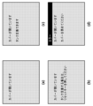
図4は、本実施形態における制御処理の例を示すフローチャートである。図5は、LCD7に表示される表示画面の例を示す図である。以下、図4のフローチャートおよび図5を参照して、本実施形態の制御処理を説明する。尚、図4に示す制御処理は、記録装置100のCPU9が、ROM10などに記憶されている制御プログラムを実行することで行われる。なお、各処理の説明における記号「S」は、当該フローチャートにおけるステップであることを意味する(以下、本明細書において同様である)。図4に示す処理は、記録装置100が電源ONされた後に行われる。また、図4は、本実施形態のユーザインターフェース制御を中心とした処理を示しており、記録動作などの他の動作の処理制御は省略している。
<Flowchart>
FIG. 4 is a flowchart showing an example of control processing in this embodiment. FIG. 5 is a diagram showing an example of a display screen displayed on the
S401にて処理が開始されると、S402においてCPU9は、カバー3が開放されているかを判定する。即ち、ユーザなどによってカバー3が開けられたかを判定する。カバー3が開放されているか否かは、カバーセンサ21によって検出することが可能である。カバー3が開放されている場合、S403に進み、そうでない場合、S402の判定を繰り返す。
When the process is started in S401, the CPU 9 determines whether the
S403においてCPU9は、操作パネル6のLCD7上に、カバーオープン中画面を表示する。図5(a)は、カバーオープン中画面の例を示している。LCD7には、カバーが開いている旨の通知がされる。その後、処理はS404に進む。
In S403, the CPU 9 displays a cover open screen on the
S404においてCPU9は、記録ヘッド1の状態チェックを行う。即ち、LCD7にカバーオープン中画面を表示する一方で、記録ヘッド1の状態を確認する。ここで、記録ヘッド1の状態は、タンク交換位置に移動可能であるか、タンク交換位置に移動可能でない(即ち、移動不可である)かのいずれかであるものとする。本実施形態では、S404の判定に基づいて、その後の制御が大きく二つに分かれることになる。タンク交換位置に移動可能である場合、S405に処理が進む。本例では、記録装置100が待機中の場合、即ち、記録装置100が印刷信号を受けていない場合、タンク交換位置に移動可能であると判定する。一方、タンク交換位置に移動不可である場合、S411に処理が進む。本例では、記録装置100が稼働中の場合、即ち、印刷信号を受けて印刷中の場合、タンク交換位置に移動不可であると判定する。また、記録装置100がメンテナンスを実行中の場合も、タンク交換位置に移動不可であると判定する。以下、それぞれの処理を説明する。
In S404, the CPU 9 checks the status of the
<(1)記録装置が待機中(印刷信号を受けていないとき)の場合>
記録装置が待機中でタンク交換位置に移動可能であると判定した場合、S405においてCPU9は、インクタンク交換のためのキー操作を誘導する画面をLCD7に表示する。図5(b)は、インクタンク交換のためのキー操作を誘導する画面の例を示している。前述したように、本実施形態では、リセットキー5が押下された場合に、インクタンク交換のための所定のキー操作が行われたと扱う。よって、図5(b)では、リセットキーを押下するように通知がされている。尚、上述したように、所定のキーがストップキーなどの他のキーである場合には、そのキーを押すように通知がされる。そして、図5(b)に示す画面をLCD7に表示した後に、処理はS406に進む。
<(1) When the recording device is on standby (not receiving a print signal)>
If it is determined that the printing apparatus is on standby and can be moved to the tank replacement position, in S405 the CPU 9 displays on the LCD 7 a screen that guides key operations for replacing the ink tank. FIG. 5B shows an example of a screen that guides key operations for ink tank replacement. As described above, in this embodiment, when the
S406においてCPU9は、インクタンク交換のためのキー操作が行われたかを判定する。CPU9は、キー操作が行われたかを、パネル制御回路14を介して検出することができる。キー操作が行われた場合、S407に処理が進み、キー操作が行われない場合、S406の判定を繰り返す。尚、S406の判定の間は、図5(b)に示す画面がLCD7に表示され続ける。
In S406, the CPU 9 determines whether a key operation for ink tank replacement has been performed. The CPU 9 can detect whether a key operation has been performed via the
キー操作を確認すると、S407においてCPU9は、記録ヘッド1をタンク交換位置に移動させる制御を行う。即ち、CPU9は、モータードライバ16を介して、記録ヘッド1を搭載しているキャリッジ8を駆動するキャリッジモータ17を制御して、記録ヘッド1を、待機位置からタンク交換位置に移動させる。S407で記録ヘッド1をタンク交換位置に移動させた後、S408においてCPU9は、タンク交換画面をLCD7に表示する。図5(c)は、タンク交換画面の例を示している。図5(c)では、タンクを交換することが可能な旨の通知がされている。タンク交換画面を表示すると、処理はS409に進む。
When the key operation is confirmed, the CPU 9 performs control to move the
このように、本実施形態では、カバー3が開放された場合に、直ちに記録ヘッド1をタンク交換位置に移動させない。カバー3が開放された時点で、タンク交換位置に記録ヘッド1が移動可能な状態である場合には、まず、タンク交換のためのキー操作を誘導する画面を表示する。これにより、ユーザに、タンクを交換するのに適したタイミングを通知することができる。また、この時点では、記録ヘッド1は、キャップにキャッピングされているので、例えば顔料インクが乾いてしまうことを抑制することができる。そして、タンク交換のためのキー操作を誘導する画面を表示した後に、所定のキー操作を受け付けた場合に、記録ヘッド1をタンク交換位置に移動させる。ユーザは、図5(b)に示すようなキー操作を誘導する画面を見たうえで、所定のキー操作を行っているので、ユーザがインクタンク2を交換する目的であることが確定する。このタイミングで記録ヘッド1を待機位置から移動させることで、適切なタイミングで記録ヘッド1をタンク交換位置に移動させることができる。
In this way, in this embodiment, when the
図4の処理の説明を続ける。S408でタンク交換画面を表示すると、ユーザによってインクタンク2が交換されることになる。その後、S409においてCPU9は、カバー3が閉められたかを判定する。カバー3が閉められたかは、カバーセンサ21によって検出することが可能である。カバー3が閉められた場合、S410に進む。カバーが閉めない場合、S409で判定を繰り返す。S409の判定がされている間、図5(c)に示す画面がLCD7に表示され続ける。
The description of the process in FIG. 4 will be continued. When the tank replacement screen is displayed in S408, the
S410においてCPU9は、記録ヘッド1を待機位置(初期位置)であるホームポジションに移動させる(戻す)制御を行う。尚、本フローチャートでは説明を省略するが、適切なインクタンク2が取り付けられない場合、LCD7にその旨を通知する画面を表示してもよい。S410で記録ヘッドを待機位置に戻すと、S413に進み、本フローチャートの処理を終了する。
In S410, the CPU 9 controls the
このような制御により、ユーザがカバー3を開けた場合に、ユーザにインク交換位置に移動可能であることを通知でき、ユーザにキー操作が可能なタイミングを通知することが可能となる。ユーザは、この通知を受けてキー操作を行い、インクタンク2を交換する。このように、本実施形態の処理では、ユーザは、適切なタイミングでタンク交換作業を行うことが可能となり、ユーザビリティを向上させることができる。
With such control, when the user opens the
<(2)記録装置が稼働中またはメンテナンス中の場合>
次に、S404において、タンク交換位置に移動不可と判定された場合、即ち、記録装置100が稼働中(即ち、印刷信号を受け印刷中)またはメンテナンス中の場合の例を説明する。記録装置100が稼働中またはメンテナンス中の場合、S411に進み、CPU9は、LCD7に、カバーオープンエラー画面を表示する。図5(d)は、カバーオープンエラー画面の例である。図5(d)では、カバー3を閉めるようにユーザに通知をしている。記録装置100が稼働中で印刷動作を実施している場合、インクタンク2を交換できない。また、記録装置100がメンテナンス処理を実施中の場合も、インクタンク2を交換できない。これらの場合、キャリッジ8が動作をしている状態である。このため、CPU9は、タンク交換位置に移動不可の状態においてカバー3が開放されると、カバーオープンエラー画面を表示し、キャリッジ8の動作を停止する。即ち、印刷処理またはメンテナンス処理が中断される。その後、S412に進み、CPU9は、カバー3が閉められたかを判定する。S412においてカバーが閉められたこと検出した場合、中断前の動作が続行される。即ち、中断していた印刷処理またはメンテナンス処理が再開される。そして、S413に進み、処理が終了する。カバー3が閉められない場合、S412で処理が繰り返される。S412の処理が繰り返される間、図5(d)の画面がLCD7に表示され続ける。
<(2) When the recording device is in operation or under maintenance>
Next, an example will be described in which it is determined in S404 that movement to the tank replacement position is not possible, that is, the
この制御により、印刷処理およびメンテナンス処理などのように、記録ヘッド1の状態がタンク交換位置に移動できない状態の場合には、エラー画面を表示することにより、ユーザに所定のキーを押下させるような余計な操作をさせずに済む。また、カバー3を閉めるようにユーザを誘導することが可能となる。
With this control, when the
<着荷状態の処理>
図6は、本実施形態の記録装置100における着荷状態の場合の制御処理を示すフローチャートである。図7は、LCD7に表示される表示画面の例を示す図である。以下、図6のフローチャートおよび図7を参照して、本実施形態の着荷時の制御処理を説明する。尚、着荷時とは、記録装置100が出荷された直後の状態である。つまり、着荷状態とは、キャリッジ8にインクタンク2が搭載されていない状態である。このため、空の状態の記録ヘッド1(キャリッジ8)にインクタンク2を挿入するようなユーザ操作が実施される。尚、記録装置100が着荷状態であるかは、CPU9が、例えばROM10またはEEPROM12に格納される着荷フラグを参照することで、判定することができる。図6のS611においてCPU9は、着荷状態において電源がONにされた場合に処理を開始する。
<Processing of arrival status>
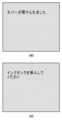
FIG. 6 is a flowchart showing control processing in the
S612においてCPU9は、カバー3が開放されているかを判定する。カバー3が開放されている場合、S613に処理が進み、開放されていない場合、S612の判定を繰り返す。S613においてCPU9は、LCD7にカバーオープン中画面を表示する。図7(a)は、カバーオープン中画面の例を示している。LCD7には、カバーが開いている旨の通知がされる。その後、処理はS614に進む。
In S612, the CPU 9 determines whether the
S614においてCPU9は、記録ヘッド1をタンク交換位置に移動させる制御を行う。即ち、CPU9は、モータードライバ16を介して、記録ヘッド1を搭載しているキャリッジ8を駆動するキャリッジモータ17を制御して、記録ヘッド1を、待機位置からタンク交換位置に移動させる。
In S614, the CPU 9 performs control to move the
S614で記録ヘッド1をタンク交換位置に移動させた後、S615においてCPU9は、タンク挿入画面をLCD7に表示する。図7(b)は、タンク挿入画面の例を示している。図7(b)では、タンクを挿入(装着)することを誘導する旨の通知がされている。S615でタンク挿入画面を表示すると、ユーザによってインクタンク2が挿入されることになる。その後、S616においてCPU9は、カバー3が閉められたかを判定する。カバー3が閉められた場合、S617に進む。カバーが閉められない場合、S616で判定を繰り返す。S616の判定がされている間、図7(b)に示す画面がLCD7に表示され続ける。S617においてCPU9は、記録ヘッド1を待機位置であるホームポジションに移動させる(戻す)制御を行う。尚、本フローチャートでは説明を省略するが、適切なインクタンク2が取り付けられない場合、LCD7にその旨を通知する画面を表示してもよい。S617で記録ヘッドを待機位置に戻すと、S618に進み、本フローチャートの処理を終了する。
After moving the
以上説明したように、着荷状態においてユーザがカバー3を開けた場合に想定されるユースケースは、インクタンク挿入のみである。つまり、インクタンク2が装着されていない状態であるので、インクタンク2を交換することは想定しなくてよい。このため、着荷状態においては、ユーザがカバー3を開けたことに応じて、タンク交換位置に記録ヘッド1を移動させる制御が行われる。即ち、所定のキー操作を行うことなく、タンク交換位置に記録ヘッド1を移動させる制御が行われる。このような制御によれば、不要なキー操作をユーザに要求することがなくなり、ユーザビリティを向上させることができる。
As described above, when the user opens the
以上説明したように、本実施形態によれば、インクタンク交換の際の通知および制御を、交換に適した状態において実施することができる。例えば、カバー3が開放された際に、インクタンク2が交換可能な状態のときのみ、交換可能な状態に移行させるための誘導画面を表示する。そして、その誘導画面に、所定のキー操作を誘導させる通知を表示する。これにより、ユーザは、画面に従って確実に交換作業を行うことが可能となり、ユーザビリティを向上させることができる。
As described above, according to the present embodiment, notification and control when replacing an ink tank can be performed in a state suitable for replacement. For example, when the
<<その他の実施形態>>
上記の実施形態では、所定の方向に往復移動が可能なシリアル走査式の記録ヘッドを用いた記録装置を例に挙げて説明した。そして、記録ヘッドが、待機位置と、インクを交換可能な交換状態の位置であるタンク交換位置とに移動する例を説明した。しかしながら、この例に限られるものではない。上記の実施形態は、記録用のインクを収容したインクタンクを装着して用いる方式の種々の記録装置に適用することができる。即ち、所定のカバーが開放された場合において、所定のキー操作に応じてタンクの交換が可能となるような形態の記録装置に適用することができる。例えば、記録媒体の幅方向に記録ヘッドの吐出口が延在しているいわゆるライン式の記録ヘッドにインクを供給するためのインクタンクを装着する記録装置であってもよい。このような形態の記録装置でも、所定のカバーが開放された場合において、所定のキー操作に応じてタンクの交換が可能となるように構成されていれば、上述した実施形態の処理を適用することは可能である。即ち、所定のカバーが開放された際に、インクタンクが交換可能な状態のときに、所定のキー操作を促す誘導画面を表示し、そのキー操作に応じて、記録装置がタンクを交換可能な状態に移行させるように制御されればよい。
<<Other embodiments>>
In the embodiments described above, a printing apparatus using a serial scanning printing head capable of reciprocating in a predetermined direction has been described as an example. An example has been described in which the recording head moves between a standby position and a tank exchange position, which is a position in an exchange state where ink can be exchanged. However, it is not limited to this example. The embodiments described above can be applied to various types of recording apparatuses that use an attached ink tank containing recording ink. That is, the present invention can be applied to a recording device in which the tank can be replaced in response to a predetermined key operation when a predetermined cover is opened. For example, it may be a printing apparatus that is equipped with an ink tank for supplying ink to a so-called line-type printing head in which the ejection ports of the printing head extend in the width direction of the printing medium. Even in this type of recording device, if the tank is configured so that the tank can be replaced in response to a predetermined key operation when a predetermined cover is opened, the processing of the embodiment described above can be applied. It is possible. That is, when a predetermined cover is opened and the ink tank is in a replaceable state, a guidance screen prompting a predetermined key operation is displayed, and in response to the key operation, the recording device is able to replace the tank. It is sufficient if the control is performed so as to cause the transition to the state.
また、記録装置がLCDを有していなくてもよく、記録装置に接続されている表示機器(例えば、PCまたはスマートフォンなど)に、誘導画面を表示させてもよい。また、記録装置は、必ずしも顔料インクを搭載していなくてもよい。 Further, the recording device does not need to have an LCD, and the guidance screen may be displayed on a display device (for example, a PC or a smartphone) connected to the recording device. Further, the recording device does not necessarily have to be equipped with pigment ink.
本発明は上述の実施形態の1以上の機能を実現するプログラムをネットワーク又は記憶媒体を介してシステム又は装置に供給し、そのシステム又は装置のコンピュータにおける1つ以上のプロセッサがプログラムを読出し実行する処理でも実現可能である。また、1以上の機能を実現する回路(例えば、ASIC)によっても実現可能である。 The present invention provides a process in which a program that implements one or more functions of the above-described embodiments is supplied to a system or device via a network or a storage medium, and one or more processors in a computer of the system or device read and execute the program. But it is possible. It can also be realized by a circuit (for example, ASIC) that realizes one or more functions.
1 記録ヘッド
2 インクタンク
3 カバー
5 リセットキー
7 LCD
9 CPU
1
9 CPU
Claims (15)
前記記録ヘッドによる記録が行われる間、前記記録ヘッドの移動領域を覆うカバーと、
ユーザ操作を受け付ける操作部と、
前記カバーが開放されたことに応じて、第一画面を表示部に表示し、
前記表示部に前記第一画面を表示した状態において前記操作部が操作された後に、前記インクタンクが交換される位置に前記記録ヘッドを移動させる、制御手段と、
を有することを特徴とする記録装置。 a recording head equipped with an ink tank containing ink used for recording and capable of reciprocating in a predetermined direction;
a cover that covers a moving area of the recording head while recording is performed by the recording head;
an operation unit that accepts user operations;
Displaying a first screen on a display unit in response to the cover being opened;
a control unit that moves the recording head to a position where the ink tank is replaced after the operation unit is operated while the first screen is displayed on the display unit;
A recording device comprising:
前記制御手段は、前記表示部に前記第一画面を表示した状態において前記所定のキーが操作された後に、前記インクタンクが交換される位置に前記記録ヘッドを移動させることを特徴とする請求項1に記載の記録装置。 The first screen includes a notification that induces the user to operate a predetermined key on the operation unit,
2. The control means moves the recording head to a position where the ink tank is replaced after the predetermined key is operated while the first screen is displayed on the display unit. 1. The recording device according to 1.
前記カバーが開放されたことに応じて、第一画面を表示部に表示するステップと、
前記表示部に前記第一画面を表示した状態において前記操作部が操作された後に、前記インクタンクが交換される位置に前記記録ヘッドを移動させるステップと、
を有することを特徴とする記録装置の制御方法。 a print head equipped with an ink tank containing ink used for printing and capable of reciprocating in a predetermined direction; a cover that covers a movement area of the print head while the print head is performing printing; and a cover for a user operation. 1. A method for controlling a recording device having an operation section that accepts the following information:
Displaying a first screen on a display unit in response to the opening of the cover;
after the operation unit is operated with the first screen displayed on the display unit, moving the recording head to a position where the ink tank is replaced;
A method for controlling a recording device, comprising:
Priority Applications (4)
| Application Number | Priority Date | Filing Date | Title |
|---|---|---|---|
| JP2020082441A JP7434050B2 (en) | 2020-05-08 | 2020-05-08 | Recording device, recording device control method, and program |
| US17/238,242 US11840094B2 (en) | 2020-05-08 | 2021-04-23 | Printing apparatus, control method of printing apparatus, and storage medium |
| US18/501,166 US20240075747A1 (en) | 2020-05-08 | 2023-11-03 | Printing apparatus, control method of printing appartus, and storage medium |
| JP2024017813A JP2024045476A (en) | 2020-05-08 | 2024-02-08 | Recording device, control method for recording device, and program |
Applications Claiming Priority (1)
| Application Number | Priority Date | Filing Date | Title |
|---|---|---|---|
| JP2020082441A JP7434050B2 (en) | 2020-05-08 | 2020-05-08 | Recording device, recording device control method, and program |
Related Child Applications (1)
| Application Number | Title | Priority Date | Filing Date |
|---|---|---|---|
| JP2024017813A Division JP2024045476A (en) | 2020-05-08 | 2024-02-08 | Recording device, control method for recording device, and program |
Publications (3)
| Publication Number | Publication Date |
|---|---|
| JP2021176686A JP2021176686A (en) | 2021-11-11 |
| JP2021176686A5 JP2021176686A5 (en) | 2023-05-15 |
| JP7434050B2 true JP7434050B2 (en) | 2024-02-20 |
Family
ID=78409194
Family Applications (2)
| Application Number | Title | Priority Date | Filing Date |
|---|---|---|---|
| JP2020082441A Active JP7434050B2 (en) | 2020-05-08 | 2020-05-08 | Recording device, recording device control method, and program |
| JP2024017813A Pending JP2024045476A (en) | 2020-05-08 | 2024-02-08 | Recording device, control method for recording device, and program |
Family Applications After (1)
| Application Number | Title | Priority Date | Filing Date |
|---|---|---|---|
| JP2024017813A Pending JP2024045476A (en) | 2020-05-08 | 2024-02-08 | Recording device, control method for recording device, and program |
Country Status (2)
| Country | Link |
|---|---|
| US (2) | US11840094B2 (en) |
| JP (2) | JP7434050B2 (en) |
Citations (7)
| Publication number | Priority date | Publication date | Assignee | Title |
|---|---|---|---|---|
| JP2001162833A (en) | 1999-12-10 | 2001-06-19 | Seiko Epson Corp | Ink-jet printer |
| JP2004230847A (en) | 2003-01-31 | 2004-08-19 | Canon Inc | Ink jet recording apparatus |
| JP2006297640A (en) | 2005-04-18 | 2006-11-02 | Canon Inc | Control method of ink jet recorder, ink jet recorder, and control program of ink jet recorder |
| JP2007144643A (en) | 2005-11-24 | 2007-06-14 | Canon Inc | Liquid jetting recording device |
| US20080252670A1 (en) | 2007-04-12 | 2008-10-16 | Labar Daniel Robert | Apparatus for Facilitating Ink Tank/Printhead Replacement In An Imaging Apparatus |
| JP2016221761A (en) | 2015-05-28 | 2016-12-28 | キヤノン株式会社 | Printer, user interface screen display method and program |
| JP2019034448A (en) | 2017-08-10 | 2019-03-07 | キヤノン株式会社 | Recording device, recording device control method and program |
Family Cites Families (2)
| Publication number | Priority date | Publication date | Assignee | Title |
|---|---|---|---|---|
| JP5317598B2 (en) * | 2008-09-12 | 2013-10-16 | キヤノン株式会社 | Printer |
| JP7257856B2 (en) * | 2019-04-05 | 2023-04-14 | キヤノン株式会社 | recording device |
-
2020
- 2020-05-08 JP JP2020082441A patent/JP7434050B2/en active Active
-
2021
- 2021-04-23 US US17/238,242 patent/US11840094B2/en active Active
-
2023
- 2023-11-03 US US18/501,166 patent/US20240075747A1/en active Pending
-
2024
- 2024-02-08 JP JP2024017813A patent/JP2024045476A/en active Pending
Patent Citations (7)
| Publication number | Priority date | Publication date | Assignee | Title |
|---|---|---|---|---|
| JP2001162833A (en) | 1999-12-10 | 2001-06-19 | Seiko Epson Corp | Ink-jet printer |
| JP2004230847A (en) | 2003-01-31 | 2004-08-19 | Canon Inc | Ink jet recording apparatus |
| JP2006297640A (en) | 2005-04-18 | 2006-11-02 | Canon Inc | Control method of ink jet recorder, ink jet recorder, and control program of ink jet recorder |
| JP2007144643A (en) | 2005-11-24 | 2007-06-14 | Canon Inc | Liquid jetting recording device |
| US20080252670A1 (en) | 2007-04-12 | 2008-10-16 | Labar Daniel Robert | Apparatus for Facilitating Ink Tank/Printhead Replacement In An Imaging Apparatus |
| JP2016221761A (en) | 2015-05-28 | 2016-12-28 | キヤノン株式会社 | Printer, user interface screen display method and program |
| JP2019034448A (en) | 2017-08-10 | 2019-03-07 | キヤノン株式会社 | Recording device, recording device control method and program |
Also Published As
| Publication number | Publication date |
|---|---|
| JP2024045476A (en) | 2024-04-02 |
| US11840094B2 (en) | 2023-12-12 |
| US20240075747A1 (en) | 2024-03-07 |
| US20210347181A1 (en) | 2021-11-11 |
| JP2021176686A (en) | 2021-11-11 |
Similar Documents
| Publication | Publication Date | Title |
|---|---|---|
| JP4622777B2 (en) | Display control device | |
| JP2009051114A (en) | Cloth printer, kind notification method and cloth printing program | |
| JP2009166479A (en) | Printing apparatus and method of controlling printing apparatus | |
| JP2007216478A (en) | Recording device and recording method | |
| JP7434050B2 (en) | Recording device, recording device control method, and program | |
| US6450610B1 (en) | Scanning apparatus | |
| JP2023060175A (en) | Liquid discharge device | |
| JP4858189B2 (en) | Display switching method, display control device, and electronic apparatus | |
| JP2004255753A (en) | Inkjet recorder | |
| EP0459515B1 (en) | Recording apparatus with an electronic typewriter | |
| JP2008102606A (en) | Printing system, printing method, control device and program | |
| JP2007106041A (en) | Inkjet recording device | |
| JPH08207389A (en) | Printer | |
| JP2008122772A (en) | Image display device, image display method, and its program | |
| JP2007080090A (en) | Image recording system, setting method and setting program for image recording device, and storage medium | |
| JP2011104879A (en) | Image forming apparatus | |
| JP4858049B2 (en) | Printer, control method thereof, and program thereof | |
| JP2018083371A (en) | Printer and printing system | |
| JP7031390B2 (en) | Image processing equipment, printable range detection method and program | |
| JP2017056660A (en) | Control method for printer and carriage drive means | |
| KR100186591B1 (en) | A detachable scanner inkjet recording apparatus | |
| EP1001362B1 (en) | A printer system | |
| JP4841989B2 (en) | Printing device | |
| JP2006264132A (en) | Printer and printing program | |
| JP3347680B2 (en) | Recording device |
Legal Events
| Date | Code | Title | Description |
|---|---|---|---|
| A521 | Request for written amendment filed |
Free format text: JAPANESE INTERMEDIATE CODE: A523 Effective date: 20230501 |
|
| A621 | Written request for application examination |
Free format text: JAPANESE INTERMEDIATE CODE: A621 Effective date: 20230501 |
|
| TRDD | Decision of grant or rejection written | ||
| A977 | Report on retrieval |
Free format text: JAPANESE INTERMEDIATE CODE: A971007 Effective date: 20231222 |
|
| A01 | Written decision to grant a patent or to grant a registration (utility model) |
Free format text: JAPANESE INTERMEDIATE CODE: A01 Effective date: 20240109 |
|
| A61 | First payment of annual fees (during grant procedure) |
Free format text: JAPANESE INTERMEDIATE CODE: A61 Effective date: 20240207 |
|
| R151 | Written notification of patent or utility model registration |
Ref document number: 7434050 Country of ref document: JP Free format text: JAPANESE INTERMEDIATE CODE: R151 |