JP7344032B2 - Image processing device - Google Patents
Image processing device Download PDFInfo
- Publication number
- JP7344032B2 JP7344032B2 JP2019133867A JP2019133867A JP7344032B2 JP 7344032 B2 JP7344032 B2 JP 7344032B2 JP 2019133867 A JP2019133867 A JP 2019133867A JP 2019133867 A JP2019133867 A JP 2019133867A JP 7344032 B2 JP7344032 B2 JP 7344032B2
- Authority
- JP
- Japan
- Prior art keywords
- image
- straight line
- distance values
- representative distance
- approximate straight
- Prior art date
- Legal status (The legal status is an assumption and is not a legal conclusion. Google has not performed a legal analysis and makes no representation as to the accuracy of the status listed.)
- Active
Links
Images


Classifications
-
- G—PHYSICS
- G06—COMPUTING; CALCULATING OR COUNTING
- G06T—IMAGE DATA PROCESSING OR GENERATION, IN GENERAL
- G06T7/00—Image analysis
- G06T7/10—Segmentation; Edge detection
- G06T7/11—Region-based segmentation
-
- G—PHYSICS
- G06—COMPUTING; CALCULATING OR COUNTING
- G06T—IMAGE DATA PROCESSING OR GENERATION, IN GENERAL
- G06T7/00—Image analysis
- G06T7/50—Depth or shape recovery
- G06T7/55—Depth or shape recovery from multiple images
- G06T7/593—Depth or shape recovery from multiple images from stereo images
-
- G—PHYSICS
- G06—COMPUTING; CALCULATING OR COUNTING
- G06T—IMAGE DATA PROCESSING OR GENERATION, IN GENERAL
- G06T7/00—Image analysis
- G06T7/10—Segmentation; Edge detection
- G06T7/187—Segmentation; Edge detection involving region growing; involving region merging; involving connected component labelling
-
- G—PHYSICS
- G06—COMPUTING; CALCULATING OR COUNTING
- G06T—IMAGE DATA PROCESSING OR GENERATION, IN GENERAL
- G06T2200/00—Indexing scheme for image data processing or generation, in general
- G06T2200/32—Indexing scheme for image data processing or generation, in general involving image mosaicing
-
- G—PHYSICS
- G06—COMPUTING; CALCULATING OR COUNTING
- G06T—IMAGE DATA PROCESSING OR GENERATION, IN GENERAL
- G06T2207/00—Indexing scheme for image analysis or image enhancement
- G06T2207/10—Image acquisition modality
- G06T2207/10004—Still image; Photographic image
- G06T2207/10012—Stereo images
-
- G—PHYSICS
- G06—COMPUTING; CALCULATING OR COUNTING
- G06T—IMAGE DATA PROCESSING OR GENERATION, IN GENERAL
- G06T2207/00—Indexing scheme for image analysis or image enhancement
- G06T2207/10—Image acquisition modality
- G06T2207/10028—Range image; Depth image; 3D point clouds
-
- G—PHYSICS
- G06—COMPUTING; CALCULATING OR COUNTING
- G06T—IMAGE DATA PROCESSING OR GENERATION, IN GENERAL
- G06T2207/00—Indexing scheme for image analysis or image enhancement
- G06T2207/20—Special algorithmic details
- G06T2207/20068—Projection on vertical or horizontal image axis
-
- G—PHYSICS
- G06—COMPUTING; CALCULATING OR COUNTING
- G06T—IMAGE DATA PROCESSING OR GENERATION, IN GENERAL
- G06T2207/00—Indexing scheme for image analysis or image enhancement
- G06T2207/30—Subject of image; Context of image processing
- G06T2207/30248—Vehicle exterior or interior
- G06T2207/30252—Vehicle exterior; Vicinity of vehicle
Landscapes
- Engineering & Computer Science (AREA)
- Computer Vision & Pattern Recognition (AREA)
- Physics & Mathematics (AREA)
- General Physics & Mathematics (AREA)
- Theoretical Computer Science (AREA)
- Image Analysis (AREA)
- Image Processing (AREA)
- Length Measuring Devices By Optical Means (AREA)
Description
本開示は、画像処理を行う画像処理装置に関する。 The present disclosure relates to an image processing device that performs image processing.
画像処理装置には、フレーム画像において画像領域を設定し、この画像領域における画像に基づいて、様々な処理を行うものがある。例えば、特許文献1には、物体の表面上の位置を表す3次元点の集合である3次元点群をクラスタリング処理により分割して点群クラスタを生成し、この点群クラスタに基づいて特徴量を抽出する特徴抽出装置が開示されている。
Some image processing apparatuses set an image area in a frame image and perform various processes based on the image in this image area. For example,
画像処理装置では、フレーム画像において画像領域を適切に設定することが望まれている。 In an image processing device, it is desired to appropriately set an image area in a frame image.
適切に画像領域を設定することができる画像処理装置を提供することが望ましい。 It is desirable to provide an image processing device that can appropriately set an image area.
本開示の一実施の形態に係る画像処理装置は、代表距離算出部と、結合処理部とを備えている。代表距離算出部は、ステレオ画像に基づいて生成された、各画素での距離値を含む距離画像に基づいて、距離画像における複数の画素列に対応づけられ、それぞれが、対応する画素列における距離値の代表値である複数の代表距離値を生成するように構成される。結合処理部は、ステレオ画像に含まれる、他車両を含む1または複数の物体の画像に基づいて設定された第1の画像領域および第2の画像領域を結合する結合処理を行うことが可能に構成される。この結合処理部は、第1の画像領域および第2の画像領域が仮結合された領域である仮結合領域が、他車両のコーナー部の画像を含むかどうかを判定する判定処理を行い、仮結合領域がコーナー部の画像を含む場合に、結合処理を回避する。結合処理部は、第1の画像領域において、複数の代表距離値のうちの、第1の画像領域が属する複数の画素列に対応する第1の複数の代表距離値に基づいて第1の近似直線を生成するとともに、第1の複数の代表距離値の第1の近似直線からの第1のばらつき度合いを算出し、第2の画像領域において、複数の代表距離値のうちの、第2の画像領域が属する複数の画素列に対応する第2の複数の代表距離値に基づいて第2の近似直線を生成するとともに、第2の複数の代表距離値の第2の近似直線からの第2のばらつき度合いを算出し、第1のばらつき度合いおよび第2のばらつき度合いに基づいて判定処理を行う。 An image processing device according to an embodiment of the present disclosure includes a representative distance calculation section and a combination processing section. The representative distance calculation unit is configured to correspond to a plurality of pixel columns in the distance image based on a distance image including distance values at each pixel and is generated based on the stereo image, and each calculates a distance in the corresponding pixel column. The method is configured to generate a plurality of representative distance values that are representative values of the distance values. The combination processing unit is capable of performing a combination process of combining a first image area and a second image area that are set based on images of one or more objects including other vehicles included in the stereo image. configured. This combination processing unit performs a determination process to determine whether a temporary combination area, which is an area where the first image area and the second image area are temporarily combined, includes an image of a corner of another vehicle. Avoid merging processing when the merging region includes corner images. The combination processing unit performs first approximation in the first image region based on a first plurality of representative distance values corresponding to a plurality of pixel columns to which the first image region belongs, among the plurality of representative distance values. While generating a straight line, a first degree of dispersion of the first plurality of representative distance values from the first approximate straight line is calculated, and in the second image area, the second of the plurality of representative distance values is A second approximate straight line is generated based on a second plurality of representative distance values corresponding to a plurality of pixel columns to which the image region belongs, and a second approximate straight line is generated from the second approximate straight line of the second plurality of representative distance values. The degree of variation is calculated, and the determination process is performed based on the first degree of variation and the second degree of variation.
本開示の一実施の形態に係る画像処理装置によれば、第1の画像領域が属する複数の画素列に対応する第1の複数の代表距離値に基づいて第1の近似直線を生成するとともに、第1の複数の代表距離値の第1の近似直線からの第1のばらつき度合いを算出し、第2の画像領域が属する複数の画素列に対応する第2の複数の代表距離値に基づいて第2の近似直線を生成するとともに、第2の複数の代表距離値の第2の近似直線からの第2のばらつき度合いを算出し、第1のばらつき度合いおよび第2のばらつき度合いに基づいて判定処理を行うようにしたので、適切に画像領域を設定することができる。 According to an image processing device according to an embodiment of the present disclosure, a first approximate straight line is generated based on a first plurality of representative distance values corresponding to a plurality of pixel columns to which a first image region belongs; , calculate a first degree of dispersion of the first plurality of representative distance values from the first approximate straight line, and calculate the first degree of dispersion of the first plurality of representative distance values from the first approximate straight line, based on the second plurality of representative distance values corresponding to the plurality of pixel columns to which the second image region belongs. to generate a second approximate straight line, calculate a second degree of dispersion of the second plurality of representative distance values from the second approximate straight line, and calculate the second degree of dispersion of the second plurality of representative distance values based on the first degree of dispersion and the second degree of dispersion. Since the determination process is performed, the image area can be appropriately set.
以下、本開示の実施の形態について、図面を参照して詳細に説明する。 Embodiments of the present disclosure will be described in detail below with reference to the drawings.
<実施の形態>
[構成例]
図1は、一実施の形態に係る画像処理装置(画像処理装置1)の一構成例を表すものである。画像処理装置1は、ステレオカメラ11と、処理部20とを有している。画像処理装置1は、自動車等の車両10に搭載される。
<Embodiment>
[Configuration example]
FIG. 1 shows a configuration example of an image processing device (image processing device 1) according to an embodiment. The
ステレオカメラ11は、車両10の前方を撮像することにより、互いに視差を有する一組の画像(左画像PLおよび右画像PR)を生成するように構成される。ステレオカメラ11は、左カメラ11Lと、右カメラ11Rとを有する。左カメラ11Lおよび右カメラ11Rのそれぞれは、レンズとイメージセンサとを含んでいる。左カメラ11Lおよび右カメラ11Rは、この例では、車両10の車両内において、車両10のフロントガラスの上部近傍に、車両10の幅方向に所定距離だけ離間して配置される。左カメラ11Lおよび右カメラ11Rは、互いに同期して撮像動作を行う。左カメラ11Lは左画像PLを生成し、右カメラ11Rは右画像PRを生成する。左画像PLおよび右画像PRは、ステレオ画像PICを構成する。左画像PLおよび右画像PRは互いに視差を有する。ステレオカメラ11は、所定のフレームレート(例えば60[fps])で撮像動作を行うことにより、一連のステレオ画像PICを生成するようになっている。
The stereo camera 11 is configured to capture an image in front of the vehicle 10 to generate a pair of images (left image PL and right image PR) having parallax with each other. The stereo camera 11 has a
処理部20は、ステレオカメラ11から供給されたステレオ画像PICに基づいて、左画像PLおよび右画像PRに含まれる、車両10の前方の車両などの様々な物体に、画像領域Rを設定することにより、物体を認識するように構成される。車両10では、例えば、処理部20が認識した物体についての情報に基づいて、例えば、車両10の走行制御を行い、あるいは、認識した物体についての情報をコンソールモニタに表示することができるようになっている。処理部20は、例えば、プログラムを実行するCPU(Central Processing Unit)、処理データを一時的に記憶するRAM(Random Access Memory)、プログラムを記憶するROM(Read Only Memory)などにより構成される。処理部20は、距離画像生成部21と、代表距離算出部22と、画像領域設定部23と、グルーピング処理部24と、分割処理部25と、結合処理部26とを有している。
Based on the stereo image PIC supplied from the stereo camera 11, the
距離画像生成部21は、左画像PLおよび右画像PRに基づいて、ステレオマッチング処理やフィルタリング処理などを含む所定の画像処理を行うことにより、距離画像PZを生成するように構成される。
The distance
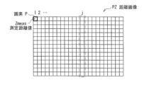
図2は、距離画像PZの一例を表すものである。左画像PLおよび右画像PRと同様に、距離画像PZにおける横軸は、車両10の車幅方向における座標xに対応し、縦軸は、車両10の車高方向における座標yに対応する。距離画像PZの各画素Pにおける画素値は、3次元の実空間における、各画素に対応する点までの距離値(測定距離値Zmeas)に対応している。言い換えれば、各画素Pにおける画素値は、車両10の車長方向における座標zに対応している。 FIG. 2 shows an example of the distance image PZ. Similarly to the left image PL and the right image PR, the horizontal axis in the distance image PZ corresponds to the coordinate x of the vehicle 10 in the vehicle width direction, and the vertical axis corresponds to the coordinate y of the vehicle 10 in the vehicle height direction. The pixel value of each pixel P of the distance image PZ corresponds to the distance value (measured distance value Zmeas) to the point corresponding to each pixel in the three-dimensional real space. In other words, the pixel value of each pixel P corresponds to the coordinate z in the longitudinal direction of the vehicle 10.
代表距離算出部22は、距離画像PZに基づいて、距離画像PZの画素列ごとに代表距離値Zpeakを算出するように構成される。具体的には、代表距離算出部22は、距離画像PZにおける複数の画素列を順次選択し、選択された画素列に属する複数の測定距離値Zmeasに基づいて、ヒストグラムHを生成する。そして、代表距離算出部22は、そのヒストグラムHに基づいて、選択された画素列における代表距離値Zpeakを算出する。
The representative
図3は、図2に示した距離画像PZにおけるj番目の画素列に属する複数の測定距離値Zmeasに基づいて生成されたヒストグラムHjの一例を表すものである。横軸は座標zの値を示し、縦軸は頻度を示す。代表距離算出部22は、頻度が一番高い座標zの値を代表距離値Zpeakとして得る。代表距離算出部22は、全ての画素列に対して、このようなヒストグラムHをそれぞれ生成することにより、代表距離値Zpeakをそれぞれ算出するようになっている。
FIG. 3 shows an example of a histogram Hj generated based on a plurality of measured distance values Zmeas belonging to the j-th pixel column in the distance image PZ shown in FIG. The horizontal axis shows the value of the coordinate z, and the vertical axis shows the frequency. The representative
画像領域設定部23は、距離画像PZに基づいて複数の画像領域Rを設定するように構成される。具体的には、画像領域設定部23は、距離画像PZにおいて、測定距離値Zmeasが連続する複数の画素Pが1つの画像領域Rに属するように、画像領域Rを設定する。
The image
図4は、画像領域Rの一例を表すものである。この例では、ステレオ画像PICにおける左画像PLは、自車両である車両10の前方における2台の車両9A,9Bの画像を含んでいる。なお、この例では左画像PLを用いて説明するが、右画像PRおよび距離画像PZについても同様である。
FIG. 4 shows an example of the image area R. In this example, the left image PL in the stereo image PIC includes images of two
車両9Aは、車両10の前方を道路に沿って走行しており、この左画像PLは、車両9Aの背面の画像を含んでいる。車両9Aの背面において、距離画像PZにおける測定距離値Zmeasは連続するので、画像領域設定部23は、車両9Aの背面に画像領域R(画像領域RA)を設定している。
The
車両9Bは、横から車両10の前に入り込んできている。この車両9Bは、道路の延伸方向からずれた方向を向いているので、左画像PLは、車両9Bの側面101の画像、車両9Bの背面102の画像、および車両9Bの側面101と背面102との間のコーナー部103の画像を含んでいる。この例では、車両9Aの側面101、背面102、およびコーナー部103において、距離画像PZにおける測定距離値Zmeasは連続するので、画像領域設定部23は、車両9Bの側面101、背面102、およびコーナー部103に1つの画像領域R(画像領域R1)を設定している。
グルーピング処理部24は、現在のステレオ画像PICに基づく処理において、過去のステレオ画像PICに基づく処理を参考にして、複数の画像領域Rを結合することにより1つの画像領域Rを設定するように構成される。具体的には、例えば、現在のステレオ画像PICにおいて、ある1つの車両に対して複数の画像領域Rが設定されており、1つ前のステレオ画像PICに基づく処理において、その車両に対して1つの画像領域Rが設定されていた場合に、グルーピング処理部24は、それらの複数の画像領域Rを結合することにより1つの画像領域Rを設定するようになっている。
The
分割処理部25は、画像領域Rにおける複数の代表距離値Zpeakに基づいて、所定の条件を満たした場合に、その画像領域Rを2つの画像領域Rに分割する領域分割処理Aを行うように構成される。領域分割処理Aは、分割処理A1を含んでいる。分割処理部25は、この分割処理A1において、例えば、ある画像領域R(画像領域R1)が属する複数の画素列に対応する複数の代表距離値Zpeakに基づいて、その画像領域R1が車両のコーナー部の画像を含むかどうかを判定する。そして、分割処理部25は、その画像領域R1がそのコーナー部の画像を含む場合に、その画像領域R1をそのコーナー部に基づいて2つの画像領域R(画像領域R2,R3)に分割する。すなわち、分割処理部25は、図4の例では、画像領域R1が車両9Bのコーナー部103を含むと判定することにより、その画像領域R1を、車両9Bの側面101の画像を含む画像領域R2と、車両9Bの背面102の画像を含む画像領域R3とに分割するようになっている。
The
結合処理部26は、2つの画像領域Rのそれぞれにおける複数の代表距離値Zpeakに基づいて、所定の条件を満たした場合に、それらの2つの画像領域Rを結合する領域結合処理Bを行うように構成される。
The
領域結合処理Bは、結合処理B1を含んでいる。結合処理部26は、この結合処理B1において、ある画像領域R(画像領域R4)に含まれる画像に対応する3次元の実空間での部分と、他のある画像領域R(画像領域R5)に含まれる画像に対応する3次元の実空間での部分とが互いに近い場合に、その2つの画像領域R4,R5を結合することにより1つの画像領域R(画像領域R6)を設定する。また、結合処理部26は、例えば、2つの画像領域R4,R5が仮結合された領域が車両のコーナー部の画像を含むかどうかを判定する。そして、結合処理部26は、その領域がそのコーナー部の画像を含む場合に、これらの2つの画像領域R4,R5を結合しないようになっている。
The region combining process B includes a combining process B1. In this combining process B1, the combining
また、領域結合処理Bは、結合処理B2を含んでいる。結合処理部26は、この結合処理B2において、ある画像領域R(画像領域R7)に含まれる画像に対応する3次元の実空間での部分と、他のある画像領域R(画像領域R8)に含まれる画像に対応する3次元の実空間での部分とが互いに少し離れている場合でも、所定の条件を満たした場合に、その2つの画像領域R7,R8を結合することにより1つの画像領域R(画像領域R9)を設定する。例えば、結合処理部26は、互いに離間する2つの画像領域R7,R8の両方が、ある1つの車両の側面における互いに異なる部分の画像を含むかどうかを判定する。そして、結合処理部26は、2つの画像領域R7,R8の両方が、その車両の側面における互いに異なる部分の画像を含む場合に、2つの画像領域R7,R8を結合することにより画像領域R9を設定する。具体的には、後述するように、例えば、画像領域R7がバスのように車長が長い車両の側面における前部の画像を含み、画像領域R8がその車両の側面における後部の画像を含む場合があり得る。すなわち、例えば、バスの側面は、パターンマッチングを行いにくいので、距離画像生成部21は、精度が高い距離画像PZを生成しにくい。この場合には、バスの側面の前部および側面の後部に、別々の画像領域R7,R8がそれぞれ設定されることがあり得る。このような場合には、結合処理部26は、その2つの画像領域R7,R8を結合することにより1つの画像領域R9を設定することができるようになっている。
Further, the region combining process B includes a combining process B2. In this combining process B2, the combining
このようにして、処理部20は、車両10の前方の車両を認識する。そして、処理部20は、その認識結果についての情報を出力するようになっている。
In this way, the
この構成により、画像処理装置1では、分割処理部25は、分割処理A1において、ある画像領域R(画像領域R1)が、車両のコーナー部の画像を含む場合に、その画像領域R1を、車両の側面の画像を含む画像領域R(画像領域R2)と、車両の背面の画像を含む画像領域R(画像領域R3)とに分割する。結合処理部26は、結合処理B1において、これらの画像領域R2および画像領域R3が仮結合された領域が車両のコーナー部の画像を含むので、これらの画像領域R2および画像領域R3を結合しない。これにより、画像処理装置1では、車両の側面とその車両の背面に、別々の画像領域R2,R3をそれぞれ設定することができるので、その車両を側面と背面とに分けて認識することができる。
With this configuration, in the
また、画像処理装置1では、結合処理部26は、結合処理B2において、ある画像領域R(画像領域R7)がバスの側面における前部の画像を含み、他のある画像領域R(画像領域R8)がバスの側面における後部の画像を含む場合に、その2つの画像領域R7,R8を結合することにより1つの画像領域R(画像領域R9)を設定する。これにより、画像処理装置1では、1つの車両の側面に1つの画像領域R9を設定することができるので、その車両の側面をまとまった1つのものとして認識することができるようになっている。
In addition, in the
ここで、代表距離算出部22は、本開示における「代表距離算出部」の一具体例に対応する。測定距離値Zmeasは、本開示における「距離値」の一具体例に対応する。代表距離値Zpeakは、本開示における「代表距離値」の一具体例に対応する。画像領域設定部23は、本開示における「画像領域設定部」の一具体例に対応する。結合処理部26は、本開示における「結合処理部」の一具体例に対応する。結合処理B1は、本開示における「結合処理」の一具体例に対応する。画像領域R4および画像領域R5は、本開示における「第1の画像領域」および「第2の画像領域」の一具体例に対応する。分割処理部25は、本開示における「分割処理部」の一具体例に対応する。分割処理A1は、本開示における「分割処理」の一具体例に対応する。画像領域R1は、本開示における「第3の画像領域」の一具体例に対応する。
Here, the representative
[動作および作用]
続いて、本実施の形態の画像処理装置1の動作および作用について説明する。
[Operation and effect]
Next, the operation and effects of the
(全体動作概要)
まず、図1を参照して、画像処理装置1の全体動作概要を説明する。ステレオカメラ11は、車両10の前方を撮像することにより、左画像PLおよび右画像PRを含むステレオ画像PICを生成する。処理部20は、ステレオカメラ11から供給されたステレオ画像PICに基づいて、左画像PLおよび右画像PRに含まれる、車両10の前方の車両などの様々な物体のそれぞれに、画像領域Rを設定することにより、物体を認識する。
(Overview of overall operation)
First, an overview of the overall operation of the
(詳細動作)
図5は、処理部20の一動作例を表すものである。処理部20は、ステレオカメラ11からステレオ画像PICが供給される度に、そのステレオ画像PICに基づいて、距離画像PZを生成し、この距離画像PZに基づいて複数の画像領域Rを設定する。そして、処理部20は、1つの画像領域Rを分割し、あるいは2つの画像領域Rを結合することにより、1または複数の画像領域Rを設定する。以下に、この処理について詳細に説明する。
(Detailed operation)
FIG. 5 shows an example of the operation of the
まず、距離画像生成部21は、ステレオ画像PICに含まれる左画像PLおよび右画像PRに基づいて、ステレオマッチング処理やフィルタリング処理などを含む所定の画像処理を行うことにより、距離画像PZを生成する(ステップS101)。
First, the distance
次に、代表距離算出部22は、距離画像PZに基づいて、距離画像PZの画素列ごとに代表距離値Zpeakを算出する(ステップS102)。具体的には、代表距離算出部22は、距離画像PZにおける複数の画素列を順次選択し、選択された画素列に属する複数の測定距離値Zmeasに基づいて、ヒストグラムH(図3)を生成する。そして、代表距離算出部22は、そのヒストグラムHにおいて、頻度が一番高い座標zの値を代表距離値Zpeakとして得る。代表距離算出部22は、全ての画素列に対して、ヒストグラムHをそれぞれ生成することにより、画素列ごとに代表距離値Zpeakをそれぞれ算出する。
Next, the representative
次に、画像領域設定部23は、距離画像PZに基づいて複数の画像領域Rを設定する(ステップS103)。具体的には、画像領域設定部23は、距離画像PZにおいて、測定距離値Zmeasが連続する複数の画素Pが1つの画像領域Rに属するように、画像領域Rを設定する。
Next, the image
次に、グルーピング処理部24は、現在のステレオ画像PICに基づく処理において、過去のステレオ画像PICに基づく処理を参考にして、複数の画像領域Rを結合することにより1つの画像領域Rを設定する(ステップS104)。具体的には、例えば、現在のステレオ画像PICにおいて、ある1つの車両に対して複数の画像領域Rが設定されており、1つ前のステレオ画像PICに基づく処理において、その車両に対して1つの画像領域Rが設定されていた場合に、グルーピング処理部24は、それらの複数の画像領域Rを結合することにより1つの画像領域Rを設定する。
Next, in the process based on the current stereo image PIC, the
次に、分割処理部25は、画像領域Rに係る複数の代表距離値Zpeakに基づいて、所定の条件を満たした場合に、その画像領域Rを2つの画像領域Rに分割する領域分割処理Aを行う(ステップS105)。この領域分割処理Aに含まれる分割処理A1については、詳細に後述する。
Next, the
次に、結合処理部26は、2つの画像領域Rのそれぞれに係る複数の代表距離値Zpeakに基づいて、所定の条件を満たした場合に、それらの2つの画像領域Rを結合する領域結合処理Bを行う(ステップS106)。この領域結合処理Bに含まれる結合処理B1,B2については、詳細に後述する。
Next, the
以上で、このフローは終了する。 With this, this flow ends.
(分割処理A1)
次に、図5のステップS105に示した領域分割処理Aに含まれる、分割処理A1について詳細に説明する。
(Split processing A1)
Next, the division process A1 included in the area division process A shown in step S105 in FIG. 5 will be described in detail.
分割処理部25は、この分割処理A1において、例えば、ある画像領域R(画像領域R1)が属する複数の画素列に対応する複数の代表距離値Zpeakに基づいて、その画像領域R1が車両のコーナー部の画像を含むかどうかを判定する。そして、分割処理部25は、その画像領域R1がそのコーナー部の画像を含む場合に、その画像領域R1をそのコーナー部に基づいて2つの画像領域R(画像領域R2,R3)に分割する。
In this division processing A1, the
図6は、図4に示した画像領域R1がこの分割処理A1により分割されることにより設定された画像領域R2,R3の一例を表すものである。図4に示したように、画像領域R1は、車両9Bの側面101の画像と、車両9Bの背面102の画像と、車両9Bのコーナー部103の画像とを含んでいる。分割処理部25は、その画像領域R1がそのコーナー部の画像を含むと判定する。そして、分割処理部25は、このコーナー部103に基づいて、図6に示したように、画像領域R1を、車両9Bの側面101の画像を含む画像領域R2と、車両9Bの背面102の画像を含む画像領域R3とに分割する。これにより、処理部20は、車両9Bを側面と背面とに分けて認識することができる。
FIG. 6 shows an example of image regions R2 and R3 set by dividing the image region R1 shown in FIG. 4 by this division process A1. As shown in FIG. 4, the image area R1 includes an image of the
図7は、分割処理A1の一例を表すものである。 FIG. 7 shows an example of the division process A1.
まず、分割処理部25は、複数の画像領域Rのうち、処理対象となる画像領域R(画像領域R1)を選択する(ステップS111)。
First, the
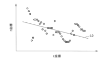
次に、分割処理部25は、画像領域R1における複数の代表距離値Zpeakに基づいて、最小二乗法により近似直線Lを算出し、これらの複数の代表距離値Zpeakの、その近似直線Lからの分散値Vを算出する(ステップS112)。
Next, the
図8は、ステップS112における処理の一例を表すものである。横軸は座標xを示し、縦軸は座標zを示す。この図8では、このようなx-z座標面において、画像領域R1が属する複数の画素列に対応する複数の代表距離値Zpeakを示す複数の座標点がプロットされている。分割処理部25は、これらの複数の代表距離値Zpeakに基づいて、最小二乗法により近似直線L0を算出する。そして、分割処理部25は、これらの複数の代表距離値Zpeakの、近似直線L0からの分散値V0を算出する。
FIG. 8 shows an example of the process in step S112. The horizontal axis shows the coordinate x, and the vertical axis shows the coordinate z. In FIG. 8, on such an xz coordinate plane, a plurality of coordinate points indicating a plurality of representative distance values Zpeak corresponding to a plurality of pixel columns to which the image region R1 belongs are plotted. The
次に、分割処理部25は、この画像領域R1において仮分割位置POSを設定して、画像領域R1に対して仮分割を行い(ステップS113)、仮分割された各領域において、その領域における複数の代表距離値Zpeakに基づいて、最小二乗法により近似直線Lを算出し、これらの複数の代表距離値Zpeakの、その近似直線Lからの分散値Vを算出する(ステップS114)。所定回数Nだけ仮分割を行っていない場合(ステップS115において“N”)には、ステップS113に戻る。そして、所定回数Nだけ仮分割を行うまで、ステップS113~S115の処理を繰り返す。
Next, the
図9A~9Eは、ステップS113~S115における処理の一例を表すものである。この例では、所定回数Nは“5”であり、分割処理部25は、画像領域R1において5つの仮分割位置POS(仮分割位置POS1~POS5)を設定している。
9A to 9E represent an example of the processing in steps S113 to S115. In this example, the predetermined number of times N is "5", and the
例えば、図9Aに示したように、分割処理部25は、仮分割位置POS1において仮分割を行う。そして、分割処理部25は、この仮分割位置POS1の左の領域における複数の代表距離値Zpeakに基づいて、最小二乗法により近似直線L11を算出し、これらの複数の代表距離値Zpeakの、近似直線L11からの分散値V11を算出する。また、分割処理部25は、この仮分割位置POS1の右の領域における複数の代表距離値Zpeakに基づいて、最小二乗法により近似直線L12を算出し、これらの複数の代表距離値Zpeakの、近似直線L12からの分散値V12を算出する。
For example, as shown in FIG. 9A, the
同様に、分割処理部25は、仮分割位置POS2(図9B)において仮分割を行うことにより、近似直線L21,L22および分散値V21,V22を算出し、仮分割位置POS2(図9C)において仮分割を行うことにより、近似直線L31,L32および分散値V31,V32を算出し、仮分割位置POS4(図9D)において仮分割を行うことにより、近似直線L41,L42および分散値V41,V42を算出し、仮分割位置POS5(図9E)において仮分割を行うことにより、近似直線L51,L52および分散値V51,V52を算出する。
Similarly, the
次に、分割処理部25は、近似直線Lからのばらつき度合いが最も小さい仮分割位置POSを選択する(ステップS116)。近似直線Lからのばらつき度合いは、例えば、以下の式を用いて評価することができる。

次に、分割処理部25は、ステップS116において選択した仮分割位置POSに基づいて、車両のコーナー部の位置(コーナー位置CP)を推定する(ステップS117)。
Next, the
図10は、ステップS117における処理の一例を表すものである。この例では、分割処理部25は、選択された仮分割位置POS4の左の領域における近似直線L41を、仮分割位置POS4の右の領域に向かって延長させるとともに、選択された仮分割位置POS4の右の領域における近似直線L42を、仮分割位置POS4の左の領域に向かって延長させる。延長された近似直線L41と、延長された近似直線L42とが互いに交差する位置は、コーナー位置CPに対応する。すなわち、横軸は、自車両である車両10の車幅方向における座標xを示し、縦軸は、車両10の車長方向における座標zを示すので、このx-z平面において、近似直線L41は、図4に示した車両9Bの側面101に対応し、近似直線L42は、この車両9Bの背面102に対応する。よって、延長された近似直線L41と、延長された近似直線L42とが互いに交差する位置は、車両9Bのコーナー部103の位置に対応する。このようにして、分割処理部25は、コーナー位置CPを推定する。
FIG. 10 shows an example of the process in step S117. In this example, the
次に、分割処理部25は、ステップS117において推定したコーナー位置CPに基づいて画像領域R1を分割する際の、所定の分割条件を満たすかどうかを判定する(ステップS118)。所定の分割条件は、例えば、以下の5つの条件を含むことができ、分割処理部25は、例えば、これらの5つの条件を満たした場合に、所定の分割条件を満たすと判定する。
Next, the
第1の条件は、ステップS117において推定されたコーナー位置CPのx座標が画像領域R1に位置していることである。すなわち、この第1の条件を満たすことは、画像領域R1がコーナー部の画像を含んでいる可能性が高いことを示しているので、この第1の条件は分割条件になり得る。 The first condition is that the x-coordinate of the corner position CP estimated in step S117 is located in the image region R1. That is, satisfying this first condition indicates that there is a high possibility that the image region R1 includes an image of a corner portion, so this first condition can be a dividing condition.
第2の条件は、コーナー位置CPのx座標で画像領域R1を分割した場合における、近似直線Lからの分散値Vが、ステップS112において算出した分散値V0よりも小さいことである。すなわち、この第2の条件を満たすことは、分割により2つの画像領域R(画像領域R2,R3)がより適切に設定されることを示しているので、この第2の条件は分割条件になり得る。 The second condition is that the variance value V from the approximate straight line L when the image region R1 is divided by the x-coordinate of the corner position CP is smaller than the variance value V0 calculated in step S112. In other words, satisfying this second condition indicates that the two image regions R (image regions R2, R3) can be set more appropriately through division, so this second condition becomes a division condition. obtain.
第3の条件は、ステップS117において使用された2つの近似直線Lのなす角θ(図10)が、90度を含む所定の角度範囲の範囲内であることである。すなわち、これらの2つの近似直線Lは、車両の側面および背面に対応するので、2つの近似直線Lのなす角θは、約90度になることが期待される。この第3の条件を満たすことは、画像領域R1がコーナー部の画像を含んでいる可能性が高いことを示しているので、この第3の条件は分割条件になり得る。 The third condition is that the angle θ (FIG. 10) formed by the two approximate straight lines L used in step S117 is within a predetermined angle range including 90 degrees. That is, since these two approximate straight lines L correspond to the side and rear surfaces of the vehicle, the angle θ formed by the two approximate straight lines L is expected to be about 90 degrees. Satisfying this third condition indicates that there is a high possibility that the image region R1 includes a corner image, so this third condition can be a dividing condition.
第4の条件は、画像領域R1における、コーナー位置CPのx座標よりも左の領域の幅が所定の幅以上であることと、コーナー位置CPのx座標よりも右の領域の幅が所定の幅以上であることである。すなわち、この第4の条件を満たすことは、分割により設定される2つの画像領域R(画像領域R2,R3)の大きさがある程度の大きさになることを示しているので、この第4の条件は分割条件になり得る。 The fourth condition is that the width of the area to the left of the x-coordinate of the corner position CP in the image area R1 is greater than or equal to a predetermined width, and the width of the area to the right of the x-coordinate of the corner position CP is a predetermined width. It must be at least the width. In other words, satisfying this fourth condition indicates that the two image regions R (image regions R2, R3) set by the division will have a certain size, so this fourth condition Conditions can be split conditions.
第5の条件は、ステップS112において算出した分散値V0が所定の値以上であることである。すなわち、この第5の条件を満たすことは、1本の近似直線L0を用いて近似することが適切でないことを示しており、言い換えれば、画像領域R1がコーナー部の画像を含んでいる可能性が高いことを示している。よって、この第5の条件は分割条件になり得る。 The fifth condition is that the variance value V0 calculated in step S112 is greater than or equal to a predetermined value. In other words, satisfying this fifth condition indicates that it is not appropriate to perform approximation using one approximation straight line L0. In other words, there is a possibility that image region R1 includes an image of a corner portion. It shows that it is high. Therefore, this fifth condition can be a dividing condition.
分割処理部25は、このような複数の条件を全て満たす場合には、所定の分割条件を満たすと判定する。言い換えれば、分割処理部25は、画像領域R1がコーナー部の画像を含んでいると判定する。
The
ステップS118において、所定の分割条件を満たさない場合(ステップS118において“N”)には、このフローは終了する。また、所定の分割条件を満たす場合(ステップS118において“Y”)には、分割処理部25は、ステップS117において推定されたコーナー位置CPのx座標を分割位置POSCとして設定し、この分割位置POSCで、画像領域R1を2つの画像領域R2,R3に分割する(ステップS119)。
In step S118, if the predetermined division condition is not satisfied (“N” in step S118), this flow ends. Further, when the predetermined division condition is satisfied (“Y” in step S118), the
以上で、この分割処理A1は終了する。分割処理部25は、複数の画像領域Rのうち、処理対象となる画像領域R1を順次選択し、選択された画像領域R1に対してこのような分割処理A1を行う。
With this, this division process A1 ends. The
画像処理装置1では、図4に示したように、画像領域R1が、車両のコーナー部の画像を含む場合には、所定の分割条件を満たすので(ステップS118において“Y”)、分割処理部25は、その画像領域R1を、車両の側面の画像を含む画像領域R2と、車両の背面の画像を含む画像領域R3とに分割する。これにより、画像処理装置1では、車両の側面とその車両の背面に、別々の画像領域R2,R3をそれぞれ設定することができるので、その車両を側面と背面とに分けて認識することができる。
In the
(結合処理B1)
次に、図5のステップS106に示した領域結合処理Bに含まれる、結合処理B1について詳細に説明する。
(Joining process B1)
Next, the combining process B1 included in the area combining process B shown in step S106 of FIG. 5 will be described in detail.
結合処理部26は、この結合処理B1において、ある画像領域R(画像領域R4)に含まれる画像に対応する3次元の実空間での部分と、他のある画像領域R(画像領域R5)に含まれる画像に対応する3次元の実空間での部分とが互いに近い場合に、その2つの画像領域R4,R5を結合することにより1つの画像領域R(画像領域R6)を設定する。また、結合処理部26は、例えば、2つの画像領域R4,R5が仮結合された領域が車両のコーナー部の画像を含むかどうかを判定する。そして、結合処理部26は、その領域がそのコーナー部の画像を含む場合に、これらの2つの画像領域R4,R5の結合を回避する。
In this combining process B1, the combining
図11は、結合処理B1の一例を表すものである。 FIG. 11 shows an example of the combination process B1.
まず、結合処理部26は、複数の画像領域Rのうち、処理対象となる2つの画像領域R(画像領域R4,R5)を選択する(ステップS121)。具体的には、結合処理部26は、複数の画像領域Rのうち、画像領域Rに含まれる画像に対応する3次元の実空間での距離が互いに所定の距離よりも近い2つの画像領域R4,R5を選択する。
First, the
次に、結合処理部26は、画像領域R4,R5に対して仮結合を行い、仮結合された領域における複数の代表距離値Zpeakに基づいて、最小二乗法により近似直線Lを算出する(ステップS122)。
Next, the
図12は、ステップS122における処理の一例を表すものである。この図12では、x-z座標面において、画像領域R4,R5が属する複数の画素列に対応する複数の代表距離値Zpeakを示す座標点がプロットされている。結合処理部26は、これらの複数の代表距離値Zpeakに基づいて、最小二乗法により近似直線L100を算出する。
FIG. 12 shows an example of the process in step S122. In FIG. 12, coordinate points indicating a plurality of representative distance values Zpeak corresponding to a plurality of pixel columns to which image regions R4 and R5 belong are plotted on the xz coordinate plane. The
次に、結合処理部26は、画像領域R4,R5のそれぞれにおいて、複数の代表距離値Zpeakに基づいて、最小二乗法により近似直線Lを算出し、複数の代表距離値Zpeakの、その近似直線Lからの分散値Vを算出する(ステップS123)。
Next, the
図13は、ステップS123における処理の一例を表すものである。結合処理部26は、画像領域R4における複数の代表距離値Zpeakに基づいて、最小二乗法により近似直線L101を算出し、これらの複数の代表距離値Zpeakの、近似直線L101からの分散値V101を算出する。同様に、結合処理部26は、画像領域R5における複数の代表距離値Zpeakに基づいて、最小二乗法により近似直線L102を算出し、これらの複数の代表距離値Zpeakの、近似直線L102からの分散値V102を算出する。
FIG. 13 shows an example of the process in step S123. The
次に、結合処理部26は、画像領域R4,R5のそれぞれにおいて、ステップS122において算出した近似直線Lの傾きおよび切片を用いて直線Mを算出し、複数の代表距離値Zpeakの、その直線からの分散値Vを算出する(ステップS124)。
Next, the
図14は、ステップS124における処理の一例を表すものである。結合処理部26は、画像領域R4において、ステップS122において算出した近似直線Lの傾きおよび切片を用いて直線M111を算出し、複数の代表距離値Zpeakの、この直線M111からの分散値V111を算出する。この分散値V111は、画像領域R4における複数の代表距離値Zpeakの、近似直線L100からの分散値Vである。同様に、結合処理部26は、画像領域R5において、ステップS122において算出した近似直線Lの傾きおよび切片を用いて直線M112を算出し、複数の代表距離値Zpeakの、この直線M112からの分散値V112を算出する。この分散値V112は、画像領域R5における複数の代表距離値Zpeakの、近似直線L100からの分散値Vである。
FIG. 14 shows an example of the process in step S124. The
次に、結合処理部26は、仮結合された領域において、複数の代表距離値Zpeakの、ステップS122において算出した近似直線Lからの分散値Vを算出する(ステップS125)。
Next, the
図15は、ステップS125における処理の一例を表すものである。結合処理部26は、仮結合された領域において、複数の代表距離値Zpeakの、ステップS122において算出した近似直線L100からの分散値V100を算出する。
FIG. 15 shows an example of the process in step S125. The
次に、結合処理部26は、仮結合を行うことによる分散値Vの変化率を算出する(ステップS126)。分散値Vの変化率は、例えば、以下のような3つの変化率を含むことができる。
Next, the
第1の変化率は、仮結合されることによる、全体領域における分散値Vの変化率である。具体的には、この第1の変化率は、例えば、画像領域R4における分散値V101および画像領域R5における分散値V102(図13)の和から、仮結合された領域における分散値V100(図15)への変化率である。 The first rate of change is the rate of change in the variance value V in the entire area due to temporary combination. Specifically, this first rate of change is, for example, calculated from the sum of the variance value V101 in the image region R4 and the variance value V102 in the image region R5 (FIG. 13) to the variance value V100 in the temporarily combined region (FIG. 15). ) is the rate of change.
第2の変化率は、仮結合されることによる、画像領域R4における分散値Vの変化率である。具体的には、第2の変化率は、例えば、画像領域R4における、近似直線L101からの分散値V101(図13)から、画像領域R4における、直線M111からの分散値V111(図14)への変化率である。 The second rate of change is the rate of change in the variance value V in the image region R4 due to temporary combination. Specifically, the second rate of change is, for example, from the dispersion value V101 (FIG. 13) from the approximate straight line L101 in the image region R4 to the dispersion value V111 (FIG. 14) from the straight line M111 in the image region R4. is the rate of change.
第3の変化率は、仮結合されることによる、画像領域R5における分散値Vの変化率である。具体的には、第3の変化率は、例えば、画像領域R5における、近似直線L102からの分散値V101(図13)から、画像領域R5における、直線M112からの分散値V112(図14)への変化率である。 The third rate of change is the rate of change in the variance value V in the image region R5 due to temporary combination. Specifically, the third rate of change is, for example, from the dispersion value V101 (FIG. 13) from the approximate straight line L102 in the image region R5 to the dispersion value V112 (FIG. 14) from the straight line M112 in the image region R5. is the rate of change.
次に、結合処理部26は、画像領域R4,R5を結合する際の、所定の結合条件を満たすかどうかを判定する(ステップS127)。所定の結合条件は、例えば、以下の3つの条件を含むことができ、結合処理部26は、例えば、これらの3つの条件を満たした場合に、所定の結合条件を満たすと判定する。第1の条件は、第1の変化率が所定の第1のしきい値より小さいことである。第2の条件は、第2の変化率が所定の第2のしきい値より小さいことである。第3の条件は、第3の変化率が所定の第3のしきい値よりも小さいことである。結合処理部26は、このような複数の条件を全て満たすかどうかを判定することにより、所定の結合条件を満たすかどうかを判定する。
Next, the
ステップS127において、所定の結合条件を満たさない場合(ステップS127において“N”)には、このフローは終了する。また、所定の結合条件を満たす場合(ステップS127において“Y”)には、結合処理部26は、画像領域R4および画像領域R5を結合することにより画像領域R6を設定する(ステップS128)。
In step S127, if the predetermined combination condition is not satisfied (“N” in step S127), this flow ends. Further, if the predetermined combining condition is satisfied (“Y” in step S127), the combining
以上で、この結合処理B1は終了する。結合処理部26は、処理対象となる2つの画像領域R4,R5を順次選択し、選択された2つの画像領域R4,R5に対してこのような結合処理B1を行う。
With this, the combining process B1 ends. The
画像処理装置1では、例えば、図7に示した分割処理A1で説明したように、画像領域R1が、車両のコーナー部の画像を含む場合には、その画像領域R1は、車両の側面の画像を含む画像領域R2と、車両の背面の画像を含む画像領域R3とに分割される。この場合には、結合処理B1において、これらの画像領域R2および画像領域R3を結合すると分散値Vが大きくなり、所定の結合条件を満たさないので(ステップS127において“N”)、結合処理部26は、これらの画像領域R2および画像領域R3を結合しない。この所定の結合条件は、仮結合された領域が車両のコーナー部の画像を含まない条件である。すなわち、この画像領域R2,R3の例では、この所定の結合条件を満たさないので、仮結合された領域が車両のコーナー部の画像を含むと判定する。よって、結合処理部26は、画像領域R2および画像領域R3を結合しない。これにより、画像処理装置1では、分割処理A1で分割することにより設定された画像領域R2,R3が、この結合処理B1において結合されることを防ぐことができる。
In the
(結合処理B2)
次に、図5のステップS106に示した領域結合処理Bに含まれる、結合処理B2について詳細に説明する。
(Joining process B2)
Next, the combining process B2 included in the area combining process B shown in step S106 in FIG. 5 will be described in detail.
結合処理部26は、この結合処理B2において、互いに離間する2つの画像領域R(画像領域R7,R8)の両方が、ある1つの車両の側面における互いに異なる部分の画像を含むかどうかを判定する。そして、2つの画像領域R7,R8の両方が、その車両の側面における互いに異なる部分の画像を含む場合には、結合処理部26は、2つの画像領域R7,R8を結合することにより画像領域R9を設定する。
In this combination processing B2, the
図16Aは、画像領域R7,R8の一例を表すものである。図16Bは、この結合処理B2によりこれらの画像領域R7,R8が結合されることにより設定された画像領域R9の一例を表すものである。この例では、ステレオ画像PICにおける左画像PLは、自車両である車両10の前方における車両9Cの画像を含んでいる。なお、この例では左画像PLを用いて説明するが、右画像PRおよび距離画像PZについても同様である。
FIG. 16A shows an example of image regions R7 and R8. FIG. 16B shows an example of an image region R9 set by combining these image regions R7 and R8 by this combining process B2. In this example, left image PL in stereo image PIC includes an image of
車両9Cは、車長が長い車両であり、この例ではバスである。この車両9Cは、横から車両10の前に入り込んできている。この車両9Cは、道路の延伸方向からずれた方向を向いているので、左画像PLは、車両9Cの側面の画像を含んでいる。画像領域設定部23は、車両9Cの側面に1つの画像領域Rを設定するのが望ましい。しかしながら、例えば、バスの側面は、パターンマッチングを行いにくいので、距離画像生成部21は、精度が高い距離画像PZを生成しにくい。具体的には、距離画像生成部21は、例えば、バスの側面の中央付近において、座標zの値を算出しにくい。これにより、代表距離算出部22が、距離画像PZにおける、バスの側面の中央付近に対応するある画素列でのヒストグラムHを生成する際、データの数が不十分になり得る。この場合には、代表距離算出部22は、代表距離値Zpeakを算出できない。よって、バスの側面の中央付近に対応する画素列では、代表距離値Zpeakが欠損する。その結果、画像領域設定部23は、図16Aに示したように、1つの車両9Cの側面に対して2つの画像領域R7,R8を設定し得る。
The
結合処理部26は、この結合処理B2において、2つの画像領域R7,R8の両方が、ある1つの車両の側面における互いに異なる部分の画像を含むと判定する。そして、結合処理部26は、図16Bに示したように、これらの画像領域R7,R8を結合することにより、画像領域R9を設定する。これにより、処理部20は、車両9Cの側面をまとまった1つのものとして認識することができる。
In the combining process B2, the combining
図17A,17Bは、結合処理B2の一例を表すものである。この結合処理B2におけるステップS132~S137は、図11に示した結合処理B1におけるステップS122~S127と同様である。 17A and 17B represent an example of the combining process B2. Steps S132 to S137 in this combination process B2 are similar to steps S122 to S127 in the combination process B1 shown in FIG.
まず、結合処理部26は、複数の画像領域Rのうち、処理対象となる2つの画像領域R(画像領域R7,R8)を選択する(ステップS131)。結合処理部26は、画像の左端から中央に向かって、2つの画像領域Rを順次選択し、画像の右端から中央に向かって、2つの画像領域Rを順次選択する。その後に、結合処理部26は、再度、画像の左端から中央に向かって、2つの画像領域Rを順次選択し、画像の右端から中央に向かって、2つの画像領域Rを順次選択する。
First, the
次に、結合処理部26は、画像領域R7,R8に対して仮結合を行い、仮結合された領域における複数の代表距離値Zpeakに基づいて、最小二乗法により近似直線Lを算出する(ステップS132)。
Next, the
図18は、ステップS132における処理の一例を表すものである。この図18では、x-z座標面において、画像領域R7,R8が属する複数の画素列に対応する複数の代表距離値Zpeakを示す座標点がプロットされている。結合処理部26は、これらの複数の座標点に基づいて、最小二乗法により近似直線L200を算出する。
FIG. 18 shows an example of the process in step S132. In FIG. 18, coordinate points indicating a plurality of representative distance values Zpeak corresponding to a plurality of pixel columns to which image regions R7 and R8 belong are plotted on the xz coordinate plane. The
次に、結合処理部26は、画像領域R7,R8のそれぞれにおいて、複数の代表距離値Zpeakに基づいて、最小二乗法により近似直線Lを算出し、複数の代表距離値Zpeakの、その近似直線Lからの分散値Vを算出する(ステップS133)。
Next, the
次に、結合処理部26は、画像領域R7,R8のそれぞれにおいて、ステップS132において算出した近似直線Lの傾きおよび切片を用いて直線Mを算出し、複数の代表距離値Zpeakの、その直線からの分散値Vを算出する(ステップS134)。
Next, the
次に、結合処理部26は、仮結合された領域において、複数の代表距離値Zpeakの、ステップS132において算出した近似直線Lからの分散値Vを算出する(ステップS135)。
Next, the
次に、結合処理部26は、仮結合を行うことによる分散値Vの変化率を算出する(ステップS136)。
Next, the
次に、結合処理部26は、画像領域R4,R5を結合する際の、所定の結合条件を満たすかどうかを判定する(ステップS137)。ステップS137において、所定の結合条件を満たさない場合(ステップS137において“N”)には、このフローは終了する。
Next, the
ステップS137において、所定の結合条件を満たす場合(ステップS137において“Y”)には、結合処理部26は、画像領域R7における代表距離値Zpeakを示す座標点と、画像領域R8における代表距離値Zpeakを示す座標点との間の領域間距離DAを算出する(ステップS138)。具体的には、結合処理部26は、図18に示したように、x-z座標面において、画像領域R7における代表距離値Zpeakを示す座標点のうちの画像領域R8に最も近い座標点と、画像領域R8における代表距離値Zpeakを示す座標点のうちの画像領域R7に最も近い座標点との間の、近似直線L200に沿った距離を、領域間距離DAとして算出する。
In step S137, if the predetermined combination condition is satisfied (“Y” in step S137), the
次に、結合処理部26は、領域間距離DAが所定のしきい値Dth以内であるかどうかを確認する(ステップS139)。領域間距離DAが所定のしきい値Dth以内である場合(ステップS139において“Y”)には、ステップS146に進む。
Next, the
ステップS139において、領域間距離DAが所定のしきい値Dth以内ではない場合(ステップS139において“N”)には、結合処理部26は、距離画像PZにおける各画素Pでの測定距離値Zmeasのうちの、画像領域R7および画像領域R8の間の各画素Pでの測定距離値Zmeasを示す座標点Qを、x-z座標面にプロットする(ステップS140)。
In step S139, if the inter-region distance DA is not within the predetermined threshold value Dth (“N” in step S139), the
図19は、ステップS140における処理の一例を表すものである。この例では、画像領域R7および画像領域R8の間の各画素Pでの測定距離値Zmeasに基づいて、5つの座標点Qをプロットしている。なお、この例では、説明の便宜上、5つの座標点Qをプロットしたが、実際には、より多くの座標点Qがプロットされ得る。これらの座標点Qは、距離画像生成部21が生成した測定距離値Zmeasを示すので、この図19に示したように、近似直線L200から少し離れることがあり得る。
FIG. 19 shows an example of the process in step S140. In this example, five coordinate points Q are plotted based on the measured distance value Zmeas at each pixel P between the image region R7 and the image region R8. Note that in this example, for convenience of explanation, five coordinate points Q are plotted, but in reality, more coordinate points Q may be plotted. These coordinate points Q indicate the measured distance value Zmeas generated by the distance
次に、結合処理部26は、x-z座標面において、ステップS140においてプロットした座標点Qを、近似直線L200上に移動させる(ステップS141)。
Next, the
図20は、ステップS141における処理の一例を表すものである。この例では、結合処理部26は、ステップS140においてプロットされた座標点Qを、近似直線L200と直交する方向において、近似直線L200に向かって移動させる。その結果、移動後の座標点Qは、近似直線L200の直線上に配置される。
FIG. 20 shows an example of the process in step S141. In this example, the
次に、結合処理部26は、近似直線L200上の複数の座標点Qの密度を算出し、これらの複数の座標点Qのうちの、密度が低い領域における座標点Qを削除する(ステップS142)。
Next, the
図21は、ステップS142における処理の一例を表すものである。この例では、ステップS141において近似直線L200上に移動した5つの座標点Qのうち、中央の座標点Qは、密度が低い領域にあるので、結合処理部26はこの座標点Qを削除している。
FIG. 21 shows an example of the process in step S142. In this example, among the five coordinate points Q moved on the approximate straight line L200 in step S141, the central coordinate point Q is in a region with low density, so the
次に、結合処理部26は、複数の座標点Qのうち、近似直線L200上の複数の座標点Qを、画像領域R7に対応するグループG7、または画像領域R8に対応するグループG8に区分する(ステップS143)。
Next, the
次に、結合処理部26は、グループG7における座標点QおよびグループG8における座標点Qの間の、近似直線L200に沿ったグループ間距離DBを算出する(ステップS144)。具体的には、結合処理部26は、図21に示したように、x-z面において、グループG7における座標点QのうちのグループG8に近い座標点Qと、グループG8における座標点QのうちのグループG7に近い座標点Qの間の、近似直線L200に沿った距離を、グループ間距離DBとして算出する。
Next, the
次に、結合処理部26は、グループ間距離DBが所定のしきい値Dth以内であるかどうかを確認する(ステップS145)。グループ間距離DBが所定のしきい値Dth以内ではない場合(ステップS145において“N”)には、このフローは終了する。
Next, the
そして、結合処理部26は、画像領域R7および画像領域R8を結合することにより画像領域R9を設定する(ステップS146)。
Then, the
以上で、この結合処理B2は終了する。結合処理部26は、処理対象となる2つの画像領域R7,R8を順次選択し、選択された2つの画像領域R7,R8に対してこのような結合処理B2を行う。
This completes the combining process B2. The
画像処理装置1では、図16Aに示したように、互いに離間する2つの画像領域R7,R8の両方が、ある1つの車両の側面における互いに異なる部分の画像を含む場合には、これらの画像領域R7,R8を結合しても、分散値Vをある程度小さい値に抑えることができるので、所定の結合条件を満たす(ステップS137において“Y”)。この場合において、例えば、画像領域R7における画像が示す車両の側面の部分と、画像領域R8における画像が示す車両の側面の部分とが互いに近い場合には、領域間距離DAが所定のしきい値Dth以内(ステップS139において“Y”)になるので、結合処理部26は、2つの画像領域R7,R8を結合することにより画像領域R9を設定する。一方、画像領域R7における画像が示す車両の側面の部分と、画像領域R8における画像が示す車両の側面の部分とがやや離れている場合には、領域間距離DAが所定のしきい値Dthよりも長くなり得る(ステップS139において“N”)。この場合でも、画像領域R7および画像領域R8の間の各画素Pでの測定距離値Zmeasを用いて、グループ間距離DBを算出し、このグループ間距離DBが所定のしきい値Dth以内である場合(ステップS145において“Y”)に、2つの画像領域R7,R8を結合することにより画像領域R9を設定する。これにより、画像処理装置1では、1つの車両の側面に1つの画像領域R9を設定することができるので、その車両の側面をまとまった1つのものとして認識することができる。
In the
ここで、近似直線L101は、本開示における「第1の近似直線」の一具体例に対応する。近似直線L102は、本開示における「第2の近似直線」の一具体例に対応する。近似直線L100は、本開示における「第3の近似直線」の一具体例に対応する。近似直線L41は、本開示における「第4の近似直線」の一具体例に対応する。近似直線L42は、本開示における「第5の近似直線」の一具体例に対応する。近似直線L0は、本開示における「第6の近似直線」の一具体例に対応する。分散値V101は、本開示における「第1のばらつき度合い」の一具体例に対応する。分散値V102は、本開示における「第2のばらつき度合い」の一具体例に対応する。分散値V100は、本開示における「第3のばらつき度合い」の一具体例に対応する。分散値V111は、本開示における「第4のばらつき度合い」の一具体例に対応する。分散値V112は、本開示における「第5のばらつき度合い」の一具体例に対応する。分散値V0は、本開示における「第6のばらつき度合い」の一具体例に対応する。分散値V41は、本開示における「第7のばらつき度合い」の一具体例に対応する。分散値V42は、本開示における「第8のばらつき度合い」の一具体例に対応する。仮分割位置POS4は、本開示における「仮分割位置」の一具体例に対応する。仮分割位置POS1~POS5は、本開示における「複数の仮分割位置」の一具体例に対応する。分割位置POSCは、本開示における「分割位置」の一具体例に対応する。 Here, the approximate straight line L101 corresponds to a specific example of a "first approximate straight line" in the present disclosure. The approximate straight line L102 corresponds to a specific example of a "second approximate straight line" in the present disclosure. The approximate straight line L100 corresponds to a specific example of the "third approximate straight line" in the present disclosure. The approximate straight line L41 corresponds to a specific example of the "fourth approximate straight line" in the present disclosure. The approximate straight line L42 corresponds to a specific example of the "fifth approximate straight line" in the present disclosure. The approximate straight line L0 corresponds to a specific example of the "sixth approximate straight line" in the present disclosure. The variance value V101 corresponds to a specific example of the "first degree of variation" in the present disclosure. The variance value V102 corresponds to a specific example of the "second degree of variation" in the present disclosure. The variance value V100 corresponds to a specific example of the "third degree of variation" in the present disclosure. The variance value V111 corresponds to a specific example of the "fourth degree of variation" in the present disclosure. The variance value V112 corresponds to a specific example of the "fifth degree of variation" in the present disclosure. The variance value V0 corresponds to a specific example of the "sixth degree of variation" in the present disclosure. The variance value V41 corresponds to a specific example of the "seventh degree of variation" in the present disclosure. The variance value V42 corresponds to a specific example of the "eighth degree of variation" in the present disclosure. The temporary division position POS4 corresponds to a specific example of a "temporary division position" in the present disclosure. Temporary division positions POS1 to POS5 correspond to a specific example of "a plurality of temporary division positions" in the present disclosure. The division position POSC corresponds to a specific example of a "division position" in the present disclosure.
以上のように、画像処理装置1では、分割処理部25が、画像領域R1が属する複数の画素列に対応する複数の代表距離値Zpeakに基づいて、画像領域R1が他車両のコーナー部の画像を含むかどうかを判定し、この画像領域R1がコーナー部の画像を含む場合に、そのコーナー部に基づいて分割処理を行うことにより2つの画像領域R2,R3を設定するようにした。これにより、画像処理装置1では、他車両の側面とその他車両の背面に、別々の画像領域R2,R3をそれぞれ設定することができるので、その他車両を側面と背面とに分けて認識することができる。このように、画像処理装置1では、適切に画像領域Rを設定することができる。
As described above, in the
特に、画像処理装置1では、分割処理部25は、図10に示したように、画像領域R1において仮分割位置POS(この例では仮分割位置POS4)を設定し、複数の代表距離値Zpeakを、この仮分割位置POSの左のグループとこの仮分割位置POSの右のグループに区分するようにした。そして、分割処理部25は、この仮分割位置POSの左のグループに区分された複数の代表距離値Zpeakに基づいて近似直線L(この例では近似直線L41)を生成し、この仮分割位置POSの右のグループに区分された複数の代表距離値Zpeakに基づいて近似直線L(この例では近似直線L42)を生成し、これらの近似直線Lに基づいて分割位置POSCを設定するようにした。これにより、画像処理装置1では、分割位置POSCを精度よく設定することができる。
In particular, in the
また、画像処理装置1では、結合処理部26は、画像領域R4,R5が仮結合された領域(仮結合領域)が、他車両のコーナー部の画像を含むかどうかを判定し、この仮結合領域がコーナー部の画像を含む場合に、2つの画像領域R4,R5を結合しないようにした。これにより、画像処理装置1では、例えば、画像領域R4が他車両の側面の画像を含み、画像領域R5が他車両の背面の画像を含む場合には、これらの2つの画像領域R4,R5を結合しないので、その他車両を側面と背面とに分けて認識することができる。このように、画像処理装置1では、適切に画像領域Rを設定することができる。
In addition, in the
特に、画像処理装置1では、図13に示したように、結合処理部26は、画像領域R4が属する複数の画素列に対応する複数の代表距離値Zpeakに基づいて近似直線L101を生成するとともに、これらの複数の代表距離値の近似直線L101からの分散値V101を算出するようにした。同様に、結合処理部26は、画像領域R5が属する複数の画素列に対応する複数の代表距離値Zpeakに基づいて近似直線L102を生成するとともに、これらの複数の代表距離値の近似直線L102からの分散値V102を算出するようにした。そして、結合処理部26は、これらの分散値Vに基づいて、仮結合領域が、他車両のコーナー部の画像を含むかどうかを判定するようにした。これにより、画像処理装置1では、仮結合により分散値Vが大きくなる場合に、他車両のコーナー部の画像を含むと判定することができ、これらの2つの画像領域R4,R5を結合しないようにすることができる。
In particular, in the
また、画像処理装置1では、結合処理部26は、画像領域R7,R8の両方が他車両の側面の画像を含むかどうかを判定し、画像領域R7,R8の両方が他車両の側面の画像を含む場合には、2つの画像領域R7,R8を結合するようにした。これにより、画像処理装置1では、例えば、画像領域R7が他車両の側面の前部の画像を含み、画像領域R8がその他車両の側面の後部の画像を含む場合には、これらの2つの画像領域R7,R8を結合させることができるので、その他車両の側面をまとまった1つのものとして認識することができる。このように、画像処理装置1では、適切に画像領域Rを設定することができる。
Furthermore, in the
特に、画像処理装置1では、結合処理部26は、図21に示したように、画像領域R7が属する複数の画素列に対応する代表距離値Zpeakと、画像領域R8が属する複数の画素列に対応する複数の代表距離値Zpeakと、画像領域R7,R8の間の各画素Pでの測定距離値Zmeasとに基づいて、画像領域R7,R8の両方が他車両の側面の画像を含むかどうかを判定するようにした。これにより、画像処理装置1では、例えばバスの側面の中央付近に対応する画素列において、代表距離値Zpeakが欠損している場合でも、測定距離値Zmeasを用いることにより、画像領域R7,R8の両方が、同じ1つの他車両の側面の画像を含むことを判定しやすくすることができ、これらの2つの画像領域R7,R8を結合させやすくすることができる。
In particular, in the
このように、画像処理装置1では、適切に画像領域を設定することができる。これにより、車両10では、この認識結果に基づいて、例えば、自車両である車両10の走行制御をより精度良く行うことができ、あるいは、認識した物体についてのより正確な情報をコンソールモニタに表示することができる。
In this way, the
[効果]
以上のように本実施の形態では、画像領域R1が属する複数の画素列に対応する複数の代表距離値に基づいて、画像領域R1が他車両のコーナー部の画像を含むかどうかを判定し、この画像領域R1がコーナー部の画像を含む場合に、そのコーナー部に基づいて分割処理を行うことにより2つの画像領域R2,R3を設定するようにした。これにより、他車両の側面とその他車両の背面に、別々の画像領域R2,R3をそれぞれ設定することができるので、適切に画像領域を設定することができる。
[effect]
As described above, in this embodiment, it is determined whether the image region R1 includes an image of the corner of another vehicle based on a plurality of representative distance values corresponding to a plurality of pixel columns to which the image region R1 belongs, When this image region R1 includes an image of a corner portion, two image regions R2 and R3 are set by performing division processing based on the corner portion. As a result, separate image areas R2 and R3 can be set on the side of the other vehicle and the back of the other vehicle, respectively, so the image areas can be set appropriately.
本実施の形態では、画像領域R4,R5が仮結合された領域である仮結合領域が、他車両のコーナー部の画像を含むかどうかを判定し、この仮結合領域がコーナー部の画像を含む場合に、2つの画像領域R4,R5を結合しないようにした。これにより、例えば、画像領域R4が他車両の側面の画像を含み、画像領域R5が他車両の背面の画像を含む場合には、これらの2つの画像領域R4,R5を結合しないので、適切に画像領域を設定することができる。 In this embodiment, it is determined whether a temporary combined area, which is an area where image areas R4 and R5 are temporarily combined, includes an image of a corner of another vehicle, and this temporary combined area includes an image of a corner. In this case, the two image regions R4 and R5 are not combined. As a result, for example, if image area R4 includes an image of the side surface of another vehicle and image area R5 includes an image of the rear side of the other vehicle, these two image areas R4 and R5 will not be combined, so that Image area can be set.
本実施の形態では、画像領域R7,R8の両方が他車両の側面の画像を含むかどうかを判定し、画像領域R7,R8の両方が他車両の側面の画像を含む場合には、2つの画像領域R7,R8を結合するようにした。これにより、例えば、画像領域R7が他車両の側面の前部の画像を含み、画像領域R8がその他車両の側面の後部の画像を含む場合には、これらの2つの画像領域R7,R8を結合させることができるので、適切に画像領域を設定することができる。 In this embodiment, it is determined whether both image regions R7 and R8 include images of the side surface of the other vehicle, and if both image regions R7 and R8 include images of the side surface of the other vehicle, the two Image areas R7 and R8 are combined. As a result, for example, if image area R7 includes an image of the front side of the other vehicle and image area R8 includes an image of the rear side of the other vehicle, these two image areas R7 and R8 can be combined. Therefore, the image area can be appropriately set.
以上、実施の形態を挙げて本技術を説明したが、本技術はこれらの実施の形態等には限定されず、種々の変形が可能である。 Although the present technology has been described above with reference to the embodiments, the present technology is not limited to these embodiments, and can be modified in various ways.
例えば、上記実施の形態では、ステレオカメラ11が車両10の前方を撮像するようにしたが、これに限定されるものではなく、例えば、車両10の側方や後方を撮像してもよい。 For example, in the embodiment described above, the stereo camera 11 images the front of the vehicle 10, but the present invention is not limited to this. For example, the stereo camera 11 may image the side or rear of the vehicle 10.
なお、本明細書中に記載された効果はあくまで例示であって限定されるものではなく、また、他の効果があってもよい。 Note that the effects described in this specification are merely examples and are not limiting, and other effects may also exist.
1…画像処理装置、10…車両、11…ステレオカメラ、11L…左カメラ、11R…右カメラ、20…処理部、21…距離画像生成部、22…代表距離算出部、23…画像領域設定部、24…グルーピング処理部、25…分割処理部、26…結合処理部、A…領域分割処理、A1…分割処理、B…領域結合処理、B1,B2…結合処理、CP…コーナー位置、DA…領域間距離、DB…グループ間距離、H…ヒストグラム、L…近似直線、M…直線、P…画素、PIC…ステレオ画像、POS…仮分割位置、POSC…分割位置、PL…左画像、PR…右画像、PZ…距離画像、R,R1~R9…画像領域、V…分散値、Zmeas…測定距離値、Zpeak…代表距離値。
DESCRIPTION OF
Claims (10)
前記ステレオ画像に含まれる、他車両を含む1または複数の物体の画像に基づいて設定された第1の画像領域および第2の画像領域を結合する結合処理を行うことが可能であり、前記第1の画像領域および前記第2の画像領域が仮結合された領域である仮結合領域が、前記他車両のコーナー部の画像を含むかどうかを判定する判定処理を行い、前記仮結合領域が前記コーナー部の画像を含む場合に、前記結合処理を回避する結合処理部と
を備え、
前記結合処理部は、
前記第1の画像領域において、前記複数の代表距離値のうちの、前記第1の画像領域が属する複数の画素列に対応する第1の複数の代表距離値に基づいて第1の近似直線を生成するとともに、前記第1の複数の代表距離値の前記第1の近似直線からの第1のばらつき度合いを算出し、
前記第2の画像領域において、前記複数の代表距離値のうちの、前記第2の画像領域が属する複数の画素列に対応する第2の複数の代表距離値に基づいて第2の近似直線を生成するとともに、前記第2の複数の代表距離値の前記第2の近似直線からの第2のばらつき度合いを算出し、
前記第1のばらつき度合いおよび前記第2のばらつき度合いに基づいて前記判定処理を行う
画像処理装置。 Based on a distance image that is generated based on a stereo image and includes a distance value at each pixel, the distance image is associated with a plurality of pixel columns in the distance image, and each of the distance images is a representative value of the distance value in the corresponding pixel column. a representative distance calculation unit that generates a plurality of representative distance values,
It is possible to perform a combination process of combining a first image area and a second image area set based on images of one or more objects including other vehicles included in the stereo image, and A determination process is performed to determine whether a temporary combined area, which is an area where the first image area and the second image area are temporarily combined, includes an image of the corner of the other vehicle. a combination processing unit that avoids the combination processing when an image of a corner portion is included;
The combination processing unit is
In the first image region, a first approximate straight line is determined based on a first plurality of representative distance values corresponding to a plurality of pixel columns to which the first image region belongs, among the plurality of representative distance values. and calculating a first degree of dispersion of the first plurality of representative distance values from the first approximate straight line;
In the second image region, a second approximate straight line is determined based on a second plurality of representative distance values corresponding to a plurality of pixel columns to which the second image region belongs, among the plurality of representative distance values. and calculating a second degree of dispersion of the second plurality of representative distance values from the second approximate straight line;
An image processing device that performs the determination process based on the first degree of variation and the second degree of variation.
前記第2の画像領域における画像は、前記他車両の背面を示す
請求項1に記載の画像処理装置。 the image in the first image area shows a side surface of the other vehicle;
The image processing device according to claim 1, wherein the image in the second image area shows the back of the other vehicle.
前記仮結合領域において、前記第1の複数の代表距離値および前記第2の複数の代表距離値に基づいて第3の近似直線を生成するとともに、前記第1の複数の代表距離値および前記第2の複数の代表距離値の前記第3の近似直線からの第3のばらつき度合いを算出し、
前記第1のばらつき度合い、前記第2のばらつき度合い、および前記第3のばらつき度合いに基づいて、前記仮結合領域が前記コーナー部の画像を含むと判定する
請求項1または請求項2に記載の画像処理装置。 In the determination process, the combination processing unit includes:
In the tentative connection area, a third approximate straight line is generated based on the first plurality of representative distance values and the second plurality of representative distance values, and the third approximate straight line is generated based on the first plurality of representative distance values and the second plurality of representative distance values. calculating a third degree of dispersion of the plurality of representative distance values of No. 2 from the third approximate straight line;
3. It is determined that the temporary bonding area includes the image of the corner portion based on the first degree of variation, the second degree of variation, and the third degree of variation. Image processing device.
前記仮結合領域において、前記第1の複数の代表距離値および前記第2の複数の代表距離値に基づいて第3の近似直線を生成し、
前記第1の画像領域において、前記第1の複数の代表距離値の前記第3の近似直線からの第4のばらつき度合いを算出し、
前記第2の画像領域において、前記第2の複数の代表距離値の前記第3の近似直線からの第5のばらつき度合いを算出し、
前記第1のばらつき度合い、前記第2のばらつき度合い、前記第4のばらつき度合い、および前記第5のばらつき度合いに基づいて、前記仮結合領域が前記コーナー部の画像を含むと判定する
請求項1または請求項2に記載の画像処理装置。 In the determination process, the combination processing unit includes:
generating a third approximate straight line in the temporary joint region based on the first plurality of representative distance values and the second plurality of representative distance values;
in the first image region, calculating a fourth degree of dispersion of the first plurality of representative distance values from the third approximate straight line;
in the second image region, calculating a fifth degree of dispersion of the second plurality of representative distance values from the third approximate straight line;
It is determined that the temporary bonding area includes the image of the corner portion based on the first degree of variation, the second degree of variation, the fourth degree of variation, and the fifth degree of variation. Or the image processing device according to claim 2.
前記第3の画像領域を前記第1の画像領域および前記第2の画像領域に分割する分割処理を行うことが可能であり、前記第3の画像領域が属する複数の画素列に対応する第3の複数の代表距離値に基づいて、前記第3の画像領域が前記他車両の前記コーナー部の画像を含むかどうかを判定する初期判定処理を行い、前記第3の画像領域が前記コーナー部の画像を含む場合に、前記コーナー部に基づいて前記分割処理を行う分割処理部をさらに備えた
請求項1から請求項4のいずれか一項に記載の画像処理装置。 an image area setting unit that sets a third image area based on the image of the one or more objects;
It is possible to perform a division process of dividing the third image area into the first image area and the second image area, and the third image area corresponds to a plurality of pixel columns to which the third image area belongs. An initial determination process is performed to determine whether the third image area includes an image of the corner portion of the other vehicle based on a plurality of representative distance values, and the third image area includes an image of the corner portion of the other vehicle. The image processing device according to any one of claims 1 to 4, further comprising a division processing unit that performs the division processing based on the corner portion when an image is included.
前記第3の画像領域において仮分割位置を設定し、
前記第3の複数の代表距離値を、前記仮分割位置に基づいて第1のグループおよび第2のグループに区分し、
前記第3の複数の代表距離値のうちの、前記第1のグループに区分された前記第3の複数の代表距離値に基づいて第4の近似直線を生成し、
前記第3の複数の代表距離値のうちの、前記第2のグループに区分された前記第3の複数の代表距離値に基づいて第5の近似直線を生成し、
前記第4の近似直線および前記第5の近似直線に基づいて、前記第3の画像領域における分割位置を設定する
請求項5に記載の画像処理装置。 In the initial determination process, the division processing unit includes:
setting a temporary division position in the third image area;
dividing the third plurality of representative distance values into a first group and a second group based on the temporary division position;
generating a fourth approximate straight line based on the third plurality of representative distance values divided into the first group among the third plurality of representative distance values;
generating a fifth approximate straight line based on the third plurality of representative distance values divided into the second group among the third plurality of representative distance values;
The image processing device according to claim 5, wherein dividing positions in the third image area are set based on the fourth approximate straight line and the fifth approximate straight line.
前記所定の条件は、前記第3の画像領域における前記分割位置についての第1の条件を満たすことを含む
請求項6に記載の画像処理装置。 The division processing unit determines that the third image area includes the image of the corner portion when a predetermined condition is satisfied;
The image processing device according to claim 6, wherein the predetermined condition includes satisfying a first condition regarding the division position in the third image area.
前記所定の条件は、前記第4の近似直線および前記第5の近似直線がなす角度についての第2の条件を満たすことを含む
請求項6または請求項7に記載の画像処理装置。 The division processing unit determines that the third image area includes the image of the corner portion when a predetermined condition is satisfied;
The image processing device according to claim 6 , wherein the predetermined condition includes satisfying a second condition regarding an angle formed by the fourth approximate straight line and the fifth approximate straight line.
前記第3の複数の代表距離値に基づいて第6の近似直線を生成するとともに、前記第3の複数の代表距離値の前記第6の近似直線からの第6のばらつき度合いを算出し、
前記第3の複数の代表距離値のうちの、前記第1のグループに区分された前記第3の複数の代表距離値の前記第4の近似直線からの第7のばらつき度合いを算出し、
前記第3の複数の代表距離値のうちの、前記第2のグループに区分された前記第3の複数の代表距離値の前記第5の近似直線からの第8のばらつき度合いを算出し、
所定の条件を満たした場合に、前記第3の画像領域が前記コーナー部の画像を含むと判定し、
前記所定の条件は、前記第6のばらつき度合い、前記第7のばらつき度合い、および前記第8のばらつき度合いについての第3の条件を満たすことを含む
請求項6から請求項8のいずれか一項に記載の画像処理装置。 In the initial determination process, the division processing unit includes:
generating a sixth approximate straight line based on the third plurality of representative distance values, and calculating a sixth degree of dispersion of the third plurality of representative distance values from the sixth approximate straight line;
Calculating a seventh degree of variation of the third plurality of representative distance values divided into the first group among the third plurality of representative distance values from the fourth approximate straight line;
Calculating an eighth degree of dispersion of the third plurality of representative distance values divided into the second group from the fifth approximate straight line among the third plurality of representative distance values;
determining that the third image area includes the image of the corner portion when a predetermined condition is satisfied;
The predetermined condition includes satisfying a third condition regarding the sixth degree of variation, the seventh degree of variation, and the eighth degree of variation. The image processing device described in .
前記第3の画像領域において複数の仮分割位置を設定し、
前記複数の仮分割位置のそれぞれに基づいて、前記第3の複数の代表距離値を、前記第1のグループおよび前記第2のグループに区分し、
前記複数の仮分割位置のそれぞれについて、前記第3の複数の代表距離値のうちの、前記第1のグループに区分された前記第3の複数の代表距離値に基づいて前記第4の近似直線を生成し、前記第1のグループに区分された前記第3の複数の代表距離値の前記第4の近似直線からの第7のばらつき度合いを算出し、
前記複数の仮分割位置のそれぞれについて、前記第3の複数の代表距離値のうちの、前記第2のグループに区分された前記第3の複数の代表距離値に基づいて前記第5の近似直線を生成し、前記第2のグループに区分された前記第3の複数の代表距離値の前記第5の近似直線からの第8のばらつき度合いを算出し、
前記複数の仮分割位置のそれぞれにおける、前記第7のばらつき度合いおよび前記第8のばらつき度合いに基づいて、前記複数の仮分割位置の1つを前記仮分割位置として選択する
請求項6に記載の画像処理装置。 In the initial determination process, the division processing unit includes:
setting a plurality of temporary division positions in the third image area;
dividing the third plurality of representative distance values into the first group and the second group based on each of the plurality of temporary division positions;
For each of the plurality of temporary division positions, the fourth approximate straight line is calculated based on the third plurality of representative distance values classified into the first group among the third plurality of representative distance values. and calculate a seventh degree of dispersion of the third plurality of representative distance values divided into the first group from the fourth approximate straight line;
For each of the plurality of temporary division positions, the fifth approximate straight line is calculated based on the third plurality of representative distance values divided into the second group among the third plurality of representative distance values. and calculate an eighth degree of dispersion of the third plurality of representative distance values divided into the second group from the fifth approximate straight line;
7. One of the plurality of temporary division positions is selected as the temporary division position based on the seventh degree of variation and the eighth degree of variation in each of the plurality of temporary division positions. Image processing device.
Priority Applications (3)
| Application Number | Priority Date | Filing Date | Title |
|---|---|---|---|
| JP2019133867A JP7344032B2 (en) | 2019-07-19 | 2019-07-19 | Image processing device |
| US16/844,664 US11295465B2 (en) | 2019-07-19 | 2020-04-09 | Image processing apparatus |
| CN202010392738.2A CN112241979A (en) | 2019-07-19 | 2020-05-11 | Image processing apparatus |
Applications Claiming Priority (1)
| Application Number | Priority Date | Filing Date | Title |
|---|---|---|---|
| JP2019133867A JP7344032B2 (en) | 2019-07-19 | 2019-07-19 | Image processing device |
Publications (2)
| Publication Number | Publication Date |
|---|---|
| JP2021018605A JP2021018605A (en) | 2021-02-15 |
| JP7344032B2 true JP7344032B2 (en) | 2023-09-13 |
Family
ID=74170474
Family Applications (1)
| Application Number | Title | Priority Date | Filing Date |
|---|---|---|---|
| JP2019133867A Active JP7344032B2 (en) | 2019-07-19 | 2019-07-19 | Image processing device |
Country Status (3)
| Country | Link |
|---|---|
| US (1) | US11295465B2 (en) |
| JP (1) | JP7344032B2 (en) |
| CN (1) | CN112241979A (en) |
Families Citing this family (1)
| Publication number | Priority date | Publication date | Assignee | Title |
|---|---|---|---|---|
| WO2023112127A1 (en) * | 2021-12-14 | 2023-06-22 | 日立Astemo株式会社 | Image recognition device and image recognition method |
Citations (1)
| Publication number | Priority date | Publication date | Assignee | Title |
|---|---|---|---|---|
| JP2010271964A (en) | 2009-05-22 | 2010-12-02 | Fuji Heavy Ind Ltd | Road shape recognition device |
Family Cites Families (7)
| Publication number | Priority date | Publication date | Assignee | Title |
|---|---|---|---|---|
| JP3349060B2 (en) * | 1997-04-04 | 2002-11-20 | 富士重工業株式会社 | Outside monitoring device |
| JP3261115B2 (en) * | 1999-09-22 | 2002-02-25 | 富士重工業株式会社 | Stereo image processing device |
| EP1901225A1 (en) * | 2005-05-10 | 2008-03-19 | Olympus Corporation | Image processing device, image processing method, and image processing program |
| KR102153030B1 (en) * | 2013-11-05 | 2020-09-07 | 현대모비스 주식회사 | Apparatus and Method for Assisting Parking |
| JPWO2017056484A1 (en) * | 2015-09-28 | 2018-04-19 | 京セラ株式会社 | Image processing apparatus, stereo camera apparatus, vehicle, and image processing method |
| US10628960B2 (en) * | 2016-11-24 | 2020-04-21 | Ricoh Company, Ltd. | Information processing apparatus, imaging apparatus, device control system, moving object, information processing method, and recording medium |
| JP6621445B2 (en) | 2017-06-19 | 2019-12-18 | 日本電信電話株式会社 | Feature extraction device, object detection device, method, and program |
-
2019
- 2019-07-19 JP JP2019133867A patent/JP7344032B2/en active Active
-
2020
- 2020-04-09 US US16/844,664 patent/US11295465B2/en active Active
- 2020-05-11 CN CN202010392738.2A patent/CN112241979A/en active Pending
Patent Citations (1)
| Publication number | Priority date | Publication date | Assignee | Title |
|---|---|---|---|---|
| JP2010271964A (en) | 2009-05-22 | 2010-12-02 | Fuji Heavy Ind Ltd | Road shape recognition device |
Also Published As
| Publication number | Publication date |
|---|---|
| US11295465B2 (en) | 2022-04-05 |
| JP2021018605A (en) | 2021-02-15 |
| US20210019902A1 (en) | 2021-01-21 |
| CN112241979A (en) | 2021-01-19 |
Similar Documents
| Publication | Publication Date | Title |
|---|---|---|
| JP5944781B2 (en) | Mobile object recognition system, mobile object recognition program, and mobile object recognition method | |
| JP6519262B2 (en) | Three-dimensional object detection device, three-dimensional object detection method, three-dimensional object detection program, and mobile device control system | |
| EP2757524B1 (en) | Depth sensing method and system for autonomous vehicles | |
| JP6131704B2 (en) | Detection method for continuous road segment and detection device for continuous road segment | |
| CN107491065B (en) | Method and apparatus for detecting side surface of object using ground boundary information of obstacle | |
| KR102569437B1 (en) | Apparatus and method tracking object based on 3 dimension images | |
| US9513108B2 (en) | Sensor system for determining distance information based on stereoscopic images | |
| JP2009075938A (en) | Road shape estimating device | |
| JP7050763B2 (en) | Detection of objects from camera images | |
| CN109074653B (en) | Method for detecting an object next to a road of a motor vehicle, computing device, driver assistance system and motor vehicle | |
| JP6816401B2 (en) | Image processing device, imaging device, mobile device control system, image processing method, and program | |
| CN111612728A (en) | 3D point cloud densification method and device based on binocular RGB image | |
| CN110809766B (en) | Advanced driver assistance system and method | |
| CN111046719A (en) | Apparatus and method for converting image | |
| CN112927309A (en) | Vehicle-mounted camera calibration method and device, vehicle-mounted camera and storage medium | |
| JP7344032B2 (en) | Image processing device | |
| JP7344031B2 (en) | Image processing device | |
| JP5655038B2 (en) | Mobile object recognition system, mobile object recognition program, and mobile object recognition method | |
| US20220410942A1 (en) | Apparatus and method for determining lane change of surrounding objects | |
| JP7134780B2 (en) | stereo camera device | |
| CN113834463A (en) | Intelligent vehicle side pedestrian/vehicle monocular depth distance measuring method based on absolute size | |
| JP7216526B2 (en) | Vehicle exterior environment recognition device and vehicle exterior environment recognition method | |
| KR102424664B1 (en) | Apparatus and method tracking object based on 3 dimension images | |
| JP7246165B2 (en) | Road surface detector | |
| JPH11232466A (en) | Road shape reognition device |
Legal Events
| Date | Code | Title | Description |
|---|---|---|---|
| A621 | Written request for application examination |
Free format text: JAPANESE INTERMEDIATE CODE: A621 Effective date: 20220318 |
|
| A977 | Report on retrieval |
Free format text: JAPANESE INTERMEDIATE CODE: A971007 Effective date: 20230320 |
|
| A131 | Notification of reasons for refusal |
Free format text: JAPANESE INTERMEDIATE CODE: A131 Effective date: 20230328 |
|
| A521 | Request for written amendment filed |
Free format text: JAPANESE INTERMEDIATE CODE: A523 Effective date: 20230525 |
|
| TRDD | Decision of grant or rejection written | ||
| A01 | Written decision to grant a patent or to grant a registration (utility model) |
Free format text: JAPANESE INTERMEDIATE CODE: A01 Effective date: 20230808 |
|
| A61 | First payment of annual fees (during grant procedure) |
Free format text: JAPANESE INTERMEDIATE CODE: A61 Effective date: 20230901 |
|
| R150 | Certificate of patent or registration of utility model |
Ref document number: 7344032 Country of ref document: JP Free format text: JAPANESE INTERMEDIATE CODE: R150 |