JP7152190B2 - 検出機器及び検出システム - Google Patents
検出機器及び検出システム Download PDFInfo
- Publication number
- JP7152190B2 JP7152190B2 JP2018101233A JP2018101233A JP7152190B2 JP 7152190 B2 JP7152190 B2 JP 7152190B2 JP 2018101233 A JP2018101233 A JP 2018101233A JP 2018101233 A JP2018101233 A JP 2018101233A JP 7152190 B2 JP7152190 B2 JP 7152190B2
- Authority
- JP
- Japan
- Prior art keywords
- state
- antenna
- circuit
- detection
- gain
- Prior art date
- Legal status (The legal status is an assumption and is not a legal conclusion. Google has not performed a legal analysis and makes no representation as to the accuracy of the status listed.)
- Active
Links
Images


Classifications
-
- G—PHYSICS
- G06—COMPUTING; CALCULATING OR COUNTING
- G06K—GRAPHICAL DATA READING; PRESENTATION OF DATA; RECORD CARRIERS; HANDLING RECORD CARRIERS
- G06K7/00—Methods or arrangements for sensing record carriers, e.g. for reading patterns
- G06K7/10—Methods or arrangements for sensing record carriers, e.g. for reading patterns by electromagnetic radiation, e.g. optical sensing; by corpuscular radiation
- G06K7/10009—Methods or arrangements for sensing record carriers, e.g. for reading patterns by electromagnetic radiation, e.g. optical sensing; by corpuscular radiation sensing by radiation using wavelengths larger than 0.1 mm, e.g. radio-waves or microwaves
- G06K7/10366—Methods or arrangements for sensing record carriers, e.g. for reading patterns by electromagnetic radiation, e.g. optical sensing; by corpuscular radiation sensing by radiation using wavelengths larger than 0.1 mm, e.g. radio-waves or microwaves the interrogation device being adapted for miscellaneous applications
-
- B—PERFORMING OPERATIONS; TRANSPORTING
- B60—VEHICLES IN GENERAL
- B60R—VEHICLES, VEHICLE FITTINGS, OR VEHICLE PARTS, NOT OTHERWISE PROVIDED FOR
- B60R16/00—Electric or fluid circuits specially adapted for vehicles and not otherwise provided for; Arrangement of elements of electric or fluid circuits specially adapted for vehicles and not otherwise provided for
- B60R16/02—Electric or fluid circuits specially adapted for vehicles and not otherwise provided for; Arrangement of elements of electric or fluid circuits specially adapted for vehicles and not otherwise provided for electric constitutive elements
- B60R16/023—Electric or fluid circuits specially adapted for vehicles and not otherwise provided for; Arrangement of elements of electric or fluid circuits specially adapted for vehicles and not otherwise provided for electric constitutive elements for transmission of signals between vehicle parts or subsystems
- B60R16/0231—Circuits relating to the driving or the functioning of the vehicle
- B60R16/0232—Circuits relating to the driving or the functioning of the vehicle for measuring vehicle parameters and indicating critical, abnormal or dangerous conditions
-
- B—PERFORMING OPERATIONS; TRANSPORTING
- B60—VEHICLES IN GENERAL
- B60R—VEHICLES, VEHICLE FITTINGS, OR VEHICLE PARTS, NOT OTHERWISE PROVIDED FOR
- B60R22/00—Safety belts or body harnesses in vehicles
- B60R22/48—Control systems, alarms, or interlock systems, for the correct application of the belt or harness
-
- G—PHYSICS
- G06—COMPUTING; CALCULATING OR COUNTING
- G06K—GRAPHICAL DATA READING; PRESENTATION OF DATA; RECORD CARRIERS; HANDLING RECORD CARRIERS
- G06K19/00—Record carriers for use with machines and with at least a part designed to carry digital markings
- G06K19/06—Record carriers for use with machines and with at least a part designed to carry digital markings characterised by the kind of the digital marking, e.g. shape, nature, code
- G06K19/067—Record carriers with conductive marks, printed circuits or semiconductor circuit elements, e.g. credit or identity cards also with resonating or responding marks without active components
- G06K19/07—Record carriers with conductive marks, printed circuits or semiconductor circuit elements, e.g. credit or identity cards also with resonating or responding marks without active components with integrated circuit chips
- G06K19/0723—Record carriers with conductive marks, printed circuits or semiconductor circuit elements, e.g. credit or identity cards also with resonating or responding marks without active components with integrated circuit chips the record carrier comprising an arrangement for non-contact communication, e.g. wireless communication circuits on transponder cards, non-contact smart cards or RFIDs
-
- G—PHYSICS
- G06—COMPUTING; CALCULATING OR COUNTING
- G06K—GRAPHICAL DATA READING; PRESENTATION OF DATA; RECORD CARRIERS; HANDLING RECORD CARRIERS
- G06K19/00—Record carriers for use with machines and with at least a part designed to carry digital markings
- G06K19/06—Record carriers for use with machines and with at least a part designed to carry digital markings characterised by the kind of the digital marking, e.g. shape, nature, code
- G06K19/067—Record carriers with conductive marks, printed circuits or semiconductor circuit elements, e.g. credit or identity cards also with resonating or responding marks without active components
- G06K19/07—Record carriers with conductive marks, printed circuits or semiconductor circuit elements, e.g. credit or identity cards also with resonating or responding marks without active components with integrated circuit chips
- G06K19/077—Constructional details, e.g. mounting of circuits in the carrier
- G06K19/07749—Constructional details, e.g. mounting of circuits in the carrier the record carrier being capable of non-contact communication, e.g. constructional details of the antenna of a non-contact smart card
- G06K19/07773—Antenna details
-
- H—ELECTRICITY
- H01—ELECTRIC ELEMENTS
- H01Q—ANTENNAS, i.e. RADIO AERIALS
- H01Q1/00—Details of, or arrangements associated with, antennas
- H01Q1/12—Supports; Mounting means
- H01Q1/22—Supports; Mounting means by structural association with other equipment or articles
- H01Q1/2208—Supports; Mounting means by structural association with other equipment or articles associated with components used in interrogation type services, i.e. in systems for information exchange between an interrogator/reader and a tag/transponder, e.g. in Radio Frequency Identification [RFID] systems
-
- H—ELECTRICITY
- H01—ELECTRIC ELEMENTS
- H01Q—ANTENNAS, i.e. RADIO AERIALS
- H01Q1/00—Details of, or arrangements associated with, antennas
- H01Q1/27—Adaptation for use in or on movable bodies
- H01Q1/32—Adaptation for use in or on road or rail vehicles
- H01Q1/3208—Adaptation for use in or on road or rail vehicles characterised by the application wherein the antenna is used
- H01Q1/3233—Adaptation for use in or on road or rail vehicles characterised by the application wherein the antenna is used particular used as part of a sensor or in a security system, e.g. for automotive radar, navigation systems
-
- H—ELECTRICITY
- H01—ELECTRIC ELEMENTS
- H01Q—ANTENNAS, i.e. RADIO AERIALS
- H01Q3/00—Arrangements for changing or varying the orientation or the shape of the directional pattern of the waves radiated from an antenna or antenna system
- H01Q3/24—Arrangements for changing or varying the orientation or the shape of the directional pattern of the waves radiated from an antenna or antenna system varying the orientation by switching energy from one active radiating element to another, e.g. for beam switching
- H01Q3/247—Arrangements for changing or varying the orientation or the shape of the directional pattern of the waves radiated from an antenna or antenna system varying the orientation by switching energy from one active radiating element to another, e.g. for beam switching by switching different parts of a primary active element
-
- H—ELECTRICITY
- H01—ELECTRIC ELEMENTS
- H01Q—ANTENNAS, i.e. RADIO AERIALS
- H01Q7/00—Loop antennas with a substantially uniform current distribution around the loop and having a directional radiation pattern in a plane perpendicular to the plane of the loop
-
- B—PERFORMING OPERATIONS; TRANSPORTING
- B60—VEHICLES IN GENERAL
- B60R—VEHICLES, VEHICLE FITTINGS, OR VEHICLE PARTS, NOT OTHERWISE PROVIDED FOR
- B60R22/00—Safety belts or body harnesses in vehicles
- B60R22/48—Control systems, alarms, or interlock systems, for the correct application of the belt or harness
- B60R2022/4808—Sensing means arrangements therefor
- B60R2022/4816—Sensing means arrangements therefor for sensing locking of buckle
-
- H—ELECTRICITY
- H01—ELECTRIC ELEMENTS
- H01Q—ANTENNAS, i.e. RADIO AERIALS
- H01Q1/00—Details of, or arrangements associated with, antennas
- H01Q1/27—Adaptation for use in or on movable bodies
Landscapes
- Engineering & Computer Science (AREA)
- Physics & Mathematics (AREA)
- Theoretical Computer Science (AREA)
- General Physics & Mathematics (AREA)
- Health & Medical Sciences (AREA)
- Toxicology (AREA)
- Computer Networks & Wireless Communication (AREA)
- Computer Hardware Design (AREA)
- Microelectronics & Electronic Packaging (AREA)
- Mechanical Engineering (AREA)
- Automation & Control Theory (AREA)
- Electromagnetism (AREA)
- General Health & Medical Sciences (AREA)
- Artificial Intelligence (AREA)
- Computer Vision & Pattern Recognition (AREA)
- Computer Security & Cryptography (AREA)
- Remote Sensing (AREA)
- Radar, Positioning & Navigation (AREA)
- Variable-Direction Aerials And Aerial Arrays (AREA)
Description
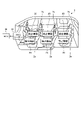
第1実施形態に係る検出システム1及び検出機器20について説明する。検出システム1は、検出機器20の検出結果に基づいて検出対象の状態を判定するものである。検出システム1は、例えば、車両2に設けられ、車両2内の検出対象の状態を判定する。検出システム1は、例えば、搭乗者の着座等による搭乗者の動作を判定するが、これに限定されない。以下、検出システム1について詳細に説明する。
次に、図6を参照して、第1実施形態の第1変形例に係る検出機器20Aについて説明する。なお、第1実施形態の第1変形例では、第1実施形態と同等の構成要素には同じ符号を付し、その詳細な説明を省略する。検出機器20Aは、第1及び第2スイッチ回路22R、22Lが電線26A、26Bを介してループアンテナ21に接続される点で第1実施形態の検出機器20とは異なる。検出機器20Aは、ループアンテナ21と、第1及び第2スイッチ回路22R、22Lと、電線26A、26Bと、RFID検出回路23とを備える。電線26Aは、2本の導体26aと、各導体26aを被覆する被覆部26bとを含んで構成される。各導体26aは、延在方向に沿って延在する。一方の導体26aは、一端がRFID検出回路23の第1回路端子23aに接続され、他端が第1スイッチ回路22Rのスイッチ端子22aに接続される。他方の導体26aは、一端がループアンテナ21の始端部21aに接続され、他端が第1スイッチ回路22Rのスイッチ端子22bに接続される。各導体26aは、延在方向に交差する方向において互いに隣接して配置される。各導体26aは、互いに隣接して配置されることにより、各電流経路を流れる電流により生じる少なくとも一部の磁界を互いに打ち消し合う。つまり、各導体26aは、一方の電流経路に流れる電流と他方の電流経路に流れる電流とが互いに反対向きに流れることにより磁界を互いに打ち消し合う。これにより、各導体26aは、ループアンテナ21に与える磁界の影響を抑制することができる。
次に、図9を参照して、第2実施形態に係る検出機器20Dについて説明する。なお、第2実施形態では、第1実施形態と同等の構成要素には同じ符号を付し、その詳細な説明を省略する。第2実施形態に係る検出機器20Dは、スイッチ部22の代わりにコンデンサ部24を備える点で第1実施形態の検出機器20とは異なる。検出機器20Dは、ループアンテナ21と、利得低減部としてのコンデンサ部24と、RFID検出回路23とを備える。コンデンサ部24は、第1コンデンサ回路24Rと、第2コンデンサ回路24Lとを含んで構成される。第1コンデンサ回路24Rは、ループアンテナ21を利得低減状態又は利得非低減状態に切り替えるものである。第1コンデンサ回路24Rは、RFID検出回路23の第1回路端子23aとループアンテナ21の始端部21aとの間に設けられる。第1コンデンサ回路24Rは、第1平板としての平板24aと、第2平板としての平板24bと、第1平板駆動機構(図示省略)とを含んで構成される。一対の平板24a、24bは、ループアンテナ21の利得を低減するための第1作用点として機能するものである。一対の平板24a、24bは、互いに対向して配置され、移動可能に設けられている。一対の平板24a、24bは、互いに接近することで電荷を蓄電可能な状態である蓄電可能状態となり、互いに離間することで電荷を蓄電不可な状態である蓄電不可状態となる。一対の平板24a、24bは、RFID検出回路23の第1回路端子23aからループアンテナ21の第1延在方向に沿ってλ/8離れた位置までのループアンテナ21上の範囲K1内に位置する。一方の平板24aは、RFID検出回路23の第1回路端子23aに接続されている。他方の平板24bは、ループアンテナ21の始端部21aに接続されている。第1平板駆動機構は、一対の平板24a、24bを互いに接近させることで蓄電可能状態に切り替え、一対の平板24a、24bを互いに離間させることで蓄電不可状態に切り替える。
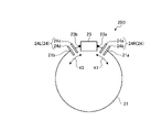
次に、図10を参照して、第2実施形態の変形例に係る検出機器20Eについて説明する。検出機器20Eは、ループアンテナ21の代わりにダイポールアンテナ40を備える点で第2実施形態の検出機器20Dとは異なる。検出機器20Eは、ダイポールアンテナ40と、第1及び第2コンデンサ回路24R、24Lと、RFID検出回路23とを備える。第1コンデンサ回路24Rは、RFID検出回路23の第1回路端子23aとダイポールアンテナ40の第1エレメント41の一端41aとの間に設けられる。第1コンデンサ回路24Rの一対の平板24a、24bは、RFID検出回路23の第1回路端子23aからダイポールアンテナ40の第1延在方向に沿ってλ/8離れた位置までのダイポールアンテナ40上の範囲K1内に位置する。第1コンデンサ回路24Rは、平板24aがRFID検出回路23の第1回路端子23aに接続され、平板24bが第1エレメント41の一端41aに接続されている。
次に、図11を参照して、第3実施形態に係る検出機器20Fについて説明する。なお、第3実施形態では、第1実施形態と同等の構成要素には同じ符号を付し、その詳細な説明を省略する。第3実施形態に係る検出機器20Fは、ループアンテナ21の導体間を接続する点で第1実施形態の検出機器20とは異なる。検出機器20Fは、ループアンテナ21と、導通線部28と、利得低減部としてのスイッチ回路25と、第1作用点としての第1接続点25dと、第2作用点としての第2接続点25eと、RFID検出回路23とを備える。第1及び第2接続点25d、25eは、ループアンテナ21の利得を低減するための作用点として機能するものである。第1接続点25dは、RFID検出回路23の第1回路端子23aからループアンテナ21の第1延在方向に沿ってλ/8離れた位置までのループアンテナ21上の範囲K1内に位置する。第2接続点25eは、RFID検出回路23の第2回路端子23bからループアンテナ21の第2延在方向に沿ってλ/8離れた位置までのループアンテナ21上の範囲K2内に位置する。第1及び第2接続点25d、25eは、導通線部28が接続される。
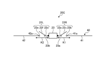
次に、図12を参照して、第3実施形態の変形例に係る検出機器20Gについて説明する。検出機器20Gは、ループアンテナ21の代わりにダイポールアンテナ40を備える点で第3実施形態の検出機器20Fとは異なる。検出機器20Gは、ダイポールアンテナ40と、導通線部28と、スイッチ回路25と、第1接続点25dと、第2接続点25eと、RFID検出回路23とを備える。第1及び第2接続点25d、25eは、ダイポールアンテナ40の利得を低減するための作用点として機能するものである。第1接続点25dは、RFID検出回路23の第1回路端子23aからダイポールアンテナ40の第1エレメント41の第1延在方向に沿ってλ/8離れた位置までの第1エレメント41上の範囲K1内に位置する。第2接続点25eは、RFID検出回路23の第2回路端子23bから第2エレメント42の第2延在方向に沿ってλ/8離れた位置までの第2エレメント42上の範囲K2内に位置する。第1及び第2接続点25d、25eは、導通線部28が接続される。
10 RFIDリーダー(読み取り装置)
20、20A、20B、20C、20D、20E、20F、20G 検出機器
21 ループアンテナ(アンテナ)
22 スイッチ部(利得低減部)
22R 第1スイッチ回路
22L 第2スイッチ回路
22a、22b スイッチ端子(第1作用点、第1端子、第2端子)
22d、22e スイッチ端子(第2作用点、第3端子、第4端子)
23 RFID検出回路(信号出力部)
23a 第1回路端子
23b 第2回路端子
24 コンデンサ部(利得低減部)
24R 第1コンデンサ回路
24L 第2コンデンサ回路
24a、24b 平板(第1作用点、第1平板、第2平板)
24c、24d 平板(第2作用点、第3平板、第4平板)
25d 第1接続点
25e 第2接続点
25 スイッチ回路(第3スイッチ回路、利得低減部)
30 ECU(判定部)
40 ダイポールアンテナ
K1、K2 範囲
Claims (6)
- 信号を含む電波を送受信するアンテナと、
前記アンテナに接続される第1回路端子及び第2回路端子を含んで構成され前記アンテナにより受信した信号に含まれる電力供給用の信号を動力として起動し検出対象を検出したことを表す検出信号を前記アンテナに出力する信号出力部と、
前記検出対象を検出していない場合に前記アンテナの利得を低減し前記信号出力部を起動させない利得低減状態となり、前記検出対象を検出した場合に前記アンテナの利得を低減せずに前記信号出力部を起動させ当該信号出力部から前記検出信号を出力させる利得非低減状態となる利得低減部と、を備え、
前記利得低減部は、前記電波の波長をλとしたとき、前記第1回路端子から前記アンテナの第1延在方向に沿ってλ/8離れた位置までの前記アンテナ上の範囲内に前記アンテナの利得を低減するための第1作用点を有し、且つ、前記第2回路端子から前記アンテナの第2延在方向に沿ってλ/8離れた位置までの前記アンテナ上の範囲内に前記アンテナの利得を低減するための第2作用点を有することを特徴とする検出機器。 - 前記第1及び第2作用点は、前記信号出力部と前記アンテナとを通電状態又は非通電状態にするための作用点である請求項1に記載の検出機器。
- 前記利得低減部は、前記第1作用点としての第1端子及び第2端子を互いに電気的に接続状態又は非接続状態に切り替え可能な第1スイッチ回路と、前記第2作用点としての第3端子及び第4端子を互いに電気的に接続状態又は非接続状態に切り替え可能な第2スイッチ回路と、を含んで構成され、
前記第1端子及び前記第2端子を接続状態とし、且つ、前記第3端子及び前記第4端子を接続状態とした前記利得非低減状態と、前記第1端子及び前記第2端子を非接続状態とし、且つ、前記第3端子及び前記第4端子を非接続状態とした前記利得低減状態と、を切り替え可能である請求項1又は2に記載の検出機器。 - 前記利得低減部は、前記第1作用点としての第1平板及び第2平板を蓄電可能状態又は蓄電不可状態に切り替え可能な第1コンデンサ回路と、前記第2作用点としての第3平板及び第4平板を蓄電可能状態又は蓄電不可状態に切り替え可能な第2コンデンサ回路と、を含んで構成され、
前記第1平板及び前記第2平板を蓄電可能状態とし、且つ、前記第3平板及び前記第4平板を蓄電可能状態とした前記利得非低減状態と、前記第1平板及び前記第2平板を蓄電不可状態とし、且つ、前記第3平板及び前記第4平板を蓄電不可状態とした前記利得低減状態と、を切り替え可能である請求項1又は2に記載の検出機器。 - 前記利得低減部は、前記第1作用点及び前記第2作用点を互いに電気的に接続状態又は非接続状態に切り替え可能な第3スイッチ回路を含んで構成され、
前記第3スイッチ回路は、前記第1作用点及び前記第2作用点を非接続状態とした前記利得非低減状態と、前記第1作用点及び前記第2作用点を接続状態とした前記利得低減状態と、を切り替え可能である請求項1に記載の検出機器。 - 信号を含む電波を送受信し、少なくとも電力供給用の信号を含む送信信号を送信する読み取り装置と、
前記読み取り装置との間で相互に信号を送受信するアンテナ、前記アンテナに接続される第1回路端子及び第2回路端子を有し前記アンテナにより受信した信号に含まれる電力供給用の信号を動力として起動し検出対象を検出したことを表す検出信号を前記アンテナに出力する信号出力部、及び、前記検出対象を検出していない場合に前記アンテナの利得を低減し前記信号出力部を起動させない利得低減状態となり、前記検出対象を検出した場合に前記アンテナの利得を低減せずに前記信号出力部を起動させ当該信号出力部から前記検出信号を出力させる利得非低減状態となる利得低減部を含んで構成される検出機器と、
前記読み取り装置に接続され、当該読み取り装置が受信した前記検出信号に基づいて前記検出対象の状態を判定する判定部と、を備え、
前記利得低減部は、前記電波の波長をλとしたとき、前記第1回路端子から前記アンテナの第1延在方向に沿ってλ/8離れた位置までの前記アンテナ上の範囲内に前記アンテナの利得を低減するための第1作用点を有し、且つ、前記第2回路端子から前記アンテナの第2延在方向に沿ってλ/8離れた位置までの前記アンテナ上の範囲内に前記アンテナの利得を低減するための第2作用点を有することを特徴とする検出システム。
Priority Applications (4)
| Application Number | Priority Date | Filing Date | Title |
|---|---|---|---|
| JP2018101233A JP7152190B2 (ja) | 2018-05-28 | 2018-05-28 | 検出機器及び検出システム |
| EP19175093.4A EP3576220B1 (en) | 2018-05-28 | 2019-05-17 | Detection device and detection system |
| US16/416,551 US10733398B2 (en) | 2018-05-28 | 2019-05-20 | Detection device and detection system |
| CN201910446828.2A CN110539719B (zh) | 2018-05-28 | 2019-05-27 | 检测设备以及检测系统 |
Applications Claiming Priority (1)
| Application Number | Priority Date | Filing Date | Title |
|---|---|---|---|
| JP2018101233A JP7152190B2 (ja) | 2018-05-28 | 2018-05-28 | 検出機器及び検出システム |
Publications (2)
| Publication Number | Publication Date |
|---|---|
| JP2019206201A JP2019206201A (ja) | 2019-12-05 |
| JP7152190B2 true JP7152190B2 (ja) | 2022-10-12 |
Family
ID=66589434
Family Applications (1)
| Application Number | Title | Priority Date | Filing Date |
|---|---|---|---|
| JP2018101233A Active JP7152190B2 (ja) | 2018-05-28 | 2018-05-28 | 検出機器及び検出システム |
Country Status (4)
| Country | Link |
|---|---|
| US (1) | US10733398B2 (ja) |
| EP (1) | EP3576220B1 (ja) |
| JP (1) | JP7152190B2 (ja) |
| CN (1) | CN110539719B (ja) |
Families Citing this family (1)
| Publication number | Priority date | Publication date | Assignee | Title |
|---|---|---|---|---|
| JP6734831B2 (ja) * | 2017-10-04 | 2020-08-05 | 矢崎総業株式会社 | 検出機器及び検出システム |
Citations (10)
| Publication number | Priority date | Publication date | Assignee | Title |
|---|---|---|---|---|
| JP2006217048A (ja) | 2005-02-01 | 2006-08-17 | Matsushita Electric Ind Co Ltd | 非接触通信用リーダ装置 |
| JP2008545137A (ja) | 2005-06-29 | 2008-12-11 | ソシエテ ドゥ テクノロジー ミシュラン | Saw較正係数を格納するrfid |
| JP2011091541A (ja) | 2009-10-21 | 2011-05-06 | Takaya Corp | アンテナ装置及び通信システム |
| US20110279232A1 (en) | 2008-06-03 | 2011-11-17 | Keystone Technology Solutions, Llc | Systems and methods to selectively connect antennas to receive and backscatter radio frequency signals |
| JP2013055611A (ja) | 2011-09-06 | 2013-03-21 | Renesas Electronics Corp | 無線通信システム、無線通信方法、およびデータ送信機 |
| JP5700135B2 (ja) | 2011-10-28 | 2015-04-15 | 株式会社村田製作所 | 受電装置、送電装置およびワイヤレス電力伝送システム |
| JP2015529971A (ja) | 2012-07-24 | 2015-10-08 | レイセオン カンパニー | スイッチで切り替え可能なコンデンサ |
| JP2016127442A (ja) | 2015-01-05 | 2016-07-11 | 株式会社リコー | 無線通信装置及び携帯端末装置 |
| WO2017043482A1 (ja) | 2015-09-11 | 2017-03-16 | タカヤ株式会社 | Rfidシステム |
| JP2017216707A (ja) | 2017-07-13 | 2017-12-07 | インテル コーポレイション | 可搬装置のための近距離場通信(nfc)および近接センサー |
Family Cites Families (10)
| Publication number | Priority date | Publication date | Assignee | Title |
|---|---|---|---|---|
| ES2136229T3 (es) * | 1994-10-17 | 1999-11-16 | Iee Sarl | Procedimiento e instalacion de deteccion de ciertos parametros de una butaca auxiliar para niño en vista al mando del funcionamiento de dos airbags de un vehiculo. |
| US6476708B1 (en) * | 1998-03-20 | 2002-11-05 | Hid Corporation | Detection of an RFID device by an RF reader unit operating in a reduced power state |
| DE60134560D1 (de) * | 2000-08-28 | 2008-08-07 | In4Tel Ltd | Derfrequenten betriebs von mobilkommunikationsantennen |
| US6830193B2 (en) * | 2001-11-29 | 2004-12-14 | Matsushita Electric Industrial Co., Ltd. | Non-contact IC card |
| KR100963041B1 (ko) * | 2008-03-05 | 2010-06-10 | 한국전자통신연구원 | 인식 거리 조절형 전파 식별 태그 장치 및 상기 장치를이용한 전파 식별 정보 운영 방법 |
| KR101266698B1 (ko) * | 2008-11-28 | 2013-05-28 | 히타치가세이가부시끼가이샤 | 멀티빔 안테나 장치 |
| JP2013049290A (ja) | 2010-03-11 | 2013-03-14 | Autoliv Development Ab | シートベルト装着検知装置 |
| WO2011132190A2 (en) * | 2010-04-22 | 2011-10-27 | R.F Keeper Ltd | Event driven context switching in passive radio frequency identification tags |
| US8665026B2 (en) * | 2012-03-14 | 2014-03-04 | Broadcom Corporation | Gain control system |
| JP5846497B2 (ja) | 2012-05-23 | 2016-01-20 | アルプス電気株式会社 | シートベルトを備えた車両 |
-
2018
- 2018-05-28 JP JP2018101233A patent/JP7152190B2/ja active Active
-
2019
- 2019-05-17 EP EP19175093.4A patent/EP3576220B1/en active Active
- 2019-05-20 US US16/416,551 patent/US10733398B2/en active Active
- 2019-05-27 CN CN201910446828.2A patent/CN110539719B/zh active Active
Patent Citations (10)
| Publication number | Priority date | Publication date | Assignee | Title |
|---|---|---|---|---|
| JP2006217048A (ja) | 2005-02-01 | 2006-08-17 | Matsushita Electric Ind Co Ltd | 非接触通信用リーダ装置 |
| JP2008545137A (ja) | 2005-06-29 | 2008-12-11 | ソシエテ ドゥ テクノロジー ミシュラン | Saw較正係数を格納するrfid |
| US20110279232A1 (en) | 2008-06-03 | 2011-11-17 | Keystone Technology Solutions, Llc | Systems and methods to selectively connect antennas to receive and backscatter radio frequency signals |
| JP2011091541A (ja) | 2009-10-21 | 2011-05-06 | Takaya Corp | アンテナ装置及び通信システム |
| JP2013055611A (ja) | 2011-09-06 | 2013-03-21 | Renesas Electronics Corp | 無線通信システム、無線通信方法、およびデータ送信機 |
| JP5700135B2 (ja) | 2011-10-28 | 2015-04-15 | 株式会社村田製作所 | 受電装置、送電装置およびワイヤレス電力伝送システム |
| JP2015529971A (ja) | 2012-07-24 | 2015-10-08 | レイセオン カンパニー | スイッチで切り替え可能なコンデンサ |
| JP2016127442A (ja) | 2015-01-05 | 2016-07-11 | 株式会社リコー | 無線通信装置及び携帯端末装置 |
| WO2017043482A1 (ja) | 2015-09-11 | 2017-03-16 | タカヤ株式会社 | Rfidシステム |
| JP2017216707A (ja) | 2017-07-13 | 2017-12-07 | インテル コーポレイション | 可搬装置のための近距離場通信(nfc)および近接センサー |
Also Published As
| Publication number | Publication date |
|---|---|
| US20190362112A1 (en) | 2019-11-28 |
| CN110539719A (zh) | 2019-12-06 |
| EP3576220A1 (en) | 2019-12-04 |
| EP3576220B1 (en) | 2020-11-18 |
| CN110539719B (zh) | 2022-02-11 |
| US10733398B2 (en) | 2020-08-04 |
| JP2019206201A (ja) | 2019-12-05 |
Similar Documents
| Publication | Publication Date | Title |
|---|---|---|
| US10777875B2 (en) | Detection device and detection system | |
| CN108944579B (zh) | 车辆用检测系统 | |
| US7019620B2 (en) | Device for the inductive transmission of electrical power | |
| US9755460B2 (en) | Power reception device, power transmission device and wireless power transmission system | |
| US9520916B2 (en) | Vehicular power line communication system and transmitter | |
| CN106465083B (zh) | 通过紧急呼叫控制设备对机动车天线的二次使用 | |
| US7271501B2 (en) | Data transmission between a chassis and a seat movably arranged on the chassis | |
| EP3055701B1 (en) | Self-contained branch circuit monitor | |
| US20180138966A1 (en) | Vehicle-mounted communication apparatus | |
| KR20150072137A (ko) | 차량의 무선 충전 시스템 | |
| JP7152190B2 (ja) | 検出機器及び検出システム | |
| CN104081580A (zh) | 天线设备和天线的配置方法 | |
| US4761826A (en) | Signal separating device | |
| JP6226718B2 (ja) | ワイヤレス給電システム | |
| JP6451577B2 (ja) | 無線通信装置 | |
| US10403985B2 (en) | Wire harness | |
| EP1533865A1 (en) | On-board signal transmitter for implementing keyless procedure | |
| CN112368947B (zh) | 用于非接触数据传输的车辆用装置 | |
| WO2006004184A1 (ja) | 無線通信システム | |
| KR101204711B1 (ko) | 노이즈 상쇄 제거를 위한 가변 코일 구조의 지뢰 탐지 시스템 | |
| CN109698401B (zh) | 用于车辆环境内的低频通信的天线及低频通信系统 | |
| JP2017139899A (ja) | 非接触送電装置、非接触受電装置、及び非接触電力伝送システム | |
| WO2020095234A1 (en) | A bi-functional receiving/ transmitting element for wireless charging | |
| CN114365353A (zh) | 天线装置、综合通信装置以及无线通信装置 | |
| JP2019062373A (ja) | 複合アンテナ装置 |
Legal Events
| Date | Code | Title | Description |
|---|---|---|---|
| A621 | Written request for application examination |
Free format text: JAPANESE INTERMEDIATE CODE: A621 Effective date: 20210416 |
|
| A131 | Notification of reasons for refusal |
Free format text: JAPANESE INTERMEDIATE CODE: A131 Effective date: 20220628 |
|
| A521 | Request for written amendment filed |
Free format text: JAPANESE INTERMEDIATE CODE: A523 Effective date: 20220808 |
|
| TRDD | Decision of grant or rejection written | ||
| A01 | Written decision to grant a patent or to grant a registration (utility model) |
Free format text: JAPANESE INTERMEDIATE CODE: A01 Effective date: 20220927 |
|
| A61 | First payment of annual fees (during grant procedure) |
Free format text: JAPANESE INTERMEDIATE CODE: A61 Effective date: 20220929 |
|
| R150 | Certificate of patent or registration of utility model |
Ref document number: 7152190 Country of ref document: JP Free format text: JAPANESE INTERMEDIATE CODE: R150 |
|
| S531 | Written request for registration of change of domicile |
Free format text: JAPANESE INTERMEDIATE CODE: R313531 |
|
| R350 | Written notification of registration of transfer |
Free format text: JAPANESE INTERMEDIATE CODE: R350 |