JP7144796B2 - Simulation system and program - Google Patents
Simulation system and program Download PDFInfo
- Publication number
- JP7144796B2 JP7144796B2 JP2018020887A JP2018020887A JP7144796B2 JP 7144796 B2 JP7144796 B2 JP 7144796B2 JP 2018020887 A JP2018020887 A JP 2018020887A JP 2018020887 A JP2018020887 A JP 2018020887A JP 7144796 B2 JP7144796 B2 JP 7144796B2
- Authority
- JP
- Japan
- Prior art keywords
- user
- information
- reference point
- character
- display
- Prior art date
- Legal status (The legal status is an assumption and is not a legal conclusion. Google has not performed a legal analysis and makes no representation as to the accuracy of the status listed.)
- Active
Links
Images


Description
本発明は、シミュレーションシステム及びプログラム等に関する。 The present invention relates to a simulation system, a program, and the like.
従来より、複合現実(MR)、拡張現実(AR)、バーチャルリアリティ(VR)などを実現するシステムが知られている。例えば特許文献1には、使用者の視点位置から観察される実空間画像に、使用者の視点位置から観察される仮想物体の画像を合成表示する画像処理装置が開示されている。この画像処理装置では、使用者が操作することで実空間の領域を指定し、指定された実空間の領域に基づいて仮想オブジェクトを作成し、作成された仮想オブジェクトを、観察された実空間画像に合成する。 Conventionally, systems that realize mixed reality (MR), augmented reality (AR), virtual reality (VR), and the like are known. For example, Patent Literature 1 discloses an image processing device that synthesizes and displays an image of a virtual object observed from the user's viewpoint position on a real space image observed from the user's viewpoint position. In this image processing device, a real space area is specified by a user's operation, a virtual object is created based on the specified real space area, and the created virtual object is converted into an observed real space image. Synthesize to
特許文献1のようなMRやARのシステムを用いれば、実空間画像に対して仮想空間画像を合成することができる。しかしながら、実空間を移動するユーザに対して、対応する仮想空間にガイド用などの配置オブジェクトを見やすく配置する工夫については、提案されていなかった。また配置オブジェクトの配置に実空間の情報を有効活用する手法についても提案されていなかった。 If an MR or AR system such as that disclosed in Patent Document 1 is used, a virtual space image can be synthesized with a real space image. However, no proposals have been made for arranging placement objects, such as guide objects, in a corresponding virtual space so that the user moving in the real space can easily see them. In addition, no technique has been proposed for effectively utilizing information on the real space in arranging objects to be arranged.
本発明の幾つかの態様によれば、実空間情報を有効活用して配置オブジェクトの好適な表示態様での表示を可能にするシミュレーションシステム及びプログラム等を提供できる。 According to some aspects of the present invention, it is possible to provide a simulation system, a program, and the like that make it possible to effectively utilize real space information and display arranged objects in a preferred display mode.
本発明の一態様は、ユーザの周囲の実空間の認識処理を行うことで得られる実空間情報と、前記ユーザの位置情報を含むユーザ情報を取得する情報取得部と、前記実空間情報に基づいて、前記実空間に対応する仮想空間を生成する仮想空間生成部と、前記ユーザ情報と前記実空間情報とに基づいて、前記仮想空間に基準点を設定し、前記基準点に基づいて配置オブジェクトを配置するオブジェクト処理部と、前記配置オブジェクトの画像を含む画像を表示部に表示する処理を行う表示処理部と、を含み、前記オブジェクト処理部は、前記ユーザに対応する前記仮想空間のユーザ移動体と前記配置オブジェクトとの位置関係に応じて、前記配置オブジェクトの表示態様を設定するシミュレーションシステムに科刑する。また本発明は、上記各部としてコンピュータを機能させるプログラム、又は該プログラムを記憶したコンピュータ読み取り可能な情報記憶媒体に関係する。 According to one aspect of the present invention, real space information obtained by performing recognition processing of a real space around a user, an information acquisition unit that acquires user information including position information of the user, and a virtual space generation unit for generating a virtual space corresponding to the real space; setting a reference point in the virtual space based on the user information and the real space information; and placing objects based on the reference point. and a display processing unit that performs processing for displaying an image including the image of the placed object on a display unit, wherein the object processing unit performs a user movement in the virtual space corresponding to the user. A simulation system that sets the display mode of the placement object according to the positional relationship between the body and the placement object. The present invention also relates to a program that causes a computer to function as the above units, or a computer-readable information storage medium that stores the program.
本発明の一態様では、ユーザの周囲の実空間の認識処理を行うことで実空間情報が取得され、実空間情報に基づき実空間に対応する仮想空間が生成される。また実空間情報に基づき基準点が設定され、基準点に基づき配置オブジェクトが仮想空間に配置される。そして仮想空間のユーザ移動体と配置オブジェクトとの位置関係に応じて、配置オブジェクトの表示態様が設定される。従って、実空間に対して、対応する仮想空間を設定して配置オブジェクトを配置し、この配置オブジェクトの表示態様を、仮想空間のユーザ移動体と配置オブジェクトとの位置関係に応じて設定できるようになる。従って、実空間情報を有効活用して配置オブジェクトの好適な表示態様での表示を可能にするシミュレーションシステム等の提供が可能になる。 In one aspect of the present invention, real space information is acquired by performing recognition processing of the real space around the user, and a virtual space corresponding to the real space is generated based on the real space information. A reference point is set based on the real space information, and the placed object is arranged in the virtual space based on the reference point. Then, the display mode of the placed object is set according to the positional relationship between the user moving body in the virtual space and the placed object. Therefore, it is possible to set a virtual space corresponding to the real space, place the placed object, and set the display mode of the placed object according to the positional relationship between the user's moving body and the placed object in the virtual space. Become. Therefore, it is possible to provide a simulation system or the like that makes effective use of real space information and enables display of arranged objects in a suitable display mode.
また本発明の一態様では、前記オブジェクト処理部は、前記配置オブジェクトとして第1の配置オブジェクト及び第2の配置オブジェクトを配置し、前記ユーザ移動体の前記基準点側の方向に、前記第1の配置オブジェクト及び前記第2の配置オブジェクトが位置する場合に、前記第1の配置オブジェクトを表示状態に設定し、前記第2の配置オブジェクトを非表示状態に設定し、前記ユーザ移動体の前記基準点側の方向の反対方向に、前記第1の配置オブジェクトが位置し、前記ユーザ移動体の前記基準点側の方向に、前記第2の配置オブジェクトが位置する場合に、前記第1の配置オブジェクトを非表示状態に設定し、前記第2の配置オブジェクトを表示状態に設定してもよい。 In one aspect of the present invention, the object processing unit arranges a first arranged object and a second arranged object as the arranged objects, and arranges the first arranged object in the direction of the reference point side of the user's moving object. When the placement object and the second placement object are positioned, the first placement object is set in a display state, the second placement object is set in a non-display state, and the reference point of the user's moving object is set. When the first placed object is positioned in the direction opposite to the side direction and the second placed object is positioned in the direction of the reference point side of the user moving body, the first placed object A non-display state may be set, and the second placed object may be set in a display state.
このようにすれば、表示される配置オブジェクトの数を制限することが可能になり、ユーザにとって見やすい配置オブジェクトの表示態様の設定が可能になる。 By doing so, it is possible to limit the number of displayed arranged objects, and it is possible to set a display mode of arranged objects that is easy for the user to see.
また本発明の一態様では、前記仮想空間のオブジェクトには表示に関する優先順位が設定されており、前記オブジェクト処理部は、前記配置オブジェクトと前記仮想空間の他のオブジェクトとが前記ユーザ移動体から見て重なって配置される場合には、前記優先順位に基づいて前記配置オブジェクトの表示態様を設定してもよい。 In one aspect of the present invention, a priority order regarding display is set for the objects in the virtual space. When the objects are arranged so as to overlap each other, the display mode of the arranged objects may be set based on the order of priority.
このようにすれば、配置オブジェクトと他のオブジェクトとの表示に関する優先順位を反映させた配置オブジェクトの表示態様の設定が可能になる。 By doing so, it is possible to set the display mode of the placed object reflecting the priority of display of the placed object and other objects.
また本発明の一態様では、前記オブジェクト処理部は、前記ユーザ移動体の視線方向に応じて、前記配置オブジェクトの表示態様又は配置態様を設定してもよい。 Further, in one aspect of the present invention, the object processing unit may set a display mode or a layout mode of the placed object according to a line-of-sight direction of the user's moving body.
このようにすれば、ユーザ移動体の視線方向に応じた適切な表示態様、配置態様に、配置オブジェクトを設定できるようになる。 By doing so, it is possible to set the placed object in an appropriate display mode and layout mode according to the line-of-sight direction of the user's moving body.
また本発明の一態様では、前記オブジェクト処理部は、前記基準点の位置に応じて、前記配置オブジェクトの表示態様又は配置態様を設定してもよい。 In one aspect of the invention, the object processing section may set a display mode or a layout mode of the placed object according to the position of the reference point.
このようにすれば、基準点の位置に応じた適切な表示態様又は配置態様に配置オブジェクトを設定できるようになる。 By doing so, it is possible to set the placed object in an appropriate display mode or layout mode according to the position of the reference point.
また本発明の一態様では、前記オブジェクト処理部は、前記ユーザの状況情報、前記ユーザ移動体の状況情報、或いはゲーム状況情報に応じて、前記基準点の設定を行ってもよい。 Further, in one aspect of the present invention, the object processing section may set the reference point according to the user's situation information, the user's mobile object's situation information, or the game situation information.
このようにすれば、ユーザの状況、ユーザ移動体の状況、或いはゲーム状況に応じた適切な基準点の設定が可能になる。 In this way, it is possible to set an appropriate reference point according to the user's situation, the user's mobile object's situation, or the game situation.
また本発明の一態様では、前記情報取得部は、前記実空間の環境情報を取得し、前記オブジェクト処理部は、前記環境情報に応じて、前記基準点の設定、或いは前記配置オブジェクトの表示態様又は配置態様の設定を行ってもよい。 In one aspect of the present invention, the information acquisition unit acquires the environment information of the real space, and the object processing unit sets the reference point or displays the arranged object according to the environment information. Alternatively, the arrangement mode may be set.
このようにすれば、実空間の環境の状況を反映させた、適切な基準点の設定や、配置オブジェクトの適切な表示態様又は配置態様の設定が可能になる。 By doing so, it is possible to set an appropriate reference point and an appropriate display mode or layout mode of the placed object, reflecting the environment of the real space.
また本発明の一態様では、前記オブジェクト処理部は、前記ユーザの状況情報、前記ユーザ移動体の状況情報、或いはゲーム状況情報に応じて、前記配置オブジェクトの表示態様又は配置態様を設定してもよい。 In one aspect of the present invention, the object processing unit may set the display mode or layout mode of the placed object according to the user situation information, the user moving body situation information, or the game situation information. good.
このようにすれば、ユーザの状況、ユーザ移動体の状況、或いはゲーム状況に応じた適切な配置オブジェクトの表示態様又は配置態様の設定が可能になる。 In this way, it is possible to set an appropriate display mode or layout mode of placed objects according to the user's situation, the user's mobile object's situation, or the game situation.
また本発明の一態様では、配置オブジェクトは、前記ユーザの移動をガイドする配置オブジェクト、或いは前記ユーザに対して警告、報知又は指示を行う配置オブジェクトであってもよい。 In one aspect of the present invention, the placement object may be a placement object that guides movement of the user, or a placement object that warns, notifies, or instructs the user.
このようにすれば、配置オブジェクトを用いることで、実空間でのユーザの好適なガイド表示を実現したり、ユーザに対して種々の状況についての警告、報知又は指示を行うことが可能になる。 In this way, by using the arranged objects, it is possible to realize a suitable guide display for the user in the real space, and to issue warnings, notifications, or instructions to the user regarding various situations.
また本発明の一態様では、前記オブジェクト処理部は、前記ユーザの行動のターゲットに対して前記基準点を設定し、前記ターゲットに設定された前記基準点に基づいて前記配置オブジェクトを配置してもよい。 Further, in one aspect of the present invention, the object processing unit may set the reference point for the target of the user's behavior, and arrange the placement object based on the reference point set for the target. good.
このようにすればユーザの行動のターゲットに対して設定された基準点に基づいて、配置オブジェクトを配置して、その表示態様を設定できるようになる。 In this way, it is possible to arrange the arrangement object and set the display mode based on the reference point set for the target of the user's action.
以下、本実施形態について説明する。なお、以下に説明する本実施形態は、特許請求の範囲に記載された本発明の内容を不当に限定するものではない。また本実施形態で説明される構成の全てが、本発明の必須構成要件であるとは限らない。 The present embodiment will be described below. It should be noted that the embodiments described below do not unduly limit the content of the present invention described in the claims. Moreover, not all the configurations described in the present embodiment are essential constituent elements of the present invention.
1.シミュレーションシステム
図1は、本実施形態のシミュレーションシステム(シミュレータ、ゲームシステム、画像生成システム)の構成例を示すブロック図である。本実施形態のシミュレーションシステムはMR(Mixed Reality)やAR(Augmented Reality)などを実現するものであり、ゲームコンテンツを提供するゲームシステムなどの種々のシステムに適用可能である。なお、本実施形態のシミュレーションシステムは図1の構成に限定されず、その構成要素(各部)の一部を省略したり、他の構成要素を追加するなどの種々の変形実施が可能である。
1. Simulation System FIG. 1 is a block diagram showing a configuration example of a simulation system (simulator, game system, image generation system) according to the present embodiment. The simulation system of this embodiment realizes MR (Mixed Reality), AR (Augmented Reality), etc., and is applicable to various systems such as a game system that provides game content. The simulation system of this embodiment is not limited to the configuration of FIG. 1, and various modifications such as omitting some of its constituent elements (each part) or adding other constituent elements are possible.
操作部160は、ユーザ(プレーヤ)が種々の操作情報(入力情報)を入力するためのものである。操作部160は、例えば操作ボタン、方向指示キー、ジョイスティック、ハンドル、ペダル、レバー又は音声入力装置等の種々の操作デバイスにより実現できる。
The
検出部162はユーザの動きを検出するものであり、例えば加速度センサ、ジャイロセンサなどのモーションセンサにより実現できる。例えば検出部162はユーザの部位などに取り付けられてユーザの部位等の動きを検出する。例えばユーザの部位が動いた時の加速度等の変化を加速度センサ等のモーションセンサにより検出して、ユーザの動きを検出する。なおユーザの動きをカメラを用いて検出してもよい。一例としては、2つの赤外LEDと2つのカメラ(ステレオカメラ)で指先等の動きを検出するリープモーションセンサを用いてもよい。或いはキネクト(登録商標)による姿勢検出によりユーザの動きを検出してもよい。
The
撮像部164(カメラ)は、被写体の撮像を行うものであり、CCDやCMOSセンサなどの画像センサと、フォーカスレンズ等により構成される光学系などにより実現される。撮像部164は赤外線カメラなどにより実現されるデプスカメラであってもよい。例えば撮像部164に、赤外線パターンを投稿するIRプロジェクターを設け、投光した赤外線パターンを赤外線カメラにより読み取り、パターンの歪みからデプス情報を取得するライトコーディング方式を採用してもよい。
The image capturing unit 164 (camera) captures an image of a subject, and is realized by an image sensor such as a CCD or CMOS sensor and an optical system including a focus lens and the like. The
記憶部170は各種の情報を記憶する。記憶部170は、処理部100や通信部196などのワーク領域として機能する。ゲームプログラムや、ゲームプログラムの実行に必要なゲームデータは、この記憶部170に保持される。記憶部170の機能は、半導体メモリ(DRAM、VRAM)、HDD(ハードディスクドライブ)、SSD、光ディスク装置などにより実現できる。記憶部170は、実空間情報記憶部171、オブジェクト情報記憶部172、描画バッファ178を含む。
The
情報記憶媒体180(コンピュータにより読み取り可能な媒体)は、プログラムやデータなどを格納するものであり、その機能は、光ディスク(DVD、BD、CD)、HDD、或いは半導体メモリ(ROM)などにより実現できる。処理部100は、情報記憶媒体180に格納されるプログラム(データ)に基づいて本実施形態の種々の処理を行う。即ち情報記憶媒体180には、本実施形態の各部としてコンピュータ(入力装置、処理部、記憶部、出力部を備える装置)を機能させるためのプログラム(各部の処理をコンピュータに実行させるためのプログラム)が記憶される。
The information storage medium 180 (computer-readable medium) stores programs and data, and its function can be realized by an optical disk (DVD, BD, CD), HDD, semiconductor memory (ROM), or the like. . The
表示部190は、本実施形態により生成された画像を出力するものであり、LCD、有機ELディスプレイ、或いはCRTなどにより実現できる。表示部190は、例えば後述の図2、図3のHMD200(頭部装着型表示装置)のディスプレイ(表示装置)である。音出力部192は、本実施形態により生成された音を出力するものであり、その機能は、スピーカ又はヘッドホンなどにより実現できる。
A
I/F(インターフェース)部194は、携帯型情報記憶媒体195とのインターフェース処理を行うものであり、その機能はI/F処理用のASICなどにより実現できる。携帯型情報記憶媒体195は、ユーザが各種の情報を保存するためのものであり、電源が非供給になった場合にもこれらの情報の記憶を保持する記憶装置である。携帯型情報記憶媒体195は、ICカード(メモリカード)、USBメモリ、或いは磁気カードなどにより実現できる。
An I/F (interface)
通信部196は、有線や無線のネットワークを介して外部(他の装置)との間で通信を行うものであり、その機能は、通信用ASIC又は通信用プロセッサなどのハードウェアや、通信用ファームウェアにより実現できる。
The
なお本実施形態の各部としてコンピュータを機能させるためのプログラム(データ)は、サーバ(ホスト装置)が有する情報記憶媒体からネットワーク及び通信部196を介して情報記憶媒体180(あるいは記憶部170)に配信してもよい。このようなサーバ(ホスト装置)による情報記憶媒体の使用も本発明の範囲内に含めることができる。
A program (data) for causing a computer to function as each part of the present embodiment is delivered from an information storage medium of a server (host device) to the information storage medium 180 (or storage unit 170) via the network and
処理部100(プロセッサ)は、操作部160からの操作情報や、図2、図3のHMD200のトラッキング情報(HMDの位置及び方向の少なくとも一方の情報。視点位置及び視線方向の少なくとも一方の情報)や、プログラムなどに基づいて、情報取得処理、仮想空間生成処理、オブジェクト処理、仮想カメラ制御処理、ゲーム処理(シミュレーション処理)、表示処理、或いは音処理などを行う。
The processing unit 100 (processor) receives operation information from the
処理部100の各部が行う本実施形態の各処理(各機能)はプロセッサ(ハードウェアを含むプロセッサ)により実現できる。例えば本実施形態の各処理は、プログラム等の情報に基づき動作するプロセッサと、プログラム等の情報を記憶するメモリにより実現できる。プロセッサは、例えば各部の機能が個別のハードウェアで実現されてもよいし、或いは各部の機能が一体のハードウェアで実現されてもよい。例えば、プロセッサはハードウェアを含み、そのハードウェアは、デジタル信号を処理する回路及びアナログ信号を処理する回路の少なくとも一方を含むことができる。例えば、プロセッサは、回路基板に実装された1又は複数の回路装置(例えばIC等)や、1又は複数の回路素子(例えば抵抗、キャパシター等)で構成することもできる。プロセッサは、例えばCPU(Central Processing Unit)であってもよい。但し、プロセッサはCPUに限定されるものではなく、GPU(Graphics Processing Unit)、或いはDSP(Digital Signal Processor)等、各種のプロセッサを用いることが可能である。またプロセッサはASICによるハードウェア回路であってもよい。またプロセッサは、アナログ信号を処理するアンプ回路やフィルター回路等を含んでもよい。メモリ(記憶部170)は、SRAM、DRAM等の半導体メモリであってもよいし、レジスターであってもよい。或いはハードディスク装置(HDD)等の磁気記憶装置であってもよいし、光学ディスク装置等の光学式記憶装置であってもよい。例えば、メモリはコンピュータにより読み取り可能な命令を格納しており、当該命令がプロセッサにより実行されることで、処理部100の各部の処理(機能)が実現されることになる。ここでの命令は、プログラムを構成する命令セットでもよいし、プロセッサのハードウェア回路に対して動作を指示する命令であってもよい。
Each process (each function) of this embodiment performed by each part of the
処理部100は、情報取得部102、仮想空間生成部104、オブジェクト処理部106、仮想カメラ制御部112、ゲーム処理部114、表示処理部120、音処理部130を含む。上述したように、これらの各部により実行される本実施形態の各処理は、プロセッサ(或いはプロセッサ及びメモリ)により実現できる。なお、これらの構成要素(各部)の一部を省略したり、他の構成要素を追加するなどの種々の変形実施が可能である。
The
情報取得部102は各種の情報の取得処理を行う。仮想空間生成部104は仮想空間の生成処理を行い、オブジェクト処理部106はキャラクタのオブジェクトや配置オブジェクトについての種々の処理を行う。情報取得部102、仮想空間生成部104、オブジェクト処理部106の詳細については後述する。
The
仮想カメラ制御部112(仮想カメラ制御処理のプログラムモジュール)は、仮想カメラの制御を行う。例えば、操作部160により入力されたユーザの操作情報やトラッキング情報などに基づいて、仮想カメラを制御する処理を行う。例えば仮想カメラ制御部112は、ユーザの一人称視点又は三人称視点として設定される仮想カメラの制御を行う。例えば実空間のユーザに対応する仮想空間のユーザ移動体の視点(一人称視点)に対応する位置に、仮想カメラを設定して、仮想カメラの視点位置や視線方向を設定することで、仮想カメラの位置(位置座標)や姿勢(回転軸回りでの回転角度)を制御する。或いは、ユーザ移動体に追従する視点(三人称視点)の位置に、仮想カメラを設定して、仮想カメラの視点位置や視線方向を設定することで、仮想カメラの位置や姿勢を制御する。
The virtual camera control unit 112 (program module for virtual camera control processing) controls the virtual camera. For example, processing for controlling the virtual camera is performed based on the user's operation information and tracking information input by the
例えば仮想カメラ制御部112は、視点トラッキングにより取得されたユーザの視点情報のトラッキング情報に基づいて、ユーザの視点変化に追従するように仮想カメラを制御する。例えば本実施形態では、ユーザの視点位置、視線方向の少なくとも1つである視点情報のトラッキング情報(視点トラッキング情報)が取得される。このトラッキング情報は、例えばHMD200のトラッキング処理を行うことで取得できる。そして仮想カメラ制御部112は、取得されたトラッキング情報(ユーザの視点位置及び視線方向の少なくとも一方の情報)に基づいて仮想カメラの視点位置、視線方向を変化させる。例えば、仮想カメラ制御部112は、実空間でのユーザの視点位置、視線方向の変化に応じて、仮想空間での仮想カメラの視点位置、視線方向(位置、姿勢)が変化するように、仮想カメラを設定する。このようにすることで、ユーザの視点情報のトラッキング情報に基づいて、ユーザの視点変化に追従するように仮想カメラを制御できる。
For example, the virtual
ゲーム処理部114(ゲーム処理のプログラムモジュール)は、ユーザがゲームをプレイするための種々のゲーム処理を行う。別の言い方をすれば、ゲーム処理部114(シミュレーション処理部)は、ユーザがMR(Mixed Reality)、AR(Augmented Reality)、又はVR(Virtual Reality)などを体験するための種々のシミュレーション処理を実行する。ゲーム処理は、例えば、ゲーム開始条件が満たされた場合にゲームを開始する処理、開始したゲームを進行させる処理、ゲーム終了条件が満たされた場合にゲームを終了する処理、或いはゲーム成績を演算する処理などである。 The game processing unit 114 (game processing program module) performs various game processing for the user to play the game. In other words, the game processing unit 114 (simulation processing unit) executes various simulation processes for the user to experience MR (Mixed Reality), AR (Augmented Reality), or VR (Virtual Reality). do. Game processing includes, for example, processing for starting a game when a game start condition is satisfied, processing for progressing a started game, processing for ending a game when a game end condition is satisfied, or calculating a game result. processing, etc.
表示処理部120は、仮想空間画像(ゲーム画像、シミュレーション画像)の表示処理を行う。例えば処理部100で行われる種々の処理(ゲーム処理、シミュレーション処理)の結果に基づいて描画処理を行い、これにより画像を生成し、表示部190に表示する。具体的には、座標変換(ワールド座標変換、カメラ座標変換)、クリッピング処理、透視変換、或いは光源処理等のジオメトリ処理が行われ、その処理結果に基づいて、描画データ(プリミティブ面の頂点の位置座標、テクスチャ座標、色データ、法線ベクトル或いはα値等)が作成される。そして、この描画データ(プリミティブ面データ)に基づいて、透視変換後(ジオメトリ処理後)のオブジェクト(1又は複数プリミティブ面)を、描画バッファ178(フレームバッファ、ワークバッファ等のピクセル単位で画像情報を記憶できるバッファ)に描画する。これにより、仮想空間において仮想カメラ(所与の視点。左眼用、右眼用の第1、第2の視点)から見える画像が生成される。なお、表示処理部120で行われる描画処理は、頂点シェーダ処理やピクセルシェーダ処理等により実現することができる。
The
音処理部130(音処理のプログラムモジュール)は、処理部100で行われる種々の処理の結果に基づいて音処理を行う。具体的には、楽曲(音楽、BGM)、効果音、又は音声などのゲーム音を生成し、ゲーム音を音出力部192に出力させる。
The sound processing unit 130 (sound processing program module) performs sound processing based on the results of various processes performed by the
そして本実施形態のシミュレーションシステムは、図1に示すように、情報取得部102と仮想空間生成部104とオブジェクト処理部106と表示処理部120を含む。
The simulation system of this embodiment includes an
情報取得部102(情報取得処理のプログラムモジュール)は、ユーザの周囲の実空間の認識処理を行うことで得られる実空間情報を取得する。また情報取得部102は、ユーザの位置情報を含むユーザ情報を取得する。実空間の認識処理は例えば空間マッピングにより実現できる。例えば撮像部164として設けられた種々のカメラを用いて実空間の認識処理を行うことで、空間マッピングが実現される。後述の図2を例にとれば、HMD200に設けられたRGBカメラ246、デプスカメラ247、環境認識カメラ248、249を用いて実空間の認識処理を行う。実空間情報は、実空間の認識処理(空間マッピング)により得られた実空間の3Dマップ情報であり、スキャンした実空間をメッシュ化した情報である。実空間をスキャンすることで得られた実空間情報は実空間情報記憶部171に記憶される。実空間情報は例えば複数の空間データにより構成される。複数の空間データの各空間データは、実空間を複数の領域に分割してスキャンした際の各領域に対応するデータである。そして各空間データに対してID(サーフェスID)が割り当てられて、実空間情報記憶部171に記憶される。このIDが割り当てられた空間データに基づいて例えばポリゴンメッシュが生成され、スキャンした実空間をメッシュ化して表示することが可能になる。また実空間のマップと仮想空間のオブジェクトとのインタラクションも可能になる。
The information acquisition unit 102 (a program module for information acquisition processing) acquires real space information obtained by performing recognition processing of the real space around the user. The
また情報取得部102は、実空間のユーザの位置情報を含むユーザ情報を取得する。ユーザ情報は実空間のユーザの方向情報を含むことができる。ユーザの位置情報としては、例えばユーザの視点位置情報を用いることができる。ユーザの方向情報としては、ユーザの視線方向情報を用いることができる。ユーザの位置情報(視点位置情報)や方向情報(視線方向情報)はHMD200のヘッドトラッキング処理により取得できる。
The
仮想空間生成部104(仮想空間生成処理のプログラムモジュール)は、情報取得部102により取得された実空間情報に基づいて、実空間に対応する仮想空間を生成する処理を行う。そして仮想空間生成部104は、3次元空間(ゲーム空間)である仮想空間の設定処理を行う。例えば実空間の認識処理(空間マッピング)により得られたマップ情報が、仮想空間情報として設定される。例えば実空間を分割した複数の領域に対応する複数の空間データにより、仮想空間情報が設定される。仮想空間情報は、オブジェクト情報としてオブジェクト情報記憶部172に記憶される。
The virtual space generation unit 104 (program module for virtual space generation processing) performs processing for generating a virtual space corresponding to the real space based on the real space information acquired by the
また仮想空間生成部104(仮想空間設定部)は、オブジェクトが配置される仮想空間(オブジェクト空間)の設定処理を行う。例えば、移動体(ユーザ移動体、キャラクタ)、配置物、マップ(地形)、建物、観客席、コース(道路)、樹木、壁、水面などの表示物を表す各種オブジェクト(ポリゴン、自由曲面又はサブディビジョンサーフェイスなどのプリミティブ面で構成されるオブジェクト)を仮想空間に配置設定する処理を行う。即ちワールド座標系でのオブジェクトの位置や回転角度(向き、方向と同義)を決定し、その位置(X、Y、Z)にその回転角度(X、Y、Z軸回りでの回転角度)でオブジェクトを配置する。具体的には、記憶部170のオブジェクト情報記憶部172には、仮想空間でのオブジェクト(パーツオブジェクト)の位置、回転角度、移動速度、移動方向等の情報であるオブジェクト情報がオブジェクト番号に対応づけて記憶される。仮想空間生成部104は、例えば各フレーム毎にこのオブジェクト情報を更新する処理などを行う。
A virtual space generation unit 104 (virtual space setting unit) performs setting processing of a virtual space (object space) in which an object is arranged. For example, various objects (polygons, free-form surfaces or sub (Objects composed of primitive surfaces such as division surfaces) are placed and set in the virtual space. That is, the position and rotation angle (synonymous with orientation and direction) of the object in the world coordinate system are determined, and at that position (X, Y, Z) at that rotation angle (rotation angle around the X, Y, Z axes) Place objects. Specifically, in the object
オブジェクト処理部106(オブジェクト処理のプログラムモジュール)は、キャラクタのオブジェクトや配置オブジェクトについての各種の処理を行う。具体的にはオブジェクト処理部106は、ユーザ情報と実空間情報とに基づいて、仮想空間に基準点を設定する。例えばユーザの位置情報と実空間情報とに基づいて、仮想空間に基準点を設定する。この基準点の設定処理は基準点設定部108が行う。そしてオブジェクト処理部106は、基準点に基づいて、配置オブジェクトを仮想空間に配置する処理を行う。例えば基準点に対応して設定された配置ポイントに配置オブジェクトを配置する処理を行う。表示処理部120(表示処理のプログラムモジュール)は、配置オブジェクトの画像を含む画像を表示部190に表示する処理を行う。例えばHMD200の表示装置に、配置オブジェクトの画像を含む画像(仮想空間画像)を表示する処理を行う。
The object processing unit 106 (program module for object processing) performs various types of processing for character objects and placement objects. Specifically, the
そして本実施形態では、オブジェクト処理部106が、ユーザに対応する仮想空間のユーザ移動体と配置オブジェクトとの位置関係に応じて、配置オブジェクトの表示態様を設定する処理を行う。例えばユーザ移動体と配置オブジェクトの距離関係や、ユーザ移動体の向く方向と配置オブジェクトとの方向関係などを、位置関係として判断する。そしてオブジェクト処理部106は、ユーザ移動体と配置オブジェクトが第1の位置関係(第1の距離関係、第1の方向関係)である場合には、配置オブジェクトが第1の表示態様で表示されるように設定する。ユーザ移動体と配置オブジェクトが第2の位置関係(第2の距離関係、第2の方向関係)である場合には、配置オブジェクトが第1の表示態様とは異なる第2の表示態様で表示されるように設定する。配置オブジェクトの表示態様は、配置オブジェクトの色、輝度(明るさ)、半透明度、テクスチャ又は表示内容などである。
In this embodiment, the
例えばオブジェクト処理部106は、ユーザ移動体と配置オブジェクトの距離が近い場合(しきい値距離以下の場合)には、配置オブジェクトを第1の色、第1の輝度、又は第1の半透明度に設定したり、第1のテクスチャをマッピングしたり、或いは配置オブジェクトの表示内容を第1の表示内容に設定する。一方、ユーザ移動体と配置オブジェクトの距離が遠い場合(しきい値距離よりも長い場合)には、配置オブジェクトを第2の色、第2の輝度、又は第2の半透明度に設定したり、第2のテクスチャをマッピングしたり、或いは配置オブジェクトの表示内容を第2の表示内容に設定する。
For example, when the distance between the user's moving body and the placed object is short (when the distance is equal to or less than the threshold value), the
またオブジェクト処理部106は、ユーザ移動体の方向(視線方向)が配置オブジェクトの方に向いている第1の方向関係である場合には、配置オブジェクトを第1の色、第1の輝度、又は第1の半透明度に設定したり、第1のテクスチャをマッピングしたり、或いは配置オブジェクトの表示内容を第1の表示内容に設定する。一方、ユーザ移動体の方向(視線方向)が配置オブジェクトとは異なる方向に向いている第2の方向関係である場合には、配置オブジェクトを第2の色、第2の輝度、又は第2の半透明度に設定したり、第2のテクスチャをマッピングしたり、或いは配置オブジェクトの表示内容を第2の表示内容に設定する。
In addition, when the direction of the user's moving object (line-of-sight direction) is the first directional relationship in which the direction of the user's moving object is directed toward the placed object, the
ここで、第1の色は、例えば第2の色よりも視認度又は識別力が高い色(目立つ色)であり、第1の輝度は、第2の輝度よりも明るい輝度であり、第1の半透明度は、第2の半透明度より半透明度(α値)が高く、より不透明に近い半透明度である。第1のテクスチャは、第2のテクスチャよりも視認度又は識別力が高いテクスチャである。 Here, the first color is, for example, a color (a conspicuous color) with higher visibility or distinguishability than the second color, the first luminance is a luminance brighter than the second luminance, and the first The translucency of is higher in translucency (α value) than the second translucency and is closer to opaque. The first texture is a texture with higher visibility or distinguishability than the second texture.
また配置オブジェクトの表示内容は、配置オブジェクトに描かれる文字、記号又は図形等により表される指示内容等である。配置オブジェクトが、ユーザへのガイド用(案内表示用)の配置オブジェクトである場合に、表示内容は、ユーザへ指示するガイドや警告などの内容である。そして第1の表示内容は、ユーザ移動体と配置オブジェクトが第1の位置関係(第1の距離関係、第1の方向関係)である場合に、ガイドや警告などのためにユーザに指示する内容である。第2の表示内容は、ユーザ移動体と配置オブジェクトが第2の位置関係(第2の距離関係、第2の方向関係)である場合に、ガイドや警告などのためにユーザに指示する内容である。 Further, the display content of the placement object is instruction content or the like represented by characters, symbols, graphics, or the like drawn on the placement object. When the placed object is a placed object for guiding the user (for guidance display), the display content is the content of a guide, warning, or the like instructing the user. The first display content is the content instructing the user for guidance, warning, etc. when the user moving body and the placed object have the first positional relationship (first distance relationship, first direction relationship). is. The second display content is content instructing the user for guidance, warning, etc. when the user's moving body and the placed object are in the second positional relationship (second distance relationship, second direction relationship). be.
またオブジェクト処理部106は、配置オブジェクトとして第1の配置オブジェクト及び第2の配置オブジェクトを配置する。なお配置オブジェクトの個数は2個に限定されず、3個以上でもよい。そしてオブジェクト処理部106は、ユーザ移動体の基準点側の方向に、第1の配置オブジェクト及び第2の配置オブジェクトが位置する場合に、第1の配置オブジェクトを表示状態に設定し、第2の配置オブジェクトを非表示状態に設定する。表示状態は例えば不透明な状態であり、非表示状態は例えば透明な状態である。そしてオブジェクト処理部106は、ユーザ移動体の基準点側の方向の反対方向に、第1の配置オブジェクトが位置し、ユーザ移動体の基準点側の方向に、第2の配置オブジェクトが位置する場合に、第1の配置オブジェクトを非表示状態に設定し、第2の配置オブジェクトを表示状態に設定する。即ち、表示状態であった第1の配置オブジェクトを非表示状態に変化させ、非表示状態であった第2の配置オブジェクトを表示状態に変化させる。例えば表示状態であった第1の配置オブジェクトを、徐々に透明にして行くことで、透明状態である非表示状態に変化させる。また非表示状態であった第2の配置オブジェクトを、徐々に半透明度(α値)を高くして行くことで、不透明状態である表示状態に変化させる。別の言い方をすれば、ユーザ移動体と基準点との距離が、第1の距離関係である場合には、第1の配置オブジェクトを表示状態に設定し、第2の配置オブジェクトを非表示状態に設定する。一方、ユーザ移動体と基準点との距離が、第1の距離関係よりも近い第2の距離関係である場合には、第1の配置オブジェクトを非表示状態に設定し、第2の配置オブジェクトを表示状態に設定する。
Also, the
また仮想空間のオブジェクトには表示に関する優先順位が設定されている。この優先順位の情報は例えば記憶部170(オブジェクト情報記憶部172)に記憶される。そしてオブジェクト処理部106は、配置オブジェクトが仮想空間の他のオブジェクトと、ユーザ移動体から見て重なって配置される場合(ユーザ移動体の視線方向において重なって配置される場合)には、優先順位に基づいて配置オブジェクトの表示態様を設定する。ここで他のオブジェクトは、第2の配置オブジェクトであってもよいし、配置オブジェクトではないオブジェクトであってもよい。配置オブジェクトではないオブジェクトとは、配置オブジェクトとは種類が異なるオブジェクトであり、例えばイベントの発生時に表示されるオブジェクトなどである。
In addition, display priorities are set for objects in the virtual space. This priority information is stored, for example, in the storage unit 170 (object information storage unit 172). Then, the
例えば配置オブジェクトよりも仮想空間の他のオブジェクト(第2の配置オブジェクト又は配置オブジェクトではないオブジェクト)の方が表示に関する優先順位が高い優先順位に設定されていたとする。そして配置オブジェクトと他のオブジェクトが、ユーザ移動体から見て(ユーザ移動体の視線方向において)、重なって配置されていたとする。この場合には、表示に関する優先順位が高い他のオブジェクトを表示状態に設定し、表示に関する優先順位が低い配置オブジェクトを非表示状態に設定する。例えば配置オブジェクトの方が、ユーザ移動体から見て他のオブジェクトよりも手前側に配置されている場合にも、他のオブジェクトを表示状態に設定し、配置オブジェクトを非表示状態に設定する。一方、仮想空間の他のオブジェクトよりも仮想空間の配置オブジェクトの方が表示に関する優先順位が高い優先順位に設定されていたとする。そして配置オブジェクトと他のオブジェクトが、ユーザ移動体から見て、重なって配置されていたとする。この場合には、表示に関する優先順位が高い配置オブジェクトを表示状態に設定し、表示に関する優先順位が低い他のオブジェクトを非表示状態に設定する。 For example, it is assumed that other objects (second placed objects or objects other than placed objects) in the virtual space are set to have higher display priority than placed objects. Suppose that the arranged object and another object overlap each other when viewed from the user's moving body (in the line-of-sight direction of the user's moving body). In this case, other objects with higher display priority are set to the display state, and arranged objects with lower display priority are set to the non-display state. For example, even if the placed object is placed closer to the user's moving body than the other objects, the other objects are set to the displayed state, and the placed object is set to the non-display state. On the other hand, it is assumed that the display priority of the placed object in the virtual space is higher than that of other objects in the virtual space. Assume that the placed object and other objects are placed overlapping each other when viewed from the user's moving body. In this case, a placed object with a high display priority is set to a display state, and other objects with a low display priority are set to a non-display state.
またオブジェクト処理部106は、ユーザ移動体の視線方向に応じて、配置オブジェクトの表示態様又は配置態様を設定する。ユーザ移動体の視線方向は、例えばユーザの視線方向に対応し、例えばユーザ移動体の向く方向とも言える。配置オブジェクトの配置態様は、配置オブジェクトの配置位置、配置方向又は配置数などである。例えばオブジェクト処理部106は、ユーザ移動体の視線方向(ユーザの視線方向)が、基準点の方に向いている場合と、基準点とは異なる方向に向いている場合とで、配置オブジェクトの表示態様又は配置態様を異ならせる。例えば、配置オブジェクトの色、輝度、半透明度、テクスチャ又は表示内容を異ならせたり、配置オブジェクトの配置態様である配置位置、配置方向又は配置数を異ならせる。
The
なおユーザ移動体は、実空間のユーザに対応するものであり、その画像が表示される表示物であってもよいし、画像が表示されない仮想的なものであってもよい。例えば仮想空間の画像として一人称視点の画像が表示される場合等には、ユーザ移動体は非表示であってもよいし、ユーザ移動体の一部の部位(例えば手、胸又は顔等)だけが表示されるものであってもよい。ユーザ移動体が非表示である場合には、例えば実空間のユーザの視点に対応する仮想空間の仮想カメラ(左眼用、右眼用の仮想カメラ)をユーザ移動体(アバター)とみなすことができる。 The user's moving body corresponds to the user in the real space, and may be a display object on which the image is displayed or a virtual object on which the image is not displayed. For example, when a first-person viewpoint image is displayed as an image of the virtual space, the user moving body may not be displayed, or only a part of the user moving body (for example, hand, chest, face, etc.) may be displayed. may be displayed. When the user's moving body is hidden, for example, virtual cameras (left-eye and right-eye virtual cameras) in the virtual space corresponding to the user's viewpoint in the real space can be regarded as the user's moving body (avatar). can.
またオブジェクト処理部106は、基準点の位置に応じて、配置オブジェクトの表示態様又は配置態様を設定する。例えば基準点として第1の基準点と第2の基準点が設定されたとする。例えば第1の基準点は、ユーザ移動体の視線方向側に位置する基準点であり、第2の基準点は、ユーザ移動体の視線方向とは異なる方向側に位置する基準点である。この場合にオブジェクト処理部106は、第1の基準点と第2の基準点とで、配置オブジェクトの表示態様又は配置態様を異ならせる。例えば、配置オブジェクトの色、輝度、半透明度、テクスチャ又は表示内容を異ならせたり、配置オブジェクトの配置態様である配置位置、配置方向又は配置数を異ならせる。
The
またオブジェクト処理部106は、ユーザの状況情報、ユーザ移動体の状況情報、或いはゲーム状況情報に応じて、基準点の設定を行う。例えばこれらの情報に基づいて、基準点の設定位置や設定数を決定したり、或いは基準点の出現タイミングを決定する。例えば基準点の設定位置や設定数を変化させたり、或いは基準点の出現タイミングを変化させる。ユーザの状況情報は、例えばユーザの年齢層、体格又は性別の情報などである。或いはユーザの状況情報は、ユーザのゲームプレイの状況である。例えばユーザのゲームレベル(初級、中級、上級)や、ユーザのゲームプレイ回数やゲームプレイ頻度の情報や、ユーザのゲーム成績の情報などである。ユーザ移動体の情報は、ユーザ移動体のステータス(レベル、経験値)や能力(攻撃力、防御力等)などの情報であり、例えばユーザ移動体のゲームパラメータにより表される情報である。ゲーム状況情報は、ゲームの進行状況や、ゲームプレイが行われるステージやマップの状況などである。
The
また情報取得部102は、実空間の環境情報を取得する。環境情報は、実空間の明るさや広さなどの環境についての情報である。例えばユーザが位置するプレイフィールドでの明るさ情報や広さ情報などである。そしてオブジェクト処理部106は、環境情報に応じて、基準点の設定を行う。或いは環境情報に応じて、配置オブジェクトの表示態様又は配置態様の設定を行う。例えば環境情報に応じて、基準点の設定位置や設定数を決定したり、或いは基準点の出現タイミングを決定する。例えば基準点の設定位置や設定数を変化させたり、或いは基準点の出現タイミングを変化させる。或いは、環境情報に応じて、配置オブジェクトの色、輝度、半透明度、テクスチャ又は表示内容を変化させたり、配置オブジェクトの配置位置、配置方向又は配置数を変化させる。
The
またオブジェクト処理部106は、ユーザの状況情報、ユーザ移動体の状況情報、或いはゲーム状況情報に応じて、配置オブジェクトの表示態様又は配置態様を設定する。例えばユーザの状況情報、ユーザ移動体の状況情報、或いはゲーム状況情報に応じて、配置オブジェクトの色、輝度、半透明度、テクスチャ又は表示内容を変化させたり、配置オブジェクトの配置位置、配置方向又は配置数を変化させる。
The
また配置オブジェクトは、ユーザの移動をガイドする配置オブジェクト、或いはユーザに対して警告、報知又は指示を行う配置オブジェクトである。ユーザの移動をガイドする配置オブジェクトは、例えば実空間において、どの方向にユーザが移動するのかを指示するオブジェクトである。ユーザに対して警告を行う配置オブジェクトは、ユーザにとって好ましくない状況等が発生した場合に、そのような状況が発生することを警告するオブジェクトである。ユーザに対して報知を行う配置オブジェクトは、ユーザに対して種々の状況を報知したり、種々の情報を報知するオブジェクトである。ユーザに対して指示を行う配置オブジェクトは、ユーザが所与の行動等を行うことを指示するオブジェクトである。但し本実施形態の配置オブジェクトは、このようなタイプの配置オブジェクトには限定されず、種々の変形実施が可能である。 A placement object is a placement object that guides the movement of the user, or a placement object that warns, notifies, or instructs the user. A placement object that guides the movement of the user is an object that indicates in which direction the user should move in real space, for example. A placement object that warns a user is an object that warns that a situation unfavorable to the user will occur when such a situation occurs. The placement object that notifies the user is an object that notifies the user of various situations or information. A placement object that instructs the user is an object that instructs the user to perform a given action or the like. However, the arranged object of this embodiment is not limited to such a type of arranged object, and various modifications are possible.
またオブジェクト処理部106は、ユーザの行動のターゲットに対して基準点を設定し、ターゲットに設定された基準点に基づいて配置オブジェクトを配置する。ユーザの行動のターゲットは、ユーザの行動の目的物や目的地(目的となる場所)などである。例えばターゲットは、ユーザのゲームプレイの目的物(例えば探索対象である宝箱等のアイテム)や目的地(プレイフィールドやマップでの目的地)である。本実施形態では、このようなターゲットに対して基準点を設定し、設定された基準点に基づいて配置オブジェクトを配置する。このようにすれば、ターゲットに対するユーザの行動をガイドしたり、ターゲットについての警告を行ったり、ターゲットの状況を報知したり、或いはターゲットに対するユーザの行動を指示するための配置オブジェクトを、ターゲットに設定された基準点に基づき設定できるようになる。
The
また本実施形態では、オブジェクト処理部106が、ユーザに対応する仮想空間のユーザ移動体の位置に基づきヒットボリュームを設定する。例えばユーザ移動体の位置を元に、ヒットボリュームの位置を決定して配置する。ユーザ移動体の位置により特定されるユーザの部位の位置や所持物の位置にヒットボリュームを設定してもよい。そしてオブジェクト処理部106は、ユーザが所与の入力を行った際に、ヒットボリュームとキャラクタとの位置関係に応じて、キャラクタに対する処理を行う。例えばユーザが所与の入力を行った際におけるヒットボリュームとキャラクタとの位置関係を判断して、キャラクタに対する処理を行う。ユーザが所与の入力を行ったか否かは、例えば操作部160や検出部162を用いて検出できる。例えば操作部160によりユーザが所与の操作を行った場合に、ユーザが所与の入力を行ったと判断する。或いは検出部162によりユーザの所与の動き(ユーザの手等の部位の動き)が検出された場合に、ユーザが所与の入力を行ったと判断する。ユーザの所与の動きを撮像部164で撮像することで検出してもよい。
Also, in this embodiment, the
そしてオブジェクト処理部106は、ユーザが所与の入力を行ったタイミングでの、ヒットボリュームとキャラクタとの位置関係を判断する。例えばキャラクタの位置がヒットボリューム内にあるか否かのヒット判定処理(衝突判定処理)を行う。或いは、ユーザ移動体の位置に基づき設定されたヒットボリュームと、キャラクタの位置に基づき設定された第2のヒットボリュームとが交差したか否かを判断するヒット判定処理を行ってもよい。これらのヒット判定処理はヒット処理部109により行われる。そして、ユーザが所与の入力を行った際に(所与の入力を行ったタイミングで)、ヒットボリュームとキャラクタが所与の位置関係になった場合に、その位置関係に応じた処理をキャラクタに対して行う。例えばヒットボリュームとキャラクタとがヒットしたと判定された場合に、キャラクタに対するヒット処理を行う。具体的には後述するような消滅処理、破壊処理、表示態様の変更処理又は音や振動による報知処理を行う。
Then, the
なおヒットボリュームは、例えばユーザの部位又はユーザの所持物に設定されるヒットボリュームである。例えばユーザの部位を内包するようなヒットボリューム、或いはユーザの所持物を内包するようなヒットボリュームが設定される。そして、このヒットボリュームとキャラクタとのヒット判定処理を行うことで、ユーザの部位又は所持物がキャラクタにヒットしたか否かを判定できる。なおヒットボリュームは例えば3次元形状のものであるが、平面的なヒットエリアであってもよい。 Note that the hit volume is, for example, the hit volume set for the user's body part or the user's belongings. For example, a hit volume that includes the user's body part or a hit volume that includes the user's belongings is set. Then, by performing hit determination processing between this hit volume and the character, it is possible to determine whether or not the user's body part or belonging has hit the character. The hit volume is, for example, a three-dimensional shape, but it may be a two-dimensional hit area.
或いはオブジェクト処理部106は、ユーザに対応する仮想空間のユーザ移動体と基準点との間に、ヒットボリュームを設定する。例えばユーザ移動体の位置と基準点の位置の間の領域(中間領域)にヒットボリュームを設定する。例えばユーザ移動体の位置と基準点の位置を結ぶ線上にヒットボリュームを設定する。そしてオブジェクト処理部106は、ユーザが所与の入力を行った際に、ヒットボリュームとキャラクタとの位置関係に応じて、キャラクタに対する処理を行う。具体的にはユーザが所与の入力を行ったか否かを、上述のように例えば操作部160や検出部162を用いて検出する。そしてユーザが所与の入力を行ったタイミングでの、ヒットボリュームとキャラクタとの位置関係を判断する。例えばキャラクタの位置がヒットボリューム内にあるか否かのヒット判定処理を行う。或いは、ユーザ移動体と基準点との間に設定されたヒットボリュームと、キャラクタの位置に基づき設定された第2のヒットボリュームとが交差(衝突)したか否かを判断するヒット判定処理(衝突判定処理)を行ってもよい。そして、ユーザが所与の入力を行った際に、ヒットボリュームとキャラクタが所与の位置関係になった場合に、その位置関係に応じた処理をキャラクタに対して行う。例えばキャラクタに対するヒット処理を行う。具体的には後述するようなキャラクタの消滅処理、破壊処理、表示態様の変更処理又は音や振動による報知処理を行う。
Alternatively, the
オブジェクト処理部106は移動体処理部110を含む。移動体処理部110は、仮想空間内で移動する移動体についての種々の処理を行う。例えば仮想空間(オブジェクト空間、ゲーム空間)において移動体を移動させる処理や、移動体を動作させる処理を行う。移動体は、ユーザに対応するユーザ移動体やキャラクタなどである。例えば移動体処理部110は、操作部160によりユーザが入力した操作情報や、取得されたトラッキング情報や、プログラム(移動・動作アルゴリズム)や、各種データ(モーションデータ)などに基づいて、移動体(モデルオブジェクト)を仮想空間内で移動させたり、移動体を動作(モーション、アニメーション)させる制御処理を行う。具体的には、移動体の移動情報(位置、回転角度、速度、或いは加速度)や動作情報(パーツオブジェクトの位置、或いは回転角度)を、1フレーム(例えば1/60秒)毎に順次求めるシミュレーション処理を行う。なおフレームは、移動体の移動・動作処理(シミュレーション処理)や画像生成処理を行う時間の単位である。
The
またオブジェクト処理部106は、ユーザ移動体と基準点とが第1の距離関係である場合には、ユーザ移動体の位置に基づきヒットボリュームを設定し、ユーザが所与の入力を行った際に、ヒットボリュームとキャラクタとの位置関係に応じて、キャラクタに対する処理を行う。一方、ユーザ移動体と基準点とが第2の距離関係である場合には、ユーザ移動体と基準点との間にヒットボリュームを設定し、ユーザが所与の入力を行った際に、ヒットボリュームとキャラクタとの位置関係に応じて、キャラクタに対する処理を行う。ここで、第1の距離関係は、第2の距離関係に比べて、ユーザ移動体と基準点との距離が近いという関係である。この場合には、ユーザ移動体の位置に基づきヒットボリュームを設定して、ヒット判定処理等を行う。一方、第2の距離関係は、第1の距離関係に比べて、ユーザ移動体と基準点との距離が遠いという関係である。この場合には、ユーザ移動体と基準点との間にヒットボリュームを設定して、ヒット判定処理等を行う。
When the user's moving body and the reference point are in the first distance relationship, the
またオブジェクト処理部106は、ユーザの動きを検出する検出部162からの情報に基づいて、ユーザが所与の入力を行ったか否かを判断する。例えば検出部162のモーションセンサー(加速度センサー等)に基づいて、ユーザの部位の動き、振動又は加速度を検出して、ユーザが所与の入力を行ったか否かを判断する。例えばユーザが叩くアクションを行ったか否かを判断する。具体的にはユーザの部位の加速度が急激に変化するタイミングを、ユーザが所与の入力を行ったタイミングと判断する。そしてユーザが所与の入力を行ったタイミングでのヒットボリュームとキャラクタとの位置関係に応じて、キャラクタに対する処理を行う。
The
またオブジェクト処理部106は、キャラクタに対する処理として、キャラクタの消滅処理、キャラクタの破壊処理、キャラクタの表示態様の変更処理又はキャラクタについての報知処理を行う。キャラクタの消滅処理は、キャラクタを非表示にして、仮想空間において視覚的に見えないようにする処理である。キャラクタの破壊処理は、キャラクタが破壊された状態の画像を表示する処理や、破壊エフェクトを発生する処理である。キャラクタの表示態様の変更処理は、キャラクタの色、輝度(明るさ)、半透明度又はテクスチャ等を変更する処理である。キャラクタの報知処理は、キャラクタに対する攻撃のヒットイベントなどが発生したことを、音や振動などを用いてユーザに報知する処理である。なお、キャラクタに対する攻撃が成功しなかった場合には、攻撃が成功しなかったことを表す演出処理を行ってもよい。
The
なお情報取得部102は、視点のトラッキング情報に基づいて、実空間でのユーザの位置情報を取得する。視点のトラッキング情報は、例えばHMD200のトラッキング処理を行うことで取得できる。例えば情報取得部102は、HMD200の位置情報を、当該HMD200を装着するユーザの位置情報として取得する。一例としては、トラッキング情報は、ユーザの初期視点位置からの視点位置の変化情報(視点位置の座標の変化値)、及び、ユーザの初期視線方向からの視線方向の変化情報(視線方向の回転軸回りでの回転角度の変化値)の少なくとも一方を含むことができる。このようなトラッキング情報が含む視点情報の変化情報に基づいて、ユーザの位置に対応する視点位置や、ユーザの方向に対応する視線方向を特定できる。なお、HMD200のトラッキング処理ではなく、ユーザやユーザの頭部などの部位を直接にトラッキングする処理により、ユーザの位置情報を取得してもよい。また情報取得部102は、ユーザの方向情報や姿勢情報を取得してもよい。例えば視点のトラッキング処理により得られたトラッキング情報に基づいて、実空間においてユーザが向く方向である方向情報を取得する。また情報取得部102は、ユーザのモーション情報である姿勢情報を取得する。姿勢情報は、ユーザの手、頭又は足などの部位の動きを特定する情報である。例えば情報取得部102は、キネクト(登録商標)と呼ばれる処理によりユーザの姿勢情報を取得する。なお、情報取得部102が取得する位置情報は、相対的な位置情報であってもよい。
Note that the
また表示処理部120(画像生成部)は、表示部190に表示される画像を、仮想空間画像として生成する。仮想空間画像は、例えばAR又はMRの画像などである。仮想空間画像はVRの画像であってもよい。ARの画像は、実空間の風景などを構成する表示物に重畳するように表示される画像である。MRの画像は、実空間と仮想空間を混合し、現実のものと仮想的なものがリアルタイムで影響し合うような新たな空間を構築するMRの手法により生成される画像であり、MRは全拡張現実と拡張仮想を包含する概念である。VRの画像は、例えば後述のHMD200を装着するユーザの視界の全周囲に亘ってVR空間が広がるように生成される画像である。
The display processing unit 120 (image generation unit) also generates an image displayed on the
また表示処理部120は、HMD200の表示画像として、仮想空間において仮想カメラ(所与の視点)から見える画像を生成する。例えばキャラクタ(ユーザキャラクタ、他ユーザキャラクタ)の視点(一人称視点)に設定された仮想カメラから見える画像の描画処理を行う。或いは、キャラクタに追従する視点(三人称視点)に設定された仮想カメラから見える画像の描画処理を行う。生成される画像は、例えば左眼用画像、右眼用画像などの立体視用の画像であることが望ましい。
Also, the
また本実施形態では、ユーザがプレイするゲームのゲーム処理として、仮想現実のシミュレーション処理を行う。仮想現実のシミュレーション処理は、実空間での事象を仮想空間で模擬するためのシミュレーション処理であり、当該事象をユーザに仮想体験させるための処理である。例えば実空間のユーザに対応する仮想ユーザやその搭乗移動体などのユーザ移動体を、仮想空間で移動させたり、移動に伴う環境や周囲の変化をユーザに体感させるための処理を行う。 Further, in the present embodiment, virtual reality simulation processing is performed as game processing of a game played by a user. The virtual reality simulation process is a simulation process for simulating an event in the real space in a virtual space, and is a process for allowing the user to virtually experience the event. For example, the virtual user corresponding to the user in the real space and the user's mobile object such as the user's mobile object are moved in the virtual space, and processing is performed to allow the user to experience changes in the environment and surroundings accompanying the movement.
なお図1の本実施形態のシミュレーションシステムの処理は、HMD200に内蔵されるプロセッサやメモリにより実現してもよい。例えばHMD200に内蔵されるプロセッサが本実施形態の各処理を行い、本実施形態の処理により生成された画像(仮想空間画像)をHMD200の表示部190に表示する。或いは本実施形態のシミュレーションシステムの処理を、家庭用ゲーム装置又は業務用ゲーム装置により実現してもよいし、家庭用ゲーム装置又は業務用ゲーム装置とサーバシステムとの分散処理により実現してもよい。或いは本実施形態のシミュレーションシステムを、施設に設置されるPC等の処理装置や、ユーザが装着する処理装置や、これらの処理装置の分散処理により実現してもよい。例えばユーザがジャケットを着用し、ジャケットの背面側にバックパックPC等の処理装置が取り付けられる。そしてユーザが装着するバックパックPC等の処理装置により本実施形態の各処理を実行したり、表示部190に表示される画像(仮想空間画像)を生成する。或いは、ユーザが装着する処理装置と、施設に設置される管理用の処理装置との分散処理により、本実施形態の各処理を実行したり、表示部190に表示される画像を生成する。或いは、本実施形態のシミュレーションシステムの処理を、ネットワークに通信接続できる携帯型通信端末や、携帯型通信端末とサーバシステムとにより実現してもよい。例えば携帯型通信端末とサーバシステムとの分散処理により実現してもよい。
Note that the processing of the simulation system of the present embodiment in FIG. 1 may be realized by a processor and memory built into the
2.HMD
次に本実施形態で用いられるHMD200及びHMD200を用いたトラッキング処理について説明する。
2. HMD
Next, the
図2は本実施形態で用いられるHMD200の一例である。図2のHMD200はシースルー型(透過型)のメガネタイプのHMDである。具体的には光学シースルー型のHMDである。このシースルー型のHMD200によれば例えばMRやARの仮想空間画像の表示が可能になる。
FIG. 2 is an example of the
図2のHMD200はテンプル部240とゴーグル部242を有する。テンプル部240にはスピーカが内蔵されている。ゴーグル部242には表示装置243とホログラフィック光学素子244が設けられている。表示装置243には、マイクロディスプレイ、ミラー、プリズム等により構成される表示ユニットが設けられている。表示装置243には左眼用の表示ユニットと右眼用の表示ユニットが設けられており、これにより立体視が実現される。また左眼用、右眼用の各表示ユニットに一対のマイクロディスプレイを設けることで虚像の位置を可変にできる。
The
表示装置243からの表示光は、ホログラフィック光学素子244の導光板内部を屈折しながら、ユーザUSの眼前に導光される。そしてホログラフィック光学素子244により表示光を眼球方向に屈折させて、眼球に表示光を送る。これにより眼前に虚像(ホログラムの再生像)があるように見えるようになる。ホログラフィック光学素子244の導光板はコンバイナーとも呼ばれ、ハーフミラーであるコンバイナーにより、外界の実像と虚像が重なって見えるようになり、MRやARが実現される。
The display light from the
またゴーグル部242には、RGBカメラ246、デプスカメラ247、環境認識カメラ248、249が設けられている。RGBカメラ246を用いることでユーザUSの正面方向の撮影が可能になる。デプスカメラ247を用いることで正面方向でのデプス情報(奥行き情報)を取得できる。例えばゴーグル部242にはデプスカメラ用のエミッター(不図示)が設けられている。そしてエミッターであるIRプロジェクターにより赤外線パターンを実空間の物体に対して投光し、投光した赤外線パターンを、デプスカメラ247である赤外線カメラにより読み取り、パターンの歪みから実空間の物体のデプス情報を取得する。更に環境認識カメラ248、249を用いることでユーザUSの周囲の環境認識が可能になる。またゴーグル部242には、加速度センサ、ジャイロセンサにより構成される慣性計測ユニット(IMU)が内蔵されている。ユーザUSの頭の位置や向く方向は、ゴーグル部242に設けられたカメラによる撮像画像と慣性計測ユニットからの測定情報などに基づいて検出され、これによりヘッドトラッキングが実現される。そしてユーザUSの位置情報(視点位置情報)や方向情報(視線方向情報)の取得も可能になる。またRGBカメラ246、デプスカメラ247、環境認識カメラ248、249を用いることで、空間マッピングと呼ばれる実空間の認識処理が実現される。これらのカメラを用いて実空間でのユーザの周囲のスキャンを行うことで、ユーザの周囲の実空間の認識処理が実現され、実空間情報が取得される。またこれらのカメラを用いることで、ユーザUSの周囲に居る他のユーザの位置情報(相対的な位置情報)、方向情報(相対的な方向情報)、或いは姿勢情報(動き情報)も取得できる。例えばキネクト(登録商標)などの処理により姿勢情報を取得することで、他のユーザがどのようなアクションを行ったかを検出できるようになる。或いはユーザ自身の部位の動きなどをユーザの姿勢情報(動き情報)として取得してもよい。
The
図3にHMD200の他の例を示す。図3のHMD200はユーザの視界の全周囲を覆うように装着されるタイプのHMDである。図3のHMDの表示部は例えば有機ELディスプレイ(OEL)や液晶ディスプレイ(LCD)などにより実現される。例えばHMD200の表示部には、ユーザの左眼の前に設定される第1のディスプレイ又は第1の表示領域と、右眼の前に設定される第2のディスプレイ又は第2の表示領域が設けられており、立体視表示が可能になっている。立体視表示を行う場合には、例えば視差が異なる左眼用画像と右眼用画像を生成し、第1のディスプレイに左眼用画像を表示し、第2のディスプレイに右眼用画像を表示する。或いは1つのディスプレイの第1の表示領域に左眼用画像を表示し、第2の表示領域に右眼用画像を表示する。またHMD200には左眼用、右眼用の2つの接眼レンズ(魚眼レンズ)が設けられており、これによりユーザの視界の全周囲に亘って広がるVR空間が表現される。そして接眼レンズ等の光学系で生じる歪みを補正するための補正処理が、左眼用画像、右眼用画像に対して行われる。
Another example of the
また図3のHMD200には、RGBカメラ216、デプスカメラ217、環境認識カメラ218、219が設けられている。これらのカメラを用いることでビデオシースルー型のHMD200が実現され、MRやARの実現が可能になる。またこれらのカメラを用いることで、図2のHMD200と同様に、実空間の認識処理や、他のユーザの位置情報、方向情報、姿勢情報(動き情報)の取得やユーザの姿勢情報の取得などを実現できる。
Further, the
図3のHMD200において、ユーザの位置情報、方向情報を取得するトラッキング処理は、HMD200に内蔵され、加速度センサ、ジャイロセンサにより構成される慣性計測ユニット(IMU)により実現してもよい。或いはHMD200に複数の受光素子を設け、ユーザの周囲に発光素子を有する測定用の装置(ベースステーション)を設ける。そして測定用の装置(複数の測定用装置)の発光素子(LED)からのレーザなどの光をHMD200の受光素子で受光することで、HMD200のトラッキング処理を行って、ユーザの位置情報(視点位置情報)や方向情報(視線情報)を取得してもよい。或いはHMD200に複数の発光素子を設け、ユーザの周囲にカメラ(第1、第2のカメラ)を有する測定用の装置を設ける。そしてHMD200の発光素子からの光を測定用の装置のカメラで撮像することで、ユーザUSの頭部の奥行き方向での位置等を検出する。またHMD200に設けられる慣性計測ユニット(モーションセンサ)の検出情報に基づいて、ユーザUSの頭部の回転角度(視線)を検出し、これによりHMD200のトラッキング処理を実現してもよい。
In the
なおユーザの位置情報や方向情報等を取得するためのトラッキング処理については、種々の変形実施が可能である。例えばHMD200に設けられた慣性計測ユニットを用いて、HMD200の単体でトラッキング処理を実現してもよいし、上述のような測定用の装置を外部に設けてトラッキング処理を実現してもよい。或いは、公知のアイトラッキング、フェイストラッキング又はヘッドトラッキングなどの種々の視点トラッキング処理を採用してもよい。
Various modifications can be made to the tracking process for acquiring the user's position information, direction information, and the like. For example, the inertial measurement unit provided in the
またHMD200として、いわゆるスマートフォンVR又はVRゴーグルと呼ばれるタイプのものを用いてもよい。このタイプのHMD200では、スマートフォンの表示部がユーザの目に対向するように、HMD200のゴーグル部の中にスマートフォンを収納する。ゴーグル部(VRゴーグル)の内側には、左眼用接眼レンズ、右眼用接眼レンズが内蔵されている。ユーザは、スマートフォンの表示部に表示された左眼用画像、右眼用画像を、各々、左眼用接眼レンズ、右眼用接眼レンズを介して見ることで、VRの立体視画像を鑑賞することができる。そしてユーザの視点位置、視線方向を特定するトラッキング処理は、スマートフォンに内蔵される慣性計測ユニット(加速度センサ、ジャイロセンサ)などに基づいて実現できる。またゴーグル部又はスマートフォンに設けられたカメラを用いて実空間の認識処理を行えばよい。
As the
3.本実施形態の手法
次に本実施形態の手法について詳細に説明する。なお、以下では、ユーザがHMDを装着して、蚊などのキャラクタを退治するアトラクションゲームに本実施形態の手法を適用した場合について主に例にとり説明を行う。但し本実施形態の手法は、種々のゲーム(仮想体験ゲーム、格闘ゲーム、競争ゲーム、RPG、スポーツゲーム、ホラー体験ゲーム、電車や飛行機等の乗り物のシミュレーションゲーム、パズルゲーム、コミュニケーションゲーム、或いは音楽ゲーム等)に適用でき、ゲーム以外にも適用可能である。また以下では、実空間のユーザに対応する仮想空間のユーザ移動体を、ユーザキャラクタと表記して説明を行う。このユーザキャラクタは、表示されるオブジェクトであってもよいし、オブジェクトとして表示されない仮想的なものであってもよい。
3. Method of this Embodiment Next, the method of this embodiment will be described in detail. In the following description, the case where the technique of the present embodiment is applied to an attraction game in which a user wears an HMD and exterminates characters such as mosquitoes will be mainly described as an example. However, the method of the present embodiment can be applied to various games (virtual experience games, fighting games, competition games, RPGs, sports games, horror experience games, vehicle simulation games such as trains and airplanes, puzzle games, communication games, and music games. etc.) and can be applied to other than games. In the following description, a user moving object in virtual space corresponding to a user in real space is referred to as a user character. This user character may be a displayed object, or may be a virtual one that is not displayed as an object.
3.1 ゲームの説明
まず本実施形態により実現されるアトラクションゲームについて説明する。本実施形態では、ユーザの周囲の実空間の認識処理を行うことにより実空間情報を取得し、取得された実空間情報に基づいて、実空間に対応する仮想空間を生成する。例えば図4(A)では、実空間に机DKや壁WLなどの物体が存在している。この実空間を、図2、図3のHMD200に設けられたカメラによりスキャンする認識処理を行うことで、実空間情報を取得する。具体的には図4(B)に示すように実空間をメッシュ化したワイヤーフレームのデータとして、実空間情報を取得する。この実空間の認識処理は例えばリアルタイムに実行され、ユーザの周囲の実空間が順次にスキャンされて実空間情報が取得される。例えばIDに対応づけられた空間データが順次に取得されて、実空間情報として、図1の実空間情報記憶部171に蓄積されて記憶される。この実空間情報は、デプス情報(奥行き値)も有しており、このデプス情報を用いることで、例えば仮想空間のオブジェクトと実空間の物体との隠面消去処理も可能になる。また実空間情報に基づいて仮想空間を生成することで、仮想的なオブジェクト(キャラクタ、配置オブジェクト)と、実空間の物体(机DK、壁WL)とのインタラクションが可能になる。例えば仮想的なオブジェクトと実空間の物体とのヒット処理(衝突処理)なども可能になり、これまでにないタイプのMRやAR(以下、単にMRと記載する)の実現が可能になる。
3.1 Description of Game First, the attraction game realized by this embodiment will be described. In this embodiment, real space information is acquired by performing recognition processing of the real space around the user, and a virtual space corresponding to the real space is generated based on the acquired real space information. For example, in FIG. 4A, objects such as a desk DK and a wall WL exist in real space. Real space information is obtained by performing recognition processing in which the real space is scanned by a camera provided in the
図5は、図2の光学シースルー型のHMD200においてユーザの目に映る画像を表すものである。図5のB1、B2、B3、B4の領域には、実空間の背景物などの風景がユーザの目に映る。そして表示領域ARVに、図2の表示装置243により生成された仮想空間画像が表示される。ユーザが顔を左右に振ると、DR1、DR2に示すように表示領域ARVの場所が左右に移動する。そしてこの表示装置243にキャラクタや配置オブジェクトなどの仮想空間のオブジェクトの画像が表示される。これによりB1、B2、B3の実空間の風景と表示領域ARVの仮想空間画像がミックスされたMRの実現が可能になる。なお図5では表示領域ARVが狭く、視野角が小さい場合の例を示したが、HMD200の各種のデバイスを改善することで、表示領域ARVを広くし、視野角を更に拡大することも可能である。
FIG. 5 shows an image seen by the user in the optical see-through
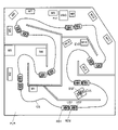
図6は本実施形態のアトラクションゲームに使用されるプレイフィールドFLの例である。本実施形態のアトラクションゲームでは、例えば室内型テーマパークのプレイフィールドFLに商店街の店舗等が設置される。ユーザは例えば図2のHMD200を頭に装着して、友達等の仲間と一緒にプレイフィールドFLを探索する。具体的には場所P1からスタートして場所P2に移動し、場所P3に出現する蚊(キャラクタ)を退治して、場所P1に戻る。その後、図14で説明するようなライド型のアトラクションゲームをプレイする。
FIG. 6 is an example of a play field FL used in the attraction game of this embodiment. In the attraction game of this embodiment, for example, stores in a shopping mall are installed in the play field FL of an indoor theme park. A user, for example, wears the
そして本実施形態では、図2のHMD200に設けられたカメラを用いて実空間の認識処理を行うことで、実空間のプレイフィールドFLに対応する仮想空間が生成されるようになる。この場合に、HMD200を装着したユーザがプレイフィールドFLを移動するにつれて、移動するユーザの周囲の実空間が順次にスキャンされて実空間情報として蓄積されて更新されるようになる。
In this embodiment, the camera provided in the
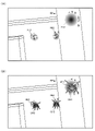
図6の場所P2にユーザが移動すると、図7(A)に示すように、ユーザの正面の壁にはマーカとなるポスターPSが貼られている。HMD200のカメラによりこのポスターPS(マーカ)の認識処理を行うことで、蚊の絵が描かれた画像IMAや、ガイドGDAが表示される。即ち画像IMAやガイドGDAが図5の表示領域ARVに表示される。ガイドGDAは、図6の場所P3の方を指しており、ユーザが場所P3の方に視線を向けると、図7(B)に示すような風景がユーザの目に映る。そして図7(B)に示すように、柱PILに対応する場所に基準点RPが設定される。例えば本実施形態では、実空間の認識処理により実空間情報が取得され、ユーザの位置情報等のユーザ情報と実空間情報に基づいて、基準点RPが設定される。具体的にはHMD200のカメラにより実空間の柱PILの認識処理が行われ、実空間の柱PILに対応する仮想的なオブジェクトが仮想空間に生成される。例えば図4(B)の机のようにメッシュポリゴンの仮想的な柱のオブジェクトが生成される。そして、この柱のオブジェクトに対応する場所に基準点RPが設定される。例えばユーザの位置情報に基づきユーザの位置が柱のオブジェクトに近いと判断された場合に、柱のオブジェクトに対して基準点RPが設定される。このようにすることで、実空間の柱PILに対応する場所に基準点RPを設定できるようになる。なおHMD200のカメラによる実空間の認識処理では正確な座標を取得できない場合がある。このため例えば図7(A)のポスターPSによるマーカの位置の絶対座標を用いることで、正確な座標の設定を行うようにしてもよい。
When the user moves to the place P2 in FIG. 6, a poster PS serving as a marker is pasted on the wall in front of the user as shown in FIG. 7(A). By recognizing this poster PS (marker) with the camera of the
そして本実施形態では、図8(A)に示すように、設定された基準点RPに基づいて、蚊のキャラクタCHのオブジェクトを出現させる。例えば基準点RPにより特定される配置ポイント(配置場所)に蚊のキャラクタCHを配置して出現させる。これにより図5で説明した表示領域ARVに蚊のキャラクタCHの画像が表示されるようになり、実空間の柱PILの場所に蚊が出現したかのように見えるMRを実現できるようになる。即ち実空間の風景(柱)と仮想空間の画像(蚊)がミックスされた画像の表示が可能になる。そして本実施形態では実空間の認識処理により生成された仮想的な柱のオブジェクトに対して基準点RPが設定されている。従って、例えばARマーカ等を用いなくても、実空間の柱PILに対応するポイントから蚊のキャラクタCHを出現させることが可能になる。また図8(A)では「前から来るぞ」という文字が書かれたガイドGD1も表示されている。このガイドGD1は仮想空間の配置オブジェクトであり、このガイドGD1の配置オブジェクトの配置ポイントも、基準点RPに基づき設定される。 In this embodiment, as shown in FIG. 8A, an object of a mosquito character CH appears based on the set reference point RP. For example, a mosquito character CH is arranged and made to appear at an arrangement point (placement location) specified by the reference point RP. As a result, the image of the mosquito character CH is displayed in the display area ARV described with reference to FIG. 5, and it is possible to realize MR in which the mosquito appears as if it appeared at the position of the pillar PIL in the real space. That is, it is possible to display an image in which the landscape (pillar) in the real space and the image (mosquito) in the virtual space are mixed. In this embodiment, the reference point RP is set for the virtual pillar object generated by the real space recognition process. Therefore, it is possible to make the mosquito character CH appear from the point corresponding to the pillar PIL in the real space without using an AR marker or the like. In addition, in FIG. 8A, a guide GD1 with the words "Coming from the front" is also displayed. This guide GD1 is an arranged object in the virtual space, and the arrangement point of the arranged object of this guide GD1 is also set based on the reference point RP.
図8(B)では、後述の図9(A)~図10で説明するように両手でパチンと叩くアクションをユーザが行うことで、攻撃のエフェクトAG(空気砲)が表示され、蚊のキャラクタCHにヒットして、蚊が退治される。蚊の退治に成功すると、「やった、戻ろう」という文字が書かれたガイドGD2が表示される。またユーザが戻る方向を指示するガイドGD3も表示される。これらのガイドGD2、GD3の配置オブジェクトの配置位置も、基準点RPに基づき設定される。 In FIG. 8B, when the user performs an action of tapping with both hands as described later with reference to FIGS. 9A to 10, an attack effect AG (air cannon) is displayed, and a mosquito character Hit CH to exterminate mosquitoes. When the mosquitoes are successfully exterminated, a guide GD2 is displayed with the words "I did it, let's go back". Also displayed is a guide GD3 for instructing the direction in which the user returns. The placement positions of the placement objects of these guides GD2 and GD3 are also set based on the reference point RP.
図9(A)~図10では、ユーザ(US)は図2のHMD200を頭部に装着している。またユーザは、その手HL、HRで所持物BL、BRを持っている。所持物BL、BRは、例えば大きな手の形状の紙製のうちわなどにより実現される。また手HLにはアームセンサSEを装着している。アームセンサSEは、アームバンド型のモーションセンサ(ジェスチャセンサ)であり、加速度センサ、3軸ジャイロセンサ、筋電位センサなどを内蔵している。このアームセンサSEを手HLに装着することで、腕の動きや手のひらの開閉などを検出できるようになる。図9(A)、図9(B)に示すように、ユーザが手HL、HRでパチンと叩くアクションを行うと、このアクションの動きがアームセンサSEの加速度センサ等により検出される。このアームセンサSEは図1の検出部162に相当するものであり、手HL、HRでパチンと叩くアクションが、本実施形態においてユーザが行う所与の入力になる。このアクションにより、攻撃のエフェクトAGが表示され、図10に示すように蚊のキャラクタCHが退治されて、消滅したり、破壊されるようになる。
In FIGS. 9A to 10, the user (US) wears the
そして図9(A)~図10の場合には、後述の図19(A)、図19(B)で説明するように、ユーザ(US)に対応するユーザキャラクタUSC(広義にはユーザ移動体)とキャラクタCHとの間にヒットボリュームHVが設定され、このヒットボリュームHVを用いてキャラクタCHに対するヒット判定処理(衝突判定処理)が行われる。即ちユーザキャラクタUSCとキャラクタCHとの間の距離が遠い場合には、図19(A)、図19(B)の手法によりヒット判定処理が行われる。 In the case of FIGS. 9A to 10, a user character USC (in a broad sense, a user moving body ) and the character CH, and the hit determination process (collision determination process) for the character CH is performed using this hit volume HV. That is, when the distance between the user character USC and the character CH is long, the hit determination process is performed by the method shown in FIGS. 19A and 19B.
一方、図11(A)、図11(B)では、後述の図17(A)、図17(B)で説明するように、ユーザキャラクタUSCの位置に基づきヒットボリュームHVが設定され、このヒットボリュームHVを用いてキャラクタCHに対するヒット判定処理が行われる。即ちユーザキャラクタUSCとキャラクタCHとの間の距離が近い場合には、図17(A)、図17(B)の手法によりヒット判定処理が行われる。この場合に例えば所持物BL、BRに対応する所持物オブジェクトを仮想空間に出現させ、ユーザが手HL、HRを叩く毎に、この所持物オブジェクトの大きさを大きくするようにしてもよい。これにより、比較的遠くに位置する蚊のキャラクタCHであっても、所持物オブジェクトをヒットさせて退治することが可能になる。 On the other hand, in FIGS. 11A and 11B, the hit volume HV is set based on the position of the user character USC, as will be described later with reference to FIGS. 17A and 17B. Hit determination processing for the character CH is performed using the volume HV. That is, when the distance between the user character USC and the character CH is short, the hit determination process is performed by the method shown in FIGS. 17A and 17B. In this case, for example, the belonging objects corresponding to the belongings BL and BR may appear in the virtual space, and the size of the belonging objects may be increased each time the user clapping the hands HL and HR. As a result, even the mosquito character CH, which is located relatively far away, can be defeated by hitting the possessed object.
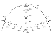
図6の場所P3に出現する蚊を、図8(A)~図11(B)で説明したように退治した後、ユーザは、最初のスタート地点である場所P1に戻ることになる。この場合に本実施形態では図12(A)~図13(B)に示すように、場所P3から場所P1にユーザを誘導して移動させるためのガイドとなる配置オブジェクトOB1~OB4を、仮想空間に配置する。具体的には場所P1に対して基準点RPが設定され、設定された基準点RPに基づいて配置オブジェクトOB1~OB4が配置される。この場合に本実施形態では、図4(A)、図4(B)で説明したような実空間の認識処理が行われ、実空間情報が取得される。そしてユーザの位置情報等のユーザ情報と、取得された実空間情報とに基づき、基準点RPが設定される。具体的にはHMD200のカメラにより実空間の認識処理が行われ、場所P1に配置される物体(例えば入り口、壁、ドア)に対応する仮想的なオブジェクトが仮想空間に生成される。そして、この仮想的なオブジェクトの場所に基準点RPが設定される。このようにすることで、場所P1に対して適切に基準点RPを設定できるようになり、基準点RPが設定される場所P1とユーザとの間に、ユーザを誘導するガイドとなる配置オブジェクトOB1~OB4を適切に配置できるようになる。
After exterminating the mosquitoes appearing at location P3 in FIG. 6 as described in FIGS. 8A to 11B, the user returns to location P1, which is the first starting point. In this case, in this embodiment, as shown in FIGS. 12A and 13B, placement objects OB1 to OB4, which serve as guides for guiding and moving the user from location P3 to location P1, are placed in the virtual space. to be placed. Specifically, a reference point RP is set for the location P1, and the placed objects OB1 to OB4 are arranged based on the set reference point RP. In this case, in the present embodiment, real space recognition processing is performed as described with reference to FIGS. 4A and 4B, and real space information is acquired. Then, the reference point RP is set based on the user information such as the user's position information and the acquired real space information. Specifically, real space recognition processing is performed by the camera of the
そして本実施形態では、ユーザに対応する仮想空間のユーザキャラクタ(ユーザ移動体)と配置オブジェクトOB1~OB4との位置関係に応じて、配置オブジェクトOB1~OB4の表示態様を変化させている。 In this embodiment, the display modes of the placed objects OB1 to OB4 are changed according to the positional relationship between the user character (user moving body) in the virtual space corresponding to the user and the placed objects OB1 to OB4.
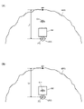
例えば図12(A)では、基準点RPから遠い位置に配置される配置オブジェクトOB1が、表示状態に設定されて表示されている。即ち図5の表示領域ARVに配置オブジェクトOB1の画像が表示される。この配置オブジェクトOB1には例えば「こっちだよ」という文字が書かれている。 For example, in FIG. 12A, a placement object OB1 placed at a position far from the reference point RP is displayed in a display state. That is, the image of the placed object OB1 is displayed in the display area ARV in FIG. For example, the text "this is it" is written on this placement object OB1.
その後、ユーザが、場所P1の基準点RPの方に移動して近づくと、図12(B)に示すように、次の配置オブジェクトOB2が表示状態に設定されて表示される。配置オブジェクトOB2は、配置オブジェクトOB1に比べて、基準点RPに近い位置に配置されるオブジェクトである。この配置オブジェクトOB2には、例えば「こっち、こっち」という文字が書かれている。この場合に配置オブジェクトOB1については、不透明状態から半透明状態に変化し、その後、非表示状態(透明状態)へと表示態様が変化する。 After that, when the user moves toward and approaches the reference point RP of the location P1, the next placed object OB2 is set in the display state and displayed as shown in FIG. 12(B). The placed object OB2 is an object placed at a position closer to the reference point RP than the placed object OB1. For example, characters such as "this way, this way" are written on this placement object OB2. In this case, the placement object OB1 changes from an opaque state to a translucent state, and then changes to a non-display state (transparent state).
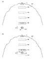
ユーザが、場所P1の基準点RPの方に更に移動して近づくと、図13(A)に示すように、次の配置オブジェクトOB3が表示状態に設定されて表示される。配置オブジェクトOB3は、配置オブジェクトOB1、OB2に比べて、基準点RPに近い位置に配置されるオブジェクトである。この配置オブジェクトOB3には、例えば「そろそろつくよ」という文字が書かれている。この場合に配置オブジェクトOB2については、不透明状態から半透明状態に変化し、その後、非表示状態へと表示態様が変化する。 When the user moves closer to the reference point RP of the location P1, the next placed object OB3 is set to the display state and displayed as shown in FIG. 13(A). Placement object OB3 is an object placed at a position closer to reference point RP than placement objects OB1 and OB2. This placement object OB3 is written with, for example, the characters "It's about time." In this case, the placement object OB2 changes from an opaque state to a translucent state, and then changes its display mode to a non-display state.
ユーザが場所P1の基準点RPの方に更に移動して、基準点RPの場所の直ぐ近くに来ると、図13(B)に示すように次の配置オブジェクトOB4が表示状態に設定されて表示される。配置オブジェクトOB4は、配置オブジェクトOB1、OB2、OB3に比べて、基準点RPに近い位置に配置されるオブジェクトである。この配置オブジェクトOB4には、例えば「おかえり」という文字が書かれている。この場合に配置オブジェクトOB3については、不透明状態から半透明状態に変化し、その後、非表示状態へと表示態様が変化する。 When the user moves further toward the reference point RP of the location P1 and comes close to the location of the reference point RP, the next placed object OB4 is set to be displayed as shown in FIG. 13B. be done. Placement object OB4 is an object placed at a position closer to reference point RP than placement objects OB1, OB2, and OB3. For example, a character "Welcome home" is written on this placement object OB4. In this case, the placement object OB3 changes from an opaque state to a translucent state, and then changes its display mode to a non-display state.
このように本実施形態では、基準点RPに基づき設定された配置オブジェクトOB1~OB4を用いることで、基準点RPの場所P1にユーザを適切に誘導して移動させることに成功している。 As described above, in this embodiment, by using the placed objects OB1 to OB4 set based on the reference point RP, the user is successfully guided to the location P1 of the reference point RP and moved.
場所P1に戻ったユーザは、場所P1にその入り口が設けられるライド型のアトラクションゲームをプレイする。図14はこのライド型のアトラクションのプレイフィールドFLRを示すものである。プレイフィールドFLRにはコースCSが設置されている。ユーザUS1、US2はライド筐体RD1、RD2に搭乗し、ライド筐体RD1、RD2はコースCSに沿って移動する。そしてプレイフィールドFLRのエリアM1~M14では、蚊が出現してユーザを襲ってくる。ユーザは、図9(A)~図11(B)で説明したような手をパチンと叩くアクションを行って、襲ってくる蚊を退治する。またプレイフィールドFLRの奥側の場所では、天井のオブジェクトOBCが崩壊して落ちてくるイベントEV1が発生する。この天井のオブジェクトOBCは仮想空間のオブジェクトで表現され、天井が落ちてくる仮想空間画像がHMD200に表示される。またエリアM13、M14では、大量の蚊が襲ってくるイベントEV2が発生し、最後は巨大な蚊のボスBSFが出現するイベントEV3が発生する。この蚊のボスBSFは実空間の物体であり、このボスBSFに対して、仮想空間のエフェクト画像が重畳して表示される演出が行われる。
The user who has returned to the place P1 plays a ride-type attraction game whose entrance is provided at the place P1. FIG. 14 shows the play field FLR of this ride type attraction. A course CS is set in the play field FLR. The users US1 and US2 board the ride enclosures RD1 and RD2, and the ride enclosures RD1 and RD2 move along the course CS. Mosquitoes appear and attack the user in the areas M1 to M14 of the play field FLR. The user performs the action of clapping his hands as described in FIGS. 9(A) to 11(B) to exterminate the attacking mosquitoes. Also, at a place on the far side of the play field FLR, an event EV1 occurs in which the object OBC on the ceiling collapses and falls. This ceiling object OBC is represented by a virtual space object, and a virtual space image of the falling ceiling is displayed on the
図15(A)、図15(B)は、プレイフィールドFLRでの蚊の出現イベントの一例を示すものである。図15(A)、図15(B)では、実空間に対して穴HE1、HE2、HE3が出現し、穴HE1、HE2、HE3から蚊のキャラクタCH1、CH2、CH3が飛び出て来るようなMRが実現される。そしてユーザは、図9(A)~図11(B)で説明したような手をパチンと叩くアクションを行って、襲ってくる蚊を退治することができる。ここで、穴HE1、HE2、HE3の画像は仮想空間画像であり、キャラクタCH1、CH2、CH3の画像も仮想空間画像であり、これらの仮想空間画像が実空間の物体に重畳して表示されるMRが実現されている。 FIGS. 15A and 15B show an example of a mosquito appearance event on the playfield FLR. In FIGS. 15A and 15B, holes HE1, HE2, and HE3 appear in the real space, and mosquito characters CH1, CH2, and CH3 pop out from the holes HE1, HE2, and HE3. is realized. The user can then perform the action of clapping his hands as described in FIGS. 9A to 11B to exterminate the attacking mosquitoes. Here, the images of the holes HE1, HE2, and HE3 are virtual space images, and the images of the characters CH1, CH2, and CH3 are also virtual space images, and these virtual space images are displayed superimposed on the objects in the real space. MR is realized.
そして本実施形態では、穴HE1~HE3のオブジェクトやキャラクタCH1~CH3のオブジェクトは基準点RPに基づき配置される。例えば図4(A)、図4(B)に示すような実空間の認識処理が、図14のプレイフィールドFLRに配置される実空間の物体に対して行われる。これにより図15(A)、図15(B)の実空間の物体に対応する仮想的なオブジェクトが配置される仮想空間が生成され、生成された仮想空間において基準点RPが設定される。そしてライド筐体に搭乗して移動するユーザに対応するユーザキャラクタが、基準点RPの位置に近づくと、図15(A)に示すように、基準点RPに関連づけて設定された穴HE1~HE3のオブジェクトが出現し、穴HE1~HE3からキャラクタCH1~CH3も出現するようになる。このようにすることで、ARマーカ等を使用しなくても、図15(A)、図15(B)に示すようなMRの画像を生成できるようになる。 In this embodiment, the objects of the holes HE1 to HE3 and the objects of the characters CH1 to CH3 are arranged based on the reference point RP. For example, real space recognition processing as shown in FIGS. 4A and 4B is performed on real space objects arranged in the play field FLR of FIG. As a result, a virtual space is generated in which virtual objects corresponding to the objects in the real space of FIGS. 15A and 15B are arranged, and a reference point RP is set in the generated virtual space. Then, when the user character corresponding to the user who moves on the ride housing approaches the position of the reference point RP, as shown in FIG. , and the characters CH1 to CH3 also appear from the holes HE1 to HE3. By doing so, it is possible to generate MR images as shown in FIGS. 15A and 15B without using an AR marker or the like.
図16では、ガイドGDが表示されている。このガイドGDは、キャラクタCHの存在位置の方向を示す配置オブジェクトである。例えば図5のように、HMD200の仮想空間画像の表示領域ARVが狭い場合(視野角が小さい場合)には、ユーザがキャラクタCHの方に視線を向けないと、表示領域ARVにキャラクタCHの画像を表示できない。この点、図16のようなガイドGDを表示すれば、例えばユーザが右方向に視線を向けることで、図5のHMD200の表示領域ARVがDR2の方向に移動して、キャラクタCHの画像が表示領域ARVに表示されるようになる。このようにガイドGDとなる配置オブジェクトを配置して表示することで、ユーザはキャラクタCHの方に視線を向けて手を叩くアクションを行うことで、蚊のキャラクタCHを退治することが可能になる。
In FIG. 16, the guide GD is displayed. This guide GD is a placement object that indicates the direction of the existing position of the character CH. For example, when the display area ARV of the virtual space image of the
なおキャラクタCHの存在位置を報知する処理は、図16のようなガイドGD等の表示物を用いる処理には限定されない。例えばHMD200等に設けられる音出力部(ヘッドホン、スピーカ)からの3次元音響を用いて、キャラクタCHの存在位置をユーザに報知してもよい。例えば右方向にキャラクタCHが存在する場合には、キャラクタCHの発生音(例えば「ブーン」という音)が、右方向から聞こえるような3次元音響の処理を行って、音出力部から出力すればよい。このようにすることで、図5のように表示領域ARVが狭く視野角が小さいHMD200を用いた場合にも、キャラクタCHの存在位置を適切にユーザに報知できるようになる。
Note that the process of notifying the existing position of the character CH is not limited to the process of using a display object such as a guide GD as shown in FIG. For example, the position of the character CH may be notified to the user using three-dimensional sound from a sound output unit (headphones, speakers) provided in the
3.2 基準点、ヒットボリュームの設定
以上のように本実施形態では、図4(A)、図4(B)で説明したようにユーザの周囲の実空間の認識処理を行うことで得られる実空間情報を取得する。またユーザの位置情報を含むユーザ情報を取得する。そして取得された実空間情報に基づいて実空間に対応する仮想空間を生成する。例えば図4(B)に示すようなポリゴンメッシュのオブジェクトが配置される仮想空間を生成する。そして図8(A)、図8(B)、図12(A)~図13(B)、図15(A)、図15(B)に示すように、例えばユーザ情報(位置情報)と実空間情報とに基づいて、仮想空間に基準点RPを設定し、基準点RPに基づいて、キャラクタのオブジェクトや配置オブジェクトを仮想空間に配置し、キャラクタや配置オブジェクトの画像を含む画像を表示部190に表示する。例えばHMD200の表示部190(表示領域ARV)にキャラクタや配置オブジェクトの画像を含む仮想空間画像を表示する。
3.2 Setting of Reference Point and Hit Volume As described above, in this embodiment, as described with reference to FIGS. Get real space information. It also acquires user information including user location information. A virtual space corresponding to the real space is generated based on the acquired real space information. For example, a virtual space is generated in which a polygon mesh object as shown in FIG. 4B is arranged. 8(A), 8(B), 12(A) to 13(B), 15(A), and 15(B), for example, user information (location information) and actual Based on the space information, a reference point RP is set in the virtual space, and based on the reference point RP, the character object and the arranged objects are arranged in the virtual space, and an image including the image of the character and the arranged object is displayed on the
そしてユーザに対応する仮想空間のユーザキャラクタ(広義にはユーザ移動体)の位置に基づき、ヒットボリュームを設定し、ユーザが所与の入力を行った際に、ヒットボリュームとキャラクタとの位置関係に応じて、キャラクタに対する処理を行う。 A hit volume is set based on the position of a user character (a user moving body in a broad sense) in a virtual space corresponding to the user, and when the user performs a given input, the positional relationship between the hit volume and the character is determined. In response, the character is processed.
例えば図17(A)。図17(B)では、実空間の認識処理(スキャン処理、マッピング処理)を行うことで取得された実空間情報に基づいて、実空間の背景物(柱、壁、ドア等)に対応する仮想空間の背景オブジェクトMRS(例えばメッシュポリゴンにより構成されるオブジェクト)が生成されている。また実空間情報等に基づいて基準点RPが設定される。実空間の背景物に対応する背景オブジェクトMRSを生成することで、実空間の背景物の対応する場所に基準点RPを設定できるようになる。そして、この基準点RPに基づいて、キャラクタCHが配置される。例えば基準点RPに基づき特定される出現ポイントからキャラクタCHを出現させる。 For example, FIG. 17(A). In FIG. 17(B), based on real space information acquired by performing real space recognition processing (scanning processing, mapping processing), a virtual image corresponding to a background object (pillar, wall, door, etc.) in the real space is displayed. A spatial background object MRS (for example, an object composed of mesh polygons) is generated. Also, a reference point RP is set based on real space information and the like. By generating the background object MRS corresponding to the background object in the real space, it becomes possible to set the reference point RP at the corresponding location of the background object in the real space. Then, the character CH is arranged based on this reference point RP. For example, the character CH is caused to appear from an appearance point specified based on the reference point RP.
基準点RPは、実空間情報に基づき設定され、キャラクタ(CH)や配置オブジェクト(OB1~OB4)の配置位置を設定するためのポイント又は場所である。キャラクタや配置オブジェクトの配意位置(出現位置)そのものが基準点RPであってもよい。基準点RPは、実空間情報に基づき設定されるため、実空間の物体の位置や形状等を反映したものになる。また基準点RPを、ユーザの位置情報や方向情報を含むユーザ情報に基づき設定することで、例えばユーザの移動や向く方向や接近等を検出して基準点を設定し、キャラクタや配置オブジェクトを出現させることが可能になる。例えば基準点RPをMRにおける擬似的なマーカのようなものとして使用できるようになる。 The reference point RP is set based on the real space information, and is a point or place for setting the placement positions of the character (CH) and the placement objects (OB1 to OB4). The reference point RP may be the intentional position (appearance position) of the character or the placed object itself. Since the reference point RP is set based on the real space information, it reflects the position, shape, etc. of the object in the real space. In addition, by setting the reference point RP based on user information including the user's position information and direction information, for example, the user's movement, facing direction, approach, etc. are detected, the reference point is set, and characters and placed objects appear. It becomes possible to let For example, the reference point RP can be used as a pseudo marker in MR.
また本実施形態では、実空間のユーザに対応するユーザキャラクタUSCの位置PSに基づき、ヒットボリュームHV(ヒットエリア)が設定される。例えば図17(A)、図17(B)では、ユーザキャラクタUSCの位置PSの前方側にヒットボリュームHVが設定される。そしてユーザが所与の入力を行った際に、ヒットボリュームHVとキャラクタCHとの位置関係が判断される。図9(A)~図11(B)を例にとれば、ユーザが手を叩くアクションを行った場合に、ユーザが所与の入力が行ったと判断される。そして、このように手を叩くアクションによる所与の入力が行われたタイミングでの、ヒットボリュームHVとキャラクタCHとの位置関係が判断される。 Further, in this embodiment, a hit volume HV (hit area) is set based on the position PS of the user character USC corresponding to the user in the real space. For example, in FIGS. 17A and 17B, the hit volume HV is set in front of the position PS of the user character USC. Then, when the user performs a given input, the positional relationship between the hit volume HV and the character CH is determined. Taking FIGS. 9A to 11B as an example, it is determined that the user has performed a given input when the user performs an action of clapping their hands. Then, the positional relationship between the hit volume HV and the character CH is determined at the timing when the given input by the action of clapping hands is performed.
例えばヒットボリュームHVとキャラクタCHの位置関係が図17(A)のような位置関係であるときに、ユーザが手を叩くアクションを行ったとする。この場合にはキャラクタCHの位置が、ヒットボリュームHV内にないため、ユーザが手を叩くことによる攻撃はキャラクタCHにヒットしなかったと判断される。 For example, when the positional relationship between the hit volume HV and the character CH is as shown in FIG. 17A, the user performs an action of clapping his hands. In this case, since the position of the character CH is not within the hit volume HV, it is determined that the attack by the user's hand clapping did not hit the character CH.
一方、ヒットボリュームHVとキャラクタCHの位置関係が図17(B)のような位置関係であるときに、ユーザが手を叩くアクションを行ったとする。この場合には、キャラクタCHの位置がヒットボリュームHV内にあるため、ユーザが手を叩くことによる攻撃がキャラクタCHにヒットしたと判断する。そしてキャラクタCHに対する処理として、キャラクタCHの消滅処理や破壊処理などを行う。このようにすることで、図11(A)、図11(B)に示すように、ユーザの直ぐ近くに接近して来るキャラクタCHに対して、攻撃を加えて、消滅させたり破壊するなどの処理が可能になる。 On the other hand, when the positional relationship between the hit volume HV and the character CH is as shown in FIG. In this case, since the position of the character CH is within the hit volume HV, it is determined that the attack by the user's hand clapping hits the character CH. Then, as the processing for the character CH, the character CH is erased, destroyed, or the like. By doing so, as shown in FIGS. 11(A) and 11(B), the character CH, which is approaching directly to the user, is attacked, destroyed or destroyed. processing becomes possible.
なお図17(A)、図17(B)において、キャラクタCHの位置に基づき第2のヒットボリュームを設定してもよい。そしてユーザキャラクタUSCの位置PSに基づき設定されたヒットボリュームHVと、キャラクタCHの位置に基づき設定された第2のヒットボリュームとの交差判定処理を行うことで、ヒット判定処理を実現してもよい。 Note that in FIGS. 17A and 17B, the second hit volume may be set based on the position of the character CH. Then, the hit determination process may be realized by performing the intersection determination process between the hit volume HV set based on the position PS of the user character USC and the second hit volume set based on the position of the character CH. .
以上のように本実施形態では、実空間の認識処理に基づき取得された実空間情報により、実空間に対応する仮想空間が生成されて、基準点RPが設定される。これにより実空間に対応する位置に基準点RPを設定できるようになる。またユーザの位置情報を含むユーザ情報を用いて基準点RPを設定することで、例えばユーザに対応するユーザキャラクタが接近して来たときに、基準点RPを設定し、基準点RPによって特定される場所にキャラクタCHを配置して出現させることができる。そして本実施形態では、ユーザキャラクタUSCの位置に基づき設定されたヒットボリュームHVとキャラクタCHとの位置関係を判断して、キャラクタCHに対する処理を行っている。従って、基準点RPに基づき出現させた仮想的なキャラクタCHとユーザとの間のインタラクションを実現でき、例えばユーザの攻撃がヒットしたか否かなどを判断するヒット判定処理を実現できるようになる。従って、実空間に対して、対応する仮想空間を設定してキャラクタCHを配置し、ユーザの入力に基づくキャラクタCHとのインタラクションを実現できるようになり、実空間情報を利用したインタラクティブなゲームの実現が可能になる。即ち、実空間情報を有効活用してユーザとキャラクタとの好適なインタラクションを実現できるシミュレーションシステムの実現が可能になる。 As described above, in the present embodiment, a virtual space corresponding to the real space is generated based on real space information acquired based on real space recognition processing, and the reference point RP is set. This makes it possible to set the reference point RP at a position corresponding to the real space. Further, by setting the reference point RP using user information including the position information of the user, for example, when a user character corresponding to the user approaches, the reference point RP is set and specified by the reference point RP. The character CH can be arranged and made to appear at a place where the character CH appears. In this embodiment, the positional relationship between the character CH and the hit volume HV set based on the position of the user character USC is determined, and the character CH is processed. Therefore, it is possible to realize an interaction between the user and the virtual character CH appearing based on the reference point RP, and it is possible to realize hit determination processing for determining whether or not the user's attack hit. Therefore, it is possible to set a virtual space corresponding to the real space, arrange the character CH, and realize interaction with the character CH based on the user's input, thereby realizing an interactive game using real space information. becomes possible. In other words, it is possible to realize a simulation system that can effectively utilize real space information and realize favorable interaction between a user and a character.
また本実施形態では、ヒットボリュームHVとして、ユーザの部位又はユーザの所持物に設定されるヒットボリュームを用いることができる。 Also, in this embodiment, as the hit volume HV, a hit volume set for a user's body part or a user's belongings can be used.
例えば図18(A)では、ユーザの部位である手HLに対してヒットボリュームHVが設定されている。例えばユーザの手HLを内包するようなヒットボリュームHVが設定される。そしてユーザが手HLを動かすと、それに連動してヒットボリュームHVも移動する。ユーザの手HLの動きは、ユーザが装着しているアームセンサSE(広義には検出部)を用いて検出できる。例えばアームセンサSEが内蔵する加速度センサや3軸ジャイロセンサなどを用いて手HLの動きを検出して、その手HLの動きに追従するようにヒットボリュームHVを移動させる。 For example, in FIG. 18A, the hit volume HV is set for the user's hand HL. For example, a hit volume HV that includes the user's hand HL is set. When the user moves the hand HL, the hit volume HV moves accordingly. The movement of the user's hand HL can be detected using an arm sensor SE (detector in a broad sense) worn by the user. For example, the motion of the hand HL is detected using an acceleration sensor or a 3-axis gyro sensor built in the arm sensor SE, and the hit volume HV is moved so as to follow the motion of the hand HL.
また図18(B)では、ユーザの所持物BLに対してヒットボリュームHVが設定されている。例えばユーザの所持物BLを内包するようなヒットボリュームHVが設定される。そしてユーザが所持物BLを動かすと、それに連動してヒットボリュームHVも移動する。所持物BLの動きは、アームセンサSEなどを用いて検出し、所持物BLの動きに追従するようにヒットボリュームHVを移動させる。この場合に、アームセンサSEなどの動き検出センサを所持物BLに取り付けて、所持物BLの動きを検出してもよい。また図18(B)では所持物BLが大きな手の形状になっているが、所持物BLとしては種々の形状のものを採用できる。例えば剣、棒、斧又は銃のような形状の所持物BLであってもよい。 Also, in FIG. 18B, a hit volume HV is set for the user's belongings BL. For example, a hit volume HV that includes the user's belongings BL is set. When the user moves the item BL, the hit volume HV moves accordingly. The movement of the possessed item BL is detected using an arm sensor SE or the like, and the hit volume HV is moved so as to follow the movement of the possessed item BL. In this case, a motion detection sensor such as an arm sensor SE may be attached to the property BL to detect the motion of the property BL. In addition, in FIG. 18B, the belonging BL has a shape of a large hand, but various shapes can be adopted as the belonging BL. For example, it may be a possession BL shaped like a sword, a stick, an ax or a gun.
このようにユーザの部位又は所持物にヒットボリュームを設定すれば、実空間においてユーザが、その部位や所持物を動かすと、それに連動してヒットボリュームも移動するようになる。従って、ユーザの部位又は所持物の動きに連動して移動するヒットボリュームを用いてヒット判定処理等を行うことが可能になり、ユーザの仮想現実感の向上を図れるようになる。 If the hit volume is set for the user's body part or belongings in this way, when the user moves that body part or belongings in real space, the hit volume will move accordingly. Therefore, it is possible to perform hit determination processing and the like using the hit volume that moves in conjunction with the movement of the user's body part or belongings, thereby improving the user's sense of virtual reality.
また本実施形態では、ユーザの動きを検出する検出部162からの情報に基づいて、ユーザが所与の入力を行ったか否かを判断する。例えば図9(A)~図11(B)のように、ユーザが手を叩くなどのアクションにより所与の入力を行ったか否かを、検出部162を用いて検出する。例えば検出部162は図18(A)、図18(B)のアームセンサSEにより実現できる。具体的にはアームセンサSEに内蔵される加速度センサを用いて検出する。図18(C)はユーザが所与の入力を行った際の加速度センサの検出結果である。ユーザが手を叩くアクションを行うと、動いていた手が急加速で停止するため、加速度センサから図18(C)のA1に示すような検出結果(実際には負方向の加速度)が得られる。この検出結果に基づいて、ユーザが手を叩くアクションにより所与の入力を行ったと判断する。そして、所与の入力が行われたと判断されるタイミングでの、ヒットボリュームHVとキャラクタCHとの位置関係を判断すればよい。
Further, in this embodiment, it is determined whether or not the user has made a given input based on information from the
このようにすれば、実空間でのユーザの実際の動きを検出して、ユーザが所与の入力を行ったか否かを判断し、ヒットボリューム等を用いたヒット判定処理等を実現できるようになる。これによりユーザは、実際に部位や所持物を動かすことで、キャラクタに対する攻撃等を行えるようになり、ユーザの仮想現実感を更に向上することが可能になる。 By doing so, it is possible to detect the actual movement of the user in the real space, determine whether or not the user has made a given input, and implement hit determination processing using the hit volume or the like. Become. As a result, the user can attack the character by actually moving the body part or belongings, thereby further improving the user's sense of virtual reality.
なおユーザが所与の入力を行ったか否かの検出処理は、このような加速度センサを用いた処理には限定されない。例えば加速度センサ以外のモーションセンサ(ジャイロセンサ等)を用いて、ユーザが入力を行った際の動きを検出したり、外部カメラなどの外部の装置を用いて、ユーザの部位や所持物の動きを検出して、ユーザが所与の入力を行ったか否かを検出してもよい。或いは、ゲームコントローラなどの操作部160を用いたユーザの操作入力を検出して、ユーザが所与の入力を行ったか否か検出してもよい。
Note that the processing for detecting whether or not the user has performed a given input is not limited to processing using such an acceleration sensor. For example, motion sensors other than acceleration sensors (gyro sensors, etc.) can be used to detect movements when the user performs input, and external devices such as external cameras can be used to detect the movements of the user's body parts and belongings. It may be detected to detect whether the user has made a given input. Alternatively, a user's operation input using the
また本実施形態では、ユーザに対応する仮想空間のユーザキャラクタと基準点との間に、ヒットボリュームを設定し、ユーザが所与の入力を行った際に、ヒットボリュームとキャラクタとの位置関係に応じて、キャラクタに対する処理を行う。 Further, in this embodiment, a hit volume is set between a user character in a virtual space corresponding to the user and a reference point, and when the user performs a given input, the positional relationship between the hit volume and the character changes. In response, the character is processed.
例えば図19(A)では、ユーザキャラクタUSCと基準点RPとの間に、ヒットボリュームHVが設定される。例えばユーザキャラクタUSCと基準点RPとを結ぶ線の中間ポイントにヒットボリュームを設定する。ユーザキャラクタUSCが基準点RPの方に視線を向けている場合に、例えばその視線の延長上にヒットボリュームHVを設定する。そしてユーザが所与の入力を行った際に、ヒットボリュームHVとキャラクタCHとの位置関係が判断される。例えば図9(A)~図11(B)のように、手を叩くアクションによる所与の入力が行われたタイミングでの、ヒットボリュームHVとキャラクタCHとの位置関係が判断される。 For example, in FIG. 19A, a hit volume HV is set between the user character USC and the reference point RP. For example, the hit volume is set at the middle point of the line connecting the user character USC and the reference point RP. When the user character USC is directing the line of sight toward the reference point RP, the hit volume HV is set on the extension of the line of sight, for example. Then, when the user performs a given input, the positional relationship between the hit volume HV and the character CH is determined. For example, as shown in FIGS. 9(A) to 11(B), the positional relationship between the hit volume HV and the character CH is determined at the timing when the given input by the action of clapping hands is performed.
そしてヒットボリュームHVとキャラクタCHの位置関係が図19(A)のような位置関係であるときに、ユーザが手を叩くアクションを行ったとする。この場合には、キャラクタCHの位置がヒットボリュームHV内にないため、ユーザが手を叩くことによる攻撃は、キャラクタCHにヒットしなかったと判断される。 Assume that the user performs an action of clapping when the positional relationship between the hit volume HV and the character CH is as shown in FIG. 19A. In this case, since the position of the character CH is not within the hit volume HV, it is determined that the attack by the user's hand clapping did not hit the character CH.
一方、ヒットボリュームHVとキャラクタCHの位置関係が図19(B)のような位置関係であるときに、ユーザが手を叩くアクションを行ったとする。この場合には、キャラクタCHの位置がヒットボリュームHV内にあるため、ユーザが手を叩くことによる攻撃がキャラクタCHにヒットしたと判断する。そしてキャラクタCHに対する処理として、キャラクタCHの消滅処理や破壊処理などを行う。このようにすることで、図9(A)~図11に示すように、ユーザから距離が離れた位置にいるキャラクタCHに対して攻撃を加えて、消滅させたり破壊するなどの処理が可能になる。 On the other hand, it is assumed that the user performs an action of clapping his hands when the positional relationship between the hit volume HV and the character CH is as shown in FIG. 19B. In this case, since the position of the character CH is within the hit volume HV, it is determined that the attack by the user's hand clapping hits the character CH. Then, as the processing for the character CH, the character CH is erased, destroyed, or the like. By doing so, as shown in FIGS. 9(A) to 11, it is possible to attack the character CH at a position distant from the user to eliminate or destroy the character CH. Become.
なお図19(A)、図19(B)において、キャラクタCHの位置に基づき第2のヒットボリュームを設定し、ユーザキャラクタUSCと基準点RPの間に設定されたヒットボリュームHVと、キャラクタCHの位置に基づき設定された第2のヒットボリュームとの交差判定処理を行うことで、ヒット判定処理を実現してもよい。またキャラクタCHが図19(B)の位置からヒットボリュームHVの範囲を越えて、ユーザキャラクタUSCの方に接近して来た場合には、キャラクタCHの攻撃をユーザキャラクタUSCが受けたと判断してもよい。そしてユーザキャラクタUSCのステータスにダメージを与えたり、ユーザキャラクタUSCのヒットポイントを減少させたり、或いは攻撃を受けたことを表すエフェクトによる演出処理を行ってもよい。 Note that in FIGS. 19A and 19B, a second hit volume is set based on the position of the character CH, and the hit volume HV set between the user character USC and the reference point RP is The hit determination process may be realized by performing the intersection determination process with the second hit volume set based on the position. Also, when the character CH exceeds the range of the hit volume HV from the position shown in FIG. good too. Then, a performance process may be performed using an effect indicating that the user character USC is damaged, hit points of the user character USC are reduced, or that an attack has been received.
図19(A)、図19(B)の手法によれば、基準点RPや基準点RPに基づき配置されるキャラクタCHの位置が、ユーザキャラクタUSCから遠くの位置にある場合にも、キャラクタCHに対するインタラクションが可能になる。即ち、基準点RPとユーザキャラクタUSCの間にヒットボリュームHVを設定することで、遠くの位置にいるキャラクタCHに対するヒット処理などが可能になり、MRにおけるユーザとキャラクタとの好適なインタラクションが可能になる。 According to the method of FIGS. 19A and 19B, even if the reference point RP or the position of the character CH arranged based on the reference point RP is far from the user character USC, the character CH It is possible to interact with In other words, by setting the hit volume HV between the reference point RP and the user character USC, it is possible to perform hit processing on the character CH located far away, and favorable interaction between the user and the character in MR. Become.
また本実施形態では、ユーザキャラクタUSCと基準点RPとが第1の距離関係である場合には、ユーザキャラクタUSCの位置に基づきヒットボリュームHVを設定し、ユーザが所与の入力を行った際に、ヒットボリュームHVとキャラクタCHとの位置関係に応じて、キャラクタCHに対する処理を行う。 Further, in this embodiment, when the user character USC and the reference point RP are in the first distance relationship, the hit volume HV is set based on the position of the user character USC, and when the user performs a given input, the hit volume HV is set. Next, the character CH is processed according to the positional relationship between the hit volume HV and the character CH.
例えば図17(A)、図17(B)のように、ユーザキャラクタUSCと基準点RPの間の距離L1が近いという第1の距離関係にある場合には、ユーザキャラクタUSCの位置に基づきヒットボリュームHVを設定して、ヒット判定処理を行う。このようにすることで、ユーザキャラクタUSCから近い距離の場所でキャラクタCHを出現させた場合に、当該キャラクタCHに対してユーザキャラクタUSCの攻撃をヒットさせるなどのインタラクションを実現できるようになる。例えば図11(A)、図11(B)のように、ユーザの直ぐ近くにいるキャラクタCHを、ユーザの所持物BL、BRや手HL、HRで実際に叩くことで攻撃を加え、キャラクタCHを消滅させたり破壊するなどの処理が可能になる。即ち、実空間の物体である所持物BL、BRや手HL、HRを用いて、仮想空間のオブジェクトであるキャラクタCHを叩くようなMRの画像表現が可能になる。 For example, as shown in FIGS. 17(A) and 17(B), when there is a first distance relationship in which the distance L1 between the user character USC and the reference point RP is short, a hit is performed based on the position of the user character USC. A volume HV is set and a hit determination process is performed. By doing so, when the character CH appears at a place close to the user character USC, it is possible to realize an interaction such as the attack of the user character USC hitting the character CH. For example, as shown in FIGS. 11(A) and 11(B), the character CH in the immediate vicinity of the user is attacked by actually hitting the character CH with the user's belongings BL, BR or the hands HL, HR. It is possible to process such as extinguishing or destroying. That is, it is possible to perform image representation of MR such that the character CH, which is an object in the virtual space, is hit with the belongings BL, BR and the hands HL, HR, which are objects in the real space.
なお、ユーザの手などの部位や所持物に対応する部位オブジェクトや所持物オブジェクトを、仮想空間に表示するようにしてもよい。例えばユーザキャラクタの一部として、部位オブジェクト又は所持物オブジェクトを表示する。そして例えばユーザが手を叩くなどのアクションを行う毎に、部位オブジェクト又は所持物オブジェクトのサイズを徐々に大きくしてもよい。こうすることで、多数の蚊等のキャラクタを発生させた場合(例えば図14でのイベントEV2)にも、これらの多数のキャラクタに対して、大きくなった手で攻撃するなどのゲーム演出が可能になる。 It should be noted that a part object such as a user's hand, a part object corresponding to a belonging, or a belonging object may be displayed in the virtual space. For example, a part object or a possession object is displayed as part of the user character. Then, for example, each time the user performs an action such as clapping hands, the size of the part object or the possessed object may be gradually increased. By doing so, even when a large number of characters such as mosquitoes are generated (for example, event EV2 in FIG. 14), it is possible to perform a game effect such as attacking these large numbers of characters with enlarged hands. become.
一方、ユーザキャラクタUSCと基準点RPとが第2の距離関係である場合には、ユーザキャラクタUSCと基準点RPとの間にヒットボリュームHVを設定し、ユーザが所与の入力を行った際に、ヒットボリュームHVとキャラクタCHとの位置関係に応じて、キャラクタCHに対する処理を行う。 On the other hand, when the user character USC and the reference point RP are in the second distance relationship, a hit volume HV is set between the user character USC and the reference point RP, and when the user performs a given input, Next, the character CH is processed according to the positional relationship between the hit volume HV and the character CH.
例えば図19(A)、図19(B)のように、ユーザキャラクタUSCと基準点RPの間の距離L2が遠いという第2の距離関係にある場合には、ユーザキャラクタUSCと基準点RPとの間にヒットボリュームHVを設定して、ヒット判定処理を行う。このようにすれば、図9(A)~図10のようにユーザキャラクタUSCから遠い距離の場所でキャラクタCHを出現させた場合にも、当該キャラクタCHに対してユーザキャラクタUSCの攻撃をヒットさせるなどのインタラクションを実現できるようになる。例えば図9(A)~図10のように、遠い距離に位置するキャラクタCHに対して、ユーザの手を叩くアクションにより発生した攻撃のエフェクトAGをヒットさせて、キャラクタCHを消滅させたり破壊するなどの処理が可能になる。 For example, as shown in FIGS. 19A and 19B, when there is a second distance relationship in which the distance L2 between the user character USC and the reference point RP is long, the distance between the user character USC and the reference point RP is A hit volume HV is set between and a hit determination process is performed. In this way, even when the character CH appears at a place far away from the user character USC as shown in FIGS. 9A to 10, the attack of the user character USC hits the character CH. It will be possible to realize interactions such as For example, as shown in FIGS. 9A to 10, an attack effect AG generated by the action of clapping the user's hands hits the character CH located at a distant distance, thereby erasing or destroying the character CH. etc. can be processed.
また本実施形態では、キャラクタに対する処理として、キャラクタの消滅処理、キャラクタの破壊処理、キャラクタの表示態様の変更処理又はキャラクタについての報知処理を行う。 In the present embodiment, character disappearing processing, character destruction processing, character display mode changing processing, or character notification processing are performed as processing for the character.
例えば図20(A)ではキャラクタCHに対する処理として、キャラクタCHの消滅処理、破壊処理又は表示態様の変更処理が行われている。例えば図17(B)、図19(B)のようにヒットボリュームHV内にキャラクタCHが位置している状態で、図9(A)~図11(B)のような手を叩くなどの入力がユーザにより行われた場合に、キャラクタCHの消滅処理、破壊処理又は表示態様の変更処理を行う。キャラクタCHの消滅処理は、キャラクタCHを仮想空間画像として非表示にする処理である。例えば、表示されるオブジェクトのリストからキャラクタCHを消去する。キャラクタCHの破壊処理は、例えばキャラクタCHのオブジェクトを、破壊された状態を表すオブジェクトに切り替えることなどにより実現できる。或いは破壊を表すような画像エフェクトの表示処理を、キャラクタCHの破壊処理として行ってもよい。キャラクタCHの表示態様の変更処理は、例えばキャラクタCHの色、輝度、半透明度又はテクスチャ等を変化させる処理である。例えばキャラクタCHがユーザからの攻撃を受けたことを表すような表示態様に変化させる。或いはキャラクタCHに対する処理として、図20(B)に示すような効果音等を用いた報知処理を行ってもよい。例えばキャラクタCHが攻撃を受けてやられたことを報知する効果音を出力する。この場合に、キャラクタCHの存在位置から効果音が聞こえてくるような3次元音響処理を行う。或いはキャラクタCHに対する処理として、振動デバイスを用いた振動による報知処理を行ってもよい。例えばキャラクタCHに攻撃がヒットしたと判断された場合に、ユーザが所持するゲームコントローラに内蔵される振動デバイスを振動させる。或いは図6のプレイフィールドFLや図14のプレイフィールドFLRに、振動デバイスや空気砲による体感装置を設け、この体感装置を用いて、キャラクタCHが攻撃を受けてやられたことを報知する処理を行ってもよい。 For example, in FIG. 20A, as the processing for the character CH, the character CH is destroyed, destroyed, or changed in display mode. For example, when the character CH is positioned within the hit volume HV as shown in FIGS. is performed by the user, the disappearance processing, destruction processing, or change processing of the display mode of the character CH is performed. The character CH disappearing process is a process of hiding the character CH as a virtual space image. For example, remove the character CH from the list of displayed objects. Destruction processing of the character CH can be realized, for example, by switching the object of the character CH to an object representing the destroyed state. Alternatively, the display processing of an image effect representing destruction may be performed as the destruction processing of the character CH. The process of changing the display mode of the character CH is, for example, a process of changing the color, luminance, translucency, texture, or the like of the character CH. For example, the display mode is changed to indicate that the character CH has been attacked by the user. Alternatively, as the processing for the character CH, notification processing using an effect sound or the like as shown in FIG. 20B may be performed. For example, a sound effect is output to inform that the character CH has been attacked. In this case, three-dimensional sound processing is performed so that the effect sound can be heard from the position where the character CH exists. Alternatively, as the processing for the character CH, notification processing by vibration using a vibration device may be performed. For example, when it is determined that the attack hits the character CH, the vibration device incorporated in the game controller held by the user is vibrated. Alternatively, the play field FL of FIG. 6 or the play field FLR of FIG. 14 is provided with a sensory device such as a vibrating device or an air cannon, and the sensory device is used to perform a process of notifying that the character CH has been attacked. may
また例えばユーザの攻撃が失敗した場合に、攻撃の失敗を知らせるような演出処理や報知処理を行ってもよい。例えば攻撃の失敗を表すエフェクト画像を表示したり、効果音を出力する。例えば図17(B)、図19(B)のようにキャラクタCHがヒットボリュームHV内に位置するタイミングで、ユーザが手を叩く入力を行わなかった場合に、このような攻撃の失敗を知らせる演出処理や報知処理を行う。或いは図19(B)において、キャラクタCHがヒットボリュームHVの範囲を超えて、ユーザキャラクタUSCの方に接近して来た場合に、このような攻撃の失敗を知らせる演出処理や報知処理を行ってもよい。 Further, for example, when the user's attack fails, an effect process or notification process may be performed to notify the failure of the attack. For example, an effect image representing the failure of an attack is displayed, or an effect sound is output. For example, when the character CH is positioned within the hit volume HV as shown in FIGS. 17(B) and 19(B), if the user does not clap his/her hands, an effect is given to indicate that such an attack has failed. Perform processing and notification processing. Alternatively, in FIG. 19(B), when the character CH exceeds the range of the hit volume HV and approaches the user character USC, effect processing or notification processing is performed to notify that the attack has failed. good too.
3.3 配置オブジェクトの設定
上述したように本実施形態では、ユーザの周囲の実空間の認識処理を行うことで得られる実空間情報と、ユーザの位置情報を含むユーザ情報を取得し、実空間情報に基づいて、実空間に対応する仮想空間を生成する。例えば図21(A)~図22(B)に示すように、実空間の背景物に対応する仮想空間の背景オブジェクトMRSを生成して、仮想空間に配置する。またユーザの位置情報を含むユーザ情報と実空間情報とに基づいて、仮想空間に基準点RPを設定し、基準点RPに基づいて配置オブジェクトを配置する。図21(A)~図22(B)では、基準点RPに基づいて配置オブジェクトOB1、OB2、OB3、OB4が配置される。例えば基準点RPとユーザキャラクタUSCとの間に、複数の配置オブジェクトOB1~OB4が配置される。そして配置オブジェクトの画像を含む画像を表示部190に表示する。例えばHMD200の表示部190(表示領域ARV)に配置オブジェクトの画像を含む仮想空間画像を表示する。
3.3 Setting of Arranged Objects As described above, in the present embodiment, real space information obtained by performing recognition processing of the real space around the user and user information including the user's position information are acquired, and the real space A virtual space corresponding to the real space is generated based on the information. For example, as shown in FIGS. 21A to 22B, a virtual space background object MRS corresponding to a real space background object is generated and arranged in the virtual space. A reference point RP is set in the virtual space based on user information including user position information and real space information, and a placement object is arranged based on the reference point RP. In FIGS. 21A to 22B, placement objects OB1, OB2, OB3, and OB4 are placed based on the reference point RP. For example, a plurality of placed objects OB1 to OB4 are placed between the reference point RP and the user character USC. Then, an image including the image of the arranged object is displayed on the
そして本実施形態では、ユーザに対応する仮想空間のユーザキャラクタ(ユーザ移動体)と配置オブジェクトとの位置関係に応じて、配置オブジェクトの表示態様を設定する。配置オブジェクトの表示態様は、配置オブジェクトの色、輝度、半透明度、テクスチャ又は表示内容などである。配置オブジェクトの表示内容は、配置オブジェクトに描かれる文字、記号又は図形等により表される指示内容である。例えば表示内容は、ユーザへ提示するガイドや警告の内容である。例えば表示内容は、図12(A)~図13(B)で説明した配置オブジェクトOB1~OB4に書かれる「こっちだよ」、「こっち、こっち」、「そろそろつくよ」、「おかえり」などのユーザへのガイド内容である。 In this embodiment, the display mode of the placed object is set according to the positional relationship between the user character (user moving body) in the virtual space corresponding to the user and the placed object. The display mode of the arranged object is the color, brightness, translucency, texture, display content, or the like of the arranged object. The display contents of the layout object are instruction contents represented by characters, symbols, graphics, or the like drawn on the layout object. For example, the display content is the content of a guide or warning presented to the user. For example, the display contents are "here you go", "here you go", "I'll be there soon", "Welcome back", etc. written in the placement objects OB1-OB4 described in FIGS. 12A-13B. This is the content of the guide to the user.
例えば図21(A)では、ユーザキャラクタUSCと配置オブジェクトOB1とが接近の位置関係になったと判断されている。例えばユーザキャラクタUSCと配置オブジェクトOB1の間の距離が所与のしきい値距離以下になったと判定されている。この場合には、配置オブジェクトOB1の表示態様が、表示状態に設定される。例えば配置オブジェクトOB1の半透明度(α値)が高い値に設定され、不透明状態である表示状態に設定される。また配置オブジェクトOB1の表示内容は、「こっちだよ」というガイド表示に設定されている。これにより図12(A)に示すような表示態様での配置オブジェクトOB1の表示が可能になる。 For example, in FIG. 21A, it is determined that the user character USC and the placement object OB1 are in a close positional relationship. For example, it is determined that the distance between the user character USC and the placed object OB1 is equal to or less than a given threshold distance. In this case, the display mode of the placed object OB1 is set to the display state. For example, the translucency (α value) of the placement object OB1 is set to a high value, and the display state is set to an opaque state. Further, the display content of the placement object OB1 is set to a guide display that says "this is it". As a result, it becomes possible to display the placed object OB1 in a display mode as shown in FIG. 12(A).
一方、図21(B)では、ユーザキャラクタUSCと配置オブジェクトOB2とが接近の位置関係になったと判断されている。例えばユーザキャラクタUSCと配置オブジェクトOB2の間の距離が所与のしきい値距離以下になったと判定されている。この場合には、配置オブジェクトOB2の表示態様が、表示状態に設定される。例えば配置オブジェクトOB2の半透明度が高い値に設定され、不透明状態である表示状態に設定される。また配置オブジェクトOB2の表示内容は、「こっち、こっち」という表示内容のガイド表示に設定されている。これにより図12(B)に示すような表示態様での配置オブジェクトOB2の表示が可能になる。なお配置オブジェクトOB1については、その表示態様を非表示状態に変化させる。例えば配置オブジェクトOB2の半透明度(α値)を徐々に低い値に変化させ、透明状態である非表示状態に徐々に変化させる。 On the other hand, in FIG. 21B, it is determined that the user character USC and the placed object OB2 are in a close positional relationship. For example, it is determined that the distance between the user character USC and the placed object OB2 is equal to or less than a given threshold distance. In this case, the display mode of the placed object OB2 is set to the display state. For example, the translucency of the placement object OB2 is set to a high value, and the opaque display state is set. The display content of the placement object OB2 is set to guide display with the display content of "this way, this way". As a result, it becomes possible to display the placed object OB2 in a display mode as shown in FIG. 12(B). Note that the display mode of the placed object OB1 is changed to a non-display state. For example, the translucency (α value) of the placed object OB2 is gradually changed to a lower value to gradually change to a non-display state, which is a transparent state.
図22(A)では、ユーザキャラクタUSCと配置オブジェクトOB3とが接近の位置関係になったと判断されている。この場合には、配置オブジェクトOB3の表示態様が、表示状態に設定される。また配置オブジェクトOB3の表示内容は、「そろそろつくよ」という表示内容のガイド表示に設定されている。これにより図13(A)に示すような表示態様での配置オブジェクトOB3の表示が可能になる。なお配置オブジェクトOB2については、その表示態様を非表示状態に変化させる。 In FIG. 22(A), it is determined that the user character USC and the placed object OB3 are in a close positional relationship. In this case, the display mode of the placed object OB3 is set to the display state. Further, the display content of the placement object OB3 is set to guide display with the display content of "It's about time." As a result, it is possible to display the placed object OB3 in a display mode as shown in FIG. 13(A). Note that the display mode of the placed object OB2 is changed to a non-display state.
図22(B)では、ユーザキャラクタUSCと配置オブジェクトOB4とが接近の位置関係になったと判断されている。この場合には、配置オブジェクトOB4の表示態様が、表示状態に設定される。また配置オブジェクトOB4の表示内容は、「おかえり」という表示内容に設定されている。これにより図13(B)に示すような表示態様での配置オブジェクトOB4の表示が可能になる。なお配置オブジェクトOB3については、その表示態様を非表示状態に変化させる。 In FIG. 22(B), it is determined that the user character USC and the placement object OB4 are in a close positional relationship. In this case, the display mode of the placed object OB4 is set to the display state. The display content of the placed object OB4 is set to "Welcome back". As a result, it is possible to display the placed object OB4 in a display mode as shown in FIG. 13B. Note that the display mode of the placed object OB3 is changed to a non-display state.
以上のように本実施形態では、ユーザキャラクタと配置オブジェクトとの位置関係に応じて、配置オブジェクトの表示態様を設定している。このようにすることで、ユーザキャラクタと配置オブジェクトとの位置関係に応じた適切な表示態様で、配置オブジェクトを表示できるようになる。 As described above, in this embodiment, the display mode of the placed object is set according to the positional relationship between the user character and the placed object. By doing so, it is possible to display the placed object in an appropriate display mode according to the positional relationship between the user character and the placed object.
例えば図21(A)に示すようにユーザキャラクタUSCが配置オブジェクトOB1に接近した場合に、配置オブジェクトOB1を表示状態に設定したり、「こっちだよ」という表示内容のガイド表示を行う。このようにすることで、配置オブジェクトOB1の方向に基準点RPが存在することを、ユーザに伝えることが可能になる。例えば基準点RPは、ユーザへのガイドのターゲットTGに対して設定されている。ターゲットTGはガイドの目的地や目的物である。例えば本実施形態では、図6の場所P3で蚊を退治したユーザを、図14のライド型のアトラクションの入り口が設置される場所P1の方に移動させる必要がある。図21(A)では、この場所P1が、目的地であるターゲットTGに設定されている。そして図21(A)、図12(A)に示すような表示態様で配置オブジェクトOB1を表示することで、ユーザが目的地であるターゲットTGの方向に移動するように適切にガイドすることが可能になる。 For example, when the user character USC approaches the placed object OB1 as shown in FIG. 21A, the placed object OB1 is set in a display state, or a guide is displayed with the display content "This way!". By doing so, it is possible to notify the user that the reference point RP exists in the direction of the placement object OB1. For example, the reference point RP is set with respect to the target TG of the guide to the user. The target TG is the guide's destination or object. For example, in this embodiment, it is necessary to move the user who exterminated the mosquitoes at the place P3 in FIG. 6 to the place P1 where the entrance of the ride-type attraction in FIG. 14 is installed. In FIG. 21A, this place P1 is set as the target TG, which is the destination. By displaying the placement object OB1 in the display modes shown in FIGS. 21A and 12A, it is possible to appropriately guide the user to move in the direction of the target TG, which is the destination. become.
このように本実施形態では、ユーザの行動のターゲットTGに対して基準点RPが設定され、ターゲットTGに設定された基準点RPに基づいて、配置オブジェクトが配置される。例えば本実施形態の配置オブジェクトは、ユーザの移動をガイドする配置オブジェクト、或いはユーザに対して警告、報知又は指示を行う配置オブジェクトである。そして配置オブジェクトが、ユーザの移動をガイドする配置オブジェクトである場合には、ターゲットTGに対して基準点RPを設定することで、例えばターゲットTGに対して移動等するようにユーザの行動をガイドすることが可能になる。また配置オブジェクトが、ユーザに対して警告を行う配置オブジェクトである場合には、配置オブジェクトを用いることで、ユーザに対してターゲットについての警告を行うことなどが可能になる。また配置オブジェクトが、ユーザに対して報知を行う配置オブジェクトである場合には、配置オブジェクトを用いることで、ターゲットTGの状況等を報知できるようになる。また配置オブジェクトが、ユーザに対して指示を行う配置オブジェクトである場合には、配置オブジェクトを用いることで、ターゲットに対するユーザの行動を指示することなどが可能になる。 As described above, in this embodiment, the reference point RP is set for the target TG of the user's action, and the placement object is arranged based on the reference point RP set for the target TG. For example, the placement object of this embodiment is a placement object that guides the movement of the user, or a placement object that warns, notifies, or instructs the user. When the placement object is a placement object that guides the movement of the user, setting the reference point RP for the target TG guides the user's behavior such as moving with respect to the target TG, for example. becomes possible. Further, when the placed object is a placed object that warns the user, it is possible to warn the user about the target by using the placed object. Further, when the placed object is a placed object that notifies the user, the situation of the target TG can be notified by using the placed object. In addition, when the placement object is a placement object that instructs the user, it is possible to instruct the user's behavior with respect to the target by using the placement object.
また図21(B)に示すようにユーザキャラクタUSCが配置オブジェクトOB2に接近した場合に、配置オブジェクトOB2を表示状態に設定したり、「こっち、こっち」という表示内容のガイド表示を行う。このようにすることで、配置オブジェクトOB1を通過したユーザに対して、配置オブジェクトOB2の方向に基準点RPが存在することを、適切に伝えることが可能になる。即ち図21(B)、図12(B)に示すような表示態様で配置オブジェクトOB2を表示することで、目的地や目的物であるターゲットTGの方向にユーザが移動するように適切にガイドすることが可能になる。 Also, as shown in FIG. 21B, when the user character USC approaches the placed object OB2, the placed object OB2 is set in a display state, or a guide display with the display contents "this way, this way" is displayed. By doing so, it is possible to appropriately inform the user who has passed the placed object OB1 that the reference point RP exists in the direction of the placed object OB2. That is, by displaying the placed object OB2 in the display modes shown in FIGS. 21B and 12B, the user is appropriately guided to move in the direction of the destination or target TG. becomes possible.
同様に、図22(A)、図22(B)に示すようにユーザキャラクタUSCが配置オブジェクトOB3、OB4に接近した場合に、配置オブジェクトOB3、OB4を表示状態に設定したり、「そろそろつくよ」、「おかえり」という表示内容のガイド表示を行う。このようにすることで、配置オブジェクトOB2を通過したユーザに対して、配置オブジェクトOB3、OB4の方向に基準点RPが存在することを、適切に伝えることが可能になる。 Similarly, when the user character USC approaches the placed objects OB3 and OB4 as shown in FIGS. ” and “Welcome back” are displayed as guides. By doing so, it is possible to appropriately inform the user who has passed the placed object OB2 that the reference point RP exists in the direction of the placed objects OB3 and OB4.
以上のように本実施形態では、実空間を移動するユーザに対して、実空間に対応して生成された仮想空間において、ガイド表示となる配置オブジェクトを見やすく配置することが可能になり、ユーザをスムーズに目的地に誘導することが可能になる。 As described above, according to the present embodiment, it is possible for a user moving in the real space to easily arrange the placed objects serving as the guide display in the virtual space generated corresponding to the real space. It is possible to smoothly guide the vehicle to its destination.
また本実施形態では、配置オブジェクトとして第1の配置オブジェクト及び第2の配置オブジェクトを配置する。そしてユーザキャラクタの基準点側の方向に、第1の配置オブジェクト及び第2の配置オブジェクトが位置する場合に、第1の配置オブジェクトを表示状態に設定し、第2の配置オブジェクトを非表示状態に設定する。一方、ユーザキャラクタの基準点側の方向の反対方向に、第1の配置オブジェクトが位置し、ユーザキャラクタの基準点側の方向に、第2の配置オブジェクトが位置する場合に、第1の配置オブジェクトを非表示状態に設定し、第2の配置オブジェクトを表示状態に設定する。 Also, in this embodiment, a first placement object and a second placement object are placed as placement objects. Then, when the first placed object and the second placed object are positioned in the direction of the reference point of the user character, the first placed object is set to the displayed state, and the second placed object is set to the non-displayed state. set. On the other hand, when the first placed object is positioned in the direction opposite to the direction of the user character's reference point side, and the second placed object is positioned in the direction of the user character's reference point side, the first placed object is set to the hidden state, and the second placed object is set to the displayed state.
例えば図21(A)、図21(B)では、配置オブジェクトOB1、OB2(第1、第2の配置オブジェクト)が配置されている。そして図21(A)に示すようにユーザキャラクタUSCの基準点RP側の方向DRに、配置オブジェクトOB1、OB2が位置する場合に、配置オブジェクトOB1が表示状態に設定され、配置オブジェクトOB2が非表示状態に設定される。配置オブジェクトOB3、OB4についても非表示状態に設定される。このようにすれば、図12(A)に示すように、ユーザの視界には配置オブジェクトOB1だけが表示され、配置オブジェクトOB2等は表示されないようになるため、ユーザにとって見やすい表示にすることが可能になる。例えば図5に示すようにHMD200の表示領域ARVが狭く、視野角が小さい場合に、多数の配置オブジェクトが表示領域ARVに表示されてしまうと、ユーザにとって見にくい表示になり、ユーザの混乱等を招くおそれがある。この点、配置オブジェクトOB1だけを表示し、他の配置オブジェクトOB2等を表示しないことで、狭い表示領域ARVであっても、ユーザにとって見やすいガイド表示を実現できるようになる。
For example, in FIGS. 21A and 21B, placed objects OB1 and OB2 (first and second placed objects) are placed. Then, as shown in FIG. 21A, when the placed objects OB1 and OB2 are positioned in the direction DR on the side of the reference point RP of the user character USC, the placed object OB1 is set to be displayed and the placed object OB2 is hidden. state. The placed objects OB3 and OB4 are also set to the non-display state. In this way, as shown in FIG. 12A, only the placed object OB1 is displayed in the field of view of the user, and the placed object OB2 and the like are not displayed. become. For example, when the display area ARV of the
一方、図21(B)に示すようにユーザキャラクタUSCの基準点RP側の方向DRの反対方向に、配置オブジェクトOB1が位置し、ユーザキャラクタUSCの基準点RP側の方向DRに配置オブジェクトOB2が位置する場合には、配置オブジェクトOB1が非表示状態に設定され、配置オブジェクトOB2が表示状態に設定される。即ち、ユーザキャラクタUSCが通過してしまった配置オブジェクトOB1については非表示状態に設定する。具体的には、配置オブジェクトOB1の半透明度を徐々に低くすることで、徐々に透明にする。そして、図21(A)では非表示状態であった配置オブジェクトOB2を表示状態に設定する。具体的には、配置オブジェクトOB2の半透明度を徐々に高くすることで、徐々に不透明にする。このようにすることで、配置オブジェクトOB1の次のガイド表示となる配置オブジェクトOB2を、図12(B)に示すようにユーザに対して適切に表示できるようになる。 On the other hand, as shown in FIG. 21B, the placed object OB1 is positioned in the direction opposite to the direction DR of the user character USC on the side of the reference point RP, and the placed object OB2 is positioned in the direction DR of the user character USC on the side of the reference point RP. When positioned, the placed object OB1 is set to the non-display state, and the placed object OB2 is set to the displayed state. That is, the placed object OB1 through which the user character USC has passed is set to a non-display state. Specifically, by gradually decreasing the translucency of the placement object OB1, the placement object OB1 becomes gradually transparent. Then, the placed object OB2, which was in the non-display state in FIG. 21A, is set to the display state. Specifically, by gradually increasing the translucency of the placed object OB2, it becomes gradually opaque. By doing so, it is possible to appropriately display the placed object OB2, which is the guide display following the placed object OB1, to the user as shown in FIG. 12B.
同様に図22(A)、図22(B)の場合にも、ユーザキャラクタUSCの基準点RP側の方向DRに、配置オブジェクトOB3、OB4が位置する場合に、配置オブジェクトOB3が表示状態に設定され、配置オブジェクトOB4が非表示状態に設定される。一方、ユーザキャラクタUSCの基準点RP側の方向DRの反対方向に、配置オブジェクトOB3が位置し、ユーザキャラクタUSCの基準点RP側の方向DRに配置オブジェクトOB4が位置する場合には、配置オブジェクトOB3が非表示状態に設定され、配置オブジェクトOB4が表示状態に設定される。 Similarly, in the cases of FIGS. 22A and 22B as well, when the placed objects OB3 and OB4 are positioned in the direction DR on the side of the reference point RP of the user character USC, the placed object OB3 is set to the display state. and the placed object OB4 is set to the non-display state. On the other hand, when the placed object OB3 is positioned in the direction opposite to the direction DR on the side of the reference point RP of the user character USC, and the placed object OB4 is positioned in the direction DR on the side of the reference point RP of the user character USC, the placed object OB3 is set to the non-display state, and the placed object OB4 is set to the display state.
以上のようにすることで、ユーザにとって更に見やすいガイド表示となる配置オブジェクトの表示態様の設定が可能になる。 By doing so, it is possible to set the display mode of the placed object that provides a guide display that is easier for the user to see.
なおユーザキャラクタと配置オブジェクトとの位置関係に応じた配置オブジェクトの表示態様の設定処理は、図21(A)~図22(B)で説明した処理には限定されず、種々の変形実施が可能である。例えば図21(A)~図22(B)では、配置オブジェクトの表示態様として、配置オブジェクトの半透明度や表示内容を変化させている。例えば基準点RP(TG)の方向にある配置オブジェクト(ユーザをガイドしたい方向にある配置オブジェクト)については、半透明度を高くしたり(不透明にしたり)、基準点RP(TG)の方にガイドする表示内容に設定している。これに対して、例えば配置オブジェクトの表示態様として、配置オブジェクトの色、輝度又はテクスチャを変化させてもよい。例えば基準点RPの方向にある配置オブジェクトについては、視認度又は識別力が高い色に設定したり、輝度を高くしたり、視認度又は識別力が高いテクスチャをマッピングする。一方、基準点RPの方向とは異なる方向にある配置オブジェクトについては、視認度又は識別力が低い色に設定したり、輝度を低くしたり、視認度又は識別力が低いテクスチャをマッピングする。 Note that the processing for setting the display mode of the placed object according to the positional relationship between the user character and the placed object is not limited to the processing described with reference to FIGS. is. For example, in FIGS. 21(A) to 22(B), as the display mode of the placed object, the translucency and display contents of the placed object are changed. For example, for a placed object in the direction of the reference point RP (TG) (placed object in the direction to guide the user), the translucency is increased (made opaque) or guided toward the reference point RP (TG). It is set in the display contents. On the other hand, for example, as the display mode of the arranged object, the color, brightness or texture of the arranged object may be changed. For example, for an arranged object in the direction of the reference point RP, a color with high visibility or discrimination is set, brightness is increased, or texture with high visibility or discrimination is mapped. On the other hand, an arranged object in a direction different from the direction of the reference point RP is set to a color with low visibility or low identifiability, lowered in brightness, or mapped with a low visibility or low identifiability texture.
また配置オブジェクトの表示内容の設定についても種々の変形実施が可能である。例えば図23では、配置オブジェクトOB1~OB4に対して矢印の記号(図形)が描かれており、この矢印の方向が、基準点RP(TG)へと向かう方向を示している。そして図23では、基準点RPに近い配置オブジェクトほど、矢印の大きさが大きくなっている。例えば基準点RPに最も近い配置オブジェクトOB4に描かれる矢印の大きさが最も大きく、基準点RPから遠い配置オブジェクトOB1に描かれる矢印の大きさが最も小さい。このように配置オブジェクトの表示態様である表示内容の変化を、記号や図形の大きさ又は形状の変化により実現してもよい。 Also, various modifications can be made to the setting of the display contents of the arranged objects. For example, in FIG. 23, arrow symbols (graphics) are drawn for the placement objects OB1 to OB4, and the direction of the arrow indicates the direction toward the reference point RP (TG). In FIG. 23, the closer the placed object is to the reference point RP, the larger the arrow. For example, the size of the arrow drawn on the placed object OB4 closest to the reference point RP is the largest, and the size of the arrow drawn on the placed object OB1 farthest from the reference point RP is the smallest. In this way, the change in the display content, which is the display mode of the placed object, may be realized by changing the size or shape of the symbol or figure.
また本実施形態では、仮想空間のオブジェクトには表示に関する優先順位が設定される。そして配置オブジェクトと他のオブジェクトがユーザキャラクタから見て重なって配置される場合には、優先順位に基づいて配置オブジェクトの表示態様を設定する。ここで他のオブジェクトは、第2の配置オブジェクトであってもよいし、配置オブジェクトとは異なる種類のオブジェクトであってもよい。 In addition, in the present embodiment, display priorities are set for objects in the virtual space. Then, when the placed object and another object are placed so as to overlap each other as viewed from the user character, the display mode of the placed object is set based on the order of priority. Here, the other object may be the second placed object, or may be an object of a different type than the placed object.
例えば図24(A)では、「こっちだよ」という文字が書かれ、基準点(目的地)の方向を示す矢印が描かれた配置オブジェクトOBが配置されて表示されている。例えば図5のHMD200の表示領域ARVに配置オブジェクトOBが表示されている。そして図24(B)では、天井が崩壊するというイベントが発生している。例えば図14のライド型のアトラクションゲームにおいて、天井のオブジェクトOBCが崩壊するというイベントEV1が発生している。そして図24(A)では、この天井の崩壊により、天井の破片がオブジェクトOBC1~OBC5として表示されている。これらのオブジェクトOBC1~OBC5はイベントにより発生するオブジェクトであり、他のオブジェクトである。この場合にオブジェクトOBC1~OBC5の表示に関する優先順位は、ガイド表示である配置オブジェクトOBに比べて高い優先順位に設定されている。そして図24(B)では、破片のオブジェクトOBC1と配置オブジェクトOBは、ユーザキャラクタの視点(ユーザの視点)から見て、重なって配置されている。この場合には、優先順位に基づいて配置オブジェクトOBの表示態様を設定する。例えば図24(B)では、表示に関する優先順位が高いオブジェクトOBC1(広義には他のオブジェクト)については、表示状態に設定する一方で、表示に関する優先順位が低い配置オブジェクトOBについては、非表示状態に設定する。或いは、配置オブジェクトOBを半透明状態に設定してもよい。或いは、配置オブジェクトOBを視認度又は識別力が低い色に設定したり、輝度を低くしたり、視認度又は識別力が低いテクスチャをマッピングするようにしてもよい。
For example, in FIG. 24(A), an arrangement object OB is arranged and displayed, in which the characters "this way" are written and an arrow indicating the direction of the reference point (destination) is drawn. For example, a placement object OB is displayed in the display area ARV of the
このようにすれば、図24(B)のイベントにおいて重要なオブジェクトOBC1の方を優先的にユーザに表示できるようになる。例えばデプス値(奥行き値)の設定が、配置オブジェクトOBの方がオブジェクトOBC1よりも手前側にある場合においても、オブジェクトOBC1の方を優先的に表示する。例えば図5に示すようにHMD200の表示領域ARVが狭い場合に、多数の配置オブジェクトが表示されてしまうと、ユーザにとって非常に見にくい表示になってしまうという事態が生じる。この点、図24(B)のように、オブジェクトOBC1の方を優先的に表示すれば、このような事態の発生を防止できるようになる。
In this way, the important object OBC1 can be preferentially displayed to the user in the event of FIG. 24(B). For example, even when the depth value (depth value) is set so that the placed object OB is closer to the front than the object OBC1, the object OBC1 is preferentially displayed. For example, when the display area ARV of the
なお、配置オブジェクトに対する優先順位の設定は、表示内容(ガイド内容)が異なる複数の配置オブジェクトに対して行ってもよい。この場合には、ユーザに対して、より優先順位の高い表示内容の配置オブジェクトの方が、より優先的に表示されるように、配置オブジェクトの表示態様を設定すればよい。例えば他のオブジェクトである第2の配置オブジェクトの表示内容の方が、配置オブジェクトの表示内容よりも、ユーザにとって、より優先順位が高い表示内容であったとする。例えば他のオブジェクトである第2の配置オブジェクトが、ユーザに対して警告(例えば物体にぶつかるおそれがあることの警告)を行うための配置オブジェクトであったとする。また配置オブジェクトが、ユーザをガイドするための配置オブジェクトであったとする。この場合には、第2の配置オブジェクトの表示内容(警告)の方が配置オブジェクトの表示内容(ガイド)よりも優先順位が高くなる。このとき、ユーザキャラクタの視点(ユーザの視点)から見て、第2の配置オブジェクトと配置オブジェクトが重なって配置された場合には、第2の配置オブジェクトの方が優先的に表示されるように表示態様を設定する。例えば第2の配置オブジェクトを表示状態に設定する一方で、配置オブジェクトを非表示状態に設定する。このようにすることで、例えば重要度などが高い情報を、より優先的にユーザに対して表示できるようになる。なお、設定された優先順位に基づいて、例えば他のオブジェクトである第2の配置オブジェクトを非表示状態に設定する一方で、配置オブジェクトの方を表示状態に設定してもよい。 It should be noted that the setting of the priority order for the arranged objects may be performed for a plurality of arranged objects having different display contents (guide contents). In this case, the display mode of the placed objects may be set so that the placed objects having the display contents with the higher priority are displayed with higher priority to the user. For example, it is assumed that the display content of the second placed object, which is another object, has a higher priority for the user than the display content of the placed object. For example, assume that a second placed object, which is another object, is a placed object for warning the user (for example, warning that there is a risk of colliding with an object). It is also assumed that the placement object is a placement object for guiding the user. In this case, the display content (warning) of the second placed object has a higher priority than the display content (guide) of the placed object. At this time, when the second placed object and the placed object overlap each other from the point of view of the user character (user's point of view), the second placed object is preferentially displayed. Set the display mode. For example, while setting the second placed object to the display state, the placed object is set to the non-display state. By doing so, for example, information having a high degree of importance can be displayed to the user with higher priority. Note that, based on the set priority, for example, the second placed object, which is another object, may be set to the non-display state, while the placed object may be set to the displayed state.
また本実施形態では、ユーザキャラクタの視線方向に応じて、配置オブジェクトの表示態様又は配置態様を設定する。例えばユーザキャラクタの視線方向に応じて、配置オブジェクトの色、輝度、半透明度、テクスチャ又は表示内容を設定する。或いはユーザキャラクタの視線方向に応じて、配置オブジェクトの配置位置、配置方向又は配置数を設定する。 Further, in this embodiment, the display mode or layout mode of the placed object is set according to the line-of-sight direction of the user character. For example, the color, brightness, translucency, texture, or display content of the placed object are set according to the line-of-sight direction of the user character. Alternatively, the arrangement position, the arrangement direction, or the number of arranged objects are set according to the line-of-sight direction of the user character.
例えば図25(A)では、ユーザキャラクタUSCの視線方向VDが基準点RPの方に向いている。ユーザキャラクタUSCの視線方向VDは、実空間のユーザの視線方向に対応するものである。例えば実空間のユーザが視線方向を変化させると、仮想空間のユーザキャラクタUSCの視線方向VD(仮想カメラの視線方向)が変化する。そしてユーザキャラクタUSCの視線方向VDが基準点RPの方を向いている場合には、図25(A)に示すような表示態様又は配置態様に配置オブジェクトOB1~OB3を設定する。例えば配置オブジェクトOB1~OB3の表示内容(表示態様)は、紙面において上方向を指す矢印として描かれている。即ち、配置オブジェクトOB1~OB3の表示内容は、ユーザキャラクタUSCから基準点RPの方へと向かう方向を示すような表示内容に設定されている。また配置オブジェクトOB1~OB3の配置位置(配置態様)は、例えばユーザキャラクタUSCと基準点RPの間の領域に設定されている。例えばユーザキャラクタUSCと基準点RPを結ぶ線上に、配置オブジェクトOB1~OB3の配置位置が設定されている。 For example, in FIG. 25A, the line-of-sight direction VD of the user character USC faces the reference point RP. The line-of-sight direction VD of the user character USC corresponds to the line-of-sight direction of the user in the real space. For example, when the user in the real space changes the line-of-sight direction, the line-of-sight direction VD (the line-of-sight direction of the virtual camera) of the user character USC in the virtual space changes. Then, when the line-of-sight direction VD of the user character USC faces the reference point RP, the placed objects OB1 to OB3 are set in the display mode or layout mode as shown in FIG. 25(A). For example, the display contents (display mode) of the layout objects OB1 to OB3 are drawn as arrows pointing upward on the paper surface. That is, the display contents of the placed objects OB1 to OB3 are set to indicate the direction from the user character USC toward the reference point RP. Also, the placement positions (placement modes) of the placement objects OB1 to OB3 are set, for example, in an area between the user character USC and the reference point RP. For example, the layout positions of the layout objects OB1 to OB3 are set on a line connecting the user character USC and the reference point RP.
一方、図25(B)では、ユーザキャラクタUSCの視線方向VDが、基準点RPとは異なる方向に向いている。そしてユーザキャラクタUSCの視線方向VDが基準点RPとは異なる方向に向いている場合には、図25(B)に示すような表示態様又は配置態様に配置オブジェクトOB1~OB3を設定する。例えば配置オブジェクトOB1~OB3の表示内容は、紙面において右斜め上方向を指す矢印として描かれている。即ち、配置オブジェクトOB1~OB3の表示内容は、各配置オブジェクトから基準点RPの方へと向かう方向を示すような表示内容に設定されている。また、ユーザキャラクタの視線方向VDは、基準点RPとは異なる方向に向いており、この視線方向VDに沿った線上に、配置オブジェクトOB1~OB3の配置位置が設定されている。 On the other hand, in FIG. 25B, the line-of-sight direction VD of the user character USC faces in a different direction from the reference point RP. When the line-of-sight direction VD of the user character USC faces in a direction different from that of the reference point RP, the placed objects OB1 to OB3 are set in the display mode or layout mode as shown in FIG. 25(B). For example, the display contents of the placed objects OB1 to OB3 are drawn as arrows pointing diagonally upward to the right on the page. That is, the display contents of the placed objects OB1 to OB3 are set to indicate the direction from each placed object toward the reference point RP. Also, the line-of-sight direction VD of the user character is oriented in a direction different from the reference point RP, and the layout positions of the placed objects OB1 to OB3 are set on a line along the line-of-sight direction VD.
このようにすれば、ユーザキャラクタUSCの視線方向VDに応じた適切な表示態様又は配置態様に、配置オブジェクトOB1~OB3を設定できるようになる。例えばユーザキャラクタUSCの視線方向VDが、基準点RPの方に向いている場合には、配置オブジェクトOB1~OB3を図25(A)に示すような表示態様又は配置態様に設定する。このような表示態様又は配置態様に設定することで、ターゲットTGに設定された基準点RPの方向に、ユーザを適切にガイドして誘導できるようになる。またユーザキャラクタUSCの視線方向VDが、基準点RPとは異なる方向に向いている場合には、配置オブジェクトOB1~OB3を図25(B)に示すような表示態様又は配置態様に設定する。このような表示態様又は配置態様に設定することで、基準点RPとは異なる方向に移動しているユーザを、基準点RPの方向に移動するようにガイドして誘導できるようになる。 By doing so, it is possible to set the placed objects OB1 to OB3 in an appropriate display mode or layout mode according to the line-of-sight direction VD of the user character USC. For example, when the line-of-sight direction VD of the user character USC is directed toward the reference point RP, the arranged objects OB1 to OB3 are set in the display mode or arrangement mode as shown in FIG. 25(A). By setting such a display mode or arrangement mode, it becomes possible to appropriately guide and guide the user in the direction of the reference point RP set on the target TG. Also, when the line-of-sight direction VD of the user character USC faces in a direction different from that of the reference point RP, the arranged objects OB1 to OB3 are set in the display mode or arrangement mode as shown in FIG. 25(B). By setting such a display mode or arrangement mode, it becomes possible to guide and guide a user who is moving in a direction different from the reference point RP to move in the direction of the reference point RP.
また本実施形態では、基準点の位置に応じて、配置オブジェクトの表示態様又は配置態様を設定する。例えば基準点の位置に応じて、配置オブジェクトの色、輝度、半透明度、テクスチャ又は表示内容を設定する。或いは基準点の位置に応じて、配置オブジェクトの配置位置、配置方向又は配置数を設定する。 Further, in this embodiment, the display mode or layout mode of the placed object is set according to the position of the reference point. For example, depending on the position of the reference point, the color, brightness, translucency, texture, or display content of the arranged object are set. Alternatively, the layout position, layout direction, or number of layout objects are set according to the position of the reference point.
例えば図26では、基準点RPの他に、基準点RP2、RP3が設定されている。基準点RPは、ユーザを誘導したい目的地や目的物であるターゲットTGに対して設定されている。一方、基準点RP2、RP3は、ターゲットTGとは異なる場所PLA、PLBに設定されている。そして、ターゲットTGに設定された基準点RPに対しては、図26に示すような表示態様又は配置態様に設定された配置オブジェクトOB1、OB2、OB3が配置されている。一方、ターゲットTGとは異なる場所PLAに設定された基準点RP2に対しては、配置オブジェクトOB1、OB2、OB3とは表示態様又は配置態様が異なる配置オブジェクトOB21、OB22、OB23が配置される。ターゲットTGとは異なる場所PLBに設定された基準点RP3に対しては、配置オブジェクトOB1、OB2、OB3とは表示態様又は配置態様が異なる配置オブジェクトOB31、OB32、OB33が配置される。即ち基準点RP、RP2、RP3に応じて、配置オブジェクトの表示態様又は配置態様が異なっている。 For example, in FIG. 26, reference points RP2 and RP3 are set in addition to the reference point RP. The reference point RP is set with respect to the target TG, which is the destination or object to which the user is to be guided. On the other hand, the reference points RP2 and RP3 are set at locations PLA and PLB different from the target TG. Placement objects OB1, OB2, and OB3 set in a display mode or a placement mode as shown in FIG. 26 are placed with respect to the reference point RP set on the target TG. On the other hand, placed objects OB21, OB22, and OB23 whose display modes or placement modes are different from those of placed objects OB1, OB2, and OB3 are placed with respect to reference point RP2 set at a location PLA different from target TG. Placed objects OB31, OB32, and OB33 having different display modes or placement modes from those of placed objects OB1, OB2, and OB3 are laid out with respect to a reference point RP3 set at a place PLB different from the target TG. That is, the display mode or layout mode of the placed object differs depending on the reference points RP, RP2, and RP3.
例えばターゲットTGに設定された基準点RPに対しては、紙面において上方向を指す矢印が描かれた配置オブジェクトOB1、OB2、OB3が、基準点RPとユーザキャラクタUSCを結ぶ線上に配置される。 For example, with respect to the reference point RP set on the target TG, placement objects OB1, OB2, and OB3 drawn with arrows pointing upward on the paper are arranged on a line connecting the reference point RP and the user character USC.
一方、ターゲットTGとは異なる場所PLAに設定された基準点RP2に対しては、紙面において右斜め上方向を指す矢印が描かれた配置オブジェクトOB21、OB22、OB23が、基準点RP2とユーザキャラクタUSCを結ぶ線上に配置される。配置オブジェクトOB21、OB22、OB23の矢印は、ターゲットTGに設定された基準点RPの方を指し示している。 On the other hand, with respect to the reference point RP2 set at a location PLA different from the target TG, the arranged objects OB21, OB22, and OB23 with arrows pointing diagonally upward to the right on the paper plane are aligned with the reference point RP2 and the user character USC. placed on the line connecting The arrows of the placement objects OB21, OB22, and OB23 point toward the reference point RP set on the target TG.
ターゲットTGとは異なる場所PLBに設定された基準点RP3に対しては、紙面において左斜め上方向を指す矢印が描かれた配置オブジェクトOB31、OB32、OB33が、基準点RP3とユーザキャラクタUSCを結ぶ線上に配置される。配置オブジェクトOB31、OB32、OB33の矢印は、ターゲットTGに設定された基準点RPの方を指し示している。 With respect to the reference point RP3 set at a location PLB different from the target TG, arranged objects OB31, OB32, and OB33 with arrows pointing diagonally upward to the left on the paper surface connect the reference point RP3 and the user character USC. placed on a line. The arrows of the placement objects OB31, OB32, and OB33 point toward the reference point RP set on the target TG.
このように基準点の位置に応じて配置オブジェクトの表示態様又は配置態様を設定することで、各基準点に適切な表示態様又は配置態様に配置オブジェクトを設定できるようになる。従って、ユーザにとって、より見やすく、ガイド表示としても好適な配置オブジェクトの配置設定が可能になる。 By setting the display mode or layout mode of the placed object according to the position of the reference point in this way, it is possible to set the placed object in a display mode or layout mode suitable for each reference point. Therefore, it is possible for the user to set the layout of the layout objects that are easier to see and suitable for use as a guide display.
また本実施形態では、ユーザの状況情報、ユーザキャラクタの状況情報、或いはゲーム状況情報に応じて、基準点の設定を行う。更に本実施形態では、実空間の環境情報を取得する。そして環境情報に応じて、基準点の設定、或いは配置オブジェクトの表示態様又は配置態様の設定を行う。即ち、種々の情報に基づいて基準点の設定を可変に変化させる。 Further, in this embodiment, the reference point is set according to the user's situation information, the user character's situation information, or the game situation information. Furthermore, in this embodiment, environment information of the real space is acquired. Then, according to the environment information, the setting of the reference point or the setting of the display mode or layout mode of the placed object is performed. That is, the setting of the reference point is variably changed based on various information.
図27に基準点の設定処理についてのフローチャートを示す。まず、実空間の明るさ情報や広さ情報などの環境情報を取得する(ステップS1)。実空間の明るさ情報や広さ情報は、例えば図6のプレイフィールドFLや図14のプレイフィールドFLRでの明るさ情報や広さ情報である。例えば明るさ情報は、プレイフィールドFL、FLRでの照明等による明るさ情報である。例えば照明が弱ければ、暗いと判断され、照明が強ければ、明るいと判断される。広さ情報は、プレイフィールドFL、FLRの広さの指標となる情報である。例えばプレイフィールドFL、FLRの広さや明るさに応じて、図4(A)、図4(B)で説明した実空間の認識処理の認識範囲や、認識の精度や信頼度等が変化する。 FIG. 27 shows a flowchart of the reference point setting process. First, environmental information such as brightness information and area information of the real space is acquired (step S1). The brightness information and the size information of the real space are, for example, the brightness information and the size information of the play field FL in FIG. 6 and the play field FLR in FIG. For example, the brightness information is brightness information due to lighting or the like in the play fields FL and FLR. For example, if the lighting is weak, it is determined to be dark, and if the lighting is strong, it is determined to be bright. The size information is information that serves as an index of the size of the play fields FL and FLR. For example, the recognition range of the real space recognition processing described with reference to FIGS. 4(A) and 4(B), the accuracy and reliability of recognition, etc. change according to the width and brightness of the play fields FL and FLR.
次にユーザの年齢層、体格、ゲームプレイ状況等のユーザの状況情報を取得する(ステップS2)。ユーザの年齢層は、例えばユーザが子供であるか大人であるかの情報である。或いはユーザが若者であるか老人であるかの情報であってもよい。体格は、例えばユーザの身長の高さなどの情報である。或いはユーザの体重の情報であってもよい。ゲームプレイ状況は、例えばユーザのゲームプレイの熟練度(初級者、中級者又は上級者)、ユーザの装備の状況、ユーザの過去のゲーム成績、ユーザのゲームプレイ回数、ユーザのゲームプレイ頻度、ユーザのゲームでの各種ステータス、或いはユーザのフレンドに関する状況などである。 Next, the user's situation information such as the user's age group, physique, and game play situation is acquired (step S2). The age group of the user is, for example, information as to whether the user is a child or an adult. Alternatively, it may be information as to whether the user is young or old. The physique is information such as the height of the user, for example. Alternatively, information on the user's weight may be used. The game play status includes, for example, the user's game play proficiency level (beginner, intermediate, or advanced), the user's equipment status, the user's past game results, the user's number of times the user has played the game, the user's game play frequency, the user's statuses in the game, or situations related to the user's friends.
次にユーザキャラクタのステータス、レベル、ゲームパラメータ等のユーザキャラクタの状況情報を取得する(ステップS3)。ユーザキャラクタのステータスは、ユーザキャラクタの攻撃力、防御力、耐久度又は装備などの状況である。ユーザキャラクタのレベルは、ゲームでのユーザキャラクタの経験値などのレベルを表すものである。ユーザキャラクタのゲームパラメータは、ゲーム処理の際に使用されるユーザキャラクタの各種のパラメータである。 Next, the situation information of the user character such as the user character's status, level, game parameters, etc. is obtained (step S3). The user character's status is the user character's attack power, defense power, durability, equipment, or the like. The level of the user character represents the level of the experience value of the user character in the game. The game parameters of the user character are various parameters of the user character used during game processing.
次にキャラクタの状況情報、種類情報を取得する(ステップS4)。キャラクタの状況情報は、キャラクタのステータス、レベル、ゲームパラメータ等の情報である。キャラクタの種類情報は、キャラクタがどのような種類に属するかについての情報である。例えばキャラクタとして、蚊以外の虫のキャラクタを出現させたり、動物のキャラクタを出現させたり、モンスターのキャラクタを出現させる場合に、種類情報は、虫や動物やモンスターの種類を表す情報である。 Next, character status information and type information are obtained (step S4). The character situation information is information such as the character's status, level, and game parameters. The character type information is information about what type the character belongs to. For example, when an insect character other than a mosquito, an animal character, or a monster character appears as a character, the type information is information indicating the type of insect, animal, or monster.
次にゲーム状況情報を取得する(ステップS5)。ゲーム状況情報は、ゲームの進行状況、ゲームでのイベントの発生状況、ゲームの難易度、ゲームステージのクリア状況、或いはゲームのマップの状況などである。 Next, game situation information is obtained (step S5). The game situation information includes the progress of the game, the occurrence of events in the game, the degree of difficulty of the game, the clearing status of the game stage, the status of the map of the game, and the like.
そして、取得された実空間の環境情報、ユーザの状況情報、ユーザキャラクタの状況情報、キャラクタの状況情報又は種類情報、或いはゲーム状況情報に基づいて、基準点を設定する(ステップS6)。或いは、環境情報に応じて、配置オブジェクトの表示態様又は配置態様の設定を行う。 Then, a reference point is set based on the acquired real space environment information, user situation information, user character situation information, character situation information or type information, or game situation information (step S6). Alternatively, the display mode or layout mode of the placed object is set according to the environment information.
例えば実空間の照明等の環境が暗いと、図4(A)、図4(B)の実空間の認識処理の認識範囲が狭まったり、認識の精度や信頼度が低下する。このため、環境が暗いと判断される場合には、ユーザキャラクタから近い位置に基準点を設定したり、基準点の設定間隔を狭める。例えばメインの基準点とユーザキャラクタとの間に、サブの基準点を設定する。或いは、実空間の認識処理によりリアルタイムに取得された実空間情報を用いるのではなく、過去の認識処理により取得されて実空間情報記憶部171に蓄積された実空間情報を用いて、基準点を設定する。
For example, if the environment such as lighting in the real space is dark, the recognition range of the real space recognition processing in FIGS. Therefore, when it is determined that the environment is dark, the reference point is set at a position close to the user character, or the interval between the reference points is narrowed. For example, a sub reference point is set between the main reference point and the user character. Alternatively, instead of using real space information acquired in real time by real space recognition processing, real space information acquired by past recognition processing and accumulated in the real space
またユーザの年齢層や体格に応じて基準点の設定位置を変化させる。例えば子供のユーザや背の低いユーザであれば低い位置に基準点を設定する。一方、大人のユーザや背の高いユーザであれば、子供や背の低いユーザに比べて高い位置に基準点を設定する。或いは、ユーザが初級者であるか上級者であるか、或いはユーザのゲームのプレイ回数やプレイ頻度に応じて、基準点の設定位置、設定数、設定間隔又は設定態様を変化させる。例えばユーザが初級者であれば、より難易度が低くなるように基準点を設定し、上級者であれば、より難易度が高くなるように基準点を設定する。またゲームのプレイ回数が多かったり、プレイ頻度が高いユーザに対しては、特典として、ユーザのゲームプレイがより有利になるように基準点を設定する。 Also, the setting position of the reference point is changed according to the age group and physique of the user. For example, if the user is a child or a short user, the reference point is set at a low position. On the other hand, for an adult user or a tall user, the reference point is set at a higher position than for a child or a short user. Alternatively, depending on whether the user is a beginner or an advanced player, or the number and frequency of games played by the user, the setting positions, the number of settings, the setting interval, or the setting mode of the reference points are changed. For example, if the user is a beginner, the reference point is set so that the difficulty level becomes lower, and if the user is an advanced user, the reference point is set so that the difficulty level becomes higher. Also, for a user who has played the game many times or has a high playing frequency, as a benefit, a reference point is set so that the user's game play becomes more advantageous.
またユーザキャラクタの攻撃力、守備力、装備又は耐久力などのステータスや、レベル、或いは各種のゲームパラメータに応じて、基準点の設定位置、設定数、設定間隔又は設定態様を変化させる。例えばユーザキャラクタの能力が高いか低いか、或いはユーザが所定の装備をしているか否かに応じて、基準点の設定を変化させる。或いはキャラクタの状況情報や種類情報に応じて、基準点の設定位置、設定数、設定間隔又は設定態様を変化させる。例えばキャラクタの攻撃力、守備力、装備又は耐久力などのステータスに応じて基準点の設定を変化させる。或いは出現するキャラクタが第1の種類(例えば第1の種類の虫、動物、モンスター)である場合と第2の種類である場合とで、基準点の設定位置などを変化させる。 In addition, the set position, number of set points, set interval, or setting mode of the reference points are changed according to the user character's status such as offensive strength, defensive strength, equipment or endurance, level, or various game parameters. For example, depending on whether the ability of the user character is high or low, or whether the user is wearing predetermined equipment, the setting of the reference point is changed. Alternatively, the setting position, setting number, setting interval, or setting mode of the reference points are changed according to the situation information and type information of the character. For example, the setting of the reference point is changed according to the character's status such as offensive power, defensive power, equipment or endurance. Alternatively, depending on whether the character that appears is of the first type (for example, a first type of insect, animal, or monster) or of the second type, the set position of the reference point or the like is changed.
またゲーム状況に応じて、基準点の設定位置、設定数、設定間隔又は設定態様を変化させる。例えばゲームの進行状況やイベントの発生状況に応じて基準点の設定を変化させる。例えば図14において天井のオブジェクトOBCの崩壊イベントが発生した場合には、天井のオブジェクトOBCの破片の奥側に基準点が設定されるのは好ましくないため、破片の手前側に基準点を設定する。或いはゲームの難易度に応じて、基準点の設定位置、設定数又は設定間隔等を変化させる。例えば、ゲームの難易度が高くなるにつれて、ユーザのゲームのクリアが難しくなうように基準点の設定を変化させる。 Also, depending on the game situation, the setting position, the number of setting, the setting interval, or the setting mode of the reference points are changed. For example, the setting of the reference point is changed according to the progress of the game or the occurrence of events. For example, in FIG. 14, when the collapse event of the ceiling object OBC occurs, it is not preferable to set the reference point on the back side of the fragment of the ceiling object OBC, so the reference point is set on the front side of the fragment. . Alternatively, the set position, the number of set points, or the set intervals of the reference points are changed according to the difficulty level of the game. For example, as the game becomes more difficult, the setting of the reference point is changed so that it becomes more difficult for the user to clear the game.
以上のようにすることで、実空間の環境、ユーザの状況、ユーザキャラクタの状況、キャラクタの状況又は種類、或いはゲーム状況に応じた適切な基準点の設定が可能になる。 By doing so, it is possible to set an appropriate reference point according to the environment of the real space, the situation of the user, the situation of the user character, the situation or type of the character, or the game situation.
なお本実施形態では、環境情報に応じて、配置オブジェクトの表示態様又は配置態様の設定を行ってもよい。例えば実空間のプレイフィールドでの照明の明るさ情報や広さ情報などに応じて、配置オブジェクトの表示態様を変化させたり、配置オブジェクトの配置態様を変化させる。例えば実空間が非常に明るい環境であるため、配置オブジェクトの視認性や識別力が低下してしまう場合には、実空間での明るさが明るいほど、配置オブジェクトの視認性や識別力を高めるような表示態様の変化処理を行う。或いは、実空間でのプレイフィールドの広さに応じて、配置オブジェクトの配置位置、配置方向又は配置数を変化させる。 Note that in this embodiment, the display mode or layout mode of the placed object may be set according to the environment information. For example, the display mode of the placed objects is changed or the placement mode of the placed objects is changed according to the brightness information of the lighting in the play field in the real space, the size information, and the like. For example, if the real space is a very bright environment, and the visibility and discrimination power of the placed object decreases, the brighter the brightness in the real space, the higher the visibility and discrimination power of the placed object. display mode change processing. Alternatively, the placement position, placement direction, or number of placement objects is changed according to the size of the play field in the real space.
また例えば実空間において、ユーザの近くに壁などが存在し、ユーザが壁にぶつかるおそれがあることが、環境情報等に基づき検出されたとする。この場合には、実空間においてユーザが壁に接近すると、壁に対応して生成された仮想空間の壁オブジェクトの位置に基準点を設定し、設定された基準点に基づいて、ユーザに対して警告を行うような配置オブジェクトを配置してもよい。 Further, for example, in real space, it is assumed that a wall or the like exists near the user, and it is detected based on environment information that the user may collide with the wall. In this case, when the user approaches the wall in the real space, a reference point is set at the position of the wall object in the virtual space generated corresponding to the wall. You may place a placement object that gives a warning.
或いは、報知イベントの発生ポイントに位置するオブジェクトに対して基準点を設定し、設定された基準点に基づいて、ユーザに対して各種のメッセージを報知したり、ゲーム状況の情報等を報知する配置オブジェクトを配置してもよい。或いは、ユーザへの指示イベントの発生ポイントに位置するオブジェクトに対して基準点を設定し、設定された基準点に基づいて、ユーザに対して、各種の行動を指示したり、ゲームプレイに関する各種の指示を行う配置オブジェクトを配置してもよい。 Alternatively, a reference point is set for the object located at the point where the notification event occurs, and based on the set reference point, various messages are notified to the user, information about the game situation, etc. You can place objects. Alternatively, a reference point is set for an object located at the point where an instruction event to the user occurs, and based on the set reference point, the user is instructed to perform various actions, or to perform various actions related to game play. A placement object that gives instructions may be placed.
また本実施形態では、ユーザの状況情報、ユーザキャラクタの状況情報、或いはゲーム状況情報に応じて、配置オブジェクトの表示態様又は配置態様を設定する。例えばユーザの状況情報、ユーザキャラクタの状況情報、或いはゲームの状況情報に応じて、配置オブジェクトの色、輝度、半透明度、テクスチャ又は表示内容を設定したり、配置オブジェクトの配置位置、配置方向又は配置数を設定する。 Further, in this embodiment, the display mode or layout mode of the placed object is set according to the user's situation information, the user character's situation information, or the game situation information. For example, depending on user situation information, user character situation information, or game situation information, the color, brightness, translucency, texture, or display content of a placed object may be set, or the position, direction, or arrangement of a placed object may be set. set the number.
図28は、ユーザやユーザキャラクタやゲームの状況情報に応じて配置オブジェクトの表示態様や配置態様を設定する処理についてのフローチャートである。まず、ユーザの年齢層、体格、ゲームプレイ状況等のユーザの状況情報を取得する(ステップS11)。次にユーザキャラクタのステータス、レベル、ゲームパラメータ等のユーザキャラクタの状況情報を取得する(ステップS12)。またキャラクタの状況情報、種類情報を取得する(ステップS13)。更にゲーム状況情報を取得する(ステップS14)。これらのユーザの状況情報、ユーザキャラクタの状況情報、キャラクタの状況情報、種類情報、ゲーム状況情報は、前述した通りの情報である。 FIG. 28 is a flowchart of processing for setting the display mode and layout mode of placed objects according to the user, user character, and game situation information. First, the user's situation information such as the user's age group, physique, and game play situation is acquired (step S11). Next, the situation information of the user character such as the user character's status, level, game parameters, etc. is obtained (step S12). Also, character status information and type information are acquired (step S13). Furthermore, game situation information is acquired (step S14). These user situation information, user character situation information, character situation information, type information, and game situation information are the information as described above.
そして、ユーザの状況情報、ユーザキャラクタの状況情報、或いはゲーム状況情報に基づいて、配置オブジェクトの表示態様又は配置態様を設定する(ステップS15)。例えばこれらの情報に基づいて、配置オブジェクトの表示態様又は配置態様を変化させる。 Then, based on the user situation information, the user character situation information, or the game situation information, the display mode or layout mode of the placed object is set (step S15). For example, based on these pieces of information, the display mode or layout mode of the placed object is changed.
例えばユーザの年齢層や体格に応じて配置オブジェクトの表示態様又は配置態様を変化させる。例えば図29(A)のように、子供や背の低いユーザUSであれば、配置オブジェクトOBの配置位置の高さLH1を低くする。一方、図29(B)のように、大人や背の高いユーザUSであれば、配置オブジェクトOBの配置位置の高さLH2を高くする。このようにすれば、ユーザUSにとって、より見やすい位置に配置オブジェクトOBを配置できるようになる。また、ユーザが初級者であるか上級者であるか、或いはユーザのゲームのプレイ回数やプレイ頻度に応じて、配置オブジェクトの表示態様又は配置態様を変化させる。例えばユーザが初級者であれば、上級者の場合に比べて、より見やすい表示態様又は配置態様で配置オブジェクトを配置する。またユーザのゲームのプレイ回数が多かったり、プレイ頻度が高いユーザに対しては、特典として、より見やすい表示態様又は配置態様で配置オブジェクトを配置する。或いは逆に、より見にくい表示態様又は配置態様で配置オブジェクトを配置してもよい。 For example, the display mode or layout mode of the placed objects is changed according to the age group and physique of the user. For example, as shown in FIG. 29A, if the user US is a child or short, the height LH1 of the placement position of the placement object OB is reduced. On the other hand, as shown in FIG. 29B, for an adult or tall user US, the height LH2 of the placement position of the placement object OB is increased. In this way, the user US can place the placement object OB at a position that is easier for the user US to see. In addition, the display mode or layout mode of the placed objects is changed according to whether the user is a beginner or an advanced player, or the number and frequency of games played by the user. For example, if the user is a beginner, the placement objects are arranged in a display mode or arrangement mode that is easier to see than for an advanced user. Also, for a user who has played the game a large number of times or has a high frequency of play, the arranged object is arranged in a more legible display mode or arrangement mode as a benefit. Alternatively, conversely, the arranged objects may be arranged in a more difficult-to-see display mode or arrangement mode.
またユーザキャラクタの攻撃力、守備力、装備又は耐久力などのステータスや、レベル、或いは各種のゲームパラメータに応じて、配置オブジェクトの表示態様又は配置態様を変化させる。例えばユーザキャラクタの能力が高いか低いか、或いはユーザが所定の装備をしているか否かに応じて、配置オブジェクトの表示態様又は配置態様を変化させる。 Also, the display mode or layout mode of the placed objects is changed according to the user character's status such as offensive power, defensive power, equipment or endurance, level, or various game parameters. For example, depending on whether the ability of the user character is high or low, or whether the user is wearing predetermined equipment, the display mode or layout mode of the placed object is changed.
またゲーム状況に応じて、配置オブジェクトの表示態様又は配置態様を変化させる。例えばゲームにおいて所定のイベントが発生したかに応じて、配置オブジェクトの表示態様又は配置態様を変化させる。或いはゲームの難易度に応じて、配置オブジェクトの表示態様又は配置態様を変化させる。例えば、ゲームの難易度が高くなるにつれて、ユーザのゲームのクリアが難しくなうように、配置オブジェクトの表示態様又は配置態様を変化させる。 Also, the display mode or layout mode of the arranged objects is changed according to the game situation. For example, depending on whether a predetermined event has occurred in the game, the display mode or layout mode of the placed objects is changed. Alternatively, the display mode or layout mode of the arranged objects is changed according to the difficulty level of the game. For example, as the difficulty level of the game increases, the display mode or layout mode of the placed objects is changed so that it becomes more difficult for the user to clear the game.
例えば図30(A)では、ターゲットTGである宝箱TRの場所に基準点RPが設定されている。そして、宝箱TRの方にユーザをガイドするための配置オブジェクトOB1、OB2、OB3が配置されている。宝箱TRが未だ開けられていなく、中身がある状態においては、図30(A)に示すような表示態様又は配置態様で配置オブジェクトOB1~OB3が配置される。そして例えば1回目のダンジョンの探索において、ユーザキャラクタUSCが、配置オブジェクトOB1~OB3のガイドにより、宝箱TRの位置にたどり着き、宝箱TRを開けてその中身を獲得したとする。この場合には図30(B)に示すように、2回目のダンジョンの探索の際には、配置オブジェクトOB1~OB3の表示態様が非表示状態に設定されたり、視認度又は識別力が低い表示態様に設定される。このように図30(A)、図30(B)ではゲーム状況に応じて、配置オブジェクトOB1~OB3の表示態様等を変化させている。 For example, in FIG. 30A, the reference point RP is set at the location of the treasure box TR, which is the target TG. Placement objects OB1, OB2, and OB3 are placed to guide the user toward the treasure box TR. When the treasure box TR has not yet been opened and there is content in it, the placed objects OB1 to OB3 are placed in a display mode or layout mode as shown in FIG. 30(A). Then, for example, in the first dungeon search, it is assumed that the user character USC reaches the position of the treasure box TR by the guidance of the placed objects OB1 to OB3, opens the treasure box TR, and obtains its contents. In this case, as shown in FIG. 30(B), when the dungeon is searched for the second time, the display mode of the placed objects OB1 to OB3 is set to a non-display state, or a display with low visibility or identification power is displayed. mode. In this way, in FIGS. 30A and 30B, the display modes of the arranged objects OB1 to OB3 are changed according to the game situation.
以上のようにすることで、ユーザの状況、ユーザキャラクタの状況、或いはゲーム状況に応じた適切な配置オブジェクトの配置設定が可能になる。 By doing so, it is possible to appropriately set the placement of the placed objects according to the user's situation, the user character's situation, or the game situation.
なお本実施形態では、実空間のプレイフィールドに宝箱TRを設置し、HMD200のカメラなどを用いて実空間の宝箱TRの認識処理を行い、ターゲットTGである宝箱TRに対応する宝箱オブジェクトを生成する。そして宝箱オブジェクトに対して基準点RPを設定し、設定された基準点RPに基づいて配置オブジェクトOB1~OB3を配置する。このようにすれば、ユーザのゲームプレイ(広義には行動)のターゲットTGに対して基準点RPを設定し、ターゲットTGに設定された基準点RPに基づいて配置オブジェクトOB1~OB3を配置できるようになる。なおターゲットTGの位置と基準点RPの位置は一致していてもよいし、ターゲットTGの位置から相対的に所与の距離だけ離れた位置に基準点RPを設定してもよい。
In this embodiment, a treasure box TR is placed in the real space play field, and recognition processing of the treasure box TR in the real space is performed using the camera of the
4.詳細な処理
次に本実施形態の詳細な処理例について図31のフローチャートを用いて説明する。
4. Detailed Processing Next, a detailed processing example of this embodiment will be described with reference to the flowchart of FIG.
まずユーザの周囲の実空間の認識処理を行って、実空間情報を取得する(ステップS21)。即ち図4(A)、図4(B)で説明したような実空間のスキャン処理を行って、取得された実空間情報を図1の実空間情報記憶部171に蓄積して行く。またユーザの位置情報を含むユーザ情報を取得する(ステップS22)。例えば図2、図3で説明したHMD200のトラッキング処理等により、ユーザの位置情報や、ユーザの方向情報、姿勢情報などを含むユーザ情報を取得する。
First, recognition processing of the real space around the user is performed to acquire real space information (step S21). That is, the real space is scanned as described with reference to FIGS. 4A and 4B, and the acquired real space information is stored in the real space
次に、取得された実空間情報に基づいて、実空間に対応する仮想空間を生成する(ステップS23)。例えば図4(B)に示すような実空間の物体(机、壁等)に対応する仮想的なオブジェクトを生成して、仮想空間に配置設定する。そしてユーザ情報と実空間情報に基づき、基準点を設定し、基準点に基づいて配置オブジェクトを仮想空間に配置する(ステップS24)。そしてユーザキャラクタと配置オブジェクトの位置関係に応じて、配置オブジェクトの表示態様を設定する(ステップS25)。例えば図21(A)~図22(B)に示すように、ユーザキャラクタUSCと配置オブジェクトOB1~OB4の位置関係に応じて、配置オブジェクトの半透明度や表示内容などの表示態様を設定する。これにより図12(A)~図13(B)に示すように、ターゲットTGにユーザを適切にガイドできるような見やすい表示態様で、配置オブジェクトOB1~OB4を表示できるようになる。 Next, a virtual space corresponding to the real space is generated based on the acquired real space information (step S23). For example, a virtual object corresponding to an object (a desk, a wall, etc.) in the real space as shown in FIG. 4B is generated and arranged in the virtual space. A reference point is set based on the user information and the real space information, and the arranged object is arranged in the virtual space based on the reference point (step S24). Then, the display mode of the placed object is set according to the positional relationship between the user character and the placed object (step S25). For example, as shown in FIGS. 21(A) to 22(B), display modes such as translucency and display contents of the placed objects are set according to the positional relationship between the user character USC and the placed objects OB1 to OB4. As a result, as shown in FIGS. 12(A) to 13(B), it is possible to display the placed objects OB1 to OB4 in an easy-to-see display mode that can appropriately guide the user to the target TG.
なお、上記のように本実施形態について詳細に説明したが、本発明の新規事項および効果から実体的に逸脱しない多くの変形が可能であることは当業者には容易に理解できるであろう。従って、このような変形例はすべて本発明の範囲に含まれるものとする。例えば、明細書又は図面において、少なくとも一度、より広義または同義な異なる用語(ユーザ移動体、検出部等)と共に記載された用語(ユーザキャラクタ、アームセンサ等)は、明細書又は図面のいかなる箇所においても、その異なる用語に置き換えることができる。また実空間情報やユーザ情報の取得処理、仮想空間の生成処理、基準点の設定処理、配置オブジェクトの配置処理、配置オブジェクトの表示態様又は配置態様の設定処理、キャラクタの配置処理、ヒットボリュームの設定処理、位置関係の判断処理等も、本実施形態で説明したものに限定されず、これらと均等な手法・処理・構成も本発明の範囲に含まれる。また本発明は種々のゲームに適用できる。また本発明は、業務用ゲーム装置、家庭用ゲーム装置、又は多数のユーザが参加する大型アトラクションシステム等の種々のシミュレーションシステムに適用できる。 Although the present embodiment has been described in detail as above, those skilled in the art will easily understand that many modifications are possible without substantially departing from the novel matters and effects of the present invention. Accordingly, all such modifications are intended to be included within the scope of this invention. For example, terms (user character, arm sensor, etc.) that are described at least once in the specification or drawings together with different terms (user moving body, detection unit, etc.) with broader meanings or synonyms may be used anywhere in the specification or drawings. can also be replaced by its different term. Real space information and user information acquisition processing, virtual space generation processing, reference point setting processing, placement object placement processing, placement object display mode or placement mode setting processing, character placement processing, hit volume setting The processing, positional relationship determination processing, and the like are not limited to those described in the present embodiment, and equivalent methods, processing, and configurations are also included in the scope of the present invention. Also, the present invention can be applied to various games. The present invention can also be applied to various simulation systems such as commercial game machines, home game machines, and large-scale attraction systems in which many users participate.
RP、RP2、RP3 基準点、CH、CH1~CH3 キャラクタ、
OB、OB1~OB4、OB21~OB23、OB31~OB33 配置オブジェクト、
TG ターゲット、US、US1、US2 ユーザ、USC ユーザキャラクタ、
MRS 背景オブジェクト、PS 位置、HV ヒットボリューム、DK 机、WL 壁、
OBC1~OBC5 オブジェクト、VD 視線方向、TR 宝箱、
ARV 表示領域、HL、HR 手、BL、BR 所持物、SE アームセンサ、
FL、FLR プレイフィールド、GD、GDA、GD1~GD3 ガイド、
PS ポスター、IMA 画像、PIL 柱、RD1、RD2 ライド筐体、
AG 攻撃のエフェクト、HE1~HE3 穴、CS コース、OBC オブジェクト、
100 処理部、102 情報取得部、104 仮想空間生成部、
106 オブジェクト処理部、108 基準点設定部、109 ヒット処理部、
107 移動体処理部、112 仮想カメラ制御部、114 ゲーム処理部、
120 表示処理部、130 音処理部、170 記憶部、171 実空間情報記憶部、
172 オブジェクト情報記憶部、178 描画バッファ、
180 情報記憶媒体、192 音出力部、194 I/F部、
195 携帯型情報記憶媒体、196 通信部、
200 HMD(頭部装着型表示装置)、216 RGBカメラ、
217 デプスカメラ、218、219 環境認識カメラ、
240 テンプル部、242 ゴーグル部、243 表示装置、
244 ホログラフィック光学素子、246 RGBカメラ、247 デプスカメラ、
248、249 環境認識カメラ、
RP, RP2, RP3 reference point, CH, CH1 to CH3 character,
OB, OB1-OB4, OB21-OB23, OB31-OB33 arrangement object,
TG Target, US, US1, US2 User, USC User Character,
MRS background object, PS position, HV hit volume, DK desk, WL wall,
OBC1 to OBC5 Object, VD Line of sight, TR Treasure box,
ARV display area, HL, HR hand, BL, BR possession, SE arm sensor,
FL, FLR Playfield, GD, GDA, GD1~GD3 Guide,
PS poster, IMA image, PIL pillar, RD1, RD2 ride housing,
AG attack effect, HE1-HE3 hole, CS course, OBC object,
100 processing unit, 102 information acquisition unit, 104 virtual space generation unit,
106 object processing unit, 108 reference point setting unit, 109 hit processing unit,
107 moving object processing unit, 112 virtual camera control unit, 114 game processing unit,
120 display processing unit, 130 sound processing unit, 170 storage unit, 171 real space information storage unit,
172 object information storage unit, 178 drawing buffer,
180 information storage medium, 192 sound output section, 194 I/F section,
195 portable information storage medium, 196 communication unit,
200 HMD (head mounted display), 216 RGB camera,
217 depth camera, 218, 219 environment recognition camera,
240 temple section, 242 goggles section, 243 display device,
244 holographic optics, 246 RGB camera, 247 depth camera,
248, 249 environment recognition camera,
Claims (8)
3次元の前記実空間情報に基づいて、前記ユーザの周囲の前記実空間に対応する3次元の仮想空間を生成する仮想空間生成部と、
前記ユーザ情報と前記実空間情報とに基づいて、前記仮想空間に基準点を設定し、前記基準点に基づいて配置オブジェクトを配置するオブジェクト処理部と、
前記配置オブジェクトの画像を含む画像を表示部に表示する処理を行う表示処理部と、
を含み、
前記オブジェクト処理部は、
前記ユーザに対応する前記仮想空間のユーザ移動体と前記配置オブジェクトとの位置関係に応じて、前記配置オブジェクトの表示態様を設定し、
前記仮想空間生成部は、
3次元の前記実空間情報に基づいて、仮想的なオブジェクトを前記仮想空間に生成し、
前記オブジェクト処理部は
前記ユーザ情報に基づき前記ユーザの位置が前記仮想的なオブジェクトに近いと判断された場合に、前記仮想的なオブジェクトに対応する場所に前記基準点を設定することを特徴とするシミュレーションシステム。 An information acquisition unit that acquires three-dimensional real space information, which is three-dimensional map information of the real space obtained by performing recognition processing for scanning the real space around the user, and user information including the position information of the user. When,
a virtual space generation unit that generates a three-dimensional virtual space corresponding to the real space around the user based on the three-dimensional real space information;
an object processing unit that sets a reference point in the virtual space based on the user information and the real space information and arranges a placed object based on the reference point;
a display processing unit that performs processing for displaying an image including the image of the arranged object on a display unit;
including
The object processing unit
setting a display mode of the placed object according to a positional relationship between the user moving object in the virtual space corresponding to the user and the placed object ;
The virtual space generation unit
generating a virtual object in the virtual space based on the three-dimensional real space information;
The object processing unit
A simulation system , wherein the reference point is set at a location corresponding to the virtual object when it is determined that the position of the user is close to the virtual object based on the user information .
前記オブジェクト処理部は、
前記配置オブジェクトとして第1の配置オブジェクト及び第2の配置オブジェクトを配置し、
前記ユーザ移動体の前記基準点側の方向に、前記第1の配置オブジェクト及び前記第2の配置オブジェクトが位置する場合に、前記第1の配置オブジェクトを表示状態に設定し、前記第2の配置オブジェクトを非表示状態に設定し、
前記ユーザ移動体の前記基準点側の方向の反対方向に、前記第1の配置オブジェクトが位置し、前記ユーザ移動体の前記基準点側の方向に、前記第2の配置オブジェクトが位置する場合に、前記第1の配置オブジェクトを非表示状態に設定し、前記第2の配置オブジェクトを表示状態に設定することを特徴とするシミュレーションシステム。 In claim 1 ,
The object processing unit
placing a first placement object and a second placement object as the placement objects;
When the first placed object and the second placed object are positioned in the direction of the reference point side of the user's moving object, the first placed object is set to a display state, and the second placed object is placed. set the object to invisible,
When the first placed object is positioned in the direction opposite to the direction of the reference point side of the user's moving body, and the second placed object is positioned in the direction of the reference point side of the user's moving body and setting the first placed object in a non-display state and setting the second placed object in a displayed state.
前記仮想空間のオブジェクトには表示に関する優先順位が設定されており、
前記オブジェクト処理部は、
前記配置オブジェクトと前記仮想空間の他のオブジェクトとが前記ユーザ移動体から見て重なって配置される場合には、前記優先順位に基づいて前記配置オブジェクトの表示態様を設定することを特徴とするシミュレーションシステム。 In claim 1 or 2 ,
A display priority is set for objects in the virtual space,
The object processing unit
A simulation characterized in that, when the arranged object and another object in the virtual space are arranged so as to overlap each other as seen from the user's moving body, a display mode of the arranged object is set based on the order of priority. system.
前記オブジェクト処理部は、
前記ユーザ移動体の視線方向に応じて、前記配置オブジェクトの表示態様又は配置態様を設定することを特徴とするシミュレーションシステム。 In any one of claims 1 to 3 ,
The object processing unit
A simulation system, wherein a display mode or an arrangement mode of the placed object is set according to a line-of-sight direction of the user's moving object.
前記情報取得部は、
前記実空間の環境情報を取得し、
前記オブジェクト処理部は、
前記環境情報に応じて、前記基準点の設定、或いは前記配置オブジェクトの表示態様又は配置態様の設定を行うことを特徴とするシミュレーションシステム。 In any one of claims 1 to 4 ,
The information acquisition unit
Acquiring environmental information of the real space;
The object processing unit
A simulation system, wherein the setting of the reference point or the setting of the display mode or layout mode of the placed object is performed according to the environment information.
前記配置オブジェクトは、前記ユーザの移動をガイドする配置オブジェクト、或いは前記ユーザに対して警告、報知又は指示を行う配置オブジェクトであることを特徴とするシミュレーションシステム。 In any one of claims 1 to 5 ,
The simulation system, wherein the placement object is a placement object that guides movement of the user, or a placement object that warns, notifies, or instructs the user.
前記オブジェクト処理部は、
前記ユーザの行動のターゲットに対して前記基準点を設定し、前記ターゲットに設定された前記基準点に基づいて前記配置オブジェクトを配置することを特徴とするシミュレーションシステム。 In any one of claims 1 to 6 ,
The object processing unit
A simulation system, wherein the reference point is set for the target of the user's behavior, and the placement object is arranged based on the reference point set for the target.
3次元の前記実空間情報に基づいて、前記ユーザの周囲の前記実空間に対応する3次元の仮想空間を生成する仮想空間生成部と、
前記ユーザ情報と前記実空間情報とに基づいて、前記仮想空間に基準点を設定し、前記基準点に基づいて配置オブジェクトを配置するオブジェクト処理部と、
前記配置オブジェクトの画像を含む画像を表示部に表示する処理を行う表示処理部として、
コンピュータを機能させ、
前記オブジェクト処理部は、
前記ユーザに対応する前記仮想空間のユーザ移動体と前記配置オブジェクトとの位置関係に応じて、前記配置オブジェクトの表示態様を設定し、
前記仮想空間生成部は、
3次元の前記実空間情報に基づいて、仮想的なオブジェクトを前記仮想空間に生成し、
前記オブジェクト処理部は
前記ユーザ情報に基づき前記ユーザの位置が前記仮想的なオブジェクトに近いと判断された場合に、前記仮想的なオブジェクトに対応する場所に前記基準点を設定することを特徴とするプログラム。 An information acquisition unit that acquires three-dimensional real space information, which is three-dimensional map information of the real space obtained by performing recognition processing for scanning the real space around the user, and user information including the position information of the user. When,
a virtual space generation unit that generates a three-dimensional virtual space corresponding to the real space around the user based on the three-dimensional real space information;
an object processing unit that sets a reference point in the virtual space based on the user information and the real space information and arranges a placed object based on the reference point;
A display processing unit that performs processing for displaying an image including the image of the arranged object on the display unit,
make your computer work
The object processing unit
setting a display mode of the placed object according to a positional relationship between the user moving object in the virtual space corresponding to the user and the placed object;
The virtual space generation unit
generating a virtual object in the virtual space based on the three-dimensional real space information;
The object processing unit
A program for setting the reference point at a location corresponding to the virtual object when the user's position is determined to be close to the virtual object based on the user information .
Priority Applications (1)
| Application Number | Priority Date | Filing Date | Title |
|---|---|---|---|
| JP2018020887A JP7144796B2 (en) | 2018-02-08 | 2018-02-08 | Simulation system and program |
Applications Claiming Priority (1)
| Application Number | Priority Date | Filing Date | Title |
|---|---|---|---|
| JP2018020887A JP7144796B2 (en) | 2018-02-08 | 2018-02-08 | Simulation system and program |
Publications (2)
| Publication Number | Publication Date |
|---|---|
| JP2019139424A JP2019139424A (en) | 2019-08-22 |
| JP7144796B2 true JP7144796B2 (en) | 2022-09-30 |
Family
ID=67694021
Family Applications (1)
| Application Number | Title | Priority Date | Filing Date |
|---|---|---|---|
| JP2018020887A Active JP7144796B2 (en) | 2018-02-08 | 2018-02-08 | Simulation system and program |
Country Status (1)
| Country | Link |
|---|---|
| JP (1) | JP7144796B2 (en) |
Families Citing this family (5)
| Publication number | Priority date | Publication date | Assignee | Title |
|---|---|---|---|---|
| JP6710845B1 (en) * | 2019-10-07 | 2020-06-17 | 株式会社mediVR | Rehabilitation support device, its method and program |
| JP7448943B2 (en) | 2019-10-07 | 2024-03-13 | 株式会社mediVR | Rehabilitation support device, method and program |
| JP7392512B2 (en) | 2020-02-20 | 2023-12-06 | 沖電気工業株式会社 | Information processing device, information processing method, program, and information processing system |
| JP2022144864A (en) * | 2021-03-19 | 2022-10-03 | 株式会社Jvcケンウッド | Image processing device, image processing method, and program |
| JP2023091513A (en) * | 2021-12-20 | 2023-06-30 | 株式会社Psychic VR Lab | Virtual reality display device, virtual reality display system, virtual reality display program, storage medium with virtual reality display program recorded thereon, and virtual reality display method |
Citations (9)
| Publication number | Priority date | Publication date | Assignee | Title |
|---|---|---|---|---|
| JP2003141569A (en) | 2001-10-31 | 2003-05-16 | Canon Inc | Method of processing information and image synthesis device |
| JP2003263102A (en) | 2002-12-26 | 2003-09-19 | Hitachi Ltd | Map display device and map display method |
| WO2007077613A1 (en) | 2005-12-28 | 2007-07-12 | Fujitsu Limited | Navigation information display system, navigation information display method and program for the same |
| JP2013059573A (en) | 2011-09-14 | 2013-04-04 | Namco Bandai Games Inc | Program, information memory medium and game apparatus |
| WO2016122898A1 (en) | 2015-01-27 | 2016-08-04 | Microsoft Technology Licensing, Llc | Dynamically adaptable virtual lists |
| JP2017151648A (en) | 2016-02-23 | 2017-08-31 | キヤノン株式会社 | Information processing apparatus, information processing method, information processing system, and program |
| JP2017162192A (en) | 2016-03-09 | 2017-09-14 | 富士通株式会社 | Image processing program, image processing apparatus, image processing system, and image processing method |
| WO2017203774A1 (en) | 2016-05-26 | 2017-11-30 | ソニー株式会社 | Information processing device, information processing method, and storage medium |
| JP2019153274A (en) | 2018-02-28 | 2019-09-12 | 東芝デジタルソリューションズ株式会社 | Position calculation device, position calculation program, position calculation method, and content addition system |
-
2018
- 2018-02-08 JP JP2018020887A patent/JP7144796B2/en active Active
Patent Citations (9)
| Publication number | Priority date | Publication date | Assignee | Title |
|---|---|---|---|---|
| JP2003141569A (en) | 2001-10-31 | 2003-05-16 | Canon Inc | Method of processing information and image synthesis device |
| JP2003263102A (en) | 2002-12-26 | 2003-09-19 | Hitachi Ltd | Map display device and map display method |
| WO2007077613A1 (en) | 2005-12-28 | 2007-07-12 | Fujitsu Limited | Navigation information display system, navigation information display method and program for the same |
| JP2013059573A (en) | 2011-09-14 | 2013-04-04 | Namco Bandai Games Inc | Program, information memory medium and game apparatus |
| WO2016122898A1 (en) | 2015-01-27 | 2016-08-04 | Microsoft Technology Licensing, Llc | Dynamically adaptable virtual lists |
| JP2017151648A (en) | 2016-02-23 | 2017-08-31 | キヤノン株式会社 | Information processing apparatus, information processing method, information processing system, and program |
| JP2017162192A (en) | 2016-03-09 | 2017-09-14 | 富士通株式会社 | Image processing program, image processing apparatus, image processing system, and image processing method |
| WO2017203774A1 (en) | 2016-05-26 | 2017-11-30 | ソニー株式会社 | Information processing device, information processing method, and storage medium |
| JP2019153274A (en) | 2018-02-28 | 2019-09-12 | 東芝デジタルソリューションズ株式会社 | Position calculation device, position calculation program, position calculation method, and content addition system |
Also Published As
| Publication number | Publication date |
|---|---|
| JP2019139424A (en) | 2019-08-22 |
Similar Documents
| Publication | Publication Date | Title |
|---|---|---|
| JP7041888B2 (en) | Simulation system and program | |
| US11865453B2 (en) | Simulation system, process method, and information storage medium | |
| JP7144796B2 (en) | Simulation system and program | |
| CN109690633B (en) | Simulation system, processing method, and information storage medium | |
| CN110199325B (en) | Simulation system, processing method, and information storage medium | |
| EP3398666B1 (en) | Game apparatus, processing method, and information storage medium | |
| WO2018124280A1 (en) | Simulation system, image processing method, and information storage medium | |
| CN109716397B (en) | Simulation system, processing method, and information storage medium | |
| JP2012093934A (en) | Image display device, game program and game control method | |
| JP2019175323A (en) | Simulation system and program | |
| JP2019152899A (en) | Simulation system and program | |
| JP6794390B2 (en) | Simulation system and program | |
| JP6580619B2 (en) | Information processing method, apparatus, and program for causing computer to execute information processing method | |
| JP2012106005A (en) | Image display device, game program, and game control method | |
| JP7104539B2 (en) | Simulation system and program | |
| JP6419268B1 (en) | Information processing method, apparatus, and program for causing computer to execute information processing method | |
| JP6290490B1 (en) | Information processing method, apparatus, and program for causing computer to execute information processing method | |
| JP6918189B2 (en) | Simulation system and program | |
| JP2018171309A (en) | Simulation system and program | |
| JP6966257B2 (en) | Information processing methods, programs, and computers | |
| JP6318224B1 (en) | A method executed by a computer to display content in a virtual space using a head-mounted device, a program for causing a computer to execute the method, and an information processing apparatus | |
| JP2022103751A (en) | Entertainment system and program | |
| JP2018085137A (en) | Method executed by computer for displaying content in virtual space using head mount device, program enabling computer to execute the same and information processing device |
Legal Events
| Date | Code | Title | Description |
|---|---|---|---|
| A711 | Notification of change in applicant |
Free format text: JAPANESE INTERMEDIATE CODE: A712 Effective date: 20190125 |
|
| RD02 | Notification of acceptance of power of attorney |
Free format text: JAPANESE INTERMEDIATE CODE: A7422 Effective date: 20190222 |
|
| RD03 | Notification of appointment of power of attorney |
Free format text: JAPANESE INTERMEDIATE CODE: A7423 Effective date: 20190222 |
|
| A521 | Request for written amendment filed |
Free format text: JAPANESE INTERMEDIATE CODE: A523 Effective date: 20190419 |
|
| A711 | Notification of change in applicant |
Free format text: JAPANESE INTERMEDIATE CODE: A712 Effective date: 20200221 |
|
| A621 | Written request for application examination |
Free format text: JAPANESE INTERMEDIATE CODE: A621 Effective date: 20210201 |
|
| A977 | Report on retrieval |
Free format text: JAPANESE INTERMEDIATE CODE: A971007 Effective date: 20211026 |
|
| A131 | Notification of reasons for refusal |
Free format text: JAPANESE INTERMEDIATE CODE: A131 Effective date: 20211109 |
|
| A521 | Request for written amendment filed |
Free format text: JAPANESE INTERMEDIATE CODE: A523 Effective date: 20220106 |
|
| A131 | Notification of reasons for refusal |
Free format text: JAPANESE INTERMEDIATE CODE: A131 Effective date: 20220607 |
|
| A521 | Request for written amendment filed |
Free format text: JAPANESE INTERMEDIATE CODE: A523 Effective date: 20220727 |
|
| TRDD | Decision of grant or rejection written | ||
| A01 | Written decision to grant a patent or to grant a registration (utility model) |
Free format text: JAPANESE INTERMEDIATE CODE: A01 Effective date: 20220816 |
|
| A61 | First payment of annual fees (during grant procedure) |
Free format text: JAPANESE INTERMEDIATE CODE: A61 Effective date: 20220908 |
|
| R150 | Certificate of patent or registration of utility model |
Ref document number: 7144796 Country of ref document: JP Free format text: JAPANESE INTERMEDIATE CODE: R150 |