JP7121050B2 - Redundant control of negative pressure wound therapy systems - Google Patents
Redundant control of negative pressure wound therapy systems Download PDFInfo
- Publication number
- JP7121050B2 JP7121050B2 JP2019561979A JP2019561979A JP7121050B2 JP 7121050 B2 JP7121050 B2 JP 7121050B2 JP 2019561979 A JP2019561979 A JP 2019561979A JP 2019561979 A JP2019561979 A JP 2019561979A JP 7121050 B2 JP7121050 B2 JP 7121050B2
- Authority
- JP
- Japan
- Prior art keywords
- negative pressure
- pair
- electrical contacts
- switch
- contacts
- Prior art date
- Legal status (The legal status is an assumption and is not a legal conclusion. Google has not performed a legal analysis and makes no representation as to the accuracy of the status listed.)
- Active
Links
Images


Classifications
-
- A—HUMAN NECESSITIES
- A61—MEDICAL OR VETERINARY SCIENCE; HYGIENE
- A61M—DEVICES FOR INTRODUCING MEDIA INTO, OR ONTO, THE BODY; DEVICES FOR TRANSDUCING BODY MEDIA OR FOR TAKING MEDIA FROM THE BODY; DEVICES FOR PRODUCING OR ENDING SLEEP OR STUPOR
- A61M1/00—Suction or pumping devices for medical purposes; Devices for carrying-off, for treatment of, or for carrying-over, body-liquids; Drainage systems
- A61M1/71—Suction drainage systems
- A61M1/74—Suction control
- A61M1/742—Suction control by changing the size of a vent
-
- A—HUMAN NECESSITIES
- A61—MEDICAL OR VETERINARY SCIENCE; HYGIENE
- A61M—DEVICES FOR INTRODUCING MEDIA INTO, OR ONTO, THE BODY; DEVICES FOR TRANSDUCING BODY MEDIA OR FOR TAKING MEDIA FROM THE BODY; DEVICES FOR PRODUCING OR ENDING SLEEP OR STUPOR
- A61M1/00—Suction or pumping devices for medical purposes; Devices for carrying-off, for treatment of, or for carrying-over, body-liquids; Drainage systems
- A61M1/71—Suction drainage systems
- A61M1/74—Suction control
- A61M1/743—Suction control by changing the cross-section of the line, e.g. flow regulating valves
-
- A—HUMAN NECESSITIES
- A61—MEDICAL OR VETERINARY SCIENCE; HYGIENE
- A61M—DEVICES FOR INTRODUCING MEDIA INTO, OR ONTO, THE BODY; DEVICES FOR TRANSDUCING BODY MEDIA OR FOR TAKING MEDIA FROM THE BODY; DEVICES FOR PRODUCING OR ENDING SLEEP OR STUPOR
- A61M1/00—Suction or pumping devices for medical purposes; Devices for carrying-off, for treatment of, or for carrying-over, body-liquids; Drainage systems
- A61M1/90—Negative pressure wound therapy devices, i.e. devices for applying suction to a wound to promote healing, e.g. including a vacuum dressing
- A61M1/96—Suction control thereof
- A61M1/962—Suction control thereof having pumping means on the suction site, e.g. miniature pump on dressing or dressing capable of exerting suction
-
- A—HUMAN NECESSITIES
- A61—MEDICAL OR VETERINARY SCIENCE; HYGIENE
- A61M—DEVICES FOR INTRODUCING MEDIA INTO, OR ONTO, THE BODY; DEVICES FOR TRANSDUCING BODY MEDIA OR FOR TAKING MEDIA FROM THE BODY; DEVICES FOR PRODUCING OR ENDING SLEEP OR STUPOR
- A61M1/00—Suction or pumping devices for medical purposes; Devices for carrying-off, for treatment of, or for carrying-over, body-liquids; Drainage systems
- A61M1/90—Negative pressure wound therapy devices, i.e. devices for applying suction to a wound to promote healing, e.g. including a vacuum dressing
- A61M1/96—Suction control thereof
- A61M1/966—Suction control thereof having a pressure sensor on or near the dressing
-
- H—ELECTRICITY
- H01—ELECTRIC ELEMENTS
- H01H—ELECTRIC SWITCHES; RELAYS; SELECTORS; EMERGENCY PROTECTIVE DEVICES
- H01H9/00—Details of switching devices, not covered by groups H01H1/00 - H01H7/00
- H01H9/16—Indicators for switching condition, e.g. "on" or "off"
-
- H—ELECTRICITY
- H01—ELECTRIC ELEMENTS
- H01H—ELECTRIC SWITCHES; RELAYS; SELECTORS; EMERGENCY PROTECTIVE DEVICES
- H01H9/00—Details of switching devices, not covered by groups H01H1/00 - H01H7/00
- H01H9/54—Circuit arrangements not adapted to a particular application of the switching device and for which no provision exists elsewhere
-
- A—HUMAN NECESSITIES
- A61—MEDICAL OR VETERINARY SCIENCE; HYGIENE
- A61M—DEVICES FOR INTRODUCING MEDIA INTO, OR ONTO, THE BODY; DEVICES FOR TRANSDUCING BODY MEDIA OR FOR TAKING MEDIA FROM THE BODY; DEVICES FOR PRODUCING OR ENDING SLEEP OR STUPOR
- A61M1/00—Suction or pumping devices for medical purposes; Devices for carrying-off, for treatment of, or for carrying-over, body-liquids; Drainage systems
- A61M1/90—Negative pressure wound therapy devices, i.e. devices for applying suction to a wound to promote healing, e.g. including a vacuum dressing
- A61M1/96—Suction control thereof
- A61M1/964—Suction control thereof having venting means on or near the dressing
-
- A—HUMAN NECESSITIES
- A61—MEDICAL OR VETERINARY SCIENCE; HYGIENE
- A61M—DEVICES FOR INTRODUCING MEDIA INTO, OR ONTO, THE BODY; DEVICES FOR TRANSDUCING BODY MEDIA OR FOR TAKING MEDIA FROM THE BODY; DEVICES FOR PRODUCING OR ENDING SLEEP OR STUPOR
- A61M2205/00—General characteristics of the apparatus
- A61M2205/13—General characteristics of the apparatus with means for the detection of operative contact with patient, e.g. lip sensor
-
- A—HUMAN NECESSITIES
- A61—MEDICAL OR VETERINARY SCIENCE; HYGIENE
- A61M—DEVICES FOR INTRODUCING MEDIA INTO, OR ONTO, THE BODY; DEVICES FOR TRANSDUCING BODY MEDIA OR FOR TAKING MEDIA FROM THE BODY; DEVICES FOR PRODUCING OR ENDING SLEEP OR STUPOR
- A61M2205/00—General characteristics of the apparatus
- A61M2205/17—General characteristics of the apparatus with redundant control systems
-
- A—HUMAN NECESSITIES
- A61—MEDICAL OR VETERINARY SCIENCE; HYGIENE
- A61M—DEVICES FOR INTRODUCING MEDIA INTO, OR ONTO, THE BODY; DEVICES FOR TRANSDUCING BODY MEDIA OR FOR TAKING MEDIA FROM THE BODY; DEVICES FOR PRODUCING OR ENDING SLEEP OR STUPOR
- A61M2205/00—General characteristics of the apparatus
- A61M2205/33—Controlling, regulating or measuring
- A61M2205/3331—Pressure; Flow
- A61M2205/3344—Measuring or controlling pressure at the body treatment site
-
- A—HUMAN NECESSITIES
- A61—MEDICAL OR VETERINARY SCIENCE; HYGIENE
- A61M—DEVICES FOR INTRODUCING MEDIA INTO, OR ONTO, THE BODY; DEVICES FOR TRANSDUCING BODY MEDIA OR FOR TAKING MEDIA FROM THE BODY; DEVICES FOR PRODUCING OR ENDING SLEEP OR STUPOR
- A61M2205/00—General characteristics of the apparatus
- A61M2205/50—General characteristics of the apparatus with microprocessors or computers
- A61M2205/502—User interfaces, e.g. screens or keyboards
-
- A—HUMAN NECESSITIES
- A61—MEDICAL OR VETERINARY SCIENCE; HYGIENE
- A61M—DEVICES FOR INTRODUCING MEDIA INTO, OR ONTO, THE BODY; DEVICES FOR TRANSDUCING BODY MEDIA OR FOR TAKING MEDIA FROM THE BODY; DEVICES FOR PRODUCING OR ENDING SLEEP OR STUPOR
- A61M2205/00—General characteristics of the apparatus
- A61M2205/58—Means for facilitating use, e.g. by people with impaired vision
- A61M2205/587—Lighting arrangements
-
- A—HUMAN NECESSITIES
- A61—MEDICAL OR VETERINARY SCIENCE; HYGIENE
- A61M—DEVICES FOR INTRODUCING MEDIA INTO, OR ONTO, THE BODY; DEVICES FOR TRANSDUCING BODY MEDIA OR FOR TAKING MEDIA FROM THE BODY; DEVICES FOR PRODUCING OR ENDING SLEEP OR STUPOR
- A61M2205/00—General characteristics of the apparatus
- A61M2205/60—General characteristics of the apparatus with identification means
- A61M2205/6027—Electric-conductive bridges closing detection circuits, with or without identifying elements, e.g. resistances, zener-diodes
-
- H—ELECTRICITY
- H01—ELECTRIC ELEMENTS
- H01H—ELECTRIC SWITCHES; RELAYS; SELECTORS; EMERGENCY PROTECTIVE DEVICES
- H01H9/00—Details of switching devices, not covered by groups H01H1/00 - H01H7/00
- H01H2009/0083—Details of switching devices, not covered by groups H01H1/00 - H01H7/00 using redundant components, e.g. two pressure tubes for pressure switch
-
- H—ELECTRICITY
- H01—ELECTRIC ELEMENTS
- H01H—ELECTRIC SWITCHES; RELAYS; SELECTORS; EMERGENCY PROTECTIVE DEVICES
- H01H2203/00—Form of contacts
- H01H2203/008—Wires
- H01H2203/0085—Layered switches integrated into garment, clothes or textile
-
- H—ELECTRICITY
- H01—ELECTRIC ELEMENTS
- H01H—ELECTRIC SWITCHES; RELAYS; SELECTORS; EMERGENCY PROTECTIVE DEVICES
- H01H2225/00—Switch site location
- H01H2225/008—Two different sites for one circuit, e.g. for safety
Landscapes
- Health & Medical Sciences (AREA)
- Heart & Thoracic Surgery (AREA)
- Animal Behavior & Ethology (AREA)
- General Health & Medical Sciences (AREA)
- Anesthesiology (AREA)
- Biomedical Technology (AREA)
- Hematology (AREA)
- Life Sciences & Earth Sciences (AREA)
- Vascular Medicine (AREA)
- Engineering & Computer Science (AREA)
- Public Health (AREA)
- Veterinary Medicine (AREA)
- Surgical Instruments (AREA)
- Media Introduction/Drainage Providing Device (AREA)
- External Artificial Organs (AREA)
- Magnetic Treatment Devices (AREA)
- Surgery (AREA)
- Acyclic And Carbocyclic Compounds In Medicinal Compositions (AREA)
Description
関連出願の相互参照
本出願は、2017年5月9日出願の米国仮特許出願第62/503,697号の利益を主張するものであり、その開示は参照によりその全体が本明細書に組み込まれる。
CROSS-REFERENCE TO RELATED APPLICATIONS This application claims the benefit of U.S. Provisional Patent Application No. 62/503,697, filed May 9, 2017, the disclosure of which is hereby incorporated by reference in its entirety. be
本開示の実施形態は、陰圧療法もしくは減圧療法または局所陰圧(TNP)療法を用いて、創傷を被覆かつ治療するための方法及び装置に関する。具体的には、限定するものではないが、本明細書に開示された実施形態は、陰圧療法デバイス、TNPシステムの動作を制御するための方法、及びTNPシステムの使用方法に関する。 Embodiments of the present disclosure relate to methods and devices for dressing and treating wounds using negative or reduced pressure therapy or topical negative pressure (TNP) therapy. In particular, but not by way of limitation, embodiments disclosed herein relate to negative pressure therapy devices, methods for controlling operation of TNP systems, and methods of using TNP systems.
一部の実施形態では、創傷への陰圧を適用するための装置が開示される。装置は、流体流路を介して陰圧を創傷被覆材に提供するよう構成された陰圧源と、ユーザ入力に応答して第一の対の電気接点の状態と第二の対の電気接点の状態とを切り替えるように構成されたアクチュエータを含むスイッチと、電気接続状態にある第一の対の電気接点と電気接続状態にある第二の対の電気接点に応答して、陰圧源で陰圧を供給し、電気接続状態にない第一の対の電気接点または電気接続状態にない第二の対の電気接点に応答して、陰圧源で陰圧を供給することを無効化するように構成された制御回路と、を含み得る。 In some embodiments, a device for applying negative pressure to a wound is disclosed. The device includes a negative pressure source configured to provide negative pressure to the wound dressing through the fluid flow path, and a state of the first pair of electrical contacts and the second pair of electrical contacts in response to user input. at a negative pressure source in response to the first pair of electrical contacts in electrical communication and the second pair of electrical contacts in electrical communication with a switch including an actuator configured to switch between a state of Providing negative pressure and disabling providing negative pressure with the negative pressure source in response to the first pair of electrical contacts not being in electrical contact or the second pair of electrical contacts not being in electrical contact. a control circuit configured to:
上記の段落に記載の装置は、以下の特徴のうちの一つまたは複数を含み得る。制御回路は、電気接続状態にある第一の対の電気接点および電気接続状態にない第二の対の電気接点に応答して、陰圧源で陰圧を供給することを無効化にするように構成される。アクチュエータは、ユーザ入力に応答して、第一の対の電気接点の状態および第二の対の電気接点の状態を同時に切り替えるように構成される。制御回路は、スイッチへのユーザ入力以外のユーザ入力がないことに応答して、陰圧源で陰圧を供給するように構成される。アクチュエータが故障し、第一の対の電気接点の状態または第二の対の電気接点の状態を切り替えることができなくなると、制御回路は、陰圧源で陰圧を供給しなくなるようにさらに構成される。制御回路は、第二の対の電気接点の状態の切り替えに続く閾値期間内に切り替わらない第一の電気接点の状態に応答して、スイッチ故障を検出するようにさらに構成される。閾値期間は、0.5秒、1秒、2秒、3秒、または5秒である。制御回路は、スイッチ故障の検出に応答してスイッチ故障表示を出力するようにさらに構成される。第一の対の電気接点は、複数の第一のトレースを含み、第二の対の電気接点は、複数の第二のトレースを含み、アクチュエータは、ユーザ入力に応答して、複数の第一のトレースを互いに短絡させ、複数の第二のトレースを互いに短絡させるように構成される。陰圧源は、創傷被覆材上か、または創傷被覆材内に配置される。制御回路は、陰圧源の動作の停止、流体流路内に位置付けられたベントの開放、または流体流路内に位置付けられた弁の閉鎖によって、陰圧源での陰圧の供給を無効化するように構成される。スイッチは、ユーザ入力をスイッチの押下として受信するように構成される。 The devices described in the paragraphs above may include one or more of the following features. The control circuit is responsive to the first pair of electrical contacts being in electrical contact and the second pair of electrical contacts not being in electrical contact to disable providing negative pressure with the negative pressure source. configured to The actuator is configured to simultaneously switch between states of the first pair of electrical contacts and states of the second pair of electrical contacts in response to user input. A control circuit is configured to provide negative pressure at the negative pressure source in response to no user input other than user input to the switch. The control circuit is further configured to no longer provide negative pressure at the negative pressure source when the actuator fails and is unable to switch the state of the first pair of electrical contacts or the state of the second pair of electrical contacts. be done. The control circuit is further configured to detect a switch failure in response to the state of the first electrical contact not switching within a threshold period of time following switching of the states of the second pair of electrical contacts. The threshold period is 0.5 seconds, 1 second, 2 seconds, 3 seconds, or 5 seconds. The control circuit is further configured to output a switch failure indication in response to detecting a switch failure. The first pair of electrical contacts includes a plurality of first traces, the second pair of electrical contacts includes a plurality of second traces, and the actuator responds to user input to the plurality of first traces. traces to each other and a plurality of second traces to each other. A negative pressure source is placed on or within the wound dressing. The control circuit disables the supply of negative pressure at the negative pressure source by deactivating the negative pressure source, opening a vent positioned within the fluid flow path, or closing a valve positioned within the fluid flow path. configured to The switch is configured to receive user input as a press on the switch.
一部の実施形態では、創傷への陰圧の適用を制御するための方法が開示される。方法は、スイッチのアクチュエータを使用することと、スイッチへのユーザ入力に応答して、第一の対の接点の状態と第二の対の接点の状態とを切り替えることと、第一の対の接点が第一の状態である状態と第二の対の接点が第二の状態である状態に応答して、流体流路を通じて陰圧源で陰圧を創傷被覆材に供給することと、第一の対の接点が第一の状態ではない状態または第二の対の接点が第二の状態ではない状態に応答して、陰圧源で陰圧を提供することを無効化することと、を含み、一回目は、第一の対の接点が第一の状態であり、第二の対の接点が第二の状態であり、二回目は、第一の対の接点の状態が第一の状態ではなく、第二の対の接点の状態が第二の状態ではない。 In some embodiments, methods are disclosed for controlling the application of negative pressure to a wound. The method includes using an actuator of the switch, switching between a state of the first pair of contacts and a state of the second pair of contacts in response to user input to the switch, and switching the state of the first pair of contacts. supplying negative pressure to the wound dressing with a negative pressure source through the fluid flow path in response to the contact being in the first state and the second pair of contacts being in the second state; disabling providing negative pressure with the negative pressure source in response to one pair of contacts not being in the first state or the second pair of contacts not being in the second state; a first time the first pair of contacts is in the first state, the second pair of contacts is in the second state, and a second time the first pair of contacts is in the first state and the state of the second pair of contacts is not the second state.
上記の段落に記載の方法は、以下の特徴のうちの一つまたは複数を含み得る。第一および第二の状態は、電気接続の形成に対応する。三回目では、第一の対の接点の状態は第一の状態であり、第二の対の状態は第二の状態ではない。切り替えは、スイッチへのユーザ入力の受信に応答して、第一の対の接点の状態と第二の対の状態とを同時に切り替えることを含む。方法は、第二の対の接点の状態の切り替えに続く閾値期間内で切り替わらない第一の対の接点の状態に応答して、スイッチ故障を検出することをさらに含む。閾値期間は0.5秒~5秒である。方法は、検出に応答してユーザへの呈示のためにスイッチ故障表示を出力することをさらに含む。無効化することは、陰圧源の動作の停止、流体流路内に位置付けられたベントの開放、または流体流路内に位置付けられた弁の閉鎖によって、陰圧源での陰圧の供給を無効化することを含む。 The methods described in the paragraphs above can include one or more of the following features. The first and second states correspond to the formation of electrical connections. A third time, the state of the first pair of contacts is the first state and the state of the second pair is not the second state. Switching includes simultaneously switching between a state of the first pair of contacts and a state of the second pair of contacts in response to receiving a user input to the switch. The method further includes detecting a switch failure in response to the state of the first pair of contacts not switching within a threshold period of time following switching of the state of the second pair of contacts. The threshold period is 0.5 seconds to 5 seconds. The method further includes outputting a switch failure indication for presentation to a user in response to the detection. Overriding is the supply of negative pressure at the negative pressure source by deactivating the negative pressure source, opening a vent positioned within the fluid flow path, or closing a valve positioned within the fluid flow path. Including disabling.
本開示の特徴および利点は、添付図面と共に下記の詳細な説明から明らかになるであろう。
本開示は、減圧療法または局所陰圧(TNP)療法を用いて、創傷を被覆かつ治療するための方法及び装置に関する。具体的には、限定するものではないが、本開示の実施形態は、陰圧療法装置、TNPシステムの動作を制御するための方法、およびTNPシステムの使用方法に関する。方法及び装置は、以下に説明する特徴の任意の組み合わせを組み込むか、または実装することができる。特定の実施形態では、本開示の特徴は、TNP装置を使用する時の患者の安全性を有利に向上させうる。 The present disclosure relates to methods and devices for dressing and treating wounds using reduced pressure therapy or topical negative pressure (TNP) therapy. In particular, but not by way of limitation, embodiments of the present disclosure relate to negative pressure therapy devices, methods for controlling operation of TNP systems, and methods of using TNP systems. The methods and apparatus may incorporate or implement any combination of the features described below. In certain embodiments, features of the present disclosure may advantageously improve patient safety when using TNP devices.
様々な種類の創傷被覆材が、ヒトまたは動物の治癒過程を補助するものとして知られている。様々な種類の創傷被覆材には、様々な種類の材料及び層、例えば、ガーゼ、パッド、フォームパッド、または多層創傷被覆材が含まれる。TNP療法は、真空補助閉鎖療法、陰圧創傷療法、または減圧創傷療法とも称されることがあり、創傷の治癒率を改善するための有益な機序になり得る。こうした療法は、切開創傷、開放創、及び腹部創などの広範な創傷に適用することができる。 Various types of wound dressings are known to assist the human or animal healing process. Different types of wound dressings include different types of materials and layers, such as gauze, pads, foam pads, or multi-layer wound dressings. TNP therapy, sometimes referred to as vacuum-assisted wound therapy, negative pressure wound therapy, or reduced pressure wound therapy, can be a beneficial mechanism for improving wound healing rates. Such therapy can be applied to a wide variety of wounds, including incisional wounds, open wounds, and abdominal wounds.
TNP療法は、組織浮腫を軽減し、血流を促し、肉芽組織の形成を促進させ、過剰な滲出物を除去し、細菌負荷つまり創傷への感染を低減することによって、創傷の閉鎖および治癒を支援することができる。その上、TNP療法は、創傷の外部障害を減らし、より迅速な治癒を促すことができる。 TNP therapy promotes wound closure and healing by reducing tissue edema, increasing blood flow, promoting granulation tissue formation, removing excess exudate, and reducing the bacterial load or infection of the wound. can support. Moreover, TNP therapy can reduce wound trauma and promote faster healing.
本明細書で使用される場合、-XmmHgといった減圧または陰圧レベルは、通常、760mmHg(または、1気圧、29.93inHg、101.325kPa、14.696psiなど)に相当する大気圧よりも低い圧力レベルを表す。したがって、-XmmHgの陰圧値は、(760-X)mmHgの圧力といった、大気圧よりもXmmHg低い圧力を表している。さらに、-XmmHgよりも「低い」または「小さい」陰圧は、大気圧により近い圧力に相当する(例えば、-40mmHgは-60mmHgよりも低くなる)。-XmmHgよりも「高い」または「大きい」陰圧は、大気圧からより遠い圧力に相当する(例えば、-80mmHgは-60mmHgよりも高くなる)。 As used herein, a reduced pressure or negative pressure level such as -X mmHg is a subatmospheric pressure typically equivalent to 760 mmHg (or 1 atmosphere, 29.93 inHg, 101.325 kPa, 14.696 psi, etc.) represents a level. Thus, a negative pressure value of -X mmHg represents a pressure of X mmHg below atmospheric pressure, such as a pressure of (760-X) mmHg. Further, negative pressures “lower” or “less” than −X mmHg correspond to pressures closer to atmospheric pressure (eg, −40 mmHg becomes less than −60 mmHg). A negative pressure that is “higher” or “greater” than −X mmHg corresponds to a pressure farther from atmospheric pressure (eg, −80 mmHg is greater than −60 mmHg).
概要
一部のTNP装置のユーザインターフェースは、それを介してユーザがユーザ入力を提供できる限定的な要素を持ちうる。一部の例では、特定のユーザインターフェースは、陰圧の送達などのTNP装置の動作を停止および開始するためにユーザによって使用可能な単一要素を含み、ユーザは単一要素の機能性を別の要素の機能性で代用したりまたは入れ替えたりすることができない場合がある。これらの特定のユーザインターフェースは、多数の要素を有するより複雑なユーザインターフェースより構築して操作することがより簡単であることが望ましい場合がある。しかしながら、特定のユーザインターフェースは、単一要素がフォルト(例えば、故障など)を経験し、想定通り機能できなくなる場合に問題を呈しうる。特定のユーザインターフェースのユーザは、例えば、望ましくないが、陰圧がTNP装置によって提供される場合、陰圧の送達を一時停止または停止することができない場合がある。
Overview The user interface of some TNP devices may have limited elements through which the user can provide user input. In some examples, a particular user interface includes a single element usable by a user to stop and start an operation of the TNP device, such as delivery of negative pressure, and the user overrides the functionality of the single element. It may not be possible to substitute or replace the functionality of the elements of These particular user interfaces may be desirable to be easier to build and operate than more complex user interfaces with many elements. However, certain user interfaces can present problems when a single element experiences a fault (eg, failure, etc.) and is unable to function as expected. Users of certain user interfaces, for example, may not be able to pause or stop the delivery of negative pressure when negative pressure is provided by a TNP device, although this is undesirable.
陰圧の送達を停止できないユーザの状況は、患者の創傷の治癒または患者の健康に対するリスクを追加的にもたらし得る。陰圧の送達中に患者が創傷被覆材から不快感を経験し、単一の要素がユーザ入力を受信するように機能できなくなった場合、患者は危険に拘らず陰圧療法の適用を継続するか、または創傷被覆材を除去するか余儀なくされ、管または内腔の一つを切断または断裂する(陰圧源が創傷被覆材に一体化されているときは不可能である)、TNP装置を破壊する(例えば、可能であれば電子機器を引き出すことにより)、電源を除去する(アクセス可能であれば)、またはそれらに似た方法で陰圧の送達を終了させる。これらのアクション(例えば、創傷被覆材の除去)は、患者の創傷を損傷する可能性があり、すでに進行していた任意の治癒軌道を妨げるほか、創傷被覆材からの保護の喪失に起因して創傷を外部汚染物質に曝露する可能性がある。 The inability of the user to stop delivering negative pressure may additionally pose a risk to the patient's wound healing or patient health. If the patient experiences discomfort from the wound dressing during delivery of negative pressure and a single element becomes incapable of receiving user input, the patient continues to apply negative pressure therapy despite the risk. or remove or be forced to remove the wound dressing, cutting or rupturing one of the ducts or lumens (not possible when the negative pressure source is integrated into the wound dressing). Terminate negative pressure delivery by destroying (eg, by pulling out the electronics if possible), removing the power source (if accessible), or the like. These actions (e.g., removal of wound dressings) can damage the patient's wound, disrupting any healing trajectory that has already progressed, as well as resulting in loss of protection from the wound dressing. Wounds may be exposed to external contaminants.
ユーザが必要とするときに陰圧の送達を停止することができなくなる局面を防止するのに役立つように、陰圧の送達の停止および開始のためにユーザによって使用される単一要素を有するTNP装置は、単一要素内の冗長起動または停止制御または機構を含むことができる。一例では、単一要素は、第一の対の接点の状態と第二の対の接点の状態とを切り替えるように構成されたアクチュエータを含むスイッチであり得る。陰圧療法の送達中に第一または第二の対の接点のいずれかまたは両方の状態が切り替えられた場合、TNP装置は陰圧療法の送達を無効化する。したがって、アクチュエータが故障して第一と第二の対の接点の状態を切り替えることのみができる場合、アクチュエータは、それでもなおもTNP装置での陰圧の送達を停止するために使用可能であり得る。 A TNP that has a single element that is used by the user to stop and start delivery of negative pressure to help prevent situations in which the user is unable to stop delivering negative pressure when needed. The device may include redundant start or stop controls or mechanisms within a single element. In one example, the single element may be a switch that includes an actuator configured to switch between states of a first pair of contacts and states of a second pair of contacts. If either or both of the first or second pairs of contacts are switched during delivery of negative pressure therapy, the TNP device disables delivery of negative pressure therapy. Therefore, if the actuator fails and can only switch states of the first and second pairs of contacts, the actuator may still be usable to stop delivery of negative pressure with the TNP device. .
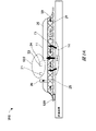
減圧療法システム及び方法
図1はTNP装置11および創傷14を含む陰圧療法システム100を示す。TNP装置11は創傷14を治療するために使用され得る。TNP装置11には、相互に電気的に通信するように構成された、制御回路12Aと、メモリ12Bと、陰圧源12Cと、ユーザインターフェース12Dと、電源12Eと、第一の圧力センサ12Fと、第二の圧力センサ12G(任意でありうる)と、皮膚検出器12Hとが含まれ得る。さらに、TNP装置11には創傷被覆材13が含まれ得る。電源12Eは、TNP装置11の一つまたは複数の構成要素に電力を供給することができる。
Reduced Pressure Therapy System and Method FIG. 1 shows a negative pressure therapy system 100 including a
制御回路12A、メモリデバイス12B、陰圧源12C、ユーザインターフェース12D、電源12E、第一の圧力センサ12F、第二の圧力センサ12G、および皮膚検出器12Hのうちの一つまたは複数が、創傷被覆材13と一体化され得るか、その被覆材13の一部として組み込まれ得るか、その被覆材13に付着され得るか、またはその被覆材13内に配置され得る。したがって、TNP装置11は、その制御エレクトロニクスを有し、創傷被覆材13から分離しているのではなく、創傷被覆材13を搭載してポンピングするとみなされ得る。
One or more of control circuit 12A, memory device 12B, negative pressure source 12C,
制御回路12Aには、一つまたは複数のコントローラと、起動回路と、ブーストコンバータと、電流制限器と、フィードバック調整回路と、Hブリッジインバータとが含まれ得る。一つまたは複数のコントローラは、メモリデバイス12Bに格納された命令に少なくとも従って、TNP装置11の一つまたは複数の他の構成要素の動作を制御することができる。一つまたは複数のコントローラは、例えば、一つまたは複数のHブリッジインバータへの信号入力(例えば、信号のパルス幅変調)を介して陰圧源12Cの動作を制御することができ、これは電源12Eから陰圧源12Cへの電力を駆動する。
Control circuitry 12A may include one or more controllers, a start-up circuit, a boost converter, a current limiter, a feedback regulation circuit, and an H-bridge inverter. One or more controllers may control the operation of one or more other components of
陰圧源12Cには、限定されないが、ロータリーダイヤフラムポンプもしくは他のダイヤフラムポンプ、圧電ポンプ、蠕動ポンプ、ピストンポンプ、ロータリーベーンポンプ、液封式ポンプ、スクロールポンプ、圧電変換器によって動作するポンプ、ボイスコイルポンプ、または他の任意の好適なポンプもしくはマイクロポンプ、あるいは上記のものの任意の組み合わせなどのポンプが含まれ得る。 Negative pressure source 12C includes, but is not limited to, rotary or other diaphragm pumps, piezoelectric pumps, peristaltic pumps, piston pumps, rotary vane pumps, liquid ring pumps, scroll pumps, pumps operated by piezoelectric transducers, voice coils. A pump, such as a pump, or any other suitable pump or micropump, or any combination of the above may be included.
ユーザインターフェース12Dは、ユーザ入力を受信するか、またはユーザ出力を患者または介護者に提供する一つまたは複数の要素を含み得る。ユーザ入力を受信する一つまたは複数の要素は、ボタン、スイッチ、ダイヤル、またはタッチスクリーンなどを含んでもよく、ユーザ出力を提供する一つまたは複数の要素は、発光ダイオード(LED)の起動もしくはディスプレイの一つまたは複数のピクセルの起動、またはスピーカーの起動などを含んでもよい。一例では、ユーザインターフェース12Dは、第一のユーザ入力(例えば、陰圧の起動または作動停止の入力)を受信するためのスイッチと、TNP装置11の動作状態(例えば、正常に機能している状態、故障状態、またはユーザ入力を待っている状態)を示すための二つのLEDとを含んでもよい。
第一の圧力センサ12Fは、陰圧源12Cと創傷14とに接続している流体流路の圧力、創傷14での圧力、または陰圧源12Cにおける圧力などの、創傷被覆材13の下の圧力を監視するために使用され得る。第二の圧力センサ12Gは、創傷被覆材13の外側の圧力を監視するために使用され得る。創傷被覆材の外側の圧力は大気圧であり得るが、大気圧は、例えば使用される高度、またはTNP装置11が使用され得る圧力調整された環境に応じて変動し得る。
The first pressure sensor 12F measures the pressure under the wound dressing 13, such as the pressure in the fluid flow path connecting the negative pressure source 12C and the
制御回路12Aは、陰圧源12Cによる陰圧の供給を、第一の圧力センサ12Fにより監視される圧力と第二の圧力センサ12Gにより監視される圧力とを少なくとも比較することによって、制御することができる。制御回路12Aは、マイクロコントローラまたはマイクロプロセッサなどのコントローラを含み得る。 The control circuit 12A controls the supply of negative pressure by the negative pressure source 12C by at least comparing the pressure monitored by the first pressure sensor 12F and the pressure monitored by the second pressure sensor 12G. can be done. Control circuitry 12A may include a controller such as a microcontroller or microprocessor.
皮膚検出器12Hは、創傷被覆材13が創傷14の上に配置されているかどうかを判定するために使用できる。皮膚検出器12Hは、例えば、患者の皮膚を検出することができる。皮膚検出器12Hによる検出は、創傷被覆材13が、創傷14の横の患者の皮膚に結合されているかどうかを確認できる。皮膚が検出されると、これにより、TNP装置11の起動は、非意図的ではなく意図的であり、TNP装置11の輸送または製造の間など、TNP装置11の非意図的な起動、またはTNP装置11の寿命末期のタイマを防止するために使用できることを示し得る。一実施例では、皮膚検出器12Hが皮膚を検出したことを制御回路12Aに示す場合、制御回路12Aは、陰圧源12Cを起動して、ユーザインターフェース12Dを介して起動入力の受信に応答して陰圧を供給することができる。一方、皮膚検出器12Hが、皮膚が検出されないと制御回路12Aに示す場合、制御回路12Aは、陰圧源12Cを起動してユーザインターフェース12Dを介して起動入力の受信に応答して陰圧を供給できない。皮膚検出器12Hは、容量センサ、インピーダンスセンサ、光学センサ、ピエゾ抵抗センサ、圧電センサ、エラスト抵抗センサ、および電気化学センサのうち一つまたは複数を含み得る。
創傷被覆材13は、創傷接触層と、スペーサ層と、吸収層とを具備し得る。創傷接触層は、創傷14に接触していてもよい。創傷接触層は、被覆材を創傷14の周囲の皮膚に固定するために、患者に対向する側に接着剤を具備し得るか、または、創傷接触層を創傷被覆材13のカバー層もしくは他の層に固定するために、上側に接着剤を具備し得る。動作時に、創傷接触層は、滲出物が創傷14に戻るのを阻止または実質的に防止しつつ、創傷から滲出物を取り除きやすくするように一方向流をもたらすことができる。スペーサ層は、創傷部位の上に陰圧を分配するよう促し、創傷滲出物及び流体を創傷被覆材13内に輸送しやすくするよう促すことができる。さらに、吸収層は創傷14から吸引された滲出物を吸収し、保持することができる。
The wound dressing 13 may comprise a wound contact layer, a spacer layer and an absorbent layer. The wound contact layer may contact the
制御回路12Aは、一部の場合、陰圧源12Cでの陰圧の供給を防止することができる。例えば、制御回路12Aは、陰圧源の動作を停止することによって陰圧の供給を防ぎ、流体流路内に位置付けられたベントを開くことおよび流体流路内に位置付けられた弁を閉じることを防止することができる。 Control circuit 12A may prevent the application of negative pressure at negative pressure source 12C in some cases. For example, the control circuit 12A prevents the supply of negative pressure by deactivating the negative pressure source, opening a vent positioned within the fluid flow path, and closing a valve positioned within the fluid flow path. can be prevented.
陰圧源12Cによる陰圧の供給は、一部の場合には無効化することができる。例えば、陰圧の供給は、陰圧源12Cまたは制御回路12Aの動作を停止すること、流体流路内に位置付けられたベントを開くこと、および流体流路内に位置付けられた弁を閉じることによって無効化することができる。一部の実装では、陰圧源12Cまたは制御回路12Aの動作の停止は、陰圧源12Cもしくは制御回路12Aへの電力の切断、または陰圧源12Cもしくは制御回路12Aに供給されるイネーブル信号の取り消しによって実施され得る。 The supply of negative pressure by negative pressure source 12C can be disabled in some cases. For example, the supply of negative pressure can be achieved by deactivating the negative pressure source 12C or the control circuit 12A, opening a vent positioned within the fluid flow path, and closing a valve positioned within the fluid flow path. Can be disabled. In some implementations, deactivating the negative pressure source 12C or the control circuit 12A may include disconnecting power to the negative pressure source 12C or the control circuit 12A or removing an enable signal supplied to the negative pressure source 12C or the control circuit 12A. It can be implemented by revocation.
制御回路12Aは、陰圧源12Cのデューティサイクルを監視できる。本明細書で使用される場合、「デューティサイクル」とは、陰圧源12Cが作動中であるか、またはある期間にわたって稼働している時間量を表し得るものである。言い換えると、デューティサイクルは、陰圧源12Cが作動状態である時間を、対象となる総時間の割合として表し得るものである。デューティサイクルの測定値は、陰圧源12Cの働きのレベルを表し得る。例えば、デューティサイクルは、陰圧源12Cが正常に動作している、よく稼働している、極めてよく稼働しているなどを示すことができる。さらに、周期的なデューティサイクル測定値といったデューティサイクルの測定値は、漏出の存在もしくは漏出の程度、または創傷から吸引される流体(例えば、空気、液体、または固体の滲出物など)の流量などの様々な動作状態を表すことができる。測定したデューティサイクルと一連の閾値(例えば、較正時に算出される)とを比較することなどによって、デューティサイクルの測定値に基づいて、コントローラは、システムの動作を制御するアルゴリズムまたはロジックを実施することができるか、または実施するようにプログラムされ得る。例えば、デューティサイクルの測定値は、大きな漏出があることを示すことができ、制御回路12Aは、この状態をユーザ(例えば、患者、介護者、または医師など)に示すようにプログラムされ得るか、または節電のために陰圧源の動作を一時的に中断もしくは一時停止するようにプログラムされ得る。 Control circuit 12A can monitor the duty cycle of negative pressure source 12C. As used herein, "duty cycle" may represent the amount of time that negative pressure source 12C is on or is on over a period of time. In other words, the duty cycle may represent the time that the negative pressure source 12C is active as a percentage of the total time of interest. The duty cycle measurement may represent the level of activity of the negative pressure source 12C. For example, the duty cycle may indicate that the negative pressure source 12C is operating normally, performing well, performing extremely well, and so on. In addition, duty cycle measurements, such as periodic duty cycle measurements, can be used to determine the presence or degree of leakage, or the flow rate of fluid (e.g., air, liquid, or solid exudates) aspirated from the wound. Various operating states can be represented. Based on the measured duty cycle, such as by comparing the measured duty cycle to a set of threshold values (e.g., calculated during calibration), the controller implements an algorithm or logic that controls the operation of the system. can be, or be programmed to do, For example, a duty cycle measurement may indicate that there is a large leak, and the control circuit 12A may be programmed to indicate this condition to a user (e.g., patient, caregiver, or physician, etc.); Or it can be programmed to temporarily suspend or suspend operation of the negative pressure source to save power.
TNP装置11が創傷14を治療するのに用いられ得る場合には、創傷被覆材13は、創傷13の周囲及び創傷被覆材13の下に実質的に密閉された空間または閉鎖された空間を作ることができ、第一の圧力センサ12Fがこの空間の圧力レベルを周期的または連続的に測定または監視することができる。制御回路12Aは、この空間の圧力レベルを、第一の陰圧設定値限界と少なくとも第二の陰圧設定値限界との間で制御することができる。一部の例では、第一の設定値限界は約-70mmHgであるか、または約-60mmHg以下~約-80mmHg以上であり得る。一部の例では、第二の設定値限界は約-90mmHgであるか、または約-80mmHg以下~約-100mmHg以上であり得る。
When the
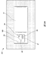
図2Aは陰圧療法システム200の側面図を示し、図2Bは陰圧療法システム200の上面図を示している。陰圧療法システム200は、陰圧療法システム100の実装例となり得る。
FIG. 2A shows a side view of negative
陰圧療法システム200では、TNP装置11の創傷被覆材13は創傷14に付着しているように示されている。創傷被覆材13を通る空気の流れと、創傷14からの創傷滲出物の流れとを矢印で示している。TNP装置11には、空気排出部26と、制御回路12A、メモリデバイス12B、陰圧源12C、ユーザインターフェース12D、電源12E、第一の圧力センサ12F、第二の圧力センサ12G、おおび皮膚検出器12Hのうちの一つまたは複数などのTNP装置11の構成要素のための構成要素のハウジングまたは構成要素の収納領域などの構成要素領域25とが含まれ得る。
In negative
陰圧療法システム200のユーザインターフェース12Dには、スイッチ21と、第一の表示器23(第一のLEDなど)と、第二の表示器24(第二のLEDなど)とが含まれ得る。スイッチ21は、陰圧の起動または停止のユーザ入力を受信すること(例えば、スイッチ21を押し下げることに応答して、起動または停止のユーザ入力を受信することなど)ができる。第一の表示器23と第二の表示器24は、正常に機能している状態、故障状態、またはユーザ入力を待っている状態などの動作状態を示すことができる。一部の実装では、スイッチ21は、陰圧源12Cもしくは制御回路12Aの電源接続部(制御回路12Aのコントローラなど)、または陰圧源12Cもしくは制御回路12Aのイネーブル信号部と連結して、陰圧の供給を起動もしくは停止するか、または陰圧の供給を無効化することができる。さらに、制御回路12Aは、スイッチ21、第一の表示器23、または第二の表示器24などのユーザインターフェース12Dを監視して、故障のような問題を検出し、故障検出に応答して、ユーザインターフェース12Dを介して故障表示を出力するか、または陰圧の供給を起動または無効化することができる。特定の実施形態では、制御回路12Aは、スイッチ21へのユーザ入力以外のユーザ入力がないことに応答して、陰圧源12Cで陰圧を供給し得る。
The
陰圧療法システム200の創傷被覆材13の構成要素部が、エアロック層27と、吸収層28と、接触層29とを含むように示されている。エアロック層27は、空気が流れるようにすることができる。吸収層28は、創傷滲出物を吸収することができる。接触層29は柔軟性があり、シリコンを含んでいてもよく、TNP装置11を患者につなげるために使用することができる。
The component parts of the wound dressing 13 of the negative
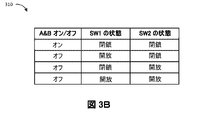
図3Aは、一部の実施形態による、スイッチ21のようなスイッチの回路図300を示す。スイッチは、二極、単投スイッチとすることができ、スイッチの押下などのユーザ入力に応答して、複数の接点のセット(例えば、二つ、三つ、四つ、またはそれ以上の接点のセット)の状態を切り替えるアクチュエータを含む。アクチュエータは同時にまたは互い違いに、複数の接点のセットの状態を切り替えることができる。図3Aに示すように、複数の接点のセットは、接点302および304(集合的に、SW1と称される第一のスイッチを形成する第一の接触パッドを有する)および接点306および308を含む第二の接点と(集合的に、SW2と称される第二のスイッチを形成する第一の接触パッドを有する)を含む。SW1およびSW2は冗長スイッチとして機能できる。概略図300は、二対の接点を示すが、本明細書に記載のスイッチのいずれも二対以上の接点を含みうる。
FIG. 3A shows a circuit diagram 300 of a switch, such as
接点302および304は開放して示され、接点306および308は開放して示されている。SW1の接触パッドは、接点302と304とを電気接続、または短絡させないため、接点302および304は開いていてもよい。接点302および304が開いている場合、SW1も開いていると考えられうる。同様に、SW2の接触パッドは、接点306と308とを電気接続、または短絡させないため、接点306および308は開いていてもよい。接点306および308が開いている場合、SW2も開いていると考えられうる。
SW1の接触パッドが接点302と304とを電気接続、または短絡させる場合、接点302および304は閉じていてもよい。接点302および304が閉じている場合、SW1も閉じていると考えられうる。SW2の接触パッドが接点306と308とを電気接続、または短絡させる場合、接点306および308は閉じていてもよい。接点306および308が閉じている場合、SW2も閉じていると考えられうる。
スイッチはさらに、入力Aおよび出力Bを含み得る。例えば、入力Aは電源(例えば、電源12E)、またはTNP装置11の接地に電気接続されてもよく、出力BはTNP装置の制御操作に電気接続されてもよい(またはその逆であってもよい)。スイッチが閉じている時、電力または接地への電気接続が形成され、それによってTNP装置11が動作または機能して療法を提供できるようになる。例えば、スイッチが閉じている場合、信号が制御回路12Aに供給されるか、または生成されて、陰圧源12Cを起動するか、または電源12EによるTNP装置11の他の構成要素への電力供給を有効化することができる。
The switch may further include an A input and a B output. For example, input A may be electrically connected to a power supply (e.g., power supply 12E), or ground of the
一部の実装では、スイッチが正常に機能している場合、複数の接点のセットの状態は、スイッチへのユーザ入力に応答してのみ、切り替えられ得る。ただし、スイッチが故障すると、アクチュエータは複数の接点のセットのうちの一つまたは複数を切り替えることができなくなり、スイッチは、ユーザ入力に応答して複数の接点のセットのすべての状態を切り替えることができない。したがって、アクチュエータが複数の接点のセットを切り替えることができなくなった場合、制御回路12Aは、陰圧源12Cで陰圧を供給するように構成されなくなり得る。 In some implementations, when the switch is functioning normally, the states of the sets of contacts may only be switched in response to user input to the switch. However, if the switch fails, the actuator will not be able to switch one or more of the sets of contacts, and the switch will switch all states of the sets of contacts in response to user input. Can not. Accordingly, if the actuator is unable to switch between sets of contacts, the control circuit 12A may no longer be configured to provide negative pressure at the negative pressure source 12C.
図3Bは、回路図300の論理真理値表310である。論理真理値表310から理解できるように、入力Aから出力Bへの電気経路は、SW1およびSW2の両方が閉じられている場合、形成されるかまたは「オン」になると考えられ、入力Aから出力Bへの電気経路は、SW1またはSW2のうちの少なくとも一つが開いている場合、形成されないかまたは「オフ」になると考えられ得る。 FIG. 3B is a logical truth table 310 for circuit diagram 300 . As can be seen from the logic truth table 310, an electrical path from input A to output B is considered to be formed or turned "on" if both SW1 and SW2 are closed; An electrical path to output B may be considered not formed or "off" if at least one of SW1 or SW2 is open.
その他の実装では、スイッチは、回路図300とは異なるように設計でき、論理真理値表310とは異なる代替的な論理真理値表に従って機能することができる。代替的な論理真理値表には、複数の可能な構成を含めることができ、各構成は入力Aから出力Bへの電気経路をオンまたはオフにする。代替的な論理真理値表の複数の可能な構成の一つまたは複数により、入力Aから出力Bへの電気経路がオンになり、代替的な論理真理値表の複数の構成の他の一つまたは複数により、入力Aから出力Bへの電気経路をオフにすることができる。特定の実施形態において、入力Aから出力Bへの電気経路をオンにする複数の構成の総数は、入力Aから出力Bへの電気経路をオフにする複数の構成の総数より少なくし得る。これにより、スイッチが適切に機能しない限り、入力Aから出力Bへの電気経路がオフになるバイアスを有利にもたらし得る。結果として、スイッチは、スイッチが適切に機能していない場合ではなく、スイッチが適切に機能している場合、陰圧源12Cを知的に動作させ得る。 In other implementations, the switch can be designed differently than schematic 300 and can function according to an alternative logical truth table different from logical truth table 310 . An alternative logic truth table can include multiple possible configurations, each turning on or off an electrical path from input A to output B. One or more of the possible configurations of the alternative logic truth table turns on an electrical path from input A to output B, and the other one of the plurality of configurations of the alternative logic truth table. or multiple, the electrical path from input A to output B can be turned off. In certain embodiments, the total number of configurations that turn on the electrical path from input A to output B may be less than the total number of configurations that turn off the electrical path from input A to output B. This can advantageously result in a bias that turns off the electrical path from input A to output B unless the switch is functioning properly. As a result, the switch may intelligently operate the negative pressure source 12C if the switch is functioning properly, rather than if the switch is not functioning properly.
図4Aおよび図4Bは、一部の実施形態による、回路図300の実装を示す。接点402、404、406、408はそれぞれ、接点302、304、306、308の実装であり得る。SW1接触パッド410は、図3AのSW1の接触パッドの実装とすることができ、SW2接触パッド412は、図3AのSW2の接触パッドの実装とすることができる。
4A and 4B show an implementation of circuit diagram 300, according to some embodiments.
図示したように、接点402、404、406、408の少なくとも一部は、一次トレースから延びる一次トレースおよび複数の二次トレースをそれぞれ含むことができる。複数の二次トレースはそれぞれ、それがそこから延びる一次トレースに対して垂直に延び得る。一次トレースは、接点402および408に関連して示されるように湾曲、または接点404および406に関連して示されるように直線とすることができる。接点402、404、406、408の一次および二次トレースは、例えば、回路基板上に印刷できる。
As shown, at least some of the
図4Aでは、接点402および404は開放して示され、接点406および408は開放して示されている。図4Bでは、接点402および404は、SW1接触パッド410の接点402および404との接触によって閉じた状態で示され、接点406および408は、SW2接触パッド412の接点406および408との接触によって閉じた状態で示される。電気経路は、入力Aから出力Bに、例えば、接点402、接触パッド410、接点404、接点406、接触パッド412、および接点408を通して形成される。SW1接触パッド410およびSW2接触パッド412は、導電板であり得る。接触パッド410および412は、一つのアクチュエータ(または複数のアクチュエータ)によって接点402、404、406、408と接触するようにされ得、これにより、機械的に、空気圧によって、電気的に、またはスイッチの押下などのユーザ入力によって作動し得る。
In FIG. 4A,
図5Aおよび図5Bは、一部の実施形態による、回路図300の別の実装を示す。接点502、504、506、508はそれぞれ、接点302、304、306、308の実装であり得る。SW1接触パッド510は、図3AのSW1の接触パッドの実装とすることができ、SW2接触パッド512は、図3AのSW2の接触パッドの実装とすることができる。
5A and 5B show another implementation of circuit diagram 300, according to some embodiments.
図示したように、接点502、504、506、508の少なくとも一部は、一次トレースと一次トレースから延びる複数の二次トレースをそれぞれ含み得る。複数の二次トレースはそれぞれ、それがそこから延びる一次トレースに対して垂直に延び得る。一次トレースは、図示した通り直線であり得る。接点502、504、506、508の一次および二次トレースは、例えば、回路基板上に印刷できる。
As shown, at least some of the
図5Aでは、接点502および504は開放して示され、接点506および508は開放して示されている。図5Bでは、接点502および504は、SW1接触パッド510の接点502および504との接触によって閉じた状態で示され、接点506および508は、SW2接触パッド512の接点506および508との接触によって閉じた状態で示される。電気経路は、入力Aから出力Bに、例えば、接点502、接触パッド510、接点504、接点506、接触パッド512、および接点508を通して形成される。SW1接触パッド510およびSW2接触パッド512は、導電板であり得る。接触パッド510および512は、一つのアクチュエータ(または複数のアクチュエータ)によって接点502、504、506、508と接触するようにされ得、これにより、機械的に、空気圧によって、電気的に、またはスイッチの押下などのユーザ入力によって作動し得る。
In FIG. 5A,
図6Aおよび図6Bは、一部の実施形態による、回路図300の別の実装を示す。接点602、604、606、608はそれぞれ、接点302、304、306、308の実装であり得る。SW1接触パッド610は、図3AのSW1の接触パッドの実装とすることができ、SW2接触パッド612は、図3AのSW2の接触パッドの実装とすることができる。
6A and 6B show another implementation of circuit diagram 300, according to some embodiments.
図示したように、接点602、604、606、608の少なくとも一部は、導電性領域の周りに延在する周縁トレースをそれぞれ含むことができる。接点602、604、606、608の周縁トレースおよび接触領域は、例えば、回路基板上に印刷できる。
As shown, at least a portion of the
図6Aでは、接点602および604は開放して示され、接点606および608は開放して示されている。図6Bでは、接点602および604は、SW1接触パッド610の接点602および604との接触によって閉じた状態で示され、接点606および608は、SW2接触パッド612の接点606および608との接触によって閉じた状態で示される。電気経路は、入力Aから出力Bに、例えば、接点602、接触パッド610、接点604、接点606、接触パッド612、および接点608を通して形成される。SW1接触パッド610およびSW2接触パッド612は、導電板であり得る。接触パッド610および612は、一つのアクチュエータ(または複数のアクチュエータ)によって接点602、604、606、608と接触するようにされ得、これにより、機械的に、空気圧によって、電気的に、またはスイッチの押下などのユーザ入力によって作動し得る。
In FIG. 6A,
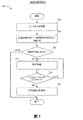
図7は、TNP装置11などの装置による陰圧療法の送達を制御するために使用可能な療法制御プロセス700を示す。便宜上、療法制御プロセス700がTNP装置11の文脈において説明されるが、代わりに、本明細書に記載の他のシステムで、または示されていない他のシステムによって実施される場合もある。療法制御プロセス700は、一部の例において、制御回路12A単独によって、またはTNP装置11のユーザインターフェース12Dとの組み合わせによって実施され得る。
FIG. 7 illustrates a
ブロック702で、療法制御プロセス700はユーザ入力を受信し得る。ユーザ入力は、例えば、スイッチ21の押下によって、ユーザインターフェース12Dを介して受信され得る。
At
ブロック704で、療法制御プロセス700は、ユーザ入力に応答して、複数のセットの接点の状態を(例えば、接点を閉じるなどして)切り替えることを試みることができる。スイッチ21は、例えば、接点302および304ならびに接点306および308などの複数の対の接点の状態を切り替えることを試みることができる一つのアクチュエータ(または複数のアクチュエータ)を含み得る。スイッチ21が正常に機能している場合、スイッチ21は複数の対の接点の状態を切り替え得る。例えば、複数の対の接点の各々が閉じているように、複数の対の接点の状態はそれぞれ同時に(または実質的に同時に)または次々に切り替えられることができる。スイッチ21が正常に機能していない場合、スイッチ21は複数の対の接点の一つまたは複数の状態を切り替えることができない。
At
ブロック706で、複数の接点のセットの状態が切り替えられなかった場合、療法制御プロセス700は終了することができる。一方で、複数の接点のセットの状態が切り替えられた場合、療法制御プロセス700はブロック708に移行して陰圧を供給することができる。陰圧の供給は制御回路12Aによって開始され、陰圧源12Cによって実施されることができ、流体流路を介して陰圧を創傷被覆材13に供給することができる。
At
ブロック710で、複数の接点のセットの状態が変化しないままである場合、療法制御プロセス700は再びブロック708に移行し、陰圧の供給を継続することができる。一方、ブロック710で、複数の接点のセットのうちの少なくとも一つの状態が変化する(例えば、開かれた)場合、療法制御プロセス700はブロック712に移行できる。例えば、ユーザ入力は、スイッチ21の押下などによりユーザインターフェース12Dを介して受信することができ、複数の対の接点の一つまたは複数の状態を切り替えることができる。スイッチ21が正常に機能している場合、スイッチ21は複数の対の接点の状態を切り替え得る。例えば、複数の対の接点の各々が開いているように、複数の対の接点の状態はそれぞれ同時に(または実質的に同時に)または次々に切り替えられることができる。スイッチ21が正常に機能していない場合、スイッチ21は複数の対の接点の一つまたは複数の状態を切り替えることができない。
At
ブロック712で、療法制御プロセス700は陰圧の供給を無効化することができる。陰圧の供給は、例えば、陰圧源12Cまたは制御回路12Aの動作の停止、流体流路内に位置付けられたベントの開放、流体流路内に位置付けられた弁の閉鎖によって無効化され得る。ブロック710で、複数の接点のセットの全てより少ないものを切り替える(例えば、開く)ことにより、療法制御プロセス700がブロック710からブロック712へと移行しうるため、療法制御プロセス700は有利には、特定の実施形態において、複数の接点のセットの全てを切り替えることに関与し得る陰圧の供給を無効化するために想定される表示を受信しないにも拘らず、陰圧の供給を無効化するいくつかの表示に応答して、陰圧の供給を無効化するか、または無効化するようにバイアスをかけられる。ブロック712の後、療法制御プロセス700は終了することができる。一部の実施形態では、ブロック710は、定期的に、または一つまたは複数の接点の状態の変化(例えば、一つまたは複数の接点の状態が切り替えられたときに生成される干渉の結果)に応答して実施され得る。特定の実装では、陰圧が供給される間にブロック710を実施し得る。
At
図8は、TNP装置11などの陰圧創傷療法を送達するよう構成された装置内のスイッチ障害を検出するために使用可能なスイッチ故障検出プロセス800を示す。便宜上、スイッチ故障検出プロセス800がTNP装置11の文脈において説明されるが、代わりに、本明細書に記載の他のシステムで、または示されていない他のシステムによって実施される場合もある。スイッチ故障検出プロセス800は、例えば、制御回路12A単独によって、またはユーザインターフェース12Dと組み合わせて実施され得る。プロセス800は、ユーザインターフェース12Dの故障を検出するために使用され得る。スイッチ故障検出プロセス800は、一部の例では、陰圧源12Cをオフにして陰圧を提供しないようにし得る。
FIG. 8 illustrates a switch
ブロック802で、スイッチ故障検出プロセス800は、一つの接点のセットの状態において切り替えを検出できる。例えば、制御回路12Aは、図3Aに示す接点302および304など、スイッチ21の接点の対のうちの一つの状態で切り替えを検出できる。切り替えは、例えば、スイッチ21の一対の接点の電気的特性(電圧または電流など)、機械的特性、圧力特性、または熱的特性の変化から検出することができ、センサを使用して検出することができる。
At
ブロック804で、スイッチ故障検出プロセス800は、別の接点のセットの状態が切り替えられたか判定できる。例えば、制御回路12Aは、スイッチ21へのユーザ入力に応答して、図3Aに示す接点306および308など、スイッチ21の接点の対のうちの別の状態で切り替えを検出できる。切り替えは、例えば、スイッチ21の接点の対の他方の電気的特性(電圧または電流など)、機械的特性、圧力特性、または熱的特性の変化から検出することができ、センサを使用して検出することができる。
At
別の接点のセットの状態が切り替えられる場合、スイッチ故障検出プロセス800はブロック806に移行し、陰圧を供給することができる。陰圧の供給は制御回路12Aによって開始され、陰圧源12Cによって実施されることができ、流体流路を介して陰圧を創傷被覆材13に供給することができる。
If another set of contacts toggles state, the switch
別の接点のセットの状態が切り替えられない場合、スイッチ故障検出プロセス800はブロック808に移行し、スイッチ故障表示を出力することができる。別の接点のセットの切り替えの失敗により、別の接点セットがユーザ入力から予期される切り替えに失敗したことが示唆され得る。例えば、制御回路12Aは、他の接点のセットが切り替えられないことからスイッチ故障を検出し、こうしてユーザインターフェース12D上の呈示などのスイッチ故障表示を出力する。ブロック804でのスイッチ故障検出プロセス800はさらに、ブロック808に移行する前に、0.5秒、1秒、2秒、3秒、5秒以上などの時間にわたり、接点の別のセットの切り替えを監視し、スイッチ故障表示を出力し得る。
If another set of contacts fails to switch states, the switch
図7および図8のプロセスは、陰圧の供給を可能または無効にするために一つまたは複数の接点を切り替えることについて記載するが、一つまたは複数の接点を切り替えることは、例えばTNP装置11の初期起動などのTNP装置11のその他の機能を制御するために使用され得る。
Although the processes of FIGS. 7 and 8 describe switching one or more contacts to enable or disable the supply of negative pressure, switching one or more contacts may be performed by the
他の変形
本開示におけるより一つまたは複数の例は、陰圧源、制御回路、または他の構成要素が創傷被覆材上などの統合ユニットの一部として記載するが、一つまたは複数の例は、こうした統合ユニットに開示の範囲を限定しない。冗長起動または無効化制御に関連する特徴は、例えば、創傷被覆材または任意の医療もしくは電子装置に一体化されていない、またはそれから分離されたTNP装置の一部として含まれ得る。
Other Variations Although one or more examples in this disclosure describe the negative pressure source, control circuitry, or other components as part of an integrated unit, such as on a wound dressing, one or more examples does not limit the scope of the disclosure to such integrated units. Features associated with redundant activation or override control may be included, for example, as part of the TNP device that is not integrated with or separate from the wound dressing or any medical or electronic device.
本明細書で提供される閾値、限界値、期間などの値は、絶対的なものであることを意図するものではなく、したがっておおよそのものでありうる。さらに、本明細書で提供される任意の閾値、限界値、期間などは、自動的にまたはユーザによって、固定されるかまたは変えられうる。さらに、本明細書で使用される場合、参照値に関連した、超える、超、未満などの相対的な程度を表す用語は、参照値と等しい場合も包含することが意図される。例えば、正の参照値を超えることは、参照値以上であることを包含することができる。その上、本明細書で使用される場合、参照値に関連した、超える、超、未満などの相対的な程度を表す用語は、参照値に関連した、下にある、未満、超などの開示された関係とは逆のものも包含することが意図される。また、種々のプロセスのブロックは、ある値が特定の閾値に達するかまたは達しないかを判定することに関して説明されうるが、ブロックは、例えば、ある値が(i)閾値未満であるかもしくは閾値を超えているか、または(ii)閾値を満たすかもしくは満たしていないかに関しても同様に解釈されうる。 Values such as thresholds, limits, time periods, etc. provided herein are not intended to be absolute and may therefore be approximate. Additionally, any thresholds, limits, time periods, etc. provided herein may be fixed or varied, either automatically or by a user. Furthermore, as used herein, terms expressing relative degrees, such as greater than, greater than, less than, relating to a reference value are intended to encompass equality to the reference value. For example, exceeding a positive reference value can include being greater than or equal to the reference value. Moreover, as used herein, terms denoting relative degrees such as above, above, below, etc. in relation to a reference value are defined as below, below, below, above, etc., in relation to a reference value. It is intended to encompass the reverse of the stated relationship as well. Also, although various process blocks may be described in terms of determining whether a value reaches or falls short of a particular threshold, a block may, for example, determine whether a value is (i) below a threshold or or (ii) meeting or not meeting a threshold can be similarly interpreted.
特定の態様、実施形態、または実施例に関連して説明される特性、物質、特徴、または群は、本明細書に記載される他の任意の態様、実施形態、または実施例に、これらと両立できないことがない限り、適用可能であることを理解されたい。本明細書(添付の任意の特許請求の範囲、要約書、及び図面を含む)に開示される全ての特徴、または同様に開示される任意の方法もしくはプロセスの全てのステップは、こうした特徴またはステップのうち少なくともいくつかが相互に排他的となる組み合わせを除いて、任意の組み合わせで組み合わされてよい。本発明の保護するものは、前述の任意の実施形態の詳細に限定されない。保護するものは、本明細書(添付の任意の特許請求の範囲、要約書、及び図面を含む)において開示される特徴のうちの任意の新規なもの、もしくは任意の新規な組み合わせに及び、または同様に開示される任意の方法またはプロセスのステップのうちの任意の新規なもの、もしくは任意の新規な組み合わせに及ぶ。 A property, material, feature, or group described in connection with a particular aspect, embodiment, or example may be used in conjunction with any other aspect, embodiment, or example described herein. It should be understood that they are applicable unless they are incompatible. Any feature disclosed in this specification (including any appended claims, abstract, and drawings) or any step of any similarly disclosed method or process may be referred to as such feature or step may be combined in any combination, except combinations in which at least some of are mutually exclusive. What this invention covers is not limited to the details of any foregoing embodiments. What is covered is any novelty, or any novel combination, of the features disclosed in this specification (including any appended claims, abstract, and drawings), or It extends to any novel one or any novel combination of the steps of any method or process disclosed as well.
特定の実施形態が説明されてきたが、これらの実施形態は、単に例として提示されており、保護範囲を限定することを意図するものではない。実際、本明細書に記載の新規な方法及びシステムは、様々な他の形態で具現化されてもよい。さらに、本明細書に記載の方法及びシステムの形態において、様々な省略、置換、及び変形がなされ得る。実施形態によっては、図示または開示されたプロセスにおいて実施される実際のステップは、図に示されたステップとは異なりうることを、当業者は認識するであろう。実施形態によっては、上述したステップのうちの特定のステップが除去される場合があり、別のものが加えられる場合もある。例えば、開示されるプロセスで実施される実際のステップまたはステップの順序は、図で示したものとは異なっていてもよい。実施形態によっては、上述したステップのうちの特定のステップが除去される場合があり、別のものが加えられる場合もある。例えば、図に示した様々な構成要素が、プロセッサ、コントローラ、ASIC、FPGA、または専用ハードウェア上のソフトウェアまたはファームウェアとして実装されてもよい。プロセッサ、ASIC、FPGA等のハードウェア構成要素には論理回路が含まれ得る。さらに、上記に開示された特定の実施形態の特徴及び特性は、様々な方法で組み合わせることができ、さらなる実施形態を形成することができるが、その全てが本開示の範囲内に収まることになる。 Although specific embodiments have been described, these embodiments are presented by way of example only and are not intended to limit the scope of protection. Indeed, the novel methods and systems described herein may be embodied in various other forms. Moreover, various omissions, substitutions, and variations may be made in the form of the methods and systems described herein. Those skilled in the art will recognize that, depending on the embodiment, the actual steps performed in the processes illustrated or disclosed may differ from those depicted in the figures. In some embodiments, certain of the steps described above may be removed and others added. For example, the actual steps or order of steps performed in the disclosed processes may differ from that shown in the figures. In some embodiments, certain of the steps described above may be removed and others added. For example, the various components shown in the figures may be implemented as software or firmware on a processor, controller, ASIC, FPGA, or dedicated hardware. Hardware components such as processors, ASICs, FPGAs, etc. may include logic circuits. Moreover, the features and characteristics of the particular embodiments disclosed above can be combined in various ways to form additional embodiments, all of which will fall within the scope of the present disclosure. .
本明細書で図示され、説明されるユーザインターフェーススクリーンには、追加の構成要素または代替の構成要素が含まれうる。これらの構成要素には、メニュー、リスト、ボタン、テキストボックス、ラベル、ラジオボタン、スクロールバー、スライダー、チェックボックス、コンボボックス、ステータスバー、ダイアログボックス、ウィンドウなどが含まれうる。ユーザインターフェーススクリーンには、追加の情報、または代替の情報が含まれうる。構成要素は、任意の好適な順番に配置され、グループ化され、標示されうる。 The user interface screens shown and described herein may include additional or alternative components. These components can include menus, lists, buttons, text boxes, labels, radio buttons, scrollbars, sliders, check boxes, combo boxes, status bars, dialog boxes, windows, and the like. User interface screens may include additional or alternative information. Components may be arranged, grouped, and labeled in any suitable order.
本開示には、特定の実施形態、実施例、及び用途が含まれるが、本開示は、具体的に開示された実施形態の範囲を超えて、他の代替の実施形態または使用ならびにその明らかな変更形及びその等価物にまで及び、これには本明細書に記載された特徴および利点の全てを提供しているとは限らない実施形態が含まれることは、当業者に理解されるであろう。したがって、本開示の範囲は、本明細書における好ましい実施形態の特定の開示によって限定されることを意図するものではなく、本明細書に提示されるまたはこの後に提示される特許請求の範囲によって画定されうる。 Although this disclosure includes specific embodiments, examples, and applications, this disclosure goes beyond the specifically disclosed embodiments and covers other alternative embodiments or uses and the obvious Those skilled in the art will appreciate that this extends to modifications and equivalents, including embodiments that do not provide all of the features and advantages described herein. deaf. Accordingly, the scope of the present disclosure is not intended to be limited by the specific disclosures of preferred embodiments herein, but is defined by the claims presented herein or hereinafter presented. can be
「し得る(can)」、「できる(could)」、「可能性がある(might)」、または「場合がある(may)」などの条件付き言い回しは、別途具体的に記載されない限り、または使用される文脈の範囲内で別途解釈されない限り、特定の実施形態が、特定の特徴、要素、またはステップを含む一方で、他の実施形態は含まないということの伝達を意図するのが通例である。したがって、こうした条件付き言い回しは、特徴、要素、またはステップが一つまたは複数の実施形態に多少なりとも必要とされるという示唆、またはこれらの特徴、要素、もしくはステップが特定の任意の実施形態に含まれているかどうか、もしくは該実施形態で実施されるべきかどうかを、ユーザ入力または命令の有無にかかわらず決定するためのロジックが、一つまたは複数の実施形態に必然的に含まれているという示唆を必ずしも意図するものではない。「備える(comprising)」、「含む(including)」、及び「有する(having)」等の用語は、同義語であり、包含的に非限定様式で用いられ、追加の要素、特徴、行為、及び動作等を排除するものではない。また、用語「または(or)」は、包括的な意味で(排他的な意味ではなく)用いられることで、例えば要素の列記をつなぐのに使用される場合、列記の要素のうちの一つ、一部、または全てを意味することになる。さらに、用語「各々」は、本明細書で使用される場合、通常の意味を有するのに加えて、用語「各々」が適用されている一連の要素の任意のサブセットも意味し得る。 Conditional phrases such as "can," "could," "might," or "may," unless specifically stated otherwise, or Unless otherwise construed within the context of use, it is generally intended to convey that certain embodiments include certain features, elements, or steps, while others do not. be. Thus, such conditional language should not be used to imply that the features, elements or steps are required in some degree in one or more embodiments or that these features, elements or steps may be required in any particular embodiment. One or more embodiments necessarily include logic for determining whether to include or to be implemented in the embodiment, with or without user input or instruction It is not necessarily intended to suggest that Terms such as “comprising,” “including,” and “having” are synonymous and are used in an inclusive, non-limiting manner to include additional elements, features, acts, and It does not exclude actions and the like. Also, the term "or" is used in an inclusive (rather than exclusive) sense, e.g., when used to join a list of elements, one of the listed elements , some or all. Further, the term "each" as used herein, in addition to having its ordinary meaning, may also refer to any subset of the series of elements to which the term "each" is applied.
語句「X、Y、およびZのうちの少なくとも一つ」などの連言的言い回しは、別途具体的に記載されない限り、ある項目や用語などが、Xか、Yか、Zのいずれかでありうることを伝えるのに一般的に用いられる文脈と共に、別途解釈されるものである。したがって、こうした連言的言い回しは、特定の実施形態が、少なくともXのうちの一つと、少なくともYのうちの一つと、少なくともZのうちの一つとを含むことを必要とするという示唆を通常意図しない。 Conjunctive phrases such as the phrase "at least one of X, Y, and Z" mean that an item, term, etc. is either X, Y, or Z, unless specifically stated otherwise. It is to be interpreted separately, along with the context in which it is commonly used to convey what is possible. Thus, such conjunctive language is generally intended to imply that a particular embodiment requires inclusion of at least one of X, at least one of Y, and at least one of Z. do not do.
本明細書で使用される「およそ」、「約」、「概して」、および「実質的に」という用語などの、本明細書で使用される程度を表す言い回しは、所望の機能を依然として果たすかまたは所望の結果をもたらす所定の値、量、または特性に近い値、量、または特性を表すものである。例えば、「およそ」、「約」、「概して」、及び「実質的に」という用語は、所定の量の10%未満以内、5%未満以内、1%未満以内、0.1%未満以内、及び0.01%未満以内の量を意味し得る。別の例として、特定の実施形態において、「概して平行」及び「実質的に平行」という用語は、丁度平行である状態から15度以下、10度以下、5度以下、3度以下、1度以下、または0.1度以下ずれている値、量、または特性を意味する。 The terms used herein, such as the terms "approximately," "about," "generally," and "substantially," as used herein, still perform their desired functions. or represents a value, quantity or property that approximates a given value, quantity or property that produces a desired result. For example, the terms “approximately,” “about,” “generally,” and “substantially” refer to a given amount within 10%, within 5%, within 1%, within 0.1%, and an amount within 0.01%. As another example, in certain embodiments, the terms "generally parallel" and "substantially parallel" refer to 15 degrees or less, 10 degrees or less, 5 degrees or less, 3 degrees or less, 1 degree from being exactly parallel. means a value, quantity, or property that deviates by less than or equal to 0.1 degrees.
本開示の範囲は、本節におけるまたは本明細書の他の箇所における好ましい実施形態の特定の開示によって制限されることを意図するものではなく、本節においてまたは本明細書の他の箇所において提示されているか、またはこの後に提示される特許請求の範囲によって定義されうる。本特許請求の範囲の言い回しは、本特許請求の範囲で用いられている言い回しに基づいて広い意味で解釈されるべきであり、本明細書で説明されている例または本出願の手続きの間に説明される例に限定されるものではなく、それらの例は非排他的なものとして解釈されるべきである。
[付記項1]
創傷に陰圧を適用する装置であって、
流体流路を介して創傷被覆材に陰圧を提供するように構成される陰圧源と、
ユーザ入力に応答して第一の対の電気接点の状態と第二の対の電気接点の状態とを切り替えるように構成されたアクチュエータを備えるスイッチと、
制御回路であって、
電気接続状態にある前記第一の対の電気接点および電気接続状態にある前記第二の対の電気接点に応答して、前記陰圧源で陰圧を供給し、
電気接続状態にない前記第一の対の電気接点および電気接続状態にない前記第二の対の電気接点に応答して、前記陰圧源で陰圧を供給することを無効化するように構成される制御回路と、を備える、装置。
[付記項2]
前記制御回路が、前記電気接続状態にある前記第一の対の電気接点および前記電気接続状態にない前記第二の対の電気接点に応答して、前記陰圧源で陰圧を供給することを無効化にするように構成される、付記項1に記載の装置。
[付記項3]
前記アクチュエータが、前記ユーザ入力に応答して、前記第一の対の電気接点の前記状態と前記第二の対の電気接点の前記状態とを同時に切り替えるように構成される、付記項1または2に記載の装置。
[付記項4]
前記制御回路が、前記スイッチへの前記ユーザ入力以外のユーザ入力がないことに応答して、前記陰圧源で陰圧を供給するように構成される、付記項1~3のいずれか一つまたは複数に記載の装置。
[付記項5]
アクチュエータが故障し、前記第一の対の電気接点の前記状態または前記第二の対の電気接点の前記状態を切り替えることができなくなると、前記制御回路が、前記陰圧源で陰圧を供給しなくなるようにさらに構成される、付記項1~4のいずれか一つまたは複数に記載の装置。
[付記項6]
前記制御回路が、前記第二の対の電気接点の前記状態の切り替えに続く閾値期間内に切り替わらない前記第一の電気接点の前記状態に応答して、スイッチ故障を検出するようにさらに構成される、付記項1~5のいずれか一つまたは複数に記載の装置。
[付記項7]
前記閾値期間が、0.5秒、1秒、2秒、3秒、または5秒である、付記項6に記載の装置。
[付記項8]
前記制御回路が、前記スイッチ故障の検出に応答して、スイッチ故障表示を出力するようにさらに構成される、付記項6または7に記載の装置。
[付記項9]
第一の対の電気接点が、複数の第一のトレースを含み、前記第二の対の電気接点が、複数の第二のトレースを含み、前記アクチュエータが、前記ユーザ入力に応答して、前記複数の第一のトレースを互いに短絡させ、前記複数の第二のトレースを互いに短絡させるように構成される、付記項1~8のいずれか一つまたは複数に記載の装置。
[付記項10]
前記陰圧源が、前記創傷被覆材上またはその中に配置される、付記項1~9のいずれか一つまたは複数に記載の装置。
[付記項11]
前記制御回路が、前記陰圧源の動作の停止、前記流体流路内に位置付けられたベントの開放、または前記流体流路内に位置付けられた弁の閉鎖によって、前記陰圧源での陰圧の供給を無効化するように構成される、付記項1~10のいずれか一つまたは複数に記載の装置。
[付記項12]
前記スイッチが、前記スイッチの押下として前記ユーザ入力を受信するように構成される、付記項1~11のいずれか一つまたは複数に記載の装置。
[付記項13]
創傷への陰圧の適用を制御するための方法であって、前記方法が、
スイッチのアクチュエータを使用して、前記スイッチへのユーザ入力の受信に応答して、第一の対の接点の状態と第二の対の接点の状態とを切り替えることと、
前記第一の対の接点の前記状態が第一の状態であり、前記第二の対の前記状態が第二の状態であることに応答して、流体流路を介して創傷被覆材に陰圧源で陰圧を供給することと、
前記第一の対の接点の前記状態が第一の状態にはなく、前記第二の対の接点の前記状態が第二の状態にはないことに応答して、前記陰圧源での陰圧の供給を無効化することと、を含み、
一回目では、前記第一の対の接点の前記状態が前記第一の状態であり、前記第二の対の接点の前記状態が前記第二の状態であり、二回目では、前記第一の対の接点の前記状態が前記第一の状態ではなく、前記第二の対の接点の前記状態が前記第二の状態ではない、方法。
[付記項14]
前記第一および前記第二の状態が、電気接続の形成に対応する、付記項13に記載の方法。
[付記項15]
三回目では、前記第一の対の接点の前記状態が前記第一の状態であり、前記第二の対の接点の前記状態が前記第二の状態ではない、付記項13または14に記載の方法。
[付記項16]
前記切り替えることが、前記スイッチへの前記ユーザ入力の受信に応答して、前記第一の対の接点の前記状態と前記第二の対の接点の前記状態とを同時に切り替えることを含む、付記項13~15のいずれか一つまたは複数に記載の方法。
[付記項17]
前記第二の対の接点の前記状態の切り替えに続く閾値期間内で切り替わらない前記第一の対の接点の前記状態に応答して、スイッチ故障を検出することをさらに含む、付記項13~16のいずれか一つまたは複数に記載の方法。
[付記項18]
前記閾値期間が0.5秒~5秒である、付記項17に記載の方法。
[付記項19]
前記検出することに応答して、ユーザへの呈示のためにスイッチ故障表示を出力することをさらに含む、付記項17または18に記載の方法。
[付記項20]
前記無効化することが、前記陰圧源の動作の停止、前記流体流路内に位置付けられたベントの開放、または前記流体流路内に位置付けられた弁の閉鎖によって、前記陰圧源での陰圧の供給を無効化することを含む、付記項13~19のいずれか一つまたは複数に記載の方法。
The scope of the present disclosure is not intended to be limited by the specific disclosures of preferred embodiments in this section or elsewhere herein, rather than the specific disclosures presented in this section or elsewhere herein. or defined by the claims set forth hereafter. The language of the claims is to be interpreted broadly based on the language used in the claims; The illustrated examples are not intended to be limiting, and those examples should be construed as non-exclusive.
[Appendix 1]
A device for applying negative pressure to a wound, comprising:
a negative pressure source configured to provide negative pressure to the wound dressing via the fluid flow path;
a switch comprising an actuator configured to switch between a state of the first pair of electrical contacts and a state of the second pair of electrical contacts in response to a user input;
A control circuit,
providing negative pressure with the negative pressure source in response to the first pair of electrical contacts in electrical contact and the second pair of electrical contacts in electrical contact;
configured to disable providing negative pressure with the negative pressure source in response to the first pair of electrical contacts not being in electrical contact and the second pair of electrical contacts not being in electrical contact; and a control circuit configured to:
[Appendix 2]
the control circuit providing negative pressure with the negative pressure source in response to the first pair of electrical contacts being in electrical contact and the second pair of electrical contacts not being in electrical contact; 2. Apparatus according to
[Appendix 3]
[Appendix 4]
4. The control circuit of any one of clauses 1-3, wherein the control circuit is configured to provide negative pressure at the negative pressure source in response to no user input other than the user input to the switch. or a device according to the plurality.
[Appendix 5]
The control circuit provides negative pressure at the negative pressure source when the actuator fails and is unable to switch between the states of the first pair of electrical contacts or the states of the second pair of electrical contacts. 5. The apparatus of any one or more of clauses 1-4, further configured to prevent
[Appendix 6]
The control circuit is further configured to detect a switch failure in response to the state of the first electrical contact not switching within a threshold period following switching of the states of the second pair of electrical contacts. Apparatus according to any one or more of
[Appendix 7]
7. The apparatus of clause 6, wherein the threshold period is 0.5 seconds, 1 second, 2 seconds, 3 seconds, or 5 seconds.
[Appendix 8]
8. The apparatus of clauses 6 or 7, wherein the control circuit is further configured to output a switch failure indication in response to detecting the switch failure.
[Appendix 9]
A first pair of electrical contacts includes a plurality of first traces, the second pair of electrical contacts includes a plurality of second traces, and the actuator responds to the user input to perform the 9. Apparatus according to any one or more of the preceding clauses, configured to short-circuit a plurality of first traces together and to short-circuit the plurality of second traces together.
[Appendix 10]
10. The apparatus of any one or more of clauses 1-9, wherein the negative pressure source is disposed on or within the wound dressing.
[Appendix 11]
The control circuit controls negative pressure at the negative pressure source by deactivating the negative pressure source, opening a vent positioned within the fluid flow path, or closing a valve positioned within the fluid flow path. 11. A device according to any one or more of the clauses 1-10, configured to disable the supply of
[Appendix 12]
12. Apparatus according to any one or more of the preceding clauses, wherein the switch is arranged to receive the user input as a depression of the switch.
[Appendix 13]
A method for controlling the application of negative pressure to a wound, said method comprising:
switching between states of a first pair of contacts and a second pair of contacts in response to receiving user input to the switch using an actuator of the switch;
responsive to said state of said first pair of contacts being a first state and said state of said second pair of contacts being a second state; providing a negative pressure with a pressure source;
negative at the negative pressure source in response to said state of said first pair of contacts not being in a first state and said state of said second pair of contacts not being in a second state; disabling the supply of pressure;
a first time, said state of said first pair of contacts is said first state, said state of said second pair of contacts is said second state, and a second time, said state of said first pair of contacts is said first state; The method, wherein said state of a pair of contacts is not said first state and said state of said second pair of contacts is not said second state.
[Appendix 14]
14. The method of
[Appendix 15]
15.
[Appendix 16]
The claim wherein said switching comprises simultaneously switching between said state of said first pair of contacts and said state of said second pair of contacts in response to receiving said user input to said switch. 16. The method according to any one or more of 13-15.
[Appendix 17]
Clauses 13-16, further comprising detecting a switch failure in response to said state of said first pair of contacts not switching within a threshold period following switching of said state of said second pair of contacts. The method according to any one or more of
[Appendix 18]
18. The method of clause 17, wherein the threshold period is between 0.5 seconds and 5 seconds.
[Appendix 19]
19. The method of clause 17 or 18, further comprising, in response to said detecting, outputting a switch failure indication for presentation to a user.
[Appendix 20]
The disabling may be performed at the negative pressure source by deactivating the negative pressure source, opening a vent positioned within the fluid flow path, or closing a valve positioned within the fluid flow path. 20. A method according to any one or more of clauses 13-19, comprising disabling the supply of negative pressure.
Claims (16)
流体流路を介して創傷被覆材に陰圧を提供するように構成される陰圧源と、
ユーザ入力に応答して第一の対の電気接点の状態と第二の対の電気接点の状態とを切り替えるように構成されたアクチュエータを備えるスイッチであって、当該スイッチが前記ユーザ入力を当該スイッチの押下として受信するように構成されている、スイッチと、
制御回路であって、
電気接続状態にある前記第一の対の電気接点および電気接続状態にある前記第二の対の電気接点に応答して、前記陰圧源で陰圧を供給し、
電気接続状態にない前記第一の対の電気接点および電気接続状態にない前記第二の対の電気接点に応答して、前記陰圧源で陰圧を供給することを無効化し、
前記電気接続状態にある前記第一の対の電気接点および前記電気接続状態にない前記第二の対の電気接点に応答して、前記陰圧源で陰圧を供給することを無効化するように構成される制御回路と、を備える、装置。 A device for applying negative pressure to a wound, comprising:
a negative pressure source configured to provide negative pressure to the wound dressing via the fluid flow path;
A switch comprising an actuator configured to switch between a state of a first pair of electrical contacts and a state of a second pair of electrical contacts in response to a user input, wherein the switch responds to the user input to the switch. a switch configured to receive as a press of a
A control circuit,
providing negative pressure with the negative pressure source in response to the first pair of electrical contacts in electrical contact and the second pair of electrical contacts in electrical contact;
disabling providing negative pressure with the negative pressure source in response to the first pair of electrical contacts not being in electrical contact and the second pair of electrical contacts not being in electrical contact ;
to disable providing negative pressure with the negative pressure source in response to the first pair of electrical contacts being in electrical contact and the second pair of electrical contacts not being in electrical contact; and a control circuit configured to:
電気接続状態にある前記第一の対の電気接点および電気接続状態にある前記第二の対の電気接点に応答して、前記制御回路が前記陰圧源で陰圧を供給するステップと、
電気接続状態にない前記第一の対の電気接点および電気接続状態にない前記第二の対の電気接点に応答して、前記制御回路が前記陰圧源で陰圧を供給することを無効化するステップと、
前記電気接続状態にある前記第一の対の電気接点および前記電気接続状態にない前記第二の対の電気接点に応答して、前記制御回路が前記陰圧源で陰圧を供給することを無効化するステップと、
を含む、方法。 A negative pressure source configured to provide a negative pressure to the wound dressing through the fluid flow path and a state of the first pair of electrical contacts and a state of the second pair of electrical contacts in response to user input. and a control circuit, wherein the switch is configured to receive the user input as a depression of the switch; and a control circuit. A method of operating a device for applying pressure, the method comprising:
in response to the first pair of electrical contacts being in electrical contact and the second pair of electrical contacts being in electrical contact, the control circuit providing negative pressure at the negative pressure source;
Responsive to the first pair of electrical contacts not being in electrical contact and the second pair of electrical contacts not being in electrical contact, the control circuit disables providing negative pressure at the negative pressure source. and
Responsive to the first pair of electrical contacts being in electrical contact and the second pair of electrical contacts not being in electrical contact, the control circuit provides negative pressure at the negative pressure source. a step of disabling;
A method, including
Applications Claiming Priority (3)
| Application Number | Priority Date | Filing Date | Title |
|---|---|---|---|
| US201762503697P | 2017-05-09 | 2017-05-09 | |
| US62/503,697 | 2017-05-09 | ||
| PCT/EP2018/061476 WO2018206420A1 (en) | 2017-05-09 | 2018-05-04 | Redundant controls for negative pressure wound therapy systems |
Publications (3)
| Publication Number | Publication Date |
|---|---|
| JP2020519371A JP2020519371A (en) | 2020-07-02 |
| JP2020519371A5 JP2020519371A5 (en) | 2021-06-17 |
| JP7121050B2 true JP7121050B2 (en) | 2022-08-17 |
Family
ID=62165544
Family Applications (1)
| Application Number | Title | Priority Date | Filing Date |
|---|---|---|---|
| JP2019561979A Active JP7121050B2 (en) | 2017-05-09 | 2018-05-04 | Redundant control of negative pressure wound therapy systems |
Country Status (8)
| Country | Link |
|---|---|
| US (1) | US11160915B2 (en) |
| EP (1) | EP3621667A1 (en) |
| JP (1) | JP7121050B2 (en) |
| CN (1) | CN110612131B (en) |
| AU (1) | AU2018265052B2 (en) |
| CA (1) | CA3062507A1 (en) |
| SG (1) | SG11201910129SA (en) |
| WO (1) | WO2018206420A1 (en) |
Families Citing this family (13)
| Publication number | Priority date | Publication date | Assignee | Title |
|---|---|---|---|---|
| EP3503857B1 (en) | 2016-08-25 | 2024-04-17 | Smith & Nephew plc | Absorbent negative pressure wound therapy dressing |
| WO2018060417A1 (en) | 2016-09-30 | 2018-04-05 | Smith & Nephew Plc | Negative pressure wound treatment apparatuses and methods with integrated electronics |
| JP7231227B2 (en) | 2017-02-22 | 2023-03-01 | コーネル ユニヴァーシティー | Mechanical vacuum dressing for mechanical management, protection and aspiration of small incisions |
| US11123471B2 (en) | 2017-03-08 | 2021-09-21 | Smith & Nephew Plc | Negative pressure wound therapy device control in presence of fault condition |
| CN110612131B (en) | 2017-05-09 | 2023-05-16 | 史密夫及内修公开有限公司 | Redundant control for negative pressure wound therapy system |
| GB201718070D0 (en) | 2017-11-01 | 2017-12-13 | Smith & Nephew | Negative pressure wound treatment apparatuses and methods with integrated electronics |
| CN111065424A (en) | 2017-09-13 | 2020-04-24 | 史密夫及内修公开有限公司 | Negative pressure wound therapy apparatus with integrated electronics and method |
| EP3703632B1 (en) | 2017-11-01 | 2024-04-03 | Smith & Nephew plc | Negative pressure wound treatment apparatuses and methods with integrated electronics |
| GB201718054D0 (en) | 2017-11-01 | 2017-12-13 | Smith & Nephew | Sterilization of integrated negative pressure wound treatment apparatuses and sterilization methods |
| GB201718072D0 (en) | 2017-11-01 | 2017-12-13 | Smith & Nephew | Negative pressure wound treatment apparatuses and methods with integrated electronics |
| JP7424638B2 (en) | 2017-12-06 | 2024-01-30 | コーネル ユニヴァーシティー | Manually operated negative pressure wound therapy (NPWT) bandage with improved pump efficiency, automatic pressure indicator and automatic pressure limiter |
| US10624794B2 (en) | 2018-02-12 | 2020-04-21 | Healyx Labs, Inc. | Negative pressure wound therapy systems, devices, and methods |
| USD898925S1 (en) | 2018-09-13 | 2020-10-13 | Smith & Nephew Plc | Medical dressing |
Citations (2)
| Publication number | Priority date | Publication date | Assignee | Title |
|---|---|---|---|---|
| JP2009506878A (en) | 2005-09-07 | 2009-02-19 | タイコ ヘルスケア グループ リミテッド パートナーシップ | Self-contained wound care with micropump |
| JP2016198577A (en) | 2010-09-20 | 2016-12-01 | スミス アンド ネフュー ピーエルシーSmith & Nephew Public Limited Company | Pressure control apparatus |
Family Cites Families (351)
| Publication number | Priority date | Publication date | Assignee | Title |
|---|---|---|---|---|
| GB1294312A (en) * | 1969-03-28 | 1972-10-25 | Goodwin Alfred George Ive | Improvements in and relating to intruder alarm systems and apparatus therefor |
| US3874387A (en) | 1972-07-05 | 1975-04-01 | Pasquale P Barbieri | Valved hemostatic pressure cap |
| US4224941A (en) | 1978-11-15 | 1980-09-30 | Stivala Oscar G | Hyperbaric treatment apparatus |
| US4398910A (en) | 1981-02-26 | 1983-08-16 | Blake L W | Wound drain catheter |
| US4534356A (en) | 1982-07-30 | 1985-08-13 | Diamond Shamrock Chemicals Company | Solid state transcutaneous blood gas sensors |
| US4569674A (en) | 1982-08-03 | 1986-02-11 | Stryker Corporation | Continuous vacuum wound drainage system |
| DE3323973A1 (en) | 1983-07-02 | 1985-01-03 | Boehringer Mannheim Gmbh, 6800 Mannheim | ERYTHROCYTE RETENTION SUBSTRATES |
| US4624656A (en) | 1983-07-25 | 1986-11-25 | Hospitak, Inc. | Hyperbaric gas treatment device |
| JPS6170333U (en) * | 1984-10-15 | 1986-05-14 | ||
| DE3441891A1 (en) | 1984-11-16 | 1986-05-28 | Walter Beck | METHOD AND DEVICE FOR SUCTIONING SECRETARY LIQUID FROM A Wound |
| DE3601363A1 (en) | 1986-01-18 | 1988-12-29 | Stierlen Maquet Ag | ELECTRICAL SWITCHING ELEMENT |
| US5527293A (en) | 1989-04-03 | 1996-06-18 | Kinetic Concepts, Inc. | Fastening system and method |
| US5056510A (en) | 1989-04-13 | 1991-10-15 | The Kendall Company | Vented wound dressing |
| US4979944A (en) | 1989-08-21 | 1990-12-25 | The Pullman Company | Surgical vacuum evacuation device |
| US5181905A (en) | 1989-11-28 | 1993-01-26 | Eric Flam | Method of monitoring the condition of the skin or wound |
| US5152757A (en) | 1989-12-14 | 1992-10-06 | Brigham And Women's Hospital | System for diagnosis and treatment of wounds |
| US5055198A (en) | 1990-03-07 | 1991-10-08 | Shettigar U Ramakrishna | Autologous blood recovery membrane system and method |
| AU662901B2 (en) | 1991-05-07 | 1995-09-21 | Nippondenso Co. Ltd. | Electronic tag |
| JPH04354722A (en) | 1991-05-30 | 1992-12-09 | Nippondenso Co Ltd | Electronic tag |
| US7198046B1 (en) | 1991-11-14 | 2007-04-03 | Wake Forest University Health Sciences | Wound treatment employing reduced pressure |
| US5636643A (en) | 1991-11-14 | 1997-06-10 | Wake Forest University | Wound treatment employing reduced pressure |
| US5266928A (en) | 1992-05-29 | 1993-11-30 | Johnson Lonnie G | Wet diaper detector |
| US5964723A (en) | 1992-06-19 | 1999-10-12 | Augustine Medical, Inc. | Normothermic tissue heating wound covering |
| USD357743S (en) | 1992-12-31 | 1995-04-25 | Alza Corporation | Electrotransport drug delivery system |
| US5902256A (en) | 1993-02-12 | 1999-05-11 | Jb Research, Inc. | Massage unit with replaceable hot and cold packs |
| GB9400994D0 (en) | 1994-01-20 | 1994-03-16 | Bristol Myers Squibb Co | Wound dressing |
| US5549584A (en) | 1994-02-14 | 1996-08-27 | The Kendall Company | Apparatus for removing fluid from a wound |
| DE69533244T2 (en) | 1994-08-22 | 2006-06-14 | Kci Licensing Inc | canister |
| US6599262B1 (en) | 1994-12-07 | 2003-07-29 | Masini Michael A | Bandage with thermal insert |
| US5643189A (en) | 1994-12-07 | 1997-07-01 | Masini; Michael A. | Composite wound dressing including inversion means |
| US6225523B1 (en) | 1994-12-07 | 2001-05-01 | Masini Michael A | Invertible wound dressings and method of making the same |
| US6261276B1 (en) | 1995-03-13 | 2001-07-17 | I.S.I. International, Inc. | Apparatus for draining surgical wounds |
| US5779657A (en) | 1995-07-21 | 1998-07-14 | Daneshvar; Yousef | Nonstretchable wound cover and protector |
| GB9523253D0 (en) | 1995-11-14 | 1996-01-17 | Mediscus Prod Ltd | Portable wound treatment apparatus |
| US6783328B2 (en) | 1996-09-30 | 2004-08-31 | Terumo Cardiovascular Systems Corporation | Method and apparatus for controlling fluid pumps |
| DE19722075C1 (en) | 1997-05-27 | 1998-10-01 | Wilhelm Dr Med Fleischmann | Medication supply to open wounds |
| US6071267A (en) | 1998-02-06 | 2000-06-06 | Kinetic Concepts, Inc. | Medical patient fluid management interface system and method |
| US6458109B1 (en) | 1998-08-07 | 2002-10-01 | Hill-Rom Services, Inc. | Wound treatment apparatus |
| US6168800B1 (en) | 1998-08-20 | 2001-01-02 | Medwrap Corporation | Antimcrobial multi-layer island dressing |
| DE19844355A1 (en) | 1998-09-28 | 2000-04-06 | Rainer E Sachse | Adhesive wound dressing of flexible, membrane like material penetrable by air comprises integrated device which drains wound secretions or produces reduced pressure, or can be connected to an external suction system |
| GB9822341D0 (en) | 1998-10-13 | 1998-12-09 | Kci Medical Ltd | Negative pressure therapy using wall suction |
| US6607495B1 (en) | 1999-06-18 | 2003-08-19 | University Of Virginia Patent Foundation | Apparatus for fluid transport and related method thereof |
| US6261283B1 (en) | 1999-08-31 | 2001-07-17 | Alcon Universal Ltd. | Liquid venting surgical system and cassette |
| EP1977776B2 (en) | 1999-11-29 | 2022-09-07 | KCI Licensing, Inc. | Wound treatment apparatus |
| US6183438B1 (en) | 2000-01-04 | 2001-02-06 | Ramon Berguer | Catheter with centering wire |
| US20050119737A1 (en) | 2000-01-12 | 2005-06-02 | Bene Eric A. | Ocular implant and methods for making and using same |
| DE20000887U1 (en) | 2000-01-19 | 2001-06-07 | Riesinger Geb Dahlmann | Collection bag with suction device |
| US6794554B2 (en) | 2000-02-01 | 2004-09-21 | Ferris Pharmaceuticals, Inc. | Wound packing material |
| AU2001261595A1 (en) | 2000-05-22 | 2001-12-03 | Arthur C. Coffey | Combination sis and vacuum bandage and method |
| US8514529B1 (en) * | 2000-11-21 | 2013-08-20 | Pass & Seymour, Inc. | Electrical wiring device |
| US6855135B2 (en) | 2000-11-29 | 2005-02-15 | Hill-Rom Services, Inc. | Vacuum therapy and cleansing dressing for wounds |
| US6685681B2 (en) | 2000-11-29 | 2004-02-03 | Hill-Rom Services, Inc. | Vacuum therapy and cleansing dressing for wounds |
| US6976977B2 (en) | 2000-12-06 | 2005-12-20 | Sherwood Services Ag | Vacuum setting and indication system for a drainage device |
| US20040076662A1 (en) | 2001-01-18 | 2004-04-22 | Thomas Riesinger | Dressing material in addition to treatment solution for use with said dressing material |
| US7700819B2 (en) | 2001-02-16 | 2010-04-20 | Kci Licensing, Inc. | Biocompatible wound dressing |
| US7070584B2 (en) | 2001-02-20 | 2006-07-04 | Kci Licensing, Inc. | Biocompatible wound dressing |
| US7108683B2 (en) | 2001-04-30 | 2006-09-19 | Kci Licensing, Inc | Wound therapy and tissue management system and method with fluid differentiation |
| DK1406567T3 (en) | 2001-07-12 | 2010-05-31 | Kci Medical Resources | Controlling the rate of vacuum change |
| US7004915B2 (en) | 2001-08-24 | 2006-02-28 | Kci Licensing, Inc. | Negative pressure assisted tissue treatment system |
| US6787682B2 (en) | 2001-11-05 | 2004-09-07 | Hollister Incorporated | Absorbent foam wound dressing |
| US7645253B2 (en) | 2001-11-16 | 2010-01-12 | National Quality Care, Inc. | Wearable ultrafiltration device |
| US6648862B2 (en) | 2001-11-20 | 2003-11-18 | Spheric Products, Ltd. | Personally portable vacuum desiccator |
| GB2382305B (en) | 2001-11-23 | 2004-12-15 | Johnson & Johnson Medical Ltd | Absorbent wound dressings containing a hydrogel layer |
| EP1627662B1 (en) | 2004-06-10 | 2011-03-02 | Candela Corporation | Apparatus for vacuum-assisted light-based treatments of the skin |
| CA2468307A1 (en) | 2001-12-26 | 2003-07-17 | Hill-Rom Services, Inc. | Vacuum bandage packing |
| AU2002359828A1 (en) | 2001-12-26 | 2003-07-24 | Hill-Rom Services Inc. | Vented vacuum bandage and method |
| ATE526918T1 (en) | 2002-02-28 | 2011-10-15 | Kci Medical Resources | EXTERNAL CATHETER ACCESS TO A VACUUM DRESSING |
| US6942633B2 (en) | 2002-03-22 | 2005-09-13 | Twin Star Medical, Inc. | System for treating tissue swelling |
| CA2481016C (en) | 2002-04-10 | 2012-04-03 | Hill-Rom Services, Inc. | Access openings in vacuum bandage |
| DE20207356U1 (en) | 2002-05-08 | 2003-06-12 | Riesinger Birgit | Absorbent body for connection to skin and mucous membrane surfaces |
| US20030212357A1 (en) | 2002-05-10 | 2003-11-13 | Pace Edgar Alan | Method and apparatus for treating wounds with oxygen and reduced pressure |
| EP2650028B1 (en) | 2002-05-31 | 2017-08-09 | KCI Medical Resources | Wound treatment apparatus |
| JP2005536275A (en) | 2002-08-21 | 2005-12-02 | ヒル−ロム サービシズ,インコーポレイテッド | Wound packing to prevent wound closure |
| US7846141B2 (en) | 2002-09-03 | 2010-12-07 | Bluesky Medical Group Incorporated | Reduced pressure treatment system |
| US7520872B2 (en) | 2002-09-13 | 2009-04-21 | Neogen Technologies, Inc. | Closed wound drainage system |
| US6979324B2 (en) | 2002-09-13 | 2005-12-27 | Neogen Technologies, Inc. | Closed wound drainage system |
| US7815616B2 (en) | 2002-09-16 | 2010-10-19 | Boehringer Technologies, L.P. | Device for treating a wound |
| GB0224986D0 (en) | 2002-10-28 | 2002-12-04 | Smith & Nephew | Apparatus |
| US20040087884A1 (en) | 2002-10-31 | 2004-05-06 | Haddock Teresa H. | Textured breathable films and their use as backing material for bandages |
| US7612248B2 (en) | 2002-12-19 | 2009-11-03 | 3M Innovative Properties Company | Absorbent medical articles |
| EP1587554B1 (en) | 2002-12-31 | 2017-05-31 | BSN medical GmbH | Wound dressing |
| US7976519B2 (en) | 2002-12-31 | 2011-07-12 | Kci Licensing, Inc. | Externally-applied patient interface system and method |
| US6951553B2 (en) | 2002-12-31 | 2005-10-04 | Kci Licensing, Inc | Tissue closure treatment system and method with externally-applied patient interface |
| EP2264650B1 (en) | 2003-07-07 | 2014-02-26 | Avery Dennison Corporation | RFID device with changeable characteristics |
| WO2005008703A1 (en) * | 2003-07-11 | 2005-01-27 | Tribotek, Inc. | Multiple-contact woven electrical switches |
| US20050033211A1 (en) | 2003-08-08 | 2005-02-10 | Samuel Scheinberg | Friction reducing bandage |
| US7942866B2 (en) | 2003-08-28 | 2011-05-17 | Boehringer Technologies, L.P. | Device for treating a wound |
| US7361184B2 (en) | 2003-09-08 | 2008-04-22 | Joshi Ashok V | Device and method for wound therapy |
| EP1673139A2 (en) | 2003-09-10 | 2006-06-28 | Power Paper Ltd. | Disposable electric bandage |
| US7531711B2 (en) | 2003-09-17 | 2009-05-12 | Ossur Hf | Wound dressing and method for manufacturing the same |
| US20050065471A1 (en) | 2003-09-23 | 2005-03-24 | Charles Kuntz | Continuous safe suction device |
| GB2406519B (en) | 2003-09-30 | 2007-04-25 | David John Chapman-Jones | Dressing for tissue treatment |
| GB0325129D0 (en) | 2003-10-28 | 2003-12-03 | Smith & Nephew | Apparatus in situ |
| JP4660171B2 (en) | 2004-02-05 | 2011-03-30 | 阿蘇製薬株式会社 | Emergency bandage |
| US8062272B2 (en) | 2004-05-21 | 2011-11-22 | Bluesky Medical Group Incorporated | Flexible reduced pressure treatment appliance |
| US7776028B2 (en) | 2004-04-05 | 2010-08-17 | Bluesky Medical Group Incorporated | Adjustable overlay reduced pressure wound treatment system |
| US8529548B2 (en) | 2004-04-27 | 2013-09-10 | Smith & Nephew Plc | Wound treatment apparatus and method |
| GB2415382A (en) | 2004-06-21 | 2005-12-28 | Johnson & Johnson Medical Ltd | Wound dressings for vacuum therapy |
| MY139135A (en) | 2004-06-30 | 2009-08-28 | Uni Charm Corp | Disposable wearing article |
| US7104767B2 (en) | 2004-07-19 | 2006-09-12 | Wilson Greatbatch Technologies, Inc. | Diaphragm pump for medical applications |
| ES2328266T3 (en) | 2004-09-20 | 2009-11-11 | Medela Holding Ag | MEMBRANE PUMP WITH VENTILATION VALVE. |
| US7030329B1 (en) * | 2004-10-22 | 2006-04-18 | Solectron Invotronics | Switch contact |
| DE202004017052U1 (en) | 2004-11-02 | 2005-06-09 | Riesinger, Birgit | Device for wound treatment using negative pressure |
| US7371270B2 (en) | 2004-11-24 | 2008-05-13 | Welland Medical Limited | Odour absorbing filters |
| DE202004018245U1 (en) | 2004-11-24 | 2005-07-07 | Riesinger, Birgit | Drainage device for treating wounds using reduced pressure has absorption body with layer(s) of textile section enriched with super-absorbents enclosed by liquid transmissive sleeve; absorbed wound secretions remain in absorption body |
| US7161056B2 (en) | 2005-01-28 | 2007-01-09 | Ossur Hf | Wound dressing and method for manufacturing the same |
| DE102005007016A1 (en) | 2005-02-15 | 2006-08-24 | Fleischmann, Wilhelm, Dr.med. | Device for the treatment of wounds |
| GB0508194D0 (en) | 2005-04-22 | 2005-06-01 | The Technology Partnership Plc | Pump |
| US20080097291A1 (en) | 2006-08-23 | 2008-04-24 | Hanson Ian B | Infusion pumps and methods and delivery devices and methods with same |
| US7503910B2 (en) | 2006-02-01 | 2009-03-17 | Carmeli Adahan | Suctioning system, method and kit |
| US7837673B2 (en) | 2005-08-08 | 2010-11-23 | Innovative Therapies, Inc. | Wound irrigation device |
| AU2006287460A1 (en) | 2005-09-07 | 2007-03-15 | Tyco Healthcare Group Lp | Wound dressing with vacuum reservoir |
| MX2008002880A (en) | 2005-09-07 | 2008-03-27 | Tyco Healthcare | Self contained wound dressing apparatus. |
| CA2628295C (en) | 2005-11-02 | 2016-02-23 | Birgit Riesinger | Absorptive element to be mounted on human or animal skin surfaces |
| US8171588B2 (en) | 2005-11-09 | 2012-05-08 | Hill-Rom Services, Inc. | Pneumatic valve assembly for a patient support |
| WO2007084792A2 (en) | 2006-01-23 | 2007-07-26 | Kci Licensing, Inc. | System and method for treating a wound using ultrasonic debribement |
| US20090012484A1 (en) | 2006-02-02 | 2009-01-08 | Brian Nielsen | Pump and System for Treatment of a Wound |
| US20070255187A1 (en) | 2006-04-26 | 2007-11-01 | Branch Alan P | Vibrating therapy device |
| US7914611B2 (en) | 2006-05-11 | 2011-03-29 | Kci Licensing, Inc. | Multi-layered support system |
| US7615036B2 (en) | 2006-05-11 | 2009-11-10 | Kalypto Medical, Inc. | Device and method for wound therapy |
| US7779625B2 (en) | 2006-05-11 | 2010-08-24 | Kalypto Medical, Inc. | Device and method for wound therapy |
| USD574500S1 (en) | 2006-05-19 | 2008-08-05 | Altea Therapeutic Corporation | Disposable microporation porator |
| US8257245B2 (en) | 2006-07-21 | 2012-09-04 | Specialties Remeex International, S.L. | Adjustable sling as a support of internal organs or anatomical tissues |
| US8212100B2 (en) | 2006-08-04 | 2012-07-03 | Quandra Innovations International, LLC | Apparatus, system, and method for protecting and treating a traumatic wound |
| EP1884223A1 (en) | 2006-08-04 | 2008-02-06 | IP Randwyck B.V. | Wound-stimulating unit |
| US7858838B2 (en) | 2006-08-10 | 2010-12-28 | 3M Innovative Properties Company | Conformable wound dressing |
| ES2340085T5 (en) | 2006-09-28 | 2014-04-16 | Smith & Nephew, Inc. | Portable wound therapy system |
| RU2417110C2 (en) | 2006-10-13 | 2011-04-27 | КейСиАй Лайсензинг Инк. | Low pressure feed system having manually activated pump for mild wound healing |
| CA2985942A1 (en) | 2006-10-17 | 2008-04-24 | Bluesky Medical Group Inc. | Auxiliary powered negative pressure wound therapy apparatuses and methods |
| MX2009008396A (en) | 2007-02-09 | 2009-10-28 | Kci Licensing Inc | A breathable interface system for topical reduced pressure. |
| CN101605568B (en) | 2007-02-09 | 2013-07-31 | 凯希特许有限公司 | System and method for managing reduced pressure at a tissue site |
| DE102008020553A1 (en) | 2007-04-29 | 2008-10-30 | Iskia Gmbh & Co.Kg | Flat drainage for wound treatment |
| US7687678B2 (en) | 2007-05-10 | 2010-03-30 | Cisco Technology, Inc. | Electronic bandage with flexible electronic controller |
| GB0710846D0 (en) | 2007-06-06 | 2007-07-18 | Bristol Myers Squibb Co | A wound dressing |
| SE531259C2 (en) | 2007-06-27 | 2009-02-03 | Moelnlycke Health Care Ab | Device for treating reduced pressure ulcers |
| DE102007029796A1 (en) | 2007-06-27 | 2009-01-08 | Paul Hartmann Ag | wound dressing |
| GB0715211D0 (en) | 2007-08-06 | 2007-09-12 | Smith & Nephew | Apparatus |
| JP2010536434A (en) | 2007-08-17 | 2010-12-02 | イシス バイオポリマー エルエルシー | Iontophoretic drug delivery system |
| GB2452720A (en) | 2007-09-11 | 2009-03-18 | Ethicon Inc | Wound dressing with an antimicrobial absorbent layer and an apertured cover sheet |
| CA2702338C (en) | 2007-10-11 | 2016-11-08 | Spiracur, Inc. | Closed incision negative pressure wound therapy device and methods of use |
| WO2009052502A1 (en) | 2007-10-18 | 2009-04-23 | Convatec Inc. | Aspiration system and body interface device for removing urine discharged by the human body |
| GB0720373D0 (en) | 2007-10-18 | 2007-11-28 | Dallison Adam | Supports |
| TWI340653B (en) | 2007-11-09 | 2011-04-21 | Ind Tech Res Inst | Detachable pump and the negative pressure wound therapy system using the same |
| HUE049431T2 (en) | 2007-11-21 | 2020-09-28 | Smith & Nephew | Wound dressing |
| MX2010005553A (en) | 2007-11-21 | 2010-06-01 | Smith & Nephew | Wound dressing. |
| GB0723852D0 (en) | 2007-12-06 | 2008-01-16 | Smith & Nephew | Wound fillers |
| GB2455962A (en) | 2007-12-24 | 2009-07-01 | Ethicon Inc | Reinforced adhesive backing sheet, for plaster |
| US8377017B2 (en) | 2008-01-03 | 2013-02-19 | Kci Licensing, Inc. | Low-profile reduced pressure treatment system |
| EP2244678A4 (en) | 2008-02-10 | 2013-01-16 | Empire Bio Medical Devices Inc | Device and method for enhanced wound treatment |
| US20100292632A1 (en) | 2008-02-15 | 2010-11-18 | Mulvihill Maureen L | Transdermal Micro-Patch |
| US8449508B2 (en) | 2008-03-05 | 2013-05-28 | Kci Licensing, Inc. | Dressing and method for applying reduced pressure to and collecting and storing fluid from a tissue site |
| US8372049B2 (en) | 2008-03-05 | 2013-02-12 | Kci Licensing, Inc. | Dressing and method for applying reduced pressure to and collecting and storing fluid from a tissue site |
| BRPI0906107A2 (en) | 2008-03-13 | 2016-06-21 | Kci Licensing Inc | system, apparatus and method for applying reduced pressure to a tissue site on a foot, and method of manufacturing an apparatus for applying reduced pressure to a tissue site on a foot. |
| TW200946152A (en) | 2008-03-13 | 2009-11-16 | Kci Licensing Inc | System and method for reduced pressure charging |
| WO2009120951A2 (en) | 2008-03-28 | 2009-10-01 | Nordson Corporation | Automated conformal coating inspection system and methods of use |
| JP2011516167A (en) | 2008-04-04 | 2011-05-26 | スリーエム イノベイティブ プロパティズ カンパニー | Wound dressing with micropump |
| SE533170C2 (en) | 2008-04-09 | 2010-07-13 | Moelnlycke Health Care Ab | Device for treating wounds with suppression |
| CN103893840B (en) | 2008-05-02 | 2016-08-17 | 凯希特许有限公司 | Have regulation pressure capability manually activates reduced pressure treatment pump |
| US8414519B2 (en) | 2008-05-21 | 2013-04-09 | Covidien Lp | Wound therapy system with portable container apparatus |
| US8007481B2 (en) | 2008-07-17 | 2011-08-30 | Tyco Healthcare Group Lp | Subatmospheric pressure mechanism for wound therapy system |
| EP2829287B1 (en) | 2008-05-30 | 2019-07-03 | KCI Licensing, Inc. | Reduced-pressure, linear-wound treatment system |
| JP5199462B2 (en) | 2008-05-30 | 2013-05-15 | ケーシーアイ ライセンシング インコーポレイテッド | Wound dressing with inflatable bladder |
| GB2461048C (en) | 2008-06-18 | 2012-11-21 | Jake Timothy | Improved wound dressing |
| JP5165793B2 (en) | 2008-06-25 | 2013-03-21 | ケーシーアイ ライセンシング インコーポレイテッド | Absorbent vacuum manifold and system |
| US20100022990A1 (en) | 2008-07-25 | 2010-01-28 | Boehringer Technologies, L.P. | Pump system for negative pressure wound therapy and improvements thereon |
| CA127437S (en) | 2008-08-06 | 2009-03-16 | Ray Arbesman | Adhesive carpal tunnel brace |
| EP2992912B1 (en) | 2008-08-08 | 2017-11-22 | KCI Licensing, Inc. | Reduced-pressure treatment systems with reservoir control |
| US9414968B2 (en) | 2008-09-05 | 2016-08-16 | Smith & Nephew, Inc. | Three-dimensional porous film contact layer with improved wound healing |
| TW201014624A (en) | 2008-09-18 | 2010-04-16 | Kci Licensing Inc | A system and method for delivering reduced pressure to subcutaneous tissue |
| WO2010033271A1 (en) | 2008-09-18 | 2010-03-25 | Kci Licensing, Inc. | Systems and methods for controlling inflammatory response |
| JP5500602B2 (en) | 2008-09-18 | 2014-05-21 | ケーシーアイ ライセンシング インコーポレイテッド | Layered dressing, system and method for applying reduced pressure to a tissue site |
| US8158844B2 (en) | 2008-10-08 | 2012-04-17 | Kci Licensing, Inc. | Limited-access, reduced-pressure systems and methods |
| US20100100160A1 (en) | 2008-10-16 | 2010-04-22 | Philometron, Inc. | Methods and devices for self adjusting phototherapeutic intervention |
| TW201021771A (en) | 2008-10-24 | 2010-06-16 | 3M Innovative Properties Co | Wound dressing |
| JP5329672B2 (en) | 2008-10-29 | 2013-10-30 | ケーシーアイ ライセンシング インコーポレイテッド | Open space, decompression therapy device and system |
| AU2009313898B2 (en) | 2008-11-14 | 2015-03-12 | 3M Innovative Properties Company | Fluid pouch, system, and method for storing fluid from a tissue site |
| CN104189964B (en) | 2008-11-18 | 2016-10-05 | 凯希特许有限公司 | Reduced-pressure, composite manifolds |
| CN102209515B (en) | 2008-11-19 | 2013-12-11 | 凯希特许有限公司 | Dynamic, reduced-pressure treatment systems and methods |
| DK2358425T3 (en) | 2008-11-25 | 2014-12-01 | Spiracur Inc | A device for the supply of reduced pressure on the body surfaces |
| FR2939320B1 (en) | 2008-12-05 | 2010-12-31 | Ind Tech Res Inst | DETACHABLE PUMP AND NEGATIVE PRESSURE WOUND TREATMENT SYSTEM USING THE SAME. |
| TWI396525B (en) | 2008-12-19 | 2013-05-21 | Ind Tech Res Inst | Apparatus for fluid collection |
| US8529528B2 (en) | 2008-12-24 | 2013-09-10 | Kci Licensing, Inc. | Reduced-pressure wound treatment systems and methods employing microstrain-inducing manifolds |
| SG172026A1 (en) | 2008-12-30 | 2011-07-28 | Kci Licensing Inc | Apparatuses, systems, and methods for managing liquid flow associated with a tissue site using the presence of reduced pressure |
| RU2011122547A (en) | 2008-12-31 | 2013-02-10 | КейСиАй ЛАЙСЕНЗИНГ, ИНК. | FABRIC Framed Rolls |
| MX2011006993A (en) | 2008-12-31 | 2011-08-04 | Kci Licensing Inc | Sleeves, manifolds, systems, and methods for applying reduced pressure to a subcutaneous tissue site. |
| DK2387432T3 (en) | 2009-01-15 | 2022-02-07 | Convatec Technologies Inc | Aspirated wound dressing |
| US8167869B2 (en) | 2009-02-10 | 2012-05-01 | Tyco Healthcare Group Lp | Wound therapy system with proportional valve mechanism |
| ES2662530T3 (en) | 2009-02-12 | 2018-04-06 | Perfuzia Medical, Inc. | Devices for acting on the circulation in a patient's circulatory system |
| CA129778S (en) | 2009-02-18 | 2010-01-21 | Ray Arbesman | Adhesive elbow support brace |
| US9452088B2 (en) | 2009-03-26 | 2016-09-27 | Medical Devices, Inc. | Vented emergency wound dressings |
| GB0905290D0 (en) | 2009-03-27 | 2009-05-13 | First Water Ltd | Multilayer compositions and dressings |
| US8444614B2 (en) | 2009-04-10 | 2013-05-21 | Spiracur, Inc. | Methods and devices for applying closed incision negative pressure wound therapy |
| EP2416816B1 (en) | 2009-04-10 | 2014-10-15 | Spiracur Inc. | Methods and devices for applying closed incision negative pressure wound therapy |
| US8663132B2 (en) | 2009-04-14 | 2014-03-04 | Kci Licensing, Inc. | Reduced-pressure treatment systems and methods employing a variable cover |
| KR101086653B1 (en) | 2009-04-24 | 2011-11-24 | 알케어캄파니리미티드 | Article for treating wound and method for manufacturing the same |
| CA2764332C (en) | 2009-06-03 | 2016-11-01 | The Technology Partnership Plc | Fluid disc pump |
| AU2009347422B2 (en) | 2009-06-03 | 2015-11-26 | The Technology Partnership Plc | Pump with disc-shaped cavity |
| GB2470940A (en) | 2009-06-10 | 2010-12-15 | Systagenix Wound Man Ip Co Bv | Vacuum wound dressing with hydrogel layer |
| WO2010147930A1 (en) | 2009-06-16 | 2010-12-23 | 3M Innovative Properties Company | Conformable medical dressing with self supporting substrate |
| DE102009031992A1 (en) | 2009-07-06 | 2011-01-13 | Paul Hartmann Ag | Device for negative pressure therapy of wounds |
| BR112012003749A2 (en) | 2009-08-21 | 2020-11-03 | Adolfo M. Llinas | kits, product and stress distributor layer, stress distributor composite and water resistant strain distributor layer |
| US20110054429A1 (en) | 2009-08-25 | 2011-03-03 | Sns Nano Fiber Technology, Llc | Textile Composite Material for Decontaminating the Skin |
| US8690844B2 (en) | 2009-08-27 | 2014-04-08 | Kci Licensing, Inc. | Re-epithelialization wound dressings and systems |
| US10071196B2 (en) | 2012-05-15 | 2018-09-11 | West Pharma. Services IL, Ltd. | Method for selectively powering a battery-operated drug-delivery device and device therefor |
| EP2482912B1 (en) | 2009-09-30 | 2019-10-23 | Lohmann & Rauscher GmbH & Co. KG | Vacuum sponge drainage |
| US8529526B2 (en) | 2009-10-20 | 2013-09-10 | Kci Licensing, Inc. | Dressing reduced-pressure indicators, systems, and methods |
| DE102009055951A1 (en) | 2009-11-27 | 2011-06-01 | Glatfelter Falkenhagen Gmbh | Absorbing structure |
| WO2011090996A2 (en) | 2010-01-20 | 2011-07-28 | Kci Licensing, Inc. | Leak-resistant bandage systems and methods with hydrophilic foam wound insert for fluid-instillation and/or negative-pressure wound therapies |
| AU2011207572A1 (en) | 2010-01-20 | 2012-07-05 | Kci Licensing, Inc. | Foam wound inserts with regions of higher and lower densities, wound dressings, and methods |
| WO2011090986A2 (en) | 2010-01-20 | 2011-07-28 | Kci Licensing, Inc. | Wound-connection pads for fluid instillation and negative pressure wound therapy, and systems and methods |
| US8646479B2 (en) | 2010-02-03 | 2014-02-11 | Kci Licensing, Inc. | Singulation of valves |
| US8371829B2 (en) | 2010-02-03 | 2013-02-12 | Kci Licensing, Inc. | Fluid disc pump with square-wave driver |
| US8500776B2 (en) | 2010-02-08 | 2013-08-06 | Covidien Lp | Vacuum patch for rapid wound closure |
| US8721606B2 (en) | 2010-03-11 | 2014-05-13 | Kci Licensing, Inc. | Dressings, systems, and methods for treating a tissue site |
| US8430867B2 (en) | 2010-03-12 | 2013-04-30 | Kci Licensing, Inc. | Reduced-pressure dressing connection pads, systems, and methods |
| US8814842B2 (en) | 2010-03-16 | 2014-08-26 | Kci Licensing, Inc. | Delivery-and-fluid-storage bridges for use with reduced-pressure systems |
| CN201664463U (en) | 2010-04-08 | 2010-12-08 | 上海理工大学 | Hand-held negative pressure wound therapeutic apparatus of low power consumption |
| GB201006323D0 (en) | 2010-04-15 | 2010-06-02 | Systagenix Wound Man Ip Co Bv | Leakage-reducing dressing |
| US20190381222A9 (en) | 2010-04-16 | 2019-12-19 | Kci Licensing, Inc. | Reduced-Pressure Sources, Systems, And Methods Employing A Polymeric, Porous, Hydrophobic Material |
| US8604265B2 (en) | 2010-04-16 | 2013-12-10 | Kci Licensing, Inc. | Dressings and methods for treating a tissue site on a patient |
| JP5866338B2 (en) | 2010-04-22 | 2016-02-17 | スリーエム イノベイティブ プロパティズ カンパニー | Nonwoven fiber web containing chemically active particulates and methods of making and using the same |
| US9061095B2 (en) | 2010-04-27 | 2015-06-23 | Smith & Nephew Plc | Wound dressing and method of use |
| GB201006983D0 (en) | 2010-04-27 | 2010-06-09 | Smith & Nephew | Wound dressing |
| US8623047B2 (en) | 2010-04-30 | 2014-01-07 | Kci Licensing, Inc. | System and method for sealing an incisional wound |
| US20110288535A1 (en) | 2010-05-18 | 2011-11-24 | Christopher Brian Locke | Systems and methods for measuring reduced pressure employing an isolated fluid path |
| US8409160B2 (en) | 2010-05-18 | 2013-04-02 | Kci Licensing, Inc. | Reduced-pressure treatment systems and methods employing a fluidly isolated pump control unit |
| US9456508B2 (en) | 2010-05-28 | 2016-09-27 | Apple Inc. | Methods for assembling electronic devices by internally curing light-sensitive adhesive |
| EP2394617B1 (en) | 2010-06-10 | 2013-12-11 | MedSkin Solutions Dr. Suwelack AG | Layer-like perforated biomatrices |
| DE102010036371A1 (en) | 2010-07-13 | 2012-01-19 | Birgit Riesinger | Wound care article for wound treatment using negative pressure containing microfibers |
| EP2593153B1 (en) | 2010-07-16 | 2016-11-02 | KCI Licensing, Inc. | System and method for interfacing with a reduced pressure dressing |
| US8795257B2 (en) | 2010-07-19 | 2014-08-05 | Kci Licensing, Inc. | Systems and methods for electrically detecting the presence of exudate in dressings |
| CN103026066A (en) | 2010-08-09 | 2013-04-03 | 凯希特许有限公司 | System and method for measuring pressure applied by a piezo-electric pump |
| CA140189S (en) | 2010-10-15 | 2011-11-07 | Smith & Nephew | Medical dressing |
| US20120109034A1 (en) | 2010-10-27 | 2012-05-03 | Kci Licensing, Inc. | Interactive, wireless reduced-pressure dressings, methods, and systems |
| JP6345935B2 (en) | 2010-10-28 | 2018-06-20 | スリーエム イノベイティブ プロパティズ カンパニー | Processed surface to reduce bacterial adhesion |
| EP3574929B1 (en) | 2010-11-17 | 2023-06-07 | 3M Innovative Properties Company | Systems for managing reduced pressure at a plurality of wound sites |
| BR112013016440A2 (en) | 2010-12-29 | 2016-10-04 | 3M Innovative Properties Co | elastic strap, elastic substrate and method of attaching a strap |
| US9107990B2 (en) | 2011-02-14 | 2015-08-18 | Kci Licensing, Inc. | Reduced-pressure dressings, systems, and methods for use with linear wounds |
| US8439894B1 (en) | 2011-03-07 | 2013-05-14 | Larry W. Miller | Negative pressure bandage with internal storage chamber |
| BR112013023118B1 (en) | 2011-03-11 | 2021-01-26 | Lohmann & Rauscher Gmbh & Co.Kg | vacuum system for endoscopic vacuum therapy and endoscopy arrangement |
| EP3628290A1 (en) | 2011-04-12 | 2020-04-01 | KCI Licensing, Inc. | Reduced-pressure dressings, systems, and methods with evaporative devices |
| CA2844279A1 (en) | 2011-05-25 | 2012-11-29 | Kci Licensing, Inc. | Wound healing system using positive pressure to promote granulation at a tissue site |
| CN106730060B (en) | 2011-05-27 | 2020-12-04 | 凯希特许有限公司 | Systems and methods for delivering fluid to a wound therapy dressing |
| JP6126090B2 (en) | 2011-07-12 | 2017-05-10 | スリーエム イノベイティブ プロパティズ カンパニー | Wound material assembly |
| EP3281652A1 (en) | 2011-07-26 | 2018-02-14 | KCI Licensing, Inc. | Systems for treating a tissue site with reduced pressure involving a reduced-pressure interface having a multi-lumen conduit for contacting a manifold |
| US10543303B2 (en) | 2013-11-08 | 2020-01-28 | Leviticus Cardio Ltd. | Batteries for use in implantable medical devices |
| CA2844480C (en) | 2011-09-13 | 2020-10-13 | Kci Licensing, Inc. | Reduced-pressure canisters having hydrophobic pores |
| US9393354B2 (en) | 2011-11-01 | 2016-07-19 | J&M Shuler Medical, Inc. | Mechanical wound therapy for sub-atmospheric wound care system |
| US9084845B2 (en) | 2011-11-02 | 2015-07-21 | Smith & Nephew Plc | Reduced pressure therapy apparatuses and methods of using same |
| DE102011055782A1 (en) | 2011-11-28 | 2013-05-29 | Birgit Riesinger | WOUND CARE DEVICE FOR TREATING WOUNDS USING ATMOSPHERIC UNDERPRESSURE |
| CN103987348B (en) | 2011-12-16 | 2016-05-11 | 凯希特许有限公司 | Releasable medical cloth list |
| CN104203301B (en) | 2012-01-10 | 2017-12-15 | 凯希特许有限公司 | System and method for applying from part delivering fluid to Wound healing and bone regeneration |
| US8944659B2 (en) | 2012-02-21 | 2015-02-03 | Apple Inc. | Methods for assembling electronic devices using embedded light guide structures |
| EP2636417B1 (en) | 2012-03-05 | 2017-04-26 | Lohmann & Rauscher GmbH | Wound treatment assembly and covering device for same |
| AU2013234034B2 (en) | 2012-03-12 | 2017-03-30 | Smith & Nephew Plc | Reduced pressure apparatus and methods |
| WO2013140255A1 (en) * | 2012-03-20 | 2013-09-26 | Smith & Nephew Plc | Controlling operation of a reduced pressure therapy system based on dynamic duty cycle threshold determination |
| RU131622U1 (en) | 2012-03-21 | 2013-08-27 | Владимир Николаевич Оболенский | DEVICE FOR TREATMENT OF INFECTED AND PURULENT RAS |
| CA2864428A1 (en) | 2012-03-28 | 2013-10-03 | Kci Licensing, Inc. | Reduced-pressure systems, dressings, and methods facilitating separation of electronic and clinical component parts |
| US20180021178A1 (en) | 2012-03-28 | 2018-01-25 | Kci Licensing, Inc. | Reduced-Pressure Systems, Dressings, Pump Assemblies And Methods |
| EP2861869B1 (en) | 2012-04-19 | 2016-07-06 | KCI Licensing, Inc. | Disc pump valve with performance enhancing valve flap |
| US9334858B2 (en) | 2012-04-19 | 2016-05-10 | Kci Licensing, Inc. | Disc pump with perimeter valve configuration |
| US9427505B2 (en) | 2012-05-15 | 2016-08-30 | Smith & Nephew Plc | Negative pressure wound therapy apparatus |
| HUE047600T2 (en) | 2012-05-23 | 2020-04-28 | Smith & Nephew | Apparatuses for negative pressure wound therapy |
| BR112014032458A2 (en) | 2012-06-26 | 2017-06-27 | 3M Innovative Properties Co | medical dressings and method of attaching a medical device |
| EP2866851B1 (en) | 2012-06-28 | 2019-09-11 | KCI Licensing, Inc. | Wound connection pad with rfid and integrated strain gauge pressure sensor |
| CN104541055A (en) | 2012-07-05 | 2015-04-22 | 凯希特许有限公司 | Systems and methods for regulating the resonant frequency of a disc pump cavity |
| CN104487033B (en) | 2012-07-30 | 2018-06-15 | 凯希特许有限公司 | Decompression absorbability for treating tissue site applies part, system and manufactures the method for applying part |
| US20150202354A1 (en) | 2012-09-04 | 2015-07-23 | Integrated Healing Technolgies, LLC | Wound Dressing |
| RU2641517C2 (en) | 2012-09-24 | 2018-01-17 | Конинклейке Филипс Н.В. | Breast pump system with drive |
| US9320840B2 (en) | 2012-10-05 | 2016-04-26 | Luis F. Angel | Catheter vacuum dressing apparatus and methods of use |
| CN111991092A (en) | 2012-11-16 | 2020-11-27 | 凯希特许有限公司 | Medical drape having patterned adhesive layer and method of making same |
| US10434284B2 (en) | 2012-12-21 | 2019-10-08 | 3M Innovative Properties Company | Medical dressing comprising a flap |
| CN104884101B (en) | 2013-01-03 | 2019-03-22 | 凯希特许有限公司 | Refill formula negative pressure wound therapy |
| US9795724B2 (en) | 2013-01-16 | 2017-10-24 | Kci Licensing, Inc. | Dressing with asymmetric absorbent core for negative pressure wound therapy |
| GB2511523B8 (en) | 2013-03-05 | 2016-06-22 | Jake Timothy | A vacuum Indicator |
| EP3613450A1 (en) | 2013-03-13 | 2020-02-26 | KCI Licensing, Inc. | Expandandable fluid collection canister |
| EP3289988A1 (en) | 2013-03-14 | 2018-03-07 | KCI Licensing, Inc. | Absorbent substrates for harvesting skin grafts |
| US9737649B2 (en) | 2013-03-14 | 2017-08-22 | Smith & Nephew, Inc. | Systems and methods for applying reduced pressure therapy |
| US9283118B2 (en) | 2013-03-14 | 2016-03-15 | Kci Licensing, Inc. | Absorbent dressing with hybrid drape |
| EP2968871B8 (en) | 2013-03-15 | 2017-08-23 | KCI Licensing, Inc. | Topical vacuum-press surgical incisional dressings |
| CN105555336B (en) | 2013-08-05 | 2019-04-30 | 康迈德医疗器械有限公司 | The patch pump of compliance |
| EP3578209B1 (en) | 2013-08-26 | 2023-12-20 | 3M Innovative Properties Company | Dressing interface with moisture controlling feature and sealing function |
| CN105682698B (en) | 2013-10-02 | 2019-06-07 | 凯希特许有限公司 | Disposable Reduced pressure treatment system with machine feedback |
| US10946124B2 (en) | 2013-10-28 | 2021-03-16 | Kci Licensing, Inc. | Hybrid sealing tape |
| EP3062833B1 (en) | 2013-10-30 | 2019-04-17 | KCI Licensing, Inc. | Absorbent conduit and system |
| US9956120B2 (en) | 2013-10-30 | 2018-05-01 | Kci Licensing, Inc. | Dressing with sealing and retention interface |
| EP3513773A1 (en) | 2013-10-30 | 2019-07-24 | KCI Licensing, Inc. | Condensate absorbing and dissipating system |
| ES2670710T3 (en) | 2013-10-30 | 2018-05-31 | Kci Licensing, Inc. | Dressing with differentially sized perforations |
| EP3068455B1 (en) | 2013-11-13 | 2017-10-18 | 3M Innovative Properties Company | Bag-shaped wound dressing system |
| GB2521135B (en) * | 2013-12-10 | 2017-01-18 | Tavrida Electric Holding Ag | Switching apparatus for electrical power systems |
| DE102013113905A1 (en) | 2013-12-12 | 2015-06-18 | Reinhausen Plasma Gmbh | Arrangement for the treatment of wounds |
| EP3488880B1 (en) | 2014-01-30 | 2020-07-01 | Murata Manufacturing Co., Ltd. | Suction device |
| US9248221B2 (en) | 2014-04-08 | 2016-02-02 | Incuvate, Llc | Aspiration monitoring system and method |
| JP6640114B2 (en) | 2014-05-09 | 2020-02-05 | ケーシーアイ ライセンシング インコーポレイテッド | Disruptive dressing for use with negative pressure and fluid dripping |
| CN111134959B (en) | 2014-05-09 | 2022-08-16 | 3M创新知识产权公司 | Dressing with a shrink layer for a linear tissue site |
| EP3821858A1 (en) | 2014-05-09 | 2021-05-19 | 3M Innovative Properties Company | Debriding dressing for use with negative pressure and fluid instillation |
| EP3854361B8 (en) | 2014-06-05 | 2024-03-27 | Solventum Intellectual Properties Company | Dressing with fluid acquisition and distribution characteristics |
| US9579868B2 (en) | 2014-07-01 | 2017-02-28 | Isola Usa Corp. | Prepregs and laminates having a UV curable resin layer |
| JP6659540B2 (en) | 2014-07-07 | 2020-03-04 | 株式会社村田製作所 | Negative pressure closure therapy device |
| JP6455515B2 (en) | 2014-07-08 | 2019-01-23 | 株式会社村田製作所 | Negative pressure closure therapy device |
| EP3960216A1 (en) | 2014-07-18 | 2022-03-02 | 3M Innovative Properties Co. | Instillation cartridge and therapy system for negative-pressure and instillation therapy |
| US10124095B2 (en) | 2014-07-18 | 2018-11-13 | Kci Licensing, Inc. | Instillation cartridge for vacuum actuated fluid delivery |
| CN112121243B (en) | 2014-07-24 | 2024-03-01 | 3M创新知识产权公司 | Combined fluid instillation and negative pressure dressing |
| USD787690S1 (en) | 2014-08-19 | 2017-05-23 | Kt Health, Llc | Kinesiology tape with an x-shaped configuration |
| AU2015314994B2 (en) | 2014-09-10 | 2020-02-27 | Solventum Intellectual Properties Company | Dynamic negative-pressure therapy with instillation |
| AU2015315099B2 (en) | 2014-09-10 | 2020-03-05 | Solventum Intellectual Properties Company | Therapy apparatus with integrated fluid conductors and noise attenuation |
| WO2016057271A1 (en) | 2014-10-06 | 2016-04-14 | Kci Licensing, Inc. | Ion exchange absorbent systems, apparatuses |
| US9483726B2 (en) | 2014-12-10 | 2016-11-01 | VivaLnk Inc. | Three dimensional electronic patch |
| EP3034054B1 (en) | 2014-12-16 | 2021-01-20 | Absorbest AB | Wound dressing with a sensor and method for manufacturing the same |
| SG11201704255WA (en) | 2014-12-22 | 2017-07-28 | Smith & Nephew | Negative pressure wound therapy apparatus and methods |
| US10828403B2 (en) | 2014-12-29 | 2020-11-10 | Smith & Nephew Plc | Negative pressure wound therapy apparatus and methods for operating the apparatus |
| TWM506601U (en) | 2015-01-08 | 2015-08-11 | Benq Materials Corp | Negative pressure wound dressing |
| EP3900685A1 (en) | 2015-01-14 | 2021-10-27 | 3M Innovative Properties Co. | Closed abdominal manifold dressing |
| US11207458B2 (en) | 2015-02-02 | 2021-12-28 | Kci Licensing, Inc. | Pressure-operated switch |
| CA2976909A1 (en) | 2015-02-17 | 2016-08-25 | Sommetrics, Inc. | Medical pump filtration device, and methods of manufacture and use thereof |
| US10285867B2 (en) | 2015-02-24 | 2019-05-14 | Scott Rapp | Pressure-sensing compression bandage |
| WO2016164177A1 (en) | 2015-04-06 | 2016-10-13 | Kci Licensing, Inc. | Apparatus, method, & system for controlling negative-pressure treatment |
| CN113367890B (en) | 2015-04-27 | 2023-02-21 | 史密夫及内修公开有限公司 | Pressure reducing device |
| EP3294245B1 (en) | 2015-05-08 | 2019-09-04 | KCI Licensing, Inc. | Low acuity dressing with integral pump |
| CA2991403A1 (en) | 2015-07-07 | 2017-01-12 | Kci Licensing, Inc. | Multi-orientation fluid management |
| CN106510960B (en) | 2015-09-15 | 2020-02-28 | 华星科技股份有限公司 | Intelligent nursing consumable and physiological monitoring device with same |
| US20190336347A9 (en) | 2015-10-27 | 2019-11-07 | Hill-Rom Services, Inc. | Dressing and Dressing Assembly for Preventing Pressure Ulcers |
| CA3003018A1 (en) | 2015-10-30 | 2017-05-04 | Lorain County Community College Innovation Foundation | Wound therapy device and method |
| US11241338B2 (en) | 2015-11-03 | 2022-02-08 | Kci Licensing, Inc. | Apparatus and methods for regulating negative pressure in a negative pressure wound therapy system |
| US20180353771A1 (en) | 2015-12-03 | 2018-12-13 | Sabic Global Technologies B.V. | Flexible phototherapy device for wound treatment |
| CA3016484A1 (en) | 2016-03-07 | 2017-09-14 | Smith & Nephew Plc | Wound treatment apparatuses and methods with negative pressure source integrated into wound dressing |
| CN114469523A (en) | 2016-04-26 | 2022-05-13 | 史密夫及内修公开有限公司 | Wound dressing and method for use with an integrated negative pressure source having a fluid intrusion inhibiting feature |
| US11096831B2 (en) | 2016-05-03 | 2021-08-24 | Smith & Nephew Plc | Negative pressure wound therapy device activation and control |
| AU2017259003B2 (en) | 2016-05-03 | 2022-09-22 | Smith & Nephew Plc | Systems and methods for driving negative pressure sources in negative pressure therapy systems |
| EP3452130B1 (en) | 2016-05-03 | 2021-12-01 | Smith & Nephew plc | Optimizing power transfer to negative pressure sources in negative pressure therapy systems |
| GB201608099D0 (en) | 2016-05-09 | 2016-06-22 | Convatec Technologies Inc | Negative pressure wound dressing |
| TWI595902B (en) | 2016-05-10 | 2017-08-21 | 明基材料股份有限公司 | Portable negative-pressure device |
| EP3503857B1 (en) | 2016-08-25 | 2024-04-17 | Smith & Nephew plc | Absorbent negative pressure wound therapy dressing |
| WO2018056060A1 (en) | 2016-09-23 | 2018-03-29 | 株式会社村田製作所 | Negative pressure wound therapy instrument |
| EP3519000A1 (en) | 2016-09-30 | 2019-08-07 | Smith & Nephew PLC | Negative pressure wound treatment apparatuses and methods with integrated electronics |
| WO2018060417A1 (en) | 2016-09-30 | 2018-04-05 | Smith & Nephew Plc | Negative pressure wound treatment apparatuses and methods with integrated electronics |
| WO2018115461A1 (en) | 2016-12-22 | 2018-06-28 | Fleming Medical Ltd. | A dressing system |
| JP7231227B2 (en) | 2017-02-22 | 2023-03-01 | コーネル ユニヴァーシティー | Mechanical vacuum dressing for mechanical management, protection and aspiration of small incisions |
| US11141521B2 (en) | 2017-02-28 | 2021-10-12 | T.J.Smith And Nephew, Limited | Multiple dressing negative pressure wound therapy system |
| CA3055629A1 (en) | 2017-03-06 | 2018-09-13 | Kci Licensing, Inc. | System and method for improving battery life of portable negative-pressure therapy through hysteresis control |
| US11123471B2 (en) | 2017-03-08 | 2021-09-21 | Smith & Nephew Plc | Negative pressure wound therapy device control in presence of fault condition |
| US10046095B1 (en) | 2017-04-04 | 2018-08-14 | Aatru Medical, LLC | Wound therapy device and method |
| WO2018185138A1 (en) | 2017-04-04 | 2018-10-11 | Roche Diabetes Care Gmbh | Body-wearable medical device |
| DE102017003826A1 (en) | 2017-04-20 | 2018-10-25 | Lohmann & Rauscher Gmbh | Wound treatment arrangement for the negative pressure therapy |
| CN110612131B (en) | 2017-05-09 | 2023-05-16 | 史密夫及内修公开有限公司 | Redundant control for negative pressure wound therapy system |
| CN111065424A (en) | 2017-09-13 | 2020-04-24 | 史密夫及内修公开有限公司 | Negative pressure wound therapy apparatus with integrated electronics and method |
| GB201718070D0 (en) | 2017-11-01 | 2017-12-13 | Smith & Nephew | Negative pressure wound treatment apparatuses and methods with integrated electronics |
| GB201718054D0 (en) | 2017-11-01 | 2017-12-13 | Smith & Nephew | Sterilization of integrated negative pressure wound treatment apparatuses and sterilization methods |
| EP3703632B1 (en) | 2017-11-01 | 2024-04-03 | Smith & Nephew plc | Negative pressure wound treatment apparatuses and methods with integrated electronics |
| GB201718072D0 (en) | 2017-11-01 | 2017-12-13 | Smith & Nephew | Negative pressure wound treatment apparatuses and methods with integrated electronics |
| GB201805584D0 (en) | 2018-04-05 | 2018-05-23 | Smith & Nephew | Negative pressure wound treatment apparatuses and methods with integrated electronics |
-
2018
- 2018-05-04 CN CN201880030714.3A patent/CN110612131B/en active Active
- 2018-05-04 CA CA3062507A patent/CA3062507A1/en active Pending
- 2018-05-04 JP JP2019561979A patent/JP7121050B2/en active Active
- 2018-05-04 US US16/609,363 patent/US11160915B2/en active Active
- 2018-05-04 AU AU2018265052A patent/AU2018265052B2/en active Active
- 2018-05-04 SG SG11201910129S patent/SG11201910129SA/en unknown
- 2018-05-04 EP EP18724502.2A patent/EP3621667A1/en active Pending
- 2018-05-04 WO PCT/EP2018/061476 patent/WO2018206420A1/en unknown
Patent Citations (2)
| Publication number | Priority date | Publication date | Assignee | Title |
|---|---|---|---|---|
| JP2009506878A (en) | 2005-09-07 | 2009-02-19 | タイコ ヘルスケア グループ リミテッド パートナーシップ | Self-contained wound care with micropump |
| JP2016198577A (en) | 2010-09-20 | 2016-12-01 | スミス アンド ネフュー ピーエルシーSmith & Nephew Public Limited Company | Pressure control apparatus |
Also Published As
| Publication number | Publication date |
|---|---|
| WO2018206420A1 (en) | 2018-11-15 |
| US20200086013A1 (en) | 2020-03-19 |
| AU2018265052A1 (en) | 2019-11-21 |
| CN110612131A (en) | 2019-12-24 |
| AU2018265052B2 (en) | 2023-08-31 |
| CA3062507A1 (en) | 2018-11-15 |
| US11160915B2 (en) | 2021-11-02 |
| JP2020519371A (en) | 2020-07-02 |
| EP3621667A1 (en) | 2020-03-18 |
| SG11201910129SA (en) | 2019-11-28 |
| CN110612131B (en) | 2023-05-16 |
Similar Documents
| Publication | Publication Date | Title |
|---|---|---|
| JP7121050B2 (en) | Redundant control of negative pressure wound therapy systems | |
| JP7361606B2 (en) | Control of negative pressure wound therapy devices in the presence of fault conditions | |
| US11896465B2 (en) | Negative pressure wound therapy device activation and control | |
| JP6975172B2 (en) | Systems and Methods for Driving Negative Pressure Sources in Negative Pressure Therapy Systems | |
| US20230310733A1 (en) | Safe operation of integrated negative pressure wound treatment apparatuses | |
| JP6975170B2 (en) | Optimization of power transfer to negative pressure sources in negative pressure therapy systems | |
| JP7032384B2 (en) | Systems and methods for controlling the operation of decompression therapy systems to detect leaks | |
| CN108136084B (en) | Systems and methods for applying reduced pressure therapy | |
| JP2023543396A (en) | Temperature monitoring and control for negative pressure wound therapy systems |
Legal Events
| Date | Code | Title | Description |
|---|---|---|---|
| RD03 | Notification of appointment of power of attorney |
Free format text: JAPANESE INTERMEDIATE CODE: A7423 Effective date: 20191122 |
|
| RD04 | Notification of resignation of power of attorney |
Free format text: JAPANESE INTERMEDIATE CODE: A7424 Effective date: 20191127 |
|
| A521 | Request for written amendment filed |
Free format text: JAPANESE INTERMEDIATE CODE: A523 Effective date: 20210427 |
|
| A621 | Written request for application examination |
Free format text: JAPANESE INTERMEDIATE CODE: A621 Effective date: 20210427 |
|
| A977 | Report on retrieval |
Free format text: JAPANESE INTERMEDIATE CODE: A971007 Effective date: 20220112 |
|
| A131 | Notification of reasons for refusal |
Free format text: JAPANESE INTERMEDIATE CODE: A131 Effective date: 20220131 |
|
| A521 | Request for written amendment filed |
Free format text: JAPANESE INTERMEDIATE CODE: A523 Effective date: 20220427 |
|
| TRDD | Decision of grant or rejection written | ||
| A01 | Written decision to grant a patent or to grant a registration (utility model) |
Free format text: JAPANESE INTERMEDIATE CODE: A01 Effective date: 20220711 |
|
| A61 | First payment of annual fees (during grant procedure) |
Free format text: JAPANESE INTERMEDIATE CODE: A61 Effective date: 20220804 |
|
| R150 | Certificate of patent or registration of utility model |
Ref document number: 7121050 Country of ref document: JP Free format text: JAPANESE INTERMEDIATE CODE: R150 |