JP6975170B2 - Optimization of power transfer to negative pressure sources in negative pressure therapy systems - Google Patents
Optimization of power transfer to negative pressure sources in negative pressure therapy systems Download PDFInfo
- Publication number
- JP6975170B2 JP6975170B2 JP2018554770A JP2018554770A JP6975170B2 JP 6975170 B2 JP6975170 B2 JP 6975170B2 JP 2018554770 A JP2018554770 A JP 2018554770A JP 2018554770 A JP2018554770 A JP 2018554770A JP 6975170 B2 JP6975170 B2 JP 6975170B2
- Authority
- JP
- Japan
- Prior art keywords
- negative pressure
- drive signal
- pressure source
- frequency
- magnitude
- Prior art date
- Legal status (The legal status is an assumption and is not a legal conclusion. Google has not performed a legal analysis and makes no representation as to the accuracy of the status listed.)
- Active
Links
- 238000002560 therapeutic procedure Methods 0.000 title description 45
- 238000005457 optimization Methods 0.000 title 1
- 239000012530 fluid Substances 0.000 claims description 7
- 206010052428 Wound Diseases 0.000 description 67
- 208000027418 Wounds and injury Diseases 0.000 description 65
- 238000000034 method Methods 0.000 description 38
- 230000008878 coupling Effects 0.000 description 28
- 238000010168 coupling process Methods 0.000 description 28
- 238000005859 coupling reaction Methods 0.000 description 28
- 230000008569 process Effects 0.000 description 20
- 210000000416 exudates and transudate Anatomy 0.000 description 8
- 230000008859 change Effects 0.000 description 6
- 230000004913 activation Effects 0.000 description 5
- 230000006837 decompression Effects 0.000 description 5
- 239000000463 material Substances 0.000 description 4
- 238000005259 measurement Methods 0.000 description 4
- 230000004044 response Effects 0.000 description 4
- 230000035876 healing Effects 0.000 description 3
- 230000001965 increasing effect Effects 0.000 description 3
- 238000009581 negative-pressure wound therapy Methods 0.000 description 3
- 230000009467 reduction Effects 0.000 description 3
- 230000002745 absorbent Effects 0.000 description 2
- 239000002250 absorbent Substances 0.000 description 2
- 238000010521 absorption reaction Methods 0.000 description 2
- 230000009471 action Effects 0.000 description 2
- 239000000853 adhesive Substances 0.000 description 2
- 230000001070 adhesive effect Effects 0.000 description 2
- 230000008901 benefit Effects 0.000 description 2
- 230000005540 biological transmission Effects 0.000 description 2
- 230000001276 controlling effect Effects 0.000 description 2
- 238000010586 diagram Methods 0.000 description 2
- 238000004519 manufacturing process Methods 0.000 description 2
- 230000007246 mechanism Effects 0.000 description 2
- 230000000737 periodic effect Effects 0.000 description 2
- 230000001737 promoting effect Effects 0.000 description 2
- 125000006850 spacer group Chemical group 0.000 description 2
- 208000033986 Device capturing issue Diseases 0.000 description 1
- 241001465754 Metazoa Species 0.000 description 1
- 206010030113 Oedema Diseases 0.000 description 1
- 206010048038 Wound infection Diseases 0.000 description 1
- 230000003187 abdominal effect Effects 0.000 description 1
- 239000003570 air Substances 0.000 description 1
- 230000001580 bacterial effect Effects 0.000 description 1
- 230000009286 beneficial effect Effects 0.000 description 1
- 230000017531 blood circulation Effects 0.000 description 1
- 238000002485 combustion reaction Methods 0.000 description 1
- 230000009849 deactivation Effects 0.000 description 1
- 230000003247 decreasing effect Effects 0.000 description 1
- 230000000881 depressing effect Effects 0.000 description 1
- 238000009826 distribution Methods 0.000 description 1
- 230000000694 effects Effects 0.000 description 1
- 229920001746 electroactive polymer Polymers 0.000 description 1
- 239000006260 foam Substances 0.000 description 1
- 230000006870 function Effects 0.000 description 1
- 230000037313 granulation tissue formation Effects 0.000 description 1
- 230000001939 inductive effect Effects 0.000 description 1
- 238000012804 iterative process Methods 0.000 description 1
- 239000007788 liquid Substances 0.000 description 1
- 230000004048 modification Effects 0.000 description 1
- 238000012986 modification Methods 0.000 description 1
- 238000012544 monitoring process Methods 0.000 description 1
- 229920001296 polysiloxane Polymers 0.000 description 1
- 230000001105 regulatory effect Effects 0.000 description 1
- 229910001285 shape-memory alloy Inorganic materials 0.000 description 1
- 239000007787 solid Substances 0.000 description 1
- 239000007858 starting material Substances 0.000 description 1
- 238000003860 storage Methods 0.000 description 1
- 239000000126 substance Substances 0.000 description 1
- 238000006467 substitution reaction Methods 0.000 description 1
- 210000001519 tissue Anatomy 0.000 description 1
- 230000029663 wound healing Effects 0.000 description 1
Images


Classifications
-
- A—HUMAN NECESSITIES
- A61—MEDICAL OR VETERINARY SCIENCE; HYGIENE
- A61F—FILTERS IMPLANTABLE INTO BLOOD VESSELS; PROSTHESES; DEVICES PROVIDING PATENCY TO, OR PREVENTING COLLAPSING OF, TUBULAR STRUCTURES OF THE BODY, e.g. STENTS; ORTHOPAEDIC, NURSING OR CONTRACEPTIVE DEVICES; FOMENTATION; TREATMENT OR PROTECTION OF EYES OR EARS; BANDAGES, DRESSINGS OR ABSORBENT PADS; FIRST-AID KITS
- A61F13/00—Bandages or dressings; Absorbent pads
- A61F13/05—Bandages or dressings; Absorbent pads specially adapted for use with sub-pressure or over-pressure therapy, wound drainage or wound irrigation, e.g. for use with negative-pressure wound therapy [NPWT]
-
- A—HUMAN NECESSITIES
- A61—MEDICAL OR VETERINARY SCIENCE; HYGIENE
- A61M—DEVICES FOR INTRODUCING MEDIA INTO, OR ONTO, THE BODY; DEVICES FOR TRANSDUCING BODY MEDIA OR FOR TAKING MEDIA FROM THE BODY; DEVICES FOR PRODUCING OR ENDING SLEEP OR STUPOR
- A61M1/00—Suction or pumping devices for medical purposes; Devices for carrying-off, for treatment of, or for carrying-over, body-liquids; Drainage systems
- A61M1/71—Suction drainage systems
- A61M1/74—Suction control
-
- A—HUMAN NECESSITIES
- A61—MEDICAL OR VETERINARY SCIENCE; HYGIENE
- A61M—DEVICES FOR INTRODUCING MEDIA INTO, OR ONTO, THE BODY; DEVICES FOR TRANSDUCING BODY MEDIA OR FOR TAKING MEDIA FROM THE BODY; DEVICES FOR PRODUCING OR ENDING SLEEP OR STUPOR
- A61M1/00—Suction or pumping devices for medical purposes; Devices for carrying-off, for treatment of, or for carrying-over, body-liquids; Drainage systems
- A61M1/90—Negative pressure wound therapy devices, i.e. devices for applying suction to a wound to promote healing, e.g. including a vacuum dressing
- A61M1/91—Suction aspects of the dressing
- A61M1/915—Constructional details of the pressure distribution manifold
-
- A—HUMAN NECESSITIES
- A61—MEDICAL OR VETERINARY SCIENCE; HYGIENE
- A61M—DEVICES FOR INTRODUCING MEDIA INTO, OR ONTO, THE BODY; DEVICES FOR TRANSDUCING BODY MEDIA OR FOR TAKING MEDIA FROM THE BODY; DEVICES FOR PRODUCING OR ENDING SLEEP OR STUPOR
- A61M1/00—Suction or pumping devices for medical purposes; Devices for carrying-off, for treatment of, or for carrying-over, body-liquids; Drainage systems
- A61M1/90—Negative pressure wound therapy devices, i.e. devices for applying suction to a wound to promote healing, e.g. including a vacuum dressing
- A61M1/96—Suction control thereof
- A61M1/962—Suction control thereof having pumping means on the suction site, e.g. miniature pump on dressing or dressing capable of exerting suction
-
- A—HUMAN NECESSITIES
- A61—MEDICAL OR VETERINARY SCIENCE; HYGIENE
- A61M—DEVICES FOR INTRODUCING MEDIA INTO, OR ONTO, THE BODY; DEVICES FOR TRANSDUCING BODY MEDIA OR FOR TAKING MEDIA FROM THE BODY; DEVICES FOR PRODUCING OR ENDING SLEEP OR STUPOR
- A61M1/00—Suction or pumping devices for medical purposes; Devices for carrying-off, for treatment of, or for carrying-over, body-liquids; Drainage systems
- A61M1/90—Negative pressure wound therapy devices, i.e. devices for applying suction to a wound to promote healing, e.g. including a vacuum dressing
- A61M1/96—Suction control thereof
- A61M1/964—Suction control thereof having venting means on or near the dressing
-
- A—HUMAN NECESSITIES
- A61—MEDICAL OR VETERINARY SCIENCE; HYGIENE
- A61M—DEVICES FOR INTRODUCING MEDIA INTO, OR ONTO, THE BODY; DEVICES FOR TRANSDUCING BODY MEDIA OR FOR TAKING MEDIA FROM THE BODY; DEVICES FOR PRODUCING OR ENDING SLEEP OR STUPOR
- A61M1/00—Suction or pumping devices for medical purposes; Devices for carrying-off, for treatment of, or for carrying-over, body-liquids; Drainage systems
- A61M1/90—Negative pressure wound therapy devices, i.e. devices for applying suction to a wound to promote healing, e.g. including a vacuum dressing
- A61M1/96—Suction control thereof
- A61M1/966—Suction control thereof having a pressure sensor on or near the dressing
-
- A—HUMAN NECESSITIES
- A61—MEDICAL OR VETERINARY SCIENCE; HYGIENE
- A61M—DEVICES FOR INTRODUCING MEDIA INTO, OR ONTO, THE BODY; DEVICES FOR TRANSDUCING BODY MEDIA OR FOR TAKING MEDIA FROM THE BODY; DEVICES FOR PRODUCING OR ENDING SLEEP OR STUPOR
- A61M2205/00—General characteristics of the apparatus
- A61M2205/02—General characteristics of the apparatus characterised by a particular materials
- A61M2205/0272—Electro-active or magneto-active materials
- A61M2205/0294—Piezoelectric materials
-
- A—HUMAN NECESSITIES
- A61—MEDICAL OR VETERINARY SCIENCE; HYGIENE
- A61M—DEVICES FOR INTRODUCING MEDIA INTO, OR ONTO, THE BODY; DEVICES FOR TRANSDUCING BODY MEDIA OR FOR TAKING MEDIA FROM THE BODY; DEVICES FOR PRODUCING OR ENDING SLEEP OR STUPOR
- A61M2205/00—General characteristics of the apparatus
- A61M2205/33—Controlling, regulating or measuring
- A61M2205/3327—Measuring
-
- A—HUMAN NECESSITIES
- A61—MEDICAL OR VETERINARY SCIENCE; HYGIENE
- A61M—DEVICES FOR INTRODUCING MEDIA INTO, OR ONTO, THE BODY; DEVICES FOR TRANSDUCING BODY MEDIA OR FOR TAKING MEDIA FROM THE BODY; DEVICES FOR PRODUCING OR ENDING SLEEP OR STUPOR
- A61M2205/00—General characteristics of the apparatus
- A61M2205/33—Controlling, regulating or measuring
- A61M2205/3331—Pressure; Flow
- A61M2205/3344—Measuring or controlling pressure at the body treatment site
-
- A—HUMAN NECESSITIES
- A61—MEDICAL OR VETERINARY SCIENCE; HYGIENE
- A61M—DEVICES FOR INTRODUCING MEDIA INTO, OR ONTO, THE BODY; DEVICES FOR TRANSDUCING BODY MEDIA OR FOR TAKING MEDIA FROM THE BODY; DEVICES FOR PRODUCING OR ENDING SLEEP OR STUPOR
- A61M2205/00—General characteristics of the apparatus
- A61M2205/50—General characteristics of the apparatus with microprocessors or computers
- A61M2205/502—User interfaces, e.g. screens or keyboards
-
- A—HUMAN NECESSITIES
- A61—MEDICAL OR VETERINARY SCIENCE; HYGIENE
- A61M—DEVICES FOR INTRODUCING MEDIA INTO, OR ONTO, THE BODY; DEVICES FOR TRANSDUCING BODY MEDIA OR FOR TAKING MEDIA FROM THE BODY; DEVICES FOR PRODUCING OR ENDING SLEEP OR STUPOR
- A61M2205/00—General characteristics of the apparatus
- A61M2205/50—General characteristics of the apparatus with microprocessors or computers
- A61M2205/52—General characteristics of the apparatus with microprocessors or computers with memories providing a history of measured variating parameters of apparatus or patient
-
- A—HUMAN NECESSITIES
- A61—MEDICAL OR VETERINARY SCIENCE; HYGIENE
- A61M—DEVICES FOR INTRODUCING MEDIA INTO, OR ONTO, THE BODY; DEVICES FOR TRANSDUCING BODY MEDIA OR FOR TAKING MEDIA FROM THE BODY; DEVICES FOR PRODUCING OR ENDING SLEEP OR STUPOR
- A61M2205/00—General characteristics of the apparatus
- A61M2205/58—Means for facilitating use, e.g. by people with impaired vision
- A61M2205/587—Lighting arrangements
-
- A—HUMAN NECESSITIES
- A61—MEDICAL OR VETERINARY SCIENCE; HYGIENE
- A61M—DEVICES FOR INTRODUCING MEDIA INTO, OR ONTO, THE BODY; DEVICES FOR TRANSDUCING BODY MEDIA OR FOR TAKING MEDIA FROM THE BODY; DEVICES FOR PRODUCING OR ENDING SLEEP OR STUPOR
- A61M2205/00—General characteristics of the apparatus
- A61M2205/82—Internal energy supply devices
- A61M2205/8206—Internal energy supply devices battery-operated
- A61M2205/8212—Internal energy supply devices battery-operated with means or measures taken for minimising energy consumption
Landscapes
- Health & Medical Sciences (AREA)
- Heart & Thoracic Surgery (AREA)
- General Health & Medical Sciences (AREA)
- Engineering & Computer Science (AREA)
- Biomedical Technology (AREA)
- Life Sciences & Earth Sciences (AREA)
- Animal Behavior & Ethology (AREA)
- Vascular Medicine (AREA)
- Public Health (AREA)
- Veterinary Medicine (AREA)
- Anesthesiology (AREA)
- Hematology (AREA)
- Media Introduction/Drainage Providing Device (AREA)
Description
関連出願の相互参照
本出願は、2016年5月3日に出願された米国仮出願第62/331,098号と2017年3月31日に出願された米国仮出願第62/479,588号の利益を主張するものであり、これらの開示はその全体が参照によって本明細書に援用される。
Cross-references to related applications This application is for US Provisional Application No. 62 / 331,098 filed May 3, 2016 and US Provisional Application No. 62 / 479,588 filed March 31, 2017. All of these disclosures are incorporated herein by reference in their entirety.
本開示の実施形態は、陰圧療法もしくは減圧療法または局所陰圧(TNP)療法を用いて、創傷を被覆かつ治療するための方法及び装置に関する。詳細には、限定するものではないが、本明細書に開示された実施形態は、陰圧療法デバイス、TNPシステムの動作を制御するための方法、及びTNPシステムの使用方法に関する。 Embodiments of the present disclosure relate to methods and devices for covering and treating wounds using negative pressure therapy or decompression therapy or local negative pressure (TNP) therapy. In particular, but not limited to, embodiments disclosed herein relate to negative pressure therapy devices, methods for controlling the operation of the TNP system, and methods of using the TNP system.
一部の実施形態では、陰圧を創傷に加える装置であって、該装置が、陰圧源と、駆動回路と、コントローラとを備え得る。陰圧源は、流体流路を介して創傷被覆材に陰圧を与えることができる。駆動回路は、陰圧源に駆動信号を供給して、陰圧源が陰圧を与えるようにすることができる。駆動信号には、駆動信号の大きさと駆動信号の周波数とが含まれ得る。コントローラは、陰圧源が創傷被覆材の下の陰圧をある圧力範囲内に保持している間に、繰り返し、ある動作周波数で、第1回で検出される駆動信号の大きさと第1回に続く第2回で検出される駆動信号の大きさとを測定し、第1回で検出される駆動信号の大きさと第2回で検出される駆動信号の大きさとを比較し、第1回で検出される駆動信号の大きさが第2回で検出される駆動信号の大きさ未満である場合には、駆動信号の周波数を増加させるように駆動回路を動作させ、第1回で検出される駆動信号の大きさが第2回で検出される駆動信号の大きさを超える場合には、駆動信号の周波数を減少させるように駆動回路を動作させることができる。 In some embodiments, it is a device that applies negative pressure to the wound, which device may include a negative pressure source, a drive circuit, and a controller. The negative pressure source can apply negative pressure to the wound dressing via the fluid flow path. The drive circuit can supply a drive signal to the negative pressure source so that the negative pressure source exerts negative pressure. The drive signal may include the magnitude of the drive signal and the frequency of the drive signal. The controller repeatedly, at a certain operating frequency, the magnitude of the drive signal detected in the first time and the first time, while the negative pressure source keeps the negative pressure under the wound covering material within a certain pressure range. The magnitude of the drive signal detected in the second round is measured, and the magnitude of the drive signal detected in the first round is compared with the magnitude of the drive signal detected in the second round. If the magnitude of the detected drive signal is less than the magnitude of the drive signal detected in the second round, the drive circuit is operated so as to increase the frequency of the drive signal, and the drive signal is detected in the first round. When the magnitude of the drive signal exceeds the magnitude of the drive signal detected in the second time, the drive circuit can be operated so as to reduce the frequency of the drive signal.
上記の段落に記載の装置は、以下の特徴のうちの1つ以上を含み得る:コントローラは、駆動回路が陰圧源を作動して陰圧の供給を開始する際に、駆動信号の周波数が初期周波数にマッチングするように駆動回路を動作させることができ、またコントローラは、駆動回路が陰圧源を作動させた後の第1の期間内に、駆動信号の周波数を増加または減少させるように駆動回路を動作させることができる。陰圧源は機械的共振周波数を有することがあり、機械的共振周波数は初期周波数より大きくてもよい。陰圧源は機械的共振周波数を有することがあり、機械的共振周波数は初期周波数より小さくてもよい。機械的共振周波数は5kHz〜100kHzの間であり得る。第1の期間は1ミリ秒〜1分の間であり得る。第1の反復の第2回で検出される駆動信号の大きさは、第1の反復に続く第2の反復の第1回で検出される駆動信号の大きさとして使用されてもよい。第1の反復と第2の反復とが、別の反復によって隔てられていなくてもよい。コントローラは、駆動信号の周波数を第1の量増加させるように駆動回路を動作させ、また駆動信号の周波数を第2の量減少させるように駆動回路を動作させることができる。第1の量は第2の量と同一であり得る。第1の量は第2の量とは異なり得る。第1の量または第2の量は経時的に変動し得る。第1の量または第2の量は、陰圧源が創傷被覆材の下の陰圧を特定の圧力範囲内に保持している間、第2の期間にわたり一定であり得る。第2の期間は10秒〜10分の間であり得る。第1の量または第2の量は1Hz〜1000Hzの間であり得る。動作周波数は経時的に変動し得る。動作周波数は、陰圧源が創傷被覆材の下の陰圧を特定の圧力範囲内に保持している間、第3の期間にわたり一定であり得る。第3の期間は10秒〜10分の間であり得る。動作周波数は0.1Hz〜100Hzの間であり得る。陰圧源は圧電ポンプを備え得る。陰圧源はマイクロポンプを備え得る。陰圧源は、創傷被覆材の下の陰圧が特定の圧力範囲内に保持されている場合に、陰圧創傷療法を行うことができる。装置は創傷被覆材をさらに含んでもよく、陰圧源は創傷被覆材の上か、または該被覆材内に配置され得る。駆動回路はHブリッジ回路を備え得る。コントローラは駆動回路に制御信号をさらに提供することができ、またコントローラは、制御信号のパルス幅変調を調整することによって駆動信号を制御することができる。駆動回路は、結合回路を介して陰圧源の入力端子間に電圧を供給することによって駆動信号を提供することができ、その電圧は−50V超から+50V未満までの範囲であり得る。駆動信号は電流を含み得る。 The device described in the above paragraph may include one or more of the following features: the controller determines the frequency of the drive signal as the drive circuit activates the negative pressure source to initiate the supply of negative pressure. The drive circuit can be operated to match the initial frequency, and the controller can increase or decrease the frequency of the drive signal within the first period after the drive circuit has activated the negative pressure source. The drive circuit can be operated. The negative pressure source may have a mechanical resonance frequency, which may be higher than the initial frequency. The negative pressure source may have a mechanical resonance frequency, which may be lower than the initial frequency. The mechanical resonance frequency can be between 5 kHz and 100 kHz. The first period can be between 1 millisecond and 1 minute. The magnitude of the drive signal detected in the second iteration of the first iteration may be used as the magnitude of the drive signal detected in the first iteration of the second iteration following the first iteration. The first iteration and the second iteration may not be separated by another iteration. The controller can operate the drive circuit to increase the frequency of the drive signal by a first amount and operate the drive circuit to decrease the frequency of the drive signal by a second amount. The first quantity can be the same as the second quantity. The first quantity can be different from the second quantity. The first or second amount can vary over time. The first or second amount can be constant over the second period while the negative pressure source keeps the negative pressure under the wound dressing within a particular pressure range. The second period can be between 10 seconds and 10 minutes. The first or second quantity can be between 1 Hz and 1000 Hz. The operating frequency can fluctuate over time. The operating frequency can be constant over a third period while the negative pressure source keeps the negative pressure under the wound dressing within a particular pressure range. The third period can be between 10 seconds and 10 minutes. The operating frequency can be between 0.1 Hz and 100 Hz. The negative pressure source may include a piezoelectric pump. The negative pressure source may be equipped with a micropump. Negative pressure sources can perform negative pressure wound therapy if the negative pressure under the wound dressing is kept within a certain pressure range. The device may further comprise a wound dressing and the negative pressure source may be located on or within the wound dressing. The drive circuit may include an H-bridge circuit. The controller can further provide a control signal to the drive circuit, and the controller can control the drive signal by adjusting the pulse width modulation of the control signal. The drive circuit can provide a drive signal by supplying a voltage between the input terminals of the negative pressure source via a coupling circuit, the voltage of which can range from more than -50V to less than + 50V. The drive signal may include current.
前述の2つの段落に記載した装置の動作方法、使用方法、または製造方法も開示される。 Also disclosed are methods of operation, use, or manufacture of the devices described in the two paragraphs above.
一部の実施形態では、陰圧創傷療法装置の動作方法が開示される。方法には、第1回及び第2回で駆動信号を陰圧源に供給することであって、該駆動信号は駆動信号の大きさと駆動信号の周波数とを有し、第2回は第1回の後に続いている、該供給することと;駆動信号に応答する陰圧源を用いて、陰圧を流体流路を介して創傷被覆材に与えることと;第1回の駆動信号の大きさと第2回の駆動信号の大きさとを測定することと;第1回の駆動信号の大きさと第2回の駆動信号の大きさとを比較することと;第1回の駆動信号の大きさが第2回の駆動信号の大きさ未満である場合には、陰圧源に供給される駆動信号の周波数を増加させることと;第1回の駆動信号の大きさが第2回の駆動信号の大きさを超える場合には、陰圧源に供給される駆動信号の周波数を減少させることと、が含まれ得る。 In some embodiments, a method of operating a negative pressure wound therapy device is disclosed. The method is to supply the drive signal to the negative pressure source in the first and second times, the drive signal has the magnitude of the drive signal and the frequency of the drive signal, and the second time is the first. Following the round, the feeding; applying negative pressure to the wound covering through the fluid flow path using a negative pressure source in response to the drive signal; magnitude of the first drive signal. And measuring the magnitude of the second drive signal; comparing the magnitude of the first drive signal with the magnitude of the second drive signal; If it is less than the magnitude of the second drive signal, increase the frequency of the drive signal supplied to the negative pressure source; the magnitude of the first drive signal is that of the second drive signal. If it exceeds the magnitude, it may include reducing the frequency of the drive signal supplied to the negative pressure source.
上記の段落に記載の方法は、以下の特徴のうちの1つ以上を含み得る:駆動信号の周波数を増加させることは、駆動信号の周波数を第1の量増加させることを含み、駆動信号の周波数を減少させることは、駆動信号の周波数を第2の量減少させることを含み得る。第1の量は第2の量と同一であり得る。第1の量は第2の量とは異なり得る。第1の量または第2の量は1Hz〜1000Hzの間であり得る。陰圧源は圧電ポンプを備え得る。陰圧源はマイクロポンプを備え得る。駆動信号は電流を含んでいてもよい。 The method described in the above paragraph may include one or more of the following features: Increasing the frequency of the drive signal comprises increasing the frequency of the drive signal by a first amount of the drive signal. Decreasing the frequency may include reducing the frequency of the drive signal by a second amount. The first quantity can be the same as the second quantity. The first quantity can be different from the second quantity. The first or second quantity can be between 1 Hz and 1000 Hz. The negative pressure source may include a piezoelectric pump. The negative pressure source may be equipped with a micropump. The drive signal may include a current.
本開示の特徴及び利点は、以下に述べる添付図面を参照した下記の詳細な説明から明らかになるであろう。
本開示は、減圧療法または局所陰圧(TNP)療法を用いて、創傷を被覆かつ治療するための方法及び装置に関する。詳細には、限定するものではないが、本開示の実施形態は、陰圧療法装置、TNPシステムの動作を制御するための方法、及びTNPシステムの使用方法に関する。方法及び装置は、以下に説明する特徴の任意の組み合わせを組み込むか、または実装することができる。 The present disclosure relates to methods and devices for covering and treating wounds using decompression therapy or local negative pressure (TNP) therapy. In particular, but not limited to, embodiments of the present disclosure relate to a negative pressure therapy device, a method for controlling the operation of a TNP system, and a method of using the TNP system. Methods and devices may incorporate or implement any combination of features described below.
様々な種類の創傷被覆材が、ヒトまたは動物の治癒過程を補助するものとして知られている。様々な種類の創傷被覆材には、様々な種類の材料及び層、例えば、ガーゼ、パッド、フォームパッド、または多層創傷被覆材が含まれる。TNP療法は、真空補助閉鎖療法、陰圧創傷療法、または減圧創傷療法とも称されることがあり、創傷の治癒率を改善するための有益な機序になり得る。こうした療法は、切開創傷、開放創、及び腹部創などの広範な創傷に適用することができる。 Various types of wound dressings are known to assist the healing process in humans or animals. Different types of wound dressings include different types of materials and layers, such as gauze, pads, foam pads, or multi-layer wound dressings. TNP therapy, sometimes also referred to as vacuum-assisted closure therapy, negative pressure wound therapy, or decompression wound therapy, can be a beneficial mechanism for improving wound healing rates. Such therapies can be applied to a wide range of wounds such as open wounds, open wounds, and abdominal wounds.
TNP療法は、組織浮腫を軽減し、血流を促し、肉芽組織の形成を促進させ、過剰な滲出物を除去し、細菌負荷つまり創傷への感染を低減することによって、創傷の閉鎖及び治癒を促すことができる。その上、TNP療法は、創傷の外部障害を減らし、より迅速な治癒を促すことができる。 TNP therapy reduces wound closure and healing by reducing tissue edema, promoting blood flow, promoting granulation tissue formation, removing excess exudates, and reducing bacterial load or wound infection. Can be prompted. Moreover, TNP therapy can reduce external damage to the wound and promote faster healing.
本明細書で使用される場合、−XmmHgといった減圧または陰圧レベルは、概して760mmHg(または、1気圧、29.93inHg、101.325kPa、14.696psiなど)に相当する大気圧よりも低い圧力レベルを表す。したがって、−XmmHgの陰圧値は、(760−X)mmHgの圧力といった、大気圧よりもXmmHg低い圧力を表している。さらに、−XmmHgよりも「低い」または「小さい」陰圧は、大気圧により近い圧力に相当する(例えば、−40mmHgは−60mmHgよりも低くなる)。−XmmHgよりも「高い」または「大きい」陰圧は、大気圧からより遠い圧力に相当する(例えば、−80mmHgは−60mmHgよりも高くなる)。 As used herein, decompression or negative pressure levels such as -X mmHg are generally lower pressure levels corresponding to 760 mmHg (or 1 atmosphere, 29.93 inHg, 101.325 kPa, 14.696 psi, etc.). Represents. Therefore, the negative pressure value of -X mmHg represents a pressure X mmHg lower than the atmospheric pressure, such as a pressure of (760-X) mmHg. In addition, negative pressures "lower" or "less than" -X mmHg correspond to pressures closer to atmospheric pressure (eg, -40 mmHg is lower than -60 mmHg). Negative pressures "higher" or "greater than" -X mmHg correspond to pressures farther from atmospheric pressure (eg, -80 mmHg is higher than -60 mmHg).
TNP装置の制御回路は、駆動信号(例えば、電流)を陰圧源に供給し、駆動信号の周波数(例えば、電流のAC波形周波数)を変動させることができる。周波数を経時的に変動させる(例えば、陰圧源の圧電ポンプの機械的共振周波数をマッチングさせるように変動させる)ことによって、制御回路は、陰圧源に伝送される電力量を最大化するように、陰圧源への電力の伝送を調整することができる。その結果として、TNP装置は、例えば、動作温度または製造差異に起因した構成要素のばらつきに対して自動的に対応することができ、最適な電力レベルまたは最適に近い電力レベルで陰圧源を動作させることができる。一部の実施態様では、陰圧源の共振周波数は、例えば、温度及び湿度などの変化に応じて変動し得る。 The control circuit of the TNP device can supply a drive signal (for example, a current) to a negative pressure source and change the frequency of the drive signal (for example, the AC waveform frequency of the current). By varying the frequency over time (eg, varying to match the mechanical resonance frequency of the piezoelectric pump of the negative pressure source), the control circuit may maximize the amount of power transmitted to the negative pressure source. In addition, the transmission of power to the negative pressure source can be adjusted. As a result, the TNP device can automatically respond to component variations due to, for example, operating temperatures or manufacturing differences, operating negative pressure sources at or near-optimal power levels. Can be made to. In some embodiments, the resonant frequency of the negative pressure source may vary in response to changes such as temperature and humidity.
減圧療法システム及び方法
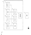
図1はTNP装置11及び創傷14を含む陰圧療法システム100を示す。TNP装置11は創傷14を治療するために使用され得る。TNP装置11には、相互に電気的通信するように構成された、制御回路12Aと、メモリ12Bと、陰圧源12Cと、ユーザーインターフェース12Dと、電源12Eと、第1の圧力センサ12Fと、第2の圧力センサ12Gとが含まれ得る。さらに、TNP装置11には創傷被覆材13が含まれ得る。電源12Eは、TNP装置11の1つ以上の構成要素に電力を供給することができる。
Decompression Therapy System and Method FIG. 1 shows a negative
制御回路12A、メモリデバイス12B、陰圧源12C、ユーザーインターフェース12D、電源12E、第1の圧力センサ12F、及び第2の圧力センサ12Gのうちの1つ以上が、創傷被覆材13と一体化され得るか、該被覆材13の一部として組み込まれ得るか、該被覆材13に付着され得るか、または該被覆材内に配置され得る。したがって、TNP装置11は、その制御エレクトロニクスを有し、創傷被覆材13から分離しているのではなく、創傷被覆材13を搭載してポンピングするとみなされ得る。
One or more of the
制御回路12Aには、1つ以上のコントローラ(例えば、マイクロコントローラまたはマイクロプロセッサ)と、起動回路と、ブーストコンバータと、電流制限器と、フィードバック調整回路と、Hブリッジインバータとが含まれ得る。制御回路12Aは、メモリデバイス12Bに格納された命令に少なくとも従って、TNP装置11の1つ以上の他の構成要素の動作を制御することができる。例えば、制御回路12Aは、陰圧の動作と陰圧の供給とを陰圧源12Cにより制御することができる。
The
陰圧源12Cには、限定されないが、ロータリーダイヤフラムポンプもしくは他のダイヤフラムポンプ、圧電ポンプ、蠕動ポンプ、ピストンポンプ、ロータリーベーンポンプ、液封式ポンプ、スクロールポンプ、圧電変換器によって動作するポンプ、または他の任意の好適なポンプもしくはマイクロポンプ、あるいは上記のものの任意の組み合わせなどのポンプが含まれ得る。ポンプには、電気エネルギー及び機械エネルギーなどのエネルギー源で駆動するアクチュエータが含まれ得る。例えば、アクチュエータは、電気モーター、圧電変換器、ボイスコイルアクチュエータ、電気活性高分子、形状記憶合金、櫛形ドライブ、油圧モーター、空気圧アクチュエータ、ねじジャッキ、サーボ機構、ソレノイドアクチュエータ、ステッピングモーター、プランジャー、燃焼機関などであり得る。一部の実施形態では、陰圧源12Cは、電気エネルギーを磁気エネルギーに変換することなく、電気エネルギーを機械エネルギーに変換することによって、陰圧を供給することができる。こうした実施形態では、ポンプは、制御回路12Aのうちの1つ以上の他の構成要素に電気的に結合されている場合に、陰圧源12Cが電気エネルギーを磁気エネルギーに変換した後に機械エネルギーに変換することによって陰圧を供給した場合とは異なる影響を有し得る。
ユーザーインターフェース12Dは、ユーザー入力を受信するか、またはユーザー出力を患者または介護者に提供する1つ以上の要素を含み得る。ユーザー入力を受信する1つ以上の要素は、ボタン、スイッチ、ダイヤル、またはタッチスクリーンなどを含んでもよく、ユーザー出力を提供する1つ以上の要素は、発光ダイオード(LED)のアクティブ化もしくはディスプレイの1つ以上のピクセルのアクティブ化、またはスピーカーのアクティブ化などを含んでもよい。一例では、ユーザーインターフェース12Dは、ユーザー入力(例えば、陰圧の作動または作動解除の入力)を受信するためのスイッチと、TNP装置11の動作状態(例えば、正常に機能している状態、故障状態、またはユーザー入力を待っている状態)を示すための2つのLEDとを含んでもよい。
The
第1の圧力センサ12Fは、陰圧源12Cと創傷14とに接続している流体流路の圧力、創傷14での圧力、または陰圧源12Cにおける圧力などの、創傷被覆材13の下側の圧力をモニタリングするために使用され得る。第2の圧力センサ12Gは、創傷被覆材13の外側の圧力をモニタリングするために使用され得る。創傷被覆材の外側の圧力は大気圧であり得るが、大気圧は、例えば使用される高度、またはTNP装置11が使用され得る圧力調整された環境に応じて変動し得る。
The
制御回路12Aは、陰圧源12Cによる陰圧の供給を、第1の圧力センサ12Fによりモニタリングされる圧力と第2の圧力センサ12Gによりモニタリングされる圧力とを少なくとも比較することによって、制御することができる。
The
創傷被覆材13は、創傷接触層と、スペーサ層と、吸収層とを具備し得る。創傷接触層は、創傷14に接触していてもよい。創傷接触層は、被覆材を創傷14の周囲の皮膚に固定するために、患者に対向する側に接着剤を具備し得るか、または、創傷接触層を創傷被覆材13のカバー層もしくは他の層に固定するために、上側に接着剤を具備し得る。動作時に、創傷接触層は、滲出物が創傷14に戻るのを阻止または実質的に防止しつつ、創傷から滲出物を取り除きやすくするように一方向流をもたらすことができる。スペーサ層は、創傷部位の上に陰圧を分配するよう促し、また創傷滲出物及び流体を創傷被覆材13内に輸送しやすくするよう促すことができる。さらに、吸収層は創傷14から吸引された滲出物を吸収し、保持することができる。
The wound dressing 13 may include a wound contact layer, a spacer layer, and an absorbent layer. The wound contact layer may be in contact with the
制御回路12Aは、陰圧源12Cの働きをモニタリングすることができ、これには、陰圧源12Cのデューティサイクル(例えば、陰圧源のアクチュエータのデューティサイクル)をモニタリングすることが挙げられ得る。本明細書で使用される場合、「デューティサイクル」とは、陰圧源12Cが作動中であるか、またはある期間にわたって稼働している時間量を表し得るものである。言い換えると、デューティサイクルは、陰圧源12Cが作動状態である時間を、対象となる総時間の割合として表し得るものである。デューティサイクルの測定値は、陰圧源12Cの働きのレベルを表し得る。例えば、デューティサイクルは、陰圧源12Cが正常に動作している、よく稼働している、極めてよく稼働しているなどを示すことができる。さらに、周期的なデューティサイクル測定値といったデューティサイクルの測定値は、漏出の存在もしくは漏出の程度、または創傷から吸引される流体(例えば、空気、液体、または固体の滲出物など)の流量などの様々な動作状態を表すことができる。測定したデューティサイクルと一連の閾値(例えば、較正時に算出される)とを比較することなどによって、デューティサイクルの測定値に基づいて、コントローラは、システムの動作を制御するアルゴリズムまたはロジックを実行することができるか、または実行するようにプログラムされ得る。例えば、デューティサイクルの測定値は、大きな漏出があることを示すことができ、制御回路12Aは、この状態をユーザー(例えば、患者、介護者、または医師など)に示すようにプログラムされ得るか、または節電のために陰圧源の動作を一時的に中断もしくは一時停止するようにプログラムされ得る。
The
TNP装置11が創傷14を治療するのに用いられる場合には、創傷被覆材13は、創傷13の周囲及び創傷被覆材13の下に実質的に密閉された空間または閉鎖された空間を作ることができ、第1の圧力センサ12Fがこの空間の圧力レベルを周期的または連続的に測定またはモニタリングすることができる。制御回路12Aは、この空間の圧力レベルを、第1の陰圧設定値限界と少なくとも第2の陰圧設定値限界との間で制御することができる。一部の例では、第1の設定値限界は約−70mmHgであるか、または約−60mmHg以下〜約−80mmHg以上であり得る。一部の例では、第2の設定値限界は約−90mmHgであるか、または約−80mmHg以下〜約−100mmHg以上であり得る。
When the
図2Aは陰圧療法システム200の側面図を示し、図2Bは陰圧療法システム200の上面図を示している。陰圧療法システム200は、陰圧療法システム100の実施態様の一例となり得る。
FIG. 2A shows a side view of the negative
陰圧療法システム200では、TNP装置11の創傷被覆材13は創傷14に付着しているように示されている。創傷被覆材13を通る空気の流れと、創傷14からの創傷滲出物の流れとを矢印で示している。TNP装置11には、空気排出部26と、制御回路12A、メモリデバイス12B、陰圧源12C、ユーザーインターフェース12D、電源12E、第1の圧力センサ12F、及び第2の圧力センサ12Gのうちの1つ以上などのTNP装置11の構成要素ハウジングまたは構成要素の収納領域などの構成要素領域25とが含まれ得る。
In the negative
陰圧療法システム200のユーザーインターフェース12Dには、スイッチ21(ドームスイッチなど)と、第1の表示器23(第1のLEDなど)と、第2の表示器24(第2のLEDなど)とが含まれ得る。スイッチ21は、陰圧の作動または作動解除のユーザー入力を受信すること(例えば、0.5秒〜5秒の間などのある期間の間スイッチ21を押し下げることに呼応して、作動または作動解除のユーザー入力を受信することなど)ができる。第1の表示器23と第2の表示器24は、正常に機能している状態、故障状態、またはユーザー入力を待っている状態などの動作状態を示すことができる。一部の実施態様では、スイッチ21は、陰圧源12Cもしくは制御回路12Aの電源接続部、または陰圧源12Cもしくは制御回路12Aのイネーブル信号部と連結して、陰圧の供給を作動もしくは作動解除するか、または陰圧を供給できないようにすることができる。
The
陰圧療法システム200の創傷被覆材13の構成要素部が、エアロック層27と、吸収層28と、接触層29とを含むように示されている。エアロック層27は、空気が流れるようにすることができる。吸収層28は、創傷滲出物を吸収することができる。接触層29は柔軟性があり、シリコンを含んでいてもよく、TNP装置11を患者につなげるために使用することができる。
The components of the wound dressing 13 of the negative
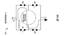
図3は、電源12Dと、制御回路12Aと、陰圧源12Cとの間の電気通信経路の例、ならびにコントローラ31と、電流制限器32と、駆動回路33と、フィードバック調整器34と、結合回路35とを備えた制御回路12Aの構成要素の例を表すブロック図300を示す。図3には、特に、コントローラ31を使用して陰圧源12Cによって陰圧の供給を制御可能にする方法を示している。
FIG. 3 shows an example of a telecommunications path between a
電源12Dは、電池(例えば、複数の3V電池)などの1つ以上の電源、または主電源への接続部を含み、TNP装置11の1つ以上の構成要素に対して電力を供給することができる。電源12Dは、例えば、電流制限器32に電流及び電圧を供給することができる。一部の実施態様では、電源12Dによって出力される電圧は約30V(29V±1Vなど)であり得る。電源12Dは、ブーストコンバータなどの回路をさらに含み、電流制限器32に供給される電流及び電圧を制御することができる。
The
電流制限器32は、最大電流レベル、例えば100mA、250mA、466mA、500mA、または1Aなどで電流を制限または維持する働きをして、駆動回路33及び陰圧源12Cに故障電流が流れる可能性を制限することができる。正常な動作下では(例えば、多くのまたは一部の例では)、電流制限器32は電流または電圧を制限するように動作しない場合がある。
The
電流制限器32は、駆動回路33に電流及び電圧を供給することができる。駆動回路33は、複数のスイッチから構成されるHブリッジ回路を含み得る。Hブリッジは、Hブリッジインバータとして動作するように構成され得る。駆動回路33は、フィードバック調整器34を介してコントローラ31にフィードバックを提供し得る。フィードバック調整器34を使用して、例えば、駆動回路33からの現行のフィードバック情報を、その現行のフィードバック情報がコントローラ31に提供される前に調整することができる。一例では、フィードバック調整器34は低減フィルタ(例えば、能動回路構成要素を備え得る低減フィルタ)を含むことができ、駆動回路33の1つ以上のスイッチのスイッチングによって生じるスイッチングノイズをフィルタリングすることができる。次に、一部の例では、コントローラ31がそのフィードバックに基づいて駆動回路33の動作を制御することができる。
The
コントローラ31は、コントローラ31の1つ以上の出力部を介して、1つ以上の制御信号を駆動回路33の1つ以上の入力部に出力することによって、駆動回路33の動作を制御し、ひいては陰圧源12Cの動作を制御することができる。例えば、コントローラ31は、コントローラ31の第1の出力部O1を介して、第1の制御信号を駆動回路33の第1の入力部I1に出力することができ、コントローラ31の第2の出力部O2を介して、第2の制御信号を駆動回路33の第2の入力部I2に出力することができる。コントローラ31は、第1の制御信号及び第2の制御信号のパルス幅変調(PWM)を変動させて、駆動回路33によって結合回路35に、次いで陰圧源12Cに供給される電流と電圧とを調整することができる。一実施態様では、駆動回路33はHブリッジを含んでもよく、Hブリッジが、ある周波数(たとえは18kHz〜24kHz、または約21kHzなど)と、あるデューティサイクルまたはディーティ比(例えば約50%など)とを有する、矩形波の電流及び電圧(例えば約±30Vなど)を、駆動回路33の第1の出力部O1と駆動回路33の第2の出力部O2とを介して出力するように、コントローラ31は第1の制御信号と第2の制御信号とを発生させることができる。
The
駆動回路33は、陰圧源12C(例えば、陰圧源12Cのアクチュエータ)に電流と電圧とを結合回路35を介して供給することによって、陰圧源12Cによる供給陰圧を制御することができる。例えば、駆動回路33は、駆動回路33の第1の出力部O1と第2の出力部O2とを介して、電流を、結合回路35の第1の入力部I1と結合回路35の第2の入力部I2とに出力することができる。続いて、結合回路35は、電流を、結合回路35の第1の出力部O1と結合回路35の第2の出力部O2とを介して、陰圧源12Cの第1の入力部I1と陰圧源12Cの第2の入力部I2とに出力することができる。特に、駆動回路33及び結合回路35により出力される電流によって、駆動回路33から流れていく(つまり、駆動回路33によって電流のソースとなる)か、または駆動回路33に流れ込む(つまり、駆動回路33によって電流のシンクとなる)正の電荷が生じると考えられ得る。
The
結合回路35は、駆動回路33によって陰圧源12Cに供給される電流の経時的な変化量を制限するか、または陰圧源12Cの第1の入力部I1と第2の入力部I2間の電圧の経時的な変化量を制限する働きをすることができる。結合回路35は、1kHzの動作周波数で1mΩ、5mΩ、10mΩ、50mΩ、100mΩ、500mΩ、750mΩを超える誘導性リアクタンスを有し得る。一部の実施形態では、結合回路35は、受動回路要素を含んで能動回路要素を含まない場合があるが、他の実施形態では、結合回路35は受動回路要素と能動回路要素のうちの一方または両方を含み得る。
The
図4A及び図4Bは、駆動回路33の簡略化した回路構成要素の例を示している。図4A及び図4Bに見られるように、駆動回路33は、第1のスイッチS1、第2のスイッチS2、第3のスイッチS3、及び第4のスイッチS4を含む少なくとも4つのスイッチから構成され得るが、合わせてHブリッジを形成することができる。図4Aに示すように、第1のスイッチS1と第4のスイッチS4とを同時に閉じ、第2のスイッチS2と第3のスイッチS3とを同時に開くことで、結合回路35と陰圧源12Cとを介して第1の方向に第1の電流i1を供給することができる。図4Bに示すように、第2のスイッチS2と第3のスイッチS3とを同時に閉じ、第1のスイッチS1と第4のスイッチS4とを同時に開くことで、結合回路35と陰圧源12Cとを介して第2の方向に第2の電流i2を供給することができる。第1の方向は、第2の方向と対向し得る。
4A and 4B show examples of simplified circuit components of the
図4Cは、抵抗器42を含む駆動回路33の回路構成要素の例(図示した例ではHブリッジ)を示している。図4Cで示されている回路構成要素の例では、抵抗器42を通って流れる電流は、結合回路35と陰圧源12C(例えば、陰圧源12Cのアクチュエータ)とを通って流れる電流と同じであるか、または実質的に同じであり得る。その結果として、フィードバック調整器34に提供されるフィードバックは、例えば、抵抗器42を通って流れる電流、ならびに結合回路35及び陰圧源12Cを通って流れる電流に比例し得る、抵抗器42の両端の電圧レベルまたは電圧降下となり得る。したがって、抵抗器42を用いて、結合回路35を介して(例えば、図5に関して説明したインダクタ52といった結合回路35のインダクタなどを介して)陰圧源12Cに供給される電流の1つ以上の特性値(大きさなど)を測定することができる。抵抗器42は、本明細書に記載の低減フィルタに連結されていてもよい。
FIG. 4C shows an example of circuit components of the
図5は、結合回路35の回路構成要素の例を示している。図5からわかるように、結合回路35には、駆動回路33の第1の出力部O1と陰圧源12Cの第1の入力部I1との間で直列に電気的に接続されたインダクタ52と、駆動回路33の第2の出力部O2と陰圧源12Cの第2の入力部I2との間で直列に電気的に接続されたワイヤまたは電気的短絡部54とが含まれ得る。インダクタ52は、0.1μH〜1000μH、1μH〜100μH、または3μH〜10μHの範囲のインダクタンス、または約7.5μHのインダクタンスを有し得る。インダクタ52は、0.25A、0.5A、0.75A、1A、または1.25Aを超える最大電流定格を有し得る。インダクタ52を用いて、陰圧源12Cを駆動させるように供給される電圧または電流の急激な変化を阻止することができる。
FIG. 5 shows an example of circuit components of the
別の実施形態では、結合回路35には、駆動回路33の第1の出力部O1と陰圧源12Cの第1の入力部I1との間で直列に電気的に接続された第1のワイヤまたは第1の電気的短絡部と、駆動回路33の第2の出力部O2と陰圧源12Cの第2の入力部I2との間で直列に電気的に接続された第2のワイヤまたは第2の電気的短絡部とが含まれ得る。
In another embodiment, the
さらに別の実施形態では、結合回路35には、駆動回路33の第1の出力部O1と陰圧源12Cの第1の入力部I1との間で直列に電気的に接続された第1のワイヤまたは第1の電気的短絡部と、駆動回路33の第2の出力部O2と陰圧源12Cの第2の入力部I2との間で直列に電気的に接続されたインダクタ(インダクタ52など)とが含まれ得る。
In yet another embodiment, the
なおもさらに別の実施形態では、結合回路35には、駆動回路33の第1の出力部O1と陰圧源12Cの第1の入力部I1との間で直列に電気的に接続された第1のインダクタ(インダクタ52など)と、駆動回路33の第2の出力部O2と陰圧源12Cの第2の入力部I2との間で直列に電気的に接続された第2のインダクタ(インダクタ52など)とが含まれ得る。
In yet another embodiment, the
特定の実施態様では、1つ以上のインダクタの代わりにまたは1つ以上のインダクタに加えて、1つ以上の作動要素を用いることができる。 In certain embodiments, one or more working elements can be used in place of or in addition to one or more inductors.
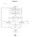
図6は、TNP装置11などの装置によって実行可能な療法制御プロセス600を示している。便宜上、療法制御プロセス600がTNP装置11との関連において説明されるが、代わりに、本明細書に記載の他のシステムで、または示されていない他のコンピューティングシステムによって実行される場合もある。療法制御プロセス600というのは、TNP装置が電力の陰圧源への伝送を調整することで(例えば、駆動信号のパラメータを調整することによって)、陰圧源に伝送される電力量を最大化し、それによって有効性(例えば、より効率的な電力消費によって評価され得るもの)を高めることができる、反復プロセスのことであり得る。
FIG. 6 shows a
療法制御プロセス600は、TNP装置の起動後のある期間内、例えば、陰圧源を用いた圧力供給開始の0.001分、0.01分、0.1分、0.5分、1分、2分、または5分以内などに開始することができる。療法制御プロセス600は、既に陰圧源に提供されている初期大きさ及び初期周波数を有する特定の駆動信号エネルギー(例えば、初期電流の大きさ及び初期電流の周波数を有する電流など)で開始することができる。初期周波数は、陰圧源の機械的共振周波数(例えば、1kHz、5kHz、10kHz、25kHz、50kHz、100kHz、200kHz、500kHz、及び1000kHzであり得る)未満であるか、または該機械的共振周波数を超える場合がある。
The
ブロック61では、療法制御プロセス600は前の回と次の回の電流の大きさを測定することができる。例えば、コントローラ31が、前の回と次の回とに駆動回路33によって結合回路35と陰圧源12Cとに供給される電流の大きさを測定することができる。前の回とは、次の回に先立つ回であり得る。前の回は、例えば、次の回の直前に反復している間の一回、または次の回の前に2回以上の反復している間の一回であり得る。コントローラ31は、フィードバック調整器34によって提供されるフィードバックから電流の大きさ(またはそれを示す値)を測定することができる。
At
ブロック62では、療法制御プロセス600は前の回と次の回の電流の大きさを比較することができる。例えば、コントローラ31は、前の回に駆動回路33によって供給される電流の大きさと、次の回に駆動回路33によって供給される電流の大きさとを比較することができる。
At
ブロック63では、療法制御プロセス600は、前の回の電流の大きさが次の回の電流の大きさよりも小さいかどうかを判定することができる。例えば、コントローラ31は、前の回に駆動回路33によって供給される電流の大きさが次の回に駆動回路33によって供給される電流の大きさよりも小さいかどうかを判定することができる。
At
ブロック63の結果が「はい」の場合には、療法制御プロセス600はブロック64で電流の周波数を増加させることができる。例えば、コントローラ31は、駆動回路33によって供給される電流の周波数をある増加量(例えば、1kHz、3kHz、5kHz、10kHz、30kHz、50kHz、70kHz、100kHz、200kHz、300kHz、500kHz、700kHz、850kHz、1000kHz、2000kHz、または5000Hz)増加させることができる。ブロック63の結果が「いいえ」の場合には、療法制御プロセス600はブロック65で電流の周波数を減少させることができる。例えば、コントローラ31は、ブロック65で、駆動回路33によって供給される電流の周波数をある減少量(例えば、1Hz、3Hz、5Hz、10Hz、30Hz、50Hz、70Hz、100Hz、200Hz、300Hz、500Hz、700Hz、850Hz、1000Hz、2000Hz、または5000Hz)減少させることができる。増加量及び減少量は、一部の例または一部の実施態様において、同一であっても相互に異なっていてもよい。さらに、増加量または減少量は経時的に変動しても、ある期間(例えば、1秒、3秒、10秒、30秒、もしくは60秒、または1分、3分、5分、10分、もしくは30分)の間一定であってもよい。
If the result of
ブロック66では、療法制御プロセス600は、ブロック61に戻るか、または終了するかどうかを決定することができる。例えば、コントローラ31は、療法制御プロセス600を、ある反復頻度(例えば、0.01Hz、0.03Hz、0.1Hz、0.3Hz、0.5Hz、1Hz、3Hz、5Hz、10Hz、30Hz、50Hz、100Hz、300Hz、500Hz、1000Hz、3000Hz、または5000Hzであってもよく、ある一定の期間、例えば1秒、3秒、10秒、30秒、もしくは60秒、または1分、3分、5分、10分、もしくは30分にわたって変動するかまたは一定であってもよい頻度)で、またはある誘起事象(例えば、温度センサで測定される検出されたTNP装置の温度変化など)に応じて反復することなどで、療法制御プロセス600の反復を行うかどうかを決定することができる。
At
療法制御プロセス600を通して、初期周波数を調整して機械的共振周波数にさらに近づけようとすることによって、療法が提供されている間に、陰圧源の機械的共振周波数を「サーチ」(例えば、連続的または周期的に)することができる。したがって、機械的共振周波数は、TNP装置の動作に先んじてわかっていなくてもよく、または高精度もしくは高精密に既知でなくてもよいが、陰圧源に提供されるエネルギーの周波数は、機械的共振周波数に実質的にマッチングするように構成され得る。さらに、陰圧源に提供されるエネルギーの周波数が機械的共振周波数に準じるように構成され得るのは、変動する動作状況によって機械的共振周波数が変化する場合があるからであり、陰圧源が創傷被覆材上かまたは該被覆材内に搭載されている場合、該変動する動作状況には、動作温度、動作期間、または湿度などが含まれ得る。
Through the
一部の実施形態では、創傷に陰圧を加える装置には、陰圧源と、駆動回路と、センサと、コントローラとが含まれている。陰圧源は、流体流路を介して、創傷の上に置かれた創傷被覆材に陰圧を与えることができる。駆動回路は、陰圧源に電流を供給して、陰圧源が陰圧を与えるようにすることができる。電流は、電流の大きさと電流の周波数とを有し得る。センサは電流の大きさを検出することができる。コントローラは、陰圧源が創傷被覆材に陰圧を供給している間、繰り返し、第1の動作周波数で、前の回で検出される電流の大きさと前の回に続く次の回で検出される電流の大きさとを測定し、前の回で検出される電流の大きさと次の回で検出される電流の大きさとを比較し、前の回で検出される電流の大きさが次の回で検出される電流の大きさ未満である場合には、電流の周波数を増加(または減少)させるように駆動回路を動作させ、前の回で検出される電流の大きさが次の回で検出される電流の大きさを超える場合には、電流の周波数を減少(または増加)させるように駆動回路を動作させることができる。 In some embodiments, the device that applies negative pressure to the wound includes a negative pressure source, a drive circuit, a sensor, and a controller. The negative pressure source can apply negative pressure to the wound dressing placed on the wound via the fluid flow path. The drive circuit can supply a current to the negative pressure source so that the negative pressure source exerts negative pressure. The current can have a magnitude of the current and a frequency of the current. The sensor can detect the magnitude of the current. The controller repeatedly detects the magnitude of the current detected in the previous round and the next round following the previous round at the first operating frequency while the negative pressure source is supplying negative pressure to the wound covering material. Measure the magnitude of the current to be detected, compare the magnitude of the current detected in the previous round with the magnitude of the current detected in the next round, and the magnitude of the current detected in the previous round is the next If it is less than the magnitude of the current detected in one round, the drive circuit is operated to increase (or decrease) the frequency of the current, and the magnitude of the current detected in the previous round is in the next round. If the magnitude of the detected current is exceeded, the drive circuit can be operated to reduce (or increase) the frequency of the current.
上記の段落に記載の装置は、以下の特徴のうちの1つ以上を含み得る:コントローラは、駆動回路が陰圧源を作動して陰圧の供給を開始する際に、電流の周波数が初期周波数にマッチングするように駆動回路を動作させることができ、またコントローラは、駆動回路が陰圧源を作動させてから第1の期間内に、電流の周波数を増加または減少させるように駆動回路を動作させることができる。陰圧源は機械的共振周波数を有することがあり、機械的共振周波数は初期周波数より大きくてもよい。陰圧源は機械的共振周波数を有することがあり、機械的共振周波数は初期周波数より小さくてもよい。陰圧源が1つ以上の低調波周波数または高調波周波数を含む機械的共振周波数を有する場合があり、コントローラは、電流の周波数が1つ以上の低調波周波数または高調波周波数のうちの1つにはならず、1つ以上の低調波周波数または高調波周波数を含む1つ以上の周波数範囲の外側にとどまるように、駆動回路を動作させて、電流の周波数を増加または減少させることができる。機械的共振周波数は、5kHz〜100kHzの間、例えば、約20kHz、22kHz、もしくは24kHz、または5kHz超もしくは未満かつ100kHz超もしくは未満であり得る。第1の期間は、1ミリ秒〜1分の間、例えば、約1ミリ秒、10ミリ秒、100ミリ秒、もしくは1秒、または1ミリ秒超もしくは未満かつ1分超もしくは未満であり得る。第1の反復における次の回で検出される電流の大きさは、第1の反復に続く第2の反復における前の回で検出される電流の大きさである。第1の反復と第2の反復とが、別の反復によって隔てられていなくてもよい。コントローラは、電流の周波数を第1の量増加させるように駆動回路を動作させ、また電流の周波数を第2の量減少させるように駆動回路を動作させることができる。第1の量は第2の量と同一であり得る。第1の量は第2の量とは異なり得る。第1の量または第2の量は経時的に変動し得る。第1の量または第2の量は、陰圧源が創傷被覆材に陰圧を供給している間、第2の期間にわたり一定であり得る。第2の期間は、10秒〜10分の間、例えば、約10秒、1分、もしくは10分、または10秒超もしくは未満かつ10分超もしくは未満であり得る。第1の量または第2の量は1Hz〜1000Hzの間、例えば約1Hz、10Hz、100Hz、もしくは1000Hz、または1Hz超もしくは未満かつ1000Hz超もしくは未満であり得る。第1の動作周波数は経時的に変動し得る。第1の周波数は、陰圧源が創傷被覆材に陰圧を供給している間、第3の期間にわたり一定であり得る。第3の期間は、10秒〜10分の間、例えば、約10秒、1分、もしくは10分、または10秒超もしくは未満かつ10分超もしくは未満であり得る。第1の動作周波数は0.1Hz〜100Hzの間、例えば約0.1Hz、1Hz、10Hz、もしくは100Hz、または0.1Hz超もしくは未満かつ100Hz超もしくは未満であり得る。陰圧源は圧電ポンプを備え得る。陰圧源はマイクロポンプであり得る。陰圧源は、創傷被覆材上か、または該被覆材内に配置され得る。駆動回路はHブリッジを含み得る。コントローラは、駆動回路に制御信号を提供することができ、またコントローラは、駆動回路により供給される電流を、制御信号のパルス幅変調を調整することによって制御することができる。駆動回路は、結合回路を介して陰圧源の入力端子間に電圧を供給することができ、その電圧は−50V超から+50V未満までの範囲であり得る。 The device described in the above paragraph may include one or more of the following features: the controller initially has a frequency of current as the drive circuit activates the negative pressure source to initiate the supply of negative pressure. The drive circuit can be operated to match the frequency, and the controller can operate the drive circuit to increase or decrease the frequency of the current within the first period after the drive circuit operates the negative pressure source. Can be operated. The negative pressure source may have a mechanical resonance frequency, which may be higher than the initial frequency. The negative pressure source may have a mechanical resonance frequency, which may be lower than the initial frequency. Negative pressure sources may have a mechanical resonance frequency that includes one or more low tuning or harmonic frequencies, and the controller may have one or more low tuning or harmonic frequencies in the frequency of the current. The drive circuit can be operated to increase or decrease the frequency of the current so that it stays outside one or more frequency ranges including one or more low frequency or harmonic frequencies. The mechanical resonance frequency can be between 5 kHz and 100 kHz, eg, about 20 kHz, 22 kHz, or 24 kHz, or greater than or less than 5 kHz and greater than or less than 100 kHz. The first period can be between 1 millisecond and 1 minute, eg, about 1 millisecond, 10 milliseconds, 100 milliseconds, or 1 second, or more than or less than 1 millisecond and more than or less than 1 minute. .. The magnitude of the current detected in the next round in the first iteration is the magnitude of the current detected in the previous round in the second iteration following the first iteration. The first iteration and the second iteration may not be separated by another iteration. The controller can operate the drive circuit to increase the frequency of the current by a first amount and operate the drive circuit to decrease the frequency of the current by a second amount. The first quantity can be the same as the second quantity. The first quantity can be different from the second quantity. The first or second amount can vary over time. The first or second amount can be constant over the second period while the negative pressure source supplies negative pressure to the wound dressing. The second period can be between 10 seconds and 10 minutes, eg, about 10 seconds, 1 minute, or 10 minutes, or more than or less than 10 seconds and more than or less than 10 minutes. The first or second quantity can be between 1 Hz and 1000 Hz, eg, about 1 Hz, 10 Hz, 100 Hz, or 1000 Hz, or greater than or less than 1 Hz and greater than or less than 1000 Hz. The first operating frequency can fluctuate over time. The first frequency can be constant over a third period while the negative pressure source supplies negative pressure to the wound dressing. The third period can be between 10 seconds and 10 minutes, eg, about 10 seconds, 1 minute, or 10 minutes, or more than or less than 10 seconds and more than or less than 10 minutes. The first operating frequency can be between 0.1 Hz and 100 Hz, for example about 0.1 Hz, 1 Hz, 10 Hz, or 100 Hz, or greater than or less than 0.1 Hz and greater than or less than 100 Hz. The negative pressure source may include a piezoelectric pump. The negative pressure source can be a micropump. The negative pressure source can be located on or within the wound dressing. The drive circuit may include an H-bridge. The controller can provide a control signal to the drive circuit, and the controller can control the current supplied by the drive circuit by adjusting the pulse width modulation of the control signal. The drive circuit can supply a voltage between the input terminals of the negative pressure source via a coupling circuit, the voltage of which can range from more than -50V to less than + 50V.
他の変化形
本明細書で提供される閾値、限界値、期間などの値は、絶対的なものであることを意図するものではなく、したがっておおよそのものであり得る。加えて、本明細書で提供される任意の閾値、限界値、期間などは、自動的にまたはユーザーによって、固定されるかまたは変えられ得る。さらに、本明細書で使用される場合、参照値に関連した、超える、超、未満などの相対的な程度を表す用語は、参照値と等しい場合も包含することが意図される。例えば、正の方向に参照値を超えることは、参照値以上であることを包含することができる。その上、本明細書で使用される場合、参照値に関連した、超える、超、未満などの相対的な程度を表す用語は、参照値に関連した、未満である、未満、超などの開示された関係とは逆のものも包含することが意図される。また、種々のプロセスのブロックは、ある値が特定の閾値に達するかまたは達しないかを判定することに関して説明され得るが、ブロックは、例えば、ある値が(i)閾値未満であるかもしくは閾値を超えているか、または(ii)閾値を満たすかもしくは満たしていないかに関しても同様に解釈され得る。
Other Variants The values such as thresholds, limits, durations, etc. provided herein are not intended to be absolute and may therefore be approximate. In addition, any thresholds, limits, durations, etc. provided herein may be fixed or changed automatically or by the user. Further, as used herein, terms relating to a reference value, such as greater than, greater than, or less than, are intended to include equal to the reference value. For example, exceeding the reference value in the positive direction can include being greater than or equal to the reference value. Moreover, as used herein, terms relating to a reference value, such as greater than, greater than, less than, etc., are related to the reference value, such as less than, less than, less than, etc. It is intended to include the opposite of the relationship made. Also, blocks of various processes can be described with respect to determining whether a value reaches or does not reach a particular threshold, which can be described, for example, as a value being less than or equal to (i) a threshold. It can be similarly interpreted as to whether or not (ii) the threshold value is satisfied or not satisfied.
特定の態様、実施形態、または実施例に関連して説明される特性、物質、特徴、または群は、本明細書に記載される他の任意の態様、実施形態、または実施例に、これらと両立できないことがない限り、適用可能であることを理解されたい。本明細書(添付の任意の特許請求の範囲、要約書、及び図面を含む)に開示される全ての特徴、または同様に開示される任意の方法もしくはプロセスの全てのステップは、こうした特徴またはステップのうち少なくともいくつかが相互に排他的となる組み合わせを除いて、任意の組み合わせで組み合わされてよい。本発明の保護するものは、前述の任意の実施形態の詳細に限定されない。保護するものは、本明細書(添付の任意の特許請求の範囲、要約書、及び図面を含む)において開示される特徴のうちの任意の新規なもの、もしくは任意の新規な組み合わせに及び、または同様に開示される任意の方法またはプロセスのステップのうちの任意の新規なもの、もしくは任意の新規な組み合わせに及ぶ。 The properties, substances, characteristics, or groups described in connection with a particular embodiment, embodiment, or example are these and any other embodiments, embodiments, or examples described herein. Please understand that it is applicable unless it is incompatible. All features disclosed herein (including any accompanying claims, abstracts, and drawings), or any step in any method or process disclosed similarly, are such features or steps. Any combination may be combined, except for combinations in which at least some of them are mutually exclusive. The protection of the present invention is not limited to the details of any of the aforementioned embodiments. Protects extend to or any novel combination of features disclosed herein (including any accompanying claims, abstracts, and drawings). It extends to any new or any new combination of steps of any method or process disclosed as well.
特定の実施形態が説明されてきたが、これらの実施形態は、単に例として提示されており、保護範囲を限定することを意図するものではない。実際、本明細書に記載の新規な方法及びシステムは、様々な他の形態で具現化されてもよい。さらに、本明細書に記載の方法及びシステムの形態において、様々な省略、置換、及び変形がなされ得る。一部の実施形態では、図示または開示されたプロセスにおいて実施される実際のステップは、図に示されたステップとは異なり得ることを、当業者は認識するであろう。実施形態によっては、上述したステップのうちの特定のステップが除去される場合があり、別のものが加えられる場合もある。例えば、開示されるプロセスで実施される実際のステップまたはステップの順序は、図で示したものとは異なっていてもよい。実施形態によっては、上述したステップのうちの特定のステップが除去される場合があり、別のものが加えられる場合もある。例えば、図に示した様々な構成要素が、プロセッサ、コントローラ、ASIC、FPGA、または専用ハードウェア上のソフトウェアまたはファームウェアとして実装されてもよい。プロセッサ、ASIC、FPGAなどのハードウェア構成要素には論理回路が含まれ得る。さらに、上記に開示された特定の実施形態の特徴及び特性は、様々な方法で組み合わせることができ、さらなる実施形態を形成することができるが、その全てが本開示の範囲内に収まることになる。 Although specific embodiments have been described, these embodiments are presented merely as examples and are not intended to limit the scope of protection. In fact, the novel methods and systems described herein may be embodied in various other forms. In addition, various omissions, substitutions, and modifications may be made in the methods and forms of the system described herein. Those skilled in the art will recognize that in some embodiments, the actual steps performed in the illustrated or disclosed process may differ from the steps shown in the figure. In some embodiments, certain steps of the steps described above may be removed, and others may be added. For example, the actual steps or sequence of steps performed in the disclosed process may differ from those shown in the figure. In some embodiments, certain steps of the steps described above may be removed, and others may be added. For example, the various components shown in the figure may be implemented as software or firmware on a processor, controller, ASIC, FPGA, or dedicated hardware. Hardware components such as processors, ASICs, FPGAs, etc. may include logic circuits. Moreover, the features and properties of the particular embodiments disclosed above can be combined in various ways to form further embodiments, all of which are within the scope of the present disclosure. ..
本明細書で図示され、説明されるユーザーインターフェーススクリーンには、追加の構成要素または代替の構成要素が含まれ得る。これらの構成要素には、メニュー、リスト、ボタン、テキストボックス、ラベル、ラジオボタン、スクロールバー、スライダー、チェックボックス、コンボボックス、ステータスバー、ダイアログボックス、ウィンドウなどが含まれ得る。ユーザーインターフェーススクリーンには、追加の情報、または代替の情報が含まれ得る。構成要素は、任意の好適な順番に配置され、グループ化され、標示され得る。 The user interface screens illustrated and described herein may include additional or alternative components. These components can include menus, lists, buttons, text boxes, labels, radio buttons, scrollbars, sliders, checkboxes, combo boxes, status bars, dialog boxes, windows, and so on. The user interface screen may contain additional or alternative information. The components may be arranged, grouped and marked in any suitable order.
本開示には、特定の実施形態、実施例、及び適用例が含まれるが、本開示は、具体的に開示された実施形態の範囲を超えて、他の代替の実施形態または使用ならびにその明らかな変更形及びその等価物にまで及び、これには本明細書に記載された特徴及び利点の全てを提供しているとは限らない実施形態が含まれることは、当業者に理解されるはずである。したがって、本開示の範囲は、本明細書における好ましい実施形態の特定の開示によって限定されることを意図するものではなく、本明細書に提示されるまたはこの後に提示される特許請求の範囲によって画定され得る。 The present disclosure includes specific embodiments, examples, and applications, but the present disclosure is beyond the scope of the specifically disclosed embodiments, as well as other alternative embodiments or uses thereof. It should be appreciated by those skilled in the art that it extends to various variations and their equivalents, including embodiments that do not provide all of the features and advantages described herein. Is. Accordingly, the scope of this disclosure is not intended to be limited by the particular disclosure of the preferred embodiments herein, but is defined by the claims presented herein or subsequently. Can be done.
「し得る(can)」、「できる(could)」、「可能性がある(might)」、または「場合がある(may)」などの条件付き言い回しは、別途具体的に記載されない限り、または使用される文脈の範囲内で別途解釈されない限り、特定の実施形態が、特定の特徴、要素、またはステップを含む一方で、他の実施形態は含まないということの伝達を意図するのが通例である。したがって、こうした条件付き言い回しは、特徴、要素、またはステップが1つ以上の実施形態に多少なりとも必要とされるという示唆、またはこれらの特徴、要素、もしくはステップが特定の任意の実施形態に含まれているかどうか、もしくは該実施形態で実施されるべきかどうかを、ユーザー入力または命令の有無にかかわらず決定するためのロジックが、1つ以上の実施形態に必然的に含まれているという示唆を必ずしも意図するものではない。「含む(comprising)」、「備える(including)」、及び「有する(having)」などの用語は、同義語であり、包含的に非限定様式で用いられ、追加の要素、特徴、行為、及び動作などを排除するものではない。また、用語「または(or)」は、包括的な意味で(排他的な意味ではなく)用いられることで、例えば要素の列記をつなぐのに使用される場合、列記の要素のうちの1つ、一部、または全てを意味することになる。さらに、用語「各々」は、本明細書で使用される場合、通常の意味を有するのに加えて、用語「各々」が適用されている一連の要素の任意のサブセットも意味し得る。 Conditional phrases such as "can", "could", "might", or "may" are used unless otherwise specified. Unless otherwise construed within the context in which it is used, it is customarily intended to convey that a particular embodiment contains a particular feature, element, or step, while not another embodiment. be. Thus, such conditional wording suggests that features, elements, or steps are more or less required in one or more embodiments, or that these features, elements, or steps are included in any particular embodiment. Suggestion that one or more embodiments necessarily include logic for determining whether or not it is, or should be implemented in the embodiment, with or without user input or instructions. Is not necessarily intended. Terms such as "comprising," "include," and "having" are synonyms and are used in an inclusive, unrestricted manner to provide additional elements, features, actions, and It does not exclude movements. Also, the term "or" is used in a comprehensive sense (rather than in an exclusive sense), for example, when used to connect a list of elements, one of the elements in the list. , Partly, or all. Further, the term "each", as used herein, may mean any subset of the set of elements to which the term "each" is applied, in addition to having the usual meaning.
語句「X、Y、及びZのうちの少なくとも1つ」などの連言的言い回しは、別途具体的に記載されない限り、ある項目や用語などが、Xか、Yか、Zのいずれかであり得ることを示唆するのに一般的に用いられる文脈によって、別途解釈されるものである。したがって、こうした連言的言い回しは、特定の実施形態が、少なくとも1つのXと、少なくとも1つYと、少なくとも1つのZとを含むことを必要とするという示唆を必ずしも意図するものではない。 Contextual phrases such as the phrase "at least one of X, Y, and Z" are such that an item or term is either X, Y, or Z, unless specifically stated otherwise. It is to be interpreted separately by the context commonly used to suggest gain. Therefore, such a conjunction does not necessarily conclude that a particular embodiment is required to include at least one X, at least one Y, and at least one Z.
本明細書で使用される「およそ」、「約」、「概して」、及び「実質的に」という用語などの、本明細書で使用される程度を表す言い回しは、所望の機能を依然として果たすかまたは所望の結果をもたらす所定の値、量、または特性に近い値、量、または特性を表すものである。例えば、「およそ」、「約」、「概して」、及び「実質的に」という用語は、所定の量の10%未満以内、5%未満以内、1%未満以内、0.1%未満以内、及び0.01%未満以内の量を意味し得る。別の例として、特定の実施形態において、「概して平行」及び「実質的に平行」という用語は、丁度平行である状態から15度以下、10度以下、5度以下、3度以下、1度以下、または0.1度以下ずれている値、量、または特性を意味する。 Do the terms used herein, such as the terms "approximately," "about," "generally," and "substantially," still serve the desired function? Alternatively, it represents a value, quantity, or characteristic that is close to a predetermined value, quantity, or characteristic that produces the desired result. For example, the terms "approximately," "about," "generally," and "substantially" are used within a given amount of less than 10%, less than 5%, less than 1%, less than 0.1%, And can mean an amount less than 0.01%. As another example, in certain embodiments, the terms "generally parallel" and "substantially parallel" are 15 degrees or less, 10 degrees or less, 5 degrees or less, 3 degrees or less, 1 degree or less from the state of being just parallel. It means a value, quantity, or characteristic that is deviated by the following or 0.1 degrees or less.
本開示の範囲は、本節におけるまたは本明細書の他の箇所における好ましい実施形態の特定の開示によって制限されることを意図するものではなく、本節においてまたは本明細書の他の箇所において提示されているか、またはこの後に提示される特許請求の範囲によって画定され得る。本特許請求の範囲の言い回しは、本特許請求の範囲で用いられている言い回しに基づいて広い意味で解釈されるべきであり、本明細書で説明されている例または本出願の手続きの間に説明される例に限定されるものではなく、それらの例は非排他的なものとして解釈されるべきである。 The scope of this disclosure is not intended to be limited by the particular disclosure of preferred embodiments in this section or elsewhere in this specification, and is presented in this section or elsewhere in this specification. Or it may be defined by the claims presented below. The wording of the claims should be construed in a broad sense based on the wording used in the claims and during the examples described herein or during the procedures of the present application. Not limited to the examples described, those examples should be construed as non-exclusive.
Claims (13)
流体流路を介して創傷被覆材(13)に陰圧を与えるように構成された陰圧源(12C)と;
前記陰圧源に駆動信号を供給して、前記陰圧源が陰圧を与えるようにすべく構成された駆動回路であって、前記駆動信号が駆動信号の大きさと駆動信号の周波数とを有する、前記駆動回路と;
前記陰圧源が前記創傷被覆材の下の陰圧をある圧力範囲内に保持している間に、繰り返し、ある動作周波数で、
第1回で検出される駆動信号の大きさと、前記第1回に続く第2回で検出される駆動信号の大きさとを測定し、
前記第1回で検出される駆動信号の大きさと前記第2回で検出される駆動信号の大きさとを比較し、
前記第1回で検出される駆動信号の大きさが前記第2回で検出される駆動信号の大きさ未満である場合には、前記駆動信号の周波数を増加させるように前記駆動回路を動作させ、
前記第1回で検出される駆動信号の大きさが前記第2回で検出される駆動信号の大きさを超える場合には、前記駆動信号の周波数を減少させるように前記駆動回路を動作させるべく構成されたコントローラと、を含み、
前記コントローラが、
前記駆動信号の周波数を第1の量増加させるように前記駆動回路を動作させ、
前記駆動信号の周波数を第2の量減少させるように前記駆動回路を動作させるべく構成されており、
前記第1の量または前記第2の量が経時的に変動する、装置。 A device that applies negative pressure to a wound, said device
With a negative pressure source (12C) configured to exert negative pressure on the wound dressing (13) through the fluid flow path;
A drive circuit configured to supply a drive signal to the negative pressure source so that the negative pressure source applies negative pressure, and the drive signal has a magnitude of the drive signal and a frequency of the drive signal. , With the drive circuit;
Repeatedly at a certain operating frequency, while the negative pressure source keeps the negative pressure under the wound dressing within a certain pressure range.
The magnitude of the drive signal detected in the first round and the magnitude of the drive signal detected in the second round following the first round are measured.
Comparing the magnitude of the drive signal detected in the first time with the size of the drive signal detected in the second time,
When the magnitude of the drive signal detected in the first round is smaller than the magnitude of the drive signal detected in the second round, the drive circuit is operated so as to increase the frequency of the drive signal. ,
When the magnitude of the drive signal detected in the first round exceeds the magnitude of the drive signal detected in the second round, the drive circuit is operated so as to reduce the frequency of the drive signal. and a controller configured, only including,
The controller
The drive circuit is operated so as to increase the frequency of the drive signal by a first amount.
It is configured to operate the drive circuit so as to reduce the frequency of the drive signal by a second amount.
An apparatus in which the first amount or the second amount fluctuates with time .
Applications Claiming Priority (5)
| Application Number | Priority Date | Filing Date | Title |
|---|---|---|---|
| US201662331098P | 2016-05-03 | 2016-05-03 | |
| US62/331,098 | 2016-05-03 | ||
| US201762479588P | 2017-03-31 | 2017-03-31 | |
| US62/479,588 | 2017-03-31 | ||
| PCT/EP2017/060452 WO2017191149A1 (en) | 2016-05-03 | 2017-05-03 | Optimizing power transfer to negative pressure sources in negative pressure therapy systems |
Publications (3)
| Publication Number | Publication Date |
|---|---|
| JP2019514479A JP2019514479A (en) | 2019-06-06 |
| JP2019514479A5 JP2019514479A5 (en) | 2020-06-18 |
| JP6975170B2 true JP6975170B2 (en) | 2021-12-01 |
Family
ID=58669791
Family Applications (1)
| Application Number | Title | Priority Date | Filing Date |
|---|---|---|---|
| JP2018554770A Active JP6975170B2 (en) | 2016-05-03 | 2017-05-03 | Optimization of power transfer to negative pressure sources in negative pressure therapy systems |
Country Status (7)
| Country | Link |
|---|---|
| US (2) | US11173240B2 (en) |
| EP (1) | EP3452130B1 (en) |
| JP (1) | JP6975170B2 (en) |
| CN (1) | CN109069710B (en) |
| AU (1) | AU2017259906B2 (en) |
| CA (1) | CA3038206A1 (en) |
| WO (1) | WO2017191149A1 (en) |
Families Citing this family (21)
| Publication number | Priority date | Publication date | Assignee | Title |
|---|---|---|---|---|
| WO2016103035A2 (en) | 2014-12-22 | 2016-06-30 | Smith & Nephew Plc | Negative pressure wound therapy apparatus and methods |
| CA3016484A1 (en) | 2016-03-07 | 2017-09-14 | Smith & Nephew Plc | Wound treatment apparatuses and methods with negative pressure source integrated into wound dressing |
| AU2017256692B2 (en) | 2016-04-26 | 2022-03-03 | Smith & Nephew Plc | Wound dressings and methods of use with integrated negative pressure source having a fluid ingress inhibition component |
| WO2017191158A1 (en) | 2016-05-03 | 2017-11-09 | Smith & Nephew Plc | Systems and methods for driving negative pressure sources in negative pressure therapy systems |
| EP3452129B1 (en) | 2016-05-03 | 2022-03-23 | Smith & Nephew plc | Negative pressure wound therapy device activation and control |
| EP3503857B1 (en) | 2016-08-25 | 2024-04-17 | Smith & Nephew plc | Absorbent negative pressure wound therapy dressing |
| US11564847B2 (en) | 2016-09-30 | 2023-01-31 | Smith & Nephew Plc | Negative pressure wound treatment apparatuses and methods with integrated electronics |
| AU2018229808B2 (en) | 2017-03-08 | 2024-04-11 | Smith & Nephew Plc | Negative pressure wound therapy device control in presence of fault condition |
| WO2018206420A1 (en) | 2017-05-09 | 2018-11-15 | Smith & Nephew Plc | Redundant controls for negative pressure wound therapy systems |
| JP7394746B2 (en) | 2017-09-13 | 2023-12-08 | スミス アンド ネフュー ピーエルシー | Negative pressure wound therapy device and method with integrated electronics |
| GB201718070D0 (en) | 2017-11-01 | 2017-12-13 | Smith & Nephew | Negative pressure wound treatment apparatuses and methods with integrated electronics |
| GB201718072D0 (en) | 2017-11-01 | 2017-12-13 | Smith & Nephew | Negative pressure wound treatment apparatuses and methods with integrated electronics |
| US11497653B2 (en) | 2017-11-01 | 2022-11-15 | Smith & Nephew Plc | Negative pressure wound treatment apparatuses and methods with integrated electronics |
| GB201718054D0 (en) | 2017-11-01 | 2017-12-13 | Smith & Nephew | Sterilization of integrated negative pressure wound treatment apparatuses and sterilization methods |
| WO2019135900A1 (en) * | 2018-01-02 | 2019-07-11 | Kci Licensing, Inc. | Negative pressure wound therapy device with silent piezoelectric pump |
| WO2019157466A1 (en) | 2018-02-12 | 2019-08-15 | Healyx Labs, Inc. | Negative pressure wound therapy systems, devices, and methods |
| USD898925S1 (en) | 2018-09-13 | 2020-10-13 | Smith & Nephew Plc | Medical dressing |
| US11484640B2 (en) | 2019-07-03 | 2022-11-01 | T.J.Smith And Nephew, Limited | Negative pressure wound therapy dressing recognition, wound status detection, and therapy adjustment |
| GB201914427D0 (en) | 2019-10-07 | 2019-11-20 | Smith & Nephew | Negative pressure wound therapy systems and methods with multiple negative pressure sources |
| AU2021213463A1 (en) | 2020-01-29 | 2022-07-21 | Convatec Limited | A pump assembly and a wound therapy apparatus |
| WO2023023405A1 (en) * | 2021-08-20 | 2023-02-23 | Zam Research Llc | Re-epithelializing dressing and treatment method |
Family Cites Families (342)
| Publication number | Priority date | Publication date | Assignee | Title |
|---|---|---|---|---|
| US1001654A (en) | 1910-10-10 | 1911-08-29 | Thomas Mcclelland Jr | Apparatus for heating water by electricity. |
| US1000491A (en) | 1910-12-10 | 1911-08-15 | Alvin C Busby | Centrifugal machine. |
| US1004609A (en) | 1911-02-07 | 1911-10-03 | Farbenfab Vorm Bayer F & Co | Triphenylmethane dye. |
| US1008611A (en) | 1911-04-19 | 1911-11-14 | Jasper C Owens | Carpet-plucker. |
| US3874387A (en) | 1972-07-05 | 1975-04-01 | Pasquale P Barbieri | Valved hemostatic pressure cap |
| US4224941A (en) | 1978-11-15 | 1980-09-30 | Stivala Oscar G | Hyperbaric treatment apparatus |
| US4398910A (en) | 1981-02-26 | 1983-08-16 | Blake L W | Wound drain catheter |
| US4534356A (en) | 1982-07-30 | 1985-08-13 | Diamond Shamrock Chemicals Company | Solid state transcutaneous blood gas sensors |
| US4569674A (en) | 1982-08-03 | 1986-02-11 | Stryker Corporation | Continuous vacuum wound drainage system |
| DE3323973A1 (en) | 1983-07-02 | 1985-01-03 | Boehringer Mannheim Gmbh, 6800 Mannheim | ERYTHROCYTE RETENTION SUBSTRATES |
| US4624656A (en) | 1983-07-25 | 1986-11-25 | Hospitak, Inc. | Hyperbaric gas treatment device |
| DE3441891A1 (en) | 1984-11-16 | 1986-05-28 | Walter Beck | METHOD AND DEVICE FOR SUCTIONING SECRETARY LIQUID FROM A Wound |
| DE3601363A1 (en) | 1986-01-18 | 1988-12-29 | Stierlen Maquet Ag | ELECTRICAL SWITCHING ELEMENT |
| US5527293A (en) | 1989-04-03 | 1996-06-18 | Kinetic Concepts, Inc. | Fastening system and method |
| US5056510A (en) | 1989-04-13 | 1991-10-15 | The Kendall Company | Vented wound dressing |
| US4979944A (en) | 1989-08-21 | 1990-12-25 | The Pullman Company | Surgical vacuum evacuation device |
| US5181905A (en) | 1989-11-28 | 1993-01-26 | Eric Flam | Method of monitoring the condition of the skin or wound |
| US5152757A (en) | 1989-12-14 | 1992-10-06 | Brigham And Women's Hospital | System for diagnosis and treatment of wounds |
| US5055198A (en) | 1990-03-07 | 1991-10-08 | Shettigar U Ramakrishna | Autologous blood recovery membrane system and method |
| US5340968A (en) | 1991-05-07 | 1994-08-23 | Nippondenso Company, Ltd. | Information storage medium with electronic and visual areas |
| US5636643A (en) | 1991-11-14 | 1997-06-10 | Wake Forest University | Wound treatment employing reduced pressure |
| US5266928A (en) | 1992-05-29 | 1993-11-30 | Johnson Lonnie G | Wet diaper detector |
| US5964723A (en) | 1992-06-19 | 1999-10-12 | Augustine Medical, Inc. | Normothermic tissue heating wound covering |
| USD357743S (en) | 1992-12-31 | 1995-04-25 | Alza Corporation | Electrotransport drug delivery system |
| US5902256A (en) | 1993-02-12 | 1999-05-11 | Jb Research, Inc. | Massage unit with replaceable hot and cold packs |
| GB9400994D0 (en) | 1994-01-20 | 1994-03-16 | Bristol Myers Squibb Co | Wound dressing |
| US5549584A (en) | 1994-02-14 | 1996-08-27 | The Kendall Company | Apparatus for removing fluid from a wound |
| ZA956968B (en) | 1994-08-22 | 1996-03-29 | Kinetic Concepts Inc | Wound drainage equipment |
| US5643189A (en) | 1994-12-07 | 1997-07-01 | Masini; Michael A. | Composite wound dressing including inversion means |
| US6599262B1 (en) | 1994-12-07 | 2003-07-29 | Masini Michael A | Bandage with thermal insert |
| US6225523B1 (en) | 1994-12-07 | 2001-05-01 | Masini Michael A | Invertible wound dressings and method of making the same |
| US6261276B1 (en) | 1995-03-13 | 2001-07-17 | I.S.I. International, Inc. | Apparatus for draining surgical wounds |
| US5779657A (en) | 1995-07-21 | 1998-07-14 | Daneshvar; Yousef | Nonstretchable wound cover and protector |
| GB9523253D0 (en) | 1995-11-14 | 1996-01-17 | Mediscus Prod Ltd | Portable wound treatment apparatus |
| US6783328B2 (en) | 1996-09-30 | 2004-08-31 | Terumo Cardiovascular Systems Corporation | Method and apparatus for controlling fluid pumps |
| DE19722075C1 (en) | 1997-05-27 | 1998-10-01 | Wilhelm Dr Med Fleischmann | Medication supply to open wounds |
| US6071267A (en) | 1998-02-06 | 2000-06-06 | Kinetic Concepts, Inc. | Medical patient fluid management interface system and method |
| US6458109B1 (en) | 1998-08-07 | 2002-10-01 | Hill-Rom Services, Inc. | Wound treatment apparatus |
| US6168800B1 (en) | 1998-08-20 | 2001-01-02 | Medwrap Corporation | Antimcrobial multi-layer island dressing |
| DE19844355A1 (en) | 1998-09-28 | 2000-04-06 | Rainer E Sachse | Adhesive wound dressing of flexible, membrane like material penetrable by air comprises integrated device which drains wound secretions or produces reduced pressure, or can be connected to an external suction system |
| GB9822341D0 (en) | 1998-10-13 | 1998-12-09 | Kci Medical Ltd | Negative pressure therapy using wall suction |
| US6607495B1 (en) | 1999-06-18 | 2003-08-19 | University Of Virginia Patent Foundation | Apparatus for fluid transport and related method thereof |
| US6261283B1 (en) | 1999-08-31 | 2001-07-17 | Alcon Universal Ltd. | Liquid venting surgical system and cassette |
| JP4681185B2 (en) | 1999-11-29 | 2011-05-11 | ケーシーアイ メディカル リソーシーズ | Trauma treatment device |
| US6183438B1 (en) | 2000-01-04 | 2001-02-06 | Ramon Berguer | Catheter with centering wire |
| US20050119737A1 (en) | 2000-01-12 | 2005-06-02 | Bene Eric A. | Ocular implant and methods for making and using same |
| DE20000887U1 (en) | 2000-01-19 | 2001-06-07 | Riesinger Geb Dahlmann | Collection bag with suction device |
| US6794554B2 (en) | 2000-02-01 | 2004-09-21 | Ferris Pharmaceuticals, Inc. | Wound packing material |
| DE60135746D1 (en) | 2000-05-22 | 2008-10-23 | Arthur C Coffey | WOUND BRACELET WITH SIS LAYER AND VACUUM CHAMBER |
| US6685681B2 (en) | 2000-11-29 | 2004-02-03 | Hill-Rom Services, Inc. | Vacuum therapy and cleansing dressing for wounds |
| US6855135B2 (en) | 2000-11-29 | 2005-02-15 | Hill-Rom Services, Inc. | Vacuum therapy and cleansing dressing for wounds |
| US6976977B2 (en) | 2000-12-06 | 2005-12-20 | Sherwood Services Ag | Vacuum setting and indication system for a drainage device |
| JP4408018B2 (en) | 2001-01-18 | 2010-02-03 | ナワ−ハイルミッテル ゲーエムベーハー | Bandage and treatment solution used with the bandage |
| US7700819B2 (en) | 2001-02-16 | 2010-04-20 | Kci Licensing, Inc. | Biocompatible wound dressing |
| US7070584B2 (en) | 2001-02-20 | 2006-07-04 | Kci Licensing, Inc. | Biocompatible wound dressing |
| US7108683B2 (en) | 2001-04-30 | 2006-09-19 | Kci Licensing, Inc | Wound therapy and tissue management system and method with fluid differentiation |
| ATE530220T1 (en) | 2001-07-12 | 2011-11-15 | Kci Medical Resources | CONTROL OF VACUUM CHANGE RATE |
| US7004915B2 (en) * | 2001-08-24 | 2006-02-28 | Kci Licensing, Inc. | Negative pressure assisted tissue treatment system |
| US6787682B2 (en) | 2001-11-05 | 2004-09-07 | Hollister Incorporated | Absorbent foam wound dressing |
| US7645253B2 (en) | 2001-11-16 | 2010-01-12 | National Quality Care, Inc. | Wearable ultrafiltration device |
| US6648862B2 (en) | 2001-11-20 | 2003-11-18 | Spheric Products, Ltd. | Personally portable vacuum desiccator |
| GB2382305B (en) | 2001-11-23 | 2004-12-15 | Johnson & Johnson Medical Ltd | Absorbent wound dressings containing a hydrogel layer |
| EP1627662B1 (en) | 2004-06-10 | 2011-03-02 | Candela Corporation | Apparatus for vacuum-assisted light-based treatments of the skin |
| CA2468307A1 (en) | 2001-12-26 | 2003-07-17 | Hill-Rom Services, Inc. | Vacuum bandage packing |
| AU2002359828A1 (en) | 2001-12-26 | 2003-07-24 | Hill-Rom Services Inc. | Vented vacuum bandage and method |
| EP1487389B1 (en) | 2002-02-28 | 2011-10-05 | KCI Medical Resources | External catheter access to vacuum bandage |
| US6942633B2 (en) | 2002-03-22 | 2005-09-13 | Twin Star Medical, Inc. | System for treating tissue swelling |
| EP1496822B1 (en) | 2002-04-10 | 2018-08-29 | KCI Medical Resources | Access openings in vacuum bandage |
| DE20207356U1 (en) | 2002-05-08 | 2003-06-12 | Riesinger Birgit | Absorbent body for connection to skin and mucous membrane surfaces |
| US20030212357A1 (en) | 2002-05-10 | 2003-11-13 | Pace Edgar Alan | Method and apparatus for treating wounds with oxygen and reduced pressure |
| ES2644226T3 (en) | 2002-05-31 | 2017-11-28 | Kci Medical Resources | Device for wound treatment |
| AU2002359833A1 (en) | 2002-08-21 | 2004-03-11 | Hill-Rom Services, Inc. | Wound packing for preventing wound closure |
| US7846141B2 (en) | 2002-09-03 | 2010-12-07 | Bluesky Medical Group Incorporated | Reduced pressure treatment system |
| US6979324B2 (en) | 2002-09-13 | 2005-12-27 | Neogen Technologies, Inc. | Closed wound drainage system |
| US7520872B2 (en) | 2002-09-13 | 2009-04-21 | Neogen Technologies, Inc. | Closed wound drainage system |
| US7815616B2 (en) | 2002-09-16 | 2010-10-19 | Boehringer Technologies, L.P. | Device for treating a wound |
| GB0224986D0 (en) | 2002-10-28 | 2002-12-04 | Smith & Nephew | Apparatus |
| US20040087884A1 (en) | 2002-10-31 | 2004-05-06 | Haddock Teresa H. | Textured breathable films and their use as backing material for bandages |
| US7612248B2 (en) | 2002-12-19 | 2009-11-03 | 3M Innovative Properties Company | Absorbent medical articles |
| AU2003294366B2 (en) | 2002-12-31 | 2009-11-05 | Bsn Medical Gmbh | Wound dressing |
| US6951553B2 (en) | 2002-12-31 | 2005-10-04 | Kci Licensing, Inc | Tissue closure treatment system and method with externally-applied patient interface |
| US7976519B2 (en) | 2002-12-31 | 2011-07-12 | Kci Licensing, Inc. | Externally-applied patient interface system and method |
| EP2264650B1 (en) | 2003-07-07 | 2014-02-26 | Avery Dennison Corporation | RFID device with changeable characteristics |
| GB2419467C (en) | 2003-07-11 | 2007-01-09 | Tribotek Inc | Multiple-contact woven electrical switches |
| US20050033211A1 (en) | 2003-08-08 | 2005-02-10 | Samuel Scheinberg | Friction reducing bandage |
| US7942866B2 (en) | 2003-08-28 | 2011-05-17 | Boehringer Technologies, L.P. | Device for treating a wound |
| US7361184B2 (en) | 2003-09-08 | 2008-04-22 | Joshi Ashok V | Device and method for wound therapy |
| EP1673139A2 (en) | 2003-09-10 | 2006-06-28 | Power Paper Ltd. | Disposable electric bandage |
| US7531711B2 (en) | 2003-09-17 | 2009-05-12 | Ossur Hf | Wound dressing and method for manufacturing the same |
| US20050065471A1 (en) | 2003-09-23 | 2005-03-24 | Charles Kuntz | Continuous safe suction device |
| GB2406519B (en) | 2003-09-30 | 2007-04-25 | David John Chapman-Jones | Dressing for tissue treatment |
| GB0325129D0 (en) | 2003-10-28 | 2003-12-03 | Smith & Nephew | Apparatus in situ |
| JP4660171B2 (en) | 2004-02-05 | 2011-03-30 | 阿蘇製薬株式会社 | Emergency bandage |
| US7776028B2 (en) | 2004-04-05 | 2010-08-17 | Bluesky Medical Group Incorporated | Adjustable overlay reduced pressure wound treatment system |
| US8062272B2 (en) | 2004-05-21 | 2011-11-22 | Bluesky Medical Group Incorporated | Flexible reduced pressure treatment appliance |
| US8529548B2 (en) | 2004-04-27 | 2013-09-10 | Smith & Nephew Plc | Wound treatment apparatus and method |
| GB2415382A (en) | 2004-06-21 | 2005-12-28 | Johnson & Johnson Medical Ltd | Wound dressings for vacuum therapy |
| MY139135A (en) | 2004-06-30 | 2009-08-28 | Uni Charm Corp | Disposable wearing article |
| US7104767B2 (en) | 2004-07-19 | 2006-09-12 | Wilson Greatbatch Technologies, Inc. | Diaphragm pump for medical applications |
| ES2328266T3 (en) | 2004-09-20 | 2009-11-11 | Medela Holding Ag | MEMBRANE PUMP WITH VENTILATION VALVE. |
| US7030329B1 (en) | 2004-10-22 | 2006-04-18 | Solectron Invotronics | Switch contact |
| DE202004017052U1 (en) | 2004-11-02 | 2005-06-09 | Riesinger, Birgit | Device for wound treatment using negative pressure |
| US7371270B2 (en) | 2004-11-24 | 2008-05-13 | Welland Medical Limited | Odour absorbing filters |
| DE202004018245U1 (en) | 2004-11-24 | 2005-07-07 | Riesinger, Birgit | Drainage device for treating wounds using reduced pressure has absorption body with layer(s) of textile section enriched with super-absorbents enclosed by liquid transmissive sleeve; absorbed wound secretions remain in absorption body |
| US7161056B2 (en) | 2005-01-28 | 2007-01-09 | Ossur Hf | Wound dressing and method for manufacturing the same |
| DE102005007016A1 (en) | 2005-02-15 | 2006-08-24 | Fleischmann, Wilhelm, Dr.med. | Device for the treatment of wounds |
| GB0508194D0 (en) | 2005-04-22 | 2005-06-01 | The Technology Partnership Plc | Pump |
| US20080097291A1 (en) | 2006-08-23 | 2008-04-24 | Hanson Ian B | Infusion pumps and methods and delivery devices and methods with same |
| US7503910B2 (en) | 2006-02-01 | 2009-03-17 | Carmeli Adahan | Suctioning system, method and kit |
| US7837673B2 (en) | 2005-08-08 | 2010-11-23 | Innovative Therapies, Inc. | Wound irrigation device |
| AU2006287463A1 (en) | 2005-09-06 | 2007-03-15 | Tyco Healthcare Group Lp | Self contained wound dressing with micropump |
| EP2898908A1 (en) | 2005-09-07 | 2015-07-29 | Smith & Nephew, Inc. | Self contained wound dressing apparatus |
| MX2008002882A (en) | 2005-09-07 | 2008-03-27 | Tyco Healthcare | Wound dressing with vacuum reservoir. |
| AU2006310751A1 (en) | 2005-11-02 | 2007-05-10 | Birgit Riesinger | Absorptive element to be mounted on human or animal skin surfaces |
| DE602006014295D1 (en) | 2005-11-09 | 2010-06-24 | Hill Rom Services Inc | AIR VALVE ASSEMBLY FOR A PATIENT SUPPORT |
| EP3616669A1 (en) | 2006-01-23 | 2020-03-04 | KCI Licensing, Inc. | System for treating a wound using ultrasonic debribement |
| WO2007087808A1 (en) | 2006-02-02 | 2007-08-09 | Coloplast A/S | Pump and system for treatment of a wound |
| US20070255187A1 (en) | 2006-04-26 | 2007-11-01 | Branch Alan P | Vibrating therapy device |
| US7615036B2 (en) | 2006-05-11 | 2009-11-10 | Kalypto Medical, Inc. | Device and method for wound therapy |
| US7914611B2 (en) | 2006-05-11 | 2011-03-29 | Kci Licensing, Inc. | Multi-layered support system |
| USD574500S1 (en) | 2006-05-19 | 2008-08-05 | Altea Therapeutic Corporation | Disposable microporation porator |
| US8257245B2 (en) | 2006-07-21 | 2012-09-04 | Specialties Remeex International, S.L. | Adjustable sling as a support of internal organs or anatomical tissues |
| EP1884223A1 (en) | 2006-08-04 | 2008-02-06 | IP Randwyck B.V. | Wound-stimulating unit |
| US8212100B2 (en) | 2006-08-04 | 2012-07-03 | Quandra Innovations International, LLC | Apparatus, system, and method for protecting and treating a traumatic wound |
| US7858838B2 (en) | 2006-08-10 | 2010-12-28 | 3M Innovative Properties Company | Conformable wound dressing |
| ATE456383T1 (en) | 2006-09-28 | 2010-02-15 | Tyco Healthcare | PORTABLE WOUND THERAPY SYSTEM |
| WO2008048527A2 (en) | 2006-10-13 | 2008-04-24 | Kci Licensing Inc. | Reduced pressure delivery system having a manually-activated pump for providing treatment to low-severity wounds |
| JP5548454B2 (en) | 2006-10-17 | 2014-07-16 | ブルースカイ・メディカル・グループ・インコーポレーテッド | Auxiliary power negative pressure wound treatment apparatus and method |
| JP5122586B2 (en) | 2007-02-09 | 2013-01-16 | ケーシーアイ ライセンシング インコーポレイテッド | System and method for managing decompression at a tissue site |
| CN103284843B (en) | 2007-02-09 | 2015-01-28 | 凯希特许有限公司 | Breathable interface system for topical reduced pressure |
| DE102008020553A1 (en) | 2007-04-29 | 2008-10-30 | Iskia Gmbh & Co.Kg | Flat drainage for wound treatment |
| US7687678B2 (en) | 2007-05-10 | 2010-03-30 | Cisco Technology, Inc. | Electronic bandage with flexible electronic controller |
| GB0710846D0 (en) | 2007-06-06 | 2007-07-18 | Bristol Myers Squibb Co | A wound dressing |
| DE102007029796A1 (en) | 2007-06-27 | 2009-01-08 | Paul Hartmann Ag | wound dressing |
| SE531259C2 (en) | 2007-06-27 | 2009-02-03 | Moelnlycke Health Care Ab | Device for treating reduced pressure ulcers |
| GB0715211D0 (en) | 2007-08-06 | 2007-09-12 | Smith & Nephew | Apparatus |
| WO2009026139A1 (en) | 2007-08-17 | 2009-02-26 | Isis Biopolymer Llc | Iontophoretic drug delivery system |
| GB2452720A (en) | 2007-09-11 | 2009-03-18 | Ethicon Inc | Wound dressing with an antimicrobial absorbent layer and an apertured cover sheet |
| JP2009089504A (en) * | 2007-09-28 | 2009-04-23 | Murata Mfg Co Ltd | Drive voltage frequency adjusting mechanism for piezoelectric element, and piezoelectric micro blower using the same |
| WO2009049232A1 (en) | 2007-10-11 | 2009-04-16 | Spiracur, Inc. | Closed incision negative pressure wound therapy device and methods of use |
| MX2010003560A (en) | 2007-10-18 | 2010-04-21 | Convatec Technologies Inc | Aspiration system for removing liquid discharged by the human body, and liquid sensor therefor. |
| GB0720373D0 (en) | 2007-10-18 | 2007-11-28 | Dallison Adam | Supports |
| TWI340653B (en) | 2007-11-09 | 2011-04-21 | Ind Tech Res Inst | Detachable pump and the negative pressure wound therapy system using the same |
| CA2705896C (en) | 2007-11-21 | 2019-01-08 | Smith & Nephew Plc | Wound dressing |
| JP5336508B2 (en) | 2007-11-21 | 2013-11-06 | スミス アンド ネフュー ピーエルシー | Wound dressing |
| GB0723852D0 (en) | 2007-12-06 | 2008-01-16 | Smith & Nephew | Wound fillers |
| GB2455962A (en) | 2007-12-24 | 2009-07-01 | Ethicon Inc | Reinforced adhesive backing sheet, for plaster |
| US8377017B2 (en) | 2008-01-03 | 2013-02-19 | Kci Licensing, Inc. | Low-profile reduced pressure treatment system |
| EP2244678A4 (en) | 2008-02-10 | 2013-01-16 | Empire Bio Medical Devices Inc | Device and method for enhanced wound treatment |
| CN102015025A (en) * | 2008-02-15 | 2011-04-13 | 压电共振概念有限公司 | Transdermal micro-patch |
| WO2009111655A2 (en) | 2008-03-05 | 2009-09-11 | Kcl Licensing Inc. | Dressing and method for applying reduced pressure to and collecting and storing fluid from a tissue site |
| US8449508B2 (en) | 2008-03-05 | 2013-05-28 | Kci Licensing, Inc. | Dressing and method for applying reduced pressure to and collecting and storing fluid from a tissue site |
| TW200946152A (en) | 2008-03-13 | 2009-11-16 | Kci Licensing Inc | System and method for reduced pressure charging |
| US8603013B2 (en) | 2008-03-13 | 2013-12-10 | Kci Licensing, Inc. | Pressure switches, transmitters, systems, and methods for monitoring a pressure at a tissue site |
| WO2009120951A2 (en) | 2008-03-28 | 2009-10-01 | Nordson Corporation | Automated conformal coating inspection system and methods of use |
| CN102046121A (en) * | 2008-04-04 | 2011-05-04 | 3M创新有限公司 | Wound dressing with micropump |
| SE533170C2 (en) | 2008-04-09 | 2010-07-13 | Moelnlycke Health Care Ab | Device for treating wounds with suppression |
| EP2298368B2 (en) | 2008-05-02 | 2020-06-24 | KCI Licensing, Inc. | Reduced pressure pump having regulated pressure capabilities |
| US8414519B2 (en) | 2008-05-21 | 2013-04-09 | Covidien Lp | Wound therapy system with portable container apparatus |
| US8007481B2 (en) | 2008-07-17 | 2011-08-30 | Tyco Healthcare Group Lp | Subatmospheric pressure mechanism for wound therapy system |
| AU2009262875B2 (en) | 2008-05-30 | 2013-03-07 | Solventum Intellectual Properties Company | Reduced-pressure surgical wound treatment systems and methods |
| EP3556407B1 (en) | 2008-05-30 | 2023-03-15 | 3M Innovative Properties Company | Reduced-pressure, linear-wound treatment systems |
| GB2461048C (en) | 2008-06-18 | 2012-11-21 | Jake Timothy | Improved wound dressing |
| EP3219337B1 (en) | 2008-06-25 | 2021-03-03 | 3M Innovative Properties Company | Absorbable, reduced-pressure manifolds and systems |
| US20100022990A1 (en) | 2008-07-25 | 2010-01-28 | Boehringer Technologies, L.P. | Pump system for negative pressure wound therapy and improvements thereon |
| CA127437S (en) | 2008-08-06 | 2009-03-16 | Ray Arbesman | Adhesive carpal tunnel brace |
| EP2992912B1 (en) | 2008-08-08 | 2017-11-22 | KCI Licensing, Inc. | Reduced-pressure treatment systems with reservoir control |
| US9414968B2 (en) | 2008-09-05 | 2016-08-16 | Smith & Nephew, Inc. | Three-dimensional porous film contact layer with improved wound healing |
| KR20110058872A (en) | 2008-09-18 | 2011-06-01 | 케이씨아이 라이센싱 인코포레이티드 | Therapy delivery systems and methods |
| EP2334349B1 (en) | 2008-09-18 | 2019-06-05 | KCI Licensing, Inc. | A system for delivering reduced pressure to subcutaneous tissue |
| JP5500602B2 (en) | 2008-09-18 | 2014-05-21 | ケーシーアイ ライセンシング インコーポレイテッド | Layered dressing, system and method for applying reduced pressure to a tissue site |
| US8158844B2 (en) | 2008-10-08 | 2012-04-17 | Kci Licensing, Inc. | Limited-access, reduced-pressure systems and methods |
| US20100100160A1 (en) | 2008-10-16 | 2010-04-22 | Philometron, Inc. | Methods and devices for self adjusting phototherapeutic intervention |
| TW201021771A (en) | 2008-10-24 | 2010-06-16 | 3M Innovative Properties Co | Wound dressing |
| MX2011004464A (en) | 2008-10-29 | 2011-05-25 | Kci Licensing Inc | Reduced-pressure, abdominal treatment systems and methods. |
| EP2349155B1 (en) | 2008-11-14 | 2015-01-28 | KCI Licensing, Inc. | Fluid pouch, system, and method for storing fluid from a tissue site |
| EP2355762B1 (en) | 2008-11-18 | 2019-09-25 | KCI Licensing, Inc. | Reduced-pressure, composite manifolds |
| EP2346468B1 (en) | 2008-11-19 | 2018-09-26 | KCI Licensing, Inc. | Dynamic, reduced-pressure treatment systems |
| EP3614114A1 (en) | 2008-11-25 | 2020-02-26 | KCI Licensing, Inc. | Device for delivery of reduced pressure to body surfaces |
| FR2939320B1 (en) | 2008-12-05 | 2010-12-31 | Ind Tech Res Inst | DETACHABLE PUMP AND NEGATIVE PRESSURE WOUND TREATMENT SYSTEM USING THE SAME. |
| TWI396525B (en) | 2008-12-19 | 2013-05-21 | Ind Tech Res Inst | Apparatus for fluid collection |
| US8529528B2 (en) | 2008-12-24 | 2013-09-10 | Kci Licensing, Inc. | Reduced-pressure wound treatment systems and methods employing microstrain-inducing manifolds |
| CN102264416B (en) | 2008-12-30 | 2012-12-12 | 凯希特许有限公司 | Apparatuses, systems, and methods for managing liquid flow associated with a tissue site using the presence of reduced pressure |
| EP3590554B1 (en) | 2008-12-31 | 2023-04-19 | 3M Innovative Properties Company | Sleeves, manifolds, and systems for applying reduced pressure to a subcutaneous tissue site |
| KR20110102921A (en) | 2008-12-31 | 2011-09-19 | 케이씨아이 라이센싱 인코포레이티드 | Tissue roll scaffolds |
| AU2010204911B2 (en) | 2009-01-15 | 2015-10-22 | Convatec Technologies Inc. | Aspirated wound dressing |
| US8167869B2 (en) | 2009-02-10 | 2012-05-01 | Tyco Healthcare Group Lp | Wound therapy system with proportional valve mechanism |
| EP2395958B1 (en) | 2009-02-12 | 2017-12-13 | Perfuzia Medical, Inc. | Devices for manipulating circulation in the circulatory system of a patient |
| CA129778S (en) | 2009-02-18 | 2010-01-21 | Ray Arbesman | Adhesive elbow support brace |
| US9452088B2 (en) | 2009-03-26 | 2016-09-27 | Medical Devices, Inc. | Vented emergency wound dressings |
| GB0905290D0 (en) | 2009-03-27 | 2009-05-13 | First Water Ltd | Multilayer compositions and dressings |
| US8444614B2 (en) | 2009-04-10 | 2013-05-21 | Spiracur, Inc. | Methods and devices for applying closed incision negative pressure wound therapy |
| EP3235525B1 (en) | 2009-04-10 | 2018-11-07 | KCI Licensing, Inc. | Devices for applying closed incision negative pressure wound therapy |
| US8663132B2 (en) | 2009-04-14 | 2014-03-04 | Kci Licensing, Inc. | Reduced-pressure treatment systems and methods employing a variable cover |
| US8377015B2 (en) | 2009-04-24 | 2013-02-19 | Alcare Co., Ltd. | Wound dressing and method for producing it |
| AU2009347422B2 (en) | 2009-06-03 | 2015-11-26 | The Technology Partnership Plc | Pump with disc-shaped cavity |
| AU2009347420B2 (en) | 2009-06-03 | 2016-02-11 | The Technology Partnership Plc | Fluid disc pump |
| GB2470940A (en) | 2009-06-10 | 2010-12-15 | Systagenix Wound Man Ip Co Bv | Vacuum wound dressing with hydrogel layer |
| JP6001449B2 (en) | 2009-06-16 | 2016-10-05 | スリーエム イノベイティブ プロパティズ カンパニー | Flexible adhesive medical article comprising a self-supporting substrate |
| DE102009031992A1 (en) | 2009-07-06 | 2011-01-13 | Paul Hartmann Ag | Device for negative pressure therapy of wounds |
| US10092366B2 (en) | 2009-08-21 | 2018-10-09 | 3M Innovative Properties Company | Products for reducing tissue trauma using water-resistant stress-distributing materials |
| US20110054429A1 (en) | 2009-08-25 | 2011-03-03 | Sns Nano Fiber Technology, Llc | Textile Composite Material for Decontaminating the Skin |
| US8690844B2 (en) | 2009-08-27 | 2014-04-08 | Kci Licensing, Inc. | Re-epithelialization wound dressings and systems |
| US10071196B2 (en) | 2012-05-15 | 2018-09-11 | West Pharma. Services IL, Ltd. | Method for selectively powering a battery-operated drug-delivery device and device therefor |
| EP3272386A1 (en) | 2009-09-30 | 2018-01-24 | Lohmann & Rauscher GmbH & Co. KG | Vacuum sponge drainage |
| US8529526B2 (en) | 2009-10-20 | 2013-09-10 | Kci Licensing, Inc. | Dressing reduced-pressure indicators, systems, and methods |
| DE102009055951A1 (en) | 2009-11-27 | 2011-06-01 | Glatfelter Falkenhagen Gmbh | Absorbing structure |
| EP3569376B1 (en) | 2010-01-20 | 2022-12-14 | 3M Innovative Properties Company | Method for making foam wound insert with regions of higher and lower densities |
| AU2011207577B2 (en) | 2010-01-20 | 2015-11-26 | Solventum Intellectual Properties Company | Leak-resistant bandage systems and methods with hydrophilic foam wound insert for fluid-instillation and/or negative-pressure wound therapies |
| EP2525841B1 (en) | 2010-01-20 | 2019-07-17 | KCI Licensing, Inc. | Wound-connection pads for fluid instillation and negative pressure wound therapy |
| US8371829B2 (en) | 2010-02-03 | 2013-02-12 | Kci Licensing, Inc. | Fluid disc pump with square-wave driver |
| US8646479B2 (en) | 2010-02-03 | 2014-02-11 | Kci Licensing, Inc. | Singulation of valves |
| US8500776B2 (en) | 2010-02-08 | 2013-08-06 | Covidien Lp | Vacuum patch for rapid wound closure |
| US8721606B2 (en) | 2010-03-11 | 2014-05-13 | Kci Licensing, Inc. | Dressings, systems, and methods for treating a tissue site |
| US8430867B2 (en) | 2010-03-12 | 2013-04-30 | Kci Licensing, Inc. | Reduced-pressure dressing connection pads, systems, and methods |
| US8814842B2 (en) | 2010-03-16 | 2014-08-26 | Kci Licensing, Inc. | Delivery-and-fluid-storage bridges for use with reduced-pressure systems |
| CN201664463U (en) | 2010-04-08 | 2010-12-08 | 上海理工大学 | Hand-held negative pressure wound therapeutic apparatus of low power consumption |
| GB201006323D0 (en) | 2010-04-15 | 2010-06-02 | Systagenix Wound Man Ip Co Bv | Leakage-reducing dressing |
| US8821458B2 (en) | 2010-04-16 | 2014-09-02 | Kci Licensing, Inc. | Evaporative body-fluid containers and methods |
| US20190381222A9 (en) | 2010-04-16 | 2019-12-19 | Kci Licensing, Inc. | Reduced-Pressure Sources, Systems, And Methods Employing A Polymeric, Porous, Hydrophobic Material |
| US9475034B2 (en) | 2010-04-22 | 2016-10-25 | 3M Innovative Properties Company | Nonwoven fibrous webs containing chemically active particulates and methods of making and using same |
| US9061095B2 (en) | 2010-04-27 | 2015-06-23 | Smith & Nephew Plc | Wound dressing and method of use |
| GB201008347D0 (en) | 2010-05-19 | 2010-07-07 | Smith & Nephew | Wound protection |
| GB201006983D0 (en) | 2010-04-27 | 2010-06-09 | Smith & Nephew | Wound dressing |
| US8623047B2 (en) | 2010-04-30 | 2014-01-07 | Kci Licensing, Inc. | System and method for sealing an incisional wound |
| US8409160B2 (en) | 2010-05-18 | 2013-04-02 | Kci Licensing, Inc. | Reduced-pressure treatment systems and methods employing a fluidly isolated pump control unit |
| US20110288535A1 (en) | 2010-05-18 | 2011-11-24 | Christopher Brian Locke | Systems and methods for measuring reduced pressure employing an isolated fluid path |
| US9456508B2 (en) | 2010-05-28 | 2016-09-27 | Apple Inc. | Methods for assembling electronic devices by internally curing light-sensitive adhesive |
| EP2394617B1 (en) | 2010-06-10 | 2013-12-11 | MedSkin Solutions Dr. Suwelack AG | Layer-like perforated biomatrices |
| DE102010036371A1 (en) | 2010-07-13 | 2012-01-19 | Birgit Riesinger | Wound care article for wound treatment using negative pressure containing microfibers |
| AU2011278982B2 (en) | 2010-07-16 | 2016-05-05 | Solventum Intellectual Properties Company | System and method for interfacing with a reduced pressure dressing |
| US9265665B2 (en) | 2010-07-19 | 2016-02-23 | Kci Licensing, Inc. | Inflatable off-loading wound dressing assemblies, systems, and methods |
| US20120034109A1 (en) | 2010-08-09 | 2012-02-09 | Aidan Marcus Tout | System and method for measuring pressure applied by a piezo-electric pump |
| GB201015656D0 (en) | 2010-09-20 | 2010-10-27 | Smith & Nephew | Pressure control apparatus |
| CA140189S (en) | 2010-10-15 | 2011-11-07 | Smith & Nephew | Medical dressing |
| US8579872B2 (en) | 2010-10-27 | 2013-11-12 | Kci Licensing, Inc. | Reduced-pressure systems, dressings, and methods employing a wireless pump |
| CN103180059A (en) | 2010-10-28 | 2013-06-26 | 3M创新有限公司 | Engineered surfaces for reducing bacterial adhesion |
| AU2011329273B2 (en) | 2010-11-17 | 2016-04-28 | Solventum Intellectual Properties Company | Systems and methods for managing reduced pressure at a plurality of wound sites |
| JP6262531B2 (en) | 2010-12-29 | 2018-01-17 | スリーエム イノベイティブ プロパティズ カンパニー | Elastic strip |
| US9107990B2 (en) | 2011-02-14 | 2015-08-18 | Kci Licensing, Inc. | Reduced-pressure dressings, systems, and methods for use with linear wounds |
| US8439894B1 (en) | 2011-03-07 | 2013-05-14 | Larry W. Miller | Negative pressure bandage with internal storage chamber |
| WO2012123414A1 (en) | 2011-03-11 | 2012-09-20 | Gunnar Loske | Vacuum system and endoscopy arrangement for endoscopic vacuum therapy |
| CN103402469B (en) | 2011-04-12 | 2015-08-19 | 凯希特许有限公司 | For vapo(u)rability fluid pouch and the system of body fluid |
| EP2714121B1 (en) | 2011-05-25 | 2015-01-14 | KCI Licensing, Inc. | Wound healing system using positive pressure to promote granulation at a tissue site |
| JP6195826B2 (en) | 2011-05-27 | 2017-09-13 | ケーシーアイ ライセンシング インコーポレイテッド | System and method for supplying fluid to a wound treatment dressing |
| US9452087B2 (en) | 2011-07-12 | 2016-09-27 | 3M Innovative Properties Company | Wound dressing assembly |
| US8758328B2 (en) | 2011-07-26 | 2014-06-24 | Kci Licensing, Inc. | Systems and methods for treating a tissue site with reduced pressure involving a reduced-pressure interface having a cutting element |
| US10543303B2 (en) | 2013-11-08 | 2020-01-28 | Leviticus Cardio Ltd. | Batteries for use in implantable medical devices |
| AU2012309115B2 (en) | 2011-09-13 | 2016-10-13 | 3M Innovative Properties Company | Reduced-pressure canisters having hydrophobic pores |
| US9393354B2 (en) | 2011-11-01 | 2016-07-19 | J&M Shuler Medical, Inc. | Mechanical wound therapy for sub-atmospheric wound care system |
| US9084845B2 (en) | 2011-11-02 | 2015-07-21 | Smith & Nephew Plc | Reduced pressure therapy apparatuses and methods of using same |
| DE102011055782A1 (en) | 2011-11-28 | 2013-05-29 | Birgit Riesinger | WOUND CARE DEVICE FOR TREATING WOUNDS USING ATMOSPHERIC UNDERPRESSURE |
| WO2013090810A1 (en) | 2011-12-16 | 2013-06-20 | Kci Licensing, Inc. | Releasable medical drapes |
| WO2013106251A1 (en) | 2012-01-10 | 2013-07-18 | Kcl Licensing, Inc. | Systems and methods for delivering fluid to a wound therapy dressing |
| US8944659B2 (en) | 2012-02-21 | 2015-02-03 | Apple Inc. | Methods for assembling electronic devices using embedded light guide structures |
| EP2636417B1 (en) | 2012-03-05 | 2017-04-26 | Lohmann & Rauscher GmbH | Wound treatment assembly and covering device for same |
| RU131622U1 (en) | 2012-03-21 | 2013-08-27 | Владимир Николаевич Оболенский | DEVICE FOR TREATMENT OF INFECTED AND PURULENT RAS |
| JP5999590B2 (en) * | 2012-03-21 | 2016-09-28 | セイコーNpc株式会社 | Frequency adjustment circuit |
| AU2013237989B2 (en) * | 2012-03-28 | 2017-07-20 | 3M Innovative Properties Company | Reduced-pressure systems, dressings, and methods facilitating separation of electronic and clinical component parts |
| US20180021178A1 (en) | 2012-03-28 | 2018-01-25 | Kci Licensing, Inc. | Reduced-Pressure Systems, Dressings, Pump Assemblies And Methods |
| US10265219B2 (en) * | 2012-04-12 | 2019-04-23 | Elwha Llc | Wound dressing monitoring systems including appurtenances for wound dressings |
| EP2861869B1 (en) | 2012-04-19 | 2016-07-06 | KCI Licensing, Inc. | Disc pump valve with performance enhancing valve flap |
| US9334858B2 (en) | 2012-04-19 | 2016-05-10 | Kci Licensing, Inc. | Disc pump with perimeter valve configuration |
| US9427505B2 (en) | 2012-05-15 | 2016-08-30 | Smith & Nephew Plc | Negative pressure wound therapy apparatus |
| EP3354293B1 (en) | 2012-05-23 | 2019-12-11 | Smith & Nephew plc | Apparatuses for negative pressure wound therapy |
| CN104994817B (en) | 2012-06-26 | 2020-02-18 | 3M创新有限公司 | Medical dressing with multiple adhesives |
| CN104541055A (en) | 2012-07-05 | 2015-04-22 | 凯希特许有限公司 | Systems and methods for regulating the resonant frequency of a disc pump cavity |
| EP3403624B1 (en) | 2012-07-30 | 2020-09-02 | KCI Licensing, Inc. | Reduced-pressure absorbent dressing, system for treating a tissue site, and method of manufacturing the dressing |
| US20150202354A1 (en) | 2012-09-04 | 2015-07-23 | Integrated Healing Technolgies, LLC | Wound Dressing |
| RU2641517C2 (en) | 2012-09-24 | 2018-01-17 | Конинклейке Филипс Н.В. | Breast pump system with drive |
| US9320840B2 (en) | 2012-10-05 | 2016-04-26 | Luis F. Angel | Catheter vacuum dressing apparatus and methods of use |
| KR20150085837A (en) | 2012-11-16 | 2015-07-24 | 케이씨아이 라이센싱 인코포레이티드 | Medical drafe with pattern adhesive layers and method of manufacturing same |
| AU2013363159B2 (en) | 2012-12-21 | 2016-09-15 | 3M Innovative Properties Company | Medical dressing comprising a flap |
| JP2016508056A (en) | 2013-01-03 | 2016-03-17 | ケーシーアイ ライセンシング インコーポレイテッド | Rechargeable negative pressure closure therapy |
| EP2945584B1 (en) | 2013-01-16 | 2016-07-20 | KCI Licensing, Inc. | Dressing with asymmetric absorbent core for negative pressure wound therapy |
| GB2511523B8 (en) | 2013-03-05 | 2016-06-22 | Jake Timothy | A vacuum Indicator |
| US10092682B2 (en) | 2013-03-13 | 2018-10-09 | Kci Licensing, Inc. | Expandable fluid collection canister |
| US9737649B2 (en) | 2013-03-14 | 2017-08-22 | Smith & Nephew, Inc. | Systems and methods for applying reduced pressure therapy |
| EP3289988A1 (en) | 2013-03-14 | 2018-03-07 | KCI Licensing, Inc. | Absorbent substrates for harvesting skin grafts |
| EP4018985A1 (en) | 2013-03-14 | 2022-06-29 | 3M Innovative Properties Co. | Absorbent dressing with hybrid drape |
| EP2968871B8 (en) | 2013-03-15 | 2017-08-23 | KCI Licensing, Inc. | Topical vacuum-press surgical incisional dressings |
| CA2916470A1 (en) * | 2013-07-18 | 2015-01-22 | Kci Licensing, Inc. | Fluid volume measurement using canister resonance for reduced pressure therapy systems |
| DK3030286T3 (en) | 2013-08-05 | 2019-11-11 | Cam Med Llc | COMFORTABLE PATCH PUMP |
| EP3578209B1 (en) | 2013-08-26 | 2023-12-20 | 3M Innovative Properties Company | Dressing interface with moisture controlling feature and sealing function |
| WO2015051018A2 (en) | 2013-10-02 | 2015-04-09 | Kci Licensing, Inc. | Disposable reduced-pressure therapy system with mechanical feedback |
| EP3470030A1 (en) | 2013-10-28 | 2019-04-17 | KCI Licensing, Inc. | Hybrid sealing tape |
| EP3257486B1 (en) | 2013-10-30 | 2019-06-05 | KCI Licensing, Inc. | Condensate absorbing and dissipating system |
| WO2015065616A1 (en) | 2013-10-30 | 2015-05-07 | Kci Licensing, Inc. | Dressing with sealing and retention intereface |
| EP3744361A1 (en) | 2013-10-30 | 2020-12-02 | KCI Licensing, Inc. | Absorbent conduit and system |
| EP3068455B1 (en) | 2013-11-13 | 2017-10-18 | 3M Innovative Properties Company | Bag-shaped wound dressing system |
| EP3488880B1 (en) | 2014-01-30 | 2020-07-01 | Murata Manufacturing Co., Ltd. | Suction device |
| US9248221B2 (en) | 2014-04-08 | 2016-02-02 | Incuvate, Llc | Aspiration monitoring system and method |
| CN111134959B (en) | 2014-05-09 | 2022-08-16 | 3M创新知识产权公司 | Dressing with a shrink layer for a linear tissue site |
| CN106413594B (en) | 2014-05-09 | 2020-07-31 | 凯希特许有限公司 | Destructive dressing for use with negative pressure and fluid instillation |
| EP3527180B1 (en) | 2014-05-09 | 2021-01-06 | 3M Innovative Properties Company | Debriding dressing for use with negative pressure and fluid instillation |
| WO2015188003A1 (en) | 2014-06-05 | 2015-12-10 | Kci Licensing, Inc. | Dressing with fluid acquisition and distribution characteristics |
| US9579868B2 (en) | 2014-07-01 | 2017-02-28 | Isola Usa Corp. | Prepregs and laminates having a UV curable resin layer |
| WO2016006457A1 (en) | 2014-07-07 | 2016-01-14 | 株式会社村田製作所 | Negative-pressure closure therapy device |
| JP6455515B2 (en) | 2014-07-08 | 2019-01-23 | 株式会社村田製作所 | Negative pressure closure therapy device |
| WO2016009869A1 (en) | 2014-07-14 | 2016-01-21 | 株式会社村田製作所 | Piezoelectric element driving circuit and suction device |
| US10124095B2 (en) | 2014-07-18 | 2018-11-13 | Kci Licensing, Inc. | Instillation cartridge for vacuum actuated fluid delivery |
| EP3960216A1 (en) | 2014-07-18 | 2022-03-02 | 3M Innovative Properties Co. | Instillation cartridge and therapy system for negative-pressure and instillation therapy |
| AU2015292343B2 (en) | 2014-07-24 | 2020-05-07 | Solventum Intellectual Properties Company | Combination fluid instillation and negative pressure dressing |
| USD787690S1 (en) | 2014-08-19 | 2017-05-23 | Kt Health, Llc | Kinesiology tape with an x-shaped configuration |
| CN106714858B (en) | 2014-09-10 | 2020-04-14 | 凯希特许有限公司 | Drip type dynamic negative pressure therapy |
| WO2016040520A1 (en) | 2014-09-10 | 2016-03-17 | Kci Licensing, Inc. | Therapy apparatus with integrated fluid conductors and noise attenuation |
| JP2017537670A (en) | 2014-10-06 | 2017-12-21 | ケーシーアイ ライセンシング インコーポレイテッド | Ion exchange absorption system, apparatus and method |
| US9483726B2 (en) | 2014-12-10 | 2016-11-01 | VivaLnk Inc. | Three dimensional electronic patch |
| EP3034054B1 (en) | 2014-12-16 | 2021-01-20 | Absorbest AB | Wound dressing with a sensor and method for manufacturing the same |
| WO2016103035A2 (en) | 2014-12-22 | 2016-06-30 | Smith & Nephew Plc | Negative pressure wound therapy apparatus and methods |
| CA2972314A1 (en) | 2014-12-29 | 2016-07-07 | Smith & Nephew Plc | Negative pressure wound therapy apparatus and method of operating the apparatus |
| TWM506601U (en) | 2015-01-08 | 2015-08-11 | Benq Materials Corp | Negative pressure wound dressing |
| WO2016114879A1 (en) | 2015-01-14 | 2016-07-21 | Kci Licensing, Inc. | Closed abdominal manifold dressing |
| CN107405433B (en) | 2015-02-02 | 2021-05-28 | 3M创新知识产权公司 | Pressure operated switch |
| CA2976909A1 (en) | 2015-02-17 | 2016-08-25 | Sommetrics, Inc. | Medical pump filtration device, and methods of manufacture and use thereof |
| US10285867B2 (en) | 2015-02-24 | 2019-05-14 | Scott Rapp | Pressure-sensing compression bandage |
| EP3597228B1 (en) | 2015-04-06 | 2023-05-03 | 3M Innovative Properties Company | Apparatus for controlling negative-pressure treatment |
| JP6743050B2 (en) | 2015-04-27 | 2020-08-19 | スミス アンド ネフュー ピーエルシーSmith & Nephew Public Limited Company | Pressure reducing device and method |
| US11246975B2 (en) | 2015-05-08 | 2022-02-15 | Kci Licensing, Inc. | Low acuity dressing with integral pump |
| CA2991403A1 (en) | 2015-07-07 | 2017-01-12 | Kci Licensing, Inc. | Multi-orientation fluid management |
| CN106510960B (en) | 2015-09-15 | 2020-02-28 | 华星科技股份有限公司 | Intelligent nursing consumable and physiological monitoring device with same |
| US20190336347A9 (en) | 2015-10-27 | 2019-11-07 | Hill-Rom Services, Inc. | Dressing and Dressing Assembly for Preventing Pressure Ulcers |
| CN108472159B (en) | 2015-10-30 | 2021-02-19 | 洛雷恩社区学院创新基金会 | Wound treatment devices and methods |
| US11241338B2 (en) | 2015-11-03 | 2022-02-08 | Kci Licensing, Inc. | Apparatus and methods for regulating negative pressure in a negative pressure wound therapy system |
| EP3370825A1 (en) | 2015-12-03 | 2018-09-12 | SABIC Global Technologies B.V. | Flexible phototherapy device for wound treatment |
| CA3016484A1 (en) | 2016-03-07 | 2017-09-14 | Smith & Nephew Plc | Wound treatment apparatuses and methods with negative pressure source integrated into wound dressing |
| AU2017256692B2 (en) | 2016-04-26 | 2022-03-03 | Smith & Nephew Plc | Wound dressings and methods of use with integrated negative pressure source having a fluid ingress inhibition component |
| EP3452129B1 (en) | 2016-05-03 | 2022-03-23 | Smith & Nephew plc | Negative pressure wound therapy device activation and control |
| WO2017191158A1 (en) | 2016-05-03 | 2017-11-09 | Smith & Nephew Plc | Systems and methods for driving negative pressure sources in negative pressure therapy systems |
| GB201608099D0 (en) | 2016-05-09 | 2016-06-22 | Convatec Technologies Inc | Negative pressure wound dressing |
| TWI595902B (en) | 2016-05-10 | 2017-08-21 | 明基材料股份有限公司 | Portable negative-pressure device |
| EP3503857B1 (en) | 2016-08-25 | 2024-04-17 | Smith & Nephew plc | Absorbent negative pressure wound therapy dressing |
| WO2018056060A1 (en) | 2016-09-23 | 2018-03-29 | 株式会社村田製作所 | Negative pressure wound therapy instrument |
| EP3519000A1 (en) | 2016-09-30 | 2019-08-07 | Smith & Nephew PLC | Negative pressure wound treatment apparatuses and methods with integrated electronics |
| US11564847B2 (en) | 2016-09-30 | 2023-01-31 | Smith & Nephew Plc | Negative pressure wound treatment apparatuses and methods with integrated electronics |
| US20190365571A1 (en) | 2016-12-22 | 2019-12-05 | Fleming Medical Ltd. | A dressing system |
| JP7231227B2 (en) | 2017-02-22 | 2023-03-01 | コーネル ユニヴァーシティー | Mechanical vacuum dressing for mechanical management, protection and aspiration of small incisions |
| EP3589250A1 (en) | 2017-02-28 | 2020-01-08 | T J Smith & Nephew Limited | Multiple dressing negative pressure wound therapy system |
| CA3055629A1 (en) | 2017-03-06 | 2018-09-13 | Kci Licensing, Inc. | System and method for improving battery life of portable negative-pressure therapy through hysteresis control |
| AU2018229808B2 (en) | 2017-03-08 | 2024-04-11 | Smith & Nephew Plc | Negative pressure wound therapy device control in presence of fault condition |
| EP3606426A1 (en) | 2017-04-04 | 2020-02-12 | Roche Diabetes Care GmbH | Body-wearable medical device |
| DE102017003826A1 (en) | 2017-04-20 | 2018-10-25 | Lohmann & Rauscher Gmbh | Wound treatment arrangement for the negative pressure therapy |
-
2017
- 2017-05-03 CA CA3038206A patent/CA3038206A1/en active Pending
- 2017-05-03 US US16/098,563 patent/US11173240B2/en active Active
- 2017-05-03 CN CN201780024627.2A patent/CN109069710B/en active Active
- 2017-05-03 EP EP17721364.2A patent/EP3452130B1/en active Active
- 2017-05-03 JP JP2018554770A patent/JP6975170B2/en active Active
- 2017-05-03 AU AU2017259906A patent/AU2017259906B2/en active Active
- 2017-05-03 WO PCT/EP2017/060452 patent/WO2017191149A1/en unknown
-
2021
- 2021-11-15 US US17/526,992 patent/US20220133978A1/en active Pending
Also Published As
| Publication number | Publication date |
|---|---|
| CN109069710B (en) | 2022-04-12 |
| AU2017259906A1 (en) | 2018-12-06 |
| US11173240B2 (en) | 2021-11-16 |
| CA3038206A1 (en) | 2017-11-09 |
| WO2017191149A1 (en) | 2017-11-09 |
| JP2019514479A (en) | 2019-06-06 |
| EP3452130A1 (en) | 2019-03-13 |
| CN109069710A (en) | 2018-12-21 |
| US20190143007A1 (en) | 2019-05-16 |
| US20220133978A1 (en) | 2022-05-05 |
| EP3452130B1 (en) | 2021-12-01 |
| AU2017259906B2 (en) | 2022-06-02 |
Similar Documents
| Publication | Publication Date | Title |
|---|---|---|
| JP6975170B2 (en) | Optimization of power transfer to negative pressure sources in negative pressure therapy systems | |
| JP6975172B2 (en) | Systems and Methods for Driving Negative Pressure Sources in Negative Pressure Therapy Systems | |
| US11896465B2 (en) | Negative pressure wound therapy device activation and control | |
| AU2018229808B2 (en) | Negative pressure wound therapy device control in presence of fault condition | |
| CN110612131B (en) | Redundant control for negative pressure wound therapy system |
Legal Events
| Date | Code | Title | Description |
|---|---|---|---|
| RD03 | Notification of appointment of power of attorney |
Free format text: JAPANESE INTERMEDIATE CODE: A7423 Effective date: 20181023 |
|
| RD04 | Notification of resignation of power of attorney |
Free format text: JAPANESE INTERMEDIATE CODE: A7424 Effective date: 20181024 |
|
| A521 | Request for written amendment filed |
Free format text: JAPANESE INTERMEDIATE CODE: A523 Effective date: 20200501 |
|
| A621 | Written request for application examination |
Free format text: JAPANESE INTERMEDIATE CODE: A621 Effective date: 20200501 |
|
| A977 | Report on retrieval |
Free format text: JAPANESE INTERMEDIATE CODE: A971007 Effective date: 20210210 |
|
| A131 | Notification of reasons for refusal |
Free format text: JAPANESE INTERMEDIATE CODE: A131 Effective date: 20210222 |
|
| A601 | Written request for extension of time |
Free format text: JAPANESE INTERMEDIATE CODE: A601 Effective date: 20210520 |
|
| A521 | Request for written amendment filed |
Free format text: JAPANESE INTERMEDIATE CODE: A523 Effective date: 20210823 |
|
| TRDD | Decision of grant or rejection written | ||
| A01 | Written decision to grant a patent or to grant a registration (utility model) |
Free format text: JAPANESE INTERMEDIATE CODE: A01 Effective date: 20211011 |
|
| A61 | First payment of annual fees (during grant procedure) |
Free format text: JAPANESE INTERMEDIATE CODE: A61 Effective date: 20211105 |
|
| R150 | Certificate of patent or registration of utility model |
Ref document number: 6975170 Country of ref document: JP Free format text: JAPANESE INTERMEDIATE CODE: R150 |