CN102046121A - Wound dressing with micropump - Google Patents
Wound dressing with micropump Download PDFInfo
- Publication number
- CN102046121A CN102046121A CN2009801194158A CN200980119415A CN102046121A CN 102046121 A CN102046121 A CN 102046121A CN 2009801194158 A CN2009801194158 A CN 2009801194158A CN 200980119415 A CN200980119415 A CN 200980119415A CN 102046121 A CN102046121 A CN 102046121A
- Authority
- CN
- China
- Prior art keywords
- wound
- micropump
- dressing
- medical dressing
- fluid
- Prior art date
- Legal status (The legal status is an assumption and is not a legal conclusion. Google has not performed a legal analysis and makes no representation as to the accuracy of the status listed.)
- Pending
Links
- 239000012530 fluid Substances 0.000 claims abstract description 134
- 210000000416 exudates and transudate Anatomy 0.000 claims abstract description 17
- 230000035876 healing Effects 0.000 claims abstract description 11
- 206010052428 Wound Diseases 0.000 claims description 342
- 208000027418 Wounds and injury Diseases 0.000 claims description 340
- 239000000463 material Substances 0.000 claims description 121
- 239000011230 binding agent Substances 0.000 claims description 48
- 239000004020 conductor Substances 0.000 claims description 43
- 230000005611 electricity Effects 0.000 claims description 41
- 230000004888 barrier function Effects 0.000 claims description 33
- 125000006850 spacer group Chemical group 0.000 claims description 33
- 238000012856 packing Methods 0.000 claims description 23
- 229920000642 polymer Polymers 0.000 claims description 23
- -1 PVDF-TrFE Polymers 0.000 claims description 22
- 238000000034 method Methods 0.000 claims description 19
- 239000004744 fabric Substances 0.000 claims description 18
- 238000007789 sealing Methods 0.000 claims description 17
- 229920001971 elastomer Polymers 0.000 claims description 14
- 239000012528 membrane Substances 0.000 claims description 13
- 229920002635 polyurethane Polymers 0.000 claims description 13
- 239000004814 polyurethane Substances 0.000 claims description 13
- 239000000806 elastomer Substances 0.000 claims description 12
- 239000007943 implant Substances 0.000 claims description 12
- 239000000853 adhesive Substances 0.000 claims description 11
- 230000001070 adhesive effect Effects 0.000 claims description 11
- 239000006260 foam Substances 0.000 claims description 11
- 229920000098 polyolefin Polymers 0.000 claims description 10
- 239000003795 chemical substances by application Substances 0.000 claims description 9
- 238000006073 displacement reaction Methods 0.000 claims description 9
- 239000003814 drug Substances 0.000 claims description 9
- MWUXSHHQAYIFBG-UHFFFAOYSA-N Nitric oxide Chemical compound O=[N] MWUXSHHQAYIFBG-UHFFFAOYSA-N 0.000 claims description 8
- 239000002033 PVDF binder Substances 0.000 claims description 8
- 239000000919 ceramic Substances 0.000 claims description 8
- 229920002981 polyvinylidene fluoride Polymers 0.000 claims description 8
- 230000008859 change Effects 0.000 claims description 7
- 238000010521 absorption reaction Methods 0.000 claims description 6
- 230000003213 activating effect Effects 0.000 claims description 6
- 239000000126 substance Substances 0.000 claims description 6
- 230000004913 activation Effects 0.000 claims description 5
- 230000000845 anti-microbial effect Effects 0.000 claims description 5
- 229920002313 fluoropolymer Polymers 0.000 claims description 5
- 229920000058 polyacrylate Polymers 0.000 claims description 5
- 229910052709 silver Inorganic materials 0.000 claims description 5
- 239000004332 silver Substances 0.000 claims description 5
- MHAJPDPJQMAIIY-UHFFFAOYSA-N Hydrogen peroxide Chemical compound OO MHAJPDPJQMAIIY-UHFFFAOYSA-N 0.000 claims description 4
- 108090000723 Insulin-Like Growth Factor I Proteins 0.000 claims description 4
- BQCADISMDOOEFD-UHFFFAOYSA-N Silver Chemical compound [Ag] BQCADISMDOOEFD-UHFFFAOYSA-N 0.000 claims description 4
- 102000013275 Somatomedins Human genes 0.000 claims description 4
- 239000002250 absorbent Substances 0.000 claims description 4
- 235000015097 nutrients Nutrition 0.000 claims description 4
- 239000012766 organic filler Substances 0.000 claims description 4
- 229920005569 poly(vinylidene fluoride-co-hexafluoropropylene) Polymers 0.000 claims description 4
- 239000011782 vitamin Substances 0.000 claims description 4
- 235000013343 vitamin Nutrition 0.000 claims description 4
- 229940088594 vitamin Drugs 0.000 claims description 4
- 229930003231 vitamin Natural products 0.000 claims description 4
- 150000003722 vitamin derivatives Chemical class 0.000 claims description 4
- 229920002413 Polyhexanide Polymers 0.000 claims description 3
- VYPSYNLAJGMNEJ-UHFFFAOYSA-N Silicium dioxide Chemical group O=[Si]=O VYPSYNLAJGMNEJ-UHFFFAOYSA-N 0.000 claims description 3
- 230000002745 absorbent Effects 0.000 claims description 3
- 239000002253 acid Substances 0.000 claims description 3
- 229940035676 analgesics Drugs 0.000 claims description 3
- 239000000730 antalgic agent Substances 0.000 claims description 3
- QVGXLLKOCUKJST-UHFFFAOYSA-N atomic oxygen Chemical compound [O] QVGXLLKOCUKJST-UHFFFAOYSA-N 0.000 claims description 3
- 230000003115 biocidal effect Effects 0.000 claims description 3
- 229920005549 butyl rubber Polymers 0.000 claims description 3
- 239000000835 fiber Substances 0.000 claims description 3
- HFGPZNIAWCZYJU-UHFFFAOYSA-N lead zirconate titanate Chemical compound [O-2].[O-2].[O-2].[O-2].[O-2].[Ti+4].[Zr+4].[Pb+2] HFGPZNIAWCZYJU-UHFFFAOYSA-N 0.000 claims description 3
- 239000001301 oxygen Substances 0.000 claims description 3
- 229910052760 oxygen Inorganic materials 0.000 claims description 3
- 229920006254 polymer film Polymers 0.000 claims description 3
- 229920002379 silicone rubber Polymers 0.000 claims description 3
- VAZJLPXFVQHDFB-UHFFFAOYSA-N 1-(diaminomethylidene)-2-hexylguanidine Polymers CCCCCCN=C(N)N=C(N)N VAZJLPXFVQHDFB-UHFFFAOYSA-N 0.000 claims description 2
- GHXZTYHSJHQHIJ-UHFFFAOYSA-N Chlorhexidine Chemical compound C=1C=C(Cl)C=CC=1NC(N)=NC(N)=NCCCCCCN=C(N)N=C(N)NC1=CC=C(Cl)C=C1 GHXZTYHSJHQHIJ-UHFFFAOYSA-N 0.000 claims description 2
- 230000002924 anti-infective effect Effects 0.000 claims description 2
- VKJLWXGJGDEGSO-UHFFFAOYSA-N barium(2+);oxygen(2-);titanium(4+) Chemical compound [O-2].[O-2].[O-2].[Ti+4].[Ba+2] VKJLWXGJGDEGSO-UHFFFAOYSA-N 0.000 claims description 2
- 229960000686 benzalkonium chloride Drugs 0.000 claims description 2
- CADWTSSKOVRVJC-UHFFFAOYSA-N benzyl(dimethyl)azanium;chloride Chemical compound [Cl-].C[NH+](C)CC1=CC=CC=C1 CADWTSSKOVRVJC-UHFFFAOYSA-N 0.000 claims description 2
- 239000006229 carbon black Substances 0.000 claims description 2
- 150000001875 compounds Chemical class 0.000 claims description 2
- 239000000017 hydrogel Substances 0.000 claims description 2
- PNDPGZBMCMUPRI-UHFFFAOYSA-N iodine Chemical compound II PNDPGZBMCMUPRI-UHFFFAOYSA-N 0.000 claims description 2
- ZBSCCQXBYNSKPV-UHFFFAOYSA-N oxolead;oxomagnesium;2,4,5-trioxa-1$l^{5},3$l^{5}-diniobabicyclo[1.1.1]pentane 1,3-dioxide Chemical compound [Mg]=O.[Pb]=O.[Pb]=O.[Pb]=O.O1[Nb]2(=O)O[Nb]1(=O)O2 ZBSCCQXBYNSKPV-UHFFFAOYSA-N 0.000 claims description 2
- 239000004945 silicone rubber Substances 0.000 claims description 2
- 229940124761 MMP inhibitor Drugs 0.000 claims 1
- 239000012190 activator Substances 0.000 claims 1
- 238000001804 debridement Methods 0.000 claims 1
- 210000005224 forefinger Anatomy 0.000 claims 1
- 229920000831 ionic polymer Polymers 0.000 claims 1
- 239000003771 matrix metalloproteinase inhibitor Substances 0.000 claims 1
- 229940121386 matrix metalloproteinase inhibitor Drugs 0.000 claims 1
- 229920000620 organic polymer Polymers 0.000 claims 1
- 229920003229 poly(methyl methacrylate) Polymers 0.000 claims 1
- 239000004926 polymethyl methacrylate Substances 0.000 claims 1
- 210000003813 thumb Anatomy 0.000 claims 1
- 239000002131 composite material Substances 0.000 abstract description 5
- 239000010408 film Substances 0.000 description 45
- 229920000131 polyvinylidene Polymers 0.000 description 37
- 210000004027 cell Anatomy 0.000 description 20
- 239000004821 Contact adhesive Substances 0.000 description 16
- 239000007788 liquid Substances 0.000 description 16
- 239000007789 gas Substances 0.000 description 14
- 239000000203 mixture Substances 0.000 description 14
- 238000000576 coating method Methods 0.000 description 12
- 229920001940 conductive polymer Polymers 0.000 description 12
- 238000013461 design Methods 0.000 description 11
- XLYOFNOQVPJJNP-UHFFFAOYSA-N water Substances O XLYOFNOQVPJJNP-UHFFFAOYSA-N 0.000 description 11
- 239000011248 coating agent Substances 0.000 description 10
- 239000000123 paper Substances 0.000 description 9
- 238000012384 transportation and delivery Methods 0.000 description 8
- 230000005540 biological transmission Effects 0.000 description 7
- 238000005516 engineering process Methods 0.000 description 7
- 239000002245 particle Substances 0.000 description 7
- 239000000460 chlorine Substances 0.000 description 6
- 229910052801 chlorine Inorganic materials 0.000 description 6
- 238000005520 cutting process Methods 0.000 description 6
- 238000001125 extrusion Methods 0.000 description 6
- 238000002560 therapeutic procedure Methods 0.000 description 6
- 229920001169 thermoplastic Polymers 0.000 description 6
- 210000001519 tissue Anatomy 0.000 description 6
- 230000029663 wound healing Effects 0.000 description 6
- 208000025865 Ulcer Diseases 0.000 description 5
- 239000000654 additive Substances 0.000 description 5
- 238000005452 bending Methods 0.000 description 5
- 229920001577 copolymer Polymers 0.000 description 5
- 230000006837 decompression Effects 0.000 description 5
- 239000000945 filler Substances 0.000 description 5
- PCHJSUWPFVWCPO-UHFFFAOYSA-N gold Chemical compound [Au] PCHJSUWPFVWCPO-UHFFFAOYSA-N 0.000 description 5
- 229910052737 gold Inorganic materials 0.000 description 5
- 239000010931 gold Substances 0.000 description 5
- 239000002655 kraft paper Substances 0.000 description 5
- 238000003475 lamination Methods 0.000 description 5
- BASFCYQUMIYNBI-UHFFFAOYSA-N platinum Chemical compound [Pt] BASFCYQUMIYNBI-UHFFFAOYSA-N 0.000 description 5
- 238000002360 preparation method Methods 0.000 description 5
- 239000004416 thermosoftening plastic Substances 0.000 description 5
- 231100000397 ulcer Toxicity 0.000 description 5
- KDLHZDBZIXYQEI-UHFFFAOYSA-N Palladium Chemical compound [Pd] KDLHZDBZIXYQEI-UHFFFAOYSA-N 0.000 description 4
- 229920005830 Polyurethane Foam Polymers 0.000 description 4
- GOOHAUXETOMSMM-UHFFFAOYSA-N Propylene oxide Chemical compound CC1CO1 GOOHAUXETOMSMM-UHFFFAOYSA-N 0.000 description 4
- YTPLMLYBLZKORZ-UHFFFAOYSA-N Thiophene Chemical compound C=1C=CSC=1 YTPLMLYBLZKORZ-UHFFFAOYSA-N 0.000 description 4
- VFIJBTVGUHVPPW-UHFFFAOYSA-N [Br].C=C Chemical group [Br].C=C VFIJBTVGUHVPPW-UHFFFAOYSA-N 0.000 description 4
- 239000011358 absorbing material Substances 0.000 description 4
- 239000011149 active material Substances 0.000 description 4
- 230000000996 additive effect Effects 0.000 description 4
- 239000012298 atmosphere Substances 0.000 description 4
- 230000015572 biosynthetic process Effects 0.000 description 4
- 230000017531 blood circulation Effects 0.000 description 4
- 238000010276 construction Methods 0.000 description 4
- 230000006866 deterioration Effects 0.000 description 4
- 210000003722 extracellular fluid Anatomy 0.000 description 4
- 239000004811 fluoropolymer Substances 0.000 description 4
- 230000006870 function Effects 0.000 description 4
- 239000000499 gel Substances 0.000 description 4
- 230000004048 modification Effects 0.000 description 4
- 238000012986 modification Methods 0.000 description 4
- 239000002861 polymer material Substances 0.000 description 4
- 239000011496 polyurethane foam Substances 0.000 description 4
- 230000000717 retained effect Effects 0.000 description 4
- BFKJFAAPBSQJPD-UHFFFAOYSA-N tetrafluoroethene Chemical group FC(F)=C(F)F BFKJFAAPBSQJPD-UHFFFAOYSA-N 0.000 description 4
- FHVDTGUDJYJELY-UHFFFAOYSA-N 6-{[2-carboxy-4,5-dihydroxy-6-(phosphanyloxy)oxan-3-yl]oxy}-4,5-dihydroxy-3-phosphanyloxane-2-carboxylic acid Chemical compound O1C(C(O)=O)C(P)C(O)C(O)C1OC1C(C(O)=O)OC(OP)C(O)C1O FHVDTGUDJYJELY-UHFFFAOYSA-N 0.000 description 3
- RYGMFSIKBFXOCR-UHFFFAOYSA-N Copper Chemical compound [Cu] RYGMFSIKBFXOCR-UHFFFAOYSA-N 0.000 description 3
- 208000004221 Multiple Trauma Diseases 0.000 description 3
- PXHVJJICTQNCMI-UHFFFAOYSA-N Nickel Chemical compound [Ni] PXHVJJICTQNCMI-UHFFFAOYSA-N 0.000 description 3
- 241000283216 Phocidae Species 0.000 description 3
- 239000004372 Polyvinyl alcohol Substances 0.000 description 3
- NIXOWILDQLNWCW-UHFFFAOYSA-N acrylic acid group Chemical group C(C=C)(=O)O NIXOWILDQLNWCW-UHFFFAOYSA-N 0.000 description 3
- 229940072056 alginate Drugs 0.000 description 3
- 229920000615 alginic acid Polymers 0.000 description 3
- 235000010443 alginic acid Nutrition 0.000 description 3
- 230000000844 anti-bacterial effect Effects 0.000 description 3
- 229920001400 block copolymer Polymers 0.000 description 3
- 239000003153 chemical reaction reagent Substances 0.000 description 3
- 229910052802 copper Inorganic materials 0.000 description 3
- 239000010949 copper Substances 0.000 description 3
- 239000013013 elastic material Substances 0.000 description 3
- 238000002474 experimental method Methods 0.000 description 3
- 239000011521 glass Substances 0.000 description 3
- 239000008187 granular material Substances 0.000 description 3
- 230000005291 magnetic effect Effects 0.000 description 3
- 229910052751 metal Inorganic materials 0.000 description 3
- 239000002184 metal Substances 0.000 description 3
- 230000002572 peristaltic effect Effects 0.000 description 3
- 239000012466 permeate Substances 0.000 description 3
- 229920000728 polyester Polymers 0.000 description 3
- 229920006264 polyurethane film Polymers 0.000 description 3
- 229920002451 polyvinyl alcohol Polymers 0.000 description 3
- 229940068984 polyvinyl alcohol Drugs 0.000 description 3
- 230000008569 process Effects 0.000 description 3
- 239000004447 silicone coating Substances 0.000 description 3
- 239000007787 solid Substances 0.000 description 3
- 238000001356 surgical procedure Methods 0.000 description 3
- DXPPIEDUBFUSEZ-UHFFFAOYSA-N 6-methylheptyl prop-2-enoate Chemical compound CC(C)CCCCCOC(=O)C=C DXPPIEDUBFUSEZ-UHFFFAOYSA-N 0.000 description 2
- 206010011224 Cough Diseases 0.000 description 2
- 241000628997 Flos Species 0.000 description 2
- YLQBMQCUIZJEEH-UHFFFAOYSA-N Furan Chemical compound C=1C=COC=1 YLQBMQCUIZJEEH-UHFFFAOYSA-N 0.000 description 2
- 244000043261 Hevea brasiliensis Species 0.000 description 2
- XEEYBQQBJWHFJM-UHFFFAOYSA-N Iron Chemical compound [Fe] XEEYBQQBJWHFJM-UHFFFAOYSA-N 0.000 description 2
- RRHGJUQNOFWUDK-UHFFFAOYSA-N Isoprene Chemical compound CC(=C)C=C RRHGJUQNOFWUDK-UHFFFAOYSA-N 0.000 description 2
- 229920002633 Kraton (polymer) Polymers 0.000 description 2
- 102000002274 Matrix Metalloproteinases Human genes 0.000 description 2
- 108010000684 Matrix Metalloproteinases Proteins 0.000 description 2
- 229920001410 Microfiber Polymers 0.000 description 2
- 241000381142 Pachydermia Species 0.000 description 2
- 239000005062 Polybutadiene Substances 0.000 description 2
- 229920002614 Polyether block amide Polymers 0.000 description 2
- 239000004698 Polyethylene Substances 0.000 description 2
- 239000004743 Polypropylene Substances 0.000 description 2
- FAPWRFPIFSIZLT-UHFFFAOYSA-M Sodium chloride Chemical compound [Na+].[Cl-] FAPWRFPIFSIZLT-UHFFFAOYSA-M 0.000 description 2
- 208000002847 Surgical Wound Diseases 0.000 description 2
- 230000002159 abnormal effect Effects 0.000 description 2
- NIXOWILDQLNWCW-UHFFFAOYSA-M acrylate group Chemical group C(C=C)(=O)[O-] NIXOWILDQLNWCW-UHFFFAOYSA-M 0.000 description 2
- 230000004523 agglutinating effect Effects 0.000 description 2
- 239000000956 alloy Substances 0.000 description 2
- HSFWRNGVRCDJHI-UHFFFAOYSA-N alpha-acetylene Natural products C#C HSFWRNGVRCDJHI-UHFFFAOYSA-N 0.000 description 2
- 230000002421 anti-septic effect Effects 0.000 description 2
- 125000003118 aryl group Chemical group 0.000 description 2
- 239000012867 bioactive agent Substances 0.000 description 2
- 238000007664 blowing Methods 0.000 description 2
- 230000010478 bone regeneration Effects 0.000 description 2
- 230000001684 chronic effect Effects 0.000 description 2
- 238000011109 contamination Methods 0.000 description 2
- 239000008367 deionised water Substances 0.000 description 2
- 229910021641 deionized water Inorganic materials 0.000 description 2
- 206010012601 diabetes mellitus Diseases 0.000 description 2
- 238000004512 die casting Methods 0.000 description 2
- 238000009792 diffusion process Methods 0.000 description 2
- 210000000981 epithelium Anatomy 0.000 description 2
- 238000000227 grinding Methods 0.000 description 2
- 229920001519 homopolymer Polymers 0.000 description 2
- 230000002209 hydrophobic effect Effects 0.000 description 2
- 208000015181 infectious disease Diseases 0.000 description 2
- 230000000977 initiatory effect Effects 0.000 description 2
- 229920000554 ionomer Polymers 0.000 description 2
- 229920001684 low density polyethylene Polymers 0.000 description 2
- 239000004702 low-density polyethylene Substances 0.000 description 2
- 238000004519 manufacturing process Methods 0.000 description 2
- 230000007246 mechanism Effects 0.000 description 2
- 239000002905 metal composite material Substances 0.000 description 2
- 244000005700 microbiome Species 0.000 description 2
- 239000003658 microfiber Substances 0.000 description 2
- 239000004531 microgranule Substances 0.000 description 2
- 229920003052 natural elastomer Polymers 0.000 description 2
- 229920001194 natural rubber Polymers 0.000 description 2
- 238000009581 negative-pressure wound therapy Methods 0.000 description 2
- 229910052759 nickel Inorganic materials 0.000 description 2
- 239000011368 organic material Substances 0.000 description 2
- 229910052763 palladium Inorganic materials 0.000 description 2
- 206010033675 panniculitis Diseases 0.000 description 2
- 229910052697 platinum Inorganic materials 0.000 description 2
- 229920001197 polyacetylene Polymers 0.000 description 2
- 229920000767 polyaniline Polymers 0.000 description 2
- 229920002857 polybutadiene Polymers 0.000 description 2
- 229920006267 polyester film Polymers 0.000 description 2
- 229920000573 polyethylene Polymers 0.000 description 2
- 229920001155 polypropylene Polymers 0.000 description 2
- 229920000123 polythiophene Polymers 0.000 description 2
- 238000013138 pruning Methods 0.000 description 2
- 230000009467 reduction Effects 0.000 description 2
- 230000003014 reinforcing effect Effects 0.000 description 2
- 230000010076 replication Effects 0.000 description 2
- 239000005060 rubber Substances 0.000 description 2
- 229920006395 saturated elastomer Polymers 0.000 description 2
- 229910001285 shape-memory alloy Inorganic materials 0.000 description 2
- 230000035943 smell Effects 0.000 description 2
- 239000011780 sodium chloride Substances 0.000 description 2
- 239000002904 solvent Substances 0.000 description 2
- 238000003860 storage Methods 0.000 description 2
- 210000004304 subcutaneous tissue Anatomy 0.000 description 2
- 238000012360 testing method Methods 0.000 description 2
- 229920002725 thermoplastic elastomer Polymers 0.000 description 2
- 229930192474 thiophene Natural products 0.000 description 2
- 238000009941 weaving Methods 0.000 description 2
- CGVQNDZUWCSFFT-UHFFFAOYSA-N $l^{1}-oxidanyloxyethane Chemical group CCO[O] CGVQNDZUWCSFFT-UHFFFAOYSA-N 0.000 description 1
- MIZLGWKEZAPEFJ-UHFFFAOYSA-N 1,1,2-trifluoroethene Chemical group FC=C(F)F MIZLGWKEZAPEFJ-UHFFFAOYSA-N 0.000 description 1
- CHRJZRDFSQHIFI-UHFFFAOYSA-N 1,2-bis(ethenyl)benzene;styrene Chemical compound C=CC1=CC=CC=C1.C=CC1=CC=CC=C1C=C CHRJZRDFSQHIFI-UHFFFAOYSA-N 0.000 description 1
- SMZOUWXMTYCWNB-UHFFFAOYSA-N 2-(2-methoxy-5-methylphenyl)ethanamine Chemical compound COC1=CC=C(C)C=C1CCN SMZOUWXMTYCWNB-UHFFFAOYSA-N 0.000 description 1
- LLYXJBROWQDVMI-UHFFFAOYSA-N 2-chloro-4-nitrotoluene Chemical compound CC1=CC=C([N+]([O-])=O)C=C1Cl LLYXJBROWQDVMI-UHFFFAOYSA-N 0.000 description 1
- KUDUQBURMYMBIJ-UHFFFAOYSA-N 2-prop-2-enoyloxyethyl prop-2-enoate Chemical compound C=CC(=O)OCCOC(=O)C=C KUDUQBURMYMBIJ-UHFFFAOYSA-N 0.000 description 1
- 229920001817 Agar Polymers 0.000 description 1
- 208000008037 Arthrogryposis Diseases 0.000 description 1
- OYPRJOBELJOOCE-UHFFFAOYSA-N Calcium Chemical compound [Ca] OYPRJOBELJOOCE-UHFFFAOYSA-N 0.000 description 1
- OKTJSMMVPCPJKN-UHFFFAOYSA-N Carbon Chemical compound [C] OKTJSMMVPCPJKN-UHFFFAOYSA-N 0.000 description 1
- 229920000049 Carbon (fiber) Polymers 0.000 description 1
- 229920002134 Carboxymethyl cellulose Polymers 0.000 description 1
- 229920000298 Cellophane Polymers 0.000 description 1
- 208000017667 Chronic Disease Diseases 0.000 description 1
- 229910002535 CuZn Inorganic materials 0.000 description 1
- 229920002595 Dielectric elastomer Polymers 0.000 description 1
- 239000005977 Ethylene Substances 0.000 description 1
- 229920003935 Flemion® Polymers 0.000 description 1
- 229910000807 Ga alloy Inorganic materials 0.000 description 1
- 101000666896 Homo sapiens V-type immunoglobulin domain-containing suppressor of T-cell activation Proteins 0.000 description 1
- DGAQECJNVWCQMB-PUAWFVPOSA-M Ilexoside XXIX Chemical compound C[C@@H]1CC[C@@]2(CC[C@@]3(C(=CC[C@H]4[C@]3(CC[C@@H]5[C@@]4(CC[C@@H](C5(C)C)OS(=O)(=O)[O-])C)C)[C@@H]2[C@]1(C)O)C)C(=O)O[C@H]6[C@@H]([C@H]([C@@H]([C@H](O6)CO)O)O)O.[Na+] DGAQECJNVWCQMB-PUAWFVPOSA-M 0.000 description 1
- 239000002841 Lewis acid Substances 0.000 description 1
- WHXSMMKQMYFTQS-UHFFFAOYSA-N Lithium Chemical compound [Li] WHXSMMKQMYFTQS-UHFFFAOYSA-N 0.000 description 1
- HBBGRARXTFLTSG-UHFFFAOYSA-N Lithium ion Chemical compound [Li+] HBBGRARXTFLTSG-UHFFFAOYSA-N 0.000 description 1
- 208000032912 Local swelling Diseases 0.000 description 1
- 241001465754 Metazoa Species 0.000 description 1
- 229920000557 Nafion® Polymers 0.000 description 1
- 229920000459 Nitrile rubber Polymers 0.000 description 1
- 241001597008 Nomeidae Species 0.000 description 1
- CBENFWSGALASAD-UHFFFAOYSA-N Ozone Chemical compound [O-][O+]=O CBENFWSGALASAD-UHFFFAOYSA-N 0.000 description 1
- 208000018262 Peripheral vascular disease Diseases 0.000 description 1
- 229920003006 Polybutadiene acrylonitrile Polymers 0.000 description 1
- 229920002367 Polyisobutene Polymers 0.000 description 1
- 239000004721 Polyphenylene oxide Substances 0.000 description 1
- 239000004734 Polyphenylene sulfide Substances 0.000 description 1
- ZLMJMSJWJFRBEC-UHFFFAOYSA-N Potassium Chemical compound [K] ZLMJMSJWJFRBEC-UHFFFAOYSA-N 0.000 description 1
- 239000004820 Pressure-sensitive adhesive Substances 0.000 description 1
- 241000124033 Salix Species 0.000 description 1
- 206010040943 Skin Ulcer Diseases 0.000 description 1
- 229920002125 Sokalan® Polymers 0.000 description 1
- 229910001329 Terfenol-D Inorganic materials 0.000 description 1
- 102100038282 V-type immunoglobulin domain-containing suppressor of T-cell activation Human genes 0.000 description 1
- 230000003187 abdominal effect Effects 0.000 description 1
- DPXJVFZANSGRMM-UHFFFAOYSA-N acetic acid;2,3,4,5,6-pentahydroxyhexanal;sodium Chemical compound [Na].CC(O)=O.OCC(O)C(O)C(O)C(O)C=O DPXJVFZANSGRMM-UHFFFAOYSA-N 0.000 description 1
- 229920006322 acrylamide copolymer Polymers 0.000 description 1
- 229920000800 acrylic rubber Polymers 0.000 description 1
- 230000009471 action Effects 0.000 description 1
- 239000004964 aerogel Substances 0.000 description 1
- 239000008272 agar Substances 0.000 description 1
- 150000001336 alkenes Chemical class 0.000 description 1
- 230000004075 alteration Effects 0.000 description 1
- 229910052782 aluminium Inorganic materials 0.000 description 1
- XAGFODPZIPBFFR-UHFFFAOYSA-N aluminium Chemical compound [Al] XAGFODPZIPBFFR-UHFFFAOYSA-N 0.000 description 1
- 238000004458 analytical method Methods 0.000 description 1
- 230000003110 anti-inflammatory effect Effects 0.000 description 1
- 239000004599 antimicrobial Substances 0.000 description 1
- 230000000712 assembly Effects 0.000 description 1
- 238000000429 assembly Methods 0.000 description 1
- 230000009286 beneficial effect Effects 0.000 description 1
- 230000008901 benefit Effects 0.000 description 1
- 210000001124 body fluid Anatomy 0.000 description 1
- 239000010839 body fluid Substances 0.000 description 1
- 239000007767 bonding agent Substances 0.000 description 1
- MAEIEVLCKWDQJH-UHFFFAOYSA-N bumetanide Chemical compound CCCCNC1=CC(C(O)=O)=CC(S(N)(=O)=O)=C1OC1=CC=CC=C1 MAEIEVLCKWDQJH-UHFFFAOYSA-N 0.000 description 1
- OJIJEKBXJYRIBZ-UHFFFAOYSA-N cadmium nickel Chemical compound [Ni].[Cd] OJIJEKBXJYRIBZ-UHFFFAOYSA-N 0.000 description 1
- 239000011575 calcium Substances 0.000 description 1
- 229910052791 calcium Inorganic materials 0.000 description 1
- 239000003990 capacitor Substances 0.000 description 1
- 239000004917 carbon fiber Substances 0.000 description 1
- 229910021393 carbon nanotube Inorganic materials 0.000 description 1
- 239000002041 carbon nanotube Substances 0.000 description 1
- 239000001768 carboxy methyl cellulose Substances 0.000 description 1
- 235000010948 carboxy methyl cellulose Nutrition 0.000 description 1
- 239000008112 carboxymethyl-cellulose Substances 0.000 description 1
- 239000000084 colloidal system Substances 0.000 description 1
- 230000006835 compression Effects 0.000 description 1
- 238000007906 compression Methods 0.000 description 1
- 239000002322 conducting polymer Substances 0.000 description 1
- 239000011231 conductive filler Substances 0.000 description 1
- 230000008602 contraction Effects 0.000 description 1
- 238000004132 cross linking Methods 0.000 description 1
- 230000001934 delay Effects 0.000 description 1
- 238000010586 diagram Methods 0.000 description 1
- YNLAOSYQHBDIKW-UHFFFAOYSA-M diethylaluminium chloride Chemical compound CC[Al](Cl)CC YNLAOSYQHBDIKW-UHFFFAOYSA-M 0.000 description 1
- 238000007599 discharging Methods 0.000 description 1
- 239000013536 elastomeric material Substances 0.000 description 1
- 230000005684 electric field Effects 0.000 description 1
- 238000005868 electrolysis reaction Methods 0.000 description 1
- 229940125532 enzyme inhibitor Drugs 0.000 description 1
- 239000002532 enzyme inhibitor Substances 0.000 description 1
- 230000008020 evaporation Effects 0.000 description 1
- 238000001704 evaporation Methods 0.000 description 1
- 239000000284 extract Substances 0.000 description 1
- 230000005294 ferromagnetic effect Effects 0.000 description 1
- 239000003302 ferromagnetic material Substances 0.000 description 1
- 238000011049 filling Methods 0.000 description 1
- IJJVMEJXYNJXOJ-UHFFFAOYSA-N fluquinconazole Chemical compound C=1C=C(Cl)C=C(Cl)C=1N1C(=O)C2=CC(F)=CC=C2N=C1N1C=NC=N1 IJJVMEJXYNJXOJ-UHFFFAOYSA-N 0.000 description 1
- 230000008014 freezing Effects 0.000 description 1
- 238000007710 freezing Methods 0.000 description 1
- 229910002804 graphite Inorganic materials 0.000 description 1
- 239000010439 graphite Substances 0.000 description 1
- 230000012010 growth Effects 0.000 description 1
- 238000010438 heat treatment Methods 0.000 description 1
- 239000008240 homogeneous mixture Substances 0.000 description 1
- 238000002513 implantation Methods 0.000 description 1
- 239000012535 impurity Substances 0.000 description 1
- 239000004615 ingredient Substances 0.000 description 1
- 239000003112 inhibitor Substances 0.000 description 1
- 208000014674 injury Diseases 0.000 description 1
- 229910010272 inorganic material Inorganic materials 0.000 description 1
- 239000011147 inorganic material Substances 0.000 description 1
- 238000009434 installation Methods 0.000 description 1
- 238000009413 insulation Methods 0.000 description 1
- 238000009940 knitting Methods 0.000 description 1
- 230000003902 lesion Effects 0.000 description 1
- 150000007517 lewis acids Chemical class 0.000 description 1
- 229910052744 lithium Inorganic materials 0.000 description 1
- 229910001416 lithium ion Inorganic materials 0.000 description 1
- 238000011068 loading method Methods 0.000 description 1
- 239000003589 local anesthetic agent Substances 0.000 description 1
- 238000012423 maintenance Methods 0.000 description 1
- QSHDDOUJBYECFT-UHFFFAOYSA-N mercury Chemical compound [Hg] QSHDDOUJBYECFT-UHFFFAOYSA-N 0.000 description 1
- 229910052753 mercury Inorganic materials 0.000 description 1
- 229910052987 metal hydride Inorganic materials 0.000 description 1
- 229910021645 metal ion Inorganic materials 0.000 description 1
- 150000002739 metals Chemical class 0.000 description 1
- VNWKTOKETHGBQD-UHFFFAOYSA-N methane Chemical compound C VNWKTOKETHGBQD-UHFFFAOYSA-N 0.000 description 1
- 238000002156 mixing Methods 0.000 description 1
- 229910001000 nickel titanium Inorganic materials 0.000 description 1
- 231100000344 non-irritating Toxicity 0.000 description 1
- 239000004745 nonwoven fabric Substances 0.000 description 1
- NJPPVKZQTLUDBO-UHFFFAOYSA-N novaluron Chemical compound C1=C(Cl)C(OC(F)(F)C(OC(F)(F)F)F)=CC=C1NC(=O)NC(=O)C1=C(F)C=CC=C1F NJPPVKZQTLUDBO-UHFFFAOYSA-N 0.000 description 1
- 238000003199 nucleic acid amplification method Methods 0.000 description 1
- 230000000474 nursing effect Effects 0.000 description 1
- 230000010355 oscillation Effects 0.000 description 1
- 230000003647 oxidation Effects 0.000 description 1
- 238000007254 oxidation reaction Methods 0.000 description 1
- 238000000059 patterning Methods 0.000 description 1
- 230000002093 peripheral effect Effects 0.000 description 1
- 230000035699 permeability Effects 0.000 description 1
- 230000002085 persistent effect Effects 0.000 description 1
- XDJOIMJURHQYDW-UHFFFAOYSA-N phenalene Chemical compound C1=CC(CC=C2)=C3C2=CC=CC3=C1 XDJOIMJURHQYDW-UHFFFAOYSA-N 0.000 description 1
- RGCLLPNLLBQHPF-HJWRWDBZSA-N phosphamidon Chemical compound CCN(CC)C(=O)C(\Cl)=C(/C)OP(=O)(OC)OC RGCLLPNLLBQHPF-HJWRWDBZSA-N 0.000 description 1
- IEQIEDJGQAUEQZ-UHFFFAOYSA-N phthalocyanine Chemical compound N1C(N=C2C3=CC=CC=C3C(N=C3C4=CC=CC=C4C(=N4)N3)=N2)=C(C=CC=C2)C2=C1N=C1C2=CC=CC=C2C4=N1 IEQIEDJGQAUEQZ-UHFFFAOYSA-N 0.000 description 1
- 239000006069 physical mixture Substances 0.000 description 1
- 239000004014 plasticizer Substances 0.000 description 1
- 238000007747 plating Methods 0.000 description 1
- 230000010287 polarization Effects 0.000 description 1
- 229920002239 polyacrylonitrile Polymers 0.000 description 1
- 229920000015 polydiacetylene Polymers 0.000 description 1
- 229920006149 polyester-amide block copolymer Polymers 0.000 description 1
- 229920000570 polyether Polymers 0.000 description 1
- 229920001195 polyisoprene Polymers 0.000 description 1
- 238000006116 polymerization reaction Methods 0.000 description 1
- 229920000069 polyphenylene sulfide Polymers 0.000 description 1
- 229920000128 polypyrrole Polymers 0.000 description 1
- 229920001296 polysiloxane Polymers 0.000 description 1
- 239000011591 potassium Substances 0.000 description 1
- 229910052700 potassium Inorganic materials 0.000 description 1
- 238000012545 processing Methods 0.000 description 1
- 239000000047 product Substances 0.000 description 1
- 238000005086 pumping Methods 0.000 description 1
- 150000003233 pyrroles Chemical class 0.000 description 1
- 230000029058 respiratory gaseous exchange Effects 0.000 description 1
- 230000004044 response Effects 0.000 description 1
- 239000006254 rheological additive Substances 0.000 description 1
- 238000000926 separation method Methods 0.000 description 1
- 239000000741 silica gel Substances 0.000 description 1
- 229910002027 silica gel Inorganic materials 0.000 description 1
- 231100000019 skin ulcer Toxicity 0.000 description 1
- 239000011734 sodium Substances 0.000 description 1
- 229910052708 sodium Inorganic materials 0.000 description 1
- 238000004544 sputter deposition Methods 0.000 description 1
- 150000005846 sugar alcohols Polymers 0.000 description 1
- 230000008093 supporting effect Effects 0.000 description 1
- 210000001138 tear Anatomy 0.000 description 1
- 229920006027 ternary co-polymer Polymers 0.000 description 1
- 229920001897 terpolymer Polymers 0.000 description 1
- 230000001225 therapeutic effect Effects 0.000 description 1
- 229920001187 thermosetting polymer Polymers 0.000 description 1
- 239000004634 thermosetting polymer Substances 0.000 description 1
- 208000037816 tissue injury Diseases 0.000 description 1
- 238000003325 tomography Methods 0.000 description 1
- 230000008733 trauma Effects 0.000 description 1
- 208000019553 vascular disease Diseases 0.000 description 1
- 201000002282 venous insufficiency Diseases 0.000 description 1
Images


Classifications
-
- A—HUMAN NECESSITIES
- A61—MEDICAL OR VETERINARY SCIENCE; HYGIENE
- A61M—DEVICES FOR INTRODUCING MEDIA INTO, OR ONTO, THE BODY; DEVICES FOR TRANSDUCING BODY MEDIA OR FOR TAKING MEDIA FROM THE BODY; DEVICES FOR PRODUCING OR ENDING SLEEP OR STUPOR
- A61M1/00—Suction or pumping devices for medical purposes; Devices for carrying-off, for treatment of, or for carrying-over, body-liquids; Drainage systems
- A61M1/80—Suction pumps
- A61M1/82—Membrane pumps, e.g. bulbs
-
- A—HUMAN NECESSITIES
- A61—MEDICAL OR VETERINARY SCIENCE; HYGIENE
- A61F—FILTERS IMPLANTABLE INTO BLOOD VESSELS; PROSTHESES; DEVICES PROVIDING PATENCY TO, OR PREVENTING COLLAPSING OF, TUBULAR STRUCTURES OF THE BODY, e.g. STENTS; ORTHOPAEDIC, NURSING OR CONTRACEPTIVE DEVICES; FOMENTATION; TREATMENT OR PROTECTION OF EYES OR EARS; BANDAGES, DRESSINGS OR ABSORBENT PADS; FIRST-AID KITS
- A61F13/00—Bandages or dressings; Absorbent pads
- A61F13/02—Adhesive plasters or dressings
- A61F13/0203—Adhesive plasters or dressings having a fluid handling member
- A61F13/0226—Adhesive plasters or dressings having a fluid handling member characterised by the support layer
-
- A61F13/05—
-
- A—HUMAN NECESSITIES
- A61—MEDICAL OR VETERINARY SCIENCE; HYGIENE
- A61M—DEVICES FOR INTRODUCING MEDIA INTO, OR ONTO, THE BODY; DEVICES FOR TRANSDUCING BODY MEDIA OR FOR TAKING MEDIA FROM THE BODY; DEVICES FOR PRODUCING OR ENDING SLEEP OR STUPOR
- A61M1/00—Suction or pumping devices for medical purposes; Devices for carrying-off, for treatment of, or for carrying-over, body-liquids; Drainage systems
- A61M1/71—Suction drainage systems
- A61M1/78—Means for preventing overflow or contamination of the pumping systems
-
- A—HUMAN NECESSITIES
- A61—MEDICAL OR VETERINARY SCIENCE; HYGIENE
- A61M—DEVICES FOR INTRODUCING MEDIA INTO, OR ONTO, THE BODY; DEVICES FOR TRANSDUCING BODY MEDIA OR FOR TAKING MEDIA FROM THE BODY; DEVICES FOR PRODUCING OR ENDING SLEEP OR STUPOR
- A61M1/00—Suction or pumping devices for medical purposes; Devices for carrying-off, for treatment of, or for carrying-over, body-liquids; Drainage systems
- A61M1/90—Negative pressure wound therapy devices, i.e. devices for applying suction to a wound to promote healing, e.g. including a vacuum dressing
- A61M1/96—Suction control thereof
- A61M1/962—Suction control thereof having pumping means on the suction site, e.g. miniature pump on dressing or dressing capable of exerting suction
-
- A—HUMAN NECESSITIES
- A61—MEDICAL OR VETERINARY SCIENCE; HYGIENE
- A61M—DEVICES FOR INTRODUCING MEDIA INTO, OR ONTO, THE BODY; DEVICES FOR TRANSDUCING BODY MEDIA OR FOR TAKING MEDIA FROM THE BODY; DEVICES FOR PRODUCING OR ENDING SLEEP OR STUPOR
- A61M27/00—Drainage appliance for wounds or the like, i.e. wound drains, implanted drains
-
- A—HUMAN NECESSITIES
- A61—MEDICAL OR VETERINARY SCIENCE; HYGIENE
- A61F—FILTERS IMPLANTABLE INTO BLOOD VESSELS; PROSTHESES; DEVICES PROVIDING PATENCY TO, OR PREVENTING COLLAPSING OF, TUBULAR STRUCTURES OF THE BODY, e.g. STENTS; ORTHOPAEDIC, NURSING OR CONTRACEPTIVE DEVICES; FOMENTATION; TREATMENT OR PROTECTION OF EYES OR EARS; BANDAGES, DRESSINGS OR ABSORBENT PADS; FIRST-AID KITS
- A61F13/00—Bandages or dressings; Absorbent pads
- A61F2013/00361—Plasters
- A61F2013/00365—Plasters use
- A61F2013/00536—Plasters use for draining or irrigating wounds
-
- A—HUMAN NECESSITIES
- A61—MEDICAL OR VETERINARY SCIENCE; HYGIENE
- A61F—FILTERS IMPLANTABLE INTO BLOOD VESSELS; PROSTHESES; DEVICES PROVIDING PATENCY TO, OR PREVENTING COLLAPSING OF, TUBULAR STRUCTURES OF THE BODY, e.g. STENTS; ORTHOPAEDIC, NURSING OR CONTRACEPTIVE DEVICES; FOMENTATION; TREATMENT OR PROTECTION OF EYES OR EARS; BANDAGES, DRESSINGS OR ABSORBENT PADS; FIRST-AID KITS
- A61F13/00—Bandages or dressings; Absorbent pads
- A61F2013/00361—Plasters
- A61F2013/00365—Plasters use
- A61F2013/0054—Plasters use for deep wounds
-
- A—HUMAN NECESSITIES
- A61—MEDICAL OR VETERINARY SCIENCE; HYGIENE
- A61M—DEVICES FOR INTRODUCING MEDIA INTO, OR ONTO, THE BODY; DEVICES FOR TRANSDUCING BODY MEDIA OR FOR TAKING MEDIA FROM THE BODY; DEVICES FOR PRODUCING OR ENDING SLEEP OR STUPOR
- A61M1/00—Suction or pumping devices for medical purposes; Devices for carrying-off, for treatment of, or for carrying-over, body-liquids; Drainage systems
- A61M1/71—Suction drainage systems
- A61M1/74—Suction control
-
- A—HUMAN NECESSITIES
- A61—MEDICAL OR VETERINARY SCIENCE; HYGIENE
- A61M—DEVICES FOR INTRODUCING MEDIA INTO, OR ONTO, THE BODY; DEVICES FOR TRANSDUCING BODY MEDIA OR FOR TAKING MEDIA FROM THE BODY; DEVICES FOR PRODUCING OR ENDING SLEEP OR STUPOR
- A61M1/00—Suction or pumping devices for medical purposes; Devices for carrying-off, for treatment of, or for carrying-over, body-liquids; Drainage systems
- A61M1/80—Suction pumps
-
- A—HUMAN NECESSITIES
- A61—MEDICAL OR VETERINARY SCIENCE; HYGIENE
- A61M—DEVICES FOR INTRODUCING MEDIA INTO, OR ONTO, THE BODY; DEVICES FOR TRANSDUCING BODY MEDIA OR FOR TAKING MEDIA FROM THE BODY; DEVICES FOR PRODUCING OR ENDING SLEEP OR STUPOR
- A61M1/00—Suction or pumping devices for medical purposes; Devices for carrying-off, for treatment of, or for carrying-over, body-liquids; Drainage systems
- A61M1/90—Negative pressure wound therapy devices, i.e. devices for applying suction to a wound to promote healing, e.g. including a vacuum dressing
- A61M1/98—Containers specifically adapted for negative pressure wound therapy
- A61M1/984—Containers specifically adapted for negative pressure wound therapy portable on the body
Landscapes
- Health & Medical Sciences (AREA)
- Heart & Thoracic Surgery (AREA)
- Public Health (AREA)
- Engineering & Computer Science (AREA)
- Biomedical Technology (AREA)
- Veterinary Medicine (AREA)
- Life Sciences & Earth Sciences (AREA)
- Animal Behavior & Ethology (AREA)
- General Health & Medical Sciences (AREA)
- Vascular Medicine (AREA)
- Anesthesiology (AREA)
- Hematology (AREA)
- Otolaryngology (AREA)
- Media Introduction/Drainage Providing Device (AREA)
- External Artificial Organs (AREA)
Abstract
A composite wound dressing apparatus promotes healing of a wound via the use of a micropump system. The micropump system includes a micropump that applies a subatmospheric pressure to the wound to effectively draw wound fluid or exudate away from the wound bed, or deliver fluids to the wound bed, without the need for a cumbersome external pressure (e.g. vacuum) source. Hence, the wound dressing and micropump system is portable which allows the patient mobility that is unavailable when an external vacuum source is used.
Description
Technical field
The present invention relates to be used for the treatment of the device of open wound, and more particularly, relate to the wound dressing with micropump, described micropump is suitable for being incorporated into fluid in the wound and extracts fluid out to promote the process of wound healing from wound.
Background technology
Epithelium and subcutaneous tissue that wound closure relates near the wound move until wound closure to the wound center.Regrettably, for big wound or infected wound, closure is difficult.In this wound, the district of being retarded by silt (that is, wherein the local swelling of tissue has limited the zone of blood flow to this tissue) is formed near the wound surface.Owing to do not have enough blood flows, the epithelium of wound circumference and subcutaneous tissue not only to receive the oxygen and the nutrient of minimizing, and not too successfully combating microorganisms infects and thereby closure not too naturally.For many years, this wound constitutes difficulty to medical personnel.
For example, skin ulcer is a FAQs in many diabeticss, and normally cause by bad blood circulation relevant with diabetes and/or vascular disease and nervous lesion.The treatment of this ulcer is usually directed to from healthy relatively skin donor part to ulcer wound location cutify.But can utilize tomography pachydermia implantation technique from the skin donor part cutify of normal healing subsequently.On the other hand, full pachydermia is transplanted the closure that needs skin donor part usually.In addition, multiple wound becomes " chronic disease ", and wherein further healing can not take place and in fact the size and the degree of depth of wound may increase.
In medical industry, used wound dressing to protect and/or promote the healing of open wound.The utilization although dissimilar dressing materials has been succeeded, the film that comprises semipermeable materials is normally preferred, because they can increase patient comfort and can reduce infection risk.Semipermeable membrane understands the permeate water steam usually, but liquid non-permeate normally.Therefore, they can promote healing by allowing wound location " breathing ".Industrial standard is 3M company (3M Company, St.Paul, MN) Tegaderm of Chu Shouing in Sao Paulo, Minnesota State city
TMAlthough transparent dressing can " be breathed ", they do not have the moisture-vapor transmission (MVTR) that is enough to allow unnecessary wound fluid exudate evaporation usually.If be allowed to gather and/or be retained on the wound, best wound healing will can not take place so.
In surgical wound, alleviate this problem by using the wound drainage pipe, the vacuum (decompression) that the utilization of described wound drainage pipe applies removes to unnecessary fluid in the remote vessel.When using the wound drainage pipe, utilize independent otch to introduce drainage tube usually.The multiple wound dressing that is used for chronic wounds can absorb unnecessary wound fluid.Example comprises the dressing of aqueous colloidal binding agent, absorbing foams dressing, alginate dressing, aerogel dressing or the like.Although these dressing meetings absorb unnecessary wound fluid, they can become saturated and make the wound fluid gather in highly exudative wound.In addition, they will can not optimize the wound healing environment of the wound that is tending towards keeping dry.The feature of this drier wounds can be not have enough blood flows to flow to wound bed.
Another kind of technology has been used negative pressure treatment, is also referred to as suction or vacuum-therapy.This device is applied to wound bed below the film dressing with vacuum.Except removing unnecessary wound fluid, it is believed that this vacuum allows interstitial fluid to flow in the wound bed to promote healing.Commercial apparatus is sold with trade name " VISTA " with trade name " Wound Vac " and by brightness company of Xerox (Smith and Nephew) (before being blue sky medical company (Bluesky Medical)) by KCI.This device comprises electric vacuum pump, wound dressing and wound fluid catcher.The wound pump is reusable, therefore in order to make the pollution to other patient drop to minimum level, the fluid catcher is arranged between vacuum pump and the wound dressing.Therefore, when catcher was filled, necessary therapy discontinued was to change catcher.Therefore at last, because whole system works, under the condition of therapy discontinued not, remove the wound fluid sample (if possible) that is used to the analyze difficulty that becomes under the condition of decompression.This system is usually big and can be not easy to carry.
For example, U.S. Patent Application Publication No.2007/0078366A1 has proposed less system, discloses the composite wound dressing device that is made of multilayered wound dressing and micropump in this patent application.Described wound dressing has basal layer, packed layer, absorbed layer and top flat.It is said top flat is sealed so that seal wound dressing (paragraph 0032).Paragraph 0034 is pointed out " micropump 120 can be embedded in the absorbed layer 106 or be assembled on the layer 106 or be associated with alternatively within the scope of wound dressing 100 ".Therefore, during operation, micropump is sealed in the cavity that is formed by wound dressing and wound, shown in Fig. 1 among the U.S. Patent Application Publication No.2007/0078366,2,4 and 6.It is said micropump evacuation (referring to as paragraph 0034) on wound bed.This is seemingly impossible at all to utilize disclosed device.Because micropump is arranged in the ventless seal chamber of dressing, therefore under the condition that from the wound cavity, does not drain fluid (gas or liquid), can not produce vacuum.As described and shown in, the entrance and exit of micropump all is positioned at wound cavity compartment.
Another problem that disclosed combine dressing design exists among the U.S. Patent Application Publication No.2007/0078366 is that a plurality of wounds (perhaps great majority) that need vacuum-therapy can produce a large amount of fluids.This open proposition to remove fluid by opening access door (referring to paragraph 0033) and removing saturated absorbed layer from dressing.For a plurality of wounds, this can need frequently to change inexpediently, healthcare unnecessarily is exposed to body fluid and compares obviously more work of needs with the current system that exudate is collected in the jar.
The convenience of using, the efficient of wound healing and constant negative pressure source are needs the persistent problem that solves by updating in Wound healing and bone regeneration.
Summary of the invention
Wound dressing micropump system of the present invention comprises wound dressing, micropump and fluid stacking device.Wound dressing comprises the film dressing that is randomly applied by binding agent, and it randomly has valve or other micropump link.Micropump is set between dressing and the fluid stacking device so that fluid flows into the entrance side of micropump and flows out from the fluid stacking device under the condition of malleation from wound dressing.In a preferred embodiment, micropump and dressing become one and pass through the compact battery power drives.The fluid stacking device can be simplified to bag or jar, randomly mixes the absorbing fluid such as superabsorbents and randomly has floss hole.
In a preferred embodiment, wound dressing apparatus comprises that size is suitable for the wound dressing that relative wound bed and micropump system position.Micropump system comprises micropump, and described micropump is used for that negative pressure is applied at least wound dressing to be sentenced and conveniently remove fluid and promote that interstitial fluid flows in the wound bed from wound bed.Preferably micropump is assembled on the wound dressing so that itself and wound dressing become one.In a further advantageous embodiment, micropump is communicated with the wound dressing fluid.It is to be lower than the about 5mmHg of atmospheric pressure to about 500mmHg and the preferably about 25mmHg negative pressure of about 250mmHg extremely that preferred micropump is suitable for the generation scope.
Preferred micropump is (that is, not have rotor) to carry out work under the situation of no motor.Preferred micropump utilizes elastic diaphragm that air and wound fluid are moved.As used herein, " micropump " is meant that actuator sizes is less than about 20cm
2, preferably less than 10cm
2, and most preferably less than about 8cm
2Micropump.With regard to the micropump with a plurality of actuators, the size of actuator is that integral body is calculated.
In a preferred embodiment, micropump is for cheaply and be disposable, thereby can reduce transmission of infection.In addition, preferred micropump dressing system not only can utilize decompression (being lower than atmospheric pressure, i.e. vacuum) to come to remove fluid from the wound, and can be under the malleation condition of (being higher than atmospheric pressure) with the fluid micro pump in stacking device.
The invention discloses the wound micropump that utilizes electricity to activate the preparation of (for example, piezoelectricity or electrostrictive) barrier film.Preferably, barrier film is constructed by electric activated membrane at least in part, the electric field that described electric activated membrane response is applied and produce mechanically deform and thereby as actuator.
Different with the wound vacuum system of other types, the structure of system disclosed in this invention does not use " fluid catcher ", and described fluid catcher can become full and thereby can pollute coupled reusable electronic micropump.This system also must shut down so that with the catcher emptying.Malleation wound fluid stacking device of the present invention can be changed under the situation of not interrupting Wound healing and bone regeneration.At last, the micropump dressing system is compared obviously much smaller and the lower and noiseless of its complexity with the negative pressure therapeutic devices of prior art.This has realized higher patient comfort and has allowed those competent patients to carry out walking simply.
Preferred wound dressing comprises the backing layer with the inside that is centered on by periphery.Backing comprises the skin contact surface with adhesive coating.Adhesive coating can be administered on all or part of of wound dressing but be administered to contact skin periphery place at least.Binding agent can be administered to or can not be administered on the interior contact portion of wound.Backing layer is further described hereinafter, and preferably include breathable semipermeable materials film, described breathable semipermeable materials film can the permeate water steam, but can not see through liquid usually, thereby suppresses germ contamination and guarantee and enough vacuum can be applied to area for treatment.Adhesive coating should be semi-permeable equally and can have continuous or discontinuous pattern.Discontinuous pattern can print or is coated with or can be random patterns according to accurate design.Can (for example) utilize blowing microfibre (BMF) contact adhesive to produce discontinuous random patterns.Although preferred embodiment uses binding agent to form sealing, it is also contemplated that not have adhesive coating and be sealed in dressing on the wound, for example wrap up in band around the circulating type of limbs or abdominal part.
Wound dressing randomly comprises at least a in the multiple actives, comprise (for example) medicament, anti-infective, antimicrobial, antiseptic (for example, poly hexamethylene biguanide (hereinafter, be called " PHMB "), hibitane, silver, iodine, iodophor, benzalkonium chloride, disclosed antiseptic: US 2005/0089539 in the patent application of hydrogen peroxide and following pending trial, US2006/0051385, US2006/0052452 and US2006/0051384, these applications are incorporated herein with way of reference), antibiotic, analgesics, local anesthetic, antiinflammatory, the healing factor, vitamin, somatomedin, enzyme inhibitor such as matrix metalloproteinase (MMP) inhibitor, with in nutrient and/or microballon implant and/or the absorbing foams one.Can by wash away in the wound dressing that comprises backing, binding agent or porous filter any part or from introducing these activating agents because reduced pressure atmosphere allows medicament to introduce the independent storage chamber in the wound space with controlled manner.Alternatively, can be according to U.S. Patent No. 6,867, the mode of instruction or inject medicament and introduce medicament in 342 by directly passing dressing.
Wound dressing also can comprise the porous filter assembly, and it is used to leach the big chip that can block micropump.In one embodiment, porous filter comprises the intermediate layer that is arranged on wound location and covers the wound packing material between the dressing.The intermediate layer can comprise multiple wound packing material with different qualities (for example, absorbability, wicking or capillarity and surperficial action by contact).Intermediate layer of material mainly is arranged in the chamber that is formed by wound (treatment region) and dressing.
For following defined term, should use these definition, unless other place of claims or this description provides different definition.
Term " electricity is quick " is meant the element of the electric charge that can store, form or accept electric charge.These elements comprise the alternating layer of conductive material and non-conducting material usually.
Term " section plane " (that is slice location) is meant the imaginary plane relevant with three-dimensional body.For example, be orientated along the planar section plane of y-z and can be used for separately each electric photosensitive elements.Section plane or slice location perpendicular to the x-dimension in these goods to be used for cutting element, wherein the face of the alternately conductive region of conductive layer be exposed and with two faces of element after separating in one consistent.
Term " unit cell " is meant the element that repeats or extend along the dimension that can cut apart.For example, the unit cell of electric photosensitive elements comprises at least one non-conductive layer and at least two conductive layers.Non-conductive layer is arranged between the conductive layer.Along y-z section plane separation unit unit from a plurality of unit cells that extend along the x-dimension.
Term " space " is meant the spacing between object or the parts.For example, the space between the conductive region is meant along the spacing between the zone that the x-dimension is extended in the conductive layer.The polymer-type non-conducting material can be contained in the space of electricity photosensitive elements.This space also can be described as non-conductive zone.
Term " datum plane " is meant the imaginary plane relevant with three-dimensional body.For example, be orientated the surface of conductive region in the planar datum plane of y-z and the conductive layer or consistent or parallel with the face of goods or electric photosensitive elements.Datum plane is perpendicular to the x-dimension and be parallel to section plane.Datum plane also can be section plane.
Word " preferably " and " preferably " are meant in some cases, the embodiment of the invention of some beneficial effect can be provided.Yet, under identical situation or other situation, also preferred other embodiment.In addition, the statement of one or more preferred embodiments does not also mean that other embodiment is unavailable, and is not that intention is got rid of other embodiment outside the scope of the invention.
As used herein, be used interchangeably " one ", " described (being somebody's turn to do) ", " at least a (individual) " and " one or more (one or more) ".Term " and/or " (if being used) means in the specified element/feature one or all, or any two or more designated components/combination of features.
Term " and/or " mean in the listed element/feature one or all, or the combination of any two or more listed element/feature.
The foregoing invention content is not that intention is described each embodiment of the present invention or every kind of embodiment.Or rather, with reference to the accompanying drawings,, will become obvious and be easy to understanding the more complete understanding of the present invention with reference to description and claims of following exemplary embodiment.
Description of drawings
Describe the various embodiment of theme wound dressing herein with reference to the accompanying drawings, wherein:
Fig. 1 is the plane graph according to an embodiment of wound dressing of the present invention.
Fig. 2 is the cutaway view that the wound dressing among Fig. 1 intercepts along the line 2-2 among Fig. 1.
Fig. 3 is the cutaway view that is arranged on the wound dressing on the wound W among Fig. 1 and 2.
Fig. 4 is the plane graph of inner surface that comprises the exemplary medical dressing of spacer element and valve.
Fig. 5 is the sketch map with electricity activation actuator of at least two electric photosensitive elements.
Fig. 6 is the sketch map of unit cell.
Fig. 7 is for all having first schematic representation of apparatus of conductive coating on two faces.
Fig. 8 is second schematic representation of apparatus that is coated with insulating barrier.
Fig. 9 is the sketch map that is included in the goods of multiple electric photosensitive elements on the x-dimension.
Figure 10 is for all having the sketch map of the goods of at least two electric photosensitive elements on x-, y-and z-dimension.
Figure 11 is the sketch map that is included in the goods of multiple electric photosensitive elements on the z-dimension.
Figure 12 is along the sketch map of face 120 observed unit cells in the y-z plane.
Figure 13 is along the sketch map of face 130 observed unit cells in the y-z plane.
Figure 14 is observed top view sketch map with goods of two electric photosensitive elements in the x-y plane.
Figure 15 is the sketch map of wound dressing and micropump system, and wherein micropump is assemblied on the wound dressing.
Figure 16 is and the similar view of the view of Fig. 3 that wound dressing and micropump system are shown that wherein micropump is communicated with the wound dressing fluid.
The block diagram of the assembly that can provide in an exemplary embodiment of wound dressing external member is provided Figure 17.
Figure 18 is the exemplary embodiment of tubulose micropump.
Figure 19 is the exemplary embodiment of tubulose micropump.
Figure 20 is the exemplary embodiment of barrier film micropump.
The specific embodiment
In the following description of the preferred embodiments of the present invention, will be with reference to the accompanying drawings, these accompanying drawings constitute its part, and in these accompanying drawings, show in illustrational mode and can implement specific embodiments of the invention.Should be appreciated that under the prerequisite that does not depart from the scope of the present invention, can utilize other embodiment and can carry out structural change.
Composite wound dressing device of the present invention promotes the healing of wound by using micropump system.The fluid that removes from wound dressing can comprise gas and/or liquid (it can comprise dispersed solids microgranule, for example slough, clot etc.).Fluidic removing can be carried out under the condition that need not remove or otherwise disturb medical dressing.Because the universality of available purposes of the present invention without limits, therefore dressing can be coated on surgical wound, esthetic surgery operation, burn, incised wound, scratch and the various types of ulcer, as diabetes, decubital ulcer, peripheral vascular disease, venous stasis and trauma ulcer.
As used herein, term " sealed environment " is meant that the fluid (and solid) in the atmospheric environment of the exterior circumferential that adheres to the medical dressing on the wound can not freely enter this sealed environment.Sealed environment preferably includes medical dressing and around the airtight sealing between the surface of wound, makes to keep negative pressure in sealed environment.Can (for example) preferably, medical dressing should be able to keep (as described herein, at least temporarily) 100mmHg vacuum (that is, being lower than the pressure of atmospheric pressure 100mmHg) and may be up to the vacuum of 200mmHg.Although some conventional medical dressing can provide this sealed environment, but medical dressing of the present invention can offer an opportunity so that at least one opening that provides by the part as medical dressing moves into and shift out sealed environment with fluid (liquid and/or gas) when finishing this function in addition.
From sealed environment, remove fluid and provide negative pressure or decompression treatment applicable to the wound that is provided with medical dressing for it.In a preferred embodiment, the sealed environment that produces by medical dressing of the present invention can preferably remain negative pressure (that is, being lower than the pressure of ambient atmosphere pressure) under the situation that does not have the effective vacuum source that is communicated with the sealed environment fluid.In other words, medical dressing of the present invention is used in and keeps having the sealed environment of negative pressure or decompression in the time period that effectively removes between the fluid from sealed environment.Therefore, medical dressing can provide negative pressure or reduced pressure atmosphere, and only intermittent or periodicity removes fluid.
Although the vacuum magnitude that keeps in sealed environment by medical dressing will be passed and deterioration (reaching after the maximum effectively remove fluid from sealed environment during) usually in time, but can be preferably, medical dressing can keep negative pressure at least some tangible time periods.In certain embodiments, can be preferably, medical dressing can keep 1 minute or longer, 5 minutes or longer, 10 minutes or longer, 15 minutes or longer, 30 minutes or longer or even 60 minutes or longer interval with at least some pressure-reduction levels in the sealed environment (under the situation that does not exist effective fluid to remove).
The deterioration of the negative pressure in the sealed environment that is limited by medical dressing can be caused by multiple source.For example, some in the deterioration are attributable to gas and pass the backing of medical dressing and/or the binding agent that medical dressing adheres to object is diffused in the sealed environment.Another source of negative pressure deterioration can be caused by the gas and/or the liquid that enter the sealed environment tissue of wound self and/or wound circumference (that is, by) from object in the sealed environment.
Although medical dressing of the present invention can be used for providing negative pressure wound therapy, in some cases, can utilize micropump to make fluid or other materials pass medical dressing and be delivered in the sealed environment.Can be preferably, utilizing micropump to make material pass medical dressing and being delivered in the sealed environment can not influence the ability that medical dressing is used to limit sealed environment as described herein.
In order to keep the negative pressure in the sealed environment, can be preferably, the opening in the medical dressing is a check valve.In other words, can be preferably, valve allows fluid to flow (outflow sealed environment) and restriction or suppress along opposite direction flow (inflow sealed environment) along a direction.Alternatively, valve allows fluid to flow (inflow sealed environment) and restriction or suppress along opposite direction flow (outflow sealed environment) along a direction.
In various embodiments, medical dressing can be included as valve provides the spacer element of open fluid passage (stop under the negative pressure in sealed environment and close), obstacle element (closure of limiting valve); Diaphragm element and/or closure elements.In some cases, closure elements can be arranged on the valve, make that valve is a hermetically closing, is removed until closure elements.
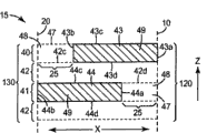
An exemplary embodiment according to wound dressing of the present invention is shown among Fig. 1,2 and 3.Wound dressing 12 comprises backing 21 (it can be preferably fitted shape as described herein).Backing 21 comprises two opposed first type surfaces: inner surface 22 and outer surface 24.During use, inner surface 22 is provided with the wound (or other body parts) of dressing and outer surface 24 wound (or other body parts) dorsad towards it.
The possible suitable material that is used for wound backing 21 is more detailed description hereinafter, but on function, and backing 21 is preferably by making as the material of the barrier of liquid and fast gas diffusion.The barrier characteristics of backing 21 can be absolute or can be not for absolute, as, backing 21 can allow limited gas to pass through, although backing 21 (and other assemblies of dressing 12) is preferably gas by enough barrier characteristics are provided, make when it is arranged on the wound, can at least temporarily enough vacuum environments be applied to treatment region.For example, backing can preferably have higher relatively moisture-vapor transmission, but impermeable liquid basically.
Dressing also comprises the binding agent on the inner surface that is positioned at backing layer, makes can utilize towards the inner surface of wound dressing is adhered on the wound of object.Binding agent 39 can cover all or part of of inner surface 22 by continuous and/or pattern application mode.Binding agent 39 shown in Figure 2 only is arranged on around the periphery or edge of backing 21, makes binding agent 39 form frame around the middle body of the inner surface 22 of backing 21.Multiple other structures also are fine.A kind of structure is shown among Fig. 3, and wherein dressing 12 is arranged on the wound W, and simultaneously binding agent 39 adheres on the tissue around the wound W (as, skin).Dressing 12 limits wherein the sealed environment that wound W and surrounding are kept apart together with organizing preferably of wound W and wound circumference.The inner surface 22 of backing 21 is towards the residing sealed environment of wound, and the outer surface 24 of backing 21 wound W dorsad.
Can preferably the binding agent shown in Fig. 1 and 2 39 be exposed on the only part of inner surface 22 of backing 21.In the embodiment shown in Fig. 1 and 2, the only part that binding agent 39 is arranged on inner surface 22 goes up (that is, the middle body of inner surface 22 does not contain binding agent 39).Yet in other embodiments, binding agent can be arranged on basically on the total inner surface 22 and a part of binding agent is covered by another element, make so only a part of binding agent be left exposure to be used to adhere to object.
Yet, in any embodiment, can be preferably, binding agent 39 extends around the peripheral seriality of backing 21, make when dressing 12 adheres on the object, can form sealed environment on wound, and the border of sealed environment is that inner surface 22 by backing 21 limits, described inner surface adheres on the wound of object by binding agent 39.
In a preferred embodiment, dressing is suitable for easily being delivered to wound.This can (for example) be disclosed in the U.S. Patent No. 6 of incorporating this paper with way of reference into by use, 742, handle in 522 and No.5,979,450 and optional reinforcing band or be disclosed in the U.S. Patent No. 6 of incorporating this paper in addition with way of reference into by use, 169,224, No.5,088,483 and No.4, what is called in 598,004 " framework is sent " is finished.
Binding agent is protected by liner usually.The liner that is suitable for using in binder composite of the present invention can be made by the complex of any person in kraft paper, polyethylene, polypropylene, polyester or these materials.Liner preferably utilizes the interleaving agent such as fluorochemical or organosilicon to be coated with.For example, U.S. Patent No. 4,472,480, its disclosure is incorporated this paper into reform, has described the perfluorochemical liner of low-surface-energy.Preferred liner is paper, polyolefin film or the polyester film through the coating of organosilicon releasable material.Commercially available example through silicone coated release paper is for deriving from the Illinois according to Bedford Parker city, state (Bedford Park, the POLYSLIK of the H.P.Smith branch of James company Ill) (James River Co.)
TMThe organosilicon release paper and by the Illinois according to willow Lu Ke city, state (Dixon, the organosilicon release paper that Dao Baier specialization company Ill.) (Daubert Chemical Co.) provides.Most preferred liner is the 1-60BKG-157 paper liner that derives from Dao Baierte, and it is the supercalendering kraft paper with water base organosilicon insulation surfaces.Alternatively, wound dressing can be no liner and with such as U.S. Patent No. 5,803, the reel form described in 086 is sent.
That wound dressing is preferably monolithic but can utilize two of being combined together to form seam or multi-disc to form, as what instructed in the U.S. Patent No. 4,969,880 of incorporating this paper with way of reference into.
In certain embodiments, can be preferably, medical dressing comprises that the absorbing material such as the wound packing material enters the fluid (as, liquid) of sealed environment with absorption.The example of absorbing material that may be suitable can include, but is not limited to hydrophilic foam, weaving material, non-woven material etc. and their combination.Can be preferably, absorbing material is absorbefacient and can discharges at least some (preferably, major parts) in any absorbed fluid when by valve vacuum being applied to sealed environment.By during from sealed environment, removing fluid, discharging absorption fluids, the ability of absorbing material absorption fluids is regenerated-this can prolong the service life of medical dressing.
Wound dressing 12 also can comprise the normally close valve 30 on the one or more passages that are attached to backing 21, and described one or more passages pass backing 21 and form.Valve allows to remove fluid from the sealed environment that is limited by wound dressing.The fluid stream that passes the one or more passages in the backing 21 is by valve 30 controls.Valve 30 (being preferably check valve) can be connected to micropump or be communicated with the micropump fluid.Can be preferably, micropump comprises seat, on the outer surface of the salable backing to wound dressing of described seat so that fluid-tight sealing to be provided.Can use valve to come subsequently for providing vacuum environment according to the wound that is provided with dressing 12 described herein on it.Although the wound dressing shown in Fig. 1 and 2 only comprises a valve 30, arrive the additional channel of the sealed environment that limits by dressing if desired, wound dressing then of the present invention can comprise a more than valve.The example valve that is used for this purpose more fully is described in applicant's the common unsettled U.S. Patent Application Serial Number 61/042,338, and this patent is filed on April 4th, 2008 and it is incorporated into way of reference in full.
Another optional structure that can be included among some embodiment of medical dressing of the present invention is a spacer element, and described spacer element can be arranged near the valve on the backing inner surface to help removing fluid from sealed environment.Fig. 4 is the plane graph of inner surface 422 of the backing 420 of medical dressing 410.Medical dressing 410 can comprise and being exposed to except that by the binding agent on the total inner surface 422 the spacer element 450 shared zones.Binding agent can be continuously or pattern application, but no matter coating method how, can be preferably, binding agent can provide airtight sealing, so that can obtain negative pressure in sealed environment.An example of possible appropriate pattern that is used to carry out the binding agent of pattern application can be lattice.Can be preferably, valve 430 is positioned at the zone of the backing 420 that is occupied by spacer element 450, although in certain embodiments, valve 430 can be positioned near the periphery of spacer element 450.
Spacer element 450 is included in the structure that certain form of open fluid passage is provided on one or more surfaces, makes like this and can remove the fluid that is positioned at the sealed environment that is limited by medical dressing 410 by valve 430.If (for example) the spacer element 450 and inner surface 422 of dressing 410 is sealed on the skin of wound or wound circumference is not set, utilizing micropump to remove fluid so from sealed environment can be hindered.Yet preferably, even when the relative atmospheric pressure of sealed environment is negative pressure, spacer element 450 also can keep open fluid passage to help removing fluid by valve 430, that is to say, even the fluid passage preferably stop close-under negative pressure.
Although the medical dressing shown in Fig. 4 only comprises a spacer element 450 and a valve 430, medical dressing of the present invention can comprise (for example) more than one and bonded valve of same spacer element.If that a relative sealed environment (for example) in the valve is provided with is improper, break down, become and block etc., it can be useful using a plurality of valves so.In another modification, medical dressing of the present invention can comprise a more than spacer element, and in the spacer element each all may link to each other with one or more valves to help removing fluid from sealed environment.If that a relative sealed environment (for example) in the spacer element is provided with is improper, become and block etc., it can be useful using a more than spacer element that combines with a medical dressing so.
The spacer element that is used for medical dressing of the present invention can present various ways.In certain embodiments, spacer element be formed directly in the inner surface of backing (by (and as) impression, grinding, die casting, cutting etc.).In other embodiments, spacer element presents the independent goods that have through impression, grinding, die casting, cutting or the groove that otherwise forms therein or other structures form of (as, film etc.).Can preferably utilize any suitable technique or these technology combination (as, binding agent, heat seal, hot weld etc.) the independent goods that will form spacer element are attached on the backing.
Groove in the spacer element can have any pattern or form, for example the honeycomb pattern of (but being not limited to) groove, grid or local grid, groove series (its for (as) parallel, radial etc.), post or other separate structure (as, vertebral body etc.).With under the certain situation of spacer element as the goods setting of the backing that is independent of medical dressing, these goods can comprise that the fluid passage on two interareas that are positioned at spacer element forms structure therein.Some may suitable interval the example of elements can be described in further (as) among the U.S. Patent Application Publication No.US2007/0172157 (Buchman), U.S. Patent No. 6,420,622 people such as () Johnston etc.
Pass medical dressing and be delivered to fluid in the sealed environment can comprise gas (as, oxygen, nitric oxide, ozone etc.) and/or liquid (as saline, water etc.).In some cases, if (as) microgranule mixes in the fluid in being delivered to sealed environment, they also can be delivered in the sealed environment so.
In some cases, maybe advantageously one or more bioactive agent deliveries are delivered to sealed environment (thereby also being delivered to the wound that covers by dressing).Activating agent can be used as that fluid is provided and/or can be carried in the fluid that is delivered to the inner space.The example of some potential suitable activating agents can comprise (as) antibacterial, antibiotic, analgesics, the healing factor, somatomedin, nutrient or the like such as vitamin.Other may be suitable the example of reagent can be described in U.S. Patent No. 6,867, in 342.
If send, activating agent (one or more) can be provided in the sealed environment continuously or off and on so.For example, bioactive agent delivery can be delivered in the sealed environment and can allow in position to keep (that is, resident) selected time period (as, some hrs), carry out subsequently (as) the sending etc. of the sending of second activating agent, negative pressure treatment.The initial activity agent can be removed or can allow it to be retained in the appropriate location before sending second reagent.Alternatively, can be before sealed environment be arranged on condition of negative pressure, sending before second reagent etc. utilization (as) saline or other rinse solution clean sealed environment.
As described herein, medical dressing of the present invention can be used for negative pressure wound therapy by micropump is provided in medical dressing, wherein can make fluid pass medical dressing and remove from the sealed environment that is limited by medical dressing.The micropump that utilization can preferably be attached on the medical dressing removes fluid from sealed environment.Can be preferably, micropump comprises on the outer surface of salable backing at medical dressing so that the seat or the valve of fluid-tight sealing to be provided.
In order from sealed environment, to remove fluid, can reduce the pressure of valve exterior circumferential fully so that open valve and from sealed environment, remove fluid by valve.Can be preferably, valve is normally closed check valve, makes when reduced pressure atmosphere no longer is present in the valve exterior circumferential (, the pressure reduction on the valve is reduced to valve is remained under the level of opening configuration) valve closure again like this.As described herein, can preferably in the sealed environment that limits by medical dressing, keep negative pressure.
In a preferred embodiment, wound dressing of the present invention and micropump system can be communicated with to form fluid-tight sealing remove fluid from the sealed environment that is limited by wound dressing during each other fast.That wound dressing itself can be preferably is structureless (as, only have the smooth outer surface of backing), and pump comprises seat, described seat has the surface that can be sealed in the required fluid-tight sealing of formation on the non-structure backing.
In certain embodiments, wound dressing and micropump can comprise more conventional connector/accessory so that fluid-tight connection is provided between micropump and wound dressing.In such an embodiment, the wound dressing external member can comprise utilization (as) contact adhesive etc. adheres to the accessory on the outer surface of backing.Accessory can (for example) comprises the tube connector that is designed to be connected on the micropump, luer lock accessory etc.The binding agent that is used for accessory is adhered to wound dressing can be strippable, promptly, accessory may be removed from dressing, and dressing is retained in the appropriate position on the wound, makes any sealed environment of limiting by wound dressing during the removing of accessory, stand intact so always.
The wound dressing micropump system comprises micropump, and described micropump is applied to wound with negative pressure so that siphon away wound fluid or exudate effectively and impel interstitial fluid to flow to the wound bed from surrounding tissue from wound bed.Therefore, form be the wound dressing apparatus of wound dressing and micropump system for extremely to be convenient for carrying, this compares when using external vacuum source and allows patient can obtain bigger activeness.Micropump of the present invention is enough little, allows even bigger activeness thereby compare with disclosed wherein patient other half portable structure that must carry micropump in loading bag among (for example) U.S. Patent Application Publication No.2007/0055209.Do not need to be restricted in the random time section of patient in the therapeutic process of wound.
Compare with known negative pressure treatment system, the present invention has used the fluidic micropump of direct contact wound.Make unnecessary wound fluid pass micropump.Therefore, micropump is preferably self-priming (selfpriming) and can pump the air that is trapped between sealing dressing and the wound bed, manually removes air although also it is contemplated that by handling wound dressing and/or micropump.In operation, open micropump and pump air to produce vacuum.As used herein, term " vacuum " is meant the pressure that is lower than around atmospheric pressure.Preferably, with pressure reduce 5-250mm mercury column (Hg) (as, be low to moderate the absolute pressure of 500-740mmHg, but this will depend on atmospheric pressure).When pressure reduced above 250mmHg, patient can feel pain.Therefore, preferably pressure is reduced and be no more than 200mmHg and more preferably no more than 175mmHg.Preferably, with pressure drop low 5mmHg, 25mmHg at least, more preferably reduce at least 50mmHg and most preferably reduce 75mmHg at least, so that remove enough interstitial fluids.
Preferably, micropump is for being designed to disposable low-cost micropump.Abandoning micropump during each change of dressing can reduce the germ contamination of wound and propagate the risk of giving other patients.Preferred micropump is the positive displacement micropump so that guarantee that it is for fast and be preferably self-priming.Multiple micropump design is suitable, comprises those that drive by small machine, for example miniature gears pump, sickle pump, piston pump, screw pump, peristaltic pump, centrifugal pump and membrane pump.As the membrane pump that does not need motor and the electric quick micropump that further describe hereinafter is most preferred.These micropumps itself have some moving-members, thereby comparatively reliable and can very undisturbedly carry out work.
Micropump of the present invention can preferably reach and be higher than atmospheric pressure (gauge pressure) output pressure of 100mmHg at least.Preferably, micropump can reach and be higher than the atmospheric pressure output pressure of 200mmHg at least.Micropump should be able to reach the flow velocity at least about 1 milliliter/hour.More preferably, micropump can reach the flow velocity at least about 3 milliliters/hour.
As hereinafter and in the common unsettled U.S. Patent Application Serial Number 11/684 that is filed in the applicant that on March 12nd, 2007 and its incorporate into way of reference in full, further described in 700, can utilize electric active material to prepare an above-mentioned micropump to form actuator.Micropump be included in have at least one surface electricity activate the pump chamber of actuator, with fluid (gas or liquid, comprise liquid, for example the wound fluid with dispersing solid) device that when the emptying of chamber, moves inward of the device that outwards moves when full in the chamber of the device, limit fluid of introducing and drawing pump chamber and limit fluid and the device that under suitable voltage, frequency and current intensity, activates the actuator power supply for electricity.
In one embodiment, micropump comprises at least three elements: electric photosensitive elements, electromotive force can be applied to the pair of electrodes on the whole thickness of at least a portion of electric photosensitive elements and can apply suitable pressure drop to obtain the power supply of required compression.Preferably, power supply (pressure drop) is adjustable, so that by apply intermittent or variable pressure in conjunction with potential difference meter.When applying voltage, electric photosensitive elements preferably can obtain 0.01% strain, preferably 0.1% strain, more preferably 1% strain even more preferably 3% strain and most preferably greater than 5% strain.Most preferred electric photosensitive elements is that electricity activates polymer, for example elastomer (polyurethane, silicone rubber, Zetpole, VHB), viscoelastic polymer and copolymer or terpolymer (PVDF, PVDF-TrFE, PVDF-HFP, PVDF-TrFE-HFP etc.), as hereinafter further as described in.The electricity photosensitive elements also can be the composite membrane of polymer such as polymer-ceramic, and wherein said ceramic component can be PZT, PZN-PT, polymer-carbon nanotube, carbon fiber, polyamide-PZT fiber etc.
The electricity active material can be the multilayer film in the common unsettled U.S. Patent Application Serial Number 11/684,700 that is disclosed in the applicant, and this patent is filed on March 12nd, 2007 and it is incorporated into way of reference in full.Multilayer film is configured with and helps significantly reduce driving voltage and control driving force better.In this multi-ply construction, voltage is applied on each layer, thereby makes them move jointly.Reduce the actuator film thickness and can significantly reduce driving voltage.In this multi-ply construction, can be easy in the identical driving voltage of maintenance, control membranous hardness by the number of plies.
Alternatively, perhaps activate the polymer except electricity as herein described, electric photosensitive elements can be magnetostriction materials.Magnetostriction materials used herein are for coming varying sized material by applying magnetic field.Preferred magnetostriction materials are Terfenol-D.For example, suitable magnetostriction materials can be ferromagnetic shape memory alloy material (FSMA), and it has the viewed twin mechanism in the conventional shape memory alloy material such as NiTi and CuZn that is similar to.In FSMA, can use the magnetic field that applies to cause alteration of form.The another kind of material of being studied is for being called ferrum/gallium alloy of Galfenol at Naval Surface Warfare Center people such as () Clark.Referring to Clark, " magnetostriction rare earth-Fe of A.E.
2Chemical compound " (ferrimagnet: magnetic order substance characteristics handbook (
Ferromagnetic Materials:A Handbook on the Properties of Magnetically Ordered Substances), the 1st volume, Wolfarth, E.P. version, 531-589 page or leaf, 1980).In these are used, can use electric current, but not voltage drives the actuator displacement that comprises magnetostriction materials.
Representational electric sensitive actuator 5 comprises the first electric photosensitive elements 100 and the second electric photosensitive elements 105 as shown in Figure 5.Electricity photosensitive elements 100 also is described in U.S. Patent No. 4,627,138 (Im); No.5,997,880 (people such as Friedl); No.5,153,859 (people such as Chatigny); And among international open No.WO 02/096647A1 people such as () Hilmas.Electricity sensitive actuator 5 comprises the first electric photosensitive elements 100 and the second electric photosensitive elements 105 unpolarized and that extend along the x-dimension.In the electricity photosensitive elements 100,105 each all has the dimension of three mutually orthogonals, x-, y-and z-dimension.Element 100,105 comprises alternative conductive layer 40,41 and non-conductive layer 42. Conductive layer 40,41 comprises the zone 43,53,44,54 of polymer-type conductive material 49 and the zone 48 of polymer-type non-conducting material 47; And non-conductive layer 42 comprises polymer-type non-conducting material 47.Electricity sensitive actuator 5 also has and is used for section plane 20 that first element 100 and second element 105 are separated.Section plane 20 is perpendicular to the x-dimension and be parallel to the y-z plane.
First conductive layer 40 and second conductive layer 41 have conductive region 43,53,44,54 separately.First conductive layer 40 has first conductive region 43 and second conductive region 53, and second conductive layer 41 has the 3rd conductive region 44 and the 4th conductive region 54.By shown in Figure 5 conductive region 43,53,44,54 is set, thereby second surface 44b, the 54b of first surface 43a, the 53a of first conductive region 43 in the conductive layer 40 of winning and second conductive region 53 and the 3rd conductive region 44 in second conductive layer 41 and the 4th conductive region 54 alternately are exposed in the element 100,105 in two opposite faces 120,130 at least one.First 120 consistent with first surface 43a, 53a and second surface 44b, 54b in second 130 corresponding conductive region 43,53 with each and 44,54.In addition, relative first 120 and second 130 are parallel to section plane 20,24 and datum plane 10.Make described two faces 120,130 be exposed to box lunch and recover single electric photosensitive elements 100 after separately at one or more section planes 20 or at datum plane 10 and section plane 20 places.
The x-dimension is finger widths or width of cloth material transverse dimensions, and the y-dimension is meant the degree of depth or the vertical dimension of width of cloth material, and the z-dimension is meant the thickness or the height of the electric sensitive actuator 5 with at least two electric photosensitive elements 100,105.Similarly, the y-z plane is corresponding to the plane with y-and z-dimension, and the x-z plane is corresponding to the plane with x-and z-dimension.The x-y plane is corresponding to the plane with x-and y-dimension.
The x-dimension that comprises the electric sensitive actuator 5 of at least two elements 100,105 is meant that electric sensitive actuator 5 and electric sensitive actuator 5 separate the width or the width of cloth material transverse dimensions of the follow-up electric photosensitive elements 100,105 of gained afterwards at section plane 20 places.The x-dimension of element 100 can be positioned at 0.01 micron to 1 centimetre scope.Preferably, the x-dimension is positioned at 1 micron to 0.1 centimetre scope, and more preferably, the x-dimension is positioned at 10 microns to 0.01 centimetre scope.
The y-dimension relates to the length or the vertical dimension of width of cloth material of the goods that comprise at least two elements 100,105.The y-dimension also relates to the element 100,105 after electric sensitive actuator 5 separates by section plane 20.Element 100,105 can have separately according to the determined specific y-dimension of given application.Can along perpendicular in the x-z plane of y-dimension from electric sensitive actuator 5 resolution elements 100.The y-dimension of element 100 can be positioned at 0.01 micron to 1 centimetre scope.Preferably, the y-dimension is positioned at 1 micron to 0.1 centimetre scope, and more preferably, the y-dimension is positioned at 10 microns to 0.01 centimetre scope.
The z-dimension relates to the thickness or the height of the electric sensitive actuator 5 of drawing together at least two electric photosensitive elements 100,105.The z-dimension can be with conductive material and non-conducting material the quantity of alternating layer when this material is extruded by the nib of extrusion device and the multiwalled drawing-off degree during coextrusion change.The z-dimension of each in the element 100,105 can be positioned at 3 microns to 3 millimeters scope.With respect to the z-dimension of electric sensitive actuator 5 after drawing-off, the z-dimension of electric sensitive actuator 5 after withdrawing from nib can be different.Preferably, the z-dimension is positioned at 10 microns to 0.5 millimeter scope, and more preferably, the z-dimension is positioned at 25 microns to 0.05 millimeter scope.
In Fig. 5, the first electric photosensitive elements 100 and the second electric photosensitive elements 105 of electric sensitive actuator 5 have first section plane 20 and second section plane 24 and datum plane 10.The datum plane 10 of goods also can be used as in the section plane 20,24.Datum plane 10 and section plane 20,24 relative to each other and similarly are parallel to the face 120,130 of element 100,105 along the y-z plane.Datum plane 10 and section plane 20,24 are separated from each other element 100,105, thereby the alternating layer of the conductive material 49 in the conductive layer 40,41 is exposed in two faces 120,130 one.Can utilize following technology realize element 100,105 separately, that described technology comprises is die-cut, cut, shear, cut, hot line engages rip cutting and their combination.When after datum plane 10 or section plane 20,24 punishment Katyuan parts 100,105, can obtain electric sensitive actuator 5 pruning part or inoperative element of any extension in the face 120,130 dorsad on the x-direction.Prune part or inoperative element and can be included in erose surface or the face that forms during the drawing-off by extruding of carrying out of nib and electric sensitive actuator 5.Pruning part can be used further in other application.
Electricity sensitive actuator 5 is included in alternative conductive layer 40,41 and the non-conductive layer 42 that extends on the z-dimension, as shown in Figure 5.Alternative conductive layer 40,41 and non-conductive layer 42 are successive on the y- dimension.Conductive layer 40,41 is discontinuous on the x-dimension, and comprises polymer-type conductive material 49.Non-conductive layer 42 comprises non-conductive polymer material 47, and it is successive on the x-dimension.
First conductive layer 40 and second conductive layer 41 among Fig. 5 comprise at least two conductive regions separately.First conductive layer 41 comprises first conductive region 43 and second conductive region 53, and second conductive layer 41 comprises the 3rd conductive region 44 and the 4th conductive region 54.Conductive region 43,53 and 44,54 is discontinuous on the x-dimension, is successive on the y-dimension.First conductive region 43 in first conductive layer 40 has first surface 43a, second surface 43b, the 3rd surperficial 43c and the 4th surperficial 43d.Second conductive region 53 in first conductive layer 40 has first surface 53a, second surface 53b, the 3rd surperficial 53c and the 4th surperficial 53d.Conductive region 43,53 is discontinuous on the x-dimension, has the space 25 that comprises non-conducting material 47.Similarly, the 3rd conductive region 44 in second conductive layer 41 has first surface 44a, second surface 44b, the 3rd surperficial 44c and the 4th surperficial 44d.The 4th conductive region 54 in second conductive layer 41 has first surface 54a, second surface 54b, the 3rd surperficial 54c and the 4th surperficial 54d.Also be discontinuous on third and fourth conductive region 44, the 54x-dimension, have the space 25 that comprises non-conducting material 47.Non-conductive layer 42 is included in the non-conducting material 47 that seriality is extended on x-and the y-dimension.
The cross section of electric sensitive actuator 5 as shown in Figure 5 has at least two electric photosensitive elements 100,105 on the x-z plane.This cross section shows the non-conductive layer 42 with the 3rd surperficial 42c and the 4th surperficial 42d.Non-conductive layer 42 is between first conductive layer 40 and second conductive layer 41.First conductive layer 40 is adjacent to the 3rd surperficial 42c of non-conductive layer 42, and second conductive layer 41 is adjacent to the 4th surperficial 42d of non-conductive layer 42.First conductive layer 40 has at least the first conductive region 43 and second conductive region 53, and second conductive layer 41 has at least the three conductive region 44 and the 4th conductive region 54, and wherein the space 25 between the conductive region 43,53,44,54 can comprise polymer-type non-conducting material 47. Conductive region 43,53 and 44,54 in the conductive layer 40 and 41 carries out repetition respectively on the x-dimension.
Fig. 6 shows the electric photosensitive elements 100,105 of electric sensitive actuator 5, and wherein each element 100,105 is all made by unit cell 15.Unit cell 15 comprises at least one non-conductive layer that comprises non-conducting material 47 42, and it has the 3rd surperficial 42c and the 4th surperficial 42d, and these two planes are along two orthogonal substantially axles, and x-and y-dimension are for successive.Unit cell 15 also is included in discontinuous at least the first conductive layer 40 and second conductive layer 41 that comprises conductive material 49 on the x-dimension, and wherein first conductive layer 40 comprises first conductive region 43, and second conductive layer 41 comprises the 3rd conductive region 44.First conductive region 43 has first surface 43a, second surface 43b, the 3rd surperficial 43c and the 4th surperficial 43d.The 3rd conductive region 44 has first surface 44a, second surface 44b, the 3rd surperficial 44c and the 4th surperficial 44d.The first surface 43a of first conductive region 43 in first conductive layer 40 is consistent with datum plane 10, and wherein the second surface 43b of first conductive region 43 does not extend to section plane 20.The second surface 44b of the 3rd conductive region 44 in second conductive layer 41 is consistent with section plane 20, and wherein the first surface 44a of the 3rd conductive region 44 does not extend to datum plane 10.Datum plane 10 is parallel with section plane 20 along the y-z plane.Unit cell 15 comprises having the alternating layer that is clipped in the non-conductive layer 42 between second conductive layer 40 and second conductive layer 41.
The electric photosensitive elements 100,105 of the electric sensitive actuator 5 among Fig. 5 is unpolarized, to be used as the assembly that is selected from actuator, pick off, thermoelectric device, capacitor and piezo-electric device.This element 100,105 generally includes the alternating layer of conductive material and non-conducting material.The number of plies in the element 100 can be limited by the design of the layered component of using with suitable extrusion device or other processing conditionss.Similarly, the size of element 100 can submit to the design that concrete structure and definite user use.
In one embodiment, the conductive layer 40,41 and the non-conductive layer 42 of the element 100 of Fig. 5 have controlled thickness.The thickness of layer is based on the design and the corresponding downstream extrusion device of layered component 400.Element 100 preferably has as far as possible thin and be subsequently applied to conductive layer 40,41 in the device under the situation of not losing electric conductivity.Non-conductive layer 42 and conductive layer 40,41 are generally symmetric and are preferably as far as possible thin so that make the electrical conductivity of the element in the device reach maximum.Relative first 120 and second 130 are used for coming separately first element 100 and second element 105 at section plane 20,24 and/or datum plane 10 places.Section plane 20,24 and/or datum plane 10 are exposed on relative first 120 and second 130 of element 100,105, as shown in Figure 6 the second surface 44b of the first surface 43a of first conductive region 43 and the 3rd conductive region 44.
In one embodiment, the unit cell among Fig. 6 15 can be used as the assembly in first device 600 shown in Figure 7.First device 600 can be coated with second conductive material 510 on relative first 120 and second 130.The second surface 44 of the first surface 43a of first conductive region 43 and the 3rd conductive region is exposed to respectively among Fig. 6 first 120 and second 130.First device 600 can be included in additional alternately conductive layer 40,41 and the non-conductive layer 42 that the z-direction is extended.
Being used for conductive region 43,44 with Fig. 7 is positioned at second conductive material 510 that exposed surface 43a, 44b on the face 120,130 carry out electrical interconnection and can has polytype.The polymer that example includes, but is not limited to scolder, silver, other conducting metals, electric conductive polymer and comprises conductive filler.Preferably second conductive material 510 being coated to each whole in the opposite face 120,130 goes up so that make one in the whole and face 120,130 of exposed surface 43a, 44b of conductive region 43,44 to carry out electrical interconnection.Also lead can be attached on second conductive material 510, carry out the polarization of first device 600 subsequently.
Fig. 8 shows second device 610 with insulating coating or layer 520.Device 610 also can be coated with insulating barrier 520 at face 120,130 and on x-y and the planar any residue face of x-z.The insulating barrier 520 of second device 610 helps to reduce moisture and the steam that passes first and second conductive layers 40,41, and the probability that reduces the electric discontinuity on whole second device 610.
The device 610 that comprises the element 100 with thickness of thin layer has usually and is lower than 10 volts voltage level.Along with reducing of layer thickness, the driving voltage that applies required in the given application is also low more.Device 610 can have the elastic modelling quantity that scope is 0.1MPa-10GPa in addition.
Fig. 9 shows the goods 180 with at least the first electric photosensitive elements 100 and second electric photosensitive elements 105, and wherein element 100,105 carries out repetition on the x-dimension.Element 100,105 is what can open in 20,24 minutes by section plane.Relative first 120 and second 130 that expose in the element 100,105 is because element 100,105 is separately produced at section plane 20,24 and/or datum plane 10 places.First conductive layer 40 is included in discontinuous first conductive region 43 and second conductive region 53 on the x-dimension.Similarly, the 3rd conductive region 44 of second conductive layer 41 and the 4th conductive region 54 are discontinuous on the x-dimension.Element the 100, the 105th utilizes unit cell shown in Figure 6 15 to make.
In one embodiment, the electric sensitive actuator 5 of Fig. 5 comprises a plurality of electric photosensitive elements 100,105, and wherein these elements can be opened by n-1 section plane in 20,24 minutes.Section plane 20,24 is perpendicular to the x-dimension of goods.A plurality of elements 100,105 comprise n unit cell 15 with n-1 section plane 20,24, and wherein n is at least 3.
In one embodiment, goods 180 comprise the multiple first electric photosensitive elements 100 on the x-dimension and the second electric photosensitive elements 105 among Fig. 9.These elements preferably include symmetric non-conductive layer 42 and and conductive layer 40,41.Preferably, the repetition scope of electric photosensitive elements 100,105 on the x-dimension is 2 to 1000 unit cells 15.More preferably, the repetition scope of element 100,105 is 5 to 500 unit cells 15, and more preferably scope is 25 to 250 unit cells 15.In addition, element 100,105 seriality on the y-dimension is extended, as shown in figure 10.Unit cell 15 can extend on the z-dimension, and this depends on the quantity of selected non-conductive layer 42 and conductive layer 40,41 and the thickness of each layer after by extrusion die symmetry ground drawing-off non-conductive layer 42 and conductive layer 40,41.
Figure 10 shows has at least two three-dimensional perspectives at the electric sensitive actuator 5 of the discerptible electric photosensitive elements 100,105 of section plane 20,24 and datum plane 10 places. Conductive layer 40,41 is successive on the y-dimension, and is discontinuous on the x-dimension.Non-conductive layer 42 is alternately arranged with conductive layer 40,41, and wherein non-conductive layer 42 is successive on x-dimension and y-dimension.Non-conducting material 47 occupies the space 25 between the conductive region 44,54 of the conductive region 43,53 of first conductive layer 40 and second conductive layer 41.
Figure 11 shows the goods 190 with at least the first electric photosensitive elements 100 and second electric photosensitive elements 105, and wherein element 100,105 has multiple alternately conductive layer 40,41 and non-conductive layer 42 on the z-dimension.Element 100,105 is discerptible at section plane 20,24.As being similar to shown in Figure 5ly, first conductive layer 40 comprises first conductive region 43 and second conductive region 53, and second conductive layer 41 is included in multiple the 3rd conductive region 44 and the 4th conductive region 54 on the x-dimension.The section plane 20,24 that is used for separate elements 100,105 is perpendicular to the x-dimension.Section plane 20,24 separate elements 100,105 along goods 190 can produce the sandwich type element that is used for application-specific.
Figure 12 shows element 100 along the planar cutaway view of y-z.First 120 of element 100 demonstrates and has alternative conductive layer 40 and non-conductive layer 42.Along the y-z plane, these layers comprise first conductive layer 40 and non-conductive layer 42.On the z-dimension, element 100 comprise first conductive layer 40, non-conductive layer 42, second conductive layer 41 as shown in Figure 5 non-conductive regional 48 in non-conducting material 47, be non-conductive layer 42 subsequently.Non-conducting material 47 can be filled space 25 between the conductive region of first conductive layer 40 or non-conductive regional 48, and wherein conductive region does not extend to first 120 datum plane 10.Conductive layer 40 comprises the polymer-type conductive material 49 in first conductive region 43, and described first conductive region is successive on the y-dimension.A plurality of alternative conductive layers 40 and non-conductive layer 42 can be by coextrusion to be used to form the sandwich type element 190 that extends on the z-dimension in Figure 11.
Figure 13 shows element 100 along the planar cutaway view of y-z.Second 130 of element 100 is showed and to have alternative conductive layer 41 and non-conductive layer 42.Along the y-z plane, these layers comprise as shown in Figure 5 first conductive layer 40 non-conductive regional 48 in non-conducting material 47, non-conductive layer 42, second conductive layer 41, follow by non-conductive layer 42.Space 25 or non-conductive regional 48 between the conductive region of first conductive layer 40 of non-conducting material 47 fillings in Figure 12.Second conductive layer 41 comprises the polymer-type conductive material 49 in the 3rd conductive region 44, and described the 3rd conductive region is successive on the y-dimension.
Figure 14 show be included in section plane 20,24 and/or the datum plane 10 places discerptible first electric photosensitive elements 100 and the second electric photosensitive elements 105 at least electric sensitive actuator 5 along the planar cutaway view of x-y.Element 100,105 demonstrates first conductive region 43 and second conductive region 53 with first conductive layer 40, and described first conductive layer has the space 25 of being filled by non-conducting material 47.The first surface 43a of first conductive region 43 is consistent with datum plane 10, and wherein second surface 43b does not extend to first section plane 20.Similarly, the first surface 53a of second conductive region 53 of first conductive layer 40 is consistent with first section plane 20, and wherein second surface 53b does not extend to second section plane 24.The 3rd surperficial 43c of first conductive region 43 and the 3rd surperficial 53c of second conductive region 53 are the upper space along x-y plane shown in Figure 14.
Alternately each in the conductive layer 40,41 can be made by the combination of different materials or material, and described material also can comprise particle or the filler that is used to provide electric conductivity.Similarly, each in the non-conductive layer 42 can comprise and is similar to the material used in the conductive layer 40,41 or the combination of material, but each independently non-conductive layer 42 all can comprise material or the combination of materials that is different from other non-conductive layers.Non-conductive layer 42 also can comprise particle to increase the electrical conductivity of the element 100 in the device.
In one embodiment, first polymeric material and organic filler form the polymer-type conductive material 49 in the conductive layer 40,41.
In one embodiment, first polymeric material is an elastomer.
Thermoplastic with rubber elastomer characteristics is commonly referred to thermoplastic elastic material.Thermoplastic elastic material is generally defined as the material with high resiliency and low creep, and they are at ambient temperature like for covalent cross-linking, and processes as the thermoplasticity inelastic body when be heated above its softening point and mobile.First polymeric material or a kind of thermoplastic elastic material in the polymeric material blend that can be used as in conductive layer and/or the non-conductive layer comprise (for example) straight chain, radial, starlike and tapered block copolymer, for example hereinafter described those.
The example of first polymeric material comprises silicone elastomer, acrylic elastomer, polyurethane, polybutadiene, thermoplastic elastomer (TPE), polybutadiene-acrylonitrile copolymer and their combination.
In one embodiment, first polymeric material is thermoplastic.
The example of thermoplasticity first polymeric material comprises contact adhesive, fluoropolymer polymer and has siloxanes and the polymer of acrylate moiety or the like.The example of fluoropolymer polymer comprises the homopolymer such as polyvinylidene fluoride (PVDF), such as polyvinylidene fluoride-trifluoro-ethylene P (VDF-TrFE), polyvinylidene fluoride-chlorine fluorothene P (VDF-CFE), polyvinylidene fluoride-hexafluoropropene P (VDF-HFP), polyvinylidene fluoride-trifluoro-ethylene-chlorine fluorothene P (VDF-TrFE-CFE), polyvinylidene fluoride-trifluoro-ethylene-CTFE P (VDF-TrFE-CTFE), polyvinylidene fluoride-tetrafluoroethene-CTFE, polyvinylidene fluoride-trifluoro-ethylene-hexafluoropropene, polyvinylidene fluoride-hexafluoropropylene (HFP)/tetrafluoroethylene (TFE), polyvinylidene fluoride-trifluoro-ethylene-tetrafluoroethene, polyvinylidene fluoride-tetrafluoroethene, polyvinylidene fluoride-trifluoro-ethylene-fluorothene, polyvinylidene fluoride-tetrafluoroethene-fluorothene, polyvinylidene fluoride-trifluoro-ethylene-perfluor (methyl ethylene) ether, polyvinylidene fluoride-tetrafluoroethene-perfluor (methyl ethylene) ether, polyvinylidene fluoride-trifluoro-ethylene-trifluoro bromine ethylene, polyvinylidene fluoride-tetrafluoroethene-trifluoro bromine ethylene, polyvinylidene fluoride-tetrafluoroethene-chlorine fluorothene, polyvinylidene fluoride-trifluoro-ethylene-vinylidene chloride, and the copolymer of polyvinylidene fluoride-tetrafluoroethene-vinylidene chloride and so on and their combination.
The example of organic conductive particle or filler comprises graphite, CNT, white carbon black and their combination.These materials can be able to be added in first polymeric material to be formed for the polymer-type conductive material 49 of conductive layer 40,41.First polymeric material can be mixed with organic material or filler, blend, synthetic or obtain to be applicable to the homogeneous mixture of the material that forms conductive layer 40,41 by other modes.
In one embodiment, first polymeric material and inorganic particulate can be carried out blend or mix to form conductive layer 40,41.The example of inorganic particulate or filler comprises silver, copper, nickel, aluminum, platinum, palladium, its derivant and their combination.These materials can have the irregularly shaped or limiting structure that is suitable for forming conductive layer 40,41.
In one embodiment, first polymeric material can be carried out blend with inorganic coating particle or mix to form conductive layer 40,41.The example that is used to be coated with the inorganic material of particle comprises gold, silver, palladium, platinum and their combination.
In one embodiment, first polymeric material can form the polymer-type conductive material 49 in the conductive layer 40,41.Example with first polymeric material of electric conductivity comprises poly-(3,4-enedioxy thiophene), polyaniline, poly-give a tongue-lashing cough up, polythiophene, polydiacetylene, polyacetylene, polyisothianaphthene, poly-impure aromatic ene-ethylene, wherein the impure aromatic ene group can be (for example) thiophene, furan or pyrroles, poly, polyphenylene sulfides, poly-perinaphthene, poly-phthalocyanine, their copolymer and physical mixture.First polymeric material can utilize optional particle or filler and be electric conductivity.
The optional additive that carries out blending with first polymeric material that conducts electricity also can comprise impurity, adulterant and their combination.Adulterant comprises iodine, peroxide, is used for carrying out adulterated lewis acid and protic acid, being used for carrying out adulterated sodium, potassium and calcium by reduction by oxidation.
First polymeric material in the conductive layer 40,41 can comprise electric conductive polymer, polymeric material or have the blend of the polymeric material of electric conductivity.In some cases, first polymeric material is mixed with organic material to produce conductive layer.
Successive non-conductive layer 42 and conductive layer 40,41 have the thickness of basic homogeneous on y-dimension or the vertical dimension of width of cloth material, and excursion is no more than ± and 10%.Similarly, wish to have thin conductive layer, wherein the thickness of these layers can be remained and the average diameter of the particle of the first polymeric material blend or the control of granularity.
Can pass through as U.S. Patent No. 4,627, the multilamellar extrusion method described in 138 obtains multi-ply construction.In another kind of multilamellar extrusion method, conductive layer (being also referred to as electrode) can be patterning, as further described in applicant's common unsettled U.S. Patent Application Serial Number 11/684,700, described patent is filed on March 12nd, 2007 and it is incorporated into way of reference in full.The method helps to control the required size of actuator but not the whole width that makes that has described in above-mentioned patent depends on die lip.The method and the relevant equipment that are used for coextruded multilayer width of cloth material are described in U.S. Patent No. 6,949,283 (people such as Kollaja), No.5, and 825,543 (people such as Ouderkirk) and No.5 are among 783,120 (people such as Ouderkirk).
Also can carry out lamination and obtain multi-ply construction by each electric active coating that will on top and bottom, have electrode layer.Can utilize multiple mode to finish the lamination process, for example use binding agent, heating lamination, use solvent (for example U.S. Patent No. 5,997, described in 800) to soften top surface.
Micropump
The micropump that is used in combination with medical dressing of the present invention can present any suitable form.In certain embodiments, micropump can be portable, self-contained device, and in other embodiments, fixed, immobilized system that micropump can be.In some cases, ((as) in battlefield or other positions) even can utilize the sucking of being undertaken by personal its mouth from the sealed environment that limits by medical dressing, to remove fluid.
Some can use or the example of the possible suitable micropump that provides can comprise the pump that is described among the U.S. Patent Application Publication No.US2007/0209326 (Tretina) with the external member with medical dressing of the present invention, but multiple other pumps can be used for replacing wherein disclosed pump.Although the pump described in the above-mentioned document comprises power supply (as, battery), the micropump that is used in combination with the present invention can be manual actuation.Some other may be suitable the example of manual actuation pumps can comprise (as) have a device of flexible cavity, described flexible cavity compressible and when returning its its pre-compressed state pump (as, spheroid or sucking type drainage bag etc.) the porch vacuum power is provided.
In certain embodiments, wound dressing of the present invention and micropump system can preferably include one or more catcher or the fluid collection elements that can collect or keep the liquid (and in certain embodiments, being gas) that removes from the sealed environment that is limited by medical dressing.Catcher can become one with micropump in certain embodiments, and in other embodiments, catcher can separate with micropump, makes replaceable catcher like this, and need not replace micropump and catcher simultaneously.Some may suitable examples that are designed to the catcher of separating liquid from removing fluid can be described in (as) among U.S. Patent Application Publication No.US 2007/0209326 (Tretina) and the US 2007/0172157 (Buchman).
Can be preferably, medical dressing of the present invention and therewith make and be used for from sealed environment, removing fluidic any micropump and during from the sealed environment that limits by medical dressing, removing fluid, can be communicated with fast each other to form fluid-tight sealing.That medical dressing itself can be preferably is structureless (as, only have the smooth outer surface of backing), and micropump comprises seat, described seat has the surface that can be sealed in the required fluid-tight sealing of formation on the non-structure backing.
In certain embodiments, medical dressing and micropump can comprise more conventional connector/accessory so that fluid-tight connection is provided between micropump and medical dressing.When (as) micropump need long-time (as, above 2 minutes) when being connected on the medical dressing, these accessories can be useful.In such an embodiment, wound dressing can comprise utilization (as) contact adhesive etc. adheres to the accessory on the outer surface of backing.Accessory can (for example) comprises the tube connector that is designed to be connected to for a long time on the micropump, luer lock accessory etc.The binding agent that is used for accessory is adhered to medical dressing can be strippable, promptly, accessory may be removed from dressing, and dressing is retained in the appropriate position on the wound, makes any sealed environment of limiting by medical dressing during the removing of accessory, stand intact so always.
Preferred pump is a micropump.Preferred micropump is the membrane pump with at least one Crumple element.These micropumps can be by multiple device startup, and described device comprises that used electricity activates polymer (EAP), uses piezoelectric pump, the ionomer type metal composite (IMPC) of the ceraminator such as PZT and mixes CNT or other conductive compositions activate the complex that responds to improve electricity.
Other preferred pumps comprise and are disclosed in US 2004/0234401, digit pulse activated form battery system pump among WO2006/065884 and the US 2005/045210, be disclosed in preferably including herein according to (for example) U.S. Patent No. 4,627,138 the EAP micropump of the multilamellar EAP element for preparing of instructing and " being used for the dielectric elastomer lamination thing (elastomer Laminates for Active Membrane PumpApplications) that the active membrane pump is used " (Proc.Of SPIE of being disclosed in people such as Pope, the 5385th volume,, 60-67 page or leaf in 2004) the EAP pump in; Such as U.S. Patent No. 5,961, the capable ripple pump described in 298.Suitable EAP material comprises such as being disclosed in U.S. Patent No. 5, the polyurethane of those in 977,685 and so on, the polyacrylate such as the VHB binding agent #4905 of 3M company, polyvinylidene fluoride (PVDF), polyvinylidene/trifluoro-ethylene (VDF-TrFE) and the siloxanes such as Nusil CF19-2186.
Micropump comprises inlet, outlet and the optional device that is used to regulate pressure.Micropump can directly be attached in the dressing or can be away from dressing but be communicated with the dressing fluid by the appropriate device such as pipe.Micropump preferably includes one-way inlet valve and unidirectional outlet valve, to guarantee that fluid is drawn out of and not allow it to be back in the wound bed.Valve can have any design such as conventional ball valve.Preferably, valve constitutes (as described herein) by elastomer element.For example, preferred valve is umbrella valve or duckbill valve, for example derives from yellow hot spring small town, Ohio (Yellow Springs, those of the valve company limited of anti-experiment Ohio) (Vernay Laboratories).
Can need check-valves or other devices to regulate pressure, especially be lower than the pump that atmospheric pressure surpasses the vacuum of 100mmHg for producing.This can finish by the check-valves of opening under predetermined pressure drop and allow gas to flow in the wound bed.If the use check-valves, it preferably has and will leach microorganism and stop them to enter the diaphragm element of wound bed so.Alternatively and preferably, micropump is equipped with pressure transducer and control circuit, the described control circuit pump speed that slows down at predetermined pressure set point place.Set point is preferably variable and is easy to be set by the clinician.The reading that can need pressure.Alternatively, micropump is for from restrictive and can not produce the vacuum that surpasses required max vacuum, as surpassing about 150mmHg.
Micropump can and can be derived from circuit or battery source by the ac/dc power drives.Preferred micropump is driven by small-sized disposable battery source.Power supply can be positioned at packing with micropump or it can be positioned at remote location and be connected to micropump.Preferably, battery can drive micropump continuous operation at least 2 hours.More preferably, battery can drive micropump continuous operation at least 8 hours even more preferably at least 1 day, more preferably continuous operation always many days.Therefore, micropump is more energy-efficient, thereby has avoided the needs for the large-sized battery source.
Micropump is preferably program-controlled, successive to extract out, intermittently or variable vacuum.For example, but micropump can be programmed to extract out and to keep the vacuum of 100mmHg or vacuum that the person is programmed to extract 150mmHg out according to mode of oscillation to keep a period of time, under the vacuum that is lower than atmospheric pressure 25mmHg, keep a period of time subsequently.
In a preferred embodiment, micropump is passed the inside of dressing or directly be fixed on the wound dressing at periphery.Under any situation, inlet tube can be unnecessary.Micropump also can connect away from dressing and by inlet tube.In this case, micropump can have a plurality of entrance and exits, and/or can use a plurality of micropumps in single dressing.This inlet device can be and makes fluid flow to simple and easy pipe in the micropump from wound bed.Can need inlet subsequently with porous filter element protection inlet tube.Inlet device can be simple and easy flexible pipe or can be other devices, for example is described in U.S. Patent No. 6,420, fluid control goods in 622 or be described in U.S. Patent No. 4,398, the drainage tube in 910.
When micropump was not directly connected in the dressing, it is the tubular structure the micropump embodiment shown in Figure 18 and 20 preferably, and it is salable to pass between dressing and the skin surface and between wound bed (inlet) and outside.
The micropump outlet preferably is communicated with the reservoir fluid, and unnecessary wound fluid is described and be designed to collect to described reservoir hereinafter further.Fluid reservoir can be emission performance rigid container, flexible container or emission performance flexible container.In rigid container, need floss hole and increase so that reduce or eliminate the interior pressure of container.Container can be such as simple vacuum jar, jar commonly used in the surgery, and perhaps it can be the simple and easy flat soft box that utilizes unnecessary wound fluid filled capacity.Reservoir can be and empty maybe can be filled with the absorbent that makes fluid solidifies when it is absorbed.Preferably, reservoir is to be similar to soft box used in the ostomy appliance and it can be flushable.With respect to the vacuum system that needs the hard catcher usually, remarkable advantage of the present invention is that reservoir is filled under positive pressure, and the hard catcher is unnecessary.Therefore, the present invention can have wound dressing by providing, the discrete part of micropump and interchangeable miniature fluid reservoir collecting bag is applicable to the ambulatory patient.Collecting bag can be made by any suitable polymers material, but is preferably such as being disclosed in U.S. Patent No. 7,270, the abnormal smells from the patient barrier in 860.In addition, the collection storage device can have and is used to point out patient or its device that should change of nursing staff.This suggestion device can be electronic installation or passive device.
Preferred fluid reservoir can be with such as U.S. Patent No. 7,214, in 217 disclosed those and so on ostomy appliance in used similar soft box.These boxes even can be flushable, as U.S. Patent No. 7,179,245 is disclosed.Yet fluid reservoir can be as such as the conventional vacuum tank that uses in the surgery, such as U.S. Patent No. 4,569, jar equally simple and easy described in 674.
Sample port can be arranged between micropump and the fluid reservoir or can be arranged on reservoir from one's body so that easily obtain the sample be used to analyze.For example, can be arranged on "T"-shaped pipe in the outlet line or can use single valve opening on the fluid reservoir, described fluid reservoir has the Luer lock that is used for attached syringe.Sample can be used to analyze fluidic chemistry of wound or physical characteristic so that assess the therapy equipment of healing or being used for other.
The wound dressing external member
Wound dressing of the present invention may be provided with the kit form with one or more optional components.Figure 17 is the sketch map of an external member 800.External member 800 can preferably be arranged at and pack (as, bag, box, pallet etc.) in.External member 800 comprises the wound dressing 810 among one or more the present invention.
Following argumentation will provide some with embodiments of the invention in the relevant limiting examples of various features that can provide.
Electricity activates polymeric film
The displacement that electricity activates actuator can be increased further by the structure of revising actuator.For example, the frame for movement that will increase displacement comprises that electric active material, single piezoelectric chip (as join on the thin metal dish piezoceramic disk), bimorph (as comprise the cantilever of two active layers.For example, the electricity of piezo-electric type bimorph activates and to cause that one deck extends and another layer contraction), the multilayer layer component of recurvation type bending part, corrugated bending part, spiral form or helical form design.Referring to the recurvation type piezoelectricity-strain-amplification actuator structure among (for example) IEEE/ASME TRANSACTIONS ON MECHATRONICS (the 3rd volume, the 4th phase, in December, 1998, the 293rd page, James D).The non-conductive polymeric material of Ervin and Diann Brei is described in U.S. Patent No. 6,605, in 246, No.6,343,129 and No.5,977,585.
Non-conductive polymer actuated modulator material comprises fluoropolymer and has siloxanes and the polymer of acrylate moiety or the like.The example of fluoropolymer polymer comprises the homopolymer such as polyvinylidene fluoride (PVDF), such as polyvinylidene fluoride-trifluoro-ethylene P (VDF-TrFE), polyvinylidene fluoride-chlorine fluorothene P (VDF-CFE), polyvinylidene fluoride-hexafluoropropene P (VDF-HFP), polyvinylidene fluoride-trifluoro-ethylene-chlorine fluorothene P (VDF-TrFE-CFE), polyvinylidene fluoride-trifluoro-ethylene-CTFE P (VDF-TrFE-CTFE), polyvinylidene fluoride-tetrafluoroethene-CTFE, polyvinylidene fluoride-trifluoro-ethylene-hexafluoropropene, polyvinylidene fluoride-hexafluoropropylene (HFP)/tetrafluoroethylene (TFE), polyvinylidene fluoride-trifluoro-ethylene-tetrafluoroethene, polyvinylidene fluoride-tetrafluoroethene, polyvinylidene fluoride-trifluoro-ethylene-fluorothene, polyvinylidene fluoride-tetrafluoroethene-fluorothene, polyvinylidene fluoride-trifluoro-ethylene-perfluor (methyl ethylene) ether, polyvinylidene fluoride-tetrafluoroethene-perfluor (methyl ethylene) ether, polyvinylidene fluoride-trifluoro-ethylene-trifluoro bromine ethylene, polyvinylidene fluoride-tetrafluoroethene-trifluoro bromine ethylene, polyvinylidene fluoride-tetrafluoroethene-chlorine fluorothene, polyvinylidene fluoride-trifluoro-ethylene-vinylidene chloride, and the copolymer of polyvinylidene fluoride-tetrafluoroethene-vinylidene chloride and so on.Other polymer comprise polyurethane, siloxanes, fluoro siloxanes, natural rubber, butadiene rubber, nitrile rubber, isoprene and their combination.
Other suitable electric active materials comprise: (a) plumbiferous ceramic actuator material, for example lead zirconium titanate (PZT), niobic acid lead zirconates: lead titanates (PZN:PT), lead magnesium niobate: lead titanates (PMN:PT), Barium metatitanate. (BaTiO
3); (b) electric conductive polymer, for example polyaniline, trans polyacetylene, poly-give a tongue-lashing cough up, polythiophene, poly-ethyl dioxy thiophenols, CNT etc.; (c) ionomer type metal composite (IMPC) film, for example Nafion
TMAnd Flemion
TMOr styrene/divinylbenzene, such as Pt (NH
3)
4The perfluorinated olefins based polyalcohol that is doped with metal ion of HCl and so on; (d) comprise the polymer gel actuator of polyacrylonitrile, carbopol gel, poly acrylic acid-poly vinyl alcohol; And any combination of above-mentioned material.
Backing
Wound dressing of the present invention can use in conjunction with the backing of any suitable shape, and described backing has enough impervious shielding for the passage of liquid and at least some gases provides.Representational backing can comprise non-woven and weaving fiber width of cloth material, knitted fabric, film, foam, polymeric film and other common back lining materials.Preferred back lining materials comprises thin elastomeric backing.The backing of these types helps to guarantee wound location suitable shape ability and high adhesion on every side.Preferred back lining materials can be the translucent or transparent polymer film that comprises polyurethane (as ESTANE), polyether polyester (as HHTREL), polyetheramides (as PEGAX) and polyolefin (as ENGAGE).
The backing that uses in conjunction with the present invention can be the permeable film backing of high water vapor.The U.S. Patent No. 3,645,835 and the No.4 that announce, 595,001 have described the method for preparing this class film and have been used to test its infiltrative method.Film (and any binding agent that uses thereon as described herein) can be to be equal to or greater than the speed rates steam of human body skin transmission steam.The film that is applied by binding agent can (as) use as U.S. Patent No. 4,595,001 described agar diffusion method is with following speed rates steam: 300g/m at least
2/ 24 hours/37 ℃/100-10% relative humidity, 700g/m at least more preferably
2/ 24 hours/37 ℃/100-10% relative humidity and 2000g/m at least most preferably
2/ 24 hours/37 ℃/100-10% relative humidity.
Backing also can preferably conform to anatomical surface.Therefore, when this backing is applied to anatomical surface, even it also can be adapted to this surface under the situation about moving on this surface.Backing also can conform to the anatomical joints of animal.When this arthrogryposis and turn back to it subsequently not during bending position, this backing can stretch adapting to the bending in this joint, but it has enough resilience forces and does not make it continue to conform to this joint during case of bending to turn back to it in this joint.The description of this feature of backing is found in the U.S. Patent No. 5,088,483 and the No.5 of announcement, in 160,315.The example of the backing that some possibilities are suitable can comprise elastomer polyurethane, polyester or polyether block amide film.But these films combine the ideal characterisitics of elasticity, high water vapor permeability and the transparency.
The commercial examples of back lining materials that may be suitable can comprise with trade name TEGADERM (3M company), BIOSITE (Johnson﹠amp; Johnson company), OPSITE (Smith﹠amp; Nephew) etc. the thin polymeric film backing of selling.Also can use multiple other backing, be included in the backing that generally uses in the preparation process of surgical operation cutting drape (as cutting drape) etc. by the commodity of 3M company preparation STERIDRAPE by name and IOBAN.
Because fluid can remove from the sealed environment that is limited by wound dressing of the present invention on one's own initiative, therefore can not need relatively than the permeable backing of high water vapor.Therefore, some other may available back lining materials can comprise (as) metallocene-polyolefin and can use SBS and SIS block copolymer (as, KRATON type) material.
In any case yet, can preferably backing be remained relatively thin so that (as) improve suitable shape ability.For example, can be preferably, backing can by (as, consist essentially of) thickness be 200 microns littler or 100 microns or littler, may 50 microns or littler or even 25 microns or littler polymeric film form.
The wound packing material
In certain embodiments, wound dressing can be provided with the wound packing material as the intermediate layer.In certain embodiments, the wound packing material also can be used as filter element as described herein (although not needing this function).In certain embodiments, the wound packing material can be resiliency compressible, thus make the wound packing material also randomly as equilibrium composition with the negative pressure in the sealed environment that helps to keep as described herein.For example, when application of vacuum, elastomeric material will be compressed.When removing vacuum and shut off valve with sealing wound cavity, elastic filler will still provide expansion force so that return its uncompressed state.This expansion will be used for producing or helping to keep vacuum a period of time.When (as) will be contained in wound in the sealed environment when being chronic wounds with remarkable concave form (its in some cases formation tunnel under the skin) around, the wound packing material can be useful.When treatment during this wound, may be advantageously, the wound packing material is provided in the wound before on wound, forming sealed environment using wound dressing.
The wound packing material can be preferably flexible, so that it can fill and/or conform to the shape of wound.The wound implant can be absorbefacient or non-absorbent.The passage that the wound implant can preferably can provide fluid therefrom to pass.Some of wound packing material may suitable example can comprise complete or local reticulated polymer foam (as, open-cell polyurethane foam etc.), fabric (as, gauze, net sheet, weave, knitting or non-woven material), granular materials, microballon etc., described material can be arranged in the wound to fill internal volume.If be provided as granule or microballon form, in certain embodiments, these granules or microballon can be contained in flexible pouch or other structures to promote that the removing of wound implant (unless (as) wound packing material serve as that biology is absorbefacient and/or biodegradable).Preferred polyurethane foam can be hydrophilic and can spontaneously absorb deionized water, for example WILSORB foam (deriving from Illbruck).Preferred hydrophilic filling component is when being put down gently contact with foam when being less than 60 seconds and also preferably being less than 30 seconds time, deionized water drop that will absorption 100 microlitres.
Also can use polyvinyl alcohol (PVA) open celled foam.Preferred fabric be supatex fabric and more preferably for rubber-like loft nonwoven fabric so that when be compressed into its thickness 50% the time will be less than 10 seconds and preferably be less than rebound in time of 1 second to original depth 90% or higher.Preferred fluffy elastic non-woven thing has the Buff Puff with 3M
TMClean the physical characteristic that sponge is similar.These structures can be treated to hydrophilic and utilize water to carry out spontaneity ground moistening.In some preferred embodiments, intermediate materials can comprise that some hydrophilic colloid materials are with absorption fluids.In other embodiments, the intermediate layer is preferably hydrophobic so that the inside growth that delays to organize.Those skilled in the art will know that to exist the multiple intermediate layer that is applicable to, comprise the combination of material mentioned above and the combination that comprises other materials to realize the material of all types of target.
The intermediate layer can directly be fixed in the dressing.For example, the intermediate layer can be fixed by coatings of pressure sensitive adhesive.In this embodiment, the intermediate layer is arranged on the part that will place the micropump entry conductor in the dressing at least.Its inside that can be positioned at dressing maybe can be arranged on periphery.
If the form that is provided with in intermediate layer is not attached on the wound dressing it, so can wound dressing be set to the form of following external member, described external member comprises wound dressing and independent barrier element and/or wound implant.Use during this external member, barrier element and/or wound implant are attached on the wound dressing.Alternatively, the intermediate layer can be arranged on the wound or within, wherein when the wound packing material is positioned at the appropriate location, wound dressing is arranged on the wound.Wound dressing 210 can use according to the method that is used for other wound dressings, and comprises intermediate layer of material is arranged on additional step at least a portion of wound location.
Contact adhesive
The proper adhesive that is applicable to wound dressing goods of the present invention comprise to skin qualified adhesion is provided and be applicable on the skin (as, binding agent should be preferably nonirritating and non-sensibility) any binding agent.Preferred adhesive is contact adhesive and preferably has higher relatively moisture-vapor transmission in certain embodiments to allow water evaporates.Suitable contact adhesive comprises the combination based on the binding agent of acrylic acid, polyurethane, KRATON and other block copolymers, silica gel, rubber-based adhesive (comprising natural rubber, polyisoprene, polyisobutylene, butyl rubber etc.) and these binding agents.The active component that adhesive ingredients can comprise viscosifier, plasticizer, rheology modifier and comprise (for example) antimicrobial.
The contact adhesive that can be preferably used in the wound dressing of the present invention can comprise the binding agent that is applied to usually on the skin, for example U.S. Patent No. RE 24, acrylate copolymer described in 906, particularly 97: 3 isooctyl acrylate: acrylamide copolymer.Another example can comprise 70: 15: 15 isooctyl acrylate: ethylene-acrylate: acrylic ternary copolymer, and as U.S. Patent number 4,737, described in 410 (examples 31).Other may be described in U.S. Patent No. 3,389,827 by available binding agent; No.4,112,213; No.4 is in 310,509 and No.4,323,557.In binding agent, be mingled with medicament or antibacterial and also can imagine, as U.S. Patent No. 4,310,509 and No.4, described in 323,557.
In certain embodiments, contact adhesive can be preferably with the speed rates steam more than or equal to human body skin transmission steam.Although can obtain this feature by selecting suitable bonding, use additive method to obtain higher relatively vapor transmission rate but also can imagine in the present invention, for example pattern of adhesiveization is applied on the backing, as US Patent No 4, described in 595,001.Other may suitable contact adhesives can comprise such as (for example) and be described in U.S. Patent No. 6,994, blowing microfibre (BMF) binding agent of those in 904 and so on.The contact adhesive that is used for wound dressing also can comprise one or more zones, in this zone binding agent self comprise such as (as) structure little replicated architecture, as U.S. Patent No. 6,893, described in 655.
Release liner
Can provide the contact adhesive that is used for dressing is adhered to patient and generation sealed environment with protection with wound dressing of the present invention with release liner.Can make by the complex of any person in supercalendering kraft paper, cellophane, polyethylene, polypropylene, polyester or these materials applicable to the release liner in the wound dressing of the present invention.Liner preferably utilizes the interleaving agent coating such as fluorochemical or siloxanes.For example, U.S. Patent No. 4,472,480 have described the perfluorochemical liner of low-surface-energy.Liner can preferably can adopt paper, polyolefin film, through the paper of polyolefin coated or scribble the form of the polyester film of siloxanes releasable material.The example of commercially available release liner through silicone coating is at the POLYSLIK on the paper of polyolefin coated
TMSiloxanes release liner, the FL2000 on film
TMSiloxanes release liner and the STICK-NOT on supercalendering kraft paper
TMSiloxanes release liner, above-mentioned liner all can derive from Loparex company (Willowbrook, Ill.); Through the supercalendering kraft paper of silicone coating derive from Akrosil (Menasha, Wis.); And derive from Huhtamaki Florchheim (Florchheim, siloxanes isolating membrane Germany).Another kind of potential liner for can derive from Huhtamaki through (1630) of silicone coating low density polyethylene (LDPE).
Can make the selection of specific release liner in conjunction with the selection of contact adhesive.Those skilled in the art will be familiar with testing needle to the new type bonding agent of different liners or at the method for the novel liner of different binding agents, to obtain required quality combination in the final products.Consideration item about the selection of siloxanes release liner is found in " contact adhesive technical manual " (the Handbook ofPressure Sensitive Adhesive Technology) (Van Nostrand-Reinhold, nineteen eighty-two) the 18th chapter 384-403 page or leaf.U.S. Patent No. 4,472,480 have also described the consideration item about the selection of PFPE release liner.
Carrier/delivery system
In some cases, the backing that is used for medical dressing of the present invention also can be flexible with softish, make like this that when release liner removes backing tends to folding and is attached to self from backing, thereby obstruction with dressing smoothly, be administered on the patient skin sterilely.
Proposed multiple delivery system and solved this problem, for example in U.S. Patent No. 4,485,809; U.S. Patent No. 4,600,001; And those disclosed among the open No.0051935 of EPO.Such as in U.S. Patent No. 6,685, the carrier model delivery system described in 682 provides the alternative delivery system that uses with suitable shape backing.
Substituting carrier and/or delivery system can comprise as the U.S. Patent No. 6,742,522 in announcement; No.5,979,450; No.6,169,224; No.5,088,483; No.4,598,004; Disclosed framework, handle, reinforcing band etc. in No.D 493,230 grades.Another may can be described among the U.S. Patent Application Publication No.US 2007/0156075A1 by suitable delivery system.In some cases, do not send backing with can having liner, as (as) U.S. Patent No. 5,803, described in 086.
Example
This paper has discussed exemplary embodiment of the present invention, and has quoted possible modification in the scope of the invention.Under the prerequisite that does not depart from the scope of the present invention, these and other variants and modifications form it will be apparent to those skilled in the art that and should be appreciated that the present invention is not limited to the exemplary embodiment shown in this paper.Therefore, the restriction of following claims that provide and equivalents thereof only is provided in the present invention.
The present invention will further be illustrated by following example, and these examples are exemplary, and it also is not intended to and limits the scope of the invention.
Example 1
Figure 15 is the generalized section of example for this reason.Tegaderm
TM(3M company, (Maplewood, MN)) wound dressing 102 is used for the wound cavity that sealing is limited by wound bed " WB " and wound dressing.The wound cavity is filled with wound implant 110.The barrier film micropump is assembled on the outer surface of wound dressing backing.Micropump is extracted fluid (gas and Wound exudate) out and this fluid is moved in the soft collecting bag 150 by the exudate gathering line.Although show single micropump, can on single wound location, use a plurality of micropumps.The design of collecting bag is very similar to ostomy bag and can weares and teares in a similar fashion.That collecting bag can be sealing or emission performance.In a preferred embodiment, it is not an emission performance.If be emission performance, it can comprise that emissions filter produces from the fluidic material of wound to reduce.Valve is arranged in the exudate gathering line 140, and described exudate gathering line can be used for collecting the fluidic sample of wound to be used for analysis.
Referring to Figure 15 and 16, evacuated system 100 is made of wound dressing 102, basic unit 108, wound implant 110, micropump 120, vent line 140 and wound fluid collection pouch 150.Wound dressing 102 is made of elastomer polyurethane film and binding agent, as U.S. Patent No. 5,088, and 483 and No.5, described in 738,642.The dressing that is provided also comprises the disposable release liner (not shown) of protection contact adhesive (PSA) 106.With the PSA106 seriality be applied on the whole surface of wound dressing backing 104.The aperture 126 of manufacturing is passed dressing and is communicated with pump intake 125.The pump intake 125 of micropump leads to the chamber 123 with self sealss elastomer one-way inlet valve 122.Fluid enters pump chamber 129 by inlet and leaves by downstream chamber 127.Outlet valve 124 is arranged on the porch of downstream chamber.Shown single admission and outlet valve are the elastomer umbrella valve, and it can derive from the valve company limited of anti-experiment of yellow hot spring small town, Ohio.Two umbrella valves are normally close valve.Although show one entrance and exit valve, can use a plurality of entrance and exit valves.Importantly, found that the entrance and exit valve need have " opening pressure ".That is the limited minimum pressure that it is opened.This can guarantee good sealing property.If do not have good airtight airtight sealing, micropump will not worked under low flow velocity so.Therefore, umbrella valve elasticity body rod is designed to be stretched so that the adaptability to changes that is enough to valve is biased to normally off is provided.Alternatively, can use duckbill valve with definite opening pressure.Duckbill valve also can derive from the valve company limited of anti-the experiment.Micropump also comprises can produce the barrier film 130 that is enough to move fluidic displacement.Barrier film is to be made by thermoplastic polymer, thermosetting polymer, pottery, metal or their combination (for example, laminates).Barrier film must be for resilience and will carry out restoring fully and apace from the strain of any generation.Strain (displacement) produces by using actuator.Actuator can be solenoid, the piezoelectric ceramics such as PZT, voice coil loudspeaker voice coil or " internal actuator ".Internal actuator is meant that at least a portion of barrier film self can be used as actuator.In one embodiment, internal actuator is as U.S. Patent No. 5,977, disclosed polyurethane material in 685.In alternative preferred embodiment, internal actuator is a multilamellar electricity photosensitive polymerization thing barrier film (EPM) as described herein.Alternatively, the digit pulse that valve (122 and 124) and barrier film 128 can be removed and replace with described in U.S. Patent Application Publication No.2004/0234401 activates actuating pump system, and a plurality of actuators directly contact with fluid in this system.Preferred piezoelectric micropump is the 1/10 ratio version that derives from the model BPH-414D piezoelectric pump of MEDO USA.
This micropump can be pumped into the vacuum that is lower than atmospheric pressure 161mmHg under the condition that need not to cause.The ideal characterisitics of micropump is that they are self-priming (that is, not having the necessity of initiation).
Alternatively, the wound micropump can utilize the membranous internal actuator of electric conductive polymer described in WO2005/042974A1 and JP04015832 to make.In this design, by need low-voltage (as less than 5 volts unidirectional current and be generally the unidirectional current of 1-2V) chemical electrolysis mechanism drive electric conductive polymer and expand and shrink.To activate pumping system similar to EAP and digit pulse, and such actuator is noiseless, thereby make the noise of micropump manufacturing very little (if any).
Can use and have less membranous a plurality of unit and produce higher inlet vacuum and higher outlet pressure.
In operation, battery is delivered to actuator with electric current, thereby causes barrier film displacement upwards, downwards or up and down.This fluid displacement that makes in the pump chamber that moves, thereby in outlet valve place generation malleation and in inlet valve place generation negative pressure.In one embodiment, max vacuum (that is, subatmospheric pressure) is according to being undertaken from restriction and for presetting by actuator and valve parameter are determined, so the clinician needn't worry for it.Alternatively, can provide controller, the vacuum that described controller can allow the clinician to regulate flow velocity and/or produced.Battery can be disposable battery, for example common table, AAA, AA, alkaline battery, lithium ion battery, lithium polymer battery, nickel-cadmium cell, nickel metal hydride battery or the like.It can be disposable or chargeable.Can use one or more batteries and it is arranged to the serial or parallel connection form.Can use transformator or transducer so that drive direct current (DC) or exchange (AC) actuator.Preferably battery is fixed to certain position on the patient, patient can not lie in this position and produce possible pressure spot.In case after micropump was activated, it just will be applied in the wound cavity for self-priming and vacuum.Dressing shown in Figure 15 and 16 may be drawn onto in the wound.They will be by 110 supportings of wound packing material.Preferred wound packing material comprises hydrophobicity open-cell polyurethane foam, such as (the FoamexInternational of Fu Mei international corporation that derives from Lin Wude city, Pennsyivania, Linwood, the perforate hydrophilic polyurethane foam of Aquazone foam PA) and so on.These foamy apertures can be 30-200 hole/inch (PPI), but are preferably 50-150PPI.Density can be 1 to 5lb/ft
3(16-80kg/M
3), but be preferably 1.5 to 3lb/ft
3(25-50kg/M
3).When enough fluids had been filled the wound implant, it entered micropump with beginning and is delivered in the wound fluid collection pouch 150 by vent line 140 subsequently.Alternatively, the wound packing material is such as 3M Buff Puff
TM(the elastic non-woven thing of 3M company (Maplewood, MN)) and so on.When collecting bag becomes full, the new box with integral type vent line can be attached on the micropump.Alternatively, collecting bag can be suitable for allowing to remove and attached vent line.Preferably, collecting bag can be easy to be poured onto in toilet or other the safe handling station.Collecting bag also can assemble and make its agglomerative super-absorbent polymer when the wound fluid enters box.In this way, collecting bag can be used as general rubbish and lose, and the leakage of need not worrying.Collecting bag also can comprise one or more antimicrobials to kill any antibacterial and to suppress abnormal smells from the patient.Similarly, the wound packing material can comprise antimicrobial or other medicaments that is applicable to the treatment wound.
Wound dressing system also can comprise wound contact layer 108.The wound contact layer can be independently assembly but preferably is bonded on the wound packing material.Agglutinating step can realize by heat or adhesive means.Fig. 5 shows the wound contact layer as stand-alone assembly.Suitable wound contact layer comprises Tegapore
TM(3M company (Maplewood, MN)) or XEROFLO
TM(Covidien branch of Kendall company (Mansfield, MA)).Other suitable wound contact layers comprise such as the alginate gel gel and such as Tegaderm
TMAlginate (the alginate fabric of 3M company (Maplewood, MN)) and so on or such as Aquacel Ag (E.R.Squibb﹠amp; The carboxymethyl cellulose supatex fabric of Convatec branch (LLC, UK)) of Sons company and so on.
Example 2:
Wound dressing emptying system in the use-case 1, different is that micropump and wound dressing are provided in the external member independently.External member comprises micropump, wound dressing, wound packing material, vent line and the Wound exudate collecting bag of (agglutinating) wound contact layer that has integral type.With identical in the example 1, wound implant/contact layer is cut into certain size and be placed in the wound.Dressing is placed on the whole wound, to guarantee to be sealed to well on the surrounding tissue and to form airtight sealing.Micropump comprises contact adhesive on its pedestal.Micropump is arranged on pre-formation aperture (126) top in the dressing.In this embodiment, micropump can be reusable (but preferably only being used for single patient) and can be applied to some dressing as required continuously.
Example 3:
Wound dressing emptying system in the use-case 2, different is that the dressing that is provided does not have the aperture.Alternately be, the aperture is that the clinician utilizes the puncher that is provided to produce, and the operation of described puncher can be similar to hand-held paper hole puncher.The aperture can be arranged on any position in the preferred dressing of clinician, and is intracardiac or along periphery in for example.A plurality of apertures and a plurality of micropump have been used.
Example 4:
Wound dressing emptying system in the use-case 1.The housing of micropump must have enough rigidity and subside during operation to prevent it.Therefore, this can produce pressure spot.In order to prevent to lie in other tissue injurys among the patient on the wound, micropump is sealed in the elastomer of suitable shape, described elastomer is as buffer unit and suppress sharp-pointed pressure spot.
Example 5:
Wound dressing emptying system in the use-case 2, different is that the wound dressing that is provided has vacuum valve on the aperture.Use is such as at the fit vacuum valve of the rete described in applicant's the common unsettled U.S. Patent Application Serial Number 61/042,338, and above-mentioned patent is filed on April 4th, 2008 and it is incorporated into way of reference in full.Preferred valve is that commerce is used for the ReynoldsHandi-Vac vacuum freezing bag (valve in the Alcoa company (Richmond, VA)).
Example 6:
Wound dressing emptying system in the use-case 1, different is that wound dressing increases the coalition that absorbed layer and hydrophobic foam implant are arranged in addition.Absorbed layer is such as being used for U.S. Patent No. 7,005, the hydrogel in 143 the dressing.
Example 7:
Wound dressing emptying system in the use-case 2, different is set micropump away from dressing and be attached to skin or independent fixing (secural) device on.Micropump is connected on the wound dressing described port utilization (for example) binding agent, heat seal or solvent welded and be fixed on the aperture of dressing by suction line (pipe) and port.
Example 8:
Wound dressing emptying system in the use-case 1, different is wound dressing comprises also that at the periphery of top surface framework sends helping, as U.S. Patent No. 5,088,483 and the No.5 that incorporates this paper with way of reference into, described in 738,642.
Example 9:
Wound dressing emptying system in the use-case 1, different is that wound dressing also comprises little replication form fluid containment structure so that promote unnecessary FLUID TRANSPORTATION to micropump on inner (towards wound) surface.The dressing that has assembled little replication form fluid containment structure is described in way of reference to be incorporated in the U.S. Patent No. 6,420,622 of this paper.
Example 10:
Wound dressing emptying system in the use-case 7, the different tubulose micropumps 180 that have been to use.The tubulose micropump comprises the part by one-way inlet valve (as duckbill valve) 184 and unidirectional outlet valve 186 separated elastic tubes 182.Have one or more devices 188 along tube portion, described device is used to push or push this pipe so that wall partially or even wholly is collapsed upon together at the one or more somes place along tube portion.This can utilize in the actuator described in the example 1 any one to realize.This is different from the peristaltic pump that uses rotation roller series, and described peristaltic pump seriality ground is pushed and fluid is moved along the pipe of valveless.The example of tubulose micropump is shown among Figure 18-20.
Example 11: elastomeric electricity activates polymer pump 210
(Maplewood, commercially available VHB-4910 MN) and 4905 bands are as actuator film (pump diaphragm) 212 will to derive from 3M company.The actuator film is stretched 400% in membrane plane (XY direction).
By being stretched and be fixed to, film make it remain the state of prestretched on the glass ring.Because the viscosity of VHB band does not use other bands to adhere to VHB on the glass ring and preparation multi-layer actuator film.Utilize Pelco SC-6 sputter coating machine that gold electrode is applied on two faces of prestretched film.Use papery annular mask to obtain the required form (diameter is 2.5cm and 4cm) of gold electrode.Use the 2.0mm * 20mm band of 3M 1181 copper conduction bands to connect in the edge of each gold plating.
With regard to the multi-layer actuator film, according to be coated with the first actuator film above illustratedly.The second actuator film is all stretched 400% and carefully be laminated on the ground floor subsequently at both direction.With the top electrodes of ground floor bottom electrode as the 2nd layer.Before another layer of lamination, a copper band is attached on the gold electrode.
After producing required multi-layer actuator, polyurethane (Tegaderm 1621) is laminated on the top that actuator stacks.The end face of polyurethane film 214 does not have any electrode.Then this film is removed and it is laminated on the top cover of pump case from glass ring.Top cover 214 is set to the bottom of pump case with the form of layer of polyurethane infra.
Apply alternating voltage by the Trek model #610E voltage amplifier that utilizes and function generator HP 3314A to link to each other and activate multi-layer actuator barrier film (causing it to move) at the Z axle.Utilize 5 layers of VHB and one deck polyurethane film to obtain the pressure of 10mmHg.
The structure that is produced is shown in hereinafter.

Example 12 and 13: instead of pump design
Example 12: electric conductive polymer pump
Can be used among the present invention the conducting polymer micropump can (Osaka, EAMEX company Japan) be commercially available and have a polypyrrole polymers-(PPy-CF that comprises modification from Osaka, Japan
3SO
3) actuator.The micropump specification of some in these micropumps is as mentioned below.

Example 13: piezoelectric ceramic pump
Piezoelectric micropump is available from BIMOR Pump company, #30805146 is available from park city, Hanover, Illinois (Hanover Park for model #BPH-414D series, IL, 60103) MEDO USA company (http://www.nitto-europe.com/german/pumps/bimor/index.html).The inlet pressure of measuring is 161mmHg.The diameter of this micropump is about 7.5 * 6.8 * 2.5cm.Therefore, the less micropump of 1/3 to 1/10 proportional-type will be particularly useful for the present invention.
Another kind of piezoelectric micro pump type #DTI-200-12.5P is available from (Brooklyn, DEAK Technologies company NY) in New York Brooklyn city.The piezoelectric that can be used in these two kinds of piezoelectric micropumps is PZT.This micropump has following size:
Pump: diameter 4.25cm, mounting flange, diameter 6.25cm, highly: 2.5cm.The micropump of 1/2 to 1/5 less proportional-type is preferably used among the present invention.
The complete open of the patent that this paper quotes, patent document and publication incorporated into way of reference in full, as each incorporated into individually (but any this class that this paper clearly provides is open and explanation between conflict should solve in the mode that helps this paper).
Claims (73)
1. wound dressing apparatus, it comprises:
Wound dressing member, this wound dressing scantling are suitable for relative wound bed and position; And
Micropump system, this micropump system comprises micropump, and it is applied to described at least wound dressing member to promote removing fluid from described wound bed with negative pressure, and described micropump is set in the described wound or is assembled on the described wound dressing member.
2. it is to be lower than the negative pressure of the about 20mmHg of atmospheric pressure to about 500mmHg that wound dressing apparatus according to claim 1, wherein said micropump are suitable for the generation scope.
3. wound dressing apparatus according to claim 1, wherein said micropump system comprise the control device of controlling described micropump work.
4. wound dressing apparatus according to claim 1, wherein said micropump system comprises the battery that drives described micropump, described battery is suitable for being fixed on described wound dressing member, described micropump or the surrounding skin.
5. wound dressing apparatus according to claim 1, wherein said wound dressing member comprise backing, are coated on binding agent and wound packed layer on the described backing.
6. wound dressing apparatus according to claim 1, it also comprises the wound contact layer.
7. wound dressing apparatus according to claim 5, the wherein said backing that is coated with by binding agent are fixed on the periphery of described wound on every side to provide sealing between the tissue around described wound dressing member and the described wound bed.
8. according to each described wound dressing apparatus among the claim 5-7, in wherein said backing layer, adhesive phase, absorbed layer or the contact layer at least one comprises at least a medicament, and described medicament comprises anti-infective, antimicrobial, poly hexamethylene biguanide, hibitane, silver, iodine, iodophor, benzalkonium chloride, hydrogen peroxide, antibiotic, debridement agent, analgesics, the healing factor, nitric oxide releasable material, matrix metallo-proteinase inhibitor, vitamin, somatomedin and nutrient.
9. wound dressing apparatus according to claim 5, wherein said wound packed layer comprises foam or elastic non-woven implant.
10. wound dressing apparatus according to claim 1, wherein said wound dressing apparatus also comprise exudate gathering line and exudate gathering-device.
11. wound dressing apparatus according to claim 10, wherein said exudate gathering-device is disposable flexible pouch.
12. wound dressing apparatus according to claim 11, wherein said exudate collecting bag can be removed to empty or to change.
13. wound dressing apparatus according to claim 11, wherein said exudate collecting bag also comprises absorbent.
14. wound dressing apparatus according to claim 1, wherein the vacuum that applies by described micropump be from restriction and can not produce and be lower than the vacuum that atmospheric pressure surpasses 200mmHg.
15. wound dressing apparatus according to claim 11, wherein said described exudate collecting bag is flushable.
16. wound dressing apparatus according to claim 1, wherein said micropump comprise that electricity activates actuator means.
17. a wound dressing apparatus, it comprises:
Wound dressing member, this wound dressing member comprise the absorption component that wound bed relatively is provided with; And
Micropump system, it is contained in the described wound dressing member or is adjacent, and described micropump system comprises micropump, and it is used for negative pressure is applied to described wound bed to promote removing fluid from described wound bed.
18. wound dressing apparatus according to claim 17, wherein said micropump system comprise the battery that is used to described micropump power supply.
19. wound dressing apparatus according to claim 17, wherein said micropump system comprise the control device of controlling described micropump work.
20. wound dressing apparatus according to claim 17, wherein said described micropump comprise that electricity activates actuator means.
21. wound dressing apparatus according to claim 17, wherein said micropump system for from restriction and only can be pumped into and be lower than about 50 to 200mmHg the vacuum of atmospheric pressure.
22. wound dressing according to claim 17, wherein said micropump comprise that piezo-activator or electricity activate polymer actuator.
23. wound dressing according to claim 17, wherein said micropump comprises tube element.
24. wound dressing according to claim 17, wherein said micropump comprises elastomer single admission and outlet valve.
25. a medical dressing, it comprises:
The backing that comprises inner surface and outer surface;
Be positioned at the binding agent at least a portion of described inner surface, wherein said binding agent extends described medical dressing is adhered on the wound of object around the periphery of the inner surface of described backing;
Be positioned near the no rotor micropump of described backing;
Wherein, when adhering to described medical dressing on the described wound, described medical dressing limits sealed environment on described wound, and the running of other wherein said micropump causes that at least one opening that the fluid in the described sealed environment passes in the described backing moves.
26. medical dressing according to claim 25, wherein said micropump are self-priming.
27. a wound micropump, it comprises:
Comprise electricity and activate membranous actuator;
At least two and described electricity activation barrier film electrodes in contact; And
Can produce the electric energy of voltage potential;
Wherein apply electric power and cause displacement in described membranous at least a portion to described electrode.
28. wound micropump according to claim 27, wherein said electricity activation barrier film obtains the strain greater than 0.01% when being applied in electric power.
29. according to each described wound micropump among the claim 27-28, wherein said electricity activation barrier film obtains the strain greater than 0.1% when being applied in electric power.
30. according to each described wound micropump among the claim 27-29, wherein said electricity activates barrier film and is selected from two or more combination in non-conductive film, conducting film, ionic polymer membranes, polymer complex, ceramic membrane, ceramic fibre film, piezoelectric, marmem, hydrogel and the above-mentioned substance.
31. according to each described wound micropump among the claim 27-30, it is that electricity activates organic polymer films or piezoelectric that wherein said electricity activates barrier film.
32. according to each described wound micropump among the claim 27-31, it is the electricity activation polymer that is selected from polyurethane, polyacrylate, silicone rubber, Zetpole viscoelastic polymer, comprises the fluorinated polymer of PVDF, PVDF-TrFE, PVDF-HFP and PVDF-TrFE-HFP that wherein said electricity activates barrier film.
33. according to each described wound micropump among the claim 27-31, it is that electricity activates the polymer ceramic complexes that wherein said electricity activates barrier film.
34. according to each described wound micropump among the claim 27-31, wherein said piezoelectric is for being selected from lead zirconium titanate (PZT), niobic acid lead zirconates: lead titanates (PZN:PT), lead magnesium niobate: lead titanates (PMN:PT), Barium metatitanate. (BaTiO
3) pottery.
35. according to each described wound micropump among the claim 27-34, it is monofilm that wherein said electricity activates barrier film.
36. according to each described wound micropump among the claim 27-35, it is the multilayer layer compound that comprises the alternating layer of electric activating element and electrode that wherein said electricity activates barrier film.
37. medical dressing according to claim 25, it also comprises fluid collection device.
38. according to the described medical dressing of claim 37, wherein said fluid collection device is all sealed except that inlet.
39. according to the described medical dressing of claim 37, wherein said fluid collection device is flexible.
40. according to the described medical dressing of claim 37, wherein said fluid collection device is dismountable.
41. medical dressing according to claim 25, wherein said dressing also comprises the normally close valve on opening that is attached to described backing, described opening passes described backing and forms, the fluid that wherein flows through described opening is controlled by described valve, and the dead volume between wherein said normally close valve and the described backing is 10mm
3Or it is littler.
42. according to the described medical dressing of claim 41, wherein said valve comprises check valve, allows fluid to flow out described sealed environment when described check valve is in open configuration and is in that limit fluid flows into described sealed environment when closing configuration.
43. according to the described medical dressing of claim 41, wherein said valve comprises a plurality of polymer films that align with described backing, wherein said a plurality of polymer films comprise wing layer, and described wing layer comprises the wing that is formed at wherein.
44. according to the described medical dressing of claim 41, wherein the maximum ga(u)ge that described valve has when measuring perpendicular to the inner surface of described backing and outer surface is one centimetre or littler.
45. according to the described medical dressing of claim 41, wherein said valve is for flexible and can be easy to fold along at least one direction between the thumb of healthcare and forefinger.
46. medical dressing according to claim 25, wherein said medical dressing also comprises spacer element, wherein when near the inner surface of the described backing that described spacer element setting is arranged in described sealed environment, described spacer element limits a plurality of fluid passages that lead to described opening on the inner surface of described backing.
47. according to the described medical dressing of claim 46, wherein said spacer element comprises the structure in the inner surface that directly is formed at described backing.
48. according to the described medical dressing of claim 46, wherein said spacer element comprises the independent goods on the inner surface that is attached to described backing.
49. according to the described medical dressing of claim 46, wherein said spacer element comprises the independent goods on the inner surface that is attached to described backing, and other wherein said spacer element comprises the structure that forms the fluid passage on two first type surfaces of described independent goods.
50. medical dressing according to claim 25, wherein said medical dressing comprises the closure member that is attached on the described medical dressing.
51. according to the described medical dressing of claim 41, wherein said medical dressing comprises the closure member on described valve that is attached to described medical dressing, wherein said closure member seal valve closes.
52. medical dressing according to claim 25, wherein said medical dressing also comprises the diaphragm element that is attached on the described backing.
53. medical dressing according to claim 25, wherein said medical dressing also are included near the barrier element that is attached to described medical dressing the inner surface of described backing.
54. a medical dressing external member, described external member comprises:
According to the described medical dressing of aforementioned each claim;
Randomly, spacer element, wherein when near the inner surface that described spacer element is arranged on the described backing in the described sealed environment, described spacer element limits a plurality of fluid passages that lead to described opening on the inner surface of described backing;
Randomly, diaphragm element;
Randomly, closure member;
Randomly, barrier element;
Randomly, wound packing material;
Randomly, valve;
Randomly, exudate fluid collection device; And
Randomly, accessory, described accessory be suitable for being attached on the outer surface of described backing on described valve.
55. according to the described medical dressing external member of claim 54, wherein said diaphragm element is attached on the described medical dressing in advance.
56. according to the described medical dressing external member of claim 54, wherein said diaphragm element is not attached on the described medical dressing.
57. according to the described medical dressing external member of claim 54, wherein said closure member is attached on the described medical dressing in advance.
58. according to the described medical dressing external member of claim 54, wherein said closure member is not attached on the described medical dressing.
59. according to the described medical dressing external member of claim 54, wherein said medical dressing comprises the closure member on described valve that is attached to described medical dressing, wherein said closure member seal valve closes.
60. a method for the treatment of wound, described method comprises:
To be administered on the wound according to the described medical dressing of aforementioned each claim;
Move described wound micropump;
Making fluid pass opening in the described medical dressing flows into or flows out described sealed environment.
61. according to the described method of claim 60, operating in of wherein said wound micropump produces intermittent vacuum in the wound cavity.
62. according to the described method of claim 60, wherein described fluid is removed in the space internally and described fluid comprises air, makes that the pressure in the described sealed environment is lower than atmospheric pressure.
63. according to the described method of claim 60, wherein the described fluid that removes in the space internally comprises the Wound exudate from described wound.
64. according to the described method of claim 60, wherein said fluid is delivered in the described inner space, makes that the pressure in the described sealed environment is higher than atmospheric pressure.
65., wherein be delivered to two or more any combination in material, medicament, oxygen and the above-mentioned substance that described fluid in the described inner space comprises flush fluid, antimicrobial, vitamin, somatomedin, MMP inhibitor, nitric oxide, generation nitric oxide according to the described method of claim 60.
66. according to each described micropump among the claim 27-36, wherein said electricity activates the first and second electric photosensitive elements that barrier film comprises the dimension that has three mutually orthogonals respectively; Described dimension is x-dimension, y-dimension and z-dimension;
Each element all has two opposite faces consistent with the y-z plane; Each element has alternative at least two conductive layers and at least one non-conductive layer on described z-dimension independently;
Described at least two conductive layers are included in the alternative conductive region and the non-conductive zone of extending on the x-dimension;
Described first conductive layer has first and second conductive regions; Described first and second conductive regions have first surface separately;
Described second conductive layer has third and fourth conductive region; Described third and fourth conductive region has second surface separately;
First and second surfaces of described conductive region alternatively are exposed in described two opposite faces one; Described two opposite faces are consistent with described first or second surface; And
Be used to separate the section plane of the described first and second electric photosensitive elements; Described section plane is perpendicular to described x-dimension.
67. according to the described micropump of claim 66, wherein said electric photosensitive elements is made by unit cell respectively, each unit cell comprises independently:
A) at least one comprises the non-conductive layer of polymer-type non-conducting material, and described non-conductive layer has along successive third and fourth surface of the dimension of two approximate vertical; Described dimension is x-dimension and y-dimension; And
B) at least the first and second conductive layers, described conductive layer comprises the polymer-type conductive material, and each in the described conductive layer all has the first and the 3rd conductive region, and the described first and the 3rd conductive region comprises:
First surface and second surface; Alternately extend along described x dimension in described conductive region and described non-conductive zone; The first surface of first conductive region in described first conductive layer is consistent with datum plane, and the second surface of first conductive region in described first conductive layer does not extend to section plane; The second surface of the 3rd conductive region in described second conductive layer is consistent with described section plane, and it has the first surface of the 3rd conductive region in described second conductive layer, and this surface does not extend to described datum plane; Described datum plane is consistent with described with described section plane and be planar along y-z.
68. according to the described goods of claim 66, the space between the conductive region in the wherein said conductive layer comprises the polymer-type non-conducting material.
69. according to the described goods of claim 66, wherein said polymer-type conductive material comprises polymeric material and organic filler.
70. according to the described goods of claim 66, wherein said polymeric material is selected from polyurethane, polyolefin, fluorinated polyolefin, polyacrylate, polyacrylonitrile-butyl rubber copolymer, polymethyl methacrylate and their combination.
71. according to the described goods of claim 69, wherein said organic filler is selected from white carbon black, CNT and their combination.
72. according to the described goods of claim 66, wherein said polymer-type non-conducting material is selected from polyurethane, polyolefin, fluorinated polyolefin, polyacrylate, polyacrylonitrile-butyl rubber copolymer and their combination.
73. according to the described micropump of aforementioned each claim, wherein said actuator comprises multilayer film, this multilayer film comprises the first and second electric photosensitive elements, and each element is on the machine-direction oriented plane of width of cloth material and be approximately perpendicular in the plane of described width of cloth material and all have two opposite faces, and comprises:
At least two have extend on y-dimension or the vertical dimension of width of cloth material and on x-dimension or width of cloth material transverse dimensions discontinuous conductive region the layer; Described conductive region has first and second surfaces consistent with two opposite faces of described element; And
At least one has the layer in the non-conductive zone of extending on vertical dimension of width of cloth material and described x-dimension, a non-conductive layer is set having between two layers of conductive region; At the above conductive region one deck of the z-of described element dimension and another layer non-alignment each other mutually; And
The described first and second electric photosensitive elements be oriented to dissect described multilamellar film web material longitudinally the section plane place be discerptible.
Applications Claiming Priority (3)
| Application Number | Priority Date | Filing Date | Title |
|---|---|---|---|
| US4269808P | 2008-04-04 | 2008-04-04 | |
| US61/042,698 | 2008-04-04 | ||
| PCT/US2009/039058 WO2009124100A1 (en) | 2008-04-04 | 2009-04-01 | Wound dressing with micropump |
Publications (1)
| Publication Number | Publication Date |
|---|---|
| CN102046121A true CN102046121A (en) | 2011-05-04 |
Family
ID=40810321
Family Applications (1)
| Application Number | Title | Priority Date | Filing Date |
|---|---|---|---|
| CN2009801194158A Pending CN102046121A (en) | 2008-04-04 | 2009-04-01 | Wound dressing with micropump |
Country Status (7)
| Country | Link |
|---|---|
| US (2) | US20110112492A1 (en) |
| EP (1) | EP2282707A1 (en) |
| JP (1) | JP2011516167A (en) |
| CN (1) | CN102046121A (en) |
| BR (1) | BRPI0906527A2 (en) |
| TW (1) | TW201002275A (en) |
| WO (1) | WO2009124100A1 (en) |
Cited By (22)
| Publication number | Priority date | Publication date | Assignee | Title |
|---|---|---|---|---|
| CN103813766A (en) * | 2011-09-14 | 2014-05-21 | 3M创新有限公司 | Positive pressure medical dressings with valve and kits containing same |
| CN103889477A (en) * | 2011-11-11 | 2014-06-25 | 凯希特许有限公司 | Reduced-pressure, tunnel-wound dressings, system, and method |
| CN104023762A (en) * | 2011-11-28 | 2014-09-03 | 比尔吉特·瑞辛格 | Wound care device for treating wounds by means of subatmospheric pressure |
| CN104225787A (en) * | 2014-08-26 | 2014-12-24 | 中国人民解放军军事医学科学院放射与辐射医学研究所 | Wound dressing |
| CN104363932A (en) * | 2012-03-05 | 2015-02-18 | 罗曼-劳氏股份有限公司 | Wound care arrangement and covering unit therefor |
| CN104955425A (en) * | 2013-01-03 | 2015-09-30 | 凯希特许有限公司 | Moisture absorbing seal |
| CN106999304A (en) * | 2014-11-20 | 2017-08-01 | 墨尼克医疗用品有限公司 | Wound dressing |
| CN107095738A (en) * | 2017-05-31 | 2017-08-29 | 西人马(厦门)科技有限公司 | Electronics bandage |
| CN107280860A (en) * | 2017-08-02 | 2017-10-24 | 中国人民解放军第三军医大学第附属医院 | A kind of set composite for having electric field application and drainage concurrently |
| CN108186200A (en) * | 2012-08-01 | 2018-06-22 | 史密夫及内修公开有限公司 | Wound dressing |
| CN108478329A (en) * | 2018-03-14 | 2018-09-04 | 张津悦 | One species diversity wound band |
| CN108814816A (en) * | 2018-07-09 | 2018-11-16 | 芜湖明凯医疗器械科技有限公司 | A kind of department of general surgery's edge of a knife recovery care device |
| CN109069711A (en) * | 2016-05-03 | 2018-12-21 | 史密夫及内修公开有限公司 | System and method for driving negative pressure source in negative pressure treatment system |
| CN109938920A (en) * | 2019-04-29 | 2019-06-28 | 振德医疗用品股份有限公司 | A kind of tiny structure foam dressing and its manufacturing method |
| CN110141497A (en) * | 2019-05-23 | 2019-08-20 | 刘芳 | A kind of tumour electrotherapeutic therapy apparatus |
| CN110420037A (en) * | 2019-09-11 | 2019-11-08 | 江苏省人民医院(南京医科大学第一附属医院) | Drying device is collected to portable medical urinary calculus |
| CN111019325A (en) * | 2019-12-17 | 2020-04-17 | 湖北君言医疗科技有限公司 | Breathable film for venous indwelling needle and preparation method thereof |
| CN111138660A (en) * | 2019-12-20 | 2020-05-12 | 浙江大学 | Preparation method of fluorinated polyhexamethylene biguanide |
| CN111780659A (en) * | 2020-07-02 | 2020-10-16 | 山西工程职业学院 | Touch sensor based on pvdf piezoelectric film |
| CN114072091A (en) * | 2019-06-28 | 2022-02-18 | 爱惜康股份有限公司 | Wound closure system including an incise drape filled with a releasable antimicrobial agent for reducing surgical site infection |
| CN114786636A (en) * | 2019-10-22 | 2022-07-22 | 护医简易股份有限公司 | Negative Pressure Wound Therapy (NPWT) bandage |
| US11484443B2 (en) | 2010-02-26 | 2022-11-01 | Smith & Nephew, Inc. | Systems and methods for using negative pressure wound therapy to manage open abdominal wounds |
Families Citing this family (184)
| Publication number | Priority date | Publication date | Assignee | Title |
|---|---|---|---|---|
| GB0224986D0 (en) | 2002-10-28 | 2002-12-04 | Smith & Nephew | Apparatus |
| GB0325129D0 (en) | 2003-10-28 | 2003-12-03 | Smith & Nephew | Apparatus in situ |
| US10058642B2 (en) | 2004-04-05 | 2018-08-28 | Bluesky Medical Group Incorporated | Reduced pressure treatment system |
| US7708724B2 (en) * | 2004-04-05 | 2010-05-04 | Blue Sky Medical Group Incorporated | Reduced pressure wound cupping treatment system |
| US7909805B2 (en) | 2004-04-05 | 2011-03-22 | Bluesky Medical Group Incorporated | Flexible reduced pressure treatment appliance |
| US8062272B2 (en) | 2004-05-21 | 2011-11-22 | Bluesky Medical Group Incorporated | Flexible reduced pressure treatment appliance |
| US7776028B2 (en) | 2004-04-05 | 2010-08-17 | Bluesky Medical Group Incorporated | Adjustable overlay reduced pressure wound treatment system |
| US7569742B2 (en) | 2005-09-07 | 2009-08-04 | Tyco Healthcare Group Lp | Self contained wound dressing with micropump |
| US7779625B2 (en) | 2006-05-11 | 2010-08-24 | Kalypto Medical, Inc. | Device and method for wound therapy |
| US9820888B2 (en) | 2006-09-26 | 2017-11-21 | Smith & Nephew, Inc. | Wound dressing |
| CA2604623C (en) | 2006-09-28 | 2018-10-30 | Tyco Healthcare Group Lp | Portable wound therapy system |
| GB0722820D0 (en) | 2007-11-21 | 2008-01-02 | Smith & Nephew | Vacuum assisted wound dressing |
| US8808259B2 (en) | 2007-11-21 | 2014-08-19 | T.J. Smith & Nephew Limited | Suction device and dressing |
| AU2008327661B2 (en) | 2007-11-21 | 2014-02-20 | Smith & Nephew Plc | Wound dressing |
| EP2214612B1 (en) | 2007-11-21 | 2019-05-01 | Smith & Nephew PLC | Wound dressing |
| US20130096518A1 (en) | 2007-12-06 | 2013-04-18 | Smith & Nephew Plc | Wound filling apparatuses and methods |
| US11253399B2 (en) | 2007-12-06 | 2022-02-22 | Smith & Nephew Plc | Wound filling apparatuses and methods |
| GB0723855D0 (en) | 2007-12-06 | 2008-01-16 | Smith & Nephew | Apparatus and method for wound volume measurement |
| GB0723872D0 (en) * | 2007-12-06 | 2008-01-16 | Smith & Nephew | Apparatus for topical negative pressure therapy |
| GB2455962A (en) | 2007-12-24 | 2009-07-01 | Ethicon Inc | Reinforced adhesive backing sheet, for plaster |
| EP3323443B1 (en) | 2008-03-05 | 2021-07-28 | 3M Innovative Properties Company | Dressing for applying reduced pressure to and collecting and storing fluid from a tissue site |
| US9033942B2 (en) | 2008-03-07 | 2015-05-19 | Smith & Nephew, Inc. | Wound dressing port and associated wound dressing |
| US20090234306A1 (en) | 2008-03-13 | 2009-09-17 | Tyco Healthcare Group Lp | Vacuum wound therapy wound dressing with variable performance zones |
| US9199012B2 (en) | 2008-03-13 | 2015-12-01 | Smith & Nephew, Inc. | Shear resistant wound dressing for use in vacuum wound therapy |
| US10646370B2 (en) * | 2008-04-01 | 2020-05-12 | Donaldson Company, Inc. | Enclosure ventilation filter and assembly method |
| CN102046120B (en) * | 2008-04-04 | 2014-09-03 | 3M创新有限公司 | Medical dressings with valve and kits containing same |
| GB0808376D0 (en) | 2008-05-08 | 2008-06-18 | Bristol Myers Squibb Co | Wound dressing |
| US8414519B2 (en) | 2008-05-21 | 2013-04-09 | Covidien Lp | Wound therapy system with portable container apparatus |
| EP2296723B1 (en) * | 2008-05-21 | 2018-09-12 | Moris Topaz | Wound healing device |
| US8177763B2 (en) | 2008-09-05 | 2012-05-15 | Tyco Healthcare Group Lp | Canister membrane for wound therapy system |
| US10912869B2 (en) | 2008-05-21 | 2021-02-09 | Smith & Nephew, Inc. | Wound therapy system with related methods therefor |
| US20100036334A1 (en) | 2008-08-08 | 2010-02-11 | Tyco Healthcare Group Lp | Wound Dressing of Continuous Fibers |
| US9414968B2 (en) | 2008-09-05 | 2016-08-16 | Smith & Nephew, Inc. | Three-dimensional porous film contact layer with improved wound healing |
| GB0817796D0 (en) | 2008-09-29 | 2008-11-05 | Convatec Inc | wound dressing |
| GB0902368D0 (en) | 2009-02-13 | 2009-04-01 | Smith & Nephew | Wound packing |
| WO2010121186A1 (en) | 2009-04-17 | 2010-10-21 | Kalypto Medical, Inc. | Negative pressure wound therapy device |
| US9168180B2 (en) | 2009-06-16 | 2015-10-27 | 3M Innovative Properties Company | Conformable medical dressing with self supporting substrate |
| MX2009007258A (en) * | 2009-07-03 | 2011-01-24 | Monterrey Inst Tecnologico Y De Estudios Superiores De | Suction compress. |
| DE102009038387A1 (en) * | 2009-08-24 | 2011-03-03 | Birgit Riesinger | Wound care article with convex insert |
| US8430867B2 (en) * | 2010-03-12 | 2013-04-30 | Kci Licensing, Inc. | Reduced-pressure dressing connection pads, systems, and methods |
| US8814842B2 (en) * | 2010-03-16 | 2014-08-26 | Kci Licensing, Inc. | Delivery-and-fluid-storage bridges for use with reduced-pressure systems |
| CN102834125A (en) * | 2010-03-31 | 2012-12-19 | 皇家飞利浦电子股份有限公司 | Wound care system |
| GB201006983D0 (en) * | 2010-04-27 | 2010-06-09 | Smith & Nephew | Wound dressing |
| GB201006985D0 (en) * | 2010-04-27 | 2010-06-09 | Smith & Nephew | Wound dressing |
| US9061095B2 (en) * | 2010-04-27 | 2015-06-23 | Smith & Nephew Plc | Wound dressing and method of use |
| US8409160B2 (en) | 2010-05-18 | 2013-04-02 | Kci Licensing, Inc. | Reduced-pressure treatment systems and methods employing a fluidly isolated pump control unit |
| GB201011173D0 (en) | 2010-07-02 | 2010-08-18 | Smith & Nephew | Provision of wound filler |
| EP2600916B2 (en) * | 2010-08-06 | 2018-04-11 | KCI Licensing, Inc. | System for treating tissue of a patient using a thermoelectric generator |
| US8303555B2 (en) | 2010-08-31 | 2012-11-06 | Apex Medical Corp. | Soft collector for a negative pressure wound therapy system and its combination |
| GB2483292B (en) * | 2010-09-03 | 2012-07-11 | Apex Medical Corp | Collector for a negative pressure wound therapy system and its combination |
| DE102010037662B4 (en) * | 2010-09-20 | 2016-03-17 | Apex Medical Corp. | Actuator for a vacuum wound therapy system |
| DE102010037663A1 (en) * | 2010-09-20 | 2012-03-22 | Apex Medical Corp. | Feedback control method of low pressure wound therapy system, involves generating negative pressure environment in opening of wound dressing unit and positive pressure environment in sampling bag |
| GB201015656D0 (en) | 2010-09-20 | 2010-10-27 | Smith & Nephew | Pressure control apparatus |
| DE102010037664B4 (en) * | 2010-09-20 | 2013-11-28 | Apex Medical Corp. | Collector for a negative pressure wound therapy system and its combination |
| WO2012051278A1 (en) | 2010-10-12 | 2012-04-19 | Tanis Kevin J | Medical device |
| CA140189S (en) | 2010-10-15 | 2011-11-07 | Smith & Nephew | Medical dressing |
| CA140188S (en) | 2010-10-15 | 2011-11-07 | Smith & Nephew | Medical dressing |
| AU2011319865C1 (en) * | 2010-10-26 | 2016-01-21 | Sommetrics, Inc. | Device and method for opening an airway |
| US20120109034A1 (en) * | 2010-10-27 | 2012-05-03 | Kci Licensing, Inc. | Interactive, wireless reduced-pressure dressings, methods, and systems |
| JP6078472B2 (en) | 2010-11-25 | 2017-02-08 | スミス アンド ネフュー ピーエルシーSmith & Nephew Public Limited Company | Compositions I-II and products and their use |
| GB201020005D0 (en) | 2010-11-25 | 2011-01-12 | Smith & Nephew | Composition 1-1 |
| GB201020236D0 (en) | 2010-11-30 | 2011-01-12 | Convatec Technologies Inc | A composition for detecting biofilms on viable tissues |
| EP2646067B1 (en) | 2010-12-01 | 2023-03-29 | Daniel Eduard Kleiner | Device for use in endoluminal vacuum therapy |
| WO2012078784A1 (en) | 2010-12-08 | 2012-06-14 | Convatec Technologies Inc. | Wound exudate system accessory |
| US10207031B2 (en) | 2010-12-08 | 2019-02-19 | Convatec Technologies Inc. | Integrated system for assessing wound exudates |
| WO2012078723A1 (en) * | 2010-12-08 | 2012-06-14 | Convatec Technologies Inc. | Method and system for removing exudates from a wound site |
| GB2488749A (en) | 2011-01-31 | 2012-09-12 | Systagenix Wound Man Ip Co Bv | Laminated silicone coated wound dressing |
| US20120203144A1 (en) * | 2011-02-07 | 2012-08-09 | Kci Licensing, Inc. | Methods and systems for treating a hoof on an ungulate mammal |
| GB201106491D0 (en) | 2011-04-15 | 2011-06-01 | Systagenix Wound Man Ip Co Bv | Patterened silicone coating |
| CA2834708A1 (en) | 2011-05-05 | 2012-11-08 | Eksigent Technologies, Llc | Gel coupling for electrokinetic delivery systems |
| GB201108229D0 (en) | 2011-05-17 | 2011-06-29 | Smith & Nephew | Tissue healing |
| EP2524705B1 (en) * | 2011-05-19 | 2014-04-23 | Lohmann & Rauscher GmbH & Co. KG | Sterilized wound dressing comprising a triblock-elastomeric component and hydrophobic polymeric Biguanid |
| US9058634B2 (en) | 2011-05-24 | 2015-06-16 | Kalypto Medical, Inc. | Method for providing a negative pressure wound therapy pump device |
| EP2714116A4 (en) | 2011-05-24 | 2015-01-07 | Kalypto Medical Inc | Device with controller and pump modules for providing negative pressure for wound therapy |
| JP2014516711A (en) * | 2011-05-25 | 2014-07-17 | ケーシーアイ ライセンシング インコーポレイテッド | Wound healing system using positive pressure to promote granulation in tissue sites |
| US9067003B2 (en) | 2011-05-26 | 2015-06-30 | Kalypto Medical, Inc. | Method for providing negative pressure to a negative pressure wound therapy bandage |
| CN107252383A (en) | 2011-07-14 | 2017-10-17 | 史密夫及内修公开有限公司 | Wound dressing and treatment method |
| WO2013026912A1 (en) * | 2011-08-23 | 2013-02-28 | Birgit Riesinger | Hygienic or personal care article having a content of copper or copper ions |
| GB201115182D0 (en) | 2011-09-02 | 2011-10-19 | Trio Healthcare Ltd | Skin contact material |
| US9084845B2 (en) | 2011-11-02 | 2015-07-21 | Smith & Nephew Plc | Reduced pressure therapy apparatuses and methods of using same |
| US20150159066A1 (en) | 2011-11-25 | 2015-06-11 | Smith & Nephew Plc | Composition, apparatus, kit and method and uses thereof |
| GB2497406A (en) | 2011-11-29 | 2013-06-12 | Webtec Converting Llc | Dressing with a perforated binder layer |
| GB201120693D0 (en) | 2011-12-01 | 2012-01-11 | Convatec Technologies Inc | Wound dressing for use in vacuum therapy |
| EP2787943B2 (en) † | 2011-12-07 | 2018-02-28 | KCI Licensing, Inc. | Synthetic granulating gauze for use with reduced-pressure treatment systems |
| US10940047B2 (en) | 2011-12-16 | 2021-03-09 | Kci Licensing, Inc. | Sealing systems and methods employing a hybrid switchable drape |
| CA2858074C (en) | 2011-12-16 | 2020-08-25 | Kci Licensing, Inc. | Releasable medical drapes |
| RU2014136477A (en) | 2012-03-12 | 2016-05-10 | СМИТ ЭНД НЕФЬЮ ПиЭлСи | DEVICE AND METHODS FOR REDUCED PRESSURE |
| EP2827917B1 (en) | 2012-03-20 | 2019-10-16 | Smith & Nephew plc | Controlling operation of a reduced pressure therapy system based on dynamic duty cycle threshold determination |
| WO2013155193A1 (en) * | 2012-04-12 | 2013-10-17 | Elwha Llc | Appurtenances for reporting information regarding wound dressings |
| TWI453114B (en) * | 2012-05-11 | 2014-09-21 | Entire Technology Co Ltd | Manufacturing method for porous composite film |
| AU346291S (en) | 2012-05-15 | 2013-01-09 | Smith & Nephew | Medical dressing |
| US9427505B2 (en) | 2012-05-15 | 2016-08-30 | Smith & Nephew Plc | Negative pressure wound therapy apparatus |
| CN107049603B (en) | 2012-05-23 | 2021-01-26 | 史密夫及内修公开有限公司 | Apparatus and method for negative pressure wound therapy |
| WO2013181686A1 (en) | 2012-06-03 | 2013-12-12 | Daniel Eduard Kleiner | Endoluminal vacuum therapy device |
| RU2015106112A (en) | 2012-08-01 | 2016-09-20 | СМИТ ЭНД НЕФЬЮ ПиЭлСи | Wound dressing |
| CA2888241C (en) | 2012-10-16 | 2020-12-29 | Surmodics, Inc. | Wound packing device and methods |
| SG11201503860RA (en) | 2012-11-16 | 2015-06-29 | Kci Licensing Inc | Medical drape with pattern adhesive layers and method of manufacturing same |
| GB201222770D0 (en) | 2012-12-18 | 2013-01-30 | Systagenix Wound Man Ip Co Bv | Wound dressing with adhesive margin |
| WO2014099637A1 (en) * | 2012-12-18 | 2014-06-26 | 3M Innovative Properties Company | Medical sealant composition and method of using same |
| CA2895896A1 (en) | 2012-12-20 | 2014-06-26 | Convatec Technologies Inc. | Processing of chemically modified cellulosic fibres |
| GB201317746D0 (en) | 2013-10-08 | 2013-11-20 | Smith & Nephew | PH indicator |
| DE102013002497A1 (en) * | 2013-02-13 | 2014-08-14 | Paul Hartmann Ag | Bandage kit for the treatment of wound cavities |
| DE102013002521A1 (en) * | 2013-02-13 | 2014-08-14 | Paul Hartmann Ag | Abdominal wound pad with lanyard |
| CA2902634C (en) | 2013-03-14 | 2023-01-10 | Smith & Nephew Inc. | Systems and methods for applying reduced pressure therapy |
| US9737649B2 (en) | 2013-03-14 | 2017-08-22 | Smith & Nephew, Inc. | Systems and methods for applying reduced pressure therapy |
| US10695226B2 (en) | 2013-03-15 | 2020-06-30 | Smith & Nephew Plc | Wound dressing and method of treatment |
| BR112015020855A2 (en) | 2013-03-15 | 2017-07-18 | Smith & Nephew | wound dressing and treatment method |
| US8893721B2 (en) | 2013-03-15 | 2014-11-25 | Futrell Medical Corporation | Surgical drape with vapor evacuation |
| US20160120706A1 (en) | 2013-03-15 | 2016-05-05 | Smith & Nephew Plc | Wound dressing sealant and use thereof |
| US10687983B2 (en) * | 2013-04-17 | 2020-06-23 | Mölnlycke Health Care Ab | Wound pad |
| WO2014193979A1 (en) * | 2013-05-28 | 2014-12-04 | Eksigent Technologies Llc | Electrokinetic pumps |
| US10155070B2 (en) | 2013-08-13 | 2018-12-18 | Smith & Nephew, Inc. | Systems and methods for applying reduced pressure therapy |
| WO2015030963A1 (en) | 2013-08-26 | 2015-03-05 | Kci Licensing, Inc. | Dressing interface with moisture controlling feature and sealing function |
| EP3513773A1 (en) | 2013-10-30 | 2019-07-24 | KCI Licensing, Inc. | Condensate absorbing and dissipating system |
| US9925092B2 (en) | 2013-10-30 | 2018-03-27 | Kci Licensing, Inc. | Absorbent conduit and system |
| CA2926932C (en) | 2013-10-30 | 2021-10-05 | Kci Licensing, Inc. | Dressing with differentially sized perforations |
| WO2015065616A1 (en) | 2013-10-30 | 2015-05-07 | Kci Licensing, Inc. | Dressing with sealing and retention intereface |
| WO2015130471A1 (en) | 2014-02-28 | 2015-09-03 | Kci Licensing, Inc. | Hybrid drape having a gel-coated perforated mesh |
| US11026844B2 (en) | 2014-03-03 | 2021-06-08 | Kci Licensing, Inc. | Low profile flexible pressure transmission conduit |
| WO2015168681A1 (en) | 2014-05-02 | 2015-11-05 | Kci Licensing, Inc. | Fluid storage devices, systems, and methods |
| EP2944565B1 (en) | 2014-05-13 | 2017-09-27 | Entrotech, Inc. | Erosion protective sleeve |
| EP3151795B1 (en) | 2014-06-05 | 2017-09-27 | KCI Licensing, Inc. | Dressing with fluid acquisition and distribution characteristics |
| CA2952284C (en) | 2014-06-18 | 2023-03-28 | Smith & Nephew Plc | Wound dressing |
| ES2804687T3 (en) * | 2014-06-24 | 2021-02-09 | Hollister Inc | Multilayer film including odor barrier layer that has sound damping properties |
| JP6659540B2 (en) * | 2014-07-07 | 2020-03-04 | 株式会社村田製作所 | Negative pressure closure therapy device |
| EP3659638A1 (en) | 2014-07-31 | 2020-06-03 | Smith & Nephew, Inc. | Systems and methods for applying reduced pressure therapy |
| US10201457B2 (en) | 2014-08-01 | 2019-02-12 | Surmodics, Inc. | Wound packing device with nanotextured surface |
| WO2016022441A1 (en) * | 2014-08-08 | 2016-02-11 | Innovation Technologies, Inc. | Materials and methods for controlling infections with negative pressure wound therapy |
| EP3233001B1 (en) | 2014-12-17 | 2020-06-17 | KCI Licensing, Inc. | Dressing with offloading capability |
| SG11201704255WA (en) | 2014-12-22 | 2017-07-28 | Smith & Nephew | Negative pressure wound therapy apparatus and methods |
| SG11201707188XA (en) | 2015-04-27 | 2017-11-29 | Smith & Nephew | Reduced pressure apparatuses |
| WO2016182977A1 (en) | 2015-05-08 | 2016-11-17 | Kci Licensing, Inc. | Low acuity dressing with integral pump |
| US10076594B2 (en) | 2015-05-18 | 2018-09-18 | Smith & Nephew Plc | Fluidic connector for negative pressure wound therapy |
| EP3741335B1 (en) | 2015-09-01 | 2023-05-24 | KCI Licensing, Inc. | Dressing with increased apposition force |
| CA2998324C (en) | 2015-09-11 | 2022-08-30 | Smith & Nephew, Inc. | Systems and methods for applying reduced negative pressure therapy |
| EP3892310A1 (en) | 2015-09-17 | 2021-10-13 | 3M Innovative Properties Co. | Hybrid silicone and acrylic adhesive cover for use with wound treatment |
| EP3397220B1 (en) | 2015-12-30 | 2020-07-01 | Smith & Nephew plc | Negative pressure wound therapy apparatus |
| EP3397219B1 (en) | 2015-12-30 | 2020-10-21 | Smith & Nephew plc | Absorbent negative pressure wound therapy dressing |
| USD796735S1 (en) | 2016-02-29 | 2017-09-05 | Smith & Nephew Plc | Mount apparatus for portable negative pressure apparatus |
| JP1586116S (en) | 2016-02-29 | 2017-09-19 | ||
| WO2017148824A1 (en) | 2016-03-04 | 2017-09-08 | Smith & Nephew Plc | Negative pressure wound therapy apparatus for post breast surgery wounds |
| AU2017230775B2 (en) | 2016-03-07 | 2021-12-23 | Smith & Nephew Plc | Wound treatment apparatuses and methods with negative pressure source integrated into wound dressing |
| CN109416355A (en) | 2016-03-30 | 2019-03-01 | 定性酶诊断有限责任两合公司 | Detect wound microbes infection |
| CN109310528B (en) | 2016-03-30 | 2021-07-20 | 康沃特克科技公司 | Detecting microbial infection in a wound |
| EP3228330A1 (en) * | 2016-04-08 | 2017-10-11 | Mölnlycke Health Care AB | Composite materials in wound treatment |
| SG11201809178XA (en) | 2016-04-26 | 2018-11-29 | Smith & Nephew | Wound dressings and methods of use with integrated negative pressure source having a fluid ingress inhibition component |
| WO2017191154A1 (en) | 2016-05-03 | 2017-11-09 | Smith & Nephew Plc | Negative pressure wound therapy device activation and control |
| EP3452130B1 (en) * | 2016-05-03 | 2021-12-01 | Smith & Nephew plc | Optimizing power transfer to negative pressure sources in negative pressure therapy systems |
| EP3454806B1 (en) * | 2016-05-13 | 2023-06-21 | Eksteen, Ehren Cronje | Wound therapy |
| WO2018009164A1 (en) * | 2016-07-02 | 2018-01-11 | Intel Corporation | Active venting garment using piezoelectric elements |
| AU2017292881B2 (en) | 2016-07-08 | 2022-03-17 | Convatec Technologies Inc. | Flexible negative pressure system |
| CN109640904A (en) | 2016-07-08 | 2019-04-16 | 康沃特克科技公司 | Fluid collection device |
| US11452808B2 (en) | 2016-07-08 | 2022-09-27 | Convatec Technologies Inc. | Fluid flow sensing |
| EP3503857B1 (en) | 2016-08-25 | 2024-04-17 | Smith & Nephew plc | Absorbent negative pressure wound therapy dressing |
| JP7055795B2 (en) | 2016-09-30 | 2022-04-18 | スミス アンド ネフュー ピーエルシー | Negative pressure wound healing equipment and methods with integrated electronic devices |
| GB2555584B (en) | 2016-10-28 | 2020-05-27 | Smith & Nephew | Multi-layered wound dressing and method of manufacture |
| US11806217B2 (en) | 2016-12-12 | 2023-11-07 | Smith & Nephew Plc | Wound dressing |
| US11491265B2 (en) * | 2017-02-22 | 2022-11-08 | Cornell University | Mechanical vacuum dressing for mechanically managing, protecting and suctioning small incisional wounds |
| WO2018160180A1 (en) | 2017-03-02 | 2018-09-07 | O&M Halyard International Unlimited Company | Disposable absorbent stoma pad for gastrostomy |
| US11123471B2 (en) | 2017-03-08 | 2021-09-21 | Smith & Nephew Plc | Negative pressure wound therapy device control in presence of fault condition |
| US11369727B2 (en) | 2017-03-15 | 2022-06-28 | Smith & Nephew, Inc. | Pressure control in negative pressure wound therapy systems |
| AU2018265052B2 (en) | 2017-05-09 | 2023-08-31 | Smith & Nephew Plc | Redundant controls for negative pressure wound therapy systems |
| CA3065380A1 (en) | 2017-06-14 | 2018-12-20 | T.J.Smith & Nephew, Limited | Negative pressure wound therapy apparatus |
| CA3066082A1 (en) | 2017-06-30 | 2019-01-03 | T. J. Smith & Nephew,Limited | Negative pressure wound therapy apparatus |
| WO2019053101A1 (en) * | 2017-09-13 | 2019-03-21 | Smith & Nephew Plc | Negative pressure wound treatment apparatuses and methods with integrated electronics |
| GB201718070D0 (en) | 2017-11-01 | 2017-12-13 | Smith & Nephew | Negative pressure wound treatment apparatuses and methods with integrated electronics |
| GB201718054D0 (en) | 2017-11-01 | 2017-12-13 | Smith & Nephew | Sterilization of integrated negative pressure wound treatment apparatuses and sterilization methods |
| WO2019086332A1 (en) | 2017-11-01 | 2019-05-09 | Smith & Nephew Plc | Negative pressure wound treatment apparatuses and methods with integrated electronics |
| GB201718072D0 (en) | 2017-11-01 | 2017-12-13 | Smith & Nephew | Negative pressure wound treatment apparatuses and methods with integrated electronics |
| CA3084180A1 (en) | 2017-12-06 | 2019-06-13 | Cornell University | Manually-operated negative pressure wound therapy (npwt) bandage with improved pump efficiency, automatic pressure indicator and automatic pressure limiter |
| CN109985283B (en) * | 2017-12-29 | 2021-08-13 | 厦门圣慈医疗器材有限公司 | Negative pressure wound therapy devices, systems, and methods |
| WO2019135900A1 (en) * | 2018-01-02 | 2019-07-11 | Kci Licensing, Inc. | Negative pressure wound therapy device with silent piezoelectric pump |
| WO2019157466A1 (en) | 2018-02-12 | 2019-08-15 | Healyx Labs, Inc. | Negative pressure wound therapy systems, devices, and methods |
| WO2019219887A1 (en) * | 2018-05-18 | 2019-11-21 | Koninklijke Philips N.V. | Vacuum patch |
| GB201811449D0 (en) | 2018-07-12 | 2018-08-29 | Smith & Nephew | Apparatuses and methods for negative pressure wound therapy |
| USD898925S1 (en) | 2018-09-13 | 2020-10-13 | Smith & Nephew Plc | Medical dressing |
| WO2021084443A1 (en) * | 2019-10-30 | 2021-05-06 | Kci Licensing, Inc. | Manifolding non-adherent layer for use in negative-pressure treatment |
| US11771819B2 (en) | 2019-12-27 | 2023-10-03 | Convatec Limited | Low profile filter devices suitable for use in negative pressure wound therapy systems |
| US11331221B2 (en) | 2019-12-27 | 2022-05-17 | Convatec Limited | Negative pressure wound dressing |
| GB202001214D0 (en) * | 2020-01-29 | 2020-03-11 | Convatec Ltd | A pump assembly and a wound therapy apparatus |
| CA3170646A1 (en) | 2020-01-29 | 2021-08-05 | Convatec Limited | A pump assembly and a wound therapy apparatus |
| EP4274514A1 (en) * | 2021-01-08 | 2023-11-15 | Novoheart International Limited | Low pressure valve assemblies |
| CN113304302B (en) * | 2021-05-25 | 2022-10-04 | 南通大学 | Anti-adhesion medical dressing for promoting healing of high-exudative wound and preparation method thereof |
| CN117379255B (en) * | 2023-12-13 | 2024-03-26 | 内蒙古一真草堂生物科技有限公司 | Auxiliary dislocation prevention fixing device for postoperative wound surface |
Citations (5)
| Publication number | Priority date | Publication date | Assignee | Title |
|---|---|---|---|---|
| US5549584A (en) * | 1994-02-14 | 1996-08-27 | The Kendall Company | Apparatus for removing fluid from a wound |
| US20020082540A1 (en) * | 1998-06-18 | 2002-06-27 | 3M Innovative Properties Company | Drug delivery dressing having fluid control film |
| US20040073151A1 (en) * | 2002-09-03 | 2004-04-15 | Weston Richard Scott | Reduced pressure treatment system |
| CN1583541A (en) * | 2004-05-27 | 2005-02-23 | 哈尔滨工程大学 | Microdriver with multilayer drivnig membrane structure and manufacturing method thereof |
| WO2007030601A2 (en) * | 2005-09-06 | 2007-03-15 | Tyco Healthcare Group Lp | Self contained wound dressing with micropump |
Family Cites Families (76)
| Publication number | Priority date | Publication date | Assignee | Title |
|---|---|---|---|---|
| CA677797A (en) * | 1955-11-18 | 1964-01-14 | Minnesota Mining And Manufacturing Company | Sheet material having a pressure-sensitive adhesive coating of acrylate ester copolymer |
| US4112213A (en) * | 1964-09-28 | 1978-09-05 | Johnson & Johnson | Pressure sensitive adhesive tapes and method of making same |
| US3389827A (en) * | 1967-04-10 | 1968-06-25 | Minnesota Mining & Mfg | Easy-open container and sealing tape |
| NO134790C (en) * | 1968-07-09 | 1984-03-22 | Smith & Nephew | Kleber ,; PRESSURE SENSITIVE, WATERPUME-PERMEABLE PRODUCT FOR SKIN USE BY HUMANS. |
| US4323557A (en) * | 1979-07-31 | 1982-04-06 | Minnesota Mining & Manufacturing Company | Pressure-sensitive adhesive containing iodine |
| US4310509A (en) * | 1979-07-31 | 1982-01-12 | Minnesota Mining And Manufacturing Company | Pressure-sensitive adhesive having a broad spectrum antimicrobial therein |
| CA1192825A (en) | 1980-11-10 | 1985-09-03 | Minnesota Mining And Manufacturing Company | Device and method for applying conformable, thin adhesive-coated films |
| US4398910A (en) | 1981-02-26 | 1983-08-16 | Blake L W | Wound drain catheter |
| US4485809A (en) * | 1981-12-11 | 1984-12-04 | Johnson & Johnson Products, Inc. | Film window dressing |
| WO1983003549A1 (en) * | 1982-04-08 | 1983-10-27 | Smith And Nephew Associated Companies P.L.C. | Surgical adhesive dressing |
| US4397910A (en) * | 1982-06-02 | 1983-08-09 | Westinghouse Electric Corp. | Light weight high temperature polyester laminates useful as lubricating rub strips |
| US4472480A (en) * | 1982-07-02 | 1984-09-18 | Minnesota Mining And Manufacturing Company | Low surface energy liner of perfluoropolyether |
| US4569674A (en) * | 1982-08-03 | 1986-02-11 | Stryker Corporation | Continuous vacuum wound drainage system |
| ATE27904T1 (en) * | 1983-04-06 | 1987-07-15 | Smith & Nephew Ass | ASSOCIATION. |
| US4600001A (en) | 1984-08-15 | 1986-07-15 | The Kendall Company | Combined wound dressing and delivery means composite |
| US4826494A (en) * | 1984-11-09 | 1989-05-02 | Stryker Corporation | Vacuum wound drainage system |
| US4655754A (en) * | 1984-11-09 | 1987-04-07 | Stryker Corporation | Vacuum wound drainage system and lipids baffle therefor |
| US4598004A (en) | 1985-01-24 | 1986-07-01 | Minnesota Mining And Manufacturing Company | Thin film surgical dressing with delivery system |
| US4627138A (en) * | 1985-08-06 | 1986-12-09 | The Dow Chemical Company | Method of making piezoelectric/pyroelectric elements |
| US4737410A (en) * | 1986-11-28 | 1988-04-12 | Minnesota Mining And Manufacturing Company | Polyalkyloxazoline-reinforced acrylic pressure-sensitive adhesive composition |
| JPH02197183A (en) * | 1988-03-29 | 1990-08-03 | Pennwalt Corp | Laminated piezoelectric structure and its forming method |
| US5219774A (en) * | 1988-05-17 | 1993-06-15 | Xicor, Inc. | Deposited tunneling oxide |
| US5088483A (en) * | 1988-11-04 | 1992-02-18 | Minnesota Mining And Manufacturing Co. | Adhesive frame bandage |
| US5527293A (en) * | 1989-04-03 | 1996-06-18 | Kinetic Concepts, Inc. | Fastening system and method |
| US5261893A (en) * | 1989-04-03 | 1993-11-16 | Zamierowski David S | Fastening system and method |
| US5100396A (en) * | 1989-04-03 | 1992-03-31 | Zamierowski David S | Fluidic connection system and method |
| US4969880A (en) * | 1989-04-03 | 1990-11-13 | Zamierowski David S | Wound dressing and treatment method |
| JPH0415832A (en) | 1990-05-09 | 1992-01-21 | Nec Corp | Fault processing system |
| US5160315A (en) * | 1991-04-05 | 1992-11-03 | Minnesota Mining And Manufacturing Company | Combined adhesive strip and transparent dressing delivery system |
| US5645081A (en) * | 1991-11-14 | 1997-07-08 | Wake Forest University | Method of treating tissue damage and apparatus for same |
| US7198046B1 (en) * | 1991-11-14 | 2007-04-03 | Wake Forest University Health Sciences | Wound treatment employing reduced pressure |
| US5636643A (en) * | 1991-11-14 | 1997-06-10 | Wake Forest University | Wound treatment employing reduced pressure |
| DK0651789T4 (en) * | 1992-07-17 | 2009-07-27 | Merck & Co Inc | Method of preventing zoster or relieving varicella-associated post-herpetic neuralgia |
| KR100355857B1 (en) * | 1993-03-22 | 2003-03-31 | 미네소타 마이닝 앤드 매뉴팩춰링 캄파니 | Adhesive composite dressing and manufacturing method |
| US6685682B1 (en) * | 1993-03-22 | 2004-02-03 | 3M Innovative Properties Company | Carrier delivered dressing and method of manufacture |
| US5977685A (en) * | 1996-02-15 | 1999-11-02 | Nitta Corporation | Polyurethane elastomer actuator |
| US5783120A (en) * | 1996-02-29 | 1998-07-21 | Minnesota Mining And Manufacturing Company | Method for making an optical film |
| US5825543A (en) * | 1996-02-29 | 1998-10-20 | Minnesota Mining And Manufacturing Company | Diffusely reflecting polarizing element including a first birefringent phase and a second phase |
| US5803086A (en) * | 1996-05-16 | 1998-09-08 | Minnesota Mining And Manufacturing Company | Linerless surgical incise drape |
| US5961298A (en) * | 1996-06-25 | 1999-10-05 | California Institute Of Technology | Traveling wave pump employing electroactive actuators |
| JP4388603B2 (en) * | 1997-02-07 | 2009-12-24 | エス アール アイ・インターナショナル | Elastic dielectric polymer film acoustic wave actuator |
| US5979450A (en) * | 1997-05-16 | 1999-11-09 | 3M Innovative Properties Company | Surgical incise drape |
| DE19732808A1 (en) * | 1997-07-30 | 1999-02-04 | Knf Neuberger Gmbh | Method for evacuating the sterilisation chamber of a steam sterilisation unit - with the medium used during evacuation cooled along its flow path in such a way that it is in or is converted into a liquid state in the delivery unit |
| EP0964781A2 (en) * | 1997-10-29 | 1999-12-22 | Koninklijke Philips Electronics N.V. | Method of manufacturing a multilayer electronic component |
| AU1590099A (en) * | 1997-11-18 | 1999-06-07 | Penn State Research Foundation, The | Ferroelectric relaxor polymers |
| US7270860B2 (en) * | 1999-11-22 | 2007-09-18 | Hollister Incorporated | Multilayer chlorine-free film with barrier layer of a polyamide blend and ostomy pouches formed therefrom |
| US6566575B1 (en) * | 2000-02-15 | 2003-05-20 | 3M Innovative Properties Company | Patterned absorbent article for wound dressing |
| US6994904B2 (en) * | 2001-05-02 | 2006-02-07 | 3M Innovative Properties Company | Pressure sensitive adhesive fibers with a reinforcing material |
| US20050082726A1 (en) | 2001-05-25 | 2005-04-21 | Advanced Ceramics Research Inc | Ceramic components having multilayered architectures and processes for manufacturing the same |
| US6893655B2 (en) * | 2001-10-09 | 2005-05-17 | 3M Innovative Properties Co. | Transdermal delivery devices |
| US6648862B2 (en) * | 2001-11-20 | 2003-11-18 | Spheric Products, Ltd. | Personally portable vacuum desiccator |
| US6949283B2 (en) * | 2001-12-19 | 2005-09-27 | 3M Innovative Properties Company | Polymeric coextruded multilayer articles |
| US6921253B2 (en) * | 2001-12-21 | 2005-07-26 | Cornell Research Foundation, Inc. | Dual chamber micropump having checkvalves |
| US7005143B2 (en) * | 2002-04-12 | 2006-02-28 | 3M Innovative Properties Company | Gel materials, medical articles, and methods |
| USD493230S1 (en) * | 2003-02-19 | 2004-07-20 | 3M Innovative Properties Company | Wound dressing |
| EP1611353B1 (en) * | 2003-02-24 | 2012-07-11 | Medipacs, Inc. | Pulse activated actuator pump system |
| DK176027B1 (en) * | 2003-12-22 | 2005-12-19 | Hollister Inc | Adhesive face plate for securing ostomy bag to skin of ostomy patient has flatus gas passages extended between flexible plate and face plate coupling ring, that engages with coupler of ostomy bag, through filter |
| US6974504B2 (en) * | 2003-08-27 | 2005-12-13 | Baugh Benton F | Electrical pipeline remediation |
| US20050058673A1 (en) * | 2003-09-09 | 2005-03-17 | 3M Innovative Properties Company | Antimicrobial compositions and methods |
| US7179245B2 (en) * | 2003-10-21 | 2007-02-20 | Hollister Incorporated | Flushable body waste collection pouch, pouch-in-pouch appliance using the same, and method relating thereto |
| JP4619690B2 (en) | 2003-10-30 | 2011-01-26 | イーメックス株式会社 | Diaphragm pump containing conductive polymer and driving method thereof |
| US7726880B2 (en) * | 2004-06-29 | 2010-06-01 | The Glad Products Company | Flexible storage bag |
| US20070172157A1 (en) * | 2004-07-23 | 2007-07-26 | Alcoa Inc. | Polymeric package with resealable closure and valve and methods relating thereto |
| US7389629B2 (en) * | 2004-07-23 | 2008-06-24 | Reynolds Foil Inc. | Portable vacuum pump for use with reclosable, evacuable containers |
| US9028852B2 (en) * | 2004-09-07 | 2015-05-12 | 3M Innovative Properties Company | Cationic antiseptic compositions and methods of use |
| US20060051384A1 (en) * | 2004-09-07 | 2006-03-09 | 3M Innovative Properties Company | Antiseptic compositions and methods of use |
| US8198326B2 (en) * | 2004-09-07 | 2012-06-12 | 3M Innovative Properties Company | Phenolic antiseptic compositions and methods of use |
| CN104819119A (en) | 2004-12-14 | 2015-08-05 | 麦德医像公司 | Actuator pump system |
| DK1922044T3 (en) * | 2005-09-07 | 2015-05-26 | Smith & Nephew Inc | CLOSED wound dressing |
| US20070073151A1 (en) * | 2005-09-13 | 2007-03-29 | General Electric Company | Automated imaging and therapy system |
| US7442849B2 (en) * | 2005-12-30 | 2008-10-28 | 3M Innovative Properties Company | Thin film delivery system and method of manufacture |
| KR101045751B1 (en) * | 2006-02-06 | 2011-06-30 | 케이씨아이 라이센싱 인코포레이티드 | Systems and methods for improved connection to wound dressings in conjunction with reduced pressure wound treatment systems |
| US7858838B2 (en) * | 2006-08-10 | 2010-12-28 | 3M Innovative Properties Company | Conformable wound dressing |
| US7777397B2 (en) * | 2007-03-12 | 2010-08-17 | 3M Innovative Properties Company | Multilayer conductive elements |
| JP5451636B2 (en) * | 2007-12-31 | 2014-03-26 | スリーエム イノベイティブ プロパティズ カンパニー | Medical care product having an edge port and method of use |
| CN102046120B (en) * | 2008-04-04 | 2014-09-03 | 3M创新有限公司 | Medical dressings with valve and kits containing same |
-
2009
- 2009-04-01 JP JP2011503122A patent/JP2011516167A/en active Pending
- 2009-04-01 BR BRPI0906527A patent/BRPI0906527A2/en not_active Application Discontinuation
- 2009-04-01 US US12/936,255 patent/US20110112492A1/en not_active Abandoned
- 2009-04-01 CN CN2009801194158A patent/CN102046121A/en active Pending
- 2009-04-01 EP EP09727597A patent/EP2282707A1/en not_active Withdrawn
- 2009-04-01 WO PCT/US2009/039058 patent/WO2009124100A1/en active Application Filing
- 2009-04-03 TW TW098111313A patent/TW201002275A/en unknown
-
2015
- 2015-05-26 US US14/721,157 patent/US10653823B2/en active Active
Patent Citations (5)
| Publication number | Priority date | Publication date | Assignee | Title |
|---|---|---|---|---|
| US5549584A (en) * | 1994-02-14 | 1996-08-27 | The Kendall Company | Apparatus for removing fluid from a wound |
| US20020082540A1 (en) * | 1998-06-18 | 2002-06-27 | 3M Innovative Properties Company | Drug delivery dressing having fluid control film |
| US20040073151A1 (en) * | 2002-09-03 | 2004-04-15 | Weston Richard Scott | Reduced pressure treatment system |
| CN1583541A (en) * | 2004-05-27 | 2005-02-23 | 哈尔滨工程大学 | Microdriver with multilayer drivnig membrane structure and manufacturing method thereof |
| WO2007030601A2 (en) * | 2005-09-06 | 2007-03-15 | Tyco Healthcare Group Lp | Self contained wound dressing with micropump |
Cited By (30)
| Publication number | Priority date | Publication date | Assignee | Title |
|---|---|---|---|---|
| US11484443B2 (en) | 2010-02-26 | 2022-11-01 | Smith & Nephew, Inc. | Systems and methods for using negative pressure wound therapy to manage open abdominal wounds |
| CN103813766A (en) * | 2011-09-14 | 2014-05-21 | 3M创新有限公司 | Positive pressure medical dressings with valve and kits containing same |
| CN103889477A (en) * | 2011-11-11 | 2014-06-25 | 凯希特许有限公司 | Reduced-pressure, tunnel-wound dressings, system, and method |
| CN104023762A (en) * | 2011-11-28 | 2014-09-03 | 比尔吉特·瑞辛格 | Wound care device for treating wounds by means of subatmospheric pressure |
| CN104363932B (en) * | 2012-03-05 | 2019-02-12 | 罗曼-劳氏股份有限公司 | Wound treatment device and cladding system for it |
| CN104363932A (en) * | 2012-03-05 | 2015-02-18 | 罗曼-劳氏股份有限公司 | Wound care arrangement and covering unit therefor |
| CN108186200A (en) * | 2012-08-01 | 2018-06-22 | 史密夫及内修公开有限公司 | Wound dressing |
| CN108186200B (en) * | 2012-08-01 | 2021-08-10 | 史密夫及内修公开有限公司 | Wound dressing |
| CN104955425A (en) * | 2013-01-03 | 2015-09-30 | 凯希特许有限公司 | Moisture absorbing seal |
| CN104225787A (en) * | 2014-08-26 | 2014-12-24 | 中国人民解放军军事医学科学院放射与辐射医学研究所 | Wound dressing |
| CN106999304A (en) * | 2014-11-20 | 2017-08-01 | 墨尼克医疗用品有限公司 | Wound dressing |
| CN106999304B (en) * | 2014-11-20 | 2020-12-04 | 墨尼克医疗用品有限公司 | Wound dressing |
| CN109069711A (en) * | 2016-05-03 | 2018-12-21 | 史密夫及内修公开有限公司 | System and method for driving negative pressure source in negative pressure treatment system |
| CN107095738A (en) * | 2017-05-31 | 2017-08-29 | 西人马(厦门)科技有限公司 | Electronics bandage |
| CN107280860A (en) * | 2017-08-02 | 2017-10-24 | 中国人民解放军第三军医大学第附属医院 | A kind of set composite for having electric field application and drainage concurrently |
| CN108478329A (en) * | 2018-03-14 | 2018-09-04 | 张津悦 | One species diversity wound band |
| CN108814816B (en) * | 2018-07-09 | 2020-11-17 | 山西白求恩医院 | Incision recovery nursing device for general surgery department |
| CN108814816A (en) * | 2018-07-09 | 2018-11-16 | 芜湖明凯医疗器械科技有限公司 | A kind of department of general surgery's edge of a knife recovery care device |
| CN109938920A (en) * | 2019-04-29 | 2019-06-28 | 振德医疗用品股份有限公司 | A kind of tiny structure foam dressing and its manufacturing method |
| CN109938920B (en) * | 2019-04-29 | 2024-02-20 | 振德医疗用品股份有限公司 | Micro negative pressure foam dressing and manufacturing method thereof |
| CN110141497A (en) * | 2019-05-23 | 2019-08-20 | 刘芳 | A kind of tumour electrotherapeutic therapy apparatus |
| CN114072091A (en) * | 2019-06-28 | 2022-02-18 | 爱惜康股份有限公司 | Wound closure system including an incise drape filled with a releasable antimicrobial agent for reducing surgical site infection |
| CN110420037A (en) * | 2019-09-11 | 2019-11-08 | 江苏省人民医院(南京医科大学第一附属医院) | Drying device is collected to portable medical urinary calculus |
| CN110420037B (en) * | 2019-09-11 | 2024-02-23 | 江苏省人民医院(南京医科大学第一附属医院) | Portable medical urolithiasis collection drying device |
| CN114786636A (en) * | 2019-10-22 | 2022-07-22 | 护医简易股份有限公司 | Negative Pressure Wound Therapy (NPWT) bandage |
| CN111019325A (en) * | 2019-12-17 | 2020-04-17 | 湖北君言医疗科技有限公司 | Breathable film for venous indwelling needle and preparation method thereof |
| CN111138660A (en) * | 2019-12-20 | 2020-05-12 | 浙江大学 | Preparation method of fluorinated polyhexamethylene biguanide |
| CN111138660B (en) * | 2019-12-20 | 2020-12-08 | 浙江大学 | Preparation method of fluorinated polyhexamethylene biguanide |
| CN111780659B (en) * | 2020-07-02 | 2022-06-28 | 山西工程职业学院 | Touch sensor based on pvdf piezoelectric film |
| CN111780659A (en) * | 2020-07-02 | 2020-10-16 | 山西工程职业学院 | Touch sensor based on pvdf piezoelectric film |
Also Published As
| Publication number | Publication date |
|---|---|
| WO2009124100A1 (en) | 2009-10-08 |
| US10653823B2 (en) | 2020-05-19 |
| US20110112492A1 (en) | 2011-05-12 |
| EP2282707A1 (en) | 2011-02-16 |
| JP2011516167A (en) | 2011-05-26 |
| TW201002275A (en) | 2010-01-16 |
| US20150250931A1 (en) | 2015-09-10 |
| BRPI0906527A2 (en) | 2016-09-06 |
Similar Documents
| Publication | Publication Date | Title |
|---|---|---|
| CN102046121A (en) | Wound dressing with micropump | |
| JP6309571B2 (en) | Method for assembling a flexible medical article comprising a self-supporting substrate | |
| AU2007212488B2 (en) | Surgical wound dressing | |
| US20200171217A9 (en) | Canister for a negative pressure wound therapy system | |
| AU757793B2 (en) | Antimicrobial multi-layer island dressing | |
| CN105963074B (en) | Wound dressing and method of treatment | |
| US8679081B2 (en) | Canister for receiving wound exudate in a negative pressure therapy system | |
| JP2009506878A (en) | Self-contained wound care with micropump | |
| TW200946149A (en) | Dressing and method for applying reduced pressure to and collecting and storing fluid from a tissue site | |
| US11737924B2 (en) | Forward osmosis medical and wound care devices | |
| RU2002133111A (en) | MEDICAL MULTILAYER BANDAGE AND PRODUCTS ON ITS BASIS | |
| EP3915600A1 (en) | A negative pressure wound therapy (npwt) system | |
| US20220002916A1 (en) | Absorbent yarn |
Legal Events
| Date | Code | Title | Description |
|---|---|---|---|
| C06 | Publication | ||
| PB01 | Publication | ||
| C10 | Entry into substantive examination | ||
| SE01 | Entry into force of request for substantive examination | ||
| C12 | Rejection of a patent application after its publication | ||
| RJ01 | Rejection of invention patent application after publication |
Application publication date: 20110504 |