JP7104631B2 - Electrode assembly and electrode carrier system - Google Patents
Electrode assembly and electrode carrier system Download PDFInfo
- Publication number
- JP7104631B2 JP7104631B2 JP2018551938A JP2018551938A JP7104631B2 JP 7104631 B2 JP7104631 B2 JP 7104631B2 JP 2018551938 A JP2018551938 A JP 2018551938A JP 2018551938 A JP2018551938 A JP 2018551938A JP 7104631 B2 JP7104631 B2 JP 7104631B2
- Authority
- JP
- Japan
- Prior art keywords
- assembly
- electrode
- gel
- electrically conductive
- tubular member
- Prior art date
- Legal status (The legal status is an assumption and is not a legal conclusion. Google has not performed a legal analysis and makes no representation as to the accuracy of the status listed.)
- Active
Links
Images


Classifications
-
- A—HUMAN NECESSITIES
- A61—MEDICAL OR VETERINARY SCIENCE; HYGIENE
- A61B—DIAGNOSIS; SURGERY; IDENTIFICATION
- A61B5/00—Measuring for diagnostic purposes; Identification of persons
- A61B5/68—Arrangements of detecting, measuring or recording means, e.g. sensors, in relation to patient
- A61B5/6801—Arrangements of detecting, measuring or recording means, e.g. sensors, in relation to patient specially adapted to be attached to or worn on the body surface
- A61B5/6802—Sensor mounted on worn items
- A61B5/6803—Head-worn items, e.g. helmets, masks, headphones or goggles
-
- A—HUMAN NECESSITIES
- A61—MEDICAL OR VETERINARY SCIENCE; HYGIENE
- A61B—DIAGNOSIS; SURGERY; IDENTIFICATION
- A61B5/00—Measuring for diagnostic purposes; Identification of persons
- A61B5/24—Detecting, measuring or recording bioelectric or biomagnetic signals of the body or parts thereof
- A61B5/25—Bioelectric electrodes therefor
- A61B5/279—Bioelectric electrodes therefor specially adapted for particular uses
- A61B5/291—Bioelectric electrodes therefor specially adapted for particular uses for electroencephalography [EEG]
-
- A—HUMAN NECESSITIES
- A61—MEDICAL OR VETERINARY SCIENCE; HYGIENE
- A61B—DIAGNOSIS; SURGERY; IDENTIFICATION
- A61B5/00—Measuring for diagnostic purposes; Identification of persons
- A61B5/24—Detecting, measuring or recording bioelectric or biomagnetic signals of the body or parts thereof
- A61B5/25—Bioelectric electrodes therefor
- A61B5/251—Means for maintaining electrode contact with the body
- A61B5/256—Wearable electrodes, e.g. having straps or bands
-
- A—HUMAN NECESSITIES
- A61—MEDICAL OR VETERINARY SCIENCE; HYGIENE
- A61B—DIAGNOSIS; SURGERY; IDENTIFICATION
- A61B5/00—Measuring for diagnostic purposes; Identification of persons
- A61B5/24—Detecting, measuring or recording bioelectric or biomagnetic signals of the body or parts thereof
- A61B5/316—Modalities, i.e. specific diagnostic methods
- A61B5/318—Heart-related electrical modalities, e.g. electrocardiography [ECG]
- A61B5/321—Accessories or supplementary instruments therefor, e.g. cord hangers
- A61B5/324—Means for providing electrolytes, e.g. syringes
-
- A—HUMAN NECESSITIES
- A61—MEDICAL OR VETERINARY SCIENCE; HYGIENE
- A61B—DIAGNOSIS; SURGERY; IDENTIFICATION
- A61B5/00—Measuring for diagnostic purposes; Identification of persons
- A61B5/24—Detecting, measuring or recording bioelectric or biomagnetic signals of the body or parts thereof
- A61B5/316—Modalities, i.e. specific diagnostic methods
- A61B5/318—Heart-related electrical modalities, e.g. electrocardiography [ECG]
- A61B5/325—Preparing electrode sites, e.g. by abrasion
-
- A—HUMAN NECESSITIES
- A61—MEDICAL OR VETERINARY SCIENCE; HYGIENE
- A61B—DIAGNOSIS; SURGERY; IDENTIFICATION
- A61B5/00—Measuring for diagnostic purposes; Identification of persons
- A61B5/72—Signal processing specially adapted for physiological signals or for diagnostic purposes
- A61B5/7203—Signal processing specially adapted for physiological signals or for diagnostic purposes for noise prevention, reduction or removal
- A61B5/7207—Signal processing specially adapted for physiological signals or for diagnostic purposes for noise prevention, reduction or removal of noise induced by motion artifacts
- A61B5/721—Signal processing specially adapted for physiological signals or for diagnostic purposes for noise prevention, reduction or removal of noise induced by motion artifacts using a separate sensor to detect motion or using motion information derived from signals other than the physiological signal to be measured
-
- A—HUMAN NECESSITIES
- A61—MEDICAL OR VETERINARY SCIENCE; HYGIENE
- A61B—DIAGNOSIS; SURGERY; IDENTIFICATION
- A61B2562/00—Details of sensors; Constructional details of sensor housings or probes; Accessories for sensors
- A61B2562/04—Arrangements of multiple sensors of the same type
- A61B2562/043—Arrangements of multiple sensors of the same type in a linear array
-
- A—HUMAN NECESSITIES
- A61—MEDICAL OR VETERINARY SCIENCE; HYGIENE
- A61B—DIAGNOSIS; SURGERY; IDENTIFICATION
- A61B2562/00—Details of sensors; Constructional details of sensor housings or probes; Accessories for sensors
- A61B2562/14—Coupling media or elements to improve sensor contact with skin or tissue
-
- A—HUMAN NECESSITIES
- A61—MEDICAL OR VETERINARY SCIENCE; HYGIENE
- A61B—DIAGNOSIS; SURGERY; IDENTIFICATION
- A61B2562/00—Details of sensors; Constructional details of sensor housings or probes; Accessories for sensors
- A61B2562/16—Details of sensor housings or probes; Details of structural supports for sensors
- A61B2562/164—Details of sensor housings or probes; Details of structural supports for sensors the sensor is mounted in or on a conformable substrate or carrier
-
- A—HUMAN NECESSITIES
- A61—MEDICAL OR VETERINARY SCIENCE; HYGIENE
- A61B—DIAGNOSIS; SURGERY; IDENTIFICATION
- A61B5/00—Measuring for diagnostic purposes; Identification of persons
- A61B5/24—Detecting, measuring or recording bioelectric or biomagnetic signals of the body or parts thereof
- A61B5/25—Bioelectric electrodes therefor
- A61B5/262—Needle electrodes
Landscapes
- Health & Medical Sciences (AREA)
- Life Sciences & Earth Sciences (AREA)
- Engineering & Computer Science (AREA)
- General Health & Medical Sciences (AREA)
- Veterinary Medicine (AREA)
- Biophysics (AREA)
- Biomedical Technology (AREA)
- Heart & Thoracic Surgery (AREA)
- Medical Informatics (AREA)
- Molecular Biology (AREA)
- Surgery (AREA)
- Animal Behavior & Ethology (AREA)
- Physics & Mathematics (AREA)
- Public Health (AREA)
- Pathology (AREA)
- Signal Processing (AREA)
- Cardiology (AREA)
- Artificial Intelligence (AREA)
- Computer Vision & Pattern Recognition (AREA)
- Physiology (AREA)
- Psychiatry (AREA)
- Measurement And Recording Of Electrical Phenomena And Electrical Characteristics Of The Living Body (AREA)
- Electrotherapy Devices (AREA)
- Electron Tubes For Measurement (AREA)
- Ceramic Capacitors (AREA)
- Secondary Cells (AREA)
Description
(関連出願への相互参照)
本願は、2016年3月29日に出願された仮出願第62/314,873号(代理人事件番号49938-703.101)および2016年12月21日に出願された実用出願第15/387,381号(代理人事件番号49938-703.201)の利益を主量子、その全開示が、参照によって本明細書に援用される。
(Cross-reference to related applications)
The present application is provisional application No. 62 / 314,873 filed on March 29, 2016 (agent case number 49938-703.101) and practical application No. 15/387 filed on December 21, 2016. , 381 (Agent Case No. 49938-703.201), the main quantum, the entire disclosure of which is incorporated herein by reference.
(発明の背景)
(1.発明の分野)
本発明は、患者の皮膚表面に対して1つまたは複数の電極の設置を促進し、患者の状態を監視するための方法および装置に関する。より具体的には、本発明は、随意に、患者の移動の追跡との組み合わせにおいて、患者の頭皮に対して1つまたは複数の脳波図(EEG)電極を設置するための速度および効率を促進するための方法ならびに装置に関する。
(Background of invention)
(1. Field of invention)
The present invention relates to methods and devices for facilitating the placement of one or more electrodes on a patient's skin surface and monitoring the patient's condition. More specifically, the invention optionally, in combination with tracking patient movement, promotes speed and efficiency for placing one or more electroencephalogram (EEG) electrodes on the patient's scalp. With respect to methods and devices for doing so.
典型的に、心電図検査および脳波記録法において使用される電極は、概して、金属電極と皮膚との間に一様な接触を提供し、電極と皮膚表面との間の界面に起因する電気的雑音を防止する。皮膚面積に一様な接触を提供するために、伝導性ゲルが、皮膚表面に適用され、電極との電気伝導を促進させてもよい。しかしながら、電極が、患者の頭皮にわたって複数の場所において設置されるべきであるとき、電極設置の判定との組み合わせにおけるゲルの適用は、専門的な訓練および技能を要求するだけではなく、非常に時間もかかる。 Electrodes typically used in electrocardiography and electroencephalography generally provide uniform contact between the metal electrodes and the skin and electrical noise due to the interface between the electrodes and the skin surface. To prevent. Conductive gels may be applied to the skin surface to promote electrical conduction with the electrodes to provide uniform contact to the skin area. However, when the electrodes should be placed in multiple locations across the patient's scalp, the application of the gel in combination with the determination of electrode placement not only requires professional training and skill, but is also very time consuming. It also costs.
いくつかの電極は、電極に接触させるために事前形成される伝導性ゲルインターフェースを利用するが、ゲルインターフェースは、毛髪が存在し、時として下にある毛髪の除去を要求し得るとき、無効になる。 Some electrodes utilize a preformed conductive gel interface to contact the electrodes, but the gel interface is disabled when hair is present and may sometimes require removal of the underlying hair. Become.
患者へのヘッドギアの設置の直後にゲルを送達するための基板に組み込まれる伝導性ゲルディスペンサを用いて、EEG電極が形成されることが、提案されている。米国特許第6,640,122号を参照されたい。しかしながら、第‘122号特許の本デバイスは、長時間にわたる電極の構成要素としてゲルの維持を提供しない。 It has been proposed that an EEG electrode be formed using a conductive gel dispenser that is incorporated into a substrate to deliver the gel immediately after installation of the headgear on the patient. See US Pat. No. 6,640,122. However, the '122 patented device does not provide gel retention as a component of the electrode over time.
故に、毛髪の存在下でも、電極の接触毎に毛髪および頭皮を手動で調製することを要求せずに、電極の設置の速度を促進し、また、電極と皮膚表面との間の接触を促進するための方法およびデバイスの必要性が、存在する。そのような方法およびデバイスが、電極アセンブリの一部としての伝導性流体またはゲルの組み込みならびに長時間にわたるそのような伝導性流体またはゲルの維持を提供し得る場合は、特に、望ましいであろう。これらの必要性の少なくともいくつかは、本明細書に説明および請求される本発明によって達成されるであろう。 Therefore, even in the presence of hair, it accelerates the speed of electrode placement and facilitates contact between the electrodes and the skin surface, without requiring manual preparation of the hair and scalp at each electrode contact. There is a need for methods and devices to do so. It would be particularly desirable if such methods and devices could provide the incorporation of conductive fluids or gels as part of the electrode assembly and the maintenance of such conductive fluids or gels over an extended period of time. At least some of these needs will be achieved by the present invention as described and claimed herein.
伝導性ゲルを分注するためのプランジャおよび/またはカプセルを有するEEG電極が、米国特許第9,408,575号、第8,805,470号、第6,640,122号、および米国特許公開第2007/0255127号において説明される。米国特許第6,381,481号は、毛髪を広げるためのフィンガを伴うEEG電極を説明する。他の着目特許は、米国特許第7,841,301号、第4,709,702号、第5,273,037号、および第5,357,957号、第4,166,457号、第4,079,731号、第4,033,334号、第3,830,229号、ならびに米国特許公開第2007/0272313号を含む。統合されたEEG電極を含むヘッドギアは、商標名B-Alert(R) Mobile EEG (http://www.advancedbrainmonitoring.com)としてAdvanced Brain monitoring, Inc.(Carlsbad, California)、および商標名StatNetTM EEG headpiece (http://www.hydrodot.net)としてHydrodot, Inc.(Westford, Massachusetts)から商業的に利用可能である。 EEG electrodes with plungers and / or capsules for dispensing conductive gels are US Pat. Nos. 9,408,575, 8,805,470, 6,640,122, and US Patent Publications. It will be described in 2007/0255127. US Pat. No. 6,381,481 describes an EEG electrode with fingers for spreading hair. Other patents of interest are US Pat. Nos. 7,841,301, 4,709,702, 5,273,037, and 5,357,957, 4,166,457, No. Includes 4,079,731, 4,033,334, 3,830,229, and US Patent Publication No. 2007/0272313. Headgear containing integrated EEG electrodes is available under the trade name B-Alert (R) Mobile EEG (http://www.advancedBrainnomicoring.com), Advanced Brain monitoring, Inc. (Carlsbad, California), and Hydrodot, Inc. as the trade name StatNet TM EEG headpiece (http://www.hydrodot.net). Commercially available from (Westford, Massachusetts).
(発明の概要)
概して、皮膚表面の選択される面積上への電極の設置および接触の促進において、電極キャリアシステムは、概して、少なくとも部分的に電気伝導性電極本体と、電極本体から延在する1つまたは複数の管状部材であって、1つまたは複数の管状部材はそれぞれ、それを通る管腔および遠位開口部を画定する、部材と、1つまたは複数の管状部材と流体連通する伝導性流体またはゲルを含有する圧縮可能な構造を有するリザーバと、電極本体およびリザーバを支持する基材とを備えてもよい。
(Outline of Invention)
In general, in facilitating the placement and contact of electrodes on selected areas of the skin surface, the electrode carrier system generally includes at least a partially electrically conductive electrode body and one or more extending from the electrode body. Tubular members, each of which is a conductive fluid or gel that communicates with the member and one or more tubular members, defining a lumen and a distal opening through which the tubular member. A reservoir having a compressible structure containing the electrode body and a base material supporting the reservoir may be provided.
他の変形例では、電極キャリアシステムは、概して、そこから延在する1つまたは複数の管状部材であって、管状部材はそれぞれ、それを通る管腔および遠位開口部を画定する、部材と、内部の体積を画定し、かつ1つまたは複数の管状部材と流体連通する圧縮可能な構造を有するリザーバと、電極本体と電気通信するコントローラおよび/または出力デバイスとを備え、コントローラおよび/または出力デバイスは、電極アセンブリから電気信号を受信し、対応する応答を記録および/または出力するように構成されてもよい。 In another variant, the electrode carrier system is generally one or more tubular members extending from it, with the tubular members defining a lumen and a distal opening through which, respectively. A reservoir having a compressible structure that defines an internal volume and fluidly communicates with one or more tubular members, and a controller and / or output device that telecommunicationss with the electrode body, the controller and / or output. The device may be configured to receive electrical signals from the electrode assembly and record and / or output the corresponding response.
電極キャリアシステムは、概して、患者の頭部の周囲に固着される基材を備えてもよい。基材は、ヘッドバンドとして構成されてもよいが、キャリアシステムは、患者の身体に対して電極を維持するために、任意の数の他のプラットフォームまたは位置付け機構の中に組み込まれてもよい。ヘッドバンドが、患者の頭部上に位置付けられるとき、電極が、EEG信号を受信するために頭部上に最適に整合されるように、個々の電極が、相互から離間される。キャリアシステムは、基材から延在する対応する伝導性ワイヤを介して電気的に結合され、かつ例えば、コントローラおよび/または出力デバイスに結合される、電極のそれぞれを有してもよい。但し、他の変形例では、電極は、無線でコントローラおよび/または出力デバイスに結合されてもよい。 The electrode carrier system may generally include a substrate that is anchored around the patient's head. The substrate may be configured as a headband, but the carrier system may be incorporated into any number of other platforms or positioning mechanisms to maintain the electrodes to the patient's body. When the headband is positioned on the patient's head, the individual electrodes are separated from each other so that the electrodes are optimally aligned on the head to receive the EEG signal. The carrier system may have each of the electrodes, which is electrically coupled via a corresponding conductive wire extending from the substrate and, for example, to a controller and / or output device. However, in other variations, the electrodes may be wirelessly coupled to the controller and / or output device.
コントローラおよび/または出力デバイスは、概して、電気生理学的監視デバイス等の電気信号を受信するための任意の数のデバイスを備えてもよく、また、例えば、fMRI、PET、NIRS等の任意の数の脳撮像デバイスとの組み合わせにおいて使用されてもよい。 The controller and / or output device may generally include any number of devices for receiving electrical signals, such as electrophysiological monitoring devices, and any number, for example, fMRI, PET, NIRS, etc. It may be used in combination with a brain imaging device.
本明細書に説明されるように、電極は、患者が、電極からの不快感なく頭部の背面または側面を表面上に静置した状態でもたれるとき等の患者の快適感を可能にしながら、基材上に位置付けられ、下層皮膚との伝導性接触を迅速に可能にしてもよい。 As described herein, the electrodes allow the patient to feel comfortable, such as when the patient leans on the surface with the back or sides of the head resting on the surface without discomfort from the electrodes. Positioned on the substrate, it may allow rapid conductive contact with the underlying skin.
電極キャリアシステムの1つの変形例では、電極はそれぞれ、視覚または触覚インジケータを含み、ユーザに、皮膚表面との十分な電極接続が達成されたというフィードバックを提供するように構成されてもよい。例えば、各電極は、コントローラおよび/または出力デバイスが、特定の電極において、例えば、5~50kΩ等の比較的低いインピーダンスを検出するとき、その電極が、電極と下層皮膚との間に十分な電気接触が達成されたことを示すために作動されるそのインジケータ(LED等)を有し得るように、インピーダンスセンサおよびインジケータを組み込んでもよい。 In one variant of the electrode carrier system, each electrode may include a visual or tactile indicator to provide the user with feedback that sufficient electrode connection with the skin surface has been achieved. For example, each electrode has sufficient electricity between the electrode and the underlying skin when the controller and / or output device detects a relatively low impedance, eg, 5-50 kΩ, at a particular electrode. Impedance sensors and indicators may be incorporated so that they may have an indicator (such as an LED) that is activated to indicate that contact has been achieved.
ここで、電極構成に目を向けると、電極キャリアシステムの1つの変形例は、伝導性ゲルまたは流体で事前に充填されるリザーバ内に封入される電極のそれぞれを備えてもよい。各電極は、個別のリザーバ内に含有される、平坦または非外傷性構成に構成されてもよく、各リザーバは、容易に圧潰することができる、例えば、シリコーン、ポリウレタン、ゴム等の任意の数の可撓性材料から形成されてもよい。電極は、基板によって電極から分離された基材を通して画定される管腔を通過する伝導性ワイヤを介して結合されてもよい。各リザーバはまた、それぞれ、それを通して伝導性ゲルまたは流体が排出され得る1つまたは複数の開口部を画定してもよい。 Now, looking at the electrode configuration, one variant of the electrode carrier system may include each of the electrodes encapsulated in a reservoir prefilled with conductive gel or fluid. Each electrode may be configured in a flat or non-traumatic configuration contained within a separate reservoir, where each reservoir can be easily crushed, eg, any number of silicones, polyurethanes, rubbers, etc. It may be formed from the flexible material of. The electrodes may be coupled via conductive wires that pass through a lumen defined through a substrate separated from the electrodes by the substrate. Each reservoir may also define one or more openings through which the conductive gel or fluid can be drained, respectively.
いったんプラットフォームが、患者の頭部にわたって据え付けられると、ユーザは、伝導性流体またはゲルが、開口部を通して患者の皮膚の上に流動するように、リザーバのそれぞれの上に押圧してもよい。開口部を通して排出される伝導性流体またはゲルは、検出される電気信号が、皮膚から電極に伝送され得るように、皮膚表面と個別の電極との間の流体連通を維持してもよい。そのうえ、リザーバの可撓性のために、いったん伝導性流体またはゲルが、皮膚表面と接触するように排出されると、基材は、依然として、電極との電気接触を維持しながら、患者が表面上に頭部を快適に横たえ得るように、皮膚表面に対して平坦な状態に置かれてもよい。 Once the platform is installed over the patient's head, the user may press onto each of the reservoirs so that the conductive fluid or gel flows over the patient's skin through the openings. The conductive fluid or gel discharged through the opening may maintain fluid communication between the skin surface and the individual electrodes so that the detected electrical signal can be transmitted from the skin to the electrodes. Moreover, due to the flexibility of the reservoir, once the conductive fluid or gel has been drained into contact with the skin surface, the substrate still maintains electrical contact with the electrodes while the patient surface. It may be laid flat against the skin surface so that the head can lie comfortably on top.
別の電極変形例は、皮膚表面に対して容易に屈曲または撓曲することができる、伝導性ワイヤまたはリボンの1つまたは複数のループを備えてもよい。電極キャリアシステムは、伝導性流体またはゲルが、1つまたは複数のループの周囲およびその中に排出され、伝導性経路を確実にし得るように、上記の通り、電極のそれぞれの周囲に伝導性流体またはゲルを含有するための圧力解放リザーバを含んでもよい。 Another electrode modification may include one or more loops of conductive wire or ribbon that can be easily flexed or flexed with respect to the skin surface. The electrode carrier system is a conductive fluid around each of the electrodes, as described above, so that the conductive fluid or gel is drained around and into one or more loops to ensure a conductive path. Alternatively, a pressure release reservoir for containing the gel may be included.
別の変形例は、基材から横方向に延在する1つまたは複数の管状部材に構成されてもよい。管状部材はそれぞれ、電極毎に円形のパターンに配列されてもよく、これらはまた、各遠位端において画定される開口部を用いてそれを通る管腔を画定してもよい。管状部材はそれぞれ、使用時にその管状形状を保定し得る、または患者の皮膚表面に対して設置されるとき、屈曲または撓曲するために十分に薄くかつ可撓性であり得る、伝導性金属から加工されてもよい。代替として、管状部材は、部材がその可撓性を保定するように、伝導性材料でコーティングまたは層形成される可撓性材料から加工されてもよい。いずれの場合でも、伝導性流体またはゲルは、管状部材内に含有されるか、または、上記の通り、各電極の周囲もしくは近接する圧力解放リザーバ内に保定されるかのいずれかであってもよい。電極の管状形状のために、それらは、電気接触を維持しながら、存在する場合、患者の毛髪を容易に通過し、皮膚表面に対して接触し得る。 Another variant may be configured in one or more tubular members extending laterally from the substrate. Each tubular member may be arranged in a circular pattern for each electrode, and they may also define a lumen through it with an opening defined at each distal end. Each tubular member is from a conductive metal that can retain its tubular shape during use or can be thin and flexible enough to bend or flex when placed against the patient's skin surface. It may be processed. Alternatively, the tubular member may be processed from a flexible material that is coated or layered with a conductive material so that the member retains its flexibility. In either case, the conductive fluid or gel is either contained within the tubular member or retained in a pressure release reservoir around or in close proximity to each electrode, as described above. good. Due to the tubular shape of the electrodes, they can easily pass through the patient's hair and come into contact with the skin surface, if present, while maintaining electrical contact.
電極実施形態のさらに別の変形例はまた、伝導性流体またはゲルで充填される圧力解放リザーバを利用してもよい。リザーバは、基材から延在する、例えば、シリコーン、ポリウレタン、ゴム等の可撓性材料から形成され、リザーバにわたって画定される1つまたは複数の開口部を伴う、湾曲されるまたは弓形の構造を形成してもよい。これらの開口部は、力が、その中に含有される流体またはゲルを押勢し、開口部を通して逃散させ、リザーバの外部表面および下層皮膚表面と接触させ得るリザーバおよび/または基材に印加されるまで、閉鎖された状態にあってもよい。リザーバの外部表面は、いったん流体またはゲルが、リザーバ内から外に、かつリザーバ外部表面および皮膚表面上の伝導性材料上に排出されると、電気接触が達成され得るように、伝導性ワイヤと電気接触する伝導性材料層を有してもよい。 Yet another variant of the electrode embodiment may also utilize a pressure release reservoir filled with a conductive fluid or gel. The reservoir has a curved or arched structure that extends from the substrate and is made of a flexible material such as silicone, polyurethane, rubber, etc., with one or more openings defined across the reservoir. It may be formed. These openings apply force to the reservoir and / or substrate that can push the fluid or gel contained therein and escape through the openings to contact the outer surface of the reservoir and the underlying skin surface. Until then, it may remain closed. The outer surface of the reservoir is with conductive wires so that electrical contact can be achieved once the fluid or gel has been drained out of the reservoir and onto the conductive material on the outer surface of the reservoir and on the skin surface. It may have a conductive material layer that is in electrical contact.
さらに別の変形例では、電極本体を有する電極キャリアシステムは、部材が、基材から離れるように横方向に突出するように、本体から延在する1つまたは複数の管状部材を画定してもよい。電極本体は、堅性であり得る金属等の伝導性材料を含んでもよい。しかしながら、他の変形例では、本体は、下層管状部材がその可撓性を保定するように、伝導性材料でコーティングまたは層形成され得る、例えば、また、伝導性シリコーン等の可撓性である伝導性材料、および/または例えば、シリコーン、ポリウレタン、ゴム等の可撓性材料から加工されてもよい。 In yet another variant, an electrode carrier system with an electrode body may define one or more tubular members extending from the body such that the members laterally project away from the substrate. good. The electrode body may contain a conductive material such as a metal that can be rigid. However, in other variations, the body can be coated or layered with a conductive material such that the underlying tubular member retains its flexibility, eg, is also flexible, such as conductive silicone. It may be processed from a conductive material and / or a flexible material such as, for example, silicone, polyurethane, rubber.
いずれの場合でも、本体は、1つまたは複数の開口部が、本体に沿って画定され、かつ圧縮可能な筐体を有するリザーバと流体連通する部材を通して延在するように、基材に固着されてもよい。リザーバはまた、基材に固着され、電極本体に局在的伝導性流体またはゲルの体積を含有してもよい。管状部材は、一様なパターン、またはそのうえ、任意のパターンで配列されてもよく、部材は、円形の構成で配列されるように示されるが、他のパターンもまた、実装されてもよい。基材が、患者に固着されたとき、リザーバは、その中に含有される流体またはゲルが、管状部材のそれぞれを通して排出され、対応する遠位開口部を通して下層皮膚表面に対して接触するように、押圧または押勢されてもよい。部材の伸長性質は、それらが、存在する場合、容易に患者の毛髪を通して通過し、皮膚表面に対して直接接触することを可能にし得る。 In either case, the body is secured to the substrate such that one or more openings are defined along the body and extend through a fluid communicating member with a reservoir having a compressible enclosure. You may. The reservoir may also be anchored to the substrate and contain a volume of localized conductive fluid or gel in the electrode body. The tubular members may be arranged in a uniform pattern, or in any pattern, and the members are shown to be arranged in a circular configuration, but other patterns may also be implemented. When the substrate is adhered to the patient, the reservoir allows the fluid or gel contained therein to be drained through each of the tubular members and into contact with the underlying skin surface through the corresponding distal opening. , Pressed or pushed. The elongating nature of the members may allow them, if present, to easily pass through the patient's hair and make direct contact with the skin surface.
別の変形例では、管状本体を有する電極キャリアシステムは、その表面にわたって1つまたは複数の開口部を画定してもよい。管状本体は、渦巻または螺旋状のパターンで基材から離れるように延在する、1つまたは複数の管状部材を有してもよい。管状部材は、管状本体からその先端における遠位開口部に延在する、それを通る管腔を画定してもよい。基材はさらに、本体が、リザーバと流体連通するように、伝導性流体またはゲルの体積を含有するリザーバを画定してもよい。加えて、および/または代替として、部材の遠位先端は、皮膚に接触するための粗面化された表面を呈してもよい。随意に粗面化された先端は、ユーザによって、回転される、または別様に平行移動されるか、もしくは皮膚表面にわたって横断して移動され、少なくとも部分的に皮膚表面を剥離し、電気接触を促進させてもよい。 In another variant, the electrode carrier system with a tubular body may define one or more openings over its surface. The tubular body may have one or more tubular members extending away from the substrate in a spiral or spiral pattern. The tubular member may define a lumen through which it extends from the tubular body to the distal opening at its tip. The substrate may further define a reservoir containing a volume of conductive fluid or gel such that the body communicates with the reservoir. In addition, and / or as an alternative, the distal tip of the member may exhibit a roughened surface for contact with the skin. The optionally roughened tip is rotated, otherwise translated, or moved across the skin surface by the user, at least partially exfoliating the skin surface and providing electrical contact. It may be promoted.
特に、電極アセンブリの遠位皮膚接触表面は、その電気伝導性部分が、皮膚と物理的に接触するとき、皮膚表面を調製し、電極アセンブリの電気伝導性部分と皮膚との間の電気のコンダクタンスを向上させるように(例えば、電気抵抗を降下させるように)修正されてもよい。例えば、電極アセンブリの組織接触表面は、例えば、研磨微粒子を伴うコーティングによる研磨表面を有するように修正されてもよく、例えば、バンプ、隆起、または同等物等の突出する堅性特徴を有するように形成または成型されてもよく、および/または電極接続インピーダンスを降下させる材料でコーティングされてもよい。標的組織場所にわたる電極アセンブリの組織接触表面のそのような掃引および/または化学的コーティングは、死組織を擦落、分解、および/または別様に粉砕し、頭皮油分を分解し得る。具体的な実施例では、電極アセンブリの遠位組織接触表面の少なくとも一部、例えば、管状部材の少なくともいくつかの遠位表面は、そのような表面特徴、表面コーティング、表面処理、またはその組み合わせを含み、電極接続の質を改良させる。 In particular, the distal skin contact surface of the electrode assembly prepares the skin surface when its electrically conductive portion makes physical contact with the skin, and the electrical conductance between the electrically conductive portion of the electrode assembly and the skin. May be modified to improve (eg, reduce electrical resistance). For example, the tissue contact surface of the electrode assembly may be modified to have, for example, a polished surface with a coating with abrasive particles, for example to have prominent rigid features such as bumps, bumps, or equivalents. It may be formed or molded and / or coated with a material that lowers the electrode connection impedance. Such sweeping and / or chemical coating of the tissue contact surface of the electrode assembly over the target tissue location can scrape, decompose, and / or otherwise grind dead tissue and decompose scalp oil. In a specific embodiment, at least a portion of the distal tissue contact surface of the electrode assembly, eg, at least some distal surfaces of the tubular member, have such surface features, surface coatings, surface treatments, or a combination thereof. Including and improving the quality of electrode connections.
さらに別の変形例では、電極キャリアシステムはまた、視覚運動追跡または加速度計のいずれか一方を採用する、患者運動追跡等の他の用途のために利用されてもよい。運動追跡は、EEGデバイスに結合され、激しい移動の間は、EEGデータを拒否してもよい。視覚運動追跡は、カメラが、ヘッドバンドをつけた患者を自動的に追跡し、患者に、記録精度ならびにより多くの移動性を提供する。 In yet another variant, the electrode carrier system may also be utilized for other applications such as patient motion tracking, which employs either visual motion tracking or accelerometers. Exercise tracking is coupled to the EEG device and may reject EEG data during strenuous movements. In visual motion tracking, the camera automatically tracks the patient wearing the headband, providing the patient with recording accuracy as well as more mobility.
本発明の別の具体的な側面では、電極アセンブリは、電極本体と、電極本体から、典型的には、電極本体の底部表面から延在する1つまたは複数の管状部材とを備える。各管状部材は、遠位先端を有し、管状部材の少なくともいくつかは、遠位先端内に遠位開口部を伴う管腔を有する。伝導性流体またはゲルを含有するリザーバは、随意に、電極本体内に配置され、電極本体は、リザーバから管腔を通して管状部材の遠位開口部から外に、伝導性流体またはゲルを分注するために構成される。代替として、いくつかの実施形態では、伝導性流体またはゲルは、注射器または他の別個の送達デバイスを使用して、管状部材の管腔の上にまたはそれを通して分注されてもよい。 In another specific aspect of the invention, the electrode assembly comprises an electrode body and one or more tubular members extending from the electrode body, typically from the bottom surface of the electrode body. Each tubular member has a distal tip, and at least some of the tubular members have a lumen with a distal opening within the distal tip. A reservoir containing the conductive fluid or gel is optionally placed within the electrode body, which dispenses the conductive fluid or gel out of the distal opening of the tubular member through the lumen from the reservoir. Is configured for. Alternatively, in some embodiments, the conductive fluid or gel may be dispensed onto or through the lumen of the tubular member using a syringe or other separate delivery device.
本明細書に使用されるように、用語「伝導性」は、例えば、非常に低い電気抵抗およびEEG信号等の低電流の生物学的信号を搬送するための能力を有する、電気伝導性であることを意味するであろう。 As used herein, the term "conductivity" is electrical conductivity, which has the ability to carry low current biological signals such as very low electrical resistance and EEG signals. Will mean that.
本明細書でさらに使用されるように、語句「管状部材」は、略伸長構造、すなわち、電極本体の底部に平行なその幅よりも大きい電極本体の底部から離れるように延在する長さを有することを意味するであろう(幅は、その最狭点において測定される)。通常、長さは、幅の少なくとも2倍であり、頻繁には、少なくとも幅の3倍であろう。例示的管状部材は、部材を垂直軸に沿った略円筒形にする、略円形の水平周辺(電極本体の底部に平行な平面に)を有してもよい。他の例示的管状部材は、三日月形の水平周辺を有してもよい。 As further used herein, the phrase "tubular member" refers to a substantially elongated structure, i.e., a length extending away from the bottom of the electrode body that is greater than its width parallel to the bottom of the electrode body. Would mean to have (width is measured at its narrowest point). Usually the length will be at least twice the width and often at least three times the width. The exemplary tubular member may have a substantially circular horizontal perimeter (in a plane parallel to the bottom of the electrode body) that makes the member substantially cylindrical along the vertical axis. Other exemplary tubular members may have a crescent-shaped horizontal perimeter.
具体的な実施形態では、電極アセンブリは、典型的には、少なくとも2つの管状部材を備え、3つの管状部材、4つの管状部材、またはさらにそれよりも多いものを備えてもよい。管状部材は、通常、電極本体の底部表面から垂直下向きに下垂し、具体的には、管状部材の遠位先端が、患者の頭皮に係合し、それに確実な電気接触を提供するであろうように、それらが、患者の毛髪を穿通し得るように構成されるであろう。電極本体の底部表面上の管状部材の組織係合面積は、通常、底部表面面積の50%またはそれ未満、頻繁には、電極本体面積の30%またはそれ未満、通常、底部表面面積の少なくとも5%であるであろう。したがって、電極本体の底部表面上の管状部材の組織係合面積は、通常、底部表面面積の5%~50%の範囲内であり、典型的には、底部表面面積の5%~30%の範囲内である。 In a specific embodiment, the electrode assembly typically comprises at least two tubular members, three tubular members, four tubular members, or more. The tubular member will typically hang vertically downward from the bottom surface of the electrode body, specifically the distal tip of the tubular member will engage the patient's scalp and provide reliable electrical contact with it. As such, they will be configured to be able to penetrate the patient's hair. The tissue engagement area of the tubular member on the bottom surface of the electrode body is usually 50% or less of the bottom surface area, often 30% or less of the electrode body area, usually at least 5 of the bottom surface area. Will be%. Therefore, the tissue engagement area of the tubular member on the bottom surface of the electrode body is typically in the range of 5% to 50% of the bottom surface area, typically 5% to 30% of the bottom surface area. It is within the range.
大部分の事例では、管状部材は、垂直の角度で電極本体の略平面状の底部から延在するであろう。しかしながら、他の事例では、管状部材は、平面に対して30°~150°の範囲内の任意の角度で、典型的には、平面に対して60°~120°で延在してもよい。しかしながら、他の事例では、管状部材は、垂直軸を中心として電極アセンブリを回転させることによって、部材が、毛髪を患者の頭皮に穿通し得るように、例えば、螺旋形状に構成される、他の構成を有してもよい。 In most cases, the tubular member will extend from the substantially planar bottom of the electrode body at a vertical angle. However, in other cases, the tubular member may extend at any angle within the range of 30 ° to 150 ° with respect to the plane, typically 60 ° to 120 ° with respect to the plane. .. However, in other cases, the tubular member is configured, for example, in a spiral shape so that the member can penetrate the hair through the patient's scalp by rotating the electrode assembly about a vertical axis. It may have a configuration.
本発明の他の具体的な実施形態では、管状部材の少なくともいくつかの遠位先端は、例えば、組織粗面化表面等の皮膚調製を有するであろう。例えば、組織粗面化表面は、管状部材の遠位先端の少なくとも一部にわたって形成される、粗粒または他の研磨粒子等の研磨材を備えてもよい。他の事例では、表面粗面化は、患者の皮膚と接触する遠位先端の少なくとも一部にわたって形成される、隆起、バンプ、溝、および同等物等の表面特徴を備えてもよい。 In another specific embodiment of the invention, at least some distal tips of the tubular member will have skin preparations such as, for example, tissue roughened surfaces. For example, the textured roughened surface may comprise an abrasive, such as coarse or other abrasive particles, formed over at least a portion of the distal tip of the tubular member. In other cases, the surface roughening may comprise surface features such as ridges, bumps, grooves, and equivalents that are formed over at least a portion of the distal tip in contact with the patient's skin.
電極本体、特に、電極本体に接続される管状部材は、少なくとも部分的に、金属、電気伝導性コーティング、埋め込まれるワイヤ、または電気伝導性ポリマー等の電気伝導性材料から形成されてもよい。そのような事例では、電極本体および/または管状部材は、管状部材の先端から以下に説明されるような電極本体上の電気端子または他の伝導性コネクタに生物学的電流を伝導するために必要とされる、電気経路の少なくとも一部を提供するであろう。しかしながら、他の事例では、電極本体および/または管状部材は、主に、またはさらに完全に、電気非伝導性である材料から形成されてもよい。そのような事例では、電気伝導性流体またはゲルは、以下にさらに詳細に説明されるように、そのような伝導性流体またはゲルが、電極本体および管状部材全体を通して分散された後、管状部材の遠位先端から電気端子に生物学的電流を送達するために必要とされる、電気伝導性経路の大部分または全てを提供するであろう。 The electrode body, in particular the tubular member connected to the electrode body, may be formed, at least in part, from an electrically conductive material such as a metal, an electrically conductive coating, an embedded wire, or an electrically conductive polymer. In such cases, the electrode body and / or tubular member is required to conduct a biological current from the tip of the tubular member to an electrical terminal or other conductive connector on the electrode body as described below. Will provide at least a portion of the electrical pathways allegedly. However, in other cases, the electrode body and / or tubular member may be formed primarily or even more completely from a material that is electrically non-conductive. In such cases, the electrically conductive fluid or gel is a tubular member after such conductive fluid or gel has been dispersed throughout the electrode body and tubular member, as described in more detail below. It will provide most or all of the electrical conductive pathways required to deliver a biological current from the distal tip to the electrical terminal.
管状部材は、種々の幾何学形状を含んでもよい。多くの場合、管状部材は、それを通して延在する管腔を有する略円筒形であろう。しかしながら、他の事例では、管状部材は、その遠位先端における湾曲される「軸」に沿って比較的広い組織接触領域を有する「プロング」として形成されてもよい。多数の事例では、プロングの組織接触領域は、以下により詳しく説明されるように、それらが、患者の組織に対して回転されるにつれて、それらが、略円形の経路を辿るであろうように、略三日月形であろう。 The tubular member may include various geometric shapes. Often, the tubular member will be substantially cylindrical with a lumen extending through it. However, in other cases, the tubular member may be formed as a "prong" having a relatively wide tissue contact area along a curved "axis" at its distal tip. In many cases, the tissue contact areas of the prongs will follow a substantially circular path as they are rotated relative to the patient's tissue, as described in more detail below. It will be almost crescent-shaped.
本発明のプロングおよび他の管状部材は、好ましくは、患者の皮膚に電気伝導性流体またはゲルを送達するために、それらの組織接触表面内にポートを有するであろう。いくつかの事例では、ポートは、管状部材またはプロングの略平坦な底部表面内に形成されてもよい。他の事例では、ポートは、プロングまたは他の管状部材の組織接触表面上のチャネルもしくは他の分布特徴に接続されてもよい。なおもさらに具体的な実施形態では、電気伝導性流体またはゲルを送達するためのポートは、プロングまたは他の管状部材の、組織接触下側表面に隣接し得る、プロングの陥凹表面内に位置してもよい。 The prongs and other tubular members of the present invention will preferably have ports within their tissue contact surfaces to deliver electrically conductive fluids or gels to the patient's skin. In some cases, the port may be formed within a substantially flat bottom surface of a tubular member or prong. In other cases, the port may be connected to a channel or other distribution feature on the tissue contact surface of the prong or other tubular member. Still in a more specific embodiment, the port for delivering the electrically conductive fluid or gel is located within the recessed surface of the prong, which may be adjacent to the lower surface of the tissue contact of the prong or other tubular member. You may.
電極アセンブリは、通常、ちょうど議論されたように、1つまたは複数の管状部材を備えるが、いくつかの代替実施形態では、電極本体は、管状および他の突出部材のない略平坦な底部を有してもよい。平坦な底部は、管状部材を通して伝導性流体またはゲルを送達するために、皮膚に係合し、かつ本明細書の他所に説明される方法のいずれかによって伝導性流体またはゲルを解放するための開口部を有するように構成されるであろう。そのような平坦な底部の組織接触表面は、標的組織表面との電気伝導性を有するために、本明細書に議論される方法のいずれかによって修正されてもよい。 The electrode assembly usually comprises one or more tubular members, as just discussed, but in some alternative embodiments, the electrode body has a substantially flat bottom with no tubular and other protruding members. You may. The flat bottom engages the skin to deliver the conductive fluid or gel through the tubular member and to release the conductive fluid or gel by any of the methods described elsewhere herein. It will be configured to have an opening. Such a flat bottom tissue contact surface may be modified by any of the methods discussed herein to have electrical conductivity with the target tissue surface.
伝導性流体またはゲルを含有する電極本体内のリザーバは、好ましくは、密封され、流体またはゲルを維持し、電気伝導性流体またはゲルで事前に充填される電極アセンブリの長期間の貯蔵を可能にするであろう。具体的な実施形態では、リザーバは、その初期製造の間、電極アセンブリの中に組み込まれ得るリザーバ内に、密封された分注容器を有するであろう。例えば、密封された分注容器は、電極本体内のチャンバ内に拘束される、例えば、パケット等の密封された分注容器を備えてもよく、電極本体は、密封された分注容器から管腔を通して管状部材の遠位開口部から外に電気伝導性流体またはゲルを送達するための密封された分注容器に対して、手動で押圧されるように構成される、プランジャを備える。具体的な事例では、密封された分注容器およびプランジャは、電極本体の上側部分に位置し、管状部材は、電極本体の下側表面から延在するであろう。そのような具体的な事例では、電極本体は、流路を画定し、密封された分注容器から管状部材内の管腔を通して管状部材の遠位開口部から外に伝導性流体またはゲルを送達するように構成されるであろう。 The reservoir within the electrode body containing the conductive fluid or gel is preferably sealed to maintain the fluid or gel and allow long-term storage of the electrode assembly prefilled with the electrically conductive fluid or gel. Will do. In a specific embodiment, the reservoir will have a sealed dispensing container within a reservoir that can be incorporated into the electrode assembly during its initial production. For example, the sealed dispensing container may include a sealed dispensing container, such as a packet, which is constrained within a chamber within the electrode body, and the electrode body is a tube from the sealed dispensing container. A plunger is provided that is configured to be manually pressed against a sealed dispensing container for delivering an electrically conductive fluid or gel out of a distal opening of a tubular member through a cavity. In a specific example, the sealed dispensing container and plunger will be located in the upper portion of the electrode body and the tubular member will extend from the lower surface of the electrode body. In such a specific case, the electrode body defines the flow path and delivers the conductive fluid or gel out of the distal opening of the tubular member through the lumen within the tubular member from a sealed dispensing container. Will be configured to.
本発明の電極アセンブリは、そのような密封された分注容器から電気伝導性流体またはゲルを解放するための種々の機構を提供してもよい。例えば、リザーバは、密封された分注容器が、プランジャによって加圧されるとき、密封された分注容器上の破裂領域を画定するように構成される分注孔を有してもよい。しかしながら、他の事例では、密封された分注容器は、注射器、手動圧搾管、ローラ圧搾管、または同等物のうちの任意の1つのものを備え、これは、電極本体の中に組み込まれる、または別様にそれと組み合わせられてもよい。 The electrode assembly of the present invention may provide various mechanisms for releasing an electrically conductive fluid or gel from such a sealed dispensing container. For example, the reservoir may have a dispensing hole configured to define a burst area on the sealed dispensing container when the sealed dispensing container is pressurized by a plunger. However, in other cases, the sealed dispensing vessel comprises any one of a syringe, a manual squeeze tube, a roller squeeze tube, or an equivalent, which is incorporated within the electrode body. Alternatively, it may be combined with it in another way.
本発明の電極アセンブリは、典型的には、EEGまたは他の電気の生物学的信号を測定するために、電極本体上に搭載され、かつコントローラまたは他の器具類への電極アセンブリの取付を可能にするように構成される、電気伝導性端子を有するであろう。電気伝導性端子は、ワイヤまたは他の従来の電気導体に電気的に結合し、制御システムに接続を提供するように構成されるであろう。開示される実施形態では、電気伝導性端子は、電気的に伝導される流体またはゲルのための電極本体内の流路内に位置する、またはそれに暴露される内部部分を有するであろう。いくつかの事例では、電気伝導性端子は、電極アセンブリの一部である、唯一の固体電気伝導性構成要素であるであろう。電気伝導性端子への生物学的信号の電気伝導は、そのような流体またはゲルが、電極本体全体を通して分散された後、電気伝導性流体またはゲルによって完全に提供されてもよい。しかしながら、他の事例では、付加的な電気伝導性構成要素、コーティング、ワイヤ、または同等物が、電気伝導性を提供する、または向上させるために、電極アセンブリの電極本体内に提供されてもよい。 The electrode assembly of the present invention is typically mounted on the electrode body and allows attachment of the electrode assembly to a controller or other instrument for measuring EEG or other electrical biological signals. Will have electrically conductive terminals configured to. Electrically conductive terminals will be configured to electrically couple to wires or other conventional electrical conductors to provide connectivity to the control system. In the disclosed embodiments, the electrically conductive terminal will have an internal portion located within or exposed to a flow path within the electrode body for an electrically conducted fluid or gel. In some cases, the electrically conductive terminal will be the only solid electrical conductive component that is part of the electrode assembly. The electrical conduction of the biological signal to the electrically conductive terminals may be provided entirely by the electrically conductive fluid or gel after such fluid or gel has been dispersed throughout the electrode body. However, in other cases, additional electrical conductivity components, coatings, wires, or equivalents may be provided within the electrode body of the electrode assembly to provide or improve electrical conductivity. ..
本発明のさらなる側面では、電極キャリアシステムは、典型的には、患者の頭部上への設置のためのヘッドバンドまたはヘッドギアとして図面に表される、伸長基材を備える。上記の通り、複数の電極アセンブリは、伸長基材の長さ上に搭載され、かつそれにわたって分散され、少なくとも1つの電気伝導性ワイヤまたは他の導体は、電極アセンブリのそれぞれに接続され、電極アセンブリから別個のコントローラおよび/または出力デバイスに低電流の生物学的信号を送達する。 In a further aspect of the invention, the electrode carrier system comprises an stretchable substrate, typically represented in the drawings as a headband or headgear for placement on the patient's head. As described above, the plurality of electrode assemblies are mounted on and dispersed over the length of the stretch substrate, and at least one electrically conductive wire or other conductor is connected to each of the electrode assemblies and the electrode assembly. Delivers low-current biological signals from to a separate controller and / or output device.
本発明のシステムはさらに、電極アセンブリから低電流の生物学的信号を受信するように構成される、コントローラおよび/または出力デバイスを備えてもよい。加えて、コントローラは、電極アセンブリからの電気信号に対応する応答を出力するように構成されてもよい。好ましい実施形態では、管状部材の遠位先端の少なくともいくつかは、組織粗面化または他の皮膚調製表面を画定し、電極アセンブリの少なくともいくつかは、移動可能に、例えば、回転可能に、伸長基材上に搭載され、ユーザが、標的組織表面にわたってアセンブリの組織係合表面を掃引または擦落し、組織表面を摩滅させ、電気接触を向上させることを可能にするであろう。特に、電極アセンブリは、電極キャリアシステムの伸長基材が、患者の頭部上に搭載された後、回転されてもよく、または代替として、接触組織表面にわたって平行移動されても(前後に押動されても)よい。 The system of the present invention may further include a controller and / or output device configured to receive a low current biological signal from the electrode assembly. In addition, the controller may be configured to output a response corresponding to an electrical signal from the electrode assembly. In a preferred embodiment, at least some of the distal tips of the tubular member define tissue roughening or other skin preparation surfaces, and at least some of the electrode assemblies are movable, eg, rotatable, elongated. Mounted on a substrate, it will allow the user to sweep or scrape the tissue engaging surface of the assembly over the target tissue surface, abrading the tissue surface and improving electrical contact. In particular, the electrode assembly may be rotated after the stretch base material of the electrode carrier system is mounted on the patient's head, or, as an alternative, translated across the contact tissue surface (pushing back and forth). May be done).
本発明のさらに具体的な側面では、複数の電極は、患者の頭皮の周辺にヘッドバンドまたは他のヘッドギアを設置することによって、患者の頭皮上に設置されてもよい。ヘッドバンドは、上記の通り、例えば、複数の電極アセンブリを担持し、電極アセンブリの少なくともいくつかから延在する1つまたは複数の管状部材の遠位先端は、頭皮組織に対して係合される。電気伝導性流体またはゲルは、次いで、流体またはゲルが、管状部材を通過し、患者の頭皮組織に電気伝導性経路を形成するように、電極アセンブリの少なくともいくつかの中に配置されるリザーバから押出される。複数の電極アセンブリは、電極アセンブリから低電力の生物学的電流を受信するように構成されるコントローラおよび/または出力デバイスに接続される。本発明の方法の具体的な側面では、管状部材の少なくともいくつかの遠位先端は、毛髪を通して患者の頭皮上に位置付けられるであろう。複数の電極アセンブリの少なくともいくつかは、回転され、該1つまたは複数の管状部材の遠位先端に隣接する頭皮組織を摩滅させ、電極アセンブリと頭皮組織との間の接触抵抗を降下させてもよい。通常、管状部材の少なくともいくつかは、例えば、組織粗面化表面等の皮膚調製を画定し、電気伝導性流体またはゲルは、リザーバから管腔を通して管状部材の中に、かつ管状部材の遠位先端上の遠位開口部から外に、頭皮組織の上に、押出される。具体的な事例では、電気伝導性流体またはゲルは、溝から外にまたはそれを通して管状部材の遠位先端上に押出されてもよい。そのような押出は、典型的には、電気伝導性流体またはゲルを保持する密封された分注容器に対して、外部の圧力を手動で印加するステップ含む、または、密封された分注容器は、典型的には、電極本体内のチャンバ内に配置されている電極アセンブリの中に組み込まれる。具体的な事例では、密封された分注容器に外部圧力を印加するステップは、プランジャを押圧し、電気伝導性流体またはゲルを担持する破裂可能な密封された分注容器に係合させるステップを含んでもよい。代替として、密封された分注容器に外部圧力を印加するステップは、管を手動で圧搾するステップ、注射器プランジャを手動で押下するステップ、圧搾管を回転させるステップ、または同等物とを含んでもよい。多数の事例では、患者の頭皮組織への電気伝導性経路は、伝導性流体またはゲルによって単独で形成される。しかしながら、他の事例では、患者の頭皮への電気的に伝導される経路は、少なくとも部分的に、管状部材または電極アセンブリの他所上の電気伝導性構造によって形成されてもよい。
本発明は、例えば、以下を提供する。
(項目1)
電極本体と、
前記電極本体から延在し、遠位先端を有する1つまたは複数の管状部材であって、前記1つまたは複数の管状部材のうちの少なくともいくつかは、前記遠位先端内に遠位開口部を伴う管腔を有する、1つまたは複数の管状部材と、
リザーバから前記管腔を通しておよび前記管状部材の前記遠位開口部から外に伝導性流体またはゲルを分注するための、前記電極本体上の手段と
を備える、電極アセンブリ。
(項目2)
少なくとも2つの管状部材を備える、項目1に記載のアセンブリ。
(項目3)
前記少なくとも2つの管状部材は、略直線状である、項目2に記載のアセンブリ。
(項目4)
前記少なくとも2つの管状部材は、前記電極本体の底部から延在するように構成される、項目3に記載のアセンブリ。
(項目5)
前記少なくとも2つの管状部材は、前記電極本体の略平面状の底部から、前記平面に対して30°~150°の範囲に及ぶ角度において延在するように構成される、項目4に記載のアセンブリ。
(項目6)
前記少なくとも2つの管状部材は、前記電極本体の略平面状の底部から、前記平面に対する前記範囲内で、略垂直の角度において延在するように構成される、項目5に記載のアセンブリ。
(項目7)
前記少なくとも2つの管状部材は、螺旋形状に構成される、項目2に記載のアセンブリ。
(項目8)
前記管状部材のうちの少なくともいくつかの前記遠位先端は、皮膚調製表面を画定する、項目1に記載のアセンブリ。
(項目9)
前記皮膚調製表面は、前記遠位先端上に(a)研磨および(b)表面特徴のうちの少なくとも1つを備える、項目8に記載のアセンブリ。
(項目10)
前記管状部材は、少なくとも部分的に、電気伝導性材料から形成される、項目1に記載のアセンブリ。
(項目11)
前記管状部材は、少なくとも部分的に、電気非伝導性材料から形成される、項目1に記載のアセンブリ。
(項目12)
前記管状部材は、前記電極本体の下側基部上に形成されるプロングを備える、項目1に記載のアセンブリ。
(項目13)
前記遠位開口部は、前記プロングの下側表面内にある、項目1に記載のアセンブリ。
(項目14)
前記下側表面は、前記遠位開口部に隣接する、少なくとも1つの皮膚調製表面領域を有する、項目13に記載のアセンブリ。
(項目15)
前記下側表面は、三日月形状を有し、前記遠位開口部は、弓形のゲル送達チャネルを備える、項目13に記載のアセンブリ。
(項目16)
前記三日月形の下側表面は、前記弓形のゲル送達チャネルに隣接する、少なくとも1つの皮膚調製表面領域を有する、項目15に記載のアセンブリ。
(項目17)
前記プロングは、隆起部分および陥凹部分を伴う下側表面を有し、前記遠位開口部は、前記陥凹部分内にある、項目13に記載のアセンブリ。
(項目18)
前記電極本体内にリザーバをさらに備え、前記リザーバは、伝導性流体またはゲルを含む、項目1に記載のアセンブリ。
(項目19)
前記リザーバは、前記電極本体内のチャンバ内に拘束される、密封された分注容器を備える、項目18に記載のアセンブリ。
(項目20)
前記リザーバから前記伝導性流体またはゲルを分注するための前記電極本体上の前記手段は、プランジャを備え、前記プランジャは、前記伝導性流体に対して手動で押圧され、前記リザーバから前記管腔を通して前記管状部材の遠位開口部から外に、前記伝導性流体またはゲルを送達するように構成される、項目18に記載のアセンブリ。
(項目21)
前記密封された分注容器および前記プランジャは、前記電極本体の上側部分内にあり、前記管状部材は、前記電極本体の下側表面から延在し、前記電極本体は、前記密封された分注容器から前記管腔を通して前記管状部材の遠位開口部の外に、前記伝導性流体またはゲルを送達するための流路を画定する、項目19に記載のアセンブリ。
(項目22)
前記流路は、前記電極本体の上側部分内に分注孔を有し、前記分注孔は、前記密封された分注容器が、前記プランジャによって加圧されるとき、前記密封された分注容器上の破裂領域を画定するように構成される、項目21に記載のアセンブリ。
(項目23)
前記密封された分注容器は、注射器、手動圧搾管、およびローラ圧搾管のうちの任意の1つを備える、項目18に記載のアセンブリ。
(項目24)
前記電極本体は、前記リザーバから前記管腔を通して前記管状部材の遠位開口部の外への前記伝導性流体またはゲルのための流路を画定する、項目1に記載のアセンブリ。
(項目25)
前記伝導性流体またはゲルとの伝導性経路を作成するために、前記電極本体上に搭載され、かつ前記流路に暴露された電気伝導性端子をさらに備え、前記電気伝導性端子は、外部の配線に取り付けられるように構成される、項目24に記載のアセンブリ。
(項目26)
前記電気伝導性端子は、前記伝導性流体またはゲルが、前記電気伝導性端子と前記管状部材の前記遠位先端との間に前記単独の電気伝導性経路を提供するように、前記管状部材の前記遠位先端内の遠位開口部から遠隔に位置する、項目25に記載のアセンブリ。
(項目27)
電極キャリアシステムであって、
患者の頭部上への設置のためのヘッドバンドとして構成される伸長基材と、
前記伸長基材の長さにわたって分散される、項目1に記載の複数の電極アセンブリと、
各電極アセンブリに接続され、前記電極アセンブリからコントローラおよび/または出力デバイスに低電流の生物学的信号を送達する、少なくとも1つの電気伝導性ワイヤと
を備える、システム。
(項目28)
前記電極アセンブリから前記低電流の生物学的信号を受信するように構成される、前記コントローラおよび/または出力デバイスをさらに備える、項目27に記載のシステム。
(項目29)
前記コントローラはさらに、前記電極アセンブリからの前記電気信号を記録するように構成される、項目28に記載のアセンブリ。
(項目30)
前記管状部材のうちの少なくともいくつかの前記遠位先端は、皮膚調製表面を画定し、前記電極アセンブリの少なくともいくつかは、前記伸長基材に対して移動可能であり、ユーザが、前記アセンブリを移動させ、組織表面を治療し、電気接触を向上させることを可能にする、項目27に記載のシステム。
In a more specific aspect of the invention, the plurality of electrodes may be placed on the patient's scalp by placing a headband or other headgear around the patient's scalp. As described above, the headband carries, for example, multiple electrode assemblies, and the distal tip of one or more tubular members extending from at least some of the electrode assemblies is engaged with respect to the scalp tissue. .. The electrically conductive fluid or gel is then placed in at least some of the electrode assemblies so that the fluid or gel passes through the tubular member and forms an electrically conductive pathway in the patient's scalp tissue. Extruded. Multiple electrode assemblies are connected to controllers and / or output devices configured to receive low power biological currents from the electrode assemblies. In a specific aspect of the method of the invention, at least some distal tips of the tubular member will be located on the patient's scalp through the hair. Even if at least some of the electrode assemblies are rotated, the scalp tissue adjacent to the distal tip of the one or more tubular members is abraded and the contact resistance between the electrode assembly and the scalp tissue is reduced. good. Usually, at least some of the tubular members define skin preparations, such as tissue roughened surfaces, and electrically conductive fluids or gels flow from the reservoir through the lumen into the tubular member and distal to the tubular member. Extruded out of the distal opening on the tip and onto the scalp tissue. In specific cases, the electrically conductive fluid or gel may be extruded out of the groove or through it onto the distal tip of the tubular member. Such extrusion typically involves the step of manually applying external pressure to a sealed dispensing container that holds an electrically conductive fluid or gel, or a sealed dispensing container. , Typically incorporated into an electrode assembly located within a chamber within the electrode body. In a specific example, the step of applying external pressure to a sealed dispensing container is the step of pressing the plunger and engaging it with a burstable sealed dispensing container carrying an electrically conductive fluid or gel. It may be included. Alternatively, the step of applying external pressure to the sealed dispensing vessel may include manually squeezing the tube, manually pressing the syringe plunger, rotating the squeeze tube, or equivalent. .. In many cases, the electrically conductive pathway to the patient's scalp tissue is formed alone by the conductive fluid or gel. However, in other cases, the electrically conductive pathway to the patient's scalp may be formed, at least in part, by an electrically conductive structure elsewhere on the tubular member or electrode assembly.
The present invention provides, for example,:
(Item 1)
With the electrode body
One or more tubular members extending from the electrode body and having a distal tip, at least some of the one or more tubular members having a distal opening within the distal tip. With one or more tubular members having a lumen with
With means on the electrode body for dispensing a conductive fluid or gel from the reservoir through the lumen and out of the distal opening of the tubular member.
The electrode assembly.
(Item 2)
The assembly of item 1, comprising at least two tubular members.
(Item 3)
The assembly according to
(Item 4)
The assembly of item 3, wherein the at least two tubular members are configured to extend from the bottom of the electrode body.
(Item 5)
The assembly of item 4, wherein the at least two tubular members are configured to extend from a substantially planar bottom of the electrode body at an angle ranging from 30 ° to 150 ° with respect to the plane. ..
(Item 6)
5. The assembly of item 5, wherein the at least two tubular members are configured to extend from a substantially planar bottom of the electrode body within said range with respect to the plane at a substantially perpendicular angle.
(Item 7)
The assembly according to
(Item 8)
The assembly of item 1, wherein at least some of the distal tips of the tubular member define a skin preparation surface.
(Item 9)
8. The assembly of
(Item 10)
The assembly of item 1, wherein the tubular member is at least partially formed from an electrically conductive material.
(Item 11)
The assembly of item 1, wherein the tubular member is at least partially formed from an electrically non-conductive material.
(Item 12)
The assembly of item 1, wherein the tubular member comprises a prong formed on the lower base of the electrode body.
(Item 13)
The assembly of item 1, wherein the distal opening is within the lower surface of the prong.
(Item 14)
13. The assembly of item 13, wherein the inferior surface has at least one skin preparation surface area adjacent to the distal opening.
(Item 15)
13. The assembly of item 13, wherein the lower surface has a crescent shape and the distal opening comprises an arched gel delivery channel.
(Item 16)
15. The assembly of
(Item 17)
13. The assembly of item 13, wherein the prong has a lower surface with a raised portion and a recessed portion, the distal opening being within the recessed portion.
(Item 18)
The assembly of item 1, further comprising a reservoir within the electrode body, wherein the reservoir comprises a conductive fluid or gel.
(Item 19)
18. The assembly of
(Item 20)
The means on the electrode body for dispensing the conductive fluid or gel from the reservoir comprises a plunger, which is manually pressed against the conductive fluid and from the reservoir to the lumen. 18. The assembly of
(Item 21)
The sealed dispensing container and the plunger are in the upper portion of the electrode body, the tubular member extends from the lower surface of the electrode body, and the electrode body is the sealed dispensing. 19. The assembly of item 19, defining a flow path for delivering the conductive fluid or gel from the container through the lumen to the outside of the distal opening of the tubular member.
(Item 22)
The flow path has a dispensing hole in the upper portion of the electrode body, and the dispensing hole is the sealed dispensing when the sealed dispensing container is pressurized by the plunger. 21. The assembly of
(Item 23)
The assembly of
(Item 24)
The assembly of item 1, wherein the electrode body defines a flow path for the conductive fluid or gel from the reservoir through the lumen to the outside of the distal opening of the tubular member.
(Item 25)
An electrically conductive terminal mounted on the electrode body and exposed to the flow path is further provided to create a conductive pathway with the conductive fluid or gel, the electrical conductive terminal being external. 24. The assembly according to item 24, which is configured to be attached to a wire.
(Item 26)
The electrically conductive terminal is a tubular member such that the conductive fluid or gel provides a single electrical conductive path between the electrically conductive terminal and the distal tip of the tubular member. 25. The assembly of item 25, located remote from the distal opening in the distal tip.
(Item 27)
Electrode carrier system
An stretchable substrate configured as a headband for placement on the patient's head,
The plurality of electrode assemblies according to item 1, which are dispersed over the length of the stretchable substrate.
With at least one electrically conductive wire that is connected to each electrode assembly and delivers a low current biological signal from the electrode assembly to the controller and / or output device.
The system.
(Item 28)
27. The system of item 27, further comprising the controller and / or output device configured to receive the low current biological signal from the electrode assembly.
(Item 29)
28. The assembly of item 28, wherein the controller is further configured to record the electrical signal from the electrode assembly.
(Item 30)
At least some of the distal tips of the tubular member define a skin preparation surface and at least some of the electrode assemblies are movable relative to the stretch substrate so that the user can move the assembly. 27. The system of item 27, which allows for movement, healing of tissue surfaces and improved electrical contact.
(発明の詳細な説明)
電極キャリアシステム10は、概して、患者Pの頭部Hの周囲に固着されるキャリアシステム10を図示する、図1の側面図に示される基材12を備えてもよい。基材12は、本変形例では、ヘッドバンドとして構成されるように示されるが、キャリアシステム10は、患者の身体に対して電極を維持するために、任意の数の他のプラットフォームまたは位置付け機構の中に組み込まれてもよい。基材12は、本変形例では、ヘッドバンドとして構成されるように示され、ヘッドバンドが、患者の頭部H上に位置付けられるとき、電極アセンブリ14が、EEG信号を受信するために頭部H上に最適に整合されるように、個々の電極アセンブリ14が、相互から離間される。電極キャリアシステム10は、基材12から延在する対応する伝導性ワイヤ16を介して電気的に結合され、かつ例えば、コントローラおよび/または出力デバイス18に結合される、電極アセンブリ14のそれぞれを有してもよい。但し、他の変形例では、電極アセンブリ14は、無線でコントローラおよび/または出力デバイス18に結合されてもよい。
(Detailed description of the invention)
The
コントローラおよび/または出力デバイス18は、概して、電気生理学的監視デバイス等の電気信号を受信するための任意の数のデバイスを備えてもよく、また、例えば、fMRI、PET、NIRS等の任意の数の脳撮像デバイスとの組み合わせにおいて使用されてもよい。1つの特定の変形例では、本明細書に説明される電極実施形態は、電極から電気信号を受信し、かつそれらを処理するように構成されるもの等のデバイスとの組み合わせにおいて使用されてもよい。
The controller and / or
本明細書に説明されるように、電極アセンブリ4は、患者Pが、示されるように、電極14からの不快感なく頭部Hの背面または側面を表面上に静置した状態でもたれるとき等の患者の快適感を可能にしながら、基材12上に位置付けられ、下層皮膚との伝導性接触を迅速に可能にしてもよい。
As described herein, the electrode assembly 4 is such that when patient P leans on the surface with the back or side of the head H resting on the surface without discomfort from the
個々の電極14が、下層皮膚との十分な接触を成すことを確実にすることにおける、1つの難題は、患者Pの頭皮S上の毛髪HRの存在である。本発明以前は、電極アセンブリ14が頭皮S上に設置される領域は、典型的には、剃毛され、電極アセンブリ14と頭皮表面との間の電気接触に干渉かつそれを妨げる余分な毛髪(存在する場合)を除去していた。対照的に、本明細書に説明される本発明の電極キャリアアセンブリは、毛髪を除去する必要なく毛髪HRを通して個々の電極アセンブリ上の頭皮表面との迅速かつ確実な電気接触を可能にする。
One challenge in ensuring that the
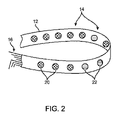
電極キャリアシステム10の1つの変形例として、図2は、電極14がそれぞれ、視覚または触覚インジケータを含み、ユーザに、皮膚表面との十分な電極接続が達成されたというフィードバックを提供するように構成され得る、斜視図を図示する。例えば、各電極14は、コントローラおよび/または出力デバイス18が、特定の電極14において、例えば、5kΩ等の比較的低いインピーダンスを検出するとき、その電極が、電極14と下層皮膚との間に十分な電気接触が達成されたことを示すために作動され得るように、インピーダンスセンサおよびインジケータを組み込んでもよい。
As an example of one modification of the
図2は、電極14がそれぞれまた、1つまたは複数の発光ダイオード(LED)等の視覚インジケータを組み込み得る、1つの実施例を示す。十分な電気接触が達成されるとき、特定の電極14上のLEDは、例えば、緑等の第1の色20の光を放射してもよいが、電極14が十分な電気接触を達成していない場合、これは、例えば、赤等の第2の色22の光を放射してもよい。代替として、十分な接触が、LEDの定常照度によって示され、不十分な接触が、点滅するLEDよって示され得る、単一色LEDが使用されてもよい。他の変形例では、電極は、例えば、圧電トランスデューサ、モータに結合される偏心性に装填された加重等を含み、電極14が、下層皮膚と十分な電気接触を有しているかどうかを示すために、振動または他の触覚応答を提供してもよい。この様式で、電極14は、別個のコントローラまたはインジケータを再視認する必要なく、電気接触の直接的なインジケーションを効率的に提供し得る。
FIG. 2 shows one embodiment in which each of the
ここで、電極構成に目を向けると、図3は、電極32Aおよび32Bが、伝導性ゲルまたは流体で事前に充填されるリザーバ内に封入され得る、電極キャリアシステム35の1つの変形例の断面詳細側面図を図示する。各電極38A、38Bは、個別のリザーバ30A、30B内に含有される、平坦または非外傷性構成に構成されてもよく、各リザーバ30A、30Bは、容易に圧潰することができる、例えば、シリコーン、ポリウレタン、ゴム等の任意の数の可撓性材料から形成されてもよい。電極38A、38Bは、基板36によって電極から分離された基材12を通して画定される管腔34を通過する伝導性ワイヤ16を介して結合されてもよい。各リザーバ30A、30Bはまた、それぞれ、それを通して伝導性ゲルまたは流体が排出され得る1つまたは複数の開口部32A、32Bを画定してもよい。
Now looking at the electrode configuration, FIG. 3 shows a cross section of one variant of the
いったんプラットフォーム12が、患者の頭部Hにわたって据え付けられると、ユーザは、伝導性流体またはゲル40A、40Bが、開口部32A、32Bを通して患者Pの皮膚の上に流動するように、リザーバ30A、30Bのそれぞれの上に押圧してもよい。開口部を通して排出される伝導性流体またはゲル40A、40Bは、検出される電気信号が、皮膚から電極38A、38Bに伝送され得るように、皮膚表面と個別の電極38A、38Bとの間の流体連通を維持してもよい。そのうえ、リザーバ30A、30Bの可撓性のために、いったん伝導性流体またはゲル40A、40Bが、皮膚表面と接触するように排出されると、基材12は、依然として、電極38A、38Bとの電気接触を維持しながら、患者Pが表面上に頭部を快適に横たえ得るように、皮膚表面に対して平坦な状態に置かれてもよい。
Once the
図4は、対の電極アセンブリ50A、50Bが、皮膚表面に対して容易に屈曲または撓曲することが可能である、伝導性ワイヤまたはリボン51A、51Bの1つまたは複数のループを含み得る、別の電極キャリアシステム35の側面図を示す。電極アセンブリ50A、50Bのいくつかまたは全ては、伝導性流体またはゲル52A、52Bが、1つまたは複数のループの周囲およびその中に排出され、ループと頭皮との間の伝導性経路を確実にし得るように、上記の通り、ワイヤまたはリボン電極51A、51Bのそれぞれの周囲に伝導性流体またはゲル52A、52Bを含有するための圧力解放リザーバ(破線53Aおよび53Bで示される)を含んでもよい。代替として、圧力解放リザーバを使用するのではなく、患者の皮膚表面に対する設置に先立って、ある量の伝導性流体またはゲルが、単に、電極アセンブリ50A、50Bの上に設置されてもよい。ワイヤまたはリボン電極51A、51Bはそれぞれ、伝導性ワイヤ16を介して電気的に接続されてもよく、ワイヤまたはリボン電極51A、51Bは、好ましくは、細い直径または幅を有するであろうため、それらが屈曲または撓曲するときでさえ、それらは、患者の毛髪を容易に通過し、頭皮表面と接触し得る。
FIG. 4 may include one or more loops of conductive wire or
図5は、そのそれぞれが、基材12の内部表面(患者の頭皮に接触する表面)から垂直またはある角度で延在し得る1つまたは複数の管状部材60A、60Bを含み得る、複数の電極アセンブリ58Aおよび58Bを有する電極キャリアシステム56の別の変形例の側面図を示す。管状部材60A、60Bは、各遠位端において画定される開口部62A、62Bを伴う、それを通る管腔を画定してもよい。管状部材60A、60Bはそれぞれ、使用時にその管状形状を保定し得る、または患者の皮膚表面に対して設置されるとき、屈曲または撓曲するために十分に薄くかつ可撓性であり得る、伝導性金属から加工されてもよい。代替として、管状部材60A、60Bは、部材がその可撓性を保定するように、伝導性材料でコーティングまたは層形成される可撓性材料から加工されてもよい。いずれの場合でも、伝導性流体またはゲル64A、64Bは、管状部材60A、60B内に含有されるか、または、上記の通り、但し、図5に示されない、各電極の周囲もしくは近接する圧力解放リザーバ内に保定されるかのいずれかであってもよい。電極の管状形状のために、それらは、電気接触を維持しながら、存在する場合、患者の毛髪を容易に通過し、皮膚表面に対して接触し得る。管状部材60A、60Bは、示されるように、縦に並んだ対に配列されてもよく、または、単一の電極アセンブリ58A、58B内に3つ、4つ、またはそれよりも多い管状部材があるとき、三角形、長方形、または円形のパターンに配列されてもよい。
FIG. 5 shows a plurality of electrodes, each of which may include one or more
図6A-6Cを参照すると、電極キャリアシステム68のさらなる実施形態は、伝導性流体またはゲル74で充填される圧力解放リザーバ70を含む。リザーバ70は、例えば、シリコーン、ポリウレタン、ゴム等の可撓性材料から形成されてもよく、基材12から延在し、リザーバ70の内部にわたって画定される1つまたは複数の開口部72を伴う、湾曲されるまたは弓形の構造を形成する。これらの開口部72は、典型的には、力Fが、リザーバ70および/または基材12に印加され、図6Bに示されるように、リザーバの内部内に含有される電気伝導性流体またはゲル74を、開口部72を通して逃散させ、リザーバ70の外部表面に接触させ、かつ下層皮膚表面への電気伝導性経路を形成させるまで、閉鎖された状態にある。伝導性材料76の層は、伝導性ワイヤ16に電気的に結合され、リザーバ70の外部表面の一部または全体にわたって形成されてもよい。皮膚表面との電気接触は、図6Bに示されるように、基材12またはリザーバ76に力Fを印加することによって、達成され、図6Cに示されるように、リザーバ70の内部から外に、かつ伝導性材料76および皮膚の上に流体またはゲル74を押出または別様に解放し、開口部72は、力Fが除去された後、その閉鎖された状態に戻り得る。
With reference to FIGS. 6A-6C, a further embodiment of the
図7A-7Bを参照すると、電極キャリアシステム78のさらなる実施形態は、その下側表面から延在する1つまたは複数の管状部材84を担持する電極本体80を有する、電極アセンブリ79を含む。管状部材84は、基材12の平面から離れるように垂直に突出する。いくつかの実施形態では、電極本体80は、少なくとも部分的に、堅性または可撓性の金属等の伝導性材料、および/または伝導性シリコーン等の伝導性ポリマーから形成されるであろう。他の実施形態では、電極本体80は、少なくとも部分的に、少なくとも管状部材84が、その可撓性を保定しながら電気伝導性であるように、伝導性材料でコーティングまたは層形成され得る、例えば、シリコーン、ポリウレタン、ゴム等の非伝導性可撓性材料から形成されるであろう。伝導性のために、電極本体80および管状部材84は、伝導性ワイヤまたはリボンに電気的に直接結合されてもよい。
Referring to FIGS. 7A-7B, a further embodiment of the
両方の場合において、電極本体80は、例えば、図1に示されるように、基材が頭部にわたって設置されるとき、管状部材84が患者の頭皮に接触することができるように、管状部材84が基材内の開口部を通して延在するように、基材12に固着されてもよい。電気伝導性流体またはゲル88は、電極本体80の内部リザーバ86内に含有され、図7B内の矢印によって示されるように、電極本体の可撓性上面上を押圧することによって、管状部材内の通路を通して送達されることができる。
In both cases, the
管状部材84は、一様または任意のパターンであって、概して、図7Aおよび7Bに図示されるように、円形のパターンで配列されてもよい。基材12が、患者に固着された後、リザーバ86は、その中に含有される流体またはゲル88が、管状部材84のそれぞれの長さに沿った中心通路を通して排出され、対応する遠位開口部を通して下層皮膚表面に対して接触するように、押圧または押勢されてもよい。部材84は、典型的には、例えば、1~2cmの範囲内の長さを有するように伸長され、存在する場合、容易に患者の毛髪を通して通過し、皮膚表面に対して直接接触し得るであろう。そのうえ、例えば、患者がその頭部を下に横たえるとき等、管状部材84が、圧潰または変形された構成にあるときでさえ、管状部材84および本体80は、下層皮膚表面からの電気信号を伝導し続けてもよい。
The
ここで図8を参照すると、電極キャリアシステム89のなおもさらなる実施形態は、その表面にわたって1つまたは複数の開口部96を画定し得る、管状本体90を含む。管状本体90は、基材12から離れるように渦巻または螺旋状のパターンで延在する、1つまたは複数の管状部材92を有してもよい。1つまたは複数の管状部材92はそれぞれ、管状本体90の底部からその先端における遠位開口部94に延在する、それを通る管腔を画定してもよい。基材12はさらに、本体90が、リザーバ100と流体連通するように、伝導性流体またはゲル102の体積を含有するリザーバ100を画定してもよい。対向壁104A、104Bは、リザーバを封入してもよく、壁104A、104Bの一方または両方は、圧搾または別様に管状本体90に向かって平行移動されてもよい。代替として、または加えて、本体90は、98によって示されるように、本体90および部材92が、その縦軸を中心に回転され、伝導性流体またはゲル102を分散させ、皮膚を剥離し、電気伝導性管状部材92と頭皮との間の電気接触を助長するように、基材12に回転可能に固着されてもよい。
Referring now to FIG. 8, a still further embodiment of the
加えて、および/または代替として、部材92の遠位先端94は、皮膚に接触するための粗面化された表面を呈してもよい。随意に粗面化された先端は、ユーザによって、皮膚表面上で回転され、少なくとも部分的に皮膚表面を剥離し、電気接触を促進させてもよい。
In addition and / or as an alternative, the distal tip 94 of the
使用時、いったん基材12が、患者の頭部に固着されると、管状本体90は、部材92が、患者の頭皮上に存在し得るいかなる毛髪の中にかつそれを通しても前進されるように、ユーザによって手動で回転されてもよい。いったん遠位先端の開口部94が、皮膚表面と接触またはそれに近接するように位置付けられると、伝導性流体またはゲル102が、開口部96を介して管状本体90の内部内に導入されるように、壁104A、104Bの一方または両方が、ユーザによって、例えば、圧搾される等、作動されてもよい。伝導性流体またはゲル102は、管状本体90の中に、部材92内に、開口部94を通して外に流動し、かつ皮膚表面上に接触してもよい。
In use, once the
上記の通り、管状本体90および/または部材92は、下層管状部材90および/または部材92がその可撓性を保定するように、伝導性材料でコーティングまたは層形成され得る、例えば、また、伝導性シリコーン等の可撓性である伝導性材料、および/または例えば、シリコーン、ポリウレタン、ゴム等の可撓性材料から加工されてもよい。伝導性のために、電極本体90は、伝導性ワイヤまたはリボンに電気的に直接結合されてもよい。さらに、管状本体90および/または部材92が、随意に可撓性構成を有するとき、部材92が、下層皮膚表面との電気伝導性を保定しながらそれ自体の上で圧潰してもよい。
As described above, the
ここで、本発明の他の側面に目を向けると、電極キャリアシステムはまた、視覚運動追跡または加速度計のいずれか一方を採用する、患者運動追跡等の他の用途のために利用されてもよい。 Now looking at other aspects of the invention, the electrode carrier system may also be utilized for other applications such as patient motion tracking, which employs either visual motion tracking or accelerometers. good.
さらなる実施形態では、電極キャリアシステムは、図9に図示されるように、ヘッドバンドとして構成され、患者P上に嵌合されてもよい。電極キャリアシステムは、伝導性ワイヤ114を介してコントローラおよび/または出力デバイス112と電気通信する。他の変形例では、本デバイス112は、そのうえ、無線で結合されてもよい。電極アセンブリ14は、本明細書に説明される電極アセンブリ変形例のいずれか、および、そのように所望される場合、任意の数の組み合わせを組み込んでもよい。図9に図示される実施形態では、ヘッドバンド基材12はさらに、カメラまたは他の光学撮像器116の視野内で、これらのマーカ110A、110Bの視覚追跡を可能にする、1つまたは複数の位置合わせマーカ110A、110Bを組み込んでもよい。マーカ110A、110Bは、示されるように、規定される形状を有する高コントラスト印刷パターンとして本変形例に示される、任意の種々の視覚インジケータを含んでもよい。他の変形例では、位置合わせマーカ110A、110Bは、LEDの配列等の光を含んでもよい。
In a further embodiment, the electrode carrier system may be configured as a headband and fitted onto the patient P, as illustrated in FIG. The electrode carrier system telecommunicationss with the controller and / or
2つのマーカが、実施例として図示されるが、付加的なマーカがさらに、基材12の円周の周囲に分散され、例えば、患者の頭部Hが、マーカの1つを隠蔽する様式で向けられ得るとき、追跡を可能にするなど、さらに精密な追跡を可能にしてもよい。記載されるように、デジタル等のカメラまたは他の光学撮像器116が、電極キャリアシステム10およびマーカ110A、110Bが、撮像器116の視野118内に留まるように、電極キャリアシステム10の使用の間、患者Pに近接して位置付けられてもよい。単一の撮像器116が、本実施例に示されるが、異なる場所において位置付けられる付加的な撮像もまた、組み合わせにおいて使用され、電極キャリアシステム10およびマーカ110A、110Bが、常時視野118内に留まることを確実にするために役立ってもよい。加えて、撮像器116は、随意に、患者Pが、撮像器116の視野118内に留まることを確実にするために、パンおよびチルト能力を伴い動力化されてもよい。
Two markers are illustrated as examples, but additional markers are further dispersed around the circumference of the
コントローラおよび/または出力デバイス112に電気的に結合される電極キャリアシステム10を用いて、撮像器116はまた、ワイヤもしくは別の通信リンク120によって、コントローラおよび/または出力デバイス112に、または有線もしくは無線の通信を通して、第2のコントローラおよび/または出力デバイスに接続されてもよい。この様式で、コントローラ120はさらに、コンピュータビジョンアルゴリズムを用いてプログラムされ、コントローラが、撮像器116からマーカ情報を受信し、患者移動をリアルタイムで判定し得るように、患者の頭部Hの位置および配向を識別してもよい。この情報は、次いで、アーチファクト除去および診断の目的のために使用されることができる。例えば、マーカ110A、110Bの視覚追跡は、特に、患者の検出される脳信号が、超音波処理される場合、患者Pが、痙攣発作を被っているかどうかを判定または確認するために使用されてもよい。
With the
さらに別の変形例では、視覚マーカの代わりとして、図10に示されるように、電極キャリアシステム10は、基材12の中にまたはそれに沿って取り付けられる、1つまたは複数の加速度計130を組み込んでもよい。1つまたは複数の加速度計130は、患者の頭部の移動を検出するために十分に敏感な3軸加速度計デバイスを備えてもよい。このデータは、患者の移動ならびにモーションアーチファクト除去を判定するための処理のために、伝導性ワイヤ134を介してコントローラおよび/または出力デバイス132に伝送されることができる。検出される加速が、事前判定された閾値を超過する場合、他の検出されるデータからのアーチファクト雑音包含を防止することを考慮して、これは、これらのモーションアーチファクトが除外されてもよいことのコントローラに対するインジケータとなり得る。
In yet another variant, as an alternative to the visual marker, the
電極キャリアシステム10は、本明細書に説明される電極の任意の組み合わせを用いて利用されてもよく、また、光学運動検出または加速度計監視のいずれか一方との任意の組み合わせにおいて使用されてもよい。他の変形例では、光学運動検出および加速度計監視は両方とも、そのように所望される場合、ともに組み合わせられて利用されてもよい。
The
ここで図11を参照すると、本発明の原理によって構成される電極キャリアシステム200は、典型的には、その長さに沿って分散される複数の電極アセンブリ202を有する、ヘッドバンドまたは他のヘッドギアの形態の伸長基材204を含む。伸長基材204は、典型的には、前述の図1に示されるように、概して、伸長基材が、患者の頭部にわたって設置されるとき、調節可能に取り付けられ得る重複端部206を有するであろう。重複端部は、Velcro(登録商標)フックおよびループ締結具を用いて等、任意の従来の方法を使用して取り付けられてもよい。
Referring now to FIG. 11, an
電極アセンブリ202は、好ましくは、伸長基材が、頭皮にわたって設置された後、患者の皮膚が、優しく摩滅され得るように、矢印208によって示されるように、ユーザが、手動でそれらを交互に回転させることができるように、回転可能に搭載される。特に、本所および以下にさらに詳細に説明されるであろうように、電気伝導性流体またはゲルを分注するステップの直前にそのような手動の摩滅を実施することが、望ましいであろう。他の事例では、摩滅は、電気伝導性流体またはゲルを分注しながら、および/または電気伝導性流体またはゲルを分注した後に、実施されることができる。
The
ここで図12-15を参照すると、電極アセンブリ202は、典型的には、下側本体部分、すなわち、基部210と、上側本体部分、すなわち、キャップ212と、下側本体部分の底部表面244から下向きに下垂する、1つまたは複数の管状部材214とを含むであろう。プランジャ216が、開口部222を通して上側本体部分212内のチャンバ224に進入するように構成される。カートリッジまたは密封された分注容器220等の密封された分注容器は、電気伝導性流体またはゲルを保持し、プランジャ216が、上側本体部分212から容易に外向きに延在する、すなわち、その非押下構成にある間、チャンバ224内に拘束されるように構成される。
With reference to FIG. 12-15, the
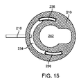
いったん密封された分注容器220が、チャンバ224内に設置されると、プランジャ216は、前縁228が、密封された分注容器の片側に隣接するように位置付けられることができる。プランジャ216を矢印217の方向に押下することによって、密封された分注容器220内の電気伝導性流体またはゲルは、加圧され、容器の一部に分注孔226を通過させるであろう。付加的な圧力が、プランジャ216を用いて印加されるにつれて、図14および16におけるように、分注孔226内のチャンバの部分が、破裂し、電気伝導性流体またはゲルを、上側本体部分212内の垂直通路232の中に流動させるであろう。図15および16に図示されるように、電気的に伝導される流体またはゲルは、次いで、電気伝導性端子218と接触し、電気伝導性流体またはゲルは、水平通路234を通してプロング214内の垂直管腔238上に流動し続けるであろう。
Once the sealed
垂直管腔238を通して流動した後、流体またはゲルは、それが、患者組織に流動し、プロングの下側表面240と接触し得るように、プロング214の底部内に形成されるチャネル240を通して外向きに流動するであろう。完全を期すために、下側本体部分、すなわち、基部210は、製造のアーチファクトであり、かつ本デバイス内の流体流において直接的役割を果たさない、中空内部242を有することに留意されたい。
After flowing through the
いったん垂直通路232からプロング214の下側表面内のチャネル238を通した全体流路が、電気伝導性流体またはゲルで充填されると、流体またはゲルの領域内に存在する生物学上の電流が、次いで、電極キャリアシステム200の基材204内に存在するワイヤまたは他の導体230に接続される、電気伝導性端子218に伝導されるであろうことが理解されるであろう。完全を期すために、ワイヤ230または他の導体の電気伝導性端子218への取付は、矢印208および図11によって示されるように、伸長基材204に対する電極アセンブリの回転に適応することができるような方式で成されるであろうことに留意されたい。
Once the entire flow path from the
ここで図17-27を参照すると、本発明の電極アセンブリの下側本体部分に関する種々の異なる構成が、説明されるであろう。図17および18は、前述の図12-15に関連して示される、下側本体部分210を図示する。図17および18の詳細図は、対のプロング214が、下側本体部分210の下側表面244上に形成されることを示す。図18に最も詳細に示されるように、プロング214は、概して、その下側表面240上に形成される湾曲されるチャネルを伴う、三日月または弓形形状を有する。しかしながら、プロング214の曲線または円弧は、下側本体部分210の円形周辺と同心ではない。代わりに、プロング214の円弧は、下側本体部分210の底部244上に非同心円状に位置付けられる。このように、プロングの垂直管腔236から進入するゲルは、前述で議論されたように、電極アセンブリ202が、交互に回転されるにつれて、それが、プロングの下側表面240によって分散されるであろうように、組織から分注されるであろう。したがって、プロングのこの非対称は、電気伝導性流体またはゲルが、垂直管腔236および弓形チャネル238を通して分注されるにつれて、その分布を助長するために役立つであろう。
With reference to FIGS. 17-27, various different configurations of the lower body portion of the electrode assembly of the present invention will be described. 17 and 18 illustrate the
代替実施形態では、下側本体部分、すなわち、基部260は、図19および20に図示されるように、底部268を中心として同心円状かつ均一に分散される、3つのプロング262を有する。したがって、垂直管腔264を通して送達され、かつ各プロングの下側表面270内に形成されるチャネル266を通して分散される、電気伝導性流体ゲルは、ゲルにわたる下側表面の通路によってさらには分散されないであろう。しかしながら、3つのプロングの存在は、確実な電気接続をさらに助長するであろう。
In an alternative embodiment, the lower body portion, i.e. the
ここで図21を参照すると、下側本体部分280の付加的な実施形態は、その下側表面284内に単一の洗浄ポート282を有する、2つの対称的なプロング286を含む。しかしながら、それぞれ、その中に洗浄ポート98を有する下側表面294を具備する、3つのプロング296を有する類似した下側本体部分290はさらに、典型的には、小さいバンプの形態の、複数の表面特徴292を含み、これは、ポート298を通して分散されている電気伝導性流体またはゲルを分散するために役立つ。
Referring now to FIG. 21, an additional embodiment of the
3つの対称的なプロング306を有する下側本体部分、すなわち、基部300のさらなる実施形態が、図示される。各プロング306は、その上に形成される複数の表面特徴302を伴う下側表面304を有する。従来の実施形態と同様に、プロングはそれぞれ、電気伝導性流体またはゲルを送達および分散するために、下側表面内に形成されるチャネル310への垂直管腔308の開口部を有する。
A further embodiment of the lower body portion having three
本発明の電極アセンブリの底部部分のなおもさらなる代替実施形態が、図24から27に示される。その中にポート形態のチャネルを伴う各プロング上に単一の下側表面を有する代わりに、これらの下側本体部分は、電気伝導性流体またはゲルを送達するための陥凹を伴う下側表面を有する。図24に示されるように、底部部分320は、その底部から延在する、対称的に設置される3つのプロング322を含む。プロングはそれぞれ、下側表面224を有するが、流体またはゲル送達ポート328が、プロングの陥凹表面内に形成される。
Still further alternative embodiments of the bottom portion of the electrode assembly of the present invention are shown in FIGS. 24-27. Instead of having a single lower surface on each prong with a channel in the form of a port therein, these lower body parts have a lower surface with a recess for delivering an electrically conductive fluid or gel. Has. As shown in FIG. 24, the
図25は、各プロングの下側表面344が、複数の表面特徴342を備える3つの非対照的なプロング342を有する、類似の底部部分340を示す。
FIG. 25 shows a
図26に図示されるように、代替の下側本体部分360は、その中にポート366を伴う隣接するゲルまたは流体送達管364を有する、プロング362を備える。プロング362は、表面特徴のない略平坦な下側表面を有する。
As illustrated in FIG. 26, the alternative
図27では、下側本体部分380は、下側本体部分360と同様に、隣接する流体送達管を有する3つのプロング386を含む。各プロング386の下側表面384は、表面特徴382を含む。
In FIG. 27, the
ここで図28A-28Cを参照すると、電極アセンブリ400は、上側部分、すなわち、キャップ402と、下側部分、すなわち、基部404とを備える。概して、前述の実施形態に関して説明されたように、プランジャ406は、キャップ402の壁を通して往復動可能に受容され、リザーバ412の中に延在する。しかしながら、前述の実施形態と対照的に、電極アセンブリ400の下側部分、すなわち、基部404は、図28Bおよび28Cに最も詳細に示されるように、平坦な底部表面408を有する。その下側部分の底部表面上に管状および他の突出部材のない電極アセンブリ400は、特に、患者の額等の毛髪のない組織表面に対する係合のために有用である。上記の通り、本発明の管状部材は、特に、電気接触が、頭皮上に存在する患者の毛髪を通して成されることを可能にすることが意図されることが、理解されるであろう。ヘッドバンド、例えば、図11内のヘッドバンド206が、患者の頭蓋骨に外接するにつれて、電極アセンブリ202の少なくともいくつかが、毛髪の殆どまたは全くない患者の額に対して係合されるであろう。そのような事例では、額に係合するこれらの電極アセンブリは、図28A-28Cに図示されるように、管状部材なしで作製されることができる。
With reference to FIGS. 28A-28C, the
前述の実施形態と同様に、電極アセンブリ400のリザーバ412は、その中に電気伝導性ゲルまたは他の流体を保持する、カプセルまたは他の密封される容器を有してもよい。代替として、ゲルは、例えば、プランジャ406内にポート424を有する通路422を通した注入によって、リザーバの中に導入される等、リザーバ412内に拘束されていなくてもよい。プランジャ406が、押下されるにつれて、リザーバ412内のゲル(カプセル化または拘束されない状態のいずれか)上の圧力は、ゲルを下向きに、垂直通路414を通して、かつ底部ポート416を通して外に、底部表面408内に形成されるスロット410の中に流動させるであろう。ゲルまたは他の電気伝導性流体は、スロットの中に分散し、下側部分、すなわち、基部404の壁内の孔418を通過する、電気伝導性端子420と電気伝導性経路を形成することができるであろう。したがって、生物学的電気信号は、電流が、電気伝導性端子420に伝わるように、患者の皮膚を通してスロット410内の電気伝導性ゲルの中に結合されてもよい。随意に、底部表面408が、修正され、電極アセンブリの他の実施形態に関連して本明細書の他所に説明される方法のいずれかによって、電気伝導性を向上させてもよい。
Similar to the embodiments described above, the
ここで図29A-29Cを参照すると、本発明の原理によって構成される電極アセンブリ430は、上側部分、すなわち、キャップ432と、下側部分、すなわち、基部434とを備える。管状部材、すなわち、プローブ436は、下向きに、下側部分、すなわち、基部434の底部表面から突出し、チャンバ440が、下側部分、すなわち、基部内に形成され、上側部分、すなわち、キャップ432内の垂直通路438を通して電気伝導性ゲルまたは他の流体を受容する。電極アセンブリ430が、本明細書に説明される他の実施形態と同様に、電気伝導性ゲルを送達するためのプランジャを含まないことが、理解されるであろう。
Referring here to FIGS. 29A-29C, the
電気伝導性ゲルまたは他の流体は、ゲルが、最初に、チャンバ44の中に、次いで、管状部材、すなわち、プローブ436を通して形成される垂直送達通路442を通して流動するように、垂直通路438を通して注入されてもよい。電気伝導性ゲルまたは他の流体は、したがって、それが、下側部分、すなわち、基部434を通してチャンバ440の中に通る、皮膚から電気伝導性端子またはピン452への電気的経路を形成することができるように、患者の皮膚上に流動し得るであろう。
The electrically conductive gel or other fluid is injected through the
電極アセンブリ430は、下側鳩目444と、随意に、鳩目446との中に搭載される。単一の鳩目444は、図29Bに示されるように、接着剤、ステープル、ピン、または同等物を使用して、ヘッドバンド445に接続されることができる。代替として、ヘッドバンド445は、図29Cに示されるように、上側および下側の鳩目444と446との間に狭入されてもよい。そのような事例では、鳩目の少なくとも1つは、スロット448を含み、電気伝導性端子452を受容し、電極アセンブリが、鳩目444および446内で回転されることを可能にするであろう。本明細書の他所に説明されるように、スロットは、電極アセンブリが回転される間、電気伝導性端子452が、移動し、皮膚への電気接触を向上させることを可能にする。
The
さらに別の実施形態では、本発明の原理によって構成される電極アセンブリ460は、図30A-30Cに図示されるように、下側部分、すなわち、基部464に固着される、上側部分、すなわち、キャップ462を備える。単一の管状部材466は、下向きに、下側部分、すなわち、基部464の底部表面465から突出する。垂直通路、すなわち、ポート468は、上側、すなわち、導入ポート470から、上側および下側部分を通して延在し、電気伝導性ゲルまたは他の流体の導入を可能にする。単一の管状部材466の下側表面は、本明細書の他所に説明されるように、概して、いくつかの表面特徴472を備え、電気伝導性ゲルまたは他の流体の垂直通路468を通した導入の前、間、または後に、表面処理または組織の摩滅を可能にする。
In yet another embodiment, the
電極アセンブリ460は、上側部分、すなわち、キャップ462の下側表面と下側部分、すなわち、基部464上のフランジ469との間に形成されるチャネル467が、板474の壁を受容し、板に対する電極アセンブリの回転を可能にするように、典型的には、開口部を通して、板、すなわち、バックル474内に設置されることができる。電気伝導性端子476は、それが、垂直通路468を通過する電気伝導性ゲルまたは他の流体と電気的に接触し、単一の管状部材466の下側表面によって接触される組織と電気伝導性経路を形成するために、下側部分、すなわち、基部464の壁を通過する。電気伝導性端子476は、端子の両側の矢印によって示されるように、バックル、すなわち、板474の下側表面上の切欠領域478内で自由に移動することができる。バックル474は、バックルが、ストラップに取り付けられ、他の類似構造にバックルを継合させることによってヘッドバンドを形成することを可能にする、側面ループ、すなわち、切欠480を含む。
In the
ここで図31Aおよび31Bを参照すると、本発明の原理によって構成される、なおもさらなる電極アセンブリ482は、上側部分484と、下側部分486とを備える。電極アセンブリ482は、スロット494内で図31Aに示される矢印の方向に自由に摺動するように、バックル、すなわち、板構造492内に受容される。電極アセンブリ482は、電気伝導性ゲルまたは他の流体を受容し、その流体を下側部分486の下側表面上の表面特徴490のアレイ内に位置する下側ポート488を通して分散させるための、ポート498を有する。このように、電極アセンブリ482が、患者の皮膚に対して係合された後、本明細書の他所にさらに詳細に説明されるように、典型的には、ヘッドバンドの一部として、電極は、バックル492およびヘッドバンドに対して交互に平行移動され、皮膚表面を処理し、電気伝導性を向上させる。バックル、すなわち、板492は、両側にスロット496を含み、ヘッドバンドアセンブリへの取付を促進する。
With reference to FIGS. 31A and 31B, an
以下の付番された段落はさらに、本発明を説明する。
31. 患者の頭皮上に複数の電極を設置するための方法であって、
患者の頭皮の周囲にヘッドバンドを設置するステップであって、該ヘッドバンドは、複数の電極アセンブリを担持する、ステップと、
頭皮組織に対して、電極アセンブリの少なくともいくつかから延在する、1つまたは複数の管状部材の遠位先端を係合させるステップと、
伝導性流体またはゲルを、電極アセンブリの少なくともいくつかの中に配置されるリザーバから、これらの電極アセンブリの管状部材を通して押出し、患者の頭皮組織への電気伝導性経路を形成するステップと、
複数の電極アセンブリを、電極アセンブリから低電力の生物学的電流を受信するように構成される、コントローラおよび/または出力デバイスに接続するステップと、
を含む、方法。
32. 管状部材の少なくともいくつかの遠位先端は、患者の頭皮上の毛髪を通して位置付けられる、請求項31に記載の方法。
33. 複数の電極アセンブリの少なくともいくつかを移動させ、該1つまたは複数の管状部材の遠位先端に隣接する頭皮組織を摩耗させ、電極アセンブリと頭皮組織との間の接触抵抗を降下させるステップをさらに含む、請求項31に記載の方法。
34. 管状部材の少なくともいくつかの遠位先端は、皮膚調製表面を画定する、請求項33に記載の方法。
35. 伝導性流体またはゲルは、リザーバから、管状部材内の管腔を通して、かつ管状部材の遠位先端上の遠位開口部から外に、頭皮組織の上に押出される、請求項31に記載の方法。
36. 伝導性流体またはゲルは、管状部材の遠位先端上の溝から外に押出される、請求項35に記載の方法。
37. リザーバから伝導性流体またはゲルを押出するステップは、伝導性流体またはゲルを保持する密封された分注容器に外部圧力を手動で印加するステップを含み、密封された分注容器は、電極アセンブリの中に組み込まれる、請求項31に記載の方法。
38. 密封された分注容器に外部圧力を印加するステップは、プランジャを押圧し、伝導性流体またはゲルを担持する、破裂可能な密封された分注容器に係合させるステップを含む、請求項37に記載の方法。
39. 密封された分注容器に外部圧力を印加するステップは、管を手動で圧搾するステップと、注射器プランジャを手動で押下するステップと、圧搾管を回転させるステップとを含む、請求項37に記載の方法。
40. 患者の頭皮組織への電気伝導性経路は、伝導性流体またはゲル単独によって、形成される、請求項31に記載の方法。
41. 患者の頭皮組織への電気伝導性経路は、少なくとも部分的に、管状部材上の電気伝導性構造によって形成される、請求項31に記載の方法。
42. 患者監視システムであって、
皮膚表面に接触するために構成される、1つまたは複数の電極と、
患者の身体に固着可能であり、かつ皮膚表面に対して1つまたは複数の電極を維持するように構成される、基材と、
基材に取り付けられる、少なくとも1つの運動検出装置と、
1つまたは複数の電極からの電気データおよび少なくとも1つの運動検出装置に関連される運動データを受信するためのコントローラであって、コントローラは、電気データおよび運動データを処理するようにプログラムされる、コントローラと、
を備える、システム。
43. 1つまたは複数の電極はそれぞれ、少なくとも部分的に電気伝導性である電極本体を備え、1つまたは複数の管状部材は、電極本体から延在し、1つまたは複数の管状部材はそれぞれ、それを通る管腔および遠位開口部を画定する、請求項42に記載のシステム。
44. 圧縮可能な構造を有し、かつ1つまたは複数の管状部材と流体連通する伝導性流体またはゲルを含有する、リザーバをさらに備える、請求項43に記載のシステム。
45. 基材は、患者の頭部上への設置のためのヘッドバンドとして構成される、請求項42に記載のシステム。
46. 少なくとも1つの運動検出装置は、1つまたは複数の位置合わせマーカを備える、請求項42に記載のシステム。
47. 1つまたは複数の位置合わせマーカを撮像するように構成される、撮像装置をさらに備える、請求項46に記載のシステム。
49. 撮像装置は、カメラを備える、請求項47に記載のシステム。
50. 撮像装置は、コントローラと通信する、請求項46に記載のシステム。
51. 少なくとも1つの運動検出装置は、1つまたは複数の加速度計を備える、請求項42に記載のシステム。
The following numbered paragraphs further describe the invention.
31. A method for placing multiple electrodes on the patient's scalp,
A step of placing a headband around the patient's scalp, wherein the headband carries multiple electrode assemblies.
With the step of engaging the distal tip of one or more tubular members with the scalp tissue, extending from at least some of the electrode assemblies.
A step of extruding a conductive fluid or gel from a reservoir located in at least some of the electrode assemblies through the tubular members of these electrode assemblies to form an electrically conductive pathway to the patient's scalp tissue.
With the step of connecting multiple electrode assemblies to a controller and / or output device configured to receive low power biological currents from the electrode assemblies.
Including methods.
32. 31. The method of claim 31, wherein at least some distal tips of the tubular member are positioned through the hair on the patient's scalp.
33. Further steps are taken to move at least some of the electrode assemblies, wear the scalp tissue adjacent to the distal tip of the one or more tubular members, and reduce the contact resistance between the electrode assembly and the scalp tissue. 31. The method of claim 31.
34. 33. The method of claim 33, wherein at least some distal tips of the tubular member define a skin preparation surface.
35. 31. The conductive fluid or gel is extruded from the reservoir through a lumen within the tubular member and out of a distal opening on the distal tip of the tubular member onto the scalp tissue. Method.
36. 35. The method of
37. The step of extruding the conductive fluid or gel from the reservoir involves manually applying external pressure to the sealed dispensing container that holds the conductive fluid or gel, and the sealed dispensing container is of the electrode assembly. 31. The method of claim 31, which is incorporated therein.
38. 37. The step of applying external pressure to a sealed dispensing container comprises the step of pressing a plunger and engaging it with a burstable sealed dispensing container carrying a conductive fluid or gel. The method described.
39. 37. The step of applying external pressure to a sealed dispensing container comprises manually squeezing the tube, manually pressing the syringe plunger, and rotating the squeezing tube. Method.
40. 31. The method of claim 31, wherein the electrically conductive pathway to the patient's scalp tissue is formed by a conductive fluid or gel alone.
41. 31. The method of claim 31, wherein the electrically conductive pathway to the patient's scalp tissue is formed, at least in part, by an electrically conductive structure on a tubular member.
42. It ’s a patient monitoring system.
With one or more electrodes configured to contact the skin surface,
With a substrate that is stickable to the patient's body and is configured to maintain one or more electrodes on the skin surface.
With at least one motion detector attached to the substrate,
A controller for receiving electrical data from one or more electrodes and motion data associated with at least one motion detector, the controller being programmed to process electrical and motion data. With the controller
The system.
43. Each one or more electrodes comprises an electrode body that is at least partially electrically conductive, one or more tubular members extending from the electrode body, and one or more tubular members each extending from the electrode body. 42. The system of claim 42, which defines a lumen and a distal opening through.
44. 43. The system of claim 43, further comprising a reservoir having a compressible structure and containing a conductive fluid or gel that communicates with one or more tubular members.
45. 42. The system of claim 42, wherein the substrate is configured as a headband for placement on the patient's head.
46. 42. The system of claim 42, wherein at least one motion detector comprises one or more alignment markers.
47. 46. The system of claim 46, further comprising an imaging apparatus configured to image one or more alignment markers.
49. The system according to claim 47, wherein the imaging device includes a camera.
50. The system according to claim 46, wherein the imaging device communicates with a controller.
51. 42. The system of claim 42, wherein the at least one motion detector comprises one or more accelerometers.
上記に議論される本デバイスおよび方法の用途は、患者の頭部上の電気感知に限定されないが、任意の数のさらなる治療用途を含んでもよい。そのうえ、そのようなデバイスおよび方法は、身体上の他の治療部位に適用されてもよい。本発明を実行するために上記で説明されたアセンブリおよび方法の修正、実践可能なものとしての異なる変形例間の組み合わせ、ならびに当業者に明白である、本発明の側面の変形例は、請求項の範囲内にあると意図される。
The applications of the devices and methods discussed above are not limited to electrical sensing on the patient's head, but may include any number of additional therapeutic applications. Moreover, such devices and methods may be applied to other therapeutic sites on the body. Modifications to the assemblies and methods described above to carry out the present invention, combinations between different variants as practicable, and variations of aspects of the invention that are apparent to those skilled in the art are claimed. Is intended to be within the range of.
Claims (29)
前記電極本体から延在し、遠位先端を有する1つまたは複数の管状部材であって、前記1つまたは複数の管状部材のうちの少なくともいくつかは、前記遠位先端内に遠位開口部を伴う管腔を有し、前記遠位開口部は、前記管状部材の下側表面内にある、1つまたは複数の管状部材と、
リザーバから前記管腔を通しておよび前記管状部材の前記遠位開口部から外に電気伝導性流体またはゲルを分注するための、前記電極本体上のアクチュエータと、
皮膚表面上に前記電気伝導性流体またはゲルを分散させるように構成されている、前記1つまたは複数の管状部材の組織接触表面にわたって延在するチャネルであって、前記1つまたは複数の管状部材の前記組織接触表面は、前記1つまたは複数の管状部材の前記下側表面に位置している、チャネルと
を備える電極アセンブリであって、前記1つまたは複数の管状部材の前記遠位先端は、皮膚調製表面を画定し、前記電極アセンブリは、前記電極アセンブリに結合される基材に対して回転可能であることにより、ユーザが、前記皮膚表面を調製しかつ電気接触を向上させるように前記アセンブリを移動させることを可能にする、電極アセンブリ。 With the electrode body
One or more tubular members extending from the electrode body and having a distal tip, at least some of the one or more tubular members having a distal opening within the distal tip. The distal opening is in the lower surface of the tubular member with one or more tubular members.
An actuator on the electrode body for dispensing an electrically conductive fluid or gel from the reservoir through the lumen and out of the distal opening of the tubular member.
A channel extending over the tissue contact surface of the one or more tubular members, which is configured to disperse the electrically conductive fluid or gel on the skin surface, the one or more tubular members . The tissue contact surface is an electrode assembly with a channel located on the inferior surface of the one or more tubular members, the distal tip of the one or more tubular members. The skin preparation surface is defined and the electrode assembly is rotatable with respect to a substrate bonded to the electrode assembly so that the user prepares the skin surface and improves electrical contact. An electrode assembly that allows the assembly to be moved.
患者の頭部上への設置のためのヘッドバンドとして構成される伸長基材と、
前記伸長基材の長さにわたって分散される、請求項1に記載の複数の電極アセンブリと、
各電極アセンブリに接続され、前記電極アセンブリからコントローラおよび/または出力デバイスに低電流の生物学的信号を送達する、少なくとも1つの電気伝導性ワイヤと
を備える、システム。 It is an electrode carrier system
An stretchable substrate configured as a headband for placement on the patient's head,
The plurality of electrode assemblies according to claim 1, which are dispersed over the length of the stretchable substrate.
A system including at least one electrically conductive wire that is connected to each electrode assembly and delivers a low current biological signal from the electrode assembly to a controller and / or output device.
Priority Applications (1)
| Application Number | Priority Date | Filing Date | Title |
|---|---|---|---|
| JP2022107639A JP2022126882A (en) | 2016-03-29 | 2022-07-04 | Electrode assembly and electrode carrier system |
Applications Claiming Priority (5)
| Application Number | Priority Date | Filing Date | Title |
|---|---|---|---|
| US201662314873P | 2016-03-29 | 2016-03-29 | |
| US62/314,873 | 2016-03-29 | ||
| US15/387,381 US9820670B2 (en) | 2016-03-29 | 2016-12-21 | Methods and apparatus for electrode placement and tracking |
| US15/387,381 | 2016-12-21 | ||
| PCT/US2017/024505 WO2017172742A1 (en) | 2016-03-29 | 2017-03-28 | Methods and apparatus for electrode placement and tracking |
Related Child Applications (1)
| Application Number | Title | Priority Date | Filing Date |
|---|---|---|---|
| JP2022107639A Division JP2022126882A (en) | 2016-03-29 | 2022-07-04 | Electrode assembly and electrode carrier system |
Publications (3)
| Publication Number | Publication Date |
|---|---|
| JP2019513069A JP2019513069A (en) | 2019-05-23 |
| JP2019513069A5 JP2019513069A5 (en) | 2020-05-07 |
| JP7104631B2 true JP7104631B2 (en) | 2022-07-21 |
Family
ID=59958472
Family Applications (2)
| Application Number | Title | Priority Date | Filing Date |
|---|---|---|---|
| JP2018551938A Active JP7104631B2 (en) | 2016-03-29 | 2017-03-28 | Electrode assembly and electrode carrier system |
| JP2022107639A Pending JP2022126882A (en) | 2016-03-29 | 2022-07-04 | Electrode assembly and electrode carrier system |
Family Applications After (1)
| Application Number | Title | Priority Date | Filing Date |
|---|---|---|---|
| JP2022107639A Pending JP2022126882A (en) | 2016-03-29 | 2022-07-04 | Electrode assembly and electrode carrier system |
Country Status (6)
| Country | Link |
|---|---|
| US (5) | US9820670B2 (en) |
| EP (2) | EP3435859B1 (en) |
| JP (2) | JP7104631B2 (en) |
| CN (2) | CN115944300A (en) |
| ES (1) | ES2950621T3 (en) |
| WO (1) | WO2017172742A1 (en) |
Families Citing this family (19)
| Publication number | Priority date | Publication date | Assignee | Title |
|---|---|---|---|---|
| US9820670B2 (en) | 2016-03-29 | 2017-11-21 | CeriBell, Inc. | Methods and apparatus for electrode placement and tracking |
| US11806165B2 (en) * | 2016-12-01 | 2023-11-07 | Mayo Foundation For Medical Education And Research | Electrophysiological and stimulation electrode |
| US11324429B2 (en) * | 2019-01-29 | 2022-05-10 | Forest Devices, Inc. | Headgear having electrodes integrally formed therein having a gel distribution apparatus |
| US11006897B2 (en) | 2017-07-18 | 2021-05-18 | Forest Devices, Inc. | Electrode array apparatus, neurological condition detection apparatus, and method of using the same |
| JP2019072310A (en) * | 2017-10-18 | 2019-05-16 | アルプスアルパイン株式会社 | Biological information measurement electrode, biological information acquisition device, and method of manufacturing biological information measurement electrode |
| US10285646B1 (en) | 2018-02-27 | 2019-05-14 | CeriBell, Inc. | Connection quality assessment for EEG electrode arrays |
| EP3758598A4 (en) * | 2018-03-01 | 2022-01-05 | Newmindvandrakechamp, LLC | Dynamic quantitative brain activity data collection devices, systems, and methods |
| CN108903941A (en) * | 2018-05-18 | 2018-11-30 | 南京航空航天大学 | A kind of portable bracelet for electrical impedance detection |
| US10433756B1 (en) * | 2018-05-31 | 2019-10-08 | CeriBell, Inc. | Adjustable geometry wearable electrodes |
| US11457860B2 (en) | 2018-07-09 | 2022-10-04 | Cheng Qian | Human-computer interactive device and method |
| CN109745046B (en) * | 2019-01-22 | 2021-07-02 | 北京航空航天大学 | Electrical impedance imaging electrode and system suitable for motion state |
| CN109745047B (en) * | 2019-01-22 | 2021-07-02 | 北京航空航天大学 | Electrical impedance imaging system based on piezoresistive electrode |
| US10849553B2 (en) | 2019-03-27 | 2020-12-01 | CeriBell, Inc. | Systems and methods for processing sonified brain signals |
| WO2020255456A1 (en) * | 2019-06-17 | 2020-12-24 | 株式会社島津製作所 | Optical measurement device and probe holder set |
| USD1018861S1 (en) | 2021-04-07 | 2024-03-19 | Forest Devices, Inc. | Headgear |
| US11241182B1 (en) * | 2021-04-07 | 2022-02-08 | Forest Devices, Inc. | Gel distribution apparatus and method |
| USD970019S1 (en) | 2021-04-07 | 2022-11-15 | Forest Devices, Inc. | Gel distribution module |
| US11266476B1 (en) | 2021-04-07 | 2022-03-08 | Forest Devices, Inc. | Headgear storage device and method of distribution |
| KR102657858B1 (en) * | 2021-07-12 | 2024-04-16 | 주식회사 모티버 | A device for providing vr contents and eeg |
Citations (6)
| Publication number | Priority date | Publication date | Assignee | Title |
|---|---|---|---|---|
| US3830227A (en) | 1966-05-17 | 1974-08-20 | H Green | Hand-held cardiac sound tone diagnostic device and method |
| JP2010051356A (en) | 2008-08-26 | 2010-03-11 | Keio Gijuku | System for detecting motion-related potential signal, headset used in the same and system unit using the same |
| US20120143020A1 (en) | 2009-04-29 | 2012-06-07 | Bio-Signal Group Corp. | Eeg kit |
| JP2012110535A (en) | 2010-11-25 | 2012-06-14 | Sony Corp | Biosignal detecting electrode and biosignal detecting device |
| WO2014152806A1 (en) | 2013-03-14 | 2014-09-25 | Encephalodynamics, Inc. | Electrode assemblies and electroencephalographs devices |
| US20160022981A1 (en) | 2013-08-27 | 2016-01-28 | Halo Neuro, Inc. | Electrode system for electrical stimulation |
Family Cites Families (56)
| Publication number | Priority date | Publication date | Assignee | Title |
|---|---|---|---|---|
| US1043375A (en) | 1911-12-11 | 1912-11-05 | Schieble Toy & Novelty Company | Toy. |
| US3474775A (en) * | 1967-02-27 | 1969-10-28 | William R Johnson | Electrode assembly for skin contact |
| US3580240A (en) | 1969-01-17 | 1971-05-25 | Hoffmann La Roche | Disposable electrode with self-sealing plug outlet |
| US3602216A (en) * | 1969-09-16 | 1971-08-31 | United Aircraft Corp | Paste dispensing body electrode |
| US3776228A (en) * | 1971-09-20 | 1973-12-04 | H Semler | Portable self-contained electrical cardiometric device with three fixed-position nonuniformly spaced input probes |
| US3896790A (en) * | 1972-05-01 | 1975-07-29 | Neuronics Inc | Alpha brain wave sensor |
| US3830229A (en) | 1972-08-09 | 1974-08-20 | J Johnson | Disposable body electrodes |
| DE2629549A1 (en) | 1975-07-03 | 1977-01-27 | Hal Charles Danby | ELECTRODE FOR MAKING AN ELECTRICAL CONNECTION TO A PATIENT'S SKIN |
| US4033334A (en) | 1975-12-03 | 1977-07-05 | Nasa | Snap-in compressible biomedical electrode |
| US4166457A (en) | 1976-08-16 | 1979-09-04 | University Of Utah Research Institute | Fluid self-sealing bioelectrode |
| DE2644236C3 (en) * | 1976-09-30 | 1981-04-02 | Siemens AG, 1000 Berlin und 8000 München | Electrode for taking physiological signals |
| US4137909A (en) | 1977-08-01 | 1979-02-06 | Ndm Corporation | Medical electrode |
| US4215696A (en) | 1978-03-20 | 1980-08-05 | Graphic Controls Corporation | Biomedical electrode with pressurized skin contact |
| JPS57160438A (en) * | 1981-03-28 | 1982-10-02 | Kogyo Gijutsuin | Electrode for live body |
| US4693711A (en) | 1981-12-22 | 1987-09-15 | Bremer Roger E | Long-life biomedical transcutaneous drug application device and method of transcutaneous application of drugs |
| US4458687A (en) * | 1982-08-12 | 1984-07-10 | Medtronic, Inc. | Trans-telephonic acoustical and electrical heart valve monitor system |
| US4709702A (en) | 1985-04-25 | 1987-12-01 | Westinghouse Electric Corp. | Electroencephalographic cap |
| JPS6218807A (en) | 1985-07-17 | 1987-01-27 | Toshiba Corp | Current mirror circuit |
| US4919148A (en) * | 1988-06-13 | 1990-04-24 | Muccio Philip E | Apparatus and method for transcutaneous electrical stimulation |
| US4968297A (en) | 1989-05-09 | 1990-11-06 | Iomec, Inc. | Iontophoretic electrode with solution containment system |
| US5273037A (en) | 1991-08-01 | 1993-12-28 | Itil Turan M | Electrode assembly for EEG headset |
| US5309909A (en) | 1992-05-22 | 1994-05-10 | Physio-Control Corporation | Combined skin preparation and monitoring electrode |
| JP2818075B2 (en) | 1992-05-27 | 1998-10-30 | 久光製薬株式会社 | Interface for iontophoresis |
| US5404875A (en) | 1993-09-17 | 1995-04-11 | Sam Technology, Inc. | Electrode electrolyte application device |
| US6201982B1 (en) * | 1998-07-02 | 2001-03-13 | Baltimore Biomedical, Inc. | Quick-placement electroencephalogram (EEG) electrode |
| US6161030A (en) | 1999-02-05 | 2000-12-12 | Advanced Brain Monitoring, Inc. | Portable EEG electrode locator headgear |
| US6640122B2 (en) | 1999-02-05 | 2003-10-28 | Advanced Brain Monitoring, Inc. | EEG electrode and EEG electrode locator assembly |
| US6366795B1 (en) | 1999-05-05 | 2002-04-02 | Biosignal Partners | Biomedical electrode with vital skin penetration |
| US6952605B1 (en) * | 2000-08-10 | 2005-10-04 | Respironics, Inc. | Pneumatic release mechanism for a patient contacting article |
| US20020173710A1 (en) * | 2001-05-18 | 2002-11-21 | Licata Mark J. | Sensor for biopotential measurements |
| US8201330B1 (en) * | 2001-09-07 | 2012-06-19 | Orbital Research Inc | Physiological recording device or electrode |
| US6640118B2 (en) | 2002-02-25 | 2003-10-28 | Koninklijke Philips Electronics N.V. | Squeezable electrode assembly |
| JP2006510431A (en) | 2002-12-19 | 2006-03-30 | コーニンクレッカ フィリップス エレクトロニクス エヌ ヴィ | Electrode assembly and system having impedance control |
| JP2005161025A (en) * | 2003-11-11 | 2005-06-23 | Olympus Corp | Biological signal detecting electrode, biological signal detecting device, and biological signal measuring system |
| US20100331883A1 (en) * | 2004-10-15 | 2010-12-30 | Schmitz Gregory P | Access and tissue modification systems and methods |
| US20070255127A1 (en) | 2006-03-20 | 2007-11-01 | Frederick Mintz | Mobile electroencephalograph data collection and diagnosis system |
| US20070272313A1 (en) | 2006-05-23 | 2007-11-29 | Olds Charles M | Pressure regulator with improved outlet pressure control |
| US7841301B2 (en) | 2007-10-29 | 2010-11-30 | Radio Systems Corporation | Low impedance probe |
| WO2009135200A2 (en) * | 2008-05-02 | 2009-11-05 | Aspect Medical Systems, Inc. | Skin preparation device and biopotential sensor |
| JP5589593B2 (en) * | 2009-06-29 | 2014-09-17 | ソニー株式会社 | Biological signal measuring device |
| US8805470B2 (en) | 2011-07-11 | 2014-08-12 | Covidien Lp | Device with encapsulated gel |
| JP6112534B2 (en) * | 2012-05-21 | 2017-04-12 | 国立研究開発法人情報通信研究機構 | EEG measurement electrode, EEG measurement electrode cap with EEG measurement electrode |
| CA2887535C (en) | 2012-10-12 | 2021-03-09 | The Regents Of The University Of California | Configuration and spatial placement of frontal electrode sensors to detect physiological signals |
| CN103961090B (en) * | 2013-01-31 | 2016-03-30 | 香港理工大学 | A kind ofly can to install and there is the device of electroencephalogram pole by head |
| US9320450B2 (en) * | 2013-03-14 | 2016-04-26 | The Nielsen Company (Us), Llc | Methods and apparatus to gather and analyze electroencephalographic data |
| EP2983593B1 (en) * | 2013-04-08 | 2021-11-10 | Irhythm Technologies, Inc. | Skin abrader |
| CN105492067B (en) * | 2013-08-27 | 2017-07-25 | 哈洛纽罗公司 | Electrode system for electro photoluminescence |
| CN105578954B (en) * | 2013-09-25 | 2019-03-29 | 迈恩德玛泽控股股份有限公司 | Physiological parameter measurement and feedback system |
| WO2015055156A1 (en) * | 2013-10-15 | 2015-04-23 | Univerzita Karlova V Praze, Lekarska Fakulta V Hradci Kralove | Mobile device for long-term monitoring of visual and brain functions |
| US10076279B2 (en) | 2013-10-22 | 2018-09-18 | Neba Health, Llc | System and method for a compact EEG headset |
| CN104068853B (en) * | 2014-06-28 | 2016-07-06 | 苏州格林泰克科技有限公司 | A kind of biopotential electrode |
| CN104068852A (en) * | 2014-06-28 | 2014-10-01 | 苏州格林泰克科技有限公司 | Bio-electricity signal sensor |
| JP6449046B2 (en) * | 2015-02-23 | 2019-01-09 | 日本光電工業株式会社 | EEG electrode |
| CN109069828A (en) | 2015-12-15 | 2018-12-21 | 波士顿科学医学有限公司 | The system and method for noninvasive laser therapy for headache |
| US9820670B2 (en) | 2016-03-29 | 2017-11-21 | CeriBell, Inc. | Methods and apparatus for electrode placement and tracking |
| US10433756B1 (en) | 2018-05-31 | 2019-10-08 | CeriBell, Inc. | Adjustable geometry wearable electrodes |
-
2016
- 2016-12-21 US US15/387,381 patent/US9820670B2/en active Active
-
2017
- 2017-03-28 CN CN202310028766.XA patent/CN115944300A/en active Pending
- 2017-03-28 CN CN201780033456.XA patent/CN109195519B/en active Active
- 2017-03-28 ES ES17776445T patent/ES2950621T3/en active Active
- 2017-03-28 EP EP17776445.3A patent/EP3435859B1/en active Active
- 2017-03-28 WO PCT/US2017/024505 patent/WO2017172742A1/en active Application Filing
- 2017-03-28 EP EP23170663.1A patent/EP4230128A1/en active Pending
- 2017-03-28 JP JP2018551938A patent/JP7104631B2/en active Active
- 2017-10-13 US US15/783,346 patent/US10888240B2/en active Active
-
2020
- 2020-11-04 US US17/089,586 patent/US20210128044A1/en active Pending
-
2021
- 2021-12-28 US US17/564,135 patent/US20220117536A1/en active Pending
- 2021-12-28 US US17/564,131 patent/US20220117535A1/en active Pending
-
2022
- 2022-07-04 JP JP2022107639A patent/JP2022126882A/en active Pending
Patent Citations (6)
| Publication number | Priority date | Publication date | Assignee | Title |
|---|---|---|---|---|
| US3830227A (en) | 1966-05-17 | 1974-08-20 | H Green | Hand-held cardiac sound tone diagnostic device and method |
| JP2010051356A (en) | 2008-08-26 | 2010-03-11 | Keio Gijuku | System for detecting motion-related potential signal, headset used in the same and system unit using the same |
| US20120143020A1 (en) | 2009-04-29 | 2012-06-07 | Bio-Signal Group Corp. | Eeg kit |
| JP2012110535A (en) | 2010-11-25 | 2012-06-14 | Sony Corp | Biosignal detecting electrode and biosignal detecting device |
| WO2014152806A1 (en) | 2013-03-14 | 2014-09-25 | Encephalodynamics, Inc. | Electrode assemblies and electroencephalographs devices |
| US20160022981A1 (en) | 2013-08-27 | 2016-01-28 | Halo Neuro, Inc. | Electrode system for electrical stimulation |
Also Published As
| Publication number | Publication date |
|---|---|
| EP3435859B1 (en) | 2023-05-03 |
| US10888240B2 (en) | 2021-01-12 |
| US20220117536A1 (en) | 2022-04-21 |
| ES2950621T3 (en) | 2023-10-11 |
| US20210128044A1 (en) | 2021-05-06 |
| WO2017172742A1 (en) | 2017-10-05 |
| EP3435859A1 (en) | 2019-02-06 |
| CN109195519A (en) | 2019-01-11 |
| CN115944300A (en) | 2023-04-11 |
| US20180049661A1 (en) | 2018-02-22 |
| EP3435859A4 (en) | 2019-11-13 |
| US20170281036A1 (en) | 2017-10-05 |
| JP2019513069A (en) | 2019-05-23 |
| US20220117535A1 (en) | 2022-04-21 |
| JP2022126882A (en) | 2022-08-30 |
| US9820670B2 (en) | 2017-11-21 |
| EP4230128A1 (en) | 2023-08-23 |
| CN109195519B (en) | 2023-01-31 |
Similar Documents
| Publication | Publication Date | Title |
|---|---|---|
| JP7104631B2 (en) | Electrode assembly and electrode carrier system | |
| US11622709B2 (en) | Headset and electrodes for sensing bioelectrical potential and methods of operation thereof | |
| JP2019513069A5 (en) | ||
| CA2866757C (en) | Transducer assemblies for dry applications of transducers | |
| US6609018B2 (en) | Electrode array and sensor attachment system for noninvasive nerve location and imaging device | |
| JP7319304B2 (en) | electrode assembly | |
| US20230210431A1 (en) | Brush electrode | |
| CN114206219A (en) | EEG signal measuring method and system | |
| FI119908B (en) | Sensor for saturation of biological voltage variation especially for the shell shell | |
| NL9201512A (en) | FLEXIBLE VACUUM ELECTRODE. | |
| AU2006201197A1 (en) | Electrode array and sensor attachment system for noninvasive nerve location and imaging device |
Legal Events
| Date | Code | Title | Description |
|---|---|---|---|
| A521 | Request for written amendment filed |
Free format text: JAPANESE INTERMEDIATE CODE: A523 Effective date: 20200324 |
|
| A621 | Written request for application examination |
Free format text: JAPANESE INTERMEDIATE CODE: A621 Effective date: 20200324 |
|
| A977 | Report on retrieval |
Free format text: JAPANESE INTERMEDIATE CODE: A971007 Effective date: 20210212 |
|
| A131 | Notification of reasons for refusal |
Free format text: JAPANESE INTERMEDIATE CODE: A131 Effective date: 20210219 |
|
| A601 | Written request for extension of time |
Free format text: JAPANESE INTERMEDIATE CODE: A601 Effective date: 20210420 |
|
| A521 | Request for written amendment filed |
Free format text: JAPANESE INTERMEDIATE CODE: A523 Effective date: 20210518 |
|
| A131 | Notification of reasons for refusal |
Free format text: JAPANESE INTERMEDIATE CODE: A131 Effective date: 20211012 |
|
| A601 | Written request for extension of time |
Free format text: JAPANESE INTERMEDIATE CODE: A601 Effective date: 20220111 |
|
| A521 | Request for written amendment filed |
Free format text: JAPANESE INTERMEDIATE CODE: A523 Effective date: 20220314 |
|
| A131 | Notification of reasons for refusal |
Free format text: JAPANESE INTERMEDIATE CODE: A131 Effective date: 20220404 |
|
| A521 | Request for written amendment filed |
Free format text: JAPANESE INTERMEDIATE CODE: A523 Effective date: 20220704 |
|
| TRDD | Decision of grant or rejection written | ||
| A01 | Written decision to grant a patent or to grant a registration (utility model) |
Free format text: JAPANESE INTERMEDIATE CODE: A01 Effective date: 20220706 |
|
| A61 | First payment of annual fees (during grant procedure) |
Free format text: JAPANESE INTERMEDIATE CODE: A61 Effective date: 20220708 |
|
| R150 | Certificate of patent or registration of utility model |
Ref document number: 7104631 Country of ref document: JP Free format text: JAPANESE INTERMEDIATE CODE: R150 |