JP7022112B2 - Wafer level package with improved performance - Google Patents
Wafer level package with improved performance Download PDFInfo
- Publication number
- JP7022112B2 JP7022112B2 JP2019507767A JP2019507767A JP7022112B2 JP 7022112 B2 JP7022112 B2 JP 7022112B2 JP 2019507767 A JP2019507767 A JP 2019507767A JP 2019507767 A JP2019507767 A JP 2019507767A JP 7022112 B2 JP7022112 B2 JP 7022112B2
- Authority
- JP
- Japan
- Prior art keywords
- die
- mold compound
- device layer
- thinning
- contacts
- Prior art date
- Legal status (The legal status is an assumption and is not a legal conclusion. Google has not performed a legal analysis and makes no representation as to the accuracy of the status listed.)
- Active
Links
Images


Classifications
-
- B—PERFORMING OPERATIONS; TRANSPORTING
- B81—MICROSTRUCTURAL TECHNOLOGY
- B81C—PROCESSES OR APPARATUS SPECIALLY ADAPTED FOR THE MANUFACTURE OR TREATMENT OF MICROSTRUCTURAL DEVICES OR SYSTEMS
- B81C1/00—Manufacture or treatment of devices or systems in or on a substrate
- B81C1/00777—Preserve existing structures from alteration, e.g. temporary protection during manufacturing
- B81C1/00785—Avoid chemical alteration, e.g. contamination, oxidation or unwanted etching
- B81C1/00801—Avoid alteration of functional structures by etching, e.g. using a passivation layer or an etch stop layer
-
- B—PERFORMING OPERATIONS; TRANSPORTING
- B81—MICROSTRUCTURAL TECHNOLOGY
- B81B—MICROSTRUCTURAL DEVICES OR SYSTEMS, e.g. MICROMECHANICAL DEVICES
- B81B7/00—Microstructural systems; Auxiliary parts of microstructural devices or systems
- B81B7/0009—Structural features, others than packages, for protecting a device against environmental influences
- B81B7/0025—Protection against chemical alteration
-
- B—PERFORMING OPERATIONS; TRANSPORTING
- B81—MICROSTRUCTURAL TECHNOLOGY
- B81B—MICROSTRUCTURAL DEVICES OR SYSTEMS, e.g. MICROMECHANICAL DEVICES
- B81B7/00—Microstructural systems; Auxiliary parts of microstructural devices or systems
- B81B7/0032—Packages or encapsulation
- B81B7/007—Interconnections between the MEMS and external electrical signals
-
- B—PERFORMING OPERATIONS; TRANSPORTING
- B81—MICROSTRUCTURAL TECHNOLOGY
- B81C—PROCESSES OR APPARATUS SPECIALLY ADAPTED FOR THE MANUFACTURE OR TREATMENT OF MICROSTRUCTURAL DEVICES OR SYSTEMS
- B81C1/00—Manufacture or treatment of devices or systems in or on a substrate
- B81C1/00015—Manufacture or treatment of devices or systems in or on a substrate for manufacturing microsystems
- B81C1/00222—Integrating an electronic processing unit with a micromechanical structure
- B81C1/0023—Packaging together an electronic processing unit die and a micromechanical structure die
-
- H—ELECTRICITY
- H01—ELECTRIC ELEMENTS
- H01L—SEMICONDUCTOR DEVICES NOT COVERED BY CLASS H10
- H01L21/00—Processes or apparatus adapted for the manufacture or treatment of semiconductor or solid state devices or of parts thereof
- H01L21/02—Manufacture or treatment of semiconductor devices or of parts thereof
- H01L21/04—Manufacture or treatment of semiconductor devices or of parts thereof the devices having at least one potential-jump barrier or surface barrier, e.g. PN junction, depletion layer or carrier concentration layer
- H01L21/50—Assembly of semiconductor devices using processes or apparatus not provided for in a single one of the subgroups H01L21/06 - H01L21/326, e.g. sealing of a cap to a base of a container
- H01L21/56—Encapsulations, e.g. encapsulation layers, coatings
- H01L21/561—Batch processing
-
- H—ELECTRICITY
- H01—ELECTRIC ELEMENTS
- H01L—SEMICONDUCTOR DEVICES NOT COVERED BY CLASS H10
- H01L21/00—Processes or apparatus adapted for the manufacture or treatment of semiconductor or solid state devices or of parts thereof
- H01L21/02—Manufacture or treatment of semiconductor devices or of parts thereof
- H01L21/04—Manufacture or treatment of semiconductor devices or of parts thereof the devices having at least one potential-jump barrier or surface barrier, e.g. PN junction, depletion layer or carrier concentration layer
- H01L21/50—Assembly of semiconductor devices using processes or apparatus not provided for in a single one of the subgroups H01L21/06 - H01L21/326, e.g. sealing of a cap to a base of a container
- H01L21/56—Encapsulations, e.g. encapsulation layers, coatings
- H01L21/568—Temporary substrate used as encapsulation process aid
-
- H—ELECTRICITY
- H01—ELECTRIC ELEMENTS
- H01L—SEMICONDUCTOR DEVICES NOT COVERED BY CLASS H10
- H01L23/00—Details of semiconductor or other solid state devices
- H01L23/28—Encapsulations, e.g. encapsulating layers, coatings, e.g. for protection
- H01L23/31—Encapsulations, e.g. encapsulating layers, coatings, e.g. for protection characterised by the arrangement or shape
- H01L23/3107—Encapsulations, e.g. encapsulating layers, coatings, e.g. for protection characterised by the arrangement or shape the device being completely enclosed
- H01L23/3135—Double encapsulation or coating and encapsulation
-
- H—ELECTRICITY
- H01—ELECTRIC ELEMENTS
- H01L—SEMICONDUCTOR DEVICES NOT COVERED BY CLASS H10
- H01L23/00—Details of semiconductor or other solid state devices
- H01L23/28—Encapsulations, e.g. encapsulating layers, coatings, e.g. for protection
- H01L23/31—Encapsulations, e.g. encapsulating layers, coatings, e.g. for protection characterised by the arrangement or shape
- H01L23/3157—Partial encapsulation or coating
- H01L23/3192—Multilayer coating
-
- H—ELECTRICITY
- H01—ELECTRIC ELEMENTS
- H01L—SEMICONDUCTOR DEVICES NOT COVERED BY CLASS H10
- H01L23/00—Details of semiconductor or other solid state devices
- H01L23/34—Arrangements for cooling, heating, ventilating or temperature compensation ; Temperature sensing arrangements
- H01L23/36—Selection of materials, or shaping, to facilitate cooling or heating, e.g. heatsinks
- H01L23/367—Cooling facilitated by shape of device
-
- H—ELECTRICITY
- H01—ELECTRIC ELEMENTS
- H01L—SEMICONDUCTOR DEVICES NOT COVERED BY CLASS H10
- H01L23/00—Details of semiconductor or other solid state devices
- H01L23/52—Arrangements for conducting electric current within the device in operation from one component to another, i.e. interconnections, e.g. wires, lead frames
- H01L23/538—Arrangements for conducting electric current within the device in operation from one component to another, i.e. interconnections, e.g. wires, lead frames the interconnection structure between a plurality of semiconductor chips being formed on, or in, insulating substrates
- H01L23/5389—Arrangements for conducting electric current within the device in operation from one component to another, i.e. interconnections, e.g. wires, lead frames the interconnection structure between a plurality of semiconductor chips being formed on, or in, insulating substrates the chips being integrally enclosed by the interconnect and support structures
-
- H—ELECTRICITY
- H01—ELECTRIC ELEMENTS
- H01L—SEMICONDUCTOR DEVICES NOT COVERED BY CLASS H10
- H01L24/00—Arrangements for connecting or disconnecting semiconductor or solid-state bodies; Methods or apparatus related thereto
- H01L24/01—Means for bonding being attached to, or being formed on, the surface to be connected, e.g. chip-to-package, die-attach, "first-level" interconnects; Manufacturing methods related thereto
- H01L24/18—High density interconnect [HDI] connectors; Manufacturing methods related thereto
- H01L24/19—Manufacturing methods of high density interconnect preforms
-
- H—ELECTRICITY
- H01—ELECTRIC ELEMENTS
- H01L—SEMICONDUCTOR DEVICES NOT COVERED BY CLASS H10
- H01L24/00—Arrangements for connecting or disconnecting semiconductor or solid-state bodies; Methods or apparatus related thereto
- H01L24/93—Batch processes
- H01L24/95—Batch processes at chip-level, i.e. with connecting carried out on a plurality of singulated devices, i.e. on diced chips
- H01L24/96—Batch processes at chip-level, i.e. with connecting carried out on a plurality of singulated devices, i.e. on diced chips the devices being encapsulated in a common layer, e.g. neo-wafer or pseudo-wafer, said common layer being separable into individual assemblies after connecting
-
- H—ELECTRICITY
- H05—ELECTRIC TECHNIQUES NOT OTHERWISE PROVIDED FOR
- H05K—PRINTED CIRCUITS; CASINGS OR CONSTRUCTIONAL DETAILS OF ELECTRIC APPARATUS; MANUFACTURE OF ASSEMBLAGES OF ELECTRICAL COMPONENTS
- H05K3/00—Apparatus or processes for manufacturing printed circuits
- H05K3/22—Secondary treatment of printed circuits
- H05K3/28—Applying non-metallic protective coatings
- H05K3/284—Applying non-metallic protective coatings for encapsulating mounted components
-
- B—PERFORMING OPERATIONS; TRANSPORTING
- B81—MICROSTRUCTURAL TECHNOLOGY
- B81B—MICROSTRUCTURAL DEVICES OR SYSTEMS, e.g. MICROMECHANICAL DEVICES
- B81B2207/00—Microstructural systems or auxiliary parts thereof
- B81B2207/01—Microstructural systems or auxiliary parts thereof comprising a micromechanical device connected to control or processing electronics, i.e. Smart-MEMS
- B81B2207/012—Microstructural systems or auxiliary parts thereof comprising a micromechanical device connected to control or processing electronics, i.e. Smart-MEMS the micromechanical device and the control or processing electronics being separate parts in the same package
-
- B—PERFORMING OPERATIONS; TRANSPORTING
- B81—MICROSTRUCTURAL TECHNOLOGY
- B81B—MICROSTRUCTURAL DEVICES OR SYSTEMS, e.g. MICROMECHANICAL DEVICES
- B81B2207/00—Microstructural systems or auxiliary parts thereof
- B81B2207/07—Interconnects
-
- B—PERFORMING OPERATIONS; TRANSPORTING
- B81—MICROSTRUCTURAL TECHNOLOGY
- B81B—MICROSTRUCTURAL DEVICES OR SYSTEMS, e.g. MICROMECHANICAL DEVICES
- B81B2207/00—Microstructural systems or auxiliary parts thereof
- B81B2207/09—Packages
- B81B2207/091—Arrangements for connecting external electrical signals to mechanical structures inside the package
- B81B2207/094—Feed-through, via
- B81B2207/096—Feed-through, via through the substrate
-
- B—PERFORMING OPERATIONS; TRANSPORTING
- B81—MICROSTRUCTURAL TECHNOLOGY
- B81B—MICROSTRUCTURAL DEVICES OR SYSTEMS, e.g. MICROMECHANICAL DEVICES
- B81B2207/00—Microstructural systems or auxiliary parts thereof
- B81B2207/11—Structural features, others than packages, for protecting a device against environmental influences
- B81B2207/115—Protective layers applied directly to the device before packaging
-
- B—PERFORMING OPERATIONS; TRANSPORTING
- B81—MICROSTRUCTURAL TECHNOLOGY
- B81C—PROCESSES OR APPARATUS SPECIALLY ADAPTED FOR THE MANUFACTURE OR TREATMENT OF MICROSTRUCTURAL DEVICES OR SYSTEMS
- B81C2201/00—Manufacture or treatment of microstructural devices or systems
- B81C2201/05—Temporary protection of devices or parts of the devices during manufacturing
- B81C2201/053—Depositing a protective layers
-
- B—PERFORMING OPERATIONS; TRANSPORTING
- B81—MICROSTRUCTURAL TECHNOLOGY
- B81C—PROCESSES OR APPARATUS SPECIALLY ADAPTED FOR THE MANUFACTURE OR TREATMENT OF MICROSTRUCTURAL DEVICES OR SYSTEMS
- B81C2203/00—Forming microstructural systems
- B81C2203/07—Integrating an electronic processing unit with a micromechanical structure
- B81C2203/0785—Transfer and j oin technology, i.e. forming the electronic processing unit and the micromechanical structure on separate substrates and joining the substrates
- B81C2203/0792—Forming interconnections between the electronic processing unit and the micromechanical structure
-
- H—ELECTRICITY
- H01—ELECTRIC ELEMENTS
- H01L—SEMICONDUCTOR DEVICES NOT COVERED BY CLASS H10
- H01L2223/00—Details relating to semiconductor or other solid state devices covered by the group H01L23/00
- H01L2223/544—Marks applied to semiconductor devices or parts
- H01L2223/54473—Marks applied to semiconductor devices or parts for use after dicing
- H01L2223/54486—Located on package parts, e.g. encapsulation, leads, package substrate
-
- H—ELECTRICITY
- H01—ELECTRIC ELEMENTS
- H01L—SEMICONDUCTOR DEVICES NOT COVERED BY CLASS H10
- H01L2224/00—Indexing scheme for arrangements for connecting or disconnecting semiconductor or solid-state bodies and methods related thereto as covered by H01L24/00
- H01L2224/01—Means for bonding being attached to, or being formed on, the surface to be connected, e.g. chip-to-package, die-attach, "first-level" interconnects; Manufacturing methods related thereto
- H01L2224/02—Bonding areas; Manufacturing methods related thereto
- H01L2224/04—Structure, shape, material or disposition of the bonding areas prior to the connecting process
- H01L2224/04105—Bonding areas formed on an encapsulation of the semiconductor or solid-state body, e.g. bonding areas on chip-scale packages
-
- H—ELECTRICITY
- H01—ELECTRIC ELEMENTS
- H01L—SEMICONDUCTOR DEVICES NOT COVERED BY CLASS H10
- H01L2224/00—Indexing scheme for arrangements for connecting or disconnecting semiconductor or solid-state bodies and methods related thereto as covered by H01L24/00
- H01L2224/01—Means for bonding being attached to, or being formed on, the surface to be connected, e.g. chip-to-package, die-attach, "first-level" interconnects; Manufacturing methods related thereto
- H01L2224/10—Bump connectors; Manufacturing methods related thereto
- H01L2224/12—Structure, shape, material or disposition of the bump connectors prior to the connecting process
- H01L2224/12105—Bump connectors formed on an encapsulation of the semiconductor or solid-state body, e.g. bumps on chip-scale packages
-
- H—ELECTRICITY
- H01—ELECTRIC ELEMENTS
- H01L—SEMICONDUCTOR DEVICES NOT COVERED BY CLASS H10
- H01L2224/00—Indexing scheme for arrangements for connecting or disconnecting semiconductor or solid-state bodies and methods related thereto as covered by H01L24/00
- H01L2224/01—Means for bonding being attached to, or being formed on, the surface to be connected, e.g. chip-to-package, die-attach, "first-level" interconnects; Manufacturing methods related thereto
- H01L2224/18—High density interconnect [HDI] connectors; Manufacturing methods related thereto
- H01L2224/23—Structure, shape, material or disposition of the high density interconnect connectors after the connecting process
- H01L2224/24—Structure, shape, material or disposition of the high density interconnect connectors after the connecting process of an individual high density interconnect connector
- H01L2224/241—Disposition
- H01L2224/24135—Connecting between different semiconductor or solid-state bodies, i.e. chip-to-chip
- H01L2224/24137—Connecting between different semiconductor or solid-state bodies, i.e. chip-to-chip the bodies being arranged next to each other, e.g. on a common substrate
-
- H—ELECTRICITY
- H01—ELECTRIC ELEMENTS
- H01L—SEMICONDUCTOR DEVICES NOT COVERED BY CLASS H10
- H01L2224/00—Indexing scheme for arrangements for connecting or disconnecting semiconductor or solid-state bodies and methods related thereto as covered by H01L24/00
- H01L2224/01—Means for bonding being attached to, or being formed on, the surface to be connected, e.g. chip-to-package, die-attach, "first-level" interconnects; Manufacturing methods related thereto
- H01L2224/18—High density interconnect [HDI] connectors; Manufacturing methods related thereto
- H01L2224/23—Structure, shape, material or disposition of the high density interconnect connectors after the connecting process
- H01L2224/24—Structure, shape, material or disposition of the high density interconnect connectors after the connecting process of an individual high density interconnect connector
- H01L2224/241—Disposition
- H01L2224/24151—Connecting between a semiconductor or solid-state body and an item not being a semiconductor or solid-state body, e.g. chip-to-substrate, chip-to-passive
- H01L2224/24153—Connecting between a semiconductor or solid-state body and an item not being a semiconductor or solid-state body, e.g. chip-to-substrate, chip-to-passive the body and the item being arranged next to each other, e.g. on a common substrate
- H01L2224/24195—Connecting between a semiconductor or solid-state body and an item not being a semiconductor or solid-state body, e.g. chip-to-substrate, chip-to-passive the body and the item being arranged next to each other, e.g. on a common substrate the item being a discrete passive component
-
- H—ELECTRICITY
- H01—ELECTRIC ELEMENTS
- H01L—SEMICONDUCTOR DEVICES NOT COVERED BY CLASS H10
- H01L23/00—Details of semiconductor or other solid state devices
- H01L23/34—Arrangements for cooling, heating, ventilating or temperature compensation ; Temperature sensing arrangements
- H01L23/42—Fillings or auxiliary members in containers or encapsulations selected or arranged to facilitate heating or cooling
- H01L23/433—Auxiliary members in containers characterised by their shape, e.g. pistons
- H01L23/4334—Auxiliary members in encapsulations
-
- H—ELECTRICITY
- H01—ELECTRIC ELEMENTS
- H01L—SEMICONDUCTOR DEVICES NOT COVERED BY CLASS H10
- H01L23/00—Details of semiconductor or other solid state devices
- H01L23/544—Marks applied to semiconductor devices or parts, e.g. registration marks, alignment structures, wafer maps
-
- H—ELECTRICITY
- H01—ELECTRIC ELEMENTS
- H01L—SEMICONDUCTOR DEVICES NOT COVERED BY CLASS H10
- H01L24/00—Arrangements for connecting or disconnecting semiconductor or solid-state bodies; Methods or apparatus related thereto
- H01L24/93—Batch processes
- H01L24/95—Batch processes at chip-level, i.e. with connecting carried out on a plurality of singulated devices, i.e. on diced chips
- H01L24/97—Batch processes at chip-level, i.e. with connecting carried out on a plurality of singulated devices, i.e. on diced chips the devices being connected to a common substrate, e.g. interposer, said common substrate being separable into individual assemblies after connecting
-
- H—ELECTRICITY
- H01—ELECTRIC ELEMENTS
- H01L—SEMICONDUCTOR DEVICES NOT COVERED BY CLASS H10
- H01L2924/00—Indexing scheme for arrangements or methods for connecting or disconnecting semiconductor or solid-state bodies as covered by H01L24/00
- H01L2924/10—Details of semiconductor or other solid state devices to be connected
- H01L2924/146—Mixed devices
- H01L2924/1461—MEMS
-
- H—ELECTRICITY
- H01—ELECTRIC ELEMENTS
- H01L—SEMICONDUCTOR DEVICES NOT COVERED BY CLASS H10
- H01L2924/00—Indexing scheme for arrangements or methods for connecting or disconnecting semiconductor or solid-state bodies as covered by H01L24/00
- H01L2924/15—Details of package parts other than the semiconductor or other solid state devices to be connected
- H01L2924/181—Encapsulation
- H01L2924/1815—Shape
- H01L2924/1816—Exposing the passive side of the semiconductor or solid-state body
- H01L2924/18162—Exposing the passive side of the semiconductor or solid-state body of a chip with build-up interconnect
-
- H—ELECTRICITY
- H01—ELECTRIC ELEMENTS
- H01L—SEMICONDUCTOR DEVICES NOT COVERED BY CLASS H10
- H01L2924/00—Indexing scheme for arrangements or methods for connecting or disconnecting semiconductor or solid-state bodies as covered by H01L24/00
- H01L2924/19—Details of hybrid assemblies other than the semiconductor or other solid state devices to be connected
- H01L2924/1901—Structure
- H01L2924/19011—Structure including integrated passive components
-
- H—ELECTRICITY
- H01—ELECTRIC ELEMENTS
- H01L—SEMICONDUCTOR DEVICES NOT COVERED BY CLASS H10
- H01L2924/00—Indexing scheme for arrangements or methods for connecting or disconnecting semiconductor or solid-state bodies as covered by H01L24/00
- H01L2924/19—Details of hybrid assemblies other than the semiconductor or other solid state devices to be connected
- H01L2924/1901—Structure
- H01L2924/1904—Component type
- H01L2924/19041—Component type being a capacitor
-
- H—ELECTRICITY
- H01—ELECTRIC ELEMENTS
- H01L—SEMICONDUCTOR DEVICES NOT COVERED BY CLASS H10
- H01L2924/00—Indexing scheme for arrangements or methods for connecting or disconnecting semiconductor or solid-state bodies as covered by H01L24/00
- H01L2924/19—Details of hybrid assemblies other than the semiconductor or other solid state devices to be connected
- H01L2924/191—Disposition
- H01L2924/19101—Disposition of discrete passive components
- H01L2924/19105—Disposition of discrete passive components in a side-by-side arrangement on a common die mounting substrate
-
- H—ELECTRICITY
- H05—ELECTRIC TECHNIQUES NOT OTHERWISE PROVIDED FOR
- H05K—PRINTED CIRCUITS; CASINGS OR CONSTRUCTIONAL DETAILS OF ELECTRIC APPARATUS; MANUFACTURE OF ASSEMBLAGES OF ELECTRICAL COMPONENTS
- H05K1/00—Printed circuits
- H05K1/18—Printed circuits structurally associated with non-printed electric components
- H05K1/182—Printed circuits structurally associated with non-printed electric components associated with components mounted in the printed circuit board, e.g. insert mounted components [IMC]
- H05K1/185—Components encapsulated in the insulating substrate of the printed circuit or incorporated in internal layers of a multilayer circuit
-
- H—ELECTRICITY
- H05—ELECTRIC TECHNIQUES NOT OTHERWISE PROVIDED FOR
- H05K—PRINTED CIRCUITS; CASINGS OR CONSTRUCTIONAL DETAILS OF ELECTRIC APPARATUS; MANUFACTURE OF ASSEMBLAGES OF ELECTRICAL COMPONENTS
- H05K2201/00—Indexing scheme relating to printed circuits covered by H05K1/00
- H05K2201/10—Details of components or other objects attached to or integrated in a printed circuit board
- H05K2201/10007—Types of components
- H05K2201/10083—Electromechanical or electro-acoustic component, e.g. microphone
-
- H—ELECTRICITY
- H05—ELECTRIC TECHNIQUES NOT OTHERWISE PROVIDED FOR
- H05K—PRINTED CIRCUITS; CASINGS OR CONSTRUCTIONAL DETAILS OF ELECTRIC APPARATUS; MANUFACTURE OF ASSEMBLAGES OF ELECTRICAL COMPONENTS
- H05K2203/00—Indexing scheme relating to apparatus or processes for manufacturing printed circuits covered by H05K3/00
- H05K2203/13—Moulding and encapsulation; Deposition techniques; Protective layers
- H05K2203/1305—Moulding and encapsulation
- H05K2203/1316—Moulded encapsulation of mounted components
-
- H—ELECTRICITY
- H05—ELECTRIC TECHNIQUES NOT OTHERWISE PROVIDED FOR
- H05K—PRINTED CIRCUITS; CASINGS OR CONSTRUCTIONAL DETAILS OF ELECTRIC APPARATUS; MANUFACTURE OF ASSEMBLAGES OF ELECTRICAL COMPONENTS
- H05K2203/00—Indexing scheme relating to apparatus or processes for manufacturing printed circuits covered by H05K3/00
- H05K2203/13—Moulding and encapsulation; Deposition techniques; Protective layers
- H05K2203/1305—Moulding and encapsulation
- H05K2203/1322—Encapsulation comprising more than one layer
-
- H—ELECTRICITY
- H05—ELECTRIC TECHNIQUES NOT OTHERWISE PROVIDED FOR
- H05K—PRINTED CIRCUITS; CASINGS OR CONSTRUCTIONAL DETAILS OF ELECTRIC APPARATUS; MANUFACTURE OF ASSEMBLAGES OF ELECTRICAL COMPONENTS
- H05K2203/00—Indexing scheme relating to apparatus or processes for manufacturing printed circuits covered by H05K3/00
- H05K2203/30—Details of processes not otherwise provided for in H05K2203/01 - H05K2203/17
- H05K2203/308—Sacrificial means, e.g. for temporarily filling a space for making a via or a cavity or for making rigid-flexible PCBs
Description
関連出願の相互参照
本出願は、2016年8月12日に出願された仮特許出願第62/374,447号の利益を主張するものであり、当該仮特許出願の開示は、その全体が参照によりここで本明細書に組み込まれる。
Cross-reference to related applications This application claims the benefit of Provisional Patent Application No. 62 / 374,447 filed on August 12, 2016, the disclosure of such provisional patent application in its entirety. Is here incorporated herein by.
本開示は、ウェーハレベルパッケージ及びそれを作製するためのプロセスに関し、より詳細には、電気的性能及び剛性性能を向上させたウェーハレベルパッケージ、ならびにウェーハレベルパッケージの電気的性能及び剛性性能を向上させるためのパッケージングプロセスに関する。 The present disclosure relates to a wafer level package and a process for manufacturing the same, and more specifically, a wafer level package having improved electrical performance and rigidity performance, and a wafer level package having improved electrical performance and rigidity performance. Regarding the packaging process for.
携帯及び無線デバイスの広範な利用により、無線周波数(RF)技術の急速な発展がもたらされている。表面上にRFデバイスが製作される基板は、RF技術で高度な性能を実現するのに重要な役割を果たす。従来のシリコン基板上にRFデバイスを製作することは、シリコン材料の低コスト化、大規模なウェーハ生産能力、十分に確立された半導体設計ツール、及び十分に確立された半導体製造技術から利益を得ることができる。 The widespread use of mobile and wireless devices has led to the rapid development of radio frequency (RF) technology. The substrate on which the RF device is made on the surface plays an important role in achieving high performance in RF technology. Manufacturing RF devices on traditional silicon substrates benefits from lower cost of silicon materials, large wafer production capacity, well-established semiconductor design tools, and well-established semiconductor manufacturing technology. be able to.
RFデバイス製作のために従来のシリコン基板を使用する利益に関わらず、従来のシリコン基板は、RFデバイスにとって2つの望ましくない性質、すなわち、高調波歪み及び低い抵抗率値を有し得ることが産業界においてよく知られている。高調波歪みは、シリコン基板上に作られたRFデバイスにおいて高度な直線性を実現する上で大きな妨げとなる。加えて、シリコン基板内に低抵抗率が生じると、マイクロ電気機械システム(MEMS)または他の受動的構成要素のQ値(Q)が高周波で低下し得る。 Despite the benefits of using conventional silicon substrates for RF device fabrication, it is an industry that conventional silicon substrates can have two undesired properties for RF devices: harmonic distortion and low resistivity values. Well known in the world. Harmonic distortion is a major obstacle to achieving a high degree of linearity in RF devices built on silicon substrates. In addition, low resistivity in the silicon substrate can reduce the Q value (Q) of microelectromechanical systems (MEMS) or other passive components at high frequencies.
ウェーハレベルファンアウト(WLFO)パッケージング技術及び埋設ウェーハレベルボールグリッドアレイ(EWLB)技術は、現在、可搬RFアプリケーションにおいて相当な注目を集めている。WLFO及びEWLB技術は、構成要素となる半導体チップのサイズを増大させずに高密度な入出力ポート(I/O)及び低プロファイルのパッケージ高さを提供するように設計されている。チップ上のI/Oパッドサイズは小さいままであり、ダイサイズを最小に保つ。この能力により、単一のウェーハ内にRFデバイスを高密度にパッケージングすることが可能になる。 Wafer-level fan-out (WLFO) packaging technology and embedded wafer-level ball grid array (EWLB) technology are currently receiving considerable attention in portable RF applications. WLFO and EWLB technologies are designed to provide high density input / output ports (I / O) and low profile package height without increasing the size of the component semiconductor chips. The I / O pad size on the chip remains small, keeping the die size to a minimum. This capability allows RF devices to be densely packaged within a single wafer.
従って、RFデバイスの有害な高調波歪みを低減し、かつWLFO/EWLBパッケージング技術の利点を利用するために、性能を向上させた改良型のパッケージ設計を提供することが本開示の目的である。更に、パッケージサイズを増大させずにRFデバイスの性能を向上させる必要もある。 Therefore, it is an object of the present disclosure to provide an improved package design with improved performance in order to reduce harmful harmonic distortion of RF devices and take advantage of WLFO / EWLB packaging technology. .. In addition, there is a need to improve the performance of RF devices without increasing the package size.
本開示は、電気的性能及び剛性性能を向上させたウェーハレベルパッケージ、及びそれを作製するためのパッケージングプロセスに関する。開示されたウェーハレベルパッケージは、第1の薄化ダイと、多層再分布構造と、第1のモールドコンパウンドと、第2のモールドコンパウンドとを備える。第1の薄化ダイは第1のデバイス層を含み、第1のデバイス層は、ガラス材料から形成され、第1のデバイス層の底面に複数の第1のダイ接点を有する。多層再分布構造は、多層再分布構造の底面に設けられた複数のパッケージ接点と、パッケージ接点を第1のダイ接点のうちの特定の1つに接続する再分布相互接続とを含む。再分布相互接続と第1のダイ接点との間の接続は無ハンダである。加えて、第1のモールドコンパウンドは、多層再分布構造の上に、かつ第1の薄化ダイの周囲に存在し、第1のモールドコンパウンド内に、かつ第1の薄化ダイの上に開口を画定するために第1の薄化ダイの上面を超えて延在する。第1の薄化ダイの上面は開口の底部に露出される。第2のモールドコンパウンドは、開口を充填し、第1の薄化ダイの上面と接触している。 The present disclosure relates to wafer level packages with improved electrical and rigid performance, and packaging processes for making them. The disclosed wafer level package comprises a first thinning die, a multi-layer redistribution structure, a first mold compound and a second mold compound. The first thinning die comprises a first device layer, the first device layer being formed of a glass material and having a plurality of first die contacts on the bottom surface of the first device layer. The multi-layer redistribution structure includes a plurality of package contacts provided on the bottom surface of the multi-layer redistribution structure and a redistribution interconnect connecting the package contacts to a particular one of the first die contacts. The connection between the redistribution interconnect and the first die contact is solder-free. In addition, the first mold compound resides on the multilayer redistribution structure and around the first thinning die and opens in the first mold compound and above the first thinning die. Extends beyond the top surface of the first thinning die to define. The top surface of the first thinning die is exposed at the bottom of the opening. The second mold compound fills the opening and is in contact with the top surface of the first thinning die.
ウェーハレベルパッケージの一実施形態において、ガラス材料は、二酸化ケイ素(SiO2)、酸化アルミニウム(Al2O3)、リチウム超酸化物(LiO2)、バリウム酸化物(BaO)、カリウム酸化物(K2O)、ナトリウム酸化物(Na2O)、ホウ素酸化物(B2O3)、マグネシウム酸化物(MgO)、ストロンチウム酸化物(SrO)及びカルシウム酸化物(CaO)からなる群のうちの少なくとも1種である。 In one embodiment of the wafer level package, the glass material is silicon dioxide (SiO 2 ), aluminum oxide (Al 2 O 3 ), lithium superoxide (LiO 2 ), barium oxide (BaO), potassium oxide (K). 2 O), sodium oxide (Na 2 O), boron oxide (B2O3), magnesium oxide (MgO), strontium oxide (SrO) and calcium oxide (CaO). be.
ウェーハレベルパッケージの一実施形態において、第1の薄化ダイはマイクロ電気機械システム(MEMS)構成要素を提供する。 In one embodiment of the wafer level package, the first thinning die provides a microelectromechanical system (MEMS) component.
別の実施形態によれば、ウェーハレベルパッケージは、多層再分布構造の上に存在する第2の完全なダイを更に備える。本明細書において、第2の完全なダイは、第2のデバイス層と、第2のデバイス層の上の完全なシリコン基板とを有し、第1のモールドコンパウンドは、第2の完全なダイを封止する。 According to another embodiment, the wafer level package further comprises a second complete die that resides on top of the multilayer redistribution structure. As used herein, the second complete die has a second device layer and a complete silicon substrate on top of the second device layer, and the first mold compound is a second complete die. To seal.
ウェーハレベルパッケージの一実施形態において、第1の薄化ダイはMEMS構成要素を提供し、第2の完全なダイは、MEMS構成要素を制御する相補型金属酸化膜半導体(CMOS)コントローラを提供する。 In one embodiment of the wafer level package, a first thinning die provides a MEMS component and a second complete die provides a complementary metal oxide semiconductor (CMOS) controller that controls the MEMS component. ..
ウェーハレベルパッケージの一実施形態において、第2のデバイス層は、誘電層と金属層との組み合わせから形成される。 In one embodiment of the wafer level package, the second device layer is formed from a combination of a dielectric layer and a metal layer.
ウェーハレベルパッケージの一実施形態において、第2のモールドコンパウンドは、1E6Ohm-cmを超える電気抵抗率を有する。 In one embodiment of the wafer level package, the second mold compound has an electrical resistivity of greater than 1E6Ohm-cm.
ウェーハレベルパッケージの一実施形態において、第1のモールドコンパウンドは、第2のモールドコンパウンドと同じ材料から形成される。 In one embodiment of the wafer level package, the first mold compound is formed from the same material as the second mold compound.
ウェーハレベルパッケージの一実施形態において、第1のモールドコンパウンドと第2のモールドコンパウンドとは、異なる材料から形成される。 In one embodiment of the wafer level package, the first mold compound and the second mold compound are made of different materials.
ウェーハレベルパッケージの一実施形態において、開口の底部に露出された第1の薄化ダイの上面は、第1のデバイス層の上面である。 In one embodiment of the wafer level package, the top surface of the first thinning die exposed at the bottom of the opening is the top surface of the first device layer.
ウェーハレベルパッケージの一実施形態において、第2のモールドコンパウンドは、2W/m・Kを超える熱伝導率を有する熱可塑性材料または熱硬化性材料から形成される。ここで、第1のデバイス層は70μm~1000μmの厚さを有する。 In one embodiment of the wafer level package, the second mold compound is formed from a thermoplastic or thermosetting material with a thermal conductivity greater than 2 W / m · K. Here, the first device layer has a thickness of 70 μm to 1000 μm.
ウェーハレベルパッケージの一実施形態において、第2のモールドコンパウンドは有機エポキシ樹脂から形成される。ここで、第1のデバイス層は5μm~1000μmの厚さを有する。 In one embodiment of the wafer level package, the second mold compound is formed from an organic epoxy resin. Here, the first device layer has a thickness of 5 μm to 1000 μm.
ウェーハレベルパッケージの一実施形態において、多層再分布構造は無ガラスである。 In one embodiment of the wafer level package, the multilayer redistribution structure is glassless.
例示的な工程に従って、第1のダイと第1のモールドコンパウンドとを有するモールドウェーハを提供する。第1のダイは、第1のデバイス層と、第1のデバイス層の上の第1のシリコン基板とを含む。第1のデバイス層は、ガラス材料から形成され、第1のデバイス層の底面に複数の第1のダイ接点を含む。第1のダイの上面は第1のシリコン基板の上面であり、第1のダイの底面は第1のデバイス層の底面である。第1のモールドコンパウンドは、第1のデバイス層の底面が露出されるように第1のダイの側面及び上部を封止する。次に、モールドウェーハの下に多層再分布構造を形成する。多層再分布構造は、多層再分布構造の底面に設けられた複数のパッケージ接点と、パッケージ接点を第1のダイ接点のうちの特定の1つに接続する再分布相互接続とを含む。再分布相互接続と第1のダイ接点との間の接続は無ハンダである。次いで、第1のモールドコンパウンドを薄化して第1のシリコン基板の上面を露出させる。第1の薄化ダイを提供し、第1のモールドコンパウンド内に、かつ第1の薄化ダイの上に開口を形成するために第1のダイの第1のシリコン基板を実質的に除去する。第1の薄化ダイの上面は、開口の底部に露出される。最後に、開口を実質的に充填し、第1の薄化ダイの上面と直接接触するように第2のモールドコンパウンドを塗布する。 According to an exemplary process, a molded wafer with a first die and a first mold compound is provided. The first die includes a first device layer and a first silicon substrate on top of the first device layer. The first device layer is made of glass material and comprises a plurality of first die contacts on the bottom surface of the first device layer. The upper surface of the first die is the upper surface of the first silicon substrate, and the lower surface of the first die is the lower surface of the first device layer. The first mold compound seals the sides and top of the first die so that the bottom surface of the first device layer is exposed. Next, a multilayer redistribution structure is formed under the molded wafer. The multi-layer redistribution structure includes a plurality of package contacts provided on the bottom surface of the multi-layer redistribution structure and a redistribution interconnect connecting the package contacts to a particular one of the first die contacts. The connection between the redistribution interconnect and the first die contact is solder-free. The first mold compound is then thinned to expose the top surface of the first silicon substrate. The first thinning die is provided and substantially removes the first silicon substrate of the first die in order to form an opening in the first mold compound and on the first thinning die. .. The top surface of the first thinning die is exposed to the bottom of the opening. Finally, the openings are substantially filled and the second mold compound is applied in direct contact with the top surface of the first thinning die.
当業者は、添付図面に関連して好ましい実施形態に関する以下の詳細な説明を読んだ後、本開示の範囲を認識し、本開示の更なる態様を理解するであろう。 Those skilled in the art will recognize the scope of the present disclosure and understand further aspects of the present disclosure after reading the following detailed description of preferred embodiments in connection with the accompanying drawings.
本明細書に組み込まれ、本明細書の一部を構成する添付図面は、本開示のいくつかの態様を例示するものであり、本説明と共に、本開示の原理を説明するのに役立つ。 The accompanying drawings incorporated herein and forming part of this specification exemplify some aspects of the present disclosure and, together with this description, serve to illustrate the principles of the present disclosure.
説明を分かりやすくするため、図1~13は縮尺に合わせて描かれていない場合があることが理解されよう。 It will be appreciated that FIGS. 1-13 may not be drawn to scale for the sake of clarity.
以下に記載された実施形態は、実施形態を実施することを当業者に可能にするために必要な情報を表し、実施形態を実施する際の最良の形態を示す。添付図面に照らして以下の説明を読むことにより、当業者は、本開示の概念を理解すると共に、本明細書において特に対象とされないこれらの概念の適用例を理解するであろう。これらの概念及び適用例は、本開示及び添付された特許請求の範囲内に含まれることが理解されるべきである。 The embodiments described below represent the information necessary to enable one of ordinary skill in the art to implement the embodiments and show the best embodiments in carrying out the embodiments. By reading the following description in the light of the accompanying drawings, one of ordinary skill in the art will understand the concepts of the present disclosure as well as the application of these concepts not specifically addressed herein. It should be understood that these concepts and examples of application are included within the scope of this disclosure and the accompanying claims.
第1、第2などの用語が、各種要素を説明するために本明細書で使用され得るものの、これらの要素は、これらの用語によって限定されるべきではないことが理解されよう。これらの用語は、単に、1つの要素を別の要素と区別するために使用される。例えば、本開示の範囲から逸脱することなく、第1の要素を第2の要素と称することができ、同様に、第2の要素を第1の要素と称することができる。本明細書で使用される場合、用語「及び/または」は、列挙された関連項目のうちの1つ以上のいずれかの組み合わせ及び全ての組み合わせを含む。 It will be appreciated that although terms such as first and second may be used herein to describe various elements, these elements should not be limited by these terms. These terms are used simply to distinguish one element from another. For example, without departing from the scope of the present disclosure, the first element can be referred to as the second element, and similarly, the second element can be referred to as the first element. As used herein, the term "and / or" includes any or all combinations of one or more of the listed related items.
層、領域または基板などの要素が別の要素の「上に(on)」存在する、または「上へと(onto)」延在すると言及されるとき、その要素は、他の要素の上に直接存在する、もしくは他の要素の上へと直接延在することができ、または介在要素が存在してもよいことが理解されよう。これに対して、要素が別の要素の「上に直接(directly on)」存在する、または「上へと直接(directly onto)」延在すると言及されるときには、介在要素が存在しない。同様に、層、領域または基板などの要素が別の要素の「上に(over)」存在する、または「上に(over)」延在すると言及されるとき、その要素は、他の要素の上に直接存在する、もしくは他の要素の上に直接延在することができ、または介在要素が存在してもよい。これに対して、要素が別の要素の「上に直接(directly over)」存在する、または「上に直接(directly over)」延在すると言及されるときには、介在要素が存在しない。要素が別の要素に「接続されている(connected)」または「結合されている(coupled)」と言及されるとき、その要素は、他の要素に直接接続もしくは結合することができ、または介在要素が存在してもよいことも理解されよう。これに対して、要素が別の要素に「直接接続されている(directly connected)」または「直接結合されている(directly coupled)」と言及されるときには、介在要素が存在しない。 When an element, such as a layer, region or substrate, is mentioned to be "on" present or "onto" extended to another element, that element is on top of the other element. It will be appreciated that it can be present directly, or can extend directly over other elements, or that intervening elements may be present. On the other hand, when an element is mentioned to be "directly on" or "directly on" another element, there is no intervening element. Similarly, when an element such as a layer, region or substrate is referred to as being "over" or extending "over" of another element, that element is of the other element. It can be directly above, or can extend directly over other elements, or may have intervening elements. On the other hand, when an element is mentioned to be "directly over" or "directly over" to another element, there is no intervening element. When an element is referred to as "connected" or "coupled" to another element, that element can be directly connected or connected to another element, or intervenes. It will also be understood that elements may exist. On the other hand, when an element is referred to as "directly connected" or "directly coupled" to another element, the intervening element is absent.
「下に(below)」または「上に(above)」または「上方に(upper)」または「下方に(lower)」または「水平に(horizontal)」または「垂直に(vertical)」などの相対的な用語は、図面に示されるように、1つの要素、層または領域と、別の要素、層または領域との関係を説明するために本明細書で使用され得る。これらの用語及び上述した用語は、図面に表された方向に加えて、デバイスの異なる方向を含むことが意図されることが理解されよう。 Relative, such as "below" or "above" or "upper" or "lower" or "horizontal" or "vertically" Terms can be used herein to describe the relationship between one element, layer or region and another element, layer or region, as shown in the drawings. It will be appreciated that these terms and the terms mentioned above are intended to include different orientations of the device in addition to the orientations shown in the drawings.
本明細書で使用される用語は、特定の実施形態を説明するためのものに過ぎず、本開示を限定することを意図しない。本明細書で使用される場合、単数形「a」、「an」及び「the」は、文脈において特に明確な指示がない限り、複数形も含むことが意図される。用語「備える(comprises)」、「備えている(comprising)」、「含む(includes)」及び/または「含んでいる(including)」は、本明細書で使用されるとき、記載された特徴、整数、ステップ、動作、要素及び/または構成要素の存在を指定するが、1つ以上の他の特徴、整数、ステップ、動作、要素、構成要素及び/またはこれらの集合の存在も追加も排除しない。 The terminology used herein is merely intended to describe a particular embodiment and is not intended to limit this disclosure. As used herein, the singular forms "a", "an" and "the" are intended to include the plural unless otherwise specified in context. The terms "comprises," "comprising," "includes," and / or "includes," as used herein, are the features described. Specifies the existence of integers, steps, actions, elements and / or components, but does not exclude the existence or addition of one or more other features, integers, steps, actions, elements, components and / or sets thereof. ..
特に定義されない限り、本明細書で使用される全ての用語(技術用語及び科学用語を含む)は、本開示が属する技術分野の当業者によって一般に理解されるのと同じ意味を有する。本明細書で使用される用語は、本明細書及び関連技術分野の文脈におけるその意味と一致する意味を有するものとして解釈されるべきであり、本明細書でそのように明確に定義されない限り、理想的な意味または過度に形式的な意味には解釈されないことが更に理解されよう。 Unless otherwise defined, all terms used herein, including technical and scientific terms, have the same meaning as commonly understood by one of ordinary skill in the art to which this disclosure belongs. The terms used herein should be construed as having a meaning consistent with that meaning in the context of this specification and related arts, unless as expressly defined herein. It will be further understood that it is not interpreted in an ideal or overly formal sense.
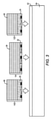
本開示は、電気的性能及び剛性性能を向上させたウェーハレベルパッケージ、及びそれを作製するためのパッケージングプロセスに関する。図1は、本開示の一実施形態に従った例示的なウェーハレベルパッケージ10を示す。この説明のために、例示的なウェーハレベルパッケージ10は、薄化ガラスベースダイ12、薄化マイクロ電気機械システム(MEMS)ダイ14、相補型金属酸化膜半導体(CMOS)コントローラダイ16、多層再分布構造18、第1のモールドコンパウンド20及び第2のモールドコンパウンド22を備える。種々の適用例において、ウェーハレベルパッケージ10は、より少ない、またはより多い薄化ガラスベース/MEMSダイを備えてもよい。例えば、いくつかの適用例において、ウェーハレベルパッケージ10は、薄化MEMSダイ及びCMOSコントローラダイのみを備える場合があり、いくつかの適用例において、ウェーハレベルパッケージ10は、薄化ガラスベースダイのみを備える場合がある。
The present disclosure relates to wafer level packages with improved electrical and rigid performance, and packaging processes for making them. FIG. 1 shows an exemplary
詳細には、薄化ガラスベースダイ12は第1のデバイス層24を備える。この層は、二酸化ケイ素(SiO2)、酸化アルミニウム(Al2O3)、リチウム超酸化物(LiO2)、バリウム酸化物(BaO)、カリウム酸化物(K2O)、ナトリウム酸化物(Na2O)、ホウ素酸化物(B2O3)、マグネシウム酸化物(MgO)、ストロンチウム酸化物(SrO)及びカルシウム酸化物(CaO)などのガラス材料から形成される。第1のデバイス層24で使用されるガラス材料は、無アルカリであってもよい。第1のデバイス層24は、複数の第1のダイ接点26、及び第1のダイ接点26に結合された少なくとも1つの電子的構成要素(図示せず)を含む。ここで、第1のダイ接点26は、第1のデバイス層24の底面にあるが、少なくとも1つの電子的構成要素(図示せず)は、第1のデバイス層24の上面に露出されていない。第1のデバイス層24は、通常は熱耐性が低いガラス材料から形成されるため、第1のデバイス層24内の少なくとも1つの電子的構成要素(図示せず)は、低電力フィルタ、低電力コンデンサなどの、低熱生成の構成要素である。第1のデバイス層24は、少なくとも100psiの成形圧力が必要となり得る5μm~1000μmの厚さを有してもよく、または、少なくとも750psiの成形圧力が必要となり得る70μm~1000μmの厚さを有してもよい(より詳細な事項については、以下の製作工程において説明する)。サイズ、コスト及び剛性の見地から、第1のデバイス層24は70μm~200μmの厚さを有してもよい。
Specifically, the thinned glass base die 12 comprises a
薄化MEMSダイ14は第2のデバイス層28を含む。この層も、二酸化ケイ素(SiO2)、酸化アルミニウム(Al2O3)、リチウム超酸化物(LiO2)、バリウム酸化物(BaO)、カリウム酸化物(K2O)、ナトリウム酸化物(Na2O)、ホウ素酸化物(B2O3)、マグネシウム酸化物(MgO)、ストロンチウム酸化物(SrO)及びカルシウム酸化物(CaO)などのガラス材料から形成される。第1のデバイス層24で使用されるガラス材料は、無アルカリであってもよい。第2のデバイス層28は、複数の第2のダイ接点30、及び第2のダイ接点30に結合されたMEMS構成要素(図示せず)を含む。ここで、第2のダイ接点30は、第2のデバイス層28の底面にあるが、MEMS構成要素は、第2のデバイス層28の上面に露出されていない。MEMS構成要素は、通常はスイッチであり、低熱を生成する。第2のデバイス層28は、少なくとも100psiの成形圧力が必要となり得る5μm~1000μmの厚さを有してもよく、または、少なくとも750psiの成形圧力が必要となり得る70μm~1000μmの厚さを有してもよい(より詳細な事項については、以下の製作工程において説明する)。サイズ、コスト及び剛性の見地から、第2のデバイス層28は70μm~200μmの厚さを有してもよい。
The thinned MEMS die 14 includes a
薄化ガラスベースダイ12と薄化MEMSダイ14とは共に薄化ダイを含み、このダイは、デバイス層、及びデバイス層の上の実質的に非シリコンの基板を有することに注意されたい。ここで、デバイス層の上の実質的に非シリコンの基板とは、デバイス層の上の最大でも2μmのシリコン基板を指す。所望の場合において、各薄化ダイは、各薄化ダイの上面がデバイス層の上面となるように、デバイス層の上のシリコン基板を全く含まない。他の場合において、1つの薄化ダイの上面は、薄いシリコン基板の上面であってもよい。
Note that both the thinned glass-based
CMOSコントローラダイ16は、第3のデバイス層32、及び第3のデバイス層32の上のシリコン基板34を含む。第3のデバイス層32は、薄化MEMSダイ14内のMEMS構成要素(図示せず)を制御するCMOSコントローラ(図示せず)、及びCMOSコントローラに結合され、第3のデバイス層32の底面にある複数の第3のダイ接点36を含んでもよい。第3のデバイス層32は、0.1μm~50μmの厚さを有し、誘電層と金属層との組み合わせ(酸化ケイ素、窒化ケイ素、アルミニウム、チタン、銅など)から形成されてもよい。CMOSコントローラダイ16は、完全なダイである。このダイは、25μm~250μmまたは10μm~750μmの厚さを有する完全なシリコン基板34を含む。
The CMOS controller die 16 includes a
本明細書において、多層再分布構造18は、上部の第1の誘電パターン38、複数の再分布相互接続40、第2の誘電パターン42及び複数のパッケージ接点44を含む。一実施形態において、薄化ガラスベースダイ12、薄化MEMSダイ14及びCMOSコントローラダイ16は、多層再分布構造18の上に直接存在する。従って、薄化ガラスベースダイ12の第1のデバイス層24、薄化MEMSダイ14の第2のデバイス層28及びCMOSコントローラダイ16の第3のデバイス層32は、第1の誘電パターン38と接触している。加えて、第1のデバイス層24の底面の第1のダイ接点26、第2のデバイス層28の底面の第2のダイ接点30及び第3のデバイス層32の底面の第3のダイ接点36は、第1の誘電パターン38を通じて露出される。
As used herein, the
この説明のために、再分布相互接続40は、5つの第1の再分布相互接続40(1)及び1つの第2の再分布相互接続40(2)を含む。種々の適用例において、再分布相互接続40は、より少ない、またはより多い第1の再分布相互接続40(1)/第2の再分布相互接続40(2)を含んでもよい。各第1の再分布相互接続40(1)は、1つのパッケージ接点44を第1、第2及び第3のダイ接点26、30及び36のうちの対応する1つに接続する。第2の再分布相互接続40(2)は、1つの第2のダイ接点30を対応する第3のダイ接点36に接続するために使用される。それにより、CMOSコントローラダイ16内のCMOSコントローラ(図示せず)は、薄化MEMSダイ14内のMEMS構成要素(図示せず)に電気的に接続される。本明細書において、各再分布相互接続40は、第1の誘電パターン38を通じて第1、第2及び第3のダイ接点26、30及び36のうちの少なくとも1つに電気的に結合され、第1の誘電パターン38の下に延在する。再分布相互接続40と第1、第2及び第3のダイ接点26、30及び36との間の接続は無ハンダである。
For this explanation, the
第2の誘電パターン42は、第1の誘電パターン38の下に形成される。第2の誘電パターン42は、各第1の再分布相互接続40(1)を部分的に封止する。従って、各第1の再分布相互接続40(1)の一部は、第2の誘電パターン42を通じて露出される。更に、第2の誘電パターン42は、第2の再分布相互接続40(2)を完全に封止する。従って、第2の再分布相互接続40(2)は、第2の誘電パターン42を通じて一部たりとも露出されない。種々の適用例において、第2の誘電パターン42を通じて再分布相互接続40に電気的に結合された追加の再分布相互接続(図示せず)が存在してもよく、追加の誘電パターン(図示せず)が、追加の再分布相互接続のそれぞれを部分的に封止するために第2の誘電パターン42の下に形成される。
The second dielectric pattern 42 is formed below the first
この実施形態において、各パッケージ接点44は、多層再分布構造18の底面に設けられ、対応する第1の再分布相互接続40(1)に、第2の誘電パターン42を通じて電気的に結合される。従って、第1の再分布相互接続40(1)は、パッケージ接点40を第1、第2及び第3のダイ接点26、30及び36のうちの特定の1つに接続する。本明細書において、パッケージ接点44は、互いに隔離され、第2の誘電パターン42の下に延在する。それにより、空隙46が、各パッケージ接点44の周囲に形成される。空隙46は、薄化ガラスベースダイ12の下に、かつ/または薄化MEMSダイ14の下に延在し得る。
In this embodiment, each
更に、多層再分布構造18は、ガラス繊維を含まなくてもよく、または無ガラスであってもよい。ここで、ガラス繊維とは、より大きいグループになるように捩られた個々のガラスストランドを指す。次いで、これらのガラスストランドを編み込んで繊維にしてもよい。第1の誘電パターン38及び第2の誘電パターン42は、ベンゾシクロブテン(BCB)またはポリイミドによって形成されてもよい。再分布相互接続40は、銅または他の好適な金属によって形成されてもよい。パッケージ接点44は、銅、金、ニッケル及びパラジウムのうちの少なくとも1種によって形成されてもよい。多層再分布構造18は、2μm~300μmの厚さを有する。
Further, the
第1のモールドコンパウンド20は、多層再分布構造18の上面の上に存在し、薄化ガラスベースダイ12及び薄化MEMSダイ14の周囲に存在し、CMOSコントローラダイ16を封止する。更に、第1のモールドコンパウンド20は、薄化ガラスベースダイ12の上面を超えて延在して、第1のモールドコンパウンド20内に、かつ薄化ガラスベースダイ12の上に第1の開口48を画定し、薄化MEMSダイ14の上面を超えて延在して、第1のモールドコンパウンド20内に、かつ薄化MEMSダイ14の上に第2の開口50を画定する。ここで、薄化ガラスベースダイ12の上面は、第1の開口48の底部に露出され、薄化MEMSダイ14の上面は第2の開口50の底部に露出される。
The
第2のモールドコンパウンド22は、第1及び第2の開口48及び50を実質的に充填し、薄化ガラスベースダイ12の上面及び薄化MEMSダイ14の上面と接触している。第2のモールドコンパウンド22は、1E6Ohm-cmを超える電気抵抗率を有し得る。第2のモールドコンパウンド22の電気抵抗率が大きいことにより、薄化MEMSダイ14のMEMS構成要素(図示せず)の高周波におけるQ値(Q)を改善することができる。
The
第2のモールドコンパウンド22は、PPS(ポリフェニルスルフィド)、窒化ホウ素またはアルミナ熱添加剤がドープされたオーバーモールドエポキシなどの、2W/m・Kを超える熱伝導率を有する熱可塑性材料または熱硬化性材料によって形成されてもよい。第2のモールドコンパウンド22は、2W/m・K未満の熱伝導率を有する有機エポキシ樹脂系から形成されてもよい。第2のモールドコンパウンド22は、第1のモールドコンパウンド20と同じ、または異なる材料によって形成されてもよい。しかしながら、第2のモールドコンパウンド22とは異なり、第1のモールドコンパウンド20は電気抵抗率の要件を持たない。本明細書において、第2のモールドコンパウンド22の一部は、第1のモールドコンパウンド20の上面の上に存在してもよい。第2のモールドコンパウンド22は、第1のモールドコンパウンド20によってCMOSコントローラダイ16から隔離されていることに注意されたい。CMOSコントローラダイ16の上面は、第1のモールドコンパウンド20と接触している。
The
図2~13は、図1に示した例示的なウェーハレベルパッケージ10を製作するための例示的なステップを提供する。例示的なステップは連続的に示されているが、例示的なステップは必ずしも順序依存ではない。いくつかのステップは、提示された順序とは異なる順序で行われてもよい。更に、本開示の範囲内の工程は、図2~13に示したステップより少ない、またはより多いステップを含んでもよい。
FIGS. 2-13 provide exemplary steps for making the exemplary
最初に、図2に示すように、支持体54の上面に粘着層52を塗布する。次いで、図3に示すように、ガラスベースダイ12D、MEMSダイ14D及びCMOSコントローラダイ16を粘着層52に取り付ける。種々の適用例において、粘着層52に取り付けられたダイは、より少なくてもよく、またはより多くてもよい。例えば、いくつかの適用例において、粘着層52に取り付けられたガラスベースダイ12Dのみが存在してもよく、いくつかの適用例において、粘着層52に取り付けられたMEMSダイ14D及びCMOSコントローラダイ16のみが存在してもよい。
First, as shown in FIG. 2, the
ガラスベースダイ12Dは、第1のデバイス層24、及び第1のデバイス層24の上の第1のシリコン基板56を含む。従って、第1のデバイス層24の底面はガラスベースダイ12Dの底面であり、第1のシリコン基板56の背面はガラスベースダイ12Dの上面である。第1のシリコン基板56は5μm~750μmの厚さを有する。ガラスベースダイ12Dは、75μm~250μmまたは10μm~1750μmの厚さを有する。
The glass-based
MEMSダイ14Dは、第2のデバイス層28、及び第2のデバイス層28の上の第2のシリコン基板58を含む。従って、第2のデバイス層28の底面はMEMSダイ14Dの底面であり、第2のシリコン基板58の背面はMEMSダイ14Dの上面である。第2のシリコン基板58は5μm~750μmの厚さを有する。MEMSダイ14Dは、75μm~250μmまたは10μm~1750μmの厚さを有する。この実施形態において、CMOSコントローラダイ16は、ガラスベースダイ12D及びMEMSダイ14Dより低くてもよい。種々の適用例において、CMOSコントローラダイ18は、ガラスベースダイ12D及びMEMSダイ14Dと同じ高さであってもよく、またはCMOSコントローラダイ18は、ガラスベースダイ12D及びMEMSダイ14Dより高くてもよい。
The MEMS die 14D includes a
次に、図4に示すように、粘着層52の上に第1のモールドコンパウンド20を塗布して、ガラスベースのダイ12D、MEMSダイ14D及びCMOSコントローラダイ16を封止する。第1のモールドコンパウンド20は、シート成形、オーバーモールディング、圧縮成形、転写成形、ダムフィル封止またはスクリーン印刷封止などの各種手順によって塗布されてもよい。典型的な圧縮成形において、第1のモールドコンパウンド20を塗布するために用いられる成形圧力は100psi~1000psiである。ガラスベースダイ12D、MEMSダイ14D及びCMOSコントローラダイ16は比較的厚く、かつガラスベースダイ12D、MEMSダイ14D及びCMOSコントローラダイ16の底面は基本的に平坦であるため、この成形ステップ中、ガラスベースダイ12Dにも、MEMSダイ14Dにも、CMOSコントローラダイ16にも垂直変形は生じ得ない。
Next, as shown in FIG. 4, a
第1のモールドコンパウンド20は、有機エポキシ樹脂系などであってもよい。この樹脂系は、ガラスベースダイ12D、MEMSダイ14D及びCMOSコントローラダイ16を水酸化カリウム(KOH)、水酸化ナトリウム(NaOH)及びアセチルコリン(ACH)などのエッチング薬品から保護するためのエッチング液バリアとして使用することができる。次いで、硬化工程(図示せず)を利用して第1のモールドコンパウンド20を硬化させる。硬化温度は100℃~320℃である。この温度は、どの材料を第1のモールドコンパウンド20として使用するかに依存する。次いで、図5に示すように、粘着層52及び支持体54を除去して、第1のデバイス層24の底面、第2のデバイス層28の底面及び第3のデバイス層32の底面を露出させる。粘着層52及び支持体54の除去は、粘着層52を加熱することによってなされてもよい。
The
図6~9を参照すると、多層再分布構造18が、本開示の一実施形態に従って形成される。図6に示すように、ガラスベースダイ12D、MEMSダイ14D及びCMOSコントローラダイ16の下に第1の誘電パターン38を最初に形成する。従って、第1、第2及び第3のダイ接点26、30及び36は、第1の誘電パターン38を通じて露出される。
Referring to FIGS. 6-9, the
次に、再分布相互接続40を図7に示すように形成する。本明細書において、再分布相互接続40は、5つの第1の再分布相互接続40(1)及び1つの第2の再分布相互接続40(2)を含む。種々の適用例において、再分布相互接続40は、より少ない、またはより多い第1の再分布相互接続40(1)/第2の再分布相互接続40(2)を含んでもよい。第1の再分布相互接続40(1)は、第1の誘電パターン38を通じて第1、第2及び第3のダイ接点26、30及び36に電気的に結合され、第1の誘電パターン38の下に延在する。第2の再分布相互接続40(2)は、1つの第2のダイ接点30を対応する第3のダイ接点36に接続するために使用される。それにより、CMOSコントローラダイ16内のCMOSコントローラ(図示せず)は、薄化MEMSダイ14内のMEMS構成要素(図示せず)に電気的に接続される。第2の再分布相互接続40(2)も、第1の誘電パターン38の下に延在し得る。再分布相互接続40と第1、第2及び第3のダイ接点26、30及び36との間の接続は無ハンダである。
Next, the
図8に示すように、第2の誘電パターン42を第1の誘電パターン38の下に形成して、各第1の再分布相互接続40(1)を部分的に封止する。従って、各第1の再分布相互接続40(1)の一部は、第2の誘電パターン42を通じて露出される。更に、第2の誘電パターン42は、第2の再分布相互接続40(2)を完全に封止する。従って、第2の再分布相互接続40(2)は、第2の誘電パターン42を通じて一部たりとも露出されない。最後に、図9に示すように、パッケージ接点44及び空隙46を形成する。各パッケージ接点44は、第2の誘電パターン42を通じて、対応する第1の再分布相互接続40(1)の露出部に結合される。従って、第1の再分布相互接続40(1)は、パッケージ接点44を第1、第2及び第3のダイ接点26、30及び36のうちの特定の1つに接続する。加えて、パッケージ接点44は、互いに隔離され、第2の誘電パターン42の下に延在する。それにより、空隙46が、各パッケージ接点44の周囲に同時に形成される。
As shown in FIG. 8, a second dielectric pattern 42 is formed beneath the first
多層再分布構造18を形成した後、図10に示すように、第1のモールドコンパウンド20を薄化して、ガラスベースダイ12Dの第1のシリコン基板56及びMEMSダイ14Dの第2のシリコン基板58を露出させる。薄化手順は、機械的研磨工程によって行われてもよい。CMOSコントローラダイ16はMEMSダイ14Dとガラスベースダイ12Dとの両方より高さが低いため、CMOSコントローラダイ16のシリコン基板34は露出せず、第1のモールドコンパウンド20によって依然として封止される。
After forming the
次に、図11に示すように、第1のシリコン基板56及び第2のシリコン基板58を実質的に除去して、先行パッケージ60を提供する。ガラスベースダイ12Dから第1のシリコン基板56を除去することにより、薄化ガラスベースダイ12が提供され、第1のモールドコンパウンド20内に、かつ薄化ガラスベースダイ12の上に第1の開口48が形成される。MEMSダイ14Dから第2のシリコン基板58を除去することにより、薄化MEMSダイ14が提供され、第1のモールドコンパウンド20内に、かつ薄化MEMSダイ14の上に第2の開口50が形成される。ここで、シリコン基板を実質的に除去することとは、シリコン基板全体のうちの少なくとも95%を除去し、最大でも2μmのシリコン基板を残すことを指す。所望の場合において、第1及び第2のシリコン基板56及び58は完全に除去される。それにより、薄化ガラスベースダイ12の第1のデバイス層24は第1の開口48の底部に露出され、薄化MEMSダイ14の第2のデバイス層28は第2の開口50の底部に露出される。
Next, as shown in FIG. 11, the
第1及び第2のシリコン基板56及び58を実質的に除去することは、湿式/乾式エッチング液薬品を用いたエッチング工程によってなされてもよく、このエッチング液薬品は、TMAH、KOH、ACH、NaOHなどであってもよい。第1のデバイス層24と第2のデバイス層28とは共に、これらの湿式/乾式エッチング薬品に耐性のあるガラス材料から形成される。それにより、第1のデバイス層24内の電子的構成要素(図示せず)及び第2のデバイス層28内のMEMS構成要素(図示せず)は、これらの湿式/乾式エッチング薬品による損傷を受けなくなる。第1のモールドコンパウンド20は、CMOSコントローラダイ16を封止し、これを湿式/乾式エッチング液薬品から保護する。いくつかの適用例において、保護層(図示せず)を多層再分布構造18の底面に配置して、パッケージ接点44をエッチング液薬品から保護してもよい。保護層は、エッチング工程の前に塗布され、エッチング工程の後に除去される。更に、CMOSコントローラダイ16のシリコン基板34が第1のモールドコンパウンド20によって封止されない場合(いくつかの適用例において、CMOSコントローラダイ16が、ガラスベースダイ12及びMEMSダイ14と同じ高さを有する、またはそれより高い場合、CMOSコントローラダイ16のシリコン基板34は、薄化工程中に露出することになる)、CMOSコントローラダイ16を湿式/乾式エッチング液薬品から保護するために、シリコン基板34の上に配置された追加の保護層(図示せず)が存在してもよい。追加の保護層は、エッチング工程の前に塗布され、エッチング工程の後に除去される。
Substantial removal of the first and
次いで、図12に示すように、第2のモールドコンパウンド22を塗布して、第1及び第2の開口48及び50を実質的に充填する。ここで、開口を実質的に充填することとは、開口全体のうちの少なくとも75%を充填することを指す。第2のモールドコンパウンド22は、薄化ガラスベースダイ12の上面及び薄化MEMSダイ14の上面の上に直接存在する。第1のシリコン基板56が第1の開口48内に残らず、かつ第2のシリコン基板58が第2の開口50内に残らない場合、第2のモールドコンパウンド22は、第1のデバイス層24及び第2のデバイス層28の上に直接存在する。加えて、第2のモールドコンパウンド22は、更に、第1のモールドコンパウンド20の上に存在してもよい。いくつかの適用例において、第2のモールドコンパウンド22を塗布して第1及び第2の開口48及び50を実質的に充填する前に、先行パッケージ60を剛性支持体(図示せず)に取り付けてもよい。剛性支持体(図示せず)は、先行パッケージ60の機械的支持を補助するのに役立つことができ、薄化ガラスベースダイ12及び薄化MEMSダイ14の更なる変形を防ぐのに役立つことができる。
Then, as shown in FIG. 12, a
第2のモールドコンパウンド22は、シート成形、オーバーモールディング、圧縮成形、転写成形、ダムフィル封止及びスクリーン印刷封止などの各種手順によって塗布されてもよい。第2のモールドコンパウンド22の成形工程中、融解及び成形圧力は、先行パッケージ60全体にわたって同一ではない。薄化ガラスベースダイ12と薄化ガラスベースダイ12の直下の多層再分布構造18の第1の部分との第1の組み合わせ、及び薄化MEMSダイ14と薄化MEMSダイ14の直下の多層再分布構造18の第2の部分との第2の組み合わせは、先行パッケージ60の他の部分より大きい成形圧力を受ける場合がある。
The
一実施形態において、第2のモールドコンパウンド22は、2W/m・Kを超える熱伝導率を有する熱可塑性材料または熱硬化性材料から形成される。第2のモールドコンパウンド20を塗布するために用いられる典型的な成形圧力(圧縮成形)は250psi~1000psiである。ここで、薄化ガラスベースダイ12の第1のデバイス層24は、少なくとも750psiの成形圧力に耐えるように70μm~1000μmの厚さを有し得る。従って、空隙46の第1の部分が薄化ガラスベースダイ12の垂直下方にあり、空隙46の第1の部分内に更なる機械的支持がない場合でも、薄化ガラスベースダイ12の垂直変形は生じ得ない、または許容程度内であり得る。同様に、薄化MEMSダイ14の第2のデバイス層28は、少なくとも750psiの成形圧力に耐えるように70μm~1000μmの厚さを有する。従って、空隙46の第2の部分が薄化MEMSダイ14の垂直下方にあり、空隙46の第2の部分内に更なる機械的支持がない場合でも、薄化MEMSダイ14の垂直変形は生じ得ない、または許容程度内であり得る。
In one embodiment, the
薄化ガラスベースダイ12と薄化MEMSダイ14とは共に低熱生成のダイであるため、薄化ガラスベースダイ12及び薄化MEMSダイ14の上に直接存在する第2のモールドコンパウンド22は、高熱伝導性を有することを必要としない。別の実施形態において、第2のモールドコンパウンド22は、2W/m・K未満の熱伝導率を有する有機エポキシ樹脂系から形成されてもよい。第2のモールドコンパウンド20を塗布するために用いられる典型的な成形圧力(オーバーモールディング)は100psi~1000psiである。ここで、薄化ガラスベースダイ12の第1のデバイス層24は、少なくとも100psiの成形圧力に耐える5μm~1000μmの厚さを有し得る。従って、空隙46の第1の部分が薄化ガラスベースダイ12の垂直下方にあり、空隙46の第1の部分内に更なる機械的支持がない場合でも、薄化ガラスベースダイ12の垂直変形は生じ得ない、または許容程度内であり得る。同様に、薄化MEMSダイ14の第2のデバイス層28は、少なくとも100psiの成形圧力に耐える5μm~1000μmの厚さを有し得る。従って、空隙46の第2の部分が薄化MEMSダイ14の垂直下方にあり、空隙46の第2の部分内に更なる機械的支持がない場合でも、薄化MEMSダイ14の垂直変形は生じ得ない、または許容程度内であり得る。
Since both the thinned glass base die 12 and the thinned MEMS die 14 are low heat generation dies, the
CMOSコントローラダイ16のシリコン基板34は、先行パッケージ60に残存し、第1のモールドコンパウンド20によって封止されることに注意されたい。従って、CMOSコントローラダイ16の第3のデバイス層36は、垂直変形を回避するためにガラス材料から形成されることも、比較的厚い厚さを有することも必要としない。第3のデバイス層36は、誘電層と金属層との組み合わせ(酸化ケイ素、窒化ケイ素、アルミニウム、チタン、銅など)から形成されてもよく、0.1μm~50μmの厚さを有する。
Note that the
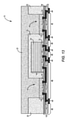
続いて、硬化工程(図示せず)により、第2のモールドコンパウンド22を硬化させる。硬化温度は100℃~320℃である。この温度は、どの材料を第2のモールドコンパウンド22として使用するかに依存する。最後に、図13に示すように、第2のモールドコンパウンド22の上面を次いで平坦化して、ウェーハレベルパッケージ10を形成する。第2のモールドコンパウンド22が第1のモールドコンパウンド20の上面を覆っていない場合、第2のモールドコンパウンド22及び/または第1のモールドコンパウンド20の上面が、同一平面となるように平坦化される(図示せず)。平坦化のために機械的研磨工程を利用してもよい。ウェーハレベルパッケージ10をマーキングし、ダイシングし、個片化して、別々の構成要素にしてもよい(図示せず)。
Subsequently, the
当業者は、本開示の好ましい実施形態に対する改良及び修正を認めるであろう。このような全ての改良及び修正は、本明細書に開示された概念及び後続する特許請求の範囲内にあるとみなされる。
Those skilled in the art will recognize improvements and modifications to the preferred embodiments of the present disclosure. All such improvements and amendments are considered to be within the concepts disclosed herein and subsequent claims.
Claims (23)
第2のデバイス層と、前記第2のデバイス層の上の完全なシリコン基板とを含む第2の完全なダイであって、前記第2のデバイス層は、前記第2のデバイス層の底面に複数の第2のダイ接点を有する、前記第2の完全なダイと、
多層再分布構造であって、前記多層再分布構造の底面の複数のパッケージ接点と、前記複数のパッケージ接点を前記複数の第1のダイ接点のうちの特定の1つおよび前記複数の第2のダイ接点のうちの特定の1つに接続する再分布相互接続とを含み、前記再分布相互接続と前記複数の第1のダイ接点との間、および前記再分布相互接続と前記複数の第2のダイ接点との間の接続は無ハンダである、前記多層再分布構造と、
前記多層再分布構造の上に存在する第1のモールドコンパウンドであって、
前記第1のモールドコンパウンドは、前記第1の薄化ダイを取り囲むとともに、前記第1のモールドコンパウンド内に、かつ前記第1の薄化ダイの上に開口を画定するために前記第1の薄化ダイの上面を超えて延在し、前記第1の薄化ダイの前記上面は前記開口の底部にあり、
前記第1のモールドコンパウンドは、前記第2の完全なダイを封止する、
前記第1のモールドコンパウンドと、
前記開口を充填し、前記第1の薄化ダイの前記上面と接触している第2のモールドコンパウンドと
を備える装置。 A first thinning die comprising a first device layer, wherein the first device layer is formed of a glass material and has a plurality of first die contacts on the bottom surface of the first device layer. With the first thinning die,
A second complete die comprising a second device layer and a complete silicon substrate on top of the second device layer, wherein the second device layer is on the bottom surface of the second device layer. With the second complete die having a plurality of second die contacts,
A multi-layered redistribution structure in which the plurality of package contacts on the bottom surface of the multi-layered redistribution structure and the plurality of package contacts are a specific one of the plurality of first die contacts and the plurality of second. A redistribution interconnect that connects to a particular one of the die contacts, between the redistribution interconnect and the plurality of first die contacts, and the redistribution interconnect and the plurality of second. The connection between the die contacts is solder-free, said multi-layer redistribution structure,
A first mold compound that resides on top of the multilayer redistribution structure.
The first mold compound surrounds the first thinning die and is intended to define an opening in the first mold compound and above the first thinning die. Extending beyond the top surface of the chemical die, the top surface of the first thinning die is at the bottom of the opening.
The first mold compound seals the second complete die.
With the first mold compound,
A device comprising a second mold compound that fills the opening and is in contact with the top surface of the first thinning die.
前記第1のダイは、第1のデバイス層と、前記第1のデバイス層の上の第1のシリコン基板とを含み、前記第1のデバイス層は、ガラス材料から形成され、前記第1のデバイス層の底面に複数の第1のダイ接点を含み、
前記第1のダイの上面は前記第1のシリコン基板の上面であり、前記第1のダイの底面は前記第1のデバイス層の前記底面であり、
前記第1のモールドコンパウンドは、前記第1のダイの側面及び前記上面を封止し、前記第1のデバイス層の前記底面が露出される、
前記提供することと、
前記モールドウェーハの下に多層再分布構造を形成することであって、
前記多層再分布構造は、前記多層再分布構造の底面の複数のパッケージ接点と、前記複数のパッケージ接点を前記複数の第1のダイ接点のうちの特定の1つに接続する再分布相互接続とを含み、
前記再分布相互接続と前記複数の第1のダイ接点との間の接続は無ハンダである、
前記形成することと、
前記第1のモールドコンパウンドを薄化して前記第1のシリコン基板の前記上面を露出させることと、
第1の薄化ダイを提供し、前記第1のモールドコンパウンド内に、かつ前記第1の薄化ダイの上に開口を形成するために前記第1のダイの前記第1のシリコン基板を完全に除去することであって、前記第1のデバイス層の上面は前記第1の薄化ダイの上面であると共に、前記開口の底部に露出される、前記除去することと、
前記開口を実質的に充填し、前記第1の薄化ダイの前記上面と直接接触するように第2のモールドコンパウンドを塗布することと
を含む方法。 To provide a molded wafer with a first die and a first mold compound.
The first die includes a first device layer and a first silicon substrate on top of the first device layer, the first device layer being formed from a glass material and said first. Includes multiple first die contacts on the bottom of the device layer,
The upper surface of the first die is the upper surface of the first silicon substrate, and the bottom surface of the first die is the bottom surface of the first device layer.
The first mold compound seals the sides and top of the first die, exposing the bottom of the first device layer.
With the above offer
By forming a multi-layer redistribution structure under the molded wafer,
The multilayer redistribution structure comprises a plurality of package contacts on the bottom surface of the multilayer redistribution structure and a redistribution interconnect connecting the plurality of package contacts to a specific one of the plurality of first die contacts. Including
The connection between the redistribution interconnect and the plurality of first die contacts is solder-free.
The formation and
By thinning the first mold compound to expose the upper surface of the first silicon substrate,
Complete the first silicon substrate of the first die to provide a first thinning die and to form an opening in the first mold compound and on top of the first thinning die. The removal is that the upper surface of the first device layer is the upper surface of the first thinning die and is exposed to the bottom of the opening.
A method comprising substantially filling the opening and applying a second mold compound in direct contact with the top surface of the first thinning die.
前記第2のモールドコンパウンドは250psi~1000psiで塗布され、
前記第1のデバイス層は70μm~1000μmの厚さを有する、請求項17に記載の方法。 The second mold compound is formed from a thermoplastic or thermosetting material having a thermal conductivity of more than 2 W / m · K.
The second mold compound is applied at 250 psi to 1000 psi and is applied.
17. The method of claim 17, wherein the first device layer has a thickness of 70 μm to 1000 μm.
前記第2のモールドコンパウンドは100psi~1000psiで塗布され、
前記第1のデバイス層は5μm~1000μmの厚さを有する、請求項17に記載の方法。 The second mold compound is formed from an organic epoxy resin and is
The second mold compound is applied at 100 psi to 1000 psi and is applied.
17. The method of claim 17, wherein the first device layer has a thickness of 5 μm to 1000 μm.
前記第2の完全なダイは、第2のデバイス層と、前記第2のデバイス層の上の第2のシリコン基板とを有し、前記第2のデバイス層は、前記第2のデバイス層の底面に複数の第2のダイ接点を有し、
前記第1のモールドコンパウンドは、前記第2の完全なダイの側面および上面を封止し、前記第2のデバイス層の前記底面が露出される、請求項17に記載の方法。 The molded wafer further comprises a second complete die.
The second complete die has a second device layer and a second silicon substrate on top of the second device layer, wherein the second device layer is of the second device layer. Has multiple second die contacts on the bottom,
17. The method of claim 17, wherein the first mold compound seals the sides and top of the second complete die, exposing the bottom surface of the second device layer.
Applications Claiming Priority (3)
| Application Number | Priority Date | Filing Date | Title |
|---|---|---|---|
| US201662374447P | 2016-08-12 | 2016-08-12 | |
| US62/374,447 | 2016-08-12 | ||
| PCT/US2017/046779 WO2018031999A1 (en) | 2016-08-12 | 2017-08-14 | Wafer-level package with enhanced performance |
Publications (3)
| Publication Number | Publication Date |
|---|---|
| JP2019525487A JP2019525487A (en) | 2019-09-05 |
| JP2019525487A5 JP2019525487A5 (en) | 2020-09-24 |
| JP7022112B2 true JP7022112B2 (en) | 2022-02-17 |
Family
ID=59684110
Family Applications (1)
| Application Number | Title | Priority Date | Filing Date |
|---|---|---|---|
| JP2019507767A Active JP7022112B2 (en) | 2016-08-12 | 2017-08-14 | Wafer level package with improved performance |
Country Status (6)
| Country | Link |
|---|---|
| US (1) | US10486965B2 (en) |
| EP (1) | EP3497718A1 (en) |
| JP (1) | JP7022112B2 (en) |
| CN (1) | CN109716511A (en) |
| SG (1) | SG11201901196RA (en) |
| WO (1) | WO2018031999A1 (en) |
Families Citing this family (22)
| Publication number | Priority date | Publication date | Assignee | Title |
|---|---|---|---|---|
| US10085352B2 (en) | 2014-10-01 | 2018-09-25 | Qorvo Us, Inc. | Method for manufacturing an integrated circuit package |
| US10773952B2 (en) | 2016-05-20 | 2020-09-15 | Qorvo Us, Inc. | Wafer-level package with enhanced performance |
| US10784149B2 (en) | 2016-05-20 | 2020-09-22 | Qorvo Us, Inc. | Air-cavity module with enhanced device isolation |
| US10103080B2 (en) | 2016-06-10 | 2018-10-16 | Qorvo Us, Inc. | Thermally enhanced semiconductor package with thermal additive and process for making the same |
| CN109716511A (en) * | 2016-08-12 | 2019-05-03 | Qorvo美国公司 | Wafer-class encapsulation with enhancing performance |
| SG11201901194SA (en) | 2016-08-12 | 2019-03-28 | Qorvo Us Inc | Wafer-level package with enhanced performance |
| US10109502B2 (en) | 2016-09-12 | 2018-10-23 | Qorvo Us, Inc. | Semiconductor package with reduced parasitic coupling effects and process for making the same |
| US10068831B2 (en) | 2016-12-09 | 2018-09-04 | Qorvo Us, Inc. | Thermally enhanced semiconductor package and process for making the same |
| US10755992B2 (en) | 2017-07-06 | 2020-08-25 | Qorvo Us, Inc. | Wafer-level packaging for enhanced performance |
| US10784233B2 (en) | 2017-09-05 | 2020-09-22 | Qorvo Us, Inc. | Microelectronics package with self-aligned stacked-die assembly |
| US11152363B2 (en) | 2018-03-28 | 2021-10-19 | Qorvo Us, Inc. | Bulk CMOS devices with enhanced performance and methods of forming the same utilizing bulk CMOS process |
| US10804246B2 (en) | 2018-06-11 | 2020-10-13 | Qorvo Us, Inc. | Microelectronics package with vertically stacked dies |
| US10964554B2 (en) | 2018-10-10 | 2021-03-30 | Qorvo Us, Inc. | Wafer-level fan-out package with enhanced performance |
| US11069590B2 (en) | 2018-10-10 | 2021-07-20 | Qorvo Us, Inc. | Wafer-level fan-out package with enhanced performance |
| US11646242B2 (en) * | 2018-11-29 | 2023-05-09 | Qorvo Us, Inc. | Thermally enhanced semiconductor package with at least one heat extractor and process for making the same |
| US20200235040A1 (en) | 2019-01-23 | 2020-07-23 | Qorvo Us, Inc. | Rf devices with enhanced performance and methods of forming the same |
| US11387157B2 (en) | 2019-01-23 | 2022-07-12 | Qorvo Us, Inc. | RF devices with enhanced performance and methods of forming the same |
| KR20210129656A (en) | 2019-01-23 | 2021-10-28 | 코르보 유에스, 인크. | RF semiconductor device and method of forming same |
| US20200235066A1 (en) | 2019-01-23 | 2020-07-23 | Qorvo Us, Inc. | Rf devices with enhanced performance and methods of forming the same |
| US11948855B1 (en) * | 2019-09-27 | 2024-04-02 | Rockwell Collins, Inc. | Integrated circuit (IC) package with cantilever multi-chip module (MCM) heat spreader |
| US11646289B2 (en) | 2019-12-02 | 2023-05-09 | Qorvo Us, Inc. | RF devices with enhanced performance and methods of forming the same |
| US11923238B2 (en) | 2019-12-12 | 2024-03-05 | Qorvo Us, Inc. | Method of forming RF devices with enhanced performance including attaching a wafer to a support carrier by a bonding technique without any polymer adhesive |
Citations (1)
| Publication number | Priority date | Publication date | Assignee | Title |
|---|---|---|---|---|
| US20150262844A1 (en) | 2011-08-25 | 2015-09-17 | Intel Mobile Communications GmbH | Semiconductor device and method of manufacturing a semiconductor device including grinding sets |
Family Cites Families (204)
| Publication number | Priority date | Publication date | Assignee | Title |
|---|---|---|---|---|
| JPS505733Y1 (en) | 1970-02-23 | 1975-02-18 | ||
| JPS6013257B2 (en) | 1976-02-20 | 1985-04-05 | 松下電器産業株式会社 | Secondary electron multiplier and its manufacturing method |
| US4366202A (en) | 1981-06-19 | 1982-12-28 | Kimberly-Clark Corporation | Ceramic/organic web |
| US5061663A (en) | 1986-09-04 | 1991-10-29 | E. I. Du Pont De Nemours And Company | AlN and AlN-containing composites |
| US5069626A (en) | 1987-07-01 | 1991-12-03 | Western Digital Corporation | Plated plastic castellated interconnect for electrical components |
| US5013681A (en) | 1989-09-29 | 1991-05-07 | The United States Of America As Represented By The Secretary Of The Navy | Method of producing a thin silicon-on-insulator layer |
| JP2821830B2 (en) | 1992-05-14 | 1998-11-05 | セイコーインスツルメンツ株式会社 | Semiconductor thin film device and its application device and method of manufacturing semiconductor thin film device |
| DE69333545T2 (en) | 1992-12-24 | 2005-08-25 | Canon K.K. | Plastic additive, plastic composition and plastic molding compound containing it |
| US5459368A (en) | 1993-08-06 | 1995-10-17 | Matsushita Electric Industrial Co., Ltd. | Surface acoustic wave device mounted module |
| DE4329696C2 (en) | 1993-09-02 | 1995-07-06 | Siemens Ag | Multichip module with SMD-compatible connection elements that can be surface-mounted on printed circuit boards |
| US5391257A (en) | 1993-12-10 | 1995-02-21 | Rockwell International Corporation | Method of transferring a thin film to an alternate substrate |
| DE59504639D1 (en) | 1994-05-02 | 1999-02-04 | Siemens Matsushita Components | ENCLOSURE FOR ELECTRONIC COMPONENTS |
| US6124179A (en) | 1996-09-05 | 2000-09-26 | Adamic, Jr.; Fred W. | Inverted dielectric isolation process |
| JP3301262B2 (en) | 1995-03-28 | 2002-07-15 | 松下電器産業株式会社 | Surface acoustic wave device |
| US5729075A (en) | 1995-06-12 | 1998-03-17 | National Semiconductor Corporation | Tuneable microelectromechanical system resonator |
| US6013948A (en) | 1995-11-27 | 2000-01-11 | Micron Technology, Inc. | Stackable chip scale semiconductor package with mating contacts on opposed surfaces |
| EP0794616B1 (en) | 1996-03-08 | 2003-01-29 | Matsushita Electric Industrial Co., Ltd. | An electronic part and a method of production thereof |
| US5709960A (en) | 1996-06-21 | 1998-01-20 | Motorola, Inc. | Mold compound |
| US6250192B1 (en) | 1996-11-12 | 2001-06-26 | Micron Technology, Inc. | Method for sawing wafers employing multiple indexing techniques for multiple die dimensions |
| US6117705A (en) | 1997-04-18 | 2000-09-12 | Amkor Technology, Inc. | Method of making integrated circuit package having adhesive bead supporting planar lid above planar substrate |
| JP3565547B2 (en) | 1998-07-31 | 2004-09-15 | シャープ株式会社 | Color liquid crystal display device and method of manufacturing the same |
| US6236061B1 (en) | 1999-01-08 | 2001-05-22 | Lakshaman Mahinda Walpita | Semiconductor crystallization on composite polymer substrates |
| US6271469B1 (en) * | 1999-11-12 | 2001-08-07 | Intel Corporation | Direct build-up layer on an encapsulated die package |
| US6154366A (en) * | 1999-11-23 | 2000-11-28 | Intel Corporation | Structures and processes for fabricating moisture resistant chip-on-flex packages |
| JP4528397B2 (en) | 1999-12-17 | 2010-08-18 | ポリマテック株式会社 | Bonding method and electronic component |
| US6426559B1 (en) | 2000-06-29 | 2002-07-30 | National Semiconductor Corporation | Miniature 3D multi-chip module |
| US6713859B1 (en) * | 2000-09-13 | 2004-03-30 | Intel Corporation | Direct build-up layer on an encapsulated die package having a moisture barrier structure |
| US6423570B1 (en) * | 2000-10-18 | 2002-07-23 | Intel Corporation | Method to protect an encapsulated die package during back grinding with a solder metallization layer and devices formed thereby |
| US20020070443A1 (en) * | 2000-12-08 | 2002-06-13 | Xiao-Chun Mu | Microelectronic package having an integrated heat sink and build-up layers |
| US6555906B2 (en) * | 2000-12-15 | 2003-04-29 | Intel Corporation | Microelectronic package having a bumpless laminated interconnection layer |
| US6943429B1 (en) | 2001-03-08 | 2005-09-13 | Amkor Technology, Inc. | Wafer having alignment marks extending from a first to a second surface of the wafer |
| US6706553B2 (en) * | 2001-03-26 | 2004-03-16 | Intel Corporation | Dispensing process for fabrication of microelectronic packages |
| US6596570B2 (en) | 2001-06-06 | 2003-07-22 | International Business Machines Corporation | SOI device with reduced junction capacitance |
| US7332819B2 (en) | 2002-01-09 | 2008-02-19 | Micron Technology, Inc. | Stacked die in die BGA package |
| US6841413B2 (en) * | 2002-01-07 | 2005-01-11 | Intel Corporation | Thinned die integrated circuit package |
| DE10206919A1 (en) | 2002-02-19 | 2003-08-28 | Infineon Technologies Ag | Production of a cover for a region of a substrate used for a SAW or BAW filter or a micromechanical element comprises forming a frame structure in the region of the substrate, and applying a lid structure on the frame structure |
| KR100476901B1 (en) | 2002-05-22 | 2005-03-17 | 삼성전자주식회사 | Method of forming SOI(Silicon-On-Insulator) semiconductor substrate |
| US7042072B1 (en) | 2002-08-02 | 2006-05-09 | Amkor Technology, Inc. | Semiconductor package and method of manufacturing the same which reduces warpage |
| US7710771B2 (en) | 2002-11-20 | 2010-05-04 | The Regents Of The University Of California | Method and apparatus for capacitorless double-gate storage |
| US7067909B2 (en) | 2002-12-31 | 2006-06-27 | Massachusetts Institute Of Technology | Multi-layer integrated semiconductor structure having an electrical shielding portion |
| US6855606B2 (en) | 2003-02-20 | 2005-02-15 | Taiwan Semiconductor Manufacturing Company, Ltd. | Semiconductor nano-rod devices |
| KR100486627B1 (en) | 2003-02-21 | 2005-05-03 | 엘지전자 주식회사 | Semiconductor package |
| JP3917946B2 (en) | 2003-03-11 | 2007-05-23 | 富士通株式会社 | Multilayer semiconductor device |
| US6864156B1 (en) | 2003-04-04 | 2005-03-08 | Xilinx, Inc. | Semiconductor wafer with well contacts on back side |
| US7109635B1 (en) | 2003-06-11 | 2006-09-19 | Sawtek, Inc. | Wafer level packaging of materials with different coefficients of thermal expansion |
| US7596849B1 (en) | 2003-06-11 | 2009-10-06 | Triquint Semiconductor, Inc. | Method of assembling a wafer-level package filter |
| WO2005010987A1 (en) | 2003-07-24 | 2005-02-03 | Matsushita Electric Industrial Co., Ltd. | Wiring board embedded with spherical semiconductor element |
| JP2005064188A (en) | 2003-08-11 | 2005-03-10 | Sumitomo Electric Ind Ltd | Method for collecting and reproducing substrate and manufacture of semiconductor wafer |
| JPWO2005063876A1 (en) | 2003-12-25 | 2007-07-19 | Jsr株式会社 | Thermoplastic elastomer composition, method for producing the same, and molded article |
| US7489032B2 (en) | 2003-12-25 | 2009-02-10 | Casio Computer Co., Ltd. | Semiconductor device including a hard sheet to reduce warping of a base plate and method of fabricating the same |
| US6992400B2 (en) | 2004-01-30 | 2006-01-31 | Nokia Corporation | Encapsulated electronics device with improved heat dissipation |
| US20050212419A1 (en) | 2004-03-23 | 2005-09-29 | Eastman Kodak Company | Encapsulating oled devices |
| JP3925809B2 (en) | 2004-03-31 | 2007-06-06 | カシオ計算機株式会社 | Semiconductor device and manufacturing method thereof |
| JP4398305B2 (en) | 2004-06-02 | 2010-01-13 | カシオ計算機株式会社 | Semiconductor device and manufacturing method thereof |
| JP3801601B2 (en) | 2004-06-15 | 2006-07-26 | シャープ株式会社 | Manufacturing method of semiconductor wafer provided with lid and manufacturing method of semiconductor device |
| US7238560B2 (en) | 2004-07-23 | 2007-07-03 | Cree, Inc. | Methods of fabricating nitride-based transistors with a cap layer and a recessed gate |
| US7591958B2 (en) * | 2004-09-14 | 2009-09-22 | Stmicroelectronics Sa | Thin glass chip for an electronic component and manufacturing method |
| US20060099733A1 (en) | 2004-11-09 | 2006-05-11 | Geefay Frank S | Semiconductor package and fabrication method |
| US7098070B2 (en) | 2004-11-16 | 2006-08-29 | International Business Machines Corporation | Device and method for fabricating double-sided SOI wafer scale package with through via connections |
| TWI259538B (en) | 2004-11-22 | 2006-08-01 | Au Optronics Corp | Thin film transistor and fabrication method thereof |
| US7519257B2 (en) | 2004-11-24 | 2009-04-14 | Cornell Research Foundation, Inc. | Waveguide structure for guiding light in low-index material |
| US7393770B2 (en) | 2005-05-19 | 2008-07-01 | Micron Technology, Inc. | Backside method for fabricating semiconductor components with conductive interconnects |
| US7619347B1 (en) | 2005-05-24 | 2009-11-17 | Rf Micro Devices, Inc. | Layer acoustic wave device and method of making the same |
| WO2006134928A1 (en) | 2005-06-16 | 2006-12-21 | Murata Manufacturing Co., Ltd. | Piezoelectric device and manufacturing method thereof |
| JP4644577B2 (en) | 2005-09-30 | 2011-03-02 | セイコーエプソン株式会社 | Semiconductor device and manufacturing method of semiconductor device |
| US8465175B2 (en) | 2005-11-29 | 2013-06-18 | GE Lighting Solutions, LLC | LED lighting assemblies with thermal overmolding |
| CN101346817B (en) | 2005-12-26 | 2010-09-01 | 夏普株式会社 | Solid state imaging element module fabrication method |
| JP4476939B2 (en) | 2006-01-12 | 2010-06-09 | 株式会社東芝 | Semiconductor device |
| US20070194342A1 (en) | 2006-01-12 | 2007-08-23 | Kinzer Daniel M | GaN SEMICONDUCTOR DEVICE AND PROCESS EMPLOYING GaN ON THIN SAPHIRE LAYER ON POLYCRYSTALLINE SILICON CARBIDE |
| US20070190747A1 (en) | 2006-01-23 | 2007-08-16 | Tessera Technologies Hungary Kft. | Wafer level packaging to lidded chips |
| US7863727B2 (en) * | 2006-02-06 | 2011-01-04 | Micron Technology, Inc. | Microelectronic devices and methods for manufacturing microelectronic devices |
| JP4591378B2 (en) | 2006-02-21 | 2010-12-01 | 株式会社デンソー | Manufacturing method of semiconductor device |
| US20070243662A1 (en) | 2006-03-17 | 2007-10-18 | Johnson Donald W | Packaging of MEMS devices |
| KR101478810B1 (en) | 2006-07-28 | 2015-01-02 | 가부시키가이샤 한도오따이 에네루기 켄큐쇼 | Power storage device |
| KR20080017965A (en) | 2006-08-23 | 2008-02-27 | 삼성전자주식회사 | Method of manufacturing panel for flexible display device |
| US7749882B2 (en) * | 2006-08-23 | 2010-07-06 | Micron Technology, Inc. | Packaged microelectronic devices and methods for manufacturing packaged microelectronic devices |
| US7960218B2 (en) | 2006-09-08 | 2011-06-14 | Wisconsin Alumni Research Foundation | Method for fabricating high-speed thin-film transistors |
| US7888742B2 (en) | 2007-01-10 | 2011-02-15 | International Business Machines Corporation | Self-aligned metal-semiconductor alloy and metallization for sub-lithographic source and drain contacts |
| JP2008235490A (en) | 2007-03-19 | 2008-10-02 | Sumitomo Bakelite Co Ltd | Hollow structure and manufacturing method therefor |
| US8183151B2 (en) | 2007-05-04 | 2012-05-22 | Micron Technology, Inc. | Methods of forming conductive vias through substrates, and structures and assemblies resulting therefrom |
| US20080277778A1 (en) | 2007-05-10 | 2008-11-13 | Furman Bruce K | Layer Transfer Process and Functionally Enhanced Integrated Circuits Products Thereby |
| JP2008279567A (en) | 2007-05-11 | 2008-11-20 | Denso Corp | Manufacturing method of semi-conductor apparatus |
| US7553752B2 (en) | 2007-06-20 | 2009-06-30 | Stats Chippac, Ltd. | Method of making a wafer level integration package |
| KR20090004147A (en) | 2007-07-06 | 2009-01-12 | 삼성전자주식회사 | Semiconductor device and method of forming the same |
| US20090014856A1 (en) | 2007-07-10 | 2009-01-15 | International Business Machine Corporation | Microbump seal |
| JP5013467B2 (en) | 2007-07-18 | 2012-08-29 | 株式会社デンソー | Manufacturing method of semiconductor device |
| US9391588B2 (en) | 2007-08-31 | 2016-07-12 | Rf Micro Devices, Inc. | MEMS vibrating structure using an orientation dependent single-crystal piezoelectric thin film layer |
| US9941245B2 (en) * | 2007-09-25 | 2018-04-10 | Intel Corporation | Integrated circuit packages including high density bump-less build up layers and a lesser density core or coreless substrate |
| US7868419B1 (en) | 2007-10-18 | 2011-01-11 | Rf Micro Devices, Inc. | Linearity improvements of semiconductor substrate based radio frequency devices |
| US7790543B2 (en) | 2008-01-11 | 2010-09-07 | International Business Machines Corporation | Device structures for a metal-oxide-semiconductor field effect transistor and methods of fabricating such device structures |
| JP4840373B2 (en) | 2008-01-31 | 2011-12-21 | カシオ計算機株式会社 | Semiconductor device and manufacturing method thereof |
| US20110102002A1 (en) | 2008-04-09 | 2011-05-05 | Riehl Bill L | Electrode and sensor having carbon nanostructures |
| US20100012354A1 (en) | 2008-07-14 | 2010-01-21 | Logan Brook Hedin | Thermally conductive polymer based printed circuit board |
| US8236609B2 (en) * | 2008-08-01 | 2012-08-07 | Freescale Semiconductor, Inc. | Packaging an integrated circuit die with backside metallization |
| US7843072B1 (en) | 2008-08-12 | 2010-11-30 | Amkor Technology, Inc. | Semiconductor package having through holes |
| JP4638530B2 (en) | 2008-08-19 | 2011-02-23 | 日本電波工業株式会社 | Piezoelectric component and manufacturing method thereof |
| US20100081237A1 (en) | 2008-09-30 | 2010-04-01 | Avago Technologies Fiber Ip (Singapore) Pte. Ltd. | Integrated Circuit Assemblies and Methods for Encapsulating a Semiconductor Device |
| US9059174B2 (en) | 2008-11-05 | 2015-06-16 | Stmicroelectronics, Inc. | Method to reduce metal fuse thickness without extra mask |
| JP5468242B2 (en) | 2008-11-21 | 2014-04-09 | 株式会社東芝 | MEMS package and method for manufacturing MEMS package |
| US7927904B2 (en) | 2009-01-05 | 2011-04-19 | Dalsa Semiconductor Inc. | Method of making BIOMEMS devices |
| JP5556072B2 (en) | 2009-01-07 | 2014-07-23 | ソニー株式会社 | Semiconductor device, method of manufacturing the same, and millimeter wave dielectric transmission device |
| JP4984179B2 (en) | 2009-02-06 | 2012-07-25 | ソニー株式会社 | Semiconductor device |
| US8508056B2 (en) | 2009-06-16 | 2013-08-13 | Dongbu Hitek Co., Ltd. | Heat releasing semiconductor package, method for manufacturing the same, and display apparatus including the same |
| JP5175803B2 (en) | 2009-07-01 | 2013-04-03 | 新光電気工業株式会社 | Manufacturing method of semiconductor device |
| US8921168B2 (en) | 2009-07-15 | 2014-12-30 | Silanna Semiconductor U.S.A., Inc. | Thin integrated circuit chip-on-board assembly and method of making |
| US8432016B1 (en) | 2009-07-29 | 2013-04-30 | Rf Micro Devices, Inc. | Stacked body-contacted field effect transistor |
| US8503186B2 (en) | 2009-07-30 | 2013-08-06 | Megica Corporation | System-in packages |
| WO2011022397A1 (en) | 2009-08-17 | 2011-02-24 | First Solar, Inc. | Barrier layer |
| US8164158B2 (en) * | 2009-09-11 | 2012-04-24 | Stats Chippac, Ltd. | Semiconductor device and method of forming integrated passive device |
| US8362599B2 (en) | 2009-09-24 | 2013-01-29 | Qualcomm Incorporated | Forming radio frequency integrated circuits |
| WO2011060558A1 (en) | 2009-11-18 | 2011-05-26 | Sensirion Ag | Sensor mounted in flip-chip technology on a substrate |
| US8030145B2 (en) | 2010-01-08 | 2011-10-04 | International Business Machines Corporation | Back-gated fully depleted SOI transistor |
| US9576919B2 (en) * | 2011-12-30 | 2017-02-21 | Deca Technologies Inc. | Semiconductor device and method comprising redistribution layers |
| US9196509B2 (en) | 2010-02-16 | 2015-11-24 | Deca Technologies Inc | Semiconductor device and method of adaptive patterning for panelized packaging |
| US9431316B2 (en) * | 2010-05-04 | 2016-08-30 | STATS ChipPAC Pte. Ltd. | Semiconductor device and method of forming channels in back surface of FO-WLCSP for heat dissipation |
| JP5584011B2 (en) * | 2010-05-10 | 2014-09-03 | 新光電気工業株式会社 | Manufacturing method of semiconductor package |
| JP2011248072A (en) | 2010-05-26 | 2011-12-08 | Hitachi Displays Ltd | Method of manufacturing image display device |
| US8557679B2 (en) | 2010-06-30 | 2013-10-15 | Corning Incorporated | Oxygen plasma conversion process for preparing a surface for bonding |
| KR101698932B1 (en) | 2010-08-17 | 2017-01-23 | 삼성전자 주식회사 | Semiconductor Package And Method For Manufacturing The Same |
| US8551798B2 (en) | 2010-09-21 | 2013-10-08 | Taiwan Semiconductor Manufacturing Company, Ltd. | Microstructure with an enhanced anchor |
| US20120094418A1 (en) | 2010-10-18 | 2012-04-19 | Triquint Semiconductor, Inc. | Wafer Level Package and Manufacturing Method Using Photodefinable Polymer for Enclosing Acoustic Devices |
| US8716051B2 (en) | 2010-10-21 | 2014-05-06 | Taiwan Semiconductor Manufacturing Company, Ltd. | MEMS device with release aperture |
| CN102456737B (en) | 2010-10-27 | 2016-03-30 | 中国科学院微电子研究所 | Semiconductor structure and manufacture method thereof |
| KR20120053332A (en) | 2010-11-17 | 2012-05-25 | 삼성전자주식회사 | Semiconductor package and method of forming the same |
| US8492210B2 (en) | 2010-12-17 | 2013-07-23 | Institute of Microelectronics, Chinese Academy of Sciences | Transistor, semiconductor device comprising the transistor and method for manufacturing the same |
| US8716800B2 (en) | 2010-12-31 | 2014-05-06 | Institute of Microelectronics, Chinese Academy of Sciences | Semiconductor structure and method for manufacturing the same |
| US8420447B2 (en) | 2011-03-23 | 2013-04-16 | Stats Chippac Ltd. | Integrated circuit packaging system with flipchip leadframe and method of manufacture thereof |
| US8399957B2 (en) | 2011-04-08 | 2013-03-19 | International Business Machines Corporation | Dual-depth self-aligned isolation structure for a back gate electrode |
| US8507989B2 (en) | 2011-05-16 | 2013-08-13 | International Business Machine Corporation | Extremely thin semiconductor-on-insulator (ETSOI) FET with a back gate and reduced parasitic capacitance |
| US8415743B2 (en) | 2011-05-24 | 2013-04-09 | International Business Machines Corporation | ETSOI CMOS with back gates |
| US9633854B2 (en) | 2011-06-23 | 2017-04-25 | Institute of Microelectronics, Chinese Academy of Sciences | MOSFET and method for manufacturing the same |
| US8772853B2 (en) | 2011-07-12 | 2014-07-08 | The Regents Of The University Of California | All graphene flash memory device |
| US9390364B2 (en) | 2011-08-08 | 2016-07-12 | Féinics Amatech Teoranta | Transponder chip module with coupling frame on a common substrate for secure and non-secure smartcards and tags |
| CN102983116B (en) | 2011-09-07 | 2015-09-30 | 中国科学院微电子研究所 | Semiconductor substrate, the integrated circuit with this Semiconductor substrate and manufacture method thereof |
| US8963321B2 (en) | 2011-09-12 | 2015-02-24 | Infineon Technologies Ag | Semiconductor device including cladded base plate |
| CN103000537B (en) * | 2011-09-15 | 2015-12-09 | 万国半导体股份有限公司 | Encapsulating structure of a kind of wafer scale and preparation method thereof |
| CN103000671B (en) | 2011-09-16 | 2015-07-15 | 中国科学院微电子研究所 | MOSFET (metal oxide semiconductor field effect transistor) and manufacturing method thereof |
| US9368429B2 (en) | 2011-10-25 | 2016-06-14 | Intel Corporation | Interposer for hermetic sealing of sensor chips and for their integration with integrated circuit chips |
| US9190391B2 (en) * | 2011-10-26 | 2015-11-17 | Maxim Integrated Products, Inc. | Three-dimensional chip-to-wafer integration |
| US8664044B2 (en) | 2011-11-02 | 2014-03-04 | Stmicroelectronics Pte Ltd. | Method of fabricating land grid array semiconductor package |
| US8643148B2 (en) | 2011-11-30 | 2014-02-04 | Taiwan Semiconductor Manufacturing Company, Ltd. | Chip-on-Wafer structures and methods for forming the same |
| KR20130064289A (en) | 2011-12-08 | 2013-06-18 | 에스케이하이닉스 주식회사 | Semiconductor device and method for manufacturing the same |
| US20130193445A1 (en) | 2012-01-26 | 2013-08-01 | International Business Machines Corporation | Soi structures including a buried boron nitride dielectric |
| KR101918608B1 (en) * | 2012-02-28 | 2018-11-14 | 삼성전자 주식회사 | Semiconductor package |
| US8835978B2 (en) | 2012-05-14 | 2014-09-16 | Infineon Technologies Ag | Lateral transistor on polymer |
| KR101970291B1 (en) | 2012-08-03 | 2019-04-18 | 삼성전자주식회사 | Methods of manufacturing semiconductor packages |
| US8963336B2 (en) | 2012-08-03 | 2015-02-24 | Samsung Electronics Co., Ltd. | Semiconductor packages, methods of manufacturing the same, and semiconductor package structures including the same |
| JP6024400B2 (en) | 2012-11-07 | 2016-11-16 | ソニー株式会社 | Semiconductor device, method for manufacturing semiconductor device, and antenna switch module |
| US8796072B2 (en) | 2012-11-15 | 2014-08-05 | Amkor Technology, Inc. | Method and system for a semiconductor device package with a die-to-die first bond |
| US9431369B2 (en) | 2012-12-13 | 2016-08-30 | Taiwan Semiconductor Manufacturing Company, Ltd. | Antenna apparatus and method |
| US8927405B2 (en) | 2012-12-18 | 2015-01-06 | International Business Machines Corporation | Accurate control of distance between suspended semiconductor nanowires and substrate surface |
| KR102031731B1 (en) | 2012-12-18 | 2019-10-14 | 삼성전자주식회사 | Semiconductor package and method of manufacturing the same |
| US8786105B1 (en) | 2013-01-11 | 2014-07-22 | Intel Mobile Communications GmbH | Semiconductor device with chip having low-k-layers |
| US9733428B2 (en) | 2013-02-04 | 2017-08-15 | American Semiconductor, Inc. | Flexible 3-D photonic device |
| US9812350B2 (en) | 2013-03-06 | 2017-11-07 | Qorvo Us, Inc. | Method of manufacture for a silicon-on-plastic semiconductor device with interfacial adhesion layer |
| US9214337B2 (en) | 2013-03-06 | 2015-12-15 | Rf Micro Devices, Inc. | Patterned silicon-on-plastic (SOP) technology and methods of manufacturing the same |
| US9583414B2 (en) | 2013-10-31 | 2017-02-28 | Qorvo Us, Inc. | Silicon-on-plastic semiconductor device and method of making the same |
| US20140252566A1 (en) | 2013-03-06 | 2014-09-11 | Rf Micro Devices, Inc. | Silicon-on-dual plastic (sodp) technology and methods of manufacturing the same |
| US20140306324A1 (en) | 2013-03-06 | 2014-10-16 | Rf Micro Devices, Inc. | Semiconductor device with a polymer substrate and methods of manufacturing the same |
| US8941248B2 (en) | 2013-03-13 | 2015-01-27 | Taiwan Semiconductor Manufacturing Company, Ltd. | Semiconductor device package and method |
| US9070660B2 (en) | 2013-03-15 | 2015-06-30 | Intel Corporation | Polymer thermal interface material having enhanced thermal conductivity |
| EP2976380B1 (en) | 2013-03-22 | 2018-10-10 | Henkel IP & Holding GmbH | Diene/dienophile couples and thermosetting resin compositions having reworkability |
| US9349700B2 (en) | 2013-04-24 | 2016-05-24 | Stats Chippac, Ltd. | Semiconductor device and method of forming stress-reduced conductive joint structures |
| CN105144385B (en) | 2013-04-26 | 2018-06-29 | 奥林巴斯株式会社 | Photographic device |
| US9275916B2 (en) | 2013-05-03 | 2016-03-01 | Infineon Technologies Ag | Removable indicator structure in electronic chips of a common substrate for process adjustment |
| US9281198B2 (en) | 2013-05-23 | 2016-03-08 | GlobalFoundries, Inc. | Method of fabricating a semiconductor device including embedded crystalline back-gate bias planes |
| US9059123B2 (en) | 2013-07-24 | 2015-06-16 | International Business Machines Corporation | Active matrix using hybrid integrated circuit and bipolar transistor |
| KR101934945B1 (en) | 2013-10-15 | 2019-01-04 | 인텔 코포레이션 | Magnetic shielded integrated circuit package |
| US9576930B2 (en) | 2013-11-08 | 2017-02-21 | Taiwan Semiconductor Manufacturing Co., Ltd. | Thermally conductive structure for heat dissipation in semiconductor packages |
| CN103730429B (en) * | 2013-12-05 | 2017-06-20 | 通富微电子股份有限公司 | Encapsulating structure |
| US9352956B2 (en) | 2014-01-16 | 2016-05-31 | Taiwan Semiconductor Manufacturing Company, Ltd. | MEMS devices and methods for forming same |
| US9653443B2 (en) | 2014-02-14 | 2017-05-16 | Taiwan Semiconductor Manufacturing Company, Ltd. | Thermal performance structure for semiconductor packages and method of forming same |
| US10056267B2 (en) | 2014-02-14 | 2018-08-21 | Taiwan Semiconductor Manufacturing Company, Ltd. | Substrate design for semiconductor packages and method of forming same |
| US9368455B2 (en) | 2014-03-28 | 2016-06-14 | Intel Corporation | Electromagnetic interference shield for semiconductor chip packages |
| US20150311132A1 (en) | 2014-04-28 | 2015-10-29 | Taiwan Semiconductor Manufacturing Company, Ltd. | Scribe line structure and method of forming same |
| US9165793B1 (en) | 2014-05-02 | 2015-10-20 | Invensas Corporation | Making electrical components in handle wafers of integrated circuit packages |
| US10141201B2 (en) | 2014-06-13 | 2018-11-27 | Taiwan Semiconductor Manufacturing Company | Integrated circuit packages and methods of forming same |
| KR102245003B1 (en) | 2014-06-27 | 2021-04-28 | 삼성전자주식회사 | Semiconductor packages capable of overcoming overhangs and methods for fabricating the same |
| US9397118B2 (en) | 2014-06-30 | 2016-07-19 | International Business Machines Corporation | Thin-film ambipolar logic |
| TWI582847B (en) | 2014-09-12 | 2017-05-11 | Rf微型儀器公司 | Printed circuit module having semiconductor device with a polymer substrate and methods of manufacturing the same |
| US10085352B2 (en) * | 2014-10-01 | 2018-09-25 | Qorvo Us, Inc. | Method for manufacturing an integrated circuit package |
| US9530709B2 (en) | 2014-11-03 | 2016-12-27 | Qorvo Us, Inc. | Methods of manufacturing a printed circuit module having a semiconductor device with a protective layer in place of a low-resistivity handle layer |
| KR101647559B1 (en) | 2014-11-07 | 2016-08-10 | 앰코 테크놀로지 코리아 주식회사 | Method of manufactuing semiconductor package and semiconductor package |
| JP6233285B2 (en) | 2014-11-28 | 2017-11-22 | 三菱電機株式会社 | Semiconductor module, power converter |
| US9548273B2 (en) | 2014-12-04 | 2017-01-17 | Invensas Corporation | Integrated circuit assemblies with rigid layers used for protection against mechanical thinning and for other purposes, and methods of fabricating such assemblies |
| US9960145B2 (en) | 2015-03-25 | 2018-05-01 | Qorvo Us, Inc. | Flip chip module with enhanced properties |
| US9613831B2 (en) * | 2015-03-25 | 2017-04-04 | Qorvo Us, Inc. | Encapsulated dies with enhanced thermal performance |
| US9875971B2 (en) | 2015-03-26 | 2018-01-23 | Globalfoundries Singapore Pte. Ltd. | Magnetic shielding of MRAM package |
| US20160343604A1 (en) | 2015-05-22 | 2016-11-24 | Rf Micro Devices, Inc. | Substrate structure with embedded layer for post-processing silicon handle elimination |
| US9969614B2 (en) | 2015-05-29 | 2018-05-15 | Taiwan Semiconductor Manufacturing Company, Ltd. | MEMS packages and methods of manufacture thereof |
| US9815685B2 (en) | 2015-06-15 | 2017-11-14 | Taiwan Semiconductor Manufacturing Company Ltd. | Semiconductor sensing structure and manufacturing method thereof |
| US9461001B1 (en) | 2015-07-22 | 2016-10-04 | Advanced Semiconductor Engineering, Inc. | Semiconductor device package integrated with coil for wireless charging and electromagnetic interference shielding, and method of manufacturing the same |
| US10276495B2 (en) | 2015-09-11 | 2019-04-30 | Qorvo Us, Inc. | Backside semiconductor die trimming |
| US9850126B2 (en) * | 2015-12-31 | 2017-12-26 | Taiwan Semiconductor Manufacturing Company, Ltd. | Integrated circuit package and method of forming same |
| US10090262B2 (en) | 2016-05-09 | 2018-10-02 | Qorvo Us, Inc. | Microelectronics package with inductive element and magnetically enhanced mold compound component |
| US10468329B2 (en) | 2016-07-18 | 2019-11-05 | Qorvo Us, Inc. | Thermally enhanced semiconductor package having field effect transistors with back-gate feature |
| US10773952B2 (en) * | 2016-05-20 | 2020-09-15 | Qorvo Us, Inc. | Wafer-level package with enhanced performance |
| US10103080B2 (en) * | 2016-06-10 | 2018-10-16 | Qorvo Us, Inc. | Thermally enhanced semiconductor package with thermal additive and process for making the same |
| US9859254B1 (en) | 2016-06-30 | 2018-01-02 | Taiwan Semiconductor Manufacturing Company Ltd. | Semiconductor structure and a manufacturing method thereof |
| CN109716511A (en) * | 2016-08-12 | 2019-05-03 | Qorvo美国公司 | Wafer-class encapsulation with enhancing performance |
| EP3497719B1 (en) * | 2016-08-12 | 2020-06-10 | Qorvo Us, Inc. | Wafer-level package with enhanced performance |
| SG11201901194SA (en) * | 2016-08-12 | 2019-03-28 | Qorvo Us Inc | Wafer-level package with enhanced performance |
| US9786586B1 (en) | 2016-08-21 | 2017-10-10 | Micron Technology, Inc. | Semiconductor package and fabrication method thereof |
| US10410999B2 (en) | 2017-12-19 | 2019-09-10 | Amkor Technology, Inc. | Semiconductor device with integrated heat distribution and manufacturing method thereof |
-
2017
- 2017-08-14 CN CN201780058052.6A patent/CN109716511A/en active Pending
- 2017-08-14 SG SG11201901196RA patent/SG11201901196RA/en unknown
- 2017-08-14 US US15/676,693 patent/US10486965B2/en active Active
- 2017-08-14 WO PCT/US2017/046779 patent/WO2018031999A1/en unknown
- 2017-08-14 EP EP17755403.7A patent/EP3497718A1/en active Pending
- 2017-08-14 JP JP2019507767A patent/JP7022112B2/en active Active
Patent Citations (1)
| Publication number | Priority date | Publication date | Assignee | Title |
|---|---|---|---|---|
| US20150262844A1 (en) | 2011-08-25 | 2015-09-17 | Intel Mobile Communications GmbH | Semiconductor device and method of manufacturing a semiconductor device including grinding sets |
Also Published As
| Publication number | Publication date |
|---|---|
| CN109716511A (en) | 2019-05-03 |
| WO2018031999A1 (en) | 2018-02-15 |
| US10486965B2 (en) | 2019-11-26 |
| SG11201901196RA (en) | 2019-03-28 |
| EP3497718A1 (en) | 2019-06-19 |
| US20180044177A1 (en) | 2018-02-15 |
| JP2019525487A (en) | 2019-09-05 |
Similar Documents
| Publication | Publication Date | Title |
|---|---|---|
| JP7022112B2 (en) | Wafer level package with improved performance | |
| JP7035014B2 (en) | Wafer level package with enhanced performance | |
| JP7265052B2 (en) | Wafer level package with improved performance | |
| US10882740B2 (en) | Wafer-level package with enhanced performance and manufacturing method thereof | |
| US10090262B2 (en) | Microelectronics package with inductive element and magnetically enhanced mold compound component | |
| JP2019525487A5 (en) | ||
| US10964554B2 (en) | Wafer-level fan-out package with enhanced performance | |
| US20160284568A1 (en) | Encapsulated dies with enhanced thermal performance | |
| US11069590B2 (en) | Wafer-level fan-out package with enhanced performance | |
| CN110112115A (en) | Ic package and forming method thereof | |
| CN107452728A (en) | The method for packing of integrated image sensor chip and logic chip |
Legal Events
| Date | Code | Title | Description |
|---|---|---|---|
| A521 | Request for written amendment filed |
Free format text: JAPANESE INTERMEDIATE CODE: A523 Effective date: 20190415 |
|
| A521 | Request for written amendment filed |
Free format text: JAPANESE INTERMEDIATE CODE: A523 Effective date: 20200812 |
|
| A621 | Written request for application examination |
Free format text: JAPANESE INTERMEDIATE CODE: A621 Effective date: 20200812 |
|
| A977 | Report on retrieval |
Free format text: JAPANESE INTERMEDIATE CODE: A971007 Effective date: 20210610 |
|
| A131 | Notification of reasons for refusal |
Free format text: JAPANESE INTERMEDIATE CODE: A131 Effective date: 20210625 |
|
| A521 | Request for written amendment filed |
Free format text: JAPANESE INTERMEDIATE CODE: A523 Effective date: 20210907 |
|
| TRDD | Decision of grant or rejection written | ||
| A01 | Written decision to grant a patent or to grant a registration (utility model) |
Free format text: JAPANESE INTERMEDIATE CODE: A01 Effective date: 20220119 |
|
| A61 | First payment of annual fees (during grant procedure) |
Free format text: JAPANESE INTERMEDIATE CODE: A61 Effective date: 20220204 |
|
| R150 | Certificate of patent or registration of utility model |
Ref document number: 7022112 Country of ref document: JP Free format text: JAPANESE INTERMEDIATE CODE: R150 |