JP6920719B2 - Digital watermarking device and method - Google Patents
Digital watermarking device and method Download PDFInfo
- Publication number
- JP6920719B2 JP6920719B2 JP2017117460A JP2017117460A JP6920719B2 JP 6920719 B2 JP6920719 B2 JP 6920719B2 JP 2017117460 A JP2017117460 A JP 2017117460A JP 2017117460 A JP2017117460 A JP 2017117460A JP 6920719 B2 JP6920719 B2 JP 6920719B2
- Authority
- JP
- Japan
- Prior art keywords
- embedded
- information
- image
- watermark
- extracted
- Prior art date
- Legal status (The legal status is an assumption and is not a legal conclusion. Google has not performed a legal analysis and makes no representation as to the accuracy of the status listed.)
- Active
Links
Images


Description
本発明は,デジタル画像データに情報を埋め込む不可視の電子透かしの装置および方法に関するものである。特に、印刷画像や表示画像から透かし情報を抽出可能なデータハイディングやAnnotationを可能とする透かし装置および方法である。 The present invention relates to an invisible digital watermarking device and method for embedding information in digital image data. In particular, it is a watermark device and method that enables data hiding and annotation that can extract watermark information from a printed image or a display image.
現在のデジタル情報社会において,情報の複製により多くの人が情報を共有することが可能となり,社会が大きく発展してきた。しかし,その利便性が,個人の著作物を違法に複製し流通させることにより,著作権侵害などの事件が起こるようになった。画像においては,近年のデジタルカメラやプリンタの高画質化により,原画と寸分も違わぬ複製が容易に得られるようになり,著作権を侵害した違反コピーだけでなく,紙幣や有価証券等の偽造行為という悪質な犯罪行為を助長させる結果となっている。 In the current digital information society, the duplication of information has made it possible for many people to share information, and the society has greatly developed. However, due to its convenience, cases such as copyright infringement have come to occur due to the illegal copying and distribution of personal works. With the recent improvement in the image quality of digital cameras and printers, it has become easier to obtain reproductions of images that are exactly the same as the original images, and not only infringing copies but also forgery of banknotes and securities. This has resulted in the promotion of malicious criminal acts called acts.
そのような状況の中で,画像情報の中に別の情報,例えば,著作者情報等を埋め込み,著作権を保護する電子透かし(Digital Watermark)技術が発展してきた。この電子透かし技術は,著作物の中に著作権者の名前や連絡先,取り扱い事項などを埋め込み,利用者に注意を喚起するのみならず,不正利用の追跡ができることなど,著作権の管理・保護,ならびにセキュリティー対策として広く使われ始めている。 Under such circumstances, digital watermark technology has been developed to protect copyright by embedding other information such as author information in image information. This digital watermarking technology embeds the name, contact information, handling items, etc. of the copyright holder in the copyrighted work, not only alerting the user, but also tracking unauthorized use, etc. It is beginning to be widely used as a protection and security measure.
電子透かしと同じように何らかの副情報を知覚されない形で画像に埋め込む技術として,データハイディング(Data Hiding)技術がある。データハイディングも電子透かしも知覚されないように情報を埋め込むという不可視化するという点では共通しているが,利用目的が異なる。電子透かしは埋め込む量は少なくても,攻撃に対する耐性は強くなければならない。一方、データハイディングは著作権保護というより原画に対する補佐的な副情報を画像に埋め込むため、埋め込まれる情報量は多い方がよく,半面,攻撃に対する耐性はあまり考慮されない。 There is a data hiding technology as a technology for embedding some sub-information in an image in a non-perceptible manner like a digital watermark. Both data hiding and digital watermarking are common in that they are invisible by embedding information so that they are not perceived, but the purpose of use is different. Even if the amount of watermarks embedded is small, the resistance to attacks must be strong. On the other hand, since data hiding embeds auxiliary information for the original image in the image rather than copyright protection, it is better to embed a large amount of information, and on the other hand, resistance to attacks is not considered so much.
一方,ステガノグラフィという技術がある。ステガノグラフィも情報を知覚されないように埋め込む点は同じであるが,情報が秘密情報であり透かしの抽出に秘密鍵が必要となる。そのほか,Fingerprint1(利用者に関する情報を埋め込み不正配布者を特定する),Integrity Mark(画像に改竄がないかを検出する),Annotation(画像に関する説明を埋め込む)などと呼ばれる方法・技術があり,それぞれ電子透かしに必要な強度や容量,システムなどの条件が異なる。 On the other hand, there is a technique called steganography. Steganography is the same in that it embeds information so that it is not perceived, but the information is secret information and a secret key is required to extract the watermark. In addition, there are methods and technologies called Fingerprint1 (embedding information about users to identify unauthorized distributors), Integrity Mark (detecting whether images have been tampered with), and Annotation (embedding explanations about images). Conditions such as strength, capacity, and system required for digital watermarking are different.
データハイディングやAnnotationなどの応用として、画像とネットとの融合が考えられる。画像に埋め込まれた情報を副情報あるいはメタ情報として、様々な情報を提供する。埋め込まれる情報量は多い方が有利であるが、不可視の埋め込みには埋め込み量に限りがあるため、情報提供者のホームページなどに誘導したり、簡単な説明ができる程度の埋め込み量が必要である。 As an application such as data hiding and annotation, fusion of images and the Internet can be considered. Various information is provided by using the information embedded in the image as sub-information or meta-information. It is advantageous to embed a large amount of information, but since the amount of invisible embedding is limited, it is necessary to have an embedding amount that can be guided to the homepage of the information provider or give a brief explanation. ..
ユーザをネットに誘導したり、商品を説明する方式として、バーコードや二次元バーコードなどがある。ユーザはこのコード化されたマークをスマートフォンなどで読み取ることにより、関連するホームページに誘導したり、様々な情報を得たりすることができる。これらの方法はコードパターンに多量の情報を埋め込むことができる。しかしながら、これらは無味乾燥なコードパターンを画像や文字情報の横に置かれ、このパターンのみでは一般ユーザにとっては内容が推測できず、興味を引くようなものではない。 There are barcodes and two-dimensional barcodes as methods for guiding users to the Internet and explaining products. By reading this coded mark with a smartphone or the like, the user can be directed to a related homepage or obtain various information. These methods can embed a large amount of information in the code pattern. However, these have a dry code pattern placed next to the image or text information, and the content cannot be guessed by a general user by this pattern alone, and it is not interesting.
このため、関連する画像の中に情報を埋め込むデータハイディングやAnnotationなどの技術は、意味ある画像内に情報を埋め込み、コードパターンの様な余分なスペースを必要としないため、近年、注目された電子透かし応用技術である。しかしながら、できる限り多くの情報を埋め込み、かつ、スキャナやカメラで読み込んで透かし情報を抽出するためには、強い耐性と正確性が必要である。 For this reason, technologies such as data hiding and Annotation that embed information in related images have attracted attention in recent years because they embed information in meaningful images and do not require extra space such as code patterns. It is a digital watermark application technology. However, strong resistance and accuracy are required in order to embed as much information as possible and read it with a scanner or camera to extract watermark information.
これまで画像データに対する耐性のある電子透かし技術として,多くの方法が提案されてきた。その一例としてパッチワーク法がある。パッチワーク手法による情報埋め込みは,統計量を利用するアプローチであるため,強い耐性を示す。この手法は,実空間(画素空間)において多数の画素ペアにわずかな偏差を与え透かし情報として埋め込む。まず,ランダムに画素のペアを選び,一方の輝度値をδ だけ上げ,他方のの輝度度値をδだけ下げる。この操作を繰り返すことにより分布の期待値に偏りが生じる。この偏りを統計的に求めることにより透かし情報を抽出することが可能となる。しかしながら,この手法は統計的な偏りを生じさせるため,埋め込める情報量は極端に少ない。また,読み取り時の照明ムラや印刷時の濃度ムラ等に弱い。 So far, many methods have been proposed as digital watermarking techniques that are resistant to image data. One example is the patchwork method. Information embedding by the patchwork method is a statistic-based approach, and therefore shows strong resistance. This method gives a slight deviation to a large number of pixel pairs in the real space (pixel space) and embeds them as watermark information. First, a pair of pixels is randomly selected, one brightness value is increased by δ, and the other brightness value is decreased by δ. By repeating this operation, the expected value of the distribution becomes biased. Watermark information can be extracted by statistically obtaining this bias. However, since this method causes statistical bias, the amount of information that can be embedded is extremely small. In addition, it is vulnerable to uneven illumination during reading and uneven density during printing.
別の方法として、画像の周波数空間で透かし情報を埋め込む方法がある。画像全体をDCT(Discrete cosine transformation)やフーリエ変換およびWavelet変換を行い,ある特定の中間周波数帯に埋め込む方法である。しかしこの方法は、埋め込む情報量を増やすと、画像の空間周波数と埋め込みスペクトルの周波数の分離が難しい。また、埋め込み強度を強くすると,周期的パターンが発生し,画像の平たん部で目につきやすなり,画像とのモアレ縞が発生するなどして画質低下をもたらし、透かし情報の抽出精度がよくない。また埋め込める情報量もさほど多くはない。 Another method is to embed watermark information in the frequency space of the image. This is a method in which the entire image is subjected to DCT (Discrete cosine transform), Fourier transform, and Wavelet transform, and embedded in a specific intermediate frequency band. However, in this method, when the amount of information to be embedded is increased, it is difficult to separate the spatial frequency of the image and the frequency of the embedded spectrum. In addition, if the embedding strength is increased, a periodic pattern is generated, which is easily noticeable in the flat part of the image, and moire fringes with the image are generated, resulting in deterioration of image quality, and the extraction accuracy of watermark information is not good. .. Also, the amount of information that can be embedded is not very large.
このため,なるべく多くの情報量を強く埋め込んでも、視覚的に画像品質が低下せず、透かしの入った画像をプリントしたり表示したものを、スキャナやカメラで読み取っても、透かし情報を正確に抽出できる耐性の強靭な電子透かし法を得ることが課題である。 For this reason, even if as much information as possible is strongly embedded, the image quality does not deteriorate visually, and even if a watermarked image is printed or displayed with a scanner or camera, the watermark information is accurately read. The challenge is to obtain a strong digital watermarking method that is resistant to extraction.
さらに,埋め込まれる画像の内容によらず、透かし情報の抽出が安定して高信頼度で抽出できることも必要である。特に、埋め込まれる画像の空間周波数が高域で高いスペクトルを有す細かなパターンからなる画像の場合でも、安定して透かし情報が抽出できる電子透かし法を得ることも課題である。 Furthermore, it is also necessary that the watermark information can be extracted stably and with high reliability regardless of the content of the embedded image. In particular, it is also an issue to obtain a digital watermarking method capable of stably extracting watermark information even in the case of an image composed of fine patterns having a high spectrum in a high spatial frequency of the embedded image.
以上の課題を解決するために,本発明は,周波数空間において低域においてそのスペクトル強度が低減した小サイズのランダムなドットパターンを原画像に重畳し埋め込むことにより,埋め込み情報量を増大させ、かつ、埋め込みの強度を強くして耐性を高める。そのようにしても視覚的に画質劣化を感じさせず、耐性のある電子透かしを実現するものである。 In order to solve the above problems, the present invention increases the amount of embedded information by superimposing and embedding a small-sized random dot pattern whose spectral intensity is reduced in the low frequency range on the original image. , Strengthen the embedding strength and increase the resistance. Even in such a case, a durable digital watermark is realized without visually deteriorating the image quality.
埋め込みに用いられるランダムなドットパターンは,スペクトルの低域で強度が低減したブルーノイズ特性か、高域および低域で強度が低下したグリーンノイズ特性を示す。かかるドットパターンは人の視覚特性からは認識されにくい。このため、強く埋め込むことにより耐性をさらに高くすることが可能である。 The random dot pattern used for embedding shows either a blue noise characteristic with reduced intensity in the low frequencies of the spectrum or a green noise characteristic with reduced intensity in the high and low frequencies. Such a dot pattern is difficult to recognize from human visual characteristics. Therefore, it is possible to further increase the resistance by embedding strongly.
一般に、画像データのスペクトル特性は0周波数近傍に分布する。このため,埋め込みに用いられるドットパターンは、画像データとのスペクトルの重なりは少なく、それぞれのスペクトルを分離することが容易で、埋め込まれた情報を高い信頼度で抽出することが可能となる。 Generally, the spectral characteristics of image data are distributed near 0 frequency. Therefore, the dot pattern used for embedding has little spectrum overlap with the image data, it is easy to separate each spectrum, and the embedded information can be extracted with high reliability.
透かし情報の埋め込みは,デジタル画像データをR画素×R画素 のブロックに分割し,それぞれのブロックに対して埋め込む透かし情報のビット情報(0あるいは1)に対応して,フーリエスペクトルが異なるドットパターンを用いて,透かし埋め込みを行う。透かし情報の抽出は,受信あるいは読み取った画像データを補正した後,ブロックに分割し,それぞれのブロックのフーリエスペクトルの分布を求め,そのスペクトル分布からパターン認識により埋め込みの情報を抽出する。 To embed watermark information, the digital image data is divided into blocks of R pixels x R pixels, and dot patterns with different Fourier spectra are created according to the bit information (0 or 1) of the watermark information embedded in each block. Use to embed watermarks. Watermark information is extracted by correcting the received or read image data, dividing it into blocks, obtaining the distribution of the Fourier spectrum of each block, and extracting the embedded information from the spectrum distribution by pattern recognition.
埋め込む情報量を多くするために、なるべく小さなブロックに分割する。ブロックサイズを小さくすると一般に抽出データの信頼度が低下する。このため、埋め込む前に画像全体に平滑化処理を行い、原画像のスペクトル特性を低域に閉じ込める操作を行い、抽出精度を向上させる。 Divide into as small blocks as possible to increase the amount of information to be embedded. Reducing the block size generally reduces the reliability of the extracted data. Therefore, the entire image is smoothed before embedding, and the spectral characteristics of the original image are confined in the low frequency range to improve the extraction accuracy.
本発明により,埋め込み情報量を多くし、また、強靭な透かし埋め込みが可能となる。このため印刷画像や表示画像をスキャナやカメラで読み取った画像でも、埋め込まれた透かし情報を高い信頼度で抽出できる。 According to the present invention, the amount of embedded information can be increased, and strong watermark embedding becomes possible. Therefore, even if the printed image or the displayed image is read by a scanner or a camera, the embedded watermark information can be extracted with high reliability.
本電子透かしは,画像の中に情報を埋め込み、かかる画像をスキャナやデジタルカメラ、スマートフォンなどで読み取り、埋め込み情報の抽出を行うデータハイディングやAnnotationを実現するものである。埋め込む情報として、リンクさせたいホームページアドレスやURL、画像の副情報などである。画像自体は比較的小さいサイズのものが使われることが多いため、小さな画像でも多くの情報量を埋め込めることが必要である。 This digital watermark realizes data hiding and annotation that embeds information in an image, reads the image with a scanner, digital camera, smartphone, etc., and extracts the embedded information. The information to be embedded includes the homepage address and URL to be linked, and sub-information of the image. Since the image itself is often used in a relatively small size, it is necessary to embed a large amount of information even in a small image.
さらに、印刷耐性を向上させ、埋め込みによる画質劣化を視覚的に緩和する必要がある。このため、グリーンノイズやブルーノイズを呈すドットパターンを、画像に重畳して埋め込む。埋め込まれた画像は、これら副情報の媒体であり、画像自体の二次使用はないため、多少の劣化は許容でき、埋め込まれる情報量、および抽出される情報の正確性を確保することが優先される。 Furthermore, it is necessary to improve the print resistance and visually alleviate the deterioration of image quality due to embedding. Therefore, a dot pattern exhibiting green noise or blue noise is superimposed and embedded in the image. Since the embedded image is a medium for these secondary information and there is no secondary use of the image itself, some deterioration can be tolerated, and priority is given to ensuring the amount of embedded information and the accuracy of the extracted information. Will be done.
このため、本発明では画像を小さなブロックサイズで分割し、かつ、埋め込みの強度gainを大きくすることで、情報量と信頼度を確保する。ブロックサイズを小さくすること、および埋め込み強度gainを大きくすることは、一般に、画質劣化が生じ、抽出精度が低下する。そこで、グリーンノイズおよびブルーノイズ特性を示すドットパターンを使用し画質劣化を感じさせなくすると同時に、前処理や抽出時の補正処理で抽出精度を向上させる。 Therefore, in the present invention, the amount of information and the reliability are ensured by dividing the image into small block sizes and increasing the strength gain of embedding. Reducing the block size and increasing the embedding strength gain generally results in deterioration of image quality and deterioration of extraction accuracy. Therefore, a dot pattern showing green noise and blue noise characteristics is used to prevent deterioration of image quality, and at the same time, extraction accuracy is improved by preprocessing and correction processing at the time of extraction.
かかる電子透かし手法を実施する為,本発明においては,原画像に埋め込むため、小サイズの異なる複数のドットパターンを用いる。かかるドットパターンはグリーンノイズやブルーノイズ特性を呈し,埋め込まれた画像の粒状性やノイズ感は視覚的に少ない。複数のパターンは、埋め込むビット情報に応じてパターンを選択する。 In order to carry out such a digital watermarking method, in the present invention, a plurality of dot patterns having different small sizes are used for embedding in the original image. Such a dot pattern exhibits green noise and blue noise characteristics, and the graininess and noise feeling of the embedded image are visually small. For a plurality of patterns, the pattern is selected according to the bit information to be embedded.
かかるドットパターンは,疑似乱数から生成したランダムなドットパターンから繰り返し演算にて得られる。フィルタ形状や初期状態を変えることにより異なるパターンが多数生成され、これらのパターンを用いて,メールアドレス,URLなどの文字列からなるビット情報に応じてパターンを選択し,画像データに埋め込む。 Such a dot pattern can be obtained by iterative calculation from a random dot pattern generated from a pseudo-random number. Many different patterns are generated by changing the filter shape and initial state, and using these patterns, patterns are selected according to the bit information consisting of character strings such as e-mail addresses and URLs, and embedded in the image data.
以下,実施例に沿って詳しく説明する。
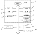
図1は本発明の情報埋め込みと抽出のための電子透かしシステムの構成図である。透かしを埋め込みたい情報提供者のコンピュータ3 には,デジタルカメラ18などで撮影された画像データが,例えばハードディスクなどのデータメモリ7に保管されている。画像データは,プログラムメモリ6にある画像処理プログラムにより,CPU11,ROM 4,RAM5などを用いて画像処理され,モニター8に表示される。コンピュータ3にはスキャナ1,プリンタ2が接続され,処理された画像はモニター8に表示されたりプリンタから出力されたりし,またスキャナ1から画像読み取りができる。かかる画像処理は負荷の高い処理が多いため,GPUなどの高速化を図るための処理ボードが入っている場合もある。
Hereinafter, a detailed description will be given with reference to Examples.
FIG. 1 is a block diagram of a digital watermarking system for embedding and extracting information of the present invention. In the
図2は,インターネット配信の処理手順を示すものである。透かし情報を埋め込まれた画像は,情報提供者16のコンピュータシステムからインターネット12により配信される(13)。あるいはチラシや広告の紙媒体で印刷物として配布してもよい。それを受信したユーザ17は,透かし情報をスキャナ1やデジタルカメラやスマートフォン18などで画像を読み取り、透かし抽出のソフトウェアにより透かし情報を抽出し、情報提供者のホームページなどにアクセスする(14)。そして、さらに詳細な情報を受け取ることができる(15)。
FIG. 2 shows a processing procedure for Internet distribution. The image in which the watermark information is embedded is distributed by the Internet 12 from the computer system of the information provider 16 (13). Alternatively, it may be distributed as a printed matter in a paper medium such as a leaflet or an advertisement. Upon receiving this, the user 17 reads the watermark information with a
ここで,まず本発明に用いられるドットプロファイル作成アルゴリズムを図3の処理フローに沿って説明する。
今,求めるドットプロファイルのサイズをR×R ( R=2^m,^はべき乗を表す)として,まず,疑似乱数発生器により,R^2/2個のランダムドット(初期状態はホワイトノイズ)を発生させ,p(x,y)とする。この時,疑似乱数発生器の初期値(SEED値)を変えることにより初期状態のドットプロファイルを変更可能である。
STEP1:p(x,y)ドットプロファイルの二次元フーリエ変換を行い,P(u,v)を得る。
STEP2:P(u,v)にフィルタD(u,v)を掛けて,新たなP'(u,v)を得る。
STEP3:P'(u,v)に逆フーリエ変換を行い,多値の点プロファイルp'(x,y)を得る。
STEP4: 誤差関数e(x,y)=p'(x,y)-p(x,y)を求め,各画素位置での誤差の大きい順に白,黒反転する。
STEP5: 上記操作を誤差が許容量以内になるまで繰り返す。
以上の操作を行い最終的に目的とするドットプロファイルを得る。
Here, first, the dot profile creation algorithm used in the present invention will be described along with the processing flow of FIG.
Now, let's assume that the size of the dot profile to be obtained is R × R (R = 2 ^ m, ^ represents the power), and first, using a pseudo-random number generator, R ^ 2/2 random dots (initial state is white noise). Is generated and is p (x, y). At this time, the dot profile in the initial state can be changed by changing the initial value (SEED value) of the pseudo-random number generator.
STEP1: Perform a two-dimensional Fourier transform of the p (x, y) dot profile to obtain P (u, v).
STEP2: Apply filter D (u, v) to P (u, v) to obtain a new P'(u, v).
STEP3: Perform an inverse Fourier transform on P'(u, v) to obtain a multi-valued point profile p'(x, y).
STEP4: Find the error function e (x, y) = p'(x, y) -p (x, y) and invert white and black in descending order of error at each pixel position.
STEP5: Repeat the above operation until the error is within the allowable amount.
By performing the above operations, the desired dot profile is finally obtained.
次に,フィルタD(u,v)について説明する。D(u,v)は,u軸方向とv軸方向で軸対称で、低域と高域をカットするフィルタとする。これは円や楕円であっても矩形であってもよい。u軸方向の低域カットオフ周波数をfmin 、高域カットオフ周波数をfmaxとし,f0=(1/2)^(1/2)・fn としたとき,
a=(fmax-f0)/fn
b=(fmin-f0)/fn
とすると,Rに非依存のドットプロファイルが得られる。ここで,fnはナイキスト周波数を示す。 ここで、aが無限大あるいはそれに近い値の場合、低域のみをカットするブルーノイズ特性、fmax,fminが有限の場合は、低域と高域をカットするグリーンノイズ特性となる。
Next, the filter D (u, v) will be described. D (u, v) is a filter that is axisymmetric in the u-axis direction and the v-axis direction and cuts low and high frequencies. It may be a circle, an ellipse, or a rectangle. When the low cutoff frequency in the u-axis direction is fmin, the high cutoff frequency is fmax, and f0 = (1/2) ^ (1/2) · fn,
a = (fmax-f0) / fn
b = (fmin-f0) / fn
Then, a dot profile that is independent of R is obtained. Here, fn indicates the Nyquist frequency. Here, when a is infinite or a value close to infinity, it has a blue noise characteristic that cuts only low frequencies, and when fmax and fmin are finite, it has a green noise characteristic that cuts low frequencies and high frequencies.
一例として,ブロックサイズR=32のドットプロファイルを求める。ブロックサイズは、一般に大きいほど透かしを抽出する精度は向上する。これはドットの集合状態や分布から透かしを抽出するため、ブロックサイズが小さいと集合の母集団数が少なくなり、統計的揺らぎが大きくなり、精度が低下するためである。種々の実験結果、R=64以上が最適であるが、埋め込む情報量を増やすためR=32として、精度向上策を別途検討した。 As an example, find the dot profile with block size R = 32. Generally, the larger the block size, the higher the accuracy of extracting the watermark. This is because the watermark is extracted from the set state and distribution of dots, so if the block size is small, the number of populations of the set will be small, the statistical fluctuation will be large, and the accuracy will be low. As a result of various experiments, R = 64 or higher is optimal, but in order to increase the amount of information to be embedded, R = 32 was set and measures to improve accuracy were separately examined.
図3は32画素×32画素におけるドットプロファイルを示したものである。同図(a)は、(a,b)=(0,-5/16)であらわされるドットプロファイルp0(i,j)およびそのスペクトル特性P0を示す。楕円率1.5とは,フィルタD(u,v)がv軸方向に1.5倍に拡大されていることを意味する。スペクトル分布がu軸,v軸に対して対象であるため,p0(i,j)の虚数部は0となる。同図(b)のドットパターンp1(i,j)はp0(i,j)を90°回転したもので,スペクトルも同様に90°回転したものとなる。同図(c)は(a,b)=(∞,0)のブルーノイズパターン,(d)は(a,b)=(3/16,-1/16)の円形フィルタによるパターン, (e)は (a,b)=( 0,-1/4)の矩形フィルタによるパターンである。これらのパターンはすべてランダムなドットパターンでスペクトルの低域が低減したパターンとなっている。 FIG. 3 shows a dot profile in 32 pixels × 32 pixels. FIG. (A) shows the dot profile p0 (i, j) represented by (a, b) = (0, -5/16) and its spectral characteristic P0. The ellipticity of 1.5 means that the filter D (u, v) is magnified 1.5 times in the v-axis direction. Since the spectral distribution is symmetrical with respect to the u-axis and v-axis, the imaginary part of p0 (i, j) is 0. The dot pattern p1 (i, j) in Fig. (B) is a 90 ° rotation of p0 (i, j), and the spectrum is also 90 ° rotated. Figure (c) shows the blue noise pattern of (a, b) = (∞, 0), (d) shows the pattern of (a, b) = (3/16, -1/16) with a circular filter, (e). ) Is a pattern by the rectangular filter of (a, b) = (0, -1 / 4). All of these patterns are random dot patterns in which the low frequencies of the spectrum are reduced.
続いて,多値画像データへの透かし埋め込みアルゴリズムについて説明する。
透かし情報の埋め込みは,カラー画像データをY,Cb,Crに変換し,輝度Yに透かし情報を埋め込む。Blue(印刷時はイエロー)に埋め込むんだ場合は、視覚的に最も目立たないが、読み取り時に,精度よく色分離することが必要である。
Next, the watermark embedding algorithm for multi-valued image data will be described.
To embed the watermark information, the color image data is converted to Y, Cb, Cr, and the watermark information is embedded in the brightness Y. When embedded in Blue (yellow when printing), it is visually least noticeable, but it is necessary to perform color separation with high accuracy when reading.
今,周波数空間においてブロック単位で異種のスペクトルパターンを埋め込むこととして,異なるスペクトルパターンをPi (u,v) (i=0,・・・,n)とする。Piは前述の低域周波数でスペクトルが低減した特性を示す。低域のカットオフ周波数fminは、埋め込まれる画像の最大周波数よりも大きい周波数を選ぶことが両者の重なりがなく理想的である。今、ブロックの画像の周波数スペクトルをI(u,v)とすると,埋め込まれたスペクトルW(u,v)は,
W(u,v)=I(u,v)+gain・Pi (u,v) ---------- (1)
となる。ここでgainは埋め込み強度を表す。
Now, let's assume that different spectral patterns are embedded in block units in the frequency space, and the different spectral patterns are Pi (u, v) (i = 0, ..., N). Pi shows the characteristic that the spectrum is reduced at the above-mentioned low frequency. For the low cutoff frequency fmin, it is ideal to select a frequency higher than the maximum frequency of the embedded image so that the two do not overlap. Now, assuming that the frequency spectrum of the block image is I (u, v), the embedded spectrum W (u, v) is
W (u, v) = I (u, v) + gain ・ Pi (u, v) ---------- (1)
Will be. Here, gain represents the embedding strength.
通常、不可視の電子透かしは、埋め込み強度を小さくし、埋め込まれたパターンが認識されないようにする。これは、著作権保護の目的で著作権情報を透かしとして画像に埋め込むが、画像自体を商品とするため、画質の劣化が問題となるからである。しかしながら、画像を媒介としてURL等を埋め込み、ホームページに誘導する応用では、むしろ、多くの情報を正確に抽出できることが優先される。したがって、本発明では大きなgain で埋め込む。とはいえ、画質の著しい劣化はユーザに魅力を感じさせない。種々の実験結果、gainが0.25以上0.75以下であれば、視覚的に劣化が目立たず、かつ正確な埋め込み情報が抽出できることが分かった。 Invisible watermarks typically reduce the embedding strength and make the embedded pattern unrecognizable. This is because the copyright information is embedded in the image as a watermark for the purpose of copyright protection, but since the image itself is a commercial product, deterioration of image quality becomes a problem. However, in the application of embedding a URL or the like via an image and guiding the user to a homepage, it is rather prioritized to be able to accurately extract a large amount of information. Therefore, in the present invention, it is embedded with a large gain. However, the significant deterioration in image quality does not appeal to users. As a result of various experiments, it was found that when the gain is 0.25 or more and 0.75 or less, the deterioration is not visually noticeable and accurate embedded information can be extracted.
実際の透かし情報の埋め込み作業は実空間で行う。式(1)を実空間(画素空間)に変換する(小文字で表す)と,
w(x,y)=i(x,y)+gain・pi (x,y) ---------- (2)
となる。今、透かし情報の1ビットの情報を1ブロックに埋め込むとする。透かし情報は,かかる異なるグリーンノイズ特性を示す2つのドットパターンp0(x,y), p1(x,y)を用意し,埋め込むビット情報(0,1)に対して,
埋め込みビット=0の時 → p0(x,y)
埋め込みビット=1の時 → p1(x,y)
として埋め込む。ここで,p0およびp1は(1,0)の二値であるが,平均輝度を保存するため(1/2,-1/2)とする。
The actual watermark information embedding work is performed in the real space. When Eq. (1) is converted to real space (pixel space) (represented in lowercase letters),
w (x, y) = i (x, y) + gain ・ pi (x, y) ---------- (2)
Will be. Now, suppose that 1-bit information of watermark information is embedded in 1 block. For the watermark information, two dot patterns p0 (x, y) and p1 (x, y) showing the different green noise characteristics are prepared, and for the bit information (0,1) to be embedded,
When embedded bit = 0 → p0 (x, y)
When embedded bit = 1 → p1 (x, y)
Embed as. Here, p0 and p1 are binary values of (1,0), but they are set to (1/2, -1 / 2) in order to preserve the average brightness.
また,p0およびp1はランダムなドットであるため,両者の境界は目立たない。ブルーノイズやグリーンノイズ特性を示すハーフトーンスクリーンは,プリンタのFMスクリーンとしてよく用いられ,分散性ドットで均一性にすぐれ、人の視覚にも一様で粒状性も感じさせない。 Moreover, since p0 and p1 are random dots, the boundary between them is not conspicuous. Halftone screens that exhibit blue noise and green noise characteristics are often used as FM screens for printers, and have excellent uniformity with dispersed dots, and are uniform to human vision and do not give graininess.
図4の(c)は(a,b)=(∞,0)、すなわちブルーノイズ特性を示すパターンp2(x,y),(d)は(a,b)=(3/16,-1/16)の円形フィルタから生成されたグリーンノイズ特性を示すパターンp3(x,y)である。これらのフィルタは後述の2ビットデータの埋め込みに用いられる。また(e)は(a,b)=( 0,-1/4)の矩形フィルタによるグリーンノイズ特性を示すパターンで、後述のヘッダー用のパターンとして用いられる。 In FIG. 4, (c) is (a, b) = (∞, 0), that is, the pattern p2 (x, y) showing the blue noise characteristic, and (d) is (a, b) = (3/16, -1). It is a pattern p3 (x, y) showing the green noise characteristic generated from the circular filter of / 16). These filters are used for embedding 2-bit data, which will be described later. Further, (e) is a pattern showing the green noise characteristic by the rectangular filter of (a, b) = (0, -1 / 4), and is used as a pattern for the header described later.
原画像への埋め込み可能なデータ量(最大ビット数)Nは,画像サイズをW画素×H画素の画像データに対して,
N=int(W/R)×int(H/R) ---------- (3)
で与えられる。ここで,int()は少数以下切り捨てを表す。埋め込み可能文字数は,ASCII文字の場合は,int(N/8)となる。ブロックサイズR=32の場合,512画素×512画素の場合,N=256ビット=32バイトの情報量が埋め込み可能である。これは通常のURLやホームページのアドレスを埋め込むためにはあまり余裕がない。より多くの情報を埋め込むためには、画像サイズを大きくするか、後で説明する多値の埋め込みを行う。
The amount of data (maximum number of bits) N that can be embedded in the original image is the image size of W pixels x H pixels for the image data.
N = int (W / R) × int (H / R) ---------- (3)
Given in. Here, int () represents truncation below the minority. The number of characters that can be embedded is int (N / 8) for ASCII characters. When the block size is R = 32 and 512 pixels x 512 pixels, the amount of information of N = 256 bits = 32 bytes can be embedded. This doesn't have much room to embed a normal URL or homepage address. In order to embed more information, increase the image size or embed multiple values, which will be described later.
通常、透かし情報の抽出にはエラーが生じる。本手法においても、原画像が非常に細かい、高周波数の多い画像の場合、そのスペクトル分布が、埋め込むパターンのスペクトル分布と重なり、正しく抽出されない。そこで、通常、埋め込むビット列を複数回繰り返し埋め込み、多数決あるいは信頼度の高いものを選んで埋め込み情報を抽出する。しかしながら、繰り返し回数を増やすと埋め込み可能なビット数はさらに減少する。 Usually, an error occurs in extracting the watermark information. Even in this method, in the case of an image in which the original image is very fine and has many high frequencies, the spectral distribution overlaps with the spectral distribution of the embedded pattern and is not extracted correctly. Therefore, usually, the bit string to be embedded is repeatedly embedded a plurality of times, and the embedded information is extracted by selecting a majority vote or a highly reliable one. However, as the number of repetitions increases, the number of bits that can be embedded further decreases.
そこで、本透かしの埋め込みは、事前に画像データにわずかなローパスフィルタを掛け、高域を低減させる。例えば2画素×2画素で、カーネル係数が同じ(1である)ローパスフィルタでは、画像の最大空間周波数は1/2となる。3×3の場合は1/3となる。したがって、透かし情報を埋め込む前に、画像データに平滑化処理を行うことにより、画像スペクトルを、ドットパターンの低域カットオフ周波数以下に閉じ込めることができ、透かしの抽出において正確性を向上させることが可能となる。 Therefore, the embedding of this watermark applies a slight low-pass filter to the image data in advance to reduce the high frequency range. For example, in a low-pass filter having 2 pixels × 2 pixels and the same kernel coefficient (1), the maximum spatial frequency of the image is halved. In the case of 3x3, it becomes 1/3. Therefore, by smoothing the image data before embedding the watermark information, the image spectrum can be confined below the low cutoff frequency of the dot pattern, and the accuracy in watermark extraction can be improved. It will be possible.
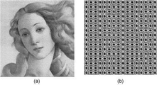
さらに、前述のように埋め込みの強度gainを大きくすることにより、耐性向上と抽出精度向上を図ることができる。gainを0.25以上0.75以下とすることにより、画質劣化をあまり感じさせずに強く埋め込むことが可能である。gain=0.25とは、8ビットの画像データで、±32の値のドットパターンを重畳することで、画像データの下位5ビットが変化する。図5(a)は、512画素×512画素の画像にgain=0.375で埋め込んだ時の画像で、原画像に±48のドットパターンを重畳したものである。同図(b)はその一部を拡大したもので、ドットパターンによるノイズが顕著である。しかしながら、グリーンノイズやブルーノイズ特性から、通常のサイズでは人の視覚特性からノイズはあまり目立たない。gain=0.75では、±96の値を重畳するもので画像データの7ビット目が変化するため、これ以上強くすると画質劣化が著しい。
以上のように、画像データに平滑化処理を行うことと、強いgainで埋め込むことで、耐性を高め、透かし抽出で正確で高い信頼度の抽出が可能となる。
Further, by increasing the strength gain of embedding as described above, it is possible to improve the resistance and the extraction accuracy. By setting the gain to 0.25 or more and 0.75 or less, it is possible to embed strongly without feeling much deterioration in image quality. Gain = 0.25 is 8-bit image data, and the lower 5 bits of the image data change by superimposing a dot pattern with a value of ± 32. FIG. 5A is an image when an image of 512 pixels × 512 pixels is embedded with gain = 0.375, and a dot pattern of ± 48 is superimposed on the original image. Figure (b) is an enlargement of a part of it, and the noise due to the dot pattern is remarkable. However, due to the green noise and blue noise characteristics, the noise is not so noticeable from the human visual characteristics at a normal size. When gain = 0.75, the value of ± 96 is superimposed and the 7th bit of the image data changes. Therefore, if the value is made stronger than this, the image quality deteriorates significantly.
As described above, by performing the smoothing process on the image data and embedding it with a strong gain, the resistance is enhanced, and accurate and highly reliable extraction becomes possible by watermark extraction.
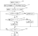
図6は透かし埋め込み処理フローを示す。まず,原画像を2×2のフィルタにより一様に平滑化を行う(20)。続いて、埋め込むための透かし情報ビット列wm(i,j)を用意する(21)。ここでiは埋め込む文字のi番目を,jはそのjビット目を表す(MSBを0ビット目とする)。ASCII文字の場合,8ビット/文字 であるので,j=0,1,…7である。また,iは,1≦i≦N/8である。ただしNは式(3)で示された埋め込み最大ビット数である。続いて,画像データをR×Rのブロックに分割し(22),ブロック単位でドットパターンを合成していくが,文字列の先頭であるか否か(23)で,先頭の場合はヘッダーパターン(pH)を埋め込む。そのあと、埋め込みビットが0の場合はp0, 埋め込みビットが1の場合はp1のパターンを埋め込む(24)。全ブロックに埋め込みが終わった段階で終了する。 FIG. 6 shows a watermark embedding processing flow. First, the original image is uniformly smoothed by a 2 × 2 filter (20). Subsequently, the watermark information bit string wm (i, j) for embedding is prepared (21). Here, i represents the i-th character to be embedded, and j represents the j-th bit (MSB is the 0th bit). In the case of ASCII characters, since it is 8 bits / character, j = 0,1, ... 7. Further, i is 1 ≦ i ≦ N / 8. However, N is the maximum number of embedded bits represented by the equation (3). Next, the image data is divided into R × R blocks (22), and the dot pattern is synthesized in block units. Depending on whether or not it is the beginning of the character string (23), the header pattern is the beginning. Embed (pH). After that, if the embedded bit is 0, the pattern of p0 is embedded, and if the embedded bit is 1, the pattern of p1 is embedded (24). It ends when the embedding in all blocks is completed.
図7は512画素×512画素の画像にブロックサイズR=32、埋め込み強度gain=0.375のドットパターンでアルファベット“a,b,c,…z”の26文字を埋め込んだものである。この画像は,式(3)より最大32バイト(ASCIIで32文字)の情報が埋め込み可能である。
同図(a)は埋め込まれた画像を示す。同図(b)は後述の抽出結果である。図中、縦長の楕円はビットが”0”を表し、横長の楕円は”1”を表す。四角のパターンは文字列の先頭のヘッダーパターンで、繰り返しパターンの区切りとして用いられる。gainが大きいため、印刷前のデータでは、埋め込み情報が正確に抽出される。印刷や表示画像からの読み取りで画質が劣化することを見越して、信頼度に余裕を持たせている。
FIG. 7 shows an image of 512 pixels × 512 pixels in which 26 characters of the alphabet “a, b, c, ... Z” are embedded in a dot pattern having a block size of R = 32 and an embedding strength of gain = 0.375. Up to 32 bytes (32 characters in ASCII) of information can be embedded in this image from equation (3).
Figure (a) shows an embedded image. Figure (b) shows the extraction results described later. In the figure, the vertically long ellipse represents "0" for the bit, and the horizontally long ellipse represents "1". The square pattern is the header pattern at the beginning of the character string and is used as a delimiter for the repeating pattern. Since the gain is large, the embedded information is accurately extracted from the data before printing. The reliability is given a margin in anticipation that the image quality will deteriorate due to printing or reading from the displayed image.
透かし情報の抽出は,読み取った画像の大きさ,傾きを補正後,ブロック単位でスペクトル画像を求める。式(2)をフーリエ変換して,
F{w(x,y)}=F{i(x,y)} + gain・F{pi (x,y)} ---------- (4)
となる。ただし,F{ }はフーリエ変換を表す。通常,F{i(x,y)}は原画像のスペクトルで,0周波数付近に局在し,F{pi (x,y)}は埋め込みに用いたドットパターンのスペクトルP0,P1で、楕円リング状で、画像スペクトルを内部に閉じ込める。このため,両者の重なりは少なく,両者を分離することは容易である。
To extract the watermark information, the size and inclination of the read image are corrected, and then the spectrum image is obtained in block units. Fourier transform Eq. (2)
F {w (x, y)} = F {i (x, y)} + gain ・ F {pi (x, y)} ---------- (4)
Will be. However, F {} represents the Fourier transform. Normally, F {i (x, y)} is the spectrum of the original image, localized near
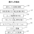
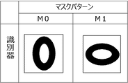
図8に透かし抽出の処理フローを示す。まず、透かし入りの画像をスキャナやカメラで撮影し(36)、画像を射影変換やAffine変換し、矩形の補正画像を得る(37)。デジタルカメラなどで撮影した場合は、斜めから撮影した時に台形歪み等が入るため、射影変換を施し補正し、矩形に切り出した画像を所定の解像度になるようにリサイズを行う。続いて、エッジ強調画像を作成する(38)。エッジ強調処理によりドットの輪郭が明瞭になり、抽出精度が向上する。そのあと、画像をR×Rのブロックに分割しブロック毎にFFTを行う(39)。続いて得られたスペクトル画像にヒストグラムイコライゼーションを施す(40)。これはスペクトルパターンのコントラストを向上させると同時に,後述の信頼度の定量化での規格化を図るためである。続いて後述のマスク処理によるパターン認識を行い(41),透かし情報wm’(i,j) および信頼度wmrel’(i,j)のデータを得る(42)。以上の操作はブロックごとに行い、すべてのブロックが終った段階で終了する。 FIG. 8 shows the processing flow of watermark extraction. First, a watermarked image is taken with a scanner or a camera (36), and the image is subjected to projective transformation or Affine transformation to obtain a rectangular corrected image (37). When a picture is taken with a digital camera or the like, trapezoidal distortion or the like occurs when the picture is taken at an angle. Therefore, a projective transformation is performed to correct the image, and the image cut out into a rectangle is resized to a predetermined resolution. Subsequently, an edge-enhanced image is created (38). The edge enhancement process makes the outline of the dots clearer and improves the extraction accuracy. After that, the image is divided into R × R blocks and FFT is performed for each block (39). Subsequently, the obtained spectral image is subjected to histogram equalization (40). This is to improve the contrast of the spectral pattern and at the same time to standardize by quantifying the reliability described later. Subsequently, pattern recognition by mask processing described later is performed (41), and data of watermark information wm'(i, j) and reliability wmrel' (i, j) are obtained (42). The above operation is performed for each block, and ends when all the blocks are completed.
図9はフーリエ変換後のスペクトル分布からパターン認識により透かし情報の抽出を行う識別器としてのマスクパターンM0およびM1を示す。M0は縦長、M1は横長の楕円形状のマスクで,埋め込み用のドットパターンのスペクトル特性P0,P1に対応したものである。図中黒の領域は値が1,白部分は値が0であるとする。透かしの入ったスペクトルにこのマスクを重ね,重なり部分の積分輝度値Q0 およびQ1の差分から,ビットが0か1かを判断する。図10はこの処理フローを示したもので、ブロックのスペクトルパターンW(i,j)に対して,以下の積分輝度値の出力Q0,Q1を得る(40)。
Q0=M0◎W=1/ZΣM0(i,j)・W(i,j)
Q1=M1◎W=1/ZΣM1(i,j)・W(i,j)
ここで◎は重なり部分の積分輝度値を求めるためのマスク演算を、Zはマスクの値が1の画素数を表す。したがって、マスク領域の1画素あたりの輝度値をあらわす。かかる出力から,
Q0>Q1 の時, 抽出ビット=wm’(i,j)=0
Q1>Q0 の時, 抽出ビット=wm’(i,j)=1
となる(41)。同時に,以下のように信頼度を得る(42)。
wmrel’(i,j)=|Q0-Q1|
かかる信頼度はその値が大きいほど抽出ビットの信頼度が高い。
FIG. 9 shows mask patterns M0 and M1 as discriminators that extract watermark information by pattern recognition from the spectral distribution after Fourier transform. M0 is a vertically long mask and M1 is a horizontally long elliptical mask, which corresponds to the spectral characteristics P0 and P1 of the dot pattern for embedding. It is assumed that the black area in the figure has a value of 1 and the white area has a value of 0. This mask is superimposed on the watermarked spectrum, and whether the bit is 0 or 1 is determined from the difference between the integrated luminance values Q0 and Q1 in the overlapping portion. FIG. 10 shows this processing flow, and obtains the outputs Q0 and Q1 of the following integrated luminance values for the spectral pattern W (i, j) of the block (40).
Q0 = M0 ◎ W = 1 / ZΣM0 (i, j) ・ W (i, j)
Q1 = M1 ◎ W = 1 / ZΣM1 (i, j) ・ W (i, j)
Here, ⊚ represents a mask operation for obtaining the integrated luminance value of the overlapping portion, and Z represents the number of pixels in which the mask value is 1. Therefore, it represents the brightness value per pixel in the mask area. From such output
When Q0> Q1, the extraction bit = wm'(i, j) = 0
When Q1> Q0, extraction bit = wm'(i, j) = 1
(41). At the same time, the reliability is obtained as follows (42).
wmrel'(i, j) = | Q0-Q1 |
The larger the value of the reliability, the higher the reliability of the extraction bit.
図11に透かし情報の精度および信頼性の向上策について説明する。画像のサイズにより式(3)から埋め込み可能最大ビット数Nが与えられる。今埋め込みたいビット数がnで n<N であるとすると,重複してビット列を埋め込むことができる。このため、まず、透かし情報の抽出で文字列の繰り返しを考慮せずにN(Nは埋め込み可能な数)までの連続した透かし情報wm’ と信頼度wmrel’ を得る。その後、繰り返しを考慮して、この連続した文字列から信頼度の高いものを選択してNまでの透かし情報を検査していく。 FIG. 11 describes measures for improving the accuracy and reliability of the watermark information. The maximum number of bits N that can be embedded is given by the equation (3) depending on the size of the image. Assuming that the number of bits to be embedded is n and n <N, duplicate bit strings can be embedded. Therefore, first, continuous watermark information wm'and reliability wmrel'up to N (N is an embeddable number) are obtained in the watermark information extraction without considering the repetition of the character string. After that, in consideration of repetition, a highly reliable character string is selected from this continuous character string and the watermark information up to N is inspected.
これを式で表すと、iを文字番号(0<i≦N),jをビット番号(0≦j≦7)としたとき,nを法としてその剰余kは,k=i mod n で表され(50),(i,j)番目の信頼度wmrel’が
wmrel’(i,j)>wmrel(k,j) の時、
wm(k,j)=wm’(i,j)
wmrel(k,j)=wmrel’(i,j)
として(52),透かし情報を信頼度の高いものに置き換える。これをiがNまで,すなわち全埋め込みビット数が終了するまで行う。
Expressing this as an equation, when i is a character number (0 <i ≤ N) and j is a bit number (0 ≤ j ≤ 7), the remainder k is expressed by k = i mod n, modulo n. (50), (i, j) th reliability wmrel'is
When wmrel'(i, j)> wmrel (k, j),
wm (k, j) = wm'(i, j)
wmrel (k, j) = wmrel'(i, j)
As (52), replace the watermark information with a highly reliable one. This is done until i is N, that is, until the total number of embedded bits is completed.
上記操作により埋め込みビット列の,最も信頼度の高い透かし情報が選ばれ,埋め込まれた文字の信頼度が高くなり,正しく抽出される。この方法は多数決で決める手法に比べて抽出誤差が少ない。 By the above operation, the most reliable watermark information of the embedded bit string is selected, the reliability of the embedded characters is increased, and the information is extracted correctly. This method has less extraction error than the method determined by majority vote.
以上のようにして透かしの抽出が行われる。前述の図7の(b)は抽出時のスペクトル分布を示す。埋め込みはASCII文字で“abcd・・・xyz” のアルファベット26文字を埋め込んだものである。各文字をビットに展開し,図3で説明したように,”0“に対してp0を,”1“に対してはp1のパターンを埋め込む。またASCII文字の先頭ビット(MSB)はすべて0であるため,これを文字列の区切り用のヘッダーパターンとして用いる。また、これは矩形、サイズ方向を計測することによりAffine変換係数検出用のパターンとしても用いることが可能である。埋め込み可能文字数は32バイトであるため,”abcdef"の6文字が重複て埋め込まれているため、前述の信頼度の高いものを選ぶことにより抽出結果の精度を向上させることができる。 The watermark is extracted as described above. (B) of FIG. 7 described above shows the spectral distribution at the time of extraction. The embedding is ASCII characters that embed 26 letters of the alphabet "abcd ... xyz". Each character is expanded into bits, and as explained in Fig. 3, the pattern of p0 is embedded for "0" and p1 is embedded for "1". Also, since the first bits (MSB) of ASCII characters are all 0, this is used as the header pattern for character string delimiters. It can also be used as a pattern for detecting the Affine transformation coefficient by measuring the rectangle and size directions. Since the number of characters that can be embedded is 32 bytes, the 6 characters of "abcdef" are embedded in duplicate, so the accuracy of the extraction result can be improved by selecting the one with high reliability described above.
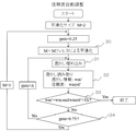
埋め込んだ透かし情報が,原画像が細かく空間周波数の高い場合、抽出ができない場合や信頼度が低い場合がある。そのため、埋め込み時に信頼度を高める処理を行う。図12はこの自動調整を行うフローを示す。まず,画像にM=2、gain=0.25として、M×M、すなわち2画素×2画素の平滑化を行う(30)。その後、透かし情報wm(i,j)の埋め込みを行う(31)。全ブロックを埋め込んだら,次に透かし読み取りを行う(32)。ここでは,抽出した透かし情報wm’(i,j)と,埋め込む前の透かし情報 wm(i,j)を比較し一致するか否かを判定する。それと同時に,抽出ビットの信頼度wmrel’(i,j)が所定の閾値以上か判定する(33)。透かし情報が一致しない場合や,一致していても信頼度が閾値以下の場合は,gainを所定量Δだけ増加させ、再び埋め込みを行う。gainが最大値0.75に達した化判断し(34)、達した場合には、平滑化のサイズMを+1して,再び透かしの埋め込みを行う。最終的には所定の信頼度を満たす埋め込みが可能となる。以上のようにして埋め込んだ透かし情報が余裕のある読み取りが可能となるよう埋め込みを自動で行うことができる。 If the embedded watermark information has a fine original image and a high spatial frequency, it may not be possible to extract it or its reliability may be low. Therefore, a process for increasing reliability is performed at the time of embedding. FIG. 12 shows a flow for performing this automatic adjustment. First, M × M, that is, 2 pixels × 2 pixels is smoothed by setting M = 2 and gain = 0.25 to the image (30). After that, the watermark information wm (i, j) is embedded (31). After embedding all the blocks, the watermark is read next (32). Here, the extracted watermark information wm'(i, j) is compared with the watermark information wm (i, j) before embedding to determine whether or not they match. At the same time, it is determined whether the reliability wmrel'(i, j) of the extraction bit is equal to or higher than a predetermined threshold value (33). If the watermark information does not match, or if the reliability is below the threshold even if they do match, gain is increased by a predetermined amount Δ and embedding is performed again. It is determined that the gain reaches the maximum value of 0.75 (34), and when it reaches the maximum value, the smoothing size M is incremented by +1 and the watermark is embedded again. Ultimately, embedding that satisfies a predetermined reliability becomes possible. Embedding can be performed automatically so that the watermark information embedded as described above can be read with a margin.
図13は透かしの埋め込まれた画像をデジタルカメラやスマートフォンで撮影して透かしを読み取った時の図である。同図(a)は、512画素×512画素の画像に2画素の平滑化を行い、gain=0.375 で埋め込んだ画像をデジタルカメラで撮影したものである。埋め込みデータは、アルファベットの“a,b,c,d,…, x,y,z”の26文字である。(b)は補正後512画素×512画素に切り出したものである。(c)は透かし抽出ソフトウェアで読み取ったもので、正しく抽出できている。本手法は,ドットの空間分布から情報を抽出するため、画像を読み取る際の照明むらや濃度むらなどの影響を受け難く、前述の自動調整により、どのような空間周波数をもった画像でも正確に読み取ることが可能となる。 FIG. 13 is a diagram when an image with an embedded watermark is taken with a digital camera or a smartphone and the watermark is read. Figure (a) shows an image of 512 pixels x 512 pixels smoothed by 2 pixels and embedded with gain = 0.375, taken with a digital camera. The embedded data is 26 characters of the alphabet "a, b, c, d, ..., x, y, z". (B) is cut out into 512 pixels × 512 pixels after correction. (C) is read by watermark extraction software and can be extracted correctly. Since this method extracts information from the spatial distribution of dots, it is not easily affected by uneven illumination and uneven density when reading an image, and the above-mentioned automatic adjustment makes it possible to accurately adjust images with any spatial frequency. It becomes possible to read.
埋め込む情報量を増やすためには,多値の埋め込みが可能である。図14は、図4で説明した複数の4つのドットパターンを用いて各2ビット情報を埋め込むことができる。すなわち、多値(今の場合4値)の埋め込みが可能である。4つの互いにスペクトル分布が異なるパターンp0(x,y),p1(x,y), p2(x,y),p3(x,y)は、埋め込まれるビット情報の2ビット(00,01,10,11)に応じて、それぞれのパターンを選択する。抽出はそれぞれのスペクトル分布に対応したマスクM0,M1,M2,M3を用いて抽出する。 In order to increase the amount of information to be embedded, it is possible to embed multiple values. In FIG. 14, each 2-bit information can be embedded using the plurality of four dot patterns described in FIG. That is, it is possible to embed multiple values (4 values in this case). The four patterns p0 (x, y), p1 (x, y), p2 (x, y), p3 (x, y) with different spectral distributions are 2 bits (00,01,10) of the embedded bit information. , 11) Select each pattern according to. Extraction is performed using masks M0, M1, M2, and M3 corresponding to each spectral distribution.
かかる2ビットの埋め込みにより、埋め込み可能な情報量は2倍になる。すなわち、512画素×512画素の画像に対して、64バイトの情報を埋め込むことが可能となる。しかしながら、パターン数が多くなれば抽出精度も低下する。このため、平滑化や埋め込み強度をさらに強くする必要がある。したがって、小さいサイズの画像で多くの情報を埋め込む必要がある場合に、画質を多少犠牲にして使う場合に有効である。 Such 2-bit embedding doubles the amount of information that can be embedded. That is, it is possible to embed 64 bytes of information in an image of 512 pixels × 512 pixels. However, as the number of patterns increases, the extraction accuracy also decreases. Therefore, it is necessary to further strengthen the smoothing and embedding strength. Therefore, it is effective when it is necessary to embed a lot of information in a small-sized image and the image quality is sacrificed to some extent.
以上,本発明の電子透かし法は、情報を埋め込んだ画像から、スキャナやカメラで読み取ることにより、埋め込まれた情報を正確に抽出することができるので、画像とネットをつなぐインターフェイス手段として有効である。例えば商品の写真に発売元のURLを透かしとして埋め込み、ユーザをそのホームページに誘導することなどが可能である。 As described above, the digital watermarking method of the present invention is effective as an interface means for connecting an image and a net because the embedded information can be accurately extracted by scanning the image with embedded information with a scanner or a camera. .. For example, it is possible to embed the URL of the seller as a watermark in the photo of the product and guide the user to the homepage.
1はスキャナー,2はプリンタ,3はコンピュータシステム,4はROM, 5はRAM,6はプログラムメモリ,7はデータメモリ,8はモニター,9はキーボード,10は通信機能,11はCPU,12はインターネット, 13は画像データの配信,14はホームページへのアクセスや詳細情報希望の連絡,15は詳細情報の配信,16は画像配信者のコンピュータ,17はユーザのコンピュータ、18はデジタルカメラやスマートフォンを表す。 1 is a scanner, 2 is a printer, 3 is a computer system, 4 is ROM, 5 is RAM, 6 is program memory, 7 is data memory, 8 is monitor, 9 is keyboard, 10 is communication function, 11 is CPU, 12 is Internet, 13 is image data distribution, 14 is access to homepage and contact for detailed information request, 15 is distribution of detailed information, 16 is image distributor's computer, 17 is user's computer, 18 is digital camera or smartphone show.
Claims (6)
透かし情報の埋め込みは,デジタル画像データをR画素×R画素 (Rは2のべき乗)のN個のブロックに分割し(N≧n),それぞれのブロックに対して埋め込む透かし情報のビット情報に対応して,フーリエスペクトルが低域で低減した複数の異なるドットパターンpi(x,y) (i=0,1,2,…)、および埋め込み強度(gain)を用いて、
w(x,y)=i(x,y) + gain ・ pi(x,y)
として透かし埋め込み画像w(x,y)を生成し,
透かし情報の抽出は,かかる透かしの埋め込まれた画像を補正処理を行った後、ブロックに分割し,それぞれのブロックのスペクトル分布から,埋め込まれた情報を抽出するとき、
前記埋め込み強度gainが、
0.75≧gain≧0.25
であり、埋め込む前に画像データi(x,y) を平滑化処理を行うことを特徴とする電子透かし方法。
In the digital watermarking method that embeds n-bit information in digital image data i (x, y),
To embed watermark information, divide the digital image data into N blocks of R pixels x R pixels (R is a power of 2) (N ≧ n), and correspond to the bit information of the watermark information to be embedded in each block. Then, using a number of different dot patterns pi (x, y) (i = 0,1,2, ...) with the Fourier spectrum reduced in the low frequency range, and the embedding intensity (gain),
w (x, y) = i (x, y) + gain ・ pi (x, y)
Generates a watermark embedded image w (x, y) as
The watermark information is extracted when the image with the embedded watermark is corrected, divided into blocks, and the embedded information is extracted from the spectral distribution of each block.
The embedding strength gain is
0.75 ≧ gain ≧ 0.25
A digital watermarking method characterized in that image data i (x, y) is smoothed before embedding.
The plurality of different dot patterns in which the Fourier spectrum is reduced in the low frequency range are filters D (u, v) in which R ^ 2/2 random dots are set to 0 in the low frequency range of the spatial frequency (however, u, v is The first aspect of claim 1, wherein the filter D (u, v) is axisymmetric with respect to the u-axis and the v-axis, which is obtained by performing a filtering operation based on (two-dimensional spatial frequency). Digital watermarking method .
The plurality of dot patterns are composed of two elliptical patterns p0 (x, y) and p1 (x, y) whose spectra are reduced even in the high frequency range and whose spectrum distributions are orthogonal to each other. The digital watermarking method according to claim 2, wherein a pattern is selected corresponding to the bit information (0,1) to be embedded and the watermark information is embedded.
The plurality of dot patterns consist of four patterns p0 (x, y), p1 (x, y), p2 (x, y), p3 (x, y) having different spectral distributions from each other, and are embedded bit information. The digital watermarking method according to claim 2, wherein a pattern is selected and information is embedded corresponding to 2 bits (00,01,10,11).
Q0>Q1 の時, 抽出ビット=0
Q1>Q0 の時, 抽出ビット=1
であり,また,信頼度を
信頼度=|Q0-Q1|
として求め,透かし情報を重複して埋め込んだ場合,重複したビットからかかる信頼度が最も高いものを透かし情報として抽出することを特徴とする請求項3に記載の電子透かし方法。
For the digital watermark extraction, there are masks M0 and M1 corresponding to the spectral characteristics of the two embedded dot patterns, and from the integrated luminance values Q0 and Q1 of the mask and the extracted spectral distribution in block units,
When Q0> Q1, extraction bit = 0
When Q1> Q0, extraction bit = 1
And the reliability is reliability = | Q0-Q1 |
The digital watermarking method according to claim 3, wherein when the watermark information is duplicated and embedded, the one having the highest reliability is extracted as the watermark information from the duplicated bits.
To embed the watermark information, first, the image is smoothed and embedded by the minimum size smoothing filter and the minimum gain, and then the watermark information is extracted, and all the bits are not extracted correctly, or each of them. If the reliability of the bits is below a certain threshold, increase the size of the gain and smoothing filter, and perform the above operation until all the bits are correctly extracted and the reliability of each bit is above a certain threshold. The digital watermarking method according to claim 5, wherein the digital watermarking method is performed automatically.
Priority Applications (1)
| Application Number | Priority Date | Filing Date | Title |
|---|---|---|---|
| JP2017117460A JP6920719B2 (en) | 2017-06-15 | 2017-06-15 | Digital watermarking device and method |
Applications Claiming Priority (1)
| Application Number | Priority Date | Filing Date | Title |
|---|---|---|---|
| JP2017117460A JP6920719B2 (en) | 2017-06-15 | 2017-06-15 | Digital watermarking device and method |
Publications (2)
| Publication Number | Publication Date |
|---|---|
| JP2019004313A JP2019004313A (en) | 2019-01-10 |
| JP6920719B2 true JP6920719B2 (en) | 2021-08-18 |
Family
ID=65006293
Family Applications (1)
| Application Number | Title | Priority Date | Filing Date |
|---|---|---|---|
| JP2017117460A Active JP6920719B2 (en) | 2017-06-15 | 2017-06-15 | Digital watermarking device and method |
Country Status (1)
| Country | Link |
|---|---|
| JP (1) | JP6920719B2 (en) |
Family Cites Families (10)
| Publication number | Priority date | Publication date | Assignee | Title |
|---|---|---|---|---|
| JP3156667B2 (en) * | 1998-06-01 | 2001-04-16 | 日本電気株式会社 | Digital watermark insertion system, digital watermark characteristic table creation device |
| JP3102417B2 (en) * | 1998-10-30 | 2000-10-23 | 富士ゼロックス株式会社 | Image processing apparatus and image processing method |
| US6993148B1 (en) * | 1999-07-16 | 2006-01-31 | Canon Kabushiki Kaisha | Image processing apparatus and method, and storage medium |
| JP3809310B2 (en) * | 1999-10-20 | 2006-08-16 | キヤノン株式会社 | Image processing apparatus and method, and storage medium |
| US7561716B2 (en) * | 2003-04-04 | 2009-07-14 | Datamark Technologies Pte Ltd | Watermarking method and apparatus |
| JP4134992B2 (en) * | 2005-03-08 | 2008-08-20 | 沖電気工業株式会社 | Watermark information detection apparatus, watermark information embedding apparatus, watermark information detection method, and watermark information embedding method |
| JP2006270434A (en) * | 2005-03-23 | 2006-10-05 | Fuji Xerox Co Ltd | Method and device for embedding information, and method and device for restoring information |
| JP2006303935A (en) * | 2005-04-21 | 2006-11-02 | Matsushita Electric Ind Co Ltd | Watermark detector, method therefor and memory medium |
| JP2010011438A (en) * | 2008-06-27 | 2010-01-14 | Toshiba Corp | Image processing apparatus and method |
| JP6541215B2 (en) * | 2015-03-02 | 2019-07-10 | 河村 尚登 | Image processing apparatus and method |
-
2017
- 2017-06-15 JP JP2017117460A patent/JP6920719B2/en active Active
Also Published As
| Publication number | Publication date |
|---|---|
| JP2019004313A (en) | 2019-01-10 |
Similar Documents
| Publication | Publication Date | Title |
|---|---|---|
| EP1953752B1 (en) | Embedding and detecting hidden information | |
| US6741758B2 (en) | Image processor and image processing method | |
| JP4137084B2 (en) | Method for processing documents with fraud revealing function and method for validating documents with fraud revealing function | |
| US7995790B2 (en) | Digital watermark detection using predetermined color projections | |
| US20020002679A1 (en) | Image processor and image processing method | |
| Fang et al. | A camera shooting resilient watermarking scheme for underpainting documents | |
| JP2003032473A (en) | Embedding and detection of electronic watermark | |
| JP2006314125A (en) | Processing method and system for password of digital image | |
| Hadmi et al. | Perceptual image hashing | |
| CN113052745B (en) | Digital watermark model training method, ceramic watermark image manufacturing method and ceramic | |
| Munib et al. | Robust image watermarking technique using triangular regions and Zernike moments for quantization based embedding | |
| Hadmi et al. | A robust and secure perceptual hashing system based on a quantization step analysis | |
| Sharma et al. | A review of image watermarking for identity protection and verification | |
| JP6937012B2 (en) | Digital watermarking device and method | |
| JP6937007B2 (en) | Digital watermarking device and method | |
| JP6937010B2 (en) | Digital watermarking device and method | |
| JP6920719B2 (en) | Digital watermarking device and method | |
| Datta et al. | Data authentication using digital watermarking | |
| JP3943573B2 (en) | Image processing method and apparatus for digital watermark | |
| JP3884891B2 (en) | Image processing apparatus and method, and storage medium | |
| JP3809310B2 (en) | Image processing apparatus and method, and storage medium | |
| JP7008950B2 (en) | Digital watermarking device and method | |
| CN110648271A (en) | Method for embedding digital watermark in halftone image by using special dots | |
| JP2020184663A (en) | High resistance digital watermarking method | |
| D’Angelo et al. | Watermark-based authentication |
Legal Events
| Date | Code | Title | Description |
|---|---|---|---|
| A621 | Written request for application examination |
Free format text: JAPANESE INTERMEDIATE CODE: A621 Effective date: 20200610 |
|
| A977 | Report on retrieval |
Free format text: JAPANESE INTERMEDIATE CODE: A971007 Effective date: 20210225 |
|
| A131 | Notification of reasons for refusal |
Free format text: JAPANESE INTERMEDIATE CODE: A131 Effective date: 20210304 |
|
| A521 | Written amendment |
Free format text: JAPANESE INTERMEDIATE CODE: A523 Effective date: 20210401 |
|
| A131 | Notification of reasons for refusal |
Free format text: JAPANESE INTERMEDIATE CODE: A131 Effective date: 20210622 |
|
| A521 | Written amendment |
Free format text: JAPANESE INTERMEDIATE CODE: A523 Effective date: 20210701 |
|
| TRDD | Decision of grant or rejection written | ||
| A01 | Written decision to grant a patent or to grant a registration (utility model) |
Free format text: JAPANESE INTERMEDIATE CODE: A01 Effective date: 20210716 |
|
| A61 | First payment of annual fees (during grant procedure) |
Free format text: JAPANESE INTERMEDIATE CODE: A61 Effective date: 20210716 |
|
| R150 | Certificate of patent or registration of utility model |
Ref document number: 6920719 Country of ref document: JP Free format text: JAPANESE INTERMEDIATE CODE: R150 |