JP6902886B2 - Image processing equipment, methods and programs - Google Patents
Image processing equipment, methods and programs Download PDFInfo
- Publication number
- JP6902886B2 JP6902886B2 JP2017049055A JP2017049055A JP6902886B2 JP 6902886 B2 JP6902886 B2 JP 6902886B2 JP 2017049055 A JP2017049055 A JP 2017049055A JP 2017049055 A JP2017049055 A JP 2017049055A JP 6902886 B2 JP6902886 B2 JP 6902886B2
- Authority
- JP
- Japan
- Prior art keywords
- image
- trimming
- scene
- type
- face
- Prior art date
- Legal status (The legal status is an assumption and is not a legal conclusion. Google has not performed a legal analysis and makes no representation as to the accuracy of the status listed.)
- Active
Links
- 238000000034 method Methods 0.000 title claims description 62
- 238000012545 processing Methods 0.000 title claims description 46
- 238000009966 trimming Methods 0.000 claims description 197
- 238000003702 image correction Methods 0.000 description 25
- 238000010191 image analysis Methods 0.000 description 20
- 230000002354 daily effect Effects 0.000 description 19
- 238000010586 diagram Methods 0.000 description 14
- 238000004458 analytical method Methods 0.000 description 7
- 238000001514 detection method Methods 0.000 description 7
- 238000006243 chemical reaction Methods 0.000 description 6
- 238000012937 correction Methods 0.000 description 6
- 230000010354 integration Effects 0.000 description 6
- 230000006870 function Effects 0.000 description 3
- 239000000203 mixture Substances 0.000 description 3
- 238000004891 communication Methods 0.000 description 2
- 241000593989 Scardinius erythrophthalmus Species 0.000 description 1
- 239000012141 concentrate Substances 0.000 description 1
- 238000013461 design Methods 0.000 description 1
- 230000003203 everyday effect Effects 0.000 description 1
- 238000002474 experimental method Methods 0.000 description 1
- 230000008921 facial expression Effects 0.000 description 1
- 230000005484 gravity Effects 0.000 description 1
- 201000005111 ocular hyperemia Diseases 0.000 description 1
- 238000010187 selection method Methods 0.000 description 1
Images


Classifications
-
- G—PHYSICS
- G06—COMPUTING; CALCULATING OR COUNTING
- G06T—IMAGE DATA PROCESSING OR GENERATION, IN GENERAL
- G06T3/00—Geometric image transformations in the plane of the image
- G06T3/40—Scaling of whole images or parts thereof, e.g. expanding or contracting
-
- G—PHYSICS
- G06—COMPUTING; CALCULATING OR COUNTING
- G06T—IMAGE DATA PROCESSING OR GENERATION, IN GENERAL
- G06T11/00—2D [Two Dimensional] image generation
- G06T11/60—Editing figures and text; Combining figures or text
-
- G—PHYSICS
- G06—COMPUTING; CALCULATING OR COUNTING
- G06T—IMAGE DATA PROCESSING OR GENERATION, IN GENERAL
- G06T2210/00—Indexing scheme for image generation or computer graphics
- G06T2210/22—Cropping
Landscapes
- Physics & Mathematics (AREA)
- General Physics & Mathematics (AREA)
- Engineering & Computer Science (AREA)
- Theoretical Computer Science (AREA)
- Processing Or Creating Images (AREA)
- Image Analysis (AREA)
Description
本発明は、画像データをレイアウトする画像処理装置、方法およびプログラムに関する。 The present invention relates to an image processing apparatus, method and program for laying out image data.
近年では、デジタルカメラの普及に加え、スマートデバイスの普及及びカメラ性能向上によりユーザの写真撮影枚数が急激に増加しており、撮影された膨大な写真を活用するものとして、写真アルバムが注目されてきている。写真アルバムの作成においては、膨大な写真からアルバムに適した画像を選択し、配置するところまでを自動で行うことや、選択した写真を円形や矩形などにトリミングして配置することで、デザイン性を高めることが求められてきている。特許文献1には、トリミングを行う際に、検出した顔が中心となるようにトリミング位置を設定することが記載されている。
In recent years, in addition to the spread of digital cameras, the number of photographs taken by users has increased rapidly due to the spread of smart devices and the improvement of camera performance, and photo albums have been attracting attention as a means of utilizing a huge number of photographs taken. ing. When creating a photo album, you can select an image suitable for the album from a huge number of photos and automatically arrange it, or trim the selected photo into a circle or rectangle and arrange it for design. Is required to increase.
しかしながら、画像の撮影シーンによっては、顔領域が中心からずれた方が、ユーザが撮影時に考慮した構図に沿ったものとなる場合がある。従って、特許文献1に記載の手法により顔領域が中心となるようなトリミングを行っても、シーンの種類によっては、ユーザに違和感を与えてしまう可能性がある。
However, depending on the shooting scene of the image, the face region deviated from the center may be in line with the composition considered by the user at the time of shooting. Therefore, even if trimming is performed so that the face region is the center by the method described in
本発明の目的は、このような従来の問題点を解決することにある。上記の点に鑑み、本発明は、シーンの種類に応じた適切な位置であるトリミング領域に対してトリミングを行う画像処理装置、方法およびプログラムを提供することを目的とする。 An object of the present invention is to solve such a conventional problem. In view of the above points, it is an object of the present invention to provide an image processing apparatus, method and program for trimming a trimming area at an appropriate position according to the type of scene.
上記課題を解決するため、本発明に係る画像処理装置は、レイアウトの対象となる画像を取得する取得手段と、前記取得手段により取得した画像において、前記画像が表すシーンの種類に応じて、トリミング領域の位置を決定する決定手段と、前記画像において、前記決定手段により決定した位置である前記トリミング領域をトリミングするトリミング手段と、を備え、前記決定手段は、前記画像に含まれる特定のオブジェクトの位置に基づきデフォルトトリミング領域の位置を決定し、前記画像が表すシーンの種類が第1種類の場合は、前記デフォルトトリミング領域の位置から前記第1種類に応じた第1移動量だけ移動させた位置を、前記トリミング領域の位置として決定し、前記画像が表すシーンの種類が前記第1種類と異なる第2種類の場合は、前記デフォルトトリミング領域の位置から、前記第1移動量と異なる、前記第2種類に応じた第2移動量だけ移動させた位置を、前記トリミング領域の位置として決定する、ことを特徴とする。 In order to solve the above problems, the image processing apparatus according to the present invention trims the image acquired by the acquisition means for acquiring the image to be laid out and the image acquired by the acquisition means according to the type of the scene represented by the image. The image includes a determination means for determining the position of the region and a trimming means for trimming the trimming area which is a position determined by the determination means in the image, and the determination means is for a specific object included in the image. The position of the default trimming area is determined based on the position, and when the type of the scene represented by the image is the first type, the position is moved from the position of the default trimming area by the first movement amount according to the first type. Is determined as the position of the trimming area, and when the type of the scene represented by the image is a second type different from the first type, the position of the default trimming area is different from the first movement amount. the position is moved by the second movement amount corresponding to the two types, it is determined as the position of the trimming area, wherein the this.
本発明によれば、シーンの種類に応じた適切な位置であるトリミング領域に対してトリミングを行うことができる。 According to the present invention, trimming can be performed on a trimming area which is an appropriate position according to the type of scene.
以下、添付図面を参照して本発明の実施形態を詳しく説明する。尚、以下の実施形態は特許請求の範囲に係る本発明を限定するものでなく、また本実施形態で説明されている特徴の組み合わせの全てが本発明の解決手段に必須のものとは限らない。なお、同一の構成要素には同一の参照番号を付して、説明を省略する。 Hereinafter, embodiments of the present invention will be described in detail with reference to the accompanying drawings. It should be noted that the following embodiments do not limit the present invention according to the claims, and not all combinations of features described in the present embodiment are essential for the means for solving the present invention. .. The same components are given the same reference numbers, and the description thereof will be omitted.
[第1の実施形態]
本実施形態では、PC(パーソナルコンピュータ)上で、アルバム作成アプリケーションを動作させ、写真アルバムの自動レイアウト生成を行う処理を説明する。
[First Embodiment]
In this embodiment, a process of operating an album creation application on a PC (personal computer) to automatically generate a layout of a photo album will be described.
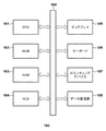
図1は、画像処理装置100のハードウェアの構成を示すブロック図である。画像処理装置100として、例えば、汎用的なPCが用いられる。CPU101は、中央演算装置(プロセッサ)であり、写真アルバムの自動レイアウト生成を行うアルバム作成アプリケーションを実行する。図1では、CPU101は、1つのみが示されているが、複数構成されていても良い。ROM102は、例えば、CPU101により実行されるプログラムを記憶する。RAM103は、例えば、CPU101によるプログラムの実行時に、各種情報を一時的に記憶するためのメモリとして用いられる。HDD(ハードディスク)104は、例えば、画像データや(以下、単に画像ともいう)、画像解析などの処理結果を保持するデータベースなどを記憶する記憶媒体である。
FIG. 1 is a block diagram showing a hardware configuration of the
ディスプレイ105は、本実施形態のユーザインタフェース(UI)画面や画像のレイアウト結果をユーザに表示する。ディスプレイ105は、タッチセンサ機能を備えても良い。キーボード106は、例えば、ユーザが、ディスプレイ105に表示されたUI画面上でアルバムの見開き数などの設定値を入力するために用いられる。ポインティングデバイス107は、ユーザがディスプレイ105に表示されたUI上のボタンをクリック等により選択/指定する際に用いられる。データ通信部108は、自動レイアウト生成が行われたデータを画像処理装置100に接続されたプリンタやサーバに送信する。上記の各ブロックは、システムバス109を介して相互に接続される。
The
図2は、アルバム作成アプリケーションの自動レイアウト処理部216に関するソフトウェアブロック図である。図2において、アルバム作成条件指定部201は、ポインティングデバイス107による後述のUI操作に応じて指定されたアルバム作成条件を自動レイアウト処理部216に出力する。
FIG. 2 is a software block diagram relating to the automatic
画像取得部202は、アルバム作成条件指定部201で指定された画像群をHDD104から取得する。HDD104に保存される画像群は、デジタルカメラやスマートデバイスで撮影された静止画像、動画から切り出された切り出し画像、データ通信部108を介してソーシャルネットワークやサーバから取得されたSNS画像、を含む。また、画像取得部202は、各画像に付随したデータを解析して取得先を判定する。例えば、SNS画像については、アルバム作成アプリケーションを介してSNSから取得され、アルバム作成アプリケーション内で、判定された取得先を管理するようにしても良い。なお、本実施形態では、上記画像種類以外の画像が用いられても良い。
The
画像変換部203は、画像を所望の画素数や色情報の画像に変換する。本実施形態では、画像変換部203は、例えば、短辺420画素の画素数とsRGBの色情報の解析画像に変換する。画像解析部204は、解析画像に対して、後述の特徴量取得、顔検出、表情認識、個人認識の各処理を実行する。また、画像解析部204は、HDD104から取得した画像に付随したデータ、例えばExif情報から、撮影日時を取得する。また、画像解析部204は、画像データを解析して、特定のオブジェクト、例えば、人物の顔画像を検出する。画像分類部205は、画像群に対して、撮影日時情報や枚数、検出した顔情報を用いて、後述のシーン分割、シーン分類を実行する。ここで、シーンとは、旅行や日常、結婚式等の撮影シーンを表す。
The
画像得点部207は、各画像に対して、レイアウトに適した画像が高得点となるような得点付けを行う。後述するが、得点付けの際、画像解析部204で取得された情報と、画像分類部205で取得された情報とが用いられる。主人公情報入力部206は、アルバム作成条件指定部201で指定された主人公のID(識別情報)を画像得点部207に入力する。画像得点部207は、例えば、主人公情報入力部206から入力された主人公のIDが含まれる画像の得点をアップする。
The
見開き割当部209は、画像群を分割して各見開きに割り当てる。見開き入力部208は、アルバム作成条件指定部201で指定されたアルバムの見開き数を見開き割当部209に入力する。見開き割当部209は、入力された見開き数に応じて画像群を分割し、各見開きに画像群の一部を割り当てる。画像選択部210は、見開き割当部209で各見開きに割り当てられた画像群の一部から、画像得点部207で付与された得点に基づいて、画像を選択する。画像レイアウト部212は、画像のレイアウトを決定する。
The
テンプレート入力部211は、アルバム作成条件指定部201で指定されたテンプレート情報に応じた複数のテンプレートを画像レイアウト部212に入力する。画像レイアウト部212は、画像選択部210で選択された画像に適したテンプレートを、テンプレート入力部211から入力された複数のテンプレートから選択し、画像のレイアウトを決定する。レイアウト情報出力部215は、画像レイアウト部212で決定された画像のレイアウトに従って、ディスプレイ105に表示するためのレイアウト情報を出力する。レイアウト情報は、例えば、選択されたテンプレートに、選択された画像をレイアウトしたビットマップデータである。
The
画像補正条件入力部213は、アルバム作成条件指定部201で指定された画像補正のON/OFF条件を画像補正部214に入力する。画像補正部214は、画像補正条件がONの場合、画像に対して補正を実行し、画像補正条件がOFFの場合、補正を実行しない。なお、画像補正部214は、画像変換部203から入力された画像に対して、画像補正条件に基づき、補正の実行を制御する。画像変換部203から画像補正部214に入力される画像の画素数は、画像レイアウト部212で決定したレイアウトの各スロットのサイズに合わせて変更可能である。
The image correction
アルバム作成アプリケーションが画像処理装置100にインストールされると、画像処理装置100上で動作するOS(オペレーティングシステム)のトップ画面(デスクトップ)上に起動アイコンが表示される。ユーザがディスプレイ105に表示されているデスクトップ上の起動アイコンをポインティングデバイス107等でダブルクリックすると、HDD104に保存されているアルバム作成アプリケーションのプログラムがROM102にロードされる。そして、ROM102のプログラムがCPU101によって実行され、アルバム作成アプリケーションが起動する。
When the album creation application is installed in the
図3は、起動したアルバム作成アプリケーションのUI画面301であり、UI画面301は、ディスプレイ105に表示される。パスボックス302は、アルバム作成の対象となる画像群のHDD104中の保存場所(パス)を示すパスボックスである。フォルダ選択ボタン303は、例えばユーザによりポインティングデバイス107でクリックされると、アルバム作成の対象とする画像群を含むフォルダがツリー構成として選択可能に表示される。ユーザにより選択された画像群を含むフォルダパスが、パスボックス302に表示される。
FIG. 3 is a
主人公指定アイコン304には、異なる顔画像のアイコンが並んで表示され、ポインティングデバイス107のクリック操作等により選択される。見開き数ボックス305は、見開き数の指定を受け付ける。例えば、ユーザのキーボード106操作により見開き数ボックス305に直接数字が入力されるか、ポインティングデバイス107の操作によりリストから見開き数ボックスに数字が入力される。
Icons of different face images are displayed side by side on the main
テンプレート指定アイコン306には、テンプレートのサイズやテンプレートのテイスト(ポップ調やシック調等)を示すアイコンが並んで表示され、ポインティングデバイス107のクリック操作等により選択される。チェックボックス307は、画像補正のON/OFFの指定を受け付ける。ポインティングデバイス107等によりチェックされた場合、画像補正がONとなり、チェックされない場合、画像補正がOFFとなる。
Icons indicating the size of the template and the taste of the template (pop style, chic style, etc.) are displayed side by side on the
OKボタン308は、UI画面301上で指定されている状態をアルバム作成条件指定部201に出力するためのボタンである。OKボタン308が例えばポインティングデバイス107でクリックされると、アルバム作成条件指定部201により、アルバム作成条件が自動レイアウト処理部216に出力される。パスボックス302に入力されたパスは、画像取得部202に出力される。主人公指定アイコン304で選択された主人公のIDは、主人公情報入力部206に出力される。見開き数ボックス305に入力された見開き数は、見開き数入力部208に出力される。テンプレート指定アイコン306で選択されたテンプレート情報は、テンプレート入力部211に出力される。画像補正チェックボックスの画像補正のON/OFF情報は、画像補正条件入力部213に出力される。リセットボタン309は、UI画面301上の各設定情報をリセットするためのボタンである。
The
図4は、アルバム作成アプリケーションの自動レイアウト処理部216の処理を示すフローチャートである。図4の処理は、例えば、CPU101がROM102に記憶されたプログラムをRAM103に読み出して実行することにより実現される。以下、図4を参照しながら、アルバム作成アプリケーションの自動レイアウト生成の処理を説明する。
FIG. 4 is a flowchart showing the processing of the automatic
S401において、画像変換部203は、解析画像を生成する。画像変換部203は、アルバム作成条件指定部201で指定されたHDD104の画像群の各画像を所定の画素数と色情報の解析画像に変換する。本実施形態では、例えば、短辺420画素とsRGBの色情報の解析画像に変換する。
In S401, the
S402において、画像解析部204は、画像の特徴量を取得する。画像解析部204は、HDD104から取得された各画像に付随する例えばExif情報から、撮影日時を取得する。また、画像解析部204は、S401で生成された解析画像から特徴量として、例えばピント情報を取得するようにしても良い。ピント情報を取得する場合、画像解析部204は、ソーベルフィルタでエッジ検出して、エッジの始点と終点の輝度差を始点と終点の距離で割ることによりエッジの傾きを算出する。そして、画像解析部204は、画像中のエッジの平均傾きを算出し、平均傾き大の画像は平均傾き小の画像よりもピントが合っていると判別する。また、傾きに対して異なる値の複数の閾値を設定し、どの閾値以上であるかを判別することでピント量を判別しても良い。例えば、画像解析部204は、異なる2つの閾値を設定し、○△×の3段階でピント量を判別する。つまり、アルバムに採用したいピントの傾きを○、許容できるピントの傾きを△、許容できない傾きを×として評価する。閾値は、例えば、実験等により予め設定される。
In S402, the
S403において、画像解析部204は、顔検出を実行する。画像解析部204は、S401で生成された解析画像から、顔検出を実行する。顔検出には、複数用意された弱識別器からAdaboostにより作成された強識別器により顔検出が実行される。画像解析部204は、顔画像を検出するとともに、検出した顔画像の位置の左上座標値と右下座標値を取得する。画像解析部204は、それらの2つの座標から、顔数、顔の位置、顔のサイズを取得する。
In S403, the
S404において、画像解析部204は、個人認識を実行する。画像解析部204は、S403で検出された顔画像と、顔辞書データベースに個人ID毎に保存されている代表顔画像との類似性を判定し、類似性が閾値以上で最も類似性が高いIDを、検出された顔画像のIDとする。なお、類似性が閾値未満の場合、画像解析部204は、新規の顔の個人IDとして、検出された顔画像を顔辞書データベースに登録する。
In S404, the
S402〜S404で取得された情報は、図5に示すように各画像を識別する画像ID毎に区別して保存される。図5に示すように、S402で取得した撮影日時情報とピント情報、S403で検出した顔数と顔の位置情報、が保存される。なお、顔の位置情報は、S404で取得した個人ID毎に区別して保存される。 As shown in FIG. 5, the information acquired in S402 to S404 is stored separately for each image ID that identifies each image. As shown in FIG. 5, the shooting date / time information and focus information acquired in S402, and the number of faces and face position information detected in S403 are stored. The face position information is stored separately for each personal ID acquired in S404.
S405において、アルバム作成条件指定部201で指定されたHDD104の画像群の全画像に対してS401〜S404の処理が終了したか否かが判定される。終了していないと判定された場合、S401からの処理を繰り返す。終了していると判定された場合、S406に進む。
In S405, it is determined whether or not the processing of S401 to S404 is completed for all the images of the image group of the
S406において、画像分類部205は、シーン分割を実行する。画像分類部205は、S402で取得済みの撮影日時情報から算出した、画像と画像の時間差に基づいて、画像群を複数に分割する。その際、画像間に撮影していない日が存在する場合には、その日を境として分割する。また、撮影日が連続する場合、時間差が16時間以上空いている場合、その時間差の部分を境として分割する。一方、時間差が16時間未満の場合、連続する各日の最初の撮影から最後の撮影までの時間差が4時間未満の場合には、それらを纏まりとして分割する。また、4時間以上の場合には、連続する各日の撮影枚数が50枚未満であれば、それらを纏まりとして分割し、50枚以上であれば、分割しない。図6(A)は、上記のシーン分割方法で分割した結果を示している。
In S406, the
S407において、画像分類部206は、シーンの種類を決定するシーン分類を実行する。本実施形態では、旅行、日常、セレモニーの各シーンに分類する例で説明する。画像分類部206は、ユーザが旅行、日常、セレモニーであると予め判定した画像群をそれぞれ複数集める。そして、画像解析部204は、各画像群について、特徴量を取得する。ここで、取得する特徴量は、例えば撮影期間、撮影枚数、撮影人数である。撮影期間は、画像群の最初の撮影から最後の撮影までの時間差である。撮影枚数は、画像群中の撮影枚数である。撮影人数は、顔が写っている画像における顔の数である。そして、シーン毎に集めた複数の画像群に対して、撮影期間の平均値と標準偏差、撮影枚数の平均値と標準偏差、1画像あたりの人数の平均値と標準偏差を求める。
In S407, the
図7は、上記で求められた各平均値と標準偏差を示しており、これらの求めた値をアルバム作成アプリケーションのプログラムに予め組み込んでおく。アルバム作成アプリケーションが起動された後、ユーザがパスボックス302で指定した画像群のS406でシーン分割された各分割群について、撮影期間と撮影枚数、撮影人数の平均値を特徴量として算出する。上述の各分割群の特徴量について、図7のシーン毎の平均値と標準偏差を用いて式(1)及び(2)により得点化を行う。
FIG. 7 shows each average value and standard deviation obtained above, and these obtained values are incorporated in the program of the album creation application in advance. After the album creation application is started, the average value of the shooting period, the number of shots, and the number of shots is calculated as the feature amount for each of the scene-divided groups of the image group specified by the user in the
得点=50−|10×(平均値−特徴量)/標準偏差| ・・・(1)
平均得点=(撮影期間の得点+撮影枚数の得点+人数の得点)/特徴量項目数 ・・・(2)
以上によって、各分割群について、旅行、日常、セレモニー毎の平均得点が算出される。そして、分割群毎に最高点のシーンにその分割群を分類することで、その分割群のシーンの種類を決定する。ここで、同点の場合には、優先シーンに分類するとする。例えば、本実施形態では、日常>セレモニー>旅行の順に、日常シーンの優先度が最も高く設定されている。図6(A)でシーン分割された後の分割群「5」は、撮影期間が36時間、撮影枚数が300枚、撮影人数の平均値が1.7人であったとする。そこで、旅行シーンについての得点が45.32、日常シーンについての得点が18.38、セレモニーについての得点が−29.92となる場合、分割群「5」は旅行シーンに分類される。
Score = 50- | 10 x (mean value-feature) / standard deviation | ... (1)
Average score = (score of shooting period + score of number of shots + score of number of people) / number of feature items ... (2)
From the above, the average score for each travel, daily life, and ceremony is calculated for each division group. Then, by classifying the divided group into the scenes with the highest points for each divided group, the type of the scene of the divided group is determined. Here, if there is a tie, it is classified as a priority scene. For example, in the present embodiment, the priority of the daily scene is set to be the highest in the order of daily life>ceremony> travel. In the division group "5" after the scene is divided in FIG. 6A, it is assumed that the shooting period is 36 hours, the number of shots is 300, and the average number of shots is 1.7. Therefore, when the score for the travel scene is 45.32, the score for the daily scene is 18.38, and the score for the ceremony is −29.92, the division group “5” is classified as a travel scene.
S408において、S406で分割された全シーンに対して、S407のシーン分類が終了したか否かを判定する。終了していないと判定された場合、S407に戻る。終了していると判定された場合、S409に進む。 In S408, it is determined whether or not the scene classification of S407 is completed for all the scenes divided in S406. If it is determined that the process has not ended, the process returns to S407. If it is determined that the process has been completed, the process proceeds to S409.
S409において、画像得点化部207は、主人公設定を実行する。主人公設定は、ユーザが指定した画像群に対して実行され、自動での実行と手動での実行の2種類がある。自動で主人公を設定する場合、S404において実行された個人認識の結果と、S406において実行されたシーン分割の結果が用いられる。取得した結果から、画像群に登場する各個人IDの回数、各シーンに登場する各個人IDの回数、各個人IDが登場するシーンの回数等を取得することが可能であり、これらの情報から主人公を設定する。本実施形態では、画像群にシーンが複数ある場合、複数のシーンに登場する個人IDが主人公IDとして設定され、画像群が単一シーンで構成される場合、登場回数が多い個人IDが主人公IDとして設定される。
In S409, the
手動で主人公を設定する場合、ユーザにより指定されている主人公設定アイコン304の個人IDが、主人公情報入力部206を介して画像得点部207に出力される。ユーザにより指定された個人IDがある場合には、上記で説明した自動設定の主人公IDは無視され、ユーザにより指定された個人IDが主人公IDとして設定される。
When the hero is manually set, the personal ID of the
S410において、画像得点化部207は、得点化を実行する。図10は、画像のレイアウトに用いるテンプレート群を示している。テンプレート1005は1枚のテンプレートを示し、メインスロット1002はメインスロットを示し、サブスロット1003と1004はサブスロットを示している。メインスロット1002は、テンプレート1005内でメインとなるスロット(画像をレイアウトする枠)であり、サブスロット1003及び1004よりもサイズが大きいという特徴がある。得点化は、メインスロット用の得点とサブスロット用の得点の両方を各画像に対して付与するように行われる。
In S410, the
図8(A)は、旅行、日常、セレモニーの各シーンについて、アルバムに採用する画像の特徴をメインスロットとサブスロットに分けて定義した情報を示す図である。画像得点化部207は、図8(A)に示す各シーンのメインスロットとサブスロットの各特徴に適合するとユーザが判定した複数の画像を予め集めておく。画像得点化部207は、集めておいた各画像の顔の数、顔の位置、顔のサイズの特徴を収集し、平均値と標準偏差を各シーン各スロット(メインスロットとサブスロット)に対して求め、アルバム作成アプリケーションのプログラムに記憶しておく。ここで、ユーザが指定した画像群の各画像がどのシーンに属するかについては、S407のシーン分類の結果から取得される。注目画像のシーンに対応する予め求めておいた平均値と標準偏差、および注目画像の主人公IDの顔数、顔位置、顔サイズの各特徴量に対して式(3)及び(4)により得点と平均得点を算出する。
FIG. 8A is a diagram showing information in which the features of the images used in the album are defined separately for the main slot and the sub slot for each scene of travel, daily life, and ceremony. The
得点=50−|10×(平均値−特徴量)/標準偏差| ・・・(3)
平均得点=(顔数の得点+顔位置の得点+顔サイズの得点)/特徴量項目数 ・・・(4)
得点化は、メインスロット用とサブスロット用の両方について行われる。ここで、アルバムに用いられる画像はピントが合っている方が好ましいので、図5に示すピントの特徴量が「○」である画像IDの画像については、得点を所定量、加算するようにしても良い。
Score = 50- | 10 x (mean value-feature) / standard deviation | ... (3)
Average score = (number of faces + score of face position + score of face size) / number of feature items ... (4)
Scoring is done for both the main slot and the subslot. Here, since it is preferable that the image used for the album is in focus, a predetermined amount of points are added to the image with the image ID whose focus feature amount shown in FIG. 5 is "○". Is also good.
図8(B)は、上記の説明の得点化による得点結果の一例を示しており、各画像IDに対して、メインスロットとサブスロットについての得点化が行われている。 FIG. 8B shows an example of the scoring result by scoring the above description, and the main slot and the sub slot are scored for each image ID.
S411において、ユーザにより指定された画像群の全画像に対してS410の画像得点化が終了したか否かが判定される。終了していないと判定された場合、S410に戻る。終了していると判定された場合、S412に進む。 In S411, it is determined whether or not the image scoring of S410 is completed for all the images in the image group specified by the user. If it is determined that the process has not ended, the process returns to S410. If it is determined that the process has been completed, the process proceeds to S412.
S412において、画像分類部205は、S406でのシーン分割の分割数が見開き数入力部208から入力される見開き数と同じであるか否かを判定する。同じでないと判定された場合、S413に進む。同じであると判定された場合、S416に進む。例えば、図6(A)のシーン分割数は8であり、見開き数入力部208の入力数が8であれば、S416に進む。
In S412, the
S413において、画像分類部205は、S406でのシーン分割の分割数が見開き数入力部208から入力される見開き数より少ないか否かを判定する。少なくないと判定された場合、S415に進む。少ないと判定された場合、S414に進む。例えば、図6(A)のシーン分割数は8であり、見開き数入力部208の入力数が10であれば、S414に進む。
In S413, the
S414において、画像分類部205は、「シーン分割数<見開き数」となっている現在の分割されたシーンを更に細分割するサブシーン分割を行う。ここでは、図6(A)のシーン分割数8に対して指定見開き数が10の場合を一例として説明する。図6(B)は、図6(A)にサブシーン分割を行った結果を示している。2と3の間の矢印、6と7の間の矢印の箇所で分割したことにより、分割数が10になっている。
In S414, the
分割の基準は、以下のとおりである。図6(A)の各分割の中で画像枚数が多い分割群を探す。ここでは、分割数を8から10に2箇所増やすために、画像枚数が多い2箇所を決定する。ここでは、画像枚数が多い方から、まず分割群「5」が決定される。次に、分割「1」と「2」は同じ枚数であるが、分割群「2」の方が最初の画像から最後の画像までの時間差が大きいので、分割群「2」が分割対象として決定される。 The criteria for division are as follows. In each division of FIG. 6A, a division group having a large number of images is searched for. Here, in order to increase the number of divisions from 8 to 10 at two locations, two locations with a large number of images are determined. Here, the division group "5" is first determined from the one with the largest number of images. Next, although the number of divisions "1" and "2" is the same, the division group "2" has a larger time difference from the first image to the last image, so the division group "2" is determined as the division target. Will be done.
分割群「5」と「2」をそれぞれ分割する。まず、分割群「2」の分割を説明する。分割群「2」には、画像枚数の山が2つあり、この2つは、撮影日が異なる。よって、図6(B)の破線矢印の箇所で分割する。次に、分割群「5」には、画像枚数の山が3つあり、3日間連続している。つまり、撮影日が変わる箇所が2箇所あるが、分割後の枚数差が小さくなるように分割する。よって、図6(B)の破線矢印の箇所で分割する。 The division groups "5" and "2" are divided, respectively. First, the division of the division group "2" will be described. The division group "2" has two peaks of the number of images, and these two have different shooting dates. Therefore, it is divided at the part indicated by the broken line arrow in FIG. 6 (B). Next, in the division group "5", there are three peaks of the number of images, which are continuous for three days. That is, although there are two places where the shooting date changes, it is divided so that the difference in the number of sheets after the division becomes small. Therefore, it is divided at the part indicated by the broken line arrow in FIG. 6 (B).
以上のように、分割数を8から10にする。ここでは、撮影日の異なる箇所で分割したが、画像枚数が多い箇所が単一日である場合には、単一日の中で時間差が最大の箇所で分割する。 As described above, the number of divisions is changed from 8 to 10. Here, the images are divided at different shooting dates, but when the number of images is large on a single day, the images are divided at the points having the largest time difference in the single day.
S415において、画像分類部205は、「シーン分割数>見開き数」となっている現在の分割されたシーンを統合するシーン統合を行う。ここでは、図6(A)のシーン分割数8に対して指定見開き数が6の場合を一例として説明する。図6(C)は、図6(A)にシーン統合を行った結果を示している。破線の箇所を統合したことで、分割数が6になっている。
In S415, the
統合の基準は、以下のとおりである。図6(A)の各分割群の中で画像枚数が少ない分割群を探す。ここでは、分割数を8から6に2箇所減らすために、画像枚数が少ない2箇所を決定する。ここでは、画像枚数が少ない方から、まず分割群「8」が決定される。次に、分割群「3」と「7」は同じ枚数であるが、分割群「7」に隣接する分割群「8」が既に統合対象であるので、分割群「3」が統合対象として決定される。 The criteria for integration are as follows: A division group having a small number of images is searched for in each division group of FIG. 6 (A). Here, in order to reduce the number of divisions from 8 to 6, two locations with a small number of images are determined. Here, the division group "8" is first determined from the one with the smallest number of images. Next, although the number of division groups "3" and "7" is the same, the division group "8" adjacent to the division group "7" is already the integration target, so the division group "3" is determined as the integration target. Will be done.
分割群「8」と分割群「3」をそれぞれ統合する。まず、分割群「3」の統合を説明する。分割群「3」の前後の分割群「2」と「4」との時間差を比較すると、分割群「4」の方が時間差が小さいので、分割群「4」に統合する。よって、図6(C)の破線の箇所で統合する。次に、分割群「8」は、後続する分割群がないので、前段の分割群「7」と統合する。よって、図6(C)の破線箇所で統合する。 The division group "8" and the division group "3" are integrated respectively. First, the integration of the division group "3" will be described. Comparing the time difference between the divided groups "2" and "4" before and after the divided group "3", the time difference of the divided group "4" is smaller, so that the divided group "4" is integrated into the divided group "4". Therefore, they are integrated at the broken line in FIG. 6 (C). Next, since there is no subsequent division group, the division group "8" is integrated with the division group "7" in the previous stage. Therefore, they are integrated at the broken line in FIG. 6 (C).
S416において、見開き割当部209は、見開き割当を実行する。S412〜S415によって、シーン分割数と指定見開き数は同じ数になっている。よって、撮影日時的に先頭の分割を見開きの先頭に割り当て、後続する分割群を、後続する見開きに順に割り当てていく。
In S416, the
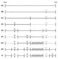
S417において、画像選択部210は、画像選択を行う。ここでは、ある見開きに割り当てられた分割群から画像を4枚選択する例を、図9を参照しながら説明する。
In S417, the
図9(A)は、見開きに割り当てられた分割群の撮影日時が最初の画像から最後の画像までの時間差(分割撮影期間)を示している。図9(B)により、1枚目を選択する方法を説明する。テンプレートには1枚のメインスロット1002がある。1枚目はメインスロット用の画像を選択する。図9(B)に示す分割撮影期間に対応する画像のうちS410で付与したメインスロット用の得点が最高点である画像を選択する。2枚目以降は、サブスロット用の画像を選択する。
FIG. 9A shows the time difference (divided shooting period) between the first image and the last image in the shooting date and time of the divided group assigned to the spread. A method of selecting the first sheet will be described with reference to FIG. 9B. The template has one
画像選択は、分割撮影期間の一部に集中しないように、以下のように、分割撮影期間を細分化するように行われる。まず、図9(C)のように、分割撮影期間を2分割する。次に、図9(D)のように1枚目が選ばれていない実線の分割撮影期間から2枚目を選択する。実線の分割撮影期間に対応する画像のうちサブスロット用の得点が最高点の画像を選択する。次に、図9(E)のように図9(D)の各分割撮影期間を2分割する。図9(F)のように1枚目と2枚目が選ばれていない実線の分割撮影期間に対応する画像のうちサブスロット用の得点が最高点の画像を3枚目として選択する。 The image selection is performed so as to subdivide the divided shooting period as follows so as not to concentrate on a part of the divided shooting period. First, as shown in FIG. 9C, the divided shooting period is divided into two. Next, as shown in FIG. 9D, the second image is selected from the solid line divided shooting period in which the first image is not selected. Select the image with the highest score for the subslot from the images corresponding to the solid line split shooting period. Next, as shown in FIG. 9 (E), each divided shooting period of FIG. 9 (D) is divided into two. As shown in FIG. 9F, among the images corresponding to the solid line split shooting period in which the first and second images are not selected, the image with the highest score for the subslot is selected as the third image.
次に、画像を選択する分割撮影期間に画像が存在せず、画像選択できない例を4枚目の選択を例として説明する。図9(G)のように、まだ画像が選ばれていない斜線の分割撮影期間から4枚目を選択したいが、この斜線の分割撮影期間には画像が存在しない場合である。そこで、図9(H)のように各分割撮影期間を2分割する。次に、図9(I)のように1〜3枚目が選ばれていない実線の分割撮影期間に対応する画像のうちサブスロット用の最高点の画像を4枚目として選択する。 Next, an example in which an image does not exist during the divided shooting period for selecting an image and the image cannot be selected will be described by taking the selection of the fourth image as an example. As shown in FIG. 9 (G), it is desired to select the fourth image from the diagonal line divided shooting period in which the image has not been selected yet, but the image does not exist in the diagonal line divided shooting period. Therefore, as shown in FIG. 9H, each divided shooting period is divided into two. Next, as shown in FIG. 9 (I), among the images corresponding to the solid line divided shooting period in which the 1st to 3rd images are not selected, the highest point image for the subslot is selected as the 4th image.
S418において、画像レイアウト部212は、画像レイアウトの決定を行う。テンプレート入力部211により、指定のテンプレート情報に従ってある見開きに対して図10のテンプレート1005〜1007が入力された例を説明する。入力されたテンプレートのスロット数は3である。選択されている画像3枚を撮影日時について並べると、図10(B)であったとする。ここでは、スロット1010がメインスロット用であり、スロット1008と1009がサブスロット用である。本実施形態では、テンプレートの左上に撮影日時がより古い画像、右下に撮影日時がより新しい画像がレイアウトされる。メインスロット用画像1010は撮影日時が一番新しいので、テンプレート1007が選択された画像に最も適したテンプレートとしてレイアウトが決定される。S418では、どの画像をどのテンプレートのどのスロットにレイアウトするかを識別できる情報が決定される。
In S418, the
S419において、画像補正部214は、画像補正を実行する。画像補正条件入力部213から画像補正がONで入力された場合、画像補正が実行される。本実施形態では、画像補正として、例えば、覆い焼き補正(輝度補正)、赤目補正、コントラスト補正が行われる。一方、画像補正条件入力部213から画像補正がOFFで入力された場合、画像補正は実行されない。例えば、補正する画像の画素数は短辺1200画素であり、sRGBの色空間に変換した画像に対して画像補正のON/OFFが設定される。
In S419, the
S420において、レイアウト情報出力部215は、レイアウト情報の作成を行う。レイアウト情報出力部215は、S418で決定されたテンプレートの各スロットに、S419の処理を介した画像をレイアウトする。このとき、レイアウト情報出力部215は、スロットのサイズ情報に合わせてレイアウトする画像を変倍してレイアウトする。レイアウト情報出力部215は、テンプレートに画像をレイアウトしたビットマップデータを生成する。 In S420, the layout information output unit 215 creates layout information. The layout information output unit 215 lays out an image through the process of S419 in each slot of the template determined in S418. At this time, the layout information output unit 215 scales and lays out the image to be laid out according to the size information of the slot. The layout information output unit 215 generates bitmap data in which an image is laid out on a template.
S421において、S417〜S20の処理が全ての見開きに対して終了したか否かが判定される。終了していないと判定された場合、S417に戻る。終了していると判定された場合、図4を終了する。 In S421, it is determined whether or not the processes of S417 to S20 have been completed for all the spreads. If it is determined that the process has not ended, the process returns to S417. When it is determined that the process is completed, FIG. 4 is terminated.
以下、画像を変倍してレイアウトする際のトリミングに関して詳細に説明する。S418で決定されたテンプレートの各スロットに割り当てた画像に対して、トリミング処理が実行される。 Hereinafter, trimming when the image is scaled and laid out will be described in detail. The trimming process is executed for the image assigned to each slot of the template determined in S418.
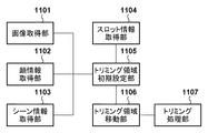
図11は、トリミング制御に関するブロック図である。図11の各ブロックは、例えば、図2のレイアウト情報出力部215内に構成される。以下、選択された図10のテンプレート1007のスロットに、画像1010をレイアウトするケースについて説明する。
FIG. 11 is a block diagram relating to trimming control. Each block of FIG. 11 is configured in, for example, the layout information output unit 215 of FIG. Hereinafter, a case where the
画像取得部1101は、画像1005を取得する。顔情報取得部1102は、画像1005に対して画像解析部204により実行された顔検出結果を取得する。取得する顔検出結果は、顔の個数、顔のサイズ(幅、高さ)、顔の位置情報、個人認識されたID情報を含む。
The
シーン情報取得部1103は、画像1005に対して画像分類部205により実行されたシーン判定結果を取得する。スロット情報取得部1104は、S418で決定されたテンプレート内の画像を配置するスロットの情報を取得する。取得するスロットの情報は、スロットの幅、および高さを含む。
The scene
トリミング領域初期設定部1105は、取得されたスロット情報に基づいて、画像のトリミング領域の暫定位置を設定する。トリミング領域の暫定位置については図12で後述する。また、トリミング領域初期設定部1105は、スロット情報、即ちトリミング領域に基づいて画像の変倍率を算出し、算出した変倍率により画像を変倍する。
The trimming area
図12は、トリミング領域の設定を説明するための図である。幅1201は、変倍後の画像の幅を示し、高さ1202は、変倍後の画像の高さを示している。また、中心軸1203は、画像の中心軸を示している。
FIG. 12 is a diagram for explaining the setting of the trimming area. The
トリミング領域に基づいて画像の変倍率を求める他に、シーンに応じてトリミング領域のサイズを変更し、変更されたトリミング領域のサイズを用いて画像を変倍しても良い。例えば、旅行シーンの場合には、トリミング領域をスロット領域より小さくし、小さく変更されたトリミング領域のサイズを用いて画像を変倍する。そして、変更前のトリミング領域によりトリミングを行うようにすることで、倍率を低くして風景と人物が一緒にトリミングされ易くすることができる。また、日常シーンの場合には、トリミング領域をスロット領域より大きくし、大きく変更されたトリミング領域のサイズを用いて画像を変倍する。そして、変更前のトリミング領域によりトリミングを行うようにすることで、倍率を高くして人物がメインとしてトリミングされ易くすることができる。 In addition to obtaining the scaling factor of the image based on the trimming area, the size of the trimming area may be changed according to the scene, and the image may be scaled using the changed size of the trimming area. For example, in the case of a travel scene, the crop area is made smaller than the slot area, and the image is scaled using the size of the crop area changed to be smaller. Then, by trimming with the trimming area before the change, it is possible to lower the magnification and facilitate the trimming of the landscape and the person together. Further, in the case of a daily scene, the trimming area is made larger than the slot area, and the image is scaled using the greatly changed size of the trimming area. Then, by trimming with the trimming area before the change, it is possible to increase the magnification and make it easier for the person to be trimmed as the main.
幅1209は、初期トリミング領域1207の幅を示し、高さ1210は、初期トリミング領域1207の高さを示している。ここでは、トリミング領域は、幅と高さが等しい正方領域とする。初期トリミング領域1207は、デフォルトとして暫定的に設定されるトリミング領域の初期設定を示している。初期設定時には、配置する画像に含まれる顔領域が考慮され、つまり、図12の人物Aの顔の中心座標が初期トリミング領域1207の中心座標となるように、初期トリミング領域1207の位置が設定される。
The
ここでは、画像内に人物が1名写っている場合を例に説明する。中心座標1204は、検出された顔の中心座標(Fx、Fy)を示している。顔幅1205は、検出された顔の幅を示し、顔高さ1206は、検出された顔の高さを示している。ここでは、顔幅1205と顔高さ1206は、同じサイズとする。中心座標1204、顔幅1205、顔高さ1206は、倍率が変更された画像に合わせて変更された値である。
Here, a case where one person is shown in the image will be described as an example. The center coordinates 1204 indicate the detected center coordinates (Fx, Fy) of the face.
初期トリミング領域1207は、検出された顔の中心座標1204に対して、初期トリミング領域1207の中心位置が重なるように配置される。このように配置すると、初期トリミング領域1207が画像領域を超えてしまう場合、画像領域を超えないよう顔の中心座標1204とトリミング領域の中心位置の距離とがなるべく短くなるように初期トリミング領域1207の位置が調整される。
The
図11のトリミング領域移動部1106は、判定されたシーン分類結果に応じた移動量分、トリミング領域初期設定部1105により設定された初期トリミング領域1207を移動する。トリミング領域移動部1106には、画像分類部205により分類されたシーン分類結果(旅行、日常、結婚式など)が入力される。一般的に、旅行シーンでは行った先の風景や建物と人物を一緒に撮影するケースが多い。そのため、引きで撮影して画像の中心からずれた位置に人物を配置する構図が多い。図12で説明した初期トリミング領域1207により顔を中心としたトリミングを行うと、一緒に撮った風景や建物などが大幅に切れてしまうことになる。その結果、ユーザの意図を反映させたアルバム作成ができず、ユーザの満足度を低下させてしまう。
The trimming
一方、日常シーンなどの場合、人物がメインで被写体となるケースが多い。そのため、初期トリミング領域1207により顔を中心としたトリミングを行った場合でも、ユーザに対して違和感を与えることなくトリミングを行うことができる。結婚式シーンなどの他のシーンの場合には、旅行シーンと日常シーンの間の構図となるようにトリミングを行う。本実施形態では、以上のように、撮影シーンを考慮して、初期トリミング領域1207を移動する。その結果、ユーザの意図を反映させたアルバム作成を行うことができる。
On the other hand, in the case of everyday scenes, there are many cases where the person is the main subject. Therefore, even when the trimming centering on the face is performed by the
以下、初期トリミング領域1207の移動を撮影シーンに応じて移動する処理を説明する。本処理においては、図12の初期トリミング領域1207を中心軸1203の方向に移動する。まず、検出された顔幅1205、顔高さ1206の2倍のサイズを顔の中心座標1204に対して設定する。以下、そのサイズの領域を顔切れ判定領域とする。ここでは、顔切れ判定領域の設定を顔サイズの定数倍としているが、シーンに応じてサイズを変更するようにしても良い。例えば、旅行シーンの場合、顔以外の風景も入れるようにするために顔切れ判定領域を小さく設定し、それ以外のシーンの場合、大きく設定するようにしても良い。
Hereinafter, a process of moving the
次に、初期トリミング領域1207から顔切れ判定領域までの距離dを算出する。図12では、式(5)により距離dを算出する。
Next, the distance d from the
d=Fx−2×(FW/2) ・・・(5)
図12では、横方向の移動のみを説明しているが、縦方向の移動であっても同様に距離dが算出可能である。算出された距離dに対して、シーンを考慮した移動量を式(6)により算出する。
d = Fx-2 × (FW / 2) ・ ・ ・ (5)
Although only the movement in the horizontal direction is described in FIG. 12, the distance d can be calculated in the same manner even in the movement in the vertical direction. With respect to the calculated distance d, the amount of movement in consideration of the scene is calculated by the equation (6).
ds=d×Rate_s ・・・(6)
Rate_sはシーンから設定される移動量の重みである。移動量の重みは、旅行シーンの場合には移動量が大きくなるように、また、それ以外のシーンの場合には移動量が小さくなるように設定される。例えば、旅行シーンの移動量の重みは0.8、日常シーンの移動量の重みは0、それ以外のシーンの移動量の重みは0.4と設定される。また、旅行以外のシーンに対して、それぞれ個別の重みを設定するようにしても良い。また、シーン判定時に、信頼度が算出される場合は、その信頼度に応じて移動量dsを調整するようにしても良い。例えば、信頼度が高い場合には、算出した移動量dsをそのまま採用し、信頼度が低い場合は、移動量dsにバイアスをかけて移動量を少なくする。上記のような手順により算出された移動量を用いて、初期トリミング領域1207からds分移動したトリミング領域1208を最終的なトリミング領域として決定する。
ds = d × Rate_s ・ ・ ・ (6)
Rate_s is the weight of the movement amount set from the scene. The weight of the movement amount is set so that the movement amount is large in the case of a travel scene and the movement amount is small in the case of other scenes. For example, the weight of the movement amount of the travel scene is set to 0.8, the weight of the movement amount of the daily scene is set to 0, and the weight of the movement amount of other scenes is set to 0.4. In addition, individual weights may be set for scenes other than travel. Further, when the reliability is calculated at the time of scene determination, the movement amount ds may be adjusted according to the reliability. For example, when the reliability is high, the calculated movement amount ds is adopted as it is, and when the reliability is low, the movement amount ds is biased to reduce the movement amount. Using the movement amount calculated by the above procedure, the
トリミング処理部1107は、トリミング領域移動部1106で移動したトリミング領域に基づいて画像をトリミングする。
The trimming
図13は、トリミング処理を示すフローチャートである。図13の処理は、図4のS420において行われる。 FIG. 13 is a flowchart showing the trimming process. The process of FIG. 13 is performed in S420 of FIG.
S1301において、画像取得部1101は、選択されたテンプレート内の指定スロットにトリミングして配置する画像を取得する。S1302において、顔情報取得部1102は、配置する画像内に含まれる顔情報を取得する。
In S1301, the
S1303において、シーン情報取得部1103は、配置する画像に関するシーンの種類の判定結果を取得する。具体的には、該画像が含まれる画像群(シーン)に対して、S407で決定されたシーンの種類が取得される。S1304において、スロット情報取得部1104は、選択されたテンプレート内で画像を配置するスロットの情報を取得する。
In S1303, the scene
S1305において、トリミング領域初期設定部1105は、スロット情報に基づいて、配置する画像および顔情報を変倍する。そして、トリミング領域初期設定部1105は、配置される画像内の顔位置とトリミング領域(スロット情報)の中心が一致するように初期トリミング領域1207を暫定的に設定し、初期トリミング領域1207と顔切れ判定領域との距離dを算出する。
In S1305, the trimming
S1306において、トリミング領域移動部1106は、S1303で取得されたシーンの種類の判定結果に応じて、初期トリミング領域1207の移動量を変更する。ここでは、旅行シーン、日常シーン、その他のシーンに応じて、初期トリミング領域1207の移動量を変更する。
In S1306, the trimming
シーン判定結果により日常シーンと判定されている場合、S1307において、トリミング領域と顔切れ判定領域との距離dに対して、重みRate_sが例えば0にセットされ、移動量dsが算出される。ここでは、重みRate_sが0であるので、移動量dsは0である。そして、移動量dsに基づいて、初期トリミング領域1207が移動され、最終的なトリミング領域が設定される。
When it is determined to be a daily scene based on the scene determination result, in S1307, the weight Rate_s is set to, for example, 0 with respect to the distance d between the trimming area and the face cut determination area, and the movement amount ds is calculated. Here, since the weight Rate_s is 0, the movement amount ds is 0. Then, the
シーン判定結果によりその他のシーンと判定されている場合、S1307において、トリミング領域と顔切れ判定領域との距離dに対して、重みRate_sが例えば0.4にセットされ、移動量dsが算出される。そして、移動量dsに基づいて、初期トリミング領域1207が移動され、最終的なトリミング領域が設定される。
When it is determined to be another scene based on the scene determination result, in S1307, the weight Rate_s is set to, for example, 0.4 with respect to the distance d between the trimming area and the face cut determination area, and the movement amount ds is calculated. .. Then, the
シーン判定結果により旅行シーンと判定されている場合、S1307において、トリミング領域と顔切れ判定領域との距離dに対して、重みRate_sが例えば0.8にセットされ、移動量dsが算出される。そして、移動量dsに基づいて、初期トリミング領域1207が移動され、最終的なトリミング領域が設定される。
When it is determined to be a travel scene based on the scene determination result, in S1307, the weight Rate_s is set to, for example, 0.8 with respect to the distance d between the trimming area and the face cut determination area, and the movement amount ds is calculated. Then, the
S1310において、トリミング処理部1107は、設定されたトリミング領域に基づいて画像をトリミングする。
In S1310, the trimming
本実施形態では、画像分類部206により行われたシーン分類結果に応じて、トリミング領域を設定する処理について説明した。しかしながら、シーン設定については、他の方法でシーンを設定するようにしても良い。例えば、ユーザ手動によりUI上でシーンを設定するようにしても良い。また、テンプレートにシーン情報を関連付け、ユーザが選んだテンプレートからシーンを設定するようにしても良い。いずれの方法によっても、設定されたシーンに応じて、初期トリミング領域1207が移動量ds分移動し、最終的なトリミング領域が設定される。その結果、ユーザの意図を反映させたアルバム作成を行うことができる。
In the present embodiment, the process of setting the trimming area according to the scene classification result performed by the
[第2の実施形態]
第2の実施形態では、画像内に複数個の顔が含まれる場合のトリミング方法について説明する。以下、第1の実施形態と異なる点について説明する。
[Second Embodiment]
In the second embodiment, a trimming method when a plurality of faces are included in the image will be described. Hereinafter, the points different from the first embodiment will be described.
図14は、トリミング制御に関するブロック図である。画像取得部1101、顔情報取得部1102、シーン情報取得部1103、スロット情報取得部1104、トリミング処理部1107については、図11における説明と同じであるので、その説明を省略する。顔選定部1401は、顔情報取得部1102により取得された顔の個数、各顔のサイズ、各顔の位置情報、各顔のID情報を用いて、取得した顔情報に基づいてトリミング領域内に含まれる顔を選定する。
FIG. 14 is a block diagram relating to trimming control. The
図15は、顔選定部1401により顔を選定する処理を説明するための図である。ここでは、説明のために、顔が2個検出された場合を例として説明する。検出された顔の中心座標から、顔が分布する領域を判定する。ここでは、画像の中心軸1203より左側であるか、右側であるかで分布をグループ分けする。グループは、更に詳細に分けるようにしても良い。図15では、画像の左側に顔が集まっているので、それらの顔を1つのグループとして判定する。本実施形態では、顔選定部1401は、この判定されたグループに対して更に、トリミング領域を設定するための顔選定を行う。ここで、グループが複数判定されている場合には、グループ内に含まれる顔数が多いグループが顔選定を行う対象として決定されても良い。もしくは、主人公情報入力部206で設定された主人公の顔を含むか否かに応じて、顔選定を行うグループを決定するようにしても良い。
FIG. 15 is a diagram for explaining a process of selecting a face by the
図15に示すように、人物A、人物Bの二人の顔が含まれている。中心座標1504は、人物Aに対して検出された顔中心座標(Fax、Fay)を表し、顔幅1505は、人物Aの顔幅を表し、顔高さは、人物Aの顔高さを表す。中心座標1511は、人物Bに対して検出された顔中心座標(Fbx、Fby)を表し、顔幅1512は、人物Bの顔幅を表し、顔高さ1513は、人物Bの顔高さを表す。
As shown in FIG. 15, two faces of a person A and a person B are included. The center coordinates 1504 represent the face center coordinates (Fax, Fay) detected for the person A, the
次に、人物Aと人物Bの各中心座標1504、1511から画像の中心軸1203までの最短距離を算出し、距離が遠い方の顔を選定する。図15の場合には、人物Aの顔が選定される。そして、後述する初期トリミング領域1207の設定は、この選定された顔に対して行われる。
Next, the shortest distance from the center coordinates 1504 and 1511 of the person A and the person B to the
本実施形態では、グループ内において、中心軸1203からより離れた顔を選定しているが、他の方法で選定するようにしても良い。例えば、顔のサイズが大きい方を選定するようにしても良いし、主人公と設定された顔を選定するようにしても良い。また、シーンに応じて選定する方法を変更するようにしても良い。例えば、旅行シーンの際には顔サイズが小さい方を選定し、日常シーンの際には顔サイズが大きい方を選定するようにしても良い。
In the present embodiment, the face farther from the
図14のトリミング領域初期設定部1402は、顔選定部1401により選定された顔と、スロット情報取得部1104により取得されたスロット情報とに基づいて、初期トリミング領域1207の暫定位置を設定する。
The trimming area
図15において人物Aの顔が選定されると、トリミング領域初期設定部1402は、選定された人物Aの顔中心座標に対して、初期トリミング領域1207の中心位置が重なるように、初期トリミング領域1207を配置する。このように配置するとトリミング領域が画像領域を超えてしまう場合、画像領域を超えないよう顔の中心座標と初期トリミング領域1207の中心位置との距離がなるべく短くなるように初期トリミング領域1207の配置を調整する。
When the face of the person A is selected in FIG. 15, the trimming area
トリミング領域移動部1403は、トリミング領域初期設定部1402により設定された初期トリミング領域1207を、判定されたシーン分類結果に応じて移動する。その際人物Aの顔幅1505、顔高さ1506の2倍のサイズが、中心座標1504に対する顔切れ判定領域として設定される。その後、トリミング処理部1107により、初期トリミング領域1207の移動量が制御される。
The trimming
図16は、本実施形態におけるトリミング処理を示すフローチャートである。S1601及びS1602は、S1301及びS1302における説明と同じであるので、その説明を省略する。S1603において、顔選定部1401は、トリミングする画像に含まれる顔情報に基づいて、初期トリミング領域1207の設定で用いる顔を選定する。
FIG. 16 is a flowchart showing a trimming process according to the present embodiment. Since S1601 and S1602 are the same as those described in S1301 and S1302, the description thereof will be omitted. In S1603, the
S1604及びS1605は、S1303及びS1304における説明と同じであるので、その説明を省略する。S1606において、トリミング領域初期設定部1402は、S1605で取得したスロット情報に基づいて、配置する画像および顔情報を変倍する。そして、トリミング領域初期設定部1402は、S1603で選定した顔に基づいて、初期トリミング領域1207を暫定的に設定し、初期トリミング領域1207と顔切れ判定領域との距離dを算出する。S1607〜S1611は、S1306〜S1310における説明と同じであるので、その説明を省略する。
Since S1604 and S1605 are the same as the description in S1303 and S1304, the description thereof will be omitted. In S1606, the trimming
以上のように、本実施形態によれば、複数の顔が画像に含まれていても、所定の条件を満たす顔を選定し、その選定された顔に基づいて、初期トリミング領域1207を設定し、また、最終的なトリミング領域を設定することができる。その結果、ユーザの意図を反映させたアルバム作成を行うことができる。
As described above, according to the present embodiment, even if a plurality of faces are included in the image, a face satisfying a predetermined condition is selected, and an
[第3の実施形態]
第3の実施形態では、シーンに応じて初期トリミング領域1207の中心位置を移動し、その後、最終的なトリミング領域を設定する方法について説明する。以下、第1および第2の実施形態と異なる点について説明する。
[Third Embodiment]
In the third embodiment, a method of moving the center position of the
図17は、トリミング制御に関するブロック図である。画像取得部1101、顔情報取得部1102、シーン情報取得部1103、スロット情報取得部1104については、図11における説明と同じであるので、その説明を省略する。
FIG. 17 is a block diagram relating to trimming control. The
トリミング領域中心設定部1705は、顔情報取得部1102により取得した顔情報に基づいて、トリミング領域の中心位置を設定する。ここでは、画像領域内に顔が1つ含まれる場合を説明する。
The trimming area
図18は、トリミング領域中心設定部1705によりトリミング領域を設定する方法を説明するための図である。顔情報取得部1102により取得した顔情報から、顔の中心座標1204が基準点として取得される。ここで、距離1805は、顔の中心座標1204から、顔中心と同じ高さとなる中心軸1203までの距離を表している。中心1806は、シーンに応じた基準点の移動後のトリミング領域の中心を表す。
FIG. 18 is a diagram for explaining a method of setting a trimming area by the trimming area
本実施形態では、距離1805で表される距離Dをシーン判定結果に応じて変更する。シーンに応じた距離Dsは、式(7)により算出される。
In the present embodiment, the distance D represented by the
Ds=D×Rate_s ・・・(7)
ここで、Rate_sは、シーンに対応する重みであり、例えば、旅行シーンでは0.8、日常シーンでは0、それ以外のシーンでは0.4と設定される。そして、顔の中心座標1204と中心軸1203とを結ぶ線上において、顔の中心座標1204から、式(7)により算出した距離Ds分離れた位置を移動後のトリミング領域の中心1806と設定する。例えば、日常シーンの場合、Rate_s=0であるので、距離Dsは0となり、移動後のトリミング領域の中心1806は、変わらず顔の中心座標1204となる。
Ds = D × Rate_s ・ ・ ・ (7)
Here, Rate_s is a weight corresponding to a scene, and is set to, for example, 0.8 in a travel scene, 0 in a daily scene, and 0.4 in other scenes. Then, on the line connecting the center coordinates 1204 of the face and the
図17のトリミング領域中心移動部1706は、上記の距離Ds分の基準点の移動を行う。
The trimming area
トリミング領域設定部1707は、トリミング領域中心移動部1706による移動後のトリミング領域の中心に基づいて、トリミング領域を設定する。トリミング領域設定部1707は、スロット情報取得部1104により取得したスロット情報に基づき変倍された画像の短辺に合わせてトリミング領域を設定する。図18では、画像の短辺が高さ1202であり、トリミング領域設定部1707は、高さ1202に合わせて矩形のトリミング領域を設定する。その際、移動後のトリミング領域の中心1806にトリミング領域の中心が重なるように、トリミング領域を設定する。トリミング領域1807は、トリミング領域設定部1707により設定されたトリミング領域である。
The trimming
トリミング領域調整部1708の動作について説明する。上記のように、トリミング領域設定部1707によりトリミング領域を設定した際に、顔領域が切れてしまう場合がある。そのため、図19に示すように、トリミング領域調整部1708は、検出した顔サイズに基づいて、顔切れ判定領域1908を設定する。ここでは、顔切れ判定領域1908は、検出した顔幅1205、顔高さ1206の2倍のサイズを設定する。トリミング領域調整部1708は、トリミング領域内に顔切れ判定領域1908が収まるか否かを判定し、顔切れ判定領域1908が収まっていない、即ち、顔切れが発生していると判定された場合は、以下の処理を実行する。
The operation of the trimming
図19において顔切れが発生すると判定された場合、画像の中央寄りにトリミング領域が設定されているということである。そこで、顔切れ判定領域1908において中心軸1203から最も離れた端辺と、その端辺から最短距離にあるトリミング領域の端辺とが重なるようにトリミング領域の位置を調整する。その結果、顔切れ判定領域1908が収まっている、即ち、顔切れが発生していない状態とすることができる。
When it is determined in FIG. 19 that the face is cut off, it means that the trimming area is set near the center of the image. Therefore, the position of the trimming region is adjusted so that the end edge of the face cut
上記では、画像内に顔が1つ含まれる場合を説明したが、顔が複数個含まれる場合であっても良い。その際、第2の実施形態で説明した処理により、顔を選定しても良い。つまり、中心軸1203から最も離れた顔を基準点として設定しても良い。また、複数の顔の重心位置を算出し、基準点として設定しても良い。また、複数の顔において主人公として指定された顔を基準点として設定しても良い。いずれの方法によっても、基準点がシーンに応じた距離分、移動され、移動後の点を中心としてトリミング領域が設定される。
In the above, the case where one face is included in the image has been described, but the case where a plurality of faces are included may be included. At that time, the face may be selected by the process described in the second embodiment. That is, the face farthest from the
図20は、本実施形態におけるトリミング処理を示すフローチャートである。S2001〜S2004は、S1301〜S1304における説明と同じであるので、その説明を省略する。S2005において、トリミング領域中心設定部1705は、取得した顔情報から基準点を設定する。S2006において、トリミング領域中心移動部1706は、取得したシーン判定結果に応じて処理を切り替える。ここでは、旅行シーン、日常シーン、その他のシーンに応じて、処理を切り替える。
FIG. 20 is a flowchart showing a trimming process according to the present embodiment. Since S2001 to S2004 are the same as the description in S1301 to S1304, the description thereof will be omitted. In S2005, the trimming area
日常シーンと判定された場合、S2007において、トリミング中心位置移動部1706は、顔の中心座標1204から中心軸1203までの距離Dに対して、重みRate_sが例えば0に設定され、式(7)により移動量Dsが算出される。そして、トリミング中心位置移動部1706は、顔の中心座標1204から距離Ds分離れた位置に、移動後のトリミング領域の中心を設定する。
When it is determined to be a daily scene, in S2007, the trimming center
その他のシーンと判定された場合、S2008において、トリミング中心位置移動部1706は、距離Dに対して、重みRate_sが例えば0.4に設定され、式(7)により移動量Dsが算出される。そして、トリミング中心位置移動部1706は、顔の中心座標1204から距離Ds分離れた位置に、移動後のトリミング領域の中心を設定する。
When it is determined to be another scene, in S2008, the trimming center
旅行シーンと判定された場合、S2009において、トリミング中心位置移動部1706は、距離Dに対して、重みRate_sが例えば0.8に設定され、式(7)により移動量Dsが算出される。そして、トリミング中心位置移動部1706は、顔の中心座標1204から距離Ds分離れた位置に、トリミング領域の中心を設定する。
When it is determined to be a travel scene, in S2009, the trimming center
S2010において、トリミング領域設定部1707は、S2004で取得したスロット情報に基づいて、画像の短辺に合わせてトリミング領域のサイズを決定する。トリミング領域設定部1707は、決定されたサイズのトリミング領域の中心と、S2007〜S2009で設定されたトリミング領域の中心とが一致するように、トリミング領域を設定する。
In S2010, the trimming
S2011において、トリミング領域調整部1708は、S2010で設定したトリミング領域により顔切れが発生しているかを判定する。顔切れが発生していないと判定された場合、図20の処理を終了する。顔切れが発生していると判定された場合、S2012へ進む。S2012において、トリミング領域調整部1708は、上述したように、トリミング領域を調整する。
In S2011, the trimming
以上のように、本実施形態によれば、第2の実施形態で説明したような初期トリミング領域を暫定的に設定することなく、最終的なトリミング領域を設定し、ユーザの意図を反映させたアルバム作成を行うことができる。 As described above, according to the present embodiment, the final trimming area is set and the user's intention is reflected without temporarily setting the initial trimming area as described in the second embodiment. You can create an album.
以上の各実施形態においては、アルバム作成アプリケーションを想定した例により説明したが、お勧め画像を自動選択するような他の画像選択処理に適用されても良い。また、画像処理装置100は、据え置き型のパーソナルコンピュータであると説明したが、携帯可能なスマートデバイスが画像処理装置100として用いられても良い。また、各実施形態は、ローカル環境を想定した構成において実行されるばかりでなく、例えば、サーバ内に保存されている画像を利用もしくは画像をアップロードすることにより、実行されても良い。
In each of the above embodiments, the description has been made by assuming an album creation application, but it may be applied to other image selection processes such as automatic selection of recommended images. Further, although the
(その他の実施例)
本発明は、上述の実施形態の1以上の機能を実現するプログラムを、ネットワーク又は記憶媒体を介してシステム又は装置に供給し、そのシステム又は装置のコンピュータにおける1つ以上のプロセッサーがプログラムを読出し実行する処理でも実現可能である。また、1以上の機能を実現する回路(例えば、ASIC)によっても実現可能である。
(Other Examples)
The present invention supplies a program that realizes one or more functions of the above-described embodiment to a system or device via a network or storage medium, and one or more processors in the computer of the system or device reads and executes the program. It can also be realized by the processing to be performed. It can also be realized by a circuit (for example, ASIC) that realizes one or more functions.
100 画像処理装置: 101 CPU: 102 ROM: 103 RAM: 216 自動レイアウト処理部 100 Image processing device: 101 CPU: 102 ROM: 103 RAM: 216 Automatic layout processing unit
Claims (16)
前記取得手段により取得した画像において、前記画像が表すシーンの種類に応じて、トリミング領域の位置を決定する決定手段と、
前記画像において、前記決定手段により決定した位置である前記トリミング領域をトリミングするトリミング手段と、を備え、
前記決定手段は、
前記画像に含まれる特定のオブジェクトの位置に基づきデフォルトトリミング領域の位置を決定し、
前記画像が表すシーンの種類が第1種類の場合は、前記デフォルトトリミング領域の位置から前記第1種類に応じた第1移動量だけ移動させた位置を、前記トリミング領域の位置として決定し、
前記画像が表すシーンの種類が前記第1種類と異なる第2種類の場合は、前記デフォルトトリミング領域の位置から、前記第1移動量と異なる、前記第2種類に応じた第2移動量だけ移動させた位置を、前記トリミング領域の位置として決定する、
ことを特徴とする画像処理装置。 An acquisition method for acquiring an image to be laid out,
In the image acquired by the acquisition means, the determination means for determining the position of the trimming region according to the type of the scene represented by the image, and the determination means.
The image includes a trimming means for trimming the trimming area at a position determined by the determining means.
The determination means is
Determine the position of the default crop area based on the position of a particular object contained in the image.
When the type of the scene represented by the image is the first type, the position moved from the position of the default trimming area by the first movement amount according to the first type is determined as the position of the trimming area.
When the type of the scene represented by the image is a second type different from the first type, the second type is moved from the position of the default trimming area by a second movement amount different from the first movement amount and corresponding to the second type. The determined position is determined as the position of the trimming area.
The image processing apparatus according to claim and this.
前記シーン判定手段は、前記得点化手段により得点化された得点に基づいて、前記複数の画像が表すシーンの種類を決定する、
ことを特徴とする請求項12に記載の画像処理装置。 A scoring means for scoring based on the features of the plurality of images is further provided.
The scene determination means determines the type of scene represented by the plurality of images based on the score scored by the scoring means.
The image processing apparatus according to claim 12.
レイアウトの対象となる画像を取得する取得工程と、
前記取得工程において取得した画像において、前記画像が表すシーンの種類に応じて、トリミング領域の位置を決定する決定工程と、
前記画像において、前記決定工程において決定した位置である前記トリミング領域をトリミングするトリミング工程と、を有し、
前記決定工程では、
前記画像に含まれる特定のオブジェクトの位置に基づきデフォルトトリミング領域の位置を決定し、
前記画像が表すシーンの種類が第1種類の場合は、前記デフォルトトリミング領域の位置から前記第1種類に応じた第1移動量だけ移動させた位置を、前記トリミング領域の位置として決定し、
前記画像が表すシーンの種類が前記第1種類と異なる第2種類の場合は、前記デフォルトトリミング領域の位置から、前記第1移動量と異なる、前記第2種類に応じた第2移動量だけ移動させた位置を、前記トリミング領域の位置として決定する、
ことを特徴とする方法。 A method performed in an image processing device
The acquisition process to acquire the image to be laid out,
In the image acquired in the acquisition step, a determination step of determining the position of the trimming region according to the type of scene represented by the image, and a determination step.
The image has a trimming step of trimming the trimming region, which is a position determined in the determination step.
In the determination step,
Determine the position of the default crop area based on the position of a particular object contained in the image.
When the type of the scene represented by the image is the first type, the position moved from the position of the default trimming area by the first movement amount according to the first type is determined as the position of the trimming area.
When the type of the scene represented by the image is a second type different from the first type, the second type is moved from the position of the default trimming area by a second movement amount different from the first movement amount and corresponding to the second type. The determined position is determined as the position of the trimming area.
Wherein a call.
Priority Applications (2)
| Application Number | Priority Date | Filing Date | Title |
|---|---|---|---|
| JP2017049055A JP6902886B2 (en) | 2017-03-14 | 2017-03-14 | Image processing equipment, methods and programs |
| US15/907,408 US10796405B2 (en) | 2017-03-14 | 2018-02-28 | Image processing apparatus and method, and non-transitory computer-readable storage medium storing program |
Applications Claiming Priority (1)
| Application Number | Priority Date | Filing Date | Title |
|---|---|---|---|
| JP2017049055A JP6902886B2 (en) | 2017-03-14 | 2017-03-14 | Image processing equipment, methods and programs |
Publications (3)
| Publication Number | Publication Date |
|---|---|
| JP2018151979A JP2018151979A (en) | 2018-09-27 |
| JP2018151979A5 JP2018151979A5 (en) | 2020-04-23 |
| JP6902886B2 true JP6902886B2 (en) | 2021-07-14 |
Family
ID=63520215
Family Applications (1)
| Application Number | Title | Priority Date | Filing Date |
|---|---|---|---|
| JP2017049055A Active JP6902886B2 (en) | 2017-03-14 | 2017-03-14 | Image processing equipment, methods and programs |
Country Status (2)
| Country | Link |
|---|---|
| US (1) | US10796405B2 (en) |
| JP (1) | JP6902886B2 (en) |
Families Citing this family (17)
| Publication number | Priority date | Publication date | Assignee | Title |
|---|---|---|---|---|
| JP6938422B2 (en) | 2018-04-23 | 2021-09-22 | キヤノン株式会社 | Image processing equipment, image processing methods, and programs |
| JP7341677B2 (en) | 2019-02-28 | 2023-09-11 | キヤノン株式会社 | Apparatus, method, and program |
| JP7341676B2 (en) | 2019-02-28 | 2023-09-11 | キヤノン株式会社 | Apparatus, method, and program |
| JP7350495B2 (en) | 2019-02-28 | 2023-09-26 | キヤノン株式会社 | Apparatus, method, and program |
| JP7286393B2 (en) * | 2019-04-17 | 2023-06-05 | キヤノン株式会社 | Image processing device, image processing method, and program |
| JP7286392B2 (en) | 2019-04-17 | 2023-06-05 | キヤノン株式会社 | Image processing device, image processing method, and program |
| JP7418976B2 (en) | 2019-06-07 | 2024-01-22 | キヤノン株式会社 | learning method |
| JP7414409B2 (en) | 2019-06-07 | 2024-01-16 | キヤノン株式会社 | learning method |
| JP2021015346A (en) * | 2019-07-10 | 2021-02-12 | キヤノン株式会社 | Information processing method, image processing device, and program |
| US11438466B2 (en) * | 2019-12-19 | 2022-09-06 | HCL Technologies Italy S.p.A. | Generating an automatic virtual photo album |
| JP7443100B2 (en) | 2020-03-10 | 2024-03-05 | キヤノン株式会社 | Electronic devices, control methods for electronic devices, programs and storage media |
| JP2022123209A (en) | 2021-02-12 | 2022-08-24 | キヤノン株式会社 | Image processing apparatus, image processing method, and program |
| JP2022123210A (en) | 2021-02-12 | 2022-08-24 | キヤノン株式会社 | Image processing apparatus, method for controlling the same, and program |
| JP2022123213A (en) | 2021-02-12 | 2022-08-24 | キヤノン株式会社 | Image processing apparatus, method for controlling the same, and program |
| JP2023021794A (en) | 2021-08-02 | 2023-02-14 | キヤノン株式会社 | Image processing apparatus, image processing method, and program |
| JP2023067166A (en) | 2021-10-29 | 2023-05-16 | キヤノン株式会社 | Image processing apparatus and image processing method |
| JP2023067164A (en) | 2021-10-29 | 2023-05-16 | キヤノン株式会社 | Image processing apparatus and image processing method |
Family Cites Families (37)
| Publication number | Priority date | Publication date | Assignee | Title |
|---|---|---|---|---|
| JP4208333B2 (en) | 1999-03-19 | 2009-01-14 | キヤノン株式会社 | Image processing apparatus, image processing system, image processing method, and storage medium |
| US7006668B2 (en) | 1999-12-28 | 2006-02-28 | Canon Kabushiki Kaisha | Image processing method and image processing apparatus |
| JP4095265B2 (en) | 2001-09-06 | 2008-06-04 | キヤノン株式会社 | Image processing apparatus, image processing method, computer-readable storage medium, and computer program |
| US8102558B2 (en) | 2002-08-05 | 2012-01-24 | Canon Kabushiki Kaisha | Image supply apparatus, control method therefor, and printing system |
| US7432985B2 (en) | 2003-03-26 | 2008-10-07 | Canon Kabushiki Kaisha | Image processing method |
| JP2007116658A (en) * | 2005-09-26 | 2007-05-10 | Fujifilm Corp | Image assembly creating system, image assembly creating method and image assembly creating program |
| JP4926568B2 (en) | 2006-06-29 | 2012-05-09 | キヤノン株式会社 | Image processing apparatus, image processing method, and image processing program |
| JP4637063B2 (en) | 2006-07-04 | 2011-02-23 | キヤノン株式会社 | Image processing apparatus, image processing method, and program |
| JP4632452B2 (en) | 2006-07-07 | 2011-02-16 | キヤノン株式会社 | Image correction processing apparatus, image correction processing method, program, and storage medium |
| JP4683339B2 (en) * | 2006-07-25 | 2011-05-18 | 富士フイルム株式会社 | Image trimming device |
| JP4837602B2 (en) | 2007-03-12 | 2011-12-14 | 富士フイルム株式会社 | Image trimming apparatus and method, and program |
| JP5032911B2 (en) | 2007-07-31 | 2012-09-26 | キヤノン株式会社 | Image processing apparatus and image processing method |
| JP5335501B2 (en) | 2009-03-18 | 2013-11-06 | キヤノン株式会社 | Image processing apparatus, image processing method, and program |
| JP5183568B2 (en) | 2009-05-21 | 2013-04-17 | キヤノン株式会社 | Image processing apparatus and method, and storage medium storing program |
| JP5328505B2 (en) | 2009-06-18 | 2013-10-30 | キヤノン株式会社 | Image processing apparatus and image processing method |
| US8472076B2 (en) | 2009-08-05 | 2013-06-25 | Canon Kabushiki Kaisha | Detecting and removing blur of a character by comparison with the original image after a thinning and fattening operation |
| JP5641782B2 (en) | 2010-05-24 | 2014-12-17 | キヤノン株式会社 | Image processing apparatus and image processing method |
| JP5956860B2 (en) | 2012-07-09 | 2016-07-27 | キヤノン株式会社 | Image processing apparatus, image processing method, and program |
| JP6012310B2 (en) | 2012-07-09 | 2016-10-25 | キヤノン株式会社 | Image processing apparatus, image processing method, and program |
| JP6039942B2 (en) | 2012-07-09 | 2016-12-07 | キヤノン株式会社 | Information processing apparatus, control method thereof, and program |
| JP5981789B2 (en) * | 2012-07-09 | 2016-08-31 | キヤノン株式会社 | Image processing apparatus, image processing method, and program |
| JP5993642B2 (en) | 2012-07-09 | 2016-09-14 | キヤノン株式会社 | Information processing apparatus, control method thereof, and program |
| KR101508977B1 (en) * | 2012-08-16 | 2015-04-08 | 네이버 주식회사 | Apparatus, method and computer readable recording medium for editting the image automatically by analyzing an image |
| US20140078157A1 (en) * | 2012-09-20 | 2014-03-20 | Kabushiki Kaisha Toshiba | Information processing apparatus and parallel processing method |
| US9088753B2 (en) | 2013-01-11 | 2015-07-21 | Canon Kabushiki Kaisha | Image forming apparatus, luminance correction method, and storage medium storing program |
| JP6417154B2 (en) | 2014-08-27 | 2018-10-31 | キヤノン株式会社 | Information processing apparatus, information processing method, and program |
| JP6322099B2 (en) | 2014-09-12 | 2018-05-09 | キヤノン株式会社 | Image processing apparatus and image processing method |
| JP6386841B2 (en) | 2014-09-12 | 2018-09-05 | キヤノン株式会社 | Image processing apparatus, program, image processing system, and image processing method |
| JP2016063324A (en) | 2014-09-16 | 2016-04-25 | キヤノン株式会社 | Image processing device, image processing method, and program |
| JP6397284B2 (en) | 2014-09-16 | 2018-09-26 | キヤノン株式会社 | Image processing apparatus, image processing method, and program |
| JP6478840B2 (en) | 2015-07-01 | 2019-03-06 | キヤノン株式会社 | Image processing apparatus and image processing method |
| JP6397382B2 (en) * | 2015-08-07 | 2018-09-26 | キヤノン株式会社 | Information processing apparatus and control method thereof |
| JP6525862B2 (en) | 2015-08-07 | 2019-06-05 | キヤノン株式会社 | Image processing apparatus, image processing method and program |
| JP6660119B2 (en) | 2015-08-07 | 2020-03-04 | キヤノン株式会社 | Information processing apparatus, information processing method, and program |
| JP6532398B2 (en) * | 2015-08-07 | 2019-06-19 | キヤノン株式会社 | Image processing apparatus, image processing method and program |
| JP6666046B2 (en) | 2016-04-25 | 2020-03-13 | キヤノン株式会社 | Image processing apparatus and image processing method |
| EP3239929B1 (en) | 2016-04-27 | 2019-06-12 | Canon Kabushiki Kaisha | Image processing apparatus, image processing method and program |
-
2017
- 2017-03-14 JP JP2017049055A patent/JP6902886B2/en active Active
-
2018
- 2018-02-28 US US15/907,408 patent/US10796405B2/en active Active
Also Published As
| Publication number | Publication date |
|---|---|
| US10796405B2 (en) | 2020-10-06 |
| US20180268520A1 (en) | 2018-09-20 |
| JP2018151979A (en) | 2018-09-27 |
Similar Documents
| Publication | Publication Date | Title |
|---|---|---|
| JP6902886B2 (en) | Image processing equipment, methods and programs | |
| JP6938422B2 (en) | Image processing equipment, image processing methods, and programs | |
| JP7224774B2 (en) | Image processing device, image processing method, and program | |
| JP6711937B2 (en) | Image processing device, image processing method, and program | |
| JP6525862B2 (en) | Image processing apparatus, image processing method and program | |
| JP6494504B2 (en) | Information processing apparatus, control method, and program | |
| JP6862164B2 (en) | Programs, image processing equipment, and image processing methods | |
| JP6723937B2 (en) | Program, image processing apparatus, and image processing method | |
| JP7286393B2 (en) | Image processing device, image processing method, and program | |
| JP6532398B2 (en) | Image processing apparatus, image processing method and program | |
| JP7336211B2 (en) | Image processing device, control method, and program | |
| JP6681192B2 (en) | Image processing apparatus, image processing method, and computer program | |
| JP7027101B2 (en) | Information processing equipment, control methods, and programs | |
| JP2020140555A (en) | Image processing device, control method, and program | |
| JP2018124776A (en) | Information processing device, information processing method, and program | |
| EP3128461B1 (en) | Image processing apparatus, image processing method, and program | |
| EP4024347A2 (en) | Image processing apparatus, image processing method, and program | |
| JP2021149195A (en) | Program, image processing method, and image processing apparatus | |
| JP2021144618A (en) | Image processing device, image processing method, and program | |
| JP2021149196A (en) | Image processing apparatus, image processing method, and program | |
| JP6700806B2 (en) | Program, information processing apparatus, and control method | |
| JP6647039B2 (en) | Image processing apparatus, image processing method, and computer program | |
| JP6700686B2 (en) | Image processing apparatus, album creating method and program | |
| JP2021149194A (en) | Program, image processing method, and image processing apparatus | |
| JP2020140556A (en) | Image processing device, control method, and program |
Legal Events
| Date | Code | Title | Description |
|---|---|---|---|
| A521 | Request for written amendment filed |
Free format text: JAPANESE INTERMEDIATE CODE: A523 Effective date: 20200310 |
|
| A621 | Written request for application examination |
Free format text: JAPANESE INTERMEDIATE CODE: A621 Effective date: 20200310 |
|
| RD01 | Notification of change of attorney |
Free format text: JAPANESE INTERMEDIATE CODE: A7421 Effective date: 20210103 |
|
| A521 | Request for written amendment filed |
Free format text: JAPANESE INTERMEDIATE CODE: A523 Effective date: 20210113 |
|
| A977 | Report on retrieval |
Free format text: JAPANESE INTERMEDIATE CODE: A971007 Effective date: 20210224 |
|
| A131 | Notification of reasons for refusal |
Free format text: JAPANESE INTERMEDIATE CODE: A131 Effective date: 20210305 |
|
| A521 | Request for written amendment filed |
Free format text: JAPANESE INTERMEDIATE CODE: A523 Effective date: 20210428 |
|
| TRDD | Decision of grant or rejection written | ||
| A01 | Written decision to grant a patent or to grant a registration (utility model) |
Free format text: JAPANESE INTERMEDIATE CODE: A01 Effective date: 20210524 |
|
| A61 | First payment of annual fees (during grant procedure) |
Free format text: JAPANESE INTERMEDIATE CODE: A61 Effective date: 20210622 |
|
| R151 | Written notification of patent or utility model registration |
Ref document number: 6902886 Country of ref document: JP Free format text: JAPANESE INTERMEDIATE CODE: R151 |