JP6890288B2 - Image processing equipment, image display system and image processing method - Google Patents
Image processing equipment, image display system and image processing method Download PDFInfo
- Publication number
- JP6890288B2 JP6890288B2 JP2018062600A JP2018062600A JP6890288B2 JP 6890288 B2 JP6890288 B2 JP 6890288B2 JP 2018062600 A JP2018062600 A JP 2018062600A JP 2018062600 A JP2018062600 A JP 2018062600A JP 6890288 B2 JP6890288 B2 JP 6890288B2
- Authority
- JP
- Japan
- Prior art keywords
- image
- vehicle
- image processing
- face position
- face
- Prior art date
- Legal status (The legal status is an assumption and is not a legal conclusion. Google has not performed a legal analysis and makes no representation as to the accuracy of the status listed.)
- Active
Links
- 238000003672 processing method Methods 0.000 title claims description 12
- 238000003384 imaging method Methods 0.000 claims description 51
- 238000001514 detection method Methods 0.000 claims description 35
- 238000010586 diagram Methods 0.000 claims description 24
- 238000000034 method Methods 0.000 claims description 14
- 230000007423 decrease Effects 0.000 claims description 5
- 239000002131 composite material Substances 0.000 description 21
- 230000004048 modification Effects 0.000 description 17
- 238000012986 modification Methods 0.000 description 17
- 238000004590 computer program Methods 0.000 description 4
- 230000003287 optical effect Effects 0.000 description 3
- 238000013459 approach Methods 0.000 description 2
- 230000015572 biosynthetic process Effects 0.000 description 2
- 230000002194 synthesizing effect Effects 0.000 description 2
- 238000001931 thermography Methods 0.000 description 2
- 125000002066 L-histidyl group Chemical group [H]N1C([H])=NC(C([H])([H])[C@](C(=O)[*])([H])N([H])[H])=C1[H] 0.000 description 1
- 230000004075 alteration Effects 0.000 description 1
- 230000006866 deterioration Effects 0.000 description 1
- 230000000694 effects Effects 0.000 description 1
- 238000010191 image analysis Methods 0.000 description 1
- 239000000463 material Substances 0.000 description 1
- 239000004065 semiconductor Substances 0.000 description 1
Images


Classifications
-
- G—PHYSICS
- G06—COMPUTING; CALCULATING OR COUNTING
- G06T—IMAGE DATA PROCESSING OR GENERATION, IN GENERAL
- G06T7/00—Image analysis
- G06T7/70—Determining position or orientation of objects or cameras
- G06T7/73—Determining position or orientation of objects or cameras using feature-based methods
-
- B—PERFORMING OPERATIONS; TRANSPORTING
- B60—VEHICLES IN GENERAL
- B60R—VEHICLES, VEHICLE FITTINGS, OR VEHICLE PARTS, NOT OTHERWISE PROVIDED FOR
- B60R1/00—Optical viewing arrangements; Real-time viewing arrangements for drivers or passengers using optical image capturing systems, e.g. cameras or video systems specially adapted for use in or on vehicles
- B60R1/12—Mirror assemblies combined with other articles, e.g. clocks
-
- B—PERFORMING OPERATIONS; TRANSPORTING
- B60—VEHICLES IN GENERAL
- B60K—ARRANGEMENT OR MOUNTING OF PROPULSION UNITS OR OF TRANSMISSIONS IN VEHICLES; ARRANGEMENT OR MOUNTING OF PLURAL DIVERSE PRIME-MOVERS IN VEHICLES; AUXILIARY DRIVES FOR VEHICLES; INSTRUMENTATION OR DASHBOARDS FOR VEHICLES; ARRANGEMENTS IN CONNECTION WITH COOLING, AIR INTAKE, GAS EXHAUST OR FUEL SUPPLY OF PROPULSION UNITS IN VEHICLES
- B60K35/00—Arrangement of adaptations of instruments
-
- B—PERFORMING OPERATIONS; TRANSPORTING
- B60—VEHICLES IN GENERAL
- B60R—VEHICLES, VEHICLE FITTINGS, OR VEHICLE PARTS, NOT OTHERWISE PROVIDED FOR
- B60R1/00—Optical viewing arrangements; Real-time viewing arrangements for drivers or passengers using optical image capturing systems, e.g. cameras or video systems specially adapted for use in or on vehicles
- B60R1/02—Rear-view mirror arrangements
- B60R1/04—Rear-view mirror arrangements mounted inside vehicle
-
- B—PERFORMING OPERATIONS; TRANSPORTING
- B60—VEHICLES IN GENERAL
- B60R—VEHICLES, VEHICLE FITTINGS, OR VEHICLE PARTS, NOT OTHERWISE PROVIDED FOR
- B60R1/00—Optical viewing arrangements; Real-time viewing arrangements for drivers or passengers using optical image capturing systems, e.g. cameras or video systems specially adapted for use in or on vehicles
- B60R1/20—Real-time viewing arrangements for drivers or passengers using optical image capturing systems, e.g. cameras or video systems specially adapted for use in or on vehicles
- B60R1/22—Real-time viewing arrangements for drivers or passengers using optical image capturing systems, e.g. cameras or video systems specially adapted for use in or on vehicles for viewing an area outside the vehicle, e.g. the exterior of the vehicle
- B60R1/23—Real-time viewing arrangements for drivers or passengers using optical image capturing systems, e.g. cameras or video systems specially adapted for use in or on vehicles for viewing an area outside the vehicle, e.g. the exterior of the vehicle with a predetermined field of view
- B60R1/26—Real-time viewing arrangements for drivers or passengers using optical image capturing systems, e.g. cameras or video systems specially adapted for use in or on vehicles for viewing an area outside the vehicle, e.g. the exterior of the vehicle with a predetermined field of view to the rear of the vehicle
-
- B—PERFORMING OPERATIONS; TRANSPORTING
- B60—VEHICLES IN GENERAL
- B60R—VEHICLES, VEHICLE FITTINGS, OR VEHICLE PARTS, NOT OTHERWISE PROVIDED FOR
- B60R1/00—Optical viewing arrangements; Real-time viewing arrangements for drivers or passengers using optical image capturing systems, e.g. cameras or video systems specially adapted for use in or on vehicles
- B60R1/20—Real-time viewing arrangements for drivers or passengers using optical image capturing systems, e.g. cameras or video systems specially adapted for use in or on vehicles
- B60R1/22—Real-time viewing arrangements for drivers or passengers using optical image capturing systems, e.g. cameras or video systems specially adapted for use in or on vehicles for viewing an area outside the vehicle, e.g. the exterior of the vehicle
- B60R1/28—Real-time viewing arrangements for drivers or passengers using optical image capturing systems, e.g. cameras or video systems specially adapted for use in or on vehicles for viewing an area outside the vehicle, e.g. the exterior of the vehicle with an adjustable field of view
-
- B—PERFORMING OPERATIONS; TRANSPORTING
- B60—VEHICLES IN GENERAL
- B60R—VEHICLES, VEHICLE FITTINGS, OR VEHICLE PARTS, NOT OTHERWISE PROVIDED FOR
- B60R11/00—Arrangements for holding or mounting articles, not otherwise provided for
- B60R11/04—Mounting of cameras operative during drive; Arrangement of controls thereof relative to the vehicle
-
- G—PHYSICS
- G06—COMPUTING; CALCULATING OR COUNTING
- G06T—IMAGE DATA PROCESSING OR GENERATION, IN GENERAL
- G06T1/00—General purpose image data processing
-
- G—PHYSICS
- G06—COMPUTING; CALCULATING OR COUNTING
- G06T—IMAGE DATA PROCESSING OR GENERATION, IN GENERAL
- G06T7/00—Image analysis
- G06T7/70—Determining position or orientation of objects or cameras
- G06T7/73—Determining position or orientation of objects or cameras using feature-based methods
- G06T7/74—Determining position or orientation of objects or cameras using feature-based methods involving reference images or patches
-
- G—PHYSICS
- G06—COMPUTING; CALCULATING OR COUNTING
- G06V—IMAGE OR VIDEO RECOGNITION OR UNDERSTANDING
- G06V20/00—Scenes; Scene-specific elements
- G06V20/50—Context or environment of the image
- G06V20/56—Context or environment of the image exterior to a vehicle by using sensors mounted on the vehicle
-
- G—PHYSICS
- G06—COMPUTING; CALCULATING OR COUNTING
- G06V—IMAGE OR VIDEO RECOGNITION OR UNDERSTANDING
- G06V20/00—Scenes; Scene-specific elements
- G06V20/50—Context or environment of the image
- G06V20/59—Context or environment of the image inside of a vehicle, e.g. relating to seat occupancy, driver state or inner lighting conditions
- G06V20/597—Recognising the driver's state or behaviour, e.g. attention or drowsiness
-
- G—PHYSICS
- G08—SIGNALLING
- G08G—TRAFFIC CONTROL SYSTEMS
- G08G1/00—Traffic control systems for road vehicles
- G08G1/16—Anti-collision systems
-
- H—ELECTRICITY
- H04—ELECTRIC COMMUNICATION TECHNIQUE
- H04N—PICTORIAL COMMUNICATION, e.g. TELEVISION
- H04N7/00—Television systems
- H04N7/18—Closed-circuit television [CCTV] systems, i.e. systems in which the video signal is not broadcast
-
- B60K35/658—
-
- B—PERFORMING OPERATIONS; TRANSPORTING
- B60—VEHICLES IN GENERAL
- B60R—VEHICLES, VEHICLE FITTINGS, OR VEHICLE PARTS, NOT OTHERWISE PROVIDED FOR
- B60R1/00—Optical viewing arrangements; Real-time viewing arrangements for drivers or passengers using optical image capturing systems, e.g. cameras or video systems specially adapted for use in or on vehicles
- B60R1/12—Mirror assemblies combined with other articles, e.g. clocks
- B60R2001/1215—Mirror assemblies combined with other articles, e.g. clocks with information displays
-
- B—PERFORMING OPERATIONS; TRANSPORTING
- B60—VEHICLES IN GENERAL
- B60R—VEHICLES, VEHICLE FITTINGS, OR VEHICLE PARTS, NOT OTHERWISE PROVIDED FOR
- B60R1/00—Optical viewing arrangements; Real-time viewing arrangements for drivers or passengers using optical image capturing systems, e.g. cameras or video systems specially adapted for use in or on vehicles
- B60R1/12—Mirror assemblies combined with other articles, e.g. clocks
- B60R2001/1253—Mirror assemblies combined with other articles, e.g. clocks with cameras, video cameras or video screens
-
- B—PERFORMING OPERATIONS; TRANSPORTING
- B60—VEHICLES IN GENERAL
- B60R—VEHICLES, VEHICLE FITTINGS, OR VEHICLE PARTS, NOT OTHERWISE PROVIDED FOR
- B60R2300/00—Details of viewing arrangements using cameras and displays, specially adapted for use in a vehicle
- B60R2300/10—Details of viewing arrangements using cameras and displays, specially adapted for use in a vehicle characterised by the type of camera system used
- B60R2300/105—Details of viewing arrangements using cameras and displays, specially adapted for use in a vehicle characterised by the type of camera system used using multiple cameras
-
- B—PERFORMING OPERATIONS; TRANSPORTING
- B60—VEHICLES IN GENERAL
- B60R—VEHICLES, VEHICLE FITTINGS, OR VEHICLE PARTS, NOT OTHERWISE PROVIDED FOR
- B60R2300/00—Details of viewing arrangements using cameras and displays, specially adapted for use in a vehicle
- B60R2300/20—Details of viewing arrangements using cameras and displays, specially adapted for use in a vehicle characterised by the type of display used
- B60R2300/202—Details of viewing arrangements using cameras and displays, specially adapted for use in a vehicle characterised by the type of display used displaying a blind spot scene on the vehicle part responsible for the blind spot
-
- B—PERFORMING OPERATIONS; TRANSPORTING
- B60—VEHICLES IN GENERAL
- B60R—VEHICLES, VEHICLE FITTINGS, OR VEHICLE PARTS, NOT OTHERWISE PROVIDED FOR
- B60R2300/00—Details of viewing arrangements using cameras and displays, specially adapted for use in a vehicle
- B60R2300/30—Details of viewing arrangements using cameras and displays, specially adapted for use in a vehicle characterised by the type of image processing
- B60R2300/303—Details of viewing arrangements using cameras and displays, specially adapted for use in a vehicle characterised by the type of image processing using joined images, e.g. multiple camera images
-
- B—PERFORMING OPERATIONS; TRANSPORTING
- B60—VEHICLES IN GENERAL
- B60R—VEHICLES, VEHICLE FITTINGS, OR VEHICLE PARTS, NOT OTHERWISE PROVIDED FOR
- B60R2300/00—Details of viewing arrangements using cameras and displays, specially adapted for use in a vehicle
- B60R2300/60—Details of viewing arrangements using cameras and displays, specially adapted for use in a vehicle characterised by monitoring and displaying vehicle exterior scenes from a transformed perspective
- B60R2300/602—Details of viewing arrangements using cameras and displays, specially adapted for use in a vehicle characterised by monitoring and displaying vehicle exterior scenes from a transformed perspective with an adjustable viewpoint
- B60R2300/605—Details of viewing arrangements using cameras and displays, specially adapted for use in a vehicle characterised by monitoring and displaying vehicle exterior scenes from a transformed perspective with an adjustable viewpoint the adjustment being automatic
-
- B—PERFORMING OPERATIONS; TRANSPORTING
- B60—VEHICLES IN GENERAL
- B60R—VEHICLES, VEHICLE FITTINGS, OR VEHICLE PARTS, NOT OTHERWISE PROVIDED FOR
- B60R2300/00—Details of viewing arrangements using cameras and displays, specially adapted for use in a vehicle
- B60R2300/80—Details of viewing arrangements using cameras and displays, specially adapted for use in a vehicle characterised by the intended use of the viewing arrangement
- B60R2300/802—Details of viewing arrangements using cameras and displays, specially adapted for use in a vehicle characterised by the intended use of the viewing arrangement for monitoring and displaying vehicle exterior blind spot views
- B60R2300/8026—Details of viewing arrangements using cameras and displays, specially adapted for use in a vehicle characterised by the intended use of the viewing arrangement for monitoring and displaying vehicle exterior blind spot views in addition to a rear-view mirror system
-
- B—PERFORMING OPERATIONS; TRANSPORTING
- B60—VEHICLES IN GENERAL
- B60R—VEHICLES, VEHICLE FITTINGS, OR VEHICLE PARTS, NOT OTHERWISE PROVIDED FOR
- B60R2300/00—Details of viewing arrangements using cameras and displays, specially adapted for use in a vehicle
- B60R2300/80—Details of viewing arrangements using cameras and displays, specially adapted for use in a vehicle characterised by the intended use of the viewing arrangement
- B60R2300/8046—Details of viewing arrangements using cameras and displays, specially adapted for use in a vehicle characterised by the intended use of the viewing arrangement for replacing a rear-view mirror system
-
- B—PERFORMING OPERATIONS; TRANSPORTING
- B60—VEHICLES IN GENERAL
- B60R—VEHICLES, VEHICLE FITTINGS, OR VEHICLE PARTS, NOT OTHERWISE PROVIDED FOR
- B60R2300/00—Details of viewing arrangements using cameras and displays, specially adapted for use in a vehicle
- B60R2300/80—Details of viewing arrangements using cameras and displays, specially adapted for use in a vehicle characterised by the intended use of the viewing arrangement
- B60R2300/8066—Details of viewing arrangements using cameras and displays, specially adapted for use in a vehicle characterised by the intended use of the viewing arrangement for monitoring rearward traffic
-
- G—PHYSICS
- G06—COMPUTING; CALCULATING OR COUNTING
- G06T—IMAGE DATA PROCESSING OR GENERATION, IN GENERAL
- G06T2207/00—Indexing scheme for image analysis or image enhancement
- G06T2207/20—Special algorithmic details
- G06T2207/20112—Image segmentation details
- G06T2207/20132—Image cropping
-
- G—PHYSICS
- G06—COMPUTING; CALCULATING OR COUNTING
- G06T—IMAGE DATA PROCESSING OR GENERATION, IN GENERAL
- G06T2207/00—Indexing scheme for image analysis or image enhancement
- G06T2207/30—Subject of image; Context of image processing
- G06T2207/30196—Human being; Person
- G06T2207/30201—Face
-
- G—PHYSICS
- G06—COMPUTING; CALCULATING OR COUNTING
- G06T—IMAGE DATA PROCESSING OR GENERATION, IN GENERAL
- G06T2207/00—Indexing scheme for image analysis or image enhancement
- G06T2207/30—Subject of image; Context of image processing
- G06T2207/30248—Vehicle exterior or interior
- G06T2207/30252—Vehicle exterior; Vicinity of vehicle
-
- G—PHYSICS
- G06—COMPUTING; CALCULATING OR COUNTING
- G06T—IMAGE DATA PROCESSING OR GENERATION, IN GENERAL
- G06T2207/00—Indexing scheme for image analysis or image enhancement
- G06T2207/30—Subject of image; Context of image processing
- G06T2207/30248—Vehicle exterior or interior
- G06T2207/30268—Vehicle interior
Description
本開示は、車両に配置された撮像装置から得られた画像を画像処理する画像処理装置、画像表示システムおよび画像処理方法に関する。 The present disclosure relates to an image processing device, an image display system, and an image processing method for image processing an image obtained from an image pickup device arranged in a vehicle.
特許文献1には、画像表示用ディスプレイが設けられたルームミラー上に定義された座標系におけるユーザの視点座標を検出し、検出した視点座標に基づいて画像表示用ディスプレイでの画像表示形態を制御する画像表示装置が開示されている。 In Patent Document 1, the user's viewpoint coordinates in the coordinate system defined on the room mirror provided with the image display are detected, and the image display form on the image display is controlled based on the detected viewpoint coordinates. The image display device to be used is disclosed.
しかしながら、特許文献1に記載の技術では、ユーザは、車両の後方が撮像された画像と、当該画像の車両との位置関係を把握しにくいという課題があった。 However, the technique described in Patent Document 1 has a problem that it is difficult for the user to grasp the positional relationship between the image captured at the rear of the vehicle and the vehicle in the image.
そこで、本発明は、車両との位置関係を把握しやすい、車両の後方を撮像した画像を出力することができる画像処理装置、画像表示システムおよび画像処理方法を提供する。 Therefore, the present invention provides an image processing device, an image display system, and an image processing method capable of outputting an image of the rear of the vehicle, which makes it easy to grasp the positional relationship with the vehicle.
本発明の一態様に係る画像処理装置は、車両の後方を撮像する向きで前記車両に配置されている撮像装置により撮像された第1画像を前記撮像装置から取得する取得部と、運転手の顔位置を検出する位置検出部と、前記位置検出部により検出された前記顔位置に応じて、前記第1画像を含む対象画像のうち当該顔位置に対応する範囲を切り出すと共に、切り出すことにより得られた第2画像の前記顔位置に対応する位置に前記車両の位置を示す位置画像を重畳する画像処理を行い、画像処理後の第3画像を出力する画像処理部と、を備え、前記画像処理部は、前記位置検出部が検出した前記顔位置が前記車両の左右方向の一方側に移動していた場合、前記対象画像から前記第2画像を切り出す範囲を前記顔位置が移動する前の範囲よりも前記車両の左右方向の他方側に移動させ、前記位置画像を重畳させる位置を前記顔位置が移動する前の位置よりも前記車両の左右方向の一方側に移動させる。
本発明の他の一態様に係る画像処理装置は、車両の後方を撮像する向きで前記車両に配置されている撮像装置により撮像された第1画像を前記撮像装置から取得する取得部と、運転手の顔位置を検出する位置検出部と、前記位置検出部により検出された前記顔位置に応じて、前記第1画像を含む対象画像のうち当該顔位置に対応する範囲を切り出すと共に、切り出すことにより得られた第2画像の前記顔位置に対応する位置に前記車両の位置を示す位置画像を重畳する画像処理を行い、画像処理後の第3画像を出力する画像処理部と、を備え、前記位置画像は、前記第2画像よりも小さい画像であり、前記運転手よりも後ろの位置にある前記車両の装備品を示す模式図である。
本発明の他の一態様に係る画像処理装置は、車両の後方を撮像する向きで前記車両に配置されている撮像装置により撮像された第1画像を前記撮像装置から取得する取得部と、運転手の顔位置を検出する位置検出部と、前記位置検出部により検出された前記顔位置に応じて、前記第1画像を含む対象画像のうち当該顔位置に対応する範囲を切り出すと共に、切り出すことにより得られた第2画像の前記顔位置に対応する位置に前記車両の位置を示す位置画像を重畳する画像処理を行い、画像処理後の第3画像を出力する画像処理部と、前記車両から所定の距離以内の位置に後続車両が位置するか否かを判定する判定部と、を備え、前記画像処理部は、前記所定の距離以内の位置に前記後続車両が位置したと前記判定部により判定された場合、前記画像処理において前記位置画像の重畳をしない。
The image processing device according to one aspect of the present invention includes an acquisition unit that acquires a first image captured by an image pickup device arranged in the vehicle in a direction for imaging the rear of the vehicle, and a driver. According to the position detection unit that detects the face position and the face position detected by the position detection unit, a range corresponding to the face position in the target image including the first image is cut out and obtained by cutting out. is performs image processing of superimposing the position image indicating the position of the vehicle at a position corresponding to the face position of the second image, comprising an image processing unit for outputting the third image after image processing, the said image When the face position detected by the position detection unit has moved to one side in the left-right direction of the vehicle, the processing unit has a range before the face position moves within a range for cutting out the second image from the target image. The vehicle is moved to the other side in the left-right direction of the vehicle from the range, and the position on which the position image is superimposed is moved to one side in the left-right direction of the vehicle from the position before the face position is moved .
An image processing device according to another aspect of the present invention includes an acquisition unit that acquires a first image captured by an image pickup device arranged in the vehicle in a direction for imaging the rear of the vehicle, and an operation unit. A range corresponding to the face position of the target image including the first image is cut out and cut out according to the position detection unit that detects the face position of the hand and the face position detected by the position detection unit. An image processing unit that performs image processing for superimposing a position image indicating the position of the vehicle on a position corresponding to the face position of the second image obtained by the above-mentioned method and outputs a third image after the image processing is provided. The position image is an image smaller than the second image, and is a schematic view showing the equipment of the vehicle located at a position behind the driver.
An image processing device according to another aspect of the present invention includes an acquisition unit that acquires a first image captured by an image pickup device arranged in the vehicle in a direction for imaging the rear of the vehicle, and an operation unit. A range corresponding to the face position of the target image including the first image is cut out and cut out according to the position detection unit that detects the face position of the hand and the face position detected by the position detection unit. The image processing unit that superimposes the position image indicating the position of the vehicle on the position corresponding to the face position of the second image obtained by the above-mentioned method and outputs the third image after the image processing, and the vehicle. The image processing unit includes a determination unit for determining whether or not the following vehicle is located within a predetermined distance, and the image processing unit determines that the following vehicle is located within the predetermined distance by the determination unit. If it is determined, the position image is not superimposed in the image processing.
なお、これらの全般的または具体的な態様は、システム、方法、集積回路、コンピュータプログラムまたはコンピュータ読み取り可能なCD−ROMなどの記録媒体で実現されてもよく、システム、方法、集積回路、コンピュータプログラムおよび記録媒体の任意な組み合わせで実現されてもよい。 It should be noted that these general or specific embodiments may be realized in a recording medium such as a system, method, integrated circuit, computer program or computer readable CD-ROM, system, method, integrated circuit, computer program. And any combination of recording media may be realized.
本発明の画像処理装置などは、車両との位置関係を把握しやすい、車両の後方の撮像した画像を出力することができる。 The image processing device of the present invention or the like can output an image captured behind the vehicle, which makes it easy to grasp the positional relationship with the vehicle.
(本発明の基礎となった知見)
本発明者は、「背景技術」の欄において記載した、画像表示装置に関し、以下の問題が生じることを見出した。
(Knowledge that became the basis of the present invention)
The present inventor has found that the following problems occur with respect to the image display device described in the "Background Technology" column.
特許文献1に記載の画像表示装置では、カメラで取得した画像情報に基づいてリアウィンドウ方向の景観を画像表示用ディスプレイに表示させ、かつ、死角となって見通し不能な景観をワイヤーフレームなどを用いて表示させることが開示されている。しかしながら、特許文献1のように、リアウィンドウ方向の景観と、死角となって見通し不能な景観とを両方表示させてしまうと、画像が煩雑になるため、ユーザは、車両と車両の周囲の画像との位置関係、および、表示されている画像における車両後方を把握しにくいという課題があった。 In the image display device described in Patent Document 1, the landscape in the direction of the rear window is displayed on the image display display based on the image information acquired by the camera, and the landscape that becomes a blind spot and cannot be seen is used by a wire frame or the like. It is disclosed that it is displayed. However, as in Patent Document 1, if both the landscape in the direction of the rear window and the landscape that becomes a blind spot and cannot be seen are displayed, the image becomes complicated, so that the user can see the image of the vehicle and the surroundings of the vehicle. There is a problem that it is difficult to grasp the positional relationship with the vehicle and the rear of the vehicle in the displayed image.
以上の課題を解決するために、本発明者は、鋭意検討の上、下記の構成の画像処理装置、画像表示システムおよび画像処理方法を見出すに至った。 In order to solve the above problems, the present inventor has devised an image processing device, an image display system, and an image processing method having the following configurations after diligent studies.
本発明の一態様に係る画像処理装置は、車両の後方を撮像する向きで前記車両に配置されている撮像装置により撮像された第1画像を前記撮像装置から取得する取得部と、運転手の顔位置を検出する位置検出部と、前記位置検出部により検出された前記顔位置に応じて、前記第1画像を含む対象画像のうち当該顔位置に対応する範囲を切り出すと共に、切り出すことにより得られた第2画像の前記顔位置に対応する位置に前記車両の位置を示す位置画像を重畳する画像処理を行い、画像処理後の第3画像を出力する画像処理部と、を備える。 The image processing device according to one aspect of the present invention includes an acquisition unit that acquires a first image captured by an image pickup device arranged in the vehicle in a direction for imaging the rear of the vehicle, and a driver. According to the position detection unit that detects the face position and the face position detected by the position detection unit, a range corresponding to the face position in the target image including the first image is cut out and obtained by cutting out. It is provided with an image processing unit that performs image processing for superimposing a position image indicating the position of the vehicle on a position corresponding to the face position of the second image and outputs a third image after the image processing.
これによれば、検出された運転手の顔位置に応じて、撮像装置により撮像された画像を含む対象画像から切り出す画像の範囲の位置と、第2画像に重畳させる位置画像の位置とを決定している。このため、車両の後方を撮像した画像を含む対象画像から運転手の顔位置に応じた適切な範囲で画像を切り出すことができ、かつ、切り出した画像の、顔位置に応じた適切な位置に位置画像を重畳させることができる。よって、車両との位置関係を把握しやすい、車両の後方を撮像した画像を出力することができる。これにより、運転手は、例えば、ルームミラーの代用として設けられた表示装置において表示された画像を見ることで、より少ない違和感で車両の後方の状況を把握することができる。 According to this, the position of the range of the image cut out from the target image including the image captured by the image pickup device and the position of the position image to be superimposed on the second image are determined according to the detected face position of the driver. doing. Therefore, the image can be cut out from the target image including the image of the rear of the vehicle in an appropriate range according to the driver's face position, and the cut out image can be cut out at an appropriate position according to the face position. Positional images can be superimposed. Therefore, it is possible to output an image of the rear of the vehicle, which makes it easy to grasp the positional relationship with the vehicle. Thereby, for example, the driver can grasp the situation behind the vehicle with less discomfort by looking at the image displayed on the display device provided as a substitute for the rear-view mirror.
また、前記画像処理部は、前記車両の車室内に配置されている表示装置の表示面をミラーと仮定したときに、当該表示面を介して、前記位置検出部により検出された前記顔位置において前記運転手が見ることができると推定される範囲を、前記対象画像から切り出してもよい。 Further, when the display surface of the display device arranged in the vehicle interior of the vehicle is assumed to be a mirror, the image processing unit performs the face position detected by the position detection unit via the display surface. The range estimated to be visible to the driver may be cut out from the target image.
このように、画像処理装置は、ルームミラーを運転手が見ていると仮定したときに見えると推定される範囲を対象画像から切り出すため、ルームミラーに慣れ親しんだ運転手に対しても違和感が少ない画像を提供することができる。 In this way, the image processing device cuts out the range estimated to be visible when the driver is looking at the rear-view mirror from the target image, so that the driver who is familiar with the rear-view mirror does not feel uncomfortable. Images can be provided.
また、前記画像処理部は、前記位置検出部が検出した前記顔位置が前記車両の左右方向の一方側に移動していた場合、前記対象画像から前記第2画像を切り出す範囲を前記顔位置が移動する前の範囲よりも前記車両の左右方向の他方側に移動させ、前記位置画像を重畳させる位置を前記顔位置が移動する前の位置よりも前記車両の左右方向の一方側に移動させてもよい。 Further, in the image processing unit, when the face position detected by the position detection unit is moved to one side in the left-right direction of the vehicle, the face position determines the range for cutting out the second image from the target image. The vehicle is moved to the other side in the left-right direction of the vehicle from the range before the movement, and the position on which the position image is superimposed is moved to one side in the left-right direction of the vehicle from the position before the face position is moved. May be good.
このように、画像処理装置は、顔位置が左右方向の一方側に移動したときには、切り出す範囲を他方側に移動させ、かつ、位置画像を重畳させる位置を一方側に移動させる。これは、顔位置が左右方向の一方側に移動したときには、ルームミラーには移動前よりも他方側の範囲が映り込むと推定されるからである。同様に、顔位置が左右方向の一方側に移動したときにはルームミラーを介した視線方向は他方側に移動するため、車両の車室内の装備品は反対側の一方側に移動すると推定されるからである。上記のように、画像処理装置は、切り出す範囲および位置画像を重畳する位置を決定するため、ルームミラーに慣れ親しんだ運転手に対しても違和感が少ない画像を提供することができる。 In this way, when the face position moves to one side in the left-right direction, the image processing device moves the cutout range to the other side and the position on which the position image is superimposed to move to one side. This is because when the face position moves to one side in the left-right direction, it is estimated that the range on the other side is reflected in the rearview mirror than before the movement. Similarly, when the face position moves to one side in the left-right direction, the line-of-sight direction through the rear-view mirror moves to the other side, so it is estimated that the equipment inside the vehicle interior moves to one side on the opposite side. Is. As described above, since the image processing device determines the cutout range and the position on which the position image is superimposed, it is possible to provide an image with less discomfort to the driver who is accustomed to the rearview mirror.
また、前記画像処理部は、前記顔位置が移動した場合に、前記位置画像を重畳させる位置を移動させる第1距離を、前記第2画像を前記対象画像から切り出す前記範囲を移動させる第2距離よりも長くしてもよい。 In addition, the image processing unit moves the first distance for moving the position on which the position image is superimposed when the face position moves, and the second distance for moving the range for cutting out the second image from the target image. May be longer than.
撮像装置により撮像された画像の撮像対象は、車両の外部にあり、位置画像が示す車両の内部の装備品の位置よりも運転手からは遠い位置にある。このため、運転手が顔位置を左右方向に移動させてルームミラーを見た場合、運転手は、近い位置にある装備品の方が遠い位置にある車両の外部の対象よりも移動する距離が大きくなる。よって、上記のように、第1距離を第2距離よりも長くすることで、撮像装置により撮像された画像を含む対象画像から切り出す画像の範囲の位置と、第2画像に重畳させる位置画像の位置とを、ルームミラーを見ているときと同様に決定することができる。このため、ルームミラーに慣れ親しんだ運転手に対しても違和感が少ない画像を提供することができる。 The image to be captured by the image pickup device is outside the vehicle, and is farther from the driver than the position of the equipment inside the vehicle indicated by the position image. For this reason, when the driver moves his / her face position to the left and right to look at the rear-view mirror, the driver can move the equipment in the near position more than the external object of the vehicle in the distant position. growing. Therefore, as described above, by making the first distance longer than the second distance, the position of the range of the image cut out from the target image including the image captured by the imaging device and the position image superimposed on the second image The position can be determined in the same way as when looking at the rearview mirror. Therefore, it is possible to provide an image with less discomfort even to a driver who is accustomed to the rearview mirror.
また、前記位置画像は、前記第2画像よりも小さい画像であり、前記運転手よりも後ろの位置にある前記車両の装備品を示す模式図であってもよい。 Further, the position image is an image smaller than the second image, and may be a schematic view showing the equipment of the vehicle located at a position behind the driver.
このように、位置画像は、切り出された画像よりも小さい画像であるため、重畳後の画像が煩雑になることを低減することができる。また、位置画像は、車両の装備品を示す模式図であるため、運転手は、画像を見ることで、車両の周囲の画像と車両との位置関係、および、表示されている画像における車両後方を直感的に把握することができる。 As described above, since the position image is smaller than the cut-out image, it is possible to reduce the complexity of the superimposed image. Further, since the position image is a schematic view showing the equipment of the vehicle, the driver can see the image to see the positional relationship between the image around the vehicle and the vehicle and the rear of the vehicle in the displayed image. Can be grasped intuitively.
また、前記画像処理部は、所定の入力に応じて前記位置画像の透明度を変更してもよい。 Further, the image processing unit may change the transparency of the position image according to a predetermined input.
このため、例えば、運転手の好み、車室内の明るさなどに応じて透明度が変更された位置画像が重畳された画像を提供することができる。 Therefore, for example, it is possible to provide an image on which a position image whose transparency is changed according to the driver's preference, the brightness of the vehicle interior, and the like is superimposed.
また、さらに、前記車両周辺の照度を検出する照度センサを備え、前記所定の入力は、前記照度センサにより検出された前記照度であり、前記画像処理部は、前記照度が小さいほど前記透明度を大きくしてもよい。 Further, an illuminance sensor for detecting the illuminance around the vehicle is provided, the predetermined input is the illuminance detected by the illuminance sensor, and the image processing unit increases the transparency as the illuminance decreases. You may.
これによれば、車両の外部の対象を撮像した画像が暗くて外部の対象を視認しにくいと推定される場合、位置画像の透明度を小さくする。透明度位置画像が表示されることで、車両1の外部の対象の視認性が低下することを低減することができる。 According to this, when it is estimated that the image of the external object of the vehicle is dark and it is difficult to visually recognize the external object, the transparency of the position image is reduced. By displaying the transparency position image, it is possible to reduce the deterioration of the visibility of the object outside the vehicle 1.
また、さらに、互いに異なる複数種類の前記位置画像を記憶している記憶部を備え、前記画像処理部は、前記記憶部に記憶されている前記複数種類の位置画像のうちの、予め選択された1以上の位置画像を前記第2画像に重畳してもよい。 Further, a storage unit that stores a plurality of types of the position images different from each other is provided, and the image processing unit is selected in advance from the plurality of types of position images stored in the storage unit. One or more position images may be superimposed on the second image.
このため、運転手の好みに応じた画像を提供することができる。 Therefore, it is possible to provide an image according to the driver's preference.
また、さらに、前記車両から所定の距離以内の位置に後続車両が位置するか否かを判定する判定部を備え、前記画像処理部は、前記所定の距離以内の位置に前記後続車両が位置したと前記判定部により判定された場合、前記画像処理において前記位置画像の重畳をしなくてもよい。 Further, the image processing unit includes a determination unit for determining whether or not the following vehicle is located within a predetermined distance from the vehicle, and the image processing unit positions the following vehicle at a position within the predetermined distance. When it is determined by the determination unit, it is not necessary to superimpose the position image in the image processing.
これによれば、後続車両が近づいて画像内に大きく映り込んでいる場合、画像処理部は、位置画像を重畳しないため、画像に写り込んでいる後続車両のサイズと位置画像のサイズとの差が大きくなることで運転手に与える違和感を低減することができる。 According to this, when the following vehicle approaches and is greatly reflected in the image, the image processing unit does not superimpose the position image, so that the difference between the size of the following vehicle and the size of the position image reflected in the image. It is possible to reduce the discomfort given to the driver by increasing the size.
本発明の一態様に係る画像表示システムは、上記の画像処理装置と、前記撮像装置と、前記画像処理装置により出力された前記第3画像を表示する表示装置と、を備える。 The image display system according to one aspect of the present invention includes the above image processing device, the image pickup device, and a display device for displaying the third image output by the image processing device.
なお、これらの全般的または具体的な態様は、方法、集積回路、コンピュータプログラムまたはコンピュータ読み取り可能なCD−ROMなどの記録媒体で実現されてもよく、システム、方法、集積回路、コンピュータプログラムまたは記録媒体の任意な組み合わせで実現されてもよい。 It should be noted that these general or specific embodiments may be realized in a recording medium such as a method, integrated circuit, computer program or computer readable CD-ROM, system, method, integrated circuit, computer program or recording. It may be realized by any combination of media.
以下、本発明の一態様に係る画像処理装置、画像表示システムおよび画像処理方法について、図面を参照しながら具体的に説明する。 Hereinafter, the image processing apparatus, the image display system, and the image processing method according to one aspect of the present invention will be specifically described with reference to the drawings.
なお、以下で説明する実施の形態は、いずれも本発明の一具体例を示すものである。以下の実施の形態で示される数値、形状、材料、構成要素、構成要素の配置位置及び接続形態、ステップ、ステップの順序などは、一例であり、本発明を限定する主旨ではない。また、以下の実施の形態における構成要素のうち、最上位概念を示す独立請求項に記載されていない構成要素については、任意の構成要素として説明される。 It should be noted that all of the embodiments described below show a specific example of the present invention. Numerical values, shapes, materials, components, arrangement positions and connection forms of components, steps, order of steps, etc. shown in the following embodiments are examples, and are not intended to limit the present invention. Further, among the components in the following embodiments, the components not described in the independent claims indicating the highest level concept are described as arbitrary components.
(実施の形態)
実施の形態に係る画像表示システムについて説明する。
(Embodiment)
The image display system according to the embodiment will be described.
[1.構成]
図1は、実施の形態に係る車両の一例を示す模式図である。図2は、実施の形態に係る画像表示システムの機能構成の一例を示すブロック図である。図3は、実施の形態に係る撮像装置により撮像される車両後方における撮像範囲を説明するための図である。図4は、実施の形態に係る画像処理装置による画像処理前後、および、画像処理過程の画像を示す説明図である。
[1. Constitution]
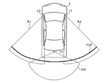
FIG. 1 is a schematic view showing an example of a vehicle according to an embodiment. FIG. 2 is a block diagram showing an example of the functional configuration of the image display system according to the embodiment. FIG. 3 is a diagram for explaining an image pickup range in the rear of the vehicle, which is imaged by the image pickup apparatus according to the embodiment. FIG. 4 is an explanatory diagram showing images before and after image processing by the image processing apparatus according to the embodiment and during the image processing process.
これらの図に示されるように、車両1は、画像表示システム100を備える。画像表示システム100は、画像処理装置10と、撮像装置12、13及び14と、表示装置40とを備える。なお、以降の説明において特に断らない場合には、前後左右の方向は、車両1の進行方向を前方とした場合の方向とし、これは車両1のユーザにとっての前後左右の方向ともいえる。
As shown in these figures, the vehicle 1 includes an
撮像装置12は、車両1の左側ドア付近に固定され、車両1の左側後方の撮像範囲R1を撮影するカメラである。撮像装置12は、車両1の左側後方の撮像範囲R1を撮影して画像51を生成する。撮像装置12が生成した画像51を左側後方画像ともいう。
The
撮像装置13は、車両1の右側ドア付近に固定され、車両1の右側後方の撮像範囲R2を撮影するカメラである。撮像装置13は、車両1の右側後方の撮像範囲R2を撮影して画像52を生成する。撮像装置13が生成した画像52を右側後方画像ともいう。
The
撮像装置14は、車両1のリアバンパー又はトランクフード付近に固定され、車両1の中央後方の撮像範囲R3を撮影するカメラである。撮像装置14は、車両1の中央後方の撮像範囲R3を撮影して画像53を生成する。撮像装置14が生成した画像53を中央後方画像ともいう。
The
このように、撮像装置12〜14のそれぞれは、車両1の後方を撮像する向きで車両1に配置されている。撮像装置12〜14により撮像範囲R1〜R3が撮像されるため、各撮像範囲R1〜R3よりも広い撮像範囲R10が、撮像装置12〜14により撮像されることとなる。
As described above, each of the
撮像装置12及び14の撮像範囲R1およびR3の一部が重なっており、撮像装置13及び14の撮像範囲R2およびR3の一部が重なっている。そのため、左側後方画像と中央後方画像との一部には共通の対象が映っている。また、右側後方画像と中央後方画像との一部には共通の対象が映っている。
A part of the imaging ranges R1 and R3 of the
撮像装置12、13及び14のそれぞれは、互いに異なる撮影条件の下で撮像することで画像を生成する。具体的には、撮像装置12、13及び14のそれぞれは、互いに異なる位置に配置され、また、互いに異なる方向を向いて配置されており、例えば60fpsで画像を取得する。また、撮像装置12、13及び14のそれぞれの光学系の光学特性は異なっていてもよい。
Each of the
画像処理装置10は、各撮像装置12〜14から画像51〜53を取得し、取得した画像51〜53に基づいて、表示装置40に表示させるための位置画像80を出力する。具体的には、画像処理装置10は、取得した画像51〜53から得られる広い撮像範囲R10の合成画像50のうち、運転手の顔位置に応じて、表示装置40の表示面をルームミラーと仮定したときにルームミラーを介して運転手が見ることができると推定される範囲の画像54を切り出して、切り出した画像54に基づく画像60を出力する。画像処理装置10の詳細な説明は、後述する。
The
表示装置40は、車両1の後方が映った画像である画像60を表示する表示装置である。表示装置40は、画像処理装置10により出力された画像60を表示する。表示装置40は、画像処理装置10により出力された画像60を表示するため、車両1の後方を、光の反射を利用して映す従来のルームミラーの代用として用いられ得る。表示装置40は、車両1の天井の前側中央部付近に配置されている。
The
図2を用いて、画像処理装置10の機能的な構成について説明する。
The functional configuration of the
画像処理装置10は、取得部101と、位置検出部102と、画像処理部103と、記憶部104とを備える。
The
取得部101は、撮像装置12〜14によりそれぞれ撮像された画像51〜53を、各撮像装置12〜14から取得する。取得部101は、異なる複数のタイミング(例えば60fps)で撮像装置12〜14のそれぞれにおいて撮像された画像を取得する。
The
位置検出部102は、運転手の顔位置を検出する。位置検出部102は、具体的には、表示装置40に配置され、表示装置40の表示面側(つまり表示装置40の運転手側または後方)を撮像する撮像部30を有し、撮像部30により撮像された画像について顔認識処理を実行することで表示装置40に対する運転手の顔位置を特定する。これにより、位置検出部102は、表示装置40の基準位置から顔位置まで方向を特定することができる。なお、基準位置は、撮像部30が配置されている表示装置40の位置であってもよいし、表示装置40の水平方向における中心位置であってもよい。また、撮像部30は、例えば、カメラである。なお、位置検出部102は、運転手の目の位置を検出してもよいし、運転手の頭部の位置を検出することで運転手の顔位置を推定してもよい。
The
画像処理部103は、上述したように、画像51〜53を合成することで、合成画像50を生成する。画像処理部103は、位置検出部102により検出された運転手の顔位置に応じて、対象画像としての合成画像50のうち当該顔位置に対応する範囲を切り出すと共に、切り出すことにより得られた画像60の顔位置に対応する位置に車両1の位置を示す位置画像80を重畳する画像処理を行う。そして、画像処理部103は、画像処理後の画像60を出力する。
As described above, the
画像処理部103は、位置検出部102が検出した運転手の顔位置が車両1の左右方向の一方に移動した場合、合成画像50から画像を切り出す範囲を顔位置が移動する前の範囲よりも車両1の左右方向の他方側に移動させ、かつ、位置画像80を重畳させる位置を顔位置が移動する前の位置よりも車両1の左右方向の一方側に移動させる。例えば、運転手の顔位置が右方向に移動した場合の例について図5〜図7を用いて説明する。
When the driver's face position detected by the
図5は、通常の運転中における顔位置で画像処理部が画像を切り出す範囲を説明するための図である。図6は、移動した後の顔位置で画像処理部が画像を切り出す範囲を説明するための図である。図7は、顔位置が移動する前後における画像処理部による画像処理の違いについて説明するための図である。 FIG. 5 is a diagram for explaining a range in which the image processing unit cuts out an image at a face position during normal driving. FIG. 6 is a diagram for explaining a range in which the image processing unit cuts out an image at the face position after moving. FIG. 7 is a diagram for explaining the difference in image processing by the image processing unit before and after the movement of the face position.
なお、図5および図6における(a)は、車両1の車室内の前側を上側から見た平面図であり、(b)は、車両1を上側から見た平面図において撮像装置12〜14により撮像された撮像範囲R10のうち表示装置40に表示される画像の範囲を示す図である。図7の(a1)および(a2)は、図5の状態における画像処理部103による画像処理を説明するための図であり、(a1)は、合成画像50から画像54を切り出す処理例を示し、(a2)は、切り出した画像54に位置画像80を重畳させる処理例を示す図である。図7の(b1)および(b2)は、図6の状態における画像処理部103による画像処理を説明するための図であり、(b1)は、合成画像50から画像55を切り出す処理例を示し、(b2)は、切り出した画像55に位置画像80を重畳させる処理例を示す図である。図5および図6における一点鎖線Xは、車両1の前後方向を示す。
Note that (a) in FIGS. 5 and 6 is a plan view of the front side of the vehicle interior of the vehicle 1 viewed from above, and (b) is a plan view of the vehicle 1 viewed from above of the
顔位置が移動する前として、図5の(a)に示されるように、例えば、運転手U1がステアリングホイール22を握って通常の運転を行っており、運転手U1は、車両1の運転席21の左右方向の中央に着座しているものとする。この場合、運転手U1が通常の運転中の顔位置P1において、表示装置40をルームミラーと仮定した場合に運転手U1に視認されるルームミラー越しの視界の中心の方向D1が車両1の後方となる画像が表示装置40に表示されるように、画像処理部103が切り出す範囲が調整されているものとする。つまり、この場合、図5の(b)に示されるように、画像処理部103は、車両1の表示装置40の中心位置(左右方向の中心位置)を起点とし、かつ、広い撮像範囲R10のうちの方向D1を中心とする角度範囲θ10に対応する範囲71が画像を切り出す範囲として決定。角度範囲θ10は、表示装置40の中心位置を起点とし、方向D1を中心とする左右それぞれの角度範囲θ11を合わせた角度範囲である。
As shown in FIG. 5A, for example, the driver U1 holds the
なお、この場合の表示装置40は、表示装置40の表示面がルームミラーとした場合に、表示面を顔位置P1にある運転手U1が見た場合に、車両1の真後ろの範囲が表示面に反射される角度となるように、角度が調整されている。つまり、運転手U1の顔位置P1から表示装置40の左右方向の中心の位置P3までの線と表示装置40の表示面とがなす角の角度は、方向D1と表示装置40の表示面とがなす角の角度と略等しい。
In this case, when the display surface of the
これにより、図7の(a1)に示されるように、画像処理部103は、合成画像50から、決定された範囲71を切り出すことにより画像54を得る。そして、図7の(a2)に示されるように、画像処理部103は、切り出した画像54の左右方向の中心の位置P11に位置画像80を重畳させ、重畳させることにより得られた画像60を表示装置40に出力する。なお、画像60は、運転手が顔位置を移動させる前において画像処理部103により画像処理された後に出力される画像の一例である。
As a result, as shown in (a1) of FIG. 7, the
次に、顔位置が移動した場合について図6を用いて説明する。 Next, the case where the face position is moved will be described with reference to FIG.
図6の(a)に示されるように、顔位置が移動した後の場合として、例えば、運転手U1が運転席21の右側に顔を移動させた場合を考える。この場合、運転手U1の顔位置P2において、表示装置40をルームミラーと仮定した場合に運転手U1に視認されるルームミラー越しの視界の中心の方向D2は、方向D1よりも左よりの方向となる。この場合、図6の(b)に示されるように、車両1の表示装置40の中心位置(左右方向の中心位置)を起点とし、かつ、広い撮像範囲R10のうちの方向D2を中心とする角度範囲θ20に対応する範囲72が画像を切り出す範囲として決定される。角度範囲θ20は、表示装置40の中心位置を起点とし、方向D2を中心とする左右それぞれの角度範囲θ11を合わせた角度範囲である。
As shown in FIG. 6A, consider, for example, a case where the driver U1 moves his face to the right side of the driver's
なお、この場合、運転手U1の顔位置P2から表示装置40の中心の位置P3までの線と表示装置40の表示面とがなす角の角度は、方向D2と表示装置40の表示面とがなす角の角度と略等しい。
In this case, the angle between the line from the face position P2 of the driver U1 to the center position P3 of the
これにより、図7の(b1)に示されるように、画像処理部103は、合成画像50から、決定された範囲72を切り出すことにより画像55を得る。そして、図7の(b2)に示されるように、画像処理部103は、顔位置P1の場合に位置画像80を重畳させた位置P11よりも第1距離d1だけ右側の位置P12に位置画像80を重畳させ、重畳させることにより得られた画像61を表示装置40に出力する。このときに、画像処理部103は、顔位置P1から顔位置P2に顔位置が移動した場合に、位置画像80を重畳させる位置を移動させる第1距離d1を、画像61を合成画像50から切り出す範囲71を移動させる第2距離d2よりも長くする。つまり、画像61は、運転手が顔位置を移動させた後において画像処理部103により画像処理された後に出力される画像の一例である。
As a result, as shown in (b1) of FIG. 7, the
ここで、第1距離d1は、画像61上における距離であり、例えば、画素数により表される。第2距離d2は、画像61上における距離であり、例えば、画像61のうち運転手の顔位置が移動する前に切り出しが行われていた範囲71の左右方向の他方側の端部の位置P21と、運転手の顔位置が移動した後の画像61の他方側の端部の位置P22との間の画素数である。また、第2距離d2は、合成画像50上における距離であり、合成画像50のうちの切り出す範囲71と同サイズの画像を画像61と同じ解像度に合成画像50を対応させた画像における画素数により表されてもよい。
Here, the first distance d1 is a distance on the
なお、図5〜図7を用いて、運転手U1の顔が右側に移動する場合を例に説明したが、左側に移動する場合も同様に説明できる。この場合、切り出す範囲は、右側に移動することとなり、位置画像80を重畳する位置は左側に移動することとなる。
In addition, although the case where the face of the driver U1 moves to the right side has been described as an example with reference to FIGS. In this case, the cutout range moves to the right side, and the position on which the
なお、画像処理部103は、上述した画像処理の他に、撮像装置12〜14の三次元空間におけるカメラの位置及び姿勢を示す外部パラメータと、カメラの焦点距離、収差、画像中心等の光学系の特性を示す内部パラメータとを調整する処理(つまり、校正)を行ってもよい。
In addition to the image processing described above, the
記憶部104は、位置画像80を記憶している。位置画像80は、切り出した画像54、55よりも小さい画像であり、運転手U1よりも後ろの位置にある車両1の装備品を示す模式図(例えばCG)である。記憶部104は、互いに異なる複数種類の位置画像を記憶していてもよい。この場合、画像処理部103は、記憶部104に記憶されている複数種類の位置画像80のうちの、予め選択された1以上の位置画像を切り出した画像54、55に重畳する。画像処理部103により重畳される位置画像には、ユーザにより予め選択された画像を用いてもよいし、画像処理装置10が工場出荷時の初期設定において選択された画像を用いてもよい。位置画像80は、図7に示されるように、車両1のシートの模式図が用いられてもよいし、車両1のリアワイパー、リアスピーカ、リアピラーなどの他の装備品の模式図が用いられてもよい。
The
[2.動作]
次に、画像表示システム100の動作について説明する。
[2. motion]
Next, the operation of the
図8は、実施の形態に係る画像表示システム100の動作の一例を示すシーケンス図である。図9は、実施の形態に係る画像処理装置における画像処理の一例を示すフローチャートである。
FIG. 8 is a sequence diagram showing an example of the operation of the
画像表示システム100では、図8に示すように、撮像装置12〜14のそれぞれは、撮像により得られた画像を出力する(S1〜S3)。
In the
画像処理装置10では、位置検出部102が運転手U1の顔位置を検出し(S4)、撮像装置12〜14により得られた画像に対して、画像処理部103が検出された顔位置に応じた画像処理を実行し(S5)、画像処理後の画像を出力する。なお、ステップS5の画像処理の詳細は後述する。
In the
表示装置40は、画像処理装置10から出力された画像を取得して、当該画像を表示する(S6)。
The
画像表示システム100では、ステップS1〜S6の処理を繰り返し実行することで、リアルタイムに、同じタイミングで撮像装置12〜14で撮像された3枚の画像を、検出した顔位置に応じて画像処理し、画像処理後の画像を表示装置40に表示する。
In the
次に、画像処理装置10における画像処理について図9を用いて説明する。
Next, the image processing in the
画像処理において、画像処理装置10では、取得部101は、撮像装置12〜14により撮像された3枚の画像51〜53を取得する(S11)。
In image processing, in the
次に、画像処理部103は、3枚の画像51〜53を合成し、合成画像50を得る(S12)。
Next, the
そして、画像処理部103は、検出された顔位置に応じて、合成画像50のうち顔位置に対応する範囲71の画像54を切り出す(S13)。
Then, the
画像処理部103は、切り出した画像54の顔位置に対応する位置に位置画像80を重畳する(S14)。
The
画像処理部103は、位置画像80を重畳した後の画像60(または画像61)を表示装置40に出力する(S15)。
The
なお、顔位置を検出する処理を実施する頻度は、画像処理の頻度よりも少なくてもよい。車両1が走行中においては、車両1の周囲の景色は変化し続けるため撮像装置12〜14により得られた最新の画像を使用する必要があるが、顔位置が移動する頻度は少なく、また、顔位置が移動する速度は、車両1が走行する速度よりも遅いためである。
The frequency of performing the process of detecting the face position may be lower than the frequency of image processing. While the vehicle 1 is running, the scenery around the vehicle 1 continues to change, so it is necessary to use the latest images obtained by the
[3.効果など]
本実施の形態に係る画像処理装置10は、取得部101と、位置検出部102と、画像処理部103とを備える。取得部101は、車両1の後方を撮像する向きで車両1に配置されている撮像装置12〜14により撮像された画像51〜53を撮像装置12〜14から取得する。位置検出部102は、運転手U1の顔位置を検出する。画像処理部103は、位置検出部102により検出された顔位置に応じて、画像51〜53を合成した合成画像50のうち当該顔位置P1に対応する範囲71を切り出すと共に、切り出すことにより得られた画像54の顔位置P1に対応する位置P11に車両1の位置を示す位置画像80を重畳する画像処理を行い、画像処理後の画像60(または画像61)を出力する。
[3. Effect etc.]
The
つまり、画像処理装置10では、検出された運転手U1の顔位置P1に応じて、撮像装置12〜14により撮像された画像51〜53を含む合成画像50から切り出す画像54の範囲71の位置P21と、画像54に重畳させる位置画像80の位置P11とを決定している。このため、車両1の後方を撮像した画像51〜53を含む合成画像50から運転手U1の顔位置P1に応じた適切な範囲71で画像54を切り出すことができ、かつ、切り出した画像54の、顔位置P1に応じた適切な位置P11に位置画像80を重畳させることができる。よって、車両1との位置関係を把握しやすい、車両1の後方を撮像した画像60(または画像61)を出力することができる。これにより、運転手U1は、例えば、ルームミラーの代用として設けられた表示装置40において表示された画像を見ることで、より少ない違和感で車両1の後方の状況を把握することができる。
That is, in the
また、本実施の形態に係る画像処理装置10において、画像処理部103は、車両1の車室内に配置されている表示装置40の表示面をミラーと仮定したときに、当該表示面を介して、位置検出部102により検出された顔位置P1、P2において運転手U1が見ることができると推定される範囲71、72を、合成画像50から切り出す。このように、画像処理装置10は、ルームミラーを運転手が見ていると仮定したときに見えると推定される範囲を対象画像から切り出すため、ルームミラーに慣れ親しんだ運転手に対しても違和感が少ない画像を提供することができる。
Further, in the
また、本実施の形態に係る画像処理装置10において、画像処理部103は、位置検出部102が検出した顔位置P2が車両1の左右方向の一方側(例えば右側)に移動していた場合、合成画像50から画像54を切り出す範囲72を顔位置が移動する前の範囲71よりも車両1の左右方向の他方側(例えば左側)に移動させ、位置画像80を重畳させる位置P12を顔位置が移動する前の顔位置P1よりも車両1の左右方向の一方側(例えば右側)に移動させる。
Further, in the
このように、画像処理装置10は、図6に示すように顔位置が左右方向の一方側(例えば右側)に移動したときには、図7に示すように、切り出す範囲を他方側(例えば左側)に移動させ、かつ、位置画像を重畳させる位置を一方側(例えば右側)に移動させる。これは、顔位置が左右方向の一方側(例えば右側)に移動したときには、ルームミラーには移動前よりも他方側(例えば左側)の範囲が映り込むと推定されるからである。同様に、顔位置が左右方向の一方側(例えば右側)に移動したときには、図6に示すように、ルームミラーを介した視線方向は他方側(例えば左側)に移動するため、車両の車室内の装備品は他方側とは反対側の一方側(例えば右側)に移動すると推定されるからである。上記のように、画像処理装置10は、切り出す範囲および位置画像を重畳する位置を決定するため、ルームミラーに慣れ親しんだ運転手に対しても違和感が少ない画像を提供することができる。
As described above, when the face position is moved to one side (for example, the right side) in the left-right direction as shown in FIG. 6, the
また、本実施の形態に係る画像処理装置10において、画像処理部103は、検出された顔位置が移動した場合に、位置画像80を重畳させる位置を移動させる第1距離d1を、画像を合成画像50から切り出す範囲を移動させる第2距離d2よりも長くする。
Further, in the
撮像装置12〜14により撮像された画像の撮像対象は、車両1の外部にあり、位置画像80が示す車両1の内部の装備品の位置よりも運転手U1からは遠い位置にある。このため、運転手U1が顔位置を左右方向に移動させてルームミラーを見た場合、運転手U1は、近い位置にある装備品の方が遠い位置にある車両1の外部の対象よりも移動する距離が大きくなる。よって、上記のように、第1距離d1を第2距離d2よりも長くすることで、撮像装置により撮像された画像を含む対象画像から切り出す画像の範囲の位置と、第2画像に重畳させる位置画像の位置とを、ルームミラーを見ているときと同様に決定することができる。このため、ルームミラーに慣れ親しんだ運転手に対しても違和感が少ない画像を提供することができる。
The image capture target of the images captured by the
また、本実施の形態に係る画像処理装置10において、位置画像80は、切り出された画像54、55よりも小さい画像であり、運転手U1よりも後ろの位置にある車両1の装備品を示す模式図である。このように、位置画像80は、切り出された画像54、55よりも小さい画像であるため、重畳後の画像60、61が煩雑になることを低減することができる。また、位置画像80は、車両1の装備品を示す模式図であるため、運転手U1は、画像60、61を見ることで、車両1の周囲の画像54、55と車両1との位置関係、および、表示されている画像60、61における車両後方を直感的に把握することができる。
Further, in the
[4.変形例]
[4−1.変形例1]
変形例1に係る画像処理装置について説明する。
[4. Modification example]
[4-1. Modification 1]
The image processing apparatus according to the first modification will be described.
変形例1に係る画像処理装置は、実施の形態の構成と同様であるが、画像処理部103がさらに下記の処理を実行する点が異なる。
The image processing apparatus according to the first modification is the same as the configuration of the embodiment, except that the
具体的には、画像処理部103は、さらに、所定の入力に応じて位置画像80の透明度を変更してもよい。つまり、画像処理部103は、切り出された画像54、55に重畳させる位置画像80の透明度を調整し、調整後の位置画像80を重畳してもよい。
Specifically, the
画像処理部103は、例えば、所定の入力としてユーザにより設定された値を用いて位置画像80の透明度を調整してもよい。
The
また、画像処理部103は、例えば、所定の入力として照度センサにより検出された照度を用いて位置画像80の透明度を調整してもよい。この場合、画像処理部103は、照度センサにより検出された照度が小さいほど位置画像80の透明度を大きくする。なお、この場合の照度センサは、車両1に設けられ、車両1周辺の照度を検出するセンサである。照度センサは、車両1の内部に配置されていてもよいし、車両1の外部に配置されていてもよい。照度センサの検出結果を用いて、車両1の外部の照度を推定できればどの位置に配置されていてもよい。
Further, the
変形例1に係る画像処理装置10では、画像処理部103は、所定の入力に応じて位置画像80の透明度を変更する。このため、例えば、運転手の好み、車室内の明るさなどに応じて透明度が変更された位置画像が重畳された画像を提供することができる。
In the
また、変形例1に係る画像処理装置10では、画像処理部103は、照度センサにより検出された照度が小さいほど透明度を大きくする。このため、車両1の外部の対象を撮像した画像が暗くて外部の対象を視認しにくいと推定される場合、位置画像80の透明度を大きくすることで、車両1の外部の対象の視認性が低下することを低減することができる。
Further, in the
[4−2.変形例2]
変形例2に係る画像処理装置について説明する。
[4-2. Modification 2]
The image processing apparatus according to the second modification will be described.
図10は、変形例2に係る画像表示システムの機能構成の一例を示すブロック図である。 FIG. 10 is a block diagram showing an example of the functional configuration of the image display system according to the second modification.
図10に示されるように、変形例2に係る画像表示システム100Aは、実施の形態に係る画像表示システム100と比較して、画像処理装置10Aがさらに判定部105を備える点と、画像処理部103Aによる処理とが異なる。変形例2に係る画像表示システム100Aのその他の構成は、実施の形態に係る画像表示システム100と同様であるので説明を省略する。
As shown in FIG. 10, in the
判定部105は、車両1から所定の距離以内の位置に後続車両が位置するか否かを判定する。判定部105は、例えば、撮像装置14により得られた画像を画像解析することにより、後続車両が所定の距離以内の位置に位置するか否かを判定してもよい。判定部105は、車両1が後方の物体との距離を検出する距離センサを有している場合には、距離センサの検出結果を用いて上記の判定を行ってもよい。
The
画像処理部103Aは、判定部105により、所定の距離以内の位置に後続車両が位置したと判定した場合、実施の形態で説明した画像処理において、検出された顔位置に応じて、合成画像50のうち当該顔位置に対応する範囲を切り出し、かつ、位置画像80の重畳をしない。
When the
図11は、変形例2に係る画像処理装置における画像処理の一例を示すフローチャートである。 FIG. 11 is a flowchart showing an example of image processing in the image processing apparatus according to the second modification.
変形例2に係る画像処理は、実施の形態に係る画像処理と比較して、ステップS21およびS22が追加されている点が異なる。実施の形態に係る画像処理と同様の処理の説明は、省略する。 The image processing according to the second modification is different from the image processing according to the embodiment in that steps S21 and S22 are added. The description of the same processing as the image processing according to the embodiment will be omitted.
まず、実施の形態と同様にステップS11〜S13が行われる。 First, steps S11 to S13 are performed in the same manner as in the embodiment.
ステップS13の後に、判定部105は、車両1から所定の距離以内の位置に後続車両が位置するか否かを判定する(S21)。
After step S13, the
画像処理部103は、判定部105により、車両1から所定の距離以内の位置に後続車両が位置すると判定された場合(S21でYes)、位置画像80を重畳せずに、重畳しない、切り出した後の画像を出力する(S22)。
When the
一方で、画像処理部103は、判定部105により、車両1から所定の距離以内の位置に後続車両が位置しないと判定された場合(S21でNo)、ステップS14、S15を行う。
On the other hand, when the
これによれば、後続車両が近づいて画像内に大きく映り込んでいる場合、画像処理部103は、位置画像80を重畳しないため、画像に写り込んでいる後続車両のサイズと位置画像80のサイズとの差が大きくなることで運転手U1に与える違和感を低減することができる。
According to this, when the following vehicle approaches and is greatly reflected in the image, the
[4−3.変形例3]
上記実施の形態およびその変形例1、2に係る画像表示システム100、100Aは、複数の撮像装置12〜14を備える構成としたが、これに限らずに、1つの撮像装置を備える構成としてもよい。
[4-3. Modification 3]
The
[4−4.変形例4]
上記実施の形態では、位置検出部102は、撮像部30を有し、撮像部30により得られた画像に顔認識処理を実行することで表示装置40に対する運転手の顔位置を特定するとしたが、これに限るものではない。例えば、位置検出部は、デプスセンサを有し、デプスセンサが検出した結果を用いて運転手の顔位置を特定してもよい。また、位置検出部は、サーモグラフィを有し、サーモグラフィが検出した結果を用いて運転手の顔位置を特定してもよい。
[4-4. Modification 4]
In the above embodiment, the
なお、上記各実施の形態において、画像処理装置10の各構成要素は、専用のハードウェアで構成されるか、各構成要素に適したソフトウェアプログラムを実行することによって実現されてもよい。各構成要素は、CPUまたはプロセッサなどのプログラム実行部が、ハードディスクまたは半導体メモリなどの記録媒体に記録されたソフトウェアプログラムを読み出して実行することによって実現されてもよい。ここで、上記各実施の形態の画像処理装置などを実現するソフトウェアは、次のようなプログラムである。
In each of the above embodiments, each component of the
すなわち、このプログラムは、コンピュータに、車両の後方を撮像する向きで前記車両に配置されている撮像装置により撮像された第1画像を前記撮像装置から取得し、運転手の顔位置を検出し、検出された前記顔位置に応じて、前記第1画像を含む対象画像のうち当該顔位置に対応する範囲を切り出すと共に、切り出すことにより得られた第2画像の前記顔位置に対応する位置に前記車両の位置を示す位置画像を重畳する画像処理を行い、画像処理後の第3画像を出力する画像処理方法を実行させる。 That is, this program acquires the first image captured by the image pickup device arranged in the vehicle in the direction of imaging the rear of the vehicle by the computer, detects the driver's face position, and detects the driver's face position. According to the detected face position, a range corresponding to the face position is cut out from the target image including the first image, and the position corresponding to the face position of the second image obtained by cutting out is performed. An image processing method for superimposing a position image indicating the position of the vehicle is performed, and an image processing method for outputting a third image after the image processing is executed.
以上、本発明の一つまたは複数の態様に係る画像処理装置、画像表示システムおよび画像処理方法について、実施の形態に基づいて説明したが、本発明は、この実施の形態に限定されるものではない。本発明の趣旨を逸脱しない限り、当業者が思いつく各種変形を本実施の形態に施したものや、異なる実施の形態における構成要素を組み合わせて構築される形態も、本発明の一つまたは複数の態様の範囲内に含まれてもよい。 The image processing apparatus, image display system, and image processing method according to one or more aspects of the present invention have been described above based on the embodiments, but the present invention is not limited to the embodiments. Absent. As long as it does not deviate from the gist of the present invention, one or more of the present embodiments may be modified by those skilled in the art, or may be constructed by combining components in different embodiments. It may be included within the scope of the embodiment.
本発明は、車両との位置関係を把握しやすい、車両の後方の撮像した画像を出力することができる画像処理装置、画像表示システムおよび画像処理方法などとして有用である。 INDUSTRIAL APPLICABILITY The present invention is useful as an image processing device, an image display system, an image processing method, etc. that can output an image captured behind the vehicle, which makes it easy to grasp the positional relationship with the vehicle.
1 車両
10、10A 画像処理装置
12〜14 撮像装置
21 運転席
22 ステアリングホイール
30 撮像部
40 表示装置
50 合成画像
51〜55、60、61 画像
71、72 範囲
80 位置画像
100、100A 画像表示システム
101 取得部
102 位置検出部
103、103A 画像処理部
104 記憶部
105 判定部
D1、D2 方向
d1 第1距離
d2 第2距離
P1、P2、P3、P11、P12、P21、P22 位置
R1、R2、R3、R10 撮像範囲
U1 運転手
θ10、θ11、θ20 角度範囲
1
Claims (12)
運転手の顔位置を検出する位置検出部と、
前記位置検出部により検出された前記顔位置に応じて、前記第1画像を含む対象画像のうち当該顔位置に対応する範囲を切り出すと共に、切り出すことにより得られた第2画像の前記顔位置に対応する位置に前記車両の位置を示す位置画像を重畳する画像処理を行い、画像処理後の第3画像を出力する画像処理部と、を備え、
前記画像処理部は、前記位置検出部が検出した前記顔位置が前記車両の左右方向の一方側に移動していた場合、前記対象画像から前記第2画像を切り出す範囲を前記顔位置が移動する前の範囲よりも前記車両の左右方向の他方側に移動させ、前記位置画像を重畳させる位置を前記顔位置が移動する前の位置よりも前記車両の左右方向の一方側に移動させる
画像処理装置。 An acquisition unit that acquires a first image captured by an imaging device arranged in the vehicle in a direction for imaging the rear of the vehicle from the imaging device.
A position detector that detects the driver's face position and
According to the face position detected by the position detection unit, a range corresponding to the face position is cut out from the target image including the first image, and the face position of the second image obtained by cutting out is used. It is provided with an image processing unit that performs image processing that superimposes a position image indicating the position of the vehicle on the corresponding position and outputs a third image after the image processing .
When the face position detected by the position detection unit has moved to one side in the left-right direction of the vehicle, the image processing unit moves the face position within a range for cutting out the second image from the target image. An image processing device that moves the vehicle to the other side in the left-right direction of the vehicle from the previous range, and moves the position on which the position image is superimposed to one side of the vehicle in the left-right direction from the position before the face position moves. ..
請求項1に記載の画像処理装置。 When the display surface of the display device arranged in the vehicle interior of the vehicle is assumed to be a mirror, the image processing unit operates the operation at the face position detected by the position detection unit via the display surface. The image processing apparatus according to claim 1, wherein a range estimated to be visible by a hand is cut out from the target image.
請求項1に記載の画像処理装置。 When the face position moves, the image processing unit sets a first distance for moving the position on which the position image is superimposed than a second distance for moving the range for cutting out the second image from the target image. The image processing apparatus according to claim 1.
運転手の顔位置を検出する位置検出部と、
前記位置検出部により検出された前記顔位置に応じて、前記第1画像を含む対象画像のうち当該顔位置に対応する範囲を切り出すと共に、切り出すことにより得られた第2画像の前記顔位置に対応する位置に前記車両の位置を示す位置画像を重畳する画像処理を行い、画像処理後の第3画像を出力する画像処理部と、を備え、
前記位置画像は、前記第2画像よりも小さい画像であり、前記運転手よりも後ろの位置にある前記車両の装備品を示す模式図である
画像処理装置。 An acquisition unit that acquires a first image captured by an imaging device arranged in the vehicle in a direction for imaging the rear of the vehicle from the imaging device.
A position detector that detects the driver's face position and
According to the face position detected by the position detection unit, a range corresponding to the face position is cut out from the target image including the first image, and the face position of the second image obtained by cutting out is used. It is provided with an image processing unit that performs image processing that superimposes a position image indicating the position of the vehicle on the corresponding position and outputs a third image after the image processing.
The position image is an image smaller than the second image, and is a schematic view showing the equipment of the vehicle located at a position behind the driver.
Images processing device.
請求項1から4のいずれか1項に記載の画像処理装置。 The image processing apparatus according to any one of claims 1 to 4 , wherein the image processing unit changes the transparency of the position image in response to a predetermined input.
前記車両周辺の照度を検出する照度センサを備え、
前記所定の入力は、前記照度センサにより検出された前記照度であり、
前記画像処理部は、前記照度が小さいほど前記透明度を大きくする
請求項5に記載の画像処理装置。 further,
It is equipped with an illuminance sensor that detects the illuminance around the vehicle.
The predetermined input is the illuminance detected by the illuminance sensor.
The image processing apparatus according to claim 5 , wherein the image processing unit increases the transparency as the illuminance decreases.
互いに異なる複数種類の前記位置画像を記憶している記憶部を備え、
前記画像処理部は、前記記憶部に記憶されている前記複数種類の位置画像のうちの、予め選択された1以上の位置画像を前記第2画像に重畳する
請求項1から6のいずれか1項に記載の画像処理装置。 further,
It is provided with a storage unit that stores a plurality of types of the position images that are different from each other.
The image processing unit is any one of claims 1 to 6 that superimposes one or more preselected position images among the plurality of types of position images stored in the storage unit on the second image. The image processing apparatus according to the section.
運転手の顔位置を検出する位置検出部と、
前記位置検出部により検出された前記顔位置に応じて、前記第1画像を含む対象画像のうち当該顔位置に対応する範囲を切り出すと共に、切り出すことにより得られた第2画像の前記顔位置に対応する位置に前記車両の位置を示す位置画像を重畳する画像処理を行い、画像処理後の第3画像を出力する画像処理部と、
前記車両から所定の距離以内の位置に後続車両が位置するか否かを判定する判定部と、を備え、
前記画像処理部は、前記所定の距離以内の位置に前記後続車両が位置したと前記判定部により判定された場合、前記画像処理において前記位置画像の重畳をしない
画像処理装置。 An acquisition unit that acquires a first image captured by an imaging device arranged in the vehicle in a direction for imaging the rear of the vehicle from the imaging device.
A position detector that detects the driver's face position and
According to the face position detected by the position detection unit, a range corresponding to the face position is cut out from the target image including the first image, and the face position of the second image obtained by cutting out is used. An image processing unit that performs image processing by superimposing a position image indicating the position of the vehicle on the corresponding position and outputs a third image after the image processing.
And a determination unit for determining whether or not the following vehicle is located at the position within a predetermined distance from the vehicle,
When the determination unit determines that the following vehicle is located within the predetermined distance, the image processing unit does not superimpose the position image in the image processing.
Images processing device.
前記撮像装置と、
前記画像処理装置により出力された前記第3画像を表示する表示装置と、を備える
画像表示システム。 The image processing apparatus according to any one of claims 1 to 8.
With the image pickup device
An image display system including a display device for displaying the third image output by the image processing device.
運転手の顔位置を検出し、
検出された前記顔位置に応じて、前記第1画像を含む対象画像のうち当該顔位置に対応する範囲を切り出すと共に、切り出すことにより得られた第2画像の前記顔位置に対応する位置に前記車両の位置を示す位置画像を重畳し、
前記顔位置が前記車両の左右方向の一方側に移動していた場合、前記対象画像から前記第2画像を切り出す範囲を前記顔位置が移動する前の範囲よりも前記車両の左右方向の他方側に移動させ、前記位置画像を重畳させる位置を前記顔位置が移動する前の位置よりも前記車両の左右方向の一方側に移動させる画像処理を行い、
画像処理後の第3画像を出力する
画像処理方法。 A first image captured by an imaging device arranged in the vehicle in a direction for imaging the rear of the vehicle is acquired from the imaging device.
Detects the driver's face position and
According to the detected face position, a range corresponding to the face position is cut out from the target image including the first image, and the position corresponding to the face position of the second image obtained by cutting out is performed. Superimpose a position image showing the position of the vehicle ,
When the face position has moved to one side in the left-right direction of the vehicle, the range for cutting out the second image from the target image is the other side in the left-right direction of the vehicle than the range before the face position moves. The image processing is performed so that the position on which the position image is superimposed is moved to one side in the left-right direction of the vehicle from the position before the face position is moved.
An image processing method that outputs a third image after image processing.
運転手の顔位置を検出し、 Detects the driver's face position and
検出された前記顔位置に応じて、前記第1画像を含む対象画像のうち当該顔位置に対応する範囲を切り出すと共に、切り出すことにより得られた第2画像の前記顔位置に対応する位置に前記車両の位置を示す位置画像であって、前記第2画像よりも小さい画像であり、前記運転手よりも後ろの位置にある前記車両の装備品を示す模式図である前記位置画像を重畳する画像処理を行い、 According to the detected face position, a range corresponding to the face position is cut out from the target image including the first image, and the position corresponding to the face position of the second image obtained by cutting out is performed. A position image showing the position of the vehicle, which is smaller than the second image and is an image superimposing the position image which is a schematic diagram showing the equipment of the vehicle located at a position behind the driver. Process and
画像処理後の第3画像を出力する Output the third image after image processing
画像処理方法。 Image processing method.
運転手の顔位置を検出し、 Detects the driver's face position and
検出された前記顔位置に応じて、前記第1画像を含む対象画像のうち当該顔位置に対応する範囲を切り出すと共に、切り出すことにより得られた第2画像の前記顔位置に対応する位置に前記車両の位置を示す位置画像を重畳する画像処理を行い、 According to the detected face position, a range corresponding to the face position is cut out from the target image including the first image, and the position corresponding to the face position of the second image obtained by cutting out is performed. Image processing is performed to superimpose a position image showing the position of the vehicle.
前記車両から所定の距離以内の位置に後続車両が位置するか否かを判定し、 It is determined whether or not the following vehicle is located within a predetermined distance from the vehicle.
前記画像処理では、前記所定の距離以内の位置に前記後続車両が位置したと判定された場合、前記画像処理において前記位置画像の重畳をしない In the image processing, when it is determined that the following vehicle is located within the predetermined distance, the position image is not superimposed in the image processing.
画像処理方法。 Image processing method.
Priority Applications (4)
| Application Number | Priority Date | Filing Date | Title |
|---|---|---|---|
| JP2018062600A JP6890288B2 (en) | 2018-03-28 | 2018-03-28 | Image processing equipment, image display system and image processing method |
| PCT/JP2018/039984 WO2019187283A1 (en) | 2018-03-28 | 2018-10-26 | Image processing device, image display system, and image processing method |
| DE112018007360.2T DE112018007360T5 (en) | 2018-03-28 | 2018-10-26 | Image processing apparatus, image display system and image processing method |
| US16/992,691 US11034305B2 (en) | 2018-03-28 | 2020-08-13 | Image processing device, image display system, and image processing method |
Applications Claiming Priority (1)
| Application Number | Priority Date | Filing Date | Title |
|---|---|---|---|
| JP2018062600A JP6890288B2 (en) | 2018-03-28 | 2018-03-28 | Image processing equipment, image display system and image processing method |
Publications (3)
| Publication Number | Publication Date |
|---|---|
| JP2019175133A JP2019175133A (en) | 2019-10-10 |
| JP2019175133A5 JP2019175133A5 (en) | 2020-05-21 |
| JP6890288B2 true JP6890288B2 (en) | 2021-06-18 |
Family
ID=68061066
Family Applications (1)
| Application Number | Title | Priority Date | Filing Date |
|---|---|---|---|
| JP2018062600A Active JP6890288B2 (en) | 2018-03-28 | 2018-03-28 | Image processing equipment, image display system and image processing method |
Country Status (4)
| Country | Link |
|---|---|
| US (1) | US11034305B2 (en) |
| JP (1) | JP6890288B2 (en) |
| DE (1) | DE112018007360T5 (en) |
| WO (1) | WO2019187283A1 (en) |
Families Citing this family (4)
| Publication number | Priority date | Publication date | Assignee | Title |
|---|---|---|---|---|
| JP7147255B2 (en) * | 2018-05-11 | 2022-10-05 | トヨタ自動車株式会社 | image display device |
| WO2020122084A1 (en) * | 2018-12-11 | 2020-06-18 | ソニー株式会社 | Image processing device, image processing method, and image processing system |
| US20200294194A1 (en) * | 2019-03-11 | 2020-09-17 | Nvidia Corporation | View synthesis using neural networks |
| CN110956134B (en) * | 2019-11-29 | 2023-08-25 | 华人运通(上海)云计算科技有限公司 | Face recognition method, device, equipment and computer readable storage medium |
Family Cites Families (25)
| Publication number | Priority date | Publication date | Assignee | Title |
|---|---|---|---|---|
| US6891563B2 (en) * | 1996-05-22 | 2005-05-10 | Donnelly Corporation | Vehicular vision system |
| JP4364471B2 (en) * | 2001-12-28 | 2009-11-18 | 株式会社エクォス・リサーチ | Image processing apparatus for vehicle |
| JP4323377B2 (en) * | 2004-05-24 | 2009-09-02 | オリンパス株式会社 | Image display device |
| JP4855158B2 (en) * | 2006-07-05 | 2012-01-18 | 本田技研工業株式会社 | Driving assistance device |
| JP5088669B2 (en) * | 2007-03-23 | 2012-12-05 | 株式会社デンソー | Vehicle periphery monitoring device |
| JP5118605B2 (en) * | 2008-10-30 | 2013-01-16 | クラリオン株式会社 | Vehicle periphery image display system |
| JP2010128794A (en) * | 2008-11-27 | 2010-06-10 | Aisin Seiki Co Ltd | Surrounding recognition assisting device for vehicle |
| WO2013084622A1 (en) * | 2011-12-09 | 2013-06-13 | 日産自動車株式会社 | Video display mirror and video display mirror system |
| JP5321711B2 (en) | 2012-04-23 | 2013-10-23 | 日産自動車株式会社 | Vehicle periphery monitoring device and video display method |
| JP6364702B2 (en) | 2013-03-29 | 2018-08-01 | アイシン精機株式会社 | Image display control device, image display system, and display unit |
| JP5562498B1 (en) * | 2014-03-04 | 2014-07-30 | サカエ理研工業株式会社 | Room mirror, vehicle blind spot support device using the room mirror, and display image adjustment method of the room mirror or vehicle blind spot support device |
| WO2016020808A1 (en) * | 2014-08-07 | 2016-02-11 | 株式会社半導体エネルギー研究所 | Display device and driving assistance system |
| DE102015002923B4 (en) * | 2015-03-06 | 2023-01-12 | Mekra Lang Gmbh & Co. Kg | Display device for a vehicle, in particular a commercial vehicle |
| JP2016195301A (en) * | 2015-03-31 | 2016-11-17 | パナソニックIpマネジメント株式会社 | Image processing device and electronic mirror system |
| EP3246664A3 (en) * | 2016-05-19 | 2018-02-14 | Ricoh Company, Ltd. | Information processing system and information display apparatus |
| US10654422B2 (en) * | 2016-08-29 | 2020-05-19 | Razmik Karabed | View friendly monitor systems |
| JP6643969B2 (en) * | 2016-11-01 | 2020-02-12 | 矢崎総業株式会社 | Display device for vehicles |
| JP6626817B2 (en) * | 2016-11-30 | 2019-12-25 | 京セラ株式会社 | Camera monitor system, image processing device, vehicle, and image processing method |
| US10518702B2 (en) * | 2017-01-13 | 2019-12-31 | Denso International America, Inc. | System and method for image adjustment and stitching for tractor-trailer panoramic displays |
| JP6665819B2 (en) * | 2017-03-17 | 2020-03-13 | トヨタ自動車株式会社 | In-vehicle display device |
| WO2019017198A1 (en) * | 2017-07-19 | 2019-01-24 | 株式会社デンソー | Display device for vehicle and display control device |
| US20200210733A1 (en) * | 2017-08-22 | 2020-07-02 | Seeing Machines Limited | Enhanced video-based driver monitoring using phase detect sensors |
| US11645840B2 (en) * | 2017-08-31 | 2023-05-09 | Sony Corporation | Information processing apparatus, information processing method, program, and moving body |
| JP2019067220A (en) * | 2017-10-02 | 2019-04-25 | シャープ株式会社 | Parking position display processor, parking position display method, and program |
| JP7283059B2 (en) * | 2018-11-28 | 2023-05-30 | 株式会社アイシン | Perimeter monitoring device |
-
2018
- 2018-03-28 JP JP2018062600A patent/JP6890288B2/en active Active
- 2018-10-26 DE DE112018007360.2T patent/DE112018007360T5/en active Pending
- 2018-10-26 WO PCT/JP2018/039984 patent/WO2019187283A1/en active Application Filing
-
2020
- 2020-08-13 US US16/992,691 patent/US11034305B2/en active Active
Also Published As
| Publication number | Publication date |
|---|---|
| US20200369207A1 (en) | 2020-11-26 |
| US11034305B2 (en) | 2021-06-15 |
| DE112018007360T5 (en) | 2021-01-14 |
| WO2019187283A1 (en) | 2019-10-03 |
| JP2019175133A (en) | 2019-10-10 |
Similar Documents
| Publication | Publication Date | Title |
|---|---|---|
| JP6890288B2 (en) | Image processing equipment, image display system and image processing method | |
| WO2017069191A1 (en) | Calibration apparatus, calibration method, and calibration program | |
| US9025819B2 (en) | Apparatus and method for tracking the position of a peripheral vehicle | |
| JP6095985B2 (en) | Playback apparatus, playback system, playback method, and program | |
| JP5093611B2 (en) | Vehicle periphery confirmation device | |
| JP6548900B2 (en) | Image generation apparatus, image generation method and program | |
| JP6730614B2 (en) | Vehicle display control device, vehicle display system, vehicle display control method and program | |
| JP2010287163A (en) | In-vehicle image display apparatus, and method for trimming image | |
| US11794667B2 (en) | Image processing apparatus, image processing method, and image processing system | |
| JP2006044596A (en) | Display device for vehicle | |
| US20240017669A1 (en) | Image processing apparatus, image processing method, and image processing system | |
| KR101964864B1 (en) | Distortion Correction Method of Around View Image of Vehicle | |
| JP5299101B2 (en) | Peripheral display device | |
| KR101278654B1 (en) | Apparatus and method for displaying arround image of vehicle | |
| US20220001803A1 (en) | Image processing apparatus, image processing method, and image processing system | |
| WO2018042976A1 (en) | Image generation device, image generation method, recording medium, and image display system | |
| JPWO2019216087A1 (en) | Image processors, mobile devices, and methods, and programs | |
| JP2005269010A (en) | Image creating device, program and method | |
| US20220030178A1 (en) | Image processing apparatus, image processing method, and image processing system | |
| KR20180094717A (en) | Driving assistance apparatus using avm | |
| JP4945315B2 (en) | Driving support system and vehicle | |
| JP2020113066A (en) | Video processing device, video processing method, and program | |
| JP2019153237A (en) | Image processing apparatus, image display system, and image processing method | |
| JP2009006968A (en) | Vehicular display device | |
| JP4696825B2 (en) | Blind spot image display device for vehicles |
Legal Events
| Date | Code | Title | Description |
|---|---|---|---|
| A521 | Request for written amendment filed |
Free format text: JAPANESE INTERMEDIATE CODE: A523 Effective date: 20200408 |
|
| A621 | Written request for application examination |
Free format text: JAPANESE INTERMEDIATE CODE: A621 Effective date: 20200408 |
|
| TRDD | Decision of grant or rejection written | ||
| A01 | Written decision to grant a patent or to grant a registration (utility model) |
Free format text: JAPANESE INTERMEDIATE CODE: A01 Effective date: 20210427 |
|
| A61 | First payment of annual fees (during grant procedure) |
Free format text: JAPANESE INTERMEDIATE CODE: A61 Effective date: 20210506 |
|
| R151 | Written notification of patent or utility model registration |
Ref document number: 6890288 Country of ref document: JP Free format text: JAPANESE INTERMEDIATE CODE: R151 |
|
| S111 | Request for change of ownership or part of ownership |
Free format text: JAPANESE INTERMEDIATE CODE: R313113 |
|
| S531 | Written request for registration of change of domicile |
Free format text: JAPANESE INTERMEDIATE CODE: R313531 |
|
| SZ03 | Written request for cancellation of trust registration |
Free format text: JAPANESE INTERMEDIATE CODE: R313Z03 |