JP6825789B2 - Systems and methods for high resolution mapping of tissues - Google Patents
Systems and methods for high resolution mapping of tissues Download PDFInfo
- Publication number
- JP6825789B2 JP6825789B2 JP2017527658A JP2017527658A JP6825789B2 JP 6825789 B2 JP6825789 B2 JP 6825789B2 JP 2017527658 A JP2017527658 A JP 2017527658A JP 2017527658 A JP2017527658 A JP 2017527658A JP 6825789 B2 JP6825789 B2 JP 6825789B2
- Authority
- JP
- Japan
- Prior art keywords
- mapping
- electrode portion
- electrode
- electrodes
- tissue
- Prior art date
- Legal status (The legal status is an assumption and is not a legal conclusion. Google has not performed a legal analysis and makes no representation as to the accuracy of the status listed.)
- Active
Links
- 238000013507 mapping Methods 0.000 title claims description 408
- 238000000034 method Methods 0.000 title description 44
- 238000001914 filtration Methods 0.000 claims description 61
- 210000003484 anatomy Anatomy 0.000 claims description 43
- 239000003990 capacitor Substances 0.000 claims description 24
- 239000003518 caustics Substances 0.000 claims description 2
- 210000001519 tissue Anatomy 0.000 description 135
- 238000002679 ablation Methods 0.000 description 44
- 238000013461 design Methods 0.000 description 32
- 239000012530 fluid Substances 0.000 description 25
- 230000002262 irrigation Effects 0.000 description 24
- 238000003973 irrigation Methods 0.000 description 24
- 238000011282 treatment Methods 0.000 description 16
- 238000010586 diagram Methods 0.000 description 15
- 239000004020 conductor Substances 0.000 description 12
- 210000002837 heart atrium Anatomy 0.000 description 12
- 230000000747 cardiac effect Effects 0.000 description 10
- 238000010438 heat treatment Methods 0.000 description 9
- 206010003658 Atrial Fibrillation Diseases 0.000 description 8
- 230000004913 activation Effects 0.000 description 8
- 230000008569 process Effects 0.000 description 8
- 208000024891 symptom Diseases 0.000 description 8
- 230000008901 benefit Effects 0.000 description 7
- 230000006870 function Effects 0.000 description 7
- 208000037265 diseases, disorders, signs and symptoms Diseases 0.000 description 6
- 230000007831 electrophysiology Effects 0.000 description 6
- 238000002001 electrophysiology Methods 0.000 description 6
- 210000002216 heart Anatomy 0.000 description 6
- 230000008878 coupling Effects 0.000 description 5
- 238000010168 coupling process Methods 0.000 description 5
- 238000005859 coupling reaction Methods 0.000 description 5
- 210000005003 heart tissue Anatomy 0.000 description 5
- 238000012545 processing Methods 0.000 description 5
- 238000000926 separation method Methods 0.000 description 5
- 208000033988 Device pacing issue Diseases 0.000 description 4
- 239000004696 Poly ether ether ketone Substances 0.000 description 4
- FAPWRFPIFSIZLT-UHFFFAOYSA-M Sodium chloride Chemical compound [Na+].[Cl-] FAPWRFPIFSIZLT-UHFFFAOYSA-M 0.000 description 4
- 238000004891 communication Methods 0.000 description 4
- 201000010099 disease Diseases 0.000 description 4
- 230000000694 effects Effects 0.000 description 4
- 238000005259 measurement Methods 0.000 description 4
- 230000008520 organization Effects 0.000 description 4
- 229920002530 polyetherether ketone Polymers 0.000 description 4
- 239000011780 sodium chloride Substances 0.000 description 4
- 239000000758 substrate Substances 0.000 description 4
- 238000002560 therapeutic procedure Methods 0.000 description 4
- 230000002411 adverse Effects 0.000 description 3
- 206010003119 arrhythmia Diseases 0.000 description 3
- 210000004204 blood vessel Anatomy 0.000 description 3
- 230000003750 conditioning effect Effects 0.000 description 3
- 208000014674 injury Diseases 0.000 description 3
- 239000011810 insulating material Substances 0.000 description 3
- 229910052751 metal Inorganic materials 0.000 description 3
- 239000002184 metal Substances 0.000 description 3
- 229920006324 polyoxymethylene Polymers 0.000 description 3
- 230000001360 synchronised effect Effects 0.000 description 3
- 230000008733 trauma Effects 0.000 description 3
- 210000002620 vena cava superior Anatomy 0.000 description 3
- 229920006362 Teflon® Polymers 0.000 description 2
- 229910045601 alloy Inorganic materials 0.000 description 2
- 239000000956 alloy Substances 0.000 description 2
- 230000002547 anomalous effect Effects 0.000 description 2
- 210000005242 cardiac chamber Anatomy 0.000 description 2
- 206010061592 cardiac fibrillation Diseases 0.000 description 2
- 238000013153 catheter ablation Methods 0.000 description 2
- 238000013500 data storage Methods 0.000 description 2
- 208000035475 disorder Diseases 0.000 description 2
- 210000001174 endocardium Anatomy 0.000 description 2
- 208000021302 gastroesophageal reflux disease Diseases 0.000 description 2
- PCHJSUWPFVWCPO-UHFFFAOYSA-N gold Chemical compound [Au] PCHJSUWPFVWCPO-UHFFFAOYSA-N 0.000 description 2
- 229910052737 gold Inorganic materials 0.000 description 2
- 239000010931 gold Substances 0.000 description 2
- 238000009413 insulation Methods 0.000 description 2
- 230000010354 integration Effects 0.000 description 2
- 150000002739 metals Chemical class 0.000 description 2
- 238000012986 modification Methods 0.000 description 2
- 230000004048 modification Effects 0.000 description 2
- 210000004165 myocardium Anatomy 0.000 description 2
- BASFCYQUMIYNBI-UHFFFAOYSA-N platinum Chemical compound [Pt] BASFCYQUMIYNBI-UHFFFAOYSA-N 0.000 description 2
- 210000003492 pulmonary vein Anatomy 0.000 description 2
- 238000011084 recovery Methods 0.000 description 2
- 230000001105 regulatory effect Effects 0.000 description 2
- 230000004044 response Effects 0.000 description 2
- 238000012546 transfer Methods 0.000 description 2
- 210000005239 tubule Anatomy 0.000 description 2
- 210000003462 vein Anatomy 0.000 description 2
- DHKHKXVYLBGOIT-UHFFFAOYSA-N 1,1-Diethoxyethane Chemical compound CCOC(C)OCC DHKHKXVYLBGOIT-UHFFFAOYSA-N 0.000 description 1
- 208000006545 Chronic Obstructive Pulmonary Disease Diseases 0.000 description 1
- RYGMFSIKBFXOCR-UHFFFAOYSA-N Copper Chemical compound [Cu] RYGMFSIKBFXOCR-UHFFFAOYSA-N 0.000 description 1
- 206010019280 Heart failures Diseases 0.000 description 1
- 206010020772 Hypertension Diseases 0.000 description 1
- 208000019693 Lung disease Diseases 0.000 description 1
- 206010027727 Mitral valve incompetence Diseases 0.000 description 1
- 206010028980 Neoplasm Diseases 0.000 description 1
- 208000012902 Nervous system disease Diseases 0.000 description 1
- 208000025966 Neurological disease Diseases 0.000 description 1
- 206010054107 Nodule Diseases 0.000 description 1
- 208000008589 Obesity Diseases 0.000 description 1
- 229930040373 Paraformaldehyde Natural products 0.000 description 1
- 239000004697 Polyetherimide Substances 0.000 description 1
- 239000004642 Polyimide Substances 0.000 description 1
- 208000001647 Renal Insufficiency Diseases 0.000 description 1
- 208000033809 Suppuration Diseases 0.000 description 1
- 239000004809 Teflon Substances 0.000 description 1
- 229920004738 ULTEM® Polymers 0.000 description 1
- 238000011298 ablation treatment Methods 0.000 description 1
- 239000011354 acetal resin Substances 0.000 description 1
- 230000009471 action Effects 0.000 description 1
- 210000001367 artery Anatomy 0.000 description 1
- 208000006673 asthma Diseases 0.000 description 1
- 230000001746 atrial effect Effects 0.000 description 1
- 230000009286 beneficial effect Effects 0.000 description 1
- 238000009529 body temperature measurement Methods 0.000 description 1
- 229910010293 ceramic material Inorganic materials 0.000 description 1
- 238000006243 chemical reaction Methods 0.000 description 1
- 238000012790 confirmation Methods 0.000 description 1
- 229910052802 copper Inorganic materials 0.000 description 1
- 239000010949 copper Substances 0.000 description 1
- 230000002638 denervation Effects 0.000 description 1
- 206010012601 diabetes mellitus Diseases 0.000 description 1
- 238000004070 electrodeposition Methods 0.000 description 1
- 210000003238 esophagus Anatomy 0.000 description 1
- 230000002600 fibrillogenic effect Effects 0.000 description 1
- 210000001035 gastrointestinal tract Anatomy 0.000 description 1
- 208000019622 heart disease Diseases 0.000 description 1
- 238000003384 imaging method Methods 0.000 description 1
- 238000003780 insertion Methods 0.000 description 1
- 230000037431 insertion Effects 0.000 description 1
- 230000001788 irregular Effects 0.000 description 1
- 201000006370 kidney failure Diseases 0.000 description 1
- 238000002350 laparotomy Methods 0.000 description 1
- 230000004807 localization Effects 0.000 description 1
- 210000004072 lung Anatomy 0.000 description 1
- 239000000463 material Substances 0.000 description 1
- 235000020824 obesity Nutrition 0.000 description 1
- 230000003287 optical effect Effects 0.000 description 1
- 210000000056 organ Anatomy 0.000 description 1
- 238000013021 overheating Methods 0.000 description 1
- 230000037361 pathway Effects 0.000 description 1
- 229910052697 platinum Inorganic materials 0.000 description 1
- HWLDNSXPUQTBOD-UHFFFAOYSA-N platinum-iridium alloy Chemical compound [Ir].[Pt] HWLDNSXPUQTBOD-UHFFFAOYSA-N 0.000 description 1
- 229920001601 polyetherimide Polymers 0.000 description 1
- 229920001721 polyimide Polymers 0.000 description 1
- -1 polyoxymethylene Polymers 0.000 description 1
- 230000002685 pulmonary effect Effects 0.000 description 1
- 238000007674 radiofrequency ablation Methods 0.000 description 1
- 230000009467 reduction Effects 0.000 description 1
- 230000003252 repetitive effect Effects 0.000 description 1
- 239000011347 resin Substances 0.000 description 1
- 229920005989 resin Polymers 0.000 description 1
- 208000023504 respiratory system disease Diseases 0.000 description 1
- 238000012552 review Methods 0.000 description 1
- 230000001568 sexual effect Effects 0.000 description 1
- 239000010935 stainless steel Substances 0.000 description 1
- 229910001220 stainless steel Inorganic materials 0.000 description 1
- 239000013589 supplement Substances 0.000 description 1
- 230000008685 targeting Effects 0.000 description 1
- 210000003708 urethra Anatomy 0.000 description 1
- 210000005166 vasculature Anatomy 0.000 description 1
- 210000001631 vena cava inferior Anatomy 0.000 description 1
- 230000002861 ventricular Effects 0.000 description 1
Images


Classifications
-
- A—HUMAN NECESSITIES
- A61—MEDICAL OR VETERINARY SCIENCE; HYGIENE
- A61B—DIAGNOSIS; SURGERY; IDENTIFICATION
- A61B18/00—Surgical instruments, devices or methods for transferring non-mechanical forms of energy to or from the body
- A61B18/04—Surgical instruments, devices or methods for transferring non-mechanical forms of energy to or from the body by heating
- A61B18/12—Surgical instruments, devices or methods for transferring non-mechanical forms of energy to or from the body by heating by passing a current through the tissue to be heated, e.g. high-frequency current
- A61B18/14—Probes or electrodes therefor
- A61B18/1492—Probes or electrodes therefor having a flexible, catheter-like structure, e.g. for heart ablation
-
- A—HUMAN NECESSITIES
- A61—MEDICAL OR VETERINARY SCIENCE; HYGIENE
- A61B—DIAGNOSIS; SURGERY; IDENTIFICATION
- A61B5/00—Measuring for diagnostic purposes; Identification of persons
- A61B5/05—Detecting, measuring or recording for diagnosis by means of electric currents or magnetic fields; Measuring using microwaves or radio waves
- A61B5/053—Measuring electrical impedance or conductance of a portion of the body
- A61B5/0538—Measuring electrical impedance or conductance of a portion of the body invasively, e.g. using a catheter
-
- A—HUMAN NECESSITIES
- A61—MEDICAL OR VETERINARY SCIENCE; HYGIENE
- A61B—DIAGNOSIS; SURGERY; IDENTIFICATION
- A61B17/00—Surgical instruments, devices or methods, e.g. tourniquets
- A61B17/32—Surgical cutting instruments
- A61B17/320068—Surgical cutting instruments using mechanical vibrations, e.g. ultrasonic
-
- A—HUMAN NECESSITIES
- A61—MEDICAL OR VETERINARY SCIENCE; HYGIENE
- A61B—DIAGNOSIS; SURGERY; IDENTIFICATION
- A61B18/00—Surgical instruments, devices or methods for transferring non-mechanical forms of energy to or from the body
- A61B18/02—Surgical instruments, devices or methods for transferring non-mechanical forms of energy to or from the body by cooling, e.g. cryogenic techniques
- A61B18/0218—Surgical instruments, devices or methods for transferring non-mechanical forms of energy to or from the body by cooling, e.g. cryogenic techniques with open-end cryogenic probe, e.g. for spraying fluid directly on tissue or via a tissue-contacting porous tip
-
- A—HUMAN NECESSITIES
- A61—MEDICAL OR VETERINARY SCIENCE; HYGIENE
- A61B—DIAGNOSIS; SURGERY; IDENTIFICATION
- A61B18/00—Surgical instruments, devices or methods for transferring non-mechanical forms of energy to or from the body
- A61B18/18—Surgical instruments, devices or methods for transferring non-mechanical forms of energy to or from the body by applying electromagnetic radiation, e.g. microwaves
- A61B18/1815—Surgical instruments, devices or methods for transferring non-mechanical forms of energy to or from the body by applying electromagnetic radiation, e.g. microwaves using microwaves
-
- A—HUMAN NECESSITIES
- A61—MEDICAL OR VETERINARY SCIENCE; HYGIENE
- A61B—DIAGNOSIS; SURGERY; IDENTIFICATION
- A61B18/00—Surgical instruments, devices or methods for transferring non-mechanical forms of energy to or from the body
- A61B18/18—Surgical instruments, devices or methods for transferring non-mechanical forms of energy to or from the body by applying electromagnetic radiation, e.g. microwaves
- A61B18/20—Surgical instruments, devices or methods for transferring non-mechanical forms of energy to or from the body by applying electromagnetic radiation, e.g. microwaves using laser
- A61B18/22—Surgical instruments, devices or methods for transferring non-mechanical forms of energy to or from the body by applying electromagnetic radiation, e.g. microwaves using laser the beam being directed along or through a flexible conduit, e.g. an optical fibre; Couplings or hand-pieces therefor
- A61B18/24—Surgical instruments, devices or methods for transferring non-mechanical forms of energy to or from the body by applying electromagnetic radiation, e.g. microwaves using laser the beam being directed along or through a flexible conduit, e.g. an optical fibre; Couplings or hand-pieces therefor with a catheter
-
- A—HUMAN NECESSITIES
- A61—MEDICAL OR VETERINARY SCIENCE; HYGIENE
- A61B—DIAGNOSIS; SURGERY; IDENTIFICATION
- A61B5/00—Measuring for diagnostic purposes; Identification of persons
- A61B5/68—Arrangements of detecting, measuring or recording means, e.g. sensors, in relation to patient
- A61B5/6846—Arrangements of detecting, measuring or recording means, e.g. sensors, in relation to patient specially adapted to be brought in contact with an internal body part, i.e. invasive
- A61B5/6847—Arrangements of detecting, measuring or recording means, e.g. sensors, in relation to patient specially adapted to be brought in contact with an internal body part, i.e. invasive mounted on an invasive device
- A61B5/6852—Catheters
- A61B5/6858—Catheters with a distal basket, e.g. expandable basket
-
- A—HUMAN NECESSITIES
- A61—MEDICAL OR VETERINARY SCIENCE; HYGIENE
- A61B—DIAGNOSIS; SURGERY; IDENTIFICATION
- A61B17/00—Surgical instruments, devices or methods, e.g. tourniquets
- A61B2017/00017—Electrical control of surgical instruments
- A61B2017/00022—Sensing or detecting at the treatment site
- A61B2017/00026—Conductivity or impedance, e.g. of tissue
-
- A—HUMAN NECESSITIES
- A61—MEDICAL OR VETERINARY SCIENCE; HYGIENE
- A61B—DIAGNOSIS; SURGERY; IDENTIFICATION
- A61B17/00—Surgical instruments, devices or methods, e.g. tourniquets
- A61B2017/00017—Electrical control of surgical instruments
- A61B2017/00022—Sensing or detecting at the treatment site
- A61B2017/00039—Electric or electromagnetic phenomena other than conductivity, e.g. capacity, inductivity, Hall effect
- A61B2017/00044—Sensing electrocardiography, i.e. ECG
-
- A—HUMAN NECESSITIES
- A61—MEDICAL OR VETERINARY SCIENCE; HYGIENE
- A61B—DIAGNOSIS; SURGERY; IDENTIFICATION
- A61B17/00—Surgical instruments, devices or methods, e.g. tourniquets
- A61B17/32—Surgical cutting instruments
- A61B17/320068—Surgical cutting instruments using mechanical vibrations, e.g. ultrasonic
- A61B2017/320069—Surgical cutting instruments using mechanical vibrations, e.g. ultrasonic for ablating tissue
-
- A—HUMAN NECESSITIES
- A61—MEDICAL OR VETERINARY SCIENCE; HYGIENE
- A61B—DIAGNOSIS; SURGERY; IDENTIFICATION
- A61B18/00—Surgical instruments, devices or methods for transferring non-mechanical forms of energy to or from the body
- A61B2018/00053—Mechanical features of the instrument of device
- A61B2018/00059—Material properties
- A61B2018/00071—Electrical conductivity
- A61B2018/00083—Electrical conductivity low, i.e. electrically insulating
-
- A—HUMAN NECESSITIES
- A61—MEDICAL OR VETERINARY SCIENCE; HYGIENE
- A61B—DIAGNOSIS; SURGERY; IDENTIFICATION
- A61B18/00—Surgical instruments, devices or methods for transferring non-mechanical forms of energy to or from the body
- A61B2018/00053—Mechanical features of the instrument of device
- A61B2018/0016—Energy applicators arranged in a two- or three dimensional array
-
- A—HUMAN NECESSITIES
- A61—MEDICAL OR VETERINARY SCIENCE; HYGIENE
- A61B—DIAGNOSIS; SURGERY; IDENTIFICATION
- A61B18/00—Surgical instruments, devices or methods for transferring non-mechanical forms of energy to or from the body
- A61B2018/00053—Mechanical features of the instrument of device
- A61B2018/00214—Expandable means emitting energy, e.g. by elements carried thereon
- A61B2018/00267—Expandable means emitting energy, e.g. by elements carried thereon having a basket shaped structure
-
- A—HUMAN NECESSITIES
- A61—MEDICAL OR VETERINARY SCIENCE; HYGIENE
- A61B—DIAGNOSIS; SURGERY; IDENTIFICATION
- A61B18/00—Surgical instruments, devices or methods for transferring non-mechanical forms of energy to or from the body
- A61B2018/00315—Surgical instruments, devices or methods for transferring non-mechanical forms of energy to or from the body for treatment of particular body parts
- A61B2018/00345—Vascular system
- A61B2018/00351—Heart
- A61B2018/00357—Endocardium
-
- A—HUMAN NECESSITIES
- A61—MEDICAL OR VETERINARY SCIENCE; HYGIENE
- A61B—DIAGNOSIS; SURGERY; IDENTIFICATION
- A61B18/00—Surgical instruments, devices or methods for transferring non-mechanical forms of energy to or from the body
- A61B2018/00571—Surgical instruments, devices or methods for transferring non-mechanical forms of energy to or from the body for achieving a particular surgical effect
- A61B2018/00577—Ablation
-
- A—HUMAN NECESSITIES
- A61—MEDICAL OR VETERINARY SCIENCE; HYGIENE
- A61B—DIAGNOSIS; SURGERY; IDENTIFICATION
- A61B18/00—Surgical instruments, devices or methods for transferring non-mechanical forms of energy to or from the body
- A61B2018/00636—Sensing and controlling the application of energy
- A61B2018/00642—Sensing and controlling the application of energy with feedback, i.e. closed loop control
-
- A—HUMAN NECESSITIES
- A61—MEDICAL OR VETERINARY SCIENCE; HYGIENE
- A61B—DIAGNOSIS; SURGERY; IDENTIFICATION
- A61B18/00—Surgical instruments, devices or methods for transferring non-mechanical forms of energy to or from the body
- A61B2018/00636—Sensing and controlling the application of energy
- A61B2018/0066—Sensing and controlling the application of energy without feedback, i.e. open loop control
-
- A—HUMAN NECESSITIES
- A61—MEDICAL OR VETERINARY SCIENCE; HYGIENE
- A61B—DIAGNOSIS; SURGERY; IDENTIFICATION
- A61B18/00—Surgical instruments, devices or methods for transferring non-mechanical forms of energy to or from the body
- A61B2018/00636—Sensing and controlling the application of energy
- A61B2018/00696—Controlled or regulated parameters
- A61B2018/00732—Frequency
-
- A—HUMAN NECESSITIES
- A61—MEDICAL OR VETERINARY SCIENCE; HYGIENE
- A61B—DIAGNOSIS; SURGERY; IDENTIFICATION
- A61B18/00—Surgical instruments, devices or methods for transferring non-mechanical forms of energy to or from the body
- A61B2018/00636—Sensing and controlling the application of energy
- A61B2018/00773—Sensed parameters
- A61B2018/00791—Temperature
-
- A—HUMAN NECESSITIES
- A61—MEDICAL OR VETERINARY SCIENCE; HYGIENE
- A61B—DIAGNOSIS; SURGERY; IDENTIFICATION
- A61B18/00—Surgical instruments, devices or methods for transferring non-mechanical forms of energy to or from the body
- A61B2018/00636—Sensing and controlling the application of energy
- A61B2018/00773—Sensed parameters
- A61B2018/00839—Bioelectrical parameters, e.g. ECG, EEG
-
- A—HUMAN NECESSITIES
- A61—MEDICAL OR VETERINARY SCIENCE; HYGIENE
- A61B—DIAGNOSIS; SURGERY; IDENTIFICATION
- A61B18/00—Surgical instruments, devices or methods for transferring non-mechanical forms of energy to or from the body
- A61B2018/00636—Sensing and controlling the application of energy
- A61B2018/00773—Sensed parameters
- A61B2018/00875—Resistance or impedance
-
- A—HUMAN NECESSITIES
- A61—MEDICAL OR VETERINARY SCIENCE; HYGIENE
- A61B—DIAGNOSIS; SURGERY; IDENTIFICATION
- A61B18/00—Surgical instruments, devices or methods for transferring non-mechanical forms of energy to or from the body
- A61B18/04—Surgical instruments, devices or methods for transferring non-mechanical forms of energy to or from the body by heating
- A61B18/12—Surgical instruments, devices or methods for transferring non-mechanical forms of energy to or from the body by heating by passing a current through the tissue to be heated, e.g. high-frequency current
- A61B18/14—Probes or electrodes therefor
- A61B2018/1467—Probes or electrodes therefor using more than two electrodes on a single probe
-
- A—HUMAN NECESSITIES
- A61—MEDICAL OR VETERINARY SCIENCE; HYGIENE
- A61B—DIAGNOSIS; SURGERY; IDENTIFICATION
- A61B2218/00—Details of surgical instruments, devices or methods for transferring non-mechanical forms of energy to or from the body
- A61B2218/001—Details of surgical instruments, devices or methods for transferring non-mechanical forms of energy to or from the body having means for irrigation and/or aspiration of substances to and/or from the surgical site
- A61B2218/002—Irrigation
-
- A—HUMAN NECESSITIES
- A61—MEDICAL OR VETERINARY SCIENCE; HYGIENE
- A61B—DIAGNOSIS; SURGERY; IDENTIFICATION
- A61B5/00—Measuring for diagnostic purposes; Identification of persons
- A61B5/24—Detecting, measuring or recording bioelectric or biomagnetic signals of the body or parts thereof
- A61B5/25—Bioelectric electrodes therefor
- A61B5/279—Bioelectric electrodes therefor specially adapted for particular uses
- A61B5/28—Bioelectric electrodes therefor specially adapted for particular uses for electrocardiography [ECG]
- A61B5/283—Invasive
- A61B5/287—Holders for multiple electrodes, e.g. electrode catheters for electrophysiological study [EPS]
Landscapes
- Health & Medical Sciences (AREA)
- Life Sciences & Earth Sciences (AREA)
- Surgery (AREA)
- Engineering & Computer Science (AREA)
- Public Health (AREA)
- General Health & Medical Sciences (AREA)
- Veterinary Medicine (AREA)
- Biomedical Technology (AREA)
- Heart & Thoracic Surgery (AREA)
- Medical Informatics (AREA)
- Molecular Biology (AREA)
- Animal Behavior & Ethology (AREA)
- Nuclear Medicine, Radiotherapy & Molecular Imaging (AREA)
- Physics & Mathematics (AREA)
- Otolaryngology (AREA)
- Biophysics (AREA)
- Pathology (AREA)
- Electromagnetism (AREA)
- Plasma & Fusion (AREA)
- Cardiology (AREA)
- Radiology & Medical Imaging (AREA)
- Optics & Photonics (AREA)
- Dentistry (AREA)
- Mechanical Engineering (AREA)
- Surgical Instruments (AREA)
- Measurement And Recording Of Electrical Phenomena And Electrical Characteristics Of The Living Body (AREA)
Description
関連出願
本出願は、2014年11月19日に出願された米国仮特許出願第62/081,710号明細書および2015年5月11日に出願された米国仮特許出願第62/159,898号明細書に対する優先権を主張し、それらの各々の全内容が全体として参照により本明細書に組み込まれる。
Related Applications This application is a US Provisional Patent Application No. 62 / 081,710 filed on November 19, 2014 and a US Provisional Patent Application No. 62 / 159,898 filed on May 11, 2015. Priority is placed on the specification and the entire contents of each of them are incorporated herein by reference as a whole.
種々の臨床疾患を治療するために、組織アブレーションを使用する場合がある。たとえば、組織アブレーションを用いて、本来、心筋に異常な電気信号を伝導するであろう異常経路を少なくとも部分的に破壊する(たとえば、少なくとも部分的にまたは完全に焼灼する、遮断する、阻止する、その伝導を終わらせる、影響を与える等)により、心臓不整脈を治療することができる。クライオアブレーション、マイクロ波アブレーション、高周波(RF)アブレーションおよび高周波超音波アブレーションを含む、いくつかのアブレーション技法が開発された。心臓用途の場合、こうした技法は、通常、臨床医によって行われ、臨床医は、静脈血管系を介して心内膜に焼灼チップを有するカテーテルを導入し、触覚フィードバック、マッピング心電図(ECG)信号、解剖学的構造および/またはX線透視撮像に基づき、臨床医が心内膜の適切な領域であると考える場所に隣接して焼灼チップを位置決めし、選択された領域の表面を冷却するように灌注液の流れを作動させ、次いで、ある期間、選択された領域において組織を破壊するのに十分であると考えられる電力で焼灼チップを作動させる。 Tissue ablation may be used to treat a variety of clinical disorders. For example, tissue ablation is used to at least partially disrupt (eg, at least partially or completely cauterize, block, block, anomalous pathways that would otherwise conduct anomalous electrical signals to the heart muscle. Cardiac arrhythmias can be treated by terminating their conduction, influencing them, etc.). Several ablation techniques have been developed, including cryoablation, microwave ablation, radio frequency (RF) ablation and radio frequency ultrasonic ablation. For cardiac applications, these techniques are usually performed by a clinician who introduces a catheter with a cautery tip into the endocardium via the venous vasculature, tactile feedback, mapping electrocardiogram (ECG) signals, Based on the anatomical structure and / or fluoroscopic imaging, the ablation tip should be positioned adjacent to what the clinician considers to be the appropriate area of the endocardium to cool the surface of the selected area. The flow of irrigation fluid is activated, and then the cautery chip is activated with power that is believed to be sufficient to destroy the tissue in the selected area for a period of time.
電気生理学処置の成功には、解剖学的基質に関する正確な知識が必要である。さらに、アブレーション処置は、その完了後の短期間内に評価される可能性がある。心臓アブレーションカテーテルは、通常、標準的なマッピング電極のみを支持する。心臓アブレーションカテーテルは、高分解能マッピング電極を組み込む場合がある。こうした高分解能マッピング電極は、解剖学的基質およびアブレーション処置の転帰に関するより正確かつより詳細な情報を提供する。 Successful electrophysiological procedures require accurate knowledge of anatomical substrates. In addition, the ablation procedure may be evaluated within a short period of time after its completion. Cardiac ablation catheters typically support only standard mapping electrodes. Cardiac ablation catheters may incorporate high resolution mapping electrodes. These high resolution mapping electrodes provide more accurate and detailed information about the outcome of the anatomical substrate and ablation procedure.
いくつかの実施形態によれば、対象者の標的組織を高分解能マッピングしかつ焼灼する装置は、近位端および遠位端を備える細長い本体(たとえば、カテーテル、別の医療器具等)、細長い本体に配置された第1高分解能電極部分と、第1電極部分に隣接して配置された第2電極部分であって、前記第1電極部分および前記第2電極部分は、対象者の組織と接触し、かつ組織を少なくとも部分的に焼灼するのに十分な高周波エネルギーを送達するように構成されている、少なくとも1つの第2電極部分、ならびに第1電極部分と第2電極部分との間に配置された少なくとも1つの絶縁ギャップであって、第1電極部分と第2電極部分とを分離するギャップ幅を有する、少なくとも1つの絶縁ギャップとを備え、第1電極部分は、フィルタリング素子を用いて第2電極部分に電気的に結合するように構成され、フィルタリング素子は、第1電極部分および第2電極部分を介して焼灼エネルギーを送達するために使用される周波数で低インピーダンスを示すように構成されており、装置は、焼灼エネルギーが第1電極部分および第2電極部分に送達されていないときに前記組織に関する高分解能マッピングデータを取得するように、対象者の標的組織内に配置されるように構成されており、装置は、取得されたマッピングデータの一部に基づき、焼灼エネルギーが第1電極部分および前記第2電極部分に送達されると、対象者の標的組織の1つまたは複数の領域を焼灼するように構成されており、装置は、別個のマッピング装
置またはシステムとともに、前記別個のマッピングシステムによって適切に対象とされていない組織領域におけるマッピングデータを提供するためにロービング(roving)装置として使用され、別個のマッピング装置またはシステムは複数のマッピング電極を備える。
According to some embodiments, the device for high resolution mapping and ablation of the subject's target tissue is an elongated body with proximal and distal ends (eg, catheter, other medical device, etc.), an elongated body. The first high-resolution electrode portion arranged in the above and the second electrode portion arranged adjacent to the first electrode portion, the first electrode portion and the second electrode portion come into contact with the tissue of the subject. At least one second electrode portion, and located between the first electrode portion and the second electrode portion, which is configured to deliver high frequency energy sufficient to at least partially cauterize the tissue. The first electrode portion is provided with at least one insulating gap having a gap width for separating the first electrode portion and the second electrode portion, and the first electrode portion is formed by using a filtering element. Configured to be electrically coupled to the two electrode portions, the filtering element is configured to exhibit low impedance at the frequencies used to deliver cauterizing energy through the first and second electrode portions. The device is to be placed within the subject's target tissue to obtain high resolution mapping data for said tissue when the cauterizing energy is not delivered to the first and second electrode portions. It is configured and the device is based on a portion of the acquired mapping data and when the cauterizing energy is delivered to the first electrode portion and the second electrode portion, one or more regions of the subject's target tissue. The device is configured to cauterize, and the device, along with a separate mapping device or system, as a roving device to provide mapping data in tissue areas not properly targeted by the separate mapping system. Used, a separate mapping device or system comprises multiple mapping electrodes.
いくつかの実施形態によれば、装置は、少なくとも1つの絶縁ギャップ内に配置された少なくとも1つのセパレータをさらに含み、細長い本体は少なくとも1つの灌注通路を備え、前記少なくとも1つの灌注流路は第1電極部分まで延在し、第1電極部分と第2電極部分とを電気的に分離することにより、標的解剖学的領域に沿った高分解能マッピングが容易になり、フィルタリング素子はコンデンサを備え、装置はフィルタリング素子を備え、フィルタリング素子は細長い本体上またはその中に含まれ、別個のマッピング装置またはシステムのマッピング電極は単極電極または双極電極であり、別個のマッピング装置またはシステムは複数のマッピング電極を備える。 According to some embodiments, the device further comprises at least one separator disposed within at least one insulating gap, the elongated body comprises at least one irrigation passage, said at least one irrigation passage being the first. By extending to the 1-electrode portion and electrically separating the 1st electrode portion and the 2nd electrode portion, high-resolution mapping along the target anatomical region is facilitated, and the filtering element is provided with a capacitor. The device comprises a filtering element, the filtering element is contained on or within an elongated body, the mapping electrode of a separate mapping device or system is a unipolar or bipolar electrode, and the separate mapping device or system is a plurality of mapping electrodes. To be equipped with.
いくつかの実施形態によれば、第1電極部分と第2電極部分とを電気的に分離することにより、標的解剖学的領域に沿った高分解能マッピングが容易になり、別個のマッピング装置またはシステムは複数のマッピング電極を備える(たとえば、多電極マッピングシステム)。 According to some embodiments, the electrical separation of the first and second electrode portions facilitates high resolution mapping along the target anatomical region and is a separate mapping device or system. Includes multiple mapping electrodes (eg, a multi-electrode mapping system).
いくつかの実施形態によれば、装置は、別個のマッピング装置またはシステムとともに、前記別個のマッピングシステムによって適切に対象とされていない組織領域におけるマッピングデータを提供するためにロービング装置として使用される。いくつかの実施形態では、別個のマッピング装置またはシステムは複数のマッピング電極(たとえば、単極電極または双極電極)を備える。いくつかの実施形態では、装置は、フィルタリング素子を備える。一実施形態では、フィルタリング素子は装置とは別個である。いくつかの実施形態では、フィルタリング素子は細長い本体上またはその中に含まれる。いくつかの構成では、フィルタリング素子は、細長い本体に固定された近位側ハンドル上またはその中に含まれる。いくつかの構成では、フィルタリング素子は、第1高分解能電極部分および少なくとも1つの第2電極部分に電力を供給するように構成された発生器上またはその中に含まれる。 According to some embodiments, the device is used as a roving device, along with a separate mapping device or system, to provide mapping data in tissue areas that are not properly targeted by the separate mapping system. In some embodiments, the separate mapping device or system comprises a plurality of mapping electrodes (eg, unipolar or bipolar electrodes). In some embodiments, the device comprises a filtering element. In one embodiment, the filtering element is separate from the device. In some embodiments, the filtering element is included on or within an elongated body. In some configurations, the filtering element is included on or within a proximal handle secured to an elongated body. In some configurations, the filtering element is included on or within a generator configured to power the first high resolution electrode portion and at least one second electrode portion.
いくつかの実施形態によれば、装置は、高分解能マッピングを容易にする手段をさらに備える。いくつかの実施形態では、第1電極部分と第2電極部分とを電気的に分離することにより、標的解剖学的領域に沿った高分解能マッピングが容易になる。 According to some embodiments, the apparatus further comprises means for facilitating high resolution mapping. In some embodiments, the electrical separation of the first and second electrode portions facilitates high resolution mapping along the target anatomical region.
いくつかの実施形態によれば、装置は、少なくとも1つの絶縁ギャップ内に配置された少なくとも1つのセパレータをさらに備える。一実施形態では、少なくとも1つのセパレータは第1電極部分の近位端および第2電極部分の遠位端と接触する。いくつかの実施形態では、フィルタリング素子はコンデンサを備える。いくつかの実施形態では、コンデンサは50〜300nF(たとえば、およそ100nF、50〜75nF、75〜100nF、100〜150nF、150〜200nF、200〜250nF、250〜300nF、上記値の間の範囲等)の静電容量を有する。一実施形態では、コンデンサは100nFの静電容量を有する。いくつかの構成では、約3オーム(Ω)より低い直列インピーダンスが、動作RF周波数範囲で第1電極および第2電極にわたって導入される。いくつかの実施形態では、動作RF周波数範囲は300kHz〜10MHzである。いくつかの実施形態では、フィルタリング素子はLC回路を備える。 According to some embodiments, the device further comprises at least one separator disposed within at least one insulating gap. In one embodiment, at least one separator contacts the proximal end of the first electrode portion and the distal end of the second electrode portion. In some embodiments, the filtering element comprises a capacitor. In some embodiments, the capacitor is 50 to 300 nF (eg, approximately 100 nF, 50 to 75 nF, 75 to 100 nF, 100 to 150 nF, 150 to 200 nF, 200 to 250 nF, 250 to 300 nF, a range between the above values, etc.). Has a capacitance of. In one embodiment, the capacitor has a capacitance of 100 nF. In some configurations, a series impedance of less than about 3 ohms (Ω) is introduced across the first and second electrodes in the operating RF frequency range. In some embodiments, the operating RF frequency range is 300 kHz to 10 MHz. In some embodiments, the filtering element comprises an LC circuit.
いくつかの実施形態によれば、装置は、エネルギー送達モジュールを第1電極部分および第2電極部分のうちの少なくとも1つに電気的に結合するように構成された少なくとも1つの導体をさらに備える。一実施形態では、少なくとも1つの導体はエネルギー送達モ
ジュールに電気的に結合されている。
According to some embodiments, the device further comprises at least one conductor configured to electrically couple the energy delivery module to at least one of a first electrode portion and a second electrode portion. In one embodiment, at least one conductor is electrically coupled to the energy delivery module.
いくつかの実施形態によれば、第1電極部分および第2電極部分に提供されるエネルギーの周波数は高周波範囲内にある。いくつかの実施形態では、第1電極部分および第2電極部分にわたって導入される直列インピーダンスは、(i)電極をエネルギー送達モジュールに電気的に結合する導体のインピーダンスおよび(ii)治療されている組織のインピーダンスより低い。いくつかの実施形態では、ギャップ幅はおよそ0.2〜1.0mm(たとえば、0.2〜0.3mm、0.3〜0.4mm、0.4〜0.5mm、0.5〜0.6mm、0.6〜0.7mm、0.7〜0.8mm、0.8〜0.9mm、0.9〜1.0mm、上記範囲の間の幅等)である。一実施形態では、ギャップ幅は0.5mmである。いくつかの実施形態では、ギャップ幅はおよそ0.2〜1.0mm(たとえば、0.2〜0.3mm、0.3〜0.4mm、0.4〜0.5mm、0.5〜0.6mm、0.6〜0.7mm、0.7〜0.8mm、0.8〜0.9mm、0.9〜1.0mm、上記範囲の間の幅等)である。 According to some embodiments, the frequencies of energy provided to the first and second electrode portions are in the high frequency range. In some embodiments, the series impedance introduced across the first and second electrode portions is (i) the impedance of the conductor that electrically couples the electrodes to the energy delivery module and (ii) the tissue being treated. Is lower than the impedance of. In some embodiments, the gap width is approximately 0.2-1.0 mm (eg, 0.2-0.3 mm, 0.3-0.4 mm, 0.4-0.5 mm, 0.5-0). 6.6 mm, 0.6 to 0.7 mm, 0.7 to 0.8 mm, 0.8 to 0.9 mm, 0.9 to 1.0 mm, width between the above ranges, etc.). In one embodiment, the gap width is 0.5 mm. In some embodiments, the gap width is approximately 0.2-1.0 mm (eg, 0.2-0.3 mm, 0.3-0.4 mm, 0.4-0.5 mm, 0.5-0). 6.6 mm, 0.6 to 0.7 mm, 0.7 to 0.8 mm, 0.8 to 0.9 mm, 0.9 to 1.0 mm, width between the above ranges, etc.).
いくつかの実施形態によれば、細長い本体は少なくとも1つの灌注通路を備え、少なくとも1つの灌注通路は第1電極部分まで延在する。いくつかの実施形態では、第1電極は、少なくとも1つの灌注通路と流体連通する少なくとも1つの出口ポートを備える。一実施形態では、別個のマッピング装置またはシステムのマッピング電極は単極電極または双極電極である。 According to some embodiments, the elongated body comprises at least one irrigation passage, the at least one irrigation passage extending to the first electrode portion. In some embodiments, the first electrode comprises at least one irrigation passage and at least one outlet port for fluid communication. In one embodiment, the mapping electrodes of a separate mapping device or system are unipolar or bipolar electrodes.
いくつかの実施形態によれば、装置は、組織が適切に焼灼されたか否かを判断するように構成されている。いくつかの実施形態では、組織が適切に焼灼されたか否かの判断は、第1電極部分および第2電極部分を用いて取得された電位図の振幅を基準電位図振幅と比較することによって決定される。 According to some embodiments, the device is configured to determine if the tissue has been properly cauterized. In some embodiments, the determination of whether the tissue has been properly cauterized is determined by comparing the amplitude of the pourbaix obtained with the first and second electrode portions to the reference pourbaix amplitude. Will be done.
いくつかの実施形態によれば、対象者の標的解剖学的組織をマッピングし、かつ少なくとも前記解剖学的組織の領域にエネルギーを送達する方法は、カテーテルに配置された高分解能チップ電極または高分解能セクション電極を配置するステップであって、高分解能チップ電極または高分解能セクション電極が第1電極部分および第2電極部分を備える、ステップを含み、絶縁ギャップが第1電極部分と第2電極部分との間に配置され、絶縁ギャップは第1電極部分と第2電極部分とを分離するギャップ幅を有し、フィルタリング素子が第1電極部分を第2電極部分に電気的に結合し、第1電極部分と第2電極部分とを電気的に分離することにより、標的解剖学的領域に沿った高分解能マッピングが容易になる。 According to some embodiments, the method of mapping the subject's target anatomical tissue and delivering energy to at least the area of said anatomical tissue is a high resolution chip electrode placed on a catheter or high resolution. A step of arranging the section electrodes, wherein the high resolution chip electrode or the high resolution section electrode includes a first electrode portion and a second electrode portion, and the insulation gap is between the first electrode portion and the second electrode portion. Arranged between them, the insulating gap has a gap width that separates the first electrode portion and the second electrode portion, and the filtering element electrically couples the first electrode portion to the second electrode portion to form the first electrode portion. By electrically separating the and the second electrode portion, high-resolution mapping along the target anatomical region becomes easy.
いくつかの実施形態によれば、カテーテルはフィルタリング素子を備える。いくつかの実施形態では、フィルタリング素子はカテーテルとは別個である。いくつかの実施形態では、本方法は、第1電極部分および第2電極部分から高分解能マッピングデータを受け取るステップであって、高分解能マッピングデータが第1電極部分および第2電極部分に隣接する対象者の組織に関する、ステップをさらに含む。いくつかの実施形態では、高分解能チップ電極または高分解能セクション電極は、別個のマッピング装置またはシステムによってマッピングされない対象者の組織の領域に配置されている。いくつかの実施形態では、高分解能チップ電極または高分解能セクション電極は別個のマッピング装置またはシステムの使用または補助なしに配置されている。 According to some embodiments, the catheter comprises a filtering element. In some embodiments, the filtering element is separate from the catheter. In some embodiments, the method is a step of receiving high resolution mapping data from the first electrode portion and the second electrode portion, wherein the high resolution mapping data is adjacent to the first electrode portion and the second electrode portion. Includes additional steps regarding the organization of the person. In some embodiments, the high resolution chip electrodes or high resolution section electrodes are located in areas of the subject's tissue that are not mapped by a separate mapping device or system. In some embodiments, the high resolution chip electrodes or high resolution section electrodes are arranged without the use or assistance of a separate mapping device or system.
いくつかの実施形態によれば、第1電極部分および第2電極部分は、対象者の組織と接触し、かつ少なくとも部分的に組織を焼灼するのに十分なエネルギーを選択的に送達するように構成されている。いくつかの実施形態では、少なくとも部分的に組織を焼灼するのに十分なエネルギーを選択的に送達するステップは、カテーテルに配置された高分解能チ
ップ電極または高分解能セクション電極によって取得された標的解剖学的領域の高分解能マッピングの少なくとも一部に基づく。一実施形態では、高分解能マッピングデータを受け取るステップは、カテーテルに配置された高分解能チップ電極に通電する前、通電する間、または通電した後に発生する。
According to some embodiments, the first and second electrode portions are to selectively deliver sufficient energy to contact the subject's tissue and at least partially cauterize the tissue. It is configured. In some embodiments, the step of selectively delivering sufficient energy to at least partially cauterize the tissue is a targeted anatomy obtained by a high resolution chip electrode or high resolution section electrode placed on the catheter. Based on at least part of the high resolution mapping of the target area. In one embodiment, the step of receiving high resolution mapping data occurs before, during, or after energizing the high resolution chip electrodes placed on the catheter.
いくつかの実施形態によれば、本方法は、マッピングされている組織が適切に焼灼されたか否かを判断するステップをさらに含む。いくつかの実施形態では、組織が適切に焼灼されたか否かを判断するステップは、第1電極部分および第2電極部分を用いて取得された電位図の振幅を基準電位図振幅と比較するステップを含む。 According to some embodiments, the method further comprises the step of determining whether the mapped tissue has been properly cauterized. In some embodiments, the step of determining whether the tissue has been properly cauterized is the step of comparing the amplitude of the electrogram obtained using the first and second electrode portions with the amplitude of the reference electrogram. including.
いくつかの実施形態によれば、対象者の組織をマッピングする方法は、高分解能チップ電極または高分解能セクション電極を用いて高分解能マッピングデータを受け取るステップであって、前記高分解能チップ電極または高分解能セクション電極が第1電極部分および第2電極部分を備える、ステップを含み、高分解能チップ電極または高分解能セクション電極は絶縁ギャップによって分離される第1電極部分および第2電極部分を備え、フィルタリング素子が、動作RF範囲で第1電極部分を第2電極部分に電気的に結合し、第1電極部分と第2電極部分とを絶縁することにより、標的解剖学的領域に沿った高分解能マッピングが容易になる。 According to some embodiments, the method of mapping a subject's tissue is a step of receiving high resolution mapping data using a high resolution chip electrode or high resolution section electrode, said high resolution chip electrode or high resolution. The section electrode includes a first electrode portion and a second electrode portion, the high resolution chip electrode or the high resolution section electrode includes a first electrode portion and a second electrode portion separated by an insulating gap, and the filtering element is provided. By electrically coupling the first electrode portion to the second electrode portion and insulating the first electrode portion and the second electrode portion in the operating RF range, high-resolution mapping along the target anatomical region is easy. become.
いくつかの実施形態によれば、フィルタリング素子は高分解能チップ電極または高分解能セクション電極に隣接して配置されている。いくつかの実施形態では、フィルタリング素子は高分解能チップ電極または高分解能セクション電極とは別個であるか、またはそれから離れている。いくつかの実施形態では、本方法は、少なくとも部分的に対象者の組織を焼灼するのに十分なエネルギーを選択的に送達するように、高分解能チップ電極または高分解能セクション電極に通電するステップをさらに含む。 According to some embodiments, the filtering element is located adjacent to the high resolution chip electrode or the high resolution section electrode. In some embodiments, the filtering element is separate from or away from the high resolution chip electrode or high resolution section electrode. In some embodiments, the method energizes a high resolution chip electrode or high resolution section electrode to selectively deliver sufficient energy to cauterize the subject's tissue, at least in part. Including further.
いくつかの実施形態によれば、高分解能マッピングデータは、第1電極部分および第2電極部分に隣接する対象者の組織に関する。いくつかの実施形態では、高分解能マッピングデータを受け取るステップは、カテーテルに配置された高分解能チップ電極または高分解能セクション電極に通電する前、通電する間、または通電した後に発生する。一実施形態では、マッピングデータは電気生理学レコーダに提供される。 According to some embodiments, the high resolution mapping data relates to the tissue of the subject adjacent to the first and second electrode portions. In some embodiments, the step of receiving high resolution mapping data occurs before, during, or after energization of the high resolution chip electrode or high resolution section electrode placed on the catheter. In one embodiment, the mapping data is provided to an electrophysiology recorder.
いくつかの実施形態によれば、第1電極および第2電極に提供されるエネルギーの周波数は高周波範囲内にある。いくつかの実施形態では、フィルタリング素子はコンデンサを備える。いくつかの実施形態では、コンデンサは50〜300nF(たとえば、およそ100nF、50〜75nF、75〜100nF、100〜150nF、150〜200nF、200〜250nF、250〜300nF等)の静電容量を有する。一実施形態では、コンデンサは100nFの静電容量を有する。いくつかの構成では、約3オーム(Ω)より低い直列インピーダンスが、動作RF周波数範囲で第1電極および第2電極にわたって導入される。いくつかの実施形態では、動作RF周波数範囲は300kHz〜10MHzである。いくつかの実施形態では、フィルタリング素子はLC回路を備える。 According to some embodiments, the frequencies of energy provided to the first and second electrodes are in the high frequency range. In some embodiments, the filtering element comprises a capacitor. In some embodiments, the capacitor has a capacitance of 50-300 nF (eg, approximately 100 nF, 50-75 nF, 75-100 nF, 100-150 nF, 150-200 nF, 200-250 nF, 250-300 nF, etc.). In one embodiment, the capacitor has a capacitance of 100 nF. In some configurations, a series impedance of less than about 3 ohms (Ω) is introduced across the first and second electrodes in the operating RF frequency range. In some embodiments, the operating RF frequency range is 300 kHz to 10 MHz. In some embodiments, the filtering element comprises an LC circuit.
いくつかの実施形態によれば、高分解能チップ電極または高分解能セクション電極が配置される装置が、別個のマッピング装置またはシステムとともに、前記別個のマッピング装置またはシステムによって適切に対象とされていない組織領域におけるマッピングデータを提供するためにロービング装置として使用される。いくつかの実施形態では、別個のマッピング装置またはシステムは複数のマッピング電極を備える。いくつかの実施形態では、別個のマッピング装置またはシステムのマッピング電極は単極電極または双極電極である。 According to some embodiments, the device in which the high resolution chip electrode or high resolution section electrode is located is not properly targeted by the separate mapping device or system together with the separate mapping device or system. Used as a roving device to provide mapping data in. In some embodiments, the separate mapping device or system comprises a plurality of mapping electrodes. In some embodiments, the mapping electrode of a separate mapping device or system is a unipolar or bipolar electrode.
いくつかの実施形態によれば、高分解能チップ電極または高分解能セクション電極が配置される装置が、組織が適切に焼灼されたか否かを判断するように構成されている。いくつかの実施形態では、組織が適切に焼灼されたか否かの判断は、第1電極部分および第2電極部分を用いて取得された電位図の振幅を基準電位図振幅と比較することによって決定される。 According to some embodiments, the device on which the high resolution chip electrode or high resolution section electrode is placed is configured to determine if the tissue has been properly cauterized. In some embodiments, the determination of whether the tissue has been properly cauterized is determined by comparing the amplitude of the pourbaix obtained with the first and second electrode portions to the reference pourbaix amplitude. Will be done.
いくつかの実施形態によれば、対象者の標的解剖学的組織に対するマッピングデータを取得するシステムは、第1装置からマッピングデータを受け取るように構成されたデータ取得装置であって、第1装置が、標的解剖学的組織に沿って組織をマッピングするように構成された少なくとも1つの高分解能電極を備え、データ取得装置が第2装置からマッピングデータを受け取るようにさらに構成され、第2装置が複数のマッピング電極を備える、データ取得装置と、第1装置および第2装置からデータ取得装置によって受け取られたマッピングデータを用いて3次元マップを生成するように構成されたプロセッサとを備える。 According to some embodiments, the system for acquiring mapping data for the target anatomical tissue of the subject is a data acquisition device configured to receive the mapping data from the first device, wherein the first device A data acquisition device is further configured to receive mapping data from a second device, with at least one high resolution electrode configured to map the tissue along the target anatomical tissue, and a plurality of second devices. It comprises a data acquisition device comprising the mapping electrodes of the above and a processor configured to generate a three-dimensional map using the mapping data received by the data acquisition device from the first and second devices.
いくつかの実施形態によれば、第1装置はカテーテルを備える。一実施形態では、カテーテルは高分解能チップ電極を備える。いくつかの実施形態では、第2装置は少なくとも1つの拡張可能部材を備え、複数のマッピング電極のうちの少なくともいくつかは少なくとも1つの拡張可能部材に沿って配置されている。いくつかの実施形態では、第2装置から受け取られたマッピングデータは単極信号を含む。いくつかの実施形態では、第2装置から受け取られたマッピングデータは双極信号を含む。 According to some embodiments, the first device comprises a catheter. In one embodiment, the catheter comprises a high resolution chip electrode. In some embodiments, the second device comprises at least one expandable member and at least some of the plurality of mapping electrodes are arranged along at least one expandable member. In some embodiments, the mapping data received from the second device comprises a unipolar signal. In some embodiments, the mapping data received from the second device comprises a bipolar signal.
いくつかの実施形態によれば、プロセッサは、第1装置および第2装置から取得されたデータを位置合せするかまたは同期させるように構成されている。いくつかの実施形態では、プロセッサは、3次元マップを表示する出力デバイスに結合するように構成されている。一実施形態では、システムは、出力デバイス(たとえば、モニタ)を備える。 According to some embodiments, the processor is configured to align or synchronize the data obtained from the first and second devices. In some embodiments, the processor is configured to be coupled to an output device that displays a 3D map. In one embodiment, the system comprises an output device (eg, a monitor).
いくつかの実施形態によれば、システムは、第1装置および/または第2装置をさらに備える。いくつかの実施形態では、データ取得装置およびプロセッサは単一アセンブリで結合されている。他の構成では、データ取得装置およびプロセッサは別個である。 According to some embodiments, the system further comprises a first device and / or a second device. In some embodiments, the data acquisition device and processor are combined in a single assembly. In other configurations, the data acquisition device and processor are separate.
いくつかの実施形態によれば、対象者の標的解剖学的組織に対するマッピングデータを取得するシステムは、標的解剖学的組織に沿って組織をマッピングするように構成された少なくとも1つの高分解能電極を含むカテーテルと、カテーテルからマッピングデータを受け取るように構成されたデータ取得装置とを備え、データ取得装置は、別個のマッピング装置に結合するように構成され、データ取得装置は、別個のマッピング装置からマッピングデータを受け取るように構成され、別個のマッピング装置が複数のマッピング電極を備える。システムは、データ取得装置によってカテーテルおよび別個のマッピング装置から受け取られたマッピングデータから3次元マップを生成するように構成されたプロセッサをさらに含む。 According to some embodiments, a system that obtains mapping data for a subject's target anatomical tissue has at least one high resolution electrode configured to map the tissue along the target anatomical tissue. It comprises a including catheter and a data acquisition device configured to receive mapping data from the catheter, the data acquisition device is configured to be coupled to a separate mapping device, and the data acquisition device is mapped from a separate mapping device. It is configured to receive data and has a separate mapping device with multiple mapping electrodes. The system further includes a processor configured to generate a 3D map from the mapping data received by the data acquisition device from the catheter and a separate mapping device.
いくつかの実施形態によれば、カテーテルは高分解能チップ電極を備える。いくつかの実施形態では、別個のマッピングシステムは少なくとも1つの拡張可能部材を備え、複数のマッピング電極のうちの少なくともいくつかは少なくとも1つの拡張可能部材に沿って配置されている。いくつかの実施形態では、別個のマッピング装置から受け取られたマッピングデータは単極信号を含む。いくつかの実施形態では、別個のマッピング装置から受け取られたマッピングデータは双極信号を含む。いくつかの実施形態では、プロセッサは、カテーテルおよび別個のマッピング装置から取得されたマッピングデータを位置合せするかまたは同期させるように構成されている。いくつかの実施形態では、プロセッサは、3次元マップを表示する出力デバイスに結合するように構成されている。一実施形態では
、システムは出力デバイス(たとえば、1つまたは複数のモニタ)を備える。いくつかの実施形態では、プロセッサはデータ取得装置内に統合されている。他の実施形態では、プロセッサはデータ取得装置とは別個である。
According to some embodiments, the catheter comprises a high resolution chip electrode. In some embodiments, the separate mapping system comprises at least one expandable member, and at least some of the plurality of mapping electrodes are arranged along at least one expandable member. In some embodiments, the mapping data received from a separate mapping device comprises a unipolar signal. In some embodiments, the mapping data received from a separate mapping device comprises a bipolar signal. In some embodiments, the processor is configured to align or synchronize mapping data obtained from a catheter and a separate mapping device. In some embodiments, the processor is configured to be coupled to an output device that displays a 3D map. In one embodiment, the system comprises an output device (eg, one or more monitors). In some embodiments, the processor is integrated within the data acquisition device. In other embodiments, the processor is separate from the data acquisition device.
いくつかの実施形態によれば、対象者の標的解剖学的組織に対するマッピングデータを取得するシステムは、マッピングカテーテルからマッピングデータを受け取るように構成されたデータ取得装置と、データ取得装置からかつ別個のマッピングシステムからマッピングデータを受け取るように構成されたプロセッサとを備え、別個のマッピングシステムはプロセッサに作動的に結合するように構成され、別個のマッピングシステムは複数のマッピング電極を備え、プロセッサはこうしたマッピングデータから3次元マップを生成するように構成されている。 According to some embodiments, the system for acquiring mapping data for the subject's target anatomical tissue is separate from and separate from the data acquisition device configured to receive the mapping data from the mapping catheter. It has a processor configured to receive mapping data from the mapping system, a separate mapping system is configured to operatively couple to the processor, a separate mapping system has multiple mapping electrodes, and the processor has these mappings. It is configured to generate a three-dimensional map from the data.
いくつかの実施形態によれば、システムは、3次元マップを表示する出力デバイスに作動的に結合するように構成されている。いくつかの実施形態では、システムは、出力デバイス(たとえば、1つまたは複数のモニタまたは他のディスプレイ)をさらに備える。いくつかの実施形態では、カテーテルの少なくとも1つの電極は高分解能チップ電極を含む。いくつかの実施形態では、カテーテルの少なくとも1つの電極は双極電極を含む。 According to some embodiments, the system is configured to be operatively coupled to an output device that displays a 3D map. In some embodiments, the system further comprises an output device (eg, one or more monitors or other displays). In some embodiments, the at least one electrode of the catheter comprises a high resolution chip electrode. In some embodiments, the at least one electrode of the catheter comprises a bipolar electrode.
いくつかの実施形態によれば、別個のマッピング装置が少なくとも1つの拡張可能部材(たとえば、ストラット、ワイヤ、ケージ等)を備え、少なくとも1つの拡張可能部材は複数のマッピング電極のうちの少なくとも1つを備える。いくつかの実施形態では、別個のマッピング装置は拡張可能バスケットまたは他の拡張可能構造を備える。いくつかの実施形態では、別個のマッピング装置のマッピング電極のうちの少なくとも1つは双極電極を含む。いくつかの実施形態では、別個のマッピング装置のマッピング電極のうちの少なくとも1つは単極電極を含む。いくつかの実施形態では、別個のマッピング装置は、別個のマッピング装置に対してマッピングデータを生成するために少なくとも1つの参照電極とともに作動するように構成されている。一実施形態では、少なくとも1つの参照電極は対象者の外部に配置されている。いくつかの実施形態では、少なくとも1つの参照電極は対象者の内部に配置されている。いくつかの実施形態では、少なくとも1つの参照電極は対象者の管腔内に配置されている。いくつかの実施形態では、対象者の管腔は対象者の上大静脈を含む。 According to some embodiments, a separate mapping device comprises at least one expandable member (eg, struts, wires, cages, etc.), the at least one expandable member being at least one of a plurality of mapping electrodes. To be equipped with. In some embodiments, the separate mapping device comprises an expandable basket or other expandable structure. In some embodiments, at least one of the mapping electrodes of the separate mapping device comprises a bipolar electrode. In some embodiments, at least one of the mapping electrodes of the separate mapping device comprises a unipolar electrode. In some embodiments, the separate mapping device is configured to work with at least one reference electrode to generate mapping data for the separate mapping device. In one embodiment, at least one reference electrode is located outside the subject. In some embodiments, at least one reference electrode is located inside the subject. In some embodiments, at least one reference electrode is located within the lumen of the subject. In some embodiments, the subject's lumen comprises the subject's superior vena cava.
いくつかの実施形態によれば、プロセッサは、カテーテルからかつ別個の装置から取得されたデータを位置合せするかまたは同期させるように構成されている。いくつかの実施形態では、システムは、ユーザ入力デバイス(たとえば、タッチスクリーン、他のキーボードまたはキーパッド、コンピュータ等)をさらに備え、そのユーザ入力デバイスにより使用者が情報またはデータを入力することができる。いくつかの実施形態では、プロセッサは、ユーザ入力デバイスに作動的に結合するように構成され、ユーザ入力デバイスにより使用者が情報またはデータを入力することができる。一実施形態では、ユーザ入力デバイスは出力デバイスに組み込まれている。いくつかの実施形態では、ユーザ入力デバイスは出力デバイスとは別個である。 According to some embodiments, the processor is configured to align or synchronize data obtained from the catheter and from a separate device. In some embodiments, the system further comprises a user input device (eg, a touch screen, other keyboard or keypad, computer, etc.) that allows the user to enter information or data. .. In some embodiments, the processor is configured to be operatively coupled to a user input device, which allows the user to enter information or data. In one embodiment, the user input device is embedded in the output device. In some embodiments, the user input device is separate from the output device.
いくつかの実施形態によれば、少なくとも1つの高分解能電極は第1高分解能電極部分を備える。いくつかの実施形態では、プロセッサはデータ取得装置内に統合されている。いくつかの実施形態では、プロセッサはデータ取得装置とは別個である。 According to some embodiments, at least one high resolution electrode comprises a first high resolution electrode portion. In some embodiments, the processor is integrated within the data acquisition device. In some embodiments, the processor is separate from the data acquisition device.
いくつかの実施形態によれば、システムは、カテーテルをさらに含む。いくつかの実施形態では、カテーテルは、標的解剖学的組織に沿って組織をマッピングするように構成された少なくとも1つの高分解能電極を備える。いくつかの実施形態では、別個のマッピングシステムは別個のデータ取得装置を備え、別個のデータ取得装置は前記別個のマッピン
グシステムの複数のマッピング電極からデータを受け取るように構成されている。一実施形態では、別個のデータ取得システムはプロセッサに作動的に結合するように構成されている。
According to some embodiments, the system further comprises a catheter. In some embodiments, the catheter comprises at least one high resolution electrode configured to map the tissue along the target anatomical tissue. In some embodiments, the separate mapping system comprises a separate data acquisition device, the separate data acquisition device being configured to receive data from multiple mapping electrodes of the separate mapping system. In one embodiment, separate data acquisition systems are configured to be operatively coupled to the processor.
いくつかの実施形態によれば、標的解剖学的領域のマップを改善する方法は、第1マッピング装置またはシステムからマッピングデータを受け取るステップであって、第1マッピング装置またはシステムが複数のマッピング電極を備える、ステップと、第2マッピングシステムから高分解能マッピングデータを受け取るステップであって、第2マッピングシステムが、第1マッピングシステムの複数のマッピング電極の間の位置まで移動されて前記高分解能マッピングデータを取得するように構成され、第2マッピング装置またはシステムが、対象者の標的解剖学的領域に沿って選択的に配置され得るロービングシステムを備える、ステップと、プロセッサを用いて、第1マッピング装置またはシステムおよび第2マッピング装置またはシステムによって取得されたマッピングデータを処理するステップであって、第2マッピング装置またはシステムが標的解剖学的領域のマップを補足および精密化するように構成されている、ステップと、プロセッサを用いて、第1マッピング装置またはシステムおよび第2マッピング装置またはシステムによって取得されたデータにより、改善された3次元マップを作成するステップとを含む。 According to some embodiments, the method of improving the mapping of the target anatomical region is the step of receiving mapping data from the first mapping device or system, where the first mapping device or system has multiple mapping electrodes. A step and a step of receiving high-resolution mapping data from the second mapping system, wherein the second mapping system is moved to a position between a plurality of mapping electrodes of the first mapping system to obtain the high-resolution mapping data. Using a step and processor, the first mapping device or system is configured to acquire and comprises a roving system in which the second mapping device or system can be selectively positioned along the subject's target anatomical region. A step of processing the system and the mapping data acquired by the second mapping device or system, wherein the second mapping device or system is configured to supplement and refine the map of the target anatomical region. And the step of creating an improved three-dimensional map from the first mapping device or system and the data acquired by the second mapping device or system using the processor.
いくつかの実施形態によれば、本方法は、3次元マップを(たとえば、モニタまたは他のディスプレイに)表示するステップをさらに含む。いくつかの実施形態では、本方法は、第1マッピング装置またはシステムの複数のマッピング電極から、かつ高分解能ロービング装置またはシステムから取得されたデータを位置合せするかまたは同期させるステップをさらに含む。いくつかの実施形態では、高分解能マッピングデータは第2マッピング装置またはシステムの高分解能電極を用いて取得される。いくつかの実施形態では、複数のマッピング電極からのデータは単極信号を含む。いくつかの実施形態では、複数のマッピング電極からのデータは双極信号を含む。 According to some embodiments, the method further comprises displaying a 3D map (eg, on a monitor or other display). In some embodiments, the method further comprises aligning or synchronizing data obtained from multiple mapping electrodes of the first mapping device or system and from the high resolution roving device or system. In some embodiments, the high resolution mapping data is acquired using the high resolution electrodes of the second mapping device or system. In some embodiments, the data from the plurality of mapping electrodes comprises a unipolar signal. In some embodiments, the data from the plurality of mapping electrodes comprises a bipolar signal.
いくつかの実施形態によれば、第1マッピング装置またはシステムは少なくとも1つの拡張可能部材を備え、マッピング電極のうちの少なくともいくつかは少なくとも1つの拡張可能部材に配置されている。いくつかの実施形態では、標的解剖学的領域は対象者の心臓に沿ってまたはその近くに位置する。いくつかの実施形態では、標的解剖学的領域は心臓組織を含む。いくつかの実施形態では、3次元マップは活性化マップ、伝播速度マップ、電圧マップおよび旋回マップのうちの少なくとも1つを含む。 According to some embodiments, the first mapping device or system comprises at least one expandable member and at least some of the mapping electrodes are located on at least one expandable member. In some embodiments, the target anatomical region is located along or near the subject's heart. In some embodiments, the target anatomical region comprises heart tissue. In some embodiments, the 3D map comprises at least one of an activation map, a propagation velocity map, a voltage map and a swirl map.
いくつかの実施形態によれば、標的解剖学的領域の改善されたマップを作成する方法は、複数のマッピング電極から第1マッピングデータセットを収集するステップと、複数のマッピング電極の間の位置に移動されるように構成されている高分解能ロービング電極から第2マッピングデータセットを収集するステップと、第1マッピングデータセットおよび第2マッピングデータセットを位置合せするかまたは同期させるステップと、位置合せされたかまたは同期された第1マッピングデータセットおよび第2マッピングデータセットを用いて、改善された3次元マップを生成するステップとを含む。 According to some embodiments, the method of creating an improved map of the target anatomical region is at the position between the step of collecting the first mapping data set from the plurality of mapping electrodes and the plurality of mapping electrodes. Aligned with the step of collecting a second mapping dataset from a high resolution roving electrode that is configured to be moved and the step of aligning or synchronizing the first and second mapping datasets. Includes steps to generate an improved three-dimensional map using the first and second mapping datasets that are either or synchronized.
いくつかの実施形態によれば、本方法は、改善された3次元マップを表示するステップをさらに含む。一実施形態では、改善された3次元マップに関するデータは、3次元マップを表示する出力デバイス(たとえば、モニタまたは他のディスプレイ)に提供される。いくつかの実施形態では、複数のマッピング電極からのデータは単極信号を含む。いくつかの実施形態では、第1マッピングシステムの複数のマッピング電極からのデータは双極信号を含む。 According to some embodiments, the method further comprises displaying an improved 3D map. In one embodiment, data about the improved 3D map is provided to an output device (eg, a monitor or other display) that displays the 3D map. In some embodiments, the data from the plurality of mapping electrodes comprises a unipolar signal. In some embodiments, the data from the plurality of mapping electrodes of the first mapping system comprises a bipolar signal.
いくつかの実施形態によれば、複数のマッピング電極は多電極マッピング装置またはシ
ステムの一部であり、多電極装置またはシステムは少なくとも1つの拡張可能部材を備え、マッピング電極のうちの少なくともいくつかは少なくとも1つの拡張可能部材に配置されている。いくつかの実施形態では、ロービングシステムはカテーテルを備え、カテーテルは少なくとも1つのマッピング電極を備える。一実施形態では、標的解剖学的領域は対象者の心臓に沿ってまたはその近くに位置する。いくつかの実施形態では、標的解剖学的領域は心臓組織を含む。いくつかの実施形態では、3次元マップは活性化マップ、伝播速度マップ、電圧マップまたは旋回マップのうちの少なくとも1つを含む。いくつかの実施形態では、
According to some embodiments, the plurality of mapping electrodes are part of a multi-electrode mapping device or system, the multi-electrode device or system comprises at least one expandable member, and at least some of the mapping electrodes It is located on at least one expandable member. In some embodiments, the roving system comprises a catheter, which comprises at least one mapping electrode. In one embodiment, the target anatomical region is located along or near the subject's heart. In some embodiments, the target anatomical region comprises heart tissue. In some embodiments, the 3D map comprises at least one of an activation map, a propagation velocity map, a voltage map or a swirl map. In some embodiments,
いくつかの実施形態によれば、組織のマッピングデータを取得するキットは、本明細書に開示する装置構成のうちの任意の1つによる高分解能マッピング用の装置と、別個のマッピング装置またはシステムであって、対象者の組織をマッピングするように構成された複数のマッピング電極を備える別個のマッピング装置またはシステムとを備え、高分解能マッピング用の装置は、別個のマッピング装置またはシステムによって適切に対象とされていない組織領域におけるマッピングデータを提供する。 According to some embodiments, the kit for acquiring tissue mapping data is a device for high resolution mapping by any one of the device configurations disclosed herein and a separate mapping device or system. It comprises a separate mapping device or system with multiple mapping electrodes configured to map the subject's tissue, and the device for high resolution mapping is properly targeted by the separate mapping device or system. Provides mapping data in non-organizational areas.
いくつかの実施形態によれば、組織のマッピングデータを取得するキットは、高分解能マッピング用の装置であって、近位端および遠位端を備える細長い本体、細長い本体に配置された第1高分解能電極部分と、第1電極部分に隣接して配置された少なくとも第2電極部分とであって、対象者の組織と接触するように構成されている、第1高分解能電極部分および少なくとも第2電極部分、ならびに第1電極部分と第2電極部分との間に配置された少なくとも1つの絶縁ギャップであって、第1電極部分と第2電極部分とを分離するギャップ幅を有する、少なくとも1つの絶縁ギャップとを備え、第1電極部分が、フィルタリング素子を用いて第2電極部分に電気的に結合するように構成され、フィルタリング素子が、第1電極部分および第2電極部分を介して焼灼エネルギーを送達するために使用される周波数で低インピーダンスを示すように構成されており、装置が、焼灼エネルギーが第1電極部分および第2電極部分に送達されていないときに前記組織に関する高分解能マッピングデータを取得するように、対象者の標的組織内に配置されるように構成されている、装置とを備える。キットは、別個のマッピング装置またはシステムをさらに備え、別個のマッピング装置またはシステムは、対象者の組織をマッピングするように構成された複数のマッピング電極を備え、高分解能マッピング用の装置は、別個のマッピング装置またはシステムによって適切に対象とされていない組織領域におけるマッピングデータを提供する。 According to some embodiments, the kit for acquiring tissue mapping data is a device for high resolution mapping, an elongated body with proximal and distal ends, a first height located on the elongated body. A first high-resolution electrode portion and at least a second electrode portion, which is a resolution electrode portion and at least a second electrode portion arranged adjacent to the first electrode portion and is configured to be in contact with the tissue of the subject. The electrode portion and at least one insulating gap arranged between the first electrode portion and the second electrode portion and having a gap width for separating the first electrode portion and the second electrode portion. It is provided with an insulating gap, and the first electrode portion is configured to be electrically coupled to the second electrode portion by using a filtering element, and the filtering element has a cauterizing energy through the first electrode portion and the second electrode portion. It is configured to exhibit low impedance at the frequency used to deliver the tissue, and the device provides high resolution mapping data for said tissue when the caulking energy is not delivered to the first and second electrode portions. It comprises a device that is configured to be placed within the target tissue of the subject so as to obtain. The kit further comprises a separate mapping device or system, the separate mapping device or system includes multiple mapping electrodes configured to map the subject's tissue, and the device for high resolution mapping is separate. Provides mapping data in organizational areas that are not properly targeted by the mapping device or system.
いくつかの実施形態によれば、キットは、装置からマッピングデータを受け取るように構成されたデータ取得装置をさらに備え、データ取得装置は別個のマッピング装置またはシステムからマッピングデータを受け取るようにさらに構成されている。いくつかの実施形態では、キットは、装置からかつ別個のマッピング装置またはシステムからデータ取得装置によって受け取られたマッピングデータを用いて3次元マップを生成するように構成されたプロセッサをさらに備える。いくつかの実施形態では、別個のマッピング装置またはシステムは少なくとも1つの拡張可能部材を備え、複数のマッピング電極のうちの少なくともいくつかは少なくとも1つの拡張可能部材に沿って配置されている。 According to some embodiments, the kit further comprises a data acquisition device configured to receive mapping data from the device, and the data acquisition device is further configured to receive mapping data from a separate mapping device or system. ing. In some embodiments, the kit further comprises a processor configured to generate a 3D map using the mapping data received by the data acquisition device from the device and from a separate mapping device or system. In some embodiments, the separate mapping device or system comprises at least one expandable member and at least some of the plurality of mapping electrodes are arranged along at least one expandable member.
いくつかの実施形態によれば、別個のマッピング装置またはシステムから受け取られたマッピングデータは単極信号を含む。いくつかの実施形態では、別個のマッピング装置またはシステムから受け取られたマッピングデータは双極信号を含む。いくつかの実施形態では、プロセッサは、装置および別個のマッピング装置またはシステムから取得されたデータを位置合せするかまたは同期させるように構成されている。いくつかの実施形態では、プロセッサは、3次元マップを表示する出力デバイスに結合するように構成されている。 According to some embodiments, the mapping data received from a separate mapping device or system comprises a unipolar signal. In some embodiments, the mapping data received from a separate mapping device or system comprises a bipolar signal. In some embodiments, the processor is configured to align or synchronize data obtained from the device and a separate mapping device or system. In some embodiments, the processor is configured to be coupled to an output device that displays a 3D map.
いくつかの実施形態によれば、別個のマッピング装置またはシステムから受け取られたデータを受け取りかつ処理するプロセッサは、高分解能マッピング用の第1装置に作動的に接続するように構成された第1ポートであって、装置がカテーテルと高分解能マッピングデータを受け取る電極アセンブリとを備える、第1ポートと、第2マッピング装置またはシステムに作動的に接続するように構成された第2ポートであって、第2マッピング装置またはシステムが、マッピングされている組織の標的領域に沿ったさまざまな部分と接触するように構成されている複数の電極を備える、第2ポートとを備え、プロセッサは、第1装置からかつ第2マッピング装置またはシステムから取得されたマッピングデータを結合するように構成されており、プロセッサは、第1装置および第2マッピング装置またはシステムから受け取られたマッピングデータを位置合せして、マッピングされている組織のより完全な3次元マップの生成を可能にするように構成されている。いくつかの実施形態では、プロセッサは、第1装置および第2装置またはシステムの両方のデータから作成された3次元マップを表示する出力デバイス(たとえば、少なくとも1つのモニタまたは他のディスプレイ)に作動的に結合されるように構成されている。 According to some embodiments, a processor that receives and processes data received from a separate mapping device or system is a first port configured to operatively connect to a first device for high resolution mapping. A first port, the device comprising a catheter and an electrode assembly for receiving high resolution mapping data, and a second port configured to be operatively connected to a second mapping device or system. 2 The mapping device or system comprises a second port with multiple electrodes configured to contact various parts along the target area of the mapped tissue, the processor from the first device. It is configured to combine the mapping data obtained from the second mapping device or system, and the processor aligns and maps the mapping data received from the first and second mapping devices or systems. It is configured to allow the generation of a more complete three-dimensional map of the tissue. In some embodiments, the processor operates on an output device (eg, at least one monitor or other display) that displays a 3D map created from the data of both the first and second devices or the system. It is configured to be combined with.
いくつかの実施形態によれば、アブレーション装置にエネルギーを選択的に送達する発生器は、本明細書に開示する実施形態のうちの任意の1つによるプロセッサと、アブレーション装置に送達する焼灼エネルギーを発生させるように構成されたエネルギー送達モジュールとを備え、エネルギー送達モジュールによって生成される焼灼エネルギーは、第1装置にかつ第1装置を通って第1装置の電極アセンブリに送達される。いくつかの実施形態では、エネルギー送達モジュールは高周波(RF)エネルギーを発生させるように構成されている。いくつかの実施形態では、プロセッサおよびエネルギー送達モジュールは単一のハウジングまたは筐体内に配置されている。いくつかの実施形態では、プロセッサおよびエネルギー送達モジュールは別個のハウジングまたは筐体内に配置されている。 According to some embodiments, the generator that selectively delivers energy to the ablation device is a processor by any one of the embodiments disclosed herein and a caustic energy delivered to the ablation device. With an energy delivery module configured to generate, the cauterizing energy generated by the energy delivery module is delivered to the first device and through the first device to the electrode assembly of the first device. In some embodiments, the energy delivery module is configured to generate radio frequency (RF) energy. In some embodiments, the processor and energy delivery module are located within a single housing or enclosure. In some embodiments, the processor and energy delivery module are located in separate housings or enclosures.
本出願のこれらおよび他の特徴、態様および利点について、本明細書に開示する概念を例示するように意図されているが限定するようには意図されていない、いくつかの実施形態の図面を参照して説明する。添付図面は、本明細書に開示する実施形態のうちの少なくともいくつかの概念を例示する目的で提供されており、正確な縮尺ではない可能性がある。 See drawings of some embodiments intended to illustrate, but not limit, the concepts disclosed herein with respect to these and other features, aspects and advantages of the present application. I will explain. The accompanying drawings are provided for the purpose of exemplifying at least some of the concepts of the embodiments disclosed herein and may not be on an exact scale.
いくつかの実施形態によれば、電気生理学処置の成功には、標的とされている解剖学的基質に関する精密な知識が必要である。加えて、アブレーション処置を行った後の短期間内にアブレーション処置の転帰を評価する(たとえば、所望の臨床転帰が達成されたことを確認する)ことが望ましい場合がある。通常、アブレーションカテーテルには、標準的なマッピング電極(たとえば、ECG電極)のみが含まれる。しかしながら、いくつかの実施形態では、こうしたカテーテルが高分解能マッピング能力を組み込むことが望ましい場合がある。いくつかの構成では、高分解能マッピング電極は、解剖学的基質およびアブレーション処置の転帰に関するより正確かつより詳細な情報を提供することができる。たとえば、こうした高分解能マッピング電極により、電気生理学(EP)専門家は、電位図の形態、それらの振幅および幅を評価し、かつ/またはペーシング閾値の変化を求めることができる。いくつかの構成によれば、形態、振幅および/またはペーシング閾値は、アブレーションの転帰に関する有用な情報を提供する信頼性の高いEPマーカとして受け入れられる。 According to some embodiments, successful electrophysiological procedures require precise knowledge of the targeted anatomical substrate. In addition, it may be desirable to assess the outcome of the ablation procedure within a short period of time after the ablation procedure (eg, confirm that the desired clinical outcome has been achieved). Usually, an ablation catheter contains only standard mapping electrodes (eg, ECG electrodes). However, in some embodiments, it may be desirable for such catheters to incorporate high resolution mapping capabilities. In some configurations, the high resolution mapping electrode can provide more accurate and more detailed information about the outcome of the anatomical substrate and ablation procedure. For example, these high resolution mapping electrodes allow electrophysiology (EP) experts to assess the morphology of the pourbaix diagrams, their amplitudes and widths, and / or determine changes in the pacing threshold. According to some configurations, morphology, amplitude and / or pacing thresholds are accepted as reliable EP markers that provide useful information about ablation outcomes.
本明細書に開示するいくつかの実施形態は、以下の利益または利点のうちの1つ、いくつかまたはすべてを含むため、特に有利である。すなわち、近位縁部の加熱を低減させること、焦げ形成の可能性を低減させること、リアルタイムでアブレーション処置を調整するために使用することができるフィードバックを提供すること、非侵襲性温度測定を可能にすること、評価されている組織のより完全かつ包括的なマップ(たとえば、3次元マップ)の生成を提供すること、組織のより完全なマップに基づいて症状(たとえば、心房細動、他の心臓不整脈等)を治療するための組織のより目標を定めたアブレーションを提供
すること、別個のマッピングシステムとの統合(たとえば、シームレスなまたは略シームレスな統合)を提供すること、より安全かつより信頼性の高いアブレーション処置を提供すること等である。
Some embodiments disclosed herein are particularly advantageous because they include one, some or all of the following benefits or advantages: That is, it reduces heating of the proximal edge, reduces the likelihood of charring, provides feedback that can be used to adjust the ablation procedure in real time, and allows non-invasive temperature measurements. To provide a more complete and comprehensive map of the tissue being evaluated (eg, a three-dimensional map), symptoms based on a more complete map of the tissue (eg, atrial fibrillation, etc.) Providing more targeted ablation of tissue for the treatment of cardiac arrhythmias, etc., providing integration with separate mapping systems (eg, seamless or near-seamless integration), safer and more reliable For example, to provide a highly sexual ablation treatment.
いくつかの実施形態によれば、本明細書では、高分解能マッピングに使用することができる電極(たとえば、高周波すなわちRF電極)のさまざまな実施形態について開示する。たとえば、本明細書においてより詳細に考察するように、アブレーションまたは他のエネルギー送達システムは、高分解能チップ設計を備えることができ、エネルギー送達部材(たとえば、高周波電極)は、2つ以上の別個の電極または電極部分を備える。本明細書において同様に考察するように、いくつかの実施形態では、こうした別個の電極または電極部分を、有利には、(たとえば、標的組織の所望の加熱またはアブレーションをまとめてもたらすように)互いに電気的に結合することができる。 According to some embodiments, this specification discloses various embodiments of electrodes (eg, high frequency or RF electrodes) that can be used for high resolution mapping. For example, as discussed in more detail herein, ablation or other energy delivery systems can include high resolution chip designs, and energy delivery members (eg, high frequency electrodes) are two or more separate. It is provided with an electrode or an electrode portion. As similarly discussed herein, in some embodiments, these separate electrodes or electrode moieties are advantageously (eg, collectively resulting in the desired heating or ablation of the target tissue) from each other. Can be electrically coupled.
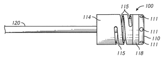
図1は、標的組織(たとえば、心臓組織、肺静脈、他の血管または器官等)を選択的に焼灼し、刺激し、調整し、かつ/または加熱もしくは処理するエネルギー送達システム10の一実施形態を概略的に示す。本明細書に開示するいくつかの実施形態は、アブレーションシステムおよび方法に関して記載するが、システムおよび方法のうちの任意のものを用いて、要求または必要に応じて、部分的または完全なアブレーションがあってもなくても、組織を刺激し、調整し、加熱し、かつ/または組織に影響を与えることができる。図示するように、システム10は、医療器具20(たとえば、カテーテル)を含むことができ、それは、その医療器具20の遠位端に沿って1つまたは複数のエネルギー送達部材30(たとえば、高周波電極)を備える。医療器具は、治療されている対象者を通して管腔内に(たとえば、血管内に)通されるようなサイズとし、形状とし、かつ/またはそのように構成することができる。さまざまな実施形態では、医療器具20は、カテーテル、シャフト、ワイヤおよび/または他の細長い器具を含む。他の実施形態では、医療器具は、血管内に配置されず、腹腔鏡または開腹処置を介して血管外に配置される。さまざまな実施形態では、医療器具20は、カテーテル、シャフト、ワイヤおよび/または他の細長い器具を含む。いくつかの実施形態では、医療器具20の遠位端に、またはその細長いシャフトに沿ってもしくはそのハンドル内に、1つまたは複数の温度検知デバイスまたはシステム60(たとえば、熱電対、サーミスタ等)を含めることができる。「遠位端」という用語は、必ずしも遠位先端または遠位端を意味するとは限らない。遠位端は、遠位先端、または遠位先端から間隔が空けられているが概して医療器具20の遠位端部分における位置を意味することができる。
FIG. 1 is an embodiment of an
いくつかの実施形態では、医療器具20は、1つまたは複数の装置または構成要素に作動的に結合される。たとえば、図1に示すように、送達モジュール40(エネルギー送達モジュール等)に医療器具20を結合することができる。いくつかの構成によれば、エネルギー送達モジュール40は、医療器具20に沿って配置されたエネルギー送達部材30(たとえば、高周波電極)を選択的に通電しかつ/または作動させるように構成されたエネルギー発生装置42を含む。いくつかの実施形態では、たとえば、エネルギー発生装置42は、高周波発生器、超音波エネルギー源、マイクロ波エネルギー源、レーザ/光源、別のタイプのエネルギー源または発生器等、およびそれらの組合せを含む。他の実施形態では、エネルギー発生装置42は、極低温流体または温度を変調する他の流体等、流体源に置き換えられるかまたはそれに加えて使用される。同様に、本明細書で用いる送達モジュール(たとえば、送達モジュール40)は、極低温装置または温度変調に対して構成された他の装置でもあり得る。
In some embodiments, the
図1の概略図を続けて参照すると、エネルギー送達モジュール40は、たとえば、タッチスクリーンデバイス、スクリーンまたは他のディスプレイ、コントローラ(たとえば、ボタン、つまみ、スイッチ、ダイヤル等)、キーパッド、マウス、ジョイスティック、ト
ラックパッドまたは他の入力デバイス等、1つまたは複数の入出力デバイスまたはコンポーネント44を含むことができる。こうしたデバイスにより、医師または他の使用者は、システム10に情報を入力しかつ/またはシステム10から情報を受け取ることができる。いくつかの実施形態では、出力デバイス44は、組織温度情報、接触情報、他の測定情報および/もしくは他のデータ、または特定の治療処置を調節するために有用であり得る指標を提供する、タッチスクリーンまたは他のディスプレイを含むことができる。
Continuing with reference to the schematic of FIG. 1, the
いくつかの実施形態によれば、エネルギー送達モジュール40は、治療システム10の1つまたは複数の態様を調節するように構成されるプロセッサ46(たとえば、処理または制御ユニット)を含む。モジュール40はまた、システム10の動作に関連する動作パラメータおよび/または他のデータを格納するために使用することができる、メモリユニットまたは他の記憶デバイス48(たとえば、コンピュータ可読媒体)も備えることができる。いくつかの実施形態では、プロセッサ46は、1つまたは複数の動作方式に基づき、エネルギー発生装置42から医療器具20のエネルギー送達部材30へのエネルギーの送達を自動的に調節するように構成される。たとえば、エネルギー送達部材30に提供されるエネルギー(したがって、標的組織にまたは標的組織から伝達される熱の量)は、特に、治療されている組織の検出された温度に基づいて調節することができる。
According to some embodiments, the
いくつかの実施形態によれば、エネルギー送達システム10は、たとえば基準温度デバイス(たとえば、熱電対、サーミスタ等)等、1つまたは複数の温度検出デバイスを含むことができる。たとえば、いくつかの実施形態では、デバイスは、治療されている組織のピーク(たとえば、高いまたは山、低いまたは谷等)温度を求めるのに役立つように、1つもしくは複数の温度センサまたは他の温度測定デバイスをさらに備える。いくつかの実施形態では、アブレーション部材(たとえば、RF電極)に、それに沿ってかつ/またはその近くに配置された温度センサ(たとえば、熱電対)は、アブレーション部材と標的組織との間に接触がなされているか否か(および/またはこうした接触がどの程度なされているか)の判断に役立つことができる。いくつかの実施形態では、こうしたピーク温度は、放射測定を用いることなく求められる。
According to some embodiments, the
図1を参照すると、エネルギー送達システム10は、灌注流体システム70を備える(または灌注流体システム70と流体連通して配置されるように構成される)。いくつかの実施形態では、図1に概略的に示すように、こうした流体システム70は、エネルギー送達モジュール40および/またはシステム10の他の構成要素とは少なくとも部分的に分離している。しかしながら、他の実施形態では、灌注流体システム70は、エネルギー送達モジュール40に少なくとも部分的に組み込まれる。灌注流体システム70は、カテーテル20の1つもしくは複数の内腔または他の通路を通して流体を選択的に移動させるように構成される、1つもしくは複数のポンプまたは他の流体移送装置を含むことができる。こうした流体を用いて、使用中にエネルギー送達部材30を選択的に冷却する(たとえば、エネルギー送達部材30から離れるように熱を伝達する)ことができる。
Referring to FIG. 1, the
図2は、医療器具(たとえば、カテーテル)20の遠位端の一実施形態を示す。図示するように、カテーテル20は、高分解能チップ設計を含むことができ、ギャップGによって分離される2つの隣接する電極または2つの隣接する電極部分30A、30Bがある。いくつかの実施形態によれば、図2の構成に示すように、異なる電極または電極部分30A、30Bの相対的な長さを変更することができる。たとえば、近位側電極30Bの長さは、要求または必要に応じて、遠位側電極30Aの1〜20倍(たとえば、1〜2倍、2〜3倍、3〜4倍、4〜5倍、5〜6倍、6〜7倍、7〜8倍、8〜9倍、9〜10倍、10〜11倍、11〜12倍、12〜13倍、13〜14倍、14〜15倍、15〜16倍、16〜17倍、17〜18倍、18〜19倍、19〜20倍、上記範囲の間の値等)であり得る。他の実施形態では、近位側電極30Bの長さは、遠位側電極30Aの20倍
より大きい(たとえば、20〜25倍、25〜30倍、30倍より大きい等)場合がある。さらに他の実施形態では、遠位側電極30Aおよび近位側電極30Bの長さは略等しい。いくつかの実施形態では、遠位側電極30Aは、(たとえば、1〜2倍、2〜3倍、3〜4倍、4〜5倍、5〜6倍、6〜7倍、7〜8倍、8〜9倍、9〜10倍、10〜11倍、11〜12倍、12〜13倍、13〜14倍、14〜15倍、15〜16倍、16〜17倍、17〜18倍、18〜19倍、19〜20倍、上記範囲の間の値等、1〜20倍)近位側電極30Bより長い。
FIG. 2 shows an embodiment of the distal end of a medical device (eg, catheter) 20. As shown, the
いくつかの実施形態では、遠位側電極または電極部分30Aは、0.5mm長である。他の実施形態では、遠位側電極または電極部分30Aは、0.1〜1mm長(たとえば、0.1〜0.2mm、0.2〜0.3mm、0.3〜0.4mm、0.4〜0.5mm、0.5〜0.6mm、0.6〜0.7mm、0.7〜0.8mm、0.8〜0.9mm、0.9〜1mm、上記範囲の間の値等)である。他の実施形態では、要求または必要に応じて、遠位側電極または電極部分30Aは、長さが1mmより大きい。いくつかの実施形態では、近位側電極または電極部分30Bは、2〜4mm長(たとえば、2〜2.5mm、2.5〜3mm、3〜3.5mm、3.5〜4mm、上記範囲間の長さ等)である。しかしながら、他の実施形態では、要求または必要に応じて、近位側電極部分30Bは、4mmより大きい(たとえば、4〜5mm、5〜6mm、6〜7mm、7〜8mm、8〜9mm、9〜10mm、10mmより大きい等)であるか、または2mmより小さい(たとえば、0.1〜0.5mm、0.5〜1mm、1〜1.5mm、1.5〜2mm、上記範囲の間の長さ等)である。高分解能電極がカテーテルシャフトに配置される実施形態では、電極の長さは1〜5mm(たとえば、1〜2mm、2〜3mm、3〜4mm、4〜5mm、上記範囲の間の長さ等)であり得る。しかしながら、他の実施形態では、要求または必要に応じて、電極は、5mmより長い(たとえば、5〜6mm、6〜7mm、7〜8mm、8〜9mm、9〜10mm、10〜15mm、15〜20mm、上記範囲の間の長さ、20mmを超える長さ等)場合がある。
In some embodiments, the distal electrode or
上述したように、高分解能チップ設計の使用により、使用者は、単一の構成で同時に、標的組織を焼灼するかまたは熱処理し、(たとえば、高分解能マッピングを用いて)マッピングすることができる。したがって、こうしたシステムにより、有利には、処理中に(たとえば、所望のレベルの治療が行われたことを確認するため)精密な高分解能マッピングを可能にすることができる。いくつかの実施形態では、2つの電極または電極部分30A、30Bを含む高分解能チップ設計を用いて、高分解能双極電位図を記録することができる。こうした目的で、2つの電極または電極部分をEPレコーダの入力に接続することができる。いくつかの実施形態では、電極または電極部分30A、30Bの間の相対的に小さい離隔距離(たとえば、ギャップG)により、高分解能マッピングが可能になる。
As mentioned above, the use of high resolution chip design allows the user to simultaneously cauterize or heat treat the target tissue in a single configuration (eg, using high resolution mapping). Therefore, such a system can advantageously allow precise high resolution mapping during processing (eg, to ensure that the desired level of treatment has been performed). In some embodiments, a high resolution chip design involving two electrodes or
いくつかの実施形態では、医療器具(たとえば、カテーテル)20は、要求または必要に応じて、(たとえば、ギャップによって分離された)3つ以上の電極または電極部分を含むことができる。こうした構成に関するさらなる詳細については後述する。いくつかの実施形態によれば、カテーテルチップに沿ってどの程度の数の電極または電極部分が配置されるかに関わらず、電極または電極部分30A、30Bは、高周波電極であり、たとえば、ステンレス鋼、白金、白金−イリジウム、金、金めっき合金等、1つまたは複数の金属を含む。
In some embodiments, the medical device (eg, catheter) 20 may include, if required or required, three or more electrodes or electrode portions (eg, separated by a gap). Further details regarding such a configuration will be described later. According to some embodiments, the electrodes or
いくつかの実施形態によれば、図2に示すように、電極または電極部分30A、30Bは、ギャップ(たとえば、絶縁ギャップ)を用いて互いから(たとえば、長手方向にまたは軸方向に)間隔を空けて配置される。いくつかの実施形態では、ギャップGの長さ(すなわち、隣接する電極または電極部分の間の離隔距離)は0.5mmである。他の実施形態では、ギャップGすなわち離隔距離は、要求または必要に応じて、たとえば、0.1〜
1mm等(たとえば、0.1〜0.2mm、0.2〜0.3mm、0.3〜0.4mm、0.4〜0.5mm、0.5〜0.6mm、0.6〜0.7mm、0.7〜0.8mm、0.8〜0.9mm、0.9〜1.0mm、上記範囲の間の値、0.1mmより小さい、1mmより大きい等)、0.5mmより大きいかまたは小さい。
According to some embodiments, as shown in FIG. 2, the electrodes or
1 mm, etc. (for example, 0.1 to 0.2 mm, 0.2 to 0.3 mm, 0.3 to 0.4 mm, 0.4 to 0.5 mm, 0.5 to 0.6 mm, 0.6 to 0) .7 mm, 0.7 to 0.8 mm, 0.8 to 0.9 mm, 0.9 to 1.0 mm, values between the above ranges, smaller than 0.1 mm, larger than 1 mm, etc.), from 0.5 mm Large or small.
いくつかの実施形態によれば、図2に示すように、隣接する電極または電極部分30A、30Bの間のギャップG内にセパレータ34が配置される。セパレータは、たとえば、テフロン(登録商標)、ポリエーテルエーテルケトン(PEEK)、ポリエーテルイミド樹脂(たとえば、ULTEMTM)、セラミック材料、ポリイミド等、1つまたは複数の絶縁材料を含むことができる。
According to some embodiments, as shown in FIG. 2, the
隣接する電極または電極部分を分離するギャップGに関して上述したように、絶縁セパレータ34は、0.5mm長さであり得る。他の実施形態では、セパレータ34の長さは、要求または必要に応じて、0.5mmより大きいかまたは0.5mmより小さい(たとえば、0.1〜0.2mm、0.2〜0.3mm、0.3〜0.4mm、0.4〜0.5mm、0.5〜0.6mm、0.6〜0.7mm、0.7〜0.8mm、0.8〜0.9mm、0.9〜1.0mm、上記範囲の間の値、0.1mmより小さい、1mmより大きい等)場合がある。
As mentioned above with respect to the gap G separating adjacent electrodes or electrode portions, the insulating
いくつかの実施形態によれば、本明細書においてより詳細に考察するように、図2に示すもの等、高分解能チップ電極設計で対象者の標的組織を適切に焼灼しまたは加熱もしくは処理するために、2つの電極または電極部分30A、30Bは、RF周波数で互いに電気的に結合される。したがって、2つの電極または電極部分は、有利には、RF周波数で単一のより長い電極として機能することができる。
According to some embodiments, to properly cauterize or heat or treat the subject's target tissue in a high resolution chip electrode design, such as that shown in FIG. 2, as discussed in more detail herein. In addition, the two electrodes or
図3および図4は、高分解能チップ設計を組み込んだカテーテルシステム100、200の異なる実施形態を示す。たとえば、図3では、電極の遠位端に沿った電極(または高周波電極)は、第1または遠位側電極または電極部分110と第2または近位側電極または電極部分114とを備える。図示し他の構成に関して本明細書においてより詳細に考察するように、高分解能チップ設計100は、第1電極または電極部分110と第2電極または電極部分114との間にギャップGを含む。いくつかの構成では、第2または近位側電極または電極部分114は、概して、第1または遠位側電極または電極部分110より長い。たとえば、近位側電極114の長さは、要求または必要に応じて、遠位側電極110の長さの1〜20倍(たとえば、1〜2倍、2〜3倍、3〜4倍、4〜5倍、5〜6倍、6〜7倍、7〜8倍、8〜9倍、9〜10倍、10〜11倍、11〜12倍、12〜13倍、13〜14倍、14〜15倍、15〜16倍、16〜17倍、17〜18倍、18〜19倍、19〜20倍、上記範囲の間の値等)であり得る。他の実施形態では、近位側電極の長さは、遠位側電極の20倍より大きい(たとえば、20〜25倍、25〜30倍、30倍より大きい等)場合がある。さらに他の実施形態では、遠位側電極および近位側電極の長さは略等しい。しかしながら、いくつかの実施形態では、遠位側電極110は、(たとえば、1〜2倍、2〜3倍、3〜4倍、4〜5倍、5〜6倍、6〜7倍、7〜8倍、8〜9倍、9〜10倍、10〜11倍、11〜12倍、12〜13倍、13〜14倍、14〜15倍、15〜16倍、16〜17倍、17〜18倍、18〜19倍、19〜20倍、上記範囲の間の値等、1〜20倍)近位側電極114より長い。
3 and 4 show different embodiments of
図3に図示しかつ上述したように、電極または電極部分110、114は、それらの正確な設計、相対長さ径、向きおよび/または他の特徴に関わらず、ギャップGで分離することができる。ギャップGは、相対的に小さい絶縁ギャップまたは空間を含むことができる。いくつかの実施形態では、第1電極または電極部分110と第2電極または電極部分114との間に、絶縁セパレータ118を隙間なく配置することができる。いくつかの実
施形態では、セパレータ118は、約0.5mmの長さを有することができる。しかしながら、他の実施形態では、セパレータ118の長さは、要求または必要に応じて、0.5mmより大きいかまたは小さい(たとえば、0.1〜0.2mm、0.2〜0.3mm、0.3〜0.4mm、0.4〜0.5mm、0.5〜0.6mm、0.6〜0.7mm、0.7〜0.8mm、0.8〜0.9mm、0.9〜1.0mm、上記範囲の間の値、0.1mmより小さい、1mmより大きい等)場合がある。セパレータは、1つまたは複数の絶縁材料(たとえば、金属または合金の導電率より約1000以下(たとえば、500〜600、600〜700、700〜800、800〜900、900〜1000、1000〜1100、1100〜1200、1200〜1300、1300〜1400、1400〜1500、上記範囲の間の値、500より小さい、1500を超える等)低い導電性を有する材料)を含むことができる。セパレータは、たとえば、テフロン、ポリエーテルエーテルケトン(PEEK)、ポリオキシメチレン、アセタール樹脂またはポリマー等の1つまたは複数の絶縁材料を含むことができる。
As illustrated and described above in FIG. 3, the electrodes or
図3に示すように、セパレータ118は、形状を円筒状とすることができ、隣接する電極または電極部分110、114と同一かまたは同様の直径および構成を有することができる。したがって、いくつかの実施形態では、電極または電極部分110、114およびセパレータ118によって形成される外面は、概して均一または平滑であり得る。しかしながら、他の実施形態では、セパレータ118の形状、サイズ(たとえば直径)および/または他の特徴は、特定の用途または使用に対する要求または必要に応じて、隣接する電極または電極部分110、114のうちの1つまたは複数とは異なる可能性がある。
As shown in FIG. 3, the
図4は、対応するギャップG1、G2によって分離された3つ以上の電極または電極部分210、212、214を有するシステム200の実施形態を示す。こうした追加のギャップ、したがって、物理的に(たとえばギャップにより)分離されているが互いに近接している追加の電極または電極部分210、212、214の使用により、システムの高分解能マッピング能力に対する追加の利益を提供することができる。たとえば、2つ(または3つ以上)のギャップを使用することにより、治療されている組織に関するより正確な高分解能マッピングデータを提供することができる。こうした複数のギャップは、心臓信号伝播の指向性に関する情報を提供することができる。さらに、複数のギャップを含む高分解能電極部分による高分解能マッピングにより、アブレーションプロセス中の損傷部の進行のより広範な観察と、標的治療容積内に生存組織ストランドが残されていないというより高い確実性とを提供することができる。いくつかの実施形態では、複数のギャップを含む高分解能電極は、焼灼された組織の表面に対するマッピングされた組織の表面の比を最適化することができる。好ましくは、こうした比は、0.2〜0.8の範囲(たとえば、0.2〜0.3、0.3〜0.4、0.4〜0.5、0.5〜0.6、0.6〜0.7、0.7〜0.8、上記範囲の間の比等)である。図4は、合計3つの電極または電極部分210、212、214(したがって、2つのギャップG1、G2)を有する実施形態を示すが、さらなる電極または電極部分、したがってさらなるギャップを備えるように、システムを設計しまたは変更することができる。たとえば、いくつかの実施形態では、アブレーションまたは他の治療システムは、要求または必要に応じて、4つ以上(たとえば、5、6、7、8、9つ以上等)の電極または電極部分(したがって、3つ以上、たとえば3、4、5、6、7つのギャップ、8つ以上のギャップ等)を含むことができる。こうした構成では、図2〜図4に示す実施形態に従って、隣接する電極または電極部分の間にギャップ(および/または電気的セパレータ)を配置することができる。
FIG. 4 shows an embodiment of a
図3および図4に示すように、カテーテル(明確にするために図示せず)の内部に灌注チューブ120、220を通すことができる。いくつかの実施形態では、灌注チューブ120、220は、カテーテルの近位部分(たとえば、流体ポンプと流体連通して配置することができる場所)からシステムの遠位端まで延在することができる。たとえば、いくつかの構成では、図3および図4の側面図に示すように、灌注チューブ120、220は延在し、遠位側電極110、210を通って半径方向外向きに延在する1つまたは複数の流体ポート211と流体連通している。したがって、いくつかの実施形態では、治療システムは開放灌注設計を備え、そこでは、生理食塩水および/または他の流体は、カテーテルを通って(たとえば、流体チューブ120、220内で)、電極110、210の1つまたは複数の出口ポート111、211を通って半径方向外向きに選択的に送達される。こうした生理食塩水または他の流体の送達は、電極および/または治療されている組織から
熱を除去するのに役立つことができる。いくつかの実施形態では、こうした開放灌注システムは、特に、電極が接触する組織に沿って、標的組織の過熱の可能性を防止するかまたは低減させるのに役立つことができる。開放灌注設計はまた、図2に概略的に示すシステムにも組み込まれる。たとえば、図2に示すように、遠位側電極または電極部分30Aは複数の出口ポート36を含むことができ、生理食塩水または他の灌注流体はそこを通って出ることができる。
As shown in FIGS. 3 and 4,
いくつかの実施形態によれば、カテーテルは、長手方向のギャップに加えてまたはその代わりに、円周方向に(たとえば、半径方向に)1つまたは複数のギャップを含む高分解能チップ電極設計を含むことができる。図5に、1つまたは複数の電極310A、310Bを備えたシステム300の一実施形態を示す。図示するように、2つ以上の電極が含まれる構成では、電極310A、310Bを互いに長手方向にまたは軸方向にずらすことができる。たとえば、いくつかの実施形態では、電極310A、310Bは、カテーテルの遠位端に沿ってまたはその近くに配置される。いくつかの実施形態では、電極310A、310Bは、カテーテルまたは他の医療器具の外側部分に沿って配置される。しかしながら、他の構成では、要求または必要に応じて、カテーテルまたは他の医療器具の異なる部分に沿って(たとえば、少なくともカテーテルの内側部分に沿って)、電極のうちの1つまたは複数を配置することができる。
According to some embodiments, the catheter comprises a high resolution chip electrode design that includes one or more gaps in the circumferential direction (eg, in the radial direction) in addition to or instead of the longitudinal gap. be able to. FIG. 5 shows an embodiment of the
続けて図5を参照すると、各電極310A、310Bは、2つ以上のセクション320A、322Aおよび/または320B、320Bを備えることができる。図示するように、いくつかの実施形態では、各セクション320A、322Aおよび/または320B、320Bは、カテーテルの直径を半周して(たとえば、180度)延在することができる。しかしながら、他の実施形態では、各セクションの円周方向の広がりは、180度より小さいことができる。たとえば、各セクションは、それが取り付けられているカテーテルの円周に0〜180度(たとえば、15度、30度、45度、60度、75度、90度、105度、120度、上記値の間の角度等)で延在することができる。したがって、いくつかの実施形態では、電極は、要求または必要に応じて、2、3、4、5、6または7つ以上の円周方向セクションを含むことができる。
Subsequently referring to FIG. 5, each
円周方向電極セクションがどのように設計されかつ向けられるかに関わらず、本明細書に開示するさまざまな実施形態に従って、高分解能マッピングを行うために電極を使用し得ることを促進するように、隣接するセクションの間に絶縁ギャップGを設けることができる。さらに、図5の実施形態に示すように、要求または必要に応じて、特定のシステム300に、2つ以上の円周方向または半径方向セクションを有する2つ以上(たとえば、3、4、5、6つ以上等)の電極310A、310Bを含めることができる。
Regardless of how the circumferential electrode section is designed and oriented, to facilitate the use of electrodes to perform high resolution mapping according to the various embodiments disclosed herein. Insulation gaps G can be provided between adjacent sections. Further, as shown in the embodiment of FIG. 5, two or more (eg, 3, 4, 5, etc.) having two or more circumferential or radial sections in a
代替実施形態では、本明細書に開示する高分解能チップ設計のさまざまな実施形態またはそれらの変形形態を、非灌注式システムまたは閉鎖灌注システム(たとえば、生理食塩水および/または他の流体が、1つまたは複数の電極を通してまたはその中でそこから熱を選択的に除去するために循環するシステム)で使用することができる。したがって、いくつかの構成では、カテーテルは、2つ以上の灌注チューブまたは導管を含むことができる。たとえば、1つのチューブまたは他の導管を用いて、流体を電極に向かってまたは電
極の近くに送達することができ、第2チューブまたは他の導管を用いて、カテーテルを通して反対方向に流体を戻すことができる。
In alternative embodiments, various embodiments of the high resolution chip design disclosed herein, or variants thereof, can be expressed in non-irrigation or closed irrigation systems (eg, saline and / or other fluids). It can be used in a circulating system) to selectively remove heat through or within one or more electrodes. Thus, in some configurations, the catheter can include more than one irrigation tube or conduit. For example, one tube or other conduit can be used to deliver fluid towards or near the electrode, and a second tube or other conduit can be used to return the fluid in the opposite direction through the catheter. Can be done.
いくつかの実施形態によれば、高分解能チップ電極は、さまざまな電極または電極部分の間で電流負荷を平衡させるように設計される。たとえば、治療システムが注意深く構成されていない場合、電気負荷は、高分解能チップシステムの電極または電極部分のうちの1つまたは複数(たとえば、短いかまたは小さい方の遠位側電極または電極部分)に主に送達される可能性がある。これにより、電極の望ましくない不均一な加熱、したがって、対象者の隣接する組織の不均一な加熱(たとえば、アブレーション)に至る可能性がある。したがって、いくつかの実施形態では、システムのさまざまな電極または電極部分に沿った加熱が概して平衡することを確実にするのに役立つように、1つまたは複数の負荷平衡構成を用いることができる。その結果、高分解能チップ設計は、不均衡な電気負荷を受ける(したがって、対象者の標的組織に不均衡な量の熱またはレベルの治療を送達する)2つ以上の電極とは対照的に、より長い単一の電極のように有利に機能することができる。 According to some embodiments, the high resolution chip electrode is designed to balance the current load between the various electrodes or electrode portions. For example, if the treatment system is not carefully configured, the electrical load will be applied to one or more of the electrodes or electrode parts of the high resolution chip system (eg, the shorter or smaller distal electrode or electrode part). May be delivered primarily. This can lead to undesired non-uniform heating of the electrodes and thus non-uniform heating (eg, ablation) of the tissue adjacent to the subject. Thus, in some embodiments, one or more load equilibrium configurations can be used to help ensure that heating along the various electrodes or parts of the system is generally balanced. As a result, the high resolution chip design, in contrast to two or more electrodes that are subject to an imbalanced electrical load (and thus deliver an imbalanced amount of heat or level of treatment to the subject's target tissue). It can function favorably like a longer single electrode.
図6に、高分解能チップ設計で電極または電極部分の各々に送達される電流負荷を平衡させるために使用することができる構成の一実施形態を概略的に示す。図示するように、電極のうちの1つ(たとえば、遠位側電極)30Aをエネルギー送達モジュール40(たとえば、RF発生器)に電気的に結合することができる。本明細書において考察するように、モジュール40は、たとえば、エネルギー部材(たとえば、RF電極)を選択的に通電しかつ/または活性化するように構成されたエネルギー発生装置、1つまたは複数の入出力デバイスまたはコンポーネント、治療システムの1つまたは複数の態様を調節するように構成されるプロセッサ(たとえば、処理または制御ユニット)、メモリ等、1つまたは複数の構成要素または特徴を有することができる。さらに、こうしたモジュールは、要求または必要に応じて、手動でまたは自動的に操作されるように構成することができる。
FIG. 6 schematically illustrates an embodiment of a configuration that can be used to balance the current load delivered to each of the electrodes or electrode portions in a high resolution chip design. As shown, one of the electrodes (eg, the distal electrode) 30A can be electrically coupled to the energy delivery module 40 (eg, the RF generator). As discussed herein, the
図6に概略的に示す実施形態では、遠位側電極30Aは、1本または複数本の導体82(たとえば、ワイヤ、ケーブル等)を用いて通電される。たとえば、いくつかの構成では、灌注チューブ38の外側は、1つまたは複数の導電性材料(たとえば、銅、他の金属等)を含みかつ/またはそれらによってコーティングされる。したがって、図6に示すように、導体82は、電極または電極部分30Aをエネルギー送達モジュールに電気的に結合するように、チューブ38のこうした導電性面または部分と接触するように配置することができる。しかしながら、電極または電極部分30Aをエネルギー送達モジュールと電気的に連絡するように配置する1つもしくは複数の他の装置および/または方法を使用することができる。たとえば、1本もしくは複数本のワイヤ、ケーブルおよび/または他の導体は、灌注チューブを用いることなく、電極に直接または間接的に結合することができる。
In the embodiment schematically shown in FIG. 6, the
続けて図6を参照すると、コンデンサ、フィルタ回路(たとえば、図16を参照)等、1つまたは複数のバンドパスフィルタリング素子84を用いて、第1もしくは遠位側電極または電極部分30Aを第2もしくは近位側電極または電極部分30Bに電気的に結合することができる。たとえば、いくつかの実施形態では、バンドパスフィルタリング素子84は、システムに高周波電流が印加されるとき、2つの電極または電極部分30A、30Bを電気的に結合する、コンデンサを備える。一実施形態では、コンデンサ84は、いくつかの構成によれば、RFアブレーションの目標周波数である500kHzで、約3Ωより低い直列インピーダンスを導入する100nFコンデンサを含む。しかしながら、他の実施形態では、システムに組み込まれるコンデンサまたは他のバンドパスフィルタリング素子84の静電容量は、要求または必要に応じて、動作RF周波数に従って、100nFより大きいかまたは100nFより小さい、たとえば、5〜300nFであり得る。いく
つかの実施形態では、フィルタリング素子84の静電容量は、特定の周波数または周波数範囲における目標インピーダンスに基づいて選択される。たとえば、いくつかの実施形態では、200kHz〜10MHzの周波数(たとえば、200〜300kHz、300〜400kHz、400〜500kHz、500〜600kHz、600〜700kHz、700〜800kHz、800〜900kHz、900〜1000kHz、最大10MHz、または上記範囲の間の高い方の周波数等)でシステムを動作させることができる。したがって、隣接する電極または電極部分を互いに結合するコンデンサは、特定の周波数に対する目標インピーダンスに基づいて選択することができる。たとえば、100nFコンデンサは、500kHzの動作アブレーション周波数で約3Ωの結合インピーダンスを提供する。
Subsequently, referring to FIG. 6, the first or distal electrode or the
いくつかの実施形態では、電極または電極部分30A、30Bを横切る3Ωの直列インピーダンスは、約5Ω〜10Ωであり得る導体82(たとえば、ワイヤ、ケーブル等)のインピーダンス、および約100Ωであり得る組織のインピーダンスと比較した場合、十分に低く、それにより、システムが使用されるとき、結果として取得される組織加熱プロファイルは悪影響を受けない。したがって、いくつかの実施形態では、フィルタリング素子は、電極または電極部分の直列インピーダンスが、電極にRFエネルギーを供給する導体のインピーダンスより低いように選択される。たとえば、いくつかの実施形態では、フィルタリング素子の挿入インピーダンスは、導体82のインピーダンスの50%もしくはそれより低く、または均等な組織インピーダンスの10%もしくはそれより低い。
In some embodiments, the series impedance of 3Ω across the electrodes or
いくつかの実施形態では、装置または付随するシステムの種々の位置にフィルタリング素子(たとえば、図16を参照して本明細書に記載するもの等のコンデンサ、フィルタ回路等)を配置することができる。たとえば、いくつかの実施形態では、フィルタリング素子は、カテーテル上またはその中に(たとえば、カテーテルの遠位端の近くに、電極に隣接して、等)配置される。しかしながら、他の実施形態では、フィルタリング素子は、カテーテルと分離されている。たとえば、カテーテルが固定されるハンドル内にまたはそれに沿って、発生器または他のエネルギー送達モジュール内に、別個のプロセッサまたは他のコンピューティングデバイスまたはコンポーネント内等に、フィルタリング素子を配置することができる。 In some embodiments, filtering elements (eg, capacitors such as those described herein with reference to FIG. 16, filter circuits, etc.) can be placed at various locations in the device or associated system. For example, in some embodiments, the filtering element is placed on or within the catheter (eg, near the distal end of the catheter, adjacent to the electrodes, etc.). However, in other embodiments, the filtering element is separated from the catheter. For example, filtering elements can be placed within or along the handle to which the catheter is secured, within a generator or other energy delivery module, within a separate processor or other computing device or component, and the like.
同様に、図7の概略図を参照すると、円周方向に配置された部分320、322を備える電極310にフィルタリング素子384を含めることができる。図7では、フィルタリング素子384により、電極310全体に対して(たとえば、電極が焼灼するように活性化されるときに)RF周波数範囲内で通電することができる。1本または複数本のRFワイヤまたは他の導体344を用いて、発生器または電源から電極に電力を送達することができる。さらに、別個の導体340を用いて、マッピングの目的で電極310に電気的に結合することができる。
Similarly, referring to the schematic diagram of FIG. 7, the
高分解能チップ設計(たとえば、図4)が3つ以上の電極または電極部分を備える実施形態では、さらなるフィルタリング素子(たとえば、コンデンサ)を用いて、電極または電極部分を互いに電気的に結合することができる。こうしたコンデンサまたは他のフィルタリング素子は、高分解能チップ電極の全長に沿って概して均一な加熱プロファイルをもたらすように選択することができる。本明細書においてさらに詳細に記すように、本明細書に開示する実施形態のうちの任意のものまたはその変形形態に対して、フィルタリング素子は、コンデンサ以外の何らかのものを含むことができる。たとえば、いくつかの配置では、フィルタリング素子は、LC回路(たとえば、共振回路、タンク回路、同調回路等)を含む。こうした実施形態は、RFエネルギーの印加およびEGM記録の測定を同時に行うことができるように構成することができる。 In embodiments where the high resolution chip design (eg, FIG. 4) comprises three or more electrodes or electrode portions, additional filtering elements (eg, capacitors) may be used to electrically couple the electrodes or electrode portions to each other. it can. Such capacitors or other filtering elements can be selected to provide a generally uniform heating profile along the overall length of the high resolution chip electrode. As described in more detail herein, for any of the embodiments disclosed herein or variants thereof, the filtering element may include anything other than a capacitor. For example, in some arrangements, the filtering element includes an LC circuit (eg, a resonant circuit, a tank circuit, a tuning circuit, etc.). Such an embodiment can be configured so that the application of RF energy and the measurement of EGM recording can be performed simultaneously.
上述したように、隣接する電極または電極部分30A、30Bの間の比較的小さいギャップGを用いて、標的組織の高分解能マッピングを促進することができる。たとえば、続けて図6の概略図を参照すると、別個の電極または電極部分30A、30Bを用いて、治療されている組織の局所電位を正確に反映する電位図を生成することができる。したがって、治療システムを用いる医師または他の専門家は、処置の前、処置中および/または処置の後、標的組織へのエネルギー送達の影響をより正確に検出することができる。たとえば、こうした構成からもたらされるより正確な電位図データにより、医師は、適切に焼灼されなかったかまたは治療されなかった標的解剖学的領域の任意のギャップまたは部分を検出することができる。具体的には、高分解能チップ設計の使用により、心臓電気生理学者は、結果としての電位図の形態、それらの振幅および幅をより正確に評価し、かつ/またはペーシング閾値を求めることができる。いくつかの実施形態では、形態、振幅およびペーシング閾値は、アブレーションまたは他の熱治療処置の転帰に関する有用な情報を提供する、許容されかつ信頼性の高いEPマーカである。
As mentioned above, the relatively small gap G between adjacent electrodes or
いくつかの構成によれば、本明細書に開示する高分解能チップ電極の実施形態は、局所高分解能電位図を提供するように構成される。たとえば、本明細書に開示する実施形態による、高分解能チップ電極を用いて取得される電位図は、図8に示すように、電位図データ(たとえば、グラフ式出力)400a、400bを提供することができる。図8に示すように、本明細書に開示する高分解能チップ電極の実施形態を用いて生成される局所電位図400a、400bは、振幅A1、A2を含む。 According to some configurations, the high resolution chip electrode embodiments disclosed herein are configured to provide a local high resolution potential diagram. For example, the potential diagram acquired using the high resolution chip electrode according to the embodiment disclosed herein provides potential diagram data (eg, graph output) 400a, 400b, as shown in FIG. Can be done. As shown in FIG. 8, local potential diagrams 400a and 400b generated using the high resolution chip electrode embodiments disclosed herein include amplitudes A1 and A2.
続けて図8を参照すると、高分解能チップ電極システムを用いて取得される電位図400a、400bの振幅を用いて、高分解能チップ電極に隣接する標的組織が、適切に焼灼されたかまたは治療されたか否かを判断することができる。たとえば、いくつかの実施形態によれば、未治療組織(たとえば、焼灼されていないまたは加熱されていない組織)における電位図400aの振幅A1は、すでに焼灼されたかまたは治療された電位図400bの振幅A2より大きい。したがって、いくつかの実施形態では、電位図の振幅を測定して、組織が治療されたか否かを判断することができる。たとえば、対象者の未治療組織の電位図振幅A1を記録し、ベースラインとして使用することができる。その後の電位図振幅測定値を取得し、組織が適切なまたは所望の程度まで焼灼されたかまたは治療されたか否かを判断しようとして、こうしたベースライン振幅に対して比較することができる。 Subsequently referring to FIG. 8, whether the target tissue adjacent to the high resolution chip electrode was properly cauterized or treated using the amplitudes of the potential diagrams 400a, 400b obtained using the high resolution chip electrode system. It is possible to judge whether or not. For example, according to some embodiments, the amplitude A1 of the potential diagram 400a in untreated tissue (eg, uncauterized or unheated tissue) is the amplitude of the already cauterized or treated potential diagram 400b. Larger than A2. Therefore, in some embodiments, the amplitude of the pourbaix diagram can be measured to determine if the tissue has been treated. For example, the pourbaix amplitude A1 of the subject's untreated tissue can be recorded and used as a baseline. Subsequent pourbaix amplitude measurements can be taken and compared to these baseline amplitudes in an attempt to determine if the tissue has been cauterized or treated to the appropriate or desired degree.
いくつかの実施形態では、試験または評価されている組織位置において電位図振幅(A2)に対するこうしたベースライン振幅(A1)の間で比較が行われる。A1対A2の比を用いて、アブレーションが完了した可能性を評価する定量的基準を提供することができる。いくつかの構成では、比(すなわち、A1/A2)が一定の最小閾値を超える場合、使用者に対して、A2振幅が取得された組織が適切に焼灼されたことを通知することができる。たとえば、いくつかの実施形態では、A1/A2比が1.5より大きい(たとえば、1.5〜1.6、1.6〜1.7、1.7〜1.8、1.8〜1.9、1.9〜2.0、2.0〜2.5、2.5〜3.0、上記範囲の間の値、3より大きい等)とき、適切なアブレーションおよび治療を確認することができる。しかしながら、他の実施形態では、A1/A2の比が1.5より小さい(たとえば、1〜1.1、1.1〜1.2、1.2〜1.3、1.3〜1.4、1.4〜1.5、上記範囲の間の値等)とき、アブレーションの確認を取得することができる。 In some embodiments, a comparison is made between these baseline amplitudes (A1) relative to the pourbaix amplitude (A2) at the tissue location being tested or evaluated. The A1 to A2 ratio can be used to provide a quantitative criterion for assessing the likelihood that ablation has been completed. In some configurations, if the ratio (ie, A1 / A2) exceeds a certain minimum threshold, the user can be notified that the tissue from which the A2 amplitude has been obtained has been properly cauterized. For example, in some embodiments, the A1 / A2 ratio is greater than 1.5 (eg, 1.5-1.6, 1.6-1.7, 1.7-1.8, 1.8-. 1.9, 1.9 to 2.0, 2.0 to 2.5, 2.5 to 3.0, values between the above ranges, greater than 3, etc.) to confirm appropriate ablation and treatment be able to. However, in other embodiments, the ratio of A1 / A2 is less than 1.5 (eg, 1-1.1, 1.1-1.2, 1.2-1.3, 1.3-1. When (4, 1.4 to 1.5, a value between the above ranges, etc.), confirmation of ablation can be obtained.
図9は、複数のマッピング電極520を備える拡張可能システム500の一実施形態を示す。こうしたシステム500は、1つまたは複数の拡張可能部材(たとえば、ストラット、バルーン等)510を含むことができ、その拡張可能部材510は、電極520を支持し、かつこうした電極を対象組織と接触させるかまたは近接させるのに役立つ。たとえば、マッピングシステム500の図示する実施形態は、拡張したときに概して球形の形態
を有する。いくつかの実施形態では、こうしたシステム500は、対象者の心腔(たとえば、心房、心室)内に配置されかつそこで拡張するようなサイズであり、形状であり、かつ/または他に構成される。いくつかの構成では、ストラットは、拡張したシステム500が、それが配置される体内腔または他の空間(たとえば、心房)に沿うかまたは概して沿うのを可能にするように十分な弾性、安定性、可撓性および/または他の特性を有する。図9には、市販のシステムの一表現を示すが、マッピング電極を備えるこうしたシステムは、たとえば、対象者の標的組織、所望のまたは必要な電極の数等、1つもしくは複数の要素および/または他の考慮事項に応じて、他の任意の形状、サイズおよび/または構成を含むことができる。たとえば、他の実施形態では、特定の用途または使用に対する要求または必要に応じて、こうしたシステムは、より多いかまたはより少ない電極、非球形の形状(たとえば、円錐形、円筒状、不規則等)等を含むことができる。
FIG. 9 shows an embodiment of the
利用することができる市販のマッピングシステムの正確な設計、構成および/または他の特性に関わらず、マッピングシステム内に含まれる電極は、要求または必要に応じて変更することができる。たとえば、いくつかの実施形態では、電極520は単極電極または双極電極を含む。さらに、こうしたシステム500で使用される電極520の形状、サイズ、構成および/または他の細部は、具体的なシステム設計に基づいて変更することができる。
Regardless of the exact design, configuration and / or other characteristics of the commercially available mapping system available, the electrodes contained within the mapping system can be modified as required or as required. For example, in some embodiments, the
いくつかの実施形態によれば、こうしたマッピングシステム500は、心臓細動(たとえば、心房細動)治療中に対象者の心腔(たとえば、心房)をマッピングするのに役立つように利用される。たとえば、場合により、心房細動の徴候がある対象者は、その心房において、疾患の特徴である心房細動旋回(rotor)パターンを示す。いくつかの構成では、対象者の心房を通して伝達されている信号を電気的にマッピングし、したがって、疾患の原因である、対応する心房細動旋回のマップをより正確に求めることは、対象者の対象治療に役立つことができる。たとえば、いくつかの実施形態では、心房細動旋回が正確にマッピングされると、専門家は、疾患の治療に役立つ心房の位置をより精密に治療することができる。これにより、有効な治療の可能性を増大させるより精密かつ正確なアブレーション、焼灼される組織の面積または体積を低減させることができることによる、対象者に対する外傷の低減等を含む、いくつかの利益を対象者に与えることができる。
According to some embodiments, such a
しかしながら、いくつかの実施形態では、図9に概略的に示すもの等、市販のマッピングシステム500にはいくつかの欠点がある。たとえば、標的解剖学的領域内にシステムがどのように配置されるか、および/またはシステムがどのように展開されるかに応じて、標的解剖学的容積、空間または他の領域のうちの1つまたは複数の領域は、マッピング電極520に近接しない可能性がある。たとえば、いくつかの実施形態では、システムのスプラインまたは他の拡張可能部材510は、均一に展開されない。他の場合、1つまたは複数の理由で、こうした拡張可能部材510は、さらには適切に拡張しない可能性があり、または意図もしくは予測通りに拡張しない場合がある。その結果、場合により、マッピング電極520は、標的組織と適切に接触せず、かつ/またはそれらの間に組織の比較的広い面積を残す可能性がある。したがって、こうした状況下では、こうしたシステム500が対象者の解剖学的構造の標的領域を正確にマッピングすることができることに対して、悪影響がある可能性がある。
However, in some embodiments, the commercially
したがって、いくつかの実施形態によれば、標的解剖学的領域のより正確かつ完全な電気マップを作成するロービングまたはギャップ充填システムとして、本明細書に開示するシステムおよび装置と同一かまたは同様の高分解能チップ電極カテーテルシステムを使用することができる。したがって、いくつかの実施形態では、本明細書に開示するシステムおよび関連方法は、マッピングされている組織(たとえば、心臓組織)のマップ(たとえば、3次元マップ)を取得するために、多電極システムまたは装置のさまざまな電極のみ
に依存することはない。例として、図10に概略的に示すように、別個のマッピングシステム500のマッピング電極520の間の1つまたは複数のギャップに対して、高分解能チップ設計の高分解能能力を用いてマッピングの観点から「充填する」かまたは対処することができる。したがって、図10に概略的に示すように、追加のマッピングデータが必要とされるかまたは要求される場所530に、高分解能チップ電極システムを向けることができる。
Therefore, according to some embodiments, as a roving or gap filling system that produces a more accurate and complete electrical map of the target anatomical region, the same or similar height as the systems and devices disclosed herein. A resolution chip electrode catheter system can be used. Thus, in some embodiments, the systems and related methods disclosed herein are multi-electrode systems for obtaining a map (eg, a three-dimensional map) of the mapped tissue (eg, heart tissue). Or it does not depend solely on the various electrodes of the device. As an example, as schematically shown in FIG. 10, from the perspective of mapping with the high resolution capabilities of the high resolution chip design for one or more gaps between the
いくつかの構成では、本明細書に開示する高分解能チップ実施形態のうちの任意のものによるカテーテル(たとえば、図1〜図7を参照して例示しかつ本明細書で考察したもの)を、いくつかの中間領域(たとえば、マッピングシステムの電極が到達するかまたは対象とすることができなかった領域)に手動で配置することができる。したがって、ロービングマッピングシステムとして高分解能チップ電極システムを使用することにより、より正確かつ包括的な電気マッピングを達成することができる。その結果、いくつかの実施形態では、こうしたロービングシステム(たとえば、高分解能電極を備えるカテーテル)は、中間組織位置(たとえば、拡張可能マッピングシステムまたは他の多電極システムもしくは装置の電極の間に配置された組織位置)に対してマッピングデータを取得するように適合される。上述したように、これにより、対象者の疾患、およびそれをより効率的に、安全にかつ有効に治療する方法についてより完全にかつ正確に理解することができる。関連して、個々のアブレーションの数(したがって、焼灼される組織の総面積または体積)を有利に低減させることができ、それにより、対象者に対する全体的な外傷が低減し、治療処置からのいかなる有害な副作用の可能性も低減しかつ緩和され、回復時間が短縮し、かつ/または1つもしくは複数の追加の利点もしくは利益がもたらされる。 In some configurations, catheters by any of the high resolution chip embodiments disclosed herein (eg, those exemplified with reference to FIGS. 1-7 and discussed herein). It can be manually placed in several intermediate regions (eg, regions that the electrodes of the mapping system could not reach or target). Therefore, more accurate and comprehensive electrical mapping can be achieved by using a high resolution chip electrode system as the roving mapping system. As a result, in some embodiments, such roving systems (eg, catheters with high resolution electrodes) are placed between the electrodes of intermediate tissue locations (eg, expandable mapping systems or other multi-electrode systems or devices). It is adapted to acquire mapping data for (organization location). As mentioned above, this provides a more complete and accurate understanding of the subject's disease and how to treat it more efficiently, safely and effectively. Relatedly, the number of individual ablation (and thus the total area or volume of ablated tissue) can be advantageously reduced, thereby reducing the overall trauma to the subject and any from therapeutic procedures. The potential for adverse side effects is also reduced and mitigated, recovery times are shortened, and / or one or more additional benefits or benefits are provided.
図11は、少なくとも2つの異なる装置を用いて組織マッピングデータを取得するように構成されたマッピングシステム600の概略図を示す。たとえば、図示する実施形態では、システム600は、第1装置またはシステム(S1)20と第2システム(S2)500とを備える。いくつかの実施形態によれば、第1システム20は、本明細書に開示するさまざまな構成またはその変形形態による(たとえば、高分解能チップ設計を備えた)ロービングカテーテルを含む。さらに、いくつかの実施形態では、第2装置またはシステム(S2)500は、複数のマッピング電極(たとえば、異なるスプラインおよび/または他の拡張可能部材に沿って電極を含む拡張可能なカテーテルベースのマッピングシステム)を備える。
FIG. 11 shows a schematic diagram of a
続けて図11の概略図を参照すると、第1装置またはシステム20および第2装置またはシステム500の各々に含まれる電極のタイプに応じて、マッピングシステム600は、1つまたは複数の参照電極50、550を含む場合がある。たとえば、電極が単極である場合、必要なマッピングデータを取得するためにこうした参照電極が必要である可能性がある。したがって、いくつかの実施形態では、参照電極は不要であり、したがって任意選択的でありかつ/または含まれない。例として、第1装置もしくはシステム20および/または第2装置もしくはシステム500が(たとえば、高分解能設計を有する)双極電極を備える場合、参照電極50、550は不要である可能性がある。本明細書で考察するように、いくつかの実施形態では、第2装置またはシステム500は、一度に複数のマッピングデータを取得するように構成される多電極設計を含むことができる。たとえば、第2システム500は、1つまたは複数の拡張可能部材(たとえば、スプライン、ストラット、バルーン、他の膨張可能部材、他の機械的に拡張可能な部材または特徴等)を含むことができる。いくつかの実施形態では、こうした拡張可能部材の各々は、第2システム500の拡張時に標的解剖学的領域(たとえば、心房、心室等)の所定領域と接触するように構成される1つまたは複数の電極(たとえば、単極、双極等)を含むことができる。したがって、第2システム500に含まれるさまざまな電極を用いて、対象者の標的解剖学的構造内のいくつかの異なるマッピングデータ点を同時に取得することができる。
With reference to the schematic of FIG. 11, the
しかしながら、本明細書に記すように、第2装置またはシステム500の電極の各々に関連する特別に事前設定されたかまたは所定の位置の間にある標的解剖学的構造の位置において、追加のマッピングデータを取得することが望ましくかつ有益である場合がある。場合により、第2装置またはシステム500は、標的解剖学的構造の全体的な所望の広がりまたは表面の被覆範囲もしくは境界を、解剖学的制約、または第2システム500のサイズもしくは他の物理的、構造上または動作上の制約のために対象とすることができず、それにより、第2システム500のみを使用した標的解剖学的構造の完全なマッピングが妨げられる可能性がある。したがって、いくつかの実施形態では、たとえば、高分解能チップ設計を有するカテーテル(たとえば、本明細書に開示するさまざまなカテーテルシステム等)等のロービングシステムを使用して、こうした中間的なまたは追加のマッピングデータを取得することができる。ロービングシステムはまた、解剖学的領域または組織境界(たとえば、上大静脈境界および肺静脈組織境界)を求めることも可能である。
However, as described herein, additional mapping data at the location of the target anatomy between specially preset or predetermined locations associated with each of the electrodes of the second device or
続けて図11の概略図を参照すると、第1装置またはシステム20(たとえば、カテーテルベースの高分解能チップシステム、別のタイプのロービングマッピングシステム等)を第1データ取得装置またはサブシステム610に作動的に結合することができる。同様に、第2装置またはシステム500(たとえば、多電極マッピングシステム)を別のデータ取得装置またはサブシステム612に作動的に結合することができる。図11に概略的に示すように、データ取得装置またはサブシステム610、612の各々を、プロセッサまたは他の制御モジュール650とデータ通信するようにし、かつ/または作動的に結合することができる。いくつかの実施形態では、マッピングシステム600は、出力デバイス670(たとえば、モニタ、他のディスプレイ、コンピューティングデバイス等)をさらに備え、それは、プロセッサ650に作動的に結合され、かつ使用者にマッピングデータおよび/または他の情報を提供するように構成されている。たとえば、こうした出力デバイス670は、第1装置またはシステム20および第2装置またはシステム500によって取得されるマッピングデータ672のグラフィカル表現および/または数値表現を含むことができる。出力デバイス670は、要求または必要に応じて、心臓信号データ(たとえば、ECG)等をさらに提供することができる。いくつかの実施形態では、出力デバイス670は、使用者が命令、情報、データ等を入力するのを可能にするユーザ入力コンポーネント(たとえば、キーパッド、キーボード、タッチスクリーン等)をさらに含むことができる。こうしたユーザ入力コンポーネント674は、出力デバイス670がタッチスクリーンを含む場合のように、出力デバイス670に組み込むことができる。しかしながら、他の実施形態では、システム600は、要求または必要に応じて、プロセッサ650に作動的に結合される別個のユーザ入力デバイス、出力デバイス670、および/またはシステム600の他の任意のコンポーネントを備える。
Subsequently referring to the schematic of FIG. 11, the first device or system 20 (eg, catheter-based high resolution chip system, another type of roving mapping system, etc.) is activated in the first data acquisition device or
いくつかの実施形態では、図11に示しかつ本明細書に記載するもの等、改善されたマッピングシステムの正確な構成に関わらず、こうしたシステム600のプロセッサ650は、多電極マッピングシステムからのマッピングデータを、ロービングシステム(たとえば、高分解能チップ電極および/またはマッピングが可能な別の電極設計を有するカテーテル)からのデータと結合するように適合される。2つのマッピング装置またはシステム20、500によって取得される結合されたマッピングデータをプロセッサ650内で有利に結合して、改善された(たとえば、より正確な、より完全な)3Dマップを提供することができる。本明細書に(たとえば、図14を参照して)より詳細に考察するように、システム600のプロセッサ650は、改善された3次元(3D)マップを作成する一環として、2つの異なるマッピング装置またはシステム20、500からのデータを「位置合せする」ように適合することができる。
In some embodiments, the
上述したように、多電極マッピング装置もしくはシステム500および/またはロービ
ング装置もしくはシステム20は、1つまたは複数の双極マッピング電極(たとえば、高分解能チップ電極)を含むことができる。したがって、こうした構成では、電極を用いて、参照電極を使用することなくマッピングデータを取得することができる。しかしながら、いくつかの実施形態では、多電極マッピング装置もしくはシステム500および/またはロービング装置もしくはシステム20は、1つまたは複数の単極マッピング電極を含むことができる。こうした構成では、それらの単極電極に対して所望のマッピングデータを取得するために、1つまたは複数の参照電極が必要である。したがって、いくつかの実施形態では、マッピングシステム600は、1つまたは複数の参照電極を含む場合がある。こうした参照電極は、要求または必要に応じて、対象者の外部(たとえば、右脚電極等、対象者の皮膚に固定された電極)、および/または対象者の内部(たとえば、対象者の上大静脈もしくは下大静脈または他の血管内)に配置することができる。
As mentioned above, the multi-electrode mapping device or
図12は、複数のマッピング電極およびロービング装置またはシステム20(たとえば、高分解能チップ電極構成を備えたカテーテル、マッピング用の別のタイプの単極または双極電極を備えたカテーテル等)を有するマッピング装置またはシステム500を含む、改善されたマッピングシステム600の一実施形態を概略的に示す。図11に概略的に示すように、マッピング装置またはシステム20、500の各々をプロセッサまたは制御ユニット650に作動的に結合することができ、プロセッサまたは制御ユニット650は、システムまたは装置20、500の各々によって取得されるマッピングデータを取り出し、マッピングされている標的解剖学的領域の改善された3Dマップまたは他の出力を生成するように構成されている。図12では、ロービングマッピング装置またはシステム(たとえば、高分解能チップ設計を備えたカテーテル)によって取得される追加のデータ点は、多電極システムまたは装置500の設定された電極位置の間のドットまたは点として示されている。したがって、本明細書においてより詳細に記すように、使用者は、追加のマッピングデータ点を取得して、マッピングされている標的解剖学的領域(たとえば、心房、心室、心臓内または心臓の近くの別の領域、別の解剖学的領域全体等)のより正確かつ完全な3Dマップを作成することができる。
FIG. 12 shows a mapping device or a mapping device having a plurality of mapping electrodes and a roving device or system 20 (eg, a catheter with a high resolution chip electrode configuration, a catheter with another type of unipolar or bipolar electrode for mapping, etc.). An embodiment of an
図13は、マッピングされている標的解剖学的領域の改善された3Dマップを作成するために、改善されたマッピングシステム(たとえば、限定なしに図11および図12のシステム600を含む、本明細書に開示する構成等)によって使用されるアルゴリズムの一実施形態を示す。図13に示すように、いくつかの実施形態では、多電極装置またはシステム(たとえば、図11および図12の多電極マッピング装置またはシステム500)からデータが収集される(ブロック710)。さらに、マッピングシステムは、高分解能カテーテルまたは他の装置もしくはシステム(たとえば、高分解能チップ電極または他の高分解能電極設計を有するカテーテル等)からデータを収集することができる(ブロック714)。いくつかの実施形態では、マッピングシステムまたは装置20、500の各々から取得されるデータは、システムによって位置合せされまたは同期化される(ブロック718)。こうしたステップは、マッピングデータが、マッピングされているさまざまな組織位置の状態を正確に反映するようにマッピングデータを正規化するのに役立つことができる。
FIG. 13 includes an improved mapping system (eg,
続けて図13を参照すると、システムは、マッピングされている解剖学的領域の改善された3Dマップを生成することができる(ブロック722)。ブロック726において、こうしたマッピングデータは、任意選択的に、マッピングされている組織に関する情報を使用者に視覚的にまたはグラフィカルに提供するために、ディスプレイに提供することができる。別法として、マッピングデータは、後に処理し検討するために記憶デバイスに保存することができる。いくつかの実施形態では、ディスプレイはシステムと一体化される。しかしながら、別法として、システムは、システムに提供されずまたは含まれない別個のディスプレイに作動的に結合するように構成することができる。
Subsequently referring to FIG. 13, the system can generate an improved 3D map of the mapped anatomical region (block 722). At
いくつかの実施形態によれば、マッピングシステムは、以下の構成要素のうちの1つまたは複数を含むことができる。すなわち、高分解能マッピングカテーテル(たとえば、ロービングカテーテル)、(たとえば、単極信号および/または双極信号を生成するように構成された)複数のマッピング電極を有する装置、発生器もしくは他のエネルギー送達モジュール、(たとえば、発生器もしくは他のエネルギー送達モジュール、システムの別の構成要素等に含めることができる)プロセッサ、(たとえば、改善された3次元マップの形態で)マッピングデータを表示するディスプレイ、ユーザ入力デバイスおよび/または他の別の構成要素である。たとえば、いくつかの実施形態では、システムは、発生器、他のエネルギー送達モジュール、および/または2つ以上のマッピング装置(たとえば、多電極装置、ロービングカテーテル装置等)からデータを受け取るように構成されたプロセッサを備える他の構成要素のみを備える。こうした実施形態では、プロセッサは、各装置からマッピングデータを受け取り、標的組織の改善された3次元マップを作成することができる。 According to some embodiments, the mapping system can include one or more of the following components: That is, a high resolution mapping catheter (eg, a roving catheter), a device with multiple mapping electrodes (eg, configured to generate unipolar and / or bipolar signals), a generator or other energy delivery module, Processors (eg, which can be included in generators or other energy delivery modules, other components of the system, etc.), displays (eg, in the form of improved three-dimensional maps), displays that display mapping data, user input devices. And / or another component. For example, in some embodiments, the system is configured to receive data from a generator, other energy delivery module, and / or two or more mapping devices (eg, multi-electrode device, roving catheter device, etc.). It has only other components that have a processor. In such an embodiment, the processor can receive mapping data from each device and create an improved 3D map of the target tissue.
他の実施形態では、マッピングシステムは、別個の多電極装置と使用されるように構成される高分解能マッピングカテーテルのみを備える。本明細書においてより詳細に考察するように、こうした高分解能カテーテルを用いて得られるマッピングデータをプロセッサに提供することができる。こうしたプロセッサはまた、別個のマッピングシステム(たとえば、多電極マッピングシステム)からマッピングデータを受け取るように構成され、2つのシステムからのマッピングデータを結合して標的領域の改善された3次元マップを作成することも可能である。いくつかの実施形態では、システムに設けられない場合もあるが、プロセッサは、高分解能カテーテルまたは多電極マッピング装置もしくは他の別個のマッピング装置の一部として含めることができる。さらに他の実施形態では、プロセッサは、マッピングカテーテルまたは多電極(または他の)マッピング装置のいずれにも設けられないスタンドアロンデバイスまたはコンポーネントとして含めることができる。したがって、こうした構成では、別個の(たとえば、装置内に配置される)プロセッサを用いて、2つの異なるマッピングシステムを接続することができる。こうしたプロセッサは、2つ以上の異なるマッピング装置および/またはシステムに(たとえば、有線、無線および/または他の接続を介して)作動的に結合するように構成することができる。プロセッサは、マッピング装置および/またはシステムの各々からマッピングデータを受け取り、改善された3次元マップを生成することができる。 In other embodiments, the mapping system comprises only a high resolution mapping catheter configured to be used with a separate multi-electrode device. Mapping data obtained with such high resolution catheters can be provided to the processor, as discussed in more detail herein. These processors are also configured to receive mapping data from separate mapping systems (eg, multi-electrode mapping systems) and combine the mapping data from the two systems to create an improved 3D map of the target area. It is also possible. In some embodiments, the processor may be included as part of a high resolution catheter or multi-electrode mapping device or other separate mapping device, although it may not be provided in the system. In yet other embodiments, the processor can be included as a stand-alone device or component that is not provided on either the mapping catheter or the multi-electrode (or other) mapping device. Thus, in such a configuration, two different mapping systems can be connected using separate processors (eg, located within the device). Such processors can be configured to be operatively coupled (eg, via wired, wireless and / or other connections) to two or more different mapping devices and / or systems. The processor can receive mapping data from each of the mapping device and / or system and generate an improved 3D map.
いくつかの実施形態によれば、マッピングシステムは、以下の装置および/または構成要素のうちの1つまたは複数を備える。すなわち、要求または必要に応じて、高分解能カテーテル、複数のマッピング電極を含む拡張可能装置、高分解能カテーテルおよび多電極マッピング装置(たとえば、マッピング電極を備えた拡張可能装置)からデータを受け取るように構成された別個のデータ取得装置、多電極マッピング装置および多電極マッピング装置の両方からデータを受け取るように構成されたデータ取得装置、1つまたは複数のデータ取得装置からマッピングデータを受け取り、かつ前記信号を処理して改善されたマップ(たとえば、標的組織の3次元マップ)を作成するように構成されたプロセッサ、高分解能カテーテルおよび別個の拡張可能装置からのマッピング電極両方からマッピングデータを受け取り、前記データを処理して改善されたマップ(たとえば、標的組織の3次元マップ)を作成するように構成された一体化したデータ取得装置およびプロセッサ、マッピングシステムによって取得されかつ処理されるマッピングデータのマップ(たとえば、3次元マップ)に関連するデータおよび/またはグラフィックスを視覚的に表示するように構成されたディスプレイまたは他の出力、ならびに/または1つもしくは複数の他の構成要素、装置および/もしくはシステムである。 According to some embodiments, the mapping system comprises one or more of the following devices and / or components: That is, configured to receive data from high resolution catheters, expandable devices containing multiple mapping electrodes, high resolution catheters and multi-electrode mapping devices (eg, expandable devices with mapping electrodes) as required or required. A data acquisition device configured to receive data from both a separate data acquisition device, a multi-electrode mapping device, and a multi-electrode mapping device, and receiving mapping data from one or more data acquisition devices and receiving the signal. Receives mapping data from both processors, high resolution catheters and mapping electrodes from separate expandable devices configured to process and create improved maps (eg, 3D maps of target tissue) and receive the data. A map of the mapping data acquired and processed by an integrated data acquisition device and processor, a mapping system configured to process and create an improved map (eg, a three-dimensional map of the target tissue). A display or other output configured to visually display data and / or graphics related to (3D map), and / or one or more other components, devices and / or systems. ..
例として、一実施形態では、マッピングシステムは、高分解能カテーテルと、複数のマ
ッピング電極を備える拡張可能装置と、高分解能カテーテルと拡張可能マッピング装置のマッピング電極との両方からマッピングデータを受け取るように構成されたデータ取得装置とを備える。こうした構成では、システムは、データ取得装置からマッピングデータを受け取り、かつこうしたデータを処理して(たとえば、位置合せして)組織の改善されたマップ(たとえば、3次元マップ)を生成するように構成されたプロセッサをさらに含むことができる。いくつかの実施形態では、システムは、ディスプレイまたは他の出力デバイスを備える(またはディスプレイまたは他の出力デバイスに、たとえば有線または無線接続を介して作動的に結合するように構成される)。
As an example, in one embodiment, the mapping system is configured to receive mapping data from both a high resolution catheter and an expandable device with multiple mapping electrodes, and the mapping electrodes of the high resolution catheter and the expandable mapping device. It is equipped with a data acquisition device. In such a configuration, the system is configured to receive mapping data from a data acquisition device and process (eg, align) such data to produce an improved map of the organization (eg, a 3D map). Can further include the processed processors. In some embodiments, the system comprises a display or other output device (or is configured to be operatively coupled to the display or other output device, eg, via a wired or wireless connection).
上述した所定の実施形態によれば、マッピングデータは、拡張可能システム(たとえば、バスケット)のさまざまなマッピング電極から、かつ高分解能電極を有するロービングカテーテルから取集される。カテーテルは、拡張可能システムの電極の間に配置された1つまたは複数のギャップ内で選択的に移動して、より完全かつ包括的なマップを作成することができる。2つの異なる装置からのマッピングデータは、単一の装置、構成要素および/またはシステム(たとえば、高分解能電極カテーテルに関連するかもしくはその一部である装置または構成要素、多電極装置に関連する装置かもしくはその一部である装置または構成要素等)によって収集することができる。さらに、本明細書に開示する実施形態のうちの少なくともいくつかの記載するように、別個のプロセッサ(たとえば、プロセッサ650)を用いて、拡張可能システムの高分解能カテーテルおよびマッピング電極のマッピングデータを取得することができる。こうしたプロセッサは、標的組織の改善された3次元マップを生成することができるために、マッピングデータを受け取りかつそれらを統合する(たとえば、それらを位置合せする)ことができる。 According to the predetermined embodiments described above, the mapping data is collected from various mapping electrodes of the expandable system (eg, basket) and from a roving catheter having high resolution electrodes. The catheter can be selectively moved within one or more gaps placed between the electrodes of the expandable system to create a more complete and comprehensive map. Mapping data from two different devices is a single device, component and / or system (eg, device or component associated with or part of a high resolution electrode catheter, device associated with a multi-electrode device). Or can be collected by a device or component that is part of it). In addition, as described in at least some of the embodiments disclosed herein, a separate processor (eg, processor 650) is used to obtain mapping data for high resolution catheters and mapping electrodes in expandable systems. can do. Such processors can receive mapping data and integrate them (eg, align them) because they can generate an improved 3D map of the target tissue.
他の実施形態では、2つの異なる装置からマッピングデータを収集する同じ装置、構成要素および/またはシステムはまた、こうしたデータを処理し、標的組織の改善されたマップ(たとえば、3次元マップ)を作成するようにも構成される。こうした単一のデータ取得装置およびプロセッサは、要求または必要に応じて、拡張可能システム、高分解能カテーテルを備えるシステム、または別個の装置、構成要素の一部、および/もしくは別個のシステム全体であり得る。 In other embodiments, the same device, component and / or system that collects mapping data from two different devices also processes such data to create an improved map of the target tissue (eg, a 3D map). It is also configured to do. Such a single data acquisition device and processor can be an expandable system, a system with a high resolution catheter, or a separate device, part of a component, and / or a separate system as a whole, as required or required. ..
さらに他の実施形態では、高分解能カテーテル装置および多電極マッピング装置の各々は、別個のデータ取得装置を備える(たとえば、システムは、2つの別個の装置からマッピングデータを受け取るように構成された単一のデータ取得装置を含まない)。こうした実施形態では、データ取得装置の各々から収集されたデータを別個のプロセッサに提供して、データを処理し(たとえば、データを統合し)、マッピングされている組織の改善されたマップ(たとえば、3次元マップ)を生成することができる。 In yet another embodiment, each of the high resolution catheter device and the multi-electrode mapping device comprises a separate data acquisition device (eg, the system is configured to receive mapping data from two separate devices). Data acquisition device is not included). In these embodiments, the data collected from each of the data acquisition devices is provided to a separate processor to process the data (eg, integrate the data) and improve the map of the mapped organization (eg, for example). 3D map) can be generated.
図14にグラフで表しかつ本明細書においてより詳細に考察するように、改善されたマッピングシステム(たとえば、2つの異なるマッピング装置またはシステムを使用するシステム)のプロセッサ(たとえば、プロセッサ650)は、システムに作動的に結合されたマッピングシステムの各々によって取得されたデータを位置合せするかまたは操作する必要がある場合がある。たとえば、いくつかの実施形態では、マッピング装置またはシステムの各々によって生成されるさまざまな心電図810、820のR波に関連する調整を適用することにより、データは位置合せされるかまたは同期化される。別法として、心臓圧力センサ等、他のセンサタイプに対して現れるものを含む他の心臓基準点を使用することができる。図14に示すように、たとえば、2つの装置またはシステムによって取得されるデータが調整されるために、かつデータを統合した対応する3Dマップが正確であるために、対応する心電図810、820において波を位置合せする(たとえば、破線830によってグラフに表す)ことができる。
As illustrated graphically in FIG. 14 and discussed in more detail herein, the processor (eg, processor 650) of an improved mapping system (eg, a system that uses two different mapping devices or systems) is a system. It may be necessary to align or manipulate the data acquired by each of the mapping systems operatively coupled to. For example, in some embodiments, the data is aligned or synchronized by applying the adjustments associated with the
いくつかの実施形態によれば、標的解剖学的領域の改善された3Dマップが取得される際かつ/または取得された後、第1装置またはシステム(たとえば、高分解能チップ電極または別のタイプの電極もしくはエネルギー送達部材)を用いて、組織のいくつかの部分を選択的に焼灼することができる。たとえば、図15Aおよび図15Bを参照して本明細書においてより詳細に考察するように、ロービングカテーテルベースのシステムを用いて対象者の標的領域(たとえば、心房)内の任意の旋回(たとえば、心房細動または他の心臓の症状の結果であり得る)または他の特徴もしくは症状を正確に検出し、前記領域の1つまたは複数の部分を(たとえば、旋回を遮断するために)焼灼することができる。いくつかの実施形態では、第1装置またはシステムを用いて、損傷部の化膿を確認することができる。 According to some embodiments, when and / or after an improved 3D map of the target anatomical region is acquired, the first device or system (eg, high resolution chip electrodes or another type). Electrodes or energy delivery members) can be used to selectively cauterize several parts of the tissue. For example, any swirl (eg, atria) within a subject's target area (eg, atria) using a roving catheter-based system, as discussed in more detail herein with reference to FIGS. 15A and 15B. Accurately detecting (possibly the result of fibrillation or other cardiac symptoms) or other features or symptoms and cauterizing one or more parts of the area (eg, to block swirl) it can. In some embodiments, the first device or system can be used to identify suppuration in the injured area.
図15Aは、多電極システムのみを用いて取得される3D組織マップ900aの一実施形態を示す。図示する構成では、多電極装置またはシステムは、対象者の標的解剖学的構造(たとえば、心房)内で拡張すると、こうした標的解剖学的構造の所定の位置と接触し、したがってそれに沿ってマッピングデータを取得するように構成される合計64の電極を備える。しかしながら、他の実施形態では、多電極装置またはシステムは、要求または必要に応じて、64より少ないかまたは多い電極を含むことができる。図示するように、3D旋回マップは、(図15Aに示すような)活性化タイミングデータを用いて作成される。心臓活性化マップ、伝播速度マップ、電圧マップ等、他のタイプの心臓マップを同様に作成することができる。
FIG. 15A shows an embodiment of a
図15Aの3D活性化マップ例に示すように、多電極装置またはシステムの隣接する電極の間に比較的大きいギャップまたは空間が存在する。その結果、多電極マッピング装置またはシステムのみを用いて生成される対応する3Dマップは、不正確でありかつ/または不完全である可能性がある。たとえば、いくつかの実施形態では、心臓不整脈(たとえば、心房細動)の旋回もしくは他のしるし、または多電極マッピング装置もしくはシステムの固定空間電極によって識別することができない他の症状が存在する場合がある。 As shown in the 3D activation map example of FIG. 15A, there is a relatively large gap or space between adjacent electrodes of a multi-electrode device or system. As a result, the corresponding 3D maps generated using only the multi-electrode mapping device or system can be inaccurate and / or incomplete. For example, in some embodiments, there may be swirling or other signs of cardiac arrhythmia (eg, atrial fibrillation), or other symptoms that cannot be identified by the multi-electrode mapping device or the fixed space electrodes of the system. is there.
例として、図15Bは、本明細書に開示するさまざまな実施形態による、ロービング(たとえば、カテーテルベースの)装置またはシステムを用いてマッピングされた対象者の解剖学的空間の領域920を示す。したがって、図15Aの3Dマップと対照すると、図15Bのマップは、多電極装置またはシステムにおける電極の設定された固定位置の間の追加のマッピングデータを提供する。たとえば、こうした追加の情報は、概して、多電極装置またはシステムの固定電極910のさまざまな設定値位置の間に配置された領域920で取得することができる。いくつかの実施形態では、こうした中間マッピングデータは、対応する組織の状態の異なる表現を検出することができる。たとえば、図15Aにおいて、位置920に配置された組織を具体的にマッピングすることができない場合、高分解能チップ電極(またはロービングマッピング電極の他の何らかの実施形態)を有するカテーテルが、その中間位置920に関する具体的なデータを取得することができる可能性がある。その結果、(図15Aに示すように)多電極装置またはシステムを使用することのみによって取得されたデータに対して、(たとえば、比較的早期の活性化を有する)中間領域を対照させることができる。したがって、改善されたマッピングシステムを用いて、旋回930の存在を検出することができる(たとえば、標的解剖学的領域のある領域が、前記組織の活性化により円形または繰返しパターンが形成される局所化領域を示す場合)。したがって、本明細書に開示する改善されたマッピング装置またはシステムの実施形態を用いて、症状の存在を正確に特定し、後に治療することができる。上に列挙したように、本明細書に開示する実施形態を用いて、限定なしに、心臓活性化マップ、心臓活動伝播速度マップ、心臓電圧マップおよび旋回マップ等、多くのタイプの改善された心臓マップを生成することができる。いくつかの実施形態によれば、改善されたマッピングシステムにより、より焦点の定まった、局所化した、または集中したアブレーションの標的が容易
になり、かつ/またはさまざまな症状を治療するために必要なアブレーションの回数を減少させることができる。
As an example, FIG. 15B shows a region of subject
図16は、本明細書に開示するマッピング装置およびシステムのうちの任意のもの(たとえば、高分解能チップを備えるロービングカテーテルシステム)と使用されるように構成された異なる実施形態1000のフィルタリング素子1004を概略的に示す。概略的に示す構成は、同時での(たとえば、標的組織にエネルギーを印加してこうした組織を加熱するかまたは焼灼する間の)RFエネルギーの印加と、(たとえば、高分解能マッピングのための)EGM記録の測定とを可能にするフィルタ回路1004を備える。したがって、いくつかの実施形態では、2つの電極または電極部分にわたって配置されるコンデンサを、図16に概略的に示すもの等のフィルタ回路に置き換えることができる。本明細書に開示する実施形態のうちの任意のものまたはその変形形態に、電極がエネルギー(たとえば、RFエネルギー)を送達し高分解能マッピングデータを取得するのを可能にする他の任意のタイプのフィルタリング素子を含めることができる。
FIG. 16 shows the
連続して図16を参照すると、フィルタリング素子1004は、LC回路を含むことができる。いくつかの実施形態では、こうしたLC回路を、RFエネルギー周波数(たとえば、460kHz、400〜500kHz、440〜480kHz、上記値の間の周波数等)の近くで共振するように同調させかつ構成することができ、それにより、高分解能カテーテルまたは他の医療器具もしくは装置20の電極または電極部分は、RFエネルギー周波数でそれらの間に比較的低いインピーダンスを有する。フィルタ回路のインピーダンスは、EGM記録に利用される周波数等、より低い周波数では劇的に上昇し、したがって、2つの電極を互いから分離することができ、それらの電極にわたってEGM信号が定式化する(formulate)ことができる。図16の構成に示すように、フィルタリング素子1004は、フィルタ1012に作動的に結合されるEGMレコーダ1010を含むことができる。さらに、RF発生器または他のエネルギー送達モジュールRFをRF戻りパッドまたは同様の部材1050に作動的に結合することができる。
With reference to FIG. 16 continuously, the
いくつかの実施形態によれば、目標周波数(たとえば、460kHz)の近くで共振し、EGM周波数で高インピーダンスを提供する回路を達成するために、0.7μH〜1000μHのインダクタ値を使用することができる。いくつかの実施形態では、静電容量の値は0.12〜170nFであり得る。いくつかの構成では、こうしたフィルタリング素子1004のLC回路は、以下の公式に従ってL値とC値との間の関係を維持することにより、およそ460kHz(たとえば、460kHz、400〜500kHz、440〜480kHz、上記値の間の周波数等)で共振するように同調する。

上述した公式では、Cは静電容量であり、Lはインダクタンスであり、fは周波数である。いくつかの実施形態によれば、LC回路に対する公称値は、L=20μHおよびC=6nFであり得る。しかしながら、他の構成では、こうした値は、特定の用途または設計に対する要求または必要に応じて変化する可能性がある。図17に、こうしたLC回路のインピーダンスの大きさ対周波数応答の一実施形態1100をグラフで例示する。本明細書に記すように、こうしたLC回路または代替的なフィルタリング素子は、本明細書に開示する高分解能実施形態のうちの任意のものにおいて(たとえば、エネルギーの送達と高分解能マッピングを行う能力との両方を可能にするコンデンサまたは変化するフィルタリング素子の代わりに)使用することができる。
In the above formula, C is the capacitance, L is the inductance, and f is the frequency. According to some embodiments, the nominal values for the LC circuit can be L = 20 μH and C = 6 nF. However, in other configurations, these values may vary as required or required for a particular application or design. FIG. 17 graphically illustrates an
いくつかの実施形態によれば、本明細書に開示するさまざまな高分解能チップシステムおよび装置に従って、標的組織のより完全かつ包括的なマップを作成するために使用される高分解能チップ電極システムの特徴により、処置中にロービングカテーテルの位置(したがって、中間マッピング位置)に関する追加の情報を取得し、使用者に提供することができる。たとえば、こうしたカテーテルの高分解能マッピング能力を考慮すると、電極に隣接する組織に関する特徴、タイプおよび他の詳細に関する情報を取得することができる。さらに、上述したように、本明細書に開示する高分解能チップ実施形態は、所定の組織領域が適切に焼灼されたか否かを判断するのに役立つことができる(図8を参照して上記開示を参照)。 According to some embodiments, features of the high resolution chip electrode system used to create a more complete and comprehensive map of the target tissue according to the various high resolution chip systems and devices disclosed herein. Allows additional information about the position of the roving catheter (and thus the intermediate mapping position) to be obtained and provided to the user during the procedure. For example, given the high resolution mapping capabilities of these catheters, it is possible to obtain information about features, types and other details about the tissue adjacent to the electrodes. Further, as described above, the high resolution chip embodiments disclosed herein can be useful in determining whether a given tissue area has been properly cauterized (see FIG. 8). See).
いくつかの実施形態では、本明細書に開示する高分解能チップ電極装置またはシステムのうちの任意のものを独立型マッピングシステムとして使用して、別個のマッピングシステム(たとえば、図9に概略的に示すもの等)を使用しても、対象者の標的解剖学的領域の状態を正確に評価することができる。たとえば、使用者は、要求または必要に応じて、対象者の解剖学的構造内のさまざまな位置まで高分解能チップ電極カテーテルまたは他の医療器具を移動させて、詳細な、正確なかつ完全な電気マップを生成することができる。 In some embodiments, any of the high resolution chip electrode devices or systems disclosed herein is used as a stand-alone mapping system and is shown schematically in a separate mapping system (eg, FIG. 9). The condition of the target anatomical region of the subject can be accurately evaluated by using (such as). For example, the user can move a high-resolution chip electrode catheter or other medical device to various locations within the subject's anatomy as required or required to provide a detailed, accurate, and complete electrical map. Can be generated.
本明細書に開示するさまざまな高分解能チップ電極カテーテル装置およびシステムの高分解能マッピング能力の結果として、対象者の標的解剖学的空間または他の領域の正確なマップを取得することができる。さらに、こうしたシステムが組織を有利に焼灼するようにも構成されるという事実を鑑みて、より効率的かつ正確な治療処置を達成することができる。たとえば、本明細書に開示する高分解能チップ電極装置またはシステムのうちの1つが、別個の(たとえば市販の)マッピングシステムを使用してまたは使用することなく対象者の解剖学的構造(たとえば、心房)をマッピングするために使用されている実施形態では、こうした高分解能チップ装置またはシステムを使用して、組織を焼灼することも可能である。これにより、治療処置の実施を容易にしかつ改善することができる。たとえば、単一の装置を使用して組織をマッピングしかつ焼灼することができることにより、使用者は、対象者の全体的な評価および治療をより能率的に行うことができる。さらに、対象者の組織のより包括的なマップを作成することができることにより、使用者は、より高い正確さおよび精度で対象治療処置を行うことができる。上述したように、これは、対象者に対する全体的な(不要な場合がある)外傷を低減させ、回復を促進し、対象者の疾患のより良好かつ効果的な治療を提供するのに役立つことができる。さらに、上述したように、使用者が、組織が十分なレベルまですでに焼灼されたかまたは治療されたか否かを判断することができることにより、処置の効力、効率および/または安全性をさらに向上させることができる。 As a result of the high resolution mapping capabilities of the various high resolution chip electrode catheter devices and systems disclosed herein, it is possible to obtain an accurate map of the subject's target anatomical space or other area. Moreover, in light of the fact that such systems are also configured to favorably cauterize tissue, more efficient and accurate therapeutic procedures can be achieved. For example, one of the high resolution chip electrode devices or systems disclosed herein uses or does not use a separate (eg, commercially available) mapping system for the subject's anatomy (eg, atria). In the embodiments used to map), it is also possible to use such a high resolution chip device or system to cauterize the tissue. This can facilitate and improve the implementation of therapeutic procedures. For example, the ability to map and cauterize tissue using a single device allows the user to more efficiently evaluate and treat the subject as a whole. In addition, the ability to create a more comprehensive map of the subject's tissue allows the user to perform the symptomatic procedure with greater accuracy and accuracy. As mentioned above, this helps reduce overall (possibly unnecessary) trauma to the subject, promotes recovery, and provides better and more effective treatment for the subject's illness. Can be done. In addition, as mentioned above, the efficacy, efficiency and / or safety of the procedure can be further improved by allowing the user to determine whether the tissue has already been cauterized or treated to a sufficient level. Can be done.
いくつかの実施形態では、システムは、(複数の特徴とは対照的に)単一の特徴として存在するさまざまな特徴を有する。たとえば、一実施形態では、システムは、組織の高分解能マッピングを取得するように構成されている単一のロービングカテーテルと、対象者の組織をマッピングするマッピング電極を含む単一の別個のマッピング装置またはシステムとを含む。別個のマッピング装置またはシステムは、少なくとも1つの拡張可能部材を含むことができ、そこでは、別個のマッピング装置またはシステムの複数のマッピング電極のうちの少なくともいくつかは、拡張可能部材に沿って配置される。ロービングカテーテルは、別個のマッピング装置またはシステムによって適切に対象とされていない組織領域においてマッピングデータを取得するように構成されている。システムは、ロービングカテーテルおよび/または別個のマッピング装置もしくはシステムからマッピングデータを受け取る単一のデータ取得装置を含むことができる。システムは、データ取得装置によって受け取られたマッピングデータを用いて3次元マップを生成するように構成される単一のプロセッサをさらに含むことができる。したがって、いくつかの実施形態では、シス
テムは、別個のマッピング装置またはシステム(たとえば、多電極マッピングシステムまたは装置、高分解能電極を有するロービングカテーテル等)から受け取られたマッピングデータを受け取りかつそれを処理するために、別個のプロセッサを必要としない。ロービングカテーテルは、スプリットチップ電極設計および/または他の任意の高分解能構成を含むことができる。プロセッサは、ロービングカテーテルおよび別個のマッピング装置またはシステムから取得されるマッピングデータに基づいて、組織を選択的に焼灼するように構成することができる。
In some embodiments, the system has a variety of features that exist as a single feature (as opposed to multiple features). For example, in one embodiment, the system is a single roving catheter configured to obtain high resolution mapping of tissue and a single separate mapping device that includes mapping electrodes that map the tissue of the subject. Including the system. A separate mapping device or system can include at least one expandable member, where at least some of the plurality of mapping electrodes of the separate mapping device or system are arranged along the expandable member. To. Robbing catheters are configured to acquire mapping data in tissue areas that are not properly targeted by a separate mapping device or system. The system can include a roving catheter and / or a separate mapping device or a single data acquisition device that receives mapping data from the system. The system can further include a single processor configured to generate a 3D map using the mapping data received by the data acquisition device. Thus, in some embodiments, the system receives and processes mapping data received from a separate mapping device or system (eg, a multi-electrode mapping system or device, a roving catheter with high resolution electrodes, etc.). Therefore, it does not require a separate processor. The roving catheter can include a split tip electrode design and / or any other high resolution configuration. The processor can be configured to selectively cauterize tissue based on mapping data obtained from a roving catheter and a separate mapping device or system.
いくつかの実施形態によれば、システムは、本質的に、組織の高分解能マッピングを取得するように構成されるロービングカテーテルと、対象者の組織をマッピングするマッピング電極を含む別個のマッピング装置またはシステムと、ロービングカテーテルおよび/または別個のマッピング装置もしくはシステムからマッピングデータを受け取るデータ取得装置とからなる。いくつかの実施形態では、システムは、本質的に、組織の高分解能マッピングを取得するように構成されるロービングカテーテルと、対象者の組織をマッピングするためにマッピング電極を含む別個のマッピング装置またはシステムと、ロービングカテーテルおよび/または別個のマッピング装置もしくはシステムからマッピングデータを受け取るデータ取得装置と、データ取得装置によって受け取られたマッピングデータを用いて3次元マップを生成するように構成されるプロセッサとからなる。 According to some embodiments, the system is essentially a separate mapping device or system that includes a roving catheter configured to obtain high resolution mapping of tissue and a mapping electrode that maps the tissue of the subject. And / or a data acquisition device that receives mapping data from a separate mapping device or system. In some embodiments, the system is essentially a separate mapping device or system that includes a roving catheter configured to obtain high resolution mapping of the tissue and a mapping electrode to map the subject's tissue. And a data acquisition device that receives mapping data from a roving catheter and / or a separate mapping device or system, and a processor configured to generate a three-dimensional map using the mapping data received by the data acquisition device. ..
いくつかの実施形態では、システムは、(複数の特徴とは対照的に)単一の特徴として存在するさまざまな特徴を有する。たとえば、一実施形態では、システムは、単一のエネルギー送達高周波電極と、ある深さで組織の温度を求めるのに役立つ1つまたは複数の温度センサ(たとえば、熱電対)とを備える単一アブレーションカテーテルを含む。システムは、インピーダンス変換ネットワークを備えることができる。代替実施形態では、複数の特徴または構成要素が提供される。 In some embodiments, the system has a variety of features that exist as a single feature (as opposed to multiple features). For example, in one embodiment, the system has a single energy delivery radiofrequency electrode and a single ablation with one or more temperature sensors (eg, thermocouples) that help determine the temperature of the tissue at a depth. Includes catheter. The system can include an impedance conversion network. In the alternative embodiment, a plurality of features or components are provided.
いくつかの実施形態では、システムは、以下のうちの1つまたは複数を備える。すなわち、組織調整手段(たとえば、アブレーションまたは他のタイプの調整カテーテルまたは送達装置)、エネルギーを発生させる手段(たとえば、発生器または他のエネルギー送達モジュール)、エネルギー発生手段を組織調整手段に接続する手段(たとえば、インタフェースもしくは入出力コネクタまたは他の結合部材)、多電極マッピングシステムを用いてマッピングデータを取得する手段(たとえば、標的組織のさまざまな部分に係合する拡張可能システム)、多電極マッピングシステムの電極の間に配置された組織の領域においてマッピングデータ(たとえば、高分解能データ)を取得する手段、多電極マッピング装置もしくはシステムおよび/または高分解能電極アセンブリを備える装置(たとえば、ロービングカテーテル)から(たとえば、1つまたは複数のデータ取得装置を用いて)データを収集する手段、データを収集する手段から取得されるマッピングデータを(たとえば、プロセッサを用いて)処理して、たとえば3次元マップを生成する手段等である。 In some embodiments, the system comprises one or more of the following: That is, tissue conditioning means (eg, ablation or other type of regulating catheter or delivery device), means for generating energy (eg, generator or other energy delivery module), means for connecting the energy generating means to the tissue conditioning means. (For example, an interface or input / output connector or other coupling member), means for obtaining mapping data using a multi-electrode mapping system (eg, an expandable system that engages different parts of the target tissue), multi-electrode mapping system From a means, a multi-electrode mapping device or system and / or a device (eg, a roving catheter) equipped with a high-resolution electrode assembly, a means of obtaining mapping data (eg, high-resolution data) in a region of tissue disposed between the electrodes of For example, a means of collecting data (using one or more data acquisition devices), mapping data obtained from the means of collecting data is processed (eg, using a processor) to generate, for example, a three-dimensional map. It is a means to do.
本明細書に記載する任意の方法を、1つもしくは複数のプロセッサまたは他のコンピューティングデバイスによって実行されるソフトウェアコードモジュールで具現化し、かつそれを介して部分的にまたは完全に自動化することができる。それらの方法は、有形のコンピュータ可読媒体から読み出されるソフトウェア命令または他の実行可能コードの実行に応じて、コンピューティングデバイスにおいて実行することができる。有形のコンピュータ可読媒体は、コンピュータシステムによって読取可能なデータを格納することができるデータ記憶デバイスである。コンピュータ可読媒体の例としては、リードオンリメモリ、ランダムアクセスメモリ、他の揮発性または不揮発性メモリデバイス、CD−ROM、磁気テープ、フラッシュドライブおよび光学データ記憶デバイスが挙げられる。 Any method described herein can be embodied in a software code module executed by one or more processors or other computing devices, through which it can be partially or fully automated. .. These methods can be performed on a computing device in response to the execution of software instructions or other executable code read from a tangible computer-readable medium. A tangible computer-readable medium is a data storage device capable of storing data readable by a computer system. Examples of computer-readable media include read-only memory, random access memory, other volatile or non-volatile memory devices, CD-ROMs, magnetic tapes, flash drives and optical data storage devices.
さらに、実施形態は、1つまたは複数の有形のコンピュータ記憶媒体に格納されたコン
ピュータ実行可能命令として実施することができる。当業者には理解されるように、有形のコンピュータ記憶媒体に格納されたこうしたコンピュータ実行可能命令は、コンピュータプロセッサ等のコンピュータハードウェアによって実行される具体的な関数を定義する。概して、こうした実施形態では、コンピュータ実行可能命令は、少なくとも1つのコンピュータプロセッサによってアクセス可能なメモリにロードされる。したがって、少なくとも1つのコンピュータプロセッサはそれらの命令を実行し、コンピュータハードウェアに対して、コンピュータ実行可能命令によって定義された具体的な関数を実行させる。当業者には理解されるように、コンピュータ実行可能命令のコンピュータによる実行は、具体的な機能を実行するように配線されるハードウェア回路を含む電子ハードウェアによる同じ機能の実行と均等である。したがって、本明細書に例示する実施形態は、典型的には、コンピュータハードウェアおよびコンピュータ実行可能命令の何らかの組合せとして実施されるが、本明細書に例示する実施形態は、本明細書に例示する具体的な関数を実行するように配線された1つまたは複数の電子回路として実施することも可能である。
Further, the embodiment can be implemented as a computer executable instruction stored in one or more tangible computer storage media. As will be appreciated by those skilled in the art, such computer-executable instructions stored in tangible computer storage media define specific functions executed by computer hardware such as computer processors. Generally, in these embodiments, computer executable instructions are loaded into memory accessible by at least one computer processor. Therefore, at least one computer processor executes those instructions and causes the computer hardware to execute specific functions defined by the computer executable instructions. As will be appreciated by those skilled in the art, the computer execution of computer executable instructions is equivalent to the execution of the same function by electronic hardware, including hardware circuits that are wired to perform the specific function. Thus, the embodiments illustrated herein are typically implemented as any combination of computer hardware and computer executable instructions, while the embodiments exemplified herein are exemplified herein. It can also be implemented as one or more electronic circuits wired to perform a specific function.
本明細書に開示するさまざまなシステム、装置および/または関連方法を用いて、限定なしに、心臓組織(たとえば、心筋、心房組織、心室組織、弁等)、体腔(たとえば、静脈、動脈、気道、食道または他の消化管腔、尿道および/または他の尿路管もしくは管腔、または管腔、他の管腔等)、括約筋、他の器官、腫瘍および/または他の増殖、神経組織および/または解剖学的構造の他の任意の部分を含む、対象者の解剖学的構造の1つまたは複数の部分を、少なくとも部分的に焼灼しかつ/もしくは焼灼し、加熱し、または熱的に治療することができる。こうした解剖学的位置の選択的アブレーションおよび/または他の加熱を用いて、たとえば、心房細動、僧帽弁逆流、他の心臓疾患、喘息、慢性閉塞性肺疾患(COPD)、良性もしくは癌の肺結節を含む他の肺もしくは呼吸疾患、高血圧、心不全、脱神経、腎不全、肥満、糖尿病、胃食道逆流症(GERD)、他の胃食道障害、他の神経関連疾患、腫瘍もしくは他の増殖、痛みおよび/または他の任意の疾患、症状もしくは病気を含む、1つまたは複数の疾患または症状を治療することができる。 Using the various systems, devices and / or related methods disclosed herein, without limitation, cardiac tissue (eg, myocardium, atrial tissue, ventricular tissue, valves, etc.), body cavity (eg, veins, arteries, airways, etc.) , The esophagus or other gastrointestinal tract, the urethra and / or other urethral or tubules, or tubules, other cavities, etc.) / Or at least partially ablate and / or ablate, heat, or thermally a part of a subject's anatomical structure, including any other part of the anatomical structure. Can be treated. With selective ablation and / or other heating of these anatomical locations, for example, atrial fibrillation, mitral regurgitation, other heart disease, asthma, chronic obstructive pulmonary disease (COPD), benign or cancerous. Other lung or respiratory disorders, including pulmonary nodules, hypertension, heart failure, denervation, renal failure, obesity, diabetes, gastroesophageal reflux disease (GERD), other gastroesophageal disorders, other neurological disorders, tumors or other growth , Pain and / or any other illness, symptom or illness, including one or more illnesses or symptoms.
本明細書に開示する実施形態のうちの任意のものでは、プロセッサ、コンピュータ可読媒体もしくは他のメモリ、コントローラ(たとえば、ダイヤル、スイッチ、つまみ等)、ディスプレイ(たとえば、温度ディスプレイ、タイマ等)等を含む1つまたは複数の構成要素が、発生器、灌注システム(たとえば、灌注ポンプ、リザーバ等)および/またはアブレーションもしくは他の調整システムの他の任意の部分の1つまたは複数のモジュールに組み込まれ、かつ/または(たとえば、可逆的にまたは非可逆的に)結合される。 In any of the embodiments disclosed herein, a processor, computer readable medium or other memory, controller (eg, dial, switch, knob, etc.), display (eg, temperature display, timer, etc.), etc. One or more components, including, are incorporated into one or more modules of the generator, irrigation system (eg, irrigation pump, reservoir, etc.) and / or any other part of the ablation or other conditioning system. And / or are combined (eg, reversibly or irreversibly).
本明細書では、いくつかの実施形態および例を開示しているが、本出願は、具体的に開示した実施形態を越えて本発明の他の代替実施形態および/または使用ならびにその変更形態および均等物まで広がる。実施形態の具体的な特徴および態様のさまざまな組合せまたは部分的組合せが作成され得、それらは、依然として本発明の範囲内にあり得ることも企図される。したがって、開示した本発明のさまざまな態様を形成するために、開示した実施形態のさまざまな特徴および態様を互いに組み合わせ得るかまたは置き換え得ることが理解されるべきである。したがって、本明細書に開示する本発明の範囲は、上述した特定の開示した実施形態によって限定されるべきではなく、以下の特許請求の範囲の公正な解釈によってのみ判断されるべきであることが意図されている。 Although some embodiments and examples are disclosed herein, the present application goes beyond specifically disclosed embodiments and / or uses of the present invention and modifications thereof and Spreads to even objects. It is also contemplated that various combinations or partial combinations of specific features and embodiments of the embodiments may be made and they may still be within the scope of the invention. Therefore, it should be understood that the various features and aspects of the disclosed embodiments may be combined or replaced with each other in order to form the various aspects of the disclosed invention. Therefore, the scope of the invention disclosed herein should not be limited by the particular disclosed embodiments described above, but should be determined only by a fair interpretation of the following claims. Intended.
本明細書に開示する実施形態は、さまざまな変更形態および代替形態が可能であるが、その具体的な例が図面に示されており、本明細書において詳細に記載されている。しかしながら、本発明は、開示した特定の形態または方法に限定されるべきではなく、逆に、本発明は、記載されたさまざまな実施形態および添付の特許請求の範囲の趣旨および範囲内にあるすべての変更形態、均等物および代替形態を包含するものであることが理解されるべきである。本明細書に開示したいかなる方法も、列挙した順序で必ずしも行われる必要
はない。本明細書に開示した方法は、専門家によって行われるいくつかの行為を含むが、それらは、明示的にまたは暗示的に、それらの行為の任意の第3者の命令も含むことができる。たとえば、「カテーテルを前進させること」または「アブレーション部材にエネルギーを送達すること」等の行為は、それぞれ「カテーテルを前進させるように命令すること」または「アブレーション部材にエネルギーを送達するように命令すること」を含む。本明細書に開示する範囲はまた、そのあらゆる部分的重なり、部分的範囲およびその組合せも包含する。「最大」、「少なくとも」、「〜を超える」、「より小さい」、「間」等の用語は、列挙される数字を含む。「約」または「およそ」等の用語に続く数字は、列挙される数字を含む。たとえば、「約10mm」は「10mm」を含む。「実質的に」等の用語に続く用語または句は、列挙される用語または句を含む。たとえば、「実質的に平行」は「平行」を含む。
The embodiments disclosed herein are capable of various modifications and alternatives, the specific examples of which are shown in the drawings and are described in detail herein. However, the invention should not be limited to the particular embodiments or methods disclosed, and conversely, the invention is all within the spirit and scope of the various embodiments described and the appended claims. It should be understood that it includes modified forms, equivalents and alternative forms of. Any of the methods disclosed herein need not necessarily be performed in the order listed. The methods disclosed herein include some acts performed by professionals, but they may also include, expressly or implicitly, the orders of any third party of those acts. For example, actions such as "advancing the catheter" or "delivering energy to the ablation member" command "command the catheter to advance" or "command the ablation member to deliver energy," respectively. That ”is included. The scope disclosed herein also includes all of its partial overlaps, partial scopes and combinations thereof. Terms such as "maximum", "at least", "greater than", "less than", and "between" include the numbers listed. The numbers following terms such as "about" or "approximately" include the numbers listed. For example, "about 10 mm" includes "10 mm". Terms or phrases that follow terms such as "substantially" include the terms or phrases listed. For example, "substantially parallel" includes "parallel".
Claims (18)
近位端および遠位端を備える細長い本体、
前記細長い本体に配置された第1電極部分と、
前記第1電極部分に隣接して配置された第2電極部分であって、前記第1電極部分および前記第2電極部分は、前記対象者の組織と接触し、かつ前記組織を少なくとも部分的に焼灼するのに十分な高周波エネルギーを送達するように構成されている、少なくとも1つの第2電極部分、ならびに
前記第1電極部分と前記第2電極部分との間に配置された少なくとも1つの絶縁ギャップであって、前記第1電極部分と前記第2電極部分とを分離するギャップ幅を有する、少なくとも1つの絶縁ギャップ
を備え、
前記装置が、焼灼エネルギーが前記第1電極部分および前記第2電極部分に送達されていないときに前記組織に関する高分解能マッピングデータを取得するように、前記対象者の標的組織内に配置されるように構成されており、
前記装置が、別個のマッピング装置またはシステムとともに、前記別個のマッピングシステムによって適切に対象とされていない組織領域におけるマッピングデータを提供するためにロービング装置として使用され、前記別個のマッピング装置またはシステムが複数のマッピング電極を備え、
前記第1電極部分が、フィルタリング素子を用いて前記第2電極部分に電気的に結合するように構成され、前記フィルタリング素子が、コイル及びコンデンサを有するLC回路を含み、前記第1電極部分および前記第2電極部分を介して焼灼エネルギーを送達するために使用される周波数で低インピーダンスを示すように構成されており、
前記第1電極部分と前記第2電極部分とを電気的に分離することにより、標的解剖学的領域に沿った高分解能マッピングが容易になり、
前記装置が、前記取得されたマッピングデータの一部に基づき、焼灼エネルギーが前記第1電極部分および前記第2電極部分を介して送達されると、前記対象者の標的組織の1つまたは複数の領域を焼灼するように構成されており、
前記フィルタリング素子が、第1高周波範囲で前記第1電極部分および前記第2電極部分からの高周波焼灼エネルギーの同時適用を可能にし、前記第1電極部分および前記第2電極部分を別々の電極として動作させて、前記第1高周波範囲とは異なる第2周波数範囲
でのマッピングを容易にするように構成されている、
装置。 A device that maps and cauterizes the target tissue of the subject with high resolution.
An elongated body with proximal and distal ends,
The first electrode portion arranged on the elongated body and
A second electrode portion arranged adjacent to the first electrode portion, wherein the first electrode portion and the second electrode portion are in contact with the tissue of the subject and at least partially cover the tissue. At least one second electrode portion configured to deliver high frequency energy sufficient to cauterize, and at least one insulating gap located between the first electrode portion and the second electrode portion. It is provided with at least one insulating gap having a gap width for separating the first electrode portion and the second electrode portion.
The device is placed within the target tissue of the subject so as to acquire high resolution mapping data for the tissue when cauterization energy is not delivered to the first and second electrode portions. Is composed of
The device is used together with a separate mapping device or system as a roving device to provide mapping data in an organizational area that is not properly targeted by the separate mapping system, and the separate mapping device or system is plural. Equipped with mapping electrodes
The first electrode portion is configured to be electrically coupled to the second electrode portion by using a filtering element, and the filtering element includes an LC circuit having a coil and a capacitor, and the first electrode portion and the said. It is configured to exhibit low impedance at the frequency used to deliver the cauterizing energy through the second electrode portion.
By electrically separating the first electrode portion and the second electrode portion, high-resolution mapping along the target anatomical region becomes easy.
When the device delivers cauterization energy through the first electrode portion and the second electrode portion based on a part of the acquired mapping data, one or more of the target tissues of the subject. It is configured to ablate the region,
The filtering element enables simultaneous application of high-frequency cauterization energy from the first electrode portion and the second electrode portion in the first high-frequency range, and operates the first electrode portion and the second electrode portion as separate electrodes. A second frequency range different from the first high frequency range.
It is configured to facilitate mapping in
apparatus.
前記データ取得装置は、前記第1電極部分および前記第2電極部分からマッピングデータを受け取るように構成され、
前記データ取得装置は、前記別個のマッピング装置またはシステムに結合するように、かつ、前記別個のマッピング装置またはシステムからマッピングデータを受け取るように構成され、
前記プロセッサは、前記別個のマッピング装置またはシステムから前記データ取得装置によって受け取られた前記マッピングデータから3次元マップを生成するように構成される、
請求項1〜7のいずれか一項に記載の装置。 A device in which a data acquisition device and a processor are operatively coupled.
The data acquisition device is configured to receive mapping data from the first electrode portion and the second electrode portion.
The data acquisition device is configured to couple to the separate mapping device or system and to receive mapping data from the separate mapping device or system.
The processor is configured to generate a three-dimensional map from the mapping data received by the data acquisition device from the separate mapping device or system.
The device according to any one of claims 1 to 7.
前記標的解剖学的組織に沿って組織をマッピングするように構成された少なくとも1つの高分解能電極を備えるカテーテルと、
前記カテーテルからマッピングデータを受け取るように構成されたデータ取得装置であって、
別個のマッピング装置に結合するように構成され、前記別個のマッピング装置からマッピングデータを受け取るように構成され、前記別個のマッピング装置が複数のマッピング電極を備える、データ取得装置と、
前記データ取得装置によって前記カテーテルおよび前記別個のマッピング装置から受け取られた前記マッピングデータから3次元マップを生成するように構成されたプロセッサと
を備え、
前記複数のマッピング電極は、少なくとも第1電極部分と第2電極部分とを含み、フィ
ルタリング要素と結合され、前記第1電極部分が、フィルタリング素子を用いて前記第2電極部分に電気的に結合するように構成され、前記フィルタリング素子が、コイル及びコンデンサを有するLC回路を含み、前記第1電極部分および前記第2電極部分を介して焼灼エネルギーを送達するために使用される周波数で低インピーダンスを示すように構成されており、
前記第1電極部分と前記第2電極部分とを電気的に分離することにより、標的解剖学的領域に沿った高分解能マッピングが容易になり、
前記装置が、前記取得されたマッピングデータの一部に基づき、焼灼エネルギーが前記第1電極部分および前記第2電極部分を介して送達されると、前記対象者の標的組織の1つまたは複数の領域を焼灼するように構成されており、
前記フィルタリング素子が、第1高周波範囲で前記第1電極部分および前記第2電極部分からの高周波焼灼エネルギーの同時適用を可能にし、前記第1電極部分および前記第2電極部分を別々の電極として動作させて、前記第1高周波範囲とは異なる第2周波数範囲でのマッピングを容易にするように構成されている、
システム。 A system that acquires mapping data for the target anatomical tissue of the subject.
A catheter with at least one high resolution electrode configured to map tissue along the target anatomical tissue.
A data acquisition device configured to receive mapping data from the catheter.
A data acquisition device configured to be coupled to a separate mapping device and configured to receive mapping data from the separate mapping device, wherein the separate mapping device comprises a plurality of mapping electrodes.
It comprises a processor configured to generate a three-dimensional map from the catheter and the mapping data received from the separate mapping device by the data acquisition device.
The plurality of mapping electrodes include at least a first electrode portion and a second electrode portion and are coupled to a filtering element, and the first electrode portion is electrically coupled to the second electrode portion using a filtering element. The filtering element comprises an LC circuit having a coil and a capacitor and exhibits low impedance at a frequency used to deliver caustic energy through the first electrode portion and the second electrode portion. Is configured to
By electrically separating the first electrode portion and the second electrode portion, high-resolution mapping along the target anatomical region becomes easy.
When the device delivers cauterization energy through the first electrode portion and the second electrode portion based on a part of the acquired mapping data, one or more of the target tissues of the subject. It is configured to ablate the region,
The filtering element enables simultaneous application of high-frequency cauterization energy from the first electrode portion and the second electrode portion in the first high-frequency range, and operates the first electrode portion and the second electrode portion as separate electrodes. It is configured to facilitate mapping in a second frequency range different from the first high frequency range.
system.
Applications Claiming Priority (5)
| Application Number | Priority Date | Filing Date | Title |
|---|---|---|---|
| US201462081710P | 2014-11-19 | 2014-11-19 | |
| US62/081,710 | 2014-11-19 | ||
| US201562159898P | 2015-05-11 | 2015-05-11 | |
| US62/159,898 | 2015-05-11 | ||
| PCT/US2015/061353 WO2016081606A1 (en) | 2014-11-19 | 2015-11-18 | Systems and methods for high-resolution mapping of tissue |
Publications (3)
| Publication Number | Publication Date |
|---|---|
| JP2018501837A JP2018501837A (en) | 2018-01-25 |
| JP2018501837A5 JP2018501837A5 (en) | 2019-01-10 |
| JP6825789B2 true JP6825789B2 (en) | 2021-02-03 |
Family
ID=56014515
Family Applications (1)
| Application Number | Title | Priority Date | Filing Date |
|---|---|---|---|
| JP2017527658A Active JP6825789B2 (en) | 2014-11-19 | 2015-11-18 | Systems and methods for high resolution mapping of tissues |
Country Status (6)
| Country | Link |
|---|---|
| US (3) | US9510905B2 (en) |
| EP (2) | EP3220844B1 (en) |
| JP (1) | JP6825789B2 (en) |
| AU (1) | AU2015350007A1 (en) |
| CA (1) | CA2967829A1 (en) |
| WO (1) | WO2016081606A1 (en) |
Families Citing this family (6)
| Publication number | Priority date | Publication date | Assignee | Title |
|---|---|---|---|---|
| WO2016081606A1 (en) | 2014-11-19 | 2016-05-26 | Advanced Cardiac Therapeutics, Inc. | Systems and methods for high-resolution mapping of tissue |
| WO2016081611A1 (en) | 2014-11-19 | 2016-05-26 | Advanced Cardiac Therapeutics, Inc. | High-resolution mapping of tissue with pacing |
| CA2967824A1 (en) | 2014-11-19 | 2016-05-26 | Advanced Cardiac Therapeutics, Inc. | Ablation devices, systems and methods of using a high-resolution electrode assembly |
| US9636164B2 (en) | 2015-03-25 | 2017-05-02 | Advanced Cardiac Therapeutics, Inc. | Contact sensing systems and methods |
| JP6923549B2 (en) | 2016-03-15 | 2021-08-18 | エピックス セラピューティクス,インコーポレイテッド | Improved system for irrigation cauterization |
| EP3614946B1 (en) | 2017-04-27 | 2024-03-20 | EPiX Therapeutics, Inc. | Determining nature of contact between catheter tip and tissue |
Family Cites Families (704)
| Publication number | Priority date | Publication date | Assignee | Title |
|---|---|---|---|---|
| US5904680A (en) | 1992-09-25 | 1999-05-18 | Ep Technologies, Inc. | Multiple electrode support structures having optimal bio-mechanical characteristics |
| US6014590A (en) | 1974-03-04 | 2000-01-11 | Ep Technologies, Inc. | Systems and methods employing structures having asymmetric mechanical properties to support diagnostic or therapeutic elements in contact with tissue in interior body regions |
| US4190053A (en) | 1977-06-20 | 1980-02-26 | Rca Corporation | Apparatus and method for hyperthermia treatment |
| US4197860A (en) | 1977-11-21 | 1980-04-15 | Rca Corporation | Hyperthermia applicator |
| US4346716A (en) | 1980-03-31 | 1982-08-31 | M/A Com, Inc. | Microwave detection system |
| US4557272A (en) | 1980-03-31 | 1985-12-10 | Microwave Associates, Inc. | Microwave endoscope detection and treatment system |
| US5385544A (en) | 1992-08-12 | 1995-01-31 | Vidamed, Inc. | BPH ablation method and apparatus |
| US5542915A (en) | 1992-08-12 | 1996-08-06 | Vidamed, Inc. | Thermal mapping catheter with ultrasound probe |
| US5421819A (en) | 1992-08-12 | 1995-06-06 | Vidamed, Inc. | Medical probe device |
| US5370675A (en) | 1992-08-12 | 1994-12-06 | Vidamed, Inc. | Medical probe device and method |
| US4614514A (en) | 1983-02-16 | 1986-09-30 | M/A Com, Inc. | Microwave sterilizer |
| US4955382A (en) | 1984-03-06 | 1990-09-11 | Ep Technologies | Apparatus and method for recording monophasic action potentials from an in vivo heart |
| US4979510A (en) | 1984-03-06 | 1990-12-25 | Ep Technologies, Inc. | Apparatus and method for recording monophasic action potentials from an in vivo heart |
| USRE33791E (en) | 1984-07-05 | 1992-01-07 | M/A-Com, Inc. | Non-invasive temperature monitor |
| US4715727A (en) | 1984-07-05 | 1987-12-29 | M/A-Com, Inc. | Non-invasive temperature monitor |
| US4727874A (en) | 1984-09-10 | 1988-03-01 | C. R. Bard, Inc. | Electrosurgical generator with high-frequency pulse width modulated feedback power control |
| US4647281A (en) | 1985-02-20 | 1987-03-03 | M/A-Com, Inc. | Infiltration detection apparatus |
| US4686498A (en) | 1985-04-15 | 1987-08-11 | M/A-Com, Inc. | Coaxial connector |
| US4632127A (en) | 1985-06-17 | 1986-12-30 | Rca Corporation | Scanning microwave hyperthermia with feedback temperature control |
| US4774961A (en) | 1985-11-07 | 1988-10-04 | M/A Com, Inc. | Multiple antennae breast screening system |
| US4815479A (en) | 1986-08-13 | 1989-03-28 | M/A Com, Inc. | Hyperthermia treatment method and apparatus |
| US6587732B1 (en) | 1987-06-26 | 2003-07-01 | Kenneth L. Carr | Heat treatment for viral inactivation |
| US5073167A (en) | 1987-06-26 | 1991-12-17 | M/A-Com, Inc. | In-line microwave warming apparatus |
| US5782897A (en) | 1987-06-26 | 1998-07-21 | Microwave Medical Systems, Inc. | Microwave heating apparatus for rapid tissue fixation |
| US5919218A (en) | 1987-06-26 | 1999-07-06 | Microwave Medical Systems | Cartridge for in-line microwave warming apparatus |
| US4922912A (en) | 1987-10-21 | 1990-05-08 | Hideto Watanabe | MAP catheter |
| US5344435A (en) | 1988-07-28 | 1994-09-06 | Bsd Medical Corporation | Urethral inserted applicator prostate hyperthermia |
| US4949718B1 (en) | 1988-09-09 | 1998-11-10 | Gynelab Products | Intrauterine cauterizing apparatus |
| US5230349A (en) | 1988-11-25 | 1993-07-27 | Sensor Electronics, Inc. | Electrical heating catheter |
| US4945912A (en) | 1988-11-25 | 1990-08-07 | Sensor Electronics, Inc. | Catheter with radiofrequency heating applicator |
| FR2650390B1 (en) | 1989-07-27 | 1992-10-30 | Inst Nat Sante Rech Med | METHOD FOR THE MEASUREMENT OF TEMPERATURES BY MICROWAVE RADIOMETRY, WITH AUTOMATIC CALIBRATION OF THE MEASUREMENT, AND DEVICE FOR CARRYING OUT SAID METHOD |
| US5624392A (en) | 1990-05-11 | 1997-04-29 | Saab; Mark A. | Heat transfer catheters and methods of making and using same |
| US5531662A (en) | 1990-12-17 | 1996-07-02 | Microwave Medical Systems, Inc. | Dual mode microwave/ionizing probe |
| WO1992010932A1 (en) | 1990-12-17 | 1992-07-09 | Microwave Medical Systems, Inc. | Therapeutic probe for radiating microwave and nuclear radiation |
| US5149198A (en) | 1991-05-02 | 1992-09-22 | Mmtc, Inc. | Temperature-measuring microwave radiometer apparatus |
| EP0588864A4 (en) | 1991-05-24 | 1996-01-10 | Ep Technologies | Combination monophasic action potential/ablation catheter and high-performance filter system |
| US5198776A (en) | 1991-06-26 | 1993-03-30 | Microwave Medical Systems, Inc. | Microwave system for detecting gaseous emboli |
| US20010051803A1 (en) | 1991-07-05 | 2001-12-13 | Desai Jawahar M. | Device and method for multi-phase radio-frequency ablation |
| FR2679455B1 (en) | 1991-07-26 | 1998-08-28 | Inst Nat Sante Rech Med | SYSTEM FOR THE INTERNAL HEAT TREATMENT OF A CERTAIN BODY AND ITS USE. |
| GB9118670D0 (en) | 1991-08-30 | 1991-10-16 | Mcnicholas Thomas A | Surgical devices and uses thereof |
| EP0566725B1 (en) | 1991-11-08 | 2003-06-04 | Boston Scientific Limited | Ablation electrode with insulated temperature sensing elements |
| US5383874A (en) | 1991-11-08 | 1995-01-24 | Ep Technologies, Inc. | Systems for identifying catheters and monitoring their use |
| US5906614A (en) | 1991-11-08 | 1999-05-25 | Ep Technologies, Inc. | Tissue heating and ablation systems and methods using predicted temperature for monitoring and control |
| US5282840A (en) | 1992-03-26 | 1994-02-01 | Medtronic, Inc. | Multiple frequency impedance measurement system |
| FR2689768B1 (en) | 1992-04-08 | 1997-06-27 | Inst Nat Sante Rech Med | APPLICATOR DEVICE FOR MICROWAVE HYPERTHERMIA IN A CERTAIN BODY. |
| US5334141A (en) | 1992-06-26 | 1994-08-02 | Medrad, Inc. | Extravasation detection system and apparatus |
| US5549644A (en) | 1992-08-12 | 1996-08-27 | Vidamed, Inc. | Transurethral needle ablation device with cystoscope and method for treatment of the prostate |
| US5667488A (en) | 1992-08-12 | 1997-09-16 | Vidamed, Inc. | Transurethral needle ablation device and method for the treatment of the prostate |
| US5720718A (en) | 1992-08-12 | 1998-02-24 | Vidamed, Inc. | Medical probe apparatus with enhanced RF, resistance heating, and microwave ablation capabilities |
| US5334193A (en) | 1992-11-13 | 1994-08-02 | American Cardiac Ablation Co., Inc. | Fluid cooled ablation catheter |
| WO1994010922A1 (en) | 1992-11-13 | 1994-05-26 | Ep Technologies, Inc. | Cardial ablation systems using temperature monitoring |
| US5348554A (en) | 1992-12-01 | 1994-09-20 | Cardiac Pathways Corporation | Catheter for RF ablation with cooled electrode |
| US5385146A (en) | 1993-01-08 | 1995-01-31 | Goldreyer; Bruce N. | Orthogonal sensing for use in clinical electrophysiology |
| WO1994021170A1 (en) | 1993-03-16 | 1994-09-29 | Ep Technologies, Inc. | Flexible circuit assemblies employing ribbon cable |
| JP3423719B2 (en) | 1993-03-16 | 2003-07-07 | ボストン サイエンティフィック リミテッド | Multiple electrode support mechanism |
| US5336222A (en) | 1993-03-29 | 1994-08-09 | Boston Scientific Corporation | Integrated catheter for diverse in situ tissue therapy |
| US20020115941A1 (en) | 1993-04-15 | 2002-08-22 | Scimed Life Systems, Inc. | Systems and methods using annotated images for controlling the use of diagnostic or therapeutic instruments in interior body regions |
| AU686173B2 (en) | 1993-06-10 | 1998-02-05 | Mir A. Imran | Transurethral radio frequency ablation apparatus |
| WO1995005212A2 (en) | 1993-08-11 | 1995-02-23 | Electro-Catheter Corporation | Improved ablation electrode |
| US5562619A (en) | 1993-08-19 | 1996-10-08 | Boston Scientific Corporation | Deflectable catheter |
| US5807395A (en) | 1993-08-27 | 1998-09-15 | Medtronic, Inc. | Method and apparatus for RF ablation and hyperthermia |
| ES2260758T3 (en) | 1993-10-14 | 2006-11-01 | Boston Scientific Limited | ELECTRODE ELEMENTS TO FORM INJURY PATTERNS. |
| US6129724A (en) | 1993-10-14 | 2000-10-10 | Ep Technologies, Inc. | Systems and methods for forming elongated lesion patterns in body tissue using straight or curvilinear electrode elements |
| US5582609A (en) | 1993-10-14 | 1996-12-10 | Ep Technologies, Inc. | Systems and methods for forming large lesions in body tissue using curvilinear electrode elements |
| US5797903A (en) | 1996-04-12 | 1998-08-25 | Ep Technologies, Inc. | Tissue heating and ablation systems and methods using porous electrode structures with electrically conductive surfaces |
| US5991650A (en) | 1993-10-15 | 1999-11-23 | Ep Technologies, Inc. | Surface coatings for catheters, direct contacting diagnostic and therapeutic devices |
| US6032061A (en) | 1997-02-20 | 2000-02-29 | Boston Scientifc Corporation | Catheter carrying an electrode and methods of assembly |
| US5840076A (en) | 1996-04-12 | 1998-11-24 | Ep Technologies, Inc. | Tissue heating and ablation systems and methods using electrode structures with distally oriented porous regions |
| US6632221B1 (en) | 1993-11-08 | 2003-10-14 | Rita Medical Systems, Inc. | Method of creating a lesion in tissue with infusion |
| US5928229A (en) | 1993-11-08 | 1999-07-27 | Rita Medical Systems, Inc. | Tumor ablation apparatus |
| US5536267A (en) | 1993-11-08 | 1996-07-16 | Zomed International | Multiple electrode ablation apparatus |
| US5683384A (en) | 1993-11-08 | 1997-11-04 | Zomed | Multiple antenna ablation apparatus |
| US6641580B1 (en) | 1993-11-08 | 2003-11-04 | Rita Medical Systems, Inc. | Infusion array ablation apparatus |
| US5462521A (en) | 1993-12-21 | 1995-10-31 | Angeion Corporation | Fluid cooled and perfused tip for a catheter |
| US5485849A (en) | 1994-01-31 | 1996-01-23 | Ep Technologies, Inc. | System and methods for matching electrical characteristics and propagation velocities in cardiac tissue |
| WO1995020348A1 (en) | 1994-01-28 | 1995-08-03 | Ep Technologies, Inc. | Matching electrical characteristics and propagation velocities to locate ablation sites |
| US5447529A (en) | 1994-01-28 | 1995-09-05 | Philadelphia Heart Institute | Method of using endocardial impedance for determining electrode-tissue contact, appropriate sites for arrhythmia ablation and tissue heating during ablation |
| US5577509A (en) | 1994-01-28 | 1996-11-26 | Ep Technologies, Inc. | Systems and methods for examining the electrical characteristics and timing of electrical events in cardiac tissue |
| WO1995020344A1 (en) | 1994-01-28 | 1995-08-03 | Ep Technologies, Inc. | System for examining cardiac tissue electrical characteristics |
| WO1995020345A1 (en) | 1994-01-28 | 1995-08-03 | Ep Technologies, Inc. | Minimizing blood contact in cardiac tissue measurements |
| US5494042A (en) | 1994-01-28 | 1996-02-27 | Ep Technologies, Inc. | Systems and methods for deriving electrical characteristics of cardiac tissue for output in iso-characteristic displays |
| US5487391A (en) | 1994-01-28 | 1996-01-30 | Ep Technologies, Inc. | Systems and methods for deriving and displaying the propagation velocities of electrical events in the heart |
| JP3347457B2 (en) | 1994-02-24 | 2002-11-20 | 日本電解株式会社 | Non-cyanide copper-zinc electroplating bath, surface treatment method of copper foil for printed wiring board using the same, and copper foil for printed wiring board |
| US6216043B1 (en) | 1994-03-04 | 2001-04-10 | Ep Technologies, Inc. | Asymmetric multiple electrode support structures |
| US5968040A (en) | 1994-03-04 | 1999-10-19 | Ep Technologies, Inc. | Systems and methods using asymmetric multiple electrode arrays |
| US5911739A (en) | 1994-03-04 | 1999-06-15 | Ep Technologies, Inc. | Structures for supporting diagnostic or therapeutic elements in internal body regions |
| US6165169A (en) | 1994-03-04 | 2000-12-26 | Ep Technologies, Inc. | Systems and methods for identifying the physical, mechanical, and functional attributes of multiple electrode arrays |
| US5584830A (en) | 1994-03-30 | 1996-12-17 | Medtronic Cardiorhythm | Method and system for radiofrequency ablation of cardiac tissue |
| US5598848A (en) | 1994-03-31 | 1997-02-04 | Ep Technologies, Inc. | Systems and methods for positioning multiple electrode structures in electrical contact with the myocardium |
| US5674191A (en) | 1994-05-09 | 1997-10-07 | Somnus Medical Technologies, Inc. | Ablation apparatus and system for removal of soft palate tissue |
| US6056744A (en) | 1994-06-24 | 2000-05-02 | Conway Stuart Medical, Inc. | Sphincter treatment apparatus |
| US5827277A (en) | 1994-06-24 | 1998-10-27 | Somnus Medical Technologies, Inc. | Minimally invasive apparatus for internal ablation of turbinates |
| US5681308A (en) | 1994-06-24 | 1997-10-28 | Stuart D. Edwards | Ablation apparatus for cardiac chambers |
| US5735846A (en) | 1994-06-27 | 1998-04-07 | Ep Technologies, Inc. | Systems and methods for ablating body tissue using predicted maximum tissue temperature |
| DE69532447T2 (en) | 1994-06-27 | 2004-11-04 | Boston Scientific Ltd., St. Michael | NON-LINEAR CONTROL SYSTEMS FOR HEATING AND REMOVING BODY TISSUE |
| US5853409A (en) | 1994-06-27 | 1998-12-29 | E.P. Technologies, Inc. | Systems and apparatus for sensing temperature in body tissue |
| CA2194061C (en) | 1994-06-27 | 2006-04-11 | David K. Swanson | Systems and methods for sensing temperature within the body |
| US6113591A (en) | 1994-06-27 | 2000-09-05 | Ep Technologies, Inc. | Systems and methods for sensing sub-surface temperatures in body tissue |
| ES2214493T3 (en) | 1994-06-27 | 2004-09-16 | Boston Scientific Limited | A TISSUE ABLATION REGULATION SYSTEM USING THE TEMPERATURE SENSORS. |
| US5616268A (en) | 1994-07-07 | 1997-04-01 | Microwave Medical Systems | Microwave blood thawing with feedback control |
| US5797905A (en) | 1994-08-08 | 1998-08-25 | E. P. Technologies Inc. | Flexible tissue ablation elements for making long lesions |
| US5810802A (en) | 1994-08-08 | 1998-09-22 | E.P. Technologies, Inc. | Systems and methods for controlling tissue ablation using multiple temperature sensing elements |
| US6030382A (en) | 1994-08-08 | 2000-02-29 | Ep Technologies, Inc. | Flexible tissue ablatin elements for making long lesions |
| US5967976A (en) | 1994-08-19 | 1999-10-19 | Novoste Corporation | Apparatus and methods for procedures related to the electrophysiology of the heart |
| US5549639A (en) | 1994-09-16 | 1996-08-27 | Sandia Corporation | Non-invasive hyperthermia apparatus including coaxial applicator having a non-invasive radiometric receiving antenna incorporated therein and method of use thereof |
| US6142994A (en) | 1994-10-07 | 2000-11-07 | Ep Technologies, Inc. | Surgical method and apparatus for positioning a diagnostic a therapeutic element within the body |
| US7175619B2 (en) | 1994-10-07 | 2007-02-13 | Boston Scientific Scimed, Inc. | Loop structures for positioning a diagnostic or therapeutic element on the epicardium or other organ surface |
| US6464700B1 (en) | 1994-10-07 | 2002-10-15 | Scimed Life Systems, Inc. | Loop structures for positioning a diagnostic or therapeutic element on the epicardium or other organ surface |
| US5836947A (en) | 1994-10-07 | 1998-11-17 | Ep Technologies, Inc. | Flexible structures having movable splines for supporting electrode elements |
| US5514130A (en) | 1994-10-11 | 1996-05-07 | Dorsal Med International | RF apparatus for controlled depth ablation of soft tissue |
| US5722402A (en) | 1994-10-11 | 1998-03-03 | Ep Technologies, Inc. | Systems and methods for guiding movable electrode elements within multiple-electrode structures |
| US5740808A (en) | 1996-10-28 | 1998-04-21 | Ep Technologies, Inc | Systems and methods for guilding diagnostic or therapeutic devices in interior tissue regions |
| US5941251A (en) | 1994-10-11 | 1999-08-24 | Ep Technologies, Inc. | Systems for locating and guiding operative elements within interior body regions |
| US5876336A (en) | 1994-10-11 | 1999-03-02 | Ep Technologies, Inc. | Systems and methods for guiding movable electrode elements within multiple-electrode structure |
| US5601088A (en) | 1995-02-17 | 1997-02-11 | Ep Technologies, Inc. | Systems and methods for filtering artifacts from composite signals |
| US5722416A (en) | 1995-02-17 | 1998-03-03 | Ep Technologies, Inc. | Systems and methods for analyzing biopotential morphologies in heart tissue to locate potential ablation sites |
| US5605157A (en) | 1995-02-17 | 1997-02-25 | Ep Technologies, Inc. | Systems and methods for filtering signals derived from biological events |
| US6101409A (en) | 1995-02-17 | 2000-08-08 | Ep Technologies, Inc. | Systems and methods for analyzing biopotential morphologies in body tissue |
| US5792064A (en) | 1995-02-17 | 1998-08-11 | Panescu; Dorin | Systems and methods for analyzing cardiac biopotential morphologies by cross-correlation |
| US5630425A (en) | 1995-02-17 | 1997-05-20 | Ep Technologies, Inc. | Systems and methods for adaptive filtering artifacts from composite signals |
| WO1996025095A1 (en) | 1995-02-17 | 1996-08-22 | Ep Technologies, Inc. | Systems and methods for making time-sequential measurements of biological events |
| US5595183A (en) | 1995-02-17 | 1997-01-21 | Ep Technologies, Inc. | Systems and methods for examining heart tissue employing multiple electrode structures and roving electrodes |
| US5711305A (en) | 1995-02-17 | 1998-01-27 | Ep Technologies, Inc. | Systems and methods for acquiring endocardially or epicardially paced electrocardiograms |
| US5609157A (en) | 1995-02-17 | 1997-03-11 | Ep Technologies, Inc. | Systems and methods for analyzing biopotential morphologies in body tissue using iterative techniques |
| US5897553A (en) | 1995-11-02 | 1999-04-27 | Medtronic, Inc. | Ball point fluid-assisted electrocautery device |
| US6409722B1 (en) | 1998-07-07 | 2002-06-25 | Medtronic, Inc. | Apparatus and method for creating, maintaining, and controlling a virtual electrode used for the ablation of tissue |
| WO1996026675A1 (en) | 1995-02-28 | 1996-09-06 | Boston Scientific Corporation | Deflectable catheter for ablating cardiac tissue |
| US5715832A (en) | 1995-02-28 | 1998-02-10 | Boston Scientific Corporation | Deflectable biopsy catheter |
| US5688050A (en) | 1995-04-03 | 1997-11-18 | Mmtc, Inc. | Temperature-measuring microwave radiometer apparatus |
| DE19514570A1 (en) | 1995-04-20 | 1996-10-24 | Rittershaus & Blecher Gmbh | Plate filter press |
| US5707369A (en) | 1995-04-24 | 1998-01-13 | Ethicon Endo-Surgery, Inc. | Temperature feedback monitor for hemostatic surgical instrument |
| US5688267A (en) | 1995-05-01 | 1997-11-18 | Ep Technologies, Inc. | Systems and methods for sensing multiple temperature conditions during tissue ablation |
| US5800432A (en) | 1995-05-01 | 1998-09-01 | Ep Technologies, Inc. | Systems and methods for actively cooling ablation electrodes using diodes |
| US6053912A (en) | 1995-05-01 | 2000-04-25 | Ep Techonologies, Inc. | Systems and methods for sensing sub-surface temperatures in body tissue during ablation with actively cooled electrodes |
| WO1996034570A1 (en) | 1995-05-01 | 1996-11-07 | Ep Technologies, Inc. | Systems and methods for obtaining desired lesion characteristics while ablating body tissue |
| US6030379A (en) | 1995-05-01 | 2000-02-29 | Ep Technologies, Inc. | Systems and methods for seeking sub-surface temperature conditions during tissue ablation |
| WO1996034567A1 (en) | 1995-05-02 | 1996-11-07 | Heart Rhythm Technologies, Inc. | System for controlling the energy delivered to a patient for ablation |
| US5683382A (en) | 1995-05-15 | 1997-11-04 | Arrow International Investment Corp. | Microwave antenna catheter |
| US5656030A (en) | 1995-05-22 | 1997-08-12 | Boston Scientific Corporation | Bidirectional steerable catheter with deflectable distal tip |
| US6022346A (en) | 1995-06-07 | 2000-02-08 | Ep Technologies, Inc. | Tissue heating and ablation systems and methods using self-heated electrodes |
| US6293943B1 (en) | 1995-06-07 | 2001-09-25 | Ep Technologies, Inc. | Tissue heating and ablation systems and methods which predict maximum tissue temperature |
| US6080150A (en) | 1995-08-15 | 2000-06-27 | Rita Medical Systems, Inc. | Cell necrosis apparatus |
| US5810804A (en) | 1995-08-15 | 1998-09-22 | Rita Medical Systems | Multiple antenna ablation apparatus and method with cooling element |
| US5672174A (en) | 1995-08-15 | 1997-09-30 | Rita Medical Systems, Inc. | Multiple antenna ablation apparatus and method |
| US6090105A (en) | 1995-08-15 | 2000-07-18 | Rita Medical Systems, Inc. | Multiple electrode ablation apparatus and method |
| US5735847A (en) | 1995-08-15 | 1998-04-07 | Zomed International, Inc. | Multiple antenna ablation apparatus and method with cooling element |
| US5980517A (en) | 1995-08-15 | 1999-11-09 | Rita Medical Systems, Inc. | Cell necrosis apparatus |
| US6235023B1 (en) | 1995-08-15 | 2001-05-22 | Rita Medical Systems, Inc. | Cell necrosis apparatus |
| US6689127B1 (en) | 1995-08-15 | 2004-02-10 | Rita Medical Systems | Multiple antenna ablation apparatus and method with multiple sensor feedback |
| US6132425A (en) | 1995-08-15 | 2000-10-17 | Gough; Edward J. | Cell necrosis apparatus |
| US5863290A (en) | 1995-08-15 | 1999-01-26 | Rita Medical Systems | Multiple antenna ablation apparatus and method |
| US5782827A (en) | 1995-08-15 | 1998-07-21 | Rita Medical Systems, Inc. | Multiple antenna ablation apparatus and method with multiple sensor feedback |
| US6059780A (en) | 1995-08-15 | 2000-05-09 | Rita Medical Systems, Inc. | Multiple antenna ablation apparatus and method with cooling element |
| US6146359A (en) | 1995-09-06 | 2000-11-14 | Microwave Medical Systems, Inc. | Apparatus for controlledly warming low flow rate infusates |
| US6496738B2 (en) | 1995-09-06 | 2002-12-17 | Kenneth L. Carr | Dual frequency microwave heating apparatus |
| US5690614A (en) | 1995-09-06 | 1997-11-25 | Microwave Medical Systems, Inc. | Microwave apparatus for warming low flow rate infusates |
| US6210367B1 (en) | 1995-09-06 | 2001-04-03 | Microwave Medical Systems, Inc. | Intracorporeal microwave warming method and apparatus |
| US6424869B1 (en) | 1995-09-06 | 2002-07-23 | Meridian Medical Systems, Llc | Dual mode transurethral microwave warming apparatus |
| US5685878A (en) | 1995-11-13 | 1997-11-11 | C.R. Bard, Inc. | Snap fit distal assembly for an ablation catheter |
| US5823955A (en) | 1995-11-20 | 1998-10-20 | Medtronic Cardiorhythm | Atrioventricular valve tissue ablation catheter and method |
| US5837001A (en) | 1995-12-08 | 1998-11-17 | C. R. Bard | Radio frequency energy delivery system for multipolar electrode catheters |
| US5868743A (en) | 1995-12-13 | 1999-02-09 | Children's Medical Center Corporation | Cardiac ablation system with low temperature target site identification |
| FR2743498B1 (en) | 1996-01-12 | 1998-03-06 | Sadis Bruker Spectrospin | PROBE, IN PARTICULAR URETHRAL PROBE, FOR THE HEATING OF TISSUES BY MICROWAVES AND FOR THE MEASUREMENT OF TEMPERATURE BY RADIOMETRY |
| US5853411A (en) | 1996-01-19 | 1998-12-29 | Ep Technologies, Inc. | Enhanced electrical connections for electrode structures |
| WO1997025917A1 (en) * | 1996-01-19 | 1997-07-24 | Ep Technologies, Inc. | Multi-function electrode structures for electrically analyzing and heating body tissue |
| US5925038A (en) | 1996-01-19 | 1999-07-20 | Ep Technologies, Inc. | Expandable-collapsible electrode structures for capacitive coupling to tissue |
| US5891136A (en) | 1996-01-19 | 1999-04-06 | Ep Technologies, Inc. | Expandable-collapsible mesh electrode structures |
| US5846239A (en) | 1996-04-12 | 1998-12-08 | Ep Technologies, Inc. | Tissue heating and ablation systems and methods using segmented porous electrode structures |
| US5846238A (en) | 1996-01-19 | 1998-12-08 | Ep Technologies, Inc. | Expandable-collapsible electrode structures with distal end steering or manipulation |
| US5871483A (en) | 1996-01-19 | 1999-02-16 | Ep Technologies, Inc. | Folding electrode structures |
| US5836874A (en) | 1996-04-08 | 1998-11-17 | Ep Technologies, Inc. | Multi-function electrode structures for electrically analyzing and heating body tissue |
| US6071278A (en) | 1996-02-28 | 2000-06-06 | Ep Technologies, Inc. | Tissue heating and ablation systems and methods using porous electrode structures with specified electrical resistivities |
| US5868736A (en) | 1996-04-12 | 1999-02-09 | Ep Technologies, Inc. | Systems and methods to control tissue heating or ablation with porous electrode structures |
| US5879348A (en) | 1996-04-12 | 1999-03-09 | Ep Technologies, Inc. | Electrode structures formed from flexible, porous, or woven materials |
| US5830213A (en) | 1996-04-12 | 1998-11-03 | Ep Technologies, Inc. | Systems for heating and ablating tissue using multifunctional electrode structures |
| US5961513A (en) | 1996-01-19 | 1999-10-05 | Ep Technologies, Inc. | Tissue heating and ablation systems and methods using porous electrode structures |
| US5879349A (en) | 1996-02-23 | 1999-03-09 | Somnus Medical Technologies, Inc. | Apparatus for treatment of air way obstructions |
| US5755760A (en) | 1996-03-11 | 1998-05-26 | Medtronic, Inc. | Deflectable catheter |
| US5662110A (en) | 1996-04-03 | 1997-09-02 | Microwave Medical Systems, Inc. | Microwave detection apparatus for locating cancerous tumors particularly breast tumors |
| US5983124A (en) | 1996-04-03 | 1999-11-09 | Microwave Medical Systems, Inc. | Microwave detection of tumors, particularly breast tumors |
| US6302880B1 (en) | 1996-04-08 | 2001-10-16 | Cardima, Inc. | Linear ablation assembly |
| US5904709A (en) | 1996-04-17 | 1999-05-18 | The United States Of America As Represented By The Administrator Of The National Aeronautics And Space Administration | Microwave treatment for cardiac arrhythmias |
| AUPN957296A0 (en) | 1996-04-30 | 1996-05-23 | Cardiac Crc Nominees Pty Limited | A system for simultaneous unipolar multi-electrode ablation |
| US6743197B1 (en) | 1996-07-10 | 2004-06-01 | Novasys Medical, Inc. | Treatment of discrete tissues in respiratory, urinary, circulatory, reproductive and digestive systems |
| US20040260278A1 (en) | 1996-10-22 | 2004-12-23 | Anderson Scott C. | Apparatus and method for ablating tissue |
| US6840936B2 (en) | 1996-10-22 | 2005-01-11 | Epicor Medical, Inc. | Methods and devices for ablation |
| US6311692B1 (en) | 1996-10-22 | 2001-11-06 | Epicor, Inc. | Apparatus and method for diagnosis and therapy of electrophysiological disease |
| US5904651A (en) | 1996-10-28 | 1999-05-18 | Ep Technologies, Inc. | Systems and methods for visualizing tissue during diagnostic or therapeutic procedures |
| US5908445A (en) | 1996-10-28 | 1999-06-01 | Ep Technologies, Inc. | Systems for visualizing interior tissue regions including an actuator to move imaging element |
| US5752518A (en) | 1996-10-28 | 1998-05-19 | Ep Technologies, Inc. | Systems and methods for visualizing interior regions of the body |
| US5722403A (en) | 1996-10-28 | 1998-03-03 | Ep Technologies, Inc. | Systems and methods using a porous electrode for ablating and visualizing interior tissue regions |
| US5848969A (en) | 1996-10-28 | 1998-12-15 | Ep Technologies, Inc. | Systems and methods for visualizing interior tissue regions using expandable imaging structures |
| US5893885A (en) | 1996-11-01 | 1999-04-13 | Cordis Webster, Inc. | Multi-electrode ablation catheter |
| US5782828A (en) | 1996-12-11 | 1998-07-21 | Irvine Biomedical, Inc. | Ablation catheter with multiple flexible curves |
| US5954719A (en) | 1996-12-11 | 1999-09-21 | Irvine Biomedical, Inc. | System for operating a RF ablation generator |
| US6076012A (en) | 1996-12-19 | 2000-06-13 | Ep Technologies, Inc. | Structures for supporting porous electrode elements |
| US6048329A (en) | 1996-12-19 | 2000-04-11 | Ep Technologies, Inc. | Catheter distal assembly with pull wires |
| US5910129A (en) | 1996-12-19 | 1999-06-08 | Ep Technologies, Inc. | Catheter distal assembly with pull wires |
| AU5722198A (en) | 1996-12-20 | 1998-07-17 | Ep Technologies Inc | Unified switching system for electrophysiological stimulation and signal recording and analysis |
| US6235022B1 (en) | 1996-12-20 | 2001-05-22 | Cardiac Pathways, Inc | RF generator and pump apparatus and system and method for cooled ablation |
| US5833688A (en) | 1997-02-24 | 1998-11-10 | Boston Scientific Corporation | Sensing temperature with plurality of catheter sensors |
| US6625482B1 (en) | 1998-03-06 | 2003-09-23 | Ep Technologies, Inc. | Graphical user interface for use with multiple electrode catheters |
| US5916163A (en) | 1997-03-07 | 1999-06-29 | Ep Technologies, Inc. | Graphical user interface for use with multiple electrode catheters |
| US6063078A (en) | 1997-03-12 | 2000-05-16 | Medtronic, Inc. | Method and apparatus for tissue ablation |
| US5954661A (en) | 1997-03-31 | 1999-09-21 | Thomas Jefferson University | Tissue characterization and treatment using pacing |
| ES2353846T3 (en) | 1997-04-11 | 2011-03-07 | United States Surgical Corporation | APPLIANCE FOR RF ABLATION AND CONTROLLER OF THE SAME. |
| US5876340A (en) | 1997-04-17 | 1999-03-02 | Irvine Biomedical, Inc. | Ablation apparatus with ultrasonic imaging capabilities |
| US5792140A (en) | 1997-05-15 | 1998-08-11 | Irvine Biomedical, Inc. | Catheter having cooled multiple-needle electrode |
| US5849028A (en) | 1997-05-16 | 1998-12-15 | Irvine Biomedical, Inc. | Catheter and method for radiofrequency ablation of cardiac tissue |
| US6217576B1 (en) | 1997-05-19 | 2001-04-17 | Irvine Biomedical Inc. | Catheter probe for treating focal atrial fibrillation in pulmonary veins |
| US5913856A (en) | 1997-05-19 | 1999-06-22 | Irvine Biomedical, Inc. | Catheter system having a porous shaft and fluid irrigation capabilities |
| EP0884024B1 (en) * | 1997-06-13 | 2003-08-13 | Sulzer Osypka GmbH | Multipolar ablation catheter |
| US6547788B1 (en) | 1997-07-08 | 2003-04-15 | Atrionx, Inc. | Medical device with sensor cooperating with expandable member |
| US6514249B1 (en) | 1997-07-08 | 2003-02-04 | Atrionix, Inc. | Positioning system and method for orienting an ablation element within a pulmonary vein ostium |
| US6009351A (en) | 1997-07-14 | 1999-12-28 | Urologix, Inc. | System and method for transurethral heating with rectal cooling |
| DE69834644T2 (en) | 1997-08-13 | 2007-05-10 | Solarant Medical, Inc., Livermore | NON-INVASIVE EQUIPMENT AND SYSTEMS FOR SHRINKING WOVEN FABRICS |
| US5836990A (en) | 1997-09-19 | 1998-11-17 | Medtronic, Inc. | Method and apparatus for determining electrode/tissue contact |
| US6086532A (en) | 1997-09-26 | 2000-07-11 | Ep Technologies, Inc. | Systems for recording use of structures deployed in association with heart tissue |
| US6238389B1 (en) | 1997-09-30 | 2001-05-29 | Boston Scientific Corporation | Deflectable interstitial ablation device |
| SE519310C2 (en) | 1997-10-02 | 2003-02-11 | Prostalund Operations Ab | Device for heat supply |
| US6610055B1 (en) | 1997-10-10 | 2003-08-26 | Scimed Life Systems, Inc. | Surgical method for positioning a diagnostic or therapeutic element on the epicardium or other organ surface |
| US6645200B1 (en) | 1997-10-10 | 2003-11-11 | Scimed Life Systems, Inc. | Method and apparatus for positioning a diagnostic or therapeutic element within the body and tip electrode for use with same |
| US6468272B1 (en) | 1997-10-10 | 2002-10-22 | Scimed Life Systems, Inc. | Surgical probe for supporting diagnostic and therapeutic elements in contact with tissue in or around body orifices |
| US6579288B1 (en) | 1997-10-10 | 2003-06-17 | Scimed Life Systems, Inc. | Fluid cooled apparatus for supporting diagnostic and therapeutic elements in contact with tissue |
| US6259941B1 (en) | 1997-10-20 | 2001-07-10 | Irvine Biomedical, Inc. | Intravascular ultrasound locating system |
| US6176857B1 (en) | 1997-10-22 | 2001-01-23 | Oratec Interventions, Inc. | Method and apparatus for applying thermal energy to tissue asymmetrically |
| US5935063A (en) | 1997-10-29 | 1999-08-10 | Irvine Biomedical, Inc. | Electrode catheter system and methods thereof |
| US6416490B1 (en) | 1997-11-04 | 2002-07-09 | Scimed Life Systems, Inc. | PMR device and method |
| US6049732A (en) | 1997-11-17 | 2000-04-11 | Ep Technologies, Inc. | Electrophysiological interface system for use with multiple electrode catheters |
| US6120476A (en) | 1997-12-01 | 2000-09-19 | Cordis Webster, Inc. | Irrigated tip catheter |
| US5935124A (en) | 1997-12-02 | 1999-08-10 | Cordis Webster, Inc. | Tip electrode with multiple temperature sensors |
| US5938658A (en) | 1997-12-02 | 1999-08-17 | Tu; Hosheng | Device and methods for treating canker sores by RF ablation |
| US6917834B2 (en) | 1997-12-03 | 2005-07-12 | Boston Scientific Scimed, Inc. | Devices and methods for creating lesions in endocardial and surrounding tissue to isolate focal arrhythmia substrates |
| DE19757720A1 (en) | 1997-12-23 | 1999-06-24 | Sulzer Osypka Gmbh | Method for operating a high-frequency ablation device and device for high-frequency tissue ablation |
| US6251130B1 (en) | 1998-03-24 | 2001-06-26 | Innercool Therapies, Inc. | Device for applications of selective organ cooling |
| US20100114087A1 (en) | 1998-02-19 | 2010-05-06 | Edwards Stuart D | Methods and devices for treating urinary incontinence |
| US8906010B2 (en) | 1998-02-19 | 2014-12-09 | Mederi Therapeutics, Inc. | Graphical user interface for association with an electrode structure deployed in contact with a tissue region |
| US6097976A (en) | 1998-02-27 | 2000-08-01 | Ep Technologies, Inc. | Catheter distal end assemblies with bonded surface coatings |
| US5933672A (en) | 1998-03-02 | 1999-08-03 | Sinpo Optical Co., Ltd. | Locking mechanism for a film compartment door |
| US5948009A (en) | 1998-03-06 | 1999-09-07 | Tu; Hosheng | Apparatus and methods for medical ablation use |
| US20070244534A1 (en) | 1998-03-17 | 2007-10-18 | Kochamba Gary S | Tissue stabilization and ablation methods |
| US20070244476A1 (en) | 1998-03-17 | 2007-10-18 | Kochamba Gary S | Tissue stabilization and ablation device |
| US6014581A (en) | 1998-03-26 | 2000-01-11 | Ep Technologies, Inc. | Interface for performing a diagnostic or therapeutic procedure on heart tissue with an electrode structure |
| US6115626A (en) | 1998-03-26 | 2000-09-05 | Scimed Life Systems, Inc. | Systems and methods using annotated images for controlling the use of diagnostic or therapeutic instruments in instruments in interior body regions |
| US6192266B1 (en) | 1998-03-26 | 2001-02-20 | Boston Scientific Corporation | Systems and methods for controlling the use of diagnostic or therapeutic instruments in interior body regions using real and idealized images |
| US6106460A (en) | 1998-03-26 | 2000-08-22 | Scimed Life Systems, Inc. | Interface for controlling the display of images of diagnostic or therapeutic instruments in interior body regions and related data |
| US6045550A (en) | 1998-05-05 | 2000-04-04 | Cardiac Peacemakers, Inc. | Electrode having non-joined thermocouple for providing multiple temperature-sensitive junctions |
| US6042580A (en) | 1998-05-05 | 2000-03-28 | Cardiac Pacemakers, Inc. | Electrode having composition-matched, common-lead thermocouple wire for providing multiple temperature-sensitive junctions |
| US6312425B1 (en) | 1998-05-05 | 2001-11-06 | Cardiac Pacemakers, Inc. | RF ablation catheter tip electrode with multiple thermal sensors |
| US6522930B1 (en) | 1998-05-06 | 2003-02-18 | Atrionix, Inc. | Irrigated ablation device assembly |
| US6216703B1 (en) | 1998-05-08 | 2001-04-17 | Thermatrx, Inc. | Therapeutic prostatic thermotherapy |
| US6508815B1 (en) * | 1998-05-08 | 2003-01-21 | Novacept | Radio-frequency generator for powering an ablation device |
| US6035226A (en) | 1998-05-22 | 2000-03-07 | Scimed Life Systems, Inc. | Systems and methods for assessing stability of an operative instrument inside a body region |
| US6129669A (en) | 1998-05-22 | 2000-10-10 | Scimed Life Systems, Inc. | Systems and methods for assessing stability of an ablation electrode in contact with heart tissue |
| US6837885B2 (en) | 1998-05-22 | 2005-01-04 | Scimed Life Systems, Inc. | Surgical probe for supporting inflatable therapeutic devices in contact with tissue in or around body orifices and within tumors |
| US6283962B1 (en) | 1998-06-08 | 2001-09-04 | Quantum Therapeutics Corp. | Device for valvular annulus treatment and methods thereof |
| US5997534A (en) | 1998-06-08 | 1999-12-07 | Tu; Hosheng | Medical ablation device and methods thereof |
| US6251107B1 (en) | 1998-06-25 | 2001-06-26 | Cardima, Inc. | Ep catheter |
| US6537272B2 (en) | 1998-07-07 | 2003-03-25 | Medtronic, Inc. | Apparatus and method for creating, maintaining, and controlling a virtual electrode used for the ablation of tissue |
| US5992419A (en) | 1998-08-20 | 1999-11-30 | Mmtc, Inc. | Method employing a tissue-heating balloon catheter to produce a "biological stent" in an orifice or vessel of a patient's body |
| US6245065B1 (en) | 1998-09-10 | 2001-06-12 | Scimed Life Systems, Inc. | Systems and methods for controlling power in an electrosurgical probe |
| US6123702A (en) | 1998-09-10 | 2000-09-26 | Scimed Life Systems, Inc. | Systems and methods for controlling power in an electrosurgical probe |
| US6183468B1 (en) | 1998-09-10 | 2001-02-06 | Scimed Life Systems, Inc. | Systems and methods for controlling power in an electrosurgical probe |
| US6123703A (en) | 1998-09-19 | 2000-09-26 | Tu; Lily Chen | Ablation catheter and methods for treating tissues |
| US8308719B2 (en) | 1998-09-21 | 2012-11-13 | St. Jude Medical, Atrial Fibrillation Division, Inc. | Apparatus and method for ablating tissue |
| US6245062B1 (en) | 1998-10-23 | 2001-06-12 | Afx, Inc. | Directional reflector shield assembly for a microwave ablation instrument |
| US7137980B2 (en) | 1998-10-23 | 2006-11-21 | Sherwood Services Ag | Method and system for controlling output of RF medical generator |
| US7844319B2 (en) | 1998-11-04 | 2010-11-30 | Susil Robert C | Systems and methods for magnetic-resonance-guided interventional procedures |
| US6210406B1 (en) | 1998-12-03 | 2001-04-03 | Cordis Webster, Inc. | Split tip electrode catheter and signal processing RF ablation system |
| US6171275B1 (en) | 1998-12-03 | 2001-01-09 | Cordis Webster, Inc. | Irrigated split tip electrode catheter |
| US6402739B1 (en) | 1998-12-08 | 2002-06-11 | Y-Beam Technologies, Inc. | Energy application with cooling |
| US6122551A (en) | 1998-12-11 | 2000-09-19 | Urologix, Inc. | Method of controlling thermal therapy |
| US20070066972A1 (en) | 2001-11-29 | 2007-03-22 | Medwaves, Inc. | Ablation catheter apparatus with one or more electrodes |
| WO2000036987A1 (en) | 1998-12-23 | 2000-06-29 | Daig Corporation | Dual sensor ablation catheter |
| US6206831B1 (en) | 1999-01-06 | 2001-03-27 | Scimed Life Systems, Inc. | Ultrasound-guided ablation catheter and methods of use |
| US7194294B2 (en) | 1999-01-06 | 2007-03-20 | Scimed Life Systems, Inc. | Multi-functional medical catheter and methods of use |
| US6423057B1 (en) | 1999-01-25 | 2002-07-23 | The Arizona Board Of Regents On Behalf Of The University Of Arizona | Method and apparatus for monitoring and controlling tissue temperature and lesion formation in radio-frequency ablation procedures |
| US6309384B1 (en) | 1999-02-01 | 2001-10-30 | Adiana, Inc. | Method and apparatus for tubal occlusion |
| US6113593A (en) | 1999-02-01 | 2000-09-05 | Tu; Lily Chen | Ablation apparatus having temperature and force sensing capabilities |
| US6217528B1 (en) | 1999-02-11 | 2001-04-17 | Scimed Life Systems, Inc. | Loop structure having improved tissue contact capability |
| US6577902B1 (en) | 1999-04-16 | 2003-06-10 | Tony R. Brown | Device for shaping infarcted heart tissue and method of using the device |
| US6463331B1 (en) | 1999-04-19 | 2002-10-08 | Novasys Medical, Inc. | Application of energy and substances in the treatment of uro-genital disorders |
| US6692490B1 (en) | 1999-05-18 | 2004-02-17 | Novasys Medical, Inc. | Treatment of urinary incontinence and other disorders by application of energy and drugs |
| US6277113B1 (en) | 1999-05-28 | 2001-08-21 | Afx, Inc. | Monopole tip for ablation catheter and methods for using same |
| US6391024B1 (en) | 1999-06-17 | 2002-05-21 | Cardiac Pacemakers, Inc. | RF ablation apparatus and method having electrode/tissue contact assessment scheme and electrocardiogram filtering |
| US7935108B2 (en) | 1999-07-14 | 2011-05-03 | Cardiofocus, Inc. | Deflectable sheath catheters |
| WO2001005306A1 (en) | 1999-07-19 | 2001-01-25 | Epicor, Inc. | Apparatus and method for ablating tissue |
| US6371955B1 (en) | 1999-08-10 | 2002-04-16 | Biosense Webster, Inc. | Atrial branding iron catheter and a method for treating atrial fibrillation |
| US6852120B1 (en) | 1999-08-10 | 2005-02-08 | Biosense Webster, Inc | Irrigation probe for ablation during open heart surgery |
| FR2798296B1 (en) | 1999-09-13 | 2002-05-31 | Centre Nat Rech Scient | ASSEMBLY FOR HEAT TREATMENT OF BIOLOGICAL TISSUES AND METHOD FOR IMPLEMENTING SAME |
| JP2003510126A (en) | 1999-09-28 | 2003-03-18 | ノヴァシス メディカル インコーポレイテッド | Tissue treatment by application of energy and drugs |
| US6230060B1 (en) | 1999-10-22 | 2001-05-08 | Daniel D. Mawhinney | Single integrated structural unit for catheter incorporating a microwave antenna |
| US20060095032A1 (en) | 1999-11-16 | 2006-05-04 | Jerome Jackson | Methods and systems for determining physiologic characteristics for treatment of the esophagus |
| US6613046B1 (en) | 1999-11-22 | 2003-09-02 | Scimed Life Systems, Inc. | Loop structures for supporting diagnostic and therapeutic elements in contact with body tissue |
| US6542781B1 (en) | 1999-11-22 | 2003-04-01 | Scimed Life Systems, Inc. | Loop structures for supporting diagnostic and therapeutic elements in contact with body tissue |
| US6745080B2 (en) | 1999-11-22 | 2004-06-01 | Scimed Life Systems, Inc. | Helical and pre-oriented loop structures for supporting diagnostic and therapeutic elements in contact with body tissue |
| US6529756B1 (en) | 1999-11-22 | 2003-03-04 | Scimed Life Systems, Inc. | Apparatus for mapping and coagulating soft tissue in or around body orifices |
| US6711444B2 (en) | 1999-11-22 | 2004-03-23 | Scimed Life Systems, Inc. | Methods of deploying helical diagnostic and therapeutic element supporting structures within the body |
| US8048070B2 (en) | 2000-03-06 | 2011-11-01 | Salient Surgical Technologies, Inc. | Fluid-assisted medical devices, systems and methods |
| US6770070B1 (en) | 2000-03-17 | 2004-08-03 | Rita Medical Systems, Inc. | Lung treatment apparatus and method |
| US6558382B2 (en) | 2000-04-27 | 2003-05-06 | Medtronic, Inc. | Suction stabilized epicardial ablation devices |
| US6514250B1 (en) | 2000-04-27 | 2003-02-04 | Medtronic, Inc. | Suction stabilized epicardial ablation devices |
| US6458123B1 (en) | 2000-04-27 | 2002-10-01 | Biosense Webster, Inc. | Ablation catheter with positional sensor |
| WO2001082811A1 (en) | 2000-04-27 | 2001-11-08 | Medtronic, Inc. | System and method for assessing transmurality of ablation lesions |
| DE60138319D1 (en) | 2000-05-03 | 2009-05-20 | Bard Inc C R | Apparatus for imaging and ablation in electrophysiological procedures |
| US6936047B2 (en) | 2000-05-12 | 2005-08-30 | Agility Capital Llc | Multi-channel RF energy delivery with coagulum reduction |
| US7252664B2 (en) | 2000-05-12 | 2007-08-07 | Cardima, Inc. | System and method for multi-channel RF energy delivery with coagulum reduction |
| US8486065B2 (en) | 2000-06-07 | 2013-07-16 | Wisconsin Alumni Research Foundation | Radio-frequency ablation system and method using multiple electrodes |
| CA2411938C (en) | 2000-06-13 | 2009-08-04 | Atrionix, Inc. | Surgical ablation probe for forming a circumferential lesion |
| US6958075B2 (en) | 2001-09-18 | 2005-10-25 | Celsion Corporation | Device and method for treatment of tissue adjacent a bodily conduit by thermocompression |
| EP1292362B1 (en) | 2000-06-20 | 2006-01-04 | Celsion Corporation | System for heating the prostate gland |
| US6477426B1 (en) | 2000-06-20 | 2002-11-05 | Celsion Corporation | System and method for heating the prostate gland to treat and prevent the growth and spread of prostate tumors |
| US7837720B2 (en) | 2000-06-20 | 2010-11-23 | Boston Scientific Corporation | Apparatus for treatment of tissue adjacent a bodily conduit with a gene or drug-coated compression balloon |
| US6511478B1 (en) | 2000-06-30 | 2003-01-28 | Scimed Life Systems, Inc. | Medical probe with reduced number of temperature sensor wires |
| US6544257B2 (en) | 2000-07-03 | 2003-04-08 | Olympus Optical Co., Ltd. | Thermal treatment apparatus |
| US6405067B1 (en) | 2000-07-07 | 2002-06-11 | Biosense Webster, Inc. | Catheter with tip electrode having a recessed ring electrode mounted thereon |
| US6477396B1 (en) | 2000-07-07 | 2002-11-05 | Biosense Webster, Inc. | Mapping and ablation catheter |
| US6699241B2 (en) | 2000-08-11 | 2004-03-02 | Northeastern University | Wide-aperture catheter-based microwave cardiac ablation antenna |
| US6669692B1 (en) | 2000-08-21 | 2003-12-30 | Biosense Webster, Inc. | Ablation catheter with cooled linear electrode |
| US6942661B2 (en) | 2000-08-30 | 2005-09-13 | Boston Scientific Scimed, Inc. | Fluid cooled apparatus for supporting diagnostic and therapeutic elements in contact with tissue |
| US20030120171A1 (en) | 2000-09-08 | 2003-06-26 | Leonidas Diamantopoulos | Vasular temperature measuring device and process for measuring vascular temperature |
| US6635067B2 (en) | 2000-09-24 | 2003-10-21 | Medtronic, Inc. | Liquid cooled, powered surgical handpiece |
| US6470219B1 (en) | 2000-10-02 | 2002-10-22 | Novasys Medical, Inc. | Apparatus and method for treating female urinary incontinence |
| US6752804B2 (en) | 2000-12-28 | 2004-06-22 | Cardiac Pacemakers, Inc. | Ablation system and method having multiple-sensor electrodes to assist in assessment of electrode and sensor position and adjustment of energy levels |
| US20020087151A1 (en) | 2000-12-29 | 2002-07-04 | Afx, Inc. | Tissue ablation apparatus with a sliding ablation instrument and method |
| US6740040B1 (en) | 2001-01-30 | 2004-05-25 | Advanced Cardiovascular Systems, Inc. | Ultrasound energy driven intraventricular catheter to treat ischemia |
| US6743225B2 (en) | 2001-03-27 | 2004-06-01 | Uab Research Foundation | Electrophysiologic measure of endpoints for ablation lesions created in fibrillating substrates |
| US20020165529A1 (en) | 2001-04-05 | 2002-11-07 | Danek Christopher James | Method and apparatus for non-invasive energy delivery |
| US8977355B2 (en) * | 2001-04-13 | 2015-03-10 | Greatbatch Ltd. | EMI filter employing a capacitor and an inductor tank circuit having optimum component values |
| US6648883B2 (en) | 2001-04-26 | 2003-11-18 | Medtronic, Inc. | Ablation system and method of use |
| US6663627B2 (en) | 2001-04-26 | 2003-12-16 | Medtronic, Inc. | Ablation system and method of use |
| US7175734B2 (en) | 2001-05-03 | 2007-02-13 | Medtronic, Inc. | Porous medical catheter and methods of manufacture |
| US20020169444A1 (en) | 2001-05-08 | 2002-11-14 | Mest Robert A. | Catheter having continuous braided electrode |
| CA2445392C (en) | 2001-05-10 | 2011-04-26 | Rita Medical Systems, Inc. | Rf tissue ablation apparatus and method |
| CA2446920A1 (en) | 2001-05-21 | 2002-11-28 | Medtronic, Inc. | Trans-septal catheter with retention mechanism |
| US20020198520A1 (en) | 2001-06-20 | 2002-12-26 | Scimed Life Systems, Inc. | Irrigation sheath |
| US6611699B2 (en) | 2001-06-28 | 2003-08-26 | Scimed Life Systems, Inc. | Catheter with an irrigated composite tip electrode |
| US6685702B2 (en) | 2001-07-06 | 2004-02-03 | Rodolfo C. Quijano | Device for treating tissue and methods thereof |
| JP2003052736A (en) | 2001-08-09 | 2003-02-25 | Olympus Optical Co Ltd | Thermotherapy apparatus |
| JP4341907B2 (en) | 2001-09-05 | 2009-10-14 | セイリアント・サージカル・テクノロジーズ・インコーポレーテッド | Fluid-assisted medical device, system and method |
| US7615049B2 (en) | 2001-09-19 | 2009-11-10 | Mederi Therapeutics, Inc. | Devices, systems and methods for treating tissue regions of the body |
| ATE320767T1 (en) | 2001-09-28 | 2006-04-15 | Rita Medical Systems Inc | IMPEDANCE CONTROLLED DEVICE FOR TISSUE ABLATION |
| JP2003111848A (en) | 2001-10-05 | 2003-04-15 | Nihon Medix | Heated balloon catheter device and its heating method |
| US6635056B2 (en) | 2001-10-09 | 2003-10-21 | Cardiac Pacemakers, Inc. | RF ablation apparatus and method using amplitude control |
| US6814730B2 (en) | 2001-10-09 | 2004-11-09 | Hong Li | Balloon catheters for non-continuous lesions |
| US7285116B2 (en) | 2004-05-15 | 2007-10-23 | Irvine Biomedical Inc. | Non-contact tissue ablation device and methods thereof |
| US20030078573A1 (en) | 2001-10-18 | 2003-04-24 | Csaba Truckai | Electrosurgical working end for controlled energy delivery |
| US6735465B2 (en) * | 2001-10-24 | 2004-05-11 | Scimed Life Systems, Inc. | Systems and processes for refining a registered map of a body cavity |
| US6895267B2 (en) | 2001-10-24 | 2005-05-17 | Scimed Life Systems, Inc. | Systems and methods for guiding and locating functional elements on medical devices positioned in a body |
| US20030093067A1 (en) | 2001-11-09 | 2003-05-15 | Scimed Life Systems, Inc. | Systems and methods for guiding catheters using registered images |
| US8175680B2 (en) | 2001-11-09 | 2012-05-08 | Boston Scientific Scimed, Inc. | Systems and methods for guiding catheters using registered images |
| US20040092806A1 (en) | 2001-12-11 | 2004-05-13 | Sagon Stephen W | Microelectrode catheter for mapping and ablation |
| US6790206B2 (en) | 2002-01-31 | 2004-09-14 | Scimed Life Systems, Inc. | Compensation for power variation along patient cables |
| US7833220B2 (en) | 2002-02-15 | 2010-11-16 | Boston Scientific Corporation | Method and apparatus treating tissue adjacent a bodily conduit with thermocompression and drugs |
| US8882755B2 (en) | 2002-03-05 | 2014-11-11 | Kimberly-Clark Inc. | Electrosurgical device for treatment of tissue |
| US7166075B2 (en) | 2002-03-08 | 2007-01-23 | Wisconsin Alumni Research Foundation | Elastographic imaging of in vivo soft tissue |
| US8347891B2 (en) | 2002-04-08 | 2013-01-08 | Medtronic Ardian Luxembourg S.A.R.L. | Methods and apparatus for performing a non-continuous circumferential treatment of a body lumen |
| US8145316B2 (en) | 2002-04-08 | 2012-03-27 | Ardian, Inc. | Methods and apparatus for renal neuromodulation |
| US7617005B2 (en) | 2002-04-08 | 2009-11-10 | Ardian, Inc. | Methods and apparatus for thermally-induced renal neuromodulation |
| US6974455B2 (en) | 2002-04-10 | 2005-12-13 | Boston Scientific Scimed, Inc. | Auto advancing radio frequency array |
| US7008417B2 (en) | 2002-04-22 | 2006-03-07 | Medtronics, Inc. | Detecting coagulum formation |
| US6746401B2 (en) | 2002-05-06 | 2004-06-08 | Scimed Life Systems, Inc. | Tissue ablation visualization |
| AUPS226502A0 (en) | 2002-05-13 | 2002-06-13 | Advanced Metal Coatings Pty Limited | A multi-electrode lead |
| US10130415B2 (en) | 2002-06-10 | 2018-11-20 | Wisconsin Alumni Research Foundation | Circumferential electrode array for tissue ablation |
| US7588568B2 (en) | 2002-07-19 | 2009-09-15 | Biosense Webster, Inc. | Atrial ablation catheter and method for treating atrial fibrillation |
| US20060167445A1 (en) | 2002-08-27 | 2006-07-27 | Gal Shafirstein | Selective conductive interstitial thermal therapy device |
| US7306593B2 (en) | 2002-10-21 | 2007-12-11 | Biosense, Inc. | Prediction and assessment of ablation of cardiac tissue |
| US7001383B2 (en) | 2002-10-21 | 2006-02-21 | Biosense, Inc. | Real-time monitoring and mapping of ablation lesion formation in the heart |
| US20040097803A1 (en) | 2002-11-20 | 2004-05-20 | Dorin Panescu | 3-D catheter localization using permanent magnets with asymmetrical properties about their longitudinal axis |
| US6888141B2 (en) | 2002-12-02 | 2005-05-03 | Multispectral Imaging, Inc. | Radiation sensor with photo-thermal gain |
| US6847848B2 (en) | 2003-01-07 | 2005-01-25 | Mmtc, Inc | Inflatable balloon catheter structural designs and methods for treating diseased tissue of a patient |
| CN1764419A (en) | 2003-02-20 | 2006-04-26 | 普罗里森姆股份有限公司 | Cardiac ablation devices |
| US8256428B2 (en) | 2003-03-12 | 2012-09-04 | Biosense Webster, Inc. | Method for treating tissue |
| AU2003901390A0 (en) | 2003-03-26 | 2003-04-10 | University Of Technology, Sydney | Microwave antenna for cardiac ablation |
| US7938828B2 (en) | 2003-03-28 | 2011-05-10 | Boston Scientific Scimed, Inc. | Cooled ablation catheter |
| AU2004235739B2 (en) | 2003-05-01 | 2010-06-17 | Covidien Ag | Method and system for programming and controlling an electrosurgical generator system |
| US7163537B2 (en) | 2003-06-02 | 2007-01-16 | Biosense Webster, Inc. | Enhanced ablation and mapping catheter and method for treating atrial fibrillation |
| US6932776B2 (en) | 2003-06-02 | 2005-08-23 | Meridian Medicalssystems, Llc | Method and apparatus for detecting and treating vulnerable plaques |
| US7263398B2 (en) | 2003-06-25 | 2007-08-28 | Meridian Medical Systems, Llc | Apparatus for measuring intravascular blood flow |
| US7678104B2 (en) | 2003-07-17 | 2010-03-16 | Biosense Webster, Inc. | Ultrasound ablation catheter and method for its use |
| US10182734B2 (en) | 2003-07-18 | 2019-01-22 | Biosense Webster, Inc. | Enhanced ablation and mapping catheter and method for treating atrial fibrillation |
| CN100445080C (en) | 2003-08-27 | 2008-12-24 | 东方化学工业株式会社 | Laser light transmitting resin composition and method for laser welding using the same |
| US20050059963A1 (en) | 2003-09-12 | 2005-03-17 | Scimed Life Systems, Inc. | Systems and method for creating transmural lesions |
| US7435248B2 (en) | 2003-09-26 | 2008-10-14 | Boston Scientific Scimed, Inc. | Medical probes for creating and diagnosing circumferential lesions within or around the ostium of a vessel |
| WO2005050151A1 (en) | 2003-10-23 | 2005-06-02 | Sherwood Services Ag | Thermocouple measurement circuit |
| US7207989B2 (en) | 2003-10-27 | 2007-04-24 | Biosense Webster, Inc. | Method for ablating with needle electrode |
| NL1024658C2 (en) | 2003-10-29 | 2005-05-02 | Univ Medisch Centrum Utrecht | Catheter and method, in particular for ablation and the like. |
| US8002770B2 (en) | 2003-12-02 | 2011-08-23 | Endoscopic Technologies, Inc. (Estech) | Clamp based methods and apparatus for forming lesions in tissue and confirming whether a therapeutic lesion has been formed |
| EP1709922A4 (en) | 2004-01-06 | 2008-06-11 | Toray Industries | Balloon catheter |
| US7371233B2 (en) | 2004-02-19 | 2008-05-13 | Boston Scientific Scimed, Inc. | Cooled probes and apparatus for maintaining contact between cooled probes and tissue |
| US20050197657A1 (en) | 2004-03-02 | 2005-09-08 | Goth Paul R. | Thermokeratoplasty system with a regulated power generator |
| US7771420B2 (en) | 2004-03-05 | 2010-08-10 | Medelec-Minimeca S.A. | Saline-enhanced catheter for radiofrequency tumor ablation |
| US7565208B2 (en) | 2004-03-25 | 2009-07-21 | Boston Scientific Scimed, Inc. | Catheter with sensor tips, tool and device and methods of use of same |
| US7699829B2 (en) | 2004-03-25 | 2010-04-20 | Boston Scientific Scimed, Inc. | Catheter with sensor tip and method of use of same |
| US7582050B2 (en) | 2004-03-31 | 2009-09-01 | The Regents Of The University Of California | Apparatus for hyperthermia and brachytherapy delivery |
| US8262653B2 (en) | 2004-04-02 | 2012-09-11 | Biosense Webster, Inc. | Irrigated catheter having a porous tip electrode |
| US20050228370A1 (en) | 2004-04-12 | 2005-10-13 | Fred Sterzer | Balloon catheter designs which incorporate an antenna cooperatively situated with respect to an external balloon surface for use in treating diseased tissue of a patient |
| KR101193709B1 (en) | 2004-04-19 | 2012-10-23 | 프로리듬, 인크. | Ablation devices with sensor structures |
| US20050245949A1 (en) | 2004-04-28 | 2005-11-03 | Goth Paul R | Thermokeratoplasty system with a guided probe tip |
| US20060064083A1 (en) | 2004-09-17 | 2006-03-23 | Steve Khalaj | Multi-tip probe used for an ocular procedure |
| US20070016272A1 (en) | 2004-09-27 | 2007-01-18 | Thompson Russell B | Systems and methods for treating a hollow anatomical structure |
| US20060089688A1 (en) | 2004-10-25 | 2006-04-27 | Dorin Panescu | Method and apparatus to reduce wrinkles through application of radio frequency energy to nerves |
| US8409191B2 (en) | 2004-11-04 | 2013-04-02 | Boston Scientific Scimed, Inc. | Preshaped ablation catheter for ablating pulmonary vein ostia within the heart |
| AU2005307754B2 (en) | 2004-11-15 | 2011-07-21 | Biosense Webster Inc. | Catheter with microfabricated temperature sensing |
| CA2588120C (en) | 2004-11-15 | 2017-05-30 | Biosense Webster Inc. | Catheter with multiple microfabricated temperature sensors |
| US20060135957A1 (en) | 2004-12-21 | 2006-06-22 | Dorin Panescu | Method and apparatus to align a probe with a cornea |
| EP1681015A1 (en) | 2005-01-17 | 2006-07-19 | Imasys SA | Temperature mapping on structural data |
| US20100312129A1 (en) | 2005-01-26 | 2010-12-09 | Schecter Stuart O | Cardiovascular haptic handle system |
| US20090030332A1 (en) | 2005-01-26 | 2009-01-29 | Schecter Stuart O | microfabricated cardiac sensor with tactile feedback and method and apparatus for calibrating the same using a plurality of signals |
| US20060167529A1 (en) | 2005-01-26 | 2006-07-27 | Schecter Stuart O | Method and algorithm for defining the pathologic state from a plurality of intrinsically and extrinsically derived signals |
| US7918851B2 (en) | 2005-02-14 | 2011-04-05 | Biosense Webster, Inc. | Irrigated tip catheter and method for manufacturing therefor |
| US20060184166A1 (en) | 2005-02-16 | 2006-08-17 | Moises Valle | Method and apparatus to automatically insert a probe into a cornea |
| US7862563B1 (en) | 2005-02-18 | 2011-01-04 | Cosman Eric R | Integral high frequency electrode |
| US8075498B2 (en) | 2005-03-04 | 2011-12-13 | Endosense Sa | Medical apparatus system having optical fiber load sensing capability |
| US7771418B2 (en) | 2005-03-09 | 2010-08-10 | Sunnybrook Health Sciences Centre | Treatment of diseased tissue using controlled ultrasonic heating |
| US7670336B2 (en) | 2005-03-25 | 2010-03-02 | Boston Scientific Scimed, Inc. | Ablation probe with heat sink |
| US20060247615A1 (en) | 2005-04-28 | 2006-11-02 | Boston Scientific Scimed, Inc. | Multi-element bi-polar ablation electrode |
| CA2607935C (en) | 2005-05-05 | 2014-07-08 | Boston Scientific Limited | Preshaped localization catheter and system for graphically reconstructing pulmonary vein ostia |
| US7857810B2 (en) | 2006-05-16 | 2010-12-28 | St. Jude Medical, Atrial Fibrillation Division, Inc. | Ablation electrode assembly and methods for improved control of temperature and minimization of coagulation and tissue damage |
| US20060293731A1 (en) | 2005-06-24 | 2006-12-28 | Boris Rubinsky | Methods and systems for treating tumors using electroporation |
| US8834461B2 (en) | 2005-07-11 | 2014-09-16 | Medtronic Ablation Frontiers Llc | Low power tissue ablation system |
| DE202006021213U1 (en) | 2005-07-21 | 2013-11-08 | Covidien Lp | Apparatus for treating a hollow anatomical structure |
| ITBO20050495A1 (en) | 2005-07-22 | 2007-01-23 | Fiab Spa | EXOGUE PIPELINE |
| EP2319444B1 (en) | 2005-08-02 | 2013-11-06 | Neurotherm, Inc. | Apparatus for diagnosing and treating neural dysfunction |
| AU2005335653A1 (en) | 2005-08-19 | 2007-02-22 | Werner Francois De Neve | Device and method for assisting heat ablation treatment of the heart |
| US20070049915A1 (en) | 2005-08-26 | 2007-03-01 | Dieter Haemmerich | Method and Devices for Cardiac Radiofrequency Catheter Ablation |
| US20070055328A1 (en) | 2005-09-02 | 2007-03-08 | Mayse Martin L | Device and method for esophageal cooling |
| US20070055227A1 (en) | 2005-09-08 | 2007-03-08 | Refractec, Inc. | Probe used for an ocular procedure |
| US8229545B2 (en) * | 2005-09-15 | 2012-07-24 | St. Jude Medical, Atrial Fibrillation Division, Inc. | System and method for mapping complex fractionated electrogram information |
| US7623899B2 (en) | 2005-09-16 | 2009-11-24 | Biosense Webster, Inc. | Catheter with flexible pre-shaped tip section |
| US7819817B2 (en) | 2005-09-21 | 2010-10-26 | Siemens Aktiengesellschaft | Temperature probe for insertion into the esophagus |
| US20070073286A1 (en) | 2005-09-29 | 2007-03-29 | Dorin Panescu | Method and apparatus for an ocular procedure |
| WO2007067940A2 (en) | 2005-12-06 | 2007-06-14 | St. Jude Medical, Atrial Fibrillation Division, Inc. | Assessment of electrode coupling for tissue ablation |
| US10362959B2 (en) | 2005-12-06 | 2019-07-30 | St. Jude Medical, Atrial Fibrillation Division, Inc. | System and method for assessing the proximity of an electrode to tissue in a body |
| US9492226B2 (en) | 2005-12-06 | 2016-11-15 | St. Jude Medical, Atrial Fibrillation Division, Inc. | Graphical user interface for real-time RF lesion depth display |
| US9254163B2 (en) | 2005-12-06 | 2016-02-09 | St. Jude Medical, Atrial Fibrillation Division, Inc. | Assessment of electrode coupling for tissue ablation |
| US8998890B2 (en) | 2005-12-06 | 2015-04-07 | St. Jude Medical, Atrial Fibrillation Division, Inc. | Assessment of electrode coupling for tissue ablation |
| US8403925B2 (en) | 2006-12-06 | 2013-03-26 | St. Jude Medical, Atrial Fibrillation Division, Inc. | System and method for assessing lesions in tissue |
| US20090177111A1 (en) | 2006-12-06 | 2009-07-09 | Miller Stephan P | System and method for displaying contact between a catheter and tissue |
| US8603084B2 (en) | 2005-12-06 | 2013-12-10 | St. Jude Medical, Atrial Fibrillation Division, Inc. | System and method for assessing the formation of a lesion in tissue |
| US8406866B2 (en) | 2005-12-06 | 2013-03-26 | St. Jude Medical, Atrial Fibrillation Division, Inc. | System and method for assessing coupling between an electrode and tissue |
| US8449535B2 (en) | 2005-12-06 | 2013-05-28 | St. Jude Medical, Atrial Fibrillation Division, Inc. | System and method for assessing coupling between an electrode and tissue |
| BRPI0621017A2 (en) | 2005-12-06 | 2011-11-29 | St Jude Medical Atrial Fibrill Div | tissue ablation electrode junction evaluation |
| US20070156114A1 (en) | 2005-12-29 | 2007-07-05 | Worley Seth J | Deflectable catheter with a flexibly attached tip section |
| US7857809B2 (en) | 2005-12-30 | 2010-12-28 | Biosense Webster, Inc. | Injection molded irrigated tip electrode and catheter having the same |
| US7628788B2 (en) | 2005-12-30 | 2009-12-08 | Biosense Webster, Inc. | Ablation catheter with improved tip cooling |
| US7879029B2 (en) | 2005-12-30 | 2011-02-01 | Biosense Webster, Inc. | System and method for selectively energizing catheter electrodes |
| DE102006001849A1 (en) | 2006-01-13 | 2007-07-19 | Siemens Ag | Mapping catheter for determining image data from the heart comprises a thermal sensor for determining temperature data on the tip of the catheter in the distal region of the catheter |
| CA2574934C (en) | 2006-01-24 | 2015-12-29 | Sherwood Services Ag | System and method for closed loop monitoring of monopolar electrosurgical apparatus |
| US7826904B2 (en) | 2006-02-07 | 2010-11-02 | Angiodynamics, Inc. | Interstitial microwave system and method for thermal treatment of diseases |
| US20070185478A1 (en) | 2006-02-08 | 2007-08-09 | Plasiatherm, Inc. | Device for local ablation of tissue |
| US7918850B2 (en) * | 2006-02-17 | 2011-04-05 | Biosense Wabster, Inc. | Lesion assessment by pacing |
| US7699841B2 (en) | 2006-03-16 | 2010-04-20 | Meridian Medical Systems, Llc | Microwave apparatus for controlled tissue ablation |
| US20070225697A1 (en) | 2006-03-23 | 2007-09-27 | Ketan Shroff | Apparatus and methods for cardiac ablation |
| US8712519B1 (en) | 2006-03-31 | 2014-04-29 | Pacesetter, Inc. | Closed-loop adaptive adjustment of pacing therapy based on cardiogenic impedance signals detected by an implantable medical device |
| US8600497B1 (en) | 2006-03-31 | 2013-12-03 | Pacesetter, Inc. | Systems and methods to monitor and treat heart failure conditions |
| US7794404B1 (en) | 2006-03-31 | 2010-09-14 | Pacesetter, Inc | System and method for estimating cardiac pressure using parameters derived from impedance signals detected by an implantable medical device |
| US8628520B2 (en) | 2006-05-02 | 2014-01-14 | Biosense Webster, Inc. | Catheter with omni-directional optical lesion evaluation |
| US7846158B2 (en) | 2006-05-05 | 2010-12-07 | Covidien Ag | Apparatus and method for electrode thermosurgery |
| US8103356B2 (en) | 2006-05-23 | 2012-01-24 | Vertech, Inc. | High frequency epidural neuromodulation catheter without needle for effectuating RF treatment |
| US20140025056A1 (en) | 2006-05-24 | 2014-01-23 | Kambiz Dowlatshahi | Image-guided removal and thermal therapy of breast cancer |
| US8011055B2 (en) | 2006-06-01 | 2011-09-06 | Carl Freudenberg Kg | Cleaning implement |
| US7662152B2 (en) | 2006-06-13 | 2010-02-16 | Biosense Webster, Inc. | Catheter with multi port tip for optical lesion evaluation |
| US8515554B2 (en) | 2006-06-26 | 2013-08-20 | Meridian Medical Systems, Llc | Radiometric heating/sensing probe |
| US7769469B2 (en) | 2006-06-26 | 2010-08-03 | Meridian Medical Systems, Llc | Integrated heating/sensing catheter apparatus for minimally invasive applications |
| CN105056408B (en) | 2006-06-28 | 2018-09-25 | 美敦力Af卢森堡公司 | The system that renal nerve for thermal induction is modulated |
| US20080033300A1 (en) | 2006-08-04 | 2008-02-07 | Anh Hoang | Systems and methods for monitoring temperature during electrosurgery or laser therapy |
| EP2051649B1 (en) | 2006-08-11 | 2012-04-25 | Koninklijke Philips Electronics N.V. | Image-based power feedback for optimal ultrasound imaging of radio frequency tissue ablation |
| WO2008024714A1 (en) | 2006-08-21 | 2008-02-28 | Mayo Foundation For Medical Education And Research | Coagulum formation controlling apparatus |
| US7774039B2 (en) | 2006-09-05 | 2010-08-10 | Boston Scientific Scimed, Inc. | Multi-bend steerable mapping catheter |
| US20080082091A1 (en) | 2006-09-10 | 2008-04-03 | Vladimir Rubtsov | Fiber optic tissue ablation |
| US20080077126A1 (en) | 2006-09-22 | 2008-03-27 | Rassoll Rashidi | Ablation for atrial fibrillation |
| WO2008045877A2 (en) | 2006-10-10 | 2008-04-17 | St. Jude Medical, Atrial Fibrillation Division, Inc. | Electrode tip and ablation system |
| JP5192489B2 (en) | 2006-10-10 | 2013-05-08 | セント・ジュード・メディカル・エイトリアル・フィブリレーション・ディヴィジョン・インコーポレーテッド | Ablation electrode assembly with insulated distal outlet |
| US7946995B1 (en) | 2006-11-09 | 2011-05-24 | Pacesetter, Inc. | Analyzing circadian variations of a hemodynamic parameter to determine an adverse cardiac condition |
| US8202224B2 (en) | 2006-11-13 | 2012-06-19 | Pacesetter, Inc. | System and method for calibrating cardiac pressure measurements derived from signals detected by an implantable medical device |
| AU2007231704B2 (en) | 2006-11-29 | 2011-02-24 | Cathrx Ltd | Heat treating a biological site in a patient's body |
| EP2101668B1 (en) | 2006-12-06 | 2012-09-05 | Boston Scientific Limited | Tissue ablation using pulse modulated radio frequency energy |
| US7766907B2 (en) | 2006-12-28 | 2010-08-03 | St. Jude Medical, Atrial Fibrillation Division, Inc. | Ablation catheter with sensor array and discrimination circuit to minimize variation in power density |
| US8444637B2 (en) | 2006-12-29 | 2013-05-21 | St. Jude Medical, Atrial Filbrillation Division, Inc. | Steerable ablation device |
| US8460285B2 (en) | 2006-12-29 | 2013-06-11 | St. Jude Medical, Atrial Fibrillation Division, Inc. | Ablation catheter electrode having multiple thermal sensors and method of use |
| US8449537B2 (en) | 2006-12-29 | 2013-05-28 | St. Jude Medical, Atrial Fibrillation Division, Inc. | Ablation catheter with thermally mediated catheter body for mitigating blood coagulation and creating larger lesion |
| GB2452103B (en) | 2007-01-05 | 2011-08-31 | Arthrocare Corp | Electrosurgical system with suction control apparatus and system |
| US9924998B2 (en) | 2007-01-12 | 2018-03-27 | Atricure, Inc. | Ablation system, clamp and method of use |
| US8211099B2 (en) | 2007-01-31 | 2012-07-03 | Tyco Healthcare Group Lp | Thermal feedback systems and methods of using the same |
| US7867227B2 (en) | 2007-02-22 | 2011-01-11 | A David Slater | Bipolar cardiac ablation system and method |
| US20090187183A1 (en) | 2007-03-13 | 2009-07-23 | Gordon Epstein | Temperature responsive ablation rf driving for moderating return electrode temperature |
| US20080243214A1 (en) | 2007-03-26 | 2008-10-02 | Boston Scientific Scimed, Inc. | High resolution electrophysiology catheter |
| US8504152B2 (en) | 2007-04-04 | 2013-08-06 | Pacesetter, Inc. | System and method for estimating cardiac pressure based on cardiac electrical conduction delays using an implantable medical device |
| US8208999B2 (en) | 2007-04-04 | 2012-06-26 | Pacesetter, Inc. | System and method for estimating electrical conduction delays from immittance values measured using an implantable medical device |
| US8517999B2 (en) | 2007-04-04 | 2013-08-27 | St. Jude Medical, Atrial Fibrillation Division, Inc. | Irrigated catheter with improved fluid flow |
| US8764742B2 (en) | 2007-04-04 | 2014-07-01 | St. Jude Medical, Atrial Fibrillation Division, Inc. | Irrigated catheter |
| US7676264B1 (en) | 2007-04-13 | 2010-03-09 | Pacesetter, Inc. | Systems and methods for use by an implantable medical device for evaluating ventricular dyssynchrony based on T-wave morphology |
| US20080275440A1 (en) | 2007-05-03 | 2008-11-06 | Medtronic, Inc. | Post-ablation verification of lesion size |
| US7957813B1 (en) | 2007-05-08 | 2011-06-07 | Pacesetter, Inc. | Adaptive staged wake-up for implantable medical device communication |
| US7989741B2 (en) | 2007-05-08 | 2011-08-02 | Meridian Medical Systems, Llc | In-line microwave warming apparatus |
| US11395694B2 (en) * | 2009-05-07 | 2022-07-26 | St. Jude Medical, Llc | Irrigated ablation catheter with multiple segmented ablation electrodes |
| ITBA20070049A1 (en) | 2007-06-14 | 2008-12-15 | Massimo Grimaldi | CATHETERS FOR ABLATION TRANSCATETER BY PERCUTANEOUS ROUTE OF HEART ARITHMIA THROUGH BIPOLAR RADIOFREQUENCY |
| US20080312521A1 (en) | 2007-06-14 | 2008-12-18 | Solomon Edward G | System and method for determining electrode-tissue contact using phase difference |
| US7976537B2 (en) | 2007-06-28 | 2011-07-12 | Biosense Webster, Inc. | Optical pyrometric catheter for tissue temperature monitoring during cardiac ablation |
| US8123745B2 (en) | 2007-06-29 | 2012-02-28 | Biosense Webster, Inc. | Ablation catheter with optically transparent, electrically conductive tip |
| US8062228B2 (en) | 2007-07-03 | 2011-11-22 | Meridian Medical Systems, Llc | Dual mode intracranial temperature detector |
| WO2009009398A1 (en) | 2007-07-06 | 2009-01-15 | Tsunami Medtech, Llc | Medical system and method of use |
| US8019419B1 (en) | 2007-09-25 | 2011-09-13 | Dorin Panescu | Methods and apparatus for leadless, battery-less, wireless stimulation of tissue |
| US8868165B1 (en) | 2007-09-28 | 2014-10-21 | Pacesetter, Inc. | Use of cardiogenic impedance waveform morphology to analyze cardiac conditions and to adjust treatment therapy |
| US9023030B2 (en) | 2007-10-09 | 2015-05-05 | Boston Scientific Scimed, Inc. | Cooled ablation catheter devices and methods of use |
| JP5400784B2 (en) | 2007-10-09 | 2014-01-29 | ボストン サイエンティフィック リミテッド | Electrophysiological electrode and device comprising electrophysiological electrode |
| US9474571B2 (en) | 2007-10-15 | 2016-10-25 | Boston Scientific Scimed, Inc. | Percutaneous tissue ablation probe with occlusive bodies |
| US9622813B2 (en) | 2007-11-01 | 2017-04-18 | Covidien Lp | Method for volume determination and geometric reconstruction |
| EP2197377B1 (en) | 2007-11-16 | 2017-11-01 | St. Jude Medical, Atrial Fibrillation Division, Inc. | Device for real-time lesion estimation during ablation |
| US8906011B2 (en) | 2007-11-16 | 2014-12-09 | Kardium Inc. | Medical device for use in bodily lumens, for example an atrium |
| US8359092B2 (en) | 2007-11-29 | 2013-01-22 | Biosense Webster, Inc. | Determining locations of ganglia and plexi in the heart using complex fractionated atrial electrogram |
| US8052684B2 (en) | 2007-11-30 | 2011-11-08 | St. Jude Medical, Atrial Fibrillation Division, Inc. | Irrigated ablation catheter having parallel external flow and proximally tapered electrode |
| US8162934B2 (en) | 2007-12-21 | 2012-04-24 | St. Jude Medical, Atrial Fibrillation Division, Inc. | Medical catheter assembly with deflection pull ring and distal tip interlock |
| US8118809B2 (en) | 2007-12-21 | 2012-02-21 | St. Jude Medical, Atrial Fibrillation Division, Inc. | Flexible conductive polymer electrode and method for ablation |
| US8562600B2 (en) | 2007-12-27 | 2013-10-22 | St. Jude Medical, Atrial Fibrillation Division, Inc. | Integration of control software with a medical device and system |
| US8290578B2 (en) | 2007-12-28 | 2012-10-16 | St. Jude Medical, Atrial Fibrillation Division, Inc. | Method and apparatus for complex impedance compensation |
| US9204927B2 (en) | 2009-05-13 | 2015-12-08 | St. Jude Medical, Atrial Fibrillation Division, Inc. | System and method for presenting information representative of lesion formation in tissue during an ablation procedure |
| US20110264000A1 (en) | 2007-12-28 | 2011-10-27 | Saurav Paul | System and method for determining tissue type and mapping tissue morphology |
| US8333762B2 (en) | 2007-12-28 | 2012-12-18 | Biosense Webster, Inc. | Irrigated catheter with improved irrigation flow |
| US7996078B2 (en) | 2007-12-31 | 2011-08-09 | St. Jude Medical, Atrial Fibrillation Division, Inc. | Systems and methods of photodynamic-based cardiac ablation via the esophagus |
| US20090306643A1 (en) | 2008-02-25 | 2009-12-10 | Carlo Pappone | Method and apparatus for delivery and detection of transmural cardiac ablation lesions |
| US20090221999A1 (en) | 2008-02-29 | 2009-09-03 | Ramin Shahidi | Thermal Ablation Design and Planning Methods |
| US20090254083A1 (en) | 2008-03-10 | 2009-10-08 | Hansen Medical, Inc. | Robotic ablation catheter |
| US9198723B2 (en) | 2008-03-31 | 2015-12-01 | Covidien Lp | Re-hydration antenna for ablation |
| US8298227B2 (en) | 2008-05-14 | 2012-10-30 | Endosense Sa | Temperature compensated strain sensing catheter |
| WO2009140067A1 (en) | 2008-05-15 | 2009-11-19 | Boston Scientific Scimed, Inc. | Apparatus for cryogenically ablating tissue and adjusting cryogenic ablation regions |
| US9050069B2 (en) | 2008-05-16 | 2015-06-09 | Medtronic Cryocath Lp | Thermocouple-controlled catheter cooling system |
| US20120123411A1 (en) | 2010-11-12 | 2012-05-17 | Estech, Inc. (Endoscopic Technologies, Inc.) | Stabilized ablation systems and methods |
| US8128617B2 (en) | 2008-05-27 | 2012-03-06 | Boston Scientific Scimed, Inc. | Electrical mapping and cryo ablating with a balloon catheter |
| US8357149B2 (en) * | 2008-06-05 | 2013-01-22 | Biosense Webster, Inc. | Filter for simultaneous pacing and ablation |
| US8206380B2 (en) | 2008-06-13 | 2012-06-26 | Advanced Caridiac Therapeutics Inc. | Method and apparatus for measuring catheter contact force during a medical procedure |
| WO2010005727A2 (en) | 2008-06-16 | 2010-01-14 | Paul Zei | Devices and methods for exercise monitoring |
| US20090312756A1 (en) | 2008-06-17 | 2009-12-17 | Hansen Medical, Inc. | Irrigated ablation catheters |
| WO2010008833A1 (en) * | 2008-06-23 | 2010-01-21 | Greatbatch Ltd. | Frequency selective passive component networks for implantable leads of active implantable medical devices utilizing an energy dissipating surface |
| US8280511B2 (en) | 2008-07-07 | 2012-10-02 | Pacesetter, Inc. | Systems and methods for use by an implantable medical device for detecting heart failure based on the independent information content of immittance vectors |
| US8882761B2 (en) | 2008-07-15 | 2014-11-11 | Catheffects, Inc. | Catheter and method for improved ablation |
| US9675411B2 (en) | 2008-07-15 | 2017-06-13 | Biosense Webster, Inc. | Catheter with perforated tip |
| WO2010007600A1 (en) | 2008-07-17 | 2010-01-21 | Maestroheart Sa | Medical device for tissue ablation |
| US8554333B2 (en) | 2008-07-24 | 2013-10-08 | Pacesetter, Inc. | Adaptable communication sensitivity for an implantable medical device |
| US8032218B2 (en) | 2008-07-31 | 2011-10-04 | Pacesetter, Inc. | Implantable cardiac device with satellite refresh |
| EP2323731B1 (en) | 2008-08-29 | 2014-10-08 | St. Jude Medical AB | Implantable medical device and method for such a device for predicting hf status of a patient |
| US20100057072A1 (en) | 2008-09-02 | 2010-03-04 | Medtronic, Inc. | Irrigated Ablation Catheter System and Methods |
| WO2010039443A1 (en) | 2008-10-04 | 2010-04-08 | Boston Scientific Scimed, Inc. | Loop structures for supporting diagnostic and/or therapeutic elements in contact with tissue |
| US8852179B2 (en) | 2008-10-10 | 2014-10-07 | Covidien Lp | Apparatus, system and method for monitoring tissue during an electrosurgical procedure |
| EP2349045B1 (en) | 2008-10-21 | 2014-07-16 | Microcube, LLC | Devices for applying energy to bodily tissues |
| US20100114227A1 (en) | 2008-10-30 | 2010-05-06 | Pacesetter, Inc. | Systems and Methds for Use by an Implantable Medical Device for Controlling Vagus Nerve Stimulation Based on Heart Rate Reduction Curves and Thresholds to Mitigate Heart Failure |
| US9757189B2 (en) | 2008-12-03 | 2017-09-12 | Biosense Webster, Inc. | Prevention of kinks in catheter irrigation tubes |
| US8355799B2 (en) | 2008-12-12 | 2013-01-15 | Arthrocare Corporation | Systems and methods for limiting joint temperature |
| US8600472B2 (en) | 2008-12-30 | 2013-12-03 | Biosense Webster (Israel), Ltd. | Dual-purpose lasso catheter with irrigation using circumferentially arranged ring bump electrodes |
| US8475450B2 (en) | 2008-12-30 | 2013-07-02 | Biosense Webster, Inc. | Dual-purpose lasso catheter with irrigation |
| US9833217B2 (en) | 2008-12-31 | 2017-12-05 | St. Jude Medical, Atrial Fibrillation Division, Inc. | Methods and apparatus for utilizing impeller-based rotationally-scanning catheters |
| US8652129B2 (en) | 2008-12-31 | 2014-02-18 | Medtronic Ardian Luxembourg S.A.R.L. | Apparatus, systems, and methods for achieving intravascular, thermally-induced renal neuromodulation |
| US8864757B2 (en) | 2008-12-31 | 2014-10-21 | St. Jude Medical, Atrial Fibrillation Division, Inc. | System and method for measuring force and torque applied to a catheter electrode tip |
| US8333759B2 (en) | 2009-01-12 | 2012-12-18 | Covidien Lp | Energy delivery algorithm for medical devices |
| US8262652B2 (en) | 2009-01-12 | 2012-09-11 | Tyco Healthcare Group Lp | Imaginary impedance process monitoring and intelligent shut-off |
| JP5829526B2 (en) | 2009-01-14 | 2015-12-09 | コーニンクレッカ フィリップス エヌ ヴェKoninklijke Philips N.V. | Monitoring device to monitor ablation treatment |
| JP2012515612A (en) | 2009-01-20 | 2012-07-12 | アドヴァンスト カーディアック セラピューティクス インコーポレイテッド | Method and apparatus for minimizing burns of another organ during tissue ablation of the organ |
| US8731684B2 (en) | 2009-01-20 | 2014-05-20 | Meridian Medical Systems, Llc | Method and apparatus for aligning an ablation catheter and a temperature probe during an ablation procedure |
| US8996126B2 (en) * | 2009-02-04 | 2015-03-31 | Greatbatch Ltd. | Composite RF current attenuator for a medical lead |
| JP5693471B2 (en) | 2009-02-11 | 2015-04-01 | ボストン サイエンティフィック サイムド,インコーポレイテッドBoston Scientific Scimed,Inc. | Insulated ablation catheter device and use thereof |
| JP2012517864A (en) | 2009-02-17 | 2012-08-09 | ボストン サイエンティフィック サイムド,インコーポレイテッド | Apparatus and method for supplying fluid to an electrophysiological device |
| EP2398540B1 (en) | 2009-02-20 | 2018-04-25 | Boston Scientific Scimed, Inc. | Steerable catheter having intermediate stiffness transition zone |
| WO2010096809A1 (en) | 2009-02-23 | 2010-08-26 | Salient Surgical Technologies, Inc. | Fluid-assisted electrosurgical device and methods of use thereof |
| US8287532B2 (en) | 2009-04-13 | 2012-10-16 | Biosense Webster, Inc. | Epicardial mapping and ablation catheter |
| US8491578B2 (en) | 2009-04-17 | 2013-07-23 | Domain Surgical, Inc. | Inductively heated multi-mode bipolar surgical tool |
| JP5444840B2 (en) | 2009-05-21 | 2014-03-19 | 東レ株式会社 | Ablation catheter with balloon and ablation catheter system with balloon |
| US8926605B2 (en) | 2012-02-07 | 2015-01-06 | Advanced Cardiac Therapeutics, Inc. | Systems and methods for radiometrically measuring temperature during tissue ablation |
| US9226791B2 (en) | 2012-03-12 | 2016-01-05 | Advanced Cardiac Therapeutics, Inc. | Systems for temperature-controlled ablation using radiometric feedback |
| US8954161B2 (en) | 2012-06-01 | 2015-02-10 | Advanced Cardiac Therapeutics, Inc. | Systems and methods for radiometrically measuring temperature and detecting tissue contact prior to and during tissue ablation |
| US9277961B2 (en) | 2009-06-12 | 2016-03-08 | Advanced Cardiac Therapeutics, Inc. | Systems and methods of radiometrically determining a hot-spot temperature of tissue being treated |
| US20100331838A1 (en) | 2009-06-25 | 2010-12-30 | Estech, Inc. (Endoscopic Technologies, Inc.) | Transmurality clamp systems and methods |
| WO2011001299A1 (en) | 2009-06-29 | 2011-01-06 | Koninklijke Philips Electronics, N.V. | Tumor ablation training system |
| EP3106116B1 (en) | 2009-06-30 | 2018-08-01 | Boston Scientific Scimed, Inc. | Map and ablate open irrigated hybrid catheter |
| DE102009048312B4 (en) | 2009-07-07 | 2017-05-11 | Erbe Elektromedizin Gmbh | Electrosurgical instrument and method for manufacturing an electrosurgical instrument |
| EP2453821A1 (en) | 2009-07-13 | 2012-05-23 | Boston Scientific Scimed, Inc. | Open-irrigated ablation catheter with turbulent flow |
| US20110022041A1 (en) | 2009-07-24 | 2011-01-27 | Frank Ingle | Systems and methods for titrating rf ablation |
| US8442613B2 (en) | 2009-07-29 | 2013-05-14 | Boston Scientific Scimed, Inc | Mapping probe assembly with skived tube body frame |
| US20110028821A1 (en) | 2009-07-31 | 2011-02-03 | Newcardio, Inc. | Electrocardiographic Monitoring System and Method Using Orthogonal Electrode Pattern |
| WO2011019838A2 (en) | 2009-08-14 | 2011-02-17 | Boston Scientific Scimed, Inc. | Systems and methods for making and using medical ablation systems having mapping catheters with improved anchoring ability |
| GB2485924B (en) | 2009-09-15 | 2015-11-04 | Boston Scient Scimed Inc | System for predicting lesion size shortly after onset of RF energy delivery |
| US9474565B2 (en) | 2009-09-22 | 2016-10-25 | Mederi Therapeutics, Inc. | Systems and methods for treating tissue with radiofrequency energy |
| US9101733B2 (en) | 2009-09-29 | 2015-08-11 | Biosense Webster, Inc. | Catheter with biased planar deflection |
| GB2474233A (en) | 2009-10-06 | 2011-04-13 | Uk Investments Associates Llc | Cooling pump comprising a detachable head portion |
| US20110105928A1 (en) | 2009-11-05 | 2011-05-05 | Newcardio, Inc. | ECG Reconstruction For Atrial Activity Monitoring And Detection |
| EP2496166B1 (en) | 2009-11-05 | 2018-12-26 | Nimbus Concepts LLC | Systems for spinal radio-frequency neurotomy |
| US20110112415A1 (en) | 2009-11-06 | 2011-05-12 | Newcardio, Inc | System and method for automated ekg analysis |
| US20110112413A1 (en) | 2009-11-06 | 2011-05-12 | Newcardio, Inc | Method for automated ekg analysis |
| US20110112414A1 (en) | 2009-11-06 | 2011-05-12 | Newcardio, Inc | System for automated ekg analysis |
| BR112012011042A2 (en) | 2009-11-13 | 2019-09-24 | St Jude Medical | ablation catheter. |
| US8414570B2 (en) | 2009-11-17 | 2013-04-09 | Bsd Medical Corporation | Microwave coagulation applicator and system |
| US8454589B2 (en) | 2009-11-20 | 2013-06-04 | St. Jude Medical, Atrial Fibrillation Division, Inc. | System and method for assessing effective delivery of ablation therapy |
| WO2011072221A1 (en) | 2009-12-11 | 2011-06-16 | St. Jude Medical, Atrial Fibrillation Division, Inc. | Systems and methods for determining the likelihood of endocardial barotrauma in tissue during ablation |
| US9179827B2 (en) | 2009-12-15 | 2015-11-10 | Boston Scientific Scimed, Inc. | Systems and methods for determining the position and orientation of medical devices inserted into a patient |
| US8920415B2 (en) | 2009-12-16 | 2014-12-30 | Biosense Webster (Israel) Ltd. | Catheter with helical electrode |
| US8882759B2 (en) | 2009-12-18 | 2014-11-11 | Covidien Lp | Microwave ablation system with dielectric temperature probe |
| US8668686B2 (en) | 2009-12-23 | 2014-03-11 | Biosense Webster (Israel) Ltd. | Sensing contact of ablation catheter using differential temperature measurements |
| US8641708B2 (en) | 2009-12-29 | 2014-02-04 | Biosense Webster (Israel), Ltd. | Measuring weak signals over ablation lines |
| US20110160726A1 (en) | 2009-12-30 | 2011-06-30 | Frank Ingle | Apparatus and methods for fluid cooled electrophysiology procedures |
| US8374670B2 (en) | 2010-01-22 | 2013-02-12 | Biosense Webster, Inc. | Catheter having a force sensing distal tip |
| US20110184313A1 (en) | 2010-01-22 | 2011-07-28 | The Regents Of The University Of Michigan | Cauterization Device and Method of Cauterizing |
| US20110184300A1 (en) | 2010-01-26 | 2011-07-28 | Newcardio, Inc. | Atrial fibrillation detection based on absence of consistent p-loops in averaged vectorcardiogram |
| CN102781358B (en) | 2010-02-05 | 2015-06-24 | 皇家飞利浦电子股份有限公司 | Combined ablation and ultrasound imaging |
| US9980772B2 (en) | 2010-03-10 | 2018-05-29 | Biosense Webster (Israel) Ltd. | Monitoring tissue temperature while using an irrigated catheter |
| US9265574B2 (en) | 2010-03-10 | 2016-02-23 | Biosense Webster (Israel) Ltd. | Monitoring tissue temperature while using an irrigated catheter |
| JP2013521935A (en) | 2010-03-15 | 2013-06-13 | ボストン サイエンティフィック サイムド,インコーポレイテッド | Ablation catheter with an insulated temperature sensing tip |
| CN103108597B (en) | 2010-04-13 | 2015-09-16 | 森特里心脏股份有限公司 | For the method and apparatus to Cardiac interventional and placing device |
| US8870863B2 (en) | 2010-04-26 | 2014-10-28 | Medtronic Ardian Luxembourg S.A.R.L. | Catheter apparatuses, systems, and methods for renal neuromodulation |
| US9949791B2 (en) | 2010-04-26 | 2018-04-24 | Biosense Webster, Inc. | Irrigated catheter with internal position sensor |
| US9943362B2 (en) | 2010-04-28 | 2018-04-17 | Biosense Webster, Inc. | Irrigated ablation catheter with improved fluid flow |
| US9943363B2 (en) | 2010-04-28 | 2018-04-17 | Biosense Webster, Inc. | Irrigated ablation catheter with improved fluid flow |
| US8834388B2 (en) | 2010-04-30 | 2014-09-16 | Medtronic Ablation Frontiers Llc | Method and apparatus to regulate a tissue temperature |
| US8696659B2 (en) | 2010-04-30 | 2014-04-15 | Arthrocare Corporation | Electrosurgical system and method having enhanced temperature measurement |
| US9179968B2 (en) | 2010-05-10 | 2015-11-10 | St. Jude Medical Luxembourg Holding S.À.R.L. | Irrigated finned ablation head |
| JP5792802B2 (en) | 2010-05-12 | 2015-10-14 | シファメド・ホールディングス・エルエルシー | Low profile electrode assembly |
| US20110295247A1 (en) | 2010-05-28 | 2011-12-01 | Hansen Medical, Inc. | System and method for automated minimally invasive therapy using radiometry |
| ITRM20100314A1 (en) | 2010-06-09 | 2011-12-10 | Luca Viviana De | CATHETER WITH REVERSIBLE STABILITY, FOR STABILIZATION DURING THE ABLATION TRANSCATETERE BY MEANS OF RADIO FREQUENCY. |
| US10271889B2 (en) | 2010-06-27 | 2019-04-30 | Sunnybrook Health Sciences Centre | Apparatus and method for cooling a tissue volume during thermal therapy treatment |
| US9402560B2 (en) | 2010-07-21 | 2016-08-02 | Diros Technology Inc. | Advanced multi-purpose catheter probes for diagnostic and therapeutic procedures |
| US20120029512A1 (en) | 2010-07-30 | 2012-02-02 | Willard Martin R | Balloon with surface electrodes and integral cooling for renal nerve ablation |
| US9463062B2 (en) | 2010-07-30 | 2016-10-11 | Boston Scientific Scimed, Inc. | Cooled conductive balloon RF catheter for renal nerve ablation |
| US9023033B2 (en) | 2010-08-04 | 2015-05-05 | St. Jude Medical, Atrial Fibrillation Division, Inc. | Magnetically guided catheters |
| US8690866B2 (en) | 2010-08-23 | 2014-04-08 | Covidien Lp | Ablation devices utilizing exothermic chemical reactions, system including same, and methods of ablating tissue using same |
| CN103313671B (en) | 2010-10-25 | 2017-06-06 | 美敦力Af卢森堡有限责任公司 | Device, the system and method for estimation and feedback for nerve modulation treatment |
| US9220558B2 (en) | 2010-10-27 | 2015-12-29 | Boston Scientific Scimed, Inc. | RF renal denervation catheter with multiple independent electrodes |
| US8992519B2 (en) | 2010-11-23 | 2015-03-31 | Boston Scientific Scime, Inc. | Inverted balloon RF ablation catheter and method |
| US9532828B2 (en) | 2010-11-29 | 2017-01-03 | Medtronic Ablation Frontiers Llc | System and method for adaptive RF ablation |
| US10016233B2 (en) | 2010-12-06 | 2018-07-10 | Biosense Webster (Israel) Ltd. | Treatment of atrial fibrillation using high-frequency pacing and ablation of renal nerves |
| US9737353B2 (en) | 2010-12-16 | 2017-08-22 | Biosense Webster (Israel) Ltd. | System for controlling tissue ablation using temperature sensors |
| US8814857B2 (en) | 2010-12-17 | 2014-08-26 | St. Jude Medical, Atrial Filbrillation Division, Inc. | Irrigated ablation electrode assemblies |
| US9788891B2 (en) | 2010-12-28 | 2017-10-17 | St. Jude Medical, Atrial Fibrillation Division, Inc. | Ablation electrode assemblies and methods for using same |
| US9186081B2 (en) * | 2010-12-30 | 2015-11-17 | St. Jude Medical, Atrial Fibrillation Division, Inc. | System and method for diagnosing arrhythmias and directing catheter therapies |
| US9089340B2 (en) | 2010-12-30 | 2015-07-28 | Boston Scientific Scimed, Inc. | Ultrasound guided tissue ablation |
| US9044245B2 (en) | 2011-01-05 | 2015-06-02 | Medtronic Ablation Frontiers Llc | Multipolarity epicardial radiofrequency ablation |
| US9265557B2 (en) | 2011-01-31 | 2016-02-23 | Medtronic Ablation Frontiers Llc | Multi frequency and multi polarity complex impedance measurements to assess ablation lesions |
| WO2012120498A1 (en) | 2011-03-04 | 2012-09-13 | Technion Research & Development | Non-invasive thermal treatment monitoring |
| US8858548B2 (en) | 2011-03-15 | 2014-10-14 | Medtronic Ablation Frontiers Llc | Independent passive cooling design for ablation catheters |
| EP2688502A1 (en) | 2011-03-25 | 2014-01-29 | Medtronic Ablation Frontiers LLC | Cooling systems for electrode arrays |
| KR20210095738A (en) | 2011-04-12 | 2021-08-02 | 써메디컬, 인코포레이티드 | Methods and devices for heating fluid in fluid enhanced ablation therapy |
| US8942828B1 (en) | 2011-04-13 | 2015-01-27 | Stuart Schecter, LLC | Minimally invasive cardiovascular support system with true haptic coupling |
| US8545409B2 (en) | 2011-04-14 | 2013-10-01 | St. Jude Medical, Inc. | Arrangement and interface for RF ablation system with acoustic feedback |
| US20120283722A1 (en) | 2011-05-02 | 2012-11-08 | Medtronic Ablation Frontiers Llc | Adiabatic cooling system for medical devices |
| US8934953B2 (en) | 2011-05-04 | 2015-01-13 | Meridian Medical Systems, Llc | Dual mode temperature transducer with oxygen saturation sensor |
| US9220433B2 (en) | 2011-06-30 | 2015-12-29 | Biosense Webster (Israel), Ltd. | Catheter with variable arcuate distal section |
| US9131853B2 (en) | 2011-07-01 | 2015-09-15 | Joseph Tiano | Medical probe and method of using same |
| US20140135715A1 (en) | 2011-07-12 | 2014-05-15 | David Lambert | Device for reducing renal sympathetic nerve activity |
| US10743932B2 (en) | 2011-07-28 | 2020-08-18 | Biosense Webster (Israel) Ltd. | Integrated ablation system using catheter with multiple irrigation lumens |
| US9801683B2 (en) | 2011-07-29 | 2017-10-31 | St. Jude Medical, Atrial Fibrillation Division, Inc. | Universal shaft for magnetic manipulation of catheters |
| US9662169B2 (en) | 2011-07-30 | 2017-05-30 | Biosense Webster (Israel) Ltd. | Catheter with flow balancing valve |
| US10201385B2 (en) | 2011-09-01 | 2019-02-12 | Biosense Webster (Israel) Ltd. | Catheter adapted for direct tissue contact |
| US8900228B2 (en) | 2011-09-01 | 2014-12-02 | Biosense Webster (Israel) Ltd. | Catheter adapted for direct tissue contact and pressure sensing |
| DE102011082307A1 (en) | 2011-09-07 | 2013-03-07 | Celon Ag Medical Instruments | Electrosurgical instrument, electrosurgical device and related methods |
| US9125668B2 (en) | 2011-09-14 | 2015-09-08 | Boston Scientific Scimed Inc. | Ablation device with multiple ablation modes |
| CA2848053A1 (en) | 2011-09-14 | 2013-03-21 | Boston Scientific Scimed, Inc. | Ablation device with ionically conductive balloon |
| US20130096447A1 (en) | 2011-09-27 | 2013-04-18 | Akshay Dhawan | System and methods for serial analysis of electrocardiograms |
| US10064678B2 (en) | 2011-10-26 | 2018-09-04 | Medtronic Ablation Frontiers Llc | Semi-circular pulmonary vein ablation catheter |
| US9131980B2 (en) | 2011-12-19 | 2015-09-15 | Medtronic Advanced Energy Llc | Electrosurgical devices |
| US9241761B2 (en) | 2011-12-28 | 2016-01-26 | Koninklijke Philips N.V. | Ablation probe with ultrasonic imaging capability |
| US20130172879A1 (en) | 2011-12-29 | 2013-07-04 | Boston Scientific Scimed, Inc. | Renal nerve modulation medical devices |
| US8956353B2 (en) | 2011-12-29 | 2015-02-17 | Biosense Webster (Israel) Ltd. | Electrode irrigation using micro-jets |
| CA2860636A1 (en) | 2012-01-10 | 2013-07-18 | Boston Scientific Scimed, Inc. | Electrophysiology system |
| US8945015B2 (en) | 2012-01-31 | 2015-02-03 | Koninklijke Philips N.V. | Ablation probe with fluid-based acoustic coupling for ultrasonic tissue imaging and treatment |
| EP3488803B1 (en) | 2012-02-03 | 2023-09-27 | Intuitive Surgical Operations, Inc. | Steerable flexible needle with embedded shape sensing |
| WO2013123020A1 (en) | 2012-02-14 | 2013-08-22 | St. Jude Medical, Atrial Fibrillation Division, Inc. | Ablation catheter with optic energy delivery system for photoacoustic tissue response |
| US9314299B2 (en) | 2012-03-21 | 2016-04-19 | Biosense Webster (Israel) Ltd. | Flower catheter for mapping and ablating veinous and other tubular locations |
| US9717554B2 (en) | 2012-03-26 | 2017-08-01 | Biosense Webster (Israel) Ltd. | Catheter with composite construction |
| US9250139B2 (en) | 2012-04-17 | 2016-02-02 | The Penn State Research Foundation | System and method for combined microwave heating and radiometry for characterizing biological tissues |
| US20130281851A1 (en) | 2012-04-19 | 2013-10-24 | Kenneth L. Carr | Heating/sensing catheter apparatus for minimally invasive applications |
| WO2013165584A1 (en) | 2012-05-04 | 2013-11-07 | St. Jude Medical, Atrial Fibrillation Division, Inc. | System and method for controlling delivery of ablation energy to tissue |
| US8900225B2 (en) | 2012-05-07 | 2014-12-02 | Biosense Webster (Israel) Ltd. | Automatic ablation tracking |
| US20130303945A1 (en) | 2012-05-14 | 2013-11-14 | Intuitive Surgical Operations, Inc. | Electromagnetic tip sensor |
| US10039473B2 (en) | 2012-05-14 | 2018-08-07 | Intuitive Surgical Operations, Inc. | Systems and methods for navigation based on ordered sensor records |
| SG11201408219TA (en) * | 2012-06-14 | 2015-01-29 | Autonomix Medical Inc | Devices, systems, and methods for diagnosis and treatment of overactive bladder |
| CA2877565A1 (en) | 2012-06-22 | 2013-12-27 | Covidien Lp | Microwave thermometry for microwave ablation systems |
| US20140018793A1 (en) | 2012-07-12 | 2014-01-16 | Covidien Lp | Heat-distribution indicators, thermal zone indicators, electrosurgical systems including same and methods of directing energy to tissue using same |
| US9168004B2 (en) | 2012-08-20 | 2015-10-27 | Biosense Webster (Israel) Ltd. | Machine learning in determining catheter electrode contact |
| US20140058244A1 (en) | 2012-08-21 | 2014-02-27 | Regents Of The University Of Minnesota | Photoacoustic monitoring |
| WO2014031865A1 (en) * | 2012-08-22 | 2014-02-27 | Boston Scientific Scimed, Inc | High resolution map and ablate catheter |
| WO2014047071A1 (en) | 2012-09-18 | 2014-03-27 | Boston Scientific Scimed, Inc. | Map and ablate closed-loop cooled ablation catheter with flat tip |
| WO2014047068A1 (en) | 2012-09-18 | 2014-03-27 | Boston Scientific Scimed, Inc. | Map and ablate closed-loop cooled ablation catheter |
| WO2014047281A1 (en) * | 2012-09-20 | 2014-03-27 | Boston Scientific Scimed Inc. | Nearfield ultrasound echography mapping |
| US9649146B2 (en) | 2012-10-02 | 2017-05-16 | Covidien Lp | Electro-thermal device |
| EP2919692B1 (en) | 2012-11-14 | 2022-10-19 | Avenu Medical, Inc. | Device comprising a proximal base, a movable distal tip and heating assemblies for creating an arteriovenous fistula |
| US20140171936A1 (en) | 2012-12-17 | 2014-06-19 | Biosense Webster (Israel) Ltd. | Irrigated catheter tip with temperature sensor and optic fiber arrays |
| US9445725B2 (en) | 2012-12-17 | 2016-09-20 | Biosense Webster (Israel) Ltd. | Irrigated catheter tip with temperature sensor array |
| AU2013365634A1 (en) | 2012-12-20 | 2015-05-21 | Renal Dynamics Ltd. | Multi point treatment probes and methods of using thereof |
| WO2014100226A1 (en) | 2012-12-21 | 2014-06-26 | Huennekens Scott | Tissue ablation catheter and methods of ablating tissue |
| US9044156B2 (en) | 2012-12-28 | 2015-06-02 | Biosense Webster (Israel) Ltd. | Catheter with improved safety line for distal tip and related method |
| US20140188440A1 (en) | 2012-12-31 | 2014-07-03 | Intuitive Surgical Operations, Inc. | Systems And Methods For Interventional Procedure Planning |
| US20140276755A1 (en) | 2013-03-12 | 2014-09-18 | Boston Scientific Scimed, Inc. | Medical systems and methods for modulating nerves |
| US9414879B2 (en) | 2013-03-12 | 2016-08-16 | Cook Medical Technologies Llc | Catalyzed exothermic ablation device |
| US9486280B2 (en) | 2013-03-13 | 2016-11-08 | Boston Scientific Scimed, Inc. | Steerable ablation device with linear ionically conductive balloon |
| US9456867B2 (en) | 2013-03-15 | 2016-10-04 | Boston Scientific Scimed Inc. | Open irrigated ablation catheter |
| US9592095B2 (en) | 2013-05-16 | 2017-03-14 | Intuitive Surgical Operations, Inc. | Systems and methods for robotic medical system integration with external imaging |
| US10052495B2 (en) | 2013-09-08 | 2018-08-21 | Tylerton International Inc. | Detection of reduced-control cardiac zones |
| WO2015042173A1 (en) | 2013-09-20 | 2015-03-26 | Advanced Cardiac Therapeutics, Inc. | Temperature sensing and tissue ablation using a plurality of electrodes |
| WO2015057521A1 (en) | 2013-10-14 | 2015-04-23 | Boston Scientific Scimed, Inc. | High resolution cardiac mapping electrode array catheter |
| US10646183B2 (en) | 2014-01-10 | 2020-05-12 | Tylerton International Inc. | Detection of scar and fibrous cardiac zones |
| EP3160359B1 (en) | 2014-06-24 | 2021-05-19 | Apama Medical, Inc. | Tissue ablation and monitoring thereof |
| WO2016081606A1 (en) | 2014-11-19 | 2016-05-26 | Advanced Cardiac Therapeutics, Inc. | Systems and methods for high-resolution mapping of tissue |
| WO2016081598A1 (en) | 2014-11-19 | 2016-05-26 | Advanced Cardiac Therapeutics, Inc. | Systems and methods for facilitating consistent radiometric tissue contact detection independent of orientation |
| CA2967824A1 (en) | 2014-11-19 | 2016-05-26 | Advanced Cardiac Therapeutics, Inc. | Ablation devices, systems and methods of using a high-resolution electrode assembly |
| WO2016081611A1 (en) | 2014-11-19 | 2016-05-26 | Advanced Cardiac Therapeutics, Inc. | High-resolution mapping of tissue with pacing |
| US11357568B2 (en) | 2014-11-19 | 2022-06-14 | Epix Therapeutics, Inc. | Radiometric tissue contact and tissue type detection |
-
2015
- 2015-11-18 WO PCT/US2015/061353 patent/WO2016081606A1/en active Application Filing
- 2015-11-18 EP EP15860225.0A patent/EP3220844B1/en active Active
- 2015-11-18 EP EP20206243.6A patent/EP3808298B1/en active Active
- 2015-11-18 CA CA2967829A patent/CA2967829A1/en not_active Abandoned
- 2015-11-18 AU AU2015350007A patent/AU2015350007A1/en not_active Abandoned
- 2015-11-18 JP JP2017527658A patent/JP6825789B2/en active Active
-
2016
- 2016-06-10 US US15/179,891 patent/US9510905B2/en active Active
- 2016-12-05 US US15/369,779 patent/US10413212B2/en active Active
-
2019
- 2019-08-02 US US16/530,426 patent/US20190350490A1/en not_active Abandoned
Also Published As
| Publication number | Publication date |
|---|---|
| US9510905B2 (en) | 2016-12-06 |
| US20170079545A1 (en) | 2017-03-23 |
| JP2018501837A (en) | 2018-01-25 |
| WO2016081606A1 (en) | 2016-05-26 |
| EP3220844A4 (en) | 2018-08-01 |
| EP3220844B1 (en) | 2020-11-11 |
| US10413212B2 (en) | 2019-09-17 |
| EP3220844A1 (en) | 2017-09-27 |
| AU2015350007A1 (en) | 2017-06-29 |
| EP3808298A1 (en) | 2021-04-21 |
| US20160278857A1 (en) | 2016-09-29 |
| US20190350490A1 (en) | 2019-11-21 |
| CA2967829A1 (en) | 2016-05-26 |
| EP3808298B1 (en) | 2023-07-05 |
Similar Documents
| Publication | Publication Date | Title |
|---|---|---|
| JP6923549B2 (en) | Improved system for irrigation cauterization | |
| US10987163B2 (en) | Treatment of atrial fibrillation using high-frequency pacing and ablation of renal nerves | |
| JP6825789B2 (en) | Systems and methods for high resolution mapping of tissues | |
| JP6725178B2 (en) | Ablation apparatus, systems and methods using high resolution electrode assemblies | |
| JP6517003B2 (en) | Flexible multi-arm diagnostic catheter | |
| US8585695B2 (en) | Systems and methods for noncontact ablation | |
| US9351783B2 (en) | Diagnostic guidewire for cryoablation sensing and pressure monitoring | |
| JP2020503144A (en) | Pulmonary vein isolation balloon catheter | |
| US20160175041A1 (en) | Balloon for ablation around pulmonary veins | |
| JP2020501664A (en) | Pulmonary vein isolation balloon catheter | |
| US11534227B2 (en) | High-resolution mapping of tissue with pacing | |
| JP2016144642A (en) | Basket catheter with far-field electrode | |
| JP2002531165A (en) | Internal mechanism for moving slidable electrodes | |
| JP2017060758A (en) | Ablation current measurement | |
| JP6732425B2 (en) | Minimization of effective parasitic capacitance for microablation electrodes | |
| WO2010027798A2 (en) | Ablation devices and related methods thereof | |
| US20190133681A1 (en) | Systems and methods for perivascular nerve denervation |
Legal Events
| Date | Code | Title | Description |
|---|---|---|---|
| A521 | Request for written amendment filed |
Free format text: JAPANESE INTERMEDIATE CODE: A523 Effective date: 20181119 |
|
| A621 | Written request for application examination |
Free format text: JAPANESE INTERMEDIATE CODE: A621 Effective date: 20181119 |
|
| A977 | Report on retrieval |
Free format text: JAPANESE INTERMEDIATE CODE: A971007 Effective date: 20190920 |
|
| A131 | Notification of reasons for refusal |
Free format text: JAPANESE INTERMEDIATE CODE: A131 Effective date: 20191001 |
|
| A521 | Request for written amendment filed |
Free format text: JAPANESE INTERMEDIATE CODE: A523 Effective date: 20191227 |
|
| A131 | Notification of reasons for refusal |
Free format text: JAPANESE INTERMEDIATE CODE: A131 Effective date: 20200428 |
|
| A521 | Request for written amendment filed |
Free format text: JAPANESE INTERMEDIATE CODE: A523 Effective date: 20200728 |
|
| TRDD | Decision of grant or rejection written | ||
| A01 | Written decision to grant a patent or to grant a registration (utility model) |
Free format text: JAPANESE INTERMEDIATE CODE: A01 Effective date: 20201215 |
|
| A61 | First payment of annual fees (during grant procedure) |
Free format text: JAPANESE INTERMEDIATE CODE: A61 Effective date: 20210112 |
|
| R150 | Certificate of patent or registration of utility model |
Ref document number: 6825789 Country of ref document: JP Free format text: JAPANESE INTERMEDIATE CODE: R150 |
|
| R250 | Receipt of annual fees |
Free format text: JAPANESE INTERMEDIATE CODE: R250 |