JP6794361B2 - Visualization of end grafts by optical shape detection - Google Patents
Visualization of end grafts by optical shape detection Download PDFInfo
- Publication number
- JP6794361B2 JP6794361B2 JP2017536524A JP2017536524A JP6794361B2 JP 6794361 B2 JP6794361 B2 JP 6794361B2 JP 2017536524 A JP2017536524 A JP 2017536524A JP 2017536524 A JP2017536524 A JP 2017536524A JP 6794361 B2 JP6794361 B2 JP 6794361B2
- Authority
- JP
- Japan
- Prior art keywords
- oss
- medical device
- graft
- deployable medical
- placement
- Prior art date
- Legal status (The legal status is an assumption and is not a legal conclusion. Google has not performed a legal analysis and makes no representation as to the accuracy of the status listed.)
- Active
Links
- 238000001514 detection method Methods 0.000 title claims description 30
- 230000003287 optical effect Effects 0.000 title claims description 27
- 238000012800 visualization Methods 0.000 title description 5
- 238000003384 imaging method Methods 0.000 claims description 30
- 210000004204 blood vessel Anatomy 0.000 claims description 13
- 238000005259 measurement Methods 0.000 claims description 12
- 239000003550 marker Substances 0.000 claims description 9
- 230000000007 visual effect Effects 0.000 claims description 9
- 238000012545 processing Methods 0.000 claims description 6
- 239000000835 fiber Substances 0.000 description 37
- 238000000034 method Methods 0.000 description 37
- 238000002591 computed tomography Methods 0.000 description 14
- 206010002329 Aneurysm Diseases 0.000 description 13
- 238000002594 fluoroscopy Methods 0.000 description 11
- 239000013307 optical fiber Substances 0.000 description 9
- 230000005855 radiation Effects 0.000 description 8
- 230000008439 repair process Effects 0.000 description 7
- 230000000694 effects Effects 0.000 description 6
- 238000003860 storage Methods 0.000 description 6
- 210000000709 aorta Anatomy 0.000 description 5
- 239000002872 contrast media Substances 0.000 description 5
- 238000007789 sealing Methods 0.000 description 5
- 210000003484 anatomy Anatomy 0.000 description 4
- 238000010586 diagram Methods 0.000 description 4
- 238000003780 insertion Methods 0.000 description 4
- 230000037431 insertion Effects 0.000 description 4
- 230000002829 reductive effect Effects 0.000 description 4
- 208000001750 Endoleak Diseases 0.000 description 3
- 230000008901 benefit Effects 0.000 description 3
- 230000008859 change Effects 0.000 description 3
- 230000006870 function Effects 0.000 description 3
- 230000004048 modification Effects 0.000 description 3
- 238000012986 modification Methods 0.000 description 3
- 210000003739 neck Anatomy 0.000 description 3
- 210000000056 organ Anatomy 0.000 description 3
- 230000002980 postoperative effect Effects 0.000 description 3
- 210000002254 renal artery Anatomy 0.000 description 3
- 238000002604 ultrasonography Methods 0.000 description 3
- 206010064396 Stent-graft endoleak Diseases 0.000 description 2
- 208000002223 abdominal aortic aneurysm Diseases 0.000 description 2
- 208000007474 aortic aneurysm Diseases 0.000 description 2
- 210000001367 artery Anatomy 0.000 description 2
- 239000008280 blood Substances 0.000 description 2
- 210000004369 blood Anatomy 0.000 description 2
- 230000017531 blood circulation Effects 0.000 description 2
- 210000003692 ilium Anatomy 0.000 description 2
- 230000000670 limiting effect Effects 0.000 description 2
- 238000010859 live-cell imaging Methods 0.000 description 2
- 210000004072 lung Anatomy 0.000 description 2
- 230000014759 maintenance of location Effects 0.000 description 2
- 230000007246 mechanism Effects 0.000 description 2
- 230000008569 process Effects 0.000 description 2
- 239000004065 semiconductor Substances 0.000 description 2
- 210000001519 tissue Anatomy 0.000 description 2
- 230000009466 transformation Effects 0.000 description 2
- 230000002792 vascular Effects 0.000 description 2
- 210000005166 vasculature Anatomy 0.000 description 2
- 208000009304 Acute Kidney Injury Diseases 0.000 description 1
- 208000033626 Renal failure acute Diseases 0.000 description 1
- 206010060872 Transplant failure Diseases 0.000 description 1
- 230000009471 action Effects 0.000 description 1
- 201000011040 acute kidney failure Diseases 0.000 description 1
- 208000012998 acute renal failure Diseases 0.000 description 1
- 230000002411 adverse Effects 0.000 description 1
- 238000000418 atomic force spectrum Methods 0.000 description 1
- 230000005540 biological transmission Effects 0.000 description 1
- 238000009530 blood pressure measurement Methods 0.000 description 1
- 238000006243 chemical reaction Methods 0.000 description 1
- 210000001072 colon Anatomy 0.000 description 1
- 239000003086 colorant Substances 0.000 description 1
- 238000004891 communication Methods 0.000 description 1
- 229940039231 contrast media Drugs 0.000 description 1
- 230000001276 controlling effect Effects 0.000 description 1
- 238000011161 development Methods 0.000 description 1
- 238000011038 discontinuous diafiltration by volume reduction Methods 0.000 description 1
- 238000005553 drilling Methods 0.000 description 1
- 239000003814 drug Substances 0.000 description 1
- 229940079593 drug Drugs 0.000 description 1
- 238000005538 encapsulation Methods 0.000 description 1
- 210000001035 gastrointestinal tract Anatomy 0.000 description 1
- 230000035876 healing Effects 0.000 description 1
- 239000007943 implant Substances 0.000 description 1
- 238000002347 injection Methods 0.000 description 1
- 239000007924 injection Substances 0.000 description 1
- 238000009434 installation Methods 0.000 description 1
- 208000028867 ischemia Diseases 0.000 description 1
- 210000003734 kidney Anatomy 0.000 description 1
- 208000017169 kidney disease Diseases 0.000 description 1
- 238000004519 manufacturing process Methods 0.000 description 1
- 238000013507 mapping Methods 0.000 description 1
- 230000005012 migration Effects 0.000 description 1
- 238000013508 migration Methods 0.000 description 1
- 230000036961 partial effect Effects 0.000 description 1
- 230000000737 periodic effect Effects 0.000 description 1
- 230000002093 peripheral effect Effects 0.000 description 1
- 238000000053 physical method Methods 0.000 description 1
- 239000002096 quantum dot Substances 0.000 description 1
- 230000001105 regulatory effect Effects 0.000 description 1
- 238000009877 rendering Methods 0.000 description 1
- 238000004904 shortening Methods 0.000 description 1
- 238000004513 sizing Methods 0.000 description 1
- 239000007787 solid Substances 0.000 description 1
- 230000005477 standard model Effects 0.000 description 1
- 238000011477 surgical intervention Methods 0.000 description 1
- 238000001356 surgical procedure Methods 0.000 description 1
- 230000008685 targeting Effects 0.000 description 1
- 238000012549 training Methods 0.000 description 1
- 238000002054 transplantation Methods 0.000 description 1
- 230000032258 transport Effects 0.000 description 1
- 230000003313 weakening effect Effects 0.000 description 1
- 238000004804 winding Methods 0.000 description 1
Images


Classifications
-
- A—HUMAN NECESSITIES
- A61—MEDICAL OR VETERINARY SCIENCE; HYGIENE
- A61B—DIAGNOSIS; SURGERY; IDENTIFICATION
- A61B34/00—Computer-aided surgery; Manipulators or robots specially adapted for use in surgery
- A61B34/20—Surgical navigation systems; Devices for tracking or guiding surgical instruments, e.g. for frameless stereotaxis
-
- A—HUMAN NECESSITIES
- A61—MEDICAL OR VETERINARY SCIENCE; HYGIENE
- A61B—DIAGNOSIS; SURGERY; IDENTIFICATION
- A61B34/00—Computer-aided surgery; Manipulators or robots specially adapted for use in surgery
- A61B34/10—Computer-aided planning, simulation or modelling of surgical operations
-
- A—HUMAN NECESSITIES
- A61—MEDICAL OR VETERINARY SCIENCE; HYGIENE
- A61B—DIAGNOSIS; SURGERY; IDENTIFICATION
- A61B17/00—Surgical instruments, devices or methods, e.g. tourniquets
- A61B2017/00743—Type of operation; Specification of treatment sites
- A61B2017/00778—Operations on blood vessels
-
- A—HUMAN NECESSITIES
- A61—MEDICAL OR VETERINARY SCIENCE; HYGIENE
- A61B—DIAGNOSIS; SURGERY; IDENTIFICATION
- A61B34/00—Computer-aided surgery; Manipulators or robots specially adapted for use in surgery
- A61B34/10—Computer-aided planning, simulation or modelling of surgical operations
- A61B2034/101—Computer-aided simulation of surgical operations
- A61B2034/102—Modelling of surgical devices, implants or prosthesis
-
- A—HUMAN NECESSITIES
- A61—MEDICAL OR VETERINARY SCIENCE; HYGIENE
- A61B—DIAGNOSIS; SURGERY; IDENTIFICATION
- A61B34/00—Computer-aided surgery; Manipulators or robots specially adapted for use in surgery
- A61B34/20—Surgical navigation systems; Devices for tracking or guiding surgical instruments, e.g. for frameless stereotaxis
- A61B2034/2046—Tracking techniques
- A61B2034/2055—Optical tracking systems
-
- A—HUMAN NECESSITIES
- A61—MEDICAL OR VETERINARY SCIENCE; HYGIENE
- A61B—DIAGNOSIS; SURGERY; IDENTIFICATION
- A61B34/00—Computer-aided surgery; Manipulators or robots specially adapted for use in surgery
- A61B34/20—Surgical navigation systems; Devices for tracking or guiding surgical instruments, e.g. for frameless stereotaxis
- A61B2034/2046—Tracking techniques
- A61B2034/2061—Tracking techniques using shape-sensors, e.g. fiber shape sensors with Bragg gratings
-
- A—HUMAN NECESSITIES
- A61—MEDICAL OR VETERINARY SCIENCE; HYGIENE
- A61F—FILTERS IMPLANTABLE INTO BLOOD VESSELS; PROSTHESES; DEVICES PROVIDING PATENCY TO, OR PREVENTING COLLAPSING OF, TUBULAR STRUCTURES OF THE BODY, e.g. STENTS; ORTHOPAEDIC, NURSING OR CONTRACEPTIVE DEVICES; FOMENTATION; TREATMENT OR PROTECTION OF EYES OR EARS; BANDAGES, DRESSINGS OR ABSORBENT PADS; FIRST-AID KITS
- A61F2/00—Filters implantable into blood vessels; Prostheses, i.e. artificial substitutes or replacements for parts of the body; Appliances for connecting them with the body; Devices providing patency to, or preventing collapsing of, tubular structures of the body, e.g. stents
- A61F2/02—Prostheses implantable into the body
- A61F2/04—Hollow or tubular parts of organs, e.g. bladders, tracheae, bronchi or bile ducts
- A61F2/06—Blood vessels
- A61F2/07—Stent-grafts
-
- A—HUMAN NECESSITIES
- A61—MEDICAL OR VETERINARY SCIENCE; HYGIENE
- A61F—FILTERS IMPLANTABLE INTO BLOOD VESSELS; PROSTHESES; DEVICES PROVIDING PATENCY TO, OR PREVENTING COLLAPSING OF, TUBULAR STRUCTURES OF THE BODY, e.g. STENTS; ORTHOPAEDIC, NURSING OR CONTRACEPTIVE DEVICES; FOMENTATION; TREATMENT OR PROTECTION OF EYES OR EARS; BANDAGES, DRESSINGS OR ABSORBENT PADS; FIRST-AID KITS
- A61F2/00—Filters implantable into blood vessels; Prostheses, i.e. artificial substitutes or replacements for parts of the body; Appliances for connecting them with the body; Devices providing patency to, or preventing collapsing of, tubular structures of the body, e.g. stents
- A61F2/82—Devices providing patency to, or preventing collapsing of, tubular structures of the body, e.g. stents
- A61F2/86—Stents in a form characterised by the wire-like elements; Stents in the form characterised by a net-like or mesh-like structure
- A61F2/90—Stents in a form characterised by the wire-like elements; Stents in the form characterised by a net-like or mesh-like structure characterised by a net-like or mesh-like structure
- A61F2/91—Stents in a form characterised by the wire-like elements; Stents in the form characterised by a net-like or mesh-like structure characterised by a net-like or mesh-like structure made from perforated sheet material or tubes, e.g. perforated by laser cuts or etched holes
-
- A—HUMAN NECESSITIES
- A61—MEDICAL OR VETERINARY SCIENCE; HYGIENE
- A61F—FILTERS IMPLANTABLE INTO BLOOD VESSELS; PROSTHESES; DEVICES PROVIDING PATENCY TO, OR PREVENTING COLLAPSING OF, TUBULAR STRUCTURES OF THE BODY, e.g. STENTS; ORTHOPAEDIC, NURSING OR CONTRACEPTIVE DEVICES; FOMENTATION; TREATMENT OR PROTECTION OF EYES OR EARS; BANDAGES, DRESSINGS OR ABSORBENT PADS; FIRST-AID KITS
- A61F2/00—Filters implantable into blood vessels; Prostheses, i.e. artificial substitutes or replacements for parts of the body; Appliances for connecting them with the body; Devices providing patency to, or preventing collapsing of, tubular structures of the body, e.g. stents
- A61F2/95—Instruments specially adapted for placement or removal of stents or stent-grafts
- A61F2/954—Instruments specially adapted for placement or removal of stents or stent-grafts for placing stents or stent-grafts in a bifurcation
-
- A—HUMAN NECESSITIES
- A61—MEDICAL OR VETERINARY SCIENCE; HYGIENE
- A61F—FILTERS IMPLANTABLE INTO BLOOD VESSELS; PROSTHESES; DEVICES PROVIDING PATENCY TO, OR PREVENTING COLLAPSING OF, TUBULAR STRUCTURES OF THE BODY, e.g. STENTS; ORTHOPAEDIC, NURSING OR CONTRACEPTIVE DEVICES; FOMENTATION; TREATMENT OR PROTECTION OF EYES OR EARS; BANDAGES, DRESSINGS OR ABSORBENT PADS; FIRST-AID KITS
- A61F2/00—Filters implantable into blood vessels; Prostheses, i.e. artificial substitutes or replacements for parts of the body; Appliances for connecting them with the body; Devices providing patency to, or preventing collapsing of, tubular structures of the body, e.g. stents
- A61F2/95—Instruments specially adapted for placement or removal of stents or stent-grafts
- A61F2/958—Inflatable balloons for placing stents or stent-grafts
-
- A—HUMAN NECESSITIES
- A61—MEDICAL OR VETERINARY SCIENCE; HYGIENE
- A61F—FILTERS IMPLANTABLE INTO BLOOD VESSELS; PROSTHESES; DEVICES PROVIDING PATENCY TO, OR PREVENTING COLLAPSING OF, TUBULAR STRUCTURES OF THE BODY, e.g. STENTS; ORTHOPAEDIC, NURSING OR CONTRACEPTIVE DEVICES; FOMENTATION; TREATMENT OR PROTECTION OF EYES OR EARS; BANDAGES, DRESSINGS OR ABSORBENT PADS; FIRST-AID KITS
- A61F2/00—Filters implantable into blood vessels; Prostheses, i.e. artificial substitutes or replacements for parts of the body; Appliances for connecting them with the body; Devices providing patency to, or preventing collapsing of, tubular structures of the body, e.g. stents
- A61F2/95—Instruments specially adapted for placement or removal of stents or stent-grafts
- A61F2002/9534—Instruments specially adapted for placement or removal of stents or stent-grafts for repositioning of stents
Landscapes
- Health & Medical Sciences (AREA)
- Surgery (AREA)
- Engineering & Computer Science (AREA)
- Life Sciences & Earth Sciences (AREA)
- Medical Informatics (AREA)
- Robotics (AREA)
- Biomedical Technology (AREA)
- Heart & Thoracic Surgery (AREA)
- Nuclear Medicine, Radiotherapy & Molecular Imaging (AREA)
- Molecular Biology (AREA)
- Animal Behavior & Ethology (AREA)
- General Health & Medical Sciences (AREA)
- Public Health (AREA)
- Veterinary Medicine (AREA)
- Prostheses (AREA)
- Apparatus For Radiation Diagnosis (AREA)
Description
本開示は、医療器具に関し、より詳細には、形状検出光ファイバによるエンドグラフト設置及び展開のためのシステム、デバイス、及び方法に関する。 The present disclosure relates to medical devices, and more particularly to systems, devices, and methods for endgraft installation and deployment with shape-detecting optical fibers.
光学形状検出(OSS)は、外科的介入の間のデバイスの位置特定及びナビゲーションのため、マルチコア光ファイバに沿って光を使用する。関与する1つの原理は、特徴的なレイリー後方散乱又は制御された格子パターンを用いて、光ファイバにおける分散された歪み測定を利用することである。光ファイバに沿った形状は、発射点(又はz=0)として知られるセンサに沿った特定の点で始まり、その後の形状の位置及び向きは、その点に対して相対的なものである。有意義な臨床的使用のため、形状検出デバイスは、(例えば術前コンピュータ断層撮影(CT)又は生の透視画像のような)参照の撮像フレームに位置合わせされることができる。 Optical shape detection (OSS) uses light along a multi-core optical fiber for device positioning and navigation during surgical intervention. One principle involved is to take advantage of distributed strain measurements in fiber optics with characteristic Rayleigh backscatter or controlled lattice patterns. The shape along the optical fiber begins at a particular point along the sensor known as the launch point (or z = 0), after which the position and orientation of the shape is relative to that point. For meaningful clinical use, the shape-detecting device can be aligned with a reference imaging frame (eg, such as preoperative computed tomography (CT) or live fluoroscopic images).
腹部大動脈瘤(AAA)の修復のための最も一般的な技術として、血管内動脈瘤修復(EVAR)が開放手術を置換した。この手順は典型的には、X線透視誘導下で実行され、ステントグラフトを正確に位置決め及び展開するため、かなりの量の造影剤を使用する。平均して、EVAR処置中に50〜100mLの造影剤が使用され、これはまれに急性腎不全を生じさせる場合がある。 As the most common technique for repairing abdominal aortic aneurysm (AAA), endovascular aneurysm repair (EVAR) has replaced open surgery. This procedure is typically performed under fluoroscopy guidance and uses a significant amount of contrast agent to accurately position and deploy the stent graft. On average, 50-100 mL of contrast medium is used during EVAR treatment, which can rarely cause acute renal failure.
EVARからの最も一般的な合併症は、ステントグラフトの大動脈への不十分な封止から生じるエンドリークである。エンドリークは、ステント周囲の不適切な流れ(例えば、近位又は遠位の取り付け部位でのステント周囲の流れ、グラフト壁を通る流れ、分岐からの逆流など)を伴う。 The most common complication from EVAR is endoleak resulting from inadequate encapsulation of the stent graft into the aorta. Endoleak involves improper flow around the stent (eg, flow around the stent at the proximal or distal attachment site, flow through the graft wall, backflow from the bifurcation, etc.).
EVARに関する別の合併症は、大動脈側枝(例えば結腸、腎臓、及び骨盤動脈など)の虚血に関する。これは、ステントが側枝の1つを部分的に又は完全に覆うように、ステントグラフトが誤って配置されるために生じる可能性がある。これは、高品質の撮像技術の欠如及び血管チームの経験の欠如に関連付けられる。 Another complication of EVA is ischemia of the lateral branches of the aorta (eg, colon, kidney, and pelvic arteries). This can occur because the stent graft is misplaced so that the stent partially or completely covers one of the side branches. This is associated with a lack of high quality imaging techniques and a lack of experience with vascular teams.
EVARでは、ステントグラフトは、エンドグラフトを血管系の正しい部分にナビゲートするのに使用されるステント展開システムに含まれる。展開システムは、比較的大きくかつ堅い血管内デバイスとなる傾向がある。ステントの展開に関する様々なステップを制御するため、それらは典型的に、ハンドル又はノブ及びダイヤル又はワイヤのセットを近位端に含む。ステントは、デバイスの遠位部分内にあり、デバイスが適切な位置にナビゲートされた後にのみ解放される。いくつかの場合において、ステントは、ワンステップで完全に展開されるが、他の場合には、最終的な展開ステップがステントを(典型的には保持/封止リングを介して)血管系にしっかりと取り付ける前に、正確な位置決め及び方向を可能にするため、ステントが部分的に展開される。 In EVAR, the stent graft is included in the stent deployment system used to navigate the endograft to the correct part of the vascular system. Deployment systems tend to be relatively large and rigid intravascular devices. To control the various steps involved in deploying the stent, they typically include a handle or knob and a set of dials or wires at the proximal end. The stent is within the distal portion of the device and is released only after the device has been navigated to the proper position. In some cases, the stent is fully deployed in one step, but in other cases, the final deployment step is to bring the stent into the vasculature (typically via a retention / sealing ring). Before being firmly attached, the stent is partially deployed to allow accurate positioning and orientation.
血管内ステントグラフトは、封止リングを着けることができる十分な量の健康な血管を必要とする。これが腎動脈の下では不可能な場合、エンドグラフトが、これらの動脈をカバーし、これらの血管への流れを維持する何らかの代替手段を作らなければならない。これは、有窓血管内動脈瘤修復(FEVAR)として知られる手順において、有窓ステント(例えば、側枝用の窓を備えたステント)を用いて行われることができる。この場合、ステントは、側枝で正しく整列されなければならない穿孔を持ち、側枝を主ステントに接続するために追加のステントが配置される。 Intravascular stent grafts require a sufficient amount of healthy blood vessels to be fitted with a sealing ring. If this is not possible under the renal arteries, the endografts must create some alternative means of covering these arteries and maintaining flow to these vessels. This can be done with a fenestrated stent (eg, a stent with a window for the side branch) in a procedure known as fenestrated endovascular aneurysm repair (FEVAR). In this case, the stent has a perforation that must be properly aligned at the side branch and an additional stent is placed to connect the side branch to the main stent.
X線誘導下で、エンドグラフトは、エンドグラフトの主要な位置にあるX線可視マーカーを介して視覚化されることができる。有窓エンドグラフトでは、マーカーは、穿孔の位置を特定し、穿孔と側枝とを適切に整列するため、ステントを方向付けるのに使用されることができる。EVARからの合併症は、エンドリークを生じさせるエンドグラフトの誤配置、側枝の閉塞をもたらすエンドグラフトの誤配置、エンドグラフト展開中に使用される高レベルの造影剤による造影腎症、並びに複雑な生体構造におけるナビゲーション及び展開が原因の長い手順時間による高造影剤量及び放射線線量を含む。更に、3次元生体構造における3次元ステントの配置は、困難であり、典型的には、X線透視法による2次元撮像誘導の下で行われる。 Under X-ray guidance, the endograft can be visualized via an X-ray visibility marker located at the primary location of the endograft. In fenestrated end grafts, markers can be used to orient the stent in order to locate the perforation and properly align the perforation with the side branch. Complications from EVAR are misalignment of the endgrafts that cause endoleaks, misplacement of the endgrafts that result in obstruction of the side branches, contrast nephropathy with high levels of contrast media used during endograft deployment, and complex Includes high contrast and radiation dose over long procedure times due to navigation and deployment in the biostructure. Furthermore, placement of a 3D stent in a 3D biostructure is difficult and is typically performed under 2D radiographic guidance by radiographic fluoroscopy.
本原理によれば、医療デバイスの展開のためのシステムは、展開可能な医療デバイス及び配置器具の少なくとも1つに関連付けられる少なくとも1つの光学形状検出OSSシステムを含む。上記OSSシステムが、上記展開可能な医療デバイス及び/又は配置器具の形状、位置又は向きの少なくとも1つを測定するよう構成される。位置合わせモジュールが、上記展開可能な医療デバイスの配置を可能にするため、OSSデータを撮像データと位置合わせするよう構成される。画像処理モジュールが、上記展開可能な医療デバイスの視覚的表現を生成し、上記展開可能な医療デバイスを上記撮像データと一緒に表示するよう構成される。 According to this principle, a system for deploying a medical device includes at least one optical shape detection OSS system associated with at least one of the deployable medical device and placement device. The OSS system is configured to measure at least one of the shapes, positions or orientations of the deployable medical device and / or placement device. The alignment module is configured to align the OSS data with the imaging data to enable the placement of the deployable medical device. The image processing module is configured to generate a visual representation of the deployable medical device and display the deployable medical device along with the imaging data.
移植可能なデバイスの展開のためのシステムが、移植可能なデバイス及び配置器具の少なくとも1つに関連付けられる少なくとも1つのOSSシステムを含み、上記OSSシステムが、上記移植可能なデバイス及び/又は配置器具の形状、位置又は向きの少なくとも1つを測定するよう構成される。編集モジュールは、血管にフィットするよう上記移植可能なデバイスのモデル又はメッシュを修正することにより、上記移植可能なデバイスタイプのデジタル表現を修正するよう構成される。レジストレーションモジュールは、上記デジタル表現を用いて、上記移植可能なデバイスの配置を可能にするため、撮像データとOSSデータとを位置合わせするよう構成される。画像処理モジュールは、上記撮像データと共に、上記移植可能なデバイスのデジタル表現を表示するよう構成される。 System for deployment of the implantable device includes at least one OSS system associated with at least one implantable device and deployment device, the OSS system, the implantable device and / or deployment instrument It is configured to measure at least one of shape, position or orientation. The editing module is configured to modify the digital representation of the implantable device type by modifying the model or mesh of the implantable device to fit the blood vessel. The registration module is configured to align the imaging data with the OSS data in order to enable the placement of the portable device using the digital representation. The image processing module is configured to display the digital representation of the portable device along with the imaging data.
医療デバイスを展開するための方法が、展開可能な医療機器のデジタル表現として展開可能な医療デバイスモデルを選択するステップと、OSS対応配置器具のOSSデータと撮像データとを位置合わせするステップと、OSSシステムの上記OSSデータ、上記デジタル表現、及び上記撮像データを共に表示して、上記デジタル表現を用いて上記展開可能な医療デバイスを位置決めするときのガイダンスを提供するステップと、上記展開可能な医療デバイスの上記デジタル表現の視覚表現を用いて、上記展開可能な医療デバイスを血管内に展開するステップとを含む。 The methods for deploying medical devices include the step of selecting a deployable medical device model as a digital representation of the deployable medical device, the step of aligning the OSS data and imaging data of the OSS-compatible placement device, and the OSS. A step of displaying the OSS data, the digital representation, and the imaging data of the system together to provide guidance when positioning the deployable medical device using the digital representation, and the deployable medical device. Includes the step of deploying the deployable medical device intravascularly using the visual representation of the digital representation of.
本開示におけるこれら及び他の目的、特徴及び利点は、添付の図面と共に参照される、その説明的な実施形態の以下の詳細な説明から明らかになるであろう。 These and other objectives, features and advantages in the present disclosure will become apparent from the following detailed description of its explanatory embodiments, which are referenced with the accompanying drawings.
本開示は、以下の図面を参照して好ましい実施形態の以下の説明を詳細に提供する。 The present disclosure provides in detail the following description of preferred embodiments with reference to the following drawings.
本原理によれば、解剖学的撮像(例えば、術前コンピュータ断層撮影(CT)画像、術中xperCT/3DRA、蛍光透視法ロードマップ、超音波など)に関するエンドグラフトの3次元視覚化が、光学形状検出(OSS)を使用して展開の間より正確に制御されることができる。血管内動脈瘤修復(EVAR)におけるナビゲーションのためのOSSの導入は、線量と造影剤の量を減らすことができ、カテーテルとガイドワイヤを3次元脈管構造内に配置するためのより直感的な方法を提供する。これは、手順時間を短縮し結果を改善する。 According to this principle, three-dimensional visualization of end grafts for anatomical imaging (eg, preoperative computed tomography (CT) images, intraoperative xperCT / 3DRA, fluorescence fluoroscopy roadmap, ultrasound, etc.) is an optical shape. Detection (OSS) can be used to be more precisely controlled during deployment. The introduction of OSS for navigation in endovascular aneurysm repair (EVAR) can reduce the dose and amount of contrast medium and is more intuitive for placing catheters and guidewires within a three-dimensional vasculature. Provide a method. This reduces procedure time and improves results.
EVAR処置の1つの特徴は、エンドグラフトの展開である。エンドグラフトの配向及び位置は、血管との良好な密封を実現し、動脈瘤がもはや圧力にさらされないように流れを調節する上で重要な考慮事項である。エンドグラフトが正しく配置されていないと、血液がステントグラフトの周りで漏れ、動脈瘤嚢内に溜まり続ける場合があるか、又は、エンドグラフトは、大動脈から側枝を閉塞する可能性がある。これは、重要な器官への乏しい血流をもたらす可能性がある。有窓血管内動脈瘤修復(FEVAR)では、側枝(腎動脈など)にカニューレが挿入される必要がある。このカニューレ挿入は、カテーテル及びガイドワイヤを半展開されたステントグラフトを通してナビゲートし、穿孔を介してステントグラフトを出て、次に標的血管に入ることを含む。これは、主にOSSを介してデバイスの既知の位置及び形状を通して行われることができるが、エンドグラフト(及び対応する穿孔)の位置を見ることも有利であり得る。従って、エンドグラフトを形状検出することにより、最適な位置決定のために、展開の間エンドグラフトの位置/向き/形状が、追跡されることができ、X線誘導なしで(又は最小限のX線誘導で)側枝のカニューレ挿入が行われることができる。一実施形態では、OSS対応デバイス、OSS対応ステントグラフト、及び術前CT/ライブ透視に基づき誘導が行われることができる。 One feature of EVAR treatment is the deployment of endografts. The orientation and position of the end graft is an important consideration in achieving good sealing with the blood vessel and regulating the flow so that the aneurysm is no longer exposed to pressure. If the end grafts are not placed correctly, blood may leak around the stent graft and continue to collect in the aneurysm sac, or the end grafts may occlude the lateral branches from the aorta. This can result in poor blood flow to vital organs. For fenestrated endovascular aneurysm repair (FEVAR), a cannula needs to be inserted into a lateral branch (such as the renal artery). This cannulation involves navigating the catheter and guidewire through a semi-deployed stent graft, exiting the stent graft through perforation and then entering the target vessel. This can be done primarily through the known location and shape of the device via OSS, but it may also be advantageous to look at the location of the end graft (and the corresponding perforation). Therefore, by shape-sensing the end-graft, the position / orientation / shape of the end-graft can be tracked during deployment for optimal positioning, without (or minimal X-ray guidance). Cannula insertion of the lateral branch can be performed (by line guidance). In one embodiment, guidance can be performed based on an OSS-enabled device, an OSS-enabled stent graft, and preoperative CT / live fluoroscopy.
いくつかの場合では、エンドグラフト全体を直接的形状検出することが適切ではない又は可能ではない場合がある。斯かる場合、情報は、OSS対応の剛性ガイドワイヤ、又はOSSデータを使用する他の組み合わせ、サブセット若しくはシナリオに関連して使用される展開デバイスのハンドルに基づきかれる、エンドグラフト上の単一の位置、剛性ガイドワイヤの位置及び向き、展開の位置、向き、及び状態に関するものとなる。エンドグラフトの形状、位置、及び向きの知識をオペレータに提供するため、光学的形状検出ガイダンスをエンドグラフト展開プロセスに導入することが可能である。 In some cases, direct shape detection of the entire end graft may not be appropriate or possible. In such cases, the information is based on the OSS-enabled rigid guidewire, or the handle of the deployment device used in connection with other combinations, subsets or scenarios that use OSS data, in a single location on the endgraft. , The position and orientation of the rigid guide wire, the position, orientation and condition of deployment. Optical shape detection guidance can be introduced into the endgraft deployment process to provide the operator with knowledge of the shape, position, and orientation of the endgraft.
本原理によれば、術中OSSデータと結合されるエンドグラフト(又はステントグラフト)、及びユーザにエンドグラフトの3D表現を提供するためのエンドグラフトの任意のライブ撮像に関して、先験的モデルが用いられることができる。更に、エンドグラフトのナビゲーション、位置決め及びアライメントを助けるための機構が、術前計画及び標的化を含めて記載される。本原理は、形状検出を使用してその展開状態に関する少なくとも部分的な情報を持つ介入デバイス(エンドグラフト、バルーンなど)の3Dモデルを予測する。その予測されたモデルは、追加の蛍光透視/撮像情報を使用して更新されることができる。デバイスの3次元(3D)モデルは、各デバイスのタイプ及びブランド、並びにその展開状態に関する情報に依存する。モデル及び最終的にデバイス自体は、収集されたOSSデータを用いて更新される。エンドグラフトが位置決めされると、その配置及び展開がより正確に提供され、従って処置中の撮像放射線への被爆が低減され、良好なフィットが確実にされ、不適切にフィットされるエンドグラフトに関連付けられる合併症が軽減される。 According to this principle, an a priori model is used for endografts (or stent grafts) that are combined with intraoperative OSS data and for any live imaging of the endografts to provide the user with a 3D representation of the endografts. Can be done. In addition, mechanisms to assist end graft navigation, positioning and alignment are described, including preoperative planning and targeting. This principle uses shape detection to predict a 3D model of an intervention device (end graft, balloon, etc.) that has at least partial information about its unfolded state. The predicted model can be updated with additional fluoroscopy / imaging information. A three-dimensional (3D) model of a device depends on information about the type and brand of each device and its unfolded state. The model and finally the device itself is updated with the collected OSS data. When the end graft is positioned, its placement and deployment is provided more accurately, thus reducing exposure to imaging radiation during the procedure, ensuring a good fit and associating with an improperly fitted end graft. Complications are reduced.
本発明は、医療器具に関して記載されるが、本発明の教示は、はるかに広範であり、任意の光ファイバ器具に適用可能である点を理解されたい。いくつかの実施形態では、本原理は、複雑な生物学的又は機械的システムの追跡又は分析に用いられる。特に、本原理は、生体系の内部追跡手順、例えば肺、胃腸管、排泄器官、血管といった身体のすべての領域における処置に適用可能である。図面に示される要素は、ハードウェア及びソフトウェアの様々な組合せにおいて実現されることができ、単一の要素又は複数の要素において組み合わせられることができる機能を提供することができる。 Although the present invention is described with respect to medical devices, it should be understood that the teachings of the present invention are much broader and applicable to any fiber optic device. In some embodiments, this principle is used to track or analyze complex biological or mechanical systems. In particular, this principle is applicable to internal follow-up procedures of the biological system, such as procedures in all areas of the body such as lungs, gastrointestinal tract, excretory organs, blood vessels. The elements shown in the drawings can be implemented in various combinations of hardware and software and can provide functionality that can be combined in a single element or in multiple elements.
図面に示されるさまざまな要素の機能は、専用ハードウェアの使用を介してというだけでなく、適切なソフトウェアに関連してソフトウェアを実行することができるハードウェアの使用を介して与えられることができる。プロセッサにより提供されるとき、この機能は、単一の専用のプロセッサにより、単一の共有プロセッサにより、又は複数の個別のプロセッサにより与えられることができる。個別のプロセッサの幾つかは、共有されることができる。更に、「プロセッサ」又は「コントローラ」という用語の明確な使用は、ソフトウェアを実行することができるハードウェアを排他的に参照するものとして解釈されるべきではなく、デジタル信号プロセッサ(「DSP」)ハードウェア、ソフトウェアを格納する読出し専用メモリ(「ROM」)、ランダムアクセスメモリ(「RAM」)及び不揮発性ストレージ等を暗に含むが、これらに限定されるものではない。 The functionality of the various elements shown in the drawings can be provided not only through the use of dedicated hardware, but also through the use of hardware that can run the software in relation to the appropriate software. .. When provided by a processor, this functionality can be provided by a single dedicated processor, by a single shared processor, or by multiple individual processors. Some of the individual processors can be shared. Moreover, the explicit use of the term "processor" or "controller" should not be construed as an exclusive reference to the hardware capable of running the software, but rather digital signal processor ("DSP") hardware. Implicitly includes, but is not limited to, read-only memory (“ROM”) for storing hardware and software, random access memory (“RAM”), non-volatile storage, and the like.
更に、本発明の原理、側面及び実施形態並びにその特別の実施例を述べる本書におけるすべての記載は、その構造的及び機能的均等の範囲の両方を含むものとして意図される。更に、斯かる均等物が、現在既知の均等物だけでなく将来開発される均等物の両方を含むものとして意図される(即ち、構造に関係なく、同じ機能を実行すべく開発される任意の要素を含む)。従って、例えば、本書に与えられるブロック図は、本発明の原理を実現する説明的なシステム要素及び/又は回路の概念表示を表すという点を当業者は理解されたい。同様に、任意のフローチャート、流れ図等は、コンピュータ可読ストレージ媒体において実質的に表されるさまざまな処理を示し、従って、コンピュータ又はプロセッサが明示的に示されるかどうかに関係なく、斯かるコンピュータ又はプロセッサにより実行される点を理解されたい。 Moreover, all statements herein describing the principles, aspects and embodiments of the invention and their particular embodiments are intended to include both the extent of their structural and functional equality. Moreover, such equivalents are intended to include both currently known equivalents as well as future developed equivalents (ie, any structure developed to perform the same function, regardless of structure. Including elements). Thus, for example, those skilled in the art will appreciate that the block diagrams given herein represent descriptive system elements and / or conceptual representations of circuits that implement the principles of the invention. Similarly, any flowchart, flow chart, etc. indicates a variety of processes that are substantially represented in a computer-readable storage medium, and thus, whether or not the computer or processor is explicitly indicated. Please understand that it is performed by.
更に、本発明の実施形態は、コンピュータ若しくは任意の命令実行システムによる使用又はこれに関連した使用のためのプログラムコードを提供する、計算機が使用可能なストレージ媒体又はコンピュータ可読ストレージ媒体からアクセス可能なコンピュータプログラムの形をとることができる。この説明のため、計算機が使用可能なストレージ媒体又はコンピュータ可読ストレージ媒体は、命令実行システム、装置又はデバイスによる使用又はこれに関連した使用のためのプログラムを、包含、格納、通信、伝搬、又は輸送することができる任意の装置とすることができる。媒体は、電気、磁気、光学、電磁気、赤外線若しくは半導体システム(又は、装置若しくはデバイス)、又は伝搬媒体とすることができる。コンピュータ可読媒体の例は、半導体又はソリッドステートメモリ、磁気テープ、リムーバブルコンピュータディスケット、ランダムアクセスメモリ(RAM)、読出し専用メモリ(ROM)、リジッド磁気ディスク及び光学ディスクを含む。光学ディスクの現在の例は、読出し専用コンパクトディスク(CD−ROM)、読出し/書込みコンパクトディスク(CD−R/W)、Blu−ray(登録商標)及びDVDを含む。 Further, embodiments of the present invention provide computer-enabled storage media or computers accessible from computer-readable storage media that provide program code for use by or in connection with a computer or any instruction execution system. It can take the form of a program. For this purpose, a computer-enabled storage medium or computer-readable storage medium contains, stores, communicates, propagates, or transports a program for use by or in connection with an instruction execution system, device or device. It can be any device that can be used. The medium can be electrical, magnetic, optical, electromagnetic, infrared or semiconductor systems (or devices or devices), or propagation media. Examples of computer-readable media include semiconductor or solid state memory, magnetic tape, removable computer disks, random access memory (RAM), read-only memory (ROM), rigid magnetic disks and optical disks. Current examples of optical discs include read-only compact discs (CD-ROMs), read / write compact discs (CD-R / W), Blu-ray® and DVDs.
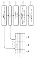
ここで図面を参照する。図面において、同様な番号は、同じ又は類似の要素を表す。最初に図1を参照すると、エンドグラフトの追跡及びナビゲーションに関するシステム100と、形状検出可能なデバイス及びシステムを持つ関連付けられるアクセサリ又はツールとが、一実施形態に基づき例示的に示される。ナビゲーションは、手動、コンピュータ支援、ロボットで実行されることができる。システム100は、手順が監督及び/又は管理されるワークステーション又はコンソール112を含むことができる。ワークステーション112は好ましくは、1つ又は複数のプロセッサ114及びプログラム及びアプリケーションを格納するメモリ116を含む。メモリ116は、1つ又は複数の形状検出デバイス又はシステム104からの光学的フィードバック信号を解釈するよう構成された光学検出モジュール115を格納することができる。光学検出モジュール115は、例えば、エンドグラフト、ステント、バルーン等といった展開可能な医療デバイス又は器具102に関連付けられる変形、偏向及び他の変化を再構成するため、光学信号フィードバック(及び他の任意のフィードバック、例えば、電磁(EM)追跡、X線又は超音波画像)を使用するよう構成される。デバイス102はまた、ガイドワイヤ、カテーテル、又は他の医療デバイスを含むことができる。
See the drawing here. In the drawings, similar numbers represent the same or similar elements. First, with reference to FIG. 1, a
形状検出システム104は、セットされた1又は複数のセットパターンにおいてシステム104に含まれる1つ又は複数の光ファイバ127を含む。光ファイバ127は、ワークステーション112に接続する。形状検出システム104は、1つ又は複数のデバイスに含まれ、例えば、配置システム107、ハンドル105(配置システム107又はガイドワイヤ若しくはカテーテル用)、カテーテル若しくはガイドワイヤ103、展開可能なデバイス102(本書においてエンドグラフト102とも呼ばれる)又は他の医療コンポーネントなどに含まれることができる。エンドグラフト、ステント若しくはマーカーの視覚的表現を生成するため、又はエンドグラフト若しくは他のデバイス展開のための光学的形状検出と組み合わせて使用される述前計画の使用を通して、OSSファイバ127又はOSSシステム104が使用される。本原理は、デバイス102又は配置システム107のナビゲーション及び配置のための光学形状検出ファイバ127の任意の使用に適用される。本原理は、バルーンカテーテル、クリップ、弁、及び他のインプラント、例えば閉塞デバイス、ステント、薬物溶出ステント、薬物被覆バルーン、肺容積減少デバイスなどにも適用されることができる。
The
一実施形態では、OSSシステム104のファイバ127は、エンドグラフト102に一体化される。他の実施形態では、OSSファイバは、配置システム107(ハンドル105も含むことができる)又はガイドワイヤ103(例えば、硬いガイドワイヤ)に一体化されることができる。OSSシステム104は、エンドグラフト102又はステントの計画又は配置のための物理的測定を行うために使用されることができる。一実施形態では、エンドグラフト102又はステントは、エンドグラフト102又はステントの位置及び向き情報を提供するため、OSSシステム104を含むことができる。
In one embodiment, the
光ファイバを備える形状検出システム104は、1つ又は複数の光ファイバにおける光ファイバブラッグ格子センサに基づかれることができる。光ファイバブラッグ格子(FBG)は、光の特定の波長を反射し、他のすべての他を透過させる光学ファイバの短いセグメントである。これは、ファイバーコアにおいて屈折率の周期変化を加えることにより実現され、波長特有の誘電体ミラーを生成する。ファイバブラッグ格子は従って、特定の波長をブロックするインライン光学フィルタとして又は波長特有の反射器として用いられることができる。
The
ファイバブラッグ格子の処理の後の基本的な原理は、屈折率が変化している各々のインタフェースでのフレネル反射である。いくつかの波長に対して、様々な期間の反射光は同相にある。その結果、反射に関して建設的干渉が存在し、結果的に、透過に関して弱め合い干渉が存在する。ブラッグ波長は、温度だけでなく歪みに対して敏感である。これは、ブラッグ格子が、光ファイバセンサにおけるセンシング要素として用いられることができることを意味する。FBGセンサでは、歪みは、ブラッグ波長のシフトをもたらす。 The basic principle after processing the Fiber Bragg lattice is Fresnel reflection at each interface with varying indices of refraction. For some wavelengths, the reflected light for different periods is in phase. As a result, there is constructive interference with respect to reflection and, as a result, weakening interference with respect to transmission. Bragg wavelengths are sensitive to strain as well as temperature. This means that the Bragg grid can be used as a sensing element in fiber optic sensors. In FBG sensors, distortion results in a shift in Bragg wavelength.
この技術の1つの利点は、様々なセンサ要素が、ファイバの長さにわたり分散されることができる点にある。構造に埋め込まれるファイバの長さに沿って様々なセンサ(ゲージ)に3又はこれ以上のコアを組み込むことは、斯かる構造の3次元形式が、通常1mmより良好な精度で正確に決定されることを可能にする。ファイバの長さに沿って、さまざまな位置で、複数のFBGセンサが配置されることができる(例えば、3つ又はこれ以上のファイバー・センシング・コア)。各FBGの圧力測定から、その位置での構造の湾曲が推定されることができる。複数の測定された位置から、全体の3次元形状が決定される。 One advantage of this technique is that various sensor elements can be dispersed over the length of the fiber. Incorporating three or more cores into various sensors (gauges) along the length of the fiber embedded in the structure determines the three-dimensional form of such structure accurately with better accuracy than usually 1 mm. Make it possible. Multiple FBG sensors can be placed at various positions along the length of the fiber (eg, three or more fiber sensing cores). From the pressure measurement of each FBG, the curvature of the structure at that position can be estimated. The entire three-dimensional shape is determined from a plurality of measured positions.
光ファイバブラッグ格子に代わるものとして、従来の光学ファイバにおける固有の後方散乱が利用されることができる。そのような手法の1つは、標準的な単一のモード通信ファイバにおけるレイリー散乱を用いることである。レイリー散乱は、ファイバーコアにおける屈折率のランダム変動の結果として発生する。これらのランダム変動は、格子長に沿った振幅及び位相のランダム変動を持つブラッグ格子としてモデル化されることができる。単一長のマルチコアファイバにおいて延びる3又はこれ以上のコアにおいてこの効果を用いることにより、関心表面の3D形状及び動力学がフォローされることができる。 As an alternative to fiber optic Bragg lattices, the inherent backscattering of conventional optics can be utilized. One such technique is to use Rayleigh scattering in a standard single mode communication fiber. Rayleigh scattering occurs as a result of random fluctuations in the index of refraction in the fiber core. These random variations can be modeled as Bragg lattices with random amplitude and phase variations along the lattice length. By using this effect in 3 or more cores extending in a single length multi-core fiber, the 3D shape and dynamics of the surface of interest can be followed.
光学形状検出は、複数の方法で実行されることができ、FBG又はレイリー散乱技術に限定されない点を理解されたい。例えば、他の技術は、ファイバにエッチングされるチャネル、反射のために量子ドットを使用すること、単一のマルチコアファイバの代わりに複数の別個のファイバ(例えば、3つ以上)を使用すること、又は他の光学的形状検出技術を含むことができる。 It should be understood that optical shape detection can be performed in multiple ways and is not limited to FBG or Rayleigh scattering techniques. For example, other techniques include channels that are etched into the fiber, the use of quantum dots for reflection, the use of multiple separate fibers (eg, three or more) instead of a single multi-core fiber, Alternatively, other optical shape detection techniques can be included.
エンドグラフト102の3D表現102'(例えば、メッシュ124又はモデル126)は、OSS測定を用いて、表示された画像内に作成され、及び配置されることができる。一実施形態では、各エンドグラフトタイプに対して、一連の画像134(例えば、CT)が、エンドグラフト102の展開のために先験的に取得される。これは、エンドグラフト102のモデルタイプ、展開状態、及びメッシュ表現の間のルックアップテーブル122を構築するために使用されるか、又はステントの代表的なモデルが、数値メッシュとして作成される。言い換えると、ルックアップテーブル122は、OSSデータにより検出される向きに一致するよう方向付けられる様々な展開状態の(ディスプレイ上で)視覚化されたオブジェクトに関する異なるモデルを含む。エンドグラフト(又は配置システム107、剛性ガイドワイヤ103など)からの光学的形状検出データを使用して、デバイス102(エンドグラフト)の視覚表現102'が作成される。視覚表現102'は、所与のエンドグラフトタイプの先験的モデル126から作成されることができるか、又は標準モデルから作成されることができる。その後、視覚表現102'は、デバイス102のOSS測定に基づき、術中(又は術前)画像134に対して配置及び配向される。この表現102'は、術中撮像からの情報、ユーザ入力、展開の状態に関する展開デバイスからの情報などを使用して更新されることもできる。
A 3D representation 102'of the end graft 102 (eg, mesh 124 or model 126) can be created and placed within the displayed image using OSS measurements. In one embodiment, for each endgraft type, a series of images 134 (eg, CT) are acquired a priori for deployment of the
術前計画は、表現102'を使用して行われることができ、OSSガイダンスを使用して実際のエンドグラフトを配置するとき、オペレータを助けるために使用されることができる。更に、OSS対応のカテーテル又はガイドワイヤ(103)が、オペレータが表現102'を選択し、位置決めするのを助けるよう、前もって血管の位置及び長さのいくつかを決定するのに使用されることができる。
Preoperative planning can be performed using the expression 102'and can be used to assist the operator when placing the actual end graft using OSS guidance. In addition, an OSS-compatible catheter or guidewire (103) may be used to predetermine some of the vessel positions and lengths to help the operator select and position the
処置の間、最も近い先験的なエンドグラフトメッシュ124又はモデル126を探すのに、エンドグラフト102に関する既知の情報が用いられる。入力情報は、例えば、エンドグラフトタイプ(製造業者、モデル番号など)、展開状態(部分的に展開、完全展開、展開構成など)及び/又はユーザ入力を含むことができる。入力情報はまた、配置デバイス(103)のハンドル105上の関連する特徴の位置、エンドグラフト102上の取り付け点の既知のOSS位置、配置システム107のシース又は他の要素の既知のOSS位置を知るため、OSSファイバ(又は代替的な検出機構)を含むことができる。
During the procedure, known information about the
先験的なエンドグラフトメッシュ124の代わりに、代表モデル126が使用されることができ、それは、(前述したように)展開状態の知識に基づき適切な状態へと膨張/変形されることができる。
Instead of the a priori end-
エンドグラフトメッシュ124は、剛性ガイドワイヤ103、ハンドル105、配置デバイス107、又はステント若しくはエンドグラフト102における特定の点の位置及び向きの形状検出知識に基づき正しい位置及び向きへと変換される。エンドグラフトメッシュ124は、剛性ガイドワイヤ103の形状、エンドグラフト102上の取り付け点の既知のOSS位置、配置デバイス107の形状(デバイスに埋め込まれたOSSファイバから)、既知の展開状態(例えば、エンドグラフトを収容するシースの既知の位置に基づかれる)などに基づき、正しい形状へと変形されることができる。これは、特定の患者の生体構造に関連する任意の必要な曲線をエンドグラフト102に与える。
The
オペレータが、蛍光透視画像(例えば、画像134)を用いてステントグラフト102の位置を確認する場合、蛍光透視画像(134)から検出されるマーカー位置を用いて、ステントグラフト102のモデルが更新されることができる。これらのマーカーは、自動的若しくは半自動的に識別されるか、又はオペレータにより画像134において選択されることができる。代替的に、ユーザは、ディスプレイ118上のグラフィカルユーザインタフェース(120)を使用してモデルを手動で調整する能力を持つことができる。
When the operator confirms the position of the
本体エンドグラフト102及び四肢の伸長部などのサイジングは、分枝血管が閉塞しないことを確認する際に最も重要である。例えば、主腸骨への四肢の伸長が長すぎる場合、それは内部腸骨をブロックすることができる。これらのエンドグラフトの選択を確認するため、OSSシステム104が使用されることができる。OSS対応デバイス又はシステム104が、大動脈にナビゲートされると、位置又はターゲットは、蛍光透視画像(134)及びOSSオーバーレイ画像136上で識別されることができる。これらの位置の間の血管の長さを決定するため、OSSファイバ(127)の長さが使用されることができる。これは、蛍光透視法ベースの測定の既知の問題である、短縮化によるこれらの長さの計算違いを排除することができる。
Sizing of the
ワークステーション112は、対象(患者)又はボリューム131の内部画像を見るためのディスプレイ118を含み、手順において使用される1つ又は複数の要素において形状検出システム104に位置合わせされるオーバーレイ又は他のレンダリングとして画像134又は画像136を含むことができる。ディスプレイ118はまた、ユーザがワークステーション112並びにそのコンポーネント及び機能(例えば、タッチスクリーン、グラフィカルユーザインタフェースなど)、又はシステム100における他の要素と対話することを可能にすることができる。これは、ユーザがワークステーション112からのフィードバックを受け、及びワークステーションと相互作用することを可能にする、キーボード、マウス、ジョイスティック、触覚デバイス又は他の任意の周辺機器若しくは制御を含むことができるインタフェース120により、更に容易にされる。
The workstation 112 includes a
レジストレーションモジュール128は、OSSファイバ127又はシステム104を物理構造(例えば、動脈瘤など)、OSSシステム104、画像134、136などに位置合わせし、エンドグラフト102をOSSシステムなどに位置合わせするよう構成される。
The registration module 128 is configured to align the
形状認識位置合わせに関して、ファイバ127から位置及び方向情報の両方を得るため、特徴的な形状が使用されることができる。ファイバ127が所定の不変の経路をとる場合、メモリ116に記憶されるファイバ変換に対する固有の画像を識別するのに、その経路の曲率及び形状情報が使用されることができる。
For shape recognition alignment, characteristic shapes can be used to obtain both position and orientation information from the
画像処理モジュール142は、ディスプレイ118上の共同の又は別個のディスプレイのために画像(134)及びOSS位置データ(画像136)を組み合わせるよう構成される。OSSデータ(例えば、画像136からの、又はファイバ127から得られた位置及び形状情報からの、又はファイバ127の曲率及び形状情報からの)及び画像データ(術前又は術中画像134からの)が、エンドグラフト102の表現102'(例えば、モデル126のレンダリングされたバージョン)を使用することにより、エンドグラフト102(又は他のステント又は移植可能なデバイス)の配置を支援するため、表示スクリーン133上で位置合わせされ、共同して表示される。表現102'は、OSSデータに位置合わせされ、スクリーン133上のディスプレイにレンダリングされ、ユーザは、その配置及び展開の間エンドグラフト102を視覚化することができる。
The
OSS測定はまた、配置されるエンドグラフト又はステントを決定するため、生体構造の測定に特に有用である。更に、OSSシステム104は、エンドグラフト圧力及びフローモデリングを評価するために使用されることができる。エンドグラフト102が展開されると、エンドグラフト封止リング、本体、及び他の要素(例えば、図5及び図6参照)の位置は、エンドグラフト102の部分により経験される圧力に重大な影響を及ぼす可能性がある。グラフト102の一部に過度の圧力がある場合、この圧力は、エンドグラフト不全、移動をもたらし、及び最終的には再介入を必要とする可能性がある。更に、グラフト102が最適に配置されない場合、グラフトを通る流れは、最適ではない可能性がある。これは、現在、術後CTを介して研究されている。術後の時点で、エンドグラフト配置において何かを変更するには遅すぎる。術後CTでは、移植や治癒後にグラフトがどのようにシフトしたかを決定するための蛍光透視法又は造影剤注入が採用されるが、OSS又は他の手段を用いてエンドグラフトを確実に配置することは、エンドグラフトの配置が不適切であることによる悪影響の可能性を低減させる。
OSS measurements are also particularly useful for measuring biostructure because they determine the endografts or stents to be placed. In addition, the
エンドグラフトの位置及び方向に関する光学的形状検出情報に基づかれるこれらの効果の術中予測により、臨床医は、最終的な展開の前にエンドグラフト102を調節することができる。有用な実施形態では、グラフト102における流れ及び/又は圧力を推定するのに、OSSシステム104の形状が使用されることができる。これらの流れ又は力のモデリングは、角度のついた首をターゲットとし、より曲がりくねったエンドグラフトに特に適切である。
Intraoperative prediction of these effects, based on optical shape detection information about the position and orientation of the end graft, allows the clinician to adjust the
図2を参照すると、一実施形態による例示的なルックアップテーブル122が示される。ルックアップテーブル122は、エンドグラフトタイプに関する列202と、展開状態に関する列204と、エンドグラフトメッシュ又はモデル(名前、ファイル名、ポインティングアドレスなど)に関する列206とを含む。手順の間、ブロック210において、オペレータは、エンドグラフトタイプ及び展開状態を入力データとしてワークステーション112に入力することができる。エンドグラフトタイプ及び展開状態は、自動的に検出されることもできる。ブロック212において、プロセッサ114は、ルックアップテーブル122(列202及び204)を検索し、入力データに関するメッシュ又はモデルを決定し、メッシュ又はモデルタイプを取得する。ブロック214において、光学形状検出ファイバからの入力情報に基づき、モデルの剛性変換が実行される。ブロック216において、モデルは、解剖学的情報、ガイドワイヤ又は他の配置ツールの形状、エンドグラフトの既知の位置などに適合するよう変換される。ブロック218において、ステントモデルは、ライブ画像(例えば、蛍光透視法)、ユーザ入力などを用いて更に更新される。こうして、エンドグラフトを視覚的な表示においてより好適に表すよう、モデルが選択及び修正されることができる。
Referring to FIG. 2, an exemplary look-up table 122 according to one embodiment is shown. Look-up table 122 includes
図3を参照すると、光学形状検出ファイバ302が、展開の様々な段階の間のエンドグラフトのモデル304とともに示される。このモデル304は、臨床医が、エンドグラフトの位置、向き、及び形状を理解するためのより簡単な方法を提供することができる。円筒状のエンドグラフトモデル304は、光学形状検出ファイバ302に対して変形及び位置合わせされることができ、ユーザが周囲の生体構造に対するステントの位置、向き、及び展開の状態を視覚化することを可能にするよう表示されることができる。モデル304の画像は、OSSファイバ302と共にレンダリングされ、エンドグラフトの展開前に測定又は比較を行うことができる。モデル304は、以前のOSS測定値又は他の情報に基づき更新される修正モデルを含むことができる。
With reference to FIG. 3, the optical
図4を参照すると、光学形状検出ファイバ302が、展開の様々な段階の間、円筒形バルーンカテーテルモデル306とともに示される。このモデル306は、臨床医がバルーンカテーテル306の位置、向き、及び形状を理解するためのより簡単な方法を提供することができる。バルーンカテーテルモデル306は、光学形状検出ファイバ302に対して変形及び位置合わせされることができ、ユーザがバルーンの位置、向き、及び膨張の状態を視覚化することを可能にするよう表示されることができる。
With reference to FIG. 4, the optical
再び図1を参照すると、ワークステーション112は、グラフト又はステントの展開手順の計画をサポートするよう構成される計画モジュール132を含むことができる。計画モジュール132は、OSS若しくは他の方法により測定されるような解剖学的特徴を使用することができ、又は術前画像から選択されることができる「標準」ステントを使用することができる。
With reference to FIG. 1 again, workstation 112 can include a
本原理に基づき、エンドグラフト術前計画は以下のように実行され得る。手順に先立って、先験的なエンドグラフトモデル又はシミュレートされたエンドグラフトモデル126又はメッシュ124を備える同じルックアップテーブル122を使用して、計画が実行されることができる。これは、エンドグラフトの先験的メッシュ124をロードし、術前CT又は類似の画像134にメッシュ124をオーバーレイすることにより実行されることができる。ユーザは、エンドグラフトをサイズ変更し、側枝のカニューレ挿入を位置決めして、エンドグラフトモデル126又はメッシュ124を修正することにより、エンドグラフトのデジタル表現(124、126)を修正するよう構成される編集モジュール140を用いて、エンドグラフトモデル126又はメッシュ124の形状を調整し、生体構造に適合することが可能にされる。これは、複数の方法又はそれらの組み合わせで実行されることができる。例えば、1つの方法は、(ディスプレイ118上のGUIを介して)ユーザによるエンドグラフトモデル126又はメッシュ124の手動変形を含む。別の方法は、半自動変形を含むことができる。そこでは、ユーザが、保持リング(又はメッシュ124の他のいくつかの特徴)を位置決めし、その後、メッシュ124の残りの部分が、生体構造に一致するように変形する。更に別の方法は、所与のエンドグラフトに先立って展開される他のエンドグラフトの位置に基づかれることができ、例えば、本体グラフトに関する腸骨肢がモデルとして使用されることができる。これは、マーカバンドに関する既知のランディングゾーンに基づき自動的に実行され、その後ユーザにより調整される。
Based on this principle, the endograft preoperative plan can be performed as follows. Prior to the procedure, the plan can be carried out using the same look-up table 122 with an a priori end-graft model or a simulated end-
エンドグラフトが所望に応じて配置されると、先験的モデル126から特徴が抽出され、ユーザにより表示又は描画又は配置される。例えば、1)ステント又は2次ステントの首に関するランディングゾーン、2)ステント又は2次ステントの首に関する標的リング、3)穿孔の位置又は対側ゲートの位置に関する標的球又はリング又はマーカーのセット。これは、ユーザがこれらの特徴のみを視覚化し、モデル全体を隠すことを選択することを可能にする。4)ステントにおける機械的力に関する予想される力プロファイル、及びエンドグラフトを通るシミュレートされた流れプロファイルなどである。
Once the end grafts are placed as desired, features are extracted from the a
術前計画について記載されたステップは、術中に提供されることもできる。これは、展開後にグラフトがどのように配置されるかをオペレータが予測することを可能にする。計画自体はオンザフライで行われることができるか、又は術前計画がオンザフライで更新されることができる。これは、比較的剛性のある展開デバイスを血管に導入すると、生体構造が大きく変わる可能性があるため、重要である。この同じ理由から、展開の間に周期的に撮影された蛍光透視画像が、このタイプのナビゲーション及び展開に関して、術前CT画像134を使用するよりも好ましい場合がある。
The steps described for preoperative planning can also be provided intraoperatively. This allows the operator to predict how the graft will be placed after deployment. The plan itself can be done on the fly, or the preoperative plan can be updated on the fly. This is important because the introduction of a relatively rigid deployable device into a blood vessel can significantly alter the anatomy. For this same reason, fluoroscopic images taken periodically during deployment may be preferable to using
本書に説明されるタスクは、特定の手順に対してオペレータを準備するため、及び/又は一般的なトレーニング目的に使用するために、シミュレータとしての手順の前にユーザに提供されることもできる。しかしながら、この効果を低減するため、術前CT画像134は、処置の間の透視画像に基づき更新されることができる。例えば、異なる投影における2つの血管造影画像が、例えば腎分岐を特定するために使用されることができる。ユーザがすでにその位置に標的リング又は球を持つ場合、標的は、ライブ血管造影画像に基づき調整されることができる。これは、他の関連する解剖学的特徴(腸骨分岐、SMA、セリアックなど)に対しても同様に行われることができる。これらの特徴がどのように調整されるかに基づき、術前CT画像134がマッチするよう同様に変形されることができる。
The tasks described in this document may also be provided to the user prior to the procedure as a simulator for preparing the operator for a particular procedure and / or for use for general training purposes. However, to reduce this effect, the
一実施形態では、術中画像におけるグラフトの視覚化を助けるため、ステントグラフトの表現が、ステントグラフトの最も可能性の高い位置に関する確率マップ若しくは確率インジケータとして、又はこれと共にオペレータに示されることができる。最適配置又は最適配置の程度が生じる位置を示す確率マップが、ディスプレイにレンダリングされることができ、これは、計算、履歴データ(他の手順から)、臨床医により設定されたゾーンなどに基づかれることができる。確率マップは、安全な配置ゾーンを示すため、又は配置があまり望ましくない領域を示すために、異なる色又はテクスチャを含むことができる。確率マップは、形状検出データの潜在的な不正確/不確実性のインジケータ又は位置合わせの質を含むことができる。例えば、ディスプレイにおけるエンドグラフトモデルは、エンドグラフトの配置に関するより良好な成功の確率を示すため、色及び/又は仮想血管を変化させることができる。確率マップの様々な変化及び使用は、当業者により理解されるであろう。 In one embodiment, the representation of the stent graft can be presented to the operator as a probability map or probability indicator for the most probable location of the stent graft to aid in the visualization of the graft in the intraoperative image. A probability map showing the optimal placement or the location where the degree of optimal placement occurs can be rendered on the display, which is based on calculations, historical data (from other procedures), zones set by the clinician, etc. be able to. Probability maps can include different colors or textures to indicate safe placement zones or areas where placement is less desirable. Probability maps can include potential inaccuracies / uncertainty indicators or alignment quality of shape detection data. For example, the endograft model on the display can vary in color and / or virtual vessels to show a better probability of success with respect to the placement of the endografts. Various changes and uses of probability maps will be understood by those skilled in the art.
代替的に、オペレータは、(グラフト全体とは対照的に)ステントグラフトの主要な特徴を示すマーカーの位置を示されることができる。マーカーは、3D表現として表示されることができ、又は2D平面に投影され、透視画像にオーバーレイされることができる。これらの特徴は、ステントグラフトを整列させる又は他の態様で位置決めするために使用される端部、リング又は他の特徴的な形状を含むことができる。オペレータが術前計画を使用している場合、視覚化は、エンドグラフトの現在の位置が一定の許容範囲内で計画と一致するときを示すことができる。 Alternatively, the operator can indicate the location of a marker (as opposed to the entire graft) that indicates the key features of the stent graft. The marker can be displayed as a 3D representation or projected onto a 2D plane and overlaid on the fluoroscopic image. These features can include ends, rings or other characteristic shapes used to align or otherwise position the stent graft. If the operator is using a preoperative plan, the visualization can indicate when the current position of the end graft matches the plan within certain tolerances.
他の実施形態では、処置の間、エンドグラフト102周辺の既知の関心領域に放射線ビームを限定することにより、患者(及び臨床医)に対する放射線量を制限するのに、エンドグラフト位置に関するOSS情報が使用されることができる。これは、撮像システム110のソースにおける画像ウェッジの自動的又はユーザ決定された位置決めにより行われることができる。撮像システム110は、蛍光透視システム、超音波システムなどを含むことができる。一実施形態では、撮像システム110は、cアーム125を含むことができる。Cアーム125の位置及び角度は、エンドグラフトの位置及び向きに関するOSSの知識に基づき、その位置を自動的に制御することにより、又はユーザに最適な位置を提案することにより、最適化されることができる。
In other embodiments, OSS information about the endograft location is used to limit the radiation dose to the patient (and clinician) by limiting the radiation beam to a known area of interest around the
図5を参照すると、血管511内の計画段階の間に描かれることができる標的リング506、球508、及びランディング領域510を含む、エンドグラフト504の配置の術前計画に関する例示的な画像502が示される。これらの計画特徴はその後、展開の間に使用されることができる。
Referring to FIG. 5, an
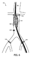
図6を参照すると、計画段階の間に描かれることができる標的リング516、球518、及びランディング領域520を含むエンドグラフト514の展開の術前計画に関する例示的な画像512が示される。これらの計画特徴はその後、展開の間に使用されることができる。
Referring to FIG. 6, an
本原理は、以下に限定されるものではないが、例えば、血管内動脈瘤修復(EVAR)、分岐有窓EVAR(BEVAR)、経皮EVAR(PEVAR)、胸部EVAR(TEVAR)、有窓EVAR(FEVAR)といった処置を含む、蛍光透視法又は他の撮像誘導下で、エンドグラフトが使用される任意の用途をカバーする点を理解されたい。 This principle is not limited to the following, but is, for example, endovascular aneurysm repair (EVAR), bifurcated fenestrated EVAR (BEVAR), percutaneous EVAR (PEVAR), chest EVAR (TEVAR), windowed EVAR ( It should be understood that endografts cover any application under fluorescence fluoroscopy or other imaging guidance, including procedures such as FEVAR).
図7を参照すると、本原理による血管内動脈瘤修復(EVAR)処置のための有窓ステントグラフト(エンドグラフト)702が示される。グラフト702の位置及び向きは、配置前にOSSシステム104を用いて計画された。更に、血管706の枝704の位置及び大きさが決定された。本原理は、情報の不足を補い、及びステントグラフトの3D表現をユーザに提供するため、術中OSSデータと結合されるステントグラフトの先験的モデル、及びステントグラフトの任意のライブ撮像を使用する。
With reference to FIG. 7, a fenestrated stent graft (end graft) 702 for endovascular aneurysm repair (EVAR) treatment according to this principle is shown. The position and orientation of the
エンドグラフト702のモデルは、編集ツール(図1の編集モジュール140)を使用して修正され、続いて、この修正に基づきグラフト702が製造される。修正は、分岐位置、エンドグラフト702のサイズ(特定の位置における長さ及び直径など)を含むことができる。これは、エンドグラフト702が、一旦展開されると良好に適合することを保証する。次いでグラフト702が展開される。エンドグラフト702は、そこに一体化されるOSSシステム104を含むことができ、これは、OSSファイバ、OSS対応カテーテル、OSS対応ガイドワイヤなどを含むことができる。OSSシステム104及び術中撮像は、血管706に対するグラフトの位置、形状及び向きを特定するために共同で使用される。
The model of the
枝704は、エンドグラフト702における対応する構造と整列され、エンドグラフト702のリング又は端は、動脈瘤又は他の損傷組織に隣接する健康な組織に配置される。このエンドグラフトは、配置ツール又は器具(例えば、ガイドワイヤ、カテーテル(例えば、バルーンカテーテル)又は他の任意の器具)とともに、又はその上に配置されることができる。配置ツール(図1の107)は、エンドグラフト702における1つの代わりに、又はこれに加えて、OSSシステム104を含むことができる。OSSシステム104を備える配置ツール107(図1)は、グラフト702の正確な配置を保証するのを助けることができる。エンドグラフト702の配向及び位置は、血管706の良好な密封を実現し、動脈瘤がもはや圧力を受けないように流れを調節するために重要である。エンドグラフト702が正しく配置されない場合、血液は、ステントグラフト702の周りで漏れることがあり、動脈瘤嚢内に溜まり続けるか、又はエンドグラフト702が、血管706(例えば大動脈)から側枝を閉塞する可能性があり、これは、重要な器官に対する貧弱な血流をもたらす可能性がある。
The
有窓血管内動脈瘤修復(FEVAR)では、側枝(例えば、腎動脈)にカニューレ挿入することが、グラフト702の展開に先立って血管706をマッピングすることにより事前に実行されることができる。このカニューレ挿入は、半展開されるステントグラフトを通してカテーテル及びガイドワイヤをナビゲートし、穿孔を介してステントグラフト702を出て、次に標的血管(分岐704)に入ることを含む。
In fenestrated endovascular aneurysm repair (FEVAR), cannulation into a lateral branch (eg, renal artery) can be performed in advance by mapping the
OSSシステム104は、最適な位置決めのため、配置の間、エンドグラフト702の位置、向き及び形状を追跡する。側血管のカニューレ挿入は、X線誘導の使用なしで(又は最小限のX線誘導で)実行されることができ、OSSシステム104のデバイス(例えば、OSS対応配置ツール、OSS対応ステントグラフト、及び/又は術前CT若しくはライブ透視法の1つ又は複数)に基づき実行されることができる。
The
図8を参照すると、例示的な実施形態に基づき、医療デバイス展開のための方法が説明及び示される。ブロック802において、術前画像及び展開可能医療デバイス又は移植可能デバイスのモデルに基づき、術前計画が実行されることができる。展開可能な医療デバイス又は移植可能物は、エンドグラフト、ステント、バルーン、クリップ、バルブ、他の移植可能なデバイス、他の展開可能なデバイス(例えば、カテーテル、ガイドワイヤなど)を含むことができる。ブロック804において、解剖学的位置(例えば、分岐、ランディングゾーンなど)はオプションで、例えばガイドワイヤ又はカテーテルといったOSS対応デバイスを用いて測定される。このステップは、OSSシステムを使用して、関連する幾何学的特徴(例えば、分岐位置、全長など)の長さ測定を行うことを含むことができる。特定の環境において、ブロック804はスキップされることができる。例えば、医師は、OSSにより提供される測定を行わずに、ブロック802からブロック806に直接移ることができる。
With reference to FIG. 8, a method for medical device deployment is described and illustrated based on exemplary embodiments. At
ブロック806において、エンドグラフトタイプが選択される。これは、ブロック804においてOSSシステムにより測定される測定値に基づかれることができる。ブロック808において、エンドグラフトタイプを選択するステップは、メモリに記憶されたルックアップテーブルを参照するステップを含むことができ、OSSシステムを用いて得られる測定値に基づき、最良適合エンドグラフトタイプが選択されるよう、エンドグラフトタイプに対して測定をインデックス化するよう構成される。選択されたタイプに関して、エンドグラフトタイプのデジタル表現が提供される。
At
ブロック810において、医療デバイス(例えば、エンドグラフト)の位置を決定するOSSデバイスが、このデバイスが配置されるべき血管の画像と共に位置合わせされる。OSSデータは好ましくは、血管の画像データと位置合わせされる。OSSデバイスは、製造中に配置システムに一体化されることができ、配置システムのハンドルにクリップされることができ、エンドグラフトに接続されることができる等となる。
At
ブロック812において、医療デバイスのデジタル表現が、入力(例えば、OSSデータからの展開可能な医療デバイスの位置及び向き、展開状態、撮像データ及び/又はユーザ入力からの入力)に基づき修正されることができる。これは、対象にフィットするよう、エンドグラフトモデル又はメッシュを修正すること、及び側枝の特徴を事前位置決めすることを含むことができる。OSSシステムは、配置器具又はシステムに一体化されることができ、少なくとも一部のエンドグラフトは、配置器具に対して仮想的に表されることができる。展開に先立ってエンドグラフトをカスタマイズすることにより、穿孔及び配置に必要な時間量が大幅に短縮される。更に、放射時間及び造影剤の量も、OSSシステムの使用により低減されることができる。
At
ブロック814において、OSSデバイス、医療デバイス表現、及び画像(CT、X線)が共同して表示される。OSSデータ及び画像データは例えば、血管内のエンドグラフトの正確な配置を可能にするため共に表示される。OSSシステムは、エンドグラフトに一体化されることができ、エンドグラフトは、共に表示される画像におけるエンドグラフトの少なくとも一部により視覚的に表されることができる。ブロック816において、エンドグラフトの少なくとも一部は、確率マップ、エンドグラフト又はマーカーの一部を含むことができる。
At
ブロック818において、撮像エネルギーは、エンドグラフトの位置及び向きのOSS情報を使用して関心領域の焦点に基づき制限される。例えば、放射線は、配置されたOSSシステムの位置により指定される関心領域に制限されることができる。こうして、放射線の狙いを定めるためにOSS位置が使用され、放射線は、関心領域/エリアに縮小される。エネルギー形態の超音波又は他の撮像モダリティも同様に制限され得る。
At
ブロック820において、エンドグラフトは例えば、バルーンカテーテルなどを拡張することにより、血管内に展開される。エンドグラフトを固定する前に、配置又はエンドグラフトに関する修正及びチェックが行われることができる。
At
添付の特許請求の範囲を解釈するにあたり、以下の点を理解されたい。 In interpreting the appended claims, please understand the following points.
a)「有する」という語は、所与の請求項に記載される要素又は行為以外の他の要素又は行為の存在を除外するものではない。 a) The word "have" does not preclude the existence of any element or act other than the element or act stated in a given claim.
b)ある要素に先行する「a」又は「an」という語は、斯かる要素が複数存在することを除外するものではない。 b) The word "a" or "an" preceding an element does not preclude the existence of more than one such element.
c)請求項における任意の参照符号は、それらの範囲を制限するものではない。 c) Any reference code in the claims does not limit their scope.
d)複数の「手段」が、同じアイテム、又はハードウェア、又はソフトウェア実現による構造体、又は機能により表されることができる。 d) Multiple "means" can be represented by the same item, or hardware, or software-implemented structure, or function.
e)特に指定がない限り、行為の特定のシーケンスが必要とされることを意図するものではない。 e) Unless otherwise specified, it is not intended to require a particular sequence of actions.
光学的形状検出を用いたエンドグラフト視覚化のための好ましい実施形態を説明してきたが(これらは例示であって限定することを意図するものではない)、上述の教示に照らして当業者であれば修正及び変形が可能である点に留意されたい。従って、添付の特許請求の範囲により概説される開示される実施形態の範囲に含まれるものとして、本開示の特定の実施形態において変更がなされることができる点を理解されたい。こうして、本開示の内容が特許法により必要とされる範囲で詳細に記載されてきたが、特許証により保護されることを望む保護の請求は、添付の特許請求の範囲に記載される。 Although preferred embodiments for end-graft visualization using optical shape detection have been described (these are exemplary and not intended to be limiting), those skilled in the art in light of the above teachings. Please note that it can be modified and modified. Therefore, it should be understood that changes may be made in the particular embodiments of the present disclosure as included in the scope of the disclosed embodiments outlined by the appended claims. Thus, although the content of the present disclosure has been described in detail to the extent required by patent law, claims for protection desired to be protected by a patent certificate are described in the appended claims.
Claims (12)
展開可能な医療デバイス及び配置器具の少なくとも1つに関連付けられる少なくとも1つの光学形状検出OSSシステムであって、前記OSSシステムが、前記展開可能な医療デバイス及び/又は配置器具の形状、位置又は向きの少なくとも1つを測定するよう構成される、OSSシステムと、
前記展開可能な医療デバイスの配置を可能にするため、OSSデータを撮像データと位置合わせするよう構成されるレジストレーションモジュールと、
前記展開可能な医療デバイスの視覚的表現を生成し、前記展開可能な医療デバイスと前記撮像データとを共に表示するよう構成される画像処理モジュールと、
前記視覚的表現として表示するよう仮想的にレンダリングされる前記展開可能な医療デバイスのモデルを提供するため、メモリに格納されるルックアップテーブルを有し、
前記モデルが、前記展開可能な医療デバイスの展開状態に基づき更新され、
前記展開状態が、前記OSSデータを使用して決定される、
システム。 A system for deploying medical devices
At least one optical shape detection OSS system associated with at least one of the deployable medical device and placement device, wherein the OSS system is of the shape, position or orientation of the deployable medical device and / or placement device. With an OSS system configured to measure at least one,
A registration module configured to align the OSS data with the imaging data to enable the placement of the deployable medical device.
An image processing module configured to generate a visual representation of the deployable medical device and display both the deployable medical device and the imaging data.
It has a look-up table stored in memory to provide a model of the deployable medical device that is virtually rendered to be displayed as the visual representation.
The model is updated based on the deployment status of the deployable medical device .
The unfolded state is determined using the OSS data.
system.
移植可能なデバイス及び配置器具の少なくとも1つに関連付けられる少なくとも1つの光学形状検出OSSシステムであって、前記OSSシステムが、前記移植可能なデバイス及び/又は配置器具の形状、位置又は向きの少なくとも1つを測定するよう構成される、OSSシステムと、
血管にフィットするよう前記移植可能なデバイスのモデル又はメッシュを修正することにより、前記移植可能なデバイスタイプのデジタル表現を修正するよう構成される編集モジュールと、
前記デジタル表現を用いて、前記移植可能なデバイスの配置を可能にするため、撮像データとOSSデータとを位置合わせするよう構成されるレジストレーションモジュールと、
前記撮像データと共に、前記移植可能なデバイスのデジタル表現を表示するよう構成される画像処理モジュールと、
表示のため仮想的にレンダリングされる前記移植可能なデバイスのモデル又はメッシュを提供するため、メモリに格納されるルックアップテーブルとを有し、
前記編集モジュールが、前記移植可能なデバイスの展開状態に基づき前記デジタル表現を変更するよう構成され、
前記展開状態が、前記OSSデータを使用して決定される、
システム。 A system for deploying portable devices,
And at least one optical shape detection OSS system associated with at least one implantable device and deployment device, the OSS system, the shape of the implantable device and / or deployment device, the position or orientation of at least 1 An OSS system that is configured to measure
An editing module configured to modify the digital representation of the implantable device type by modifying the model or mesh of the implantable device to fit a blood vessel.
Using the digital representation, a registration module configured to align the imaging data with the OSS data to enable placement of the portable device.
An image processing module configured to display the digital representation of the portable device along with the imaging data.
It has a look-up table stored in memory to provide a model or mesh of the portable device that is virtually rendered for display.
The editing module is configured to modify the digital representation based on the deployed state of the portable device .
The unfolded state is determined using the OSS data.
system.
Applications Claiming Priority (3)
| Application Number | Priority Date | Filing Date | Title |
|---|---|---|---|
| US201562106271P | 2015-01-22 | 2015-01-22 | |
| US62/106,271 | 2015-01-22 | ||
| PCT/IB2016/050077 WO2016116825A1 (en) | 2015-01-22 | 2016-01-08 | Endograft visualization with optical shape sensing |
Publications (3)
| Publication Number | Publication Date |
|---|---|
| JP2018502646A JP2018502646A (en) | 2018-02-01 |
| JP2018502646A5 JP2018502646A5 (en) | 2020-07-16 |
| JP6794361B2 true JP6794361B2 (en) | 2020-12-02 |
Family
ID=55310850
Family Applications (1)
| Application Number | Title | Priority Date | Filing Date |
|---|---|---|---|
| JP2017536524A Active JP6794361B2 (en) | 2015-01-22 | 2016-01-08 | Visualization of end grafts by optical shape detection |
Country Status (5)
| Country | Link |
|---|---|
| US (1) | US11844576B2 (en) |
| EP (1) | EP3247301B1 (en) |
| JP (1) | JP6794361B2 (en) |
| CN (1) | CN107205785B (en) |
| WO (1) | WO2016116825A1 (en) |
Families Citing this family (8)
| Publication number | Priority date | Publication date | Assignee | Title |
|---|---|---|---|---|
| CN110691553A (en) * | 2017-03-30 | 2020-01-14 | 皇家飞利浦有限公司 | OSS perspective shortening detection system, controller and method |
| JP7262923B2 (en) * | 2017-12-27 | 2023-04-24 | キヤノンメディカルシステムズ株式会社 | MEDICAL IMAGE PROCESSING APPARATUS, CONTROL METHOD THEREOF, AND PROGRAM |
| EP3527123B1 (en) * | 2018-02-15 | 2022-08-31 | Leica Instruments (Singapore) Pte. Ltd. | Image processing method and apparatus using elastic mapping of vascular plexus structures |
| EP3545847A1 (en) | 2018-03-27 | 2019-10-02 | Koninklijke Philips N.V. | Assessing device for assessing an instrument's shape with respect to its registration suitability |
| US11515031B2 (en) * | 2018-04-16 | 2022-11-29 | Canon Medical Systems Corporation | Image processing apparatus, X-ray diagnostic apparatus, and image processing method |
| JP7309377B2 (en) * | 2019-02-12 | 2023-07-18 | キヤノンメディカルシステムズ株式会社 | X-ray diagnostic device, medical information processing device and program |
| JP7394645B2 (en) * | 2020-02-05 | 2023-12-08 | 富士フイルム株式会社 | Teacher image generation device, method and program, learning device, method and program, discriminator, and radiation image processing device, method and program |
| WO2023227431A1 (en) * | 2022-05-23 | 2023-11-30 | Koninklijke Philips N.V. | Devices, methods, and systems for improved planning and guidance in laser fenestration applications |
Family Cites Families (30)
| Publication number | Priority date | Publication date | Assignee | Title |
|---|---|---|---|---|
| CA2333393C (en) * | 1998-05-28 | 2007-08-07 | Orthosoft Inc. | Interactive computer-assisted surgical system and method thereof |
| US7840393B1 (en) | 2000-10-04 | 2010-11-23 | Trivascular, Inc. | Virtual prototyping and testing for medical device development |
| JP4467522B2 (en) | 2003-08-05 | 2010-05-26 | 株式会社日立メディコ | Tomographic image constructing apparatus and method |
| US7772541B2 (en) * | 2004-07-16 | 2010-08-10 | Luna Innnovations Incorporated | Fiber optic position and/or shape sensing based on rayleigh scatter |
| US20060106406A1 (en) | 2004-09-27 | 2006-05-18 | Judah Weinberger | Methods and devices for extravascular intervention |
| US7892177B2 (en) * | 2005-02-28 | 2011-02-22 | Scimed Life Systems, Inc. | Systems and methods for estimating the length and position of a stent to be applied within a patient |
| US8165360B2 (en) * | 2006-12-06 | 2012-04-24 | Siemens Medical Solutions Usa, Inc. | X-ray identification of interventional tools |
| US7970719B2 (en) | 2008-06-06 | 2011-06-28 | Siemens Aktiengesellschaft | Method and simulation device for structurally individualized simulation of the introduction of a wall support element into a section of a tubular structure |
| JP5833548B2 (en) | 2009-06-24 | 2015-12-16 | コーニンクレッカ フィリップス エヌ ヴェKoninklijke Philips N.V. | Characterization of the space and shape of an embedded device within an object |
| JP2013523415A (en) * | 2010-04-14 | 2013-06-17 | スミス アンド ネフュー インコーポレーテッド | System and method for patient-assisted computer-assisted surgical procedure |
| US20120001388A1 (en) * | 2010-06-30 | 2012-01-05 | Ming-Yuan Wu | Spherical puzzle |
| WO2012042413A1 (en) * | 2010-09-30 | 2012-04-05 | Koninklijke Philips Electronics N.V. | Detection of bifurcations using traceable imaging device and imaging tool |
| MX2013004542A (en) * | 2010-10-27 | 2013-07-03 | Koninkl Philips Electronics Nv | Adaptive imaging and frame rate optimizing based on real-time shape sensing of medical instruments. |
| US20130324833A1 (en) | 2011-02-24 | 2013-12-05 | Koninklijke Philips N.V. | Non-rigid-body morphing of vessel image using intravascular device shape |
| EP2685900B1 (en) * | 2011-03-15 | 2022-12-21 | Koninklijke Philips N.V. | Medical imaging device for providing an image representation supporting in positioning an intervention device |
| RU2013150250A (en) * | 2011-04-12 | 2015-05-20 | Конинклейке Филипс Н.В. | INTEGRATED 3D MODELING |
| US8900131B2 (en) * | 2011-05-13 | 2014-12-02 | Intuitive Surgical Operations, Inc. | Medical system providing dynamic registration of a model of an anatomical structure for image-guided surgery |
| WO2013001388A1 (en) * | 2011-06-27 | 2013-01-03 | Koninklijke Philips Electronics N.V. | Live 3d angiogram using registration of a surgical tool curve to an x-ray image |
| US20130035537A1 (en) | 2011-08-05 | 2013-02-07 | Wallace Daniel T | Robotic systems and methods for treating tissue |
| RU2014143669A (en) * | 2012-03-29 | 2016-05-27 | Конинклейке Филипс Н.В. | TROUBLESHOOTING USING FORM READING |
| US10357304B2 (en) * | 2012-04-18 | 2019-07-23 | CardioSonic Ltd. | Tissue treatment |
| EP2846691B1 (en) * | 2012-05-09 | 2020-04-01 | Koninklijke Philips N.V. | System and method for stabilizing optical shape sensing |
| CN108542499B (en) | 2012-05-14 | 2020-12-04 | 直观外科手术操作公司 | Systems and methods for deformation compensation using shape sensing |
| WO2014001977A2 (en) * | 2012-06-28 | 2014-01-03 | Koninklijke Philips N.V. | Fiber optic sensor guided navigation for vascular visualization and monitoring |
| BR112015006625A2 (en) * | 2012-09-28 | 2017-07-04 | Koninklijke Philips Nv | shape detection enabled instrument, shape detection system, and shape detection method of a shape detection enabled instrument |
| CN104000655B (en) * | 2013-02-25 | 2018-02-16 | 西门子公司 | Surface reconstruction and registration for the combination of laparoscopically surgical operation |
| US9014851B2 (en) * | 2013-03-15 | 2015-04-21 | Hansen Medical, Inc. | Systems and methods for tracking robotically controlled medical instruments |
| US9592095B2 (en) * | 2013-05-16 | 2017-03-14 | Intuitive Surgical Operations, Inc. | Systems and methods for robotic medical system integration with external imaging |
| RU2687826C2 (en) * | 2013-05-31 | 2019-05-16 | Конинклейке Филипс Н.В. | Assistance to the user during surgical procedure device |
| US20150305823A1 (en) * | 2014-04-25 | 2015-10-29 | General Electric Company | System and method for processing navigational sensor data |
-
2016
- 2016-01-08 CN CN201680006724.4A patent/CN107205785B/en active Active
- 2016-01-08 EP EP16703358.8A patent/EP3247301B1/en active Active
- 2016-01-08 JP JP2017536524A patent/JP6794361B2/en active Active
- 2016-01-08 WO PCT/IB2016/050077 patent/WO2016116825A1/en active Application Filing
- 2016-01-08 US US15/544,649 patent/US11844576B2/en active Active
Also Published As
| Publication number | Publication date |
|---|---|
| CN107205785B (en) | 2021-07-27 |
| US11844576B2 (en) | 2023-12-19 |
| CN107205785A (en) | 2017-09-26 |
| JP2018502646A (en) | 2018-02-01 |
| EP3247301B1 (en) | 2020-10-28 |
| EP3247301A1 (en) | 2017-11-29 |
| US20180008352A1 (en) | 2018-01-11 |
| WO2016116825A1 (en) | 2016-07-28 |
Similar Documents
| Publication | Publication Date | Title |
|---|---|---|
| JP6794361B2 (en) | Visualization of end grafts by optical shape detection | |
| JP6902533B2 (en) | Hub for device placement with shape detection system | |
| JP7098703B2 (en) | Device visualization by optical shape sensing of guide wires | |
| JP2018502646A5 (en) | ||
| US20180263716A1 (en) | Robotic control of an endovascular deployment device with optical shape sensing feedback | |
| JP6797200B2 (en) | A system to help guide intravascular instruments within the vascular structure and how the system operates | |
| CN109475725B (en) | Balloon catheter including shape sensing optical fiber | |
| US11887236B2 (en) | Animated position display of an OSS interventional device | |
| CN108366834B (en) | Navigation assistance system | |
| WO2017051279A1 (en) | System and method to find improved views in transcatheter valve replacement with combined optical shape sensing and ultrasound image guidance | |
| JP6734282B2 (en) | Visualization of endografts with pre-incorporated or removable optical shape sensing attachments | |
| Jäckle et al. | Instrument localisation for endovascular aneurysm repair: Comparison of two methods based on tracking systems or using imaging |
Legal Events
| Date | Code | Title | Description |
|---|---|---|---|
| A521 | Request for written amendment filed |
Free format text: JAPANESE INTERMEDIATE CODE: A523 Effective date: 20181220 |
|
| A621 | Written request for application examination |
Free format text: JAPANESE INTERMEDIATE CODE: A621 Effective date: 20181220 |
|
| A977 | Report on retrieval |
Free format text: JAPANESE INTERMEDIATE CODE: A971007 Effective date: 20191122 |
|
| A131 | Notification of reasons for refusal |
Free format text: JAPANESE INTERMEDIATE CODE: A131 Effective date: 20191210 |
|
| A601 | Written request for extension of time |
Free format text: JAPANESE INTERMEDIATE CODE: A601 Effective date: 20200309 |
|
| A524 | Written submission of copy of amendment under article 19 pct |
Free format text: JAPANESE INTERMEDIATE CODE: A524 Effective date: 20200605 |
|
| A131 | Notification of reasons for refusal |
Free format text: JAPANESE INTERMEDIATE CODE: A131 Effective date: 20200721 |
|
| A521 | Request for written amendment filed |
Free format text: JAPANESE INTERMEDIATE CODE: A523 Effective date: 20201019 |
|
| TRDD | Decision of grant or rejection written | ||
| A01 | Written decision to grant a patent or to grant a registration (utility model) |
Free format text: JAPANESE INTERMEDIATE CODE: A01 Effective date: 20201105 |
|
| A61 | First payment of annual fees (during grant procedure) |
Free format text: JAPANESE INTERMEDIATE CODE: A61 Effective date: 20201111 |
|
| R150 | Certificate of patent or registration of utility model |
Ref document number: 6794361 Country of ref document: JP Free format text: JAPANESE INTERMEDIATE CODE: R150 |
|
| R250 | Receipt of annual fees |
Free format text: JAPANESE INTERMEDIATE CODE: R250 |