JP6780817B2 - Dehumidifying element and dehumidifying device with it - Google Patents
Dehumidifying element and dehumidifying device with it Download PDFInfo
- Publication number
- JP6780817B2 JP6780817B2 JP2016218146A JP2016218146A JP6780817B2 JP 6780817 B2 JP6780817 B2 JP 6780817B2 JP 2016218146 A JP2016218146 A JP 2016218146A JP 2016218146 A JP2016218146 A JP 2016218146A JP 6780817 B2 JP6780817 B2 JP 6780817B2
- Authority
- JP
- Japan
- Prior art keywords
- dehumidifying
- air
- tubular case
- space
- flow path
- Prior art date
- Legal status (The legal status is an assumption and is not a legal conclusion. Google has not performed a legal analysis and makes no representation as to the accuracy of the status listed.)
- Active
Links
Images


Classifications
-
- B—PERFORMING OPERATIONS; TRANSPORTING
- B01—PHYSICAL OR CHEMICAL PROCESSES OR APPARATUS IN GENERAL
- B01D—SEPARATION
- B01D53/00—Separation of gases or vapours; Recovering vapours of volatile solvents from gases; Chemical or biological purification of waste gases, e.g. engine exhaust gases, smoke, fumes, flue gases, aerosols
- B01D53/26—Drying gases or vapours
- B01D53/268—Drying gases or vapours by diffusion
-
- F—MECHANICAL ENGINEERING; LIGHTING; HEATING; WEAPONS; BLASTING
- F24—HEATING; RANGES; VENTILATING
- F24F—AIR-CONDITIONING; AIR-HUMIDIFICATION; VENTILATION; USE OF AIR CURRENTS FOR SCREENING
- F24F3/00—Air-conditioning systems in which conditioned primary air is supplied from one or more central stations to distributing units in the rooms or spaces where it may receive secondary treatment; Apparatus specially designed for such systems
- F24F3/12—Air-conditioning systems in which conditioned primary air is supplied from one or more central stations to distributing units in the rooms or spaces where it may receive secondary treatment; Apparatus specially designed for such systems characterised by the treatment of the air otherwise than by heating and cooling
- F24F3/14—Air-conditioning systems in which conditioned primary air is supplied from one or more central stations to distributing units in the rooms or spaces where it may receive secondary treatment; Apparatus specially designed for such systems characterised by the treatment of the air otherwise than by heating and cooling by humidification; by dehumidification
-
- B—PERFORMING OPERATIONS; TRANSPORTING
- B01—PHYSICAL OR CHEMICAL PROCESSES OR APPARATUS IN GENERAL
- B01D—SEPARATION
- B01D53/00—Separation of gases or vapours; Recovering vapours of volatile solvents from gases; Chemical or biological purification of waste gases, e.g. engine exhaust gases, smoke, fumes, flue gases, aerosols
- B01D53/22—Separation of gases or vapours; Recovering vapours of volatile solvents from gases; Chemical or biological purification of waste gases, e.g. engine exhaust gases, smoke, fumes, flue gases, aerosols by diffusion
- B01D53/228—Separation of gases or vapours; Recovering vapours of volatile solvents from gases; Chemical or biological purification of waste gases, e.g. engine exhaust gases, smoke, fumes, flue gases, aerosols by diffusion characterised by specific membranes
-
- B—PERFORMING OPERATIONS; TRANSPORTING
- B01—PHYSICAL OR CHEMICAL PROCESSES OR APPARATUS IN GENERAL
- B01D—SEPARATION
- B01D63/00—Apparatus in general for separation processes using semi-permeable membranes
- B01D63/02—Hollow fibre modules
-
- B—PERFORMING OPERATIONS; TRANSPORTING
- B01—PHYSICAL OR CHEMICAL PROCESSES OR APPARATUS IN GENERAL
- B01D—SEPARATION
- B01D63/00—Apparatus in general for separation processes using semi-permeable membranes
- B01D63/02—Hollow fibre modules
- B01D63/04—Hollow fibre modules comprising multiple hollow fibre assemblies
-
- B—PERFORMING OPERATIONS; TRANSPORTING
- B01—PHYSICAL OR CHEMICAL PROCESSES OR APPARATUS IN GENERAL
- B01D—SEPARATION
- B01D53/00—Separation of gases or vapours; Recovering vapours of volatile solvents from gases; Chemical or biological purification of waste gases, e.g. engine exhaust gases, smoke, fumes, flue gases, aerosols
- B01D53/22—Separation of gases or vapours; Recovering vapours of volatile solvents from gases; Chemical or biological purification of waste gases, e.g. engine exhaust gases, smoke, fumes, flue gases, aerosols by diffusion
- B01D2053/221—Devices
- B01D2053/223—Devices with hollow tubes
- B01D2053/224—Devices with hollow tubes with hollow fibres
-
- B—PERFORMING OPERATIONS; TRANSPORTING
- B01—PHYSICAL OR CHEMICAL PROCESSES OR APPARATUS IN GENERAL
- B01D—SEPARATION
- B01D2257/00—Components to be removed
- B01D2257/80—Water
-
- B—PERFORMING OPERATIONS; TRANSPORTING
- B01—PHYSICAL OR CHEMICAL PROCESSES OR APPARATUS IN GENERAL
- B01D—SEPARATION
- B01D2313/00—Details relating to membrane modules or apparatus
- B01D2313/08—Flow guidance means within the module or the apparatus
-
- B—PERFORMING OPERATIONS; TRANSPORTING
- B01—PHYSICAL OR CHEMICAL PROCESSES OR APPARATUS IN GENERAL
- B01D—SEPARATION
- B01D2313/00—Details relating to membrane modules or apparatus
- B01D2313/19—Specific flow restrictors
-
- B—PERFORMING OPERATIONS; TRANSPORTING
- B01—PHYSICAL OR CHEMICAL PROCESSES OR APPARATUS IN GENERAL
- B01D—SEPARATION
- B01D2313/00—Details relating to membrane modules or apparatus
- B01D2313/20—Specific housing
- B01D2313/201—Closed housing, vessels or containers
-
- B—PERFORMING OPERATIONS; TRANSPORTING
- B01—PHYSICAL OR CHEMICAL PROCESSES OR APPARATUS IN GENERAL
- B01D—SEPARATION
- B01D2313/00—Details relating to membrane modules or apparatus
- B01D2313/21—Specific headers, end caps
-
- B—PERFORMING OPERATIONS; TRANSPORTING
- B01—PHYSICAL OR CHEMICAL PROCESSES OR APPARATUS IN GENERAL
- B01D—SEPARATION
- B01D2313/00—Details relating to membrane modules or apparatus
- B01D2313/44—Cartridge types
-
- B—PERFORMING OPERATIONS; TRANSPORTING
- B01—PHYSICAL OR CHEMICAL PROCESSES OR APPARATUS IN GENERAL
- B01D—SEPARATION
- B01D2315/00—Details relating to the membrane module operation
- B01D2315/22—Membrane contactor
-
- F—MECHANICAL ENGINEERING; LIGHTING; HEATING; WEAPONS; BLASTING
- F24—HEATING; RANGES; VENTILATING
- F24F—AIR-CONDITIONING; AIR-HUMIDIFICATION; VENTILATION; USE OF AIR CURRENTS FOR SCREENING
- F24F3/00—Air-conditioning systems in which conditioned primary air is supplied from one or more central stations to distributing units in the rooms or spaces where it may receive secondary treatment; Apparatus specially designed for such systems
- F24F3/12—Air-conditioning systems in which conditioned primary air is supplied from one or more central stations to distributing units in the rooms or spaces where it may receive secondary treatment; Apparatus specially designed for such systems characterised by the treatment of the air otherwise than by heating and cooling
- F24F3/14—Air-conditioning systems in which conditioned primary air is supplied from one or more central stations to distributing units in the rooms or spaces where it may receive secondary treatment; Apparatus specially designed for such systems characterised by the treatment of the air otherwise than by heating and cooling by humidification; by dehumidification
- F24F2003/1435—Air-conditioning systems in which conditioned primary air is supplied from one or more central stations to distributing units in the rooms or spaces where it may receive secondary treatment; Apparatus specially designed for such systems characterised by the treatment of the air otherwise than by heating and cooling by humidification; by dehumidification comprising semi-permeable membrane
-
- F—MECHANICAL ENGINEERING; LIGHTING; HEATING; WEAPONS; BLASTING
- F24—HEATING; RANGES; VENTILATING
- F24F—AIR-CONDITIONING; AIR-HUMIDIFICATION; VENTILATION; USE OF AIR CURRENTS FOR SCREENING
- F24F3/00—Air-conditioning systems in which conditioned primary air is supplied from one or more central stations to distributing units in the rooms or spaces where it may receive secondary treatment; Apparatus specially designed for such systems
- F24F3/12—Air-conditioning systems in which conditioned primary air is supplied from one or more central stations to distributing units in the rooms or spaces where it may receive secondary treatment; Apparatus specially designed for such systems characterised by the treatment of the air otherwise than by heating and cooling
- F24F3/14—Air-conditioning systems in which conditioned primary air is supplied from one or more central stations to distributing units in the rooms or spaces where it may receive secondary treatment; Apparatus specially designed for such systems characterised by the treatment of the air otherwise than by heating and cooling by humidification; by dehumidification
- F24F2003/144—Air-conditioning systems in which conditioned primary air is supplied from one or more central stations to distributing units in the rooms or spaces where it may receive secondary treatment; Apparatus specially designed for such systems characterised by the treatment of the air otherwise than by heating and cooling by humidification; by dehumidification by dehumidification only
Landscapes
- Chemical & Material Sciences (AREA)
- Chemical Kinetics & Catalysis (AREA)
- Engineering & Computer Science (AREA)
- Analytical Chemistry (AREA)
- General Chemical & Material Sciences (AREA)
- Oil, Petroleum & Natural Gas (AREA)
- Combustion & Propulsion (AREA)
- Mechanical Engineering (AREA)
- General Engineering & Computer Science (AREA)
- Separation Using Semi-Permeable Membranes (AREA)
- Drying Of Gases (AREA)
Description
本発明は、中空糸膜を使用した除湿エレメント及びそれを有する除湿装置に関するものである。 The present invention relates to a dehumidifying element using a hollow fiber membrane and a dehumidifying device having the same.
被除湿エアを除湿して流体圧機器等に供給するための除湿装置としては、上記被除湿エアを中空糸膜内に流通させて、その被除湿エアに含まれる水蒸気を上記中空糸膜の外側へと透過させると共に、その透過させた水蒸気をパージエアを用いて外部に排出することにより、該被除湿エアを除湿するものが従来から知られている。そして、その一例として、特許文献1や特許文献2には、除湿エレメントの筒状ケース内に複数の中空糸膜を収容し、この中空糸膜内に被除湿エアを流通させると共に、上記筒状ケース内にパージエアを給排することにより、被除湿エアを除湿する除湿装置が開示されている。
As a dehumidifying device for dehumidifying the dehumidified air and supplying it to a fluid pressure device or the like, the dehumidified air is circulated in the hollow fiber membrane, and the water vapor contained in the dehumidified air is discharged to the outside of the hollow fiber membrane. It has been conventionally known that the dehumidified air is dehumidified by permeating the air into the air and discharging the permeated water vapor to the outside using purge air. As an example thereof, in Patent Document 1 and
ところで、このような中空糸膜を使用した除湿装置において被除湿エアをより効率的に除湿するためには、パージエアと中空糸膜との接触面積をより大きく確保して、中空糸膜を透過した水蒸気をそのパージエアでより多く排出できることが望ましい。
しかしながら、特許文献1や特許文献2に開示されているような従来の除湿装置においては、一般的に、除湿エレメントの筒状ケース内に形成された断面が円形状や環状を成す除湿用空間に、上記複数の中空糸膜がまとめて捩じられた状態で収容されている。そのため、該筒状ケース内の除湿用空間において、撓んだ中空糸膜同士が互いに密着した状態で偏在し、それによりパージエアの流れにも偏りが生じがちである。そして、そのような状態が生ずると、パージエアと中空糸膜との接触面積を充分に確保することができなくなり、その結果、除湿効果も低下してしまう。
By the way, in order to dehumidify the dehumidified air more efficiently in a dehumidifying device using such a hollow fiber membrane, a larger contact area between the purge air and the hollow fiber membrane is secured and the hollow fiber membrane is permeated. It is desirable that the purge air can discharge more water vapor.
However, in the conventional dehumidifying device as disclosed in Patent Document 1 and
そこで、本発明の技術的課題は、中空糸膜を使用した除湿エレメント及びそれを有する除湿装置において、筒状ケース内の除湿用空間における中空糸膜の偏在を抑制して、除湿効率の低下を防止することにある。 Therefore, a technical subject of the present invention is to suppress uneven distribution of the hollow fiber membrane in the dehumidifying space in the tubular case in a dehumidifying element using the hollow fiber membrane and a dehumidifying device having the hollow fiber membrane to reduce the dehumidifying efficiency. It is to prevent.
上記目的を達成するため、本発明に係る除湿エレメントは、軸方向の両端に筒開口部をそれぞれ有する中空の筒状ケースと、該筒状ケース内にその軸方向に沿って収容され、被除湿エアを流通させるための複数の中空糸膜と、それら中空糸膜の両端部が貫通して固定されると共に、上記筒状ケースの各筒開口部をそれぞれ閉塞する一対のポッティング材と、上記筒状ケース内における一対のポッティング材の間に形成された除湿用空間と、該除湿用空間に対してパージエアを供給するための給気孔と、上記除湿用空間から上記パージエアを排出するための排気孔と、を備えた除湿エレメントであって、上記筒状ケース内における上記除湿用空間には、上記軸方向から見たときに複数の領域を形成するように配置されたガイド部材が設けられており、上記複数の中空糸膜が、上記複数の領域にそれぞれ分配された状態で該除湿用空間に直接収容され、上記給気孔と排気孔との対は、上記ガイド部材によって分けられた複数の領域にそれぞれ一対ずつ設けられ、上記領域は、上記給気孔と排気孔との間で一続きに連続していることを特徴とするものである。 In order to achieve the above object, the dehumidifying element according to the present invention is housed in a hollow tubular case having cylindrical openings at both ends in the axial direction and in the tubular case along the axial direction to be dehumidified. A plurality of hollow fiber membranes for circulating air, a pair of potting materials in which both ends of the hollow fiber membranes are penetrated and fixed, and each cylinder opening of the tubular case is closed, and the cylinder. A dehumidifying space formed between a pair of potting materials in the hollow case, an air supply hole for supplying purge air to the dehumidifying space, and an exhaust hole for discharging the purge air from the dehumidifying space. In the dehumidifying space in the tubular case, a guide member arranged so as to form a plurality of regions when viewed from the axial direction is provided. The plurality of hollow fiber membranes are directly housed in the dehumidifying space in a state of being distributed to the plurality of regions, and the pair of the air supply hole and the exhaust hole is a plurality of regions separated by the guide member. Each pair is provided in each of the above regions, and the region is characterized in that the air supply holes and the exhaust holes are continuously continuous .
上記除湿エレメントにおいて、好ましくは、上記給気孔が上記除湿用空間における軸方向中央よりも一方のポッティング材側に開設され、上記排気孔が該除湿用空間における軸方向中央よりも他方のポッティング材側に開設されている。この場合において、上記給気孔及び排気孔は上記筒状ケースに開設されていてもよい。
また、上記除湿エレメントにおいて、好ましくは、上記排気孔は、上記給気孔よりも大径である。
In the dehumidifying element, preferably, the air supply hole is provided on one potting material side with respect to the axial center in the dehumidifying space, and the exhaust hole is formed on the other potting material side with respect to the axial center in the dehumidifying space. It is open in. In this case, the air supply hole and the exhaust hole may be provided in the tubular case.
Further, in the dehumidifying element, preferably, the exhaust hole has a larger diameter than the air supply hole.
上記の除湿エレメントの好ましい実施形態においては、複数の上記ガイド部材が、上記筒状ケースの軸方向から見たときに、放射方向に向けて配されている。このとき、好ましくは、上記ガイド部材は、上記筒状ケースの軸方向に延設されたガイド板である。さらに好ましくは、上記複数のガイド板が、上記軸方向において上記除湿用空間全体に亘って延設されている。 In a preferred embodiment of the dehumidifying element, the plurality of guide members are arranged in the radial direction when viewed from the axial direction of the tubular case. At this time, preferably, the guide member is a guide plate extending in the axial direction of the tubular case. Preferably the is found, the plurality of guide plates are extended over the entire space for dampening the vibration in the axial direction.
なお、上記除湿エレメントにおいては、上記筒状ケース内に、両端に一対の管開口部をそれぞれ有する中空の内管が、上記軸方向に沿って収容されていて、上記内管の両端部が、上記一対のポッティング材を貫通しており、上記内管と筒状ケースとの間に、上記除湿用空間が形成されていてもよい。 In the dehumidifying element, a hollow inner pipe having a pair of pipe openings at both ends is housed in the tubular case along the axial direction, and both ends of the inner pipe are housed. The dehumidifying space may be formed between the inner pipe and the tubular case by penetrating the pair of potting materials.
そして、上記除湿エレメントを有する除湿装置は、上記筒状ケースの軸方向の両端には、それぞれキャップ部材が取り付けられていて、これらキャップ部材には、上記被除湿エアを外部から入力するための導入ポートを有して、該被除湿エアを上記筒開口部の一方に対して供給する導入流路と、除湿後の乾燥エアを外部へと出力するための導出ポートを有して、上記筒開口部の他方からの上記乾燥エアを上記導出ポートへと導く導出流路と、該導出流路から分岐されて、上記乾燥エアの一部を上記パージエアとして上記給気孔に対して供給するパージ流路とが設けられていることを特徴とするものである。 In the dehumidifying device having the dehumidifying element, cap members are attached to both ends in the axial direction of the tubular case, and the cap members are introduced to input the dehumidified air from the outside. It has a port and has an introduction flow path for supplying the dehumidified air to one of the cylinder openings and a lead-out port for outputting the dehumidified dry air to the outside. A lead-out flow path that guides the dry air from the other side to the take-out port, and a purge flow path that is branched from the take-out flow path and supplies a part of the dry air as the purge air to the air supply hole. It is characterized in that and is provided.
本発明に係る除湿エレメント及びそれを有する除湿装置においては、筒状ケース内における除湿用空間に、該筒状ケースの軸方向から見たときに複数の領域を形成するように配置されたガイド部材が設けられており、被除湿エアを流通させるための複数の中空糸膜が、上記複数の領域にそれぞれ分配された状態で上記除湿用空間に収容されている。そのため、上記除湿用空間における中空糸膜の偏在を抑制して、パージエアと中空糸膜との接触面積をより大きく確保することが可能となり、その結果、除湿効率の低下を防止することができる。 In the dehumidifying element according to the present invention and the dehumidifying device having the same, a guide member arranged so as to form a plurality of regions in the dehumidifying space in the tubular case when viewed from the axial direction of the tubular case. Is provided, and a plurality of hollow fiber membranes for circulating dehumidified air are housed in the dehumidifying space in a state of being distributed to the plurality of regions. Therefore, it is possible to suppress the uneven distribution of the hollow fiber membrane in the dehumidifying space and secure a larger contact area between the purge air and the hollow fiber membrane, and as a result, it is possible to prevent a decrease in the dehumidifying efficiency.
以下に、本発明に係る除湿エレメント1及び該除湿エレメント1を有する除湿装置50の一実施形態について、図面を用いて詳細に説明する。
図1に示すように、本実施形態に係る除湿装置50は、被除湿エアを除湿するための中空糸膜3を備えた除湿エレメント1と、該除湿エレメント1の軸方向の両端に、気密かつ着脱可能に取り付けられた第1キャップ部材51及び第2キャップ部材52とを有している。
Hereinafter, an embodiment of the dehumidifying element 1 according to the present invention and the
As shown in FIG. 1, the
第1キャップ部材51には、導入ポート53を有する導入流路55と、導出ポート54を有する導出流路56とが形成されていて、外部から導入ポート53に入力された高湿の被除湿エアが、上記導入流路55を通じて上記除湿エレメント1へと供給され、そして、除湿エレメント1で除湿された乾燥エアが、上記導出流路56を通じて上記導出ポート54から外部へ出力されるようになっている。
The
また、図1及び図2に示すように、第1キャップ部材51は、その側壁から垂下して、除湿エレメント1の一端側(図中上端側)の外周面、すなわち後述する筒状ケース2の一端側の外周面を気密に覆う環状の取付壁57を一体に有している。そして、この取付壁57と除湿エレメント1(筒状ケース2)との間には、導出流路56から分岐されて上記乾燥エアの一部を、被除湿エアよりも低湿のパージエアとして、除湿エレメント1内に供給するための環状のパージ流路58が形成されている。なお、導出流路56とパージ流路58との間には、導出流路56からパージ流路58に流通させるパージエアを、上記導出流路56を流れる乾燥エアの圧力よりも下げるためのオリフィス59、好ましくは可変オリフィスが配されている。
Further, as shown in FIGS. 1 and 2, the
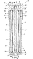
上記除湿エレメント1は、図3乃至図6に示すように、軸L方向に延びる中空の円筒形に形成され、その軸L方向両端の第1及び第2端部23,24に、第1及び第2筒開口部21,22をそれぞれ有する筒状ケース2と、該筒状ケース2内に上記軸L方向に沿って収容された複数の中空糸膜3と、上記筒状ケース2よりも小径の円筒形を成して該筒状ケース2内に同軸に収容され、その軸L方向両端の第1及び第2端部43,44に、第1及び第2管開口部41,42をそれぞれ有する中空の内管4とを備えている。すなわち、本実施形態において、上記第1及び第2筒開口部21,22は、上記筒状ケース2の第1端部23と上記内管4の第1端部43との間、及び、該筒状ケース2の第2端部24と該内管4の第2端部44との間に、それぞれ環状に形成されている。
As shown in FIGS. 3 to 6, the dehumidifying element 1 is formed in a hollow cylindrical shape extending in the axis L direction, and the first and second
筒状ケース2の第1及び第2端部23,24には、上記第1及び第2筒開口部21,22に嵌合されてそれらを閉塞する断面環状の第1及び第2ポッティング材5,6がそれぞれ設けられている。第1ポッティング材5には、上記中空糸膜3の第1端部33が軸L方向に貫通して上記第1筒開口部21に至ることにより固定され、上記内管4の第1端部43も同じく軸L方向に気密に貫通することにより固定されている。その一方で、第2ポッティング材6には、上記中空糸膜3の第2端部34が軸L方向に貫通して上記第2筒開口部21に至ることにより固定され、上記内管4の第2端部44も同じく軸L方向に気密に貫通することにより固定されている。そして、径方向における筒状ケース2と内管4との間であって、軸L方向における第1ポッティング材5と第2ポッティング材6との間に形成された空間が、そこに収容された複数の中空糸膜3によって上記被除湿エアを除湿するための断面環状の除湿用空間7を成している。
The first and
また、上記筒状ケース2内の除湿用空間7には、ガイド部材47としてのガイド板が複数(本実施形態では8枚)、放射状に配置されている。これらガイド部材47は、上記空間7において、複数の中空糸膜3を複数の束に分けて位置決めして偏在することなく略均等に配置するためのもので、図6に示すように、この空間7を上記軸L方向から見たときに、該空間内7に周方向に沿って複数(本実施形態では8つ)の領域を形成している。
Further, in the
より具体的には、これらガイド板47は、筒状ケース2の軸L方向を長手とし径方向を短手とする長方形に形成されていて、上記除湿用空間7全体を軸L方向から見たときに、等角度間隔で放射方向に配置され、実質的に等面積の扇状領域を複数(本実施形態では8つ)形成している。そして、上記複数の中空糸膜3が捩じりを加えていない略均等な束に分けられて、これら中空糸膜3の束が上記複数の領域にそれぞれ配置されている。また、これらガイド板47の短手の幅は、上記筒状ケース2の内側壁と内管4の外側壁と間の距離よりも若干小さくなっていて、それにより、これらガイド板47の幅方向両側端と上記筒状ケース2の内側壁及び内管4の外側壁との間には、それぞれ若干の隙間49が形成されている。ただし、本実施形態のように、後述するパージエアの給気孔35と排気孔36との対が上記各領域にそれぞれ開設されているのであれば、この隙間49は必ずしも形成されていなくてもよい。
More specifically, these
本実施形態において、上記複数のガイド板47の上記筒状ケース2及び内管4に対する取り付けは、上記筒状ケース2の第1及び第2端部23,24の内側壁にそれぞれ気密に嵌着された一対の外環リング25a,25bと、上記内管4の第1及び第2端部43,44の外側壁にそれぞれ気密に嵌着された一対の内環リング45a,45bとによって為されている。これら外環リング25a,25bの内周、及び、内環リング45a,45bの外周には、図4及び図5に示すように、周方向(軸L周り)に延びて上下方向(軸L方向)に並設された複数(本実施形態では2本)の環状溝26a,46aと、上下方向に延びて周方向に並設された上記ガイド板47と同数(本実施形態では8本)の位置決め溝26b,46bとが、それぞれ形成されている。このとき、上記外環リング25a,25b及び内環リング45a,45bの各位置決め溝26b,46bは、上記軸Lを中心とした同じ角度位置に互いに対向してそれぞれ形成されている。
In the present embodiment, the plurality of
このような構成を有する外環リング25a,25b及び内環リング45a,45bは、それらの環状溝26a,46aに上記第1及び第2ポッティング材5,6が侵入して、該ポッティング材5,6に対し軸L方向に係止された状態で、その外周壁及び内周壁にそれぞれ嵌着されている。そして、図4及び図5に示すように、上記ガイド板47の長手方向両端におけるポッティング材5,6に埋設された第1及び第2端部47a,47bの幅方向両側端が、上記外環リング25a,25b及び内環リング45a,45bの各位置決め溝26b,46bに嵌合され、それにより、これらガイド板7が、上述のように放射状に位置決めされた状態で、該ポッティング材5,6に対して固定されている。その結果、本実施形態においては、上記ガイド板47が、除湿用空間7の軸L方向全体に亘って延設された状態となっている。
In the outer ring rings 25a and 25b and the inner ring rings 45a and 45b having such a configuration, the first and
また、上記筒状ケース2の第1及び第2端部23,24の内側壁には、それぞれ環状段部23a,24aが形成されていて、これら環状段部23a,24aに上記外環リング25a,25bがそれぞれ嵌合されている。そうすることで、上記筒状ケース2内に収容された上記中空糸膜3やポッティング材5,6やガイド板47等の内容物が、軸L方向において該筒状ケース2に対し固定されている。
なお、上記ガイド板47は、例えば内管4と一体に形成されていてもよく、この場合、このような内環リング45a,45bは必ずしも設ける必要性はない。
In addition,
Incidentally, the
さらに、上記除湿エレメント1には、上記パージ流路58に接続されてパージエアを上記除湿用空間7に供給するための給気孔35と、該除湿用空間7からの上記パージエアを外部に排出するための排気孔36とが、上記除湿用空間7の軸L方向一端側と他端側とにそれぞれ開設されている。具体的には、これら給気孔35及び排気孔36は、上記筒状ケース2に開設されており、除湿エレメント1の軸L方向中央O(すなわち、除湿用空間7の軸方向中央O)と第1ポッティング材5との間、及び該中央Oと第2ポッテイング材6との間とにそれぞれ開設されている。
Further, the dehumidifying element 1 has an
そして、上記給気孔35及び排気孔36の対が、上記筒状ケース2の周方向に等角度間隔(本実施形態では45度間隔)で開設されていて、それにより、上記複数のガイド板47によって上記除湿用空間7に形成された複数の領域(本実施形態では8つの領域)にそれぞれ設けられている。また、排気孔36は給気孔35よりも大径すなわち大面積に形成されていて、それにより、除湿用空間7内を流通するパージエアの圧力上昇を防止することができるようになっている。このように、上記オリフィス59の作用と共に除湿用空間7内におけるパージエアの圧力をより低く保つことにより、中空糸膜3内を流通する被除湿エアの水蒸気を効率よく中空糸膜3の外側に透過させることが可能となり、その結果、除湿エレメント1の除湿効率が向上する。ただし、給気孔35と排気孔36の大きさは必ずしも異なっている必要性はなく、互いに同じ大きさであってもよい。
Then, said pair of air supply holes 35 and discharge holes 36, have been opened at equal angular intervals (45 degree intervals in the present embodiment) in the circumferential direction of the
また、図1に示すように、上記内管4内には、上記第1及び第2キャップ部材51,52を上記除湿エレメント1に対して固定するための連結ロッド61が軸方向に沿って挿通されており、この連結ロッド61における軸L方向両端には、第1及び第2雄ネジ部62,63がそれぞれ形成されている。その一方で、上記第1キャップ部材51には、その内面側に第1雌ネジ部64が形成され、また、上記第2キャップ部材52は環状に形成されていて、その中央の穴に、第2雌ネジ部65を備えた締結ボルト66の該雌ネジ部65が挿通されている。そして、上記締結ロッド61の第1雄ネジ部62を上記第1雌ネジ部64に螺合させると共に、第2雄ネジ部63を上記第2雌ネジ部65に螺合させて、上記締結ボルト66で気密に締結することにより、上記第1及び第2キャップ部材51,52と除湿エレメント1とが共締めされている。
Further, as shown in FIG. 1, a connecting
次に、この除湿装置50内に形成された被除湿エア、除湿後の乾燥エア及びパージエアの流路構成、及びその作用効果について具体的に説明する。
上記第1キャップ部材51に形成された導入流路55は、上記除湿エレメント1に設けられた内管4の第1管開口部41に対し接続されている。
その一方で、上記第2キャップ部材52の内面側には凹部が形成されており、それによって形成された接続流路60により、上記内管4の第2管開口部42が、該第2管開口部42と径方向において隣接して上記複数の中空糸膜3が開口した上記第2筒開口部22に対し接続されている。
Next, the flow path configurations of the dehumidified air formed in the
The
On the other hand, a recess is formed on the inner surface side of the
そして、同じく上記第1管開口部41と径方向において隣接して上記複数の中空糸膜3が開口した上記第1筒開口部21に対し、上記第1キャップ部材51に形成された導出流路56が接続されている。このとき、上記第1筒開口部21と第1管開口部41とは、上記第1キャップ部材51によって気密に分離されている。
さらに、上述したように、上記導出流路56から分岐されたパージ流路58が、上記給気孔35を通じて上記除湿用空間7に対し接続されており、また同時に、該除湿用空間7は、上記排気孔36を通じて大気に開放されている。
Then, a lead-out flow path formed in the
Further, as described above, the
このような流路構成を備えて成る上記除湿装置50において、上記第1キャップ部材51の導入ポート53に接続された配管(図示省略)から、上記導入流路55に流入した高湿の被除湿エアは、上記内管4を通じて上記第2キャップ部材52の接続流路60へと導かれる。
次に、この被除湿エアは、該接続流路60で反転して上記除湿エレメント1の第2筒開口部22から上記複数の中空糸膜3内へと導入され、これら中空糸膜3内を流れる間に、上記除湿用空間7において、これら中空糸膜3の周囲を流れるパージエアとの水蒸気分圧差(水蒸気の濃度差)によって除湿される。すなわち、上記水蒸気分圧差によって、上記複数の中空糸膜内の被除湿エアに含まれる水蒸気が該中空糸膜の外側へと透過し、その透過した水蒸気を上記パージエアが取り去ることで、該被除湿エアが除湿される。
In the
Next, the dehumidified air is inverted in the
そして、除湿後の乾燥エアが、上記除湿エレメント1の第1筒開口部21から導出流路56へと流出し、上記導出ポート54に接続された配管(図示省略)を通じて所望の空圧機器等へと出力される。また、上記導出流路56を流れる除湿後の乾燥エアの一部が、該導出流路56から上記パージエアとして分岐され、上記オリフィス59で減圧されたうえで、上記パージ流路58及び給気孔35を通じて上記除湿エレメント1の除湿用空間7内へと供給される。そして、そのパージエアは、該除湿用空間内を軸Lに沿って流通しながら、上記中空糸膜3の外側へと透過した上記被除湿エアの水蒸気を取り去ったうえで、上記排気孔36を通じて大気へと排気される。
Then, the dried air after dehumidification flows out from the
このとき、除湿用空間7は、放射状に配置された複数(本実施形態では8枚)のガイド板47によって、それと同数(本実施形態では8つ)の領域に分けられており、該除湿用空間7において、上記複数の中空糸膜3が、これら領域のそれぞれに略均等に分配された状態で収容されている。そのため、上記除湿用空間7における中空糸膜3の偏在を抑制して、上記パージエアと中空糸膜3との接触面積をより大きく確保することが可能となる。その結果、上記中空糸膜3の外側へと透過した上記被除湿エアの水蒸気を、パージエアによってより効率よく取り去ることが可能となり、除湿効率の低下を防止することができる。しかも、上記ガイド板47によって形成された各領域に、上記給気孔35と排気孔36との対をそれぞれ設けたため、パージエアの流れもより均一化され、上記水蒸気をさらに効率よく取り去って排出することが可能となる。
At this time, the
以上、本発明に係る除湿エレメント及びそれを用いた除湿装置について詳細に説明してきたが、本発明は上記の実施形態に限定されるものではなく、特許請求の範囲の趣旨を逸脱しない範囲で様々な設計変更が可能であることは言うまでもない。 Although the dehumidifying element and the dehumidifying device using the dehumidifying element according to the present invention have been described in detail above, the present invention is not limited to the above embodiment and varies within the scope of the claims. Needless to say, it is possible to make various design changes.
例えば、本実施形態では、ガイド部材として、放射方向に延びる複数のガイド板47を用いた除湿エレメント1について説明しているが、ガイド部材は、筒状ケース2の除湿用空間7全体を軸L方向から見たときに、該除湿用空間7内に複数の領域を形成するように配置されていれば他の構成であってもよい。例えば、ガイド部材47は、除湿用空間7を軸L方向から見たときに放射状に配置されるように、軸L方向に沿って螺旋状に内管4の外側壁から立設された棒状の複数のガイドピンであってもよい。この場合は、軸L方向から見たときに互いに隣接するガイドピンによって形成された複数の領域に、上記複数の中空糸膜3をそれぞれ分配して位置決めされた状態で収容することができ、その結果、除湿用空間7内における中空糸膜3の偏在を抑制することができる。
For example, in the present embodiment, the dehumidifying element 1 using a plurality of
また、本実施形態では、パージエアを除湿用空間7に対して給排する給気孔35及び排気孔36の対が、ガイド板47によって分けられた各領域毎に開設されているが、除湿用空間7において、各領域間におけるパージエアの流通や、給気孔35及び排気孔36からのパージエアーの円滑な給排さえ十分に確保されていれば、これら孔35,36の対の数を上記領域の数よりも少なくしたり、これら孔35,36の数を互いに異ならせたり等してもよい。
Further, in the present embodiment, a pair of air supply holes 35 and
そして、本実施形態では、第1キャップ部材51に被除湿エアの導入流路55と乾燥エアの導出流路56の双方を設けているが、第1キャップ部材51に導入流路55及び導出流路56の何れか一方の流路を設け、第2キャップ部材52に何れか他方の流路を設けたりしてもよい。その場合、上記除湿エレメント1においては、上記内管4は省略してもよいし、該内管4の一端を気密に閉塞するなどして、該内管4をパージ流路58として利用し、該内管4に上記パージエアの給気孔35を開設してもよい。また、上記各キャップ部材51,52は、上記除湿エレメント1に対して必ずしも着脱可能でなくてもよい。
さらに、上記ガイド部材47は、除湿用空間7を軸L方向から見たときに、必ずしも軸Lを中心とした放射方向に配されている必要性はなく、例えば格子状に配置されていてもよい。
In the present embodiment, the
Further, the
1 除湿エレメント
2 筒状ケース
3 中空糸膜
4 内管
5 第1ポッティング材
6 第2ポッティング材
7 除湿用空間
21 筒状ケースの第1筒開口部
22 筒状ケースの第2筒開口部
23 筒状ケースの第1端部
24 筒状ケースの第2端部
23a,24a 環状段部
25a,25b 外環リング
26a 外環リングの環状溝
26b 外環リングの位置決め溝
33 中空糸膜の第1端部
34 中空糸膜の第2端部
35 パージエアの給気孔
36 パージエアの排気孔
41 内管の第1管開口部
42 内管の第2管開口部
43 内管の第1端部
44 内管の第2端部
45a,45b 内環リング
46a 内環リングの環状溝
46b 内環リングの位置決め溝
47 ガイド板(ガイド部材)
47a ガイド板の第1端部
47b ガイド板の第2端部
49 隙間
50 除湿装置
51 第1キャップ部材
52 第2キャップ部材
53 導入ポート
54 導出ポート
55 導入流路
56 導出流路
58 パージ流路
59 オリフィス
60 接続流路
61 連結ロッド
62 第1雄ネジ部
63 第2雄ネジ部
64 第1雌ネジ部
65 第2雌ネジ部
66 締結ボルト
L 軸
O 軸方向中央
1
47a 1st end of
Claims (9)
該筒状ケース内にその軸方向に沿って収容され、被除湿エアを流通させるための複数の中空糸膜と、
それら中空糸膜の両端部が貫通して固定されると共に、上記筒状ケースの各筒開口部をそれぞれ閉塞する一対のポッティング材と、
上記筒状ケース内における一対のポッティング材の間に形成された除湿用空間と、
該除湿用空間に対してパージエアを供給するための給気孔と、
上記除湿用空間から上記パージエアを排出するための排気孔と、
を備えた除湿エレメントであって、
上記筒状ケース内における上記除湿用空間には、上記軸方向から見たときに複数の領域を形成するように配置されたガイド部材が設けられており、
上記複数の中空糸膜が、上記複数の領域にそれぞれ分配された状態で該除湿用空間に直接収容され、
上記給気孔と排気孔との対は、上記ガイド部材によって分けられた複数の領域にそれぞれ一対ずつ設けられ、
上記領域は、上記給気孔と排気孔との間で一続きに連続している、
ことを特徴とするもの。 A hollow tubular case with tubular openings at both ends in the axial direction,
A plurality of hollow fiber membranes housed in the tubular case along the axial direction and for circulating dehumidified air, and
A pair of potting materials that penetrate and fix both ends of the hollow fiber membrane and close each tubular opening of the tubular case,
A dehumidifying space formed between a pair of potting materials in the tubular case,
An air supply hole for supplying purge air to the dehumidifying space,
An exhaust hole for discharging the purge air from the dehumidifying space,
It is a dehumidifying element equipped with
The dehumidifying space in the tubular case is provided with a guide member arranged so as to form a plurality of regions when viewed from the axial direction.
The plurality of hollow fiber membranes are directly housed in the dehumidifying space in a state of being distributed to the plurality of regions .
A pair of the air supply hole and the exhaust hole is provided in each of a plurality of regions divided by the guide member.
The region is continuous and continuous between the air supply hole and the exhaust hole.
What is characterized by that.
上記給気孔が上記除湿用空間における軸方向中央よりも一方のポッティング材側に開設され、上記排気孔が該除湿用空間における軸方向中央よりも他方のポッティング材側に開設されている、
ことを特徴とするもの。 The dehumidifying element according to claim 1.
The air supply hole is opened on one potting material side with respect to the axial center in the dehumidifying space, and the exhaust hole is opened on the other potting material side with respect to the axial center in the dehumidifying space.
What is characterized by that.
上記給気孔及び排気孔は上記筒状ケースに開設されている、
ことを特徴とするもの。 The dehumidifying element according to claim 2.
The air supply hole and the exhaust hole are provided in the tubular case.
What is characterized by that.
上記排気孔は、上記給気孔よりも大径である、
ことを特徴とするもの。 The dehumidifying element according to any one of claims 1 to 3.
The exhaust hole has a larger diameter than the air supply hole.
What is characterized by that.
複数の上記ガイド部材が、上記筒状ケースの軸方向から見たときに、放射方向に向けて配されている、
ことを特徴とするもの。 The dehumidifying element according to any one of claims 1 to 4.
A plurality of the guide members are arranged in the radial direction when viewed from the axial direction of the tubular case.
What is characterized by that.
上記ガイド部材は、上記筒状ケースの軸方向に延設されたガイド板である、
ことを特徴とするもの。 The dehumidifying element according to claim 5.
The guide member is a guide plate extending in the axial direction of the tubular case.
What is characterized by that.
上記複数のガイド板が、上記軸方向において上記除湿用空間全体に亘って延設されている、
ことを特徴とするもの。 The dehumidifying element according to claim 6 .
The plurality of guide plates extend over the entire dehumidifying space in the axial direction.
What is characterized by that.
上記筒状ケース内に、両端に一対の管開口部をそれぞれ有する中空の内管が、上記軸方向に沿って収容されていて、
上記内管の両端部が、上記一対のポッティング材を貫通しており、
上記内菅と筒状ケースとの間に、上記除湿用空間が形成されている、
ことを特徴とするもの。 The dehumidifying element according to any one of claims 1 to 7 .
A hollow inner tube having a pair of tube openings at both ends is housed in the tubular case along the axial direction.
Both ends of the inner pipe penetrate the pair of potting materials.
The dehumidifying space is formed between the inner tube and the tubular case.
What is characterized by that.
上記筒状ケースの軸方向の両端には、それぞれキャップ部材が取り付けられていて、
これらキャップ部材には、
上記被除湿エアを外部から入力するための導入ポートを有して、該被除湿エアを上記筒開口部の一方に対して供給する導入流路と、
除湿後の乾燥エアを外部へと出力するための導出ポートを有して、上記筒開口部の他方からの上記乾燥エアを上記導出ポートへと導く導出流路と、
該導出流路から分岐されて、上記乾燥エアの一部を上記パージエアとして上記給気孔に対して供給するパージ流路と、
が設けられていることを特徴とするもの。 A dehumidifying device having the dehumidifying element according to any one of claims 1 to 8 .
Cap members are attached to both ends of the tubular case in the axial direction.
For these cap members,
An introduction flow path having an introduction port for inputting the dehumidified air from the outside and supplying the dehumidified air to one of the cylinder openings.
A lead-out flow path that has a lead-out port for outputting the dehumidified dry air to the outside and guides the dry air from the other side of the cylinder opening to the lead-out port.
A purge flow path that is branched from the lead-out flow path and supplies a part of the dry air as the purge air to the air supply hole.
The feature is that is provided.
Priority Applications (7)
| Application Number | Priority Date | Filing Date | Title |
|---|---|---|---|
| JP2016218146A JP6780817B2 (en) | 2016-11-08 | 2016-11-08 | Dehumidifying element and dehumidifying device with it |
| EP17869975.7A EP3539643B1 (en) | 2016-11-08 | 2017-11-02 | Dehumidifying element and dehumidifying device having same |
| KR1020197013660A KR102432606B1 (en) | 2016-11-08 | 2017-11-02 | Dehumidifying element and dehumidifying device having same |
| PCT/JP2017/039658 WO2018088310A1 (en) | 2016-11-08 | 2017-11-02 | Dehumidifying element and dehumidifying device having same |
| US16/342,583 US11141693B2 (en) | 2016-11-08 | 2017-11-02 | Dehumidifying element and dehumidifying device having same |
| CN201780068586.7A CN109922874B (en) | 2016-11-08 | 2017-11-02 | Dehumidifying element and dehumidifying device with the same |
| TW106138020A TWI765930B (en) | 2016-11-08 | 2017-11-03 | Dehumidification element and dehumidification apparatus having the same |
Applications Claiming Priority (1)
| Application Number | Priority Date | Filing Date | Title |
|---|---|---|---|
| JP2016218146A JP6780817B2 (en) | 2016-11-08 | 2016-11-08 | Dehumidifying element and dehumidifying device with it |
Publications (3)
| Publication Number | Publication Date |
|---|---|
| JP2018075513A JP2018075513A (en) | 2018-05-17 |
| JP2018075513A5 JP2018075513A5 (en) | 2019-07-11 |
| JP6780817B2 true JP6780817B2 (en) | 2020-11-04 |
Family
ID=62110544
Family Applications (1)
| Application Number | Title | Priority Date | Filing Date |
|---|---|---|---|
| JP2016218146A Active JP6780817B2 (en) | 2016-11-08 | 2016-11-08 | Dehumidifying element and dehumidifying device with it |
Country Status (7)
| Country | Link |
|---|---|
| US (1) | US11141693B2 (en) |
| EP (1) | EP3539643B1 (en) |
| JP (1) | JP6780817B2 (en) |
| KR (1) | KR102432606B1 (en) |
| CN (1) | CN109922874B (en) |
| TW (1) | TWI765930B (en) |
| WO (1) | WO2018088310A1 (en) |
Families Citing this family (3)
| Publication number | Priority date | Publication date | Assignee | Title |
|---|---|---|---|---|
| CN109045952B (en) * | 2018-07-03 | 2020-11-27 | 华南理工大学 | Novel gas-liquid membrane contactor |
| CN108993103B (en) * | 2018-09-30 | 2023-11-10 | 天津华电北宸分布式能源有限公司 | Dehumidification filter equipment |
| CN115282746A (en) * | 2022-08-04 | 2022-11-04 | 中元汇吉生物技术股份有限公司 | Dehumidification subassembly, cylinder dehumidification subassembly and analysis appearance |
Family Cites Families (31)
| Publication number | Priority date | Publication date | Assignee | Title |
|---|---|---|---|---|
| FR2231421B1 (en) * | 1973-05-30 | 1976-05-07 | Rhone Poulenc Ind | |
| JPH0641629Y2 (en) * | 1988-11-21 | 1994-11-02 | シーケーディ株式会社 | Dehumidifier |
| JP2932394B2 (en) | 1989-08-23 | 1999-08-09 | 旭化成工業株式会社 | Hollow fiber membrane separation module and hollow fiber membrane separation device |
| US5176725A (en) | 1991-07-26 | 1993-01-05 | Air Products And Chemicals, Inc. | Multiple stage countercurrent hollow fiber membrane module |
| JPH0641629U (en) | 1992-11-19 | 1994-06-03 | タイジ株式会社 | Onsen |
| US5525143A (en) * | 1994-10-17 | 1996-06-11 | Air Products And Chemicals, Inc. | Hollow fiber membrane dryer with internal sweep |
| JPH0957043A (en) * | 1995-08-29 | 1997-03-04 | Kuroda Precision Ind Ltd | Air dehumidifier |
| JP3727723B2 (en) * | 1996-07-15 | 2005-12-14 | 株式会社東芝 | Exhaust gas dryer |
| JPH1133338A (en) | 1997-07-16 | 1999-02-09 | Kuroda Precision Ind Ltd | Membrane dryer |
| FR2802444B1 (en) * | 1999-12-16 | 2002-06-14 | Polymen | HOLLOW FIBER WATER FILTRATION MODULE |
| JP2001219026A (en) * | 2000-02-09 | 2001-08-14 | Nabco Ltd | Dehumidifier |
| DE10106722B4 (en) | 2001-02-14 | 2008-11-06 | Fraunhofer-Gesellschaft zur Förderung der angewandten Forschung e.V. | Special hollow fiber membrane module for use in heavily fouled processes and its production |
| US6755894B2 (en) * | 2001-05-02 | 2004-06-29 | Praxair Technology, Inc. | Hollow fiber membrane gas separation cartridge and gas purification assembly |
| JP2002358988A (en) * | 2001-06-01 | 2002-12-13 | Honda Motor Co Ltd | Hollow fiber module |
| JP3834537B2 (en) * | 2002-08-30 | 2006-10-18 | ダイセン・メンブレン・システムズ株式会社 | Reinforcing material for hollow fiber membrane bundle |
| KR100535301B1 (en) * | 2003-05-13 | 2005-12-08 | 연세대학교 산학협력단 | Hollow fiber membrane module and Method for making thereof |
| EP2567747B1 (en) | 2003-09-29 | 2014-11-12 | Asahi Kasei Chemicals Corporation | External pressure type hollow fiber membrane module with fibre density distribution. |
| JP2006006989A (en) * | 2004-06-22 | 2006-01-12 | Anest Iwata Corp | Hollow fiber membrane type air dryer |
| JP2007029794A (en) * | 2005-07-22 | 2007-02-08 | Koganei Corp | Air dryer |
| EP2172255A4 (en) * | 2007-07-02 | 2012-09-26 | Toshiba Kk | Hollow fiber membrane dehumidifier |
| US20090049983A1 (en) * | 2007-08-22 | 2009-02-26 | Flair Corporation, A Delaware Corporation | Energy management system for membrane separation device |
| CN201744280U (en) * | 2010-03-19 | 2011-02-16 | 张隆华 | High molecular hollow membrane compressed gas dehumidifier |
| CN101856594A (en) * | 2010-06-25 | 2010-10-13 | 苏州顶裕节能设备有限公司 | Hollow fiber ultra-filtration film component with crisscross separating film |
| WO2012091070A1 (en) * | 2010-12-27 | 2012-07-05 | 旭化成ケミカルズ株式会社 | Adsorption/separation membrane module, method for producing adsorption/separation membrane module, and partition member |
| CN202336281U (en) * | 2011-09-09 | 2012-07-18 | 中国船舶重工集团公司第七一八研究所 | Membrane dryer with blowing and sweeping air distribution structure |
| ES2626754T3 (en) * | 2012-11-26 | 2017-07-25 | Gambro Lundia Ab | Adsorption device that combines beads and hollow fiber membranes |
| KR101459455B1 (en) * | 2012-12-12 | 2014-11-07 | 현대자동차 주식회사 | Humidifying apparatus and method of fuel cell |
| TWI511774B (en) * | 2012-12-20 | 2015-12-11 | Ind Tech Res Inst | Dehumidification system |
| DE102014104386B4 (en) * | 2014-03-28 | 2019-03-14 | Beko Technologies Gmbh | Housing head with purge air controller |
| CN103920375B (en) * | 2014-04-25 | 2016-08-24 | 中山大学 | One utilizes capillary power-actuated hollow-fibre membrane liquid dehumidifying device |
| WO2015168392A1 (en) * | 2014-05-01 | 2015-11-05 | Sabic Global Technologies B.V. | Skinned, asymmetric poly(phenylene ether) co-polymer membrane; gas separation unit, and preparation method thereof |
-
2016
- 2016-11-08 JP JP2016218146A patent/JP6780817B2/en active Active
-
2017
- 2017-11-02 CN CN201780068586.7A patent/CN109922874B/en active Active
- 2017-11-02 US US16/342,583 patent/US11141693B2/en active Active
- 2017-11-02 EP EP17869975.7A patent/EP3539643B1/en active Active
- 2017-11-02 KR KR1020197013660A patent/KR102432606B1/en active IP Right Grant
- 2017-11-02 WO PCT/JP2017/039658 patent/WO2018088310A1/en unknown
- 2017-11-03 TW TW106138020A patent/TWI765930B/en active
Also Published As
| Publication number | Publication date |
|---|---|
| US20200179871A1 (en) | 2020-06-11 |
| TW201829048A (en) | 2018-08-16 |
| EP3539643B1 (en) | 2022-03-23 |
| CN109922874B (en) | 2021-12-24 |
| TWI765930B (en) | 2022-06-01 |
| EP3539643A4 (en) | 2020-06-17 |
| KR102432606B1 (en) | 2022-08-16 |
| KR20190077402A (en) | 2019-07-03 |
| JP2018075513A (en) | 2018-05-17 |
| WO2018088310A1 (en) | 2018-05-17 |
| CN109922874A (en) | 2019-06-21 |
| US11141693B2 (en) | 2021-10-12 |
| EP3539643A1 (en) | 2019-09-18 |
Similar Documents
| Publication | Publication Date | Title |
|---|---|---|
| JP6780817B2 (en) | Dehumidifying element and dehumidifying device with it | |
| WO2021065889A1 (en) | Gas separation membrane module | |
| JP2012223765A5 (en) | ||
| US20100107880A1 (en) | Hollow fiber membrane dehumidifier | |
| US20160074795A1 (en) | Filter elements and a filter device having at least one filter element | |
| JP2018075513A5 (en) | ||
| EP3434349B1 (en) | Fluid degassing systems | |
| EP1390117B1 (en) | Media bed support grid | |
| KR101193732B1 (en) | Purifying Filter Structure for Waters with Enlarged Filtration Area | |
| JP7361770B2 (en) | Device for substance exchange between blood and at least one gas/gas mixture | |
| EP2226112A2 (en) | Air Dryer for Electrical Enclosures | |
| JP2010127583A (en) | Humidifying device | |
| JPH03110A (en) | Separation membrane module | |
| JP2017056369A (en) | Separation membrane module | |
| EP3434350A1 (en) | Fluid degassing systems | |
| ES2712146B2 (en) | Flow separation system in multifilter equipment | |
| KR100936165B1 (en) | Interlayer assembly for an air pressure type moisture remover | |
| KR102149212B1 (en) | Shell and tube heat exchanger | |
| RU2019278C1 (en) | Apparatus for scrubbing gases | |
| US625809A (en) | Conrad schwager | |
| JP3082183U (en) | Dehumidifier | |
| EP1541212B1 (en) | Media bed support grid | |
| IT202100013712A1 (en) | DISTRIBUTION UNITS, PARTICULARLY FOR AIR DISTRIBUTION IN VENTILATION SYSTEMS | |
| JPH08290033A (en) | Membrane type dehumidifier | |
| JP2021030095A (en) | Hollow fiber membrane module for dehumidification |
Legal Events
| Date | Code | Title | Description |
|---|---|---|---|
| A521 | Request for written amendment filed |
Free format text: JAPANESE INTERMEDIATE CODE: A523 Effective date: 20190607 |
|
| A621 | Written request for application examination |
Free format text: JAPANESE INTERMEDIATE CODE: A621 Effective date: 20190607 |
|
| A131 | Notification of reasons for refusal |
Free format text: JAPANESE INTERMEDIATE CODE: A131 Effective date: 20200609 |
|
| A521 | Request for written amendment filed |
Free format text: JAPANESE INTERMEDIATE CODE: A523 Effective date: 20200803 |
|
| TRDD | Decision of grant or rejection written | ||
| A01 | Written decision to grant a patent or to grant a registration (utility model) |
Free format text: JAPANESE INTERMEDIATE CODE: A01 Effective date: 20200915 |
|
| A61 | First payment of annual fees (during grant procedure) |
Free format text: JAPANESE INTERMEDIATE CODE: A61 Effective date: 20201001 |
|
| R150 | Certificate of patent or registration of utility model |
Ref document number: 6780817 Country of ref document: JP Free format text: JAPANESE INTERMEDIATE CODE: R150 |
|
| R250 | Receipt of annual fees |
Free format text: JAPANESE INTERMEDIATE CODE: R250 |