JP6768343B2 - Image processing equipment, image processing methods and programs - Google Patents
Image processing equipment, image processing methods and programs Download PDFInfo
- Publication number
- JP6768343B2 JP6768343B2 JP2016093162A JP2016093162A JP6768343B2 JP 6768343 B2 JP6768343 B2 JP 6768343B2 JP 2016093162 A JP2016093162 A JP 2016093162A JP 2016093162 A JP2016093162 A JP 2016093162A JP 6768343 B2 JP6768343 B2 JP 6768343B2
- Authority
- JP
- Japan
- Prior art keywords
- value
- color
- ink
- image processing
- change characteristic
- Prior art date
- Legal status (The legal status is an assumption and is not a legal conclusion. Google has not performed a legal analysis and makes no representation as to the accuracy of the status listed.)
- Active
Links
Images


Classifications
-
- H—ELECTRICITY
- H04—ELECTRIC COMMUNICATION TECHNIQUE
- H04N—PICTORIAL COMMUNICATION, e.g. TELEVISION
- H04N1/00—Scanning, transmission or reproduction of documents or the like, e.g. facsimile transmission; Details thereof
- H04N1/46—Colour picture communication systems
- H04N1/56—Processing of colour picture signals
- H04N1/60—Colour correction or control
- H04N1/6016—Conversion to subtractive colour signals
- H04N1/6019—Conversion to subtractive colour signals using look-up tables
-
- H—ELECTRICITY
- H04—ELECTRIC COMMUNICATION TECHNIQUE
- H04N—PICTORIAL COMMUNICATION, e.g. TELEVISION
- H04N1/00—Scanning, transmission or reproduction of documents or the like, e.g. facsimile transmission; Details thereof
- H04N1/46—Colour picture communication systems
- H04N1/52—Circuits or arrangements for halftone screening
-
- G—PHYSICS
- G06—COMPUTING; CALCULATING OR COUNTING
- G06K—GRAPHICAL DATA READING; PRESENTATION OF DATA; RECORD CARRIERS; HANDLING RECORD CARRIERS
- G06K15/00—Arrangements for producing a permanent visual presentation of the output data, e.g. computer output printers
- G06K15/02—Arrangements for producing a permanent visual presentation of the output data, e.g. computer output printers using printers
- G06K15/18—Conditioning data for presenting it to the physical printing elements
- G06K15/1867—Post-processing of the composed and rasterized print image
- G06K15/1872—Image enhancement
- G06K15/1878—Adjusting colours
-
- H—ELECTRICITY
- H04—ELECTRIC COMMUNICATION TECHNIQUE
- H04N—PICTORIAL COMMUNICATION, e.g. TELEVISION
- H04N1/00—Scanning, transmission or reproduction of documents or the like, e.g. facsimile transmission; Details thereof
- H04N1/46—Colour picture communication systems
- H04N1/56—Processing of colour picture signals
- H04N1/60—Colour correction or control
- H04N1/6002—Corrections within particular colour systems
- H04N1/6008—Corrections within particular colour systems with primary colour signals, e.g. RGB or CMY(K)
-
- H—ELECTRICITY
- H04—ELECTRIC COMMUNICATION TECHNIQUE
- H04N—PICTORIAL COMMUNICATION, e.g. TELEVISION
- H04N1/00—Scanning, transmission or reproduction of documents or the like, e.g. facsimile transmission; Details thereof
- H04N1/46—Colour picture communication systems
- H04N1/56—Processing of colour picture signals
- H04N1/60—Colour correction or control
- H04N1/6027—Correction or control of colour gradation or colour contrast
-
- G—PHYSICS
- G06—COMPUTING; CALCULATING OR COUNTING
- G06K—GRAPHICAL DATA READING; PRESENTATION OF DATA; RECORD CARRIERS; HANDLING RECORD CARRIERS
- G06K15/00—Arrangements for producing a permanent visual presentation of the output data, e.g. computer output printers
- G06K15/02—Arrangements for producing a permanent visual presentation of the output data, e.g. computer output printers using printers
- G06K15/10—Arrangements for producing a permanent visual presentation of the output data, e.g. computer output printers using printers by matrix printers
- G06K15/102—Arrangements for producing a permanent visual presentation of the output data, e.g. computer output printers using printers by matrix printers using ink jet print heads
- G06K15/105—Multipass or interlaced printing
-
- H—ELECTRICITY
- H04—ELECTRIC COMMUNICATION TECHNIQUE
- H04N—PICTORIAL COMMUNICATION, e.g. TELEVISION
- H04N2201/00—Indexing scheme relating to scanning, transmission or reproduction of documents or the like, and to details thereof
- H04N2201/0077—Types of the still picture apparatus
- H04N2201/0082—Image hardcopy reproducer
Landscapes
- Engineering & Computer Science (AREA)
- Multimedia (AREA)
- Signal Processing (AREA)
- Physics & Mathematics (AREA)
- Theoretical Computer Science (AREA)
- General Physics & Mathematics (AREA)
- General Engineering & Computer Science (AREA)
- Facsimile Image Signal Circuits (AREA)
- Color Image Communication Systems (AREA)
- Ink Jet (AREA)
- Particle Formation And Scattering Control In Inkjet Printers (AREA)
- Color, Gradation (AREA)
- Image Processing (AREA)
- Mathematical Physics (AREA)
Description
本発明は、入力画像信号を、出力デバイスが扱う複数の色成分に対応する信号に変換する画像処理に関する。 The present invention relates to image processing that converts an input image signal into a signal corresponding to a plurality of color components handled by an output device.
インクジェット方式や電子写真方式に代表されるプリンタは、画像信号(通常はRGBの色信号)を入力として受け取り、その色信号をプリンタに搭載された色材の量を表す信号に変換することで印刷データを生成している。この変換は一般的に、色分解処理あるいは色変換処理と呼ばれており、入力画像の信号成分に応じた次元数の多次元LUTと補間処理とを組み合わせたものがある。 Printers typified by the inkjet method and electrophotographic method print by receiving an image signal (usually an RGB color signal) as an input and converting the color signal into a signal representing the amount of color material mounted on the printer. Generating data. This conversion is generally called a color separation process or a color conversion process, and there is a combination of a multidimensional LUT having a number of dimensions according to a signal component of an input image and an interpolation process.
上記方式において使用する多次元LUTは、通常は、装置の記憶容量を節約するため、入力色空間を間引いた格子点上の値(入力値に対応する出力値)のみを保持する。そして、3次元LUTから直接得ることができない格子点間の出力値を、補間処理によって導出する。このとき、補間処理において誤差が生じ、格子点間の色再現精度が低下するという問題がある。 The multidimensional LUT used in the above method usually holds only the value on the grid point (the output value corresponding to the input value) obtained by thinning out the input color space in order to save the storage capacity of the device. Then, the output value between the grid points that cannot be directly obtained from the three-dimensional LUT is derived by the interpolation process. At this time, there is a problem that an error occurs in the interpolation processing and the color reproduction accuracy between the grid points is lowered.
この問題に対しては、入力色によって補間処理を切り替えることで補間処理の誤差を低減する技術が提案されている。特許文献1には、無彩色グラデーション保証線上の入力色の場合は非線形変換を行い、それ以外の入力色の場合は線形変換を行う手法が開示されている。また、特許文献2には、グレー軸以外は立方体補間を行い、グレー軸は四面体補間を行うといった具合に、補間の単位格子を切り替える手法が開示されている。さらに、特許文献3には、3次元LUTによる変換の前に1次元LUTによる非線形な変換を行うことで補間処理の誤差を低減する手法が開示されている。より詳細には、RGBの色毎に異なる1次元LUTを備え、RGBの色信号を各一次元の軸方向に対して格子点の間隔を不均等化することで、格子点間での出力信号の線形性を高める手法である。
To solve this problem, a technique has been proposed in which the error of the interpolation processing is reduced by switching the interpolation processing depending on the input color.
しかしながら、多次元LUTと補間処理とを組み合わせた方式による色分解処理において、単位格子内の出力特性は単位格子の位置(アドレス)によって異なることがわかっている。例えば、入力画像の信号成分がRGBの色信号の場合、より高精度な補間を行うためには、各単位格子内のRGB軸毎に、補間の変化特性が異なるようにする必要がある。この点、例えば、特許文献1及び特許文献2の技術の場合、無彩色方向と無彩色以外の方向とで補間の線形性を変えること、RGBの色毎に補間の単位格子を変えることは可能であるが、RGB軸方向に補間方法を変えることはできない。また、特許文献3の技術では、RGB軸方向に対して補間方法(格子点の間隔)を異ならせることができるが、3次元LUTにおける単位格子毎にRGB軸方向のそれぞれの補間方法を変えることはできない。また、最も精度を高めたい特定の色領域かつ軸方向が分かったとした場合、上述の各特許文献の手法では、特定の軸方向に合わせて、RGBすべての軸方向の格子点間隔または補間方法の精度を一律に高める必要がある。そのため、計算負荷や回路規模の増大を引き起こしてしまう。
However, in the color separation processing by the method combining the multidimensional LUT and the interpolation processing, it is known that the output characteristics in the unit cell differ depending on the position (address) of the unit cell. For example, when the signal component of the input image is an RGB color signal, in order to perform more accurate interpolation, it is necessary to make the change characteristics of the interpolation different for each RGB axis in each unit cell. In this respect, for example, in the case of the techniques of
本発明に係る画像処理装置は、入力画像の信号成分に応じた複数次元のルックアップテーブルを用いた補間処理によって、前記入力画像の各画素値を入力値として、出力デバイスが扱う信号成分に対応する出力値に色分解する色分解処理手段を備え、前記ルックアップテーブルの各格子点には、前記複数次元の次元毎に、各格子点間の変化特性を表す情報が対応付けられ、前記色分解処理手段は、前記変化特性を表す情報に基づいて前記補間処理を行うことを特徴とする。 The image processing apparatus according to the present invention corresponds to the signal component handled by the output device by using each pixel value of the input image as an input value by interpolation processing using a multidimensional look-up table according to the signal component of the input image. A color separation processing means for color-separating the output value to be performed is provided, and information representing a change characteristic between the lattice points is associated with each lattice point of the lookup table for each of the plurality of dimensions, and the color is described. The decomposition processing means is characterized in that the interpolation processing is performed based on the information representing the change characteristic.
本発明によれば、多次元LUTと補間処理とを組み合わせた方式による色分解処理において、補間処理に伴う誤差をより低減し、滑らかな階調性を実現できる。 According to the present invention, in the color separation processing by the method combining the multidimensional LUT and the interpolation processing, the error associated with the interpolation processing can be further reduced and smooth gradation can be realized.
以下、本発明の実施例について、図面を参照して説明する。なお、以下の実施例は本発明を限定するものではなく、また、本実施例で説明されている特徴の組み合わせの全てが本発明の解決手段に必須のものとは限らない。なお、同一の構成については、同じ符号を付して説明する。 Hereinafter, examples of the present invention will be described with reference to the drawings. It should be noted that the following examples do not limit the present invention, and not all combinations of features described in the present examples are essential for the means for solving the present invention. The same configuration will be described with the same reference numerals.
本実施例では、複数次元のLUTを用いた補間処理に基づく色分解処理を行うことを前提に、各格子点に対応付けられた格子点間の変化特性を表す情報に基づいて、格子点間における出力値を補間処理で求める例について説明する。なお、本明細書における各実施例では、インクジェット方式のプリンタによって印刷出力する場合を例に説明を行うものとするが、プリンタの方式はこれに限定されない。例えば、電子写真方式のプリンタや、昇華型のプリンタ、紫外線を照射することで硬化する色材を用いたUVプリンタ、3次元物体を形成する3Dプリンタであってもよい。また、ディスプレイやプロジェクタなどの画像表示装置に対しても適用可能である。また、写真編集ソフトウェア、CG制作ソフトウェアなどの画像処理ソフトウェアに対しても適用可能である。 In this embodiment, on the premise that color separation processing is performed based on interpolation processing using a multidimensional LUT, inter-lattice points are based on information representing change characteristics between lattice points associated with each lattice point. An example of obtaining the output value in the above by interpolation processing will be described. In each embodiment of the present specification, the case of printing and outputting by an inkjet printer will be described as an example, but the printer method is not limited to this. For example, it may be an electrophotographic printer, a sublimation printer, a UV printer using a coloring material that is cured by irradiating ultraviolet rays, or a 3D printer that forms a three-dimensional object. It can also be applied to image display devices such as displays and projectors. It is also applicable to image processing software such as photo editing software and CG production software.
(出力装置の構成)
図1は、本実施例に係る印刷システムの構成の一例を示したブロック図である。印刷システムは、画像処理装置10と印刷装置(プリンタ)20とで構成され、プリンタインタフェース又は回路によって接続されている。画像処理装置10は例えば一般的なパーソナルコンピュータであり、以下に述べる画像処理機能は、インストールされたプリンタドライバによって実現される。すなわち、以下に説明する画像処理装置10の各部は、コンピュータ内のCPUがメモリ(ROMなど)やハードディスク(HDD)に格納された所定のプログラムを実行することにより実現されることになる。なお、プリンタ20が画像処理装置10を内包する構成であってもよい。
(Configuration of output device)
FIG. 1 is a block diagram showing an example of the configuration of the printing system according to the present embodiment. The printing system is composed of an
画像処理装置10は、入力端子101を介して印刷対象の画像を表す画像データの入力を受け付ける。入力された画像データはカラーマッチング処理部102に送られる。ここで、入力画像データは、各画素をRGBそれぞれ8ビット(256階調)の色信号で表したRGB画像データであるものとする。
The
カラーマッチング処理部102は、入力画像データに対するカラーマッチング処理を行い、RGB画像の色を補正する。カラーマッチング処理により、異なる色再現特性を有するプリンタや記録媒体を用いた場合にも、統一的な色再現を得ることができる。カラーマッチング処理に際しては、不図示のHDD等に格納された3次元のカラーマッチングLUT103が用いられる。カラーマッチングLUT103は、RGBそれぞれが256階調で表された入力値を、17×17×17点に間引いた格子点上のみに出力値(RGB値)を記述したLUTである。格子点間の出力値は線形補間により導出される。
The color
色分解処理部104は、カラーマッチング処理部102で補正されたRGB画像データから、プリンタ20が備える色材の色(ここではCMYKの4色)に対応した、4プレーンの8ビットインク値画像を生成する。色分解処理に際しては、不図示のHDD等に格納された、色分解LUT105a、変化特性識別情報DB105b及び変化特性情報DB105cを参照した補間処理が行われる。色分解LUT105aは、入力画像の信号成分に応じた次元数の多次元LUT(ルックアップテーブル)であり、当該入力画像の各画素値を出力デバイスが扱う信号成分に対応する出力値(ここでは、色材の量を表す色材値としてのインク値)に変換するのに用いる。本実施例の場合、17×17×17点に間引いた格子点上にインク値が記述された3次元LUTであり、インクの種類毎(ここではCMYK)に用意される。 変化特性識別情報DB105bは、各格子点間で異なり得る変化特性を、格子点間それぞれについて指定するための識別情報(本実施例ではインデックス値)を格納したデータベースである。そして、このインデックス値は、入力画像の色成分に応じた複数の次元(ここではRGBの3つの次元)それぞれにおいて、各格子点間に割り当てられる。本実施例の場合、インデックス値は、R軸、G軸、B軸の次元毎に各格子点と関連付けられて、隣接する格子点との間の変化特性を識別する0〜4の数値が割り当てられることになる。ただし、各軸の位置座標で最大値(255)となる格子点には、次の格子点がない(格子点間が存在しない)ため、インデックス値の割り当ては行わない。すなわち、17×17×17個の全格子点のうち16×16×16個分のインデックス値が用意される(後述の図8を参照)。変化特性情報DB105cは、格子点間での変化特性を表す情報(ここでは数式)を格納したデータベースである。本実施例では、上述のインデックス値に対応付けられた、それぞれ異なる特性を表す5種類の数式データが格納されている。
From the RGB image data corrected by the color
アウトプットガンマ(OPG)処理部106は、色分解処理部104で生成されたインク値画像に対し、ガンマ補正処理を施す。ガンマ補正処理に際しては、不図示のHDD等に格納された1次元のOPGLUT107を参照する。OPGLUT107は、CMYKそれぞれのインクのみを用いて記録した場合に、インク値画像の画素値に対して印刷物の明度が線形に変化するように、インク種毎に予め値が設定されている。なお、明度の評価値としてはCIELABで規定されたL*を用いる。
The output gamma (OPG)
ハーフトーン処理部108は、OPG処理部106によって得られた各色のインク値画像の画素値を2値(または2値以上で入力階調数より少ない階調数)に変換するハーフトーン処理(量子化処理)を行う。ハーフトーン処理には、例えば公知のディザマトリクス法などが用いられる。ハーフトーン処理によって得られたハーフトーン画像データは、出力端子109を介してプリンタ20へ送られる。
The
インクジェット方式のプリンタ20は、記録ヘッド111を記録媒体112に対して相対的に縦横に移動することにより、画像処理装置10で生成されたハーフトーン画像データに従った画像を記録媒体上に形成する。記録ヘッド111は、複数の記録素子(ノズル)を有する。本実施例ではシアン(C)、マゼンタ(M)、イエロー(Y)、ブラック(K)の4色のインクを記録ヘッド111に搭載している。移動部113は、ヘッド制御部114の制御下で、記録ヘッド111を移動させる。搬送部115は、ヘッド制御部114の制御下で、記録媒体112を搬送する。なお、本実施例では、記録媒体112上で記録ヘッド111によって複数回の走査を行って画像を完成させるマルチパス記録方式を用いるものとする。パス分解処理部116は、画像処理装置10で生成された各色のハーフトーン画像データ及び、パスマスクDB117から取得したパスマスクに基づき、各インク色の走査データを生成する。インク色選択部118は、生成された各色の走査データに基づき、記録ヘッド111に搭載されるインク色の中から、インク色を選択する。
The
(印刷処理の概要)
次に、本実施例に係る印刷システムにおける印刷処理の概要について説明する。図2は、本実施例に係る印刷システムにおける印刷処理の大まかな流れを示すフローチャートである。
(Outline of printing process)
Next, an outline of the printing process in the printing system according to this embodiment will be described. FIG. 2 is a flowchart showing a rough flow of printing processing in the printing system according to the present embodiment.
まず、ステップ201で、RGB画像データが入力端子101を介して取得される。取得したRGB画像データはカラーマッチング処理部102に送られる。続くステップ202では、カラーマッチング処理部102が、3次元のカラーマッチングLUT103を参照して、カラーマッチング処理を行う。
First, in step 201, RGB image data is acquired via the
次に、ステップ203では、色分解処理の対象とするインクの種類(注目インク種)が、CMYK4色の中から決定される。そして、ステップ204では、色分解処理部104が、カラーマッチング処理が施されたRGB画像データに対し色分解処理を行なって、注目インク種についてのインク値画像データを生成する。注目インク種が例えばシアンであれば、シアンに対応したインク値画像データが生成される。この色分解処理においては、注目インク種に対応する上述の色分解LUTと、インデックス値によって紐づけられた格子点間の変化特性を示す数式を用いた補間処理によって、格子点間のインク値が求められる。この場合において、色分解LUT105a、変化特性識別情報DB105b及び変化特性情報DB105cは、それぞれ別々の格納領域(HDDやメモリ)に保存されていてもよいし、1つにまとめて保存されていてもよい。この色分解処理の詳細については後述する。
Next, in
次に、ステップ205で、OPG処理部106が、色分解処理によって得られたインク値画像データに対し、ガンマ補正処理を施す。このガンマ補正処理では、注目インク種に対応する1次元のOPGLUT107が適用される。例えば注目インク種がシアンの場合であれば、シアンインクのみを用いて記録した場合に、インク値画像の画素値に対して印刷物の明度が線形に変化するように予め値が設定されたOPGLUT107が用いられる。
Next, in step 205, the
ステップ206では、CMYKの全てのインク種について、OPG処理までが完了したかどうかが判定される。すべてのインク種について処理が完了している場合には、ステップ207へ進む。一方、未処理のインク種がある場合には、ステップ203に戻って次のインク種を注目インク種に決定して、ステップ204〜206の各処理を繰り返す。なお、本実施例では注目インク種の順番を、シアン、マゼンタ、イエロー、ブラックの順とするが、これに限定されない。 In step 206, it is determined whether or not the OPG processing has been completed for all the CMYK ink types. If the processing is completed for all the ink types, the process proceeds to step 207. On the other hand, when there is an untreated ink type, the process returns to step 203 to determine the next ink type as the ink type of interest, and each process of steps 204 to 206 is repeated. In this embodiment, the order of the ink types of interest is cyan, magenta, yellow, and black, but the order is not limited to this.
ステップ207では、ハーフトーン処理部108が、OPG処理がなされた各インク色の画像データに対しハーフトーン処理を行って、ハーフトーン画像データに変換する。このハーフトーン画像データは、画像全体、或いは単位記録領域毎のバンド幅分といった任意のサイズで、出力端子109より出力され、プリンタ20に送られる。
In step 207, the
ステップ208では、入力端子110を介して入力されたハーフトーン画像データがパス分解処理部116へ送られて、各インク色について走査データに変換される。そして、ステップ209で、各インク色について走査データに基づいた画像形成が開始される。具体的には、各走査データに適合するインク色がインク色選択部118により選択され、当該選択されたインク色に基づき記録ヘッド111が記録媒体112に対して移動しながら、一定の駆動間隔で、各ノズルを駆動して記録媒体上に画像を記録する。記録媒体112は、走査毎に所定の搬送量だけ搬送され、画像全体が形成される。
In
以上が、本実施例の印刷システムにおける印刷処理の概要である。 The above is the outline of the printing process in the printing system of this embodiment.
(色分解処理)
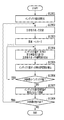
次に、本実施例の特徴である、3次元LUTと補間処理とを組み合わせた色分解処理の詳細について説明する。図3は、本実施例に係る色分解処理の詳細を示すフローチャートである。なお、補間処理には、処理対象色値を囲むどの格子点の情報を利用するかによって様々な種類があるが、本実施例では四面体補間を例に説明を行うものする。
(Color separation processing)
Next, the details of the color separation processing that combines the three-dimensional LUT and the interpolation processing, which is a feature of this embodiment, will be described. FIG. 3 is a flowchart showing details of the color separation process according to this embodiment. There are various types of interpolation processing depending on which grid point information surrounding the color value to be processed is used, but in this embodiment, tetrahedral interpolation will be described as an example.
ステップ301では、カラーマッチング処理部102から受け取った、カラーマッチング処理が施されたRGB色空間の入力画像データから、処理対象として注目するRGB値(以下、注目RGB値)が取得される。
In step 301, the RGB value of interest as the processing target (hereinafter, the RGB value of interest) is acquired from the input image data of the RGB color space subjected to the color matching process received from the color
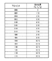
次に、ステップ302では、注目RGB値の上位ビットに基づき、当該注目RGB値が属する単位格子及び四面体が決定される。ここで上位ビットは、RGB各値が8ビットで表される値の上位4ビットである。図4において、(a)は単位格子の模式図であり、同(b)は四面体の模式図である。はじめに、単位格子の決定について説明する。四面体補間を用いた色分解処理では、入力色空間がRGB各軸に沿って複数の単位格子に分割され、更にその単位格子が四面体により分割される。どの単位格子に属するかの決定にあたっては、注目RGB各値の上位ビットが参照される。ここでは、図5に示すような、RGB値の上位4ビットと単位格子の位置とを対応付けたテーブルを用いる。具体的には、入力画像データのRGB各値(8ビット)について、その上位4ビットを参照し、RGB色空間全体で16×16×16個存在する単位格子のうち、いずれの単位格子に属するかを決定する。例えば、注目RGB値におけるR値の上位4ビットが“0111”のとき、R軸において、単位格子の始点の位置が“112”で終点の位置が“128”と決定される。なお、上位4ビットの値を10進数に変換した数値によって何番目(上の例では10進数に変換した数値が7であり順番としては8番目)の単位格子に属するかを決定してもよい。次に、四面体の決定について説明する。四面体の決定に際しては、まず注目RGB値についてR、G、B相互の大小関係を求める。そして、求めた大小関係に基づいて、図4(b)中の6通りの四面体401〜406の中から、1つの四面体を決定する。図4(b)に示す6通りの四面体401〜406のそれぞれは、単位格子を構成する8個の格子点のうちの黒丸で示した4個の格子点で構成される。このとき、四面体401〜406のそれぞれが決定される際の大小関係については、各図の下側に付与している。例えば、四面体401は、注目RGB値が「R≧G≧B」の条件を満たす四面体であり、他の四面体402〜406も、R、G、Bの大小関係から一義に決まる四面体である。この場合において、6通りの四面体401〜406はいずれも、2個の格子点PK(0,0,0)及びPW(1,1,1)を含む。なお、注目RGB値が四面体の境界に位置する場合には境界を含む複数の四面体が候補となり得るが、候補となる四面体のいずれを用いてもよく、例えば、大小関係を求める際に最初に条件を満たした四面体を選択すればよい。このようにして、注目RGB値が属する単位格子と四面体が決定される。図3のフローの説明に戻る。
Next, in step 302, the unit cell and tetrahedron to which the RGB value of interest belongs are determined based on the high-order bits of the RGB value of interest. Here, the high-order bits are the high-
ステップ303では、決定された四面体を構成する頂点(4つの格子点)のインク値が、色分解LUT105aを参照して取得される。
In step 303, the ink values of the vertices (four grid points) constituting the determined tetrahedron are acquired with reference to the
ステップ304では、注目RGB値の下位ビットを参照し、ステップ302で決定された四面体における注目RGB値の相対位置が導出される。ここでの下位ビットは、RGB各値が8ビットで表される値の下位4ビットである。図6は、四面体における注目RGB値の相対位置を導出する様子を示す模式図である。いま、注目RGB値をP(r,g,b)とすると、その相対位置fR、fG、fBは、注目RGB値の下位ビットを参照して以下のように求められる。ここでは、RGB値の下位4ビットと相対位置とを対応付けたテーブル(図7を参照)を用いて、RGB各軸とも16段階の相対位置を求めている。例えば、注目RGB値におけるR値の下位4ビットが“0100”のとき、その相対位置fRは“4/16”となる。或いは下位4ビットの値を10進数に変換し、0〜15の値を相対位置の分子としてもよい。さらには、以下の式(1)〜式(3)を用いて相対位置を求めることもできる。この場合において、格子点PKの位置が(r0,g0,b0)、格子点PWの位置が(r1,g1,b1)で表されるものとする。
fR=(r−r0)/(r1−r0) ・・・ 式(1)
fG=(g−g0)/(g1−g0) ・・・ 式(2)
fB=(b−b0)/(b1−b0) ・・・ 式(3)
上記式(1)〜(3)から明らかなように、相対位置fR、fG、fBの各値は“0〜1”の間の割合で表される値である。図3のフローの説明に戻る。
In step 304, the lower bits of the RGB value of interest are referred to, and the relative position of the RGB value of interest in the tetrahedron determined in step 302 is derived. The low-order bits here are the low-
f R = (r − r 0 ) / (r 1 −r 0 ) ・ ・ ・ Equation (1)
f G = (g-g 0 ) / (g 1 -g 0) ··· (2)
f B = (b − b 0 ) / (b 1 − b 0 ) ・ ・ ・ Equation (3)
As is clear from the above equations (1) to (3), each value of the relative positions f R , f G , and f B is a value represented by a ratio between “0 and 1”. Returning to the explanation of the flow of FIG.
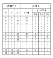
ステップ305では、ステップ302で決定された四面体に対応する変化特性識別情報としてのインデックス値が、変化特性識別情報DB105bからRGBの各軸分取得される。上述のとおり本実施例におけるインデックス値は、5通りの変化特性を示す数式のいずれかを指定する“0〜4”の値である。図8は、ブラックインクについての、入力画像データのRGB値と、インク値及びインデックス値の対応関係を示したテーブルの一例である。前述の通り、各格子点におけるインク値は色分解LUT105aに格納され、インデックス値は変化特性識別情報DB105bに格納されている。入力画像データのRGB値に対応する、ブラックインクについてのインデックス値C_K(R,G,B)は、以下の式(4)で表される。
C_K(R,G,B)={C_KR(R,G,B),C_KG(R,G,B),C_KB(R,G,B)} ・・・ 式(4)
このように、各格子点のインク値と共に、各格子点が属する四面体におけるインデックス値が、RGB各軸方向に対して用意される。例えば、RGB値が(0,0,0)の格子点が属する四面体については、インデックス値C_K(0,0,0)={2,2,3}のように、R軸、G軸、B軸の各々のインデックス値が用意される。そして、他のインク色(シアン、マゼンタ、イエロー)についても、インク値及びインデックス値と、入力画像データのRGB値とを対応付けた同様のテーブルが用意される。この場合において、シアン、マゼンタ、イエローの各インデックス値は、それぞれ以下の式(5)〜式(7)で表される。
C_C(R,G,B)={C_CR(R,G,B),C_CG(R,G,B),C_CB(R,G,B)} ・・・ 式(5)
C_M(R,G,B)={C_MR(R,G,B),C_MG(R,G,B),C_MB(R,G,B)} ・・・ 式(6)
C_Y(R,G,B)={C_YR(R,G,B),C_YG(R,G,B),C_YB(R,G,B)} ・・・ 式(7)
In step 305, the index value as the change characteristic identification information corresponding to the tetrahedron determined in step 302 is acquired from the change characteristic
C_K (R, G, B) = {C_K R (R, G, B), C_K G (R, G, B), C_K B (R, G, B)} ・ ・ ・ Equation (4)
In this way, along with the ink value of each grid point, the index value in the tetrahedron to which each grid point belongs is prepared for each RGB axial direction. For example, for a tetrahedron to which the grid points with RGB values (0,0,0) belong, the R-axis, G-axis, such as index value C_K (0,0,0) = {2,2,3}, Each index value of the B axis is prepared. Then, for other ink colors (cyan, magenta, yellow), a similar table in which the ink value and the index value are associated with the RGB value of the input image data is prepared. In this case, each index value of cyan, magenta, and yellow is represented by the following equations (5) to (7), respectively.
C_C (R, G, B) = {C_C R (R, G, B), C_C G (R, G, B), C_C B (R, G, B)} ・ ・ ・ Equation (5)
C_M (R, G, B) = {C_M R (R, G, B), C_M G (R, G, B), C_M B (R, G, B)} ・ ・ ・ Equation (6)
C_Y (R, G, B) = {C_Y R (R, G, B), C_Y G (R, G, B), C_Y B (R, G, B)} ・ ・ ・ Equation (7)
ステップ306では、ステップ305で取得したRGB各軸分のインデックス値に対応する変化特性情報としての変化特性式が、変化特性情報DB105cから取得される。上述のとおり変化特性式は、RGB各軸の相対位置とインデックス値とを入力した場合に出力値が求まる変換式であり、上記インデックス値と対応付けられている。インデックス値cを“0〜4”の5段階、RGB軸の各軸をx(xはR、G、Bのいずれかを示す)とすると、変化特性式f´x(c)は、以下の式(8)〜式(12)で表される。
・インデックス値が0の場合
f´x(0)=1−(1−fx)2.5 ・・・ 式(8)
・インデックス値が1の場合
f´x(1)=1−(1−fx)1.4 ・・・ 式(9)
・インデックス値が2の場合
f´x(2)=fx ・・・ 式(10)
・インデックス値が3の場合
f´x(3)=fx 1.4 ・・・ 式(11)
・インデックス値が4の場合
f´x(4)=fx 2.5 ・・・ 式(12)
上記式(8)〜式(12)における右辺の指数は、変化特性の変化の程度を制御するためのもので、この指数によって各変化特性における変化の程度を調整することができる。また、変化特性式は、上記式(8)〜式(12)に限定されるものではなく、fxに対するf´xの値が一意に決定される増加・連続関数であればよい。また、本実施例では、上記式(8)〜式(12)を、各インク色で共通に使用するが、格子点間での変化特性がインク色によって大きく異なる場合には、インク色毎に別々の変化特性式を用意してもよい。図9は、インデックス値に対応付けられた上記式(8)〜式(12)の変化特性式を、fxに対するf´xのグラフで示した図である。図9から明らかなように、“0〜4”の各インデックス値に対し、各グラフは、上に凸(程度大)、上に凸(程度小)、線形、下に凸(程度小)、下に凸(程度大)の特徴を有している。図3のフローの説明に戻る。
In step 306, the change characteristic formula as the change characteristic information corresponding to the index value for each RGB axis acquired in step 305 is acquired from the change characteristic information DB 105c. As described above, the change characteristic formula is a conversion formula for obtaining the output value when the relative position of each RGB axis and the index value are input, and is associated with the index value. 5 out of the index value c "0 to 4", when (the x R, G, indicates one of B) each axis x of the RGB-axis to change characteristic equation f'x (c), the following It is represented by equations (8) to (12).
If the index value is 0 f'x (0) = 1- (1-f x) 2.5 ··· formula (8)
If the index value is 1 f'x (1) = 1- (1-f x) 1.4 ··· formula (9)
• If the index value is 2 f'x (2) = f x ··· formula (10)
• If the index value is 3 f'x (3) = f x 1.4 ··· formula (11)
• If the index value is 4 f'x (4) = f x 2.5 ··· formula (12)
The index on the right side in the above equations (8) to (12) is for controlling the degree of change in the change characteristic, and the degree of change in each change characteristic can be adjusted by this index. The change characteristic equation is not limited to the above equation (8) to Formula (12) may be any increase or continuous function value of f'x for f x is uniquely determined. Further, in this embodiment, the above equations (8) to (12) are commonly used for each ink color, but when the change characteristics between the grid points differ greatly depending on the ink color, each ink color is used. Separate change characteristic formulas may be prepared. Figure 9 is a diagram above formula associated with the index value (8) to Formula variation characteristics equation (12), shown in the graph of f'x for f x. As is clear from FIG. 9, for each index value of "0 to 4", each graph is convex upward (large degree), convex upward (small degree), linear, convex downward (small degree), and It has the characteristic of being convex downward (large degree). Returning to the explanation of the flow of FIG.
ステップ307では、ステップ304で導出した注目RGB値の相対位置とステップ306で取得した変化特性式とに基づき、ステップ302で決定された四面体を構成する4つの格子点の重み係数が導出される。図10は、図4(b)で示した6つの四面体401〜406についての各4つの格子点と、それに対応する重み係数をまとめたテーブルである。ここで、重み係数w1〜w4は、その合計が1.0になるように設定されている。前述のとおりどの四面体に属するかはRGBの大小関係で決定され、当該決定された四面体の4つの格子点P1、P2、P3、P4について、図10に示された内容の重み係数w1、w2、w3、w4が導出されることになる。
In
ステップ308では、注目RGB値に対応する出力値が四面体補間による補間処理によって導出される。具体的には、ステップ303で取得された4つの格子点のインク値と、ステップ307で導出された重み係数とを用いた積和演算が実行される。この積和演算で求まる補間値(インク値)Vは、以下の式(13)で表される。
V=Σ(wi×Pi)=w1×P1+w2×P2+w3×P3+w4×P4 ・・・ 式(13)
例えば、(P1,P2,P3,P4)=(100,120,100,80)、(w1,w2,w3,w4)=(0.4,0.3,0.2,0.1)であるとき、補間値Vは、0.4×100+0.3×120+0.2×100+0.1×80=104となる。
In step 308, the output value corresponding to the RGB value of interest is derived by the interpolation process by tetrahedral interpolation. Specifically, a product-sum operation is executed using the ink values of the four grid points acquired in step 303 and the weighting coefficients derived in
V = Σ (w i × P i ) = w 1 × P 1 + w 2 × P 2 + w 3 × P 3 + w 4 × P 4・ ・ ・ Equation (13)
For example, when (P 1 , P 2 , P 3 , P 4 ) = (100,120,100,80), (w 1 , w 2 , w 3 , w 4 ) = (0.4,0.3,0.2,0.1), interpolation The value V is 0.4 × 100 + 0.3 × 120 + 0.2 × 100 + 0.1 × 80 = 104.
ステップ309では、入力画像データ内のすべての画素値(RGB値)について、処理が完了したかどうかが判定される。全画素値について処理が完了している場合には、色分解処理を終了する。一方、未処理の画素値がある場合はステップ301に戻って次の注目RGB値を決定して処理を続行する。 In step 309, it is determined whether or not the processing is completed for all the pixel values (RGB values) in the input image data. When the processing is completed for all pixel values, the color separation processing is terminated. On the other hand, if there is an unprocessed pixel value, the process returns to step 301 to determine the next RGB value of interest and continue the process.
以上が、本実施例に係る色分解処理の内容である。上述した色分解処理によって、入力画像データの各RGB値に対応する補間値(インク値)を得ることができる。図11は、本実施例の補間処理によって得られる補間値(インク値)の変化を示すグラフである。各グラフは、横軸が入力値(RGBのいずれか)で、縦軸が補間処理によって得られる出力値(インク値)を表している。図11(a)の縦に並んだ5つのグラフは、格子点間でインク値が増加する場合のグラフであり、インデックス値が大きくなるに従って上に凸から下に凸へとその特性が変化しているのが分かる。また、図11(b)の縦に並んだ5つのグラフは、格子点間でインク値が減少する場合のグラフであり、インデックス値が大きくなるに従って下に凸から上に凸へとその特性が変化しているのが分かる。インデックス値を制御することで、格子点間におけるインク値の変化特性が異なる補間処理を実現することができる。 The above is the content of the color separation treatment according to this embodiment. By the color separation process described above, an interpolation value (ink value) corresponding to each RGB value of the input image data can be obtained. FIG. 11 is a graph showing changes in the interpolation value (ink value) obtained by the interpolation processing of this embodiment. In each graph, the horizontal axis represents an input value (any of RGB), and the vertical axis represents an output value (ink value) obtained by interpolation processing. The five vertically arranged graphs in FIG. 11A are graphs in which the ink value increases between the grid points, and the characteristics change from upward convex to downward convex as the index value increases. You can see that. The five vertically arranged graphs in FIG. 11B are graphs in which the ink value decreases between the grid points, and the characteristics change from downwardly convex to upwardly convex as the index value increases. You can see that it is changing. By controlling the index value, it is possible to realize an interpolation process in which the change characteristics of the ink values between the grid points are different.
<色分解LUT及びインデックス値の作成方法>
続いて、上述の色分解処理で用いる、多次元LUTと変化特性識別情報としてのインデックス値の作成方法について説明する。本実施例では、RGB色空間の入力画像データに対応する17×17×17個の格子点を持つ3次元LUTと、上述した“0〜4”までのいずれかの値を有するインデックス値を作成する場合について説明する。
<How to create color separation LUT and index value>
Subsequently, a method of creating a multidimensional LUT and an index value as change characteristic identification information used in the above-mentioned color separation processing will be described. In this embodiment, a three-dimensional LUT having 17 × 17 × 17 grid points corresponding to the input image data in the RGB color space and an index value having any value from “0 to 4” described above are created. The case of doing so will be described.
(色分解LUTの作成)
図12は、本実施例に係る、3次元の色分解LUT作成の流れを示すフローチャートである。この処理は、CMYKのインク種毎に行われる。
(Creation of color separation LUT)
FIG. 12 is a flowchart showing a flow of creating a three-dimensional color separation LUT according to the present embodiment. This process is performed for each CMYK ink type.
ステップ1201では、作成対象の3次元LUTが初期化される。具体的には、プリンタ20の開発者等によって予め設計された補間のターゲットとなる3次元LUT(格子点数:65×65×65)に基づき、実際の色分解処理で用いる3次元LUT(格子点数:17×17×17)の各格子点に対して暫定的なインク値を設定する。本実施例の場合、ターゲットLUTにおける格子点値を間引くことで、対象3次元LUTの各格子点に初期値が与えられる。なお、補間のターゲットとなる3次元LUT(ターゲットLUT)は、プリンタ20の開発者等によって予め用意される。ターゲットLUTは、実際の色分解処理で用いる3次元LUTの格子点間における変化特性を再現すべく、実際の色分解処理で用いる3次元LUTの格子点よりも多くの格子点を有している。
In step 1201, the three-dimensional LUT to be created is initialized. Specifically, based on a 3D LUT (number of grid points: 65 x 65 x 65) that is a target of interpolation designed in advance by the developer of the
ステップ1202では、作成対象3次元LUTの全格子点の中から、処理対象とする格子点(注目格子点p)が1つ決定される。処理開始直後の段階では、例えば位置(0,0,0)の格子点が注目格子点pとして選択される。 In step 1202, one lattice point (attention lattice point p) to be processed is determined from all the lattice points of the three-dimensional LUT to be created. Immediately after the start of processing, for example, the grid point at the position (0,0,0) is selected as the grid point p of interest.
ステップ1203では、変数sの値が初期化される。ここで、変数sは、最適な格子点値(インク値)を見つけるための変動幅を表す変数である。初期値をどのような値にするかは任意であるが、本実施例では“10”が設定される。 In step 1203, the value of the variable s is initialized. Here, the variable s is a variable representing the fluctuation range for finding the optimum grid point value (ink value). What kind of value the initial value should be is arbitrary, but in this embodiment, "10" is set.
ステップ1204では、注目格子点pにおけるインク値と変数sで与えられる変動幅とを用いて、L0、L1、L2の3種類のLUTを作成する。L0は注目格子点pのインク値そのままで変動を加えないLUT、L1は注目格子点pのインク値に+sした場合のLUT、L2は注目格子点pのインク値に−sした場合のLUTである。 In step 1204, three types of LUTs, L0, L1 and L2, are created by using the ink value at the grid point p of interest and the fluctuation range given by the variable s. L0 is the LUT that does not change the ink value of the attention grid point p as it is, L1 is the LUT when the ink value of the attention grid point p is + s, and L2 is the LUT when the ink value of the attention grid point p is −s. is there.
ステップ1205では、ステップ1204で得られた3種類のLUT(L0、L1、L2)をそれぞれ用いて補間値を算出した場合の、それぞれの評価値E0、E1、E2が導出される。ここで、評価値には、例えば、ターゲットLUTの格子点値(ターゲット値)と、その対応する格子点位置における本方法で算出した補間値(インク値)との差分を求め、当該差分を平方した値の合計(差分二乗和)を用いる。この場合、誤差が少ないほど評価値は小さくなるため、E0、E1、E2のうち最も評価値が小さいものが最良の評価値となる。なお、評価方法は任意であり、上述の差分二乗和を用いるのに代えて、誤差の最大値を用いた評価を行ってもよい。また、インク値からL*a*b*などの均等色空間の値に変換してから誤差を評価してもよい。また、インク値やL*a*b*の変化の滑らかさを評価値として用いてもよい。さらには、これらの評価値を積和演算により組み合わせた総合評価値を用いてもよい。 In step 1205, the evaluation values E0, E1 and E2 when the interpolated values are calculated using the three types of LUTs (L0, L1 and L2) obtained in step 1204 are derived. Here, for the evaluation value, for example, the difference between the grid point value (target value) of the target LUT and the interpolated value (ink value) calculated by this method at the corresponding grid point position is obtained, and the difference is squared. Use the sum of the values (sum of differences squared). In this case, the smaller the error, the smaller the evaluation value, so the one with the smallest evaluation value among E0, E1, and E2 is the best evaluation value. The evaluation method is arbitrary, and instead of using the above-mentioned sum of squared differences, evaluation may be performed using the maximum value of the error. Further, the error may be evaluated after converting the ink value to a value in a uniform color space such as L * a * b *. Further, the smoothness of the change of the ink value and L * a * b * may be used as the evaluation value. Further, a comprehensive evaluation value obtained by combining these evaluation values by a product-sum operation may be used.
ステップ1206では、ステップ1205で導出した評価値E0、E1、E2が比較される。そして、評価値が最良(ここでは、最小)のLUTが、現時点で最良のLUTとして保持(更新)される。 In step 1206, the evaluation values E0, E1 and E2 derived in step 1205 are compared. Then, the LUT having the best evaluation value (here, the minimum) is held (updated) as the best LUT at the present time.
ステップ1207では、最良の評価値が収束したかどうかが判定される。判定の基準としては、現時点で保持されている最良のLUTの評価値が、変動なしの評価値E0と等しければ収束したと見做す。判定の結果、最良の評価値が収束していなければステップ1203へ戻り、処理を続行する。一方、最良の評価値が収束していればステップ1208へ進む。 In step 1207, it is determined whether the best evaluation value has converged. As a criterion for judgment, if the evaluation value of the best LUT held at present is equal to the evaluation value E0 without fluctuation, it is considered to have converged. As a result of the determination, if the best evaluation value has not converged, the process returns to step 1203 and the process is continued. On the other hand, if the best evaluation value has converged, the process proceeds to step 1208.
ステップ1208では、変数sの値が更新される。本実施例では、それまでの値を“2”で割った値を新たな変数sの値とする。ただし、段階的に小さい値にできればよく、変数sの更新のやり方はこれに限定されない。 In step 1208, the value of the variable s is updated. In this embodiment, the value obtained by dividing the previous value by "2" is used as the value of the new variable s. However, it suffices if the value can be gradually reduced, and the method of updating the variable s is not limited to this.
ステップ1209では、変数sの値が“1.0”未満であるかどうかが判定される。変数sの値が“1.0”以上であればステップ1203へ戻り、処理を続行する。一方、変数sの値が“1.0”未満であればステップ1210へ進む。 In step 1209, it is determined whether the value of the variable s is less than "1.0". If the value of the variable s is "1.0" or more, the process returns to step 1203 and the process continues. On the other hand, if the value of the variable s is less than "1.0", the process proceeds to step 1210.
ステップ1210では、作成対象3次元LUTの全ての格子点について処理が完了したかどうか判定される。未処理の格子点があればステップ1202に戻り、次の格子点を注目格子点pに決定して処理を続行する。一方、全ての格子点について処理が完了していれば本処理を終了する。 In step 1210, it is determined whether or not the processing is completed for all the grid points of the three-dimensional LUT to be created. If there is an unprocessed lattice point, the process returns to step 1202, determines the next lattice point as the attention lattice point p, and continues the process. On the other hand, if the processing is completed for all the grid points, this processing is terminated.
以上のようにして、最適な格子点値(インク値)を有する3次元の色分解LUTが作成される。 As described above, a three-dimensional color separation LUT having an optimum grid point value (ink value) is created.
(インデックス値の作成)
図13は、本実施例に係る、インデックス値作成の流れを示すフローチャートである。なお、以下の処理の実行時には、前述した5種類の変化特性式が予め作成され、読み込み可能な状態に用意されているものとする。
(Creation of index value)
FIG. 13 is a flowchart showing a flow of index value creation according to this embodiment. At the time of executing the following processing, it is assumed that the above-mentioned five types of change characteristic expressions are created in advance and prepared in a readable state.
ステップ1301では、インデックス値が初期化される。具体的には、色分解処理で用いる3次元LUTの全格子点それぞれにおけるインデックス値の初期値として、格子点間の変化が線形である場合の変化特性式を指し示す“2”が設定される。 In step 1301, the index value is initialized. Specifically, as the initial value of the index value at each of all the grid points of the three-dimensional LUT used in the color separation processing, "2" indicating the change characteristic formula when the change between the grid points is linear is set.
ステップ1302では、3次元LUTの全格子点の中から、注目する格子点(注目格子点p)が1つ決定される。処理開始直後の段階では、例えば位置(0,0,0)の格子点が注目格子点pとして選択される。 In step 1302, one lattice point of interest (attention lattice point p) is determined from all the lattice points of the three-dimensional LUT. Immediately after the start of processing, for example, the grid point at the position (0,0,0) is selected as the grid point p of interest.
ステップ1303では、インデックス値を表す変数iと、インデックス値の個数を表す定数Nが設定される。本実施例では、変数iの初期値として“0”、定数Nの値として“5”が設定される。 In step 1303, a variable i representing the index value and a constant N representing the number of index values are set. In this embodiment, "0" is set as the initial value of the variable i, and "5" is set as the value of the constant N.
ステップ1304では、インデックス値が変数iのときの変化特性式に基づき、注目格子点pの補間値が導出される。 In step 1304, the interpolated value of the grid point p of interest is derived based on the change characteristic formula when the index value is the variable i.
ステップ1305では、インデックス値が変数iのときの評価値が導出される。この評価値も、3次元LUTの格子点値の最適化時と同様、ターゲットLUTの格子点値(ターゲット値)と、その対応する格子点位置における本方法で算出した補間値(インク値)との差分を求め、当該差分を平方した値の合計(差分二乗和)を用いる。 In step 1305, the evaluation value when the index value is the variable i is derived. This evaluation value also includes the grid point value (target value) of the target LUT and the interpolation value (ink value) calculated by this method at the corresponding grid point position, as in the case of optimizing the grid point value of the three-dimensional LUT. The difference is obtained, and the sum of the squared values of the difference (sum of differences squared) is used.
ステップ1306では、すべてのインデックス値の評価が完了したかどうかが判定される。未評価のインデックス値があれば(変数iの値がN−1未満の場合)、変数iをインクリメント(i=i+1)してステップ1304へ戻り、次のインデックス値iについての処理を続行する。一方、全てのインデックス値の評価が完了していれば(変数iの値がN−1に達した場合)、ステップ1307へ進む。 In step 1306, it is determined whether the evaluation of all the index values is completed. If there is an unevaluated index value (when the value of the variable i is less than N-1), the variable i is incremented (i = i + 1), the process returns to step 1304, and the processing for the next index value i is continued. On the other hand, if the evaluation of all the index values is completed (when the value of the variable i reaches N-1), the process proceeds to step 1307.
ステップ1307では、各インデックス値(変数iが0〜4)における評価値に基づいて、評価値が最良となる変数iが、注目格子点pにおけるインデックス値として決定される。 In step 1307, the variable i having the best evaluation value is determined as the index value at the grid point p of interest, based on the evaluation value at each index value (variable i is 0 to 4).
ステップ1308では、3次元LUTの全格子点についての処理が完了したかどうか判定される。未処理の格子点があればステップ1302に戻り、次の格子点を注目格子点pに決定して処理を続行する。一方、全ての格子点について処理が完了していれば本処理を終了する。 In step 1308, it is determined whether or not the processing for all the grid points of the three-dimensional LUT is completed. If there is an unprocessed lattice point, the process returns to step 1302, determines the next lattice point as the attention lattice point p, and continues the process. On the other hand, if the processing is completed for all the grid points, this processing is terminated.
以上のようにして、3次元LUTの各格子点におけるインデックス値が作成される。 As described above, the index value at each grid point of the three-dimensional LUT is created.
(本実施例の効果)
以下、本実施例において、格子点間の出力値の変化特性(非線形性)を各単位格子のRGB軸毎に制御することの効果について説明する。図14は、3次元の色分解LUTにおける格子点上のインク値をグラフ化したものである。図14において、(a)は入力RGBのB値が“0”のとき、同(b)は“144”のときにおける、R軸及びB軸の格子点(その数は9×9)上のインク値をプロットしたものである。入力RGBに対するインク値CMYKは4次元の情報であるため、可視化の都合上、入力の一次元であるB値を一定値に固定し、B値が異なる場合の例を2つ示している。入力されるRGB値によって、格子点間でのインク値の変化特性が単位格子のRGB軸毎に異なり得ることが、両グラフの比較から分かる。このとき、図14(a)における格子点Pは、RGB値が(0,144,0)の格子点であり、以下、この格子点Pに着目して詳細に説明する。
(Effect of this example)
Hereinafter, in this embodiment, the effect of controlling the change characteristic (non-linearity) of the output value between the grid points for each RGB axis of each unit grid will be described. FIG. 14 is a graph showing the ink values on the grid points in the three-dimensional color separation LUT. In FIG. 14, (a) is on the grid points (the number is 9 × 9) of the R axis and the B axis when the B value of the input RGB is “0” and the same (b) is “144”. It is a plot of ink values. Since the ink value CMYK for the input RGB is four-dimensional information, for convenience of visualization, two examples are shown in which the B value, which is one dimension of the input, is fixed to a constant value and the B value is different. It can be seen from the comparison of both graphs that the change characteristic of the ink value between the grid points may differ for each RGB axis of the unit grid depending on the input RGB value. At this time, the grid point P in FIG. 14A is a grid point having an RGB value of (0,144,0), and the grid points P will be described in detail below.
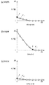
図15は、RGB各軸方向のインク値の変化を示すグラフである。図15において、(a)〜(c)はそれぞれ、R軸、G軸、B軸方向におけるインク値の変化を表している。図15(a)〜(c)における黒丸が上述の格子点Pを示し、当該格子点Pの各軸における正の方向に隣接する格子点を、それぞれP´R、P´G、P´Bとしている。図15(a)〜(c)から、各軸方向における格子点間P−P´R、P−P´G、P−P´Bは、それぞれインク値の変化の特性が異なっているのが分かる。特に、インク値が入り始める領域に格子点Pが位置する図15(b)の場合、より滑らかにインク値を増加させることが望ましいことが理解できる。 FIG. 15 is a graph showing changes in ink values in each of the RGB axes. In FIG. 15, (a) to (c) represent changes in ink values in the R-axis, G-axis, and B-axis directions, respectively. 15 black circles in (a) ~ (c) shows the lattice point P mentioned above, the lattice points adjacent to the positive direction of each axis of the grid point P, respectively P'R, P'G, P'B It is said. Figures 15 (a) ~ (c) , the grid points between the P-P'R in each axial direction, P-P'G, P- P'B is that have different characteristics of change of the ink values respectively I understand. In particular, in the case of FIG. 15B in which the grid point P is located in the region where the ink value starts to enter, it can be understood that it is desirable to increase the ink value more smoothly.
上記の事実を踏まえ、本実施例では、格子点毎に各軸方向で異なる変化特性を実現すべく、格子点間の変化特性の情報(変化特性式)を各格子点に持たせるようにしている。そして、この変化特性情報そのものを各格子点に対して持たせるのではなく、変化特性情報を識別するインデックス値として持たせることで、その情報量を少なくしている。また、本実施例の手法の場合、格子点間の変化特性をRGB軸毎に変化させる際に、補間対象の単位格子に含まれる格子点とそれに対応するインデックス値と変化特性式のみを参照する。そのため、周辺のより広い範囲の格子点も参照して補間する高次の補間方法、例えば、スプライン補間、ベジェ補間、NURBS等と比べて、参照点及び計算量が少なくなる。 Based on the above facts, in this embodiment, in order to realize different change characteristics in each axial direction for each grid point, information on the change characteristic between the grid points (change characteristic formula) is provided to each grid point. There is. Then, the amount of information is reduced by having the change characteristic information itself as an index value for identifying the change characteristic information, instead of having it for each lattice point. Further, in the case of the method of this embodiment, when changing the change characteristic between the grid points for each RGB axis, only the grid points included in the unit grid to be interpolated and the corresponding index values and change characteristic formulas are referred to. .. Therefore, the number of reference points and the amount of calculation are smaller than those of higher-order interpolation methods such as spline interpolation, Bezier interpolation, NURBS, etc., which perform interpolation by referring to a wider range of grid points in the periphery.
本実施例では、インデックス値を色分解LUTの全格子点(各軸の位置座標で最大値となる格子点を除く)に対して持たせたが、一部の格子点に対してのみ持たせる構成であってもよい。例えば、淡インクは中間調領域の格子点のみ、濃インクは暗部領域の格子点のみにインデックス値を持たせるようにしてもよい。 In this embodiment, the index value is given to all the grid points of the color separation LUT (excluding the grid point that becomes the maximum value in the position coordinates of each axis), but it is given to only some grid points. It may be a configuration. For example, the light ink may have an index value only at the grid points in the halftone region, and the dark ink may have the index value only at the grid points in the dark region.
また、本実施例では、プリンタ20で用いる全インク種についてインデックス値及び変化特性式を用意したが、一部のインク色についてのみ用意する構成であってもよい。例えば、CMYK4色のうち、イエローを除く3色(シアン、マゼンタ、ブラック)についてのみ用意してもよい。
Further, in this embodiment, the index value and the change characteristic formula are prepared for all the ink types used in the
また、インデックス値及び変化特性式をRGB軸の一部の軸のみ有する構成であってもよい。例えば、シアンインクはG、B軸のみ、マゼンタインクはR、B軸のみ、イエローインクはR、G軸のみ有する構成であってもよい。この場合、補間処理の精度が多少落ちる場合もあるが、保持する情報量を削減することができる。 Further, the index value and the change characteristic expression may be configured to have only a part of the RGB axes. For example, the cyan ink may have only the G and B axes, the magenta ink may have only the R and B axes, and the yellow ink may have only the R and G axes. In this case, the accuracy of the interpolation processing may be slightly lowered, but the amount of information to be held can be reduced.
また、格子点間の補間処理の手法も、多面体補間であれば広く適用可能であり、四面体以外の立体的な構造、例えばピラミッド、プリズム、立方体、直方体等を用いる他の手法であってもよい。 Further, the method of interpolation processing between lattice points can be widely applied as long as it is polyhedral interpolation, and even if it is another method using a three-dimensional structure other than a tetrahedron, for example, a pyramid, a prism, a cube, a rectangular parallelepiped, etc. Good.
また、記録ヘッド111の構成として、シアン(C)、マゼンタ(M)、イエロー(Y)、ブラック(K)の4色のインクを備える例を示したが、インクの数や種類はこれらに限定されない。濃度の薄い淡インク、レッドやグリーン等の特色インク、白色インクを用いてもよい。また、無色透明のクリアインクや、金属調のメタリックインクを用いてもよい。
Further, an example is shown in which the
また、入力画像データをRGBのカラー画像としたが、これに限定されず、例えばCMYKのカラー画像であってもよい。この場合、インデックス値は、C軸、M軸、Y軸、K軸の次元毎に各格子点に対して割り当てられることになる。さらには、色以外の成分、例えば光沢を表す成分や距離を表す成分を含んでもよい。これらの場合、色分解処理で用いる多次元LUTは4次元以上のLUTとなる。図16(a)は、入力画像データがCMYK色空間の場合の色分解LUTとその各格子点値に設定されるインデックス値の一例を示すテーブルである。そして、図16(b)は、入力画像データがRGB色空間であって、さらに光沢の情報を持つ場合の色分解LUTとその各格子点値に設定されるインデックス値の一例を示すテーブルである。図16(b)のテーブルにおいて、入力画像データにおけるXが光沢成分を示しており、その値が大きいほど光沢性が高く(正反射光量が多い)、より多くのクリアインクを使用する(インク値が大きい)ことを表している。図16(b)は、カラー暗部側の光沢性が高く、カラー明部側の光沢性が低いという場合の一例である。このように、入力画像データが持つ成分に応じた色分解LUTとインデックス値を用意することで、同様の効果を得ることができる。 Further, the input image data is an RGB color image, but the present invention is not limited to this, and for example, a CMYK color image may be used. In this case, the index value is assigned to each grid point for each dimension of the C-axis, M-axis, Y-axis, and K-axis. Furthermore, a component other than color, for example, a component representing gloss or a component representing distance may be contained. In these cases, the multidimensional LUT used in the color separation process is a LUT having four or more dimensions. FIG. 16A is a table showing an example of the color separation LUT when the input image data is in the CMYK color space and the index value set for each grid point value thereof. FIG. 16B is a table showing an example of the color separation LUT when the input image data is in the RGB color space and further has gloss information and the index value set for each lattice point value. .. In the table of FIG. 16B, X in the input image data indicates a gloss component, and the larger the value, the higher the gloss (the amount of specular reflection is large), and more clear ink is used (ink value). Is large). FIG. 16B is an example in which the glossiness on the dark side of the color is high and the glossiness on the bright side of the color is low. In this way, the same effect can be obtained by preparing the color separation LUT and the index value according to the components of the input image data.
さらに、RGB軸毎の変化特性式を用いて格子点間の補間演算を行ったが、変化特性式に代えて、予め用意した有限なエントリー数の変化特性テーブルを使用してもよい。変化特性テーブルとしては、所定数(例えば10個)の入力値と出力値との関係を規定する、前述の各変化特性式のグラフ(図9を参照)の特徴を持つLUTが考えられる。変化特性式に代えてこのようなテーブルを用いる場合、指数演算を行う必要がなくなるので、処理負荷をさらに軽減することができる。 Further, although the interpolation calculation between the grid points is performed using the change characteristic formula for each RGB axis, a change characteristic table having a finite number of entries prepared in advance may be used instead of the change characteristic formula. As the change characteristic table, a LUT having the characteristics of the graph (see FIG. 9) of each of the above-mentioned change characteristic expressions that defines the relationship between a predetermined number (for example, 10) of input values and output values can be considered. When such a table is used instead of the change characteristic expression, it is not necessary to perform an exponential operation, so that the processing load can be further reduced.
以上説明したように本実施例によれば、入力画像データを色分解処理する際に用いる多次元LUTにおいて、当該入力画像データの各入力成分及び格子点間毎に、非線形な変化特性を持たせることができる。これにより、例えばRGBの各軸方向で格子点間での補間の変化特性が異なる場合においても、補間演算による精度悪化を低減し、各格子点間での階調性の滑らかさを向上させることができる。 As described above, according to the present embodiment, in the multidimensional LUT used when the input image data is color-separated, a non-linear change characteristic is provided for each input component of the input image data and between lattice points. be able to. As a result, for example, even when the change characteristics of interpolation between grid points are different in each axis direction of RGB, the deterioration of accuracy due to the interpolation calculation is reduced and the smoothness of gradation between each grid point is improved. Can be done.
実施例1では、3次元LUTを用いた補間処理によって色分解を行う際に、各単位格子内のRGB軸毎に格子点間での補間の変化特性を異ならせる例を説明した。次に、3次元LUTを用いた補間処理による色分解を行う前に、1次元LUTを用いた非線形な変換を行うことで補間演算の精度をより高める態様について、実施例2として説明する。なお、実施例1と共通の部分については説明を簡易化または省略し、以下では差異点を中心に説明するものとする。 In the first embodiment, when color separation is performed by the interpolation processing using the three-dimensional LUT, an example in which the change characteristic of the interpolation between the lattice points is different for each RGB axis in each unit lattice has been described. Next, a mode in which the accuracy of the interpolation calculation is further improved by performing a non-linear conversion using the one-dimensional LUT before performing the color separation by the interpolation processing using the three-dimensional LUT will be described as Example 2. The description of the parts common to the first embodiment will be simplified or omitted, and the differences will be mainly described below.
(装置の構成)
図17は、本実施例に係る印刷システムの構成の一例を示したブロック図である。実施例1の図1と異なるのは、非線形変換部1700がカラーマッチング処理部102と色分解処理部104との間に挿入され、非線形変換部1700が参照する非線形変換LUT1701が追加されている点である。
(Device configuration)
FIG. 17 is a block diagram showing an example of the configuration of the printing system according to the present embodiment. The difference from FIG. 1 of the first embodiment is that the
非線形変換部1700は、カラーマッチング処理後の画像データに対する非線形変換を行う。非線形変換処理は、プリンタ20が備える各インク色について行われる。いま、記録ヘッド111は、シアン(C)、マゼンタ(M)、イエロー(Y)、ブラック(K)の4色のインクを搭載している。非線形変換処理に際しては、不図示のHDD等に格納された1次元の非線形変換LUTが用いられる。図18は、非線形変換LUTの一例を示し、横軸が入力のRGB値であり、縦軸が出力(非線形変換後)のRGB値である。LUT1801はシアン、LUT1802はマゼンタ、LUT1803はイエロー、LUT1804はブラックにそれぞれ対応している。各LUTは、17個の格子点上のみにそれぞれ8ビットの入力値に対応した出力値が記述されている。
The
(印刷処理の概要)
次に、本実施例に係る印刷システム100における印刷処理の概要について説明する。図19は、本実施例に係る印刷システム100における印刷処理の大まかな流れを示すフローチャートである。
(Outline of printing process)
Next, an outline of the printing process in the printing system 100 according to this embodiment will be described. FIG. 19 is a flowchart showing a rough flow of printing processing in the printing system 100 according to the present embodiment.
ステップ1901〜1903は、実施例1の図2のフローにおけるステップ201〜203と同じである。すなわち、入力されたRGB画像データ(S1901)に対してカラーマッチング処理が施されると(S1902)、当該RGB画像データは非線形変換部1700に送られ、色分解処理の対象とする注目インク種が決定される(S1903)。
ステップ1904では、非線形変換部1700が、ステップ1903で決定された注目インク種に応じた非線形変換LUTが取得される。ここでは、シアンに対応したLUT1801が取得されたものとする。
In step 1904, the
ステップ1905では、非線形変換部1700が、ステップ1904で取得した非線形変換LUTを用いて、カラーマッチング処理が施された画像データを、出力値の色成分毎の特性(非線形性)に応じた画像データに変換する。注目インク種がシアンであれば、シアンの特性(非線形性)に応じた画像データに変換される。
In step 1905, the
以降のステップ1906〜1911は、実施例1の図2のフローにおけるステップ204〜209と同じである。ただし、ステップ1906における色分解処理の内容は実施例1とは異なるので、以下では、本実施例の色分解処理について説明する。 Subsequent steps 1906 to 1911 are the same as steps 204 to 209 in the flow of FIG. 2 of the first embodiment. However, since the content of the color separation process in step 1906 is different from that of the first embodiment, the color separation process of the present embodiment will be described below.
(色分解処理の詳細)
図20は、本実施例に係る色分解処理の詳細を示すフローチャートである。
(Details of color separation processing)
FIG. 20 is a flowchart showing details of the color separation process according to this embodiment.
ステップ2001では、非線形変換部1700から受け取った、非線形変換処理が施された注目インク種についての画像データから、処理対象とする注目RGB値が取得される。
In step 2001, the RGB value of interest to be processed is acquired from the image data of the ink type of interest that has undergone the nonlinear conversion process, which is received from the
ステップ2002では、非線形変換による格子点の不均等化位置が取得される。この不均等化位置の情報は、均等な間隔の格子点が、非線形変換部1700における非線形変換によって不均等な間隔の格子点となるときの各格子点の位置を事前に計算によって求め、HDD等に保持しておけばよい。
In step 2002, the non-linear transformation of the grid points is acquired. The information on the non-uniform spacing is obtained by calculating in advance the positions of the grid points when the grid points at equal intervals become the grid points at non-uniform intervals due to the non-linear conversion in the
ステップ2003では、ステップ2002で取得した格子点の不均等化位置を参照し、注目RGB値が属する単位格子及び四面体が決定される。 In step 2003, the unit lattice and tetrahedron to which the RGB values of interest belong are determined with reference to the non-uniform positions of the lattice points acquired in step 2002.
ステップ2004では、ステップ2002で取得した格子点の不均等化位置に対する注目RGB値の位置を正規化した上で、ステップ2003で決定された四面体における注目RGB値の相対位置が導出される。以降のステップ2006〜2010は、実施例1の図3のフローにおけるステップ305〜309と同じであるので説明を省く。 In step 2004, after normalizing the position of the RGB value of interest with respect to the uneven position of the grid points acquired in step 2002, the relative position of the RGB value of interest in the tetrahedron determined in step 2003 is derived. Subsequent steps 2006 to 2010 are the same as steps 305 to 309 in the flow of FIG. 3 of the first embodiment, and thus the description thereof will be omitted.
以上が、本実施例に係る色分解処理の内容である。このように本実施例の色分解処理では、入力画像データを出力色毎に非線形変換し、格子点の間隔を不均等化する。そして、各格子点間の位置関係(距離)を正規化した上で、注目RGB値の相対位置を導出している。これにより、格子点の位置関係(距離)が異なる単位格子であっても、実施例1と同様の変化特性情報(変化特性式)を用いた補間処理を行うことができる。 The above is the content of the color separation treatment according to this embodiment. As described above, in the color separation processing of this embodiment, the input image data is non-linearly converted for each output color, and the spacing between the grid points is made uneven. Then, after normalizing the positional relationship (distance) between the grid points, the relative position of the RGB value of interest is derived. As a result, even if the unit grids have different positional relationships (distances) between the grid points, the interpolation processing using the change characteristic information (change characteristic formula) similar to that in the first embodiment can be performed.
(非線形変換LUTの作成方法)
続いて、非線形変換処理で用いる1次元LUTの作成方法について説明する。図21は、非線形変換LUT作成の流れを示すフローチャートである。
(Method of creating nonlinear transformation LUT)
Subsequently, a method of creating a one-dimensional LUT used in the nonlinear conversion process will be described. FIG. 21 is a flowchart showing a flow of creating a nonlinear conversion LUT.
ステップ2101では、本フローにおけるルーチン(S2102〜S2104)のループ回数を表す変数iと、ループ回数iの上限を規定する定数Nがセットされる。ここでは、変数iに“1”、定数Nに“1000”がセットされるものとする。なお、定数Nの値は任意である。 In step 2101, a variable i representing the number of loops of the routines (S2102 to S2104) in this flow and a constant N defining the upper limit of the number of loops i are set. Here, it is assumed that the variable i is set to "1" and the constant N is set to "1000". The value of the constant N is arbitrary.
ステップ2102では、非線形変換LUTが初期化される。この初期化では、非線形変換LUTの17個の格子点の位置と初期値が設定される。格子点の位置は、0、16、32、・・・、240、255の均等間隔とする。そして、各格子点の初期値は“0〜255”のいずれかの値が乱数によって与えられる。ただし、各格子点の値は格子点位置に対して単調増加になるように設定される。このように初期値を乱数によって与え、所定のループ回数だけ以下に述べる最適化処理を繰り返すことによって、より高精度のLUTを得ることができる。 In step 2102, the non-linear transformation LUT is initialized. In this initialization, the positions and initial values of the 17 grid points of the nonlinear transformation LUT are set. The positions of the grid points shall be evenly spaced 0, 16, 32, ..., 240, 255. Then, as the initial value of each grid point, any value of "0 to 255" is given by a random number. However, the value of each grid point is set so as to increase monotonically with respect to the grid point position. By giving the initial value by a random number and repeating the optimization process described below for a predetermined number of loops in this way, a more accurate LUT can be obtained.
ステップ2103では、非線形変換LUTの最適化処理が実行される。この非線形変換LUTの最適化処理は、実施例1の図12で説明した、色分解LUTの作成処理におけるステップ1202〜1210における処理と同様の処理である。 In step 2103, the non-linear transformation LUT optimization process is executed. The optimization process of this nonlinear conversion LUT is the same process as the process in steps 1202 to 1210 in the process of creating the color separation LUT described with reference to FIG. 12 of Example 1.
ステップ2104では、ループ回数iの値が上限に達したかどうかが判定される。上限に達していなければ(変数iの値がN未満の場合)、変数iをインクリメント(i=i+1)してステップ2102へ戻り、処理を続行する。一方、ループ回数iの値が上限に達していれば(変数iの値=N)、本処理を終える。 In step 2104, it is determined whether or not the value of the number of loops i has reached the upper limit. If the upper limit has not been reached (when the value of the variable i is less than N), the variable i is incremented (i = i + 1), the process returns to step 2102, and the process is continued. On the other hand, if the value of the number of loops i reaches the upper limit (value of variable i = N), this process ends.
以上のようにして、最適な格子点値(出力RGB値)を有する非線形変換LUTが作成される。 As described above, the nonlinear conversion LUT having the optimum grid point value (output RGB value) is created.
本実施例によれば、色変換処理の前に非線形変換を行うことで、色変換処理で用いる多次元LUTの格子点間隔が不均等化される。このように格子点間隔が不均等な場合でも多次元の入力画像データの成分毎に、各格子点間の変化特性を持たせることができ、補間演算の精度をより高めることができる。 According to this embodiment, by performing the non-linear conversion before the color conversion process, the grid point spacing of the multidimensional LUT used in the color conversion process is made uneven. As described above, even when the grid point spacing is uneven, it is possible to give a change characteristic between each grid point for each component of the multidimensional input image data, and it is possible to further improve the accuracy of the interpolation calculation.
[その他の実施例]
また、本発明は、上述の実施例の1以上の機能を実現するプログラムを、ネットワーク又は記憶媒体を介してシステム又は装置に供給し、そのシステム又は装置のコンピュータにおける1つ以上のプロセッサーがプログラムを読出し実行する処理でも実現可能である。また、1以上の機能を実現する回路(例えば、ASIC)によっても実現可能である。
[Other Examples]
The present invention also supplies a program that realizes one or more functions of the above-described embodiment to a system or device via a network or storage medium, and one or more processors in the computer of the system or device implement the program. It can also be realized by the process of reading and executing. It can also be realized by a circuit (for example, ASIC) that realizes one or more functions.
画像処理装置 10
色分解処理部104
色分解LUT105a
Color
Color Separations LUT105a
Claims (15)
前記ルックアップテーブルの各格子点の少なくとも一部には、前記複数次元の次元毎に、各格子点間の変化特性を表す情報が対応付けられ、
前記色分解処理手段は、前記変化特性を表す情報に基づいて前記補間処理を行う
ことを特徴とする画像処理装置。 Color separation that uses each pixel value of the input image as an input value and color-separates it into an output value corresponding to the signal component handled by the output device by interpolation processing using a multidimensional lookup table according to the signal component of the input image. Equipped with processing means
At least a part of each grid point of the look-up table is associated with information representing a change characteristic between the grid points for each of the plurality of dimensions.
The color separation processing means is an image processing apparatus characterized in that the interpolation processing is performed based on the information representing the change characteristic.
前記出力デバイスが扱う信号成分に対応する出力値は、前記印刷装置における印刷出力に使用する色材の量を表す色材値である
ことを特徴とする請求項5又は6に記載の画像処理装置。 The output device is a printing device.
The image processing apparatus according to claim 5 or 6, wherein the output value corresponding to the signal component handled by the output device is a color material value representing the amount of the color material used for the print output in the printing apparatus. ..
前記インデックス値は、前記インクの種類に応じて、前記ルックアップテーブルにおける一部の格子点とだけ対応付けられることを特徴とする請求項7に記載の画像処理装置。 The printing device is an inkjet printing device that uses ink as the coloring material.
The image processing apparatus according to claim 7, wherein the index value is associated with only a part of the grid points in the look-up table according to the type of the ink.
前記ルックアップテーブルは、R軸、G軸、B軸の次元毎に、各格子点間の変化特性を表す情報が各格子点に対応付けられている
ことを特徴とする請求項1乃至10のいずれか1項に記載の画像処理装置。 The signal component of the input image is RGB.
The lookup table according to claim 1 to 10, wherein information representing a change characteristic between each lattice point is associated with each lattice point for each dimension of the R axis, the G axis, and the B axis. The image processing apparatus according to any one item.
前記ルックアップテーブルは、C軸、M軸、Y軸及びK軸の次元毎に、各格子点間の変化特性を表す情報が各格子点に対応付けられている
ことを特徴とする請求項1乃至10のいずれか1項に記載の画像処理装置。 The signal component of the input image is CMYK.
Claim 1 is characterized in that the look-up table is associated with information representing change characteristics between each grid point for each dimension of the C-axis, M-axis, Y-axis, and K-axis. 10. The image processing apparatus according to any one of 10.
前記ルックアップテーブルの各格子点の少なくとも一部には、前記複数次元の次元毎に、各格子点間の変化特性を表す情報が対応付けられ、
前記色分解処理では、前記変化特性を表す情報に基づいて前記補間処理を行う
ことを特徴とする方法。 Color separation that uses each pixel value of the input image as an input value and color-separates it into an output value corresponding to the signal component handled by the output device by interpolation processing using a multidimensional lookup table according to the signal component of the input image. It ’s a processing method,
At least a part of each grid point of the look-up table is associated with information representing a change characteristic between the grid points for each of the plurality of dimensions.
The color separation process is a method characterized in that the interpolation process is performed based on the information representing the change characteristic.
Priority Applications (2)
| Application Number | Priority Date | Filing Date | Title |
|---|---|---|---|
| JP2016093162A JP6768343B2 (en) | 2016-05-06 | 2016-05-06 | Image processing equipment, image processing methods and programs |
| US15/492,654 US10356282B2 (en) | 2016-05-06 | 2017-04-20 | Image processing apparatus and color separation processing method by interpolation processing using a multi-dimensional lookup table |
Applications Claiming Priority (1)
| Application Number | Priority Date | Filing Date | Title |
|---|---|---|---|
| JP2016093162A JP6768343B2 (en) | 2016-05-06 | 2016-05-06 | Image processing equipment, image processing methods and programs |
Publications (3)
| Publication Number | Publication Date |
|---|---|
| JP2017201758A JP2017201758A (en) | 2017-11-09 |
| JP2017201758A5 JP2017201758A5 (en) | 2019-10-10 |
| JP6768343B2 true JP6768343B2 (en) | 2020-10-14 |
Family
ID=60244216
Family Applications (1)
| Application Number | Title | Priority Date | Filing Date |
|---|---|---|---|
| JP2016093162A Active JP6768343B2 (en) | 2016-05-06 | 2016-05-06 | Image processing equipment, image processing methods and programs |
Country Status (2)
| Country | Link |
|---|---|
| US (1) | US10356282B2 (en) |
| JP (1) | JP6768343B2 (en) |
Families Citing this family (25)
| Publication number | Priority date | Publication date | Assignee | Title |
|---|---|---|---|---|
| JP6639138B2 (en) * | 2015-07-30 | 2020-02-05 | キヤノン株式会社 | Image processing apparatus, image processing method, and program |
| JP6758997B2 (en) | 2016-08-23 | 2020-09-23 | キヤノン株式会社 | Color separation processing device, color separation processing method, color separation LUT creation method and program |
| JP6840604B2 (en) | 2017-04-11 | 2021-03-10 | キヤノン株式会社 | Color conversion table creation device, color conversion table creation method, color conversion processing device, color conversion processing method and program |
| JP6862267B2 (en) | 2017-05-02 | 2021-04-21 | キヤノン株式会社 | Color conversion look-up table creation device, color conversion lookup table creation method and program |
| JP6922512B2 (en) * | 2017-07-24 | 2021-08-18 | セイコーエプソン株式会社 | Image processing device, image processing system, image forming device, and image processing program |
| JP2019096928A (en) | 2017-11-17 | 2019-06-20 | キヤノン株式会社 | Image processing system, image processing method, and program, and image display unit |
| JP7210294B2 (en) | 2018-01-26 | 2023-01-23 | キヤノン株式会社 | Image processing device, image processing method and program |
| US10516809B2 (en) | 2018-02-28 | 2019-12-24 | Ricoh Company, Ltd. | Optimizing number of grid points in multi-dimensional color lookup table |
| JP2019204428A (en) | 2018-05-25 | 2019-11-28 | キヤノン株式会社 | Image processing device, display system, image processing method, and program |
| JP7214404B2 (en) | 2018-08-31 | 2023-01-30 | キヤノン株式会社 | IMAGE PROCESSING APPARATUS, IMAGE PROCESSING METHOD, AND PROGRAM |
| JP2020040334A (en) | 2018-09-12 | 2020-03-19 | キヤノン株式会社 | Image processing device, image processing method and program |
| CN109615666A (en) * | 2018-11-12 | 2019-04-12 | 北京中科慧眼科技有限公司 | A kind of three-dimensional color space data transfer device and device |
| JP7187278B2 (en) | 2018-11-15 | 2022-12-12 | キヤノン株式会社 | Image processing device, image processing method, and program |
| US10855877B2 (en) | 2018-12-03 | 2020-12-01 | Canon Kabushiki Kaisha | Image processing apparatus, image processing method and storage medium |
| EP3664429B1 (en) | 2018-12-07 | 2022-07-27 | Canon Kabushiki Kaisha | Image processing apparatus, image processing method, and program |
| US10834288B2 (en) | 2018-12-21 | 2020-11-10 | Canon Kabushiki Kaisha | Generating image region dot data based on corrected number of dots and determined arrangement priority |
| JP2020100064A (en) | 2018-12-21 | 2020-07-02 | キヤノン株式会社 | Image processing device, image processing method, and program |
| US11020985B2 (en) | 2019-01-31 | 2021-06-01 | Canon Kabushiki Kaisha | Image processing apparatus, image processing method and storage medium |
| CN110435319B (en) * | 2019-08-13 | 2021-06-08 | Oppo(重庆)智能科技有限公司 | Substrate with gradient color effect, manufacturing method thereof and electronic equipment |
| JP7391619B2 (en) | 2019-11-07 | 2023-12-05 | キヤノン株式会社 | Image processing device, image processing method and program |
| JP7475928B2 (en) | 2020-03-31 | 2024-04-30 | キヤノン株式会社 | Image processing device, control method thereof, and program |
| JP2021160196A (en) | 2020-03-31 | 2021-10-11 | キヤノン株式会社 | Image processing device, control method and program thereof |
| JP7481935B2 (en) | 2020-07-21 | 2024-05-13 | キヤノン株式会社 | Image processing device and image processing method |
| JP2022121956A (en) * | 2021-02-09 | 2022-08-22 | キヤノン株式会社 | Information processing apparatus, information processing method, and program |
| US20230344952A1 (en) * | 2022-04-26 | 2023-10-26 | Hewlett-Packard Development Company, L.P. | Interpolation in a component space |
Family Cites Families (24)
| Publication number | Priority date | Publication date | Assignee | Title |
|---|---|---|---|---|
| JPH0877341A (en) * | 1994-08-29 | 1996-03-22 | Xerox Corp | Equipment and method for color image processing |
| JP3664364B2 (en) | 1998-11-26 | 2005-06-22 | 富士通株式会社 | Color conversion method |
| JP2004128585A (en) * | 2002-09-30 | 2004-04-22 | Canon Inc | Color correction table forming method, control program, storing medium, and apparatus thereof |
| US7706604B2 (en) * | 2003-11-03 | 2010-04-27 | Seiko Epson Corporation | Production of color conversion profile for printing |
| JP4420447B2 (en) * | 2004-06-14 | 2010-02-24 | キヤノン株式会社 | Color processing apparatus and color processing method |
| KR100698331B1 (en) * | 2005-01-28 | 2007-03-23 | 삼성전자주식회사 | Image display device and method for regulating color thereof |
| JP4765833B2 (en) * | 2006-08-18 | 2011-09-07 | コニカミノルタビジネステクノロジーズ株式会社 | Image processing apparatus and image processing method |
| JP2009177285A (en) | 2008-01-22 | 2009-08-06 | Seiko Epson Corp | Color data conversion device and color data converting method |
| JP5202150B2 (en) * | 2008-07-16 | 2013-06-05 | キヤノン株式会社 | Image processing apparatus and method |
| JP5922898B2 (en) | 2011-09-15 | 2016-05-24 | キヤノン株式会社 | Information processing apparatus, communication method, and program |
| JP5526251B1 (en) | 2013-03-25 | 2014-06-18 | Eizo株式会社 | Color conversion method, gradation value correction apparatus, computer program, and display apparatus |
| JP6353271B2 (en) | 2013-06-04 | 2018-07-04 | キヤノン株式会社 | Image processing apparatus and method |
| US9749496B2 (en) | 2013-06-19 | 2017-08-29 | Canon Kabushiki Kaisha | Performing halftone processing using intra-cell sum value differences applied so as to correct boundary pixels |
| JP6252003B2 (en) * | 2013-07-12 | 2017-12-27 | セイコーエプソン株式会社 | Printing apparatus, printing method, image processing apparatus, and program |
| JP2015168225A (en) | 2014-03-10 | 2015-09-28 | キヤノン株式会社 | Control device, control method, and program for recording apparatus |
| JP6079703B2 (en) * | 2014-06-06 | 2017-02-15 | コニカミノルタ株式会社 | Profile creation method, profile creation program, and recording medium |
| JP6075328B2 (en) * | 2014-06-06 | 2017-02-08 | コニカミノルタ株式会社 | Profile creation method, profile creation program, and recording medium |
| EP3754962B1 (en) | 2014-07-01 | 2022-12-21 | Canon Kabushiki Kaisha | Image processing apparatus, image processing method, printing medium and storage medium |
| JP6316135B2 (en) | 2014-08-01 | 2018-04-25 | キヤノン株式会社 | Image processing apparatus, image processing method, and program |
| JP6639138B2 (en) * | 2015-07-30 | 2020-02-05 | キヤノン株式会社 | Image processing apparatus, image processing method, and program |
| JP6706985B2 (en) | 2015-08-06 | 2020-06-10 | キヤノン株式会社 | Image processing apparatus and control method thereof |
| JP6624881B2 (en) | 2015-10-19 | 2019-12-25 | キヤノン株式会社 | Image forming apparatus and control method thereof |
| JP6584278B2 (en) | 2015-10-19 | 2019-10-02 | キヤノン株式会社 | Image forming apparatus and density correction method in image forming apparatus |
| JP6840604B2 (en) * | 2017-04-11 | 2021-03-10 | キヤノン株式会社 | Color conversion table creation device, color conversion table creation method, color conversion processing device, color conversion processing method and program |
-
2016
- 2016-05-06 JP JP2016093162A patent/JP6768343B2/en active Active
-
2017
- 2017-04-20 US US15/492,654 patent/US10356282B2/en active Active
Also Published As
| Publication number | Publication date |
|---|---|
| JP2017201758A (en) | 2017-11-09 |
| US20170324885A1 (en) | 2017-11-09 |
| US10356282B2 (en) | 2019-07-16 |
Similar Documents
| Publication | Publication Date | Title |
|---|---|---|
| JP6768343B2 (en) | Image processing equipment, image processing methods and programs | |
| JP4595734B2 (en) | Profile creation method, profile creation device, profile creation program, print control method, print control device, and print control program | |
| US7542167B2 (en) | Smoothing lattice positions | |
| JP6840604B2 (en) | Color conversion table creation device, color conversion table creation method, color conversion processing device, color conversion processing method and program | |
| JP4200365B2 (en) | Correspondence definition data creation grid point determination method, correspondence definition data creation grid point determination apparatus, correspondence definition data creation grid point determination program, print control apparatus, print control method, print control program, and image data processing apparatus | |
| JP4238992B2 (en) | Color image processing method, color image processing apparatus, color image processing program, and storage medium | |
| JP2004320624A (en) | Lattice point determining method for preparing correspondence relation defining data, lattice point determining apparatus for preparing correspondence relation defining data, lattice point determining program for preparing correspondence relation defining data, print control apparatus, print control method, and print control program | |
| US6023351A (en) | Regularized printer LUT with improved accuracy | |
| US7652806B2 (en) | Optimal node placement for multi-dimensional profile luts for arbitrary media and halftones using parameterized minimization | |
| JP2004320625A (en) | Lattice point determining method for preparing correspondence relation defining data, lattice point determining apparatus for preparing correspondence relation defining data, lattice point determining program for preparing correspondence relation defining data, print control apparatus, print control method, and print control program | |
| JP5777497B2 (en) | Color processing apparatus and method | |
| JP4512354B2 (en) | Digital image printing using a reduced amount of colorant while maintaining perceived color | |
| JP2017034377A (en) | Image processing device and image processing method, and program | |
| JP5854066B2 (en) | Color processing apparatus, image forming apparatus, and program | |
| JP2008147937A (en) | Image processor and image processing method | |
| JP3981790B2 (en) | Color image processing method, color image processing apparatus, color conversion coefficient generation method, color conversion coefficient generation apparatus, and storage medium | |
| JP4127281B2 (en) | Image processing apparatus and image processing method | |
| JP6750850B2 (en) | Color conversion device, color conversion method, and program | |
| JP4228208B2 (en) | Color image processing method, color image processing apparatus, color image processing program, and storage medium | |
| JP3683947B2 (en) | Image processing apparatus and method | |
| JP2003283856A5 (en) | ||
| JP4921339B2 (en) | Color processing apparatus and method | |
| JP2005210339A (en) | Image processor, print controller, and image processing method and program | |
| US20220400187A1 (en) | Updating a color profile | |
| JP6740871B2 (en) | Color conversion table creation method and color conversion table creation system |
Legal Events
| Date | Code | Title | Description |
|---|---|---|---|
| A621 | Written request for application examination |
Free format text: JAPANESE INTERMEDIATE CODE: A621 Effective date: 20190507 |
|
| A521 | Written amendment |
Free format text: JAPANESE INTERMEDIATE CODE: A523 Effective date: 20190829 |
|
| A977 | Report on retrieval |
Free format text: JAPANESE INTERMEDIATE CODE: A971007 Effective date: 20200324 |
|
| A131 | Notification of reasons for refusal |
Free format text: JAPANESE INTERMEDIATE CODE: A131 Effective date: 20200331 |
|
| TRDD | Decision of grant or rejection written | ||
| A01 | Written decision to grant a patent or to grant a registration (utility model) |
Free format text: JAPANESE INTERMEDIATE CODE: A01 Effective date: 20200825 |
|
| A61 | First payment of annual fees (during grant procedure) |
Free format text: JAPANESE INTERMEDIATE CODE: A61 Effective date: 20200923 |
|
| R151 | Written notification of patent or utility model registration |
Ref document number: 6768343 Country of ref document: JP Free format text: JAPANESE INTERMEDIATE CODE: R151 |