JP4921339B2 - Color processing apparatus and method - Google Patents
Color processing apparatus and method Download PDFInfo
- Publication number
- JP4921339B2 JP4921339B2 JP2007324012A JP2007324012A JP4921339B2 JP 4921339 B2 JP4921339 B2 JP 4921339B2 JP 2007324012 A JP2007324012 A JP 2007324012A JP 2007324012 A JP2007324012 A JP 2007324012A JP 4921339 B2 JP4921339 B2 JP 4921339B2
- Authority
- JP
- Japan
- Prior art keywords
- color
- value
- grid point
- output value
- conversion profile
- Prior art date
- Legal status (The legal status is an assumption and is not a legal conclusion. Google has not performed a legal analysis and makes no representation as to the accuracy of the status listed.)
- Expired - Fee Related
Links
Images


Landscapes
- Image Processing (AREA)
- Facsimile Image Signal Circuits (AREA)
- Color Image Communication Systems (AREA)
Description
本発明は、入力信号値を、色材量を表す出力値に変換する色変換プロファイルを生成する色処理に関する。 The present invention relates to color processing for generating a color conversion profile for converting an input signal value into an output value representing a color material amount.
印刷装置に用いる記録剤が、例えばシアン、マゼンタ、イエロー、ブラックのインクやトナーなどの場合、印刷データを生成する画像処理は、RGBデータを記録剤それぞれに対応するCMYKデータに色変換する。色変換処理には、通常、ルックアップテーブル(LUT)を用いる。つまり、このテーブルの内容が、RGBデータの組み合わせに対して、どの記録剤を組み合わせるかという、色変換の仕方を定めている。 When the recording agent used in the printing apparatus is, for example, cyan, magenta, yellow, or black ink or toner, image processing for generating print data converts RGB data into CMYK data corresponding to each recording agent. Usually, a look-up table (LUT) is used for the color conversion process. That is, the contents of this table define the color conversion method, which recording agent is combined with the combination of RGB data.
こうした色変換処理の規則を定めたものを色変換プロファイルと呼び、とくにRGBデータの組み合わせをCMYKデータに変換する規則を定めた色変換プロファイルを色分解プロファイルと呼ぶ。上述のLUTは、この色分解プロファイルの一形態である。 Such a color conversion processing rule is called a color conversion profile, and in particular, a color conversion profile that defines a rule for converting a combination of RGB data into CMYK data is called a color separation profile. The LUT described above is a form of this color separation profile.
色分解プロファイルは、印刷媒体や記録剤の組み合わせ、印刷速度や印刷品質など、各種印刷条件に応じて変更することが望ましい。言い換えれば、高い印刷画質を得るには、印刷条件ごとに一つの色分解プロファイルを用意する必要がある。なお、印刷画質には、再現可能な色域の広さと形状、粒状性、光沢性、カラーコンスタンシ、階調性、色安定性などの項目が挙げられる。 The color separation profile is desirably changed according to various printing conditions such as a combination of a printing medium and a recording agent, a printing speed and a printing quality. In other words, in order to obtain high print image quality, it is necessary to prepare one color separation profile for each printing condition. The print image quality includes items such as reproducible color gamut width and shape, graininess, gloss, color constant, gradation, and color stability.
一方、印刷装置が対応すべき印刷媒体や印刷条件の数は年々増大する傾向にある。つまり、印刷装置を開発する際、多数の色分解プロファイルを作成する必要があり、低工数・低コストによる色分解プロファイルの生成が重要になっている。 On the other hand, the number of printing media and printing conditions that the printing apparatus should deal with tends to increase year by year. That is, when developing a printing apparatus, it is necessary to create a large number of color separation profiles, and generation of a color separation profile with low man-hours and low costs is important.
作成工数、コストを削減する方法として、色分解プロファイルを自動生成することが考えられる。例えば、特許文献1は、出力側のM変数のうち、M-N変数に反復的に定数を与える。そして、残るN変数の第二の色信号については、ノイゲバウアの式を用いたプリンタモデルを構築し、ニュートン法などの反復法を用いてプリンタモデルを反転し、所望の色空間上の座標を再現する色分解プロファイルを求める技術を開示する。こうした反転したプリンタモデルを用いて、色分解プロファイルを自動設計する手法も知られている。
As a method for reducing the number of production steps and cost, it is conceivable to automatically generate a color separation profile. For example,
また、インクジェットプリンタにおいては、粒状性の低減を目的とし、シアン、マゼンタ、イエローの基本色およびブラックの記録剤(以下、濃色材)に加え、グレイ、淡シアン、淡マゼンダなど、相対的に濃度が低い記録剤(以下、淡色材)を用いる場合がある。濃色材の一部を淡色材に置き換えて印刷することにより、良好な粒状性を得ることができる。しかし、淡色材の使用量が増えるに従い再現可能な色域が狭まる傾向にある。また、CMYK四色のプリンタにおいても粒状性などの観点から100%UCRを行わず、補色と墨を併用して低明度部を色分解することが多く、この場合も再現可能な色域が狭まる傾向にある。基本的に、こうした印刷装置において、色域の広さと粒状性はトレードオフの関係にある。 In addition, in inkjet printers, in order to reduce graininess, in addition to cyan, magenta, yellow basic colors and black recording agents (hereinafter referred to as dark color materials), gray, light cyan, light magenta, etc. A recording agent having a low concentration (hereinafter, a light color material) may be used. Good granularity can be obtained by replacing a part of the dark color material with a light color material for printing. However, the reproducible color gamut tends to narrow as the amount of light color material used increases. Also, CMYK four-color printers often do not perform 100% UCR from the viewpoint of graininess, etc., and often use low-lightness parts in color separation by using complementary colors and black ink, which also reduces the reproducible color gamut. There is a tendency. Basically, in such a printing apparatus, the color gamut width and graininess are in a trade-off relationship.
本発明にかかる色処理は、入力信号値を、色材量を表す出力値に変換する色変換プロファイルを生成する際に、生成すべき色変換プロファイルの格子点の合計色材量を含む情報を入力し、前記入力した情報に基づき、前記生成すべき色変換プロファイルに類似する色変換プロファイルとその色域データを取得し、前記合計色材量に基づき、前記取得した色変換プロファイルの頂点格子点の出力値から、前記生成すべき色変換プロファイルの頂点格子点の出力値を決定し、前記決定した頂点格子点の出力値によって再現される色値を予測し、前記予測した頂点格子点の色値と前記色域データに基づき、前記生成すべき色変換プロファイルの前記頂点格子点の間に位置する中間格子点の色値を設定し、前記設定した中間格子点の色値を再現する前記中間格子点の出力値を決定し、前記頂点格子点および前記中間格子点の出力値から、前記生成すべき色変換プロファイルの各格子点の出力値を計算することを特徴とする。 In the color processing according to the present invention, when generating a color conversion profile for converting an input signal value into an output value representing a color material amount, information including the total color material amount of grid points of the color conversion profile to be generated is included. Based on the input information, obtain a color conversion profile similar to the color conversion profile to be generated and its color gamut data, and based on the total color material amount, vertex grid points of the acquired color conversion profile The output value of the vertex grid point of the color conversion profile to be generated is determined from the output value of the color, the color value reproduced by the output value of the determined vertex grid point is predicted, and the color of the predicted vertex grid point Before setting the color value of the intermediate grid point located between the vertex grid points of the color conversion profile to be generated based on the value and the color gamut data, and reproducing the color value of the set intermediate grid point It determines the output values of the intermediate grid points, from the output value of the vertex grid points and the intermediate grid points, and calculates the output value of each grid point of the color conversion profile to be the product.
特許文献1の手法は、第二の色信号の一部に定数を反復的に与えることにより、色空間上の所望の座標を再現する色分解値を得ることはできる。しかし、記録剤の量を粒状性を加味して最適化することはできず、印刷物において部分的に粒状性が劣化する危惧や、充分な広さの色域が得られない危惧がある。
The method of
また、特許文献2は、再現色と同様に画質を推定するプリンタモデルを構築し、再現色、粒状性、モアレを同時に評価し、色分解プロファイルを自動設計する方法を開示する。特許文献2の手法によれば、好適な画質を得る墨量を予め決定することができる。しかし、色の測定に比べて、粒状性の測定工数が非常に大きいなどの理由から、画質を予測するプリンタモデルの構築自体に膨大な工数を必要とし、工数の削減は難しい。
本発明は、色域と他の画質項目を考慮した色変換プロファイルを低工数で生成することを目的とする。 An object of the present invention is to generate a color conversion profile in consideration of a color gamut and other image quality items with a low man-hour.
本発明は、前記の目的を達成する一手段として、以下の構成を備える。 The present invention has the following configuration as one means for achieving the above object.
本発明にかかる色処理は、入力信号値を、色材量を表す出力値に変換する色変換プロファイルを生成する際に、生成すべき色変換プロファイルの格子点の合計色材量を含む情報を入力し、前記入力した情報に基づき、前記生成すべき色変換プロファイルに類似する色変換プロファイルとその色域データを取得し、前記合計色材量に基づき、前記取得した色変換プロファイルの頂点格子点の出力値から、前記生成すべき色変換プロファイルの頂点格子点の出力値を決定し、前記決定した頂点格子点の出力値によって再現される色値を予測し、前記予測した頂点格子点の色値と前記色域データに基づき、前記生成すべき色変換プロファイルの前記頂点格子点の間に位置する中間格子点の色値を設定し、前記設定した中間格子点の色値を再現する前記中間格子点の出力値を決定し、前記頂点格子点および前記中間格子点の出力値から、前記生成すべき色変換プロファイルの格子点の出力値を計算することを特徴とする。 In the color processing according to the present invention, when generating a color conversion profile for converting an input signal value into an output value representing a color material amount, information including the total color material amount of grid points of the color conversion profile to be generated is included. Based on the input information, obtain a color conversion profile similar to the color conversion profile to be generated and its color gamut data, and based on the total color material amount, vertex grid points of the acquired color conversion profile The output value of the vertex grid point of the color conversion profile to be generated is determined from the output value of the color, the color value reproduced by the output value of the determined vertex grid point is predicted, and the color of the predicted vertex grid point Before setting the color value of the intermediate grid point located between the vertex grid points of the color conversion profile to be generated based on the value and the color gamut data, and reproducing the color value of the set intermediate grid point It determines the output values of the intermediate grid points, from the output value of the vertex grid points and the intermediate grid points, and calculates the output values of the grid points of the color conversion profile to be the product.
本発明によれば、色域と他の画質項目を考慮した色変換プロファイルを低工数で生成することができる。 According to the present invention, it is possible to generate a color conversion profile in consideration of the color gamut and other image quality items with low man-hours.
以下、本発明にかかる実施例の色処理を図面を参照して詳細に説明する。 Hereinafter, color processing according to an embodiment of the present invention will be described in detail with reference to the drawings.
[装置の構成]
図1は実施例の印刷システムの構成例を示すブロック図で、インクジェット記録方式のプリンタ102と、画像処理装置として機能するコンピュータ(ホスト装置)101を備える。
[Device configuration]
FIG. 1 is a block diagram illustrating a configuration example of a printing system according to an embodiment, which includes an inkjet
●ホスト装置
ホスト装置101のオペレーティングシステム(OS)上では、アプリケーションプログラム(AP)104が稼働する。AP104は、ユーザインタフェイス(UI)を後述するモニタ1209に表示する。ユーザは、このUIを操作して画像データをホスト装置101に入力する。
Host Device An application program (AP) 104 runs on the operating system (OS) of the
画像データの入力は、例えば、メモリカードに記録されたディジタルカメラで撮像されたJPEG形式の画像データをメモリカードリーダを介して入力する。また、スキャナが読み取ったTIFF形式の画像データをUSBなどの後述するシリアルバス1211を介して入力したり、CD-ROMに記録された画像データをディスクドライブを介して入力することができる。勿論、後述するネットワーク1210上のサーバやWebサイトから画像データを入力してもよい。
For example, JPEG format image data captured by a digital camera recorded on a memory card is input via a memory card reader. Further, TIFF format image data read by the scanner can be input via a serial bus 1211 (described later) such as USB, or image data recorded on a CD-ROM can be input via a disk drive. Of course, image data may be input from a server or a Web site on the
画像データを入力すると、AP104は、画像データが表す画像をUIに表示する。ユーザは、UIを操作して、画像を編集、加工して、印刷を指示する。印刷指示に応じて、AP104(またはOS)は、例えばsRGB規格のデータ(各色8ビット)に変換した画像データをOS上で稼働するプリンタドライバ103に渡す。
When image data is input, the
プリンタドライバ103は、カラーマッチング処理105を実行し、入力された画像データを色域マッピングする。つまり、カラーマッチング処理105は、sRGB規格の画像データが再現可能な色域と、プリンタ102が再現可能な色域の関係を示す三次元LUT(3DLUT)を用いる補間演算により、sRGBデータをプリンタ用のRGBデータに変換する。なお、以下では、sRGB規格の画像データが再現可能な色域をsRGB色域、プリンタ102が再現可能な色域をプリンタ色域と呼ぶ場合がある。
The printer driver 103 executes
次に、プリンタドライバ103は、色分解処理106を実行し、色域マッピングされたRGBデータCMYKデータ(各色8ビット)に色分解する。色分解処理には、カラーマッチング処理105と同様、3DLUTと補間演算を用いる。
Next, the printer driver 103 executes a
次に、プリンタドライバ103は、ガンマ補正107を実行し、CMYKデータの各色データごとに、その階調値を補正(ガンマ補正)する。具体的には、プリンタ102の各色材の階調特性に応じた一次元LUT(1DLUT)を用いて、各色データをプリンタ102の階調特性に対応付ける変換処理を行う。
Next, the printer driver 103 executes
次に、プリンタドライバ103は、ハーフトーニング108を実行し、例えば誤差拡散法を用いて、8ビットの色データを4ビットの色データに変換(量子化)する。この4ビットデータは、プリンタ102におけるドットの配置パターンを表すインデックスデータである。
Next, the printer driver 103 executes halftoning 108, and converts (quantizes) 8-bit color data into 4-bit color data using, for example, an error diffusion method. This 4-bit data is index data representing a dot arrangement pattern in the
次に、プリンタドライバ103は、印刷データ生成109を実行し、4ビットのインデックスデータに印刷制御情報を加えて、印刷データを生成する。
Next, the printer driver 103 executes
図2はホスト装置101の構成例を示すブロック図である。
FIG. 2 is a block diagram illustrating a configuration example of the
マイクロプロセッサ(CPU)1201は、ランダムアクセスメモリ(RAM)1202をワークメモリとして、OS、AP104、プリンタドライバ103などのプログラムを実行する。なお、OS、AP104、プリンタドライバ103などのプログラムは、読出専用メモリ(ROM)1203やハードディスクドライブ(HDD)1204に格納されている。
The microprocessor (CPU) 1201 executes programs such as the OS, the
CPU1201は、システムバス1205を介して、シリアルバスインタフェイス(I/F)1206、ネットワークインタフェイスカード(NIC)1207を制御し、シリアルバス1211やネットワーク1210を介して各種データを入出力する。さらに、ビデオカード1208を介してモニタ1209にUIなどを表示する。
The
●プリンタ
プリンタ102は、ホスト装置101から入力されるCMYK印刷データそれぞれにドット配置処理110およびマスク処理111を施す。ドット配置処理110は、印刷画像の画素(以下、印刷画素)ごとに、4ビットのインデックスデータ(階調値情報)に従いドットを配置する。つまり、4ビットデータで表される階調値に対応するドットパターンを各印刷画素に割り当て、印刷画素の複数のセルに対応するドットそれぞれのオンオフを定義し、セルごとに‘1’または‘0’の吐出データを配置する。
Printer The
マスク処理111は、吐出データにマスク処理を施す。つまり、副走査方向に所定幅の走査領域(以下、バンド)の記録を、複数回の記録ヘッド113の走査により完成するために、各走査に対応するマスクで吐出データをマスク処理して、各走査用の吐出データを生成する。走査ごとのC、M、Y、Kの吐出データは、適切なタイミングで、ヘッド駆動回路112に送られる。ヘッド駆動回路112は、吐出データに従い各色材を吐出するように、記録へッド113を駆動する。
A mask process 111 performs a mask process on the ejection data. That is, in order to complete recording of a scanning area (hereinafter referred to as a band) having a predetermined width in the sub-scanning direction by scanning the recording head 113 a plurality of times, the ejection data is masked with a mask corresponding to each scanning, Scan ejection data is generated. C, M, Y, and K ejection data for each scan are sent to the head drive circuit 112 at an appropriate timing. The head driving circuit 112 drives the
なお、ドット配置処理およびマスク処理は、専用のハードウェア回路を用いて、プリンタ102の制御部を構成するCPUの制御の下に実行される。勿論、プリンタ102のCPUがドット配置処理およびマスク処理を行ってもよいし、ホスト装置101のプリンタドライバ103がドット配置処理およびマスク処理を行うこともできる。
The dot arrangement process and the mask process are executed under the control of the CPU that constitutes the control unit of the
なお、本実施例において、画素は、階調表現が可能な最小単位のことで、多値データの画像処理(カラーマッチング処理105、色分解処理106、ガンマ補正107、ハーフトーニング108など)の最小単位データである。また、印刷データ生成109、ドット配置処理110における印刷画素は4×4セルのドットパターンに対応する。つまり、セルは、ドットのオンオフが定義可能な最小単位である。
In this embodiment, the pixel is the smallest unit capable of gradation expression, and is the minimum of multi-value data image processing (
また、カラーマッチング処理105、色分解処理106、ガンマ補正107における画像データは、画素の集合を表し、各画素は例えば各色8ビットの階調値を有するRGBまたはCMYKデータによって表される。さらに、ハーフトーニング108によって、各色8ビットのCMYKデータは、各色4ビットの階調値を有するインデックスデータに変換される。
The image data in the
[色分解プロファイルの生成]
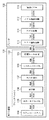
図3は本実施例における色分解プロファイルを生成する装置の構成例を示すブロック図で、CPU1201が色分解プロファイルの生成プログラムを実行することで実現される。
[Generate color separation profile]
FIG. 3 is a block diagram illustrating a configuration example of a device for generating a color separation profile in the present embodiment, which is realized by the
●色分解プロファイルDB
HDD1204などに格納された色分解プロファイルデータベース(DB)201は、種々の条件で最適化された複数の既存の色分解プロファイル(3DLUT)と、色分解プロファイルに対応するガンマ補正テーブル(1DLUT)を格納する。さらに、それらLUTによって再現可能な色域データを格納する。
Color separation profile DB
The color separation profile database (DB) 201 stored in HDD1204 etc. stores multiple existing color separation profiles (3DLUT) optimized under various conditions and a gamma correction table (1DLUT) corresponding to the color separation profile. To do. Furthermore, color gamut data reproducible by these LUTs is stored.
色分解プロファイルは、入力RGB値に対する色分解後のCMYK値を記述した3DLUTと補間演算部から構成される。本実施例の補間演算部は、各色分解プロファイルに共通である。従って、本実施例における色分解プロファイルの生成は3DLUTの生成と同義である。 The color separation profile includes a 3DLUT describing the CMYK value after color separation for the input RGB value and an interpolation calculation unit. The interpolation calculation unit of this embodiment is common to each color separation profile. Therefore, the generation of the color separation profile in this embodiment is synonymous with the generation of 3DLUT.
●色変換部
色変換部209は、プリンタモデル部210とプリンタモデル反転部211を有し、CMYKデータと表色系の色座標値Labの間の相互変換機能を提供する。プリンタモデル部210は、ノイゲバウアの式を用いて、色分解プロファイルの印刷条件において、CMYKデータを印刷した際に再現される色値(再現色値)Labを予測する。
Color Conversion Unit The
なお、目標とする工数以内に収まれば、通常のノイゲバウアの式に代えて、色材空間を多数のセルに細分化し、精度を向上したセル化ノイゲバウアの式を用いてもよい。勿論、ノイゲバウアの式に限らず、他の色予測手法によってプリンタモデルを構築してもよい。また、プリンタモデル部210は、色値Labの予測だけではなく、種々の画質評価項目を予測してもよい。
As long as it falls within the target man-hours, instead of the normal Neugebauer equation, a cellized Neugebauer equation in which the color material space is subdivided into a large number of cells to improve accuracy may be used. Of course, the printer model may be constructed not only by Neugebauer's equation but also by other color prediction methods. Further, the
しかし、色分解プロファイルの生成(プリンタモデルの構築)における工数の低減が目的であるから、目標工数に収まる範囲の評価によってプリンタモデルを構築する。例えば、カラーコンスタンシの評価値であるCIIはLab値を算出する過程で得られる分光反射率特性から計算可能であり、CIIをプリンタモデルの評価に使用することは好適である。 However, since the purpose is to reduce the man-hours in the generation of the color separation profile (construction of the printer model), the printer model is constructed by evaluating the range within the target man-hours. For example, CII, which is an evaluation value of color constant, can be calculated from the spectral reflectance characteristics obtained in the process of calculating the Lab value, and it is preferable to use CII for evaluation of the printer model.
プリンタモデル反転部211は、ニュートンの反復法によりプリンタモデル部210を繰り返し実行し、解を収束させることで、色分解プロファイルの印刷条件において、Lab値を再現可能なCMYKデータを予測する。ただし、解であるCMYKデータの次元数が、入力であるLab値の次元数よりも高いので、一意に解が収束しない場合がある。本実施例は、予め設定した合計色材量からCMYKの三変数を減算して、残るCMYKの一変数を求める。従って、実質的に入出力とも三変数にすることが可能で、反復法によってプリンタモデルを反転することが可能である。
The printer
なお、プリンタモデルの反転手法は、ニュートンの反復法に限らず、種々の最適化手法、探索手法が適用可能である。例えばシンプレックス法や粒子群最適化手法などを用いてもよい。 The printer model inversion method is not limited to Newton's iterative method, and various optimization methods and search methods can be applied. For example, a simplex method or a particle swarm optimization method may be used.
●プロファイル生成部
プロファイル生成部202は、生成条件入力部203(CPU1201が提供するUI)からのユーザ入力に従い色分解プロファイルを生成する。ユーザは、生成条件入力部203を操作して、色分解プロファイルの生成に必要な諸条件を入力する。本実施例においては、色分解プロファイル(3DLUT)の各格子点における合計色材量の最大値、生成する色分解プロファイルに対応するガンマ補正テーブルの情報、および、生成する色分解プロファイルの対象印刷媒体の種類を示す情報を入力する。
Profile generation unit The
頂点色分解決定部204は、生成条件である合計色材量の最大値と印刷媒体の種類に基づき、色分解プロファイルDB201から既存の色分解プロファイルを検索し、その3DLUTデータを取得する。検索する色分解プロファイルは、生成条件である合計色材量の最大値と印刷媒体の種類と類似する印刷条件を有する色分解プロファイルである。類似する複数の色分解プロファイルを検出した場合は、例えば、印刷媒体の種類、合計色材量の最大値の差、ガンマ補正テーブルの種類を考慮して、一つの色分解プロファイルを選択する。
The vertex color
色分解プロファイルDB201に格納されている色分解プロファイルは、様々な条件設定により検索可能であることが望ましいが、ユーザが生成条件入力部203において色分解プロファイルを直接指定する方式でもよい。また、色分解プロファイルDB201外のサーバなどに存在する色分解プロファイルと色域データを、ユーザが生成条件入力部203を操作して指定してもよい。
The color separation profile stored in the color
頂点色分解決定部204は、取得した3DLUTデータの合計色材量の最大値と、生成条件の合計色材量の最大値が異なる場合、生成条件の合計色材量の最大値に合致するように3DLUTの頂点格子点(以下、頂点)の色分解値(出力値)を調整する。3DLUTの頂点とは、入力値であるRGB値のうち少なくとも一つが最小値0または最大値255になる八頂点を指す。以降、この八頂点を下記のように呼ぶ。
K点 (R, G, B)=( 0, 0, 0)、
R点 (R, G, B)=(255, 0, 0)、
G点 (R, G, B)=( 0, 255, 0)、
B点 (R, G, B)=( 0, 0, 255)、
C点 (R, G, B)=( 0, 255, 255)、
M点 (R, G, B)=(255, 0, 255)、
Y点 (R, G, B)=( 0, 0, 255)、
W点 (R, G, B)=(255, 255, 255)
If the maximum value of the total color material amount of the acquired 3DLUT data is different from the maximum value of the total color material amount of the generation condition, the vertex color
K point (R, G, B) = (0, 0, 0),
R point (R, G, B) = (255, 0, 0),
G point (R, G, B) = (0, 255, 0),
B point (R, G, B) = (0, 0, 255),
C point (R, G, B) = (0, 255, 255),
M point (R, G, B) = (255, 0, 255),
Y point (R, G, B) = (0, 0, 255),
W point (R, G, B) = (255, 255, 255)
頂点再現色予測部205は、頂点色分解決定部204が調整した八頂点の色分解値に対する再現色値Lab(目標色)を、プリンタモデル部210によって計算する。
The vertex reproduction
格子点目標色決定部206は、八頂点の目標値と、色分解プロファイルDB201から取得した既存の色分解プロファイルの色域データに基づき、生成する色分解プロファイル(3DLUT)の外郭面とグレイラインに相当する各格子点の目標色を決定する。なお、3DLUTの外郭面は色域の境界に対応する。
The grid point target
目標色の決定は、既に目標色か色分解値が決定されている二つの格子点(両端点)を選択し、両端点の間に位置する中間格子点(以下、中間点)の目標色を決定する。まず、両端点と中間点の各格子点に対応する、既存の色分解プロファイルの格子点の再現色値を、既存の色分解プロファイルの色域データから抽出する。つまり、両端点と中間点と同一の入力値(RGB値)をもつ格子点の再現色値を取得する。 To determine the target color, select two grid points (both end points) for which the target color or color separation value has already been determined, and select the target color of the intermediate grid point (hereinafter referred to as the intermediate point) located between the end points. decide. First, the reproduction color values of the grid points of the existing color separation profile corresponding to the grid points of the end points and the intermediate points are extracted from the color gamut data of the existing color separation profile. That is, the reproduction color value of the grid point having the same input value (RGB value) as the end point and the intermediate point is acquired.
次に、両端点と中間点の各格子点に対応する再現色値に、後述する移動・変形を任意順、任意回数、適用して、両端点に対応する再現色値がプリンタモデル部210によって計算した目標色に一致するように、再現色値を調整する。そして、調整後の中間点の再現色値を中間点の目標色にする。
Next, the
各点(両端点と中間点)に対応する再現色値の調整は、再現色値の並びによって表される曲線に下記の移動・変形を任意回数、施す。
(1) Lab空間における平行移動、
(2) 各点の明度値Lの相対的な間隔を維持した、L軸方向の伸縮、
(3) 各点の彩度値Cの相対的な間隔を維持した、C軸方向の伸縮、
(4) 各点の色相値Hの相対的な間隔を維持した、H軸方向の伸縮、
(5) 各点の相対的な位置を維持した、L軸を中心とする回転
The adjustment of the reproduction color value corresponding to each point (both end points and intermediate points) is performed the following movement / deformation an arbitrary number of times on the curve represented by the arrangement of the reproduction color values.
(1) Translation in Lab space
(2) Expansion and contraction in the L-axis direction, maintaining the relative spacing of the lightness value L of each point,
(3) Expansion and contraction in the C-axis direction, maintaining the relative spacing of the saturation value C of each point,
(4) Expansion and contraction in the H-axis direction, maintaining the relative spacing of the hue value H of each point,
(5) Rotation around the L axis while maintaining the relative position of each point
上記の調整により、両端点の目標色を維持し、既存の色分解プロファイルの色域境界の形状と相似の色域境界をもつ色分解プロファイルの目標色を決定することができる。勿論、既存の色分解プロファイルの色域境界の形状と相似の色域境界をもつ色分解プロファイルの目標色を生成することが可能であれば、再現色値の調整方法は上記に限るものではない。 By the above adjustment, the target colors of the color separation profile having the color gamut boundary similar to the shape of the color gamut boundary of the existing color separation profile can be determined while maintaining the target colors of both end points. Of course, the reproduction color value adjustment method is not limited to the above as long as the target color of the color separation profile having a color gamut boundary similar to the shape of the color gamut boundary of the existing color separation profile can be generated. .
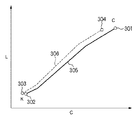
図4は新たな色分解プロファイルのC点-K点間の目標色を決定する調整をLC平面上で示す図である。頂点再現色予測部205によって、C点304、K点303の目標色が得られているとする。
FIG. 4 is a diagram showing adjustment on the LC plane for determining a target color between points C and K of a new color separation profile. It is assumed that the target colors of the
格子点目標色決定部206は、既存の色分解プロファイルの色域データから、C点304とK点303に対応するC点301とK点302の再現色値、および、C-K間の中間点に対応する、実線で示す再現色値の軌跡(曲線)305を取得する。次に、格子点目標色決定部206は、C点301とK点302を結ぶ曲線305に上記の変形・移動を任意回数施して、C点301がC点304に、K点302がK点303に一致するように曲線305を変形・移動する。図4に破線で示す曲線306は、調整後のC点304-K点303間の中間点の目標色を示す。
The grid point target
格子点目標色決定部206は、生成する色分解プロファイル(3DLUT)の八頂点の色分解値に基づき、上記の調整を繰り返して、3DLUTの外郭面とグレイライン上の全格子点の目標色を決定する。
The grid point target
格子点色分解決定部207は、プリンタモデル反転部211によって、格子点目標色決定部206が目標色を決定した格子点の色分解値CMYKを決定する。さらに、格子点色分解決定部207は、補間演算により、3DLUTの外殻面とグレイライン上の各格子点の色分解値から3DLUT内部の各格子点の色分解値を計算する。
The lattice point color
なお、3DLUT内の格子点の色分解値の決定は、当該格子点の目標色を格子点目標色決定部206により決定し、プリンタモデル反転部211を用いて色分解値を決定してもよい。また、3DLUTの各辺と外郭面の対角線上の格子点について目標色を決定し、プリンタモデル反転部211を用いて色分解値を決定し、外郭面上の残る格子点と3DLUT内の格子点の色分解値を補間演算によって計算してもよい。何れの方法を用いても、色域境界の形状が既存の色分解プロファイルの色域形状によって最適化される。
Note that the determination of the color separation value of the grid point in the 3DLUT may be performed by determining the target color of the grid point by the grid point target
プロファイル出力部208は、格子点色分解決定部207によって決定された3DLUTのデータを、所定形式で記述した色分解プロファイルをユーザが指定する出力先に出力する。色分解プロファイルの出力先はユーザ指示に従うが、同時に、生成した色分解プロファイルを色分解プロファイルDB201に登録してもよい。
The
このように、既存の色分解プロファイルを参照して、生成する色分解プロファイルの各格子点の目標色を決定することにより、色域の形状と他の画質項目を考慮した色分解プロファイルを低工数で生成することができる。つまり、既存の色分解プロファイルの画質項目の特性を引き継いで、新たな色分解プロファイルを生成することができる。 In this way, by referring to the existing color separation profile and determining the target color of each grid point of the generated color separation profile, the color separation profile considering the shape of the color gamut and other image quality items can be reduced in man-hours. Can be generated. That is, a new color separation profile can be generated by inheriting the characteristics of the image quality item of the existing color separation profile.
つまり、既存の色分解プロファイルの色域形状と相似の色域形状をもつ新しい色分解プロファイルを生成することができ、色材や印刷媒体などの印刷条件が充分に近ければ、既存の色分解プロファイルとほぼ同等の再現特性を有する色分解プロファイルが得られる。従って、既存の色分解プロファイルとして、色域と他の画質項目のバランスが充分に最適化されたものを使用することにより、工数を増大させることなく、良好な再現特性を有する色分解プロファイルを生成することが可能になる。 In other words, a new color separation profile with a color gamut shape similar to that of the existing color separation profile can be generated, and if the printing conditions such as color materials and print media are close enough, the existing color separation profile A color separation profile having substantially the same reproduction characteristics can be obtained. Therefore, by using an existing color separation profile in which the balance between the color gamut and other image quality items is sufficiently optimized, a color separation profile having good reproduction characteristics can be generated without increasing man-hours. It becomes possible to do.
以下、本発明にかかる実施例2の色処理を説明する。なお、実施例2において、実施例1と略同様の構成については、同一符号を付して、その詳細説明を省略する。 The color processing according to the second embodiment of the present invention will be described below. Note that the same reference numerals in the second embodiment denote the same parts as in the first embodiment, and a detailed description thereof will be omitted.
以下では、CMYKに加えて、淡色材のフォトシアンLc、フォトマゼンタPm、グレイGyの計七色の色材を使用するプリンタ用の色分解プロファイルの生成を説明する。装置の構成は、実施例1と同様であるが、色分解処理は七色の色材に対応するデータを生成するように拡張されている。また、色変換部209も七色の色材に対応するように拡張されている。
In the following, generation of a color separation profile for a printer that uses a total of seven color materials, that is, light cyan photocyan Lc, photomagenta Pm, and gray Gy in addition to CMYK will be described. The configuration of the apparatus is the same as that of the first embodiment, but the color separation process is extended to generate data corresponding to the seven color materials. In addition, the
前述したように、出力信号の次元数が入力信号の次元数より高い場合、反転プリンタモデル(プリンタモデル反転部211)の解が一意に収束しないという問題がある。実施例2における反転プリンタモデルの出力値はCMYKLcLmGyであり、合計記色材量が設定されていることから実質的に六次元の出力であり、三次元の入力値(Lab値)に対する一意の解を得ることはできない。そのため、反転プリンタモデルの出力値のうち三値について何らかの値を与え、反転プリンタモデルの入力値と同じ三次元まで解空間を落とし込む必要がある。 As described above, when the number of dimensions of the output signal is higher than the number of dimensions of the input signal, there is a problem that the solution of the inverted printer model (printer model inversion unit 211) does not uniquely converge. The output value of the reversal printer model in Example 2 is CMYKLcLmGy, and since the total color material amount is set, it is substantially a 6-dimensional output, and is a unique solution for a 3-dimensional input value (Lab value). Can't get. Therefore, it is necessary to give some value to the three values among the output values of the reverse printer model, and to drop the solution space to the same three dimensions as the input values of the reverse printer model.
実施例2の格子点色分解決定部207は、プリンタモデル反転部211へLab値を入力するのに先立ち、固定値を与える色材の選択と、既存の色分解プロファイルの色分解値に基づき与える固定値の設定を行う。
Prior to inputting the Lab value to the printer
まず、中間格子点に対応する、既存の色分解プロファイルの格子点において使用されない色材(出力値=0)の色分解値に0を設定する。残る色材が五色以上(つまり四次元以上)の場合、既存の色分解プロファイルの濃色材(C、M、K)の出力値を評価する。そして、出力値が所定値以上(閾値以上)の濃色材に対応する淡色材Lc、Lm、Gyの色分解値に固定値を設定し、出力値が所定値未満の濃色材の色分解値に固定値を設定する。 First, 0 is set to the color separation value of the color material (output value = 0) that is not used at the grid point of the existing color separation profile corresponding to the intermediate grid point. If the remaining color material is five colors or more (that is, four or more colors), the output value of the dark color material (C, M, K) of the existing color separation profile is evaluated. Then, a fixed value is set for the color separation values of the light color materials Lc, Lm, and Gy corresponding to the dark color material whose output value is greater than or equal to the predetermined value (threshold value or more), and color separation of the dark color material whose output value is less than the predetermined value Set a fixed value for the value.
色分解値として与える固定値は、既に色分解値が決定されている近傍の格子点と比較して色分解値が急激に変化しないように、既存の色分解プロファイルの色分解値を調整して設定する。そのため、固定値は、格子点ごとに設定するのではなく、所定範囲の複数の格子点の固定値をまとめて設定することが望ましい。例えば、格子点目標色決定部206が選択した両端点と中間点の一部または全部を一括して固定値の設定を行うことで、両端点の間の色分解値のジャンプの発生を抑制することができる。
The fixed value given as the color separation value is adjusted by adjusting the color separation value of the existing color separation profile so that the color separation value does not change abruptly compared to the neighboring grid points for which the color separation value has already been determined. Set. For this reason, it is desirable that the fixed value is not set for each grid point, but fixed values for a plurality of grid points within a predetermined range are set collectively. For example, by setting a fixed value for a part or all of the end points and intermediate points selected by the grid point target
以上の処理によって、格子点色分解決定部207は、プリンタモデル反転部211によって入力値を再現可能な色分解値を取得する。言い換えれば、既存の色分解プロファイルの色分解の特徴を引き継ぐように固定値を設定して、色分解プロファイルを生成することができる。
Through the above processing, the lattice point color
このように、五色以上の色材を使用するプリンタ用の、既存の色分解プロファイルの画質項目の特性を引き継いだ、新たな色分解プロファイルを生成することができる。 In this manner, a new color separation profile can be generated that inherits the characteristics of the image quality items of the existing color separation profile for a printer that uses color materials of five colors or more.
[変形例]
上記では、表色系にCIELabを用いる例を説明したが、他の表色系を用いても構わない。例えばCIEXYZ、CIELuv、CIECAM02などを利用してもよい。また、入力信号もsRGBに限らず、CMYK信号を入力として五色以上の色材量を示す色分解値を出力する色分解プロファイルを生成することも可能である。
[Modification]
In the above, an example in which CIELab is used for the color system has been described, but other color systems may be used. For example, CIEXYZ, CIELuv, CIECAM02, etc. may be used. Further, the input signal is not limited to sRGB, and it is also possible to generate a color separation profile that outputs a color separation value indicating a color material amount of five or more colors by inputting a CMYK signal.
また、プリンタの記録方式は、複数色の色材を使用するものであればよく、色材ごとに製版を伴う各種の印刷方式でもよいし、インクジェット方式、電子写真方式、熱転写方式、ドットインパクト方式などの製版を伴わない記録方式でもよい。インクジェット方式においては、記録領域に対して記録ヘッドを縦横に走査するシリアル型でもよいし、記録領域の幅に合わせて記録ノズルを配置し、一方向にのみ走査を行うラインヘッド型でもよい。 In addition, the printer recording method may be any method that uses a plurality of color materials, and may be any printing method that involves making a plate for each color material. Ink jet method, electrophotographic method, thermal transfer method, dot impact method A recording method that does not involve plate making may be used. In the ink jet system, a serial type that scans the recording head vertically and horizontally with respect to the recording area may be used, or a line head type that scans only in one direction by arranging recording nozzles in accordance with the width of the recording area may be used.
また、色分解プロファイルのデータベース、および/または、色分解プロファイルを生成するソフトウェアをサーバに搭載し、クライアントからの操作によってサーバが色分解プロファイルを生成してもよい。 Further, a database of color separation profiles and / or software for generating a color separation profile may be installed in a server, and the server may generate a color separation profile by an operation from a client.
[他の実施例]
なお、本発明は、複数の機器(例えばコンピュータ、インタフェイス機器、リーダ、プリンタなど)から構成されるシステムに適用しても、一つの機器からなる装置(例えば、複写機、ファクシミリ装置、制御装置など)に適用してもよい。
[Other embodiments]
Note that the present invention can be applied to a system composed of a plurality of devices (for example, a computer, an interface device, a reader, a printer, etc.), or a device (for example, a copier, a facsimile machine, a control device) composed of a single device. Etc.).
また、本発明の目的は、上記実施例の機能を実現するコンピュータプログラムを記録した記憶媒体をシステムまたは装置に供給し、そのシステムまたは装置のコンピュータ(CPUやMPU)が前記コンピュータプログラムを実行することでも達成される。この場合、記憶媒体から読み出されたソフトウェア自体が上記実施例の機能を実現することになり、そのコンピュータプログラムと、そのコンピュータプログラムを記憶する、コンピュータが読み取り可能な記憶媒体は本発明を構成する。 Another object of the present invention is to supply a storage medium storing a computer program for realizing the functions of the above-described embodiments to a system or apparatus, and the computer (CPU or MPU) of the system or apparatus executes the computer program. But it is achieved. In this case, the software read from the storage medium itself realizes the functions of the above embodiments, and the computer program and the computer-readable storage medium storing the computer program constitute the present invention. .
また、前記コンピュータプログラムの実行により上記機能が実現されるだけではない。つまり、そのコンピュータプログラムの指示により、コンピュータ上で稼働するオペレーティングシステム(OS)および/または第一の、第二の、第三の、…プログラムなどが実際の処理の一部または全部を行い、それによって上記機能が実現される場合も含む。 Further, the above functions are not only realized by the execution of the computer program. That is, according to the instruction of the computer program, the operating system (OS) and / or the first, second, third,... This includes the case where the above function is realized.
また、前記コンピュータプログラムがコンピュータに接続された機能拡張カードやユニットなどのデバイスのメモリに書き込まれていてもよい。つまり、そのコンピュータプログラムの指示により、第一の、第二の、第三の、…デバイスのCPUなどが実際の処理の一部または全部を行い、それによって上記機能が実現される場合も含む。 The computer program may be written in a memory of a device such as a function expansion card or unit connected to the computer. That is, it includes the case where the CPU of the first, second, third,... Device performs part or all of the actual processing according to the instructions of the computer program, thereby realizing the above functions.
本発明を前記記憶媒体に適用する場合、その記憶媒体には、先に説明したフローチャートに対応または関連するコンピュータプログラムが格納される。 When the present invention is applied to the storage medium, the storage medium stores a computer program corresponding to or related to the flowchart described above.
Claims (7)
生成すべき色変換プロファイルの格子点の合計色材量を含む情報を入力する入力手段と、
前記入力した情報に基づき、前記生成すべき色変換プロファイルに類似する色変換プロファイルとその色域データを取得する取得手段と、
前記合計色材量に基づき、前記取得した色変換プロファイルの頂点格子点の出力値から、前記生成すべき色変換プロファイルの頂点格子点の出力値を決定する決定手段と、
前記決定した頂点格子点の出力値によって再現される色値を予測する予測手段と、
前記予測した頂点格子点の色値と前記色域データに基づき、前記生成すべき色変換プロファイルの前記頂点格子点の間に位置する中間格子点の色値を設定する設定手段と、
前記設定した中間格子点の色値を再現する前記中間格子点の出力値を決定し、前記頂点格子点および前記中間格子点の出力値から、前記生成すべき色変換プロファイルの各格子点の出力値を計算する計算手段とを有することを特徴とする色処理装置。 A color processing device that generates a color conversion profile for converting an input signal value into an output value representing a color material amount,
An input means for inputting information including the total color material amount of grid points of the color conversion profile to be generated;
An acquisition means for acquiring a color conversion profile similar to the color conversion profile to be generated and its color gamut data based on the input information;
Determining means for determining an output value of a vertex grid point of the color conversion profile to be generated from an output value of a vertex grid point of the acquired color conversion profile based on the total color material amount;
Predicting means for predicting a color value reproduced by the output value of the determined vertex grid point;
Setting means for setting a color value of an intermediate lattice point located between the vertex lattice points of the color conversion profile to be generated based on the color value of the predicted vertex lattice point and the color gamut data;
The output value of the intermediate grid point that reproduces the color value of the set intermediate grid point is determined, and the output of each grid point of the color conversion profile to be generated from the output value of the vertex grid point and the intermediate grid point A color processing apparatus comprising: calculation means for calculating a value.
前記入力手段が、生成すべき色変換プロファイルの格子点の合計色材量を含む情報を入力し、
前記取得手段が、前記入力した情報に基づき、前記生成すべき色変換プロファイルに類似する色変換プロファイルとその色域データを取得し、
前記決定手段が、前記合計色材量に基づき、前記取得した色変換プロファイルの頂点格子点の出力値から、前記生成すべき色変換プロファイルの頂点格子点の出力値を決定し、
前記予測手段が、前記決定した頂点格子点の出力値によって再現される色値を予測し、
前記設定手段が、前記予測した頂点格子点の色値と前記色域データに基づき、前記生成すべき色変換プロファイルの前記頂点格子点の間に位置する中間格子点の色値を設定し、
前記計算手段が、前記設定した中間格子点の色値を再現する前記中間格子点の出力値を決定し、前記頂点格子点および前記中間格子点の出力値から、前記生成すべき色変換プロファイルの各格子点の出力値を計算することを特徴とする色処理方法。 A color processing method of a color processing apparatus that includes an input unit, an acquisition unit, a determination unit, a prediction unit, a setting unit, and a calculation unit, and generates a color conversion profile that converts an input signal value into an output value representing a color material amount. There,
The input means inputs information including the total color material amount of grid points of the color conversion profile to be generated,
The acquisition means acquires a color conversion profile similar to the color conversion profile to be generated and its color gamut data based on the input information,
The determining means determines the output value of the vertex grid point of the color conversion profile to be generated from the output value of the vertex grid point of the acquired color conversion profile based on the total color material amount,
The predicting means predicts a color value reproduced by an output value of the determined vertex grid point;
The setting means sets a color value of an intermediate grid point located between the vertex grid points of the color conversion profile to be generated based on the color value of the predicted vertex grid point and the color gamut data,
The calculation means determines an output value of the intermediate grid point that reproduces the color value of the set intermediate grid point, and determines the color conversion profile to be generated from the output value of the vertex grid point and the intermediate grid point. A color processing method characterized by calculating an output value of each grid point.
Priority Applications (1)
| Application Number | Priority Date | Filing Date | Title |
|---|---|---|---|
| JP2007324012A JP4921339B2 (en) | 2007-12-14 | 2007-12-14 | Color processing apparatus and method |
Applications Claiming Priority (1)
| Application Number | Priority Date | Filing Date | Title |
|---|---|---|---|
| JP2007324012A JP4921339B2 (en) | 2007-12-14 | 2007-12-14 | Color processing apparatus and method |
Publications (3)
| Publication Number | Publication Date |
|---|---|
| JP2009147755A JP2009147755A (en) | 2009-07-02 |
| JP2009147755A5 JP2009147755A5 (en) | 2011-02-03 |
| JP4921339B2 true JP4921339B2 (en) | 2012-04-25 |
Family
ID=40917828
Family Applications (1)
| Application Number | Title | Priority Date | Filing Date |
|---|---|---|---|
| JP2007324012A Expired - Fee Related JP4921339B2 (en) | 2007-12-14 | 2007-12-14 | Color processing apparatus and method |
Country Status (1)
| Country | Link |
|---|---|
| JP (1) | JP4921339B2 (en) |
Families Citing this family (1)
| Publication number | Priority date | Publication date | Assignee | Title |
|---|---|---|---|---|
| JP5589520B2 (en) * | 2010-04-09 | 2014-09-17 | セイコーエプソン株式会社 | Color conversion profile creation apparatus, color conversion profile creation method, color conversion profile creation program, and printing apparatus |
Family Cites Families (3)
| Publication number | Priority date | Publication date | Assignee | Title |
|---|---|---|---|---|
| JP3910323B2 (en) * | 1999-11-11 | 2007-04-25 | 富士フイルム株式会社 | Profile creation method and profile creation apparatus |
| JP3787534B2 (en) * | 2002-05-20 | 2006-06-21 | キヤノン株式会社 | Image processing apparatus, image processing method, and image processing program |
| JP4390040B2 (en) * | 2003-08-11 | 2009-12-24 | 富士ゼロックス株式会社 | Image processing apparatus, image processing method, image processing program, and recording medium |
-
2007
- 2007-12-14 JP JP2007324012A patent/JP4921339B2/en not_active Expired - Fee Related
Also Published As
| Publication number | Publication date |
|---|---|
| JP2009147755A (en) | 2009-07-02 |
Similar Documents
| Publication | Publication Date | Title |
|---|---|---|
| JP5147390B2 (en) | Color processing apparatus and method | |
| JP4022748B2 (en) | Color processing method, color processing apparatus, recording medium, color processing program, and image forming apparatus | |
| JP2006068982A (en) | Image processor, image processing method and printer driver | |
| JP4264687B2 (en) | Color processing method, storage medium, color processing apparatus, and image forming apparatus | |
| JP2012049823A (en) | Gamut shape prediction method, gamut shape prediction program, and printing apparatus loaded with color conversion table created with the use of gamut predicted by the gamut shape prediction method | |
| US7522309B2 (en) | Image processing method, image processing apparatus and storage medium storing a program | |
| US8773723B2 (en) | Generating color separation table for printer having color forming materials with high and low relative densities using a gamut boundary to limit use of dark color material | |
| JP3912486B2 (en) | Color processing method, storage medium, color processing apparatus, color conversion apparatus, and image forming apparatus | |
| JP2007028148A (en) | Apparatus, method and program for color conversion, and recording medium | |
| JP5882763B2 (en) | Image processing apparatus and profile creation method | |
| US8995035B2 (en) | Image processing method and apparatus, and color separation table generating method optimizing color gamut for each printing mode | |
| JP7297547B2 (en) | Image processing device, image forming device | |
| JP4646567B2 (en) | Color conversion table creation method and image processing apparatus | |
| JP2005176280A (en) | Color image processing method, color image processing apparatus, color image processing program, and storage medium | |
| JP4921339B2 (en) | Color processing apparatus and method | |
| JP4228207B2 (en) | Color image processing method, color image processing apparatus, color image processing program, and storage medium | |
| JP5014192B2 (en) | Color processing apparatus and color processing method | |
| US8203751B2 (en) | Color signal converting apparatus, image forming apparatus, color signal conversion method and computer readable medium | |
| JP2003283856A5 (en) | ||
| JP6241184B2 (en) | Color processing apparatus, color adjustment system, and program | |
| JPH09261492A (en) | Color predictive expression preparing device | |
| JP5957989B2 (en) | Image confirmation apparatus, image forming system, and program | |
| JP2011151491A (en) | Device and program for color conversion | |
| JP2007288495A (en) | Color separating method, color separation table creating method and image processing apparatus | |
| JP4130550B2 (en) | PROFILE GENERATION DEVICE, PROFILE GENERATION METHOD, PROGRAM, AND RECORDING MEDIUM |
Legal Events
| Date | Code | Title | Description |
|---|---|---|---|
| A521 | Written amendment |
Free format text: JAPANESE INTERMEDIATE CODE: A523 Effective date: 20101210 |
|
| A621 | Written request for application examination |
Free format text: JAPANESE INTERMEDIATE CODE: A621 Effective date: 20101210 |
|
| A977 | Report on retrieval |
Free format text: JAPANESE INTERMEDIATE CODE: A971007 Effective date: 20111227 |
|
| TRDD | Decision of grant or rejection written | ||
| A01 | Written decision to grant a patent or to grant a registration (utility model) |
Free format text: JAPANESE INTERMEDIATE CODE: A01 Effective date: 20120106 |
|
| A01 | Written decision to grant a patent or to grant a registration (utility model) |
Free format text: JAPANESE INTERMEDIATE CODE: A01 |
|
| A61 | First payment of annual fees (during grant procedure) |
Free format text: JAPANESE INTERMEDIATE CODE: A61 Effective date: 20120202 |
|
| R151 | Written notification of patent or utility model registration |
Ref document number: 4921339 Country of ref document: JP Free format text: JAPANESE INTERMEDIATE CODE: R151 |
|
| FPAY | Renewal fee payment (event date is renewal date of database) |
Free format text: PAYMENT UNTIL: 20150210 Year of fee payment: 3 |
|
| LAPS | Cancellation because of no payment of annual fees |