JP6761345B2 - Biostructure-independent deflection device - Google Patents
Biostructure-independent deflection device Download PDFInfo
- Publication number
- JP6761345B2 JP6761345B2 JP2016545785A JP2016545785A JP6761345B2 JP 6761345 B2 JP6761345 B2 JP 6761345B2 JP 2016545785 A JP2016545785 A JP 2016545785A JP 2016545785 A JP2016545785 A JP 2016545785A JP 6761345 B2 JP6761345 B2 JP 6761345B2
- Authority
- JP
- Japan
- Prior art keywords
- wire
- filter
- catheter
- attached
- transverse structure
- Prior art date
- Legal status (The legal status is an assumption and is not a legal conclusion. Google has not performed a legal analysis and makes no representation as to the accuracy of the status listed.)
- Active
Links
- 210000002376 aorta thoracic Anatomy 0.000 claims description 29
- 239000011324 bead Substances 0.000 claims description 18
- 230000007246 mechanism Effects 0.000 claims description 16
- 208000005189 Embolism Diseases 0.000 claims description 15
- 230000005855 radiation Effects 0.000 claims description 7
- 229910052751 metal Inorganic materials 0.000 claims description 6
- 239000002184 metal Substances 0.000 claims description 6
- 239000003550 marker Substances 0.000 claims description 2
- RVTZCBVAJQQJTK-UHFFFAOYSA-N oxygen(2-);zirconium(4+) Chemical compound [O-2].[O-2].[Zr+4] RVTZCBVAJQQJTK-UHFFFAOYSA-N 0.000 claims description 2
- 229920000642 polymer Polymers 0.000 claims 1
- 210000004204 blood vessel Anatomy 0.000 description 30
- 238000013461 design Methods 0.000 description 14
- 238000000034 method Methods 0.000 description 11
- 239000002245 particle Substances 0.000 description 11
- 239000000463 material Substances 0.000 description 10
- 239000013618 particulate matter Substances 0.000 description 10
- 210000000709 aorta Anatomy 0.000 description 9
- 210000001367 artery Anatomy 0.000 description 6
- 210000004369 blood Anatomy 0.000 description 6
- 239000008280 blood Substances 0.000 description 6
- 210000004556 brain Anatomy 0.000 description 6
- 230000006378 damage Effects 0.000 description 6
- 229910001000 nickel titanium Inorganic materials 0.000 description 5
- HLXZNVUGXRDIFK-UHFFFAOYSA-N nickel titanium Chemical compound [Ti].[Ti].[Ti].[Ti].[Ti].[Ti].[Ti].[Ti].[Ti].[Ti].[Ti].[Ni].[Ni].[Ni].[Ni].[Ni].[Ni].[Ni].[Ni].[Ni].[Ni].[Ni].[Ni].[Ni].[Ni] HLXZNVUGXRDIFK-UHFFFAOYSA-N 0.000 description 5
- 210000003743 erythrocyte Anatomy 0.000 description 4
- 210000000265 leukocyte Anatomy 0.000 description 4
- 239000011148 porous material Substances 0.000 description 4
- 239000004677 Nylon Substances 0.000 description 3
- 238000010586 diagram Methods 0.000 description 3
- 229920001778 nylon Polymers 0.000 description 3
- BASFCYQUMIYNBI-UHFFFAOYSA-N platinum Chemical compound [Pt] BASFCYQUMIYNBI-UHFFFAOYSA-N 0.000 description 3
- -1 polytetrafluoroethylene Polymers 0.000 description 3
- 229920001343 polytetrafluoroethylene Polymers 0.000 description 3
- 239000004810 polytetrafluoroethylene Substances 0.000 description 3
- 239000002033 PVDF binder Substances 0.000 description 2
- 229920006362 Teflon® Polymers 0.000 description 2
- 208000007536 Thrombosis Diseases 0.000 description 2
- 206010000891 acute myocardial infarction Diseases 0.000 description 2
- 210000001765 aortic valve Anatomy 0.000 description 2
- 230000000747 cardiac effect Effects 0.000 description 2
- 210000001326 carotid sinus Anatomy 0.000 description 2
- 239000000788 chromium alloy Substances 0.000 description 2
- 238000002591 computed tomography Methods 0.000 description 2
- 230000003073 embolic effect Effects 0.000 description 2
- 230000010102 embolization Effects 0.000 description 2
- 238000009434 installation Methods 0.000 description 2
- 238000002595 magnetic resonance imaging Methods 0.000 description 2
- 238000012986 modification Methods 0.000 description 2
- 230000004048 modification Effects 0.000 description 2
- 229920002981 polyvinylidene fluoride Polymers 0.000 description 2
- 230000008439 repair process Effects 0.000 description 2
- 229910001285 shape-memory alloy Inorganic materials 0.000 description 2
- 210000003270 subclavian artery Anatomy 0.000 description 2
- 229910052715 tantalum Inorganic materials 0.000 description 2
- GUVRBAGPIYLISA-UHFFFAOYSA-N tantalum atom Chemical compound [Ta] GUVRBAGPIYLISA-UHFFFAOYSA-N 0.000 description 2
- 206010065558 Aortic arteriosclerosis Diseases 0.000 description 1
- 229910000684 Cobalt-chrome Inorganic materials 0.000 description 1
- 208000002330 Congenital Heart Defects Diseases 0.000 description 1
- 229920004934 Dacron® Polymers 0.000 description 1
- 206010014498 Embolic stroke Diseases 0.000 description 1
- JOYRKODLDBILNP-UHFFFAOYSA-N Ethyl urethane Chemical compound CCOC(N)=O JOYRKODLDBILNP-UHFFFAOYSA-N 0.000 description 1
- 229920000271 Kevlar® Polymers 0.000 description 1
- 239000004743 Polypropylene Substances 0.000 description 1
- 241000124033 Salix Species 0.000 description 1
- 208000006011 Stroke Diseases 0.000 description 1
- 230000001154 acute effect Effects 0.000 description 1
- 239000000956 alloy Substances 0.000 description 1
- 238000002583 angiography Methods 0.000 description 1
- 201000001962 aortic atherosclerosis Diseases 0.000 description 1
- 229920003235 aromatic polyamide Polymers 0.000 description 1
- 206010003119 arrhythmia Diseases 0.000 description 1
- 230000003143 atherosclerotic effect Effects 0.000 description 1
- 230000008901 benefit Effects 0.000 description 1
- 230000015572 biosynthetic process Effects 0.000 description 1
- 230000000903 blocking effect Effects 0.000 description 1
- 210000000601 blood cell Anatomy 0.000 description 1
- 230000017531 blood circulation Effects 0.000 description 1
- 230000036770 blood supply Effects 0.000 description 1
- 210000001168 carotid artery common Anatomy 0.000 description 1
- 230000008859 change Effects 0.000 description 1
- 239000002131 composite material Substances 0.000 description 1
- 208000028831 congenital heart disease Diseases 0.000 description 1
- 230000008878 coupling Effects 0.000 description 1
- 238000010168 coupling process Methods 0.000 description 1
- 238000005859 coupling reaction Methods 0.000 description 1
- 238000002716 delivery method Methods 0.000 description 1
- 238000001514 detection method Methods 0.000 description 1
- 229910003460 diamond Inorganic materials 0.000 description 1
- 239000010432 diamond Substances 0.000 description 1
- 239000003814 drug Substances 0.000 description 1
- 229940079593 drug Drugs 0.000 description 1
- 238000002592 echocardiography Methods 0.000 description 1
- 206010014665 endocarditis Diseases 0.000 description 1
- 230000003511 endothelial effect Effects 0.000 description 1
- 229920000295 expanded polytetrafluoroethylene Polymers 0.000 description 1
- 239000000835 fiber Substances 0.000 description 1
- 229920002313 fluoropolymer Polymers 0.000 description 1
- 239000004811 fluoropolymer Substances 0.000 description 1
- 238000002594 fluoroscopy Methods 0.000 description 1
- 210000004491 foramen ovale Anatomy 0.000 description 1
- 208000014951 hematologic disease Diseases 0.000 description 1
- 238000003384 imaging method Methods 0.000 description 1
- 239000007943 implant Substances 0.000 description 1
- 230000002401 inhibitory effect Effects 0.000 description 1
- 238000003780 insertion Methods 0.000 description 1
- 230000037431 insertion Effects 0.000 description 1
- 238000002608 intravascular ultrasound Methods 0.000 description 1
- 230000001788 irregular Effects 0.000 description 1
- 230000003902 lesion Effects 0.000 description 1
- 210000004115 mitral valve Anatomy 0.000 description 1
- 239000008194 pharmaceutical composition Substances 0.000 description 1
- 229910052697 platinum Inorganic materials 0.000 description 1
- 229920000515 polycarbonate Polymers 0.000 description 1
- 239000004417 polycarbonate Substances 0.000 description 1
- 229920000728 polyester Polymers 0.000 description 1
- 229920001155 polypropylene Polymers 0.000 description 1
- 230000033764 rhythmic process Effects 0.000 description 1
- 238000009958 sewing Methods 0.000 description 1
- 239000004753 textile Substances 0.000 description 1
- 230000001225 therapeutic effect Effects 0.000 description 1
- 230000001732 thrombotic effect Effects 0.000 description 1
- 238000002604 ultrasonography Methods 0.000 description 1
- 238000011144 upstream manufacturing Methods 0.000 description 1
- 230000002792 vascular Effects 0.000 description 1
- 210000003462 vein Anatomy 0.000 description 1
- 238000012800 visualization Methods 0.000 description 1
Images


Classifications
-
- A—HUMAN NECESSITIES
- A61—MEDICAL OR VETERINARY SCIENCE; HYGIENE
- A61F—FILTERS IMPLANTABLE INTO BLOOD VESSELS; PROSTHESES; DEVICES PROVIDING PATENCY TO, OR PREVENTING COLLAPSING OF, TUBULAR STRUCTURES OF THE BODY, e.g. STENTS; ORTHOPAEDIC, NURSING OR CONTRACEPTIVE DEVICES; FOMENTATION; TREATMENT OR PROTECTION OF EYES OR EARS; BANDAGES, DRESSINGS OR ABSORBENT PADS; FIRST-AID KITS
- A61F2/00—Filters implantable into blood vessels; Prostheses, i.e. artificial substitutes or replacements for parts of the body; Appliances for connecting them with the body; Devices providing patency to, or preventing collapsing of, tubular structures of the body, e.g. stents
- A61F2/01—Filters implantable into blood vessels
- A61F2/011—Instruments for their placement or removal
-
- A—HUMAN NECESSITIES
- A61—MEDICAL OR VETERINARY SCIENCE; HYGIENE
- A61F—FILTERS IMPLANTABLE INTO BLOOD VESSELS; PROSTHESES; DEVICES PROVIDING PATENCY TO, OR PREVENTING COLLAPSING OF, TUBULAR STRUCTURES OF THE BODY, e.g. STENTS; ORTHOPAEDIC, NURSING OR CONTRACEPTIVE DEVICES; FOMENTATION; TREATMENT OR PROTECTION OF EYES OR EARS; BANDAGES, DRESSINGS OR ABSORBENT PADS; FIRST-AID KITS
- A61F2/00—Filters implantable into blood vessels; Prostheses, i.e. artificial substitutes or replacements for parts of the body; Appliances for connecting them with the body; Devices providing patency to, or preventing collapsing of, tubular structures of the body, e.g. stents
- A61F2/01—Filters implantable into blood vessels
- A61F2/013—Distal protection devices, i.e. devices placed distally in combination with another endovascular procedure, e.g. angioplasty or stenting
-
- A—HUMAN NECESSITIES
- A61—MEDICAL OR VETERINARY SCIENCE; HYGIENE
- A61F—FILTERS IMPLANTABLE INTO BLOOD VESSELS; PROSTHESES; DEVICES PROVIDING PATENCY TO, OR PREVENTING COLLAPSING OF, TUBULAR STRUCTURES OF THE BODY, e.g. STENTS; ORTHOPAEDIC, NURSING OR CONTRACEPTIVE DEVICES; FOMENTATION; TREATMENT OR PROTECTION OF EYES OR EARS; BANDAGES, DRESSINGS OR ABSORBENT PADS; FIRST-AID KITS
- A61F2/00—Filters implantable into blood vessels; Prostheses, i.e. artificial substitutes or replacements for parts of the body; Appliances for connecting them with the body; Devices providing patency to, or preventing collapsing of, tubular structures of the body, e.g. stents
- A61F2/01—Filters implantable into blood vessels
- A61F2002/016—Filters implantable into blood vessels made from wire-like elements
-
- A—HUMAN NECESSITIES
- A61—MEDICAL OR VETERINARY SCIENCE; HYGIENE
- A61F—FILTERS IMPLANTABLE INTO BLOOD VESSELS; PROSTHESES; DEVICES PROVIDING PATENCY TO, OR PREVENTING COLLAPSING OF, TUBULAR STRUCTURES OF THE BODY, e.g. STENTS; ORTHOPAEDIC, NURSING OR CONTRACEPTIVE DEVICES; FOMENTATION; TREATMENT OR PROTECTION OF EYES OR EARS; BANDAGES, DRESSINGS OR ABSORBENT PADS; FIRST-AID KITS
- A61F2/00—Filters implantable into blood vessels; Prostheses, i.e. artificial substitutes or replacements for parts of the body; Appliances for connecting them with the body; Devices providing patency to, or preventing collapsing of, tubular structures of the body, e.g. stents
- A61F2/01—Filters implantable into blood vessels
- A61F2002/018—Filters implantable into blood vessels made from tubes or sheets of material, e.g. by etching or laser-cutting
-
- A—HUMAN NECESSITIES
- A61—MEDICAL OR VETERINARY SCIENCE; HYGIENE
- A61F—FILTERS IMPLANTABLE INTO BLOOD VESSELS; PROSTHESES; DEVICES PROVIDING PATENCY TO, OR PREVENTING COLLAPSING OF, TUBULAR STRUCTURES OF THE BODY, e.g. STENTS; ORTHOPAEDIC, NURSING OR CONTRACEPTIVE DEVICES; FOMENTATION; TREATMENT OR PROTECTION OF EYES OR EARS; BANDAGES, DRESSINGS OR ABSORBENT PADS; FIRST-AID KITS
- A61F2220/00—Fixations or connections for prostheses classified in groups A61F2/00 - A61F2/26 or A61F2/82 or A61F9/00 or A61F11/00 or subgroups thereof
- A61F2220/0025—Connections or couplings between prosthetic parts, e.g. between modular parts; Connecting elements
- A61F2220/0041—Connections or couplings between prosthetic parts, e.g. between modular parts; Connecting elements using additional screws, bolts, dowels or rivets, e.g. connecting screws
-
- A—HUMAN NECESSITIES
- A61—MEDICAL OR VETERINARY SCIENCE; HYGIENE
- A61F—FILTERS IMPLANTABLE INTO BLOOD VESSELS; PROSTHESES; DEVICES PROVIDING PATENCY TO, OR PREVENTING COLLAPSING OF, TUBULAR STRUCTURES OF THE BODY, e.g. STENTS; ORTHOPAEDIC, NURSING OR CONTRACEPTIVE DEVICES; FOMENTATION; TREATMENT OR PROTECTION OF EYES OR EARS; BANDAGES, DRESSINGS OR ABSORBENT PADS; FIRST-AID KITS
- A61F2230/00—Geometry of prostheses classified in groups A61F2/00 - A61F2/26 or A61F2/82 or A61F9/00 or A61F11/00 or subgroups thereof
- A61F2230/0002—Two-dimensional shapes, e.g. cross-sections
- A61F2230/0004—Rounded shapes, e.g. with rounded corners
- A61F2230/0008—Rounded shapes, e.g. with rounded corners elliptical or oval
Description
本発明は、大動脈内の塞栓が動脈に入ることをブロックするためのデバイスに関する。 The present invention relates to a device for blocking an embolus in an aorta from entering an artery.
血管内フィルタなどのデバイスが、処置の前若しくは間、又は別のときに血管内に挿入され得る。 Devices such as intravascular filters can be inserted into the blood vessel before, during, or at another time during the procedure.
そのようなデバイスは、静脈又は動脈を通り、例えば大動脈又は他の血管内に通され得るカテーテルによって挿入することができ、そこでデバイスは、カテーテルから解放され、例えば展開され得る。デバイスは、塞栓又は他の物体を、脳に供給する血液供給部に入らないようにフィルタにかけ、偏向させ、又はブロックすることができる。 Such a device can be inserted by a catheter that can be routed through a vein or artery, eg, into an aorta or other blood vessel, where the device can be released from the catheter and deployed, eg. The device can filter, deflect, or block the embolus or other object from entering the blood supply that supplies the brain.
第1の態様では、本発明は、塞栓を偏向させるための血管内デバイスであって、横方向構造体(lateral structure)と、フィルタと、横方向構造体に連結された二本のワイヤとを有しているデバイスを提供する。横方向構造体は、80mmから120mmの間の長さと、30mmから45mmの間の幅を有している細長い形状(例えば、楕円、長円、又は他の非直線の形状)を取り囲み得る。ヒト対象の大動脈弓内におけるデバイスの設置時、大動脈弓の上壁と接触するように横方向構造体はサイズ設定され得る。さらに、実質的に平坦な細長い(例えば楕円、長円、又は他の非直線の形状)フィルタが、横方向構造体の長さ及び幅に取り付けられ得る。第1のワイヤは、横方向構造体の遠位端部に取り付けられ、第2のワイヤは、横方向構造体の近位端部に取り付けられ得る。 In a first aspect, the invention is an intravascular device for deflecting an embolus that comprises a lateral structure, a filter, and two wires connected to the lateral structure. Provide the device you have. The transverse structure can enclose an elongated shape (eg, an ellipse, an oval, or other non-linear shape) having a length between 80 mm and 120 mm and a width between 30 mm and 45 mm. Upon placement of the device within the aortic arch of a human subject, the lateral structure may be sized to contact the upper wall of the aortic arch. In addition, substantially flat elongated (eg, elliptical, oval, or other non-linear shapes) filters can be attached to the length and width of the lateral structure. The first wire can be attached to the distal end of the transverse structure and the second wire can be attached to the proximal end of the transverse structure.
追加の実施形態では、デバイスの横方向構造体は、大動脈弓内におけるデバイスの設置時、大動脈弓の壁と共にシールを形成する。一部の実施形態では、デバイスのフィルタは、横方向構造体によって取り囲まれた周囲を越えて延びて、例えば、血管壁、例えば大動脈弓に対するシールを形成する。 In an additional embodiment, the lateral structure of the device forms a seal with the wall of the aortic arch when the device is installed within the aortic arch. In some embodiments, the filter of the device extends beyond the perimeter surrounded by the transverse structure to form a seal, eg, on the vessel wall, eg, the aortic arch.
上記のデバイスのフィルタの孔は、これらが、血液(例えば、赤血球(赤血球)、白血球(白血球)、血小板(血小板)、及び血漿)を通すことができるが、例えば50、100、又は200μmより大きな寸法を有する塞栓はほぼ通すことができないようにサイズ設定可能である。 The filter holes of the above devices allow these to pass blood (eg, red blood cells (red blood cells), white blood cells (white blood cells), platelets (platelets), and plasma), but are larger than, for example, 50, 100, or 200 μm. Embolisms with dimensions can be sized so that they are almost impervious.
特定の実施形態では、デバイスの二本のワイヤは、同じ又は異なる硬度を有することができ(例えば、第1のワイヤは第2のワイヤより硬くてもよく、又は第2のワイヤは第1のワイヤより硬くてもよい)、容易に打ち延ばすことができる。デバイスは、金属、例えばニチノールワイヤから作製され得る。デバイスのワイヤ及び横方向構造体の直径は、1、0.5、0.25、0.1mm又はそれ以下であり得る。横方向構造体並びに/又は第1及び/若しくは第2のワイヤは、二本以上のワイヤを一緒にねじって所望の厚さ(例えば約0.5mm未満の直径を有する)及び硬度を備えた複合ワイヤを形成することによって形成され得る。 In certain embodiments, the two wires of the device can have the same or different hardness (eg, the first wire may be stiffer than the second wire, or the second wire may be the first. It may be harder than a wire) and can be easily stretched. The device can be made from a metal, eg Nitinol wire. The diameters of the device wires and lateral structures can be 1, 0.5, 0.25, 0.1 mm or less. The transverse structure and / or the first and / or second wire is a composite wire having the desired thickness (eg, having a diameter of less than about 0.5 mm) and hardness by twisting two or more wires together. Can be formed by forming.
特定の実施形態では、第1及び/又は第2のワイヤは、横方向構造体の長さに沿って(例えば横方向構造体の中央線に沿って)、フィルタ又は横方向構造体に取り付けられる。特定の実施形態では、第2のワイヤは中空チューブである。 In certain embodiments, the first and / or second wire is attached to the filter or transverse structure along the length of the transverse structure (eg, along the centerline of the transverse structure). .. In certain embodiments, the second wire is a hollow tube.
一実施形態では、デバイスの第1のワイヤは、その遠位端部に配置されたねじ様機構(screw-like mechanism)を有しており、デバイスのフィルタ又は横方向構造体は、その遠位端部に、ねじ様機構を受け入れるのに適した接続構成要素を含んでいる。デバイスのフィルタ又は横方向構造体の接続構成要素は、フィルタの遠位端部近くに取り付けられたビーズ(bead)、例えば球状ビーズ、又は追加の要素を含んで、横方向構造体又はフィルタを第1又は第2のワイヤに不可逆式に又は可逆式に連結することができる(例えば、ねじ及びねじを受け入れるくぼみ、又はボール及びスネア機構(snare mechanism))。追加の要素は、一つ以上(例えば二つ、三つ、四つ又はそれ以上の)ボール(複数可)、例えば球状ボール(複数可)、又はチップ(tip)(複数可)を横方向構造体の遠位端部及び近位端部に含むことができる。デバイスの第1及び/又は第2のワイヤはまた、スネアを含むこともでき、スネアは、デバイスのフィルタ又は横方向構造体に取り付けられたビーズ、ボール、チップ、又は他の受け入れ要素と接合することができる。 In one embodiment, the first wire of the device has a screw-like mechanism located at its distal end, and the filter or transverse structure of the device is distal thereof. At the end, it contains a connecting component suitable for accepting a thread-like mechanism. The connecting component of the device's filter or transverse structure comprises beads attached near the distal end of the filter, such as spherical beads, or additional elements to include the transverse structure or filter. It can be irreversibly or reversibly connected to the first or second wire (eg, a screw and a recess that accepts the screw, or a ball and snare mechanism). Additional elements laterally structure one or more (eg, two, three, four or more) balls (s), such as spherical balls (s), or tips (s). It can be included in the distal and proximal ends of the body. The first and / or second wire of the device can also include a snare, which joins a bead, ball, chip, or other receiving element attached to the filter or transverse structure of the device. be able to.
上記の実施形態のいずれにおいても、本発明のデバイスは、さらに、放射線不透過性マーカを含むことができる。 In any of the above embodiments, the device of the present invention can further include a radiation opaque marker.
別の態様では、本発明は、塞栓を偏向させるためのシステムであって、横方向構造体と、フィルタと、第1及び第2のワイヤとを有する血管内デバイスの上述した実施形態のいずれかと、デバイスが中に装填され得るカテーテルとを含んでいるシステムを特徴として有する。一部の実施形態では、システムのカテーテルは、ガイドワイヤを含む。 In another aspect, the invention is a system for deflecting an embolus, with any of the above-described embodiments of an intravascular device having a transverse structure, a filter, and first and second wires. It features a system that includes a catheter in which the device can be loaded. In some embodiments, the catheter of the system comprises a guide wire.
上記のシステムは、さらに、保護されたリップ部をシステムの遠位端部に含むことができる。保護されたリップ部は、(例えば、カテーテルより小さい直径を有する)拡張器であり得、この拡張器は、カテーテルの遠位に配置される。本発明のシステムはまた、ピッグテール(pigtail)カテーテルを含むこともできる。 The system described above can further include a protected lip portion at the distal end of the system. The protected lip can be a dilator (eg, having a diameter smaller than the catheter), which dilator is located distal to the catheter. The system of the present invention can also include a pigtail catheter.
本発明のシステムの一実施形態では、カテーテル内に装填されたとき、デバイスの横方向構造体及びフィルタは、例えば圧縮され、存在する場合、拡張器の後方に配置され得る。別の実施形態では、デバイスに対するカテーテルの後退時(又はカテーテルに対するデバイスの前進時)、デバイスの横方向構造体及びフィルタは拡張する。上記で説明したカテーテルは、遠位開口部を有することができ、遠位開口部は、カテーテルの長さに対して垂直であるか、又はカテーテルの長さに対して非垂直である。開口部の角度は、所望の配向のデバイスの送達を可能にするように調整され得る。 In one embodiment of the system of the invention, when loaded into the catheter, the lateral structure and filter of the device can be, for example, compressed and, if present, placed behind the dilator. In another embodiment, when the catheter retracts relative to the device (or when the device advances relative to the catheter), the lateral structure and filter of the device expands. The catheter described above can have a distal opening, which is either perpendicular to the length of the catheter or non-vertical to the length of the catheter. The angle of the opening can be adjusted to allow delivery of the device in the desired orientation.
別の態様では、本発明は、対象の血管(例えば大動脈弓)内に、デバイスを含むカテーテル(デバイスは、対象へのカテーテルの導入前又は導入後にカテーテル内に装填され得る)を挿入することによって、上記のデバイスのいずれかを対象に導入する方法を特徴として有する。デバイスは、例えば第1のワイヤに力をかけることによってカテーテル内に装填され得る。デバイスに対するカテーテルの後退時(又はカテーテルに対するデバイスの前進時)、横方向構造体及びフィルタは、血管内の所望の場所に、例えば大動脈弓内に展開する。さらに、大動脈弓内における設置時、上記のデバイスの横方向構造体及び/又はフィルタは、血管の壁(例えば大動脈弓)と共にシールを形成することができ得る。デバイスは、第1及び第2のワイヤを相反して押し引きすることによって大動脈弓内に配置され得る。 In another aspect, the invention is by inserting a catheter containing a device (the device can be loaded into the catheter before or after introduction of the catheter into the subject) into the blood vessel of the subject (eg, the aortic arch). , Which features a method of introducing any of the above devices. The device can be loaded into the catheter, for example by applying force to the first wire. When the catheter retracts relative to the device (or when the device advances relative to the catheter), the transverse structure and filter deploy at the desired location within the vessel, eg, within the aortic arch. In addition, upon installation within the aortic arch, the transverse structures and / or filters of the above devices may be able to form a seal with the walls of the blood vessel (eg, the aortic arch). The device can be placed within the aortic arch by pushing and pulling the first and second wires in opposition.
特定の実施形態では、デバイスは、対象内へのカテーテルの導入前又は導入後にカテーテル内に装填される。カテーテルは、さらに、ガイドワイヤを含むことができる。ピッグテールカテーテルもまた、カテーテルを通して導入され得る。さらに、ピッグテールカテーテルは、ガイドワイヤ上に挿入されてよく、ガイドワイヤは、デバイスの展開の前にカテーテルを通って後退され得る。 In certain embodiments, the device is loaded into the catheter before or after introduction of the catheter into the subject. The catheter can further include a guide wire. Pigtail catheters can also be introduced through the catheter. In addition, the pigtail catheter may be inserted over the guide wire, which can be retracted through the catheter prior to deployment of the device.
本明細書で用いる場合、用語「実質的に平坦」は、80mm以下(例えば、10mm、20mm、30mm、40mm、50mm、60mm又は70mm以下)の曲率半径を指す。 As used herein, the term "substantially flat" refers to a radius of curvature of 80 mm or less (eg, 10 mm, 20 mm, 30 mm, 40 mm, 50 mm, 60 mm or 70 mm or less).
本明細書で用いる場合、用語「細長い」は、その幅より大きな長さを有する形状を指す。 As used herein, the term "elongated" refers to a shape that has a length greater than its width.
本明細書で用いる場合、用語「構造的支持をもたらす」は、デバイスの形状及び硬度に寄与する特性を指す。 As used herein, the term "providing structural support" refers to properties that contribute to the shape and hardness of the device.
本明細書で用いる場合、用語「ワイヤ」は、任意の非分解性材料(例えば、ポリカーボネート、ポリテトラフルオロエチレン(PTFE)、延伸ポリテトラフルオロエチレン(ePTFE)、フッ化ポリビニリデン(PVDF)、ポリプロピレン、多孔性ウレタン、金属、ニチノール、フッ素重合体(例えば、テフロン(Teflon)(登録商標))、コバルトクロム合金(CoCr)、及びパラアラミド(ケブラー(Kevlar)(登録商標))、又は織物(例えば、ナイロン、ポリエステル(例えば、ダクロン(Dacron)(登録商標))、又は絹)から製作された、任意の細長い構造(例えば、コード、ファイバー、ヤーン、フィラメント、ケーブル、及び糸(thread))を指す。 As used herein, the term "wire" refers to any non-degradable material such as polycarbonate, polytetrafluoroethylene (PTFE), stretched polytetrafluoroethylene (ePTFE), polyvinylidene fluoride (PVDF), polypropylene. , Porous urethane, metal, nitinol, fluoropolymers (eg, Teflon®), cobalt-chromium alloys (CoCr), and paraaramids (Kevlar®), or textiles (eg, Teflon®). Refers to any elongated structure (eg, cord, fiber, yarn, filament, cable, and thread) made of nylon, polyester (eg, Dacron®), or silk).
本明細書で用いる場合、用語「ピッグテール(pigtail)カテーテル」は、埋め込み物(例えば人工大動脈弁)の確認のために放射線不透過性コントラストを導入するために使用される外科的デバイスを指す。 As used herein, the term "pigtail catheter" refers to a surgical device used to introduce radiopaque contrast for identification of an implant (eg, an artificial aortic valve).
本明細書で用いる場合、用語「拡張器」は、血管などの身体開口部を、より広く、大きく、又はより開くようにするために使用される外科的器具を指す。 As used herein, the term "dilator" refers to a surgical instrument used to make a body opening, such as a blood vessel, wider, larger, or more open.
本発明は、潜在的に有害な粒子状物質の血流の通り抜けを阻害する方法に関する。血液内に存在し得る粒子状物質は、限定的ではないが、血餅、石灰化片、及び塞栓を含む。極めて小さな粒子状物質は、重大な害を引き起こすことはないが、大きな粒子状物質の通過の結果、脳卒中又は他の有害な結果が生じ得る。粒子状物質の通過に起因する損傷のリスクは、血管系を摂動させる特定の状態又は医療的処置に関連して増大し得る。これらのリスクを軽減するために、本発明は、血管内デバイスを特徴として有し、この血管内デバイスは、血管内の粒子がフィルタを通過することを防止するために使用されるフィルタと、フィルタを支持する横方向構造体と、横方向構造体にその遠位端部及び近位端部において一本ずつ取り付けられた二本のワイヤとを有する。横方向構造体は、実質的に平坦であり、フィルタの平面の上方又は下方に延びるいかなる支持部材も含まない。好ましい実施形態では、横方向構造体の端部に取り付けられた二本のワイヤは、フィルタが血管内(例えば大動脈弓)にすでに配置された後、その配向を偏向させ又は制御するために使用され得る。二本のワイヤは、容易に送達システムを通って移動して、デバイスを所望の場所に送達することができ得、これらは、相反して押し引きされてデバイスを偏向させることができる。 The present invention relates to a method of inhibiting the passage of potentially harmful particulate matter through the bloodstream. Particulate matter that can be present in the blood includes, but is not limited to, clots, calcified debris, and embolisms. Very small particulate matter does not cause significant harm, but the passage of large particulate matter can result in stroke or other harmful consequences. The risk of damage due to the passage of particulate matter can be increased in connection with certain conditions or medical procedures that perturb the vascular system. To mitigate these risks, the invention features an intravascular device, which is a filter and a filter used to prevent particles in the blood vessel from passing through the filter. It has a transverse structure that supports it and two wires that are attached to the transverse structure one by one at its distal and proximal ends. The transverse structure is substantially flat and does not include any support members extending above or below the plane of the filter. In a preferred embodiment, two wires attached to the ends of the transverse structure are used to deflect or control the orientation of the filter after it has already been placed in the blood vessel (eg, the aortic arch). obtain. The two wires can easily move through the delivery system to deliver the device to the desired location, which can be pushed and pulled in opposition to deflect the device.
一部の実施形態では、フィルタが血管内に設置され、二本のワイヤを使用して所望に応じて配向された後、これらのワイヤは、次いで、フィルタ及びその横方向構造体のみを血管内に残して、デバイスから取り外され得る。この取り外しは、デバイスの第1のワイヤの遠位端部に取り付けられたねじ様機構によって容易にすることができ、このねじ様機構は、デバイスのフィルタ、横方向構造体、又は別の部分の遠位端部に取り付けられた要素に適切に接続される。ねじ、又は適切な代替物を結合させることができるデバイスに取り付けられた接続要素は、ビーズであり得る。 In some embodiments, after the filters are placed intravascularly and oriented as desired using two wires, these wires then only intravascularize the filter and its transverse structure. Can be removed from the device, leaving in. This removal can be facilitated by a screw-like mechanism attached to the distal end of the first wire of the device, which is a filter, transverse structure, or other part of the device. Properly connected to an element attached to the distal end. The connecting element attached to the screw, or device to which a suitable alternative can be attached, can be beads.
別の実施形態では、デバイスは、横方向構造体の近位端部及び遠位端部の両方に取り付けられた小さなボール又はチップを特徴として有する。そのような実施形態は、第1及び/又は第2のワイヤを横方向構造体に、各々の小さなボール又はチップの周りに配置されたスネアを介して取り付けることを可能にする。スネアは、チップ又はボールに取り付けられたとき、第1及び第2のワイヤを押し引きすることによってデバイスの配向の偏向又は制御を可能にする。ワイヤの一本又はその両方は、取り付けられたボール又はチップの周りからスネアを取り外すことによって、横方向構造体から取り外され得る。デバイスのこれらの追加の特徴は、第1のワイヤと、例えば、第1のワイヤとフィルタの間を通過し得る任意の器具類との間の潜在的なもつれを修正することができる。 In another embodiment, the device features small balls or chips attached to both the proximal and distal ends of the transverse structure. Such an embodiment allows the first and / or second wire to be attached to the transverse structure via a snare placed around each small ball or chip. The snare allows for deflection or control of the orientation of the device by pushing and pulling the first and second wires when attached to a chip or ball. One or both of the wires can be removed from the lateral structure by removing the snare from around the attached ball or tip. These additional features of the device can correct potential entanglements between the first wire and, for example, any instrument that may pass between the first wire and the filter.
デバイスのワイヤの一方は、同じ平面内のフィルタ若しくは横方向構造体上に、又はフィルタ若しくは横方向構造体に取り付けられるか、又は縫い付けられ得る。例えば、ワイヤは、フィルタの中央に沿って取り付けられ、第1のワイヤ及びフィルタを使用前に凹状形状に曲げることを可能にすることができる。曲げられたワイヤは、剛性であってもよく、フィルタに、例えばその上側に取り付けられ得る。フィルタは、代替的には、安定した可撓性材料から作製され、フィルタの長さ(例えば中央線)に沿って配置されて取り付けられた中空チューブを有することができる。中空チューブは、デバイスの第2のワイヤであってもよい。一部の実施形態では、チューブは、これを通り抜ける第1のワイヤを有し、第1のワイヤはチューブ内で前後に動くことができ、その結果、チューブの全体的偏向、したがってフィルタの形状の変化を生じさせる。そのようなチューブは、各々の端部に一つずつ配置された二つのストッパを含んで、チューブ内のワイヤの移動を抑え、制御することができる。 One of the wires of the device can be attached to or sewn onto a filter or transverse structure in the same plane, or to the filter or transverse structure. For example, the wires are mounted along the center of the filter and can allow the first wire and filter to be bent into a concave shape prior to use. The bent wire may be rigid and may be attached to the filter, eg, above it. Alternatively, the filter can have a hollow tube made from a stable flexible material and mounted arranged along the length of the filter (eg, the center line). The hollow tube may be the second wire of the device. In some embodiments, the tube has a first wire through it that allows the first wire to move back and forth within the tube, resulting in overall deflection of the tube, and thus of the shape of the filter. Make a difference. Such a tube may include two stoppers, one at each end, to suppress and control the movement of wires within the tube.
デバイスは、横方向構造体に対するワイヤの配向に関して非対称設計を有することができる。代替の実施形態では、デバイスは対称設計を有し、それによってフィルタが直立の凹状式に又は逆向きの凸状式に配向されることを可能にする。デバイスはまた、デバイスの残りの部分より薄いか又は狭くてもよい一つ以上の端部を特徴として有することもできる。デバイスの端部の狭小化は、点ではなく円形のノブ形状で終端することができる。 The device can have an asymmetric design with respect to the orientation of the wires with respect to the lateral structure. In an alternative embodiment, the device has a symmetrical design, which allows the filter to be oriented in an upright concave or reverse convex orientation. The device can also feature one or more ends that may be thinner or narrower than the rest of the device. The narrowing of the end of the device can be terminated by a circular knob shape rather than a point.
デバイスの横方向構造体は、例えば、フィルタに対して構造をもたらし、主要血管の生体構造内のフィルタの制御を容易にすることができる。例えば、この横方向構造体は、オペレータが主要血管内のデバイスの配向を制御してデバイスを主要血管の特定の特徴部に押し付ける(例えば、デバイスを一つ以上の二次血管の開口部に、又は主要血管の壁に押し付ける)ことを可能にし得る。本発明のデバイスは、例えば、可撓性材料から作製されたばねリングワイヤフレームである、横方向構造体を特徴として有することができる。このばねリングフレームは、長円又は楕円の形状に形成され得る。一部の実施形態では、本発明のデバイスはまた、外側の横方向構造体を特徴として有することもでき、外側の横方向構造体は、内部の横方向構造体に連結されて、例えば楕円形状を有する骨格を形成する。外側の横方向構造体は、デバイスに対して追加の構造的支持をもたらすことができ、デバイスのフィルタと血管壁の間にシールを作り出すことを容易にすることができる。あるいは、フィルタそれ自体が、横方向構造体の周囲を越えて延びることによって血管壁に対するシールを作り出すことができる。 The lateral structure of the device can, for example, provide structure to the filter, facilitating control of the filter within the biostructure of the major blood vessels. For example, this transverse structure allows the operator to control the orientation of the device within the major vessel to push the device against a particular feature of the major vessel (eg, to the opening of one or more secondary vessels). Or it can be pressed against the wall of a major blood vessel). The device of the present invention can feature, for example, a transverse structure, which is a spring ring wire frame made of a flexible material. The spring ring frame can be formed in the shape of an oval or ellipse. In some embodiments, the device of the invention can also feature an outer transverse structure, the outer transverse structure being connected to an inner transverse structure, eg, an elliptical shape. Form a skeleton with. The outer lateral structure can provide additional structural support for the device, facilitating the creation of a seal between the device's filter and the vessel wall. Alternatively, the filter itself can create a seal against the vessel wall by extending beyond the perimeter of the transverse structure.
本発明のデバイスは、フィルタと、その平面を越えて延びる支持部材を有さない横方向構造体と、二本のワイヤとを含むことができる。デバイスは、塞栓又は他の大きな物体を、保護された二次血管に入らないようにフィルタにかけ、及び/又は偏向させることができる。デバイスは、治療部位への送達を容易にするために、その長手方向軸に沿って潰れることができる。デバイスは、さらに、介入性心臓病学(例えば、TAVI処置)において使用される一般的な送達方法に適合することができる。デバイスは、送達、例えばカテーテル、システムに一体化され得る。一部の実施形態では、デバイスは、送達ワイヤから取り外し可能であり得る。取り出し時、デバイスは、元の展開配向に実質的に類似する配向で後退され得る。 The device of the present invention can include a filter, a transverse structure without a support member extending beyond its plane, and two wires. The device can filter and / or deflect emboli or other large objects out of the protected secondary vessels. The device can be collapsed along its longitudinal axis to facilitate delivery to the treatment site. The device can also be adapted to common delivery methods used in interventional cardiology (eg, TAVI treatment). The device can be integrated into the delivery, eg catheter, system. In some embodiments, the device may be removable from the delivery wire. Upon removal, the device can be retracted in an orientation substantially similar to the original unfolded orientation.
本発明のデバイスの横方向構造体ワイヤ又は送達ワイヤのいずれも、全体的に又は部分的に、例えば、ニチノール若しくは他の金属ワイヤ、超弾性若しくは形状記憶合金材料、容易に打ち延ばすことができる材料、又はナイロンから製作され得る。金属ワイヤは、例えばタンタル又はプラチナを含むことができる。デバイスのワイヤの直径は、1.0mmより小さいか、又はこれに等しくてよい(例えば、1.0、0.5、0.25、0.1mm又はそれ以下)。横方向構造体のワイヤ及び/又は送達ワイヤの厚さ又は直径は、異なる厚さを有して剛性又は可撓性などの異なる特性を付与することができる。例えば、デバイスの横方向構造体は、一つ以上(例えば、一つ、二つ、三つ、四つ、五つ又はそれ以上)のワイヤのねじりを含むことによって硬化され得る。さらに、特定のゲージの複数のワイヤが、一緒に巻き付けられて横方向構造体の硬度を増大させることができる(例えば、横方向構造体は、二本、三本、四本、五本、又はそれ以上のワイヤを含んで血管内デバイスの硬度を増大させることができる)。 Either the lateral structure wire or the delivery wire of the device of the present invention may be in whole or in part, eg, nitinol or other metal wire, superelastic or shape memory alloy material, material that can be easily stretched. , Or can be made from nylon. The metal wire can include, for example, tantalum or platinum. The wire diameter of the device may be less than or equal to 1.0 mm (eg, 1.0, 0.5, 0.25, 0.1 mm or less). The thickness or diameter of the wires and / or delivery wires of the transverse structure can have different thicknesses and impart different properties such as rigidity or flexibility. For example, the lateral structure of the device can be cured by including twisting one or more (eg, one, two, three, four, five or more) wires. In addition, multiple wires of a particular gauge can be wound together to increase the hardness of the transverse structure (eg, the transverse structure has two, three, four, five, or More wires can be included to increase the hardness of the intravascular device).
本発明の血管内デバイスのフィルタは、メッシュ(例えば、ニチノール若しくは他の金属ワイヤ、ナイロン、又はその両方の組合せで製作されたメッシュ)又は穿孔されたフィルムを含むことができる。メッシュが存在するデバイスでは、フィルタメッシュは、直線状(例えば正方形)又はひし形であり得る。フィルタの孔が直線状又はひし形であるデバイスでは、孔の一方又は両方の横方向寸法は、50から1000ミクロン(例えば、100、200、300、400、500、600、又はそれ以上のミクロン)の間であり得る。穿孔されたフィルムが存在するとき、穿孔されたフィルム内に形成された孔は、可変若しくは非可変の形状を含み、フィルムにわたって可変若しくは一定の密度を有し、及び/又は一定若しくは可変のサイズを有する。フィルタの孔のサイズは、孔寸法より大きな塞栓又は他の望ましくない粒子を通さずに、血液細胞(例えば、赤血球(赤血球)、白血球(白血球)、血小板(血小板)、及び血漿)の通過を可能にする。本発明のフィルタによってフィルタにかけられる塞栓は、典型的には、フィルタのメッシュの開口より一つ以上の寸法において大きな塞栓又は他の内皮粒子である。本発明の血管内デバイスによってフィルタにかけられる塞栓は、50μmより大きい、例えば50μm、60μm、70μm、80μm、90μm、100μm、200μm、300μm、400μm、500μm、若しくは1000μm又はそれ以上の寸法を有するようにサイズ設定され得る。 Filters for intravascular devices of the invention can include meshes (eg, meshes made from nitinol or other metal wires, nylon, or a combination of both) or perforated films. In devices where the mesh is present, the filter mesh can be linear (eg square) or diamond. For devices where the filter holes are linear or diamond-shaped, the lateral dimensions of one or both holes are 50 to 1000 microns (eg, 100, 200, 300, 400, 500, 600, or more microns). Can be between. When a perforated film is present, the pores formed within the perforated film include a variable or non-variable shape, have a variable or constant density across the film, and / or have a constant or variable size. Have. The size of the filter pores allows the passage of blood cells (eg, red blood cells (erythrocytes), white blood cells (white blood cells), platelets (platelets), and plasma) without passing through embolisms or other unwanted particles larger than the pore size. To. The embolus filtered by the filters of the present invention is typically an embolus or other endothelial particle that is larger in one or more dimensions than the mesh opening of the filter. The embolus filtered by the intravascular device of the present invention is sized to have dimensions greater than 50 μm, such as 50 μm, 60 μm, 70 μm, 80 μm, 90 μm, 100 μm, 200 μm, 300 μm, 400 μm, 500 μm, or 1000 μm or more. Can be set.
さまざまな実施形態では、本発明のデバイス、又は本発明のデバイスと併用して使用される治療装置のすべて若しくは一部分の進行を追跡することが望ましい。例えば進行を視覚化することによって、デバイスのすべて又は一部分の進行を追跡するための多様な機構が企図される。追跡の方法は、限定的ではないが、X線、蛍光透視法、超音波、心エコー検査、MRI(磁気共鳴映像法)、直接血管内視鏡、近赤外線脈管学、血管内超音波、CT(コンピュータ断層撮影)スキャン、及び/又は任意の他の適切な画像化技術を含む。 In various embodiments, it is desirable to track the progression of all or part of the device of the invention, or of a therapeutic device used in combination with the device of the invention. Various mechanisms are envisioned for tracking the progression of all or part of the device, for example by visualizing the progression. Tracking methods are not limited, but X-ray, fluorescence fluoroscopy, ultrasound, echocardiography, MRI (magnetic resonance imaging), direct angiography, near-infrared angiology, intravascular ultrasound, Includes CT (Computed Tomography) scans and / or any other suitable imaging technique.
特定の場合、デバイスは、デバイスのすべて又は一部分の進行を追跡する一つ以上の方法を容易にするために一つ以上の改変を必要とし得る。特定の実施形態では、一つ以上の放射線不透過性要素が、デバイスに取り付けられ、含められ、又は一体化され得る。例えば、横方向構造体又はフィルタの一部分は、ドローンフィルドチュービング(Drawn Filled Tubing)(DFTワイヤ)から構築され得る。そのようなワイヤは、タンタル及び/又はプラチナのコアと、ニチノールの外側材料とを含むことができる。特定の実施形態では、DFTワイヤは、血管内デバイス横方向構造体、ワイヤ、又はフィルタのすべて又は一部分内に組み込まれ得る。放射線不透過性ワイヤ(例えばDFTワイヤ)がフィルタに使用される実施形態では、これは、フィルタ全体にわたって、又はその特定のサブセットにおいて使用され得る。 In certain cases, the device may require one or more modifications to facilitate one or more ways of tracking the progress of all or part of the device. In certain embodiments, one or more radiation opaque elements may be attached to, included, or integrated with the device. For example, a portion of the transverse structure or filter can be constructed from Drone Filled Tubing (DFT wire). Such wires can include a tantalum and / or platinum core and a nitinol outer material. In certain embodiments, the DFT wire can be incorporated within all or part of the intravascular device transverse structure, wire, or filter. In embodiments where radiation opaque wire (eg, DFT wire) is used in the filter, it can be used throughout the filter or in a particular subset thereof.
複数の放射線不透過性要素がデバイスに取り付けられ、含められ、又は一体化される一部の実施形態を含む特定の実施形態では、デバイスのすべて又は一部の進行及び特定の配向の両方を検出することが可能である。さらにより特定の実施形態では、複数の放射線不透過性要素は、フィルタの一つ以上の形態(conformation)の二つ又は三つの寸法において不規則であるようにフィルタに取り付けられ、含められ、又は一体化され、それにより、フィルタの場所、配向、及び/又は形態が、放射線不透過性要素の検出時に示される。 In certain embodiments, including some embodiments in which multiple radiation opaque elements are attached to, included, or integrated with the device, both the progress and specific orientation of all or part of the device is detected. It is possible to do. In an even more specific embodiment, multiple radiation opaque elements are attached to, included, or included in the filter so that they are irregular in two or three dimensions of one or more conformations of the filter. Integrated, thereby indicating the location, orientation, and / or morphology of the filter upon detection of radiation opaque elements.
本発明はまた、血管内デバイスの使用の方法を特徴として有し、血管内デバイスは、血管内の粒子がフィルタを通り抜けることを防止するために使用されるフィルタと、フィルタを支持する横方向構造体と、横方向構造体にその遠位端部及び近位端部において一本ずつ取り付けられた二本のワイヤとを有する。本発明のデバイスは、対象の大動脈弓内に挿入され得る。デバイスの長さは、約80mmから120mmであってもよく、又は別の形で必要に応じて、腕頭動脈の開口部の上流側の対象の上行大動脈の上壁と、左鎖骨下の開口部の下流側の、対象の下行大動脈の上側壁との間の距離を近似するのに必要とされ得るようなものでもよい。デバイスの幅は、30mmから45mmであってもよく、又は別の形で対象の大動脈の内径を近似するようなものでもよい。デバイスは、つぶされた形態でカテーテル内に含められて対象の血管内に導入され得る。ピッグテールカテーテルもまた、カテーテルを通して導入されてデバイスの視覚化及び配置を可能にすることができる。ピッグテールカテーテルは、ガイドワイヤ上に挿入されてよく、ガイドワイヤは、その後、デバイスが展開される前に、カテーテルを通して後退され得る。デバイスの第1のワイヤは、カテーテルを通してデバイスを前進させるために利用され得る。対象の血管内の所望の場所への到達時、カテーテルは後退され、デバイスの横方向構造体及びフィルタが、カテーテルからの解放又は展開時、伸長された形態をとることを可能にすることができる。大動脈弓などの所望の場所内のデバイスの位置は、デバイスの第1及び第2のワイヤを相反して押し引きすることによって調整され得る。所望の位置において、デバイスは、横方向構造体に取り付けられたフィルタを延ばすことができ、それにより、フィルタは、大動脈弓の上壁と大動脈弓の下壁の間のほぼ中ほどの位置をとり、大動脈の分岐動脈間の距離にわたって延びる。配置されたデバイスは、塞栓材料を、大動脈の分岐動脈に入らないようにフィルタにかける。 The present invention also features a method of using an intravascular device, wherein the intravascular device is a filter used to prevent particles in the blood vessel from passing through the filter and a transverse structure supporting the filter. It has a body and two wires attached to the transverse structure, one at its distal end and one at its proximal end. The device of the present invention can be inserted into the aortic arch of interest. The length of the device may be approximately 80 mm to 120 mm, or otherwise optionally, the upper wall of the subject's ascending aorta upstream of the opening of the brachiocephalic artery and the opening below the left subclavian artery. It may be such that it may be needed to approximate the distance between the downstream side of the part and the superior wall of the descending aorta of the subject. The width of the device may be 30 mm to 45 mm, or may otherwise approximate the inner diameter of the aorta of interest. The device can be included in the catheter in crushed form and introduced into the blood vessel of interest. Pigtail catheters can also be introduced through the catheter to allow visualization and placement of the device. The pigtail catheter may be inserted over the guide wire, which can then be retracted through the catheter before the device is deployed. The first wire of the device can be utilized to advance the device through the catheter. Upon reaching the desired location within the vessel of interest, the catheter can be retracted, allowing the lateral structure and filter of the device to take an extended form upon release or deployment from the catheter. .. The position of the device within the desired location, such as the aortic arch, can be adjusted by pushing and pulling the first and second wires of the device in opposition. At the desired position, the device can extend the filter attached to the transverse structure, whereby the filter takes a nearly mid-position between the upper wall of the aortic arch and the lower wall of the aortic arch. Extends over the distance between the bifurcations of the aorta. The placed device filters the embolic material out of the bifurcation of the aorta.
一実施形態では、本発明の実施形態によるデバイスは、大動脈弁バルーン形成術、僧帽弁バルーン形成術などの侵襲性心臓内処置の前、間、及び/若しくは後に脳を塞栓から保護するため、異所性調律部位の切除を有するか若しくは有さない電気生理学的検査のため、自動除細動器の挿入のため、経皮的な弁の補修若しくは取り換えのため、又は他の処置のために使用され得る。デバイスの実施形態は、例えば、大動脈アテロームを有する対象において、日常的な心臓カテーテル挿入中の脳の保護のため、又はアテローム性又は血栓性材料の血管内の「取り除き」のために使用され得る。そのような実施形態は、心臓内血餅を形成する高いリスク又は傾向を有する対象、例えば血液病、心臓の不整脈を有する対象、人工心臓対象、支援装置対象、機械弁置換対象、病変の心臓内修復後の対象、又は患者卵円孔などの先天性心臓疾患を有する対象などにおいて使用され得る。血液粒子状物質フィルタ、血液粒子状物質フィルタの使用から利益を得る医療的処置、及び血液粒子状物質に起因する損傷のリスクのある患者の他の適用が、当技術分野において知られている。 In one embodiment, the device according to an embodiment of the invention protects the brain from embolization before, during, and / or after an invasive intracardiac procedure such as aortic valve balloon plasty, mitral valve balloon plasty, etc. For electrophysiological examinations with or without excision of the ectopic rhythm site, for insertion of an automatic defibrillator, for percutaneous valve repair or replacement, or for other procedures Can be used. Embodiments of the device can be used, for example, in subjects with aortic atherosclerosis to protect the brain during routine cardiac catheterization, or to "remove" atherosclerotic or thrombotic material into blood vessels. Such embodiments include subjects with a high risk or tendency to form intracardiac clots, such as blood diseases, subjects with cardiac arrhythmias, artificial heart subjects, assistive device subjects, mechanical valve replacement subjects, intracardiac lesions. It can be used in subjects after repair, or in subjects with congenital heart disease such as the patient's foramen ovale. Blood particulate matter filters, medical procedures that benefit from the use of blood particulate matter filters, and other applications of patients at risk of damage due to blood particulate matter are known in the art.
本発明の実施形態によるデバイスは、例えば、急性状態に対して一時的に使用され得る。例えば、デバイスは、その状態の期間、又は知られている期間の間挿入され得る。例えば、デバイスは、一時的に挿入されて心臓塞栓性脳卒中又は塞栓性脳卒中に対して保護することができる。本発明のデバイスは、対象内の塞栓などの血液粒子状物質に起因する損傷のリスクを、そのリスクの上昇に関連付けられた状態、例えば急性心筋梗塞(AMI)などを患わないように低減するために使用され得る。したがって、さらなる実施形態では、デバイスは、処置又は治療の期間の間挿入されてよい。他の実施形態では、デバイスは、長期間又は永久的に挿入されてよい。 The device according to an embodiment of the present invention can be used temporarily, for example, for an acute condition. For example, the device can be inserted for a period of that state, or for a known period. For example, the device can be temporarily inserted to protect against cardiac embolic or embolic stroke. The device of the present invention reduces the risk of damage caused by blood particulate matter such as embolisms within a subject so that it does not suffer from conditions associated with increased risk, such as acute myocardial infarction (AMI). Can be used for. Therefore, in a further embodiment, the device may be inserted during the treatment or treatment period. In other embodiments, the device may be inserted for a long period of time or permanently.
本発明の数多くの実施形態の一つの特定の使用又は使用の結果は、粒子状物質が、脳に到達すること、又は脳への血流を妨げることを防止することを含む。 One particular use or result of use of one of the many embodiments of the present invention comprises preventing particulate matter from reaching the brain or obstructing blood flow to the brain.
本発明のデバイスは、心内膜炎又は血餅を治療するために知られている薬物などの一つ以上の製薬組成物と併用して使用され得る。 The devices of the present invention can be used in combination with one or more pharmaceutical compositions such as drugs known for treating endocarditis or blood clots.
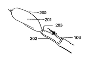
本発明の送達システムを示す図1A〜1Cに、参照がなされる。図1Aは、カテーテルから展開され、拡張器に連結された血管内デバイス(IVD)100を示す。図1Bは、IVD100に対してカテーテル103を介して(例えば血管から)引き出されている拡張器101を示す。図1Cは、本発明の実施形態による、ピッグテールカテーテル104の存在下の、カテーテル103から展開されたデバイスを示す。IVD100は、例えば、血管内に挿入されてよく、粒子、例えば血餅、塞栓、又はそのような粒子が中に留まり得る血管を損傷させ得る他の物体などの粒子の通過を防止し、粒子をブロックし、又はフィルタにかけることができる。IVD100は、例えば、カテーテル103を介して血管内に挿入されてよく、例えばIVD100が中に埋め込まれ得る血管内に通されてよい。カテーテル103は、ガイドワイヤ102上で前進され得る。例えば、血管内を容易に前進するために、カテーテル103は、保護されたリップ部を有する必要があり得る。これは、カテーテルを、例えば血管を通るカテーテル103の通過を円滑にし得る拡張器101と共に使用することによって達成され得る。
References are made to FIGS. 1A-1C showing the delivery system of the present invention. FIG. 1A shows an intravascular device (IVD) 100 unfolded from a catheter and attached to a dilator. FIG. 1B shows a
一部の実施形態では、カテーテル103内に配置された拡張器101の直径は、ガイドワイヤ102及び拡張器101が同時にカテーテル内に存在するときにガイドワイヤ102が拡張器101を通りすぎることができるほど十分な小ささであり得る。カテーテル103が部分的に引き出されると、IVD100は広がることができ、拡張器101は、カテーテル103を介して引き出され得る。拡張器101は、例えば、同じカテーテル103内にさまざまなワイヤが引き続き存在しても、カテーテル103を介して引き出されるほど十分可撓性であり得る。一部の実施形態では、ピッグテールカテーテル104をガイドワイヤ102上にカテーテル103を介して上行大動脈内に挿入するための十分な空間が存在する。IVD100を血管内に埋め込むための他の方法が可能である。
In some embodiments, the diameter of the
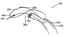
カテーテル103から展開された血管内デバイス100の図である図2Aに、参照がなされる。ワイヤ203は潰れることができ、ワイヤ202は硬性であり得る。図2Bは、円形リングフレーム209の上面図である。図2Cは、細長いフィルタの上面図である。図2Dは、血管内に設置された細長いフィルタの断面図であり、これらすべては、本発明の実施形態によるものである。IVD100は、横方向構造体200と、横方向構造体200によって保持され又は支持され得るフィルタ201とを含むことができる。IVD100の一つ以上の端部206a及び206bは、IVD100の残りの部分より薄いか又は狭くてもよい。一部の実施形態では、端部206は、円形ノブ形状で終端し、それにより、例えば、IVD100は狭くなるが、点で終端しない。
Reference is made to FIG. 2A, which is a diagram of the
一部の実施形態では、横方向構造体200は、ニチノール又は他の超弾性若しくは形状記憶合金若しくは材料を含むことができるか、又は構築され得る。他の材料が、横方向構造体及び骨格を作製するために使用され得る。図2Cは、骨格207を形成する外側200a及び内側200b構造体を有するIVD100の概略図であり、この構造は、フィルタ201と、例えば大動脈弓205の上壁との間の並置(apposition)を改良することができる。フィルタ201は、穿孔されたフィルム、又は目の細かいワイヤネット、又は300ミクロン以下の孔若しくは目を有するメッシュなどのメッシュであるか、又はこれらを含むことができ、それにより、例えば300ミクロンより大きい粒子が、フィルタを通り抜けることが防止される。他のサイズの穴又は目が使用されてよい。一部の実施形態では、フィルタの形状は、横方向構造体200の形状によって規定又は支持され得る。IVD100は、伸長された長円又は柳の葉の形状をとることができる。他の形状が使用されてもよい。
In some embodiments, the
一部の実施形態では、円形のばねリングワイヤフレーム209は、細長い形状を有する内側の横方向構造体200bになるように作製されてよく、それによってIVD100の骨格207の一部を形成することができる。内側の横方向構造体200bは、残留外側力208を及ぼし、それによってそれ自体を例えば大動脈弓205内に配置することを助けることができ、塞栓などの粒子が頸動脈洞枝204に入ることを防止することを助けることができる。フィルタ201は、実質的に平坦でも平坦でなくてもよい。図2Dに示すように、大動脈弓205内における設置時、IVD100は上行大動脈の上壁及び下行大動脈の上壁とのみ接触することができる。IVD100はまた、頸動脈洞枝204の開口部と接触しても接触しなくてもよい。
In some embodiments, the circular spring
フィルタ201に取り付けられた二本のワイヤ202、203を有する血管内デバイス100の図である図3A、大動脈弓205内に配置されたデバイス100の側面図である図3B、及び二本のワイヤ202,203によって操作されているデバイス100の側面図である図3Cに、参照がなされる。一部の実施形態では、IVD100は、例えば、カテーテル103によって大動脈弓205又は他の血管に導入される。IVD100は、その横方向構造体200が上行大動脈の内壁の近くの又はこれに接する領域から、下行大動脈の内壁の近く又はこれに接する領域まで延びるように埋め込まれてよく、これは図3B及び3Cに示される。他の埋め込み位置が可能である。好ましい実施形態では、フィルタ201は、腕頭動脈、左総頸動脈、左鎖骨下動脈、又は他の血管の開口部の一つ以上を覆う。一部の実施形態では、粒子を、そのような動脈に入らないようにフィルタにかけることで、粒子が患者の脳に入ることを防止することができ、また、粒子を、体の下側部分、すなわちそのような粒子があまり損傷を与えない部分に向けることができる。
FIG. 3A, a diagram of an
一部の実施形態では、第1のワイヤ202は、デバイスの横方向構造体200の遠位端部に取り付けられ、第2のワイヤ203は、横方向構造体の近位端部に取り付けられる。一部の実施形態では、第1のワイヤ202は、第2のワイヤ203より硬く、例えば大動脈弓205内におけるデバイスの設置時、これらのワイヤ202、203は、相反して押し引きされてIVD100を偏向させることができる。これらのワイヤ202、203は、装置を、例えば血管内の所与の場所に送達するために使用されてよく、容易にカテーテル103を通って移動することもでき得る。
In some embodiments, the
本発明の実施形態によるビーズ機構400を有するIVD100の概略図である図4に、参照がなされる。IVD100は、これに取り付けられた小さなビーズ400を有することができ、ビーズ400は、ねじと結合するように適合され得る。ビーズ400はまた、デバイスが動脈に傷を負わせる可能性を低減するのにも適し得る。ねじを受け入れ、これと接続することができるこの要素は、ビーズであってもビーズでなくてもよい。一部の実施形態は、第1のワイヤ202の遠位末端部に位置するねじ様機構401を有する。第1のワイヤ202は硬くてよく、第2のワイヤ203は潰れることができるか、又は硬くてもよい。一部の実施形態では、ねじ又は適切な代替物と結合することができるビーズ400は、デバイスのフィルタ201、横方向構造体200、又は別の部分に取り付けられる。一部の実施形態では、これら二つの機構400、401は、第1のワイヤ202をデバイスの横方向構造体200、フィルタ201、又は別の部分にねじ様機構401及びビーズ400の結合によって取り付けるのに利用される。逆に言うと、第1のワイヤ202は、ねじ様機構401をビーズ400又はその代替策から取り外すことによって、横方向構造体200から取り外され得る。ねじ様機構401及びビーズ400若しくはその適切な代替物の同じ配置が、IVD100の第2のワイヤ203に適用することができる。一部の実施形態では、ねじを受け入れるデバイスの要素は、ビーズではない。これらの特徴部は、例えば、第1のワイヤ202と、例えば、第1のワイヤ202とフィルタ201の間を通過し得る任意の器具類との間の潜在的なもつれを修正することができる。
Reference is made to FIG. 4, which is a schematic view of the
一部の実施形態では、第1のワイヤ及び第2のワイヤ202、203の両方は、等しい硬度のものである。一部の実施形態では、ガイドワイヤ102は、遠位置においてフィルタ201を通り抜ける。一部の実施形態では、カテーテル103は、フィルタ201の横方向構造体200においてガイドワイヤ102の通路を押さえ付け、それによってガイドワイヤ102をそれ自体フィルタ201から解放させて、例えばカテーテル103が血管をさらに下って前進することを可能にする。
In some embodiments, both the first wire and the
一部の実施形態では、例えば血管の内側に配置されたカテーテル103の端部は、カテーテル103の長手方向軸に対して垂直でない開口部を有する。本発明の実施形態による、非直角の開口部500を有するカテーテル103から展開された血管内デバイス100の図である図5に、参照がなされる。この実施形態では、開口部500の角度の結果、かなりの大きさの開口部500が、フィルタ201の平面の下方に配置される。
In some embodiments, for example, the end of the
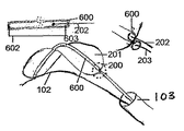
本発明のいくつかの実施形態による、フィルタ201の平面内で、デバイスのフィルタ201に取り付け点604において取り付けられたワイヤ202を有する血管内デバイス100の概略図である図6A〜Cに、参照がなされる。一部の実施形態では、第1のワイヤ202は、例えば、これをフィルタ201にさまざまな取り付け点604においてフィルタに沿って縫い付けることによってIVD100に取り付けられる。第1のワイヤ202は、その使用の前に、例えば凹状形状に曲げられてよく、この結果、フィルタ201は類似の形状に曲がり得る。これらの実施形態では、ガイドワイヤ102は依然として存在し、フィルタ201をその遠位の近傍の位置において通り抜けることができるか、又はこれに連結されてよい。図6Aに示すように、第2のワイヤ203は、第1のワイヤが通り抜けるチューブでよい。フィルタ201は、フィルタ201の中央内に取り付けられて配置された可撓性の中空チューブ600を有することができる。チューブ600は、フィルタ201の長さに沿って配置され得る。チューブ600は、任意の安定した可撓性の材料から作製されてよく、その二つの端部の両方に配置された二つのストッパ602及び603を有することができる。この実施形態は、第1のワイヤ202がチューブ600内で前後に移動することができるように配置されてよく、その結果、チューブの全体的な偏向及びフィルタ201の形状の変化を生じさせ、これは図6Bに示される。さらに、これらの実施形態はまた、ガイドワイヤ102と他のワイヤの間の潜在的なもつれも修正する。一部の実施形態では、曲げられた第1のワイヤ202は、フィルタに取り付けられたとき、詳細にはフィルタの上側に取り付けられ、剛性であることができる。図6Cに示すように、この第1のワイヤ202の湾曲の結果、第1のワイヤ202がカテーテル103を通って前進している間、関連するカテーテル103は、その長手方向軸から離れるように片側偏向601することができる。これらの実施形態の一部では、ガイドワイヤ102は、カテーテル103内にわたって事前に層状にされて、例えば、ピッグテールカテーテル104がこれを通って前進することを支援し、これは、図6Aに示される。一部の実施形態では、ピッグテールカテーテル104は、第1のワイヤ202及びフィルタ201などのデバイスのさまざまな要素を一緒に連結するために使用される。一部の実施形態では、第2のワイヤ203は、中空であり、第1のワイヤ202は、中空の第2のワイヤ203を通り抜ける。
See FIGS. 6A-C, which are schematic views of an
本発明の実施形態による、非対称的な設計を有する血管内デバイス100の概略図である図7A〜Dに、参照がなされる。図7Aは、非対称の設計を有し、取り外し可能又は部分的に取り外し可能なワイヤ202、203を両端部に有する血管内デバイス100を示す。一部の実施形態では、IVD100の横方向構造体200は、その遠位端部及び近位端部の両方に取り付けられた小さなボール又はチップ700を有する。第1及び/又は第2のワイヤ202、203は、横方向構造体200に、各々の小さなボール700の周りに配置されたスネア701を介して取り付けられ得る。一部の実施形態では、スネア701は、チップ700に取り付けられたとき、第1及び第2のワイヤ202、203によるIVD100の配向の有用な偏向又は制御を依然として可能にする。ワイヤ202、203の一方、又は両方は、取り付けられたボール700周りからスネア701を取り外すことによって、横方向構造体200から取り外され得る。さらに、スネア701によって横方向構造体200に連結されているときでさえも、第1及び第2のワイヤ202、203は、IVD100を偏向させ又は再配向する目的で、押し引きするために依然として使用され得る。一部の実施形態では、遠位端部が(図7B及び7Cに示すような)よじれ又は鋭敏なねじりの形成を防止するように設計された、トルク可能なカテーテルが使用されて、IVD100を前進させる。これらのようなカテーテルは、IVD100が、例えば、第1及び第2のワイヤ202、203の押し引きによって内側に配置されるときに、左右両側の偏向を受け得る。
References are made to FIGS. 7A-D, which are schematic views of the
本発明の実施形態による、対称設計を有する血管内デバイス100の概略図である図8A〜8Dに、参照がなされる。一部の実施形態では、対称設計は、フィルタ201が、例えば直立の凹状式に配向されることを可能にする。一部の実施形態では、対称設計は、フィルタ201を、例えば、逆向きの凸状式に配向することを可能にする。これらの異なる配向は、図8A及び8Bに相互に重ね合わされて示される。さらに、デバイスの対称設計は、血管内におけるその設置時、その直立又は逆向きの配置を可能にすることができる。第2のワイヤ203は、もつれるようになる場合に取り外されてもよい。一部の実施形態では、二つの別の等しいワイヤ202、203の下側に配置されたワイヤの剛性又はその欠如は、カテーテル103が、フィルタ201の下方に配置されるようにどれだけ前方に進むことができるかを決定する。一部の実施形態では、第1及び/又は第2のワイヤ202、203はいずれも、フィルタ201に、その遠位端部及び近位端部において比較的対称的に取り付けられ得る。
References are made to FIGS. 8A-8D, which are schematic views of the
第1及び/又は第2のワイヤ202、203をIVD100のフィルタ201に連結するいくつかの方法が存在し得る。一部の実施形態では、スネア701は、第1及び/又は第2のワイヤ202、203の端部に配置される。このスネア701は、フィルタのフレーム200の端部にあるチップ700上で輪状にされて、状況に応じてワイヤ202、203をフィルタ201に取り付け、そこから取り外すことを可能にし得る。一部の実施形態では、第1及び/又は第2のワイヤ202、203は、ねじ様機構401をその遠位末端部に含む。このねじ様機構401は、デバイスの横方向構造体200、フィルタ201、又は別の部分上に位置するビーズ400などの適切な要素と受け入れ式に結合することができ得る。ねじ込む、及びねじって外すことにより、第1及び/又は第2のワイヤ202、203は、IVD100にそれぞれ取り付けられ、又はIVD100の残りの部分から取り外され得る。第1及び/又は第2のワイヤをIVD100に取り付けて取り外す他の方法が可能であり得る。
There may be several ways to connect the first and / or
さらに他の実施形態では、IVD100は、他の塞栓保護デバイス(例えば、米国特許出願第13/300,936号及び米国特許出願第13/205,255号、米国公報第2008-0255603号及び米国公報第2011-0106137号、並びに米国特許第8,062,324号及び米国特許第7,232,453号に記載されているものなど)との使用に適合されており、これらの文献は、参照によって全体的に本明細書に組み込まれる。 In yet another embodiment, the IVD100 is a device of other embolization protection devices (eg, U.S. Patent Application No. 13 / 300,936 and U.S. Patent Application No. 13 / 205,255, U.S. Publication No. 2008-0255603 and U.S. Publication No. 2011-0106137. No., as well as those described in US Pat. No. 8,062,324 and US Pat. No. 7,232,453), these documents are incorporated herein by reference in their entirety.
本明細書内に引用されるすべての公報及び特許は、各々個々の公報又は特許が、参照によって組み込まれるように詳細に且つ個々に示されるかのように、参照によって本明細書に組み込まれる。前述の本発明は、明確な理解のために例証として一部詳細に説明されてきたが、本開示の教示に照らして、特定の変更及び改変が、付属の特許請求の範囲の趣旨又は範囲から逸脱することなく加えられ得ることが当業者に容易に明らかになろう。 All publications and patents cited herein are incorporated herein by reference as if each individual publication or patent is shown in detail and individually as incorporated by reference. The invention described above has been described in some detail by way of illustration for the sake of clarity, but in light of the teachings of the present disclosure, certain changes and modifications may be made within the scope or purpose of the appended claims. It will be readily apparent to those skilled in the art that it can be added without deviation.
Claims (22)
細長い形状を取り囲む横方向構造体(200)と、
前記横方向構造体(200)の長さ及び幅に取り付けられた細長いフィルタ(201)とを備えるデバイスにおいて、
前記横方向構造体の前記長さに沿って配置され、前記デバイスが前記大動脈弓に配置されたときに、前記横方向構造体の遠位端部に、または前記フィルタ(201)の遠位端部に直接または間接的に接続された第1のワイヤ(202)と、
前記横方向構造体又は前記フィルタ(201)の近位端部に取り付けられた第2のワイヤ(203)とを備え、
前記フィルタ(201)が前記第1のワイヤ(202)と類似の形状に曲げられるように、前記第1のワイヤ(202)が、予め曲げられた形状を有し、前記フィルタ(201)の中央に沿って取り付けられており、
前記第1のワイヤ(202)及び前記第2のワイヤ(203)は、前記デバイス(100)の位置、配向、若しくは偏向を制御するように、拡張したフィルタ(201)に対して配置され、前記デバイスが前記大動脈弓に配置されたときに前記第1のワイヤ(202)が前記横方向構造体の遠位端部または前記フィルタ(201)の遠位端部から取り外し可能である、デバイス。 A device placed in the aortic arch to deflect an embolus,
A lateral structure (200) surrounding an elongated shape,
In a device with an elongated filter (201) attached to the length and width of the transverse structure (200).
Arranged along the length of the lateral structure and when the device is placed in the aortic arch, at the distal end of the transverse structure or at the distal end of the filter (201) . first wire that is directly or indirectly connected to the part (202),
With a second wire (203) attached to the transverse structure or the proximal end of the filter (201).
The first wire (202) has a pre-bent shape and is centered on the filter (201) so that the filter (201) is bent into a shape similar to that of the first wire (202). It is installed along the wire
Said first wire (202) and said second wire (203), the position of the device (100), to control the orientation, or the deflection, is arranged against the expanded filter (201), the A device in which the first wire (202) is removable from the distal end of the transverse structure or the distal end of the filter (201) when the device is placed in the aortic arch .
Priority Applications (1)
| Application Number | Priority Date | Filing Date | Title |
|---|---|---|---|
| JP2020105495A JP6978548B2 (en) | 2014-01-10 | 2020-06-18 | Biostructure-independent deflection device |
Applications Claiming Priority (3)
| Application Number | Priority Date | Filing Date | Title |
|---|---|---|---|
| US201461926142P | 2014-01-10 | 2014-01-10 | |
| US61/926,142 | 2014-01-10 | ||
| PCT/IB2015/000410 WO2015104645A2 (en) | 2014-01-10 | 2015-01-09 | Anatomy independent deflector |
Related Child Applications (1)
| Application Number | Title | Priority Date | Filing Date |
|---|---|---|---|
| JP2020105495A Division JP6978548B2 (en) | 2014-01-10 | 2020-06-18 | Biostructure-independent deflection device |
Publications (3)
| Publication Number | Publication Date |
|---|---|
| JP2017501840A JP2017501840A (en) | 2017-01-19 |
| JP2017501840A5 JP2017501840A5 (en) | 2019-06-06 |
| JP6761345B2 true JP6761345B2 (en) | 2020-09-23 |
Family
ID=52997479
Family Applications (2)
| Application Number | Title | Priority Date | Filing Date |
|---|---|---|---|
| JP2016545785A Active JP6761345B2 (en) | 2014-01-10 | 2015-01-09 | Biostructure-independent deflection device |
| JP2020105495A Active JP6978548B2 (en) | 2014-01-10 | 2020-06-18 | Biostructure-independent deflection device |
Family Applications After (1)
| Application Number | Title | Priority Date | Filing Date |
|---|---|---|---|
| JP2020105495A Active JP6978548B2 (en) | 2014-01-10 | 2020-06-18 | Biostructure-independent deflection device |
Country Status (5)
| Country | Link |
|---|---|
| US (2) | US20160324621A1 (en) |
| EP (1) | EP3091937B1 (en) |
| JP (2) | JP6761345B2 (en) |
| CN (2) | CN110215312A (en) |
| WO (1) | WO2015104645A2 (en) |
Families Citing this family (18)
| Publication number | Priority date | Publication date | Assignee | Title |
|---|---|---|---|---|
| EP1461112B1 (en) | 2001-12-05 | 2012-11-21 | Sagax Inc. | Endovascular device for entrapment of particulate matter and method for use |
| EP4353190A2 (en) * | 2014-05-21 | 2024-04-17 | SWAT Medical AB | Improved embolic protection device |
| BR112017015542A2 (en) * | 2015-01-20 | 2018-04-17 | Keystone Heart Ltd | intravascular devices and delivery systems and uses thereof |
| WO2016168616A1 (en) | 2015-04-16 | 2016-10-20 | Sanford Health | Vessel filter and methods for use |
| JP6921419B2 (en) | 2015-09-07 | 2021-08-18 | フィルターレックス メディカル リミテッド | Intra-aortic embolism protection filter device |
| ES2887381T3 (en) * | 2015-10-09 | 2021-12-22 | Transverse Medical Inc | Catheter-based devices |
| EP3838219B1 (en) * | 2016-03-02 | 2024-05-15 | C. R. Bard, Inc. | Embolic protection basket apparatus |
| US20190076231A1 (en) | 2016-03-10 | 2019-03-14 | Keystone Heart Ltd. | Intra-Aortic Device |
| DE102016012869A1 (en) * | 2016-10-28 | 2018-05-03 | Protembis Gmbh | Embolic protection device, method for its folding and shaping device |
| JP7032446B2 (en) * | 2017-02-22 | 2022-03-08 | ボストン サイエンティフィック サイムド,インコーポレイテッド | Protective system to protect the cerebrovascular system |
| JP7194445B2 (en) * | 2017-03-27 | 2022-12-22 | トランスバース メディカル インコーポレイテッド | Filter device and method |
| EP3400901A1 (en) * | 2017-05-12 | 2018-11-14 | Keystone Heart Ltd. | A device for filtering embolic material in a vascular system |
| JP7401446B2 (en) * | 2018-03-07 | 2023-12-19 | イノベイティブ カーディオバスキュラー ソリューションズ, エルエルシー | Embolic protection device |
| GB2576334B (en) | 2018-08-14 | 2021-06-02 | Mokita Medical Gmbh | Embolic protection systems and devices |
| BR112021011486A2 (en) * | 2018-12-15 | 2021-08-31 | Eric Raul Guerra | THROMBECTOMY CATHETER AND METHODS OF USE |
| US11707351B2 (en) | 2019-08-19 | 2023-07-25 | Encompass Technologies, Inc. | Embolic protection and access system |
| CN112263355A (en) * | 2019-12-25 | 2021-01-26 | 上海微创医疗器械(集团)有限公司 | Thrombus blocking device and embolism protection system |
| WO2024042527A1 (en) * | 2022-08-25 | 2024-02-29 | Capricon Medical Ltd | Fixation of debris protection devices in body lumens |
Family Cites Families (21)
| Publication number | Priority date | Publication date | Assignee | Title |
|---|---|---|---|---|
| US6258120B1 (en) * | 1997-12-23 | 2001-07-10 | Embol-X, Inc. | Implantable cerebral protection device and methods of use |
| US6371935B1 (en) * | 1999-01-22 | 2002-04-16 | Cardeon Corporation | Aortic catheter with flow divider and methods for preventing cerebral embolization |
| US6361545B1 (en) * | 1997-09-26 | 2002-03-26 | Cardeon Corporation | Perfusion filter catheter |
| US6908474B2 (en) * | 1998-05-13 | 2005-06-21 | Gore Enterprise Holdings, Inc. | Apparatus and methods for reducing embolization during treatment of carotid artery disease |
| US6245087B1 (en) * | 1999-08-03 | 2001-06-12 | Embol-X, Inc. | Variable expansion frame system for deploying medical devices and methods of use |
| US20030023263A1 (en) * | 2001-07-24 | 2003-01-30 | Incept Llc | Apparatus and methods for aspirating emboli |
| EP1461112B1 (en) | 2001-12-05 | 2012-11-21 | Sagax Inc. | Endovascular device for entrapment of particulate matter and method for use |
| US20080255603A1 (en) | 2005-06-10 | 2008-10-16 | Sagax, Inc. | Implant Device Particularly Useful For Implantation In the Intravascular System For Diverting Emboli |
| US8062324B2 (en) * | 2006-05-08 | 2011-11-22 | S.M.T. Research And Development Ltd. | Device and method for vascular filter |
| US20100324589A1 (en) * | 2006-09-11 | 2010-12-23 | Carpenter Judith T | Embolic deflection device |
| WO2011135556A1 (en) * | 2010-04-28 | 2011-11-03 | Neuravi Limited | Clot engagement and removal systems |
| CN107028678B (en) * | 2008-09-04 | 2020-02-21 | Swat医疗有限公司 | Temporary embolic protection device and medical method of providing same |
| US8974489B2 (en) * | 2009-07-27 | 2015-03-10 | Claret Medical, Inc. | Dual endovascular filter and methods of use |
| US20140074152A1 (en) * | 2010-12-23 | 2014-03-13 | Keystone Heart Ltd. | Device and method for deflecting emboli in an aorta |
| EP2522307B1 (en) * | 2011-05-08 | 2020-09-30 | ITSO Medical AB | Device for delivery of medical devices to a cardiac valve |
| PT2713944T (en) * | 2011-05-26 | 2021-09-16 | Keystone Heart Ltd | An embolic filter device and method of use thereof |
| WO2013074521A1 (en) * | 2011-11-14 | 2013-05-23 | Boston Scientific Scimed, Inc. | Embolic protection device and method |
| US20150039016A1 (en) * | 2012-03-09 | 2015-02-05 | Keystone Heart Ltd. | Device and method for deflecting emboli in an aorta |
| US9888994B2 (en) * | 2012-05-15 | 2018-02-13 | Transverse Medical, Inc. | Catheter-based apparatuses and methods |
| EP2732794A1 (en) * | 2012-11-14 | 2014-05-21 | Contego AB | Improved embolic protection device and method |
| CN103349577B (en) * | 2012-11-30 | 2015-05-06 | 宁波健世生物科技有限公司 | Percutaneous aorta bracket or aortic valve bracket system with far-end protection |
-
2015
- 2015-01-09 EP EP15717961.5A patent/EP3091937B1/en active Active
- 2015-01-09 US US15/110,764 patent/US20160324621A1/en not_active Abandoned
- 2015-01-09 CN CN201910661478.1A patent/CN110215312A/en active Pending
- 2015-01-09 WO PCT/IB2015/000410 patent/WO2015104645A2/en active Application Filing
- 2015-01-09 CN CN201580013235.7A patent/CN106102654B/en active Active
- 2015-01-09 JP JP2016545785A patent/JP6761345B2/en active Active
-
2020
- 2020-06-18 JP JP2020105495A patent/JP6978548B2/en active Active
-
2023
- 2023-08-11 US US18/448,839 patent/US20230414336A1/en active Pending
Also Published As
| Publication number | Publication date |
|---|---|
| US20160324621A1 (en) | 2016-11-10 |
| CN106102654B (en) | 2019-06-28 |
| US20230414336A1 (en) | 2023-12-28 |
| CN110215312A (en) | 2019-09-10 |
| JP6978548B2 (en) | 2021-12-08 |
| JP2020163184A (en) | 2020-10-08 |
| CN106102654A (en) | 2016-11-09 |
| JP2017501840A (en) | 2017-01-19 |
| EP3091937B1 (en) | 2024-03-20 |
| WO2015104645A2 (en) | 2015-07-16 |
| WO2015104645A3 (en) | 2015-11-19 |
| EP3091937A2 (en) | 2016-11-16 |
Similar Documents
| Publication | Publication Date | Title |
|---|---|---|
| JP6978548B2 (en) | Biostructure-independent deflection device | |
| JP7157131B2 (en) | Intravascular devices and delivery systems | |
| JP7191339B2 (en) | Improved embolic protection device and method | |
| US11020211B2 (en) | Accessory device to provide neuroprotection during interventional procedures | |
| CN105392432B (en) | Distal embolic protection system and method with pressure and ultrasonic wave characteristic | |
| US10973618B2 (en) | Embolic protection device | |
| US9480548B2 (en) | Embolic protection device and method of use | |
| JP6232000B2 (en) | Distal protection filter | |
| JP5896575B2 (en) | Angiography catheter | |
| US9089406B2 (en) | Embolic filter devices, systems, and methods for capturing emboli during medical procedures |
Legal Events
| Date | Code | Title | Description |
|---|---|---|---|
| RD01 | Notification of change of attorney |
Free format text: JAPANESE INTERMEDIATE CODE: A7426 Effective date: 20161215 |
|
| A521 | Request for written amendment filed |
Free format text: JAPANESE INTERMEDIATE CODE: A821 Effective date: 20161215 |
|
| A521 | Request for written amendment filed |
Free format text: JAPANESE INTERMEDIATE CODE: A523 Effective date: 20171212 |
|
| A621 | Written request for application examination |
Free format text: JAPANESE INTERMEDIATE CODE: A621 Effective date: 20171212 |
|
| A977 | Report on retrieval |
Free format text: JAPANESE INTERMEDIATE CODE: A971007 Effective date: 20180912 |
|
| A131 | Notification of reasons for refusal |
Free format text: JAPANESE INTERMEDIATE CODE: A131 Effective date: 20180925 |
|
| A601 | Written request for extension of time |
Free format text: JAPANESE INTERMEDIATE CODE: A601 Effective date: 20181219 |
|
| A524 | Written submission of copy of amendment under article 19 pct |
Free format text: JAPANESE INTERMEDIATE CODE: A524 Effective date: 20190322 |
|
| RD02 | Notification of acceptance of power of attorney |
Free format text: JAPANESE INTERMEDIATE CODE: A7422 Effective date: 20190322 |
|
| A521 | Request for written amendment filed |
Free format text: JAPANESE INTERMEDIATE CODE: A523 Effective date: 20190401 |
|
| RD04 | Notification of resignation of power of attorney |
Free format text: JAPANESE INTERMEDIATE CODE: A7424 Effective date: 20190401 |
|
| A131 | Notification of reasons for refusal |
Free format text: JAPANESE INTERMEDIATE CODE: A131 Effective date: 20190611 |
|
| A601 | Written request for extension of time |
Free format text: JAPANESE INTERMEDIATE CODE: A601 Effective date: 20190910 |
|
| A601 | Written request for extension of time |
Free format text: JAPANESE INTERMEDIATE CODE: A601 Effective date: 20191111 |
|
| A521 | Request for written amendment filed |
Free format text: JAPANESE INTERMEDIATE CODE: A523 Effective date: 20191209 |
|
| A02 | Decision of refusal |
Free format text: JAPANESE INTERMEDIATE CODE: A02 Effective date: 20200218 |
|
| A521 | Request for written amendment filed |
Free format text: JAPANESE INTERMEDIATE CODE: A523 Effective date: 20200618 |
|
| A911 | Transfer to examiner for re-examination before appeal (zenchi) |
Free format text: JAPANESE INTERMEDIATE CODE: A911 Effective date: 20200630 |
|
| A131 | Notification of reasons for refusal |
Free format text: JAPANESE INTERMEDIATE CODE: A131 Effective date: 20200818 |
|
| A521 | Request for written amendment filed |
Free format text: JAPANESE INTERMEDIATE CODE: A523 Effective date: 20200824 |
|
| TRDD | Decision of grant or rejection written | ||
| A01 | Written decision to grant a patent or to grant a registration (utility model) |
Free format text: JAPANESE INTERMEDIATE CODE: A01 Effective date: 20200901 |
|
| A61 | First payment of annual fees (during grant procedure) |
Free format text: JAPANESE INTERMEDIATE CODE: A61 Effective date: 20200904 |
|
| R150 | Certificate of patent or registration of utility model |
Ref document number: 6761345 Country of ref document: JP Free format text: JAPANESE INTERMEDIATE CODE: R150 |
|
| R250 | Receipt of annual fees |
Free format text: JAPANESE INTERMEDIATE CODE: R250 |