JP6755121B2 - Radar device - Google Patents
Radar device Download PDFInfo
- Publication number
- JP6755121B2 JP6755121B2 JP2016102475A JP2016102475A JP6755121B2 JP 6755121 B2 JP6755121 B2 JP 6755121B2 JP 2016102475 A JP2016102475 A JP 2016102475A JP 2016102475 A JP2016102475 A JP 2016102475A JP 6755121 B2 JP6755121 B2 JP 6755121B2
- Authority
- JP
- Japan
- Prior art keywords
- antenna
- antennas
- virtual
- element spacing
- elements
- Prior art date
- Legal status (The legal status is an assumption and is not a legal conclusion. Google has not performed a legal analysis and makes no representation as to the accuracy of the status listed.)
- Active
Links
- 230000005540 biological transmission Effects 0.000 claims description 107
- 239000013598 vector Substances 0.000 claims description 78
- 238000000034 method Methods 0.000 claims description 61
- 230000008569 process Effects 0.000 claims description 34
- 238000012545 processing Methods 0.000 description 45
- 238000004364 calculation method Methods 0.000 description 38
- 238000007792 addition Methods 0.000 description 28
- 230000000694 effects Effects 0.000 description 17
- 230000007274 generation of a signal involved in cell-cell signaling Effects 0.000 description 17
- 238000010586 diagram Methods 0.000 description 13
- 238000006243 chemical reaction Methods 0.000 description 12
- 238000005094 computer simulation Methods 0.000 description 11
- 230000006870 function Effects 0.000 description 11
- 238000004458 analytical method Methods 0.000 description 10
- 238000003491 array Methods 0.000 description 9
- 238000004422 calculation algorithm Methods 0.000 description 9
- 230000000875 corresponding effect Effects 0.000 description 9
- 238000011156 evaluation Methods 0.000 description 9
- 238000001514 detection method Methods 0.000 description 8
- 238000005259 measurement Methods 0.000 description 8
- 230000010354 integration Effects 0.000 description 7
- 238000005070 sampling Methods 0.000 description 7
- 230000001427 coherent effect Effects 0.000 description 6
- 238000000926 separation method Methods 0.000 description 6
- 238000005516 engineering process Methods 0.000 description 4
- 238000012935 Averaging Methods 0.000 description 3
- 239000011159 matrix material Substances 0.000 description 3
- 230000005855 radiation Effects 0.000 description 3
- 238000004590 computer program Methods 0.000 description 2
- 230000002596 correlated effect Effects 0.000 description 2
- 238000009499 grossing Methods 0.000 description 2
- 238000012986 modification Methods 0.000 description 2
- 230000004048 modification Effects 0.000 description 2
- 238000004088 simulation Methods 0.000 description 2
- 230000001629 suppression Effects 0.000 description 2
- 101100134058 Caenorhabditis elegans nth-1 gene Proteins 0.000 description 1
- 230000003321 amplification Effects 0.000 description 1
- 238000012937 correction Methods 0.000 description 1
- 230000008878 coupling Effects 0.000 description 1
- 238000010168 coupling process Methods 0.000 description 1
- 238000005859 coupling reaction Methods 0.000 description 1
- 125000004122 cyclic group Chemical group 0.000 description 1
- 238000000354 decomposition reaction Methods 0.000 description 1
- PCHJSUWPFVWCPO-UHFFFAOYSA-N gold Chemical compound [Au] PCHJSUWPFVWCPO-UHFFFAOYSA-N 0.000 description 1
- 239000010931 gold Substances 0.000 description 1
- 229910052737 gold Inorganic materials 0.000 description 1
- 230000006872 improvement Effects 0.000 description 1
- 238000004519 manufacturing process Methods 0.000 description 1
- 230000015654 memory Effects 0.000 description 1
- 239000000203 mixture Substances 0.000 description 1
- 238000003199 nucleic acid amplification method Methods 0.000 description 1
- 230000010363 phase shift Effects 0.000 description 1
- 230000009467 reduction Effects 0.000 description 1
- 230000000630 rising effect Effects 0.000 description 1
- 239000004065 semiconductor Substances 0.000 description 1
- 230000001360 synchronised effect Effects 0.000 description 1
- 230000003936 working memory Effects 0.000 description 1
Images


Landscapes
- Variable-Direction Aerials And Aerial Arrays (AREA)
- Radar Systems Or Details Thereof (AREA)
Description
本開示は、レーダ装置に関する。 The present disclosure relates to a radar device.
近年、高分解能が得られるマイクロ波又はミリ波を含む波長の短いレーダ送信信号を用いたレーダ装置の検討が進められている。また、屋外での安全性を向上させるために、車両以外にも、歩行者を含む物体(ターゲット)を広角範囲で検知するレーダ装置(広角レーダ装置)の開発が求められている。 In recent years, studies have been conducted on radar devices using radar transmission signals having a short wavelength including microwaves or millimeter waves that can obtain high resolution. Further, in order to improve outdoor safety, it is required to develop a radar device (wide-angle radar device) that detects an object (target) including a pedestrian in a wide-angle range in addition to a vehicle.
例えば、レーダ装置として、パルス波を繰り返し発信するパルスレーダ装置が知られている。広角範囲において車両/歩行者を検知する広角パルスレーダの受信信号は、近距離に存在するターゲット(例えば車両)と、遠距離に存在するターゲット(例えば歩行者)とからの複数の反射波が混合された信号となる。このため、(1)レーダ送信部では、低いレンジサイドローブとなる自己相関特性(以下、低レンジサイドローブ特性と呼ぶ)を有するパルス波又はパルス変調波を送信する構成が要求され、(2)レーダ受信部では、広い受信ダイナミックレンジを有する構成が要求される。 For example, as a radar device, a pulse radar device that repeatedly transmits a pulse wave is known. The received signal of the wide-angle pulse radar that detects a vehicle / pedestrian in a wide-angle range is a mixture of multiple reflected waves from a target existing at a short distance (for example, a vehicle) and a target existing at a long distance (for example, a pedestrian). It becomes a signal. Therefore, (1) the radar transmitter is required to transmit a pulse wave or a pulse-modulated wave having an autocorrelation characteristic (hereinafter referred to as a low-range sidelobe characteristic) having a low range sidelobe, and (2). The radar receiver is required to have a configuration having a wide reception dynamic range.
広角レーダ装置の構成として、以下の2つの構成が挙げられる。 The following two configurations can be mentioned as the configuration of the wide-angle radar device.
一つ目は、パルス波又は変調波を狭角(数度程度のビーム幅)の指向性ビームを用いて、機械的又は電子的に走査してレーダ波を送信し、狭角の指向性ビームを用いて反射波を受信する構成である。この構成では、高分解能を得るためには多くの走査が必要となるので、高速移動するターゲットに対する追従性が劣化する。 The first is a narrow-angle directional beam that transmits radar waves by mechanically or electronically scanning a pulse wave or modulated wave using a narrow-angle (beam width of about several degrees) directional beam. Is configured to receive the reflected wave using. In this configuration, a lot of scanning is required to obtain high resolution, so that the followability to a target moving at high speed is deteriorated.
二つ目は、複数のアンテナ(アンテナ素子)で構成されるアレーアンテナによって反射波を受信し、アンテナ間隔に対する受信位相差に基づく信号処理アルゴリズムによって反射波の到来角を推定する手法(Direction of Arrival (DOA) estimation)を用いる構成である。この構成では、送信ブランチでの送信ビームの走査間隔を間引いたとしても、受信ブランチにおいて到来角を推定できるので、走査時間の短縮化が図れ、1つ目の構成と比較して追従性が向上する。例えば、到来方向推定方法には、行列演算に基づくフーリエ変換、逆行列演算に基づくCapon法及びLP(Linear Prediction)法、又は、固有値演算に基づくMUSIC(Multiple Signal Classification)及びESPRIT(Estimation of Signal Parameters via Rotational Invariance Techniques)が挙げられる。 The second method is to receive the reflected wave by an array antenna composed of multiple antennas (antenna elements) and estimate the arrival angle of the reflected wave by a signal processing algorithm based on the reception phase difference with respect to the antenna spacing (Direction of Arrival). (DOA) estimation) is used. In this configuration, even if the scanning interval of the transmitting beam in the transmitting branch is thinned out, the arrival angle can be estimated in the receiving branch, so that the scanning time can be shortened and the followability is improved as compared with the first configuration. To do. For example, the arrival direction estimation method includes Fourier transform based on matrix calculation, Capon method and LP (Linear Prediction) method based on inverse matrix calculation, or MUSIC (Multiple Signal Classification) and ESPRIT (Estimation of Signal Parameters) based on eigenvalue calculation. via Rotational Invariance Techniques).
また、レーダ装置として、受信ブランチに加え、送信ブランチにも複数のアンテナ(アレーアンテナ)を備え、送受信アレーアンテナを用いた信号処理によりビーム走査を行う構成(MIMOレーダと呼ぶこともある)が提案されている(例えば、非特許文献1を参照)。 In addition, as a radar device, a configuration (sometimes called MIMO radar) is proposed in which a plurality of antennas (array antennas) are provided in the transmission branch in addition to the reception branch, and beam scanning is performed by signal processing using the transmission / reception array antennas. (See, for example, Non-Patent Document 1).
MIMOレーダでは、送受信アレーアンテナにおけるアンテナ素子の配置を工夫することにより、最大で送信アンテナ素子数と受信アンテナ素子数との積に等しい仮想的な受信アレーアンテナ(以下、仮想受信アレーと呼ぶ)を構成することができる。これにより、少ない素子数によってアレーアンテナの実効的な開口長を増大させる効果がある。 In MIMO radar, by devising the arrangement of antenna elements in the transmission / reception array antenna, a virtual reception array antenna (hereinafter referred to as a virtual reception array) equal to the product of the number of transmission antenna elements and the number of reception antenna elements at the maximum is obtained. Can be configured. This has the effect of increasing the effective aperture length of the array antenna with a small number of elements.
また、垂直方向又は水平方向の一次元走査以外にも、垂直方向及び水平方向の2次元におけるビーム走査を行う場合にもMIMOレーダが適用可能である。 In addition to one-dimensional scanning in the vertical or horizontal direction, MIMO radar can also be applied to two-dimensional beam scanning in the vertical and horizontal directions.
しかしながら、MIMOレーダに対して小型化かつ低コスト化を図るために送受信ブランチのアンテナ数の制約(例えば、送信4アンテナ程度/受信4アンテナ程度)がある場合、MIMOレーダによる面的な仮想受信アレーにおいて垂直方向及び水平方向の開口長が制約される。 However, if there is a restriction on the number of antennas in the transmission / reception branch (for example, about 4 transmission antennas / about 4 reception antennas) in order to reduce the size and cost of the MIMO radar, a planar virtual reception array by the MIMO radar The vertical and horizontal opening lengths are constrained in.
本開示の一態様は、仮想受信アレーにおける開口長を最大限拡大することができるレーダ装置を提供する。 One aspect of the present disclosure provides a radar device capable of maximally increasing the aperture length in a virtual reception array.
本開示の一態様に係るレーダ装置は、所定の送信周期にて複数のレーダ信号を複数の送信アンテナのそれぞれから送信するレーダ送信部と、前記複数のレーダ信号がターゲットにおいて反射された複数の反射波信号を複数の受信アンテナを用いて受信するレーダ受信部と、を具備し、前記複数の送信アンテナは、第1の方向に配置されるNt1個の送信アンテナと、前記第1の方向と直交する第2の方向に配置されるNt2個の送信アンテナと、を含み、前記複数の受信アンテナは、前記第1の方向に配置されるNa1個の受信アンテナと、前記第2の方向に配置されるNa2個の受信アンテナと、を含み、前記第1の方向において、前記Nt1個の送信アンテナ間の各素子間隔、及び、前記Na1個の受信アンテナ間の各素子間隔は、それぞれ第1の間隔の整数倍の値であり、全て異なる値であり、前記第2の方向において、前記Nt2個の送信アンテナ間の各素子間隔、及び、前記Na2個の受信アンテナ間の各素子間隔は、それぞれ第2の間隔の整数倍の値であり、全て異なる値である構成を採る。 The radar device according to one aspect of the present disclosure includes a radar transmitter that transmits a plurality of radar signals from each of the plurality of transmitting antennas in a predetermined transmission cycle, and a plurality of reflections of the plurality of radar signals reflected at the target. A radar receiving unit that receives a wave signal using a plurality of receiving antennas is provided, and the plurality of transmitting antennas are orthogonal to the one transmitting antenna of Nt arranged in the first direction and the first direction. The plurality of receiving antennas include a two Nt transmitting antennas arranged in the second direction, and the plurality of receiving antennas are arranged in the second direction and the receiving antenna of one Na arranged in the first direction. In the first direction, the element spacing between the Nt1 transmitting antennas and the element spacing between the Na1 receiving antennas are the first intervals, respectively. The values are integral multiples of, and are all different values. In the second direction, the element spacing between the two Nt transmitting antennas and the element spacing between the two Na receiving antennas are the first. The values are integral multiples of the interval of 2, and all have different values.
なお、これらの包括的または具体的な態様は、システム、方法、集積回路、コンピュータプログラム、または、記録媒体で実現されてもよく、システム、装置、方法、集積回路、コンピュータプログラムおよび記録媒体の任意な組み合わせで実現されてもよい。 It should be noted that these comprehensive or specific aspects may be realized by a system, a method, an integrated circuit, a computer program, or a recording medium, and any of the systems, devices, methods, integrated circuits, computer programs, and recording media. It may be realized by various combinations.
本開示の一態様によれば、仮想受信アレーにおける開口長を最大限拡大することができる。 According to one aspect of the present disclosure, the aperture length in the virtual reception array can be maximized.
本開示の一態様における更なる利点および効果は、明細書および図面から明らかにされる。かかる利点および/または効果は、いくつかの実施形態並びに明細書および図面に記載された特徴によってそれぞれ提供されるが、1つまたはそれ以上の同一の特徴を得るために必ずしも全てが提供される必要はない。 Further advantages and effects in one aspect of the present disclosure will be apparent from the specification and drawings. Such advantages and / or effects are provided by some embodiments and features described in the specification and drawings, respectively, but not all need to be provided in order to obtain one or more identical features. There is no.
[本開示の一態様をするに至った経緯]
図1Aは、4個の送信アンテナ(Tx#1〜Tx#4)を含む送信アレーアンテナのアンテナ配置を示し、図1Bは、4個の受信アンテナ(Rx#1〜Rx#4)を含む受信アレーアンテナのアンテナ配置を示す。
[Background to one aspect of this disclosure]
FIG. 1A shows an antenna arrangement of a transmitting array antenna including four transmitting antennas (
図1A及び図1Bにおいて、dHは受信アンテナの水平方向の素子間隔を示し、dVは受信アンテナの垂直方向の素子間隔を示す。また、図1Aでは、送信アンテナの水平方向及び垂直方向の素子間隔は、それぞれ、2dH、2dVとする。 In FIGS. 1A and 1B, d H indicates the horizontal element spacing of the receiving antenna, and d V indicates the vertical element spacing of the receiving antenna. Further, in FIG. 1A, the element spacings in the horizontal direction and the vertical direction of the transmitting antenna are 2d H and 2d V , respectively.
図1Cは、図1A及び図1Bに示すアンテナ配置の送受信アレーアンテナを含む仮想受信アレーを示す。 FIG. 1C shows a virtual reception array including a transmit / receive array antenna with the antenna arrangement shown in FIGS. 1A and 1B.
図1Cに示すように、仮想受信アレーは、水平方向に4アンテナ、垂直方向に4アンテナが面的に配置された16素子の仮想受信アンテナ(VA#1〜VA#16)を含む。
As shown in FIG. 1C, the virtual reception array includes 16 element virtual reception antennas (
図1Cでは、仮想受信アンテナの水平方向及び垂直方向の素子間隔は、それぞれ、dH、dVとなる。すなわち、仮想受信アレーの水平方向及び垂直方向の開口長DH、DVは、3dH、3dVとなる。 In FIG. 1C, the element spacings in the horizontal direction and the vertical direction of the virtual receiving antenna are d H and d V , respectively. In other words, the opening length D H in the horizontal direction and the vertical direction of the virtual reception array, D V is, 3d H, a 3d V.
一例として、素子間隔d=dH=dV、開口長D=DH=DVの仮想受信アレーを用いた、等振幅ウェイトであり、かつ、フーリエビームによるビーム幅(フーリエビーム幅)BWは、次式で表される。なお、λは送信ブランチから送信される無線信号(RF信号)のキャリア周波数の波長を示す。
BW≒0.7λ/D[rad]
As an example, element spacing d = d H = d V, using the virtual reception array aperture length D = D H = D V, is equal amplitude weights and beam width by Fourier beam (Fourier beam width) BW is , Expressed by the following equation. Note that λ indicates the wavelength of the carrier frequency of the radio signal (RF signal) transmitted from the transmission branch.
BW ≒ 0.7λ / D [rad]
図1Cに示す仮想受信アレー(D=3d)では、フーリエビーム幅BW≒0.7λ/3d[rad]となる。 In the virtual reception array (D = 3d) shown in FIG. 1C, the Fourier beam width BW≈0.7λ / 3d [rad] is obtained.
例えば、d=0.5λではフーリエビーム幅BW≒0.7/1.5[rad]≒30°であり、d=0.7λではフーリエビーム幅BW≒0.7/2.1[rad]≒19°である。 For example, when d = 0.5λ, the Fourier beam width BW ≈ 0.7 / 1.5 [rad] ≈ 30 °, and when d = 0.7λ, the Fourier beam width BW ≈ 0.7 / 2.1 [rad] ≈19 °.
素子間隔dを更に広くすることにより、フーリエビーム幅BWをより狭くすることができる。しかし、素子間隔dを広くするほど、メインビームに比較的近い角度においてグレーティングローブが発生し、誤検出が増大してしまう。 By further widening the element spacing d, the Fourier beam width BW can be further narrowed. However, as the element spacing d is widened, a grating lobe is generated at an angle relatively close to the main beam, and erroneous detection increases.
例えば、図2Aは素子間隔d=0.5λにおける指向性パターンを示し、図2Bは、素子間隔d=1.3λにおける指向性パターンを示す。なお、図2A及び図2Bでは、メインビームが0°方向に形成されている。 For example, FIG. 2A shows a directivity pattern at an element spacing d = 0.5λ, and FIG. 2B shows a directivity pattern at an element spacing d = 1.3λ. In FIGS. 2A and 2B, the main beam is formed in the 0 ° direction.
図2Aに示すように、素子間隔d=0.5λでは、メインビームのフーリエビーム幅BWが30°程度と比較的広くなる。また、図2Aでは、±90°の範囲においてグレーティングローブは発生しない。 As shown in FIG. 2A, when the element spacing d = 0.5λ, the Fourier beam width BW of the main beam is relatively wide, about 30 °. Further, in FIG. 2A, no grating lobe is generated in the range of ± 90 °.
一方、図2Bに示すように、素子間隔d=1.3λでは、メインビームのフーリエビーム幅BWが10°程度と比較的狭くなるが、メインビーム(0°方向)から±50°程度離れた角度にグレーティングローブが発生する。 On the other hand, as shown in FIG. 2B, when the element spacing d = 1.3λ, the Fourier beam width BW of the main beam is relatively narrow, about 10 °, but is about ± 50 ° away from the main beam (0 ° direction). A grating lobe is generated at the angle.
例えば、図2Bにおいて、広角レーダの検知角が±25°程度以上に広いでは、検知角度範囲内にグレーティングローブが発生することになり、誤検出が増加する。 For example, in FIG. 2B, when the detection angle of the wide-angle radar is as wide as about ± 25 ° or more, a grating lobe is generated within the detection angle range, and erroneous detection increases.
このように、フーリエビーム幅BWを狭めるために素子間隔dを広くすることには制約がある。また、素子間隔dを広くする代わりに、アンテナ素子数を増やすことにより開口長Dを広くしてもよいが、低コスト化を考慮すると、仮想受信アレーの開口長Dにも制約が生じる。 As described above, there is a limitation in widening the element spacing d in order to narrow the Fourier beam width BW. Further, instead of widening the element spacing d, the aperture length D may be widened by increasing the number of antenna elements, but in consideration of cost reduction, the aperture length D of the virtual reception array is also restricted.
上記制約の下で10°程度の角度分解能を実現するに、DOA推定アルゴリズムとして、例えば、MUSIC、Capon法等を用いる場合、固有値分解又は逆行列演算を行うための演算量が増加する。また、高分解能を実現するDOA推定アルゴリズムを適用する場合でも、SNR(Signal to Noise Ratio)が十分に高くなければ、高い角度分離性能は得ることは困難である。 When, for example, the MUSIC, Capon method, or the like is used as the DOA estimation algorithm in order to realize an angular resolution of about 10 ° under the above constraints, the amount of calculation for performing eigenvalue decomposition or inverse matrix calculation increases. Further, even when a DOA estimation algorithm that realizes high resolution is applied, it is difficult to obtain high angle separation performance unless the SNR (Signal to Noise Ratio) is sufficiently high.
本開示に係る一態様は、MIMOレーダを用いて垂直方向及び水平方向の2次元においてビーム走査を行う場合に、垂直方向及び水平方向の仮想受信アレーの開口長を最大限拡大する。このような仮想受信アレーを用いることで、少ないアンテナ素子数による角度分解能の向上を可能とし、レーダ装置の小型化、低コスト化を図る。 One aspect of the present disclosure maximizes the aperture length of a virtual reception array in the vertical and horizontal directions when beam scanning is performed in two dimensions in the vertical and horizontal directions using MIMO radar. By using such a virtual reception array, it is possible to improve the angular resolution with a small number of antenna elements, and to reduce the size and cost of the radar device.
以下、本開示の一態様に係る実施の形態について、図面を参照して詳細に説明する。なお、実施の形態において、同一の構成要素には同一の符号を付し、その説明は重複するので省略する。 Hereinafter, embodiments according to one aspect of the present disclosure will be described in detail with reference to the drawings. In the embodiment, the same components are designated by the same reference numerals, and the description thereof will be duplicated and will be omitted.
なお、以下では、レーダ装置において、送信ブランチにおいて、複数の送信アンテナから符号分割多重された異なる送信信号を送出し、受信ブランチにおいて、各送信信号を分離して受信処理を行う構成について説明する。しかし、レーダ装置の構成は、これに限定されず、送信ブランチにおいて、複数の送信アンテナから周波数分割多重された異なる送信信号を送出し、受信ブランチにおいて、各送信信号を分離して受信処理を行う構成でもよい。また、同様に、レーダ装置の構成は、送信ブランチで複数の送信アンテナから時分割多重された送信信号を送出し、受信ブランチで、受信処理を行う構成でもよい。 In the radar device, a configuration will be described in which different transmission signals code-division-multiplexed are transmitted from a plurality of transmission antennas in the transmission branch, and each transmission signal is separated and received in the reception branch. However, the configuration of the radar device is not limited to this, and in the transmission branch, different transmission signals frequency-division-multiplexed are transmitted from a plurality of transmission antennas, and in the reception branch, each transmission signal is separated and received. It may be configured. Similarly, the radar device may be configured to transmit time-division-multiplexed transmission signals from a plurality of transmission antennas at the transmission branch and perform reception processing at the reception branch.
[実施の形態1]
[レーダ装置の構成]
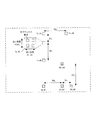
図3は、本実施の形態に係るレーダ装置10の構成を示すブロック図である。
[Embodiment 1]
[Radar device configuration]
FIG. 3 is a block diagram showing the configuration of the
レーダ装置10は、レーダ送信部(送信ブランチ)100と、レーダ受信部(受信ブランチ)200と、基準信号生成部300と、を有する。
The
レーダ送信部100は、基準信号生成部300から受け取るリファレンス信号に基づいて高周波(無線周波数:Radio Frequency)のレーダ信号(レーダ送信信号)を生成する。そして、レーダ送信部100は、複数の送信アンテナ106−1〜106−Ntによって構成される送信アレーアンテナを用いて、レーダ送信信号を所定の送信周期にて送信する。
The
レーダ受信部200は、ターゲット(図示せず)により反射したレーダ送信信号である反射波信号を、複数の受信アンテナ202−1〜202−Naを含む受信アレーアンテナを用いて受信する。レーダ受信部200は、基準信号生成部300から受け取るリファレンス信号を用いて、下記の処理動作を行うことで、レーダ送信部と同期した処理を行う。すなわち、レーダ受信部200は、各受信アンテナ202において受信した反射波信号を信号処理し、少なくともターゲットの有無検出、方向推定を行う。なお、ターゲットはレーダ装置10が検出する対象の物体であり、例えば、車両(4輪及び2輪を含む)又は人を含む。
The radar receiving unit 200 receives a reflected wave signal, which is a radar transmission signal reflected by a target (not shown), by using a receiving array antenna including a plurality of receiving antennas 202-1 to 202-Na. The radar receiving unit 200 performs the following processing operation using the reference signal received from the reference
基準信号生成部300は、レーダ送信部100及びレーダ受信部200のそれぞれに接続されている。基準信号生成部300は、基準信号としてのリファレンス信号をレーダ送信部100及びレーダ受信部200に供給し、レーダ送信部100及びレーダ受信部200の処理を同期させる。
The reference
[レーダ送信部100の構成]
レーダ送信部100は、レーダ送信信号生成部101−1〜101−Ntと、送信無線部105−1〜105−Ntと、送信アンテナ106−1〜106−Ntと、を有する。すなわち、レーダ送信部100は、Nt個の送信アンテナ106を有し、各送信アンテナ106は、それぞれ個別のレーダ送信信号生成部101及び送信無線部105に接続されている。
[Structure of radar transmitter 100]
The
レーダ送信信号生成部101は、基準信号生成部300から受け取るリファレンス信号を所定数倍したタイミングクロックを生成し、生成したタイミングクロックに基づいてレーダ送信信号を生成する。そして、レーダ送信信号生成部101は、所定のレーダ送信周期(Tr)にてレーダ送信信号を繰り返し出力する。レーダ送信信号は、rz(k, M)=Iz(k, M)+j Qz(k, M)で表される。ここで、zは各送信アンテナ106に対応する番号を表し、z=1,…,Ntである。また、jは虚数単位を表し、kは離散時刻を表し、Mはレーダ送信周期の序数を表す。
The radar transmission
各レーダ送信信号生成部101は、符号生成部102と、変調部103と、LPF(Low Pass Filter)104とを含む。以下、第z番目(z=1,…,Nt)の送信アンテナ106に対応するレーダ送信信号生成部101−zにおける各構成部について説明する。
Each radar transmission
具体的には、符号生成部102は、レーダ送信周期Tr毎に、符号長Lの符号系列の符号a(z)n(n=1,…,L)(パルス符号)を生成する。各符号生成部102−1〜102−Ntにおいて生成される符号a(z)n(z=1,…,Nt)には、互いに低相関又は無相関となる符号が用いられる。符号系列としては、例えば、Walsh-Hadamard符号、M系列符号、Gold符号などが挙げられる。 Specifically, the code generation unit 102 generates the code a (z) n (n = 1, ..., L) (pulse code) of the code series having the code length L for each radar transmission cycle Tr. For the codes a (z) n (z = 1, ..., Nt) generated in each code generation unit 102-1 to 102-Nt, codes that have low or no correlation with each other are used. Examples of the code sequence include a Walsh-Hadamard code, an M-sequence code, and a Gold code.
変調部103は、符号生成部102から受け取る符号a(z)nに対してパルス変調(振幅変調、ASK(Amplitude Shift Keying)、パルスシフトキーイング)又は位相変調(Phase Shift Keying)を行い、変調信号をLPF104へ出力する。
The
LPF104は、変調部103から受け取る変調信号のうち、所定の制限帯域以下の信号成分を、ベースバンドのレーダ送信信号として送信無線部105へ出力する。
The
第z(z=1,…,Nt)番目の送信無線部105は、第z番目のレーダ送信信号生成部101から出力されるベースバンドのレーダ送信信号に対して周波数変換を施してキャリア周波数(Radio Frequency:RF)帯のレーダ送信信号を生成し、送信増幅器により所定の送信電力P[dB]に増幅して第z番目の送信アンテナ106へ出力する。
The z-th (z = 1, ..., Nt) th
第z(z=1,…,Nt)番目の送信アンテナ106は、第z番目の送信無線部105から出力されるレーダ送信信号を空間に放射する。
The z-th (z = 1, ..., Nt)
図4は、レーダ送信部100のNt個の送信アンテナ106から送信されるレーダ送信信号を示す。符号送信区間Tw内には符号長Lのパルス符号系列が含まれる。各レーダ送信周期Trのうち、符号送信区間Twの間にパルス符号系列が送信され、残りの区間(Tr-Tw)は無信号区間となる。1つのパルス符号(a(z)n)あたり、No個のサンプルを用いたパルス変調が施されることにより、各符号送信区間Tw内には、Nr(=No×L)個のサンプルの信号が含まれる。すなわち、変調部103におけるサンプリングレートは、(No×L)/Twである。また、無信号区間(Tr-Tw)には、Nu個のサンプルが含まれる。
FIG. 4 shows radar transmission signals transmitted from
なお、レーダ送信部100は、レーダ送信信号生成部101の代わりに、図5に示すレーダ送信信号生成部101aを備えてもよい。レーダ送信信号生成部101aは、図3に示す符号生成部102、変調部103及びLPF104を有さず、代わりに符号記憶部111及びDA変換部112を備える。符号記憶部111は、符号生成部102(図3)において生成される符号系列を予め記憶し、記憶している符号系列を巡回的に順次読み出す。DA変換部112は、符号記憶部111から出力される符号系列(デジタル信号)をアナログ信号に変換する。
The
[レーダ受信部200の構成]
図3において、レーダ受信部200は、Na個の受信アンテナ202を備え、アレーアンテナを構成する。また、レーダ受信部200は、Na個のアンテナ系統処理部201−1〜201−Naと、方向推定部214と、を有する。
[Structure of radar receiver 200]
In FIG. 3, the radar receiving unit 200 includes
各受信アンテナ202は、ターゲット(物体)に反射したレーダ送信信号である反射波信号を受信し、受信した反射波信号を、対応するアンテナ系統処理部201へ受信信号として出力する。
Each receiving
各アンテナ系統処理部201は、受信無線部203と、信号処理部207とを有する。
Each antenna
受信無線部203は、増幅部204と、周波数変換器205と、直交検波器206と、を有する。受信無線部203は、基準信号生成部300から受け取るリファレンス信号を所定数倍したタイミングクロックを生成し、生成したタイミングクロックに基づいて動作する。具体的には、増幅器204は、受信アンテナ202から受け取る受信信号を所定レベルに増幅し、周波数変換器205は、高周波帯域の受信信号をベースバンド帯域に周波数変換し、直交検波器206は、ベースバンド帯域の受信信号を、I信号及びQ信号を含むベースバンド帯域の受信信号に変換する。
The receiving radio unit 203 includes an
信号処理部207は、AD変換部208、209と、分離部210−1〜210−Ntと、を有する。
The signal processing unit 207 includes
AD変換部208には、直交検波器206からI信号が入力され、AD変換部209には、直交検波器206からQ信号が入力される。AD変換部208は、I信号を含むベースバンド信号に対して、離散時間でのサンプリングを行うことにより、I信号をデジタルデータに変換する。AD変換部209は、Q信号を含むベースバンド信号に対して、離散時間でのサンプリングを行うことにより、Q信号をデジタルデータに変換する。
An I signal is input from the
ここで、AD変換部208,209のサンプリングでは、レーダ送信信号における1つのサブパルスの時間Tp(=Tw/L)あたり、Ns個の離散サンプルが行われる。すなわち、1サブパルスあたりのオーバーサンプル数はNsとなる。
Here, in the sampling of the
以下の説明では、I信号Ir(k, M)及びQ信号Qr(k, M)を用いて、AD変換部208,209の出力としての第M番目のレーダ送信周期Tr[M]の離散時間kにおけるベースバンドの受信信号を複素数信号x(k, M)=Ir(k, M)+j Qr(k, M)と表す。また、以下では、離散時刻kは、レーダ送信周期(Tr)の開始するタイミングを基準(k=1)とし、信号処理部207は、レーダ送信周期Trが終了する前までのサンプル点であるk=(Nr+Nu)Ns/Noまで周期的に動作する。すなわち、k=1,…,(Nr+Nu)Ns/Noとなる。ここで、jは虚数単位である。
In the following description, the discrete time of the Mth radar transmission period Tr [M] as the output of the
信号処理部207は、送信アンテナ106の個数分の系統数に等しいNt個の分離部210を含む。各分離部210は、相関演算部211と、加算部212と、ドップラー周波数解析部213と、を有する。以下、第z(z=1,…,Nt)番目の分離部210の構成について説明する。
The signal processing unit 207 includes Nt separation units 210 equal to the number of systems corresponding to the number of transmitting
相関演算部211は、レーダ送信周期Tr毎に、AD変換部208,209から受け取る離散サンプル値Ir(k, M)及びQr(k, M)を含む離散サンプル値x(k, M)と、レーダ送信部100において送信される符号長Lのパルス符号a(z)n(ただし、z=1,…,Nt、n=1,…,L)との相関演算を行う。例えば、相関演算部211は、離散サンプル値x(k, M)と、パルス符号a(z)nとのスライディング相関演算を行う。例えば、第M番目のレーダ送信周期Tr[M]における離散時刻kのスライディング相関演算の相関演算値AC(z)(k, M)は、次式に基づき算出される。

上式において、アスタリスク(*)は複素共役演算子を表す。 In the above equation, the asterisk (*) represents the complex conjugate operator.
相関演算部211は、例えば、式(1)に従って、k=1,…,(Nr+Nu)Ns/Noの期間に渡って相関演算を行う。
For example, the
なお、相関演算部211は、k=1,…,(Nr+Nu)Ns/Noに対して相関演算を行う場合に限定されず、レーダ装置10の測定対象となるターゲットの存在範囲に応じて、測定レンジ(すなわち、kの範囲)を限定してもよい。これにより、レーダ装置10では、相関演算部211の演算処理量の低減が可能となる。例えば、相関演算部211は、k=Ns(L+1),…,(Nr+Nu)Ns /No-NsLに測定レンジを限定してもよい。この場合、図6に示すように、レーダ装置10は、符号送信区間Twに相当する時間区間では測定を行わない。
The
これにより、レーダ装置10は、レーダ送信信号がレーダ受信部200に直接的に回り込むような場合でも、レーダ送信信号が回り込む期間(少なくともτ1未満の期間)では相関演算部211による処理が行われないので、回り込みの影響を排除した測定が可能となる。また、測定レンジ(kの範囲)を限定する場合、以下で説明する加算部212、ドップラー周波数解析部213及び方向推定部214の処理に対しても、同様に測定レンジ(kの範囲)を限定した処理を適用すればよい。これにより、各構成部での処理量を削減でき、レーダ受信部200における消費電力を低減できる。
As a result, even if the radar transmission signal wraps around the radar receiving unit 200 directly, the
加算部212は、第M番目のレーダ送信周期Trの離散時刻k毎に相関演算部211から受け取る相関演算値AC(z)(k, M)を用いて、所定回数(Np回)のレーダ送信周期Trの期間(Tr×Np)に渡って、相関演算値AC(z)(k, M)を加算(コヒーレント積分)する。期間(Tr×Np)に渡る加算数Npの加算(コヒーレント積分)処理は次式で表される。
ここで、CI(z)(k, m)は相関演算値の加算値(以下、相関加算値と呼ぶ)を表し、Npは1以上の整数値であり、mは加算部212における加算回数Npを1個の単位とした場合における加算回数の序数を示す1以上の整数である。また、z=1,…,Ntである。
Here, CI (z) (k, m) represents the addition value of the correlation calculation value (hereinafter referred to as the correlation addition value), Np is an integer value of 1 or more, and m is the number of additions Np in the
加算部212は、レーダ送信周期Trを単位として得られた相関演算部211の出力を一つの単位として、Np回の加算を行う。つまり、加算部212は、相関演算値AC(z)(k, Np(m-1)+1)〜AC(z)(k, Np×m)を一単位として、離散時刻kのタイミングを揃えて加算した相関値CI(z)(k, m)を離散時刻k毎に算出する。これにより、加算部212は、相関演算値のNp回に渡る加算の効果により、ターゲットからの反射波信号が高い相関を有する範囲において、反射波信号のSNRを向上できる。よって、レーダ受信部200は、ターゲットの到来距離の推定に関する測定性能を向上できる。
The
なお、理想的な加算利得を得るためには、相関演算値の加算回数Npの加算区間において、相関演算値の位相成分がある程度の範囲で揃う条件が必要である。つまり、加算回数Npは、測定対象となるターゲットの想定最大移動速度に基づいて設定されることが好ましい。これは、ターゲットの想定最大速度が大きいほど、ターゲットからの反射波に含まれるドップラー周波数の変動量が大きい。このため、高い相関を有する時間期間が短くなるため、加算回数Npは小さい値となり、加算部212での加算による利得向上効果が小さくなる。
In addition, in order to obtain an ideal addition gain, it is necessary to have a condition in which the phase components of the correlation calculation values are aligned within a certain range in the addition interval of the number of additions of the correlation calculation values Np. That is, the number of additions Np is preferably set based on the assumed maximum moving speed of the target to be measured. This is because the larger the assumed maximum velocity of the target, the larger the fluctuation amount of the Doppler frequency included in the reflected wave from the target. Therefore, since the time period having a high correlation is shortened, the number of additions Np becomes a small value, and the gain improvement effect due to the addition by the
ドップラー周波数解析部213は、離散時刻k毎に得られた加算部212のNc個の出力であるCI(z)(k, Nc(w-1)+1)〜CI(z)(k,Nc×w)を一単位として、離散時刻kのタイミングを揃えてコヒーレント積分を行う。例えば、ドップラー周波数解析部213は、次式に示すように、2Nf個の異なるドップラー周波数fsΔΦに応じた位相変動Φ(fs)=2πfs(Tr×Np)ΔΦを補正した後に、コヒーレント積分を行う。
ここで、FT_CI(z) Nant(k, fs, w)は、ドップラー周波数解析部213における第w番目の出力であり、第Nant番目のアンテナ系統処理部201における離散時刻kでのドップラー周波数fsΔΦのコヒーレント積分結果を示す。ただし、Nant=1〜Naであり、fs=-Nf+1,…,0,…,Nfであり、k=1,…, (Nr+Nu)Ns/Noであり、wは1以上の整数であり、ΔΦは位相回転単位である。
Here, FT_CI (z) Nant (k, fs, w) is the w-th output in the Doppler
これにより、各アンテナ系統処理部201は、離散時刻k毎の2Nf個のドップラー周波数成分に応じたコヒーレント積分結果であるFT_CI(z) Nant(k, -Nf+1,w),…, FT_CI(z) Nant(k, Nf-1, w)を、レーダ送信周期間Trの複数回Np×Ncの期間(Tr×Np×Nc)毎に得る。なお、jは虚数単位であり、z=1,…,Ntである。
As a result, each antenna
ΔΦ=1/Ncとした場合、上述したドップラー周波数解析部213の処理は、サンプリング間隔Tm=(Tr×Np)、サンプリング周波数fm=1/Tmで加算部212の出力を離散フーリエ変換(DFT)処理していることと等価である。
When ΔΦ = 1 / Nc, the above-mentioned processing of the Doppler
また、Nfを2のべき乗の数に設定することで、ドップラー周波数解析部213では、高速フーリエ変換(FFT:Fast Fourier Transform)処理を適用でき、演算処理量を削減できる。なお、Nf>Ncでは、q>Ncとなる領域においてCI(z)(k、Nc(w-1)+q)=0とするゼロ埋め処理を行うことで、同様にFFT処理を適用でき、演算処理量を削減できる。
Further, by setting Nf to a power of 2, the Doppler
また、ドップラー周波数解析部213において、FFT処理の代わりに、上式(3)に示す積和演算を逐次的に演算する処理を行ってもよい。つまり、ドップラー周波数解析部213は、離散時刻k毎に得られた加算部212のNc個の出力であるCI(z)(k, Nc(w-1)+q+1)に対して、fs=-Nf+1,…,0,…,Nf-1に対応する係数exp[-j2πfsTrNpqΔφ]を生成し、逐次的に積和演算処理してもよい。ここで、q=0〜Nc−1である。
Further, the Doppler
なお、以下の説明では、Na個のアンテナ系統処理部201の各々において同様の処理を施して得られた第w番目の出力FT_CI(z) 1(k, fs, w), FT_CI(z) 2(k, fs, w),…, FT_CI(z) Na(k, fs, w)を、次式のように仮想受信アレー相関ベクトルh(k, fs, w)として表記する。仮想受信アレー相関ベクトルh(k, fs, w)は、送信アンテナ数Ntと受信アンテナ数Naとの積であるNt×Na個の要素を含む。仮想受信アレー相関ベクトルh(k, fs, w)は、後述する、ターゲットからの反射波信号に対して受信アンテナ202間の位相差に基づく方向推定を行う処理の説明に用いる。ここで、z=1,…,Ntであり、b=1, …, Naである。
以上、信号処理部207の各構成部における処理について説明した。 The processing in each component of the signal processing unit 207 has been described above.
方向推定部214は、アンテナ系統処理部201−1〜201−Naから出力されるw番目のドップラー周波数解析部213の仮想受信アレー相関ベクトルh(k, fs, w)に対してアレー補正値h_cal[y]を用いてアンテナ系統処理部201間の位相偏差及び振幅偏差を補正した仮想受信アレー相関ベクトルh_after_cal(k, fs, w)を算出する。仮想受信アレー相関ベクトルh_after_cal(k, fs, w)は次式で表される。なお、y=1,…,(Nt×Na)である。
アンテナ間偏差を補正した仮想受信アレー相関ベクトルh_after_cal(k, fs, w)は、Na×Nr個の要素からなる列ベクトルである。以下では、仮想受信アレー相関ベクトルh_after_cal(k, fs, w)の各要素をh1(k, fs, w),…,hNa×Nr(k, fs, w)と表記して、方向推定処理の説明に用いる。 The virtual reception array correlation vector h _after_cal (k, fs, w) corrected for the deviation between antennas is a column vector consisting of Na × Nr elements. In the following, each element of the virtual reception array correlation vector h _after_cal (k, fs, w) is expressed as h 1 (k, fs, w),…, h Na × Nr (k, fs, w) and the direction. Used to explain the estimation process.
[レーダ装置10におけるアンテナ配置]
以上の構成を有するレーダ装置10におけるNt個の送信アンテナ106及びNa個の受信アンテナ202の配置について説明する。
[Antenna arrangement in radar device 10]
The arrangement of the
Nt個の送信アンテナ106及びNa個の受信アンテナ202の各々は、水平方向及び垂直方向において不等間隔に配置される。
Each of the
具体的には、水平方向に直線上に配置されるNTH(Nt1と表すこともある)個の送信アンテナ106の各素子間隔、及び、水平方向に直線上に配置されるNRH(Na1と表すこともある)個の受信アンテナ202の各素子間隔は、それぞれ所定値dH(第1の所定値に相当)の整数倍の関係であり、これらの素子間隔は全て異なる値となる。
Specifically, (sometimes expressed as Nt1) N TH disposed on a straight line in the horizontal direction each element spacing of transmit
同様に、垂直方向に直線上に配置されるNTV(Nt2と表すこともある)個の送信アンテナ106の各素子間隔、及び、垂直方向に直線上に配置されるNRV(Na2と表すこともある)個の受信アンテナ202の各素子間隔は、それぞれ所定値dV(第2の所定値に相当)の整数倍の関係であり、これらの素子間隔は全て異なる値となる。
Similarly, (sometimes expressed as Nt2) N TV arranged on a straight line in the vertical direction each element spacing of transmit
また、本実施の形態に係る送信アンテナ106及び受信アンテナ202の配置では以下の制約条件を満たすものとする。
Further, the arrangement of the transmitting
なお、送信アンテナ106の水平方向に直線上に配置されるアンテナ素子数をNTH本とし、それぞれの素子間隔をα1×dH,α2×dH,…,αNTH−1×dHとする。また、受信アンテナ202の水平方向に直線上に配置されるアンテナ素子数をNRH本とし、それぞれの素子間隔をβ1×dH,β2×dH,…,βNRH−1×dHとする。
Incidentally, the number of antenna elements arranged in a straight line in the horizontal direction of the transmitting
また、送信アンテナ106の垂直方向に直線上に配置されるアンテナ素子数をNTV本とし、それぞれの素子間隔をγ1×dV,γ2×dV,…,γNTV−1×dVとする。また、受信アンテナ202の垂直方向に直線上に配置されるアンテナ素子数をNRV本とし、それぞれの素子間隔をη1×dV,η2×dV,…,ηNRV−1×dVとする。
Further, the number of antenna elements arranged in a straight line in the vertical direction of the transmitting
<条件A−1>
水平方向に直線上に配置される受信アンテナ202の素子間隔の総和(受信アンテナ202の水平方向の開口長)は、水平方向に直線上に配置される送信アンテナ106の素子間隔の最小値よりも小さい。
min(α1 , α2 , ・・・ )> (β1 +β2 +・・・)
<Condition A-1>
The total element spacing of the receiving
min (α 1, α 2,・ ・ ・ )> (β 1 + β 2 + ・ ・ ・)
または、水平方向に直線上に配置される送信アンテナ106の素子間隔の総和(送信アンテナ106の水平方向の開口長)は、水平方向に直線上に配置される受信アンテナ202の素子間隔の最小値よりも小さい。
min(β1 , β2 , ・・・ )> (α1 +α2 +・・・)
Alternatively, the total element spacing of the transmitting
min (β 1, β 2,・ ・ ・ )> (α 1 + α 2 + ・ ・ ・)
つまり、水平方向において、送信アンテナ106及び受信アンテナ202のうち、一方のアンテナの素子間隔の総和は、他方のアンテナの素子間隔の最小値よりも小さい。
That is, in the horizontal direction, the sum of the element spacings of one of the transmitting
条件A−1を満たすことにより、仮想受信アレーには、NTH×NRH本の水平方向直線アレーが含まれる。例えば、NTH=NRH=3の場合、水平方向直線アレーは以下の配置位置の素子によって構成される。
{0、β1、β1+β2、
α1、α1+β1、α1+β1+β2、
α2、α2+β1、α2+β1+β2}×dH
By satisfying the condition A-1, the virtual reception array includes N TH × N RH horizontal linear arrays. For example, when N TH = N RH = 3, the horizontal linear array is composed of the elements at the following arrangement positions.
{0, β 1 , β 1 + β 2 ,
α 1 , α 1 + β 1 , α 1 + β 1 + β 2 ,
α 2 , α 2 + β 1 , α 2 + β 1 + β 2 } × d H
<条件A−2>
素子間隔αnth、βnrhは、Nt×Na本の仮想受信アレーのうち、水平方向の直線上に配置されるNTH×NRH本の水平方向直線アレーの任意の2つの素子間隔として、1×dH、2×dH、3×dH〜n×dH(nは2以上の整数)まで、順次dH毎に増加するように、配置される。ここで、上記所定数は、次式がとり得る最大の自然数である。
Element spacing alpha nth, beta NRH, among the virtual reception array Nt × Na present, as any two element spacing in the horizontal direction linear array of N TH × N RH present which is arranged in the horizontal direction of the straight line, 1 × d H, up to 2 × d H, 3 × d H ~n × d H (n is an integer of 2 or more), so as to increase each sequential d H, are arranged. Here, the above-mentioned predetermined number is the maximum natural number that can be taken by the following equation.
<条件B−1>
垂直方向に直線上に配置される受信アンテナ202の素子間隔の総和(受信アンテナ202の垂直方向の開口長)は、垂直方向に直線上に配置される送信アンテナ106の素子間隔の最小値よりも小さい。
min(γ1 , γ2 , ・・・ )> (η1 +η2 +・・・)
<Condition B-1>
The total element spacing of the receiving
min (γ 1, γ 2, ... )> (η 1 + η 2 + ...)
または、垂直方向に直線上に配置される送信アンテナ106の素子間隔の総和(送信アンテナ106の垂直方向の開口長)は、垂直方向に直線上に配置される受信アンテナ202の素子間隔の最小値よりも小さい。
min(η1 , η2 , ・・・ )> (γ1 +γ2 +・・・)
Alternatively, the total element spacing of the transmitting
min (η 1, η 2, ... )> (γ 1 + γ 2 + ・ ・ ・)
つまり、垂直方向において、送信アンテナ106及び受信アンテナ202のうち、一方のアンテナの素子間隔の総和は、他方のアンテナの素子間隔の最小値よりも小さい。
That is, in the vertical direction, the total element spacing of one of the transmitting
条件B−1を満たすことにより、仮想受信アレーには、NTV×NRV本の垂直方向直線アレーが含まれる。例えば、NTV=NRV=3の場合、垂直方向直線アレーは以下の配置位置の素子によって構成される。
{0、η1、η1+η2、
γ1、γ1+η1、γ1+η1+η2、
γ2、γ2+η1、γ2+η1+η2}×dV
By satisfying the condition B-1, the virtual reception array includes N TV × NR V vertical linear arrays. For example, when N TV = NRV = 3, the vertical linear array is composed of the elements at the following arrangement positions.
{0, η 1 , η 1 + η 2 ,
γ 1 , γ 1 + η 1 , γ 1 + η 1 + η 2 ,
γ 2 , γ 2 + η 1 , γ 2 + η 1 + η 2 } × d V
<条件B−2>
素子間隔γntv、ηnrvは、Nt×Na本の仮想受信アレーのうち、垂直方向の直線上に配置されるNTV×NRV本の垂直方向直線アレーの任意の2つの素子間隔として、1×dV、2×dV、3×dV〜n×dV(nは2以上の整数)まで、順次dV毎に増加するように、配置される。ここで、上記所定数は、次式がとり得る最大の自然数である。
Element spacing gamma ntv, eta nrv, among the virtual reception array Nt × Na present, as any two elements interval N TV × N RV of vertical direction linear array disposed on the vertical straight line, 1 It is arranged so as to increase sequentially by d V from × d V , 2 × d V , 3 × d V to n × d V (n is an integer of 2 or more). Here, the above-mentioned predetermined number is the maximum natural number that can be taken by the following equation.
以上、A−1,A−2,B−1,B−2の条件について説明した。 The conditions of A-1, A-2, B-1, and B-2 have been described above.
仮想受信アレーは、A−1,A−2,B−1,B−2の条件を満たすことにより、水平方向に最長となる不等間隔直線アレー及び垂直方向に最長となる不等間隔直線アレーにおける任意の2つのアレー素子の素子間隔の冗長性を最小化するアレー配置(Minimum Redundancy Array:最小冗長アレー。例えば、参考非特許文献1を参照)となる。これにより、レーダ装置は、アレー開口を増大させることで角度分解能を高めることができ、かつ、検知範囲内においてグレーティングローブが発生しない基本単位(例えば、dH、dV:0.5λ程度)毎に、アレー素子による空間的なサンプリングができるので、グレーティングローブ及びサイドローブの抑圧を図ることができる。 The virtual reception array has the longest non-equidistant linear array in the horizontal direction and the longest non-equidistant linear array in the vertical direction by satisfying the conditions of A-1, A-2, B-1, and B-2. It is an array arrangement (Minimum Redundancy Array: minimum redundant array. For example, see Reference Non-Patent Document 1) that minimizes the redundancy of the element spacing of any two array elements in the above. As a result, the radar device can improve the angular resolution by increasing the array aperture, and every basic unit (for example, d H , d V : about 0.5 λ) at which a grating lobe does not occur within the detection range. In addition, since spatial sampling can be performed by the array element, it is possible to suppress the grating lobe and the side lobe.
(参考非特許文献1)A. Moffet, "Minimum-redundancy linear arrays", Antennas and Propagation, IEEE Transactions on, vol. 16, no. 2,(1968), pp. 172-175. (Reference Non-Patent Document 1) A. Moffet, "Minimum-redundancy linear arrays", Antennas and Propagation, IEEE Transactions on, vol. 16, no. 2, (1968), pp. 172-175.
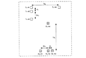
次に、図7Aは、送信アンテナ106及び受信アンテナ202の配置例を示す。また、図7Bは、図7Aに示すアンテナ配置によって得られる仮想受信アレーの配置を示す。
Next, FIG. 7A shows an arrangement example of the transmitting
ここでは、送信アンテナ106の個数Nt=4個とし、受信アンテナ202の個数Na=4個とする。また、4個の送信アンテナ106をTx#1〜Tx#4で表し、4個の受信アンテナ202をRx#1〜Rx#4で表す。
Here, the number of transmitting
図7Aにおいて、送信アンテナTx#1〜Tx#4は、垂直方向に配置した3つのアンテナのうちの上端である送信アンテナTx#1を基点に、水平右方向に更に1つのアンテナを配置し(L字を+90°回転)、受信アンテナRx#1〜Rx#4は、水平方向に配置した3つのアンテナのうちの右端である受信アンテナRx#3を基点に垂直上方向に更に1つのアンテナを配置する(L字を−90°回転)。
In FIG. 7A, the transmitting
また、図7A、図7Bにおいて、dHは水平方向の素子間隔の基本単位を示し、dVは垂直方向の素子間隔の基本単位を示す。図7Aでは、送信アンテナ106の水平方向の素子間隔は7dHであり、垂直方向の素子間隔はdVと2dVとである。また、図7Aでは、受信アンテナ202の水平方向の素子間隔は2dHとdHとである、垂直方向の素子間隔は7dVである。
Further, in FIGS. 7A and 7B, d H indicates a basic unit of element spacing in the horizontal direction, and d V indicates a basic unit of element spacing in the vertical direction. In Figure 7A, the horizontal direction of the element spacing of the transmit
図7Aでは、水平方向において、受信アンテナ202の素子間隔の総和(3dH)は、送信アンテナ106の素子間隔の最小値(7dH)よりも小さい。また、図7Aでは、垂直方向において、送信アンテナ106の素子間隔の総和(3dH)は、受信アンテナ202の素子間隔の最小値(7dH)よりも小さい。つまり、図7Aのアンテナ配置は、上述したA−1及びB−1の条件を満たす。
In FIG. 7A, in the horizontal direction, the sum of the element spacings of the receiving antenna 202 (3d H ) is smaller than the minimum element spacing of the transmitting antenna 106 (7d H ). Further, in FIG. 7A, in the vertical direction, the total element spacing (3d H ) of the transmitting
また、図7Aでは、水平方向において、NTH個の送信アンテナ106とNRH個の受信アンテナ202のうち、アンテナ数の少ない送信アンテナ106の素子間隔の最大値(7dH)は、アンテナ数の多い受信アンテナ202の素子間隔の最大値(2dH)よりも大きい。同様に、図7Aでは、垂直方向において、NTV個の送信アンテナ106とNRV個の受信アンテナ202のうち、アンテナ数の少ない受信アンテナ202の素子間隔の最大値(7dH)は、アンテナ数の多い送信アンテナ106の素子間隔の最大値(2dH)よりも大きい。
Further, in FIG. 7A, in the horizontal direction, among the N TH transmit
また、Nt個の送信アンテナ106は、NTH×NTVが最大となるように配置され、Na個の受信アンテナ202は、NRH×NRVが最大となるように配置されることが好ましい。例えば、図7Aでは、Nt(=4)個の送信アンテナ106は、(NTH×NTV)=(2×3)となるように配置され、Na(=4)個の受信アンテナ202は、(NRH×NRV)=(3×2)となるように配置される。こうすることで、Nt個の送信アンテナ106及びNa個の受信アンテナ202によって構成される仮想受信アレーの開口面を最大化することができる。
Further, it is preferable that the
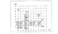
上述した図7Aに示すアンテナ配置によって構成される、図7Bに示す仮想受信アレーの配置は以下のような特徴を有する。 The arrangement of the virtual reception array shown in FIG. 7B, which is composed of the antenna arrangement shown in FIG. 7A described above, has the following features.
(1)水平方向
図7Aにおいて水平方向に素子間隔7dHによって配置された2つの送信アンテナTx#1,Tx#4と、水平方向に素子間隔2dH、dHによって配置された3つの受信アンテナRx#1, Rx#2, Rx#3との水平位置関係から、図7Bに示す仮想受信アレーは、水平方向に素子間隔2dH、dH、4dH、2dH、dHでそれぞれ直線上に配置された6素子の水平方向仮想直線アレーアンテナHLAを含む(図7Bに示す破線で囲まれた、VA#1, VA#5, VA#9, VA#4, VA#8, VA#12)。
(1) Horizontal direction In FIG. 7A, two transmitting
VA#1の水平位置を基準とする場合、水平方向仮想直線アレーアンテナHLAを構成する6素子(VA#1, VA#5, VA#9, VA#4, VA#8, VA#12)の各々の水平座標(x1,x2, x3, x4, x5, x6)は、(x1,x2, x3, x4, x5, x6)= [0, 2 dH, 3 dH, 7 dH, 9 dH, 10 dH]となる。
When the horizontal position of
ここで、水平方向仮想直線アレーアンテナHLAに含まれる任意の異なる2つの素子の素子間隔|xA - xB|(ただし、A,Bは各々1から6の整数値をとり、A≠Bである)は、{1, 2, 3, 4, 5, 6, 7, 8, 9, 10}×dHとなる。すなわち、6素子の水平方向仮想直線アレーアンテナHLAを用いることによって、水平方向の基本単位dHを素子間隔とする11素子の等間隔直線アレーと仮想的にみなした到来方向推定が可能となる。 Here, the element spacing of any two different elements included in the horizontal virtual linear array antenna HLA | x A --x B | (However, A and B each take an integer value of 1 to 6, and A ≠ B. Yes) is {1, 2, 3, 4, 5, 6, 7, 8, 9, 10} × d H. That is, by using the horizontal virtual linear array antenna HLA of 6 elements, it is possible to DOA estimation with uniform linear array of 11 elements that the basic unit d H in the horizontal direction and the element spacing was considered virtually.
例えば、dH=0.5λとすることで、レーダ装置10は、水平方向±90°の範囲の広範囲に渡ってグレーティングローブの発生を抑えた到来方向推定が可能となる。また、レーダ装置10は、アレー開口長が10dH=5λとなり、ビーム幅BWが約8°となるため、BW=10°以下の高い角度分解能を実現することができる。
For example, by setting d H = 0.5λ, the
方向推定部214における具体的な水平方向の方向推定処理は以下のように行われる。
The specific horizontal direction estimation process in the
まず、図7Bにおいて上述した{1, 2, 3, 4, 5, 6, 7, 8, 9, 10}×dHとなる2つの素子の素子間隔は、例えば、以下の水平方向の仮想受信アレーの組み合わせで得られる。
1×dHとなる素子間隔:VA#5, VA#9の組み合わせ
2×dHとなる素子間隔:VA#4, VA#8の組み合わせ
3×dHとなる素子間隔:VA#1, VA#9の組み合わせ
4×dHとなる素子間隔:VA#9, VA#4の組み合わせ
5×dHとなる素子間隔:VA#5, VA#4の組み合わせ
6×dHとなる素子間隔:VA#9, VA#8の組み合わせ
7×dHとなる素子間隔:VA#1, VA#4の組み合わせ
8×dHとなる素子間隔:VA#5, VA#12の組み合わせ
9×dHとなる素子間隔:VA#1, VA#8の組み合わせ
10×dHとなる素子間隔:VA#1, VA#12の組み合わせ
First, in FIG. 7B, the element spacing between the two elements having {1, 2, 3, 4, 5, 6, 7, 8, 9, 10} × d H described above is, for example, the following virtual reception in the horizontal direction. Obtained by combining arrays.
Element spacing of 1 × d H : Combination of
Element spacing of 2 × d H : Combination of
Element spacing of 3 × d H : Combination of
Element spacing of 4 × d H : Combination of
Element spacing of 5 × d H : Combination of
Element spacing of 6 × d H : Combination of
Element spacing of 7 × d H : Combination of
Element spacing of 8 × d H : Combination of
Element spacing of 9 × d H : Combination of
Element spacing of 10 × d H : Combination of
すなわち、水平方向の直線上に配置されるNTH×NRH本の仮想アンテナ素子(VA)のうちの任意の2つの仮想アンテナ素子の素子間隔の各々はdHの1以上の整数倍であり、任意の2つの仮想アンテナ素子は、間隔dHの整数倍を素子間隔とする素子であり、素子間隔が、1倍から所定値倍までの全てを含む。すなわち、図7Aのアンテナ配置は、上述したA−2の条件を満たしている。 That is, each of the element intervals of any two virtual antenna elements (VA) of N TH × N RH arranged on a straight line in the horizontal direction is an integer multiple of 1 or more of d H. , any two virtual antenna elements, an element for an integral multiple of the element spacing distance d H, element spacing, including everything from 1-fold to a predetermined value times. That is, the antenna arrangement in FIG. 7A satisfies the above-mentioned condition A-2.
なお、同一の素子間隔となる素子の組み合わせが複数ある場合には、その一つを選択してもよく、複数の組み合わせに対して加算平均処理が施されてもよい(ここでは一つを選択する例を示している)。 When there are a plurality of combinations of elements having the same element spacing, one of them may be selected, or the addition / averaging process may be performed on the plurality of combinations (here, one is selected). An example is shown).
上記仮想受信アレーの素子番号(VA#の番号)は、式(6)に示すアンテナ間偏差を補正した仮想受信アレー相関ベクトルh_after_cal(k、fs, w)の列ベクトルの要素番号に対応する。例えば、VA#1はh_after_cal(k、fs, w)の列ベクトル要素の1番目の要素h1(k、fs, w)に対応する。他のVA#2〜VA#16についても同様である。
The element number (VA # number) of the virtual reception array corresponds to the element number of the column vector of the virtual reception array correlation vector h _after_cal (k, fs, w) in which the deviation between the antennas shown in the equation (6) is corrected. .. For example,
方位推定部214は、上記の素子間隔と仮想受信アレー素子との組み合わせに基づいて、水平方向の基本単位dHを素子間隔とする11素子の等間隔直線アレーの相関ベクトルhVAH(k、fs, w)を生成する。等間隔直線アレーの相関ベクトルhVAH(k、fs, w)は次式で表される。なお、水平方向の等間隔直線アレーの相関ベクトルhVAH(k、fs, w)の要素数をNVAHと表す(図7BではNVAH=11)。
水平到来方向推定において、方位推定部214は、方向推定評価関数値PH(θ、k、fs、w)における方位方向θを所定の角度範囲内で可変として空間プロファイルを算出し、算出した空間プロファイルの極大ピークを大きい順に所定数抽出し、極大ピークの方位方向を到来方向推定値として出力する。
In the horizontal direction of arrival estimation,
なお、評価関数値PH(θ、k、fs、w)は、到来方向推定アルゴリズムによって各種の方法がある。例えば参考非特許文献2に開示されているアレーアンテナを用いた推定方法を用いてもよい。また、相関の高い複数波が到来する場合は、相関抑圧のために空間スムージング手法を適用した後に、各種の到来方向推定アルゴリズムを適用してもよい。このことは、以下で記載される到来方向推定処理についても同様に適用が可能である。
The evaluation function value P H (θ, k, fs , w) , there are a variety of ways by the arrival direction estimation algorithm. For example, an estimation method using an array antenna disclosed in
(参考非特許文献2)Direction-of-arrival estimation using signal subspace modeling Cadzow, J.A.; Aerospace and Electronic Systems, IEEE Transactions on Volume: 28 , Issue: 1 Publication Year: 1992 , Page(s): 64 - 79 (Reference Non-Patent Document 2) Direction-of-arrival estimation using signal subspace modeling Cadzow, J.A .; Aerospace and Electronic Systems, IEEE Transactions on Volume: 28, Issue: 1 Publication Year: 1992, Page (s): 64 --79
例えばビームフォーマ法は次式のように表すことができる。他にも、Capon, MUSICといった手法も同様に適用可能である。
ここで、上付き添え字Hはエルミート転置演算子である。また、aH(θu)は、方位方向θuの到来波に対する仮想受信アレーの方向ベクトルを示す。 Here, the superscript H is the Hermitian transpose operator. Further, a H (θ u ) indicates the direction vector of the virtual reception array with respect to the incoming wave in the azimuth direction θ u .
また、方位方向θuは到来方向推定を行う方位範囲内を所定の方位間隔β1で変化させたベクトルである。例えば、θuは以下のように設定される。
θu=θmin + uβ1、u=0,…, NU
NU=floor[(θmax-θmin)/β1]+1
ここでfloor(x)は、実数xを超えない最大の整数値を返す関数である。
The azimuth direction θ u is a vector obtained by changing the azimuth range in which the arrival direction is estimated by a predetermined azimuth interval β 1 . For example, θ u is set as follows.
θ u = θ min + u β 1 , u = 0,…, NU
NU = floor [(θmax-θmin) / β 1 ] +1
Here, floor (x) is a function that returns the maximum integer value that does not exceed the real number x.
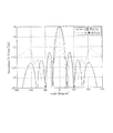
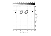
図8は上記構成を用いて得られる方向推定結果(計算機シミュレーション結果)を示す。図8では、シミュレーション条件として、ビームフォーマ法を使用し、ターゲット方向を0°としている。また、図8に示す方向推定結果は、水平方向における基本単位dHを素子間隔とする11素子の等間隔直線アレーと仮想的にみなした到来方向推定が行われた結果である。 FIG. 8 shows a direction estimation result (computer simulation result) obtained by using the above configuration. In FIG. 8, the beam former method is used as the simulation condition, and the target direction is set to 0 °. The direction estimation result shown in FIG. 8 is a result of the arrival direction estimation regarded virtually as uniform linear array of 11 elements and element spacing basic unit d H is performed in the horizontal direction.
図8に示すように、ターゲット方向0°のビームのビーム幅BWが約8°であり、13dB以下のサイドローブレベルが得られ、かつ、グレーティングローブが発生していないことが分かる。 As shown in FIG. 8, it can be seen that the beam width BW of the beam at 0 ° in the target direction is about 8 °, a side lobe level of 13 dB or less is obtained, and no grating lobe is generated.
(2)垂直方向
図7Aにおいて、垂直方向に素子間隔dV、2dVによって配置された3つの送信アンテナTx#1,Tx#2,Tx#3と、垂直方向に素子間隔7dVによって配置された2つの受信アンテナRx#3, Rx#4との垂直位置関係から、図7Bに示す仮想受信アレーは、垂直方向に素子間隔2dV、dV、4dV、2dV、dVによって直線上に配置された6素子の垂直方向仮想直線アレーアンテナVLAを含む(図7Bに示す破線で囲まれた、VA#11, VA#10, VA#9, VA#15, VA#14, VA#13)。
(2) in the vertical direction Figure 7A, element spacing d V in the vertical direction, and the three placed by 2d V transmit
VA#11の垂直位置を基準とする場合、垂直方向仮想直線アレーアンテナVLAを構成する6素子(VA#11, VA#10, VA#9, VA#15, VA#14, VA#13)の各々の垂直座標(y1,y2, y3, y4, y5, y6)は、(y1,y2, y3, y4, y5, y6)= [0, 2 dV, 3 dV, 7 dV, 9 dV, 10 dV]となる。
When the vertical position of
ここで、垂直方向仮想直線アレーアンテナVLAに含まれる任意の異なる2つの素子の素子間隔|yA - yB|(ただし、A,Bは各々1から6の整数値をとり、A≠Bである)は、{1, 2, 3, 4, 5, 6, 7, 8, 9, 10}×dVとなる。すなわち、レーダ装置10は、6素子の垂直方向仮想直線アレーアンテナVLAを、垂直方向における素子間隔が基本単位dVである11素子の等間隔直線アレーを有すると仮想的にみなすことができ、高い角度分解能による到来方向推定ができる。
Here, the element spacing of any two different elements included in the vertical virtual linear array antenna VLA | y A --y B | (However, A and B each take an integer value of 1 to 6, and A ≠ B. Yes) is {1, 2, 3, 4, 5, 6, 7, 8, 9, 10} × d V. In other words, the
例えば、dV=0.5λでは、レーダ装置10は、垂直方向±90°の範囲の広範囲に渡ってグレーティングローブの発生を抑えた到来方向推定が可能となる。また、レーダ装置10は、アレー開口長が10dV=5λとなるため、ビーム幅BWが約8°となり、BW=10°以下の高い角度分解能を実現できる。
For example, the d V = 0.5 [lambda, the
方向推定部214における具体的な垂直方向の方向推定処理は以下のように行われる。
The specific vertical direction estimation process in the
まず、図7Bにおいて上述した{1, 2, 3, 4, 5, 6, 7, 8, 9, 10}×dVとなる2つの素子の素子間隔は、例えば、以下の垂直方向の仮想受信アレーの組み合わせで得られる。
1×dVとなる素子間隔は、VA#10, VA#9の組み合わせで得られる。
2×dVとなる素子間隔:VA#11, VA#10の組み合わせ
3×dVとなる素子間隔:VA#11, VA#9の組み合わせ
4×dVとなる素子間隔:VA#9, VA#15の組み合わせ
5×dVとなる素子間隔:VA#10, VA#15の組み合わせ
6×dVとなる素子間隔:VA#9, VA#14の組み合わせ
7×dVとなる素子間隔:VA#10, VA#14の組み合わせ
8×dVとなる素子間隔:VA#10, VA#13の組み合わせ
9×dVとなる素子間隔:VA#11, VA#14の組み合わせ
10×dVとなる素子間隔:VA#11, VA#13の組み合わせ
First, in FIG. 7B, the element distance between the two elements having {1, 2, 3, 4, 5, 6, 7, 8, 9, 10} × d V described above is, for example, the following virtual reception in the vertical direction. Obtained by combining arrays.
The element spacing of 1 × d V can be obtained by combining
Element spacing of 2 x d V : Combination of
Element spacing of 3 × d V : Combination of
Element spacing of 4 x d V : Combination of
Element spacing of 5 x d V : Combination of
Element spacing of 6 × d V : Combination of
Element spacing of 7 x d V : Combination of
Element spacing of 8 x d V : Combination of
Element spacing of 9 x d V : Combination of
Element spacing of 10 × d V : Combination of
すなわち、垂直方向の直線上に配置されるNTV×NRV本の仮想アンテナ素子(VA)のうちの任意の2つの仮想アンテナ素子の素子間隔の各々はdVの1以上の整数倍であり、任意の2つの仮想アンテナ素子は、間隔dVの整数倍を素子間隔とする素子であり、素子間隔が、1倍から所定値倍までの全てを含む。すなわち、図7Aのアンテナ配置は、上述したB−2の条件を満たしている。 That is, each of the element spacing of any two virtual antenna elements of the N TV × N RV present virtual antenna elements are arranged on the vertical straight line (VA) is 1 or more integer multiples of d V , any two virtual antenna elements, an element for an integral multiple of the element spacing distance d V, element spacing, including everything from 1-fold to a predetermined value times. That is, the antenna arrangement of FIG. 7A satisfies the above-mentioned condition of B-2.
なお、同一の素子間隔となる素子の組み合わせが複数ある場合には、その一つを選択してもよく、複数の組み合わせに対して加算平均処理が施されてもよい(ここでは一つを選択する例を示している)。 When there are a plurality of combinations of elements having the same element spacing, one of them may be selected, or the addition / averaging process may be performed on the plurality of combinations (here, one is selected). An example is shown).
上記仮想受信アレーの素子番号(VA#の番号)は、式(6)に示すアンテナ間偏差を補正した仮想受信アレー相関ベクトルh_after_cal(k、fs, w)の列ベクトルの要素番号に対応する。例えば、VA#1はh_after_cal(k、fs, w)の列ベクトル要素の1番目の要素h1(k、fs, w)に対応する。他のVA#2〜VA#16についても同様である。
The element number (VA # number) of the virtual reception array corresponds to the element number of the column vector of the virtual reception array correlation vector h _after_cal (k, fs, w) in which the deviation between the antennas shown in the equation (6) is corrected. .. For example,
方位推定部214は、上記の素子間隔と仮想受信アレー素子との組み合わせに基づいて、垂直方向の基本単位dVを素子間隔とする11素子の等間隔直線アレーの相関ベクトルhVAV(k、fs, w)を生成する。等間隔直線アレーの相関ベクトルhVAV(k、fs, w)は次式で表される。なお、垂直方向の等間隔直線アレーの相関ベクトルhVAV(k、fs, w)の要素数をNVAVと表す(図7BではNVAV=11)。
垂直到来方向推定において、方位推定部214は、方向推定評価関数値PV(φ、k、fs、w)における仰角方向φを所定の角度範囲内で可変として空間プロファイルを算出し、算出した空間プロファイルの極大ピークを大きい順に所定数抽出し、極大ピークの仰角方向を到来方向推定値として出力する。
In the vertical direction of arrival estimation,
なお、評価関数値PV(φ、k、fs、w)は、到来方向推定アルゴリズムによって各種の方法がある。例えば参考非特許文献2に開示されているアレーアンテナを用いた推定方法を用いてもよい。また、相関の高い複数波が到来する場合は、相関抑圧のために空間スムージング手法を適用した後に、各種の到来方向推定アルゴリズムを適用してもよい。このことは、以下で記載される到来方向推定処理についても同様に適用が可能である。
The evaluation function value P V (φ, k, fs , w) , there are a variety of ways by the arrival direction estimation algorithm. For example, an estimation method using an array antenna disclosed in
例えばビームフォーマ法は次式のように表すことができる。他にも、Capon, MUSICといった手法も同様に適用可能である。
ここで、上付き添え字Hはエルミート転置演算子である。また、aV(φv)は、仰角方向φvの到来波に対する仮想受信アレーの方向ベクトルを示す。 Here, the superscript H is the Hermitian transpose operator. Further, a V (φ v ) indicates the direction vector of the virtual reception array with respect to the incoming wave in the elevation angle direction φ v .
また、φvは到来方向推定を行う仰角範囲内を所定の方位間隔β2で変化させたものである。例えば、φvは以下のように設定される。
φv=φmin + vβ2、v=0,…, NV
NV=floor[(φmax-φmin)/β2]+1
Further, φ v is obtained by changing the range of the elevation angle for estimating the arrival direction with a predetermined azimuth interval β 2 . For example, φ v is set as follows.
φ v = φ min + vβ 2 , v = 0,…, NV
NV = floor [(φmax-φmin) / β 2 ] +1
以上、図7Bに示す仮想受信アレーの配置の特徴について説明した。 The features of the arrangement of the virtual reception array shown in FIG. 7B have been described above.
なお、本実施の形態では、後述する仮想受信アレー配置VA#1,…, VA#(Nt×Na)に基づいて仮想受信アレーの方向ベクトルが予め算出されているとする。
In this embodiment, it is assumed that the direction vector of the virtual reception array is calculated in advance based on the virtual reception array
また、上述した時刻情報kは、距離情報に変換して出力されてもよい。時刻情報kを距離情報R(k)に変換するには次式を用いればよい。ここで、Twは符号送信区間を表し、Lはパルス符号長を表し、C0は光速度を表す。
また、ドップラー周波数情報(fsΔΦ)は相対速度成分に変換して出力されてもよい。ドップラー周波数fsΔΦを相対速度成分vd(fs)に変換するには、次式を用いて変換することができる。ここで、λは送信無線部105から出力されるRF信号のキャリア周波数の波長である。
以上のように、送信アンテナ数4個、受信アンテナ数4個という比較的少ないアンテナ素子数において、図7Aに示すアレー配置を用いることで、図7Bに示す仮想受信アレーの水平方向及び垂直方向によって構成される開口面を最大化することができる。 As described above, by using the array arrangement shown in FIG. 7A with a relatively small number of antenna elements of 4 transmitting antennas and 4 receiving antennas, the virtual receiving array shown in FIG. 7B can be used in the horizontal and vertical directions. The formed opening surface can be maximized.
つまり、本実施の形態によれば、レーダ装置10は、MIMOレーダを用いて垂直方向及び水平方向の2次元でのビーム走査を行う場合に、垂直方向及び水平方向の仮想受信アレーの開口長を最大限拡大することができる。
That is, according to the present embodiment, when the
また、レーダ装置10は、受信アンテナ202における水平方向及び垂直方向の双方の素子間隔(dH、dV)を例えば0.5λとし、フーリエビーム幅BW=8°程度の高分解能を、等振幅ウェイトであるフーリエビーム走査によって実現できる。すなわち、レーダ装置10は、高分解能を実現可能な到来方向推定アルゴリズムを適用することなく、水平方向及び垂直方向の高分解能化を低演算量で実現できる。
Further, the
このように、本実施の形態では、このような仮想受信アレーを用いることで少ないアンテナ数による角度分解能の向上を可能とし、レーダ装置10の小型化、低コスト化を図ることができる。
As described above, in the present embodiment, by using such a virtual reception array, it is possible to improve the angular resolution with a small number of antennas, and it is possible to reduce the size and cost of the
なお、図7Aにおいて、送信アンテナTx#1〜Tx#4と、受信アンテナRx#1〜Rx#4との間隔は、仮想受信アレーの配置には影響しない。ただし、送信アンテナTx#1〜Tx#4と受信アンテナRx#1〜Rx#4とが近接することにより送受信アンテナ間の結合度が高まるので、送信アンテナTx#1〜Tx#4と受信アンテナRx#1〜Rx#4とは、許容されるアンテナサイズ内においてできるだけ離す配置の方がより好適である。このことは、後述する他のアンテナ配置においても同様である。
In FIG. 7A, the distance between the transmitting
また、図7Aでは、一例として、送信アンテナを4素子、受信アンテナを4素子とした場合のアンテナ配置を示した。しかし、図7Aにおける送信アンテナ配置を受信アンテナ配置とし、受信アンテナ配置を送信アンテナ配置とした場合でも、図7Bに示す仮想受信アレーの配置と同様な構成が得られ、同様な効果を得ることができる。このことは、後述する他のアンテナ配置においても同様である。 Further, in FIG. 7A, as an example, the antenna arrangement when the transmitting antenna is 4 elements and the receiving antenna is 4 elements is shown. However, even when the transmitting antenna arrangement in FIG. 7A is the receiving antenna arrangement and the receiving antenna arrangement is the transmitting antenna arrangement, the same configuration as the virtual receiving array arrangement shown in FIG. 7B can be obtained, and the same effect can be obtained. it can. This also applies to other antenna arrangements described later.
(実施の形態1のバリエーション1)
送信アンテナ106を4素子、受信アンテナ202を4素子とした場合のアンテナ配置は、図7Aに示すアンテナ配置に限らない。例えば、図9Aは、送信アンテナ106を4素子、受信アンテナ202を4素子とした場合の他のアンテナ配置例を示す。また、図9Bは、図9Aに示すアンテナ配置によって得られる仮想受信アレーの配置を示す。
(
The antenna arrangement when the transmitting
図9Aにおいて、送信アンテナTx#1〜Tx#4は、図7Aと同様、垂直方向に配置した3つのアンテナのうちの上端である送信アンテナTx#1を基点に、水平右方向に更に1つのアンテナを配置したパターンである。一方、図9Aにおいて、受信アンテナRx#1〜Rx#4は、水平方向に配置した3つのアンテナのうちの中央である受信アンテナRx#2を基点に、垂直上方向に更に1つのアンテナを配置する(T字を180°回転)。
In FIG. 9A, the transmitting
図9Aに示すアンテナ配置によって構成される、図9Bに示す仮想受信アレーの配置は、図7Bと同様、上述した特徴(1)、(2)を有する。以下、図9A及び図9Bを用いて具体的に説明する。 The arrangement of the virtual reception array shown in FIG. 9B, which is composed of the antenna arrangement shown in FIG. 9A, has the above-mentioned features (1) and (2) as in FIG. 7B. Hereinafter, a specific description will be made with reference to FIGS. 9A and 9B.
(1)水平方向
図9Aにおいて水平方向に素子間隔7dHによって配置された2つの送信アンテナTx#1,Tx#4と、水平方向に素子間隔2dH、dHによって配置された3つの受信アンテナRx#1, Rx#2, Rx#3との水平位置関係から、図9Bに示す仮想受信アレーは、水平方向に素子間隔2dH、dH、4dH、2dH、dHでそれぞれ直線上に配置された6素子の水平方向仮想直線アレーアンテナHLAを含む(図9Bに示す破線で囲まれた、VA#1, VA#5, VA#9, VA#4, VA#8, VA#12)。
(1) Horizontal direction In FIG. 9A, two transmitting
VA#1の水平位置を基準とする場合、水平方向仮想直線アレーアンテナHLAを構成する6素子(VA#1, VA#5, VA#9, VA#4, VA#8, VA#12)の各々の水平座標(x1,x2, x3, x4, x5, x6)は、(x1,x2, x3, x4, x5, x6)= [0, 2 dH, 3 dH, 7 dH, 9 dH, 10 dH]となる。
When the horizontal position of
ここで、水平方向仮想直線アレーアンテナHLAに含まれる任意の異なる2つの素子の素子間隔|xA - xB|(ただし、A,Bは各々1から6の整数値をとり、A≠Bである)は、{1, 2, 3, 4, 5, 6, 7, 8, 9, 10}×dHとなる。すなわち、レーダ装置10は、6素子の水平方向仮想直線アレーアンテナHLAを用いることによって、水平方向における基本単位dHを素子間隔とする11素子の等間隔直線アレーを有すると仮想的にみなすことができ、高い角度分解能による到来方向推定ができる。
Here, the element spacing of any two different elements included in the horizontal virtual linear array antenna HLA | x A --x B | (However, A and B each take an integer value of 1 to 6, and A ≠ B. Yes) is {1, 2, 3, 4, 5, 6, 7, 8, 9, 10} × d H. In other words, the
例えば、レーダ装置10は、dH=0.5λでは、水平方向±90°の範囲の広範囲に渡ってグレーティングローブの発生を抑えた到来方向推定ができる。また、レーダ装置10は、アレー開口長が10dH=5λとなるため、ビーム幅BWが約8°となり、BW=10°以下の高い角度分解能を実現できる。
For example, at d H = 0.5λ, the
(2)垂直方向
図9Aにおいて、垂直方向に素子間隔dV、2dVによって配置された3つの送信アンテナTx#1,Tx#2,Tx#3と、垂直方向に素子間隔7dVによって配置された2つの受信アンテナRx#2, Rx#4との垂直位置関係から、図9Bに示す仮想受信アレーは、垂直方向に素子間隔2dV、dV、4dV、2dV、dVによって直線上に配置された6素子の垂直方向仮想直線アレーアンテナVLAを含む(図9Bに示す破線で囲まれた、VA#7, VA#6, VA#5, VA#15, VA#14, VA#13)。
(2) in the vertical direction Figure 9A, element spacing d V in the vertical direction, and the three placed by 2d V transmit
VA#7の垂直位置を基準とする場合、垂直方向仮想直線アレーアンテナVLAを構成する6素子(VA#7, VA#6, VA#5, VA#15, VA#14, VA#13)の各々の垂直座標(y1,y2, y3, y4, y5, y6)は、(y1,y2, y3, y4, y5, y6)= [0, 2 dV, 3 dV, 7 dV, 9 dV, 10 dV]となる。
When the vertical position of
ここで、垂直方向仮想直線アレーアンテナVLAに含まれる任意の異なる2つの素子の素子間隔|yA - yB|(ただし、A,Bは各々1から6の整数値をとり、A≠Bである)は、{1, 2, 3, 4, 5, 6, 7, 8, 9, 10}×dVとなる。すなわち、レーダ装置10は、6素子の垂直方向仮想直線アレーアンテナVLAを用いることによって、垂直方向における基本単位dVを素子間隔とする11素子の等間隔直線アレーを有すると仮想的にみなすことができ、高い角度分解能による到来方向推定ができる。
Here, the element spacing of any two different elements included in the vertical virtual linear array antenna VLA | y A --y B | (However, A and B each take an integer value of 1 to 6, and A ≠ B. Yes) is {1, 2, 3, 4, 5, 6, 7, 8, 9, 10} × d V. In other words, the
例えば、レーダ装置10は、dV=0.5λでは、垂直方向±90°の範囲の広範囲に渡ってグレーティングローブの発生を抑えた到来方向推定ができる。また、レーダ装置10は、アレー開口長が10dV=5λとなるため、ビーム幅BWが約8°となり、BW=10°以下の高い角度分解能を実現できる。
For example, the
(実施の形態1のバリエーション2)
実施の形態1において、水平方向又は垂直方向の何れか一方の角度分解能として10°程度の高い分解能が必要でない場合、レーダ装置10は、送信アンテナ106の素子数又は受信アンテナ202の素子数を3素子としてもよい。
(
In the first embodiment, when a high resolution of about 10 ° is not required as the angular resolution in either the horizontal direction or the vertical direction, the
以下では、一例として、垂直方向の角度分解能として高い分解能が要求されない場合に、送信アンテナ106の素子数を3素子とし、受信アンテナ202の素子数を4素子とするレーダ装置10について説明する。
In the following, as an example, a
図10Aは、送信アンテナ106及び受信アンテナ202の配置例を示す。また、図10Bは、図10Aに示すアンテナ配置によって得られる仮想受信アレーの配置を示す。
FIG. 10A shows an arrangement example of the transmitting
図10Aにおいて、3個の送信アンテナ106をTx#1〜Tx#3で表し、4個の受信アンテナ202をRx#1〜Rx#4で表す。図10Aにおいて、送信アンテナTx#1〜Tx#3は、垂直方向に配置した2つのアンテナのうちの上端である送信アンテナTx#1を基点に、水平右方向に更に1つのアンテナを、垂直方向の素子間隔よりも狭い間隔によって、配置し(L字を+90°回転)、受信アンテナRx#1〜Rx#4は、水平方向に配置した3つのアンテナのうちの右端である受信アンテナRx#3を基点に垂直上方向に更に1つのアンテナを、水平方向の素子間隔よりも狭い間隔によって、配置する(L字を−90°回転)。
In FIG. 10A, the three transmitting
また、本バリエーションに係る送信アンテナ106及び受信アンテナ202の配置では、実施の形態1で説明した制約条件A−1、A−2、B−1、B−2を満たすものとする。
Further, in the arrangement of the transmitting
図10Aに示すアンテナ配置によって構成される、図10Bに示す仮想受信アレーの配置は以下のような特徴を有する。 The arrangement of the virtual reception array shown in FIG. 10B, which is composed of the antenna arrangement shown in FIG. 10A, has the following features.
(1)水平方向
図10Aにおいて水平方向に素子間隔5dHによって配置された2つの送信アンテナTx#1,Tx#3と、水平方向に素子間隔dH、2dHによって配置された3つの受信アンテナRx#1, Rx#2, Rx#3との水平位置関係から、図10Bに示す仮想受信アレーは、水平方向に素子間隔dH、2dH、2dH、dH、2dHによって直線上に配置された6素子の水平方向仮想直線アレーアンテナHLAを含む(図10Bに示す破線で囲まれた、VA#1, VA#4, VA#7, VA#3, VA#6, VA#9)。
(1) Horizontal direction In FIG. 10A, two transmitting
VA#1の水平位置を基準とする場合、水平方向仮想直線アレーアンテナHLAを構成する6素子(VA#1, VA#4, VA#7, VA#3, VA#6, VA#9)の各々の水平座標(x1,x2, x3, x4, x5, x6)は、(x1,x2, x3, x4, x5, x6)= [0, dH, 3 dH, 5 dH, 6 dH, 8 dH]となる。
When the horizontal position of
ここで、水平方向仮想直線アレーアンテナHLAに含まれる任意の異なる2つの素子の素子間隔|xA - xB|(ただし、A,Bは各々1から6の整数値をとり、A≠Bである)は、{1, 2, 3, 4, 5, 6, 7, 8}×dHとなる。すなわち、レーダ装置10は、6素子の水平方向仮想直線アレーアンテナHLAを用いることによって、水平方向における基本単位dHを素子間隔とする9素子の等間隔直線アレーを有すると仮想的にみなすことができ、高い角度分解能による到来方向推定ができる。
Here, the element spacing of any two different elements included in the horizontal virtual linear array antenna HLA | x A --x B | (However, A and B each take an integer value of 1 to 6, and A ≠ B. Yes) is {1, 2, 3, 4, 5, 6, 7, 8} × d H. In other words, the
例えば、レーダ装置10は、dH=0.5λとすることで、水平方向±90°の範囲の広範囲に渡ってグレーティングローブの発生を抑えた到来方向推定が可能となる。また、レーダ装置10は、アレー開口長が8dH=4λとなるため、ビーム幅BWが約10°となり、BW=10°以下の高い角度分解能を実現できる。
For example, by setting d H = 0.5λ in the
(2)垂直方向
図10Aにおいて、垂直方向に素子間隔dVによって配置された2つの送信アンテナTx#1,Tx#2と、垂直方向に素子間隔3dVによって配置された2つの受信アンテナRx#3, Rx#4との垂直位置関係から、図10Bに示す仮想受信アレーは、垂直方向に素子間隔dV、2dV、dVによって直線上に配置された4素子の垂直方向仮想直線アレーアンテナVLAを含む(図10Bに示す破線で囲まれた、VA#8, VA#7, VA#11, VA#10)。
(2) in the vertical direction Figure 10A, the vertical direction of the two placed by element distance d V transmit
VA#8の垂直位置を基準とする場合、垂直方向仮想直線アレーアンテナVLAを構成する4素子(VA#8, VA#7, VA#11, VA#10)の各々の垂直座標(y1,y2, y3, y4)は、(y1,y2, y3, y4)= [0, dV, 3 dV, 4 dV]となる。
When the vertical position of
ここで、垂直方向仮想直線アレーアンテナVLAに含まれる任意の異なる2つの素子の素子間隔|yA - yB|(ただし、A,Bは各々1から4の整数値をとり、A≠Bである)は、{1, 2, 3, 4}×dVとなる。すなわち、レーダ装置10は、4素子の垂直方向仮想直線アレーアンテナVLAを用いることによって、垂直方向における素子間隔が基本単位dVである5素子の等間隔直線アレーを有すると仮想的にみなすことができ、高い角度分解能による到来方向推定ができる。
Here, the element spacing of any two different elements included in the vertical virtual linear array antenna VLA | y A --y B | (However, A and B each take an integer value of 1 to 4, and A ≠ B. Yes) is {1, 2, 3, 4} × d V. In other words, the
例えば、レーダ装置10は、dV=0.5λでは、垂直方向±90°の範囲の広範囲に渡ってグレーティングローブの発生を抑えた到来方向推定ができる。また、レーダ装置10は、アレー開口長が4dV=2λとなるため、ビーム幅BWが約20°となる。
For example, the
(実施の形態1のバリエーション3)
実施の形態1において、受信アンテナ202の素子数として5素子以上用いるレーダ装置10では、送信アンテナ106の素子数を3素子としてもよい。又は、送信アンテナ106の素子数として5素子以上用いるレーダ装置10では、受信アンテナ202の素子数を3素子としてもよい。
(
In the
以下では、一例として、送信アンテナ106の素子数を3素子とし、受信アンテナ202の素子数を5素子とするレーダ装置10について説明する。
Hereinafter, as an example, the
図11Aは、送信アンテナ106及び受信アンテナ202の配置例を示す。また、図11Bは、図11Aに示すアンテナ配置によって得られる仮想受信アレーの配置を示す。
FIG. 11A shows an arrangement example of the transmitting
図11Aにおいて、3個の送信アンテナ106をTx#1〜Tx#3で表し、5個の受信アンテナ202をRx#1〜Rx#5で表す。図11Aにおいて、送信アンテナTx#1〜Tx#3は、垂直方向に配置した2つのアンテナのうちの上端である送信アンテナTx#1を基点に、水平右方向に更に1つのアンテナを配置し(L字を+90°回転)、受信アンテナRx#1〜Rx#5は、水平方向に配置した3つのアンテナのうちの中央である受信アンテナRx#3を基点に垂直上下方向にそれぞれ1つのアンテナを配置する(十字型)。なお、受信アンテナRx#1〜Rx#5の配置は十字配置に限定されるものではなく、L字配置でも、T字配置でもよい(例えば、後述する図24A〜図24Fを参照)。
In FIG. 11A, the three transmitting
また、本バリエーションに係る送信アンテナ106及び受信アンテナ202の配置では、実施の形態1で説明した制約条件A−1、A−2、B−1、B−2を満たす配置である。
Further, in the arrangement of the transmitting
図11Aに示すアンテナ配置によって構成される、図11Bに示す仮想受信アレーの配置は以下のような特徴を有する。 The arrangement of the virtual reception array shown in FIG. 11B, which is composed of the antenna arrangement shown in FIG. 11A, has the following features.
(1)水平方向
図11Aにおいて水平方向に素子間隔7dHによって配置された2つの送信アンテナTx#1,Tx#3と、水平方向に素子間隔2dH、dHによって配置された3つの受信アンテナRx#2, Rx#3, Rx#4との水平位置関係から、図11Bに示す仮想受信アレーは、水平方向に素子間隔2dH、dH、4dH、2dH、dHによって直線上に配置されたによって6素子の水平方向仮想直線アレーアンテナHLAを含む(図11Bに示す破線で囲まれた、VA#4, VA#7, VA#10, VA#6, VA#9, VA#12)。
(1) Horizontal direction In FIG. 11A, two transmitting
VA#4の水平位置を基準とする場合、水平方向仮想直線アレーアンテナHLAを構成する6素子(VA#4, VA#7, VA#10, VA#6, VA#9, VA#12)の各々の水平座標(x1,x2, x3, x4, x5, x6)は、(x1,x2, x3, x4, x5, x6)= [0, 2 dH, 3 dH, 7 dH, 9 dH, 10 dH]となる。
When the horizontal position of
ここで、水平方向仮想直線アレーアンテナHLAに含まれる任意の異なる2つの素子の素子間隔|xA - xB|(ただし、A,Bは各々1から6の整数値をとり、A≠Bである)は、{1, 2, 3, 4, 5, 6, 7, 8, 9, 10}×dHとなる。すなわち、レーダ装置10は、6素子の水平方向仮想直線アレーアンテナHLAを用いることによって、水平方向における素子間隔が基本単位dHである11素子の等間隔直線アレーを有すると仮想的にみなすことができ、高い角度分解能による到来方向推定ができる。
Here, the element spacing of any two different elements included in the horizontal virtual linear array antenna HLA | x A --x B | (However, A and B each take an integer value of 1 to 6, and A ≠ B. Yes) is {1, 2, 3, 4, 5, 6, 7, 8, 9, 10} × d H. In other words, the
例えば、レーダ装置10は、dH=0.5λでは、水平方向±90°の範囲の広範囲に渡ってグレーティングローブの発生を抑えた到来方向推定が可能となる。また、レーダ装置10は、アレー開口長が10dH=5λとなるため、ビーム幅BWが約8°となり、BW=10°以下の高い角度分解能を実現できる。
For example, at d H = 0.5λ, the
(2)垂直方向
図11Aにおいて、垂直方向に素子間隔7dVによって配置された2つの送信アンテナTx#1,Tx#2と、垂直方向に素子間隔dV、2dVによって配置された3つの受信アンテナRx#1, Rx#3, Rx#5との垂直位置関係から、図11Bに示す仮想受信アレーは、垂直方向に素子間隔dV、2dV、4dV、dV、2dVによって直線上に配置された6素子の垂直方向仮想直線アレーアンテナVLAを含む(図11Bに示す破線で囲まれた、VA#2, VA#8, VA#14, VA#1, VA#7, VA#13)。
(2) in the vertical direction Figure 11A, and the two arranged by element spacing 7d V in the vertical direction transmission
VA#2の垂直位置を基準とする場合、垂直方向仮想直線アレーアンテナVLAを構成する6素子(VA#2, VA#8, VA#14, VA#1, VA#7, VA#13)の各々の垂直座標(y1,y2, y3, y4, y5, y6)は、(y1,y2, y3, y4, y5, y6)= [0, dV, 3 dV, 7 dV, 8 dV, 10 dV]となる。
When the vertical position of
ここで、垂直方向仮想直線アレーアンテナVLAに含まれる任意の異なる2つの素子の素子間隔|yA - yB|(ただし、A,Bは各々1から6の整数値をとり、A≠Bである)は、{1, 2, 3, 4, 5, 6, 7, 8, 9, 10}×dVとなる。すなわち、レーダ装置10は、6素子の垂直方向仮想直線アレーアンテナVLAを用いることによって、垂直方向における素子間隔が基本単位dVである11素子の等間隔直線アレーを有すると仮想的にみなすことができ、高い角度分解能による到来方向推定ができる。なお、等間隔直線アレーは、基本単位dV以外の素子間隔は含まない。
Here, the element spacing of any two different elements included in the vertical virtual linear array antenna VLA | y A --y B | (However, A and B each take an integer value of 1 to 6, and A ≠ B. Yes) is {1, 2, 3, 4, 5, 6, 7, 8, 9, 10} × d V. In other words, the
例えば、レーダ装置10は、dV=0.5λでは、垂直方向±90°の範囲の広範囲に渡ってグレーティングローブの発生を抑えた到来方向推定が可能となる。また、レーダ装置10は、アレー開口長が10dV=5λとなるため、ビーム幅BWが約8°となり、BW=10°以下の高い角度分解能を実現できる。
For example, the
[実施の形態2]
レーダ装置は、アレーアンテナの指向性利得を高めるために、アレーアンテナを構成するアレー素子の各々が更に複数のアンテナ素子(サブアレー化したアンテナ素子)を含むサブアレーアンテナを用いることがある。
[Embodiment 2]
In order to increase the directivity gain of the array antenna, the radar device may use a sub-array antenna in which each of the array elements constituting the array antenna further includes a plurality of antenna elements (sub-array antenna elements).
例えば、図12は、レーダ装置が垂直方向のレーダ検知範囲を狭くでき、垂直方向の最小素子間隔が2dVである場合、図13Aにサブアレー化したアンテナ素子を適用した一例である。図12では、2つのアレー素子を垂直方向にスタック配置してサブアレー化したサブアレー素子を用いることにより、垂直方向の指向性を狭め、不要な方向への輻射を低減し、アレー素子利得を向上することができる。 For example, FIG. 12, the radar device can be narrowed radar detection range in the vertical direction, if the minimum element spacing in the vertical direction is 2d V, is an example of applying the subarray of the antenna element in Fig. 13A. In FIG. 12, by using a sub-array element in which two array elements are stacked in the vertical direction to form a sub-array, the directivity in the vertical direction is narrowed, radiation in an unnecessary direction is reduced, and the array element gain is improved. be able to.
アレーアンテナの素子間隔は、アレー素子のサイズよりも狭い間隔には配置困難である。例えば、サブアレーアンテナのアレー素子を垂直方向にスタック配置することで、アレー素子のサイズが1波長程度に増加するため、レーダ装置は、アレーアンテナの配置上の制約を受ける。すなわち、レーダ装置は、サブアレーアンテナ構成では、アレー配置垂直方向の最小素子間隔が所定値以上となる制約を受ける。 It is difficult to arrange the element spacing of the array antenna at a spacing narrower than the size of the array element. For example, by stacking the array elements of the sub-array antenna in the vertical direction, the size of the array elements increases to about one wavelength, so that the radar device is restricted in the arrangement of the array antennas. That is, the radar device is restricted in the sub-array antenna configuration so that the minimum element spacing in the vertical direction of the array arrangement is equal to or greater than a predetermined value.
このように、レーダ装置は、サブアレーアンテナ構成を用いる場合、アレー素子のサイズが大きくなるので、サブアレーアンテナ間の間隔を広げる必要があり、アレーアンテナによる指向性パターン上に、グレーティングローブが発生する可能性がある。 As described above, when the radar device uses the sub-array antenna configuration, the size of the array element becomes large, so that it is necessary to widen the distance between the sub-array antennas, and a grating lobe may occur on the directivity pattern by the array antenna. There is sex.
そこで、本実施の形態では、サブアレーアンテナを用いる場合でも、広範囲に渡りグレーティングローブの発生を抑えた到来方向推定を可能とし、垂直/水平方向の高分解能化を実現するアンテナ配置について説明する。 Therefore, in the present embodiment, an antenna arrangement that enables estimation of the arrival direction in which the occurrence of grating lobes is suppressed over a wide range and realizes high resolution in the vertical / horizontal direction will be described even when a sub-array antenna is used.
なお、本実施の形態に係るレーダ装置は、実施の形態1に係るレーダ装置10と基本構成が共通するので、図3を援用して説明する。
Since the radar device according to the present embodiment has the same basic configuration as the
また、以下では、一例として、垂直方向にアレー素子がスタック配置されることによって、サブアレー化されたレーダ装置10について説明する。なお、水平方向のアレー素子はサブアレー化されず、実施の形態1と同様の特徴を有するレーダ装置10である。
Further, in the following, as an example, the
実施の形態1と同様、Nt個の送信アンテナ106及びNa個の受信アンテナ202の各々は、水平方向及び垂直方向において不等間隔に配置される。
Similar to the first embodiment, the
また、本実施の形態に係る送信アンテナ106及び受信アンテナ202は、垂直方向(サブアレーアンテナが構成される方向)において、NTV本の送信アンテナ106の素子間隔と、NRV本の受信アンテナ202の素子間隔との間で、素子間隔の差が垂直方向の素子間隔の基本単位dVとなる組み合わせが1つ以上含まれるように配置される。また、垂直方向の素子間隔の基本単位dVは1λ未満(例えば0.5λ)に設定する。すなわち、送信アンテナ106及び受信アンテナ202は、以下の式(以下、条件B−3と呼ぶ)を満たす配置が少なくとも一つ含まれるように配置される。
The transmitting
<条件B−3>
|(送信アンテナ106の垂直方向の素子間隔)-(受信アンテナ202の垂直方向の素子間隔)|
=dV≒0.5λ < 1λ
<Condition B-3>
| (Vertical element spacing of transmitting antenna 106)-(Vertical element spacing of receiving antenna 202) |
= D V ≒ 0.5λ <1λ
また、本実施の形態に係る送信アンテナ106及び受信アンテナ202の配置を有するレーダ装置10は、実施の形態1で説明した制約条件のうち、B−1以外のA−1、A−2、B−2を満たす。
Further, the
一例として、図13Aは、送信アンテナ106及び受信アンテナ202の配置例を示す。また、図13Bは、図13Aに示すアンテナ配置によって得られる仮想受信アレーの配置を示す。
As an example, FIG. 13A shows an arrangement example of the transmitting
ここでは、送信アンテナ106の個数Nt=4個とし、受信アンテナ202の個数Na=4個とする。また、4個の送信アンテナ106をTx#1〜Tx#4で表し、4個の受信アンテナ202をRx#1〜Rx#4で表す。
Here, the number of transmitting
図13Aにおいて、送信アンテナTx#1〜Tx#4は、垂直方向に配置した3つのアンテナのうちの上端である送信アンテナTx#1を基点に、水平右方向に更に1つのアンテナを配置したパターンである(L字を+90°回転)、受信アンテナRx#1〜Rx#4は、水平方向に配置した3つのアンテナのうちの中央である受信アンテナRx#2を基点に、垂直上方向に更に1つのアンテナを配置したパターンである(T字型を180°回転)。
In FIG. 13A, the transmitting
図13Aに示すアンテナ配置によって構成される、図13Bに示す仮想受信アレーの配置は以下のような特徴を有する。 The arrangement of the virtual reception array shown in FIG. 13B, which is composed of the antenna arrangement shown in FIG. 13A, has the following features.
(1)水平方向
図13Aにおいて水平方向に素子間隔7dHによって配置された2つの送信アンテナTx#1,Tx#4と、水平方向に素子間隔2dH、dHによって配置された3つの受信アンテナRx#1, Rx#2, Rx#3との水平位置関係から、図13Bに示す仮想受信アレーは、水平方向に素子間隔2dH、dH、4dH、2dH、dHによって直線上に配置された6素子の水平方向仮想直線アレーアンテナHLAを含む(図13Bに示す破線で囲まれた、VA#1, VA#5, VA#9, VA#4, VA#8, VA#12)。
(1) Horizontal direction In FIG. 13A, two transmitting
VA#1の水平位置を基準とする場合、水平方向仮想直線アレーアンテナHLAを構成する6素子(VA#1, VA#5, VA#9, VA#4, VA#8, VA#12)の各々の水平座標(x1,x2, x3, x4, x5, x6)は、(x1,x2, x3, x4, x5, x6)= [0, 2 dH, 3 dH, 7 dH, 9 dH, 10 dH]となる。
When the horizontal position of
ここで、水平方向仮想直線アレーアンテナHLAに含まれる任意の異なる2つの素子の素子間隔|xA - xB|(ただし、A,Bは各々1から6の整数値をとり、A≠Bである)は、{1, 2, 3, 4, 5, 6, 7, 8, 9, 10}×dHとなる。すなわち、レーダ装置10は、6素子の水平方向仮想直線アレーアンテナHLAを用いることによって、水平方向における基本単位dHを素子間隔とする11素子の等間隔直線アレーを有すると仮想的にみなすことができ、高い角度分解能による到来方向推定ができる。
Here, the element spacing of any two different elements included in the horizontal virtual linear array antenna HLA | x A --x B | (However, A and B each take an integer value of 1 to 6, and A ≠ B. Yes) is {1, 2, 3, 4, 5, 6, 7, 8, 9, 10} × d H. In other words, the
例えば、レーダ装置10は、dH=0.5λでは、水平方向±90°の範囲の広範囲に渡ってグレーティングローブの発生を抑えた到来方向推定ができる。また、レーダ装置10は、アレー開口長が10dH=5λとなるため、ビーム幅BWが約8°となり、BW=10°以下の高い角度分解能を実現できる。
For example, at d H = 0.5λ, the
(2)垂直方向
図13Aにおいて、垂直方向に素子間隔2dV、4dVによって配置された3つの送信アンテナTx#1,Tx#2,Tx#3と、垂直方向に素子間隔5dVによって配置された2つの受信アンテナRx#2, Rx#4との垂直位置関係から、図13Bに示す仮想受信アレーは、垂直方向に素子間隔4dV、dV、dV、3dV、2dVによって直線上に配置された6素子の垂直方向仮想直線アレーアンテナVLAを含む(図13Bに示す破線で囲まれた、VA#7, VA#6, VA#15, VA#5, VA#14, VA#13)。
(2) Vertical direction In FIG. 13A, the three transmitting
VA#7の垂直位置を基準とする場合、垂直方向仮想直線アレーアンテナVLAを構成する6素子(VA#7, VA#6, VA#15, VA#5, VA#14, VA#13)の各々の垂直座標(y1,y2, y3, y4, y5, y6)は、(y1,y2, y3, y4, y5, y6)= [0, 4 dV, 5 dV, 6 dV, 9 dV, 11 dV]となる。
When the vertical position of
ここで、垂直方向仮想直線アレーアンテナVLAに含まれる任意の異なる2つの素子の素子間隔|yA - yB|(ただし、A,Bは各々1から6の整数値をとり、A≠Bである)は、{1, 2, 3, 4, 5, 6, 7, 9, 11}×dVとなる。すなわち、レーダ装置10は、6素子の垂直方向仮想直線アレーアンテナVLAのうち、{1, 2, 3, 4, 5, 6, 7}×dVとなる素子間隔の組み合わせを用いることによって、垂直方向における素子間隔が基本単位dVである8素子の等間隔直線アレーを有すると仮想的にみなすことができ、高い角度分解能による到来方向推定ができる。
Here, the element spacing of any two different elements included in the vertical virtual linear array antenna VLA | y A --y B | (However, A and B each take an integer value of 1 to 6, and A ≠ B. Yes) is {1, 2, 3, 4, 5, 6, 7, 9, 11} × d V. In other words, the
なお、レーダ装置10は、{1, 2, 3, 4, 5, 6, 7, 9, 11}×dVとなる素子間隔の組み合わせを用いることによって、垂直方向における基本単位dVを2倍した素子間隔2dVを含む10素子の直線アレーを有すると仮想的にみなして、到来方向推定を行ってもよい。この場合、10素子の直線アレーを有するとみなしたレーダ装置10は、基本単位dVを素子間隔とする8素子の等間隔直線アレーと比較して、空間的なサイドローブが若干上昇するが、開口長が更に拡大するため、角度分解能を向上させることができる。
Incidentally, the
例えば、レーダ装置10は、dV=0.5λでは、垂直方向±90°の範囲の広範囲に渡ってグレーティングローブの発生を抑えた到来方向推定ができる。また、レーダ装置10は、基本単位dVを素子間隔とする8素子の等間隔直線アレーを有すると仮想的にみなして到来方向推定を行う場合、アレー開口長が7dV=3.5λとなるため、ビーム幅Bが約11°となる。また、レーダ装置10は、素子間隔2dVを含む10素子の直線アレーを有すると仮想的にみなして到来方向推定を行う場合、アレー開口長が11dV=5.5λとなるため、ビーム幅BWは約7°となり、BW=10°以下の高い角度分解能を実現できる。
For example, the
このように、レーダ装置10は、dV=0.5λでは、図13Aにおいて、(|(Tx#2及びTx#3の垂直方向の素子間隔4dV)-(Rx#2及びRx#4の垂直方向素子間隔5dV)|=dV≒0.5λ < 1λとなり、条件B−3を満たす。これにより、図13Bでは、仮想受信アレーの垂直方向の配置において、1λ以下の素子間隔(≒0.5λ)が1つ以上含まれる(図13Bに示すVA#6及びVA#15の素子間隔、VA#15及びVA#5の素子間隔、)。図13Aを用いたレーダ装置10は、サブアレーアンテナ構成であっても、垂直方向における基本単位dVを素子間隔とする複数素子の等間隔直線アレーを有すると仮想的にみなすることができ、高い角度分解能による到来方向推定ができる。
Thus, the
図14は上記構成を用いて得られる方向推定結果(計算機シミュレーション結果)を示す。図14では、シミュレーション条件として、ビームフォーマ法を使用し、ターゲット方向を0°としている。また、図14において実線で示す方向推定結果(8素子DOA)は、垂直方向における基本単位dVを素子間隔とする8素子の等間隔直線アレーと仮想的にみなして到来方向推定を行った結果であり、点線で示す方向推定結果(10素子DOA)は、垂直方向における基本単位dVの2倍の素子間隔を含む10素子の直線アレーと仮想的にみなして到来方向推定を行った結果である。 FIG. 14 shows a direction estimation result (computer simulation result) obtained by using the above configuration. In FIG. 14, the beam former method is used as the simulation condition, and the target direction is set to 0 °. The direction estimation result (8 elements DOA) indicated by the solid line in FIG. 14, as a result of the uniform linear array of 8 elements and element spacing the basic unit d V and virtually regarded by DOA estimation in the vertical direction , and the dotted line in the direction estimation result indicating (10 elements DOA) is a result of the 10 linear array of elements, including twice the element spacing of the basic unit d V in the vertical direction was virtually regarded by DOA estimation is there.
図14に示すように、8素子の等間隔直線アレーであると仮想的にみなしたレーダ装置10では、ターゲット方向0°のビームのビーム幅BWが約11°であり、13dB以下のサイドローブレベルが得られていることが分かる。また、図14に示すように、10素子の直線アレーであると仮想的にみなしたレーダ装置10では、8素子の等間隔直線アレーであると仮想的にみなした場合(実線)と比較して、サイドローブが上昇しているが、ターゲット方向0°のビームのビーム幅BWが狭まることが分かる。また、図14に示すように、双方においてグレーティングローブが発生していないことが分かる。
As shown in FIG. 14, in the
以上のように、本実施の形態によれば、レーダ装置10は、サブアレーアンテナ構成において、MIMOレーダを用いて垂直方向及び水平方向の2次元でのビーム走査を行う場合に、垂直方向及び水平方向の仮想受信アレーの開口長を最大限拡大することができる。すなわち、本実施の形態によれば、レーダ装置10は、仮想受信アレーを用いることで、少ないアンテナ数による角度分解能の向上を可能とし、小型化、低コスト化を図ることができる。
As described above, according to the present embodiment, when the
(実施の形態2のバリエーション1)
上述した図13AのMIMOレーダにおけるアンテナ配置は、垂直方向にスタック配置してサブアレー化されたアレー素子の垂直方向におけるサイズが2dVよりも小さければ適用可能である。
(
Antenna arrangement in MIMO radar of Figure 13A described above, the size in the vertical direction of the array elements are subarrays of stuck arranged vertically is applicable is smaller than 2d V.
図13Aの配置において、垂直方向の素子間隔が最小となるのは、Tx#1とTx#2の素子間隔で、2dVである。一方、図15Aの配置において、垂直方向の素子間隔が最小となるのは、Rx#2とRx#4の素子間隔で、3dVである。そのため、図15Aの配置は、より垂直方向のサイズが大きいサブアレー化したアンテナ素子を適用できることになる。垂直方向のサイズが大きいサブアレー化したアンテナ素子を用いることで、垂直方向の利得を高め、また、垂直方向の指向性を絞ることができる。
In the arrangement of FIG. 13A, the element spacing in the vertical direction is minimized, with element spacing of
一方で、垂直方向にスタック配置してサブアレー化されたアレー素子の垂直方向のサイズが2dVより大きく、例えば、図15Cに示すように垂直方向に3つのアンテナ素子をスタック配置してサブアレー化したアンテナ素子を用いる場合、以下に説明するアンテナ配置を用いればよい。以下では、垂直方向にスタック配置してサブアレー化されたアレー素子の垂直方向のサイズが3dV以下であれば適用可能であるアンテナ配置例について説明する。 On the other hand, it is greater than 2d V vertical size of the array elements which are sub-arrays by being stacked vertically disposed, for example, and subarray by being stacked arrangement with three antenna elements in the vertical direction as shown in FIG. 15C When an antenna element is used, the antenna arrangement described below may be used. The following describes an antenna arrangement example vertical size of the array elements which are sub-arrays by being stacked arrangement is applicable not more than 3d V in the vertical direction.
図15Aは、送信アンテナ106及び受信アンテナ202の配置例を示す。また、図15Bは、図15Aに示すアンテナ配置によって得られる仮想受信アレーの配置を示す。
FIG. 15A shows an arrangement example of the transmitting
ここでは、送信アンテナ106の個数Nt=4個とし、受信アンテナ202の個数Na=4個とする。また、4個の送信アンテナ106をTx#1〜Tx#4で表し、4個の受信アンテナ202をRx#1〜Rx#4で表す。
Here, the number of transmitting
図15Aにおいて、送信アンテナTx#1〜Tx#4は、垂直方向に配置した3つのアンテナのうちの上端である送信アンテナTx#1を基点に、水平右方向に更に1つのアンテナを配置し(L字を+90°回転)、受信アンテナRx#1〜Rx#4は、水平方向に配置した3つのアンテナのうちの中央である受信アンテナRx#2を基点に、垂直上方向に更に1つのアンテナを配置する(T字を180°回転)。
In FIG. 15A, the transmitting
図15Aに示すアンテナ配置によって構成される、図15Bに示す仮想受信アレーの配置は以下のような特徴を有する。 The arrangement of the virtual reception array shown in FIG. 15B, which is composed of the antenna arrangement shown in FIG. 15A, has the following features.
(1)水平方向
図15Aにおいて水平方向に素子間隔7dHによって配置された2つの送信アンテナTx#1,Tx#4と、水平方向に素子間隔2dH、dHによって配置された3つの受信アンテナRx#1, Rx#2, Rx#3との水平位置関係から、図15Bに示す仮想受信アレーは、水平方向に素子間隔2dH、dH、4dH、2dH、dHによって直線上に配置された6素子の水平方向仮想直線アレーアンテナHLAを含む(図15Bに示す破線で囲まれた、VA#1, VA#5, VA#9, VA#4, VA#8, VA#12)。
(1) Horizontal direction In FIG. 15A, two transmitting
VA#1の水平位置を基準とする場合、水平方向仮想直線アレーアンテナHLAを構成する6素子(VA#1, VA#5, VA#9, VA#4, VA#8, VA#12)の各々の水平座標(x1,x2, x3, x4, x5, x6)は、(x1,x2, x3, x4, x5, x6)= [0, 2 dH, 3 dH, 7 dH, 9 dH, 10 dH]となる。
When the horizontal position of
ここで、水平方向仮想直線アレーアンテナHLAに含まれる任意の異なる2つの素子の素子間隔|xA - xB|(ただし、A,Bは各々1から6の整数値をとり、A≠Bである)は、{1, 2, 3, 4, 5, 6, 7, 8, 9, 10}×dHとなる。すなわち、レーダ装置10は、6素子の水平方向仮想直線アレーアンテナHLAを用いることによって、水平方向における素子間隔が基本単位dHである11素子の等間隔直線アレーを有すると仮想的にみなすことができ、高い角度分解能を有する到来方向推定ができる。
Here, the element spacing of any two different elements included in the horizontal virtual linear array antenna HLA | x A --x B | (However, A and B each take an integer value of 1 to 6, and A ≠ B. Yes) is {1, 2, 3, 4, 5, 6, 7, 8, 9, 10} × d H. In other words, the
例えば、レーダ装置10は、dH=0.5λでは、水平方向±90°の範囲の広範囲に渡ってグレーティングローブの発生を抑えた到来方向推定ができる。また、レーダ装置10は、アレー開口長が10dH=5λとなるため、ビーム幅BWが約8°となり、BW=10°以下の高い角度分解能を実現できる。
For example, at d H = 0.5λ, the
(2)垂直方向
図15Aにおいて、垂直方向に素子間隔4dV、5dVによって配置された3つの送信アンテナTx#1,Tx#2,Tx#3と、垂直方向に素子間隔3dVによって配置された2つの受信アンテナRx#2, Rx#4との垂直位置関係から、図15Bに示す仮想受信アレーは、垂直方向に素子間隔3dV、2dV、3dV、1dV、3dVによって直線上に配置された6個の垂直方向仮想直線アレーアンテナVLAを含む(図15Bに示す破線で囲まれた、VA#7, VA#15, VA#6, VA#14, VA#5, VA#13)。
(2) Vertical direction In FIG. 15A, the three transmitting
VA#7の垂直位置を基準とする場合、垂直方向仮想直線アレーアンテナVLAを構成する6素子(VA#7, VA#15, VA#6, VA#14, VA#5, VA#13)の各々の垂直座標(y1,y2, y3, y4, y5, y6)は、(y1,y2, y3, y4, y5, y6)= [0, 3 dV, 5 dV, 8 dV, 9 dV, 12 dV]となる。
When the vertical position of
ここで、垂直方向仮想直線アレーアンテナVLAに含まれる任意の異なる2つの素子の素子間隔|yA - yB|(ただし、A,Bは各々1から6の整数値をとり、A≠Bである)は、{1, 2, 3, 4, 5, 6, 7, 8, 9, 12}×dVとなる。すなわち、レーダ装置10は、6素子の垂直方向仮想直線アレーアンテナVLAのうち、{1, 2, 3, 4, 5, 6, 7, 8, 9}×dVとなる素子間隔の組み合わせを用いることによって、垂直方向における素子間隔が基本単位dVである10素子の等間隔直線アレーを有すると仮想的にみなすことができ、高い角度分解能による到来方向推定ができる。
Here, the element spacing of any two different elements included in the vertical virtual linear array antenna VLA | y A --y B | (However, A and B each take an integer value of 1 to 6, and A ≠ B. Is) is {1, 2, 3, 4, 5, 6, 7, 8, 9, 12} × d V. In other words, the
なお、レーダ装置10は、{1, 2, 3, 4, 5, 6, 7, 8, 9, 12}×dVとなる素子間隔の組み合わせを用いることによって、垂直方向の基本単位dVの3倍の素子間隔3dVを含む11素子の直線アレーを有すると仮想的にみなして、到来方向推定を行ってもよい。この場合、10素子の直線アレーを有するとみなしたレーダ装置10は、基本単位dVを素子間隔とする10素子の等間隔直線アレーと比較して、空間的なサイドローブが若干上昇するが、開口長が更に拡大するため、角度分解能を向上させることができる。
The
例えば、レーダ装置10は、dV=0.5λでは、垂直方向±90°の範囲の広範囲に渡ってグレーティングローブの発生を抑えた到来方向推定ができる。また、レーダ装置10は、基本単位dVを素子間隔とする10素子の等間隔直線アレーを有すると仮想的にみなして、到来方向推定を行う場合、アレー開口長が9dV=4.5λとなるため、ビーム幅BWが約9°となり、BW=10°以下の高い角度分解能を実現できる。また、素子間隔3dVを含む11素子の直線アレーを有すると仮想的にみなして、到来方向推定を行う場合、アレー開口長が12dV=6λとなるため、ビーム幅BWが約7°となり、BW=10°以下の高い角度分解能を実現できる。
For example, the
(実施の形態2のバリエーション2)
上記実施の形態では、垂直方向においてアレー素子をサブアレー化する場合について説明したが、水平方向においてアレー素子をサブアレー化してもよい。すなわち、図16は、レーダ装置10が水平方向のレーダ検知範囲を狭くでき、水平方向の最小素子間隔が2dHである場合、サブアレー化したアンテナ素子を図17Aに適用した一例である。図16では、2つのアレー素子を水平方向にスタック配置してサブアレー化することにより、水平方向の指向性を狭め、不要な方向への輻射を低減し、アレー素子利得を向上することができる。
(
In the above embodiment, the case where the array element is sub-arrayed in the vertical direction has been described, but the array element may be sub-arrayed in the horizontal direction. That is, FIG. 16 can narrow the radar detection range of the
ただし、上述した垂直方向と同様に、サブアレーアンテナのアレー素子を水平方向にスタック配置することで、アレー素子のサイズが1波長程度に増加するため、アレーアンテナの配置上の制約が生じる。すなわち、レーダ装置10は、サブアレーアンテナ構成では、アレー配置水平方向の最小素子間隔が所定値以上となる制約を受ける。
However, as in the vertical direction described above, by stacking the array elements of the sub-array antennas in the horizontal direction, the size of the array elements increases to about one wavelength, which imposes restrictions on the arrangement of the array antennas. That is, the
そこで、本バリエーションでは、水平方向においてサブアレーアンテナを用いる場合でも、広範囲に渡りグレーティングローブの発生を抑えた到来方向推定が可能であり、垂直/水平方向の高分解能化を実現するためのアンテナ配置について説明する。 Therefore, in this variation, even when a sub-array antenna is used in the horizontal direction, it is possible to estimate the arrival direction while suppressing the occurrence of grating lobes over a wide range, and the antenna arrangement for achieving high resolution in the vertical / horizontal direction. explain.
実施の形態1と同様、Nt個の送信アンテナ106及びNa個の受信アンテナ202の各々は、水平方向及び垂直方向において不等間隔に配置される。
Similar to the first embodiment, the
また、本実施の形態に係る送信アンテナ106及び受信アンテナ202は、水平方向(サブアレーアンテナが構成される方向)において、NTV本の送信アンテナ106の素子間隔と、NRV本の受信アンテナ202の素子間隔との間で、素子間隔の差が水平方向の素子間隔の基本単位dHとなる組み合わせが1つ以上含まれるように配置される。また、水平方向の素子間隔の基本単位dHは1λ未満(例えば0.5λ)に設定する。すなわち、送信アンテナ106及び受信アンテナ202は、以下の式(以下、条件A−3と呼ぶ)を満たす配置が少なくとも一つ含まれるように配置される。
The transmitting
<条件A−3>
|(送信アンテナ106の水平方向の素子間隔)-(受信アンテナ202の水平方向の素子間隔)|
= dH ≒0.5λ < 1λ
<Condition A-3>
| (Horizontal element spacing of transmitting antenna 106)-(Horizontal element spacing of receiving antenna 202) |
= D H ≒ 0.5λ <1λ
また、本バリエーションに係る送信アンテナ106及び受信アンテナ202の配置では、実施の形態1で説明した制約条件のうち、A−1以外のA−2、B−1、B−2を満たすものとする。
Further, in the arrangement of the transmitting
こうすることで、レーダ装置10は、水平方向のサブアレーアンテナ構成においても、垂直方向及び水平方向の仮想受信アレーの開口長を最大限拡大することができ、仮想受信アレーを用いることで、少ないアンテナ数による角度分解能の向上を可能とし、小型化、低コスト化を図ることができる。
By doing so, the
(実施の形態2のバリエーション3)
本バリエーションでは、垂直方向及び水平方向の双方においてアレー素子をサブアレー化する場合について説明する。図18は、垂直方向及び水平方向の双方のレーダ検知範囲を狭くでき、垂直方向/水平方向の最小素子間隔が2dV、2dHである場合、2素子×2素子のサブアレー化したアンテナ素子を図17Aに適用した一例である。図18では、アレー素子を垂直方向及び水平方向にスタック配置してサブアレー化することにより、垂直方向及び水平方向の指向性を狭め、不要な方向への輻射を低減し、アレー素子利得を向上することができる。
(
In this variation, a case where the array element is sub-arrayed in both the vertical direction and the horizontal direction will be described. 18 can narrow the both radar detection range of the vertical and horizontal directions, the minimum element spacing in the vertical direction / horizontal direction 2d V, if a 2d H, a subarray of the antenna element of the two elements × 2 elements This is an example applied to FIG. 17A. In FIG. 18, by stacking the array elements in the vertical and horizontal directions to form a sub-array, the directivity in the vertical and horizontal directions is narrowed, radiation in unnecessary directions is reduced, and the array element gain is improved. be able to.
ただし、レーダ装置10は、アレー素子を垂直方向及び水平方向にスタック配置することで、アレー素子のサイズが1波長以上に増加するため、アレーアンテナの配置上の制約が生じる。すなわち、レーダ装置10は、アレー配置の垂直方向及び水平方向の最小素子間隔が所定値以上となる制約を受ける。
However, in the
そこで、本バリエーションでは、垂直方向及び水平方向の双方においてサブアレーアンテナを用いる場合でも、広範囲に渡りグレーティングローブの発生を抑えた到来方向推定が可能であり、垂直/水平方向の高分解能化を実現するためのアンテナ配置について説明する。 Therefore, in this variation, even when the sub-array antenna is used in both the vertical direction and the horizontal direction, it is possible to estimate the arrival direction while suppressing the occurrence of grating lobes over a wide range, and high resolution in the vertical / horizontal direction is realized. The antenna arrangement for this will be described.
実施の形態1と同様、Nt個の送信アンテナ106及びNa個の受信アンテナ202の各々は、水平方向及び垂直方向において不等間隔に配置される。
Similar to the first embodiment, the
本実施の形態に係る送信アンテナ106及び受信アンテナ202は、垂直方向において、NTV本の送信アンテナ106の素子間隔と、NRV本の受信アンテナ202の素子間隔との間で、素子間隔の差が垂直方向の素子間隔の基本単位dVとなる組み合わせが1つ以上含まれるように配置される。また、垂直方向の素子間隔の基本単位dVは1λ未満(例えば0.5λ)に設定する。すなわち、送信アンテナ106及び受信アンテナ202は、垂直方向において、以下の式(条件B−3)を満たす配置が少なくとも一つ含まれるように配置される。
Transmitting
<条件B−3>
|(送信アンテナ106の垂直方向の素子間隔)-(受信アンテナ202の垂直方向の素子間隔)|
= dV ≒0.5λ < 1λ
<Condition B-3>
| (Vertical element spacing of transmitting antenna 106)-(Vertical element spacing of receiving antenna 202) |
= D V ≒ 0.5λ <1λ
また、本実施の形態に係る送信アンテナ106及び受信アンテナ202は、水平方向において、NTV本の送信アンテナ106の素子間隔と、NRV本の受信アンテナ202の素子間隔との間で、素子間隔の差が水平方向の素子間隔の基本単位dHとなる組み合わせが1つ以上含まれるように配置される。また、水平方向の素子間隔の基本単位dHは1λ未満(例えば0.5λ)に設定する。すなわち、送信アンテナ106及び受信アンテナ202は、水平方向において、以下の式(条件A−3)を満たす配置が少なくとも一つ含まれるように配置される。
The transmitting
<条件A−3>
|(送信アンテナ106の水平方向の素子間隔)-(受信アンテナ202の水平方向の素子間隔)|
=dH≒0.5λ < 1λ
<Condition A-3>
| (Horizontal element spacing of transmitting antenna 106)-(Horizontal element spacing of receiving antenna 202) |
= D H ≒ 0.5λ <1λ
また、本バリエーションに係る送信アンテナ106及び受信アンテナ202の配置では、実施の形態1で説明した制約条件のうち、A−1、B−1以外のA−2、B−2を満たすものとする。
Further, in the arrangement of the transmitting
一例として、図17Aは、送信アンテナ106及び受信アンテナ202の配置例を示す。また、図17Bは、図17Aに示すアンテナ配置によって得られる仮想受信アレーの配置を示す。
As an example, FIG. 17A shows an arrangement example of the transmitting
ここでは、送信アンテナ106の個数Nt=4個とし、受信アンテナ202の個数Na=4個とする。また、4個の送信アンテナ106をTx#1〜Tx#4で表し、4個の受信アンテナ202をRx#1〜Rx#4で表す。
Here, the number of transmitting
図17Aにおいて、送信アンテナTx#1〜Tx#4は、垂直方向に配置した3つのアンテナのうちの上端である送信アンテナTx#1を基点に、水平右方向に更に1つのアンテナを配置し(L字を+90°回転)、受信アンテナRx#1〜Rx#4は、水平方向に配置した3つのアンテナのうちの中央である受信アンテナRx#2を基点に、垂直上方向に更に1つのアンテナを配置する。
In FIG. 17A, the transmitting
図17Bは、図17Aに示すアンテナ配置によって構成される仮想受信アレーの配置を示す。図17Bに示す仮想受信アレーの配置は以下のような特徴を有する。 FIG. 17B shows the arrangement of the virtual reception array configured by the antenna arrangement shown in FIG. 17A. The arrangement of the virtual reception array shown in FIG. 17B has the following features.
(1)水平方向
図17Aにおいて水平方向に素子間隔5dHによって配置された2つの送信アンテナTx#1,Tx#4と、水平方向に素子間隔4dH、2dHによって配置された3つの受信アンテナRx#1, Rx#2, Rx#3との水平位置関係から、図17Bに示す仮想受信アレーは、水平方向に素子間隔4dH、dH、dH、3dH、2dHによって直線上に配置された6素子の水平方向仮想直線アレーアンテナHLAを含む(図17Bに示す破線で囲まれた、VA#1, VA#5, VA#4, VA#9, VA#8, VA#12)。
(1) Horizontal direction In FIG. 17A, two transmitting
VA#1の水平位置を基準とする場合、水平方向仮想直線アレーアンテナHLAを構成する6素子(VA#1, VA#5, VA#4, VA#9, VA#8, VA#12)の各々の水平座標(x1,x2, x3, x4, x5, x6)は、(x1,x2, x3, x4, x5, x6)= [0, 4 dH, 5 dH, 6 dH, 9 dH, 11 dH]となる。
When the horizontal position of
ここで、水平方向仮想直線アレーアンテナHLAに含まれる任意の異なる2つの素子の素子間隔|xA - xB|(ただし、A,Bは各々1から6の整数値をとり、A≠Bである)は、{1, 2, 3, 4, 5, 6, 7, 9, 11}×dHとなる。すなわち、レーダ装置10は、6素子の水平方向仮想直線アレーアンテナHLAのうち、{1, 2, 3, 4, 5, 6, 7}×dHとなる素子間隔の組み合わせを用いることによって、水平方向における素子間隔が基本単位dHである8素子の等間隔直線アレーを有すると仮想的にみなすことができ、高い角度分解能による到来方向推定ができる。
Here, the element spacing of any two different elements included in the horizontal virtual linear array antenna HLA | x A --x B | (However, A and B each take an integer value of 1 to 6, and A ≠ B. Yes) is {1, 2, 3, 4, 5, 6, 7, 9, 11} × d H. That is, the
なお、レーダ装置10は、{1, 2, 3, 4, 5, 6, 7, 9, 11}×dHとなる素子間隔の組み合わせを用いることによって、水平方向における基本単位dHを2倍した素子間隔2dHを含む10素子の直線アレーを有すると仮想的にみなして、到来方向推定を行ってもよい。この場合、10素子の直線アレーを有するとみなしたレーダ装置10は、基本単位dHを素子間隔とする8素子の等間隔直線アレーと比較して、空間的なサイドローブが若干上昇するが、開口長が更に拡大するため、角度分解能を向上させることができる。
The
例えば、レーダ装置10は、dH=0.5λでは、水平方向±90°の範囲の広範囲に渡ってグレーティングローブの発生を抑えた到来方向推定ができる。また、レーダ装置10は、基本単位dHを素子間隔とする8素子の等間隔直線アレーと仮想的にみなして到来方向推定を行う場合、アレー開口長が7dH=3.5λとなるため、ビーム幅BWが約11°となる。また、レーダ装置10は、素子間隔2dHを含む10素子の直線アレーと仮想的にみなして到来方向推定を行う場合、アレー開口長が11dV=5.5λとなるため、ビーム幅BWが約7°となり、BW=10°以下の高い角度分解能を実現できる。
For example, at d H = 0.5λ, the
このように、レーダ装置10は、dH=0.5λでは、図17Aにおいて、|(Tx#1及びTx#4の水平方向の素子間隔5dV)-(Rx#1及びRx#2の水平方向素子間隔4dV)|=dH≒0.5λ < 1λの条件A−3を満たす。これにより、図17Bでは、仮想受信アレーの水平方向の配置において、1λ以下の素子間隔(≒0.5λ)が1つ以上含まれる(図17Bに示すVA#5及びVA#4の素子間隔、VA#4及びVA#9の素子間隔、)。図17Aを用いたレーダ装置10は、水平方向における基本単位dVを素子間隔とする複数素子の直線アレーと仮想的にみなして、高い角度分解能による到来方向推定ができる。
Thus, the
(2)垂直方向
図17Aにおいて、垂直方向に素子間隔2dV、4dVによって配置された3つの送信アンテナTx#1,Tx#2,Tx#3と、垂直方向に素子間隔5dVによって配置された2つの受信アンテナRx#2, Rx#4との垂直位置関係から、図17Bに示す仮想受信アレーは、垂直方向に素子間隔4dV、dV、dV、3dV、2dVによって直線上に配置された6素子の垂直方向仮想直線アレーアンテナVLAを含む(図17Bに示す破線で囲まれた、VA#7, VA#6, VA#15, VA#5, VA#14, VA#13)。
(2) Vertical direction In FIG. 17A, the three transmitting
VA#7の垂直位置を基準とする場合、垂直方向仮想直線アレーアンテナVLAを構成する6素子(VA#7, VA#6, VA#15, VA#5, VA#14, VA#13)の各々の垂直座標(y1,y2, y3, y4, y5, y6)は、(y1,y2, y3, y4, y5, y6)= [0, 4 dV, 5 dV, 6 dV, 9 dV, 11 dV]となる。
When the vertical position of
ここで、垂直方向仮想直線アレーアンテナVLAに含まれる任意の異なる2つの素子の素子間隔|yA - yB|(ただし、A,Bは各々1から6の整数値をとり、A≠Bである)は、{1, 2, 3, 4, 5, 6, 7, 9, 11}×dVとなる。すなわち、レーダ装置10は、6素子の垂直方向仮想直線アレーアンテナVLAのうち、{1, 2, 3, 4, 5, 6, 7}×dVとなる素子間隔の組み合わせを用いることによって、垂直方向における素子間隔が基本単位dVである8素子の等間隔直線アレーを有すると仮想的にみなすことができ、高い角度分解能を有する到来方向推定ができる。
Here, the element spacing of any two different elements included in the vertical virtual linear array antenna VLA | y A --y B | (However, A and B each take an integer value of 1 to 6, and A ≠ B. Yes) is {1, 2, 3, 4, 5, 6, 7, 9, 11} × d V. In other words, the
なお、レーダ装置10は、{1, 2, 3, 4, 5, 6, 7, 9, 11}×dVとなる素子間隔の組み合わせを用いることによって、垂直方向における基本単位dVを2倍した素子間隔2dVを含む10素子の直線アレーと仮想的にみなして、到来方向推定を行ってもよい。この場合、10素子の直線アレーを有するとみなしたレーダ装置10は、基本単位dVを素子間隔とする8素子の等間隔直線アレーと比較して、空間的なサイドローブが若干上昇するが、開口長が更に拡大するため、角度分解能を向上させることができる。
Incidentally, the
例えば、レーダ装置10は、dV=0.5λでは、垂直方向±90°の範囲の広範囲に渡ってグレーティングローブの発生を抑えた到来方向推定ができる。また、レーダ装置10は、基本単位dVを素子間隔とする8素子の等間隔直線アレーと仮想的にみなして到来方向推定を行う場合、アレー開口長が7dV=3.5λとなるため、ビーム幅BWが約11°となる。また、レーダ装置は、素子間隔2dVを含む10素子の直線アレーと仮想的にみなして到来方向推定を行う場合、アレー開口長が11dV=5.5λとなるため、ビーム幅BWが約7°となり、BW=10°以下の高い角度分解能を実現できる。
For example, the
このように、レーダ装置10は、dV=0.5λでは、図17Aにおいて、|(Tx#2及びTx#3の垂直方向の素子間隔4dV)-(Rx#2及びRx#4の垂直方向素子間隔5dV)|= dV≒0.5λ < 1λの条件B−3を満たす。これにより、図17Bでは、仮想受信アレーの垂直方向の配置において、1λ以下の素子間隔(≒0.5λ)が1つ以上含まれる(図17Bに示すVA#6及びVA#15の素子間隔、VA#15及びVA#5の素子間隔、)。図17Aを用いたレーダ装置10は、垂直方向における基本単位dVを素子間隔とする複数素子の直線アレーを有すると仮想的にみなすことができるため、高い角度分解能による到来方向推定ができる。
As described above, when d V = 0.5λ, the
このため、レーダ装置10は、垂直方向及び水平方向の双方がサブアレーアンテナ構成の場合でも、垂直方向及び水平方向の仮想受信アレーの開口長を最大限拡大することができ、仮想受信アレーを用いることで、少ないアンテナ数による角度分解能の向上を可能とし、レーダ装置10の小型化、低コスト化を図ることができる。
Therefore, the
(実施の形態2のバリエーション4)
バリエーション3で説明したMIMOレーダにおけるアンテナ配置は、垂直方向及び水平方向にスタック配置してサブアレー化されたアレー素子の垂直方向のサイズが2dVより小さく、かつ、水平方向のサイズが2dHより小さければ適用可能である。
(
Antenna arrangement in MIMO radar described in
一方で、レーダ装置10は、垂直方向/水平方向にスタック配置してサブアレー化されたアレー素子の垂直方向/水平方向のサイズが2dV、2dHより大きく、例えば、図19に示すように垂直方向及び水平方向に3つのアンテナ素子をスタック配置してサブアレー化したアンテナ素子を用いる場合、以下に説明するアンテナ配置を用いればよい。以下では、垂直方向にスタック配置してサブアレー化されたアレー素子の垂直方向のサイズが3dVより小さく、水平方向にスタック配置してサブアレー化されたアレー素子の水平方向のサイズが3dHより小さければ適用可能であるアンテナ配置例について説明する。
On the other hand, the
図20Aは、送信アンテナ106及び受信アンテナ202の配置例を示す。また、図20Bは、図20Aに示すアンテナ配置によって得られる仮想受信アレーの配置を示す。
FIG. 20A shows an arrangement example of the transmitting
ここでは、送信アンテナ106の個数Nt=4個とし、受信アンテナ202の個数Na=4個とする。また、4個の送信アンテナ106をTx#1〜Tx#4で表し、4個の受信アンテナ202をRx#1〜Rx#4で表す。
Here, the number of transmitting
図20Aにおいて、送信アンテナTx#1〜Tx#4は、垂直方向に配置した3つのアンテナのうちの上端である送信アンテナTx#1を基点に、水平右方向に更に1つのアンテナを、垂直方向の素子間隔よりも狭い間隔によって、配置したパターンであり(L字を−180°回転)、受信アンテナRx#1〜Rx#4は、水平方向に配置した3つのアンテナのうちの右端である受信アンテナRx#3を基点に垂直上方向に更に1つのアンテナを、水平方向の素子間隔よりも狭い間隔によって、配置する(L字を−90°回転)。
In FIG. 20A, the transmitting
図20Aに示すアンテナ配置によって構成される、図20Bに示す仮想受信アレーの配置は以下のような特徴を有する。 The arrangement of the virtual reception array shown in FIG. 20B, which is composed of the antenna arrangement shown in FIG. 20A, has the following features.
(1)水平方向
図20Aにおいて水平方向に素子間隔3dHによって配置された2つの送信アンテナTx#1,Tx#4と、水平方向に素子間隔4dH、5dHによって配置された3つの受信アンテナRx#1, Rx#2, Rx#3との水平位置関係から、条件A−3を満たし、図20Bに示す仮想受信アレーは、水平方向に素子間隔3dH、dH、3dH、2dH、3dHによって直線上に配置された6素子の水平方向仮想直線アレーアンテナHLAを含む(図20Bに示す破線で囲まれた、VA#1, VA#4, VA#5, VA#8, VA#9, VA#12)。
(1) Horizontal direction In FIG. 20A, two transmitting
VA#1の水平位置を基準とする場合、水平方向仮想直線アレーアンテナHLAを構成する6素子(VA#1, VA#4, VA#5, VA#8, VA#9, VA#12)の各々の水平座標(x1,x2, x3, x4, x5, x6)は、(x1,x2, x3, x4, x5, x6)= [0, 3 dH, 4 dH, 7 dH, 9 dH, 12 dH]となる。
When the horizontal position of
ここで、水平方向仮想直線アレーアンテナHLAに含まれる任意の異なる2つの素子の素子間隔|xA - xB|(ただし、A,Bは各々1から6の整数値をとり、A≠Bである)は、{1, 2, 3, 4, 5, 6, 7, 8, 9, 12}×dHとなる。すなわち、レーダ装置10は、6素子の水平方向仮想直線アレーアンテナHLAのうち、{1, 2, 3, 4, 5, 6, 7, 8, 9}×dHとなる素子間隔の組み合わせを用いることによって、水平方向における素子間隔が基本単位dHである10素子の等間隔直線アレーを有すると仮想的にみなすことができ、高い角度分解能を有する到来方向推定ができる。
Here, the element spacing of any two different elements included in the horizontal virtual linear array antenna HLA | x A --x B | (However, A and B each take an integer value of 1 to 6, and A ≠ B. Yes) is {1, 2, 3, 4, 5, 6, 7, 8, 9, 12} × d H. That is, the
なお、レーダ装置10は、{1, 2, 3, 4, 5, 6, 7, 8, 9, 12}×dHとなる素子間隔の組み合わせを用いることによって、水平方向における基本単位dHを3倍した素子間隔3dHを含む11素子の直線アレーを有すると仮想的にみなして、到来方向推定を行ってもよい。この場合、11素子の直線アレーを有するとみなしたレーダ装置10は、基本単位dHを素子間隔とする10素子の等間隔直線アレーと比較して、空間的なサイドローブが若干上昇するが、開口長が更に拡大するため、角度分解能を向上させることができる。
The
例えば、レーダ装置10は、dH=0.5λでは、水平方向±90°の範囲の広範囲に渡ってグレーティングローブの発生を抑えた到来方向推定ができる。また、レーダ装置10は、基本単位dHを素子間隔とする10素子の等間隔直線アレーを有すると仮想的にみなして到来方向推定を行う場合、アレー開口長が9dH=4.5λとなるため、ビーム幅BWが約9°となり、ビーム幅BWが約7°となり、BW=10°以下の高い角度分解能を実現できる。また、レーダ装置10は、素子間隔3dHを含む11素子の直線アレーを有すると仮想的にみなして到来方向推定を行う場合、アレー開口長が12dV=6λとなるため、ビーム幅BWが約7°となり、BW=10°以下の高い角度分解能を実現できる。
For example, at d H = 0.5λ, the
(2)垂直方向
図20Aにおいて、垂直方向に素子間隔4dV、5dVによって配置された3つの送信アンテナTx#1,Tx#2,Tx#3と、垂直方向に素子間隔3dVによって配置された2つの受信アンテナRx#3, Rx#4との垂直位置関係から、条件B−3を満たし、図20Bに示す仮想受信アレーは、垂直方向に素子間隔3dV、2dV、3dV、dV、3dVによって直線上に配置された6素子の垂直方向仮想直線アレーアンテナVLAを含む(図20Bに示す破線で囲まれた、VA#11, VA#15, VA#10, VA#14, VA#9, VA#13)。
(2) Vertical direction In FIG. 20A, the three transmitting
VA#11の垂直位置を基準とする場合、垂直方向仮想直線アレーアンテナVLAを構成する6素子(VA#11, VA#15, VA#10, VA#14, VA#9, VA#13)の各々の垂直座標(y1,y2, y3, y4, y5, y6)は、(y1,y2, y3, y4, y5, y6)= [0, 3 dV, 5 dV, 8 dV, 9 dV, 12 dV]となる。
When the vertical position of
ここで、垂直方向仮想直線アレーアンテナVLAに含まれる任意の異なる2つの素子の素子間隔|yA - yB|(ただし、A,Bは各々1から6の整数値をとり、A≠Bである)は、{1, 2, 3, 4, 5, 6, 7, 8, 9, 12}×dVとなる。すなわち、レーダ装置10は、6素子の垂直方向仮想直線アレーアンテナVLAのうち、{1, 2, 3, 4, 5, 6, 7, 8, 9}×dVとなる素子間隔の組み合わせを用いることによって、垂直方向における素子間隔が基本単位dVである10素子の等間隔直線アレーを有すると仮想的にみなすことができ、高い角度分解能による到来方向推定ができる。
Here, the element spacing of any two different elements included in the vertical virtual linear array antenna VLA | y A --y B | (However, A and B each take an integer value of 1 to 6, and A ≠ B. Is) is {1, 2, 3, 4, 5, 6, 7, 8, 9, 12} × d V. In other words, the
なお、レーダ装置10は、{1, 2, 3, 4, 5, 6, 7, 8, 9, 12}×dVとなる素子間隔の組み合わせを用いることによって、垂直方向における基本単位dVを3倍した素子間隔3dVを含む11素子の直線アレーを有すると仮想的にみなして、到来方向推定を行ってもよい。この場合、11素子の直線アレーを有するとみなしたレーダ装置10は、基本単位dVを素子間隔とする10素子の等間隔直線アレーと比較して、空間的なサイドローブが若干上昇するが、開口長が更に拡大するため、角度分解能を向上させることができる。
The
例えば、レーダ装置10は、dV=0.5λでは、垂直方向±90°の範囲の広範囲に渡ってグレーティングローブの発生を抑えた到来方向推定ができる。また、レーダ装置10は、基本単位dVを素子間隔とする10素子の等間隔直線アレーを有すると仮想的にみなして到来方向推定を行う場合、アレー開口長が9dV=4.5λとなるため、ビーム幅BWが約9°となり、BW=10°以下の高い角度分解能を実現できる。また、レーダ装置10は、素子間隔3dVを含む11素子の直線アレーを有すると仮想的にみなして到来方向推定を行う場合、アレー開口長が12dV=6λとなるため、ビーム幅BWが約7°となり、BW=10°以下の高い角度分解能を実現できる。
For example, the
(実施の形態2のバリエーション5)
実施の形態2において、水平方向又は垂直方向の何れか一方の角度分解能として10°程度の高い分解能が必要でない場合、送信アンテナ106の素子数又は受信アンテナ202の素子数を3素子としてもよい。
(
In the second embodiment, when a high resolution of about 10 ° is not required as the angular resolution in either the horizontal direction or the vertical direction, the number of elements of the transmitting
以下では、一例として、垂直方向の角度分解能として高い分解能が要求されない場合に、送信アンテナ106の素子数を3素子とし、受信アンテナ202の素子数を4素子とする場合について説明する。
In the following, as an example, a case where the number of elements of the transmitting
また、アレー素子を垂直及び水平方向にスタック配置することで、アレー素子のサイズが縦横1波長(1λ)以上になる場合のMIMOアレー配置を用いる。 Further, by stacking the array elements in the vertical and horizontal directions, the MIMO array arrangement is used when the size of the array elements is one wavelength (1λ) or more in the vertical and horizontal directions.
図21Aは、送信アンテナ106及び受信アンテナ202の配置例を示す。また、図21Bは、図21Aに示すアンテナ配置によって得られる仮想受信アレーの配置を示す。
FIG. 21A shows an arrangement example of the transmitting
図21Aにおいて、3個の送信アンテナ106をTx#1〜Tx#3で表し、4個の受信アンテナ202をRx#1〜Rx#4で表す。図21Aにおいて、送信アンテナTx#1〜Tx#3は、垂直方向に配置した2つのアンテナのうちの上端である送信アンテナTx#1を基点に、水平右方向に更に1つのアンテナを、垂直方向の素子間隔よりも広い間隔によって、配置したパターンであり(L字を+90°回転)、受信アンテナRx#1〜Rx#4は、水平方向に配置した3つのアンテナのうちの中央である受信アンテナRx#2を基点に、垂直上方向に更に1つのアンテナを、水平方向の素子間隔よりも狭い間隔によって配置する(T字を180°回転)。
In FIG. 21A, the three transmitting
また、本バリエーションに係る送信アンテナ106及び受信アンテナ202の配置では、実施の形態1で説明した制約条件のうち、A−1、B−1以外の、A−2、B−2を満たすものとする。
Further, in the arrangement of the transmitting
図21Aに示すアンテナ配置によって構成される、図21Bに示す仮想受信アレーの配置は以下のような特徴を有する。 The arrangement of the virtual reception array shown in FIG. 21B, which is composed of the antenna arrangement shown in FIG. 21A, has the following features.
(1)水平方向
図21Aにおいて水平方向に素子間隔5dHによって配置された2つの送信アンテナTx#1,Tx#3と、水平方向に素子間隔4dH、2dHによって配置された3つの受信アンテナRx#1, Rx#2, Rx#3との水平位置関係から、条件A−3を満たし、図21Bに示す仮想受信アレーは、水平方向に素子間隔4dH、dH、dH、3dH、2dHによって直線上に配置された6素子の水平方向仮想直線アレーアンテナHLAを含む(図21Bに示す破線で囲まれた、VA#1, VA#4, VA#3, VA#7, VA#6, VA#9)。
(1) Horizontal direction In FIG. 21A, two transmitting
VA#1の水平位置を基準とする場合、水平方向仮想直線アレーアンテナHLAを構成する6素子(VA#1, VA#4, VA#3, VA#7, VA#6, VA#9)の各々の水平座標(x1,x2, x3, x4, x5, x6)は、(x1,x2, x3, x4, x5, x6)= [0, 4 dH, 5 dH, 6 dH, 9 dH, 11 dH]となる。
When the horizontal position of
ここで、水平方向仮想直線アレーアンテナHLAに含まれる任意の異なる2つの素子の素子間隔|xA - xB|(ただし、A,Bは各々1から6の整数値をとり、A≠Bである)は、{1, 2, 3, 4, 5, 6, 7, 9, 11}×dHとなる。すなわち、レーダ装置10は、6素子の水平方向仮想直線アレーアンテナHLAのうち、{1, 2, 3, 4, 5, 6, 7}×dHとなる素子間隔の組み合わせを用いることによって、水平方向における素子間隔が基本単位dHである8素子の等間隔直線アレーを有すると仮想的にみなすことができ、高い角度分解能による到来方向推定ができる。
Here, the element spacing of any two different elements included in the horizontal virtual linear array antenna HLA | x A --x B | (However, A and B each take an integer value of 1 to 6, and A ≠ B. Yes) is {1, 2, 3, 4, 5, 6, 7, 9, 11} × d H. That is, the
なお、レーダ装置10は、{1, 2, 3, 4, 5, 6, 7, 9, 11}×dHとなる素子間隔の組み合わせを用いることによって、水平方向における基本単位dHを2倍した素子間隔2dHを含む10素子の直線アレーを有すると仮想的にみなして、到来方向推定を行ってもよい。この場合、10素子の直線アレーを有するとみなしたレーダ装置10は、基本単位dHを素子間隔とする8素子の等間隔直線アレーと比較して、空間的なサイドローブが若干上昇するが、開口長が更に拡大するため、角度分解能を向上させることができる。
The
例えば、レーダ装置10は、dH=0.5λでは、水平方向±90°の範囲の広範囲に渡ってグレーティングローブの発生を抑えた到来方向推定ができる。また、レーダ装置10は、基本単位dHを素子間隔とする8素子の等間隔直線アレーを有すると仮想的にみなして到来方向推定を行う場合、アレー開口長が7dH=3.5λとなるため、ビーム幅BWが約11°となる。また、素子間隔2dHを含む10素子の直線アレーを有すると仮想的にみなして到来方向推定を行う場合、アレー開口長が11dV=5.5λとなるため、ビーム幅BWが約7°となり、BW=10°以下の高い角度分解能を実現できる。
For example, at d H = 0.5λ, the
(2)垂直方向
図21Aにおいて、垂直方向に素子間隔2dVによって配置された2つの送信アンテナTx#1,Tx#2と、垂直方向に素子間隔3dVによって配置された2つの受信アンテナRx#2, Rx#4との垂直位置関係から、条件B−3を満たし、図21Bに示す仮想受信アレーは、垂直方向に素子間隔2dV、dV、2dVによって直線上に配置された4素子の垂直方向仮想直線アレーアンテナVLAを含む(図21Bに示す破線で囲まれた、VA#5, VA#4, VA#11, VA#10)。
(2) in the vertical direction Figure 21A, a vertical two placed by element spacing 2d V to the transmission
VA#5の垂直位置を基準とする場合、垂直方向仮想直線アレーアンテナVLAを構成する4素子(VA#5, VA#4, VA#11, VA#10)の各々の垂直座標(y1,y2, y3, y4)は、(y1,y2, y3, y4)= [0, 2 dV, 3 dV, 5 dV]となる。
When the vertical position of
ここで、垂直方向仮想直線アレーアンテナVLAに含まれる任意の異なる2つの素子の素子間隔|yA - yB|(ただし、A,Bは各々1から4の整数値をとり、A≠Bである)は、{1, 2, 3, 5}×dVとなる。すなわち、レーダ装置10は、4素子の垂直方向仮想直線アレーアンテナVLAのうち、{1, 2, 3}×dVとなる素子間隔の組み合わせを用いることによって、垂直方向における基本単位dVを素子間隔とする4素子の等間隔直線アレーを有すると仮想的にみなすことができ、高い角度分解能による到来方向推定ができる。
Here, the element spacing of any two different elements included in the vertical virtual linear array antenna VLA | y A --y B | (However, A and B each take an integer value of 1 to 4, and A ≠ B. Yes) is {1, 2, 3, 5} × d V. In other words, the
なお、レーダ装置10は、{1, 2, 3, 5}×dVとなる素子間隔の組み合わせを用いることによって、垂直方向における基本単位dVを2倍した素子間隔2dVを含む5素子の直線アレーを有すると仮想的にみなして、到来方向推定を行ってもよい。この場合、5素子の直線アレーを有するとみなしたレーダ装置10は、基本単位dVを素子間隔とする4素子の等間隔直線アレーと比較して、空間的なサイドローブが若干上昇するが、開口長が更に拡大するため、角度分解能を向上させることができる。
Incidentally, the
例えば、レーダ装置10は、dV=0.5λでは、垂直方向±90°の範囲の広範囲に渡ってグレーティングローブの発生を抑えた到来方向推定ができる。また、レーダ装置10は、素子間隔2dVを含む5素子の直線アレーを有すると仮想的にみなして到来方向推定を行う場合、アレー開口長が5dV=2.5λとなるため、ビーム幅BWが約16°となる。
For example, the
(実施の形態2のバリエーション6)
実施の形態2において、受信アンテナ202の素子数として5素子以上用いるレーダ装置10では、送信アンテナ106の素子数を3素子としてもよい。又は、送信アンテナ106の素子数として5素子以上用いるレーダ装置10では、受信アンテナ202の素子数を3素子としてもよい。
(
In the second embodiment, in the
以下では、一例として、送信アンテナ106の素子数を3素子とし、受信アンテナ202の素子数を5素子とするレーダ装置10について説明する。
Hereinafter, as an example, the
また、アレー素子を垂直及び水平方向にスタック配置することで、アレー素子のサイズが縦横1波長(1λ)程度になるMIMOアレー配置を用いて説明する。 Further, a MIMO array arrangement in which the size of the array elements is about one wavelength (1λ) in the vertical and horizontal directions by stacking the array elements in the vertical and horizontal directions will be described.
図22Aは、送信アンテナ106及び受信アンテナ202の配置例を示す。また、図22Bは、図22Aに示すアンテナ配置によって得られる仮想受信アレーの配置を示す。
FIG. 22A shows an arrangement example of the transmitting
図22Aにおいて、3個の送信アンテナ106をTx#1〜Tx#3で表し、5個の受信アンテナ202をRx#1〜Rx#5で表す。図22Aにおいて、送信アンテナTx#1〜Tx#3は、垂直方向に配置した3つのアンテナのうちの上端である送信アンテナTx#1を基点に、水平右方向に更に1つのアンテナを配置したパターンである(L字を+90°回転)、
受信アンテナRx#1〜Rx#5は、水平方向に配置した3つのアンテナのうちの中央である受信アンテナRx#3を基点に垂直上下方向にそれぞれ1つのアンテナを配置する(十字型)。なお、受信アンテナRx#1〜Rx#5の配置は十字配置に限定されるものではなく、L字配置でも、T字配置でもよい(例えば、後述する図24A〜図24Fを参照)。
In FIG. 22A, the three transmitting
For the receiving
また、本バリエーションに係る送信アンテナ106及び受信アンテナ202の配置では、実施の形態1で説明した制約条件のうち、A−1、B−1以外のA−2、B−2を満たすものとする。
Further, in the arrangement of the transmitting
図22Aに示すアンテナ配置によって構成される、図22Bに示す仮想受信アレーの配置は以下のような特徴を有する。 The arrangement of the virtual reception array shown in FIG. 22B, which is composed of the antenna arrangement shown in FIG. 22A, has the following features.
(1)水平方向
図22Aにおいて水平方向に素子間隔5dHによって配置された2つの送信アンテナTx#1,Tx#3と、水平方向に素子間隔4dH、2dHによって配置された3つの受信アンテナRx#2, Rx#3, Rx#4との水平位置関係から、条件A−3を満たし、図22Bに示す仮想受信アレーは、水平方向に素子間隔4dH、dH、dH、3dH、2dHによって直線上に配置された6素子の水平方向仮想直線アレーアンテナHLAを含む(図22Bに示す破線で囲まれた、VA#4, VA#7, VA#6, VA#10, VA#9, VA#12)。
(1) Horizontal direction In FIG. 22A, two transmitting
VA#4の水平位置を基準とする場合、水平方向仮想直線アレーアンテナHLAを構成する6素子(VA#4, VA#7, VA#6, VA#10, VA#9, VA#12)の各々の水平座標(x1,x2, x3, x4, x5, x6)は、(x1,x2, x3, x4, x5, x6)= [0, 4 dH, 5 dH, 6 dH, 9 dH, 11 dH]となる。
When the horizontal position of
ここで、水平方向仮想直線アレーアンテナHLAに含まれる任意の異なる2つの素子の素子間隔|xA - xB|(ただし、A,Bは各々1から6の整数値をとり、A≠Bである)は、{1, 2, 3, 4, 5, 6, 7, 9, 11}×dHとなる。すなわち、レーダ装置10は、6素子の水平方向仮想直線アレーアンテナHLAのうち、{1, 2, 3, 4, 5, 6, 7}×dHとなる素子間隔の組み合わせを用いることによって、水平方向における基本単位dHを素子間隔とする8素子の等間隔直線アレーを有すると仮想的にみなすことができ、高い角度分解能による到来方向推定ができる。
Here, the element spacing of any two different elements included in the horizontal virtual linear array antenna HLA | x A --x B | (However, A and B each take an integer value of 1 to 6, and A ≠ B. Yes) is {1, 2, 3, 4, 5, 6, 7, 9, 11} × d H. That is, the
なお、レーダ装置10は、{1, 2, 3, 4, 5, 6, 7, 9, 11}×dHとなる素子間隔の組み合わせを用いることによって、水平方向における基本単位dHを2倍した素子間隔2dHを含む10素子の直線アレーを有すると仮想的にみなして、到来方向推定を行ってもよい。この場合、10素子の直線アレーを有するとみなしたレーダ装置10は、基本単位dHを素子間隔とする8素子の等間隔直線アレーと比較して、空間的なサイドローブが若干上昇するが、開口長が更に拡大するため、角度分解能を向上させることができる。
The
例えば、レーダ装置10は、dH=0.5λでは、水平方向±90°の範囲の広範囲に渡ってグレーティングローブの発生を抑えた到来方向推定ができる。また、レーダ装置10は、基本単位dHを素子間隔とする8素子を含む等間隔直線アレーと仮想的にみなして到来方向推定を行う場合、アレー開口長が7dH=3.5λとなるため、ビーム幅BWが約11°となる。またレーダ装置10は、素子間隔2dHを含む10素子の直線アレーと仮想的にみなして到来方向推定を行う場合、アレー開口長が11dV=5.5λとなるため、ビーム幅BWが約7°となり、BW=10°以下の高い角度分解能を実現できる。
For example, at d H = 0.5λ, the
(2)垂直方向
図22Aにおいて、垂直方向に素子間隔5dVによって配置された2つの送信アンテナTx#1,Tx#2と、垂直方向に素子間隔2dV、4dVによって配置された3つの受信アンテナRx#1, Rx#3, Rx#5との垂直位置関係から、条件B−3を満たし、図22Bに示す仮想受信アレーは、垂直方向に素子間隔2dV、3dV、dV、dV、4dVによって直線上に配置された6素子の垂直方向仮想直線アレーアンテナVLAを含む(図22Bに示す破線で囲まれた、VA#2, VA#8, VA#1, VA#14, VA#7, VA#13)。
(2) in the vertical direction Figure 22A, and the two arranged by element spacing 5d V in the vertical direction transmission
VA#2の垂直位置を基準とする場合、垂直方向仮想直線アレーアンテナVLAを構成する6素子(VA#2, VA#8, VA#1, VA#14, VA#7, VA#13)の各々の垂直座標(y1,y2, y3, y4, y5, y6)は、(y1,y2, y3, y4, y5, y6)= [0, 2 dV, 5 dV, 6 dV, 7 dV, 11 dV]となる。
When the vertical position of
ここで、垂直方向仮想直線アレーアンテナVLAに含まれる任意の異なる2つの素子の素子間隔|yA - yB|(ただし、A,Bは各々1から6の整数値をとり、A≠Bである)は、{1, 2, 3, 4, 5, 6, 7, 9, 11}×dVとなる。すなわち、レーダ装置10は、6素子の垂直方向仮想直線アレーアンテナVLAのうち、{1, 2, 3, 4, 5, 6, 7}×dVとなる素子間隔の組み合わせを用いることによって、垂直方向における素子間隔が基本単位dVである8素子の等間隔直線アレーを有すると仮想的にみなすことができ、高い角度分解能による到来方向推定ができる。
Here, the element spacing of any two different elements included in the vertical virtual linear array antenna VLA | y A --y B | (However, A and B each take an integer value of 1 to 6, and A ≠ B. Yes) is {1, 2, 3, 4, 5, 6, 7, 9, 11} × d V. In other words, the
なお、レーダ装置10は、{1, 2, 3, 4, 5, 6, 7, 9, 11}×dVとなる素子間隔の組み合わせを用いることによって、垂直方向において基本単位dVと基本単位dVを2倍した素子間隔2dVとを含む10素子の直線アレーを有すると仮想的にみなして、到来方向推定を行ってもよい。この場合、10素子の直線アレーを有するとみなしたレーダ装置10は、基本単位dVを素子間隔とする8素子の等間隔直線アレーと比較して、空間的なサイドローブが若干上昇するが、開口長が更に拡大するため、メインビームが鋭くなり、角度分解能を向上させることができる。
The
例えば、レーダ装置10は、dV=0.5λでは、垂直方向±90°の範囲の広範囲に渡ってグレーティングローブの発生を抑えた到来方向推定ができる。また、レーダ装置10は、基本単位dVを素子間隔とする8素子の等間隔直線アレーを有すると仮想的にみなして到来方向推定を行う場合、アレー開口長が7dV=3.5λとなるため、ビーム幅BWが約11°となる。また、レーダ装置10は、素子間隔2dVを含む10素子の直線アレーを有すると仮想的にみなして到来方向推定を行う場合、アレー開口長が11dV=5.5λとなるため、ビーム幅BWが約7°となり、BW=10°以下の高い角度分解能を実現できる。
For example, the
以上、本開示の一態様に係る実施の形態について説明した。 The embodiment according to one aspect of the present disclosure has been described above.
なお、上記実施の形態、及び、各バリエーションに係る動作を適宜組み合わせて実施してもよい。 In addition, the above-described embodiment and the operations related to each variation may be combined as appropriate.
[他の実施の形態]
(1)送信アンテナ106を4素子、受信アンテナ202を4素子としたレーダ装置10のアンテナ配置は、図7A、図9A、図13A、図15A〜図20Aに示すアンテナ配置に限らない。
[Other embodiments]
(1) The antenna arrangement of the
例えば、送信アンテナ106及び受信アンテナ202の各々の配置をL字型又はT字型の何れかとした配置の組み合わせでもよい。これによって、上記実施の形態と同様に、仮想受信アレーの垂直方向/水平方向によって構成される開口面を最大化する効果を得ることができる。また、送信アンテナ106及び受信アンテナ202の各々の配置をL字型又はT字型を上下反転させた配置、左右反転させた配置としてもよい。
For example, a combination of arrangements in which the transmitting
図23A〜図23Fは、水平方向に2素子、垂直方向に3素子を構成する4素子の送信アンテナ106として等価の効果を得られるアンテナ配置の一例を示す。図23A〜図23Fに示すように、L字型配置(図23C)、L字を上下反転した配置(図23A)、L字を180°回転した配置(図23D)、L字を左右反転した配置(図23F)、T字を+90°回転した配置(図23E)、T字を−90°回転した配置(図23B)としてもよい。
23A to 23F show an example of an antenna arrangement that can obtain an equivalent effect as a
また、送信アンテナ106の素子数は4素子に限定されない。また、図23A〜図23Fに示す送信アンテナ106において、垂直方向の直線上に並ぶ3素子の素子間隔α、βを入れ替えても同様な効果が得られる。すなわち、素子#1と素子#2の素子間隔αdV及び素子#2と素子#3の素子間隔βdVを、素子#1と素子#2の素子間隔βdV及び素子#2と素子#3の素子間隔αdVに入れ替えても同様な効果が得られる。
Further, the number of elements of the transmitting
図24A〜図24Fは、水平方向に3素子、垂直方向に2素子を構成する4素子の受信アンテナ202として等価の効果を得られるアンテナ配置の一例を示す。図24A〜図24Fに示すように、L字型配置(図24B)、L字型を左右反転した配置(図24C)、L字型を上下反転した配置(図24E)、L字を180°回転した配置(図24F)、T字型配置(図24D)、T字型を上下反転した配置(図24A)としてもよい。
24A to 24F show an example of an antenna arrangement that can obtain an equivalent effect as a receiving
また、受信アンテナ202の素子数は4素子に限定されない。また、図24A〜図24Fに示す受信アンテナ202において、水平方向の直線上に並ぶ3素子の素子間隔α、βを入れ替えても同様な効果が得られる。すなわち、素子#1と素子#2の素子間隔αdH及び素子#2と素子#3の素子間隔βdHを、素子#1と素子#2の素子間隔βdH及び素子#2と素子#3の素子間隔αdHに入れ替えても同様な効果が得られる。
Further, the number of elements of the receiving
送信アンテナ106の配置を図23A〜図23Fの何れかの配置とし、受信アンテナ202の配置を図24A〜図24Fの何れかの配置としたレーダ装置10は、それぞれにおいて、上記実施の形態と同様の効果が得られる。また、送信アンテナ106の配置を図24A〜図24Fに示す受信アンテナ202の何れかの配置とし、受信アンテナ202の配置を図23A〜図23Fに示す送信アンテナ106の何れかの配置としたレーダ装置10でも、それぞれにおいて、上記実施の形態と同様の効果が得られる。
The
(2)上記実施の形態では、符号化パルスレーダを用いる場合について説明したが、本開示は、チャープ(Chirp)パルスレーダのような周波数変調したパルス波を用いたレーダ方式についても適用可能である。 (2) In the above embodiment, the case where a coded pulse radar is used has been described, but the present disclosure is also applicable to a radar method using a frequency-modulated pulse wave such as a chirp pulse radar. ..
(3)図3に示すレーダ装置10において、レーダ送信部100及びレーダ受信部200は、物理的に離れた場所に個別に配置されてもよい。
(3) In the
(4)レーダ装置10は、図示しないが、例えば、CPU(Central Processing Unit)、制御プログラムを格納したROM(Read Only Memory)等の記憶媒体、およびRAM(Random Access Memory)等の作業用メモリを有する。この場合、上記した各部の機能は、CPUが制御プログラムを実行することにより実現される。但し、レーダ装置10のハードウェア構成は、かかる例に限定されない。例えば、レーダ装置10の各機能部は、集積回路であるIC(Integrated Circuit)として実現されてもよい。各機能部は、個別に1チップ化されてもよいし、その一部または全部を含むように1チップ化されてもよい。
(4) Although not shown, the
(5)上記実施の形態では、方位推定部214は、水平方向の方向推定処理として、任意の異なる2つの素子の水平方向の素子間隔を基に、水平方向仮想直線アレーアンテナHLAを構成して方向推定処理を行った。更に、方位推定部214は、垂直方向の方向推定処理として、任意の異なる2つの素子の垂直方向の素子間隔を基に、垂直方向仮想直線アレーアンテナVLAを構成して方向推定処理を行った。
(5) In the above embodiment, the
しかし、上記の方向推定処理に限定されず、水平及び垂直方向の素子間隔を基に仮想的に面配置したアレーアンテナ(以下、仮想面配置アレーアンテナと呼ぶ)を構成して2次元方向推定処理を行ってもよい。 However, the present invention is not limited to the above-mentioned direction estimation process, and a two-dimensional direction estimation process is performed by configuring an array antenna (hereinafter referred to as a virtual surface-arranged array antenna) virtually arranged on a surface based on the element spacing in the horizontal and vertical directions. May be done.
図25は、方向推定部の他の構成を示す図である。 FIG. 25 is a diagram showing another configuration of the direction estimation unit.
以下、図25に示す方向推定部250を用いて、動作の説明を行う。 Hereinafter, the operation will be described using the direction estimation unit 250 shown in FIG. 25.
図25に示す方向推定部250は、上記実施の形態と同様に、Na個のアンテナ系統処理部201の各々において処理を施して得られた仮想受信アレー相関ベクトルh(k, fs, w)を入力とし、方向ベクトル記憶部251、相関ベクトル生成部252、及び評価関数演算部253を含む。
The direction estimation unit 250 shown in FIG. 25 uses the virtual reception array correlation vector h (k, fs, w) obtained by processing each of the Na antenna
図26は、方向推定部250の動作説明に用いる3次元座標系を示す図である。まず、図26では、原点Oを基準とした物標PTの位置ベクトルをrPTと定義する。 FIG. 26 is a diagram showing a three-dimensional coordinate system used for explaining the operation of the direction estimation unit 250. First, in FIG. 26, the position vector of the target object P T relative to the origin O is defined as r PT.
物標PTの位置ベクトルrPTをXZ平面に射影した射影点をPT’とした場合、方位角θは直線O-PT’とZ軸とのなす角と定義する(物標PTのX座標が正の場合、θ>0とする)。仰角φは、物標PT、原点O、及び射影点PT’を含む平面内での、物標PT、原点O、及び射影点PT’を結ぶ線の角度とする定義する(物標PTのY座標が正の場合、φ>0とする)。なお、以下では、XY平面内に送信アンテナ106及び受信アンテナ202を配置する場合を一例に説明を行う。
'If a, the azimuth angle θ linear O-P T' position vector r PT of the target P T projective points obtained by projecting the XZ plane P T is defined as the angle between the Z-axis (the target P T If the X coordinate of is positive, then θ> 0). Elevation φ is the target P T, 'in a plane containing, target P T, the origin O, and the projection point P T' origin O, and the projection point P T defined an angle of a line connecting the (things If the Y coordinate of the mark PT is positive, φ> 0). In the following, a case where the transmitting
原点Oを基準とした、仮想受信アレーにおける第nva番目の素子の位置ベクトルをSnvaと表記する。ここで、nva=1,…, Nt×Naである。 Relative to the origin O, and the position vector of the n va th element in the virtual receiving array is expressed as Sn va. Here, n va = 1, ..., Nt × Na.
ここで、仮想受信アレーにおける第1番目の素子の位置ベクトルS1は、第1番目の受信アンテナ202−1の物理的な位置と原点Oとの位置関係を基に決定する。その他の位置位置ベクトルS2,…,Snvaは、仮想受信アレーにおける第1番目の素子の位置ベクトルS1を基準に、XY平面内に存在する送信アンテナ106及び受信アンテナ202の素子間隔から決定される仮想受信アレーの相対的な配置を保持した状態で決定する。なお、原点Oを第1番目の受信アンテナ202−1の物理的な位置と一致させても良い。
Here, the position vector S 1 of the first element in the virtual reception array is determined based on the positional relationship between the physical position of the first reception antenna 202-1 and the origin O. The other position / position vectors S 2 , ..., Sn va are determined from the element spacings of the transmitting
レーダ受信部200が遠方界に存在する物標PTからの反射波を受信する場合、仮想受信アレーの第1番目の素子での受信信号を基準とした、第2番目の素子での受信信号間の位相差d(rPT,2,1)は式(15)で示される。ここで、<x,y>はベクトルx及びベクトルyの内積演算子である。
また、式(16)に、仮想受信アレーの第1番目の素子の位置ベクトルを基準とした、第2番目の素子の位置ベクトルを、素子間ベクトルD(2,1)として表す。
同様に、レーダ受信部200が遠方界に存在する物標PTからの反射波を受信する場合、仮想受信アレーの第nva (r)番目の素子での受信信号を基準とした、第nva (t)番目の素子での受信信号との位相差d(rPT, nva (t),nva (r))は式(17)で示される。ここで、nva (r)=1,…, Nt×Na、nva (t)=1,…, Nt×Naである。
また、式(18)に、仮想受信アレーの第nva (r)番目の素子の位置ベクトルを基準とした、第nva (t)番目の素子の位置ベクトルを、素子間ベクトルD(nva (t),nva (r))として表す。
式(17)及び式(18)に示すように、仮想受信アレーの第nva (r)番目の素子での受信信号を基準とした、第nva (t)番目の素子での受信信号との位相差d(rPT, nva (t),nva (r))は遠方界に存在する物標PTの方向を示す単位ベクトル(rPT/|rPT|)、および素子間ベクトルD(nva (t),nva (r))に依存する。 As shown in the equations (17) and (18), the received signal at the n va (t) th element and the received signal at the n va (t) th element based on the received signal at the n va (r) th element of the virtual reception array. of the phase difference d (r PT, n va ( t), n va (r)) is a unit vector indicating the direction of the target object P T present in the far field (r PT / | r PT | ), and the inter-element vector It depends on D (n va (t) , n va (r) ).
また、仮想受信アレーが同一平面内に存在する場合、素子間ベクトルD(nva (t),nva (r))は同一平面上に存在する。方向推定部250は、このような素子間ベクトルの全て、あるいは一部を用いて、素子間ベクトルが示す位置に仮想的に素子が存在するものとして、仮想面配置アレーアンテナを構成し、2次元における方向推定処理を行う。 Further, when the virtual reception array exists in the same plane, the inter-element vector D (n va (t) , n va (r) ) exists in the same plane. The direction estimation unit 250 uses all or a part of such inter-element vectors to form a virtual surface-arranged array antenna assuming that the elements virtually exist at the positions indicated by the inter-element vectors, and is two-dimensional. Performs direction estimation processing in.
なお、仮想的な素子の配置が重複する場合、予めそのうちの一つの素子を固定的に選択する。あるいは、重複する全てあるいは一部の仮想的な素子での受信信号を用いて加算平均処理を施してもよい。 When the arrangement of virtual elements overlaps, one of them is fixedly selected in advance. Alternatively, the addition averaging process may be performed using the received signals of all or some of the overlapping virtual elements.
以下、Nq個の素子間ベクトル群を用いて、仮想面配置アレーアンテナを構成した場合における、ビームフォーマ法を用いた2次元における方向推定処理について説明を行う。 Hereinafter, using N q pieces of elements between vector group, in case where the virtual plane arranged array antenna, a description is given direction estimation process in two dimensions using the beam former method.
ここで、仮想面配置アレーアンテナを構成する第nq番目の素子間ベクトルD(nva(nq) (t),nva(nq) (r))と表す。ここで、nq=1,…,Nqである。 Here, it is expressed as the nqth inter-element vector D (n va (nq) (t) , n va (nq) (r) ) constituting the virtual surface-arranged array antenna. Here, nq = 1, ..., a N q.
相関ベクトル生成部252は、仮想受信アレー相関ベクトルh_after_cal(k, fs, w)の各要素であるh1(k, fs, w),…,hNa×Nr(k, fs, w)を用いて、式(19)に示す仮想面配置アレーアンテナ相関ベクトルhVA(k, fs, w)を生成する。
方向ベクトル記憶部251は、式(20)で示される仮想面配置アレー方向ベクトルaVA(θu, φv)を記憶する。
仮想受信アレーがXY平面内に存在する場合、物標PTの方向を示す単位ベクトル(rPT/|rPT|)と方位角θ及び仰角φとの関係を式(21)に示す。このため、評価関数演算部253は、垂直方向及び水平方向の2次元空間プロファイルを算出する各角度方向θu,φvに対し、式(21)を用いてrPT/|rPT|を算出する。
評価関数演算部253は、仮想面配置アレーアンテナ相関ベクトル及び仮想面配置アレー方向ベクトルを用いて水平及び垂直方向の2次元方向推定処理を行う。
The evaluation
ビームフォーマ法を用いた2次元における方向推定処理は、仮想面配置アレーアンテナ相関ベクトルhVA(k, fs, w)及び仮想面配置アレー方向ベクトルaVA(θu, φv)を用いて、式(22)で示される2次元における方向推定評価関数を用いて垂直方向及び水平方向の2次元空間プロファイルを算出し、2次元空間プロファイルの最大値あるいは極大値となる方位角及び仰角方向を到来方向推定値とする。
なお、レーダ受信部200は、ビームフォーマ法以外にも、仮想面配置アレーアンテナ相関ベクトルhVA(k, fs, w)及び仮想面配置アレー方向ベクトルaVA(θu, φv)を用いて、Capon法やMUSIC法などの高分解能到来方向推定アルゴリズムを適用することで、演算量は増加するが、さらに角度分解能を高めることができる。 In addition to the beamformer method, the radar receiver 200 uses the virtual surface-arranged array antenna correlation vector h VA (k, fs, w) and the virtual surface-arranged array direction vector a VA (θu, φv) to capon. By applying a high-resolution arrival direction estimation algorithm such as the method or the MUSIC method, the amount of calculation increases, but the angular resolution can be further increased.
図27は、図9Aのアンテナ配置及び、図9Bの仮想受信アレーの配置を用いて構成した仮想面配置アレーアンテナを示す図である。具体的に、図27は、図9Bに示す16(=Nt×Na)素子の仮想受信アレーを基に、16通りの素子間ベクトルD(nva (t),1)、D(nva (t),2)、…、D(nva (t),16)が示す各位置に仮想的に素子が存在するものとして仮想面配置アレーアンテナを構成したものである。nva (t)=1,…, 16(=Nt×Na)であるため、16通りの素子間ベクトルD(nva (t),1)、D(nva (t),2)、…、D(nva (t),16)が示す各位置に重複がなければ仮想的な素子は256(=16×16)素子となるが、図27では、位置の重複を含むため169素子から構成される。従って、Nq=169の素子間ベクトル群を用いて仮想面配置アレーアンテナは構成される。なお、DH=0.6波長、DV=0.68波長を用いた。
FIG. 27 is a diagram showing a virtual surface-arranged array antenna configured by using the antenna arrangement of FIG. 9A and the arrangement of the virtual reception array of FIG. 9B. Specifically, FIG. 27
ここで、図28Aは、素子間ベクトルD(nva (t),1)が示す位置に仮想的に配置した素子を示す図である。また、図28Bは、素子間ベクトルD(nva (t),2)が示す位置に仮想的に配置した素子を示す図である。ここで、nva (t)=1,…, 16(=Nt×Na)である。つまり、図28Aは、図9Bにおける素子VA#1を基準とした、素子VA#1、…、素子VA#16との素子間ベクトルが示す各位置に仮想的に素子が配置されおり、図28Bは、図9Bにおける素子VA#2を基準とした、素子VA#1、…、素子VA#16との素子間ベクトルが示す各位置に仮想的に素子が配置されている。
Here, FIG. 28A is a diagram showing elements virtually arranged at the positions indicated by the inter-element vector D (n va (t) , 1). Further, FIG. 28B is a diagram showing elements virtually arranged at the positions indicated by the inter-element vector D (n va (t) , 2). Here, n va (t) = 1, ..., 16 (= Nt × Na). That is, in FIG. 28A, the elements are virtually arranged at each position indicated by the
また、図28A、図28Bと同様に、素子間ベクトルD(nva (t),3)、…、D(nva (t),16) が示す各位置に仮想的に素子が配置され、全ての素子間ベクトルD(nva (t),1)、D(nva (t),2)、…、D(nva (t),16)が示す各位置に仮想的に配置された全素子を仮想面配置アレーアンテナとして図27に示す。ここで、仮想的な素子には重複したものが含まれるが、予めそのうちの一つの素子を固定的に選択して処理を行った。 Further, similarly to FIGS. 28A and 28B, the elements are virtually arranged at the positions indicated by the inter-element vectors D (n va (t) , 3), ..., D (n va (t) , 16). Virtually arranged at each position indicated by all inter-element vectors D (n va (t) , 1), D (n va (t) , 2), ..., D (n va (t) , 16). All elements are shown in FIG. 27 as virtual surface-arranged array antennas. Here, although some virtual elements are duplicated, one of the elements is fixedly selected and processed in advance.
図27に示す仮想面配置アレーアンテナを用いることで、レーダ受信部200は、仮想的に素子数を増大することができ、2次元における方向推定処理で算出される2次元空間プロファイルにおけるグレーティングローブ及びサイドローブレベルを低減する効果が得られる。 By using the virtual surface-arranged array antenna shown in FIG. 27, the radar receiving unit 200 can virtually increase the number of elements, and the grating lobe and the grating lobe in the two-dimensional space profile calculated by the two-dimensional direction estimation process and The effect of reducing the side lobe level can be obtained.
図29Aは、図9Bに示す仮想受信アレーを用いて、2次元における方向推定処理を条件Aにおいて計算機シミュレーションした結果を示す図である。図29Bは、図9Bに示す仮想受信アレーを用いて、2次元における方向推定処理を条件Bにおいて計算機シミュレーションした結果を示す図である。図29Cは図27に示した仮想面配置アレーアンテナを用いて、2次元における方向推定処理を条件Aにおいて計算機シミュレーション結果を示す図である。図29Dは図27に示した仮想面配置アレーアンテナを用いて、2次元における方向推定処理を条件Bにおいて計算機シミュレーション結果を示す図である。 FIG. 29A is a diagram showing a result of computer simulation of two-dimensional direction estimation processing under condition A using the virtual reception array shown in FIG. 9B. FIG. 29B is a diagram showing a result of computer simulation of two-dimensional direction estimation processing under condition B using the virtual reception array shown in FIG. 9B. FIG. 29C is a diagram showing a computer simulation result under condition A for direction estimation processing in two dimensions using the virtual surface-arranged array antenna shown in FIG. 27. FIG. 29D is a diagram showing computer simulation results under condition B for direction estimation processing in two dimensions using the virtual surface-arranged array antenna shown in FIG. 27.
図29A、図29Cにおいて、条件Aは、2つの異なる方向(θ、φ)=(15°、5°)、(15°、−5°)から物標が等しい受信電力レベルで到来した場合のビームフォーマ法による2次元空間プロファイルをヒートマップ表示した。ヒートマップの右端に示す数値はデシベル(dB)値を表す。 In FIGS. 29A and 29C, condition A is when the targets arrive at the same received power level from two different directions (θ, φ) = (15 °, 5 °), (15 °, −5 °). The two-dimensional spatial profile by the beamformer method was displayed as a heat map. The numerical value shown at the right end of the heat map represents a decibel (dB) value.
また、図29B、図29Dにおいて、条件Bは、2つの異なる方向(θ、φ)=(―20°、0°)、(―10°、0°)から物標が等しい受信電力レベルで到来した場合のビームフォーマ法による2次元空間プロファイルをヒートマップ表示した。ヒートマップの右端に示す数値はデシベル(dB)値を表す。 Further, in FIGS. 29B and 29D, the condition B arrives from two different directions (θ, φ) = (-20 °, 0 °) and (-10 °, 0 °) at the same received power level. The two-dimensional spatial profile by the beamformer method was displayed as a heat map. The numerical value shown at the right end of the heat map represents a decibel (dB) value.
計算機シミュレーション結果から、図29C、図29Dは、図29A、図29Bよりも、ヒートマップ表示の領域が少ない、つまり、図29C及び図29Dでは、仮想面配置アレーアンテナを用いることで、仮想的に素子数を増大することができ、2次元方向推定処理で算出される2次元空間プロファイルにおけるグレーティングローブ及びサイドローブレベルを低減する効果が得られることがわかる。 From the computer simulation results, FIGS. 29C and 29D have a smaller heat map display area than FIGS. 29A and 29B. That is, in FIGS. 29C and 29D, the virtual plane-arranged array antenna is used virtually. It can be seen that the number of elements can be increased and the effect of reducing the grating lobe and side lobe levels in the two-dimensional spatial profile calculated by the two-dimensional direction estimation process can be obtained.
なお、方向推定部250は、仮想面配置アレーアンテナを用いて2次元空間プロファイルを算出するため、方向推定部214と比較して、演算処理量が増大するが、ビームフォーマ法を用いる場合、2次元FFT処理を用いることで演算量を削減することも可能である。
Since the direction estimation unit 250 calculates the two-dimensional space profile using the virtual surface arrangement array antenna, the amount of calculation processing increases as compared with the
以上、図面を参照しながら各種の実施形態について説明したが、本開示はかかる例に限定されないことは言うまでもない。当業者であれば、特許請求の範囲に記載された範疇内において、各種の変更例または修正例に想到し得ることは明らかであり、それらについても当然に本開示の技術的範囲に属するものと了解される。また、開示の趣旨を逸脱しない範囲において、上記実施形態における各構成要素を任意に組み合わせてもよい。 Although various embodiments have been described above with reference to the drawings, it goes without saying that the present disclosure is not limited to such examples. It is clear that a person skilled in the art can come up with various modifications or modifications within the scope of the claims, which naturally belong to the technical scope of the present disclosure. Understood. In addition, each component in the above embodiment may be arbitrarily combined as long as the purpose of disclosure is not deviated.
上記各実施形態では、本開示はハードウェアを用いて構成する例にとって説明したが、本開示はハードウェアとの連携においてソフトウェアでも実現することも可能である。 In each of the above embodiments, the present disclosure has been described for an example of configuration using hardware, but the present disclosure can also be realized by software in cooperation with hardware.
また、上記各実施形態の説明に用いた各機能ブロックは、典型的には集積回路であるLSIとして実現される。集積回路は、上記実施の形態の説明に用いた各機能ブロックを制御し、入力端子と出力端子を備えてもよい。これらは個別に1チップ化されてもよいし、一部または全てを含むように1チップ化されてもよい。ここでは、LSIとしたが、集積度の違いにより、IC、システムLSI、スーパーLSI、ウルトラLSIと呼称されることもある。 Further, each functional block used in the description of each of the above embodiments is typically realized as an LSI which is an integrated circuit. The integrated circuit may control each functional block used in the description of the above embodiment and may include an input terminal and an output terminal. These may be individually integrated into one chip, or may be integrated into one chip so as to include a part or all of them. Although it is referred to as LSI here, it may be referred to as IC, system LSI, super LSI, or ultra LSI depending on the degree of integration.
また、集積回路化の手法はLSIに限るものではなく、専用回路または汎用プロセッサを用いて実現してもよい。LSI製造後に、プログラムすることが可能なFPGA(Field Programmable Gate Array)、LSI内部の回路セルの接続又は設定を再構成可能なリコンフィギュラブル プロセッサ(Reconfigurable Processor)を利用してもよい。 Further, the method of making an integrated circuit is not limited to LSI, and may be realized by using a dedicated circuit or a general-purpose processor. An FPGA (Field Programmable Gate Array) that can be programmed after the LSI is manufactured, or a reconfigurable processor that can reconfigure the connection or setting of the circuit cells inside the LSI may be used.
さらには、半導体技術の進歩又は派生する別技術により、LSIに置き換わる集積回路化の技術が登場すれば、当然、その技術を用いて機能ブロックを集積化してもよい。バイオ技術の適用等が可能性としてありえる。 Furthermore, if an integrated circuit technology that replaces an LSI appears due to advances in semiconductor technology or another technology derived from it, the functional blocks may be integrated using that technology. There is a possibility of applying biotechnology.
<本開示のまとめ>
本開示のレーダ装置は、所定の送信周期にてレーダ信号を複数の送信アンテナのそれぞれから送信するレーダ送信部と、前記複数のレーダ信号がターゲットにおいて反射された複数の反射波信号を複数の受信アンテナを用いて受信するレーダ受信部と、を具備し、前記複数の送信アンテナは、第1の方向に配置されるNt1個の送信アンテナと、前記第1の方向と直交する第2の方向に配置されるNt2個の送信アンテナと、を含み、前記複数の受信アンテナは、前記第1の方向に配置されるNa1個の受信アンテナと、前記第2の方向に配置されるNa2個の受信アンテナと、を含み、前記第1の方向において、前記Nt1個の送信アンテナ間の各素子間隔、及び、前記Na1個の受信アンテナ間の各素子間隔は、それぞれ第1の間隔の整数倍の値であり、全て異なる値であり、前記第2の方向において、前記Nt2個の送信アンテナ間の各素子間隔、及び、前記Na2個の受信アンテナ間の各素子間隔は、それぞれ第2の間隔の整数倍の値であり、全て異なる値である構成を採る。
<Summary of this disclosure>
The radar device of the present disclosure includes a radar transmitter that transmits radar signals from each of a plurality of transmitting antennas at a predetermined transmission cycle, and a plurality of reflected wave signals that are reflected by the plurality of radar signals at a target. The plurality of transmitting antennas include a radar receiving unit that receives using an antenna, and the plurality of transmitting antennas have one transmitting antenna of Nt arranged in the first direction and a second direction orthogonal to the first direction. The plurality of receiving antennas include a two Nt transmitting antennas arranged, and the plurality of receiving antennas include a one Na receiving antenna arranged in the first direction and two Na receiving antennas arranged in the second direction. In the first direction, the element spacing between the Nt1 transmitting antennas and the element spacing between the Na1 receiving antennas are each an integral multiple of the first spacing. Yes, they are all different values, and in the second direction, the element spacing between the Nt2 transmitting antennas and the element spacing between the Na2 receiving antennas are each an integral multiple of the second spacing. It is a value of, and all have different values.
本開示のレーダ装置において、前記送信アンテナの前記第1の方向におけるアンテナ素子間隔の総和は、前記受信アンテナの前記第1の方向におけるアンテナ素子間隔の最小値よりも小さい、又は、前記受信アンテナの前記第1の方向におけるアンテナ素子間隔の総和は、前記送信アンテナの前記第1の方向におけるアンテナ素子間隔の最小値よりも小さい。 In the radar device of the present disclosure, the sum of the antenna element spacings of the transmitting antennas in the first direction is smaller than the minimum value of the antenna element spacings of the receiving antennas in the first direction, or of the receiving antennas. The sum of the antenna element spacings in the first direction is smaller than the minimum value of the antenna element spacings in the first direction of the transmitting antenna.
本開示のレーダ装置において、前記第1の方向において、前記Nt1個の送信アンテナと前記Na1個の受信アンテナとでは、アンテナ個数が少ないアンテナの素子間隔の最大値は、アンテナ個数が多いアンテナの素子間隔の最大値よりも大きく、前記第2の方向において、前記Nt2個の送信アンテナと前記Na2個の受信アンテナとでは、アンテナ個数が少ないアンテナの素子間隔の最大値は、アンテナ個数が多いアンテナの素子間隔の最大値よりも大きい。 In the radar device of the present disclosure, in the first direction, the maximum value of the element spacing of the antenna having a small number of antennas is the element of the antenna having a large number of antennas in the transmitting antenna having one Nt and the receiving antenna having one Na. In the second direction, the maximum value of the element spacing of the antenna having a small number of antennas is larger than the maximum value of the spacing, and the maximum value of the element spacing of the antenna having a small number of antennas is the antenna having a large number of antennas. It is larger than the maximum value of the element spacing.
本開示のレーダ装置において、前記レーダ受信部は、前記複数の反射波信号を、前記複数の送信アンテナ及び前記複数の受信アンテナによって構成される仮想受信アレーを用いて受信した信号として、受信処理し、前記仮想受信アレーにおいて、前記第1の方向に配置されるNt1×Na1個の仮想アンテナ素子のうちの任意の2つの仮想アンテナ素子の素子間隔の各々は、前記第1の間隔の1以上の整数倍であり、複数の前記任意の2つの仮想アンテナ素子の素子間隔は、1倍から第1所定値倍までの全てを含む。 In the radar device of the present disclosure, the radar receiving unit receives and processes the plurality of reflected wave signals as signals received by using the virtual reception array composed of the plurality of transmitting antennas and the plurality of receiving antennas. In the virtual reception array, each of the element spacings of any two virtual antenna elements among the Nt1 × Na 1 virtual antenna elements arranged in the first direction is one or more of the first spacing. It is an integral multiple, and the element spacing of the plurality of arbitrary two virtual antenna elements includes all from 1 times to the first predetermined value times.
本開示のレーダ装置において、前記レーダ受信部は、前記複数の反射波信号を、前記複数の送信アンテナ及び前記複数の受信アンテナによって構成される仮想受信アレーを用いて受信した信号として、受信処理し、前記仮想受信アレーにおいて、前記第2の方向に配置されるNt2×Na2個の仮想アンテナ素子のうちの任意の2つの仮想アンテナ素子の素子間隔の各々は、前記第2の間隔の1以上の整数倍であり、複数の前記任意の2つの仮想アンテナ素子の素子間隔は、1倍から第2所定値倍までの全てを含む。 In the radar device of the present disclosure, the radar receiving unit receives and processes the plurality of reflected wave signals as signals received by using the virtual reception array composed of the plurality of transmitting antennas and the plurality of receiving antennas. In the virtual reception array, each of the element spacings of any two virtual antenna elements among the two Nt2 × Na virtual antenna elements arranged in the second direction is one or more of the second spacing. It is an integral multiple, and the element spacing of the plurality of arbitrary two virtual antenna elements includes all from 1 time to 2nd predetermined value times.
本開示のレーダ装置において、前記複数の送信アンテナ及び前記複数の受信アンテナの少なくとも一方のアンテナは複数のサブアレー素子で構成され、前記少なくとも一方のアンテナの前記第1の方向の各アンテナのサイズが1波長以上の場合、前記Nt1個の送信アンテナの各素子間隔と前記Na1個の受信アンテナの各素子間隔との間で、各素子間隔の差が1波長未満となる組み合わせが少なくとも1つ含まれ、前記少なくとも一方のアンテナの前記第2の方向の各アンテナのサイズが1波長以上の大きい場合、前記Nt2個の送信アンテナの各素子間隔と前記Na2個の受信アンテナの各素子間隔との間で、素子間隔の差が1波長未満となる組み合わせが少なくとも1つ含まれる。 In the radar device of the present disclosure, at least one of the plurality of transmitting antennas and the plurality of receiving antennas is composed of a plurality of sub-array elements, and the size of each antenna of the at least one antenna in the first direction is 1. In the case of a wavelength or more, at least one combination is included in which the difference between the element spacings of the Nt1 transmitting antenna and the element spacing of the Na1 receiving antenna is less than one wavelength. When the size of each antenna in the second direction of the at least one antenna is larger than one wavelength, between each element spacing of the Nt2 transmitting antenna and each element spacing of the Na2 receiving antenna. At least one combination in which the difference in element spacing is less than one wavelength is included.
本開示のレーダ装置において、前記レーダ受信部は、前記複数の反射波信号を、前記複数の送信アンテナ及び前記複数の受信アンテナによって構成される仮想受信アレーの全ての素子における素子間ベクトルが示す位置に仮想的に配置された仮想面配置アレーアンテナを用いて受信した信号として、受信処理し、前記仮想受信アレーにおいて、前記第1の方向に配置されるNt1×Na1個の仮想アンテナ素子のうちの任意の2つの仮想アンテナ素子の素子間隔の各々は、前記第1の間隔の1以上の整数倍であり、複数の前記任意の2つの仮想アンテナ素子の素子間隔は、1倍から第1所定値倍までの全てを含む。 In the radar device of the present disclosure, the radar receiving unit is a position where the plurality of reflected wave signals are indicated by inter-element vectors in all the elements of the virtual reception array composed of the plurality of transmitting antennas and the plurality of receiving antennas. Of the Nt1 × Na1 virtual antenna elements arranged in the first direction in the virtual reception array, which is received and processed as a signal received by using the virtual surface-arranged array antenna virtually arranged in the above. Each of the element spacings of the two arbitrary virtual antenna elements is an integral multiple of one or more of the first spacing, and the element spacings of the plurality of arbitrary two virtual antenna elements are one to a first predetermined value. Includes everything up to double.
本開示のレーダ装置において、前記レーダ受信部は、前記複数の反射波信号を、前記複数の送信アンテナ及び前記複数の受信アンテナによって構成される仮想受信アレーの全ての素子における素子間ベクトルが示す位置に仮想的に配置された仮想面配置アレーアンテナを用いて受信した信号として、受信処理し、前記仮想受信アレーにおいて、前記第2の方向に配置されるNt2×Na2個の仮想アンテナ素子のうちの任意の2つの仮想アンテナ素子の素子間隔の各々は、前記第2の間隔の1以上の整数倍であり、複数の前記任意の2つの仮想アンテナ素子の素子間隔は、1倍から第2所定値倍までの全てを含む。 In the radar device of the present disclosure, the radar receiving unit is a position where the plurality of reflected wave signals are indicated by inter-element vectors in all the elements of the virtual reception array composed of the plurality of transmitting antennas and the plurality of receiving antennas. Of the two Nt2 × Na virtual antenna elements arranged in the second direction in the virtual reception array, which is received and processed as a signal received by using the virtual surface-arranged array antenna virtually arranged in the above. Each of the element spacings of the two arbitrary virtual antenna elements is an integral multiple of one or more of the second spacing, and the element spacings of the plurality of arbitrary two virtual antenna elements are one to a second predetermined value. Includes everything up to double.
本開示のレーダ装置において、前記複数の送信アンテナは、Nt1×Nt2が最大となるように配置され、前記複数の受信アンテナは、Na1×Na2が最大となるように配置される。 In the radar device of the present disclosure, the plurality of transmitting antennas are arranged so that Nt1 × Nt2 is maximized, and the plurality of receiving antennas are arranged so that Na1 × Na2 is maximized.
本開示のレーダ装置において、前記複数の送信アンテナ及び前記複数の受信アンテナは、L字型、T字型又は十字型に配置される。 In the radar device of the present disclosure, the plurality of transmitting antennas and the plurality of receiving antennas are arranged in an L-shape, a T-shape, or a cross shape.
本開示は、広角範囲を検知するレーダ装置として好適である。 The present disclosure is suitable as a radar device for detecting a wide-angle range.
10 レーダ装置
100 レーダ送信部
200 レーダ受信部
300 基準信号生成部
101,101a レーダ送信信号生成部
102 符号生成部
103 変調部
104 LPF
105 送信無線部
106 送信アンテナ
111 符号記憶部
112 DA変換部
201 アンテナ系統処理部
202 受信アンテナ
203 受信無線部
204 増幅器
205 周波数変換器
206 直交検波器
207 信号処理部
208,209 AD変換部
210 分離部
211 相関演算部
212 加算部
213 ドップラー周波数解析部
214,250 方向推定部
251 方向ベクトル記憶部
252 相関ベクトル生成部
253 評価関数演算部
10
105
Claims (9)
前記複数のレーダ信号がターゲットにおいて反射された複数の反射波信号を複数の受信アンテナを用いて受信するレーダ受信部と、
を具備し、
前記複数の送信アンテナは、第1の方向に配置されるNt1個の送信アンテナと、前記第1の方向と直交する第2の方向に配置されるNt2個の送信アンテナと、を含み、
前記複数の受信アンテナは、前記第1の方向に配置されるNa1個の受信アンテナと、前記第2の方向に配置されるNa2個の受信アンテナと、を含み、
前記第1の方向において、前記Nt1個の送信アンテナ間の各素子間隔、及び、前記Na1個の受信アンテナ間の各素子間隔は、それぞれ第1の間隔の整数倍の値であり、全て異なる値であり、
前記第2の方向において、前記Nt2個の送信アンテナ間の各素子間隔、及び、前記Na2個の受信アンテナ間の各素子間隔は、それぞれ第2の間隔の整数倍の値であり、全て異なる値であり、
前記Nt1個の送信アンテナの前記第1の方向におけるアンテナ素子間隔の総和は、前記Na1個の受信アンテナの前記第1の方向におけるアンテナ素子間隔の最小値よりも小さく、又は、前記Na1個の受信アンテナの前記第1の方向におけるアンテナ素子間隔の総和は、前記Nt1個の送信アンテナの前記第1の方向におけるアンテナ素子間隔の最小値よりも小さく、
前記Nt2個の送信アンテナの前記第2の方向におけるアンテナ素子間隔の総和は、前記Na2個の受信アンテナの前記第2の方向におけるアンテナ素子間隔の最小値よりも小さい、又は、前記Na2個の受信アンテナの前記第2の方向におけるアンテナ素子間隔の総和は、前記Nt2個の送信アンテナの前記第2の方向におけるアンテナ素子間隔の最小値よりも小さい、
レーダ装置。 A radar transmitter that transmits a plurality of radar signals from each of the plurality of transmitting antennas in a predetermined transmission cycle,
A radar receiving unit that receives a plurality of reflected wave signals reflected by the target by the plurality of radar signals using a plurality of receiving antennas.
Equipped with
The plurality of transmitting antennas include one Nt transmitting antenna arranged in the first direction and two Nt transmitting antennas arranged in a second direction orthogonal to the first direction.
The plurality of receiving antennas include a receiving antenna having one Na arranged in the first direction and a receiving antenna having two Na arranged in the second direction.
In the first direction, the element spacing between the Nt1 transmitting antennas and the element spacing between the Na1 receiving antennas are integer multiples of the first spacing, and are all different values. And
In the second direction, the element spacing between the two Nt transmitting antennas and the element spacing between the two Na receiving antennas are integer multiples of the second spacing, and are all different values. der is,
The sum of the antenna element spacings of the Nt1 transmitting antennas in the first direction is smaller than the minimum value of the antenna element spacings of the Na1 receiving antennas in the first direction, or the reception of one Na. The sum of the antenna element spacings of the antennas in the first direction is smaller than the minimum value of the antenna element spacings of the Nt1 transmitting antennas in the first direction.
The sum of the antenna element spacings of the Nt2 transmitting antennas in the second direction is smaller than the minimum value of the antenna element spacings of the Na2 receiving antennas in the second direction, or the receiving of the Na2s. The sum of the antenna element spacings of the antennas in the second direction is smaller than the minimum value of the antenna element spacings of the Nt2 transmitting antennas in the second direction.
Radar device.
アンテナ個数が少ないアンテナの素子間隔の最大値は、アンテナ個数が多いアンテナの素子間隔の最大値よりも大きく、
前記第2の方向において、前記Nt2個の送信アンテナと前記Na2個の受信アンテナとでは、
アンテナ個数が少ないアンテナの素子間隔の最大値は、アンテナ個数が多いアンテナの素子間隔の最大値よりも大きい、
請求項1に記載のレーダ装置。 In the first direction, the Nt1 transmitting antenna and the Na1 receiving antenna
The maximum value of the element spacing of an antenna with a small number of antennas is larger than the maximum value of the element spacing of an antenna with a large number of antennas.
In the second direction, the Nt2 transmitting antenna and the Na2 receiving antenna
The maximum value of the element spacing of an antenna with a small number of antennas is larger than the maximum value of the element spacing of an antenna with a large number of antennas.
The radar device according to claim 1.
前記仮想受信アレーにおいて、前記第1の方向に配置されるNt1×Na1個の仮想アンテナ素子のうちの任意の2つの仮想アンテナ素子の素子間隔の各々は、前記第1の間隔の1以上の整数倍であり、複数の前記任意の2つの仮想アンテナ素子の素子間隔は、1倍から第1所定値倍までの全てを含む、
請求項1に記載のレーダ装置。 The radar receiving unit receives and processes the plurality of reflected wave signals as signals received by using the virtual reception array composed of the plurality of transmitting antennas and the plurality of receiving antennas.
In the virtual reception array, each of the element spacings of any two virtual antenna elements among the Nt1 × Na1 virtual antenna elements arranged in the first direction is an integer of 1 or more of the first spacing. The element spacing of the plurality of arbitrary two virtual antenna elements is doubled, and the element spacing of the plurality of arbitrary two virtual antenna elements includes all from 1x to 1st predetermined value.
The radar device according to claim 1.
前記仮想受信アレーにおいて、前記第2の方向に配置されるNt2×Na2個の仮想アンテナ素子のうちの任意の2つの仮想アンテナ素子の素子間隔の各々は、前記第2の間隔の1以上の整数倍であり、複数の前記任意の2つの仮想アンテナ素子の素子間隔は、1倍から第2所定値倍までの全てを含む、
請求項1に記載のレーダ装置。 The radar receiving unit receives and processes the plurality of reflected wave signals as signals received by using the virtual reception array composed of the plurality of transmitting antennas and the plurality of receiving antennas.
In the virtual reception array, each of the element spacings of any two virtual antenna elements among the Nt2 × Na2 virtual antenna elements arranged in the second direction is an integer of 1 or more of the second spacing. The element spacing of the plurality of arbitrary two virtual antenna elements is doubled, and the element spacing of the plurality of arbitrary two virtual antenna elements includes all from 1x to 2nd predetermined value.
The radar device according to claim 1.
前記少なくとも一方のアンテナの前記第1の方向の各アンテナのサイズが1波長以上の場合、前記Nt1個の送信アンテナの各素子間隔と前記Na1個の受信アンテナの各素子間隔との間で、各素子間隔の差が1波長未満となる組み合わせが少なくとも1つ含まれ、
前記少なくとも一方のアンテナの前記第2の方向の各アンテナのサイズが1波長以上の大きい場合、前記Nt2個の送信アンテナの各素子間隔と前記Na2個の受信アンテナの各素子間隔との間で、素子間隔の差が1波長未満となる組み合わせが少なくとも1つ含まれる、
請求項1に記載のレーダ装置。 At least one of the plurality of transmitting antennas and the plurality of receiving antennas is composed of a plurality of sub-array elements.
When the size of each antenna in the first direction of at least one of the antennas is one wavelength or more, each element spacing of the Nt1 transmitting antenna and each element spacing of the Na1 receiving antenna are used. At least one combination in which the difference in element spacing is less than one wavelength is included.
When the size of each antenna in the second direction of at least one of the antennas is larger than one wavelength, between each element spacing of the Nt2 transmitting antenna and each element spacing of the Na2 receiving antenna. At least one combination in which the difference in element spacing is less than one wavelength is included.
The radar device according to claim 1.
前記仮想受信アレーにおいて、前記第1の方向に配置されるNt1×Na1個の仮想アンテナ素子のうちの任意の2つの仮想アンテナ素子の素子間隔の各々は、前記第1の間隔の1以上の整数倍であり、複数の前記任意の2つの仮想アンテナ素子の素子間隔は、1倍から第1所定値倍までの全てを含む、
請求項1に記載のレーダ装置。 In the radar receiving unit, the plurality of reflected wave signals are indicated by inter-element vectors in all the elements of the virtual reception array composed of (Nt1 + Nt2-1) transmitting antennas and (Na1 + Na2-1) receiving antennas. Received and processed as a signal received using the virtual surface-arranged array antenna virtually arranged at the position.
In the virtual reception array, each of the element spacings of any two virtual antenna elements among the Nt1 × Na1 virtual antenna elements arranged in the first direction is an integer of 1 or more of the first spacing. The element spacing of the plurality of arbitrary two virtual antenna elements is doubled, and the element spacing of the plurality of arbitrary two virtual antenna elements includes all from 1x to 1st predetermined value.
The radar device according to claim 1.
前記仮想受信アレーにおいて、前記第2の方向に配置されるNt2×Na2個の仮想アンテナ素子のうちの任意の2つの仮想アンテナ素子の素子間隔の各々は、前記第2の間隔の1以上の整数倍であり、複数の前記任意の2つの仮想アンテナ素子の素子間隔は、1倍から第2所定値倍までの全てを含む、
請求項1に記載のレーダ装置。 In the radar receiving unit, the plurality of reflected wave signals are indicated by inter-element vectors in all the elements of the virtual reception array composed of (Nt1 + Nt2-1) transmitting antennas and (Na1 + Na2-1) receiving antennas. Received and processed as a signal received using the virtual surface-arranged array antenna virtually arranged at the position.
In the virtual reception array, each of the element spacings of any two virtual antenna elements among the Nt2 × Na2 virtual antenna elements arranged in the second direction is an integer of 1 or more of the second spacing. The element spacing of the plurality of arbitrary two virtual antenna elements is doubled, and the element spacing of the plurality of arbitrary two virtual antenna elements includes all from 1x to 2nd predetermined value.
The radar device according to claim 1.
(Na1+Na2−1)個の受信アンテナは、Na1×Na2が最大となるように、前記第1の方向に前記Na1個の受信アンテナおよび前記第2の方向に前記Na2個の受信アンテナが配置される、
請求項1から7までのいずれか一項に記載のレーダ装置。 As for the (Nt1 + Nt2-1) transmitting antennas , the Nt1 transmitting antenna and the Nt2 transmitting antennas are arranged in the first direction so that Nt1 × Nt2 is maximized. ,
As for the (Na1 + Na2-1) receiving antennas , the Na1 receiving antenna is arranged in the first direction and the Na2 receiving antenna is arranged in the second direction so that Na1 × Na2 is maximized. Ru,
The radar device according to any one of claims 1 to 7 .
請求項1に記載のレーダ装置。 The (Nt1 + Nt2-1) transmitting antenna and the (Na1 + Na2-1) receiving antenna are arranged in an L-shape, a T-shape, or a cross shape.
The radar device according to claim 1.
Priority Applications (4)
| Application Number | Priority Date | Filing Date | Title |
|---|---|---|---|
| CN202111293083.4A CN114185042A (en) | 2015-09-17 | 2016-08-22 | Radar apparatus |
| CN201610702468.4A CN106546983B (en) | 2015-09-17 | 2016-08-22 | Radar apparatus |
| US15/256,509 US10371796B2 (en) | 2015-09-17 | 2016-09-02 | Radar device |
| US17/394,286 USRE49619E1 (en) | 2015-09-17 | 2021-08-04 | Radar device |
Applications Claiming Priority (2)
| Application Number | Priority Date | Filing Date | Title |
|---|---|---|---|
| JP2015184055 | 2015-09-17 | ||
| JP2015184055 | 2015-09-17 |
Publications (3)
| Publication Number | Publication Date |
|---|---|
| JP2017058359A JP2017058359A (en) | 2017-03-23 |
| JP2017058359A5 JP2017058359A5 (en) | 2019-02-28 |
| JP6755121B2 true JP6755121B2 (en) | 2020-09-16 |
Family
ID=58389840
Family Applications (1)
| Application Number | Title | Priority Date | Filing Date |
|---|---|---|---|
| JP2016102475A Active JP6755121B2 (en) | 2015-09-17 | 2016-05-23 | Radar device |
Country Status (1)
| Country | Link |
|---|---|
| JP (1) | JP6755121B2 (en) |
Families Citing this family (28)
| Publication number | Priority date | Publication date | Assignee | Title |
|---|---|---|---|---|
| JP6491254B2 (en) * | 2017-03-29 | 2019-03-27 | セコム株式会社 | Antenna device and radar device |
| JP7023564B2 (en) * | 2017-10-06 | 2022-02-22 | 日本無線株式会社 | Antenna device |
| JP7023566B2 (en) * | 2017-10-06 | 2022-02-22 | 日本無線株式会社 | Array antenna device |
| JP6887091B2 (en) * | 2017-10-10 | 2021-06-16 | パナソニックIpマネジメント株式会社 | Radar device |
| JP6570610B2 (en) * | 2017-12-22 | 2019-09-04 | 三菱電機株式会社 | Radar equipment |
| JP6844525B2 (en) * | 2017-12-26 | 2021-03-17 | 株式会社デンソー | Antenna device |
| JP6947054B2 (en) * | 2018-01-24 | 2021-10-13 | 株式会社デンソー | Radar device |
| JP6911778B2 (en) * | 2018-01-24 | 2021-07-28 | 株式会社デンソー | Radar device |
| JP7266234B2 (en) * | 2018-03-19 | 2023-04-28 | パナソニックIpマネジメント株式会社 | radar equipment |
| JP6990850B2 (en) | 2018-03-23 | 2022-01-12 | パナソニックIpマネジメント株式会社 | Radar device |
| JP7249546B2 (en) * | 2018-03-23 | 2023-03-31 | パナソニックIpマネジメント株式会社 | radar equipment |
| DE102018210070A1 (en) * | 2018-06-21 | 2019-12-24 | Robert Bosch Gmbh | Procedure for calibrating a MIMO radar sensor for motor vehicles |
| DE102018210114A1 (en) * | 2018-06-21 | 2019-12-24 | Robert Bosch Gmbh | Device and method for evaluating radar signals |
| US11448745B2 (en) | 2018-06-22 | 2022-09-20 | Asahi Kasei Microdevices Corporation | Sensor device and system, and biometric sensing method and system |
| KR102232075B1 (en) * | 2018-06-27 | 2021-03-25 | 주식회사 비트센싱 | Radar and antenna built in radar |
| WO2020004942A1 (en) * | 2018-06-27 | 2020-01-02 | 주식회사 비트센싱 | Radar device and antenna device used for radar device |
| JP7292841B2 (en) * | 2018-09-14 | 2023-06-19 | 株式会社東芝 | antenna device |
| US11448725B2 (en) * | 2018-09-28 | 2022-09-20 | Panasonic Intellectual Property Management Co., Ltd. | Radar apparatus |
| JP7117557B2 (en) * | 2018-09-28 | 2022-08-15 | パナソニックIpマネジメント株式会社 | radar equipment |
| JP7266258B2 (en) * | 2018-09-28 | 2023-04-28 | パナソニックIpマネジメント株式会社 | radar equipment |
| KR102159784B1 (en) * | 2018-10-26 | 2020-09-24 | 재단법인대구경북과학기술원 | Method, apparatus and transmission/reception antenna for estimating radar angle |
| JP2020085529A (en) * | 2018-11-19 | 2020-06-04 | 株式会社デンソー | Radar apparatus |
| JP7150068B2 (en) * | 2019-01-31 | 2022-10-07 | 三菱電機株式会社 | Antenna device and radar device |
| WO2020157915A1 (en) * | 2019-01-31 | 2020-08-06 | 三菱電機株式会社 | Transmission and reception device and radar device |
| JP7251993B2 (en) * | 2019-01-31 | 2023-04-04 | 古河電気工業株式会社 | Position estimation device and position estimation method |
| JP7228791B2 (en) * | 2019-03-20 | 2023-02-27 | パナソニックIpマネジメント株式会社 | radar equipment |
| JP2020153869A (en) * | 2019-03-20 | 2020-09-24 | パナソニックIpマネジメント株式会社 | Radar device and transmission/reception array antenna |
| JP2021139762A (en) | 2020-03-05 | 2021-09-16 | 株式会社東芝 | Radar device and method for sending and receiving |
Family Cites Families (11)
| Publication number | Priority date | Publication date | Assignee | Title |
|---|---|---|---|---|
| JP4067456B2 (en) * | 2003-06-09 | 2008-03-26 | 富士通テン株式会社 | Radar apparatus and signal processing control method thereof |
| KR100859864B1 (en) * | 2005-06-13 | 2008-09-24 | 삼성전자주식회사 | Plate board type MIMO array antenna comprising isolation element |
| JP2011033498A (en) * | 2009-08-03 | 2011-02-17 | Fujitsu Ten Ltd | Radar device |
| EP2315312A1 (en) * | 2009-10-22 | 2011-04-27 | Toyota Motor Europe NV | Antenna having sparsely populated array of elements |
| JP2013098835A (en) * | 2011-11-02 | 2013-05-20 | Mitsubishi Electric Corp | Array antenna device and radar device |
| CN102521472B (en) * | 2012-01-04 | 2013-06-12 | 电子科技大学 | Method for constructing thinned MIMO (Multiple Input Multiple Output) planar array radar antenna |
| JP6130116B2 (en) * | 2012-09-20 | 2017-05-17 | 日本無線株式会社 | Receiving array antenna device |
| JP6133569B2 (en) * | 2012-10-26 | 2017-05-24 | 日本無線株式会社 | MIMO radar system and signal processing apparatus |
| KR102179823B1 (en) * | 2013-07-30 | 2020-11-17 | 엘지전자 주식회사 | Method for reporting channel state information for partial antenna array based beamforming in wireless communication system, and apparatus therefor |
| DE102014200692A1 (en) * | 2014-01-16 | 2015-07-16 | Robert Bosch Gmbh | PROCESS, ANTENNA ARRANGEMENT, RADAR SYSTEM AND VEHICLE |
| JP5686920B1 (en) * | 2014-07-02 | 2015-03-18 | 眞吉 西本 | Quantization multiplexing / narrow beam forming method within array antenna beam width, quantization multiplexing / narrow beam forming apparatus within array antenna beam width, and radar system |
-
2016
- 2016-05-23 JP JP2016102475A patent/JP6755121B2/en active Active
Also Published As
| Publication number | Publication date |
|---|---|
| JP2017058359A (en) | 2017-03-23 |
Similar Documents
| Publication | Publication Date | Title |
|---|---|---|
| JP6755121B2 (en) | Radar device | |
| USRE49619E1 (en) | Radar device | |
| US11815586B2 (en) | Radar device | |
| JP6887091B2 (en) | Radar device | |
| US10854992B2 (en) | Radar device | |
| JP6853642B2 (en) | Radar device | |
| JP6377000B2 (en) | Radar equipment | |
| US20220075023A1 (en) | Radar device | |
| US20220003834A1 (en) | Radar device and transmitting/receiving array antenna | |
| JP6694027B2 (en) | Radar equipment | |
| JP2019164114A (en) | Radar device | |
| JP6980937B2 (en) | Radar device | |
| JP6821845B2 (en) | Radar device | |
| JP7457289B2 (en) | radar equipment | |
| JP2022010323A (en) | Radar device | |
| JP2022020795A (en) | Radar device |
Legal Events
| Date | Code | Title | Description |
|---|---|---|---|
| A521 | Request for written amendment filed |
Free format text: JAPANESE INTERMEDIATE CODE: A523 Effective date: 20190116 |
|
| A621 | Written request for application examination |
Free format text: JAPANESE INTERMEDIATE CODE: A621 Effective date: 20190116 |
|
| RD02 | Notification of acceptance of power of attorney |
Free format text: JAPANESE INTERMEDIATE CODE: A7422 Effective date: 20190718 |
|
| RD04 | Notification of resignation of power of attorney |
Free format text: JAPANESE INTERMEDIATE CODE: A7424 Effective date: 20191121 |
|
| A977 | Report on retrieval |
Free format text: JAPANESE INTERMEDIATE CODE: A971007 Effective date: 20191129 |
|
| A131 | Notification of reasons for refusal |
Free format text: JAPANESE INTERMEDIATE CODE: A131 Effective date: 20191224 |
|
| A521 | Request for written amendment filed |
Free format text: JAPANESE INTERMEDIATE CODE: A523 Effective date: 20200220 |
|
| TRDD | Decision of grant or rejection written | ||
| A01 | Written decision to grant a patent or to grant a registration (utility model) |
Free format text: JAPANESE INTERMEDIATE CODE: A01 Effective date: 20200804 |
|
| A61 | First payment of annual fees (during grant procedure) |
Free format text: JAPANESE INTERMEDIATE CODE: A61 Effective date: 20200825 |
|
| R151 | Written notification of patent or utility model registration |
Ref document number: 6755121 Country of ref document: JP Free format text: JAPANESE INTERMEDIATE CODE: R151 |
|
| S111 | Request for change of ownership or part of ownership |
Free format text: JAPANESE INTERMEDIATE CODE: R313113 |
|
| S533 | Written request for registration of change of name |
Free format text: JAPANESE INTERMEDIATE CODE: R313533 |
|
| R350 | Written notification of registration of transfer |
Free format text: JAPANESE INTERMEDIATE CODE: R350 |