JP6700552B2 - Process control program, process control device, and process control method - Google Patents
Process control program, process control device, and process control method Download PDFInfo
- Publication number
- JP6700552B2 JP6700552B2 JP2016024560A JP2016024560A JP6700552B2 JP 6700552 B2 JP6700552 B2 JP 6700552B2 JP 2016024560 A JP2016024560 A JP 2016024560A JP 2016024560 A JP2016024560 A JP 2016024560A JP 6700552 B2 JP6700552 B2 JP 6700552B2
- Authority
- JP
- Japan
- Prior art keywords
- connection start
- start instruction
- information
- processing
- connection
- Prior art date
- Legal status (The legal status is an assumption and is not a legal conclusion. Google has not performed a legal analysis and makes no representation as to the accuracy of the status listed.)
- Expired - Fee Related
Links
- 238000000034 method Methods 0.000 title claims description 225
- 238000004886 process control Methods 0.000 title claims description 22
- 230000005540 biological transmission Effects 0.000 claims description 63
- 230000010365 information processing Effects 0.000 claims description 53
- 238000013468 resource allocation Methods 0.000 claims description 18
- 230000004044 response Effects 0.000 claims description 6
- 238000007726 management method Methods 0.000 description 172
- 238000004891 communication Methods 0.000 description 59
- 238000010586 diagram Methods 0.000 description 22
- 230000005856 abnormality Effects 0.000 description 4
- 238000012790 confirmation Methods 0.000 description 4
- 230000006870 function Effects 0.000 description 4
- 230000001174 ascending effect Effects 0.000 description 2
- 230000003203 everyday effect Effects 0.000 description 2
- 101100433475 African swine fever virus (isolate Warthog/Namibia/Wart80/1980) War-013 gene Proteins 0.000 description 1
- 230000000694 effects Effects 0.000 description 1
Images


Classifications
-
- G—PHYSICS
- G05—CONTROLLING; REGULATING
- G05B—CONTROL OR REGULATING SYSTEMS IN GENERAL; FUNCTIONAL ELEMENTS OF SUCH SYSTEMS; MONITORING OR TESTING ARRANGEMENTS FOR SUCH SYSTEMS OR ELEMENTS
- G05B19/00—Programme-control systems
- G05B19/02—Programme-control systems electric
- G05B19/04—Programme control other than numerical control, i.e. in sequence controllers or logic controllers
- G05B19/042—Programme control other than numerical control, i.e. in sequence controllers or logic controllers using digital processors
- G05B19/0426—Programming the control sequence
-
- G—PHYSICS
- G05—CONTROLLING; REGULATING
- G05B—CONTROL OR REGULATING SYSTEMS IN GENERAL; FUNCTIONAL ELEMENTS OF SUCH SYSTEMS; MONITORING OR TESTING ARRANGEMENTS FOR SUCH SYSTEMS OR ELEMENTS
- G05B2219/00—Program-control systems
- G05B2219/20—Pc systems
- G05B2219/25—Pc structure of the system
- G05B2219/25274—Communication processor, link interface
Landscapes
- Physics & Mathematics (AREA)
- General Physics & Mathematics (AREA)
- Engineering & Computer Science (AREA)
- Automation & Control Theory (AREA)
- Computer And Data Communications (AREA)
- Hardware Redundancy (AREA)
Description
本発明は、処理制御プログラム、処理制御装置及び処理制御方法に関する。 The present invention relates to a processing control program, a processing control device, and a processing control method.
例えば、利用者に対してサービスを提供する事業者(以下、単にサービス事業者とも呼ぶ)は、利用者に対して各種サービスの提供を行うために、用途に応じた業務システム(以下、情報処理システムとも呼ぶ)を構築して稼働させる。この場合、サービス事業者は、例えば、パブリッククラウド環境の貸し出しを行う事業者(以下、クラウド事業者とも呼ぶ)から、業務システムを構築するために必要なリソースを含むパブリッククラウド環境を借り受ける。そして、サービス事業者は、借り受けたパブリッククラウド環境に業務システムを構築することにより、利用者に対するサービスの提供を行う。 For example, a business operator that provides a service to a user (hereinafter, also simply referred to as a service business operator) uses a business system (hereinafter referred to as an information processing system) according to a purpose in order to provide various services to the user. (Also called a system) to build and operate. In this case, the service provider borrows a public cloud environment including resources necessary for constructing a business system from, for example, a provider who lends out a public cloud environment (hereinafter also referred to as a cloud provider). Then, the service provider provides the service to the user by constructing the business system in the borrowed public cloud environment.
上記のようなクラウド事業者は、一般的に、サービス事業者に貸し出すためのパブリッククラウド環境を管理するための管理装置を配備する。この管理装置は、例えば、パブリッククラウド環境を構成する各物理マシンのリソースの使用状況の監視等を行う。そして、クラウド事業者は、例えば、管理装置が取得した情報を参照し、必要に応じてパブリッククラウド環境を構成する物理マシンの追加や一部の物理マシンの停止等を行う。これにより、クラウド事業者は、パブリッククラウド環境を構成する物理マシンを効率的に稼働させることが可能になる(例えば、特許文献1から5参照)。
The above-mentioned cloud service provider generally deploys a management device for managing the public cloud environment for lending to the service service provider. This management device, for example, monitors the usage status of the resources of each physical machine constituting the public cloud environment. Then, for example, the cloud business operator refers to the information acquired by the management device, and adds a physical machine that constitutes the public cloud environment or stops a part of the physical machines as necessary. As a result, the cloud operator can efficiently operate the physical machines that make up the public cloud environment (see, for example,
上記のようなパブリッククラウド環境において、パブリッククラウド環境を構成する物理マシンの数が増大した場合、クラウド事業者は、例えば、複数の管理装置の配備を行うことにより各物理マシンの管理を行う。 In the public cloud environment as described above, when the number of physical machines constituting the public cloud environment increases, the cloud business operator manages each physical machine by, for example, deploying a plurality of management devices.
しかしながら、各物理マシンを管理するために配備する管理装置の数が増える場合、パブリッククラウド環境を維持するために要するコストは上昇する。そのため、クラウド事業者は、可能な限り少ない数の管理装置によって、パブリッククラウド環境を構成する全ての物理マシンの管理を行うことが好ましい。 However, if the number of management devices deployed to manage each physical machine increases, the cost required to maintain the public cloud environment increases. Therefore, it is preferable that the cloud business operator manages all the physical machines that make up the public cloud environment by using as few management devices as possible.
そこで、一つの側面では、本発明は、リソースを考慮した接続制御を行うことを可能とする処理制御プログラム、処理制御装置及び処理制御方法を提供することを目的とする。 Therefore, in one aspect, an object of the present invention is to provide a processing control program, a processing control device, and a processing control method that enable connection control in consideration of resources.
実施の形態の一態様では、コンピュータに、前記コンピュータに対して処理要求を行う処理要求装置からの接続開始指示を受け付け、処理待ちの複数の接続開始指示が存在する場合、前記複数の接続開始指示のそれぞれに対応する情報処理システムに対するリソースの割り当て量と、前記情報処理システムにおけるリソースの使用量とに基づいて、前記複数の接続開始指示の中から優先して処理する第1接続開始指示を決定する、処理を実行させる。 In one aspect of the embodiment, when the computer receives a connection start instruction from a processing request device that makes a processing request to the computer and there are a plurality of connection start instructions waiting for processing, the plurality of connection start instructions A first connection start instruction to be preferentially processed from the plurality of connection start instructions based on the resource allocation amount to the information processing system corresponding to each of the above and the resource usage amount in the information processing system. Yes, execute the process.
一つの側面によれば、リソースを考慮した接続制御を行うことを可能とする。 According to one aspect, it is possible to perform connection control in consideration of resources.
[管理装置及び物理マシンの構成]
図1は、管理装置1及び物理マシン2の構成を示す図である。図1に示す例では、例えば、図示しないデータセンター内に、管理装置1(以下、処理要求装置1とも呼ぶ)と、物理マシン2aと、物理マシン2bと、物理マシン2cとが設けられている。以下、物理マシン2a、物理マシン2b及び物理マシン2cを総称して物理マシン2、処理装置2または処理制御装置2とも呼ぶ。また、以下、管理装置1が3台の物理マシン(物理マシン2a、2b及び2c)と接続する場合について説明を行うが、管理装置1は、これ以外の数の物理マシン2と接続を行うものであってよい。
[Configuration of management device and physical machine]
FIG. 1 is a diagram showing the configurations of the
物理マシン2は、パブリッククラウド環境を構成する物理マシンである。クラウド事業者は、例えば、各物理マシン2が有するリソースを、サービス事業者に貸し出す論理的な単位(以下、テナントとも呼ぶ)に区分して管理する。
The
具体的に、図1に示す例において、物理マシン2aは、テナント21aを有している。また、物理マシン2cは、テナント21c、テナント22c及びテナント23cを有している。そして、テナント21a、21c、22c及び23cには、それぞれ業務システムSYS21a、SYS21c、SYS22c及びSYS23c(サービス事業者が利用者にサービスを提供するために稼働させる業務システム)が構築されている。なお、クラウド事業者は、例えば、各テナントを異なるサービス事業者に貸し出すものであってよい。また、クラウド事業者は、例えば、複数のテナントを同一のサービス事業者に貸し出すものであってもよい。
Specifically, in the example shown in FIG. 1, the
一方、図1に示す例において、物理マシン2bには、仮想マシン31b及び仮想マシン32bが動作している。以下、仮想マシン(VM)31b及び仮想マシン(VM)32bを総称して仮想マシン3とも呼ぶ。
On the other hand, in the example shown in FIG. 1, a
具体的に、仮想マシン31b及び仮想マシン32bは、例えば、管理装置1から指示を受けた仮想化ソフトウエア(物理マシン2b等で動作する図示しないソフトウエア)が、物理マシン2bのリソースが割り当てることにより生成される。
Specifically, for example, the
そして、図1に示す例において、仮想マシン31b及び仮想マシン32bには、それぞれ業務システムSYS31b及び業務システムSYS32b(サービス事業者が利用者にサービスを提供するために稼働させる業務システム)が構築されている。なお、クラウド事業者は、物理マシン2の場合と同様に、例えば、各仮想マシン3が有するリソースを複数のテナントに区分して管理するものであってもよい。
In the example shown in FIG. 1, a business system SYS31b and a business system SYS32b (a business system operated by a service provider to provide a service to a user) are built in the
管理装置1は、例えば、各物理マシン2のリソースの使用状況等を予め定められたタイミングで監視する。そして、管理装置1は、例えば、物理マシン2のリソースが不足していることを検知した場合、その旨をクラウド事業者に通知する。
The
なお、以下、クラウド事業者がサービス事業者に対して貸し出すテナント及び仮想マシン3を総称して、単にテナントとも呼ぶ。また、以下、各テナントには、業務システムが1つのみ構築可能であるものとする。さらに、以下、テナントを借り受けたサービス事業者は、例えば、管理装置1に対する設定等を行うことにより、借り受けたテナントに対するリソースの割り当て量を決定(変更)することができるものとする。
In addition, hereinafter, the tenant and the
[大規模なパブリッククラウド環境を管理する場合の具体例]
次に、大規模なパブリッククラウド環境を管理する場合の具体例について説明を行う。図2及び図3は、大規模なパブリッククラウド環境を管理する場合の具体例を説明する図である。
[Specific example of managing a large-scale public cloud environment]
Next, a specific example of managing a large-scale public cloud environment will be described. 2 and 3 are diagrams for explaining a specific example of managing a large-scale public cloud environment.
図1で説明したパブリッククラウド環境において、パブリッククラウド環境を構成する物理マシン2の数が増大した場合、クラウド事業者は、例えば、管理装置1を増設する必要がある場合がある。
In the public cloud environment described in FIG. 1, when the number of
具体的に、管理装置1は、各物理マシン2に対するコネクション(TCP(Transmission Control Protocol)によるコネクション)の設定を行う場合、エフェメラルポートを使用する。そのため、管理装置1が同時に接続する物理マシン2の数が管理装置1のエフェメラルポートの上限数(16383個)に達した場合、管理装置1は、物理マシン2との間において新たな接続を行うことができなくなる。したがって、管理装置1は、この場合、パブリッククラウド環境を構成する全ての物理マシン2の管理を行うことができなくなる。
Specifically, the
そこで、クラウド事業者は、パブリッククラウド環境を構成する物理マシン2の数が増大した場合、図2に示すように、例えば、管理装置1の増設を行う。これにより、クラウド事業者は、パブリッククラウド環境を構成する物理マシン2の数が増大した場合であっても、全ての物理マシン2の管理を行うことが可能になる。
Therefore, when the number of
しかしながら、各物理マシン2を管理するために配備する管理装置1の数が増える場合、パブリッククラウド環境を維持するために要するコストは上昇する。そのため、クラウド事業者は、可能な限り少ない数の管理装置1によって、パブリッククラウド環境を構成する全ての物理マシン2の管理を行うことが好ましい。
However, if the number of
そこで、クラウド事業者は、例えば、図3に示すように、管理装置1と物理マシン2との間のコネクションの設定を物理マシン2に行わせる場合がある。これにより、管理装置1は、管理装置1のエフェメラルポートを数多く使用することなく、物理マシン2との間においてコネクションの設定を行うことが可能になる。
Therefore, the cloud company may cause the
しかしながら、管理装置1と物理マシン2との間において設定されたコネクションは、管理装置1のオペレーティングシステム(OS:Operating System)において、ディスクリプタとして取り扱われる。そのため、管理装置1が設定したコネクションの数がエフェメラルポートの上限数に達していない場合であっても、ディスクリプタが上限に達した場合、管理装置1は、物理マシン2との間において新たなコネクションの設定を行うことができなくなる。
However, the connection established between the
そこで、本実施の形態における物理マシン2は、管理装置1からの接続開始指示を受け付ける。そして、物理マシン2は、処理待ちの複数の接続開始指示が存在する場合、複数の接続開始指示のそれぞれに対応する業務システムに対するリソースの割り当て量を取得する。また、物理マシン2は、各業務システムにおけるリソースの使用量を取得する。
Therefore, the
その後、物理マシン2は、取得したリソースの割り当て量及びリソースの使用量に基づいて、複数の接続開始指示の中から優先して処理する接続開始指示(以下、第1接続開始指示とも呼ぶ)を決定する。
After that, the
すなわち、本実施の形態における物理マシン2は、各業務システムに対応する接続開始指示を一元的に管理することにより、管理装置1と物理マシン2との間において設定されるコネクションの本数を抑制する。以下、第1の実施の形態における物理マシン2について説明を行う。
That is, the
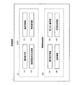
図4は、第1の実施の形態における物理マシン2について説明する図である。図4に示すように、物理マシン2aのCPU(図示しない)は、処理制御部22aとして動作し、物理マシン2bのCPU(図示しない)は、処理制御部21b及び処理制御部22bとして動作する。また、物理マシン2cのCPU(図示しない)は、処理制御部24cとして動作する。そして、処理制御部22a、21b、22b及び24cは、図4に示すように、管理装置1と物理マシン2との間に設定するコネクションの本数を抑えるように制御を行う。なお、以下、処理制御部22a、21b、22b及び24cを総称して処理制御部20とも呼ぶ。
FIG. 4 is a diagram illustrating the
具体的に、図4に示す例において、処理制御部24cは、テナント21c、22c及び23cにそれぞれ構築された業務システムSYS21c、22c及び23cに対する複数の接続開始指示を受け付けた場合であっても、各接続開始指示に伴う処理を同時に行わない。そして、処理制御部24cは、例えば、複数の接続開始指示の優先順位を決定し、管理装置1と物理マシン2cとの間に設定されるコネクションの本数が常に所定の本数(例えば、1本)以下になるように、優先順位の高い接続開始指示から順に処理を行う。
Specifically, in the example illustrated in FIG. 4, even when the
これにより、各処理制御部20は、管理装置1と各物理マシン2との間に設定されるコネクションの本数を抑えることが可能になる。そのため、クラウド事業者は、配備する管理装置1の数の増加を抑制しながら、大規模なパブリッククラウド環境を構成する物理マシン2を管理することが可能になる。
As a result, each
なお、図4に示す例において、物理マシン2bには、仮想マシン31bと仮想マシン32bとが生成されている。そして、仮想マシン31bのリソースが複数のテナントに区分されている場合、仮想マシン31bにおいて複数の業務システムが構築される可能性がある。同様に、仮想マシン32bのリソースが複数のテナントに区分されている場合、仮想マシン32bにおいて複数の業務システムが構築される可能性がある。そのため、物理マシン2bのCPUは、図4に示すように、仮想マシン31bに構築された業務システムに対応する接続開始指示を制御する処理制御部21bと、仮想マシン32bに構築された業務システムに対応する接続開始指示を制御する処理制御部22bとしてそれぞれ動作するものであってもよい。すなわち、各物理マシン2のCPUは、各物理マシン2に生成された仮想マシン3毎の処理制御部20としてそれぞれ動作するものであってよい。
In the example shown in FIG. 4, the
[管理装置及び物理マシンのハードウエア構成]
次に、管理装置1及び物理マシン2のハードウエア構成について説明する。図5は、管理装置1及び物理マシン2のハードウエア構成を示す図である。なお、図5に示す物理マシン2のハードウエア構成は、図4で説明した物理マシン2a、2b及び2cのハードウエア構成にそれぞれ対応する。
[Hardware configuration of management device and physical machine]
Next, the hardware configurations of the
管理装置1は、プロセッサであるCPU101と、メモリ102と、外部インターフェース(I/Oユニット)103と、記憶媒体104とを有する。各部は、バス105を介して互いに接続される。
The
記憶媒体104は、例えば、記憶媒体104内のプログラム格納領域(図示しない)に、物理マシン2との間に設定されたコネクションを管理する処理(以下、接続制御処理とも呼ぶ)を行うためのプログラム110を記憶する。また、記憶媒体104は、例えば、接続制御処理を行う際に用いられる情報を記憶する情報格納領域130(以下、記憶部130とも呼ぶ)を有する。
The
CPU101は、図5に示すように、プログラム110の実行時に、プログラム110を記憶媒体104からメモリ102にロードし、プログラム110と協働して接続制御処理を行う。また、外部インターフェース103は、例えば、各物理マシン2と通信を行う。
As shown in FIG. 5, when executing the program 110, the
物理マシン2は、プロセッサであるCPU201と、メモリ202と、外部インターフェース(I/Oユニット)203と、記憶媒体204とを有する。各部は、バス205を介して互いに接続される。
The
記憶媒体204は、例えば、記憶媒体204内のプログラム格納領域(図示しない)に、管理装置1から物理マシン2に対する接続開始指示を制御する処理(以下、処理制御処理とも呼ぶ)を行うためのプログラム210を記憶する。また、記憶媒体204は、例えば、処理制御処理を行う際に用いられる情報を記憶する情報格納領域230(以下、記憶部230とも呼ぶ)を有する。
The
CPU201は、図5に示すように、プログラム210の実行時に、プログラム210を記憶媒体204からメモリ202にロードし、プログラム210と協働して処理制御処理を行う。
As shown in FIG. 5, the
外部インターフェース203は、例えば、管理装置1と通信を行う。また、外部インターフェース103は、例えば、インターネット網等からなるネットワークNWを介して、利用者がサービスの提供を受けるために使用する利用者端末11と通信を行う。
The
[管理装置の機能]
次に、管理装置1の機能について説明する。図6は、管理装置1の機能ブロック図である。
[Function of management device]
Next, the function of the
管理装置1のCPU101は、プログラム110と協働することにより、例えば、運用実行部111と、接続開始指示送信部112と、通信制御部113と、情報管理部114として動作する。また、情報格納領域130には、例えば、運用実行情報131と、接続情報132と、割り当て量情報133と、処理結果情報134とが記憶される。
By cooperating with the program 110, the
運用実行部111は、例えば、物理マシン2に構築された業務システムの稼働状況を示す情報を収集する処理等(以下、単に運用処理とも呼ぶ)を行う。具体的に、運用実行部111は、各運用処理を行う日時を示す情報を含む運用実行情報131を参照する。そして、運用実行部111は、運用実行情報131が示す日時になった場合に、物理マシン2に接続開始指示を送信する旨の指示を接続開始指示送信部112に行う。
The
なお、運用実行情報131は、サービス事業者が予め情報格納領域130に記憶するものであってよい。また、運用実行部111は、例えば、物理マシン2から業務システムの稼働状況を示す情報の収集を行った後、収集した情報を参照し、異常が発生している業務システムの検知を行う。運用実行情報131の具体例については後述する。
The
接続開始指示送信部112は、運用実行部111から指示があった場合に、物理マシン2に接続開始指示を送信する。すなわち、接続開始指示送信部112は、管理装置1と物理マシン2との間においてコネクションを設定する場合、その設定を行うための処理を物理マシン2に行わせる。これにより、管理装置1は、管理装置1のエフェメラルポートの使用数を抑制することが可能になる。
The connection start
なお、接続開始指示送信部112は、UDP(User Datagram Protocol)によるマルチキャスト送信またはユニキャスト通信を行うことにより、物理マシン2に対する接続開始指示の送信を行う。これにより、管理装置1は、物理マシン2に対して接続開始指示を送信する際に、管理装置1と物理マシン2との間においてコネクションが設定されることを防止することが可能になる。そのため、管理装置1は、物理マシン2に対する接続開始指示の送信に伴って、管理装置1のエフェメラルポートの使用数またはディスクリプタの数が上限に達することを防止することが可能になる。
The connection start
通信制御部113は、物理マシン2が送信した、第1接続開始指示に伴う処理(以下、単に第1処理とも呼ぶ)の実行指示の送信要求(以下、単に送信要求とも呼ぶ)を受信する。第1処理は、例えば、業務システムの稼働状況を示す情報を管理装置1に対して送信する処理等、管理装置1が運用処理を行うために各物理マシン2に実行させる必要がある処理である。
The
そして、通信制御部113は、物理マシン2から送信要求を受信した場合、物理マシン2(送信要求を送信した物理マシン2)に対して、第1処理の実行指示を送信する。さらに、通信制御部113は、物理マシン2が送信した第1処理の処理結果を受信する。
Then, when receiving the transmission request from the
また、通信制御部113は、管理装置1と物理マシン2との間において設定されたコネクションを管理する接続情報132を参照する。そして、通信制御部113は、管理装置1と接続している物理マシン2(以下、接続先装置2とも呼ぶ)が所定の数を上回っている場合、管理装置1と接続している物理マシン2の数が所定の数以下になるまで、管理装置1と接続先装置2との間に設定されたコネクションを切断する。具体的に、通信制御部113は、例えば、今後通信が行われる可能性が低いコネクションを選択し、選択したコネクションを切断する。これにより、管理装置1は、管理装置1と物理マシン2との間において設定されたコネクションによって、管理装置1のディスクリプタの数が上限に達することを防止することが可能になる。接続情報132の具体例については後述する。また、通信制御部113が切断するコネクションを選択する場合の処理の詳細については後述する。
Further, the
情報管理部114は、通信制御部113が第1処理の処理結果(以下、単に処理結果とも呼ぶ)を受信した場合、受信した処理結果を処理結果情報134として情報格納領域130に記憶する。また、情報管理部114は、管理装置1と物理マシン2との間において新たなコネクションが設定された場合、または、管理装置1と物理マシン2との間におけるコネクションが切断された場合、情報格納領域130に記憶された接続情報132を更新する。
When the
なお、割り当て量情報133は、クラウド事業者が情報格納領域130に予め設定するものであってよい。
The
[物理マシンの機能]
次に、物理マシン2の機能について説明する。図7は、物理マシン2の機能ブロック図である。
[Physical machine functions]
Next, the function of the
物理マシン2のCPU201は、プログラム210と協働することにより、例えば、接続開始指示受信部211(以下、単に受信部211とも呼ぶ)と、接続開始指示決定部212(以下、単に決定部212とも呼ぶ)として動作する。また、物理マシン2のCPU201は、プログラム210と協働することにより、例えば、通信制御部213と、処理実行部214と、送信決定部215と、情報管理部216として動作する。なお、接続開始指示決定部212は、図4で説明した処理制御部20に対応する。また、処理実行部214は、物理マシン2に構築された業務システム毎に存在する。
By cooperating with the program 210, the
さらに、情報格納領域230には、例えば、割り当て量情報231と、使用量情報232と、接続開始指示情報233と、処理結果情報234とが記憶される。
Further, in the
接続開始指示受信部211は、管理装置1が送信した接続開始指示を受信する。そして、情報管理部216は、接続開始指示受信部211が受信した接続開始指示を接続開始指示情報233として情報格納領域230に記憶する。
The connection start
接続開始指示決定部212は、情報格納領域230に記憶された接続開始指示情報233が複数存在する場合、割り当て量情報231と使用量情報232とを取得する。
When there are a plurality of connection start
割り当て量情報231は、複数の接続開始指示情報233のそれぞれに対応する業務システムに対するリソースの割り当て量を示す情報である。なお、割り当て量情報231は、割り当て量情報133と同一の情報であり、クラウド事業者が情報格納領域230に予め設定するものであってよい。
The
また、使用量情報232は、各業務システムにおけるリソースの使用量を示す情報である。具体的に、使用量情報232は、各業務システムにおける現在のリソースの使用量を示す情報であり、接続開始指示決定部212によって取得されるものであってよい。なお、情報管理部216は、接続開始指示決定部212が使用量情報232を取得した際に、その使用量情報232を情報格納領域230に記憶するものであってよい。
The
そして、接続開始指示決定部212は、割り当て量情報231と使用量情報232とに基づいて、複数の接続開始指示情報233の中から優先して処理する第1接続開始指示を決定する。すなわち、接続開始指示決定部212は、例えば、情報格納領域230に記憶された接続開始指示情報233のうち、優先度が最も高い接続開始指示を第1接続開始指示として決定する。これにより、物理マシン2は、優先度が最も高い接続開始指示情報233に伴う処理から順に処理を実行することが可能になる。そのため、管理装置1は、各物理マシン2との間において設定されるコネクションの本数を抑制することが可能になる。
Then, the connection start
通信制御部213は、例えば、接続開始指示決定部212が第1接続開始指示を決定した後、管理装置1との間においてコネクションの設定を行う。その後、通信制御部213は、第1接続開始指示に伴う処理(第1処理)の実行指示の送信要求を管理装置1に送信する。また、通信制御部213は、管理装置1が送信した第1処理の実行指示を受信する。さらに、通信制御部213は、処理実行部214が第1処理を実行した場合、実行された第1処理の処理結果を管理装置1に送信する。
The
処理実行部214は、通信制御部213が管理装置1から第1処理の実行指示を受信した場合、その第1処理を実行する。そして、情報管理部216は、処理実行部214が実行した第1処理の処理結果を処理結果情報234として情報格納領域230に記憶する。
When the
送信決定部215は、送信待ちの第1処理の処理結果情報234が情報格納領域230に複数記憶されている場合、例えば、実行された日時が最も古い第1処理の処理結果情報234を、管理装置1に優先して送信する処理結果情報234として決定する。
When a plurality of process result
[第1の実施の形態]
次に、第1の実施の形態について説明する。図8及び図9は、第1の実施の形態における処理制御処理の概略を説明するフローチャート図である。また、図10から図13は、第1の実施の形態における処理制御処理の概略を説明する図である。図10から図13を参照しながら図8及び図9の処理制御処理の概略について説明する。
[First Embodiment]
Next, the first embodiment will be described. 8 and 9 are flowcharts for explaining the outline of the process control process according to the first embodiment. 10 to 13 are diagrams for explaining the outline of the process control process according to the first embodiment. An outline of the process control process of FIGS. 8 and 9 will be described with reference to FIGS. 10 to 13.
初めに、図10に示す物理マシン2cについて説明を行う。図10に示す物理マシン2cは、図4で説明した物理マシン2cに対応する。
First, the
図10に示す物理マシン2cの情報格納領域230には、管理装置1から既に受信した接続開始指示情報233a及び接続開始指示情報233bが記憶されている。また、図10に示す物理マシン2cにおいて、処理実行部214a、214b及び214cは、それぞれ図4で説明した業務システムSYS21c、22c及び23cに対応する第1処理を実行する。なお、図10に示す物理マシン2cにおいて、接続開始指示受信部211、送信決定部215、情報管理部216及び各業務システムについての記載は省略する。以下、図8及び図9を参照し、第1の実施の形態における処理制御処理の概略について説明を行う。
In the
物理マシン2の接続開始指示受信部211は、図8に示すように、管理装置1から接続開始指示を受信するまで待機する(S1のNO)。そして、接続開始指示を受け付けた場合(S1のYES)、物理マシン2の情報管理部216は、図11に示すように、S1の処理で受信した接続開始指示を接続開始指示情報233として情報格納領域230に記憶する(S2)。具体的に、情報管理部216は、図11に示すように、管理装置1から受信した接続開始指示を、接続開始指示情報233cとして情報格納領域230に新たに記憶する。
As shown in FIG. 8, the connection start
一方、物理マシン2の接続開始指示決定部212は、図9に示すように、接続開始指示の処理タイミングになるまで待機する(S11のNO)。接続開始指示の処理タイミングは、例えば、接続開始指示受信部211が接続開始指示を受信したタイミングであってよい。また、接続開始指示の処理タイミングは、例えば、接続開始指示情報233が情報格納領域230に1つ以上記憶されていることを接続開始指示決定部212が検知したタイミングであってよい。そして、接続開始指示の処理タイミングになった場合(S11のYES)、接続開始指示決定部212は、処理待ちの複数の接続開始指示情報233が情報格納領域230に記憶されているか否かを判定する(S12)。
On the other hand, as shown in FIG. 9, the connection start
その結果、処理待ちの複数の接続開始指示情報233が記憶されていると判定した場合(S12のYES)、接続開始指示決定部212は、複数の接続開始指示情報233のそれぞれに対応する業務システムに対するリソースの割り当て量情報231を情報格納領域230から取得する(S13)。また、接続開始指示決定部212は、この場合、各業務システムにおけるリソースの使用量情報232を取得する(S13)。その後、接続開始指示決定部212は、図12に示すように、S13の処理で取得した割り当て量情報231と使用量情報232とに基づいて、優先して処理する第1接続開始指示を決定する(S14)。
As a result, when it is determined that the plurality of connection start
すなわち、物理マシン2は、各業務システムに対する複数の接続開始指示を受け付けた場合、受け付けた複数の接続開始指示を一元的に管理する。そして、物理マシン2は、例えば、複数の接続開始指示の中から優先度が最も高い接続開始指示から順に処理を行う。これにより、物理マシン2は、管理装置1と各業務システムとの間においてそれぞれコネクションを設定する必要がなくなり、管理装置1と各物理マシン2との間において設定されるコネクションの本数を抑制することが可能になる。そのため、クラウド事業者は、配備する必要がある管理装置1の数の増加を抑制しながら、大規模なパブリッククラウド環境を構成する物理マシン2を管理することが可能になる。
That is, when the
一方、処理待ちの複数の接続開始指示情報233が記憶されていないと判定した場合、すなわち、処理待ちの接続開始指示情報233が1つのみ記憶されている場合(S12のNO)、接続開始指示決定部212は、その記憶されている接続開始指示を第1接続開始指示として決定する。
On the other hand, when it is determined that the plurality of connection start
その後、物理マシン2の通信制御部213は、管理装置1との間におけるコネクションを設定し、第1処理の実行指示を要求する。具体的に、通信制御部213は、図12に示すように、例えば、接続開始指示情報233aに対応する第1処理の実行指示を要求する。
After that, the
そして、通信制御部213が第1処理の実行指示を受信した場合、物理マシン2の処理実行部214は、第1処理を実行する。具体的に、受信した第1処理の実行指示が業務システムSYS23cに対応する実行指示である場合、図13に示すように、処理実行部214cが第1処理の実行を行う。さらに、通信制御部213は、第1処理の処理結果を管理装置1に送信する。
Then, when the
このように、本実施の形態における物理マシン2は、物理マシン2に対して処理要求を行う管理装置1からの接続開始指示を受け付ける。そして、物理マシン2は、処理待ちの複数の接続開始指示が存在する場合、複数の接続開始指示のそれぞれに対応する業務システムに対するリソースの割り当て量情報231を取得する。また、物理マシン2は、この場合、各情報処理システムにおけるリソースの使用量情報232を取得する。その後、物理マシン2は、割り当て量情報231と使用量情報232とに基づいて、複数の接続開始指示の中から優先して処理する第1接続開始指示を決定する。
As described above, the
これにより、物理マシン2は、管理装置1と各業務システムとの間にそれぞれコネクションを設定する必要がなくなり、各物理マシン2と管理装置1との間に設定されるコネクションの本数を抑えることが可能になる。そのため、クラウド事業者は、配備する必要がある管理装置1の数の増加を抑制しながら、大規模なパブリッククラウド環境を構成する物理マシン2を管理することが可能になる。
As a result, the
[第1の実施の形態の詳細]
次に、第1の実施の形態の詳細について説明する。図14から図19は、第1の実施の形態における処理制御処理の詳細を説明するフローチャート図である。また、図20から図30は、第1の実施の形態における処理制御処理の詳細を説明する図である。図20から図30を参照しながら、図14から図19の処理制御処理の詳細を説明する。
[Details of First Embodiment]
Next, details of the first embodiment will be described. 14 to 19 are flowcharts illustrating details of the process control process according to the first embodiment. 20 to 30 are diagrams illustrating details of the process control process according to the first embodiment. The details of the process control process of FIGS. 14 to 19 will be described with reference to FIGS. 20 to 30.
[管理装置における処理制御処理]
管理装置1の運用実行部111は、運用実行タイミングになるまで待機する(S21のNO)。運用実行タイミングは、運用実行情報131に情報が含まれる日時であってよい。すなわち、運用実行タイミングは、運用処理を行う日時としてクラウド事業者が予め定めた日時であってよい。以下、運用実行情報131の具体例について説明を行う。
[Process control processing in management device]
The
[運用実行情報の具体例]
図20は、運用実行情報131の具体例を説明する図である。図20に示す運用実行情報131は、運用実行情報131内の各情報を識別する「項番」と、各運用処理を識別する「処理識別情報」とを項目として有する。また、図20に示す運用実行情報131は、運用処理を実行するための処理(第1処理)の実行を指示する業務システムを識別する「システム識別情報」と、運用処理の内容を示す「処理内容」とを項目として有する。さらに、図20に示す運用実行情報131は、運用処理の実行タイミングを示す「運用実行タイミング」を項目として有する。
[Specific example of operation execution information]
FIG. 20 is a diagram illustrating a specific example of the
具体的に、図20に示す運用実行情報131において、「項番」が「1」である情報には、「処理識別情報」として「142000」が設定され、「システム識別情報」として「SYS23c」が設定されている。また、図20に示す運用実行情報131において、「項番」が「1」である情報には、「処理内容」として「CPU及びメモリ使用率確認」が設定され、「運用実行タイミング」として「21:30(毎日)」が設定されている。
Specifically, in the
すなわち、運用実行部111は、図20に示す運用実行情報131を参照し、業務システムSYS23cのCPU及びメモリの使用率の確認を、毎日21時30分に実行する。これにより、クラウド事業者は、予め定めた運用実行情報131の内容に基づいて、各業務システムに対する運用処理を自動的に実行することが可能になる。
That is, the
なお、管理装置1が管理を行う新たな物理マシン2が追加された場合、サービス事業者は、運用実行情報131の「システム識別情報」に設定された情報に、追加された新たな物理マシン2に構築された業務システムを示す情報を追加するものであってよい。図20に含まれる他の情報については説明を省略する。
When a new
図14に戻り、運用実行タイミングになった場合(S21のYES)、管理装置1の通信制御部113は、実行される運用処理に対応する業務システムが稼働する物理マシン2に対して、接続開始指示を送信する(S22)。具体的に、通信制御部113は、例えば、運用実行情報131を参照し、実行される運用処理の「システム識別情報」に情報が設定された業務システムが稼働する物理マシンに対して、接続開始指示のマルチキャスト送信またはユニキャスト送信を行う。
Returning to FIG. 14, when the operation execution timing comes (YES in S21), the
その後、通信制御部113は、接続開始指示を送信した物理マシン2から、第1処理の実行指示の送信要求を受信するまで待機する(S23のNO)。具体的に、通信制御部113は、接続開始指示を送信した物理マシン2が管理装置1との間においてコネクションを設定し、第1処理の実行指示の送信要求を送信するまで待機する。そして、第1処理の実行指示の送信要求を受信した場合(S23のYES)、通信制御部113は、S23の処理で送信要求を受信した物理マシン2に対し、第1処理の実行指示を送信する(S24)。
After that, the
すなわち、管理装置1と物理マシン2との間においてコネクションの設定を行う場合、物理マシン2がコネクションの設定を行うための処理を行う。これにより、管理装置1は、管理装置1のエフェメラルポートの使用を抑制することが可能になる。
That is, when setting the connection between the
そして、通信制御部113は、第1処理の実行指示を送信した物理マシン2から、第1処理の処理結果を受信するまで待機する(S25のNO)。そして、管理装置1の情報管理部114は、通信制御部113が第1処理の処理結果を受信した場合(S25のYES)、受信した第1処理の処理結果を処理結果情報134として情報格納領域130に記憶する(S26)。
Then, the
その後、通信制御部113は、接続情報132を参照し、管理装置1と接続している接続先装置2(第1処理を実行した物理マシン2を含む)の数が、所定数(クラウド事業者が予め定めた数)を上回っているか否かを判定する(S27)。その結果、接続先装置2の数が所定数を上回っている場合(S27のYES)、通信制御部113は、接続先装置2の数が所定の数以下になるまで、接続先装置2との接続を切断する(S28)。これにより、通信制御部113は、管理装置1と物理マシン2との間において設定されたコネクションによって、管理装置1のディスクリプタの数が上限に達することを防止することが可能になる。
After that, the
具体的に、通信制御部113は、例えば、割り当て量情報231が同一であって、管理装置1との情報の送受信を要する処理(例えば、第1処理)が実行中である他の業務システムが存在する業務システムを特定する。そして、通信制御部113は、特定した業務システムが稼働する物理マシン2以外の物理マシンとの間に設定されたコネクションを優先して切断する。
Specifically, for example, the
すなわち、サービス事業者は、例えば、利用者毎に業務システムを構築し、各利用者に対するサービスの提供を行う。ここで、サービス事業者は、例えば、ある利用者に対する業務システムを複数のテナントにそれぞれ構築している場合、複数のテナントに対して同じ運用処理が行われるように、運用実行情報131の作成を行う場合がある。そのため、管理装置1は、ある業務システムにおいて運用処理が実行中である場合、例えば、同一の利用者に対して構築された他の業務システムにおいても同じ運用処理が実行される可能性があると判定することが可能である。したがって、管理装置1は、例えば、運用処理を実行中である業務システムが稼働する物理マシンとの間に設定されたコネクションのみではなく、同一の利用者に対して構築された他の業務システムが稼働する物理マシンとの間のコネクションについても切断を行わない。
That is, the service provider constructs a business system for each user and provides a service to each user, for example. Here, for example, when the business system for a certain user is constructed in a plurality of tenants, the service provider creates the
これにより、管理装置1は、今後通信が行われる可能性のあるコネクションが切断される頻度を抑えることが可能になる。そのため、管理装置1は、物理マシン2との間においてコネクションの切断及び再設定が行われる回数を抑制することが可能になる。
As a result, the
なお、クラウド事業者は、サービス事業者に貸し出したテナントに構築された業務システムのうち、同一の利用者に対して構築された業務システムについての情報を有していない場合がある。そのため、管理装置1は、例えば、サービス事業者に貸し出したテナントに構築された各業務システムの割り当て量情報133を参照し、割り当て量情報133が同じである業務システムを、同一の利用者に対して構築された業務システムであると判定するものであってよい。また、管理装置1は、例えば、サービス事業者に貸し出したテナントに構築された各業務システムにインストールされたソフトウエアの構成を確認し、ソフトウエアの構成が同じである業務システムを、同一の利用者に対して構築された業務システムであるものと判定するものであってもよい。以下、接続情報132及び割り当て量情報133の具体例について説明を行う。
It should be noted that the cloud business may not have information about the business system built for the same user among the business systems built in the tenants lent to the service business. Therefore, for example, the
[接続情報の具体例]
図21は、接続情報132の具体例を説明する図である。図21に示す接続情報132は、接続情報132内の各情報を識別する「項番」と、管理装置1とコネクションが設定されている物理マシン2を識別する「物理マシン識別情報」とを項目として有する。
[Specific example of connection information]
FIG. 21 is a diagram illustrating a specific example of the
具体的に、図21に示す接続情報132において、「項番」が「1」である情報には、「物理マシン識別情報」として「物理マシン2a」が設定され、「項番」が「2」である情報には、「物理マシン識別情報」として「物理マシン2b」が設定されている。また、図21に示す接続情報132において、「項番」が「3」である情報には、「物理マシン識別情報」として「物理マシン2c」が設定されている。すなわち、図21に示す接続情報132は、図4等で説明した全ての物理マシン2と管理装置1との間においてコネクションが設定されていることを示している。
Specifically, in the
[割り当て量情報の具体例]
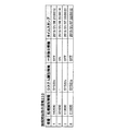
次に、割り当て量情報133(割り当て量情報231)の具体例について説明を行う。図22は、割り当て量情報133の具体例を説明する図である。図22に示す割り当て量情報133は、割り当て量情報133内の各情報を識別する「項番」と、各業務システムを識別する「システム識別情報」と、各業務システムにそれぞれ割り当てられたCPUの割り当て量を示す「CPU情報」とを項目として有している。また、図22に示す割り当て量情報133は、各業務システムにそれぞれ割り当てられたメモリの割り当て量を示す「メモリ情報」を項目として有する。さらに、図22に示す割り当て量情報133は、各業務システムにそれぞれ割り当てられたI/Oリソースの割り当て率(各業務システムが構築された物理マシン2のI/Oリソースに対する割り当て率)を示す「I/O情報」を項目として有する。
[Specific example of quota information]
Next, a specific example of the allocation amount information 133 (allocation amount information 231) will be described. FIG. 22 is a diagram illustrating a specific example of the
具体的に、図22に示す割り当て量情報133において、「項番」が「1」である情報には、「システム識別情報」として「SYS21a」が設定され、「CPU情報」として「2.4(Ghz)」が設定され、「メモリ情報」として「20(GB)」が設定されている。また、図22に示す割り当て量情報133において、「項番」が「1」である情報には、「I/O情報」として「15(%)」が設定されている。
Specifically, in the
すなわち、図22に示す割り当て量情報133における「項番」が「1」である情報は、業務システムSYS21aに、2.4(Ghz)のCPUと、20(GB)のメモリとが割り当てられていることを示している。また、図22に示す割り当て量情報133における「項番」が「1」である情報は、業務システムSYS21aに、物理マシン2aが有するI/Oリソースのうちの15(%)に相当するI/Oリソースが割り当てられていることを示している。図22に含まれる他の情報については説明を省略する。
That is, in the information in which the “item number” is “1” in the
[S28の処理の具体例]
次に、図21及び図22を参照し、S28の処理の具体例について説明を行う。以下、S28における所定の数(管理装置1がコネクションを設定することができる物理マシン2の数)が2(台)であるものとして説明を行う。
[Specific Example of Processing in S28]
Next, a specific example of the process of S28 will be described with reference to FIGS. In the following description, it is assumed that the predetermined number in S28 (the number of
図21で説明した接続情報132において、管理装置1との間にコネクションが設定されている物理マシン2は、物理マシン2a、2b及び2cである。そのため、通信制御部213は、S28の処理において、物理マシン2a、2b及び2cとの間で設定されたコネクションのうちの1つを切断する必要がある。
In the
具体的に、通信制御部213は、図22で説明した割り当て量情報133を参照し、割り当てられたリソース(「CPU情報」、「メモリ情報」及び「I/O情報」にそれぞれ設定された情報)が同一である業務システムSYS23cと業務システムSYS32bとを特定する。そして、業務システムSYS23c及びSYS32bのうちの少なくとも1つにおいて、管理装置1と情報の送受信を要する処理が実行されている場合、通信制御部213は、物理マシン2bとのコネクションと、物理マシン2cとのコネクションとを切断しない旨の判定を行う。そのため、通信制御部213は、この場合、例えば、物理マシン2aとの間に設定されたコネクションを切断する旨の判定を行う。
Specifically, the
一方、通信制御部213は、業務システムSYS23c及びSYS32bにおいて、管理装置1と情報の送受信を要する処理が実行中でない場合、例えば、物理マシン2a、2b及び2cとの間にそれぞれ設定されたコネクションのいずれかを切断する旨の判定を行う。
On the other hand, the
なお、通信制御部213は、例えば、業務システム毎に、割り当て量情報231が同一であって、管理装置1と情報の送受信を要する処理を実行中である他の業務システムの数をスコア化するものであってよい。そして、通信制御部213は、物理マシン2毎に各業務システムのスコアを集計し、最もスコアが少ない物理マシン2とのコネクションを切断する旨の判定を行うものであってもよい。
The
また、通信制御部213は、例えば、運用実行情報131を参照し、業務システム毎に、管理装置1との間において情報の送受信が行われる予定回数のスコア化を行うものであってよい。そして、通信制御部213は、物理マシン2毎に各業務システムのスコアを集計し、最もスコアが少ない物理マシン2とのコネクションを切断する旨の判定を行うものであってもよい。
Further, the
図15に戻り、通信制御部113は、接続開始指示を送信した全ての物理マシン2から第1処理の処理結果を受信したか否かを判定する(S31)。その結果、接続開始指示を送信した全ての物理マシン2から処理結果を受信した場合(S31のYES)、運用実行部111は、次の運用実行タイミングまで待機する(S21のNO)。すなわち、管理装置1は、この場合、S22の処理で送信した接続開始指示に伴う運用処理の実行を終了する。
Returning to FIG. 15, the
一方、全ての物理マシン2から送信要求を受信していない場合(S31のNO)、通信制御部113は、例えば、接続開始指示を送信してから所定の時間(例えば、10分)が経過したにもかかわらず、送信要求を受信できない物理マシン2が存在するか否かを判定する(S32)。その結果、送信要求を受信できない物理マシン2が存在する場合(S32のYES)、通信制御部113は、S32の処理で存在した物理マシン2に対して、S22の処理で送信した接続開始指示を再度送信する(S33)。
On the other hand, when the transmission request has not been received from all the physical machines 2 (NO in S31), the
すなわち、通信制御部113は、S22の処理において、通信の信頼性が乏しいUDPに従って接続開始指示を送信している。そのため、通信制御部113が接続開始指示を送信した物理マシン2に、接続開始指示を受信することができなかった物理マシン2が存在する可能性がある。したがって、通信制御部113は、接続開始指示を送信してから所定の時間が経過したにもかかわらず、送信要求を受信できない物理マシン2が存在する場合、その物理マシン2には接続開始指示が送信されなかったものと判定する。これにより、通信制御部113は、接続開始指示を送信する必要がある全ての物理マシン2に対して接続開始指示を送信することが可能になる。
That is, in the process of S22, the
一方、送信要求を受信できない物理マシン2が存在しない場合(S32のNO)、通信制御部113は、S33の処理を実行しない。そして、S32またはS33の処理の後、通信制御部113は、S23以降の処理を再度実行する。
On the other hand, when there is no
[物理マシンにおける処理制御処理]
次に、物理マシン2における処理制御処理について説明を行う。接続開始指示受信部211は、図8で説明したように、管理装置1から接続開始指示を受信するまで待機する(S1のNO)。そして、接続開始指示を受信した場合(S1のYES)、情報管理部216は、S1の処理で受信した接続開始指示に対応する情報を、接続開始指示情報233として情報格納領域230に記憶する(S2)。以下、管理装置1が送信した接続開始指示及び情報格納領域230に記憶された接続開始指示情報233の具体例について説明を行う。
[Process control processing in physical machine]
Next, the processing control processing in the
[管理装置が送信した接続開始指示の具体例(1)]
図23及び図25は、管理装置1が送信した接続開始指示の具体例を説明する図である。図23及び図25に示す接続開始指示は、接続開始指示に含まれる各情報を識別する「項番」と、各運用処理を識別する「処理識別情報」と、運用処理を実行するために必要な処理(第1処理)を実行させる業務システムを識別する「システム識別情報」とを項目として有する。また、図23及び図25に示す接続開始指示は、複数の業務システムに対して送信される接続開始指示であるか否かを識別する「一斉指示情報」を項目として有する。「一斉指示情報」には、1つの業務システムに対してのみ送信される接続開始指示であることを示す「OFF」、または、複数の業務システムに対して送信される接続開始指示であることを示す「ON」が設定される。
[Specific example of connection start instruction transmitted by management device (1)]
23 and 25 are diagrams illustrating a specific example of the connection start instruction transmitted by the
具体的に、図23に示す接続開始指示において、「項番」が「1」である情報には、「処理識別情報」として「211000」が設定され、「システム識別情報」として「SYS21c」が設定され、「一斉指示情報」として「OFF」が設定されている。図25の説明については後述する。 Specifically, in the connection start instruction shown in FIG. 23, “211000” is set as the “process identification information” and “SYS21c” is set as the “system identification information” for the information whose “item number” is “1”. It is set, and "OFF" is set as the "simultaneous instruction information". The description of FIG. 25 will be given later.
[情報格納領域に記憶された接続開始指示情報の具体例(1)]
次に、情報格納領域230に記憶された接続開始指示情報233の具体例について説明を行う。
[Specific example (1) of connection start instruction information stored in the information storage area]
Next, a specific example of the connection start
図24及び図26は、情報格納領域230に記憶された接続開始指示情報233の具体例を説明する図である。図24及び図26に示す接続開始指示情報233は、図23で説明した接続開始指示と同じ項目を有している。さらに、図24及び図26に示す接続開始指示情報233は、管理装置1から受信した接続開始指示が情報格納領域230に記憶される日時を示す「タイムスタンプ」を項目として有している。
24 and 26 are diagrams illustrating specific examples of the connection start
情報管理部216は、接続開始指示受信部211が接続開始指示を受信した場合、受信した接続開始指示に対応する情報を、接続開始指示情報233として情報格納領域230に記憶する。具体的に、情報管理部216は、図24の下線部分に示すように、「項番」が「4」である情報の「処理識別情報」、「システム識別情報」及び「一斉指示情報」に、図23で説明した接続開始指示における「項番」が「1」である情報と同じ情報を設定する。さらに、情報管理部216は、図24の下線部分に示すように、「項番」が「4」である情報の「タイムスタンプ」に、例えば、図23で説明した接続開始指示を情報格納領域230に記憶する日時である「2016/01/07 02:00:12」を設定する。図24に含まれる他の情報については説明を省略する。図26の説明については後述する。
When the connection start
[管理装置が送信した接続開始指示の具体例(2)]
次に、管理装置1が送信した接続開始指示の他の具体例について説明を行う。図25は、管理装置1が送信した接続開始指示の他の具体例を説明する図である。
[Specific example of connection start instruction transmitted by management device (2)]
Next, another specific example of the connection start instruction transmitted by the
図25に示す接続開始指示において、「項番」が「1」である情報には、「処理識別情報」として「185000」が設定され、「システム識別情報」として「−」が設定され、「一斉指示情報」として「ON」が設定されている。 In the connection start instruction shown in FIG. 25, "185000" is set as the "process identification information", "-" is set as the "system identification information", and "-" is set for the information whose "item number" is "1". "ON" is set as "simultaneous instruction information".
なお、図25に示す接続開始指示は、複数の業務システムに対して送信される接続開始指示であるため、「システム識別情報」として、同一の接続開始指示が他の業務システムにも送信されていることを示す「−」が設定されている。 Since the connection start instruction shown in FIG. 25 is a connection start instruction transmitted to a plurality of business systems, the same connection start instruction is also transmitted to other business systems as “system identification information”. "-" is set to indicate that there is.
[情報格納領域に記憶された接続開始指示情報の具体例(2)]
次に、情報格納領域230に記憶された接続開始指示情報233の他の具体例について説明を行う。図26は、情報格納領域230に記憶された接続開始指示情報233の他の具体例を説明する図である。
[Specific example (2) of connection start instruction information stored in the information storage area]
Next, another specific example of the connection start
図26に示す接続開始指示情報233において、図26の下線部分に示すように、「項番」が「5」である情報の「処理識別情報」、「システム識別情報」及び「一斉指示情報」に、図25で説明した接続開始指示における「項番」が「1」である情報と同じ情報を設定する。また、情報管理部216は、図26の下線部分に示すように、「項番」が「5」である情報の「タイムスタンプ」に、例えば、図25で説明した接続開始指示を情報格納領域230に記憶する日時である「2016/01/07 04:30:10」を設定する。図26に含まれる他の情報については説明を省略する。
In the connection start
図16に戻り、接続開始指示決定部212は、図9で説明した場合と同様に、接続開始指示の処理タイミングになるまで待機する(S41のNO)。そして、接続開始指示の処理タイミングになった場合(S41のYES)、接続開始指示決定部212は、処理待ちの複数の接続開始指示が存在するか否かを判定する(S42)。具体的に、接続開始指示決定部212は、情報格納領域230に記憶された接続開始指示情報233に、管理装置1から送信された複数の接続開始指示に対応する情報が含まれているか否かを判定する。
Returning to FIG. 16, the connection start
その結果、処理待ちの複数の接続開始指示が存在すると判定した場合(S42のYES)、接続開始指示決定部212は、第1接続開始指示を決定する処理(以下、第1接続開始指示決定処理とも呼ぶ)を実行する(S43)。以下、第1接続開始指示決定処理について説明を行う。
As a result, when it is determined that there are a plurality of connection start instructions waiting for processing (YES in S42), the connection start
[第1接続開始指示決定処理]
接続開始指示決定部212は、図18に示すように、接続開始指示受信部211が受信してから所定時間(例えば、1時間)を経過した接続開始指示が存在するか否かを判定する(S61)。具体的に、接続開始指示決定部212は、情報格納領域230に記憶された接続開始指示情報233に、接続開始指示受信部211が受信してから所定時間を経過した接続開始指示に対応する情報が含まれているか否かを判定する。
[First connection start instruction determination process]
As shown in FIG. 18, the connection start
そして、所定時間を経過した接続開始指示が存在する場合(S61のYES)、接続開始指示決定部212は、存在した接続開始指示を第1接続開始指示として決定する(S62)。なお、S61の処理において、所定時間を経過した接続開始指示が複数存在した場合、接続開始指示情報233の「タイムスタンプ」に設定された日時が最も古い接続開始指示を第1接続開始指示として決定するものであってよい。
Then, if there is a connection start instruction that has passed the predetermined time (YES in S61), the connection start
また、所定時間を経過した接続開始指示が存在しない場合(S61のNO)、接続開始指示決定部212は、複数の業務システムに対応する接続開始指示、すなわち、「一斉指示情報」に「ON」が設定された情報が接続開始指示情報233に存在するか否かを判定する(S63)。そして、複数の業務システムに対応する接続開始指示が存在する場合(S63のYES)、接続開始指示決定部212は、存在した複数の業務システムに対応する接続開始指示を優先して、第1接続開始指示として決定する。
If there is no connection start instruction that has passed the predetermined time (NO in S61), the connection start
すなわち、例えば、管理装置1が処理結果情報234の受信を待って後続処理を実行する場合、物理マシン2は、処理結果情報234を可能な限り早く管理装置1に送信する必要がある。ここで、「一斉指示情報」に「ON」が設定された接続開始指示情報233に対する第1処理は、複数の業務システムにおいて実行される。そのため、「一斉指示情報」に「ON」が設定された接続開始指示情報233に対する第1処理の全ての処理結果情報234が管理装置1に送信されるまでに要する時間は、「一斉指示情報」に「OFF」が設定された接続開始指示情報233の場合の時間よりも長くなる可能性が高い。そのため、接続開始指示決定部212は、例えば、「一斉指示情報」に「ON」が設定された接続開始指示情報233を、「一斉指示情報」に「OFF」が設定された接続開始指示情報233よりも、優先的に第1接続開始指示として決定する。これにより、接続開始指示決定部212は、管理装置1における後続処理の実行待ち時間を短縮することが可能になる。
That is, for example, when the
なお、S63の処理において、複数の業務システムに対応する接続開始指示が複数存在する場合、接続開始指示情報233の「タイムスタンプ」に設定された日時が最も古い接続開始指示を第1接続開始指示として決定するものであってよい。
In the process of S63, when there are a plurality of connection start instructions corresponding to a plurality of business systems, the connection start instruction with the earliest date and time set in the "time stamp" of the connection start
一方、複数の業務システムに対応する接続開始指示情報233が存在しない場合(S63のNO)、接続開始指示決定部212は、図19に示すように、リソースの割り当て量情報231を情報格納領域230から取得する(S71)。具体的に、接続開始指示決定部212は、接続開始指示情報233に含まれる情報のそれぞれに対応する業務システムに対するリソースの割り当て量情報231を、情報格納領域230から取得する。また、接続開始指示決定部212は、この場合、各業務システムにおけるリソースの使用量情報232を取得する(S71)。さらに、接続開始指示決定部212は、接続開始指示情報233に伴う処理(第1処理)の現在の実行数を、業務システム毎に取得する(S72)。
On the other hand, when the connection start
その後、接続開始指示決定部212は、例えば、割り当て量情報231が他の業務システムの割り当て量情報231よりも大きい業務システムに、他の業務システムよりも高いスコアを設定する(S73)。すなわち、接続開始指示決定部212は、処理能力がより高い業務システムに高いスコアを設定する。
After that, the connection start
また、接続開始指示決定部212は、例えば、使用量情報232が他の業務システムの使用量情報232よりも小さい業務システムに、他の業務システムよりも高いスコアを設定する(S74)。さらに、例えば、接続開始指示決定部212は、第1処理の実行数が他の業務システムの実行数よりも少ない業務システムに、他の業務システムよりも高いスコアを設定する(S75)。すなわち、接続開始指示決定部212は、処理能力に余裕のある業務システムに高いスコアを設定する。
Further, the connection start
そして、接続開始指示決定部212は、S73の処理で設定したスコアと、S74の処理で設定したスコアと、S75の処理で設定したスコアとの合計値が最も高い業務システムに対応する接続開始指示情報233を優先して、第1接続開始指示として決定する(S76)。これにより、接続開始指示決定部212は、各業務システムの処理負担の増大を防ぎながら第1処理を実行させることが可能になる。
Then, the connection start
[S73からS76の処理の具体例]
次に、S71からS76の処理の具体例について説明を行う。以下、CPU係数が「1.2」であり、メモリ係数が「1」であり、I/O係数が「0.4」であるものとして説明を行う。
[Specific Example of Processing from S73 to S76]
Next, a specific example of the processing of S71 to S76 will be described. In the following description, it is assumed that the CPU coefficient is “1.2”, the memory coefficient is “1”, and the I/O coefficient is “0.4”.
接続開始指示決定部212は、例えば、以下の式(1)に従い、S73の処理においてスコアを決定する際に用いられる各業務システムの処理能力を算出する。
業務システムの処理能力 = 業務システムに対するCPU割り当て率 * CPU係数 + 業務システムに対するメモリ割り当て率 * メモリ係数 + 業務システムに対するI/Oリソース割り当て率 * I/O係数 (1)
The connection start
Business system processing capacity = CPU allocation rate for business system * CPU coefficient + Memory allocation rate for business system * Memory coefficient + I/O resource allocation rate for business system * I/O coefficient (1)
具体的に、図22に示す割り当て量情報133(割り当て量情報231)において、「システム識別情報」が「SYS21a」である業務システムの「CPU情報」、「メモリ情報」及び「I/O情報」は、それぞれ「2.4(Ghz)」、「20(GB)」及び「15(%)」である。そのため、物理マシン2aのCPUの割当可能量が「16(Ghz)」である場合、業務システムSYS21aに対するCPU割り当て率は、「2.4(Ghz)」を「16(Ghz)」で除算した「0.15」になる。また、物理マシン2aのメモリの割当可能量が「30(GB)」である場合、業務システムSYS21aに対するメモリ割り当て率は、「20(GB)」を「25(GB)」で除算した、「0.8」になる。さらに、業務システムSYS21aに対するI/Oリソース割り当て率は、「0.15」になる。
Specifically, in the allocation amount information 133 (allocation amount information 231) shown in FIG. 22, "CPU information", "memory information", and "I/O information" of the business system whose "system identification information" is "SYS21a". Are "2.4 (Ghz)", "20 (GB)" and "15 (%)", respectively. Therefore, when the CPU allocatable amount of the
したがって、この場合、業務システムSYS21aの処理能力は、CPU割り当て率である「0.15」に、CPU係数である「1.2」を乗算した値と、メモリ割り当て率である「0.8」に、メモリ係数である「1」を乗算した値と、I/Oリソース割り当て率である「0.15」に、I/O係数である「0.4」を乗算した値と、を加算した値である「1.04」になる。 Therefore, in this case, the processing capacity of the business system SYS21a is a value obtained by multiplying the CPU allocation rate "0.15" by the CPU coefficient "1.2" and the memory allocation rate "0.8". And a value obtained by multiplying the memory coefficient by "1" and a value obtained by multiplying the I/O resource allocation rate by "0.15" by the I/O coefficient by "0.4". The value becomes “1.04”.
そして、接続開始指示決定部212は、例えば、各業務システムの処理能力を算出した後、算出した処理能力が他の業務システムよりも大きい業務システムに、他の業務システムのスコアよりも相対的に高いスコアを設定する。具体的に、接続開始指示決定部212は、例えば、図4等で説明した業務システムSYS21a、31b、32b、21c、22c及び23cにおいて、算出した処理能力の示す値が大きい順に、それぞれ「5」、「4」、「3」、「2」、「1」及び「0」をスコアとして設定する。
Then, for example, the connection start
また、接続開始指示決定部212は、例えば、以下の式(2)に従い、S74の処理においてスコアを決定する際に用いられる各業務システムの負荷情報を算出する。
業務システムの負荷情報 = 業務システムに割当てられたCPUに対する使用率 * CPU係数 + 業務システムに割当てられたメモリに対する使用率 * メモリ係数 + 業務システムに割当てられたI/Oリソースに対する使用率 * I/O係数 (2)
Further, the connection start
Business system load information = Usage rate for CPU allocated to business system * CPU coefficient + Usage rate for memory allocated to business system * Memory coefficient + Usage rate for I/O resource allocated to business system * I/ O coefficient (2)
具体的に、図22に示す割り当て量情報133(割り当て量情報231)において、「システム識別情報」が「SYS21a」である業務システムの「CPU情報」は「2.4(Ghz)」であり、「メモリ情報」は「20(GB)」であり、「I/O情報」は「15(%)」である。そのため、物理マシン2aのCPUの使用量が「1.2(Ghz)」である場合、業務システムSYS21aに割当てられたCPUに対する使用率は、「1.2(Ghz)」を「2.4(Ghz)」で除算した「0.5」になる。また、物理マシン2aのメモリの使用量が「15(GB)」である場合、業務システムSYS21aに割当てられたメモリに対する使用率は、「15(GB)」を「20(GB)」で除算した「0.75」になる。さらに、業務システムSYS21aのI/Oリソースの使用量が、物理マシン2aのI/Oリソースの割り当て可能量に対する「6(%)」である場合、業務システムSYS21aに割当てられたI/Oリソースに対する使用率は、「6(%)」を「15(%)」で除算した「0.4」になる。
Specifically, in the allocation amount information 133 (allocation amount information 231) shown in FIG. 22, the “CPU information” of the business system whose “system identification information” is “SYS21a” is “2.4 (Ghz)”, The “memory information” is “20 (GB)” and the “I/O information” is “15 (%)”. Therefore, when the usage amount of the CPU of the
したがって、この場合、業務システムSYS21aの負荷情報は、CPU使用率である「0.5」に、CPU係数である「1.2」を乗算した値と、メモリ使用率である「0.75」に、メモリ係数である「1」を乗算した値と、I/Oリソース使用率である「0.4」に、I/O係数である「0.4」を乗算した値と、を加算した値である「1.51」になる。 Therefore, in this case, the load information of the business system SYS21a is obtained by multiplying the CPU usage rate "0.5" by the CPU coefficient "1.2" and the memory usage rate "0.75". And a value obtained by multiplying the memory coefficient by "1" and a value obtained by multiplying the I/O resource usage rate by "0.4" by the I/O coefficient by "0.4". The value becomes “1.51”.
そして、接続開始指示決定部212は、例えば、各業務システムの負荷情報を算出した後、算出した負荷情報が他の業務システムよりも小さい業務システムに、他の業務システムのスコアよりも相対的に高いスコアを設定する。具体的に、接続開始指示決定部212は、例えば、業務システムSYS21a、31b、32b、21c、22c及び23cにおいて、算出した負荷情報が示す値の小さい順に、それぞれ「5」、「4」、「3」、「2」、「1」及び「0」をスコアとして設定する。
Then, the connection start
さらに、接続開始指示決定部212は、S75の処理において、第1処理を現在実行している数が少ない順に、各業務システムのスコアを設定する。具体的に、接続開始指示決定部212は、例えば、業務システムSYS21a、31b、32b、21c、22c及び23cにおいて、第1処理を現在実行している数が少ない順に、それぞれ「5」、「4」、「3」、「2」、「1」及び「0」をスコアとして設定する。
Furthermore, in the process of S75, the connection start
その後、接続開始指示決定部212は、S76の処理において、S73の処理で設定したスコアと、S74の処理で設定したスコアと、S75の処理で設定したスコアとの合計値を、業務システム毎に算出する。具体的に、例えば、業務システムSYS21cについて算出したスコアの合計値が最も高い場合、接続開始指示決定部212は、業務システムSYS21cに対応する接続開始指示を第1接続開始指示として決定する。
Then, in the process of S76, the connection start
なお、接続開始指示決定部212は、S76の処理において、スコアとの合計値が最も高い業務システムに対応する接続開始指示が複数存在する場合、接続開始指示情報233の「タイムスタンプ」に設定された日時が最も古い接続開始指示を、第1接続開始指示として決定するものであってよい。
In the process of S76, the connection start
図16に戻り、管理装置1との間においてコネクションが存在しない場合(S44のNO)、通信制御部213は、管理装置1との間においてコネクションの設定を行う(S45)。一方、管理装置1との間においてコネクションが存在する場合(S44のYES)、通信制御部213は、S45の処理を行わない。そして、通信制御部213は、第1処理の実行指示の送信要求を管理装置1に送信する(S46)。
Returning to FIG. 16, when there is no connection with the management device 1 (NO in S44), the
なお、管理装置1の通信制御部113は、S45の処理においてコネクションの設定を行った結果、管理装置1と接続している接続先装置2の数が所定数を上回った場合、S28で説明した処理と同じ処理を実行し、今後情報の送受信が行われる可能性が低いコネクションの切断を行うものであってもよい。
When the number of
その後、通信制御部213は、図17に示すように、管理装置1から第1処理の実行指示を受信するまで待機する(S51のNO)。そして、第1処理の実行指示を受信した場合(S51のYES)、処理実行部214は、第1処理を実行する(S52)。以下、第1処理の実行指示の具体例について説明を行う。
Thereafter, as shown in FIG. 17, the
[第1処理の実行指示の具体例]
図27及び図28は、第1処理の実行指示の具体例を説明する図である。なお、図27に示す実行指示は、図26で説明した接続開始指示情報233における「項番」が「4」である情報に対応する実行指示である。また、図28に示す実行指示は、図26に示す接続開始指示情報233における「項番」が「5」である情報に対応する実行指示である。
[Specific Example of Execution Instruction of First Process]
27 and 28 are diagrams for explaining a specific example of the execution instruction of the first process. The execution instruction shown in FIG. 27 is an execution instruction corresponding to the information whose “item number” is “4” in the connection start
図27及び図28に示す実行指示は、実行指示に含まれる各情報を識別する「項番」と、運用処理を識別する「処理識別情報」と、運用処理を実行するための処理(第1処理)を実行させる業務システムを識別する「システム識別情報」とを項目として有する。また、図27及び図28に示す第1処理の実行指示は、第1処理の内容を示す「処理内容」を項目として有する。 The execution instructions shown in FIGS. 27 and 28 are the “item number” for identifying each piece of information included in the execution instruction, the “process identification information” for identifying the operation process, and the process for executing the operation process (first The item has “system identification information” for identifying a business system that executes a process. Further, the instruction to execute the first process shown in FIGS. 27 and 28 has “process content” indicating the content of the first process as an item.
具体的に、図27に示す実行指示において、「項番」が「1」である情報には、「処理識別情報」として「211000」が設定され、「システム識別情報」として「SYS23c」が設定されている。また、図27に示す実行指示において、「項番」が「1」である情報には、「処理内容」として「CPU及びメモリ使用率確認」が設定されている。 Specifically, in the execution instruction shown in FIG. 27, “211000” is set as the “process identification information” and “SYS23c” is set as the “system identification information” for the information whose “item number” is “1”. Has been done. Further, in the execution instruction shown in FIG. 27, “CPU and memory usage rate confirmation” is set as the “processing content” in the information whose “item number” is “1”.
すなわち、図26に示す接続開始指示情報233における「項番」が「4」である情報の「一斉指示情報」には、「OFF」が設定されている。そのため、図27に示す実行指示は、1つの業務システム(SYS23c)に対する実行指示を含んでいる。したがって、この場合、業務システムSYS23cに対応する処理実行部214のみが第1処理を実行する。
That is, "OFF" is set in the "simultaneous instruction information" of the information in which the "item number" is "4" in the connection start
また、図28に示す実行指示において、「項番」が「1」である情報には、「処理識別情報」として「185000」が設定され、「システム識別情報」として「SYS21a」が設定されている。また、図28に示す実行指示において、「項番」が「1」である情報には、「処理内容」として「各処理の処理状況確認」が設定されている。さらに、「項番」が「2」である情報には、「処理識別情報」として「185000」が設定され、「システム識別情報」として「SYS31b」が設定されている。また、図28に示す実行指示において、「項番」が「2」である情報には、「処理内容」として「各処理の処理状況確認」が設定されている。 Further, in the execution instruction shown in FIG. 28, "185000" is set as the "process identification information" and "SYS21a" is set as the "system identification information" in the information whose "item number" is "1". There is. Further, in the execution instruction shown in FIG. 28, “confirmation of processing status of each processing” is set as “processing content” in the information whose “item number” is “1”. Further, in the information whose "item number" is "2", "185000" is set as "process identification information" and "SYS31b" is set as "system identification information". Further, in the execution instruction shown in FIG. 28, “confirmation of processing status of each processing” is set as “processing content” in the information whose “item number” is “2”.
すなわち、図26に示す接続開始指示情報233における「項番」が「5」である情報の「一斉指示情報」には、「ON」が設定されている。そのため、図28に示す実行指示は、複数の業務システム(SYS21a、31b、32b、21c、22c及び23c)に対する実行指示を含んでいる。したがって、この場合、各業務システムに対応する処理実行部214がそれぞれ第1処理を実行する。
That is, "ON" is set to the "simultaneous instruction information" of the information in which the "item number" is "5" in the connection start
なお、管理装置1から受信した第1処理の実行指示が同一の物理マシン2に構築された複数の業務システムに対する実行指示を含む場合、物理マシン2は、例えば、以下の式(3)に従って各業務システムの余裕値を算出するものであってもよい。そして、物理マシン2は、例えば、算出した余裕値が小さい業務システムに対応する処理実行部214から順に、第1処理を実行させるものであってよい。
業務システムの余裕値 = 業務システムに割当てられたCPUの未使用量 * CPU係数 + 業務システムに割当てられたメモリの未使用量 * メモリ係数 + 業務システムに割当てられたI/Oリソースの未使用量 * I/O係数 (3)
When the execution instruction of the first process received from the
Margin value of business system = unused amount of CPU allocated to business system * CPU coefficient + unused amount of memory allocated to business system * memory coefficient + unused amount of I/O resource allocated to business system * I/O coefficient (3)
具体的に、図22に示す割り当て量情報133において、「システム識別情報」が「SYS23a」である業務システムの「CPU情報」は「2.4(Ghz)」であり、「メモリ情報」は「20(GB)」である。そのため、業務システムSYS21aのCPUの使用量が「1.6(Ghz)」である場合、業務システムSYS21aに割当てられたCPUの未使用量は、「2.4(Ghz)」から「1.6(Ghz)」を減算した「0.8(Ghz)」になる。また、業務システムSYS21aのメモリの使用量が「18(GB)」である場合、業務システムSYS21aに割当てられたメモリの未使用量は、「20(GB)」から「18(GB)」を減算した「2(GB)」になる。さらに、業務システムSYS21aに対するI/Oリソースの割り当て量が「12」であり、業務システムSYS21aのI/Oリソースの使用量が「8」である場合、業務システムSYS21aに割当てられたI/Oリソースの未使用量は、「12」から「8」を減算した「4」になる。
Specifically, in the
したがって、この場合、業務システムSYS21aの余裕値は、CPUの未使用量である「0.8(Ghz)」に、CPU係数である「1.2」を乗算した値と、メモリの未使用量である「2(GB)」に、メモリ係数である「1」を乗算した値と、I/Oリソースの未使用量である「4」に、I/O係数である「0.4」を乗算した値と、を加算した値である「4.56」になる。 Therefore, in this case, the margin value of the business system SYS21a is obtained by multiplying the unused amount of the CPU “0.8 (Ghz)” by the CPU coefficient “1.2” and the unused amount of the memory. "2 (GB)" which is the memory coefficient multiplied by "1" which is the memory coefficient, and "4" which is the unused amount of the I/O resource and "0.4" which is the I/O coefficient. The value obtained by adding the value obtained by the multiplication becomes "4.56".
そして、例えば、算出した余裕値が最も小さい業務システムが業務システムSYS31bである場合、物理マシン2は、業務システムSYS31bから順に、第1処理を実行させるものであってよい。
Then, for example, when the business system having the smallest calculated margin value is the business system SYS31b, the
これにより、物理マシン2は、処理負荷が高い業務システム(リソースに余裕がないために処理に多くの時間を要する可能性がある業務システム)を優先して、第1処理を実行させることが可能になる。そのため、物理マシン2は、実行すべき全ての第1処理の実行に要する時間を短縮させることが可能になる。
As a result, the
図17に戻り、情報管理部216は、S52の処理で各処理実行部214が実行した第1処理の処理結果を、処理結果情報234として情報格納領域230に記憶する(S53)。以下、処理結果情報234の具体例について説明を行う。
Returning to FIG. 17, the
[処理結果情報の具体例]
図29及び図30は、処理結果情報234の具体例を説明する図である。なお、図29に示す実行指示は、図27で説明した第1処理の実行指示に対応する処理結果情報234である。また、図30に示す実行指示は、図28で説明した第1処理の実行指示に対応する処理結果情報234である。
[Specific example of processing result information]
29 and 30 are diagrams illustrating specific examples of the
図29及び図30に示す処理結果情報234は、処理結果情報234に含まれる各情報を識別する「項番」と、運用処理を識別する「処理識別情報」と、第1処理を実行した業務システムを識別する「システム識別情報」とを項目として有する。また、図29及び図30に示す処理結果情報234は、第1処理の処理結果を示す「処理結果」と、第1処理が実行された日時を示す「タイムスタンプ」と、管理装置1に対して送信済の情報であるか否か示す「送信状況」を項目として有する。「送信状況」には、管理装置1に対して既に送信した情報であることを示す「送信済」、または、管理装置1に対して送信されていない情報であることを示す「未送信」が設定される。
The processing result
具体的に、図29に示す処理結果情報234において、「項番」が「1」である情報には、「処理識別情報」として「211000」が設定され、「システム識別情報」として「SYS23c」が設定されている。また、図29に示す処理結果情報234において、「項番」が「1」である情報には、「処理結果」として「特に異常なし」が設定され、「タイムスタンプ」として「2016/01/07 02:22:31」が設定され、「送信状況」として「未送信」が設定されている。
Specifically, in the
すなわち、図29に示す処理結果情報234は、業務システムSYS23cにおいて第1処理を実行した結果、特に異常が存在しなかったことを示している。
That is, the process result
また、図30に示す処理結果情報234において、「項番」が「1」である情報には、「処理識別情報」として「185000」が設定され、「システム識別情報」として「SYS21a」が設定されている。また、図30に示す処理結果情報234において、「項番」が「1」である情報には、「処理結果」として「特に異常なし」が設定され、「タイムスタンプ」として「2016/01/07 04:42:32」が設定され、「送信状況」として「未送信」が設定されている。そして、「項番」が「4」である情報には、「処理識別情報」として「185000」が設定され、「システム識別情報」として「SYS21c」が設定されている。また、図30に示す処理結果情報234において、「項番」が「4」である情報には、「処理結果」として「警告あり ID:WAR013」が設定され、「タイムスタンプ」として「2016/01/07 04:45:12」が設定され、「送信状況」として「未送信」が設定されている。
Further, in the
すなわち、図30に示す処理結果情報234は、業務システムSYS21cにおいて第1処理を実行した結果、警告が発生したことを示している。そのため、クラウド事業者は、後述するように、通信制御部213が処理結果情報234を管理装置1に送信することにより、業務システムSYS21cの稼働状況についての調査を行う必要性を認識することが可能になる。図30に含まれる他の情報については説明を省略する。
That is, the process result
図17に戻り、送信決定部215は、情報格納領域230に記憶された処理結果情報234のうち、送信待ちの処理結果情報234を管理装置1に送信する(S54)。具体的に、送信決定部215は、例えば、情報格納領域230に記憶された処理結果情報234のうち、「送信状況」が「未送信」である処理結果情報234を特定することにより、送信待ちの処理結果情報234を特定する。そして、送信決定部215は、管理装置1に送信した処理結果情報234に対応する「送信状況」に設定された情報を「送信済」に更新する。
Returning to FIG. 17, the
なお、情報格納領域230に記憶された処理結果情報234のうち、送信待ちの処理結果情報234が複数存在する場合、送信決定部215は、例えば、処理結果情報234の「タイムスタンプ」に設定された日時が最も古い処理結果情報234を管理装置1に送信する。
When there are a plurality of processing result
また、接続開始指示決定部212は、S43の処理(第1接続開始指示決定処理)を実行する際に、送信待ちの処理結果情報234が存在する場合、送信待ちの処理結果情報234の全てが管理装置1に送信されるまで、S43の処理の実行を中止するものであってよい。これにより、接続開始指示決定部212は、処理結果情報234を管理装置1に迅速に送信することが可能になる。そのため、管理装置1は、例えば、処理結果情報234の受信を待って後続処理を実行する必要がある場合に、後続処理を実行するタイミングを早めることが可能になる。
In addition, the connection start
このように、本実施の形態における物理マシン2は、物理マシン2に対して処理要求を行う管理装置1からの接続開始指示を受け付ける。そして、物理マシン2は、処理待ちの複数の接続開始指示が存在する場合、複数の接続開始指示のそれぞれに対応する業務システムに対するリソースの割り当て量情報231を取得する。また、物理マシン2は、この場合、各情報処理システムにおけるリソースの使用量情報232を取得する。その後、物理マシン2は、割り当て量情報231と使用量情報232とに基づいて、複数の接続開始指示の中から優先して処理する第1接続開始指示を決定する。
As described above, the
これにより、物理マシン2は、管理装置1と各業務システムとの間にそれぞれコネクションを設定する必要がなくなり、各物理マシン2と管理装置1との間に設定されるコネクションの本数を抑えることが可能になる。そのため、クラウド事業者は、配備する管理装置1の数の増加を抑制しながら、大規模なパブリッククラウド環境を構成する物理マシン2を管理することが可能になる。
As a result, the
以上の実施の形態をまとめると、以下の付記のとおりである。 The above embodiments are summarized as the following supplementary notes.
(付記1)
コンピュータに、
前記コンピュータに対して処理要求を行う処理要求装置からの接続開始指示を受け付け、
処理待ちの複数の接続開始指示が存在する場合、前記複数の接続開始指示のそれぞれに対応する情報処理システムに対するリソースの割り当て量と、前記情報処理システムにおけるリソースの使用量とに基づいて、前記複数の接続開始指示の中から優先して処理する第1接続開始指示を決定する、
処理を実行させることを特徴とする処理制御プログラム。
(Appendix 1)
On the computer,
Accepting a connection start instruction from a processing requesting device that requests processing to the computer,
When there are a plurality of connection start instructions waiting to be processed, the plurality of connection start instructions are allocated based on the resource allocation amount to the information processing system corresponding to each of the plurality of connection start instructions and the resource usage amount in the information processing system. Determining the first connection start instruction to be preferentially processed from among the connection start instructions of
A process control program for executing a process.
(付記2)
付記1において、
前記第1接続開始指示を決定する処理では、前記割り当て量が他の情報処理システムの前記割り当て量よりも大きい情報処理システムに対応する接続開始指示を、前記他の情報処理システムに対応する接続開始指示よりも優先して前記第1接続開始指示として決定する、
ことを特徴とする処理制御プログラム。
(Appendix 2)
In
In the process of determining the first connection start instruction, the connection start instruction corresponding to the information processing system whose allocation amount is larger than the allocation amount of the other information processing system is used to start the connection start corresponding to the other information processing system. Priority is given to the instruction, and the first connection start instruction is determined.
A processing control program characterized by the above.
(付記3)
付記1において、
前記第1接続開始指示を決定する処理では、
前記使用量を前記割り当て量で除算することにより、前記情報処理システム毎のリソースの使用率を算出し、
算出した前記使用率が他の情報処理システムの前記使用率よりも小さい情報処理システムに対応する接続開始指示を、前記他の情報処理システムに対応する接続開始指示よりも優先して前記第1接続開始指示として決定する、
ことを特徴とする処理制御プログラム。
(Appendix 3)
In
In the process of determining the first connection start instruction,
By dividing the usage amount by the allocation amount, the resource usage rate of each information processing system is calculated,
The connection start instruction corresponding to the information processing system whose calculated usage rate is smaller than the usage rate of the other information processing system is prioritized over the connection start instruction corresponding to the other information processing system, and the first connection Determined as a start instruction,
A processing control program characterized by the above.
(付記4)
付記1において、
前記接続開始指示は、対応する情報処理システムが複数存在するか否かを示す情報を含み、
前記第1接続開始指示を決定する処理では、対応する情報処理システムが複数存在することを示す情報を含む前記接続開始指示を、対応する情報処理システムが複数存在しないことを示す情報を含む前記接続開始指示よりも優先して前記第1接続開始指示として決定する、
ことを特徴とする処理制御プログラム。
(Appendix 4)
In
The connection start instruction includes information indicating whether or not there are a plurality of corresponding information processing systems,
In the process of determining the first connection start instruction, the connection start instruction including information indicating that a plurality of corresponding information processing systems exists, the connection including information indicating that a plurality of corresponding information processing systems do not exist Priority is given to the start instruction, and the first connection start instruction is determined.
A processing control program characterized by the above.
(付記5)
付記1において、
前記接続開始指示の送信は、UDP(User Datagram Protocol)に従って行われる、
ことを特徴とする処理制御プログラム。
(Appendix 5)
In
The transmission of the connection start instruction is performed according to UDP (User Datagram Protocol).
A processing control program characterized by the above.
(付記6)
付記5において、さらに、
前記第1接続開始指示を決定する処理の後、前記処理要求装置との間において接続を開始し、前記第1接続開始指示に伴う第1処理の実行指示の送信要求を前記処理要求装置に送信し、
前記第1処理の実行指示を受け付けたことに応じて、前記第1接続開始指示に対応する情報処理システムに前記第1処理を実行させ、
前記第1処理の処理結果を前記処理要求装置に送信する、
処理をコンピュータに実行させることを特徴とする処理制御プログラム。
(Appendix 6)
In
After the process of determining the first connection start instruction, a connection is started with the process request device, and a transmission request of a first process execution instruction accompanying the first connection start instruction is transmitted to the process request device. Then
In response to receiving the execution instruction of the first process, the information processing system corresponding to the first connection start instruction is caused to execute the first process,
Transmitting the processing result of the first processing to the processing requesting device,
A process control program for causing a computer to execute a process.
(付記7)
付記6において、
前記第1処理の実行指示の送信要求の送信、前記第1処理の実行指示の送信及び前記第1処理の処理結果の送信は、TCP(Transmission Control Protocol)に従って行われる、
ことを特徴とする処理制御プログラム。
(Appendix 7)
In
The transmission of the transmission instruction of the execution instruction of the first process, the transmission of the execution instruction of the first process, and the transmission of the processing result of the first process are performed according to TCP (Transmission Control Protocol).
A processing control program characterized by the above.
(付記8)
付記6において、
前記第1接続開始指示を決定する処理では、前記第1処理の実行数が他の情報処理システムの前記実行数よりも少ない情報処理システムに対応する接続開始指示を、前記他の情報処理システムに対応する接続開始指示よりも優先して前記第1接続開始指示として決定する、
ことを特徴とする処理制御プログラム。
(Appendix 8)
In
In the process of determining the first connection start instruction, a connection start instruction corresponding to an information processing system in which the number of executions of the first process is smaller than the number of executions of another information processing system is given to the other information processing system. Deciding as the first connection start instruction with priority over the corresponding connection start instruction,
A processing control program characterized by the above.
(付記9)
付記6において、
前記第1接続開始指示を決定する処理では、送信待ちの前記第1処理の処理結果が存在する場合、前記第1処理の処理結果の送信が行われるまで、前記第1接続開始指示の決定を中止する、
ことを特徴とする処理制御プログラム。
(Appendix 9)
In
In the process of determining the first connection start instruction, when there is a process result of the first process waiting for transmission, the first connection start instruction is determined until the process result of the first process is transmitted. Abort,
A processing control program characterized by the above.
(付記10)
処理要求を行う処理要求装置からの接続開始指示を受け付ける受信部と、
処理待ちの複数の接続開始指示が存在する場合、前記複数の接続開始指示のそれぞれに対応する情報処理システムに対するリソースの割り当て量と、前記情報処理システムにおけるリソースの使用量とに基づいて、前記複数の接続開始指示の中から優先して処理する第1接続開始指示を決定する決定部と、を有する、
ことを特徴とする処理制御装置。
(Appendix 10)
A receiving unit that receives a connection start instruction from a processing request device that makes a processing request,
When there are a plurality of connection start instructions awaiting processing, the plurality of connection start instructions are allocated based on the resource allocation amount to the information processing system corresponding to each of the plurality of connection start instructions and the resource usage amount in the information processing system. A first connection start instruction to be preferentially processed from among the connection start instructions of
A processing control device characterized by the above.
(付記11)
処理装置に対して処理要求を行う処理要求装置が、前記処理装置に対して接続開始指示を送信し、
前記処理装置が、前記処理要求装置から送信された前記接続開始指示を受け付け、
処理待ちの複数の接続開始指示が存在する場合、前記処理装置が、前記複数の接続開始指示のそれぞれに対応する情報処理システムに対するリソースの割り当て量と、前記情報処理システムにおけるリソースの使用量とに基づいて、前記複数の接続開始指示の中から優先して処理する第1接続開始指示を決定する、
ことを特徴とする処理制御方法。
(Appendix 11)
A processing request device that makes a processing request to the processing device transmits a connection start instruction to the processing device,
The processing device receives the connection start instruction transmitted from the processing request device,
When there are a plurality of connection start instructions waiting for processing, the processing device sets the resource allocation amount to the information processing system corresponding to each of the plurality of connection start instructions and the resource usage amount in the information processing system. On the basis of the plurality of connection start instructions, the first connection start instruction to be preferentially processed is determined.
A process control method characterized by the above.
(付記12)
付記11において、さらに、
前記第1接続開始指示を決定する工程の後、前記処理装置が、前記処理要求装置との間において接続を開始し、前記第1接続開始指示に伴う第1処理の実行指示の送信要求を前記処理要求装置に送信し、
前記処理要求装置が、前記第1処理の実行指示の送信要求を受け付けたことに応じて、前記第1処理の実行指示を前記処理装置に送信し、
前記処理装置が、前記第1処理の実行指示を受け付けたことに応じて、前記第1接続開始指示に対応する情報処理システムに前記第1処理を実行させ、
前記処理装置が、前記第1処理の処理結果を前記処理要求装置に送信する、
ことを特徴とする処理制御方法。
(Appendix 12)
In
After the step of determining the first connection start instruction, the processing device starts a connection with the processing request device, and sends a request to send a first process execution instruction accompanying the first connection start instruction. Send to the processing request device,
The processing request device transmits an execution instruction of the first process to the processing device in response to receiving a transmission request of the execution instruction of the first process,
The processing device causes the information processing system corresponding to the first connection start instruction to execute the first processing in response to receiving the execution instruction of the first processing,
The processing device transmits a processing result of the first process to the processing request device,
A process control method characterized by the above.
(付記13)
付記12において、さらに、
前記第1処理の処理結果を送信する工程の後、前記処理要求装置と接続している接続先装置の数が所定の数を上回っている場合、前記処理要求装置が、前記割り当て量が同一であって、前記処理要求装置との情報の送受信を要する処理が実行中である他の情報処理システムが存在する前記情報処理システムを特定し、特定した前記情報処理システムが稼働する前記接続先装置以外の前記接続先装置との接続を優先して、前記接続先装置の数が前記所定の数以下になるまで前記接続先装置との接続を切断する、
ことを特徴とする処理制御方法。
(Appendix 13)
In Appendix 12,
After the step of transmitting the processing result of the first processing, if the number of connection destination devices connected to the processing request device exceeds a predetermined number, the processing request device determines that the allocation amount is the same. Except for the connection destination device that identifies the information processing system in which there is another information processing system in which a process that requires transmission and reception of information with the process requesting device is present, and that the identified information processing system operates Prioritizing connection with the connection destination device, disconnecting the connection destination device until the number of the connection destination devices is equal to or less than the predetermined number,
A process control method characterized by the above.
(付記14)
付記11において、さらに、
前記接続開始指示を送信した前記処理装置のうち、前記第1処理の実行指示の送信要求を受信できない処理装置が存在する場合、前記処理要求装置が、前記第1処理の実行指示の送信要求を受信できない処理装置に、送信した前記接続開始指示を再度送信する、
ことを特徴とする処理制御方法。
(Appendix 14)
In
If there is a processing device that cannot receive the transmission request for the execution instruction of the first process among the processing devices that transmitted the connection start instruction, the processing request device sends a transmission request for the execution instruction of the first process. Resend the transmitted connection start instruction to the processing device that cannot be received,
A process control method characterized by the above.
1:管理装置 2a:物理マシン
2b:物理マシン 2c:物理マシン
11:利用者端末 NW:ネットワーク
1:
Claims (13)
前記コンピュータに対して処理要求を行う処理要求装置からの接続開始指示を受け付け、
処理待ちの複数の接続開始指示が存在する場合、前記複数の接続開始指示のそれぞれに対応する情報処理システムに対するリソースの割り当て量と、前記情報処理システムにおけるリソースの使用量とに基づいて、前記複数の接続開始指示の中から優先して処理する第1接続開始指示を決定する、
処理を実行させることを特徴とする処理制御プログラム。 On the computer,
Accepting a connection start instruction from a processing request device that makes a processing request to the computer,
When there are a plurality of connection start instructions awaiting processing, the plurality of connection start instructions are allocated based on the resource allocation amount to the information processing system corresponding to each of the plurality of connection start instructions and the resource usage amount in the information processing system. Determining the first connection start instruction to be preferentially processed from among the connection start instructions of
A process control program for executing a process.
前記第1接続開始指示を決定する処理では、前記割り当て量が他の情報処理システムの前記割り当て量よりも大きい情報処理システムに対応する接続開始指示を、前記他の情報処理システムに対応する接続開始指示よりも優先して前記第1接続開始指示として決定する、
ことを特徴とする処理制御プログラム。 In claim 1,
In the process of determining the first connection start instruction, the connection start instruction corresponding to the information processing system whose allocation amount is larger than the allocation amount of the other information processing system is used to start the connection start corresponding to the other information processing system. Priority is given to the instruction, and the first connection start instruction is determined.
A processing control program characterized by the above.
前記第1接続開始指示を決定する処理では、
前記使用量を前記割り当て量で除算することにより、前記情報処理システム毎のリソースの使用率を算出し、
算出した前記使用率が他の情報処理システムの前記使用率よりも小さい情報処理システムに対応する接続開始指示を、前記他の情報処理システムに対応する接続開始指示よりも優先して前記第1接続開始指示として決定する、
ことを特徴とする処理制御プログラム。 In claim 1,
In the process of determining the first connection start instruction,
By dividing the usage amount by the allocation amount, the resource usage rate of each information processing system is calculated,
The connection start instruction corresponding to the information processing system whose calculated usage rate is smaller than the usage rate of the other information processing system is prioritized over the connection start instruction corresponding to the other information processing system, and the first connection Determined as a start instruction,
A processing control program characterized by the above.
前記接続開始指示は、対応する情報処理システムが複数存在するか否かを示す情報を含み、
前記第1接続開始指示を決定する処理では、対応する情報処理システムが複数存在することを示す情報を含む前記接続開始指示を、対応する情報処理システムが複数存在しないことを示す情報を含む前記接続開始指示よりも優先して前記第1接続開始指示として決定する、
ことを特徴とする処理制御プログラム。 In claim 1,
The connection start instruction includes information indicating whether or not there are a plurality of corresponding information processing systems,
In the process of determining the first connection start instruction, the connection start instruction including information indicating that a plurality of corresponding information processing systems exists, the connection including information indicating that a plurality of corresponding information processing systems do not exist Priority is given to the start instruction, and the first connection start instruction is determined.
A processing control program characterized by the above.
前記接続開始指示の送信は、UDP(User Datagram Protocol)に従って行われる、
ことを特徴とする処理制御プログラム。 In claim 1,
The transmission of the connection start instruction is performed according to UDP (User Datagram Protocol).
A processing control program characterized by the above.
前記第1接続開始指示を決定する処理の後、前記処理要求装置との間において接続を開始し、前記第1接続開始指示に伴う第1処理の実行指示の送信要求を前記処理要求装置に送信し、
前記第1処理の実行指示を受け付けたことに応じて、前記第1接続開始指示に対応する情報処理システムに前記第1処理を実行させ、
前記第1処理の処理結果を前記処理要求装置に送信する、
処理をコンピュータに実行させることを特徴とする処理制御プログラム。 In claim 5, further
After the process of determining the first connection start instruction, a connection is started with the process request device, and a transmission request of a first process execution instruction accompanying the first connection start instruction is transmitted to the process request device. Then
In response to receiving the execution instruction of the first process, the information processing system corresponding to the first connection start instruction is caused to execute the first process,
Transmitting the processing result of the first processing to the processing request device,
A process control program for causing a computer to execute a process.
前記第1接続開始指示を決定する処理では、前記第1処理の実行数が他の情報処理システムの前記実行数よりも少ない情報処理システムに対応する接続開始指示を、前記他の情報処理システムに対応する接続開始指示よりも優先して前記第1接続開始指示として決定する、
ことを特徴とする処理制御プログラム。 In claim 6,
In the process of determining the first connection start instruction, a connection start instruction corresponding to an information processing system in which the number of executions of the first process is smaller than the number of executions of another information processing system is given to the other information processing system. Deciding as the first connection start instruction with priority over the corresponding connection start instruction,
A processing control program characterized by the above.
前記第1接続開始指示を決定する処理では、送信待ちの前記第1処理の処理結果が存在する場合、前記第1処理の処理結果の送信が行われるまで、前記第1接続開始指示の決定を中止する、
ことを特徴とする処理制御プログラム。 In claim 6,
In the process of determining the first connection start instruction, when there is a process result of the first process waiting for transmission, the first connection start instruction is determined until the process result of the first process is transmitted. Abort,
A processing control program characterized by the above.
処理待ちの複数の接続開始指示が存在する場合、前記複数の接続開始指示のそれぞれに対応する情報処理システムに対するリソースの割り当て量と、前記情報処理システムにおけるリソースの使用量とに基づいて、前記複数の接続開始指示の中から優先して処理する第1接続開始指示を決定する決定部と、を有する、
ことを特徴とする処理制御装置。 A receiving unit that receives a connection start instruction from a processing request device that makes a processing request,
When there are a plurality of connection start instructions waiting to be processed, the plurality of connection start instructions are allocated based on the resource allocation amount to the information processing system corresponding to each of the plurality of connection start instructions and the resource usage amount in the information processing system. A first connection start instruction to be preferentially processed from among the connection start instructions of
A processing control device characterized by the above.
前記処理装置が、前記処理要求装置から送信された前記接続開始指示を受け付け、
処理待ちの複数の接続開始指示が存在する場合、前記処理装置が、前記複数の接続開始指示のそれぞれに対応する情報処理システムに対するリソースの割り当て量と、前記情報処理システムにおけるリソースの使用量とに基づいて、前記複数の接続開始指示の中から優先して処理する第1接続開始指示を決定する、
ことを特徴とする処理制御方法。 A processing request device that makes a processing request to the processing device transmits a connection start instruction to the processing device,
The processing device receives the connection start instruction transmitted from the processing request device,
When there are a plurality of connection start instructions waiting for processing, the processing device sets the resource allocation amount to the information processing system corresponding to each of the plurality of connection start instructions and the resource usage amount in the information processing system. On the basis of the plurality of connection start instructions, the first connection start instruction to be preferentially processed is determined.
A process control method characterized by the above.
前記第1接続開始指示を決定する工程の後、前記処理装置が、前記処理要求装置との間において接続を開始し、前記第1接続開始指示に伴う第1処理の実行指示の送信要求を前記処理要求装置に送信し、
前記処理要求装置が、前記第1処理の実行指示の送信要求を受け付けたことに応じて、前記第1処理の実行指示を前記処理装置に送信し、
前記処理装置が、前記第1処理の実行指示を受け付けたことに応じて、前記第1接続開始指示に対応する情報処理システムに前記第1処理を実行させ、
前記処理装置が、前記第1処理の処理結果を前記処理要求装置に送信する、
ことを特徴とする処理制御方法。 In Claim 10, Furthermore,
After the step of determining the first connection start instruction, the processing device starts a connection with the processing request device, and sends a request to send a first process execution instruction accompanying the first connection start instruction. Send to the processing request device,
The processing request device transmits an execution instruction of the first process to the processing device in response to receiving a transmission request of the execution instruction of the first process,
The processing device causes the information processing system corresponding to the first connection start instruction to execute the first processing in response to receiving the execution instruction of the first processing,
The processing device transmits a processing result of the first process to the processing request device,
A process control method characterized by the above.
前記第1処理の処理結果を送信する工程の後、前記処理要求装置と接続している接続先装置の数が所定の数を上回っている場合、前記処理要求装置が、前記割り当て量が同一であって、前記処理要求装置との情報の送受信を要する処理が実行中である他の情報処理システムが存在する前記情報処理システムを特定し、特定した前記情報処理システムが稼働する前記接続先装置以外の前記接続先装置との接続を優先して、前記接続先装置の数が前記所定の数以下になるまで前記接続先装置との接続を切断する、
ことを特徴とする処理制御方法。 In Claim 11, Furthermore,
After the step of transmitting the processing result of the first processing, if the number of connection destination devices connected to the processing request device exceeds a predetermined number, the processing request device determines that the allocation amount is the same. Except for the connection destination device that identifies the information processing system in which there is another information processing system in which a process that requires transmission and reception of information with the process requesting device is present, and that the identified information processing system operates Prioritizing the connection with the connection destination device, disconnecting the connection destination device until the number of the connection destination device is equal to or less than the predetermined number,
A process control method characterized by the above.
前記接続開始指示を送信した送信先である前記処理装置を送信元とする前記第1処理の実行指示の送信要求が前記処理要求装置において受信できない場合、前記処理要求装置が、送信先である前記処理装置に、送信した前記接続開始指示を再度送信する、
ことを特徴とする処理制御方法。 According to claim 1 1, further
The connection start instruction If you can not receive the transmission request of the execution instruction of the first processing as a source of the processing device is transmitted to the transmission destination in the processing request device, wherein the processing request device, is the destination wherein the processing device, the transmitting connection start instruction again that transmitted,
A process control method characterized by the above.
Priority Applications (2)
| Application Number | Priority Date | Filing Date | Title |
|---|---|---|---|
| JP2016024560A JP6700552B2 (en) | 2016-02-12 | 2016-02-12 | Process control program, process control device, and process control method |
| US15/416,807 US20170235288A1 (en) | 2016-02-12 | 2017-01-26 | Process control program, process control device, and process control method |
Applications Claiming Priority (1)
| Application Number | Priority Date | Filing Date | Title |
|---|---|---|---|
| JP2016024560A JP6700552B2 (en) | 2016-02-12 | 2016-02-12 | Process control program, process control device, and process control method |
Publications (2)
| Publication Number | Publication Date |
|---|---|
| JP2017142716A JP2017142716A (en) | 2017-08-17 |
| JP6700552B2 true JP6700552B2 (en) | 2020-05-27 |
Family
ID=59559726
Family Applications (1)
| Application Number | Title | Priority Date | Filing Date |
|---|---|---|---|
| JP2016024560A Expired - Fee Related JP6700552B2 (en) | 2016-02-12 | 2016-02-12 | Process control program, process control device, and process control method |
Country Status (2)
| Country | Link |
|---|---|
| US (1) | US20170235288A1 (en) |
| JP (1) | JP6700552B2 (en) |
Families Citing this family (3)
| Publication number | Priority date | Publication date | Assignee | Title |
|---|---|---|---|---|
| JP7165659B2 (en) | 2017-07-24 | 2022-11-04 | 株式会社小糸製作所 | Vehicle cleaner system and vehicle cleaner control device |
| JP6829670B2 (en) * | 2017-08-22 | 2021-02-10 | 日本電信電話株式会社 | Resource management server and resource management method |
| US11010171B2 (en) * | 2019-05-30 | 2021-05-18 | Microsoft Technology Licensing, Llc | Efficient out of process reshuffle of streaming data |
Family Cites Families (14)
| Publication number | Priority date | Publication date | Assignee | Title |
|---|---|---|---|---|
| JP3595143B2 (en) * | 1997-12-22 | 2004-12-02 | 三菱電機株式会社 | Communication attribute setting and communication volume processing |
| JP3654197B2 (en) * | 2001-02-07 | 2005-06-02 | 日本電気株式会社 | Radio wave propagation characteristic prediction system, method and program |
| JP2004241948A (en) * | 2003-02-05 | 2004-08-26 | Nec Corp | Packet communication system, network equipment, and resource managing method used for same |
| FR2873830B1 (en) * | 2004-07-30 | 2008-02-22 | Commissariat Energie Atomique | TASK PROCESSING ORDERING METHOD AND DEVICE FOR CARRYING OUT THE METHOD |
| JP2008250669A (en) * | 2007-03-30 | 2008-10-16 | Nec Corp | Web monitoring control system, web server control device and web server control program |
| US8898620B2 (en) * | 2007-07-09 | 2014-11-25 | Nolio Ltd. | System and method for application process automation over a computer network |
| JP2010097566A (en) * | 2008-10-20 | 2010-04-30 | Hitachi Ltd | Information processing apparatus, and method for assigning batch processing in information processing system |
| US8549146B2 (en) * | 2010-01-28 | 2013-10-01 | Telefonaktiebolaget L M Ericsson (Publ) | Stateless forwarding of load balanced packets |
| JP2011186810A (en) * | 2010-03-09 | 2011-09-22 | Fujitsu Ltd | Device, method and program for distributing load |
| US8873480B2 (en) * | 2010-10-01 | 2014-10-28 | Intel Corporation | Techniques for dynamic spectrum management, allocation, and sharing |
| JP5842639B2 (en) * | 2012-01-31 | 2016-01-13 | 富士通株式会社 | Connection device, storage device, connection request transmission control method, and connection request transmission control program |
| JP5991013B2 (en) * | 2012-05-08 | 2016-09-14 | 富士通株式会社 | Base station and radio resource allocation method |
| US20140143391A1 (en) * | 2012-11-20 | 2014-05-22 | Hitachi, Ltd. | Computer system and virtual server migration control method for computer system |
| US9503387B2 (en) * | 2013-08-21 | 2016-11-22 | Cisco Technology, Inc. | Instantiating incompatible virtual compute requests in a heterogeneous cloud environment |
-
2016
- 2016-02-12 JP JP2016024560A patent/JP6700552B2/en not_active Expired - Fee Related
-
2017
- 2017-01-26 US US15/416,807 patent/US20170235288A1/en not_active Abandoned
Also Published As
| Publication number | Publication date |
|---|---|
| US20170235288A1 (en) | 2017-08-17 |
| JP2017142716A (en) | 2017-08-17 |
Similar Documents
| Publication | Publication Date | Title |
|---|---|---|
| JP5416156B2 (en) | Integrated monitoring system and integrated monitoring program | |
| JP6563936B2 (en) | Method, system, and computer-readable medium for cloud-based virtual orchestrator | |
| US10313424B2 (en) | Cloud application processing method, cloud application deployment method, and related apparatus and system | |
| US20120167081A1 (en) | Application Service Performance in Cloud Computing | |
| US20130091284A1 (en) | Systems and methods for managing cloud computing resources | |
| JP6089783B2 (en) | Control device, resource control program, and resource control method | |
| EP3386169B1 (en) | Address allocation method, gateway and system | |
| EP3252602A1 (en) | System, virtualization control device, method for controlling virtualization control device, and program | |
| CN105144110A (en) | Automatic configuration of external services based upon network activity | |
| CN103699428A (en) | Method and computer device for affinity binding of interrupts of virtual network interface card | |
| JP2011065645A (en) | Multi-core processor system | |
| JP5596716B2 (en) | Resource management apparatus, resource management system, resource management method, and resource management program | |
| JP6700552B2 (en) | Process control program, process control device, and process control method | |
| US8606908B2 (en) | Wake-up server | |
| JP2019032686A (en) | Managing device, control method for managing device, and program | |
| CN111338785A (en) | Resource scheduling method and device, electronic equipment and storage medium | |
| CN103905337A (en) | Network resource processing device, method and system | |
| JP4834622B2 (en) | Business process operation management system, method, process operation management apparatus and program thereof | |
| CN102404388B (en) | A kind of load sharing method of application virtualization and device | |
| CN110162397A (en) | Resource allocation methods, apparatus and system | |
| CN108028806A (en) | The method and apparatus that virtual resource is distributed in network function virtualization NFV networks | |
| JP5735899B2 (en) | Service providing system, file update method, and distributed management apparatus | |
| JP2011203810A (en) | Server, computer system, and virtual computer management method | |
| JP2011182115A (en) | Communication method, communication system and server | |
| JP6091333B2 (en) | Network management apparatus and network management method |
Legal Events
| Date | Code | Title | Description |
|---|---|---|---|
| A621 | Written request for application examination |
Free format text: JAPANESE INTERMEDIATE CODE: A621 Effective date: 20181011 |
|
| A977 | Report on retrieval |
Free format text: JAPANESE INTERMEDIATE CODE: A971007 Effective date: 20190729 |
|
| A131 | Notification of reasons for refusal |
Free format text: JAPANESE INTERMEDIATE CODE: A131 Effective date: 20190813 |
|
| A521 | Request for written amendment filed |
Free format text: JAPANESE INTERMEDIATE CODE: A523 Effective date: 20191011 |
|
| TRDD | Decision of grant or rejection written | ||
| A01 | Written decision to grant a patent or to grant a registration (utility model) |
Free format text: JAPANESE INTERMEDIATE CODE: A01 Effective date: 20200331 |
|
| A61 | First payment of annual fees (during grant procedure) |
Free format text: JAPANESE INTERMEDIATE CODE: A61 Effective date: 20200413 |
|
| R150 | Certificate of patent or registration of utility model |
Ref document number: 6700552 Country of ref document: JP Free format text: JAPANESE INTERMEDIATE CODE: R150 |
|
| LAPS | Cancellation because of no payment of annual fees |