JP6685706B2 - Image processing apparatus and image processing method - Google Patents
Image processing apparatus and image processing method Download PDFInfo
- Publication number
- JP6685706B2 JP6685706B2 JP2015234268A JP2015234268A JP6685706B2 JP 6685706 B2 JP6685706 B2 JP 6685706B2 JP 2015234268 A JP2015234268 A JP 2015234268A JP 2015234268 A JP2015234268 A JP 2015234268A JP 6685706 B2 JP6685706 B2 JP 6685706B2
- Authority
- JP
- Japan
- Prior art keywords
- image
- tomographic
- polarization
- luminance
- image processing
- Prior art date
- Legal status (The legal status is an assumption and is not a legal conclusion. Google has not performed a legal analysis and makes no representation as to the accuracy of the status listed.)
- Expired - Fee Related
Links
- 238000012545 processing Methods 0.000 title claims description 71
- 238000003672 processing method Methods 0.000 title claims description 7
- 230000010287 polarization Effects 0.000 claims description 101
- 206010047642 Vitiligo Diseases 0.000 claims description 35
- 230000028161 membrane depolarization Effects 0.000 claims description 34
- 238000005259 measurement Methods 0.000 claims description 25
- 230000003902 lesion Effects 0.000 claims description 24
- 238000001514 detection method Methods 0.000 claims description 7
- 230000002999 depolarising effect Effects 0.000 claims description 3
- 230000002093 peripheral effect Effects 0.000 claims description 2
- 238000012014 optical coherence tomography Methods 0.000 description 41
- 241000519995 Stachys sylvatica Species 0.000 description 30
- 238000000034 method Methods 0.000 description 24
- 239000000835 fiber Substances 0.000 description 23
- 230000003287 optical effect Effects 0.000 description 19
- 210000003583 retinal pigment epithelium Anatomy 0.000 description 17
- 238000003384 imaging method Methods 0.000 description 8
- 230000008569 process Effects 0.000 description 8
- 239000000284 extract Substances 0.000 description 6
- 238000000605 extraction Methods 0.000 description 6
- 210000001519 tissue Anatomy 0.000 description 6
- 238000004364 calculation method Methods 0.000 description 5
- 230000008859 change Effects 0.000 description 5
- 210000001525 retina Anatomy 0.000 description 5
- 238000003325 tomography Methods 0.000 description 5
- 238000012935 Averaging Methods 0.000 description 3
- 238000004458 analytical method Methods 0.000 description 3
- 230000002207 retinal effect Effects 0.000 description 3
- 230000011218 segmentation Effects 0.000 description 3
- 230000001225 therapeutic effect Effects 0.000 description 3
- 206010012689 Diabetic retinopathy Diseases 0.000 description 2
- XUMBMVFBXHLACL-UHFFFAOYSA-N Melanin Chemical compound O=C1C(=O)C(C2=CNC3=C(C(C(=O)C4=C32)=O)C)=C2C4=CNC2=C1C XUMBMVFBXHLACL-UHFFFAOYSA-N 0.000 description 2
- 238000012790 confirmation Methods 0.000 description 2
- 238000010586 diagram Methods 0.000 description 2
- 201000010099 disease Diseases 0.000 description 2
- 208000037265 diseases, disorders, signs and symptoms Diseases 0.000 description 2
- 208000002741 leukoplakia Diseases 0.000 description 2
- 210000003733 optic disk Anatomy 0.000 description 2
- 238000011160 research Methods 0.000 description 2
- 230000003595 spectral effect Effects 0.000 description 2
- 206010061818 Disease progression Diseases 0.000 description 1
- 208000010412 Glaucoma Diseases 0.000 description 1
- 206010064930 age-related macular degeneration Diseases 0.000 description 1
- 230000004323 axial length Effects 0.000 description 1
- 210000004204 blood vessel Anatomy 0.000 description 1
- 238000003745 diagnosis Methods 0.000 description 1
- 230000005750 disease progression Effects 0.000 description 1
- 239000006185 dispersion Substances 0.000 description 1
- 210000000416 exudates and transudate Anatomy 0.000 description 1
- 239000011521 glass Substances 0.000 description 1
- 238000010191 image analysis Methods 0.000 description 1
- 238000007689 inspection Methods 0.000 description 1
- 239000004973 liquid crystal related substance Substances 0.000 description 1
- 208000002780 macular degeneration Diseases 0.000 description 1
- 239000000203 mixture Substances 0.000 description 1
- 230000000877 morphologic effect Effects 0.000 description 1
- 230000035772 mutation Effects 0.000 description 1
- 210000004126 nerve fiber Anatomy 0.000 description 1
- 239000013307 optical fiber Substances 0.000 description 1
- 210000000056 organ Anatomy 0.000 description 1
- 210000004798 organs belonging to the digestive system Anatomy 0.000 description 1
- 238000012805 post-processing Methods 0.000 description 1
- 230000009467 reduction Effects 0.000 description 1
- 239000000126 substance Substances 0.000 description 1
- 238000010408 sweeping Methods 0.000 description 1
- 230000008685 targeting Effects 0.000 description 1
- 238000012800 visualization Methods 0.000 description 1
Images


Classifications
-
- G—PHYSICS
- G01—MEASURING; TESTING
- G01B—MEASURING LENGTH, THICKNESS OR SIMILAR LINEAR DIMENSIONS; MEASURING ANGLES; MEASURING AREAS; MEASURING IRREGULARITIES OF SURFACES OR CONTOURS
- G01B9/00—Measuring instruments characterised by the use of optical techniques
- G01B9/02—Interferometers
- G01B9/02001—Interferometers characterised by controlling or generating intrinsic radiation properties
-
- A—HUMAN NECESSITIES
- A61—MEDICAL OR VETERINARY SCIENCE; HYGIENE
- A61B—DIAGNOSIS; SURGERY; IDENTIFICATION
- A61B3/00—Apparatus for testing the eyes; Instruments for examining the eyes
- A61B3/0016—Operational features thereof
- A61B3/0025—Operational features thereof characterised by electronic signal processing, e.g. eye models
-
- A—HUMAN NECESSITIES
- A61—MEDICAL OR VETERINARY SCIENCE; HYGIENE
- A61B—DIAGNOSIS; SURGERY; IDENTIFICATION
- A61B3/00—Apparatus for testing the eyes; Instruments for examining the eyes
- A61B3/10—Objective types, i.e. instruments for examining the eyes independent of the patients' perceptions or reactions
- A61B3/102—Objective types, i.e. instruments for examining the eyes independent of the patients' perceptions or reactions for optical coherence tomography [OCT]
-
- G—PHYSICS
- G01—MEASURING; TESTING
- G01B—MEASURING LENGTH, THICKNESS OR SIMILAR LINEAR DIMENSIONS; MEASURING ANGLES; MEASURING AREAS; MEASURING IRREGULARITIES OF SURFACES OR CONTOURS
- G01B9/00—Measuring instruments characterised by the use of optical techniques
- G01B9/02—Interferometers
- G01B9/02083—Interferometers characterised by particular signal processing and presentation
- G01B9/02087—Combining two or more images of the same region
-
- G—PHYSICS
- G01—MEASURING; TESTING
- G01B—MEASURING LENGTH, THICKNESS OR SIMILAR LINEAR DIMENSIONS; MEASURING ANGLES; MEASURING AREAS; MEASURING IRREGULARITIES OF SURFACES OR CONTOURS
- G01B9/00—Measuring instruments characterised by the use of optical techniques
- G01B9/02—Interferometers
- G01B9/02083—Interferometers characterised by particular signal processing and presentation
- G01B9/02089—Displaying the signal, e.g. for user interaction
-
- G—PHYSICS
- G01—MEASURING; TESTING
- G01B—MEASURING LENGTH, THICKNESS OR SIMILAR LINEAR DIMENSIONS; MEASURING ANGLES; MEASURING AREAS; MEASURING IRREGULARITIES OF SURFACES OR CONTOURS
- G01B9/00—Measuring instruments characterised by the use of optical techniques
- G01B9/02—Interferometers
- G01B9/0209—Low-coherence interferometers
- G01B9/02091—Tomographic interferometers, e.g. based on optical coherence
-
- G—PHYSICS
- G01—MEASURING; TESTING
- G01B—MEASURING LENGTH, THICKNESS OR SIMILAR LINEAR DIMENSIONS; MEASURING ANGLES; MEASURING AREAS; MEASURING IRREGULARITIES OF SURFACES OR CONTOURS
- G01B9/00—Measuring instruments characterised by the use of optical techniques
- G01B9/02—Interferometers
- G01B9/02092—Self-mixing interferometers, i.e. feedback of light from object into laser cavity
-
- G—PHYSICS
- G06—COMPUTING; CALCULATING OR COUNTING
- G06T—IMAGE DATA PROCESSING OR GENERATION, IN GENERAL
- G06T7/00—Image analysis
- G06T7/0002—Inspection of images, e.g. flaw detection
- G06T7/0012—Biomedical image inspection
-
- G—PHYSICS
- G06—COMPUTING; CALCULATING OR COUNTING
- G06T—IMAGE DATA PROCESSING OR GENERATION, IN GENERAL
- G06T7/00—Image analysis
- G06T7/10—Segmentation; Edge detection
- G06T7/11—Region-based segmentation
-
- G—PHYSICS
- G06—COMPUTING; CALCULATING OR COUNTING
- G06T—IMAGE DATA PROCESSING OR GENERATION, IN GENERAL
- G06T7/00—Image analysis
- G06T7/10—Segmentation; Edge detection
- G06T7/187—Segmentation; Edge detection involving region growing; involving region merging; involving connected component labelling
-
- G—PHYSICS
- G06—COMPUTING; CALCULATING OR COUNTING
- G06T—IMAGE DATA PROCESSING OR GENERATION, IN GENERAL
- G06T7/00—Image analysis
- G06T7/70—Determining position or orientation of objects or cameras
- G06T7/73—Determining position or orientation of objects or cameras using feature-based methods
-
- G—PHYSICS
- G06—COMPUTING; CALCULATING OR COUNTING
- G06V—IMAGE OR VIDEO RECOGNITION OR UNDERSTANDING
- G06V10/00—Arrangements for image or video recognition or understanding
- G06V10/20—Image preprocessing
- G06V10/25—Determination of region of interest [ROI] or a volume of interest [VOI]
-
- G—PHYSICS
- G06—COMPUTING; CALCULATING OR COUNTING
- G06V—IMAGE OR VIDEO RECOGNITION OR UNDERSTANDING
- G06V10/00—Arrangements for image or video recognition or understanding
- G06V10/40—Extraction of image or video features
- G06V10/44—Local feature extraction by analysis of parts of the pattern, e.g. by detecting edges, contours, loops, corners, strokes or intersections; Connectivity analysis, e.g. of connected components
-
- G—PHYSICS
- G06—COMPUTING; CALCULATING OR COUNTING
- G06V—IMAGE OR VIDEO RECOGNITION OR UNDERSTANDING
- G06V40/00—Recognition of biometric, human-related or animal-related patterns in image or video data
- G06V40/10—Human or animal bodies, e.g. vehicle occupants or pedestrians; Body parts, e.g. hands
- G06V40/18—Eye characteristics, e.g. of the iris
- G06V40/193—Preprocessing; Feature extraction
-
- G—PHYSICS
- G01—MEASURING; TESTING
- G01B—MEASURING LENGTH, THICKNESS OR SIMILAR LINEAR DIMENSIONS; MEASURING ANGLES; MEASURING AREAS; MEASURING IRREGULARITIES OF SURFACES OR CONTOURS
- G01B2290/00—Aspects of interferometers not specifically covered by any group under G01B9/02
- G01B2290/70—Using polarization in the interferometer
-
- G—PHYSICS
- G06—COMPUTING; CALCULATING OR COUNTING
- G06T—IMAGE DATA PROCESSING OR GENERATION, IN GENERAL
- G06T2207/00—Indexing scheme for image analysis or image enhancement
- G06T2207/10—Image acquisition modality
- G06T2207/10072—Tomographic images
- G06T2207/10101—Optical tomography; Optical coherence tomography [OCT]
-
- G—PHYSICS
- G06—COMPUTING; CALCULATING OR COUNTING
- G06T—IMAGE DATA PROCESSING OR GENERATION, IN GENERAL
- G06T2207/00—Indexing scheme for image analysis or image enhancement
- G06T2207/30—Subject of image; Context of image processing
- G06T2207/30004—Biomedical image processing
- G06T2207/30041—Eye; Retina; Ophthalmic
Description
本発明は、被検眼の偏光断層画像を処理する画像処理装置及び画像処理方法に関する。 The present invention relates to an image processing apparatus and an image processing method for processing a polarization tomographic image of an eye to be inspected.
近年、低コヒーレンス光による干渉を利用した光断層画像撮像(Optical Coherence Tomography:OCT)装置(以下、OCT装置と記載)が実用化されている。これは、被検査物の断層画像を高分解能で且つ非侵襲に取得することができる。そのため、OCT装置は、特に眼科領域において、被検眼の眼底の断層画像を得るうえで、必要不可欠な装置になりつつある。また、眼科領域以外でも、皮膚の断層観察や、内視鏡やカテーテルとして構成して、消化器、循環器の壁面断層画像撮像等が試みられている。 2. Description of the Related Art In recent years, an optical coherence tomography (OCT) device (hereinafter, referred to as an OCT device) that utilizes interference due to low coherence light has been put into practical use. This makes it possible to acquire a tomographic image of the inspection object with high resolution and non-invasively. Therefore, the OCT apparatus is becoming an indispensable apparatus for obtaining a tomographic image of the fundus of the eye to be inspected, particularly in the ophthalmologic region. Further, in areas other than the ophthalmology region, attempts have been made to observe skin tomography and to image wall surface tomography of digestive organs and circulatory organs by configuring the endoscope and catheter.
眼科用OCT装置においては、眼底組織の形状をイメージングする通常のOCT画像(輝度画像とも言う)に加えて、眼底組織の光学特性や動き等をイメージングする機能OCT画像の取得が試みられている。特に、神経線維層や網膜層の描出が可能な偏光OCT装置は、機能OCT装置の一つとして開発されており、緑内障や加齢黄斑変性などを対象とした研究が進められている。また、偏光OCT装置を用いて網膜層に生じた変異を検出し、疾患の進行や治療効果を判断するための研究も進められている。 In the OCT apparatus for ophthalmology, in addition to a normal OCT image (also referred to as a brightness image) for imaging the shape of the fundus tissue, an attempt has been made to acquire a functional OCT image for imaging the optical characteristics and movement of the fundus tissue. In particular, a polarized OCT device capable of visualizing the nerve fiber layer and the retina layer has been developed as one of the functional OCT devices, and research targeting glaucoma, age-related macular degeneration and the like is underway. In addition, research is being conducted to detect mutations that occur in the retinal layer using a polarization OCT apparatus and determine the progression of disease and the therapeutic effect.
偏光OCT装置は、眼底組織の光学特性の一つである偏光パラメータ(リターデーション、オリエンテーション、DOPU(Degree of polarization uniformity))を用いて偏光OCT画像を構成し、眼底組織の区別やセグメンテーションを行うことができる。一般的に、偏光OCT装置は波長板(例えば、λ/4板やλ/2板)を用いることで、OCT装置の測定光と参照光の偏光状態を任意に変化させられるように光学系が構成されている。光源から出射される光の偏光を制御し、試料を観察する測定光に所望の偏光状態に変調した光を用い、干渉光を2つの直交する直線偏光として分割して検出して、偏光OCT画像を生成する。ここで、閾値処理により決定されるDOPUパラメータによって再構成されるDOPU画像から、偏光解消領域(偏光解消性を持つ領域)の一つである網膜の網膜色素上皮(RPE:Retinal pigment epithelium)層を特異的に描出する方法が非特許文献1に開示されている。ここで、偏光解消は、被検体において偏光が解消される度合いを表す指標である。偏光解消は、例えば、組織内の微小構造(例えばメラニン)で測定光の反射により、偏光の方向や位相がランダムに変化する事に起因すると考えられている。
The polarization OCT apparatus constructs a polarization OCT image using polarization parameters (retardation, orientation, DOPU (Degree of polarization uniformity)), which are one of the optical characteristics of the fundus tissue, and distinguishes and segmentes the fundus tissue. You can Generally, a polarization OCT apparatus uses a wavelength plate (for example, a λ / 4 plate or a λ / 2 plate) so that an optical system can change the polarization states of the measurement light and the reference light of the OCT device arbitrarily. It is configured. The polarization OCT image is obtained by controlling the polarization of the light emitted from the light source, using the light that has been modulated into a desired polarization state as the measurement light for observing the sample, and dividing and detecting the interference light as two orthogonal linear polarizations. To generate. Here, a retinal pigment epithelium (RPE) layer of the retina, which is one of depolarization regions (regions having depolarization properties), is reconstructed from the DOPU image reconstructed by the DOPU parameter determined by the threshold processing. Non-Patent
ここで、DOPU画像は、偏光OCT装置によって取得される断層画像データを用いて算出されるDOPUパラメータを領域ごとに計算して2次元的に再構成したものである。また、DOPUパラメータは光の偏光度を示すパラメータであり、0から1までの値をとる。検出する光が完全偏光の場合に1となり、逆に偏光状態が不均一になっており、偏光状態が全くそろわない無偏光の場合に0の値をとる。偏光解消領域の偏光度は、他の組織からの戻り光に比べて低い値となる。DOPUパラメータは、各画素に対して計算する事ができるが、当該画素を含む一定範囲の空間の偏光状態を統計的に処理する(平均値を求める)ため、DOPU画像は通常の輝度画像などに比べ、解像度が低下する。結果として、偏光解消領域の正しい輪郭(範囲)を捉えることが難しかった。 Here, the DOPU image is a two-dimensionally reconstructed DOPU parameter calculated for each region using the tomographic image data acquired by the polarization OCT apparatus. The DOPU parameter is a parameter indicating the degree of polarization of light and takes a value of 0 to 1. The value is 1 when the light to be detected is completely polarized, and conversely, the polarization state is nonuniform, and the value is 0 when the polarization state is completely non-polarized. The degree of polarization of the depolarization region has a lower value than the return light from other tissues. The DOPU parameter can be calculated for each pixel, but since the polarization state of the space in a certain range including the pixel is statistically processed (an average value is calculated), the DOPU image is a normal luminance image or the like. In comparison, the resolution is reduced. As a result, it was difficult to capture the correct contour (range) of the depolarization area.
本発明の目的の一つは、偏光解消領域の輪郭(範囲)を精度良く求めることである。 One of the objects of the present invention is to accurately determine the contour (range) of the depolarization region.
本発明に係る画像処理装置の一つは、
測定光を照射した被検眼からの戻り光と参照光とによる共通のOCT信号を処理することで得られる前記被検眼の断層輝度画像及び偏光断層画像を取得する断層画像取得手段と、
前記偏光断層画像における偏光解消領域を抽出することにより、偏光解消性を有するRPE層及び病変部を抽出する抽出手段と、
前記偏光断層画像における前記抽出された病変部の位置と前記断層輝度画像の輝度値とを用いて、前記断層輝度画像における一部の領域であって、前記抽出された病変部に対応する一部の領域を検出する検出手段と、
前記検出された一部の領域のサイズに関する情報を取得する情報取得手段と、
前記取得されたサイズに関する情報を表示手段に表示させる表示制御手段と、を有する。
One of the image processing apparatuses according to the present invention is
The tomographic image acquisition unit configured to acquire a tomographic luminance image and polarization tomographic image of the subject's eye obtained by processing the common OCT signal by the return light and the reference light from the eye irradiated with measurement light,
Extracting means for extracting an RPE layer having depolarization property and a lesion by extracting a depolarization region in the polarization tomographic image;
Using the luminance value of the tomographic luminance image and the extracted position of the lesion in the polarization tomographic image, wherein a partial region in the tomographic luminance image, a portion corresponding to the lesion the extracted Detection means for detecting the area of
An information acquisition unit that acquires information about the size of the detected partial area;
Display control means for displaying information on the acquired size on a display means .
また、本発明に係る画像処理方法の一つは、
測定光を照射した被検眼からの戻り光と参照光とによる共通のOCT信号を処理することで得られる前記被検眼の断層輝度画像及び偏光断層画像を取得する工程と、
前記偏光断層画像における偏光解消領域を抽出することにより、偏光解消性を有するRPE層及び病変部を抽出する工程と、
前記偏光断層画像における前記抽出された病変部の位置と前記断層輝度画像の輝度値とを用いて、前記断層輝度画像における一部の領域であって、前記抽出された病変部に対応する一部の領域を検出する工程と、
前記検出された一部の領域のサイズに関する情報を取得する工程と、
前記取得されたサイズに関する情報を表示手段に表示させる工程と、を有する。
Further, one of the image processing methods according to the present invention is
A step of acquiring a tomographic luminance image and polarization tomographic image of the subject's eye obtained by processing the common OCT signal by the return light and the reference light from the eye irradiated with measurement light,
Extracting a depolarized region in the polarized tomographic image to extract a depolarizing RPE layer and a lesion .
Using the luminance value of the tomographic luminance image and the extracted position of the lesion in the polarization tomographic image, wherein a partial region in the tomographic luminance image, a portion corresponding to the lesion the extracted Detecting the area of
Acquiring information about the size of the detected partial area,
And a step of displaying the acquired information on the size on a display unit .
本発明の一つによれば、偏光解消領域の輪郭(範囲)を精度良く求めることができる。 According to one aspect of the present invention, the contour (range) of the depolarization region can be accurately obtained.
本実施形態に係る画像処理装置の一つは、被検眼の偏光断層画像(例えば、DOPU画像)における偏光解消領域(偏光解消性を持つ領域)を抽出する抽出手段を有する。ここで、抽出手段は、偏光断層画像から偏光解消領域を直接的に抽出しても良いし、偏光断層画像が生成される前の信号から偏光解消領域に対応する信号を抽出しても良い。また、偏光解消領域は、例えば、RPE層や硬性白斑を含む領域である。また、本実施形態に係る画像処理装置の一つは、偏光断層画像に対応する被検眼の断層輝度画像における、抽出された偏光解消領域に対応する領域を検出する検出手段を有する。ここで、検出手段は、断層輝度画像からこの領域を直接的に検出しても良いし、断層輝度画像が生成される前の信号からこの領域に対応する信号を検出しても良い。これにより、偏光解消領域の輪郭(範囲)を精度良く求めることができる。 One of the image processing apparatuses according to the present embodiment has an extraction unit that extracts a depolarization area (area having depolarization property) in a polarization tomographic image (for example, DOPU image) of an eye to be inspected. Here, the extraction means may directly extract the depolarization region from the polarization tomographic image, or may extract the signal corresponding to the depolarization region from the signal before the polarization tomographic image is generated. In addition, the depolarization region is, for example, a region including the RPE layer and hard white spots. Further, one of the image processing apparatuses according to the present embodiment has a detection unit that detects a region corresponding to the extracted depolarization region in the tomographic luminance image of the subject's eye corresponding to the polarization tomographic image. Here, the detection means may directly detect this region from the tomographic luminance image, or may detect a signal corresponding to this region from the signal before the tomographic luminance image is generated. As a result, the contour (range) of the depolarization region can be accurately obtained.
また、本実施形態に係る画像処理装置の一つは、検出された領域を断層輝度画像に重ねて表示手段に表示させる表示制御手段を有する。これにより、偏光解消領域を精度良く表示させることができる。 Further, one of the image processing apparatuses according to the present embodiment has a display control unit that causes the display unit to display the detected region on the tomographic luminance image. As a result, the depolarized region can be displayed accurately.
また、本実施形態に係る画像処理装置の一つは、検出された領域のサイズを算出する算出手段を有する。ここで、検出された領域のサイズは、偏光断層画像が3次元画像である場合には体積であることが好ましい。また、偏光断層画像が2次元画像である場合には面積であることが好ましい。もちろん、偏光断層画像が3次元画像であっても、検出された領域のサイズとして面積が算出されても良い。なお、検出された領域のサイズは、体積や面積以外に、幅や外周長等であっても良い。これにより、偏光解消領域のサイズを精度良く求めることができる。 Further, one of the image processing apparatuses according to the present embodiment has a calculation unit that calculates the size of the detected area. Here, the size of the detected region is preferably a volume when the polarization tomographic image is a three-dimensional image. Further, when the polarization tomographic image is a two-dimensional image, it is preferably the area. Of course, even if the polarization tomographic image is a three-dimensional image, the area may be calculated as the size of the detected region. The size of the detected region may be the width, the outer peripheral length, or the like in addition to the volume and the area. As a result, the size of the depolarization region can be accurately obtained.
ここで、DOPU画像を用いて、糖尿病網膜症患者に生じる硬性白斑を、偏光解消領域として抽出することもできる。硬性白斑は、偏光解消性を持つ変性部位であり、糖尿病網膜症患者における疾患の進行との関連性が研究されている。本実施形態に係る画像処理装置の一つによれば、偏光解消領域は硬性白斑であっても良く、このとき、硬性白斑の輪郭を精度良く求めることができる。また、硬性白斑を精度良く表示させることができる。これにより、硬性白斑の進行や治療効果の確認等の経過観察において、ユーザはモニタに表示された硬性白斑を確認しながら、硬性白斑のサイズや数の変化を容易に確認することができる。また、硬性白斑のサイズを精度良く求めることができる。これにより、硬性白斑の進行や治療効果の確認等の経過観察において、硬性白斑のサイズや数の変化を定量的に評価することができる。 Here, using the DOPU image, the hard vitiligo occurring in the diabetic retinopathy patient can also be extracted as the depolarization region. Hard vitiligo is a depolarized site with depolarization properties, and its relationship with disease progression in diabetic retinopathy patients has been studied. According to one of the image processing apparatuses of the present embodiment, the depolarization region may be hard white spots, and at this time, the contour of the hard white spots can be accurately obtained. In addition, the hard vitiligo can be displayed with high accuracy. This allows the user to easily confirm the change in the size and number of the hard white spots while confirming the hard white spots displayed on the monitor in the follow-up observation such as the progress of the hard white spots and the confirmation of the therapeutic effect. In addition, the size of the hard white spots can be accurately obtained. This makes it possible to quantitatively evaluate changes in the size and number of hard leukoplakia during follow-up observation such as progression of hard leukoplakia and confirmation of therapeutic effect.
以下、本発明の一実施形態を、図面を用いて詳細に説明する。 Hereinafter, an embodiment of the present invention will be described in detail with reference to the drawings.
[装置の全体構成]
図1は、本実施形態における断層撮影装置の一例である偏光OCT装置の全体構成の概略図である。本実施形態では、SS(Swept Source)−OCTによる偏光OCT装置について説明する。ただし、本発明はこれに限定されるものではなく、SD(Spectral Domain)−OCTによる偏光OCT装置に対しても適用することができる。
[Overall configuration of device]
FIG. 1 is a schematic diagram of the overall configuration of a polarization OCT apparatus which is an example of the tomography apparatus according to this embodiment. In the present embodiment, a polarization OCT apparatus based on SS (Swept Source) -OCT will be described. However, the present invention is not limited to this, and can be applied to a polarization OCT apparatus by SD (Spectral Domain) -OCT.
<偏光OCT装置100の構成>
偏光OCT装置100の構成について説明する。光源101は、波長掃引型(Swept Source:以下SS)光源であり、例えば、掃引中心波長1050nm、掃引幅100nmで掃引しながら光を出射する。光源101から出射された光は、シングルモードファイバ(以下SMファイバと記載)102、偏光制御器103コネクタ104、SMファイバ105、ポラライザ106、偏波保持(Polarization Maintaining:PM)ファイバ(以下PMファイバと記載)107、コネクタ108、PMファイバ109を介して、ビームスプリッタ110に導かれ、測定光(OCT測定光とも言う)と参照光(OCT測定光に対応する参照光とも言う)に分岐される。ビームスプリッタ110の分岐比は、90(参照光):10(測定光)である。偏光制御器103は光源101から射出する光の偏光を所望の偏光状態へ変化させることが出来る。一方、ポラライザ106は特定の直線偏光成分のみを通過させる特性を持つ光学素子である。通常光源101から射出される光は偏光度が高く、特定の偏光方向を持つ光が支配的であるが、ランダム偏光成分と呼ばれる、特定の偏光方向を持たない光が含まれている。このランダム偏光成分は偏光OCT画像の画質を悪化させることが知られており、ポラライザによってランダム偏光成分をカットしてやる。なお、ポラライザ106を通過できるのは特定の直線偏光状態の光のみであるため、所望の光量が被検眼118に入射するように偏光制御器103によって偏光状態を調整する。
<Configuration of polarization OCT device 100>
The configuration of the polarization OCT apparatus 100 will be described. The
分岐された測定光は、PMファイバ111を介して出射され、コリメータ112によって平行光とされる。平行光となった測定光は1/4波長板113を透過したのち、被検眼118の眼底Erにおいて測定光を走査するガルバノスキャナ114、スキャンレンズ115、フォーカスレンズ116を介して被検眼118に入射する。ここで、ガルバノスキャナ114は単一のミラーとして記載したが、実際は被検眼118の眼底Erをラスタースキャンするように2枚のガルバノスキャナによって構成している。もちろん、光を2次元方向に走査可能な単一のミラーで構成しても良い。また、2枚のガルバノスキャナを近接して配置しても良いし、両方とも被検眼118の前眼部に対して光学的に共役な位置に配置しても良い。また、フォーカスレンズ116はステージ117上に固定されており、光軸方向に動くことで、フォーカス調整することが出来る。ガルバノスキャナ114とステージ117は駆動制御部145によって制御され、被検眼118の眼底Erの所望の範囲(断層画像の取得範囲、断層画像の取得位置、測定光の照射位置とも言う)で測定光を走査することが出来る。また1/4波長板113は、1/4波長板の光学軸と、その光学軸に対して直交する軸との間の位相を1/4波長分だけ遅延させる特性を持つ光学素子である。本実施形態ではPMファイバ111より射出する測定光の直線偏光の方向に対して1/4波長板の光学軸を45°だけ光軸を回転軸として回転させ、被検眼118に入射する光を円偏光とする。
The branched measurement light is emitted through the
なお、本実施形態では詳細な説明はしていないが、眼底Erの動きを検出し、ガルバノスキャナ114のミラーを眼底Erの動きに追従させて走査させるトラッキング機能が付与されていても、本実施形態の方法が適用可能である。その場合、トラッキング方法については一般的な技術を用いて行うことが可能であり、リアルタイムで行うことも、ポストプロセッシングで行うことも可能である。例えば、走査型レーザ検眼鏡(Scanning Laser Ophthalmoscope:SLO)を用いる方法がある。これは眼底Erについて、SLOを用いて光軸に対して垂直な面内の2次元画像を経時的に取得し、画像中の血管分岐などの特徴箇所を抽出する。取得する2次元画像中の特徴箇所がどのように動いたかを眼底Erの移動量として算出し、算出した移動量をガルバノスキャナ114にフィードバックすることでリアルタイムトラッキングを行うことが出来る。
Although not described in detail in the present embodiment, even if a tracking function for detecting the movement of the fundus Er and causing the mirror of the
測定光は、ステージ117上に乗ったフォーカスレンズ116により、被検眼118に入射し、眼底Erにフォーカスされる。眼底Erを照射した測定光は各網膜層で反射・散乱し、上述の光学経路をビームスプリッタ110に戻る。ビームスプリッタ110に入射した測定光の戻り光はPMファイバ126を経由し、ビームスプリッタ128に入射する。
The measurement light is incident on the
一方、ビームスプリッタ106で分岐された参照光は、PMファイバ119を介して出射され、コリメータ120によって平行光とされる。参照光は1/2波長板121、分散補償ガラス122、NDフィルタ123、コリメータ124を介し、PMファイバ127に入射する。コリメータレンズ124とPMファイバ127の一端はコヒーレンスゲートステージ125の上に固定されており、被検者の眼軸長の相違等に対応して光軸方向に駆動するように、駆動制御部145で制御される。1/2波長板121は、1/2波長板の光学軸と、その光学軸に対して直交する軸との間の位相を1/2波長分だけ遅延させる特性を持つ光学素子である。本実施形態ではPMファイバ119より射出する参照光の直線偏光がPMファイバ127において長軸が45°傾いた偏光状態となるように調整する。なお本実施形態では参照光の光路長を変更しているが、測定光の光路と参照光の光路との光路長差を変更出来ればよい。
On the other hand, the reference light split by the
PMファイバ127を通過した参照光はビームスプリッタ128に入射する。ビームスプリッタ128では参照光の戻り光と参照光が合波されて干渉光とされた上で二つに分割される。分割される干渉光は互いに反転した位相の干渉光(以下、正の成分および負の成分と表現する)となっている。分割された干渉光の正の成分はPMファイバ129、コネクタ131、PMファイバ133を経由して偏光ビームスプリッタ135に入射する。一方、干渉光の負の偏光成分はPMファイバ130、コネクタ132、PMファイバ134を経由して偏光ビームスプリッタ136に入射する。
The reference light that has passed through the
偏光ビームスプリッタ135および136では、直交する二つの偏光軸に合わせて干渉光が分割され、垂直(Vertical)偏光成分(以下、V偏光成分)と水平(Horizontal)偏光成分(以下、H偏光成分)の二つの光にそれぞれ分割される。偏光ビームスプリッタ135に入射した正の干渉光は偏光ビームスプリッタ135において正のV偏光成分と正のH偏光成分の二つの干渉光に分割される。分割された正のV偏光成分はPMファイバ137を経由してディテクタ141に入射し、正のH偏光成分はPMファイバ138を経由してディテクタ142に入射する。一方、偏光ビームスプリッタ136に入射した負の干渉光は偏光ビームスプリッタ136において負のV偏光成分と負のH偏光成分に分割される。負のV偏光成分はPMファイバ139を経由してディテクタ141に入射し、負のH偏光成分はPMファイバ140を経由してディテクタ142に入射する。
ディテクタ141および142はいずれも差動検出器となっており、位相が180°反転した二つの干渉信号が入力すると、直流成分を除去し、干渉成分のみを出力する。
ディテクタ141で検出された干渉信号のV偏光成分とディテクタ142で検出された干渉信号のH偏光成分はそれぞれ光の強度に応じた電気信号として出力され、断層画像生成部の一例である信号処理部144に入力する。
In the
Each of the
The V-polarized component of the interference signal detected by the
<制御部143>
本実施形態に係る画像処理装置の一例である制御部143について説明する。制御部143は、本実施形態に係る断層撮影装置と通信可能に接続されている。なお、制御部143は、断層撮影装置と一体に設けられても良いし、別々に設けられても良い。ここで、制御部143は、信号処理部144、駆動制御部145、表示部146によって構成される。駆動制御部145は、上述の通りに各部を制御する。信号処理部144は、ディテクタ141、142から出力される信号に基づき、画像の生成、生成された画像の解析、解析結果の可視化情報の生成を行う。すなわち、信号処理部144は表示制御手段の機能を有し、信号処理部144は、信号処理部144で生成される画像や解析結果を表示部146の表示画面に表示させることができる。なお、表示制御手段は、信号処理部144は別々に設けられても良い。ここで、表示部146は、例えば液晶等のディスプレイである。なお、信号処理部144で生成された画像データは、表示部146に有線で送信されても良いし、無線で送信されても良い。また、本実施形態において表示部146等は制御部143に含まれているが、本発明はこれに限らず、制御部143とは別に設けられても良く、例えばユーザが持ち運び可能な装置の一例であるタブレットでも良い。この場合、表示部にタッチパネル機能を搭載させ、タッチパネル上で画像の表示位置の移動、拡大縮小、表示される画像の変更等を操作可能に構成することが好ましい。
<
The
[画像処理]
次に、信号処理部144における画像生成について説明する。信号処理部144は、ディテクタ141、142から出力された干渉信号に対して、一般的な再構成処理を行うことで、各偏光成分に基づいた2つの断層画像である、H偏光成分に対応する断層画像と、V偏光成分に対応する断層画像を生成する。
[Image processing]
Next, image generation in the
まず、信号処理部144は、干渉信号から固定パターンノイズ除去を行う。固定パターンノイズ除去は検出した複数のAスキャン信号を平均することで固定パターンノイズを抽出し、これを入力した干渉信号から減算することで行われる。次に、信号処理部144は、有限区間でフーリエ変換した場合にトレードオフの関係となる、深さ分解能とダイナミックレンジを最適化するために、窓関数処理を行う。本実施形態ではコサインテーパーによる窓関数処理を行う。その後、FFT処理を行う事によって断層信号を生成する。以上の処理を2つの偏光成分の干渉信号に対して行うことにより、2つの断層画像が生成される。なお、窓関数処理の方法はコサインテーパーに限定されず、術者が目的に合わせて任意に選択してよい。他の窓関数処理、例えばガウシアン窓関数、ハニング窓関数など、一般的に知られる窓関数処理が適用可能である。
First, the
<輝度画像(断層輝度画像)の生成>
信号処理部144は、前述した2つの断層信号から輝度画像を生成する。輝度画像は従来のOCTにおける断層画像と基本的に同じもので、本明細書では断層輝度画像とも呼ぶ。断層輝度画像の画素値rは、ディテクタ141、142から得られるH偏光成分の振幅AHおよびV偏光成分の振幅AVから式1によって計算される。
<Generation of luminance image (tomographic luminance image)>
The

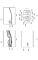
図2(a)に視神経乳頭部の輝度画像の例を示す。また、ガルバノスキャナ114によってラスタースキャンすることにより、被検眼118の眼底ErのBスキャン画像を構成し、さらに眼底上の位置が異なる複数のBスキャン像を副走査方向に取得することで、輝度画像のボリュームデータを生成する。
FIG. 2A shows an example of a luminance image of the optic papilla. Further, raster scanning is performed by the
<DOPU画像生成>
信号処理部144は、取得した振幅AH、AVとそれらの間の位相差ΔΦから、各画素毎にストークスベクトルSを式2により計算する。
<DOPU image generation>
The
ただし、ΔΦは2つの断層画像を計算する際に得られる各信号の位相ΦHとΦVからΔΦ=ΦV−ΦHとして計算する。
However, ΔΦ is calculated as ΔΦ = Φ V −Φ H from the phases Φ H and Φ V of each signal obtained when calculating two tomographic images.
次に、信号処理部144は、各Bスキャン画像を概ね計測光の主走査方向に70μm、深度方向に18μm程度のサイズのウィンドウを設定し、各ウィンドウ内において式2で画素毎に計算されたストークスベクトルの各要素を平均し、当該ウィンドウ内の偏光の均一性DOPU(Degree Of Polarization Uniformity)を式3により計算する。
Next, the
ただし、Qm、Um、Vmは各ウィンドウ内のストークスベクトルの要素Q、U、Vを平均した値である。この処理をBスキャン画像内の全てのウィンドウに対して行うことで、図2(b)に示す視神経乳頭部のDOPU画像(偏光の均一度を示す断層画像とも言う)が生成される。
However, Q m , U m , and V m are values obtained by averaging the elements Q, U, and V of the Stokes vector in each window. By performing this process for all the windows in the B-scan image, the DOPU image (also referred to as a tomographic image showing the uniformity of polarization) of the optic papilla shown in FIG. 2B is generated.
DOPUは偏光の均一性を表す数値であり、偏光が保たれている個所においては1に近い数値となり、偏光が解消された保たれない箇所においては1よりも小さい数値となるものである。網膜内の構造においては、RPE層が偏光状態を解消する性質があるため、DOPU画像においてRPE層に対応する部分は、他の領域に対してその値が小さくなる。図2(b)において、濃淡が淡い場所210がRPE層を示しており、濃淡が濃い場所220は偏光が保たれている網膜層領域を示している。DOPU画像は、RPE層等の偏光を解消する層を画像化しているので、病気などによりRPE層が変形している場合においても、輝度の変化よりも確実にRPE層を画像化出来る。DOPU画像も輝度画像と同様に、上記で得られるBスキャン画像のおけるDOPU画像を副走査方向に並べ、DOPU画像のボリュームデータを生成することが可能である。なお、本明細書において、DOPU画像やリターデーション画像等を、偏光断層画像とも言うことにする。また、本明細書において、DOPU画像を、偏光解消性を示す画像とも言うことにする。また、本明細書において、リターデーション画像のボリュームデータから生成されたリターデーションマップや複屈折マップ等を、偏光眼底画像とも言うことにする。 DOPU is a numerical value showing the uniformity of polarized light, and is a value close to 1 at the place where the polarized light is kept and smaller than 1 at the place where the polarized light is not kept. In the structure inside the retina, since the RPE layer has a property of canceling the polarization state, the value of the portion corresponding to the RPE layer in the DOPU image becomes smaller than that of other regions. In FIG. 2B, a light and dark place 210 indicates the RPE layer, and a dark and light place 220 indicates a retinal layer region where polarization is maintained. Since the DOPU image is an image of a layer that eliminates polarization such as the RPE layer, even when the RPE layer is deformed due to a disease or the like, the RPE layer can be imaged more reliably than the change in brightness. Similarly to the luminance image, the DOPU image can be arranged in the sub-scanning direction with the DOPU image of the B-scan image obtained above to generate volume data of the DOPU image. In addition, in this specification, a DOPU image, a retardation image, etc. are also called a polarization tomographic image. In the present specification, the DOPU image is also referred to as an image showing depolarization property. Further, in this specification, the retardation map, the birefringence map, and the like generated from the volume data of the retardation image are also referred to as a polarized fundus image.
[処理動作]
次に本偏光OCT装置における処理動作について説明する。図3は、本偏光OCT装置における処理動作を示すフローチャートである。
[Processing operation]
Next, the processing operation in the polarized OCT apparatus will be described. FIG. 3 is a flowchart showing the processing operation in this polarization OCT apparatus.
<調整>
まず、ステップS101において、被検眼を本装置に配置した状態で、本装置と被検眼のアライメントを行う。なお、ワーキングディスタンス等のXYZ方向のアライメント、フォーカス、コヒーレンスゲートの調整等は一般的であるのでその説明は省略する。
<Adjustment>
First, in step S101, the apparatus and the eye to be inspected are aligned with the eye to be inspected placed in the apparatus. Incidentally, alignment in the XYZ directions such as working distance, focus, adjustment of the coherence gate, etc. are general, and therefore description thereof is omitted.
<撮像>〜<画像生成>
ステップS102〜S103において、光源101から光を射出し、測定光および参照光を生成する。測定光が被検眼118の網膜Erより反射、または散乱した戻り光と参照光との干渉光をディテクタ141および142で受光し、信号処理部144で前述のとおり各画像を生成する。
<Imaging>-<Image generation>
In steps S102 to S103, light is emitted from the
<解析>
(DOPU画像における硬性白斑を検出)
信号処理部144はステップS104において、作成されたDOPU画像における硬性白斑を検出する。図4に硬性白斑の含まれる輝度画像410(図4(a))およびDOPU画像411、412(図4(b、c))の例を示す。DOPU画像は測定対象となる物質の偏光解消性を画像化するものである。図4(a)に示す輝度画像410では、偏光解消性を有する硬性白斑領域401およびRPE層402と共に、網膜を構成する断層が描出される。一方、図4(b)に示すDOPU画像411では偏光解消領域が描出される。本実施形態においてはDOPU画像として描出するDOPUの閾値を0.75とし、それよりも偏光解消性の高い領域、つまり反射、散乱による戻り光の偏光度が低くなる領域について、DOPU<0.75の領域をDOPU画像として描出している。結果として硬性白斑領域403およびRPE層404がDOPU画像411として描出される。なお、本実施形態ではDOPUの閾値を0.75としたがこれに限定されるものではない。検者が測定対象、測定の目的等に応じて任意に設定可能である。
<Analysis>
(Detecting hard vitiligo in DOPU image)
In step S104, the
本実施形態において信号処理部144は、DOPU画像411からRPE層404を特定し、偏光解消領域から特定されたRPE層404を除外することにより、硬性白斑領域403を抽出する。抽出の方法としては、硬性白斑領域403がRPE層404より内層側に存在する事や、連続的な層構造を持たないという形状的な特徴を利用することができる。例えば輝度画像410を用いて層のセグメンテーションを行ってRPE層402の座標を算出し、DOPU画像411においてその座標近傍のDOPUデータを除く方法や、DOPU画像411からGraph Cut法などの手法によってDOPU密度の高い領域を抽出し、それによってフィッティングされるライン近傍のDOPUデータを除く方法などがある。以上の処理を加えることで、DOPU画像において硬性白斑領域403を特異的に抽出することが出来る(図4(c))。信号処理部144は、これらの処理を取得したDOPU画像のボリュームデータを構成する全てのBスキャン画像に対して実施することで、ボリュームデータ内の硬性白斑領域を特異的に抽出する。
In the present embodiment, the
(DOPU画像において検出された硬性白斑を用いて輝度画像の硬性白斑位置を特定)
信号処理部144は、硬性白斑領域403を特異的に抽出したのち、DOPU画像412からその座標値を取得する。上述した通り、DOPU画像は取得した振幅AH、AVとそれらの間の位相差ΔΦから、画素毎にストークスベクトルSを求め、得られたストークスベクトルSの各要素を平均することで得られるDOPUをBスキャン画像内で行うことで生成される。そのため、画像サイズや画素ピッチなどは同一である。すなわち、DOPU画像と断層輝度画像との位置関係は対応付いている。もちろん、DOPU画像と断層輝度画像とが、別々のタイミングあるいは別々の光学系で取得されたものであっても良い。この場合、画像相関等を用いてこれらの画像を位置合わせすることにより、互いの位置関係を対応付けることができる。そのため、DOPU画像412で取得される座標値を輝度画像410に適用することで、DOPU画像412内の硬性白斑403の位置を輝度画像410において特定することが出来る。
(The hard white spot position of the luminance image is specified using the hard white spot detected in the DOPU image)
The
図4(d)に硬性白斑領域401を拡大した図を示す。硬性白斑領域403には硬性白斑420〜427に対応するDOPU画像が含まれている。ここで、信号処理部144は、それぞれの硬性白斑の座標を算出するが、各硬性白斑の一部が含まれていればよく、各硬性白斑の面積全体の座標情報は必須ではない。例えばDOPU画像412で取得される座標値は、抽出される硬性白斑420〜427それぞれの重心座標428〜435や、その他に、DOPU画像中のそれぞれの硬性白斑の最も左側に存在する画素の座標などが利用できる。これらの処理を取得したDOPU画像のボリュームデータを構成する全てのBスキャン画像に対して実施することで、輝度画像のボリュームデータ内の硬性白斑の座標を特定することが出来る。
FIG. 4D shows an enlarged view of the
(輝度画像中の硬性白斑を特異的に検出)
輝度画像410における硬性白斑420〜427がどの座標にあるかが特定されたら、次に信号処理部144は硬性白斑420〜427を特異的に描出する。抽出に際し、本実施形態では領域拡張法を用いるものとして説明するが、本発明はこれに限定されるものではない。空間的な初期位置に基づいて領域分割を行うどのようなアルゴリズムでも、初期位置をDOPU画像412において決定することで適用ができる。信号処理部144は硬性白斑420〜427の各々に対して特定された座標値に対して、各々種子点(シードポイント)を設定し、判定条件として輝度画像410に対する閾値を用いて領域拡張を行う。すなわち、信号処理部144はDOPU画像412で決定されたシードポイントから輝度画像410において領域の拡張を開始し、輝度値が閾値以下となるまで拡張処理を行う。閾値は実験的に決めることが可能であるが、さらに拡張の範囲がDOPU画像412によって描出された硬性白斑の範囲を超えないように条件を付加することが望ましい。このように、DOPU画像によって特定された硬性白斑は、DOPUパラメータの計算に必要なウィンドウ処理の影響によって、その輪郭が実際よりも広がっている可能性があるが、上記の処理は輝度画像に基づいて輪郭を決定しているため、より正確に硬性白斑の形状を抽出する事ができる。なお、これらの処理は取得した輝度画像のボリュームデータを構成する全てのBスキャン画像に対して実施することができる。このとき、輝度画像のボリュームデータ内の硬性白斑領域を特定することが出来る。もちろん、本発明は、1枚のBスキャン画像だけでも適用することは可能である。
(Specifically detects hard vitiligo in a brightness image)
When the coordinates of the hard
(輝度画像による硬性白斑の表示)
上述の通りに硬性白斑420〜427を抽出後、ステップS105において画像の出力を行うことができる。画像の出力は表示部146によって行われる。ステップS104で特定された輝度画像410中の硬性白斑420〜427を判別しやすい状態で輝度画像410に重ねて表示される。例えば、輝度画像410中の硬性白斑420〜427は、輝度画像410の他の領域との区別を容易にするために、輝度画像410に使用されていない色(例えば、赤や黄色)で輝度画像410に重ねて表示される。
(Display of hard white spots by brightness image)
After extracting the hard
以上説明した撮像装置および画像処理方法を用いることで、偏光解消性を有する病変部位を特異的に表示することが可能となる。また、病変部位のサイズを正確に表示することが可能となる。本実施形態では偏光OCT装置のみの構成としたが、例えば走査型レーザ検眼鏡(Scanning Laser Ophthalmoscope:SLO)などの眼底観察装置と組み合わせ、偏光OCT装置の撮像位置との対応を付けることで、より正確な診断を行うことが可能である。また、本実施形態では硬性白斑を対象としたが、これに限定されるものではなく、眼底に生じる偏光解消性を有する病変の表示であれば、本方法が適応可能である。また、本実施形態では偏光OCT装置のBスキャン画像に対してのみ画像表示方法を記したが、これに限定されるものではない。例えば偏光OCT装置によって複数のBスキャンによる3次元データを取得し、各Bスキャン画像に対して上述の画像解析処理を行ったうえでボリュームデータとすることで、偏光解消性を有する病変部位を3次元的に描出することが可能である。 The above-described imaging apparatus and images processing method by using, it is possible to specifically display the lesion with a depolarization property. Further, it is possible to accurately display the size of the lesion site. Although only the polarization OCT apparatus is configured in the present embodiment, for example, by combining with a fundus observation apparatus such as a scanning laser ophthalmoscope (Scanning Laser Ophthalmoscope: SLO), and by associating with the imaging position of the polarization OCT apparatus, It is possible to make an accurate diagnosis. In addition, although hard vitiligo is targeted in the present embodiment, the present invention is not limited to this, and the present method can be applied as long as it is a display of a depolarizing lesion occurring on the fundus. Further, in the present embodiment, the image display method is described only for the B scan image of the polarization OCT apparatus, but the present invention is not limited to this. For example, the polarization OCT apparatus acquires three-dimensional data by a plurality of B scans, performs the above-described image analysis processing on each B scan image, and then sets the volume data, so that the lesion site having the depolarization property is 3 It is possible to depict it dimensionally.
(輝度画像による硬性白斑領域の計算)
上述の通りに輝度画像のボリュームデータを構成する全てのBスキャン画像に対して硬性白斑の領域を特定後、信号処理部144はボリュームデータ内の硬性白斑領域の体積を算出することもできる。まず信号処理部144は、取得した輝度画像の全てのBスキャン画像を副走査方向(y方向)に取得した順番で並べ、輝度画像のボリュームデータを作成する。次に、各Bスキャン画像に対して特定した硬性白斑領域について、各Bスキャンの副走査方向に連続するかまたは一部が接するピクセルを抽出し、結合する。抽出はBスキャン画像中の硬性白斑の抽出と同様に、領域拡張法を用いて実施する。最後に抽出した硬性白斑のボクセルについて、ボリュームデータの縦(y方向)、横(x方向)、深さ(z方向)の各軸に対するピクセル分解能を考慮して体積を算出する。本実施形態では、縦6mm、横8mm、深さ2mmのボリュームを縦256ピクセル、横512ピクセル、深さ1024ピクセルで撮像している。そのため、1ピクセルあたりの長さはそれぞれ、縦23μm、横16μm、深さ2μmとなる。これらの処理はボリュームデータ中に含まれる各硬性白斑について算出される。
(Calculation of a hard vitiligo region using a luminance image)
As described above, after the hard vitiligo region is specified for all the B scan images forming the volume data of the luminance image, the
上述の通り硬性白斑の体積が算出すると、体積値は抽出された硬性白斑それぞれに対応してリストが表示部146に表示される。表示部146に表示される表示画面の例を図5に示す。表示画面501には画像表示部502およびリスト表示部522が配置されている。画像表示部501には生成したボリュームデータから得られるxy面における輝度画像マップ523および輝度画像のBスキャン画像503が示される。なお、スライダ521を動かすことで、取得した全てのBスキャン画像の中から任意のBスキャン画像を表示することが可能となっている。一方、リスト表示部522にはリスト504が表示され、抽出された硬性白斑の座標値及び体積値が対応付けられて表示される。
When the volume of hard white spots is calculated as described above, a list of volume values corresponding to the extracted hard white spots is displayed on the
術者がリスト504から任意の行を選択すると輝度画像マップ523およびBスキャン画像503の中の硬性白斑領域505〜512および513〜520のうち、対応する硬性白斑領域がハイライト表示される。また、反対に、術者が輝度画像マップ523またはBスキャン画像523に表示される硬性白斑領域505〜512および513〜520のいずれかを選択すると、リスト504の対応する行がハイライト表示されるようになっている。
When the operator selects any row from the
なお、本実施形態では複数の硬性白斑についてそれぞれ体積値を算出したが、任意の範囲に存在する硬性白斑の体積値を積算して表示しても良い。また、本実施形態では輝度画像マップおよび輝度画像のBスキャン画像を表示する例を示したが、これに限定されない。セグメンテーション後のEn faceマップやDOPU画像など、偏光OCT装置で取得、生成可能な全ての画像から任意に選択して表示してよい。 In the present embodiment, the volume value is calculated for each of a plurality of hard white spots, but the volume values of hard white spots existing in an arbitrary range may be integrated and displayed. Further, although an example in which the luminance image map and the B-scan image of the luminance image are displayed has been shown in the present embodiment, the present invention is not limited to this. Any image that can be acquired and generated by the polarization OCT apparatus, such as an En face map or DOPU image after segmentation, may be arbitrarily selected and displayed.
以上説明した撮像装置および画像処理方法を用いることで、硬性白斑のより正確な体積を算出することが可能である。本実施形態の中でも記載しているが、偏光OCT装置のみの構成ではなく、例えば走査型レーザ検眼鏡(Scanning Laser Ophthalmoscope:SLO)などの眼底観察装置と組み合わせ、偏光OCT装置の撮像位置との対応を付けることで、より正確な算出を行うことが可能である。例えばSLOによって取得される眼底画像を基に被検眼の動きをトラッキングし、被検眼の動き量を補正してボリュームデータを生成することで、被検眼の動きによるBスキャンごとの位置ずれをなくし、正確に硬性白斑の面積および体積を算出ることが出来る。また、本実施形態では硬性白斑を対象としたが、これに限定されるものではなく、眼底に生じる偏光解消性を有する病変部の領域の算出に対しては、本方法が適応可能である。また、本実施形態では偏光OCT装置のボリュームデータを用いて硬性白斑の体積を算出する方法について記載したが、これに限定されるものではない。例えば、Bスキャン画像を用いて偏光解消性を有する病変部の面積を算出することや、En face画像中の偏光解消性を有する病変部の面積を算出することも可能である。 By using the described imaging apparatus and images processing method above, it is possible to calculate a more accurate volume of the hard exudates. Although described in the present embodiment, the configuration is not limited to the polarization OCT apparatus alone, but is combined with a fundus observation device such as a scanning laser ophthalmoscope (SLO) to correspond to the imaging position of the polarization OCT apparatus. By adding, it is possible to perform more accurate calculation. For example, the movement of the eye to be inspected is tracked based on the fundus image acquired by SLO, and the amount of movement of the eye to be inspected is corrected to generate volume data, thereby eliminating the positional deviation for each B scan due to the movement of the eye to be inspected, The area and volume of hard vitiligo can be calculated accurately. Further, although hard vitiligo is targeted in the present embodiment, the present invention is not limited to this, and the present method can be applied to calculation of a region of a lesion part having depolarization properties that occurs on the fundus. Further, although the present embodiment describes the method of calculating the volume of hard vitiligo using the volume data of the polarization OCT apparatus, the present invention is not limited to this. For example, it is possible to calculate the area of a lesion part having depolarization properties using a B scan image, or to calculate the area of a lesion part having depolarization properties in an En face image.
(その他の実施形態)
また、本発明は、以下の処理を実行することによっても実現される。即ち、上述した実施形態の機能を実現するソフトウェア(プログラム)を、ネットワーク又は各種記憶媒体を介してシステム或いは装置に供給し、そのシステム或いは装置のコンピュータ(またはCPUやMPU等)がプログラムを読み出して実行する処理である。
(Other embodiments)
The present invention is also realized by executing the following processing. That is, software (program) that realizes the functions of the above-described embodiments is supplied to a system or device via a network or various storage media, and the computer (or CPU, MPU, etc.) of the system or device reads the program. This is the process to be executed.
Claims (13)
前記偏光断層画像における偏光解消領域を抽出することにより、偏光解消性を有するRPE層及び病変部を抽出する抽出手段と、
前記偏光断層画像における前記抽出された病変部の位置と前記断層輝度画像の輝度値とを用いて、前記断層輝度画像における一部の領域であって、前記抽出された病変部に対応する一部の領域を検出する検出手段と、
前記検出された一部の領域のサイズに関する情報を取得する情報取得手段と、
前記取得されたサイズに関する情報を表示手段に表示させる表示制御手段と、
を有することを特徴とする画像処理装置。 The tomographic image acquisition unit configured to acquire a tomographic luminance image and polarization tomographic image of the subject's eye obtained by processing the common OCT signal by the return light and the reference light from the eye irradiated with measurement light,
Extracting means for extracting an RPE layer having depolarization property and a lesion by extracting a depolarization region in the polarization tomographic image;
Using the luminance value of the tomographic luminance image and the extracted position of the lesion in the polarization tomographic image, wherein a partial region in the tomographic luminance image, a portion corresponding to the lesion the extracted Detection means for detecting the area of
An information acquisition unit that acquires information about the size of the detected partial area;
Display control means for displaying information on the acquired size on a display means;
An image processing apparatus comprising:
前記情報取得手段は、前記検出された輪郭を用いて前記一部の領域のサイズに関する情報を取得することを特徴とする請求項1に記載の画像処理装置。 Said detecting means, using said position of said extracted lesion in the polarization tomographic image to detect the position of the partial region before Symbol tomographic luminance image, the luminance of the detected position and the tomographic luminance image wherein detecting a contour of a portion of the area using the values,
The image processing apparatus according to claim 1, wherein the information acquisition unit acquires information regarding the size of the partial area by using the detected contour .
前記病変部は、硬性白斑領域であり、
前記サイズに関する情報は、前記検出された一部の領域の体積、面積、幅、外周長の少なくとも1つであることを特徴とする請求項1乃至5のいずれか1項に記載の画像処理装置。 The polarization tomographic image, Ri DOPU image der,
The lesion is a hard vitiligo region,
Information on the size, the volume of the detected portion of the regions, the area, the width, the image processing according to any one of claims 1 to 5, wherein at least one Tsudea Rukoto the outer peripheral length apparatus.
前記検出手段は、前記断層輝度画像を用いて抽出されたRPE層の位置と前記偏光断層画像における前記抽出された病変部の位置と前記断層輝度画像の輝度値とを用いて、前記一部の領域を検出することを特徴とする請求項1乃至6のいずれか1項に記載の画像処理装置。 The polarized tomographic image and the tomographic luminance image, the position of the site of the eye to be examined on the image is associated with each other ,
The detection means uses the position of the RPE layer extracted using the tomographic luminance image, the position of the extracted lesion in the polarized tomographic image, and the luminance value of the tomographic luminance image to determine the partial the image processing apparatus according to any one of claims 1 to 6, characterized that you detect the region.
前記情報取得手段は、前記検出された複数の一部の領域のサイズに関する複数の情報を取得し、
前記表示制御手段は、前記検出された複数の一部の領域を識別可能に、前記断層輝度画像、前記断層輝度画像に関するボリュームデータを用いて生成されたマップ、前記偏光断層画像に関するボリュームデータを用いて生成されたマップのうち少なくとも1つを前記表示手段に表示させ、前記検出された複数の一部の領域と対応させて前記取得されたサイズに関する複数の情報を前記表示手段に表示させることを特徴とする請求項1乃至8のいずれか1項に記載の画像処理装置。 The detection means is a plurality of partial regions in the tomographic luminance image, which are extracted by using the position of the extracted lesion in the polarized tomographic image and the luminance value of the tomographic luminance image. Detects several partial areas corresponding to the lesion,
The information acquisition unit acquires a plurality of pieces of information regarding the sizes of the plurality of detected partial areas,
The display control means uses the tomographic luminance image , a map generated using volume data relating to the tomographic luminance image, and volume data relating to the polarized tomographic image so as to be able to identify the plurality of detected partial areas. Displaying at least one of the generated maps on the display means, and displaying on the display means a plurality of pieces of information regarding the acquired size in association with the plurality of detected partial areas. 9. The image processing apparatus according to claim 1 , wherein the image processing apparatus is characterized in that.
前記偏光断層画像における偏光解消領域を抽出することにより、偏光解消性を有するRPE層及び病変部を抽出する工程と、
前記偏光断層画像における前記抽出された病変部の位置と前記断層輝度画像の輝度値とを用いて、前記断層輝度画像における一部の領域であって、前記抽出された病変部に対応する一部の領域を検出する工程と、
前記検出された一部の領域のサイズに関する情報を取得する工程と、
前記取得されたサイズに関する情報を表示手段に表示させる工程と、
を有することを特徴とする画像処理方法。 A step of acquiring a tomographic luminance image and polarization tomographic image of the subject's eye obtained by processing the common OCT signal by the return light and the reference light from the eye irradiated with measurement light,
Extracting a depolarized region in the polarized tomographic image to extract a depolarizing RPE layer and a lesion .
Using the luminance value of the tomographic luminance image and the extracted position of the lesion in the polarization tomographic image, wherein a partial region in the tomographic luminance image, a portion corresponding to the lesion the extracted Detecting the area of
Acquiring information about the size of the detected partial area,
Displaying the acquired size information on a display means;
An image processing method comprising:
Priority Applications (2)
| Application Number | Priority Date | Filing Date | Title |
|---|---|---|---|
| PCT/JP2015/006376 WO2016110917A1 (en) | 2015-01-07 | 2015-12-22 | Image processing apparatus and image processing method for polarization-sensitive optical coherence tomography |
| US15/541,912 US20180003479A1 (en) | 2015-01-07 | 2015-12-22 | Image processing apparatus and image processing method |
Applications Claiming Priority (4)
| Application Number | Priority Date | Filing Date | Title |
|---|---|---|---|
| JP2015001679 | 2015-01-07 | ||
| JP2015001679 | 2015-01-07 | ||
| JP2015001678 | 2015-01-07 | ||
| JP2015001678 | 2015-01-07 |
Publications (3)
| Publication Number | Publication Date |
|---|---|
| JP2016129663A JP2016129663A (en) | 2016-07-21 |
| JP2016129663A5 JP2016129663A5 (en) | 2019-01-10 |
| JP6685706B2 true JP6685706B2 (en) | 2020-04-22 |
Family
ID=56414923
Family Applications (2)
| Application Number | Title | Priority Date | Filing Date |
|---|---|---|---|
| JP2015234269A Expired - Fee Related JP6719891B2 (en) | 2015-01-07 | 2015-11-30 | Image processing apparatus and image processing method |
| JP2015234268A Expired - Fee Related JP6685706B2 (en) | 2015-01-07 | 2015-11-30 | Image processing apparatus and image processing method |
Family Applications Before (1)
| Application Number | Title | Priority Date | Filing Date |
|---|---|---|---|
| JP2015234269A Expired - Fee Related JP6719891B2 (en) | 2015-01-07 | 2015-11-30 | Image processing apparatus and image processing method |
Country Status (2)
| Country | Link |
|---|---|
| US (1) | US20180003479A1 (en) |
| JP (2) | JP6719891B2 (en) |
Families Citing this family (9)
| Publication number | Priority date | Publication date | Assignee | Title |
|---|---|---|---|---|
| JP2017080344A (en) * | 2015-10-30 | 2017-05-18 | キヤノン株式会社 | Image processing device, image processing method and optical interference tomographic device |
| AU2018221899A1 (en) * | 2017-02-17 | 2019-08-15 | The University Of Western Australia | System and a method for detecting a material in region of interest |
| JP6929684B2 (en) * | 2017-04-06 | 2021-09-01 | キヤノン株式会社 | Ophthalmologic imaging device and its control method |
| JP6910935B2 (en) * | 2017-11-24 | 2021-07-28 | 株式会社トプコン | Ophthalmology information processing equipment, ophthalmology system, ophthalmology information processing method, and program |
| CN108510497B (en) * | 2018-04-10 | 2022-04-26 | 四川和生视界医药技术开发有限公司 | Method and device for displaying focus information of retina image |
| EP3572765A1 (en) | 2018-05-23 | 2019-11-27 | Haag-Streit Ag | Oct system and oct method |
| JP7162479B2 (en) * | 2018-09-25 | 2022-10-28 | 株式会社トプコン | Ophthalmic information processing device, ophthalmic system, ophthalmic information processing method, and program |
| EP3760967A3 (en) | 2019-07-02 | 2021-04-07 | Topcon Corporation | Method of processing optical coherence tomography (oct) data |
| CN116209886A (en) * | 2020-10-15 | 2023-06-02 | 应用材料公司 | Perspective metering system, apparatus and method for optical devices |
Family Cites Families (5)
| Publication number | Priority date | Publication date | Assignee | Title |
|---|---|---|---|---|
| JP5149535B2 (en) * | 2007-04-27 | 2013-02-20 | 国立大学法人 筑波大学 | Polarization-sensitive optical coherence tomography apparatus, signal processing method for the apparatus, and display method for the apparatus |
| JP2010125291A (en) * | 2008-12-01 | 2010-06-10 | Nidek Co Ltd | Ophthalmological photographic apparatus |
| JP6061555B2 (en) * | 2012-08-27 | 2017-01-18 | キヤノン株式会社 | Image processing apparatus and image processing method |
| JP2014110884A (en) * | 2012-10-30 | 2014-06-19 | Canon Inc | Image processor and image processing method |
| JP2014110883A (en) * | 2012-10-30 | 2014-06-19 | Canon Inc | Image processor and image processing method |
-
2015
- 2015-11-30 JP JP2015234269A patent/JP6719891B2/en not_active Expired - Fee Related
- 2015-11-30 JP JP2015234268A patent/JP6685706B2/en not_active Expired - Fee Related
- 2015-12-22 US US15/541,912 patent/US20180003479A1/en not_active Abandoned
Also Published As
| Publication number | Publication date |
|---|---|
| JP6719891B2 (en) | 2020-07-08 |
| JP2016129663A (en) | 2016-07-21 |
| US20180003479A1 (en) | 2018-01-04 |
| JP2016129664A (en) | 2016-07-21 |
Similar Documents
| Publication | Publication Date | Title |
|---|---|---|
| JP6685706B2 (en) | Image processing apparatus and image processing method | |
| US10136806B2 (en) | Image display method, image display apparatus, and storage medium | |
| JP6843521B2 (en) | Image processing device and image processing method | |
| JP6598502B2 (en) | Image generating apparatus, image generating method, and program | |
| JP6632267B2 (en) | Ophthalmic apparatus, display control method and program | |
| JP5210443B1 (en) | Optical tomographic imaging apparatus and control method | |
| JP6598466B2 (en) | Tomographic imaging apparatus, tomographic imaging method, and program | |
| JP6184232B2 (en) | Image processing apparatus and image processing method | |
| JP2008246158A (en) | Optical image measurement instrument, program controlling it, and optical image measurement method | |
| JP2014110884A (en) | Image processor and image processing method | |
| WO2016110917A1 (en) | Image processing apparatus and image processing method for polarization-sensitive optical coherence tomography | |
| JP6503665B2 (en) | Optical coherence tomography apparatus and program | |
| JP2022176282A (en) | Ophthalmologic apparatus and control method thereof | |
| JP6682291B2 (en) | Image processing apparatus, image processing method and program | |
| JP6375760B2 (en) | Optical coherence tomography apparatus and fundus image processing program | |
| JP2018020024A (en) | Image processing device, image processing method, and program | |
| JP6849776B2 (en) | Information processing device and information processing method | |
| JP6888643B2 (en) | OCT analysis processing device and OCT data processing program | |
| JP2018102757A (en) | Ophthalmologic analyzer, ophthalmologic oct, and ophthalmologic analysis program | |
| JP2017140316A (en) | Image processing apparatus, image processing method, and program therefor | |
| JP2018033506A (en) | Tomographic imaging device, image forming device, tomographic imaging method, image forming method, and program | |
| JP6992030B2 (en) | Image generator, image generation method and program | |
| JP7216545B2 (en) | OPHTHALMOLOGICAL APPARATUS, OPHTHALMOLOGICAL APPARATUS CONTROL METHOD, AND PROGRAM | |
| JP2018051177A (en) | Ophthalmic imaging apparatus and operation method for ophthalmic imaging apparatus | |
| JP2021087817A (en) | Image processing apparatus and image processing method |
Legal Events
| Date | Code | Title | Description |
|---|---|---|---|
| A521 | Request for written amendment filed |
Free format text: JAPANESE INTERMEDIATE CODE: A523 Effective date: 20181120 |
|
| A621 | Written request for application examination |
Free format text: JAPANESE INTERMEDIATE CODE: A621 Effective date: 20181120 |
|
| A131 | Notification of reasons for refusal |
Free format text: JAPANESE INTERMEDIATE CODE: A131 Effective date: 20191126 |
|
| A521 | Request for written amendment filed |
Free format text: JAPANESE INTERMEDIATE CODE: A523 Effective date: 20200124 |
|
| TRDD | Decision of grant or rejection written | ||
| A01 | Written decision to grant a patent or to grant a registration (utility model) |
Free format text: JAPANESE INTERMEDIATE CODE: A01 Effective date: 20200303 |
|
| A61 | First payment of annual fees (during grant procedure) |
Free format text: JAPANESE INTERMEDIATE CODE: A61 Effective date: 20200401 |
|
| R151 | Written notification of patent or utility model registration |
Ref document number: 6685706 Country of ref document: JP Free format text: JAPANESE INTERMEDIATE CODE: R151 |
|
| LAPS | Cancellation because of no payment of annual fees |