JP6992030B2 - Image generator, image generation method and program - Google Patents
Image generator, image generation method and program Download PDFInfo
- Publication number
- JP6992030B2 JP6992030B2 JP2019182532A JP2019182532A JP6992030B2 JP 6992030 B2 JP6992030 B2 JP 6992030B2 JP 2019182532 A JP2019182532 A JP 2019182532A JP 2019182532 A JP2019182532 A JP 2019182532A JP 6992030 B2 JP6992030 B2 JP 6992030B2
- Authority
- JP
- Japan
- Prior art keywords
- image
- motion contrast
- layer
- value
- threshold value
- Prior art date
- Legal status (The legal status is an assumption and is not a legal conclusion. Google has not performed a legal analysis and makes no representation as to the accuracy of the status listed.)
- Active
Links
Images


Landscapes
- Eye Examination Apparatus (AREA)
Description
開示の技術は、画像生成装置、画像生成方法およびプログラムに関する。 The disclosed technique relates to an image generator, an image generation method and a program.
生体などの測定対象の断層像を非破壊、非侵襲で取得する方法として、光干渉断層撮像法(Optical Coherence Tomography、以下OCTという)が実用化されている。OCTは、特に眼科領域で被検眼の眼底における網膜の断層像が取得され、網膜の眼科診断等において広く利用されている。 Optical coherence tomography (hereinafter referred to as OCT) has been put into practical use as a method for acquiring a tomographic image of a measurement target such as a living body in a non-destructive and non-invasive manner. OCT is widely used in ophthalmic diagnosis of the retina because a tomographic image of the retina in the fundus of the eye to be inspected is acquired, especially in the field of ophthalmology.
OCTは、測定対象から反射した光と参照鏡から反射した光を干渉させ、その干渉した光強度の時間依存性または波数依存性を解析することにより断層像を得ている。このような光干渉断層像取得装置として、参照鏡の位置を変えることで測定対象の深さ情報を得るタイムドメインOCTが知られている。また、広帯域光源を使用したスペクトラルドメインOCT(SD-OCT:Spectral Domain Optical Coherence Tomography)が知られている。さらに、発振波長を変えることができる波長可変光源装置を光源として使用した波長掃引光コヒーレンストモグラフィー(SS-OCT:Swept Source Optical Coherence Tomography)装置が知られている。なお、SD-OCTとSS-OCTは総称して(FD-OCT:Fourier Domain Optical Coherence Tomography)と呼ばれる。 OCT obtains a tomographic image by interfering the light reflected from the measurement target with the light reflected from the reference mirror and analyzing the time dependence or wave number dependence of the interfering light intensity. As such an optical coherence tomographic image acquisition device, a time domain OCT that obtains depth information of a measurement target by changing the position of a reference mirror is known. Further, a spectral domain OCT (SD-OCT: Spectral Domain Optical Coherence Tomography) using a wide band light source is known. Further, a wavelength sweeping optical coherence tomography (SS-OCT) device using a wavelength variable light source device capable of changing the oscillation wavelength as a light source is known. In addition, SD-OCT and SS-OCT are collectively referred to as (FD-OCT: Fourier Optic Coherence Tomography).
近年、このFD-OCTを用いた擬似血管造影法が提案されており、OCTアンギオグラフィー(OCTA)と呼ばれている。 In recent years, a pseudo-angiography method using this FD-OCT has been proposed and is called OCT angiography (OCTA).
現代の臨床医療で一般的な血管造影法である蛍光造影は、体内に蛍光色素(例えばフルオレセインまたはインドシアニングリーン)の注入を必要としている。蛍光色素の通り道となる血管を2次元的に表示するが、OCTアンギオグラフィーは非侵襲で擬似的な血管造影を可能にし、血流部位のネットワークを3次元的に表示すること可能である。さらに、蛍光造影に比べて高分解能であり、眼底の微小血管または血流を描出することができるため注目を集めている。 Fluorescence, a common angiography technique in modern clinical medicine, requires the injection of a fluorescent dye (eg, fluorescein or indocyanine green) into the body. While the blood vessels that serve as the path of the fluorescent dye are displayed two-dimensionally, OCT angiography enables non-invasive and pseudo-angiography, and it is possible to display the network of blood flow sites three-dimensionally. Furthermore, it is attracting attention because it has a higher resolution than fluorescence contrast and can visualize microvessels or blood flow in the fundus.
OCTアンギオグラフィーは血流検出方法の違いにより複数の方法が提案されている。OCT信号から時間変調が起こっている信号のみを抽出することで血流からのOCT信号を分離する方法(非特許文献1)が提案されている。また、血流による位相のバラツキを利用した方法(非特許文献2)、血流による強度のバラツキを利用した方法(非特許文献3、特許文献1)、などが提案されている。尚、本明細書中では、OCT信号から時間変調が起こっている信号を画像として表示したものをモーションコントラスト画像、またその画素値をモーションコントラスト、そのデータセットをモーションコントラストデータと呼ぶ場合がある。 A plurality of methods have been proposed for OCT angiography depending on the difference in blood flow detection method. A method (Non-Patent Document 1) has been proposed in which an OCT signal from a bloodstream is separated by extracting only a signal in which time modulation occurs from the OCT signal. Further, a method utilizing a variation in phase due to blood flow (Non-Patent Document 2), a method utilizing a variation in intensity due to blood flow (Non-Patent Document 3 and Patent Document 1), and the like have been proposed. In the present specification, a signal obtained by time modulation from an OCT signal may be referred to as a motion contrast image, a pixel value thereof may be referred to as a motion contrast, and a data set thereof may be referred to as a motion contrast data.
しかし、上記のOCTアンギオグラフィーでは、網膜色素上皮(RPE)等からの強い反射光や種々のノイズの影響を受けて血流部位の描出が十分に明瞭でなかったりノイズに埋もれたりして、診断に適するモーションコントラスト画像を容易に得ることが難しかった。 However, in the above-mentioned OCT angiography, the depiction of the blood flow site is not sufficiently clear or buried in the noise due to the influence of strong reflected light from the retinal pigment epithelium (RPE) and various noises, and the diagnosis is made. It was difficult to easily obtain a motion contrast image suitable for.
開示の技術は、モーションコントラスト画像の迅速・適切な描出を課題とする。具体的には、網膜部位の構造情報を用いてモーションコントラスト画像から不要なノイズを除去し、診断に有用なモーションコントラスト画像を描出する画像形成方法及び装置を提供することを課題とする。 The disclosed technology aims at rapid and appropriate depiction of motion contrast images. Specifically, it is an object of the present invention to provide an image forming method and an apparatus for removing unnecessary noise from a motion contrast image by using structural information of a retinal region and drawing a motion contrast image useful for diagnosis.
開示の技術は上記の課題に鑑みてなされたものであり、適切なモーションコントラスト画像を生成することを目的の1つとする。 The disclosed technique has been made in view of the above problems, and one of the purposes is to generate an appropriate motion contrast image.
なお、前記目的に限らず、後述する発明を実施するための形態に示す各構成により導かれる作用効果であって、従来の技術によっては得られない作用効果を奏することも本件の他の目的の1つとして位置付けることができる。 Not limited to the above-mentioned purpose, it is also an action and effect derived by each configuration shown in the embodiment for carrying out the invention described later, and it is also another purpose of the present invention to exert an action and effect which cannot be obtained by the conventional technique. It can be positioned as one.
開示の画像生成方法の一つは、
被検眼の略同一位置を測定光で複数回走査することにより得た前記被検眼の複数の断層像データ間の対応する画素データを用いてモーションコントラスト値を算出する工程と、
前記モーションコントラスト値と閾値とを比較して得た比較結果に基づいて、前記閾値以下のモーションコントラスト値を無効化する工程と、
前記モーションコントラスト値が算出される前に前記複数の断層像データの位置合わせを行う工程と、
前記複数の断層像データの平均化画像を用いてセグメンテーション処理を行うことにより、複数の層境界を検出する工程と、
前記無効化が行われた後に、前記検出された複数の層境界に基づいて分類された複数の層のうち少なくとも一つの層と前記モーションコントラスト値とに基づいて、前記被検眼のモーションコントラスト正面画像を生成する工程と、
前記少なくとも一つの層におけるモーションコントラスト値のヒストグラムにおけるノイズの分布と血流領域の分布とに応じて自動的に設定された初期値であって、前記複数の層のうち少なくとも一つの層を決定するための検者からの指示に応じて自動的に変更された初期値から、検者からの指示に応じて前記閾値を変更する工程と、
前記決定された少なくとも一つの層と、前記変更されることにより得た閾値を用いて再度比較して得た比較結果とに基づいて、前記被検眼のモーションコントラスト正面画像を再度生成する工程と、を有する。
One of the disclosed image generation methods is
A step of calculating a motion contrast value using the corresponding pixel data between a plurality of tomographic image data of the eye to be inspected obtained by scanning substantially the same position of the eye to be inspected multiple times with measurement light.
Based on the comparison result obtained by comparing the motion contrast value and the threshold value, the step of invalidating the motion contrast value below the threshold value and the step of invalidating the motion contrast value.
The step of aligning the plurality of tomographic image data before the motion contrast value is calculated, and
A step of detecting a plurality of layer boundaries by performing a segmentation process using the averaged images of the plurality of tomographic image data, and
After the invalidation is performed, the motion contrast front image of the eye to be inspected is based on at least one of the plurality of layers classified based on the detected plurality of layer boundaries and the motion contrast value. And the process of generating
It is an initial value automatically set according to the distribution of noise and the distribution of the blood flow region in the histogram of the motion contrast value in the at least one layer, and determines at least one of the plurality of layers. The process of changing the threshold value according to the instruction from the examiner from the initial value automatically changed according to the instruction from the examiner.
A step of regenerating the motion contrast front image of the eye to be inspected based on the at least one determined layer and the comparison result obtained by comparing again using the threshold value obtained by the change. And have.
開示の技術によれば、適切なモーションコントラスト画像を生成することが可能となる。 According to the disclosed technique, it is possible to generate an appropriate motion contrast image.
以下、添付の図面を参照して、本実施形態に係る撮像装置を説明する。なお、以下の実施形態において示す構成は一例に過ぎず、本発明は以下の実施形態に限定されるものではない。なお、本実施形態で被検体を人眼(眼底)としているがこれに限るものではなく、例えば皮膚等に用いることとしてもよい。また、本実施形態において撮像対象は眼の眼底としているが、前眼を撮影対象とすることとしてもよい。 Hereinafter, the image pickup apparatus according to the present embodiment will be described with reference to the attached drawings. The configuration shown in the following embodiments is only an example, and the present invention is not limited to the following embodiments. In the present embodiment, the subject is the human eye (fundus), but the present invention is not limited to this, and the subject may be used, for example, on the skin or the like. Further, although the image pickup target is the fundus of the eye in the present embodiment, the anterior eye may be the image pickup target.
〔第1の実施形態〕
本実施形態では、後述する制御部143が撮影された3次元光干渉信号から断層画像を生成し、モーションコントラストを算出する。そして、制御部143は、部位の構造情報を用いてノイズ閾値を調整し、明瞭化された3次元血流部位情報を取得する例を示す。
[First Embodiment]
In the present embodiment, the
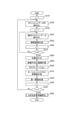
[画像形成装置全体の構成]
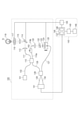
図1は、本実施形態における光干渉断層法を用いた画像形成装置の構成例を示す図である。図1に示す装置は、光干渉断層信号を取得する光干渉断層取得部100と制御部143を備える。制御部143は、信号処理部144、信号取得制御部145、表示部146および表示制御部149を備えて構成される。信号処理部144は、さらに画像生成部147とマップ生成部148とを備える。ここで、制御部143は例えばコンピュータであり、コンピュータに備えられたCPUが不図示の記憶装置に記憶されたプログラムを実行することで信号処理部144、信号取得制御部145、画像生成部147、マップ生成部148および表示制御部149としてとして機能する。
[Structure of the entire image forming apparatus]
FIG. 1 is a diagram showing a configuration example of an image forming apparatus using the optical coherence tomography method in the present embodiment. The device shown in FIG. 1 includes an optical interference
なお、制御部143が備えるCPUおよび記憶装置は1つであってもよいし複数であってもよい。すなわち、少なくとも1以上の処理装置(CPU)と少なくとも1つの記憶装置(RAMおよびROM)とが接続されており、少なくとも1以上の処理装置が少なくとも1以上の記憶装置に記憶されたプログラムを実行した場合に制御部143は上記の各手段として機能する。なお、処理装置はCPUに限定されるものではなく、FPGA等であってもよい。
The CPU and the storage device included in the
まず光干渉断層取得部100の構成について説明する。図1は、本実施形態における光干渉断層取得部の例としてOCT装置の構成例を示す図である。OCT装置は、例えば、SD-OCTまたはSS-OCTである。本実施形態ではOCT装置がSS-OCTである場合の構成を示す。
First, the configuration of the optical interference
<OCT装置100の構成>
OCT装置100の構成について説明する。
<Configuration of
The configuration of the
光源101は波長掃引型(Swept Source:以下SS)光源であり、例えば、掃引中心波長1050nm、掃引幅100nmで掃引しながら光を出射する。ここで、波長や掃引幅については例示であり、本発明は上記の値に限定されるものではない。以下の実施形態についても同様に、記載された数値は例示であり、本発明は記載された数値に限定されるものではない。
The
光源101から出射された光は光ファイバ102を介して、ビームスプリッタ110に導かれ、測定光(OCT測定光とも言う)と参照光(OCT測定光に対応する参照光とも言う)に分岐される。ビームスプリッタ110の分岐比は、90(参照光):10(測定光)である。分岐された測定光は、光ファイバ111を介して出射され、コリメータ112によって平行光とされる。平行光となった測定光は、被検眼118の眼底Erにおいて測定光を走査するガルバノスキャナ114、スキャンレンズ115、フォーカスレンズ116を介して被検眼118に入射する。ここで、ガルバノスキャナ114は単一のミラーとして記載したが、実際は被検眼118の眼底Erをラスタースキャンするように不図示の2枚のガルバノスキャナ、X軸スキャナー114aとY軸スキャナー114b、によって構成している。また、フォーカスレンズ116はステージ117上に固定されており、光軸方向に動くことで、フォーカス調整することが出来る。ガルバノスキャナ114とステージ117は信号取得制御部145によって制御され、被検眼118の眼底Erの所望の範囲(断層画像の取得範囲、断層画像の取得位置、測定光の照射位置とも言う)で測定光を走査することが出来る。
The light emitted from the
なお、本実施形態では詳細な説明はしていないが、眼底Erの動きを検出し、ガルバノスキャナ114のミラーを眼底Erの動きに追従させて走査させるトラッキング機能が付与されていることが望ましい。トラッキング方法については一般的な技術を用いて行うことが可能であり、リアルタイムで行うことも、ポストプロセッシングで行うことも可能である。例えば、走査型レーザ検眼鏡(Scanning Laser Ophthalmoscope:SLO)を用いる方法がある。これは眼底Erについて、SLOを用いて光軸に対して垂直な面内の2次元画像(眼底表面画像)を経時的に取得し、画像中の血管分岐などの特徴箇所を抽出する。取得する2次元画像中の特徴箇所がどのように動いたかを眼底Erの移動量として算出し、算出した移動量をガルバノスキャナ114にフィードバックすることでリアルタイムトラッキングを行うことが出来る。
Although not described in detail in this embodiment, it is desirable that a tracking function for detecting the movement of the fundus Er and scanning the mirror of the
測定光は、ステージ117上に乗ったフォーカスレンズ116により、被検眼118に入射し、眼底Erにフォーカスされる。眼底Erを照射した測定光は各網膜層で反射・散乱し、上述の光学経路をビームスプリッタ110に戻る。ビームスプリッタ110に入射した測定光の戻り光は光ファイバ126を経由し、ビームスプリッタ128に入射する。
The measurement light is incident on the eye to be inspected 118 by the
一方、ビームスプリッタ106で分岐された参照光は、光ファイバ119a、偏光制御器150、光ファイバ119b、を介して出射され、コリメータ120によって平行光とされる。偏光制御器150には参照光の偏光を所望の偏光状態へ変化させることが出来る。参照光は分散補償ガラス122、NDフィルタ123、コリメータ124を介し、光ファイバ127に入射する。コリメータレンズ124と光ファイバ127の一端はコヒーレンスゲートステージ125の上に固定されており、被検者の眼軸長の相違等に対応して光軸方向に駆動するように、信号取得制御部145で制御される。なお本実施形態では参照光の光路長を変更しているが、測定光の光路と参照光の光路との光路長差を変更出来ればよい。
On the other hand, the reference light branched by the beam splitter 106 is emitted via the
光ファイバ127を通過した参照光はビームスプリッタ128に入射する。ビームスプリッタ128では参照光の戻り光と参照光が合波されて干渉光とされた上で二つに分割される。分割される干渉光は互いに反転した位相の干渉光(以下、正の成分および負の成分と表現する)となっている。分割された干渉光の正の成分は光ファイバ129を経由してディテクタ141の一方の入力ポートに入射する。一方、干渉光の負の成分は光ファイバ130を経由してディテクタ141の他方に入射する。ディテクタ141は差動検出器となっており、位相が180°反転した二つの干渉光が入力されると、直流成分を除去し、干渉成分のみの干渉信号を出力する。
The reference light that has passed through the
ディテクタ141で検出された干渉光は光の強度に応じた電気信号(干渉信号)として出力され、断層画像生成部の一例である信号処理部144に入力される。
The interference light detected by the
<制御部143>
本装置全体を制御するための制御部143について説明する。
<
A
制御部143は信号処理部144、信号取得制御部145、表示部146、表示制御部149によって構成される。また、信号処理部144はさらに、画像生成部147とマップ生成部148を持つ構成となっている。画像生成部147はディテクタ141から送られる電気信号(干渉信号)から輝度画像およびモーションコントラスト画像を生成する機能を有し、マップ生成部148は輝度画像から層情報(網膜のセグメンテーション)を生成する機能を有する。
The
信号取得制御部145は上述の通りに各部を制御する。信号処理部144はディテクタ141から出力される干渉信号に基づき、画像の生成、生成された画像の解析、解析結果の可視情報の生成を行う。
The signal
信号処理部144で生成された画像および解析結果は表示制御部149に送られ、表示制御部149は表示部146の表示画面に画像および解析結果を表示させる。ここで、表示部146は、例えば液晶等のディスプレイである。なお、信号処理部144で生成された画像データは表示制御部149に送られた後、表示部146に有線で送信されても良いし、無線で送信されても良い。また、本実施形態において表示部146等は制御部143に含まれているが、本発明はこれに限らず、制御部143とは別に設けられても良く、例えばユーザが持ち運び可能な装置の一例であるタブレットでも良い。この場合、表示部にタッチパネル機能を搭載させ、タッチパネル上で画像の表示位置の移動、拡大縮小、表示される画像の変更等を操作可能に構成することが好ましい。
The image and analysis result generated by the
以上が、被検体118のある1点における断層に関する情報の取得のプロセスの説明である。このように被検体118の奥行き方向の断層に関する情報を取得することをA-scanと呼ぶ。また、A-scanと直交する方向で被検体の断層に関する情報、すなわち2次元画像を取得するための走査方向をB-scan、更にB-scanにより得られた断層像に直交する方向に走査することをC-scanと呼ぶ。これは、3次元断層像を取得する際に眼底面内に2次元ラスター走査する場合、高速な走査方向がB-scan、B-scanをその直交方向に並べて走査する低速な走査方向をC-scanと呼ぶ。A-scan及びB-scanを行うことで2次元の断層像が得られ、A-scan、B-scan及びC-scanを行うことで、3次元の断層像を得ることができる。B-scan、C-scanは、上述したガルバノスキャナ114により行われる。
The above is the description of the process of acquiring information about the tomography at one point of the subject 118. Acquiring information about the tomographic fault in the depth direction of the subject 118 in this way is called A-scan. Further, the information about the tomography of the subject in the direction orthogonal to the A-scan, that is, the scanning direction for acquiring the two-dimensional image is scanned in the direction orthogonal to the tomographic image obtained by the B-scan and the B-scan. This is called C-scan. This is because when two-dimensional raster scanning is performed in the bottom of the eye when acquiring a three-dimensional tomographic image, the high-speed scanning direction is B-scan, and the low-speed scanning direction in which B-scan is arranged in the orthogonal direction is C-. Called scan. A two-dimensional tomographic image can be obtained by performing A-scan and B-scan, and a three-dimensional tomographic image can be obtained by performing A-scan, B-scan and C-scan. B-scan and C-scan are performed by the above-mentioned
なお、不図示のX軸スキャナー114a、Y軸スキャナー114bは、それぞれ回転軸が互いに直交するよう配置された偏向ミラーで構成されている。X軸スキャナー114aは、X軸方向の走査を行い、Y軸スキャナー114bは、Y軸方向の走査を行う。X軸方向、Y軸方向の各方向は、眼球の眼軸方向に対して垂直な方向で、互いに垂直な方向である。また、B-scan、C-scanのようなライン走査方向と、X軸方向またはY軸方向とは、一致していなくてもよい。このため、B-scan、C-scanのライン走査方向は、撮像したい2次元の断層像あるいは3次元の断層像に応じて、適宜決めることができる。 The X-axis scanner 114a and the Y-axis scanner 114b (not shown) are each composed of deflection mirrors arranged so that their rotation axes are orthogonal to each other. The X-axis scanner 114a scans in the X-axis direction, and the Y-axis scanner 114b scans in the Y-axis direction. Each of the X-axis direction and the Y-axis direction is a direction perpendicular to the eye axis direction of the eyeball and is a direction perpendicular to each other. Further, the line scanning direction such as B-scan and C-scan does not have to coincide with the X-axis direction or the Y-axis direction. Therefore, the line scanning direction of B-scan and C-scan can be appropriately determined according to the two-dimensional tomographic image or the three-dimensional tomographic image to be imaged.
[スキャンパターン]
次に、図2を用いて本実施形態のスキャンパターンの一例を説明する。
[Scan pattern]
Next, an example of the scan pattern of the present embodiment will be described with reference to FIG.
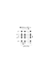
OCTアンギオグラフィーでは血流によるOCT干渉信号の時間変化を計測するため、同じ場所(または略同じ場所)で複数回の計測が必要となる。本実施形態ではOCT装置は同じ場所でのBスキャンをm回繰り返しつつ、n箇所のyポジションに移動するスキャンを行う。 In OCT angiography, the time change of the OCT interference signal due to blood flow is measured, so that multiple measurements are required at the same place (or substantially the same place). In the present embodiment, the OCT device repeats the B scan at the same place m times and performs a scan that moves to the y position at n locations.
具体的なスキャンパターンを図2に示す。眼底平面上でy1~ynのn箇所のyポジションについて、それぞれBスキャンを繰り返しm回づつ実施する。 A specific scan pattern is shown in FIG. B scan is repeated m times for each of n positions of y1 to yn on the fundus plane.
mが大きいと同じ場所での計測回数が増えるため、血流の検出精度が向上する。その一方でスキャン時間が長くなり、スキャン中の眼の動き(固視微動)により画像にモーションアーチファクトが発生する問題と被検者の負担が増える問題が生じる。本実施形態では両者のバランスを考慮してm=4として実施した。なお、OCT装置のAスキャン速度、被検体118の眼底表面画像の運動解析に応じて、制御部143はmを変更してもよい。
When m is large, the number of measurements at the same place increases, so that the accuracy of blood flow detection improves. On the other hand, the scanning time becomes long, and there arises a problem that motion artifacts occur in the image due to eye movements (fixed vision fine movements) during scanning and a problem that the burden on the subject increases. In this embodiment, m = 4 is carried out in consideration of the balance between the two. The
図2においてpは1つのBスキャンにおけるAスキャンのサンプリング数を示している。すなわち、p×nにより平面画像サイズが決定される。p×nが大きいと、同じ計測ピッチであれば広範囲がスキャンできるが、スキャン時間が長くなり、上述のモーションアーチファクトおよび患者負担の問題が生じる。本実施形態では両者のバランスを考慮してn=p=300として実施した。なお、上記n,pは適宜自由に変更が可能である。 In FIG. 2, p indicates the sampling number of A scan in one B scan. That is, the plane image size is determined by p × n. If p × n is large, a wide range can be scanned at the same measurement pitch, but the scanning time becomes long, and the above-mentioned motion artifact and patient burden problems occur. In this embodiment, n = p = 300 is carried out in consideration of the balance between the two. The above n and p can be freely changed as appropriate.
また、図2におけるΔxは隣り合うxポジションの間隔(xピッチ)であり、Δyは隣り合うyポジションの間隔(yピッチ)である。本実施形態ではxピッチ、yピッチは眼底における照射光のビームスポット径の1/2として決定し、10μmとする。xピッチ、yピッチを眼底上ビームスポット径の1/2とすることで生成する画像を高精細に形成することができる。xピッチ、yピッチを眼底ビームスポット径の1/2より小さくしても生成する画像の精細度をそれ以上高くする効果は小さい。 Further, Δx in FIG. 2 is an interval (x pitch) between adjacent x positions, and Δy is an interval (y pitch) between adjacent y positions. In the present embodiment, the x-pitch and y-pitch are determined as 1/2 of the beam spot diameter of the irradiation light in the fundus and set to 10 μm. By setting the x-pitch and y-pitch to 1/2 of the diameter of the beam spot on the fundus, it is possible to form a high-definition image. Even if the x-pitch and y-pitch are made smaller than 1/2 of the fundus beam spot diameter, the effect of further increasing the definition of the generated image is small.
逆にxピッチ、yピッチを眼底ビームスポット径の1/2より大きくすると精細度は悪化するが、小さなデータ容量で広い範囲の画像を取得することができる。臨床上の要求に応じてxピッチ、yピッチを自由に変更してもよい。 On the contrary, if the x-pitch and y-pitch are made larger than 1/2 of the fundus beam spot diameter, the definition is deteriorated, but a wide range of images can be acquired with a small data capacity. The x-pitch and y-pitch may be freely changed according to clinical requirements.
本実施形態のスキャン範囲は、x方向がp×Δx=3mm、y方向がn×Δy=3mmである。 The scan range of this embodiment is p × Δx = 3 mm in the x direction and n × Δy = 3 mm in the y direction.
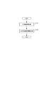
次に、図3を用いて本実施形態の画像形成方法の具体的な処理の手順を説明する。
ステップS101において、信号取得制御部145は光干渉断層像取得部100を制御し、光干渉断層信号を取得する。処理の詳細説明は後述する。ステップS102において、制御部143は表示情報を生成する。処理の詳細説明を、後述する。以上のステップを実施して、本実施形態の画像形成方法の処理の手順を終了する。
Next, a specific processing procedure of the image forming method of the present embodiment will be described with reference to FIG.
In step S101, the signal
[干渉信号取得手順]
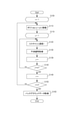
次に、図4を用いて本実施形態のステップS101の干渉信号取得の具体的な処理の手順を説明する。ステップS109において、信号取得制御部145は図2のポジションyiのインデックスiを1に設定する。ステップS110において、OCT装置はスキャン位置をyiに移動する。ステップS119において、信号取得制御部145は繰り返しBスキャンのインデックスjを1に設定する。ステップS120において、OCT装置はBスキャンを実施する。
[Interference signal acquisition procedure]
Next, a specific processing procedure for acquiring the interference signal in step S101 of the present embodiment will be described with reference to FIG. In step S109, the signal
ステップS130においてディテクタ141はAスキャン毎に干渉信号を検出し、不図示のA/D変換器を介して上記干渉信号が信号処理部144に記憶される。信号処理部144はAスキャンの干渉信号をpサンプル取得することで、1Bスキャン分の干渉信号とする。
ステップS139において、信号取得制御部145は繰り返しBスキャンのインデックスjをインクリメントする。
In step S130, the
In step S139, the signal
ステップS140において信号取得制御部145はjが所定回数(m)より大きいか判断する。すなわち、ポジションyiでのBスキャンがm回繰り返されたかを判断する。繰り返されてない場合はS120に戻り、同一位置のBスキャン計測を繰り返す。所定回数繰り返された場合は、S149に進む。ステップS149において、信号取得制御部145はポジションyiのインデックスiをインクリメントする。ステップS150において信号取得制御部145はiが所定のY位置の計測回数(n)より大きいか、すなわちn箇所の全てのyポジションでBスキャンを実施したかを判断する。所定のY位置の計測回数に満たない(no)の場合はS110に戻り、次の計測ポジションで計測することを繰り返す。所定のY位置の計測回数を終了した(yes)場合は、次ステップS160へ進む。
In step S140, the signal
ステップS160においてOCT装置はバックグラウンドデータを取得する。OCT装置はシャッター85を閉じた状態で100回Aスキャンを計測し、信号取得制御部145は100回のAスキャンを平均化して記憶する。なお、バックグラウンドの測定回数は100回に限るものではない。
In step S160, the OCT apparatus acquires background data. The
以上のステップを実施して、本実施形態における干渉信号取得手順を終了することになる。 By carrying out the above steps, the interference signal acquisition procedure in the present embodiment is completed.
[信号処理手順]
次に、図5を用いて本実施形態のステップS102の3次元血流部位情報生成の具体的な処理を説明する。
[Signal processing procedure]
Next, a specific process for generating three-dimensional blood flow site information in step S102 of the present embodiment will be described with reference to FIG.
本実施形態では、OCTアンギオグラフィー情報から3次元血流部位情報を生成するために、OCTアンギオグラフィーのモーションコントラストを計算する必要がある。 In this embodiment, it is necessary to calculate the motion contrast of the OCT angiography in order to generate the three-dimensional blood flow site information from the OCT angiography information.
ここでモーションコントラストとは、被験体組織のうち流れのある組織(例えば血液)と流れのない組織の間の対比と定義する。モーションコントラストを表現する特徴量を単にモーションコントラスト(或いはモーションコントラスト特徴量、モーションコントラスト値)と定義する。モーションコントラストについては後述する。 Here, motion contrast is defined as a contrast between a flowing tissue (for example, blood) and a non-flowing tissue among the subject tissues. The feature amount expressing the motion contrast is simply defined as the motion contrast (or the motion contrast feature amount, the motion contrast value). The motion contrast will be described later.
ステップS210において、信号処理部144はポジションyiのインデックスiを1に設定する。ステップS220において、信号処理部144はポジションyiにおける繰り返しBスキャン干渉信号(m回分)を抜き出す。ステップS230において、信号処理部144は繰り返しBスキャンのインデックスjを1に設定する。ステップS240において、信号処理部144はj番目のBスキャンデータを抜き出す。
In step S210, the
ステップS250において、信号処理部144はステップS240のBスキャンデータの干渉信号に対して、一般的な再構成処理を行うことで断層像の輝度画像を生成する。
In step S250, the
まず画像生成部147は、干渉信号からバックグラウンドデータからなる固定パターンノイズ除去を行う。固定パターンノイズ除去は検出した複数のバックグラウンドデータのAスキャン信号を平均することで固定パターンノイズを抽出し、これを入力した干渉信号から減算することで行われる。次に、画像生成部147は、有限区間でフーリエ変換した場合にトレードオフの関係となる、深さ分解能とダイナミックレンジとを最適化するために、所望の窓関数処理を行う。その後、FFT処理を行う事によって断層像の輝度画像を生成する。ステップS260において、信号処理部144は繰り返しBスキャンのインデックスjをインクリメントする。ステップS270において信号処理部144がmより大きいか判断する。すなわち、ポジションyiでのBスキャンの輝度計算がm回繰り返されたかを判断する。noの場合はステップS240に戻り、同一Y位置での繰り返しBスキャンの輝度計算を繰り返す。すなわち、画像生成部147は、それぞれ被検体の略同一箇所における断層を示す被検体の複数の断層像データ(断層像)を取得する。
First, the
一方、ステップS270でyesと判断された場合は、ステップS280へ進む。ステップS280において信号処理部144はあるyiポジションにおける繰り返しBスキャンのmフレームを位置合わせする。具体的には、まず信号処理部144はmフレームのうち、任意の1枚をテンプレートとして選択する。テンプレートとして選択するフレームは、互いに全ての組み合わせで相関を計算し、フレーム別に相関係数の和を求め、その和が最大となるフレームを選択してもよい。次に、信号処理部144はテンプレートでフレーム毎に照合し位置ずれ量(δX、δY、δθ)を求める。具体的には、信号処理部144はテンプレート画像の位置と角度を変えながら類似度を表す指標であるNormalized Cross-Correlation(NCC)を計算し、この値が最大となるときの画像位置の差を位置ずれ量として求める。
On the other hand, if yes is determined in step S270, the process proceeds to step S280. In step S280, the
なお、本発明では、類似度を表す指標は、テンプレートとフレーム内の画像の特徴の類似性を表す尺度であれば種々変更が可能である。例えばSum of AbusoluteDifference(SAD)、Sum of Squared Difference(SSD)、Zero-means Normalized Cross-Correlation(ZNCC)を用いてもよい。また、Phase Only Correlation(POC)、Rotation Invariant Phase Only Correlation(RIPOC)等を用いてもよい。 In the present invention, the index indicating the degree of similarity can be variously changed as long as it is a scale indicating the similarity between the features of the template and the image in the frame. For example, Sum of Absolute Difference (SAD), Sum of Squared Difference (SSD), Zero-means Normalized Cross-Correlation (ZNCC) may be used. Further, Phase Only Correlation (POC), Rotation Invariant Phase Only Correlation (RIPOC) and the like may be used.
次に信号処理部144は位置ずれ量(δX、δY、δθ)に応じて位置補正をテンプレート以外のm-1フレームに適用し、mフレームの位置合わせを行う。
Next, the
ステップS290において信号処理部144はステップS280で計算した位置合わせされた輝度画像を平均化し、輝度平均化画像を生成する。
In step S290, the
ステップS300においてマップ生成部148は、信号処理部144がステップS290で生成した輝度平均化画像から、網膜のセグメンテーション(部位情報取得)をする工程であるが、第1の実施形態ではこの工程は使用しないため本工程はスキップされる。説明は第2の実施形態で行う。
In step S300, the
ステップS310において画像生成部147はモーションコントラストを計算する。本実施例ではステップS300にて信号処理部144が出力したmフレームの断層像の輝度画像から同じ位置のピクセルごとに信号強度(輝度)の分散値を計算し、その分散値をモーションコントラストとする。すなわち、画像生成部147は算出された複数の断層像データ間の対応する画素データを用いてモーションコントラストを算出する。なお、分散値以外に、標準偏差、差分値、非相関値および相関値の何れを用いることとしてもよい。また、信号強度ではなく位相を用いることとしてもよい。
In step S310, the
なお、モーションコントラストの求め方は種々あり、本発明においてモーションコントラストの特徴量の種類は同一Y位置での複数Bスキャン像の各ピクセルの輝度値の変化を表す指標であれば適用が可能である。また、モーションコントラストはmフレームの断層像の輝度画像から同じ位置のピクセルごとに分散値の変わりに、各フレームの同ピクセルごとの平均値で正規化した変動係数を用いることも可能である。この場合、網膜の構造を示すピクセル値にモーションコントラストが独立となりより感度の高いモーションコントラストを得ることが可能となる。しかし、その反面モーションコントラストは位置合わせ誤差・カメラノイズ等の種々要因により低い画素値におけるノイズ成分が相対的に強調される。そのため、例えば毛細血管をあまり含まない層において、ノイズと血流領域の切り分けが困難となる。このため本発明の画像処理方法はよりいっそう効果的に作用する。 There are various methods for obtaining the motion contrast, and in the present invention, the type of the feature amount of the motion contrast can be applied as long as it is an index showing the change in the luminance value of each pixel of the plurality of B scan images at the same Y position. .. Further, for the motion contrast, it is also possible to use a coefficient of variation normalized by the average value for each pixel of each frame instead of the variance value for each pixel at the same position from the luminance image of the tomographic image of m frame. In this case, the motion contrast becomes independent of the pixel value indicating the structure of the retina, and it becomes possible to obtain a more sensitive motion contrast. However, on the other hand, in the motion contrast, the noise component at a low pixel value is relatively emphasized due to various factors such as alignment error and camera noise. Therefore, for example, in a layer containing few capillaries, it becomes difficult to separate the noise and the blood flow region. Therefore, the image processing method of the present invention works even more effectively.
ステップS320において信号処理部144は、信号処理部144で出力したモーションコントラストの第一の閾値処理をする。第一閾値の値は信号処理部144がステップS311で出力した輝度平均化画像から、ノイズフロアでランダムノイズのみが表示されているエリアを抽出し、標準偏差σを計算し、ノイズフロアの平均輝度+2σと設定する。信号処理部144は、各輝度が、上記閾値以下の領域に対応したモーションコントラストの値を0に設定する。
In step S320, the
S320の第一閾値処理により、ランダムノイズによる輝度変化に由来するモーションコントラストを除去することでノイズを軽減することができる。 By the first threshold processing of S320, noise can be reduced by removing the motion contrast caused by the change in luminance due to random noise.
なお、第一閾値の値は、小さいほどモーションコントラストの検出感度は上がる一方、ノイズ成分も増す。また、大きいほどノイズは減るがモーションコントラスト検出の感度は下がる。 The smaller the value of the first threshold value, the higher the detection sensitivity of the motion contrast, but also the noise component. Also, the larger the value, the less noise, but the lower the sensitivity of motion contrast detection.
本実施形態では閾値をノイズフロアの平均輝度+2σとして設定したが、閾値はこれに限るものではない。 In the present embodiment, the threshold value is set as the average brightness of the noise floor + 2σ, but the threshold value is not limited to this.
ステップS330において信号処理部144は、ポジションyiのインデックスiをインクリメントする。
In step S330, the
ステップS340において信号処理部144は、iがnより大きいか判断する。すなわち、n箇所の全てのyポジションで位置合わせ、輝度画像平均化計算、モーションコントラストの計算、及び閾値処理をしたかを判断する。noの場合はS220に戻る。yesの場合は、次ステップS350へ進む。
In step S340, the
S340を終了した時点で、すべてのY位置でのBスキャン像(Z深さvs X方向データ)の各ピクセルの輝度平均画像とモーションコントラストの3次元データが取得されたこととなる。なお、複数のY位置でのBスキャン像は3次元の断層像データに相当する。 At the end of S340, the brightness average image of each pixel of the B scan image (Z depth vs. X direction data) at all Y positions and the three-dimensional data of the motion contrast are acquired. The B scan images at the plurality of Y positions correspond to the three-dimensional tomographic image data.
ステップS350において信号処理部144は、モーションコントラストの3次元データを用いて表示情報生成処理を行う。図6は、ステップS350の詳細を示したものである。
In step S350, the
ステップS351において信号処理部144は、先にもとめたモーションコントラストの3次元データを取得する。
In step S351, the
ステップS352において信号処理部144は、血流部位情報は残しつつノイズを除去するために、モーションコントラスト3次元データに対して平滑化処理を施す。
モーションコントラストの性質によって最適な平滑化処理は異なるが、例えば以下のようなものが考えられる。
In step S352, the
The optimum smoothing process differs depending on the nature of the motion contrast, but the following can be considered, for example.
注目画素の近傍nx×ny×nz個のボクセルからモーションコントラストの最大値を出力する平滑化方法。あるいは、注目画素の近傍nx×ny×nz個のボクセルのモーションコントラストの平均値を出力する平滑化方法。あるいは、注目画素の近傍nx×ny×nz個のボクセルのモーションコントラストの中央値を出力する平滑化方法。あるいは、注目画素の近傍nx×ny×nz個のボクセルのモーションコントラストに対して、距離による重みをつける平滑化方法。あるいは、注目画素の近傍nx×ny×nz個のボクセルのモーションコントラストに対して、距離による重みと注目画素との画素値の差に応じて重みをつける平滑化方法。あるいは、注目画素のまわりの小領域のモーションコントラストパターンと、周辺画素のまわりの小領域のモーションコントラストのパターンの類似度に応じた重みを用いた値を出力する平滑化方法。 A smoothing method that outputs the maximum value of motion contrast from nx × ny × nz voxels in the vicinity of the pixel of interest. Alternatively, a smoothing method that outputs the average value of the motion contrasts of nx × ny × nz voxels in the vicinity of the pixel of interest. Alternatively, a smoothing method that outputs the median value of the motion contrast of nx × ny × nz voxels in the vicinity of the pixel of interest. Alternatively, a smoothing method in which the motion contrast of nx × ny × nz voxels in the vicinity of the pixel of interest is weighted by a distance. Alternatively, a smoothing method in which the motion contrast of nx × ny × nz voxels in the vicinity of the pixel of interest is weighted according to the difference between the weight due to the distance and the pixel value of the pixel of interest. Alternatively, a smoothing method that outputs a value using weights according to the similarity between the motion contrast pattern of a small area around a pixel of interest and the motion contrast pattern of a small area around a peripheral pixel.
なお、その他の血流部位情報を残しつつ平滑化をおこなう手法を用いてもよい。 In addition, a method of smoothing while leaving other blood flow site information may be used.
ステップS353において信号処理部144は、表示制御部149より、ステップS353にて表示する画素を決定する閾値及び表示する深さ方向の範囲の初期値を得る。表示範囲の初期値としては通例深さ方向の1/4程度としほぼ網膜表層の範囲が含まれる位置とされる。ここで表示範囲の初期値として深さ方向全範囲としないのは、表層部における主要血管・毛細血管網をまずは見やすく表示したいからである。すなわち、主要血管・毛細血管網を含む表層部と血管を有さずノイズの大きいRPE層とを同時に表示すると、表層部における主要血管・毛細血管網の判別に支障をきたすのである。尚、表示閾値の初期値の決定法は後述する。
In step S353, the
次にステップ354にて、表示閾値の初期値を用い平滑化処理された3次元データに対してこれを超える画素を表示する表示閾値処理を施す。本処理によるモーションコントラスト画素値から表示用画素値への変換例を図7に示す。図7(a)では表示閾値以下の画素値をゼロ、閾値上の画素値から最大強度までの画素に比例する表示画素値を割り振る例であり、図7(b)では表示閾値以下の画素値に対し0をかけ、それ以上の画素値は1をかけた表示値を割り振った例となる。いずれにしろモーションコントラストが表示閾値以下のものはモーションコントラストが無効化され、表示される連結を持つモーションコントラストを持つ領域が分離した形で表示されることになる。すなわち、モーションコントラストと閾値との比較結果に応じてモーションコントラストの値が制御される。ステップS354における処理はモーションコントラストと閾値とを比較する工程および比較の結果に基づいて閾値以下のモーションコントラストを無効化する工程の一例に相当する。 Next, in step 354, a display threshold value process for displaying pixels exceeding the smoothed three-dimensional data using the initial value of the display threshold value is performed. FIG. 7 shows an example of conversion from the motion contrast pixel value to the display pixel value by this processing. FIG. 7 (a) shows an example in which a pixel value below the display threshold is set to zero, and a display pixel value proportional to the pixels from the pixel value on the threshold to the maximum intensity is assigned. In FIG. 7 (b), the pixel value below the display threshold is assigned. Is multiplied by 0, and the pixel values beyond that are multiplied by 1, which is an example of allocating the display value. In any case, if the motion contrast is equal to or less than the display threshold value, the motion contrast is invalidated, and the area having the motion contrast to be displayed is displayed in a separated form. That is, the value of the motion contrast is controlled according to the comparison result between the motion contrast and the threshold value. The process in step S354 corresponds to an example of a step of comparing the motion contrast and the threshold value and a step of invalidating the motion contrast below the threshold value based on the result of the comparison.
ステップS355では、図7に示した表示閾値処理されたモーションコントラスト画像を表示制御部149が表示部146に表示させる。すなわち、ステップS355における処理は、無効化する工程が行われた後に、モーションコントラストに基づいてモーションコントラスト画像を生成する工程の一例に相当する。例えば表示工程ステップ355は、図8(b)に示すGUI及び3次元モーションコントラスト画像を表示するよう設計され、表示部146上にそれらを表示する。400は表示部146に用意された平行四辺形領域であり、算出された3次元モーションコントラスト画像を投影表示するための表示領域枠である。その側方には表示する3次元モーションコントラスト画像を表示する深さ方向の範囲を調整するスライダ407が表示される。検者はスライダ407の操作部端である401、402を例えばマウスでドラッグすることにより、表示部149に表示する3次元モーションコントラスト画像の深さ方向の範囲を指定することが出来る。また、スライダ407の操作部の例えば中央部をドラッグすることにより、表示する深さ範囲の幅を変えることなく表示される深さ位置を変えることが出来る。図8(a)には対応する深さの説明のために、3次元モーションコントラスト画像の一断層像を併記した。断層像上の輝線403,404はスライダ端401,402に対応する断層像上の位置である。表示工程は両輝線間にはさまれた領域405のモーションコントラスト画像のみを表示領域枠401に表示する。例えば、表示制御部149は表示部149に図8(a)、(b)に示した全ての画像を表示させることとしてもよいし、図8(b)に示した画像のみを表示させることとしてよい。
In step S355, the
また、この表示領域枠400の下方にはもうひとつのスライダ406が表示する画素を決定する閾値を調整するために設けられている。検者がこのスライダを例えばマウスでドラッグすると、図6のステップS356では表示閾値を変更し、ステップS354へ処理を戻し表示する3次元モーションコントラスト画像を更新することになる。ステップS356の処理は閾値を変更する工程の一例に相当する。また、ステップS354,355が繰返し実行されることは、閾値の変更に応じてモーションコントラスト画像を生成する工程とモーションコントラスト画像を表示する工程とが繰返し実行されることに相当する。
Further, below the
この時、閾値の調整は初期値に対する相対値で変更できるよう設定しておくと、異なる被検眼・部位等対象の異なるデータに対しても等価な効果が得られる。以上の構成により検者は表示する深さ範囲を随意に変更することが可能となり、かつその選択された深さ範囲に最適な表示閾値を設定することが可能となる。また同様に検者が深さ方向の表示範囲を変更するためにスライダ操作部端である401、402をマウスでドラッグすると、ステップS357は表示する範囲を変更する。そして、ステップS354へ処理を戻し表示する3次元モーションコントラスト画像を更新することになる。すなわち、表示範囲の変更に応じて表示されるモーションコントラスト画像が更新される。ここで、ステップS357の処理はモーションコントラスト画像の深さ方向の表示範囲を設定する工程の一例に相当する。さらに、ステップS357が実行された後にステップS355が実行されることは、設定された表示範囲に基づいてモーションコントラスト画像を表示する工程の一例に相当する。 At this time, if the threshold value adjustment is set so that it can be changed by a relative value with respect to the initial value, an equivalent effect can be obtained for different data of different subjects such as different eyes and sites. With the above configuration, the examiner can arbitrarily change the display depth range, and can set the optimum display threshold value for the selected depth range. Similarly, when the examiner drags the slider operation unit ends 401 and 402 with the mouse to change the display range in the depth direction, step S357 changes the display range. Then, the process is returned to step S354 to update the three-dimensional motion contrast image to be displayed. That is, the motion contrast image displayed is updated according to the change in the display range. Here, the process of step S357 corresponds to an example of a step of setting a display range in the depth direction of a motion contrast image. Further, the execution of step S355 after the execution of step S357 corresponds to an example of a step of displaying a motion contrast image based on a set display range.
以上の説明では、図8(a)に示した断層像は説明のためにのみ用いたが、表示工程でこの断層像を同時に表示すれば、検者が表示する深さ範囲の設定を容易に行えるようになり、より好適である。さらに断層像は深さ方向を明示するために表示領域枠400の側方に設けることが望ましい。また、表示する断層像に対応する位置を3次元モーションコントラスト画像に重ねて表示することが望ましい。例えば、表表示制御部149は3次元モーションコントラスト画像上に断層像に対応するラインを重ねて表示させることとしてもよい。
In the above explanation, the tomographic image shown in FIG. 8A is used only for explanation, but if this tomographic image is displayed at the same time in the display step, it is easy for the examiner to set the depth range to be displayed. It becomes possible to do it, and it is more suitable. Further, it is desirable that the tomographic image is provided on the side of the
図9は上記選択された深さ範囲の3次元モーションコントラスト画像の各画素値を深さ方向に投影または積算することにより生成された2次元モーションコントラスト画像の一例を示す図である。 FIG. 9 is a diagram showing an example of a two-dimensional motion contrast image generated by projecting or integrating each pixel value of the three-dimensional motion contrast image in the selected depth range in the depth direction.
上記の実施形態においては図8(b)に示すように3次元モーションコントラスト画像を表示させることとしたが、これに限定されるものではなく2次元モーションコントラスト画像を表示させることとしてもよい。例えば、3次元モーションコントラスト画像に代えて2次元モーションコントラスト画像を表示させることとしてもよいし、両者を同時に表示させることとしてもよい。 In the above embodiment, the three-dimensional motion contrast image is displayed as shown in FIG. 8B, but the present invention is not limited to this, and the two-dimensional motion contrast image may be displayed. For example, a two-dimensional motion contrast image may be displayed instead of the three-dimensional motion contrast image, or both may be displayed at the same time.
2次元モーションコントラスト画像を生成するには対応する画素のモーションコントラスト値を積算する他、最大値、最小値、中央値等の代表値を抽出し投影することでも可能である。ここでは積算した場合の二次元モーションコントラスト画像の例を図9に示す。もちろん検者が図8に示したスライダ406を操作することにより表示閾値は同様に変更することが可能である。図9(b)は閾値が経験的に最適となると考えられた初期値の場合、(a)は(b)より閾値を下げた場合、(c)は(b)より閾値を上げた場合に相当する。(a)ではノイズが現れ血流部位の構造把握には不適といえるが、微細血流部位構造の把握には(b)が好適、また従来の蛍光眼底撮影写真と比較するような場合には(c)の如き画像が好まれよう。
In order to generate a two-dimensional motion contrast image, it is possible not only to integrate the motion contrast values of the corresponding pixels, but also to extract and project representative values such as the maximum value, the minimum value, and the median value. Here, FIG. 9 shows an example of a two-dimensional motion contrast image when integrated. Of course, the display threshold can be changed in the same manner by the examiner operating the
ここで、閾値を自動的に決定する方法について図10を用いて説明する。図10(a)はある深さ範囲が選択された場合、その範囲にあるモーションコントラストのヒストグラムを取ったものであり、低輝度側にノイズのピークN1、高輝度側に血流領域の信号のピークが観測される。表示閾値工程ではこの2つのピークの交点に相当するTh1を表示閾値の初期値となるようにプログラムされる。もちろん経験的に一定の割合、もしくは一定量のシフトを与えておくことも可能である。図10(b),(c)は検者が表示する深さ方向の範囲を変更した場合のヒストグラムの変化を示す。血流が少ない範囲を選択した場合が(b)であり、血流の多い範囲を選択した場合に(c)のごとく、ノイズN2・N3・血流領域の信号のピークS2・S3はそれぞれ移動し、それに適した表示閾値の初期値Th2・Th3が設定される。すなわち、モーションコントラスト画像の表示範囲に連動して自動的に表示閾値が変更される。このように、本実施形態によれば、所定領域のモーションコントラストのヒストグラムからモーション領域と非モーション領域を推定し、モーション領域のヒストグラムおよび非モーション領域のヒストグラムから閾値を決定することができる。 Here, a method of automatically determining the threshold value will be described with reference to FIG. FIG. 10A is a histogram of the motion contrast in a certain depth range selected, and the noise peak N1 is on the low-luminance side and the signal in the blood flow region is on the high-luminance side. A peak is observed. In the display threshold step, Th1 corresponding to the intersection of these two peaks is programmed to be the initial value of the display threshold. Of course, it is also possible to give a certain ratio or a certain amount of shift empirically. FIGS. 10 (b) and 10 (c) show changes in the histogram when the range in the depth direction displayed by the examiner is changed. When the range with low blood flow is selected, it is (b), and when the range with high blood flow is selected, the noise N2, N3, and the signal peaks S2 and S3 in the blood flow region move, respectively, as in (c). Then, the initial values Th2 and Th3 of the display threshold value suitable for it are set. That is, the display threshold value is automatically changed in conjunction with the display range of the motion contrast image. As described above, according to the present embodiment, the motion region and the non-motion region can be estimated from the histogram of the motion contrast of the predetermined region, and the threshold value can be determined from the histogram of the motion region and the histogram of the non-motion region.
以上、対象領域である深さ方向の表示範囲にあるモーションコントラストのヒストグラムを用い、対象領域に対しして一律の閾値を決定する方法について説明を行ったが、これに限定されるものではない。例えば同領域に対して閾値を一律に設けず、同表示領域の所定領域に対し、モーションコントラストの平均値と分散に基づいて決定する等の局所的決定法を用いることも可能である。 The method of determining a uniform threshold value for the target area using the motion contrast histogram in the display range in the depth direction, which is the target area, has been described above, but the present invention is not limited to this. For example, it is also possible to use a local determination method such as determining a predetermined region of the same display region based on the average value and the variance of the motion contrast without uniformly setting the threshold value for the same region.
もちろん前述のごとく検者がスライダ406を操作した場合、その値を記憶し、それ以降の表示の閾値とすることも可能であるし、またさらに初期設定へ戻すスイッチを別途も設けることも可能である。
Of course, when the examiner operates the
上記の実施形態によれば、OCTアンギオグラフィーを構成するモーションコントラストデータに対し適切な表示閾値を可変または複数とすることにより、モーションコントラスト算出におけるノイズを除去し、より見やすい血流部位情報を迅速に提供することが可能になる。 According to the above embodiment, by making the appropriate display threshold value variable or plural for the motion contrast data constituting the OCT angiography, noise in the motion contrast calculation is removed, and blood flow site information that is easier to see can be quickly obtained. It will be possible to provide.
また、前記モーションコントラストを算出する工程に、モーションコントラストを前記算出に用いた複数の断層像データの対応する画素データの平均値を用いて正規化する工程をさらに有することによって発生するモーションコントラスト算出におけるノイズを効果的に除去することが可能となる。 Further, in the motion contrast calculation generated by further including a step of normalizing the motion contrast by using the average value of the corresponding pixel data of the plurality of tomographic image data used in the calculation in the step of calculating the motion contrast. It is possible to effectively remove noise.
さらに、算出されたモーションコントラスト画像の表示に際し、深さ方向の表示範囲を設定することにより、表示範囲を簡単に変更可能でかつ適切な表示閾値が設定可能となる。 Further, when displaying the calculated motion contrast image, by setting the display range in the depth direction, the display range can be easily changed and an appropriate display threshold value can be set.
また、その表示設定範囲を断層像深さ方向の所定幅に制限することによってモーションコントラスト画像の不要な重なり部分を除去できるため、理解しやすい画像を教示することが出来る。すなわち、本実施形態では、設定可能な表示範囲が深さ方向の所定の幅に制限可能となっている。 Further, by limiting the display setting range to a predetermined width in the tomographic image depth direction, unnecessary overlapping portions of the motion contrast image can be removed, so that an easy-to-understand image can be taught. That is, in the present embodiment, the settable display range can be limited to a predetermined width in the depth direction.
この場合、3次元断層像データから被検眼の断層像の層構造を検出する工程をさらに設けることにより、深さ方向の表示範囲を被検眼網膜の構造に従って選択・制限することが可能となり、被検眼の解剖学的構造に従った表示処理が可能となり、より効果的である。 In this case, by further providing a step of detecting the layer structure of the tomographic image of the eye to be inspected from the three-dimensional tomographic image data, it becomes possible to select and limit the display range in the depth direction according to the structure of the retina of the inspected eye. Display processing according to the anatomical structure of the optometry becomes possible, which is more effective.
さらに、上記表示範囲の選択に従って、3次元モーションコントラストを投影・積算して2次元モーションコントラスト画像を生成すれば、より直感的に理解しやすいモーションコントラスト画像を提供することが出来る。 Further, if a two-dimensional motion contrast image is generated by projecting and integrating the three-dimensional motion contrast according to the selection of the display range, it is possible to provide a motion contrast image that is easier to understand more intuitively.
また、表示手段はモーションコントラスト画像で指定した位置に対応する位置の断層像を3次元モーションコントラストから選択または生成して表示すれば、現在どの層に関する情報を表示しているかの同定をより直感的に行うことが出来る。すなわち、本実施形態では、モーションコントラスト画像を表示する工程において、モーションコントラスト画像上で指定した位置に対応する位置の断層像を3次元モーションコントラストから選択または生成して表示する。 In addition, if the display means selects or generates a tomographic image of the position corresponding to the position specified in the motion contrast image from the three-dimensional motion contrast and displays it, it is more intuitive to identify which layer the information is currently displayed. Can be done. That is, in the present embodiment, in the step of displaying the motion contrast image, the tomographic image of the position corresponding to the position designated on the motion contrast image is selected or generated from the three-dimensional motion contrast and displayed.
さらに、所定領域の閾値は、閾値が適用されるモーションコントラスト画像各画素の周辺画素のモーションコントラスト値に基づいて適応的に決定することができる。例えば所定領域のモーションコントラストのヒストグラムからモーション領域と非モーション領域を推定し各領域のヒストグラムから閾値を適応的に決定できる。または、所定領域のモーションコントラストの平均値と分散に基づいて局所的に閾値を決定することができる。従って、より見やすく且つ理解のしやすいモーションコントラスト画像を提供することが出来る。 Further, the threshold value in the predetermined region can be adaptively determined based on the motion contrast value of the peripheral pixels of each pixel of the motion contrast image to which the threshold value is applied. For example, the motion region and the non-motion region can be estimated from the motion contrast histogram of the predetermined region, and the threshold value can be adaptively determined from the histogram of each region. Alternatively, the threshold can be determined locally based on the mean value and variance of the motion contrast in a predetermined area. Therefore, it is possible to provide a motion contrast image that is easier to see and understand.
〔第2の実施形態〕
上述の第1の実施形態では、検査者が深さ方向の表示範囲を直接選択する形態を示したが、撮像対象である被検眼の眼底は図11に示すように層構造を有することが広く知られている。また、深さ方向の網膜層ごとに血管密度が異なることを考慮すると、層ごとに血流部位検出のための閾値を可変にすることが好ましい。第1の実施形態では使用しなかった図5ステップS300はこの層構造をセグメンテーションする工程であり、本実施形態では6層を検出することが可能である。すなわち、ステップS300における処理は断層像データから層を検出する工程の一例に相当する。なお、検出する層の数は6層に限定されるものではない。ここで、6層の内訳は、(1)神経線維層(NFL) 、(2)神経節細胞層(GCL)+内網状層(IPL)を合わせた層、(3)内顆粒層(INL)+外網状層(OPL) を合わせた層、(4)外顆粒層(ONL)+外境界膜(ELM)を合わせた層、(5)Ellipsoid Zone(EZ) + Interdigitation Zone(IZ)+ 網膜色素上皮(RPE)を合わせた層、(6)脈絡膜(Choroid)である。
[Second Embodiment]
In the first embodiment described above, the examiner directly selects the display range in the depth direction, but the fundus of the eye to be imaged has a layered structure as shown in FIG. Are known. Further, considering that the blood vessel density differs for each retinal layer in the depth direction, it is preferable to make the threshold value for detecting the blood flow site variable for each layer. FIG. 5 step S300, which was not used in the first embodiment, is a step of segmenting this layer structure, and in this embodiment, six layers can be detected. That is, the process in step S300 corresponds to an example of a step of detecting a layer from tomographic image data. The number of layers to be detected is not limited to six. Here, the breakdown of the 6 layers is (1) a layer combining (1) a nerve fiber layer (NFL), (2) a ganglion cell layer (GCL) + an inner plexiform layer (IPL), and (3) an inner nuclear layer (INL). + Outer plexiform layer (OPL) combined layer, (4) Outer nuclear layer (ONL) + External limiting membrane (ELM) combined layer, (5) Ellipside Zone (EZ) + Interdiction Zone (IZ) + Retinal pigment A layer combined with epithelium (RPE), (6) Choroid.
本実施形態におけるステップS102の3次元血流部位情報の生成の具体的な処理は図5に示した第1の実施形態とほぼ同様であるため詳細な説明は省略する。ここでは、特徴的なステップS300における網膜のセグメンテーションについて以下に説明する。 Since the specific process of generating the three-dimensional blood flow site information in step S102 in this embodiment is almost the same as that of the first embodiment shown in FIG. 5, detailed description thereof will be omitted. Here, the segmentation of the retina in the characteristic step S300 will be described below.
マップ生成部148は、輝度平均化画像から抜き出した処理の対象とする断層像に対して、メディアンフィルタとSobelフィルタをそれぞれ適用して画像を作成する(以下、それぞれメディアン画像、Sobel画像ともいう)。次に、作成したメディアン画像とSobel画像から、Aスキャン毎にプロファイルを作成する。メディアン画像では輝度値のプロファイル、Sobel画像では勾配のプロファイルとなる。そして、Sobel画像から作成したプロファイル内のピークを検出する。検出したピークの前後やピーク間に対応するメディアン画像のプロファイルを参照することで、網膜層の各領域の境界を抽出する。ステップS300によって得られたセグメンテーション結果はここで一度保持され、以下の第一の実施例と同様に処理が行われた後、ステップ350の表示情報生成工程が行われる。
The
第2の実施形態におけるステップ350の表示情報生成工程について図12を用いて説明する。第2の実施形態においては、モーションコントラスト画像の深さ方向の表示範囲の設定が、ステップS300における網膜のセグメンテーションの結果に基づいた層の選択により行われることが特徴である。すなわち、検出された層に基づいて表示範囲を選択することが可能である。 The display information generation step of step 350 in the second embodiment will be described with reference to FIG. The second embodiment is characterized in that the setting of the display range in the depth direction of the motion contrast image is performed by selecting the layer based on the result of the segmentation of the retina in step S300. That is, it is possible to select the display range based on the detected layer.
図12は、ステップS350の詳細を示したものである。ただし、基本はやはり第1の実施形態と同様である。すなわち、ステップS351においてモーションコントラストの3次元データを取得し、ステップS352において血流部位情報は残しつつノイズを除去するために、モーションコントラスト3次元データに対して平滑化処理を施す。 FIG. 12 shows the details of step S350. However, the basics are the same as those in the first embodiment. That is, in step S351, three-dimensional motion contrast data is acquired, and in step S352, smoothing processing is performed on the three-dimensional motion contrast data in order to remove noise while retaining the blood flow site information.
次にステップS353において信号処理部144は、ステップS353にて表示する画素を決定するための表示閾値及び表示する層の初期値を得る。表示閾値の初期値の決定法は第1の実施形態と同様であるが、表示範囲の初期値としては例えば、表層からの4層、すなわち神経線維層(NFL) 、神経節細胞層(GCL)、内網状層(IPL)、内顆粒層(INL)が設定される。なお、初期値として表層からの4層から少なくとも3層を選択することとしてもよい。但し、複数の層を初期値として選択する場合には連続する層であることが望ましい。なお、網膜層のセグメンテーションにより分離できない層の場合はその合成層として表記されるものが望ましい。ここで表示範囲の初期値として網膜層全層としないのは、表層部における主要血管・毛細血管網をまずは見やすく表示したいからである。すなわち、主要血管・毛細血管網を含む表層部と血管を有さずノイズの大きいRPE層とを同時に表示すると、表層部における主要血管・毛細血管網の判別に支障をきたすのである。
Next, in step S353, the
次にステップS354にて、同初期値を用い平滑化処理された3次元データに対してこれを超える画素を表示する表示閾値処理を施す。その後、ステップS355では、図13に示すような、表示閾値処理されたモーションコントラスト画像を表示する工程が行われる。例えば図13に示すごとく2次元モーションコントラスト画像71、その側方に2次元モーションコントラスト画像71上に示されたマーカA-A‘の位置の断層像72とその他のGUI73が表示制御部149により表示部146に表示される。
Next, in step S354, display threshold processing for displaying pixels exceeding this is performed on the three-dimensional data smoothed using the same initial value. After that, in step S355, a step of displaying the motion contrast image processed by the display threshold value as shown in FIG. 13 is performed. For example, as shown in FIG. 13, the two-dimensional
断層像72の側方にはさらにその他のGUI73が設けられている。その構成は右から、2次元モーションコントラスト画像表示に利用する網膜層の名称、それを選択するためのチェックボックス、さらに選択した層に対するそれぞれの表示画素を決定する閾値を調整するためスライダが設けられている。検者がこのスライダをマウスでドラッグすると、図12ステップS356では表示閾値を変更し、ステップS354へ処理を戻し表示する2次元モーションコントラスト画像を更新する。すなわち、GUI73に示すように本実施形態では閾値は検出された層毎に設定されている。
また検者が層の選択を変更するためにチェックボックスのチェックを変更する(第一実施例の深さ方向の表示範囲の変更に相当する。)と、ステップS357ではモーションコントラスト画像の表示する範囲を変更し、ステップS354へ処理を戻し表示する2次元モーションコントラスト画像を更新することになる。 Further, when the examiner changes the check of the check box to change the layer selection (corresponding to the change of the display range in the depth direction of the first embodiment), in step S357, the display range of the motion contrast image is changed. Is changed, and the process is returned to step S354 to update the two-dimensional motion contrast image to be displayed.
この時、層の選択の数は例えば5層までと制限がかけると共に、網膜上部層の選択した場合(例えば、神経線維層(NFL) 、神経節細胞層(GCL)、内網状層(IPL)、内顆粒層(INL)、外網状層(OPL) 、外顆粒層(ONL)、外境界膜(ELM)のいずれか)少なくともEllipsoid Zone(EZ)、 Interdigitation Zone(IZ)、RPE層と脈絡膜のひとつを選択不能とする。もしくは網膜下部層を選択した場合(例えば、内顆粒層(INL)、外網状層(OPL)、外顆粒層(ONL)、外境界膜(ELM)、Ellipsoid Zone(EZ)、 Interdigitation Zone(IZ)、網膜色素上皮(RPE)層、脈絡膜のいずれか)少なくとも神経線維層(NFL) 、神経節細胞層(GCL)、内網状層(IPL)、内顆粒層(INL)、外網状層(OPL) 、外顆粒層(ONL)、外境界膜(ELM)のひとつを選択不能とする制御も表示するモーションコントラスト画像の診断価値を維持する上で有効である。上述のように本実施形態では、表示範囲の設定において、検出された層に基づいて任意の層を選択可能であるとともに、選択可能な層の数を制限可能である。 At this time, the number of layer selections is limited to, for example, 5 layers, and when the upper retinal layer is selected (for example, nerve fiber layer (NFL), ganglion cell layer (GCL), inner plexiform layer (IPL)). , Inner nuclear layer (INL), Outer plexiform layer (OPL), Outer plexiform layer (ONL), External limiting membrane (ELM)) At least Ellipside Zone (EZ), Interdictionation Zone (IZ), RPE layer and choroid Make one unselectable. Alternatively, when the lower retinal layer is selected (eg, inner plexiform layer (INL), outer plexiform layer (OPL), outer plexiform layer (ONL), external limiting membrane (ELM), Ellipside Zone (EZ), Interdiction Zone (IZ)). , Retinal pigment epithelium (RPE) layer, or choroidal membrane) at least nerve fiber layer (NFL), ganglion cell layer (GCL), inner plexiform layer (IPL), inner granule layer (INL), outer plexiform layer (OPL) It is also effective in maintaining the diagnostic value of the motion contrast image, which also displays the control of making one of the outer plexiform layer (ONL) and the outer limiting membrane (ELM) unselectable. As described above, in the present embodiment, in the setting of the display range, any layer can be selected based on the detected layer, and the number of selectable layers can be limited.
尚、断層像にはセグメンテーションの結果として各層の境界が重ねてさらに表示されると共に、選択された層が容易に認識されるようマーキングを行うことが望ましい。又、その他のGUI73の最下部におかれたLayer/Borderのラジオボタン74は、2次元モーションコントラスト画像を生成する方法を選択するためのラジオボタンである。Layerが選択されている場合には、選択され層全域の3次元モーションコントラスト画像の各画素値の情報を基に2次元モーションコントラスト画像を生成する。しかし、Borderが選択されている場合、選択できるチェックボックスは隣り合う2つに制限がかかるよう制御されており、選択された2つの層の境界を挟む所定深さの3次元モーションコントラスト画像の各画素値の情報を基に2次元モーションコントラスト画像が生成される。
It is desirable that the tomographic image be further displayed with the boundaries of each layer superimposed as a result of segmentation, and marked so that the selected layer can be easily recognized. The Layer /
なお、第1の実施形態と第2の実施形態とを組み合わせることとしてもよい。例えば、図8(b)に示したスライダ406を図13における画面に表示させることとしてもよい。
The first embodiment and the second embodiment may be combined. For example, the
本実施形態によれば、セグメンテーション結果を利用して簡単にモーションコントラスト画像の表示範囲を設定することが可能となる。 According to this embodiment, it is possible to easily set the display range of the motion contrast image by using the segmentation result.
〔第3の実施形態〕
第2の実施形態においては、3次元血流部位情報の明瞭化のために部位構造情報として輝度情報に基づいて算出されたセグメンテーション結果を用いた例を説明した。一方、本実施形態では、部位構造情報として光干渉断層の偏光情報を用いた部位構造情報取得の例を説明する。
[Third Embodiment]
In the second embodiment, an example using the segmentation result calculated based on the luminance information as the site structure information for clarifying the three-dimensional blood flow site information has been described. On the other hand, in this embodiment, an example of acquiring site structure information using polarization information of an optical interference fault as site structure information will be described.
図14は、本実施形態における光干渉断層法を用いた画像形成方法及び装置の構成例を示す図である。画像形成方法及び装置は、光干渉断層信号を取得する光干渉断層取得部800と制御部143から構成される。制御部143は、さらに信号処理部144、信号取得制御部145、表示制御部149と表示部146から構成される。信号処理部144は、さらに画像生成部とマップ生成部から構成される。
FIG. 14 is a diagram showing a configuration example of an image forming method and an apparatus using the optical coherence tomography method in the present embodiment. The image forming method and apparatus are composed of an optical interference
まず光干渉断層取得部800の構成について説明する。本実施形態ではSS(Swept Source)‐OCTによる偏光OCT装置について説明する。なお、SD-OCTによる偏光OCT装置に本発明を適用することも可能である。
First, the configuration of the optical interference
<偏光OCT装置800の構成>
偏光OCT装置800の構成について説明する。
<Configuration of
The configuration of the
光源801は波長掃引型(Swept Source:以下SS)光源であり、例えば、掃引中心波長1050nm、掃引幅100nmで掃引しながら光を出射する。
The
光源801から出射された光は、シングルモードファイバ(以下SMファイバと記載)802、偏光制御器803コネクタ804、SMファイバ805、ポラライザ806、偏波保持(Polarization Maintaining:PM)ファイバ(以下PMファイバと記載)807、コネクタ808、PMファイバ809を介して、ビームスプリッタ810に導かれ、測定光(OCT測定光とも言う)と参照光(OCT測定光に対応する参照光とも言う)に分岐される。ビームスプリッタ810の分岐比は、90(参照光):10(測定光)である。偏光制御器103は光源101から射出する光の偏光を所望の偏光状態へ変化させることが出来る。一方、ポラライザ806は特定の直線偏光成分のみを通過させる特性を持つ光学素子である。通常光源801から射出される光は偏光度が高く、特定の偏光方向を持つ光が支配的であるが、ランダム偏光成分と呼ばれる、特定の偏光方向を持たない光が含まれている。このランダム偏光成分は偏光OCT画像の画質を悪化させることが知られており、ポラライザによってランダム偏光成分をカットしてやる。なお、ポラライザ806を通過できるのは特定の直線偏光状態の光のみであるため、所望の光量が被検眼118に入射するように偏光制御器803によって偏光状態を調整する。
The light emitted from the
分岐された測定光は、PMファイバ811を介して出射され、コリメータ812によって平行光とされる。平行光となった測定光は1/4波長板813を透過したのち、被検眼818の眼底Erにおいて測定光を走査するガルバノスキャナ814、スキャンレンズ815、フォーカスレンズ816を介して被検眼818に入射する。ここで、ガルバノスキャナ814は単一のミラーとして記載したが、実際は被検眼118の眼底Erをラスタースキャンするように2枚のガルバノスキャナによって構成している。また、フォーカスレンズ816はステージ817上に固定されており、光軸方向に動くことで、フォーカス調整することが出来る。ガルバノスキャナ814とステージ817は信号取得制御部145によって制御され、被検眼118の眼底Erの所望の範囲(断層画像の取得範囲、断層画像の取得位置、測定光の照射位置とも言う)で測定光を走査することが出来る。また1/4波長板813は、1/4波長板の光学軸と、その光学軸に対して直交する軸との間の位相を1/4波長分だけ遅延させる特性を持つ光学素子である。本実施例ではPMファイバ811より射出する測定光の直線偏光の方向に対して1/4波長板の光学軸を45°だけ光軸を回転軸として回転させ、被検眼118に入射する光を円偏光とする。なお、本実施形態では詳細な説明はしていないが、眼底Erの動きを検出し、ガルバノスキャナ114のミラーを眼底Erの動きに追従させて走査させるトラッキング機能が付与されていることが望ましい。トラッキング方法については一般的な技術を用いて行うことが可能であり、リアルタイムで行うことも、ポストプロセッシングで行うことも可能である。例えば、走査型レーザ検眼鏡(Scanning Laser Ophthalmoscope:SLO)を用いる方法がある。これは眼底Erについて、SLOを用いて光軸に対して垂直な面内の2次元画像を経時的に取得し、画像中の血管分岐などの特徴箇所を抽出する。取得する2次元画像中の特徴箇所がどのように動いたかを眼底Erの移動量として算出し、算出した移動量をガルバノスキャナ814にフィードバックすることでリアルタイムトラッキングを行うことが出来る。
The branched measurement light is emitted via the
測定光は、ステージ817上に乗ったフォーカスレンズ816により、被検眼118に入射し、眼底Erにフォーカスされる。眼底Erを照射した測定光は各網膜層で反射・散乱し、上述の光学経路をビームスプリッタ810に戻る。ビームスプリッタ810に入射した測定光の戻り光はPMファイバ826を経由し、ビームスプリッタ828に入射する。
The measurement light is incident on the eye to be inspected 118 by the
一方、ビームスプリッタ806で分岐された参照光は、PMファイバ819を介して出射され、コリメータ820によって平行光とされる。参照光は1/2波長板821、分散補償ガラス822、NDフィルタ823、コリメータ824を介し、PMファイバ827に入射する。コリメータレンズ824とPMファイバ827の一端はコヒーレンスゲートステージ825の上に固定されており、被検者の眼軸長の相違等に対応して光軸方向に駆動するように、信号取得制御部145で制御される。1/2波長板821は、1/2波長板の光学軸と、その光学軸に対して直交する軸との間の位相を1/2波長分だけ遅延させる特性を持つ光学素子である。本実施例ではPMファイバ819より射出する参照光の直線偏光がPMファイバ827において長軸が45°傾いた偏光状態となるように調整する。なお本実施形態では参照光の光路長を変更しているが、測定光の光路と参照光の光路との光路長差を変更出来ればよい。
On the other hand, the reference light branched by the
PMファイバ827を通過した参照光はビームスプリッタ828に入射する。ビームスプリッタ828では参照光の戻り光と参照光が合波されて干渉光とされた上で二つに分割される。分割される干渉光は互いに反転した位相の干渉光(以下、正の成分および負の成分と表現する)となっている。分割された干渉光の正の成分はPMファイバ829、コネクタ831、PMファイバ833を経由して偏光ビームスプリッタ835に入射する。一方、干渉光の負の偏光成分はPMファイバ830、コネクタ832、PMファイバ834を経由して偏光ビームスプリッタ836に入射する。
The reference light that has passed through the
偏光ビームスプリッタ835および836では、直交する二つの偏光軸に合わせて干渉光が分割され、垂直(Vertical)偏光成分(以下、V偏光成分)と水平(Horizontal)偏光成分(以下、H偏光成分)の二つの光にそれぞれ分割される。偏光ビームスプリッタ835に入射した正の干渉光は偏光ビームスプリッタ835において正のV偏光成分と正のH偏光成分の二つの干渉光に分割される。分割された正のV偏光成分はPMファイバ837を経由してディテクタ841に入射し、正のH偏光成分はPMファイバ838を経由してディテクタ842に入射する。一方、偏光ビームスプリッタ836に入射した負の干渉光は偏光ビームスプリッタ836において負のV偏光成分と負のH偏光成分に分割される。負のV偏光成分はPMファイバ839を経由してディテクタ841に入射し、負のH偏光成分はPMファイバ840を経由してディテクタ142に入射する。
ディテクタ841および842はいずれも差動検出器となっており、位相が180°反転した二つの干渉信号が入力すると、直流成分を除去し、干渉成分のみを出力する。
In the
Both the
ディテクタ841で検出された干渉信号のV偏光成分とディテクタ842で検出された干渉信号のH偏光成分はそれぞれ光の強度に応じた電気信号として出力され、断層画像生成部の一例である信号処理部144に入力する。
The V-polarized component of the interference signal detected by the
<制御部143>
本装置全体を制御するための制御部143について説明する。
<
A
制御部143は信号処理部144、信号取得制御部145、表示部146、表示制御部149によって構成される。また、信号処理部144はさらに、画像生成部147とマップ生成部148を持つ構成となっている。画像生成部147は信号処理部144に送られる電気信号から輝度画像および偏光特性画像を生成する機能を有し、マップ生成部148は神経線維束や網膜色素上皮を検出する機能を有する。
The
信号取得制御部145は上述の通りに各部を制御する。信号処理部144はディテクタ841、842から出力される信号に基づき、画像の生成、生成された画像の解析、解析結果の可視化情報の生成を行う。
The signal
表示部146と表示制御部149は、第1の実施形態に示すものと略同様であるため、詳細な説明は省略する。
Since the
[画像処理]
次に、信号処理部144における画像生成について説明する。信号処理部144はディテクタ841、842から出力された干渉信号に対して、画像生成部147において一般的な再構成処理を行う。この処理により、信号処理部144は、各偏光成分に基づいた2つの断層画像である、H偏光成分に対応する断層画像と、V偏光成分に対応する断層画像を生成する。
[Image processing]
Next, the image generation in the
まず画像生成部147は、干渉信号から固定パターンノイズ除去を行う。固定パターンノイズ除去は検出した複数のAスキャン信号を平均することで固定パターンノイズを抽出し、これを入力した干渉信号から減算することで行われる。次に、画像生成部147は、有限区間でフーリエ変換した場合にトレードオフの関係となる、深さ分解能とダイナミックレンジを最適化するために、所望の窓関数処理を行う。その後、FFT処理を行う事によって断層信号を生成する。
First, the
以上の処理を2つの偏光成分の干渉信号に対して行うことにより、2つの断層画像が生成される。これらの断層信号および断層画像を基に、輝度画像および偏光特性画像を生成する。偏光特性画像とは、被検眼の偏光特性を画像化したもので、例えばリターデーション情報に基づく画像、オリエンテーション情報に基づく画像、複屈折情報に基づく画像などがある。 By performing the above processing on the interference signals of the two polarization components, two tomographic images are generated. Luminance images and polarization characteristic images are generated based on these tomographic signals and tomographic images. The polarization characteristic image is an image of the polarization characteristics of the eye to be inspected, and includes, for example, an image based on retardation information, an image based on orientation information, and an image based on birefringence information.
<輝度画像の生成>
画像生成部147は、前述した2つの断層信号から輝度画像を生成する。輝度画像は従来のOCTにおける断層画像と基本的に同じもので(第1実施形態のステップS250と同様)、その画素値rはディテクタ141、142から得られるH偏光成分の断層信号AHおよびV偏光成分の断層信号AVから式1によって計算される。
<Generation of luminance image>
The

また、ガルバノスキャナ814によってラスタースキャンすることにより、被検眼818の眼底ErのBスキャン画像を副走査方向に並べ、輝度画像の3次元データを生成する。
Further, by raster scanning with the
また、第1の実施形態で説明した処理を適用すると、OCTアンギオグラフィー用のスキャンパターンで眼底Erを撮影し、上記で算出した輝度画像からOCTアンギオグラフィーを取得する。 Further, when the process described in the first embodiment is applied, the fundus Er is photographed with the scan pattern for OCT angiography, and the OCT angiography is acquired from the luminance image calculated above.
網膜色素上皮(RPE)は偏光を解消する性質を持っているため、信号処理部144はその性質に基づいてRPEの検出をする。
Since the retinal pigment epithelium (RPE) has a property of eliminating polarization, the
[RPE segmentation]
<DOPU画像生成>
画像生成部147は、取得した断層信号AH、AVとそれらの間の位相差ΔΦから、各画素毎にストークスベクトルSを式2により計算する。
[RPE segmentation]
<DOPU image generation>
The
<DOPU画像生成>
画像生成部147は、取得した断層信号AH、AVとそれらの間の位相差ΔΦから、各画素毎にストークスベクトルSを式2により計算する。
<DOPU image generation>
The
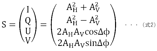
ただし、ΔΦは2つの断層画像を計算する際に得られる各信号の位相ΦHとΦVからΔΦ=ΦV-ΦHとして計算する。 However, ΔΦ is calculated as ΔΦ = Φ V −Φ H from the phases Φ H and Φ V of each signal obtained when calculating two tomographic images.
次に画像生成部147は、各Bスキャン画像を概ね計測光の主走査方向に70μm、深度方向に18μm程度の大きさのウィンドウを設定し、各ウィンドウ内において式2で画素毎に計算されたストークスベクトルの各要素を平均し、当該ウィンドウ内の偏光の均一性DOPU(Degree Of Polarization Uniformity)を式3により計算する。
Next, the
![]()
![]()
ただし、Qm、Um、Vmは各ウィンドウ内のストークスベクトルの要素Q,U,Vを平均した値である。この処理をBスキャン画像内の全てのウィンドウに対して行うことで、DOPU画像(偏光の均一度を示す断層画像とも言う)が生成される。 However, Q m , U m , and V m are values obtained by averaging the elements Q, U, and V of the Stokes vector in each window. By performing this process on all windows in the B-scan image, a DOPU image (also referred to as a tomographic image showing the uniformity of polarization) is generated.
DOPUは偏光の均一性を表す数値であり、偏光が保たれている個所においては1に近い数値となり、偏光が解消された保たれない箇所においては1よりも小さい数値となるものである。網膜内の構造においては、RPEが偏光状態を解消する性質があるため、DOPU画像においてRPEに対応する部分は、他の領域に対してその値が小さくなる。DOPU画像は、RPE等の偏光を解消する層を画像化しているので、病気などによりRPEが変形している場合においても、輝度の変化よりも確実にRPEを画像化出来る。 DOPU is a numerical value indicating the uniformity of polarization, and is a numerical value close to 1 in a place where polarization is maintained, and a numerical value smaller than 1 in a place where polarization is not maintained. In the structure in the retina, since RPE has a property of eliminating the polarized state, the value of the portion corresponding to RPE in the DOPU image becomes smaller than that of other regions. Since the DOPU image images a layer that eliminates polarization such as RPE, even when the RPE is deformed due to a disease or the like, the RPE can be imaged more reliably than the change in brightness.
このDOPU画像からRPEのセグメンテーション情報を取得する。 The segmentation information of RPE is acquired from this DOPU image.
この処理によって、撮像された干渉信号(3次元データ)から、それぞれの位置がRPEであるかどうかの判断をする。 By this processing, it is determined whether or not each position is RPE from the captured interference signal (three-dimensional data).
[処理動作]
次に、本実施形態の画像形成方法の具体的な処理の手順を説明する。本実施形態での基本的な処理フローは、第1実施形態の処理フローと同じであるため、概要説明を省略する。ただし、ステップS250、ステップS300、ステップS320の詳細処理が異なるため、それぞれに対応する本実施形のステップS250A、ステップS300A、ステップS320Aについて、以下に詳細説明をする。
[Processing operation]
Next, a specific processing procedure of the image forming method of the present embodiment will be described. Since the basic processing flow in the present embodiment is the same as the processing flow in the first embodiment, the outline description will be omitted. However, since the detailed processing of step S250, step S300, and step S320 is different, the corresponding steps S250A, step S300A, and step S320A of the present embodiment will be described in detail below.
ステップS250Aにおいて、信号処理部144は断層像AHおよび断層像AVを生成し、輝度画像を生成する。さらに、DOPU画像を生成する。
In step S250A , the
ステップS300Aにおいて、マップ生成部148は、輝度画像とDOPU画像を用いて、RPEセグメンテーションを行う。
In step S300A, the
ステップS320Aにおいて、信号処理部144は、ステップS300Aで取得された部位情報(網膜セグメンテーション情報)を用いて、OCTアンギオグラフィー情報(ここではモーションコントラスト)の補正を行う。ここでは、網膜セグメンテーション情報から得られる、ピクセルのDOPU情報(RPEである情報)を用いて、RPEにおけるモーションコントラストのノイズ閾値(第一閾値)を上げる。例えば、RPEより上部の領域の閾値よりRPEに係る閾値を高くする。または、モーションコントラストを低くして、血流部位で無い事にする。そうすることで、ステップS320Aで行う閾値処理は、より正確に行う事ができる。なお、RPEより深い部分の閾値を他の領域に比べて高くすることで、深い位置のノイズを低減することとしてもよい。
In step S320A, the
以上、説明した偏光OCT装置を用いることで、RPEのセグメンテーションが得られて、モーションコントラストの3次元データからより正確にノイズを削減することができ、明瞭化された3次元血流部位情報の取得ができる。また、不確かな血流部位を表示しないようにすることができる。 By using the polarized OCT device described above, RPE segmentation can be obtained, noise can be reduced more accurately from the 3D data of motion contrast, and clear 3D blood flow site information can be obtained. Can be done. In addition, it is possible to hide the uncertain blood flow site.
なお、ステップS354における表示閾値を上記のノイズ閾値のように制御することとしてもよい。例えば、RPEより深い部分の表示閾値を他の領域に比べて高くすることで、深い位置のノイズを低減することとしてもよい。また、RPEより上部の領域の表示閾値よりRPEに係る表示閾値を高くすることとしてもよい。 The display threshold value in step S354 may be controlled like the noise threshold value described above. For example, noise at a deep position may be reduced by raising the display threshold value in a portion deeper than the RPE as compared with other regions. Further, the display threshold value related to the RPE may be higher than the display threshold value of the region above the RPE.
〔第4の実施形態〕
第3の実施形態においては、部位構造情報として光干渉断層の偏光情報を用いたRPEの構造情報取得の例を説明したが、本実施形態では、RNFLの構造情報取得の例を説明する。
[Fourth Embodiment]
In the third embodiment, an example of acquiring structural information of RPE using polarization information of an optical interference fault as site structure information has been described, but in this embodiment, an example of acquiring structural information of RNFL will be described.
本実施形態における画像形成方法及び装置の構成例は、第3の実施形態の図14と同じであるので、ここで説明を省略する。 The image forming method and the configuration example of the apparatus in this embodiment are the same as those in FIG. 14 of the third embodiment, and thus the description thereof will be omitted here.
複屈折性を持つ層としては網膜神経線維層(RNFL)であり、本実施形態の信号処理部144はその性質に基づいてRNFLの検出をする。
The layer having birefringence is the retinal nerve fiber layer (RNFL), and the
<リターデーション画像生成>
画像生成部147は、互いに直行する偏光成分の断層画像からリターデーション画像を生成する。
<Retention image generation>
The
リターデーション画像の各画素の値δは、断層画像を構成する各画素の位置において、垂直偏光成分と水平偏光成分の間の位相差を数値化したものであり、各断層信号AHおよびAVから式4によって計算される。 The value δ of each pixel of the retardation image is a numerical value of the phase difference between the vertical polarization component and the horizontal polarization component at the position of each pixel constituting the tomographic image, and each tomographic signal A H and AV Is calculated from Equation 4.
![]()
![]()
リターデーション画像を生成することにより、網膜神経線維層(RNFL)のように複屈折性のある層を把握する。 By generating a retardation image, a layer with birefringence such as the retinal nerve fiber layer (RNFL) is grasped.
信号処理部144は、複数のBスキャン像に対して得たリターデーション(Retardation)画像から網膜神経線維層(RNFL)の検出を行う。
The
<リターデーションマップ生成>
信号処理部144は、複数のBスキャン像に対して得たリターデーション(Retardation)画像からリターデーションマップを生成する。
<Generation map generation>
The
まず、信号処理部144は、各Bスキャン画像において、網膜色素上皮(RPE)を検出する。RPEは偏光を解消する性質を持っているため、各Aスキャンを深度方向に沿って内境界膜(ILM)からRPEを含まない範囲でリターデーションの分布を調べ、その最大値を当該Aスキャンにおけるリターデーションの代表値とする。
First, the
マップ生成部148は、以上の処理を全てのリターデーション画像に対して行うことにより、リターデーションマップを生成する。
The
[RNFL segmentation]
<複屈折マップ生成>
画像生成部147は、先に生成されたリターデーション画像の各Aスキャン画像において、ILMから網膜神経線維層(RNFL)の範囲でリターデーションδの値を線形近似し、その傾きを当該Aスキャン画像の網膜上の位置における複屈折として決定する。この処理を取得した全てのリターデーション画像に対して行うことで、複屈折を表すマップを生成する。そして、マップ生成部148は複屈折値を用いて、RNFLのセグメンテーションを行う。
[RNFL segmentation]
<Birrefringence map generation>
The
[処理動作]
次に、本実施形態の画像形成方法の具体的な処理の手順を説明する。本実施形態での基本的な処理フローは、第2の実施形態の処理フローと同じであるため、概要説明を省略する。ただし、ステップS250A、ステップS300A、ステップS320Aの詳細処理が異なるため、それぞれに対応する本実施形のステップS250B、ステップS300B、ステップS320Bについて、以下に詳細説明をする。
[Processing operation]
Next, a specific processing procedure of the image forming method of the present embodiment will be described. Since the basic processing flow in the present embodiment is the same as the processing flow in the second embodiment, the outline description will be omitted. However, since the detailed processing of step S250A, step S300A, and step S320A is different, the corresponding step S250B, step S300B, and step S320B of the present embodiment will be described in detail below.
ステップS250Bにおいて、信号処理部144は断層像AHおよび断層像AVを生成し、輝度画像を生成する。さらに、リターデーション画像を生成する。
In step S250B , the
ステップS300Bにおいて、マップ生成部148は、輝度画像とリターデーション画像を用いて、リターデーションマップの生成と、RNFLセグメンテーションを行う。
In step S300B, the
ステップS320Bにおいて、信号処理部144は、ステップS300Bで取得された部位情報(網膜セグメンテーション情報)を用いて、OCTアンギオグラフィー情報(ここではモーションコントラスト)の補正を行う。ここでは、網膜セグメンテーション情報から得られる、ピクセルのリターデーション情報(RNFLである情報)を用いて、RNFLモーションコントラストのノイズ閾値(第一閾値)を上げる。または、モーションコントラストを低くして、血流部位で無い事にする。そうすることで、ステップS320Bで行う閾値処理は、より正確に行う事ができる。
In step S320B, the
以上、説明した偏光OCT装置を用いることで、RNFLのセグメンテーションが得られて、モーションコントラストの3次元データからより正確にノイズを削減することができ、明瞭化された3次元血流部位情報の取得ができる。 By using the polarized OCT device described above, RNFL segmentation can be obtained, noise can be reduced more accurately from the 3D data of motion contrast, and clear 3D blood flow site information can be obtained. Can be done.
なお、ステップS354における表示閾値を上記のノイズ閾値のように制御することとしてもよい。 The display threshold value in step S354 may be controlled like the noise threshold value described above.
以上で、偏光OCTの情報を用いてRPEや、RNFLのセグメンテーションを行い、より明瞭な3次元血流部位情報の取得方法を説明したが本実施形態はRPEやRNFLに限るものではなく、その他の部位にも適用しても良い。 In the above, a method of segmenting RPE and RNFL using the information of polarized OCT and acquiring clearer three-dimensional blood flow site information has been described, but the present embodiment is not limited to RPE and RNFL, and other It may also be applied to the site.
さらに、血管壁の偏光特性を用いて、血管を特定し、モーションコントラスト情報と組み合わせ結果の信頼性を上げる事ができる。 Furthermore, the polarization characteristics of the blood vessel wall can be used to identify the blood vessel and combine it with the motion contrast information to improve the reliability of the result.
[その他の実施例]
以上、実施例を詳述したが、本発明は例えば、システム、装置、方法、プログラム若しくは記録媒体(記憶媒体)等としての実施態様をとることが可能である。具体的には、複数の機器(例えば、ホストコンピュータ、インタフェース機器、撮像装置、webアプリケーション等)から構成されるシステムに適用しても良いし、また、一つの機器からなる装置に適用しても良い。
[Other Examples]
Although the examples have been described in detail above, the present invention can be implemented as, for example, a system, an apparatus, a method, a program, a recording medium (storage medium), or the like. Specifically, it may be applied to a system composed of a plurality of devices (for example, a host computer, an interface device, an image pickup device, a web application, etc.), or may be applied to a device consisting of one device. good.
また、開示の技術の目的は、以下のようにすることによって達成されることはいうまでもない。即ち、前述した実施例の機能を実現するソフトウェアのプログラムコード(コンピュータプログラム)を記録した記録媒体(または記憶媒体)を、システムあるいは装置に供給する。係る記憶媒体は言うまでもなく、コンピュータ読み取り可能な記憶媒体である。そして、そのシステムあるいは装置のコンピュータ(またはCPUやMPU)が記録媒体に格納されたプログラムコードを読み出し実行する。この場合、記録媒体から読み出されたプログラムコード自体が前述した実施例の機能を実現することになり、そのプログラムコードを記録した記録媒体は本発明を構成することになる。 Needless to say, the purpose of the disclosed technology is achieved by doing the following. That is, a recording medium (or storage medium) in which a program code (computer program) of software that realizes the functions of the above-described embodiment is recorded is supplied to the system or device. Needless to say, the storage medium is a computer-readable storage medium. Then, the computer (or CPU or MPU) of the system or device reads and executes the program code stored in the recording medium. In this case, the program code itself read from the recording medium realizes the function of the above-described embodiment, and the recording medium on which the program code is recorded constitutes the present invention.
143 制御部
144 信号処理部
145 信号取得制御部
146 表示部
147 画像生成部
148 マップ生成部
149 表示制御部
143
Claims (18)
前記モーションコントラスト値と閾値とを比較して得た比較結果に基づいて、前記閾値以下のモーションコントラスト値を無効化する工程と、
前記モーションコントラスト値が算出される前に前記複数の断層像データの位置合わせを行う工程と、
前記複数の断層像データの平均化画像を用いてセグメンテーション処理を行うことにより、複数の層境界を検出する工程と、
前記無効化が行われた後に、前記検出された複数の層境界に基づいて分類された複数の層のうち少なくとも一つの層と前記モーションコントラスト値とに基づいて、前記被検眼のモーションコントラスト正面画像を生成する工程と、
前記少なくとも一つの層におけるモーションコントラスト値のヒストグラムにおけるノイズの分布と血流領域の分布とに応じて自動的に設定された初期値であって、前記複数の層のうち少なくとも一つの層を決定するための検者からの指示に応じて自動的に変更された初期値から、検者からの指示に応じて前記閾値を変更する工程と、
前記決定された少なくとも一つの層と、前記変更されることにより得た閾値を用いて再度比較して得た比較結果とに基づいて、前記被検眼のモーションコントラスト正面画像を再度生成する工程と、
を有することを特徴とする画像生成方法。 A step of calculating a motion contrast value using the corresponding pixel data between a plurality of tomographic image data of the eye to be inspected obtained by scanning substantially the same position of the eye to be inspected multiple times with measurement light.
Based on the comparison result obtained by comparing the motion contrast value and the threshold value, the step of invalidating the motion contrast value below the threshold value and the step of invalidating the motion contrast value.
The step of aligning the plurality of tomographic image data before the motion contrast value is calculated, and
A step of detecting a plurality of layer boundaries by performing a segmentation process using the averaged images of the plurality of tomographic image data, and
After the invalidation is performed, the motion contrast front image of the eye to be inspected is based on at least one of the plurality of layers classified based on the detected plurality of layer boundaries and the motion contrast value. And the process of generating
It is an initial value automatically set according to the distribution of noise and the distribution of the blood flow region in the histogram of the motion contrast value in the at least one layer, and determines at least one of the plurality of layers. The process of changing the threshold value according to the instruction from the examiner from the initial value automatically changed according to the instruction from the examiner.
A step of regenerating the motion contrast front image of the eye to be inspected based on the at least one determined layer and the comparison result obtained by comparing again using the threshold value obtained by the change. When,
An image generation method characterized by having.
前記設定された表示範囲に基づいて生成された前記モーションコントラスト正面画像を表示する工程と、を更に有し、
前記表示範囲の変更に応じて表示される前記モーションコントラスト正面画像が更新されることを特徴とする請求項1または2に記載の画像生成方法。 A step of setting a display range in the depth direction of the motion contrast front image based on at least one of the detected plurality of layer boundaries, and a step of setting the display range in the depth direction.
It further comprises a step of displaying the motion contrast front image generated based on the set display range.
The image generation method according to claim 1 or 2, wherein the motion contrast front image displayed in response to a change in the display range is updated.
前記複数の層境界は、前記平均化画像を用いてセグメンテーション処理を行うことにより検出されることを特徴とする請求項1乃至8の何れか1項に記載の画像生成方法。 The averaged image of the plurality of aligned tomographic image data on which the information indicating the positions of the plurality of layers is superimposed and the information indicating the substantially same position corresponding to the averaged image are superimposed. Further, it has a step of displaying the motion contrast front image and the information for accepting the change of the threshold value side by side on the display means.
The image generation method according to any one of claims 1 to 8, wherein the plurality of layer boundaries are detected by performing a segmentation process using the averaged image.
前記偏光OCT画像を用いて前記セグメンテーションが行われ、
前記モーションコントラスト値を算出するための断層像データと共通の断層像データを用いて得た偏光情報を用いて偏光情報を示すマップが生成されることを特徴とする請求項1乃至13の何れか1項に記載の画像生成方法。 The image obtained by using the at least one tomographic image data is a polarized OCT image.
The segmentation is performed using the polarized OCT image, and the segmentation is performed.
Any of claims 1 to 13, wherein a map showing the polarization information is generated using the polarization information obtained by using the tomographic image data for calculating the motion contrast value and the tomographic image data common to the tomographic image data. The image generation method according to item 1.
前記モーションコントラスト値と閾値とを比較して得た比較結果に基づいて、前記閾値以下のモーションコントラスト値を無効化する無効化手段と、
前記モーションコントラスト値が算出される前に前記複数の断層像データの位置合わせを行う位置合わせ手段と、
前記複数の断層像データの平均化画像を用いてセグメンテーション処理を行うことにより、複数の層境界を検出する検出手段と、
前記無効化が行われた後に、前記検出された複数の層境界に基づいて分類された複数の層のうち少なくとも一つの層と前記モーションコントラスト値とに基づいて、前記被検眼のモーションコントラスト正面画像を生成する生成手段と、
前記少なくとも一つの層におけるモーションコントラスト値のヒストグラムにおけるノイズの分布と血流領域の分布とに応じて自動的に設定された初期値であって、前記複数の層のうち少なくとも一つの層を決定するための検者からの指示に応じて自動的に変更された初期値から、検者からの指示に応じて前記閾値を変更する変更手段と、を備え、
前記生成手段は、前記決定された少なくとも一つの層と、前記変更されることにより得た閾値を用いて再度比較して得た比較結果とに基づいて、前記被検眼のモーションコントラスト正面画像を再度生成することを特徴とする画像生成装置。 A calculation means for calculating a motion contrast value using the corresponding pixel data between a plurality of tomographic image data of the eye to be inspected obtained by scanning substantially the same position of the eye to be inspected with measurement light multiple times.
Based on the comparison result obtained by comparing the motion contrast value and the threshold value, an invalidation means for invalidating the motion contrast value below the threshold value and an invalidation means.
An alignment means for aligning the plurality of tomographic image data before the motion contrast value is calculated, and
A detection means for detecting a plurality of layer boundaries by performing a segmentation process using the averaged images of the plurality of tomographic image data.
After the invalidation is performed, the motion contrast front image of the eye to be inspected is based on at least one of the plurality of layers classified based on the detected plurality of layer boundaries and the motion contrast value. And the generation method to generate
It is an initial value automatically set according to the distribution of noise and the distribution of the blood flow region in the histogram of the motion contrast value in the at least one layer, and determines at least one of the plurality of layers. It is provided with a changing means for changing the threshold value according to the instruction from the examiner from the initial value automatically changed according to the instruction from the examiner.
The generation means is a motion contrast frontal image of the eye to be inspected based on the at least one determined layer and the comparison result obtained by recomparing with the threshold value obtained by the modification. An image generator characterized by regenerating the image.
前記被検眼を測定光で走査するための走査手段と、前記測定光を照射した前記被検眼からの戻り光と参照光との干渉光を検出する光検出手段とを有する光干渉断層撮像装置と、
を備えることを特徴とするシステム。 The image generator according to claim 17 and
An optical interference tomographic imaging apparatus having a scanning means for scanning the eye to be inspected with the measurement light and a light detection means for detecting the interference light between the return light from the eye to be inspected and the reference light irradiated with the measurement light. ,
A system characterized by being equipped with.
Priority Applications (1)
| Application Number | Priority Date | Filing Date | Title |
|---|---|---|---|
| JP2019182532A JP6992030B2 (en) | 2019-10-02 | 2019-10-02 | Image generator, image generation method and program |
Applications Claiming Priority (1)
| Application Number | Priority Date | Filing Date | Title |
|---|---|---|---|
| JP2019182532A JP6992030B2 (en) | 2019-10-02 | 2019-10-02 | Image generator, image generation method and program |
Related Parent Applications (1)
| Application Number | Title | Priority Date | Filing Date |
|---|---|---|---|
| JP2015094339A Division JP6598502B2 (en) | 2015-05-01 | 2015-05-01 | Image generating apparatus, image generating method, and program |
Publications (2)
| Publication Number | Publication Date |
|---|---|
| JP2019217388A JP2019217388A (en) | 2019-12-26 |
| JP6992030B2 true JP6992030B2 (en) | 2022-01-13 |
Family
ID=69094975
Family Applications (1)
| Application Number | Title | Priority Date | Filing Date |
|---|---|---|---|
| JP2019182532A Active JP6992030B2 (en) | 2019-10-02 | 2019-10-02 | Image generator, image generation method and program |
Country Status (1)
| Country | Link |
|---|---|
| JP (1) | JP6992030B2 (en) |
Citations (10)
| Publication number | Priority date | Publication date | Assignee | Title |
|---|---|---|---|---|
| JP2003052634A (en) | 2001-08-10 | 2003-02-25 | Matsushita Electric Works Ltd | Method and instrument for extracting pupillary margin and pupillary margin extraction program |
| JP2009523563A (en) | 2006-01-19 | 2009-06-25 | オプトビュー,インコーポレーテッド | Examining the eye by optical coherence tomography |
| JP2013144048A (en) | 2012-01-16 | 2013-07-25 | Canon Inc | Ophthalmologic image pickup apparatus and control method thereof |
| JP2013148482A (en) | 2012-01-19 | 2013-08-01 | Nidek Co Ltd | Optical coherence tomography device |
| WO2013167641A1 (en) | 2012-05-10 | 2013-11-14 | Carl Zeiss Meditec Ag | Analysis and visualization of oct angiography data |
| JP2014061085A (en) | 2012-09-20 | 2014-04-10 | National Institute Of Advanced Industrial & Technology | Method fo detecting ellipse approximating to pupil portion |
| US20140160487A1 (en) | 2012-12-10 | 2014-06-12 | The Johns Hopkins University | Real-time 3d and 4d fourier domain doppler optical coherence tomography system |
| US20140221827A1 (en) | 2011-06-07 | 2014-08-07 | California Institute Of Technology | Enhanced optical angiography using intensity contrast and phase contrast imaging methods |
| JP2015511146A (en) | 2012-02-03 | 2015-04-16 | オレゴン ヘルス アンド サイエンス ユニバーシティ | Optical flow imaging in vivo |
| JP2016209198A (en) | 2015-05-01 | 2016-12-15 | キヤノン株式会社 | Image generation apparatus, image generation method, and program |
-
2019
- 2019-10-02 JP JP2019182532A patent/JP6992030B2/en active Active
Patent Citations (11)
| Publication number | Priority date | Publication date | Assignee | Title |
|---|---|---|---|---|
| JP2003052634A (en) | 2001-08-10 | 2003-02-25 | Matsushita Electric Works Ltd | Method and instrument for extracting pupillary margin and pupillary margin extraction program |
| JP2009523563A (en) | 2006-01-19 | 2009-06-25 | オプトビュー,インコーポレーテッド | Examining the eye by optical coherence tomography |
| US20140221827A1 (en) | 2011-06-07 | 2014-08-07 | California Institute Of Technology | Enhanced optical angiography using intensity contrast and phase contrast imaging methods |
| JP2013144048A (en) | 2012-01-16 | 2013-07-25 | Canon Inc | Ophthalmologic image pickup apparatus and control method thereof |
| JP2013148482A (en) | 2012-01-19 | 2013-08-01 | Nidek Co Ltd | Optical coherence tomography device |
| JP2015511146A (en) | 2012-02-03 | 2015-04-16 | オレゴン ヘルス アンド サイエンス ユニバーシティ | Optical flow imaging in vivo |
| WO2013167641A1 (en) | 2012-05-10 | 2013-11-14 | Carl Zeiss Meditec Ag | Analysis and visualization of oct angiography data |
| JP2014061085A (en) | 2012-09-20 | 2014-04-10 | National Institute Of Advanced Industrial & Technology | Method fo detecting ellipse approximating to pupil portion |
| US20140160487A1 (en) | 2012-12-10 | 2014-06-12 | The Johns Hopkins University | Real-time 3d and 4d fourier domain doppler optical coherence tomography system |
| JP2016209198A (en) | 2015-05-01 | 2016-12-15 | キヤノン株式会社 | Image generation apparatus, image generation method, and program |
| JP6598502B2 (en) | 2015-05-01 | 2019-10-30 | キヤノン株式会社 | Image generating apparatus, image generating method, and program |
Also Published As
| Publication number | Publication date |
|---|---|
| JP2019217388A (en) | 2019-12-26 |
Similar Documents
| Publication | Publication Date | Title |
|---|---|---|
| JP6598502B2 (en) | Image generating apparatus, image generating method, and program | |
| US10660515B2 (en) | Image display method of providing diagnosis information using three-dimensional tomographic data | |
| JP6843521B2 (en) | Image processing device and image processing method | |
| JP6598503B2 (en) | Image generating apparatus, image generating method, and program | |
| JP6632267B2 (en) | Ophthalmic apparatus, display control method and program | |
| JP6702764B2 (en) | Optical coherence tomographic data processing method, program for executing the method, and processing apparatus | |
| JP6602108B2 (en) | Ophthalmic apparatus, information processing method, and program | |
| JP7009265B2 (en) | Image processing equipment, image processing methods and programs | |
| WO2016110917A1 (en) | Image processing apparatus and image processing method for polarization-sensitive optical coherence tomography | |
| JP6682291B2 (en) | Image processing apparatus, image processing method and program | |
| JP6849776B2 (en) | Information processing device and information processing method | |
| JP2020039430A (en) | Image processing device, image processing method and program | |
| JP6736734B2 (en) | Ophthalmic photographing device and ophthalmic information processing device | |
| JP2017079886A (en) | Blood flow measurement device | |
| JP6992030B2 (en) | Image generator, image generation method and program | |
| JP2017202369A (en) | Ophthalmologic image processing device | |
| JP2018191761A (en) | Information processing device, information processing method, and program | |
| JP7246862B2 (en) | IMAGE PROCESSING DEVICE, CONTROL METHOD AND PROGRAM OF IMAGE PROCESSING DEVICE | |
| JP6849780B2 (en) | Ophthalmic equipment, display control methods and programs | |
| JP6992031B2 (en) | Image generator, image generation method and program | |
| JP7387812B2 (en) | Image processing device, image processing method and program | |
| JP2021087817A (en) | Image processing apparatus and image processing method | |
| JP2023128334A (en) | Information processor, optical coherence tomography device, information processing method, and program | |
| JP2017131551A (en) | Image processing device and image processing method | |
| JP2017144047A (en) | Imaging apparatus and driving method therefor, and program |
Legal Events
| Date | Code | Title | Description |
|---|---|---|---|
| A521 | Written amendment |
Free format text: JAPANESE INTERMEDIATE CODE: A523 Effective date: 20191025 |
|
| A621 | Written request for application examination |
Free format text: JAPANESE INTERMEDIATE CODE: A621 Effective date: 20191025 |
|
| A977 | Report on retrieval |
Free format text: JAPANESE INTERMEDIATE CODE: A971007 Effective date: 20200917 |
|
| A131 | Notification of reasons for refusal |
Free format text: JAPANESE INTERMEDIATE CODE: A131 Effective date: 20201013 |
|
| A521 | Written amendment |
Free format text: JAPANESE INTERMEDIATE CODE: A523 Effective date: 20201210 |
|
| A131 | Notification of reasons for refusal |
Free format text: JAPANESE INTERMEDIATE CODE: A131 Effective date: 20210420 |
|
| A521 | Written amendment |
Free format text: JAPANESE INTERMEDIATE CODE: A523 Effective date: 20210604 |
|
| TRDD | Decision of grant or rejection written | ||
| A01 | Written decision to grant a patent or to grant a registration (utility model) |
Free format text: JAPANESE INTERMEDIATE CODE: A01 Effective date: 20211109 |
|
| A61 | First payment of annual fees (during grant procedure) |
Free format text: JAPANESE INTERMEDIATE CODE: A61 Effective date: 20211208 |
|
| R151 | Written notification of patent or utility model registration |
Ref document number: 6992030 Country of ref document: JP Free format text: JAPANESE INTERMEDIATE CODE: R151 |