JP6665415B2 - Projector and projector control method - Google Patents
Projector and projector control method Download PDFInfo
- Publication number
- JP6665415B2 JP6665415B2 JP2015068094A JP2015068094A JP6665415B2 JP 6665415 B2 JP6665415 B2 JP 6665415B2 JP 2015068094 A JP2015068094 A JP 2015068094A JP 2015068094 A JP2015068094 A JP 2015068094A JP 6665415 B2 JP6665415 B2 JP 6665415B2
- Authority
- JP
- Japan
- Prior art keywords
- image
- projection
- unit
- size
- movement
- Prior art date
- Legal status (The legal status is an assumption and is not a legal conclusion. Google has not performed a legal analysis and makes no representation as to the accuracy of the status listed.)
- Active
Links
Images


Classifications
-
- G—PHYSICS
- G09—EDUCATION; CRYPTOGRAPHY; DISPLAY; ADVERTISING; SEALS
- G09G—ARRANGEMENTS OR CIRCUITS FOR CONTROL OF INDICATING DEVICES USING STATIC MEANS TO PRESENT VARIABLE INFORMATION
- G09G5/00—Control arrangements or circuits for visual indicators common to cathode-ray tube indicators and other visual indicators
- G09G5/36—Control arrangements or circuits for visual indicators common to cathode-ray tube indicators and other visual indicators characterised by the display of a graphic pattern, e.g. using an all-points-addressable [APA] memory
- G09G5/38—Control arrangements or circuits for visual indicators common to cathode-ray tube indicators and other visual indicators characterised by the display of a graphic pattern, e.g. using an all-points-addressable [APA] memory with means for controlling the display position
-
- G—PHYSICS
- G03—PHOTOGRAPHY; CINEMATOGRAPHY; ANALOGOUS TECHNIQUES USING WAVES OTHER THAN OPTICAL WAVES; ELECTROGRAPHY; HOLOGRAPHY
- G03B—APPARATUS OR ARRANGEMENTS FOR TAKING PHOTOGRAPHS OR FOR PROJECTING OR VIEWING THEM; APPARATUS OR ARRANGEMENTS EMPLOYING ANALOGOUS TECHNIQUES USING WAVES OTHER THAN OPTICAL WAVES; ACCESSORIES THEREFOR
- G03B21/00—Projectors or projection-type viewers; Accessories therefor
- G03B21/14—Details
-
- G—PHYSICS
- G06—COMPUTING; CALCULATING OR COUNTING
- G06F—ELECTRIC DIGITAL DATA PROCESSING
- G06F3/00—Input arrangements for transferring data to be processed into a form capable of being handled by the computer; Output arrangements for transferring data from processing unit to output unit, e.g. interface arrangements
- G06F3/01—Input arrangements or combined input and output arrangements for interaction between user and computer
- G06F3/017—Gesture based interaction, e.g. based on a set of recognized hand gestures
-
- G—PHYSICS
- G06—COMPUTING; CALCULATING OR COUNTING
- G06F—ELECTRIC DIGITAL DATA PROCESSING
- G06F3/00—Input arrangements for transferring data to be processed into a form capable of being handled by the computer; Output arrangements for transferring data from processing unit to output unit, e.g. interface arrangements
- G06F3/01—Input arrangements or combined input and output arrangements for interaction between user and computer
- G06F3/03—Arrangements for converting the position or the displacement of a member into a coded form
- G06F3/033—Pointing devices displaced or positioned by the user, e.g. mice, trackballs, pens or joysticks; Accessories therefor
- G06F3/0354—Pointing devices displaced or positioned by the user, e.g. mice, trackballs, pens or joysticks; Accessories therefor with detection of 2D relative movements between the device, or an operating part thereof, and a plane or surface, e.g. 2D mice, trackballs, pens or pucks
- G06F3/03542—Light pens for emitting or receiving light
-
- G—PHYSICS
- G06—COMPUTING; CALCULATING OR COUNTING
- G06F—ELECTRIC DIGITAL DATA PROCESSING
- G06F3/00—Input arrangements for transferring data to be processed into a form capable of being handled by the computer; Output arrangements for transferring data from processing unit to output unit, e.g. interface arrangements
- G06F3/01—Input arrangements or combined input and output arrangements for interaction between user and computer
- G06F3/03—Arrangements for converting the position or the displacement of a member into a coded form
- G06F3/033—Pointing devices displaced or positioned by the user, e.g. mice, trackballs, pens or joysticks; Accessories therefor
- G06F3/0354—Pointing devices displaced or positioned by the user, e.g. mice, trackballs, pens or joysticks; Accessories therefor with detection of 2D relative movements between the device, or an operating part thereof, and a plane or surface, e.g. 2D mice, trackballs, pens or pucks
- G06F3/03545—Pens or stylus
-
- G—PHYSICS
- G06—COMPUTING; CALCULATING OR COUNTING
- G06F—ELECTRIC DIGITAL DATA PROCESSING
- G06F3/00—Input arrangements for transferring data to be processed into a form capable of being handled by the computer; Output arrangements for transferring data from processing unit to output unit, e.g. interface arrangements
- G06F3/01—Input arrangements or combined input and output arrangements for interaction between user and computer
- G06F3/03—Arrangements for converting the position or the displacement of a member into a coded form
- G06F3/041—Digitisers, e.g. for touch screens or touch pads, characterised by the transducing means
- G06F3/042—Digitisers, e.g. for touch screens or touch pads, characterised by the transducing means by opto-electronic means
-
- G—PHYSICS
- G06—COMPUTING; CALCULATING OR COUNTING
- G06F—ELECTRIC DIGITAL DATA PROCESSING
- G06F3/00—Input arrangements for transferring data to be processed into a form capable of being handled by the computer; Output arrangements for transferring data from processing unit to output unit, e.g. interface arrangements
- G06F3/01—Input arrangements or combined input and output arrangements for interaction between user and computer
- G06F3/048—Interaction techniques based on graphical user interfaces [GUI]
- G06F3/0484—Interaction techniques based on graphical user interfaces [GUI] for the control of specific functions or operations, e.g. selecting or manipulating an object, an image or a displayed text element, setting a parameter value or selecting a range
- G06F3/04845—Interaction techniques based on graphical user interfaces [GUI] for the control of specific functions or operations, e.g. selecting or manipulating an object, an image or a displayed text element, setting a parameter value or selecting a range for image manipulation, e.g. dragging, rotation, expansion or change of colour
-
- G—PHYSICS
- G06—COMPUTING; CALCULATING OR COUNTING
- G06F—ELECTRIC DIGITAL DATA PROCESSING
- G06F3/00—Input arrangements for transferring data to be processed into a form capable of being handled by the computer; Output arrangements for transferring data from processing unit to output unit, e.g. interface arrangements
- G06F3/01—Input arrangements or combined input and output arrangements for interaction between user and computer
- G06F3/048—Interaction techniques based on graphical user interfaces [GUI]
- G06F3/0487—Interaction techniques based on graphical user interfaces [GUI] using specific features provided by the input device, e.g. functions controlled by the rotation of a mouse with dual sensing arrangements, or of the nature of the input device, e.g. tap gestures based on pressure sensed by a digitiser
- G06F3/0488—Interaction techniques based on graphical user interfaces [GUI] using specific features provided by the input device, e.g. functions controlled by the rotation of a mouse with dual sensing arrangements, or of the nature of the input device, e.g. tap gestures based on pressure sensed by a digitiser using a touch-screen or digitiser, e.g. input of commands through traced gestures
-
- H—ELECTRICITY
- H04—ELECTRIC COMMUNICATION TECHNIQUE
- H04N—PICTORIAL COMMUNICATION, e.g. TELEVISION
- H04N9/00—Details of colour television systems
- H04N9/12—Picture reproducers
- H04N9/31—Projection devices for colour picture display, e.g. using electronic spatial light modulators [ESLM]
- H04N9/3179—Video signal processing therefor
- H04N9/3185—Geometric adjustment, e.g. keystone or convergence
-
- H—ELECTRICITY
- H04—ELECTRIC COMMUNICATION TECHNIQUE
- H04N—PICTORIAL COMMUNICATION, e.g. TELEVISION
- H04N9/00—Details of colour television systems
- H04N9/12—Picture reproducers
- H04N9/31—Projection devices for colour picture display, e.g. using electronic spatial light modulators [ESLM]
- H04N9/3191—Testing thereof
- H04N9/3194—Testing thereof including sensor feedback
-
- G—PHYSICS
- G09—EDUCATION; CRYPTOGRAPHY; DISPLAY; ADVERTISING; SEALS
- G09G—ARRANGEMENTS OR CIRCUITS FOR CONTROL OF INDICATING DEVICES USING STATIC MEANS TO PRESENT VARIABLE INFORMATION
- G09G2320/00—Control of display operating conditions
- G09G2320/08—Arrangements within a display terminal for setting, manually or automatically, display parameters of the display terminal
Description
本発明は、プロジェクター、及び、プロジェクターの制御方法に関する。 The present invention relates to a projector and a method for controlling the projector.
従来、画像を表示する装置(表示制御装置)において、表示した画像をスクロール等のユーザーの操作によって画面上で移動させる技術が知られている(例えば、特許文献1参照。)
また、近年、スクリーン等の投射面にGUI(Graphical User Interface)等のオブジェクトを投射するプロジェクターが広く普及している。そして、プロジェクターにより、オブジェクトを含む投射画像が投射される領域(投射画像の投射が可能な領域(画素の形成が可能な領域))のサイズは、プロジェクターと投射面との離間距離や、プロジェクターの投射光学系に関する設定等により、変化し、一定ではない。
2. Description of the Related Art Conventionally, in a device for displaying an image (display control device), a technique of moving a displayed image on a screen by a user operation such as scrolling has been known (for example, see Patent Document 1).
In recent years, projectors that project objects such as a GUI (Graphical User Interface) onto a projection surface such as a screen have become widespread. The size of the area where the projection image including the object is projected by the projector (the area where the projection image can be projected (the area where pixels can be formed)) is determined by the distance between the projector and the projection surface and the size of the projector. The value varies depending on the setting of the projection optical system and is not constant.
ここで、プロジェクターが投射面に投射したオブジェクトを、特許文献1に記載の技術のように、ユーザーの操作により、投射面上で移動させることを想定する。この場合において、プロジェクターにより投射画像が投射される領域のサイズが一定でないことを踏まえ、投射画像が投射される領域のサイズに対応した態様でオブジェクトを移動させることができれば、ユーザーの利便性が向上する。一方、このようなプロジェクターにより投射画像が投射される領域のサイズが一定でないことに対応する処理を実行可能なプロジェクターは無かった。
本発明は、上述した事情に鑑みてなされたものであり、投射面に投射画像を投射するプロジェクターについて、投射画像が投射される領域のサイズが一定でないことに対応する処理を実行できるようにすることを目的とする。
Here, it is assumed that the object projected on the projection surface by the projector is moved on the projection surface by a user operation as in the technique described in
The present invention has been made in view of the above circumstances, and enables a projector that projects a projection image on a projection surface to execute a process corresponding to the fact that the size of an area where the projection image is projected is not constant. The purpose is to:
上記目的を達成するために、本発明のプロジェクターは、投射面に第1のオブジェクトを含む投射画像を投射する投射部と、前記投射画像が投射される領域のサイズを検出する投射サイズ検出部と、前記投射面に対する指示体の操作を検出する検出部と、前記検出部により検出した前記指示体の操作が、前記第1のオブジェクトを移動させる操作であった場合、前記投射画像が投射される領域のサイズに応じて、前記第1のオブジェクトの移動量を異ならせる移動量調整部と、を備えることを特徴とする。
本発明の構成によれば、プロジェクターは、投射画像が投射される領域のサイズが一定でないことに対応して、第1のオブジェクトを移動させる操作に基づいて第1のオブジェクトの位置を移動させるときの移動量を、当該サイズに対応した値とすることができる。
In order to achieve the above object, a projector according to an aspect of the invention includes a projection unit that projects a projection image including a first object on a projection surface, and a projection size detection unit that detects a size of an area where the projection image is projected. A detection unit that detects an operation of a pointer on the projection surface; and if the operation of the pointer detected by the detection unit is an operation of moving the first object, the projection image is projected. A moving amount adjusting unit that changes the moving amount of the first object according to the size of the region.
According to the configuration of the present invention, the projector moves the position of the first object based on the operation of moving the first object in response to the fact that the size of the area where the projection image is projected is not constant Can be set to a value corresponding to the size.
また、本発明のプロジェクターは、前記移動量調整部は、前記投射画像が投射される領域のサイズが第1のサイズの場合に前記第1のオブジェクトを移動させる第1の操作が行われた時の前記第1のオブジェクトの第1の移動量と、前記投射画像が投射される領域のサイズが前記第1のサイズよりも大きい第2のサイズの場合に前記第1の操作が行われた時の前記第1のオブジェクトの第2の移動量とでは、前記第2の移動量を大きくすることを特徴とする。
本発明の構成によれば、投射画像が投射される領域のサイズが大きいほど、同様の指示体の操作が行われたときの第1のオブジェクトの移動量を大きくすることができ、操作者(ユーザー)による第1のオブジェクトの移動時の作業が容易化する。
Further, in the projector according to the aspect of the invention, the movement amount adjustment unit may be configured to perform a first operation for moving the first object when a size of an area where the projection image is projected is a first size. When the first operation is performed when the first movement amount of the first object and the size of the area where the projection image is projected is a second size larger than the first size. The second movement amount of the first object is set to be larger than the second movement amount of the first object.
According to the configuration of the present invention, the larger the size of the area where the projection image is projected, the larger the amount of movement of the first object when the same pointer is operated, and the operator ( Work by the user) when moving the first object is facilitated.
また、本発明のプロジェクターは、前記移動量調整部は、前記投射画像が投射される領域のサイズが大きいほど、同様の前記指示体の操作が行われた場合における前記第1のオブジェクトの移動量を大きくすることを特徴とする。
本発明の構成によれば、投射画像が投射される領域のサイズが大きいほど、同様の指示体の操作が行われたときの第1のオブジェクトの移動量を大きくすることができ、操作者(ユーザー)による第1のオブジェクトの移動時の作業が容易化する。
Also, in the projector according to the aspect of the invention, the movement amount adjustment unit may be configured to perform the same movement of the first object as the size of the area on which the projection image is projected is larger. Is increased.
According to the configuration of the present invention, the larger the size of the area where the projection image is projected, the larger the amount of movement of the first object when the same pointer is operated, and the operator ( Work by the user) when moving the first object is facilitated.
また、本発明のプロジェクターは、前記第1のオブジェクトを移動させる操作は、前記指示体が前記投射面に接触して移動する状態から非接触で移動する状態へ連続して移行する操作であり、前記移動量調整部は、前記指示体が前記投射面に非接触の状態へ移行した後の前記指示体の移動距離に、前記投射画像が投射される領域のサイズに応じた係数を乗じて前記第1のオブジェクトの移動量を算出することを特徴とする。
本発明の構成によれば、操作者が、第1のオブジェクトを移動させる意思をもって意図的に行った操作を、第1のオブジェクトを移動させる操作として判定できる。また、移動量調整部は、移動量係数を用いて、移動量の値を、画像投射領域のサイズに応じた適切な値とすることができる。
Further, in the projector according to the aspect of the invention, the operation of moving the first object is an operation of continuously shifting from a state in which the indicator moves in contact with the projection surface to a state in which the pointer moves without contact, The moving amount adjustment unit multiplies a moving distance of the pointer after the pointer is shifted to a state of non-contact with the projection surface by a coefficient corresponding to a size of an area where the projection image is projected. The amount of movement of the first object is calculated.
According to the configuration of the present invention, an operation intentionally performed by the operator with the intention of moving the first object can be determined as an operation of moving the first object. Further, the movement amount adjustment unit can use the movement amount coefficient to set the value of the movement amount to an appropriate value according to the size of the image projection area.
また、本発明のプロジェクターは、前記投射面を撮影する撮影部を備え、前記投射サイズ検出部は、前記投射部により前記投射面に特定のパターン画像を投射させ、前記パターン画像が投射された前記投射面を前記撮影部により撮影させ、前記撮影部による撮影結果に基づいて、前記投射画像が投射される領域のサイズを検出することを特徴とする。
本発明の構成によれば、投射画像が投射される領域のサイズの検出について、ユーザーの作業が必要なく、ユーザーの利便性が向上する。
Further, the projector of the present invention includes a photographing unit that photographs the projection surface, the projection size detection unit projects a specific pattern image on the projection surface by the projection unit, and the pattern image is projected. A projection surface is photographed by the photographing unit, and a size of an area where the projection image is projected is detected based on a photographing result by the photographing unit.
ADVANTAGE OF THE INVENTION According to the structure of this invention, about the size of the area | region where a projection image is projected, a user's operation is not required and the user's convenience improves.
また、上記目的を達成するために、本発明のプロジェクターの制御方法は、投射面に第1のオブジェクトを含む投射画像を投射する投射部を備えるプロジェクターの制御方法であって、前記投射画像が投射される領域のサイズを検出し、前記投射面に対する指示体の操作を検出し、検出した前記指示体の操作が、前記第1のオブジェクトを移動させる操作であった場合、前記投射画像が投射される領域のサイズに応じて、前記第1のオブジェクトの移動量を異ならせることを特徴とする。 In order to achieve the above object, a projector control method according to the present invention is a control method for a projector including a projection unit that projects a projection image including a first object on a projection surface, wherein the projection image is Detecting the size of the region to be detected, detecting the operation of the pointer on the projection surface, and if the detected operation of the pointer is an operation of moving the first object, the projection image is projected. The amount of movement of the first object is made different depending on the size of the area to be moved.
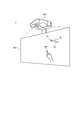
図1は、プロジェクター100の設置状態を示す図である。
プロジェクター100は、スクリーンSC(投射面)の直上又は斜め上方に設置され、斜め下方のスクリーンSCに向けて画像(投射画像)を投射する。スクリーンSCは、壁面に固定され、又は床面に立設された平板又は幕である。本発明は、この例に限定されず、壁面をスクリーンSCとして使用することも可能である。この場合、スクリーンSCとして使用される壁面の上部にプロジェクター100を取り付けるとよい。
FIG. 1 is a diagram illustrating an installation state of the
The
プロジェクター100は、PC(パーソナルコンピューター)、ビデオ再生装置、DVD再生装置、Blu−ray(登録商標) Disc(ブルーレイディスク)再生装置等の画像供給装置に接続される。プロジェクター100は、画像供給装置から供給されるアナログ画像信号又はデジタル画像データに基づいて、スクリーンSCに画像を投射する。また、プロジェクター100は、内蔵する記憶部60(図2)や外部接続される記憶媒体に記憶された画像データを読み出して、この画像データに基づきスクリーンSCに画像を表示してもよい。
The
プロジェクター100は、スクリーンSCに対する操作者の操作を検出する。スクリーンSCに対する操作には、ペン型の第1の指示体70、又は操作者の手指である第2の指示体80が利用される。
また、スクリーンSCに対する操作には、第1の指示体70又は第2の指示体80により、スクリーンSC上の一定の位置を指定(指示)する操作や、スクリーンSC上の異なる位置を連続して指示する操作が含まれる。
スクリーンSC上の一定の位置を指定(指示)する操作は、第1の指示体70又は第2の指示体80を、スクリーンSC上の一定の位置に一定時間接触させる操作である。
また、スクリーンSC上の異なる位置を連続して指示する操作は、第1の指示体70又は第2の指示体80をスクリーンSCに接触させながら動かして、文字や図形等を描く操作である。
プロジェクター100は、操作者が第1の指示体70又は第2の指示体80により行った操作を検出して、検出した操作をスクリーンSCの投射画像に反映させる。さらに、プロジェクター100は、指示位置を検出することによりポインティングデバイスとして動作し、スクリーンSC上の指示位置の座標を出力してもよい。また、この座標を用いて、プロジェクター100に対してGUI(Graphical User Interface)操作を行うこともできる。
The
In the operation on the screen SC, an operation of designating (pointing) a certain position on the screen SC by the
The operation of designating (pointing) a certain position on the screen SC is an operation of bringing the
In addition, the operation of continuously indicating different positions on the screen SC is an operation of moving the
The
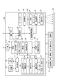
図2は、プロジェクター100の構成を示す構成図である。
プロジェクター100は、外部の装置に接続されるインターフェースとして、I/F(インターフェース)部11及び画像I/F(インターフェース)部12を備える。I/F部11及び画像I/F部12は、有線接続用のコネクターを備え、このコネクターに対応するインターフェース回路を備えていてもよい。また、I/F部11及び画像I/F部12は、無線通信インターフェースを備えていてもよい。有線接続用のコネクター及びインターフェース回路としては有線LAN、IEEE1394、USB等に準拠したものが挙げられる。また、無線通信インターフェースとしては無線LANやBluetooth(登録商標)等に準拠したものが挙げられる。画像I/F部12には、HDMI(登録商標)インターフェース等の画像データ用のインターフェースを用いることもできる。画像I/F部12は、音声データが入力されるインターフェースを備えてもよい。
FIG. 2 is a configuration diagram showing a configuration of the
The
I/F部11は、PC等の外部の装置との間で各種データを送受信するインターフェースである。I/F部11は、画像の投射に関するデータ、プロジェクター100の動作を設定するデータ等を入出力する。後述する制御部30は、I/F部11を介して外部の装置とデータを送受信する機能を有する。
画像I/F部12は、デジタル画像データが入力されるインターフェースである。本実施形態のプロジェクター100は、画像I/F部12を介して入力されるデジタル画像データに基づき画像を投射する。なお、プロジェクター100は、アナログ画像信号に基づき画像を投射する機能を備えていてもよく、この場合、画像I/F部12は、アナログ画像用のインターフェースと、アナログ画像信号をデジタル画像データに変換するA/D変換回路とを備えてもよい。
The I /
The image I /
プロジェクター100は、光学的な画像の形成を行う投射部20を備える。投射部20は、光源部21、光変調装置22及び投射光学系23を有する。光源部21は、キセノンランプ、超高圧水銀ランプ、LED(Light Emitting Diode)又はレーザー光源等からなる光源を備える。また、光源部21は、光源が発した光を光変調装置22に導くリフレクター及び補助リフレクターを備えていてもよい。さらに、プロジェクター100は、投射光の光学特性を高めるためのレンズ群(図示略)、偏光板、又は光源が発した光の光量を光変調装置22に至る経路上で低減させる調光素子等を備えていてもよい。
The
光変調装置22は、例えばRGBの三原色に対応した3枚の透過型液晶パネルを備え、この液晶パネルを透過する光を変調して画像光を生成する。光源部21からの光はRGBの3色の色光に分離され、各色光は対応する各液晶パネルに入射される。各液晶パネルを通過して変調された色光はクロスダイクロイックプリズム等の合成光学系によって合成され、投射光学系23に射出される。
The
投射光学系23は、光変調装置22により変調された画像光をスクリーンSC方向へ導き、スクリーンSC上に結像させるレンズ群を備える。また、投射光学系23は、スクリーンSCの表示画像の拡大・縮小及び焦点の調整を行うズーム機構、フォーカスの調整を行うフォーカス調整機構を備えていてもよい。プロジェクター100が短焦点型である場合、投射光学系23に、画像光をスクリーンSCに向けて反射する凹面鏡を備えていてもよい。
The projection
投射部20は、制御部30の制御に従って光源部21を点灯させる光源駆動部45、及び制御部30の制御に従って光変調装置22を動作させる光変調装置駆動部46に接続される。光源駆動部45は、光源部21の点灯、消灯の切り替えを行い、光源部21の光量を調整する機能を有していてもよい。
The
プロジェクター100は、投射部20が投射する画像を処理する画像処理系を備える。この画像処理系は、プロジェクター100を制御する制御部30、記憶部60、操作検出部17、画像処理部40、光源駆動部45及び光変調装置駆動部46を含む。また、画像処理部40にはフレームメモリー41が接続され、制御部30には位置検出部50が接続される。これらの各部を画像処理系に含めてもよい。
The
制御部30は、所定の制御プログラム61を実行することによりプロジェクター100の各部を制御する。
記憶部60は、制御部30が実行する制御プログラム61のほか、制御部30が処理するデータ、その他のデータを不揮発的に記憶する。
The
The
画像処理部40は、制御部30の制御に従って、画像I/F部12を介して入力される画像データを処理し、光変調装置駆動部46に画像信号を出力する。画像処理部40が実行する処理は、3D(立体)画像と2D(平面)画像の判別処理や、解像度変換処理、フレームレート変換処理、歪み補正処理、デジタルズーム処理、色調補正処理、輝度補正処理等である。画像処理部40は、制御部30により指定された処理を実行し、必要に応じて、制御部30から入力されるパラメーターを使用して処理を行う。また、上記のうち複数の処理を組み合わせて実行することも勿論可能である。
画像処理部40は、フレームメモリー41に接続されている。画像処理部40は、画像入力I/F12から入力される画像データをフレームメモリー41に展開して、展開した画像データに対し上記の各種処理を実行する。画像処理部40は、処理後の画像データをフレームメモリー41から読み出して、この画像データに対応するR、G、Bの画像信号を生成し、光変調装置駆動部46に出力する。
光変調装置駆動部46は、光変調装置22の液晶パネルに接続される。光変調装置駆動部46は、画像処理部40から入力される画像信号に基づいて液晶パネルを駆動し、各液晶パネルに画像を描画する。
The
The
The light
操作検出部17は、入力デバイスとして機能するリモコン受光部18及び操作パネル19に接続され、リモコン受光部18及び操作パネル19を介した操作を検出する。
リモコン受光部18は、プロジェクター100の操作者が使用するリモコン(図示略)がボタン操作に対応して送信した赤外線信号を受光する。リモコン受光部18は、上記リモコンから受光した赤外線信号をデコードして、上記リモコンにおける操作内容を示す操作データを生成し、制御部30に出力する。
操作パネル19は、プロジェクター100の外装筐体に設けられ、各種スイッチ及びインジケーターランプを有する。操作検出部17は、制御部30の制御に従い、プロジェクター100の動作状態や設定状態に応じて操作パネル19のインジケーターランプを適宜点灯及び消灯させる。この操作パネル19のスイッチが操作されると、操作されたスイッチに対応する操作データが操作検出部17から制御部30に出力される。
The
The remote control
The
位置検出部50は、第1の指示体70及び第2の指示体80の少なくともいずれかによる指示位置を検出する。位置検出部50は、撮影部51、送信部52、撮影制御部53、対象検出部54及び座標算出部55の各部を備える。
The
撮影部51は、スクリーンSCとその周辺部とを含む範囲を撮影範囲として撮影した撮影画像を形成する。撮影部51は、赤外光による撮影と、可視光による撮影とをそれぞれ実行できる。具体的には、赤外光を撮影する赤外用撮像素子、可視光を撮影する可視光用撮像素子、赤外用撮像素子のインターフェース回路、及び可視光用撮像素子のインターフェース回路を備えた構成とすることができる。また、1つの撮像素子により可視光と赤外光との撮影を行う構成であってもよい。また、例えば、撮影部51に、撮像素子に入射する光の一部を遮るフィルターを設け、撮像素子に赤外光を受光させる場合に、主に赤外領域の光を透過するフィルターを撮像素子の前に配置させてもよい。撮像素子には、CCD、CMOSのいずれを用いることも可能であり、また、他の素子を用いることもできる。
The photographing
撮影部51の赤外光による撮影時の撮影方向および撮影範囲(画角)は、投射光学系23と同じ方向、又は略同じ方向を向き、投射光学系23がスクリーンSC上に画像を投射する範囲をカバーする。同様に、撮影部51の可視光による撮影時の撮影方向及び撮影範囲は、投射光学系23と同じ方向、又は略同じ方向を向き、投射光学系23がスクリーンSC上に画像を投射する範囲をカバーする。撮影部51は、赤外光で撮影した撮影画像のデータ、及び可視光で撮影した撮影画像のデータをそれぞれ出力する。
The shooting direction and the shooting range (angle of view) of the
撮影制御部53は、制御部30の制御に従って撮影部51を制御し、撮影部51に撮影を実行させる。撮影制御部53は、撮影部51の撮影画像のデータを取得して、対象検出部54に出力する。
以下、撮影部51が可視光で撮影した撮影画像のデータを「可視光撮影画像データ」といい、撮影部51が赤外光で撮影した撮影画像のデータを「赤外光撮影画像データ」という。
可視光撮影画像のデータには、撮影範囲に第1の指示体70が存在する場合は、第1の指示体70が写る。また、可視光撮影画像データには、撮影範囲に第2の指示体80としての操作者の手指が存在する場合は、第2の指示体80が写る。
また、赤外光撮影画像のデータには、第1の指示体70が発する赤外光の像が写る。
The photographing
Hereinafter, data of an image captured by the
When the
In addition, the data of the infrared light captured image includes an image of the infrared light emitted by the
送信部52は、撮影制御部53の制御に従って、第1の指示体70に対して赤外線信号を送信する。送信部52は、赤外LED等の光源を有し、この光源を撮影制御部53の制御に従って点灯及び消灯させる。
The
対象検出部54は、可視光撮影画像データから、操作者の手指の画像を検出して第2の指示体80を検出する。
例えば、対象検出部54は、以下の方法で第2の指示体80を検出する。すなわち、対象検出部54は、可視光撮影画像データから、人物が写った人物領域を検出する。人物領域は、撮影画像において人物の像を含む領域である。対象検出部54による人物領域の検出は、一般的に知られた方法を用いることができる。例えば、対象検出部54は、入力された可視光撮影画像データのエッジを検出して、人の形状にマッチする領域を人物領域として検出する。また、対象検出部54は、色情報(輝度、色度等)が所定時間内に変化する領域を検出して、検出した領域のサイズが所定値以上のものや、検出した領域の経時的な移動範囲が所定範囲内のものを人物領域として検出してもよい。次いで、対象検出部54は、検出した人物領域から、予め定めた手指の形状や特徴に近い領域を、第2の指示体80の領域として検出する。対象検出部54が検出する操作者の手指は、1本又は複数本の指、手全体、又は指を含む手の一部のいずれであってもよい。
また、対象検出部54は、検出した第2の指示体80の領域から手指の先端(指先)を特定し、特定した手指の先端の位置を指示位置として検出する。対象検出部54は、第2の指示体80の指示位置の座標を、撮影画像のデータにおける座標で算出する。
The
For example, the
Further, the
また、対象検出部54は、検出した第2の指示体80の指示位置とスクリーンSCとの距離を検出する。対象検出部54は、検出した手指の先端(指示位置)と、スクリーンSCとの距離を可視光撮影画像データに基づいて判定する。例えば、対象検出部54は、撮影画像のデータから指の画像と、指の影の画像とを検出して、検出した画像の間の距離に基づいて、手指の先端とスクリーンSCとの距離を求める。
なお、第2の指示体80の指示位置とスクリーンSCとの距離の検出方法は、例示した方法に限られない。例えば、スクリーンSCの表面に平行な光軸で、スクリーンSCの表面から所定の範囲を可視光により撮影する他の撮影部を設ける。そして、当該他の撮影部の撮影結果に基づく、撮影画像のデータを対象検出部54に出力する。対象検出部54は、入力された撮影画像のデータから上述した方法と同様の方法で、手指の先端の位置を指示位置として検出し、撮影画像のデータにおける検出した指示位置と、スクリーンSCの表面に対応する画像との離間量に基づいて、指示位置(手指の先端)とスクリーンSCとの距離を求める。
In addition, the
Note that the method for detecting the distance between the designated position of the
また、対象検出部54は、赤外光撮影画像データに基づいて、第1の指示体70の指示位置の座標を検出する。対象検出部54は、撮影部51が赤外光により撮影した撮影画像のデータに写った赤外光の像を検出して、撮影画像のデータにおける、第1の指示体70の指示位置の座標を検出する。撮影部51の撮影画像のデータから第1の指示体70を特定する方法の詳細については後述する。
また、対象検出部54は、第1の指示体70の先端部71がスクリーンSCに接触しているか否かを判定して、先端部71がスクリーンSCに接触しているか否かを示すタッチ情報を生成する。第1の指示体70の先端部71がスクリーンSCに接触しているか否かの判定方法についても後述する。
The
In addition, the
また、対象検出部54は、第1の指示体70の先端部71(指示位置)とスクリーンSCとの距離を検出する。例えば、対象検出部54は、第2の指示体80の指示位置とスクリーンSCとの距離の算出で例示した方法と同様、可視光撮影画像データから第1の指示体70の画像と、第1の指示体70の影の画像とを検出して、検出した画像の間の距離に基づいて、手指の先端とスクリーンSCとの距離を求める。また例えば、対象検出部54は、第2の指示体80の指示位置とスクリーンSCとの距離の算出で例示した方法と同様、スクリーンSCの表面に平行な光軸でスクリーンSCの表面から所定の範囲を可視光により撮影する他の撮影部から入力された撮影画像のデータに基づいて、第1の指示体70の指示位置とスクリーンSCとの距離を求める。
The
座標算出部55は、指示位置の座標を、スクリーンSCの表示画像における指示位置の座標に変換する。対象検出部54が検出する第1の指示体70及び第2の指示体80の指示位置の座標は、撮影画像のデータにおける座標である。座標算出部55は、対象検出部54が検出した指示位置の座標から、キャリブレーションの結果に基づいて、スクリーンSCの表示画像上に仮想的に設けられた座標軸における指示位置の座標を算出する。撮影画像のデータにおける座標は、プロジェクター100とスクリーンSCとの距離、投射光学系23におけるズーム率、プロジェクター100の設置角度、撮影部51とスクリーンSCとの距離等の様々な要素の影響を受ける。座標算出部55は、事前に実施されるキャリブレーションの結果に基づき、撮影画像のデータにおける指示位置の座標から、スクリーンSCの表示画像における指示位置の座標を算出する。キャリブレーションでは、所定のパターン画像を投射部20からスクリーンSCに投射して、表示されたパターン画像を撮影部51で撮影する。撮影部51の撮影したパターン画像に基づいて、撮影画像のデータにおける座標と、スクリーンSCの表示画像上の座標との対応関係(座標変換パラメーター)が導かれる。
The coordinate
座標算出部55は、第2の指示体80について、第2の指示体80の指示位置の座標と、対象検出部54が検出した第2の指示体80の指示位置とスクリーンSCとの距離を示す情報(以下、「第2離間距離情報」という。)と、を制御部30に出力する。
また、座標算出部55は、第1の指示体70について、第1の指示体70の指示位置の座標と、対象検出部54が検出した第1の指示体70の指示位置とスクリーンSCとの距離を示す情報(以下、「第1離間距離情報」という。)と、タッチ情報と、を制御部30に出力する。
The coordinate
In addition, the coordinate
第1の指示体70は、制御部73、送受信部74、操作スイッチ75及び電源部76を備え、これらの各部は軸部72(図1)に収容される。制御部73は、送受信部74及び操作スイッチ75に接続され、操作スイッチ75のオン/オフ状態を検出する。送受信部74は、赤外LED等の光源と、赤外光を受光する受光素子とを備え、制御部73の制御に従って光源を点灯及び消灯させるとともに、受光素子の受光状態を示す信号を制御部73に出力する。
操作スイッチ75は、第1の指示体70の先端部71が接触しているか否かによってオン/オフが切り替わるスイッチである。
電源部76は、電源として乾電池又は二次電池を有し、制御部73、送受信部74及び操作スイッチ75の各部に電力を供給する。第1の指示体70は、電源部76からの電源供給をオン/オフする電源スイッチを備えていてもよい。
The
The
The
ここで、位置検出部50と第1の指示体70との相互の通信により、撮影部51の赤外光撮影画像データから第1の指示体70の指示位置を特定する方法について説明する。
制御部30は、第1の指示体70による操作を検出する場合に、撮影制御部53を制御して、送信部52から同期用の信号を送信させる。すなわち、撮影制御部53は、制御部30の制御に従って、送信部52の光源を所定の周期で点灯させる。
一方、制御部73は、電源部76から電源の供給が開始され、所定の初期化動作を行った後、プロジェクター100の送信部52が発する赤外光を、送受信部74により受光する。送信部52が周期的に発する赤外光を送受信部74により受光すると、制御部73は、この赤外光のタイミングに同期させて、予め設定された第1の指示体70に固有の点灯パターンで送受信部74の光源を点灯(発光)させる。また、制御部73は、操作スイッチ75の操作状態に応じて、送受信部74の点灯パターンを切り替える。このため、プロジェクター100の対象検出部54は、複数の撮影画像のデータに基づいて、第1の指示体70の操作状態、すなわち先端部71がスクリーンSCに押しつけられているか否かを判定できる。
また、制御部73は、電源部76から電源が供給されている間、上記のパターンを繰り返し実行する。つまり、送信部52は、第1の指示体70に対し、同期用の赤外線信号を周期的に送信し、第1の指示体70は、送信部52が送信する赤外線信号に同期して、予め設定された赤外線信号を送信する。
Here, a method of specifying the designated position of the
The
On the other hand, after the supply of power from the
The
撮影制御部53は、撮影部51による撮影タイミングを、第1の指示体70が点灯するタイミングに合わせる制御を行う。この撮影タイミングは、撮影制御部53が送信部52を点灯させるタイミングに基づいて決定される。対象検出部54は、撮影部51の撮影画像のデータに第1の指示体70の光の像が写っているか否かにより、第1の指示体70が点灯するパターンを特定できる。対象検出部54は、複数の撮影画像のデータに基づいて、第1の指示体70の先端部71がスクリーンSCに押しつけられているか否かを判定して、タッチ情報を生成する。
第1の指示体70の点灯パターンは、第1の指示体70の個体毎に固有のパターン、又は複数の第1の指示体70に共通のパターンと個体毎に固有のパターンとを含むものとすることができる。この場合、対象検出部54は、撮影画像のデータに複数の第1の指示体70が発する赤外光の像が含まれる場合に、各々の像を、異なる第1の指示体70の像として区別できる。
The
The lighting pattern of the
制御部30は、記憶部60に記憶された制御プログラム61を読み出して実行することにより投射制御部31、投射サイズ検出部32、検出部33、移動量調整部34の機能を実現し、プロジェクター100の各部を制御する。
The
投射制御部31は、操作検出部17から入力される操作データに基づいて、操作者がリモコンを操作して行った操作内容を取得する。投射制御部31は、操作者が行った操作に応じて画像処理部40、光源駆動部45及び光変調装置駆動部46を制御し、スクリーンSCに画像を投射させる。
また、投射制御部31は、画像処理部40を制御して、上述した3D(立体)画像と2D(平面)画像の判別処理、解像度変換処理、フレームレート変換処理、歪み補正処理、デジタルズーム処理、色調補正処理、輝度補正処理等を実行させる。また、投射制御部31は、画像処理部40の処理に合わせて光源駆動部45を制御し、光源部21の光量を制御する。
The
Further, the
投射サイズ検出部32は、プロジェクター100の電源投入時や、ユーザーの指示に応じて行われるキャリブレーションにおいて、以下の処理を行って、スクリーンSCにおいてプロジェクター100によって画像を投射可能な領域(画素を形成可能な領域)である画像投射領域のサイズを検出する。なお、画像投射領域のサイズは、「投射画像が投射される領域のサイズ」に相当する。
すなわち、キャリブレーションにおいて、投射サイズ検出部32は、特定のパターン画像(以下、「特定パターン画像」という。)の画像データ(以下、「特定パターン画像データ」という。)を取得する。特定パターン画像データは、記憶部60の所定の記憶領域に事前に記憶される。次いで、投射サイズ検出部32は、取得した特定パターン画像データに基づいて画像処理部40を制御すると共に、光源駆動部45、光変調装置駆動部46、その他の機構を制御して、スクリーンSCに特定パターン画像を投射する。
特定パターン画像は、例えば、画素を形成可能な最大の領域(画像投射領域に対応する領域)の四隅に、四隅を示す所定の形状の画像を含む画像である。
The projection
That is, in the calibration, the projection
The specific pattern image is, for example, an image including an image of a predetermined shape indicating the four corners at four corners of a maximum area in which pixels can be formed (an area corresponding to an image projection area).
次いで、投射サイズ検出部32は、撮影制御部53を制御して撮影部51を制御して、スクリーンSCを撮影させる。撮影部51の撮影結果に基づく撮影画像データは、撮影制御部53から投射サイズ検出部32に出力される。投射サイズ検出部32は、撮影制御部53から入力された撮影画像データを分析して、例えば、以下の方法で、画像投射領域のサイズを検出する。すなわち、投射サイズ検出部32は、撮影画像データにおける、四隅を示す画像のデータをパターンマッチング等の方法で特定する。次いで、投射サイズ検出部32は、4隅の画像のデータのうち、上下方向に離間する2隅の画像のデータの撮影画像データにおける離間距離を検出する。ここで、画像データにおける上下に離間する2隅の画像のデータの離間距離と、スクリーンSCに投射された特定パターン画像において対応する2隅の画像の離間距離(=画像投射領域の上下方向の長さ)は、比例関係にある。これを踏まえ、投射サイズ検出部32は、特定パターン画像の投射に際して実行された台形補正等の画像処理や、投射光学系23におけるズーム率等の投射光学系23に関する設定を加味した上で、検出した離間距離に基づいて、画像投射領域の上下方向の長さを検出する。同様の方法で、投射サイズ検出部32は、撮影画像データにおける左右方向に離間する2隅の画像のデータの離間距離に基づいて、画像投射領域の左右方向の長さを検出する。以上のようにして検出された画像投射領域の上下方向の長さ、及び、左右方向の長さの組み合わせが、画像投射領域のサイズに相当する。
なお、画像投射領域の上下方向の長さ、及び、画像投射領域の左右方向の長さとは、所定の単位で表すことが可能な物理的な長さを意味する。
Next, the projection
Note that the vertical length of the image projection area and the horizontal length of the image projection area mean a physical length that can be expressed in a predetermined unit.
検出部33は、第2の指示体80について、座標算出部55が出力した第2の指示体80の指示位置の座標と、第2離間距離情報(第2の指示体80の指示位置とスクリーンSCとの距離を示す情報)を取得する。検出部33は、取得した情報に基づいて、第2の指示体80により所定の操作が行われた場合、当該所定の操作が行われたことを検出する。例えば、検出部33は、所定の処理の実行を指示するアイコンを含むGUIが第2の指示体80により操作された場合、取得した情報に基づいて、そのことを検出する。
また、検出部33は、第1の指示体70について、座標算出部55が出力した第1の指示体70の指示位置の座標と、第1離間距離情報(第1の指示体70の指示位置とスクリーンSCとの距離を示す情報)と、タッチ情報と、を取得する。検出部33は、取得した情報に基づいて、第1の指示体70により所定の操作が行われた場合、当該所定の操作が行われたことを検出する。例えば、検出部33は、所定の処理の実行を指示するアイコンを含むGUIが第1の指示体70により操作された場合、取得した情報に基づいて、そのことを検出する。
For the
In addition, the
さらに、検出部33は、第1の指示体70、又は、第2の指示体80により、オブジェクト画像(第1のオブジェクト)のスクリーンSC上での移動を指示する所定のジェスチャー(以下、「移動ジェスチャー」)が行われた場合、そのことを検出する。
オブジェクト画像、移動ジェスチャーの態様、及び、移動ジェスチャーの検出方法については、後述する。
Furthermore, the
The object image, the mode of the movement gesture, and the method of detecting the movement gesture will be described later.
移動量調整部34の機能、及び、機能に基づく処理については後述する。
The function of the movement
以下の説明において、第1の指示体70、及び、第2の指示体80を区別せずに表現する場合、「指示体S」と表現する。
In the following description, when the
ところで、プロジェクター100は、スクリーンSCに、画像I/F部12からの入力に基づく画像のほかに、オブジェクト画像を表示可能である。
本実施形態において、オブジェクト画像とは、移動ジェスチャー(後述)により、スクリーンSCにおける表示位置を移動可能な画像のことをいう。例えば、プロジェクター100の機能により提供されるGUIや、外部の装置からI/F部11を介して入力される画像データに基づくウインドウ、第2の指示体80又は第1の指示体70によって操作者が描画した画像等であって、移動ジェスチャーによって表示位置を移動可能な画像が、オブジェクト画像に相当する。
Incidentally, the
In the present embodiment, an object image refers to an image whose display position on the screen SC can be moved by a movement gesture (described later). For example, a GUI provided by the function of the
ここで、スクリーンSCにおける上述した画像投射領域のサイズは、プロジェクター100の機種の相違や、スクリーンSCとプロジェクター100の離間距離、プロジェクターの設定、その他の要因により変化し、一定でない。
そして、本実施形態に係るプロジェクター100では、画像投射領域に表示されたオブジェクト画像について、当該オブジェクト画像を指示体Sで接触し、スクリーンSCに指示体Sを接触させた状態を維持しつつ指示体Sを所定方向に移動させることにより、指示体Sの移動に応じてオブジェクト画像を移動させることができる。
上述した方法で、オブジェクト画像を移動させる場合、以下のような課題がある。すなわち、例えば、画像投射領域の左右の幅が、操作者が両手を広げて届く範囲の場合、操作者は、上述した方法で、画像投射領域の左右方向における一方の端部に位置するオブジェクト画像を、他方の端部に移動させることを容易にできる。一方、画像投射領域の左右の幅が、操作者が両手を広げて届く範囲よりも相当量大きい場合において、上述した方法で画像投射領域の左右方向における一方の端部に位置するオブジェクト画像を、他方の端部に移動させる場合、操作者が歩行しなければならない状況が生じ得、当該操作が操作者にとって容易ではない場合がある。
以上を踏まえ、プロジェクター100は、オブジェクト画像の移動に関し、以下の処理を実行する。
Here, the size of the above-described image projection area on the screen SC varies depending on the type of the
Then, in the
When the object image is moved by the method described above, there are the following problems. That is, for example, when the left and right widths of the image projection area are within the reach of the operator with both hands spread, the operator can use the method described above to set the object image positioned at one end in the left and right direction of the image projection area. Can be easily moved to the other end. On the other hand, if the left and right width of the image projection area is considerably larger than the range that the operator can reach with both hands open, the object image located at one end in the left and right direction of the image projection area by the method described above, When moving to the other end, a situation may arise in which the operator must walk, and the operation may not be easy for the operator.
Based on the above, the
図3は、プロジェクター100の動作を示すフローチャートである。
図3の処理の開始時点では、投射制御部31による画像処理部40の制御に基づいて、フレームメモリー41に、オブジェクト画像に対応する画像データが展開され、スクリーンSCの画像投射領域に、オブジェクト画像が表示された状態である。
図3に示すように、検出部33は、座標算出部55からの入力に基づいて、第1の指示体70が撮影部51の撮影範囲に存在する場合、第1の指示体70の指示位置の座標(以下、「第1指示位置座標」という。)、及び、第1離間距離情報を所定の周期で取得し、また、第2の指示体80が撮影部51の撮影範囲に存在する場合、第2の指示体80の指示位置(以下、「第2指示位置座標」という。)の座標、及び、第2離間距離情報を所定の周期で取得する(ステップSA1)。
FIG. 3 is a flowchart illustrating the operation of the
At the start of the processing in FIG. 3, image data corresponding to the object image is developed in the
As illustrated in FIG. 3, based on an input from the coordinate
次いで、検出部33は、ステップSA1で取得した情報に基づいて、指示体Sにより移動ジェスチャーが行われたか否かを判別する(ステップSA2)。すなわち、検出部33は、ステップSA1において所定の周期で取得する連続した第1指示位置座標、及び、第1離間距離情報に基づいて、第1の指示体70により移動ジェスチャーが行われたか否かを判別し、また、所定の周期で取得する連続した第2指示位置座標、及び、第2離間距離情報に基づいて、第2の指示体80により移動ジェスチャーが行われたか否かを判別する。以下、ステップSA2の処理について詳述する。
Next, the detecting
図4は、移動ジェスチャーを説明するための図である。図4(A)は、スクリーンSCの表面に沿って、スクリーンSCを上方に向かって見た場合において移動ジェスチャーが行われたときの指示体Sの指示位置の軌道を示す。図4(B)は、図1に示すプロジェクター100の設定状態において、投射光学系の光軸(スクリーンSCに向かって斜め下方へ向かう方向に延びる軸)に沿ってスクリーンSCを見た場合において図4(A)示す移動ジェスチャーと同じ移動ジェスチャーが行われたときの指示体Sの指示位置の軌道を示す。図4(C)は、スクリーンSCを正面視した場合において図4(A)で示す移動ジェスチャーと同じ移動ジェスチャーが行われたときの指示体Sの指示位置の軌道を示す。
FIG. 4 is a diagram for explaining a movement gesture. FIG. 4A shows the trajectory of the pointing position of the pointer S when the movement gesture is performed when the screen SC is viewed upward along the surface of the screen SC. FIG. 4B is a diagram when the screen SC is viewed along the optical axis of the projection optical system (the axis extending obliquely downward toward the screen SC) in the setting state of the
移動ジェスチャーは、指示体Sの指示位置がスクリーンSCに接触しつつ第1の方向に移動する第1の移動と、当該第1の移動に連続し、指示体Sの指示位置がスクリーンSCに非接触の状態で、第2の方向に移動する第2の移動とを含むジェスチャーである。
図4において、軌道Kは、T1を始点とし、T2を終点とする移動ジェスチャーにおける指示体Sの指示位置の軌道を示す。また、軌道Kにおいて、軌道K1は、第1の移動において第1の方向H1へ向かって移動する指示体Sの指示位置の軌道を示し、軌道K2は、第2の移動において第2の方向H2へ向かって移動する指示体Sの指示位置の軌道を示す。
The movement gesture includes a first movement in which the designated position of the indicator S moves in the first direction while contacting the screen SC, and a continuous movement following the first movement, in which the designated position of the indicator S is not on the screen SC. And a second movement that moves in a second direction in a state of contact.
In FIG. 4, the trajectory K indicates the trajectory of the position indicated by the pointer S in the movement gesture with T1 as the start point and T2 as the end point. In the trajectory K, the trajectory K1 indicates the trajectory of the designated position of the pointer S moving in the first direction H1 in the first movement, and the trajectory K2 is in the second direction H2 in the second movement. 4 shows the trajectory of the pointing position of the pointer S moving toward.
第2の移動は、指示体Sの指示位置の軌道が以下の条件を満たすことを条件とする。
なお、以下の説明では、第1の移動から第2の移動へ移行する移行ポイント(図4ではP1)を起点として第1の方向に延びる仮想直線に対して、当該移行ポイントを起点として、スクリーンSCの面に直交する方向の角度が第1の角度(図4(A)では「θ1」。)内で、かつ、スクリーンSCの面に平行な方向の角度が第2の角度(図4(C)の例では「θ2」。)内で広がる三次元の所定の範囲の領域(図4において斜線で表す領域。)を「移動可能領域」という。
移動可能領域の大きさは、移行ポイントを起点として第1の方向に延びる仮想直線の長さ(図4では、L1)によって規定される。
そして、第2の移動と判定する条件は、移動ポイントを起点とする指示体Sの軌道について、スクリーンSCの面に直交する方向の角度が第1の角度内であり、スクリーンSCの面に平行な方向の角度が第2の角度内であることを条件とする。条件を満たさない場合は、検出部33は、第2の移動と判定しない。例えば、図4(A)で破線によって示す指示体Sの軌道K3は、スクリーンSCの面に直交する方向の角度が第1の角度(θ1)を超えているため、検出部33は、軌道K3について第2の移動と判定しない。
The second movement is conditioned on the trajectory of the pointing position of the pointer S satisfying the following condition.
In the following description, a virtual straight line extending in the first direction starting from a transition point (P1 in FIG. 4) that transitions from the first movement to the second movement is referred to as a screen starting from the transition point. The angle in the direction perpendicular to the plane of the screen SC is within the first angle (“θ1” in FIG. 4A), and the angle in the direction parallel to the plane of the screen SC is the second angle (see FIG. In the example of C), an area within a predetermined three-dimensional range (an area indicated by oblique lines in FIG. 4) extending within “θ2” is referred to as a “movable area”.
The size of the movable area is defined by the length of a virtual straight line (L1 in FIG. 4) extending in the first direction starting from the transition point.
The condition for determining the second movement is that the trajectory of the indicator S starting from the movement point has an angle in a direction orthogonal to the plane of the screen SC within the first angle and is parallel to the plane of the screen SC. The condition is that the angle in the appropriate direction is within the second angle. If the condition is not satisfied, the
このように、指示体Sの軌道が、移動可能領域の範囲内の場合に、第2の移動と判定する理由は、以下である。
すなわち、操作者が、オブジェクト画像を後述する態様で移動させる意思をもって意図的に行ったジェスチャーを、移動ジェスチャーとして判定するためである。すなわち、移動ジェスチャーとして判定されるジェスチャーは、上述した第1の移動と第2の移動が連続する偶発的に生じにくい動作であり、指示体Sの軌道が移動可能領域の範囲内の場合に、第2の移動と判定することにより、ユーザーの意図的に行ったジェスチャーを移動ジェスチャーとして判定できる。また、移動ジェスチャーとして判定されるジェスチャーは、物理的な紙媒体を所定方向に移動させるときに行う動作を連想させるものであり、ユーザーは、移動ジェスチャーとして判定させるためにおこなうべき作業をイメージしやすい。
As described above, the reason for determining the second movement when the trajectory of the pointer S is within the range of the movable area is as follows.
That is, a gesture intentionally performed by the operator with the intention of moving the object image in a manner described later is determined as a movement gesture. That is, the gesture determined as the movement gesture is an operation in which the first movement and the second movement described above are consecutive and hard to occur by accident, and when the trajectory of the pointer S is within the range of the movable area, By determining that the movement is the second movement, a gesture intentionally performed by the user can be determined as a movement gesture. In addition, the gesture determined as the movement gesture is associated with an operation performed when the physical paper medium is moved in a predetermined direction, and the user can easily imagine an operation to be performed to determine the gesture as the movement gesture. .
さて、ステップSA2において、検出部33は、第1の指示体70について、所定の周期で連続して入力された情報に基づく第1指示位置座標、及び、第1離間距離情報に基づいて、第1の指示体70の指示位置の軌道を検出する。具体的には、検出部33は、スクリーンSCの表面に平行して左右方向に延びる仮想軸をx軸とし、スクリーンSCの表面に並行して上下方向に延びる仮想軸をy軸とし、スクリーンSCの表面に直交して延びる仮想軸をz軸とした仮想的な3次元空間の直交座標系において、所定の周期で連続する第1の指示体70の指示位置をプロットし、プロットした点を結ぶ線(以下、「軌道線」という。)を第1の指示体70の指示位置の軌道として検出する。次いで、検出部33は、上述した座標系における軌道線が、第1の移動に対応する線と、当該線に連続する第2の移動に対応する線とを含むか否かを判別する。なお、軌道線に含まれる所定の線が第2の移動に対応する線であるか否かの判別に関し、検出部33は、上述した座標系における移動可能領域に対応する領域を算出し、算出した領域と、当該所定の線との位置関係に基づいて、当該所定の線に対応する第1の指示体70の指示位置の軌跡が上述した条件を満たすか否かを判別し、条件を満たさない場合は、当該所定の線を、第2の移動に対応する線と判別しない。検出部33は、上述した座標系における軌道線が、第1の移動に対応する線と、当該線に連続する第2の移動に対応する線とを含むと判別した場合、移動ジェスチャーが行われたと判別する。
ステップSA2において、検出部33は、第2の指示体80について、第1の指示体70と同様の方法で、移動ジェスチャーが行われたか否かを判別する。
By the way, in step SA2, the
In step SA2, the
図3(A)に示すように、移動ジェスチャーが行われていないと判別した場合(ステップSA2:NO)、移動量調整部34は、処理を終了する。
As shown in FIG. 3A, when it is determined that the movement gesture is not performed (step SA2: NO), the movement
図3(A)に示すように、移動ジェスチャーが行われたと判別した場合(ステップSA2:YES)、移動量調整部34は、以下の処理を実行する(ステップSA3)。
すなわち、移動量調整部34は、第2の移動における指示体Sの第1の方向における長さである指示体移動距離を取得する。
ここで、移動量調整部34は、第2の移動による指示体Sの指示位置の軌跡の終点が、移動可能領域を超える場合、換言すれば、第2の移動による指示体Sの指示位置の軌跡の第1の方向における長さが、移動可能領域の第1の方向における長さを上回る場合、移動可能領域の第1の方向における長さを、指示体移動距離の値とする。
例えば、図4(A)において、軌道K2は、第2の移動における指示体Sの指示位置の軌道であり、軌道K2の終点T2は、移動可能領域を超える。この場合、移動量調整部34は、移動可能距離の第1の方向における長さL1を、指示体移動距離の値とする。
また例えば、図4(A)において、2点鎖線で示す軌道K4は、その終点T3が、移動可能領域の範囲内にある。この場合、移動量調整部34は、軌道K4の第1の方向H1における長さL2を、指示体移動距離の値とする。
ステップSA3において、移動量調整部34は、上述した座標系における軌道線に基づいて、指示体移動距離の値を算出する。
As shown in FIG. 3A, when it is determined that the movement gesture has been performed (step SA2: YES), the movement
That is, the movement
Here, when the end point of the trajectory of the designated position of the indicator S by the second movement exceeds the movable area, in other words, the movement
For example, in FIG. 4A, the trajectory K2 is the trajectory of the position indicated by the pointer S in the second movement, and the end point T2 of the trajectory K2 exceeds the movable area. In this case, the moving
Further, for example, in FIG. 4A, the end point T3 of the trajectory K4 indicated by the two-dot chain line is within the range of the movable area. In this case, the movement
In step SA3, the movement
次いで、移動量調整部34は、移動量係数を取得する(ステップSA4)。
ここで、記憶部60の所定の記憶領域には、画像投射領域のサイズ(画像投射領域の上下方向の長さと、画像投射領域の左右方向の長さとの組み合わせ)ごとに、サイズと、移動量係数とを対応付けて記憶するテーブルが事前に記憶される。また、投射サイズ検出部32がキャリブレーション時に検出した画像投射領域のサイズを示す情報は、記憶部60の所定の記録領域に記憶される。ステップSA4において、移動量調整部34は、記憶部60に記憶された画像投射領域のサイズを取得し、上述したテーブルを参照し、当該テーブルにおいて、取得した画像投射領域のサイズと対応付けられた移動量係数を取得する。
なお、上述したテーブルにおいて、画像投射領域のサイズが大きければ大きいほど、画像投射領域のサイズと対応付けられた移動量係数の値は大きい。移動量係数の使用方法、及び、画像投射領域のサイズと移動量係数との値が正の相関関係にあることの理由は、後述する。
なお、移動量係数を取得する方法は、上述した方法に限られない。例えば、画像投射領域のサイズを利用して、移動量係数を算出するための所定の数式が事前に設定され、移動量調整部34は、当該数式を用いて移動量係数を算出してもよい。
Next, the movement
Here, the predetermined storage area of the
In the table described above, the larger the size of the image projection area, the larger the value of the movement amount coefficient associated with the size of the image projection area. The method of using the movement amount coefficient and the reason that the size of the image projection area and the movement amount coefficient have a positive correlation will be described later.
Note that the method of acquiring the movement amount coefficient is not limited to the method described above. For example, a predetermined formula for calculating the moving amount coefficient is set in advance using the size of the image projection area, and the moving
次いで、移動量調整部34は、ステップSA4で取得した移動量係数に基づいて、移動量を算出する(ステップSA5)。以下、ステップSA5の処理について詳述する。
Next, the movement
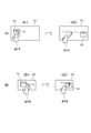
図5(A)は、移動量の説明に利用する図である。図5(A1)は、スクリーンSCの画像投射領域Q1の左端部にオブジェクト画像G1が表示された様子を操作者と共に表す図である。図5(A2)は、図5(A1)の状態において操作者が移動ジェスチャーを行い、オブジェクト画像G1の位置が、画像投射領域Q1の右端部へ移動した様子を操作者と共に表す図である。
ここで、1のオブジェクト画像について移動ジェスチャー(第1の操作)が行われた場合、後に説明する処理により、移動量調整部34が算出する移動量(第2の移動量)分、当該移動ジェスチャーに係る第1の方向へ向かって、当該1のオブジェクト画像が移動する。
すなわち、移動量とは、移動ジェスチャーが行われてオブジェクト画像の移動が行われた場合に、移動前のオブジェクト画像の位置と、移動後のオブジェクト画像の位置との離間距離のことである。図5(A)の例では、図5(A1)に示すオブジェクト画像G1の位置と、図5(A2)に示すオブジェクト画像G1の位置との離間距離が、移動量に相当する。
FIG. 5A is a diagram used for describing the amount of movement. FIG. 5A1 is a diagram illustrating a state in which the object image G1 is displayed at the left end of the image projection area Q1 of the screen SC together with the operator. FIG. 5A2 is a diagram illustrating a state in which the operator performs a movement gesture in the state of FIG. 5A1 and the position of the object image G1 moves to the right end of the image projection area Q1 together with the operator.
Here, when the movement gesture (first operation) is performed on one object image, the movement gesture is calculated by the movement amount (second movement amount) calculated by the movement
That is, the movement amount refers to a separation distance between the position of the object image before the movement and the position of the object image after the movement when the movement gesture is performed to move the object image. In the example of FIG. 5A, the distance between the position of the object image G1 shown in FIG. 5A1 and the position of the object image G1 shown in FIG. 5A2 corresponds to the movement amount.
ステップSA5において、移動量調整部34は、ステップSA3で取得した指示体移動距離と、ステップSA4で取得した移動量係数とに基づいて、以下の式で移動量を算出する。
(式) 移動量 = 指示体移動距離×移動量係数
In step SA5, the movement
(Formula) Moving amount = Pointer moving distance x Moving amount coefficient
ここで、上述したとおり、画像投射領域のサイズと、移動量係数とは、画像投射領域のサイズが大きいほど、対応する移動量係数が大きい関係にある。従って、上記の式で求められる移動量の値は、指示体移動距離が同一であれば、画像投射領域のサイズが大きいほど、大きくなる。これにより、以下の効果を奏する。 Here, as described above, the size of the image projection area and the movement amount coefficient have a relationship in which the larger the size of the image projection area, the larger the corresponding movement amount coefficient. Therefore, if the moving distance of the pointer is the same, the value of the moving amount obtained by the above equation becomes larger as the size of the image projection area becomes larger. This produces the following effects.
図5(B1)は、画像投射領域Q1よりもサイズが小さい画像投射領域Q2の左端部にオブジェクト画像G1が表示された様子を操作者と共に表す図である。図5(B2)は、図5(B1)の状態において操作者が、図5(A)と同一の態様の移動ジェスチャーを行い、オブジェクト画像G1の位置が、画像投射領域Q2の右端部へ移動した様子を操作者と共に表す図である。
同一の態様の移動ジェスチャーとは、移動ジェスチャーのそれぞれについて、第1の移動における指示体Sの指示位置の軌跡の方向である第1の方向と、第2の移動における指示体Sの指示位置の軌跡の方向である第2の方向とが一致し、また、指示体移動距離が一致することを意味する。
FIG. 5B1 is a diagram illustrating a state in which the object image G1 is displayed at the left end of the image projection area Q2 smaller in size than the image projection area Q1 together with the operator. FIG. 5B2 shows a state in which the operator performs a movement gesture in the same manner as in FIG. 5A in the state of FIG. 5B1, and the position of the object image G1 moves to the right end of the image projection area Q2. It is a figure showing the situation which performed with an operator.
The movement gesture in the same mode is, for each of the movement gestures, a first direction that is the direction of the trajectory of the pointing position of the pointer S in the first movement, and a pointing position of the pointing position of the pointer S in the second movement. It means that the second direction, which is the direction of the trajectory, matches, and that the pointer movement distance matches.
画像投射領域のサイズが大きいほど移動量係数が大きくなるため、同一の態様で移動ジェスチャーが行われた場合、画像投射領域のサイズが大きいほど、移動量が多くなる。例えば、図5(A)で示す画像投写領域のサイズ(第2のサイズ)のときにオブジェクト画像について移動ジェスチャー(第1の操作)が行われた時のオブジェクト画像の移動量(第2の移動量)と、図5(B)で示すように画像投写領域のサイズが図5(A)で示す画像投写領域より小さいサイズ(第1のサイズ)である場合に同一態様での移動ジェスチャー(第1の操作)を行った時のオブジェクト画像の移動量(第1の移動量)とでは、投写画像領域のサイズが大きい図5(A)で示す場合の移動量(第2の移動量)の方が大きくなっている。この結果、図5(A)と、図5(B)との比較で明らかなとおり、操作者は、オブジェクト画像を画像投射領域の1の端部から他の端部へ移動させる場合、画像投射領域のサイズにかかわらず、同様の態様で移動ジェスチャーを行えばよい。この結果、図5(B)の例のように、画像投射領域Q1の1の端部から他の端部へオブジェクト画像G1を移動させる場合に、従来の方法では歩行を伴う作業が必要であったが、作業者は、当該作業に代えて移動ジェスチャーを行ってオブジェクト画像G1を移動させることができ、作業者が行うべき作業(操作)が容易化する。 The larger the size of the image projection area, the larger the movement amount coefficient. Therefore, when the movement gesture is performed in the same manner, the larger the size of the image projection area, the larger the movement amount. For example, when the movement gesture (first operation) is performed on the object image when the size (second size) of the image projection area shown in FIG. 5A is used, the movement amount (second movement) of the object image 5A) and the movement gesture (the first size) in the same mode when the size of the image projection area is smaller than the image projection area shown in FIG. 5A (first size) as shown in FIG. 5B. The movement amount (first movement amount) of the object image when the (1) operation is performed is the movement amount (second movement amount) in the case where the size of the projection image area is large as shown in FIG. Is larger. As a result, as apparent from a comparison between FIG. 5A and FIG. 5B, when the operator moves the object image from one end of the image projection area to the other end, the operator performs image projection. Regardless of the size of the region, the movement gesture may be performed in a similar manner. As a result, when the object image G1 is moved from one end of the image projection area Q1 to the other end as in the example of FIG. 5B, a work involving walking is required in the conventional method. However, the worker can move the object image G1 by performing a movement gesture instead of the work, and the work (operation) to be performed by the worker is facilitated.
続くステップSA6において、投射制御部31は、画像処理部40を制御して、フレームメモリー41におけるオブジェクト画像の画像データの展開位置を移動させ、移動ジェスチャーによる移動の対象となったオブジェクト画像について、画像投射領域における表示位置を、ステップSA6で移動量調整部34が算出した移動量分、第1の方向に移動させる。
ステップSA6の処理の結果、移動ジェスチャーに対応して、オブジェクト画像の位置が、画像投射領域のサイズに対応する移動量分、移動する。
In the following step SA6, the
As a result of the processing in step SA6, the position of the object image is moved by a movement amount corresponding to the size of the image projection area in accordance with the movement gesture.
なお、ステップSA6において、オブジェクト画像が外部の装置から供給された画像データに基づく画像である場合は、投射制御部31は、以下の処理を行ってもよい。すなわち、移動ジェスチャーに伴う移動後のオブジェクト画像の座標を示す情報を外部の装置に送信する。外部の装置は、受信した情報に基づいて、例えば、オブジェクト画像の表示位置を管理するための情報を更新し、当該情報をオブジェクト画像の実際の表示位置に対応する値とする。
If the object image is an image based on image data supplied from an external device in step SA6, the
以上説明したように、本実施形態に係るプロジェクター100は、スクリーンSC(投射面)にオブジェクト画像(第1のオブジェクト)を含む投射画像を投射する投射部20と、画像投射領域(投射画像が投射される領域)のサイズを検出する投射サイズ検出部32と、スクリーンSCに対する指示体S(第1の指示体70、第2の指示体80)の操作を検出する検出部33と、検出部33により検出した指示体Sの操作が、移動ジェスチャー(オブジェクト画像を移動させる操作)であった場合、画像投射領域のサイズに応じて、オブジェクト画像の移動量を異ならせる移動量調整部34と、を備える。
この構成によれば、プロジェクター100は、画像投射量領域のサイズが一定でないことに対応して、移動ジェスチャーに基づいてオブジェクト画像の位置を移動させるときの移動量を、画像投射領域のサイズに対応した値とすることができる。
As described above, the
According to this configuration, in response to the fact that the size of the image projection amount area is not constant, the
また、本実施形態では、移動量調整部34は、画像投射領域のサイズが第1のサイズの場合に指示体Sの操作(第1の操作)が行われた時のオブジェクト画像の移動量(第1の移動量)と、画像投射領域のサイズが第1のサイズよりも大きい第2のサイズの場合に指示体Sの操作(第1のサイズの場合に行う操作と同様な操作である第1の操作)が行われた場合の移動量(第2の移動量)とでは、第2のサイズの場合の方がオブジェクト画像の移動量(第2の移動量)を大きくする。
また、移動量調整部34は、画像投射領域のサイズが大きいほど、同様の指示体Sの操作が行われた場合におけるオブジェクト画像の移動量を大きくする。
この構成によれば、画像投射領域のサイズが大きいほど、同一の態様で移動ジェスチャーが行われたときのオブジェクト画像の移動量を大きくすることができ、操作者によるオブジェクト画像の移動が容易化する。
In the present embodiment, the movement
In addition, the movement
According to this configuration, as the size of the image projection area is larger, the amount of movement of the object image when the movement gesture is performed in the same manner can be increased, and the movement of the object image by the operator is facilitated. .
また、本実施形態では、移動ジェスチャーは、指示体SがスクリーンSCに接触して移動する状態から非接触で移動する状態へ連続して移行する操作である。
そして、移動量調整部34は、指示体SがスクリーンSCに非接触の状態へ移行した後の指示体Sの移動距離(指示体移動距離)に、画像投射領域のサイズに応じた係数(移動量係数)を乗じてオブジェクト画像の移動量を算出する。
この構成によれば、操作者が、オブジェクト画像を移動させる意思をもって意図的に行ったジェスチャーを、移動ジェスチャーとして判定できる。また、移動ジェスチャーとして判定されるジェスチャーは、物理的な紙媒体を所定方向に移動させるときに行う動作を連想させるものであり、ユーザーにとって、移動ジェスチャーとして判定させるためにおこなうべき作業をイメージしやすい。また、移動量調整部34は、移動量係数を用いて、移動量の値を、画像投射領域のサイズに応じた適切な値とすることができる。
In the present embodiment, the movement gesture is an operation for continuously shifting from a state in which the pointer S moves in contact with the screen SC to a state in which the pointer S moves without contact.
Then, the movement
According to this configuration, a gesture intentionally performed by the operator with an intention to move the object image can be determined as a movement gesture. The gesture determined as a movement gesture is associated with an operation performed when a physical paper medium is moved in a predetermined direction, and it is easy for a user to imagine an operation to be performed to determine the gesture as a movement gesture. . Further, the movement
また、本実施形態では、投射サイズ検出部32は、投射部20によりスクリーンSCに特定パターン画像(特定のパターン画像)を投射させ、特定パターン画像が投射されたスクリーンSCを撮影部51により撮影させ、撮影部51による撮影結果に基づいて、画像投射領域のサイズを検出する。
この構成によれば、画像投射領域のサイズの検出について、ユーザーの作業が必要なく、ユーザーの利便性が向上する。
In the present embodiment, the projection
According to this configuration, the operation of the user is not required for detecting the size of the image projection area, and the convenience for the user is improved.
なお、上述した実施形態及び変形例は本発明を適用した具体的態様の例に過ぎず、本発明を限定するものではなく、異なる態様として本発明を適用することも可能である。例えば、第1の指示体70はペン型の指示体に限らず、第2の指示体80は操作者の手指に限らない。例えば、第1の指示体70として、レーザーポインターや指示棒等を用いてもよく、その形状やサイズは限定されない。
Note that the above-described embodiments and modified examples are merely examples of specific aspects to which the present invention is applied, and do not limit the present invention. The present invention can be applied as different aspects. For example, the
また、上記実施形態では、位置検出部50は、撮影部51によりスクリーンSCを撮影して第1の指示体70及び第2の指示体80の位置を特定するものとしたが、本発明はこれに限定されない。例えば、撮影部51は、プロジェクター100の本体に設けられ、投射光学系23の投射方向を撮影するものに限定されない。撮影部51をプロジェクター100本体とは別体とした構成とし、撮影部51がスクリーンSCの側方や正面から撮影を行うものとしてもよい。
また、上記実施形態では、フロントプロジェクション型のプロジェクター100から画像が投射(表示)されるスクリーンSCに対して、ユーザーが第1の指示体70及び第2の指示体80による操作を行う態様について説明した。これ以外に、プロジェクター100以外の表示装置が表示する表示画面に対して指示操作を行う態様であってもよい。プロジェクター100以外の表示装置としては、リアプロジェクション(背面投射)型のプロジェクター、液晶ディスプレイ、有機EL(Electro Luminescence)ディスプレイを用いることができる。また、表示装置としては、プラズマディスプレイ、CRT(陰極線管)ディスプレイ、SED(Surface-conduction Electron-emitter Display)等を用いることができる。
In the above embodiment, the
In the above-described embodiment, a mode in which the user operates the
また、上記実施形態では、プロジェクター100から第1の指示体70に対し、送信部52が発する赤外線信号を用いて第1の指示体70に同期用の信号を送信する構成を説明したが、同期用の信号は赤外線信号に限定されない。例えば、電波通信や超音波無線通信により同期用の信号を送信する構成としてもよい。この構成は、電波通信や超音波無線通信により信号を送信する送信部52をプロジェクター100に設け、同様の受信部を第1の指示体70に設けることで実現できる。
In the above-described embodiment, the configuration has been described in which the synchronization signal is transmitted from the
また、上記実施形態では、光源が発した光を変調する光変調装置22として、RGBの各色に対応した3枚の透過型の液晶パネルを用いた構成を例に挙げて説明したが、本発明はこれに限定されるものではない。例えば、3枚の反射型液晶パネルを用いた構成としてもよいし、1枚の液晶パネルとカラーホイールを組み合わせた方式を用いてもよい。また、3枚のデジタルミラーデバイス(DMD)を用いた方式、1枚のデジタルミラーデバイスとカラーホイールを組み合わせたDMD方式等により構成してもよい。光変調装置として1枚のみの液晶パネル又はDMDを用いる場合には、クロスダイクロイックプリズム等の合成光学系に相当する部材は不要である。また、液晶パネル及びDMD以外にも、光源が発した光を変調可能な光変調装置であれば問題なく採用できる。
Further, in the above embodiment, the configuration using three transmissive liquid crystal panels corresponding to each color of RGB as the
また、図2に示したプロジェクター100の各機能部は機能的構成を示すものであって、具体的な実装形態は特に制限されない。つまり、必ずしも各機能部に個別に対応するハードウェアが実装される必要はなく、一つのプロセッサーがプログラムを実行することで複数の機能部の機能を実現する構成とすることも勿論可能である。また、上記実施形態においてソフトウェアで実現される機能の一部をハードウェアで実現してもよく、あるいは、ハードウェアで実現される機能の一部をソフトウェアで実現してもよい。その他、プロジェクター100の他の各部の具体的な細部構成についても、本発明の趣旨を逸脱しない範囲で任意に変更可能である。
Each functional unit of the
20…投射部、32…投射サイズ検出部、33…検出部、34…移動量調整部、51…撮影部、100…プロジェクター、70…第1の指示体(指示体)、80…第2の指示体(指示体)。 Reference numeral 20: projection unit, 32: projection size detection unit, 33: detection unit, 34: movement amount adjustment unit, 51: imaging unit, 100: projector, 70: first indicator (indicator), 80: second Pointer (pointer).
Claims (6)
前記投射画像が投射される領域のサイズを検出する投射サイズ検出部と、
前記投射面に対する指示体の指示位置を検出する位置検出部と、
前記第1のオブジェクトの移動量を算出して調整するものであり、前記位置検出部により検出した、前記投射面に沿った方向に移動する前記指示位置の軌道が、前記第1のオブジェクトを移動させる操作に該当する場合、前記投射画像が投射される領域のサイズに応じて、前記第1のオブジェクトの移動量を異ならせる移動量調整部と、を備え、
前記移動量調整部は、前記投射画像が投射される領域のサイズが第1のサイズの場合に前記第1のオブジェクトを移動させる第1の操作が行われた時の前記第1のオブジェクトの第1の移動量と、前記投射画像が投射される領域のサイズが前記第1のサイズよりも大きい第2のサイズの場合に前記第1の操作が行われた時の前記第1のオブジェクトの第2の移動量とでは、前記第2の移動量を大きくする
ことを特徴とするプロジェクター。 A projection unit configured to project a projection image including the first object on a projection surface;
A projection size detection unit that detects the size of the area where the projection image is projected,
A position detection unit that detects a pointing position of the pointer with respect to the projection surface,
The movement amount of the first object is calculated and adjusted, and the trajectory of the designated position moving in the direction along the projection plane detected by the position detection unit moves the first object. A moving amount adjustment unit that varies a moving amount of the first object according to a size of an area where the projection image is projected,
The movement amount adjustment unit is configured to control a position of the first object when a first operation of moving the first object is performed when a size of the area where the projection image is projected is a first size. 1 and the second size of the first object when the first operation is performed when the size of the area where the projection image is projected is a second size larger than the first size. The projector according to claim 2, wherein the second movement amount is increased by the second movement amount.
前記移動量調整部により求めた移動量分、前記第1のオブジェクトを前記領域において移動させることを特徴とする請求項1に記載のプロジェクター。 The movement amount adjustment unit sets the movement amount of the first object to an amount larger than the movement amount of the designated position according to a size of an area where the projection image is projected,
The projector according to claim 1, wherein the first object is moved in the area by the movement amount obtained by the movement amount adjustment unit.
前記移動量調整部により求めた移動量分、前記第1のオブジェクトを前記第1の方向に移動させることを特徴とする請求項2に記載のプロジェクター。 The movement amount adjustment unit multiplies a movement amount of the designated position in a first direction along the projection surface by a movement amount coefficient corresponding to a size of the region, and the first amount in the first direction. Calculate the amount of movement of the object,
The projector according to claim 2, wherein the first object is moved in the first direction by the movement amount obtained by the movement amount adjustment unit.
前記指示位置が前記投射面に接触しつつ移動する第1の移動と、前記第1の移動に連続し、前記指示位置が前記投射面に非接触の状態で移動する第2の移動とが検出された場合に、前記移動量調整部は、前記第2の移動における前記指示位置の移動量に、前記投射画像が投射される領域のサイズに応じた移動量係数を乗じて前記第1のオブジェクトの移動量を算出することを特徴とする請求項3に記載のプロジェクター。 The position detection unit, the pointing position of the indicator is in contact with the projection surface, and detects the pointing position of the indicator is in non-contact with the projection surface,
A first movement in which the designated position moves while contacting the projection surface and a second movement continuous with the first movement and in which the designated position moves without contacting the projection surface are detected. In this case, the movement amount adjustment unit multiplies the movement amount of the designated position in the second movement by a movement amount coefficient corresponding to a size of an area on which the projection image is projected, so that the first object The projector according to claim 3, wherein the movement amount is calculated.
前記投射サイズ検出部は、
前記投射部により前記投射面に特定のパターン画像を投射させ、前記パターン画像が投射された前記投射面を前記撮影部により撮影させ、前記撮影部による撮影結果に基づいて、前記投射画像が投射される領域のサイズを検出することを特徴とする請求項1乃至4のいずれか1項に記載のプロジェクター。 An imaging unit for imaging the projection surface,
The projection size detector,
The projection unit projects a specific pattern image on the projection surface, the projection surface on which the pattern image is projected is shot by the shooting unit, and the projection image is projected based on a shooting result by the shooting unit. The projector according to any one of claims 1 to 4, wherein a size of an area to be detected is detected.
前記投射画像が投射される領域のサイズを検出し、
前記投射面に対する指示体の指示位置を検出し、
前記投射面に沿った方向に移動する前記指示位置の軌道が、前記第1のオブジェクトを移動させる操作に該当する場合、前記第1のオブジェクトの移動量を算出して調整する処理により、前記投射画像が投射される領域のサイズに応じて、前記第1のオブジェクトの移動量を異ならせ、
前記投射画像が投射される領域のサイズが第1のサイズの場合に前記第1のオブジェクトを移動させる第1の操作が行われた時の前記第1のオブジェクトの第1の移動量と、前記投射画像が投射される領域のサイズが前記第1のサイズよりも大きい第2のサイズの場合に前記第1の操作が行われた時の前記第1のオブジェクトの第2の移動量とでは、前記第2の移動量を大きくする
ことを特徴とするプロジェクターの制御方法。 A control method of a projector including a projection unit configured to project a projection image including a first object on a projection surface,
Detecting the size of the area where the projection image is projected,
Detecting a pointing position of the pointer with respect to the projection surface,
When the trajectory of the designated position moving in the direction along the projection plane corresponds to an operation of moving the first object, the projection amount is calculated by a process of calculating and adjusting the amount of movement of the first object. Making the amount of movement of the first object different according to the size of the area where the image is projected;
A first movement amount of the first object when a first operation of moving the first object is performed when a size of an area where the projection image is projected is a first size; The second movement amount of the first object when the first operation is performed when the size of the area on which the projection image is projected is a second size larger than the first size, A method for controlling a projector, comprising: increasing the second movement amount.
Priority Applications (3)
| Application Number | Priority Date | Filing Date | Title |
|---|---|---|---|
| JP2015068094A JP6665415B2 (en) | 2015-03-30 | 2015-03-30 | Projector and projector control method |
| US15/560,380 US20180075821A1 (en) | 2015-03-30 | 2016-03-18 | Projector and method of controlling projector |
| PCT/JP2016/001602 WO2016157804A1 (en) | 2015-03-30 | 2016-03-18 | Projector and projector control method |
Applications Claiming Priority (1)
| Application Number | Priority Date | Filing Date | Title |
|---|---|---|---|
| JP2015068094A JP6665415B2 (en) | 2015-03-30 | 2015-03-30 | Projector and projector control method |
Publications (3)
| Publication Number | Publication Date |
|---|---|
| JP2016188892A JP2016188892A (en) | 2016-11-04 |
| JP2016188892A5 JP2016188892A5 (en) | 2018-04-26 |
| JP6665415B2 true JP6665415B2 (en) | 2020-03-13 |
Family
ID=57004905
Family Applications (1)
| Application Number | Title | Priority Date | Filing Date |
|---|---|---|---|
| JP2015068094A Active JP6665415B2 (en) | 2015-03-30 | 2015-03-30 | Projector and projector control method |
Country Status (3)
| Country | Link |
|---|---|
| US (1) | US20180075821A1 (en) |
| JP (1) | JP6665415B2 (en) |
| WO (1) | WO2016157804A1 (en) |
Families Citing this family (4)
| Publication number | Priority date | Publication date | Assignee | Title |
|---|---|---|---|---|
| JP2019078845A (en) * | 2017-10-23 | 2019-05-23 | セイコーエプソン株式会社 | Projector and method for controlling projector |
| JP6868665B2 (en) * | 2019-07-03 | 2021-05-12 | 三菱電機インフォメーションシステムズ株式会社 | Data entry device, data entry method and data entry program |
| JPWO2022044386A1 (en) * | 2020-08-28 | 2022-03-03 | ||
| CN114363595A (en) * | 2021-12-31 | 2022-04-15 | 上海联影医疗科技股份有限公司 | Projection device and inspection equipment |
Family Cites Families (15)
| Publication number | Priority date | Publication date | Assignee | Title |
|---|---|---|---|---|
| ES2435248T3 (en) * | 2000-07-05 | 2013-12-17 | Smart Technologies Ulc | Touch system and camera-based method |
| JP2003280813A (en) * | 2002-03-25 | 2003-10-02 | Ejikun Giken:Kk | Pointing device, pointer controller, pointer control method and recording medium with the method recorded thereon |
| JP2005148661A (en) * | 2003-11-19 | 2005-06-09 | Sony Corp | Information processing apparatus and information processing method |
| US20070013873A9 (en) * | 2004-04-29 | 2007-01-18 | Jacobson Joseph M | Low cost portable computing device |
| KR20080040930A (en) * | 2006-11-06 | 2008-05-09 | 삼성전자주식회사 | Computer system and control method of the same |
| JP5346941B2 (en) * | 2008-09-16 | 2013-11-20 | パナソニック株式会社 | Data display apparatus, integrated circuit, data display method, data display program, and recording medium |
| US8297757B2 (en) * | 2008-10-29 | 2012-10-30 | Seiko Epson Corporation | Projector and projector control method |
| JP5488306B2 (en) * | 2010-07-29 | 2014-05-14 | 船井電機株式会社 | projector |
| US20120044140A1 (en) * | 2010-08-19 | 2012-02-23 | Sanyo Electric Co., Ltd. | Information display system and program, and optical input system, projection-type images and display apparatus |
| JP5853394B2 (en) * | 2011-04-07 | 2016-02-09 | セイコーエプソン株式会社 | Cursor display system, cursor display method, and projector |
| WO2013191888A1 (en) * | 2012-06-20 | 2013-12-27 | 3M Innovative Properties Company | Device allowing tool-free interactivity with a projected image |
| JP2014029656A (en) * | 2012-06-27 | 2014-02-13 | Soka Univ | Image processor and image processing method |
| JP2014089522A (en) * | 2012-10-29 | 2014-05-15 | Kyocera Corp | Electronic apparatus and control program, and operation method of electronic apparatus |
| US10394434B2 (en) * | 2013-02-22 | 2019-08-27 | Samsung Electronics Co., Ltd. | Apparatus and method for recognizing proximity motion using sensors |
| US9785243B2 (en) * | 2014-01-30 | 2017-10-10 | Honeywell International Inc. | System and method for providing an ergonomic three-dimensional, gesture based, multimodal interface for use in flight deck applications |
-
2015
- 2015-03-30 JP JP2015068094A patent/JP6665415B2/en active Active
-
2016
- 2016-03-18 WO PCT/JP2016/001602 patent/WO2016157804A1/en active Application Filing
- 2016-03-18 US US15/560,380 patent/US20180075821A1/en not_active Abandoned
Also Published As
| Publication number | Publication date |
|---|---|
| JP2016188892A (en) | 2016-11-04 |
| US20180075821A1 (en) | 2018-03-15 |
| WO2016157804A1 (en) | 2016-10-06 |
Similar Documents
| Publication | Publication Date | Title |
|---|---|---|
| JP6064319B2 (en) | Projector and projector control method | |
| JP5849560B2 (en) | Display device, projector, and display method | |
| US9645678B2 (en) | Display device, and method of controlling display device | |
| JP6387644B2 (en) | Position detection device, position detection system, and position detection method | |
| US10431131B2 (en) | Projector and control method for projector | |
| JP6349838B2 (en) | POSITION DETECTION DEVICE, POSITION DETECTION SYSTEM, AND POSITION DETECTION DEVICE CONTROL METHOD | |
| JP6665415B2 (en) | Projector and projector control method | |
| WO2016157803A1 (en) | Display device, display device control method, document camera and document camera control method | |
| JP6051828B2 (en) | Display device and control method of display device | |
| US9870073B2 (en) | Position detection device, projector, and position detection method | |
| EP2916201B1 (en) | Position detecting device and position detecting method | |
| US9841892B2 (en) | Position detection device, projector, and position detection method | |
| JP6269801B2 (en) | Projector and projector control method | |
| JP6273671B2 (en) | Projector, display system, and projector control method | |
| JP6439398B2 (en) | Projector and projector control method | |
| JP2019117322A (en) | Projection type display unit, method of controlling the same, and program | |
| JP6098153B2 (en) | Display device and control method of display device | |
| JP6111682B2 (en) | Display device and control method of display device | |
| JP6056447B2 (en) | Display device and control method of display device | |
| JP6255810B2 (en) | Display device and control method of display device | |
| JP6145963B2 (en) | Projector, display system, and projector control method | |
| JP6524741B2 (en) | Position detection device, display device, control method of position detection device, and control method of display device | |
| WO2016075905A1 (en) | Display device, and method of controlling display device | |
| JP2019078901A (en) | Projection device and control method thereof, and program |
Legal Events
| Date | Code | Title | Description |
|---|---|---|---|
| A521 | Request for written amendment filed |
Free format text: JAPANESE INTERMEDIATE CODE: A523 Effective date: 20180314 |
|
| A621 | Written request for application examination |
Free format text: JAPANESE INTERMEDIATE CODE: A621 Effective date: 20180314 |
|
| A131 | Notification of reasons for refusal |
Free format text: JAPANESE INTERMEDIATE CODE: A131 Effective date: 20181113 |
|
| A521 | Request for written amendment filed |
Free format text: JAPANESE INTERMEDIATE CODE: A523 Effective date: 20190111 |
|
| A131 | Notification of reasons for refusal |
Free format text: JAPANESE INTERMEDIATE CODE: A131 Effective date: 20190702 |
|
| A521 | Request for written amendment filed |
Free format text: JAPANESE INTERMEDIATE CODE: A523 Effective date: 20190823 |
|
| TRDD | Decision of grant or rejection written | ||
| A01 | Written decision to grant a patent or to grant a registration (utility model) |
Free format text: JAPANESE INTERMEDIATE CODE: A01 Effective date: 20200121 |
|
| A61 | First payment of annual fees (during grant procedure) |
Free format text: JAPANESE INTERMEDIATE CODE: A61 Effective date: 20200203 |
|
| R150 | Certificate of patent or registration of utility model |
Ref document number: 6665415 Country of ref document: JP Free format text: JAPANESE INTERMEDIATE CODE: R150 |