JP6255810B2 - Display device and control method of display device - Google Patents

Display device and control method of display device Download PDF

Info

Publication number
JP6255810B2
JP6255810B2 JP2013184770A JP2013184770A JP6255810B2 JP 6255810 B2 JP6255810 B2 JP 6255810B2 JP 2013184770 A JP2013184770 A JP 2013184770A JP 2013184770 A JP2013184770 A JP 2013184770A JP 6255810 B2 JP6255810 B2 JP 6255810B2
Authority
JP
Japan
Prior art keywords
function
area
image
display
operation area
Prior art date
Legal status (The legal status is an assumption and is not a legal conclusion. Google has not performed a legal analysis and makes no representation as to the accuracy of the status listed.)
Expired - Fee Related
Application number
JP2013184770A
Other languages
Japanese (ja)
Other versions
JP2015052874A (en
JP2015052874A5 (en
Inventor
博行 市枝
博行 市枝
Current Assignee (The listed assignees may be inaccurate. Google has not performed a legal analysis and makes no representation or warranty as to the accuracy of the list.)
Seiko Epson Corp
Original Assignee
Seiko Epson Corp
Priority date (The priority date is an assumption and is not a legal conclusion. Google has not performed a legal analysis and makes no representation as to the accuracy of the date listed.)
Filing date
Publication date
Application filed by Seiko Epson Corp filed Critical Seiko Epson Corp
Priority to JP2013184770A priority Critical patent/JP6255810B2/en
Priority to US14/105,507 priority patent/US9645678B2/en
Priority to CN201310689418.3A priority patent/CN103870233B/en
Publication of JP2015052874A publication Critical patent/JP2015052874A/en
Publication of JP2015052874A5 publication Critical patent/JP2015052874A5/ja
Application granted granted Critical
Publication of JP6255810B2 publication Critical patent/JP6255810B2/en
Expired - Fee Related legal-status Critical Current
Anticipated expiration legal-status Critical

Links

Images

Landscapes

  • Position Input By Displaying (AREA)
  • User Interface Of Digital Computer (AREA)

Description

本発明は、表示面に画像を表示する表示装置、及び、表示装置の制御方法に関する。   The present invention relates to a display device that displays an image on a display surface and a control method for the display device.

従来、プロジェクター等の表示装置が表示する画像の特定の位置が指示体により指示された場合に、指示位置を検出し、検出した位置に対応するようにポインター等を表示する装置が知られている(例えば、特許文献1参照)。この種の装置では、指示された位置を検出すると、例えば指示された位置に対応してポインターを表示し、指示位置の軌跡を示す画像を描画、表示したりして、表示面に表示された画像が制御される。   Conventionally, when a specific position of an image displayed by a display device such as a projector is instructed by an indicator, an apparatus that detects the indicated position and displays a pointer or the like so as to correspond to the detected position is known. (For example, refer to Patent Document 1). In this type of apparatus, when the designated position is detected, for example, a pointer is displayed corresponding to the designated position, and an image indicating the locus of the designated position is drawn and displayed, and displayed on the display surface. The image is controlled.

特開2004−272433号公報JP 2004-272433 A

しかしながら、表示装置を制御して、表示装置の各種機能を実行するためには、表示装置本体に設けられた操作ボタンや表示装置を遠隔操作するリモコン等を用いて行う必要があった。そのため、ユーザーは表示画像を制御する指示体と、表示装置を制御するリモコン等とを切り替えて使用する必要があり、操作性の向上が望まれていた。
本発明は、上述した従来の技術が有する課題を解消し、表示装置の各種機能を実行する際の操作性の向上を図ることを目的とする。
However, in order to control the display device and execute various functions of the display device, it has been necessary to use an operation button provided on the display device body, a remote control for remotely operating the display device, or the like. Therefore, it is necessary for the user to switch between an indicator for controlling the display image and a remote controller for controlling the display device, and improvement in operability has been desired.
An object of the present invention is to solve the problems of the conventional technology described above and to improve operability when executing various functions of a display device.

上記目的を達成するために、本発明は、表示面に画像を表示する表示手段と、前記表示面における操作位置を検出する検出手段と、前記表示面における画像の表示領域の外側に操作領域が設定され、前記検出手段により検出された前記操作位置が前記操作領域内である場合に、当該操作領域に対応付けられた操作に関する機能を実行する制御手段と、前記操作領域に表示されているパターンを認識する認識手段と、前記認識手段が認識したパターンに応じた機能情報を前記操作領域に対応付ける設定手段と、を備え、前記制御手段は、前記操作位置が前記操作領域内である場合に、前記操作領域に対応付けられた前記機能情報に基づく機能を実行することを特徴とする。
このような表示装置によれば、表示面上の操作領域内に表示されているパターンを認識する。そして、操作を行った操作領域のパターンに対応する表示装置の機能を実行することができる。
In order to achieve the above object, the present invention provides a display means for displaying an image on a display surface, a detection means for detecting an operation position on the display surface, and an operation area outside the image display area on the display surface. When the operation position set and detected by the detection means is within the operation area, a control means for executing a function related to an operation associated with the operation area, and a pattern displayed in the operation area Recognizing means for recognizing and setting means for associating functional information corresponding to the pattern recognized by the recognizing means with the operation area, and the control means when the operation position is within the operation area, A function based on the function information associated with the operation area is executed.
According to such a display device, the pattern displayed in the operation area on the display surface is recognized. And the function of the display apparatus corresponding to the pattern of the operation area | region which operated can be performed.

また、本発明は、上記表示装置において、前記認識手段は、前記操作領域に表示されているパターンを検出するパターン検出手段と、パターンに対応付けられた機能情報を記憶する機能記憶手段と、前記パターン検出手段が検出したパターンに対応した機能情報を前記機能記憶手段から取得する機能取得手段と、を有することを特徴とする。
このような表示装置によれば、機能記憶手段は、パターンに対応付けられた機能情報を記憶する。機能取得手段は、検出したパターンに対応した機能情報を機能記憶手段から取得する。これにより、パターンが表示された操作領域で操作が行われた際に、機能記憶手段に記憶されたパターンと機能情報に基づいて、表示装置の機能を実行することができる。
In the display device according to the present invention, the recognition unit includes a pattern detection unit that detects a pattern displayed in the operation area, a function storage unit that stores functional information associated with the pattern, And a function acquisition unit that acquires function information corresponding to the pattern detected by the pattern detection unit from the function storage unit.
According to such a display device, the function storage unit stores the function information associated with the pattern. The function acquisition unit acquires function information corresponding to the detected pattern from the function storage unit. Accordingly, when an operation is performed in the operation area where the pattern is displayed, the function of the display device can be executed based on the pattern and the function information stored in the function storage unit.

また、本発明は、上記表示装置において、前記操作位置が、前記パターン検出手段によってパターンが検出されない操作領域内である場合、前記制御手段は、機能を実行しないことを特徴とする。
このような表示装置によれば、操作位置が、パターンが検出されない操作領域である場合には、機能を実行しない。これにより、パターンが存在しない操作領域において操作が行われても誤って機能が実行されることを防止できる。
Further, the present invention is characterized in that, in the display device, the control means does not execute a function when the operation position is within an operation area where a pattern is not detected by the pattern detection means.
According to such a display device, the function is not executed when the operation position is an operation region in which no pattern is detected. Thereby, even if an operation is performed in an operation area where no pattern exists, it is possible to prevent the function from being erroneously executed.

また、本発明は、上記表示装置において、前記表示領域を含む範囲を撮影する撮像手段を備え、前記検出手段は、前記撮像手段の撮影画像に基づいて前記操作位置を検出し、前記操作領域は、前記撮像手段の撮影可能領域内に設定されたことを特徴とする。
この構成によれば、表示されている画像に対する操作位置をより速やかに、かつ正確に検出できる。
The display device may further include an imaging unit that captures a range including the display region, the detection unit detects the operation position based on a captured image of the imaging unit, and the operation region is The image pickup unit is set within a shootable area.
According to this configuration, the operation position for the displayed image can be detected more quickly and accurately.

また、本発明は、上記表示装置において、前記制御手段は、前記検出手段により前記操作領域に対する操作が検出された場合に、前記表示領域に表示されている画像を他の画像に切り替える切替機能、表示されている画像を静止させるフリーズ機能、画像の表示を停止するミュート機能、表示されている画像を拡大または縮小させるズーム機能、前記表示領域に表示されている画像の表示位置を変更する機能、および、前記検出手段により検出された操作位置を示す情報を前記表示装置内部で処理するモードと当該情報を外部に出力するモードとを切り替える機能のうち、少なくともいずれかを実行することを特徴とする。
この構成によれば、表示装置の操作パネルやリモコンを操作することなく、表示面上の操作領域に対する操作で、表示装置が有する種々の機能を操作することができ、操作性の向上を図ることができる。
In the display device according to the aspect of the invention, the control unit may switch the image displayed in the display region to another image when an operation on the operation region is detected by the detection unit. A freeze function that freezes the displayed image, a mute function that stops the display of the image, a zoom function that enlarges or reduces the displayed image, a function that changes the display position of the image displayed in the display area, And at least one of a function of switching between a mode for processing the information indicating the operation position detected by the detection means inside the display device and a mode for outputting the information to the outside. .
According to this configuration, various functions of the display device can be operated by operating the operation area on the display surface without operating the operation panel or the remote control of the display device, thereby improving operability. Can do.

また、上記目的を達成するために、本発明は、表示面に画像を表示する表示手段を備える表示装置の制御方法であって、前記表示面における操作位置を検出する検出ステップと、前記表示面における画像の表示領域の外側に操作領域が設定され、前記検出ステップによって検出された前記操作位置が前記操作領域内である場合に、当該操作領域に対応付けられた操作に関する機能を実行する制御ステップと、前記操作領域に表示されているパターンを認識する認識ステップと、前記認識ステップによって認識されたパターンに応じた機能情報を前記操作領域に対応付ける設定ステップと、を備え、前記制御ステップでは、前記操作位置が前記操作領域内である場合に、前記操作領域に対応付けられた前記機能情報に基づく機能を実行することを特徴とする。
このような表示装置の制御方法によれば、表示面上の操作領域内に表示されているパターンを認識する。そして、操作を行った操作領域のパターンに対応する表示装置の機能を実行することができる。
In order to achieve the above object, the present invention provides a control method for a display device including display means for displaying an image on a display surface, the detection step for detecting an operation position on the display surface, and the display surface A control step of executing a function related to an operation associated with the operation region when the operation region is set outside the image display region in the image and the operation position detected by the detection step is within the operation region And a recognition step for recognizing a pattern displayed in the operation area; and a setting step for associating functional information corresponding to the pattern recognized in the recognition step with the operation area. In the control step, When the operation position is within the operation area, the function based on the function information associated with the operation area is executed. And features.
According to such a control method of the display device, the pattern displayed in the operation area on the display surface is recognized. And the function of the display apparatus corresponding to the pattern of the operation area | region which operated can be performed.

本発明によれば、表示面上の操作領域内での操作で、操作を行った操作領域に対応する表示装置の機能を操作することができ、表示装置の各種機能を実行する操作の操作性を向上することができる。   According to the present invention, it is possible to operate the function of the display device corresponding to the operated region by the operation in the operation region on the display surface, and the operability of the operation for executing various functions of the display device. Can be improved.

第1の実施形態に係る表示システムの構成を示す図である。It is a figure which shows the structure of the display system which concerns on 1st Embodiment. 表示システムを構成する各部の機能ブロック図である。It is a functional block diagram of each part which comprises a display system. 表示システムの動作を示すフローチャートである。It is a flowchart which shows operation | movement of a display system. スクリーン上の操作領域の配置例と操作に対応して表示を制御する動作を説明する図であり、(A)は表示切替機能に関する例を示し、(B)はソース切換機能に関する例を示し、(C)はズーム機能に関する例を示す。It is a figure explaining the operation | movement which controls the display corresponding to the example of arrangement | positioning of the operation area | region on a screen, and operation, (A) shows the example regarding a display switching function, (B) shows the example regarding a source switching function, (C) shows an example relating to the zoom function. スクリーン上の操作領域の配置例と操作に対応して表示を制御する動作を説明する図であり、(A)は横スクロール機能に関する例を示し、(B)は縦スクロール機能に関する例を示し、(C)はミュート機能に関する例を示し、(D)はネットワーク接続待機機能に関する例を示し、(E)は操作ロック/解除機能に関する例を示す。It is a figure explaining the operation | movement which controls the display corresponding to the example of arrangement | positioning of the operation area | region on a screen, and operation, (A) shows the example regarding a horizontal scroll function, (B) shows the example regarding a vertical scroll function, (C) shows an example related to the mute function, (D) shows an example related to the network connection standby function, and (E) shows an example related to the operation lock / release function. 第2の実施形態に係る表示システムの機能的構成を示すブロック図である。It is a block diagram which shows the functional structure of the display system which concerns on 2nd Embodiment. 機能テーブルの説明図である。It is explanatory drawing of a function table. マークの検出処理のフローチャートである。It is a flowchart of the detection process of a mark. 指示体によって、プロジェクターの機能を実行する操作が行われた際のプロジェクターの動作を示すフローチャートである。It is a flowchart which shows operation | movement of a projector when operation which performs the function of a projector is performed by the indicator. スクリーン上の操作領域の配置例と操作に対応して表示を制御する動作を説明する図であり、(A)はズーム機能に関する例を示し、(B)はソース切換機能に関する例を示す。It is a figure explaining the operation | movement which controls the display corresponding to the example of arrangement | positioning of the operation area | region on a screen, and operation, (A) shows the example regarding a zoom function, (B) shows the example regarding a source switching function. マークが印刷されたスクリーンの正面図である。It is a front view of the screen on which the mark was printed.

以下、図面を参照して本発明を適用した実施形態について説明する。
(第1の実施形態)
図1は、第1の実施形態に係るプロジェクター11を用いた表示システム10の構成を示す図である。
表示装置としてのプロジェクター11は、画像供給部としてのPC(Personal Computer)13に画像信号ケーブル等により有線接続されている。PC13は、モニター144を有し、例えば、モニター144に表示中の画像と同じ画像の画像データをプロジェクター11に出力する。
プロジェクター11は、入力された画像データに基づいて、投射面(表示面)としてのスクリーンSCに表示画像を投射する。PC13から入力される画像データは動画像(映像)データおよび静止画像データのいずれであってもよく、プロジェクター11は入力される画像データに基づき動画像および静止画像のいずれも投射できる。また、プロジェクター11は、画像データを伝送する画像信号ケーブル等とは別に、USBケーブルやLANケーブル等の制御信号伝送用の通信回線によりPC13に接続され、この通信回線を介してPC13との間で制御データ等を送受信する。なお、制御信号伝送用の通信回線として無線通信回線を用いることも可能である。また、PC13とプロジェクター11とを接続する1本のケーブルに、画像データと、制御データとを重畳して伝送する構成としてもよい。
投射面(表示面)としては、壁面や床面に設置された幕または平板の他、壁面自体を使用してもよい。
図1に示すように、スクリーンSC上において、プロジェクター11が画像を投射可能な最大の範囲(領域)を表示可能領域5とする。
Embodiments to which the present invention is applied will be described below with reference to the drawings.
(First embodiment)
FIG. 1 is a diagram illustrating a configuration of a display system 10 using a projector 11 according to the first embodiment.
The projector 11 as a display device is connected to a PC (Personal Computer) 13 as an image supply unit by an image signal cable or the like. The PC 13 has a monitor 144 and outputs, for example, image data of the same image as the image being displayed on the monitor 144 to the projector 11.
The projector 11 projects a display image on a screen SC as a projection surface (display surface) based on the input image data. The image data input from the PC 13 may be either moving image (video) data or still image data, and the projector 11 can project both moving images and still images based on the input image data. The projector 11 is connected to the PC 13 via a control signal transmission communication line such as a USB cable or a LAN cable, separately from the image signal cable or the like for transmitting image data, and is connected to the PC 13 via this communication line. Send and receive control data. It is also possible to use a wireless communication line as a control signal transmission communication line. Alternatively, the image data and the control data may be superimposed and transmitted on a single cable connecting the PC 13 and the projector 11.
As a projection surface (display surface), a wall surface itself may be used in addition to a curtain or a flat plate installed on a wall surface or a floor surface.
As shown in FIG. 1, the maximum range (region) in which the projector 11 can project an image is set as a displayable region 5 on the screen SC.

また、プロジェクター11には、図示は省略するが、画像供給部として、複数のPC13の他に、DVDプレーヤーやビデオレコーダー等の画像供給装置を接続することもできる。また、プロジェクター11は、画像供給部を内蔵している構成であってもよい。すなわち、プロジェクター11が内蔵する回路により、プロジェクター11が投射する画像データを生成する構成であってもよい。
プロジェクター11は、表示可能領域5内に一つの表示領域を設けて一つの画像供給装置から入力された画像データに基づく画像を表示するシングル画面表示、および、複数の表示領域6(図4参照。以下、表示領域6A、6Bという)を設けて、複数の画像供給装置から入力された画像データを、複数の表示領域6A、6Bのそれぞれに表示させるマルチ画面表示を実行できる。
Although not shown, the projector 11 can be connected to an image supply device such as a DVD player or a video recorder in addition to a plurality of PCs 13 as an image supply unit. Further, the projector 11 may be configured to incorporate an image supply unit. In other words, the image data projected by the projector 11 may be generated by a circuit built in the projector 11.
The projector 11 provides a single display area in the displayable area 5 and displays an image based on image data input from one image supply apparatus, and a plurality of display areas 6 (see FIG. 4). (Hereinafter, referred to as display areas 6A and 6B), it is possible to execute multi-screen display in which image data input from a plurality of image supply devices is displayed in each of the plurality of display areas 6A and 6B.

表示システム10では、スクリーンSC上で、指示体70を用いて位置指示操作を行うことが可能である。指示体70は、例えばペン型のデバイスであり、ユーザーは、指示体70の軸部71を手に持って、先端をスクリーンSCに押しつけるように使用する。指示体70の先端には押圧操作を検出する操作スイッチ72が設けられ、ユーザーが指示体70の先端をスクリーンSCに押し付けた場合に、操作スイッチ72がオンになる。
プロジェクター11は、指示体70の先端位置を指示位置70Aとして検出する機能を有する。プロジェクター11は、検出した指示位置70Aの座標を示す制御データを、プロジェクター11内部の回路により処理して、例えば検出した指示位置70Aの座標に基づいて画像を描画する等の処理を行うことができる。また、プロジェクター11は、指示位置70Aの座標を示す制御データをPC13に出力することもできる。
また、プロジェクター11は、ユーザーがスクリーンSC上で指示体70の先端をスクリーンSCに押しつける操作を行った場合に、ソース切替機能、フリーズ機能、ミュート機能、ズーム機能などの各種機能を実行する。この動作については後述する。
In the display system 10, it is possible to perform a position instruction operation using the indicator 70 on the screen SC. The indicator 70 is a pen-type device, for example, and the user uses the shaft portion 71 of the indicator 70 in his hand and presses the tip against the screen SC. An operation switch 72 that detects a pressing operation is provided at the tip of the indicator 70, and the operation switch 72 is turned on when the user presses the tip of the indicator 70 against the screen SC.
The projector 11 has a function of detecting the tip position of the indicator 70 as the indication position 70A. The projector 11 can process control data indicating the coordinates of the detected designated position 70A by a circuit inside the projector 11 and perform processing such as drawing an image based on the detected coordinates of the designated position 70A, for example. . The projector 11 can also output control data indicating the coordinates of the designated position 70A to the PC 13.
In addition, when the user performs an operation of pressing the tip of the indicator 70 against the screen SC on the screen SC, the projector 11 executes various functions such as a source switching function, a freeze function, a mute function, and a zoom function. This operation will be described later.

図2は、表示システム10の機能的構成を示すブロック図である。
プロジェクター11は、PC13から入力される画像データに基づいて、スクリーンSCに画像を表示するための画像処理を実行する画像処理ユニット110と、画像処理ユニット110によって処理された画像をスクリーンSCに投射する投射ユニット(表示手段)3と、スクリーンSC上の指示体70の指示位置70Aを検出する位置検出ユニット(位置検出手段)150と、これらの各部を制御する制御部103と、を備えている。
制御部103は、図示しないCPU、不揮発性メモリー、RAM等により構成され、制御部103に接続された記憶部105に記憶されている制御プログラム105Aを読み出して実行し、プロジェクター11の各部を制御する。また、制御部103は、記憶部105に記憶された制御プログラム105Aを実行することで、位置検出ユニット150の撮影範囲(画角)すなわち撮影画像データにおける位置と、実投射領域上の位置と、画像処理部113が描画した画像上の位置との対応関係を特定するキャリブレーションを実行する。制御部103は、キャリブレーションにより特定された撮影画像上の位置と実投射領域上の位置との対応関係に基づいて、座標算出部159が用いる座標変換パラメーターを求める。座標変換パラメーターには、画像処理部113が描画した画像上の座標と、撮影画像データ上で求められた座標とを対応づけるデータ等が含まれる。座標算出部159は、この座標変換パラメーターに基づいて、撮影画像データ上で求められた座標を画像処理部113が描画した画像上の座標に変換することができる。キャリブレーションは、基本的に、プロジェクター11単体で行われ、プロジェクター11は、座標変換パラメーターを取得して、マニュアル、または、オートで実投射領域の座標系と、撮影画像の座標系との対応付けを行う。プロジェクター11は、座標算出の際には、取得した座標変換パラメーターに基づいて、撮影画像上の位置を実投射領域上の位置へと変換する。プロジェクター11は、PC13から入力された画像データ上の座標と、実投射領域上の座標との変換については、PC13から入力された画像の解像度及び実投射領域上の表示位置の情報に基づいて行う。記憶部105は、磁気的、光学的記録装置または半導体記憶素子により構成され、制御プログラム105Aを含む各種プログラム、及び、各種設定値等のデータを記憶する。
FIG. 2 is a block diagram illustrating a functional configuration of the display system 10.
Based on the image data input from the PC 13, the projector 11 projects an image processing unit 110 that performs image processing for displaying an image on the screen SC, and an image processed by the image processing unit 110 on the screen SC. A projection unit (display means) 3, a position detection unit (position detection means) 150 that detects the indicated position 70 </ b> A of the indicator 70 on the screen SC, and a control unit 103 that controls these parts are provided.
The control unit 103 includes a CPU, a non-volatile memory, a RAM, and the like (not shown). The control unit 103 reads out and executes a control program 105A stored in the storage unit 105 connected to the control unit 103, and controls each unit of the projector 11. . Further, the control unit 103 executes the control program 105A stored in the storage unit 105, so that the shooting range (angle of view) of the position detection unit 150, that is, the position in the shot image data, the position on the actual projection area, The image processing unit 113 executes calibration for specifying the correspondence with the position on the image drawn. The control unit 103 obtains a coordinate conversion parameter used by the coordinate calculation unit 159 based on the correspondence relationship between the position on the captured image specified by the calibration and the position on the actual projection area. The coordinate conversion parameters include data that associates the coordinates on the image drawn by the image processing unit 113 with the coordinates obtained on the captured image data. The coordinate calculation unit 159 can convert the coordinates obtained on the captured image data into the coordinates on the image drawn by the image processing unit 113 based on the coordinate conversion parameters. Calibration is basically performed by the projector 11 alone. The projector 11 acquires coordinate conversion parameters, and manually or automatically associates the coordinate system of the actual projection area with the coordinate system of the captured image. I do. When calculating the coordinates, the projector 11 converts the position on the captured image into the position on the actual projection area based on the acquired coordinate conversion parameter. The projector 11 converts the coordinates on the image data input from the PC 13 and the coordinates on the actual projection area based on the resolution of the image input from the PC 13 and information on the display position on the actual projection area. . The storage unit 105 is configured by a magnetic or optical recording device or a semiconductor storage element, and stores various programs including a control program 105A and data such as various setting values.

制御部103には、操作部としての操作パネル41、及び、操作部としてのリモコンの操作を検出するリモコン受光部45が接続されている。
操作パネル41は、各種スイッチ及びインジケーターランプを備え、プロジェクター11の外装筐体(図示略)に配置されている。操作パネル41のスイッチが操作されると、操作されたスイッチに対応する操作信号が制御部103に出力される。
リモコン受光部45は、プロジェクター11を操作する操作者としてのユーザーが使用するリモコン(図示略)がボタン操作に対応して送信した赤外線信号を受光する。リモコン受光部45は、上記リモコンから受光した赤外線信号を復調およびデコードし、リモコンにおける操作を示す操作信号を制御部103に出力する。
なお、プロジェクター11の操作は、指示体70、操作パネル41およびリモコンの他、PC13によっても実行できる。この場合、PC13はプロジェクター11を操作するための制御データを出力し、操作部として機能する。
制御部103は、操作パネル41、リモコン受光部45から入力される操作信号に基づいて、ユーザーの操作を検出し、この操作に従ってプロジェクター11を制御する。
The control unit 103 is connected with an operation panel 41 as an operation unit and a remote control light receiving unit 45 that detects an operation of a remote control as an operation unit.
The operation panel 41 includes various switches and indicator lamps, and is disposed in an exterior housing (not shown) of the projector 11. When a switch on the operation panel 41 is operated, an operation signal corresponding to the operated switch is output to the control unit 103.
The remote control light receiving unit 45 receives an infrared signal transmitted in response to a button operation by a remote control (not shown) used by a user as an operator who operates the projector 11. The remote control light receiving unit 45 demodulates and decodes the infrared signal received from the remote control, and outputs an operation signal indicating an operation on the remote control to the control unit 103.
The operation of the projector 11 can be executed by the PC 13 in addition to the indicator 70, the operation panel 41, and the remote controller. In this case, the PC 13 outputs control data for operating the projector 11 and functions as an operation unit.
The control unit 103 detects a user operation based on operation signals input from the operation panel 41 and the remote control light receiving unit 45, and controls the projector 11 according to the operation.

投射部30は、照明光学系31、光変調装置32(光変調手段)、及び投射光学系33を備えて構成される。照明光学系31は、キセノンランプ、超高圧水銀ランプ、LED(Light Emitting Diode)等からなる光源を備える。また、照明光学系31は、光源が発した光を光変調装置32に導くリフレクター及び補助リフレクター、投射光の光学特性を高めるためのレンズ群(図示略)、偏光板、或いは光源が発した光を減光させる調光素子等を備えていてもよい。
光変調装置32は、照明光学系31からの光を変調して画像光を形成する。本実施形態では、透過型液晶パネルを用いて光変調装置32を構成した場合を例に挙げる。この構成では、光変調装置32はRGBの三原色に対応した3枚の液晶パネルを有し、照明光学系31が発した光はRGBの3色の色光に分離され、各色光が対応する各液晶パネルに入射する。各液晶パネルを通過して変調された色光はクロスダイクロイックプリズム等の合成光学系によって合成され、投射光学系33に射出される。
The projection unit 30 includes an illumination optical system 31, a light modulation device 32 (light modulation unit), and a projection optical system 33. The illumination optical system 31 includes a light source including a xenon lamp, an ultra high pressure mercury lamp, an LED (Light Emitting Diode), and the like. The illumination optical system 31 also includes a reflector and auxiliary reflector that guides light emitted from the light source to the light modulation device 32, a lens group (not shown) for enhancing the optical characteristics of the projection light, a polarizing plate, or light emitted from the light source. A dimming element or the like for dimming light may be provided.
The light modulation device 32 modulates the light from the illumination optical system 31 to form image light. In the present embodiment, a case where the light modulation device 32 is configured using a transmissive liquid crystal panel will be described as an example. In this configuration, the light modulation device 32 has three liquid crystal panels corresponding to the three primary colors of RGB, and the light emitted from the illumination optical system 31 is separated into three color lights of RGB, and each liquid crystal corresponds to each color light. Incident on the panel. The color light modulated by passing through each liquid crystal panel is combined by a combining optical system such as a cross dichroic prism and emitted to the projection optical system 33.

投射光学系33は、投射する画像の拡大・縮小および焦点の調整を行うレンズまたはレンズ群と、レンズを駆動してズームの度合いを調整するズーム調整用モーターおよびフォーカスの調整を行うフォーカス調整用モーター等を備える。
投射ユニット3は、投射部30とともに、投射光学系駆動部121、光変調装置駆動部119、及び、光源駆動部117を備えている。投射光学系駆動部121は、画像処理ユニット110の表示制御部107の制御に従って投射光学系33が備える各モーターを駆動する。光変調装置駆動部119は、表示制御部107から出力される画像信号に基づいて光変調装置32を駆動して描画を行う。光源駆動部117は、制御部103の制御に従って照明光学系31が備える光源を駆動する。
The projection optical system 33 includes a lens or a lens group that performs enlargement / reduction and focus adjustment of an image to be projected, a zoom adjustment motor that adjusts the degree of zoom by driving the lens, and a focus adjustment motor that performs focus adjustment. Etc.
The projection unit 3 includes a projection optical system drive unit 121, a light modulation device drive unit 119, and a light source drive unit 117 together with the projection unit 30. The projection optical system drive unit 121 drives each motor included in the projection optical system 33 according to the control of the display control unit 107 of the image processing unit 110. The light modulation device driving unit 119 performs drawing by driving the light modulation device 32 based on the image signal output from the display control unit 107. The light source driving unit 117 drives a light source included in the illumination optical system 31 according to the control of the control unit 103.

画像処理ユニット110は、PC13に接続される画像入力部104を備えている。画像入力部104は、PC13を含む各種画像供給装置が画像データを入力するインターフェイスであり、例えば、DVIインターフェイス、USBインターフェイス、LANインターフェイス、HDMI(登録商標)インターフェイス等の汎用インターフェイスを用いることができる。また、画像入力部104に、無線通信を利用して画像データを入力してもよい。また、画像入力部104が、アナログ映像信号をデジタル画像データに変換するA/D変換回路と、VGA端子等のアナログ映像信号入力端子を備えていてもよい。また、画像入力部104がDisplayPort(商標)インターフェイスを備えていてもよく、この場合、プロジェクター11は、PC13や、PC13と同等の機能を有する携帯型デバイスが備えるDisplayPortに接続することができる。
画像処理ユニット110は、画像入力部104を介して入力された画像データを処理する表示制御部107、および、表示制御部107の制御に従って画像をフレームメモリー115に展開し、投射部30が投射する画像を生成する画像処理部113を備えている。画像処理部113は、プロジェクター11が内蔵する画像供給部として機能する。
The image processing unit 110 includes an image input unit 104 connected to the PC 13. The image input unit 104 is an interface through which various image supply devices including the PC 13 input image data. For example, a general-purpose interface such as a DVI interface, a USB interface, a LAN interface, or an HDMI (registered trademark) interface can be used. In addition, image data may be input to the image input unit 104 using wireless communication. The image input unit 104 may include an A / D conversion circuit that converts an analog video signal into digital image data and an analog video signal input terminal such as a VGA terminal. Further, the image input unit 104 may include a DisplayPort (trademark) interface. In this case, the projector 11 can be connected to the DisplayPort included in the PC 13 or a portable device having the same function as the PC 13.
The image processing unit 110 develops the image in the frame memory 115 according to the control of the display control unit 107 that processes the image data input via the image input unit 104 and the display control unit 107, and the projection unit 30 projects the image. An image processing unit 113 that generates an image is provided. The image processing unit 113 functions as an image supply unit built in the projector 11.

表示制御部107は、画像入力部104を介して入力される画像データのフォーマット(フレームレート、解像度、圧縮状態)の判別等を行い、光変調装置32に表示画像を表示するために必要な処理を決定し、画像処理部113を制御して当該処理を実行する。ここで実行される処理は、例えば、フレームレート変換、インターレース/プログレッシブ変換、解像度変換、圧縮された画像データの伸張処理、立体画像データのフォーマット変換等である。画像処理部113は、表示制御部107の制御に従って、画像入力部104に入力された画像データをフレームメモリー115に展開し、上述したような各種処理を実行する。画像処理部113はフレームメモリー115に描画した処理後の画像に基づいて、この画像を表示するための所定フォーマットの画像信号を生成し、表示制御部107に出力する。表示制御部107は、画像処理部113が生成した画像信号を光変調装置駆動部119に出力する。
また、画像処理部113は、表示制御部107の制御に従って、キーストーン補正、カラーモードに対応した色調補正、画像の拡大/縮小処理等の各種の画像処理を実行することも可能である。すなわち、制御部103が、操作パネル41またはリモコン受光部45から入力された操作信号に基づいて、表示制御部107に対し、キーストーン補正の実行、表示画像の拡大/縮小処理を実行させる。表示制御部107は、キーストーン補正や表示画像の拡大/縮小処理に必要な各種パラメーターを算出し、画像処理部113を制御して、キーストーン補正や表示画像の拡大/縮小処理を実行する。
The display control unit 107 determines the format (frame rate, resolution, compression state) of image data input via the image input unit 104 and performs processing necessary for displaying the display image on the light modulation device 32. And the image processing unit 113 is controlled to execute the process. The processing executed here is, for example, frame rate conversion, interlace / progressive conversion, resolution conversion, compressed image data expansion processing, stereoscopic image data format conversion, and the like. The image processing unit 113 expands the image data input to the image input unit 104 in the frame memory 115 under the control of the display control unit 107, and executes various processes as described above. The image processing unit 113 generates an image signal of a predetermined format for displaying the image based on the processed image drawn in the frame memory 115 and outputs the image signal to the display control unit 107. The display control unit 107 outputs the image signal generated by the image processing unit 113 to the light modulation device driving unit 119.
The image processing unit 113 can also perform various image processing such as keystone correction, color tone correction corresponding to the color mode, and image enlargement / reduction processing under the control of the display control unit 107. That is, the control unit 103 causes the display control unit 107 to execute keystone correction and display image enlargement / reduction processing based on an operation signal input from the operation panel 41 or the remote control light receiving unit 45. The display control unit 107 calculates various parameters necessary for keystone correction and display image enlargement / reduction processing, and controls the image processing unit 113 to execute keystone correction and display image enlargement / reduction processing.

ユーザーが操作する指示体70は、上述した操作スイッチ72と、操作スイッチ72の操作状態(オン/オフ)を示す信号を出力する送信部74とを備える。送信部74は、例えば、IrDA規格に準拠した方式により操作スイッチ72のオン/オフを示す赤外線信号を送信する。
指示体70による指示位置は、上述のように位置検出ユニット150により検出される。なお、位置検出ユニット150は、1種類の指示体70を検出する構成であっても良いし、或いは、複数種類の指示体70、例えば、ペン型の操作デバイスおよびユーザーの指等、をいずれも検出できる構成であっても良い。位置検出ユニット150が複数種類の指示体70を検出できる場合には、位置検出ユニット150は、指示体70の種類を検出できる構成であっても良い。
位置検出ユニット150は、送信部74が送信する信号に基づいて操作スイッチ72の操作状態を検出する。また、位置検出ユニット150は、指示体70の先端がスクリーンSCに接触しているか否かを検出して、指示体70による位置指示操作を検出する構成であっても良い。
The indicator 70 operated by the user includes the above-described operation switch 72 and a transmission unit 74 that outputs a signal indicating the operation state (ON / OFF) of the operation switch 72. For example, the transmission unit 74 transmits an infrared signal indicating ON / OFF of the operation switch 72 by a method compliant with the IrDA standard.
The position indicated by the pointer 70 is detected by the position detection unit 150 as described above. The position detection unit 150 may be configured to detect one type of indicator 70, or a plurality of types of indicators 70 such as a pen-type operation device and a user's finger. The structure which can be detected may be sufficient. When the position detection unit 150 can detect a plurality of types of indicators 70, the position detection unit 150 may be configured to detect the types of the indicators 70.
The position detection unit 150 detects the operation state of the operation switch 72 based on the signal transmitted by the transmission unit 74. Further, the position detection unit 150 may be configured to detect whether or not the tip of the indicator 70 is in contact with the screen SC and detect a position indication operation by the indicator 70.

位置検出ユニット150による指示体70の検出は、種々の手法を採用可能である。例えば、指示体70が不図示の発光部を有し、指示体70の先端がスクリーンSCに接触した際に、当該発光部が発光する構成であっても良い。そして、位置検出ユニット150は、指示体70の発光部の発光位置を後述する撮像部153の撮影画像データ上で解析して、指示体70の指示位置70Aの座標を算出する構成であっても良い。この構成によれば、指示体70の指示位置70A及び指示体70のスクリーンSCへの接触/非接触の検出が可能となる。なお、指示体70の発光部が射出する光は、可視光である構成でも良いし、或いは、赤外光等の非可視光である構成でも良い。指示体70の発光部が非可視光を射出する場合には、撮像部153の前に赤外光だけを通す可視光カットフィルターを設ける構成であっても良い。
また、指示体70は、先端がスクリーンSCに接触した際に発光部が発光する構成の他に、先端がスクリーンSCに接触している時と、接触していない時とで、発光部の明滅(発光/非発光)パターンを変える構成であっても良い。この構成によれば、指示体70の指示位置70A及び指示体70のスクリーンSCへの接触/非接触の検出が可能となる。また、この構成によれば、指示体70の先端がスクリーンSCに接触していない状態で、指示体70がスクリーンSC上を移動する指示体70のホバリング状態を検出することも可能となる。
The detection of the indicator 70 by the position detection unit 150 can employ various methods. For example, the indicator 70 may have a light emitting unit (not shown), and the light emitting unit may emit light when the tip of the indicator 70 contacts the screen SC. Further, the position detection unit 150 may analyze the light emission position of the light emitting unit of the indicator 70 on the captured image data of the imaging unit 153, which will be described later, and calculate the coordinates of the instruction position 70A of the indicator 70. good. According to this configuration, it is possible to detect contact / non-contact of the pointing position 70A of the indicator 70 and the screen SC of the indicator 70. The light emitted from the light emitting portion of the indicator 70 may be visible light, or may be invisible light such as infrared light. When the light emitting unit of the indicator 70 emits invisible light, a configuration in which a visible light cut filter that allows only infrared light to pass therethrough may be provided in front of the imaging unit 153.
In addition to the configuration in which the light emitting unit emits light when the tip contacts the screen SC, the indicator 70 blinks when the tip is in contact with the screen SC and when the tip is not in contact. (Light emission / non-light emission) The structure which changes a pattern may be sufficient. According to this configuration, it is possible to detect contact / non-contact of the pointing position 70A of the indicator 70 and the screen SC of the indicator 70. Further, according to this configuration, it is possible to detect the hovering state of the indicator 70 that moves on the screen SC while the tip of the indicator 70 is not in contact with the screen SC.

位置検出ユニット150は、撮像部153、撮影制御部155、受信部154、及び、位置検出処理部157を有する位置検出部151と、位置検出部151が検出した指示位置70Aの座標を算出する座標算出部159と、を備えている。
撮像部153は、投射光学系33が画像光を投射する方向を撮影するようにプロジェクター11に搭載されたデジタルカメラである。撮像部153が撮影する画角は、スクリーンSC上の表示可能領域5を含む撮像領域7となっている。撮像部153は、撮影制御部155の制御に従って撮影を実行し、撮影画像データを出力する。撮影制御部155は、制御部103の制御に従って、撮像部153を制御して撮影を実行させる。撮像部153が撮影時のズーム倍率、フォーカス、絞りの調整を行う機構を有する場合、撮影制御部155は、これらの機構を制御して予め設定された条件で撮影を実行させる。撮影後、撮影制御部155は撮像部153が出力する撮影画像データを取得して、位置検出処理部157に出力する。撮像部153から出力される撮影画像データは、RGBやYUV等の形式で表されるものであっても良く、輝度成分のみを表すものであってもよい。撮像部153が可視光以外の光(例えば赤外光)を撮影する構成であってもよい。また、撮影制御部155は、撮像部153から出力される撮影画像データをそのまま位置検出処理部157へ出力してもよく、解像度の調整や所定のファイルフォーマット(JPEG、BMPなど)への変換等を行った上で位置検出処理部157へ出力してもよい。
The position detection unit 150 is a coordinate that calculates the coordinates of the position detection unit 151 including the imaging unit 153, the imaging control unit 155, the reception unit 154, and the position detection processing unit 157, and the designated position 70A detected by the position detection unit 151. And a calculation unit 159.
The imaging unit 153 is a digital camera mounted on the projector 11 so as to capture the direction in which the projection optical system 33 projects image light. The angle of view taken by the imaging unit 153 is the imaging area 7 including the displayable area 5 on the screen SC. The imaging unit 153 performs imaging in accordance with the control of the imaging control unit 155, and outputs captured image data. The imaging control unit 155 controls the imaging unit 153 to execute imaging in accordance with the control of the control unit 103. When the imaging unit 153 has mechanisms for adjusting zoom magnification, focus, and aperture during shooting, the shooting control unit 155 controls these mechanisms to execute shooting under preset conditions. After shooting, the shooting control unit 155 acquires the shot image data output by the imaging unit 153 and outputs it to the position detection processing unit 157. The captured image data output from the imaging unit 153 may be expressed in a format such as RGB or YUV, or may represent only a luminance component. The imaging unit 153 may be configured to capture light other than visible light (for example, infrared light). Further, the shooting control unit 155 may output the shot image data output from the imaging unit 153 as it is to the position detection processing unit 157, and adjusts the resolution, converts it into a predetermined file format (JPEG, BMP, etc.), etc. May be output to the position detection processing unit 157.

受信部154は、指示体70の送信部74が送信した無線信号を受信して、操作スイッチ72の操作状態を検出して、検出結果を示すデータを位置検出処理部157に出力する。位置検出処理部157は、撮像部153の撮影画像データに基づいて指示体70の指示位置70Aを検出し、受信部154から入力されるデータに基づいて操作スイッチ72の操作状態を取得する。
なお、撮像部153が赤外光を受光して撮影を行い、送信部74が赤外線信号を送信する構成とされた場合には、送信部74が送信した赤外線信号を、撮影画像データに基づいて位置検出処理部157が検出することにより、受信部154を省略することができる。
The receiving unit 154 receives the radio signal transmitted by the transmitting unit 74 of the indicator 70, detects the operation state of the operation switch 72, and outputs data indicating the detection result to the position detection processing unit 157. The position detection processing unit 157 detects the pointing position 70A of the pointer 70 based on the captured image data of the imaging unit 153, and acquires the operation state of the operation switch 72 based on the data input from the receiving unit 154.
In addition, when the imaging unit 153 receives infrared light to perform shooting and the transmission unit 74 is configured to transmit an infrared signal, the infrared signal transmitted by the transmission unit 74 is based on the captured image data. By detecting the position detection processing unit 157, the receiving unit 154 can be omitted.

位置検出処理部157は、撮影制御部155から入力される撮影画像データを解析することにより、指示体70の先端の位置、すなわち指示位置70Aを検出する。本実施形態では、撮影制御部155の制御により撮像部153が所定時間毎に撮影を実行し、位置検出処理部157は、撮影制御部155から所定時間毎に入力される撮影画像データに基づいて指示位置70Aを検出し、操作スイッチ72のオン操作を検出したときの指示位置70Aを、操作スイッチ72の操作時の指示位置70Aとして確定する。
座標算出部159は、位置検出処理部157が検出した指示位置70Aの座標を算出する。座標算出部159が算出する座標は、指示位置70Aの撮影画像データにおける座標であり、スクリーンSCの表示画像上に仮想的に設けられた座標軸における座標である。撮影画像データにおける座標は、プロジェクター11とスクリーンSCとの距離、投射光学系33におけるズーム率、プロジェクター11の設置角度、撮像部153とスクリーンSCとの距離等の様々な要素の影響を受ける。一方、撮像部153の画角と投射光学系33の投射範囲との位置関係、撮像部153の撮影倍率、投射光学系33におけるズーム率等は既知であるため、座標算出部159は、撮影画像データとスクリーンSCに表示された表示可能領域5との対応関係を算出できる。この処理により、座標算出部159は、スクリーンSCの表示画像における指示位置70Aの座標を算出して、座標データを出力する。また、座標算出部159は、位置検出処理部157が操作スイッチ72のオン操作を検出したときの指示位置70Aの座標データには、操作スイッチ72がオンであることを示すデータを付加して出力する。
The position detection processing unit 157 detects the position of the tip of the indicator 70, that is, the indicated position 70A by analyzing the captured image data input from the imaging control unit 155. In the present embodiment, the imaging unit 153 performs imaging at predetermined time intervals under the control of the imaging control unit 155, and the position detection processing unit 157 is based on captured image data input from the imaging control unit 155 at predetermined time intervals. The indication position 70A is detected, and the indication position 70A when the operation switch 72 is turned on is determined as the indication position 70A when the operation switch 72 is operated.
The coordinate calculation unit 159 calculates the coordinates of the designated position 70A detected by the position detection processing unit 157. The coordinates calculated by the coordinate calculation unit 159 are coordinates in the captured image data at the designated position 70A, and are coordinates on a coordinate axis virtually provided on the display image of the screen SC. The coordinates in the captured image data are affected by various factors such as the distance between the projector 11 and the screen SC, the zoom ratio in the projection optical system 33, the installation angle of the projector 11, and the distance between the imaging unit 153 and the screen SC. On the other hand, since the positional relationship between the angle of view of the imaging unit 153 and the projection range of the projection optical system 33, the imaging magnification of the imaging unit 153, the zoom rate in the projection optical system 33, and the like are known, the coordinate calculation unit 159 The correspondence relationship between the data and the displayable area 5 displayed on the screen SC can be calculated. By this processing, the coordinate calculation unit 159 calculates the coordinates of the designated position 70A in the display image of the screen SC, and outputs the coordinate data. In addition, the coordinate calculation unit 159 adds data indicating that the operation switch 72 is ON to the coordinate data of the designated position 70A when the position detection processing unit 157 detects the ON operation of the operation switch 72, and outputs it. To do.

座標算出部159が出力する座標データは座標変換部160に入力される。座標変換部160は、制御部103の制御に従って座標データの変換を行う。座標データをPC13に出力する場合、座標変換部160は、座標算出部159から入力された座標データを、PC13が画像入力部104に入力する画像データのフレームにおける座標を示す座標データに変換する。この変換処理は、PC13が画像入力部104に入力する画像データの解像度や、画像処理部113により画像データに対して行った処理に基づいて実行される。また、座標データを画像処理ユニット110に出力する場合、座標変換部160は、座標算出部159から入力された座標データを、画像処理部113が描画する画像のフレームにおける座標を示す座標データへ変換する。つまり、座標変換部160は、外部接続された画像供給部であるPC13、および、プロジェクター11が内蔵する画像供給部である画像処理ユニット110に対応する座標への変換を行うことが可能であり、座標データの出力先の画像供給部に対応する座標に変換する。
座標変換部160が座標を変換する処理において必要な情報としては、例えば、画像処理部113が描画する画像の画像データの解像度、アスペクト比、光変調装置32の液晶表示パネルにおける表示サイズ、光変調装置32の液晶表示パネルにおいて画像が描画される位置等の情報がある。これらの情報は、制御部103の制御または座標変換部160の要求により、画像処理部113から座標変換部160に出力される。
座標変換部160は、画像処理ユニット110に対応して座標を変換した場合、変換後の座標データを画像処理部113に出力する。また、座標変換部160は、PC13に対応して座標を変換した場合、変換後の座標データを出力部101に出力する。つまり、変換処理の際に制御部103により指定された画像供給部に対して、変換後の座標データを出力する。
The coordinate data output from the coordinate calculation unit 159 is input to the coordinate conversion unit 160. The coordinate conversion unit 160 converts coordinate data according to the control of the control unit 103. When the coordinate data is output to the PC 13, the coordinate conversion unit 160 converts the coordinate data input from the coordinate calculation unit 159 into coordinate data indicating the coordinates in the frame of the image data input to the image input unit 104 by the PC 13. This conversion process is executed based on the resolution of the image data input to the image input unit 104 by the PC 13 and the process performed on the image data by the image processing unit 113. When the coordinate data is output to the image processing unit 110, the coordinate conversion unit 160 converts the coordinate data input from the coordinate calculation unit 159 into coordinate data indicating the coordinates in the frame of the image drawn by the image processing unit 113. To do. That is, the coordinate conversion unit 160 can perform conversion into coordinates corresponding to the PC 13 that is an externally connected image supply unit and the image processing unit 110 that is an image supply unit built in the projector 11. The coordinates are converted into coordinates corresponding to the output destination image supply unit.
Examples of information necessary for the process of converting coordinates by the coordinate conversion unit 160 include, for example, the resolution of the image data of the image drawn by the image processing unit 113, the aspect ratio, the display size on the liquid crystal display panel of the light modulation device 32, and the light modulation. There is information such as a position where an image is drawn on the liquid crystal display panel of the device 32. These pieces of information are output from the image processing unit 113 to the coordinate conversion unit 160 in response to control by the control unit 103 or a request from the coordinate conversion unit 160.
When the coordinate conversion unit 160 converts the coordinates corresponding to the image processing unit 110, the coordinate conversion unit 160 outputs the converted coordinate data to the image processing unit 113. In addition, when the coordinate conversion unit 160 converts the coordinates corresponding to the PC 13, the coordinate conversion unit 160 outputs the converted coordinate data to the output unit 101. That is, the converted coordinate data is output to the image supply unit designated by the control unit 103 during the conversion process.

出力部101は、座標変換部160が出力した変換後の座標データをPC13に出力するインターフェイスであり、例えば、USBインターフェイス、LANインターフェイス、IEEE1394等の汎用インターフェイスで構成され、有線通信、及び、無線通信のどちらであってもよい。ここで、画像入力部104と出力部101とを統合し、物理的に一つのインターフェイス(例えば、USBインターフェイス)で出力部101と画像入力部104との両方の機能を実現してもよい。出力部101には複数のPC13が接続され、出力部101は、制御部103の制御により一つ以上のPC13を選択して、座標データを出力する。通常、出力部101は、画像入力部104に対して画像データを供給しているPC13を選択する。画像データを供給しているPC13が複数存在する場合、出力部101は、制御部103の制御に従って、これらPC13の中から一つ以上のPC13を出力先として選択する。
出力部101がPC13に出力する座標データは、各PC13において、マウス、トラックボール、デジタイザー、或いはペンタブレット等のポインティングデバイスが出力する座標データと同様のデータとして入力される。
また、出力部101が、画像処理ユニット110が備える画像処理部113に接続され、座標変換部160が出力した変換後の座標データを画像処理ユニット110に出力してもよい。
The output unit 101 is an interface that outputs the converted coordinate data output from the coordinate conversion unit 160 to the PC 13. For example, the output unit 101 includes a general-purpose interface such as a USB interface, a LAN interface, or IEEE1394, and performs wired communication and wireless communication. Either of them may be used. Here, the functions of both the output unit 101 and the image input unit 104 may be realized by integrating the image input unit 104 and the output unit 101 and physically using one interface (for example, a USB interface). A plurality of PCs 13 are connected to the output unit 101, and the output unit 101 selects one or more PCs 13 under the control of the control unit 103 and outputs coordinate data. Normally, the output unit 101 selects the PC 13 that supplies image data to the image input unit 104. When there are a plurality of PCs 13 that supply image data, the output unit 101 selects one or more PCs 13 as an output destination from the PCs 13 according to the control of the control unit 103.
Coordinate data output from the output unit 101 to the PC 13 is input as data similar to coordinate data output from a pointing device such as a mouse, trackball, digitizer, or pen tablet in each PC 13.
Further, the output unit 101 may be connected to the image processing unit 113 included in the image processing unit 110, and the converted coordinate data output from the coordinate conversion unit 160 may be output to the image processing unit 110.

PC13において、出力部101から出力される座標データを汎用的なポインティングデバイスが出力する座標データと同等に扱う場合、これらの汎用的なポインティングデバイスに対応した汎用のデバイスドライバープログラムを利用できる。このような汎用のデバイスドライバープログラムは、通常、PC13のOS(オペレーティングシステム)の一部として予めインストールされているため、デバイスドライバープログラムのインストールを行うことなく利用できる。
このように汎用のデバイスドライバープログラムを利用する場合、専用のデバイスドライバープログラムが必要ないという利点があるが、プロジェクター11とPC13との間でやり取りできる情報は、汎用のデバイスドライバープログラムの仕様で定められた範囲に限定される。そこで、プロジェクター11に対応した専用のデバイスドライバープログラムをPC13にインストールして、このデバイスドライバープログラムによって出力部101が出力する座標データを処理してもよい。この場合、プロジェクター11とPCとの間でやり取りできる情報は、専用のデバイスドライバープログラムの仕様に応じて任意に設定することができる。
When the PC 13 handles the coordinate data output from the output unit 101 in the same manner as the coordinate data output by the general-purpose pointing device, a general-purpose device driver program corresponding to these general-purpose pointing devices can be used. Such a general-purpose device driver program is normally installed in advance as a part of the OS (operating system) of the PC 13, and thus can be used without installing the device driver program.
Thus, when using a general-purpose device driver program, there is an advantage that a dedicated device driver program is not required, but information that can be exchanged between the projector 11 and the PC 13 is determined by the specifications of the general-purpose device driver program. It is limited to the range. Therefore, a dedicated device driver program corresponding to the projector 11 may be installed in the PC 13 and the coordinate data output from the output unit 101 may be processed by this device driver program. In this case, information that can be exchanged between the projector 11 and the PC can be arbitrarily set according to the specifications of the dedicated device driver program.

PC13は、出力部101から入力された座標データに基づいて、例えば線や図形を描画し、描画した線や図形を、プロジェクター11に出力中の画像に重ねて新たな画像データを生成し、この画像データをプロジェクター11に出力する。
画像処理部113は、座標変換部160または出力部101から入力される座標データに基づいて、フレームメモリー115に展開している表示用の画像に重ねて、例えば線や図形を描画し、描画後の画像を表示するための画像信号を生成して光変調装置駆動部119に出力する。
これにより、表示システム10では、ユーザーが指示体70の操作によって位置指示操作を行うことにより、操作した位置に対応して、スクリーンSCに表示中の画像に重ねて図形等が描画され、表示される。
The PC 13 draws, for example, a line or a figure based on the coordinate data input from the output unit 101, and generates new image data by superimposing the drawn line or figure on the image being output to the projector 11. The image data is output to the projector 11.
Based on the coordinate data input from the coordinate conversion unit 160 or the output unit 101, the image processing unit 113 draws, for example, a line or a figure on the display image developed in the frame memory 115, and after the drawing An image signal for displaying the image is generated and output to the light modulator driving unit 119.
As a result, in the display system 10, when the user performs a position instruction operation by operating the indicator 70, a figure or the like is drawn and displayed over the image being displayed on the screen SC corresponding to the operated position. The

次に、プロジェクター11の動作について、図3〜図5を参照して説明する。
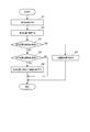
図3は、指示体70によって、プロジェクター11の機能を実行する操作が行われた際のプロジェクター11の動作を示すフローチャートである。
位置検出処理部157は、指示体70の操作スイッチ72の操作状態がオンであることを検出すると(ステップS1)、撮影制御部155から入力された撮影画像データを解析して、指示体70による指示位置70Aを確定し(ステップS2)、確定した指示位置70Aに関する情報を制御部103に出力する。
Next, the operation of the projector 11 will be described with reference to FIGS.
FIG. 3 is a flowchart showing the operation of the projector 11 when an operation for executing the function of the projector 11 is performed by the indicator 70.
When the position detection processing unit 157 detects that the operation state of the operation switch 72 of the indicator 70 is ON (step S1), the position detection processing unit 157 analyzes the captured image data input from the imaging control unit 155 and uses the indicator 70. The designated position 70A is confirmed (step S2), and information regarding the confirmed designated position 70A is output to the control unit 103.

制御部103は、位置検出処理部157により確定された指示位置70Aが、画像が表示されている表示領域内であるか否かを判定する(ステップS3)。制御部103は、指示位置70Aが表示領域内であると判定した場合には(ステップS3:Yes)、位置検出処理部157により確定した指示位置70Aの座標を、上述したように座標算出部159及び座標変換部160の機能によりPC13の入力画像データに対応する座標に変換し、変換後の座標データを出力部101からPC13に出力して(ステップS4)、位置指示操作に対応する描画等の処理を実行させる。
一方、指示位置70Aが表示領域外であると判定した場合(ステップS3:No)、制御部103は、指示位置70Aが、表示領域の外側に配置された操作領域内であるか否かを判定する(ステップS5)。制御部103は、指示位置70Aが操作領域内ではないと判定した場合には(ステップS5:No)、動作を終了する。また、制御部103は、指示位置70Aが操作領域内であると判定した場合(ステップS5:Yes)、指示位置70Aに重なる操作領域に対応づけて予め設定されたプロジェクター11の機能を実行する(ステップS6)。
The control unit 103 determines whether or not the designated position 70A determined by the position detection processing unit 157 is within the display area where the image is displayed (step S3). When the control unit 103 determines that the designated position 70A is within the display region (step S3: Yes), the coordinate calculation unit 159 determines the coordinates of the designated position 70A determined by the position detection processing unit 157 as described above. The coordinates of the input image data of the PC 13 are converted by the function of the coordinate conversion unit 160 and the converted coordinate data is output from the output unit 101 to the PC 13 (step S4). Execute the process.
On the other hand, when it is determined that the designated position 70A is outside the display area (step S3: No), the control unit 103 determines whether the designated position 70A is within the operation area arranged outside the display area. (Step S5). If the control unit 103 determines that the designated position 70A is not within the operation region (step S5: No), the operation ends. Further, when the control unit 103 determines that the designated position 70A is within the operation region (step S5: Yes), the control unit 103 executes a function of the projector 11 that is set in advance in association with the operation region that overlaps the designated position 70A ( Step S6).

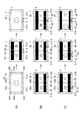
図4は、スクリーンSC上の操作領域の配置例と操作に対応して表示を制御する動作を説明する図であり、(A)は表示切替機能に関する例を示し、(B)はソース切換機能に関する例を示し、(C)はズーム機能に関する例を示す。
図4(A)に示す例ではプロジェクター11がシングル画面表示を実行しており、PC13から入力される画像データに基づく画像が、表示可能領域5に配置された表示領域6に表示されている。上述のように、表示可能領域5は投射光学系33により画像を表示可能な領域である。より詳細には、投射光学系33が画像を表示可能な最大の領域、または、台形歪み補正や糸巻き型歪み補正を施した後の画像を表示可能な最大の領域である。表示可能領域5の大きさは投射光学系33のズーム率、スクリーンSCから投射光学系33までの距離、光変調装置32の液晶パネルにおいて表示に使用できる領域等により変化するが、制御部103は、撮像部153の撮影画像データから画像を検出することにより、表示可能領域5を決定できる。
表示可能領域5には、画像を表示する表示領域6が配置される。図4(A)の例では、スクリーンSCに一つの画像を表示するシングル画面表示の実行時には、一つの表示領域6表示可能領域5に配置される。この図4(A)には表示可能領域5の全体を表示領域6とした例を示す。また、複数のPC13から供給された画像データに基づく画像をスクリーンSCに並べて表示するマルチ画面表示を実行する場合には、図4(B)に示すように、表示可能領域5に複数の表示領域6A、6Bが配置される。表示領域6A、6Bのアスペクト比によっては、表示可能領域5に画像が表示されない非表示領域6Cが生じる。非表示領域6Cは、図4(B)に示すマルチ画面表示の実行時に限らず、シングル画面表示の実行時にも発生し得る。
4A and 4B are diagrams for explaining an example of the arrangement of the operation area on the screen SC and an operation for controlling the display corresponding to the operation. FIG. 4A shows an example related to the display switching function, and FIG. 4B shows a source switching function. (C) shows an example related to the zoom function.
In the example illustrated in FIG. 4A, the projector 11 performs single screen display, and an image based on image data input from the PC 13 is displayed in the display area 6 arranged in the displayable area 5. As described above, the displayable area 5 is an area in which an image can be displayed by the projection optical system 33. More specifically, it is the maximum area where the projection optical system 33 can display an image, or the maximum area where an image after trapezoidal distortion correction or pincushion distortion correction can be displayed. The size of the displayable area 5 varies depending on the zoom rate of the projection optical system 33, the distance from the screen SC to the projection optical system 33, the area that can be used for display on the liquid crystal panel of the light modulation device 32, and the like. The displayable area 5 can be determined by detecting an image from the captured image data of the imaging unit 153.
A display area 6 for displaying an image is arranged in the displayable area 5. In the example of FIG. 4A, one display area 6 is arranged in the displayable area 5 when executing single screen display for displaying one image on the screen SC. FIG. 4A shows an example in which the entire displayable area 5 is the display area 6. When executing multi-screen display in which images based on image data supplied from a plurality of PCs 13 are displayed side by side on the screen SC, a plurality of display areas are displayed in the displayable area 5 as shown in FIG. 6A and 6B are arranged. Depending on the aspect ratio of the display areas 6A and 6B, a non-display area 6C in which no image is displayed in the displayable area 5 is generated. The non-display area 6C can be generated not only when the multi-screen display shown in FIG. 4B is executed but also when the single-screen display is executed.

表示可能領域5の周囲には、操作領域80が配置されている。操作領域80は、表示可能領域5の下方に配置された下縁操作領域81A、81B、表示可能領域5の左右の側方に配置された側縁操作領域82A、82B、表示可能領域5の上方に配置された上縁操作領域84A、84B、表示可能領域5の隅部の外側に配置された下隅操作領域83A、83Bおよび上隅操作領域85A、85Bを含む。操作領域80はスクリーンSCに実際に表示されるものではなく、制御部103により仮想的に設定されるものである。また、操作領域80を構成する各操作領域は、互いに重複しないように、かつ、表示可能領域5と重ならないよう配置され、表示可能領域5と操作領域80との境界は操作領域80に含まれない。また、操作領域80の全体は、プロジェクター11が指示体70の指示位置70Aを検出可能な範囲の内部、すなわち撮像部153の撮像領域7の内部にある。図4(A)の例では撮像領域7の全体が操作領域80および表示領域6となっている。
この図4(A)の例では、撮像領域7の内部で指示体70の位置指示操作が行われた場合、指示位置70Aは、表示可能領域5の上か、或いは、操作領域80のいずれかに属する。なお、操作領域80を構成する各操作領域が離れて配置されていてもよいし、表示可能領域5と操作領域80との間が離れていてもよい。
また、上述のように非表示領域6Cが発生する場合、操作領域80は非表示領域6Cよりも外側に配置される。この場合、ユーザーが操作領域80と非表示領域6Cとの境界を認識しやすくなるように、非表示領域6Cに周縁部にガイド(例えば、直線や点)を表示してもよい。
An operation area 80 is arranged around the displayable area 5. The operation area 80 includes lower edge operation areas 81A and 81B disposed below the displayable area 5, side edge operation areas 82A and 82B disposed on the left and right sides of the displayable area 5, and above the displayable area 5. Upper edge operation areas 84A and 84B, lower corner operation areas 83A and 83B, and upper corner operation areas 85A and 85B arranged outside the corners of the displayable area 5 . The operation area 80 is not actually displayed on the screen SC but is virtually set by the control unit 103. The operation areas constituting the operation area 80 are arranged so as not to overlap each other and not to overlap the displayable area 5, and the boundary between the displayable area 5 and the operation area 80 is included in the operation area 80. Absent. Further, the entire operation area 80 is within a range in which the projector 11 can detect the designated position 70 </ b> A of the indicator 70, that is, inside the imaging area 7 of the imaging unit 153. In the example of FIG. 4A, the entire imaging area 7 is an operation area 80 and a display area 6.
In the example of FIG. 4A, when the position indicating operation of the indicator 70 is performed inside the imaging area 7, the indicated position 70A is either on the displayable area 5 or the operation area 80. Belonging to. In addition, each operation area | region which comprises the operation area | region 80 may be arrange | positioned separately, and the displayable area | region 5 and the operation area | region 80 may be distant.
In addition, when the non-display area 6C occurs as described above, the operation area 80 is disposed outside the non-display area 6C. In this case, a guide (for example, a straight line or a point) may be displayed on the periphery of the non-display area 6C so that the user can easily recognize the boundary between the operation area 80 and the non-display area 6C.

操作領域80の各操作領域には、それぞれ、プロジェクター11の機能を割り当てることができる。指示位置70Aがいずれかの操作領域に属する場合、制御部103は、その操作領域に割り当てられた機能を実行する。
図4(A)の例では、下縁操作領域81A、81Bが、シングル画面表示とマルチ画面表示とを交互に切り替える表示切替機能に対応付けられている。シングル画面表示の実行時、下縁操作領域81A、81Bのいずれかが指示体70により操作されると、制御部103は表示状態をマルチ画面表示に切り替える。また、マルチ画面表示の実行中に下縁操作領域81A、81Bが操作されると、シングル画面表示への切り替えが行われる。マルチ画面表示中は、下縁操作領域81Aは一方の表示領域6Aに対応づけられ、下縁操作領域81Bは他方の表示領域6Bに対応づけられる。このため、下縁操作領域81Aが操作されると、表示領域6Aに表示中の画像がシングル画面表示される。同様に、下縁操作領域81Bが操作されると、表示領域6Bに表示中の画像がシングル画面表示される。
このように、指示体70により操作領域80をタップ操作することで、シングル画面表示とマルチ画面表示とを交互に切り替えさせることができる。また、複数の表示領域に画像を表示するマルチ画面表示中に、操作領域80を構成する複数の操作領域を、いずれかの表示領域に対応づけることができる。これにより、指示位置70Aが操作領域に重なる場合に、その操作領域に対応する表示領域が特定され、特定された表示領域に表示中の画像に対する機能が実行される。つまり、指示体70による1回の操作によって、実行する機能を指定するだけでなく、当該機能の実行対象の画像を指定することができる。
The function of the projector 11 can be assigned to each operation area of the operation area 80. When the designated position 70A belongs to any one of the operation areas, the control unit 103 executes a function assigned to the operation area.
In the example of FIG. 4A, the lower edge operation areas 81A and 81B are associated with a display switching function that alternately switches between single screen display and multi-screen display. When any one of the lower edge operation areas 81A and 81B is operated by the indicator 70 during the execution of the single screen display, the control unit 103 switches the display state to the multi-screen display. Further, when the lower edge operation areas 81A and 81B are operated during execution of multi-screen display, switching to single-screen display is performed. During multi-screen display, the lower edge operation area 81A is associated with one display area 6A, and the lower edge operation area 81B is associated with the other display area 6B. For this reason, when the lower edge operation area 81A is operated, the image being displayed in the display area 6A is displayed on a single screen. Similarly, when the lower edge operation area 81B is operated, the image being displayed in the display area 6B is displayed on a single screen.
In this way, by tapping the operation area 80 with the indicator 70, the single screen display and the multi-screen display can be switched alternately. Further, during multi-screen display in which images are displayed in a plurality of display areas, the plurality of operation areas constituting the operation area 80 can be associated with any one of the display areas. Thereby, when the designated position 70A overlaps the operation area, the display area corresponding to the operation area is specified, and the function for the image being displayed in the specified display area is executed. That is, not only a function to be executed can be specified by a single operation by the indicator 70, but also an image to be executed for the function can be specified.

また、図4(B)に示すように、操作領域を、プロジェクター11に画像データを供給する画像供給装置を切替えるソース切替機能に対応付けることができる。この例では、下縁操作領域81A、81Bにソース切替機能が割り当てられ、下縁操作領域81Bに重なる位置で、指示体70のフリック操作(指示体70を横にスライドさせる操作)が行われた場合に、表示領域6Bに画像供給装置として画像データを供給しているPC13が、他のPC13に切り替えられる。例えば図2のPC13Aが出力する画像データに基づく画像を表示領域6Bに表示している間に、下縁操作領域81Bでフリック操作が行われると、PC13Bが出力する画像データに基づく画像が表示領域6Bに表示される。
この例では、操作領域80を構成する操作領域の各々が、複数の表示領域6A、6Bに対応づけられている。例えば、下縁操作領域81Aは表示領域6Aに対応し、下縁操作領域81Bは表示領域6Bに対応する。他の操作領域を表示領域6A、6Bに対応づけることも勿論可能である。
As shown in FIG. 4B, the operation area can be associated with a source switching function for switching an image supply device that supplies image data to the projector 11. In this example, the source switching function is assigned to the lower edge operation areas 81A and 81B, and the flick operation of the indicator 70 (operation to slide the indicator 70 sideways) is performed at a position overlapping the lower edge operation area 81B. In this case, the PC 13 that supplies image data to the display area 6B as the image supply device is switched to another PC 13. For example, when a flick operation is performed in the lower edge operation area 81B while an image based on the image data output from the PC 13A in FIG. 2 is displayed in the display area 6B, an image based on the image data output from the PC 13B is displayed in the display area 6B. 6B.
In this example, each of the operation areas constituting the operation area 80 is associated with a plurality of display areas 6A and 6B. For example, the lower edge operation area 81A corresponds to the display area 6A, and the lower edge operation area 81B corresponds to the display area 6B. Of course, other operation areas can be associated with the display areas 6A and 6B.

また、図4(C)に示すように、操作領域を、プロジェクター11が表示する画像の拡大/縮小を行うズーム機能の操作に対応付けることができる。
この例では、下縁操作領域81A、81Bにズーム機能が割り当てられている。ズーム機能は、拡大か縮小かを指定する操作、および、拡大率や縮小率を指定する操作等が必要になるが、この例では、指示体70による操作態様により拡大か縮小かの別と拡大率/縮小率を指定できる。
操作態様の一例として、ここでは、2つの指示体70、70を用いた操作を例示する。2つの指示体70で操作領域にタッチし、2つの指示体70、70を近づける(間隔を狭める)ように操作するとズーム機能により画像が縮小され、2つの指示体70、70を離す(間隔を拡げる)ように操作されるとズーム機能により画像が拡大される。縮小率、拡大率は、2つの指示体70、70間の距離の変化量に対応する。
As shown in FIG. 4C, the operation area can be associated with an operation of a zoom function for enlarging / reducing an image displayed by the projector 11.
In this example, a zoom function is assigned to the lower edge operation areas 81A and 81B. The zoom function requires an operation for specifying whether to enlarge or reduce, an operation for specifying an enlargement ratio or a reduction ratio, and the like. In this example, enlargement or reduction is performed depending on the operation mode of the indicator 70. You can specify the rate / reduction rate.
Here, as an example of the operation mode, an operation using two indicators 70 and 70 is illustrated. When the operation area is touched with the two indicators 70 and the two indicators 70 and 70 are operated so as to be close (to narrow the interval), the zoom function reduces the image, and the two indicators 70 and 70 are separated (the interval is set to be small). When the operation is performed, the image is enlarged by the zoom function. The reduction rate and the enlargement rate correspond to the amount of change in the distance between the two indicators 70 and 70.

図4(C)の例では、プロジェクター11は、マルチ画面表示を行っており、下縁操作領域81Aは表示領域6Aに対応し、下縁操作領域81Bは表示領域6Bに対応する。下縁操作領域81Aが操作されると表示領域6Aの画像のズーム機能が実行され、下縁操作領域81Bが操作されると表示領域6Bの画像のズーム機能が実行される。さらに、下縁操作領域81Aと下縁操作領域81Bにまたがる操作が行われると、表示領域6Aの画像および表示領域6Bの画像の両方が拡大または縮小される。
図4(C)の例では、マルチ画面表示中に下縁操作領域81Aで2つの指示体70、70が操作されることで、表示領域6Aの画像が拡大されている。また、下縁操作領域81A上の指示体70と、下縁操作領域81B上の指示体70とを離すように操作が行われた場合に、表示領域6Aの画像と表示領域6Bの画像の両方が拡大されている。
このように、プロジェクター11は、操作領域に対する操作に応じて、予め割り当てられた機能を実行でき、マルチ画面表示時には操作領域を選択することで機能の実行対象の画像を指定できる。さらに、指示体70による操作態様によって機能の実行に関する詳細なパラメーターを指定できる。
指示体70の操作態様は、複数の指示体70による上記操作に限定されず、例えば、複数回のタップ操作の組み合わせ等がある。また、マルチ画面表示を行っている際に、画像のズーム機能を実行し、表示領域6Aの画像を拡大する操作を行うと、それに伴って、表示領域6Bの画像が縮小され、且つ、表示領域6A、及び、表示領域6Bの其々対応する操作領域の範囲も画像のサイズに応じて変更される構成であっても良い。
In the example of FIG. 4C, the projector 11 performs multi-screen display, the lower edge operation area 81A corresponds to the display area 6A, and the lower edge operation area 81B corresponds to the display area 6B. When the lower edge operation area 81A is operated, the zoom function of the image in the display area 6A is executed, and when the lower edge operation area 81B is operated, the zoom function of the image in the display area 6B is executed. Further, when an operation that extends over the lower edge operation area 81A and the lower edge operation area 81B is performed, both the image of the display area 6A and the image of the display area 6B are enlarged or reduced.
In the example of FIG. 4C, the image of the display area 6A is enlarged by operating the two indicators 70, 70 in the lower edge operation area 81A during multi-screen display. Further, when an operation is performed so that the indicator 70 on the lower edge operation area 81A is separated from the indicator 70 on the lower edge operation area 81B, both the image of the display area 6A and the image of the display area 6B are displayed. Has been expanded.
As described above, the projector 11 can execute a function assigned in advance according to an operation on the operation area, and can specify an image to be executed by selecting the operation area during multi-screen display. Further, detailed parameters regarding the execution of the function can be specified by the operation mode of the indicator 70.
The operation mode of the indicator 70 is not limited to the above-described operation by the plurality of indicators 70, and includes, for example, a combination of a plurality of tap operations. Further, when performing a zoom function of an image and performing an operation of enlarging the image in the display area 6A during multi-screen display, the image in the display area 6B is reduced accordingly, and the display area The range of the operation area corresponding to each of 6A and the display area 6B may be changed according to the size of the image.

図5は、スクリーンSC上の操作領域の配置例、及び、操作領域に対する操作に対応して表示を制御する動作を説明する図であり、図5(A)は横スクロール機能に関する例を示し、図5(B)は縦スクロール機能に関する例を示し、図5(C)はミュート機能に関する例を示し、図5(D)はネットワーク接続待機機能に関する例を示し、図5(E)は操作ロック/解除機能に関する例を示す。
図5(A)及び図5(B)に示す例では、操作領域に対して表示領域6に表示中の画像のスクロール(表示移動)機能(表示領域6に表示中の画像の位置を移動させる機能)が割り当てられている。具体的には、下縁操作領域81A、81Bに横スクロール機能が、側縁操作領域82A、82Bに縦スクロール機能が対応付けられる。図5(A)に示すように、下縁操作領域81A内でタッチ操作した指示体70を左右に移動させる操作を行うことで、表示領域6Aに表示された画像が指示体70の移動に伴って左右に移動される。また、図5(B)に示すように、側縁操作領域82B内でタッチ操作した指示体70を上下に移動させる操作により、表示領域6Bに表示された画像が指示体70の移動に伴って上下に移動される。なお、本実施形態では、縦方向の画像の移動と、横方向の画像の移動とが、異なる操作領域に割り当てられている構成としたが、これに限らず、1つの操作領域に縦方向、横方向、及び、斜め方向への画像の移動が割り当てられている構成であっても良い。
FIG. 5 is a diagram for explaining an example of the arrangement of the operation area on the screen SC and an operation for controlling the display corresponding to the operation on the operation area. FIG. 5A shows an example of the horizontal scroll function. 5B shows an example related to the vertical scroll function, FIG. 5C shows an example related to the mute function, FIG. 5D shows an example related to the network connection standby function, and FIG. 5E shows an operation lock. An example regarding the / release function is shown.
In the example shown in FIG. 5A and FIG. 5B, the scrolling (display movement) function of the image displayed in the display area 6 (the position of the image displayed in the display area 6 is moved relative to the operation area). Function) is assigned. Specifically, the horizontal scroll function is associated with the lower edge operation areas 81A and 81B, and the vertical scroll function is associated with the side edge operation areas 82A and 82B. As shown in FIG. 5A, an image displayed in the display area 6A is moved with the movement of the indicator 70 by performing an operation of moving the indicator 70 touched in the lower edge operation region 81A to the left and right. To move left and right. Further, as shown in FIG. 5B, an image displayed in the display area 6B is moved along with the movement of the indicator 70 by the operation of moving the indicator 70 touched in the side edge operation region 82B up and down. Moved up and down. In this embodiment, the vertical image movement and the horizontal image movement are assigned to different operation areas. However, the present invention is not limited to this. A configuration in which movement of an image in a horizontal direction and an oblique direction is assigned may be used.

図5(C)に示す例では、操作領域に対してプロジェクター11の表示画像を消すミュート機能が対応付けられる。具体的には、下隅操作領域83Aで指示体70によるタッチ操作が行われると、投射部30による画像光の投射が停止され、表示領域6Aに表示中の画像が消される(表示が停止する)。この機能は、光変調装置32の液晶パネルにおいて該当する領域の表示を全黒とする方法や、照明光学系31が発する光を遮光する方法により実現される。なお、ミュート機能が実行された際には、表示領域に全黒を表示する他に、青画像を表示する、あるいは、ミュート状態である旨を示す画像を表示する構成とすることができる。   In the example shown in FIG. 5C, a mute function for deleting the display image of the projector 11 is associated with the operation area. Specifically, when the touch operation by the indicator 70 is performed in the lower corner operation area 83A, the projection of the image light by the projection unit 30 is stopped, and the image being displayed in the display area 6A is erased (display is stopped). . This function is realized by a method in which the display of the corresponding region in the liquid crystal panel of the light modulation device 32 is all black, or a method in which the light emitted from the illumination optical system 31 is blocked. When the mute function is executed, in addition to displaying all black in the display area, a blue image may be displayed, or an image indicating that the mute state is displayed.

図5(D)に示す例では、操作領域に対してプロジェクター11とPC13との間のネットワーク接続を待機状態とするネットワーク接続待機機能が対応付けられる。下隅操作領域83Aで指示体70によるタッチ操作が行われると、表示領域6Aに表示されている画像を供給するPC13との接続状態が、待機状態に切り替えられる。待機状態では、PC13から画像が入力されないので、表示領域6Aに画像が表示されない。このため、PC13または他の画像供給装置との再接続を容易にするため、図5(D)のように、表示領域6Aにネットワークの接続情報が含まれた2次元コードを表示してもよい。また、プロジェクター11は、プロジェクター11との接続に必要な具体的な接続情報(例えば、プロジェクターのIPアドレスやSSID等)を表示しても良い。さらに、プロジェクター11が無線通信インターフェイスを介して、ネットワーク接続に必要な電波を送出してもよい。   In the example shown in FIG. 5D, a network connection standby function for setting the network connection between the projector 11 and the PC 13 in a standby state is associated with the operation area. When a touch operation by the indicator 70 is performed in the lower corner operation area 83A, the connection state with the PC 13 that supplies the image displayed in the display area 6A is switched to the standby state. In the standby state, no image is input from the PC 13, and therefore no image is displayed in the display area 6A. Therefore, in order to facilitate reconnection with the PC 13 or other image supply device, a two-dimensional code including network connection information may be displayed in the display area 6A as shown in FIG. 5D. . Further, the projector 11 may display specific connection information necessary for connection with the projector 11 (for example, the IP address and SSID of the projector). Further, the projector 11 may send out radio waves necessary for network connection via a wireless communication interface.

図5(E)に示す例では、複数の操作領域を跨ぐ操作に対し、表示されている画像に対する操作をロックする操作ロック/解除機能が対応付けられる。具体的には、指示体70が下隅操作領域83Aを通過するような操作に対し、表示領域6Aの操作ロック機能が割り当てられ、下隅操作領域83Bを通過するような操作に対して表示領域6Bの操作ロック機能が割り当てられている。指示体70が側縁操作領域82Aから下隅操作領域83Aを通り、そのまま下縁操作領域81Aまで移動されると、表示領域6Aに表示される画像に対する操作がロックされ、一時的に操作不可能となる。同様の操作が再度行われると、表示領域6Aについて設定された操作のロックが解除され、操作可能となる。これらの操作は特徴的であるから、ユーザーが意図せず誤ってロック/ロック解除をしてしまうおそれがなく、操作性の向上と操作の確実性を両立できる。
このほか、例えば、上隅操作領域85Aをタッチし、続いて下隅操作領域83Aをタッチする操作に対し、入力映像を表示しないパスワードロック状態への移行および解除を割り当てることもできる。このパスワードロック状態はプロジェクター11の盗難防止のために利用され、操作パネル41やリモコンの操作により正規のパスワードを入力するか、上記操作を再度行うかのいずれかにより解除できる。
In the example shown in FIG. 5E, an operation lock / release function that locks an operation on a displayed image is associated with an operation that straddles a plurality of operation areas. Specifically, the operation lock function of the display area 6A is assigned to an operation in which the indicator 70 passes through the lower corner operation area 83A, and the operation of the display area 6B in response to an operation through the lower corner operation area 83B. The operation lock function is assigned. When the indicator 70 moves from the side edge operation area 82A through the lower corner operation area 83A to the lower edge operation area 81A, the operation on the image displayed in the display area 6A is locked, and the operation is temporarily disabled. Become. When the same operation is performed again, the operation set for the display area 6A is unlocked and can be operated. Since these operations are characteristic, there is no possibility that the user unintentionally locks / unlocks accidentally, and both improvement in operability and certainty of operation can be achieved.
In addition, for example, a transition to the password lock state in which the input video is not displayed and release can be assigned to an operation of touching the upper corner operation area 85A and subsequently touching the lower corner operation area 83A. This password lock state is used for theft prevention of the projector 11 and can be canceled by either inputting a regular password by operating the operation panel 41 or the remote control or performing the above operation again.

上述した例に限らず、プロジェクター11は、位置検出ユニット150により検出された指示体70の操作位置を示す情報をプロジェクター11内部で処理し、操作位置の座標に基づく処理をプロジェクター11が実行するPJインターラクティブモードと、位置検出ユニット150により検出された指示体70の操作位置を示す情報を外部のPC13に出力し、PC13に操作位置の座標に基づく処理を実行させるPCインターラクティブモードとが切替可能に構成され、PJインターラクティブモードと、PCインターラクティブモードとを、操作領域80に対する操作で切り替えることができるモード切替機能を有していても良い。
また、操作領域80の操作領域に対しては、表示領域6A、6Bに表示している画像の静止、回転、プロジェクター11の機能に関するメニュー画面のOSD表示/非表示等のプロジェクター11の各種機能を割り当てることができる。また、各操作領域に対する操作態様を組み合わせて割り当てることにより、より複雑な操作に対する割り当てを行って誤操作を防止したり、実行する機能の内容に関する設定や指示を行えるようにしたり、多種多様な機能を割り当てたりすることが可能となるので、プロジェクター11の操作性をより一層向上させることができる。なお、操作領域、操作領域において実行可能な機能、及び機能を実行するための操作のうち、少なくとも2つの関連付けは、メニュー画面上の操作によって可能である構成であっても良い。
The projector 11 is not limited to the example described above, and the projector 11 processes information indicating the operation position of the indicator 70 detected by the position detection unit 150 inside the projector 11, and the projector 11 executes processing based on the coordinates of the operation position. The interactive mode and the PC interactive mode in which information indicating the operation position of the indicator 70 detected by the position detection unit 150 is output to the external PC 13 and the PC 13 executes processing based on the coordinates of the operation position can be switched. In addition, it may have a mode switching function capable of switching between the PJ interactive mode and the PC interactive mode by an operation on the operation area 80.
For the operation area of the operation area 80, various functions of the projector 11 such as stillness and rotation of images displayed in the display areas 6A and 6B, and OSD display / non-display of the menu screen related to the functions of the projector 11 are provided. Can be assigned. Also, by assigning combinations of operation modes for each operation area, it is possible to assign more complicated operations to prevent erroneous operations, and to make settings and instructions related to the contents of functions to be executed. Thus, the operability of the projector 11 can be further improved. It should be noted that at least two of the operation area, the function executable in the operation area, and the operation for executing the function may be associated with each other by an operation on the menu screen.

また、プロジェクター11は、指示位置70Aが表示可能領域5の外である場合、指示位置70Aの座標をPC13に出力できない。PC13に対して出力される座標は、そのPC13が入力する画像データに対応する座標であり、表示領域6の外側は画像データの外となるからである。ここで、制御部103は、指示位置70Aが操作領域80のいずれかにあたる位置であった場合に、この操作領域を示す制御データ、或いは、この操作領域に対応づけられたプロジェクター11の機能を示す制御データを、PC13に送信してもよい。この場合、指示体70による表示可能領域5の外に対する操作に応じて、PC13に何らかの機能を実行させることが可能となる。
Further, when the designated position 70A is outside the displayable area 5, the projector 11 cannot output the coordinates of the designated position 70A to the PC 13. This is because the coordinates output to the PC 13 are coordinates corresponding to the image data input by the PC 13 and the outside of the display area 6 is outside the image data. Here, when the designated position 70 </ b> A is a position corresponding to one of the operation areas 80, the control unit 103 indicates the control data indicating the operation area or the function of the projector 11 associated with the operation area. Control data may be transmitted to the PC 13. In this case, it is possible to cause the PC 13 to execute some function in response to an operation on the outside of the displayable area 5 by the indicator 70.

以上説明したように、本発明を適用した第1の実施形態におけるプロジェクター11は、スクリーンSCに画像を表示する投射ユニット3と、スクリーンSCにおける指示体70の指示位置70Aを検出する位置検出ユニット150と、スクリーンSCにおける画像の表示領域6の外側に複数の操作領域81A、81B、82A、82B・・・が設定され、指示位置70Aが操作領域81A、81B、82A、82B・・・内である場合に、操作領域81A、81B、82A、82B・・・に対応付けられた操作に関する機能を実行する制御部103と、を備えているので、スクリーンSC上で指示体70による位置指示操作を行うことで、操作領域に対応するプロジェクター11の機能を実行させることができる。これにより、ユーザーは、プロジェクター11の操作パネル41、或いは、プロジェクター11のリモコンを操作することなく、プロジェクター11の各種の機能を操作することができ、例えば指示体70で描画等の操作を行っている場合に、リモコンに持ち替える動作等を行わずに、プロジェクター11の各種機能を実行でき、操作性の向上を図ることができる。また、表示領域6の外側に操作領域81A、81B、82A、82B・・・を設定したため、操作切替用のアイコンやツールバーを表示領域6内に表示する必要がなく、入力映像がアイコン等によって遮られることがなく、描画範囲を広げることができる。   As described above, the projector 11 according to the first embodiment to which the present invention is applied includes the projection unit 3 that displays an image on the screen SC and the position detection unit 150 that detects the indicated position 70A of the indicator 70 on the screen SC. A plurality of operation areas 81A, 81B, 82A, 82B... Are set outside the image display area 6 on the screen SC, and the designated position 70A is within the operation areas 81A, 81B, 82A, 82B. In this case, the control unit 103 that executes functions related to operations associated with the operation areas 81A, 81B, 82A, 82B,... Thus, the function of the projector 11 corresponding to the operation area can be executed. Accordingly, the user can operate various functions of the projector 11 without operating the operation panel 41 of the projector 11 or the remote control of the projector 11. For example, the user performs an operation such as drawing with the indicator 70. In this case, the various functions of the projector 11 can be executed without performing the operation of switching to the remote control, and the operability can be improved. Further, since the operation areas 81A, 81B, 82A, 82B... Are set outside the display area 6, it is not necessary to display an operation switching icon or toolbar in the display area 6, and the input video is blocked by the icon or the like. The drawing range can be expanded without being done.

また、外部の装置を含む複数のPC13から供給された画像データを、投射ユニット3によりスクリーンSCに設けられた複数の表示領域6A、6Bのそれぞれに表示させる画像処理ユニット110を備え、複数の操作領域81A、81B、82A、82B・・・は、各々の表示領域6A、6Bに対応付けられている。この構成によれば、スクリーンSCに複数のPC13から供給された画像データに基づく画像を並べて表示するマルチ画面表示を行う場合に、表示される各々の画像に対してスクリーンSCの操作領域81A、81B、82A、82B・・・の操作が対応づけられるため、指示体70の操作によりプロジェクター11の機能を実行させ、実行対象の画像を指定できる。これにより、ユーザーは、プロジェクター11の操作パネル41やリモコンを操作することなく、指示体70による操作でプロジェクター11の各種機能を詳細に操作することができ、操作性のより一層の向上を図ることができる。   In addition, the image processing unit 110 is provided that displays the image data supplied from a plurality of PCs 13 including an external device on each of the plurality of display areas 6A and 6B provided on the screen SC by the projection unit 3, and includes a plurality of operations. The areas 81A, 81B, 82A, 82B... Are associated with the display areas 6A, 6B, respectively. According to this configuration, when performing multi-screen display in which images based on image data supplied from a plurality of PCs 13 are displayed side by side on the screen SC, the operation areas 81A and 81B of the screen SC are displayed for each displayed image. , 82A, 82B,... Are associated with each other, the function of the projector 11 can be executed by operating the indicator 70, and an image to be executed can be designated. Thus, the user can operate the various functions of the projector 11 in detail by operating the indicator 70 without operating the operation panel 41 or the remote control of the projector 11, thereby further improving the operability. Can do.

また、プロジェクター11によれば、複数の操作領域81A、81B、82A、82B・・・に跨がる指示体70の操作が検出された場合に、当該複数の操作領域81A、81B、82A、82B・・・にまたがる操作に対応付けられた機能を実行することができる。さらに、プロジェクター11は、表示領域6A、6Bを含む範囲を撮影する撮像部153を備え、位置検出ユニット150は、撮像部153の撮影画像に基づいて指示体70の指示位置70Aを検出するので、操作領域80を表示可能領域5の外側に設定できる。これにより、表示領域6A、6Bを小さくすることなく、操作領域80を設けることができ、画像の表示サイズに影響を与えることなく、操作性の向上を図ることができる。   Further, according to the projector 11, when an operation of the indicator 70 across the plurality of operation areas 81A, 81B, 82A, 82B... Is detected, the plurality of operation areas 81A, 81B, 82A, 82B are detected. The function associated with the operation across... Can be executed. Further, the projector 11 includes an imaging unit 153 that captures a range including the display areas 6A and 6B, and the position detection unit 150 detects the indicated position 70A of the indicator 70 based on the captured image of the imaging unit 153. The operation area 80 can be set outside the displayable area 5. Thus, the operation area 80 can be provided without reducing the display areas 6A and 6B, and the operability can be improved without affecting the display size of the image.

また、プロジェクター11は、位置検出ユニット150により、操作領域80に対する操作が検出された場合に、表示領域6A、6Bに表示された画像を供給するPC13を切り替えるソース切替機能、表示された画像を静止させるフリーズ機能、表示された画像を消去させるミュート機能、表示された画像を拡大または縮小させるズーム機能、表示領域6に表示されている画像の表示位置を変更する機能、および、位置検出ユニット150により検出された操作位置を示す情報をプロジェクター11内部で処理するモードと当該情報を外部に出力するモードとを切り替える機能のうち、少なくともいずれかを実行するので、ユーザーは、プロジェクター11の操作パネル41、或いは、プロジェクター11のリモコンを操作することなく、プロジェクター11が有する種々の機能を操作することができる。   The projector 11 also has a source switching function for switching the PC 13 that supplies the images displayed in the display areas 6A and 6B when the operation for the operation area 80 is detected by the position detection unit 150, and the displayed image is stopped. By the freeze function to be performed, the mute function to erase the displayed image, the zoom function to enlarge or reduce the displayed image, the function to change the display position of the image displayed in the display area 6, and the position detection unit 150 Since the user executes at least one of the function of switching the information indicating the detected operation position inside the projector 11 and the mode of outputting the information to the outside, the user can operate the operation panel 41 of the projector 11, Alternatively, without operating the remote control of the projector 11 It can operate the various functions projector 11 has.

(第2の実施形態)
第2の実施形態では、操作領域に設けられたパターンであるマークを認識するプロジェクターを用いた表示システムについて説明する。なお、「パターン」は、領域を識別可能とするものであり、マーク(記号)に限らず、文字であってもよいし、模様や色であってもよい。
(Second Embodiment)
In the second embodiment, a display system using a projector that recognizes marks that are patterns provided in an operation area will be described. The “pattern” is used to identify a region, and is not limited to a mark (symbol) but may be a character, a pattern, or a color.

図6は、第2の実施形態に係る表示システム20の機能的構成を示すブロック図である。
表示システム20の構成は、プロジェクター21以外は、第1の実施形態の表示システム10と同様(図2参照)である。よって、プロジェクター21以外の説明は省略する。ここで、第1の実施形態と同一の構成部については、同一の番号を使用する。
FIG. 6 is a block diagram illustrating a functional configuration of the display system 20 according to the second embodiment.
The configuration of the display system 20 is the same as that of the display system 10 of the first embodiment except for the projector 21 (see FIG. 2). Therefore, descriptions other than the projector 21 are omitted. Here, the same number is used about the same component as 1st Embodiment.

プロジェクター21の構成は、記憶部105以外は、第1の実施形態のプロジェクター11と同様(図2参照)である。また、位置検出処理部157が行う処理内容が、第1の実施形態のプロジェクター11に対して変更されている。よって、記憶部105および位置検出処理部157以外の説明は省略する。なお、投射ユニット3が表示手段に相当し、位置検出ユニット150が、検出手段に相当し、制御部103が、制御手段に相当する。   The configuration of the projector 21 is the same as that of the projector 11 of the first embodiment except for the storage unit 105 (see FIG. 2). Further, the processing content performed by the position detection processing unit 157 is changed with respect to the projector 11 of the first embodiment. Therefore, descriptions other than the storage unit 105 and the position detection processing unit 157 are omitted. The projection unit 3 corresponds to a display unit, the position detection unit 150 corresponds to a detection unit, and the control unit 103 corresponds to a control unit.

記憶部105は、第1の実施形態の構成に加えて、機能記憶手段としての機能テーブル105Bを有している。
図7は、機能テーブル105Bの説明図である。
機能テーブル105Bは、操作領域に設けられたマークと機能の対応を表すテーブルであり、記憶部105に備えられている。図7に示すように、機能テーブル105Bでは、それぞれのマーク毎に、プロジェクター21の機能が対応付けて記憶されている。機能テーブル105Bにおける機能は、第1の実施形態のプロジェクター11が有する機能と同様としている。なお、モード切替機能とは、位置検出ユニット150により検出された操作位置を示す情報をプロジェクター21内部で処理するモードと当該情報を外部に出力するモードとを切り替える機能を表している。また、マークは、図7に示す機能テーブル105Bで表された種類に限定されず、プロジェクター21で認識可能であればどのような形状でもよい。
The storage unit 105 includes a function table 105B as function storage means in addition to the configuration of the first embodiment.
FIG. 7 is an explanatory diagram of the function table 105B.
The function table 105 </ b> B is a table representing the correspondence between marks provided in the operation area and functions, and is provided in the storage unit 105. As shown in FIG. 7, in the function table 105B, the function of the projector 21 is stored in association with each mark. The functions in the function table 105B are the same as the functions of the projector 11 of the first embodiment. The mode switching function represents a function for switching between a mode in which information indicating the operation position detected by the position detection unit 150 is processed inside the projector 21 and a mode in which the information is output to the outside. Further, the mark is not limited to the type shown in the function table 105B shown in FIG. 7, and may have any shape as long as it can be recognized by the projector 21.

本実施形態では、機能テーブル105Bにおけるマークと機能の対応付けを変更することが可能である。具体的には、所定の操作によって、制御部103は、画像処理ユニット110にプロジェクター21のメニュー画面を表示させる。メニュー画面において、操作パネル41やリモコンに備わるスイッチが操作されて、機能テーブル変更項目が選択されると、プロジェクター21は、機能テーブル105Bに相当するテーブルを視覚的に表示し、機能テーブル変更モードとなる。機能テーブル変更モードにおいて、操作パネル41やリモコンに備わるスイッチを操作されると、制御部103は、マークと機能との対応付けを変更し、機能テーブル105Bに記憶することができる。   In the present embodiment, it is possible to change the association between marks and functions in the function table 105B. Specifically, the control unit 103 causes the image processing unit 110 to display the menu screen of the projector 21 by a predetermined operation. When a switch on the operation panel 41 or the remote control is operated on the menu screen and a function table change item is selected, the projector 21 visually displays a table corresponding to the function table 105B, and the function table change mode is displayed. Become. When the switch provided on the operation panel 41 or the remote controller is operated in the function table change mode, the control unit 103 can change the association between the mark and the function and store the change in the function table 105B.

また、本実施形態では、機能テーブル105Bにおけるマークと機能の対応付けを追加することが可能である。具体的には、メニュー画面において、操作パネル41やリモコンに備わるスイッチが操作されて、機能テーブル追加項目が選択されると、プロジェクター21は、機能テーブル105Bに相当するテーブルを視覚的に表示し、機能テーブル追加モードとなる。機能テーブル追加モードにおいて、操作パネル41やリモコンに備わるスイッチが操作されると、制御部103は、マークと機能との対応付けを追加し、機能テーブル105Bに記憶することができる。   In the present embodiment, it is possible to add a correspondence between a mark and a function in the function table 105B. Specifically, on the menu screen, when a switch provided on the operation panel 41 or the remote control is operated and a function table addition item is selected, the projector 21 visually displays a table corresponding to the function table 105B, The function table addition mode is set. In the function table addition mode, when a switch provided on the operation panel 41 or the remote controller is operated, the control unit 103 can add the association between the mark and the function and store the association in the function table 105B.

操作領域に設けられたマークは、位置検出処理部157が、撮影画像データを解析することにより検出される。位置検出処理部157は、パターンマッチング等の処理を行い、マークを検出(認識)する。位置検出処理部157が、パターン検出手段に相当する。位置検出処理部157は、検出したマークの情報を制御部103に通知する。また、座標変換部160は、マークが検出された座標情報を制御部103に通知する。制御部103は、マークの情報に基づいて、機能テーブル105Bから、対応する機能の情報を取得する。そして、制御部103は、マークが検出された座標情報に基づいて操作領域を特定する。制御部103は、マークが検出された操作領域と機能の情報とを対応付けて記憶部105等のメモリーに記憶する。位置検出ユニット150、機能テーブル105B、および制御部103が、認識手段に相当する。制御部103および記憶部105が、設定手段に相当する。
なお、本実施形態では、位置検出処理部157が撮影画像データを解析することによりマークを検出するものとしたが、撮像部153で撮影した撮影画像データを記憶部105等に保存して、制御部103が撮影画像データを解析し、マークを検出するような構成としてもよい。
The mark provided in the operation area is detected by the position detection processing unit 157 analyzing the captured image data. The position detection processing unit 157 performs processing such as pattern matching and detects (recognizes) the mark. The position detection processing unit 157 corresponds to a pattern detection unit. The position detection processing unit 157 notifies the control unit 103 of information on the detected mark. In addition, the coordinate conversion unit 160 notifies the control unit 103 of the coordinate information in which the mark is detected. The control unit 103 acquires the corresponding function information from the function table 105B based on the mark information. Then, the control unit 103 identifies an operation area based on the coordinate information where the mark is detected. The control unit 103 stores the operation area in which the mark is detected and the function information in a memory such as the storage unit 105 in association with each other. The position detection unit 150, the function table 105B, and the control unit 103 correspond to a recognition unit. The control unit 103 and the storage unit 105 correspond to setting means.
In the present embodiment, the position detection processing unit 157 detects the mark by analyzing the captured image data. However, the captured image data captured by the imaging unit 153 is stored in the storage unit 105 or the like for control. The unit 103 may analyze the captured image data and detect a mark.

ここで、マークの検出処理について、フローチャートを用いて説明する。
図8は、マークの検出処理のフローチャートである。
図8に示すマーク検出処理は、ユーザーが、リモコン操作や操作パネル41の操作を行ったタイミングで実行される。また、プロジェクター21が起動された後、定期的にマーク検出処理が実行されてもよい。
Here, the mark detection process will be described with reference to a flowchart.
FIG. 8 is a flowchart of mark detection processing.
The mark detection process shown in FIG. 8 is executed at the timing when the user performs the remote control operation or the operation panel 41 operation. Further, after the projector 21 is activated, the mark detection process may be periodically executed.

撮影制御部155は、撮像部153が撮像した撮影画像データを位置検出処理部157に出力し、位置検出処理部は、撮影画像データを解析して、マークの検出を行い、マークの情報を制御部103に通知する。さらに、座標変換部160は、マークが検出された座標情報を制御部103に通知する。(ステップS21)。なお、マークが無い場合も、マークが無い旨の情報を検出する。制御部103は、検出されたマークが、機能テーブル105Bに記憶されているマークのいずれかに該当するか否かを判断する(ステップS22)。   The imaging control unit 155 outputs the captured image data captured by the imaging unit 153 to the position detection processing unit 157. The position detection processing unit analyzes the captured image data, detects a mark, and controls mark information. Notification to the unit 103. Further, the coordinate conversion unit 160 notifies the control unit 103 of the coordinate information where the mark is detected. (Step S21). Even when there is no mark, information indicating that there is no mark is detected. The control unit 103 determines whether or not the detected mark corresponds to any of the marks stored in the function table 105B (step S22).

機能テーブル105Bに記憶されているマークに該当した場合(ステップS22:YES)、制御部103は、機能テーブル105Bから、マークに対応した機能の情報を取得する(ステップS23)。制御部103は、座標情報に基づく操作領域と、マークに対応した機能情報とを対応付けて記憶部105のメモリーに記憶する(ステップS24)。このときの制御部103が機能取得手段に相当する。   When the mark corresponds to the mark stored in the function table 105B (step S22: YES), the control unit 103 acquires information on the function corresponding to the mark from the function table 105B (step S23). The control unit 103 associates the operation area based on the coordinate information and the function information corresponding to the mark and stores them in the memory of the storage unit 105 (step S24). The control unit 103 at this time corresponds to a function acquisition unit.

機能テーブル105Bに記憶されているマークに該当しない場合(ステップS22:NO)、制御部103は、対応する機能は無いと判断する(ステップS25)。そして、ステップS24に移行し、当該操作領域には機能無しであると対応付けて記憶する。   When the mark does not correspond to the mark stored in the function table 105B (step S22: NO), the control unit 103 determines that there is no corresponding function (step S25). Then, the process proceeds to step S24, and the operation area is stored in association with no function.

次に、指示体70によって、プロジェクター21の機能を実行する際の処理について、フローチャートを用いて説明する。
図9は、指示体70によって、プロジェクター21の機能を実行する操作が行われた際のプロジェクター21の動作を示すフローチャートである。
図9のフローチャートのステップS31からステップS35は、第1の実施形態の図3のフローチャートのステップS1からステップS5と同様である。よって、説明は省略する。
Next, processing when the function of the projector 21 is executed by the indicator 70 will be described using a flowchart.
FIG. 9 is a flowchart showing the operation of the projector 21 when an operation for executing the function of the projector 21 is performed by the indicator 70.
Steps S31 to S35 in the flowchart in FIG. 9 are the same as steps S1 to S5 in the flowchart in FIG. 3 of the first embodiment. Therefore, the description is omitted.

制御部103は、指示位置70Aが操作領域内であると判定した場合(ステップS35:YES)、指示位置70Aの操作領域に、機能が対応付けられているか否かを判定する(ステップS36)。制御部103は、指示位置70Aの操作領域に、機能が対応付けられていないと判定した場合には(ステップS36:NO)、動作を終了する。   When it is determined that the designated position 70A is within the operation area (step S35: YES), the control unit 103 determines whether or not a function is associated with the operation area at the designated position 70A (step S36). When it is determined that the function is not associated with the operation area at the designated position 70A (step S36: NO), the control unit 103 ends the operation.

制御部103は、指示位置70Aの操作領域に、機能が対応付けられていると判定した場合には(ステップS36:YES)、指示位置70Aに重なる操作領域に対応付けられたプロジェクター21の機能を実行する(ステップS37)。   When it is determined that the function is associated with the operation region at the designated position 70A (step S36: YES), the control unit 103 determines the function of the projector 21 associated with the operation region that overlaps the designated position 70A. Execute (Step S37).

図10は、スクリーンSC上の操作領域の配置例と操作に対応して表示を制御する動作を説明する図であり、(A)はズーム機能に関する例を示し、(B)はソース切換機能に関する例を示す。
図10(A)、(B)に示す例では、プロジェクター21がシングル画面表示を実行しており、PC13から入力される画像データに基づく画像が、表示可能領域5に配置された表示領域6に表示されている。なお、第1の実施形態と同様に、プロジェクター21は、マルチ画面表示を実行することも可能である。
10A and 10B are diagrams for explaining an example of the arrangement of the operation area on the screen SC and an operation for controlling display corresponding to the operation. FIG. 10A shows an example related to the zoom function, and FIG. 10B shows an example related to the source switching function. An example is shown.
In the example shown in FIGS. 10A and 10B, the projector 21 performs single screen display, and an image based on image data input from the PC 13 is displayed in the display area 6 arranged in the displayable area 5. It is displayed. Note that, similarly to the first embodiment, the projector 21 can also perform multi-screen display.

表示可能領域5の周囲には、操作領域80が配置されている。操作領域80は、第1の実施形態と同様に、表示可能領域5の下方に配置された下縁操作領域81A、81B、表示可能領域5の左右の側方に配置された側縁操作領域82A、82B、表示可能領域5の上方に配置された上縁操作領域84A、84B、表示可能領域5の隅部の外側に配置された下隅操作領域83A、83Bおよび上隅操作領域85A、85Bを含む。

An operation area 80 is arranged around the displayable area 5. As in the first embodiment, the operation area 80 includes lower edge operation areas 81A and 81B arranged below the displayable area 5, and a side edge operation area 82A arranged on the left and right sides of the displayable area 5. , 82B, upper edge operation areas 84A and 84B arranged above the displayable area 5 , lower corner operation areas 83A and 83B and upper corner operation areas 85A and 85B arranged outside the corners of the displayable area 5 .

操作領域80の各操作領域には、それぞれ、マークを配置することができる。例えば、ユーザーが、スクリーンSC上にマジックのようなペンでマークを描画してもよいし、紙等で作成された物理的なオブジェクトを貼り付けてもよい。そして、このようなマークは、上述した機能テーブル105Bによって、プロジェクター21の機能が割り当てられている。指示位置70Aがいずれかの操作領域に属する場合、制御部103は、その操作領域に割り当てられた機能を実行する。   A mark can be arranged in each operation area of the operation area 80. For example, the user may draw a mark with a pen like magic on the screen SC, or may paste a physical object created with paper or the like. Such a mark is assigned the function of the projector 21 by the function table 105B described above. When the designated position 70A belongs to any one of the operation areas, the control unit 103 executes a function assigned to the operation area.

図10(A)の例では、右側縁操作領域82Bに三角マークMK1が設けられており、ズーム機能に対応付けられている。また、下縁操作領域81Aには、丸マークMK2が設けられており、ソース切替機能に対応付けられている。右側縁操作領域82Bが、指示体70により操作されると、ズーム状態が変化される。
また、図10(B)の例では、下縁操作領域81Aに重なる位置で、指示体70の操作が行われた場合に、表示領域6に画像供給装置として画像データを供給しているPC13が、他のPC13に切り替えられる。即ち、ソース切替機能が実行される。
In the example of FIG. 10A, a triangle mark MK1 is provided in the right edge operation area 82B, and is associated with the zoom function. The lower edge operation area 81A is provided with a circle mark MK2, which is associated with the source switching function. When the right edge operation area 82B is operated by the indicator 70, the zoom state is changed.
In the example of FIG. 10B, when the indicator 70 is operated at a position overlapping the lower edge operation area 81A, the PC 13 that supplies image data to the display area 6 as an image supply apparatus. , Switching to another PC13. That is, the source switching function is executed.

プロジェクター21の位置検出ユニット150は、操作領域に対して指示体70によって行われる操作として、タッチ(タップ)操作だけでなく、フリック操作やスワイプ操作等も検出することが可能である。例えば、フリック操作の方向(上下方向/左右方向)によって、異なる動作を割り付けることもできる。具体的には、フリック操作の方向によって、ズーム機能のズームを拡大したり縮小したり、ソース切替機能のソース切替を昇順の入力ソースに切り替えたり、降順の入力ソースに切り替えたりすること等が可能である。
また、位置検出ユニット150により検出された指示体70の操作位置を示す情報を外部のPC13に出力し、PC13に操作位置の座標に基づく処理を実行させるPCインターラクティブモードにおいては、フリック操作の方向によって、PC13に対して、ページ送りやページ戻しなどの指示をすることも可能である。
The position detection unit 150 of the projector 21 can detect not only a touch (tap) operation but also a flick operation and a swipe operation as operations performed by the indicator 70 on the operation area. For example, different actions can be assigned depending on the direction of the flick operation (vertical direction / horizontal direction). Specifically, it is possible to enlarge or reduce the zoom of the zoom function according to the direction of the flick operation, switch the source switching of the source switching function to an ascending input source, switch to a descending input source, etc. It is.
Further, in the PC interactive mode in which information indicating the operation position of the indicator 70 detected by the position detection unit 150 is output to the external PC 13 and the PC 13 executes a process based on the coordinates of the operation position, the information depends on the direction of the flick operation. It is also possible to instruct the PC 13 such as page feed and page return.

以上説明したように、本発明を適用した第2の実施形態におけるプロジェクター21は、スクリーンSCの操作領域におけるマークを検出する位置検出ユニット150と、検出されたマークに対応付けられた機能情報を機能テーブル105Bから取得して、操作領域に対応付ける制御部103と、を備えている。スクリーンSC上で指示体70による位置指示操作が行われると、制御部103は、操作領域に対応付けされたプロジェクター21の機能を実行する。これにより、ユーザーは、プロジェクター21の操作パネル41、或いは、プロジェクター21のリモコンを操作することなく、プロジェクター21の各種の機能を操作することができる。また、ユーザーは、マークを視認してその機能を判断し、指示体70によって操作領域上で操作を行うことが可能になるため、利便性が向上する。つまり、マークによって、操作領域にどのような機能が割り当てられているのかを目視で確認することができるため、使い勝手が向上する。また、操作領域に、ユーザー自らマークを描画することで、当該マークに対応付けされた機能を、当該操作領域に割り当てることが可能であるため、有益である。   As described above, the projector 21 according to the second embodiment to which the present invention is applied functions the position detection unit 150 that detects the mark in the operation area of the screen SC, and the function information associated with the detected mark. And a control unit 103 that is obtained from the table 105B and is associated with the operation area. When a position instruction operation by the indicator 70 is performed on the screen SC, the control unit 103 executes the function of the projector 21 associated with the operation area. As a result, the user can operate various functions of the projector 21 without operating the operation panel 41 of the projector 21 or the remote control of the projector 21. In addition, the user can visually recognize the mark, determine its function, and perform an operation on the operation area using the indicator 70, so that convenience is improved. That is, it is possible to visually confirm what function is assigned to the operation area by the mark, so that the usability is improved. In addition, since the user himself / herself draws a mark in the operation area, a function associated with the mark can be assigned to the operation area, which is beneficial.

また、機能テーブル105Bは、マークに対応付けられた機能情報を記憶する。そして、制御部103が、検出したマークに対応した機能情報を機能テーブル105Bから取得して、操作領域に割り付ける。これにより、マークが表示された操作領域で操作が行われた際に、操作領域に割り付けられた機能情報に基づいて、プロジェクター21の機能を実行することができる。さらに、プロジェクター21のメニュー画面の機能テーブル変更モードにおいて、操作パネル41やリモコンに備わるスイッチを操作することで、制御部103は、マークと機能との対応付けを変更し、機能テーブル105Bに記憶することができる。さらに、機能テーブル追加モードにおいて、操作パネル41やリモコンに備わるスイッチを操作することで、制御部103は、マークと機能との対応付けを追加し、機能テーブル105Bに記憶することができる。このように機能テーブル105Bを変更することが可能であり、ユーザーは、所望のマークに所望の機能を対応付けすることができるため、利便性が向上する。   The function table 105B stores function information associated with the mark. Then, the control unit 103 acquires function information corresponding to the detected mark from the function table 105B and assigns it to the operation area. Accordingly, when an operation is performed in the operation area where the mark is displayed, the function of the projector 21 can be executed based on the function information assigned to the operation area. Furthermore, in the function table change mode of the menu screen of the projector 21, by operating a switch provided on the operation panel 41 or the remote controller, the control unit 103 changes the association between the mark and the function and stores it in the function table 105B. be able to. Furthermore, in the function table addition mode, by operating a switch provided on the operation panel 41 or the remote controller, the control unit 103 can add the association between the mark and the function and store it in the function table 105B. The function table 105B can be changed in this way, and the user can associate a desired function with a desired mark, so that convenience is improved.

また、プロジェクター21の制御部103は、指示体70による操作位置が、マークが検出されない操作領域である場合には、対応する機能が無いものとして機能を実行しない。これにより、マークが存在しない操作領域において、指示体70による誤操作が行われても機能が実行されることを防止することができるため、有益である。   Further, when the operation position by the indicator 70 is an operation area where no mark is detected, the control unit 103 of the projector 21 does not execute the function because it does not have a corresponding function. This is advantageous because it is possible to prevent the function from being executed even if an erroneous operation is performed by the indicator 70 in the operation region where no mark exists.

なお、上記第1の実施形態および第2の実施形態は本発明を適用した具体的態様の例に過ぎず、本発明を限定するものではなく、上記実施形態とは異なる態様として本発明を適用することも可能である。例えば、指示体70は、ペン型の操作デバイスである構成の他に、棒形状の操作デバイスであっても良く、位置検出処理部157は、棒形状の操作デバイスの先端がスクリーンSCに接触していることを検知して、位置指示操作のオン・オフを検知する構成であってもよい。また、指示体70は、指やレーザーポインター等のポインターであってもよい。また、複数の指示体70を備え、各々の指示体70に異なる機能を割り当てて、同一の操作領域に対する同様の操作であっても、指示体70によって異なる機能を操作することができる構成であってもよい。また、異種の指示体70との組み合わせによって、同一の操作領域に対する同様の操作であっても、異なる機能を操作することができる構成であってもよい。
また、上記第1の実施形態および第2の実施形態では、複数の操作領域の各々に異なる操作が対応付けられている構成としたが、これに限らず、1つの操作領域に複数の操作が割り当てられ、各操作が識別可能に構成されていてもよい。
The first embodiment and the second embodiment are merely examples of specific modes to which the present invention is applied, and are not intended to limit the present invention. The present invention is applied as a mode different from the above-described embodiments. It is also possible to do. For example, the indicator 70 may be a bar-shaped operation device in addition to the configuration of a pen-type operation device, and the position detection processing unit 157 may contact the screen SC with the tip of the bar-shaped operation device. It may be configured to detect whether the position indicating operation is on or off. The indicator 70 may be a pointer such as a finger or a laser pointer. In addition, a plurality of indicators 70 are provided, and different functions are assigned to the respective indicators 70 so that different functions can be operated by the indicators 70 even in the same operation on the same operation area. May be. In addition, by combining with different types of indicators 70, a configuration in which different functions can be operated even with the same operation on the same operation area may be employed.
Moreover, in the said 1st Embodiment and 2nd Embodiment, it was set as the structure by which different operation was matched with each of several operation area | regions, but not only this but several operation | movement in one operation area | region. It may be configured that each operation is assigned and can be identified.

また、上記第1の実施形態では、表示領域6B等に表示されている画像を他の画像に切り替える切替機能の一例として、プロジェクター11に画像データを供給する画像供給装置を切替えるソース切替機能を例示して説明したが、画像の切替機能はこれに限られない。例えば、プロジェクター11に画像データを供給する画像供給装置は切替えることなく、その画像供給装置がプロジェクター11に対して供給する画像データを変更させることによって、画像の切替機能を実現しても良い。   In the first embodiment, as an example of a switching function for switching an image displayed in the display area 6B or the like to another image, a source switching function for switching an image supply device that supplies image data to the projector 11 is illustrated. As described above, the image switching function is not limited to this. For example, an image switching function may be realized by changing the image data supplied to the projector 11 by the image supply device without switching the image supply device that supplies the image data to the projector 11.

また、上記第1の実施形態および第2の実施形態の構成において、位置検出ユニット150が有する撮像部153及び撮影制御部155を、プロジェクター11,21に外部接続されたデジタルカメラにより代替することも可能である。この場合のデジタルカメラは、制御部103の制御により撮影を実行して撮影画像データを位置検出処理部157に出力するものであればよい。また、このデジタルカメラとプロジェクター11,21とを接続するインターフェイスとしてはUSB等の汎用インターフェイスを利用できるので、容易に実現可能である。
また、撮像部153は、非可視光(赤外光など)を撮像可能な構成であっても良く、非可視光を撮像可能な場合には、指示体70が非可視光を射出して、撮像部153が指示体70から射出された非可視光を撮像する構成や、指示体70が非可視光を反射可能な反射部を備えており、制御部103の制御によってプロジェクター11,21からスクリーンSCに対して非可視光を投射し、指示体70の反射部によって反射された非可視光を撮像部153によって撮像する構成等を採用することができる。
In the configurations of the first embodiment and the second embodiment, the imaging unit 153 and the imaging control unit 155 included in the position detection unit 150 may be replaced with a digital camera externally connected to the projectors 11 and 21. Is possible. The digital camera in this case only needs to execute photographing under the control of the control unit 103 and output photographed image data to the position detection processing unit 157. In addition, since a general-purpose interface such as USB can be used as an interface for connecting the digital camera and the projectors 11 and 21, it can be easily realized.
In addition, the imaging unit 153 may be configured to be able to image invisible light (such as infrared light). When the invisible light can be imaged, the indicator 70 emits invisible light, A configuration in which the imaging unit 153 captures the invisible light emitted from the indicator 70, and the indicator 70 includes a reflection unit that can reflect the invisible light. A configuration in which invisible light is projected onto the SC and the invisible light reflected by the reflecting portion of the indicator 70 is imaged by the imaging unit 153 can be employed.

また、上記第1の実施形態および第2の実施形態では、表示システム10は、通常のスクリーンSCを用いるものとしたが、操作領域に予めマークが印刷されたスクリーンを用いてもよい。
図11は、マークが印刷されたスクリーンの正面図である。
図11に示すように、マークが印刷されたスクリーンSC1では、操作領域80に相当する位置に各種のマークが印刷されている。図11では、下縁操作領域81Aには丸マークMK2、下縁操作領域81Bには星マークMK3、側縁操作領域82Aには矢印マークMK6、側縁操作領域82Bには三角マークMK1、上縁操作領域84Aには四角マークMK4、上縁操作領域84BにはバツマークMK5が印刷されている。このようなマークが印刷されたスクリーンSC1を使用することで、第1の実施形態では、ユーザーはマークを目印として操作領域上で指示体70を操作し、操作領域に割り当てられた機能をプロジェクター11に実行させることができる。第2の実施形態でも、ユーザーはマークを目印として操作領域上で指示体70を操作することができる。プロジェクター21は、マークを認識し、マークに対応付けられた機能を操作領域に割り当てる。よって、ユーザーがマークを目印として操作領域上で操作を行うことで、操作領域に対応した機能を実行させることができる。このように、ユーザーは、マークを視認して所望の操作を行うことが可能になる。また、ユーザーが自らマークを描画する必要がない。そして、ユーザーが操作する際の利便性が向上する。
Moreover, in the said 1st Embodiment and 2nd Embodiment, although the display system 10 shall use the normal screen SC, you may use the screen by which the mark was printed previously in the operation area | region.
FIG. 11 is a front view of the screen on which the mark is printed.
As shown in FIG. 11, on the screen SC1 on which the mark is printed, various marks are printed at a position corresponding to the operation area 80. In FIG. 11, the lower edge operation area 81A has a circle mark MK2, the lower edge operation area 81B has a star mark MK3, the side edge operation area 82A has an arrow mark MK6, the side edge operation area 82B has a triangle mark MK1, and the upper edge. A square mark MK4 is printed in the operation area 84A, and a cross mark MK5 is printed in the upper edge operation area 84B. By using the screen SC1 on which such a mark is printed, in the first embodiment, the user operates the indicator 70 on the operation area using the mark as a mark, and the function assigned to the operation area is assigned to the projector 11. Can be executed. Also in the second embodiment, the user can operate the indicator 70 on the operation area using the mark as a mark. The projector 21 recognizes the mark and assigns a function associated with the mark to the operation area. Therefore, when the user performs an operation on the operation area using the mark as a mark, a function corresponding to the operation area can be executed. In this way, the user can visually recognize the mark and perform a desired operation. Further, the user does not have to draw the mark himself. And the convenience at the time of a user's operation improves.

また、上記第1の実施形態で操作領域に割り付けられる機能、および、第2の実施形態でマークに割り付けられる機能は、ソース切替機能、ズーム機能、ミュート機能、フリーズ機能、表示位置変更機能、モード切替機能に限定されるものではない。例えば、画像を回転させる機能、スタンバイモードと通常モードとを切り替える機能等、プロジェクター11,21が備える機能であればよい。   The function assigned to the operation area in the first embodiment and the function assigned to the mark in the second embodiment are a source switching function, a zoom function, a mute function, a freeze function, a display position changing function, and a mode. The switching function is not limited. For example, any function provided in the projectors 11 and 21 such as a function of rotating an image and a function of switching between a standby mode and a normal mode may be used.

また、上記第2の実施形態では、スクリーンSC上の右側縁操作領域82B、および、下縁操作領域81Aにマークが配置されているが、マークを配置する操作領域はこれに限定するものではない。操作領域81A,81B,82A,82B,83A,83B,84A,84B,85A,85Bのいずれの領域に配置してもよい。さらに、操作領域80を細分化して、多くの操作領域を設け、それぞれの操作領域にマークを配置してもよい。   In the second embodiment, the mark is arranged in the right edge operation area 82B and the lower edge operation area 81A on the screen SC. However, the operation area in which the mark is arranged is not limited to this. . You may arrange | position in any area | region of operation area | region 81A, 81B, 82A, 82B, 83A, 83B, 84A, 84B, 85A, 85B. Furthermore, the operation area 80 may be subdivided to provide a large number of operation areas, and a mark may be arranged in each operation area.

また、上記第2の実施形態において、操作領域においてマークを検出した際に、検出したマークに対応した機能を実行してもよい。例えば、操作領域に第1の入力ソースを表すマークが設置(表示)された際に、プロジェクター21は入力ソース切替機能を実行し、第1の入力ソースを投写してもよい。これによれば、シングル画面やマルチ画面において、入力ソースを切替える際の利便性が向上する。また、操作領域に、機能を表すマークとともに、機能の実行対象を表すマークを配置可能な態様とすることも可能である。例えば、操作領域に、第1の入力ソースを表すマークがある状態で、さらにミュート機能に対応するマークを設置(表示)すると、第1の入力ソースに対してミュート機能が実行され、ミュート状態になるものとしてもよい。このような機能は、プロジェクターの他の機能にも適用することが可能である。   In the second embodiment, when a mark is detected in the operation area, a function corresponding to the detected mark may be executed. For example, when a mark representing the first input source is placed (displayed) in the operation area, the projector 21 may execute the input source switching function and project the first input source. According to this, convenience when switching the input source is improved in a single screen or a multi-screen. Moreover, it is also possible to adopt a mode in which a mark representing a function execution target can be arranged in the operation area together with a mark representing a function. For example, when there is a mark representing the first input source in the operation area and a mark corresponding to the mute function is further set (displayed), the mute function is executed for the first input source, and the mute state is set. It may be. Such a function can also be applied to other functions of the projector.

また、上記第1の実施形態および第2の実施形態では、光源が発した光を変調する手段として、光変調装置32がRGBの各色に対応した3枚の透過型の液晶パネルを用いた構成を例に挙げて説明したが、本発明はこれに限定されるものではなく、例えば、反射型の液晶パネルを用いてもよいし、デジタルミラーデバイス(DMD)を用いた方式、デジタルミラーデバイスとカラーホイールを組み合わせた方式等により構成してもよい。ここで、表示部として1枚の液晶パネルまたはDMDを用いる場合には、クロスダイクロイックプリズム等の合成光学系に相当する部材は不要である。また、液晶パネル及びDMD以外にも、光源が発した光を変調可能な構成であれば問題なく採用できる。さらに、スクリーンSCの背面側から画像光を投射する背面投射型のプロジェクターとしてもよい。   In the first and second embodiments, the light modulator 32 uses three transmissive liquid crystal panels corresponding to the respective RGB colors as means for modulating the light emitted from the light source. However, the present invention is not limited to this example. For example, a reflective liquid crystal panel may be used, a method using a digital mirror device (DMD), a digital mirror device, and the like. You may comprise by the system etc. which combined the color wheel. Here, when a single liquid crystal panel or DMD is used as the display unit, a member corresponding to a composite optical system such as a cross dichroic prism is unnecessary. In addition to the liquid crystal panel and the DMD, any configuration that can modulate the light emitted from the light source can be used without any problem. Further, it may be a rear projection type projector that projects image light from the back side of the screen SC.

また、本発明の表示装置は、スクリーンSCに画像を投射するプロジェクターに限定されず、液晶表示パネルに画像/画像を表示する液晶モニターまたは液晶テレビ、或いは、PDP(プラズマディスプレイパネル)に画像/画像を表示するモニター装置またはテレビ受像機、OLED(Organic light-emitting diode)、OEL(Organic Electro-Luminescence)等と呼ばれる有機EL表示パネルに画像/画像を表示するモニター装置またはテレビ受像機等の自発光型の表示装置など、各種の表示装置も本発明の画像表示装置に含まれる。この場合、液晶表示パネル、プラズマディスプレイパネル、有機EL表示パネルが表示手段に相当し、その表示画面が表示面に相当する。
さらに、上記実施形態の構成では、位置検出ユニット150が撮影画像データに基づいて指示体70による指示位置70Aを検出する構成を例に挙げて説明したが、本発明はこれに限定されず、例えば、表示面としてのスクリーンSC或いは他の表示方式における表示画面に、感圧式や静電容量式のタッチパネルを設け、このタッチパネルによって指示体70としてのユーザーの指や棒体等の接触を検出する構成としてもよい。また、指示体が発する赤外線信号を検出して指示位置を特定する方法や、スクリーンSC上に設けられた複数の装置により指示体までの距離を検出することで、指示位置を特定する方法を採用してもよい。
Further, the display device of the present invention is not limited to a projector that projects an image on the screen SC, and the image / image is displayed on a liquid crystal monitor or a liquid crystal television that displays an image / image on a liquid crystal display panel, or a plasma display panel (PDP). Monitor device or television receiver for displaying the image, self-light emission of the monitor device or television receiver for displaying an image / image on an organic EL display panel called OLED (Organic light-emitting diode), OEL (Organic Electro-Luminescence), etc. Various display devices such as a type display device are also included in the image display device of the present invention. In this case, the liquid crystal display panel, the plasma display panel, and the organic EL display panel correspond to display means, and the display screen corresponds to the display surface.
Furthermore, in the configuration of the above embodiment, the configuration in which the position detection unit 150 detects the pointing position 70A by the pointer 70 based on the captured image data has been described as an example. However, the present invention is not limited to this, for example, A configuration in which a pressure-sensitive or capacitive touch panel is provided on a screen SC as a display surface or a display screen in another display method, and the touch of a user's finger or bar as an indicator 70 is detected by this touch panel. It is good. In addition, a method of specifying an indication position by detecting an infrared signal emitted from the indicator, or a method of specifying an indication position by detecting a distance to the indicator by a plurality of devices provided on the screen SC is adopted. May be.

また、図2および図6に示した表示システム10,20の各機能部は、ハードウェアとソフトウェアとの協働により実現される機能的構成を示すものであって、具体的な実装形態は特に制限されない。従って、必ずしも各機能部に個別に対応するハードウェアが実装される必要はなく、一つのプロセッサーがプログラムを実行することで複数の機能部の機能を実現する構成とすることも勿論可能である。また、上記実施形態においてソフトウェアで実現されている機能の一部をハードウェアで実現してもよく、あるいは、ハードウェアで実現されている機能の一部をソフトウェアで実現してもよい。その他、プロジェクター11,21及びPC13を含む表示システム10,20の他の各部の具体的な細部構成についても、本発明の趣旨を逸脱しない範囲で任意に変更可能である。
また、上記第1の実施形態および第2の実施形態において記憶部105が記憶していた制御プログラム105Aを、プロジェクター11,21が通信ネットワークを介して接続された他の装置からダウンロードして実行してもよいし、可搬型の記録媒体に制御プログラム105Aを記録して、この記録媒体から上記各プログラムを読み取って実行する構成としてもよい。
The functional units of the display systems 10 and 20 shown in FIG. 2 and FIG. 6 indicate functional configurations realized by cooperation of hardware and software, and the specific mounting form is particularly Not limited. Therefore, it is not always necessary to mount hardware corresponding to each function unit individually, and it is of course possible to realize a function of a plurality of function units by one processor executing a program. In addition, in the above embodiment, a part of the function realized by software may be realized by hardware, or a part of the function realized by hardware may be realized by software. In addition, specific detailed configurations of other parts of the display systems 10 and 20 including the projectors 11 and 21 and the PC 13 can be arbitrarily changed without departing from the gist of the present invention.
Further, the control program 105A stored in the storage unit 105 in the first and second embodiments is downloaded from another device to which the projectors 11 and 21 are connected via a communication network and executed. Alternatively, the control program 105A may be recorded on a portable recording medium, and each of the above programs may be read from the recording medium and executed.

3…投射ユニット(表示手段)、5…表示可能領域、6、6A、6B…表示領域、7…撮像領域、10、20…表示システム、11、21…プロジェクター、30…投射部、31…照明光学系、32…光変調装置、33…投射光学系、70…指示体、70A…指示位置、72…操作スイッチ、80、81A、81B、82A、82B、83A、83B、84A、84B、85A、85B…操作領域、103…制御部(制御手段)、103B…位置情報判断部、105…記憶部、105B…機能テーブル、110…画像処理ユニット(表示制御手段)、150…位置検出ユニット(検出手段)、151…位置検出部、153…撮像部、157…位置検出処理部、SC…スクリーン。   DESCRIPTION OF SYMBOLS 3 ... Projection unit (display means), 5 ... Displayable area, 6, 6A, 6B ... Display area, 7 ... Imaging area, 10, 20 ... Display system, 11, 21 ... Projector, 30 ... Projection part, 31 ... Illumination Optical system 32 ... Light modulation device 33 ... Projection optical system 70 ... Indicator 70A ... Indicating position 72 ... Operation switch 80, 81A, 81B, 82A, 82B, 83A, 83B, 84A, 84B, 85A, 85B ... Operation area 103 ... Control unit (control unit) 103B ... Position information determination unit 105 ... Storage unit 105B ... Function table 110 ... Image processing unit (display control unit) 150 ... Position detection unit (detection unit) 151, position detection unit, 153, imaging unit, 157, position detection processing unit, SC, screen.

Claims (6)

表示面に画像を表示する表示手段と、
前記表示面における操作位置を検出する検出手段と、
前記表示面における画像の表示領域の外側に第1の操作領域及び第2の操作領域が設定され、前記検出手段により検出された前記操作位置が前記第1の操作領域内である場合に、当該第1の操作領域に対応付けられた操作に関する機能を実行し、前記検出手段により検出された前記操作位置が前記第2の操作領域内である場合に、当該第2の操作領域に対応付けられた操作に関する機能を実行する制御手段と、
前記第1の操作領域に表示されている第1のパターン、及び、前記第2の操作領域に表示されている第2のパターンを認識する認識手段と、
前記認識手段が認識した前記第1のパターンに応じた第1の機能情報を前記第1の操作領域に対応付け、前記認識手段が認識した前記第2のパターンに応じた第2の機能情報を前記第2の操作領域に対応付ける設定手段と、
を備え、
前記制御手段は、前記操作位置が前記第1の操作領域内である場合に、前記第1の操作領域に対応付けられた前記第1の機能情報に基づく機能を実行し、前記操作位置が前記第2の操作領域内である場合に、前記第2の操作領域に対応付けられた前記第2の機能情報に基づく機能を実行することを特徴とする表示装置。
Display means for displaying an image on the display surface;
Detecting means for detecting an operation position on the display surface;
When the first operation area and the second operation area are set outside the display area of the image on the display surface, and the operation position detected by the detection means is within the first operation area, When a function related to the operation associated with the first operation area is executed and the operation position detected by the detection means is within the second operation area, the function is associated with the second operation area. A control means for executing a function related to the operation ,
Said first pattern displayed on the first operation area, and, recognizing means for recognizing a second pattern displayed in the second operation area,
Associating a first function information corresponding to the first pattern in which the recognition means recognizes the first operating region, the second function information corresponding to the second pattern in which the recognition means recognizes a setting unit that associates to the second operation area,
With
The control means executes a function based on the first function information associated with the first operation area when the operation position is within the first operation area, and the operation position is A display device that executes a function based on the second function information associated with the second operation area when it is within the second operation area .
請求項1に記載の表示装置であって、
前記認識手段は、
前記第1の操作領域に表示されている前記第1のパターン、及び、前記第2の操作領域に表示されている前記第2のパターンを検出するパターン検出手段と、
前記第1のパターンに対応付けられた前記第1の機能情報、及び、前記第2のパターンに対応付けられた前記第2の機能情報を記憶する機能記憶手段と、
前記パターン検出手段が検出した、前記第1のパターンに対応した前記第1の機能情報、及び、前記第2のパターンに対応した前記第2の機能情報を前記機能記憶手段から取得する機能取得手段と、
を有することを特徴とする表示装置。
The display device according to claim 1,
The recognition means is
Said first pattern displayed on said first operation area, and a pattern detecting means for detecting said second pattern being displayed on the second operation area,
And wherein the first function information associated with the first pattern, and the function storage means for storing the second feature information associated with the second pattern,
Said pattern detecting means detects said first of said corresponding to the pattern first function information, and the function acquiring means for acquiring the second function information corresponding to the second pattern from the function storage means When,
A display device comprising:
請求項2に記載の表示装置であって、
前記操作位置が、前記パターン検出手段によって前記第1のパターン又は前記第2のパターンが検出されない操作領域内である場合、前記制御手段は、機能を実行しないことを特徴とする表示装置。
The display device according to claim 2,
The display device according to claim 1 , wherein when the operation position is within an operation region in which the first pattern or the second pattern is not detected by the pattern detection unit, the control unit does not execute a function.
請求項1から3のいずれかに記載の表示装置であって、
前記表示領域を含む範囲を撮影する撮像手段を備え、前記検出手段は、前記撮像手段の撮影画像に基づいて前記操作位置を検出し、前記第1の操作領域及び前記第2の操作領域は、前記撮像手段の撮影可能領域内に設定されたことを特徴とする表示装置。
The display device according to any one of claims 1 to 3,
The image pickup means for photographing a range including the display area, the detection means detects the operation position based on a photographed image of the image pickup means, and the first operation area and the second operation area are: A display device that is set within a shootable area of the image pickup means.
請求項1から4のいずれかに記載の表示装置であって、
前記制御手段は、前記検出手段により前記第1の操作領域又は前記第2の操作領域に対する操作が検出された場合に、前記表示領域に表示されている画像を他の画像に切り替える切替機能、表示されている画像を静止させるフリーズ機能、画像の表示を停止するミュート機能、表示されている画像を拡大または縮小させるズーム機能、前記表示領域に表示されている画像の表示位置を変更する機能、および、前記検出手段により検出された操作位置を示す情報を前記表示装置内部で処理するモードと当該情報を外部に出力するモードとを切り替える機能のうち、少なくともいずれかを実行することを特徴とする表示装置。
The display device according to any one of claims 1 to 4,
A switching function for switching an image displayed in the display area to another image when an operation on the first operation area or the second operation area is detected by the detection means; A freeze function that freezes the displayed image, a mute function that stops displaying the image, a zoom function that enlarges or reduces the displayed image, a function that changes the display position of the image displayed in the display area, and And a display that performs at least one of a function of switching between a mode for processing information indicating the operation position detected by the detection means inside the display device and a mode for outputting the information to the outside. apparatus.
表示面に画像を表示する表示手段を備える表示装置の制御方法であって、
前記表示面における操作位置を検出する検出ステップと、
前記表示面における画像の表示領域の外側に第1の操作領域及び第2の操作領域が設定され、前記検出ステップによって検出された前記操作位置が前記第1の操作領域内である場合に、当該第1の操作領域に対応付けられた操作に関する機能を実行し、前記検出ステップによって検出された前記操作位置が前記第2の操作領域内である場合に、当該第2の操作領域に対応付けられた操作に関する機能を実行する制御ステップと、
前記第1の操作領域に表示されている第1のパターン、及び、前記第2の操作領域に表示されている第2のパターンを認識する認識ステップと、
前記認識ステップによって認識された前記第1のパターンに応じた第1の機能情報を前記第1の操作領域に対応付け、前記認識ステップによって認識された前記第2のパターンに応じた第2の機能情報を前記第2の操作領域に対応付ける設定ステップと、
を備え、
前記制御ステップでは、前記第1の操作位置が前記第1の操作領域内である場合に、前記第1の操作領域に対応付けられた前記第1の機能情報に基づく機能を実行し、前記操作位置が前記第2の操作領域内である場合に、前記第2の操作領域に対応付けられた前記第2の機能情報に基づく機能を実行することを特徴とする表示装置の制御方法。
A control method for a display device comprising display means for displaying an image on a display surface,
A detection step of detecting an operation position on the display surface;
When the first operation area and the second operation area are set outside the display area of the image on the display surface, and the operation position detected by the detection step is within the first operation area, When a function related to an operation associated with the first operation area is executed and the operation position detected by the detection step is within the second operation area, the function is associated with the second operation area. A control step for executing a function related to the operation ,
Said first pattern displayed on the first operation area, and the second of the second pattern recognition step of recognizing that the operation area is displayed,
The correspondence of the first function information corresponding to the recognized first pattern by the recognition step to the first operation area, the second function according to the second pattern that is recognized by said recognition step a setting step that associates the information to the second operation area,
With
In the control step, when the first operating position is the first operating region, it performs the function based on the first function information associated with the first operation area, the operation When the position is within the second operation area, a function based on the second function information associated with the second operation area is executed .
JP2013184770A 2012-12-18 2013-09-06 Display device and control method of display device Expired - Fee Related JP6255810B2 (en)

Priority Applications (3)

Application Number Priority Date Filing Date Title
JP2013184770A JP6255810B2 (en) 2013-09-06 2013-09-06 Display device and control method of display device
US14/105,507 US9645678B2 (en) 2012-12-18 2013-12-13 Display device, and method of controlling display device
CN201310689418.3A CN103870233B (en) 2012-12-18 2013-12-16 Display device and its control method

Applications Claiming Priority (1)

Application Number Priority Date Filing Date Title
JP2013184770A JP6255810B2 (en) 2013-09-06 2013-09-06 Display device and control method of display device

Publications (3)

Publication Number Publication Date
JP2015052874A JP2015052874A (en) 2015-03-19
JP2015052874A5 JP2015052874A5 (en) 2016-10-06
JP6255810B2 true JP6255810B2 (en) 2018-01-10

Family

ID=52701870

Family Applications (1)

Application Number Title Priority Date Filing Date
JP2013184770A Expired - Fee Related JP6255810B2 (en) 2012-12-18 2013-09-06 Display device and control method of display device

Country Status (1)

Country Link
JP (1) JP6255810B2 (en)

Families Citing this family (1)

* Cited by examiner, † Cited by third party
Publication number Priority date Publication date Assignee Title
JP2016218315A (en) * 2015-05-22 2016-12-22 株式会社 オルタステクノロジー Projection device

Family Cites Families (18)

* Cited by examiner, † Cited by third party
Publication number Priority date Publication date Assignee Title
JPH05165102A (en) * 1991-12-11 1993-06-29 Tohoku Ricoh Co Ltd Overhead projector
JP3270643B2 (en) * 1994-12-22 2002-04-02 キヤノン株式会社 Pointed position detection method and device
JPH11212724A (en) * 1998-01-21 1999-08-06 Toshiba Corp Image projection method, system therefor and record medium for programming and recording the method
JP3832132B2 (en) * 1999-03-11 2006-10-11 セイコーエプソン株式会社 Display system and presentation system
US6346933B1 (en) * 1999-09-21 2002-02-12 Seiko Epson Corporation Interactive display presentation system
JP2003233462A (en) * 2002-02-12 2003-08-22 Seiko Epson Corp Drawing auxiliary system, image printing system, drawing auxiliary program and image printing program, as well as drawing auxiliary method and image printing method
JP2004078682A (en) * 2002-08-20 2004-03-11 Casio Comput Co Ltd Display controlling device, information terminal device, and display controlling program
JP2004144875A (en) * 2002-10-23 2004-05-20 Fuji Photo Optical Co Ltd Presentation system
JP2005141151A (en) * 2003-11-10 2005-06-02 Seiko Epson Corp Projector and method for setting projector function
JP5124958B2 (en) * 2006-03-01 2013-01-23 セイコーエプソン株式会社 Projection device and control method of projection device
US7677737B2 (en) * 2006-08-17 2010-03-16 Sony Ericsson Mobile Communications Ab Projector adaptation for self-calibration
JP2008298819A (en) * 2007-05-29 2008-12-11 Nikon Corp Portable electronic equipment, camera and cellular phone
WO2010070870A1 (en) * 2008-12-18 2010-06-24 日本電気株式会社 Information acquiring apparatus, information acquiring method and program
JP2010283674A (en) * 2009-06-05 2010-12-16 Panasonic Electric Works Co Ltd Projection system and projection method
JP2011084050A (en) * 2009-10-13 2011-04-28 Plus Vision Corp Electronic writing system
US8818027B2 (en) * 2010-04-01 2014-08-26 Qualcomm Incorporated Computing device interface
JP5938638B2 (en) * 2011-01-13 2016-06-22 パナソニックIpマネジメント株式会社 Interactive presentation system
JP6064319B2 (en) * 2011-12-27 2017-01-25 セイコーエプソン株式会社 Projector and projector control method

Also Published As

Publication number Publication date
JP2015052874A (en) 2015-03-19

Similar Documents

Publication Publication Date Title
JP6064319B2 (en) Projector and projector control method
US9645678B2 (en) Display device, and method of controlling display device
JP6088127B2 (en) Display device, display device control method, and program
JP5849560B2 (en) Display device, projector, and display method
JP6141596B2 (en) Display device, display system, and data supply method for display device
JP5927845B2 (en) Display device, display device control method, and program
JP5874401B2 (en) Display device, projector, display system, and device switching method
US9324295B2 (en) Display device and method of controlling display device
JP6051828B2 (en) Display device and control method of display device
JP6064321B2 (en) Display device and display control method
JP6117470B2 (en) Display device, projector, image display method, and display system
JP6269801B2 (en) Projector and projector control method
US20150279336A1 (en) Bidirectional display method and bidirectional display device
JP6273671B2 (en) Projector, display system, and projector control method
JP6296144B2 (en) Display device and display control method
JP6255810B2 (en) Display device and control method of display device
JP6056447B2 (en) Display device and control method of display device
JP6098153B2 (en) Display device and control method of display device
JP2018054880A (en) Display device, information processing device, and information processing method
JP6111682B2 (en) Display device and control method of display device
JP6145963B2 (en) Projector, display system, and projector control method
JP2014119530A (en) Display control device, projector, and control method of projector
JP2013195659A (en) Display device and display control method

Legal Events

Date Code Title Description
RD04 Notification of resignation of power of attorney

Free format text: JAPANESE INTERMEDIATE CODE: A7424

Effective date: 20150114

RD04 Notification of resignation of power of attorney

Free format text: JAPANESE INTERMEDIATE CODE: A7424

Effective date: 20160617

RD03 Notification of appointment of power of attorney

Free format text: JAPANESE INTERMEDIATE CODE: A7423

Effective date: 20160627

A521 Request for written amendment filed

Free format text: JAPANESE INTERMEDIATE CODE: A523

Effective date: 20160817

A621 Written request for application examination

Free format text: JAPANESE INTERMEDIATE CODE: A621

Effective date: 20160817

A977 Report on retrieval

Free format text: JAPANESE INTERMEDIATE CODE: A971007

Effective date: 20170412

A131 Notification of reasons for refusal

Free format text: JAPANESE INTERMEDIATE CODE: A131

Effective date: 20170509

A521 Request for written amendment filed

Free format text: JAPANESE INTERMEDIATE CODE: A523

Effective date: 20170706

TRDD Decision of grant or rejection written
A01 Written decision to grant a patent or to grant a registration (utility model)

Free format text: JAPANESE INTERMEDIATE CODE: A01

Effective date: 20171107

A61 First payment of annual fees (during grant procedure)

Free format text: JAPANESE INTERMEDIATE CODE: A61

Effective date: 20171120

R150 Certificate of patent or registration of utility model

Ref document number: 6255810

Country of ref document: JP

Free format text: JAPANESE INTERMEDIATE CODE: R150

LAPS Cancellation because of no payment of annual fees