JP6654633B2 - Billiard table lighting and game play monitor - Google Patents
Billiard table lighting and game play monitor Download PDFInfo
- Publication number
- JP6654633B2 JP6654633B2 JP2017526481A JP2017526481A JP6654633B2 JP 6654633 B2 JP6654633 B2 JP 6654633B2 JP 2017526481 A JP2017526481 A JP 2017526481A JP 2017526481 A JP2017526481 A JP 2017526481A JP 6654633 B2 JP6654633 B2 JP 6654633B2
- Authority
- JP
- Japan
- Prior art keywords
- image
- camera
- frame
- billiard table
- table surface
- Prior art date
- Legal status (The legal status is an assumption and is not a legal conclusion. Google has not performed a legal analysis and makes no representation as to the accuracy of the status listed.)
- Active
Links
- 230000033001 locomotion Effects 0.000 claims description 86
- 238000012545 processing Methods 0.000 claims description 66
- 230000004044 response Effects 0.000 claims description 24
- 238000005286 illumination Methods 0.000 claims description 22
- 238000001514 detection method Methods 0.000 claims description 16
- 238000004891 communication Methods 0.000 claims description 12
- 238000012544 monitoring process Methods 0.000 claims description 3
- 238000005259 measurement Methods 0.000 description 24
- 238000000034 method Methods 0.000 description 23
- 239000002131 composite material Substances 0.000 description 21
- 238000013459 approach Methods 0.000 description 16
- 230000008569 process Effects 0.000 description 14
- 238000010191 image analysis Methods 0.000 description 13
- 230000000694 effects Effects 0.000 description 6
- 101100420776 Arabidopsis thaliana SYN1 gene Proteins 0.000 description 5
- VUDQSRFCCHQIIU-UHFFFAOYSA-N DIF1 Natural products CCCCCC(=O)C1=C(O)C(Cl)=C(OC)C(Cl)=C1O VUDQSRFCCHQIIU-UHFFFAOYSA-N 0.000 description 5
- 101150001108 DIF1 gene Proteins 0.000 description 5
- 101100396286 Homo sapiens IER3 gene Proteins 0.000 description 5
- 102100036900 Radiation-inducible immediate-early gene IEX-1 Human genes 0.000 description 5
- 239000000872 buffer Substances 0.000 description 5
- 238000003384 imaging method Methods 0.000 description 5
- 239000003550 marker Substances 0.000 description 5
- 238000004458 analytical method Methods 0.000 description 4
- 238000010586 diagram Methods 0.000 description 4
- 230000006870 function Effects 0.000 description 4
- BASFCYQUMIYNBI-UHFFFAOYSA-N platinum Chemical compound [Pt] BASFCYQUMIYNBI-UHFFFAOYSA-N 0.000 description 4
- 230000009471 action Effects 0.000 description 3
- 229910003460 diamond Inorganic materials 0.000 description 3
- 239000010432 diamond Substances 0.000 description 3
- 238000012986 modification Methods 0.000 description 3
- 230000004048 modification Effects 0.000 description 3
- 230000003287 optical effect Effects 0.000 description 3
- 238000012552 review Methods 0.000 description 3
- 230000000007 visual effect Effects 0.000 description 3
- XAGFODPZIPBFFR-UHFFFAOYSA-N aluminium Chemical compound [Al] XAGFODPZIPBFFR-UHFFFAOYSA-N 0.000 description 2
- 229910052782 aluminium Inorganic materials 0.000 description 2
- 230000008901 benefit Effects 0.000 description 2
- 230000008859 change Effects 0.000 description 2
- 238000013461 design Methods 0.000 description 2
- 230000014509 gene expression Effects 0.000 description 2
- 229910052697 platinum Inorganic materials 0.000 description 2
- 238000004088 simulation Methods 0.000 description 2
- 238000012935 Averaging Methods 0.000 description 1
- 230000003213 activating effect Effects 0.000 description 1
- 230000005540 biological transmission Effects 0.000 description 1
- 238000009792 diffusion process Methods 0.000 description 1
- 230000007613 environmental effect Effects 0.000 description 1
- 230000007717 exclusion Effects 0.000 description 1
- 238000001125 extrusion Methods 0.000 description 1
- 238000009434 installation Methods 0.000 description 1
- 230000010354 integration Effects 0.000 description 1
- 238000002372 labelling Methods 0.000 description 1
- 238000013507 mapping Methods 0.000 description 1
- 230000002093 peripheral effect Effects 0.000 description 1
- 230000002085 persistent effect Effects 0.000 description 1
- 230000011514 reflex Effects 0.000 description 1
- 230000011218 segmentation Effects 0.000 description 1
- 238000000926 separation method Methods 0.000 description 1
- 230000005236 sound signal Effects 0.000 description 1
- 239000000758 substrate Substances 0.000 description 1
Images


Classifications
-
- A—HUMAN NECESSITIES
- A63—SPORTS; GAMES; AMUSEMENTS
- A63D—BOWLING GAMES, e.g. SKITTLES, BOCCE OR BOWLS; INSTALLATIONS THEREFOR; BAGATELLE OR SIMILAR GAMES; BILLIARDS
- A63D15/00—Billiards, e.g. carom billiards or pocket billiards; Billiard tables
-
- F—MECHANICAL ENGINEERING; LIGHTING; HEATING; WEAPONS; BLASTING
- F21—LIGHTING
- F21S—NON-PORTABLE LIGHTING DEVICES; SYSTEMS THEREOF; VEHICLE LIGHTING DEVICES SPECIALLY ADAPTED FOR VEHICLE EXTERIORS
- F21S4/00—Lighting devices or systems using a string or strip of light sources
- F21S4/20—Lighting devices or systems using a string or strip of light sources with light sources held by or within elongate supports
- F21S4/28—Lighting devices or systems using a string or strip of light sources with light sources held by or within elongate supports rigid, e.g. LED bars
-
- F—MECHANICAL ENGINEERING; LIGHTING; HEATING; WEAPONS; BLASTING
- F21—LIGHTING
- F21S—NON-PORTABLE LIGHTING DEVICES; SYSTEMS THEREOF; VEHICLE LIGHTING DEVICES SPECIALLY ADAPTED FOR VEHICLE EXTERIORS
- F21S8/00—Lighting devices intended for fixed installation
- F21S8/04—Lighting devices intended for fixed installation intended only for mounting on a ceiling or the like overhead structures
- F21S8/046—Lighting devices intended for fixed installation intended only for mounting on a ceiling or the like overhead structures having multiple lighting devices, e.g. connected to a common ceiling base
-
- F—MECHANICAL ENGINEERING; LIGHTING; HEATING; WEAPONS; BLASTING
- F21—LIGHTING
- F21V—FUNCTIONAL FEATURES OR DETAILS OF LIGHTING DEVICES OR SYSTEMS THEREOF; STRUCTURAL COMBINATIONS OF LIGHTING DEVICES WITH OTHER ARTICLES, NOT OTHERWISE PROVIDED FOR
- F21V21/00—Supporting, suspending, or attaching arrangements for lighting devices; Hand grips
- F21V21/02—Wall, ceiling, or floor bases; Fixing pendants or arms to the bases
- F21V21/03—Ceiling bases, e.g. ceiling roses
-
- F—MECHANICAL ENGINEERING; LIGHTING; HEATING; WEAPONS; BLASTING
- F21—LIGHTING
- F21V—FUNCTIONAL FEATURES OR DETAILS OF LIGHTING DEVICES OR SYSTEMS THEREOF; STRUCTURAL COMBINATIONS OF LIGHTING DEVICES WITH OTHER ARTICLES, NOT OTHERWISE PROVIDED FOR
- F21V33/00—Structural combinations of lighting devices with other articles, not otherwise provided for
- F21V33/008—Leisure, hobby or sport articles, e.g. toys, games or first-aid kits; Hand tools; Toolboxes
-
- F—MECHANICAL ENGINEERING; LIGHTING; HEATING; WEAPONS; BLASTING
- F21—LIGHTING
- F21V—FUNCTIONAL FEATURES OR DETAILS OF LIGHTING DEVICES OR SYSTEMS THEREOF; STRUCTURAL COMBINATIONS OF LIGHTING DEVICES WITH OTHER ARTICLES, NOT OTHERWISE PROVIDED FOR
- F21V7/00—Reflectors for light sources
- F21V7/005—Reflectors for light sources with an elongated shape to cooperate with linear light sources
-
- H—ELECTRICITY
- H04—ELECTRIC COMMUNICATION TECHNIQUE
- H04N—PICTORIAL COMMUNICATION, e.g. TELEVISION
- H04N23/00—Cameras or camera modules comprising electronic image sensors; Control thereof
- H04N23/56—Cameras or camera modules comprising electronic image sensors; Control thereof provided with illuminating means
-
- H—ELECTRICITY
- H04—ELECTRIC COMMUNICATION TECHNIQUE
- H04N—PICTORIAL COMMUNICATION, e.g. TELEVISION
- H04N23/00—Cameras or camera modules comprising electronic image sensors; Control thereof
- H04N23/90—Arrangement of cameras or camera modules, e.g. multiple cameras in TV studios or sports stadiums
-
- H—ELECTRICITY
- H04—ELECTRIC COMMUNICATION TECHNIQUE
- H04N—PICTORIAL COMMUNICATION, e.g. TELEVISION
- H04N5/00—Details of television systems
- H04N5/76—Television signal recording
- H04N5/765—Interface circuits between an apparatus for recording and another apparatus
- H04N5/77—Interface circuits between an apparatus for recording and another apparatus between a recording apparatus and a television camera
-
- H—ELECTRICITY
- H04—ELECTRIC COMMUNICATION TECHNIQUE
- H04N—PICTORIAL COMMUNICATION, e.g. TELEVISION
- H04N7/00—Television systems
- H04N7/18—Closed-circuit television [CCTV] systems, i.e. systems in which the video signal is not broadcast
- H04N7/181—Closed-circuit television [CCTV] systems, i.e. systems in which the video signal is not broadcast for receiving images from a plurality of remote sources
-
- H—ELECTRICITY
- H04—ELECTRIC COMMUNICATION TECHNIQUE
- H04N—PICTORIAL COMMUNICATION, e.g. TELEVISION
- H04N9/00—Details of colour television systems
- H04N9/79—Processing of colour television signals in connection with recording
- H04N9/80—Transformation of the television signal for recording, e.g. modulation, frequency changing; Inverse transformation for playback
- H04N9/82—Transformation of the television signal for recording, e.g. modulation, frequency changing; Inverse transformation for playback the individual colour picture signal components being recorded simultaneously only
- H04N9/8205—Transformation of the television signal for recording, e.g. modulation, frequency changing; Inverse transformation for playback the individual colour picture signal components being recorded simultaneously only involving the multiplexing of an additional signal and the colour video signal
- H04N9/8211—Transformation of the television signal for recording, e.g. modulation, frequency changing; Inverse transformation for playback the individual colour picture signal components being recorded simultaneously only involving the multiplexing of an additional signal and the colour video signal the additional signal being a sound signal
-
- H—ELECTRICITY
- H05—ELECTRIC TECHNIQUES NOT OTHERWISE PROVIDED FOR
- H05B—ELECTRIC HEATING; ELECTRIC LIGHT SOURCES NOT OTHERWISE PROVIDED FOR; CIRCUIT ARRANGEMENTS FOR ELECTRIC LIGHT SOURCES, IN GENERAL
- H05B45/00—Circuit arrangements for operating light-emitting diodes [LED]
-
- H—ELECTRICITY
- H05—ELECTRIC TECHNIQUES NOT OTHERWISE PROVIDED FOR
- H05B—ELECTRIC HEATING; ELECTRIC LIGHT SOURCES NOT OTHERWISE PROVIDED FOR; CIRCUIT ARRANGEMENTS FOR ELECTRIC LIGHT SOURCES, IN GENERAL
- H05B47/00—Circuit arrangements for operating light sources in general, i.e. where the type of light source is not relevant
- H05B47/10—Controlling the light source
- H05B47/105—Controlling the light source in response to determined parameters
- H05B47/115—Controlling the light source in response to determined parameters by determining the presence or movement of objects or living beings
- H05B47/12—Controlling the light source in response to determined parameters by determining the presence or movement of objects or living beings by detecting audible sound
-
- H—ELECTRICITY
- H05—ELECTRIC TECHNIQUES NOT OTHERWISE PROVIDED FOR
- H05B—ELECTRIC HEATING; ELECTRIC LIGHT SOURCES NOT OTHERWISE PROVIDED FOR; CIRCUIT ARRANGEMENTS FOR ELECTRIC LIGHT SOURCES, IN GENERAL
- H05B47/00—Circuit arrangements for operating light sources in general, i.e. where the type of light source is not relevant
- H05B47/10—Controlling the light source
- H05B47/105—Controlling the light source in response to determined parameters
- H05B47/115—Controlling the light source in response to determined parameters by determining the presence or movement of objects or living beings
- H05B47/125—Controlling the light source in response to determined parameters by determining the presence or movement of objects or living beings by using cameras
-
- F—MECHANICAL ENGINEERING; LIGHTING; HEATING; WEAPONS; BLASTING
- F21—LIGHTING
- F21Y—INDEXING SCHEME ASSOCIATED WITH SUBCLASSES F21K, F21L, F21S and F21V, RELATING TO THE FORM OR THE KIND OF THE LIGHT SOURCES OR OF THE COLOUR OF THE LIGHT EMITTED
- F21Y2103/00—Elongate light sources, e.g. fluorescent tubes
- F21Y2103/10—Elongate light sources, e.g. fluorescent tubes comprising a linear array of point-like light-generating elements
-
- F—MECHANICAL ENGINEERING; LIGHTING; HEATING; WEAPONS; BLASTING
- F21—LIGHTING
- F21Y—INDEXING SCHEME ASSOCIATED WITH SUBCLASSES F21K, F21L, F21S and F21V, RELATING TO THE FORM OR THE KIND OF THE LIGHT SOURCES OR OF THE COLOUR OF THE LIGHT EMITTED
- F21Y2115/00—Light-generating elements of semiconductor light sources
- F21Y2115/10—Light-emitting diodes [LED]
-
- Y—GENERAL TAGGING OF NEW TECHNOLOGICAL DEVELOPMENTS; GENERAL TAGGING OF CROSS-SECTIONAL TECHNOLOGIES SPANNING OVER SEVERAL SECTIONS OF THE IPC; TECHNICAL SUBJECTS COVERED BY FORMER USPC CROSS-REFERENCE ART COLLECTIONS [XRACs] AND DIGESTS
- Y02—TECHNOLOGIES OR APPLICATIONS FOR MITIGATION OR ADAPTATION AGAINST CLIMATE CHANGE
- Y02B—CLIMATE CHANGE MITIGATION TECHNOLOGIES RELATED TO BUILDINGS, e.g. HOUSING, HOUSE APPLIANCES OR RELATED END-USER APPLICATIONS
- Y02B20/00—Energy efficient lighting technologies, e.g. halogen lamps or gas discharge lamps
- Y02B20/40—Control techniques providing energy savings, e.g. smart controller or presence detection
Landscapes
- Engineering & Computer Science (AREA)
- Multimedia (AREA)
- Signal Processing (AREA)
- General Engineering & Computer Science (AREA)
- Non-Portable Lighting Devices Or Systems Thereof (AREA)
- Studio Devices (AREA)
- Measurement Of The Respiration, Hearing Ability, Form, And Blood Characteristics Of Living Organisms (AREA)
- Studio Circuits (AREA)
- Image Analysis (AREA)
Description
関連出願
[0001] 本出願は、2014年8月1日出願の米国仮特許出願第62/032,187号の利益を主張するものであり、その内容を完全に本明細書中に記載したのと同様に参照としてここに組み込む。
Related application
[0001] This application claims the benefit of US Provisional Patent Application No. 62 / 032,187, filed August 1, 2014, the contents of which are as fully described herein. Incorporated herein by reference.
[0002] 本発明は、ビリヤードテーブル照明全般に係り、特に、撮像、画像及び動画の自動統合、並びにその他の関連特徴を含む、自動ゲームプレイモニタリングを促進する略均一なビリヤードテーブル照明を提供することに係る。 [0002] The present invention relates generally to billiard table lighting, and more particularly to providing substantially uniform billiard table lighting that facilitates automatic game play monitoring, including automatic integration of imaging, image and video, and other related features. According to.
[0003] ビリヤードゲーム及び関連のテーブルトップゲームは、長年に亘って知られている。このようなゲームには、テーブルトップ上におけるボールの動きが含まれる。通常、ボールは、ボールをテーブルトップ面の周辺で打って配置し、その他のボールを打って移動させることなどを行う、キュー等の道具で打たれる。いくつかの変形例において、ボールは、ポケットと称されるテーブルトップの縁部の穴に打ち込まれる。他の変形例において、ボールは、テーブルトップ上の他のボール、及び/又は、テーブルトップ面上にボールを維持するためにテーブルトップを線引きするクッションと特別な方法で接触するように打たれる。これらのゲームは、中でも、キュースポーツ、ビリヤード、プール、スヌーカ、ポケットビリヤードを含む、種々の名称を有する。明確さ及び簡便さのため、これらのゲームを総称してビリヤードと称することにする。 [0003] Billiard games and related table top games have been known for many years. Such a game involves the movement of a ball on a tabletop. Usually, the ball is hit with a tool such as a cue which hits and arranges the ball around the table top surface and hits and moves another ball. In some variations, the ball is driven into a hole in the edge of the tabletop, called a pocket. In another variation, the ball is struck in a special manner with another ball on the tabletop and / or a cushion that draws the tabletop to keep the ball on the tabletop surface. . These games have various names, including cue sports, billiards, pool, snooker, and pocket billiards, among others. For clarity and simplicity, these games will be collectively referred to as billiards.
[0004] 一般的に述べると、ビリヤードの最も人気のある形態には、テーブル上に配置される多数の色付きボールが含まれる。このスポーツは、長年に亘って、ゴルフやテニスと同様に、観覧イベントとして、また個人的な娯楽又は趣味として、大衆の関心を著しく引き付けてきた。その色彩に富んだ性質により、ゲームプレイの記録又は解析のために最新の動画撮影技術及び演算撮像技術を適用することへの関心が高まっている。ブーム又は戦略的に配置されたカメラを使用したトーナメント又は観覧における例など、洗練されたゲームプレイの動画録画方法が利用可能であり、ここではディレクタがプレイ中にどのカメラフィードを使用するかを手動で命令し、動画記録内には遠隔音声コメントが差し込まれる。手動で配置されたカメラからの「自作」ビデオ記録の例も多数存在し、ここでは、視野が一定距離から大局的視界においてテーブル全体とプレーヤの活動を網羅している。さらに、テーブルの上方に直接カメラを配置し、画像解析を使用してボールの配置及びボールの追跡を行いつつ、ビデオカメラによるゲームプレイの単純な記録において顕著な特徴であるテーブル周辺の領域及びプレーヤの活動を無視するという試みも行われてきている。 [0004] Generally speaking, the most popular form of billiards includes a number of colored balls placed on a table. This sport, for many years, has attracted a great deal of public attention, as well as golf and tennis, as a viewing event and as a personal entertainment or hobby. Due to its rich nature, there is increasing interest in applying the latest motion picture and computational imaging techniques for recording or analyzing gameplay. Sophisticated gameplay video recording methods are available, such as in tournaments or viewing with booms or strategically placed cameras, where the director can manually determine which camera feed to use during play. And a remote voice comment is inserted into the video recording. There are also many examples of "home-grown" video recordings from manually positioned cameras, where the field of view covers the entire table and player activity in a global view from a fixed distance. In addition, the camera is positioned directly above the table, and the ball is positioned and tracked using image analysis, while the area around the table and the player, which is a distinctive feature in the simple recording of game play with a video camera. Attempts have been made to disregard this activity.
[0005] しかしながら、動画記録及び画像ボール認識システムにおけるこのような試みは、より幅広いビリヤードゲームプレーヤの一般的聴衆に適用可能でない。従来の試みにおける顕著な失敗として、テーブルの照明、ボールの音及びプレーヤの声の動画記録及び音声記録の双方の形態を、低コストで、且つ、単一の一体化装置に関連した使用の容易さを伴って1つのアプローチに組み込むという、一体的なアプローチが不足していることが挙げられる。 [0005] However, such attempts at video recording and image ball recognition systems are not applicable to the general audience of a wider pool of billiard game players. A significant failure in the prior art has been the use of both forms of table lighting, ball sound and video and audio recording of the player's voice at low cost and ease of use in connection with a single integrated device. Therefore, there is a lack of an integrated approach to incorporate it into one approach.
[0006] 例えば、演算化画像解析でゲームプレイの改善に十分の高品質のボール画像を撮影するには、ビリヤードテーブル面は略均一に照明されていなければならない。画像解析による迅速なボール認識を達成するには、平坦で均一に照明された背景を有することにより、画像解析手順のシーンセグメント化部分が最も効率的に達成される。しかしながら、ビリヤードテーブルは、通常、テーブルの中央上方に配された1つ以上の光源を使用して照明されており、テーブルの縁部の照明が中央よりも際立って悪化する。世界プールビリヤード協会は、照明について以下の装備仕様を提供しているが、このような仕様は、撮像投影に通常必要とされる均一な照度レベルを提示するものでない。「15.ライト:テーブルのベッド及びレールは、各地点で少なくとも520lux(48フートキャンドル)の光を受けなければならない。スクリーン又はリフレクタ構成は、テーブルの中央がテーブルのレール及び隅に比べて照明を目に見えて多く受けることのないように助言する。テーブル上の照明器具が脇へ移動される場合(レフリ)、器具の最低高さは、テーブルのベッド上方40インチ(1.016m)以上でなければならない。テーブル上方の照明器具が非可動式である場合、この器具は、テーブルのベッド上方65インチ(1.65m)以上でなければならない。テーブルにおいてプレーヤに向けられるいずれの光の強度も眩しくてはならない。眩しい光とは、5000lux(465フートキャンドル)の直視以上をいう。会場の他の部分(見物席等)は、少なくとも50lux(5フートキャンドル)の光を受けなければならない。」このような仕様の下、撮像解析に十分である均一な照度を容易に得ることはできない。結果として、テーブル縁部におけるボールの自動画像解析が、不正確なボール識別又は十分に正確でないボール位置判定に繋がり得る。結果として、従来のビリヤードテーブル照明では、ボールの動き及び位置の迅速な自動画像解析を、効率的に、且つ、コスト効率もよく達成できない。 [0006] For example, in order to capture a high-quality ball image sufficient for improving game play by computerized image analysis, the billiard table surface must be substantially uniformly illuminated. To achieve rapid ball recognition by image analysis, having a flat, uniformly illuminated background, the scene segmentation portion of the image analysis procedure is most efficiently achieved. However, billiard tables are typically illuminated using one or more light sources located above the center of the table, and illumination at the edges of the table is significantly worse than at the center. The World Pool Billiards Association provides the following equipment specifications for lighting, but such specifications do not provide the uniform illumination levels normally required for imaging projection. "15. Lights: Table beds and rails must receive at least 520 lux (48 foot candles) of light at each point. The screen or reflector configuration is such that the center of the table provides more illumination than the table rails and corners. Advise not to receive a noticeable amount of light.If the luminaire on the table is moved aside (reflex), the minimum height of the luminaire should be at least 40 inches (1.016 m) above the bed of the table. If the luminaire above the table is immobile, the luminaire must be no less than 65 inches (1.65 m) above the bed of the table. Dazzling light is more than 5000 lux (465 foot candles) Other parts of the venue (such as seats) must receive at least 50 lux (5 foot candles) of light. ”Under such specifications, it is not easy to obtain a uniform illumination that is sufficient for imaging analysis Can not. As a result, automatic image analysis of the ball at the table edge can lead to incorrect ball identification or ball position determination that is not sufficiently accurate. As a result, conventional billiard table lighting cannot efficiently and cost-effectively quickly and automatically analyze images of ball movement and position.
[0007] さらに、テーブル面の平面内で同時に画像解析を行うことによって達成されてもよいものなど、正確なボールの動き及び位置を同時に考慮可能なゲームプレイの1つの動画記録により、テーブルの周縁部近傍におけるプレーヤの活動の動画ビューを提供させるニーズがある。 [0007] Furthermore, one moving image recording of game play that can simultaneously consider the accurate ball movement and position, such as may be achieved by performing image analysis in the plane of the table surface at the same time, enables the periphery of the table to be displayed. There is a need to provide a video view of a player's activity in the vicinity of a club.
[0008] 一般的に述べると、これらの種々の実施形態に従って、ビリヤードテーブル面の略均一な照明を提供し、任意でライト構造自体に組み込まれた、ゲームプレイを記録及び視聴するための複数の装置と一体化された構成要素として含むビリヤードテーブルトップ照明装置について説明する。1つの形態において、照明装置は、ビリヤードテーブル面の中央部分上方にライトが支持されることのないように、非中心部に配置されたライトを支持するフレームを含む。他の照明構成も可能である。 [0008] Generally speaking, in accordance with these various embodiments, a plurality of billing table surfaces are provided for providing substantially uniform illumination and optionally incorporated into the light structure itself for recording and viewing game play. A billiard tabletop lighting device included as a component integrated with the device will be described. In one form, the lighting device includes a frame that supports a light that is located at a non-central portion such that the light is not supported above a central portion of the billiard table surface. Other lighting configurations are possible.
[0009] このように構成されることにより、フレームは魅力的な外形を有することができ、ビリヤードテーブル面上方に追加のアイテムをさらに含むことにより、他の種々の特徴を有効にすることができる。例えば、フレームは、1つ以上のカメラ、1つ以上の動きセンサ、1つ以上のマイクロフォン、及び/又は1つ以上の演算装置を支持することにより、種々の革新的な特徴のいずれかを有効にしてもよい。このような特徴には、複数のカメラによる1つ以上の視点からのゲームプレイ自動記録、再生、検討、解析を行うための複数のカメラビューからの自動再構築統合動画トラックの記憶、照明及び調光の自動制御、いずれかのモバイルデバイスからの装置の制御等が含まれ得る。以下の詳細な説明を徹底的に検討及び研究することにより、これらの利点及びその他の利点がより明らかにされてもよい。 [0009] With this configuration, the frame can have an attractive shape, and various other features can be made effective by further including additional items above the billiard table surface. . For example, a frame may enable any of a variety of innovative features by supporting one or more cameras, one or more motion sensors, one or more microphones, and / or one or more computing devices. It may be. Such features include automatic replay of integrated video tracks from multiple camera views for automatic recording, playback, review, and analysis of gameplay from one or more perspectives from multiple cameras, storage, lighting and keying. Automatic control of light, control of the device from any mobile device, etc. may be included. These and other advantages may become more apparent through a thorough review and study of the following detailed description.
[0010] 以上のニーズは、特に図面とともに研究したとき、以下の詳細な説明に記載のビリヤードテーブル照明及びゲームプレイモニタを提供することにより、少なくとも部分的に達成される。 [0010] The foregoing needs are at least partially met by providing billiard table lighting and a game play monitor described in the following detailed description, particularly when studied in conjunction with the drawings.
[0034] 当業者には、図中の要素は、簡易さ及び明確さのために示されており、必ずしも寸法を示すものでないことがわかるであろう。例えば、図中の要素の一部の寸法及び/又は相対的位置関係は、本発明の種々の実施形態のより良い理解を助けるために、他の要素に対して強調されることもある。また商業的に実現可能な実施形態において有用又は必要である一般的且つよく知られている要素は、これらの種々の実施形態が曖昧になることを避けるために、省略されることが多い。さらに、特定のアクション及び/又はステップが特定の発生順に説明又は図示されることもあるが、当業者は、シーケンスに関するこのような特異性は実際には要求されないことがわかるであろう。また、本明細書中で使用する用語及び表現は、本明細書中で異なる特定の意味を示すことのない限り、上述の技術分野の当業者によってそれらの用語及び表現に認められた通常の技術的意味を有するものであることが理解されるであろう。 [0034] Those of skill in the art will understand that elements in the figures are shown for simplicity and clarity and do not necessarily indicate dimensions. For example, the dimensions and / or relative positions of some of the elements in the figures may be exaggerated relative to other elements to aid in a better understanding of various embodiments of the invention. Also, common and well-known elements that are useful or necessary in commercially feasible embodiments are often omitted to avoid obscuring these various embodiments. Further, although certain actions and / or steps may be described or illustrated in a particular chronological order, those skilled in the art will appreciate that such specificity with respect to sequences is not actually required. In addition, the terms and expressions used herein are not limited to the specific technical meanings described herein, and unless otherwise specified, those skilled in the art in the art described above will recognize the ordinary technical knowledge of those terms and expressions. It will be understood that this has meaning.
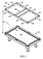
[0035] 以下、図面のうち特に図1を参照して、ビリヤードテーブル面110を照明する、本教示のうちの多くに対応する一例としての照明装置100について示す。ビリヤードテーブル面110は、テーブル115に支持され、ビリヤードテーブル面の縁部を規定するクッション117で囲まれている。照明装置100は、ビリヤードテーブル面110の上方において離間距離Zで1つ以上のライト130を支持するように構成されたフレーム120を含む。ゲームプレイ画像撮影及び解析特徴の一部を有効にするために、1つ以上のライト130は、ビリヤードテーブル面110の略均一な照度を提供する構成において、フレーム120に搭載された1つ又は複数の光源を含む。本開示において検討する例は種々の周辺照明アプローチに関連するものであるが、戦略的に配置されたライト、レンズ効果、リフレクタ、シェード、拡散器等を任意の組み合わせで使用するなど、均一な照度を提供する任意の照明配置が適用可能であると考えられる。
[0035] Referring now particularly to the drawings, and in particular to Fig. 1, an
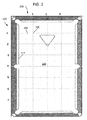
[0036] 均一な照度という概念について、図2〜図6を参照してさらに検討する。本開示の照明アプローチによる均一な照度を確認するため、異なる照度測定値セットを採用した。図2は、フット端部210において1、2、及び3とラベル付けし、テーブル側方220において1〜7とラベル付けしたテーブルマーカをいかにして使用し、テーブルマーカからの投影240が交差するテーブル面状の測定地点230を確立したかを示している。他の環境光源を伴うことなく、Diamond Billiards製の通常のオーバヘッド中央配置ビリヤードテーブルライトで照明した標準のビリヤードテーブル上の各測定地点に、Extechフートキャンドル/lux照度計を配置した。図2に示す測定地点における照度測定値をフートキャンドル及びluxの双方で以下の表1に一覧表示する。表1はさらに、平均照度(AVG)、測定値の変動係数(CV)(可能性分布又は頻度分布の分散の標準化測定値であり、相加平均値又は平均値に対する標準偏差の比率として規定される)、及び測定値の標準偏差(STD)を示している。
The concept of uniform illuminance will be further discussed with reference to FIGS. Different sets of illuminance measurements were employed to ensure uniform illuminance with the illumination approach of the present disclosure. FIG. 2 shows how to use table markers labeled 1, 2, and 3 at the foot ends 210 and 1-7 at the table sides 220, and the
[0037]

[0038] 表2は、その他の環境光源を伴わない、図1及び図7〜図12のアプローチに応じて構成されたライトを使用するビリヤードテーブルの同一測定地点における照度測定値を一覧表示している。 [0038] Table 2 lists illuminance measurements at the same measurement point on a billiard table using lights constructed according to the approaches of Figures 1 and 7-12 without any other environmental light sources. I have.
[0039]
[0040] 図3は、ビリヤードテーブル面110のより多くについて照明の均一性を判定するためにクッション117とのマーカ投影の交差を含むように地点Xを拡張したことを除き、照度測定地点Xを確立する同様のアプローチを示している。標準のDiamond Billiards製ライトを有するテーブルの照度は、これらの測定地点を使用して再測定し、その結果を以下の表3と図4に示す。また測定は、シカゴエリアにおける2つの商業プール機関において、一般的に使用される他の中央テーブルライトを備えた多数の他のプールテーブル上で行われたものであり、以下の表3に示すものと同様の測定結果が得られた。
[0040] FIG. 3 shows that the illuminance measurement point X is different from the illuminance measurement point X, except that the point X is extended to include the intersection of the marker projection with the
[0041]
[0042] 以上に第1の測定値を一覧表示したプロトタイプのライトで照明したビリヤードテーブルは、その照度を、図3の測定地点を使用して、平均照明出力を市販のDiamond Billiards製ライトにより近くなるように調整するために設定した調光で再測定した。その結果を以下の表4に一覧表示し、図5に示す。 The billiard table illuminated with the prototype light in which the first measured values are listed above has an illuminance whose average illumination output is closer to that of a commercially available Diamond Billards light using the measurement points in FIG. Re-measurement was performed with the dimming set to adjust the brightness. The results are listed in Table 4 below and shown in FIG.
[0043]
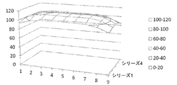
[0044] このアプローチについてさらに示すため、市販の照明光線追跡シミュレーションプログラム(LTI OpticsのPhotopiaソフトウェア)を使用して、表4及び図5に従って照明したビリヤードテーブルのシミュレーション照度レベルを生成した。以下の表5に一覧表示して図6に示したシミュレーション結果は、別に得られた物理的照度測定値と非常に一致している。 [0044] To further illustrate this approach, a simulated illumination level of a billiard table illuminated according to Tables 4 and 5 was generated using a commercially available illumination ray tracing simulation program (Photopia software from LTI Optics). The simulation results, listed in Table 5 below and shown in FIG. 6, are in good agreement with the separately obtained physical illuminance measurements.
[0045]
[0046] 従って、本明細書に記載に配置は、約50〜115フートキャンドルの略均一なビリヤードテーブル面の照度を実証している。要するに、テーブル中央表示値のみを使用したときの変動が15%であり、又はクッションにおける照度を含んだときが28%であった代わりに、本開示の照明装置は、テーブル中央表示値のみを使用すると変動係数がわずか3%であり、クッションにおける照度を使用したときにもわずか7%である。要するに、本開示の照明装置についてのクッション間の全体照度の均一性は、標準のビリヤードテーブルライトのテーブル中央照度の均一性より良好であった。従って、このテーブルについての略均一な照度では、図3に示す上述の位置で測定したクッション間の照度変動係数が約14%以下、より好ましくは10%以下となるであろう。 [0046] Thus, the arrangements described herein demonstrate a substantially uniform billiard table surface illumination of about 50 to 115 foot candles. In short, instead of using 15% of the variation when using only the table center display value, or 28% when including the illuminance in the cushion, the lighting device of the present disclosure uses only the table center display value. The coefficient of variation is then only 3%, and only 7% when using the illuminance on the cushion. In short, the overall illumination uniformity between cushions for the lighting device of the present disclosure was better than the table center illumination uniformity of a standard billiard table light. Thus, for a substantially uniform illuminance for this table, the coefficient of illuminance variation between the cushions measured at the above-described positions shown in FIG.
[0047] 以上に測定した一例としての照明アプローチに戻り、図7及び図8を参照にすると、フレーム120は、1つ以上の光源130をフレーム120内に搭載してビリヤードテーブル面の上方に搭載される。1つ又は複数の光源は、ビリヤードテーブル面110の周縁近傍における構成において、フレーム120内に搭載された光源130を含んでもよい。この周縁は、通常、ビリヤードテーブル面110のクッション又は縁部の上方に突出した領域に対応するであろう。例えば、フレーム120は、クッション117の縁部の垂直突起から10インチ以内、より好ましくは5インチ以内等、ビリヤードテーブル110の縁部から与えられた水平距離内に1つ以上のライト130を搭載するように構成され得る。1つのアプローチにおいて、1つ以上のライトは、光源がビリヤードテーブル面110の中央部分の略直上に配置されることがないように非中央部分に配置される。ビリヤードテーブル面110の中央部分は、通常、図3の側方テーブル220マーカのうちの凡そマーカ2から凡そマーカ8までの図3のフット端部210のマーカ2及び4の突起間の表面110の領域に対応するものと理解されるであろう。
Returning to the exemplary lighting approach measured above, and referring to FIGS. 7 and 8, the
[0048] 1つのアプローチにおいて、フレーム120は、ビリヤードテーブル面110の各隅の上方における略垂直構成において、1つ以上のライト130の対710を搭載するように構成される。さらなる態様において、フレーム120は、図1に示す通り、ビリヤードテーブル面110の各長辺に沿って略等間隔に配置された1つ以上のライト130のうちの2つを搭載するように構成される。フレーム120は、ビリヤードテーブル面110上方に搭載されるとき、ビリヤードテーブル面110の中央部分に対応するフレーム120の中央部分160に亘って掛かる中央フレーム部分720をさらに含んでもよい。
[0048] In one approach, the
[0049] 光源130は、任意の好適な光源を備え得る。図示の例において、各光源130は、図9に示すような線状構成に搭載された発光ダイオード(LED)ライト930のセットを含む。本例において、光源130は、本明細書中においては線状構成においてのみLEDライト930の搭載された搭載面940を有する、PHLIPS製の既製品ライトバーであるが、線状構成に設定されたものに加え、追加のLEDライトが搭載され得る。搭載面940内の搭載穴950は、フレーム120への光源130の搭載を促進する。電気コネクタ960により、1つの光源又はドライバが1つを上回る数の光源130に対する動力供給及び駆動を行うことができるように、電源又はドライバ又は他の光源130に対する有線接続を可能にする。
[0049]
[0050] 図10は、照明装置、本例ではPHILIPS XITANIUM 75W 0.7−2.0A 0−10V調光装置の光源130に動力供給するための一例としてのドライバ又は動力回路を示す。ここでは、光源130は、2つの群に分割され、各群は、独自の、又は、同一の回路1010及び1012を有する。次いで、各回路は、光源130と直列に接続された電源1020、レジスタ1030、及び加減抵抗器1040を含む。加減抵抗器1040は、LED光源130を通じて流れる電流の量を制御することにより、光の明度を群として制御する。代替として、従来既知の通り、パルス幅変調(PWM)回路を使用して光の強度を変調してもよい。
FIG. 10 shows an exemplary driver or power circuit for powering a
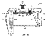
[0051] 一般的に述べると、フレーム120はさらに、光源130からの光をビリヤードテーブル面に方向付け、プレーヤの目をLEDに直接晒してしまうことから保護するために、シェード又はリフレクタ等を支持する。代替又は追加として、LEDからの光を拡散し、より均一な美観を提供するために、1つ以上のリフレクタ及び/又は拡散器要素を追加することができる。図11に示すフレーム1120の内側部分の一例としての設計において、フレーム1120は、反射板の形状、すなわち、光源支持部、リフレクタ、及び拡散器のホルダとして機能する、幅の狭い反転された谷部である。反射板フレーム1120は、その内側構造において略中空であり、搭載時にビリヤードテーブル面に最も近い反射板フレームの部分に対向する、内側構造の頂上部分又は上部支持構造1124により、1つ以上のライトを支持するように構成される。反射板フレーム1120の両側は、ライトを収容する頂上部分から下方に延び、反射面を支持する。図示の例は、押出アルミニウムから構成され、部屋の天井にフレームを搭載する支持部とビデオカメラ750又はその他の装置の取り付けのための取付地点を提供するために、頂上面と内面の長さに沿って連続T字スロットを有する。T字スロットは、T字スロットナットと、T字スロット軌道に沿ってスライドするねじ/ボルト1122を収容し、種々の取付を補助する。フレームの上部支持構造1124は、テーブル面の方向に向くように照明要素(ここでは、LED1130を支持するLED回路基板1140)を支持する。本例において、LED1130は、基本的に真っ直ぐ下方に向くように支持され、換言すると、LED1130が支持される平面がテーブル面に対して基本的に水平となるようにされるが、その他の配置も可能である。しかしながら、LED1130からの光は、種々の方向に射出され、人の視野内で気を散らすほど明るくなり得る。
[0051] Generally speaking, the
[0052] 光を広げてプレーヤがLED1130から気を散らされることなくプレイできるように、フレーム1120は、1つ以上の拡散器を支持する。図11に図示の例では、フレームによって吸収されるか、又は、テーブルに当たらないように方向付けられる、LED1130からの光線を再方向付けする特定の拡散器配置が示されており、ビリヤードテーブル面を十分に照明してLED1130からの光をさらに拡散するようにし、且つ、プレーヤの気を散らさないようにする。本例において、第1のミラー付き拡散器1150は、1つ又は複数の光源(LED1130等)とビリヤードテーブル面の中央の反対に向いたフレーム1120の外壁1126との間に配される。裏面1155は、ミラー付きであり、拡散器1150のより厚い部分の残りは、ミラー付き面1155による反射の前後双方で反射光を拡散する基板から構成される。拡散器1150の幅は、拡散器1150のミラー付き面1155が光をビリヤードテーブルの中央に向かって反射し、テーブル面に十分な照明を提供する補助となるように、ビリヤードテーブル面に対して基本的に垂直となるように向けられる。1つのアプローチにおいて、この拡散器1150は、市販の拡散器(Evonik Platinum Ice OM001X1)であり、厚さが0.34インチである。図11に示す設計のアルミニウム押出については、ミラー付き拡散器は図11の断面において頂上部から底部までが1.8インチであり、標準サイズの9フットポケットビリヤードテーブルについては、フレームの側方に沿って95.8インチであり、フレームの端部に沿って45.8インチである。他の長さも可能である。
[0052]
[0053] 底部拡散器1160は、1つ又は複数の光源(LED1130等)とビリヤード面との間に配されるように支持される。本例において、底部拡散器1160は、厚さが0.08インチで幅が2.125インチである市販の拡散器(Evonik Satin Ice OD002DF)である。拡散器1160は、ゲームプレーヤが個々のLEDから放射され得る強い光によって気を散らされることのないように、LED1130の光を拡散する。代わりに、観察される光は拡散され、より均一に表れた光を提供する。この拡散により、テーブル面に亘ってより均一に光を広げる。また底部拡散器1160は、LED1130がキューで打たれることのないように保護する。
[0053]
[0054] 第2のミラー付き拡散器1170は、1つ又は複数の光源(LED1130等)とビリヤードテーブル面の中央を向いたフレーム1120の内壁1128との間に配される。内壁1128は、1つ以上のカメラ、動きセンサ、又は照明装置の中央部分160等の追加の要素を任意で支持するT字スロット溝部1129を規定してもよい。本例において、第2のミラー付き拡散器1160は、厚さが0.118インチで幅が1.3インチである市販の拡散器(Evonik Platinum Ice OM001 X1)であり、標準サイズの9フットポケットビリヤードについては、フレームの側方に沿って95.8インチであり、フレームの端部に沿って45.8インチである。その他の長さも可能である。第2のミラー付き拡散器1170は、そのミラー付き面1175が実質的に底部拡散器1160と第1ミラー付き拡散器1150の双方に向かって光を反射し、底部拡散器1160を通って、且つ、第1ミラー付き拡散器1140の追加反射を介してビリヤードテーブル面でより多くの光の方向を有効にする。拡散器1150、1160、及び1170は、少なくともLED130が支持されるフレームの長さに対応するフレーム1120の長さ分だけ延びるが、拡散器1150、1160、及び1170は、フレームに沿って任意の長さ延びるものとすることができる。通常、例えば、底部拡散器1160は、フレーム1120全体の周囲に延び、フレーム1120のより均一な美観を提供するであろう。
[0054] The second diffuser with
[0055] ビリヤードテーブルの上方に搭載されるフレーム1120の一例としての実装を図12に示すが、ここでは、内側フレームミラー及び拡散器構成の組み合わせにより、LEDからの光を平滑化し、テーブル面上に審美的且つ均一な照度を生じる。
FIG. 12 shows an example of the mounting of the
[0056] 図7及び図8を再び参照すると、中央フレーム部分720は、他の種々の要素を支持することにより、照明装置に種々の特徴を加えるように構成されてもよい。例えば、種々の機能を提供するのに必要とされる電気的要素及び/又は演算要素のすべて又は一部は、プレーヤに見えないように中央フレーム部分720の頂上部側に搭載され得る。一適用例において、A/C電源コード722が中央フレーム部分720に搭載され、種々の要素に出口電源を提供する。A/Cスイッチ724は、照明装置100のマスタ電源スイッチを提供する。
[0056] Referring again to FIGS. 7 and 8, the
[0057] 一態様において、フレーム120の中央部分720は、ビリヤードテーブル面110の画像記録を対象とする中央カメラ730を支持する。カメラ730は、カメラレンズが、その画像センサ上にテーブル面領域全体を投射させるように、 画像センサを、テーブル面に対して基本的に平行にして、且つ、テーブル上方において十分に高い面にくるように搭載される。必要であれば、テーブルからカメラまでの光路は、カメラレンズと画像センサのサイズに応じて、好適な高さの範囲内に図1における距離Zを保つため、45度ミラー又は同様の光学配置で反らされ、画像センサがテーブル面に直角になるようにしてもよい。実際には、光路の距離は、テーブル上方でフレームの好適な高さを変えず、依然として画像センサ上に完全なテーブル面領域のマッピングを取得するように、フレーム720の中央部分内に水平に調整可能とされる。いずれの構成においても、中央カメラ730からの動画の1フレームは、画像処理を迅速且つ効率的にする目的のために、画像センサ上にテーブル面全体をマップする。テーブル面の単一フレームの画像処理は、照明装置で提供される均一照度の制御により、さらにより効率を高められる
[0057] In one aspect, the
[0058] 図13A及び図13Bは、中央カメラ730で撮影した一例としての画像を示している。本明細書においてさらに説明する照明装置は、中央カメラ730で記録した画像を受信するように動作可能に通信を行う処理装置745を含んでもよい。当業者は、このようなプロセッサ装置が使途の決まった、ハードウェアで実現されたプラットフォームを備えることができるか、若しくは部分的又は全体的にプログラム可能なプラットフォームを備えることができることを認識及び理解するであろう。これらの構造上の選択肢はすべて、当分野でよく知られ理解されており、本明細書においてさらなる説明を必要としない。このように構成されることにより、処理装置745は、本明細書中でさらに説明する通り、画像比較技術による画像を使用したり、又はフレーム間のボールの動きを追跡するためのフレーム比較に基づいたフレーム上のビリヤードボールの対象識別を使用することにより、中央カメラ730によって記録された画像に基づいて、ビリヤードテーブル面110上のボールが移動中であるか、又は非移動中であるかを判定するようにも構成され得る。そして、処理装置745は、少なくとも部分的にボールが移動中又は非移動中のいずれであるかに基づき、照明装置100の設定を自動制御することができる。例えば、処理装置745は、ビリヤードテーブル面上のボールが非移動中である旨の判定に応じて、中央カメラ730からの画像の記録又は提供の停止を有効にする。そこで、画像が変化しないとき、すなわちプレーヤによるショット間において、ビリヤードテーブル面110の画像の送信又は記録を継続する理由がないため、処理装置745及び中央カメラ730は、より効率的に動作するようにともに作動し得る。1つのアプローチにおいて、処理装置745は、中央カメラ730及び端部カメラ750からの画像の提供を有効にし、本明細書で記載の通り、組み合わせたカメラからリアルタイムの動画記録、又は記録された動画記録を再構築する。
FIGS. 13A and 13B show an example of an image captured by the
[0059] 同様に、一例において、処理装置745は、中央カメラ730の視野において特定の画像を検出し、これに応じて画像の記録又は提供の開始、停止、又は一時停止を有効にできるように構成される。例えば、特定の画像を有するカードを、中央カメラ730の視野内にくるようにビリヤードテーブル面上に配置可能であり、又は特定の手のジェスチャをテーブル面上方で行ってもよい。処理装置745は、いずれの特定画像を検出するかに応じて、特定の対応する方法で反応してもよい。例えば、処理装置745は、1つの特別な画像(カード又はその他独自のインジケータ上の大きな赤いドット等)の検出に応じて、モニタしたゲームに関連のプログラムの実行を自動停止することができる。このように、処理装置740が特定の画像の除外を検出したことに応じてプログラムの自動再開をすることができるため、プレーヤはゲームプレイの途中にプログラムを容易に「一時停止」可能である。同様に、処理装置745は、カード上の大きな緑のドット等、そのアクションに関連付けられた特定の画像の検出に応じて、「新たな」ゲームの記録を自動開始してもよい。
[0059] Similarly, in one example, the
[0060] さらなる態様において、ビリヤードテーブル面110の上方に搭載されたときのビリヤードテーブル面110のヘッド端部又はフット端部に対応するフレーム120の端部は、ビリヤードテーブル面110の少なくとも一部と、端部カメラ750が搭載されたのと反対側のビリヤードテーブル面110のヘッド端部又はフット端部を包囲する領域との画像を記録するように向けられた端部カメラ750を支持することができる。図14は、端部カメラ750で撮影した画像の一例を示している。図7及び図8に示す通り、フレーム120は、テーブルの両端の画像を撮影するために、ヘッド端部とフット端部との双方で端部カメラ750を支持することができる。端部カメラ750は、テーブル周辺におけるプレーヤの動きと、プレーヤのショットへのアプローチとの動画を提供する。このような画像は、リアルタイム視聴、記録、又は送信に有用とされ得る。本明細書においてさらに記載する通り、これらの画像を使用して、中央カメラ730で同時に取得したテーブルビュー画像フレームとともに複合動画フレームも構築することができる。
[0060] In a further aspect, an end of the
[0061] 動きセンサ760を使用して、照明装置の動作を促進することができる。この点について、処理装置740は、動きの検出に応じて照明装置の設定を自動制御するために、動きセンサ760に対して動作可能に通信することができる。一例において、処理装置740は、動きセンサ760がA/Cスイッチ回路724との電気的に連通による閾値設定期間の動きの検出に失敗したことに応じて、複数のライト130を自動的にオフするように構成されてもよい。同様に、処理装置740は、パルス幅変調回路1040と通信し、淡色表示から画像撮影を可能とするのに十分な明るさまで上げ、本明細書に記載の通り、記録することにより、照明レベルを上昇させるように構成されてもよい。他の例において、処理装置740は、第1の動きセンサからの動きの検出に応じて、第1のカメラから画像を提供し、第2の動きセンサからの動きの検出に応じて、第2のカメラから画像を提供するように構成されてもよい。例えば、プレーヤの動きを自動的に記録又は送信することを保証するために、動きを検出する領域から画像を撮影するように向けられたカメラから動画又は画像を記録又は送信するであろう。
[0061] The
[0062] さらに他の態様において、処理装置745は、ビリヤードボールを打つキューの性質を有するストライク音を検出し、ストライク音の検出に応じて、照明装置100の設定を自動制御するために、マイクロフォン770によって取得した音をモニタするように構成されてもよい。マイクロフォン770は、フレーム120に搭載されるか、処理装置745と通信するその他の装置の一部(ビデオカメラの1つ等)であってもよい。さらに、処理装置は、ストライク音の検出に応じて、フレーム120の中央フレーム部分720に搭載された中央カメラ730からの画像の記録又は提供を開始し、移動中のボールの画像を自動撮影するように構成可能である。
[0062] In still another aspect, the
[0063] 以上の要素は、種々の方法で組み合わせられ、自動化された特徴及び/又は遠隔制御された特徴の組み合わせを多く提供することができる。このような1つの特徴に、照明装置を完全制御し、照明装置100と無線通信するモバイルデバイスから、カメラ730及び750による画像を記録する能力が挙げられる。一般的に述べると、処理装置は、ユーザ通信装置、ここでは、その他の装置の使用も可能であるがモバイルデバイス1510と通信し、ビリヤードテーブル面110及び/又はビリヤードテーブル面110を包囲する領域の画像を撮影するように配された1つ以上のカメラ730及び750から画像を提供するように構成される。その他のアプローチにおいて、処理装置は、ユーザ通信装置と直接通信してもよい。その後、処理装置は、ユーザ通信装置1510への画像の記憶又は画像の提供を調節するために、1つ以上のカメラ730及び750のうちの少なくとも2つのカメラと通信してもよい。このような一例としての配置が図15に示されており、第1及び第2の処理装置740及び745(各々、図15のコンピュータ1及びコンピュータ2)を利用しており、第1の処理装置740が、照明装置をオンし、明度を調整し、ゲームプレイを開始するように動作しており、第2の処理装置745が、カメラ730及び750との通信専用とされ、個々の動画ストリームを記憶し、及び/又は、ユーザ通信装置1510に提供するカメラの選択を促進する。第2の処理装置745は、有線接続742(イーサネット又は同様の方法等)を介して第1の処理装置740に対して動作可能に通信し、画像の視聴又は記録の開始及び停止に関するコマンドを受信する。ここでは、一般的に利用可能なルータ装置1520は、モバイルデバイス1510と照明装置100の処理装置740との間でWiFi等を通じた無線通信を調節可能である。本例において、処理装置745は、モバイルデバイス1510から作動されるウェブページのホストであるサーバを作動する。ウェブページの一例を図16に示す。サーバは、ルータ1520によってローカルIPアドレスが割り当てられ、IPアドレスがLCDパネル1560に表示される。モバイルデバイス1510は、ウェブページを通じて相互作用してライトを制御し、ユーザにボタン1720のクリックでライトをオン又はオフさせる。ウェブページインタフェースは、ユーザにインタフェース内の一連のバー1730のうちの1つをクリックすることによって光レベルも調整させる。画面上の「高」をクリックすると、バー1740が上方に移動することによって示される、より高いライトレベルを提供する。図16のウェブページは、処理装置1641からランプ回路へのA/Cスイッチ724を通じたオン又はオフのいずれかの切替を行うようにウェブページを介してインタフェース接続された処理装置1641上で動作中の背景プログラムを通じて、又は、強度調整の場合には、ランプ回路電源1020へのパルス幅変調回路インタフェースを制御することにより、ランプのオン/オフと強度の制御を可能にする。
[0063] The above elements can be combined in various ways to provide many combinations of automated and / or remotely controlled features. One such feature is the ability to fully control the lighting device and record images from
[0064] さらに、背景プログラムは、動き検出器760をモニタし、動き検出器の視野内に動きがあるか否かに応じて光の強度を調整する。動きが存在する限り、ランプはユーザの設定したレベルに留まる。予め設定された期間、動きのない場合、ランプはパルス幅変調制御を使用してより低レベルに自動調光を行う。さらに事前設定された期間、動きのない状態が続く場合、ランプは電源オン/オフスイッチを通じてオフする。
Further, the background program monitors the
[0065] 図15の構成要素を様々に使用した他の例において、第2のプロセッサ745は、表示画面、キーボード、及びマウス1685で作動され、3つのビデオカメラ730及び750のすべてからの出力を組み合わせた自動生成複合動画をリアルタイムで(例えば、1秒間に30フレーム)表示するソフトウェアプログラムを動作させる。複合動画は、任意で、後に行われる検索及びレビューのために記録されてもよい。この動画は、時間的に連続して撮影されたシーンからデジタルに作成された視覚画像の記録、再生、又は表示であり、特定の期間、明らかな動きがない場合であっても、視覚動画として視聴可能である。1つのアプローチでは、複数のビデオカメラから同時に記録したビリヤードゲームプレイの動画を作成する方法には、同一の時間間隔で非同期的に別のカメラと個々に関連付けられた少なくとも3つの独立した画像撮影スレッドを作動することを含む。独立の画像撮影スレッドでは、互いの通信のために、共有メモリリソース及びイベント終了フラグを使用する。独立の画像撮影スレッドは、別のカメラからの個々の画像フレームを非同期的に撮影し、別のカメラから撮影した個々の画像フレームの画像解析を行って、別のカメラのうちの所定のカメラからの個々の画像フレームを比較し、個々の画像フレームのうちのいずれかが別のカメラの各々からの各記録シーケンス内の動きを記録しているかを判定する。別のカメラのうちのいずれかが動きを記録しているかに基づき、特定のフレームを選択、表示し、単一の動画メモリ内に保存する。この方法は、1秒間に30フレーム等、特定の時間間隔でビリヤードゲームプレイの動画ファイル内に選択フレームを記録することを含む。動画ファイルに記録された選択フレームは、単一の動画メモリ内にその瞬間に存在するすべてを備える。
[0065] In another example of various uses of the components of FIG. 15, a
[0066] 図15の例を再び参照すると、一例としての実装において、3つのカメラ730及び750からの動画ストリームは、USBポートを通じて第2の処理装置745(図15中ではコンピュータ2とラベル付けされている)に接続される。3つのビデオカメラからの動画ストリームは、USBポートを通じて、同様にコンピュータ2とラベル付けされた処理装置745に接続される。本例において、処理装置745は、ハイパースレッディングを備えたインテルクアッドコアCPU、すなわち8つの別の論理CPUを有する。コンピュータ2の動作システムは、Ubuntuシステムである。8つの論理CPUは、複数スレッドの複数プロセッサ環境において同時に、且つ、非同期的に作動可能であり、別のソフトウェアスレッドが8つの論理CPUの各々で同時に作動可能となるようにする。図15に示し、図18A、図18B、及び図18C並びに以下の表6に詳細を示した例において、各動画ストリームは、それ自体のスレッド上で作動する別のソフトウェアモジュールに入力され、表6に一覧表示されたメモリ割当を共有する。
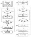
[0067] 以下、図18A、図18B、及び図18Cを参照すると、8つのフロー図1810、1820、1830、1840、1850、1860、1870、及び1880が示されており、各フロー図は別のソフトウェアスレッドを示している。主要なペアレントソフトウェアプロセスは、これらのスレッドのすべてを非同期的に始動する処理装置745から作動する。しかしながら、これらは、ペアレントプロセスに割り当てられた共有メモリリソースの使用を通じて、画像及びデータを共有してもよい。異なるスレッドの動作を明確に表し、理解できるようにするため、これらの共有リソースを表6に挙げて一覧表示している。
Referring now to FIGS. 18A, 18B, and 18C, eight flow diagrams 1810, 1820, 1830, 1840, 1850, 1860, 1870, and 1880 are shown, each of which is a separate flow diagram. Shows a software thread. The main parent software process runs from a
[0068] 3つのカメラ動画ストリームから入力されたフレーム毎の画像を受信する3つの画像フレーム撮影スレッド1810、1830、及び1850が存在する。例えば、1810において、撮影スレッド0は、図7の中央カメラ730から入力された動画を受信する。動画のうちの各連続フレームは、33.3msec(30フレーム/秒)でそのカメラの内部ハードウェア画像バッファ内で利用可能である。ステップ1812において、このスレッドは、その動画ストリームのために処理装置745のプロセスを割り当てられたメモリCFB0にCAM0からの画像フレームを入れる。ステップ1814において、このスレッドは、そのフレーム撮影フラグCFLG0を1に設定した後、1822にて、比較プロセススレッド0に現在のフレームと過去のフレームPFB0との間の差異測定値DIF0を演算させる。その後、プロセススレッド0は、1824にて、CFB0内の現在の画像のコピーを継続して過去のフレームバッファPFB0内の画像を置き換えた後、そのPFLG0を1に設定することにより、非同期的に作動するディレクタスレッドに図18CのDIF0値を使用させてAVGDIFを更新する。同時に、画像撮影スレッド1及び2の1830及び1850は、同様に動作して、図7の各ビデオカメラ750から画像フレームを取得し、プロセッサスレッド1及び2の1840及び1860は、それらの現在の画像フレームと過去の画像フレームとの間の差異測定値DIF1及びDIF2を各々演算するように動作する。従って、本例では、6つの別の論理CPU上で動作する6つのスレッドがこのように動作して、3つの動画ストリームからの画像フレーム入力を達成する。
[0068] There are three image
[0069] 撮影スレッドが作動して画像を取得するのと同時に、2つの他のスレッド、すなわちディレクタスレッド1870及びライタスレッド1880が複合動画ストリームを構築するように作動し、3つの別の動画ストリームを1つの最終的な複合ストリームに組み合わせる。この複合動画は、ディレクタスレッドによって表示され、ディレクタスレッド1870は、動画のうちのいずれのフレームを使用して3つの入力からの複合動画を構築するかを判定する。記録フラグRFLGが設定された場合、複合動画も30フレーム/秒で記憶され、プロセスの終了時に、複合動画ストリームに結合される音声ファイルも記録される。本例において、Ubuntu動作システム上で作動するSoX音声交換プログラムを使用して、記録済み.wavファイルをライタスレッドで作成された記録済み.aviファイルと統合する。
[0069] At the same time that the shooting thread operates to acquire an image, two other threads, a
[0070] 再構築複合動画の一次入力は、フレーム毎に収集されるが、図7の中央カメラ730であり、テーブル面の全体ビューを提供するカメラ0から到来する。複合動画の目的の1つとして、各ショットが行われる前とその後のボールの移動中とにおけるボールの配置の正確な記録を取得することが挙げられる。しかしながら、ボールが移動を停止した後に、プレイの他の興味深い情報的側面が発生する期間がある。再構築された複合動画は、3つのカメラの利用による3つの活動と1つの複合動画記録の再構築との双方を取得する。動きが発生している限り、中央カメラ730のビューにおいては、カメラ750からの残り2つの端部テーブル動画ストリームが再構築に含まれない。本例における動き判定は、カメラ0からの連続フレーム間の差異DIF0をモニタリングすることによって行われ、プロセススレッド0の1820において1822で演算される。ディレクタスレッドは、AVGDIF、すなわち最終30個の連続DIF0値の移動平均を演算し、この値を固定閾値THRSと比較して動きが発生したか否かを決定する。
[0070] The primary input of the reconstructed composite video, which is collected on a frame-by-frame basis, comes from
[0071] キューボールをヒットするキュースティックのストライク音を使用するもの(米国仮特許出願第62/032,187号に記載の通りであり、参照としてここに組み込む)、又は当分野でよく知られている通り、対象のボールの動きを具体的に追跡することによるものなど、動きの開始を判定する他の方法を利用して、複数のカメラからいずれのフレームを複合動画に含めるかを判定又は規定することもできる。 [0071] Using a cue stick strike sound to hit the cue ball (as described in US Provisional Patent Application No. 62 / 032,187, incorporated herein by reference) or is well known in the art. As described above, using other methods of determining the start of the movement, such as by specifically tracking the movement of the target ball, to determine which frame from multiple cameras to include in the composite video or It can also be specified.
[0072] ディレクタスレッド1870を再び参照すると、1871においてPFLG0、PFLG、及びPFLG2のすべてが1に等しい場合、新たな画像フレームが現在のフレームバッファCFB0、CFB1、及びCFB2内にあることを意味し、1872にてスレッドはコピーCFB0からDFBに進む。DFBは、現在の画像フレームを表示するメモリバッファであり、それは修正なしの現在のCFB0動画フレームであるか、又はスレッド内で後に、PIP画像とともに隅に重畳される。1873において、現在のDIF0を移動平均に平均化することによってAVGDIF値を更新し、その後、1874において、更新済みのAVGDIFをTHRSと比較して中央カメラのテーブルビュー内に動きが存在するか否かを決定する。図13A及び図13Bは、動きが検出された場合に含まれるフレームの種別を示している。これらの図面は、動画フレームのシーケンスからのものであり、より濃い「4ボール」が白いキューボールにヒットされて、「4」ボールを再度ポケットに向かって推進させる様子を示している。これらの連続フレーム及び過去の連続フレームから得たボールの動きが閾値THRSを上回るAVGDIF値を生じるため、これらのフレームは、端部カメラビューを除外して、再構築された複合動画ストリームに単純に加えられるであろう。
[0072] Referring again to
[0073] 1874にて動きが存在しない場合、スレッドは、1875において、いずれの端部ビューが進行中の動きを最も多く有するかを見るため、DIF1及びDIF2を比較する。より高い差異値DIF1又はDIF2に反映される、動きを最も多く有する動画ストリームが選択され、ステップ1876又は1877にて1/4に縮小され、ステップ1879にてDFBの隅に重畳されて、写真内写真の再構築画像フレームを作成する。動画ストリーム1の差異値DIF1が動画ストリーム2の差異値DIF2より大きい場合、PIPフレームは、動画ストリーム0及び1からの動画フレームから再構築される(1870)。動画ストリーム2の差異値DIF2が動画ストリーム1の差異値DIF1より大きい場合、PIPフレームは、動画ストリーム0及び2からの動画フレームから再構築される(1876)。結果として得られた動画フレームは、図17A及び17Bに示されるものに対応し、ここでは、選択される端部ビューフレームが最も多く動きを含むものである。従って、ディレクタスレッドの動作は、動きの有無を判定し、表示される動画に適切な次の連続画像フレームを選択することである。テーブル上に動きがない場合、再構築動画は、テーブル周縁近傍の活動を示していなければならず、これは通常、次のショットに備えているプレーヤである。PIPフレームは、これを示すものの、動きの停止前のテーブル面上のボールの全体ビューの文脈において示す。
[0073] If there is no motion at 1874, the thread compares DIF1 and DIF2 at 1875 to see which end view has the most motion in progress. The video stream with the most motion, which is reflected in the higher difference value DIF1 or DIF2, is selected, reduced in
[0074] 以下、図18Cのステップ1880に戻ると、ライタスレッドは、複合動画記録の記録プロセスの同期を制御する。ライタスレッドは、装置のオペレータによって任意に駆動されるが、その場合、ライタスレッドは、ディレクタスレッドによって生成及び開始される。それは、同期中の音声記録も開始し、記録フレームの時間間隔を精密に測定するためにmsecクロックを開始する。音声信号はリアルタイムで記録されているため、その視覚コンテンツに関する音声記録に正確に対応する複合動画ストリームが生成されなければならない。そこで、撮影スレッド0、1、及び2において、3つの別のビデオカメラストリームを非同期的に開始及び動作させることができ、プロセッサスレッド0、1、及び2において、これらの撮影画像を非同期的に画像処理することによって動き解析測定値を演算することができる。その後、ディレクタスレッドはさらに、非同期的に、且つ、必要に応じて、包含対象のPIPフレームを選択してもよい。しかしながら、時間変動を伴わないライタスレッドは、正確に1秒の1/30で表示バッファDFMのコンテンツを記録し、複合動画を構築しなければならない。その精密な時間でDFM表示内で生じるものすべてを記録動画出力ファイルに書き込む。
Hereinafter, returning to step 1880 of FIG. 18C, the writer thread controls the synchronization of the recording process of the composite moving image recording. The writer thread is arbitrarily driven by the operator of the device, in which case the writer thread is created and started by the director thread. It also starts audio recording during synchronization and starts the msec clock to precisely measure the time interval between recording frames. Since the audio signal is recorded in real time, a composite video stream must be generated that exactly corresponds to the audio recording of the visual content. Thus, three different video camera streams can be started and operated asynchronously in
[0075] 提供された画像に関する上述の制御は、多数の代替の方法で有効とされ得る。ボールの動きを伴わない時間、いずれの端部カメラのビューを表示すべきかという判定は、各端部カメラの各視野に対応するテーブルの周辺領域における動きを検出するためにフレーム上に配された動きセンサからの情報を使用して行われ得る。他のアプローチにおいて、1つ以上の処理装置は、いずれのカメラが最も多くの動きを撮影しているかという判定を行うために、各カメラによって提供される動画フィードに画像解析を実施することができる。端部カメラから重畳動画フィードをいつ除外するかという判定は、キューがボールを打つ音の検出、中央カメラからの動画フィードの画像解析、又はその双方の組み合わせによって行われ得る。例えば、時として、中央カメラが、ボールの動きと混乱し得るキューの移動等、テーブル上のボールの動き以外の動きを撮影することもある。ボールの画像解析をキューのストライク音検出と組み合わせることにより、キューのストライク音検出に応じて重畳動画フレームの除外を行い、ボールの動き検出中は、重畳動画フレームの除外を維持することができる。このようなアクションを有効にするのに必要な処理は、任意の組み合わせの処理装置に対して実施することができる。 [0075] The controls described above with respect to the provided images may be enabled in a number of alternative ways. The determination of which end camera view to display during the time without ball movement was placed on the frame to detect movement in the peripheral area of the table corresponding to each field of view of each end camera. This can be done using information from the motion sensor. In another approach, one or more processing units may perform image analysis on the video feed provided by each camera to determine which camera is capturing the most movement. . Determining when to remove the superimposed video feed from the end camera may be made by detecting the sound of the cue hitting the ball, analyzing the image of the video feed from the central camera, or a combination of both. For example, at times, the central camera may capture movements other than ball movements on the table, such as cue movements that may be confused with ball movements. By combining the image analysis of the ball with the cue strike sound detection, it is possible to exclude the superimposed moving image frame in response to the cue strike sound detection, and maintain the removal of the superimposed moving image frame during the ball motion detection. The processing required to enable such an action can be performed on any combination of processing devices.
[0076] 図19を参照すると、画像記憶を自動提供し、及び/又は、ゲームプレイ条件に基づいて異なるカメラからの表示を行うために照明装置によって実行される他の一例としてのプロセスについて説明する。本例において、処理装置は、テーブル面の画像を動画メモリVM2内に取得する図7の中央カメラ730と、ビリヤードテーブルの両端及びテーブルの各端部を包囲する第1及び第2の領域の画像を動画メモリVM1又はVM3に各々取得する、フレームの両端部のカメラ750と、テーブルの両端を包囲する領域における動きを検出するように配された図7の動きセンサ760(図19においてMS1及びMS2とラベル付けする)と、マイクロフォンと通信する。カメラ及び動き検出器は、テーブル端部上方のカメラに加え、又は、テーブル端部上方のカメラの代わりに、テーブルの側方の上方に搭載可能であり、及び/又は、その周囲における動きの画像を撮影するか、又はその周囲における動きを感知することができる。
Referring to FIG. 19, another example process performed by the lighting device to automatically provide image storage and / or to provide display from different cameras based on game play conditions will be described. . In this example, the processing device acquires the image of the table surface in the moving image memory VM2, the
[0077] まず、処理装置は、初期化プロセス1910を起動又は再設定する。そして、テーブル上にボールの動きがないと仮定すれば、処理装置は、1つ以上の動き検出器の使用又は上述のリアルタイム画像解析技術により、ビリヤードテーブル面を包囲する第1の領域及び第2の領域からの動きをモニタする。そして、処理装置は、ステップ1920において、カメラ画像を動画メモリVM4(出力又は表示/記録動画メモリ)に記憶又は表示されなければならない、検出された動きに対する判定を行う。より具体的には、第1の領域からの動きの検出に応じて(又は、双方の領域における動きの場合、動き信号が第1の領域においてより高い)、処理装置は、第2の側方/端部カメラからVM4への画像の記憶又は提供の停止を有効にし、第1の側方/端部カメラからの画像の記憶又は提供を有効にして(1933)、画像を第1の領域からVM4に記憶又は提供する。例えば、これには、ディスプレイ上で表示可能な動画又は動画ファイルの記憶又は提供が含まれる。第2の領域からの動きの検出に応じて(又は、双方の領域における動きの場合、動き信号が第2の領域においてより高い)、処理装置は、第1の側方/端部カメラからVM4への画像の記憶又は提供の停止を有効にし、第2の側方/端部カメラからの画像の記憶又は提供を有効にして(1936)、画像を第2の領域から記憶又は提供する。いずれの場合においても(双方のステップに対する同一の手順に1940とラベル付けする)、処理装置は、次いで、例えば、リアルタイム画像解析などの動き検出により、及び/又は、例えば、ビリヤードボールを打つキューの性質を有するストライク音の検出など、ボールを打つことにより、ボールヒットのモニタを行う。処理装置は、ボールヒットの検出に応じて、各側方/端部カメラからVM4への画像の記憶又は提供の停止を有効にし、テーブルを撮影する視野の画像とボールの動きとを撮影するように、ステップ1950にて、中央カメラのメモリVM2からの画像VM2のVM4への記憶又は提供を有効にする。
First, the processing device starts or resets the
[0078] その後、処理装置は、上述の通り、1つ以上の動き検出器の使用又はリアルタイム画像解析等により、ボールの動きの停止をモニタする(1960)。ビリヤードテーブル面上でのボールの動きの停止を検出したことに応じて、処理装置は、以上に検討した通り、中央カメラからの画像の記憶又は提供の停止を有効にし、側方/端部カメラのうちの1つからの画像の記憶又は提供を有効にする。処理装置は、プレイ中のゲームについていずれのボールがテーブル上にあるかを追跡すること、又は、プレイの終了を示すユーザ潜在信号を受信することのいずれかにより、ゲームが終了したことを判定する(1970)。ゲームの終了を判定したことに応じて、画像撮影及びその他のゲームプロセスを終了する(1980)。 Thereafter, the processing device monitors the stop of the movement of the ball by using one or more motion detectors or real-time image analysis as described above (1960). In response to detecting a stoppage of the ball movement on the billiard table, the processor, as discussed above, enables the stop of storing or providing images from the central camera, and the side / end camera. Enable storage or presentation of an image from one of the images. The processing device determines that the game is over, either by tracking which ball is on the table for the game being played or by receiving a user latent signal indicating the end of play. (1970). In response to the determination of the end of the game, the image shooting and other game processes are ended (1980).
[0079] さらなる代替実施形態において、図18A、図18B、図18C、及び図19に示す機能又は論理は、別のプロセッサ回路で実行されてもよいコードの形で実施されてもよい。ソフトウェアで実施される場合、各ブロックは、特定の論理機能を実施するためのプログラム指示を備えるモジュール、セグメント、又はコードの一部を表してもよい。プログラム指示は、プログラミング言語で記載された人による読取可能な記述を備えるソースコード、又は、コンピュータシステム又はその他のシステムのプロセッサ等、好適な実行システムによって認識可能な数値支持を備える機械コードの形で実施されてもよい。この機械コードは、ソースコード等から変換されてもよい。ハードウェアで実施される場合、各ブロックは、特定の論理的機能を実施する回路又は多数の相互接続回路を表してもよい。従って、コンピュータ可読媒体(持続性又は有形である)が、本明細書に記載の通り、処理装置に動作を実施させるように構成されたこのような指示を記憶してもよい。 [0079] In a further alternative embodiment, the functions or logic shown in FIGS. 18A, 18B, 18C, and 19 may be implemented in code that may be executed on another processor circuit. When implemented in software, each block may represent a module, segment, or portion of code that comprises program instructions for performing a particular logical function. The program instructions may be in the form of source code comprising a human readable description in a programming language, or machine code comprising a numerical support recognizable by a suitable execution system, such as a processor of a computer system or other system. May be implemented. This machine code may be converted from source code or the like. When implemented in hardware, each block may represent a circuit or a number of interconnect circuits that perform the specified logical function. Accordingly, a computer-readable medium (persistent or tangible) may store such instructions configured to cause a processing device to perform the operations, as described herein.
[0080] 当業者は、本発明の範囲から逸脱することなく、以上に記載の実施形態には幅広い種々の修正、変更、及び組み合わせが行われ得ること、またこのような修正、変更、及び組み合わせも本発明の概念の範囲内としてみなされなければならないことを認識するであろう。
[0080] It will be appreciated by those skilled in the art that a wide variety of modifications, changes, and combinations may be made to the above-described embodiments without departing from the scope of the invention, and that such modifications, changes, and combinations may be made. Will also be recognized as falling within the scope of the inventive concept.
Claims (11)
前記ビリヤードテーブル面上方に複数のライトを支持するように構成されたフレームであって、前記複数のライトは、前記ビリヤードテーブル面に略均一な照度を提供する構成において前記フレームに搭載される、フレームと、
前記ビリヤードテーブル面の上方に搭載されたとき、前記ビリヤードテーブル面の中央部分に対応する前記フレームの中央部分に亘って掛かる中央フレーム部であって、前記フレームの中央部分は、前記ビリヤードテーブル面の画像の記録を対象とする中央カメラを支持するように構成される、中央フレーム部と、
前記中央カメラによって記録された前記画像を受信するため、動作可能に通信を行う処理装置と、を備え、
前記処理装置は、前記中央カメラによって記録された前記画像に基づいて、前記ビリヤードテーブル面上のボールが移動中又は非移動中であるかを判定し、少なくとも部分的にボールが移動中又は非移動中のいずれかであることに基づき、前記照明装置の設定を自動制御するように構成される、照明装置。 A lighting device for illuminating a billiard table surface,
Wherein a frame configured to support the billiard table surface above the plurality of lights, the plurality of lights are mounted on the frame in a configuration that provides a substantially uniform illumination on the billiard table surface, a frame When,
When mounted above the billiard table surface, the central frame portion extends over the central portion of the frame corresponding to the central portion of the billiard table surface, and the central portion of the frame is the central portion of the billiard table surface. A central frame portion configured to support a central camera intended for image recording;
A processing unit operably communicating to receive the image recorded by the central camera,
The processing device determines whether the ball on the billiard table is moving or not moving, based on the image recorded by the central camera, and at least partially moves or does not move the ball. A lighting device configured to automatically control settings of the lighting device based on one of the following.
前記フレームの前記端部は、前記ビリヤードテーブル面の少なくとも一部と、端部カメラが搭載されるのと反対側における前記ビリヤードテーブル面のヘッド端部又はフット端部を包囲する領域と、の画像を記録することを対象とする前記端部カメラを支持するように構成される、請求項1又は2に記載の照明装置。 When mounted above the billiard table surface, the game device further comprises an end of the frame corresponding to a head end or a foot end of the billiard table surface,
The end of the frame is an image of at least a portion of the billiard table surface and an area surrounding the head end or foot end of the billiard table surface on the side opposite to the end camera mounted. 3. The lighting device according to claim 1, wherein the lighting device is configured to support the end camera intended to record the edge camera.
前記処理装置は、動きの検出に応じて前記照明装置の設定を自動制御するために、前記動きセンサに対して動作可能に通信を行う、請求項1〜3のいずれか一項に記載の照明装置。 Further comprising a motion sensor supported by the frame,
The lighting device according to any one of claims 1 to 3, wherein the processing device operably communicates with the motion sensor to automatically control settings of the lighting device in response to the detection of the motion. apparatus.
The processing device stores or provides an image from the central camera in response to the detection of the strike sound, and in response to the detection that the ball on the billiard table surface is not moving, the first camera 11. The lighting device of claim 10, wherein the lighting device is configured to store or provide an image from the second camera.
Applications Claiming Priority (3)
| Application Number | Priority Date | Filing Date | Title |
|---|---|---|---|
| US201462032187P | 2014-08-01 | 2014-08-01 | |
| US62/032,187 | 2014-08-01 | ||
| PCT/US2015/043198 WO2016019288A1 (en) | 2014-08-01 | 2015-07-31 | Billiard table lighting and game play monitor |
Publications (3)
| Publication Number | Publication Date |
|---|---|
| JP2017524507A JP2017524507A (en) | 2017-08-31 |
| JP2017524507A5 JP2017524507A5 (en) | 2018-09-06 |
| JP6654633B2 true JP6654633B2 (en) | 2020-02-26 |
Family
ID=55181432
Family Applications (1)
| Application Number | Title | Priority Date | Filing Date |
|---|---|---|---|
| JP2017526481A Active JP6654633B2 (en) | 2014-08-01 | 2015-07-31 | Billiard table lighting and game play monitor |
Country Status (5)
| Country | Link |
|---|---|
| US (4) | US9485399B2 (en) |
| EP (1) | EP3174612B1 (en) |
| JP (1) | JP6654633B2 (en) |
| CN (1) | CN107073328A (en) |
| WO (1) | WO2016019288A1 (en) |
Families Citing this family (20)
| Publication number | Priority date | Publication date | Assignee | Title |
|---|---|---|---|---|
| CN104117202B (en) * | 2014-07-02 | 2015-12-30 | 乔冰 | Projection type billiard batting intelligent assistance system and method |
| CN104117201B (en) * | 2014-07-02 | 2015-12-09 | 乔冰 | Projection type billiard system gesture/club control system and its implementation |
| US9827483B2 (en) | 2014-08-01 | 2017-11-28 | Smart Billiard Lighting LLC | Billiard table lighting and game play monitor |
| EP3174612B1 (en) | 2014-08-01 | 2019-09-04 | Smart Billiard Lighting LLC | Billiard table lighting and game play monitor |
| USD835652S1 (en) | 2015-12-10 | 2018-12-11 | Smart Billiard Lighting LLC | Display screen with transitional graphical user interface of a billiard game |
| JP6873730B2 (en) * | 2016-02-17 | 2021-05-19 | スマート ビリヤード ライティング エルエルシー | Billiard table lighting and gameplay monitor |
| USD792002S1 (en) * | 2016-04-12 | 2017-07-11 | Lite Systems, Inc. | Pendant billiard luminaire |
| CN109691237A (en) * | 2016-09-16 | 2019-04-26 | 昕诺飞控股有限公司 | Light control |
| KR101840134B1 (en) * | 2016-10-25 | 2018-03-19 | 박정길 | Billiard practice system having light control function |
| US11462121B2 (en) * | 2017-02-15 | 2022-10-04 | Cae Inc. | Visualizing sub-systems of a virtual simulated element in an interactive computer simulation system |
| CN107297069B (en) * | 2017-07-21 | 2023-06-13 | 佛山科学技术学院 | Intelligent billiard training table |
| GB2567800A (en) * | 2017-08-29 | 2019-05-01 | Social Entertainment Ventures Ltd | Detecting ball strike position |
| CN108211319B (en) * | 2018-01-30 | 2019-06-18 | 平顶山学院 | Multifunctional intellectual scoring table for sport track and field |
| USD880755S1 (en) * | 2018-06-13 | 2020-04-07 | Lite Systems, Inc. | Pendant luminaire with louvers |
| USD930747S1 (en) * | 2019-02-20 | 2021-09-14 | Indian Industries, Inc. | Collapsible billiards table |
| WO2020219850A1 (en) * | 2019-04-26 | 2020-10-29 | Starker Thomas Charles | Broadcast-ready table sports system |
| CN112929792B (en) * | 2021-01-21 | 2022-06-28 | 稿定(厦门)科技有限公司 | Sox-based audio processing method, medium, device and apparatus |
| CN117980658A (en) * | 2021-08-31 | 2024-05-03 | 敏锐照明股份有限公司 | Billiard ball lamp |
| US11748406B2 (en) * | 2021-11-01 | 2023-09-05 | Lucasfilm Entertainment Company Ltd. LLC | AI-assisted sound effect editorial |
| WO2023154654A2 (en) * | 2022-02-09 | 2023-08-17 | Martin Blake Robert | Interactive led system for enhancing billiard gameplay |
Family Cites Families (108)
| Publication number | Priority date | Publication date | Assignee | Title |
|---|---|---|---|---|
| GB190808509A (en) * | 1908-04-16 | 1909-02-25 | John Henry Faulkner | |
| GB191107344A (en) * | 1911-03-24 | 1912-01-04 | Herbert Mitchell | Improvements in and connected with Electric Lighting Arrangements for Billiard Tables, Shops and the like. |
| GB611673A (en) * | 1946-05-04 | 1948-11-02 | Vincent Hartley | An improved illuminating means for use with billiard tables and the like |
| US3743287A (en) | 1972-01-19 | 1973-07-03 | C Liermann | Combined frame and elevatable pool table assembly |
| US4882676A (en) | 1988-09-09 | 1989-11-21 | Kop Andrew R Van De | Method and apparatus for rating billiard shots and displaying optimal paths |
| GB8826296D0 (en) | 1988-11-10 | 1988-12-14 | Williams G A | Game |
| DE4039315C2 (en) | 1990-12-10 | 1996-04-25 | Nsm Ag | Learning and playing device for ball and ball games |
| DE4132678A1 (en) | 1991-10-01 | 1993-04-08 | Thorn Licht Gmbh | WORKPLACE LAMP WITH AT LEAST ONE FLUORESCENT LAMP |
| USD372591S (en) | 1995-04-06 | 1996-08-13 | Simmons Juvenile Products Company, Inc. | Mirror |
| USD396841S (en) | 1995-10-16 | 1998-08-11 | Taylor Gregory P | Motorboat gas tank cushion kit |
| JPH09213160A (en) | 1996-02-02 | 1997-08-15 | Yazaki Corp | Lock mechanism |
| US6626558B2 (en) | 1997-02-28 | 2003-09-30 | Electro Optical Sciences Inc. | Apparatus for uniform illumination of an object |
| USD420354S (en) | 1997-10-17 | 2000-02-08 | Domingo Morales | Light emitting strip for a pager |
| US5947583A (en) * | 1997-12-29 | 1999-09-07 | Castano; Guillermo | Illuminating cue stick rack |
| US6244970B1 (en) * | 1998-06-19 | 2001-06-12 | Diamond Billiard Products, Inc. | Optical sensors for cue ball detection |
| TW457732B (en) | 1999-08-27 | 2001-10-01 | Lumileds Lighting Bv | Luminaire, optical element and method of illuminating an object |
| FR2804879A1 (en) | 2000-02-10 | 2001-08-17 | Thierry Lecoq | Interactive billiard ball analysis/tactics division system having camera viewing billiard ball table and central processor recognizing positions and calculating possible movements following game rules. |
| US6601976B1 (en) | 2000-04-07 | 2003-08-05 | Thin-Lite Corporation | Snap assembled light fixture apparatus |
| JP2002186702A (en) * | 2000-12-22 | 2002-07-02 | Sefamedeia Create:Kk | Billiard practicing device and billiard practicing system |
| US6540373B2 (en) | 2001-03-29 | 2003-04-01 | Bendrix L. Bailey | Lighting system |
| US20040132535A1 (en) * | 2003-01-07 | 2004-07-08 | Sumko Michael H. | Laser billiard ball positioning apparatus |
| US20040254024A1 (en) | 2003-06-12 | 2004-12-16 | Marvin Thomas | Color coded pool table numbering system |
| JP4152843B2 (en) | 2003-09-17 | 2008-09-17 | 株式会社モリテックス | Illumination device and illuminated imaging device |
| US7697026B2 (en) | 2004-03-16 | 2010-04-13 | 3Vr Security, Inc. | Pipeline architecture for analyzing multiple video streams |
| CA2462620A1 (en) | 2004-03-30 | 2005-09-30 | Jvl Corporation | Pool video game |
| JP2006043017A (en) | 2004-08-03 | 2006-02-16 | Seiko Epson Corp | Display device |
| CA2520923A1 (en) | 2004-09-23 | 2006-03-23 | Michael Greenspan | Method and apparatus for positional error correction in a robotic pool system using a cue-aligned local camera |
| JP2006306305A (en) | 2005-04-28 | 2006-11-09 | T An T:Kk | Interior light for vehicle |
| US20070026956A1 (en) | 2005-07-29 | 2007-02-01 | Tournament Games, Inc. | One-player pool scoring system and method |
| USD564694S1 (en) | 2006-02-17 | 2008-03-18 | Liteco | Light fixture |
| US8105174B1 (en) | 2006-02-21 | 2012-01-31 | Schofield Paul E Sr | Computerized method and system for administering universal rating of pocket billiard players |
| US7648257B2 (en) | 2006-04-21 | 2010-01-19 | Cree, Inc. | Light emitting diode packages |
| CN2906295Y (en) | 2006-04-29 | 2007-05-30 | 中山腾龙体育器材有限公司 | Ceiling light used for billiard table |
| US7665862B2 (en) | 2006-09-12 | 2010-02-23 | Cree, Inc. | LED lighting fixture |
| US10124240B2 (en) | 2006-11-14 | 2018-11-13 | Lydia Parvanta | Game table television and projector system, and method for same |
| JP2008129554A (en) * | 2006-11-27 | 2008-06-05 | Sanyo Electric Co Ltd | Imaging device and automatic focusing control method |
| DE102008013764A1 (en) | 2007-03-16 | 2008-10-23 | J.Morita Manufacturing Corp. | Medical lighting device and medical imaging device |
| US20090116210A1 (en) | 2007-03-30 | 2009-05-07 | Shaun Cutler | Device for intelligent illumination |
| US8210723B2 (en) | 2007-06-29 | 2012-07-03 | Dialight Corporation | LED lens array optic with a highly uniform illumination pattern |
| JP5441900B2 (en) | 2007-07-16 | 2014-03-12 | コーニンクレッカ フィリップス エヌ ヴェ | Driving the light source |
| KR20090013980A (en) | 2007-08-03 | 2009-02-06 | 포항공과대학교 산학협력단 | Apparatus and method of supporting billiard game using camera images |
| AU2009200364A1 (en) | 2008-02-04 | 2009-08-20 | Aristocrat Technologies Australia Pty Limited | A method of gaming, a gaming system, and a gaming apparatus |
| US7766536B2 (en) * | 2008-02-15 | 2010-08-03 | Lunera Lighting, Inc. | LED light fixture |
| US7976187B2 (en) | 2008-03-27 | 2011-07-12 | Cree, Inc. | Uniform intensity LED lighting system |
| AT506742A1 (en) | 2008-04-17 | 2009-11-15 | Riml Thomas Dipl Ing | DEVICE FOR EXERCISING A SPORTS OR BZW. GAMES AT SPANISHED PLAYS OF PLAY |
| JP5356724B2 (en) | 2008-05-13 | 2013-12-04 | 株式会社タイトー | Billiard table ball movement management device |
| KR20100015258A (en) | 2008-08-04 | 2010-02-12 | 신진석 | Counter apparatus of billiards counter |
| JP5428007B2 (en) | 2008-08-25 | 2014-02-26 | 株式会社セガ | Game device having imaging means |
| US20100062859A1 (en) | 2008-09-10 | 2010-03-11 | Rice Patrick G | Method and system for tracking parlor game statistics |
| US8258721B2 (en) | 2008-09-16 | 2012-09-04 | Evolution Lighting, Llc | Remotely controllable track lighting system |
| CN201293279Y (en) | 2008-10-16 | 2009-08-19 | 郑榕彬 | LED illumination lamp |
| CN201282530Y (en) | 2008-10-27 | 2009-07-29 | 刘铮 | Assistant judgment device for computer billiards |
| CN102216671B (en) | 2008-11-19 | 2015-09-02 | 罗姆股份有限公司 | Led |
| WO2010068989A1 (en) | 2008-12-16 | 2010-06-24 | Thomas David Penna | An arrangement adapted to be used with conventional billiard tables for greater utilisation, versatility and/or application of said tables |
| CN102483577B (en) | 2009-03-06 | 2014-09-17 | 麦克罗尼克迈达塔有限责任公司 | Rotor imaging system and method with variable-rate pixel clock |
| USD653800S1 (en) | 2009-03-31 | 2012-02-07 | Grand General Accessories Manufacturing | Bezel for a vehicle |
| EP2419674B1 (en) | 2009-04-16 | 2015-08-12 | Koninklijke Philips N.V. | Lighting system, space with a lighting system, and method of providing an illumination profile using such a lighting system |
| KR101056927B1 (en) | 2009-06-05 | 2011-08-12 | 이선표 | Billiards Game Coaching System |
| JP2011227197A (en) | 2010-04-16 | 2011-11-10 | Opto Design Inc | Illumination display method and illumination display device |
| JP5498064B2 (en) * | 2009-06-29 | 2014-05-21 | キヤノン株式会社 | Imaging apparatus and control method thereof |
| USD649974S1 (en) | 2009-07-17 | 2011-12-06 | Tencent Technology (Shenzhen) Company Limited | Display panel with a transitional computer icon |
| US8616971B2 (en) | 2009-07-27 | 2013-12-31 | Obscura Digital, Inc. | Automated enhancements for billiards and the like |
| US8992315B2 (en) | 2009-07-27 | 2015-03-31 | Obscura Digital, Inc. | Automated enhancements for billiards and the like |
| US8727875B2 (en) * | 2009-07-27 | 2014-05-20 | Obscura Digital, Inc. | Automated enhancements for billiards and the like |
| CN102474955B (en) | 2009-08-05 | 2015-05-20 | 皇家飞利浦电子股份有限公司 | Lighting system with concurrent adjustment of intensity and orientation |
| CN101628174B (en) | 2009-08-18 | 2011-04-27 | 刘铮 | Automatic distortion correction extraction method of coordinates of Snooker tabletop |
| US8292733B2 (en) | 2009-08-31 | 2012-10-23 | Disney Enterprises, Inc. | Entertainment system providing dynamically augmented game surfaces for interactive fun and learning |
| ES2333839B1 (en) | 2009-09-22 | 2010-10-13 | Cubensis, S.L. | BILLAR PERSONAL TRAINER DEVICE. |
| KR20110006697U (en) * | 2009-12-28 | 2011-07-06 | 주식회사 코스모스산업 | a illuminated billiad table |
| KR20110075967A (en) | 2009-12-29 | 2011-07-06 | 이기혁 | The billiard room system |
| KR20110085735A (en) * | 2010-01-21 | 2011-07-27 | 조영복 | Apparatus for offering image of billiard and method thereof |
| KR101223266B1 (en) | 2010-04-07 | 2013-01-17 | 장경일 | System and Method for Playing Billiard Game Using Touch-Screen Monitor |
| US20110255276A1 (en) | 2010-04-19 | 2011-10-20 | Coward Mark T | Lighting assembly |
| CN102859266A (en) | 2010-04-23 | 2013-01-02 | 皇家飞利浦电子股份有限公司 | LED-based lighting unit |
| GB2479902A (en) * | 2010-04-28 | 2011-11-02 | Christopher Mark Southworth | Billiards apparatus for automatically tallying a player's score |
| US9308435B1 (en) | 2010-05-07 | 2016-04-12 | Thomas Rohrmeister | Stylized billiard rack and a method of playing a moving billiard game using the stylized billard rack |
| CN101848376A (en) | 2010-05-19 | 2010-09-29 | 朱万政 | Television system for analyzing displacement of billiards |
| CN201815088U (en) | 2010-09-13 | 2011-05-04 | 刘铮 | Snooker interactive device |
| USD689504S1 (en) | 2010-10-14 | 2013-09-10 | Aisin Seiki Kabushiki Kaisha | Display screen for a vehicle with graphical user interface |
| USD689062S1 (en) | 2010-10-14 | 2013-09-03 | Aisin Seiki Kabushiki Kaisha | Display screen for a vehicle with graphical user interface |
| KR101205811B1 (en) | 2010-12-20 | 2012-11-28 | 주식회사 웨이브애프터 | System and method for correcting billiards pose, and recording media thereof |
| KR101065708B1 (en) | 2011-01-13 | 2011-09-19 | 엘지전자 주식회사 | Led lighting device and method for manufactureing the same |
| JP2012187221A (en) | 2011-03-09 | 2012-10-04 | Hiroyuki Hashimoto | Communication system using billiard device |
| DE202011000598U1 (en) | 2011-03-16 | 2011-10-17 | U. K. Technology Corp. | ceiling light |
| KR20120113578A (en) * | 2011-04-05 | 2012-10-15 | 권택만 | Billiards guide device |
| US20120285060A1 (en) | 2011-05-12 | 2012-11-15 | Design Ideas, Ltd. | Picture frames |
| CN103562625A (en) | 2011-05-17 | 2014-02-05 | 毕克斯照明有限责任公司 | Flat panel lighting device and driving circuitry |
| JP2013004312A (en) | 2011-06-16 | 2013-01-07 | Panasonic Corp | Lighting control system |
| US8573823B2 (en) | 2011-08-08 | 2013-11-05 | Quarkstar Llc | Solid-state luminaire |
| KR101145126B1 (en) | 2011-08-19 | 2012-05-14 | 주식회사 비앤에스 | Billiadrs teaching system and method |
| USD676599S1 (en) | 2011-08-30 | 2013-02-19 | Honda Motor Co., Ltd. | Vehicle headlight washer cover |
| CN102327697B (en) * | 2011-10-14 | 2013-04-10 | 李姣昂 | Projection-type billiard training system and implementation method thereof |
| CN202270324U (en) * | 2011-10-14 | 2012-06-13 | 李姣昂 | Projection type billiard training system |
| KR101346345B1 (en) | 2011-11-23 | 2013-12-31 | (주)한일에스티엠 | Billiards simulator |
| CN103170126A (en) | 2011-12-20 | 2013-06-26 | 西安天动数字科技有限公司 | Interactive billiard table system |
| KR101331821B1 (en) | 2012-01-27 | 2013-11-22 | 류연식 | Apparatus and Method for sorting billiard videos, and Service System using the apparatus |
| JP6013040B2 (en) | 2012-06-26 | 2016-10-25 | 株式会社カネカ | Organic EL module |
| KR101329889B1 (en) * | 2012-07-13 | 2013-11-15 | 주식회사 필립인텍스 | Lighting apparatus |
| US9124856B2 (en) | 2012-08-31 | 2015-09-01 | Disney Enterprises, Inc. | Method and system for video event detection for contextual annotation and synchronization |
| CN203249110U (en) | 2013-01-23 | 2013-10-23 | 余姚付世光电科技有限公司 | LED panel lamp |
| CN103182177A (en) | 2013-04-07 | 2013-07-03 | 张云 | Automatic billiard scoring and auxiliary penalizing system |
| US20140308999A1 (en) | 2013-04-10 | 2014-10-16 | Arkady AIZENBERG | Method of playing a ricochet game |
| CN203258508U (en) | 2013-05-20 | 2013-10-30 | 杨伟 | Combined type table tennis lamp |
| CN103285578B (en) | 2013-06-28 | 2015-09-30 | 刘星语 | Billiard repositioning device |
| USD730563S1 (en) | 2013-12-24 | 2015-05-26 | Kaper Ii, Inc. | Ceiling or cabinet light |
| EP3174612B1 (en) | 2014-08-01 | 2019-09-04 | Smart Billiard Lighting LLC | Billiard table lighting and game play monitor |
| US9827483B2 (en) | 2014-08-01 | 2017-11-28 | Smart Billiard Lighting LLC | Billiard table lighting and game play monitor |
| USD776328S1 (en) | 2015-12-10 | 2017-01-10 | Smart Billiard Lighting LLC | Light frame |
-
2015
- 2015-07-31 EP EP15827424.1A patent/EP3174612B1/en active Active
- 2015-07-31 JP JP2017526481A patent/JP6654633B2/en active Active
- 2015-07-31 CN CN201580048360.1A patent/CN107073328A/en active Pending
- 2015-07-31 WO PCT/US2015/043198 patent/WO2016019288A1/en active Application Filing
- 2015-07-31 US US14/815,318 patent/US9485399B2/en active Active
-
2016
- 2016-10-27 US US15/336,062 patent/US11045713B2/en active Active
-
2021
- 2021-06-29 US US17/362,264 patent/US11654346B2/en active Active
-
2023
- 2023-04-11 US US18/298,840 patent/US20230241489A1/en active Pending
Also Published As
| Publication number | Publication date |
|---|---|
| EP3174612B1 (en) | 2019-09-04 |
| US20160037139A1 (en) | 2016-02-04 |
| CN107073328A (en) | 2017-08-18 |
| JP2017524507A (en) | 2017-08-31 |
| US20210394042A1 (en) | 2021-12-23 |
| EP3174612A1 (en) | 2017-06-07 |
| US11654346B2 (en) | 2023-05-23 |
| US9485399B2 (en) | 2016-11-01 |
| US20230241489A1 (en) | 2023-08-03 |
| US11045713B2 (en) | 2021-06-29 |
| WO2016019288A1 (en) | 2016-02-04 |
| US20170043241A1 (en) | 2017-02-16 |
| EP3174612A4 (en) | 2018-06-06 |
Similar Documents
| Publication | Publication Date | Title |
|---|---|---|
| JP6654633B2 (en) | Billiard table lighting and game play monitor | |
| US10226685B2 (en) | Billiard table lighting and game play monitor | |
| US10842003B2 (en) | Ambience control system | |
| US10764544B2 (en) | Robotically controlled entertainment elements | |
| EP3165264A1 (en) | Infrared projection billiard entertainment system and implementation method thereof | |
| JP2017524507A5 (en) | ||
| US8830329B2 (en) | 3-D glasses with camera based head tracking | |
| US20110001935A1 (en) | Digital image projection system | |
| WO2009003011A1 (en) | Digital image projection system | |
| JP6873730B2 (en) | Billiard table lighting and gameplay monitor | |
| JP6973785B2 (en) | Lighting production system and lighting production method | |
| JPWO2006006642A1 (en) | Video production system and video production method | |
| WO2022024598A1 (en) | Lighting control device, lighting control system, lighting system, lighting control method, and program | |
| JP6403650B2 (en) | Aerial image rendering device, control method thereof, and program | |
| JP2024049187A (en) | Production system and production method | |
| JP2023050477A (en) | lighting control system |
Legal Events
| Date | Code | Title | Description |
|---|---|---|---|
| A521 | Request for written amendment filed |
Free format text: JAPANESE INTERMEDIATE CODE: A523 Effective date: 20180727 |
|
| A621 | Written request for application examination |
Free format text: JAPANESE INTERMEDIATE CODE: A621 Effective date: 20180727 |
|
| A131 | Notification of reasons for refusal |
Free format text: JAPANESE INTERMEDIATE CODE: A131 Effective date: 20190617 |
|
| A977 | Report on retrieval |
Free format text: JAPANESE INTERMEDIATE CODE: A971007 Effective date: 20190628 |
|
| A521 | Request for written amendment filed |
Free format text: JAPANESE INTERMEDIATE CODE: A523 Effective date: 20190911 |
|
| TRDD | Decision of grant or rejection written | ||
| A01 | Written decision to grant a patent or to grant a registration (utility model) |
Free format text: JAPANESE INTERMEDIATE CODE: A01 Effective date: 20191203 |
|
| A601 | Written request for extension of time |
Free format text: JAPANESE INTERMEDIATE CODE: A601 Effective date: 20191227 |
|
| A61 | First payment of annual fees (during grant procedure) |
Free format text: JAPANESE INTERMEDIATE CODE: A61 Effective date: 20200130 |
|
| R150 | Certificate of patent or registration of utility model |
Ref document number: 6654633 Country of ref document: JP Free format text: JAPANESE INTERMEDIATE CODE: R150 |
|
| R250 | Receipt of annual fees |
Free format text: JAPANESE INTERMEDIATE CODE: R250 |
|
| R250 | Receipt of annual fees |
Free format text: JAPANESE INTERMEDIATE CODE: R250 |