JP6652468B2 - Wireless communication device and wireless communication method - Google Patents
Wireless communication device and wireless communication method Download PDFInfo
- Publication number
- JP6652468B2 JP6652468B2 JP2016173435A JP2016173435A JP6652468B2 JP 6652468 B2 JP6652468 B2 JP 6652468B2 JP 2016173435 A JP2016173435 A JP 2016173435A JP 2016173435 A JP2016173435 A JP 2016173435A JP 6652468 B2 JP6652468 B2 JP 6652468B2
- Authority
- JP
- Japan
- Prior art keywords
- frame
- terminal
- wireless communication
- frames
- terminals
- Prior art date
- Legal status (The legal status is an assumption and is not a legal conclusion. Google has not performed a legal analysis and makes no representation as to the accuracy of the status listed.)
- Active
Links
- 230000006854 communication Effects 0.000 title claims description 315
- 238000004891 communication Methods 0.000 title claims description 314
- 238000000034 method Methods 0.000 title claims description 76
- 230000005540 biological transmission Effects 0.000 claims description 211
- 238000012384 transportation and delivery Methods 0.000 claims description 40
- 230000004044 response Effects 0.000 claims description 39
- 238000012790 confirmation Methods 0.000 claims description 10
- 238000012545 processing Methods 0.000 description 112
- 230000002776 aggregation Effects 0.000 description 81
- 238000004220 aggregation Methods 0.000 description 81
- 238000006243 chemical reaction Methods 0.000 description 29
- 230000008569 process Effects 0.000 description 27
- 238000010586 diagram Methods 0.000 description 25
- 238000007726 management method Methods 0.000 description 25
- 230000006870 function Effects 0.000 description 13
- 101100172132 Mus musculus Eif3a gene Proteins 0.000 description 12
- 238000012546 transfer Methods 0.000 description 10
- OVGWMUWIRHGGJP-WTODYLRWSA-N (z)-7-[(1r,3s,4s,5r)-3-[(e,3r)-3-hydroxyoct-1-enyl]-6-thiabicyclo[3.1.1]heptan-4-yl]hept-5-enoic acid Chemical compound OC(=O)CCC\C=C/C[C@H]1[C@H](/C=C/[C@H](O)CCCCC)C[C@H]2S[C@@H]1C2 OVGWMUWIRHGGJP-WTODYLRWSA-N 0.000 description 9
- 101100042610 Arabidopsis thaliana SIGB gene Proteins 0.000 description 9
- 101100294408 Saccharomyces cerevisiae (strain ATCC 204508 / S288c) MOT2 gene Proteins 0.000 description 8
- 101150117326 sigA gene Proteins 0.000 description 8
- 238000012937 correction Methods 0.000 description 6
- 239000013078 crystal Substances 0.000 description 4
- 238000012549 training Methods 0.000 description 4
- 230000001174 ascending effect Effects 0.000 description 3
- 230000006835 compression Effects 0.000 description 3
- 238000007906 compression Methods 0.000 description 3
- 230000006837 decompression Effects 0.000 description 3
- 238000007689 inspection Methods 0.000 description 3
- 239000011159 matrix material Substances 0.000 description 3
- 230000010355 oscillation Effects 0.000 description 3
- 125000004122 cyclic group Chemical group 0.000 description 2
- 239000000284 extract Substances 0.000 description 2
- 238000001914 filtration Methods 0.000 description 2
- 230000007246 mechanism Effects 0.000 description 2
- 238000000926 separation method Methods 0.000 description 2
- 230000002123 temporal effect Effects 0.000 description 2
- 101100421503 Arabidopsis thaliana SIGA gene Proteins 0.000 description 1
- 241001522296 Erithacus rubecula Species 0.000 description 1
- 108700026140 MAC combination Proteins 0.000 description 1
- 238000007476 Maximum Likelihood Methods 0.000 description 1
- 230000004931 aggregating effect Effects 0.000 description 1
- VYLDEYYOISNGST-UHFFFAOYSA-N bissulfosuccinimidyl suberate Chemical compound O=C1C(S(=O)(=O)O)CC(=O)N1OC(=O)CCCCCCC(=O)ON1C(=O)C(S(O)(=O)=O)CC1=O VYLDEYYOISNGST-UHFFFAOYSA-N 0.000 description 1
- 230000010267 cellular communication Effects 0.000 description 1
- 230000008859 change Effects 0.000 description 1
- 239000004020 conductor Substances 0.000 description 1
- 239000000470 constituent Substances 0.000 description 1
- 238000013500 data storage Methods 0.000 description 1
- 230000007423 decrease Effects 0.000 description 1
- 230000003111 delayed effect Effects 0.000 description 1
- 229920005994 diacetyl cellulose Polymers 0.000 description 1
- 230000012447 hatching Effects 0.000 description 1
- 238000005259 measurement Methods 0.000 description 1
- 238000012986 modification Methods 0.000 description 1
- 230000004048 modification Effects 0.000 description 1
- 230000003287 optical effect Effects 0.000 description 1
- 230000010363 phase shift Effects 0.000 description 1
- 238000013468 resource allocation Methods 0.000 description 1
- 238000010187 selection method Methods 0.000 description 1
- 229910000679 solder Inorganic materials 0.000 description 1
- 239000000758 substrate Substances 0.000 description 1
- 230000001360 synchronised effect Effects 0.000 description 1
- 238000009827 uniform distribution Methods 0.000 description 1
Images


Landscapes
- Mobile Radio Communication Systems (AREA)
Description
本発明の実施形態は、無線通信用装置および無線通信方法に関する。 Embodiments described herein relate generally to a wireless communication device and a wireless communication method.
アクセスポイントと無線通信端末(以下、端末と呼ぶ)間で通信を行う無線通信システムが知られている。例えば、CSMA/CA(Carrier Sense Multiple Access/Collision Avoidance)を採用する無線LAN(Local Area Network)が広く知られている。無線LANでは、端末ごとに異なる周波数成分を通信リソースとして用いて、複数の端末宛ての送信または複数の端末からの受信を同時に行う周波数多重通信がある。ここでは、周波数成分を、1つまたは複数のサブキャリアを含むリソースユニットとして定義し、リソースユニットを通信リソースとして用いて、複数の端末宛ての送信または複数の端末からの受信を同時に行う直交周波数分割多元接続方式(OFDMA;Orthogonal Frequency Division Multiple Access)を考える。アクセスポイントから複数の端末宛ての同時送信はダウンリンクOFDMA(DL−OFDMA)送信、複数の端末からアクセスポイントへの同時送信はアップリンクOFDMA(UL−OFDMA)送信に相当する。 A wireless communication system that performs communication between an access point and a wireless communication terminal (hereinafter, referred to as a terminal) is known. For example, a wireless LAN (Local Area Network) adopting CSMA / CA (Carrier Sense Multiple Access / Collision Aidance) is widely known. In the wireless LAN, there is frequency multiplex communication in which transmission to a plurality of terminals or reception from a plurality of terminals is performed simultaneously using different frequency components for each terminal as communication resources. Here, the frequency component is defined as a resource unit including one or a plurality of subcarriers, and orthogonal frequency division for simultaneously transmitting to a plurality of terminals or receiving from a plurality of terminals using the resource unit as a communication resource. A multiple access method (OFDMA; Orthogonal Frequency Division Multiple Access) is considered. Simultaneous transmission from an access point to a plurality of terminals corresponds to downlink OFDMA (DL-OFDMA) transmission, and simultaneous transmission from a plurality of terminals to the access point corresponds to uplink OFDMA (UL-OFDMA) transmission.
このようなOFDMAでは端末毎に異なるフレーム種別のフレームを同時に送受信する場合もあり得る。このような異なる種別のフレームを、異なるリソースユニットに割り当てた場合に、リソースユニット毎でフレーム送信時間が異なることが起こり得る。例えば、Block ACKフレームといった制御フレームと、データフレームとでは、フレーム長が大きく異なる。OFDMA実施後のフレーム送受信の開始可能タイミングは、OFDMAにおいて最も長いフレーム長に依存するため、OFDMAでフレーム長の短いフレームが送受信されるリソースユニットでは効率が低下する。このような問題は、他の多重通信方式、例えばマルチユーザMIMO(Multi−Input Multi−Output)でも生じ得る。 In such OFDMA, frames of different frame types may be simultaneously transmitted and received for each terminal. When such different types of frames are assigned to different resource units, the frame transmission time may differ for each resource unit. For example, a control frame such as a Block ACK frame and a data frame have greatly different frame lengths. Since the timing at which frame transmission / reception can be started after the execution of OFDMA depends on the longest frame length in OFDMA, the efficiency decreases in resource units in which frames with a short frame length are transmitted / received in OFDMA. Such a problem may also occur in other multiplex communication systems, for example, a multi-user MIMO (Multi-Input Multi-Output).
本発明の実施形態は、複数の端末と多重通信を行う場合に、通信の効率を高めることを目的とする。 An embodiment of the present invention aims to improve communication efficiency when performing multiplex communication with a plurality of terminals.
本発明の実施形態としての無線通信装置は、多重送信された複数の第1フレームを受信する受信部と、第2フレームと第3フレームを多重送信する送信部と、を備える。前記第2フレームは、前記複数の第1フレームのうちの少なくとも2つの前記第1フレームについて受信に成功したか否かを示す送達確認応答を含む。 A wireless communication device as an embodiment of the present invention includes a receiving unit that receives a plurality of multiplexed first frames and a transmitting unit that multiplexes a second frame and a third frame. The second frame includes a delivery acknowledgment indicating whether or not at least two of the plurality of first frames have been successfully received.
以下、図面を参照しながら、本発明の実施形態について、説明する。無線LANの規格書して知られているIEEE Std 802.11TM−2012およびIEEE Std 802.11acTM−2013と、次世代無線LAN規格であるIEEE Std 802.11ax用の仕様フレームワーク文書(Specification Framework Document)である2015年7月20日付けのIEEE 802.11−15/0132r7は、本明細書においてその全てが参照によって組み込まれる(incorporated by reference)ものとする。 Hereinafter, embodiments of the present invention will be described with reference to the drawings. IEEE Std 802.11 ™ -2012 and IEEE Std 802.11ac ™ -2013, which are known as wireless LAN standards, and a specification framework document (Specification) for IEEE Std 802.11ax, which is a next-generation wireless LAN standard. Framework Document), IEEE 802.11-15 / 0132r7, dated July 20, 2015, is incorporated by reference herein in its entirety.
(第1の実施形態)
図1は、第1の実施形態に係る基地局であるアクセスポイント(AP:Access Point)と、無線通信端末(以下、端末)とを備えた無線通信システムの構成図である。この無線通信システムは、IEEE802.11規格に準拠するとするが、これ以外の通信方式に準拠するシステムも可能である。アクセスポイントは、中継機能などを有すること以外は端末と基本的に同様の機能を有するため、アクセスポイントも端末の一形態であるといえる。アクセスポイントおよび端末は、それぞれIEEE802.11規格に準拠した通信を行う無線通信装置を備えている。端末に搭載される無線通信装置は、アクセスポイントに搭載される無線通信装置と通信する。アクセスポイントに搭載される無線通信装置は、端末に搭載される無線通信装置と通信する。
(First embodiment)
FIG. 1 is a configuration diagram of a wireless communication system including an access point (AP), which is a base station according to the first embodiment, and a wireless communication terminal (hereinafter, a terminal). The wireless communication system is based on the IEEE 802.11 standard, but a system based on another communication system is also possible. An access point has basically the same function as a terminal except that it has a relay function and the like, and thus it can be said that an access point is also one form of a terminal. Each of the access point and the terminal includes a wireless communication device that performs communication conforming to the IEEE 802.11 standard. The wireless communication device mounted on the terminal communicates with the wireless communication device mounted on the access point. The wireless communication device mounted on the access point communicates with the wireless communication device mounted on the terminal.
アクセスポイント(AP:Access Point)11に、端末(STA:STAtion)1〜8が接続して、1つの無線通信システムもしくは無線通信グループ(BSS:Basic Service Set)を形成している。接続とは、無線リンクを確立した状態を意味しており、アクセスポイントとのアソシエーションプロセスを経て、通信に必要なパラメータの交換が完了することで、無線リンクが確立される。端末1〜8はクセスポイント11のBSSに属している。
Terminals (STAs: STAs) 1 to 8 are connected to an access point (AP: Access Point) 11 to form one wireless communication system or a wireless communication group (BSS: Basic Service Set). The connection means a state in which a wireless link has been established, and a wireless link is established by completing the exchange of parameters necessary for communication through an association process with an access point. The
アクセスポイント11は、少なくとも1つのアンテナを備える。ここでは、アクセスポイント11は、複数のアンテナを備える。アクセスポイント11の無線通信装置は、これらのアンテナを介して、複数の端末とMACフレーム(以下、フレームと呼ぶ場合もある)の送受信を行う。無線通信装置は、アンテナに接続されてフレームを送受信する無線通信部(Transceiver)と、端末との通信を制御する制御部とを備える。無線通信部(Transceiver)は、一例としてRF(Radio Frequency)集積回路により形成され、制御部は、一例としてベースバンド集積回路により形成されるが、この構成に限定されるものではない。
The
各端末1〜8は、1つまたは複数のアンテナを備える。各端末は、無線通信装置(後述する図27参照)を搭載する。各端末の無線通信装置は、アンテナを介して、アクセスポイントとフレームの送受信を行う。各端末の無線通信装置は、アンテナに接続されフレームを送受信する無線通信部(Transceiver)と、アクセスポイント11との通信を制御する制御部とを備える。無線通信部(Transceiver)は、一例としてRF(Radio Frequency)集積回路により形成され、制御部は、一例としてベースバンド集積回路により形成されるが、この構成に限定されるものではない。
Each
アクセスポイント11は、各端末との間でBSSまたは無線ネットワーク(第1ネットワークと呼ぶ)を形成する。また、アクセスポイント11は、これとは別に、有線または無線またはこれらのハイブリッドである他のネットワーク(第2ネットワークと呼ぶ)に接続されてもよい。アクセスポイント11は、これら第1ネットワークおよび第2ネットワーク間の通信を中継してもよい。またアクセスポイント11は、第1ネットワーク内の複数の端末間の通信も中継してもよい。各端末1〜8で生成されたデータフレーム等のフレームは、アクセスポイント11に送信される。アクセスポイント11は、当該データフレームをその受信先アドレスに応じて、第1ネットワーク内の他の端末、あるいは第2ネットワークに送信する。なお、本明細書で述べるフレームは、例えばIEEE802.11規格でフレームと呼ばれているもののみならず、パケットと呼ばれているものであってもよい。
The
本実施形態では、アクセスポイント11と、複数の端末1〜8またはこれらのうちから選択した複数の端末との間で、OFDMA(OFDMA:Orthogonal Frequency Division Multiple Access)通信を行う場合を想定する。OFDMAでは、1つまたは複数のサブキャリアを含むリソースユニット(サブチャネル、リソースブロック、周波数ブロックなどと呼んでもよい)を通信リソースとして端末に割り当て、リソースユニットベースで、複数の端末と同時に通信する。アップリンクのOFDMAをUL−OFDMA、ダウンリンクのOFDMAをDL−OFDMと記述する。
In the present embodiment, it is assumed that OFDMA (Orthogonal Frequency Division Multiple Access) communication is performed between the
リソースユニットは、通信を行うリソースの最小単位となる周波数成分である。図2に、1つのチャネル(ここではチャネルMと記述している)の連続した周波数領域内に確保したリソースユニット(RU#1、RU#2、・・・RU#K)を示す。チャネルMには、互いに直交する複数のサブキャリアが配置されており、1つまたは複数の連続するサブキャリアを含む複数のリソースユニットがチャネルM内に定義されている。リソースユニット間には、1つ以上のサブキャリア(ガードサブキャリア)が配置されてもよいが、ガードサブキャリアは必須ではない。チャネル内の各サブキャリアには、サブキャリアを識別するための番号が付与されていてもよい。1つのチャネルの帯域幅は、一例として、20MHz、40MHz、80MHz、160MHzなどであるが、これらに限定されない。20MHzの複数のチャネルをまとめて1つのチャネルとしてもよい。帯域幅に応じてチャネル内のサブキャリア数またはリソースユニット数が異なってもよい。複数の端末がそれぞれ異なるリソースユニットを同時に用いることで、OFDMA通信が実現される。
The resource unit is a frequency component that is a minimum unit of a resource for communication. FIG. 2 shows resource units (
リソースユニットの帯域幅(あるいはサブキャリア数)は、各リソースユニットで共通でもよいし、リソースユニットごとに帯域幅(あるいはサブキャリア数)が異なってもよい。図3に、1つのチャネル内におけるリソースユニットの配置パターン例を模式的に示す。紙面に沿って横方向が周波数領域方向に対応する。図3(A)は、同じ帯域幅の複数のリソースユニット(RU#1、RU#2、・・・RU#K)を配置した例を示し。図3(B)は、図3(A)より大きな帯域幅の複数のリソースユニット(RU#11−1、RU#11−2、・・・、RU#11−L)を配置した例を示す。図3(C)は3種類の帯域幅のリソースユニットを配置した例を示す。リソースユニット(RU#12−1、RU#12−2)が最も大きな帯域幅を有し、リソースユニットRU#12−(L−1)は図3(B)と同じ帯域幅、リソースユニット(RU#K−1、RU#K)は図3(A)と同じ帯域幅である。
The bandwidth (or the number of subcarriers) of the resource unit may be common to each resource unit, or the bandwidth (or the number of subcarriers) may be different for each resource unit. FIG. 3 schematically shows an example of an arrangement pattern of resource units in one channel. The horizontal direction along the paper surface corresponds to the frequency domain direction. FIG. 3A shows an example in which a plurality of resource units (
なお、各端末がOFDMAで使用するリソースユニット数は、特定の値に制限されず、1つまたは複数のリソースユニットを用いてもよい。端末が複数のリソースユニットを用いる場合、周波数的に連続する複数のリソースユニットをボンディングして1つのリソースユニットとして用いてもよいし、離れた箇所にある複数のリソースユニットを用いることを許容してもよい。図3(B)のリソースユニット#11−1は、図3(A)のリソースユニット#1と#2をボンディングしたリソースユニットの一例である。ボンディングされたリソースユニットに、識別子(#11−1)が割り当てられている。
Note that the number of resource units used by each terminal in OFDMA is not limited to a specific value, and one or more resource units may be used. When the terminal uses a plurality of resource units, a plurality of frequency-continuous resource units may be bonded and used as one resource unit, or a plurality of resource units at distant locations may be used. Is also good. The resource unit # 11-1 in FIG. 3B is an example of a resource unit obtained by bonding the
非連続に配置された複数のサブキャリアからリソースユニットを定義してもよい。OFDMA通信で使用するチャネルは1つに限定されず、チャネルMと周波数領域で離れた位置に配置された別のチャネル(図2ではチャネルNを参照)内にも、チャネルMと同様にしてリソースユニットを確保し、チャネルMとチャネルNの両方内のリソースユニットを用いてもよい。チャネルMとチャネルNとでリソースユニットの配置方法は同じであっても、異なってもよい。1つのチャネルの帯域幅は、一例として、上述のように、20MHz、40MHz、80MHz、160MHzなどであるが、これらに限定されない。3つ以上のチャネルを用いることも可能である。なお、チャネルMとチャネルNをまとめて1つのチャネルとして考えることも可能である。 A resource unit may be defined from a plurality of subcarriers arranged discontinuously. The number of channels used in the OFDMA communication is not limited to one, and another channel (see channel N in FIG. 2) arranged in a frequency domain away from channel M also has the same resources as channel M. Units may be reserved and resource units in both channel M and channel N may be used. The allocation method of the resource units in the channel M and the channel N may be the same or different. The bandwidth of one channel is, for example, 20 MHz, 40 MHz, 80 MHz, 160 MHz, or the like as described above, but is not limited thereto. It is also possible to use more than two channels. Note that the channel M and the channel N can be considered together as one channel.
なお、OFDMAを実施する端末は、少なくとも後方互換の対象となるレガシー端末での基本チャネル幅(IEEE802.11a/b/g/n/ac規格対応端末をレガシー端末とするなら20MHzチャネル幅)のチャネルで、フレームを含む物理パケットを受信・復号(復調および誤り訂正符号の復号等を含む)できるものとする。キャリアセンスに関しては基本チャネル幅の単位で行うものとする。キャリアセンスは、CCA(Clear Channel Assessment)のビジー/アイドルに関する物理的なキャリアセンス(Physical Carrier Sense)と、受信したフレームの中に記載されている媒体予約時間に基づく仮想的なキャリアセンス(Virtual Carrier Sense)との両方を包含してもよい。後者のように、仮想的に媒体をビジーであると判定する仕組み、或いは、仮想的に媒体をビジーであるとする期間は、NAV(Network Allocation Vector)と呼ばれる。なお、チャネル単位で行ったCCAまたはNAVに基づくキャリアセンス情報は、チャネル内の全リソースユニットに共通に適用してもよい。例えばキャリアセンス情報がアイドルを示すチャネルに属するリソースユニットはすべてアイドルである。 Note that a terminal that implements OFDMA has at least a channel having a basic channel width (a 20 MHz channel width if a terminal compatible with the IEEE 802.11a / b / g / n / ac standard is a legacy terminal) in a legacy terminal to be backward-compatible. Thus, a physical packet including a frame can be received and decoded (including demodulation and decoding of an error correction code). Carrier sensing is performed in units of the basic channel width. The carrier sense includes physical carrier sense (Physical Carrier Sense) related to busy / idle of CCA (Clear Channel Assessment) and virtual carrier sense (Virtual Carrier) based on a medium reservation time described in a received frame. Sense). As in the latter case, a mechanism for virtually determining that a medium is busy, or a period in which a medium is virtually busy, is called a NAV (Network Allocation Vector). The carrier sense information based on CCA or NAV performed on a channel basis may be commonly applied to all resource units in the channel. For example, all resource units belonging to a channel whose carrier sense information indicates idle are idle.
なお、OFDMAは上述したリソースユニットベースのOFDMA以外に、チャネルベースでのOFDMAも可能である。この場合のOFDMAを特にMU−MC(Multi−User Multi−Channel)と呼ぶことがある。MU−MCでは、アクセスポイントが複数のチャネル(1つのチャネル幅は例えば20MHzなど)を複数の端末に割り当て、当該複数のチャネルを同時に用いて、複数端末宛て同時送信もしくは複数端末からの同時受信を行う。以降に説明するOFDMAでは、リソースユニットベースのOFDMAを想定するが、以降の説明のリソースユニットをチャネルに読み替えるなど、必要な読み替えを行うことで、チャネルベースのOFDMAの実施形態も実現可能である。 In addition to the above-described resource unit-based OFDMA, OFDMA can be a channel-based OFDMA. The OFDMA in this case may be particularly called an MU-MC (Multi-User Multi-Channel). In the MU-MC, an access point allocates a plurality of channels (one channel width is, for example, 20 MHz) to a plurality of terminals, and simultaneously transmits to a plurality of terminals or simultaneously receives from a plurality of terminals by using the plurality of channels simultaneously. Do. In the OFDMA described below, a resource unit-based OFDMA is assumed, but an embodiment of a channel-based OFDMA can be realized by performing necessary replacement such as replacing a resource unit described below with a channel.
図4(A)は、MACフレームの基本的なフォーマット例を示す。本実施形態に係るデータフレーム、管理フレームおよび制御フレーム(各フレーム種別の詳細は後述する実施形態で説明)は、このようなフレームフォーマットをベースとする。本フレームフォーマットは、MACヘッダ(MAC header)、フレームボディ(Frame body)及びFCSの各フィールドを含む。MACヘッダは、図4(B)に示すように、Frame Control、Duration/ID、Address1、Address2、Address3, Sequence Control、QoS Control及び HT(High Throughput) controlの各フィールドを含む。 FIG. 4A shows a basic format example of a MAC frame. The data frame, management frame, and control frame according to the present embodiment (the details of each frame type will be described in an embodiment described later) are based on such a frame format. This frame format includes a MAC header (MAC header), a frame body (Frame body), and FCS fields. 4B, the MAC header includes fields of Frame Control, Duration / ID, Address1, Address2, Address3, Sequence Control, QoS Control, and HT (High Throughput) control.
これらのフィールドは必ずしもすべて存在する必要はなく、フレームの種別に応じて一部のフィールドが存在しない場合もあり得る。例えばAddress3フィールドが存在しない場合もある。また、QoS ControlおよびHT Controlフィールドの両方または一方が存在しない場合もある。またフレームボディフィールドが存在しない場合もあり得る。一方、図4に示されていない他のフィールドが存在してもよい。例えば、Address4フィールドがさらに存在してもよい。
Not all of these fields need to be present, and some fields may not be present depending on the type of frame. For example, the
Address1のフィールドには、受信先アドレス(Receiver Address;RA)が、Address2のフィールドには送信元アドレス(Transmitter Address;TA)が入り、Address3のフィールドにはフレームの用途に応じてBSSの識別子であるBSSID(Basic Service Set IDentifier)(全てのビットに1を入れて全てのBSSを対象とするwildcard BSSID場合もある)か、あるいはTAが入る。
The
Frame Controlフィールドには、前述したようにタイプ(Type)、サブタイプ(Subtype)という2つのフィールド等が含まれる。データフレームか、管理フレームか、制御フレームかの大別はTypeフィールドで行われ、大別されたフレームの中での細かい種別、例えば管理フレームの中のBAフレーム、BARフレーム、Beaconフレームといった識別はSubtypeフィールドで行われる。後述するトリガーフレームも、タイプおよびサブタイプの組み合わせで区別してもよい。 As described above, the Frame Control field includes two fields such as a type (Type) and a subtype (Subtype). Data frames, management frames, and control frames are roughly classified in the Type field, and the detailed classification of the roughly classified frames, such as a BA frame, a BAR frame, and a Beacon frame in the management frame, is performed. This is performed in the Subtype field. Trigger frames to be described later may also be distinguished by combinations of types and subtypes.
Duration/IDフィールドは媒体予約時間を記載し、他の端末宛てのMACフレームを受信した場合に、当該MACフレームを含む物理パケットの終わりから媒体予約時間に亘って、媒体が仮想的にビジーであると判定する。このような仮想的に媒体をビジーであると判定する仕組み、或いは、仮想的に媒体をビジーであるとする期間は、前述したように、NAV(Network Allocation Vector)と呼ばれる。QoSフィールドは、フレームの優先度を考慮して送信を行うQoS制御を行うために用いられる。HT Controlフィールドは、IEEE802.11nで導入されたフィールドである。 The Duration / ID field describes the medium reservation time, and when a MAC frame addressed to another terminal is received, the medium is virtually busy from the end of the physical packet including the MAC frame to the medium reservation time. Is determined. Such a mechanism for virtually determining that the medium is busy, or a period in which the medium is virtually busy, is referred to as a NAV (Network Allocation Vector), as described above. The QoS field is used for performing QoS control for performing transmission in consideration of the priority of the frame. The HT Control field is a field introduced in IEEE 802.11n.
管理フレームでは、固有のElement ID(IDentifier)が割り当てられた情報エレメント(Information element;IE)をFrame Bodyフィールドに設定する。フレームボディフィールドには、1つまたは複数の情報エレメントを設定できる。情報エレメントは、図5に示すように、Element IDフィールド、Lengthフィールド、情報(Information)フィールドの各フィールドを有する。情報エレメントは、Element IDで識別される。情報フィールドは、通知する情報の内容を格納し、Lengthフィールドは、情報フィールドの長さ情報を格納する。 In the management frame, an information element (Information element; IE) to which a unique Element ID (IDentifier) is assigned is set in the Frame Body field. One or more information elements can be set in the frame body field. As shown in FIG. 5, the information element has an Element ID field, a Length field, and an information (Information) field. An information element is identified by an Element ID. The information field stores the content of the information to be notified, and the Length field stores the length information of the information field.
FCSフィールドには、受信側でフレームの誤り検出のため用いられるチェックサム符号としてFCS(Frame Check Sequence)情報が設定される。FCS情報の例としては、CRC(Cyclic Redundancy Code)などがある。 In the FCS field, FCS (Frame Check Sequence) information is set as a checksum code used for detecting a frame error on the receiving side. Examples of the FCS information include a CRC (Cyclic Redundancy Code).
図6に、本実施形態に係るアクセスポイント11と、端末1〜8との典型的な動作シーケンス例を示す。本動作シーケンスの始まる前では、前提として、アクセスポイントと端末1〜8の一部または全部との間でCSMA/CAベースで個別に通信(シングルユーザ通信)が行われている。シングルユーザ通信では、例えば基本チャネル幅(例えば20MHz)の1チャネルでアクセスポイントおよび端末間で通信が行われている。シングルユーザ通信の例として、端末でアップリンク送信用のデータが保持されている場合、端末はCSMA/CAに従って、無線媒体へのアクセス権を獲得する。このため、端末はDIFS/AIFS[AC]時間と、ランダムに決定したバックオフ時間とのキャリアセンス時間(待機時間)の間、キャリアセンスを行い、媒体(CCA)がアイドルと判断されると、例えば1フレームを送信するアクセス権を獲得する。端末は、送信するデータを含むデータフレーム(より詳細にはデータフレームを含む物理パケット)を送信し、アクセスポイントがこのデータフレームを正常に受信すると、データフレームの受信完了からSIFS時間後に、送達確認応答フレームであるACKフレーム(より詳細にはACKフレームを含む物理パケット)を返す。端末はACKフレームを受信することで、データフレームの送信が成功したと判断する。アクセスポイントに送信するデータフレームはアグリゲーションフレーム(A-MPDU(medium access control (MAC) protocol data unit)等)でもよく、この場合、アクセスポイントが応答する送達確認応答フレームはBA(Block Ack)フレームでよい(以下同様)。なお、DIFS/AIFS[AC]は、DIFSおよびAIFS[AC]のいずれか一方を意味する。QoS対応でない場合はDIFSを指し、QoS対応の場合は、送信するデータのアクセスカテゴリ(AC:Access Category)に応じて決まるAIFS[AC]を指す。
FIG. 6 shows a typical operation sequence example of the
ここでアクセスポイントが、任意のタイミングでOFDMAシーケンス(UL−OFDMAとDL−OFDMA)の開始を決定する。OFDMAシーケンスとは、アクセスポイントが定めた一定期間内で、UL−OFDMAとDL−OFDMAとを含む通信を行うことを意味する。本例ではOFDMAをシングルユーザ通信と同じチャネル(基本チャネル幅20MHzの1チャネル)で行う場合を想定する。つまり、基本チャネル幅20MHzのチャネル内に定義された複数のリソースユニットを用いてOFDMAを行う場合を想定する。ただし、40MHz、80MHzなど、他のチャネル幅でOFDMAを行うことも可能である。また複数の20MHzチャネルを同時に用いて、チャネル別にOFDMAを行うことも可能である。OFDMAシーケンスで行われる各UL−OFDMAおよびDL−OFDMAでは、リソースユニットの配置および割り当てが同じである必要はない。 Here, the access point determines the start of the OFDMA sequence (UL-OFDMA and DL-OFDMA) at an arbitrary timing. The OFDMA sequence means that communication including UL-OFDMA and DL-OFDMA is performed within a certain period determined by the access point. In this example, it is assumed that OFDMA is performed on the same channel as that for single-user communication (one channel having a basic channel width of 20 MHz). That is, it is assumed that OFDMA is performed using a plurality of resource units defined in a channel having a basic channel width of 20 MHz. However, it is also possible to perform OFDMA with other channel widths such as 40 MHz and 80 MHz. It is also possible to perform OFDMA for each channel by using a plurality of 20 MHz channels simultaneously. In each UL-OFDMA and DL-OFDMA performed in the OFDMA sequence, the arrangement and allocation of resource units do not need to be the same.
アクセスポイントは、OFDMAシーケンスとして、最初にUL−OFDMAの実施を決定するとする。この場合、アクセスポイントは、UL−OFDMAに必要な事項を決定して、トリガーフレーム501を生成する。アクセスポイントは、CSMA/CAに従って獲得したアクセス権に基づき、当該トリガーフレーム501(より詳細にはトリガーフレームを含む物理パケット)を送信する。トリガーフレーム501は、シングルユーザ通信と同じチャネルの基本チャネル幅のチャネルで送信する。トリガーフレームを含む物理パケットは、一例として、トリガーフレームの先頭に物理ヘッダを付加したものである。物理ヘッダは、一例として、図7に示すように、IEEE802.11規格で定義されているL−STF(Legacy−Short Training Field)、L−LTF(Legacy−Long TrainingField)、L−SIG(Legacy Signal Field)、を含む。L−STF、L−LTF、L−SIGは、例えば、IEEE802.11aなどのレガシー規格の端末が認識可能なフィールドであり、それぞれ信号検出、周波数補正(伝搬路推定)、伝送速度などの情報が格納される。ここで述べた以外のフィールド(例えばレガシー端末が認識できず、OFDMA対応端末が認識できるフィールド)が含まれてもよい。トリガーフレーム501は、UL−OFDMA対応端末の他、レガシー端末も受信および復号可能なフレームでもよい。なお、図7の「・・・」は、この箇所に図示されている以外のフィールドが存在しても、存在しなくてもよいことを意味する。
Assume that the access point first decides to perform UL-OFDMA as an OFDMA sequence. In this case, the access point determines necessary items for UL-OFDMA and generates the
アクセスポイント11は、トリガーフレーム501の生成にあたり必要なUL−OFDMAに必要な事項の決定として、例えばUL−OFDMAを行う端末を選択する。選択の方法としては、例えば事前に各端末からUL−OFDMA送信の要求有無を収集し、要求有りの端末から選択してもよい。または、各端末における送信用のデータ量に基づき、データ量が最も大きい端末から優先的に選択してもよいし、データ量が同じくらいの端末を選択してもよい。
The
また、アクセスポイントが端末をグループ化して管理している場合に、同じグループに属する全部または一部の端末を選択、またはグループを選択してもよい。この場合、アクセスポイントは、アソシエーションプロセスまたはその後の任意のタイミングで、自局に属する端末群をグルーピングし、各端末に各グループの識別情報(IEEE802.11acのグループIDでもよいし、これとは別に定義されるグループIDでもよい)と、各グループに属する端末群のリストとを表したグルーピング情報を管理フレーム等で通知しているものとする。各端末にすべてのグループに関するリストを送っても良いし、自端末が属するグループのリストのみを送っても良い。グループを選択する基準として、各グループに属する端末ごとのUL−OFDMA送信の要求の有無、送信用データ量などの項目を考慮してもよい。 When the access point manages the terminals in groups, all or some terminals belonging to the same group may be selected, or a group may be selected. In this case, the access point groups the terminal groups belonging to its own station in the association process or at any timing thereafter, and assigns each terminal identification information of each group (a group ID of IEEE802.11ac, or It is assumed that grouping information indicating a terminal ID belonging to each group and a list of terminal groups belonging to each group is notified by a management frame or the like. A list for all groups may be sent to each terminal, or only a list of groups to which the terminal belongs may be sent. As a criterion for selecting a group, items such as the presence or absence of a UL-OFDMA transmission request and the amount of transmission data for each terminal belonging to each group may be considered.
または、ラウンドロビンで、端末またはグループを選択してもよいし、ランダムで端末またはグループを選択してもよい。 Alternatively, a terminal or a group may be selected by round robin, or a terminal or a group may be selected at random.
または、次に送信するデータのサイズが同じ、または近いと推定されるデータを有する端末を選択、またはデータの発生周期が同じ、または発生周期が近い端末(発生周期が一定値以内に含まれる端末、または発生周期が最も近い所定数の端末など)を選択することも可能である。 Alternatively, select a terminal having data that is estimated to be the same or close to the size of data to be transmitted next, or a terminal that has the same or close data generation cycle (a terminal whose generation cycle falls within a certain value) , Or a predetermined number of terminals having the closest occurrence cycle).
また、送信するデータのデータ種別が同じ端末を選択してもよい。データ種別として、QoS対応の場合には、AC(Access Category:アクセスカテゴリ)でもよい。また、データ種別は、TID(Traffic ID:トラヒック種別)でもよい。 Alternatively, terminals having the same data type of data to be transmitted may be selected. If the data type is QoS-compliant, the data type may be an AC (Access Category). Further, the data type may be TID (Traffic ID: traffic type).
なお、選択する端末数の下限が定められている場合に、下限以上の端末数を選択してもよい。ここで述べた端末の選択例は一例に過ぎず、ここで述べた以外の方法で端末を選択してもよい。 In addition, when the lower limit of the number of terminals to be selected is set, the number of terminals equal to or more than the lower limit may be selected. The example of selecting a terminal described here is merely an example, and a terminal may be selected by a method other than the method described here.
またアクセスポイントは、選択した端末に対し、UL−OFDMAで使用させる少なくとも1つのリソースユニットを決定する。さらに、アクセスポイントは、端末が送信する最大のパケット長(PPDU(Physical Protocol Data Unit)長)を共通にまたは個別に決定してもよい。例えば各端末から、次の送信に必要なTXOP長またはデータ量またはこれらの両方を含む情報を取得している場合に、各端末から通知されたTXOP長またはデータ量(PPDU長等)を利用して、PPDU長を決定してもよい。各端末に共通にパケット長を決定する場合、例えば、端末の中でTXOPまたはデータ量が最も長いものに基づき、PPDU長を決定してもよい。ここで述べた以外の項目を決定してもよい。例えば、誤り訂正符号方式、PHYまたはMACまたはこれらの両方の送信レートを規定するMCS(Modulation and Coding Scheme:変調符号化方式)、の少なくとも1つを決定してもよい。具体的に、各端末のPPDU長が等しくまたは近くなるように、端末毎のMCSを決定してもよい。MCSはフレームのみならず、物理ヘッダ(プリアンブル)に対しても指定可能な場合は、物理ヘッダに対して適用するMCSを決定してもよい。また、各端末の送信電力を決定してもよい。例えば各端末から受信する受信電力(RSSI等)が同じまたは一定の範囲内に収まるような送信電力を、測定により決定してもよい。 Further, the access point determines at least one resource unit to be used by the selected terminal in UL-OFDMA. Furthermore, the access point may determine the maximum packet length (PPDU (Physical Protocol Data Unit) length) transmitted by the terminal in common or individually. For example, when the information including the TXOP length and / or the data amount necessary for the next transmission or both of them is acquired from each terminal, the TXOP length or the data amount (PPDU length or the like) notified from each terminal is used. Thus, the PPDU length may be determined. When the packet length is determined in common for each terminal, for example, the PPDU length may be determined based on the TXOP or the longest data amount among the terminals. Items other than those described here may be determined. For example, at least one of an error correction coding system, MCS (Modulation and Coding Scheme) that defines a transmission rate of PHY or MAC, or both of them may be determined. Specifically, the MCS for each terminal may be determined so that the PPDU length of each terminal is equal or close. If the MCS can be specified not only for the frame but also for the physical header (preamble), the MCS applied to the physical header may be determined. Also, the transmission power of each terminal may be determined. For example, the transmission power such that the reception power (such as RSSI) received from each terminal falls within the same or a certain range may be determined by measurement.
アクセスポイントは、UL−OFDMAを行う端末、当該端末に割り当てるリソースユニット等、UL−OFDMA通信の実施に必要な事項が決定したら、トリガーフレーム501を生成する。トリガーフレーム501は、UL−OFDMA送信の実施にあたり端末に通知する必要のある情報(通知情報)を含む。
The access point generates a
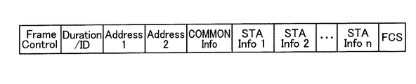
図8にトリガーフレームのフォーマット例を示す。トリガーフレーム501は、図5に示した一般的なMACフレームのフォーマットをベースに定義される。トリガーフレームのヘッダまたはフレームボディフィールドには、共通フィールド(COMMOM Info.)と、少なくともUL−OFDMAを行う端末の台数分の端末情報(STA Info.)フィールドとを備える。
FIG. 8 shows a format example of the trigger frame. The
Frame Controlフィールドのタイプは制御フレームを表す値とし、サブタイプの値は、トリガーフレーム用に新規に定義した値とすればよい。ただし、トリガーフレームのフレームタイプは、制御フレームではなく、管理フレームまたはデータフレームとする構成も排除されない。既存の管理フレームのフレームボディフィールドにトリガーフレーム501の役割として必要な情報(共通フィールドおよび端末情報フィールドの情報)を情報エレメントとして追加してもよい。サブタイプの値も既存の規格の値を流用してもよい。 The type of the Frame Control field may be a value representing the control frame, and the value of the subtype may be a value newly defined for the trigger frame. However, a configuration in which the frame type of the trigger frame is not a control frame but a management frame or a data frame is not excluded. Information necessary for the role of the trigger frame 501 (information of the common field and the terminal information field) may be added as an information element to the frame body field of the existing management frame. The value of the existing standard may be used as the value of the subtype.
トリガーフレーム501のRA(受信先アドレス)は、一例として、ブロードキャストアドレスまたはマルチキャストアドレスとし、当該アドレスを、アドレス1フィールドに設定すればよい。またTA(送信元アドレス)は、アクセスポイントのMACアドレスまたはBSSIDを、アドレス2フィールドに設定すればよい。
The RA (reception destination address) of the
図6のシーケンス例では、トリガーフレームのフレームボディフィールドには、5台の端末1〜5を選定したため、5つの端末情報フィールド(STA infoフィールド)1〜5を設定する。各端末情報フィールドには、端末に個別に通知する情報を設定する。共通フィールドには、UL-OFDMAの対象として選択された端末1〜5に共通に通知する情報を設定する。
In the sequence example of FIG. 6, since five
共通フィールドに設定する情報の例として、例えば、端末情報フィールドの個数に関する情報を設定する。端末情報フィールドの数は、選択された端末数に応じて変動し得るため、端末情報フィールドに関する数を、共通フィールドに設定することが考えられる。端末情報フィールドの個数が固定の場合は、当該情報は不要である。 As an example of information to be set in the common field, for example, information on the number of terminal information fields is set. Since the number of terminal information fields can fluctuate according to the number of selected terminals, it is conceivable to set the number of terminal information fields in the common field. If the number of terminal information fields is fixed, the information is unnecessary.
また、トリガーフレームでUL−OFDMAの送信タイミングに関する情報を設定してもよい。なお、トリガーフレームの受信完了から予め定めた一定時間(予め定めた値のIFS)後にアップリンク送信を行うことが定められている場合は、各端末でこの時間は既知であるため、当該情報の設定は不要である。 Further, information on the transmission timing of UL-OFDMA may be set in the trigger frame. If it is determined that uplink transmission is to be performed after a predetermined time (IFS of a predetermined value) from completion of reception of the trigger frame, since this time is known at each terminal, No settings are required.
また、各端末でアップリンク送信するパケット長または時間長が共通の場合は、パケット長または時間長またはこれらの両方を特定する情報を、共通フィールドに設定してもよい。 When the packet length or the time length for uplink transmission is common in each terminal, information specifying the packet length and / or the time length may be set in the common field.
また、UL−OFDMAを行う対象となる端末として、端末のグループを選択した場合は、当該グループを識別する情報(グループID)を、共通フィールドに設定してもよい。この際、当該グループに属するすべての端末が、UL-OFDMAを許可する対象の端末であるとのルールがあるときは、各端末が、複数の端末情報フィールドのいずれに自端末の情報が設定されているかを認識できる限り、各端末情報フィールドに端末の識別子を設定することを省略してもよい。例えば、自端末が先頭または末尾から何番目の端末情報フィールドを割り当てられているかを、事前にアクセスポイントから通知されている場合は、端末の識別子の設定を省略してもよい。または、グループ内の端末のリストにおいて自端末の位置に応じて端末情報フィールドの位置が一義的に定まる場合も、端末の識別子の設定を省略してもよい。 When a group of terminals is selected as a terminal to be subjected to UL-OFDMA, information (group ID) for identifying the group may be set in the common field. At this time, if there is a rule that all the terminals belonging to the group are the terminals for which UL-OFDMA is permitted, each terminal sets its own information in any of a plurality of terminal information fields. The setting of the terminal identifier in each terminal information field may be omitted as long as it is possible to recognize whether or not the terminal identifier is set. For example, if the access point has previously notified which terminal information field the terminal has been assigned to which terminal information field from the beginning or end, the setting of the terminal identifier may be omitted. Alternatively, when the position of the terminal information field is uniquely determined according to the position of the own terminal in the list of terminals in the group, the setting of the terminal identifier may be omitted.
端末情報フィールド1〜nには、一例として、端末の識別子を設定するフィールド(STA IDフィールド)およびリソースユニットを指定する情報を設定するフィールド(RU#フィールド)等を含む。これ以外にも、端末に個別に通知する種々のフィールドを含んでもよい。STA IDフィールドには、各端末の識別子を設定する。端末の識別子は、端末のアソシエーションID(AID)、MACアドレス、その他、端末のユニークなIDでもよい。アソシエーションIDは、端末がアクセスポイントのBSSに属するためにアクセスポイントとの間で行うアソシエーションプロセス時に付与される識別子である。 The terminal information fields 1 to n include, for example, a field for setting a terminal identifier (STA ID field) and a field for setting information for specifying a resource unit (RU # field). In addition, various fields that individually notify the terminal may be included. The identifier of each terminal is set in the STA ID field. The identifier of the terminal may be an association ID (AID) of the terminal, a MAC address, or another unique ID of the terminal. The association ID is an identifier assigned at the time of an association process performed between the terminal and the access point because the terminal belongs to the BSS of the access point.
また、RU#フィールドには、該当する端末がUL−OFDMAで使用するリソースユニットを指定する情報を設定する。リソースユニットを指定する情報の形式は、当該リソースユニットを特定可能な限り、どのような形式でもよい。例えばリソースユニットの番号(識別子)によって指定してもよい。高周波側または低周波側から何番目のリソースユニットかを指定してもよい。UL-OFDMAで使用するチャネルの識別子との組み合わせでリソースユニットを指定することもあり得る。なお、複数のリソースユニットの集合を識別する識別子を別途定義し、当該集合の識別子を1つまたは複数、RU#フィールドで指定する構成も考えられる。この場合、端末は、当該集合の識別子から利用可能なリソースユニットを把握することができるものとする。 In the RU # field, information for specifying a resource unit used by the corresponding terminal in UL-OFDMA is set. The format of the information specifying the resource unit may be any format as long as the resource unit can be specified. For example, it may be specified by the number (identifier) of the resource unit. The number of the resource unit from the high frequency side or the low frequency side may be specified. A resource unit may be specified in combination with a channel identifier used in UL-OFDMA. Note that a configuration is also conceivable in which an identifier for identifying a set of a plurality of resource units is separately defined, and one or more identifiers of the set are specified in the RU # field. In this case, the terminal can grasp the available resource units from the identifier of the set.
他のパラメータ例として、送信を許可するパケット長(PPDU長など)、誤り訂正符号方式、PHYまたはMACまたはこれらの両方の送信レートを規定するMCS、の少なくとも1つに関する情報を設定してもよい。パケット長の単位は、データサイズでもよいし、時間長(空間での占有時間長)でもよい。パケット長が各端末で共通の場合は、パケット長に関する情報は、端末情報フィールドでの設定を省略し、共通フィールドに設定してもよい。なおパケット長の最大値は、規格またはシステムで事前に決められていてもよく、この場合最大値以下の範囲で、パケット長をしてもよい。なお、パケット長の代わりに、MACフレーム長またはMSDU(medium access control (MAC) service data unit)長などを用いることも可能である。また、さらに別のパラメータ例として、各端末が送信すべきデータ種別の情報を指定してもよい。データ種別として、アクセスカテゴリ(AC)またはトラヒック情報(TID:Traffic ID)を設定してもよい。指定するデータ種別は、端末ごとに異なってもよいし、各端末で共通でもよい。また複数のデータ種別を指定してもよい。また各端末の送信電力を指定する情報を設定してもよい。また、UL−OFDMAの送信タイミングを端末に個別に指定する場合(UL−OFDMAの送信タイミングを端末ごとに調整する場合)には、送信タイミングに関する情報を設定してもよい。例えば当該情報として、予め定められた送信タイミングに対する調整量を設定してもよい。 As another parameter example, information on at least one of a packet length (such as a PPDU length) that is allowed to be transmitted, an error correction coding scheme, and an MCS that defines a PHY and / or a MAC or both transmission rates may be set. . The unit of the packet length may be the data size or the time length (the occupation time length in space). When the packet length is common to the terminals, the information on the packet length may be set in the common field by omitting the setting in the terminal information field. Note that the maximum value of the packet length may be determined in advance by a standard or a system, and in this case, the packet length may be set within a range equal to or less than the maximum value. Instead of the packet length, it is also possible to use a MAC frame length or a medium access control (MAC) service data unit (MSDU) length. Further, as another parameter example, information of a data type to be transmitted by each terminal may be specified. As the data type, an access category (AC) or traffic information (TID: Traffic ID) may be set. The specified data type may be different for each terminal, or may be common for each terminal. Also, a plurality of data types may be specified. Information for designating the transmission power of each terminal may be set. When the UL-OFDMA transmission timing is individually specified for each terminal (when the UL-OFDMA transmission timing is adjusted for each terminal), information regarding the transmission timing may be set. For example, an adjustment amount for a predetermined transmission timing may be set as the information.
図8の例では、共通フィールドおよび端末情報フィールドを、ヘッダまたはフレームボディフィールドに設定する例を示したが、共通フィールドおよび端末情報フィールドに設定する情報の一部または全部を、図9に示すように、物理ヘッダ内に配置してもよい。図9の物理ヘッダは、L−STF(Legacy−Short Training Field)、L−LTF(Legacy−Long TrainingField)、L−SIG(Legacy Signal Field)の後に、共通フィールド、端末数分の端末情報フィールドを含む。通知する必要のある情報がすべて物理ヘッダ内に設定される場合は、MACフレームから共通情報フィールドおよび端末情報フィールドを省略してもよい。 In the example of FIG. 8, an example in which the common field and the terminal information field are set in the header or the frame body field has been described. However, part or all of the information set in the common field and the terminal information field is as shown in FIG. 9. Alternatively, it may be placed in the physical header. The physical header in FIG. 9 includes a common field and a terminal information field for the number of terminals after L-STF (Legacy-Short Training Field), L-LTF (Legacy-Long Training Field), and L-SIG (Legacy Signal Field). Including. When all the information to be notified is set in the physical header, the common information field and the terminal information field may be omitted from the MAC frame.
なお、図10に示すように、共通フィールドを省略するトリガーフレームの構成もあり得る。端末情報フィールド数が固定であり、端末情報フィールドで必要な情報をすべて個別に通知する場合は、共通フィールドを省略してもよい。 As shown in FIG. 10, there may be a trigger frame configuration in which the common field is omitted. When the number of terminal information fields is fixed and all necessary information in the terminal information field is individually notified, the common field may be omitted.
アクセスポイントから送信されたトリガーフレーム501は端末1〜8で受信される。端末1〜8は、トリガーフレーム501を復号し、FCS検査(CRC検査等)で受信に成功したと判断すると、自端末が端末情報フィールド1〜nのいずれかで指定されているかを検査する。これは、例えば端末情報フィールド1〜nのSTA IDフィールドに自端末の識別子が設定されているかを調べることで判断できる。共通フィールドに、自端末の属するグループIDが設定されている場合のみ、当該端末情報フィールドのSTA IDフィールドを検査するようにしてもよい。あるいは、自端末の属するグループIDが設定されている場合に自端末が常に指定されたとのルールがある場合は、自端末が指定されたと判断してもよい。あるいは、共通フィールドに、UL-OFDMAの対象となる端末を指定する情報として、個々の端末の識別子が設定されている場合には、当該共通フィールドに基づき、自端末が指定されたかを判断してもよい。ここで述べた以外の方法で判断することも可能である。
The
UL−OFDMAの対象として指定された端末は、自端末が使用するリソースユニットを特定する。例えば、端末情報フィールドのRU#フィールドに設定された情報から、使用するリソースユニットを特定する。 A terminal specified as a target of UL-OFDMA specifies a resource unit used by the terminal itself. For example, the resource unit to be used is specified from the information set in the RU # field of the terminal information field.
本例では端末1〜8がトリガーフレーム501を受信し、端末1〜5は自端末が指定されていると判断し、端末6〜8は自端末が指定されていないと判断する。端末1〜5は、アップリンク送信用のデータを含むデータフレーム511、512、513、514、515(より詳細には当該データフレームを含むパケット)を生成して、自端末に指定されたリソースユニットで、アクセスポイントに送信する。送信電力、MCS、パケット長などのパラメータを指定されている場合、当該パラメータにしたがって、データフレームを生成および送信する。例えば、端末1はリソースユニット#1、端末2はリソースユニット#2、端末3はリソースユニット#3、端末4はリソースユニット#4、端末5はリソースユニット#5を指定されている。ここではデータフレーム511〜515のそれぞれが、複数のデータフレームを集約したアグリゲーションフレームである場合を想定する。ただし、データフレーム511〜515がそれぞれ単一のデータフレームでも(アグリゲーションフレームでなくても)かまわない。
In this example, the
各データフレームの送信は、端末1〜5によるトリガーフレーム501の受信完了から時間T1(図示せず)後に行われ、これらのデータフレームは、アクセスポイントで同時に受信される。これによりUL−OFDMA送信が行われる。時間T1は、一例として、予め定義されたIFS時間[μs]を用いることができる。予め定義されたIFS時間は、IEEE802.11無線LANのMACプロトコル仕様で規定されているフレーム間のタイムインターバルであるSIFS時間(=16μs)でもよいし、これより大きな値または小さな値でもよい。時間T1の値が共通情報フィールドまたは端末情報フィールドまたはこれらの両方に格納されており、端末1〜5は共通情報フィールドまたは端末情報フィールドまたはこれらの両方から時間T1の値を取得してもよい。その他、時間T1は、ビーコンフレームあるいはその他の管理フレームなど、別の方法で事前に通知されてもよい。
The transmission of each data frame is performed after a time T1 (not shown) from the completion of reception of the
アクセスポイントが端末1〜5の送信タイミングの調整量を、トリガーフレームの端末情報フィールドまたは共通フィールドで通知している場合は、端末1〜5は通知された調整量だけ送信タイミングを調整して、データフレームを送信してもよい。
When the access point notifies the adjustment amount of the transmission timing of the
なお、端末1〜5が送信するデータフレーム511、512、513、514、515は、異なる内容のフレームであっても、同一の内容のフレームでもよい。一般的な表現として、複数の端末が第Xのフレームを送信または受信、またはアクセスポイントが複数の第Xフレームを受信または送信すると表現するとき、これらの第Xのフレームの内容は同じであっても、異なってもよい。
The data frames 511, 512, 513, 514, and 515 transmitted by the
なお、端末が、アップリンク送信するデータを有さない場合、その端末は、予め定めた形式のフレーム、例えば物理ヘッダは存在するもののデータフィールドが存在しないフレーム、または物理ヘッダとMACヘッダは存在するものの、フレームボディフィールドが存在しないフレームを送信してもよい。あるいは、その端末は、送信動作は何も行わないようにしてもよい。アクセスポイントでは、そのようなフレームを受信した場合、または何も受信しなかった場合、当該端末は送信すべきデータが存在しなかったと判断してもよい。 If the terminal does not have data to be transmitted on the uplink, the terminal has a frame of a predetermined format, for example, a frame having a physical header but no data field, or a physical header and a MAC header. However, a frame having no frame body field may be transmitted. Alternatively, the terminal may not perform any transmission operation. When the access point receives such a frame or receives no such frame, the terminal may determine that there is no data to be transmitted.
アクセスポイント11は、UL−OFDMA送信された複数の端末からのデータフレームを受信すると、各受信したデータフレームのCRC(cyclic redundancy code)を検査する。ここではデータフレームはアグリゲーションフレームであることを想定しているため、端末ごとに複数のデータフレームのCRCを検査する。CRC検査より、各端末が送信したアグリゲーションフレーム内の複数のデータフレームのそれぞれを、正しく受信できたか否かを判断する。アクセスポイント11は、各端末1〜5に対する検査の結果に基づき、各端末に対する複数の検査結果を含む送達確認応答フレームとしてBlock Ackフレーム(BAフレーム)を端末毎に生成する。また、アクセスポイント11は、図6に示すように、各端末1〜5宛のデータを含む1つ以上のデータフレームと、各端末1〜5宛の送達確認フレームとを集約したアグリゲーションフレーム521、522、523、524、525を端末毎に生成する。アクセスポイント11は、各端末のアグリゲーション521〜525を、各端末がUL−OFDMA送信時に使用したリソースユニットと同じリソースユニットで、データフレーム511〜515の受信完了から一定時間(SIFS時間等)後に送信(すなわちDL−OFDMA送信)する。より詳細には、これらのアグリゲーションフレームにそれぞれ物理ヘッダを付加して送信する。この物理ヘッダの所定フィールド(ここではSIG1フィールドと呼ぶ)に端末毎に、受信すべきリソースユニットの識別子を指定してもよい。
When the
図11に、アグリゲーションフレーム521〜525のDL−OFDMA送信時の物理パケットの構成例を示す。図7で説明したL−STF、L−LTF、L−SIGのフィールドは、一例として20MHzのチャネル幅で送信され、アグリゲーション521〜525のいずれでも同じ値(ビット列)が設定される。SIG1フィールドは、端末毎に使用するリソースユニットを指定するため、端末の識別子と、リソースユニットの番号(識別子)とを対応づけた情報を設定する。端末の識別子はアソシエーションID(AID)でもよいし、AIDの一部(Partial AID)でもよいし、MACアドレス等のその他の識別子でもよい。SIG1フィールドも、20MHzのチャネル幅で送信され、アグリゲーション521〜525のいずれでも同じ値(ビット列)が設定される。端末1〜5(およびその他の端末6〜8)のいずれもSIG1フィールドを復号可能である。SIG2フィールドはリソースユニット毎に設定され、データフィールドの復号に必要なMCS等の情報が設定されてもよい。したがって、アクセスポイント11からの信号を受信した各端末はSIG1フィールドを復号することで、自端末が復号すべきリソースユニットを把握できる。全部または特定のグループの端末を指定するID(ここでは便宜上、ブロードキャストIDまたはマルチキャストIDと呼ぶ)を定義し、当該ブロードキャストIDまたはマルチキャストIDと、リソースユニットとを対応づけた情報を設定することも可能である。
FIG. 11 shows a configuration example of a physical packet at the time of DL-OFDMA transmission of the aggregation frames 521 to 525. For example, the L-STF, L-LTF, and L-SIG fields described in FIG. 7 are transmitted with a channel width of 20 MHz, and the same value (bit string) is set in any of the
端末1〜5は、アグリゲーションフレーム521〜525をそれぞれ指定されたリソースユニットの信号を復号することで受信する。端末1〜5は、アグリゲーションフレーム521〜525内のデータフレームを復号してCRC検査をするとともに、アグリゲーションフレーム521〜525内のBAフレームを復号して、自端末が送信したデータフレーム511〜515の成功可否を判断する。この後、端末1〜5は、アクセスポイントから受信したデータフレームに対する送達確認応答フレーム(BAフレーム等)を生成して、アグリゲーションフレーム521〜525の受信完了から一定時間(SIFS時間等)後に、送達確認応答フレームを送信(UL−OFDMA送信)してもよい。あるいは、端末1〜5は、当該送達確認応答フレームに他のフレームを集約したアグリゲーションフレームを、それぞれDL−OFDMAで指定されたのと同じリソースユニットで送信(UL−OFDMA送信)してもよい。以降、同様にして、DL−OFDMAおよびUL−OFDMAが継続して繰り返し行われても良い。OFDMAシーケンスの期間は、一例としてトリガーフレーム501で通知されてもよい。例えばトリガーフレーム501のDuration/IDフィールドで指定される媒体予約期間をTXOP(Transmission Opportunity)として、OFDMAシーケンスが継続されてもよいし、共通フィールドで当該期間に関する情報を各端末に通知してもよい。
The
図6のシーケンスにおいて、アクセスポイントがDL−OFDM送信時に、端末1〜5宛のデータを有さない場合もある。例えば、アクセスポイントが、端末1宛のデータを有するものの、端末2〜5宛のデータを有さない場合もあり得る。この場合に、端末1には、アグリゲーションフレーム521を送信し、端末2〜5にはBAフレームのみを送信することが考えられる。この場合のシーケンス例を図12に示す。この場合、端末2〜5用のリソースユニットでは、BAフレームの送信完了から、端末1用のリソースユニットで送信されるアグリゲーションフレーム521の末尾までの時間の間、フレーム通信が行われず、非効率である。なお、この場合、端末2〜5用のリソースユニットで送信されるBAフレームの末尾には、アグリゲーションフレーム521の末尾までの時間の間、当該リソースユニットがビジーであることを他の端末に通知するため、パディングデータが付加されている。ただし、パディングデータを付加しないことも可能である。図のハッチングはパディングデータを表している(以下、同様)。
In the sequence of FIG. 6, the access point may not have data addressed to
そこで本実施形態に係るアクセスポイントは、DL−OFDMA送信の効率を高めるため、DL−OFDMAのスケジューリング(どのリソースユニットに、どの端末宛のどのようなフレームを割り当てるか)を効果的に行うことに特徴の1つを有する。 Therefore, the access point according to the present embodiment effectively performs DL-OFDMA scheduling (which resource unit is assigned which frame to which terminal) in order to increase the efficiency of DL-OFDMA transmission. It has one of the features.
図13に、本実施形態に係るアクセスポイントのDL−OFDMAのスケジューリングに関するフローチャートを示す。本動作を行うタイミングは、任意でよいが、一例として、トリガーフレーム501を送信完了時、またはUL−OFDMA送信されるフレームの受信完了時などが考えられる。
FIG. 13 shows a flowchart relating to DL-OFDMA scheduling of the access point according to the present embodiment. The timing at which this operation is performed may be arbitrarily determined, but may be, for example, when the transmission of the
アクセスポイントは、トリガーフレーム501で指定した端末またはUL−OFDMA送信した端末(以下、これらを対象端末と呼ぶ)に対して、送達確認応答フレーム以外に送信するフレーム(以下、送信フレームと呼ぶ)が存在するかを、対象端末ごとに判断する(S101)。一例として、アクセスポイントは、バッファに対象端末宛のデータが存在するかで、対象端末に送信する送信フレームが存在するかを判断してもよい。送信フレームは、新規に送信するフレームでもよいし、以前の送信で失敗したフレームの再送のフレームでもよい。フレームの種類は、データフレームでもよいし、管理フレームでもよい。ここではデータフレームを想定する。
The access point transmits a frame other than the acknowledgment response frame (hereinafter, referred to as a transmission frame) to the terminal specified by the
対象端末のすべてとも、送信フレームが存在しない場合は、各対象端末にそれぞれがUL−OFDMA送信で使用したリソースユニットで送達確認応答フレーム(BAフレーム等)を送信することを決定する(S103)。そして、アクセスポイントは、UL−OFDMA送信されたデータフレーム511〜515の受信完了から、一定時間(SIFS時間等)後、これらの送達確認応答フレームをDL−OFDMA送信する(S107)。この場合のシーケンス例を図14に示す。アクセスポイントが、端末1〜5にBAフレーム541、542、543、544、545をDL−OFDMA送信している。
If there is no transmission frame for all of the target terminals, it is determined that each of the target terminals transmits a delivery confirmation response frame (BA frame or the like) using the resource unit used for UL-OFDMA transmission (S103). Then, the access point performs DL-OFDMA transmission of these acknowledgment frames after a fixed time (SIFS time or the like) after completion of reception of the data frames 511 to 515 transmitted by UL-OFDMA (S107). FIG. 14 shows a sequence example in this case. The access point transmits the BA frames 541, 542, 543, 544, and 545 to the
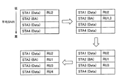
または、ステップS103では、これらの対象端末のすべての送達確認応答を含むフレーム(Multi−STA BAフレームと呼ぶ)を、チャネル幅帯域(ここでは20MHzチャネル幅帯域)で送信することを決定してもよい。そして、UL−OFDMA送信されたデータフレーム511〜515の受信完了から一定時間(SIFS時間等)後、チャネル幅帯域で、Multi−STA BAフレームを送信する(S107)。この場合のシーケンス例を図15に示す。アクセスポイント11が、端末1〜5にMulti−STA BAフレーム551をチャネル幅の帯域で送信している。Multi−STA BAフレームの宛先アドレスは、一例としてブロードキャストアドレスまたはマルチキャストアドレスである。変形例としてトリガーフレーム501で指定した複数の端末のうちの1つの端末のMACアドレスを設定してもよい。Multi−STA BAフレームは、BAフレームを、複数の端末に送達確認応答を通知するために流用したフレームであり、その詳細は後述する。
Alternatively, in step S103, it may be determined that a frame including all the delivery acknowledgments of these target terminals (called a Multi-STA BA frame) is to be transmitted in a channel width band (here, a 20 MHz channel width band). Good. After a certain time (SIFS time or the like) from the completion of the reception of the data frames 511 to 515 transmitted by the UL-OFDMA, a Multi-STA BA frame is transmitted in the channel width band (S107). FIG. 15 shows a sequence example in this case. The
アクセスポイントは、ステップS102で少なくとも1つの対象端末に対しては送信フレームが存在すると判断した場合は、送信フレームが存在しない対象端末が1台か複数台かを判断する(S104)。送信フレームが存在しない対象端末が1台の場合(すなわち送信フレームが存在する対象端末が複数台の場合)は、送信フレームが存在する対象端末については、送達確認応答フレーム(BAフレーム等)と送信フレームとを集約したアグリゲーションフレームを各々のリソースユニットで送信することを決定し、送信フレームが存在しない1台の対象端末については送達確認応答フレーム(BAフレーム等)を、当該端末用のリソースユニットで送信することを決定する(S106)。送信フレームが存在しない対象端末が1台のときは、複数の端末分の送達確認応答を1フレームでまとめる効率化はできないため、このような決定を行う。アクセスポイントは、UL−OFDMA送信されたデータフレーム511〜515の受信完了から、一定時間(SIFS時間等)後、当該決定に従って、DL−OFDMA送信を行う(S107)。この場合のシーケンス例を図16に示す。アクセスポイントが端末1〜4にアグリゲーションフレーム561、562、563、564を、端末5にBAフレーム565を送信(DL−OFDMA送信)している。なお、BAフレーム565の末尾にはパディングデータを付加している。
If the access point determines in step S102 that a transmission frame exists for at least one target terminal, the access point determines whether there is one or more target terminals for which no transmission frame exists (S104). When there is one target terminal having no transmission frame (that is, when there are a plurality of target terminals having a transmission frame), for the target terminal having a transmission frame, a transmission acknowledgment frame (such as a BA frame) is transmitted. It decides to transmit an aggregation frame that aggregates the frames with each resource unit, and for one target terminal having no transmission frame, sends an acknowledgment response frame (such as a BA frame) in the resource unit for the terminal. It is determined to transmit (S106). When the number of target terminals having no transmission frame is one, it is not possible to efficiently combine the delivery acknowledgments for a plurality of terminals into one frame, and thus such a determination is made. The access point performs DL-OFDMA transmission according to the determination after a fixed time (SIFS time or the like) from the completion of reception of the data frames 511 to 515 transmitted by UL-OFDMA (S107). FIG. 16 shows a sequence example in this case. The access point transmits the aggregation frames 561, 562, 563, and 564 to the
アクセスポイントは、ステップS104で送信フレームが存在しない対象端末が複数台と判断された場合は、送信フレームが存在しない対象端末については、これらの対象端末の送達確認応答を含むフレーム(Multi−STA BAフレーム)を送信することを決定し、送信フレームが存在する対象端末については、送信フレームと送達確認応答フレームとを集約したアグリゲーションフレームを送信することを決定する(S105)。また、Multi−STA BAフレームを送信するリソースユニットと、アグリゲーションフレームを送信するリソースユニットを決定する(同S105)。Multi−STA BAフレームは1つのリソースユニットに割り当て、複数の端末分の送達確認応答を1つのMulti−STA BAフレームにまとめたことで、リソースユニットに空きが生じるため、アグリゲーションフレームのうちの少なくとも1つは、2つ以上のリソースユニットをボンディングしたリソースユニットに当該アグリゲーションフレームを割り当ててもよい。アクセスポイントは、UL−OFDMA送信されたデータフレーム511〜515の受信完了から、一定時間(SIFS時間等)後、当該決定に従って、DL−OFDMA送信を行う(S107)。この場合のシーケンス例を図17に示す。アクセスポイントが端末1〜2にアグリゲーションフレーム571、572を、端末1〜2がUL−OFDMA送信で使用したリソースユニットで送信し、端末3、4の送達確認応答を含むMulti−STA BAフレーム573をUL−OFDMA送信で端末3が使用したリソースユニットで送信し、端末5にアグリゲーションレーム575を、端末4、5がUL−OFDMA送信で使用した2つのリソースユニットをボンディングしたリソースユニットで送信している。なお、ボンディングされたリソースユニットの識別子は、当該ボンディング後のリソースユニットの識別子が定義されていてもよいし、ボンディング前の2つのリソースユニットの識別子と、ボンディングを示す情報とによって表現されてもよい。Multi−STA BAフレーム573の末尾にはパディングデータを付加して、他のフレームの末尾にフレーム長を合わせている。端末5は、端末1、2に比べて多くの通信リソースを利用できるため、より大きいサイズのデータを送信できる。これにより、DL−OFDMAを効率化できる。
If it is determined in step S104 that there are a plurality of target terminals having no transmission frame, the access point determines, for the target terminals having no transmission frame, a frame including a delivery acknowledgment response of these target terminals (Multi-STA BA (S105), and for the target terminal having the transmission frame, it is determined to transmit an aggregation frame in which the transmission frame and the acknowledgment response frame are aggregated (S105). Further, the resource unit for transmitting the Multi-STA BA frame and the resource unit for transmitting the aggregation frame are determined (S105). Since the Multi-STA BA frame is allocated to one resource unit, and the delivery acknowledgments for a plurality of terminals are combined into one Multi-STA BA frame, a free space is created in the resource unit. Therefore, at least one of the aggregation frames is generated. First, the aggregation frame may be assigned to a resource unit obtained by bonding two or more resource units. The access point performs DL-OFDMA transmission according to the determination after a fixed time (SIFS time or the like) from the completion of reception of the data frames 511 to 515 transmitted by UL-OFDMA (S107). FIG. 17 shows a sequence example in this case. The access point transmits the aggregation frames 571 and 572 to the
ここでMulti−STA BAフレームについて説明する。Multi−STA BAフレームは、複数の端末に対する送達確認応答を1フレームで通知するためにBlock Ackフレーム(BAフレーム)を流用したものである。BAフレームを再利用する場合、通常のBAフレームと同様、フレームタイプは制御(Control)、フレームサブタイプはBlockAckとすればよい。図18(A)にBAフレームを再利用する場合のMulti−STA BAフレームのフォーマット例を示す。図18(B)は、BAフレームにおけるBA Controlフィールドのフォーマットの例を示し、図18(C)は、BAフレームにおけるBA Informationフィールドのフォーマットの例を示す。BAフレームを再利用する場合、複数の端末に関する送達確認応答を通知するために拡張したBAフレームフォーマットであるということを、BA Controlフィールドの中で示してもよい。例えばIEEE802.11規格では、Multi−TIDサブフィールドが1、かつCompressed Bitmapサブフィールドが0の場合が、現状予約(Reserved)になっている。これを複数の端末に関する送達確認応答を通知するために拡張したBAフレームフォーマットであることを示すために用いるようにしてもよい。あるいは図18(B)ではビットB3−B8の領域が予約サブフィールドになっているが、この領域の一部または全てを、複数の端末に関する送達確認応答を通知するために拡張したBAフレームフォーマットであることを示すために定義してもよい。あるいは、このような通知を明示的に行わなくても良い。 Here, the Multi-STA BA frame will be described. The Multi-STA BA frame is obtained by diverting a Block Ack frame (BA frame) in order to notify delivery acknowledgments to a plurality of terminals in one frame. When reusing a BA frame, the frame type may be control and the frame subtype may be BlockAck, as in a normal BA frame. FIG. 18A shows a format example of a Multi-STA BA frame when a BA frame is reused. FIG. 18B shows an example of a format of a BA Control field in a BA frame, and FIG. 18C shows an example of a format of a BA Information field in a BA frame. When reusing the BA frame, the BA Control field may indicate that the BA frame format has been extended to notify the delivery acknowledgment regarding a plurality of terminals. For example, in the IEEE 802.11 standard, the case where the Multi-TID subfield is 1 and the Compressed Bitmap subfield is 0 is the current reservation (Reserved). This may be used to indicate that it is an extended BA frame format for notifying delivery acknowledgments for a plurality of terminals. Alternatively, in FIG. 18 (B), the area of bits B3 to B8 is a reserved subfield, but a part or all of this area is in a BA frame format extended to notify delivery acknowledgments for a plurality of terminals. May be defined to indicate something. Alternatively, such notification need not be explicitly performed.
BAフレームにおけるRAフィールドは、ブロードキャストアドレスでも、マルチキャストアドレスでもよい。あるいは、トリガーフレームで指定した端末のうちの1台のユニキャストアドレスでもよい。BA ControlフィールドのMulti−Userサブフィールドには、BA Informationフィールドでレポートするユーザ数(端末数)を設定してもよい。BA Informationフィールドには、ユーザ(端末)ごとに、アソシエーションID(Association ID:AID)設定用のサブフィールド(図18(C)ではPer TID Infoと記載)と、Block Ack開始シーケンスコントロール(Block Ack Starting Sequence Control)サブフィールドと、Block Ackビットマップ(Block Ack Bitmap)サブフィールドとを配置する。 The RA field in the BA frame may be a broadcast address or a multicast address. Alternatively, a unicast address of one of the terminals specified in the trigger frame may be used. The number of users (the number of terminals) reporting in the BA Information field may be set in the Multi-User subfield of the BA Control field. In the BA Information field, for each user (terminal), a subfield for setting an association ID (Association ID: AID) (described as Per TID Info in FIG. 18C) and a Block Ack start sequence control (Block Ack Starting) A Sequence Control subfield and a Block Ack Bitmap subfield are arranged.
アソシエーションID(Per TID Info)サブフィールドにはユーザ識別を行うためAIDを設定する。Block Ack開始シーケンスコントロールサブフィールドおよびBlock Ackビットマップサブフィールドは、端末が送信するフレームが単一のデータフレームである場合(アグリゲーションフレームではない場合)は、省略すればよい。端末が送信するフレームがアグリゲーションフレームのときは、Block Ack開始シーケンスコントロールサブフィールドには、当該BlockAckフレームが示す送達確認応答の最初のMSDU(medium access control (MAC) service data unit)のシーケンス番号を格納する。Block Ackビットマップサブフィールドには、Block Ack開始シーケンス番号以降の各シーケンス番号の受信成功可否のビットからなるビットマップ(Block Ackビットマップ)を入れればよい。 In the association ID (Per TID Info) subfield, an AID is set for user identification. The Block Ack start sequence control subfield and the Block Ack bitmap subfield may be omitted when the frame transmitted by the terminal is a single data frame (when it is not an aggregation frame). When the frame transmitted by the terminal is an aggregation frame, the sequence number of the first MSDU (medium access control (MAC) service data unit) of the delivery acknowledgment indicated by the BlockAck frame is stored in the Block Ack start sequence control subfield. I do. In the Block Ack bitmap subfield, a bitmap (Block Ack bitmap) including bits indicating whether or not each of the sequence numbers after the Block Ack start sequence number has been successfully received may be inserted.
Multi−STA BAフレームを受信した端末は、フレームコントロールフィールドのTypeおよびSubtypeを確認する。これらが、制御およびBlockAckであることを検出すると、次に、RAフィールドを確認し、この値がブロードキャストアドレス等であることから、自端末が送信したフレーム(ここではアグリゲーションフレーム)内の各データフレームに対する送達確認応答(成功可否)の情報をBlock Ack Bitmapフィールドから特定し、各データフレームの送信成功の可否を判断する。例えば、自端末のAIDを格納しているTID Infoサブフィールドを、BA Informationフィールド内から特定し、特定したTID Infoサブフィールドに後続するBlock Ack Starting Sequence Controlサブフィールドに設定された値(開始シーケンス番号)を特定し、開始シーケンス番号以降の各シーケンス番号の送信成功の可否を、Block Ackビットマップから特定する。AIDのビット長は、TID Infoサブフィールド長より短くてよく、AIDは、例えばTID Infoサブフィールドの一部の領域(例えば2オクテット(16ビット)のうち先頭から11ビット(B0−B10))に格納されてもよい。 The terminal that has received the Multi-STA BA frame confirms the Type and the Subtype in the frame control field. When these are detected as control and BlockAck, the RA field is checked next, and since this value is a broadcast address or the like, each data frame in the frame transmitted by the terminal itself (here, an aggregation frame) is checked. The information of the delivery acknowledgment (success / non-success) is specified from the Block Ack Bitmap field, and whether the transmission of each data frame is successful is determined. For example, the TID Info subfield storing the AID of the own terminal is specified from within the BA Information field, and the value set in the Block Ack Starting Sequence Control subfield following the specified TID Info subfield (start sequence number) ) Is specified, and whether or not each sequence number after the start sequence number has been successfully transmitted is specified from the Block Ack bitmap. The bit length of the AID may be shorter than the length of the TID Info subfield, and the AID is, for example, in a partial area of the TID Info subfield (for example, 11 bits (B0-B10) from the top of 2 octets (16 bits)). It may be stored.
複数の端末が、UL−OFDMAでアグリゲーションフレームではなく、単一のデータフレームを送信した場合にBAフレームを流用する場合は、例えば以下のようにすればよい。各BA情報フィールドのTID Infoサブフィールドにおける1つのビット(例えば2オクテット(16ビット)のうち、先頭から12ビット目(先頭をB0とすれば、B11))をACKかBAかを示すビット(ACK/BAビット)として用い、当該ビットにACKを示す値を設定する。ACKを示す値を設定した場合に、Block Ack Starting Sequence ControlサブフィールドおよびBlock Ack Bitmapサブフィールドは省略する。これにより、1つのBAフレームで複数の端末のACKを通知できる。前述したような複数の端末がアグリゲーションフレームを送信した場合は、ACK/BAビットに、BAを示す値を設定すればよい。これにより、複数の端末がアグリゲーションフレームおよび単一のデータフレームのいずれを送信する場合においても、BAフレームを流用して、複数の端末に送達確認応答を行うことができる。 When a plurality of terminals use a BA frame when transmitting a single data frame instead of an aggregation frame in UL-OFDMA, for example, the following may be performed. One bit in the TID Info subfield of each BA information field (for example, of the two octets (16 bits), the twelfth bit from the beginning (B11 if the beginning is B0)) is a bit (ACK) indicating whether it is ACK or BA. / BA bit), and a value indicating ACK is set in the bit. When a value indicating ACK is set, the Block Ack Starting Sequence Control subfield and the Block Ack Bitmap subfield are omitted. Thereby, ACKs of a plurality of terminals can be notified by one BA frame. When a plurality of terminals transmit aggregation frames as described above, a value indicating BA may be set in the ACK / BA bit. Thereby, even when a plurality of terminals transmit an aggregation frame or a single data frame, a delivery confirmation response can be sent to the plurality of terminals using the BA frame.
なお、データフレームをあるリソースユニットで送信した後の端末側の処理の例として、アクセスポイントから信号の受信待ちをし、受信した信号のSIG1フィールドから、自端末のAIDおよびリソースユニット情報があるかを探す。自端末のAIDが無い場合に、ブロードキャストまたはマルチキャスト指定のリソースユニット(すなわちブロードキャストIDまたはマルチキャストIDが指定されたリソースユニット)を復号して、Multi−STA BAフレームを受信してもよい。Multi−STA BAフレームの受信先アドレスは、ブロードキャストアドレスもしくはマルチキャストアドレスある。 In addition, as an example of processing on the terminal side after transmitting a data frame by a certain resource unit, the terminal waits for reception of a signal from the access point, and determines whether there is AID and resource unit information of the own terminal from the SIG1 field of the received signal. Search for When there is no AID of the own terminal, the multi-STA BA frame may be received by decoding a resource unit designated by broadcast or multicast (that is, a resource unit designated by broadcast ID or multicast ID). The destination address of the Multi-STA BA frame is a broadcast address or a multicast address.
図19に、本実施形態に係るアクセスポイントのDL−OFDMAの他のスケジューリング例に関するフローチャートを示す。図13のフローチャートではステップS101で端末に送信すべきフレーム(送信フレーム)が存在するか否かを、対象端末(トリガーフレームで指定された端末、またはUL−OFDMA送信した端末)に対して判断したが、図19のスケジューリングでは、トリガーフレームで指定していない端末(以下、その他の端末と呼ぶ)についても送信フレームが存在するか判断する(S201)。 FIG. 19 is a flowchart illustrating another example of the DL-OFDMA scheduling of the access point according to the present embodiment. In the flowchart of FIG. 13, in step S101, it is determined whether or not there is a frame to be transmitted to the terminal (transmission frame) with respect to the target terminal (the terminal specified by the trigger frame or the terminal that has transmitted UL-OFDMA). However, in the scheduling of FIG. 19, it is determined whether or not there is a transmission frame for a terminal not specified in the trigger frame (hereinafter, referred to as another terminal) (S201).
対象端末の全てとも送信フレームが存在せず(S102のYES)、その他の端末でも送信フレームが存在しない場合は(S202のYES)、図13と同様にステップS103の処理を行う。一方、対象端末の全てとも送信フレームが存在しないが(S102のYES)、その他の1つまたは複数の端末で送信フレームが存在する場合は(S202のNO)、全ての対象端末の送達確認応答を含むフレーム(Multi−STA BAフレーム)を送信することを決定し、送信フレームが存在する他の端末については、当該送信フレームを送信することを決定する(S203)。また、Multi−STA BAフレームを送信するリソースユニットと、送信フレームを送信するリソースユニットを決定する(同S203)。Multi−STA BAフレームは1つのリソースユニットに割り当て、送信フレームを送信する他の端末については、当該他の端末の台数と利用可能なリソースユニットに応じて、割り当てるリソースユニットを決定すればよい。なお、Multi−STA BAフレームを1つのリソースユニットに割り当てる場合、割り当て可能なその他の端末の最大数は、一例として、利用可能なリソースユニット数から1を減算した値である。アクセスポイントは、UL−OFDMA送信されたデータフレーム511〜515の受信完了から、一定時間(SIFS時間等)後、当該決定に従って、DL−OFDMA送信を行う(S107)。この場合のシーケンス例を図20に示す。 If there is no transmission frame in all of the target terminals (YES in S102) and there are no transmission frames in other terminals (YES in S202), the process of step S103 is performed as in FIG. On the other hand, if transmission frames do not exist in all of the target terminals (YES in S102), but transmission frames exist in one or more other terminals (NO in S202), the delivery acknowledgment responses of all the target terminals are sent. It decides to transmit a frame (Multi-STA BA frame) including the transmission frame, and decides to transmit the transmission frame for other terminals having the transmission frame (S203). Further, the resource unit for transmitting the Multi-STA BA frame and the resource unit for transmitting the transmission frame are determined (S203). The Multi-STA BA frame is allocated to one resource unit, and for other terminals transmitting the transmission frame, the resource unit to be allocated may be determined according to the number of other terminals and available resource units. When a Multi-STA BA frame is allocated to one resource unit, the maximum number of other terminals that can be allocated is, for example, a value obtained by subtracting 1 from the number of available resource units. The access point performs DL-OFDMA transmission according to the determination after a fixed time (SIFS time or the like) from the completion of reception of the data frames 511 to 515 transmitted by UL-OFDMA (S107). FIG. 20 shows a sequence example in this case.
図20において、アクセスポイントが、端末1〜5のそれぞれの送達確認応答を含むMulti−STA BAフレーム581を、UL−OFDMA送信で端末3が使用したリソースユニットで送信している。また、端末6にデータフレーム586を、UL−OFDMAで端末1が使用したリソースユニットで送信している。また、端末7にデータフレーム587を、UL−OFDMAで端末2が使用したリソースユニットで送信している。また、端末8にデータフレーム588を、UL−OFDMAで端末4、5が使用したリソースユニットをボンディングしたリソースユニットで送信している。データフレーム586、587、588は、複数のデータフレームを集約したアグリゲーションレームでも、単一のデータフレームでもよい。データフレーム586、587、588の宛先アドレスは、端末6〜8のアドレスであり、UL−OFDMA送信を行った端末1〜5のアドレスとは異なる。なお、Multi−STA BAフレーム581の末尾にはパディングデータを付加して、他のフレーム586、587、588の末尾にフレーム長を合わせている。
In FIG. 20, the access point transmits a
対象端末の少なくとも1つに対して送信フレームが存在し(S102のNO)、当該送信フレームが存在しない対象端末が1台の場合は(S104のNO)、図13と同様にステップS106の処理を行う。なお、変形例として、その他の端末の中に送信フレームが存在する端末が存在するときは、当該端末の送信フレームを、当該1台の対象端末の送達確認応答フレーム(BAフレーム等)と集約してアグリゲーションフレームを生成することもあり得る。一方、送信フレームが存在しない対象端末が複数台のとき(S104のYES)、送信フレームが存在しない対象端末については、これらの対象端末の送達確認応答を含むフレーム(Multi−STA BAフレーム)を送信し、送信フレームが存在する対象端末については、送信フレームと送達確認応答フレームとを集約したアグリゲーションフレームを送信し、送信フレームが存在するその他の端末については、送信フレームを送信することを決定する(S204)。また、Multi−STA BAフレームを送信するリソースユニットと、アグリゲーションフレームを送信するリソースユニットと、その他の端末に対する送信フレームを送信するリソースユニットとを決定する(同S204)。なお、対象端末をその他の端末よりも優先して、リソースユニットを多く割り当て、その他の端末はDL−OFDMAの対象として選択しないことも可能である。アクセスポイントは、UL−OFDMA送信されたデータフレーム511〜515の受信完了から、一定時間(SIFS時間等)後、当該決定に従って、DL−OFDMA送信を行う(S107)。この場合のシーケンス例を図21に示す。 If there is a transmission frame for at least one of the target terminals (NO in S102) and there is one target terminal in which the transmission frame does not exist (NO in S104), the process of step S106 is performed as in FIG. Do. As a modified example, when there is a terminal having a transmission frame among the other terminals, the transmission frame of the terminal is aggregated with the acknowledgment response frame (BA frame or the like) of the one target terminal. To generate an aggregation frame. On the other hand, when there are a plurality of target terminals having no transmission frame (YES in S104), for a target terminal having no transmission frame, a frame including a delivery acknowledgment response of these target terminals (Multi-STA BA frame) is transmitted. Then, for the target terminal where the transmission frame exists, an aggregation frame in which the transmission frame and the acknowledgment response frame are aggregated is transmitted, and for the other terminal where the transmission frame exists, it is determined that the transmission frame is transmitted ( S204). In addition, a resource unit for transmitting a Multi-STA BA frame, a resource unit for transmitting an aggregation frame, and a resource unit for transmitting a transmission frame to another terminal are determined (S204). In addition, it is also possible that the target terminal is prioritized over the other terminals and more resource units are allocated, and the other terminals may not be selected as DL-OFDMA targets. The access point performs DL-OFDMA transmission according to the determination after a fixed time (SIFS time or the like) from the completion of reception of the data frames 511 to 515 transmitted by UL-OFDMA (S107). FIG. 21 shows a sequence example in this case.
図21において、アクセスポイントが端末1にアグリゲーションフレーム591を、端末1がUL−OFDMA送信で使用したリソースユニットで送信し、端末2〜5の送達確認応答を含むMulti−STA BAフレーム592をUL−OFDMA送信で端末3が使用したリソースユニットで送信し、その他の端末である端末7にデータフレーム597を、端末2がUL−OFDMA送信で使用したリソースユニットで送信している。また、その他の端末である端末8にデータフレーム598を、端末5がUL−OFDMA送信で使用したリソースユニットで送信している。データフレーム597、598は、複数のデータフレームを集約したアグリゲーションレームでも、単一のデータフレームでもよい。Multi−STA BAフレーム592の末尾にはパディングデータを付加して、他のフレーム591、597、598の末尾にフレーム長を合わせている。データフレーム597を送信する代わりに、そのリソースユニットを端末1用のリソースユニットにボンディングしたリソースユニットを利用して、アグリゲーションフレーム591を送信してもよい。
In FIG. 21, the access point transmits an
図13のステップS105、図19のステップS203、S204の説明では、複数の端末の送達確認応答を1つのMulti−STA BAフレームにまとめ、当該Multi−STA BAフレームを1つのリソースユニットで送信した。この場合、使用するリソースユニットは、当該複数の端末で共通して、当該フレームの送信に必要なMCSの通信品質を満たすことが望ましい。以下、これについて詳細に説明する。 In the description of step S105 in FIG. 13 and steps S203 and S204 in FIG. 19, the acknowledgment responses of a plurality of terminals are combined into one Multi-STA BA frame, and the Multi-STA BA frame is transmitted by one resource unit. In this case, it is desirable that the resource unit used satisfies the communication quality of the MCS necessary for transmission of the frame, common to the plurality of terminals. Hereinafter, this will be described in detail.
アクセスポイントは、個々の端末とUL−OFDMAまたはDL−OFDMAを行う場合に、事前に複数のリソースユニットの通信品質を個々の端末との間で測定しておく。通信品質は、例えばSNR(Signal to Noise Ratio)等がある。通信品質の範囲と、利用可能なMCSとの関係が事前に定義されており、この関係を利用して、端末ごとにリソースユニットを割り当てることが考えられる。1つのMulti−STA BAフレームを送信する場合は、アクセスポイントは、当該複数の端末のいずれも、Multi−STA BAフレームの送信に必要なMCSの通信品質を満たすリソースユニットしてもよい。 When performing UL-OFDMA or DL-OFDMA with an individual terminal, the access point measures the communication quality of a plurality of resource units between the individual terminals in advance. The communication quality includes, for example, SNR (Signal to Noise Ratio). The relationship between the range of communication quality and the available MCS is defined in advance, and it is conceivable to allocate a resource unit for each terminal using this relationship. When transmitting one Multi-STA BA frame, the access point may use any of the plurality of terminals as a resource unit that satisfies the MCS communication quality required for transmitting the Multi-STA BA frame.
この際、選択するリソースユニットは、当該複数の端末がUL−OFDMA送信の際に使用したリソースユニットの中から選択するようにしてもよい。DL−OFDMAでアグリゲーションフレーム(送信フレームとBAフレームとを集約)を送信する端末用のリソースユニットは、当該端末が原則として利用するものとして、選択対象から除外してもよい。 At this time, the resource unit to be selected may be selected from resource units used by the plurality of terminals at the time of UL-OFDMA transmission. A resource unit for a terminal that transmits an aggregation frame (a transmission frame and a BA frame are aggregated) by DL-OFDMA may be excluded from selection targets, as the terminal uses the resource unit in principle.
Multi−STA BAフレームを送信する対象となる複数の端末が共通に通信品質を満足するリソースユニットが存在しない場合は、複数の端末の送達確認応答を複数のMulti−STA BAフレームに分けて送信してもよい。この際、1台の端末のみ当該端末用のリソースユニット(UL−OFDMAで使用したリソースユニット)でBAフレームを送信し、それ以外の複数の端末については、これらの端末に共通に必要なMCSの通信品質を満足するリソースユニットでMuti−STA BAフレームを送信してもよい。 If there is no resource unit that satisfies the communication quality for a plurality of terminals to which the Multi-STA BA frame is to be transmitted in common, the acknowledgment responses of the plurality of terminals are divided into a plurality of Multi-STA BA frames and transmitted. You may. At this time, only one terminal transmits a BA frame using a resource unit for that terminal (a resource unit used in UL-OFDMA), and for other terminals, the MCS of the MCS required in common for these terminals is transmitted. The Multi-STA BA frame may be transmitted by a resource unit that satisfies the communication quality.
先に示した図20のシーケンスにおいて、端末1〜5に対するMulti−STA BAフレームを2つに分けて送信するようにシーケンスを変形した例を図22に示す。図22において、アクセスポイントが、端末3〜5のそれぞれの送達確認応答を含むMulti−STA BAフレーム603を、UL−OFDMA送信で端末3が使用したリソースユニットで送信している。端末1〜2については、端末3用のリソースユニットに対する通信品質が、必要なMCSの通信品質を満たさないため、端末1用のリソースユニットで、端末1〜2の送達確認応答を含むMulti−STA BAフレーム601を送信している。なお、図20のシーケンスでは端末6に端末1用のリソースユニットでデータフレーム586を送信したが、当該リソースユニットではMulti−STA BAフレーム601を送信することになったため、図22のシーケンス例では、端末6に対する送信は行われていない。なお、Multi−STA BAフレーム601,603の末尾にはパディングデータを付加して、他のフレーム587、588の末尾にフレーム長を合わせている。
FIG. 22 shows an example in which the sequence shown in FIG. 20 described above is modified so that the Multi-STA BA frame to
このように複数の端末の送達確認応答をまとめることによりリソースユニットの空きが生じ、この空きのリソースユニットを利用して、その他の端末に追加でデータフレームを送信できる。 By combining the delivery acknowledgment responses of a plurality of terminals in this way, a vacancy of a resource unit is generated, and a data frame can be additionally transmitted to another terminal by using the vacant resource unit.
図22の例では、2つのMulti−STA BAフレームを送信したが、1台の端末、例えば端末1のみが、端末3用のリソースユニットに対してMulti−STA BAフレームの送信に必要なMCSの通信品質の基準を満たさない場合は、当該端末1については、通常のBAフレームを送信すればよい。この場合のシーケンス例を図23に示す。端末1用のリソースユニット(端末1がUL−OFDMAで使用したリソースユニット)で、端末1にBAフレーム611を送信し、端末3用のリソースユニットで端末2〜5の送達確認応答を含むMulti−STA BAフレーム613を送信している。
In the example of FIG. 22, two Multi-STA BA frames are transmitted. However, only one terminal, for example, the
また、Multi−STA BAフレームを送信するリソースユニットを選択する際、他のリソースユニットとボンディングできないリソースユニットを選択するようにしてもよい。OFDMAで使用する複数のリソースユニットは、リソースユニットのボンディングルールによっては、他のリソースユニットとボンディングできないリソースユニットもあり得る。例えば、周波数領域におけるDC成分の位置に対し、その両側に位置する2つの周波数成分からなるリソースユニットは、他のリソースユニットとボンディングできず、単独での使用しか認められないことが考えられる。そこで、Multi−STA BAフレームのリソースユニットを選択する際、そのようなリソースユニットを優先的に選択することで、データフレームやアグリゲーションフレーム等、他のフレームを送信する端末に対して、複数のリソースユニットをボンディングして利用させる可能性を高めることができ、より柔軟性の高いリソースユニット割り当てが可能となる。 Further, when selecting a resource unit that transmits a Multi-STA BA frame, a resource unit that cannot be bonded to another resource unit may be selected. A plurality of resource units used in OFDMA may not be able to bond with other resource units depending on the resource unit bonding rules. For example, it is conceivable that a resource unit composed of two frequency components located on both sides of the position of the DC component in the frequency domain cannot be bonded to another resource unit and can be used only by itself. Therefore, when a resource unit of a Multi-STA BA frame is selected, such a resource unit is preferentially selected, so that a plurality of resources are transmitted to a terminal transmitting another frame such as a data frame or an aggregation frame. It is possible to increase the possibility of using the unit by bonding, and it is possible to allocate resource units with higher flexibility.
図13のステップS105、図19のステップS203、S204の説明では、Multi−STA BAフレームは単一のフレームとして送信したが、Multi−STA BAフレームを、別の種類のフレームと集約してアグリゲーションフレームを生成し、当該アグリゲーションフレームを送信することも可能である。この場合、別の種類のフレームとして、トリガーフレームを集約してもよい。前述した図20に示したシーケンスで、Multi−STA BAフレーム581の代わりに、Multi−STA BAフレームをトリガーフレームと集約したアグリゲーションフレームを送信する例を、図24に示す。アクセスポイントは、端末1〜5の送達確認応答を含むMulti−STA BAフレームと、トリガーフレームとを集約したアグリゲーションフレーム621を送信している。このトリガーフレームでは、一例として、端末1〜5の全部または一部を、当該DL−OFDMAの完了から一定時間後に行われるUL−OFDMA(図示せず)を許可する対象として指定する。端末1〜5の全部または一部に加えて、端末6〜8の一部または全部を指定の対象に含めてもよい。トリガーフレームの構成は、図8〜図10の例と同様でよい。これにより、リソースユニットをより有効活用して、効率を高めることができる。
In the description of step S105 in FIG. 13 and steps S203 and S204 in FIG. 19, the Multi-STA BA frame is transmitted as a single frame. However, the Multi-STA BA frame is aggregated with another type of frame to aggregate the aggregation frame. Is generated, and the aggregation frame can be transmitted. In this case, trigger frames may be aggregated as another type of frame. FIG. 24 shows an example of transmitting an aggregation frame in which a Multi-STA BA frame is aggregated with a trigger frame instead of the
これまでの説明では、アクセスポイントがトリガーフレームを送信し、トリガーフレームに応答して複数の端末がUL−OFDMA送信し、アクセスポイントが当該UL−OFDMA送信に応答してDL−OFDMA送信を行うシーケンスを基本として示した。しかしながら、アクセスポイントがDL−OFDMA送信を行うタイミングは、このシーケンスに限定されない。例えばアクセスポイントがCSMA/CAベースでキャリアセンスによりアクセス権を獲得し、当該アクセス権に基づきDL−OFDMA送信を行うことも可能である。またDL−OFDMA送信では、リソースユニットごとにトリガーフレームを含むアグリゲーションフレームを送信するなど、様々な送信形態が可能である。このようなシーケンスを行う場合にも、複数の端末の送達確認応答を含むMulti−STA BAフレームを1つのリソースユニットで送信することで、効率化を図ることができる。このようなシーケンスの例を図25に示す。 In the above description, a sequence in which the access point transmits a trigger frame, a plurality of terminals transmit UL-OFDMA in response to the trigger frame, and the access point performs DL-OFDMA transmission in response to the UL-OFDMA transmission, Is shown as a basis. However, the timing at which the access point performs DL-OFDMA transmission is not limited to this sequence. For example, the access point can acquire an access right by carrier sense on a CSMA / CA basis and perform DL-OFDMA transmission based on the access right. Also, in DL-OFDMA transmission, various transmission forms are possible, such as transmitting an aggregation frame including a trigger frame for each resource unit. Even when such a sequence is performed, efficiency can be improved by transmitting a Multi-STA BA frame including delivery acknowledgments of a plurality of terminals using one resource unit. FIG. 25 shows an example of such a sequence.
アクセスポイントは、端末4、端末1、端末2、端末3にそれぞれ異なるリソースユニットを用いて、アグリゲーションフレームをDL−OFDMA送信する。端末3は2つのリソースユニットをボンディングしたリソースユニットを利用している。各アグリゲーションフレームは、複数のデータフレームとトリガーフレームとを含んでいる。トリガーフレームは、すべて同じ内容のフレームでもよいし、端末ごとに内容が異なってもよい。一例として、端末4用のトリガーフレームは端末4と、端末4が使用するリソースユニットを指定し、端末1用のトリガーフレームは端末1と、端末1が使用するリソースユニットを指定し、端末2用のトリガーフレームは端末2と、端末2が使用するリソースユニットを指定し、端末3用のトリガーフレームは端末3および端末5と、端末3および端末5がそれぞれ使用するリソースユニットを指定してもよい。この場合、端末4、1、2のトリガーフレームの受信先アドレスは端末4、1、2のMACアドレスで、端末3用のトリガーフレームの受信先アドレスは、ブロードキャストアドレスまたはマルチキャストアドレスでよい。また、DL−OFDMA送信されるこれらのフレームの先頭側に付加される物理ヘッダの所定領域(図11のSIG1フィールドなど)には端末の識別子(AID等)と、当該端末が復号すべきリソースユニットの識別子とが対応づけて格納されていてもよい。全ての端末があるリソースユニットを復号することを要求する場合は、全部の端末を指定するID(ここでは便宜上、ブロードキャストIDと呼ぶ)を定義し、当該ブロードキャストIDと、当該リソースユニットの識別子とを対応づけて設定してもよい。
The access point performs DL-OFDMA transmission of the aggregation frame using different resource units for the
端末4、端末1、端末2、端末5および端末3は、アクセスポイントから送信される信号を受信し、物理ヘッダから復号するべきリソースユニットを特定して、復号し、アグリゲーションフレームを取得する。端末4、1、2、3は、アグリゲーションフレーム内のデータフレームをCRC検査し、検査結果に応じたBAフレームを生成する。またアグリゲーションフレーム内のトリガーフレームの指示に従ってアップリンク送信するフレーム(ここでは複数のデータフレーム)を生成する。これら複数のデータフレームとBAフレームとを集約したアグリゲーションフレームを生成する。端末5は、アグリゲーションフレーム内のトリガーフレームでの指示に従って、アップリンク送信するフレーム(ここでは複数のデータフレームを集約したアグリゲーションフレーム)を生成する。端末4、1、2、5、3は、それぞれアグリゲーションフレームを、DL−OFDMAの受信完了から一定時間後に送信する。これによりUL−OFDMAが行われる。なお、アクセスポイントからアグリゲーションフレーム内のデータフレームを受信したが、当該アグリゲーション内のトリガーフレームで自端末が指定されていない場合は、その端末は送達確認応答フレーム(BAフレーム等)のみを、一定時間(SIFS時間等)後に送信することを許容されていると解釈してもよい。
The
アクセスポイントは、これらの端末からUL−OFDMA送信されるアグリゲーションフレームを受信する。この際、端末1からのアグリゲーションフレームのBAフレームの受信に失敗したとする(図25のBAフレームを表す枠内の斜線参照)。アクセスポイントは、次のDL−OFDMAのスケジューリングに従って、DL−OFDMA送信の対象となる端末に対してそれぞれフレームを生成する。ここでは、端末2、3、4に対して追加で送信するデータフレームは存在しないため、端末2、3、4の送達確認応答を含むMulti−STA BAフレームを生成し、このフレームとトリガーフレームとを集約したアグリゲーションフレームを生成する。端末1に対しては、端末1の送達確認応答を含むBAフレームとともに、送信に失敗したフレームの再送のフレーム(図25の端末1用のデータフレームを表す枠内の斜線参照)と、トリガーフレームとを集約したアグリゲーションフレームを生成する。端末5に対しては、追加で送信するデータフレームが存在するため、当該データフレームと、端末5の送達確認応答を含むBAフレームと、トリガーフレームとを集約したアグリゲーションフレームを生成する。また、端末6に送信するデータフレームが存在するため、当該データフレームとトリガーフレームとを集約したアグリゲーションフレームを生成する。各アグリゲーションフレームに含まれるトリガーフレームの内容は同一でもよいし、それぞれ異なる内容でもよい。アクセスポイントは、これらの生成したアグリゲーションフレームを、UL−OFDMAの受信完了から一定時間後に送信する。これによりDL−OFDMAが行われる。このシーケンスにおいても、Multi−STA BAフレームを送信することで、利用可能なリソースユニットを増やし、効率的な通信が行われる。なお、図示のアグリゲーションフレーム内のフレームの組み合わせまたは順序は一例であり、これに限定されるものではない。本例では、アクセスポイントは、端末1に対して送信に失敗したフレームを再送したが、この代わりにBAR(Block Ack Request)フレームを送信してもよい。
The access point receives an aggregation frame transmitted by UL-OFDMA from these terminals. At this time, it is assumed that the reception of the BA frame of the aggregation frame from the
図26は、アクセスポイント11に搭載される無線通信装置の機能ブロック図である。前述したように、アクセスポイント11は、少なくとも図1に示した端末1〜8側のネットワークに接続され、さらに、これとは別のネットワークに接続されることもできる。図26では、端末1〜8側のネットワークに接続される無線通信装置の構成を示している。
FIG. 26 is a functional block diagram of the wireless communication device mounted on the
アクセスポイント11の無線通信装置は、制御部101と、送信部102と、受信部103と、アンテナ12A、12B、12C、12Dと、バッファ104とを備えている。アンテナの個数はここでは4つであるが、少なくとも1つのアンテナを備えていればよい。制御部101は、端末との通信を制御する制御部またはベースバンド集積回路に対応し、送信部102と受信部103は、アンテナを介してフレームを送受信する無線通信部(Transceiver)またはRF集積回路を形成する。制御部101の処理、および送信部102と受信部103のデジタル領域の処理の全部または一部は、CPU等のプロセッサで動作するソフトウェア(プログラム)によって行われてもよいし、ハードウェアによって行われてもよいし、これらのソフトウェアとハードウェアの両方によって行われてもよい。アクセスポイントは、制御部101、送信部102および受信部103の全部または一部の処理を行うプロセッサを備えてもよい。
The wireless communication device of the
バッファ104は、上位層と制御部101との間で、フレーム等を受け渡しするための記憶部である。バッファ104はDRAM等の揮発性メモリでもよいし、NAND、MRAM等の不揮発メモリでもよい。上位層は、別のネットワークから受信したフレームを端末1〜8側のネットワークへの中継のためバッファ104に格納してもよい。また、端末側のネットワークから受信したフレームまたはそのペイロードを、制御部101からバッファ104を介して受けとってもよい。上位層は、TCP/IPやUDP/IPなど、MAC層の上位の通信処理を行ってもよい。または、上位層は、TCP/IPやUDP/IP制御部101で行い、上位層では、それより上位のアプリケーション層の処理を行ってもよい。上位層の動作は、CPU等のプロセッサによるソフトウェア(プログラム)の処理によって行われてもよいし、ハードウェアによって行われてもよいし、ソフトウェアとハードウェアの両方によって行われてもよい。
The
制御部101は、主としてMAC層の処理、物理層の処理の一部(例えばOFDMA関連の処理等)を行う。制御部101は、送信部102および受信部103を介して、フレームを送受信することで、各端末との通信を制御する。また制御部101は、定期的にアクセスポイントのBSS(Basic Service Set)の属性および同期情報等を通知するため、ビーコンフレームを送信するよう制御してもよい。また、制御部101は、クロックを生成するクロック生成部を含み、クロック生成部で生成するクロックを利用して、内部時間を管理してもよい。制御部101は、クロック生成部で作ったクロックを、外部に出力してもよい。あるいは、制御部101は、外部のクロック生成部で生成してクロックの入力を受け、当該クロックを利用して、内部時間を管理してもよい。
The
制御部101は、端末からのアソシエーション要求を受けて、アソシエーションプロセスを行い、お互いの能力・属性等の必要な情報(OFDMAを実施可能か否かの能力情報を含んでもよい)を交換することで、当該端末と無線リンクを確立する。必要に応じて、事前に端末との間で認証プロセスを行ってもよい。制御部101は、バッファ104を定期的に確認することで、バッファ104の状態を把握する。または、制御部101は、バッファ104等の外部(デバイス)からのトリガによりバッファ104の状態を確認する。
The
制御部101は、任意のタイミングで、無線リンクを確立した端末(OFDMA対応端末)の中から、UL−OFDMAを指定する複数の端末を選択し、また各端末に利用させるリソースユニットを特定する。また、パケット長(PPDU長等)やMCS等、その他のパラメータを必要に応じて決定する。これらの詳細は前述したとおりである。なお、リソースユニットとリソースユニットの識別子との対応や、OFDMAで使用するチャネルに関する情報は、事前に端末に通知してもよいし、またはシステムまたは仕様で定まっていてもよい。トリガーフレームで、これらの一部または全部の情報を通知してもよい。制御部101は、選択した端末を指定する情報、リソースユニットを指定する情報、およびその他のパラメータ等を、トリガーフレームにおける共通フィールドまたは端末情報フィールドまたはこれらの両方に設定する。また、トリガーフレームには、OFDMAシーケンスを継続する期間(TXOP)を特定する情報を共通フィールドに設定してもよい。または、当該期間を、Duration/IDフィールドに媒体予約期間として設定してもよい。
The
制御部101は、生成したトリガーフレームを、例えばレガシー端末も受信可能な20MHzチャネル幅で、送信部102から送信する。一例として、送信前にCSMA/CAに従って、キャリアセンスを行い、無線媒体へのアクセス権を獲得できたら、トリガーフレームを送信部102に出力する。送信部102は、入力されたトリガーフレームに符号化および変調処理、および物理ヘッダの付加など、所望の物理層の処理を行って物理パケットを生成する。また物理パケットに対して、DA変換、所望帯域成分を抽出するフィルタ処理、周波数変換(アップコンバート)等を行い、これらにより得られた信号をプリアンプで増幅して、1つまたは複数のアンテナから空間に電波として放射する。なお、アンテナ毎に送信系統を備え、送信系統毎に物理層の処理を行って、同時に同じ信号を送信してもよい。または、複数のアンテナを使って、送信の指向性を制御することも可能である。
The
各アンテナで受信された信号は、受信部103において、それぞれアンテナに対応する受信系統ごとに処理される。例えば、トリガーフレームの送信後に、トリガーフレームで指定した複数の端末からOFDMAで返信されるデータフレーム(アグリゲーションフレームの場合も含む)の信号が、各アンテナで同時に受信される。各受信信号は、それぞれ受信系統において低雑音増幅器(LNA:Low Noise Amplifier)により増幅され、周波数変換(ダウンコンバート)され、フィルタリング処理で所望帯域成分が抽出される。各抽出された信号は、さらにAD変換によりデジタル信号に変換されて、復調および誤り訂正復号、物理ヘッダの処理等、物理層の処理を経た後、それぞれ制御部101にデータフレームが入力される。ここで受信系統ごとに、対応する周波数帯域が異なってもよく、リソースユニット単位で受信系統が配置されてもよい。あるいは、各受信系統が同じ周波数帯域に対応し、これらの受信系統で受信された信号をダイバーシティ技術により合成してもよい。この場合、各リソースユニットの信号はデジタルフィルタ処理で抽出してもよい。OFDMA受信を行わない場合は、1本のアンテナのみ受信部103に接続し、残りのアンテナは受信部103に接続しない構成で受信を行うことも可能である。
The signal received by each antenna is processed in the receiving
制御部101は、上述したトリガーフレームを送信完了した時点またはその後、トリガーフレームに応答してUL−OFDMA送信されたデータフレームの受信完了した時点またはその後、または、以下に述べるデータフレームのCRC検査を行った後など、任意の時点で、UL−OFDMAの一定時間後に行うDL−OFDMAのスケジューリングを行う。なお、変形例として、トリガーフレームの送信前に当該スケジューリングを行うこともあり得る。スケジューリングの動作例は、図13または図19を用いて説明した通りである。
The
制御部101は、各端末からUL−OFDMAで同時に受信したデータフレームのCRC検査(アグリゲーションフレームの場合は、アグリゲーションフレーム内の複数のデータフレームごとにCRC検査)を行う。制御部101は、スケジューリング結果に基づき、DL−OFDMA送信の対象となる複数の端末に送信するフレームをそれぞれ生成し、当該フレームをリソースユニット(ボンディングしたリソースユニットの場合も含む)に割り当てる。
The
制御部101は、UL−OFDMAでの各端末からのデータフレームの受信完了から予め定めた時間後に、スケジューリング結果で決定した複数の端末に、それぞれ該当するリソースユニットで、生成したフレームを送信部102から送信するよう制御する。送信部102は、各フレームに符号化および変調処理、および物理ヘッダの付加など、所望の物理層の処理を行って物理パケットを生成する。また物理パケットに対して、DA変換、所望帯域成分を抽出するフィルタ処理、周波数変換(アップコンバート)等を行い、これらにより得られた信号をプリアンプで増幅して、1つまたは複数のアンテナから空間に電波として放射する。
After a predetermined time from the completion of the reception of the data frame from each terminal in UL-OFDMA, the
なお、制御部101は、トリガーフレーム等で各端末に通知する情報、または各端末から通知された情報、またはこれらの両方を格納するための記憶装置にアクセスして当該情報を読み出してもよい。記憶装置は、内部メモリでも、外部メモリでもよく、揮発性メモリでも不揮発メモリでもよい。また、記憶装置は、メモリ以外に、SSD、ハードディスク等でもよい。
Note that the
上述した、制御部101と送信部102の処理の切り分けは一例であり、上述した形態とは別の形態も可能である。例えばデジタル領域の処理およびDA変換までは、制御部101で行い、DA変換より後の処理を、送信部102で行うようにしてもよい。制御部101と受信部103の処理の切り分けも同様に、AD変換より前までの処理を、受信部103で行い、AD変換後の処理を含むデジタル領域の処理を、制御部101で行うようにしてもよい。一例として、本実施形態に係るベースバンド集積回路は、制御部101と、送信部102における物理層の処理を行う部分およびDA変換を行う部分と、受信部103におけるAD変換以降の処理を行う部分とに対応し、RF集積回路は、送信部102におけるDA変換より後の処理を行う部分と、受信部103におけるAD変換より前の処理を行う部分に対応する。本実施形態に係る無線通信用集積回路は、ベースバンド集積回路およびRF集積回路のうち、少なくともベースバンド集積回路を含む。ここで述べた以外の方法でブロック間の処理、あるいはベースバンド集積回路およびRF集積回路間の処理を切り分けてもよい。
The above-described separation between the processes of the
図27は、端末に搭載される無線通信装置の機能ブロック図である。図1の端末1〜8に搭載される無線通信装置は、いずれも図27の構成を有する。
FIG. 27 is a functional block diagram of a wireless communication device mounted on a terminal. Each of the wireless communication devices mounted on the
無線通信装置は、制御部201と、送信部202と、受信部203と、少なくとも1つのアンテナ1Aと、バッファ204とを備えている。制御部201は、アクセスポイント11との通信を制御する制御部またはベースバンド集積回路に対応し、送信部202と受信部203は、フレームを送受信する無線通信部(Transceiver)またはRF集積回路に対応する。制御部201の処理、および送信部202と受信部203のデジタル領域の処理の全部または一部は、CPU等のプロセッサで動作するソフトウェア(プログラム)によって行われてもよいし、ハードウェアによって行われてもよいし、これらのソフトウェアとハードウェアの両方によって行われてもよい。端末は、制御部201、送信部202および受信部203の全部または一部の処理を行うプロセッサを備えてもよい。
The wireless communication device includes a
バッファ204は、上位層と制御部201との間で、フレーム等を受け渡しするための記憶部である。バッファ204はDRAM等の揮発性メモリでもよいし、NAND、MRAM等の不揮発メモリでもよい。上位層は、他の端末、アクセスポイント11、またはサーバ等の他のネットワーク上の装置に送信するフレームを生成して、バッファ204に格納したり、他の端末、アクセスポイント11または装置等から受信したフレームを制御部201からバッファ204を介して受け取ったりする。上位層は、TCP/IPやUDP/IPなど、MAC層の上位の通信処理を行ってもよい。また、TCP/IPやUDP/IPは制御部201で処理し、上位層は、これより上位のアプリケーション層の処理を行ってもよい。上位層の動作は、CPU等のプロセッサによるソフトウェア(プログラム)の処理によって行われてもよいし、ハードウェアによって行われてもよいし、ソフトウェアとハードウェアの両方によって行われてもよい。
The
制御部201は、主としてMAC層の処理、物理層の処理の一部(例えばOFDMA関連の処理等)を行う。制御部201は、送信部202および受信部203を介して、アクセスポイント11とフレームを送受信することで、アクセスポイント11との通信を制御する。また、制御部201は、クロックを生成するクロック生成部を含み、クロック生成部で生成するクロックを利用して、内部時間を管理してもよい。制御部201は、クロック生成部で作ったクロックを、外部に出力してもよい。あるいは、制御部201は、外部のクロック生成部で生成してクロックの入力を受け、当該クロックを利用して、内部時間を管理してもよい。
The
制御部201は、一例としてビーコンフレームを受信してアクセスポイント11のBSSの属性および同期情報を把握した後、アクセスポイント11にアソシエーション要求を行ってアソシエーションプロセスを行う。これにより、お互いの能力・属性等の必要な情報(OFDMAを実施可能か否かの能力情報を含んでもよい)を交換することで、当該アクセスポイント11と無線リンクを確立する。必要に応じて、事前にアクセスポイントとの間で認証プロセスを行ってもよい。制御部201は、バッファ204を定期的に確認することで、バッファ204の状態を把握する。または、制御部201は、バッファ204等の外部(デバイス)からのトリガによりバッファ204の状態を確認する。制御部201は、アクセスポイント11へ送信するデータフレーム等のフレームの存在を確認したら、CSMA/CA等に基づき無線媒体へのアクセス権(送信権)を獲得後、当該フレームを、送信部202およびアンテナ1Aを介して送信してもよい。
As an example, the
送信部202は、制御部201から入力されたフレームに符号化および変調処理、および物理ヘッダの付加など、所望の物理層の処理を行って物理パケットを生成する。また、物理パケットに対して、DA変換や、所望帯域成分を抽出するフィルタ処理、周波数変換(アップコンバート)等を行い、これらにより得られた信号をプリアンプで増幅して、1つまたは複数のアンテナから空間に電波として放射する。なお、複数のアンテナを備える場合、アンテナ毎に送信系統を備え、送信系統毎に物理層の処理を行って、同時に同じ信号を送信してもよい。または、複数のアンテナを使って、送信の指向性を制御することも可能である。
The
アンテナ1Aで受信された信号は、受信部203において処理される。受信された信号は、受信部203においてLNAにより増幅され、周波数変換(ダウンコンバート)され、ファイルタリング処理で所望帯域成分が抽出される。抽出された信号は、さらにAD変換によりデジタル信号に変換されて、復調および誤り訂正復号、物理ヘッダの処理等の物理層の処理を経た後、制御部201にデータフレーム等のフレームが入力される。
The signal received by antenna 1A is processed in receiving
制御部201は、アクセスポイント11からトリガーフレームが受信された場合、トリガーフレームにおいて自端末がUL−OFDMAの対象として指定されているかを確認する。確認の方法は、前述したように、自端末の識別情報がいずれかの端末情報フィールド、または共通フィールドに格納されているかで確認してもよい。または、共通フィールドでグループIDが指定されている場合に、グループIDに属するすべての端末がOFDMAの対象として許可されるとのルールがある場合は、当該グループIDに属するかで、自端末が指定されているかを判断してもよい。なお、この場合、端末は、アクセスポイント11から、各グループに属する端末のリスト(もしくはリストに関する情報)を取得しておく。また制御部201は、トリガーフレームのDuration/IDフィールドまたは共通情報フィールド等に、OFDMAシーケンスの期間に関する情報が設定されている場合は、当該情報に基づき、OFDMAシーケンスの期間を把握する。端末は、例えばこの期間の間は、CSMA/CAベースでのシングルユーザ送信は行わないことを決定してもよい。
When a trigger frame is received from the
制御部201は、自端末がUL−OFDMAの対象として指定されている場合は、必要に応じて、自端末が利用するリソースユニットおよびその他のパラメータの情報を、共通フィールドまたは端末情報フィールドまたはこれらの両方から取得する。制御部201は、当該情報に従って、バッファ204に格納されているデータフレームを読み出して、トリガーフレームの受信から予め定めた時間後にアクセスポイント11に送信するように制御する。読み出すデータフレームの例として、例えばパケット長(PPDU長等)が指定されている場合は、送信するパケットが当該パケット長以下になるようにデータフレームを選択および読み出す。アクセスカテゴリが指定されている場合は、指定されたアクセスカテゴリのデータフレームを読み出す。複数のデータフレームを読み出して、アグリゲーションフレームを生成してもよい。なお、パケット長が、指定されたパケット長に満たない場合は、パディングデータをデータフレームの末尾に付加してもよい。また、送信するタイイングの調整量が指定されている場合は、トリガーフレームの受信から予め定めた時間に対して調整量だけずらしたタイミングで送信する。データフレームは、送信部202およびアンテナ1Aを介して物理パケットとして送信される。送信部202の動作は上述した通りである。
When the own terminal is specified as a target of UL-OFDMA, the
制御部201は、データフレームの送信後、アクセスポイント11からDL−OFDMA送信される信号を受信する。制御部201は、物理ヘッダの所定フィールド(図11のSIG1フィールド等)から自端末に指定されたリソースユニットを特定する。制御部201はトリガーフレームで自端末が指定されていなかった場合に当該DL−OFDMA送信された信号を受信した場合、当該所定フィールドで自端末に対して指定されたリソースユニットがあるかを検査する。
After transmitting the data frame,
制御部201は、自端末に指定されたリソースユニットの信号を復号してフレームを取得する。取得したフレームが送達確認応答フレーム(BAフレーム、Multi−STA
BAフレーム、ACKフレーム、等)である場合は、自端末の送信成功の可否(自端末が送信したデータフレームがアクセスポイント11で正しく受信されたか)を特定する。
The
If it is a BA frame, an ACK frame, or the like), it specifies whether the transmission of the own terminal is successful (whether the data frame transmitted by the own terminal is correctly received by the access point 11).
取得したフレームが送達確認応答フレームとデータフレームとを含むアグリゲーションフレームの場合は、送達確認応答フレームに基づき自端末の送信成功の可否を特定するとともに、データフレームのCRC検査を行う。取得したフレームがデータフレームの場合は、データフレームのCRC検査(複数のデータフレームを含むアグリゲーションフレームの場合は、データフレームごとにCRC検査)を行う。 If the acquired frame is an aggregation frame including a delivery acknowledgment frame and a data frame, the terminal determines whether or not the terminal itself has succeeded in transmission based on the delivery acknowledgment frame, and performs a CRC check on the data frame. If the acquired frame is a data frame, a CRC check of the data frame is performed (in the case of an aggregation frame including a plurality of data frames, a CRC check is performed for each data frame).
アクセスポイントからデータフレームを受信した場合、受信完了後の一定時間(SIFS時間)後に、続けてアップリンク送信することができるとのルールが存在する場合は、送達確認応答フレームをデータフレームの受信完了から一定時間後に、データフレームを受信したのと同じリソースユニットまたは別の方法で決定したリソースユニットで送信してもよい。または今回のDL−OFDMAでトリガーフレームがアグリゲーションフレームに含まれており、当該トリガーフレームで自端末が指定された場合は、当該トリガーフレームでの指定に従って、送達確認応答フレーム、または当該送達確認フレームとデータフレームとを含むアグリゲーションフレームを送信してもよい。 When a data frame is received from the access point, if there is a rule that the uplink transmission can be continued after a fixed time (SIFS time) after the completion of the reception, the acknowledgment frame is sent to the data frame when the reception is completed. After a certain time from, the data frame may be transmitted in the same resource unit as that in which the data frame was received or in a resource unit determined in another way. Or, when the trigger frame is included in the aggregation frame in the current DL-OFDMA, and the own terminal is specified in the trigger frame, according to the specification in the trigger frame, the delivery confirmation response frame, or the delivery confirmation frame An aggregation frame including a data frame may be transmitted.
制御部201は、送信に失敗したと判断したデータフレームについては、必要に応じて、データフレームの再送処理を行う。再送の方法は任意でよい。例えば次回トリガーフレームで自端末が指定された際に、UL−OFDMAでデータフレームを再送してもよい。または、今回のDL−OFDMAでトリガーフレームもアグリゲーションフレーム内に含まれており、当該トリガーフレームで自端末が指定された場合、当該トリガーフレームでの指定に従って、当該データフレームを送信してもよい。または、OFDMAシーケンス期間の終了後、CSMA/CAベース、またはRTSフレームおよびCTSフレームの送受信により、アクセス権を獲得して、データフレームを再送(シングルユーザ送信)してもよい。これら以外の方法で再送を行ってもよい。
The
なお、ここでは主に、UL−OFDMAで送信するフレームは、データフレームである場合を例にしたが、管理フレームまたは制御フレームでもよい。 Here, the case where the frame transmitted by UL-OFDMA is mainly a data frame has been described as an example, but may be a management frame or a control frame.
制御部201は、アクセスポイント11に通知する情報、またはアクセスポイント11から通知した情報、またはこれらの両方を格納するための記憶装置にアクセスして情報を読み出してもよい。記憶装置は、内部メモリでも、外部メモリでもよく、揮発性メモリでも不揮発メモリでもよい。また、記憶装置は、メモリ以外に、SSD、ハードディスク等でもよい。
The
上述した、制御部201と送信部202の処理の切り分けは一例であり、上述した形態とは別の形態も可能である。例えばデジタル領域の処理およびDA変換までは、制御部201で行い、DA変換より後の処理を、送信部202で行うようにしてもよい。制御部201と受信部203の処理の切り分けも同様に、AD変換より前までの処理を受信部203で行い、AD変換後の処理を含むデジタル領域の処理を、制御部201で行うようにしてもよい。一例として、本実施形態に係るベースバンド集積回路は、制御部201と、送信部202における物理層の処理を行う部分およびDA変換を行う部分と、受信部203におけるAD変換以降の処理を行う部分とに対応し、RF集積回路は、送信部202におけるDA変換より後の処理を行う部分と、受信部203におけるAD変換より前の処理を行う部分に対応する。本実施形態に係る無線通信用集積回路は、ベースバンド集積回路およびRF集積回路のうち、少なくともベースバンド集積回路を含む。ここで述べた以外の方法でブロック間の処理、あるいはベースバンド集積回路およびRF集積回路間の処理を切り分けてもよい。
The above-described separation of the processes of the
図28は、第1の実施形態に係るアクセスポイントの動作のフローチャートである。アクセスポイントの制御部101は、UL−OFDMAの対象となる複数の端末(または複数の無線通信装置)を選択し、また、選択した端末に利用させるリソースユニットを選択する(S301)。また、必要に応じて、MCSまたはパケット長などのパラメータを決定する。選択した端末およびリソースユニットを指定する情報、および決定したパラメータの情報を設定したトリガーフレームを生成する(S302)。アクセスポイントの制御部101は、キャリアセンス等によりトリガーフレーム送信用のアクセス権を獲得した後、トリガーフレームを、送信部101を介して送信する(S303)。
FIG. 28 is a flowchart of the operation of the access point according to the first embodiment. The
アクセスポイントの制御部101は、トリガーフレームの送信後、上記UL−OFDMAの実行完了の一定時間後に行うDL−OFDMAのスケジューリングを行う(S304)。スケジューリングの詳細は、図13または図19を用いて説明したとおりである。
After transmitting the trigger frame, the
アクセスポイントの制御部101は、トリガーフレームで指定した複数の端末から、それぞれ指定したリソースユニットで送信されるデータフレーム等のフレームの受信を待機する。制御部101は、これらの複数の端末から多重送信されるデータフレーム等のフレームを、受信部102を介して同時に受信する(S305)。制御部101は、フレームの受信にそれぞれ成功したか否かの検査(CRC検査等)を行う。制御部101は、フレームの受信の成功可否に関する検査結果(CRC結果)と、ステップS304のスケジューリングの結果に基づき、複数の端末に対する複数のフレームを生成する(S306)。制御部101は、ステップS305で複数の端末から多重送信されるフレームの受信完了後、予め定めた時間経過後に、生成した複数のフレームを送信(DL−OFDMA送信)する(S307)。
The
図29は、第1の実施形態に係る端末の動作のフローチャートである。端末の制御部201は、アクセスポイントから送信されるトリガーフレームを、受信部202を介して受信する(S401)。トリガーフレームには、UL−OFDMAの対象として複数の端末を指定する情報、および各端末が利用するリソースユニットを指定する情報、その他、必要なパラメータに関する情報が、共通フィールドまたは端末情報フィールドまたはこれらの両方に設定されている。
FIG. 29 is a flowchart of the operation of the terminal according to the first embodiment. The
端末の制御部201は、トリガーフレームで自端末がUL−OFDMAの対象として指定されているかを調べ(S402)、指定されている場合は、自端末が利用するリソースユニット、および必要に応じて、送信に必要なパラメータを把握する。当該パラメータに従ってデータフレーム等のフレーム(ここではデータフレーム)を生成し、トリガーフレームの受信完了から、予め定められた時間の経過後、データフレーム(より詳細には、データフレームを含む物理パケット)を、トリガーフレームで指定されたリソースユニットを用いて、送信部202を介して、アクセスポイントに送信する(S403)。
The
端末の制御部201は、データフレームの送信後、予め定めた時間の経過後に、アクセスポイントから送信されるフレームを受信する(S404)。より詳細には、アクセスポイントから送信されるフレームに付加されている物理ヘッダ内の所定フィールドから自端末に指定されたリソースユニットを特定し、当該リソースユニットの信号を復号することで、フレームを取得する。制御部201は、フレームを解析し、フレームがBAフレームか、Multi−STA BAフレームか、複数のフレームを集約したアグリゲーションフレームか等を判断し、判断結果に応じて動作する(S405)。アグリゲーションフレーム内のトリガーフレームが存在すれば、ステップS401から同様の処理を繰り返してもよい。取得したフレームの受信先アドレスがブロードキャストアドレス、自端末が属するマルチキャストアドレス、自端末のMACアドレスであれば、自端末が当該フレームを処理する。
After the transmission of the data frame, the
本実施形態では、アップリンクの多重送信としてUL−OFDMA、ダウンリンクの多重送信としてDL−OFDMAを用いたが、代わりに、それぞれアップリンクのマルチユーザMIMO(Multi−Input Multi−Output)(UL−MU−MIMO)、およびダウンリンクのマルチユーザMIMO(DL−MU−MIMO)を用いることも可能である。DL−MU−MIMOでは、アクセスポイントはビームフォーミングと呼ばれる技術を用いることで、各端末に対して空間的に直交したビームによりフレーム送信を行う。これらの直交するビームが端末の通信リソースに対応する。UL−MU−MIMOでは、複数の端末が同じタイミングで、それぞれ同一周波数帯でフレーム送信を行う。この際、アクセスポイントでは各端末とのアップリンクの伝搬路応答を利用してフレームの復号を行う。 In the present embodiment, UL-OFDMA is used for uplink multiplex transmission and DL-OFDMA is used for downlink multiplex transmission. Instead, each of the uplink multi-user MIMO (Multi-Input Multi-Output) (UL-OFDMA) is used. MU-MIMO) and downlink multi-user MIMO (DL-MU-MIMO) can also be used. In DL-MU-MIMO, an access point uses a technique called beamforming to transmit frames to each terminal using spatially orthogonal beams. These orthogonal beams correspond to the communication resources of the terminal. In UL-MU-MIMO, a plurality of terminals transmit frames at the same timing and in the same frequency band. At this time, the access point decodes the frame using the uplink channel response with each terminal.
UL−MU−MIMOでは、アクセスポイント11は、無線端末1〜4から同時に受信したデータストリームからデータフレームを空間的に分離する必要がある。このために、アクセスポイント11は、無線端末1〜4のそれぞれとのアップリンクの伝搬路応答を利用する。アクセスポイントは、各端末のアップリンクの無線伝搬路応答を、複数の端末がUL−MU−MIMO送信されるフレームの先頭側に付加したプリアンブルを利用して推定できる。これらのプリンアンブルが、本実施形態に係る通信リソースに対応する。以下、プリアンブルについて説明する。
In UL-MU-MIMO, the
プリアンブルは、既知ビット列で構成される。アクセスポイント11は、既知ビット列を利用して、アップリンクの伝搬路応答を推定することで、プリアンブルより後のフィールド(例えばデータフィールド)を正しく空間的に分離(復号)出来る。これは、公知の手法、例えばZF(Zero−Forcing)法、または、MMSE(Minimum Mean Square Error)法、または、最尤推定法等、任意の方法を用いて行うことができる。プリアンブルフィールドは、一例として、MACフレームの先頭側に配置される物理ヘッダ(PHYヘッダ)内に配置される。物理ヘッダ内のプリアンブルフィールドより前の各フィールドでは各端末から同じ信号が送信される。各無線端末のプリアンブルは互いに直交している必要がある。プリアンブルが直交していることは、アクセスポイント11が、各無線端末から同時に受信した信号から無線端末毎のプリアンブルを個別に特定できることを意味する。これにより、アクセスポイント11が、無線端末毎のプリアンブルを用いて、各無線端末からアクセスポイント11への伝搬路を推定することができる。
The preamble is composed of a known bit string. The
無線端末間のプリアンブルの直交化の方法として、時間的、周波数的、符号的のいずれの方法を用いてもよい。時間直交の場合には、プリアンブルフィールドが複数の区間に分割され、各端末が互いに異なる区間でプリアンブルを送信する。ある区間には、いずれか1台数端末のみがプリアンブルを送信していることになる。つまり端末間でプリアンブルを送信する時間的な位置が異なっている。ある端末がプリアンブルを送信する間、他の端末は何も送信しない期間になる。時間直交の場合、プリアンブルは、送信するプリアンブルのデータのみならず、どの時間で送信するかに関する情報も含んでいる。周波数直交の場合には、各端末が互いに直交関係にある周波数でプリアンブルのデータを送信する。周波数直交の場合、プリアンブルは、どの周波数(サブキャリア)で送信するかに関する情報も含んでいる。符号直交の場合には、各端末がそれぞれ直交行列の互いに異なる行(または互いに異なる列)に含まれる複数の値(複数の値のそれぞれに対応するシンボル)を配置したデータを送信する。直交行列の各行(または各列)は互いに直交の関係にある。いずれの直交化の方法でも、アクセスポイント11では各端末のプリアンブルの識別が可能となる。
Any of temporal, frequency, and code methods may be used as a method of orthogonalizing the preamble between wireless terminals. In the case of time orthogonality, the preamble field is divided into a plurality of sections, and each terminal transmits the preamble in a section different from each other. In a certain section, only one terminal is transmitting the preamble. That is, the temporal position at which the preamble is transmitted differs between the terminals. While one terminal transmits a preamble, another terminal does not transmit anything. In the case of time orthogonality, the preamble includes not only the data of the preamble to be transmitted, but also information on when to transmit. In the case of frequency orthogonality, each terminal transmits preamble data at frequencies orthogonal to each other. In the case of frequency orthogonality, the preamble also includes information on which frequency (subcarrier) to transmit. In the case of code orthogonality, each terminal transmits data in which a plurality of values (symbols corresponding to each of a plurality of values) included in different rows (or different columns) of the orthogonal matrix are arranged. Each row (or each column) of the orthogonal matrix is orthogonal to each other. With any of the orthogonalization methods, the
各無線端末が互いに直交するプリアンブルを使用させるために、各無線端末が使用するプリアンブルの情報を、与えておく必要がある、具体的には、時間直交の場合にはどのタイミングでそれぞれプリアンブルを送信するか、周波数直交の場合にはどの周波数でそれぞれプリアンブルを送信するか、符号直交の場合にはどの符号化パターン(直交行列のどの行または列のパターン)でそれぞれプリアンブルを送信するか、の情報が必要となる。この情報は、アクセスポイント11が送信するトリガーフレーム内でUL−MU−MIMO送信を許可する無線端末にそれぞれ設定してもよい。あるいは、これとは別の方法で事前に、各無線端末にこの情報を通知してもよい。いずれにしろ、各無線端末はUL−MU−MIMO送信を行う際には、それぞれが使用するプリアンブルの情報が、何らかの方法で把握出来ている。
In order for each wireless terminal to use a preamble that is orthogonal to each other, information on the preamble used by each wireless terminal needs to be given. Specifically, in the case of time orthogonal, the preamble is transmitted at each timing. Information on whether to transmit the preamble at which frequency in the case of frequency orthogonal, and which coding pattern (pattern of which row or column of the orthogonal matrix) to transmit the preamble in the case of code orthogonal. Is required. This information may be set in each of the wireless terminals that permit the UL-MU-MIMO transmission in the trigger frame transmitted by the
その他の多重送信方式として、OFDMAとMU−MIMO(Multiple−Input Multiple−Output)を組み合わせた通信方式(OFDMA&MU−MIMOと呼ぶ)も可能である。OFDMA&MU−MIMOの場合、複数の端末が同じリソースユニットを利用して、MU−MIMO送信を行うことになる。 As another multiplexing transmission method, a communication method (referred to as OFDMA & MU-MIMO) combining OFDMA and MU-MIMO (Multiple-Input Multiple-Output) is also possible. In the case of OFDMA & MU-MIMO, a plurality of terminals perform MU-MIMO transmission using the same resource unit.
このように本実施形態で用いる多重送信は、OFDMA、MU−MIMO、およびこれらの組み合わせのいずれも可能である。 As described above, the multiplex transmission used in the present embodiment can be any of OFDMA, MU-MIMO, and a combination thereof.
以上のように、本実施形態によれば、複数の端末と多重通信する場合に、効率的な通信を行うことができる。 As described above, according to the present embodiment, when performing multiplex communication with a plurality of terminals, efficient communication can be performed.
(第2の実施形態)
アクセスポイントがDL−OFDMA送信を行う場合、第1の実施形態の説明でも記載したように、1つの種類のフレームのみならず、複数種類のフレームを複数端末に送信することも可能である。例えば、図30に示すように、端末1、2、3にはデータフレーム、端末4、5にはトリガーフレームを、それぞれ異なるリソースユニットを用いてDL−OFDMA送信することも可能である。なお、「Trigger to STA4」は、端末4に送信するトリガーフレームの受信先アドレスが端末4のMACアドレスであることを意味する。このような場合に、フレームの種類によって、出来るだけ高いMCSで送信したいフレーム、MCSが低くてもよいフレームがあり得る。例えばデータフレームは出来るだけ高いMCSで送ることで効率向上させることが望まれる。一方、トリガーフレームまたはBAフレーム等は、フレーム長も短く、かつ仕様にて送受信レートに制約があるため、指定されたレートを満たせば、低いMCSでも問題ないと考えられる。また、複数の端末間で、リソースユニット毎の通信品質、またはチャネル幅帯域(複数のリソースユニットを含む帯域)の通信品質は通常異なり、また、同じ端末でもリソースユニットによって通信品質が通常異なる。本実施形態では、このように複数種類のフレームをDL−OFDMA送信する場合に、端末ごとのリソースユニット毎の通信品質、端末ごとのチャネル幅帯域(複数のリソースユニットを含む帯域)の通信品質、および、端末ごとに送信するフレームの種類に応じて、効率的なスケジューリングを行うことに関する。
(Second embodiment)
When the access point performs DL-OFDMA transmission, as described in the description of the first embodiment, not only one type of frame but also a plurality of types of frames can be transmitted to a plurality of terminals. For example, as shown in FIG. 30, it is also possible to transmit data frames to
図31は、第2の実施形態に係るアクセスポイントの制御部が行うスケジューリングの動作の一例を示すフローチャートである。アクセスポイントは、事前に複数の端末のそれぞれとの間で、OFDMAで利用可な複数のリソースユニットの通信品質を測定しておく。通信品質は、ここではSNR(Signal to Noise Ratio)するが、これに限定されない。例えばRSSI(Received Signal Strength Indicator)を用いてもよい。SNRは端末側でリソースユニット毎に測定した値でもよいし、アクセスポイント側でリソースユニット毎に測定した値でもよいし、これらの両方の平均等の値でもよい。また、端末毎に、複数のリソースユニットのSNRの平均を平均SNRとして計算しておく。平均SNRを計算する代わりに、複数のリソースユニットを含むチャネル幅(例えば20MHzチャネル幅)の帯域のSNRを測定し、それを用いてもよい。アクセスポイントは、各端末との通信品質を定期的に測定してもよいし、DL−OFDMAを実行することを決定したときに測定してもよいし、その他のタイミングで測定してもよい。 FIG. 31 is a flowchart illustrating an example of a scheduling operation performed by the control unit of the access point according to the second embodiment. The access point measures in advance the communication quality of a plurality of resource units available for OFDMA with each of the plurality of terminals. Here, the communication quality is SNR (Signal to Noise Ratio), but is not limited to this. For example, an RSSI (Received Signal Strength Indicator) may be used. The SNR may be a value measured for each resource unit on the terminal side, a value measured for each resource unit on the access point side, or a value such as an average of both. In addition, an average of SNRs of a plurality of resource units is calculated as an average SNR for each terminal. Instead of calculating the average SNR, the SNR of a band having a channel width (for example, a 20 MHz channel width) including a plurality of resource units may be measured and used. The access point may measure the communication quality with each terminal periodically, may measure it when it decides to execute DL-OFDMA, or may measure it at another timing.
アクセスポイントは、平均SNRが低い順に、DL−OFDMAの対象として選択した複数の端末(対象端末)をソートする(S501)。端末がN台存在する場合、平均SNRが低い順に各端末をSTA1、STA2、・・・、STAnと記載する。任意の1台の端末をSTAiと記載する。一番平均SNRが低い端末STAi(すなわちSTA1)を選択し、当該端末のフレームがデータフレームかを調べる(S502)。データフレームの場合は、当該端末に、複数の利用可能なリソースユニットの中から選択したリソースユニットを割り当てる(S504)。選択するリソースユニットは、一例として、当該端末にとってSNRが最も高いリソースユニットである。なお、複数のリソースユニットをボンディングして割り当てる場合は、一例としてボンディングされる複数のリソースユニットのSNRの平均または合計が最も大きいリソースユニットの組を選択してもよい。ここで示したリソースユニットの選択例は一例であり、他の方法で選択してもかまわない。アクセスポイントは、まだリソースユニットの割り当てを行っていない端末の中で、次に平均SNRが低い端末を選択(iを1インクリメントした端末を選択)し(S505、S506)、ステップS502に戻る。 The access point sorts a plurality of terminals (target terminals) selected as targets of DL-OFDMA in order of a low average SNR (S501). When there are N terminals, the terminals are described as STA 1 , STA 2 ,..., STA n in ascending order of average SNR. An arbitrary terminal is described as STA i . The terminal STA i having the lowest average SNR (that is, STA 1 ) is selected, and it is checked whether the frame of the terminal is a data frame (S502). In the case of a data frame, a resource unit selected from a plurality of available resource units is allocated to the terminal (S504). The resource unit to be selected is, for example, a resource unit having the highest SNR for the terminal. When a plurality of resource units are bonded and allocated, as an example, a set of resource units having the largest average or total SNR of the plurality of bonded resource units may be selected. The example of selecting the resource unit shown here is an example, and the resource unit may be selected by another method. The access point selects a terminal with the next lowest average SNR (selects a terminal with i incremented by 1) from among terminals to which resource units have not been allocated yet (S505, S506), and returns to step S502.
アクセスポイントは、ステップS502で、端末STAiのフレームがデータフレームではないと判断した場合、まだリソースユニットを割り当てていない他の対象端末の中で、データフレームを送信する対象となる端末が存在するかを判断する(S503)。データフレームでないフレームとは、制御フレームまたは管理フレームのことである。例えばトリガーフレーム、BAフレーム、Multi−STA フレーム、ACKフレームなどがあり得る。 If the access point determines in step S502 that the frame of the terminal STAi is not a data frame, there is a terminal to which the data frame is to be transmitted among other target terminals to which the resource unit has not been allocated yet. Is determined (S503). A frame that is not a data frame is a control frame or a management frame. For example, there can be a trigger frame, a BA frame, a Multi-STA frame, an ACK frame, and the like.
そのような端末が存在しない場合は、ステップS502で判断された端末STAiに、リソースユニットを割り当てる(S504)。割り当てるリソースユニットは、一例として、まだ割り当てられていないリソースユニットの中で、(データフレームでない)フレームを送信するために必要な所定のMCSの通信品質を満たす任意のリソースユニットでもよいし、そのようなリソースユニットの中で当該端末STAiにとってSNRが最も高いリソースユニットでもよい。一方、他の対象端末の中で、データフレームを送信する対象となる端末が存在する場合は、ステップS502で判断された端末STAiに対するリソース割り当てはスキップし、平均SNRが次に低い端末を選択(iをインクリメントした端末を選択)する(S505、S506)。 If such a terminal does not exist, a resource unit is allocated to the terminal STAi determined in step S502 (S504). The resource unit to be allocated may be, for example, any resource unit that has not yet been allocated and that satisfies a predetermined MCS communication quality required for transmitting a frame (not a data frame). The resource unit having the highest SNR for the terminal STAi among the various resource units may be used. On the other hand, when there is a terminal to which the data frame is to be transmitted among the other target terminals, resource allocation to the terminal STAi determined in step S502 is skipped, and a terminal having the next lowest average SNR is selected ( The terminal that increments i is selected) (S505, S506).
以降、すべての端末にリソースユニットが割りあたるまで、同様の処理を繰り返す。ステップS505でiの値がnのときにiを更新する場合は、iを初期値に戻す。すなわち、まだリソースユニットが割り当てられていない端末の中で最も平均SNRが低い端末を選択する。 Thereafter, the same processing is repeated until resource units are allocated to all terminals. To update i when the value of i is n in step S505, i is returned to the initial value. That is, a terminal having the lowest average SNR is selected from terminals to which resource units have not been allocated yet.
以上のようにスケジューリングすることで、DL−OFDMAで複数の端末に送信する複数のフレームの送信成功の可能性を高めることができ、効率的な通信が可能となる。 By performing scheduling as described above, the possibility of successful transmission of a plurality of frames to be transmitted to a plurality of terminals by DL-OFDMA can be increased, and efficient communication can be performed.
図32は、第2の実施形態に係るアクセスポイントの制御部が行うスケジューリングの動作の一例を示すフローチャートである。アクセスポイントは事前に図31の説明と同様にして、各端末との間で通信品質を測定しておく。またアクセスポイントは、利用可能なリソースユニットのリストを候補リストとして用意しておく。 FIG. 32 is a flowchart illustrating an example of a scheduling operation performed by the control unit of the access point according to the second embodiment. The access point measures the communication quality with each terminal in advance in the same manner as described with reference to FIG. The access point prepares a list of available resource units as a candidate list.
アクセスポイントは、平均SNRが低い順に、DL−OFDMAの対象として選択した複数の端末(対象端末)をソートする(S601)。端末がN台存在する場合、SNRが低い順に各端末をSTA1、STA2、・・・、STAnと記載する。任意の1台の端末をSTAiと記載する。一番平均SNRが低い端末STAi(すなわちSTA1)を選択し、当該端末のフレームがデータフレームかを調べる(S602)。データフレームでない場合(非データフレームの場合)は、所定のMCSを満たし、かつまだ未選択のリソースユニットをすべて候補リストから選択し、候補リソースユニットとして、当該端末に対して一時的に割り当てる(S603)。この時点では、まだ端末に最終的に割り当てられるリソースユニットは確定していない。このとき候補リストから当該一時的に割り当てたリソースユニットを削除する。 The access point sorts a plurality of terminals (target terminals) selected as targets of DL-OFDMA in order of a low average SNR (S601). When there are N terminals, the terminals are described as STA 1 , STA 2 ,..., STA n in ascending order of SNR. An arbitrary terminal is described as STA i . The terminal STA i having the lowest average SNR (that is, STA 1 ) is selected, and it is checked whether the frame of the terminal is a data frame (S602). If it is not a data frame (in the case of a non-data frame), all resource units that satisfy a predetermined MCS and are not yet selected are selected from the candidate list, and are temporarily allocated to the terminal as candidate resource units (S603). ). At this time, the resource unit finally allocated to the terminal has not been determined yet. At this time, the temporarily allocated resource unit is deleted from the candidate list.
当該端末のフレームがデータフレームの場合は、当該端末に対して、候補リスト、またはステップS603で端末に一時的に割り当てた候補リソースユニットが複数存在するとき(残っているとき)は当該複数の候補リソースユニットから、リソースユニットを選択する。そして、選択したリソースユニットを当該端末に割り当てる(S604)。選択するリソースユニットは、一例として、当該端末にとってSNRが最も高いリソースユニットである。候補リストからリソースユニットを割り当てた場合、当該リソースユニットを候補リストから削除する(S605)。ステップS603で端末に一時的に割り当てた候補リソースユニットの中からリソースユニットを割り当てた場合は、当該端末の候補リソースユニットから当該割り当てたリソースユニットを削除する。この結果、候補リソースユニット数が1つになった場合は、その1つの候補リソースユニットを当該端末に割り当てることを確定する。 If the frame of the terminal is a data frame, the candidate list or the plurality of candidate resource units temporarily allocated to the terminal in step S603 (when remaining) exist in the candidate list. Select a resource unit from the resource units. Then, the selected resource unit is allocated to the terminal (S604). The resource unit to be selected is, for example, a resource unit having the highest SNR for the terminal. When a resource unit is assigned from the candidate list, the resource unit is deleted from the candidate list (S605). If a resource unit has been allocated from the candidate resource units temporarily allocated to the terminal in step S603, the allocated resource unit is deleted from the candidate resource units of the terminal. As a result, when the number of candidate resource units becomes one, it is determined that the one candidate resource unit is allocated to the terminal.
アクセスポイントは、ステップS605の後、次に平均SNRが低い端末を選択(iを1インクリメントした端末を選択)し(S606、S607)、ステップS602に戻る。 After step S605, the access point selects a terminal with the next lowest average SNR (selects a terminal with i incremented by 1) (S606, S607), and returns to step S602.
以降、すべての端末にリソースユニットが割りあたるまで、同様の処理を繰り返す。 Thereafter, the same processing is repeated until resource units are allocated to all terminals.
以上のようにスケジューリングすることで、DL−OFDMAで複数の端末に送信する複数のフレームの送信成功の可能性を高めることができ、効率的な通信が可能となる。 By performing scheduling as described above, the possibility of successful transmission of a plurality of frames to be transmitted to a plurality of terminals by DL-OFDMA can be increased, and efficient communication can be performed.
図33は、図32の動作の具体例を説明するための図である。最初、候補リストには、リソースユニット1〜4が登録されているとする。平均SNRが低い順に、4つの端末がSTA1、STA2,STA3、STA4の順に並べられている。最初、端末STA1が選択され、STA1のフレームはデータフレームであるため、端末STA1にとって最もSNRが高いリソースユニット2を候補リストから選択し、割り当てる(図の左上)。候補リストからリソースユニット2が削除される。
FIG. 33 is a diagram for describing a specific example of the operation in FIG. 32. First, it is assumed that
次に、端末STA2を選択し、端末STA2のフレームはBAフレーム(非データフレーム)であるため、候補リストに残っているリソースユニットから所定MCSを満たすリソースユニットを全て特定する。ここではリソースユニット1、3を特定し、これらを候補リソースユニットとして、一時的に端末STA2に割り当てる(図の右上)。候補リストからリソースユニット1,3を削除する。
Then select the terminal STA 2, the frame terminal STA 2 is for a BA frame (non-data frames) to identify all the resource units satisfying a predetermined MCS from a resource unit remaining in the candidate list. Here,
次に、端末STA3を選択し、端末STA3のフレームはデータフレームであるため、候補リスト、また端末STA2に一時的に割り当てた候補リソースユニット1,3から、端末STA3にとって最もSNRが高いリソースユニット3を割り当てる。このとき、端末STA2の候補リソースユニットから、リソースユニット3が削除され、リソースユニット1のみになる。このとき、端末STA2に割り当てるリソースユニットはリソースユニット1に確定する。
Next, the terminal STA 3 is selected. Since the frame of the terminal STA 3 is a data frame, the SNR of the terminal STA 3 is the highest for the terminal STA 3 from the candidate list and the
次に、端末STA4を選択し、端末STA4のフレームはデータフレームであるため、候補リストから端末STA4にとって最もSNRが高いリソースユニット(ここではリソースユニット4)を割り当てる。なお、複数の候補リソースユニットを割り当てられている端末はこの時点で存在しないため、端末STA4には、候補リソースユニットからのリソースユニットの割り当ては行われない。 Next, the terminal STA 4 is selected, and since the frame of the terminal STA 4 is a data frame, a resource unit having the highest SNR for the terminal STA 4 (here, resource unit 4) is allocated from the candidate list. Since the terminal is assigned a plurality of candidate resource unit does not exist at this time, the terminal STA 4, assignment of resource units from the candidate resource unit is not performed.
(第3の実施形態)
図34は、端末(非アクセスポイントの端末)またはアクセスポイントの全体構成例を示したものである。この構成例は一例であり、本実施形態はこれに限定されるものではない。端末またはアクセスポイントは、1つまたは複数のアンテナ1〜n(nは1以上の整数)と、無線LANモジュール148と、ホストシステム149を備える。無線LANモジュール148は、第1〜第2のいずれかの実施形態に係る無線通信装置に対応する。無線LANモジュール148は、ホスト・インターフェースを備え、ホスト・インターフェースで、ホストシステム149と接続される。接続ケーブルを介してホストシステム149と接続される他、ホストシステム149と直接接続されてもよい。また、無線LANモジュール148が基板にはんだ等で実装され、基板の配線を介してホストシステム149と接続される構成も可能である。ホストシステム149は、任意の通信プロトコルに従って、無線LANモジュール148およびアンテナ1〜nを用いて、外部の装置と通信を行う。通信プロトコルは、TCP/IPと、それより上位の層のプロトコルを含んでもよい。または、TCP/IPは無線LANモジュール148に搭載し、ホストシステム149は、それより上位層のプロトコルを実行してもよい。この場合、ホストシステム149の構成を簡単化できる。本実施形態に係るアクセスポイントおよび端末は、例えば、移動体端末、TV、デジタルカメラ、ウェアラブルデバイス、タブレット、スマートフォン、ゲーム装置、ネットワークストレージ装置、モニタ、デジタルオーディオプレーヤ、Webカメラ、ビデオカメラ、プロジェクト、ナビゲーションシステム、外部アダプタ、内部アダプタ、セットトップボックス、ゲートウェイ、プリンタサーバ、モバイルアクセスポイント、ルータ、エンタープライズ/サービスプロバイダアクセスポイント、ポータブル装置、ハンドヘルド装置、自動車等でもよい。また、無線LANモジュール148がIEEE802.11規格に加え他の無線通信規格(LTE、LTE−Advancedなどのセルラー向け通信規格)の機能を搭載してもよい。
(Third embodiment)
FIG. 34 shows an example of the overall configuration of a terminal (terminal of a non-access point) or an access point. This configuration example is an example, and the present embodiment is not limited to this. The terminal or the access point includes one or a plurality of
図35は、無線LANモジュールのハードウェア構成例を示す。この構成は、無線通信装置が非アクセスポイントの端末およびアクセスポイントのいずれに搭載される場合にも適用可能である。つまり、図26または図27に示した無線通信装置の具体的な構成の一例として適用できる。この構成例では、アンテナは1本のみであるが、2本以上のアンテナを備えていてもよい。この場合、各アンテナに対応して、送信系統(216、222〜225)、受信系統(217、232〜235)、PLL242、水晶発振器243およびスイッチ245のセットが複数配置され、各セットがそれぞれベースバンド回路(制御回路)212に接続されてもよい。
FIG. 35 illustrates a hardware configuration example of the wireless LAN module. This configuration can be applied to a case where the wireless communication device is mounted on both a non-access point terminal and an access point. That is, it can be applied as an example of a specific configuration of the wireless communication device shown in FIG. 26 or FIG. In this configuration example, there is only one antenna, but two or more antennas may be provided. In this case, a plurality of sets of a transmission system (216, 222 to 225), a reception system (217, 232 to 235), a
無線LANモジュール(無線通信装置)は、ベースバンドIC(Integrated Circuit)211と、RF(Radio Frequency)IC221と、バラン225と、スイッチ245と、アンテナ247とを備える。
The wireless LAN module (wireless communication device) includes a baseband IC (Integrated Circuit) 211, an RF (Radio Frequency)
ベースバンドIC211は、ベースバンド回路(制御回路)212、メモリ213、ホスト・インターフェース214、CPU215、DAC(Digital to Analog Conveter)216、およびADC(Analog to Digital Converter)217を備える。
The baseband IC 211 includes a baseband circuit (control circuit) 212, a
ベースバンドIC211とRF IC221は同じ基板上に形成されてもよい。また、ベースバンドIC211とRF IC221は1チップで構成されてもよい。DAC216およびADC217の両方またはいずれか一方が、RF IC221に配置されてもよいし、別のICに配置されてもよい。またメモリ213およびCPU215の両方またはいずれか一方が、ベースバンドICとは別のICに配置されてもよい。
The baseband IC 211 and the
メモリ213は、ホストシステムとの間で受け渡しするデータを格納する。またメモリ213は、端末またはアクセスポイントに通知する情報、または端末またはアクセスポイントから通知された情報、またはこれらの両方を格納する。また、メモリ213は、CPU215の実行に必要なプログラムを記憶し、CPU215がプログラムを実行する際の作業領域として利用されてもよい。メモリ213はSRAM、DRAM等の揮発性メモリでもよいし、NAND、MRAM等の不揮発メモリでもよい。
The
ホスト・インターフェース214は、ホストシステムと接続するためのインターフェースである。インターフェースは、UART、SPI、SDIO、USB、PCI Expressなど何でも良い。
The
CPU215は、プログラムを実行することによりベースバンド回路212を制御するプロセッサである。ベースバンド回路212は、主にMAC層の処理および物理層の処理を行う。ベースバンド回路212、CPU215またはこれらの両方は、通信を制御する制御部に対応する。
The
ベースバンド回路212およびCPU215の少なくとも一方は、クロックを生成するクロック生成部を含み、当該クロック生成部で生成するクロックにより、内部時間を管理してもよい。
At least one of the
ベースバンド回路212は、送信するフレームに、物理層の処理として、物理ヘッダの付加、符号化、暗号化、変調処理(MIMO変調を含んでもよい)など行い、例えば2種類のデジタルベースバンド信号(以下、デジタルI信号とデジタルQ信号)を生成する。
The
DAC216は、ベースバンド回路212から入力される信号をDA変換する。より詳細には、DAC216はデジタルI信号をアナログのI信号に変換し、デジタルQ信号をアナログのQ信号に変換する。なお、直交変調せずに一系統の信号のままで送信する場合もありうる。複数のアンテナを備え、一系統または複数系統の送信信号をアンテナの数だけ振り分けて送信する場合には、アンテナの数に応じた数のDAC等を設けてもよい。
The
RF IC221は、一例としてRFアナログICあるいは高周波IC、あるいはこれらの両方である。RF IC221は、フィルタ222、ミキサ223、プリアンプ(PA)224、PLL(Phase Locked Loop:位相同期回路)242、低雑音増幅器(LNA) 234、バラン235、ミキサ233、およびフィルタ232を備える。これらの要素のいくつかが、ベースバンドIC211または別のIC上に配置されてもよい。フィルタ222、232は、帯域通過フィルタでも、低域通過フィルタでもよい。
The
フィルタ222は、DAC216から入力されるアナログI信号およびアナログQ信号のそれぞれから所望帯域の信号を抽出する。PLL242は、水晶発振器243から入力される発振信号を用い、発振信号を分周または逓倍またはこれらの両方を行うことで、入力信号の位相に同期した、一定周波数の信号を生成する。なお、PLL242は、VCO(Voltage Controlled Oscillator)を備え、水晶発振器243から入力される発振信号に基づき、VCOを利用してフィードバック制御を行うことで、当該一定周波数の信号を得る。生成した一定周波数の信号は、ミキサ223およびミキサ233に入力される。PLL242は、一定周波数の信号を生成する発信装置の一例に相当する。
The
ミキサ223は、フィルタ222を通過したアナログI信号およびアナログQ信号を、PLL242から供給される一定周波数の信号を利用して、無線周波数にアップコンバートする。PA 224は、ミキサ223で生成された無線周波数のアナログI信号およびアナログQ信号を、所望の出力電力まで増幅する。バラン225は、平衡信号(差動信号)を不平衡信号(シングルエンド信号)に変換するための変換器である。RF IC221では平衡信号が扱われるが、RF IC221の出力からアンテナ247までは不平衡信号が扱われるため、バラン225でこれらの信号変換を行う。
The
スイッチ245は、送信時は、送信側のバラン225に接続され、受信時は、受信側のLNA234またはRF IC221に接続される。スイッチ245の制御はベースバンドIC211またはRF IC221により行われてもよいし、スイッチ245を制御する別の回路が存在し、当該回路からスイッチ245の制御を行ってもよい。
The
プリアンプ224で増幅された無線周波数のアナログI信号およびアナログQ信号は、バラン225で平衡−不平衡変換された後、アンテナ247から空間に電波として放射される。
The analog I signal and analog Q signal of the radio frequency amplified by the
アンテナ247は、チップアンテナでもよいし、プリント基板上に配線により形成したアンテナでもよいし、線状の導体素子を利用して形成したアンテナでもよい。
The
RF IC221におけるLNA234は、アンテナ247からスイッチ245を介して受信した信号を、雑音を低く抑えたまま、復調可能なレベルまで増幅する。バラン235は、低雑音増幅器(LNA)234で増幅された信号を、不平衡−平衡変換する。ミキサ233は、バラン235で平衡信号に変換された受信信号を、PLL242から入力される一定周波数の信号を用いてベースバンドにダウンコンバートする。より詳細には、ミキサ233は、PLL242から入力される一定周波数の信号に基づき、互いに90°位相のずれた搬送波を生成する手段を有し、バラン235で変換された受信信号を、互いに90°位相のずれた搬送波により直交復調して、受信信号と同位相のI(In−phase)信号と、これより90°位相が遅れたQ(Quad−phase)信号とを生成する。フィルタ232は、これらI信号とQ信号から所望周波数成分の信号を抽出する。フィルタ232で抽出されたI信号およびQ信号は、ゲインが調整された後に、RF IC221から出力される。
The
ベースバンドIC211におけるADC217は、RF IC221からの入力信号をAD変換する。より詳細には、ADC217はI信号をデジタルI信号に変換し、Q信号をデジタルQ信号に変換する。なお、直交復調せずに一系統の信号だけを受信する場合もあり得る。
The
複数のアンテナが設けられる場合には、アンテナの数に応じた数のADCを設けてもよい。ベースバンド回路212は、デジタルI信号およびデジタルQ信号に基づき、復調処理、誤り訂正符号処理、物理ヘッダの処理など、物理層の処理(MIMO復調を含んでもよい)等を行い、フレームを得る。ベースバンド回路212は、フレームに対してMAC層の処理を行う。なお、ベースバンド回路212は、TCP/IPを実装している場合は、TCP/IPの処理を行う構成も可能である。
When a plurality of antennas are provided, a number of ADCs corresponding to the number of antennas may be provided. The
上述した各部の処理の詳細は、図26および図27の説明から自明であるため、重複する説明は省略する。 Details of the processing of each unit described above are obvious from the description of FIG. 26 and FIG. 27, and thus redundant description will be omitted.
(第4の実施形態)
図36(A)および図36(B)は、それぞれ第4の実施形態に係る無線端末の斜視図である。図36(A)の無線端末はノートPC301であり、図36(B)の無線端末は移動体無線端末321である。本実施形態に係る無線端末は、第1〜第3の実施形態におけるアクセスポイントおよび端末の一形態である。ノートPC301および移動体無線端末321は、それぞれ無線通信装置305、315を搭載している。無線通信装置305、315として、これまで説明してきた無線端末に搭載されていた無線通信装置(図27、図35等)、またはアクセスポイント11に搭載されていた無線通信装置(図26、図35等)、またはこれらの両方を用いることができる。無線通信装置を搭載する無線端末は、ノートPCや移動体無線端末に限定されない。例えば、TV、デジタルカメラ、ウェアラブルデバイス、タブレット、スマートフォン、ゲーム装置、ネットワークストレージ装置、モニタ、デジタルオーディオプレーヤ、Webカメラ、ビデオカメラ、プロジェクト、ナビゲーションシステム、外部アダプタ、内部アダプタ、セットトップボックス、ゲートウェイ、プリンタサーバ、モバイルアクセスポイント、ルータ、エンタープライズ/サービスプロバイダアクセスポイント、ポータブル装置、ハンドヘルド装置、自動車等にも搭載可能である。
(Fourth embodiment)
FIGS. 36A and 36B are perspective views of a wireless terminal according to the fourth embodiment. The wireless terminal in FIG. 36A is the
また、無線端末またはアクセスポイント11、またはこれらの両方に搭載されていた無線通信装置は、メモリーカードにも搭載可能である。当該無線通信装置をメモリーカードに搭載した例を図37に示す。メモリーカード331は、無線通信装置355と、メモリーカード本体332とを含む。メモリーカード331は、外部の装置(無線端末またはアクセスポイント11、またはこれらの両方等)との無線通信のために無線通信装置335を利用する。なお、図37では、メモリーカード331内の他の要素(例えばメモリ等)の記載は省略している。
In addition, the wireless communication device mounted on the wireless terminal or the
(第5の実施形態)
第5の実施形態では、第1〜第4のいずれかの実施形態に係る無線通信装置(アクセスポイントの無線通信装置または無線端末の無線通信装置、またはこれらの両方)の構成に加えて、バス、プロセッサ部、及び外部インターフェース部を備える。プロセッサ部及び外部インターフェース部は、バスを介して外部メモリ(バッファ)と接続される。プロセッサ部ではファームウエアが動作する。このように、ファームウエアを無線通信装置に含める構成とすることにより、ファームウエアの書き換えによって無線通信装置の機能の変更を容易に行うことが可能となる。ファームウエアが動作するプロセッサ部は、本実施形態に係る制御部または制御部の処理を行うプロセッサであってもよいし、当該処理の機能拡張または変更に係る処理を行う別のプロセッサであってもよい。ファームウエアが動作するプロセッサ部を、本実施形態に係るアクセスポイントあるいは無線端末あるいはこれらの両方が備えてもよい。または当該プロセッサ部を、アクセスポイントに搭載される無線通信装置内の集積回路、または無線端末に搭載される無線通信装置内の集積回路が備えてもよい。
(Fifth embodiment)
In the fifth embodiment, in addition to the configuration of the wireless communication device according to any one of the first to fourth embodiments (the wireless communication device of the access point or the wireless communication device of the wireless terminal, or both of them), the bus , A processor unit, and an external interface unit. The processor and the external interface are connected to an external memory (buffer) via a bus. Firmware operates in the processor unit. As described above, by including the firmware in the wireless communication device, the function of the wireless communication device can be easily changed by rewriting the firmware. The processor unit on which the firmware operates may be the control unit according to the present embodiment or a processor that performs processing of the control unit, or may be another processor that performs processing related to function expansion or change of the processing. Good. The access point, the wireless terminal, or both of them may include a processor unit on which firmware operates. Alternatively, the integrated circuit in the wireless communication device mounted on the access point or the integrated circuit in the wireless communication device mounted on the wireless terminal may include the processor unit.
(第6の実施形態)
第6の実施形態では、第1〜第4のいずれかの実施形態に係る無線通信装置(アクセスポイントの無線通信装置または無線端末の無線通信装置、またはこれらの両方)の構成に加えて、クロック生成部を備える。クロック生成部は、クロックを生成して出力端子より無線通信装置の外部にクロックを出力する。このように、無線通信装置内部で生成されたクロックを外部に出力し、外部に出力されたクロックによってホスト側を動作させることにより、ホスト側と無線通信装置側とを同期させて動作させることが可能となる。
(Sixth embodiment)
In the sixth embodiment, in addition to the configuration of the wireless communication device according to any one of the first to fourth embodiments (the wireless communication device of the access point or the wireless communication device of the wireless terminal, or both of them), the clock A generating unit. The clock generation unit generates a clock and outputs the clock to the outside of the wireless communication device from an output terminal. Thus, by outputting the clock generated inside the wireless communication device to the outside and operating the host with the clock output to the outside, the host and the wireless communication device can be operated in synchronization with each other. It becomes possible.
(第7の実施形態)
第7の実施形態では、第1〜第4のいずれかの実施形態に係る無線通信装置(アクセスポイントの無線通信装置または無線端末の無線通信装置、またはこれらの両方)の構成に加えて、電源部、電源制御部、及び無線電力給電部を含む。電源制御部は、電源部と無線電力給電部とに接続され、無線通信装置に供給する電源を選択する制御を行う。このように、電源を無線通信装置に備える構成とすることにより、電源を制御した低消費電力化動作が可能となる。
(Seventh embodiment)
In the seventh embodiment, in addition to the configuration of the wireless communication device according to any one of the first to fourth embodiments (the wireless communication device of the access point or the wireless communication device of the wireless terminal, or both of them), a power supply Unit, a power control unit, and a wireless power supply unit. The power control unit is connected to the power supply unit and the wireless power supply unit, and performs control for selecting power to be supplied to the wireless communication device. In this manner, by providing a power supply in the wireless communication device, a power-saving operation in which the power supply is controlled can be performed.
(第8の実施形態)
第8の実施形態では、第7の実施形態に係る無線通信装置の構成に加えて、SIMカードを含む。SIMカードは、無線通信装置における送信部(102または202)または受信部(103または203)または制御部(101または201)、またはこれらのうちの複数と接続される。このように、SIMカードを無線通信装置に備える構成とすることにより、容易に認証処理を行うことが可能となる。
(Eighth embodiment)
The eighth embodiment includes a SIM card in addition to the configuration of the wireless communication device according to the seventh embodiment. The SIM card is connected to the transmission unit (102 or 202) or the reception unit (103 or 203) or the control unit (101 or 201) or a plurality of these units in the wireless communication device. As described above, by providing the SIM card in the wireless communication device, the authentication process can be easily performed.
(第9の実施形態)
第9の実施形態では、第5の実施形態に係る無線通信装置の構成に加えて、動画像圧縮/伸長部を含む。動画像圧縮/伸長部は、バスと接続される。このように、動画像圧縮/伸長部を無線通信装置に備える構成とすることにより、圧縮した動画像の伝送と受信した圧縮動画像の伸長とを容易に行うことが可能となる。
(Ninth embodiment)
The ninth embodiment includes a moving image compression / decompression unit in addition to the configuration of the wireless communication device according to the fifth embodiment. The moving image compression / decompression unit is connected to the bus. As described above, by providing the moving image compression / decompression unit in the wireless communication device, transmission of the compressed moving image and expansion of the received compressed moving image can be easily performed.
(第10の実施形態)
第10の実施形態では、第1〜第4のいずれかの実施形態に係る無線通信装置(アクセスポイントの無線通信装置または無線端末の無線通信装置、またはこれらの両方)の構成に加えて、LED部を含む。LED部は、送信部(102または202)または受信部(103または203)または制御部(101または201)またはこれらのうちの複数と接続される。このように、LED部を無線通信装置に備える構成とすることにより、無線通信装置の動作状態をユーザに容易に通知することが可能となる。
(Tenth embodiment)
In the tenth embodiment, in addition to the configuration of the wireless communication device according to any one of the first to fourth embodiments (the wireless communication device of the access point or the wireless communication device of the wireless terminal, or both of them), Including parts. The LED unit is connected to the transmitting unit (102 or 202), the receiving unit (103 or 203), the control unit (101 or 201), or a plurality of these units. As described above, by providing the wireless communication device with the LED unit, it is possible to easily notify the user of the operation state of the wireless communication device.
(第11の実施形態)
第11の実施形態では、第1〜第4のいずれかの実施形態に係る無線通信装置(アクセスポイントの無線通信装置または無線端末の無線通信装置、またはこれらの両方)の構成に加えて、バイブレータ部を含む。バイブレータ部は、送信部(102または202)または受信部(103または203)または制御部(101または201)またはこれらのうちの複数と接続される。このように、バイブレータ部を無線通信装置に備える構成とすることにより、無線通信装置の動作状態をユーザに容易に通知することが可能となる。
(Eleventh embodiment)
In the eleventh embodiment, in addition to the configuration of the wireless communication device according to any one of the first to fourth embodiments (the wireless communication device of the access point or the wireless communication device of the wireless terminal, or both), a vibrator is provided. Including parts. The vibrator unit is connected to the transmission unit (102 or 202), the reception unit (103 or 203), the control unit (101 or 201), or a plurality of these units. As described above, by providing the vibrator unit in the wireless communication device, it is possible to easily notify the user of the operation state of the wireless communication device.
(第12の実施形態)
第12の実施形態では、第1〜第4のいずれかの実施形態に係る無線通信装置(アクセスポイントの無線通信装置または無線端末の無線通信装置、またはこれらの両方)の構成に加えて、ディスプレイを含む。ディスプレイは、図示しないバスを介して、無線通信装置の制御部(101または201)に接続されてもよい。このようにディスプレイを備える構成とし、無線通信装置の動作状態をディスプレイに表示することで、無線通信装置の動作状態をユーザに容易に通知することが可能となる。
(Twelfth embodiment)
In the twelfth embodiment, in addition to the configuration of the wireless communication device according to any one of the first to fourth embodiments (the wireless communication device of the access point or the wireless communication device of the wireless terminal, or both of them), a display including. The display may be connected to the control unit (101 or 201) of the wireless communication device via a bus (not shown). With the configuration including the display as described above, by displaying the operation state of the wireless communication device on the display, it is possible to easily notify the user of the operation state of the wireless communication device.
(第13の実施形態)
本実施形態では、[1]無線通信システムにおけるフレーム種別、[2]無線通信装置間の接続切断の手法、[3]無線LANシステムのアクセス方式、[4]無線LANのフレーム間隔について説明する。
[1]通信システムにおけるフレーム種別
一般的に無線通信システムにおける無線アクセスプロトコル上で扱うフレームは、大別してデータ(data)フレーム、管理(management)フレーム、制御(control)フレームの3種類に分けられる。これらの種別は、通常、フレーム間で共通に設けられるヘッダ部で示される。フレーム種別の表示方法としては、1つのフィールドで3種類を区別できるようにしてあってもよいし、2つのフィールドの組み合わせで区別できるようにしてあってもよい。
(Thirteenth embodiment)
In this embodiment, [1] a frame type in a wireless communication system, [2] a method of disconnection between wireless communication devices, [3] an access method of a wireless LAN system, and [4] a frame interval of a wireless LAN will be described.
[1] Frame Type in Communication System Generally, frames handled on a wireless access protocol in a wireless communication system are roughly classified into three types: a data frame, a management frame, and a control frame. These types are usually indicated by a header section commonly provided between frames. As a display method of the frame type, three types may be distinguished by one field, or a combination of two fields may be distinguished.
管理フレームは、他の無線通信装置との間の物理的な通信リンクの管理に用いるフレームである。例えば、他の無線通信装置との間の通信設定を行うために用いられるフレームや通信リンクをリリースする(つまり接続を切断する)ためのフレーム、無線通信装置でのパワーセーブ動作に係るフレームがある。 The management frame is a frame used for managing a physical communication link with another wireless communication device. For example, there are a frame used for setting communication with another wireless communication device, a frame for releasing a communication link (that is, disconnecting a connection), and a frame related to a power saving operation in the wireless communication device. .
データフレームは、他の無線通信装置と物理的な通信リンクが確立した上で、無線通信装置の内部で生成されたデータを他の無線通信装置に送信するフレームである。データは本実施形態の上位層で生成され、例えばユーザの操作によって生成される。 The data frame is a frame for transmitting data generated inside the wireless communication device to another wireless communication device after a physical communication link has been established with another wireless communication device. The data is generated in a higher layer of the present embodiment, and is generated by, for example, a user operation.
制御フレームは、データフレームを他の無線通信装置との間で送受(交換)する際の制御に用いられるフレームである。無線通信装置がデータフレームや管理フレームを受信した場合にその送達確認のために送信される応答フレームは、制御フレームに属する。 The control frame is a frame used for control when transmitting / receiving (exchanging) a data frame with another wireless communication device. When the wireless communication device receives a data frame or a management frame, a response frame transmitted to confirm delivery of the data frame or the management frame belongs to a control frame.
これら3種類のフレームは、物理層で必要に応じた処理を経て物理パケットとしてアンテナを経由して送出される。なお、接続確立の手順においては、接続要求フレームと接続受付フレームが管理フレームであり、接続受付フレームへの確認フレームは制御フレームの応答フレームを用いることができる。 These three types of frames are transmitted through the antenna as physical packets through necessary processing in the physical layer. In the connection establishment procedure, the connection request frame and the connection acceptance frame are management frames, and the confirmation frame for the connection acceptance frame can use a response frame of the control frame.
[2]無線通信装置間の接続切断の手法
接続の切断には、明示的な手法と暗示的な手法とがある。明示的な手法としては、接続している無線通信装置のいずれか一方が切断のためのフレームを送信する。このフレームは管理フレームに分類される。切断のためのフレームは、例えば接続をリリースするという意味でリリースフレームと呼ぶことがある。通常、リリースフレームを送信する側の無線通信装置ではリリースフレームを送信した時点で、リリースフレームを受信する側の無線通信装置ではリリースフレームを受信した時点で、接続の切断と判定する。その後、通信フェーズでの初期状態、例えば通信相手の無線通信装置を探索する状態に戻る。これは、切断のためのフレームを送信する際には、接続先の無線通信装置と通信距離が離れて無線信号が受信不可あるいは復号不可になるといった、物理的な無線リンクが確保できないことがあるからである。
[2] Method of Disconnecting Connection between Wireless Communication Devices There are an explicit method and an implicit method for disconnecting a connection. As an explicit method, one of the connected wireless communication devices transmits a frame for disconnection. This frame is classified as a management frame. A frame for disconnection may be referred to as a release frame, for example, to release a connection. Normally, the wireless communication device that transmits the release frame determines that the connection has been disconnected when the release frame is transmitted, and the wireless communication device that receives the release frame receives the release frame. Thereafter, the process returns to the initial state in the communication phase, for example, a state of searching for a wireless communication device of a communication partner. This is because when transmitting a frame for disconnection, a physical wireless link may not be able to be secured, for example, a communication distance between the wireless communication device and a wireless signal becomes unreceivable or undecodable. Because.
一方、暗示的な手法としては、一定期間接続を確立した接続相手の無線通信装置からフレーム送信(データフレーム及び管理フレームの送信、あるいは自端末が送信したフレームへの応答フレームの送信)を検知しなかった場合に、接続状態の切断の判定を行う。このような手法があるのは、上述のように接続の切断を判定するような状況では、接続先の無線通信装置と通信距離が離れて無線信号が受信不可あるいは復号不可になるなど物理的な無線リンクが確保できない状態が考えられるからである。すなわち、リリースフレームの受信を期待できないからである。 On the other hand, as an implicit method, a frame transmission (transmission of a data frame and a management frame, or transmission of a response frame to a frame transmitted by the own terminal) is detected from a wireless communication device of a connection partner that has established a connection for a certain period of time. If there is no connection, the connection state is determined to be disconnected. Such a technique exists because, in the situation where the disconnection is determined as described above, the communication distance with the wireless communication apparatus to which the wireless communication apparatus is connected is so large that the wireless signal cannot be received or decoded. This is because a state in which a wireless link cannot be secured is considered. That is, the reception of the release frame cannot be expected.
暗示的な方法で接続の切断を判定する具体例としては、タイマを使用する。例えば、送達確認応答フレームを要求するデータフレームを送信する際、当該フレームの再送期間を制限する第1のタイマ(例えばデータフレーム用の再送タイマ)を起動し、第1のタイマが切れるまで(つまり所望の再送期間が経過するまで)当該フレームへの送達確認応答フレームを受信しないと再送を行う。当該フレームへの送達確認応答フレームを受信すると第1のタイマは止められる。 As a specific example of determining the disconnection by an implicit method, a timer is used. For example, when transmitting a data frame requesting an acknowledgment frame, a first timer (for example, a retransmission timer for a data frame) that limits the retransmission period of the frame is started, and the first timer expires (that is, the first timer expires). If no acknowledgment frame for the frame is received (until the desired retransmission period elapses), retransmission is performed. When receiving the acknowledgment frame for the frame, the first timer is stopped.
一方、送達確認応答フレームを受信せず第1のタイマが切れると、例えば接続相手の無線通信装置がまだ(通信レンジ内に)存在するか(言い換えれば、無線リンクが確保できているか)を確認するための管理フレームを送信し、それと同時に当該フレームの再送期間を制限する第2のタイマ(例えば管理フレーム用の再送タイマ)を起動する。第1のタイマと同様、第2のタイマでも、第2のタイマが切れるまで当該フレームへの送達確認応答フレームを受信しないと再送を行い、第2のタイマが切れると接続が切断されたと判定する。 On the other hand, if the first timer expires without receiving the acknowledgment frame, for example, it is determined whether the wireless communication device to be connected still exists (within the communication range) (in other words, whether the wireless link has been secured). A management frame is transmitted, and at the same time, a second timer (for example, a retransmission timer for a management frame) for limiting the retransmission period of the frame is started. Similarly to the first timer, the second timer performs retransmission unless the acknowledgment frame for the frame is received until the second timer expires, and determines that the connection has been disconnected when the second timer expires. .
あるいは接続相手の無線通信装置からフレームを受信すると第3のタイマを起動し、新たに接続相手の無線通信装置からフレームを受信するたびに第3のタイマを止め、再び初期値から起動する。第3のタイマが切れると前述と同様に接続相手の無線通信装置がまだ(通信レンジ内に)存在するか(言い換えれば、無線リンクが確保できているか)を確認するための管理フレームを送信し、それと同時に当該フレームの再送期間を制限する第2のタイマ(例えば管理フレーム用の再送タイマ)を起動する。この場合も、第2のタイマが切れるまで当該フレームへの送達確認応答フレームを受信しないと再送を行い、第2のタイマが切れると接続が切断されたと判定する。後者の、接続相手の無線通信装置がまだ存在するかを確認するための管理フレームは、前者の場合の管理フレームとは異なるものであってもよい。また後者の場合の管理フレームの再送を制限するためのタイマはここでは第2のタイマとして前者の場合と同じものを用いたが、異なるタイマを用いるようにしてもよい。 Alternatively, when a frame is received from the wireless communication device of the connection partner, the third timer is started, and every time a frame is newly received from the wireless communication device of the connection partner, the third timer is stopped and restarted from the initial value. When the third timer expires, a management frame for confirming whether the wireless communication device of the connection partner is still present (within the communication range) (in other words, whether a wireless link has been secured) is transmitted as described above. At the same time, a second timer (for example, a management frame retransmission timer) for limiting the retransmission period of the frame is started. Also in this case, if the acknowledgment frame for the frame is not received until the second timer expires, retransmission is performed, and if the second timer expires, the connection is determined to be disconnected. The latter management frame for confirming whether the wireless communication device of the connection partner still exists may be different from the management frame in the former case. In this case, the timer for restricting retransmission of the management frame in the latter case is the same as the second timer here as the second timer, but a different timer may be used.
[3]無線LANシステムのアクセス方式
例えば複数の無線通信装置と通信または競合することを想定した無線LANシステムがある。IEEE802.11(拡張規格なども含む)無線LANではCSMA/CAをアクセス方式の基本としている。ある無線通信装置の送信を把握し、その送信終了から固定時間を置いて送信を行う方式では、その無線通信装置の送信を把握した複数の無線通信装置で同時に送信を行うことになり、その結果、無線信号が衝突してフレーム送信に失敗する。ある無線通信装置の送信を把握し、その送信終了からランダム時間待つことで、その無線通信装置の送信を把握した複数の無線通信装置での送信が確率的に分散することになる。よって、ランダム時間の中で最も早い時間を引いた無線通信装置が1つなら無線通信装置のフレーム送信は成功し、フレームの衝突を防ぐことができる。ランダム値に基づき送信権の獲得が複数の無線通信装置間で公平になることから、Carrier Avoidanceを採用した方式は、複数の無線通信装置間で無線媒体を共有するために適した方式であるということができる。
[3] Access method of wireless LAN system For example, there is a wireless LAN system that is assumed to communicate or compete with a plurality of wireless communication devices. In an IEEE802.11 (including extended standard) wireless LAN, CSMA / CA is the basis of an access method. In a system in which transmission from a certain wireless communication device is grasped and transmission is performed at a fixed time after the end of the transmission, transmission is simultaneously performed by a plurality of wireless communication devices grasping the transmission of the wireless communication device. The frame transmission fails due to collision of radio signals. By grasping the transmission of a certain wireless communication device and waiting for a random time from the end of the transmission, the transmissions of the plurality of wireless communication devices that grasped the transmission of the wireless communication device are stochastically dispersed. Therefore, if only one wireless communication device subtracts the earliest time from the random time, frame transmission by the wireless communication device succeeds, and it is possible to prevent frame collision. Since the acquisition of the transmission right becomes fair among a plurality of wireless communication devices based on a random value, the method employing Carrier Aviodance is said to be a method suitable for sharing a wireless medium among a plurality of wireless communication devices. be able to.
[4]無線LANのフレーム間隔
IEEE802.11無線LANのフレーム間隔について説明する。IEEE802.11無線LANで用いられるフレーム間隔は、distributed coordination function interframe space(DIFS)、arbitration interframe space(AIFS)、point coordination function interframe space(PIFS)、short interframe space(SIFS)、extended interframe space(EIFS)、reduced interframe space(RIFS)の6種類ある。
[4] Wireless LAN Frame Interval The IEEE 802.11 wireless LAN frame interval will be described. Frame interval used in IEEE802.11 wireless LAN, distributed coordination function interframe space (DIFS), arbitration interframe space (AIFS), point coordination function interframe space (PIFS), short interframe space (SIFS), extended interframe space (EIFS) , Reduced interframe space (RIFS).
フレーム間隔の定義は、IEEE802.11無線LANでは送信前にキャリアセンスアイドルを確認して開けるべき連続期間として定義されており、厳密な前のフレームからの期間は議論しない。従ってここでのIEEE802.11無線LANシステムでの説明においてはその定義を踏襲する。IEEE802.11無線LANでは、CSMA/CAに基づくランダムアクセスの際に待つ時間を固定時間とランダム時間との和としており、固定時間を明確にするためこのような定義になっているといえる。 In the IEEE 802.11 wireless LAN, the definition of the frame interval is defined as a continuous period in which carrier sense idle should be confirmed and opened before transmission, and a period from a strict previous frame will not be discussed. Therefore, the description in the IEEE 802.11 wireless LAN system here follows the definition. In the IEEE802.11 wireless LAN, the time to wait for random access based on CSMA / CA is the sum of the fixed time and the random time, and it can be said that such a definition is used to clarify the fixed time.
DIFSとAIFSとは、CSMA/CAに基づき他の無線通信装置と競合するコンテンション期間にフレーム交換開始を試みるときに用いるフレーム間隔である。DIFSは、トラヒック種別による優先権の区別がないとき、AIFSはトラヒック種別(Traffic Identifier:TID)による優先権が設けられている場合に用いる。 DIFS and AIFS are frame intervals used when trying to start frame exchange during a contention period competing with another wireless communication device based on CSMA / CA. The DIFS is used when there is no distinction between priorities based on the traffic type, and the AIFS is used when a priority based on the traffic type (Traffic Identifier: TID) is provided.
DIFSとAIFSとで係る動作としては類似しているため、以降では主にAIFSを用いて説明する。IEEE802.11無線LANでは、MAC層でフレーム交換の開始などを含むアクセス制御を行う。さらに、上位層からデータを渡される際にQoS(Quality of Service)対応する場合には、データとともにトラヒック種別が通知され、トラヒック種別に基づいてデータはアクセス時の優先度のクラス分けがされる。このアクセス時のクラスをアクセスカテゴリ(Access Category;AC)と呼ぶ。従って、アクセスカテゴリごとにAIFSの値が設けられることになる。 Since operations related to DIFS and AIFS are similar, the following description will be made mainly using AIFS. In the IEEE 802.11 wireless LAN, access control including the start of frame exchange is performed in the MAC layer. Further, when QoS (Quality of Service) is supported when data is passed from the upper layer, a traffic type is notified together with the data, and the data is classified according to the priority at the time of access based on the traffic type. The class at the time of this access is called an access category (Access Category; AC). Therefore, an AIFS value is provided for each access category.
PIFSは、競合する他の無線通信装置よりも優先権を持つアクセスができるようにするためのフレーム間隔であり、DIFS及びAIFSのいずれの値よりも期間が短い。SIFSは、応答系の制御フレームの送信時あるいは一旦アクセス権を獲得した後にバーストでフレーム交換を継続する場合に用いることができるフレーム間隔である。EIFSはフレーム受信に失敗した場合に発動されるフレーム間隔である。 PIFS is a frame interval for enabling access having priority over other competing wireless communication devices, and has a shorter period than any of the values of DIFS and AIFS. SIFS is a frame interval that can be used when transmitting a control frame for a response system or when frame exchange is continued in a burst after acquiring an access right once. EIFS is a frame interval that is activated when the frame reception fails.
RIFSは一旦アクセス権を獲得した後にバーストで同一無線通信装置に複数のフレームを連続して送信する場合に用いることができるフレーム間隔であり、RIFSを用いている間は送信相手の無線通信装置からの応答フレームを要求しない。 RIFS is a frame interval that can be used when a plurality of frames are continuously transmitted to the same wireless communication device in a burst after the access right is once obtained. Does not request a response frame.
ここでIEEE802.11無線LANにおけるランダムアクセスに基づく競合期間のフレーム交換の一例を図38に示す。 FIG. 38 shows an example of frame exchange during a contention period based on random access in an IEEE 802.11 wireless LAN.
ある無線通信装置においてデータフレーム(W_DATA1)の送信要求が発生した際に、キャリアセンスの結果、媒体がビジーである(busy medium)と認識する場合を想定する。この場合、キャリアセンスがアイドルになった時点から固定時間のAIFSを空け、その後ランダム時間(random backoff)空いたところで、データフレームW_DATA1を通信相手に送信する。 It is assumed that when a transmission request for a data frame (W_DATA1) occurs in a certain wireless communication apparatus, the medium is recognized as a busy medium as a result of carrier sense. In this case, an AIFS is provided for a fixed time from the time when the carrier sense becomes idle, and thereafter, when a random time (random backoff) is provided, the data frame W_DATA1 is transmitted to the communication partner.
ランダム時間は0から整数で与えられるコンテンションウィンドウ(Contention Window:CW)の間の一様分布から導かれる擬似ランダム整数にスロット時間をかけたものである。ここで、CWにスロット時間をかけたものをCW時間幅と呼ぶ。CWの初期値はCWminで与えられ、再送するたびにCWの値はCWmaxになるまで増やされる。CWminとCWmaxの両方とも、AIFSと同様アクセスカテゴリごとの値を持つ。W_DATA1の送信先の無線通信装置では、データフレームの受信に成功するとその受信終了時点からSIFS後に応答フレーム(W_ACK1)を送信する。W_DATA1を送信した無線通信装置は、W_ACK1を受信すると送信バースト時間制限内であればまたSIFS後に次のフレーム(例えばW_DATA2)を送信することができる。 The random time is obtained by multiplying a slot time by a pseudorandom integer derived from a uniform distribution during a contention window (CW) given as an integer from 0. Here, the value obtained by multiplying the slot time by the CW is called a CW time width. The initial value of CW is given by CWmin, and every time retransmission is performed, the value of CW is increased until it becomes CWmax. Both CWmin and CWmax have values for each access category, similar to AIFS. When the wireless communication apparatus at the transmission destination of W_DATA1 succeeds in receiving the data frame, it transmits a response frame (W_ACK1) after SIFS from the end of the reception of the data frame. Upon receiving W_ACK1, the wireless communication device that has transmitted W_DATA1 can transmit the next frame (for example, W_DATA2) after the SIFS within the transmission burst time limit.
AIFS、DIFS、PIFS及びEIFSは、SIFSとスロット時間との関数になるが、SIFSとスロット時間とは物理層ごとに規定されている。また、AIFS、CWmin及びCWmaxなどアクセスカテゴリごとに値が設けられるパラメータは、通信グループ(IEEE802.11無線LANではBasic Service Set(BSS))ごとに設定可能であるが、デフォルト値が定められている。 AIFS, DIFS, PIFS, and EIFS are functions of SIFS and slot time, and SIFS and slot time are defined for each physical layer. Also, parameters for which values are provided for each access category such as AIFS, CWmin, and CWmax can be set for each communication group (Basic Service Set (BSS) in IEEE 802.11 wireless LAN), but default values are defined. .
例えば、802.11acの規格策定では、SIFSは16μs、スロット時間は9μsであるとして、それによってPIFSは25μs、DIFSは34μs、AIFSにおいてアクセスカテゴリがBACKGROUND(AC_BK)のフレーム間隔はデフォルト値が79μs、BEST EFFORT(AC_BE)のフレーム間隔はデフォルト値が43μs、VIDEO(AC_VI)とVOICE(AC_VO)のフレーム間隔はデフォルト値が34μs、CWminとCWmaxとのデフォルト値は、各々AC_BKとAC_BEとでは31と1023、AC_VIでは15と31、AC_VOでは7と15になるとする。なお、EIFSは、SIFSとDIFSと最も低速な必須の物理レートで送信する場合の応答フレームの時間長の和である。本実施形態では、このようなフレーム間隔のパラメータを用いる無線通信システムを通信レンジの広い干渉システムとして想定する。 For example, in the standardization of 802.11ac, the SIFS is 16 μs and the slot time is 9 μs, whereby the PIFS is 25 μs, the DIFS is 34 μs. BEST EFFORT (AC_BE) frame interval has a default value of 43 μs, VIDEO (AC_VI) and VOICE (AC_VO) frame interval has a default value of 34 μs, and CWmin and CWmax have default values of 31 and 1023 for AC_BK and AC_BE, respectively. , 15 for AC_VI and 7 and 15 for AC_VO. The EIFS is the sum of the SIFS, the DIFS, and the time length of the response frame when transmitting at the lowest required physical rate. In the present embodiment, a wireless communication system using such a parameter of the frame interval is assumed as an interference system having a wide communication range.
(第14の実施形態)
図39は、第14の実施形態に係るアクセスポイント400の機能ブロック図である。このアクセスポイントは、通信処理部401と、送信部402と、受信部403と、アンテナ42A、42B、42C、42Dと、ネットワーク処理部404と、有線I/F405と、メモリ406とを備えている。アクセスポイント400は、有線I/F405を介して、サーバ407と接続されている。通信処理部401、送信部402、受信部403は、それぞれ、第1の実施形態で説明した制御部101、送信部102、受信部103と同様な機能を有している。ここで、通信処理部401は、ネットワーク処理部404との間でデータを受け渡しするためのバッファを内部に保有してもよい。このバッファは、DRAM等の揮発性メモリでもよいし、NAND、MRAM等の不揮発メモリでもよい。
(14th embodiment)
FIG. 39 is a functional block diagram of an
ネットワーク処理部404は、通信処理部401とのデータ交換、メモリ406とのデータ書き込み・読み出し、および、有線I/F405を介したサーバ407との通信を制御する。ネットワーク処理部404は、TCP/IPやUDP/IPなど、MAC層の上位の通信処理やアプリケーション層の処理を行ってもよい。ネットワーク処理部の動作は、CPU等のプロセッサによるソフトウェア(プログラム)の処理によって行われてもよいし、ハードウェアによって行われてもよいし、ソフトウェアとハードウェアの両方によって行われてもよい。
The
一例として、通信処理部401は、ベースバンド集積回路に対応し、送信部402と受信部403は、フレームを送受信するRF集積回路に対応する。通信処理部401とネットワーク処理部404とが1つの集積回路(1チップ)で構成されてもよい。また、通信処理部401が、TCP/IPやUDP/IPなど、MAC層の上位の通信処理を実行するようにしてもよい。また、アンテナの個数はここでは4つであるが、少なくとも1つのアンテナを備えていればよい。
As an example, the
メモリ406は、サーバ407から受信したデータや、受信部402で受信したデータの保存等を行う。メモリ406は、例えば、DRAM等の揮発性メモリでもよいし、NAND、MRAM等の不揮発メモリでもよい。また、SSDやHDD、SDカード、eMMC等がであってもよい。メモリ406が、アクセスポイント400の外部にあってもよい。
The
有線I/F405は、サーバ407とのデータの送受信を行う。本実施形態では、サーバ407との通信を有線で行っているが、サーバ407との通信を無線で実行するようにしてもよい。
The wired I /
サーバ407は、データの送信を要求するデータ転送要求を受けて、要求されたデータを含む応答を返す通信装置であり、例えばHTTPサーバ(Webサーバ)、FTPサーバ等が想定される。ただし、要求されたデータを返す機能を備えている限り、これに限定されるものではない。PCやスマートフォン等のユーザが操作する通信装置でもよい。また、アクセスポイント400と無線で通信してもよい。
The
アクセスポイント400のBSSに属するSTAが、サーバ407に対するデータの転送要求を発行した場合、このデータ転送要求に関するパケットが、アクセスポイント400に送信される。アクセスポイント400は、アンテナ42A〜42Dを介してこのパケットを受信し、受信部403で物理層の処理等を、通信処理部401でMAC層の処理等を実行する。
When the STA belonging to the BSS of the
ネットワーク処理部404は、通信処理部401から受信したパケットの解析を行う。具体的には、宛先IPアドレス、宛先ポート番号等を確認する。パケットのデータがHTTP GETリクエストのようなデータ転送要求である場合、ネットワーク処理部404は、このデータ転送要求で要求されたデータ(例えば、HTTP GETリクエストで要求されたURLに存在するデータ)が、メモリ406にキャッシュされているかを確認する。ここで、データがメモリ406にキャッシュされていることを、メモリ406にキャッシュデータが存在すると表現する。
The
メモリ406にキャッシュデータが存在しない場合、ネットワーク処理部404は、有線I/F405介して、サーバ407に対してデータ転送要求を送信する。つまり、ネットワーク処理部404は、STAの代理として、サーバ407へデータ転送要求を送信する。具体的には、ネットワーク処理部404は、HTTPリクエストを生成し、TCP/IPヘッダの付加などのプロトコル処理を行い、パケットを有線I/F405へ渡す。有線I/F405は、受け取ったパケットをサーバ407へ送信する。
If no cache data exists in the
有線I/F405は、データ転送要求に対する応答であるパケットをサーバ407から受信する。ネットワーク処理部404は、有線I/F405を介して受信したパケットのIPヘッダから、STA宛のパケットであることを把握し、通信処理部401へパケットを渡す。通信処理部401はこのパケットに対するMAC層の処理等を、送信部402は物理層の処理等を実行し、STA宛のパケットをアンテナ42A〜42Dから送信する。ここで、ネットワーク処理部404は、サーバ407から受信したデータを、メモリ406にキャッシュデータとして保存する。
The wired I /
メモリ406にキャッシュデータが存在する場合、ネットワーク処理部404は、データ転送要求で要求されたデータをメモリ406から読み出して、このデータを通信処理部401へ送信する。具体的には、メモリ406から読み出したデータにHTTPヘッダ等を付加して、TCP/IPヘッダの付加等のプロトコル処理を行い、通信処理部401へパケットを送信する。このとき、一例として、パケットの送信元IPアドレスは、サーバと同じIPアドレスに設定し、送信元ポート番号もサーバと同じポート番号(通信端末が送信するパケットの宛先ポート番号)に設定する。したがって、STAから見れば、あたかもサーバ407と通信をしているかのように見える。通信処理部401はこのパケットに対するMAC層の処理等を、送信部402は物理層の処理等を実行し、STA宛のパケットをアンテナ42A〜Dから送信する。
When cache data exists in the
このような動作により、頻繁にアクセスされるデータは、メモリ406に保存されたキャッシュデータに基づいて応答することになり、サーバ407とアクセスポイント400間のトラフィックを削減できる。なお、ネットワーク処理部404の動作は、本実施形態の動作に限定されるものではない。STAの代わりにサーバ407からデータを取得して、メモリ406にデータをキャッシュし、同一のデータに対するデータ転送要求に対しては、メモリ406のキャッシュデータから応答するような一般的なキャッシュプロキシであれば、別の動作でも問題はない。
With such an operation, frequently accessed data responds based on the cache data stored in the
なお、本実施形態では、キャッシュ機能を備えたアクセスポイントについて説明を行ったが、図27で示した構成に、ネットワーク処理部404と、有線I/F405と、メモリ406を追加することで、キャッシュ機能を備えたSTAを実現することもできる。また、上述した実施例に記載のアクセスポイントおよびSTA間のデータ交換は、本実施例記載のキャッシュ機能を用いて実現することができる。
In the present embodiment, an access point having a cache function has been described. However, by adding a
上述した実施例では、受信フレームがユニキャスト、マルチキャスト、ブロードキャストの何れであるかを判別する識別子として、アドレス情報を用いる実施形態を開示したが、これに限定されるものではない。例えば、アドレス情報以外の識別情報として、受信フレームに含まれるAIDフィールドの数を用いて判別する形態も可能である。この場合、AIDフィールドが1つの場合はユニキャスト送信、複数の場合はマルチキャスト送信もしくはブロードキャスト送信であると判別することができる。 In the above-described embodiment, the embodiment in which the address information is used as the identifier for determining whether the received frame is a unicast, a multicast, or a broadcast has been disclosed. However, the present invention is not limited to this. For example, a form in which the identification is performed using the number of AID fields included in the received frame as identification information other than the address information is also possible. In this case, it can be determined that unicast transmission is performed when there is one AID field, and that multicast transmission or broadcast transmission is performed when there are multiple AID fields.
なお、各実施形態で記載されているフレームは、Null Data Packetなど、IEEE802.11規格または準拠する規格で、パケットと呼ばれるものを指してもよい。 Note that the frame described in each embodiment may refer to a packet called a packet in the IEEE 802.11 standard or a compliant standard such as Null Data Packet.
本実施形態で用いられる用語は、広く解釈されるべきである。例えば用語“プロセッサ”は、汎用目的プロセッサ、中央処理装置(CPU)、マイクロプロセッサ、デジタル信号プロセッサ(DSP)、コントローラ、マイクロコントローラ、状態マシンなどを包含してもよい。状況によって、“プロセッサ”は、特定用途向け集積回路、フィールドプログラマブルゲートアレイ(FPGA)、プログラム可能論理回路 (PLD)などを指してもよい。“プロセッサ”は、複数のマイクロプロセッサのような処理装置の組み合わせ、DSPおよびマイクロプロセッサの組み合わせ、DSPコアと協働する1つ以上のマイクロプロセッサを指してもよい。 The terms used in this embodiment should be interpreted broadly. For example, the term “processor” may include a general purpose processor, a central processing unit (CPU), a microprocessor, a digital signal processor (DSP), a controller, a microcontroller, a state machine, and the like. In some circumstances, "processor" may refer to an application specific integrated circuit, a field programmable gate array (FPGA), a programmable logic circuit (PLD), and the like. “Processor” may refer to a combination of processing devices, such as a plurality of microprocessors, a combination of a DSP and a microprocessor, or one or more microprocessors cooperating with a DSP core.
別の例として、用語“メモリ”は、電子情報を格納可能な任意の電子部品を包含してもよい。“メモリ”は、ランダムアクセスメモリ(RAM)、読み出し専用メモリ(ROM)、プログラム可能読み出し専用メモリ(PROM)、消去可能プログラム可能読み出し専用メモリ(EPROM)、電気的消去可能PROM(EEPROM)、不揮発性ランダムアクセスメモリ(NVRAM)、フラッシュメモリ、磁気または光学データストレージを指してもよく、これらはプロセッサによって読み出し可能である。プロセッサがメモリに対して情報を読み出しまたは書き込みまたはこれらの両方を行うならば、メモリはプロセッサと電気的に通信すると言うことができる。メモリは、プロセッサに統合されてもよく、この場合も、メモリは、プロセッサと電気的に通信していると言うことができる。 As another example, the term “memory” may encompass any electronic component capable of storing electronic information. “Memory” includes random access memory (RAM), read only memory (ROM), programmable read only memory (PROM), erasable programmable read only memory (EPROM), electrically erasable PROM (EEPROM), and non-volatile It may refer to random access memory (NVRAM), flash memory, magnetic or optical data storage, which are readable by a processor. If a processor reads and / or writes information to and from a memory, then the memory can be said to be in electrical communication with the processor. The memory may be integrated with the processor, and again, the memory may be said to be in electrical communication with the processor.
なお、本発明は上記実施形態そのままに限定されるものではなく、実施段階ではその要旨を逸脱しない範囲で構成要素を変形して具体化できる。また、上記実施形態に開示されている複数の構成要素の適宜な組み合わせにより、種々の発明を形成できる。例えば、実施形態に示される全構成要素から幾つかの構成要素を削除してもよい。さらに、異なる実施形態にわたる構成要素を適宜組み合わせてもよい。 Note that the present invention is not limited to the above-described embodiment as it is, and can be embodied by modifying constituent elements in an implementation stage without departing from the scope of the invention. In addition, various inventions can be formed by appropriately combining a plurality of components disclosed in the above embodiments. For example, some components may be deleted from all the components shown in the embodiment. Further, components of different embodiments may be appropriately combined.
11:アクセスポイント(基地局、無線端末)
12A、12B、12C、12D:アンテナ
1、2、3、4、5、6、7、8:無線端末
1A:アンテナ
501:トリガーフレーム
541〜545:送達確認応答フレーム(BAフレーム)
551:Multi−STA BAフレーム
561〜564:アグリゲーションフレーム
565:BAフレーム
571、572、575:アグリゲーションフレーム
573:Multi−STA BAフレーム
581:Multi−STA BAフレーム
586、587、588:データフレーム
591:アグリゲーションフレーム
592:Multi−STA BAフレーム
597、598:データフレーム
601、603:Multi−STA BAフレーム
611:BAフレーム
613:Multi−STA BAフレーム
621:アグリゲーションフレーム
101、201:制御部
102、202:送信部
103、203:受信部
104、204:バッファ
211:ベースバンドIC
213:メモリ
214:ホスト・インターフェース
215:CPU
216:DAC
217:ADC
221:RF IC
222、232:フィルタ
223、233:ミキサ
224、234:アンプ
225、235:バラン
242:PLL
243:水晶発振器
247:アンテナ
245:スイッチ
148:無線LANモジュール
149:ホストシステム
301:ノートPC
305、315、355:無線通信装置
321:移動体無線端末
331:メモリーカード
332:メモリーカード本体
42A、42B、42C、42D:アンテナ
401:通信制御部
402:送信部
403:受信部
404:ネットワーク処理部
405:有線I/F
406:メモリ
407:サーバ
11: Access point (base station, wireless terminal)
12A, 12B, 12C, 12D:
551: Multi-STA BA frames 561-564: Aggregation frame 565: BA frames 571, 572, 575: Aggregation frame 573: Multi-STA BA frame 581:
213: memory 214: host interface 215: CPU
216: DAC
217: ADC
221: RF IC
222, 232:
243: crystal oscillator 247: antenna 245: switch 148: wireless LAN module 149: host system 301: notebook PC
305, 315, 355: wireless communication device 321: mobile wireless terminal 331: memory card 332:
406: Memory 407: Server
Claims (10)
前記複数の第1無線通信装置のうち第2フレームを送信する対象となる第2無線通信装置と前記第2フレームを送信する対象とならない第3無線通信装置とを決定し、
受信先アドレスが前記各第2無線通信装置である1つ以上の第3フレームと、前記第3無線通信装置から受信された前記第1フレームの全ての送達確認応答を含む第4フレームと、を多重送信する送信部と、
を備え、
前記第3フレームは、前記第2フレームと前記第2無線通信装置から受信された前記第1フレームの送達確認応答とを含み、
前記受信部は、第1の周波数帯域に属する複数の第1通信リソースを介して、前記複数の第1フレームを受信し、
前記第3無線通信装置の台数は2以上であり、
前記送信部は、1つの第2通信リソースで前記第4フレームを送信し、
前記送信部は、前記第2無線通信装置の台数と同数の第3通信リソースを用いて前記1つ以上の第3フレームを送信し、前記各第3通信リソースは前記各第3フレームを送信し、
前記第2通信リソース及び前記第3通信リソースは、前記第1の周波数帯域に属する
無線通信装置。 A receiving unit that receives a plurality of multiplexed first frames, the source address being a plurality of first wireless communication devices ;
Determining a second wireless communication device that is a target for transmitting a second frame and a third wireless communication device that is not a target for transmitting the second frame among the plurality of first wireless communication devices;
One or more third frames whose destination addresses are the respective second wireless communication devices, and a fourth frame including all acknowledgments of the first frames received from the third wireless communication device. A transmission unit for multiplexing transmission,
Equipped with a,
The third frame includes the second frame and a delivery confirmation response of the first frame received from the second wireless communication device,
The receiving unit receives the plurality of first frames via a plurality of first communication resources belonging to a first frequency band,
The number of the third wireless communication devices is two or more,
The transmitting unit transmits the fourth frame using one second communication resource,
The transmitting unit transmits the one or more third frames using the same number of third communication resources as the number of the second wireless communication devices, and each of the third communication resources transmits each of the third frames. ,
The wireless communication device, wherein the second communication resource and the third communication resource belong to the first frequency band .
前記第5フレームは、前記第3フレーム及び前記第4フレームと多重される、 The fifth frame is multiplexed with the third frame and the fourth frame,
請求項1に記載の無線通信装置。 The wireless communication device according to claim 1.
請求項1に記載の無線通信装置。 The wireless communication device according to claim 1.
請求項1〜3のいずれか一項に記載の無線通信装置。 Wherein at least one of the second frame, the radio communication apparatus according to any one of claims 1 to 3 is a data frame.
請求項1〜3のいずれか一項に記載の無線通信装置。 The wireless communication device according to any one of claims 1 to 3 , wherein at least one of the second frames includes information instructing the second wireless communication device to transmit a seventh frame.
前記第3フレームと前記第4フレームは、少なくとも周波数多重および空間多重の何れか一つを用いて多重送信される The third frame and the fourth frame are multiplexed and transmitted using at least one of frequency multiplexing and spatial multiplexing.
請求項1〜5のいずれか一項に記載の無線通信装置。 The wireless communication device according to claim 1.
請求項1〜6のいずれか一項に記載の無線通信装置。 The wireless communication device according to claim 1.
前記複数の第1無線通信装置のうち第2フレームを送信する対象となる第2無線通信装置と前記第2フレームを送信する対象とならない第3無線通信装置とを決定し、
受信先アドレスが前記各第2無線通信装置である1つ以上の第3フレームと、前記第3無線通信装置から受信された前記第1フレームの全ての送達確認応答を含む第4フレームと、を多重送信し、
前記第3フレームは、前記第2フレームと、前記第2無線通信装置から受信された前記第1フレームの送達確認応答とを含み、
前記複数の第1フレームを、第1の周波数帯域に属する複数の第1通信リソースを介して受信し、
前記第3無線通信装置の台数は2以上であり、
1つの第2通信リソースで前記第4フレームを送信し、
前記第2無線通信装置の台数と同数の第3通信リソースを用いて前記1つ以上の第3フレームを送信し、前記各第3通信リソースは前記各第3フレームを送信し、
前記第2通信リソース及び前記第3通信リソースは、前記第1の周波数帯域に属する
無線通信方法。 Receiving a plurality of multiplexed first frames whose source addresses are a plurality of first wireless communication devices ;
Determining a second wireless communication device that is a target for transmitting a second frame and a third wireless communication device that is not a target for transmitting the second frame among the plurality of first wireless communication devices;
One or more third frames whose destination addresses are the respective second wireless communication devices, and a fourth frame including all acknowledgments of the first frames received from the third wireless communication device. Multiplex,
The third frame includes the second frame and a delivery acknowledgment of the first frame received from the second wireless communication device,
Receiving the plurality of first frames via a plurality of first communication resources belonging to a first frequency band;
The number of the third wireless communication devices is two or more,
Transmitting the fourth frame with one second communication resource;
Transmitting the one or more third frames using the same number of third communication resources as the number of the second wireless communication devices, each of the third communication resources transmitting each of the third frames,
The second communication resource and the third communication resource belong to the first frequency band
Wireless communication method.
前記複数の第1無線通信装置から受信された前記第1フレームの全ての送達確認応答を含む第2フレームと、少なくとも1つの第3フレームとを多重送信する送信部と、 A transmitting unit configured to multiplex a second frame including all acknowledgments of the first frame received from the plurality of first wireless communication devices, and at least one third frame;
を備え、 With
前記第3フレームの受信先アドレスは、前記複数の第1無線通信装置と異なる第2無線通信装置であり、 The destination address of the third frame is a second wireless communication device different from the plurality of first wireless communication devices,
前記受信部は、第1の周波数帯域に属する複数の第1通信リソースを介して、前記複数の第1フレームを受信し、 The receiving unit receives the plurality of first frames via a plurality of first communication resources belonging to a first frequency band,
1つの第2通信リソースで前記第2フレームを送信し、 Transmitting the second frame with one second communication resource;
前記送信部は、前記第2無線通信装置の台数と同数の第3通信リソースを用いて各第3フレームを送信し、各第3通信リソースは各第3フレームを送信し、 The transmitting unit transmits each third frame using the same number of third communication resources as the number of the second wireless communication devices, and each third communication resource transmits each third frame;
前記第2通信リソース及び前記第3通信リソースは、前記第1の周波数帯域に属する The second communication resource and the third communication resource belong to the first frequency band
無線通信装置。 Wireless communication device.
送信元アドレスが複数の第1無線通信装置である、多重送信された複数の第1フレームを受信し、Receiving a plurality of multiplexed first frames whose source addresses are a plurality of first wireless communication devices;
前記複数の第1無線通信装置から受信された前記第1フレームの全ての送達確認応答を含む第2フレームと、少なくとも1つの第3フレームとを多重送信し、 Multiplexing a second frame including all acknowledgments of the first frame received from the plurality of first wireless communication devices and at least one third frame;
前記第3フレームの受信先アドレスは、前記複数の第1無線通信装置と異なる第2無線通信装置であり、 The destination address of the third frame is a second wireless communication device different from the plurality of first wireless communication devices,
第1の周波数帯域に属する複数の第1通信リソースを介して、前記複数の第1フレームを受信し、 Receiving the plurality of first frames via a plurality of first communication resources belonging to a first frequency band;
1つの第2通信リソースで前記第2フレームを送信し、 Transmitting the second frame with one second communication resource;
前記第2無線通信装置の台数と同数の第3通信リソースを用いて各第3フレームを送信し、各第3通信リソースは各第3フレームを送信し、 Transmitting each third frame using the same number of third communication resources as the number of the second wireless communication devices, each third communication resource transmitting each third frame,
前記第2通信リソース及び前記第3通信リソースは、前記第1の周波数帯域に属する The second communication resource and the third communication resource belong to the first frequency band
無線通信方法。 Wireless communication method.
Priority Applications (1)
| Application Number | Priority Date | Filing Date | Title |
|---|---|---|---|
| US15/261,201 US10911185B2 (en) | 2015-09-10 | 2016-09-09 | Wireless communication device and wireless communication method |
Applications Claiming Priority (2)
| Application Number | Priority Date | Filing Date | Title |
|---|---|---|---|
| JP2015178943 | 2015-09-10 | ||
| JP2015178943 | 2015-09-10 |
Publications (3)
| Publication Number | Publication Date |
|---|---|
| JP2017055399A JP2017055399A (en) | 2017-03-16 |
| JP2017055399A5 JP2017055399A5 (en) | 2018-10-11 |
| JP6652468B2 true JP6652468B2 (en) | 2020-02-26 |
Family
ID=58317561
Family Applications (1)
| Application Number | Title | Priority Date | Filing Date |
|---|---|---|---|
| JP2016173435A Active JP6652468B2 (en) | 2015-09-10 | 2016-09-06 | Wireless communication device and wireless communication method |
Country Status (1)
| Country | Link |
|---|---|
| JP (1) | JP6652468B2 (en) |
Families Citing this family (5)
| Publication number | Priority date | Publication date | Assignee | Title |
|---|---|---|---|---|
| US11438889B2 (en) * | 2017-04-21 | 2022-09-06 | Canon Kabushiki Kaisha | Resource units for unassociated stations and grouped multi-user transmissions in 802.11ax networks |
| WO2018211807A1 (en) | 2017-05-16 | 2018-11-22 | ソニー株式会社 | Communication device and communication method |
| CN109218243A (en) * | 2017-07-04 | 2019-01-15 | 华为技术有限公司 | A kind of data processing method and device |
| US11438798B2 (en) | 2018-03-27 | 2022-09-06 | Sony Corporation | Communication apparatus for transmitting trigger frames and receiving multiplexed data from a plurality of apparatuses |
| JP2021100145A (en) | 2018-03-28 | 2021-07-01 | ソニーグループ株式会社 | Wireless communication device and wireless communication method |
Family Cites Families (2)
| Publication number | Priority date | Publication date | Assignee | Title |
|---|---|---|---|---|
| US8976741B2 (en) * | 2009-02-27 | 2015-03-10 | Qualcomm Incorporated | Piggybacking information in transmit opportunities |
| JP5391816B2 (en) * | 2009-05-08 | 2014-01-15 | ソニー株式会社 | COMMUNICATION DEVICE AND COMMUNICATION METHOD, COMPUTER PROGRAM, AND COMMUNICATION SYSTEM |
-
2016
- 2016-09-06 JP JP2016173435A patent/JP6652468B2/en active Active
Also Published As
| Publication number | Publication date |
|---|---|
| JP2017055399A (en) | 2017-03-16 |
Similar Documents
| Publication | Publication Date | Title |
|---|---|---|
| US11032810B2 (en) | Wireless communication device and wireless communication method including history of uplink multi-user transmission | |
| US10911185B2 (en) | Wireless communication device and wireless communication method | |
| JP6818830B2 (en) | Wireless communication device, wireless communication terminal and wireless communication method | |
| JP6482653B2 (en) | Wireless communication apparatus and wireless communication method | |
| JP6402121B2 (en) | Wireless communication apparatus and wireless communication method | |
| US10321481B2 (en) | Wireless communication device | |
| WO2016175328A1 (en) | Wireless communication device | |
| JP6986052B2 (en) | Wireless communication device and wireless communication method | |
| JP6335205B2 (en) | Wireless communication apparatus and wireless communication method | |
| JP6652468B2 (en) | Wireless communication device and wireless communication method | |
| JP2020005266A (en) | Wireless communication device and wireless communication method | |
| US20170134138A1 (en) | Wireless communication device and wireless communication method | |
| JP2020014215A (en) | Radio communication device | |
| WO2016080408A1 (en) | Wireless communication terminal, wireless communication method, and wireless communication system | |
| JP7146042B2 (en) | Wireless communication device and wireless communication method | |
| JP6702545B2 (en) | Wireless communication device and wireless communication method | |
| JP2017055314A (en) | Radio communication system and radio communication method | |
| JP2017092538A (en) | Integrated circuit for radio communication, radio communication terminal and radio communication method | |
| JP2017059911A (en) | Wireless communication device and wireless communication method | |
| JP7130090B2 (en) | Wireless communication device and wireless communication method | |
| JP2017055312A (en) | Wireless communication terminal and wireless communication method | |
| WO2016080410A1 (en) | Integrated circuit for wireless communication | |
| JP2017092686A (en) | Integrated circuit for radio communication, radio communication terminal and radio communication method | |
| JP2017092942A (en) | Wireless communication device and wireless communication method | |
| JP2017055311A (en) | Integrated circuit for wireless communication |
Legal Events
| Date | Code | Title | Description |
|---|---|---|---|
| A711 | Notification of change in applicant |
Free format text: JAPANESE INTERMEDIATE CODE: A712 Effective date: 20170907 |
|
| A711 | Notification of change in applicant |
Free format text: JAPANESE INTERMEDIATE CODE: A711 Effective date: 20170911 |
|
| A521 | Request for written amendment filed |
Free format text: JAPANESE INTERMEDIATE CODE: A523 Effective date: 20180903 |
|
| A621 | Written request for application examination |
Free format text: JAPANESE INTERMEDIATE CODE: A621 Effective date: 20180903 |
|
| A977 | Report on retrieval |
Free format text: JAPANESE INTERMEDIATE CODE: A971007 Effective date: 20190408 |
|
| A131 | Notification of reasons for refusal |
Free format text: JAPANESE INTERMEDIATE CODE: A131 Effective date: 20190524 |
|
| A521 | Request for written amendment filed |
Free format text: JAPANESE INTERMEDIATE CODE: A523 Effective date: 20190719 |
|
| TRDD | Decision of grant or rejection written | ||
| A01 | Written decision to grant a patent or to grant a registration (utility model) |
Free format text: JAPANESE INTERMEDIATE CODE: A01 Effective date: 20191224 |
|
| A61 | First payment of annual fees (during grant procedure) |
Free format text: JAPANESE INTERMEDIATE CODE: A61 Effective date: 20200123 |
|
| R150 | Certificate of patent or registration of utility model |
Ref document number: 6652468 Country of ref document: JP Free format text: JAPANESE INTERMEDIATE CODE: R150 |
|
| S111 | Request for change of ownership or part of ownership |
Free format text: JAPANESE INTERMEDIATE CODE: R313117 |
|
| R350 | Written notification of registration of transfer |
Free format text: JAPANESE INTERMEDIATE CODE: R350 |
|
| S111 | Request for change of ownership or part of ownership |
Free format text: JAPANESE INTERMEDIATE CODE: R313113 |
|
| R350 | Written notification of registration of transfer |
Free format text: JAPANESE INTERMEDIATE CODE: R350 |
|
| R250 | Receipt of annual fees |
Free format text: JAPANESE INTERMEDIATE CODE: R250 |
|
| R250 | Receipt of annual fees |
Free format text: JAPANESE INTERMEDIATE CODE: R250 |